JP7686879B2 - Automotive lighting devices - Google Patents
Automotive lighting devices Download PDFInfo
- Publication number
- JP7686879B2 JP7686879B2 JP2024514030A JP2024514030A JP7686879B2 JP 7686879 B2 JP7686879 B2 JP 7686879B2 JP 2024514030 A JP2024514030 A JP 2024514030A JP 2024514030 A JP2024514030 A JP 2024514030A JP 7686879 B2 JP7686879 B2 JP 7686879B2
- Authority
- JP
- Japan
- Prior art keywords
- light
- light emitting
- light source
- collector
- module
- Prior art date
- Legal status (The legal status is an assumption and is not a legal conclusion. Google has not performed a legal analysis and makes no representation as to the accuracy of the status listed.)
- Active
Links
Images


Classifications
-
- F—MECHANICAL ENGINEERING; LIGHTING; HEATING; WEAPONS; BLASTING
- F21—LIGHTING
- F21S—NON-PORTABLE LIGHTING DEVICES; SYSTEMS THEREOF; VEHICLE LIGHTING DEVICES SPECIALLY ADAPTED FOR VEHICLE EXTERIORS
- F21S41/00—Illuminating devices specially adapted for vehicle exteriors, e.g. headlamps
- F21S41/30—Illuminating devices specially adapted for vehicle exteriors, e.g. headlamps characterised by reflectors
- F21S41/32—Optical layout thereof
- F21S41/36—Combinations of two or more separate reflectors
-
- F—MECHANICAL ENGINEERING; LIGHTING; HEATING; WEAPONS; BLASTING
- F21—LIGHTING
- F21S—NON-PORTABLE LIGHTING DEVICES; SYSTEMS THEREOF; VEHICLE LIGHTING DEVICES SPECIALLY ADAPTED FOR VEHICLE EXTERIORS
- F21S41/00—Illuminating devices specially adapted for vehicle exteriors, e.g. headlamps
- F21S41/10—Illuminating devices specially adapted for vehicle exteriors, e.g. headlamps characterised by the light source
- F21S41/14—Illuminating devices specially adapted for vehicle exteriors, e.g. headlamps characterised by the light source characterised by the type of light source
- F21S41/141—Light emitting diodes [LED]
- F21S41/147—Light emitting diodes [LED] the main emission direction of the LED being angled to the optical axis of the illuminating device
- F21S41/148—Light emitting diodes [LED] the main emission direction of the LED being angled to the optical axis of the illuminating device the main emission direction of the LED being perpendicular to the optical axis
-
- F—MECHANICAL ENGINEERING; LIGHTING; HEATING; WEAPONS; BLASTING
- F21—LIGHTING
- F21S—NON-PORTABLE LIGHTING DEVICES; SYSTEMS THEREOF; VEHICLE LIGHTING DEVICES SPECIALLY ADAPTED FOR VEHICLE EXTERIORS
- F21S41/00—Illuminating devices specially adapted for vehicle exteriors, e.g. headlamps
- F21S41/10—Illuminating devices specially adapted for vehicle exteriors, e.g. headlamps characterised by the light source
- F21S41/19—Attachment of light sources or lamp holders
-
- F—MECHANICAL ENGINEERING; LIGHTING; HEATING; WEAPONS; BLASTING
- F21—LIGHTING
- F21S—NON-PORTABLE LIGHTING DEVICES; SYSTEMS THEREOF; VEHICLE LIGHTING DEVICES SPECIALLY ADAPTED FOR VEHICLE EXTERIORS
- F21S41/00—Illuminating devices specially adapted for vehicle exteriors, e.g. headlamps
- F21S41/20—Illuminating devices specially adapted for vehicle exteriors, e.g. headlamps characterised by refractors, transparent cover plates, light guides or filters
- F21S41/25—Projection lenses
- F21S41/26—Elongated lenses
-
- F—MECHANICAL ENGINEERING; LIGHTING; HEATING; WEAPONS; BLASTING
- F21—LIGHTING
- F21S—NON-PORTABLE LIGHTING DEVICES; SYSTEMS THEREOF; VEHICLE LIGHTING DEVICES SPECIALLY ADAPTED FOR VEHICLE EXTERIORS
- F21S41/00—Illuminating devices specially adapted for vehicle exteriors, e.g. headlamps
- F21S41/30—Illuminating devices specially adapted for vehicle exteriors, e.g. headlamps characterised by reflectors
- F21S41/32—Optical layout thereof
- F21S41/321—Optical layout thereof the reflector being a surface of revolution or a planar surface, e.g. truncated
-
- F—MECHANICAL ENGINEERING; LIGHTING; HEATING; WEAPONS; BLASTING
- F21—LIGHTING
- F21S—NON-PORTABLE LIGHTING DEVICES; SYSTEMS THEREOF; VEHICLE LIGHTING DEVICES SPECIALLY ADAPTED FOR VEHICLE EXTERIORS
- F21S41/00—Illuminating devices specially adapted for vehicle exteriors, e.g. headlamps
- F21S41/30—Illuminating devices specially adapted for vehicle exteriors, e.g. headlamps characterised by reflectors
- F21S41/32—Optical layout thereof
- F21S41/33—Multi-surface reflectors, e.g. reflectors with facets or reflectors with portions of different curvature
- F21S41/334—Multi-surface reflectors, e.g. reflectors with facets or reflectors with portions of different curvature the reflector consisting of patch like sectors
-
- F—MECHANICAL ENGINEERING; LIGHTING; HEATING; WEAPONS; BLASTING
- F21—LIGHTING
- F21S—NON-PORTABLE LIGHTING DEVICES; SYSTEMS THEREOF; VEHICLE LIGHTING DEVICES SPECIALLY ADAPTED FOR VEHICLE EXTERIORS
- F21S41/00—Illuminating devices specially adapted for vehicle exteriors, e.g. headlamps
- F21S41/60—Illuminating devices specially adapted for vehicle exteriors, e.g. headlamps characterised by a variable light distribution
- F21S41/65—Illuminating devices specially adapted for vehicle exteriors, e.g. headlamps characterised by a variable light distribution by acting on light sources
- F21S41/663—Illuminating devices specially adapted for vehicle exteriors, e.g. headlamps characterised by a variable light distribution by acting on light sources by switching light sources
-
- F—MECHANICAL ENGINEERING; LIGHTING; HEATING; WEAPONS; BLASTING
- F21—LIGHTING
- F21W—INDEXING SCHEME ASSOCIATED WITH SUBCLASSES F21K, F21L, F21S and F21V, RELATING TO USES OR APPLICATIONS OF LIGHTING DEVICES OR SYSTEMS
- F21W2102/00—Exterior vehicle lighting devices for illuminating purposes
- F21W2102/10—Arrangement or contour of the emitted light
- F21W2102/13—Arrangement or contour of the emitted light for high-beam region or low-beam region
- F21W2102/135—Arrangement or contour of the emitted light for high-beam region or low-beam region the light having cut-off lines, i.e. clear borderlines between emitted regions and dark regions
- F21W2102/155—Arrangement or contour of the emitted light for high-beam region or low-beam region the light having cut-off lines, i.e. clear borderlines between emitted regions and dark regions having inclined and horizontal cutoff lines
Landscapes
- Engineering & Computer Science (AREA)
- General Engineering & Computer Science (AREA)
- Physics & Mathematics (AREA)
- Microelectronics & Electronic Packaging (AREA)
- Optics & Photonics (AREA)
- Non-Portable Lighting Devices Or Systems Thereof (AREA)
Description
本発明は自動車照明の分野に関する。より詳細には、本発明は自動車の発光装置に関する。 The present invention relates to the field of automotive lighting. More specifically, the present invention relates to a light emitting device for an automobile.
ロービームタイプの照明を提供する光線を投射することのできる自動車発光装置が知られている。このタイプの光線は、概して全体的に平坦な上部カットオフを有するが、その形状は、これらの発光装置の認証に関連する様々な規則に応じて変わる。たとえば、欧州規則、ECE no.112では、具体的には全体的に平坦なカットオフに対して元の水平軸の0.57°下に位置することが要求され、上方へ投射されていなければならず、一方で米規格no.108では、具体的には全体的に平坦なカットオフに対してこの水平軸に重ねられることが要求され、上方への投射は要求されない。 Automotive light emitting devices are known that are capable of projecting a light beam that provides low beam type illumination. This type of light beam generally has a generally flat upper cutoff, but its shape varies according to the various regulations related to the approval of these light emitting devices. For example, the European regulation ECE no. 112 specifically requires that the generally flat cutoff be located 0.57° below the original horizontal axis and projected upwards, while the US standard no. 108 specifically requires that the generally flat cutoff be superimposed on this horizontal axis and does not require an upward projection.
これらの規則のうちの一つに準拠する、単一の装置の異なるバージョンを設計するのを避けるため、それぞれが特定の発光モジュールを用いて作られる複数の異なる部分へ光線を分解することが知られている。したがって、第1発光モジュールは略平坦な上部カットオフを有する第1光線を提供することができて、一方で第2発光モジュールはキンク(kink)として知られる突き出た上部カットオフを有する第2光線を提供することができる。各発光モジュールは、これらの光線の垂直方向および水平方向の配向を変えることを可能とする調節手段を備え、その結果、適切な垂直方向の配向を有する第1光線と第2光線を組み合わせることで、欧州規則と米国規則のどちらか一方に準拠するロービームタイプの光線を得ることができる。たとえば、欧州において法令により定められるロービームタイプの光線を得るために、第1発光モジュールは第1光線の略平坦なカットオフが水平軸の0.57°下に位置するように調節することができて、第2発光モジュールは第2光線のカットオフの投光がこの略平坦なカットオフの上に位置するように調節することができる。それどころか、米国において法令により定められるロービームタイプの光線を得るために、第1発光モジュールは第1光線の略平坦なカットオフが水平軸上に位置するように調節することができて、第2発光モジュールは第2光線のカットオフの投光もこの水平軸上に位置するように調節することができる。 To avoid designing different versions of a single device that comply with one of these regulations, it is known to decompose the light beam into several different parts, each of which is made with a specific light-emitting module. Thus, a first light-emitting module can provide a first light beam with an approximately flat upper cut-off, while a second light-emitting module can provide a second light beam with a protruding upper cut-off, known as a kink. Each light-emitting module is provided with adjustment means that make it possible to vary the vertical and horizontal orientation of these light beams, so that by combining the first and second light beams with the appropriate vertical orientation, a low-beam type light beam that complies with either the European or the US regulations can be obtained. For example, to obtain a low-beam type light beam as stipulated by law in Europe, the first light-emitting module can be adjusted so that the approximately flat cut-off of the first light beam is located 0.57° below the horizontal axis, and the second light-emitting module can be adjusted so that the projection of the cut-off of the second light beam is located above this approximately flat cut-off. Instead, to obtain a low beam type of light as required by law in the United States, the first light emitting module can be adjusted so that the substantially flat cutoff of the first light beam is located on a horizontal axis, and the second light emitting module can be adjusted so that the projection of the cutoff of the second light beam is also located on this horizontal axis.
しかし、この種類のソリューションは、工場において異なる光線の配向の機械的な調整が必要となり、これは面倒で特定の設備を必要とする。加えて、光線の配向は車両が走行している際、具体的には下手なハンドル操作、摩耗や振動の結果として位置ずれしやすく、このため新しい規則が必要となりうる。 However, this kind of solution requires mechanical adjustment of the different beam orientations in the factory, which is tedious and requires specific equipment. In addition, the beam orientation is prone to misalignment when the vehicle is moving, in particular as a result of poor steering, wear and vibration, which may require new regulations.
これらの欠点を除去するために発光装置が考案され、この発光装置は2つの発光モジュールを含み、この発光モジュールは、それぞれ略平坦な上部カットオフを有する光線を放射することができて、その垂直位置は一つの光線ごとに異なる。したがって、規則のうちのどちらか一方に従ってロービームタイプの光線を得るためには、同じ場所に存在する突出部を有する上部カットオフを有する光線とこれらの光線のうちの一つを組み合わせるためにこれらの発光モジュールのどちらか一方を作動させるので充分である。しかし、このソリューションは、これらのモジュールのうちの一つだけが点灯され、残りは消灯されたままであるという点で満足できるものではない。発光装置の点灯時の外観における均一性の欠如は魅力がないと見えることがあり、それゆえ問題をもたらす。 To eliminate these drawbacks, a light-emitting device has been devised, which comprises two light-emitting modules, each capable of emitting a light beam with a substantially flat upper cut-off, the vertical position of which differs from one beam to the other. To obtain a low-beam type light beam according to one of the rules, it is therefore sufficient to activate one of these light-emitting modules in order to combine one of these beams with a beam with an upper cut-off with a protrusion present in the same place. However, this solution is unsatisfactory in that only one of these modules is lit, while the rest remain unlit. The lack of uniformity in the appearance of the light-emitting device when lit can appear unattractive and therefore poses problems.
したがって、本発明はこの文脈に含まれ、その目的は、挙げられた様々なソリューションの欠点を除去しながら前述の要求を満たすことである。 The present invention is therefore included in this context and its object is to meet the aforementioned requirements whilst eliminating the drawbacks of the various solutions mentioned.
このため、本発明の主題は自動車の発光装置であり、この装置は、第1光源と第1光源により放射される光を集めて反射するよう設計されている反射面を含む第1集光器とを備える第1サブモジュールを含む第1発光モジュールを含み、第1モジュールは第1上部カットオフを有する第1光線において第1集光器により反射される光を投射するよう設計されているレンズを含み、前記第1光線は前記レンズにより形成される第1集光器の反射面の像により形成され、第1発光モジュールは第2光源と第2光源により放射される光を集めて反射するよう設計されている反射面を含む第2集光器とを備える第2サブモジュールを含み、前記レンズは第2上部カットオフを有する第2光線において第2集光器により反射される光を投射するよう設計されており、前記第2光線は前記レンズにより形成される第2集光器の反射面の像により形成され、第1および第2サブモジュールは、第1上部カットオフが第2上部カットオフに対して垂直方向にオフセットされていることを特徴とする。 The subject of the present invention is therefore a lighting device for a motor vehicle, comprising a first light-emitting module comprising a first sub-module comprising a first light source and a first collector comprising a reflective surface designed to collect and reflect the light emitted by the first light source, the first module comprising a lens designed to project the light reflected by the first collector in a first light beam with a first upper cut-off, the first light beam being formed by an image of the reflective surface of the first collector formed by the lens, the first light-emitting module comprising a second sub-module comprising a second light source and a second collector comprising a reflective surface designed to collect and reflect the light emitted by the second light source, the lens designed to project the light reflected by the second collector in a second light beam with a second upper cut-off, the second light beam being formed by an image of the reflective surface of the second collector formed by the lens, the first and second sub-modules being characterized in that the first upper cut-off is vertically offset with respect to the second upper cut-off.
本発明によれば、一つの投射装置、つまり第1発光モジュールのレンズを介して、それぞれが略平坦な上部カットオフを有する2つの光線を提供することが可能であり、これらのカットオフは、たとえばこれらの光線が発光装置から25mに位置する単一の垂直スクリーン上に投射された場合に異なる高さに位置するが、2つのサブモジュールは同じ方法で調節される。したがって、これらの光線のそれぞれは、たとえば別の光線と組み合わされた場合は、特定の規則の要件に対応するロービームタイプの照明機能を提供することを可能とする。加えて、発光装置の点灯時の外観は一つの機能から他の機能まで同じままであり、第1発光モジュールは、提供することが望まれるロービームタイプの照明機能とは関係なく完全に点灯されたままである。 According to the invention, it is possible to provide, via the lens of one projection device, i.e. the first light-emitting module, two light beams, each with a substantially flat upper cut-off, which are located at different heights when these light beams are projected, for example, on a single vertical screen located 25 m from the light-emitting device, but the two sub-modules are adjusted in the same way. Each of these light beams, when combined, for example, with another beam, thus makes it possible to provide a low-beam type lighting function that corresponds to the requirements of a particular regulation. In addition, the lit appearance of the light-emitting device remains the same from one function to the other, and the first light-emitting module remains fully lit regardless of the low-beam type lighting function it is desired to provide.
有利には、第1および第2発光サブモジュールは、第1上部カットオフ、第2上部カットオフがそれぞれ略平坦な上部カットオフとなるように設計される。 Advantageously, the first and second light emitting submodules are designed such that the first upper cutoff and the second upper cutoff are each substantially flat upper cutoffs.
一実施形態によれば、発光装置から25mに位置する直交基準点が与えられた垂直スクリーンに第1光線が投射された場合、第1上部カットオフは前記基準点の水平軸の0.57°下に位置する。該当する場合、第2光線が発光装置から25mに位置する同じスクリーンに投射される場合、第1および第2サブモジュールの調節は変化せず、第2上部カットオフは前記基準点の水平軸にほぼ重ねられる。したがって、第1光線はEEC規則no.112の要件に対応するロービームタイプの照明機能の作成に関与することができて、一方で第2光線は米国規則種類FMVSS 108またはSAE規格の要件に対応するロービームタイプの照明機能の作成に関与することができる。第1発光モジュールは、別の光源と、この他の光源により放射される光を集めて反射するよう設計されている反射面を含む別の集光器とを備える第3発光モジュールを含むと考えられ、前記レンズはこの他の集光器の反射面の像により形成される、前記レンズにより形成される像により形成される別の光線においてこの他の集光器により反射される光を投射するよう設計されており、この他の光線のカットオフも第1上部カットオフおよび第2上部カットオフに対して垂直方向にオフセットされている。 According to one embodiment, when the first light beam is projected on a vertical screen provided with an orthogonal reference point located 25 m from the light-emitting device, the first upper cutoff is located 0.57° below the horizontal axis of said reference point. If applicable, when the second light beam is projected on the same screen located 25 m from the light-emitting device, the adjustment of the first and second sub-modules does not change and the second upper cutoff is approximately superimposed on the horizontal axis of said reference point. Thus, the first light beam can be responsible for creating a low-beam type lighting function corresponding to the requirements of EEC regulation no. 112, while the second light beam can be responsible for creating a low-beam type lighting function corresponding to the requirements of US regulation type FMVSS 108 or SAE standard. The first light emitting module is considered to include a third light emitting module comprising another light source and another concentrator including a reflective surface designed to collect and reflect the light emitted by the other light source, the lens being designed to project the light reflected by the other concentrator in another light beam formed by an image formed by the lens of the reflective surface of the other concentrator, the cutoff of the other light beam also being vertically offset with respect to the first upper cutoff and the second upper cutoff.
有利には、第1および第2サブモジュールは発光装置の横軸に沿って、たとえば第1発光モジュールの前記レンズが沿って延びる横軸に沿って隣接して配置される。該当する場合、発光装置は、それぞれが第1集光器と第2集光器の両方を規定する少なくとも2つの空洞が形成されている部分を含むことができて、それぞれの空洞には規定する集光器の反射面を形成する反射コーティングがなされている。たとえば、前記集光器は、少なくともその一部が2つの集光器に共通である側縁部を含みうる。 Advantageously, the first and second sub-modules are arranged adjacent to each other along a transverse axis of the light emitting device, for example along the transverse axis along which the lens of the first light emitting module extends. Where applicable, the light emitting device may include a portion in which at least two cavities are formed, each defining both a first concentrator and a second concentrator, each cavity having a reflective coating forming a reflective surface of the concentrator it defines. For example, the concentrator may include a side edge, at least a portion of which is common to the two concentrators.
有利には、第1集光器および第2集光器のそれぞれは後端部を有し、レンズは、前記レンズにより形成される第1集光器の後端部の像により形成される上部カットオフを第1光線が有するように、また前記レンズにより形成される第2集光器の後端部の像により形成される上部カットオフを第2光線が有するように設計され、第1集光器の後端部は第2集光器の後端部に対して垂直方向にオフセットされている。 Advantageously, each of the first and second collectors has a rear end, the lens is designed such that the first light ray has an upper cutoff formed by an image of the rear end of the first collector formed by the lens, and the second light ray has an upper cutoff formed by an image of the rear end of the second collector formed by the lens, and the rear end of the first collector is vertically offset relative to the rear end of the second collector.
たとえば、第1集光器および第2集光器のそれぞれの反射面は放物線形状または楕円形状を有することができる。好ましくは、反射面は前記形状の回転面である。有利には、前記レンズの光軸に平行な軸の周りに回転が行われる。一変形によれば、反射面は自由形状の面、スイープサーフェス、または非対称な面である。また、複数の区域を含みうる。 For example, the reflecting surface of each of the first and second collectors may have a parabolic or elliptical shape. Preferably, the reflecting surface is a surface of revolution of said shape. Advantageously, the rotation is performed around an axis parallel to the optical axis of the lens. According to a variant, the reflecting surface is a free-form surface, a sweep surface or an asymmetric surface. It may also include a plurality of zones.
好ましくは、第1光源および第2光源は、それぞれ第1集光器の前記反射面の焦点、第2集光器の前記反射面の焦点に位置する。該当する場合、後端部に沿った前記反射面により反射される光線は、前記レンズの光軸に対して平行である、または25°以下の傾斜角、好ましくは前記光軸に対して垂直な面上で10°以下の傾斜角を有する。 Preferably, the first and second light sources are located at the focal points of the reflecting surfaces of the first and second collectors, respectively. If applicable, the light rays reflected by the reflecting surfaces along the rear end are parallel to the optical axis of the lens or have an inclination angle of 25° or less, preferably 10° or less in a plane perpendicular to the optical axis.
有利には、第1光源および第2光源は同じ支持物、具体的には平坦な支持物に取り付けられる。該当する場合、前記支持物はプリント回路基板とすることができる。したがって、第1光源および第2光源は、同じ方向に光線を放射することができる。 Advantageously, the first light source and the second light source are mounted on the same support, in particular a flat support. If applicable, said support may be a printed circuit board. The first light source and the second light source may therefore emit light rays in the same direction.
有利には、レンズは、第2集光器の前記後端部の付近に位置する焦点領域を有する。たとえば、レンズは、第1集光器および第2集光器の後端部を通って水平方向に通過し、第2集光器の後端部のみを通って垂直方向に通過する焦線を有することができる。この特徴によれば、第1発光モジュールのレンズに対する第1集光器の後端部のわずかなデフォーカスは許容されるが、この種の光学的配置は第1発光モジュールの異なる要素の互いに対する位置調整と比べて大きな公差を有するのでこれは問題ではない。 Advantageously, the lens has a focal region located near said rear end of the second collector. For example, the lens can have a focal line passing horizontally through the rear ends of the first and second collectors and vertically through only the rear end of the second collector. With this feature, a slight defocus of the rear end of the first collector relative to the lens of the first light emitting module is tolerated, but this is not a problem since this type of optical arrangement has a large tolerance compared to the positional adjustment of the different elements of the first light emitting module relative to each other.
本発明の一実施形態によれば、第1発光モジュールは、それぞれが第1光源と第1光源により放射される光を集めて反射するよう設計されている反射面を含む第1集光器とを備える複数の第1サブモジュール、および、それぞれが第2光源と第2光源により放射される光を集めて反射するよう設計されている反射面を含む第2集光器とを備える複数の第2サブモジュールを含み、第1および第2サブモジュールは互いに隣接して互い違いに配置される。これらの特徴により、第1発光モジュールの点灯時の外観の均一性を強化することができる。 According to one embodiment of the present invention, the first light-emitting module includes a plurality of first sub-modules, each of which includes a first light source and a first collector including a reflective surface designed to collect and reflect the light emitted by the first light source, and a plurality of second sub-modules, each of which includes a second light source and a second collector including a reflective surface designed to collect and reflect the light emitted by the second light source, the first and second sub-modules being arranged adjacent to each other in a staggered manner. These features can enhance the uniformity of the appearance of the first light-emitting module when lit.
この実施形態によれば、第1発光モジュールのレンズは、第1上部カットオフを有する第1光線において複数の第1集光器により反射される光を投射するよう設計され、この第1光線は前記レンズにより形成される複数の第1集光器の反射面の像により形成され、複数の第1カットオフはほぼ揃えられる、および/または重ねられ、また第1発光モジュールのレンズは、第2上部カットオフを有する第2光線において複数の第2集光器により反射される光を投射するよう設計され、この第2光線は前記レンズにより形成される複数の第2集光器の反射面の像により形成され、複数の第2カットオフはほぼ揃えられる、および/または重ねられて、第1カットオフに対して垂直方向にオフセットされている。 According to this embodiment, the lens of the first light emitting module is designed to project the light reflected by the first plurality of collectors in a first light beam having a first upper cutoff, the first light beam being formed by images of the reflective surfaces of the first plurality of collectors formed by the lens, the first plurality of cutoffs being approximately aligned and/or overlapping, and the lens of the first light emitting module is designed to project the light reflected by the second plurality of collectors in a second light beam having a second upper cutoff, the second light beam being formed by images of the reflective surfaces of the second plurality of collectors formed by the lens, the second plurality of cutoffs being approximately aligned and/or overlapping and vertically offset with respect to the first cutoffs.
有利には、第1および第2サブモジュールの組立品は発光装置の横軸に沿って、たとえば第1発光モジュールの前記レンズが沿って延びる横軸に沿って隣接して配置される。該当する場合、発光装置は、選択的に第1集光器と第2集光器のどちらか一方を規定する複数の空洞が形成されている部分を含むことができて、それぞれの空洞には規定する集光器の反射面を形成する反射コーティングがなされている。 Advantageously, the assembly of the first and second sub-modules is arranged adjacent to one another along a transverse axis of the light emitting device, for example along the transverse axis along which the lens of the first light emitting module extends. Where applicable, the light emitting device may include a portion in which a number of cavities are formed to selectively define either the first or second concentrator, each cavity having a reflective coating that forms a reflective surface of the concentrator it defines.
有利には、発光装置は第1光源および第2光源のそれぞれを選択的に制御するよう設計されている制御部を含み、制御部は前記第1光源および前記第2光源の一方が消灯されている場合のみに前記第1光源および前記第2光源の他方を点灯するよう設計されている。 Advantageously, the light emitting device includes a control unit designed to selectively control each of the first and second light sources, the control unit being designed to turn on one of the first and second light sources only when the other of the first and second light sources is turned off.
本発明の実施形態によれば、発光装置は、少なくとも1つの平坦部を有する第3上部カットオフを含む第3光線を放射することができる第2発光モジュールを含み、第1発光モジュールおよび第2発光モジュールは、第3上部カットオフの平坦部が第2上部カットオフと揃えられるように設計されている。該当する場合、したがって前記平坦部は投光を形成するために第1カットオフの上に位置する。したがってこの第3光線は、ECE R112規則に従って、またはFMVSS 108もしくはSAE規則に従ってロービームタイプの照明機能を提供するために、第1光線と第2光線のどちらか一方と同時に作動させることができる。 According to an embodiment of the present invention, the light emitting device includes a second light emitting module capable of emitting a third light beam including a third upper cutoff having at least one flat portion, the first light emitting module and the second light emitting module being designed such that the flat portion of the third upper cutoff is aligned with the second upper cutoff. If applicable, said flat portion is thus located above the first cutoff to form a floodlight. This third light beam can thus be operated simultaneously with either the first or second light beam to provide a low beam type lighting function according to ECE R112 regulations or according to FMVSS 108 or SAE regulations.
好ましくは、第2発光モジュールは、装置の横軸に沿って第1発光モジュールに隣接して配置される。 Preferably, the second light emitting module is positioned adjacent to the first light emitting module along the horizontal axis of the device.
有利には、第2発光モジュールは、第3光源と第2発光モジュールの前記第3光源により放射される光を集めて反射するよう設計されている反射面を含む第3集光器とを備える少なくとも1つの発光サブモジュールを含み、第2発光モジュールは第2発光モジュールの第3集光器により反射される光を投射するよう設計されているレンズを含み、前記第3光線は前記レンズにより形成される第3集光器の反射面の像により形成される。該当する場合、第3集光器はセットバックの付いた後端部を有することができて、前記レンズは第3集光器の前記後端部の付近に位置する焦点領域を有することができて、その結果、第3光線の前記上部カットオフは前記レンズにより形成される第3集光器の後端部の像により形成される。 Advantageously, the second light emitting module includes at least one light emitting sub-module comprising a third light source and a third collector including a reflective surface designed to collect and reflect the light emitted by the third light source of the second light emitting module, the second light emitting module including a lens designed to project the light reflected by the third collector of the second light emitting module, the third light beam being formed by an image of the reflective surface of the third collector formed by the lens. If applicable, the third collector can have a rear end with a setback and the lens can have a focal area located near the rear end of the third collector, so that the upper cut-off of the third light beam is formed by an image of the rear end of the third collector formed by the lens.
有利には、第2発光モジュールは発光装置の横軸に沿って、たとえば第1発光モジュールおよび第2発光モジュールのレンズが沿って延びる横軸に沿って隣接して配置される複数のサブモジュールを含みうる。 Advantageously, the second light emitting module may include a number of sub-modules arranged adjacently along a transverse axis of the light emitting device, for example along the transverse axis along which the lenses of the first light emitting module and the second light emitting module extend.
有利には、第2発光モジュールは第3光源を含み、第1光源、第2光源、および第3光源は同じ支持物、具体的には平坦な支持物、たとえば単一のプリント回路基板に取り付けられる。 Advantageously, the second light emitting module includes a third light source, and the first light source, the second light source and the third light source are mounted on the same support, in particular a flat support, for example a single printed circuit board.
有利には、制御部は第1光源と第2光源のどちらか一方と同時に第3光源をオンにするよう設計される。 Advantageously, the control unit is designed to switch on the third light source simultaneously with either the first or second light source.
本発明の一実施形態によれば、発光装置は、第1発光モジュールの下に配置されて第1発光モジュールの第1サブモジュールとまったく同じ第3サブモジュールと第1発光モジュールの第2サブモジュールとまったく同じ第4サブモジュールと、第4上部カットオフを有する第4光線において第3発光モジュールにより放射される光を投射し、第5上部カットオフを有する第5光線において第4発光モジュールにより放射される光を投射するよう設計されているレンズと、を含む第3発光モジュールを含み、第3サブモジュールおよび第4サブモジュールは第4上部カットオフが第1上部カットオフと揃えられる、および/または重ねられて、第5上部カットオフは第2上部カットオフと揃えられる、および/または重ねられるように配置される。 According to one embodiment of the present invention, the light emitting device includes a third light emitting module arranged below the first light emitting module, the third submodule being identical to the first submodule of the first light emitting module, a fourth submodule being identical to the second submodule of the first light emitting module, and a lens designed to project the light emitted by the third light emitting module in a fourth light ray having a fourth upper cutoff and to project the light emitted by the fourth light emitting module in a fifth light ray having a fifth upper cutoff, the third submodule and the fourth submodule being arranged such that the fourth upper cutoff is aligned and/or overlapped with the first upper cutoff and the fifth upper cutoff is aligned and/or overlapped with the second upper cutoff.
有利には、発光装置は、少なくとも部分的に第2上部カットオフの上へ延びる第6光線を放射することのできる第4発光モジュールを含む。 Advantageously, the light emitting device includes a fourth light emitting module capable of emitting a sixth light beam that extends at least partially above the second upper cutoff.
好ましくは、第4発光モジュールは、装置の横軸に沿って第3発光モジュールに隣接して配置される。 Preferably, the fourth light emitting module is positioned adjacent to the third light emitting module along the horizontal axis of the device.
有利には、第4発光モジュールは、光源と第4発光モジュールの前記光源により放射される光を集めて反射するよう設計されている反射面を含む集光器とを備える少なくとも1つの発光サブモジュールを含み、第4発光モジュールは第4発光モジュールの集光器により反射される光を投射するよう設計されているレンズを含み、前記第6光線は前記レンズにより形成される前記集光器の反射面の像により形成される。 Advantageously, the fourth light emitting module comprises at least one light emitting sub-module comprising a light source and a concentrator including a reflective surface designed to collect and reflect the light emitted by the light source of the fourth light emitting module, the fourth light emitting module comprising a lens designed to project the light reflected by the concentrator of the fourth light emitting module, the sixth light beam being formed by an image of the reflective surface of the concentrator formed by the lens.
該当する場合、第3発光モジュールの第3サブモジュールおよび第4サブモジュールの集光器および光源は、第3発光モジュールおよび第4発光モジュールのレンズの光軸に対して、第4発光モジュールの発光サブモジュールの光源および集光器の反対側にある。 If applicable, the concentrators and light sources of the third and fourth sub-modules of the third light emitting module are on opposite sides of the optical axes of the lenses of the third and fourth light emitting modules from the light sources and concentrators of the light emitting sub-modules of the fourth light emitting module.
有利には、第1発光モジュールおよび第2発光モジュールのレンズ、および任意選択で第3発光モジュールおよび第4発光モジュールのレンズは、発光装置の単一のレンズの異なる部分により形成される。 Advantageously, the lenses of the first and second light emitting modules, and optionally the lenses of the third and fourth light emitting modules, are formed by different parts of a single lens of the light emitting device.
これより本発明について複数の例と添付の図面を用いて説明するが、それらの例は本発明の範囲を例示するに過ぎず、本発明の範囲を決して限定しない。図面において、様々な図は以下を表す。 The invention will now be described with the aid of a number of examples and the accompanying drawings, which are merely illustrative and in no way limiting of the scope of the invention. In the drawings, the various figures represent:
以下の説明において、異なる図に現れる、構造または機能に関して同一の要素は、特に指定のない限り、同じ参照番号が維持される。 In the following description, elements that are identical in terms of structure or function that appear in different figures retain the same reference numbers unless otherwise specified.
図1は、本発明の実施形態に係る発光装置1の透視図を表す。図2は、発光装置1を背面図で表す。
Figure 1 shows a perspective view of a light-emitting
発光装置1は、第1発光モジュール2、第2発光モジュール3、第3発光モジュール4、および第4発光モジュール5を含む。
The
第1発光モジュール2は、2つの第1サブモジュール21と、2つの第2サブモジュール22とを含み、これらの第1サブモジュール21および第2サブモジュール22は、発光装置1の横軸Yに沿って隣接して、互い違いに配置される。第2発光モジュール22のうちの一つはしたがって2つの第1発光モジュール21により囲まれ、第1発光モジュール21のうちの一つはしたがって2つの第2発光モジュール22により囲まれる。
The first light-emitting
これらの第1サブモジュール21および第2サブモジュール22は、第1サブモジュール21はそれぞれが第1光源31とこの光源により放射される光を集めて反射する反射面を含む第1集光器41を、第2サブモジュール22はそれぞれが第2光源32とこの光源により放射される光を集めて反射する反射面を含む第2集光器42を備える。第1集光器41および第2集光器42は、それぞれ少なくとも1つの側縁部を含み、少なくともその一部はそれぞれ第2集光器と第1集光器41のうちの一つで共通であることが分かるであろう。
The
また、第1発光モジュール2は、第1光線および第2光線のそれぞれにおいて第1集光器および第2集光器のそれぞれにより反射される光を投射するよう設計されているレンズ51も含む。
The first
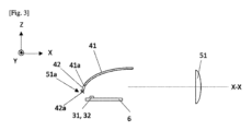
図3は、第1発光モジュール2のサブモジュール21およびサブモジュール22の垂直平面XZでの断面図を表す。
Figure 3 shows a cross-sectional view of
第1集光器41および第2集光器42は、それぞれが第1光源31、第2光源32がそれぞれ配置される空洞を規定する、垂直方向に切断された放物線形状または楕円形状を有する。第1光源31および第2光源32は単一のプリント回路基板6に取り付けられた発光ダイオードであり、したがって同じ方向Zに光線を放射することができる。プリント回路基板6は平坦であり、その結果、第1光源31および第2光源32はレンズ51の光軸X-Xから同じ距離に位置する。
The first and
発光ダイオード31は集光器41の焦点に位置し、その結果、この発光ダイオード31により放射される光線は集光器41の反射面により、レンズ51の光軸X-Xに対する傾斜角に応じて25°以下、好ましくは10°未満で反射される。同様に、発光ダイオード32は集光器42の焦点に位置し、その結果、この発光ダイオード32により放射される光線は集光器42の反射面により、レンズ51の光軸X-Xに対する傾斜角に応じて25°以下、好ましくは25°未満で反射される。
The
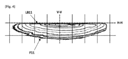
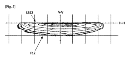
集光器41、42のそれぞれの反射面は、それぞれの発光ダイオード31、32により放射される光を集めて、この光を道路へ投射するよう設計されているレンズ51へ向けて反射する。したがって、第1発光サブモジュール21は第1光線F11を形成し、第2発光サブモジュール22は第2光線F12を形成する。図4は発光装置1から25mに位置する垂直スクリーンへの光線F11の投光を表し、直交基準系が与えられている。図5は発光装置1から25mに位置する垂直スクリーンへの光線F12の投光を表し、直交基準系が与えられており、第1サブモジュール21および第2サブモジュール22が調節されて図4のものに対して変化していない。
The reflecting surface of each of the
このように、第1集光器41はそれぞれが後端部41aを、第2集光器42はそれぞれが後端部42aを有する。後端部41aはレンズ51の光軸X-Xに対して同じ高さに位置し、後端部42aはこの光軸X-Xに対して同じ高さに位置して、後端部41aに対して垂直方向にオフセットされていることが分かるであろう。これらの後端部42aは光軸X-X上にあると考えることができる。
Thus, each of the
レンズ51は焦点領域、たとえば焦線51aを有し、この線は第1集光器41および第2集光器42の後端部41a、42aのすべてを経由して水平方向へ通り(この線はしたがって湾曲している)、第2集光器42の後端部42aのみを経由して垂直方向へ通って、第1集光器41の後端部41aの付近に留まる。
The
したがって、レンズ51は集光器41、42のそれぞれの反射面の像を道路へ投影し、その結果、この投影により生じる光線F11はそれぞれが第1上部カットオフLB11を、光線F12はそれぞれが第2上部カットオフLB12を有し、この集光器の後端部41a、42aにより形成される点灯される領域と点灯されない領域を画定する。後端部41a、42aはそれぞれ略楕円形状を有し、その結果、第1上部カットオフLB11および第2上部カットオフLB12は略平坦である。
Thus,
後端部41a、42aが相対的に位置調整されることで、光線F11の複数の第1カットオフLB11は互いに揃えられ、光線F12の複数の第2カットオフLB12も同様に互いに揃えられるが、第2カットオフLB12は第1カットオフLB11に対して垂直方向上方へオフセットされている。したがって、記載される例では、第1上部カットオフLB11はそれぞれ前記基準系の水平軸H-Hの0.57°下に位置し、第2上部カットオフLB12はそれぞれ前記基準系の水平軸H-Hにほぼ重ねられる。
By adjusting the relative positions of the
第2発光モジュール3は、それぞれが光源33、集光器43、およびレンズ52を備える複数の発光サブモジュール23を含む。
The second light-emitting
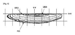
各サブモジュール23は、このサブモジュールの集光器43の形状、具体的には、レンズ51の光軸に対する第2集光器42の後端部42aの形状のように略楕円形状でレンズ52の光軸に対して略同一の高さに位置する後端部43aの形状を除いて、第1発光モジュール2のサブモジュール21、22と類似している。図6および図7に表されているように、各サブモジュール4の各集光器の像のレンズ52による投影により生じる光線の上部カットオフはしたがって平坦な上部LB13を有し、LB13は水平軸H-H、ひいては光線F12の第2カットオフLB12と揃えられるように、または光線F11の第1カットオフLB11の上へ延びるように設計されている。
Each
言い換えれば、光源31、33が同時に点灯され、光源32が消灯された場合、図6に表されているような光線を組み合わせることで、ECE R112規則に従ってロービームタイプの照明機能を提供することが可能となる。その一方で、光源32、33が同時に点灯され、光源31が消灯された場合、図7に表されているような光線を組み合わせることで、FMVSS 108またはSAEの規則に従ってロービームタイプの照明機能を提供することが可能となる。
In other words, when
第2発光モジュール3は装置1の横軸Yに沿って第1発光モジュール2に隣接して配置され、この第2発光モジュール3のサブモジュール23は横軸Yに沿って互いに隣接して配置され、加えて、集光器43は集光器41、42と同じ方向に配置されているのが分かるであろう。したがって、光源31、32、33は単一のプリント回路基板6の上に配置することができて、集光器41、42、43は、それぞれがこれらの集光器のうちの一つを規定する空洞が形成されている発光装置の一つの部分により形成することができて、各空洞にはそれぞれが規定する集光器の反射面を形成する反射コーティングがなされている。
It will be seen that the second
図1および図2の例では、第3発光モジュール4はあらゆる点で第1発光モジュール2と同一であり、それぞれが光源34、集光器44、およびレンズ53とを備える複数の発光サブモジュール24と、それぞれが光源35、集光器45、およびレンズ53を備える複数の発光サブモジュール25を含む。したがって、第3発光モジュール4は、この第1発光モジュール2と同じ光線F11、F12を形成するよう設計される。この第3発光モジュール4の第1発光サブモジュールと第2発光サブモジュールの入れ替わりは、第1発光モジュール2のものに対して反転されていることだけは分かるであろう。
1 and 2, the third
そして、第4発光モジュール5は、それぞれが光源36、集光器46、およびレンズ54を備える複数の発光サブモジュール26を含む。第4発光モジュール4は、セグメント化された、またはピクセル化された光線を投射するよう設計され、この光線は少なくとも部分的に光線F12の第2上部カットオフLB12の上へ延びる。
The fourth light-emitting
これらの発光モジュール2、3、4、5のレンズ51、52、53、54は、発光装置1の単一のレンズ7の異なる部分により形成されることが分かるであろう。
It will be seen that the
発光装置は制御部(描写されていない)を含み、この制御部は所与の測光機能の放射命令を受信することができて、この命令に応答して、光を放射するように光源31、32、33、34、35、36を制御するように設計される。
The light emitting device includes a control unit (not depicted) that is capable of receiving an emission command for a given photometric function and is designed to control the
たとえば、欧州式ロービームタイプの機能の放射命令を受信している間、制御部は第1光源31、33、34を作動させ、発光装置が欧州式ロービームタイプの前記機能を提供する。米国式ロービームタイプの機能の放射命令を受信している間、制御部は光源32、33、35を作動させ、発光装置が米国式ロービームタイプの前記機能を提供する。
For example, while receiving a command to emit a European low beam type function, the control unit activates the
また、ハイビームタイプの機能の放射命令を受信している間、制御部は光源31、33、34、36を作動させる。
The control unit also activates
上述の説明は、本発明が設定した目的、すなわち、複数の特定の規則の要件に準拠するロービームタイプの照明機能を提供し、その動作モードとは関係なく点灯時の外観を同じに保つことのできる発光装置を得るという目的の実現をいかにして可能とするかを明確に説明している。 The above description clearly explains how the invention makes it possible to achieve the objective it has set, namely to obtain a light-emitting device that provides a low-beam type lighting function that complies with the requirements of several specific regulations and that maintains the same appearance when lit, regardless of its operating mode.
いずれにしても、本発明は本明細書で具体的に記載された実施形態には限定されず、特にすべての等価な手段、および、技術的に実行可能なそれらの手段の任意の組み合わせにまで及ぶ。たとえば、説明されたもの以外の複数の種類の光学デバイス、具体的には反射器、レンズ、コリメータ、光導波路、遮蔽版の複数の光学素子のうちの一つまたは組み合わせを含む任意の光学デバイスを用いて想像することは可能である。また、他の形状、および/または他の大きさ、および/または光線の他の位置調整を想像することも可能である。 In any case, the invention is not limited to the embodiments specifically described herein, but in particular extends to all equivalent means and any combination of these means that is technically feasible. For example, it is possible to imagine using optical devices of different types than those described, in particular any optical device that includes one or a combination of the following optical elements: reflectors, lenses, collimators, optical waveguides, shielding plates. It is also possible to imagine other shapes and/or other sizes and/or other alignments of the light beam.
Claims (9)
第1光源(31)と前記第1光源により放射される光を集めて反射するよう設計されている反射面を含む第1集光器(41)とを備える第1サブモジュール(21)を含む第1発光モジュール(2)を含み、
前記第1発光モジュールは、前記第1集光器により反射される光を第1上部カットオフ(LB11)を有する第1光線(F11)として投射するよう設計されている第1レンズ(51)を含み、前記第1光線は前記第1レンズにより形成される前記第1集光器の前記反射面の像により形成され、
前記第1発光モジュールは、さらに、第2光源(32)と前記第2光源により放射される光を集めて反射するよう設計されている反射面を含む第2集光器(42)とを備える第2サブモジュール(22)を含み、
前記第1レンズは、前記第2集光器により反射される光を第2上部カットオフ(LB12)を有する第2光線(F12)として投射するよう設計されており、前記第2光線は前記第1レンズにより形成される前記第2集光器の前記反射面の像により形成され、
前記第1サブモジュールおよび前記第2サブモジュールは、前記第1上部カットオフが前記第2上部カットオフに対して垂直方向にオフセットされるように設計されており、
前記発光装置(1)は、さらに、前記第1光源(31)および前記第2光源(32)のそれぞれを選択的に制御するよう設計されている制御部を含み、前記制御部は前記第1光源および前記第2光源の一方が消灯されている場合のみに前記第1光源および前記第2光源の他方を点灯するよう設計されている、自動車の発光装置(1)。 A lighting device (1) for an automobile, comprising:
a first light emitting module (2) including a first sub-module (21) with a first light source (31) and a first collector (41) including a reflective surface designed to collect and reflect the light emitted by the first light source,
the first light emitting module comprises a first lens (51) designed to project the light reflected by the first collector as a first light ray (F11) having a first upper cutoff (LB11) , the first light ray being formed by an image of the reflecting surface of the first collector formed by the first lens;
The first light emitting module further comprises a second sub-module (22) comprising a second light source (32) and a second collector (42) including a reflective surface designed to collect and reflect the light emitted by the second light source,
the first lens is designed to project the light reflected by the second collector as a second light ray (F12) having a second upper cutoff (LB12) , the second light ray being formed by an image of the reflecting surface of the second collector formed by the first lens;
the first sub-module and the second sub-module are designed such that the first upper cutoff is vertically offset relative to the second upper cutoff;
The lighting device (1) further includes a control unit designed to selectively control each of the first light source (31) and the second light source (32), and the control unit is designed to turn on one of the first light source and the second light source only when the other of the first light source and the second light source is turned off .
前記第1光線(F11)の前記第1上部カットオフ(LB11)が前記第1レンズ(51)により形成される前記第1集光器の前記後端部の像により形成され、かつ、前記第2光線(F12)の前記第2上部カットオフ(LB12)が前記第1レンズ(51)により形成される前記第2集光器の前記後端部の像により形成されるようになっており、
前記第1集光器の前記後端部の垂直方向高さ位置が、前記第2集光器の前記後端部の垂直方向高さ位置と異なっている、請求項1に記載の発光装置(1)。 Each of the first collector (41) and the second collector (42) has a rear end (41a, 42a);
the first upper cut-off (LB11) of the first light ray (F11) is formed by an image of the rear end of the first collector formed by the first lens (51), and the second upper cut-off (LB12) of the second light ray (F12) is formed by an image of the rear end of the second collector formed by the first lens (51),
2. The light emitting device (1) according to claim 1 , wherein a vertical height position of the rear end of the first collector is different from a vertical height position of the rear end of the second collector .
前記第1発光モジュールは複数の第2サブモジュール(22)を含み、前記複数の第2サブモジュール(22)のそれぞれが、第2光源(32)と前記第2光源により放射される光を集めて反射するよう設計されている反射面を含む第2集光器(42)とを備えており、
前記第1サブモジュールおよび前記第2サブモジュールは互いに隣接して互い違いに配置されている、請求項1に記載の発光装置(1)。 The first light emitting module (2) comprises a plurality of first sub-modules (21), each of which comprises a first light source (31) and a first collector (41) including a reflective surface designed to collect and reflect light emitted by the first light source ;
the first light emitting module includes a plurality of second sub-modules (22), each of the plurality of second sub-modules (22) comprising a second light source (32) and a second light collector (42) including a reflective surface designed to collect and reflect light emitted by the second light source ;
2. The light emitting device (1) according to claim 1, wherein the first sub-module and the second sub-module are arranged adjacent to each other in a staggered manner.
前記第3発光モジュールは、前記第1発光モジュールの前記第1サブモジュール(21)とまったく同じ第3サブモジュール(24)と、前記第1発光モジュールの前記第2サブモジュール(22)とまったく同じ第4サブモジュール(25)と、第2レンズ(53)とを有し、
前記第2レンズ(53)は、前記第3サブモジュール(24)により放射される光を第4上部カットオフを有する第4光線として投射し、かつ、前記第4サブモジュール(25)により放射される光を第5上部カットオフを有する第5光線として投射するよう設計されており、
前記第3サブモジュールおよび前記第4サブモジュールは、前記第4上部カットオフが前記第1上部カットオフ(LB11)と揃えられるかまたは重ねられ、かつ、前記第5上部カットオフが前記第2上部カットオフ(LB12)と揃えられるかまたは重ねられるように配置されていることを特徴とする、請求項7に記載の発光装置(1)。 Further comprising a third light emitting module (4) disposed below the first light emitting module (2) ,
the third light emitting module has a third submodule (24) identical to the first submodule (21) of the first light emitting module, a fourth submodule (25) identical to the second submodule (22) of the first light emitting module, and a second lens (53);
the second lens (53) is designed to project the light emitted by the third sub-module (24) as a fourth light ray having a fourth upper cut-off and to project the light emitted by the fourth sub-module (25) as a fifth light ray having a fifth upper cut-off ;
The light emitting device (1) of claim 7 , characterized in that the third submodule and the fourth submodule are arranged such that the fourth upper cutoff is aligned or overlaps with the first upper cutoff (LB11) and the fifth upper cutoff is aligned or overlaps with the second upper cutoff (LB12).
Applications Claiming Priority (3)
| Application Number | Priority Date | Filing Date | Title |
|---|---|---|---|
| FR2109226A FR3126747B1 (en) | 2021-09-03 | 2021-09-03 | Lighting device of a motor vehicle |
| FR2109226 | 2021-09-03 | ||
| PCT/EP2022/074362 WO2023031344A1 (en) | 2021-09-03 | 2022-09-01 | Lighting device for a motor vehicle |
Publications (2)
| Publication Number | Publication Date |
|---|---|
| JP2024533180A JP2024533180A (en) | 2024-09-12 |
| JP7686879B2 true JP7686879B2 (en) | 2025-06-02 |
Family
ID=77999199
Family Applications (1)
| Application Number | Title | Priority Date | Filing Date |
|---|---|---|---|
| JP2024514030A Active JP7686879B2 (en) | 2021-09-03 | 2022-09-01 | Automotive lighting devices |
Country Status (6)
| Country | Link |
|---|---|
| US (1) | US12320485B2 (en) |
| EP (1) | EP4396492A1 (en) |
| JP (1) | JP7686879B2 (en) |
| CN (1) | CN117957398A (en) |
| FR (1) | FR3126747B1 (en) |
| WO (1) | WO2023031344A1 (en) |
Citations (3)
| Publication number | Priority date | Publication date | Assignee | Title |
|---|---|---|---|---|
| JP2010218964A (en) | 2009-03-18 | 2010-09-30 | Ichikoh Ind Ltd | Vehicular lighting fixture |
| JP2017212067A (en) | 2016-05-24 | 2017-11-30 | スタンレー電気株式会社 | Vehicle lamp module |
| JP2020149975A (en) | 2019-03-14 | 2020-09-17 | ヴァレオ ビジョンValeo Vision | A light emitting device that projects the illuminated surface of at least two concentrators. |
Family Cites Families (7)
| Publication number | Priority date | Publication date | Assignee | Title |
|---|---|---|---|---|
| JP4529946B2 (en) * | 2006-06-01 | 2010-08-25 | 市光工業株式会社 | Vehicle lighting |
| FR2910592B1 (en) * | 2006-12-20 | 2012-07-20 | Valeo Vision | LUMINOUS PROJECTOR MODULE OF A MOTOR VEHICLE FOR A CUT-OFF BEAM |
| JP4953922B2 (en) * | 2007-05-30 | 2012-06-13 | 株式会社小糸製作所 | Vehicle headlamp |
| FR3084728B1 (en) * | 2018-07-31 | 2021-03-19 | Valeo Vision | LIGHT MODULE IMAGING THE ILLUMINATED SURFACE OF A COLLECTOR |
| FR3103252B1 (en) * | 2019-11-19 | 2022-06-24 | Valeo Vision | LIGHTING MODULE FOR VEHICLE WITH MODULAR CUT-OFF BETWEEN LEFT-HAND DRIVE AND RIGHT-HAND DRIVE |
| FR3118120B1 (en) | 2020-12-18 | 2023-05-05 | Valeo Vison Service Ip | Automotive headlamp with several lighting modules on a common inclined plate. |
| FR3125862B1 (en) | 2021-07-30 | 2023-10-06 | Valeo Vision | Light module for motor vehicle |
-
2021
- 2021-09-03 FR FR2109226A patent/FR3126747B1/en active Active
-
2022
- 2022-09-01 US US18/687,067 patent/US12320485B2/en active Active
- 2022-09-01 WO PCT/EP2022/074362 patent/WO2023031344A1/en not_active Ceased
- 2022-09-01 CN CN202280059742.4A patent/CN117957398A/en active Pending
- 2022-09-01 EP EP22772501.7A patent/EP4396492A1/en active Pending
- 2022-09-01 JP JP2024514030A patent/JP7686879B2/en active Active
Patent Citations (3)
| Publication number | Priority date | Publication date | Assignee | Title |
|---|---|---|---|---|
| JP2010218964A (en) | 2009-03-18 | 2010-09-30 | Ichikoh Ind Ltd | Vehicular lighting fixture |
| JP2017212067A (en) | 2016-05-24 | 2017-11-30 | スタンレー電気株式会社 | Vehicle lamp module |
| JP2020149975A (en) | 2019-03-14 | 2020-09-17 | ヴァレオ ビジョンValeo Vision | A light emitting device that projects the illuminated surface of at least two concentrators. |
Also Published As
| Publication number | Publication date |
|---|---|
| EP4396492A1 (en) | 2024-07-10 |
| JP2024533180A (en) | 2024-09-12 |
| US20240280233A1 (en) | 2024-08-22 |
| FR3126747A1 (en) | 2023-03-10 |
| US12320485B2 (en) | 2025-06-03 |
| WO2023031344A1 (en) | 2023-03-09 |
| FR3126747B1 (en) | 2023-11-17 |
| CN117957398A (en) | 2024-04-30 |
Similar Documents
| Publication | Publication Date | Title |
|---|---|---|
| CN106662314B (en) | Lamp unit and vehicle headlamp | |
| US7607811B2 (en) | Lighting unit | |
| KR102155080B1 (en) | Vehicle headlamp | |
| KR100564711B1 (en) | Headlights for vehicles | |
| US8287167B2 (en) | Lamp unit | |
| JP5714346B2 (en) | Vehicle headlamp | |
| CN108375029B (en) | Optical unit | |
| US12152744B2 (en) | Motor vehicle headlamp with multiple lighting modules on an inclined common plate | |
| CN110094689B (en) | smart headlight | |
| CN107401715B (en) | LED headlamp with refractive interface producing cut-off for vehicle | |
| JP2014013758A (en) | Light module | |
| JP6713869B2 (en) | Vehicle lighting | |
| JP5407097B2 (en) | Vehicle lighting | |
| JP5497408B2 (en) | Vehicle headlamp | |
| JP2020135924A (en) | Vehicular lighting fixture | |
| CN212565607U (en) | Car light optical system, car light module and vehicle | |
| CN111750328A (en) | Light module for motor vehicle headlights with n sub-light modules arranged side by side in a row | |
| JP7686879B2 (en) | Automotive lighting devices | |
| JP2011003515A (en) | Vehicular headlight for low beam | |
| JP2016207275A (en) | Vehicular lighting fixture | |
| CN118829822A (en) | Lighting equipment for vehicles | |
| CN223345204U (en) | A high and low beam integrated lens and a car using the same | |
| JP7575982B2 (en) | Lamp unit | |
| EP4624800A1 (en) | Vehicle lamp | |
| WO2019244783A1 (en) | Vehicular lamp |
Legal Events
| Date | Code | Title | Description |
|---|---|---|---|
| A521 | Request for written amendment filed |
Free format text: JAPANESE INTERMEDIATE CODE: A523 Effective date: 20240430 |
|
| A621 | Written request for application examination |
Free format text: JAPANESE INTERMEDIATE CODE: A621 Effective date: 20240430 |
|
| A131 | Notification of reasons for refusal |
Free format text: JAPANESE INTERMEDIATE CODE: A131 Effective date: 20241203 |
|
| A601 | Written request for extension of time |
Free format text: JAPANESE INTERMEDIATE CODE: A601 Effective date: 20250303 |
|
| A521 | Request for written amendment filed |
Free format text: JAPANESE INTERMEDIATE CODE: A523 Effective date: 20250327 |
|
| TRDD | Decision of grant or rejection written | ||
| A01 | Written decision to grant a patent or to grant a registration (utility model) |
Free format text: JAPANESE INTERMEDIATE CODE: A01 Effective date: 20250422 |
|
| A61 | First payment of annual fees (during grant procedure) |
Free format text: JAPANESE INTERMEDIATE CODE: A61 Effective date: 20250521 |
|
| R150 | Certificate of patent or registration of utility model |
Ref document number: 7686879 Country of ref document: JP Free format text: JAPANESE INTERMEDIATE CODE: R150 |