JP7686876B2 - Beam application method and device - Google Patents
Beam application method and device Download PDFInfo
- Publication number
- JP7686876B2 JP7686876B2 JP2024507035A JP2024507035A JP7686876B2 JP 7686876 B2 JP7686876 B2 JP 7686876B2 JP 2024507035 A JP2024507035 A JP 2024507035A JP 2024507035 A JP2024507035 A JP 2024507035A JP 7686876 B2 JP7686876 B2 JP 7686876B2
- Authority
- JP
- Japan
- Prior art keywords
- symbols
- transmission
- subcarrier spacing
- dci
- downlink
- Prior art date
- Legal status (The legal status is an assumption and is not a legal conclusion. Google has not performed a legal analysis and makes no representation as to the accuracy of the status listed.)
- Active
Links
Images


Classifications
-
- H—ELECTRICITY
- H04—ELECTRIC COMMUNICATION TECHNIQUE
- H04B—TRANSMISSION
- H04B7/00—Radio transmission systems, i.e. using radiation field
- H04B7/02—Diversity systems; Multi-antenna system, i.e. transmission or reception using multiple antennas
- H04B7/04—Diversity systems; Multi-antenna system, i.e. transmission or reception using multiple antennas using two or more spaced independent antennas
- H04B7/06—Diversity systems; Multi-antenna system, i.e. transmission or reception using multiple antennas using two or more spaced independent antennas at the transmitting station
- H04B7/0686—Hybrid systems, i.e. switching and simultaneous transmission
- H04B7/0695—Hybrid systems, i.e. switching and simultaneous transmission using beam selection
- H04B7/06952—Selecting one or more beams from a plurality of beams, e.g. beam training, management or sweeping
-
- H—ELECTRICITY
- H04—ELECTRIC COMMUNICATION TECHNIQUE
- H04L—TRANSMISSION OF DIGITAL INFORMATION, e.g. TELEGRAPHIC COMMUNICATION
- H04L27/00—Modulated-carrier systems
- H04L27/26—Systems using multi-frequency codes
- H04L27/2601—Multicarrier modulation systems
- H04L27/2602—Signal structure
- H04L27/26025—Numerology, i.e. varying one or more of symbol duration, subcarrier spacing, Fourier transform size, sampling rate or down-clocking
-
- H—ELECTRICITY
- H04—ELECTRIC COMMUNICATION TECHNIQUE
- H04L—TRANSMISSION OF DIGITAL INFORMATION, e.g. TELEGRAPHIC COMMUNICATION
- H04L5/00—Arrangements affording multiple use of the transmission path
- H04L5/0001—Arrangements for dividing the transmission path
- H04L5/0003—Two-dimensional division
- H04L5/0005—Time-frequency
- H04L5/0007—Time-frequency the frequencies being orthogonal, e.g. OFDM(A) or DMT
- H04L5/001—Time-frequency the frequencies being orthogonal, e.g. OFDM(A) or DMT the frequencies being arranged in component carriers
-
- H—ELECTRICITY
- H04—ELECTRIC COMMUNICATION TECHNIQUE
- H04L—TRANSMISSION OF DIGITAL INFORMATION, e.g. TELEGRAPHIC COMMUNICATION
- H04L5/00—Arrangements affording multiple use of the transmission path
- H04L5/0001—Arrangements for dividing the transmission path
- H04L5/0014—Three-dimensional division
- H04L5/0023—Time-frequency-space
-
- H—ELECTRICITY
- H04—ELECTRIC COMMUNICATION TECHNIQUE
- H04L—TRANSMISSION OF DIGITAL INFORMATION, e.g. TELEGRAPHIC COMMUNICATION
- H04L5/00—Arrangements affording multiple use of the transmission path
- H04L5/003—Arrangements for allocating sub-channels of the transmission path
- H04L5/0048—Allocation of pilot signals, i.e. of signals known to the receiver
-
- H—ELECTRICITY
- H04—ELECTRIC COMMUNICATION TECHNIQUE
- H04L—TRANSMISSION OF DIGITAL INFORMATION, e.g. TELEGRAPHIC COMMUNICATION
- H04L5/00—Arrangements affording multiple use of the transmission path
- H04L5/003—Arrangements for allocating sub-channels of the transmission path
- H04L5/0053—Allocation of signalling, i.e. of overhead other than pilot signals
-
- H—ELECTRICITY
- H04—ELECTRIC COMMUNICATION TECHNIQUE
- H04L—TRANSMISSION OF DIGITAL INFORMATION, e.g. TELEGRAPHIC COMMUNICATION
- H04L5/00—Arrangements affording multiple use of the transmission path
- H04L5/0091—Signalling for the administration of the divided path, e.g. signalling of configuration information
- H04L5/0094—Indication of how sub-channels of the path are allocated
-
- H—ELECTRICITY
- H04—ELECTRIC COMMUNICATION TECHNIQUE
- H04W—WIRELESS COMMUNICATION NETWORKS
- H04W72/00—Local resource management
- H04W72/04—Wireless resource allocation
-
- H—ELECTRICITY
- H04—ELECTRIC COMMUNICATION TECHNIQUE
- H04W—WIRELESS COMMUNICATION NETWORKS
- H04W72/00—Local resource management
- H04W72/04—Wireless resource allocation
- H04W72/044—Wireless resource allocation based on the type of the allocated resource
- H04W72/0446—Resources in time domain, e.g. slots or frames
-
- H—ELECTRICITY
- H04—ELECTRIC COMMUNICATION TECHNIQUE
- H04W—WIRELESS COMMUNICATION NETWORKS
- H04W72/00—Local resource management
- H04W72/04—Wireless resource allocation
- H04W72/044—Wireless resource allocation based on the type of the allocated resource
- H04W72/046—Wireless resource allocation based on the type of the allocated resource the resource being in the space domain, e.g. beams
-
- H—ELECTRICITY
- H04—ELECTRIC COMMUNICATION TECHNIQUE
- H04W—WIRELESS COMMUNICATION NETWORKS
- H04W72/00—Local resource management
- H04W72/12—Wireless traffic scheduling
- H04W72/1263—Mapping of traffic onto schedule, e.g. scheduled allocation or multiplexing of flows
-
- H—ELECTRICITY
- H04—ELECTRIC COMMUNICATION TECHNIQUE
- H04W—WIRELESS COMMUNICATION NETWORKS
- H04W72/00—Local resource management
- H04W72/20—Control channels or signalling for resource management
- H04W72/23—Control channels or signalling for resource management in the downlink direction of a wireless link, i.e. towards a terminal
- H04W72/232—Control channels or signalling for resource management in the downlink direction of a wireless link, i.e. towards a terminal the control data signalling from the physical layer, e.g. DCI signalling
Landscapes
- Engineering & Computer Science (AREA)
- Signal Processing (AREA)
- Computer Networks & Wireless Communication (AREA)
- Physics & Mathematics (AREA)
- Mathematical Physics (AREA)
- Mobile Radio Communication Systems (AREA)
Description
本出願は通信技術の分野に関し、特にビーム適用方法及びその装置に関する。 This application relates to the field of communications technology, and in particular to a beam application method and device.
無線通信では、通常、ビームは、物理ダウリンク制御チャネル(physical downlink control channel、PDCCH)、物理ダウリンク共有チャネル(physical downlink share channel、PDSCH)、物理アップリンク制御チャネル(physical uplink control channel、PUCCH)、物理アップリンク共有チャネル(physical uplink share channel、PUSCH)及び/又はリファレンス信号(reference signal、RS)でアプリケーションを指示する。PDCCHとPUCCHはメディアアクセス制御(medium access control 、MAC)制御要素(control element、CE)を使用して1つのビームをアクティブ化または適用することができる。一方、PDSCHとPUSCHは、DCIシグナリングに基づいて、それぞれのビームを指示または適用することができる。この方法では、ネットワークデバイスと端末デバイスのビームにばらつきが発生する可能性がある。 In wireless communications, beams typically indicate applications on a physical downlink control channel (PDCCH), a physical downlink shared channel (PDSCH), a physical uplink control channel (PUCCH), a physical uplink shared channel (PUSCH) and/or a reference signal (RS). PDCCH and PUCCH can activate or apply a beam using a medium access control (MAC) control element (CE). On the other hand, the PDSCH and PUSCH can indicate or apply their respective beams based on DCI signaling. This method may cause variations in the beams of the network device and the terminal device.
現在、ビーム適用ための有効な手段が不足する。 Currently, there is a lack of effective means to apply the beam.
本出願の実施例はビーム適用方法及びその装置を提供し、ロングタームエボリューション(long term evolution、LTE)システム、第5世代(5th generation、5G)移動通信システム、5G新しい無線(new radio、NR)システムなどの分野に適用可能であり、前記ダウンリンク制御情報(Downlink Control Information、DCI)に基づいて、対応するアップリンク伝送のビーム適用時間及び/又はダウンリンク伝送のビーム適用時間を決定し、ビーム適用を行う。これにより、前記ネットワークデバイスと前記端末デバイスのビームが一致し、伝送性能が向上することを確保する。 The embodiments of the present application provide a beam application method and device, which can be applied to fields such as long term evolution (LTE) systems, 5th generation (5G) mobile communication systems, and 5G new radio (NR) systems, and determine the beam application time of the corresponding uplink transmission and/or the beam application time of the corresponding downlink transmission based on the downlink control information (DCI), and perform beam application. This ensures that the beams of the network device and the terminal device are consistent and the transmission performance is improved.
第1の態様では、本出願の実施例は、端末デバイスに適用されるビーム適用(application)方法を提供し、前記方法は、ネットワークデバイスからのダウンリンク制御情報(DCI)を受信するステップであって、前記DCIが統合伝送設定(configuration)指示状態を含むステップと、前記統合伝送設定指示状態に対応するアップリンク伝送のビーム適用時間及び/又はダウンリンク伝送のビーム適用時間を決定するステップと、を含む。 In a first aspect, an embodiment of the present application provides a beam application method applied to a terminal device, the method including the steps of receiving downlink control information (DCI) from a network device, the DCI including an integrated transmission configuration indication state, and determining a beam application time for uplink transmission and/or a beam application time for downlink transmission corresponding to the integrated transmission configuration indication state.
選択的に、前記DCIはダウンリンク割り当て指示情報を含むか、または含まない。 Optionally, the DCI may or may not include downlink allocation indication information.
選択的に、前記アップリンク伝送のビーム適用時間及び/又はダウンリンク伝送のビーム適用時間は前記DCIに対するハイブリッド自動再送要求(HARQ)確認文字(ACK)フィードバックの伝送時間の後の複数のシンボルの後であり、前記アップリンク伝送のビーム適用時間及び/又はダウンリンク伝送のビーム適用時間は前記統合伝送設定指示状態の適用時間である。 Optionally, the beam application time of the uplink transmission and/or the beam application time of the downlink transmission is several symbols after the transmission time of a hybrid automatic repeat request (HARQ) acknowledgement character (ACK) feedback for the DCI, and the beam application time of the uplink transmission and/or the beam application time of the downlink transmission is an application time of the integrated transmission setting indication state.
選択的に、前記複数のシンボルは第1の数のシンボルであり、前記第1の数のシンボルは前記ダウンリンク伝送のサブキャリア間隔に基づいて決定され、前記ビーム適用時間が前記ダウンリンク伝送のビーム適用時間であり、及び/又は、前記複数のシンボルは第2の数のシンボルであり、前記第2の数のシンボルは前記アップリンク伝送のサブキャリア間隔に基づいて決定され、前記ビーム適用時間が前記アップリンク伝送のビーム適用時間である。 Optionally, the plurality of symbols is a first number of symbols, the first number of symbols is determined based on a subcarrier spacing of the downlink transmission, and the beam application time is the beam application time of the downlink transmission, and/or the plurality of symbols is a second number of symbols, the second number of symbols is determined based on a subcarrier spacing of the uplink transmission, and the beam application time is the beam application time of the uplink transmission.
選択的に、前記複数のシンボルの時間長(duration)は第1の時間値であり、または、前記複数のシンボルは第3の数のシンボルであり、前記第3の数のシンボルは前記アップリンク伝送または前記ダウンリンク伝送のサブキャリア間隔に基づいて決定され、前記ビーム適用時間が前記アップリンク伝送および前記ダウンリンク伝送のビーム適用時間である。 Optionally, the duration of the plurality of symbols is a first time value, or the plurality of symbols is a third number of symbols, the third number of symbols being determined based on a subcarrier spacing of the uplink transmission or the downlink transmission, and the beam application time is a beam application time of the uplink transmission and the downlink transmission.
選択的に、前記DCIと前記アップリンク伝送及び/又はダウンリンク伝送とが同一のキャリアのコンポーネントキャリア(component carrier)に対応し、または、前記DCIと前記アップリンク伝送及び/又はダウンリンク伝送とが異なるキャリアの前記コンポーネントキャリアに対応し、前記DCIに対応するサブキャリア間隔は前記アップリンク伝送のサブキャリア間隔及び/又はダウンリンク伝送のサブキャリア間隔以上である。 Optionally, the DCI and the uplink transmission and/or the downlink transmission correspond to component carriers of the same carrier, or the DCI and the uplink transmission and/or the downlink transmission correspond to component carriers of different carriers, and the subcarrier spacing corresponding to the DCI is equal to or greater than the subcarrier spacing of the uplink transmission and/or the subcarrier spacing of the downlink transmission.
選択的に、前記複数のシンボルは第4の数のシンボルと第5の数のシンボルとを含み、前記第4の数のシンボルは前記ダウンリンク伝送のサブキャリア間隔に基づいて決定され、前記第5の数のシンボルは前記DCIのサブキャリア間隔と前記ダウンリンク伝送のサブキャリア間隔とに基づいて決定され、前記ビーム適用時間が前記ダウンリンク伝送のビーム適用時間であり、及び/又は、前記複数のシンボルは第6の数のシンボルと第7の数のシンボルとを含み、前記第6の数のシンボルは前記アップリンク伝送のサブキャリア間隔に基づいて決定され、前記第7の数のシンボルは前記DCIのサブキャリア間隔と前記アップリンク伝送のサブキャリア間隔とに基づいて決定され、前記ビーム適用時間が前記アップリンク伝送のビーム適用時間である。 Optionally, the plurality of symbols includes a fourth number of symbols and a fifth number of symbols, the fourth number of symbols being determined based on a subcarrier spacing of the downlink transmission, the fifth number of symbols being determined based on a subcarrier spacing of the DCI and a subcarrier spacing of the downlink transmission, and the beam application time being the beam application time of the downlink transmission, and/or the plurality of symbols includes a sixth number of symbols and a seventh number of symbols, the sixth number of symbols being determined based on a subcarrier spacing of the uplink transmission, the seventh number of symbols being determined based on a subcarrier spacing of the DCI and a subcarrier spacing of the uplink transmission, and the beam application time being the beam application time of the uplink transmission.
選択的に、前記複数のシンボルの時間長は第2の時間値であり、前記複数のシンボルは第8の数のシンボルと第9の数のシンボルとを含み、前記第8の数のシンボルは前記アップリンク伝送のサブキャリア間隔に基づいて決定され、前記第9の数のシンボルは前記DCIのサブキャリア間隔と前記アップリンク伝送のサブキャリア間隔とに基づいて決定され、または前記第8の数のシンボルは前記ダウンリンク伝送のサブキャリア間隔に基づいて決定され、前記第9の数のシンボルは前記DCIのサブキャリア間隔と前記ダウンリンク伝送のサブキャリア間隔とに基づいて決定され、前記ビーム適用時間が前記アップリンク伝送および前記ダウンリンク伝送のビーム適用時間である。 Optionally, the time length of the plurality of symbols is a second time value, the plurality of symbols includes an eighth number of symbols and a ninth number of symbols, the eighth number of symbols is determined based on a subcarrier spacing of the uplink transmission, the ninth number of symbols is determined based on a subcarrier spacing of the DCI and a subcarrier spacing of the uplink transmission, or the eighth number of symbols is determined based on a subcarrier spacing of the downlink transmission, the ninth number of symbols is determined based on a subcarrier spacing of the DCI and a subcarrier spacing of the downlink transmission, and the beam application time is a beam application time of the uplink transmission and the downlink transmission.
選択的に、前記DCIと前記アップリンク伝送及び/又はダウンリンク伝送とが異なるキャリアのコンポーネントキャリア(component carrier)に対応し、前記DCIに対応するサブキャリア間隔は前記アップリンク伝送のサブキャリア間隔及び/又はダウンリンク伝送のサブキャリア間隔より小さい。 Optionally, the DCI and the uplink transmission and/or the downlink transmission correspond to component carriers of different carriers, and the subcarrier spacing corresponding to the DCI is smaller than the subcarrier spacing of the uplink transmission and/or the subcarrier spacing of the downlink transmission.
選択的に、前記ダウンリンク伝送はダウンリンクチャネル及び/又はダウンリンクリファレンス信号を含み、前記ダウンリンクチャネルは、物理ダウリンク制御チャネル(PDCCH)と、物理ダウリンク共有チャネル(PDSCH)と、物理ブロードキャストチャネル(PBCH)と、のうちの少なくとも1つを含み、前記ダウンリンクリファレンス信号は、同期信号ブロック(SSB)と、チャネル状態情報リファレンス信号(CSI-RS)と、復調リファレンス信号(DMRS)と、測位リファレンス信号(PRS)とのうちの少なくとも1つを含む。 Optionally, the downlink transmission includes a downlink channel and/or a downlink reference signal, the downlink channel including at least one of a physical downlink control channel (PDCCH), a physical downlink shared channel (PDSCH), and a physical broadcast channel (PBCH), and the downlink reference signal including at least one of a synchronization signal block (SSB), a channel state information reference signal (CSI-RS), a demodulation reference signal (DMRS), and a positioning reference signal (PRS).
選択的に、前記アップリンク伝送はアップリンクチャネル及び/又はアップリンクリファレンス信号を含み、前記アップリンクチャネルは、物理アップリンク共有チャネル(PUSCH)と、物理アップリンク制御チャネル(PUCCH)と、物理ランダムアクセスチャネル(PRACH)とのうちの少なくとも1つを含み、前記アップリンクリファレンス信号は、サウンディングリファレンス信号(SRS)と、DMRSと、のうちの少なくとも1つを含む。 Optionally, the uplink transmission includes an uplink channel and/or an uplink reference signal, the uplink channel including at least one of a physical uplink shared channel (PUSCH), a physical uplink control channel (PUCCH), and a physical random access channel (PRACH), and the uplink reference signal including at least one of a sounding reference signal (SRS) and a DMRS.
選択的に、前記DCIと前記アップリンク伝送及び/又はダウンリンク伝送とが異なるコンポーネントキャリアに対応することは、前記異なるコンポーネントキャリアが異なるサービングセルに対応すること、または、前記異なるコンポーネントキャリアがサービングセルと非サービングセルに対応することを含む。 Optionally, the DCI and the uplink transmission and/or the downlink transmission correspond to different component carriers including the different component carriers corresponding to different serving cells or the different component carriers corresponding to a serving cell and a non-serving cell.
前記ダウンリンク制御情報(DCI)に基づいて対応するアップリンク伝送のビーム適用時間及び/又はダウンリンク伝送のビーム適用時間を決定し、ビーム適用を行う。これにより、前記ネットワークデバイスと前記端末デバイスのビームが一致し、伝送性能が向上することを確保する。 Based on the downlink control information (DCI), the beam application time of the corresponding uplink transmission and/or the beam application time of the corresponding downlink transmission are determined, and beam application is performed. This ensures that the beams of the network device and the terminal device match, improving transmission performance.
第2の態様では、本出願の実施例は、ネットワークデバイスに適用される別のビーム適用方法を提供し、前記方法は、端末デバイスにダウンリンク制御情報(DCI)を送信するステップであって、前記DCIが統合伝送設定指示状態を含むステップと、前記ダウンリンク制御情報に基づいてビームを適用するステップと、を含む。 In a second aspect, an embodiment of the present application provides another beam application method applied to a network device, the method including the steps of transmitting downlink control information (DCI) to a terminal device, the DCI including an integrated transmission configuration indication state, and applying a beam based on the downlink control information.
第3の態様では、本出願の実施例は、上記第1の態様に記載の方法における端末デバイスを実現する機能の一部または全部を有する通信装置を提供し、例えば、通信装置の機能は本出願の一部または全部の実施例における機能を備えてもよいし、本出願のいずれかの実施例を単独で実行する機能を備えてもよい。前記機能は、ハードウェアによって実現されてもよく、ハードウェアによって対応するソフトウェアを実行することによって実現されてもよい。前記ハードウェアまたはソフトウェアは、上記の機能に対応する1つまたは複数のユニットまたはモジュールを含む。 In a third aspect, an embodiment of the present application provides a communication device having some or all of the functions of implementing the terminal device in the method according to the first aspect above. For example, the functions of the communication device may include the functions in some or all of the embodiments of the present application, or may include the function of independently executing any of the embodiments of the present application. The functions may be implemented by hardware, or may be implemented by executing corresponding software by hardware. The hardware or software includes one or more units or modules corresponding to the above functions.
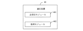
一実現形態では、この通信装置の構成には、送受信モジュールと処理モジュールとが含まれることができ、前記処理モジュールは、通信装置が上記の方法における対応する機能を実行することをサポートするように構成される。前記送受信モジュールは、通信装置と他のデバイスとの間の通信をサポートするために使用される。前記通信装置は、送受信モジュールと処理モジュールとに結合するための記憶モジュールをさらに含むことができ、この記憶モジュールが通信装置に必要なコンピュータプログラムとデータとを保存する。 In one implementation, the configuration of the communication device may include a transceiver module and a processing module, the processing module configured to support the communication device to perform the corresponding functions of the above method. The transceiver module is used to support communication between the communication device and other devices. The communication device may further include a storage module for coupling to the transceiver module and the processing module, the storage module storing computer programs and data required for the communication device.
例として、処理モジュールはプロセッサであってもよく、送受信モジュールはトランシーバまたは通信インターフェースであってもよく、記憶モジュールはメモリであってもよい。 As examples, the processing module may be a processor, the transceiver module may be a transceiver or a communication interface, and the storage module may be a memory.
一実施形態では、前記通信装置は、ネットワークデバイスからのダウンリンク制御情報(DCI)を受信するための受信モジュールであって、前記DCIが統合伝送設定指示状態を含む受信モジュールと、前記統合伝送設定指示状態に対応するアップリンク伝送のビーム適用時間及び/又はダウンリンク伝送のビーム適用時間を決定するための決定モジュールと、を含む。 In one embodiment, the communication device includes a receiving module for receiving downlink control information (DCI) from a network device, the DCI including an integrated transmission setting indication state, and a determining module for determining a beam application time for uplink transmission and/or a beam application time for downlink transmission corresponding to the integrated transmission setting indication state.
第4の態様では、本出願の実施例は、上記第2の態様に記載の方法の例におけるネットワークデバイスを実現する機能の一部または全部を有する別の通信装置を提供し、例えば、通信装置の機能は本出願の一部または全部の実施例における機能を備えてもよいし、本出願のいずれかの実施例を単独で実行する機能を備えてもよい。前記機能は、ハードウェアによって実現されてもよく、ハードウェアによって対応するソフトウェアを実行することによって実現されてもよい。前記ハードウェアまたはソフトウェアは、上記の機能に対応する1つまたは複数のユニットまたはモジュールを含む。 In a fourth aspect, an embodiment of the present application provides another communication device having some or all of the functions of implementing the network device in the example of the method according to the second aspect above. For example, the functions of the communication device may include the functions in some or all of the embodiments of the present application, or may include the function of independently executing any of the embodiments of the present application. The functions may be implemented by hardware, or may be implemented by executing corresponding software by hardware. The hardware or software includes one or more units or modules corresponding to the above functions.
一実現形態では、この通信装置の構成には、送受信モジュールと処理モジュールとが含まれることができ、当該処理モジュールは、通信装置が上記の方法における対応する機能を実行することをサポートするように構成される。送受信モジュールは、通信装置と他のデバイスとの間の通信をサポートするために使用される。前記通信装置は、送受信モジュールと処理モジュールとに結合するための記憶モジュールをさらに含むことができ、この記憶モジュールが通信装置に必要なコンピュータプログラムとデータとを保存する。 In one implementation, the configuration of the communication device may include a transceiver module and a processing module, the processing module being configured to support the communication device to perform the corresponding functions of the above method. The transceiver module is used to support communication between the communication device and other devices. The communication device may further include a storage module for coupling to the transceiver module and the processing module, the storage module storing computer programs and data required by the communication device.
例として、処理モジュールはプロセッサであってもよく、送受信モジュールはトランシーバまたは通信インターフェースであってもよく、記憶モジュールはメモリであってもよい。 As examples, the processing module may be a processor, the transceiver module may be a transceiver or a communication interface, and the storage module may be a memory.
一実施形態では、前記通信装置は、端末デバイスにダウンリンク制御情報(DCI)を送信するための送信モジュールであって、前記DCIが統合伝送設定指示状態を含む送信モジュールと、前記ダウンリンク制御情報に基づいてビームを適用するための適用モジュールと、を含む。 In one embodiment, the communication device includes a transmission module for transmitting downlink control information (DCI) to a terminal device, the DCI including an integrated transmission configuration indication state, and an application module for applying a beam based on the downlink control information.
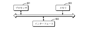
第5の態様では、本出願の実施例はプロセッサを含む通信装置を提供し、このプロセッサがメモリ内のコンピュータプログラムを呼び出すとき、上記第1の態様に記載の方法を実行する。 In a fifth aspect, an embodiment of the present application provides a communications device including a processor, the communications device performing the method of the first aspect when the processor invokes a computer program in a memory.
第6の態様では、本出願の実施例はプロセッサを含む通信装置を提供し、このプロセッサがメモリ内のコンピュータプログラムを呼び出すとき、上記第2の態様に記載の方法を実行する。 In a sixth aspect, an embodiment of the present application provides a communications device including a processor, the communications device performing the method of the second aspect when the processor invokes a computer program in a memory.
第7の態様では、本出願の実施例はプロセッサとメモリとを含む通信装置を提供し、このメモリにはコンピュータプログラムが記憶されており、前記プロセッサはこのメモリに記憶されるコンピュータプログラムを実行することにより、この通信装置に上記第1の態様に前記の方法を実行させる。 In a seventh aspect, an embodiment of the present application provides a communication device including a processor and a memory, the memory storing a computer program, and the processor executes the computer program stored in the memory to cause the communication device to perform the method of the first aspect.
第8の態様では、本出願の実施例はプロセッサとメモリとを含む通信装置を提供し、このメモリにはコンピュータプログラムが記憶されており、前記プロセッサはこのメモリに記憶されるコンピュータプログラムを実行することにより、この通信装置に上記第2の態様に前記の方法を実行させる。 In an eighth aspect, an embodiment of the present application provides a communication device including a processor and a memory, the memory storing a computer program, and the processor executes the computer program stored in the memory to cause the communication device to perform the method of the second aspect.
第9の態様では、本出願の実施例はプロセッサとインターフェース回路とを含む通信装置を提供し、このインターフェース回路はコード命令を受信してこのプロセッサに送信するために使用され、このプロセッサは、前記コード命令を実行することにより、この通信装置に上記第1の態様に前記の方法を実行させるために使用される。 In a ninth aspect, an embodiment of the present application provides a communications device including a processor and an interface circuit, the interface circuit being used to receive and transmit code instructions to the processor, the processor being used to execute the code instructions, thereby causing the communications device to perform the method of the first aspect.
第10の態様では、本出願の実施例はプロセッサとインターフェース回路とを含む通信装置を提供し、このインターフェース回路はコード命令を受信してこのプロセッサに送信するために使用され、このプロセッサは、前記コード命令を実行することにより、この通信装置に上記第2の態様に前記の方法を実行させるために使用される。 In a tenth aspect, an embodiment of the present application provides a communication device including a processor and an interface circuit, the interface circuit being used to receive and transmit code instructions to the processor, the processor being used to execute the code instructions, thereby causing the communication device to perform the method of the second aspect.
第11の態様では、本出願の実施例は、第3の態様に記載の通信装置と、第4の態様に記載の通信装置とを含み、または、第5の態様に記載の通信装置と第6の態様に記載の通信装置とを含み、または、第7の態様に記載の通信装置と第8の態様に記載の通信装置とを含み、または、第9の態様に記載の通信装置と第10の態様に記載の通信装置とを含むビーム適用システムを提供する。 In an eleventh aspect, an embodiment of the present application provides a beam application system including a communication device according to the third aspect and a communication device according to the fourth aspect, or including a communication device according to the fifth aspect and a communication device according to the sixth aspect, or including a communication device according to the seventh aspect and a communication device according to the eighth aspect, or including a communication device according to the ninth aspect and a communication device according to the tenth aspect.
第12の態様では、本発明の実施例は、上記の端末デバイスによって使用される命令を記憶するためのコンピュータ読み取り可能な記憶媒体を提供し、前記命令が実行される場合、上記第1の態様に記載の方法を前記端末デバイスに実行させる。 In a twelfth aspect, an embodiment of the present invention provides a computer-readable storage medium for storing instructions for use by the terminal device described above, the instructions, when executed, causing the terminal device to perform the method described in the first aspect above.
第13の態様では、本発明の実施例は、上記ネットワークデバイスによって使用される命令を記憶するための読み取り可能な記憶媒体を提供し、前記命令が実行される場合、上記第2の態様に記載の方法を前記ネットワークデバイスに実行させる。 In a thirteenth aspect, an embodiment of the present invention provides a readable storage medium for storing instructions for use by the network device, the instructions, when executed, causing the network device to perform the method of the second aspect.
第14の態様では、本出願はコンピュータプログラムを含むコンピュータプログラム製品をさらに提供し、それがコンピュータで実行される場合、上記第1の態様に記載の方法をコンピュータに実行させる。 In a fourteenth aspect, the present application further provides a computer program product comprising a computer program which, when executed on a computer, causes the computer to perform the method according to the first aspect above.
第15の態様では、本出願はコンピュータプログラムを含むコンピュータプログラム製品をさらに提供し、それがコンピュータで実行される場合、上記第2の態様に記載の方法をコンピュータに実行させる。 In a fifteenth aspect, the present application further provides a computer program product comprising a computer program which, when executed on a computer, causes the computer to perform the method according to the second aspect above.
第16の態様では、本出願は、端末デバイスが第1の態様に係る機能、例えば、上記方法に係るデータと情報とのうちの少なくとも1つを決定または処理することを実現することをサポートするための少なくとも1つのプロセッサとインターフェースとを含むチップシステムを提供する。可能な設計では、前記チップシステムは、端末デバイスに必要なコンピュータプログラムとデータとを保存するためのメモリをさらに含む。このチップシステムは、チップから構成されていてもよいし、チップや他のディスクリート素子を含んでいてもよい。 In a sixteenth aspect, the present application provides a chip system including at least one processor and an interface for supporting a terminal device to realize the functionality according to the first aspect, e.g., determining or processing at least one of the data and information according to the method. In a possible design, the chip system further includes a memory for storing computer programs and data required by the terminal device. The chip system may be composed of chips or may include chips and other discrete elements.
第17の態様では、本出願は、ネットワークデバイスが第2の態様に係る機能、例えば、上記方法に係るデータと情報とのうちの少なくとも1つを決定または処理することを実現することをサポートするための少なくとも1つのプロセッサとインターフェースとを含むチップシステムを提供する。可能な設計では、前記チップシステムは、ネットワークデバイスに必要なコンピュータプログラムとデータとを保存するためのメモリをさらに含む。このチップシステムは、チップから構成されていてもよいし、チップや他のディスクリート素子を含んでいてもよい。 In a seventeenth aspect, the present application provides a chip system including at least one processor and an interface for supporting a network device to realize the functionality of the second aspect, e.g., determining or processing at least one of the data and information of the method. In a possible design, the chip system further includes a memory for storing computer programs and data required by the network device. The chip system may be comprised of chips or may include chips and other discrete elements.
第18の態様では、本出願はコンピュータプログラムを提供し、それがコンピュータで実行される場合、上記第1の態様に記載の方法をコンピュータに実行させる。 In an eighteenth aspect, the present application provides a computer program which, when executed on a computer, causes the computer to perform the method according to the first aspect above.
第19の態様では、本出願はコンピュータプログラムを提供し、それがコンピュータで実行される場合、上記第2の態様に記載の方法をコンピュータに実行させる。 In a nineteenth aspect, the present application provides a computer program which, when executed on a computer, causes the computer to perform the method according to the second aspect above.
本出願の実施例または背景技術における技術案をより明確に説明するために、以下、本出願の実施例または背景技術において使用する必要がある図面を説明する。
理解を容易にするために、まず本出願に係る用語を説明する。 To facilitate understanding, we will first explain the terms used in this application.
1、ダウンリンク制御情報(downlink control information、DCI)
DCIは物理ダウリンク制御チャネル(physical downlink control channel、PDCCH)によって運ばれ(carry)、DCIはアップダウンリンクリソース割り当てと、ハイブリッド自動再送要求(hybrid automatic repeat request、HARQ)情報と、電力制御などとを含むことができる。PDCCHは前記ダウンリンク制御情報を運ぶための物理チャネルである。
1. Downlink control information (DCI)
DCI is carried by a physical downlink control channel (PDCCH), and DCI may include uplink and downlink resource allocation, hybrid automatic repeat request (HARQ) information, power control, etc. The PDCCH is a physical channel for carrying the downlink control information.
2、ビーム(beam)指示
Rel-16では、物理ダウンリンク制御チャネル(PDCCH)、物理ダウリンク共有チャネル(physical downlink share channel、PDSCH)、物理アップリンク制御チャネル(physical uplink control channel、PUCCH)、物理アップリンク共有チャネル(physical uplink share channel、PUSCH)及び/又はリファレンス信号(reference signal、RS)などに対応するビームを指示することができる。
2. Beam Indication In Rel-16, a beam corresponding to a physical downlink control channel (PDCCH), a physical downlink shared channel (PDSCH), a physical uplink control channel (PUCCH), a physical uplink shared channel (PUSCH) and/or a reference signal (RS), etc., can be indicated.
前記リファレンス信号RSはチャネル状態情報リファレンス信号(channel state information reference signal、CSI-RS)と、サウンディングリファレンス信号(sounding reference signal、SRS)と、測位リファレンス信号(positioning reference signal、PRS)、トラッキングリファレンス信号(tracking reference signal、TRS)などとを含み、前記CSI-RSは、チャネル状態情報測定のためのCSI-RS、ビーム測定のためのCSI-RS、またはチャネル損失(pathloss)推定のためのCSI-RSを含み、SRSはコードブックcodebookまたは非コードブックnon-codebookに基づくチャネル状態情報測定のためのSRS、ビーム測定のためのSRS、または測位測定のためのSRSを含む。 The reference signal RS includes a channel state information reference signal (CSI-RS), a sounding reference signal (SRS), a positioning reference signal (PRS), and a tracking reference signal (TRS). signal, TRS), etc., the CSI-RS includes a CSI-RS for channel state information measurement, a CSI-RS for beam measurement, or a CSI-RS for channel loss estimation, and the SRS includes an SRS for channel state information measurement based on a codebook or non-codebook, an SRS for beam measurement, or an SRS for positioning measurement.
本明細書で説明されたビームは、伝送設定指示(transmission configuration indicator、TCI)状態(state))とも呼ばれる。TCI stateには擬似コロケーション(Quasi Co-location、 QCL)Type D情報が含まれる。本明細書で説明されたビーム適用時間は、TCI stateの適用時間とも呼ばれる。 The beams described herein are also referred to as transmission configuration indicator (TCI) states. The TCI states include Quasi Co-location (QCL) Type D information. The beam application times described herein are also referred to as TCI state application times.
本出願の実施例によって開示されるビーム適用方法をよりよく理解するために、以下、まず本出願の実施例で適用される通信システムを説明する。 To better understand the beam application method disclosed in the embodiments of the present application, the following first describes a communication system to which the embodiments of the present application are applied.
図1を参照すると、図1は本出願の実施例によって提供される通信システムのアーキテクチャの概略図である。通信システムは、1つのネットワークデバイスと1つの端末デバイスとを含むことができるが、これに限定されるものではなく、図1に示されるデバイスの数と形態は、例示のためだけに使用され、本出願の実施例の限定を構成するものではなく、実際の適用では、2つ以上のネットワークデバイスと、2つ以上の端末デバイスとを含んでもよい。図1に示される通信システムが1つのネットワークデバイス101と1つの端末デバイス102とを含むことを例とする。
Referring to FIG. 1, FIG. 1 is a schematic diagram of the architecture of a communication system provided by an embodiment of the present application. The communication system may include, but is not limited to, one network device and one terminal device, and the number and form of devices shown in FIG. 1 are used for illustration only and do not constitute limitations of the embodiment of the present application, and in actual application, may include two or more network devices and two or more terminal devices. Take as an example that the communication system shown in FIG. 1 includes one
なお、本出願の実施例の技術案は、各種の通信システムに適用可能である。例えば、ロングタームエボリューション(long term evolution、LTE)システム、第5世代(5th generation、5G)移動通信システム、5G新しい無線(new radio、NR)システム、またはその他の未来の新型移動通信システムなどである。なお、本出願の実施例におけるサイドリンクは、サイドリンクまたはダイレクト通信リンクとも呼ばれることができる。 The technical solutions of the embodiments of the present application may be applied to various communication systems, such as long term evolution (LTE) systems, 5th generation (5G) mobile communication systems, 5G new radio (NR) systems, or other future new mobile communication systems. The sidelink in the embodiments of the present application may also be referred to as a sidelink or a direct communication link.
本出願の実施例におけるネットワークデバイス101は、信号を送信または受信するためのネットワークのエンティティである。例えば、ネットワークデバイス101は、進化型基地局(evolved NodeB、eNB)、送受信ポイント(transmission reception point、TRP)、NRシステムにおける次世代基地局(next generation NodeB、gNB)、他の未来移動通信システムにおける基地局またはワイヤレスフィデリティ(wireless fidelity、WiFi)システムにおけるアクセスノードなどであってもよい。本出願の実施例はネットワークデバイスによって採用される具体的な技術と具体的なデバイス形態を限定しない。本出願の実施例によって提供されるネットワークデバイスは、集中ユニット(central unit、CU)と分散型ユニット(distributed unit、DU)とから構成されてもよく、ここで、CUは制御ユニット(control unit)とも呼ばれ、CU-DUの構造を採用して、ネットワークデバイス、例えば基地局のプロトコル層を分離し、一部のプロトコル層の機能をCUに集中制御させ、残りの一部又は全てのプロトコル層の機能をDUに分散させ、CUによってDUを集中制御することができる。
The
本出願の実施例における端末デバイス102は、携帯電話などの信号を受信または送信するためのユーザ側のエンティティである。端末デバイスは、端末(terminal)、ユーザイクイップメント(user equipment、UE)、移動局(mobile station、MS)、移動端末デバイス(mobile terminal、MT)などとも呼ばれることができる。端末デバイスは、通信機能を備える自動車、スマートカー、携帯電話(mobile phone)、ウェアラブルデバイス、タブレット(Pad)、無線送受信機能付きパソコン、仮想現実(virtual reality、VR)端末デバイス、拡張現実(augmented reality、AR)端末デバイス、産業制御(industrial control)の無線端末デバイス、自動運転(self-driving)の無線端末デバイス、遠隔手術(remote medical surgery)の無線端末デバイス、スマートグリッド(smart grid)の無線端末デバイス、輸送安全(transportation safety)の無線端末デバイス、スマートシティ(smart city)の無線端末デバイス、スマートホーム(smart home)の無線端末デバイスなどであってもよい。本出願の実施例は端末デバイスによって採用される具体的な技術と具体的なデバイス形態を限定しない。
The
Rel-16では、PDCCH、PDSCH、PUSCH、PUCCH及び/又はリファレンス信号などのビームは個別に指示される。前記リファレンス信号はCSI-RS、SRS、PRS、TRSなどを含み、CSI-RSはチャネル状態情報測定のためのCSI-RS、ビーム測定のためのCSI-RSまたはpathloss推定のためのCSI-RSを含み、SRSはコードブックcodebookまたは非コードブックnon-codebookに基づくチャネル状態情報測定のためのSRS、ビーム測定のためのSRS、または測位測定のためのSRSを含み、またPDCCHとPUCCHはメディアアクセス制御(medium access control 、MAC)制御要素(control element、CE)を使用して1つのビームをアクティブ化する。一方、PDSCHとPUSCHは、DCIシグナリングに従って、それぞれのビームを指示する。現在、シグナリングオーバーヘッドを低減するために、共通ビーム(common beam)を使用するという方法が可能であり、common beamは現在、アップリンク伝送の個別のアップリンク伝送設定指示状態(separate UL TCI state)とダウンリンク伝送の個別のダウンリンク伝送設定指示状態(separate DL TCI state)によって別々に指示され、またはアップダウンリンクの連携伝送設定指示状態(joint TCI state)によって連携して指示される可能性がある。すなわち、基地局がダウンリンク用のcommon beamを指示する場合、このcommon beamはユーザイクイップメント(UE)専用PDCCHなど、端末デバイスのPDSCH及び一部/全部のPDCCHのために使用でき、基地局がアップリンク用のcommon beamを指示する場合、このcommon beamは端末のPUSCH及び一部/全部のPUCCHのために使用されることができる。 In Rel-16, beams such as PDCCH, PDSCH, PUSCH, PUCCH and/or reference signals are individually indicated. The reference signals include CSI-RS, SRS, PRS, TRS, etc., where CSI-RS includes CSI-RS for channel state information measurement, CSI-RS for beam measurement or CSI-RS for pathloss estimation, and SRS includes SRS for channel state information measurement based on a codebook or non-codebook, SRS for beam measurement, or SRS for positioning measurement, and PDCCH and PUCCH activate one beam using a medium access control (MAC) control element (CE). Meanwhile, the PDSCH and PUSCH indicate their respective beams according to DCI signaling. Currently, in order to reduce signaling overhead, a method of using a common beam is possible, and the common beam is currently indicated separately by a separate uplink transmission setting indication state (separate UL TCI state) of uplink transmission and a separate downlink transmission setting indication state (separate DL TCI state) of downlink transmission, or may be jointly indicated by a joint transmission setting indication state (joint TCI state) of uplink and downlink. That is, when the base station indicates a common beam for the downlink, this common beam can be used for the PDSCH and some/all PDCCHs of the terminal device, such as a user equipment (UE) dedicated PDCCH, and when the base station indicates a common beam for the uplink, this common beam can be used for the PUSCH and some/all PUCCHs of the terminal.
DCIによって指示されるunified TCI stateに対して、現在、このDCIに対するハイブリッド自動再送要求(Hybrid Automatic Repeat Request 、HARQ)確認文字(Acknowledge character、ACK)フィードバックの送信後のT時間以降に、このDCIによって指示されるunified TCI stateを使用できることが提案されており、すなわちビーム適用時間beam application time はHARQ ACKフィードバックの送信後のT時間以降である。しかし、現在、トランスキャリア指示中のbeam application timeの決定方法が不足しているため、トランスキャリア指示中に前記ネットワークデバイスと前記端末デバイスとのビームが一致することを確保することはできない。 For the unified TCI state indicated by the DCI, it is currently proposed that the unified TCI state indicated by this DCI can be used after T time after the transmission of Hybrid Automatic Repeat Request (HARQ) Acknowledge character (ACK) feedback for this DCI, i.e., the beam application time is after T time after the transmission of HARQ ACK feedback. However, currently, due to the lack of a method for determining the beam application time during transcarrier indication, it is not possible to ensure that the beams of the network device and the terminal device match during transcarrier indication.
なお、本出願の実施例で説明された通信システムは、本出願の実施例の技術案をより明確に説明するためであり、本出願の実施例によって提供される技術案に対する限定を構成するものではなく、当業者であれば、システムアーキテクチャの進化と新たなサービスシーンの出現につれて、本出願の実施例によって提供される技術案は同様な技術課題に対して、同様に適用されることが分かることができる。 The communication system described in the embodiments of the present application is intended to more clearly explain the technical solutions of the embodiments of the present application, and does not constitute a limitation on the technical solutions provided by the embodiments of the present application. Those skilled in the art will understand that as system architectures evolve and new service scenarios emerge, the technical solutions provided by the embodiments of the present application can be similarly applied to similar technical issues.
以下、図面と併せて本出願によって提供されるビーム適用方法及びその装置を詳細には説明する。 The beam application method and device provided by this application are described in detail below in conjunction with the drawings.
図2を参照すると、図2は本出願の実施例によって提供されるビーム適用方法の概略フローチャートである。前記方法は端末デバイスに適用される。図2に示すように、この方法は以下のステップ201~202を含むことができるが、これらに限定されない。 Referring to FIG. 2, FIG. 2 is a schematic flowchart of a beam application method provided by an embodiment of the present application. The method is applied to a terminal device. As shown in FIG. 2, the method may include, but is not limited to, the following steps 201-202.
ステップS201では、ネットワークデバイスからのダウンリンク制御情報(DCI)を受信し、前記DCIが統合伝送設定指示状態を含む。 In step S201, downlink control information (DCI) is received from a network device, and the DCI includes an integrated transmission setting indication state.
本開示の実施例では、前記ダウンリンク制御情報(DCI)における統合伝送設定指示状態(unified TCI state)または共通伝送設定指示状態(common TCI state)に基づいてビームを指示し、前記ビームは共通ビーム(common beam)であってもよい。端末デバイスは前記DCIにおけるunified TCI stateまたはcommon TCI stateを受信した後、ビームを適用することができる。 In an embodiment of the present disclosure, a beam may be indicated based on a unified TCI state or a common TCI state in the downlink control information (DCI), and the beam may be a common beam. After receiving the unified TCI state or the common TCI state in the DCI, the terminal device may apply the beam.
ステップS202では、前記統合伝送設定指示状態に対応するアップリンク伝送のビーム適用時間及び/又はダウンリンク伝送のビーム適用時間を決定する。 In step S202, the beam application time for uplink transmission and/or the beam application time for downlink transmission corresponding to the integrated transmission setting instruction state is determined.
本開示の実施例では、前記ビーム適用時間は、前記ビームの適用を開始する時点であり、通信品質を確保するためには、前記ネットワークデバイスと前記端末デバイスとのビーム適用時間を一致させる必要がある。前記DCIにおける統合伝送設定指示状態を受信した後に前記統合伝送設定指示状態に対応するアップリンク伝送のビーム適用時間及び/又はダウンリンク伝送のビーム適用時間を決定することができる。または、前記ビーム適用時間は、前記ビームの適用を開始する時点であり、通信品質を確保するためには、前記ネットワークデバイスと前記端末デバイスとのビーム適用時間を一致させる必要がある。前記DCIにおける統合伝送設定指示状態を受信した後に前記統合伝送設定指示状態に対応するダウンリンク伝送のビーム適用時間を決定することができる。 In an embodiment of the present disclosure, the beam application time is a time point at which application of the beam is started, and in order to ensure communication quality, it is necessary to match the beam application time between the network device and the terminal device. After receiving the integrated transmission setting instruction state in the DCI, it is possible to determine the beam application time for uplink transmission and/or the beam application time for downlink transmission corresponding to the integrated transmission setting instruction state. Alternatively, the beam application time is a time point at which application of the beam is started, and in order to ensure communication quality, it is necessary to match the beam application time between the network device and the terminal device. After receiving the integrated transmission setting instruction state in the DCI, it is possible to determine the beam application time for downlink transmission corresponding to the integrated transmission setting instruction state.
本出願の実施例によれば、前記ダウンリンク制御情報(DCI)に基づいて対応するアップリンク伝送のビーム適用時間及び/又はダウンリンク伝送のビーム適用時間を決定し、ビーム適用を行うことを実現する。これにより、前記ネットワークデバイスと前記端末デバイスのビームが一致し、伝送性能が向上することを確保する。 According to an embodiment of the present application, a beam application time for the corresponding uplink transmission and/or a beam application time for the corresponding downlink transmission are determined based on the downlink control information (DCI), thereby realizing beam application. This ensures that the beams of the network device and the terminal device are consistent, and improves transmission performance.
選択的に、前記DCIはダウンリンク割り当て指示情報を含むか、または含まない。 Optionally, the DCI may or may not include downlink allocation indication information.
前記DCIには、前記PDSCHの時間周波数リソースを指示するための前記ダウンリンク割り当て指示情報DL assignmentが含まれてもよく、前記ダウンリンク割り当て指示情報DL assignmentが含まれなくてもよい。 The DCI may include the downlink assignment indication information DL assignment for indicating the time-frequency resources of the PDSCH, or may not include the downlink assignment indication information DL assignment.
選択的に、前記アップリンク伝送のビーム適用時間及び/又はダウンリンク伝送のビーム適用時間は前記DCIに対するハイブリッド自動再送要求(HARQ)確認文字(ACK)フィードバックの伝送時間の後の複数のシンボルの後である。前記アップリンク伝送のビーム適用時間及び/又はダウンリンク伝送のビーム適用時間は前記統合伝送設定指示状態の適用時間である。 Optionally, the beam application time of the uplink transmission and/or the beam application time of the downlink transmission is several symbols after the transmission time of a hybrid automatic repeat request (HARQ) acknowledgement character (ACK) feedback for the DCI. The beam application time of the uplink transmission and/or the beam application time of the downlink transmission is an application time of the integrated transmission setting indication state.
本開示の実施例では、ハイブリッド自動再送要求(HARQ)は順方向誤り訂正(forward error correction、FEC)と自動再送要求(Automatic Repeat Request 、ARQ)とを組み合わせて形成される技術である。基本原理は以下の通りである:受信側でFEC技術を使用してすべての誤りのうちの訂正可能な部分を修正し、誤り検出を行って訂正できないパケットを判断し、訂正できないパケットを破棄し、同じパケットを送信側に再送信するように要求する。ハイブリッド自動再送要求(HARQ)前記確認文字(ACK)は前記受信側が送信側に送信したフィードバック情報である。前記端末デバイスは受信側であり、端末デバイスがネットワークデバイスに前記HARQ ACKを送信した時間の後の複数のシンボルの後の時間は前記ビーム適用時間である。 In the embodiment of the present disclosure, Hybrid Automatic Repeat Request (HARQ) is a technology formed by combining forward error correction (FEC) and Automatic Repeat Request (ARQ). The basic principle is as follows: the receiver uses FEC technology to correct all errors that can be corrected, performs error detection to determine which packets cannot be corrected, discards the uncorrectable packets, and requests the sender to retransmit the same packets. Hybrid Automatic Repeat Request (HARQ) The acknowledgment character (ACK) is feedback information sent by the receiver to the sender. The terminal device is the receiver, and the time after a number of symbols after the time when the terminal device sends the HARQ ACK to the network device is the beam application time.
本出願の実施例によれば、前記ダウンリンク制御情報(DCI)に対する前記HARQ ACKフィードバックの伝送時間に基づいて対応するアップリンク伝送のビーム適用時間及び/又はダウンリンク伝送のビーム適用時間を決定することが実現される。これにより、前記ネットワークデバイスと前記端末デバイスのビームが一致し、伝送性能が向上することを確保する。 According to an embodiment of the present application, it is possible to determine a beam application time of a corresponding uplink transmission and/or a beam application time of a corresponding downlink transmission based on the transmission time of the HARQ ACK feedback for the downlink control information (DCI). This ensures that the beams of the network device and the terminal device are consistent and improves the transmission performance.
選択的に、前記複数のシンボルは第1の数のシンボルであり、前記第1の数のシンボルは前記ダウンリンク伝送のサブキャリア間隔に基づいて決定され、前記ビーム適用時間が前記ダウンリンク伝送のビーム適用時間であり、及び/又は、前記複数のシンボルは第2の数のシンボルであり、前記第2の数のシンボルは前記アップリンク伝送のサブキャリア間隔に基づいて決定され、前記ビーム適用時間が前記アップリンク伝送のビーム適用時間である。 Optionally, the plurality of symbols is a first number of symbols, the first number of symbols is determined based on a subcarrier spacing of the downlink transmission, and the beam application time is the beam application time of the downlink transmission, and/or the plurality of symbols is a second number of symbols, the second number of symbols is determined based on a subcarrier spacing of the uplink transmission, and the beam application time is the beam application time of the uplink transmission.
本開示の実施例では、前記ビーム適用時間はハイブリッド自動再送要求(HARQ)確認文字(ACK)フィードバックの伝送時間の後の第1の数のシンボルの後である。前記第1の数のシンボルはダウンリンクサブキャリア間隔(sub-carrier space、SCS)に基づいて決定され、前記シンボルは時間シンボルであり、前記ビーム適用時間が前記ダウンリンク伝送のビーム適用時間である。
及び/又は、前記ビーム適用時間はハイブリッド自動再送要求(HARQ)確認文字(ACK)フィードバックの伝送時間の後の第2の数のシンボルの後である。前記第2の数のシンボルはアップリンク伝送のサブキャリア間隔(sub-carrier space、SCS)に基づいて決定され、前記シンボルは時間シンボルであり、前記ビーム適用時間が前記アップリンク伝送のビーム適用時間である。
In an embodiment of the present disclosure, the beam application time is after a first number of symbols after a transmission time of a hybrid automatic repeat request (HARQ) acknowledgment character (ACK) feedback, the first number of symbols being determined based on a downlink sub-carrier space (SCS), the symbols being time symbols, and the beam application time being a beam application time of the downlink transmission.
and/or the beam application time is after a second number of symbols after a transmission time of a hybrid automatic repeat request (HARQ) acknowledgment character (ACK) feedback, the second number of symbols being determined based on a sub-carrier space (SCS) of an uplink transmission, the symbols being time symbols, and the beam application time being a beam application time of the uplink transmission.
選択的に、前記第1の数のシンボルはダウンリンク伝送のサブキャリア間隔に基づいて決定されることは、各シンボルが占める時間長はダウンリンク伝送のサブキャリア間隔に基づいて決定されることを指す。例えば、ダウンリンク伝送のサブキャリア間隔が15KHzである場合、各スロット(slot)の時間長は1msであり、1つのslotがN個のシンボルを含む場合、各シンボルが占める時間長は1/14msであり、Nの値が12または14であり、また、例えば、ダウンリンク伝送のサブキャリア間隔が30KHzである場合、各スロット(slot)の時間長は0.5msであり、1つのslotがN個のシンボルを含む場合、各シンボルが占める時間長は1/28msであり、Nの値が12または14である。 Optionally, the first number of symbols being determined based on the subcarrier spacing of the downlink transmission refers to the time length occupied by each symbol being determined based on the subcarrier spacing of the downlink transmission. For example, when the subcarrier spacing of the downlink transmission is 15 KHz, the time length of each slot is 1 ms, and when one slot includes N symbols, the time length occupied by each symbol is 1/14 ms, where N is 12 or 14; for example, when the subcarrier spacing of the downlink transmission is 30 KHz, the time length of each slot is 0.5 ms, and when one slot includes N symbols, the time length occupied by each symbol is 1/28 ms, where N is 12 or 14.
選択的に、前記第2の数のシンボルはアップリンク伝送のサブキャリア間隔に基づいて決定されることは、各シンボルが占める時間長はアップリンク伝送のサブキャリア間隔に基づいて決定されることを指す。例えばアップリンク伝送のサブキャリア間隔が15KHzである場合、各スロット(slot)の時間長は1msであり、1つのslotがN個のシンボルを含む場合、各シンボルが占める時間長は1/14msであり、Nの値が12または14であり、また、例えば、アップリンク伝送のサブキャリア間隔が30KHzである場合、各スロット(slot)の時間長は0.5msであり、1つのslotがN個のシンボルを含む場合、各シンボルが占める時間長は1/28msであり、Nの値が12または14である。 Optionally, the second number of symbols being determined based on the subcarrier spacing of the uplink transmission refers to the time length occupied by each symbol being determined based on the subcarrier spacing of the uplink transmission. For example, when the subcarrier spacing of the uplink transmission is 15 KHz, the time length of each slot is 1 ms, and when one slot includes N symbols, the time length occupied by each symbol is 1/14 ms, where N is 12 or 14. Also, for example, when the subcarrier spacing of the uplink transmission is 30 KHz, the time length of each slot is 0.5 ms, and when one slot includes N symbols, the time length occupied by each symbol is 1/28 ms, where N is 12 or 14.
選択的に、第1の数の値及び/又は第2の数の値はネットワークデバイスによって設定される。第1の数の値と第2の数の値は同じであってもく、または異なってもよい。 Optionally, the value of the first number and/or the value of the second number are set by the network device. The value of the first number and the value of the second number may be the same or different.
本出願の実施例によれば、前記サブキャリア間隔に基づいて前記第1の数のシンボル及び/又は前記第2の数のシンボルを決定し、前記HARQ ACKフィードバックの伝送時間に基づいて対応するアップリンク伝送のビーム適用時間及び/又はダウンリンク伝送のビーム適用時間を決定することが実現される。これにより、前記ネットワークデバイスと前記端末デバイスのビームが一致し、伝送性能が向上することを確保する。 According to an embodiment of the present application, the first number of symbols and/or the second number of symbols are determined based on the subcarrier spacing, and the corresponding uplink transmission beam application time and/or downlink transmission beam application time are determined based on the transmission time of the HARQ ACK feedback. This ensures that the beams of the network device and the terminal device are consistent, and improves transmission performance.
選択的に、前記複数のシンボルの時間長は第1の時間値であり、または、前記複数のシンボルは第3の数のシンボルであり、前記第3の数のシンボルは前記アップリンク伝送または前記ダウンリンク伝送のサブキャリア間隔に基づいて決定され、前記ビーム適用時間が前記アップリンク伝送および前記ダウンリンク伝送のビーム適用時間である。 Optionally, the time length of the plurality of symbols is a first time value, or the plurality of symbols is a third number of symbols, the third number of symbols being determined based on a subcarrier spacing of the uplink transmission or the downlink transmission, and the beam application time is a beam application time of the uplink transmission and the downlink transmission.
本開示の実施例では、前記複数のシンボルの時間長は前記第1の時間値であってもよく、前記第1の時間値は、前記シンボル数ではなく、時間絶対値である。すなわち、前記ビーム適用時間はハイブリッド自動再送要求(HARQ)確認文字(ACK)フィードバックの伝送時間の後の第1の時間値以降である。前記第1の時間値の具体的な数値は、実施者が実施の実際の状況に基づいて調整することができ、本開示は前記第1の時間値の具体的な数値を限定しない。可能な一実施形態では、前記第1の時間値はネットワークデバイスによって設定される。前記ビーム適用時間は前記アップリンク伝送および前記ダウンリンク伝送のビーム適用時間である。すなわち、アップリンク伝送とダウンリンク伝送のサブキャリア間隔がいくらであっても、アップリンク伝送とダウンリンク伝送の両方は第1の時間値の後に、DCIによって指示されるTCI stateを採用する。または、 In an embodiment of the present disclosure, the time length of the plurality of symbols may be the first time value, and the first time value is not the number of symbols but an absolute time value. That is, the beam application time is the first time value after the transmission time of a hybrid automatic repeat request (HARQ) acknowledgement character (ACK) feedback. The specific value of the first time value may be adjusted by the implementer based on the actual situation of the implementation, and the present disclosure does not limit the specific value of the first time value. In a possible embodiment, the first time value is set by a network device. The beam application time is the beam application time of the uplink transmission and the downlink transmission. That is, no matter what the subcarrier interval of the uplink transmission and the downlink transmission is, both the uplink transmission and the downlink transmission adopt the TCI state indicated by the DCI after the first time value. Or,
前記ビーム適用時間はハイブリッド自動再送要求(HARQ)確認文字(ACK)フィードバックの伝送時間の後の第3の数のシンボルの後である。前記第3の数のシンボルは前記アップリンク伝送または前記ダウンリンク伝送のサブキャリア間隔(SCS)に基づいて決定され、前記シンボルは時間シンボルであり、前記ビーム適用時間が前記アップリンク伝送および前記ダウンリンク伝送のビーム適用時間である。すなわち、アップリンク伝送とダウンリンク伝送とのうちの1つのサブキャリア間隔を使用して第3の数のシンボルが占める時間長を決定する。この場合、アップリンク伝送とダウンリンク伝送のサブキャリア間隔が異なる場合、アップリンク伝送とダウンリンク伝送も同じ時間以降にDCIによって指示されるTCI stateを採用する。 The beam application time is after a third number of symbols after the transmission time of a hybrid automatic repeat request (HARQ) acknowledgement character (ACK) feedback. The third number of symbols is determined based on a subcarrier spacing (SCS) of the uplink transmission or the downlink transmission, the symbols are time symbols, and the beam application time is the beam application time of the uplink transmission and the downlink transmission. That is, the subcarrier spacing of one of the uplink transmission and the downlink transmission is used to determine the time length occupied by the third number of symbols. In this case, if the subcarrier spacing of the uplink transmission and the downlink transmission is different, the uplink transmission and the downlink transmission also adopt the TCI state indicated by the DCI after the same time.
選択的に、第3の数の値はネットワークデバイスによって設定される。前記第3の数のシンボルは前記アップリンク伝送または前記ダウンリンク伝送のサブキャリア間隔(SCS)に基づいて決定されることは、第3の数のシンボルのうちの各シンボルが占める時間長が前記アップリンク伝送または前記ダウンリンク伝送のサブキャリア間隔(SCS)によって決定されることを指す。 Optionally, the value of the third number is set by a network device. The third number of symbols is determined based on a subcarrier spacing (SCS) of the uplink transmission or the downlink transmission, meaning that the length of time occupied by each symbol of the third number of symbols is determined by the subcarrier spacing (SCS) of the uplink transmission or the downlink transmission.
本出願の実施例によれば、前記アップリンク伝送または前記ダウンリンク伝送のサブキャリア間隔に基づいて前記第3の数のシンボルを決定し、前記HARQ ACKフィードバックの伝送時間に基づいて対応するアップリンク伝送のビーム適用時間及び/又はダウンリンク伝送のビーム適用時間を決定し、または、前記第1の時間値と前記HARQ ACKフィードバックの伝送時間とに基づいて対応するアップリンク伝送のビーム適用時間及び/又はダウンリンク伝送のビーム適用時間を決定することが実現される。これにより、前記ネットワークデバイスと前記端末デバイスのビームが一致し、伝送性能が向上することを確保する。 According to an embodiment of the present application, the third number of symbols is determined based on the subcarrier spacing of the uplink transmission or the downlink transmission, and the beam application time of the corresponding uplink transmission and/or the beam application time of the downlink transmission is determined based on the transmission time of the HARQ ACK feedback, or the beam application time of the corresponding uplink transmission and/or the beam application time of the downlink transmission is determined based on the first time value and the transmission time of the HARQ ACK feedback. This ensures that the beams of the network device and the terminal device are consistent and improves the transmission performance.
選択的に、前記DCIと前記アップリンク伝送及び/又はダウンリンク伝送とが同一のキャリアのコンポーネントキャリア(component carrier)に対応し、すなわち、前記DCIは同一のキャリアでのアップリンク伝送及び/又はダウンリンク伝送のTCI stateを指示する。 Optionally, the DCI and the uplink transmission and/or the downlink transmission correspond to component carriers of the same carrier, i.e., the DCI indicates the TCI state of the uplink transmission and/or the downlink transmission on the same carrier.
または、前記DCIと前記アップリンク伝送及び/又はダウンリンク伝送とが異なるキャリアの前記コンポーネントキャリアに対応し、前記DCIに対応するサブキャリア間隔は前記アップリンク伝送のサブキャリア間隔及び/又はダウンリンク伝送のサブキャリア間隔以上である。すなわち、前記DCIは異なるキャリアでのアップリンク伝送及び/又はダウンリンク伝送のTCI stateを指示する。 Or, the DCI and the uplink transmission and/or the downlink transmission correspond to the component carriers of different carriers, and the subcarrier spacing corresponding to the DCI is equal to or greater than the subcarrier spacing of the uplink transmission and/or the subcarrier spacing of the downlink transmission. That is, the DCI indicates the TCI state of the uplink transmission and/or the downlink transmission on the different carriers.
選択的に、前記複数のシンボルは第4の数のシンボルと第5の数のシンボルとを含み、前記第4の数のシンボルは前記ダウンリンク伝送のサブキャリア間隔に基づいて決定され、前記第5の数のシンボルは前記DCIのサブキャリア間隔と前記ダウンリンク伝送のサブキャリア間隔とに基づいて決定され、前記ビーム適用時間が前記ダウンリンク伝送のビーム適用時間であり、及び/又は、前記複数のシンボルは第6の数のシンボルと第7の数のシンボルとを含み、前記第6の数のシンボルは前記アップリンク伝送のサブキャリア間隔に基づいて決定され、前記第7の数のシンボルは前記DCIのサブキャリア間隔と前記アップリンク伝送のサブキャリア間隔とに基づいて決定され、前記ビーム適用時間が前記アップリンク伝送のビーム適用時間である。 Optionally, the plurality of symbols includes a fourth number of symbols and a fifth number of symbols, the fourth number of symbols being determined based on a subcarrier spacing of the downlink transmission, the fifth number of symbols being determined based on a subcarrier spacing of the DCI and a subcarrier spacing of the downlink transmission, and the beam application time being the beam application time of the downlink transmission, and/or the plurality of symbols includes a sixth number of symbols and a seventh number of symbols, the sixth number of symbols being determined based on a subcarrier spacing of the uplink transmission, the seventh number of symbols being determined based on a subcarrier spacing of the DCI and a subcarrier spacing of the uplink transmission, and the beam application time being the beam application time of the uplink transmission.
本開示の実施例では、前記DCIと前記ダウンリンク伝送とが異なるキャリアのコンポーネントキャリア(component carrier)に対応し、前記DCIに対応するサブキャリア間隔は前記ダウンリンク伝送のサブキャリア間隔より小さいため、端末デバイスはデータをタイムリーに処理できず、追加の遅延、つまり追加のシンボルを必要とされる。従って、前記ダウンリンク伝送のサブキャリア間隔に基づいて前記第4の数のシンボルを決定した後、追加の数のシンボルを決定する。前記追加の数のシンボルは前記ダウンリンク伝送のサブキャリア間隔に正比例し、前記DCIのサブキャリア間隔に反比例する。前記追加の数のシンボルは前記第5の数のシンボルである。前記複数のシンボルは第4の数のシンボルと第5の数のシンボルとを含み、前記ビーム適用時間はハイブリッド自動再送要求(HARQ)確認文字(ACK)フィードバックの伝送時間の後の第4の数のシンボルと第5の数のシンボルとの和の後である。前記シンボルは時間シンボルであり、前記ビーム適用時間が前記ダウンリンク伝送のビーム適用時間である。及び/又は、前記DCIと前記アップリンク伝送とが異なるキャリアのコンポーネントキャリア(component carrier)に対応し、前記DCIに対応するサブキャリア間隔は前記ダウンリンク伝送のサブキャリア間隔より小さいため、端末デバイスはデータをタイムリーに処理できず、追加の遅延、つまり追加のシンボルを必要とされる。従って、前記アップリンク伝送のサブキャリア間隔に基づいて前記の第6の数のシンボルを決定した後、追加の数のシンボルを決定する。前記追加の数のシンボルは前記アップリンク伝送のサブキャリア間隔に正比例し、前記DCIのサブキャリア間隔に反比例する。前記追加の数のシンボルは前記の第7の数のシンボルである。前記ビーム適用時間はハイブリッド自動再送要求(HARQ)確認文字(ACK)フィードバックの伝送時間の後の第6の数のシンボルと第7の数のシンボルとの和の後である。前記シンボルは時間シンボルであり、前記ビーム適用時間が前記アップリンク伝送のビーム適用時間である。 In an embodiment of the present disclosure, since the DCI and the downlink transmission correspond to component carriers of different carriers, and the subcarrier spacing corresponding to the DCI is smaller than the subcarrier spacing of the downlink transmission, the terminal device cannot process data in a timely manner, and an additional delay, i.e., an additional symbol, is required. Therefore, after determining the fourth number of symbols based on the subcarrier spacing of the downlink transmission, an additional number of symbols is determined. The additional number of symbols is directly proportional to the subcarrier spacing of the downlink transmission and inversely proportional to the subcarrier spacing of the DCI. The additional number of symbols is the fifth number of symbols. The plurality of symbols includes a fourth number of symbols and a fifth number of symbols, and the beam application time is after the sum of the fourth number of symbols and the fifth number of symbols after the transmission time of a hybrid automatic repeat request (HARQ) acknowledgement character (ACK) feedback. The symbols are time symbols, and the beam application time is the beam application time of the downlink transmission. And/or, the DCI and the uplink transmission correspond to component carriers of different carriers, and the subcarrier spacing corresponding to the DCI is smaller than the subcarrier spacing of the downlink transmission, so that the terminal device cannot process data in a timely manner and additional delay, i.e., additional symbols, is required. Therefore, after determining the sixth number of symbols based on the subcarrier spacing of the uplink transmission, the additional number of symbols is determined. The additional number of symbols is directly proportional to the subcarrier spacing of the uplink transmission and inversely proportional to the subcarrier spacing of the DCI. The additional number of symbols is the seventh number of symbols. The beam application time is after the sum of the sixth number of symbols and the seventh number of symbols after the transmission time of a hybrid automatic repeat request (HARQ) acknowledgement character (ACK) feedback. The symbols are time symbols, and the beam application time is the beam application time of the uplink transmission.
選択的に、前記第4の数のシンボルはダウンリンク伝送のサブキャリア間隔に基づいて決定されることは、各シンボルが占める時間長がダウンリンク伝送のサブキャリア間隔に基づいて決定されることを指す。例えば、ダウンリンク伝送のサブキャリア間隔が15KHzである場合、各スロット(slot)の時間長は1msであり、1つのslotがN個のシンボルを含む場合、各シンボルが占める時間長は1/14msであり、Nの値が12または14であり、また、例えば、ダウンリンク伝送のサブキャリア間隔が30KHzである場合、各スロット(slot)の時間長は0.5msであり、1つのslotがN個のシンボルを含む場合、各シンボルが占める時間長は1/28msであり、Nの値が12または14である。 Optionally, the fourth number of symbols being determined based on the subcarrier spacing of the downlink transmission refers to the time length occupied by each symbol being determined based on the subcarrier spacing of the downlink transmission. For example, when the subcarrier spacing of the downlink transmission is 15 KHz, the time length of each slot is 1 ms, and when one slot includes N symbols, the time length occupied by each symbol is 1/14 ms, where N is 12 or 14; for example, when the subcarrier spacing of the downlink transmission is 30 KHz, the time length of each slot is 0.5 ms, and when one slot includes N symbols, the time length occupied by each symbol is 1/28 ms, where N is 12 or 14.
選択的に、前記第5の数のシンボルは前記DCIのサブキャリア間隔と前記ダウンリンク伝送のサブキャリア間隔とに基づいて決定されることは、前記第5の数の値が Optionally, the fifth number of symbols is determined based on the subcarrier spacing of the DCI and the subcarrier spacing of the downlink transmission, where the value of the fifth number is

であることを指し、d1はシンボル個数の値であり、2μDLは前記ダウンリンク伝送のサブキャリア間隔であり、前記2μDCIは前記DCIのサブキャリア間隔である。第5の数の値が決定された後、第5の数のシンボルのうちの各シンボルが占める時間長は第4の数のシンボルのうちの各シンボルが占める時間長と同じであり、ダウンリンク伝送のサブキャリア間隔に基づいて決定される。 where d 1 is the value of the number of symbols, 2 μDL is the subcarrier spacing of the downlink transmission, and 2 μDCI is the subcarrier spacing of the DCI. After the value of the fifth number is determined, the time length occupied by each symbol of the fifth number of symbols is the same as the time length occupied by each symbol of the fourth number of symbols, and is determined based on the subcarrier spacing of the downlink transmission.
選択的に、前記第6の数のシンボルがアップリンク伝送のサブキャリア間隔に基づいて決定されることは、各シンボルが占める時間長がアップリンク伝送のサブキャリア間隔に基づいて決定されることを指す。例えば、アップリンク伝送のサブキャリア間隔が15KHzである場合、各スロット(slot)の時間長は1msであり、1つのslotがN個のシンボルを含む場合、各シンボルが占める時間長は1/14 msであり、Nの値が12または14であり、また、例えば、アップリンク伝送のサブキャリア間隔が30KHzである場合、各スロット(slot)の時間長は0.5msであり、1つのslotがN個のシンボルを含む場合、各シンボルが占める時間長は1/28 msであり、Nの値が12または14である。 Optionally, the sixth number of symbols being determined based on the subcarrier spacing of the uplink transmission refers to the time length occupied by each symbol being determined based on the subcarrier spacing of the uplink transmission. For example, when the subcarrier spacing of the uplink transmission is 15 KHz, the time length of each slot is 1 ms, and when one slot includes N symbols, the time length occupied by each symbol is 1/14 ms, where N is 12 or 14. Also, for example, when the subcarrier spacing of the uplink transmission is 30 KHz, the time length of each slot is 0.5 ms, and when one slot includes N symbols, the time length occupied by each symbol is 1/28 ms, where N is 12 or 14.
選択的に、前記第7の数のシンボルが前記DCIのサブキャリア間隔と前記アップリンク伝送のサブキャリア間隔に基づいて決定されることは、前記第7の数の値が Optionally, the seventh number of symbols is determined based on the subcarrier spacing of the DCI and the subcarrier spacing of the uplink transmission, where the value of the seventh number is

であることを指し、d2はシンボル個数の値であり、2μULは前記アップリンク伝送のサブキャリア間隔であり、前記2μDCIは前記DCIのサブキャリア間隔である。第7の数の値が決定された後、第7の数のシンボルのうちの各シンボルが占める時間長は第6の数のシンボルのうちの各シンボルが占める時間長と同じであり、アップリンク伝送のサブキャリア間隔に基づいて決定される。 where d2 is the value of the number of symbols, 2μUL is the subcarrier spacing of the uplink transmission, and 2μDCI is the subcarrier spacing of the DCI. After the value of the seventh number is determined, the time length occupied by each symbol of the seventh number of symbols is the same as the time length occupied by each symbol of the sixth number of symbols, and is determined based on the subcarrier spacing of the uplink transmission.
選択的に、第4の数の値及び/又は第6の数の値はネットワークデバイスによって設定される。第4の数の値と第6の数の値は同じであってもく、または異なってもよい。 Optionally, the value of the fourth number and/or the value of the sixth number are set by the network device. The value of the fourth number and the value of the sixth number may be the same or different.
選択的に、d1及び/又はd2の値はネットワークデバイスによって設定され、またはアップリンク伝送及び/又はダウンリンク伝送のサブキャリア間隔、及びサブキャリア間隔とd1及び/又はd2とのマッピングテーブルに基づいて端末によって決定される。 Optionally, the values of d1 and/or d2 are set by a network device or determined by the terminal based on the subcarrier spacing of the uplink transmission and/or downlink transmission and a mapping table between the subcarrier spacing and d1 and/or d2 .
本出願の実施例によれば、前記アップリンク及び/又はダウンリンク伝送のサブキャリア間隔と前記DCIのサブキャリア間隔とに基づいて前記第4の数及び/又は第5の数及び/又は第6の数及び/又は第7の数のシンボルを決定し、前記HARQ ACKフィードバックの伝送時間に基づいて対応するアップリンク伝送のビーム適用時間及び/又はダウンリンク伝送のビーム適用時間を決定することが実現される。これにより、前記ネットワークデバイスと前記端末デバイスのビームが一致し、伝送性能が向上することを確保する。 According to an embodiment of the present application, the fourth number and/or the fifth number and/or the sixth number and/or the seventh number of symbols are determined based on the subcarrier spacing of the uplink and/or downlink transmission and the subcarrier spacing of the DCI, and the corresponding beam application time of the uplink transmission and/or the beam application time of the downlink transmission are determined based on the transmission time of the HARQ ACK feedback. This ensures that the beams of the network device and the terminal device are consistent and improves the transmission performance.
選択的に、前記複数のシンボルの時間長は第2の時間値であり、または、前記複数のシンボルは第8の数のシンボルと第9の数のシンボルとを含み、前記第8の数のシンボルは前記アップリンク伝送のサブキャリア間隔に基づいて決定され、前記第9の数のシンボルは前記DCIのサブキャリア間隔と前記アップリンク伝送のサブキャリア間隔とに基づいて決定され、または、前記第8の数のシンボルは前記ダウンリンク伝送のサブキャリア間隔に基づいて決定され、前記第9の数のシンボルは前記DCIのサブキャリア間隔と前記ダウンリンク伝送のサブキャリア間隔とに基づいて決定され、前記ビーム適用時間が前記アップリンク伝送および前記ダウンリンク伝送のビーム適用時間である。 Optionally, the time length of the plurality of symbols is a second time value, or the plurality of symbols includes an eighth number of symbols and a ninth number of symbols, the eighth number of symbols being determined based on a subcarrier spacing of the uplink transmission, the ninth number of symbols being determined based on a subcarrier spacing of the DCI and a subcarrier spacing of the uplink transmission, or the eighth number of symbols being determined based on a subcarrier spacing of the downlink transmission, the ninth number of symbols being determined based on a subcarrier spacing of the DCI and a subcarrier spacing of the downlink transmission, and the beam application time is a beam application time of the uplink transmission and the downlink transmission.
本開示の実施例では、前記DCIと前記アップリンク伝送及び/又はダウンリンク伝送とが異なるキャリアのコンポーネントキャリア(component carrier)に対応し、前記DCIに対応するサブキャリア間隔は前記アップリンク伝送及び/又はダウンリンク伝送のサブキャリア間隔より小さく、前記複数のシンボルの時間長は前記第2の時間値であってもよく、前記第2の時間値は、前記シンボル数ではなく、時間絶対値である。すなわち、前記ビーム適用時間はハイブリッド自動再送要求(HARQ)確認文字(ACK)フィードバックの伝送時間の後の第2の時間値以降である。前記第2の時間値の具体的な数値は、実施者が実施の実際の状況に基づいて調整することができ、本開示は前記第2の時間値の具体的な数値を限定しない。可能な一実施形態では、前記第2の時間値はネットワークデバイスによって設定される。前記統合伝送設定指示状態(unified TCI state)はアップリンク伝送とダウンリンク伝送のために使用される。すなわち、アップリンク伝送とダウンリンク伝送のサブキャリア間隔がいくらであっても、アップリンク伝送とダウンリンク伝送の両方は第2の時間値の後にDCIによって指示されるTCI stateを採用する。または、 In an embodiment of the present disclosure, the DCI and the uplink transmission and/or downlink transmission correspond to component carriers of different carriers, the subcarrier spacing corresponding to the DCI is smaller than the subcarrier spacing of the uplink transmission and/or downlink transmission, and the time length of the plurality of symbols may be the second time value, and the second time value is a time absolute value rather than the number of symbols. That is, the beam application time is a second time value after the transmission time of a hybrid automatic repeat request (HARQ) acknowledgement character (ACK) feedback. The specific value of the second time value may be adjusted by the implementer based on the actual situation of the implementation, and the present disclosure does not limit the specific value of the second time value. In one possible embodiment, the second time value is set by a network device. The unified transmission configuration indication state (unified TCI state) is used for uplink transmission and downlink transmission. That is, regardless of the subcarrier spacing between the uplink and downlink transmissions, both the uplink and downlink transmissions adopt the TCI state indicated by the DCI after the second time value. Or,
前記DCIと前記ダウンリンク伝送とが異なるキャリアのコンポーネントキャリア(component carrier)に対応し、前記DCIに対応するサブキャリア間隔は前記ダウンリンク伝送のサブキャリア間隔より小さいため、端末デバイスはデータをタイムリーに処理できず、追加の遅延、つまり追加のシンボルを必要とされる。従って、前記ダウンリンク伝送のサブキャリア間隔に基づいて前記の第8の数のシンボルを決定した後、追加の数のシンボルを決定する。前記追加の数のシンボルは前記ダウンリンク伝送のサブキャリア間隔に正比例し、前記DCIのサブキャリア間隔に反比例する。前記追加の数のシンボルは前記第9の数のシンボルである。前記ビーム適用時間はハイブリッド自動再送要求(HARQ)確認文字(ACK)フィードバックの伝送時間の後の第8の数のシンボルと第9の数のシンボルとの和の後である。前記シンボルは時間シンボルであり、前記統合伝送設定指示状態(unified TCI state)はアップリンク伝送とダウンリンク伝送のために使用される。すなわちダウンリンク伝送のサブキャリア間隔を使用して第8の数のシンボルが占める時間長と第9の数の値とを決定する。この場合、アップリンク伝送とダウンリンク伝送のサブキャリア間隔が異なる場合、アップリンク伝送とダウンリンク伝送も同じ時間以降にDCIによって指示されるTCI stateを採用する。または、 Since the DCI and the downlink transmission correspond to component carriers of different carriers, and the subcarrier spacing corresponding to the DCI is smaller than the subcarrier spacing of the downlink transmission, the terminal device cannot process data in a timely manner, and additional delay, i.e., additional symbols, are required. Therefore, after determining the eighth number of symbols based on the subcarrier spacing of the downlink transmission, the additional number of symbols is determined. The additional number of symbols is directly proportional to the subcarrier spacing of the downlink transmission and inversely proportional to the subcarrier spacing of the DCI. The additional number of symbols is the ninth number of symbols. The beam application time is after the sum of the eighth number of symbols and the ninth number of symbols after the transmission time of a hybrid automatic repeat request (HARQ) acknowledgement character (ACK) feedback. The symbols are time symbols, and the unified transmission configuration indication state (unified TCI state) is used for uplink transmission and downlink transmission. That is, the subcarrier spacing of the downlink transmission is used to determine the time length occupied by the eighth number of symbols and the value of the ninth number. In this case, if the subcarrier spacing of the uplink transmission and the downlink transmission is different, the uplink transmission and the downlink transmission also adopt the TCI state indicated by the DCI after the same time. Or,
前記DCIと前記アップリンク伝送とが異なるキャリアのコンポーネントキャリア(component carrier)に対応し、前記DCIに対応するサブキャリア間隔は前記ダウンリンク伝送のサブキャリア間隔より小さいため、端末デバイスはデータをタイムリーに処理できず、追加の遅延、つまり追加のシンボルを必要とされる。従って、前記アップリンク伝送のサブキャリア間隔に基づいて前記の第8の数のシンボルを決定した後、追加の数のシンボルを決定する。前記追加の数のシンボルは前記アップリンク伝送のサブキャリア間隔に正比例し、前記DCIのサブキャリア間隔に反比例する。前記追加の数のシンボルは前記第9の数のシンボルである。前記ビーム適用時間はハイブリッド自動再送要求(HARQ)確認文字(ACK)フィードバックの伝送時間の後の前記第8の数のシンボルと第9の数のシンボルとの和の後である。前記シンボルは時間シンボルであり、前記統合伝送設定指示状態(unified TCI state)はアップリンク伝送とダウンリンク伝送のために使用される。すなわちアップリンク伝送のサブキャリア間隔を使用して第8の数のシンボルが占める時間長と第9の数の値とを決定する。この場合、アップリンク伝送とダウンリンク伝送のサブキャリア間隔が異なる場合、アップリンク伝送とダウンリンク伝送も同じ時間以降にDCIによって指示されるTCI stateを採用する。 Since the DCI and the uplink transmission correspond to component carriers of different carriers, and the subcarrier spacing corresponding to the DCI is smaller than the subcarrier spacing of the downlink transmission, the terminal device cannot process data in a timely manner, and additional delay, i.e., additional symbols, are required. Therefore, after determining the eighth number of symbols based on the subcarrier spacing of the uplink transmission, the additional number of symbols is determined. The additional number of symbols is directly proportional to the subcarrier spacing of the uplink transmission and inversely proportional to the subcarrier spacing of the DCI. The additional number of symbols is the ninth number of symbols. The beam application time is after the sum of the eighth number of symbols and the ninth number of symbols after the transmission time of a hybrid automatic repeat request (HARQ) acknowledgement character (ACK) feedback. The symbols are time symbols, and the unified transmission configuration indication state (unified TCI state) is used for uplink transmission and downlink transmission. That is, the subcarrier spacing of the uplink transmission is used to determine the time length occupied by the eighth number of symbols and the value of the ninth number. In this case, if the subcarrier spacing of the uplink transmission and the downlink transmission are different, the uplink transmission and the downlink transmission also adopt the TCI state indicated by the DCI after the same time.
選択的に、前記第8の数のシンボルがアップリンク伝送のサブキャリア間隔に基づいて決定されることは、各シンボルが占める時間長がアップリンク伝送のサブキャリア間隔に基づいて決定されることを指す。例えばアップリンク伝送のサブキャリア間隔が15KHzである場合、各スロット(slot)の時間長は1msであり、1つのslotがN個のシンボルを含む場合、各シンボルが占める時間長は1/14msであり、Nの値が12または14であり、また、例えば、アップリンク伝送のサブキャリア間隔が30KHzである場合、各スロット(slot)の時間長は0.5msであり、1つのslotがN個のシンボルを含む場合、各シンボルが占める時間長は1/28msであり、Nの値が12または14である。 Optionally, the eighth number of symbols being determined based on the subcarrier spacing of the uplink transmission refers to the time length occupied by each symbol being determined based on the subcarrier spacing of the uplink transmission. For example, when the subcarrier spacing of the uplink transmission is 15 KHz, the time length of each slot is 1 ms, and when one slot contains N symbols, the time length occupied by each symbol is 1/14 ms, where N is 12 or 14. Also, for example, when the subcarrier spacing of the uplink transmission is 30 KHz, the time length of each slot is 0.5 ms, and when one slot contains N symbols, the time length occupied by each symbol is 1/28 ms, where N is 12 or 14.
選択的に、前記第9の数のシンボルが前記DCIのサブキャリア間隔と前記アップリンク伝送のサブキャリア間隔とに基づいて決定されることは、前記第9の数の値が Optionally, the ninth number of symbols is determined based on the subcarrier spacing of the DCI and the subcarrier spacing of the uplink transmission, where the value of the ninth number is

であることを指し、d3はシンボル個数の値であり、2μULは前記アップリンク伝送のサブキャリア間隔であり、前記2μDCIは前記DCIのサブキャリア間隔である。第9の数の値が決定された後、第9の数のシンボルのうちの各シンボルが占める時間長は第8の数のシンボルのうちの各シンボルが占める時間長と同じであり、アップリンク伝送のサブキャリア間隔に基づいて決定される。 where d3 is the value of the number of symbols, 2μUL is the subcarrier spacing of the uplink transmission, and 2μDCI is the subcarrier spacing of the DCI. After the value of the ninth number is determined, the time length occupied by each symbol of the ninth number of symbols is the same as the time length occupied by each symbol of the eighth number of symbols, and is determined based on the subcarrier spacing of the uplink transmission.
選択的に、前記の第8の数のシンボルがダウンリンク伝送のサブキャリア間隔に基づいて決定されることは、各シンボルが占める時間長がダウンリンク伝送のサブキャリア間隔に基づいて決定されることを指す。例えば、ダウンリンク伝送のサブキャリア間隔が15KHzである場合、各スロット(slot)の時間長は1msであり、1つのslotがN個のシンボルを含む場合、各シンボルが占める時間長は1/14msであり、Nの値が12または14であり、また、例えば、ダウンリンク伝送のサブキャリア間隔が30KHzである場合、各スロット(slot)の時間長は0.5msであり、1つのslotがN個のシンボルを含む場合、各シンボルが占める時間長は1/28 msであり、Nの値が12または14である。 Optionally, the eighth number of symbols being determined based on the subcarrier spacing of the downlink transmission refers to the time length occupied by each symbol being determined based on the subcarrier spacing of the downlink transmission. For example, when the subcarrier spacing of the downlink transmission is 15 KHz, the time length of each slot is 1 ms, and when one slot includes N symbols, the time length occupied by each symbol is 1/14 ms, where N is 12 or 14; for example, when the subcarrier spacing of the downlink transmission is 30 KHz, the time length of each slot is 0.5 ms, and when one slot includes N symbols, the time length occupied by each symbol is 1/28 ms, where N is 12 or 14.
選択的に、前記第9の数のシンボルが前記DCIのサブキャリア間隔と前記ダウンリンク伝送のサブキャリア間隔とに基づいて決定されることは、前記第9の数の値が Optionally, the ninth number of symbols is determined based on the subcarrier spacing of the DCI and the subcarrier spacing of the downlink transmission, where the value of the ninth number is

であることを指し、d4はシンボル個数の値であり、2μDLは前記ダウンリンク伝送のサブキャリア間隔であり、前記2μDCIは前記DCIのサブキャリア間隔である。第9の数の値が決定された後、第9の数のシンボルのうちの各シンボルが占める時間長は第8の数のシンボルのうちの各シンボルが占める時間長と同じであり、ダウンリンク伝送のサブキャリア間隔に基づいて決定される。 where d4 is the value of the number of symbols, 2μDL is the subcarrier spacing of the downlink transmission, and 2μDCI is the subcarrier spacing of the DCI. After the value of the ninth number is determined, the time length occupied by each symbol of the ninth number of symbols is the same as the time length occupied by each symbol of the eighth number of symbols, and is determined based on the subcarrier spacing of the downlink transmission.
選択的に、第8の数の値はネットワークデバイスによって設定される。 Optionally, the value of the eighth number is set by the network device.
選択的に、d3及び/又はd4の値はネットワークデバイスによって設定され、またはアップリンク伝送及び/又はダウンリンク伝送のサブキャリア間隔、及びサブキャリア間隔とd3及び/又はd4とのマッピングテーブルに基づいて端末によって決定される。 Alternatively, the values of d3 and/or d4 are set by a network device or determined by the terminal based on the subcarrier spacing of the uplink transmission and/or downlink transmission and a mapping table between the subcarrier spacing and d3 and/or d4 .
本出願の実施例によれば、前記アップリンク伝送及び/又は前記ダウンリンク伝送のサブキャリア間隔及び/又は前記DCIのサブキャリア間隔と、前記HARQ ACKフィードバックの伝送時間とに基づいて対応するアップリンク伝送のビーム適用時間及び/又はダウンリンク伝送のビーム適用時間を決定し、または前記第2の時間値と前記HARQ ACKフィードバックの伝送時間とに基づいて対応するアップリンク伝送のビーム適用時間及び/又はダウンリンク伝送のビーム適用時間を決定することが実現される。これにより、前記ネットワークデバイスと前記端末デバイスのビームが一致し、伝送性能が向上することを確保する。 According to an embodiment of the present application, a beam application time of the corresponding uplink transmission and/or a beam application time of the corresponding downlink transmission is determined based on the subcarrier spacing of the uplink transmission and/or the downlink transmission and/or the subcarrier spacing of the DCI and the transmission time of the HARQ ACK feedback, or a beam application time of the corresponding uplink transmission and/or a beam application time of the corresponding downlink transmission is determined based on the second time value and the transmission time of the HARQ ACK feedback. This ensures that the beams of the network device and the terminal device are consistent and the transmission performance is improved.
選択的に、前記DCIと前記アップリンク伝送及び/又はダウンリンク伝送とが異なるキャリアのコンポーネントキャリア(component carrier)に対応し、前記DCIに対応するサブキャリア間隔は前記アップリンク伝送のサブキャリア間隔及び/又はダウンリンク伝送のサブキャリア間隔より小さい。 Optionally, the DCI and the uplink transmission and/or the downlink transmission correspond to component carriers of different carriers, and the subcarrier spacing corresponding to the DCI is smaller than the subcarrier spacing of the uplink transmission and/or the subcarrier spacing of the downlink transmission.
本開示の実施例では、前記DCIと前記アップリンク伝送及び/又はダウンリンク伝送とが異なるキャリアのコンポーネントキャリア(component carrier)に対応し、前記DCIに対応するサブキャリア間隔は前記アップリンク伝送及び/又はダウンリンク伝送のサブキャリア間隔より小さく、端末デバイスはデータをタイムリーに処理できず、追加の遅延、つまり追加のシンボルを必要とされる。 In an embodiment of the present disclosure, the DCI and the uplink transmission and/or the downlink transmission correspond to component carriers of different carriers, and the subcarrier spacing corresponding to the DCI is smaller than the subcarrier spacing of the uplink transmission and/or the downlink transmission, and the terminal device cannot process the data in a timely manner and additional delay, i.e., additional symbols, are required.
選択的に、前記ダウンリンク伝送はダウンリンクチャネル及び/又はダウンリンクリファレンス信号を含み、前記ダウンリンクチャネルは、物理ダウリンク制御チャネル(PDCCH)と、物理ダウリンク共有チャネル(PDSCH)と、物理ブロードキャストチャネル(physical broadcast channel、PBCH)と、のうちの少なくとも1つを含み、前記ダウンリンクリファレンス信号は、同期信号ブロック(Synchronization Signal Block 、SSB)と、チャネル状態情報リファレンス信号(CSI-RS)と、復調リファレンス信号(demodulation reference signal、DMRS)と、測位リファレンス信号(PRS)と、のうちの少なくとも1つを含む。 Optionally, the downlink transmission includes a downlink channel and/or a downlink reference signal, the downlink channel including at least one of a physical downlink control channel (PDCCH), a physical downlink shared channel (PDSCH), and a physical broadcast channel (PBCH), and the downlink reference signal including at least one of a synchronization signal block (SSB), a channel state information reference signal (CSI-RS), a demodulation reference signal (DMRS), and a positioning reference signal (PRS).
選択的に、前記アップリンク伝送はアップリンクチャネル及び/又はアップリンクリファレンス信号を含み、前記アップリンクチャネルは、物理アップリンク共有チャネル(PUSCH)と、物理アップリンク制御チャネル(PUCCH)と、物理ランダムアクセスチャネル(PRACH)とのうちの少なくとも1つを含み、前記アップリンクリファレンス信号は、サウンディングリファレンス信号(SRS)と、DMRSと、のうちの少なくとも1つを含む。 Optionally, the uplink transmission includes an uplink channel and/or an uplink reference signal, the uplink channel including at least one of a physical uplink shared channel (PUSCH), a physical uplink control channel (PUCCH), and a physical random access channel (PRACH), and the uplink reference signal including at least one of a sounding reference signal (SRS) and a DMRS.
選択的に、前記DCIと前記アップリンク伝送及び/又はダウンリンク伝送とが異なるコンポーネントキャリアに対応することは、前記異なるコンポーネントキャリアが異なるサービングセルに対応すること、または前記異なるコンポーネントキャリアがサービングセルと非サービングセルに対応することを含む。 Optionally, the DCI and the uplink transmission and/or the downlink transmission correspond to different component carriers including the different component carriers corresponding to different serving cells or the different component carriers corresponding to a serving cell and a non-serving cell.
図3を参照すると、図3は本出願の実施例によって提供されるビーム適用方法の概略フローチャートである。前記方法はネットワークデバイスに適用される。図3に示すように、この方法は以下のステップ301~302を含むことができるが、これらに限定されない。 Referring to FIG. 3, FIG. 3 is a schematic flowchart of a beam application method provided by an embodiment of the present application. The method is applied to a network device. As shown in FIG. 3, the method may include, but is not limited to, the following steps 301-302.
ステップS301では、端末デバイスにダウンリンク制御情報(DCI)を送信し、前記DCIが統合伝送設定指示状態を含む。 In step S301, downlink control information (DCI) is transmitted to the terminal device, and the DCI includes an integrated transmission setting indication state.
本開示の実施例では、前記ネットワークデバイスは前記ダウンリンク制御信号(DCI)を前記端末デバイスに送信し、前記DCIが統合伝送設定指示状態を含む。前記ダウンリンク制御情報(DCI)における統合伝送設定指示状態(unified TCI state)または共通伝送設定指示状態(common TCI state)に基づいてビームを指示し、前記ビームは共通ビーム(common beam)であってもよい。端末デバイスは前記DCIにおけるunified TCI stateまたはcommon TCI stateを受信した後、ビームを適用することができる。 In an embodiment of the present disclosure, the network device transmits the downlink control information (DCI) to the terminal device, and the DCI includes a unified transmission configuration indication state. The network device may indicate a beam based on the unified transmission configuration indication state (unified TCI state) or the common transmission configuration indication state (common TCI state) in the downlink control information (DCI), and the beam may be a common beam. After receiving the unified TCI state or the common TCI state in the DCI, the terminal device may apply the beam.
ステップS302では、前記ダウンリンク制御情報に基づいてビームを適用する。 In step S302, the beam is applied based on the downlink control information.
本開示の実施例では、前記DCIに基づいてビームに対応するビーム適用時間を取得し、前記ビーム適用時間は、前記ビームの適用を開始する時点であり、通信品質を確保するためには、前記ネットワークデバイスと前記端末デバイスとのビーム適用時間を一致させる必要がある。前記DCIにおける統合伝送設定指示状態を受信した後に前記統合伝送設定指示状態に対応するアップリンク伝送のビーム適用時間及び/又はダウンリンク伝送のビーム適用時間を決定することができる。 In an embodiment of the present disclosure, a beam application time corresponding to a beam is obtained based on the DCI, and the beam application time is a time point at which application of the beam is started. In order to ensure communication quality, it is necessary to match the beam application time between the network device and the terminal device. After receiving an integrated transmission setting instruction state in the DCI, a beam application time for uplink transmission and/or a beam application time for downlink transmission corresponding to the integrated transmission setting instruction state can be determined.
本出願の実施例によれば、前記ダウンリンク制御情報(DCI)に基づいて対応するアップリンク伝送のビーム適用時間及び/又はダウンリンク伝送のビーム適用時間を決定し、ビーム適用を行うことを実現する。これにより、前記ネットワークデバイスと前記端末デバイスのビームが一致し、伝送性能が向上することを確保する。 According to an embodiment of the present application, a beam application time for the corresponding uplink transmission and/or a beam application time for the corresponding downlink transmission are determined based on the downlink control information (DCI), thereby realizing beam application. This ensures that the beams of the network device and the terminal device are consistent, and improves transmission performance.
上記の本出願によって提供される実施例では、それぞれネットワークデバイス、端末デバイスの観点から本出願の実施例によって提供される方法を説明した。上記の本出願の実施例によって提供される方法における各機能を実現するために、ネットワークデバイスと端末デバイスは、ハードウェア構成、ソフトウェアモジュールを含むことができ、ハードウェア構成、ソフトウェアモジュール、またはハードウェア構成プラスソフトウェアモジュールの形態で上記各機能を実現することができる。上記の各機能のうちのある機能は、ハードウェア構成、ソフトウェアモジュール、またはハードウェア構成プラスソフトウェアモジュールの形態で実行することができる。 In the above embodiments provided by the present application, the methods provided by the embodiments of the present application have been described from the perspective of a network device and a terminal device, respectively. To realize each function in the methods provided by the above embodiments of the present application, the network device and the terminal device may include a hardware configuration and a software module, and each of the above functions may be realized in the form of a hardware configuration, a software module, or a hardware configuration plus a software module. Some of the above functions may be executed in the form of a hardware configuration, a software module, or a hardware configuration plus a software module.
図4を参照すると、図4は、本出願の実施例によって提供される通信装置40の概略構成図である。図4に示す通信装置40は、送受信モジュール401と処理モジュール402とを含むことができる。送受信モジュール401は送信モジュール及び/又は受信モジュールを含むことができ、送信モジュールが送信機能を実現するために使用され、受信モジュールが受信機能を実現するために使用され、送受信モジュール401が送信機能及び/又は受信機能を実現できる。
Referring to FIG. 4, FIG. 4 is a schematic configuration diagram of a
通信装置40は、端末デバイス(前記方法の実施例における端末デバイス)であってもよいし、端末デバイス内の装置であってもよいし、端末デバイスとマッチングして使用可能な装置であってもよい。または、通信装置40は、ネットワークデバイスであってもよいし、ネットワークデバイス内の装置であってもよいし、ネットワークデバイスとマッチングして使用可能な装置であってもよい。
The
通信装置40が端末デバイス(前記方法の実施例における端末デバイス)である場合、前記通信装置は、受信モジュールと決定モジュールとを含む。
When the
受信モジュールは、ネットワークデバイスからのダウンリンク制御情報(DCI)を受信し、前記DCIが統合伝送設定指示状態を含む。 The receiving module receives downlink control information (DCI) from a network device, the DCI including an integrated transmission configuration indication state.
本開示の実施例では、前記ダウンリンク制御情報(DCI)における統合伝送設定指示状態(unified TCI state)または共通伝送設定指示状態(common TCI state)に基づいてビームを指示し、前記ビームは共通ビーム(common beam)であってもよい。端末デバイスは前記DCIにおけるunified TCI stateまたはcommon TCI stateを受信した後、ビームを適用することができる。 In an embodiment of the present disclosure, a beam may be indicated based on a unified TCI state or a common TCI state in the downlink control information (DCI), and the beam may be a common beam. After receiving the unified TCI state or the common TCI state in the DCI, the terminal device may apply the beam.
決定モジュールは、前記統合伝送設定指示状態に対応するアップリンク伝送のビーム適用時間及び/又はダウンリンク伝送のビーム適用時間を決定する。 The determination module determines a beam application time for uplink transmission and/or a beam application time for downlink transmission corresponding to the integrated transmission setting instruction state.
本開示の実施例では、前記ビーム適用時間は、前記ビームの適用を開始する時点であり、通信品質を確保するためには、前記ネットワークデバイスと前記端末デバイスとのビーム適用時間を一致させる必要がある。前記DCIにおける統合伝送設定指示状態を受信した後に前記統合伝送設定指示状態に対応するアップリンク伝送のビーム適用時間及び/又はダウンリンク伝送のビーム適用時間を決定することができる。 In an embodiment of the present disclosure, the beam application time is the time point at which application of the beam begins, and in order to ensure communication quality, it is necessary to match the beam application time between the network device and the terminal device. After receiving an integrated transmission setting indication state in the DCI, it is possible to determine a beam application time for uplink transmission and/or a beam application time for downlink transmission corresponding to the integrated transmission setting indication state.
本出願の実施例によれば、前記ダウンリンク制御情報(DCI)に基づいて対応するアップリンク伝送のビーム適用時間及び/又はダウンリンク伝送のビーム適用時間を決定し、ビーム適用を行うことを実現する。これにより、前記ネットワークデバイスと前記端末デバイスのビームが一致し、伝送性能が向上することを確保する。 According to an embodiment of the present application, a beam application time for the corresponding uplink transmission and/or a beam application time for the corresponding downlink transmission are determined based on the downlink control information (DCI), thereby realizing beam application. This ensures that the beams of the network device and the terminal device are consistent, and improves transmission performance.
一実現形態では、前記DCIはダウンリンク割り当て指示情報を含むか、または含まない。 In one implementation, the DCI may or may not include downlink allocation indication information.
前記DCIには、前記PDSCHの時間周波数リソースを指示するための前記ダウンリンク割り当て指示情報DL assignmentが含まれてもよく、前記ダウンリンク割り当て指示情報DL assignmentが含まれなくてもよい。 The DCI may include the downlink assignment indication information DL assignment for indicating the time-frequency resources of the PDSCH, or may not include the downlink assignment indication information DL assignment.
一実現形態では、前記アップリンク伝送のビーム適用時間及び/又はダウンリンク伝送のビーム適用時間は前記DCIに対するハイブリッド自動再送要求(HARQ)確認文字(ACK)フィードバックの伝送時間の後の複数のシンボルの後であり、前記アップリンク伝送のビーム適用時間及び/又はダウンリンク伝送のビーム適用時間は前記統合伝送設定指示状態の適用時間である。 In one implementation, the beam application time of the uplink transmission and/or the beam application time of the downlink transmission is several symbols after the transmission time of a hybrid automatic repeat request (HARQ) acknowledgement character (ACK) feedback for the DCI, and the beam application time of the uplink transmission and/or the beam application time of the downlink transmission is the application time of the integrated transmission setting indication state.
本開示の実施例では、ハイブリッド自動再送要求(HARQ)は順方向誤り訂正(forward error correction、FEC)と自動再送要求(Automatic Repeat Request 、ARQ)とを組み合わせて形成される技術である。基本原理は以下の通りである:受信側でFEC技術を使用してすべての誤りのうちの訂正可能な部分を修正し、誤り検出を行って訂正できないパケットを判断し、訂正できないパケットを破棄し、同じパケットを送信側に再送信するように要求する。ハイブリッド自動再送要求(HARQ)前記確認文字(ACK)は前記受信側が送信側に送信したフィードバック情報である。前記端末デバイスは受信側であり、端末デバイスがネットワークデバイスに前記HARQ ACKを送信した時間の後の複数のシンボルの後の時間は前記ビーム適用時間である。 In the embodiment of the present disclosure, Hybrid Automatic Repeat Request (HARQ) is a technology formed by combining forward error correction (FEC) and Automatic Repeat Request (ARQ). The basic principle is as follows: the receiver uses FEC technology to correct all errors that can be corrected, performs error detection to determine which packets cannot be corrected, discards the uncorrectable packets, and requests the sender to retransmit the same packets. Hybrid Automatic Repeat Request (HARQ) The acknowledgment character (ACK) is feedback information sent by the receiver to the sender. The terminal device is the receiver, and the time after a number of symbols after the time when the terminal device sends the HARQ ACK to the network device is the beam application time.
本出願の実施例によれば、前記ダウンリンク制御情報(DCI)に対する前記HARQ ACKフィードバックの伝送時間に基づいて対応するアップリンク伝送のビーム適用時間及び/又はダウンリンク伝送のビーム適用時間を決定することが実現される。これにより、前記ネットワークデバイスと前記端末デバイスのビームが一致し、伝送性能が向上することを確保する。 According to an embodiment of the present application, it is possible to determine a beam application time of a corresponding uplink transmission and/or a beam application time of a corresponding downlink transmission based on the transmission time of the HARQ ACK feedback for the downlink control information (DCI). This ensures that the beams of the network device and the terminal device are consistent and improves the transmission performance.
一実現形態では、前記複数のシンボルは第1の数のシンボルであり、前記第1の数のシンボルは前記ダウンリンク伝送のサブキャリア間隔に基づいて決定され、前記ビーム適用時間が前記ダウンリンク伝送のビーム適用時間であり、及び/又は、
前記複数のシンボルは第2の数のシンボルであり、前記第2の数のシンボルは前記アップリンク伝送のサブキャリア間隔に基づいて決定され、前記ビーム適用時間が前記アップリンク伝送のビーム適用時間である。
In one implementation, the plurality of symbols is a first number of symbols, the first number of symbols being determined based on a subcarrier spacing of the downlink transmission, and the beam application time is a beam application time of the downlink transmission; and/or
The plurality of symbols is a second number of symbols, the second number of symbols being determined based on a subcarrier spacing of the uplink transmission, and the beam application time is a beam application time of the uplink transmission.
本開示の実施例では、前記ビーム適用時間はハイブリッド自動再送要求(HARQ)確認文字(ACK)フィードバックの伝送時間の後の第1の数のシンボルの後である。前記第1の数のシンボルはダウンリンクサブキャリア間隔(sub-carrier space、SCS)に基づいて決定され、前記シンボルは時間シンボルであり、前記ビーム適用時間が前記ダウンリンク伝送のビーム適用時間である。
及び/又は、前記ビーム適用時間はハイブリッド自動再送要求(HARQ)確認文字(ACK)フィードバックの伝送時間の後の第2の数のシンボルの後である。前記第2の数のシンボルはアップリンクサブキャリア間隔(sub-carrier space、SCS)に基づいて決定され、前記シンボルは時間シンボルであり、前記ビーム適用時間が前記アップリンク伝送のビーム適用時間である。
In an embodiment of the present disclosure, the beam application time is after a first number of symbols after a transmission time of a hybrid automatic repeat request (HARQ) acknowledgment character (ACK) feedback, the first number of symbols being determined based on a downlink sub-carrier space (SCS), the symbols being time symbols, and the beam application time being a beam application time of the downlink transmission.
And/or the beam application time is after a second number of symbols after a transmission time of a Hybrid Automatic Repeat Request (HARQ) Acknowledgement Character (ACK) feedback, the second number of symbols being determined based on an uplink sub-carrier space (SCS), the symbols being time symbols, and the beam application time being a beam application time of the uplink transmission.
選択的に、前記第1の数のシンボルがダウンリンク伝送のサブキャリア間隔に基づいて決定されることは、各シンボルが占める時間長がダウンリンク伝送のサブキャリア間隔に基づいて決定されることを指す。例えば、ダウンリンク伝送のサブキャリア間隔が15KHzである場合、各スロット(slot)の時間長は1msであり、1つのslotがN個のシンボルを含む場合、各シンボルが占める時間長は1/14msであり、Nの値が12または14であり、また、例えば、ダウンリンク伝送のサブキャリア間隔が30KHzである場合、各スロット(slot)の時間長は0.5msであり、1つのslotがN個のシンボルを含む場合、各シンボルが占める時間長は1/28msであり、Nの値が12または14である。 Optionally, the first number of symbols being determined based on the subcarrier spacing of the downlink transmission refers to the time length occupied by each symbol being determined based on the subcarrier spacing of the downlink transmission. For example, when the subcarrier spacing of the downlink transmission is 15 KHz, the time length of each slot is 1 ms, and when one slot includes N symbols, the time length occupied by each symbol is 1/14 ms, where N is 12 or 14. Also, for example, when the subcarrier spacing of the downlink transmission is 30 KHz, the time length of each slot is 0.5 ms, and when one slot includes N symbols, the time length occupied by each symbol is 1/28 ms, where N is 12 or 14.
選択的に、前記第2の数のシンボルがアップリンク伝送のサブキャリア間隔に基づいて決定されることは、各シンボルが占める時間長がアップリンク伝送のサブキャリア間隔に基づいて決定されることを指す。例えばアップリンク伝送のサブキャリア間隔が15KHzである場合、各スロット(slot)の時間長は1msであり、1つのslotがN個のシンボルを含む場合、各シンボルが占める時間長は1/14msであり、Nの値が12または14であり、また、例えば、アップリンク伝送のサブキャリア間隔が30KHzである場合、各スロット(slot)の時間長は0.5msであり、1つのslotがN個のシンボルを含む場合、各シンボルが占める時間長は1/28msであり、Nの値が12または14である。 Optionally, the second number of symbols being determined based on the subcarrier spacing of the uplink transmission refers to the time length occupied by each symbol being determined based on the subcarrier spacing of the uplink transmission. For example, when the subcarrier spacing of the uplink transmission is 15 KHz, the time length of each slot is 1 ms, and when one slot contains N symbols, the time length occupied by each symbol is 1/14 ms, where N is 12 or 14. Also, for example, when the subcarrier spacing of the uplink transmission is 30 KHz, the time length of each slot is 0.5 ms, and when one slot contains N symbols, the time length occupied by each symbol is 1/28 ms, where N is 12 or 14.
選択的に、第1の数の値及び/又は第2の数の値はネットワークデバイスによって設定される。第1の数の値と第2の数の値は同じであってもく、または異なってもよい。 Optionally, the value of the first number and/or the value of the second number are set by the network device. The value of the first number and the value of the second number may be the same or different.
本出願の実施例によれば、前記サブキャリア間隔に基づいて前記第1の数のシンボル及び/又は前記第2の数のシンボルを決定し、前記HARQ ACKフィードバックの伝送時間に基づいて対応するアップリンク伝送のビーム適用時間及び/又はダウンリンク伝送のビーム適用時間を決定することが実現される。これにより、前記ネットワークデバイスと前記端末デバイスのビームが一致し、伝送性能が向上することを確保する。 According to an embodiment of the present application, the first number of symbols and/or the second number of symbols are determined based on the subcarrier spacing, and the corresponding uplink transmission beam application time and/or downlink transmission beam application time are determined based on the transmission time of the HARQ ACK feedback. This ensures that the beams of the network device and the terminal device are consistent, and improves transmission performance.
一実現形態では、前記複数のシンボルの時間長は第1の時間値であり、または、前記複数のシンボルは第3の数のシンボルであり、前記第3の数のシンボルは前記アップリンク伝送または前記ダウンリンク伝送のサブキャリア間隔に基づいて決定され、前記ビーム適用時間が前記アップリンク伝送および前記ダウンリンク伝送のビーム適用時間である。 In one implementation, the time length of the plurality of symbols is a first time value, or the plurality of symbols is a third number of symbols, the third number of symbols being determined based on a subcarrier spacing of the uplink transmission or the downlink transmission, and the beam application time is a beam application time of the uplink transmission and the downlink transmission.
本開示の実施例では、前記複数のシンボルの時間長は前記第1の時間値であってもよく、前記第1の時間値は、前記シンボル数ではなく、時間絶対値である。すなわち、前記ビーム適用時間はハイブリッド自動再送要求(HARQ)確認文字(ACK)フィードバックの伝送時間の後の第1の時間値以降である。前記第1の時間値の具体的な数値は、実施者が実施の実際の状況に基づいて調整することができ、本開示は前記第1の時間値の具体的な数値を限定しない。可能な一実施形態では、前記第1の時間値はネットワーク側によって設定される。前記ビーム適用時間は前記アップリンク伝送および前記ダウンリンク伝送のビーム適用時間である。すなわち、アップリンク伝送とダウンリンク伝送のサブキャリア間隔がいくらであっても、アップリンク伝送とダウンリンク伝送の両方は第1の時間値の後にDCIによって指示されるTCI stateを採用する。または、前記ビーム適用時間はハイブリッド自動再送要求(HARQ)確認文字(ACK)フィードバックの伝送時間の後の第3の数のシンボルの後である。前記第3の数のシンボルは前記アップリンク伝送または前記ダウンリンク伝送のサブキャリア間隔(SCS)に基づいて決定され、前記シンボルは時間シンボルであり、前記ビーム適用時間が前記アップリンク伝送および前記ダウンリンク伝送のビーム適用時間である。すなわち、アップリンク伝送とダウンリンク伝送とのうちの1つのサブキャリア間隔を使用して第3の数のシンボルのうちの各シンボルが占める時間長を決定する。この場合、アップリンク伝送とダウンリンク伝送のサブキャリア間隔が異なる場合、アップリンク伝送とダウンリンク伝送も同じ時間以降にDCIによって指示されるTCI stateを採用する。 In an embodiment of the present disclosure, the time length of the plurality of symbols may be the first time value, and the first time value is not the number of symbols but a time absolute value. That is, the beam application time is after the first time value after the transmission time of a hybrid automatic repeat request (HARQ) acknowledgement character (ACK) feedback. The specific value of the first time value can be adjusted by the implementer based on the actual situation of the implementation, and the present disclosure does not limit the specific value of the first time value. In a possible embodiment, the first time value is set by the network side. The beam application time is the beam application time of the uplink transmission and the downlink transmission. That is, no matter how many subcarrier intervals the uplink transmission and the downlink transmission are, both the uplink transmission and the downlink transmission adopt the TCI state indicated by the DCI after the first time value. Or, the beam application time is after a third number of symbols after the transmission time of a hybrid automatic repeat request (HARQ) acknowledgement character (ACK) feedback. The third number of symbols is determined based on the subcarrier spacing (SCS) of the uplink transmission or the downlink transmission, the symbols are time symbols, and the beam application time is the beam application time of the uplink transmission and the downlink transmission. That is, the subcarrier spacing of one of the uplink transmission and the downlink transmission is used to determine the time length occupied by each symbol of the third number of symbols. In this case, if the subcarrier spacing of the uplink transmission and the downlink transmission is different, the uplink transmission and the downlink transmission also adopt the TCI state indicated by the DCI after the same time.
選択的に、第3の数の値はネットワークデバイスによって設定される。前記第3の数のシンボルが前記アップリンク伝送または前記ダウンリンク伝送のサブキャリア間隔(SCS)に基づいて決定されることは、第3の数のシンボルのうちの各シンボルが占める時間長が前記アップリンク伝送または前記ダウンリンク伝送のサブキャリア間隔(SCS)によって決定されることを指す。 Optionally, the value of the third number is set by a network device. The third number of symbols being determined based on a subcarrier spacing (SCS) of the uplink transmission or the downlink transmission means that the time length occupied by each symbol of the third number of symbols is determined by the subcarrier spacing (SCS) of the uplink transmission or the downlink transmission.
本出願の実施例によれば、前記アップリンク伝送または前記ダウンリンク伝送のサブキャリア間隔に基づいて前記第3の数のシンボルを決定し、前記HARQ ACKフィードバックの伝送時間に基づいて対応するアップリンク伝送のビーム適用時間及び/又はダウンリンク伝送のビーム適用時間を決定し、または、前記第1の時間値と前記HARQ ACKフィードバックの伝送時間とに基づいて対応するアップリンク伝送のビーム適用時間及び/又はダウンリンク伝送のビーム適用時間を決定することが実現される。これにより、前記ネットワークデバイスと前記端末デバイスのビームが一致し、伝送性能が向上することを確保する。 According to an embodiment of the present application, the third number of symbols is determined based on the subcarrier spacing of the uplink transmission or the downlink transmission, and the beam application time of the corresponding uplink transmission and/or the beam application time of the downlink transmission is determined based on the transmission time of the HARQ ACK feedback, or the beam application time of the corresponding uplink transmission and/or the beam application time of the downlink transmission is determined based on the first time value and the transmission time of the HARQ ACK feedback. This ensures that the beams of the network device and the terminal device are consistent and improves the transmission performance.
一実現形態では、前記DCIと前記アップリンク伝送及び/又はダウンリンク伝送とが同一のキャリアのコンポーネントキャリア(component carrier)に対応し、または、前記DCIと前記アップリンク伝送及び/又はダウンリンク伝送とが異なるキャリアの前記コンポーネントキャリアに対応し、前記DCIに対応するサブキャリア間隔は前記アップリンク伝送のサブキャリア間隔及び/又はダウンリンク伝送のサブキャリア間隔以上である。 In one implementation, the DCI and the uplink transmission and/or the downlink transmission correspond to component carriers of the same carrier, or the DCI and the uplink transmission and/or the downlink transmission correspond to component carriers of different carriers, and the subcarrier spacing corresponding to the DCI is equal to or greater than the subcarrier spacing of the uplink transmission and/or the subcarrier spacing of the downlink transmission.
一実現形態では、前記複数のシンボルは第4の数のシンボルと第5の数のシンボルとを含み、前記第4の数のシンボルは前記ダウンリンク伝送のサブキャリア間隔に基づいて決定され、前記第5の数のシンボルは前記DCIのサブキャリア間隔と前記ダウンリンク伝送のサブキャリア間隔とに基づいて決定され、前記ビーム適用時間が前記ダウンリンク伝送のビーム適用時間であり、及び/又は、前記複数のシンボルは第6の数のシンボルと第7の数のシンボルとを含み、前記第6の数のシンボルは前記アップリンク伝送のサブキャリア間隔に基づいて決定され、前記第7の数のシンボルは前記DCIのサブキャリア間隔と前記アップリンク伝送のサブキャリア間隔とに基づいて決定され、前記ビーム適用時間が前記アップリンク伝送のビーム適用時間である。 In one implementation, the plurality of symbols includes a fourth number of symbols and a fifth number of symbols, the fourth number of symbols being determined based on a subcarrier spacing of the downlink transmission, the fifth number of symbols being determined based on a subcarrier spacing of the DCI and a subcarrier spacing of the downlink transmission, and the beam application time being the beam application time of the downlink transmission; and/or the plurality of symbols includes a sixth number of symbols and a seventh number of symbols, the sixth number of symbols being determined based on a subcarrier spacing of the uplink transmission, the seventh number of symbols being determined based on a subcarrier spacing of the DCI and a subcarrier spacing of the uplink transmission, and the beam application time being the beam application time of the uplink transmission.
本開示の実施例では、前記DCIと前記ダウンリンク伝送とが異なるキャリアのコンポーネントキャリア(component carrier)に対応し、前記DCIに対応するサブキャリア間隔は前記ダウンリンク伝送のサブキャリア間隔より小さいため、端末デバイスはデータをタイムリーに処理できず、追加の遅延、つまり追加のシンボルを必要とされる。従って、前記ダウンリンク伝送のサブキャリア間隔に基づいて前記第4の数のシンボルを決定した後、追加の数のシンボルを決定する。前記追加の数のシンボルは前記ダウンリンク伝送のサブキャリア間隔に正比例し、前記DCIのサブキャリア間隔に反比例する。前記追加の数のシンボルは前記第5の数のシンボルである。前記複数のシンボルは第4の数のシンボルと第5の数のシンボルとを含み、前記ビーム適用時間はハイブリッド自動再送要求(HARQ)確認文字(ACK)フィードバックの伝送時間の後の第4の数のシンボルと第5の数のシンボルとの和の後である。前記シンボルは時間シンボルであり、前記ビーム適用時間が前記ダウンリンク伝送のビーム適用時間である。及び/又は、前記DCIと前記アップリンク伝送とが異なるキャリアのコンポーネントキャリア(component carrier)に対応し、前記DCIに対応するサブキャリア間隔は前記ダウンリンク伝送のサブキャリア間隔より小さいため、端末デバイスはデータをタイムリーに処理できず、追加の遅延、つまり追加のシンボルを必要とされる。従って、前記アップリンク伝送のサブキャリア間隔に基づいて前記の第6の数のシンボルを決定した後、追加の数のシンボルを決定する。前記追加の数のシンボルは前記アップリンク伝送のサブキャリア間隔に正比例し、前記DCIのサブキャリア間隔に反比例する。前記追加の数のシンボルは前記の第7の数のシンボルである。前記ビーム適用時間はハイブリッド自動再送要求(HARQ)確認文字(ACK)フィードバックの伝送時間の第6の数のシンボルと第7の数のシンボルとの和の後である。前記シンボルは時間シンボルであり、前記ビーム適用時間が前記アップリンク伝送のビーム適用時間である。 In an embodiment of the present disclosure, since the DCI and the downlink transmission correspond to component carriers of different carriers, and the subcarrier spacing corresponding to the DCI is smaller than the subcarrier spacing of the downlink transmission, the terminal device cannot process data in a timely manner, and an additional delay, i.e., an additional symbol, is required. Therefore, after determining the fourth number of symbols based on the subcarrier spacing of the downlink transmission, an additional number of symbols is determined. The additional number of symbols is directly proportional to the subcarrier spacing of the downlink transmission and inversely proportional to the subcarrier spacing of the DCI. The additional number of symbols is the fifth number of symbols. The plurality of symbols includes a fourth number of symbols and a fifth number of symbols, and the beam application time is after the sum of the fourth number of symbols and the fifth number of symbols after the transmission time of a hybrid automatic repeat request (HARQ) acknowledgement character (ACK) feedback. The symbols are time symbols, and the beam application time is the beam application time of the downlink transmission. And/or, the DCI and the uplink transmission correspond to component carriers of different carriers, and the subcarrier spacing corresponding to the DCI is smaller than the subcarrier spacing of the downlink transmission, so that the terminal device cannot process data in a timely manner and additional delay, i.e., additional symbols, is required. Therefore, after determining the sixth number of symbols based on the subcarrier spacing of the uplink transmission, the additional number of symbols is determined. The additional number of symbols is directly proportional to the subcarrier spacing of the uplink transmission and inversely proportional to the subcarrier spacing of the DCI. The additional number of symbols is the seventh number of symbols. The beam application time is after the sum of the sixth number of symbols and the seventh number of symbols of the transmission time of a hybrid automatic repeat request (HARQ) acknowledgement character (ACK) feedback. The symbols are time symbols, and the beam application time is the beam application time of the uplink transmission.
選択的に、前記第4の数のシンボルがダウンリンク伝送のサブキャリア間隔に基づいて決定されることは、各シンボルが占める時間長がダウンリンク伝送のサブキャリア間隔に基づいて決定されることを指す。例えば、ダウンリンク伝送のサブキャリア間隔が15KHzである場合、各スロット(slot)の時間長は1msであり、1つのslotがN個のシンボルを含む場合、各シンボルが占める時間長は1/14msであり、Nの値が12または14であり、また、例えば、ダウンリンク伝送のサブキャリア間隔が30KHzである場合、各スロット(slot)の時間長は0.5msであり、1つのslotがN個のシンボルを含む場合、各シンボルが占める時間長は1/28 msであり、Nの値が12または14である。 Optionally, the fourth number of symbols being determined based on the subcarrier spacing of the downlink transmission refers to the time length occupied by each symbol being determined based on the subcarrier spacing of the downlink transmission. For example, when the subcarrier spacing of the downlink transmission is 15 KHz, the time length of each slot is 1 ms, and when one slot includes N symbols, the time length occupied by each symbol is 1/14 ms, where N is 12 or 14. Also, for example, when the subcarrier spacing of the downlink transmission is 30 KHz, the time length of each slot is 0.5 ms, and when one slot includes N symbols, the time length occupied by each symbol is 1/28 ms, where N is 12 or 14.
選択的に、前記第5の数のシンボルが前記DCIのサブキャリア間隔と前記ダウンリンク伝送のサブキャリア間隔とに基づいて決定されることは、前記第5の数の値が Optionally, the fifth number of symbols is determined based on the subcarrier spacing of the DCI and the subcarrier spacing of the downlink transmission, where the value of the fifth number is

であることを指し、d1はシンボル個数の値であり、2μDLは前記ダウンリンク伝送のサブキャリア間隔であり、前記2μDCIは前記DCIのサブキャリア間隔である。第5の数の値が決定された後、第5の数のシンボルのうちの各シンボルが占める時間長は第4の数のシンボルのうちの各シンボルが占める時間長と同じであり、ダウンリンク伝送のサブキャリア間隔に基づいて決定される。 where d 1 is the value of the number of symbols, 2 μDL is the subcarrier spacing of the downlink transmission, and 2 μDCI is the subcarrier spacing of the DCI. After the value of the fifth number is determined, the time length occupied by each symbol of the fifth number of symbols is the same as the time length occupied by each symbol of the fourth number of symbols, and is determined based on the subcarrier spacing of the downlink transmission.
選択的に、前記第6の数のシンボルがアップリンク伝送のサブキャリア間隔に基づいて決定されることは、各シンボルが占める時間長がアップリンク伝送のサブキャリア間隔に基づいて決定されることを指す。例えばアップリンク伝送のサブキャリア間隔が15KHzである場合、各スロット(slot)の時間長は1msであり、1つのslotがN個のシンボルを含む場合、各シンボルが占める時間長は1/14msであり、Nの値が12または14であり、また、例えば、アップリンク伝送のサブキャリア間隔が30KHzである場合、各スロット(slot)の時間長は0.5msであり、1つのslotがN個のシンボルを含む場合、各シンボルが占める時間長は1/28msであり、Nの値が12または14である。 Optionally, the sixth number of symbols being determined based on the subcarrier spacing of the uplink transmission refers to the time length occupied by each symbol being determined based on the subcarrier spacing of the uplink transmission. For example, when the subcarrier spacing of the uplink transmission is 15 KHz, the time length of each slot is 1 ms, and when one slot includes N symbols, the time length occupied by each symbol is 1/14 ms, where N is 12 or 14. Also, for example, when the subcarrier spacing of the uplink transmission is 30 KHz, the time length of each slot is 0.5 ms, and when one slot includes N symbols, the time length occupied by each symbol is 1/28 ms, where N is 12 or 14.
選択的に、前記第7の数のシンボルが前記DCIのサブキャリア間隔と前記アップリンク伝送のサブキャリア間隔に基づいて決定されることは、前記第7の数の値が Optionally, the seventh number of symbols is determined based on the subcarrier spacing of the DCI and the subcarrier spacing of the uplink transmission, where the value of the seventh number is

であることを指し、d2はシンボル個数の値であり、2μULは前記アップリンク伝送のサブキャリア間隔であり、前記2μDCIは前記DCIのサブキャリア間隔である。第7の数の値が決定された後、第7の数のシンボルのうちの各シンボルが占める時間長は第6の数のシンボルのうちの各シンボルが占める時間長と同じであり、アップリンク伝送のサブキャリア間隔に基づいて決定される。 where d2 is the value of the number of symbols, 2μUL is the subcarrier spacing of the uplink transmission, and 2μDCI is the subcarrier spacing of the DCI. After the value of the seventh number is determined, the time length occupied by each symbol of the seventh number of symbols is the same as the time length occupied by each symbol of the sixth number of symbols, and is determined based on the subcarrier spacing of the uplink transmission.
選択的に、第4の数の値及び/又は第6の数の値はネットワークデバイスによって設定される。第4の数の値と第6の数の値は同じであってもく、または異なってもよい。 Optionally, the value of the fourth number and/or the value of the sixth number are set by the network device. The value of the fourth number and the value of the sixth number may be the same or different.
選択的に、d1及び/又はd2の値はネットワークデバイスによって設定され、またはアップリンク伝送及び/又はダウンリンク伝送のサブキャリア間隔、及びサブキャリア間隔とd1及び/又はd2とのマッピングテーブルに基づいて端末によって決定される。 Optionally, the values of d1 and/or d2 are set by a network device or determined by the terminal based on the subcarrier spacing of the uplink transmission and/or downlink transmission and a mapping table between the subcarrier spacing and d1 and/or d2 .
本出願の実施例によれば、前記アップリンク及び/又はダウンリンク伝送のサブキャリア間隔と前記DCIのサブキャリア間隔とに基づいて前記第4の数及び/又は第5の数及び/又は第6の数及び/又は第7の数のシンボルを決定し、前記HARQ ACKフィードバックの伝送時間に基づいて対応するアップリンク伝送のビーム適用時間及び/又はダウンリンク伝送のビーム適用時間を決定することが実現される。これにより、前記ネットワークデバイスと前記端末デバイスのビームが一致し、伝送性能が向上することを確保する。 According to an embodiment of the present application, the fourth number and/or the fifth number and/or the sixth number and/or the seventh number of symbols are determined based on the subcarrier spacing of the uplink and/or downlink transmission and the subcarrier spacing of the DCI, and the corresponding beam application time of the uplink transmission and/or the beam application time of the downlink transmission are determined based on the transmission time of the HARQ ACK feedback. This ensures that the beams of the network device and the terminal device are consistent and improves the transmission performance.
一実現形態では、前記複数のシンボルの時間長は第2の時間値であり、前記複数のシンボルは第8の数のシンボルと第9の数のシンボルとを含み、前記第8の数のシンボルは前記アップリンク伝送のサブキャリア間隔に基づいて決定され、前記第9の数のシンボルは前記DCIのサブキャリア間隔と前記アップリンク伝送のサブキャリア間隔とに基づいて決定され、または前記第8の数のシンボルは前記ダウンリンク伝送のサブキャリア間隔に基づいて決定され、前記第9の数のシンボルは前記DCIのサブキャリア間隔と前記ダウンリンク伝送のサブキャリア間隔とに基づいて決定され、前記ビーム適用時間が前記アップリンク伝送および前記ダウンリンク伝送のビーム適用時間である。 In one implementation, the time length of the plurality of symbols is a second time value, the plurality of symbols includes an eighth number of symbols and a ninth number of symbols, the eighth number of symbols is determined based on a subcarrier spacing of the uplink transmission, the ninth number of symbols is determined based on a subcarrier spacing of the DCI and a subcarrier spacing of the uplink transmission, or the eighth number of symbols is determined based on a subcarrier spacing of the downlink transmission, the ninth number of symbols is determined based on a subcarrier spacing of the DCI and a subcarrier spacing of the downlink transmission, and the beam application time is a beam application time of the uplink transmission and the downlink transmission.
本開示の実施例では、前記DCIと前記ダウンリンク伝送とが異なるキャリアのコンポーネントキャリア(component carrier)に対応し、前記DCIに対応するサブキャリア間隔は前記ダウンリンク伝送のサブキャリア間隔より小さく、前記複数のシンボルの時間長は前記第2の時間値であってもよく、前記第2の時間値は、前記シンボル数ではなく、時間絶対値である。すなわち、前記ビーム適用時間はハイブリッド自動再送要求(HARQ)確認文字(ACK)フィードバックの伝送時間の後の第2の時間値以降である。前記第2の時間値の具体的な数値は、実施者が実施の実際の状況に基づいて調整することができ、本開示は前記第2の時間値の具体的な数値を限定しない。可能な一実施形態では、前記第2の時間値はネットワーク側によって設定される。すなわち、アップリンク伝送とダウンリンク伝送のサブキャリア間隔がいくらであっても、アップリンク伝送とダウンリンク伝送の両方は第2の時間値の後にDCIによって指示されるTCI stateを採用する。前記統合伝送設定指示状態(unified TCI state)はアップリンク伝送とダウンリンク伝送のために使用される。または、 In an embodiment of the present disclosure, the DCI and the downlink transmission correspond to component carriers of different carriers, the subcarrier spacing corresponding to the DCI is smaller than the subcarrier spacing of the downlink transmission, and the time length of the plurality of symbols may be the second time value, and the second time value is a time absolute value rather than the number of symbols. That is, the beam application time is after the second time value after the transmission time of a hybrid automatic repeat request (HARQ) acknowledgement character (ACK) feedback. The specific value of the second time value may be adjusted by the implementer based on the actual situation of the implementation, and the present disclosure does not limit the specific value of the second time value. In one possible embodiment, the second time value is set by the network side. That is, no matter what the subcarrier spacing of the uplink transmission and the downlink transmission is, both the uplink transmission and the downlink transmission adopt the TCI state indicated by the DCI after the second time value. The unified transmission configuration indication state (unified TCI state) is used for uplink transmission and downlink transmission. Or,
前記DCIと前記ダウンリンク伝送とが異なるキャリアのコンポーネントキャリア(component carrier)に対応し、前記DCIに対応するサブキャリア間隔は前記ダウンリンク伝送のサブキャリア間隔より小さいため、端末デバイスはデータをタイムリーに処理できず、追加の遅延、つまり追加のシンボルを必要とされる。従って、前記ダウンリンク伝送のサブキャリア間隔に基づいて前記の第8の数のシンボルを決定した後、追加の数のシンボルを決定する。前記追加の数のシンボルは前記ダウンリンク伝送のサブキャリア間隔に正比例し、前記DCIのサブキャリア間隔に反比例する。前記追加の数のシンボルは前記第9の数のシンボルである。前記ビーム適用時間はハイブリッド自動再送要求(HARQ)確認文字(ACK)フィードバックの伝送時間の後の第8の数のシンボルと第9の数のシンボルとの和の後である。前記シンボルは時間シンボルであり、前記統合伝送設定指示状態(unified TCI state)はアップリンク伝送とダウンリンク伝送のために使用される。すなわちダウンリンク伝送のサブキャリア間隔を使用して第8の数のシンボルが占める時間長と第9の数の値とを決定する。この場合、アップリンク伝送とダウンリンク伝送のサブキャリア間隔が異なる場合、アップリンク伝送とダウンリンク伝送も同じ時間以降にDCIによって指示されるTCI stateを採用する。または、 Since the DCI and the downlink transmission correspond to component carriers of different carriers, and the subcarrier spacing corresponding to the DCI is smaller than the subcarrier spacing of the downlink transmission, the terminal device cannot process data in a timely manner, and additional delay, i.e., additional symbols, are required. Therefore, after determining the eighth number of symbols based on the subcarrier spacing of the downlink transmission, the additional number of symbols is determined. The additional number of symbols is directly proportional to the subcarrier spacing of the downlink transmission and inversely proportional to the subcarrier spacing of the DCI. The additional number of symbols is the ninth number of symbols. The beam application time is after the sum of the eighth number of symbols and the ninth number of symbols after the transmission time of a hybrid automatic repeat request (HARQ) acknowledgement character (ACK) feedback. The symbols are time symbols, and the unified transmission configuration indication state (unified TCI state) is used for uplink transmission and downlink transmission. That is, the subcarrier spacing of the downlink transmission is used to determine the time length occupied by the eighth number of symbols and the value of the ninth number. In this case, if the subcarrier spacing of the uplink transmission and the downlink transmission is different, the uplink transmission and the downlink transmission also adopt the TCI state indicated by the DCI after the same time. Or,
前記DCIと前記アップリンク伝送とが異なるキャリアのコンポーネントキャリア(component carrier)に対応し、前記DCIに対応するサブキャリア間隔は前記ダウンリンク伝送のサブキャリア間隔より小さいため、端末デバイスはデータをタイムリーに処理できず、追加の遅延、つまり追加のシンボルを必要とされる。従って、前記アップリンク伝送のサブキャリア間隔に基づいて前記の第8の数のシンボルを決定した後、追加の数のシンボルを決定する。前記追加の数のシンボルは前記アップリンク伝送のサブキャリア間隔に正比例し、前記DCIのサブキャリア間隔に反比例する。前記追加の数のシンボルは前記第9の数のシンボルである。前記ビーム適用時間はハイブリッド自動再送要求(HARQ)確認文字(ACK)フィードバックの伝送時間の後の第8の数のシンボルと第9の数のシンボルとの和の後である。前記シンボルは時間シンボルであり、前記統合伝送設定指示状態(unified TCI state)はアップリンク伝送とダウンリンク伝送のために使用される。すなわちアップリンク伝送のサブキャリア間隔を使用して第8の数のシンボルが占める時間長と第9の数の値とを決定する。この場合、アップリンク伝送とダウンリンク伝送のサブキャリア間隔が異なる場合、アップリンク伝送とダウンリンク伝送も同じ時間以降にDCIによって指示されるTCI stateを採用する。 Since the DCI and the uplink transmission correspond to component carriers of different carriers, and the subcarrier spacing corresponding to the DCI is smaller than the subcarrier spacing of the downlink transmission, the terminal device cannot process data in a timely manner, and additional delay, i.e., additional symbols, are required. Therefore, after determining the eighth number of symbols based on the subcarrier spacing of the uplink transmission, the additional number of symbols is determined. The additional number of symbols is directly proportional to the subcarrier spacing of the uplink transmission and inversely proportional to the subcarrier spacing of the DCI. The additional number of symbols is the ninth number of symbols. The beam application time is after the sum of the eighth number of symbols and the ninth number of symbols after the transmission time of a hybrid automatic repeat request (HARQ) acknowledgement character (ACK) feedback. The symbols are time symbols, and the unified transmission configuration indication state (unified TCI state) is used for uplink transmission and downlink transmission. That is, the subcarrier spacing of the uplink transmission is used to determine the time length occupied by the eighth number of symbols and the value of the ninth number. In this case, if the subcarrier spacing of the uplink transmission and the downlink transmission are different, the uplink transmission and the downlink transmission also adopt the TCI state indicated by the DCI after the same time.
選択的に、前記第8の数のシンボルがアップリンク伝送のサブキャリア間隔に基づいて決定されることは、各シンボルが占める時間長がアップリンク伝送のサブキャリア間隔に基づいて決定されることを指す。例えばアップリンク伝送のサブキャリア間隔が15KHzである場合、各スロット(slot)の時間長は1msであり、1つのslotがN個のシンボルを含む場合、各シンボルが占める時間長は1/14msであり、Nの値が12または14であり、また、例えば、アップリンク伝送のサブキャリア間隔が30KHzである場合、各スロット(slot)の時間長は0.5msであり、1つのslotがN個のシンボルを含む場合、各シンボルが占める時間長は1/28msであり、Nの値が12または14である。 Optionally, the eighth number of symbols being determined based on the subcarrier spacing of the uplink transmission refers to the time length occupied by each symbol being determined based on the subcarrier spacing of the uplink transmission. For example, when the subcarrier spacing of the uplink transmission is 15 KHz, the time length of each slot is 1 ms, and when one slot contains N symbols, the time length occupied by each symbol is 1/14 ms, where N is 12 or 14. Also, for example, when the subcarrier spacing of the uplink transmission is 30 KHz, the time length of each slot is 0.5 ms, and when one slot contains N symbols, the time length occupied by each symbol is 1/28 ms, where N is 12 or 14.
選択的に、前記第9の数のシンボルが前記DCIのサブキャリア間隔と前記アップリンク伝送のサブキャリア間隔とに基づいて決定されることは、前記第9の数の値が Optionally, the ninth number of symbols is determined based on the subcarrier spacing of the DCI and the subcarrier spacing of the uplink transmission, where the value of the ninth number is

であることを指し、d3はシンボル個数の値であり、2μULは前記アップリンク伝送のサブキャリア間隔であり、前記2μDCIは前記DCIのサブキャリア間隔である。第9の数の値が決定された後、第9の数のシンボルのうちの各シンボルが占める時間長は第8の数のシンボルのうちの各シンボルが占める時間長と同じであり、アップリンク伝送のサブキャリア間隔に基づいて決定される。 where d3 is the value of the number of symbols, 2μUL is the subcarrier spacing of the uplink transmission, and 2μDCI is the subcarrier spacing of the DCI. After the value of the ninth number is determined, the time length occupied by each symbol of the ninth number of symbols is the same as the time length occupied by each symbol of the eighth number of symbols, and is determined based on the subcarrier spacing of the uplink transmission.
選択的に、前記の第8の数のシンボルがダウンリンク伝送のサブキャリア間隔に基づいて決定されることは、各シンボルが占める時間長がダウンリンク伝送のサブキャリア間隔に基づいて決定されることを指す。例えば、ダウンリンク伝送のサブキャリア間隔が15KHzである場合、各スロット(slot)の時間長は1msであり、1つのslotがN個のシンボルを含む場合、各シンボルが占める時間長は1/14msであり、Nの値が12または14であり、また、例えば、ダウンリンク伝送のサブキャリア間隔が30KHzである場合、各スロット(slot)の時間長は0.5msであり、1つのslotがN個のシンボルを含む場合、各シンボルが占める時間長は1/28msであり、Nの値が12または14である。 Optionally, the eighth number of symbols being determined based on the subcarrier spacing of the downlink transmission refers to the time length occupied by each symbol being determined based on the subcarrier spacing of the downlink transmission. For example, when the subcarrier spacing of the downlink transmission is 15 KHz, the time length of each slot is 1 ms, and when one slot contains N symbols, the time length occupied by each symbol is 1/14 ms, where N is 12 or 14; for example, when the subcarrier spacing of the downlink transmission is 30 KHz, the time length of each slot is 0.5 ms, and when one slot contains N symbols, the time length occupied by each symbol is 1/28 ms, where N is 12 or 14.
選択的に、前記第9の数のシンボルが前記DCIのサブキャリア間隔と前記ダウンリンク伝送のサブキャリア間隔とに基づいて決定されることは、前記第9の数の値が Optionally, the ninth number of symbols is determined based on the subcarrier spacing of the DCI and the subcarrier spacing of the downlink transmission, where the value of the ninth number is

であることを指し、d4はシンボル個数の値であり、2μDLは前記ダウンリンク伝送のサブキャリア間隔であり、前記2μDCIは前記DCIのサブキャリア間隔である。第9の数の値が決定された後、第9の数のシンボルのうちの各シンボルが占める時間長は第8の数のシンボルのうちの各シンボルが占める時間長と同じであり、ダウンリンク伝送のサブキャリア間隔に基づいて決定される。 where d4 is the value of the number of symbols, 2μDL is the subcarrier spacing of the downlink transmission, and 2μDCI is the subcarrier spacing of the DCI. After the value of the ninth number is determined, the time length occupied by each symbol of the ninth number of symbols is the same as the time length occupied by each symbol of the eighth number of symbols, and is determined based on the subcarrier spacing of the downlink transmission.
選択的に、第8の数の値はネットワークデバイスによって設定される。 Optionally, the value of the eighth number is set by the network device.
選択的に、d3及び/又はd4の値はネットワークデバイスによって設定され、またはアップリンク伝送及び/又はダウンリンク伝送のサブキャリア間隔、及びサブキャリア間隔とd3及び/又はd4とのマッピングテーブルに基づいて端末によって決定される。 Alternatively, the values of d3 and/or d4 are set by a network device or determined by the terminal based on the subcarrier spacing of the uplink transmission and/or downlink transmission and a mapping table between the subcarrier spacing and d3 and/or d4 .
本出願の実施例によれば、前記アップリンク伝送及び/又は前記ダウンリンク伝送のサブキャリア間隔及び/又は前記DCIのサブキャリア間隔と、前記HARQ ACKフィードバックの伝送時間とに基づいて対応するアップリンク伝送のビーム適用時間及び/又はダウンリンク伝送のビーム適用時間を決定し、または前記第2の時間値と前記HARQ ACKフィードバックの伝送時間とに基づいて対応するアップリンク伝送のビーム適用時間及び/又はダウンリンク伝送のビーム適用時間を決定することが実現される。これにより、前記ネットワークデバイスと前記端末デバイスのビームが一致し、伝送性能が向上することを確保する。 According to an embodiment of the present application, a beam application time of the corresponding uplink transmission and/or a beam application time of the corresponding downlink transmission is determined based on the subcarrier spacing of the uplink transmission and/or the downlink transmission and/or the subcarrier spacing of the DCI and the transmission time of the HARQ ACK feedback, or a beam application time of the corresponding uplink transmission and/or a beam application time of the corresponding downlink transmission is determined based on the second time value and the transmission time of the HARQ ACK feedback. This ensures that the beams of the network device and the terminal device are consistent and the transmission performance is improved.
一実現形態では、前記DCIと前記アップリンク伝送及び/又はダウンリンク伝送とが異なるキャリアのコンポーネントキャリア(component carrier)に対応し、前記DCIに対応するサブキャリア間隔は前記アップリンク伝送のサブキャリア間隔及び/又はダウンリンク伝送のサブキャリア間隔より小さい。 In one implementation, the DCI and the uplink transmission and/or the downlink transmission correspond to component carriers of different carriers, and the subcarrier spacing corresponding to the DCI is smaller than the subcarrier spacing of the uplink transmission and/or the subcarrier spacing of the downlink transmission.
本開示の実施例では、前記DCIと前記アップリンク伝送とが異なるキャリアのコンポーネントキャリア(component carrier)に対応し、前記DCIに対応するサブキャリア間隔は前記アップリンク伝送のサブキャリア間隔より小さいため、端末デバイスはデータをタイムリーに処理できず、追加の遅延、つまり追加のシンボルを必要とされる。 In an embodiment of the present disclosure, the DCI and the uplink transmission correspond to component carriers of different carriers, and the subcarrier spacing corresponding to the DCI is smaller than the subcarrier spacing of the uplink transmission, so the terminal device cannot process the data in a timely manner and additional delay, i.e., additional symbols, are required.
一実現形態では、前記ダウンリンク伝送はダウンリンクチャネル及び/又はダウンリンクリファレンス信号を含み、前記ダウンリンクチャネルは、物理ダウリンク制御チャネル(PDCCH)と、物理ダウリンク共有チャネル(PDSCH)と、物理ブロードキャストチャネル(PBCH)と、のうちの少なくとも1つを含み、前記ダウンリンクリファレンス信号は、同期信号ブロック(SSB)と、チャネル状態情報リファレンス信号(CSI-RS)と、復調リファレンス信号(DMRS)と、測位リファレンス信号(PRS)とのうちの少なくとも1つを含む。 In one implementation, the downlink transmission includes a downlink channel and/or a downlink reference signal, the downlink channel including at least one of a physical downlink control channel (PDCCH), a physical downlink shared channel (PDSCH), and a physical broadcast channel (PBCH), and the downlink reference signal including at least one of a synchronization signal block (SSB), a channel state information reference signal (CSI-RS), a demodulation reference signal (DMRS), and a positioning reference signal (PRS).
一実現形態では、前記アップリンク伝送はアップリンクチャネル及び/又はアップリンクリファレンス信号を含み、前記アップリンクチャネルは、物理アップリンク共有チャネル(PUSCH)と、物理アップリンク制御チャネル(PUCCH)と、物理ランダムアクセスチャネル(PRACH)とのうちの少なくとも1つを含み、前記アップリンクリファレンス信号は、サウンディングリファレンス信号(SRS)と、DMRSと、のうちの少なくとも1つを含む。 In one implementation, the uplink transmission includes an uplink channel and/or an uplink reference signal, the uplink channel including at least one of a physical uplink shared channel (PUSCH), a physical uplink control channel (PUCCH), and a physical random access channel (PRACH), and the uplink reference signal including at least one of a sounding reference signal (SRS) and a DMRS.
一実現形態では、前記DCIと前記アップリンク伝送及び/又はダウンリンク伝送とが異なるコンポーネントキャリアに対応することは、前記異なるコンポーネントキャリアが異なるサービングセルに対応すること、または、前記異なるコンポーネントキャリアがサービングセルと非サービングセルに対応することを含む。 In one implementation, the DCI and the uplink transmission and/or the downlink transmission corresponding to different component carriers includes the different component carriers corresponding to different serving cells, or the different component carriers corresponding to a serving cell and a non-serving cell.
通信装置40がネットワークデバイスである場合、送信モジュールと適用モジュールとを含む。
When the
送信モジュールは、端末デバイスにダウンリンク制御情報(DCI)を送信し、前記DCIが統合伝送設定指示状態を含む。 The transmitting module transmits downlink control information (DCI) to the terminal device, the DCI including an integrated transmission configuration indication state.
本開示の実施例では、前記ネットワークデバイスは前記ダウンリンク制御信号(DCI)を前記端末デバイスに送信し、前記DCIが統合伝送設定指示状態を含む。前記ダウンリンク制御情報(DCI)における統合伝送設定指示状態(unified TCI state)または共通伝送設定指示状態(common TCI state)に基づいてビームを指示し、前記ビームは共通ビーム(common beam)であってもよい。端末デバイスは前記DCIにおけるunified TCI stateまたはcommon TCI stateを受信した後、ビームを適用することができる。 In an embodiment of the present disclosure, the network device transmits the downlink control information (DCI) to the terminal device, and the DCI includes a unified transmission configuration indication state. The network device may indicate a beam based on the unified transmission configuration indication state (unified TCI state) or the common transmission configuration indication state (common TCI state) in the downlink control information (DCI), and the beam may be a common beam. After receiving the unified TCI state or the common TCI state in the DCI, the terminal device may apply the beam.
適用モジュールは、前記ダウンリンク制御情報に基づいてビームを適用する。 The application module applies the beam based on the downlink control information.
本開示の実施例では、前記DCIに基づいてビームに対応するビーム適用時間を取得し、前記ビーム適用時間は、前記ビームの適用を開始する時点であり、通信品質を確保するためには、前記ネットワークデバイスと前記端末デバイスとのビーム適用時間を一致させる必要がある。前記DCIにおける統合伝送設定指示状態を受信した後に前記統合伝送設定指示状態に対応するアップリンク伝送のビーム適用時間及び/又はダウンリンク伝送のビーム適用時間を決定することができる。 In an embodiment of the present disclosure, a beam application time corresponding to a beam is obtained based on the DCI, and the beam application time is a time point at which application of the beam is started. In order to ensure communication quality, it is necessary to match the beam application time between the network device and the terminal device. After receiving an integrated transmission setting instruction state in the DCI, a beam application time for uplink transmission and/or a beam application time for downlink transmission corresponding to the integrated transmission setting instruction state can be determined.
本出願の実施例によれば、前記ダウンリンク制御情報(DCI)に基づいて対応するアップリンク伝送のビーム適用時間及び/又はダウンリンク伝送のビーム適用時間を決定し、ビーム適用を行うことを実現する。これにより、前記ネットワークデバイスと前記端末デバイスのビームが一致し、伝送性能が向上することを確保する。 According to an embodiment of the present application, a beam application time for the corresponding uplink transmission and/or a beam application time for the corresponding downlink transmission are determined based on the downlink control information (DCI), thereby realizing beam application. This ensures that the beams of the network device and the terminal device are consistent, and improves transmission performance.
図5を参照すると、図5は、本出願の実施例別によって提供される別の通信装置50の概略構成図である。通信装置50は、ネットワークデバイスであってもよいし、端末デバイス(前記方法の実施例における端末デバイス)であってもよいし、ネットワークデバイスが上記方法を実現することを支援するチップ、チップシステム、またはプロセッサなどであってもよいし、端末デバイスが上記方法を実現することを支援するチップ、チップシステム、またはプロセッサなどであってもよい。この装置は、上記方法の実施例で説明された方法を実現するために使用されることができる。具体的には、上記方法の実施例の説明を参照することができる。
Referring to FIG. 5, FIG. 5 is a schematic diagram of another
通信装置50は、1つまたは複数のプロセッサ501を含むことができる。プロセッサ501は、汎用プロセッサまたは専用プロセッサなどであってよい。例えば、ベースバンドプロセッサまたは中央プロセッサであってもよい。ベースバンドプロセッサは、通信プロトコルと通信データとを処理するために使用されることができ、中央処理ユニットは、通信装置(例えば、基地局、ベースバンドチップ、端末デバイス、端末デバイスチップ、DUまたはCUなど)を制御し、コンピュータプログラムを実行し、コンピュータプログラムのデータを処理するために使用されることができる。
The
選択的に、通信装置50にはコンピュータプログラム503が記憶可能である1つまたは複数のメモリ502がさらに含まれることができ、通信装置50が上記方法の実施例で説明された方法を実行するように、プロセッサ501は、前記コンピュータプログラム503を実行する。選択的に、前記メモリ502にはさらにデータが記憶されることができる。通信装置50とメモリ502は、個別に設けられてもよく、統合されてもよい。
Optionally, the
選択的に、通信装置50は、トランシーバ504、アンテナ505をさらに含むことができる。トランシーバ504は、送受信機能を実現するために、送受信ユニット、トランシーバ、または送受信回路などと呼ぶことができる。トランシーバ504は、受信器と送信機とを含むことができ、受信機は受信機能を実現するための受信機または受信回路などと呼ばれることができ、送信機は、送信機能を実現するための送信機や送信回路などと呼ばれることがる。
Optionally, the
選択的に、通信装置50には、1つまたは複数のインターフェース回路506をさらに含まれることができる。インターフェース回路506は、コード命令を受信してプロセッサ501に伝送するために使用される。プロセッサ501は、上記方法の実施例で説明された方法を通信装置50に実行させるために前記コード命令を実行する。
Optionally, the
通信装置50が端末デバイス(前記の方法の実施例における端末デバイスなど)である場合、プロセッサ501は、図2のステップS202、図3aのステップS302、図4のステップS402、図5のステップS502、または図6のステップS604を実行するために使用される。トランシーバ504は、図6のステップS601を実行するために使用される。
If the
通信装置50がネットワークデバイスである場合、トランシーバ504は、図2のステップS201、図3aのステップS301、図4のステップS401、図5のステップS501、または図6のステップS603を実行するために使用される。プロセッサ501は、図6のステップS602を実行するために使用される。
If the
一実施形態では、プロセッサ501には、受信および送信機能を実現するためのトランシーバが含まれることができる。例えば、このトランシーバは、送受信回路であってもよいし、またはインターフェースであってもよいし、インターフェース回路であるもよい。受信と送信機能を実現するための送受信回路、インターフェースまたはインターフェース回路は、別々であってもよく、統合されていてもよい。上記送受信回路、インターフェースまたはインターフェース回路は、コード/データの読み書きのために使用され、または、上記送受信回路、インターフェースまたはインターフェース回路は、信号の伝送または伝達のために使用されることができる。
In one embodiment, the
一実現形態では、プロセッサ501は、コンピュータプログラム503がプロセッサ501で実行すると、上記方法の実施例で説明された方法を通信装置50に実行させることができるコンピュータプログラム503を記憶することができる。コンピュータプログラム503は、プロセッサ501内に硬化する可能性があり、この場合、プロセッサ501はハードウェアによって実現される可能性がある。
In one implementation, the
一実現形態では、通信装置50は、上記方法の実施例における送信または受信または通信の機能を実現可能である回路を含むことができる。本出願で説明されたプロセッサとトランシーバは、集積回路(integrated circuit、IC)、アナログIC、無線周波数集積回路RFIC、ハイブリッド信号IC、専用集積回路(application specific integrated circuit、ASIC)、プリント基板(printed circuit board、PCB)、電子デバイスなどに実現されることができる。このプロセッサとトランシーバは、相補型金属酸化物半導体(complementary metal oxide semiconductor、CMOS)、N型金属酸化物半導体(nMetal-oxide-semiconductor、NMOS)、P型金属酸化物半導体(positive channel metal oxide semiconductor、PMOS)、バイポーラ接合型トランジスタ(bipolar junction transistor、BJT)、バイポーラCMOS(BiCMOS)、シリコンゲルマニウム(SiGe)、ガリウム砒素(GaAs)などの様々なICプロセス技術で製造することもできる。
In one implementation, the
上記の実施例で説明された通信装置は、ネットワークデバイスまたは端末デバイス(前記の方法の実施例における端末デバイスなど)であってもよいが、本出願で説明された通信装置の範囲はこれに限定されず、通信装置の構造は図5に限定されないものであってもよい。通信装置は独立したデバイスであってもよいし、大きなデバイスの一部であってもよい。例えば、前記通信装置は、以下の通りであってもよい:
(1)独立した集積回路IC、またはチップ、またはチップシステムまたはサブシステム、
(2)1つまたは複数のICのセットを有し、選択的に、このICセットはデータ、コンピュータプログラムを記憶するための記憶部品を含むことができること、
(3)モデム(Modem)などのASIC、
(4)他のデバイスに組み込まれることができるモジュール、
(5)受信機、端末デバイス、スマート端末デバイス、携帯電話、無線デバイス、ハンドヘルド、モバイルユニット、車載デバイス、ネットワークデバイス、クラウドデバイス、人工知能デバイスなど、
(6)その他など。
The communication device described in the above embodiment may be a network device or a terminal device (such as the terminal device in the above method embodiment), but the scope of the communication device described in this application is not limited thereto, and the structure of the communication device may not be limited to that in FIG. 5. The communication device may be an independent device or a part of a larger device. For example, the communication device may be as follows:
(1) An independent integrated circuit IC, or chip, or a chip system or subsystem;
(2) having a set of one or more ICs, optionally including a storage component for storing data, computer programs;
(3) ASICs such as modems,
(4) A module that can be incorporated into other devices;
(5) Receivers, terminal devices, smart terminal devices, mobile phones, wireless devices, handhelds, mobile units, in-vehicle devices, network devices, cloud devices, artificial intelligence devices, etc.
(6) Others.
通信装置がチップまたはチップシステムであってもよい場合、図6に示されるチップの概略構成図を参照することができる。図6に示されるチップは、プロセッサ601とインターフェース602とを含む。ここで、プロセッサ601の数は1つまたは複数であってもよく、インターフェース602の数は複数であってもよい。
When the communication device may be a chip or a chip system, reference may be made to the schematic configuration diagram of the chip shown in FIG. 6. The chip shown in FIG. 6 includes a
チップが本出願の実施例における端末デバイス(前記方法の実施例における端末デバイス)の機能を実現するために使用される場合、ネットワークデバイスからのダウンリンク制御情報(DCI)を受信することであって、前記DCIが統合伝送設定指示状態を含むことと、前記統合伝送設定指示状態に対応するアップリンク伝送のビーム適用時間及び/又はダウンリンク伝送のビーム適用時間を決定することと、が実現されることができる。 When the chip is used to realize the functions of a terminal device in an embodiment of the present application (a terminal device in an embodiment of the method), it can realize receiving downlink control information (DCI) from a network device, the DCI including an integrated transmission setting indication state, and determining a beam application time of uplink transmission and/or a beam application time of downlink transmission corresponding to the integrated transmission setting indication state.
チップが本出願の実施例におけるネットワークデバイスの機能を実現するために使用される場合、インターフェース602は、端末デバイスにダウンリンク制御情報(DCI)を送信するために使用され、前記DCIが統合伝送設定指示状態を含み、前記ダウンリンク制御情報に基づいてビームを適用する。
When the chip is used to realize the functions of a network device in an embodiment of the present application, the
選択的に、チップは、必要なコンピュータプログラムとデータとを記憶するためのメモリ603をさらに含む。
Optionally, the chip further includes
当業者はまた、本出願の実施例に記載されたさまざまな例示的な論理ブロック(illustrative logical block)とステップ(step)が、電子ハードウェア、コンピュータソフトウェア、または両方の組み合わせによって実現できることが理解することができる。このような機能をハードウェアで実現するかソフトウェアで実現するかは、特定のアプリケーションとシステム全体の設計要件によって決定される。当業者は、それぞれの特定の適用に対して、様々な方法を使用して説明された機能を実現することができるが、この実装は、本出願の実施例の保護の範囲を超えていると理解されたくない。 Those skilled in the art can also understand that the various illustrative logical blocks and steps described in the embodiments of the present application can be realized by electronic hardware, computer software, or a combination of both. Whether such functions are realized by hardware or software is determined by the specific application and the design requirements of the overall system. Those skilled in the art can realize the described functions using various methods for each specific application, but this implementation should not be understood as going beyond the scope of protection of the embodiments of the present application.
本出願の実施例は、前記図4の実施例における端末デバイス(例えば、前記方法の実施例における端末デバイス)としての通信装置とネットワークデバイスとしての通信装置とを含み、または、前記図5の実施例における端末デバイス(例えば、前記方法の実施例における端末デバイス)としての通信装置とネットワークデバイスとしての通信装置とを含むビーム適用システムをさらに提供する。 An embodiment of the present application further provides a beam application system including a communication device as a terminal device in the embodiment of FIG. 4 (e.g., a terminal device in the embodiment of the method) and a communication device as a network device, or including a communication device as a terminal device in the embodiment of FIG. 5 (e.g., a terminal device in the embodiment of the method) and a communication device as a network device.
本出願は、コンピュータによって実行される場合、上記のいずれかの方法の実施例の機能を実現する命令が記憶される読み取り可能な記憶媒体をさらに提供する。 The present application further provides a readable storage medium having stored thereon instructions that, when executed by a computer, implement the functionality of any of the embodiments of the above methods.
本出願は、コンピュータによって実行される場合、上記のいずれかの方法の実施例の機能を実現するコンピュータプログラム製品をさらに提供する。 The present application further provides a computer program product that, when executed by a computer, implements the functionality of any of the embodiments of the methods described above.
上記の実施例では、ソフトウェア、ハードウェア、ファームウェア、またはそれらの任意の組み合わせによって、すべてまたは部分的に実現することができる。ソフトウェアを使用して実現される場合に、コンピュータプログラム製品の形態で全体的にまたは部分的に実現されることができる。前記コンピュータプログラム製品は、1つまたは複数のコンピュータプログラムを含む。本出願の前記の実施例に従ったプロセスまたは機能は、コンピュータで前記コンピュータプログラムをロードして実行するとき、全体的にまたは部分的に生成される。前記コンピュータは、汎用コンピュータ、専用コンピュータ、コンピュータネットワーク、または他のプログラマブル装置であってもよい。前記コンピュータプログラムは、コンピュータ読み取り可能な記憶媒体に記憶され、または1つのコンピュータ読み取り可能な記憶媒体から別のコンピュータ読み取り可能な記憶媒体に伝送されることができ、例えば、前記コンピュータプログラムは、有線(例えば、同軸ケーブル、光ファイバ、デジタル加入者線(digital subscriber line、DSL)または無線(例えば、赤外線、無線、マイクロ波など)を介して、1つのウェブサイト、コンピュータ、サーバ、またはデータセンターから別のウェブサイト、コンピュータ、サーバ、またはデータセンターに伝送されることができる。前記コンピュータ読み取り可能な記憶媒体は、コンピュータがアクセス可能な任意の利用可能な媒体であってもよいし、1つまたは複数の利用可能な媒体によって統合されたサーバ、データセンターなどのデータ記憶デバイスを含んでいてもよい。前記利用可能な媒体は、磁気媒体(例えば、フロッピーディスク、ハードディスク、磁気テープ)、光媒体(例えば、高密度デジタルビデオディスク(digital video disc、DVD))、または半導体媒体(例えば、ソリッドステートハードディスク(solid state disk、SSD))などであってもよい。 The above embodiments may be implemented in whole or in part by software, hardware, firmware, or any combination thereof. When implemented using software, they may be implemented in whole or in part in the form of a computer program product. The computer program product includes one or more computer programs. The process or function according to the above embodiments of the present application is generated in whole or in part when the computer program is loaded and executed by a computer. The computer may be a general-purpose computer, a special-purpose computer, a computer network, or other programmable device. The computer program may be stored in a computer-readable storage medium or transmitted from one computer-readable storage medium to another, for example, the computer program may be transmitted from one website, computer, server, or data center to another website, computer, server, or data center via wire (e.g., coaxial cable, optical fiber, digital subscriber line (DSL)) or wireless (e.g., infrared, radio, microwave, etc.). The computer-readable storage medium may be any available medium accessible by a computer, or may include a data storage device such as a server, data center, etc. integrated with one or more available media. The available medium may be a magnetic medium (e.g., floppy disk, hard disk, magnetic tape), an optical medium (e.g., high-density digital video disc (DVD)), or a semiconductor medium (e.g., solid state disk (SSD)).
当業者であれば、本出願に係る第1、第2等の各種の数字番号は、説明の便宜的な区分のみであり、本出願の実施例の範囲を限定するものではなく、優先順位も示さないことが理解することができる。 Those skilled in the art will understand that the various numerals such as 1st, 2nd, etc. in this application are merely used for the convenience of explanation, and do not limit the scope of the embodiments of this application, nor indicate any order of priority.
本出願のうちの少なくとも1つは、1つまたは複数として説明することもでき、複数は、2つ、3つ、4つまたはそれ以上であってもよく、本出願に限定されるものではない。本出願の実施例では、1つの技術的特徴に対して、「第1」、「第2」、「第3」、「A」、「B」、「C」、及び「D」等によって当該種類の技術的特徴における技術的特徴を区別し、当該「第1」、「第2」、「第3」、「A」、「B」、「C」、及び「D」に記載の技術的特徴間には前後の順序や大小の順序がない。 At least one of the present application may be described as one or more, and more may be two, three, four or more, and is not limited to the present application. In the examples of the present application, for one technical feature, the technical features in the technical feature type are distinguished by "first", "second", "third", "A", "B", "C", and "D", etc., and there is no order of precedence or precedence or order of magnitude between the technical features described in the "first", "second", "third", "A", "B", "C", and "D".
本出願における各表に示される対応関係は、設定されていてもよいし、予め定義されていてもよい。各表の情報の値は単なる例であり、他の値として設定することができ、本出願に限定されるものではない。情報と各パラメータとの対応関係を設定するとき、各表に示される対応関係のすべてを設定すべきものではないとは限らない。例えば、本出願の表では、ある行によって示される対応関係が設定されなくてもよい。別の例として、分割、マージなどの適切な変形調整は、上記の表に基づいて行うことができる。上記の各表にタイトルに示されるパラメータの名称は、通信装置が理解可能な他の名称を採用することもでき、そのパラメータの値のや表示方式は、通信装置が理解可能な他の値や表示方式を採用することもできる。上記各表は、実現時には、他のデータ構造を採用することもでき、例えば、配列、キュー、コンテナ、スタック、線形テーブル、ポインタ、リンクテーブル、ツリー、図、構造体、クラス、ヒープ、ハッシュリスト、またはハッシュテーブルなどを採用することができる。 The correspondences shown in each table in this application may be set or may be predefined. The values of the information in each table are merely examples and may be set as other values and are not limited to this application. When setting the correspondence between the information and each parameter, it is not necessary to set all of the correspondences shown in each table. For example, in the table of this application, the correspondence shown by a certain row may not be set. As another example, appropriate transformation adjustments such as splitting and merging can be performed based on the above tables. The names of the parameters shown in the titles of each table above may also adopt other names that are understandable by the communication device, and the values and display methods of the parameters may also adopt other values and display methods that are understandable by the communication device. The above tables may also adopt other data structures when implemented, such as arrays, queues, containers, stacks, linear tables, pointers, link tables, trees, diagrams, structures, classes, heaps, hash lists, or hash tables.
本出願における予め定義は、定義、予め定義、記憶、予め記憶、予め交渉、予め設定、硬化、または予め焼成として理解することができる。 Predefined in this application can be understood as defined, predefined, stored, pre-stored, pre-negotiated, pre-set, hardened, or pre-baked.
当業者であれば、本明細書に開示された実施例で説明された各例のユニットとアルゴリズムステップと併せて、電子ハードウェア、またはコンピュータソフトウェアと電子ハードウェアの組み合わせで実現できることを認識することができる。ある機能はいかにハードウェアまたはソフトウェアの方式で実行するかどうかは、技術案の特定の適用と設計制約条件によって決定される。当業者は、各特定の適用に対して異なる方法を使用して説明された機能を実現することができるが、このような実現は、本出願の範囲を超えていると考えすべきではない。 Those skilled in the art can recognize that the units and algorithm steps of each example described in the embodiments disclosed herein can be realized in electronic hardware, or a combination of computer software and electronic hardware. Whether a function is implemented in hardware or software is determined by the specific application and design constraints of the technical solution. Those skilled in the art can realize the described functions using different methods for each specific application, but such realization should not be considered as going beyond the scope of this application.
当業者が明らかに分かるように、説明の便宜と簡潔のために、上記に記載のシステム、装置及びユニットの具体的な動作プロセスは、上記方法の実施例における対応プロセスを参照することができ、ここでは説明を省略する。 As can be clearly understood by those skilled in the art, for convenience and brevity of description, the specific operation processes of the systems, devices and units described above may refer to the corresponding processes in the embodiments of the above method, and the description will be omitted here.
以上で説明されたように、本出願の具体的な実施形態のみであるが、本出願の保護範囲はこれに限定されるものではなく、当業者であれば、本出願が開示した技術範囲内では、変更または置換が本出願の保護範囲内に含まれるべきることを容易に想到できる。したがって、本出願の保護範囲は請求項の保護範囲を基准とするべきである。 As described above, the scope of protection of the present application is not limited to the specific embodiments of the present application, and a person skilled in the art can easily imagine that modifications or replacements within the technical scope disclosed in the present application should be included in the scope of protection of the present application. Therefore, the scope of protection of the present application should be based on the scope of protection of the claims.
Claims (11)
ネットワークデバイスからのダウンリンク制御情報(DCI)を受信するステップであって、前記DCIが統合伝送設定指示状態を含むステップと、
前記統合伝送設定指示状態に対応するアップリンク伝送のビーム適用時間及び/又はダウンリンク伝送のビーム適用時間を決定するステップと、を含み、
前記アップリンク伝送のビーム適用時間及び/又はダウンリンク伝送のビーム適用時間は前記DCIに対するハイブリッド自動再送要求確認(HARQ ACK)フィードバックの伝送時間の後の複数のシンボルの後であり、
前記DCIと前記アップリンク伝送及び/又はダウンリンク伝送とが同一のキャリアのコンポーネントキャリアに対応する場合、または、前記DCIと前記アップリンク伝送及び/又はダウンリンク伝送とが異なるキャリアの前記コンポーネントキャリアに対応し、かつ前記DCIに対応するサブキャリア間隔が前記アップリンク伝送のサブキャリア間隔及び/又はダウンリンク伝送のサブキャリア間隔以上である場合、
前記複数のシンボルは第1の数のシンボルであり、前記第1の数のシンボルは前記ダウンリンク伝送のサブキャリア間隔に基づいて決定され、前記ビーム適用時間が前記ダウンリンク伝送のビーム適用時間であり、及び/又は、前記複数のシンボルは第2の数のシンボルであり、前記第2の数のシンボルは前記アップリンク伝送のサブキャリア間隔に基づいて決定され、前記ビーム適用時間が前記アップリンク伝送のビーム適用時間であるか、又は、
前記複数のシンボルは第3の数のシンボルであり、前記第3の数のシンボルは前記アップリンク伝送または前記ダウンリンク伝送のサブキャリア間隔に基づいて決定され、前記ビーム適用時間が前記アップリンク伝送および前記ダウンリンク伝送のビーム適用時間である、
ことを特徴とするビーム適用方法。 A beam application method performed by a terminal device, comprising:
receiving downlink control information (DCI) from a network device, the DCI including an aggregate transmission configuration indication status;
determining a beam application time of an uplink transmission and/or a beam application time of a downlink transmission corresponding to the integrated transmission setting indication state ;
the beam application time of the uplink transmission and/or the beam application time of the downlink transmission is a number of symbols after a transmission time of a Hybrid Automatic Repeat Request Acknowledgement (HARQ ACK) feedback for the DCI;
When the DCI and the uplink transmission and/or the downlink transmission correspond to component carriers of the same carrier, or when the DCI and the uplink transmission and/or the downlink transmission correspond to the component carriers of different carriers and the subcarrier spacing corresponding to the DCI is equal to or greater than the subcarrier spacing of the uplink transmission and/or the subcarrier spacing of the downlink transmission,
the plurality of symbols is a first number of symbols, the first number of symbols being determined based on a subcarrier spacing of the downlink transmission, and the beam application time is the beam application time of the downlink transmission; and/or the plurality of symbols is a second number of symbols, the second number of symbols being determined based on a subcarrier spacing of the uplink transmission, and the beam application time is the beam application time of the uplink transmission; or
the plurality of symbols is a third number of symbols, the third number of symbols is determined based on a subcarrier spacing of the uplink transmission or the downlink transmission, and the beam application time is a beam application time of the uplink transmission and the downlink transmission .
A method of applying a beam.
前記複数のシンボルは第4の数のシンボルと第5の数のシンボルとを含み、前記第4の数のシンボルは前記ダウンリンク伝送のサブキャリア間隔に基づいて決定され、前記第5の数のシンボルは前記DCIのサブキャリア間隔と前記ダウンリンク伝送のサブキャリア間隔とに基づいて決定され、前記ビーム適用時間が前記ダウンリンク伝送のビーム適用時間であり、及び/又は、
前記複数のシンボルは第6の数のシンボルと第7の数のシンボルとを含み、前記第6の数のシンボルは前記アップリンク伝送のサブキャリア間隔に基づいて決定され、前記第7の数のシンボルは前記DCIのサブキャリア間隔と前記アップリンク伝送のサブキャリア間隔とに基づいて決定され、前記ビーム適用時間が前記アップリンク伝送のビーム適用時間である、
ことを特徴とする請求項1に記載のビーム適用方法。 If the DCI and the uplink transmission and/or the downlink transmission correspond to component carriers of different carriers, and the subcarrier spacing corresponding to the DCI is smaller than the subcarrier spacing of the uplink transmission and/or the subcarrier spacing of the downlink transmission,
the plurality of symbols includes a fourth number of symbols and a fifth number of symbols, the fourth number of symbols being determined based on a subcarrier spacing of the downlink transmission, the fifth number of symbols being determined based on a subcarrier spacing of the DCI and a subcarrier spacing of the downlink transmission, and the beam application time is a beam application time of the downlink transmission; and/or
the plurality of symbols includes a sixth number of symbols and a seventh number of symbols, the sixth number of symbols is determined based on a subcarrier spacing of the uplink transmission, the seventh number of symbols is determined based on a subcarrier spacing of the DCI and a subcarrier spacing of the uplink transmission, and the beam application time is a beam application time of the uplink transmission.
2. The method of claim 1 , wherein the beam is applied to a substrate.
前記複数のシンボルは第8の数のシンボルと第9の数のシンボルとを含み、前記第8の数のシンボルは前記アップリンク伝送のサブキャリア間隔に基づいて決定され、前記第9の数のシンボルは前記DCIのサブキャリア間隔と前記アップリンク伝送のサブキャリア間隔とに基づいて決定され、または前記第8の数のシンボルは前記ダウンリンク伝送のサブキャリア間隔に基づいて決定され、前記第9の数のシンボルは前記DCIのサブキャリア間隔と前記ダウンリンク伝送のサブキャリア間隔とに基づいて決定され、前記ビーム適用時間が前記アップリンク伝送および前記ダウンリンク伝送のビーム適用時間である、
ことを特徴とする請求項1に記載のビーム適用方法。 If the DCI and the uplink transmission and/or the downlink transmission correspond to component carriers of different carriers, and the subcarrier spacing corresponding to the DCI is smaller than the subcarrier spacing of the uplink transmission and/or the subcarrier spacing of the downlink transmission,
the plurality of symbols includes an eighth number of symbols and a ninth number of symbols, the eighth number of symbols being determined based on a subcarrier spacing of the uplink transmission, the ninth number of symbols being determined based on a subcarrier spacing of the DCI and a subcarrier spacing of the uplink transmission, or the eighth number of symbols being determined based on a subcarrier spacing of the downlink transmission, the ninth number of symbols being determined based on a subcarrier spacing of the DCI and a subcarrier spacing of the downlink transmission, and the beam application time is a beam application time of the uplink transmission and the downlink transmission.
2. The method of claim 1 , wherein the beam is applied to a substrate.
前記ダウンリンクチャネルは、物理ダウリンク制御チャネル(PDCCH)と、物理ダウリンク共有チャネル(PDSCH)と、物理ブロードキャストチャネル(PBCH)と、のうちの少なくとも1つを含み、
前記ダウンリンクリファレンス信号は、同期信号ブロック(SSB)と、チャネル状態情報リファレンス信号(CSI-RS)と、復調リファレンス信号(DMRS)と、測位リファレンス信号(PRS)とのうちの少なくとも1つを含む、
ことを特徴とする請求項1に記載のビーム適用方法。 the downlink transmission includes a downlink channel and/or a downlink reference signal;
The downlink channel includes at least one of a physical downlink control channel (PDCCH), a physical downlink shared channel (PDSCH), and a physical broadcast channel (PBCH);
The downlink reference signal includes at least one of a synchronization signal block (SSB), a channel state information reference signal (CSI-RS), a demodulation reference signal (DMRS), and a positioning reference signal (PRS).
2. The method of claim 1, wherein the beam is applied to a substrate.
前記アップリンクチャネルは、物理アップリンク共有チャネル(PUSCH)と、物理アップリンク制御チャネル(PUCCH)と、物理ランダムアクセスチャネル(PRACH)とのうちの少なくとも1つを含み、
前記アップリンクリファレンス信号は、サウンディングリファレンス信号(SRS)と、DMRSと、のうちの少なくとも1つを含む、
ことを特徴とする請求項1に記載のビーム適用方法。 the uplink transmission includes an uplink channel and/or an uplink reference signal;
The uplink channel includes at least one of a physical uplink shared channel (PUSCH), a physical uplink control channel (PUCCH), and a physical random access channel (PRACH);
The uplink reference signal includes at least one of a sounding reference signal (SRS) and a dynamic mobile reference signal (DMRS).
2. The method of claim 1, wherein the beam is applied to a substrate.
前記異なるコンポーネントキャリアが異なるサービングセルに対応すること、または、
前記異なるコンポーネントキャリアがサービングセルと非サービングセルに対応することを含む、
ことを特徴とする請求項1に記載のビーム適用方法。 The DCI and the uplink transmission and/or the downlink transmission correspond to different component carriers,
the different component carriers correspond to different serving cells; or
the different component carriers corresponding to a serving cell and a non-serving cell.
2. The method of claim 1 , wherein the beam is applied to a substrate.
端末デバイスにダウンリンク制御情報(DCI)を送信するステップであって、前記DCIが統合伝送設定指示状態を含むステップと、
前記ダウンリンク制御情報に基づいてビームを適用するステップと、を含み、
前記ダウンリンク制御情報は、前記統合伝送設定指示状態に対応するアップリンク伝送のビーム適用時間及び/又はダウンリンク伝送のビーム適用時間を決定するために使用され、
前記アップリンク伝送のビーム適用時間及び/又はダウンリンク伝送のビーム適用時間は前記DCIに対するハイブリッド自動再送要求確認(HARQ ACK)フィードバックの伝送時間の後の複数のシンボルの後であり、
前記DCIと前記アップリンク伝送及び/又はダウンリンク伝送とが同一のキャリアのコンポーネントキャリアに対応する場合、または、前記DCIと前記アップリンク伝送及び/又はダウンリンク伝送とが異なるキャリアの前記コンポーネントキャリアに対応し、かつ前記DCIに対応するサブキャリア間隔が前記アップリンク伝送のサブキャリア間隔及び/又はダウンリンク伝送のサブキャリア間隔以上である場合、
前記複数のシンボルは第1の数のシンボルであり、前記第1の数のシンボルは前記ダウンリンク伝送のサブキャリア間隔に基づいて決定され、前記ビーム適用時間が前記ダウンリンク伝送のビーム適用時間であり、及び/又は、前記複数のシンボルは第2の数のシンボルであり、前記第2の数のシンボルは前記アップリンク伝送のサブキャリア間隔に基づいて決定され、前記ビーム適用時間が前記アップリンク伝送のビーム適用時間であるか、又は、
前記複数のシンボルは第3の数のシンボルであり、前記第3の数のシンボルは前記アップリンク伝送または前記ダウンリンク伝送のサブキャリア間隔に基づいて決定され、前記ビーム適用時間が前記アップリンク伝送および前記ダウンリンク伝送のビーム適用時間である、
ことを特徴とするビーム適用方法。 1. A beam application method performed by a network device, the method comprising:
sending downlink control information (DCI) to a terminal device, the DCI including an integrated transmission configuration indication status;
and adapting a beam based on the downlink control information .
The downlink control information is used to determine a beam application time of an uplink transmission and/or a beam application time of a downlink transmission corresponding to the integrated transmission setting indication state,
the beam application time of the uplink transmission and/or the beam application time of the downlink transmission is a number of symbols after a transmission time of a Hybrid Automatic Repeat Request Acknowledgement (HARQ ACK) feedback for the DCI;
When the DCI and the uplink transmission and/or the downlink transmission correspond to component carriers of the same carrier, or when the DCI and the uplink transmission and/or the downlink transmission correspond to the component carriers of different carriers and the subcarrier spacing corresponding to the DCI is equal to or greater than the subcarrier spacing of the uplink transmission and/or the subcarrier spacing of the downlink transmission,
the plurality of symbols is a first number of symbols, the first number of symbols being determined based on a subcarrier spacing of the downlink transmission, and the beam application time is the beam application time of the downlink transmission; and/or the plurality of symbols is a second number of symbols, the second number of symbols being determined based on a subcarrier spacing of the uplink transmission, and the beam application time is the beam application time of the uplink transmission; or
the plurality of symbols is a third number of symbols, the third number of symbols is determined based on a subcarrier spacing of the uplink transmission or the downlink transmission, and the beam application time is a beam application time of the uplink transmission and the downlink transmission .
A method of applying a beam.
前記通信装置はプロセッサとメモリとを含み、前記メモリにはコンピュータプログラムが記憶され、前記プロセッサは、前記通信装置が請求項1~6のいずれかに記載の方法を実行するように、前記メモリに記憶されるコンピュータプログラムを実行する、
ことを特徴とする通信装置。 1. A communication device, comprising:
The communication device includes a processor and a memory, the memory stores a computer program, and the processor executes the computer program stored in the memory such that the communication device performs the method according to any one of claims 1 to 6 .
A communication device comprising:
前記通信装置はプロセッサとメモリとを含み、前記メモリにはコンピュータプログラムが記憶され、前記プロセッサは、前記通信装置が請求項7に記載の方法を実行するように、前記メモリに記憶されるコンピュータプログラムを実行する、The communication device includes a processor and a memory, the memory storing a computer program, and the processor executes the computer program stored in the memory such that the communication device performs the method of claim 7.
ことを特徴とする通信装置。A communication device comprising:
前記コンピュータプログラムがプロセッサによって実行される場合、請求項1~6のいずれかに記載の方法が実現される、
ことを特徴とするコンピュータプログラム。 A computer program comprising:
When the computer program is executed by a processor, the method according to any one of claims 1 to 6 is realized.
A computer program comprising:
前記コンピュータプログラムがプロセッサによって実行される場合、請求項7に記載の方法が実現される、When the computer program is executed by a processor, the method according to claim 7 is realized.
ことを特徴とするコンピュータプログラム。A computer program comprising:
Applications Claiming Priority (1)
| Application Number | Priority Date | Filing Date | Title |
|---|---|---|---|
| PCT/CN2021/111038 WO2023010473A1 (en) | 2021-08-05 | 2021-08-05 | Beam application method and apparatus |
Publications (2)
| Publication Number | Publication Date |
|---|---|
| JP2024529047A JP2024529047A (en) | 2024-08-01 |
| JP7686876B2 true JP7686876B2 (en) | 2025-06-02 |
Family
ID=78873897
Family Applications (1)
| Application Number | Title | Priority Date | Filing Date |
|---|---|---|---|
| JP2024507035A Active JP7686876B2 (en) | 2021-08-05 | 2021-08-05 | Beam application method and device |
Country Status (6)
| Country | Link |
|---|---|
| US (1) | US20240340878A1 (en) |
| EP (1) | EP4383879A4 (en) |
| JP (1) | JP7686876B2 (en) |
| KR (1) | KR20240042012A (en) |
| CN (1) | CN113785645B (en) |
| WO (1) | WO2023010473A1 (en) |
Families Citing this family (5)
| Publication number | Priority date | Publication date | Assignee | Title |
|---|---|---|---|---|
| CN115707107B (en) * | 2021-08-06 | 2025-09-19 | 维沃移动通信有限公司 | Method for determining beam application time, terminal and network side equipment |
| US20250105906A1 (en) * | 2022-03-25 | 2025-03-27 | Qualcomm Incorporated | Beam application time with bandwidth part switching in wireless communications |
| WO2024000203A1 (en) * | 2022-06-28 | 2024-01-04 | 北京小米移动软件有限公司 | Method for determining usage time of transmission configuration indication (tci) state, and apparatus therefor |
| US20240147494A1 (en) * | 2022-10-27 | 2024-05-02 | Qualcomm Incorporated | Techniques for updating transmission configuration indicator (tci) states in wireless communications |
| WO2024178705A1 (en) * | 2023-03-02 | 2024-09-06 | Qualcomm Incorporated | Beam application time for unified transmission configuration indicator states |
Family Cites Families (8)
| Publication number | Priority date | Publication date | Assignee | Title |
|---|---|---|---|---|
| CN109803427B (en) * | 2017-11-17 | 2023-01-13 | 华为技术有限公司 | Beam configuration method and device |
| US10972244B2 (en) * | 2018-08-01 | 2021-04-06 | Samsung Electronics Co., Ltd. | Method and apparatus for low-overhead and low latency multi-beam operation |
| CA3051706A1 (en) * | 2018-08-09 | 2020-02-09 | Comcast Cable Communications, Llc | Resource management for beam failure recovery procedures |
| CN111510267B (en) * | 2019-01-31 | 2021-12-14 | 成都华为技术有限公司 | Method and communication device for beam indication |
| US11595826B2 (en) * | 2019-11-08 | 2023-02-28 | Qualcomm Incorporated | Reference signal update timing for uplink signals |
| WO2021149260A1 (en) * | 2020-01-24 | 2021-07-29 | 株式会社Nttドコモ | Terminal, wireless communication method, and base station |
| US20240063979A1 (en) * | 2020-12-29 | 2024-02-22 | Beijing Xiaomi Mobile Software Co., Ltd. | Beam indication method, beam indication apparatus and storage medium |
| CN117320035A (en) * | 2021-03-04 | 2023-12-29 | 北京小米移动软件有限公司 | Beam configuration method, beam configuration device and storage medium |
-
2021
- 2021-08-05 CN CN202180002441.3A patent/CN113785645B/en active Active
- 2021-08-05 EP EP21952357.8A patent/EP4383879A4/en active Pending
- 2021-08-05 WO PCT/CN2021/111038 patent/WO2023010473A1/en not_active Ceased
- 2021-08-05 US US18/294,387 patent/US20240340878A1/en active Pending
- 2021-08-05 KR KR1020247007276A patent/KR20240042012A/en active Pending
- 2021-08-05 JP JP2024507035A patent/JP7686876B2/en active Active
Non-Patent Citations (3)
| Title |
|---|
| MediaTek Inc.,Enhancement on multi-beam operation,3GPP TSG RAN WG1 #104-e R1-2100588,Internet<URL:https://www.3gpp.org/ftp/tsg_ran/WG1_RL1/TSGR1_104-e/Docs/R1-2100588.zip>,2021年01月19日 |
| Sony,Further enhancement on multi-beam operation,3GPP TSG RAN WG1#105e R1-2105151,Internet<URL:https://www.3gpp.org/ftp/tsg_ran/WG1_RL1/TSGR1_105-e/Docs/R1-2105151.zip>,2021年05月12日 |
| Xiaomi,Enhancements on multi-beam operation,3GPP TSG RAN WG1 #105-e R1-2105540,Internet<URL:https://www.3gpp.org/ftp/tsg_ran/WG1_RL1/TSGR1_105-e/Docs/R1-2105540.zip>,2021年05月12日 |
Also Published As
| Publication number | Publication date |
|---|---|
| CN113785645A (en) | 2021-12-10 |
| EP4383879A4 (en) | 2024-10-09 |
| CN113785645B (en) | 2024-06-21 |
| EP4383879A1 (en) | 2024-06-12 |
| JP2024529047A (en) | 2024-08-01 |
| WO2023010473A1 (en) | 2023-02-09 |
| US20240340878A1 (en) | 2024-10-10 |
| KR20240042012A (en) | 2024-04-01 |
Similar Documents
| Publication | Publication Date | Title |
|---|---|---|
| JP7686876B2 (en) | Beam application method and device | |
| CN113169831B (en) | Resource mapping method and device for uplink control information UCI | |
| WO2023010471A1 (en) | Transmission configuration indicator (tci) state configuration method and apparatus | |
| US20240188054A1 (en) | Method and device for time-domain resource allocation | |
| JP2025514252A (en) | Method and apparatus for determining transmission configuration indication status - Patents.com | |
| JP7637804B2 (en) | Method and device for determining beam usage time | |
| US20240380531A1 (en) | Frequency hopping method and apparatus | |
| CN115336222B (en) | A method and device for determining hybrid automatic repeat request HARQ feedback | |
| CN114051763B (en) | A method and device for HARQ feedback of CG resources | |
| JP2025526804A (en) | HARQ feedback method and device | |
| JP2025118963A (en) | Hybrid automatic repeat request acknowledgement feedback method and apparatus | |
| US20250151118A1 (en) | Terminal device scheduling method and apparatus | |
| EP4465719A1 (en) | Method and apparatus for determining processing time parameter of physical downlink shared channel | |
| JP7667885B2 (en) | Method and apparatus for physical uplink control channel beam recovery - Patents.com | |
| WO2023004796A1 (en) | Hybrid automatic repeat request feedback method and device | |
| WO2022266926A1 (en) | Timing relationship adjustment method and apparatus | |
| RU2835857C2 (en) | Beam application method and device | |
| RU2843342C2 (en) | Method and apparatus for scheduling a terminal device | |
| US20250386339A1 (en) | Indication method and apparatus | |
| RU2831520C2 (en) | Method and device for returning confirmation of hybrid automatic retransmission request |
Legal Events
| Date | Code | Title | Description |
|---|---|---|---|
| A521 | Request for written amendment filed |
Free format text: JAPANESE INTERMEDIATE CODE: A523 Effective date: 20240205 |
|
| A621 | Written request for application examination |
Free format text: JAPANESE INTERMEDIATE CODE: A621 Effective date: 20240205 |
|
| A977 | Report on retrieval |
Free format text: JAPANESE INTERMEDIATE CODE: A971007 Effective date: 20250109 |
|
| A131 | Notification of reasons for refusal |
Free format text: JAPANESE INTERMEDIATE CODE: A131 Effective date: 20250121 |
|
| A521 | Request for written amendment filed |
Free format text: JAPANESE INTERMEDIATE CODE: A523 Effective date: 20250414 |
|
| TRDD | Decision of grant or rejection written | ||
| A01 | Written decision to grant a patent or to grant a registration (utility model) |
Free format text: JAPANESE INTERMEDIATE CODE: A01 Effective date: 20250507 |
|
| A61 | First payment of annual fees (during grant procedure) |
Free format text: JAPANESE INTERMEDIATE CODE: A61 Effective date: 20250521 |
|
| R150 | Certificate of patent or registration of utility model |
Ref document number: 7686876 Country of ref document: JP Free format text: JAPANESE INTERMEDIATE CODE: R150 |