JP7686859B2 - Encoding device and decoding device - Google Patents
Encoding device and decoding device Download PDFInfo
- Publication number
- JP7686859B2 JP7686859B2 JP2024153040A JP2024153040A JP7686859B2 JP 7686859 B2 JP7686859 B2 JP 7686859B2 JP 2024153040 A JP2024153040 A JP 2024153040A JP 2024153040 A JP2024153040 A JP 2024153040A JP 7686859 B2 JP7686859 B2 JP 7686859B2
- Authority
- JP
- Japan
- Prior art keywords
- image
- unit
- parameters
- block
- prediction
- Prior art date
- Legal status (The legal status is an assumption and is not a legal conclusion. Google has not performed a legal analysis and makes no representation as to the accuracy of the status listed.)
- Active
Links
Images


Classifications
-
- G—PHYSICS
- G06—COMPUTING OR CALCULATING; COUNTING
- G06T—IMAGE DATA PROCESSING OR GENERATION, IN GENERAL
- G06T5/00—Image enhancement or restoration
- G06T5/80—Geometric correction
-
- H—ELECTRICITY
- H04—ELECTRIC COMMUNICATION TECHNIQUE
- H04N—PICTORIAL COMMUNICATION, e.g. TELEVISION
- H04N19/00—Methods or arrangements for coding, decoding, compressing or decompressing digital video signals
- H04N19/10—Methods or arrangements for coding, decoding, compressing or decompressing digital video signals using adaptive coding
- H04N19/134—Methods or arrangements for coding, decoding, compressing or decompressing digital video signals using adaptive coding characterised by the element, parameter or criterion affecting or controlling the adaptive coding
- H04N19/157—Assigned coding mode, i.e. the coding mode being predefined or preselected to be further used for selection of another element or parameter
- H04N19/159—Prediction type, e.g. intra-frame, inter-frame or bidirectional frame prediction
-
- H—ELECTRICITY
- H04—ELECTRIC COMMUNICATION TECHNIQUE
- H04N—PICTORIAL COMMUNICATION, e.g. TELEVISION
- H04N19/00—Methods or arrangements for coding, decoding, compressing or decompressing digital video signals
- H04N19/10—Methods or arrangements for coding, decoding, compressing or decompressing digital video signals using adaptive coding
- H04N19/169—Methods or arrangements for coding, decoding, compressing or decompressing digital video signals using adaptive coding characterised by the coding unit, i.e. the structural portion or semantic portion of the video signal being the object or the subject of the adaptive coding
- H04N19/17—Methods or arrangements for coding, decoding, compressing or decompressing digital video signals using adaptive coding characterised by the coding unit, i.e. the structural portion or semantic portion of the video signal being the object or the subject of the adaptive coding the unit being an image region, e.g. an object
- H04N19/176—Methods or arrangements for coding, decoding, compressing or decompressing digital video signals using adaptive coding characterised by the coding unit, i.e. the structural portion or semantic portion of the video signal being the object or the subject of the adaptive coding the unit being an image region, e.g. an object the region being a block, e.g. a macroblock
-
- H—ELECTRICITY
- H04—ELECTRIC COMMUNICATION TECHNIQUE
- H04N—PICTORIAL COMMUNICATION, e.g. TELEVISION
- H04N19/00—Methods or arrangements for coding, decoding, compressing or decompressing digital video signals
- H04N19/46—Embedding additional information in the video signal during the compression process
-
- H—ELECTRICITY
- H04—ELECTRIC COMMUNICATION TECHNIQUE
- H04N—PICTORIAL COMMUNICATION, e.g. TELEVISION
- H04N19/00—Methods or arrangements for coding, decoding, compressing or decompressing digital video signals
- H04N19/50—Methods or arrangements for coding, decoding, compressing or decompressing digital video signals using predictive coding
- H04N19/597—Methods or arrangements for coding, decoding, compressing or decompressing digital video signals using predictive coding specially adapted for multi-view video sequence encoding
-
- H—ELECTRICITY
- H04—ELECTRIC COMMUNICATION TECHNIQUE
- H04N—PICTORIAL COMMUNICATION, e.g. TELEVISION
- H04N19/00—Methods or arrangements for coding, decoding, compressing or decompressing digital video signals
- H04N19/85—Methods or arrangements for coding, decoding, compressing or decompressing digital video signals using pre-processing or post-processing specially adapted for video compression
Landscapes
- Engineering & Computer Science (AREA)
- Multimedia (AREA)
- Signal Processing (AREA)
- Physics & Mathematics (AREA)
- General Physics & Mathematics (AREA)
- Theoretical Computer Science (AREA)
- Compression Or Coding Systems Of Tv Signals (AREA)
- Geometry (AREA)
- Studio Devices (AREA)
Description
本開示は、画像を符号化する装置および方法と、符号化された画像を復号する装置および方法とに関する。 The present disclosure relates to an apparatus and method for encoding an image, and an apparatus and method for decoding the encoded image.
現在、画像符号化の規格としてHEVCが策定されている(例えば、非特許文献1参照)。しかし、次世代ビデオ(例えば360度動画)の送信および格納には、現在の符号化性能をも超える符号化効率を要する。また、ノンレクティリニア・レンズなどの広角レンズによって撮像された動画像の圧縮に関連する研究および実験は、これまでいくつか行なわれていた。これらの研究などでは、画像サンプルを操作して歪曲収差を排除することにより、処理対象の画像を符号化する前に直線的にする。このために、一般的には画像処理技術が使用されている。 Currently, HEVC has been established as a standard for image coding (see, for example, Non-Patent Document 1). However, the transmission and storage of next-generation videos (e.g., 360-degree videos) will require coding efficiency that exceeds current coding performance. In addition, several studies and experiments have been conducted on the compression of video images captured by wide-angle lenses such as non-rectilinear lenses. In these studies, image samples are manipulated to eliminate distortion aberrations, thereby making the image to be processed linear before it is encoded. Image processing techniques are generally used for this purpose.
しかしながら、従来の符号化装置および復号装置では、符号化または復号される画像を適切に扱うことができないという問題がある。 However, conventional encoding and decoding devices have the problem that they are unable to properly handle the images being encoded or decoded.
そこで、本開示は、符号化または復号される画像を適切に扱うことができる符号化装置などを提供する。 Therefore, the present disclosure provides an encoding device and the like that can appropriately handle images to be encoded or decoded.
本開示の一態様に係る符号化装置は、処理回路と、前記処理回路に接続されたメモリとを備え、前記処理回路は、前記メモリを用いて、複数の画像を繋ぎ合せる繋ぎ合わせ処理を行うことで、繋ぎ合わせ画像を生成し、前記繋ぎ合わせ画像中の、前記繋ぎ合わせ処理によって生成される空き領域を特定するパラメータを取得し、前記繋ぎ合わせ画像について、画面間予測処理を行い、前記パラメータをビットストリームに書き込み、前記画面間予測処理は、前記空き領域内の画素の値を前記繋ぎ合わせ画像中の前記空き領域ではない他の領域の値で置換するパディング処理を含み、前記他の領域の値は、前記空き領域から最も近い画素の値であり、前記繋ぎ合わせ画像にデブロッキング・フィルタを適用する。 An encoding device according to one aspect of the present disclosure includes a processing circuit and a memory connected to the processing circuit, and the processing circuit uses the memory to perform a stitching process that stitches together a plurality of images to generate a stitched image, obtains parameters that specify free areas in the stitched image that are generated by the stitching process, performs inter-screen prediction processing on the stitched image, and writes the parameters to a bitstream, the inter-screen prediction processing includes a padding process that replaces pixel values in the free areas with values of other areas in the stitched image that are not the free areas, the values of the other areas being the values of pixels closest to the free areas, and applies a deblocking filter to the stitched image.
なお、これらの包括的または具体的な態様は、システム、方法、集積回路、コンピュータプログラムまたはコンピュータ読み取り可能なCD-ROMなどの記録媒体で実現されてもよく、システム、方法、集積回路、コンピュータプログラムおよび記録媒体の任意な組み合わせで実現されてもよい。 These comprehensive or specific aspects may be realized as a system, method, integrated circuit, computer program, or computer-readable recording medium such as a CD-ROM, or may be realized as any combination of a system, method, integrated circuit, computer program, and recording medium.
本開示の符号化装置は、符号化または復号される画像を適切に扱うことができる。 The encoding device of the present disclosure can appropriately handle images to be encoded or decoded.
以下、実施の形態について図面を参照しながら具体的に説明する。 The following describes the embodiment in detail with reference to the drawings.
なお、以下で説明する実施の形態は、いずれも包括的または具体的な例を示すものである。以下の実施の形態で示される数値、形状、材料、構成要素、構成要素の配置位置及び接続形態、ステップ、ステップの順序などは、一例であり、請求の範囲を限定する主旨ではない。また、以下の実施の形態における構成要素のうち、最上位概念を示す独立請求項に記載されていない構成要素については、任意の構成要素として説明される。 The embodiments described below are all comprehensive or specific examples. The numerical values, shapes, materials, components, component placement and connection forms, steps, and order of steps shown in the following embodiments are merely examples and are not intended to limit the scope of the claims. Furthermore, among the components in the following embodiments, components that are not described in an independent claim that indicates a top-level concept are described as optional components.
(実施の形態1)
[符号化装置の概要]
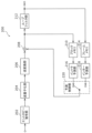
まず、実施の形態1に係る符号化装置の概要を説明する。図1は、実施の形態1に係る符号化装置100の機能構成を示すブロック図である。符号化装置100は、動画像/画像をブロック単位で符号化する動画像/画像符号化装置である。
(Embodiment 1)
[Outline of the encoding device]
First, an overview of a coding device according to
図1に示すように、符号化装置100は、画像をブロック単位で符号化する装置であって、分割部102と、減算部104と、変換部106と、量子化部108と、エントロピー符号化部110と、逆量子化部112と、逆変換部114と、加算部116と、ブロックメモリ118と、ループフィルタ部120と、フレームメモリ122と、イントラ予測部124と、インター予測部126と、予測制御部128と、を備える。
As shown in FIG. 1, the
符号化装置100は、例えば、汎用プロセッサ及びメモリにより実現される。この場合、メモリに格納されたソフトウェアプログラムがプロセッサにより実行されたときに、プロセッサは、分割部102、減算部104、変換部106、量子化部108、エントロピー符号化部110、逆量子化部112、逆変換部114、加算部116、ループフィルタ部120、イントラ予測部124、インター予測部126及び予測制御部128として機能する。また、符号化装置100は、分割部102、減算部104、変換部106、量子化部108、エントロピー符号化部110、逆量子化部112、逆変換部114、加算部116、ループフィルタ部120、イントラ予測部124、インター予測部126及び予測制御部128に対応する専用の1以上の電子回路として実現されてもよい。
The
以下に、符号化装置100に含まれる各構成要素について説明する。
The components included in the
[分割部]
分割部102は、入力動画像に含まれる各ピクチャを複数のブロックに分割し、各ブロックを減算部104に出力する。例えば、分割部102は、まず、ピクチャを固定サイズ(例えば128x128)のブロックに分割する。この固定サイズのブロックは、符号化ツリーユニット(CTU)と呼ばれることがある。そして、分割部102は、再帰的な四分木(quadtree)及び/又は二分木(binary tree)ブロック分割に基づいて、固定サイズのブロックの各々を可変サイズ(例えば64x64以下)のブロックに分割する。この可変サイズのブロックは、符号化ユニット(CU)、予測ユニット(PU)あるいは変換ユニット(TU)と呼ばれることがある。なお、本実施の形態では、CU、PU及びTUは区別される必要はなく、ピクチャ内の一部又はすべてのブロックがCU、PU、TUの処理単位となってもよい。
[Divided part]
The
図2は、実施の形態1におけるブロック分割の一例を示す図である。図2において、実線は四分木ブロック分割によるブロック境界を表し、破線は二分木ブロック分割によるブロック境界を表す。
Figure 2 is a diagram showing an example of block division in
ここでは、ブロック10は、128x128画素の正方形ブロック(128x128ブロック)である。この128x128ブロック10は、まず、4つの正方形の64x64ブロックに分割される(四分木ブロック分割)。
Here, block 10 is a square block of 128x128 pixels (128x128 block). This
左上の64x64ブロックは、さらに2つの矩形の32x64ブロックに垂直に分割され、左の32x64ブロックはさらに2つの矩形の16x64ブロックに垂直に分割される(二分木ブロック分割)。その結果、左上の64x64ブロックは、2つの16x64ブロック11、12と、32x64ブロック13とに分割される。
The top-left 64x64 block is further divided vertically into two rectangular 32x64 blocks, and the left 32x64 block is further divided vertically into two rectangular 16x64 blocks (binary tree block division). As a result, the top-left 64x64 block is divided into two
右上の64x64ブロックは、2つの矩形の64x32ブロック14、15に水平に分割される(二分木ブロック分割)。 The top right 64x64 block is split horizontally into two rectangular 64x32 blocks 14 and 15 (binary tree block splitting).
左下の64x64ブロックは、4つの正方形の32x32ブロックに分割される(四分木ブロック分割)。4つの32x32ブロックのうち左上のブロック及び右下のブロックはさらに分割される。左上の32x32ブロックは、2つの矩形の16x32ブロックに垂直に分割され、右の16x32ブロックはさらに2つの16x16ブロックに水平に分割される(二分木ブロック分割)。右下の32x32ブロックは、2つの32x16ブロックに水平に分割される(二分木ブロック分割)。その結果、左下の64x64ブロックは、16x32ブロック16と、2つの16x16ブロック17、18と、2つの32x32ブロック19、20と、2つの32x16ブロック21、22とに分割される。
The bottom left 64x64 block is divided into four square 32x32 blocks (quadtree block division). Of the four 32x32 blocks, the top left and bottom right blocks are further divided. The top left 32x32 block is divided vertically into two rectangular 16x32 blocks, and the right 16x32 block is further divided horizontally into two 16x16 blocks (binary tree block division). The bottom right 32x32 block is divided horizontally into two 32x16 blocks (binary tree block division). As a result, the bottom left 64x64 block is divided into a
右下の64x64ブロック23は分割されない。
The bottom
以上のように、図2では、ブロック10は、再帰的な四分木及び二分木ブロック分割に基づいて、13個の可変サイズのブロック11~23に分割される。このような分割は、QTBT(quad-tree plus binary tree)分割と呼ばれることがある。 As described above, in FIG. 2, block 10 is divided into 13 variable-sized blocks 11 to 23 based on recursive quad-tree and binary-tree block division. This type of division is sometimes called QTBT (quad-tree plus binary tree) division.
なお、図2では、1つのブロックが4つ又は2つのブロックに分割されていたが(四分木又は二分木ブロック分割)、分割はこれに限定されない。例えば、1つのブロックが3つのブロックに分割されてもよい(三分木ブロック分割)。このような三分木ブロック分割を含む分割は、MBT(multi type tree)分割と呼ばれることがある。 Note that in FIG. 2, one block is divided into four or two blocks (quadtree or binary tree block division), but the division is not limited to this. For example, one block may be divided into three blocks (ternary tree block division). Divisions that include such ternary tree block division are sometimes called MBT (multi type tree) divisions.
[減算部]
減算部104は、分割部102によって分割されたブロック単位で原信号(原サンプル)から予測信号(予測サンプル)を減算する。つまり、減算部104は、符号化対象ブロック(以下、カレントブロックという)の予測誤差(残差ともいう)を算出する。そして、減算部104は、算出された予測誤差を変換部106に出力する。
[Subtraction section]
The
原信号は、符号化装置100の入力信号であり、動画像を構成する各ピクチャの画像を表す信号(例えば輝度(luma)信号及び2つの色差(chroma)信号)である。以下において、画像を表す信号をサンプルともいうこともある。
The original signal is an input signal to the
[変換部]
変換部106は、空間領域の予測誤差を周波数領域の変換係数に変換し、変換係数を量子化部108に出力する。具体的には、変換部106は、例えば空間領域の予測誤差に対して予め定められた離散コサイン変換(DCT)又は離散サイン変換(DST)を行う。
[Conversion section]
The
なお、変換部106は、複数の変換タイプの中から適応的に変換タイプを選択し、選択された変換タイプに対応する変換基底関数(transform basis function)を用いて、予測誤差を変換係数に変換してもよい。このような変換は、EMT(explicit multiple core transform)又はAMT(adaptive multiple transform)と呼ばれることがある。
The
複数の変換タイプは、例えば、DCT-II、DCT-V、DCT-VIII、DST-I及びDST-VIIを含む。図3は、各変換タイプに対応する変換基底関数を示す表である。図3においてNは入力画素の数を示す。これらの複数の変換タイプの中からの変換タイプの選択は、例えば、予測の種類(イントラ予測及びインター予測)に依存してもよいし、イントラ予測モードに依存してもよい。 The multiple transform types include, for example, DCT-II, DCT-V, DCT-VIII, DST-I, and DST-VII. FIG. 3 is a table showing the transform basis functions corresponding to each transform type. In FIG. 3, N indicates the number of input pixels. The selection of a transform type from among these multiple transform types may depend, for example, on the type of prediction (intra prediction and inter prediction) or on the intra prediction mode.
このようなEMT又はAMTを適用するか否かを示す情報(例えばAMTフラグと呼ばれる)及び選択された変換タイプを示す情報は、CUレベルで信号化される。なお、これらの情報の信号化は、CUレベルに限定される必要はなく、他のレベル(例えば、シーケンスレベル、ピクチャレベル、スライスレベル、タイルレベル又はCTUレベル)であってもよい。 Information indicating whether such EMT or AMT is applied (e.g., called an AMT flag) and information indicating the selected transformation type are signaled at the CU level. Note that signaling of this information does not need to be limited to the CU level, but may be at other levels (e.g., sequence level, picture level, slice level, tile level, or CTU level).
また、変換部106は、変換係数(変換結果)を再変換してもよい。このような再変換は、AST(adaptive secondary transform)又はNSST(non-separable secondary transform)と呼ばれることがある。例えば、変換部106は、イントラ予測誤差に対応する変換係数のブロックに含まれるサブブロック(例えば4x4サブブロック)ごとに再変換を行う。NSSTを適用するか否かを示す情報及びNSSTに用いられる変換行列に関する情報は、CUレベルで信号化される。なお、これらの情報の信号化は、CUレベルに限定される必要はなく、他のレベル(例えば、シーケンスレベル、ピクチャレベル、スライスレベル、タイルレベル又はCTUレベル)であってもよい。
The
[量子化部]
量子化部108は、変換部106から出力された変換係数を量子化する。具体的には、量子化部108は、カレントブロックの変換係数を所定の走査順序で走査し、走査された変換係数に対応する量子化パラメータ(QP)に基づいて当該変換係数を量子化する。そして、量子化部108は、カレントブロックの量子化された変換係数(以下、量子化係数という)をエントロピー符号化部110及び逆量子化部112に出力する。
[Quantization section]
The
所定の順序は、変換係数の量子化/逆量子化のための順序である。例えば、所定の走査順序は、周波数の昇順(低周波から高周波の順)又は降順(高周波から低周波の順)で定義される。 The predetermined order is the order for quantization/dequantization of the transform coefficients. For example, the predetermined scanning order is defined as ascending frequency (low to high frequency) or descending frequency (high to low frequency).
量子化パラメータとは、量子化ステップ(量子化幅)を定義するパラメータである。例えば、量子化パラメータの値が増加すれば量子化ステップも増加する。つまり、量子化パラメータの値が増加すれば量子化誤差が増大する。 The quantization parameter is a parameter that defines the quantization step (quantization width). For example, if the value of the quantization parameter increases, the quantization step also increases. In other words, if the value of the quantization parameter increases, the quantization error increases.
[エントロピー符号化部]
エントロピー符号化部110は、量子化部108から入力である量子化係数を可変長符号化することにより符号化信号(符号化ビットストリーム)を生成する。具体的には、エントロピー符号化部110は、例えば、量子化係数を二値化し、二値信号を算術符号化する。
[Entropy coding unit]
The
[逆量子化部]
逆量子化部112は、量子化部108からの入力である量子化係数を逆量子化する。具体的には、逆量子化部112は、カレントブロックの量子化係数を所定の走査順序で逆量子化する。そして、逆量子化部112は、カレントブロックの逆量子化された変換係数を逆変換部114に出力する。
[Dequantization section]
The
[逆変換部]
逆変換部114は、逆量子化部112からの入力である変換係数を逆変換することにより予測誤差を復元する。具体的には、逆変換部114は、変換係数に対して、変換部106による変換に対応する逆変換を行うことにより、カレントブロックの予測誤差を復元する。そして、逆変換部114は、復元された予測誤差を加算部116に出力する。
[Inverse conversion section]
The
なお、復元された予測誤差は、量子化により情報が失われているので、減算部104が算出した予測誤差と一致しない。すなわち、復元された予測誤差には、量子化誤差が含まれている。
Note that the restored prediction error does not match the prediction error calculated by the
[加算部]
加算部116は、逆変換部114からの入力である予測誤差と予測制御部128からの入力である予測信号とを加算することによりカレントブロックを再構成する。そして、加算部116は、再構成されたブロックをブロックメモリ118及びループフィルタ部120に出力する。再構成ブロックは、ローカル復号ブロックと呼ばれることもある。
[Adder]
The
[ブロックメモリ]
ブロックメモリ118は、イントラ予測で参照されるブロックであって符号化対象ピクチャ(以下、カレントピクチャという)内のブロックを格納するための記憶部である。具体的には、ブロックメモリ118は、加算部116から出力された再構成ブロックを格納する。
[Block Memory]
The
[ループフィルタ部]
ループフィルタ部120は、加算部116によって再構成されたブロックにループフィルタを施し、フィルタされた再構成ブロックをフレームメモリ122に出力する。ループフィルタとは、符号化ループ内で用いられるフィルタ(インループフィルタ)であり、例えば、デブロッキング・フィルタ(DF)、サンプルアダプティブオフセット(SAO)及びアダプティブループフィルタ(ALF)などを含む。
[Loop filter section]
The
ALFでは、符号化歪みを除去するための最小二乗誤差フィルタが適用され、例えばカレントブロック内の2x2サブブロックごとに、局所的な勾配(gradient)の方向及び活性度(activity)に基づいて複数のフィルタの中から選択された1つのフィルタが適用される。 In ALF, a least squared error filter is applied to remove coding artifacts. For example, for each 2x2 subblock in the current block, one filter is selected from among multiple filters based on the local gradient direction and activity.
具体的には、まず、サブブロック(例えば2x2サブブロック)が複数のクラス(例えば15又は25クラス)に分類される。サブブロックの分類は、勾配の方向及び活性度に基づいて行われる。例えば、勾配の方向値D(例えば0~2又は0~4)と勾配の活性値A(例えば0~4)とを用いて分類値C(例えばC=5D+A)が算出される。そして、分類値Cに基づいて、サブブロックが複数のクラス(例えば15又は25クラス)に分類される。 Specifically, first, a subblock (e.g., a 2x2 subblock) is classified into a number of classes (e.g., 15 or 25 classes). The subblocks are classified based on the gradient direction and activity. For example, a classification value C (e.g., C=5D+A) is calculated using the gradient direction value D (e.g., 0-2 or 0-4) and the gradient activity value A (e.g., 0-4). Then, based on the classification value C, the subblocks are classified into a number of classes (e.g., 15 or 25 classes).
勾配の方向値Dは、例えば、複数の方向(例えば水平、垂直及び2つの対角方向)の勾配を比較することにより導出される。また、勾配の活性値Aは、例えば、複数の方向の勾配を加算し、加算結果を量子化することにより導出される。 The gradient direction value D is derived, for example, by comparing gradients in multiple directions (e.g., horizontal, vertical, and two diagonal directions). The gradient activity value A is derived, for example, by adding gradients in multiple directions and quantizing the sum.
このような分類の結果に基づいて、複数のフィルタの中からサブブロックのためのフィルタが決定される。 Based on the results of this classification, a filter for the subblock is selected from among multiple filters.
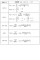
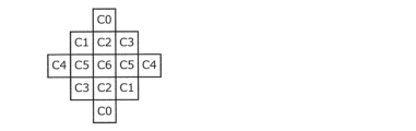
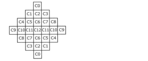
ALFで用いられるフィルタの形状としては例えば円対称形状が利用される。図4A~図4Cは、ALFで用いられるフィルタの形状の複数の例を示す図である。図4Aは、5x5ダイヤモンド形状フィルタを示し、図4Bは、7x7ダイヤモンド形状フィルタを示し、図4Cは、9x9ダイヤモンド形状フィルタを示す。フィルタの形状を示す情報は、ピクチャレベルで信号化される。なお、フィルタの形状を示す情報の信号化は、ピクチャレベルに限定される必要はなく、他のレベル(例えば、シーケンスレベル、スライスレベル、タイルレベル、CTUレベル又はCUレベル)であってもよい。 The filter shape used in ALF is, for example, a circularly symmetric shape. Figures 4A to 4C are diagrams showing several examples of filter shapes used in ALF. Figure 4A shows a 5x5 diamond-shaped filter, Figure 4B shows a 7x7 diamond-shaped filter, and Figure 4C shows a 9x9 diamond-shaped filter. Information indicating the filter shape is signaled at the picture level. Note that signaling of information indicating the filter shape does not need to be limited to the picture level, and may be at other levels (e.g., sequence level, slice level, tile level, CTU level, or CU level).
ALFのオン/オフは、例えば、ピクチャレベル又はCUレベルで決定される。例えば、輝度についてはCUレベルでALFを適用するか否かが決定され、色差についてはピクチャレベルでALFを適用するか否かが決定される。ALFのオン/オフを示す情報は、ピクチャレベル又はCUレベルで信号化される。なお、ALFのオン/オフを示す情報の信号化は、ピクチャレベル又はCUレベルに限定される必要はなく、他のレベル(例えば、シーケンスレベル、スライスレベル、タイルレベル又はCTUレベル)であってもよい。 The on/off state of ALF is determined, for example, at the picture level or CU level. For example, whether or not to apply ALF for luminance is determined at the CU level, and whether or not to apply ALF for chrominance is determined at the picture level. Information indicating whether ALF is on/off is signaled at the picture level or CU level. Note that the signaling of information indicating whether ALF is on/off does not need to be limited to the picture level or CU level, and may be at another level (for example, the sequence level, slice level, tile level, or CTU level).
選択可能な複数のフィルタ(例えば15又は25までのフィルタ)の係数セットは、ピクチャレベルで信号化される。なお、係数セットの信号化は、ピクチャレベルに限定される必要はなく、他のレベル(例えば、シーケンスレベル、スライスレベル、タイルレベル、CTUレベル、CUレベル又はサブブロックレベル)であってもよい。 The coefficient sets of multiple selectable filters (e.g., up to 15 or 25 filters) are signaled at the picture level. Note that the signaling of the coefficient sets does not have to be limited to the picture level, but may be at other levels (e.g., sequence level, slice level, tile level, CTU level, CU level, or subblock level).
[フレームメモリ]
フレームメモリ122は、インター予測に用いられる参照ピクチャを格納するための記憶部であり、フレームバッファと呼ばれることもある。具体的には、フレームメモリ122は、ループフィルタ部120によってフィルタされた再構成ブロックを格納する。
[Frame memory]
The
[イントラ予測部]
イントラ予測部124は、ブロックメモリ118に格納されたカレントピクチャ内のブロックを参照してカレントブロックのイントラ予測(画面内予測ともいう)を行うことで、予測信号(イントラ予測信号)を生成する。具体的には、イントラ予測部124は、カレントブロックに隣接するブロックのサンプル(例えば輝度値、色差値)を参照してイントラ予測を行うことでイントラ予測信号を生成し、イントラ予測信号を予測制御部128に出力する。
[Intra prediction unit]
The
例えば、イントラ予測部124は、予め規定された複数のイントラ予測モードのうちの1つを用いてイントラ予測を行う。複数のイントラ予測モードは、1以上の非方向性予測モードと、複数の方向性予測モードと、を含む。
For example, the
1以上の非方向性予測モードは、例えばH.265/HEVC(High-Efficiency Video Coding)規格(非特許文献1)で規定されたPlanar予測モード及びDC予測モードを含む。 The one or more non-directional prediction modes include, for example, the planar prediction mode and DC prediction mode defined in the H.265/HEVC (High-Efficiency Video Coding) standard (Non-Patent Document 1).
複数の方向性予測モードは、例えばH.265/HEVC規格で規定された33方向の予測モードを含む。なお、複数の方向性予測モードは、33方向に加えてさらに32方向の予測モード(合計で65個の方向性予測モード)を含んでもよい。図5は、イントラ予測における67個のイントラ予測モード(2個の非方向性予測モード及び65個の方向性予測モード)を示す図である。実線矢印は、H.265/HEVC規格で規定された33方向を表し、破線矢印は、追加された32方向を表す。 The multiple directional prediction modes include, for example, the 33 prediction modes defined in the H.265/HEVC standard. The multiple directional prediction modes may include 32 prediction modes in addition to the 33 directions (a total of 65 directional prediction modes). FIG. 5 is a diagram showing 67 intra prediction modes (2 non-directional prediction modes and 65 directional prediction modes) in intra prediction. The solid arrows represent the 33 directions defined in the H.265/HEVC standard, and the dashed arrows represent the additional 32 directions.
なお、色差ブロックのイントラ予測において、輝度ブロックが参照されてもよい。つまり、カレントブロックの輝度成分に基づいて、カレントブロックの色差成分が予測されてもよい。このようなイントラ予測は、CCLM(cross-component linear model)予測と呼ばれることがある。このような輝度ブロックを参照する色差ブロックのイントラ予測モード(例えばCCLMモードと呼ばれる)は、色差ブロックのイントラ予測モードの1つとして加えられてもよい。 Note that the luminance block may be referenced in intra prediction of the chrominance block. That is, the chrominance component of the current block may be predicted based on the luminance component of the current block. This type of intra prediction is sometimes called CCLM (cross-component linear model) prediction. An intra prediction mode of the chrominance block that references such a luminance block (e.g., called a CCLM mode) may be added as one of the intra prediction modes of the chrominance block.
イントラ予測部124は、水平/垂直方向の参照画素の勾配に基づいてイントラ予測後の画素値を補正してもよい。このような補正をともなうイントラ予測は、PDPC(position dependent intra prediction combination)と呼ばれることがある。PDPCの適用の有無を示す情報(例えばPDPCフラグと呼ばれる)は、例えばCUレベルで信号化される。なお、この情報の信号化は、CUレベルに限定される必要はなく、他のレベル(例えば、シーケンスレベル、ピクチャレベル、スライスレベル、タイルレベル又はCTUレベル)であってもよい。
The
[インター予測部]
インター予測部126は、フレームメモリ122に格納された参照ピクチャであってカレントピクチャとは異なる参照ピクチャを参照してカレントブロックのインター予測(画面間予測ともいう)を行うことで、予測信号(インター予測信号)を生成する。インター予測は、カレントブロック又はカレントブロック内のサブブロック(例えば4x4ブロック)の単位で行われる。例えば、インター予測部126は、カレントブロック又はサブブロックについて参照ピクチャ内で動き探索(motion estimation)を行う。そして、インター予測部126は、動き探索により得られた動き情報(例えば動きベクトル)を用いて動き補償を行うことでカレントブロック又はサブブロックのインター予測信号を生成する。そして、インター予測部126は、生成されたインター予測信号を予測制御部128に出力する。
[Inter prediction section]
The
動き補償に用いられた動き情報は信号化される。動きベクトルの信号化には、予測動きベクトル(motion vector predictor)が用いられてもよい。つまり、動きベクトルと予測動きベクトルとの間の差分が信号化されてもよい。 The motion information used for motion compensation is signaled. A motion vector predictor may be used to signal the motion vector. That is, the difference between the motion vector and the motion vector predictor may be signaled.
なお、動き探索により得られたカレントブロックの動き情報だけでなく、隣接ブロックの動き情報も用いて、インター予測信号が生成されてもよい。具体的には、動き探索により得られた動き情報に基づく予測信号と、隣接ブロックの動き情報に基づく予測信号と、を重み付け加算することにより、カレントブロック内のサブブロック単位でインター予測信号が生成されてもよい。このようなインター予測(動き補償)は、OBMC(overlapped block motion compensation)と呼ばれることがある。 Note that an inter prediction signal may be generated using not only the motion information of the current block obtained by motion search, but also the motion information of an adjacent block. Specifically, an inter prediction signal may be generated for each sub-block in the current block by performing weighted addition of a prediction signal based on the motion information obtained by motion search and a prediction signal based on the motion information of an adjacent block. Such inter prediction (motion compensation) is sometimes called OBMC (overlapped block motion compensation).
このようなOBMCモードでは、OBMCのためのサブブロックのサイズを示す情報(例えばOBMCブロックサイズと呼ばれる)は、シーケンスレベルで信号化される。また、OBMCモードを適用するか否かを示す情報(例えばOBMCフラグと呼ばれる)は、CUレベルで信号化される。なお、これらの情報の信号化のレベルは、シーケンスレベル及びCUレベルに限定される必要はなく、他のレベル(例えばピクチャレベル、スライスレベル、タイルレベル、CTUレベル又はサブブロックレベル)であってもよい。 In such an OBMC mode, information indicating the size of the subblock for OBMC (e.g., called OBMC block size) is signaled at the sequence level. Also, information indicating whether or not to apply the OBMC mode (e.g., called OBMC flag) is signaled at the CU level. Note that the signaling level of these pieces of information does not need to be limited to the sequence level and CU level, and may be other levels (e.g., picture level, slice level, tile level, CTU level, or subblock level).
なお、動き情報は信号化されずに、復号装置側で導出されてもよい。例えば、H.265/HEVC規格で規定されたマージモードが用いられてもよい。また例えば、復号装置側で動き探索を行うことにより動き情報が導出されてもよい。この場合、カレントブロックの画素値を用いずに動き探索が行われる。 The motion information may be derived on the decoding device side without being signaled. For example, the merge mode defined in the H.265/HEVC standard may be used. Also, for example, the motion information may be derived by performing motion estimation on the decoding device side. In this case, the motion estimation is performed without using the pixel values of the current block.
ここで、復号装置側で動き探索を行うモードについて説明する。この復号装置側で動き探索を行うモードは、PMMVD(pattern matched motion vector derivation)モード又はFRUC(flame rate up-conversion)モードと呼ばれることがある。 Here, we will explain the mode in which motion estimation is performed on the decoding device side. This mode in which motion estimation is performed on the decoding device side is sometimes called PMMVD (pattern matched motion vector derivation) mode or FRUC (frame rate up-conversion) mode.
まず、マージリストに含まれる候補の1つがパターンマッチングによる探索の開始位置として選択される。パターンマッチングとしては、第1パターンマッチング又は第2パターンマッチングが用いられる。第1パターンマッチング及び第2パターンマッチングは、それぞれ、バイラテラルマッチング(bilateral matching)及びテンプレートマッチング(template matching)と呼ばれることがある。 First, one of the candidates included in the merge list is selected as the starting position for the search by pattern matching. As the pattern matching, first pattern matching or second pattern matching is used. The first pattern matching and the second pattern matching are sometimes called bilateral matching and template matching, respectively.
第1パターンマッチングでは、異なる2つの参照ピクチャ内の2つのブロックであってカレントブロックの動き軌道(motion trajectory)に沿う2つのブロックの間でパターンマッチングが行われる。 In the first pattern matching, pattern matching is performed between two blocks in two different reference pictures that are along the motion trajectory of the current block.
図6は、動き軌道に沿う2つのブロック間でのパターンマッチング(バイラテラルマッチング)を説明するための図である。図6に示すように、第1パターンマッチングでは、カレントブロック(Cur block)の動き軌道に沿う2つのブロックであって異なる2つの参照ピクチャ(Ref0、Ref1)内の2つのブロックのペアの中で最もマッチするペアを探索することにより2つの動きベクトル(MV0、MV1)が導出される。 Figure 6 is a diagram for explaining pattern matching (bilateral matching) between two blocks along a motion trajectory. As shown in Figure 6, in the first pattern matching, two motion vectors (MV0, MV1) are derived by searching for the most matching pair of two blocks along the motion trajectory of the current block (Cur block) and in two different reference pictures (Ref0, Ref1).
連続的な動き軌道の仮定の下では、2つの参照ブロックを指し示す動きベクトル(MV0、MV1)は、カレントピクチャ(Cur Pic)と2つの参照ピクチャ(Ref0、Ref1)との間の時間的な距離(TD0、TD1)に対して比例する。例えば、カレントピクチャが時間的に2つの参照ピクチャの間に位置し、カレントピクチャから2つの参照ピクチャへの時間的な距離が等しい場合、第1パターンマッチングでは、鏡映対称な双方向の動きベクトルが導出される。 Under the assumption of continuous motion trajectories, the motion vectors (MV0, MV1) pointing to two reference blocks are proportional to the temporal distances (TD0, TD1) between the current picture (Cur Pic) and the two reference pictures (Ref0, Ref1). For example, if the current picture is located between two reference pictures in time and the temporal distances from the current picture to the two reference pictures are equal, the first pattern matching derives bidirectional motion vectors that are mirror-symmetric.
第2パターンマッチングでは、カレントピクチャ内のテンプレート(カレントピクチャ内でカレントブロックに隣接するブロック(例えば上及び/又は左隣接ブロック))と参照ピクチャ内のブロックとの間でパターンマッチングが行われる。 In the second pattern matching, pattern matching is performed between a template in the current picture (a block adjacent to the current block in the current picture (e.g., an upper and/or left adjacent block)) and a block in the reference picture.
図7は、カレントピクチャ内のテンプレートと参照ピクチャ内のブロックとの間でのパターンマッチング(テンプレートマッチング)を説明するための図である。図7に示すように、第2パターンマッチングでは、カレントピクチャ(Cur Pic)内でカレントブロック(Cur block)に隣接するブロックと最もマッチするブロックを参照ピクチャ(Ref0)内で探索することによりカレントブロックの動きベクトルが導出される。 Figure 7 is a diagram for explaining pattern matching (template matching) between a template in a current picture and a block in a reference picture. As shown in Figure 7, in the second pattern matching, a motion vector of the current block is derived by searching in the reference picture (Ref0) for a block that best matches a block adjacent to the current block (Cur block) in the current picture (Cur Pic).
このようなFRUCモードを適用するか否かを示す情報(例えばFRUCフラグと呼ばれる)は、CUレベルで信号化される。また、FRUCモードが適用される場合(例えばFRUCフラグが真の場合)、パターンマッチングの方法(第1パターンマッチング又は第2パターンマッチング)を示す情報(例えばFRUCモードフラグと呼ばれる)がCUレベルで信号化される。なお、これらの情報の信号化は、CUレベルに限定される必要はなく、他のレベル(例えば、シーケンスレベル、ピクチャレベル、スライスレベル、タイルレベル、CTUレベル又はサブブロックレベル)であってもよい。 Information indicating whether or not such a FRUC mode is applied (e.g., when the FRUC flag is true) is signaled at the CU level. Also, when the FRUC mode is applied (e.g., when the FRUC flag is true), information indicating the pattern matching method (first pattern matching or second pattern matching) (e.g., when the FRUC mode flag is true) is signaled at the CU level. Note that the signaling of such information does not need to be limited to the CU level, and may be at other levels (e.g., sequence level, picture level, slice level, tile level, CTU level, or subblock level).
なお、動き探索とは異なる方法で、復号装置側で動き情報が導出されてもよい。例えば、等速直線運動を仮定したモデルに基づき、画素単位で周辺画素値を用いて動きベクトルの補正量が算出されてもよい。 Motion information may be derived on the decoding device side using a method other than motion search. For example, based on a model that assumes uniform linear motion, the correction amount of the motion vector may be calculated on a pixel-by-pixel basis using surrounding pixel values.
ここで、等速直線運動を仮定したモデルに基づいて動きベクトルを導出するモードについて説明する。このモードは、BIO(bi-directional optical flow)モードと呼ばれることがある。 Here, we explain a mode in which motion vectors are derived based on a model that assumes uniform linear motion. This mode is sometimes called BIO (bi-directional optical flow) mode.
図8は、等速直線運動を仮定したモデルを説明するための図である。図8において、(vx,vy)は、速度ベクトルを示し、τ0、τ1は、それぞれ、カレントピクチャ(Cur Pic)と2つの参照ピクチャ(Ref0,Ref1)との間の時間的な距離を示す。(MVx0,MVy0)は、参照ピクチャRef0に対応する動きベクトルを示し、(MVx1、MVy1)は、参照ピクチャRef1に対応する動きベクトルを示す。 Fig. 8 is a diagram for explaining a model assuming uniform linear motion. In Fig. 8, ( vx , vy ) indicates a velocity vector, and τ0 , τ1 indicate the temporal distance between the current picture (CurPic) and two reference pictures ( Ref0 , Ref1 ), respectively. ( MVx0 , MVy0 ) indicates a motion vector corresponding to reference picture Ref0 , and ( MVx1 , MVy1 ) indicates a motion vector corresponding to reference picture Ref1 .
このとき速度ベクトル(vx,vy)の等速直線運動の仮定の下では、(MVx0,MVy0)及び(MVx1,MVy1)は、それぞれ、(vxτ0,vyτ0)及び(-vxτ1,-vyτ1)と表され、以下のオプティカルフロー等式(1)が成り立つ。 In this case, under the assumption of uniform linear motion of the velocity vector (v x , v y ), (MVx 0 , MVy 0 ) and (MVx 1 , MVy 1 ) are expressed as (v x τ 0 , v y τ 0 ) and (-v x τ 1 , -v y τ 1 ), respectively, and the following optical flow equation (1) holds.
![]()
![]()
ここで、I(k)は、動き補償後の参照画像k(k=0,1)の輝度値を示す。このオプティカルフロー等式は、(i)輝度値の時間微分と、(ii)水平方向の速度及び参照画像の空間勾配の水平成分の積と、(iii)垂直方向の速度及び参照画像の空間勾配の垂直成分の積と、の和が、ゼロと等しいことを示す。このオプティカルフロー等式とエルミート補間(Hermite interpolation)との組み合わせに基づいて、マージリスト等から得られるブロック単位の動きベクトルが画素単位で補正される。 Here, I (k) denotes the luminance value of reference image k (k=0,1) after motion compensation. This optical flow equation indicates that the sum of (i) the time derivative of the luminance value, (ii) the product of the horizontal velocity and the horizontal component of the spatial gradient of the reference image, and (iii) the product of the vertical velocity and the vertical component of the spatial gradient of the reference image is equal to zero. Based on a combination of this optical flow equation and Hermite interpolation, block-by-block motion vectors obtained from a merge list or the like are corrected pixel by pixel.
なお、等速直線運動を仮定したモデルに基づく動きベクトルの導出とは異なる方法で、復号装置側で動きベクトルが導出されてもよい。例えば、複数の隣接ブロックの動きベクトルに基づいてサブブロック単位で動きベクトルが導出されてもよい。 Note that the motion vector may be derived on the decoding device side using a method other than the method of deriving the motion vector based on a model that assumes uniform linear motion. For example, the motion vector may be derived on a sub-block basis based on the motion vectors of multiple adjacent blocks.
ここで、複数の隣接ブロックの動きベクトルに基づいてサブブロック単位で動きベクトルを導出するモードについて説明する。このモードは、アフィン動き補償予測(affine motion compensation prediction)モードと呼ばれることがある。 Here, we will explain a mode in which a motion vector is derived for each sub-block based on the motion vectors of multiple adjacent blocks. This mode is sometimes called an affine motion compensation prediction mode.
図9は、複数の隣接ブロックの動きベクトルに基づくサブブロック単位の動きベクトルの導出を説明するための図である。図9において、カレントブロックは、16の4x4サブブロックを含む。ここでは、隣接ブロックの動きベクトルに基づいてカレントブロックの左上角制御ポイントの動きベクトルv0が導出され、隣接サブブロックの動きベクトルに基づいてカレントブロックの右上角制御ポイントの動きベクトルv1が導出される。そして、2つの動きベクトルv0及びv1を用いて、以下の式(2)により、カレントブロック内の各サブブロックの動きベクトル(vx,vy)が導出される。 9 is a diagram for explaining the derivation of a motion vector for each subblock based on the motion vectors of multiple adjacent blocks. In FIG. 9, the current block includes 16 4x4 subblocks. Here, the motion vector v0 of the upper left corner control point of the current block is derived based on the motion vectors of the adjacent blocks, and the motion vector v1 of the upper right corner control point of the current block is derived based on the motion vectors of the adjacent subblocks. Then, using the two motion vectors v0 and v1 , the motion vectors ( vx , vy ) of each subblock in the current block are derived by the following formula (2).
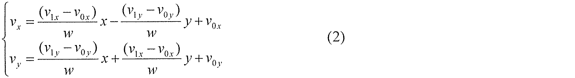
ここで、x及びyは、それぞれ、サブブロックの水平位置及び垂直位置を示し、wは、予め定められた重み係数を示す。 Here, x and y indicate the horizontal and vertical positions of the subblock, respectively, and w indicates a predetermined weighting coefficient.
このようなアフィン動き補償予測モードでは、左上及び右上角制御ポイントの動きベクトルの導出方法が異なるいくつかのモードを含んでもよい。このようなアフィン動き補償予測モードを示す情報(例えばアフィンフラグと呼ばれる)は、CUレベルで信号化される。なお、このアフィン動き補償予測モードを示す情報の信号化は、CUレベルに限定される必要はなく、他のレベル(例えば、シーケンスレベル、ピクチャレベル、スライスレベル、タイルレベル、CTUレベル又はサブブロックレベル)であってもよい。 Such affine motion compensation prediction modes may include several modes in which the methods of deriving the motion vectors of the top-left and top-right corner control points are different. Information indicating such affine motion compensation prediction modes (e.g., called an affine flag) is signaled at the CU level. Note that the signaling of the information indicating this affine motion compensation prediction mode does not need to be limited to the CU level, but may be at other levels (e.g., sequence level, picture level, slice level, tile level, CTU level, or subblock level).
[予測制御部]
予測制御部128は、イントラ予測信号及びインター予測信号のいずれかを選択し、選択した信号を予測信号として減算部104及び加算部116に出力する。
[Predictive control unit]
The
[復号装置の概要]
次に、上記の符号化装置100から出力された符号化信号(符号化ビットストリーム)を復号可能な復号装置の概要について説明する。図10は、実施の形態1に係る復号装置200の機能構成を示すブロック図である。復号装置200は、動画像/画像をブロック単位で復号する動画像/画像復号装置である。
[Overview of the Decoding Device]
Next, an overview of a decoding device capable of decoding the coded signal (coded bit stream) output from the
図10に示すように、復号装置200は、エントロピー復号部202と、逆量子化部204と、逆変換部206と、加算部208と、ブロックメモリ210と、ループフィルタ部212と、フレームメモリ214と、イントラ予測部216と、インター予測部218と、予測制御部220と、を備える。
As shown in FIG. 10, the
復号装置200は、例えば、汎用プロセッサ及びメモリにより実現される。この場合、メモリに格納されたソフトウェアプログラムがプロセッサにより実行されたときに、プロセッサは、エントロピー復号部202、逆量子化部204、逆変換部206、加算部208、ループフィルタ部212、イントラ予測部216、インター予測部218及び予測制御部220として機能する。また、復号装置200は、エントロピー復号部202、逆量子化部204、逆変換部206、加算部208、ループフィルタ部212、イントラ予測部216、インター予測部218及び予測制御部220に対応する専用の1以上の電子回路として実現されてもよい。
The
以下に、復号装置200に含まれる各構成要素について説明する。
The components included in the
[エントロピー復号部]
エントロピー復号部202は、符号化ビットストリームをエントロピー復号する。具体的には、エントロピー復号部202は、例えば、符号化ビットストリームから二値信号に算術復号する。そして、エントロピー復号部202は、二値信号を多値化(debinarize)する。これにより、エントロピー復号部202は、ブロック単位で量子化係数を逆量子化部204に出力する。
[Entropy Decoding Section]
The
[逆量子化部]
逆量子化部204は、エントロピー復号部202からの入力である復号対象ブロック(以下、カレントブロックという)の量子化係数を逆量子化する。具体的には、逆量子化部204は、カレントブロックの量子化係数の各々について、当該量子化係数に対応する量子化パラメータに基づいて当該量子化係数を逆量子化する。そして、逆量子化部204は、カレントブロックの逆量子化された量子化係数(つまり変換係数)を逆変換部206に出力する。
[Dequantization section]
The
[逆変換部]
逆変換部206は、逆量子化部204からの入力である変換係数を逆変換することにより予測誤差を復元する。
[Inverse conversion section]
The
例えば符号化ビットストリームから読み解かれた情報がEMT又はAMTを適用することを示す場合(例えばAMTフラグが真)、逆変換部206は、読み解かれた変換タイプを示す情報に基づいてカレントブロックの変換係数を逆変換する。
For example, if the information interpreted from the encoded bitstream indicates that EMT or AMT is to be applied (e.g., the AMT flag is true), the
また例えば、符号化ビットストリームから読み解かれた情報がNSSTを適用することを示す場合、逆変換部206は、変換された変換係数(変換結果)を再変換する。
Also, for example, if the information interpreted from the encoded bitstream indicates that NSST is to be applied, the
[加算部]
加算部208は、逆変換部206からの入力である予測誤差と予測制御部220からの入力である予測信号とを加算することによりカレントブロックを再構成する。そして、加算部208は、再構成されたブロックをブロックメモリ210及びループフィルタ部212に出力する。
[Adder]
The
[ブロックメモリ]
ブロックメモリ210は、イントラ予測で参照されるブロックであって復号対象ピクチャ(以下、カレントピクチャという)内のブロックを格納するための記憶部である。具体的には、ブロックメモリ210は、加算部208から出力された再構成ブロックを格納する。
[Block Memory]
The
[ループフィルタ部]
ループフィルタ部212は、加算部208によって再構成されたブロックにループフィルタを施し、フィルタされた再構成ブロックをフレームメモリ214及び表示装置等に出力する。
[Loop filter section]
The
符号化ビットストリームから読み解かれたALFのオン/オフを示す情報がALFのオンを示す場合、局所的な勾配の方向及び活性度に基づいて複数のフィルタの中から1つのフィルタが選択され、選択されたフィルタが再構成ブロックに適用される。 If the information indicating ALF on/off read from the encoded bitstream indicates ALF on, one filter is selected from among multiple filters based on the local gradient direction and activity, and the selected filter is applied to the reconstruction block.
[フレームメモリ]
フレームメモリ214は、インター予測に用いられる参照ピクチャを格納するための記憶部であり、フレームバッファと呼ばれることもある。具体的には、フレームメモリ214は、ループフィルタ部212によってフィルタされた再構成ブロックを格納する。
[Frame memory]
The
[イントラ予測部]
イントラ予測部216は、符号化ビットストリームから読み解かれたイントラ予測モードに基づいて、ブロックメモリ210に格納されたカレントピクチャ内のブロックを参照してイントラ予測を行うことで、予測信号(イントラ予測信号)を生成する。具体的には、イントラ予測部216は、カレントブロックに隣接するブロックのサンプル(例えば輝度値、色差値)を参照してイントラ予測を行うことでイントラ予測信号を生成し、イントラ予測信号を予測制御部220に出力する。
[Intra prediction unit]
The
なお、色差ブロックのイントラ予測において輝度ブロックを参照するイントラ予測モードが選択されている場合は、イントラ予測部216は、カレントブロックの輝度成分に基づいて、カレントブロックの色差成分を予測してもよい。
Note that if an intra prediction mode that references a luminance block in intra prediction of a chrominance block is selected, the
また、符号化ビットストリームから読み解かれた情報がPDPCの適用を示す場合、イントラ予測部216は、水平/垂直方向の参照画素の勾配に基づいてイントラ予測後の画素値を補正する。
In addition, if the information interpreted from the encoded bitstream indicates the application of PDPC, the
[インター予測部]
インター予測部218は、フレームメモリ214に格納された参照ピクチャを参照して、カレントブロックを予測する。予測は、カレントブロック又はカレントブロック内のサブブロック(例えば4x4ブロック)の単位で行われる。例えば、インター予測部126は、符号化ビットストリームから読み解かれた動き情報(例えば動きベクトル)を用いて動き補償を行うことでカレントブロック又はサブブロックのインター予測信号を生成し、インター予測信号を予測制御部128に出力する。
[Inter prediction section]
The
なお、符号化ビットストリームから読み解かれた情報がOBMCモードを適用することを示す場合、インター予測部218は、動き探索により得られたカレントブロックの動き情報だけでなく、隣接ブロックの動き情報も用いて、インター予測信号を生成する。
When the information interpreted from the encoded bitstream indicates that the OBMC mode is to be applied, the
また、符号化ビットストリームから読み解かれた情報がFRUCモードを適用することを示す場合、インター予測部218は、符号化ストリームから読み解かれたパターンマッチングの方法(バイラテラルマッチング又はテンプレートマッチング)に従って動き探索を行うことにより動き情報を導出する。そして、インター予測部218は、導出された動き情報を用いて動き補償を行う。
Also, if the information interpreted from the encoded bitstream indicates that the FRUC mode is to be applied, the
また、インター予測部218は、BIOモードが適用される場合に、等速直線運動を仮定したモデルに基づいて動きベクトルを導出する。また、符号化ビットストリームから読み解かれた情報がアフィン動き補償予測モードを適用することを示す場合には、インター予測部218は、複数の隣接ブロックの動きベクトルに基づいてサブブロック単位で動きベクトルを導出する。
When the BIO mode is applied, the
[予測制御部]
予測制御部220は、イントラ予測信号及びインター予測信号のいずれかを選択し、選択した信号を予測信号として加算部208に出力する。
[Predictive control unit]
The
(実施の形態2)
次に、以上のように構成された符号化装置100及び復号装置200において行われる一部の処理について図面を参照しながら具体的に説明する。なお、本開示の利益をさらに拡大するために、後述の各実施の形態を組み合わせてもよいことは、当業者には明らかであろう。
(Embodiment 2)
Next, a part of the processing performed in the
本実施の形態における符号化装置および復号装置などは、任意のマルチメディアデータの符号化および復号に使用することができ、より具体的には、ノンレクティリニアの(例えばフィッシュアイ)カメラに撮像された画像の符号化および復号において使用することができる。 The encoding device and decoding device of this embodiment can be used to encode and decode any multimedia data, and more specifically, can be used to encode and decode images captured by a non-rectilinear (e.g., fisheye) camera.
ここで、上述の先行技術では、処理された画像およびレクティリニア・レンズによって直接撮像された画像の圧縮には、これまでと同じ動画像符号化ツールが使用される。この種の処理画像を異なる方法で圧縮するために特別に、カスタマイズされた動画像符号化ツールは先行技術には存在しない。 Now, in the above-mentioned prior art, the same video encoding tools are used to compress the processed images and the images captured directly by the rectilinear lens. There are no video encoding tools in the prior art that are specifically customized to compress this type of processed image in a different way.
一般的には、はじめに複数のカメラによって撮像され、複数のカメラによって撮像された画像が繋ぎ合わせられて大きな画像が、360度画像として作成される。平面状のディスプレイでより快適に画像を表示することができるように、または、機械学習技術を用いて画像中の対象物をより容易に検出可能にするために、画像の符号化を行う前に「魚眼レンズの歪みを補正(defish)する」こと、または直線的にするための画像補正を含む画像変換処理を行う場合がある。しかしながら、この画像変換処理では、通常、画像サンプルを補間するため、画像内に保持される情報に重複部分が生じる。また、繋ぎ合わせ処理および画像変換処理により、画像内に空き領域が形成される場合があり、これは通常はデフォルトの画素値(例えば黒色画素)で埋められる。繋ぎ合わせ処理と画像変換処理によって生じたこのような問題は、符号化処理の符号化効率を低減させる要因となる。 Typically, images are first captured by multiple cameras, and then the images captured by the multiple cameras are stitched together to create a large image, known as a 360-degree image. To make the image more comfortable to view on a flat display or to make objects in the image easier to detect using machine learning techniques, image transformation processes may be performed before encoding the image, including "defishing" or straightening the image. However, this image transformation process usually involves interpolating image samples, which results in duplication of information held in the image. Also, the stitching and image transformation processes may create empty areas in the image, which are usually filled with default pixel values (e.g., black pixels). Such problems caused by the stitching and image transformation processes reduce the coding efficiency of the coding process.
これらの問題を解決するために、本実施の形態では、カスタマイズされた動画像符号化ツールおよび動画像復号ツールとして適応的動画像符号化ツールおよび適応的動画像復号ツールを用いる。符号化効率を向上させるために、この適応的動画像符号化ツールは、エンコーダに先立って画像を処理するために用いられる画像変換処理または画像繋ぎ合わせ処理に適応できる。本開示は、符号化処理中に適応的動画像符号化ツールを上述のような処理に適応することによって、これらの処理で生じたあらゆる重複を低減することができる。適応的動画像復号ツールについても、適応的動画像符号化ツールと同様である。 To solve these problems, the present embodiment uses an adaptive video encoding tool and an adaptive video decoding tool as customized video encoding tool and video decoding tool. To improve encoding efficiency, the adaptive video encoding tool can be adapted to image conversion or image stitching processes used to process images prior to the encoder. By adapting the adaptive video encoding tool to such processes during the encoding process, the present disclosure can reduce any duplication caused by these processes. The adaptive video decoding tool is similar to the adaptive video encoding tool.
本実施の形態では、画像変換処理または/および画像繋ぎ合わせ処理の情報を使用して動画像符号化ツールおよび動画像復号ツールを適応させる。そのため、動画像符号化ツールおよび動画像復号ツールは異なる種類の処理済み画像に適用可能である。したがって、本実施の形態では、圧縮効率を向上させることができる。 In this embodiment, information from the image conversion process and/or image stitching process is used to adapt the video encoding tool and the video decoding tool. Therefore, the video encoding tool and the video decoding tool can be applied to different types of processed images. Therefore, in this embodiment, compression efficiency can be improved.
[符号化処理]
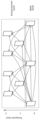
図11に示す本開示の実施の形態2による、ノンレクティリニア・レンズを使用して撮像された画像に動画像符号化を行う方法について説明する。なお、ノンレクティリニア・レンズは、広角レンズまたはその一例である。
[Encoding process]
A method of performing video coding on an image captured using a nonrectilinear lens according to the second embodiment of this disclosure shown in Fig. 11 will be described. Note that the nonrectilinear lens is a wide-angle lens or an example thereof.
図11は、本実施の形態における動画像符号化処理の一例を示すフローチャートである。 Figure 11 is a flowchart showing an example of a video encoding process in this embodiment.
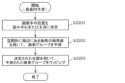
ステップS101では、符号化装置はパラメータ一式をヘッダに書き込む。図12は、圧縮された動画像ビットストリームにおいて上記ヘッダの可能な位置を示す。書き込まれたパラメータ(すなわち図12中のカメラ画像パラメータ)は、画像補正処理に関する1以上のパラメータを含む。例えば、このようなパラメータは、図12に示すように、ビデオパラメータセット、シーケンスパラメータセット、ピクチャパラメータセット、スライスヘッダ、またはビデオシステムセットアップパラメータセットに書き込まれる。つまり、本実施の形態において書き込まれるパラメータは、ビットストリームの何れのヘッダに書き込まれてもよく、SEI(Supplemental Enhancement Information)に書き込まれてもよい。なお、画像補正処理は、上述の画像変換処理に相当する。 In step S101, the encoding device writes a set of parameters into a header. FIG. 12 shows possible locations of the header in a compressed video bitstream. The written parameters (i.e., the camera image parameters in FIG. 12) include one or more parameters related to image enhancement processing. For example, such parameters are written into a video parameter set, a sequence parameter set, a picture parameter set, a slice header, or a video system setup parameter set, as shown in FIG. 12. That is, the parameters written in this embodiment may be written into any header of the bitstream, or into SEI (Supplemental Enhancement Information). Note that the image enhancement processing corresponds to the image conversion processing described above.
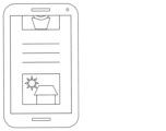
<画像補正処理のパラメータの例>
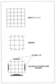
図13に示すように、撮像された画像は、画像の撮像中に使用されるレンズの特性により歪んでいてもよい。また、撮像された画像を直線的に補正するために画像補正処理を使用した。なお、撮像された画像を直線的に補正することによって、矩形の画像が生成される。書き込まれたパラメータは、使用された画像補正処理を特定するため、または記述するためのパラメータを含む。画像補正処理で使用されるパラメータは、一例として、入力画像の画素を、画像補正処理の意図した出力画素値にマッピングするためのマッピングテーブルを構成するパラメータを含む。これらのパラメータは、1以上の補間処理用の重みパラメータ、または/およびピクチャの入力画素および出力画素の位置を特定する位置パラメータを含んでもよい。画像補正処理の可能な実施例の一つとして、画像補正処理用のマッピングテーブルを、補正された画像内のすべての画素に使用してもよい。
<Examples of parameters for image correction processing>
As shown in FIG. 13, the captured image may be distorted due to the characteristics of the lens used during capture of the image. An image correction process was used to linearly correct the captured image. By linearly correcting the captured image, a rectangular image is generated. The written parameters include parameters for identifying or describing the image correction process used. The parameters used in the image correction process include, as an example, parameters constituting a mapping table for mapping pixels of the input image to the intended output pixel values of the image correction process. These parameters may include weight parameters for one or more interpolation processes, or/and position parameters for identifying the positions of the input and output pixels of the picture. In one possible implementation of the image correction process, the mapping table for the image correction process may be used for all pixels in the corrected image.
画像補正処理を記述するために用いられるパラメータの他の例としては、複数の予め定義された補正アルゴリズムから一つを選択する選択パラメータと、補正アルゴリズムの複数の所定の方向から一つを選択する、方向パラメータと、または/および補正アルゴリズムを較正するか、微調整するキャリブレーションパラメータとが含まれる。例えば、複数の予め定義された補正アルゴリズムがある場合(例えば、異なるアルゴリズムが異なる種類のレンズに用いられる場合)、選択パラメータは、これらの予め定義されたアルゴリズムのうちから1つを選択するために用いられる。例えば、補正アルゴリズムを適用することができる2以上の方向がある場合(例えば、水平方向、垂直方向、またはどちらの方向でも画像補正処理を行うことができる場合)、方向パラメータは、これらの予め定義された方向のうちの1つを選択する。画像補正処理を較正することができる場合、キャリブレーションパラメータにより、異なる種類のレンズに適合するように画像補正処理を調整することができる。 Other examples of parameters used to describe an image correction process include a selection parameter that selects one of multiple predefined correction algorithms, a direction parameter that selects one of multiple predefined directions of the correction algorithm, and/or a calibration parameter that calibrates or fine-tunes the correction algorithm. For example, if there are multiple predefined correction algorithms (e.g., different algorithms are used for different types of lenses), the selection parameter is used to select one of these predefined algorithms. For example, if there are two or more directions in which the correction algorithm can be applied (e.g., if the image correction process can be applied horizontally, vertically, or in either direction), the direction parameter selects one of these predefined directions. If the image correction process can be calibrated, the calibration parameter allows the image correction process to be adjusted to suit different types of lenses.
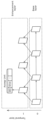
<繋ぎ合わせ処理のパラメータの例>
書き込まれたパラメータは、さらに繋ぎ合わせ処理に関する1以上のパラメータを含んでもよい。図14および図15に示されるように、符号化装置に入力される画像は、異なるカメラからの複数の画像を組み合わせる繋ぎ合わせ処理の結果、得られたものでもよい。書き込まれたパラメータは、例えば、カメラの数、歪み中心または各カメラの主軸、および歪みレベルなどの繋ぎ合わせ処理に関する情報を提供するパラメータを含む。繋ぎ合わせ処理について記述するパラメータの別の例では、複数の画像からの重複する画素によって生成される、繋ぎ合わせられた画像の位置を特定するパラメータを含む。これらの画像の各々は、カメラの角度に重複する領域が存在することがあるため、他の画像に現れてもよい画素を含んでいてもよい。繋ぎ合わせ処理において、これらの重複する画素を処理して減らし、繋ぎ合わせられた画像を生成する。
<Example of parameters for splicing process>
The written parameters may further include one or more parameters related to the stitching process. As shown in Figures 14 and 15, the image input to the encoding device may be the result of a stitching process that combines multiple images from different cameras. The written parameters include parameters that provide information about the stitching process, such as the number of cameras, the distortion center or the principal axis of each camera, and the distortion level. Another example of parameters describing the stitching process includes parameters that identify the location of the stitched image that is generated by overlapping pixels from multiple images. Each of these images may contain pixels that may appear in other images, since there may be overlapping areas in the camera angles. In the stitching process, these overlapping pixels are processed and reduced to generate the stitched image.
繋ぎ合わせ処理について記述するパラメータの別の例としては、繋ぎ合わせられた画像のレイアウトを特定するパラメータを含む。例えば、正距円筒図法、立方体の3x2レイアウトおよび立方体の4x3レイアウトなどの360度画像の形式によって、繋ぎ合わせられた画像内の画像の配置は異なる。なお、3×2レイアウトは、3列2行に配置された6個の画像のレイアウトであり、4×3レイアウトは、4列3行に配置された12個の画像のレイアウトである。上記パラメータである配置パラメータは、画像の配置に基づいて、ある方向での画像の連続性を特定するために使用される。動き補償処理中に、他の画像またはビューからの画素を画面間予測処理に使用することができ、これらの画像またはビューは配置パラメータによって特定される。いくつかの画像または画像中の画素も連続性を確保するために回転する必要がある場合がある。 Another example of a parameter describing the stitching process includes a parameter that specifies the layout of the stitched images. For example, different 360-degree image formats, such as equirectangular projection, cubic 3x2 layout, and cubic 4x3 layout, have different image arrangements in the stitched image. Note that a 3x2 layout is a layout of 6 images arranged in 3 columns and 2 rows, and a 4x3 layout is a layout of 12 images arranged in 4 columns and 3 rows. The above parameter, the alignment parameter, is used to specify the continuity of images in a direction based on the image arrangement. During the motion compensation process, pixels from other images or views can be used for inter-prediction processing, and these images or views are specified by the alignment parameter. Some images or pixels in images may also need to be rotated to ensure continuity.
パラメータの他の例としては、カメラおよびレンズのパラメータが挙げられる(例えば、カメラにおいて使用される焦点距離、主点、スケール係数、イメージセンサの形式など)。パラメータのさらに他の例としては、カメラの配置に関する物理的情報(例えば、カメラの位置、カメラの角度など)がある。 Other examples of parameters include camera and lens parameters (e.g., focal length, principal point, scale factor, type of image sensor used in the camera, etc.). Still other examples of parameters include physical information about the placement of the camera (e.g., camera position, camera angle, etc.).
次に、ステップS102において、符号化装置は、書き込まれたこれらのパラメータに基づく適応的動画像符号化ツールによって画像を符号化する。適応的動画像符号化ツールには、画面間予測処理が含まれる。適応的動画像符号化ツールの一式には、さらに画像再構成処理が含まれてもよい。 Next, in step S102, the encoding device encodes the image using adaptive video encoding tools based on these written parameters. The adaptive video encoding tools include an inter-frame prediction process. The set of adaptive video encoding tools may further include an image reconstruction process.
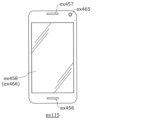
<画面間予測での歪み補正>
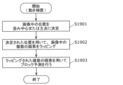
図16は、画像がノンレクティリニア・レンズを使用して撮像されると特定される場合、または、画像が直線的に処理されると特定される場合、または、画像が1以上の画像から繋ぎ合わせられたと特定される場合に、適応される画面間予測処理を示すフローチャートである。図16に示すように、ステップS1901において、符号化装置は、ヘッダに書き込まれたパラメータに基づき、画像内のある位置が歪み中心または主点であると判定する。図17は、魚眼レンズによって生じた歪曲収差の一例を示す。なお、魚眼レンズは広角レンズの一例である。歪み中心から遠くなるにつれて、拡大は焦点軸に沿って減少する。したがって、ステップS1902では、符号化装置は、歪み中心に基づいて、画像を直線的にするために、画像内の画素をラッピング処理して歪みを補正するか、または行われた補正を元に戻すことができる。つまり、符号化装置は、符号化の処理の対象とされる歪んだ画像のブロックに対して画像補正処理(すなわちラッピング処理)を行う。最後に、符号化装置は、ラッピング処理された画像の画素に基づいて、ステップS1903において、予測サンプルのブロックを導き出すブロック予測を行うことができる。なお、本実施の形態におけるラッピング処理またはラッピングは、画素、ブロックまたは画像を、配置または再配置する処理である。また、符号化装置は、予測されたブロックである予測ブロックを画像補正処理が行われる前の元の歪んだ状態に戻し、歪んだ状態の予想ブロックを歪んだ処理対象ブロックの予測画像として用いもよい。なお、予測画像および処理対象ブロックは、実施の形態1の予測信号およびカレントブロックに相当する。
<Distortion correction in inter-frame prediction>
FIG. 16 is a flow chart showing an inter-prediction process that is applied when an image is identified as being captured using a non-rectilinear lens, when an image is identified as being linearly processed, or when an image is identified as being stitched together from one or more images. As shown in FIG. 16, in step S1901, the encoding device determines that a certain position in an image is a distortion center or a principal point based on the parameters written in the header. FIG. 17 shows an example of a distortion aberration caused by a fish-eye lens. Note that a fish-eye lens is an example of a wide-angle lens. As the distance from the distortion center increases, the magnification decreases along the focal axis. Therefore, in step S1902, the encoding device can wrap pixels in the image to correct the distortion or undo the correction that was made based on the distortion center to make the image linear. That is, the encoding device performs an image correction process (i.e., wrapping process) on a block of the distorted image to be encoded. Finally, in step S1903, the encoding device can perform block prediction to derive a block of predicted samples based on the pixels of the wrapped image. In this embodiment, the wrapping process or wrapping is a process of arranging or rearranging pixels, blocks, or images. The encoding device may also return a predicted block, which is a predicted block, to its original distorted state before the image correction process is performed, and use the distorted predicted block as a predicted image of the distorted target block. The predicted image and the target block correspond to the predicted signal and current block in the first embodiment.
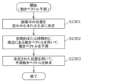
適応された画面間予測処理の別の例には、適応された動きベクトル処理が含まれる。動きベクトルの解像度は、歪み中心から近い画像ブロックよりも、歪み中心から遠い画像ブロックの方が低い。例えば、歪み中心から遠い画像ブロックは、半画素精度までの動きベクトルの精度を有してもよい。一方、歪み中心に近い画像ブロックは、1/8画素精度までという高い動きベクトル精度を有してもよい。適応した動きベクトル精度には、画像ブロック位置に基づき差が生じるため、ビットストリームにおいて符号化された動きベクトルの精度は、動きベクトルの終了位置および/または開始位置に応じて、適応可能であってもよい。つまり、符号化装置は、パラメータを用いて、動きベクトルの精度をブロックの位置に応じて異ならせてもよい。 Another example of an adapted inter prediction process includes adapted motion vector processing. The resolution of the motion vector is lower for image blocks farther from the distortion center than for image blocks closer to the distortion center. For example, image blocks farther from the distortion center may have a motion vector precision up to half-pixel accuracy, while image blocks closer to the distortion center may have a high motion vector precision up to ⅛-pixel accuracy. Since the adapted motion vector precision differs based on the image block position, the precision of the motion vectors coded in the bitstream may be adaptive depending on the end and/or start position of the motion vector. That is, the coding device may use parameters to vary the precision of the motion vector depending on the position of the block.
適応した画面間予測処理の別の例には、適応した動き補償処理が含まれ、この動き補償処理においては、ヘッダにおいて書き込まれた配置パラメータに基づいた対象のビューからの画像サンプルを予測するために、異なるビューからの画素を使用してもよい。例えば、正距円筒図法、立方体の3x2のレイアウト、立方体の4x3のレイアウトなどの360度の画像形式によって、繋ぎ合わせられた画像内の画像の配置は異なる。配置パラメータは、画像の配置に基づき、一定方向での画像の連続性を特定するために使用される。動き補償処理中に、他の画像または他のビューからの画素を画面間予測処理に使用することができ、これらの画像またはビューは配置パラメータによって特定される。いくつかの画像または画像中の画素も連続性を確保するために回転する必要がある場合がある。 Another example of an adaptive inter-prediction process includes an adaptive motion compensation process, in which pixels from different views may be used to predict image samples from a target view based on the alignment parameters written in the header. For example, different 360-degree image formats, such as equirectangular projection, cubic 3x2 layout, cubic 4x3 layout, etc., have different image alignments in the stitched image. The alignment parameters are used to specify image continuity in a certain direction based on the image alignment. During the motion compensation process, pixels from other images or other views may be used for the inter-prediction process, and these images or views are specified by the alignment parameters. Some images or pixels in an image may also need to be rotated to ensure continuity.
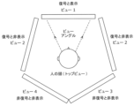
つまり、符号化装置は、連続性を確保する処理を行ってもよい。例えば、符号化装置は、図15に示す繋ぎ合わせ画像を符号化する場合、そのパラメータに基づいてラッピング処理を行ってもよい。具体的には、繋ぎ合わせ画像に含まれる5つの画像(すなわち画像A~Dとトップビュー)のうち、トップビューは、180度画像であり、画像A~Dは90度画像である。したがって、トップビューに映し出されている空間は、画像A~Dのそれぞれに映し出されている空間と連続し、画像Aに映し出されている空間と、画像Bに映し出されている空間とは連続している。しかし、繋ぎ合わせ画像では、トップビューは、画像A,CおよびDと連続しておらず、画像Aは画像Bと連続していない。そこで、符号化装置は、符号化効率を向上するために、上述のラッピング処理を行う。つまり、符号化装置は、繋ぎ合わせ画像に含まれる各画像を再配置する。例えば、符号化装置は、画像Aと画像Bとが連続するように各画像を再配置する。これにより、画像Aおよび画像Bに分離されて映し出されているオブジェクトが連続し、符号化効率を向上することができる。なお、このような各画像を再配置または配置する処理であるラッピング処理は、フレームパッキングともいう。 That is, the encoding device may perform a process to ensure continuity. For example, when encoding the spliced image shown in FIG. 15, the encoding device may perform a wrapping process based on the parameters. Specifically, of the five images (i.e., images A to D and the top view) included in the spliced image, the top view is a 180-degree image, and images A to D are 90-degree images. Therefore, the space displayed in the top view is continuous with the spaces displayed in each of images A to D, and the space displayed in image A is continuous with the space displayed in image B. However, in the spliced image, the top view is not continuous with images A, C, and D, and image A is not continuous with image B. Therefore, the encoding device performs the above-mentioned wrapping process to improve the encoding efficiency. That is, the encoding device rearranges each image included in the spliced image. For example, the encoding device rearranges each image so that image A and image B are continuous. As a result, the objects displayed separately in images A and B are continuous, and the encoding efficiency can be improved. The wrapping process, which involves rearranging or arranging each image in this way, is also called frame packing.
<画面間予測でのパディング>
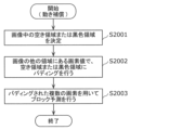
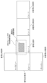
図18は、画像がノンレクティリニア・レンズを使用して撮像されていると特定される場合、または画像が直線的に処理されると特定される場合、または、画像が2つ以上の画像から繋ぎ合わせられたと特定される場合に、適応される画面間予測処理の変形例を示すフローチャートである。図18に示すように、符号化装置は、ヘッダに書き込まれたパラメータに基づいて、画像の領域がステップS2001において空き領域であると特定する。これらの空き領域は、撮像された画像の画素を含んでいない画像の領域であり、一般的には、所定の画素値(例えば、黒色画素)で置換される。図13は、画像内のこれらの領域の一例を示す図である。図15は、複数の画像を繋ぎ合わせる場合における、これらの領域の別の例を示す図である。次に、符号化装置は、図18のステップS2002において、特定されたこれらの領域内の画素を、動き補償処理を行っている間に、画像の空き領域ではない他の領域の値でパディング処理する。パディング処理された値は、物理的な3次元の空間に応じて、空き領域ではない領域における最も近い画素からの値、または最も近い画素からの値であってもよい。最後に、ステップS2003において、符号化装置は、パディング処理された値に基づいて予測サンプルのブロックを生成するためにブロック予測を行う。
<Padding in inter-prediction>
FIG. 18 is a flow chart showing a variation of the inter prediction process that is applied when the image is identified as being captured using a non-rectilinear lens, when the image is identified as being linearly processed, or when the image is identified as being stitched together from two or more images. As shown in FIG. 18, the encoding device identifies regions of the image as free regions in step S2001 based on parameters written in the header. These free regions are regions of the image that do not contain pixels of the captured image, and are typically replaced with a predetermined pixel value (e.g., black pixels). FIG. 13 shows an example of these regions in an image. FIG. 15 shows another example of these regions when multiple images are stitched together. Next, the encoding device pads the pixels in these identified regions with values from other non-free regions of the image during motion compensation in step S2002 of FIG. 18. The padded values may be values from the nearest pixel in the non-free region or values from the nearest pixel, depending on the physical three-dimensional space. Finally, in step S2003, the encoder performs block prediction to generate a block of predicted samples based on the padded values.
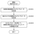
<画像再構成での歪み補正>
図19は、画像がノンレクティリニア・レンズを使用して撮像されていると特定される場合、または、画像が直線的に処理されると特定される場合、または、画像が2以上の画像から繋ぎ合わせらされたと特定される場合に、適応される画像再構成処理を示すフローチャートである。図19に示すように、符号化装置は、ヘッダに書き込まれたパラメータに基づいて、画像内の位置を、ステップS1801において歪み中心または主点として判定する。図17は、魚眼レンズによって生じた歪曲収差の一例を示す。焦点の軸芯が歪み中心から離れるにつれて、拡大は焦点の軸芯に沿って減少する。したがって、ステップS1802では、符号化装置は、歪み中心に基づいて、画像内の再構成画素に対して、歪みを補正するか、または画像を直線的にするために行われた補正を元に戻すために、ラッピング処理を行ってもよい。例えば、符号化装置は、逆変換によって生成される予測誤差の画像と、予測画像とを加算することによって、再構成画像を生成する。このとき、符号化装置は、予測誤差の画像および予測画像のそれぞれを直線的にするためにラッピング処理を行う。
<Distortion correction during image reconstruction>
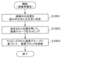
FIG. 19 is a flowchart showing an image reconstruction process that is applied when an image is identified as being captured using a non-rectilinear lens, when an image is identified as being linearly processed, or when an image is identified as being stitched together from two or more images. As shown in FIG. 19, the encoding device determines a position in an image as a distortion center or a principal point based on a parameter written in a header in step S1801. FIG. 17 shows an example of a distortion aberration caused by a fisheye lens. As the focal axis moves away from the distortion center, the magnification decreases along the focal axis. Therefore, in step S1802, the encoding device may perform a wrapping process on reconstructed pixels in an image based on the distortion center to correct the distortion or to undo the correction made to make the image linear. For example, the encoding device generates a reconstructed image by adding an image of a prediction error generated by an inverse transform and a predicted image. At this time, the encoding device performs a wrapping process to make each of the image of the prediction error and the predicted image linear.
最後に、ステップS1803において、符号化装置は、ラッピング処理が行われた画像の画素に基づいて再構成された画像のブロックを、メモリに格納する。 Finally, in step S1803, the encoding device stores in memory the blocks of the image reconstructed based on the pixels of the image that has been subjected to the wrapping process.
<画像再構成での画素値の置き換え>
図20は、画像がノンレクティリニア・レンズを使用して撮像されていると特定される場合、または、画像が直線的に処理されると特定される場合、または、画像が1以上の画像から繋ぎ合わせらされたと特定される場合に、適応される画像再構成処理の変形例を示す。図20に示すように、ヘッダに書き込まれたパラメータに基づいて、ステップS2101において、符号化装置は、画像の領域を空き領域として特定する。これらの空き領域は、撮像された画像の画素を含んでおらず、一般的に所定の画素値(例えば黒色画素)と置換される画像の領域である。図13は、画像においてこれらの領域の一例を示す図である。図15は、複数の画像を繋ぎ合わせる場合における、これらの領域の別の例を示す図である。次に、ステップS2102において、符号化装置は、画像サンプルのブロックを再構成する。
<Replacing pixel values in image reconstruction>
Fig. 20 shows a variation of the image reconstruction process that is applied when the image is identified as having been captured using a non-rectilinear lens, or when the image is identified as having been processed linearly, or when the image is identified as having been stitched together from one or more images. As shown in Fig. 20, based on the parameters written in the header, in step S2101, the encoding device identifies regions of the image as free regions. These free regions are regions of the image that do not contain pixels of the captured image and are typically replaced with a predetermined pixel value (e.g. black pixels). Fig. 13 shows an example of such regions in an image. Fig. 15 shows another example of such regions in the case of stitching together multiple images. Next, in step S2102, the encoding device reconstructs blocks of image samples.
また、ステップS2103において、符号化装置は、これらの特定された領域内の再構成された画素を、所定の画素値と置き換える。 Also, in step S2103, the encoding device replaces the reconstructed pixels in these identified regions with predetermined pixel values.
<符号化処理の省略>
図11のステップS102において、適応的動画像符号化ツールについて可能な別の変形例では、画像の符号化処理を省略してもよい。つまり、画像のレイアウト配置に関して書き込まれたパラメータ、およびユーザの目の視線または頭の方向に基づくアクティブなビュー領域についての情報に基づいて、符号化装置は、画像の符号化処理を省略してもよい。すなわち、符号化装置は部分符号化処理を行う。
<Omission of encoding process>
Another possible variant of the adaptive video coding tool in step S102 of Fig. 11 is that the coding device may skip the coding process of the image, i.e., based on the written parameters regarding the layout arrangement of the image and the information about the active viewing area based on the user's eye line or head direction, the coding device may skip the coding process of the image, i.e., the coding device performs a partial coding process.
図21は、異なるカメラによって撮像された異なるビューに関する、ユーザの視線の視角または頭の向きの一例を示す。同図に示すように、ユーザの視角はビュー1のみからのカメラによって撮像された画像内にある。この例においては、他のビューからの画像は、ユーザの視角外にあるため符号化する必要はない。そのため、符号化の複雑さを低減させるため、または圧縮画像の送信ビットレートを低減させるために、これらの画像に対する符号化処理または送信処理を省略することができる。図示している別の可能な一例において、ビュー5およびビュー2はアクティブなビュー1に物理的に近接しているため、ビュー5からの画像、およびビュー2からの画像も、符号化されて送信される。これらの画像は、現時点ではビューアまたはユーザに表示されないが、ビューアが自身の頭の向きを変える時に、ビューアまたはユーザに表示される。これらの画像は、ビューアが自身の頭の方向を変える時に、ユーザの視聴体感を向上させるために使用される。
Figure 21 shows an example of the user's viewing angle or head orientation with respect to different views captured by different cameras. As shown, the user's viewing angle is within the images captured by the cameras from
図22は、ユーザの異なるカメラによって撮像された異なるビューに対する視線の角度または頭の向きの別の一例を示す。ここでは、アクティブな視線領域は、ビュー2からの画像内にある。したがって、ビュー2からの画像が符号化されてユーザに表示される。ここでは、符号化装置は、ビューアの頭が近々動くと推定される範囲を予測して、今後のフレームの視線領域になる可能性がある範囲として、より広い領域を定義する。符号化装置は、対象のアクティブな視線領域内ではなく、より広い今後の視線領域内にある(ビュー2以外の)ビューからの画像も符号化し、ビューアの方でビューをより速く描画できるように送信する。つまり、ビュー2からの画像だけでなく、図22に示す可能視線領域に少なくとも一部が重複する、トップビューおよびビュー1からの画像も符号化されて送信される。残りのビュー(ビュー3、ビュー4、およびボトムビュー)からの画像は符号化されず、これらの画像の符号化処理は省略される。
Figure 22 shows another example of the gaze angle or head orientation for different views captured by different cameras of a user. Here, the active gaze area is within the image from
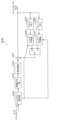
[符号化装置]
図23は、本実施の形態における動画像を符号化する符号化装置の構成を示すブロック図である。
[Encoding device]
FIG. 23 is a block diagram showing the configuration of a coding device for coding moving pictures in this embodiment.
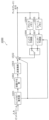
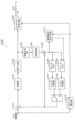
符号化装置900は、出力ビットストリームを生成するために、ブロックごとに入力動画像を符号化するための装置であって、実施の形態1の符号化装置100に相当する。図23に示すように、符号化装置900は、変換部901、量子化部902、逆量子化部903、逆変換部904、ブロックメモリ905、フレームメモリ906、イントラ予測部907、インター予測部908、減算部921、加算部922、エントロピー符号化部909、およびパラメータ導出部910を備える。
The
入力動画像の画像(すなわち処理対象ブロック)は、減算部921へ入力され、減算された値は変換部901に出力される。つまり、減算部921は、処理対象ブロックから予測画像を減算することによって、予測誤差を算出する。変換部901は、減算された値(すなわち予測誤差)を周波数係数に変換し、得られた周波数係数を量子化部902に出力する。量子化部902は、入力された周波数係数を量子化し、逆量子化部903およびエントロピー符号化部909に、得られた量子化値を出力する。
An image of the input video (i.e., the block to be processed) is input to the
逆量子化部903は、量子化部902から出力されたサンプル値(すなわち量子化値)を逆量子化し、逆変換部904に周波数係数を出力する。逆変換部904は、周波数係数を画像のサンプル値、すなわち画素値に変換するために逆周波数変換を行い、得られたサンプル値を加算部922に出力する。
The
パラメータ導出部910は、画像補正処理に関するパラメータ、またはカメラに関するパラメータ、または繋ぎ合わせ処理に関するパラメータを画像から導出し、インター予測部908と、加算部922と、エントロピー符号化部909とに出力する。例えば、入力動画像には、これらのパラメータが含まれていてもよく、この場合には、パラメータ導出部910は、動画像に含まれるパラメータを抽出して出力する。または、入力動画像には、これらのパラメータを導出するためのベースとなるパラメータが含まれていてもよい。この場合には、パラメータ導出部910は、動画像に含まれるベースのパラメータを抽出して、その抽出されたベースのパラメータを、上述の各パラメータに変換して出力する。
The
加算部922は、逆変換部904から出力されたサンプル値を、イントラ予測部907またはインター予測部908から出力された予測画像の画素値に加算する。つまり、加算部922は、再構成画像を生成する画像再構成処理を行う。加算部922は、さらなる予測を行うために、ブロックメモリ905またはフレームメモリ906に、得られた加算値を出力する。
The
イントラ予測部907は、画面内予測を行う。つまり、イントラ予測部907は、ブロックメモリ905に格納された、処理対象ブロックのピクチャと同じピクチャに含まれる再構成画像を用いて、処理対象ブロックの画像を推定する。インター予測部908は、画面間予測を行う。つまり、インター予測部908は、フレームメモリ906に格納された、処理対象ブロックのピクチャと異なるピクチャに含まれる再構成画像を用いて、処理対象ブロックの画像を推定する。
The
ここで、本実施の形態では、インター予測部908および加算部922は、パラメータ導出部910によって導出されたパラメータに基づいて処理を適応させる。つまり、インター予測部908および加算部922は、上述の適応的動画像符号化ツールによる処理として、図16、図18、図19および図20に示すフローチャートにしたがった処理を行う。
Here, in this embodiment, the
エントロピー符号化部909は、量子化部902から出力された量子化値と、パラメータ導出部910によって導出されたパラメータとを符号化し、ビットストリームを出力する。つまり、エントロピー符号化部909は、そのパラメータをビットストリームのヘッダに書き込む。
The
[復号処理]
図24は、本実施の形態における動画像復号処理の一例を示すフローチャートである。
[Decryption process]
FIG. 24 is a flowchart showing an example of the video decoding process in this embodiment.
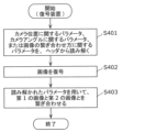
ステップS201では、復号装置は、パラメータ一式をヘッダから読み解く。図12は、圧縮された動画像ビットストリームにおいて上記ヘッダの可能な位置を示す。読み解かれたパラメータは、画像補正処理に関する1以上のパラメータを含む。 In step S201, the decoding device parses a set of parameters from the header. Figure 12 shows possible locations of said header in a compressed video bitstream. The parsed parameters include one or more parameters related to image correction processing.
<画像補正処理のパラメータの例>
図13に示すように、撮像された画像は、画像の撮像中に使用されるレンズの特性により歪んでいてもよい。また、撮像された画像を直線的に補正するために画像補正処理を使用した。読み解かれたパラメータは、使用された画像補正処理を特定する、または使用された画像補正処理を記載するためのパラメータを含む。画像補正処理において使用されるパラメータの例には、画像補正処理の意図した出力画素値に入力画像の画素をマッピングするためのマッピングテーブルを構成するパラメータを含む。これらのパラメータは、1以上の補間処理用の重みパラメータ、または/およびピクチャの入力画素および出力画素の位置を特定する位置パラメータを含んでもよい。画像補正処理の可能な一実施例において、画像補正処理用のマッピングテーブルは、補正された画像内のすべての画素に使用されてもよい。
<Examples of parameters for image correction processing>
As shown in Fig. 13, the captured image may be distorted due to the characteristics of the lens used during capture of the image. An image correction process was used to linearly correct the captured image. The interpreted parameters include parameters that identify or describe the image correction process used. Examples of parameters used in the image correction process include parameters that constitute a mapping table for mapping pixels of the input image to the intended output pixel values of the image correction process. These parameters may include weight parameters for one or more interpolation processes, or/and location parameters that identify the location of the input and output pixels of the picture. In one possible implementation of the image correction process, the mapping table for the image correction process may be used for all pixels in the corrected image.
画像補正処理を記載するために用いられるパラメータの他の例としては、予め定義された複数の補正アルゴリズムから一つを選択するための選択パラメータと、補正アルゴリズムの複数の所定の方向からの一つを選択するための方向パラメータと、または/および補正アルゴリズムを較正、または微調整するためのキャリブレーションパラメータとが含まれる。例えば、予め定義された複数の補正アルゴリズムがある場合(例えば、異なるアルゴリズムが異なる種類のレンズに使用される場合)、選択パラメータは、予め定義されたこれらのアルゴリズムのうちの1つを選択するために使用される。例えば、補正アルゴリズムを適用することができる方向が2つ以上ある場合(例えば、水平方向、垂直方向、またはどちらの方向でも画像補正処理を行うことが可能な場合)、方向パラメータは、予め定義されたこれらの方向のうちの1つを選択する。例えば、画像補正処理を較正することができる場合、キャリブレーションパラメータにより、異なる種類のレンズに適合するように画像補正処理を調整することができる。 Other examples of parameters used to describe the image correction process include a selection parameter for selecting one of a number of predefined correction algorithms, a direction parameter for selecting one of a number of predefined directions of the correction algorithm, and/or a calibration parameter for calibrating or fine-tuning the correction algorithm. For example, if there are a number of predefined correction algorithms (e.g., different algorithms are used for different types of lenses), the selection parameter is used to select one of these predefined algorithms. For example, if there are two or more directions in which the correction algorithm can be applied (e.g., if the image correction process can be performed horizontally, vertically, or in either direction), the direction parameter selects one of these predefined directions. For example, if the image correction process can be calibrated, the calibration parameter allows the image correction process to be adjusted to suit different types of lenses.
<繋ぎ合わせ処理のパラメータの例>
読み解かれたパラメータは、さらに繋ぎ合わせ処理に関する1以上のパラメータを含んでもよい。図14および図15に示すように、復号装置に入力される符号化された画像は、異なるカメラからの複数の画像を組み合わせる繋ぎ合わせ処理の結果、得られたものでもよい。読み解かれたパラメータは、例えば、カメラの数、歪み中心、または各カメラの主軸、および歪みレベルなどの繋ぎ合わせ処理に関する情報を提供するパラメータを含む。繋ぎ合わせ処理について記載するパラメータの別の例としては、複数の画像からの重複する画素から生成される、繋ぎ合わせられた画像の位置を特定するパラメータがある。これらの画像の各々は、カメラの角度に重複する領域が存在することがあるため、他の画像に現れてもよい画素を含んでいてもよい。この繋ぎ合わせ処理において、これらの重複する画素を処理して減らし、繋ぎ合わせられた画像を生成する。
<Example of parameters for splicing process>
The interpreted parameters may further include one or more parameters related to the stitching process. As shown in Figures 14 and 15, the encoded image input to the decoder may be the result of a stitching process that combines multiple images from different cameras. The interpreted parameters include parameters that provide information about the stitching process, such as the number of cameras, the distortion center or principal axis of each camera, and the distortion level. Another example of a parameter that describes the stitching process is a parameter that specifies the location of a stitched image that is generated from overlapping pixels from multiple images. Each of these images may contain pixels that may appear in other images, since there may be overlapping areas in the camera angles. In the stitching process, these overlapping pixels are processed and reduced to generate the stitched image.
繋ぎ合わせ処理について記述するパラメータの別の例としては、繋ぎ合わせられた画像のレイアウトを特定するパラメータを含む。例えば、正距円筒図法、立方体の3x2のレイアウトまたは立方体の4x3のレイアウトなどの360度画像の形式によって、繋ぎ合わせられた画像内の画像の配置は異なる。上記パラメータである配置パラメータは、画像の配置に基づいて、ある方向での画像の連続性を特定するために使用される。動き補償処理中に、他の画像またはビューからの画素を画面間予測処理に使用することができ、これらの画像またはビューは配置パラメータによって特定される。いくつかの画像または画像中の画素も連続性を確保するために回転する必要がある場合がある。 Another example of parameters describing the stitching process includes parameters that specify the layout of the stitched images. For example, different 360 degree image formats, such as equirectangular projection, cubic 3x2 layout, or cubic 4x3 layout, have different arrangements of images in the stitched image. The above parameters, the alignment parameters, are used to specify the continuity of images in a direction based on the arrangement of the images. During the motion compensation process, pixels from other images or views can be used for inter prediction, and these images or views are specified by the alignment parameters. Some images or pixels in images may also need to be rotated to ensure continuity.
パラメータの他の例としては、カメラおよびレンズのパラメータが挙げられる(例えば、カメラにおいて使用される焦点距離、主点、スケール係数、イメージセンサの形式など)。パラメータのさらに他の例としては、カメラの配置に関する物理的情報(例えば、カメラの位置、カメラの角度など)がある。 Other examples of parameters include camera and lens parameters (e.g., focal length, principal point, scale factor, type of image sensor used in the camera, etc.). Still other examples of parameters include physical information about the placement of the camera (e.g., camera position, camera angle, etc.).
次に、ステップS202において、復号装置は、読み解かれたこれらのパラメータに基づく適応的動画像復号ツールによって画像を復号する。適応的動画像復号ツールには、画面間予測処理が含まれる。適応的動画像復号ツールの一式には、画像再構成処理が含まれてもよい。なお、動画像復号ツールまたは適応的動画像復号ツールは、上述の動画像符号化ツールまたは適応的動画像符号化ツールと同一またはそれに対応するツールである。 Next, in step S202, the decoding device decodes the image using an adaptive video decoding tool based on these interpreted parameters. The adaptive video decoding tool includes an inter-frame prediction process. The set of adaptive video decoding tools may also include an image reconstruction process. Note that the video decoding tool or adaptive video decoding tool is the same as or corresponds to the above-mentioned video encoding tool or adaptive video encoding tool.
<画面間予測での歪み補正>
図16は、画像がノンレクティリニア・レンズを使用して撮像されると特定される場合、または、画像が直線的に処理されると特定される場合、または、画像が1以上の画像から繋ぎ合わせられたと特定される場合に、適応される画面間予測処理を示すフローチャートである。図16に示すように、ステップS1901において、復号装置は、ヘッダに書き込まれたパラメータに基づき、画像内のある位置が歪み中心または主点であると判定する。図17は、魚眼レンズによって生じた歪曲収差の一例を示す。焦点軸が歪み中心から離れるにつれて、拡大は焦点軸に沿って減少する。したがって、ステップS1902では、復号装置は、歪み中心に基づいて、歪みを補正するか、または画像を直線的にするために行われた補正を元に戻すために、画像内の画素に対してラッピング処理を行ってもよい。つまり、復号装置は、復号の処理の対象とされる歪んだ画像のブロックに対して画像補正処理(すなわちラッピング処理)を行う。最後に、復号装置は、ステップS1903において、ラッピング処理が行われた画像の画素に基づいて、予測サンプルのブロックを導き出すブロック予測を行うことができる。また、復号装置は、予測されたブロックである予測ブロックを画像補正処理が行われる前の元の歪んだ状態に戻し、歪んだ状態の予想ブロックを歪んだ処理対象ブロックの予測画像として用いもよい。
<Distortion correction in inter-frame prediction>
FIG. 16 is a flowchart showing an inter-prediction process that is adapted when an image is identified as being captured using a non-rectilinear lens, when an image is identified as being linearly processed, or when an image is identified as being stitched together from one or more images. As shown in FIG. 16, in step S1901, the decoding device determines that a certain position in the image is the distortion center or principal point based on the parameters written in the header. FIG. 17 shows an example of distortion aberration caused by a fisheye lens. As the focal axis moves away from the distortion center, the magnification decreases along the focal axis. Therefore, in step S1902, the decoding device may perform a wrapping process on pixels in the image based on the distortion center to correct the distortion or to undo the correction made to straighten the image. That is, the decoding device performs an image correction process (i.e., a wrapping process) on a block of the distorted image that is the target of the decoding process. Finally, in step S1903, the decoding device may perform block prediction to derive a block of predicted samples based on the pixels of the image that has been subjected to the wrapping process. The decoding device may also restore the predicted block, which is a prediction block, to its original distorted state before the image correction process was performed, and use the distorted prediction block as a predicted image for the distorted block to be processed.
適応された画面間予測処理の別の例には、適応された動きベクトル処理が含まれる。動きベクトルの解像度は、歪み中心から近い画像ブロックよりも、歪み中心から遠い画像ブロックの方が低い。例えば、歪み中心から遠い画像ブロックは、半画素精度までの動きベクトル精度を有してもよい。一方、歪み中心に近い画像ブロックは、1/8画素精度までという高い動きベクトル精度を有してもよい。適応した動きベクトル精度には、画像ブロック位置に基づき差が生じるため、ビットストリームにおいて符号化された動きベクトル精度は、動きベクトルの終了位置および/または開始位置に応じて、適応的であってもよい。つまり、復号装置は、パラメータを用いて、動きベクトルの精度をブロックの位置に応じて異ならせてもよい。 Another example of an adapted inter prediction process includes adapted motion vector processing. The resolution of the motion vector is lower for image blocks farther from the distortion center than for image blocks closer to the distortion center. For example, image blocks farther from the distortion center may have a motion vector precision up to half-pixel accuracy, while image blocks closer to the distortion center may have a high motion vector precision up to ⅛-pixel accuracy. Since the adapted motion vector precision differs based on the image block position, the motion vector precision coded in the bitstream may be adaptive depending on the end and/or start position of the motion vector. That is, the decoding device may use parameters to vary the precision of the motion vector depending on the block position.
適応した画面間予測処理の別の例には、適応した動き補償処理が含まれ、この動き補償処理においては、ヘッダにおいて書き込まれた配置パラメータに基づいた対象のビューからの画像サンプルを予測するために、異なるビューからの画素を使用してもよい。例えば、正距円筒図法、立方体の3x2のレイアウト、立方体の4x3のレイアウトなどの360度画像の形式によって、繋ぎ合わせられた画像内の画像の配置は異なる。配置パラメータは、画像の配置に基づき、一定方向での画像の連続性を特定するために使用される。動き補償処理中に、他の画像または他のビューからの画素を画面間予測処理に使用することができ、これらの画像またはビューは配置パラメータによって特定される。いくつかの画像または画像中の画素も連続性を確保するために回転する必要がある場合がある。 Another example of an adaptive inter prediction process includes an adaptive motion compensation process, in which pixels from different views may be used to predict image samples from a target view based on the alignment parameters written in the header. For example, different 360 degree image formats, such as equirectangular projection, cubic 3x2 layout, cubic 4x3 layout, etc., have different image alignments in the stitched image. The alignment parameters are used to specify image continuity in a certain direction based on the image alignment. During the motion compensation process, pixels from other images or other views may be used for the inter prediction process, and these images or views are specified by the alignment parameters. Some images or pixels in an image may also need to be rotated to ensure continuity.
つまり、復号装置は、連続性を確保する処理を行ってもよい。例えば、復号装置は、図15に示す繋ぎ合わせ画像を符号化する場合、そのパラメータに基づいてラッピング処理を行ってもよい。具体的には、復号装置は、上述の符号化装置と同様に、画像Aと画像Bとが連続するように各画像を再配置する。これにより、画像Aおよび画像Bに分離されて映し出されているオブジェクトが連続し、符号化効率を向上することができる。 In other words, the decoding device may perform processing to ensure continuity. For example, when encoding the spliced image shown in FIG. 15, the decoding device may perform wrapping processing based on the parameters. Specifically, the decoding device rearranges each image so that image A and image B are continuous, similar to the encoding device described above. This makes it possible to make the objects displayed separately in image A and image B continuous, improving encoding efficiency.
<画面間予測でのパディング>
図18は、画像がノンレクティリニア・レンズを使用して撮像されていると特定される場合、または画像が直線的に処理されると特定される場合、または、画像が2つ以上の画像から繋ぎ合わせられたと特定される場合に、適応される画面間予測処理の変形例を示すフローチャートである。図18に示されるように、復号装置は、ヘッダから読み解かれたパラメータに基づいて、画像の領域がステップS2001において空き領域であると特定する。これらの空き領域は、撮像された画像の画素を含んでおらず、一般的に所定の画素値(例えば、黒色画素)と置き換えられる画像の領域である。図13は、画像内におけるこれらの領域の例を示す。図15は、複数の画像を繋ぎ合わせる場合における、これらの領域の別の例を示す図である。次に、復号装置は、図18のステップS2002において、これらの特定された領域内の画素を、動き補償処理中に、画像の他の空き領域ではない他の領域の値でパディング処理する。パディング処理された値は、物理的な3次元の空間に応じて、空き領域ではない領域における最も近い画素、または最も近い画素からの値であってもよい。最後に、ステップS2003において、復号装置は、パディング処理された値に基づいて予測サンプルのブロックを生成するためにブロック予測を行う。
<Padding in inter-prediction>
FIG. 18 is a flow chart showing a variation of the inter prediction process that is applied when an image is identified as being captured using a non-rectilinear lens, when an image is identified as being linearly processed, or when an image is identified as being stitched together from two or more images. As shown in FIG. 18, the decoding device identifies regions of the image as free regions in step S2001 based on parameters read from the header. These free regions are regions of the image that do not contain pixels of the captured image and are generally replaced with a predetermined pixel value (e.g., black pixels). FIG. 13 shows examples of these regions in an image. FIG. 15 shows another example of these regions in the case of stitching together multiple images. Next, in step S2002 of FIG. 18, the decoding device pads pixels in these identified regions with values from other non-free regions of the image during motion compensation. The padded values may be values from the nearest pixel in the non-free region or the nearest pixel, depending on the physical three-dimensional space. Finally, in step S2003, the decoder performs block prediction to generate a block of predicted samples based on the padded values.
<画像再構成での歪み補正>
図19は、画像がノンレクティリニア・レンズを使用して撮像されていると特定される場合、または、画像が直線的に処理されると特定される場合、または、画像が2以上の画像から繋ぎ合わせられたと特定される場合に、適応される画像再構成処理を示すフローチャートである。図19に示すように、復号装置は、ヘッダから読み解かれたパラメータに基づいて、画像内の位置を、ステップS1801において歪み中心または主点として判定する。図17は、魚眼レンズによって生じた歪曲収差の一例を示す。焦点の軸芯が歪み中心から離れるにつれて、拡大は焦点の軸芯に沿って減少する。したがって、ステップS1802では、復号装置は、歪み中心に基づいて、画像内の再構成画素に対して、歪みを補正するか、または画像を直線的にするために行われた補正を元に戻すために、ラッピング処理を行ってもよい。例えば、復号装置は、逆変換によって生成される予測誤差の画像と、予測画像とを加算することによって、再構成画像を生成する。このとき、復号装置は、予測誤差の画像および予測画像のそれぞれを直線的にするためにラッピング処理を行う。
<Distortion correction during image reconstruction>
FIG. 19 is a flowchart showing an image reconstruction process that is applied when an image is identified as being captured using a non-rectilinear lens, when an image is identified as being linearly processed, or when an image is identified as being stitched together from two or more images. As shown in FIG. 19, the decoding device determines a position in the image as a distortion center or a principal point in step S1801 based on parameters read from the header. FIG. 17 shows an example of distortion aberration caused by a fisheye lens. As the focal axis moves away from the distortion center, the magnification decreases along the focal axis. Therefore, in step S1802, the decoding device may perform a wrapping process on the reconstructed pixels in the image based on the distortion center to correct the distortion or to undo the correction made to linearize the image. For example, the decoding device generates a reconstructed image by adding an image of a prediction error generated by an inverse transform and a predicted image. At this time, the decoding device performs a wrapping process to linearize each of the image of the prediction error and the predicted image.
最後に、ステップS1803において、復号装置は、ラッピング処理が行われた画像の画素に基づいて、再構成された画像のブロックを、メモリに格納する。 Finally, in step S1803, the decoding device stores in memory the reconstructed image block based on the pixels of the image that has been subjected to the wrapping process.
<画像再構成での画素値の置き換え>
図20は、画像がノンレクティリニア・レンズを使用して撮像されていると特定される場合、または、画像が直線的に処理されると特定される場合、または、画像が1以上の画像から繋ぎ合わせらされたと特定される場合に、適応される画像再構成処理の変形例を示す。図20に示すように、ヘッダから読み解かれたパラメータに基づいて、ステップS2001において、復号装置は、画像の領域を空き領域として特定する。これらの空き領域は、撮像された画像の画素を含んでおらず、一般的に所定の画素値(例えば黒色画素)と置換される画像の領域である。図13は、画像におけるこれらの領域の例を示す。図15は、複数の画像を繋ぎ合わせる場合における、これらの領域の別の例を示す図である。次に、ステップS2102において、復号装置は、画像サンプルのブロックを再構成する。
<Replacing pixel values in image reconstruction>
Fig. 20 shows a variation of the image reconstruction process that is applied when the image is identified as having been captured using a non-rectilinear lens, or when the image is identified as having been processed linearly, or when the image is identified as having been stitched together from one or more images. As shown in Fig. 20, based on the parameters read from the header, in step S2001, the decoder identifies regions of the image as free regions. These free regions are regions of the image that do not contain pixels from the captured image and are typically replaced with a predefined pixel value (e.g., black pixels). Fig. 13 shows an example of such regions in an image. Fig. 15 shows another example of such regions in the case of stitching together multiple images. Next, in step S2102, the decoder reconstructs blocks of image samples.
また、ステップS2103において、復号装置は、これらの特定された領域内の再構成された画素を、所定の画素値と置き換える。 Also, in step S2103, the decoding device replaces the reconstructed pixels in these identified regions with predetermined pixel values.
<復号処理の省略>
図24のステップS202において、画像の適応的動画像復号ツールの別の可能な変形例では、画像の復号処理を省略してもよい。つまり、画像のレイアウト配置に関して読み解かれたパラメータ、およびユーザの目の視線または頭の方向に基づくアクティブなビュー領域についての情報に基づいて、復号装置は、画像の復号処理を省略してもよい。すなわち、復号装置は部分復号処理を行う。
<Omission of decryption process>
In step S202 of Fig. 24, another possible variant of the adaptive video decoding tool for an image may skip the decoding process of the image, i.e., based on the interpreted parameters of the layout arrangement of the image and the information about the active viewing area based on the user's eye gaze or head direction, the decoding device may skip the decoding process of the image, i.e., perform a partial decoding process.
図21は、異なるカメラによって撮像された異なるビューに関する、ユーザの視線の視角または頭の向きの一例を示す。同図に示すように、ユーザの視角はビュー1のみからのカメラによって撮像された画像内にある。この例においては、他のビューからの画像は、ユーザの視角外にあるため復号する必要はない。そのため、復号の複雑さを低減させるため、または圧縮画像の送信ビットレートを低減させるために、これらの画像に対する復号処理または表示処理を省略することができる。図示している別の可能な一例において、ビュー5およびビュー2はアクティブなビュー1に物理的に近接しているため、ビュー5からの画像、およびビュー2からの画像も、復号される。これらの画像は、現時点ではビューアまたはユーザに表示されないが、ビューアが自身の頭の向きを変える時に、ビューアまたはユーザに表示される。ユーザの頭の動きに応じてビューを復号して表示する時間を低減させることにより、ユーザが頭の向きを変更する時に、ユーザの視聴体感を向上させるために、これらの画像が可能な限り早く表示される。
Figure 21 shows an example of the user's viewing angle or head orientation with respect to different views captured by different cameras. As shown, the user's viewing angle is within the images captured by the cameras from
図22は、ユーザの異なるカメラによって撮像された異なるビューに対する視線の角度または頭の向きの別の一例を示す。ここでは、アクティブな視線領域は、ビュー2からの画像内にある。したがって、ビュー2からの画像が復号されてユーザに表示される。ここでは、復号装置は、ビューアの頭が近々動くと推定される範囲を予測して、今後のフレームの視線領域になる可能性がある範囲として、より広い領域を定義する。復号装置は、対象のアクティブな視線領域内ではなく、より広い今後の視線領域内にある(ビュー2以外の)ビューからの画像も復号する。つまり、ビュー2からの画像だけでなく、図22に示す可能視線領域に少なくとも一部が重複する、トップビューおよびビュー1からの画像も復号される。これにより、ビューアの方でビューをより速く描画できるように画像が表示される。残りのビュー(ビュー3、ビュー4、および下のビュー)からの画像は復号されず、これらの画像の復号処理は省略される。
Figure 22 shows another example of the gaze angle or head orientation for different views captured by different cameras of a user. Here, the active gaze area is within the image from
[復号装置]
図25は、本実施の形態における動画像を復号する復号装置の構成を示すブロック図である。
[Decoding device]
FIG. 25 is a block diagram showing the configuration of a decoding device for decoding moving images according to this embodiment.
復号装置1000は、復号動画像を生成するために、ブロックごとに、入力された符号化動画像(すなわち入力ビットストリーム)を復号するための装置であって、実施の形態1の復号装置200に相当する。図25に示すように、復号装置1000は、エントロピー復号部1001、逆量子化部1002、逆変換部1003、ブロックメモリ1004、フレームメモリ1005、加算部1022、イントラ予測部1006、およびインター予測部1007を備える。
The
入力ビットストリームは、エントロピー復号部1001に入力される。その後、エントロピー復号部1001は、入力ビットストリームに対してエントロピー復号を行い、そのエントロピー復号によって得られた値(すなわち量子化値)を、逆量子化部1002に出力する。エントロピー復号部1001は、さらに、入力ビットストリームからパラメータを読み解き、インター予測部1007および加算部1022にそのパラメータを出力する。
The input bitstream is input to the
逆量子化部1002は、エントロピー復号によって得られた値を逆量子化し、逆変換部1003に周波数係数を出力する。逆変換部1003は、周波数係数に対して逆周波数変換を行って周波数係数をサンプル値(すなわち画素値)に変換し、得られた画素値を加算部1022に出力する。加算部1022は、得られた画素値を、イントラ予測部1006またはインター予測部1007から出力された予測画像の画素値に加算する。つまり、加算部1022は、再構成画像を生成する画像再構成処理を行う。加算部1022は、加算によって得られた値(すなわち復号画像)をディスプレイに出力し、さらなる予測を行うために、ブロックメモリ1004またはフレームメモリ1005に、その得られた値を出力する。
The
イントラ予測部1006は、画面内予測を行う。つまり、イントラ予測部1006は、ブロックメモリ1004に格納された、処理対象ブロックのピクチャと同じピクチャに含まれる再構成画像を用いて、処理対象ブロックの画像を推定する。インター予測部1007は、画面間予測を行う。つまり、インター予測部1007は、フレームメモリ1005に格納された、処理対象ブロックのピクチャと異なるピクチャに含まれる再構成画像を用いて、処理対象ブロックの画像を推定する。
The
ここで、本実施の形態では、インター予測部1007および加算部1022は、読み解かれたパラメータに基づいた処理を適応させる。つまり、インター予測部1007および加算部1022は、上述の適応的動画像復号ツールによる処理として、図16、図18、図19および図20に示すフローチャートにしたがった処理を行う。
Here, in this embodiment, the
(実施の形態3)
[符号化処理]
図26に示す本開示の実施の形態3による、ノンレクティリニア・レンズを使用して撮像された画像に対して動画像符号化処理を行う方法について説明する。
(Embodiment 3)
[Encoding process]
A method of performing a video coding process on an image captured using a nonrectilinear lens according to the third embodiment of this disclosure shown in FIG. 26 will be described.
図26は、本実施の形態における動画像符号化処理の一例を示すフローチャートである。 Figure 26 is a flowchart showing an example of a video encoding process in this embodiment.
ステップS301では、符号化装置はパラメータ一式をヘッダに書き込む。図12は、圧縮した動画像ビットストリームにおいて上記ヘッダの可能な位置を示す。書き込まれたパラメータには、カメラの位置に関する1以上のパラメータが含まれる。書き込まれたパラメータには、さらにカメラアングルに関するパラメータ、または複数の画像を繋ぎ合わせる方法についての指示に関するパラメータが1以上含まれてもよい。 In step S301, the encoding device writes a set of parameters into a header. Figure 12 shows possible locations of said header in a compressed video bitstream. The written parameters include one or more parameters relating to the camera position. The written parameters may also include one or more parameters relating to the camera angle, or instructions on how to stitch together multiple images.
パラメータの他の例としては、カメラおよびレンズのパラメータ(例えば、カメラにおいて使用される焦点距離、主点、スケール係数、イメージセンサの形式など)が含まれる。パラメータのさらなる例としては、カメラの配置に関する物理的情報(例えば、カメラの位置、カメラの角度など)が含まれる。 Other examples of parameters include camera and lens parameters (e.g., focal length, principal point, scale factor, type of image sensor used in the camera, etc.). Further examples of parameters include physical information about the placement of the camera (e.g., camera position, camera angle, etc.).
本実施の形態においてヘッダに書き込まれる上記各パラメータは、カメラパラメータまたは繋ぎ合わせパラメータともいう。 In this embodiment, the above parameters written to the header are also called camera parameters or stitching parameters.
図15は、2台以上のカメラからの画像を繋ぎ合わせる方法の一例を示す。図14は、2台以上のカメラからの画像を繋ぎ合わせる方法の別の例を示す。 Figure 15 shows an example of a method for stitching together images from two or more cameras. Figure 14 shows another example of a method for stitching together images from two or more cameras.
次に、ステップS302において、符号化装置は画像を符号化する。ステップS302において、繋ぎ合わせられた画像に基づいて符号化処理が適応されてもよい。例えば、符号化装置は、動き補償処理において、復号された画像と同じ大きさの画像(すなわち、繋ぎ合わされていない画像)の代わりに、より大きな繋ぎ合わせられた画像を、参照画像として参照してもよい。 Next, in step S302, the encoding device encodes the image. In step S302, the encoding process may be adapted based on the stitched image. For example, the encoding device may refer to the larger stitched image as a reference image in the motion compensation process, instead of an image of the same size as the decoded image (i.e., the unstitched image).
最後に、ステップS303において、符号化装置は、ステップS302で符号化されて再構成された画像である第1の画像を、書き込まれたパラメータに基づき、第2の画像と繋ぎ合わせて、より大きな画像を作成する。繋ぎ合わせによって得られた画像は未来のフレームの予測(すなわち画面間予測または動き補償)に使用されてもよい。 Finally, in step S303, the encoding device stitches the first image, which is the image encoded and reconstructed in step S302, with the second image based on the written parameters to create a larger image. The stitched image may be used for prediction of future frames (i.e., inter-frame prediction or motion compensation).
図27は、ヘッダに書き込まれたパラメータが使用される繋ぎ合わせ処理を示すフローチャートである。ステップS2401において、符号化装置は、カメラパラメータまたは繋ぎ合わせパラメータを、対象の画像に対して書き込まれたパラメータから決定する。同様に、ステップS2402において、符号化装置は、他の画像のカメラパラメータまたは繋ぎ合わせパラメータを、他の画像に対して書き込まれたパラメータから決定する。最後に、ステップS2403において、符号化装置は、これらの決定されたパラメータを使用して画像を繋ぎ合わせ、より大きな画像を作成する。これらの決定されたパラメータが、ヘッダに書き込まれる。なお、符号化装置は、符号化効率がより向上されるように複数の画像を配置または再配置するラッピング処理またはフレームパッキングを行ってもよい。 Figure 27 is a flowchart showing a splicing process in which the parameters written in the header are used. In step S2401, the encoding device determines camera parameters or splicing parameters from the parameters written for the target image. Similarly, in step S2402, the encoding device determines camera parameters or splicing parameters for the other images from the parameters written for the other images. Finally, in step S2403, the encoding device uses these determined parameters to splice the images together to create a larger image. These determined parameters are written to the header. Note that the encoding device may perform a wrapping process or frame packing to arrange or rearrange multiple images so as to further improve encoding efficiency.
[符号化装置]
図28は、本実施の形態における動画像を符号化する符号化装置の構成を示すブロック図である。
[Encoding device]
FIG. 28 is a block diagram showing the configuration of a coding device for coding moving pictures in this embodiment.
符号化装置1100は、出力ビットストリームを生成するために、ブロックごとに入力動画像を符号化するための装置であって、実施の形態1の符号化装置100に相当する。図28に示すように、符号化装置1100は、変換部1101、量子化部1102、逆量子化部1103、逆変換部1104、ブロックメモリ1105、フレームメモリ1106、イントラ予測部1107、インター予測部1108、減算部1121、加算部1122、エントロピー符号化部1109、パラメータ導出部1110、および画像繋ぎ合わせ部1111を備える。
The
入力動画像の画像(すなわち処理対象ブロック)は、減算部1121に入力され、減算された値は変換部1101に出力される。つまり、減算部1121は、処理対象ブロックから予測画像を減算することによって、予測誤差を算出する。変換部1101は、減算された値(すなわち予測誤差)を周波数係数に変換し、得られた周波数係数を量子化部1102に出力する。量子化部1102は入力された周波数係数を量子化し、逆量子化部1103およびエントロピー符号化部1109に、得られた量子化値を出力する。
An image of the input video (i.e., the target block) is input to the
逆量子化部1103は、量子化部1102から出力されたサンプル値(すなわち量子化地)を逆量子化し、逆変換部1104に周波数係数を出力する。逆変換部1104は、逆周波数変換を周波数係数に対して行うことによって、その周波数係数を画像のサンプル値、すなわち画素値に変換し、その結果得られたサンプル値を加算部1122に出力する。
The
加算部1122は、逆変換部1104から出力されたサンプル値を、イントラ予測部1107またはインター予測部1108から出力された予測画像の画素値に加算する。加算部1122は、さらなる予測を行うために、ブロックメモリ1105またはフレームメモリ1106に、得られた加算値を出力する。
The
パラメータ導出部1110は、実施の形態1と同様に、画像の繋ぎ合わせ処理に関するパラメータ、またはカメラに関するパラメータを画像から導出して、画像繋ぎ合わせ部1111およびエントロピー符号化部1109に出力する。つまり、このパラメータ導出部1110は、図27に示すステップS2401およびS2402の処理を実行する。例えば、入力動画像には、これらのパラメータが含まれていてもよく、この場合には、パラメータ導出部1110は、動画像に含まれるパラメータを抽出して出力する。または、入力動画像には、これらのパラメータを導出するためのベースとなるパラメータが含まれていてもよい。この場合には、パラメータ導出部1110は、動画像に含まれるベースのパラメータを抽出して、その抽出されたベースのパラメータを、上述の各パラメータに変換して出力する。
As in the first embodiment, the
画像繋ぎ合わせ部1111は、図26のステップS303および図27のステップS2403に示すように、パラメータを用いて、再構成された対象画像を他の画像に繋ぎ合わせる。その後、画像繋ぎ合わせ部1111は、繋ぎ合わせられた画像をフレームメモリ1106に出力する。
As shown in step S303 of FIG. 26 and step S2403 of FIG. 27, the
イントラ予測部1107は、画面内予測を行う。つまり、イントラ予測部1107は、ブロックメモリ1105に格納された、処理対象ブロックのピクチャと同じピクチャに含まれる再構成画像を用いて、処理対象ブロックの画像を推定する。インター予測部1108は、画面間予測を行う。つまり、インター予測部1108は、フレームメモリ1106に格納された、処理対象ブロックの画像のピクチャと異なるピクチャに含まれる再構成画像を用いて、処理対象ブロックの画像を推定する。このとき、インター予測部1108は、フレームメモリ1106に格納されている、画像繋ぎ合わせ部1111によって複数の画像が繋ぎ合わされて得られた大きな画像を、参照画像として参照してもよい。
The
エントロピー符号化部1109は、量子化部1102から出力された量子化値を符号化し、パラメータ導出部1110からパラメータを取得し、ビットストリームを出力する。つまり、エントロピー符号化部1109は、量子化値およびパラメータに対してエントロピー符号化を行い、そのパラメータをビットストリームのヘッダに書き込む。
The
[復号処理]
図29は、本実施の形態における動画像復号処理の一例を示すフローチャートである。
[Decryption process]
FIG. 29 is a flowchart showing an example of the video decoding process in this embodiment.
ステップS401では、復号装置は、ヘッダからパラメータ一式を読み解く。図12は、圧縮したビデオビットストリームにおける上記ヘッダの可能な位置を示す。読み解かれたパラメータは、カメラの位置に関する1以上のパラメータを含む。読み解かれたパラメータは、さらにカメラアングルに関するパラメータ、または複数の画像を繋ぎ合わせる方法についての指示に関するパラメータが1以上含まれてもよい。パラメータの他の例としては、カメラとレンズのパラメータ(例えばカメラにおいて使用される焦点距離、主点、スケール係数、イメージセンサの形式など)が含まれる。パラメータのさらなる例としては、カメラの配置に関する物理的情報(例えば、カメラの位置、カメラの角度など)が含まれる。 In step S401, the decoder parses a set of parameters from the header. FIG. 12 shows possible locations of such a header in a compressed video bitstream. The parsed parameters include one or more parameters related to the position of the camera. The parsed parameters may further include one or more parameters related to the camera angle, or instructions on how to stitch together multiple images. Other examples of parameters include camera and lens parameters (e.g. focal length, principal point, scale factor, type of image sensor used in the camera, etc.). Further examples of parameters include physical information related to the placement of the camera (e.g. camera position, camera angle, etc.).
図15は、2台以上のカメラからの画像を繋ぎ合わせられる方法の一例を示す。図14は、2台以上のカメラからの画像を繋ぎ合わせられる方法の別の例を示す。 Figure 15 shows one example of how images from two or more cameras can be stitched together. Figure 14 shows another example of how images from two or more cameras can be stitched together.
次に、ステップS402において、復号装置は画像を復号する。ステップS402における復号処理も、繋ぎ合わせられた画像に基づいて適応させてもよい。例えば、復号装置は、動き補償処理において、復号画像と同じ大きさの画像(すなわち、繋ぎ合わされていない画像)の代わりに、繋ぎ合わせられたより大きな画像を、参照画像として参照することができる。 Next, in step S402, the decoding device decodes the image. The decoding process in step S402 may also be adapted based on the stitched image. For example, the decoding device may refer to the larger stitched image as a reference image in the motion compensation process, instead of an image of the same size as the decoded image (i.e., the unstitched image).
また、最後に、ステップS403において、復号装置は、ステップS402において再構成された画像である第1の画像を、読み解かれたパラメータに基づき、第2の画像と繋ぎ合わせて、より大きな画像を作成する。繋ぎ合わせによって得られた画像は、未来の画像の予測(すなわち画面間予測または動き補償)に使用されてもよい。 And finally, in step S403, the decoding device stitches the first image reconstructed in step S402 with the second image based on the interpreted parameters to create a larger image. The stitched image may be used for prediction of future images (i.e., inter-frame prediction or motion compensation).
図27は、読み解かれたパラメータを使用する繋ぎ合わせ処理を示すフローチャートである。ステップS2401において、復号装置は、カメラパラメータまたは繋ぎ合わせパラメータを、対象画像に対するヘッダを読み解くことによって決定する。同様に、復号装置は、ステップS2402において、カメラパラメータまたは繋ぎ合わせパラメータを、他の画像に対するヘッダを読み解くことによって決定される。最後に、ステップS2403において、復号装置は、これらの読み解かれたパラメータを使用して画像を繋ぎ合わせ、より大きな画像を作成する。 Figure 27 is a flow chart showing the stitching process using the decoded parameters. In step S2401, the decoder determines the camera parameters or stitching parameters by decode the header for the target image. Similarly, in step S2402, the decoder determines the camera parameters or stitching parameters by decode the header for the other image. Finally, in step S2403, the decoder uses these decoded parameters to stitch the images together to create a larger image.
[復号装置]
図30は、本実施の形態における動画像を復号する復号装置の構成を示すブロック図である。
[Decoding device]
FIG. 30 is a block diagram showing the configuration of a decoding device for decoding moving images according to this embodiment.
復号装置1200は、入力された符号化動画像(すなわち入力ビットストリーム)をブロックごとに復号して復号動画像を出力する装置であって、実施の形態1の復号装置200に相当する。図30に示されるように、復号装置1200は、エントロピー復号部1201、逆量子化部1202、逆変換部1203、ブロックメモリ1204、フレームメモリ1205、加算部1222、イントラ予測部1206、インター予測部1207、および画像繋ぎ合わせ部1208を備える。
The
入力ビットストリームは、エントロピー復号部1201に入力される。その後、エントロピー復号部1201は、入力ビットストリームに対してエントロピー復号を行い、そのエントロピー復号によって得られた値(すなわち量子化値)を、逆量子化部1202に出力する。エントロピー復号部1201は、さらに、入力ビットストリームからパラメータを読み解き、そのパラメータを画像繋ぎ合わせ部1208に出力する。
The input bitstream is input to the
画像繋ぎ合わせ部1208は、パラメータを用いて、再構成された対象画像を他の画像に繋ぎ合わせる。その後、画像繋ぎ合わせ部1208は、繋ぎ合わせによって得られた画像をフレームメモリ1205に出力する。
The
逆量子化部1202は、エントロピー復号によって得られた値を逆量子化し、逆変換部1203に周波数係数を出力する。逆変換部1203は、周波数係数に対して逆周波数変換を行い、周波数係数をサンプル値(すなわち画素値)に変換し、その結果得られた画素値を加算部1222に出力する。加算部1222は、その結果得られた画素値を、イントラ予測部1206またはインター予測部1207から出力された予測画像の画素値に加算する。加算部1222は、加算によって得られた値(すなわち復号画像)をディスプレイに出力し、さらなる予測のために、ブロックメモリ1204またはフレームメモリ1205に、その得られた値を出力する。
The
イントラ予測部1206は、画面内予測を行う。つまり、イントラ予測部1206は、ブロックメモリ1204に格納された、処理対象ブロックのピクチャと同じピクチャに含まれる再構成画像を用いて、処理対象ブロックの画像を推定する。インター予測部1207は、画面間予測を行う。つまり、インター予測部1207は、フレームメモリ1205に格納された、処理対象ブロックのピクチャと異なるピクチャに含まれる再構成画像を用いて、処理対象ブロックの画像を推定する。
The
(実施の形態4)
[符号化処理]
図31に示す本開示の実施の形態4による、ノンレクティリニア・レンズを使用して撮像された画像に対して、動画像符号化処理を行う方法について説明する。
(Embodiment 4)
[Encoding process]
A method of performing a video coding process on an image captured using a nonrectilinear lens according to the fourth embodiment of this disclosure shown in FIG. 31 will be described.
図31は、本実施の形態における動画像符号化処理の一例を示すフローチャートである。 Figure 31 is a flowchart showing an example of a video encoding process in this embodiment.
ステップS501では、符号化装置はパラメータ一式をヘッダに書き込む。図12は、圧縮された動画像ビットストリームにおける上記ヘッダの可能な位置を示す。書き込まれたパラメータには、画像がノンレクティリニア・レンズで撮像されているかどうかを示す識別子に関する1以上のパラメータが含まれる。図13に示すように、撮像された画像は、画像の撮像中に使用されるレンズの特性により歪んでいてもよい。書き込まれたパラメータの一例としては、歪みの中心または主軸の位置を示すパラメータである。 In step S501, the encoding device writes a set of parameters into a header. Figure 12 shows possible locations of said header in a compressed video bitstream. The written parameters include one or more parameters relating to an identifier indicating whether the image has been captured with a non-rectilinear lens. As shown in Figure 13, the captured image may be distorted due to the characteristics of the lens used during capture of the image. One example of a written parameter is a parameter indicating the location of the center or principal axis of distortion.
次に、ステップS502において、符号化装置は、書き込まれたパラメータに基づく適応的動画像符号化ツールによって画像を符号化する。適応的動画像符号化ツールには、動きベクトル予測処理が含まれる。適応的動画像符号化ツールの一式には、画面内予測処理が含まれてもよい。 Next, in step S502, the encoding device encodes the image using adaptive video encoding tools based on the written parameters. The adaptive video encoding tools include a motion vector prediction process. The set of adaptive video encoding tools may also include an intra-frame prediction process.
<画面内予測処理>
図32は、書き込まれたパラメータに基づいて適応される画面内予測処理を示すフローチャートである。図32に示すように、符号化装置は、ステップS2201において、書き込まれたパラメータに基づいて、画像内のある位置を歪み中心または主点として判定する。次に、ステップS2202において、符号化装置は、空間的に近隣の画素値を用いて一つのサンプルグループを予測する。サンプルグループは、例えば処理対象ブロックなどの画素群である。
<In-screen prediction processing>
Fig. 32 is a flow chart showing an intra prediction process adapted based on the written parameters. As shown in Fig. 32, in step S2201, the encoding device determines a position in an image as a distortion center or principal point based on the written parameters. Next, in step S2202, the encoding device predicts a sample group using spatially neighboring pixel values. The sample group is, for example, a group of pixels such as a block to be processed.
最後に、ステップS2203において、符号化装置は、予測されたサンプルグループに対して、判定された歪み中心または主点を用いてラッピング処理を行い、予測サンプルのブロックを生成する。例えば、符号化装置は、その予測サンプルのブロックの画像を歪ませ、その歪んだ画像を予測画像として用いてもよい。 Finally, in step S2203, the encoding device performs a wrapping operation on the predicted sample group using the determined distortion center or principal point to generate a block of predicted samples. For example, the encoding device may distort an image of the block of predicted samples and use the distorted image as the predicted image.
<動きベクトル予測>
図33は、書き込まれたパラメータに基づいて適応される動きベクトル予測処理を示すフローチャートである。図33に示すように、符号化装置は、ステップS2301において、書き込まれたパラメータに基づいて、画像内のある位置を歪み中心または主点として判定する。次に、ステップS2302において、符号化装置は、空間的か時間的に隣接する動きベクトルから動きベクトルを予測する。
<Motion Vector Prediction>
33 is a flow chart showing a motion vector prediction process adapted based on the written parameters. As shown in FIG. 33, in step S2301, the encoding device determines a position in an image as a distortion center or principal point based on the written parameters. Next, in step S2302, the encoding device predicts a motion vector from spatially or temporally adjacent motion vectors.
最後に、ステップS2303において、符号化装置は、判定された歪み中心または主点を用いて、予測された動きベクトルの方向を補正する。 Finally, in step S2303, the encoding device corrects the direction of the predicted motion vector using the determined distortion center or principal point.
[符号化装置]
図34は、本実施の形態において動画像を符号化する符号化装置の構成を示すブロック図である。
[Encoding device]
FIG. 34 is a block diagram showing the configuration of a coding device that codes moving pictures in this embodiment.
符号化装置1300は、出力ビットストリームを生成するために、ブロックごとに入力動画像を符号化するための装置であって、実施の形態1の符号化装置100に相当する。図34に示すように、符号化装置1300は、変換部1301、量子化部1302、逆量子化部1303、逆変換部1304、ブロックメモリ1305、フレームメモリ1306、イントラ予測部1307、インター予測部1308、減算部1321、加算部1322、エントロピー符号化部1309、およびパラメータ導出部1310を備える。
The
入力動画像の画像(すなわち処理対象ブロック)は、減算部1321へ入力され、減算された値は変換部1301に出力される。つまり、減算部1321は、処理対象ブロックから予測画像を減算することによって、予測誤差を算出する。変換部1301は、減算された値(すなわち予測誤差)を周波数係数に変換し、その結果得られた周波数係数を量子化部1302に出力する。量子化部1302は、入力された周波数係数を量子化し、逆量子化部1303およびエントロピー符号化部1309に、その結果得られた量子化値を出力する。
An image of the input video (i.e., the target block) is input to the
逆量子化部1303は、量子化部1302から出力されたサンプル値(すなわち量子化値)を逆量子化し、逆変換部1304に周波数係数を出力する。逆変換部1304は、周波数係数に対して逆周波数変換を行い、周波数係数を画像のサンプル値、すなわち画素値に変換し、その結果得られたサンプル値を加算部1322に出力する。
The
パラメータ導出部1310は、実施の形態1と同様に、画像から、その画像がノンレクティリニア・レンズで撮像されているかどうかを示す識別子に関する1以上のパラメータ(具体的には、歪み中心または主点を示すパラメータ)を導出する。そして、パラメータ導出部1310は、導出されたパラメータを、イントラ予測部1307、インター予測部1308、およびエントロピー符号化部1309に出力する。例えば、入力動画像には、これらのパラメータが含まれていてもよく、この場合には、パラメータ導出部1310は、動画像に含まれるパラメータを抽出して出力する。または、入力動画像には、これらのパラメータを導出するためのベースとなるパラメータが含まれていてもよい。この場合には、パラメータ導出部1310は、動画像に含まれるベースのパラメータを抽出して、その抽出されたベースのパラメータを、上述の各パラメータに変換して出力する。
As in the first embodiment, the
加算部1322は、逆変換部1304から出力された画像のサンプル値を、イントラ予測部1307またはインター予測部1308から出力された予測画像の画素値に加算する。加算部922は、さらなる予測を行うために、得られた加算値をブロックメモリ1305またはフレームメモリ1306に出力する。
The
イントラ予測部1307は、画面内予測を行う。つまり、イントラ予測部1307は、ブロックメモリ1305に格納された、処理対象ブロックのピクチャと同じピクチャに含まれる再構成画像を用いて、処理対象ブロックの画像を推定する。インター予測部1308は、画面間予測を行う。つまり、インター予測部1308は、フレームメモリ1306内の、処理対象ブロックのピクチャと異なるピクチャに含まれる再構成画像を用いて、処理対象ブロックの画像を推定する。
The
ここで、本実施の形態では、イントラ予測部1307およびインター予測部1308は、パラメータ導出部1310によって導出されたパラメータに基づいた処理を行う。つまり、イントラ予測部1307およびインター予測部1308はそれぞれ、図32および図33に示すフローチャートにしたがった処理を行う。
Here, in this embodiment, the
エントロピー符号化部1309は、量子化部1302から出力された量子化値と、パラメータ導出部1310によって導出されたパラメータとを符号化し、ビットストリームを出力する。つまり、エントロピー符号化部1309は、そのパラメータをビットストリームのヘッダに書き込む。
The
[復号処理]
図35は、本実施の形態における動画像復号処理の一例を示すフローチャートである。
[Decryption process]
FIG. 35 is a flowchart showing an example of the video decoding process in this embodiment.
ステップS601では、復号装置は、パラメータ一式をヘッダから読み解く。図12は、圧縮された動画像ビットストリームにおける上記ヘッダの可能な位置を示す。読み解かれたパラメータには、画像がノンレクティリニア・レンズで撮像されているかどうかを示す識別子に関する1以上のパラメータが含まれる。図13に示すように、撮像された画像は、画像の撮像中に使用されるレンズの特性により歪んでいてもよい。読み解かれたパラメータの一例としては、歪みの中心または主軸の位置を示すパラメータである。 In step S601, the decoding device decodes a set of parameters from the header. FIG. 12 shows possible locations of said header in a compressed video bitstream. The decoded parameters include one or more parameters relating to an identifier indicating whether the image has been captured with a non-rectilinear lens. As shown in FIG. 13, the captured image may be distorted due to the characteristics of the lens used during capture of the image. One example of a decoded parameter is a parameter indicating the location of the center or principal axis of distortion.
次に、ステップS602において、復号装置は、これらの読み解かれたパラメータに基づいて、適応的動画像復号化ツールによって画像を復号する。適応的動画像復号ツールは、動きベクトル予測処理を含む。適応的動画像復号ツールは、画面内予測処理も含んでもよい。なお、動画像復号ツールまたは適応的動画像復号ツールは、上述の動画像符号化ツールまたは適応的動画像符号化ツールと同一またはそれに対応するツールである。 Next, in step S602, the decoding device decodes the image using an adaptive video decoding tool based on these interpreted parameters. The adaptive video decoding tool includes a motion vector prediction process. The adaptive video decoding tool may also include an intra-frame prediction process. Note that the video decoding tool or adaptive video decoding tool is the same as or corresponds to the above-mentioned video encoding tool or adaptive video encoding tool.
<画面内予測処理>
図32は、読み解かれたパラメータに基づいて適応される画面内予測処理を示すフローチャートである。図32に示されるように、復号装置は、ステップS2201において、読み解かれたパラメータに基づいて、画像内のある位置を歪み中心または主点として判定する。次に、ステップS2202において、復号装置は、空間的に近隣の画素値を用いて、一つのサンプルグループを予測する。最後に、ステップS2203において、復号装置は、予測されたサンプルグループに対して、判定された歪み中心または主点を用いてラッピング処理を行い、予測サンプルのブロックを生成する。例えば、復号装置は、その予測サンプルのブロックの画像を歪ませ、その歪んだ画像を予測画像として用いてもよい。
<In-screen prediction processing>
FIG. 32 is a flowchart showing an intra-frame prediction process adapted based on the interpreted parameters. As shown in FIG. 32, in step S2201, the decoding device determines a position in an image as a distortion center or principal point based on the interpreted parameters. Next, in step S2202, the decoding device predicts a group of samples using spatially neighboring pixel values. Finally, in step S2203, the decoding device performs a wrapping process on the predicted group of samples using the determined distortion center or principal point to generate a block of predicted samples. For example, the decoding device may distort an image of the block of predicted samples and use the distorted image as a predicted image.
<動きベクトル予測>
図33は、読み解かれたパラメータに基づいて適応される動きベクトル予測処理を示すフローチャートである。図33に示すように、復号装置は、ステップS2301において、読み解かれたパラメータに基づいて、画像内のある位置を歪み中心または主点として判定する。次に、ステップS2302において、復号装置は、空間的か時間的に隣接する動きベクトルから動きベクトルを予測する。最後に、ステップS2303において、復号装置は、判定された歪み中心または主点を用いて、動きベクトルの方向を補正する。
<Motion Vector Prediction>
Fig. 33 is a flow chart showing a motion vector prediction process adapted based on the interpreted parameters. As shown in Fig. 33, in step S2301, the decoder determines a position in an image as a distortion center or principal point based on the interpreted parameters. Next, in step S2302, the decoder predicts a motion vector from spatially or temporally adjacent motion vectors. Finally, in step S2303, the decoder corrects the direction of the motion vector using the determined distortion center or principal point.
[復号装置]
図36は、本実施の形態における、動画像を復号する復号装置の構成を示すブロック図である。
[Decoding device]
FIG. 36 is a block diagram showing a configuration of a decoding device for decoding moving images in this embodiment.
復号装置1400は、入力された符号化動画像(すなわち入力ビットストリーム)をブロックごとに復号し、復号動画像を出力するための装置であって、実施の形態1の復号装置200に相当する。図36に示すように、復号装置1400は、エントロピー復号部1401、逆量子化部1402、逆変換部1403、ブロックメモリ1404、フレームメモリ1405、加算部1422、イントラ予測部1406、およびインター予測部1407を備える。
The
入力ビットストリームは、エントロピー復号部1401に入力される。その後、エントロピー復号部1401は、入力ビットストリームに対してエントロピー復号を行い、そのエントロピー復号によって得られた値(すなわち量子化値)を、逆量子化部1402に出力する。エントロピー復号部1401は、さらに、入力ビットストリームからパラメータを読み解き、インター予測部1407およびイントラ予測部1406にそのパラメータを出力する。
The input bitstream is input to the
逆量子化部1402は、エントロピー復号によって得られた値を逆量子化し、逆変換部1403に周波数係数を出力する。逆変換部1403は、周波数係数に対して逆周波数変換を行って、周波数係数をサンプル値(すなわち画素値)に変換し、その結果得られた画素値を加算部1422に出力する。加算部1422は、その結果得られた画素値を、イントラ予測部1406またはインター予測部1407から出力された予測画像の画素値に加算する。加算部1422は、加算によって得られた値(すなわち復号画像)をディスプレイに出力し、さらなる予測のために、ブロックメモリ1404またはフレームメモリ1405に、その得られた値を出力する。
The
イントラ予測部1406は、画面内予測を行う。つまり、イントラ予測部1406は、ブロックメモリ1404に格納された、処理対象ブロックのピクチャと同じピクチャに含まれる再構成画像を用いて、処理対象ブロックの画像を予測する。インター予測部1407は、画面間予測を行う。つまり、インター予測部1407は、フレームメモリ1405に格納された、処理対象ブロックのピクチャと異なるピクチャに含まれる再構成画像を用いて、処理対象ブロックの画像を推定する。
The
ここで、本実施の形態では、インター予測部1407およびイントラ予測部1406は、読み解かれたパラメータに基づいて処理を適応させる。つまり、インター予測部1407およびイントラ予測部1406は、適応的動画像復号ツールによる処理として、図32および図33に示すフローチャートにしたがった処理を行う。
Here, in this embodiment, the
(まとめ)
以上、本開示の符号化装置および復号装置の一例について各実施の形態を用いて説明したが、本開示の一態様に係る符号化装置および復号装置は、これらの実施の形態に限定されるものではない。
(summary)
Although examples of the encoding device and decoding device of the present disclosure have been described above using each embodiment, the encoding device and decoding device according to one aspect of the present disclosure are not limited to these embodiments.
例えば、上記各実施の形態では、符号化装置は、画像の歪みに関するパラメータ、または画像の繋ぎ合わせに関するパラメータを用いて、動画像を符号化し、復号装置は、それらのパラメータを用いて、符号化された動画像を復号する。しかし、本開示の一態様に係る符号化装置および復号装置は、それらのパラメータを用いた符号化または復号を行わなくてもよい。つまり、上記実施の形態における適応的動画像符号化ツールおよび適応的動画像復号ツールを用いた処理を行わなくてもよい。 For example, in each of the above embodiments, the encoding device encodes video using parameters related to image distortion or parameters related to image splicing, and the decoding device decodes the encoded video using those parameters. However, the encoding device and decoding device according to one aspect of the present disclosure do not need to perform encoding or decoding using those parameters. In other words, they do not need to perform processing using the adaptive video encoding tool and adaptive video decoding tool in the above embodiments.
図37は、本開示の一態様に係る符号化装置のブロック図である。 Figure 37 is a block diagram of an encoding device according to one aspect of the present disclosure.
本開示の一態様に係る符号化装置1500は、実施の形態1の符号化装置100に相当する装置であって、図37に示すように、変換部1501、量子化部1502、逆量子化部1503、逆変換部1504、ブロックメモリ1505、フレームメモリ1506、イントラ予測部1507、インター予測部1508、減算部1521、加算部1522、およびエントロピー符号化部1509を備える。なお、符号化装置1500は、パラメータ導出部910、1110および1310を備えていない。
The
符号化装置1500に含まれる上記各構成要素は、上記実施の形態1~4と同様の処理を実行するが、適応的動画像符号化ツールを用いた処理を行わない。つまり、加算部1522、イントラ予測部1507およびインター予測部1508は、実施の形態2~4のパラメータ導出部910、1110および1310のそれぞれによって導出されるパラメータを用いずに、符号化のための処理を行う。
The above-mentioned components included in the
また、符号化装置1500は、動画像と、その動画像に関するパラメータとを取得し、そのパラメータを使わずに動画像を符号化することによってビットストリームを生成し、そのビットストリームに上述のパラメータを書き込む。具体的には、エントロピー符号化部1509が、パラメータをビットストリームに書き込む。なお、ビットストリームに書き込まれるパラメータの位置はどのような位置であってもよい。
The
また、符号化装置1500に入力される上述の動画像に含まれる各画像(すなわちピクチャ)は、歪みが補正された画像であってもよく、または、複数のビューからの画像を繋ぎ合わせることによって得られる繋ぎ合わせ画像であってもよい。歪みが補正された画像は、ノンレクティリニア・レンズのような広角レンズによって撮像された画像の歪みを補正することによって得られる矩形の画像である。このような符号化装置1500は、その歪みが補正された画像または繋ぎ合わせ画像を含む動画像を符号化する。
In addition, each image (i.e., picture) included in the above-mentioned moving image input to the
ここで、量子化部1502、逆量子化部1503、逆変換部1504、イントラ予測部1507、インター予測部1508、減算部1521、加算部1522、およびエントロピー符号化部1509は、例えば処理回路として構成される。さらに、ブロックメモリ1505およびフレームメモリ1506は、メモリとして構成される。
Here, the
つまり、符号化装置1500は、処理回路と、その処理回路に接続されたメモリとを備える。この処理回路は、メモリを用いて、広角レンズによって撮像された画像の歪みを補正する第1の処理と、複数の画像を繋ぎ合せる第2の処理とのうちの少なくとも1つの処理に関するパラメータを取得し、上記画像または上記複数の画像に基づく処理対象の画像を符号化することによって符号化画像を生成し、その符号化画像を含むビットストリームにパラメータを書き込む。
In other words, the
これにより、ビットストリームには上述のパラメータが書き込まれているため、そのパラメータを用いることによって、符号化または復号される画像を適切に扱うことができる。 As a result, the above parameters are written into the bitstream, and the images being encoded or decoded can be handled appropriately using these parameters.
ここで、そのパラメータの書き込みでは、パラメータをビットストリーム中のヘッダに書き込んでもよい。また、処理対象の画像の符号化では、その処理対象の画像に含まれるブロックごとに、パラメータに基づく符号化処理を当該ブロックに適応することによって、当該ブロックを符号化してもよい。ここで、その符号化処理は、画面間予測処理および画像再構成処理のうちの少なくとも1つを含んでもよい。 Here, the writing of the parameters may involve writing the parameters into a header in the bitstream. Furthermore, in encoding the image to be processed, for each block included in the image to be processed, the block may be encoded by applying an encoding process based on the parameters to the block. Here, the encoding process may include at least one of an inter-frame prediction process and an image reconstruction process.
これにより、例えば、実施の形態2のように、画面間予測処理および画像再構成処理を適応的動画像符号化ツールとして用いることによって、例えば歪んだ画像、または、繋ぎ合わせ画像である処理対象の画像を適切に符号化することができる。その結果、その処理対象の画像に対する符号化効率を向上することができる。 As a result, for example, as in the second embodiment, by using inter-frame prediction processing and image reconstruction processing as adaptive video coding tools, it is possible to appropriately code a processing target image, for example a distorted image or a spliced image. As a result, it is possible to improve the coding efficiency for the processing target image.
また、パラメータの書き込みでは、上述の第2の処理に関するパラメータを、ビットストリーム中のヘッダに書き込み、処理対象の画像の符号化では、その第2の処理によって得られた処理対象の画像に含まれるブロックごとに、そのパラメータに基づいて、当該ブロックに対する符号化処理を省略してもよい。 In addition, when writing the parameters, the parameters related to the above-mentioned second process may be written into a header in the bit stream, and when encoding the image to be processed, for each block included in the image to be processed obtained by the second process, the encoding process for that block may be omitted based on the parameters.
これにより、例えば、実施の形態2における図21および図22に示すように、繋ぎ合わせ画像に含まれる複数の画像のうち、ユーザによって近い将来に注視されない画像に含まれる各ブロックの符号化を省略することができる。その結果、処理負担の軽減、および符号量の削減を図ることができる。 As a result, for example, as shown in Figs. 21 and 22 in the second embodiment, it is possible to omit coding of each block included in an image that is not going to be looked at by the user in the near future, among the multiple images included in the stitched image. As a result, it is possible to reduce the processing load and the amount of code.
また、パラメータの書き込みでは、上述の第2の処理に関するパラメータとして、複数のカメラのそれぞれの、位置およびカメラアングルのうちの少なくとも1つをビットストリーム中のヘッダに書き込んでもよい。また、処理対象の画像の符号化では、上述の複数の画像のうちの1つである処理対象の画像を符号化し、処理対象の画像を、そのヘッダに書き込まれるパラメータを用いて、上述の複数の画像のうちの他の画像と繋ぎ合わせてもよい。 In addition, when writing the parameters, at least one of the positions and camera angles of each of the multiple cameras may be written into a header in the bitstream as a parameter related to the second process described above. In addition, when encoding the image to be processed, the image to be processed, which is one of the multiple images described above, may be encoded, and the image to be processed may be spliced with another image of the multiple images described above using the parameters written into its header.
これにより、例えば、実施の形態3のように、繋ぎ合わせによって得られる大きな画像を画面間予測または動き補償に用いることができ、符号化効率を向上することができる。 This allows the larger image obtained by stitching to be used for inter-frame prediction or motion compensation, as in the third embodiment, for example, thereby improving coding efficiency.
また、パラメータの書き込みでは、上述の第1の処理に関するパラメータとして、画像が広角レンズで撮像されているか否かを示すパラメータ、および、広角レンズによって生じた歪曲収差に関するパラメータのうちの少なくとも1つを、ビットストリーム中のヘッダに書き込んでもよい。また、処理対象の画像の符号化では、広角レンズによって撮像された画像である処理対象の画像に含まれるブロックごとに、そのヘッダに書き込まれるパラメータに基づく符号化処理を当該ブロックに適応することによって、当該ブロックを符号化してもよい。ここで、その符号化処理は、動きベクトル予測処理および画面内予測処理のうちの少なくとも1つを含んでもよい。 In addition, when writing the parameters, at least one of a parameter indicating whether or not the image was captured with a wide-angle lens and a parameter related to distortion caused by the wide-angle lens may be written to a header in the bit stream as a parameter related to the above-mentioned first process. In addition, when encoding the image to be processed, for each block included in the image to be processed, which is an image captured with a wide-angle lens, the block may be encoded by applying an encoding process based on the parameters written to the header to the block. Here, the encoding process may include at least one of a motion vector prediction process and an intra-screen prediction process.
これにより、例えば実施の形態4のように、動きベクトル予測処理および画面内予測処理を適応的動画像符号化ツールとして用いることによって、例えば歪んだ画像である処理対象の画像を適切に符号化することができる。その結果、歪んだ画像の符号化効率の向上を図ることができる。 Therefore, as in the fourth embodiment, for example, by using motion vector prediction processing and intra-screen prediction processing as adaptive video coding tools, it is possible to appropriately code a processing target image, for example a distorted image. As a result, it is possible to improve the coding efficiency of distorted images.
また、符号化処理は、画面間予測処理および画面内予測処理のうちの一方の予測処理を含み、その予測処理は、画像に含まれる複数の画素の配置または再配置を行う処理であるラッピング処理を含んでもよい。 The encoding process may also include one of inter-screen prediction and intra-screen prediction processes, and the prediction process may include a wrapping process, which is a process for arranging or rearranging multiple pixels included in an image.
これにより、例えば実施の形態2のように、処理対象の画像の歪みを補正して、補正された画像に基づいて適切に画面間予測処理を行うことができる。また、例えば実施の形態4のように、歪んだ画像に対して画面内予測処理を行って、その処理によって得られる予測画像を、歪んだ処理対象の画像にあわせて適切に歪ませることができる。その結果、歪んだ画像の符号化効率の向上を図ることができる。 As a result, as in the second embodiment, for example, it is possible to correct the distortion of the image to be processed and perform appropriate inter-screen prediction processing based on the corrected image. Also, as in the fourth embodiment, for example, it is possible to perform intra-screen prediction processing on a distorted image and appropriately distort the predicted image obtained by the processing to match the distorted image to be processed. As a result, it is possible to improve the coding efficiency of distorted images.
また、符号化処理は、画面間予測処理を含み、その画面間予測処理は、湾曲した、斜めの、または角のある画像境界に対する処理であって、上述のヘッダに書き込まれるパラメータを用いた画像のパディング処理を含んでもよい。 The encoding process may also include an inter-frame prediction process for curved, diagonal or angular image boundaries, and may include padding the image using parameters written in the header described above.
これにより、例えば実施の形態2のように、画面間予測処理を適切に行うことができ、符号化効率を向上することができる。
This allows inter-frame prediction processing to be performed appropriately, as in
また、符号化処理は、画面間予測処理および画像再構成処理を含み、その画面間予測処理および画像再構成処理はそれぞれ、上述のヘッダに書き込まれるパラメータに基づいて画素値を所定の値に置き換えるための処理を含んでもよい。 The encoding process may also include inter-frame prediction processing and image reconstruction processing, each of which may include processing for replacing pixel values with predetermined values based on parameters written in the above-mentioned header.
これにより、例えば実施の形態2のように、画面間予測処理および画像再構成処理を適切に行うことができ、符号化効率を向上することができる。
This allows inter-frame prediction processing and image reconstruction processing to be performed appropriately, as in
また、処理対象の画像の符号化では、符号化された処理対象の画像を再構成し、再構成された処理対象の画像と上述の他の画像との繋ぎ合わせによって得られる画像を、画面間予測処理に使用される参照フレームとしてメモリに格納してもよい。 In addition, when encoding the image to be processed, the encoded image to be processed may be reconstructed, and the image obtained by stitching the reconstructed image to be processed with the other image described above may be stored in memory as a reference frame to be used in the inter-frame prediction process.
これにより、例えば、実施の形態3のように、繋ぎ合わせによって得られる大きな画像を画面間予測または動き補償に用いることができ、符号化効率を向上することができる。 This allows the larger image obtained by stitching to be used for inter-frame prediction or motion compensation, as in the third embodiment, for example, thereby improving coding efficiency.
なお、上記実施の形態2~4の符号化装置は、歪んだ画像を含む動画像、繋ぎ合わせ画像を含む動画像、または、複数のビューからの繋ぎ合わされていない画像を含む動画像を符号化する。しかし、本開示の符号化装置は、動画像の符号化のために、その動画像に含まれる画像の歪みを補正してもよく、歪みを補正しなくてもよい。歪みを補正しない場合には、符号化装置は、予め他の装置によってその歪みが補正された画像を含む動画像を取得して、その動画像を符号化する。同様に、本開示の符号化装置は、動画像の符号化のために、その動画像に含まれる複数のビューからの画像を繋ぎ合わせてもよく、繋ぎ合わせをしなくてもよい。繋ぎ合わせをしない場合には、符号化装置は、予め他の装置によって複数のビューからの画像が繋ぎ合わされた画像を含む動画像を取得して、その動画像を符号化する。また、本開示の符号化装置は、歪みの補正の全てを行ってもよく、一部のみを行ってもよい。さらに、本開示の符号化装置は、複数のビューからの画像の繋ぎ合わせの全てを行ってもよく、一部のみを行ってもよい。 The encoding devices of the above-mentioned second to fourth embodiments encode a video including distorted images, a video including spliced images, or a video including images that are not spliced from multiple views. However, the encoding device of the present disclosure may correct the distortion of images included in the video in order to encode the video, or may not correct the distortion. If distortion is not corrected, the encoding device obtains a video including images whose distortion has been corrected in advance by another device, and encodes the video. Similarly, the encoding device of the present disclosure may splice images from multiple views included in the video in order to encode the video, or may not splice images. If splicing is not performed, the encoding device obtains a video including images in which images from multiple views have been spliced in advance by another device, and encodes the video. Furthermore, the encoding device of the present disclosure may perform all or only a portion of the distortion correction. Furthermore, the encoding device of the present disclosure may perform all or only a portion of the splicing of images from multiple views.
図38は、本開示の一態様に係る復号装置のブロック図である。 Figure 38 is a block diagram of a decoding device according to one aspect of the present disclosure.
本開示の一態様に係る復号装置1600は、実施の形態1の復号装置200に相当する装置であって、図38に示すように、エントロピー復号部1601、逆量子化部1602、逆変換部1603、ブロックメモリ1604、フレームメモリ1605、イントラ予測部1606、インター予測部1607、および加算部1622を備える。
The
復号装置1600に含まれる上記各構成要素は、上記実施の形態1~4と同様の処理を実行するが、適応的動画像復号ツールを用いた処理を行わない。つまり、加算部1622、イントラ予測部1606およびインター予測部1607は、ビットストリームに含まれる上述のパラメータを用いずに、復号のための処理を行う。
The above-mentioned components included in the
また、復号装置1600は、ビットストリームを取得し、そのビットストリームから、符号化された動画像およびパラメータを抽出し、符号化された動画像をそのパラメータを使わずに復号する。具体的には、エントロピー復号部1601が、パラメータをビットストリームから読み解く。なお、ビットストリームに書き込まれているパラメータの位置はどのような位置であってもよい。
The
また、復号装置1600に入力されるビットストリームに含まれる各画像(すなわち符号化されたピクチャ)は、歪みが補正された画像であってもよく、または、複数のビューからの画像を繋ぎ合わせることによって得られる繋ぎ合わせ画像であってもよい。歪みが補正された画像は、ノンレクティリニア・レンズのような広角レンズによって撮像された画像の歪みを補正することによって得られる矩形の画像である。このような復号装置1600は、その歪みが補正された画像または繋ぎ合わせ画像を含む動画像を復号する。
In addition, each image (i.e., an encoded picture) included in the bitstream input to the
ここで、エントロピー復号部1601、逆量子化部1602、逆変換部1603、イントラ予測部1606、インター予測部1607、および加算部1622は、例えば処理回路として構成される。さらに、ブロックメモリ1604およびフレームメモリ1605は、メモリとして構成される。
Here, the
つまり、復号装置1600は、処理回路と、その処理回路に接続されたメモリとを備える。この処理回路は、メモリを用いて、符号化画像を含むビットストリームを取得し、広角レンズによって撮像された画像の歪みを補正する第1の処理と、複数の画像を繋ぎ合せる第2の処理とのうちの少なくとも1つの処理に関するパラメータを、そのビットストリームから読み解き、その符号化画像を復号する。
In other words, the
これにより、ビットストリームから読み解かれた上述のパラメータを用いることによって、符号化または復号される画像を適切に扱うことができる。 This allows the image being encoded or decoded to be handled appropriately by using the above parameters read from the bitstream.
ここで、そのパラメータの読み解きでは、パラメータをビットストリーム中のヘッダから読み解いてもよい。また、符号化画像の復号では、その符号化画像に含まれるブロックごとに、パラメータに基づく復号処理を当該ブロックに適応することによって、当該ブロックを復号してもよい。ここで、その復号処理は、画面間予測処理および画像再構成処理のうちの少なくとも1つを含んでもよい。 Here, the parameters may be interpreted from a header in the bitstream. Also, in decoding an encoded image, for each block included in the encoded image, a decoding process based on the parameters may be applied to the block, thereby decoding the block. Here, the decoding process may include at least one of an inter-frame prediction process and an image reconstruction process.
これにより、例えば、実施の形態2のように、画面間予測処理および画像再構成処理を適応的動画像復号ツールとして用いることによって、例えば歪んだ画像、または、繋ぎ合わせ画像である符号化画像を適切に復号することができる。
As a result, for example, as in
また、パラメータの読み解きでは、上述の第2の処理に関するパラメータを、ビットストリーム中のヘッダから読み解き、符号化画像の復号では、その第2の処理によって得られた画像の符号化によって生成された符号化画像に含まれるブロックごとに、そのパラメータに基づいて、当該ブロックに対する復号処理を省略してもよい。 In addition, when interpreting the parameters, the parameters related to the above-mentioned second process are read from the header in the bitstream, and when decoding the encoded image, for each block contained in the encoded image generated by encoding the image obtained by the second process, the decoding process for that block may be omitted based on the parameters.
これにより、例えば、実施の形態2における図21および図22に示すように、符号化画像である繋ぎ合わせ画像に含まれる複数の画像のうち、ユーザによって近い将来に注視されない画像に含まれる各ブロックの復号を省略することができる。その結果、処理負担の軽減を図ることができる。 As a result, for example, as shown in Figs. 21 and 22 in the second embodiment, it is possible to omit decoding of each block included in an image that will not be looked at by the user in the near future, among multiple images included in a spliced image that is an encoded image. As a result, it is possible to reduce the processing load.
また、パラメータの読み解きでは、上述の第2の処理に関するパラメータとして、複数のカメラのそれぞれの、位置およびカメラアングルのうちの少なくとも1つをビットストリーム中のヘッダから読み解いてもよい。また、符号化画像の復号では、上述の複数の画像のうちの1つの符号化によって生成された符号化画像を復号し、復号された符号化画像を、そのヘッダから読み解かれたパラメータを用いて、上述の複数の画像のうちの他の画像と繋ぎ合わせてもよい。 In addition, in interpreting the parameters, at least one of the positions and camera angles of each of the multiple cameras may be interpreted from a header in the bitstream as a parameter related to the second process described above. In decoding the encoded images, an encoded image generated by encoding one of the multiple images described above may be decoded, and the decoded encoded image may be spliced with another image of the multiple images described above using the parameters interpreted from the header.
これにより、例えば、実施の形態3のように、繋ぎ合わせによって得られる大きな画像を画面間予測または動き補償に用いることができ、符号化効率が向上されたビットストリームを適切に復号することができる。 This allows, for example, as in embodiment 3, to use a large image obtained by stitching for inter-frame prediction or motion compensation, and allows the bitstream with improved coding efficiency to be properly decoded.
また、パラメータの読み解きでは、上述の第1の処理に関するパラメータとして、画像が広角レンズで撮像されているか否かを示すパラメータ、および、広角レンズによって生じた歪曲収差に関するパラメータのうちの少なくとも1つを、ビットストリーム中のヘッダから読み解いてもよい。また、符号化画像の復号では、広角レンズによって撮像された画像の符号化によって生成された符号化画像に含まれるブロックごとに、そのヘッダから読み解かれたパラメータに基づく復号処理を当該ブロックに適応することによって、当該ブロックを復号してもよい。ここで、その復号処理は、動きベクトル予測処理および画面内予測処理のうちの少なくとも1つを含んでもよい。 In interpreting the parameters, at least one of a parameter indicating whether or not the image was captured with a wide-angle lens and a parameter related to distortion caused by the wide-angle lens may be interpreted from a header in the bitstream as a parameter related to the above-mentioned first process. In decoding the encoded image, for each block included in the encoded image generated by encoding an image captured with a wide-angle lens, the block may be decoded by applying a decoding process based on the parameters interpreted from the header to the block. Here, the decoding process may include at least one of a motion vector prediction process and an intra-frame prediction process.
これにより、例えば実施の形態4のように、動きベクトル予測処理および画面内予測処理を適応的動画像復号ツールとして用いることによって、例えば歪んだ画像である符号化画像を適切に復号することができる。
As a result, for example, as in
また、復号処理は、画面間予測処理および画面内予測処理のうちの一方の予測処理を含み、その予測処理は、画像に含まれる複数の画素の配置または再配置を行う処理であるラッピング処理を含んでもよい。 The decoding process may also include one of inter-screen prediction and intra-screen prediction, and the prediction process may include a wrapping process that arranges or rearranges multiple pixels included in an image.
これにより、例えば実施の形態2のように、符号化画像の歪みを補正して、補正された画像に基づいて適切に画面間予測処理を行うことができる。また、例えば実施の形態4のように、歪んだ符号化画像に対して画面内予測処理を行い、その結果得られる予測画像を、その歪んだ符号化画像にあわせて適切に歪ませることができる。その結果、歪んだ画像である符号化画像を適切に予測することができる。 As a result, as in the second embodiment, for example, it is possible to correct the distortion of the encoded image and perform inter-screen prediction processing appropriately based on the corrected image. Also, as in the fourth embodiment, for example, it is possible to perform intra-screen prediction processing on a distorted encoded image and appropriately distort the resulting predicted image to match the distorted encoded image. As a result, it is possible to appropriately predict the distorted encoded image.
また、復号処理は、画面間予測処理を含み、その画面間予測処理は、湾曲した、斜めの、または角のある画像境界に対する処理であって、上述のヘッダから読み解かれたパラメータを用いた画像のパディング処理を含んでもよい。 The decoding process may also include inter-prediction processing, which may involve curved, diagonal or angular image boundaries, and may include padding of the image using parameters interpreted from the header described above.
これにより、例えば実施の形態2のように、画面間予測処理を適切に行うことができる。
This allows inter-screen prediction processing to be performed appropriately, for example as in
また、復号処理は、画面間予測処理および画像再構成処理を含み、その画面間予測処理および画像再構成処理はそれぞれ、上述のヘッダから読み解かれたパラメータに基づいて画素値を所定の値に置き換えるための処理を含んでもよい。 The decoding process may also include inter-frame prediction processing and image reconstruction processing, each of which may include processing for replacing pixel values with predetermined values based on parameters interpreted from the above-mentioned header.
これにより、例えば実施の形態2のように、画面間予測処理および画像再構成処理を適切に行うことができる。
This allows inter-screen prediction processing and image reconstruction processing to be performed appropriately, for example as in
また、符号化画像の復号では、その符号化画像を復号し、復号された符号化画像と上述の他の画像との繋ぎ合わせによって得られる画像を、画面間予測処理に使用される参照フレームとしてメモリに格納してもよい。 In addition, when decoding an encoded image, the encoded image may be decoded, and an image obtained by splicing the decoded encoded image with the other image described above may be stored in memory as a reference frame to be used in the inter-frame prediction process.
これにより、例えば、実施の形態3のように、繋ぎ合わせによって得られる大きな画像を画面間予測または動き補償に用いることができる。 This allows the larger image obtained by stitching to be used for inter-frame prediction or motion compensation, for example, as in embodiment 3.
なお、上記実施の形態2~4の復号装置は、歪んだ画像を含むビットストリーム、繋ぎ合わせ画像を含むビットストリーム、または、複数のビューからの繋ぎ合わされていない画像を含むビットストリームを復号する。しかし、本開示の復号装置は、ビットストリームの復号のために、そのビットストリームに含まれる画像の歪みを補正してもよく、歪みを補正しなくてもよい。歪みを補正しない場合には、復号装置は、予め他の装置によってその歪みが補正された画像を含むビットストリームを取得して、そのビットストリームを復号する。同様に、本開示の復号装置は、ビットストリームの復号のために、そのビットストリームに含まれる複数のビューからの画像を繋ぎ合わせてもよく、繋ぎ合わせをしなくてもよい。繋ぎ合わせをしない場合には、復号装置は、予め他の装置によって複数のビューからの画像が繋ぎ合わされて生成された大きな画像を含むビットストリームを取得して、そのビットストリームを復号する。また、本開示の復号装置は、歪みの補正の全てを行ってもよく、一部のみを行ってもよい。さらに、本開示の復号装置は、複数のビューからの画像の繋ぎ合わせの全てを行ってもよく、一部のみを行ってもよい。 The decoding devices of the above-mentioned second to fourth embodiments decode a bitstream including a distorted image, a bitstream including a spliced image, or a bitstream including images from multiple views that are not spliced together. However, the decoding device of the present disclosure may correct the distortion of the images included in the bitstream in order to decode the bitstream, or may not correct the distortion. When the distortion is not corrected, the decoding device obtains a bitstream including images whose distortion has been corrected in advance by another device, and decodes the bitstream. Similarly, the decoding device of the present disclosure may splice together images from multiple views included in the bitstream in order to decode the bitstream, or may not splice together images. When the splicing is not performed, the decoding device obtains a bitstream including a large image that has been generated in advance by splicing together images from multiple views by another device, and decodes the bitstream. In addition, the decoding device of the present disclosure may perform all or only a part of the distortion correction. Furthermore, the decoding device of the present disclosure may perform all or only a part of the splicing together of images from multiple views.
(その他の実施の形態)
以上の各実施の形態において、機能ブロックの各々は、通常、MPU及びメモリ等によって実現可能である。また、機能ブロックの各々による処理は、通常、プロセッサなどのプログラム実行部が、ROM等の記録媒体に記録されたソフトウェア(プログラム)を読み出して実行することで実現される。当該ソフトウェアはダウンロード等により配布されてもよいし、半導体メモリなどの記録媒体に記録して配布されてもよい。なお、各機能ブロックをハードウェア(専用回路)によって実現することも、当然、可能である。
Other Embodiments
In each of the above embodiments, each of the functional blocks can be typically realized by an MPU, a memory, or the like. Furthermore, the processing by each of the functional blocks is typically realized by a program execution unit such as a processor reading and executing software (programs) recorded on a recording medium such as a ROM. The software may be distributed by downloading, or may be recorded on a recording medium such as a semiconductor memory and distributed. Of course, each functional block can also be realized by hardware (dedicated circuitry).
また、各実施の形態において説明した処理は、単一の装置(システム)を用いて集中処理することによって実現してもよく、又は、複数の装置を用いて分散処理することによって実現してもよい。また、上記プログラムを実行するプロセッサは、単数であってもよく、複数であってもよい。すなわち、集中処理を行ってもよく、又は分散処理を行ってもよい。 The processing described in each embodiment may be realized by centralized processing using a single device (system), or may be realized by distributed processing using multiple devices. The processor that executes the above program may be either single or multiple. In other words, centralized processing or distributed processing may be performed.
本発明は、以上の実施例に限定されることなく、種々の変更が可能であり、それらも本発明の範囲内に包含される。 The present invention is not limited to the above examples, and various modifications are possible, and these are also included within the scope of the present invention.
さらにここで、上記各実施の形態で示した動画像符号化方法(画像符号化方法)又は動画像復号化方法(画像復号方法)の応用例とそれを用いたシステムを説明する。当該システムは、画像符号化方法を用いた画像符号化装置、画像復号方法を用いた画像復号装置、及び両方を備える画像符号化復号装置を有することを特徴とする。システムにおける他の構成について、場合に応じて適切に変更することができる。 Furthermore, here, we will explain application examples of the video encoding method (image encoding method) or video decoding method (image decoding method) shown in each of the above embodiments, and a system using the same. The system is characterized by having an image encoding device that uses the image encoding method, an image decoding device that uses the image decoding method, and an image encoding/decoding device that includes both. Other configurations of the system can be appropriately changed depending on the case.
[使用例]
図39は、コンテンツ配信サービスを実現するコンテンツ供給システムex100の全体構成を示す図である。通信サービスの提供エリアを所望の大きさに分割し、各セル内にそれぞれ固定無線局である基地局ex106、ex107、ex108、ex109、ex110が設置されている。
[Example of use]
39 is a diagram showing the overall configuration of a content supply system ex100 that realizes a content distribution service. The area in which communication services are provided is divided into cells of a desired size, and base stations ex106, ex107, ex108, ex109, and ex110, which are fixed wireless stations, are installed in each cell.
このコンテンツ供給システムex100では、インターネットex101に、インターネットサービスプロバイダex102又は通信網ex104、及び基地局ex106~ex110を介して、コンピュータex111、ゲーム機ex112、カメラex113、家電ex114、及びスマートフォンex115などの各機器が接続される。当該コンテンツ供給システムex100は、上記のいずれかの要素を組合せて接続するようにしてもよい。固定無線局である基地局ex106~ex110を介さずに、各機器が電話網又は近距離無線等を介して直接的又は間接的に相互に接続されていてもよい。また、ストリーミングサーバex103は、インターネットex101等を介して、コンピュータex111、ゲーム機ex112、カメラex113、家電ex114、及びスマートフォンex115などの各機器と接続される。また、ストリーミングサーバex103は、衛星ex116を介して、飛行機ex117内のホットスポット内の端末等と接続される。 In this content supply system ex100, devices such as a computer ex111, a game machine ex112, a camera ex113, a home appliance ex114, and a smartphone ex115 are connected to the Internet ex101 via an Internet service provider ex102 or a communication network ex104, and base stations ex106 to ex110. The content supply system ex100 may be configured to connect a combination of any of the above elements. Each device may be directly or indirectly connected to each other via a telephone network or short-range wireless communication, etc., without going through the base stations ex106 to ex110, which are fixed wireless stations. In addition, the streaming server ex103 is connected to each device such as a computer ex111, a game machine ex112, a camera ex113, a home appliance ex114, and a smartphone ex115 via the Internet ex101, etc. In addition, the streaming server ex103 is connected to terminals in a hotspot on the airplane ex117 via a satellite ex116.
なお、基地局ex106~ex110の代わりに、無線アクセスポイント又はホットスポット等が用いられてもよい。また、ストリーミングサーバex103は、インターネットex101又はインターネットサービスプロバイダex102を介さずに直接通信網ex104と接続されてもよいし、衛星ex116を介さず直接飛行機ex117と接続されてもよい。 In addition, wireless access points or hot spots may be used instead of the base stations ex106 to ex110. Also, the streaming server ex103 may be directly connected to the communication network ex104 without going through the Internet ex101 or the Internet service provider ex102, or may be directly connected to the airplane ex117 without going through the satellite ex116.
カメラex113はデジタルカメラ等の静止画撮影、及び動画撮影が可能な機器である。また、スマートフォンex115は、一般に2G、3G、3.9G、4G、そして今後は5Gと呼ばれる移動通信システムの方式に対応したスマートフォン機、携帯電話機、又はPHS(Personal Handyphone System)等である。 The camera ex113 is a device capable of taking still images and videos, such as a digital camera. The smartphone ex115 is a smartphone, mobile phone, or PHS (Personal Handyphone System) that is compatible with the mobile communication system standards generally known as 2G, 3G, 3.9G, 4G, and in the future, 5G.
家電ex118は、冷蔵庫、又は家庭用燃料電池コージェネレーションシステムに含まれる機器等である。 The home appliance ex118 is a refrigerator or an appliance included in a home fuel cell cogeneration system.
コンテンツ供給システムex100では、撮影機能を有する端末が基地局ex106等を通じてストリーミングサーバex103に接続されることで、ライブ配信等が可能になる。ライブ配信では、端末(コンピュータex111、ゲーム機ex112、カメラex113、家電ex114、スマートフォンex115、及び飛行機ex117内の端末等)は、ユーザが当該端末を用いて撮影した静止画又は動画コンテンツに対して上記各実施の形態で説明した符号化処理を行い、符号化により得られた映像データと、映像に対応する音を符号化した音データと多重化し、得られたデータをストリーミングサーバex103に送信する。即ち、各端末は、本発明の一態様に係る画像符号化装置として機能する。 In the content supply system ex100, a terminal having a photographing function is connected to a streaming server ex103 via a base station ex106 or the like, thereby enabling live distribution and the like. In live distribution, a terminal (such as a computer ex111, a game machine ex112, a camera ex113, a home appliance ex114, a smartphone ex115, or a terminal in an airplane ex117) performs the encoding process described in each of the above embodiments on still image or video content captured by a user using the terminal, multiplexes the video data obtained by encoding with sound data obtained by encoding sound corresponding to the video, and transmits the obtained data to the streaming server ex103. That is, each terminal functions as an image encoding device according to one aspect of the present invention.
一方、ストリーミングサーバex103は要求のあったクライアントに対して送信されたコンテンツデータをストリーム配信する。クライアントは、上記符号化処理されたデータを復号化することが可能な、コンピュータex111、ゲーム機ex112、カメラex113、家電ex114、スマートフォンex115、又は飛行機ex117内の端末等である。配信されたデータを受信した各機器は、受信したデータを復号化処理して再生する。即ち、各機器は、本発明の一態様に係る画像復号装置として機能する。 Meanwhile, the streaming server ex103 streams the transmitted content data to the requesting client. The clients are computers ex111, game consoles ex112, cameras ex113, home appliances ex114, smartphones ex115, or terminals in airplanes ex117, etc., capable of decoding the encoded data. Each device that receives the distributed data decodes and plays back the received data. In other words, each device functions as an image decoding device according to one aspect of the present invention.
[分散処理]
また、ストリーミングサーバex103は複数のサーバ又は複数のコンピュータであって、データを分散して処理したり記録したり配信するものであってもよい。例えば、ストリーミングサーバex103は、CDN(Contents Delivery Network)により実現され、世界中に分散された多数のエッジサーバとエッジサーバ間をつなぐネットワークによりコンテンツ配信が実現されていてもよい。CDNでは、クライアントに応じて物理的に近いエッジサーバが動的に割り当てられる。そして、当該エッジサーバにコンテンツがキャッシュ及び配信されることで遅延を減らすことができる。また、何らかのエラーが発生した場合又はトラフィックの増加などにより通信状態が変わる場合に複数のエッジサーバで処理を分散したり、他のエッジサーバに配信主体を切り替えたり、障害が生じたネットワークの部分を迂回して配信を続けることができるので、高速かつ安定した配信が実現できる。
[Distributed Processing]
The streaming server ex103 may be a plurality of servers or computers that process, record, and distribute data in a distributed manner. For example, the streaming server ex103 may be realized by a CDN (Contents Delivery Network), and content distribution may be realized by a network that connects a large number of edge servers distributed around the world. In the CDN, an edge server that is physically close to the client is dynamically assigned according to the client. The content is cached and distributed to the edge server, thereby reducing delays. In addition, when an error occurs or the communication state changes due to an increase in traffic, the processing can be distributed among multiple edge servers, the distribution entity can be switched to another edge server, or distribution can be continued by bypassing the part of the network where a failure has occurred, thereby realizing high-speed and stable distribution.
また、配信自体の分散処理にとどまらず、撮影したデータの符号化処理を各端末で行ってもよいし、サーバ側で行ってもよいし、互いに分担して行ってもよい。一例として、一般に符号化処理では、処理ループが2度行われる。1度目のループでフレーム又はシーン単位での画像の複雑さ、又は、符号量が検出される。また、2度目のループでは画質を維持して符号化効率を向上させる処理が行われる。例えば、端末が1度目の符号化処理を行い、コンテンツを受け取ったサーバ側が2度目の符号化処理を行うことで、各端末での処理負荷を減らしつつもコンテンツの質と効率を向上させることができる。この場合、ほぼリアルタイムで受信して復号する要求があれば、端末が行った一度目の符号化済みデータを他の端末で受信して再生することもできるので、より柔軟なリアルタイム配信も可能になる。 In addition to the distributed processing of the distribution itself, the encoding process of the captured data may be performed by each terminal, by the server, or by sharing among them. As an example, in the encoding process, a processing loop is generally performed twice. In the first loop, the complexity of the image or the amount of code is detected for each frame or scene. In the second loop, processing is performed to improve the encoding efficiency while maintaining the image quality. For example, the terminal performs the first encoding process, and the server side that receives the content performs the second encoding process, thereby improving the quality and efficiency of the content while reducing the processing load on each terminal. In this case, if there is a request to receive and decode almost in real time, the data encoded the first time by the terminal can be received and played by another terminal, making more flexible real-time distribution possible.
他の例として、カメラex113等は、画像から特徴量抽出を行い、特徴量に関するデータをメタデータとして圧縮してサーバに送信する。サーバは、例えば特徴量からオブジェクトの重要性を判断して量子化精度を切り替えるなど、画像の意味に応じた圧縮を行う。特徴量データはサーバでの再度の圧縮時の動きベクトル予測の精度及び効率向上に特に有効である。また、端末でVLC(可変長符号化)などの簡易的な符号化を行い、サーバでCABAC(コンテキスト適応型二値算術符号化方式)など処理負荷の大きな符号化を行ってもよい。 As another example, the camera ex113 etc. extracts features from an image, compresses the data related to the features as metadata, and transmits it to the server. The server performs compression according to the meaning of the image, for example by determining the importance of an object from the features and switching the quantization precision. The feature data is particularly effective in improving the precision and efficiency of motion vector prediction when the server compresses again. Alternatively, the terminal may perform simple encoding such as VLC (variable length coding), and the server may perform encoding with a high processing load such as CABAC (context-adaptive binary arithmetic coding).
さらに他の例として、スタジアム、ショッピングモール、又は工場などにおいては、複数の端末によりほぼ同一のシーンが撮影された複数の映像データが存在する場合がある。この場合には、撮影を行った複数の端末と、必要に応じて撮影をしていない他の端末及びサーバを用いて、例えばGOP(Group of Picture)単位、ピクチャ単位、又はピクチャを分割したタイル単位などで符号化処理をそれぞれ割り当てて分散処理を行う。これにより、遅延を減らし、よりリアルタイム性を実現できる。 As another example, in a stadium, shopping mall, or factory, multiple video data may exist that show almost the same scene captured by multiple terminals. In this case, the multiple terminals that captured the video and, as necessary, other terminals and servers that did not capture the video are used to perform distributed processing, for example, by GOP (group of picture) unit, picture unit, or tile unit into which a picture is divided. This reduces delays and achieves better real-time performance.
また、複数の映像データはほぼ同一シーンであるため、各端末で撮影された映像データを互いに参照し合えるように、サーバで管理及び/又は指示をしてもよい。または、各端末からの符号化済みデータを、サーバが受信し複数のデータ間で参照関係を変更、又はピクチャ自体を補正或いは差し替えて符号化しなおしてもよい。これにより、一つ一つのデータの質と効率を高めたストリームを生成できる。 In addition, since the multiple video data are of almost the same scene, the server may manage and/or instruct the video data shot by each terminal to be mutually referenced. Alternatively, the server may receive encoded data from each terminal and change the reference relationships between the multiple data, or correct or replace the pictures themselves and re-encode them. This makes it possible to generate a stream in which the quality and efficiency of each piece of data is improved.
また、サーバは、映像データの符号化方式を変更するトランスコードを行ったうえで映像データを配信してもよい。例えば、サーバは、MPEG系の符号化方式をVP系に変換してもよいし、H.264をH.265に変換してもよい。 The server may also perform transcoding to change the encoding method of the video data before distributing it. For example, the server may convert an MPEG-based encoding method to a VP-based encoding method, or convert H.264 to H.265.
このように、符号化処理は、端末、又は1以上のサーバにより行うことが可能である。よって、以下では、処理を行う主体として「サーバ」又は「端末」等の記載を用いるが、サーバで行われる処理の一部又は全てが端末で行われてもよいし、端末で行われる処理の一部又は全てがサーバで行われてもよい。また、これらに関しては、復号処理についても同様である。 In this way, the encoding process can be performed by a terminal or one or more servers. Therefore, in the following, descriptions such as "server" or "terminal" are used to indicate the entity performing the processing, but some or all of the processing performed by the server may be performed by the terminal, and some or all of the processing performed by the terminal may be performed by the server. The same applies to the decoding process.
[3D、マルチアングル]
近年では、互いにほぼ同期した複数のカメラex113及び/又はスマートフォンex115などの端末により撮影された異なるシーン、又は、同一シーンを異なるアングルから撮影した画像或いは映像を統合して利用することも増えてきている。各端末で撮影した映像は、別途取得した端末間の相対的な位置関係、又は、映像に含まれる特徴点が一致する領域などに基づいて統合される。
[3D, multi-angle]
In recent years, it has become increasingly common to integrate and use images or videos of different scenes or the same scene taken from different angles by multiple devices such as a camera ex113 and/or a smartphone ex115 that are almost synchronized with each other. The videos taken by each device are integrated based on the relative positional relationship between the devices obtained separately, or on areas where feature points included in the videos match.
サーバは、2次元の動画像を符号化するだけでなく、動画像のシーン解析などに基づいて自動的に、又は、ユーザが指定した時刻において、静止画を符号化し、受信端末に送信してもよい。サーバは、さらに、撮影端末間の相対的な位置関係を取得できる場合には、2次元の動画像だけでなく、同一シーンが異なるアングルから撮影された映像に基づき、当該シーンの3次元形状を生成できる。なお、サーバは、ポイントクラウドなどにより生成した3次元のデータを別途符号化してもよいし、3次元データを用いて人物又はオブジェクトを認識或いは追跡した結果に基づいて、受信端末に送信する映像を、複数の端末で撮影した映像から選択、又は、再構成して生成してもよい。 The server may not only encode two-dimensional video images, but may also encode still images automatically based on scene analysis of the video images or at a time specified by the user, and transmit the encoded images to the receiving terminal. Furthermore, if the server can obtain the relative positional relationship between the capturing terminals, the server may generate a three-dimensional shape of the scene based on not only two-dimensional video images, but also images of the same scene captured from different angles. The server may separately encode three-dimensional data generated by a point cloud or the like, or may generate images to be transmitted to the receiving terminal by selecting or reconstructing images from images captured by multiple terminals based on the results of recognizing or tracking people or objects using the three-dimensional data.
このようにして、ユーザは、各撮影端末に対応する各映像を任意に選択してシーンを楽しむこともできるし、複数画像又は映像を用いて再構成された3次元データから任意視点の映像を切り出したコンテンツを楽しむこともできる。さらに、映像と同様に音も複数の相異なるアングルから収音され、サーバは、映像に合わせて特定のアングル又は空間からの音を映像と多重化して送信してもよい。 In this way, the user can enjoy a scene by selecting any video corresponding to each shooting device, or can enjoy content in which a video from any viewpoint is cut out from 3D data reconstructed using multiple images or videos. Furthermore, like the video, sound can also be collected from multiple different angles, and the server can multiplex the sound from a specific angle or space with the video and transmit it in accordance with the video.
また、近年ではVirtual Reality(VR)及びAugmented Reality(AR)など、現実世界と仮想世界とを対応付けたコンテンツも普及してきている。VRの画像の場合、サーバは、右目用及び左目用の視点画像をそれぞれ作成し、Multi-View Coding(MVC)などにより各視点映像間で参照を許容する符号化を行ってもよいし、互いに参照せずに別ストリームとして符号化してもよい。別ストリームの復号時には、ユーザの視点に応じて仮想的な3次元空間が再現されるように互いに同期させて再生するとよい。 In recent years, content that associates the real world with a virtual world, such as Virtual Reality (VR) and Augmented Reality (AR), has also become popular. In the case of VR images, the server creates viewpoint images for the right eye and the left eye, respectively, and may perform encoding that allows reference between each viewpoint video using Multi-View Coding (MVC) or the like, or may encode them as separate streams without mutual reference. When decoding the separate streams, it is preferable to play them in synchronization with each other so that a virtual three-dimensional space is reproduced according to the user's viewpoint.
ARの画像の場合には、サーバは、現実空間のカメラ情報に、仮想空間上の仮想物体情報を、3次元的位置又はユーザの視点の動きに基づいて重畳する。復号装置は、仮想物体情報及び3次元データを取得又は保持し、ユーザの視点の動きに応じて2次元画像を生成し、スムーズにつなげることで重畳データを作成してもよい。または、復号装置は仮想物体情報の依頼に加えてユーザの視点の動きをサーバに送信し、サーバは、サーバに保持される3次元データから受信した視点の動きに合わせて重畳データを作成し、重畳データを符号化して復号装置に配信してもよい。なお、重畳データは、RGB以外に透過度を示すα値を有し、サーバは、3次元データから作成されたオブジェクト以外の部分のα値が0などに設定し、当該部分が透過する状態で、符号化してもよい。もしくは、サーバは、クロマキーのように所定の値のRGB値を背景に設定し、オブジェクト以外の部分は背景色にしたデータを生成してもよい。 In the case of an AR image, the server superimposes virtual object information in the virtual space on camera information in the real space based on the three-dimensional position or the movement of the user's viewpoint. The decoding device may acquire or hold virtual object information and three-dimensional data, generate a two-dimensional image according to the movement of the user's viewpoint, and smoothly connect them to create superimposed data. Alternatively, the decoding device may transmit the movement of the user's viewpoint to the server in addition to a request for virtual object information, and the server may create superimposed data according to the movement of the viewpoint received from the three-dimensional data held by the server, encode the superimposed data, and distribute it to the decoding device. Note that the superimposed data has an α value indicating the transparency in addition to RGB, and the server may set the α value of the part other than the object created from the three-dimensional data to 0, etc., and encode the part in a transparent state. Alternatively, the server may generate data in which a predetermined value of RGB value is set to the background like a chromakey, and the part other than the object is the background color.
同様に配信されたデータの復号処理はクライアントである各端末で行っても、サーバ側で行ってもよいし、互いに分担して行ってもよい。一例として、ある端末が、一旦サーバに受信リクエストを送り、そのリクエストに応じたコンテンツを他の端末で受信し復号処理を行い、ディスプレイを有する装置に復号済みの信号が送信されてもよい。通信可能な端末自体の性能によらず処理を分散して適切なコンテンツを選択することで画質のよいデータを再生ことができる。また、他の例として大きなサイズの画像データをTV等で受信しつつ、鑑賞者の個人端末にピクチャが分割されたタイルなど一部の領域が復号されて表示されてもよい。これにより、全体像を共有化しつつ、自身の担当分野又はより詳細に確認したい領域を手元で確認することができる。 Similarly, the decoding process of the distributed data may be performed by each client terminal, or on the server side, or the task may be shared among the terminals. As an example, one terminal may first send a reception request to the server, and the content corresponding to the request may be received by other terminals, which may then decode the content, and the decoded signal may be sent to a device having a display. By distributing the processing and selecting appropriate content regardless of the performance of the communication-capable terminals themselves, data with good image quality can be reproduced. As another example, large-sized image data may be received on a TV or the like, while a portion of the image, such as tiles into which the picture is divided, is decoded and displayed on the viewer's personal terminal. This allows the viewer to share the overall picture while checking their own area of responsibility or areas they wish to check in more detail.
また今後は、屋内外にかかわらず近距離、中距離、又は長距離の無線通信が複数使用可能な状況下で、MPEG-DASHなどの配信システム規格を利用して、接続中の通信に対して適切なデータを切り替えながらシームレスにコンテンツを受信することが予想される。これにより、ユーザは、自身の端末のみならず屋内外に設置されたディスプレイなどの復号装置又は表示装置を自由に選択しながらリアルタイムで切り替えられる。また、自身の位置情報などに基づいて、復号する端末及び表示する端末を切り替えながら復号を行うことができる。これにより、目的地への移動中に、表示可能なデバイスが埋め込まれた隣の建物の壁面又は地面の一部に地図情報を表示させながら移動することも可能になる。また、符号化データが受信端末から短時間でアクセスできるサーバにキャッシュされている、又は、コンテンツ・デリバリー・サービスにおけるエッジサーバにコピーされている、などの、ネットワーク上での符号化データへのアクセス容易性に基づいて、受信データのビットレートを切り替えることも可能である。 In the future, it is expected that content will be seamlessly received by switching appropriate data for the currently connected communication using delivery system standards such as MPEG-DASH in situations where multiple short-distance, medium-distance, or long-distance wireless communications are available, whether indoors or outdoors. This allows users to freely select and switch in real time not only their own terminals but also decoding devices or display devices such as displays installed indoors or outdoors. Decoding can also be performed while switching the decoding terminal and the display terminal based on the user's location information, etc. This makes it possible to move to a destination while displaying map information on a part of the wall or ground of a neighboring building in which a displayable device is embedded. It is also possible to switch the bit rate of received data based on the ease of access to the encoded data on the network, such as when the encoded data is cached on a server that can be accessed in a short time from the receiving terminal, or copied to an edge server in a content delivery service.
[スケーラブル符号化]
コンテンツの切り替えに関して、図40に示す、上記各実施の形態で示した動画像符号化方法を応用して圧縮符号化されたスケーラブルなストリームを用いて説明する。サーバは、個別のストリームとして内容は同じで質の異なるストリームを複数有していても構わないが、図示するようにレイヤに分けて符号化を行うことで実現される時間的/空間的スケーラブルなストリームの特徴を活かして、コンテンツを切り替える構成であってもよい。つまり、復号側が性能という内的要因と通信帯域の状態などの外的要因とに応じてどのレイヤまで復号するかを決定することで、復号側は、低解像度のコンテンツと高解像度のコンテンツとを自由に切り替えて復号できる。例えば移動中にスマートフォンex115で視聴していた映像の続きを、帰宅後にインターネットTV等の機器で視聴したい場合には、当該機器は、同じストリームを異なるレイヤまで復号すればよいので、サーバ側の負担を軽減できる。
[Scalable Coding]
Regarding the switching of contents, a scalable stream compressed and coded by applying the video coding method shown in each of the above embodiments, as shown in FIG. 40, will be used for explanation. The server may have multiple streams with the same content but different qualities as individual streams, but may be configured to switch contents by taking advantage of the characteristics of a temporal/spatial scalable stream realized by coding in layers as shown in the figure. In other words, the decoding side can freely switch and decode low-resolution content and high-resolution content by determining which layer to decode according to an internal factor such as performance and an external factor such as the state of the communication band. For example, if a user wants to continue watching a video that was viewed on a smartphone ex115 while on the move on a device such as an Internet TV after returning home, the device can simply decode the same stream up to a different layer, thereby reducing the burden on the server side.
さらに、上記のように、レイヤ毎にピクチャが符号化されており、ベースレイヤの上位にエンハンスメントレイヤが存在するスケーラビリティを実現する構成以外に、エンハンスメントレイヤが画像の統計情報などに基づくメタ情報を含み、復号側が、メタ情報に基づきベースレイヤのピクチャを超解像することで高画質化したコンテンツを生成してもよい。超解像とは、同一解像度におけるSN比の向上、及び、解像度の拡大のいずれであってもよい。メタ情報は、超解像処理に用いる線形或いは非線形のフィルタ係数を特定するため情報、又は、超解像処理に用いるフィルタ処理、機械学習或いは最小2乗演算におけるパラメータ値を特定する情報などを含む。 Furthermore, in addition to the above-mentioned configuration that realizes scalability in which pictures are coded for each layer and an enhancement layer exists above a base layer, the enhancement layer may include meta-information based on image statistics, etc., and the decoding side may generate high-quality content by super-resolving pictures in the base layer based on the meta-information. Super-resolution may be either an improvement in the signal-to-noise ratio at the same resolution or an increase in resolution. The meta-information includes information for specifying linear or nonlinear filter coefficients to be used in the super-resolution process, or information for specifying parameter values in the filter process, machine learning, or least squares calculation to be used in the super-resolution process.
または、画像内のオブジェクトなどの意味合いに応じてピクチャがタイル等に分割されており、復号側が、復号するタイルを選択することで一部の領域だけを復号する構成であってもよい。また、オブジェクトの属性(人物、車、ボールなど)と映像内の位置(同一画像における座標位置など)とをメタ情報として格納することで、復号側は、メタ情報に基づいて所望のオブジェクトの位置を特定し、そのオブジェクトを含むタイルを決定できる。例えば、図41に示すように、メタ情報は、HEVCにおけるSEIメッセージなど画素データとは異なるデータ格納構造を用いて格納される。このメタ情報は、例えば、メインオブジェクトの位置、サイズ、又は色彩などを示す。 Alternatively, a picture may be divided into tiles or the like according to the meaning of objects in the image, and the decoding side may select tiles to decode and decode only a portion of the area. Also, by storing the object's attributes (person, car, ball, etc.) and its position in the video (coordinate position in the same image, etc.) as meta information, the decoding side can identify the position of a desired object based on the meta information and determine the tile that contains the object. For example, as shown in FIG. 41, meta information is stored using a data storage structure different from pixel data, such as an SEI message in HEVC. This meta information indicates, for example, the position, size, or color of the main object.
また、ストリーム、シーケンス又はランダムアクセス単位など、複数のピクチャから構成される単位でメタ情報が格納されてもよい。これにより、復号側は、特定人物が映像内に出現する時刻などが取得でき、ピクチャ単位の情報と合わせることで、オブジェクトが存在するピクチャ、及び、ピクチャ内でのオブジェクトの位置を特定できる。 Meta information may also be stored in units consisting of multiple pictures, such as streams, sequences, or random access units. This allows the decoding side to obtain the time at which a particular person appears in the video, and by combining this with picture-based information, it is possible to identify the picture in which the object exists and the position of the object within the picture.
[Webページの最適化]
図42は、コンピュータex111等におけるwebページの表示画面例を示す図である。図43は、スマートフォンex115等おけるwebページの表示画面例を示す図である。図42及び図43に示すようにwebページが、画像コンテンツへのリンクであるリンク画像を複数含む場合があり、閲覧するデバイスによってその見え方は異なる。画面上に複数のリンク画像が見える場合には、ユーザが明示的にリンク画像を選択するまで、又は画面の中央付近にリンク画像が近付く或いはリンク画像の全体が画面内に入るまでは、表示装置(復号装置)は、リンク画像として各コンテンツが有する静止画又はIピクチャを表示したり、複数の静止画又はIピクチャ等でgifアニメのような映像を表示をしたり、ベースレイヤのみ受信して映像を復号及び表示したりする。
[Web page optimization]
FIG. 42 is a diagram showing an example of a display screen of a web page on a computer ex111 or the like. FIG. 43 is a diagram showing an example of a display screen of a web page on a smartphone ex115 or the like. As shown in FIG. 42 and FIG. 43, a web page may include a plurality of link images that are links to image content, and the appearance of the link images differs depending on the device used to view the page. When a plurality of link images are visible on the screen, the display device (decoding device) displays a still image or I picture that each content has as a link image, displays an image such as a GIF animation using a plurality of still images or I pictures, or receives only the base layer to decode and display the image, until the user explicitly selects the link image, or until the link image approaches the center of the screen or the entire link image enters the screen.
ユーザによりリンク画像が選択された場合、表示装置は、ベースレイヤを最優先にして復号する。なお、webページを構成するHTMLにスケーラブルなコンテンツであることを示す情報があれば、表示装置は、エンハンスメントレイヤまで復号してもよい。また、リアルタイム性を担保するために、選択される前又は通信帯域が非常に厳しい場合には、表示装置は、前方参照のピクチャ(Iピクチャ、Pピクチャ、前方参照のみのBピクチャ)のみを復号及び表示することで、先頭ピクチャの復号時刻と表示時刻との間の遅延(コンテンツの復号開始から表示開始までの遅延)を低減できる。また、表示装置は、ピクチャの参照関係を敢えて無視して全てのBピクチャ及びPピクチャを前方参照にして粗く復号し、時間が経ち受信したピクチャが増えるにつれて正常の復号を行ってもよい。 When a link image is selected by the user, the display device gives top priority to decoding the base layer. Note that if the HTML constituting the web page contains information indicating that the content is scalable, the display device may decode up to the enhancement layer. Also, in order to ensure real-time performance, before selection or when the communication bandwidth is very tight, the display device decodes and displays only forward-reference pictures (I pictures, P pictures, and B pictures with forward reference only), thereby reducing the delay between the decoding time of the first picture and the display time (the delay from the start of content decoding to the start of display). Also, the display device may intentionally ignore the reference relationship of pictures and roughly decode all B and P pictures with forward reference, and then perform normal decoding as the number of received pictures increases over time.
[自動走行]
また、車の自動走行又は走行支援のため2次元又は3次元の地図情報などの静止画又は映像データを送受信する場合、受信端末は、1以上のレイヤに属する画像データに加えて、メタ情報として天候又は工事の情報なども受信し、これらを対応付けて復号してもよい。なお、メタ情報は、レイヤに属してもよいし、単に画像データと多重化されてもよい。
[Autonomous Driving]
Furthermore, when transmitting and receiving still image or video data such as two-dimensional or three-dimensional map information for automatic driving or driving assistance of a vehicle, the receiving terminal may receive weather or construction information as meta information in addition to image data belonging to one or more layers, and may associate and decode these. Note that the meta information may belong to a layer, or may simply be multiplexed with the image data.
この場合、受信端末を含む車、ドローン又は飛行機などが移動するため、受信端末は、当該受信端末の位置情報を受信要求時に送信することで、基地局ex106~ex110を切り替えながらシームレスな受信及び復号を実現できる。また、受信端末は、ユーザの選択、ユーザの状況又は通信帯域の状態に応じて、メタ情報をどの程度受信するか、又は地図情報をどの程度更新していくかを動的に切り替えることが可能になる。 In this case, since the car, drone, or airplane containing the receiving terminal is moving, the receiving terminal can realize seamless reception and decoding while switching between base stations ex106 to ex110 by transmitting the location information of the receiving terminal at the time of a reception request. In addition, the receiving terminal can dynamically switch how much meta information to receive or how much to update the map information depending on the user's selection, the user's situation, or the state of the communication bandwidth.
以上のようにして、コンテンツ供給システムex100では、ユーザが送信した符号化された情報をリアルタイムでクライアントが受信して復号し、再生することができる。 In this way, in the content supply system ex100, the client can receive, decode, and play back the encoded information sent by the user in real time.
[個人コンテンツの配信]
また、コンテンツ供給システムex100では、映像配信業者による高画質で長時間のコンテンツのみならず、個人による低画質で短時間のコンテンツのユニキャスト、又はマルチキャスト配信が可能である。また、このような個人のコンテンツは今後も増加していくと考えられる。個人コンテンツをより優れたコンテンツにするために、サーバは、編集処理を行ってから符号化処理を行ってもよい。これは例えば、以下のような構成で実現できる。
[Distribution of personal content]
Furthermore, the content supply system ex100 allows not only high-quality, long-duration content by video distributors, but also low-quality, short-duration content by individuals to be distributed by unicast or multicast. It is expected that such personal content will continue to increase in the future. To improve the quality of personal content, the server may perform editing before encoding. This can be achieved, for example, by the following configuration.
撮影時にリアルタイム又は蓄積して撮影後に、サーバは、原画又は符号化済みデータから撮影エラー、シーン探索、意味の解析、及びオブジェクト検出などの認識処理を行う。そして、サーバは、認識結果に基いて手動又は自動で、ピントずれ又は手ブレなどを補正したり、明度が他のピクチャに比べて低い又は焦点が合っていないシーンなどの重要性の低いシーンを削除したり、オブジェクトのエッジを強調したり、色合いを変化させるなどの編集を行う。サーバは、編集結果に基いて編集後のデータを符号化する。また撮影時刻が長すぎると視聴率が下がることも知られており、サーバは、撮影時間に応じて特定の時間範囲内のコンテンツになるように上記のように重要性が低いシーンのみならず動きが少ないシーンなどを、画像処理結果に基き自動でクリップしてもよい。または、サーバは、シーンの意味解析の結果に基づいてダイジェストを生成して符号化してもよい。 In real time during shooting or after accumulating, the server performs recognition processing such as shooting errors, scene search, semantic analysis, and object detection from the original image or encoded data. Then, based on the recognition results, the server manually or automatically corrects out-of-focus or camera shake, deletes less important scenes such as scenes that are less bright than other pictures or are out of focus, emphasizes object edges, changes color, and performs other editing. The server encodes the edited data based on the editing results. It is also known that if the shooting time is too long, the viewer rating will decrease, and the server may automatically clip not only scenes of low importance as described above but also scenes with little movement based on the image processing results so that the content will be within a specific time range depending on the shooting time. Alternatively, the server may generate a digest based on the results of the semantic analysis of the scene and encode it.
なお、個人コンテンツには、そのままでは著作権、著作者人格権、又は肖像権等の侵害となるものが写り込んでいるケースもあり、共有する範囲が意図した範囲を超えてしまうなど個人にとって不都合な場合もある。よって、例えば、サーバは、画面の周辺部の人の顔、又は家の中などを敢えて焦点が合わない画像に変更して符号化してもよい。また、サーバは、符号化対象画像内に、予め登録した人物とは異なる人物の顔が映っているかどうかを認識し、映っている場合には、顔の部分にモザイクをかけるなどの処理を行ってもよい。または、符号化の前処理又は後処理として、著作権などの観点からユーザが画像を加工したい人物又は背景領域を指定し、サーバは、指定された領域を別の映像に置き換える、又は焦点をぼかすなどの処理を行うことも可能である。人物であれば、動画像において人物をトラッキングしながら、顔の部分の映像を置き換えることができる。 In some cases, personal content may contain content that infringes copyright, moral rights, or portrait rights, and the scope of sharing may exceed the intended scope, which may be inconvenient for individuals. Therefore, for example, the server may change the image to an unfocused image of a person's face on the periphery of the screen, or the inside of a house, and encode it. The server may also recognize whether the image to be encoded contains the face of a person other than a person registered in advance, and if so, may perform processing such as blurring the face. Alternatively, as pre-processing or post-processing of encoding, the user may specify a person or background area that they would like to process in the image from the perspective of copyright, etc., and the server may replace the specified area with another image or blur the focus. If it is a person, the image of the face can be replaced while tracking the person in the video.
また、データ量の小さい個人コンテンツの視聴はリアルタイム性の要求が強いため、帯域幅にもよるが、復号装置は、まずベースレイヤを最優先で受信して復号及び再生を行う。復号装置は、この間にエンハンスメントレイヤを受信し、再生がループされる場合など2回以上再生される場合に、エンハンスメントレイヤも含めて高画質の映像を再生してもよい。このようにスケーラブルな符号化が行われているストリームであれば、未選択時又は見始めた段階では粗い動画だが、徐々にストリームがスマートになり画像がよくなるような体験を提供することができる。スケーラブル符号化以外にも、1回目に再生される粗いストリームと、1回目の動画を参照して符号化される2回目のストリームとが1つのストリームとして構成されていても同様の体験を提供できる。 In addition, because viewing of personal content with a small amount of data requires real-time performance, the decoding device first receives the base layer as a top priority, and performs decoding and playback, depending on the bandwidth. The decoding device may receive the enhancement layer during this time, and if the content is played back more than twice, such as when playback is looped, it may play high-quality video including the enhancement layer. In this way, a stream that has been scalably encoded can provide an experience in which the video is rough when not selected or when viewing begins, but the stream gradually becomes smarter and the image improves. In addition to scalable encoding, a similar experience can be provided even if a rough stream that is played the first time and a second stream that is encoded with reference to the first video are configured as a single stream.
[その他の使用例]
また、これらの符号化又は復号処理は、一般的に各端末が有するLSIex500において処理される。LSIex500は、ワンチップであっても複数チップからなる構成であってもよい。なお、動画像符号化又は復号用のソフトウェアをコンピュータex111等で読み取り可能な何らかの記録メディア(CD-ROM、フレキシブルディスク、又はハードディスクなど)に組み込み、そのソフトウェアを用いて符号化又は復号処理を行ってもよい。さらに、スマートフォンex115がカメラ付きである場合には、そのカメラで取得した動画データを送信してもよい。このときの動画データはスマートフォンex115が有するLSIex500で符号化処理されたデータである。
[Other use cases]
Moreover, these encoding or decoding processes are generally processed in the LSIex500 possessed by each terminal. The LSIex500 may be a one-chip or a multi-chip configuration. In addition, software for encoding or decoding moving images may be incorporated into some recording medium (such as a CD-ROM, a flexible disk, or a hard disk) that can be read by the computer ex111, etc., and the encoding or decoding process may be performed using the software. Furthermore, if the smartphone ex115 has a camera, video data acquired by the camera may be transmitted. The video data at this time is data that has been encoded and processed by the LSIex500 possessed by the smartphone ex115.
なお、LSIex500は、アプリケーションソフトをダウンロードしてアクティベートする構成であってもよい。この場合、端末は、まず、当該端末がコンテンツの符号化方式に対応しているか、又は、特定サービスの実行能力を有するかを判定する。端末がコンテンツの符号化方式に対応していない場合、又は、特定サービスの実行能力を有さない場合、端末は、コーデック又はアプリケーションソフトをダウンロードし、その後、コンテンツ取得及び再生する。 The LSIex500 may be configured to download and activate application software. In this case, the terminal first determines whether the terminal supports the content encoding method or has the ability to execute a specific service. If the terminal does not support the content encoding method or does not have the ability to execute a specific service, the terminal downloads a codec or application software, and then acquires and plays the content.
また、インターネットex101を介したコンテンツ供給システムex100に限らず、デジタル放送用システムにも上記各実施の形態の少なくとも動画像符号化装置(画像符号化装置)又は動画像復号化装置(画像復号装置)のいずれかを組み込むことができる。衛星などを利用して放送用の電波に映像と音が多重化された多重化データを載せて送受信するため、コンテンツ供給システムex100のユニキャストがし易い構成に対してマルチキャスト向きであるという違いがあるが符号化処理及び復号処理に関しては同様の応用が可能である。 Furthermore, at least one of the video encoding devices (image encoding devices) or video decoding devices (image decoding devices) of the above embodiments can be incorporated into a digital broadcasting system, not limited to the content supply system ex100 via the Internet ex101. Since multiplexed data in which video and audio are multiplexed is transmitted and received over broadcast radio waves using a satellite or the like, there is a difference in that it is more suited to multicast compared to the content supply system ex100, which has a configuration that is easy to use for unicast, but similar applications are possible with regard to the encoding and decoding processes.
[ハードウェア構成]
図44は、スマートフォンex115を示す図である。また、図45は、スマートフォンex115の構成例を示す図である。スマートフォンex115は、基地局ex110との間で電波を送受信するためのアンテナex450と、映像及び静止画を撮ることが可能なカメラ部ex465と、カメラ部ex465で撮像した映像、及びアンテナex450で受信した映像等が復号されたデータを表示する表示部ex458とを備える。スマートフォンex115は、さらに、タッチパネル等である操作部ex466と、音声又は音響を出力するためのスピーカ等である音声出力部ex457と、音声を入力するためのマイク等である音声入力部ex456と、撮影した映像或いは静止画、録音した音声、受信した映像或いは静止画、メール等の符号化されたデータ、又は、復号化されたデータを保存可能なメモリ部ex467と、ユーザを特定し、ネットワークをはじめ各種データへのアクセスの認証をするためのSIMex468とのインタフェース部であるスロット部ex464とを備える。なお、メモリ部ex467の代わりに外付けメモリが用いられてもよい。
[Hardware configuration]
Fig. 44 is a diagram showing a smartphone ex115. Fig. 45 is a diagram showing a configuration example of the smartphone ex115. The smartphone ex115 includes an antenna ex450 for transmitting and receiving radio waves to and from the base station ex110, a camera unit ex465 capable of taking videos and still images, and a display unit ex458 for displaying the video captured by the camera unit ex465 and the decoded data of the video and the like received by the antenna ex450. The smartphone ex115 further includes an operation unit ex466 such as a touch panel, an audio output unit ex457 such as a speaker for outputting voice or sound, an audio input unit ex456 such as a microphone for inputting voice, a memory unit ex467 capable of storing encoded data such as captured video or still images, recorded voice, received video or still images, and e-mail, or decoded data, and a slot unit ex464 which is an interface unit with a SIM ex468 for identifying a user and authenticating access to various data including a network. An external memory may be used instead of the memory unit ex467.
また、表示部ex458及び操作部ex466等を統括的に制御する主制御部ex460と、電源回路部ex461、操作入力制御部ex462、映像信号処理部ex455、カメラインタフェース部ex463、ディスプレイ制御部ex459、変調/復調部ex452、多重/分離部ex453、音声信号処理部ex454、スロット部ex464、及びメモリ部ex467とがバスex470を介して接続されている。 In addition, the main control unit ex460, which controls the display unit ex458 and the operation unit ex466, etc., is connected to the power supply circuit unit ex461, the operation input control unit ex462, the video signal processing unit ex455, the camera interface unit ex463, the display control unit ex459, the modulation/demodulation unit ex452, the multiplexing/separation unit ex453, the audio signal processing unit ex454, the slot unit ex464, and the memory unit ex467 via a bus ex470.
電源回路部ex461は、ユーザの操作により電源キーがオン状態にされると、バッテリパックから各部に対して電力を供給することによりスマートフォンex115を動作可能な状態に起動する。 When the power key is turned on by the user's operation, the power supply circuit unit ex461 starts up the smartphone ex115 into an operational state by supplying power to each unit from the battery pack.
スマートフォンex115は、CPU、ROM及びRAM等を有する主制御部ex460の制御に基づいて、通話及データ通信等の処理を行う。通話時は、音声入力部ex456で収音した音声信号を音声信号処理部ex454でデジタル音声信号に変換し、これを変調/復調部ex452でスペクトラム拡散処理し、送信/受信部ex451でデジタルアナログ変換処理及び周波数変換処理を施した後にアンテナex450を介して送信する。また受信データを増幅して周波数変換処理及びアナログデジタル変換処理を施し、変調/復調部ex452でスペクトラム逆拡散処理し、音声信号処理部ex454でアナログ音声信号に変換した後、これを音声出力部ex457から出力する。データ通信モード時は、本体部の操作部ex466等の操作によってテキスト、静止画、又は映像データが操作入力制御部ex462を介して主制御部ex460に送出され、同様に送受信処理が行われる。データ通信モード時に映像、静止画、又は映像と音声を送信する場合、映像信号処理部ex455は、メモリ部ex467に保存されている映像信号又はカメラ部ex465から入力された映像信号を上記各実施の形態で示した動画像符号化方法によって圧縮符号化し、符号化された映像データを多重/分離部ex453に送出する。また、音声信号処理部ex454は、映像又は静止画等をカメラ部ex465で撮像中に音声入力部ex456で収音した音声信号を符号化し、符号化された音声データを多重/分離部ex453に送出する。多重/分離部ex453は、符号化済み映像データと符号化済み音声データを所定の方式で多重化し、変調/復調部(変調/復調回路部)ex452、及び送信/受信部ex451で変調処理及び変換処理を施してアンテナex450を介して送信する。 The smartphone ex115 performs processes such as telephone calls and data communications under the control of the main control unit ex460 having a CPU, ROM, and RAM. During a telephone call, the voice signal collected by the voice input unit ex456 is converted into a digital voice signal by the voice signal processing unit ex454, which is then subjected to spectrum spreading processing by the modulation/demodulation unit ex452, and the digital-to-analog conversion processing and frequency conversion processing by the transmission/reception unit ex451 is then transmitted via the antenna ex450. In addition, the received data is amplified and subjected to frequency conversion processing and analog-to-digital conversion processing, spectrum inverse spreading processing by the modulation/demodulation unit ex452, and the audio signal processing unit ex454 converts the data into an analog voice signal, which is then output from the audio output unit ex457. During a data communication mode, text, still images, or video data is sent to the main control unit ex460 via the operation input control unit ex462 by operating the operation unit ex466 of the main unit, and transmission and reception processing is performed in the same manner. When transmitting video, still images, or video and audio in the data communication mode, the video signal processing unit ex455 compresses and codes the video signal stored in the memory unit ex467 or the video signal input from the camera unit ex465 by the moving image coding method shown in each of the above embodiments, and sends the coded video data to the multiplexing/separation unit ex453. The audio signal processing unit ex454 also codes the audio signal collected by the audio input unit ex456 while the camera unit ex465 is capturing video or still images, and sends the coded audio data to the multiplexing/separation unit ex453. The multiplexing/separation unit ex453 multiplexes the coded video data and coded audio data by a predetermined method, and transmits the data through the antenna ex450 after performing modulation and conversion processing in the modulation/demodulation unit (modulation/demodulation circuit unit) ex452 and the transmission/reception unit ex451.
電子メール又はチャットに添付された映像、又はウェブページ等にリンクされた映像を受信した場合、アンテナex450を介して受信された多重化データを復号するために、多重/分離部ex453は、多重化データを分離することにより、多重化データを映像データのビットストリームと音声データのビットストリームとに分け、同期バスex470を介して符号化された映像データを映像信号処理部ex455に供給するとともに、符号化された音声データを音声信号処理部ex454に供給する。映像信号処理部ex455は、上記各実施の形態で示した動画像符号化方法に対応した動画像復号化方法によって映像信号を復号し、ディスプレイ制御部ex459を介して表示部ex458から、リンクされた動画像ファイルに含まれる映像又は静止画が表示される。また音声信号処理部ex454は、音声信号を復号し、音声出力部ex457から音声が出力される。なおリアルタイムストリーミングが普及しているため、ユーザの状況によっては音声の再生が社会的にふさわしくない場も起こりえる。そのため、初期値としては、音声信号は再生せず映像データのみを再生する構成の方が望ましい。ユーザが映像データをクリックするなど操作を行った場合にのみ音声を同期して再生してもよい。 When receiving a video attached to an e-mail or chat, or a video linked to a web page, etc., in order to decode the multiplexed data received via the antenna ex450, the multiplexing/separation unit ex453 separates the multiplexed data into a bit stream of video data and a bit stream of audio data, and supplies the encoded video data to the video signal processing unit ex455 via the synchronization bus ex470, and supplies the encoded audio data to the audio signal processing unit ex454. The video signal processing unit ex455 decodes the video signal by a video decoding method corresponding to the video encoding method shown in each of the above embodiments, and the video or still image contained in the linked video file is displayed on the display unit ex458 via the display control unit ex459. The audio signal processing unit ex454 also decodes the audio signal, and audio is output from the audio output unit ex457. Note that since real-time streaming is widespread, there may be situations in which audio playback is socially inappropriate depending on the user's situation. Therefore, it is preferable to initially play only the video data without playing the audio signal. Audio may be played in sync only when the user performs an operation such as clicking on the video data.
またここではスマートフォンex115を例に説明したが、端末としては符号化器及び復号化器を両方持つ送受信型端末の他に、符号化器のみを有する送信端末、及び、復号化器のみを有する受信端末という3通りの実装形式が考えられる。さらに、デジタル放送用システムにおいて、映像データに音楽データなどが多重化された多重化データを受信又は送信するとして説明したが、多重化データには、音声データ以外に映像に関連する文字データなどが多重化されてもよいし、多重化データではなく映像データ自体が受信又は送信されてもよい。 Although the smartphone ex115 has been used as an example here, three types of implementation are possible for the terminal: a transmitting/receiving terminal having both an encoder and a decoder, a transmitting terminal having only an encoder, and a receiving terminal having only a decoder. Furthermore, in the digital broadcasting system, multiplexed data in which music data and the like are multiplexed onto video data is received or transmitted, but the multiplexed data may also include text data related to the video in addition to audio data, or the video data itself may be received or transmitted instead of the multiplexed data.
なお、CPUを含む主制御部ex460が符号化又は復号処理を制御するとして説明したが、端末はGPUを備えることも多い。よって、CPUとGPUで共通化されたメモリ、又は共通に使用できるようにアドレスが管理されているメモリにより、GPUの性能を活かして広い領域を一括して処理する構成でもよい。これにより符号化時間を短縮でき、リアルタイム性を確保し、低遅延を実現できる。特に動き探索、デブロックフィルタ、SAO(Sample Adaptive Offset)、及び変換・量子化の処理を、CPUではなく、GPUでピクチャなどの単位で一括して行うと効率的である。 Although the main control unit ex460 including the CPU has been described as controlling the encoding or decoding process, terminals often also include a GPU. Therefore, a configuration may be used in which a wide area is processed collectively by utilizing the performance of the GPU using a memory shared by the CPU and GPU, or a memory whose addresses are managed so that they can be used in common. This can shorten the encoding time, ensure real-time performance, and achieve low latency. It is particularly efficient to perform the processes of motion search, deblocking filter, SAO (Sample Adaptive Offset), and transformation/quantization collectively in units such as pictures by the GPU, rather than by the CPU.
本開示は、例えば、テレビ、デジタルビデオレコーダー、カーナビゲーション、携帯電話、デジタルカメラ、またはデジタルビデオカメラ等の装置であって、画像を符号化する符号化装置、または符号化された画像を復号する復号装置などに適用することができる。 The present disclosure can be applied to devices such as televisions, digital video recorders, car navigation systems, mobile phones, digital cameras, and digital video cameras, as encoding devices that encode images, or as decoding devices that decode encoded images.
1500 符号化装置
1501 変換部
1502 量子化部
1503 逆量子化部
1504 逆変換部
1505 ブロックメモリ
1506 フレームメモリ
1507 イントラ予測部
1508 インター予測部
1509 エントロピー符号化部
1521 減算部
1522 加算部
1600 復号装置
1601 エントロピー復号部
1602 逆量子化部
1603 逆変換部
1604 ブロックメモリ
1605 フレームメモリ
1606 イントラ予測部
1607 インター予測部
1622 加算部
1500
Claims (2)
前記処理回路に接続されたメモリとを備え、
前記処理回路は、前記メモリを用いて、
複数の画像を繋ぎ合せる繋ぎ合わせ処理を行うことで、繋ぎ合わせ画像を生成し、
前記繋ぎ合わせ画像中の、前記繋ぎ合わせ処理によって生成される空き領域を特定するパラメータを取得し、
前記繋ぎ合わせ画像について、画面間予測処理を行い、
前記パラメータをビットストリームに書き込み、
前記画面間予測処理は、前記空き領域内の画素の値を前記繋ぎ合わせ画像中の前記空き領域ではない他の領域の値で置換するパディング処理を含み、
前記他の領域の値は、前記空き領域から最も近い画素の値であり、
前記繋ぎ合わせ画像にデブロッキング・フィルタを適用する、
符号化装置。 A processing circuit;
a memory coupled to the processing circuit;
The processing circuitry uses the memory to:
A stitched image is generated by stitching multiple images together.
obtaining a parameter that identifies an empty area in the stitched image that is generated by the stitching process;
performing an inter-picture prediction process on the stitched image;
writing said parameters into a bitstream;
the inter prediction process includes a padding process of replacing pixel values in the free space with values in another area in the stitched image that is not the free space,
the value of the other region is the value of the pixel closest to the free region,
applying a deblocking filter to the stitched image;
Encoding device.
前記処理回路に接続されたメモリとを備え、
前記処理回路は、前記メモリを用いて、
複数の画像を繋ぎ合せる繋ぎ合わせ処理によって生成される空き領域を特定するパラメータをビットストリームから取得し、
前記繋ぎ合わせ処理を行うことで、繋ぎ合わせ画像を生成し、
前記繋ぎ合わせ画像について、画面間予測処理を行い、
前記画面間予測処理は、前記空き領域内の画素の値を前記繋ぎ合わせ画像中の前記空き領域ではない他の領域の値で置換するパディング処理を含み、
前記他の領域の値は、前記空き領域から最も近い画素の値であり、
前記繋ぎ合わせ画像にデブロッキング・フィルタを適用する、
復号装置。 A processing circuit;
a memory coupled to the processing circuit;
The processing circuitry uses the memory to:
Obtaining parameters from the bitstream that identify free space that will be generated by a stitching process that stitches together a plurality of images;
By performing the stitching process, a stitched image is generated;
performing an inter-picture prediction process on the stitched image;
the inter prediction process includes a padding process of replacing pixel values in the free space with values in another area in the stitched image that is not the free space,
the value of the other region is the value of the pixel closest to the free region,
applying a deblocking filter to the stitched image;
Decryption device.
Applications Claiming Priority (4)
| Application Number | Priority Date | Filing Date | Title |
|---|---|---|---|
| US201662342517P | 2016-05-27 | 2016-05-27 | |
| US62/342,517 | 2016-05-27 | ||
| JP2021179243A JP2022033737A (en) | 2016-05-27 | 2021-11-02 | Decoding device |
| JP2023037969A JP2023063398A (en) | 2016-05-27 | 2023-03-10 | decoding device |
Related Parent Applications (1)
| Application Number | Title | Priority Date | Filing Date |
|---|---|---|---|
| JP2023037969A Division JP2023063398A (en) | 2016-05-27 | 2023-03-10 | decoding device |
Publications (2)
| Publication Number | Publication Date |
|---|---|
| JP2024166239A JP2024166239A (en) | 2024-11-28 |
| JP7686859B2 true JP7686859B2 (en) | 2025-06-02 |
Family
ID=60412304
Family Applications (14)
| Application Number | Title | Priority Date | Filing Date |
|---|---|---|---|
| JP2018519545A Pending JPWO2017204185A1 (en) | 2016-05-27 | 2017-05-23 | Encoding device, decoding device, encoding method, and decoding method |
| JP2021096225A Active JP7340563B2 (en) | 2016-05-27 | 2021-06-08 | encoding device |
| JP2021096226A Pending JP2021145379A (en) | 2016-05-27 | 2021-06-08 | Coding device |
| JP2021179243A Pending JP2022033737A (en) | 2016-05-27 | 2021-11-02 | Decoding device |
| JP2023037969A Ceased JP2023063398A (en) | 2016-05-27 | 2023-03-10 | decoding device |
| JP2024153041A Active JP7686860B2 (en) | 2016-05-27 | 2024-09-05 | Encoding device and decoding device |
| JP2024153039A Active JP7686858B2 (en) | 2016-05-27 | 2024-09-05 | Encoding device and decoding device |
| JP2024153042A Active JP7693076B2 (en) | 2016-05-27 | 2024-09-05 | Encoding device and decoding device |
| JP2024153040A Active JP7686859B2 (en) | 2016-05-27 | 2024-09-05 | Encoding device and decoding device |
| JP2025093224A Active JP7835938B2 (en) | 2016-05-27 | 2025-06-04 | Encoding device and decoding device |
| JP2025093221A Active JP7811682B2 (en) | 2016-05-27 | 2025-06-04 | Encoding device and decoding device |
| JP2025093223A Active JP7823261B2 (en) | 2016-05-27 | 2025-06-04 | Encoding device and decoding device |
| JP2025093222A Active JP7815521B2 (en) | 2016-05-27 | 2025-06-04 | Encoding device and decoding device |
| JP2025093220A Active JP7811681B2 (en) | 2016-05-27 | 2025-06-04 | Encoding device and decoding device |
Family Applications Before (8)
| Application Number | Title | Priority Date | Filing Date |
|---|---|---|---|
| JP2018519545A Pending JPWO2017204185A1 (en) | 2016-05-27 | 2017-05-23 | Encoding device, decoding device, encoding method, and decoding method |
| JP2021096225A Active JP7340563B2 (en) | 2016-05-27 | 2021-06-08 | encoding device |
| JP2021096226A Pending JP2021145379A (en) | 2016-05-27 | 2021-06-08 | Coding device |
| JP2021179243A Pending JP2022033737A (en) | 2016-05-27 | 2021-11-02 | Decoding device |
| JP2023037969A Ceased JP2023063398A (en) | 2016-05-27 | 2023-03-10 | decoding device |
| JP2024153041A Active JP7686860B2 (en) | 2016-05-27 | 2024-09-05 | Encoding device and decoding device |
| JP2024153039A Active JP7686858B2 (en) | 2016-05-27 | 2024-09-05 | Encoding device and decoding device |
| JP2024153042A Active JP7693076B2 (en) | 2016-05-27 | 2024-09-05 | Encoding device and decoding device |
Family Applications After (5)
| Application Number | Title | Priority Date | Filing Date |
|---|---|---|---|
| JP2025093224A Active JP7835938B2 (en) | 2016-05-27 | 2025-06-04 | Encoding device and decoding device |
| JP2025093221A Active JP7811682B2 (en) | 2016-05-27 | 2025-06-04 | Encoding device and decoding device |
| JP2025093223A Active JP7823261B2 (en) | 2016-05-27 | 2025-06-04 | Encoding device and decoding device |
| JP2025093222A Active JP7815521B2 (en) | 2016-05-27 | 2025-06-04 | Encoding device and decoding device |
| JP2025093220A Active JP7811681B2 (en) | 2016-05-27 | 2025-06-04 | Encoding device and decoding device |
Country Status (5)
| Country | Link |
|---|---|
| US (10) | US11134270B2 (en) |
| JP (14) | JPWO2017204185A1 (en) |
| CN (17) | CN114979648B (en) |
| TW (11) | TWI874187B (en) |
| WO (1) | WO2017204185A1 (en) |
Families Citing this family (37)
| Publication number | Priority date | Publication date | Assignee | Title |
|---|---|---|---|---|
| US11405611B2 (en) | 2016-02-15 | 2022-08-02 | Qualcomm Incorporated | Predicting filter coefficients from fixed filters for video coding |
| CN118945345A (en) | 2016-10-04 | 2024-11-12 | 有限公司B1影像技术研究所 | Image encoding/decoding method, medium, and method for transmitting bit stream |
| WO2018113658A1 (en) * | 2016-12-22 | 2018-06-28 | Mediatek Inc. | Method and apparatus of motion refinement for video coding |
| FR3064145A1 (en) * | 2017-03-16 | 2018-09-21 | Orange | METHOD FOR ENCODING AND DECODING IMAGES, CORRESPONDING ENCODING AND DECODING DEVICE AND COMPUTER PROGRAMS |
| US10778974B2 (en) * | 2017-07-05 | 2020-09-15 | Qualcomm Incorporated | Adaptive loop filter with enhanced classification methods |
| EP3457695A1 (en) * | 2017-09-18 | 2019-03-20 | Thomson Licensing | Method and apparatus for motion vector predictor adaptation for omnidirectional video |
| US11310517B2 (en) | 2017-12-07 | 2022-04-19 | Electronics And Telecommunications Research Institute | Method and apparatus for encoding and decoding using selective information sharing between channels |
| WO2019181101A1 (en) * | 2018-03-19 | 2019-09-26 | ソニー株式会社 | Image processing device and image processing method |
| KR102664681B1 (en) * | 2018-06-19 | 2024-05-09 | 삼성전자 주식회사 | Electronic device for performing image compresion and method for the same |
| CN110620932B (en) | 2018-06-19 | 2022-11-08 | 北京字节跳动网络技术有限公司 | Mode-dependent motion vector difference accuracy set |
| CN112352425B (en) * | 2018-06-21 | 2024-02-13 | 索尼公司 | Image processing device and image processing method |
| JP7212150B2 (en) | 2018-09-19 | 2023-01-24 | 北京字節跳動網絡技術有限公司 | Using Syntax for Affine Modes with Adaptive Motion Vector Resolution |
| WO2020094057A1 (en) | 2018-11-06 | 2020-05-14 | Beijing Bytedance Network Technology Co., Ltd. | Position based intra prediction |
| CN113170122B (en) | 2018-12-01 | 2023-06-27 | 北京字节跳动网络技术有限公司 | Parameter derivation for intra prediction |
| PH12021551289A1 (en) | 2018-12-07 | 2022-03-21 | Beijing Bytedance Network Tech Co Ltd | Context-based intra prediction |
| WO2020150148A1 (en) * | 2019-01-14 | 2020-07-23 | Futurewei Technologies, Inc. | Efficient patch rotation in point cloud coding |
| CN120980252A (en) | 2019-01-31 | 2025-11-18 | 北京字节跳动网络技术有限公司 | Fast Algorithm for Symmetric Motion Vector Difference Encoding/Decoding Mode |
| WO2020156516A1 (en) | 2019-01-31 | 2020-08-06 | Beijing Bytedance Network Technology Co., Ltd. | Context for coding affine mode adaptive motion vector resolution |
| MY207950A (en) * | 2019-02-22 | 2025-03-31 | Beijing Bytedance Network Tech Co Ltd | Neighboring sample selection for intra prediction |
| CN113491121B (en) | 2019-02-24 | 2022-12-06 | 北京字节跳动网络技术有限公司 | Method, apparatus and computer readable medium for encoding and decoding video data |
| CN111698501B (en) * | 2019-03-11 | 2022-03-01 | 杭州海康威视数字技术股份有限公司 | Decoding method and device |
| CN113767631B (en) | 2019-03-24 | 2023-12-15 | 北京字节跳动网络技术有限公司 | Conditions in parameter derivation for intra prediction |
| JP7692827B2 (en) * | 2019-06-21 | 2025-06-16 | パナソニック インテレクチュアル プロパティ コーポレーション オブ アメリカ | Encoding device and decoding device |
| CN110246106B (en) * | 2019-06-22 | 2021-09-28 | 福州大学 | NSST domain flotation froth image enhancement and denoising method based on quantum harmony search fuzzy set |
| JP6899053B2 (en) * | 2019-06-24 | 2021-07-07 | Kddi株式会社 | Image decoding device, image decoding method and program |
| US11375238B2 (en) | 2019-09-20 | 2022-06-28 | Tencent America LLC | Method for padding processing with sub-region partitions in video stream |
| CN112868234A (en) * | 2019-09-24 | 2021-05-28 | 深圳市大疆创新科技有限公司 | Motion estimation method, system and storage medium |
| WO2021075537A1 (en) * | 2019-10-18 | 2021-04-22 | パナソニック インテレクチュアル プロパティ コーポレーション オブ アメリカ | Three-dimensional data decoding method, and three-dimensional data decoding device |
| WO2021172471A1 (en) * | 2020-02-25 | 2021-09-02 | パナソニック インテレクチュアル プロパティ コーポレーション オブ アメリカ | Encoding device, decoding device, encoding method, and decoding method |
| WO2022186616A1 (en) * | 2021-03-04 | 2022-09-09 | 현대자동차주식회사 | Method and apparatus for video coding by using derivation of intra prediction mode |
| JP7720723B2 (en) * | 2021-05-31 | 2025-08-08 | キヤノン株式会社 | Image processing device, image processing method, and program |
| EP4387230A4 (en) * | 2021-08-13 | 2025-08-06 | Lg Electronics Inc | Point cloud data transmission method, point cloud data transmission device, point cloud data reception method, and point cloud data reception device |
| US12190431B2 (en) * | 2021-10-06 | 2025-01-07 | Lifecast Incorporated | Image processing systems and methods |
| CN117652139A (en) * | 2021-11-25 | 2024-03-05 | 英特尔公司 | Method and apparatus for tile-based splicing and encoding of images |
| US12355978B2 (en) * | 2022-02-24 | 2025-07-08 | Tencent America LLC | Enhancement process for video coding for machines |
| CN115460415B (en) * | 2022-08-26 | 2024-07-23 | 同济大学 | A video compression method for human-machine hybrid vision |
| JPWO2024203013A1 (en) * | 2023-03-28 | 2024-10-03 |
Citations (3)
| Publication number | Priority date | Publication date | Assignee | Title |
|---|---|---|---|---|
| WO2004004363A1 (en) | 2002-06-28 | 2004-01-08 | Sharp Kabushiki Kaisha | Image encoding device, image transmission device, and image pickup device |
| JP2004207862A (en) | 2002-12-24 | 2004-07-22 | Nippon Telegr & Teleph Corp <Ntt> | Video encoding device, video decoding device, method therefor, and program therefor |
| JP2015180040A (en) | 2014-03-18 | 2015-10-08 | パナソニックIpマネジメント株式会社 | Predicted image generation method, image encoding method, image decoding method, and predicted image generation apparatus |
Family Cites Families (34)
| Publication number | Priority date | Publication date | Assignee | Title |
|---|---|---|---|---|
| JP2970417B2 (en) * | 1994-08-22 | 1999-11-02 | 日本電気株式会社 | Video coding method |
| EP1110414A1 (en) * | 1998-08-28 | 2001-06-27 | Sarnoff Corporation | Method and apparatus for synthesizing high-resolution imagery using one high-resolution camera and a lower resolution camera |
| JP4000928B2 (en) * | 2002-07-04 | 2007-10-31 | ソニー株式会社 | Motion compensation device |
| JP4100146B2 (en) * | 2002-11-27 | 2008-06-11 | ソニー株式会社 | Bi-directional communication system, video communication device |
| US8130827B2 (en) * | 2004-08-13 | 2012-03-06 | Samsung Electronics Co., Ltd. | Method and apparatus for interpolating a reference pixel in an annular image and encoding/decoding an annular image |
| KR100688382B1 (en) * | 2004-08-13 | 2007-03-02 | 경희대학교 산학협력단 | Reference pixel interpolation method of annular image, apparatus, annular image encoding method, apparatus and annular image decoding method and apparatus |
| JP2006222550A (en) * | 2005-02-08 | 2006-08-24 | Casio Comput Co Ltd | Recording system and moving picture recording apparatus |
| KR100763194B1 (en) * | 2005-10-14 | 2007-10-04 | 삼성전자주식회사 | Intra base prediction method satisfying single loop decoding condition, video coding method and apparatus using the prediction method |
| JP2008034892A (en) * | 2006-03-28 | 2008-02-14 | Victor Co Of Japan Ltd | Multi-viewpoint image encoder |
| JP2007295215A (en) * | 2006-04-25 | 2007-11-08 | Victor Co Of Japan Ltd | Padding processing circuit |
| BR122018004903B1 (en) * | 2007-04-12 | 2019-10-29 | Dolby Int Ab | video coding and decoding tiling |
| SG150414A1 (en) * | 2007-09-05 | 2009-03-30 | Creative Tech Ltd | Methods for processing a composite video image with feature indication |
| US8355041B2 (en) * | 2008-02-14 | 2013-01-15 | Cisco Technology, Inc. | Telepresence system for 360 degree video conferencing |
| KR101446773B1 (en) * | 2008-02-20 | 2014-10-02 | 삼성전자주식회사 | Inter prediction coding and decoding method and apparatus using image restoration |
| JP5153674B2 (en) * | 2008-02-26 | 2013-02-27 | キヤノン株式会社 | Moving picture coding apparatus and moving picture coding method |
| EP2150060A1 (en) * | 2008-07-28 | 2010-02-03 | Alcatel, Lucent | Method and arrangement for video encoding |
| WO2010085361A2 (en) | 2009-01-26 | 2010-07-29 | Thomson Licensing | Frame packing for video coding |
| JP5268743B2 (en) * | 2009-03-30 | 2013-08-21 | パナソニック株式会社 | Image communication system |
| DE102009026248A1 (en) * | 2009-07-24 | 2011-01-27 | Degudent Gmbh | Generation of a complete data record |
| WO2011129163A1 (en) * | 2010-04-16 | 2011-10-20 | コニカミノルタホールディングス株式会社 | Intra prediction processing method and intra prediction processing program |
| MX338462B (en) * | 2010-09-30 | 2016-04-15 | Mitsubishi Electric Corp | Motion-video encoding apparatus, motion-video decoding apparatus, motion-video encoding method, and motion-video decoding method. |
| US8787689B2 (en) * | 2012-05-15 | 2014-07-22 | Omnivision Technologies, Inc. | Apparatus and method for correction of distortion in digital image data |
| CN103297778B (en) * | 2013-05-27 | 2017-04-19 | 华为技术有限公司 | Methods and equipment for encoding and decoding images |
| JP2015082839A (en) * | 2013-10-22 | 2015-04-27 | パナソニック インテレクチュアル プロパティ コーポレーション オブアメリカPanasonic Intellectual Property Corporation of America | Motion compensation method, image encoding method, image decoding method, image encoding device, and image decoding device |
| JP6494294B2 (en) * | 2014-05-15 | 2019-04-03 | キヤノン株式会社 | Image processing apparatus and imaging system |
| CN103985254B (en) * | 2014-05-29 | 2016-04-06 | 四川川大智胜软件股份有限公司 | A kind of multi-view point video for large scene traffic monitoring merges and traffic parameter acquisition method |
| US10204658B2 (en) | 2014-07-14 | 2019-02-12 | Sony Interactive Entertainment Inc. | System and method for use in playing back panorama video content |
| US10104361B2 (en) * | 2014-11-14 | 2018-10-16 | Samsung Electronics Co., Ltd. | Coding of 360 degree videos using region adaptive smoothing |
| CN105306837A (en) * | 2015-10-27 | 2016-02-03 | 浙江宇视科技有限公司 | Multi-image splicing method and device |
| US10282814B2 (en) * | 2016-01-07 | 2019-05-07 | Mediatek Inc. | Method and apparatus of image formation and compression of cubic images for 360 degree panorama display |
| CN105554506B (en) * | 2016-01-19 | 2018-05-29 | 北京大学深圳研究生院 | Panorama video code, coding/decoding method and device based on multimode Boundary filling |
| US10681326B2 (en) | 2016-05-19 | 2020-06-09 | AVAGO TECHNOLOGlES INTERNATIONAL SALES PTE. LIMITED | 360 degree video system with coordinate compression |
| KR20230079466A (en) | 2017-04-11 | 2023-06-07 | 브이아이디 스케일, 인크. | 360-degree video coding using face continuities |
| KR102025735B1 (en) * | 2017-11-23 | 2019-09-26 | 전자부품연구원 | 360 VR image conversion system and method using multiple images |
-
2017
- 2017-05-23 CN CN202210526598.2A patent/CN114979648B/en active Active
- 2017-05-23 CN CN201780031614.8A patent/CN109155854B/en active Active
- 2017-05-23 CN CN202210527875.1A patent/CN115150619B/en active Active
- 2017-05-23 CN CN202210528627.9A patent/CN114679588B/en active Active
- 2017-05-23 CN CN202210528648.0A patent/CN114745547B/en active Active
- 2017-05-23 CN CN202210526401.5A patent/CN114979647B/en active Active
- 2017-05-23 CN CN202210533740.6A patent/CN114866775B/en active Active
- 2017-05-23 CN CN202210526618.6A patent/CN115150630B/en active Active
- 2017-05-23 CN CN202210526402.XA patent/CN115037949B/en active Active
- 2017-05-23 CN CN202210526384.5A patent/CN114979646B/en active Active
- 2017-05-23 CN CN202210527871.3A patent/CN114866774B/en active Active
- 2017-05-23 JP JP2018519545A patent/JPWO2017204185A1/en active Pending
- 2017-05-23 CN CN202210528629.8A patent/CN114979649B/en active Active
- 2017-05-23 CN CN202210526631.1A patent/CN115150618B/en active Active
- 2017-05-23 CN CN202210527891.0A patent/CN115150620B/en active Active
- 2017-05-23 CN CN202210526613.3A patent/CN115037939B/en active Active
- 2017-05-23 WO PCT/JP2017/019113 patent/WO2017204185A1/en not_active Ceased
- 2017-05-23 CN CN202210528665.4A patent/CN114979650B/en active Active
- 2017-05-23 CN CN202210526617.1A patent/CN115150617B/en active Active
- 2017-05-25 TW TW113113768A patent/TWI874187B/en active
- 2017-05-25 TW TW113113675A patent/TWI874184B/en active
- 2017-05-25 TW TW113113674A patent/TWI908022B/en active
- 2017-05-25 TW TW113113770A patent/TWI874188B/en active
- 2017-05-25 TW TW113113767A patent/TWI874186B/en active
- 2017-05-25 TW TW113113730A patent/TWI874185B/en active
- 2017-05-25 TW TW113113732A patent/TWI878091B/en active
- 2017-05-25 TW TW113113769A patent/TWI886900B/en active
- 2017-05-25 TW TW111124531A patent/TWI842000B/en active
- 2017-05-25 TW TW111101293A patent/TWI772244B/en active
- 2017-05-25 TW TW106117414A patent/TWI754644B/en active
-
2018
- 2018-11-19 US US16/194,586 patent/US11134270B2/en active Active
-
2021
- 2021-06-08 JP JP2021096225A patent/JP7340563B2/en active Active
- 2021-06-08 JP JP2021096226A patent/JP2021145379A/en active Pending
- 2021-07-12 US US17/373,069 patent/US11962804B2/en active Active
- 2021-07-12 US US17/373,106 patent/US11985350B2/en active Active
- 2021-07-12 US US17/373,066 patent/US11985349B2/en active Active
- 2021-11-02 JP JP2021179243A patent/JP2022033737A/en active Pending
-
2023
- 2023-03-10 JP JP2023037969A patent/JP2023063398A/en not_active Ceased
- 2023-09-06 US US18/242,846 patent/US12069303B2/en active Active
- 2023-09-06 US US18/242,747 patent/US12063390B2/en active Active
-
2024
- 2024-07-01 US US18/760,731 patent/US20240357169A1/en active Pending
- 2024-07-03 US US18/762,925 patent/US20240357170A1/en active Pending
- 2024-09-05 JP JP2024153041A patent/JP7686860B2/en active Active
- 2024-09-05 JP JP2024153039A patent/JP7686858B2/en active Active
- 2024-09-05 JP JP2024153042A patent/JP7693076B2/en active Active
- 2024-09-05 JP JP2024153040A patent/JP7686859B2/en active Active
-
2025
- 2025-06-04 JP JP2025093224A patent/JP7835938B2/en active Active
- 2025-06-04 JP JP2025093221A patent/JP7811682B2/en active Active
- 2025-06-04 JP JP2025093223A patent/JP7823261B2/en active Active
- 2025-06-04 JP JP2025093222A patent/JP7815521B2/en active Active
- 2025-06-04 JP JP2025093220A patent/JP7811681B2/en active Active
- 2025-10-03 US US19/349,371 patent/US20260032285A1/en active Pending
- 2025-10-27 US US19/370,062 patent/US20260052276A1/en active Pending
Patent Citations (3)
| Publication number | Priority date | Publication date | Assignee | Title |
|---|---|---|---|---|
| WO2004004363A1 (en) | 2002-06-28 | 2004-01-08 | Sharp Kabushiki Kaisha | Image encoding device, image transmission device, and image pickup device |
| JP2004207862A (en) | 2002-12-24 | 2004-07-22 | Nippon Telegr & Teleph Corp <Ntt> | Video encoding device, video decoding device, method therefor, and program therefor |
| JP2015180040A (en) | 2014-03-18 | 2015-10-08 | パナソニックIpマネジメント株式会社 | Predicted image generation method, image encoding method, image decoding method, and predicted image generation apparatus |
Non-Patent Citations (1)
| Title |
|---|
| Adeel Abbas,GoPro test sequences for Virtual Reality video coding,Joint Video Exploration Team (JVET),2016年05月26日,[JVET-C0021] (version 4) |
Also Published As
Similar Documents
| Publication | Publication Date | Title |
|---|---|---|
| JP7686859B2 (en) | Encoding device and decoding device | |
| JP7527451B2 (en) | Decoding device, encoding device, decoding method, and encoding method | |
| JP7509975B2 (en) | Encoding device and decoding device | |
| JP7681757B2 (en) | Encoding device and decoding device | |
| JP7529740B2 (en) | Decoding device and encoding device | |
| JP7665687B2 (en) | Encoding device and encoding method |
Legal Events
| Date | Code | Title | Description |
|---|---|---|---|
| A621 | Written request for application examination |
Free format text: JAPANESE INTERMEDIATE CODE: A621 Effective date: 20240905 |
|
| TRDD | Decision of grant or rejection written | ||
| A01 | Written decision to grant a patent or to grant a registration (utility model) |
Free format text: JAPANESE INTERMEDIATE CODE: A01 Effective date: 20250513 |
|
| A61 | First payment of annual fees (during grant procedure) |
Free format text: JAPANESE INTERMEDIATE CODE: A61 Effective date: 20250521 |
|
| R150 | Certificate of patent or registration of utility model |
Ref document number: 7686859 Country of ref document: JP Free format text: JAPANESE INTERMEDIATE CODE: R150 |