JP7686833B2 - Image capture device, image capture device control method and program - Google Patents
Image capture device, image capture device control method and program Download PDFInfo
- Publication number
- JP7686833B2 JP7686833B2 JP2024066997A JP2024066997A JP7686833B2 JP 7686833 B2 JP7686833 B2 JP 7686833B2 JP 2024066997 A JP2024066997 A JP 2024066997A JP 2024066997 A JP2024066997 A JP 2024066997A JP 7686833 B2 JP7686833 B2 JP 7686833B2
- Authority
- JP
- Japan
- Prior art keywords
- patient information
- imaging device
- display
- patient
- image
- Prior art date
- Legal status (The legal status is an assumption and is not a legal conclusion. Google has not performed a legal analysis and makes no representation as to the accuracy of the status listed.)
- Active
Links
Images


Classifications
-
- H—ELECTRICITY
- H04—ELECTRIC COMMUNICATION TECHNIQUE
- H04N—PICTORIAL COMMUNICATION, e.g. TELEVISION
- H04N23/00—Cameras or camera modules comprising electronic image sensors; Control thereof
- H04N23/60—Control of cameras or camera modules
- H04N23/63—Control of cameras or camera modules by using electronic viewfinders
- H04N23/633—Control of cameras or camera modules by using electronic viewfinders for displaying additional information relating to control or operation of the camera
-
- A—HUMAN NECESSITIES
- A61—MEDICAL OR VETERINARY SCIENCE; HYGIENE
- A61B—DIAGNOSIS; SURGERY; IDENTIFICATION
- A61B5/00—Measuring for diagnostic purposes; Identification of persons
- A61B5/74—Details of notification to user or communication with user or patient; User input means
- A61B5/7475—User input or interface means, e.g. keyboard, pointing device, joystick
- A61B5/7495—User input or interface means, e.g. keyboard, pointing device, joystick using a reader or scanner device, e.g. barcode scanner
-
- A—HUMAN NECESSITIES
- A61—MEDICAL OR VETERINARY SCIENCE; HYGIENE
- A61B—DIAGNOSIS; SURGERY; IDENTIFICATION
- A61B90/00—Instruments, implements or accessories specially adapted for surgery or diagnosis and not covered by any of the groups A61B1/00 - A61B50/00, e.g. for luxation treatment or for protecting wound edges
- A61B90/90—Identification means for patients or instruments, e.g. tags
- A61B90/94—Identification means for patients or instruments, e.g. tags coded with symbols, e.g. text
- A61B90/96—Identification means for patients or instruments, e.g. tags coded with symbols, e.g. text using barcodes
-
- H—ELECTRICITY
- H04—ELECTRIC COMMUNICATION TECHNIQUE
- H04N—PICTORIAL COMMUNICATION, e.g. TELEVISION
- H04N1/00—Scanning, transmission or reproduction of documents or the like, e.g. facsimile transmission; Details thereof
- H04N1/00127—Connection or combination of a still picture apparatus with another apparatus, e.g. for storage, processing or transmission of still picture signals or of information associated with a still picture
- H04N1/00326—Connection or combination of a still picture apparatus with another apparatus, e.g. for storage, processing or transmission of still picture signals or of information associated with a still picture with a data reading, recognizing or recording apparatus, e.g. with a bar-code apparatus
- H04N1/00328—Connection or combination of a still picture apparatus with another apparatus, e.g. for storage, processing or transmission of still picture signals or of information associated with a still picture with a data reading, recognizing or recording apparatus, e.g. with a bar-code apparatus with an apparatus processing optically-read information
- H04N1/00334—Connection or combination of a still picture apparatus with another apparatus, e.g. for storage, processing or transmission of still picture signals or of information associated with a still picture with a data reading, recognizing or recording apparatus, e.g. with a bar-code apparatus with an apparatus processing optically-read information with an apparatus processing barcodes or the like
-
- H—ELECTRICITY
- H04—ELECTRIC COMMUNICATION TECHNIQUE
- H04N—PICTORIAL COMMUNICATION, e.g. TELEVISION
- H04N1/00—Scanning, transmission or reproduction of documents or the like, e.g. facsimile transmission; Details thereof
- H04N1/21—Intermediate information storage
- H04N1/2104—Intermediate information storage for one or a few pictures
- H04N1/2112—Intermediate information storage for one or a few pictures using still video cameras
-
- H—ELECTRICITY
- H04—ELECTRIC COMMUNICATION TECHNIQUE
- H04N—PICTORIAL COMMUNICATION, e.g. TELEVISION
- H04N1/00—Scanning, transmission or reproduction of documents or the like, e.g. facsimile transmission; Details thereof
- H04N1/32—Circuits or arrangements for control or supervision between transmitter and receiver or between image input and image output device, e.g. between a still-image camera and its memory or between a still-image camera and a printer device
- H04N1/32101—Display, printing, storage or transmission of additional information, e.g. ID code, date and time or title
- H04N1/32106—Display, printing, storage or transmission of additional information, e.g. ID code, date and time or title separate from the image data, e.g. in a different computer file
-
- H—ELECTRICITY
- H04—ELECTRIC COMMUNICATION TECHNIQUE
- H04N—PICTORIAL COMMUNICATION, e.g. TELEVISION
- H04N1/00—Scanning, transmission or reproduction of documents or the like, e.g. facsimile transmission; Details thereof
- H04N1/32—Circuits or arrangements for control or supervision between transmitter and receiver or between image input and image output device, e.g. between a still-image camera and its memory or between a still-image camera and a printer device
- H04N1/32101—Display, printing, storage or transmission of additional information, e.g. ID code, date and time or title
- H04N1/32128—Display, printing, storage or transmission of additional information, e.g. ID code, date and time or title attached to the image data, e.g. file header, transmitted message header, information on the same page or in the same computer file as the image
-
- H—ELECTRICITY
- H04—ELECTRIC COMMUNICATION TECHNIQUE
- H04N—PICTORIAL COMMUNICATION, e.g. TELEVISION
- H04N23/00—Cameras or camera modules comprising electronic image sensors; Control thereof
- H04N23/60—Control of cameras or camera modules
-
- H—ELECTRICITY
- H04—ELECTRIC COMMUNICATION TECHNIQUE
- H04N—PICTORIAL COMMUNICATION, e.g. TELEVISION
- H04N23/00—Cameras or camera modules comprising electronic image sensors; Control thereof
- H04N23/60—Control of cameras or camera modules
- H04N23/61—Control of cameras or camera modules based on recognised objects
-
- H—ELECTRICITY
- H04—ELECTRIC COMMUNICATION TECHNIQUE
- H04N—PICTORIAL COMMUNICATION, e.g. TELEVISION
- H04N23/00—Cameras or camera modules comprising electronic image sensors; Control thereof
- H04N23/60—Control of cameras or camera modules
- H04N23/63—Control of cameras or camera modules by using electronic viewfinders
- H04N23/631—Graphical user interfaces [GUI] specially adapted for controlling image capture or setting capture parameters
- H04N23/632—Graphical user interfaces [GUI] specially adapted for controlling image capture or setting capture parameters for displaying or modifying preview images prior to image capturing, e.g. variety of image resolutions or capturing parameters
-
- H—ELECTRICITY
- H04—ELECTRIC COMMUNICATION TECHNIQUE
- H04N—PICTORIAL COMMUNICATION, e.g. TELEVISION
- H04N23/00—Cameras or camera modules comprising electronic image sensors; Control thereof
- H04N23/60—Control of cameras or camera modules
- H04N23/63—Control of cameras or camera modules by using electronic viewfinders
- H04N23/633—Control of cameras or camera modules by using electronic viewfinders for displaying additional information relating to control or operation of the camera
- H04N23/634—Warning indications
-
- H—ELECTRICITY
- H04—ELECTRIC COMMUNICATION TECHNIQUE
- H04N—PICTORIAL COMMUNICATION, e.g. TELEVISION
- H04N23/00—Cameras or camera modules comprising electronic image sensors; Control thereof
- H04N23/60—Control of cameras or camera modules
- H04N23/65—Control of camera operation in relation to power supply
-
- H—ELECTRICITY
- H04—ELECTRIC COMMUNICATION TECHNIQUE
- H04N—PICTORIAL COMMUNICATION, e.g. TELEVISION
- H04N5/00—Details of television systems
- H04N5/76—Television signal recording
- H04N5/765—Interface circuits between an apparatus for recording and another apparatus
- H04N5/77—Interface circuits between an apparatus for recording and another apparatus between a recording apparatus and a television camera
- H04N5/772—Interface circuits between an apparatus for recording and another apparatus between a recording apparatus and a television camera the recording apparatus and the television camera being placed in the same enclosure
-
- H—ELECTRICITY
- H04—ELECTRIC COMMUNICATION TECHNIQUE
- H04N—PICTORIAL COMMUNICATION, e.g. TELEVISION
- H04N9/00—Details of colour television systems
- H04N9/79—Processing of colour television signals in connection with recording
- H04N9/80—Transformation of the television signal for recording, e.g. modulation, frequency changing; Inverse transformation for playback
- H04N9/82—Transformation of the television signal for recording, e.g. modulation, frequency changing; Inverse transformation for playback the individual colour picture signal components being recorded simultaneously only
- H04N9/8205—Transformation of the television signal for recording, e.g. modulation, frequency changing; Inverse transformation for playback the individual colour picture signal components being recorded simultaneously only involving the multiplexing of an additional signal and the colour video signal
- H04N9/8233—Transformation of the television signal for recording, e.g. modulation, frequency changing; Inverse transformation for playback the individual colour picture signal components being recorded simultaneously only involving the multiplexing of an additional signal and the colour video signal the additional signal being a character code signal
-
- H—ELECTRICITY
- H04—ELECTRIC COMMUNICATION TECHNIQUE
- H04N—PICTORIAL COMMUNICATION, e.g. TELEVISION
- H04N2101/00—Still video cameras
-
- H—ELECTRICITY
- H04—ELECTRIC COMMUNICATION TECHNIQUE
- H04N—PICTORIAL COMMUNICATION, e.g. TELEVISION
- H04N2201/00—Indexing scheme relating to scanning, transmission or reproduction of documents or the like, and to details thereof
- H04N2201/0077—Types of the still picture apparatus
- H04N2201/0084—Digital still camera
-
- H—ELECTRICITY
- H04—ELECTRIC COMMUNICATION TECHNIQUE
- H04N—PICTORIAL COMMUNICATION, e.g. TELEVISION
- H04N2201/00—Indexing scheme relating to scanning, transmission or reproduction of documents or the like, and to details thereof
- H04N2201/32—Circuits or arrangements for control or supervision between transmitter and receiver or between image input and image output device, e.g. between a still-image camera and its memory or between a still-image camera and a printer device
- H04N2201/3201—Display, printing, storage or transmission of additional information, e.g. ID code, date and time or title
- H04N2201/3269—Display, printing, storage or transmission of additional information, e.g. ID code, date and time or title of machine readable codes or marks, e.g. bar codes or glyphs
-
- H—ELECTRICITY
- H04—ELECTRIC COMMUNICATION TECHNIQUE
- H04N—PICTORIAL COMMUNICATION, e.g. TELEVISION
- H04N2201/00—Indexing scheme relating to scanning, transmission or reproduction of documents or the like, and to details thereof
- H04N2201/32—Circuits or arrangements for control or supervision between transmitter and receiver or between image input and image output device, e.g. between a still-image camera and its memory or between a still-image camera and a printer device
- H04N2201/3201—Display, printing, storage or transmission of additional information, e.g. ID code, date and time or title
- H04N2201/3274—Storage or retrieval of prestored additional information
- H04N2201/3276—Storage or retrieval of prestored additional information of a customised additional information profile, e.g. a profile specific to a user ID
-
- H—ELECTRICITY
- H04—ELECTRIC COMMUNICATION TECHNIQUE
- H04N—PICTORIAL COMMUNICATION, e.g. TELEVISION
- H04N2201/00—Indexing scheme relating to scanning, transmission or reproduction of documents or the like, and to details thereof
- H04N2201/32—Circuits or arrangements for control or supervision between transmitter and receiver or between image input and image output device, e.g. between a still-image camera and its memory or between a still-image camera and a printer device
- H04N2201/3201—Display, printing, storage or transmission of additional information, e.g. ID code, date and time or title
- H04N2201/3274—Storage or retrieval of prestored additional information
- H04N2201/3277—The additional information being stored in the same storage device as the image data
Landscapes
- Engineering & Computer Science (AREA)
- Multimedia (AREA)
- Signal Processing (AREA)
- Health & Medical Sciences (AREA)
- Life Sciences & Earth Sciences (AREA)
- Surgery (AREA)
- Molecular Biology (AREA)
- General Health & Medical Sciences (AREA)
- Pathology (AREA)
- Biomedical Technology (AREA)
- Heart & Thoracic Surgery (AREA)
- Medical Informatics (AREA)
- General Engineering & Computer Science (AREA)
- Veterinary Medicine (AREA)
- Animal Behavior & Ethology (AREA)
- Public Health (AREA)
- Human Computer Interaction (AREA)
- Biophysics (AREA)
- Nuclear Medicine, Radiotherapy & Molecular Imaging (AREA)
- Oral & Maxillofacial Surgery (AREA)
- Physics & Mathematics (AREA)
- Studio Devices (AREA)
- Indication In Cameras, And Counting Of Exposures (AREA)
- Television Signal Processing For Recording (AREA)
- Details Of Cameras Including Film Mechanisms (AREA)
- Accommodation For Nursing Or Treatment Tables (AREA)
Description
本発明は、撮像装置、撮像装置の制御方法及びプログラムに関する。 The present invention relates to an imaging device, a control method for an imaging device, and a program.
画像に写るある被写体とその被写体に関する情報とを関連付ける技術が提案されている。例えば、特許文献1には、患者の写真とその患者の識別番号を表すバーコードとを対応付けて表示したシートを出力するシステムが記載されている。また、特許文献2には、患者のリストバンドに付されたバーコードから読み込んだID情報に基づいてデータベースからその患者の写真をダウンロードし、端末画面に表示するシステムが記載されている。
Technology has been proposed that associates a subject in an image with information about that subject. For example,
被写体とその被写体に関する情報との関連付けをする一態様として、撮影した被写体の画像を、その被写体に関する情報と関連付けて記録する撮像装置を構成することが考えられる。例えば、予め被写体の情報に関連付けられたバーコード等を読み取り被写体の情報を取得しておき、撮影した被写体の画像データを記録する際に、取得した被写体の情報をその画像データに関連付けることができる。 One way to associate a subject with information about that subject is to configure an imaging device that records a captured image of the subject in association with information about the subject. For example, a barcode or the like associated with the subject information can be read in advance to obtain the subject information, and when recording the image data of the captured subject, the obtained subject information can be associated with the image data.
しかしながら、撮影者が予め取得した被写体の情報を画像の撮影時に特定できない場合、撮影中の画像に写る被写体とは無関係の情報が撮影した画像データに誤って関連付けられる虞があった。 However, if the photographer is unable to identify the subject information that he or she has previously acquired when capturing an image, there is a risk that information unrelated to the subject that appears in the image being captured may be mistakenly associated with the captured image data.
本発明の目的は、撮影画像に被写体の情報を関連付けて記録する場合に、被写体とその情報との誤った関連付けを防止することにある。 The object of the present invention is to prevent erroneous association of a subject with information about the subject when recording the captured image in association with that information.
本発明の一観点によれば、撮像部と、前記撮像部が取得した画像を表示部に表示するよう制御する表示制御部と、前記撮像部が取得した画像を画像データとして記録媒体に記録する記録部と、複数のコードの各々に関連付けられた所定の情報を格納するデータベースと、前記撮像部が取得した画像に写るコードをもとに前記データベースを検索し、前記コードに関連付けられた情報を取得する情報取得部と、を有し、前記表示制御部は、前記画像データが前記記録媒体に記録される前に、前記情報を前記撮像部が取得した画像に重ねて前記表示部に表示するよう制御し、前記記録部は、前記画像データと前記表示部に表示された前記情報とを関連付けて前記記録媒体に記録する撮像装置が提供される。 According to one aspect of the present invention, there is provided an imaging device having an imaging unit, a display control unit that controls the image acquired by the imaging unit to be displayed on a display unit, a recording unit that records the image acquired by the imaging unit as image data on a recording medium, a database that stores predetermined information associated with each of a plurality of codes, and an information acquisition unit that searches the database based on the code appearing in the image acquired by the imaging unit and acquires the information associated with the code, wherein the display control unit controls the information to be displayed on the display unit in a superimposed manner on the image acquired by the imaging unit before the image data is recorded on the recording medium, and the recording unit associates the image data with the information displayed on the display unit and records them on the recording medium.
本発明の他の一観点によれば、撮像部と、前記撮像部が取得した画像を表示部に表示するよう制御する表示制御部と、前記撮像部が取得した画像を画像データとして記録媒体に記録する記録部と、複数のコードの各々に関連付けられた所定の情報を格納するデータベースと、を有する撮像装置の制御方法であって、前記撮像部によりコードの画像を取得するステップと、前記撮像部が取得した画像に写る前記コードをもとに前記データベースを検索し、前記コードに関連付けられた情報を取得するステップと、前記撮像部により被写体の画像を取得するステップと、前記被写体の画像を画像データとして前記記録媒体に記録する前に、前記情報を前記撮像部により取得された画像に重ねて前記表示部に表示するよう制御するステップと、を有する制御方法が提供される。 According to another aspect of the present invention, there is provided a control method for an imaging device having an imaging unit, a display control unit that controls the image acquired by the imaging unit to be displayed on a display unit, a recording unit that records the image acquired by the imaging unit as image data on a recording medium, and a database that stores predetermined information associated with each of a plurality of codes, the control method including the steps of acquiring an image of a code by the imaging unit, searching the database based on the code shown in the image acquired by the imaging unit and acquiring information associated with the code, acquiring an image of a subject by the imaging unit, and controlling the display unit to display the information superimposed on the image acquired by the imaging unit before recording the image of the subject as image data on the recording medium.
本発明によれば、撮影画像に被写体の情報を関連付けて記録する場合に、被写体とその情報との誤った関連付けを防止することができる。 The present invention makes it possible to prevent erroneous association of a subject with information about the subject when recording the captured image in association with the information about the subject.
本発明の一実施形態による撮像装置及び撮像装置の制御方法について、図1乃至図7を用いて説明する。 The imaging device and the control method for the imaging device according to one embodiment of the present invention will be described with reference to Figs. 1 to 7.
はじめに、本実施形態による撮像装置の概略構成について、図1及び図2を用いて説明する。図1は、本実施形態による撮像装置の機能構成を示すブロック図である。図2は、本実施形態による撮像装置のハードウェア構成を示すブロック図である。 First, the schematic configuration of the imaging device according to this embodiment will be described with reference to Figs. 1 and 2. Fig. 1 is a block diagram showing the functional configuration of the imaging device according to this embodiment. Fig. 2 is a block diagram showing the hardware configuration of the imaging device according to this embodiment.
本実施形態による撮像装置は、図1に示すように、撮像部100と、表示制御部107と、記録部120と、データベース130と、情報取得部140と、制御部150と、を有する。
As shown in FIG. 1, the imaging device according to this embodiment has an
撮像部100は、被写体の光学像を電気信号に変換して画像データとして出力するカメラユニットである。撮像部100は、CCDイメージセンサやCMOSイメージセンサ等により構成される撮像素子を含む。撮像部100は、撮像素子から出力されるアナログ信号をデジタル信号に変換するA/D変換部を含み得る。
The
データベース130は、複数のコードの各々に対して所定の情報(本実施形態では患者情報)を関連付けるための参照テーブルを格納する。コードとは、バーコード等の1次元コードやQRコード(登録商標)等の2次元コードであり、数値や文字が図形によって表された識別子である。参照テーブルは、コードから読み取った数値や文字に、患者情報を関連付けるためのものである。例えば、コードは、患者が身につけるリストバンドに付されたバーコードであり、バーコードに関連付けられた患者情報は、その患者のID番号や氏名である。
The
情報取得部140は、撮像部100が取得した画像に写るコードから読み取った数値や文字をもとにデータベース130を検索し、そのコードに関連付けられた患者情報をデータベース130から取得する機能を備える。
The
表示制御部107は、撮像部100が取得した画像データに基づく画像を表示部106(図2参照)に表示するよう制御する機能を備える。また、表示制御部107は、情報取得部140がデータベース130から取得した患者情報を、撮像部100が取得した画像データに基づく画像に重ねて表示部106に表示するよう制御する機能を備える。なお、撮像部100が取得した画像データは、撮像部100が取得した画像データに基づく画像をリアルタイムで表示部106に表示する機能、いわゆるライブビュー機能にも利用される。
The
記録部120は、撮像部100が取得した画像データを、図示しない記録媒体に記録する機能を備える。記録媒体は、例えばフラッシュメモリ等であり、撮像装置本体から着脱可能でもよいし、着脱不能でもよい。また、記録部120は、撮像部100が取得した画像データに、情報取得部140がデータベース130から取得した患者情報を関連付けて記録する機能を備える。なお、撮像部100が取得した画像データと、情報取得部140がデータベース130から取得した患者情報とを関連付けて記録する態様は、特に限定されるものではない。例えば、画像データに情報データを付加した1つのファイルとして記録する方法や、画像データと患者情報データとをファイル名等によって関連付けられた別々のファイルとして記録する方法等が挙げられる。
The
制御部150は、撮像部100、表示制御部107、記録部120、情報取得部140の全体の制御を司る機能を備える。
The
図1に示す撮像装置の各機能は、例えば図2に示すハードウェア構成によって実現可能である。
本実施形態による撮像装置は、図2に示すように、撮像部100と、CPU(中央処理装置)101と、RAM102と、ROM103と、バス104と、操作部105と、表示部106と、表示制御部107と、を有する。更に、撮像装置は、撮像部制御部108と、デジタル信号処理部109と、エンコーダ部110と、外部メモリ制御部111と、画像処理部112と、を有する。各部は、バス104を介して相互に通信可能に接続されている。
Each function of the imaging apparatus shown in FIG. 1 can be realized by, for example, the hardware configuration shown in FIG.
2, the imaging device according to this embodiment includes an
撮像部100は、前述のように、被写体の光学像を電気信号に変換して画像データとして出力するカメラユニットである。
As described above, the
CPU101は、撮像装置内の各構成部を統括的に制御するプロセッサである。CPU101は、制御部150としての機能を備える。RAM102は、CPU101の主メモリ、ワークエリア等として機能するメモリである。ROM103は、CPU101で実行される制御プログラム等を格納するメモリである。バス104は、各種データの伝送経路である。例えば、撮像部100が取得した画像データは、バス104を介して所定の処理部に伝送される。
The
操作部105は、撮影者からの指示を撮像装置に入力するデバイスである。操作部105は、例えば電源ボタン、シャッターボタン、モードダイヤル等により構成される。モードダイヤルは、例えば、情報取得モード、撮影モード等の動作モードを切り替えるダイヤルである。
The
表示部106は、画像や文字等の表示を行う表示装置であり、例えば液晶ディスプレイ等により構成される。表示部106は、タッチスクリーンとしてのタッチ入力機能を備えていてもよく、その場合はタッチスクリーンも操作部105に該当する。撮像装置がファインダーを有する場合、ファインダーも表示部106に該当する。
The
表示制御部107は、表示部106に表示される画像や文字等の表示制御を行うためのインターフェースである。
The
撮像部制御部108は、CPU101からの指示に基づき、例えばフォーカス調整、シャッター開閉、開口絞り調節等の撮像部100の制御を行う。
The image capture
デジタル信号処理部109は、バス104を介して受け取った画像データに対し、例えばホワイトバランス処理、ガンマ処理、ノイズ低減処理等の画像処理を行う。
The digital
エンコーダ部110は、バス104を介して受け取った画像データを、例えばJPEG、MPEG等のファイルフォーマットに変換する処理を行う。
The
外部メモリ制御部111は、撮像装置をPCや記録メディア(例えば、ハードディスク、メモリカード、CFカード、SDカード、USBメモリ等)に接続するためのインターフェースである。撮像部100が取得した画像データや画像処理部112が生成した画像データは、外部メモリ制御部111を介して、図示しない記録媒体に記録される。すなわち、外部メモリ制御部111は、記録部120としての機能を備える。
The external
画像処理部112は、撮像部100が取得した画像データやデジタル信号処理部109が出力した画像データを用いて、表示画像の生成等の画像処理を行う。また、画像処理部112は、撮像部100が取得した画像に写るコードを解析する。すなわち、画像処理部112は、情報取得部140としての機能を備える。
The
次に、本実施形態による撮像装置の基本動作について説明する。
撮像装置は、動作モードとして、情報取得モードと、撮影モードと、を含む。情報取得モードは、撮像装置が撮影したコードに基づいてそのコードに関連付けられた患者情報をデータベース130から取得するモードである。撮影モードは、被写体の画像データを取得するモードである。動作モードは、操作部105を介した撮影者の操作により、選択することができる。なお、情報取得モードから撮影モードへの移行は、情報取得モードにおける患者情報の取得が完了したことに応じて自動的に行うようにしてもよい。
Next, the basic operation of the imaging apparatus according to this embodiment will be described.
The imaging device has operation modes including an information acquisition mode and an imaging mode. The information acquisition mode is a mode in which patient information associated with a code captured by the imaging device is acquired from the
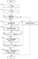
図3は、本実施形態による撮像装置の基本動作の一例を示すフローチャートである。図3に示すステップS301からステップS310までのうち、ステップS301からステップS305までが情報取得モードにおける動作に対応し、ステップS306からステップS310までが撮影モードにおける動作に対応する。 Figure 3 is a flowchart showing an example of the basic operation of the imaging device according to this embodiment. Of steps S301 to S310 shown in Figure 3, steps S301 to S305 correspond to the operation in the information acquisition mode, and steps S306 to S310 correspond to the operation in the shooting mode.
まず、ステップS301において、撮像部100は、操作部105を介した撮影者の操作に応じて、コードの撮影を行う。ここでは一例として、コードが、患者が身につけるリストバンドに付されたバーコードである場合を想定する。
First, in step S301, the
次いで、ステップS302において、情報取得部140は、所定の解析手段を用いて、撮像部100が取得した画像に写るコードを読み取って解析を行い、コードが表す文字列を取得する。
Next, in step S302, the
次いで、ステップS303において、情報取得部140は、撮像部100が取得した画像に写るコードの解析結果に基づいてデータベース130を検索し、そのコードに関連付けられた患者情報がデータベース130に登録されているか否かを判定する。上記の例では、データベース130に登録された患者情報は、例えば、バーコードが示す情報に関連付けられた患者のID番号や氏名である。なお、バーコードが示す情報自体が患者のID番号であり、データベース130には患者の氏名等が登録され、ID番号に基づいて患者の氏名をデータベース130から検索するようにしてもよい。
Next, in step S303, the
データベース130を検索した結果、撮像部100により取得した画像に写るコードに関連付けられた情報がデータベース130に登録されていない場合(ステップS303における「NO」)には、ステップS304へと移行する。そして、ステップS304において、表示制御部107は、撮像部100により取得した画像に写るコードに関連付けられた患者情報がデータベース130に未登録である旨の警告メッセージを、表示部106に表示されているライブビュー画像に重ねて表示する。
If, as a result of searching the
図4(b)は、表示部106に表示する警告メッセージの一例を示す図である。撮影したコードに関連付けられた患者情報がデータベース130に登録されていない場合には、表示制御部107は、図4(b)に示すような警告メッセージ421をライブビュー画像400に重ねて表示する。なお、撮影したコードに関連付けられた情報がデータベース130に登録されていない場合には、撮影モードにおける撮影指示の受け付けを禁止するようにしてもよい。
Fig. 4(b) is a diagram showing an example of a warning message displayed on the
データベース130を検索した結果、撮像部100により取得した画像に写るコードに関連付けられた患者情報がデータベース130に登録されている場合(ステップS303における「YES」)には、ステップS305へと移行する。そして、ステップS305において、情報取得部140は、撮像部100が取得した画像に写るコードに関連付けられた患者情報をデータベース130から取得する。
If, as a result of searching the
撮影モードでは、情報取得モードにおいて撮影したコードに関連する被写体の撮影を行う。上記の例では、被写体は、バーコードが付されたリストバンドを身につけた患者である。 In the photography mode, a photograph is taken of the subject associated with the code photographed in the information acquisition mode. In the above example, the subject is a patient wearing a wristband with a barcode attached.
次いで、ステップS306において、表示制御部107は、撮影モードにおいて被写体の撮影指示が行われるまでの間、情報取得部140がデータベース130から取得した患者情報を、表示部106に表示されているライブビュー画像に重ねて表示する。患者情報をライブビュー画像に重ねて表示することにより、撮影者は、撮影しようとする被写体の画像データに関連付けて記録される予定の患者情報を一見して把握することができる。例えば、コードの撮影に失敗して前回の被写体の患者情報のままであったり、コードの読み取りを誤って異なる患者情報を取得したりしている等のエラーがあれば、撮影者がライブビュー画像の被写体と患者情報が一致しないことに簡単に気づくことができる。そして、撮影者は、被写体が身につけているリストバンドのコードを撮影し直し、上述のステップS301からの処理をやり直すことにより、正しい患者情報へ変更することができる。よって、被写体とその患者情報との誤った関連付けを防止することができる。なお、表示部106への患者情報の表示は、連続的でもよいし、断続的でもよい。
Next, in step S306, the
図4(a)は、表示部106に表示する患者情報の一例を示す図である。情報取得モードにおいて撮影したコードに関連付けられた患者情報がデータベース130に登録されている場合には、表示制御部107は、図4(a)に示すような患者情報をライブビュー画像400に重ねて表示する。この例におけるコードは、例えば、患者が身につけるリストバンドに付されたバーコードであり、バーコードに関連付けられた患者情報は、その患者のID番号や氏名である。なお、図4(a)においては、情報取得モードにおいて撮影したバーコードのサムネイル画像410、患者のID番号411、患者の氏名412が表示部106に表示されているが、バーコードのサムネイル画像410を表示しないようにしてもよい。
Figure 4(a) is a diagram showing an example of patient information displayed on the
次いで、ステップS307において、制御部150は、撮影者によりシャッターボタンが半押しされているか否かを判定する。シャッターボタンが半押しされていると判定された場合(ステップS307における「YES」)には、ステップS308へと移行する。一方、シャッターボタンが半押しされていないと判定された場合(ステップS307における「NO」)には、表示部106に患者情報を表示した状態を維持し、ステップS307に戻る。なお、制御部150は、撮影者によるシャッターボタンへの操作を、全押しと半押しの2段階で検出する。
Next, in step S307, the
次いで、ステップS308において、表示制御部107は、表示部106に表示している患者情報を非表示にする。シャッターボタンの半押しは、撮影しようとする被写体を撮影者が確定したことを示す動作、すなわち、撮影指示の開始であると考えられる。患者情報を非表示にすることで、患者情報に邪魔されることなく、撮影者が撮影しようとする被写体を表示部106において、より確認し易くすることができる。なお、本実施形態ではシャッターボタンが半押しされていると判定された場合に、患者情報を非表示にするようにしたが、シャッターボタンの代わりに他の操作部材が操作されたことを検知することにより、非表示にするようにしてもよい。また、患者情報を表示した後、所定時間が経過すると、非表示にするようにしてもよい。
Next, in step S308, the
次いで、ステップS309において、制御部150は、撮影者によりシャッターボタンが全押しされて被写体の撮影画像の記録指示が行われたか否かを判定する。被写体の撮影画像の記録指示が行われたと判定された場合(ステップS309における「YES」)には、ステップS310へと移行する。一方、被写体の撮影画像の記録指示が行われていないと判定された場合(ステップS309における「NO」)には、ステップS306に戻り、表示制御部107は、再び患者情報を表示部106に表示されているライブビュー画像に重ねて表示する。制御部150は、例えば、シャッターボタンの押下操作が解除された場合や、撮影者がシャッターボタンを押す力を弱めて半押しを止めて検出されなくなった場合等に、被写体の撮影画像の記録指示が行われていないと判定する。
Next, in step S309, the
次いで、ステップS310において、記録部120は、シャッターボタンの全押しが検知されたことに応答して、撮像部100が取得した被写体の画像データを、情報取得部140がデータベース130から取得した患者情報に関連付けて記録媒体に記録する。
Next, in step S310, in response to detection of the shutter button being fully pressed, the
情報取得モードにおいて撮影したコードに基づいて、ステップS305においてデータベース130から取得した患者情報は、撮影モードにおいて取得した被写体の画像データに関連付けて記録する予定の情報として、RAM102等のメモリに一時的に保持される。ステップS306において患者情報を表示する際には、このメモリに保持されている患者情報が読み出されて、ライブビュー画像とともに表示部106に表示される。また、ステップS310において被写体の画像データを記録する際には、このメモリに保持されている患者情報が、被写体の画像データに関連付けて記録される患者情報として読み出される。メモリに保持された患者情報は、情報取得モードにおいてステップS301からS305までの処理が実行され、新たな患者情報が取得されるたびに書き換えられる。
The patient information acquired from the
また、撮影者の操作により、メモリに保持された患者情報を任意に消去できるようにしてもよい。メモリに保持された患者情報は、撮像装置の電源切断と連動して消去することも可能である。例えば、撮影者の設定により、撮像装置の電源切断時にメモリに保持された患者情報を自動的に消去するようにしてもよい。また、メモリに保持された患者情報を消去するか否かについて、撮像装置の電源切断時に撮影者に問い合わせることにより、メモリに保持された患者情報を消去するか又は電源切断後も保持するかを撮影者が選択できるようにしてもよい。 The patient information stored in the memory may be erased at will by the photographer. The patient information stored in the memory may also be erased in conjunction with the power being turned off of the imaging device. For example, the photographer may set it so that the patient information stored in the memory is automatically erased when the imaging device is turned off. The photographer may also be asked whether or not to erase the patient information stored in the memory when the imaging device is turned off, allowing the photographer to select whether to erase the patient information stored in the memory or to retain it after the power is turned off.
図5は、撮像装置の電源切断時における患者情報の消去処理の一例を示すフローチャートである。 Figure 5 is a flowchart showing an example of the process for deleting patient information when the imaging device is turned off.
まず、ステップS501において、制御部150は、操作部105を介した撮影者の操作に応じて電源切断する時に、メモリに保持された患者情報を自動消去する設定であるか否かを判定する。
First, in step S501, the
判定の結果、自動消去する設定である場合(ステップS501における「YES」)には、ステップS502へと移行する。そして、ステップS502において、制御部150は、メモリに保持された患者情報を消去する。その後、ステップS503へと移行する。一方、自動消去する設定でない場合(ステップS501における「NO」)には、メモリに保持された患者情報を消去することなく、ステップS503へと移行する。
If the result of the determination is that automatic deletion is set ("YES" in step S501), the process proceeds to step S502. Then, in step S502, the
次いで、ステップS503において、制御部150は、所定のシャットダウン・シーケンスに基づいて撮像装置の電源を切断する。その際、メモリに患者情報が保持されている場合には(S501における「NO」)、必要に応じて、その患者情報を不揮発性メモリ等に退避する等、メモリに保持された患者情報が電源切断により消失しないようにするための所定の処理を行う。
Next, in step S503, the
撮像装置の電源投入時に患者情報が保持されている場合には、保持されている患者情報を直ちに、表示部106に表示するようにしてもよい。
If patient information is stored when the imaging device is turned on, the stored patient information may be displayed immediately on the
次に、本実施形態による患者情報の表示処理について説明する。
撮像装置は、取得した患者情報を、図3におけるステップS306の患者情報表示処理において、ライブビュー画像に重ねて表示する。この際、撮像装置は、患者情報を再取得する場合には、再取得した患者情報の表示位置を変更するようにしてもよい。患者情報の表示位置を変更することにより、表示する患者情報が変更されたことの視認性を高めることができる。なお、表示する患者情報が変更されたことの視認性を高めるために、患者情報の表示位置を変更するのではなく、表示色を変更するようにしてもよいし、患者情報の表示位置の変更と、表示色の変更とを合わせて行うようにしてもよい。
Next, the display process of patient information according to this embodiment will be described.
The imaging device displays the acquired patient information superimposed on a live view image in the patient information display process of step S306 in Fig. 3. At this time, when the imaging device reacquires the patient information, the imaging device may change the display position of the reacquired patient information. Changing the display position of the patient information can improve visibility that the displayed patient information has been changed. Note that, in order to improve visibility that the displayed patient information has been changed, the display color of the patient information may be changed instead of the display position of the patient information, or the display position of the patient information may be changed and the display color may be changed together.
図6は、本実施形態による撮像装置における患者情報の表示処理の一例を示すフローチャートである。図6においては、表示部106における患者情報の表示位置が3箇所である場合について説明する。
Figure 6 is a flowchart showing an example of the display process of patient information in the imaging device according to this embodiment. In Figure 6, a case is described in which the
まず、ステップS601において、制御部150は、カウンタ変数iの値を0に設定する。制御部150は、例えば、情報取得部140が患者情報を取得した場合や、撮像装置の電源投入時に保持されている患者情報を初期表示すると判定した場合等に、カウンタ変数iの値を0に設定する。以下、撮像装置の電源投入時の場合を一例として説明する。
First, in step S601, the
次いで、ステップS602において、制御部150は、患者情報が撮像装置の電源投入後の(3i+1)件目の表示であるか否かを判定する。
Next, in step S602, the
患者情報が撮像装置の電源投入後の(3i+1)件目の表示であると判定された場合(ステップS602における「YES」)には、ステップS603へと移行する。そして、ステップS603において、表示制御部107は、表示部106の第1表示位置720に患者情報を表示する。図7(a)は、表示部106における患者情報の第1表示位置720の一例を示す図である。
If it is determined that the patient information is the (3i+1)th display since the imaging device was powered on ("YES" in step S602), the process proceeds to step S603. Then, in step S603, the
患者情報が撮像装置の電源投入後の(3i+1)件目の表示でないと判定された場合(ステップS602における「NO」)には、ステップS604へと移行する。そして、ステップS604において、制御部150は、患者情報が撮像装置の電源投入後の(3i+2)件目の表示であるか否かを判定する。
If it is determined that the patient information is not the (3i+1)th item displayed since the imaging device was powered on ("NO" in step S602), the process proceeds to step S604. Then, in step S604, the
患者情報が撮像装置の電源投入後の(3i+2)件目の表示であると判定された場合(ステップS604における「YES」)には、ステップS605へと移行する。そして、ステップS605において、表示制御部107は、表示部106の第1表示位置720とは異なる第2表示位置721に患者情報を表示する。図7(b)は、表示部106における患者情報の第2表示位置721の一例を示す図である。
If it is determined that the patient information is the (3i+2)th item to be displayed since the imaging device was powered on ("YES" in step S604), the process proceeds to step S605. Then, in step S605, the
患者情報が撮像装置の電源投入後の(3i+2)件目の表示でないと判定された場合(ステップS604における「NO」)には、ステップS606へと移行する。そして、ステップS606において、制御部150は、患者情報が撮像装置の電源投入後の(3i+3)件目の表示であるか否かを判定する。
If it is determined that the patient information is not the (3i+2)th item displayed since the imaging device was powered on ("NO" in step S604), the process proceeds to step S606. Then, in step S606, the
患者情報が撮像装置の電源投入後の(3i+3)件目の表示であると判定された場合(ステップS606における「YES」)には、ステップS607へと移行する。そして、ステップS607において、表示制御部107は、表示部106の第1表示位置720及び第2表示位置721とは異なる第3表示位置722に患者情報を表示する。図7(c)は、表示部106における患者情報の第3表示位置722の一例を示す図である。
If it is determined that the patient information is the (3i+3)th item to be displayed since the imaging device was powered on ("YES" in step S606), the process proceeds to step S607. Then, in step S607, the
患者情報が撮像装置の電源投入後の(3i+3)件目の表示でないと判定された場合(ステップS606における「NO」)には、ステップS608へと移行する。そして、ステップS608において、制御部150は、カウンタ変数iに1を加算してステップS602に戻る。以降、患者情報の表示位置が決まるまで、ステップS602からステップS608までを繰り返す。すなわち、撮像装置の電源投入後、1件目の患者情報は第1表示位置720に、2件目は第2表示位置721に、3件目は第3表示位置722に表示される。更に、4件目は再び第1表示位置720に表示され、5件目以降についても順番に表示位置が変更される。患者情報の表示位置を変更することにより、患者情報が変更されたことを一見して把握することができる。
If it is determined that the patient information is not the (3i+3)th item displayed after the imaging device is powered on ("NO" in step S606), the process proceeds to step S608. Then, in step S608, the
このように、本実施形態によれば、撮影画像に被写体の情報を関連付けて記録する場合に、被写体とその情報との誤った関連付けを防止することができる。 In this way, according to this embodiment, when recording a captured image in association with information about the subject, it is possible to prevent erroneous association between the subject and that information.
[変形実施形態]
本発明は、上述の実施形態に限らず種々の変形が可能である。
例えば、撮像装置は、顔認証機能を更に備えていてもよい。撮像装置は、取得した患者情報が人物の顔画像データに関連付けて予め登録されている場合には、その顔画像データと、ライブビュー画像に写る人物の顔とを照合し、別人物と判定した時に警告する。例えば、撮像装置が、Aさんの顔画像データに関連付けて予め登録されているAさんの患者情報をメモリに保持している時に、Bさんを撮影してライブビュー画像に表示している場合を一例として説明する。この場合、撮像装置は、Aさんの顔画像データとBさんの顔とを照合し、別人物であると判定して警告を行う。よって、撮影者は、Aさんの患者情報を、誤ってBさんの写る撮影画像に関連付けて記録することを防止することができる。
[Modified embodiment]
The present invention is not limited to the above-described embodiment, and various modifications are possible.
For example, the imaging device may further include a face authentication function. When the acquired patient information is registered in advance in association with face image data of a person, the imaging device compares the face image data with the face of the person appearing in the live view image, and issues a warning when it is determined that the person is different. For example, a case will be described as an example in which the imaging device photographs person B and displays it in the live view image when the patient information of person A, which is registered in advance in association with face image data of person A, is stored in the memory. In this case, the imaging device compares the face image data of person A with the face of person B, determines that the person is different, and issues a warning. Therefore, the photographer can prevent the patient information of person A from being erroneously recorded in association with the photographed image in which person B appears.
また、上述の実施形態では、被写体の撮影画像データに関連付けて記録する情報を、コードに関連付けられた患者情報として説明したが、そのコードのサムネイル画像データも合わせて被写体の撮影画像データに関連付けて記録してもよい。 In addition, in the above embodiment, the information recorded in association with the photographed image data of the subject is described as patient information associated with a code, but thumbnail image data of the code may also be recorded in association with the photographed image data of the subject.
また、上述の実施形態では、被写体を人物として説明したが、被写体は、情報取得モードにおいて撮影したコードに関連していればよく、必ずしも人物でなくてもよい。 In addition, in the above embodiment, the subject is described as a person, but the subject does not necessarily have to be a person as long as it is related to the code photographed in the information acquisition mode.
また、上述の実施形態では、表示部106における患者情報の表示位置を3箇所として説明したが、患者情報の表示位置は、必ずしも3箇所でなくてもよい。
In addition, in the above embodiment, the
本発明は、上述の実施形態の1以上の機能を実現するプログラムを、ネットワーク又は記録媒体を介してシステム又は装置に供給し、そのシステム又は装置のコンピュータにおける1つ以上のプロセッサがプログラムを読出し実行する処理でも実現可能である。また、1以上の機能を実現する回路(例えば、ASIC)によっても実現可能である。 The present invention can also be realized by supplying a program that realizes one or more of the functions of the above-mentioned embodiments to a system or device via a network or a recording medium, and having one or more processors in the computer of the system or device read and execute the program. It can also be realized by a circuit (e.g., an ASIC) that realizes one or more of the functions.
なお、上述の実施形態は、いずれも本発明を実施するにあたっての具体化の例を示したものに過ぎず、これらによって本発明の技術的範囲が限定的に解釈されてはならない。すなわち、本発明はその技術思想、又はその主要な特徴から逸脱することなく、様々な形で実施することができる。 The above-mentioned embodiments are merely examples of the implementation of the present invention, and the technical scope of the present invention should not be interpreted as being limited by them. In other words, the present invention can be implemented in various forms without departing from its technical concept or main features.
100…撮像部
106…表示部
107…表示制御部
120…記録部
130…データベース
140…情報取得部
150…制御部
100...imaging
Claims (18)
前記撮像部を用いて、識別子を被写体として撮像することにより識別子画像を取得する識別子取得手段と、
前記識別子画像に基づいて、前記識別子に対応する患者情報をデータベースから取得する患者情報取得手段と、
前記撮像部を用いて、患者を被写体として撮像することにより患者画像を取得する患者画像取得手段と、
前記患者情報取得手段により取得した患者情報と、前記患者画像取得手段により取得した患者画像とを関連付ける手段と、
前記患者情報を表示部に表示するよう制御する表示制御手段と、
前記撮像装置の電源切断時に前記患者情報取得手段により取得した患者情報を消去せずに保持し、前記撮像装置の電源投入時に、前記保持された患者情報を利用するように制御する制御手段と、を有し、
前記表示制御手段は、前記撮像装置の電源投入時に患者情報が保持されている場合は、第1の表示形態で前記保持された患者情報を表示するように制御し、その後、前記患者情報取得手段により前記データベースから患者情報を取得した場合は、前記取得した患者情報を、前記第1の表示形態とは異なる第2の表示形態で表示するように制御する、ことを特徴とする撮像装置。 An imaging device having an imaging unit,
an identifier acquisition means for acquiring an identifier image by capturing an image of the identifier as a subject using the imaging unit;
a patient information acquiring means for acquiring patient information corresponding to the identifier from a database based on the identifier image;
a patient image acquiring means for acquiring a patient image by capturing an image of a patient as a subject using the imaging unit;
a means for associating the patient information acquired by the patient information acquisition means with the patient image acquired by the patient image acquisition means;
A display control means for controlling the patient information to be displayed on a display unit;
a control means for holding the patient information acquired by the patient information acquisition means without erasing it when the power supply of the imaging device is turned off, and for controlling the imaging device to use the held patient information when the power supply of the imaging device is turned on,
an imaging device characterized in that, when patient information is stored when the imaging device is powered on, the display control means controls the stored patient information to be displayed in a first display form, and, when patient information is subsequently acquired from the database by the patient information acquisition means, controls the acquired patient information to be displayed in a second display form different from the first display form.
前記制御手段は、電源切断時に消去することが設定された場合は、前記撮像装置の電源切断時に前記患者情報を自動的に消去するように制御し、電源切断時に消去しないことが設定された場合は、前記撮像装置の電源切断時に前記患者情報を消去せずに保持するように制御する、
ことを特徴とする請求項2に記載の撮像装置。 a setting means for setting whether or not the patient information acquired by the patient information acquisition means is automatically deleted when the power is turned off according to a user setting;
The control means controls the patient information to be automatically deleted when the imaging device is powered off if the patient information is set to be deleted when the imaging device is powered off, and controls the patient information to be retained without being deleted when the imaging device is powered off if the patient information is set not to be deleted when the imaging device is powered off.
3. The imaging device according to claim 2.
前記撮像部を用いて、識別子を被写体として撮像することにより識別子画像を取得する識別子取得ステップと、
前記識別子画像に基づいて、前記識別子に対応する患者情報をデータベースから取得する患者情報取得ステップと、
前記撮像部を用いて、患者を被写体として撮像することにより患者画像を取得する患者画像取得ステップと、
前記患者情報取得ステップにより取得した患者情報と、前記患者画像取得ステップにより取得した患者画像とを関連付けるステップと、
前記患者情報を表示部に表示するよう制御する表示制御ステップと、
前記撮像装置の電源切断時に前記患者情報取得ステップにより取得した患者情報を消去せずに保持し、前記撮像装置の電源投入時に、前記保持された患者情報を利用するように制御する制御ステップと、を有し、
前記表示制御ステップは、前記撮像装置の電源投入時に患者情報が保持されている場合は、第1の表示形態で前記保持された患者情報を表示するように制御し、その後、前記患者情報取得ステップにより前記データベースから患者情報を取得した場合は、前記取得した患者情報を、前記第1の表示形態とは異なる第2の表示形態で表示するように制御する、ことを特徴とする制御方法。 A method for controlling an imaging device having an imaging unit, comprising:
an identifier acquisition step of acquiring an identifier image by capturing an image of the identifier as a subject using the imaging unit;
a patient information acquisition step of acquiring patient information corresponding to the identifier from a database based on the identifier image;
a patient image acquiring step of acquiring a patient image by capturing an image of a patient as a subject using the imaging unit;
a step of associating the patient information acquired in the patient information acquiring step with the patient image acquired in the patient image acquiring step;
a display control step of controlling the patient information to be displayed on a display unit;
a control step of holding the patient information acquired by the patient information acquisition step without erasing it when the power supply of the imaging device is turned off, and controlling the imaging device to use the held patient information when the power supply of the imaging device is turned on,
a display control step of controlling a display of the stored patient information in a first display form when patient information is stored when the imaging device is powered on, and thereafter, when patient information is acquired from the database by the patient information acquisition step, controlling the display of the acquired patient information in a second display form different from the first display form.
前記制御ステップは、電源切断時に消去することが設定された場合は、前記撮像装置の電源切断時に前記患者情報を自動的に消去するように制御し、電源切断時に消去しないことが設定された場合は、前記撮像装置の電源切断時に前記患者情報を消去せずに保持するように制御する、
ことを特徴とする請求項8に記載の制御方法。 a setting step for setting whether or not the patient information acquired in the patient information acquisition step is to be automatically deleted when the power is turned off according to a user setting;
The control step performs control so that the patient information is automatically deleted when the imaging device is powered off if the setting is such that the patient information is deleted when the imaging device is powered off, and performs control so that the patient information is not deleted but is retained when the imaging device is powered off if the setting is such that the patient information is not deleted when the imaging device is powered off.
9. The control method according to claim 8.
前記撮像部を用いて、識別子を被写体として撮像することにより識別子画像を取得する識別子取得手段と、
前記識別子画像に基づいて、前記識別子に対応する患者情報をデータベースから取得する患者情報取得手段と、
前記撮像部を用いて、患者を被写体として撮像することにより患者画像を取得する患者画像取得手段と、
前記患者情報取得手段により取得した患者情報と、前記患者画像取得手段により取得した患者画像とを関連付ける手段と、
前記患者情報を表示部に表示するよう制御する表示制御手段と、
前記撮像装置の電源切断時に前記患者情報取得手段により取得した患者情報を消去せずに保持し、前記撮像装置の電源投入時に、前記保持された患者情報を利用するように制御する制御手段と、
して前記コンピュータを機能させ、
前記表示制御手段は、前記撮像装置の電源投入時に患者情報が保持されている場合は、第1の表示形態で前記保持された患者情報を表示するように制御し、その後、前記患者情報取得手段により前記データベースから患者情報を取得した場合は、前記取得した患者情報を、前記第1の表示形態とは異なる第2の表示形態で表示するように制御する、ことを特徴とするプログラム。 A program for causing a computer to function as each means of an imaging device having an imaging unit,
an identifier acquisition means for acquiring an identifier image by capturing an image of the identifier as a subject using the imaging unit;
a patient information acquiring means for acquiring patient information corresponding to the identifier from a database based on the identifier image;
a patient image acquiring means for acquiring a patient image by capturing an image of a patient as a subject using the imaging unit;
a means for associating the patient information acquired by the patient information acquisition means with the patient image acquired by the patient image acquisition means;
A display control means for controlling the patient information to be displayed on a display unit;
a control means for holding the patient information acquired by the patient information acquisition means without erasing it when the power supply of the imaging device is turned off, and for controlling the imaging device to use the held patient information when the power supply of the imaging device is turned on;
to cause the computer to function,
the display control means controls the imaging device to display the stored patient information in a first display form if patient information is stored when the imaging device is powered on, and thereafter, when patient information is acquired from the database by the patient information acquisition means, controls the acquired patient information to be displayed in a second display form different from the first display form.
前記制御手段は、電源切断時に消去することが設定された場合は、前記撮像装置の電源切断時に前記患者情報を自動的に消去するように制御し、電源切断時に消去しないことが設定された場合は、前記撮像装置の電源切断時に前記患者情報を消去せずに保持するように制御する、
ことを特徴とする請求項14に記載のプログラム。 The computer is further caused to function as a setting means for setting, by a user, whether or not the patient information acquired by the patient information acquisition means is automatically deleted when the power is turned off;
The control means controls the patient information to be automatically deleted when the imaging device is powered off if the patient information is set to be deleted when the imaging device is powered off, and controls the patient information to be retained without being deleted when the imaging device is powered off if the patient information is set not to be deleted when the imaging device is powered off.
15. The program according to claim 14 .
Priority Applications (1)
| Application Number | Priority Date | Filing Date | Title |
|---|---|---|---|
| JP2024066997A JP7686833B2 (en) | 2018-02-20 | 2024-04-17 | Image capture device, image capture device control method and program |
Applications Claiming Priority (3)
| Application Number | Priority Date | Filing Date | Title |
|---|---|---|---|
| JP2018027816A JP7137316B2 (en) | 2018-02-20 | 2018-02-20 | IMAGING DEVICE, IMAGING DEVICE CONTROL METHOD AND PROGRAM |
| JP2022139257A JP7476264B2 (en) | 2018-02-20 | 2022-09-01 | Image capture device, image capture device control method and program |
| JP2024066997A JP7686833B2 (en) | 2018-02-20 | 2024-04-17 | Image capture device, image capture device control method and program |
Related Parent Applications (1)
| Application Number | Title | Priority Date | Filing Date |
|---|---|---|---|
| JP2022139257A Division JP7476264B2 (en) | 2018-02-20 | 2022-09-01 | Image capture device, image capture device control method and program |
Publications (2)
| Publication Number | Publication Date |
|---|---|
| JP2024091794A JP2024091794A (en) | 2024-07-05 |
| JP7686833B2 true JP7686833B2 (en) | 2025-06-02 |
Family
ID=67618339
Family Applications (3)
| Application Number | Title | Priority Date | Filing Date |
|---|---|---|---|
| JP2018027816A Active JP7137316B2 (en) | 2018-02-20 | 2018-02-20 | IMAGING DEVICE, IMAGING DEVICE CONTROL METHOD AND PROGRAM |
| JP2022139257A Active JP7476264B2 (en) | 2018-02-20 | 2022-09-01 | Image capture device, image capture device control method and program |
| JP2024066997A Active JP7686833B2 (en) | 2018-02-20 | 2024-04-17 | Image capture device, image capture device control method and program |
Family Applications Before (2)
| Application Number | Title | Priority Date | Filing Date |
|---|---|---|---|
| JP2018027816A Active JP7137316B2 (en) | 2018-02-20 | 2018-02-20 | IMAGING DEVICE, IMAGING DEVICE CONTROL METHOD AND PROGRAM |
| JP2022139257A Active JP7476264B2 (en) | 2018-02-20 | 2022-09-01 | Image capture device, image capture device control method and program |
Country Status (2)
| Country | Link |
|---|---|
| US (2) | US11165964B2 (en) |
| JP (3) | JP7137316B2 (en) |
Families Citing this family (9)
| Publication number | Priority date | Publication date | Assignee | Title |
|---|---|---|---|---|
| JP7137316B2 (en) * | 2018-02-20 | 2022-09-14 | キヤノン株式会社 | IMAGING DEVICE, IMAGING DEVICE CONTROL METHOD AND PROGRAM |
| JP7140540B2 (en) * | 2018-05-07 | 2022-09-21 | キヤノン株式会社 | Electronic device, electronic device control method, program, storage medium |
| JP7706982B2 (en) * | 2021-08-10 | 2025-07-14 | キヤノン株式会社 | Imaging device, control method thereof, program, and recording medium |
| JP2023077991A (en) | 2021-11-25 | 2023-06-06 | キヤノン株式会社 | Imaging device and its control method |
| JP7767121B2 (en) | 2021-11-25 | 2025-11-11 | キヤノン株式会社 | Imaging device and control method thereof |
| JP7781612B2 (en) * | 2021-11-25 | 2025-12-08 | キヤノン株式会社 | Display control device, control method thereof, program, and recording medium |
| EP4336387B1 (en) * | 2022-09-07 | 2026-01-28 | Ambu A/S | Configuration of a medical visualisation system |
| JP2024082121A (en) * | 2022-12-07 | 2024-06-19 | キヤノン株式会社 | Imaging device, control method, and program |
| US12495202B1 (en) * | 2023-04-14 | 2025-12-09 | Gopro, Inc. | Deletion of content captured by an image capture device |
Citations (4)
| Publication number | Priority date | Publication date | Assignee | Title |
|---|---|---|---|---|
| WO2006035788A1 (en) | 2004-09-28 | 2006-04-06 | Sanyo Electric Co., Ltd | Imaging device and imaging method |
| JP2009130688A (en) | 2007-11-26 | 2009-06-11 | Nikon Corp | Electronic camera |
| JP2012010358A (en) | 2011-07-27 | 2012-01-12 | Fujifilm Corp | Three-dimensional imaging apparatus and three-dimensional image display method |
| JP2014236284A (en) | 2013-05-31 | 2014-12-15 | 株式会社ニコン | Imaging apparatus |
Family Cites Families (12)
| Publication number | Priority date | Publication date | Assignee | Title |
|---|---|---|---|---|
| JPS6344217A (en) * | 1986-08-12 | 1988-02-25 | Nec Corp | Station conversation control system |
| US6393431B1 (en) * | 1997-04-04 | 2002-05-21 | Welch Allyn, Inc. | Compact imaging instrument system |
| JP2002230182A (en) | 2000-05-26 | 2002-08-16 | Astec Corp:Kk | Risk management support system |
| US6697761B2 (en) * | 2000-09-19 | 2004-02-24 | Olympus Optical Co., Ltd. | Three-dimensional position/orientation sensing apparatus, information presenting system, and model error detecting system |
| JP2003052767A (en) | 2001-08-14 | 2003-02-25 | Sony Corp | Information management system, information processing apparatus and method, recording medium, and program |
| JP4266891B2 (en) | 2004-07-06 | 2009-05-20 | 三洋電機株式会社 | Imaging device |
| JP2010243780A (en) | 2009-04-06 | 2010-10-28 | Alps Electric Co Ltd | Method for manufacturing camera module |
| JP5424732B2 (en) * | 2009-06-15 | 2014-02-26 | キヤノン株式会社 | Imaging apparatus, control method thereof, and program |
| US8416262B2 (en) * | 2009-09-16 | 2013-04-09 | Research In Motion Limited | Methods and devices for displaying an overlay on a device display screen |
| US9742492B2 (en) * | 2015-12-30 | 2017-08-22 | Surefire Llc | Systems and methods for ad-hoc networking in an optical narrowcasting system |
| US10412300B2 (en) * | 2017-09-28 | 2019-09-10 | Photon Ventures Inc. | Imaging apparatus for professional-quality photography of objects |
| JP7137316B2 (en) * | 2018-02-20 | 2022-09-14 | キヤノン株式会社 | IMAGING DEVICE, IMAGING DEVICE CONTROL METHOD AND PROGRAM |
-
2018
- 2018-02-20 JP JP2018027816A patent/JP7137316B2/en active Active
-
2019
- 2019-02-14 US US16/276,012 patent/US11165964B2/en active Active
-
2021
- 2021-09-24 US US17/484,328 patent/US11523062B2/en active Active
-
2022
- 2022-09-01 JP JP2022139257A patent/JP7476264B2/en active Active
-
2024
- 2024-04-17 JP JP2024066997A patent/JP7686833B2/en active Active
Patent Citations (4)
| Publication number | Priority date | Publication date | Assignee | Title |
|---|---|---|---|---|
| WO2006035788A1 (en) | 2004-09-28 | 2006-04-06 | Sanyo Electric Co., Ltd | Imaging device and imaging method |
| JP2009130688A (en) | 2007-11-26 | 2009-06-11 | Nikon Corp | Electronic camera |
| JP2012010358A (en) | 2011-07-27 | 2012-01-12 | Fujifilm Corp | Three-dimensional imaging apparatus and three-dimensional image display method |
| JP2014236284A (en) | 2013-05-31 | 2014-12-15 | 株式会社ニコン | Imaging apparatus |
Also Published As
| Publication number | Publication date |
|---|---|
| JP2019145984A (en) | 2019-08-29 |
| JP7476264B2 (en) | 2024-04-30 |
| JP2022173234A (en) | 2022-11-18 |
| US20220014685A1 (en) | 2022-01-13 |
| US20190260944A1 (en) | 2019-08-22 |
| US11523062B2 (en) | 2022-12-06 |
| JP7137316B2 (en) | 2022-09-14 |
| US11165964B2 (en) | 2021-11-02 |
| JP2024091794A (en) | 2024-07-05 |
Similar Documents
| Publication | Publication Date | Title |
|---|---|---|
| JP7686833B2 (en) | Image capture device, image capture device control method and program | |
| US8532345B2 (en) | Camera and image recording program product | |
| JP4315212B2 (en) | Imaging apparatus, imaging control program, and imaging control method | |
| KR101560203B1 (en) | Image sensing apparatus, information processing apparatus and control method | |
| US20160334948A1 (en) | Image display apparatus equipped with a touch panel | |
| JP2018101385A (en) | Picture managing device, method for managing pictures, and program | |
| JP2004247983A (en) | Photographing apparatus, image processing apparatus, and image processing program | |
| JP2008209306A (en) | camera | |
| JP4962312B2 (en) | Imaging apparatus and program | |
| JP6210699B2 (en) | Imaging apparatus and control method thereof | |
| JP6097632B2 (en) | IMAGING DEVICE, ITS CONTROL METHOD, PROGRAM, AND STORAGE MEDIUM | |
| KR101477535B1 (en) | Image searching method and apparatus, digital photographing apparatus using the same | |
| JP6712861B2 (en) | Information processing device, information processing method, and program | |
| WO2009157314A1 (en) | Imaging device | |
| JP2014022921A (en) | Electronic apparatus and program | |
| JP2005217505A (en) | Imaging apparatus, viewer software, communication software, and image management software | |
| KR101623494B1 (en) | Apparatus and method for managing photo file | |
| JP2011172079A (en) | Image reproducing device, and image reproducing program | |
| JP2025083917A (en) | DISPLAY CONTROL DEVICE, IMAGING DEVICE, DISPLAY CONTROL METHOD, AND PROGRAM | |
| JP2017017471A (en) | Information processing system, control method therefor, and program | |
| JP2024030555A (en) | Imaging device, control method, and program | |
| JP2014232394A (en) | Image data file processor and processing method | |
| JP2006086887A (en) | Image information processing apparatus and digital camera | |
| CN104159018B (en) | Image acquisition device and image processing method thereof | |
| JP2006109141A (en) | Electronic camera |
Legal Events
| Date | Code | Title | Description |
|---|---|---|---|
| A621 | Written request for application examination |
Free format text: JAPANESE INTERMEDIATE CODE: A621 Effective date: 20240426 |
|
| TRDD | Decision of grant or rejection written | ||
| A01 | Written decision to grant a patent or to grant a registration (utility model) |
Free format text: JAPANESE INTERMEDIATE CODE: A01 Effective date: 20250422 |
|
| A61 | First payment of annual fees (during grant procedure) |
Free format text: JAPANESE INTERMEDIATE CODE: A61 Effective date: 20250521 |
|
| R150 | Certificate of patent or registration of utility model |
Ref document number: 7686833 Country of ref document: JP Free format text: JAPANESE INTERMEDIATE CODE: R150 |