JP7686822B2 - Golf club head with adjustable weighting system - Google Patents
Golf club head with adjustable weighting system Download PDFInfo
- Publication number
- JP7686822B2 JP7686822B2 JP2024028960A JP2024028960A JP7686822B2 JP 7686822 B2 JP7686822 B2 JP 7686822B2 JP 2024028960 A JP2024028960 A JP 2024028960A JP 2024028960 A JP2024028960 A JP 2024028960A JP 7686822 B2 JP7686822 B2 JP 7686822B2
- Authority
- JP
- Japan
- Prior art keywords
- channel
- club head
- weight
- inches
- weights
- Prior art date
- Legal status (The legal status is an assumption and is not a legal conclusion. Google has not performed a legal analysis and makes no representation as to the accuracy of the status listed.)
- Active
Links
Images


Classifications
-
- A—HUMAN NECESSITIES
- A63—SPORTS; GAMES; AMUSEMENTS
- A63B—APPARATUS FOR PHYSICAL TRAINING, GYMNASTICS, SWIMMING, CLIMBING, OR FENCING; BALL GAMES; TRAINING EQUIPMENT
- A63B53/00—Golf clubs
- A63B53/04—Heads
-
- A—HUMAN NECESSITIES
- A63—SPORTS; GAMES; AMUSEMENTS
- A63B—APPARATUS FOR PHYSICAL TRAINING, GYMNASTICS, SWIMMING, CLIMBING, OR FENCING; BALL GAMES; TRAINING EQUIPMENT
- A63B53/00—Golf clubs
- A63B53/04—Heads
- A63B53/0466—Heads wood-type
-
- A—HUMAN NECESSITIES
- A63—SPORTS; GAMES; AMUSEMENTS
- A63B—APPARATUS FOR PHYSICAL TRAINING, GYMNASTICS, SWIMMING, CLIMBING, OR FENCING; BALL GAMES; TRAINING EQUIPMENT
- A63B53/00—Golf clubs
- A63B53/04—Heads
- A63B53/06—Heads adjustable
-
- A—HUMAN NECESSITIES
- A63—SPORTS; GAMES; AMUSEMENTS
- A63B—APPARATUS FOR PHYSICAL TRAINING, GYMNASTICS, SWIMMING, CLIMBING, OR FENCING; BALL GAMES; TRAINING EQUIPMENT
- A63B53/00—Golf clubs
- A63B53/04—Heads
- A63B2053/0491—Heads with added weights, e.g. changeable, replaceable
-
- A—HUMAN NECESSITIES
- A63—SPORTS; GAMES; AMUSEMENTS
- A63B—APPARATUS FOR PHYSICAL TRAINING, GYMNASTICS, SWIMMING, CLIMBING, OR FENCING; BALL GAMES; TRAINING EQUIPMENT
- A63B53/00—Golf clubs
- A63B53/04—Heads
- A63B2053/0491—Heads with added weights, e.g. changeable, replaceable
- A63B2053/0495—Heads with added weights, e.g. changeable, replaceable moving on impact, slidable, spring or otherwise elastically biased
-
- A—HUMAN NECESSITIES
- A63—SPORTS; GAMES; AMUSEMENTS
- A63B—APPARATUS FOR PHYSICAL TRAINING, GYMNASTICS, SWIMMING, CLIMBING, OR FENCING; BALL GAMES; TRAINING EQUIPMENT
- A63B53/00—Golf clubs
- A63B53/02—Joint structures between the head and the shaft
- A63B53/022—Joint structures between the head and the shaft allowing adjustable positioning of the head with respect to the shaft
- A63B53/023—Joint structures between the head and the shaft allowing adjustable positioning of the head with respect to the shaft adjustable angular orientation
- A63B53/025—Joint structures between the head and the shaft allowing adjustable positioning of the head with respect to the shaft adjustable angular orientation lie angle only, i.e. relative angular adjustment between the shaft and the club head about an axis parallel to the intended line of play when the club is in its normal address position
-
- A—HUMAN NECESSITIES
- A63—SPORTS; GAMES; AMUSEMENTS
- A63B—APPARATUS FOR PHYSICAL TRAINING, GYMNASTICS, SWIMMING, CLIMBING, OR FENCING; BALL GAMES; TRAINING EQUIPMENT
- A63B53/00—Golf clubs
- A63B53/02—Joint structures between the head and the shaft
- A63B53/022—Joint structures between the head and the shaft allowing adjustable positioning of the head with respect to the shaft
- A63B53/023—Joint structures between the head and the shaft allowing adjustable positioning of the head with respect to the shaft adjustable angular orientation
- A63B53/026—Joint structures between the head and the shaft allowing adjustable positioning of the head with respect to the shaft adjustable angular orientation loft angle only, i.e. relative angular adjustment between the shaft and the club head about a horizontal axis perpendicular to the intended line of play when the club is in its normal address position
-
- A—HUMAN NECESSITIES
- A63—SPORTS; GAMES; AMUSEMENTS
- A63B—APPARATUS FOR PHYSICAL TRAINING, GYMNASTICS, SWIMMING, CLIMBING, OR FENCING; BALL GAMES; TRAINING EQUIPMENT
- A63B53/00—Golf clubs
- A63B53/04—Heads
- A63B53/0408—Heads characterised by specific dimensions, e.g. thickness
-
- A—HUMAN NECESSITIES
- A63—SPORTS; GAMES; AMUSEMENTS
- A63B—APPARATUS FOR PHYSICAL TRAINING, GYMNASTICS, SWIMMING, CLIMBING, OR FENCING; BALL GAMES; TRAINING EQUIPMENT
- A63B53/00—Golf clubs
- A63B53/04—Heads
- A63B53/0408—Heads characterised by specific dimensions, e.g. thickness
- A63B53/0412—Volume
-
- A—HUMAN NECESSITIES
- A63—SPORTS; GAMES; AMUSEMENTS
- A63B—APPARATUS FOR PHYSICAL TRAINING, GYMNASTICS, SWIMMING, CLIMBING, OR FENCING; BALL GAMES; TRAINING EQUIPMENT
- A63B53/00—Golf clubs
- A63B53/04—Heads
- A63B53/0433—Heads with special sole configurations
-
- A—HUMAN NECESSITIES
- A63—SPORTS; GAMES; AMUSEMENTS
- A63B—APPARATUS FOR PHYSICAL TRAINING, GYMNASTICS, SWIMMING, CLIMBING, OR FENCING; BALL GAMES; TRAINING EQUIPMENT
- A63B53/00—Golf clubs
- A63B53/04—Heads
- A63B53/0445—Details of grooves or the like on the impact surface
Landscapes
- Health & Medical Sciences (AREA)
- General Health & Medical Sciences (AREA)
- Physical Education & Sports Medicine (AREA)
- Life Sciences & Earth Sciences (AREA)
- Engineering & Computer Science (AREA)
- Wood Science & Technology (AREA)
- Golf Clubs (AREA)
Description
本開示はゴルフクラブに関し、より詳細には、部材を受け入れる単一のポートを含むゴルフクラブヘッド用の調整可能な加重システムに関する。1つまたは複数のウェイトを部材の1つまたは複数の場所に取り付けることができる。 The present disclosure relates to golf clubs, and more particularly to an adjustable weighting system for a golf club head that includes a single port that receives a member. One or more weights can be attached to the member at one or more locations.
関連出願への相互参照
本出願は、2017年5月23日に出願された米国特許仮出願第62/509,817号、2017年5月4日に出願された米国特許仮出願第62/501,474号、2017年1月23日に出願された米国仮特許出願第62/449,332号、および2016年6月29日に出願された米国特許仮出願第62/356,416号に対する優先権を主張する。これらの全ての内容は、その全体が組み込まれている。
CROSS-REFERENCE TO RELATED APPLICATIONS This application claims priority to U.S. Provisional Patent Application No. 62/509,817, filed May 23, 2017, U.S. Provisional Patent Application No. 62/501,474, filed May 4, 2017, U.S. Provisional Patent Application No. 62/449,332, filed January 23, 2017, and U.S. Provisional Patent Application No. 62/356,416, filed June 29, 2016, the contents of all of which are incorporated in their entirety.
ゴルフクラブの様々な特性がゴルフクラブの性能に影響を及ぼし得る。例えば、ゴルフクラブヘッドの重心および慣性モーメントは、性能に影響を及ぼし得る特性である。 Various characteristics of a golf club can affect the performance of the golf club. For example, the center of gravity and moment of inertia of the golf club head are characteristics that can affect performance.
ゴルフクラブヘッドの重心および慣性モーメントは、ゴルフクラブヘッドの質量分布の関数である。特に、クラブヘッドの質量をクラブヘッドのソール部分により近い、クラブヘッドの打撃面により近い、および/またはクラブヘッドのトウ部分およびヒール部分により近いように分布させると、クラブヘッドの重心および/または慣性モーメントを変えることができる。クラブヘッドの慣性モーメントを変えることは、ゴルフクラブの許容度、ゴルフボールの飛行方向、および/またはゴルフボールの飛行角度を変えることができる。 The center of gravity and moment of inertia of a golf club head are a function of the distribution of mass in the golf club head. In particular, distributing the mass of the club head closer to the sole portion of the club head, closer to the striking face of the club head, and/or closer to the toe and heel portions of the club head can change the center of gravity and/or moment of inertia of the club head. Changing the moment of inertia of the club head can change the forgiveness of the golf club, the direction of flight of the golf ball, and/or the angle of flight of the golf ball.
現在のゴルフクラブヘッドにおける多くの加重システムは、クラブヘッドの慣性モーメントを減少させるとともに、クラブヘッドの重心を上方(クラウン方向)および前方(フェース方向)に移動させる、大きくて複雑な内部構造を必要とする。当技術分野では、慣性モーメントまたは重心位置に悪影響を与えることなく、ボールの飛行(軌道および/またはスピン)に影響を与えるために、クラブヘッドの重量および重心位置の調整可能性をユーザに提供するクラブヘッドが必要である。 Many current weighting systems in golf club heads require large and complex internal structures that reduce the club head's moment of inertia and move the club head's center of gravity upward (towards the crown) and forward (towards the face). There is a need in the art for a club head that provides the user with adjustability of the club head's weight and center of gravity location to affect ball flight (trajectory and/or spin) without adversely affecting the moment of inertia or center of gravity location.
本明細書に記載されているのは、高い慣性モーメントならびに低いおよび後方のヘッド重心位置を維持しながら、ユーザがクラブヘッドの重心を調整できる多構成の調整可能な加重システムを有するゴルフクラブヘッドである。多くの実施形態では、クラブヘッドは、ソールと反対側のクラウン、ヒール端と反対側のトウ端、後端及びホーゼルを有しており、チャネルが形成されているクラブ本体を備えている。調整可能な加重システムは、前記チャネルによって受け入れられるとともに前記クラブ本体に固定される部材を有しており、その部材は、第1端部と第2端部を有する部材本体を有する。第1のウェイトが、前記部材本体の前記第1端部に結合するように構成されており、第2のウェイトが、前記部材本体の前記第2端部に結合するように構成されている。前記第1のウェイトと前記第2のウェイトは、前記クラブヘッドの重心を調整するために、再設置または再配置可能であり、これにより、ボールの飛行特性(すなわち、ボールのスピンまたは軌跡)が変化する。多くの実施形態では、調整可能な加重システムは、クラブヘッド本体の密度と同等または少ない密度を有する締結具を用いて前記チャネルに取り外し可能に結合することができる。 Described herein are golf club heads with a multi-configuration adjustable weighting system that allows a user to adjust the center of gravity of the club head while maintaining a high moment of inertia and a low and rearward head center of gravity location. In many embodiments, the club head includes a club body having a crown opposite a sole, a toe opposite a heel, a back end, and a hosel, and having a channel formed therein. The adjustable weighting system includes a member received by the channel and secured to the club body, the member having a member body having a first end and a second end. A first weight is configured to couple to the first end of the member body, and a second weight is configured to couple to the second end of the member body. The first weight and the second weight are relocatable or repositionable to adjust the center of gravity of the club head, thereby changing ball flight characteristics (i.e., ball spin or trajectory). In many embodiments, the adjustable weighting system can be removably coupled to the channel using fasteners having a density equal to or less than the density of the club head body.
多くの実施形態では、本明細書に記載の調整可能な加重システムは、クラブヘッドの外部輪郭から突出するか、またはクラブヘッドの外部輪郭から最小限挿入される。さらに、多くの実施形態では、本明細書に記載の調整可能な加重システムは、クラブヘッドの周囲付近に配置されている。調整可能な重み付けシステムの位置決めは、周辺重量および低いおよび後部重量の位置決めを最大にし、これにより、偏心打撃に対する許容度のためのクラブヘッドの慣性モーメントを最大にし、クラブヘッドの重心を低くおよび後方に位置決めして打ち出し角度を増加しバックスピンを減らす。したがって、本明細書に記載のゴルフクラブヘッドは、最適な設計および性能特性(高い慣性モーメントならびに低くおよび後方の重心位置)を維持しながら、クラブヘッドの重心をユーザが調整してボールの飛行を調整することができる。 In many embodiments, the adjustable weighting system described herein protrudes from or is minimally recessed from the exterior contour of the club head. Additionally, in many embodiments, the adjustable weighting system described herein is located near the perimeter of the club head. The positioning of the adjustable weighting system maximizes perimeter weighting and low and rear weighting positioning, thereby maximizing the club head's moment of inertia for forgiveness on off-center hits, and positions the club head's center of gravity low and rearward to increase launch angle and reduce backspin. Thus, the golf club head described herein allows the user to adjust the club head's center of gravity to tune ball flight while maintaining optimal design and performance characteristics (high moment of inertia and low and rearward center of gravity location).
本明細書に記載されている多くの実施形態は、慣性モーメントおよびヘッド重心位置に悪影響を与えるような重要な内部構造を必要とせずに、溝部またはチャネル内に配置された調整可能な加重システムを含む。 Many of the embodiments described herein include adjustable weighting systems located within grooves or channels without the need for significant internal structures that would adversely affect the moment of inertia and center of gravity position.
本明細書に開示されるように、ゴルフクラブの「ロフト」または「ロフト角」という用語は、クラブフェースとシャフトの間に形成される角度を示しており、その角度は任意の適切なロフトおよびライ器具によって測定される。 As disclosed herein, the term "loft" or "loft angle" of a golf club refers to the angle formed between the club face and the shaft, as measured by any suitable loft and lie device.
本明細書に記載のゴルフクラブの「フェース角」という用語は、クラブフェースとゴルフボールとの間、より具体的にはクラブフェースとプレーヤーの意図するターゲットラインに沿ってゴルフボールから延びる仮想線との間に形成される角度を指す。本明細書に記載のゴルフクラブの「アドレス時のフェース角」または「静止フェース角」という用語は、アドレス時(すなわち、スイング前に)のクラブフェースとゴルフボールとの間に形成される角度、より具体的にはアドレス時のクラブフェースとプレーヤーの意図するターゲットラインに沿ってゴルフボールから延びる仮想線との間に形成される角度を指す。クラブフェースがゴルフボール/仮想線に対してスクエア(またはほぼ垂直)であるとき、フェース角は中立位置にあることを理解されたい。クラブヘッドがシャフトの周りを回転してトウ端部がボールから離れるとき、フェース角はオープン位置にある。クラブヘッドがシャフトの周りを回転してトウ端部がボールに向かって移動するとき、フェース角はクローズ位置にある。 The term "face angle" of a golf club as described herein refers to the angle formed between the club face and the golf ball, more specifically between the club face and an imaginary line extending from the golf ball along the player's intended target line. The term "face angle at address" or "rest face angle" of a golf club as described herein refers to the angle formed between the club face and the golf ball at address (i.e., before swinging), more specifically between the club face at address and an imaginary line extending from the golf ball along the player's intended target line. It should be understood that the face angle is in a neutral position when the club face is square (or nearly perpendicular) to the golf ball/imaginary line. When the club head rotates around the shaft with the toe end moving away from the ball, the face angle is in an open position. When the club head rotates around the shaft with the toe end moving towards the ball, the face angle is in a closed position.
もしあれば、本明細書および特許請求の範囲における用語「第1」、「第2」、「第3」、「第4」等は、類似要素を区別するために使用され、必ずしも特定の連続した順序または古い順を記述するためのものではない。そのように使用された用語は、本明細書に記載される実施形態が例えば、例示されているかまたは別様に本明細書に記載されているもの以外の順序で操作可能であるように、適切な状況において置き換え可能であると理解すべきである。さらに、用語「含む」および「有する」ならびにこれらの任意の活用形は、要素のリストを含むプロセス、方法、システム、物品、デバイス、もしくは装置が必ずしもそれらの要素に限定されていないが、明示的に列挙されていないか、またはかかるプロセス、方法、システム、物品、デバイス、もしくは装置に固有ではない他の要素を含んでもよいように、非排他的包含を網羅することが意図される。 The terms "first," "second," "third," "fourth," etc., if any, in this specification and claims are used to distinguish between similar elements and are not necessarily intended to describe a particular sequential or chronological order. Terms so used should be understood to be interchangeable in appropriate circumstances such that the embodiments described herein are operable, for example, in sequences other than those illustrated or otherwise described herein. Furthermore, the terms "comprise" and "have" and any conjugations thereof are intended to cover a non-exclusive inclusion such that a process, method, system, article, device, or apparatus that includes a list of elements is not necessarily limited to those elements, but may include other elements not expressly listed or inherent to such process, method, system, article, device, or apparatus.
もしあれば、本明細書および特許請求の範囲における用語「左」、「右」、「前」、「後」、「上」、「下」、「の上」、「の下」等は、説明目的で使用され、必ずしも永久的な相対位置を記述するためのものではない。そのように使用された用語は、本明細書に記載される製造装置、製造方法、および/または製造物品の実施形態が、例えば、例示されているかまたは別様に本明細書に記載されているもの以外の配向で操作可能であるように、適切な状況において置き換え可能であると理解すべきである。 If any, the terms "left," "right," "front," "rear," "top," "bottom," "above," "below," and the like in this specification and claims are used for descriptive purposes and not necessarily to describe permanent relative positions. It should be understood that terms so used are interchangeable in appropriate circumstances such that embodiments of the apparatus, methods, and/or articles of manufacture described herein are operable, for example, in orientations other than those illustrated or otherwise described herein.
用語「連結する(couple、couples)」、「連結された」、「連結している」等は、広く理解されるべきであり、2つまたはそれ以上の要素を機械的に、または別の方法で接続することを意味する。(機械的なまたは別の方法での)連結は、任意の長さの時間、例えば、永久的、または半永久的、またはほんの一瞬であってもよい。 The terms "couple," "coupled," "connected," and the like should be understood broadly and mean to connect two or more elements mechanically or otherwise. The connection (mechanical or otherwise) may be for any length of time, e.g., permanent, semi-permanent, or only momentarily.
他の特徴および態様は、以下の詳細な説明および添付図面を検討すれば明らかになろう。本開示のいずれかの実施形態を詳細に説明する前に、本開示は、その適用において、以下の説明に記載の、または図面に示される構成要素の細部もしくは構成および配置に限定されないことを理解されたい。本開示は、他の実施形態をサポートすることができ、かつ様々な方法で実施または実行することができる。特定の実施形態の記述は、本開示が、本開示の趣旨および範囲に含まれるすべての変更形態、均等な形態、および代替形態を含むことを制限するように意図するものではないことを理解されたい。さらに、本明細書で使用される表現法および専門用語は、説明のためのものであり、限定するものと見なすべきではないことを理解されたい。 Other features and aspects will become apparent upon review of the following detailed description and the accompanying drawings. Before describing any embodiment of the present disclosure in detail, it should be understood that the disclosure is not limited in its application to the details or configuration and arrangement of components set forth in the following description or illustrated in the drawings. The present disclosure can support other embodiments and can be implemented or carried out in various ways. It should be understood that the description of a particular embodiment is not intended to limit the disclosure to include all modifications, equivalents, and alternatives falling within the spirit and scope of the present disclosure. Moreover, it should be understood that the phraseology and terminology used herein are for the purpose of description and should not be regarded as limiting.
論議および理解を容易にするために、また単に説明の目的で、以下の詳細な記述では、ゴルフクラブヘッド10をウッド、より詳細にはドライバーとして説明する。本明細書で開示されるように、調整可能な加重システム500、700、800、900、1000、1100、1300、1400、1500、1600、1700、1800、1900、2000、2100、2200、2300の1つまたは複数の実施形態を説明するために、ウッドが提供されることを理解されたい。開示されるシステム500、700、800、900、1000、1100、1300、1400、1500、1600、1700、1800、1900、2000、2100、2200、2300は、1つまたは複数のウェイトがゴルフクラブヘッドに調整可能に配置され、及び/又は、アドレス時のフェース角が調整される、任意の望ましいウッド、ハイブリッド、アイアン、または他のゴルフクラブで使用することができる。例えば、クラブヘッド10は、これだけに限らないが、ドライバー、フェアウェイウッド、ハイブリッド、1番アイアン、2番アイアン、3番アイアン、4番アイアン、5番アイアン、6番アイアン、7番アイアン、8番アイアン、9番アイアン、ピッチングウェッジ、ギャップウェッジ、ユーティリティウェッジ、サンドウェッジ、ロブウェッジ、および/またはパターを含むことができる。加えて、ゴルフクラブヘッド10は、約3度から約65度(3、3.5、4、4.5、5、5.5、6、6.5、7、7.5、8、8.5、9、9.5、10、10.5、11、11.5、12、12.5、13、13.5、14、14.5、15、15.5、16、16.5、17、17.5、18、18.5、19、19.5、20、20.5、21、21.5、22、22.5、23、23.5、24、24.5、25、25.5、26、26.5、27、27.5、28、28.5、29、29.5、30、30.5、31、31.5、32、32.5、33、33.5、34、34.5、35、35.5、36、36.5、37、37.5、38、38.5、39、39.5、40、40.5、41、41.5、42、42.5、43、43.5、44、44.5、45、45.5、46、46.5、47、47.5、48、48.5、49、49.5、50、50.5、51、51.5、52、52.5、53、53.5、54、54.5、55、55.5、56、56.5、57、57.5、58、58.5、59、59.5、60、60.5、61.61.5、62、62.5、63、63.5、64、64.5、および/または65度に限らないが、これらを含む)の範囲とすることのできるロフトを有することができる。
For ease of discussion and understanding, and for purposes of illustration only, the following detailed description will describe the
A.調整可能な加重システムを備えたゴルフクラブヘッド
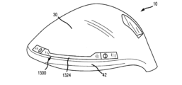
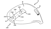
ここで図面を参照する。図1~図3は、本明細書に開示される調整可能な加重システム500、700、800、900、1000、1100、1300、1400、1500、1600、1700、1800、1900、2000、2100、2200、2300の1つまたは複数の実施形態を組み込んだゴルフクラブヘッド10の一実施形態を示す。本明細書に記載の調整可能な加重システムは、クラブヘッドの本体のチャネルまたは溝に取り外し可能に結合されたウェイト構造を含む。調節可能な加重システムのウェイト構造は、様々な構成で複数のウェイトを受け入れるように構成された部材を含む。調整可能な加重システムをクラブヘッドのチャネルから取り外すことができ、調整可能な加重システムがキャビティ内で再配置されるとクラブヘッドの重心が変化するように異なる質量を有する複数のウェイトが再配置または交換される。これにより、ボールの飛行特性(すなわちボールスピンまたは軌道)が変化する。
A. Golf Club Head with Adjustable Weighting System Referring now to the drawings, Figures 1-3 show one embodiment of a
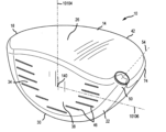
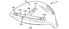
ゴルフクラブヘッド10は、ヒールまたはヒール端22の反対側のトウまたはトウ端18を有するクラブ本体14(または本体14)を含む。本体14はまた、ソールまたはボトム30の反対側にクラウンまたはトップ26を含む。本体14は、打撃面38(図1~2に示す)を画定し、後端または後部または後または後部端42(図1に示す)の反対側にあるフェースプレートまたは打撃プレートまたはクラブフェースまたは打撃フェース34(図1~2に示す)を担持する。ゴルフクラブヘッド10はまた、ホーゼル50の中心を通って延びるホーゼル軸54(図2に示す)を有するホーゼル50を含む。ホーゼル50は、グリップ(図示せず)を担持するゴルフクラブシャフト(図示せず)を受け入れるように構成されている。
The
図3に示すように、ゴルフクラブヘッド10は、クラウン26とソール30との間の移行領域を画定するレールまたはスカート74を含む。レール74は、一般にトウ端18におけるフェースプレート34の端部からヒール端22におけるフェースプレート34の端部までゴルフクラブヘッドの本体14の周りを延びている。図示の実施形態では、レール74は、概して湾曲しているかまたは弓形の形状である。
As shown in FIG. 3, the
多くの実施形態では、ゴルフクラブヘッド10は、ドライバータイプのクラブヘッドを含む。これらの実施形態では、クラブヘッド100のロフト角は、約16度未満、約15度未満、約14度未満、約13度未満、約12度未満、約11度未満、または約10度未満であり得る。さらに、これらの実施形態では、クラブヘッド100の容積は、約400cc超、約425cc超、約450cc超、約475cc超、約500cc超、約525cc超、約550cc超、約575cc超、約600cc超、約625cc超、約650cc超、約675cc超、または約700cc超とすることができる。いくつかの実施形態において、クラブヘッドの容積は、約400cc~600cc、約500cc~600cc、約500cc~650cc、約550cc~700cc、約600cc~650cc、約600cc~700cc、または約600cc~800ccであり得る。
In many embodiments, the
いくつかの実施形態では、クラブヘッド10は、フェアウェイウッドタイプのクラブヘッドを含むことができる。これらの実施形態では、クラブヘッド100のロフト角は、約35度未満、約34度未満、約33度未満、約32度未満、約31度未満、または約30度未満であり得る。さらに、これらの実施形態では、クラブヘッド100のロフト角は、約12度超、約13度超、約14度超、約15度超、約16度超、約17度超、約18度超、約19度超、または約20度超であってもよい。さらに、これらの実施形態では、クラブヘッド100の容積は、約400cc未満、約375cc未満、約350cc未満、約325cc未満、約300cc未満、約275cc未満、約250cc未満、約225cc未満、または約200cc未満であり得る。例えば、クラブヘッドの容積は、約300cc~400cc、約325cc~400cc、約350cc~400cc、約250cc~400cc、約250~350cc、または約275~375ccであり得る。
In some embodiments, the
いくつかの実施形態では、クラブヘッド10は、ハイブリッド型クラブヘッドを含むことができる。これらの実施形態では、クラブヘッド100のロフト角は、約40度未満、約39度未満、約38度未満、約37度未満、約36度未満、約35度未満、約34度未満、約33度未満、約32度未満、約31度未満、または約30度未満であり得る。さらに、これらの実施形態では、クラブヘッド100のロフト角は、約16度超、約17度超、約18度超、約19度超、約20度超、約21度超、約22度超、約23度超、約24度超、または約25度超であってもよい。さらに、これらの実施形態では、クラブヘッド100の容積は、約200cc未満、約175cc未満、約150cc未満、約125cc未満、約100cc未満、または約75cc未満であり得る。例えば、クラブヘッドの容積は、約100cc~150cc、約75cc~150cc、約100cc~125cc、または約75cc~125ccであり得る。他の実施形態では、ゴルフクラブヘッド100は、任意の種類のゴルフクラブヘッドを含むことができる。
In some embodiments, the
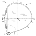
フェースプレート34には、複数の溝46(図1~図2に示す)が配置されている。クラブヘッド10の打撃フェース34は、幾何学的中心140を画定する。いくつかの実施形態では、幾何学的中心140は、打撃フェース周囲の幾何学的中心点、およびフェース高さの中点に配置することができる。同じまたは他の例では、幾何学的中心140は、打撃フェース上の溝の領域によって画定することができる設計された衝撃ゾーンに関する中心に置くこともできる。別のアプローチとして、打撃フェースの幾何学的中心は、米国ゴルフ協会(USGA)のようなゴルフ統治体の定義に従って配置することができる。例えば、打撃フェース34の幾何学的中心140は、ゴルフクラブヘッドの柔軟性を測定するためのUSGAの手順の第6.1項(USGA-TPX3004,Rev.1.0.0, May 1, 2008)(http://www.usga.org/equipment/testing/protocols/Procedure-For-Measuring-The-Flexibility-Of-A-Golf-Club-Head/)(「柔軟性の手順」)に従って決定され得る。
The
クラブヘッド10は、打撃フェース34の幾何学的中心140に接するロフト面10102を画定する。クラブヘッド10はさらに、打撃フェース34の幾何学的中心140に位置する原点を有する座標系を画定する。座標系は、x’軸10106、y’軸10104、およびz’軸10108を有する。x’軸10106は、打撃フェース34の幾何学的中心140を通って、クラブヘッド10のヒール22からトウ18までの方向に伸びている。y’軸10104は、打撃フェース34の幾何学的中心140を通って、クラウン26からクラブヘッド10のソール30への方向に、かつ、x’軸10106に垂直な方向に伸びている。z’軸10108は、打撃フェース34の幾何学的中心140を通って、打撃面34からクラブヘッド100の後端部42の方向に、x’軸10106およびy’軸10104に対して垂直に伸びている。
The
座標系は、x’軸10106とy’軸10104を通って延びるx’y’平面10124、x’軸10106とz’軸10108を通って延びるx’z’平面10126、および、y’軸10104とz’軸10108を通って延びるy’z’平面10128を画定する。ここで、x’y’平面10124、x’z’平面10126、およびy’z’平面10128はすべて相互に垂直であり、打撃フェース34の幾何学的中心140に位置する座標系の原点で交差する。x’y’面10124は、ホーゼル軸線54と平行に延びており、ロフト面10102からクラブヘッド100のロフト角に対応する角度で配置されている。さらに、x’軸10106は、x’y’平面10124に垂直な方向から見たときにホーゼル軸54に対して60度の角度で配置されている
The coordinate system defines an x'y' plane 10124 extending through the x'
これらまたは他の実施形態では、打撃フェース34をx’y’平面10124に垂直な方向から見たときの正面図(図2)からクラブヘッド10を見ることができる。さらに、これらまたは他の実施形態では、ヒール22をy’z’平面10128に垂直な方向から見たときの側面図または側面断面図(図3B)からクラブヘッド10を見ることができる。
In these or other embodiments, the
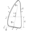
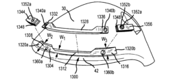
ここで、図2、図3A、および図3Bを参照すると、ゴルフクラブヘッド10は、x軸62、y軸66、およびz軸70を含む座標系の原点を画定する重心またはCG58を含む。y軸66(図2に示す)は、クラブヘッド10の重心58を通って、クラウンまたはトップ26からソールまたはボトム30まで伸びており、側面図から見たときにホーゼル軸54と平行であり、正面図(図2)から見たときに、ホーゼル軸54から30度の角度で配置されている。x軸62(図3に示す)は、クラブヘッドの重心58を通って、トウまたはトウ端18からヒールまたはヒール端22まで伸びており、正面から見たときにy軸66に垂直であり、x’y’平面10124に平行である。z軸70(図3に示す)は、クラブヘッド10の重心58を通って、クラブフェース34から後端部42まで伸びており、x軸62およびy軸66に対して垂直である。x軸62は、ヘッドCG58を通って、トウまたはトウ端18からヒールまたはヒール端22まで伸びており、かつx’軸10106と平行に伸びている。y軸66は、ヘッドCG58を通って、クラウンまたはトップ26からソールまたはボトム30まで伸びており、y’軸10104と平行に伸びている。z軸70は、ヘッドCG58を通って、クラブフェース34から後端部42まで伸びており、z’軸10108と平行である。
2, 3A, and 3B, the
図3Bに示すように、クラブヘッド100は、ヘッド深さ平面10120とヘッド深さ軸10122とをさらに含む。ヘッド深さ平面10120は、打撃面34の幾何学的中心140を通って、ロフト平面10102に対して垂直に、クラブヘッド10のヒール22からトウ18への方向に沿って延びている。ヘッド深さ軸10122は、打撃面34の幾何学的中心140を通って、ロフト面10102に対して垂直に延びている。多くの実施形態では、ヘッドCG58は、x’y’平面10124に垂直な方向に測定したときに、x’y’平面10124からヘッドCGの深さ10130に配置されている。いくつかの実施形態では、ヘッドCG58は、ロフト面10102に垂直な方向で測定したときに、ロフト面10102からヘッドCGの深さ10130に配置することができる。ヘッドCG58はさらに、ヘッド深さ平面10120に垂直な方向に測定したときに、ヘッド深さ平面10120からヘッドCGの高さ10132に位置する。さらに、ヘッドCG高さ10132は、ヘッド深さ平面10120に垂直にクラウン26またはソール30に向かう方向へのヘッド深さ平面10120からのヘッドCG58のオフセット距離として測定される。
3B, the club head 100 further includes a head depth plane 10120 and a head depth axis 10122. The head depth plane 10120 extends through the
本明細書の技術革新を説明するさらなるガイダンスのために、x軸62およびz軸70は、図3Aのアナログ時計上の数字と一致するように配置される。z軸70は12時(クラブフェース34を通って「12」)と6時(バック42を通って「6」)の間を延びており、x軸62は3時(トウ端18を通る「3」)と9時(ヒール端22を通る「9」)の間を延びている。
For further guidance in describing the innovations herein, the
クラブヘッドの慣性モーメント、クラブヘッドの重心位置、およびクラブヘッドの重心調整可能性などの所望の性能特性を達成する上で、様々なゴルフクラブヘッドパラメータが重要である。クラブヘッドの慣性モーメントが高いと、偏心打撃に対するクラブヘッドの許容度を増加させる。クラブヘッドの重心が低くかつ後方に(すなわち、クラブヘッドのソールおよび後方に向かって)位置決めされると、慣性モーメントが有利に増大し、バックスピンが減少し、そしてインパクト時のゴルフボールの打ち出し角度を増大させる。クラブヘッドの重心の調整可能性は、ユーザによるクラブヘッドの所望の軌道調整を可能にする。これらの各パラメータは、ゴルフクラブの設計において、所望のまたは最適な性能特性を達成するために重要である。しかしながら、多くの現在の重心調整機構が(1)クラブヘッドの慣性モーメントを低下させる、および/または(2)クラブヘッドの重心を上方および前部にシフトさせるので、内部および/またはかさばったウェイト構造、および/または不適当なウェイト構造の位置決めにより、ゴルフクラブヘッドにこれらのパラメータすべてを含めることに設計上の課題が存在する。 Various golf club head parameters are important in achieving desired performance characteristics such as the club head moment of inertia, the club head center of gravity location, and the club head center of gravity adjustability. A high club head moment of inertia increases the club head's tolerance to off-center hits. A club head center of gravity positioned low and rearward (i.e., toward the sole and rear of the club head) advantageously increases the moment of inertia, reduces backspin, and increases the launch angle of the golf ball at impact. The adjustability of the club head center of gravity allows the user to adjust the desired trajectory of the club head. Each of these parameters is important in the design of a golf club to achieve desired or optimal performance characteristics. However, design challenges exist in including all of these parameters in a golf club head, as many current center of gravity adjustment mechanisms (1) reduce the club head moment of inertia, and/or (2) shift the club head center of gravity upward and forward, due to internal and/or bulky weight structures, and/or inappropriate weight structure positioning.
以下に記載されるゴルフクラブヘッドの実施形態は、クラブヘッドの慣性モーメントの大幅な減少、クラブヘッドの低く後方の重心位置を維持または防止しながら調整可能な加重システムを含んでいる。例えば、以下の多くの実施形態は、調節可能な重み付けがないクラブヘッドと同様に、ボールの飛行および/または軌道のユーザ調整可能性を提供しながら、高いクラブヘッドの慣性モーメントならびに低いおよび後方のクラブヘッドの重心位置を維持するための、薄型の調節可能な加重システムおよび/または最適位置調節可能な加重システムを説明する。クラブヘッドCG周りの高いクラブヘッド慣性モーメントを維持することは、偏心打撃に対する許容度の増大をもたらし、そしてホーゼル軸周りの高いクラブヘッドモーメントを維持することは、スイング中の回転安定性の増大をもたらす。さらに、クラブヘッドの低く後方の重心位置を維持することは、ヘッドCG周りのクラブヘッドの慣性モーメントを有利に増大させ、バックスピンを減少させる。 The golf club head embodiments described below include adjustable weighting systems that significantly reduce the club head moment of inertia, while maintaining or preventing a low and rearward club head center of gravity position. For example, many of the following embodiments describe low profile adjustable weighting systems and/or optimally positioned adjustable weighting systems to maintain a high club head moment of inertia and a low and rearward club head center of gravity position while providing user adjustability of ball flight and/or trajectory similar to club heads without adjustable weighting. Maintaining a high club head moment of inertia about the club head CG provides increased tolerance to off-center hits, and maintaining a high club head moment about the hosel axis provides increased rotational stability during the swing. Additionally, maintaining a low and rearward club head center of gravity position advantageously increases the club head moment of inertia about the head CG, reducing backspin.
本明細書に記載のクラブヘッド10は、x軸周りの慣性モーメントIxx(すなわち、クラウン-ソール慣性モーメント)、y軸周りの慣性モーメントIyy(すなわち、ヒール-トウ慣性モーメント)と、ホーゼル軸周りの慣性モーメントIhhと、を含む。
The
本明細書に記載の調整可能な加重システムを含むクラブヘッドは、3100g・cm2超、3200g・cm2超、3300g・cm2超、3400g・cm2超、3500g・cm2超、3600g・cm2超、3700g・cm2超、3800g・cm2超、3900g・cm2超、4000g・cm2超、4100g・cm2超、4200g・cm2超、4300g・cm2超、4400g・cm2超、または4500g・cm2超のx軸周りの慣性モーメントIxxを有することができる。いくつかの実施形態では、本明細書に記載の調整可能な加重システムを備えるクラブヘッドは、3100~4000g・cm2の間、3100~3800g・cm2の間、3200~4000g・cm2の間、3200~4000g・cm2の間、3300~4000g・cm2の間、3400~4000g・cm2の間、または3500~4000g・cm2の間のx軸周りの慣性モーメントIxxを有する。 Club heads including the adjustable weighting systems described herein can have a moment of inertia about the x-axis Ixx of greater than 3100 g cm2 , greater than 3200 g cm2 , greater than 3300 g cm2 , greater than 3400 g cm2 , greater than 3500 g cm2 , greater than 3600 g cm2 , greater than 3700 g cm2 , greater than 3800 g cm2 , greater than 3900 g cm2 , greater than 4000 g cm2 , greater than 4100 g cm2 , greater than 4200 g cm2 , greater than 4300 g cm2 , greater than 4400 g cm2, or greater than 4500 g cm2 . In some embodiments, a club head equipped with an adjustable weighting system described herein has a moment of inertia about the x-axis I xx of between 3100-4000 g cm 2 , between 3100-3800 g cm 2 , between 3200-4000 g cm 2 , between 3200-4000 g cm 2 , between 3300-4000 g cm 2 , between 3400-4000 g cm 2 , or between 3500-4000 g cm 2 .
さらに、本明細書に記載の調整可能な加重システムを備えるクラブヘッドは、4700g・cm2超、4800g・cm2超、4900g・cm2超、5000g・cm2超、5100g・cm2超、5200g・cm2超、5300g・cm2超、5400g・cm2超、5500g・cm2超、5600g・cm2超、5700g・cm2超、5800g・cm2超、5900g・cm2超、または6000g・cm2超のy軸周りの慣性モーメントIyyを有することができる。いくつかの実施形態では、本明細書に記載の調整可能な加重システムを含むクラブヘッドは、4800~6000g・cm2の間、4900~6000g・cm2の間、5000~6000g・cm2の間、5100~6000g・cm2の間、5200~6000g・cm2の間、5300~6000g・cm2の間、または5400~6000g・cm2の間のy軸回りの慣性モーメントIyyを有する。 Additionally, club heads with adjustable weighting systems described herein can have a moment of inertia about the y-axis Iyy of greater than 4700 g cm2 , greater than 4800 g cm2 , greater than 4900 g cm2 , greater than 5000 g cm2 , greater than 5100 g cm2 , greater than 5200 g cm2 , greater than 5300 g cm2 , greater than 5400 g cm2 , greater than 5500 g cm2 , greater than 5600 g cm2, greater than 5700 g cm2 , greater than 5800 g cm2 , greater than 5900 g cm2, or greater than 6000 g cm2 . In some embodiments, a club head including an adjustable weighting system described herein has a moment of inertia about the y-axis I yy between 4800-6000 g cm 2 , between 4900-6000 g cm 2 , between 5000-6000 g cm 2 , between 5100-6000 g cm 2 , between 5200-6000 g cm 2 , between 5300-6000 g cm 2 , or between 5400-6000 g cm 2 .
さらにまた、本明細書に記載の調整可能な加重システムを備えるクラブヘッドは、8500g・cm2超、8750g・cm2超、9000g・cm2超、9050g・cm2超、または10000g・cm2超のホーゼル軸周りの慣性モーメントIhhを有することができる。いくつかの実施形態では、本明細書に記載の調整可能な加重システムを含むクラブヘッドは、または9000~10000g・cm2の間のホーゼル軸周りの慣性モーメントを有する。 Furthermore, club heads with adjustable weighting systems described herein can have a moment of inertia Ihh about the hosel axis of greater than 8500 g cm2 , greater than 8750 g cm2 , greater than 9000 g cm2 , greater than 9050 g cm2 , or greater than 10000 g cm2 . In some embodiments, club heads including the adjustable weighting systems described herein have a moment of inertia Ihh about the hosel axis of between 9000 and 10000 g cm2 .
以下の関係1(Relation 1)を参照すると、調整可能な加重システムを有するクラブヘッドの多くの実施形態は、x軸周りの慣性モーメントとy軸周りの慣性モーメントの和として定義されるヘッドCG周りの合成慣性モーメント(MOICG)を含む。
![]()
![]()
ヘッド重心周りの合成慣性モーメントMOICGは、7600g・cm2超、7700g・cm2超、7800g・cm2超、7900g・cm2超、8000g・cm2超、8100g・cm2超、8200g・cm2超、8300g・cm2超、8400g・cm2超、8500g・cm2超、8600g・cm2超、8700g・cm2超、8800g・cm2超、8900g・cm2超、9000g・cm2超、9100g・cm2超、9200g・cm2超、または9300g・cm2超とすることができる。例えば、ヘッド重心周りの合成慣性モーメントMOICGは、7700~9500g・cm2の間、7800~9500g・cm2の間、7900~9500g・cm2の間、8000~9500g・cm2の間、8100~9500g・cm2の間、8200~9500g・cm2の間、または8300~9500g・cm2の間とすることができる。 The composite moment of inertia about the head center of gravity, MOI CG , can be greater than 7600 g cm2 , greater than 7700 g cm2 , greater than 7800 g cm2 , greater than 7900 g cm2 , greater than 8000 g cm2 , greater than 8100 g cm2 , greater than 8200 g cm2 , greater than 8300 g cm2 , greater than 8400 g cm2 , greater than 8500 g cm2 , greater than 8600 g cm2 , greater than 8700 g cm2 , greater than 8800 g cm2 , greater than 8900 g cm2, greater than 9000 g cm2 , greater than 9100 g cm2 , greater than 9200 g cm2 , or greater than 9300 g cm2 . For example, the composite moment of inertia about the head center of gravity MOI CG can be between 7700 and 9500 g· cm2 , between 7800 and 9500 g· cm2 , between 7900 and 9500 g· cm2 , between 8000 and 9500 g· cm2 , between 8100 and 9500 g· cm2 , between 8200 and 9500 g· cm2 , or between 8300 and 9500 g· cm2 .
以下の関係2(Relation 2)を参照すると、調整可能な加重システムを有するクラブヘッドの多くの実施形態は、x軸周りの慣性モーメントとy軸周りの慣性モーメントとホーゼル軸周りの慣性モーメントの合計として定義される、ヘッドCGとホーゼル周りの合成慣性モーメント(MOICG-H)を含む。
![]()
![]()
ヘッドCGとホーゼル周りの合成慣性モーメントMOICG-Hは、14800g・cm2超、14900g・cm2超、15000g・cm2超、15100g・cm2超、15200g・cm2超、15300g・cm2超、15400g・cm2超、15500g・cm2超、15600g・cm2超、15700g・cm2超、15800g・cm2超、15900g・cm2超、16000g・cm2超、16200g・cm2超、16400g・cm2超、16600g・cm2超、16800g・cm2超、17000g・cm2超、17200g・cm2超、17400g・cm2超、17600g・cm2超、17800g・cm2超、18000g・cm2超、18400g・cm2超、18800g・cm2超、19000g・cm2超、19200g・cm2超、または19400g・cm2超とすることができる。例えば、ヘッドCGとホーゼル周りの合成慣性モーメントMOICG-Hは、15000~19500g・cm2の間、15000~19000g・cm2の間、15000~18000g・cm2の間、16000~19500g・cm2の間、16000~19000g・cm2の間、または16000~18000g・cm2の間とすることができる。これらの実施形態では、425~450立方センチメートル(cc)の間の容積を有する調整可能な加重システムを備えたクラブヘッドについては、ヘッドCGとホーゼル周りの合成慣性モーメントMOICG-Hを15000g・cm2超とすることができ、450~500立方センチメートル(cc)の間の容積を有する調整可能な加重システムを有するクラブヘッドについては、ヘッドCGとホーゼル周りの合成慣性モーメントMOICG-Hを17000g・cm2超とすることができる。 The composite moment of inertia MOI CG-H of the head CG and the hosel periphery is greater than 14,800 g cm 2 , greater than 14,900 g cm 2 , greater than 15,000 g cm 2 , greater than 15,100 g cm 2 , greater than 15,200 g cm 2 , greater than 15,300 g cm 2 , greater than 15,400 g cm 2 , greater than 15,500 g cm 2 , greater than 15,600 g cm 2 , greater than 15,700 g cm 2 , greater than 15,800 g cm 2 , greater than 15,900 g cm 2 , greater than 16,000 g cm 2 , greater than 16,200 g cm 2 , greater than 16,400 g cm 2 , greater than 16,600 g cm 2 , greater than 16,800 g cm 2 , greater than 17,000 g cm 2 , greater than 17200 g cm2 , greater than 17400 g cm2 , greater than 17600 g cm2 , greater than 17800 g cm2 , greater than 18000 g cm2 , greater than 18400 g cm2 , greater than 18800 g cm2 , greater than 19000 g cm2 , greater than 19200 g cm2 , or greater than 19400 g cm2 . For example, the composite moment of inertia MOI CG-H of the head CG and around the hosel can be between 15,000 and 19,500 g· cm2 , between 15,000 and 19,000 g· cm2 , between 15,000 and 18,000 g· cm2 , between 16,000 and 19,500 g· cm2 , between 16,000 and 19,000 g· cm2 , or between 16,000 and 18,000 g· cm2 . In these embodiments, for club heads with adjustable weighting systems having a volume between 425-450 cubic centimeters (cc), the combined moment of inertia MOI CG-H about the head CG and hosel may be greater than 15,000 g- cm2 , and for club heads with adjustable weighting systems having a volume between 450-500 cubic centimeters (cc), the combined moment of inertia MOI CG-H about the head CG and hosel may be greater than 17,000 g- cm2 .
本明細書に記載の調整可能な加重システムを含むクラブヘッドは、1.6インチ超、1.65インチ超、1.7インチ超、1.75インチ超、1.8インチ超、1.85インチ超、1.9超、1.95インチ超、または2.0インチ超のヘッドCG深さ10130を有することができる。例えば、調整可能な加重システムを有するクラブヘッドは、1.61~2.0インチの間、1.65~2.0インチの間、1.7~2.0インチの間、1.8~2.0インチの間、1.61~3.0インチの間、1.65~3.0インチの間、1.7~3.0インチの間、1.8~3.0インチの間、1.9~3.0インチの間、または2.0~3.0インチの間のヘッドCG深さ10130を有することができる。
Club heads including the adjustable weighting systems described herein can have a
さらに、本明細書に記載の調整可能な加重システムを備えるクラブヘッドは、ヘッド深さ平面10120の下に位置する(すなわち、ヘッド深さ平面10120とクラブヘッドのソール30との間に位置する)ヘッドCG高さ10132を有することができる。さらに、本明細書に記載の調整可能な加重システムを含むクラブヘッドは、ヘッド深さ平面10120からクラウン26に向かって又はクラブヘッドのソール30に向かって、0.25インチ以内、0.20インチ以内、0.15インチ以内、0.10インチ以内、0.09インチ以内、0.08インチ以内、0.07インチ以内、0.06以内、0.05インチ以内、又は0.04インチ以内に位置するヘッドCG高さ10132を有することができる。
Additionally, a club head with an adjustable weighting system as described herein may have a
多くの実施形態において、そして上記のように、クラブヘッド10の調節可能な加重システムは、1つ以上のウェイトを複数の構成で受け入れることができるインサートまたは部材を含み、1つのウェイトは残りの重りの少なくとも1つより大きい質量を有する。部材は、ウェイトを受け入れるための複数の取り付け配置または位置を含む。さらに、部材は、ヘッドCG位置を調整するために、様々な構成で配置されたウェイトを用いて、クラブヘッドのチャネルまたは溝内に取り外し可能に配置可能である。例えば、クラブヘッドのCG位置を調整するために、調整可能な加重システムをチャネルまたは溝部から取り外し、そしてウェイトを交換または再配置する(すなわち、重いウェイトを異なる取り付け位置に移動させる)ことができる。これにより、調整可能な加重システムがクラブヘッドのチャネルまたは溝内に再配置されると、クラブヘッドの重心は変化する。本明細書に記載の調整可能な加重システムを使用してヘッドCG位置を調整することは、高いクラブヘッド慣性モーメントを維持しながら、インパクト時のクラブヘッドのボール軌道および/またはスピン特性に影響を及ぼすことができる。
In many embodiments, and as described above, the adjustable weighting system of the
多くの実施形態では、クラブヘッドのチャネルは、前後方向におけるチャネルの両側の間の距離として定義される幅W、およびソールとチャンネルの底面との間の距離として定義される高さHを含む。チャネルの幅Wおよび高さHは、ヒールの近くからトウの近くまでチャネルの長さに沿って一定であり得るか、または、チャネルの幅Wおよび高さHは、チャネルの断面積が変化するように、ヒールからトウまでのチャネルの長さに沿って変わり得る。多くの実施形態では、チャネルの高さHは、0.05インチから0.4インチの間、0.05インチから0.5インチの間、0.05インチから0.6インチの間、0.1インチから0.4の間、0.1インチから0.5の間、または0.1インチから0.6インチの間の範囲であり得る。多くの実施形態では、溝の幅Wは、0.05インチから1.25インチの間、0.05インチから1.0インチの間、0.05インチから0.75インチの間、0.25インチから1.25インチの間、0.25インチから1.0インチの間、または0.25インチと0.75インチの間とすることができる。 In many embodiments, the channel of the club head includes a width W, defined as the distance between the sides of the channel in the fore-aft direction, and a height H, defined as the distance between the sole and the bottom of the channel. The channel width W and height H may be constant along the length of the channel from near the heel to near the toe, or the channel width W and height H may vary along the length of the channel from the heel to the toe such that the cross-sectional area of the channel changes. In many embodiments, the channel height H may range from between 0.05 inches to 0.4 inches, between 0.05 inches to 0.5 inches, between 0.05 inches to 0.6 inches, between 0.1 inches to 0.4 inches, between 0.1 inches to 0.5 inches, or between 0.1 inches to 0.6 inches. In many embodiments, the width W of the groove can be between 0.05 inches and 1.25 inches, between 0.05 inches and 1.0 inches, between 0.05 inches and 0.75 inches, between 0.25 inches and 1.25 inches, between 0.25 inches and 1.0 inches, or between 0.25 inches and 0.75 inches.
多くの実施形態では、調整可能な加重システムは、2つ以上のウェイトを受け取ることができる。多くの実施形態において、調節可能な加重システムは、2、3、4、または5つのウェイトを含み得る。例えば、2つのウェイトを有する調整可能な加重システムの実施形態(例えば、図4~図10、図13~図21)では、調整可能な加重システムの一構成は、ウェイトを含む部材がクラブヘッドのチャネル内に配置されているときに、クラブヘッドの後端42およびトウ18に向かって配置される第1のウェイトと、クラブヘッドの後端42およびヒール22に向かって配置される第2のウェイトと、を含むことができる。これらの実施形態では、第1のウェイトと第2のウェイトとの間の距離は、0.8インチ超、0.9インチ超、1.0インチ超、1.1インチ超、1.2インチ超、または1.3インチ超であり得る。例えば、第1のウェイトと第2のウェイトとの間の距離は、0.8~1.3インチの間、0.9~1.3インチの間、1.0~1.3インチの間、または1.1~1.3インチの間であり得る。
In many embodiments, the adjustable weighting system can receive two or more weights. In many embodiments, the adjustable weighting system can include two, three, four, or five weights. For example, in an embodiment of an adjustable weighting system having two weights (e.g., FIGS. 4-10, 13-21), one configuration of the adjustable weighting system can include a first weight disposed toward the
さらなる例では、3つのウェイトを有する調整可能な加重システムの実施形態(図23~26)では、調整可能な加重システムの一構成は、クラブヘッドの後端42およびトウ18に向かって配置され得る第1のウェイトと、クラブヘッドの後端42およびヒール22に向かって配置される第2のウェイトと、クラブヘッドの後端42に向かって、および/またはヘッド深さ軸10122と実質的に一致又は隣接するように、および/または第1ウェイトと第2ウェイトとの間となるように配置され得る第3のウェイトと、を含むことができる。これらの実施形態では、隣接するウェイト間の距離(例えば、第1のウェイトと第3のウェイトとの間の距離、または第2のウェイトと第3のウェイトとの間の距離)は、0.5インチ超、0.6インチ超、0.7インチ超、0.8インチ超、0.9インチ超、または1.0インチ超とすることができる。例えば、隣接するウェイト間の距離(例えば、第1のウェイトと第3のウェイトとの間の距離、または第2のウェイトと第3のウェイトとの間の距離)は、0.5~1.0インチの間、0.6~1.0インチの間、0.7~1.0インチの間、または0.8~1.0インチの間とすることができる。
In a further example, in an embodiment of an adjustable weighting system having three weights (FIGS. 23-26), one configuration of the adjustable weighting system can include a first weight that can be positioned toward the
他の実施形態では、調整可能な加重システムは、2つ、3つ、4つ、5つ、6つ、7つ、8つ、またはそれ以上のウェイトなど、1より大きい任意の数の重みを含むことができる。調整可能な加重システムが4つのウェイトを含む実施形態では、隣接するウェイト間の距離は、0.4インチ超、0.5インチ超、0.6インチ超、0.7インチ超、0.8インチ超、または0.9インチ超とすることができる。例えば、4つのウェイトを含む実施形態では、隣接するウェイト間の距離は、0.4~0.9インチの間、0.5~0.9インチの間、0.6~0.9インチの間、または0.7~0.9インチの間とすることができる。調整可能な加重システムが5つのウェイトを含む実施形態では、隣接するウェイト間の距離は、0.3インチ超、0.4インチ超、0.5インチ超、0.6インチ超、0.7インチ超、または0.8インチ超とすることができる。例えば、5つのウェイトを含む実施形態では、隣接するウェイト間の距離は、0.3~0.8インチの間、0.4~0.8インチの間、0.5~0.8インチの間、または0.6~0.8インチの間とすることができる。 In other embodiments, the adjustable weighting system can include any number of weights greater than one, such as two, three, four, five, six, seven, eight, or more weights. In embodiments where the adjustable weighting system includes four weights, the distance between adjacent weights can be greater than 0.4 inches, greater than 0.5 inches, greater than 0.6 inches, greater than 0.7 inches, greater than 0.8 inches, or greater than 0.9 inches. For example, in embodiments where the adjustable weighting system includes four weights, the distance between adjacent weights can be between 0.4 and 0.9 inches, between 0.5 and 0.9 inches, between 0.6 and 0.9 inches, or between 0.7 and 0.9 inches. In embodiments where the adjustable weighting system includes five weights, the distance between adjacent weights can be greater than 0.3 inches, greater than 0.4 inches, greater than 0.5 inches, greater than 0.6 inches, greater than 0.7 inches, or greater than 0.8 inches. For example, in an embodiment including five weights, the distance between adjacent weights can be between 0.3 and 0.8 inches, between 0.4 and 0.8 inches, between 0.5 and 0.8 inches, or between 0.6 and 0.8 inches.
調整可能な加重システムの1つ以上のウェイトは、クラウンからソール方向に測定された高さHw、ヒールからトウ方向に測定された幅Ww、および前後方向に測定された深さDwを有することができる。多くの実施形態では、高さHwは、0.5インチ未満、0.4インチ未満、0.3インチ未満、0.25インチ未満、0.2インチ未満、0.18インチ未満、0.16インチ未満、0.14インチ未満、0.12mm未満、または0.10インチ未満であり得る。例えば、いくつかの実施形態では、高さHwは、0.1インチから0.5インチの間であり得る。多くの実施形態では、幅Wwは、1.3インチ未満、1.2インチ未満、1.1インチ未満、1.0インチ未満、0.9インチ未満、0.8インチ未満、0.7インチ未満、0.6インチ未満、0.5インチ未満、または0.4インチ未満であり得る。例えば、幅Wwは、0.25インチから1.25インチの間であり得る。多くの実施形態において、深さDwは、1.0インチ未満、0.9インチ未満、0.8インチ未満、0.7インチ未満、0.6インチ未満、0.5インチ未満、0.4インチ未満、0.3インチ未満、0.2インチ未満、または0.1インチ未満であり得る。例えば、深さDwは、0.25インチから1.25インチの間であり得る。 One or more weights of the adjustable weighting system can have a height H w measured from crown to sole, a width W w measured from heel to toe, and a depth D w measured in the fore-aft direction. In many embodiments, the height H w can be less than 0.5 inches, less than 0.4 inches, less than 0.3 inches, less than 0.25 inches, less than 0.2 inches, less than 0.18 inches, less than 0.16 inches, less than 0.14 inches, less than 0.12 mm, or less than 0.10 inches. For example, in some embodiments, the height H w can be between 0.1 inches and 0.5 inches. In many embodiments, the width W w can be less than 1.3 inches, less than 1.2 inches, less than 1.1 inches, less than 1.0 inches, less than 0.9 inches, less than 0.8 inches, less than 0.7 inches, less than 0.6 inches, less than 0.5 inches, or less than 0.4 inches. For example, the width W w can be between 0.25 inches and 1.25 inches. In many embodiments, the depth Dw can be less than 1.0 inch, less than 0.9 inch, less than 0.8 inch, less than 0.7 inch, less than 0.6 inch, less than 0.5 inch, less than 0.4 inch, less than 0.3 inch, less than 0.2 inch, or less than 0.1 inch. For example, the depth Dw can be between 0.25 inch and 1.25 inch.
多くの実施形態において、第1のウェイトは、残りのウェイトのうちの1つ以上(例えば、第2のウェイト、第3のウェイト、第4のウェイト、および/または第5のウェイト)よりも重い。第1のウェイトは、10グラム超、12グラム超、14グラム超、16グラム超、18グラム超、20グラム超、22グラム超、24グラム超、26グラム超、28グラム超、または30グラム超の質量を含むことができる。例えば、第1のウェイトは、6~20グラムの間、6~50グラムの間、10~50グラムの間、15~50グラムの間、20~50グラムの間、15~40グラムの間、20~40グラムの間、25~35グラムの間、10~25グラムの間、15~25グラムの間、10~20グラムの間、または15~20グラムの間の質量を含むことができる。残りのウェイト(例えば、第2のウェイト、第3のウェイト、第4のウェイト、および/または第5のウェイト)は、20グラム未満、18グラム未満、16グラム未満、14グラム未満、12グラム未満、10グラム未満、8グラム未満、6グラム未満、4グラム未満、または2グラム未満の質量を含むことができる。例えば、残りのウェイトは、0.10~15グラムの間、0.25~10グラムの間、0.25~10グラムの間、0.5~7グラムの間、または1~10グラムの間の質量を含むことができる。さらに、残りのウェイトは、互いに同じまたは異なる質量を含むことができる。 In many embodiments, the first weight is heavier than one or more of the remaining weights (e.g., the second weight, the third weight, the fourth weight, and/or the fifth weight). The first weight can include a mass of more than 10 grams, more than 12 grams, more than 14 grams, more than 16 grams, more than 18 grams, more than 20 grams, more than 22 grams, more than 24 grams, more than 26 grams, more than 28 grams, or more than 30 grams. For example, the first weight can include a mass between 6-20 grams, between 6-50 grams, between 10-50 grams, between 15-50 grams, between 20-50 grams, between 15-40 grams, between 20-40 grams, between 25-35 grams, between 10-25 grams, between 15-25 grams, between 10-20 grams, or between 15-20 grams. The remaining weights (e.g., the second weight, the third weight, the fourth weight, and/or the fifth weight) can include masses of less than 20 grams, less than 18 grams, less than 16 grams, less than 14 grams, less than 12 grams, less than 10 grams, less than 8 grams, less than 6 grams, less than 4 grams, or less than 2 grams. For example, the remaining weights can include masses between 0.10 and 15 grams, between 0.25 and 10 grams, between 0.25 and 10 grams, between 0.5 and 7 grams, or between 1 and 10 grams. Additionally, the remaining weights can include the same or different masses from one another.
部材および各ウェイトは、1つの材料、2つ以上の材料、または複数の材料から形成することができる。例えば、部材は、金属(例えば、アルミニウム、鋼、チタン)、金属合金(例えば、アルミニウム合金、チタン合金、スチール合金)、プラスチックまたはプラスチック群、粉末金属を含むプラスチック、複合材料、粉末金属を含む複合材料、または他の適切な材料で形成することができる。さらなる例では、1つまたは複数のウェイトは、高密度材料(たとえばタングステンなど)、低密度材料(たとえばポリウレタンまたは他の適切なプラスチックなど)、2つまたはそれ以上の高密度材料の組み合わせ、2つ以上の低密度材料の組み合わせ、または高密度材料と低密度材料の組み合わせで形成することができる。さらなる例として、1つまたは複数のウェイトは、金属、金属合金、プラスチックまたはプラスチック群、粉末金属を含むプラスチック、複合材料、粉末金属を含む複合材料、または他の任意の適切な材料から形成することができる。 The members and each weight can be formed from one material, two or more materials, or multiple materials. For example, the members can be formed from a metal (e.g., aluminum, steel, titanium), a metal alloy (e.g., aluminum alloy, titanium alloy, steel alloy), a plastic or plastic group, a plastic including powdered metal, a composite material, a composite material including powdered metal, or other suitable material. In a further example, the weight or weights can be formed from a high density material (e.g., tungsten, etc.), a low density material (e.g., polyurethane or other suitable plastic, etc.), a combination of two or more high density materials, a combination of two or more low density materials, or a combination of a high density material and a low density material. As a further example, the weight or weights can be formed from a metal, a metal alloy, a plastic or plastic group, a plastic including powdered metal, a composite material, a composite material including powdered metal, or any other suitable material.
第1のウェイトは、部材の任意の取り付け位置に配置することができる。2つの取り付け位置を含む調整可能な加重システムを有する実施形態では、部材がクラブヘッドに結合されたときに第1のウェイトがトウ18の近くに配置されるように、第1のウェイトを第1の取り付け位置に配置することができる。さらに、第1のウェイトは、部材がクラブヘッドに結合されたときに第1のウェイトがヒール22の近くに配置されるように、第2の取り付け位置に配置することができる。これらの実施形態では、第1のウェイトを第1の取り付け位置から第2の取り付け位置に移動させると、ヘッドCGがヒール22に向かって移動し、第1のウェイトを第2の取り付け位置から第1の取り付け位置に移動させると、ヘッドCGがトウ18に向かって移動する。これらの実施形態では、残りの取り付け位置は、第1のウェイトより軽い第2のウェイトを含むことができる。
The first weight can be located at any mounting location on the member. In embodiments having an adjustable weighting system that includes two mounting locations, the first weight can be located at the first mounting location such that the first weight is located near the
3つのウェイトを備える調整可能な加重システムを有する実施形態では、部材の中央に配置された第3の取り付け位置に第1のウェイトを配置することができ、それによって中立なヘッドCG位置を生じさせる。第1のウェイトは、第3の取り付け位置から第1の取り付け位置へと移動することができ、これはトウ18の方へ位置決めされ、それによってヘッドCG58をトウ18の方向へある距離だけ移動させる。第1のウェイトは、第3の取り付け位置から第2の取り付け位置へと移動することができ、これはヒール22の方に位置決めされ、それによってヘッドCG58をヒール22の方向にある距離だけ移動する。これらの実施形態では、残りの位置にはウェイトがなくてもよく、または残りの位置が第1のウェイトよりも軽い追加のウェイトを含んでもよい。
In embodiments having an adjustable weighting system with three weights, the first weight can be located at a third mounting location located in the center of the member, thereby producing a neutral head CG position. The first weight can be moved from the third mounting location to the first mounting location, which is positioned toward the
第1のウェイトをトウ18に最も近い取り付け位置からヒール22に最も近い取り付け位置に移動させると、ヘッドCG58を少なくとも0.10インチ、少なくとも0.15インチ、少なくとも0.20インチ、少なくとも0.25インチの距離、少なくとも0.30インチだけ、x軸62と平行に延びる方向にシフトさせることができる。例えば、多くの実施形態において、第1ウェイトをトウ18に最も近い取り付け位置からヒール22に最も近い取り付け位置へ移動させることは、ヘッドCG58を0.05から0.30インチの間、0.15から0.30インチの間、0.20から0.30インチの間、0.15から0.25インチの間、または0.20から0.25インチの間で移動させることができる。
Moving the first weight from a mounting position closest to the
これらの、または他の実施形態では、ヘッドCG58をトウ18に向かってシフトさせると、フェードを生じさせるか、またはフックを修正することができる。逆に、ヘッドCG58をヒール22に向かって移動させると、ドローを生じさせるか、またはスライスを修正することができる。以下に説明する調整可能な加重システムの実施形態では、ヘッドCG58をx軸62に平行に延びる方向に0.10インチと0.30インチとの間でシフトさせると、4.6から13.9ヤードのショット曲げの変化をもたらすことができる。
In these or other embodiments, shifting the
他の実施形態は、クラブヘッドの打撃フェース34に向かって配置された部材上の1つまたは複数の取り付け位置を含むことができる(例えば、図22および図29)。これらの実施形態では、打撃フェース34の近くの取り付け位置からクラブヘッドの後端42の近くの取り付け位置に1つまたは複数のウェイトを移動させると、ヘッドCG周りのクラブヘッド慣性モーメントMOICGが増加し、ゴルフボールの動的なロフト角または打ち出し角が増加する。逆に、後端42近くの取り付け位置からクラブヘッドの打撃面34近くの取り付け位置に1つまたは複数のウェイトを移動させると、ゴルフボールの動的なロフト角または打ち出し角を減少させることができる。
Other embodiments may include one or more mounting locations on a member disposed toward the
本明細書に記載の調整可能な加重システムを有するクラブヘッドの実施形態は、ヘッドCGの深さ10130およびクラブヘッド慣性モーメントを最大化する(または非調整可能なクラブヘッドと比較して調整性の導入に典型的に伴うヘッドCGの深さ10130およびクラブヘッド慣性モーメントの減少の最小化)。多くの実施形態において、最大のヘッドCGの深さおよびクラブヘッドの慣性モーメントは、比較的低い質量を有する第1の調整可能ウェイトによって達成され、それによって、ボールスピンおよび/または軌道のユーザ調整可能性を可能にしながら、クラブヘッド性能特性(例えば、許容度、低バックスピン、高打ち上げ)を維持するための設計効率が高められる。
Embodiments of club heads having adjustable weighting systems as described herein maximize
下記の関係3(Relation 3)を参照すると、調整可能な加重システムを有するクラブヘッドは、第1のウェイトの質量Wmに対するヘッドCGの深さ10130である深さ対質量比を含む。多くの実施形態では、クラブヘッドの深さ対質量比は、0.060インチ/グラム超、0.070インチ/グラム超、0.080インチ/グラム超、0.090インチ/グラム超、0.100インチ/グラム超、とすることができる。0.110インチ/グラム超、0.120インチ/グラム超、または0.130インチ/グラム超であり得る。いくつかの実施形態では、深さ対質量比は、0.070~0.13インチ/グラムの間、0.080~0.13インチ/グラムの間、0.090~0.13インチ/グラムの間、0.070~0.11インチ/グラムの間、0.080~0.11インチ/グラムの間、または0.090から0.11インチ/グラムの間であり得る。これらの実施形態では、第1のウェイトの質量は、25グラム未満、24グラム未満、23グラム未満、22グラム未満、20グラム未満、19グラム未満、18グラム未満、17グラム未満、16グラム未満、または15グラム未満であり得る。いくつかの実施形態では、第1のウェイトの質量は、6~20グラムの間、10~20グラムの間、12~20グラムの間、14~20グラムの間、16~20グラムの間、10~18グラムの間、12~18グラムの間、または14~18グラムの間であり得る。
![]()
![]()
下記の関係4(Relation 4)を参照すると、調整可能な加重システムを有するクラブヘッドは、第1のウェイトの質量Wmに対するヘッドCG周りの合成慣性モーメントMOICGとして定義される第1の慣性対質量比を含むことができる。多くの実施形態では、第1の慣性対質量比は、400cm2超、410cm2超、420cm2超、430cm2超、440cm2超、450cm2超、460cm2超、470cm2超、480cm2超、490cm2超、500cm2超、510cm2超、520cm2超、530cm2超、540cm2超、550cm2超、560cm2超、570cm2超、580cm2超、590cm2超、600cm2超、610cm2超、620cm2超、630cm2超、640cm2超、650cm2超、660cm2超、670cm2超、680cm2超、690cm2超、または700cm2超であり得る。いくつかの実施形態において、第1慣性質量比は、400~700cm2の間、510~750cm2の間、520~750cm2の間、530~750cm2の間、540~750cm2の間、550~750cm2の間、500~700cm2の間、510~700cm2の間、520~700cm2の間、530~700cm2の間、540~700cm2の間、または550~700cm2の間であり得る。これらの実施形態では、第1のウェイトの質量は、25グラム未満、24グラム未満、23グラム未満、22グラム未満、20グラム未満、19グラム未満、18グラム未満、17グラム未満、16グラム未満、または15グラム未満であり得る。いくつかの実施形態では、第1のウェイトの質量は、6~20グラムの間、10~20グラムの間、12~20グラムの間、14~20グラムの間、16~20グラムの間、10~18グラムの間、12~18グラムの間、または14~18グラムの間であり得る。
![]()
![]()
本明細書に記載の調整可能な加重システムを有するクラブヘッドの実施形態は、部材の複数の取り付け位置に対する1つまたは複数のウェイトを調整することによって、ヘッドCGの総シフトを最大にすることが可能である。多くの実施形態では、ヘッドCGの最大総シフトは、比較的低い質量を有する第1の調整可能ウェイトによって達成され、それによって、ボールスピンおよび/または軌道のユーザ調整可能性を可能にしながら、クラブヘッド性能特性(例えば、許容度、低バックスピン、高打ち上げ)を維持するための設計効率が高められる。 Embodiments of club heads having adjustable weighting systems described herein are capable of maximizing the total shift of the head CG by adjusting one or more weights for multiple mounting locations of the members. In many embodiments, the maximum total shift of the head CG is achieved with a first adjustable weight having a relatively low mass, thereby enhancing design efficiency to maintain club head performance characteristics (e.g., forgiveness, low backspin, high launch) while allowing user adjustability of ball spin and/or trajectory.
下記の関係5(Relation 5)を参照すると、調整可能な加重システムを有するクラブヘッドは、第1のウェイトの質量に対するヘッドCGの総シフトまたは最大ヘッドCGシフトとして定義されるヘッドCG対質量比を含む。多くの実施形態では、ヘッドCG対質量比は、0.008インチ/グラム超、0.009インチ/グラム超、0.010インチ/グラム超、0.011インチ/グラム超、0.012インチ/グラム超、0.013超、0.014インチ/グラム超、または0.015インチ/グラム超であり得る。いくつかの実施形態では、ヘッドCG対質量比は、0.008~0.015インチ/グラムの間、0.009~0.015インチ/グラムの間、0.010~0.015インチ/グラムの間、0.008~0.013インチ/グラムの間、0.009~0.013インチ/グラムの間、または0.010~0.013インチ/グラムの間であり得る。これらの実施形態では、第1のウェイトの質量は、25グラム未満、24グラム未満、23グラム未満、22グラム未満、20グラム未満、19グラム未満、18グラム未満、17グラム未満、16グラム未満、または15グラム未満であり得る。いくつかの実施形態では、第1のウェイトの質量は、6~20グラムの間、10~20グラムの間、12~20グラムの間、14~20グラムの間、16~20グラムの間、10~18グラムの間、12~18グラムの間、または14~18グラムの間であり得る。
![]()
![]()
調整可能な加重システムの1つまたは複数のウェイトは、ウェイトCGWCGを含む。多くの実施形態では、ウェイトCGWCGは、上面図または底面図から見たときに、クラブヘッドの後部周囲部またはスカート74の近くで、打撃フェース34の幾何学的中心140から最大の距離に位置する。クラブヘッドの後部周囲部74の近くまたは打撃フェース34から離れて重量CGWCGを配置することは、周辺部の重量およびクラブヘッドの慣性モーメントを増加させることができ、これにより、より近くに配置された調整可能ウェイトと比較して、偏心打撃に対するクラブヘッドの許容度を向上させる。さらに、ウェイトCGWCGを後部周囲部74の近くまたは打撃フェース34から離して位置決めすることにより、ヘッドCG位置をより低くかつより後ろにすることができ、これにより、打撃フェースに近い位置の調整可能ウェイトと比較して、クラブヘッドの慣性モーメントが増加し、バックスピンが減少する。
The adjustable weighting system one or more weights include a weight CGW CG . In many embodiments, the weight CGW CG is located near the rear perimeter or
これらの実施形態では、1つまたは複数のウェイトのウェイトCGWCGは、クラブヘッドの後部周囲部74から距離D1のところに配置されている。距離D1は、x’z’平面10126に垂直な、クラブヘッドを底面から見たときの、ウェイトCGから周囲部74までの最小投影距離として測定することができる。さらに、距離D1は、x’z’平面10126に平行な方向に測定することができる。例えば、1つまたは複数のウェイトのウェイトCGWCGは、クラブヘッドの後部周囲部74から0.7インチ以内、0.65インチ以内、0.6インチ以内、0.55インチ以内、0.5インチ以内、0.45インチ以内、0.4インチ以内、0.35インチ以内、0.3インチ以内、0.25インチ以内、または0.2インチ以内に配置することができる。さらなる例では、1つまたは複数のウェイトのウェイトCGWCGは、クラブヘッドの後部周囲部74から0.10~0.50インチの間、0.25~0.5インチの間、0.10~0.25インチの間、0.10~0.35インチの間、または0.10~0.45インチの間に配置することができる。
In these embodiments, the weight CGW CG of the one or more weights is located a distance D1 from the
さらに、これらの実施形態では、1つまたは複数のウェイトのウェイトCGWCGは、クラブヘッドの打撃フェース34の幾何学的中心140から距離D2に配置されている。例えば、1つまたは複数のウェイトのウェイトCGWCGは、打撃フェースの幾何学的中心から2.0インチ超、2.25インチ超、2.5インチ超、2.75インチ超、3.0インチ超、3.25インチ超、3.5インチ超、または3.75インチ超の距離D2に配置することができる。さらなる例では、1つまたは複数のウェイトのウェイトCGWCGは、打撃フェース34の幾何学的中心140から3.0~3.75インチの間、3.0~4.0インチの間、3.2~4.0インチの間、または3.5~4.0インチの間の距離D2に配置することができる。打撃フェース34の幾何学的中心140からウェイトCGWCGを遠ざけることにより、周囲部の重量およびクラブヘッドの慣性モーメントを増加させることができ、これにより、打撃フェースに近い位置の調整可能ウェイトと比較して、偏心打撃に対するクラブヘッドの許容度が向上する。さらに、打撃フェース34の幾何学的中心140からウェイトCGWCGを遠ざけることにより、ヘッドCG位置をより低くかつより後ろにすることができ、これにより、打撃フェースに近い位置の調整可能ウェイトと比較して、クラブヘッドの慣性モーメントが増加し、バックスピンが減少する。
Further, in these embodiments, the weight CGW CG of the one or more weights is located a distance D2 from the
多くの実施形態では、ウェイトCGWCGは、ソール30の外部輪郭または外面10146から突き出し、ソール30の外部輪郭10146と同一平面上に配置され、および/またはソール30の外部輪郭10146に対して最小の内向きに配置される。ウェイトCGWCGを、ソール30の外側輪郭10146に対して最小にはめ込む、同一平面にする、またはそれに対して外側に位置決めすることにより、1つまたは複数のウェイトを受け入れるために必要な構造支持材料が少なくて済み、これにより、薄型の調整可能な加重システムを維持することとなる。したがって、ウェイトCGWCGを、ソール30の外部輪郭10146に対して最小にはめ込む、同一平面にする、または外部に配置することにより、周囲部の重量およびクラブヘッドの慣性モーメントを増加させることができ、これにより、内部調整可能ウェイトまたはクラブヘッドに埋め込まれた調整可能ウェイトと比較して、偏心打撃に対するクラブヘッドの許容性が向上する。さらに、ウェイトCGWCGを、ソール30の外部輪郭10146に対して最小にはめ込む、同一平面にする、またはそれに対して外側に位置決めすることにより、ヘッドCGの位置をより低くかつより後方にすることができ、これにより、内部調整可能ウェイトまたはクラブヘッドに埋め込まれた調整可能ウェイトと比較して、クラブヘッドの慣性モーメントが増大し、バックスピンが減少する。
In many embodiments, the weights CGW CG protrude from the exterior contour or
これらの実施形態では、1つまたは複数のウェイトのウェイトCGWCGは、ソール30の外部輪郭10146から距離D3に配置され、距離D3は、y軸66に平行な方向に測定される。例えば、1つまたは複数のウェイトのウェイトCGWCGは、ソールの外部輪郭10146から最大0.10インチ、最大0.15インチ、最大0.20インチ、最大0.25インチ、または最大0.30インチ突出することができる。いくつかの実施形態では、1つまたは複数のウェイトのウェイトCGWCGは、ソール30の外部輪郭10146から0.10から0.25インチの間、0.15から0.25インチの間、0.15から0.25インチの間、または0.15から0.30インチの間で突出している。さらなる例では、ウェイトCGWCGは、ソール30の外部輪郭10146に対して、0.15インチ未満、0.14インチ未満、0.13インチ未満、0.125インチ未満、0.12インチ未満、0.11インチ未満、0.10インチ未満、0.09インチ未満、0.08インチ未満、または0.07インチ未満の距離D3だけ差し込まれることができる。いくつかの実施形態では、1つまたは複数のウェイトのウェイトCGWCGは、ソール30の外部輪郭10148に対して、0.05と0.15インチの間、0.05と0.125インチの間、0.05と0.15インチの間、0.10と0.15インチの間、0.10と0.125インチの間、または0.10と0.15インチの間の距離D3だけはめ込まれている。
In these embodiments, the weight CGW CG of the one or more weights is disposed a distance D3 from the
B.調整可能な加重システムの実施形態
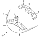
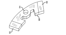
図4Aおよび図4Bを参照すると、調整可能な加重システム500の一実施形態が示されている。調整可能な加重システム500は、クラブヘッド10のソール30に配置されている単一のポートまたはチャネルまたは溝状トラック504を含む。図示の実施形態では、チャネル504は、フェースプレート34よりもクラブヘッド10の後部42の近位に、またはそれに近い位置に配置されている。しかしながら、他の実施形態では、チャネル504は、フェースプレート34に対してクラブヘッド10のソール30の任意の適切な位置に配置することができる。さらに、チャネル504は弓形または湾曲形状を有するように示されている。しかしながら、他の実施形態では、チャネル504は任意の適切な形状(例えば、直線状、幾何学的形状など)を有することができる。図4Aに示すように、チャネル504は、幅Wおよび高さ(または深さ)Hを含む。幅Wは、チャネル504の対向する側面間の距離として定義される。高さHは、ソール30とチャネル504の底面との間の距離として定義される。図示の実施形態では、幅Wおよび高さHは、チャネル504に沿って一定である(すなわち、チャネル504に沿った異なる位置において同じである)。他の実施形態では、高さHがチャネル504に沿って変化するかまたは変化しているように、チャネル504の底面を傾斜または階段状にすることができる。さらに他の実施形態では、チャネル504の対向する側面間の距離は、チャネル504に沿って可変幅Wを有するように変化(例えば、増加または減少)することができる。
B. Adjustable Weighting System Embodiments With reference to FIGS. 4A and 4B, one embodiment of an
調節可能な加重システム500はまた、チャネル504によって受け入れられるように構成されている部材508(またはインサート708)を含む。部材508は、(図4Bに示される)本体幅WBおよび本体高さ(または本体深さ)HBを有する本体512を含む。本体幅WBは、チャネル504の幅Wを超えないように、チャネル504の幅Wに対応することが好ましい。同様に、本体の高さHBは、チャネル504の高さHを超えないように、チャネル504の高さHに対応することが好ましい。これにより、部材508がチャネル504によって受け入れられることが可能になる。他の実施形態では、本体幅WBはチャネル504の幅Wより小さくてもよく、および/または本体高さHBはチャネル504の高さHより小さくてもよいことを理解されたい。さらに他の実施形態では、本体の高さHBはチャネル504の高さHより大きくてもよく、これにより、部材508がチャネル504から延出される。本体512は、本体512を完全に貫通して延びる開口部514を画定する。開口部514は、チャネル504内に配置されたチャネル開口部78(図4Bに示される)と整列するように構成される。位置合わせされると、開口部514およびチャネル開口部78は、部材508をチャネル504に結合するように構成された締結具510を受け入れる。図示の実施形態では、締結具510は、ねじ付き締結具(例えば、ねじ、ボルトなど)、または部材508をチャネル504に選択的に固定するための任意の適切な装置とすることができる。さらに、多くの実施形態では、締結具510がクラブヘッド本体10の密度に有意に寄与しないように、締結具510はクラブヘッド本体の密度と同等またはそれ未満の密度を含むことができる。
The
図4Bを参照すると、本体512は第1の端部516および第2の端部520を含む。第1の端部516は本体512の一方の端部に配置され、第2の端部520は第1の端部516と反対側の本体512の他方の端部に配置されている。各端部516、520は、様々な構成でそれぞれのウェイト532、536と係合するように構成されているそれぞれの取り付け位置524、528を含む。図示の実施形態では、第1の端部516に位置する第1の取り付け位置524は第1の突出部524として示されている。第1の突出部524は第1および第2のアームを含み、各アームはフック形状を有し、空隙またはチャネル525を画定する。第2の端部520に位置する第2の取り付け位置528は、第2の突出部528として示されている。第2の突出部528は第1および第2のアームを含み、それぞれがフック形状を有し、空隙またはチャネル529を画定する。各ウェイト532、536は、第1および第2の突出部524、528に形状が対応し、突出部524、528のうちの1つと係合し、より具体的にはそれらを受け入れるように構成される空隙またはチャネル540を画定する。図示の実施形態では、ウェイト532、536は、突出部524、528の空隙525、529内に受け入れられて、ウェイト532、536を部材508に仮固定することができる柱542をさらに含む。これらの実施形態では、ウェイト532、536は、スナップ嵌合または圧入機構によって部材508に結合するように構成される。他の実施形態では、以下の実施形態でさらに説明されるように、ウェイト532、536は他の任意の適切な機構を使用して部材に結合することができる。
4B, the
各ウェイト532、536は丸い幾何学的形状を有する。他の実施形態では、ウェイト532、536は、正方形、円形、長方形、三角形、または任意の適切な多角形形状、または少なくとも1つの曲面を有する形状などの異なる形状を有することができる。さらに、ウェイトは、アドレス時にフェース角を調整するのに適した形状を有することができ、これについては、フェース角調整システム1200に関連して以下でさらに詳細に説明する。
Each
第1および第2のウェイト532、536は、後述するように、重量分布およびクラブヘッドの重心を調整するために、ボールの弾道および/またはスピンに影響を与えるように、任意の取り付け位置524、528に配置または再配置することができる。
The first and
図5~図6を参照すると、調整可能な加重システム700の実施形態が示されている。調整可能な加重システム700は、調整可能な加重システム500と同様の構成要素を有し、同様の名称および/または同様の番号は同様の構成要素を識別する。調整可能な加重システム700は、クラブヘッド10のソール30に配置されている単一のポートまたはチャネルまたは溝状トラック704を含む。図示の実施形態では、チャネル704は、フェースプレート34よりもクラブヘッド10の後部42の近位に、またはその近くに配置されている。しかしながら、他の実施形態では、チャネル704は、クラブヘッド10のソール30の任意の適切な位置に配置することができる。さらに、チャネル704は弓形または湾曲形状を有するように示されている。しかしながら、他の実施形態では、チャネル704は任意の適切な形状(例えば、直線状、幾何学的形状など)を有することができる。図6に示すように、チャネル704は幅Wと高さ(または深さ)Hを含む。幅Wはチャネル704の対向する側面間の距離として定義される。高さHは、ソール30とチャネル704の底面との間の距離として定義される。図示の実施形態では、幅Wおよび高さHはチャネル704に沿って一定である(すなわち、チャネル704に沿った異なる位置において同じである)。他の実施形態では、高さHがチャネル704に沿って変化する、または変化するように、チャネル704の底面を傾斜または段差にすることができる。さらに他の実施形態では、チャネル704の対向する側面間の距離は、チャネル704に沿って変化する幅Wを有するように変化(例えば、増加または減少)することができる。
5-6, an embodiment of an
図5~図6を参照すると、調節可能な加重システム700はまた、チャネル704によって受け入れられるように構成されている部材708(またはインサート708)を含む。部材708は、(図5に示される)本体幅WBおよび本体高さ(または本体深さ)HBを有する本体712を含む。本体幅WBは、チャネル704の幅Wを超えないように、チャネル704の幅Wに対応することが好ましい。同様に、本体の高さHBは、チャネル704の高さHを超えないように、チャネル704の高さHに対応することが好ましい。これにより、部材708がチャネル704によって受け入れられることが可能になる。他の実施形態では、本体幅WBはチャネル704の幅Wより小さくてもよく、および/または本体高さHBはチャネル704の高さHより小さくてもよいことを理解されたい。さらに他の実施形態では、本体の高さHBはチャネル704の高さHより大きくてもよく、それにより部材708がチャネル704から延出される。本体712は、本体712を完全に貫通して延びる開口部714を画定する。開口部714は、チャネル704内に配置されたチャネル開口部78(図11に示す)と整列するように構成される。位置合わせされると、開口部714およびチャネル開口部78(図11に示される)は、部材708をチャネル704に結合するように構成された締結具(図5~図6には示されないが、図7、図9、および図11に810、910、1010としてそれぞれ示される)を受け入れる。図示の実施形態では、締結具は、ネジ付き締結具(例えば、ネジ、ボルトなど)または部材708をチャネル704に選択的に締結するための任意の適切な装置とすることができる。さらに、多くの実施形態では、締結具710は、締結具710がクラブヘッド10の重量分布に大きく寄与しないように、クラブヘッド本体の密度と同等またはそれ未満の密度を含むことができる。
5-6, the
図6に示すように、本体712は、第1の端部716と第2の端部720とを含む。第1の端部716は本体712の一方の端部に配置され、第2の端部720は第1の端部716とは反対側の本体712の他方の端部に配置されている。各端部716、720は、様々な構成でそれぞれのウェイト732、736と係合するように構成されているそれぞれの取り付け位置724、728を含む。図示の実施形態では、第1の端部716に位置する第1の取り付け位置724は、第1の突出部724(または第1の柱724)として示されている。第2の端部720に位置する第2の取り付け位置728は、第2の突出部728(または第2の柱728)として示されている。各ウェイト732、736は、突出部724、728のうちの1つと係合し、より具体的にはそれを受け入れるように構成された開口部740(または穴740)を画定することができる。各突出部724、728は、各開口部740内に配置された対応するねじ山とねじ連結部を形成するようにねじ山を切ることができる。他の実施形態では、各突出部724、728は、各開口部740が突出部724、728のうちの1つをスライド可能に受け入れて各取り付け位置724、728のうちの1つをスライド可能に取り付けるように滑らかな(または比較的滑らかな)表面を有し得る。開口部740は、各ウェイト732、736内に部分的に延びるように示されている。他の実施形態では、開口部740は、ウェイト732、736のうちの1つまたは複数を完全に貫通して延びることができる。各ウェイト732、736は本体712に対して取り外し可能に結合されるように示されているが、他の実施形態では、ウェイト732、736がユーザによって本体712から意図的に外されないように、各ウェイト732、736を本体712に取り付けることができる。例えば、ウェイト732、736は、接着剤または他の任意の永久もしくは半永久的な取り付け材料によって本体712にさらに取り付けることができる。
As shown in FIG. 6, the
各ウェイト732、736は幾何学的形状または多角形形状を有する。例えば、図6に示す実施形態では、各ウェイト732、736は三角形の断面形状を有する。各ウェイト732、736の三角形の断面形状は、異なる長さの辺を有することができる(例えば、二等辺三角形、不等辺三角形、鋭角、直角、鈍角など)。他の実施形態では、各ウェイト732、736の三角形の断面形状は、正三角形状であり得る(すなわち、三角形の各辺は同じ長さを有する)。さらに他の実施形態では、ウェイト732、736は、円錐ピラミッド形(または三角錐台形)の形状を有することができ、または異なる断面形状を有することができる。例えば、後述する図7~図10の実施形態では、各ウェイト832、836、932、936は、概して長方形の形状を有する。さらに他の実施形態では、各ウェイトは、本体712の断面形状に対応し、本体712の断面形状よりも大きく、本体712の断面形状よりも小さく、チャネル704の形状に対応し(すなわち、各ウェイトがチャネル704によって受け入れられるように)、チャネル704の幅Wおよび/または高さHより寸法が小さいか、またはチャネル704の高さHより寸法が大きい(例えば、ウェイトがチャネル704の外に延びてソール30から突出するように)。さらに他の実施形態では、1つまたは複数のウェイトは、正方形、円形、長方形、三角形、または任意の適切な多角形であり得る。さらに、ウェイトは、アドレス時にフェース角を調整するのに適した形状を有することができ、これについては、フェース角調整システム1200に関連して以下でさらに詳細に説明する。
Each
第1および第2のウェイト732、736は、後述するように、ボールの弾道および/またはスピンに影響を与えるように、重量分布およびクラブヘッドの重心を調整するために、任意の取り付け位置724、728に配置または再配置され得る。
The first and
図7~図8は、調整可能な加重システム800の他の実施形態を示す。調整可能な加重システム800は、調整可能な加重システム700と同様の構成要素を有し、同様の名称および/または同様の番号は同様の構成要素を識別する。図7に示すように、調整可能な加重システム800は、チャネル804と部材808を含む。チャネル804は、形状を除いてチャネル704と実質的に同じである。より具体的には、チャネル804は、異なる位置で異なる幅を有するように「U字形」を有する。例えば、チャネル804の端部における第1の幅W1は、チャネル804の中心(または中点)における第2の幅W2よりも大きい。部材808はまた、チャネル804によって受け入れられるように、チャネル804の形状に対応する「U字形」を有する。部材808は、締結具810によってチャネル804に結合されている。より具体的には、開口部814はチャネル開口部78(図11に示す)と位置合わせされ、開口部814およびチャネル開口部78(図11に示す)は締結具810を受け入れ、部材808がチャネル804に取り付けられる。さらに、多くの実施形態では、締結具810は、クラブヘッド10の重量分布に大きく寄与しないように、クラブヘッド本体の密度と同等またはそれ未満の密度を含むことができる。
7-8 show another embodiment of an
部材808はまた、様々な構成で第1のウェイト832および第2のウェイト836を担持する。ウェイト832、836は、形状を除いてウェイト732、736と実質的に同じである(例えば、ウェイト832、836は突出部828などによって部材808に取り付けられる)。図7に示すように、ウェイト832、836は、ウェイト幅WWがウェイト高さWHよりも大きい(または長い)ように、概して長方形の形状を有する。
図9~図10は、調整可能な加重システム900の他の実施形態を示す。調整可能な加重システム900は、調整可能な加重システム700、800と同様の構成要素を有し、同様の名称および/または同様の番号は同様の構成要素を識別する。図9に示すように、調整可能な加重システム900はチャネル904と部材908を含む。チャネル904は、形状を除いてチャネル704、804と実質的に同じである。より具体的には、チャネル904は、チャネル904が異なる位置で異なる幅を有するように「M字形」を有する。部材908はまた、チャネル904によって受け入れられるように対応する「M字形」を有する。部材908は締結具910によって溝904に結合する。より具体的には、開口部914(図10に示す)がチャネル開口部78(図11に示す)と整列し、開口部914およびチャネル開口部78(図11に示す)が締結具910を受け入れて、部材908がチャネル904に取り付けられる。さらに、多くの実施形態では、締結具910は、クラブヘッド10の重量分布に大きく寄与しないように、クラブヘッド本体の密度と同等またはそれ未満の密度を含むことができる。
9-10 show another embodiment of an
部材908はまた、様々な構成で第1のウェイト932および第2のウェイト936を担持する。ウェイト932、936は、ウェイト732、736、832、836と実質的に同じであり、ウェイト832、836と同じ長方形の形状を有することも含む。
The
図11は、調整可能な加重システム1000の他の実施形態を示す。調整可能な加重システム1000は、調整可能な加重システム700、800、900と同様の構成要素を有し、同様の名称および/または同様の番号は同様の構成要素を識別する。図11に示すように、調整可能な加重システム1000は、チャネル1004と部材1008とを含む。チャネル1004は、チャネル704と実質的に同じである。第1のウェイト1032は、第1のウェイト1032の形状を除いて、第1のウェイト732と実質的に同じである。特に、第1のウェイト1032は突出タブ1044を含む。突出タブ1044は、部材1008に整列して結合するための係合面として機能する。より具体的には、突出タブは、突出タブ1044を通って延びる開口部1048を含む。部材1008は、開口部714と実質的に同じ部材開口部1014が突出タブ開口部1048と整列するように突出タブ1044上に位置決めされる。次に、部材1018およびウェイト1032は、開口部1014、1048がチャネル開口部78と整列するようにチャネル1004内に配置される。開口部1014、1048、78が整列すると、それらは締結具1010を受け入れる。締結具1010は締結具810、910と実質的に同じである。他の実施形態では、突出タブ1044が部材1008の上方を延びることができ、あるいは突出タブ1044が(ウェイト1032ではなく)部材1008と共に形成することができる。さらに他の実施形態では、突出タブ1044は、部材1008の全体を含む部材1008の一部分の下方を延びることができ、または部材1008を越えて延びることができる。
FIG. 11 illustrates another embodiment of an
図12は、調整可能な加重システム1100の他の実施形態を示す。調整可能な加重システム1100は、調整可能な加重システム700、800、900、1000と同様の構成要素を有し、同様の名称および/または同様の番号は同様の構成要素を識別する。図12に示すように、調整可能な加重システム1100は、チャネル1104と部材1108を含む。チャネル1004はチャネル704と実質的に同じであり、部材1108は部材708と実質的に同じである。違いは、部材1108の本体1112が、4つの異なるウェイトとして示されている複数のウェイトに係合するように構成されていることである。調節可能な加重システム700と同様に、第1のウェイト1132が本体1112の第1の端部1116の第1の取り付け位置に取り付けられ、第2のウェイト1136が本体1112の第2の端部1120の第2の取り付け位置に取り付けられる。しかしながら、調整可能な加重システム1100のこの実施形態では、第3のウェイト1152が本体1112の第1の側面1156の第3の取り付け位置に取り付けられ、第4のウェイト1160が反対側の本体1112の第2の側面1164の第4の取り付け位置に取り付けられる。各ウェイト1132、1136、1152、1160は、ウェイト732、736と実質的に同じであってもよく、上記と同様に本体1112に取り付けられてもよい。さらに、第1、第2、第3、および第4のウェイト1132、1136、1152、1160は、後述するように、ボールの弾道および/またはスピンに影響を与えるために、部材の任意の取り付け位置に配置されるかまたはそれらの間に再配置されて、重量分布およびクラブヘッド重心を調整することができる。
FIG. 12 illustrates another embodiment of an
図13は、フェース角調整システム1200の一実施形態を示す。図示のシステム1200は、調整可能な加重システム700と構造的に類似しており、類似の名前および/または類似の番号は類似の構成要素を識別する。違いは、この実施形態では、各端部部材1232、1236は重み付けされていないが、その代わりに、静止フェース角度の調整を可能にするのに適した幾何学的形状(または形状)を有していることである。この実施形態は、本明細書に開示される調整可能な加重システム500、700、800、900、1000、1100とは別に説明されるが、フェース角調整システム1200の特徴は、調整可能な加重と静止フェース角の調整の双方が可能となるシステムを提供するために、調整可能な加重システム500、700、800、900、1000、1100の実施形態のいずれにも組み込むことができることを理解されたい。したがって、他の実施形態では、各端部部材1232、1236は、本明細書に開示される静止フェース角度の調整を可能にする特徴も含むウェイト(例えば、ウェイト732、736、832、836、932、936、1132、1136、1152、1160など)であり得る。
FIG. 13 illustrates one embodiment of a face
図13に示すように、フェース角調整システム1200は、ソール30に配置されたチャネル1204と、本体1212を有する部材1208とを含む。本体1212は、部材1208をチャネル1204に結合するために締結具(図示せず、図7、9、および11にそれぞれ810、910、1010として示す)を受け入れるように構成された開口1214を画定する。本体1212は、第1の端部1216および第2の端部1220を含み、第1の端部1216および第2の端部1220は、本体1212の両端に配置されている。第1の取り付け位置1224(または第1の突出部1224または第1の柱1224)は第1の端部1216に配置され、第2の取り付け位置1228(または第2の突出部1228または第2の柱1228)は第2の端部1220に配置される。第1の端部部材1232は第1の取り付け位置1224に取り外し可能に結合し、第2の端部部材1236は第2の取り付け位置1228に取り外し可能に結合する。各端部部材1232、1236は複数の側面1268a、1268bを有する。少なくとも1つの側面1268aは、第2の側面1268bの長さよりも大きい長さを有することができる(または少なくとも1つの側面1268aは、第2の側面1268bの長さよりも短い長さを有することができる)。したがって、端部部材1232、1236の一方または両方が本体1212に対して回転する(またはそれぞれの取り付け位置1224、1228に対して回転する)と、複数の側面1268a、1268bのうちの1つをチャネル1204から延出するように、ソール30と同一平面になるように(例えば、チャネル1204から延出するまたは突出しないように)、および/またはチャネル1204内に陥没するように、配向することができる。各端部部材1232、1236は、開口部740と実質的に同じである開口部1240を含むことができることを理解されたい。したがって、端部部材1232、1236は、上述したように、ウェイト732、736が本体712に取り付けられるのと同じ方法で本体1212に取り付けることができる。
13, the face
調整可能な加重システム500、700、800、900、1000、1100の動作において、ユーザは、締結具510、810、910、1010を外すことにより、関連するチャネル504、704、804、908、1004、1104から部材508、708、808、908、1008、1108を取り除くことができる。その後、ユーザは、ウェイト532、536、732、736、832、836、932、936、1032、1036、1132、1136、1152、1160のうちの1つまたは複数を取り除いて再配置し、そして部材508、708、808、908、1008、1108をチャネル504、704、804、908、1004、1104に再び取り付けることができる。
In operation of the
取り外し可能なウェイトのない実施形態では、ユーザは、関連するチャネル504、704、804、908、1004、1104から部材508、708、808、908、1008、1108を取り外し、次いで異なる重量を有する第2の部材構成(すなわち、ウェイト532、536、732、736、832、836、932、936、1032、1036、1132、1136、1152、1160のうちの1つ以上は、取り除かれた部材とは異なる質量を有する)を取り付けることができる。
In embodiments without removable weights, a user can remove a
代替的に又は追加的に、部材508、708、808、908、1008、1108を取り外し、配向を変え、そしてチャネル507、704、804、908、1004、1104に再設置することができる。例えば、部材508、708、808、908、1008、1108は、第1のウェイト532、732、832、932、1032、1132がヒール端よりもトウ端18の近くに配置されている第1の配向から取り外され、再配向され(例えば、180度回転させる、ひっくり返す等)、そして、第1のウェイト532、732、832、932、1032、1132がトウ端18よりもヒール端22の近くに配置される第2の配向で再び取り付けられる。
Alternatively or additionally, the
ウェイト532、536、732、736、832、836、932、936、1032、1036、1132、1136、1152、1160のうちの1つまたは複数の重量を変更することによって、および/または部材508、708、808、908、1008、1108を再配向することによって、重心58を調整(または変更)することができる。例えば、重心58を調整(または移動)することができる距離は、0.01インチから0.50インチの範囲内とすることができ、その結果、ボール軌道の変化は0.46ヤードから23ヤードとなる。他の実施形態では、クラブヘッドの重心58は、0.050インチから0.200インチの範囲で調整(または移動)することができ、その結果、ボール軌道の変化が2.3ヤードから9.2ヤードとなる。
The center of
フェース角調整システム1200の動作において、ユーザは、締結具510、810、910、1010を外すことによってチャネル1204から部材1208を取り外すことができる。次いで、ユーザは、端部部材1232、1236の一方または両方を回転させ、取り外して交換し、または別の方法で配向を変え、次いで部材1208をチャネル1204に再設置し、部材1208をチャネル1204に再び取り付けることができる。
In operation of the face
例えば、トウ端18に最も近い位置にある端部部材1232、1236を再び取り付けるときにチャネル1204の外に延びるように向きを変え、ヒール端22に最も近い位置にある端部部材1236、1232を再び取り付けるときにチャネル1204の外に延びないように向きを変えることにより、アドレス時のフェース角(またはゴルフクラブの静止フェース角)は、アドレス時にトウ端18がヒール端22よりもゴルフボールに近い、クローズ位置に再配向することができる(例えば、ドローやフックを促進するためなど)。
For example, by reorienting the
別の例としては、トウ端18に最も近い位置にある端部部材1232、1236を再び取り付けるときにチャネル1204の外に延びないように向きを変え、ヒール端22に最も近い位置にある端部部材1236、1232を再び取り付けるときにチャネル1204の外に延びるように向きを変えることにより、アドレス時のフェース角(またはゴルフクラブの静止フェース角)は、アドレス時にヒール端22がトウ端18よりもゴルフボールに近い、オープン位置(オープン構成)に再配向することができる(例えば、カットやスライスを促進するためなど)。
As another example, by reorienting the
さらに別の例として、トウ端18に最も近い位置にある端部部材1232、1236を再び取り付けるときにチャネル1204の外に延びないように向きを変え、ヒール端22に最も近い位置にある端部部材1236、1232を再び取り付けるときにチャネル1204の外に延びないように向きを変えることにより、アドレス時のフェース角(またはゴルフクラブの静止フェース角)は、アドレス時にヒール端22とトウ端18のどちらかがゴルフボールに近いことがない、ニュートラル位置(ニュートラル構成またはスクエア構成)に再配向することができる(例えば、ストレートなボール飛行を促進するためなど)。
As yet another example, by orienting the
また、フェース角調整システム1200の図示の実施形態はウェイトを含まないが、端部部材1232、1236は、本明細書に開示されるように、フェース角調整システム1200が調整可能な加重システム500、700、800、900、1000、1100の1つ以上に組み込まれ得るようなウェイトであり得ることを理解されたい。
Also, while the illustrated embodiment of the face
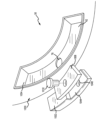
図14~図15を参照すると、調整可能な加重システム1300の他の実施形態が示されている。調整可能な加重システム1300は、クラブヘッド10のソール30に配置されている単一のポートまたはチャネルまたは溝状トラック1304(図15に示されている)を含む。図示の実施形態では、チャネル1304は、フェースプレート34よりもクラブヘッド10の後部42の近位に、またはその近くに配置されている。しかしながら、他の実施形態では、チャネル1304はクラブヘッド10のソール30の任意の適切な位置に配置することができる。チャネル1304は、弓形または湾曲形状を有するように示されている。他の実施形態では、チャネル1304は任意の適切な形状(例えば直線状など)を有することができる。
14-15, another embodiment of an
図15に示すように、チャネル1304は、第1のチャネル部1308、第2のチャネル部1312、および第3のチャネル部1316を含む。チャネル部1308、1312、1316は、チャネル1304(またはチャネル1304の一部)を集合的に画定することができる。第2のチャネル部1312は、第1のチャネル部分1308と第3のチャネル部分1316との間に配置されている。第2のチャネル部1312は、第2のチャネル部1312内のチャネル1304の対向する縁部間の距離を画定する第1の幅W1を含む。第1のチャネル部1308は、第1のチャネル部1308内のチャネル1304の対向する縁部間の距離を画定する第2の幅W2を含む。同様に、第3のチャネル部1316は、第3のチャネル部1316内のチャネル1304の対向する縁部間の距離を画定する第3の幅W3を含む。第1の幅W1は第2の幅W2および第3の幅W3より小さく、チャネル1304にテーパを形成する。言い換えれば、チャネル1304は、第1および第3のチャネル部1308、1316よりも第2のチャネル部1312の方が狭い。図示の実施形態では、第2幅W2と第3幅W3は実質的に同じ(または等しい)。しかしながら、他の実施形態では、第2の幅W2と第3の幅W3は異なる幅であり得る(または等しくなくてもよい)。
15 , the
チャネル1304はテーパ状端部1320a、bを含む。テーパ端部1320a、bは、(幅テーパの代わりに)深さテーパを画定し、それぞれのチャネル部分1308、1316からチャネル1304の縁部まで深さを徐々に減少させるようにチャネル1304の両端に配置される。第1のテーパ状端部1320aは、第1のチャネル部分1308内に位置決めされ、そして減少する深さを有する。言い換えれば、テーパ状端部1320aに沿った深さは、第1のチャネル部分1308における深さよりも小さい。第2のテーパ状端部1320bは、それが第3のチャネル部分1316内に位置決めされることを除いて、第1のテーパ状端部1320aと実質的に同じである。実施形態の他の例では、チャネル1304は、テーパ状端部1320を含むかまたはテーパ状端部を含まない一端を有することができる。
The
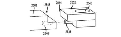
図14~図15を参照すると、調節可能な加重システム1300はまた、チャネル1304によって受け入れられるように構成されている部材1324(またはインサート1324)を含む。図示の実施形態では、部材1324は、チャネル1304によって受け入れられるように、チャネル1304と相補的な形状を有する。
With reference to FIGS. 14-15, the
図15に示すように、部材1324は本体1328(または中央部材1328)を含む。本体1328は、第2の端部1336の反対側にある第1の端部1332を含む。端部1332、1336の各々は、本体1328の厚さ(または深さ)よりも小さい厚さ(または深さ)を有する。各端部1332、1336はまた、端部1332、1336を完全に貫通して延びるそれぞれの開口部1340a、bを画定する。本体1328は、ウェイト(またはマス)を有することができる。第1のウェイト1344は、第1の端部1332で第1の取り付け位置に取り付けるように構成されている。より具体的には、第1のウェイト1344は、第1の端部1332を受け入れる(またはスライド可能に受け入れる)ように構成されたスロット1348を画定する。第1のウェイト1344はまた、スロット1348の両側で第1のウェイト1344を貫通して配置された対向する開口部1352a、bを含む。第2のウェイト1356は、第1のウェイト1344と実質的に同じであり、同じ番号は同じ構成要素を識別する。部材1324が本体1328、第1のウェイト1344、および第2のウェイト1356を含むことを理解されたい。
15, the
第1のウェイト1344は、第1の端部1332で本体1328に取り外し可能に取り付けられている。第1のウェイト1344は、スロット1348内に第1の端部1332を受け入れる。言い換えれば、第1の端部1332は、第1のウェイト1344のスロット1348によってスライド可能に受け入れられる。次に、開口部1352a、1340a、および1352bを位置合わせして位置決めし、第1の端部1332の開口部1340aを第1のウェイト1344の開口部1352a、1352bの間に位置決めする。位置合わせされると、開口部1352a、1340a、1352bは締結具(例えば、ネジ付きネジなど)を受け入れることができる(図示せず)。第2のウェイト1356は、同じ方法で第2の端部1336の第2の取り付け位置で本体1328に取り外し可能に取り付けられる。より具体的には、第2のウェイト1356は、スロット1348内に第2の端部1336を受け入れる。言い換えれば、第2の端部1336は、第2のウェイト1356のスロット1348によってスライド可能に受け入れられる。次に、開口部1352a、1340b、および1352bを位置合わせして位置決めし、第2の端部1336の開口部1340bを第2のウェイト1356の開口部1352a、1352bの間に位置決めする。位置合わせされると、開口部1352a、1340b、1352bは締結具(例えば、ネジ付きネジなど)を受け入れることができる(図示せず)。
The
ウェイト1344、1356を本体1328に結合する締結具(図示せず)はまた、チャネル1324内で部材1324をクラブヘッド10に結合することができる。より具体的には、締結具(図示せず)は、チャネル1304内に配置されたそれぞれの穴1360a、b内に受け入れられる(または係合)ように構成される。より具体的には、第1の穴1360aが第1のチャネル部1308内に位置決めされ、第2の孔1360bが第3のチャネル部1316内に位置決めされる。多くの実施形態では、締結具は、クラブヘッド10の重量分布に大きく寄与しないように、クラブヘッド本体の密度と同等以下の密度を含むことができる。
Fasteners (not shown) that couple the
第1および第2のウェイト1344、1356は、後述するように、ボールの弾道および/またはスピンに影響を与えるために、重量分布およびクラブヘッドの重心を調整するために、任意の取り付け位置に配置または再配置することができる。
The first and
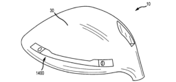
図16~図17は、調整可能な加重システム1400の他の実施形態を示す。調整可能な加重システム1400は、調整可能な加重システム1300と同様の構成要素を有し、同様の名称および/または同様の番号は同様の構成要素を識別する。調整可能な加重システム1400は実質的に調整可能な加重システム1300と類似しており、相違点のみが本明細書に記載されており、同様の構造は「100」だけ増分された同じ参照番号で参照される(例えば1304および1404は両方ともチャネルなどを参照)。
16-17 show another embodiment of an
図17に示すように、調整可能な加重システム1400は、第1のチャネル部1408、第2のチャネル部1412、および第3のチャネル部1416を有するチャネル1404を含む。チャネル部1408、1412、1416は、チャネル部1308、1312、1316と実質的に同じであるが、第2のチャネル部1412内のチャネル1404の対向する縁部間の距離を画定する第1の幅W1Aが第2のチャネル部1312の第1の幅W1より大きい。第1の幅W1Aは、第1のチャネル部1408内のチャネル1404の対向する縁部間の距離を画定する第2の幅W2Aより小さい。第1の幅W1Aはまた、第3のチャネル部1416内のチャネル1404の対向する縁部間の距離を画定する第3の幅W3Aよりも小さい。加えて、チャネル1404に形成されたテーパが存在するが、チャネル1304に形成されたテーパよりも目立たない(またはそれほど重要ではない)。
17, the
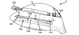
図18~図19は、調整可能な加重システム1500の他の実施形態を示している。調整可能な加重システム1500は、調整可能な加重システム1300、1400と同様の構成要素を有し、同様の名称および/または同様の番号は同様の構成要素を識別する。調整可能な加重システム1500は実質的に調整可能な加重システム1300と類似しており、相違点のみが本明細書で説明され、同様の構造は「200」だけ増分された同じ参照番号で参照される(例えば、1304および1504は両方ともチャネルなどを参照)。
18-19 show another embodiment of an
図19に示すように、調整可能な加重システム1500は、第1のチャネル部1508、第2のチャネル部1512、および第3のチャネル部1516を有するチャネル1504を含む。チャネル部1508、1512、1516は、チャネル1504がチャネル部1508、1512、1516に沿って一定の幅W1Bを有し、チャネル1504が可変の深さを有することを除いて、チャネル部1308、1312、1316と実質的に同じである。より具体的には、第2のチャネル部1512内のチャネルの深さは、第1のチャネル部1508および第3のチャネル部1516内のチャネルの深さよりも小さい。より具体的には、第2のチャネル部1512は第1の深さD1を含む。第1のチャネル部1508は第2の深さD2を含み、第3のチャネル部1516は第3の深さD3を含む。第1深さD1は、第2深さD2および第3深さD3よりも小さい。したがって、チャネル1504は、第2のチャネル部1508よりもウェイト1544、1556をそれぞれ受け入れる第1および第3のチャネル部1508、1516においてより大きな深さを有する。ウェイト1544、1556はウェイト1344、1356と実質的に同じであることを理解されたい。
As shown in FIG. 19, the
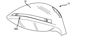
図20~図21は、調整可能な加重システム1600の他の実施形態を示している。調整可能な加重システム1600は、調整可能な加重システム100、1300、1400、1500と同様の構成要素を有し、同様の名称および/または同様の番号は同様の構成要素を識別する。調整可能な加重システム1600は実質的に調整可能な加重システム1500と類似しており、相違点のみが本明細書で説明され、同様の構造は「100」だけ増分された同じ参照番号で参照される(例えば1404および1504は両方ともチャネルなどを参照)。
20-21 show another embodiment of an
図21に示すように、調整可能な加重システム1600は、第1のチャネル部1608、第2のチャネル部1612、および第3のチャネル部1616を有するチャネル1604を含む。チャネル部1608、1612、1616は、チャネル1604が、第2のチャネル部1612と第1のチャネル部1608との間、および第2のチャネル部1612と第3のチャネル部1616の間にテーパ状移行部を含むことを除いて、チャネル部1508、1512、1516と実質的に同じである。より具体的には、チャネル1604は、第2のチャネル部1612と第1のチャネル部1608との間に第1のテーパ状深さ移行部1664aを含む。第1のテーパ状深さ移行部1664aは、第2のチャネル部1612から第1のチャネル部1608へのチャネル深さの増分的増加である。言い換えれば、第1のテーパ状深さ移行部1664aは、第2のチャネル部1612と第1のチャネル部1608との間の勾配である。チャネル1604はまた、第2のチャネル部1612と第3のチャネル部1616との間に第2のテーパ状深さ移行部1664bを含む。第2のテーパ状深さ移行部1664bは、それが第2のチャネル部1612と第3のチャネル部1616との間に配置されることを除いて、第1のテーパ状深さ移行部1664aと実質的に同じである。
21, the
図22は、調整可能な加重システム1700の他の実施形態を示す。調整可能な加重システム1700は、調整可能な加重システム1300、1400、1500、1600と同様の構成要素を有し、同様の名称および/または同様の番号は同様の構成要素を識別する。調整可能な加重システム1700は実質的に調整可能な加重システム1300と類似しており、相違点のみが本明細書で説明され、同様の構造は「400」だけ増分された同じ参照番号で参照される(例えば、1304および1704は両方ともチャネルなどを参照)。
22 illustrates another embodiment of an
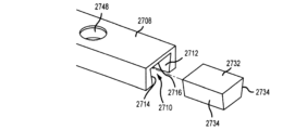
調整可能な加重システム1700は、チャネル1704(破線で示される)によって受け入れられるように構成されている部材1724(またはインサート1724)を含む。図示の実施形態では、部材1724は、チャネル1704によって受け入れられるように、チャネル1704と相補的な形状を有する。部材1724は、第1のウェイト1744および第2のウェイト1756を含む。部材1724は部材1324と実質的に同じであり、ウェイト1744、1756はウェイト1344、1356とほぼ同じである。しかしながら、部材1724は、それが「T字形」を有するという点で異なる。より具体的には、部材1724は、本体部1728と、本体部1728とほぼ直交する向きの脚部1768とを含む。したがって、チャネル1704は、第2のチャネル部(図示せず)に対してほぼ直角に配向され、脚部1768を受け入れるように構成された対応する追加のチャネル部(図示せず)を有する。脚部1768は、第1および第2のウェイト1344、1356と実質的に同じである第3のウェイト1772を含む。さらに、第3のウェイト1772は、第1および第2のウェイト1344、1356が本体1328に取り外し可能に結合するのと同じ方法で、脚部1768に取り外し可能に結合する。
The
調整可能な加重システム1300、1400、1500、1600、1700の動作は実質的に同様であり、したがって、動作は調整可能な加重システム1300に関連して説明される。同じステップが、加重システム1400、1500、1600、1700の他の実施形態にも当てはまる。
The operation of
ユーザは、チャネル1304内に配置されたそれぞれの穴1360から締結具(図示せず)を外すことによって、チャネル1324から部材1324を取り外すことができる。チャネル1304から取り外されると、ユーザは、本体1328から1つまたは複数のウェイト1344、1356を外す(または別の方法で取り外す)ことができる。それぞれのウェイト1344、1356を取り外すために、ユーザは、位置合わせされた開口部1352a、1340、1352bから締結具(図示せず)を外す。それぞれのウェイト1344、1356は、それから本体1328から自由に外れる。次いで、ユーザは、本体1328またはウェイト1344、1356を、異なる質量(例えば、より軽いまたはより重い)を有する別のものと交換して、ゴルフクラブヘッド10の重量特性を変えることができる。次いで、異なる質量を有する本体1328および/またはウェイト1344、1356を再係合(または再取り付け)することができる。より具体的には、ウェイト1344、1356は、本体1328の一部(例えば、第1の端部1332、第2の端部1336など)をスライド可能に受け入れ、開口部1352a、1340、1352bを整列させる。開口部1352a、1340、1352bが整列すると、締結具(図示せず)を開口部1352a、1340、1352bを通して再挿入することができる。次いで、部材1324をチャネル1304内に位置決め(または再位置決め)することができ、各締結具(図示せず)をチャネル1304内のそれぞれの穴1360と係合(または再係合)させることができる。上記の動作は、ウェイト1344、1356の取り外しだけでなく、3つのウェイト1744、1756、1772を有する実施形態にも適用されることを理解されたい。
A user can remove the
本体1328および/またはウェイト1344、1356(またはウェイト1744、1756、1772)のうちの1つまたは複数を変更することによって、重心58を調整(または変更)することができる。例えば、重心58を調整(または移動)することができる距離は、0.01インチから0.50インチの範囲内とすることができ、その結果、ボール軌道の変化は0.46ヤードから23ヤードとなる。他の実施形態では、クラブヘッドの重心58は、0.050インチから0.200インチの範囲で調整(または移動)することができ、その結果、ボール軌道の変化は2.3ヤードから9.2ヤードとなる。
By modifying one or more of the
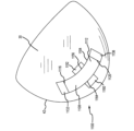
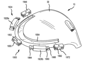
図23~図24を参照すると、調整可能な加重システム1800の一実施形態が示されている。システム1800は、様々な構成で複数のウェイトを受け入れるように構成された単一のポートまたはチャネルまたは溝状トラック1804を含む。チャネル1804は、ソール30の一部に配置された弓形または湾曲チャネル1804である。言い換えれば、チャネル1804は、レール74に近接してクラブヘッド10の後部42に向かって配置されるか、またはフェースプレート34よりもクラブヘッド10の後部42に近く配置される。他の実施形態では、チャネル1804は、スカート74に、スカート74とソール30の両方に、および/またはクラブヘッド10の他の任意の適切な場所に配置することができる。チャネル1804は概ね弓形の形状を有するように示されているが、他の実施形態では、チャネル1804は任意の形状をとることができる(例えば、直線状、幾何学的形状など)。
23-24, one embodiment of an
図24に示すように、チャネル1804は、第1のチャネル部1808、第2のチャネル部1812、および第3のチャネル部1816を含む。チャネル部1808、1812、1816は、チャネル1804(またはチャネル1804の一部)を集合的に画定することができる。第2のチャネル部1812は、第1のチャネル部1808と第3のチャネル部1816との間に配置されている。第2のチャネル部1812は湾曲したまたは弓形の形状を含み、一方、第1および第3のチャネル部分1808、1816は概してまっすぐな形状である。したがって、チャネル1804は、弓形または湾曲形状を有する部分を有するように示されている。他の実施形態では、チャネル1804は任意の適切な形状(例えば、直線状など)を有することができる。チャネル1804は、様々なチャネル幅を有するように示されている。より具体的には、チャネル1804は、第1のチャネル部1808または第3のチャネル部1816において、第2のチャネル部1812とは異なる幅を有することができる(例えば、第1および第3のチャネル部1808、1816は、第2のチャネル部1812よりも狭く(または広く)なり得る)。他の実施形態では、チャネル1804は、チャネルの部1808、1812、1816を通る一定の(または実質的に同じ)幅を有することができる。
As shown in FIG. 24, the
図23~図24を参照すると、調整可能な加重システム1800はまた、チャネル1804によって受け入れられるように構成されている部材1824(またはインサート1824)を含む。図示の実施形態では、部材1824は、チャネル1804によって受け入れられるように、チャネル1804と相補的な形状を有する。
23-24, the
図24に示すように、部材1824は本体1828を含む。本体1828は、第2の端部1836の反対側にある第1の端部1832を含む。本体1828はまた、複数の取り付け点または取り付け位置1876を含む。より具体的には、本体1828は、(第1の端部1832に配置されている)第1の取り付け位置1876a、(第1と第2の端部1832、1836の間に配置されている)第2の取り付け位置1876b、および(第2の端部1836に配置されている)第3の取り付け位置1876cを含む。図示の実施形態では、第2の取り付け位置1876bは、第1および第2の端部1832、1836からほぼ等距離に(または本体1828に沿ったほぼ中心位置に)配置されている。他の実施形態では、第2の取り付け位置1876bは、第1の端部1832と第2の端部1836の間の任意の位置に配置することができる。さらに、複数の第2の取り付け位置1876bを、第1の端部1832と第2の端部1836との間の任意の適切な位置に配置することができる。
24, the
図示の実施形態では、各取り付け位置1876は、本体1828の他の部分の厚さ(または深さ)よりも小さい厚さ(または深さ)を有する。したがって、各ウェイトは各取り付け位置1876で本体1828に結合する。図示されるように、各ウェイトは、各取り付け位置1876で本体1828と係合するようにスライド(またはクリップ)することができる。図24に示すように、第1のウェイト1844は第1の取り付け位置1876aに取り外し可能に結合し、第2のウェイト1856は第2の取り付け位置1876bに取り外し可能に結合し、第3のウェイト1872は第3の取り付け位置1876cに取り外し可能に結合する。係合を容易にするために、各ウェイト1844、1856、1872はチャネル1880を含む。より具体的には、各ウェイト1844、1856、1872は、チャネル1880を画定するためにU字型の構成を有する。チャネル1880は、それぞれのウェイト1844、1856、1872を本体1828に結合するか、そうでなければ取り付けるために、それぞれの取り付け位置1876(すなわち、本体1828のより薄い、またはより薄い部分)を受け入れるように構成される。各ウェイト1844、1856、1872はまた、チャネル1880の両側に配置されている整列した開口部1852a、bを含むことができる。各取り付け位置1876はまた、開口部1852cを含み得る。各ウェイト1844、1856、1872がそれぞれの取り付け位置1876で本体1828に結合されているのに応答して、開口部1852a、c、bは整列するように位置決めされる。位置合わせされた開口部1852a、1852b、1852bは、締結具(例えば、ネジ、ボルトなど)(図示せず)を受け入れることができる。締結具(図示せず)はさらに、部材1824をチャネル1804内でクラブヘッド10に結合することができる。より具体的には、締結具(図示せず)は、チャネル1804内に配置されたそれぞれの穴(図示せず)内に受け入れられる(または係合)ように構成される。多くの実施形態において、締結具は、クラブヘッド10の重量分布に有意に寄与しないように、クラブヘッド本体の密度と同等またはそれ未満の密度を含むことができる。
In the illustrated embodiment, each mounting location 1876 has a thickness (or depth) that is less than the thickness (or depth) of the remainder of the
本体1828および各ウェイト1844、1856、1872は幾何学的形状または多角形形状を有する。他の実施形態では、本体1828および/または各ウェイト1844、1856、1872は、取り外し可能に取り付けられ(例えば、ウェイト1844、1856、1872)、チャネル1804によって受け入れられるのに適した任意の形状を有することができる。
The
第1、第2、および第3のウェイト1844、1856、1872は、後述のように、重量分布およびクラブヘッドの重心を調整するために、ボールの軌道および/またはスピンに影響を与えるために、任意の取り付け位置に配置または再配置され得る。
The first, second, and
図25は、調整可能な加重システム1900の他の実施形態を示す。調整可能な加重システム1900は、調整可能な加重システム1800と同様の構成要素を有し、同様の名称および/または同様の番号は同様の構成要素を識別する。調整可能な加重システム1900は実質的に調整可能な加重システム1800と類似しており、相違点のみが本明細書で説明され、同様の構造は「100」だけ増分された同じ参照番号で参照される(例えば1804および1904は両方ともチャネルなどを参照)。
25 illustrates another embodiment of an
図25に示すように、調整可能な加重システム1900は、部材1924(またはインサート1924)を受け入れるように構成されているチャネル1904を含む。部材1924は、少なくとも1つの接続部材1928(または本体1928)および少なくとも1つのウェイト1944を含み得る。より具体的には、図25に示すように、部材1924は、複数の接続部材1928a、1928bおよび複数のウェイト1944、1956、1972を含む。各ウェイト1944、1956、1972は、少なくとも1つの接続部材1928a、1928bと有鍵の関係にある。より具体的には、各ウェイト1944、1956、1972は、部材1928を画定するために接続部材1928a、1928bのうちの1つと連結するように構成される。連結接続を容易にするために、接続部材1928a、1928bはそれぞれ、少なくとも1つのピン1984、より具体的には各部材1928a、1928bの両端に配置されたピン1984を含む。ピン1984は、シャフト1990によって部材1928に接続されているヘッド1988を含むことができる。ヘッド1988はシャフト1990とは異なる厚さを有する。ピン1984は、各ウェイト1944、1956、1972の対応する開口部1992に受け入れられるように構成されている。各ウェイトは、ウェイト1944、1956、1972の両端に配置された開口部1992を含む。これは、部材1924を画定するために、ウェイトと接続部材が交互となる鎖状配置を容易にする。より具体的には、第1のウェイト1944が第1の接続部材1928aの一端に取り外し可能に接続され、第2のウェイト1956の第1の端部が第1の接続部材1928aの反対側の第2の端部に取り外し可能に接続される。第2のウェイト1956は、第2の接続部材1928bの第1の端部に取り外し可能に接続されている。第2の接続部材1928bは、第1の端部とは反対側の第2のウェイト1956の第2の端部に接続する。第3のウェイト1972もまた、第2の接続部材1928bの第1の端部とは反対側の第2の端部に取り外し可能に接続される。したがって、接続部材1928a、1928bおよびウェイト1944、1956、1972は、有鍵の連結関係を介して取り外し可能に接続される。接続部材1928a、1928bおよびウェイト1944、1956、1972は、本体1828およびウェイト1844、1856、1872に関連して上述したように、類似の材料で構成することができ、および/または質量を有することができることを理解されたい。さらに、部材1924は、1つまたは複数の締結具(図示せず)によってチャネル1804内でクラブヘッド10に取り外し可能に結合することができる。締結具(図示せず)は、各ウェイト1944、1956、1972の開口部1952およびチャネルの穴1960が整列するように位置決めされたときに、開口部1952と穴1960によって受け入れられる(または係合する)ように構成される。
As shown in FIG. 25, the
図26は、調整可能な加重システム2000の他の実施形態を示す。調整可能な加重システム2000は、調整可能な加重システム1800、1900と同様の構成要素を有し、同様の名称および/または同様の番号は同様の構成要素を識別する。調整可能な加重システム2000は調整可能な加重システム1800と実質的に類似しており、相違点のみが本明細書で説明され、同様の構造は「200」だけ増分された同じ参照番号で参照される(例えば1804および2004は両方ともチャネルなどを参照)。)
26 illustrates another embodiment of an
調節可能な加重システム2000は、部材2024を取り外し可能に受け入れるチャネル2004を含む。部材2024は本体2028を含む。複数のウェイト2044、2056、2072は、本体2028の異なる位置で本体2028に取り外し可能に結合するように構成される。図示のように、本体2028は、それぞれがウェイト2044、2056、2072のうちの1つに結合するように構成されている3つの取り付け位置(または縁部)(図示せず)を含む。ウェイト2044、2056、2072は実質的に同じ形状(または幾何学的形状)および/またはサイズであり、それによって各ウェイト2044、2056、2072を取り付け位置(図示せず)のいずれか1つに接続することが可能になる。例えば、各ウェイト2044、2056、2072は、周縁に沿ってチャネル(図示せず)を有することができる。例えば、チャネルは、ウェイト2044、2056、2072の各縁に配置することができ、その結果、チャンネルは、縁によって定義されるような全周を含む縁に沿って配置することができる。これにより、ウェイト2044、2056、2072を再配向して所望の取り付け位置(図示せず)に結合するために要求される向きに合わせることによって、ウェイト2044、2056、2072の適切な縁部を(調整可能な加重システム1900に関して開示された有鍵の関係などによって)適切な取り付け位置に結合することが可能になる。
The
図27は、調整可能な加重システム2100の他の実施形態を示す。調整可能な加重システム2100は、調整可能な加重システム1800、1900、2000と同様の構成要素を有し、同様の名称および/または同様の番号は同様の構成要素を識別する。調整可能な加重システム2100は調整可能な加重システム2000と実質的に類似しており、相違点のみが本明細書で説明され、類似の構造は「100」だけ増分された同じ参照番号で参照される(例えば、2004および2104は両方ともチャネルなどを参照)。
27 illustrates another embodiment of an
調節可能な加重システム2100は、部材2124を取り外し可能に受け入れるチャネル2104を含む。部材2124は本体2128を含む。複数のウェイトが、本体2128の異なる位置で本体2128に取り外し可能に連結されている。本体2128は、3つ、4つ、または5つのウェイト取り付け位置を提供するために一般的な「U字形」を有する。例えば、本体2128は、ウェイト2144、2156、2172に対して3つの取り付け位置(図示せず)を含むことができる。本体2128はまた、2つの追加のウェイト2172a、2172bに対して追加の取り付け位置(図示せず)を追加することができる。ウェイト2144、2156、2172、2172a、2172bは、調整可能な加重システム2000に関連して説明したように、本体2128に取り外し可能に連結することができる。さらに、ウェイト2144、2156、2172、2172a、2172bは、実質的に同じ形状(または幾何学的形状)および/またはサイズを同じにすることができ、それによって各ウェイト2144、2156、2172、2172a、2172bを任意の取り付け位置(図示せず)の1つに接続することができる。他の実施形態では、本体2128は、1つ、2つ、3つ、4つ、または5つのウェイト取り付け位置を含むことができ、本明細書に開示される取り付け位置のいずれか1つまたは組合せを含むことができる。
The
図28は、調整可能な加重システム2200の他の実施形態を示す。調整可能な加重システム2200は、調整可能な加重システム1800、1900、2000、2100と同様の構成要素を有し、同様の名称および/または同様の番号は同様の構成要素を識別する。調整可能な加重システム2200は実質的に調整可能な加重システム2000と類似しており、相違点のみが本明細書に記載され、同様の構造は「200」だけ増分された同じ参照番号で参照される(例えば、2004および2204は両方ともチャネルなどを参照)。
28 illustrates another embodiment of an
調節可能な加重システム2200は、部材2224を取り外し可能に受け入れるチャネル2204を含む。部材2224は本体2228を含む。複数のウェイトが、本体2228の異なる位置で本体2228に取り外し可能に連結されている。本体2228は、4つ、5つ、または6つのウェイト取り付け位置を提供するために一般的な「O字形」を有する。例えば、本体2228は、ウェイト2244、2256、2272、2272aのための4つの取り付け位置(図示せず)を含むことができる。本体2228はまた、2つの追加のウェイト2272b、2272cに対して追加の取り付け位置(図示せず)を追加することができる。ウェイト2244、2256、2272、2272a、2272b、2272cは、調整可能な加重システム2000に関連して説明したように、本体2228に取り外し可能に連結することができる。さらに、ウェイト2244、2256、2272、2272a、2272b、2272cは、実質的に同じ形状(または幾何学的形状)および/またはサイズを有することができ、それによって各ウェイト2244、2256、2272、2272a、2272b、2272cを取り付け位置のいずれか1つ(図示せず)に接続することが可能になる。他の実施形態では、本体2228は、1、2、3、4、5、または6つのウェイト取り付け位置を含むことができ、本明細書に開示される取り付け位置のうちの任意の1つまたは組み合わせを含むことができる。
The
図29は、調整可能な加重システム2300の他の実施形態を示す。調整可能な加重システム2300は、調整可能な加重システム1800、1900、2000、2100、2200と同様の構成要素を有し、同様の名称および/または同様の番号は同様の構成要素を識別する。調整可能な加重システム2300は実質的に調整可能な加重システム1800と類似しており、相違点のみが本明細書で説明され、同様の構造は「500」だけ増分された同じ参照番号で参照される(例えば、1804および2304は両方ともチャネルなどを参照)。
29 illustrates another embodiment of an
調節可能な加重システム2300は、部材2324を取り外し可能に受け入れるチャネル2304を含む。部材2324は本体2328を含む。ウェイト2344、2356は、本体2328の両端で取り外し可能に連結する。部材2324は、クラブヘッド10のフェースプレート34とバック42の両方と交差する平面内に延びるように配向されている。したがって、本体2328に対するウェイト2344、2356の取り外しおよび再調整は、クラブヘッド10によって打たれたゴルフボールのスピン速度(例えば、バックスピン)に影響を及ぼし得る。
The
本体2328およびウェイト2344、2356は、本体1828およびウェイト1844、1856に関連して上述したように、類似の材料で構成することができ、および/または質量を有することができることを理解されたい。さらに、部材2324は、1つまたは複数の締結具(図示せず)によって、チャネル2304内でクラブヘッド10に取り外し可能に結合することができる。締結具(図示せず)は、各ウェイト2344、2356の開口部2352およびチャネル2304の穴(図示せず)が整列するように位置決めされたときに、開口部2352と穴(図示せず)によって受け入れられる(または係合する)ように構成される。
It should be understood that the
調整可能な加重システム1800、1900、2000、2100、2200、2300の動作は実質的に類似しており、したがって、調整可能な加重システム1800に関連して動作を説明する。同じ手順が加重システム1900、2000、2100、2200、2300の他の実施形態他にも適用される。
The operation of
ユーザは、チャネル1804内に配置されたそれぞれの穴(図示せず)から締結具(図示せず)を外すことによって、部材1804をチャネル1804から取り外すことができる。チャネル1804から取り外されると、ユーザは、本体1828から1つまたは複数のウェイト1844、1856、1872を外す(または別の方法で取り外す)ことができる。それぞれのウェイト1844、1856、1872を取り外すために、ユーザは、整列した開口部1852a、1852c、1852bから締結具(図示せず)を外す。次に、それぞれのウェイト1844、1856、1872は、本体1828から(例えば、スライドなどによって)自由に外れることができる。次いで、ユーザは、本体1828または1つ以上のウェイト1844、1856、1872を異なる質量(例えば、より軽いまたはより重い)を有する別のものと交換して、ゴルフクラブヘッド10の重量特性を変えることができる。次いで、異なる質量を有する本体1828および/またはウェイト1844、1856、1872を再係合(または再取り付け)することができる。より具体的には、ウェイト1844、1856、1872は、取り付け点1876で本体1328の一部をスライド可能に受け入れる。次いで、開口部1852a、1852c、1852bを整列させることができ、締結具(図示せず)を開口部1852a、1852c、1852bを通して再挿入することができる。次いで、部材1824をチャネル1804内に位置決め(または再位置決め)することができ、各締結具(図示せず)をチャネル1304内のそれぞれの穴(図示せず)と係合(または再係合)させることができる。上記の動作は、ウェイト1844、1856、1872の取り外しだけでなく、3つより多いウェイト(例えば、3、4、5、または6以上の重みなど)を有する実施形態にも適用されることを理解されたい。
A user can remove the
本体1828および/またはウェイト1844、1856、1872のうちの1つまたは複数を変更することによって、重心58を調整(または変更)することができる。例えば、重心58を調整(または移動)することができる距離は、0.01インチから0.50インチの範囲内とすることができ、その結果、ボール軌道の変化は0.46ヤードから23ヤードとなる。他の実施形態では、クラブヘッドの重心58は、0.050インチから0.200インチの範囲で調整(または移動)することができ、その結果、ボール軌道の変化は2.3ヤードから9.2ヤードとなる。
By modifying the
C.調整可能な加重システム.
図30~33は、1つまたは複数のウェイトを、本明細書に開示される調整可能な加重システム700、800、900、1000、1100、1300、1400、1500、1600、1700、1800、1900、2000、2100、2200、2300のインサートまたは部材に結合するための例示的な手段を示す。図30~図33を参照して説明される部材またはインサートへのウェイトの結合機構は、本明細書に記載の調整可能な加重システム700、800、900、1000、1100、1300、1400、1500、1600、1700、1800、1900、2000、2100、2200、2300のいずれかと共に使用することができる。さらに、ウェイトを、図30~図33を参照して説明される部材またはインサートへのウェイトの結合機構は、調整可能な加重システム700、800、900、1000、1100、1300、1400、1500、1600、1700、1800、1900、2000、2100、2200、2300に関して説明した機構に加えて、またはその代わりに、使用することができる。
C. Adjustable Weighting System.
30-33 illustrate exemplary means for coupling one or more weights to an insert or member of the
図30を参照すると、いくつかの実施形態では、インサートまたは部材2508は、1つまたは複数のウェイト2532を部材2508に仮結合するために、1つまたは複数のウェイト2532上の突出部2528を受け入れることができる穴2540を備えることができる。図示の実施形態では、穴2540および突出部2528は円筒形である。他の実施形態では、穴2540および突出部2528は任意の対応する形状を有することができる。いくつかの実施形態では、1つまたは複数のウェイト2532は、調節可能な加重システムがクラブヘッドのチャネル内に位置決めされたときに、ウェイトを部材にさらに固定するために、部材の溝部2546内または上方に位置決め可能なリップ2544をさらに含むことができる。
30, in some embodiments, the insert or
図31を参照すると、いくつかの実施形態では、インサートまたは部材2608は、第1の側壁2612、第2の側壁2614、および後壁2616によって画定される1つ以上の空隙2610を含み得る。1つ以上の空隙2610は、1つ以上のウェイト2632を受け入れることができる。図示の実施形態では、部材の後壁2616は、ウェイト2632上の突出部(図示せず)を受け入れることができる穴2640を有する。さらに、図示の実施形態では、部材2608の第1の側壁2612は、ウェイト2632上のチャネル2646を通して位置決め可能なリブまたはレール2644を備える。調整可能な加重システムの穴および突出部、ならびにリブおよびチャネルは、ウェイト2632を部材2608に仮結合する。
31, in some embodiments, the insert or
図30~図31を参照すると、調節可能な加重システムは、1つまたは複数のウェイト2532、2632の穴2548、2648を通して位置決め可能なねじ付き締結具(図示せず)によってチャネル内に固定されている。他の実施形態では、調節可能な加重システムは、部材の1つ以上の穴を通って位置決め可能な1つ以上のねじ付き締結具によってチャネル内に固定することができる。さらに他の実施形態では、他の機構を使用して調整可能な加重システムをチャネル内に固定することができる。
Referring to FIGS. 30-31, the adjustable weighting system is secured within the channel by threaded fasteners (not shown) positionable through
図32を参照すると、いくつかの実施形態では、インサートまたは部材2708は、第1の側壁2712、第2の側壁2714、および上壁2716によって画定される1つまたは複数の空隙2710を含むことができる。1つ以上の空隙2710は、1つ以上のウェイト2732を受け入れることができる。図示の実施形態では、第1および第2の側壁2712、2714は、空隙の幅が開放底部付近よりも上部壁2716付近で大きくなるように先細りになっている。ウェイト2732は、部材2708の空隙2710の先細りの第1および第2の側壁2712、2714に対応する先細りの側壁2734を備える。部材の空隙およびウェイトの先細りの壁構成は、ウェイト2734を部材2708の空隙2710内に暫定的に固定し、調整可能な加重システムがクラブヘッドから取り外されたときにウェイト2734が部材2708から外れるのを防ぐ。さらに、図示の実施形態では、部材2708は、調整可能な加重システムをクラブヘッドに結合するためのねじ付き締結具を受け入れることができる穴2748を含む。
32, in some embodiments, the insert or
図33を参照すると、いくつかの実施形態では、インサートまたは部材2808は、第1の側壁2812、第2の側壁2814、および上壁2816によって画定される1つまたは複数の空隙2810を含むことができる。1つ以上の空隙2810は、1つ以上のウェイト2832を受け入れることができる。図示の実施形態では、第1および第2の側壁2812、2814は、空隙の幅が開放底部付近よりも上部壁2816付近で大きくなるように先細りになっている。ウェイト2832は、部材2808の空隙2810の先細りの第1および第2の側壁2812、2814に対応する先細りの側壁2834を含む。部材の空隙およびウェイトの先細りの壁構成は、ウェイト2834を部材2808の空隙2810内に仮固定し、調整可能な加重システムがクラブヘッドから取り外されたときにウェイト2834が部材2808から外れるのを防ぐ。さらに、図示の実施形態では、部材2808は、ウェイト2834上の穴2850に対応する穴2848を含む。穴2848、2850は、調整可能な加重システムをクラブヘッドに結合するためのねじ付き締結具を受け入れることができる。
33, in some embodiments, the insert or
実施例1
一例によれば、図23および図24に示される調整可能な加重システム1800を有するゴルフクラブヘッド10は、チャネル1804によって受け入れられるように構成された部材1824を備える。部材1824は、本体1828と、第1の取り付け位置1876a、第2の取り付け位置1876b、および第3の取り付け位置1876cを含む複数の取り付け位置1876と、を含む。複数の取り付け位置は、様々な構成で、第1のウェイト1844、第2のウェイト1856、および第3のウェイト1872を含む複数のウェイトを受け入れるように構成される。
Example 1
According to one example, the
例示的な調整可能な加重システム1800の第1のウェイト1844は15グラムの質量を有し、例示的な調整可能な加重システム1800の第2のウェイト1856は0.5グラムの質量を有し、そして例示的な調整可能な加重システム1800の第3のウェイト1872は0.5グラムの質量を有する。
The
調整可能な加重システム1800がチャネル1804内に配置されるときに、第1のウェイトは、クラブヘッドのトウの近くの第1の取り付け位置、クラブヘッドの中心の近くの第2の取り付け位置、またはクラブヘッドのヒールの近くの第3の取り付け位置に配置され得る。以下の表1を参照すると、第1のウェイトが第1、第2、または第3の取り付け位置に配置されたときに、第1のウェイトの重心WCGは、クラブヘッド10の後部周囲74から0.342インチから0.641インチの距離D1に位置する。さらに、第1のウェイトが第1、第2、または第3の取り付け位置に配置されたときに、第1のウェイトの重心WCGは、打撃フェース34の幾何学的中心140から2.912インチから3.926インチの距離D2に配置される。
When the
以下の表1をさらに参照すると、クラブヘッド10は、第1のウェイトが第1、第2、または第3の取り付け位置に配置されたときに、1.626インチから1.817インチの間のヘッドCG深さ10130、およびヘッド深さ平面10120の上に0.206インチから0.210インチのヘッドCG高さ10132を含む。例示的なクラブヘッド10はさらに、第1のウェイトが第1、第2、または第3の取り付け位置に配置されたときに、3,665から4,052g・cm2の間のx軸周りの慣性モーメントIxx、5,419から5,710g・cm2の間のy軸周りの慣性モーメントIyy、9,722~1,1026g・cm2の間のホーゼル軸周りの慣性モーメントIhhを含む。例示的なクラブヘッド10のクラブヘッドCG周りの合成慣性モーメント(すなわち、x軸を中心とした慣性モーメントとy軸を中心とした慣性モーメントの和)は、第1のウェイトが第1、第2、または第3の取り付け位置に配置されたときに、9,084から9,664g・cm2の間である。例示的なクラブヘッド10のクラブヘッドCGとホーゼル軸の周りの合成慣性モーメント(すなわち、x軸の周りの慣性モーメント、y軸の周りの慣性モーメント、およびホーゼル軸の周りの慣性モーメントの合計)は、第1のウェイトが第1、第2、または第3の取り付け位置に配置されたときに、18,806から20,690g・cm2の間である。
With further reference to Table 1 below, the
以下の表1をさらに参照すると、調整可能な加重システム1800を有する例示的なクラブヘッドでは、第1のウェイトが第1、第2、または第3の取り付け位置に配置されたときに、第1のウェイトの質量に対するクラブヘッドCG深さである深さ対質量比が、0.108インチから0.121インチの間である。さらに、調整可能な加重システム1800を有する例示的なクラブヘッドでは、第1のウェイトの質量に対するヘッドCG周りのクラブヘッドの合成慣性モーメントである第1の慣性対質量比が、606~644cm2である。さらにまた、調整可能な加重システム1800を有する例示的なクラブヘッドでは、第1のウェイトの質量に対するヘッドCGの最大シフトであるヘッドCG対質量比が、0.015インチ/グラムである。したがって、例示的なクラブヘッド10の調整可能な加重システム1800は、かなりの重量構造を必要とする大きくて重い重量を使用することなく、ユーザにより、ヘッドCG深さ、慣性モーメント、およびヘッドCGの移動を最大化する。

第1、第2、および第3の取り付け位置の間でウェイトを移動させると、クラブヘッドの重心において最大0.2インチのシフトが生じる。例示的なクラブヘッド6710の重心の最大シフトは、最大9.3ヤード(すなわち、第1のウェイトを第1の取り付け位置から第2の取り付け位置へ、または第2の取り付け位置から第1の取り付け位置へシフトするとき)の総軌道変化をもたらす。したがって、ウェイトを第3の取り付け位置から第2の取り付け位置へ移動させることは、ゴルフボールの軌道を4.6ヤード変更してスライスを修正するかまたはドローを生じさせることができる。さらに、第3の取り付け位置から第1の取り付け位置へ重量を移動させると、ゴルフボールの軌道を4.6ヤード変更してフックを修正するかまたはフェードを生じさせることができる。 Moving the weight between the first, second, and third mounting locations results in a maximum 0.2 inch shift in the center of gravity of the club head. The maximum shift in the center of gravity of the exemplary club head 6710 results in a total trajectory change of up to 9.3 yards (i.e., when shifting the first weight from the first mounting location to the second mounting location or from the second mounting location to the first mounting location). Thus, moving the weight from the third mounting location to the second mounting location can change the trajectory of the golf ball by 4.6 yards to correct a slice or create a draw. Additionally, moving the weight from the third mounting location to the first mounting location can change the trajectory of the golf ball by 4.6 yards to correct a hook or create a fade.
第1条項:ゴルフクラブヘッドであって、ソールと反対側のクラウン、ヒール端と反対側のトウ端、後端及びホーゼルを有しており、チャネルが形成されているクラブ本体と、調整可能な加重システムと、を備えており、前記調整可能な加重システムは、前記チャネルによって受け入れられるとともに前記クラブ本体に取り外し可能に結合するように構成されている部材であって、第1端部と第2端部を有する部材本体を有し、さらに、前記第1端部に配置されている第1の取り付け位置と、前記第1端部と前記第2端部の間に配置されている第2の取り付け位置と、前記第2端部に配置されている第3の取り付け位置と、を含む、部材と、前記部材本体の前記第1の取り付け位置に取り外し可能に結合するように構成されており、第1質量を有する、第1のウェイトと、前記部材本体の前記第2の取り付け位置に取り外し可能に結合するように構成されており、前記第1質量よりも小さい第2質量を有する、第2のウェイトと、前記部材本体の前記第3の取り付け位置に取り外し可能に結合するように構成されており、前記第1質量よりも小さい第3質量を有する、第3のウェイトと、を有しており、前記第1のウェイトと前記第2のウェイトと前記第3のウェイトは、前記クラブヘッドの重心を変化させるために、前記部材から取り外して再配置可能である、ゴルフクラブヘッド。 Clause 1: A golf club head, comprising: a club body having a crown opposite a sole, a toe end opposite a heel end, a rear end, and a hosel, the club body having a channel formed therein; and an adjustable weighting system, the adjustable weighting system comprising a member configured to be received by the channel and to be removably coupled to the club body, the member body having a first end and a second end, the member further comprising a first attachment position disposed at the first end, a second attachment position disposed between the first end and the second end, and a third attachment position disposed at the second end; A golf club head comprising: a first weight configured to be removably coupled to the first mounting location of the member body and having a first mass; a second weight configured to be removably coupled to the second mounting location of the member body and having a second mass smaller than the first mass; and a third weight configured to be removably coupled to the third mounting location of the member body and having a third mass smaller than the first mass, wherein the first weight, the second weight, and the third weight are removable from the member and repositionable to change the center of gravity of the club head.
第2条項:前記第1のウェイトは、6グラムから20グラムの間の質量を有しており、前記第2のウェイトと前記第3のウェイトは、0.25グラムから4グラムの間の質量を有している、第1条項に記載のゴルフクラブヘッド。
Clause 2: The golf club head described in
第3条項:前記クラブヘッドはさらに、1.6インチよりも大きいクラブヘッド重心深さを有する、第2条項に記載のゴルフクラブヘッド。 Clause 3: The golf club head described in clause 2, wherein the club head further has a club head center of gravity depth greater than 1.6 inches.
第4条項:前記クラブヘッドはさらに、0.060インチ/グラムよりも大きい、前記第1のウェイトの質量に対する前記クラブヘッドの重心深さである深さ対質量比を有する、第3条項に記載のゴルフクラブヘッド。
Clause 4: The golf club head of
第5条項:前記チャネルは、0.1インチから0.5インチの間の高さを有する、第1条項に記載のゴルフクラブヘッド。
Clause 5: The golf club head described in
第6条項:前記チャネルの前記高さは、前記チャネルの断面積が変化するように、前記クラブヘッドの前記ヒール端の近くから前記クラブヘッドの前記トウ端の近くに向けて変化する、第5条項に記載のゴルフクラブヘッド。 Clause 6: The golf club head of clause 5, wherein the height of the channel varies from near the heel end of the club head to near the toe end of the club head such that the cross-sectional area of the channel varies.
第7条項:前記ウェイトのそれぞれは、前記クラブヘッドの周囲の0.50インチ以内に配置されたウェイト重心を有する、条項1に記載のゴルフクラブヘッド。
Clause 7: The golf club head of
第8条項:前記第1のウェイトが第1の開口部を含み、前記部材本体の前記第1の取り付け位置が前記第1の開口部と整列した第2の開口部を含み、整列した前記第1の開口部と前記第2の開口部が第1の締結具を受け入れるように構成されており、前記第2のウェイトが第3の開口部を含み、前記部材本体の前記第2の取り付け位置が前記第3の開口部と整列した第4の開口部を含み、整列した前記第3の開口部と前記第4の開口部が第2の締結具を受け入れるように構成されており、前記第3のウェイトが第5の開口部を含み、前記部材本体の前記第3の取り付け位置が前記第5の開口部と整列した第6の開口部を含み、整列した前記第5の開口部と前記第6の開口部が第3の締結具を受け入れるように構成されている、第1条項に記載のゴルフクラブヘッド。
Clause 8: The golf club head according to
第9条項:前記チャネルが、第1の穴、第2の穴及び第3の穴を含み、前記部材を前記クラブ本体に固定するために、前記第1の穴が前記第1の締結具を受け入れるように構成されており、前記第2の穴が前記第2の締結具を受け入れるように構成されており、前記第3の穴が前記第3の締結具を受け入れるように構成されており、前記第1の締結具と前記第2の締結具と前記第3の締結具は、前記クラブヘッド本体と同等または小さい密度を有する、第8条項に記載のゴルフクラブヘッド。 Clause 9: The golf club head of clause 8, wherein the channel includes a first hole, a second hole, and a third hole, the first hole configured to receive the first fastener, the second hole configured to receive the second fastener, and the third hole configured to receive the third fastener for securing the member to the club body, and the first fastener, the second fastener, and the third fastener have a density equal to or less than that of the club head body.
第10条項:クラウンからソールへの慣性モーメントとヒールからトウへの慣性モーメントとの合計として定義される、前記クラブヘッドの重心周りの前記クラブヘッドの合成慣性モーメントが、8,000g・cm2より大きい、第2条項に記載のゴルフクラブヘッド。 Clause 10: The golf club head of clause 2, wherein a composite moment of inertia of the club head about a center of gravity of the club head, defined as the sum of a crown-to-sole moment of inertia and a heel-to-toe moment of inertia, is greater than 8,000 g- cm2 .
第11条項:前記第1のウェイトの質量に対する前記クラブヘッドの重心周りの前記クラブヘッドの合成慣性モーメントの比が、400cm2よりも大きい、第10条項に記載のゴルフクラブヘッド。
第12条項:ゴルフクラブヘッドであって、ソールと反対側のクラウン、ヒール端と反対側のトウ端、後端及びホーゼルを有しており、チャネルが形成されているクラブ本体と、調整可能な加重システムと、を備えており、前記調整可能な加重システムは、前記チャネルによって受け入れられるとともに前記クラブ本体に取り外し可能に結合するように構成されている部材であって、第1端部と第2端部を有する部材本体を有する、部材と、前記部材本体の前記第1端部に取り外し可能に結合するように構成されており、第1質量を有する、第1のウェイトと、前記部材本体の前記第2端部に取り外し可能に結合するように構成されており、前記第1質量よりも小さい第2質量を有する、第2のウェイトと、を有しており、前記第1のウェイトと前記第2のウェイトは、前記クラブヘッドの重心を変化させるために、前記部材から取り外して再配置可能である、ゴルフクラブヘッド。 Clause 12: A golf club head comprising: a club body having a crown opposite a sole, a toe opposite a heel, a back end, and a hosel, the club body having a channel formed therein; and an adjustable weighting system, the adjustable weighting system comprising: a member configured to be received by the channel and to be removably coupled to the club body, the member having a member body having a first end and a second end; a first weight configured to be removably coupled to the first end of the member body and having a first mass; and a second weight configured to be removably coupled to the second end of the member body and having a second mass less than the first mass, the first weight and the second weight being removable from the member and repositionable to change the center of gravity of the club head.
第13条項:前記第1のウェイトが第1の開口部を含み、前記本体の前記第1端部が前記第1の開口部と整列した第2の開口部を含み、整列した前記第1の開口部と前記第2の開口部が締結具を受け入れるように構成されている、第12条項に記載のゴルフクラブヘッド。
Clause 13: The golf club head of
第14条項:前記チャネルが、前記部材を前記クラブ本体の前記チャネル内に固定するために、前記締結具を受け入れるように構成されている穴を含む、第13条項に記載のゴルフクラブヘッド。 Clause 14: The golf club head of clause 13, wherein the channel includes a hole configured to receive the fastener to secure the member within the channel of the club body.
第15条項:前記締結具が第1の締結具であり、前記第2のウェイトが第3の開口部を含み、前記本体の前記第2端部が前記第3の開口部と整列した第4の開口部を含み、整列した前記第3の開口部と前記第4の開口部が第2の締結具を受け入れるように構成されている、第13条項に記載のゴルフクラブヘッド。 Clause 15: The golf club head of clause 13, wherein the fastener is a first fastener, the second weight includes a third opening, the second end of the body includes a fourth opening aligned with the third opening, and the aligned third and fourth openings are configured to receive a second fastener.
第16条項:前記チャネルが、第1の穴及び第2の穴を含み、前記部材を前記クラブ本体に固定するために、前記第1の穴が前記第1の締結具を受け入れるように構成されており、前記第2の穴が前記第2の締結具を受け入れるように構成されている、第15条項に記載のゴルフクラブヘッド。 Clause 16: The golf club head of clause 15, wherein the channel includes a first hole and a second hole, the first hole configured to receive the first fastener and the second hole configured to receive the second fastener to secure the member to the club body.
第17条項:ゴルフクラブヘッドであって、ソールと反対側のクラウン、ヒール端と反対側のトウ端、後端及びホーゼルを有するクラブ本体と、前記ソールに配置されているフェース角調整システムと、を備えており、前記フェース角調整システムは、単一のチャネルと、前記チャネルによって取り外し可能に受け入れられている、部材と、を有しており、前記部材は、第1の端部部材と第2の端部部材とを含む部材本体、を有しており、前記部材は、前記ゴルフクラブヘッドの静止フェース角を調整するために前記チャネル内に再配置するように構成されている、ゴルフクラブヘッド。 Clause 17: A golf club head comprising a club body having a crown opposite a sole, a toe end opposite a heel end, a rear end, and a hosel, and a face angle adjustment system disposed on the sole, the face angle adjustment system having a single channel and a member removably received by the channel, the member having a member body including a first end member and a second end member, the member being configured to be repositioned within the channel to adjust the static face angle of the golf club head.
第18条項:前記部材は、本体を有しており、前記第1の端部部材が、前記本体に結合するとともに前記本体に対して回転するように構成されており、前記第2の端部部材が、前記本体に結合するとともに前記本体に対して回転するように構成されている、第17条項に記載のゴルフクラブヘッド。 Clause 18: The golf club head of clause 17, wherein the member has a body, the first end member is configured to couple to the body and rotate relative to the body, and the second end member is configured to couple to the body and rotate relative to the body.
第19条項:前記第1の端部部材と前記第2の端部部材は、第1の構成、第2の構成及び第3の構成の間で前記本体に対して回転するように構成されており、前記第1の構成では、前記第1の端部部材が前記チャネルから延出し、前記第2の端部部材が前記チャネルから延出せず、前記第2の構成では、前記第2の端部部材が前記チャネルから延出し、前記第1の端部部材が前記チャネルから延出せず、前記第3の構成では、前記第1の端部部材と前記第2の端部部材が前記チャネルから延出しない、第18条項に記載のゴルフクラブヘッド。
Clause 19: The golf club head of
第20条項:前記第の端部部材と前記第2の端部部材のそれぞれは、第1の側面と第2の側面を含み、前記第1の側面は前記第2の側面よりも長い、第17条項に記載のゴルフクラブヘッド。 Clause 20: The golf club head described in clause 17, wherein each of the end member and the second end member includes a first side and a second side, and the first side is longer than the second side.
1つまたは複数の請求された要素の置き換えは、再構成を構成するものであり、修復は構成しない。さらに、利益、他の利点、および問題に対する解決法を、特定の実施形態に関して上記に説明した。しかし、利益、利点、問題に対する解決法、および任意の利益、利点、または解決法を生じさせ得るかまたはそれらをより明白にし得るいずれの要素(1つまたは複数)も、そのような利益、利点、解決法、または要素が請求項のいずれかまたはすべてにおいて明示的に述べられていない限り、そのような請求項の重要、必要、または不可欠な特徴または要素として解釈すべきではない。 The substitution of one or more claimed elements constitutes a rearrangement, not a repair. Moreover, benefits, other advantages, and solutions to problems have been described above with respect to particular embodiments. However, the benefits, advantages, solutions to problems, and any element or elements that may give rise to or make more apparent any benefit, advantage, or solution should not be construed as a key, necessary, or essential feature or element of such claim unless such benefit, advantage, solution, or element is expressly recited in any or all of the claims.
ゴルフのルールは時々変更され得るため(例えば、ゴルフの標準的組織および/または管理機関、例えば、全米ゴルフ協会(USGA)、全英ゴルフ協会(R&A)等によって、新たな規則が採用され得るか、または古い規則が削除または変更されてもよい)、本明細書に記載の装置、方法、および製造物品に関連するゴルフ器具は、任意の特定の時期におけるゴルフのルールに適合する場合も、適合しない場合もある。したがって、本明細書に記載の装置、方法、および製造物品に関連するゴルフ器具は、適合または非適合ゴルフ器具として宣伝され、市場に出され、かつ/または販売される場合がある。本明細書に記載の装置、方法、および製造物品はこの点で限定されない。 Because the rules of golf may change from time to time (e.g., new rules may be adopted or old rules may be eliminated or modified by golf's standards organizations and/or governing bodies, such as the United States Golf Association (USGA), the Royal and American Golf Association (R&A), etc.), golf equipment related to the apparatus, methods, and articles of manufacture described herein may or may not conform to the rules of golf at any particular time. Accordingly, golf equipment related to the apparatus, methods, and articles of manufacture described herein may be advertised, marketed, and/or sold as conforming or non-conforming golf equipment. The apparatus, methods, and articles of manufacture described herein are not limited in this respect.
上記実施例は、ウッド型ゴルフクラブとの関連で説明され得るが、本明細書に記載の装置、方法、および製造物品は、他の種類のゴルフクラブ、例えば、ドライバーウッド型ゴルフクラブ、フェアウェイウッド型ゴルフクラブ、ハイブリッド型ゴルフクラブ、アイアン型ゴルフクラブ、ウェッジ型ゴルフクラブ、またはパター型ゴルフクラブにも適用できる。あるいは、本明細書に記載の装置、方法、および製造物品は、他の種類のスポーツ器具、例えば、ホッケー用スティック、テニスラケット、釣竿、スキーポール等にも適用できる。 Although the above embodiments may be described in the context of a wood-type golf club, the apparatus, methods, and articles of manufacture described herein may also be applied to other types of golf clubs, such as driver wood-type golf clubs, fairway wood-type golf clubs, hybrid-type golf clubs, iron-type golf clubs, wedge-type golf clubs, or putter-type golf clubs. Alternatively, the apparatus, methods, and articles of manufacture described herein may also be applied to other types of sports equipment, such as hockey sticks, tennis racquets, fishing rods, ski poles, etc.
さらに、本明細書に開示される実施形態および制限は、実施形態および/または制限が(1)請求項に明示的に特許請求されておらず、(2)均等論下で請求項の明白な要素および/または制限の潜在的な等価物である場合に、公有の原則下で公衆に供されない。 Furthermore, the embodiments and limitations disclosed herein are not available to the public under the doctrine of public domain if the embodiment and/or limitation (1) is not explicitly claimed in the claims and (2) is a potential equivalent of an explicit element and/or limitation of the claims under the doctrine of equivalents.
本開示のさまざまな特徴および利点は以下の請求項に記載される。 Various features and advantages of the present disclosure are set forth in the following claims.
Claims (18)
ソールと反対側のクラウン、ヒール端と反対側のトウ端、後端及びホーゼルを有しており、チャネルが形成されているクラブ本体と、
調整可能な加重システムと、を備えており、
前記調整可能な加重システムは、前記チャネルによって受け入れられるとともに本体を有する部材を有しており、
前記本体は、
第1の端部とその第1の端部と反対側の第2の端部であって、前記第1の端部と前記第2の端部が開口部を画定する、第1の端部及び第2の端部と、
前記第1の端部の第1の取り付け位置にスライド可能に取り付けられるように構成されているスロットを備える第1のウェイトと、
前記第2の端部の第2の取り付け位置にスライド可能に取り付けられるように構成されているスロットを備える第2のウェイトと、を有しており、
前記チャネルはさらに、第1のチャネル部と、第2のチャネル部と、第3のチャネル部と、を有しており、
前記第2のチャネル部は、前記第1のチャネル部と前記第3のチャネル部の間に配置されており、
前記第1のチャネル部は、前記第1のチャネル部内の前記チャネルの対向する側面間の距離を画定する第2の幅を画定しており、
前記第2のチャネル部は、前記第2のチャネル部内の前記チャネルの対向する側面間の距離を画定する第1の幅を画定しており、
前記第3のチャネル部は、前記第3のチャネル部内の前記チャネルの対向する側面間の距離を画定する第3の幅を画定しており、
前記第1の幅が前記第2の幅よりも小さく、前記第1の幅が前記第3の幅よりも小さく、
前記第2の幅と前記第3の幅が異なる、ゴルフクラブヘッド。 A golf club head,
a club body having a sole and a crown opposite a heel end, a toe end opposite a heel end, a rear end, and a hosel, the club body having a channel formed therein;
It has an adjustable weighting system,
the adjustable weighting system includes a member received by the channel and having a body;
The body includes:
a first end and a second end opposite the first end, the first end and the second end defining an opening;
a first weight having a slot configured to be slidably mounted in a first mounting location of the first end;
a second weight having a slot configured to be slidably mounted in a second mounting location of the second end;
the channel further comprises a first channel portion, a second channel portion, and a third channel portion;
the second channel portion is disposed between the first channel portion and the third channel portion;
the first channel portion defines a second width defining a distance between opposing sides of the channel within the first channel portion;
the second channel portion defines a first width defining a distance between opposing sides of the channel within the second channel portion;
the third channel portion defines a third width defining a distance between opposing sides of the channel within the third channel portion;
the first width is smaller than the second width, the first width is smaller than the third width,
The second width and the third width are different.
前記第1のテーパ状端部は、前記第1のチャネル部内に位置するとともに第1の深さを有しており、
前記第2のテーパ状端部は、前記第3のチャネル部内に位置するとともに第2の深さを有しており、
前記第1のテーパ状端部と前記第2のテーパ状端部は、同一形状である、請求項1に記載のゴルフクラブヘッド。 the channel has a first tapered end and a second tapered end;
the first tapered end is located within the first channel portion and has a first depth;
the second tapered end is located within the third channel portion and has a second depth;
The golf club head of claim 1 , wherein the first tapered end and the second tapered end are identical in shape.
前記第2のウェイトは、0.25グラムから4グラムの間の質量を有している、請求項1~6のいずれか一項に記載のゴルフクラブヘッド。 the first weight has a mass between 6 grams and 20 grams;
The golf club head according to any one of claims 1 to 6 , wherein the second weight has a mass between 0.25 grams and 4 grams.
ソールと反対側のクラウン、ヒール端と反対側のトウ端、後端及びホーゼルを有しており、チャネルが形成されているクラブ本体と、
調整可能な加重システムと、を備えており、
前記調整可能な加重システムは、前記チャネルによって受け入れられるとともに本体を有する部材を有しており、
前記本体は、
第1の端部とその第1の端部と反対側の第2の端部であって、前記第1の端部と前記第2の端部が開口部を画定する、第1の端部及び第2の端部と、
前記第1の端部の第1の取り付け位置にスライド可能に取り付けられるように構成されているスロットを備える第1のウェイトと、
前記第2の端部の第2の取り付け位置にスライド可能に取り付けられるように構成されているスロットを備える第2のウェイトと、を有しており、
前記チャネルはさらに、第1のチャネル部と、第2のチャネル部と、第3のチャネル部と、を有しており、
前記第2のチャネル部は、前記第1のチャネル部と前記第3のチャネル部の間に配置されており、
前記第1のチャネル部は、前記第1のチャネル部内の前記チャネルの対向する側面間の距離を画定する第2の幅を画定しており、
前記第2のチャネル部は、前記第2のチャネル部内の前記チャネルの対向する側面間の距離を画定する第1の幅を画定しており、
前記第3のチャネル部は、前記第3のチャネル部内の前記チャネルの対向する側面間の距離を画定する第3の幅を画定しており、
前記第1の幅が前記第2の幅よりも小さく、前記第1の幅が前記第3の幅よりも小さく、
前記第2の幅と前記第3の幅が等しい、ゴルフクラブヘッド。 A golf club head,
a club body having a sole and a crown opposite a heel end, a toe end opposite a heel end, a rear end, and a hosel, the club body having a channel formed therein;
It has an adjustable weighting system,
the adjustable weighting system includes a member received by the channel and having a body;
The body includes:
a first end and a second end opposite the first end, the first end and the second end defining an opening;
a first weight having a slot configured to be slidably mounted in a first mounting location of the first end;
a second weight having a slot configured to be slidably mounted in a second mounting location of the second end;
the channel further comprises a first channel portion, a second channel portion, and a third channel portion;
the second channel portion is disposed between the first channel portion and the third channel portion;
the first channel portion defines a second width defining a distance between opposing sides of the channel within the first channel portion;
the second channel portion defines a first width defining a distance between opposing sides of the channel within the second channel portion;
the third channel portion defines a third width defining a distance between opposing sides of the channel within the third channel portion;
the first width is smaller than the second width, the first width is smaller than the third width,
The second width and the third width are equal.
前記第1のテーパ状端部は、前記第1のチャネル部内に位置するとともに第1の深さを有しており、
前記第2のテーパ状端部は、前記第3のチャネル部内に位置するとともに第2の深さを有しており、
前記第1のテーパ状端部と前記第2のテーパ状端部は、実質的に同一形状である、請求項11に記載のゴルフクラブヘッド。 the channel has a first tapered end and a second tapered end;
the first tapered end is located within the first channel portion and has a first depth;
the second tapered end is located within the third channel portion and has a second depth;
The golf club head of claim 11 , wherein the first tapered end and the second tapered end are substantially the same shape.
Priority Applications (2)
| Application Number | Priority Date | Filing Date | Title |
|---|---|---|---|
| JP2025085143A JP2025122105A (en) | 2016-06-29 | 2025-05-21 | Golf club head with adjustable weighting system |
| JP2025085144A JP2025122106A (en) | 2016-06-29 | 2025-05-21 | Golf club head with adjustable weighting system |
Applications Claiming Priority (10)
| Application Number | Priority Date | Filing Date | Title |
|---|---|---|---|
| US201662356415P | 2016-06-29 | 2016-06-29 | |
| US62/356,415 | 2016-06-29 | ||
| US201762449332P | 2017-01-23 | 2017-01-23 | |
| US62/449,332 | 2017-01-23 | ||
| US201762501474P | 2017-05-04 | 2017-05-04 | |
| US62/501,474 | 2017-05-04 | ||
| US201762509817P | 2017-05-23 | 2017-05-23 | |
| US62/509,817 | 2017-05-23 | ||
| JP2020209316A JP7077390B2 (en) | 2016-06-29 | 2020-12-17 | Golf club head with adjustable weighting system |
| JP2022081900A JP7447184B2 (en) | 2016-06-29 | 2022-05-18 | Golf club head with adjustable weighting system |
Related Parent Applications (1)
| Application Number | Title | Priority Date | Filing Date |
|---|---|---|---|
| JP2022081900A Division JP7447184B2 (en) | 2016-06-29 | 2022-05-18 | Golf club head with adjustable weighting system |
Related Child Applications (2)
| Application Number | Title | Priority Date | Filing Date |
|---|---|---|---|
| JP2025085143A Division JP2025122105A (en) | 2016-06-29 | 2025-05-21 | Golf club head with adjustable weighting system |
| JP2025085144A Division JP2025122106A (en) | 2016-06-29 | 2025-05-21 | Golf club head with adjustable weighting system |
Publications (2)
| Publication Number | Publication Date |
|---|---|
| JP2024063108A JP2024063108A (en) | 2024-05-10 |
| JP7686822B2 true JP7686822B2 (en) | 2025-06-02 |
Family
ID=60785252
Family Applications (6)
| Application Number | Title | Priority Date | Filing Date |
|---|---|---|---|
| JP2018567862A Active JP6813601B2 (en) | 2016-06-29 | 2017-06-29 | Golf club head with adjustable weighting system |
| JP2020209316A Active JP7077390B2 (en) | 2016-06-29 | 2020-12-17 | Golf club head with adjustable weighting system |
| JP2022081900A Active JP7447184B2 (en) | 2016-06-29 | 2022-05-18 | Golf club head with adjustable weighting system |
| JP2024028960A Active JP7686822B2 (en) | 2016-06-29 | 2024-02-28 | Golf club head with adjustable weighting system |
| JP2025085144A Pending JP2025122106A (en) | 2016-06-29 | 2025-05-21 | Golf club head with adjustable weighting system |
| JP2025085143A Pending JP2025122105A (en) | 2016-06-29 | 2025-05-21 | Golf club head with adjustable weighting system |
Family Applications Before (3)
| Application Number | Title | Priority Date | Filing Date |
|---|---|---|---|
| JP2018567862A Active JP6813601B2 (en) | 2016-06-29 | 2017-06-29 | Golf club head with adjustable weighting system |
| JP2020209316A Active JP7077390B2 (en) | 2016-06-29 | 2020-12-17 | Golf club head with adjustable weighting system |
| JP2022081900A Active JP7447184B2 (en) | 2016-06-29 | 2022-05-18 | Golf club head with adjustable weighting system |
Family Applications After (2)
| Application Number | Title | Priority Date | Filing Date |
|---|---|---|---|
| JP2025085144A Pending JP2025122106A (en) | 2016-06-29 | 2025-05-21 | Golf club head with adjustable weighting system |
| JP2025085143A Pending JP2025122105A (en) | 2016-06-29 | 2025-05-21 | Golf club head with adjustable weighting system |
Country Status (5)
| Country | Link |
|---|---|
| US (6) | US10463928B2 (en) |
| JP (6) | JP6813601B2 (en) |
| KR (5) | KR102249693B1 (en) |
| GB (3) | GB2596937B (en) |
| WO (1) | WO2018005876A2 (en) |
Families Citing this family (26)
| Publication number | Priority date | Publication date | Assignee | Title |
|---|---|---|---|---|
| US10737149B2 (en) * | 2008-12-18 | 2020-08-11 | Karsten Manufacturing Corporation | Golf clubs and golf club heads having interchangeable rear body members |
| US10639524B2 (en) | 2010-12-28 | 2020-05-05 | Taylor Made Golf Company, Inc. | Golf club head |
| US11213730B2 (en) | 2018-12-13 | 2022-01-04 | Acushnet Company | Golf club head with improved inertia performance |
| US11534663B2 (en) * | 2015-01-23 | 2022-12-27 | Karsten Manufacturing Corporation | Golf club head having face reinforcing structure |
| US11819743B2 (en) * | 2016-05-27 | 2023-11-21 | Karsten Manufacturing Corporation | Mixed material golf club head |
| GB2593305B (en) * | 2016-06-17 | 2022-02-23 | Karsten Mfg Corp | Golf club head having a magnetic adjustable weighting system |
| KR102249693B1 (en) * | 2016-06-29 | 2021-05-10 | 카스턴 매뉴팩츄어링 코오포레이숀 | Golf club head with adjustable weighting system |
| US10653926B2 (en) | 2018-07-23 | 2020-05-19 | Taylor Made Golf Company, Inc. | Golf club heads |
| US11192005B2 (en) * | 2018-12-13 | 2021-12-07 | Acushnet Company | Golf club head with improved inertia performance |
| US20220134197A1 (en) * | 2018-12-13 | 2022-05-05 | Acushnet Company | Golf club head with improved inertia performance |
| US20230233911A1 (en) * | 2018-12-13 | 2023-07-27 | Acushnet Company | Golf club head with improved inertia performance |
| EP4467212B1 (en) * | 2018-12-21 | 2026-04-01 | Karsten Manufacturing Corporation | Golf club with adjustable weighting system |
| JP7592976B2 (en) | 2020-03-24 | 2024-12-03 | 住友ゴム工業株式会社 | Golf Club Head |
| US11752406B2 (en) * | 2020-04-22 | 2023-09-12 | Acushnet Company | Weighted golf club |
| JP7094479B2 (en) * | 2020-10-30 | 2022-07-04 | 株式会社SUE Corporation | Golf club head balancer |
| US11759685B2 (en) | 2020-12-28 | 2023-09-19 | Taylor Made Golf Company, Inc. | Golf club heads |
| US20230139568A1 (en) * | 2020-12-28 | 2023-05-04 | Taylor Made Golf Company, Inc. | Golf club heads |
| JP2022160000A (en) * | 2021-04-05 | 2022-10-18 | アクシネット・カンパニー | Golf club having adjustable weight assembly |
| US11998810B1 (en) * | 2021-09-20 | 2024-06-04 | Cobra Golf Incorporated | Reversible sole plate for a golf club head |
| US20230338786A1 (en) | 2022-04-20 | 2023-10-26 | Acushnet Company | Multi-material golf club head |
| JP7180025B1 (en) * | 2022-06-03 | 2022-11-29 | グローブライド株式会社 | golf club head |
| JP7853024B2 (en) * | 2022-06-23 | 2026-04-28 | ブリヂストンスポーツ株式会社 | Golf club head |
| WO2024015626A1 (en) * | 2022-07-15 | 2024-01-18 | Karsten Manufacturing Corporation | Golf club head with optimized moment of inertia |
| EP4565339A4 (en) * | 2022-08-24 | 2025-11-12 | Karsten Mfg Corp | GOLF CLUB HEADS WITH DYNAMIC BACKWEIGHTS |
| US11911672B1 (en) | 2022-08-30 | 2024-02-27 | Acushnet Company | Golf club head with adjustable weighting |
| US20250121428A1 (en) * | 2023-10-13 | 2025-04-17 | Chi-Hung Su | Method for manufacturing iron golf club head |
Citations (5)
| Publication number | Priority date | Publication date | Assignee | Title |
|---|---|---|---|---|
| WO2007076304A2 (en) | 2005-12-29 | 2007-07-05 | Callaway Golf Company | Golf club head with customizable center of gravity |
| JP2014000410A (en) | 2012-06-20 | 2014-01-09 | Acushnet Co | Iron type golf club |
| JP2014524343A (en) | 2011-08-23 | 2014-09-22 | ナイキ インターナショナル リミテッド | Golf club structure and golf club head structure |
| US20150306473A1 (en) | 2014-04-25 | 2015-10-29 | Cobra Golf Incorporated | Golf club with adjustable weight assembly |
| JP2016019731A (en) | 2014-07-03 | 2016-02-04 | テイラー メイド ゴルフ カンパニー, インコーポレーテッド | Golf club heads |
Family Cites Families (70)
| Publication number | Priority date | Publication date | Assignee | Title |
|---|---|---|---|---|
| US806782A (en) | 1903-02-21 | 1905-12-12 | Arnold Magnetic Clutch Company | Magnetic clutch. |
| US4043563A (en) * | 1972-08-03 | 1977-08-23 | Roy Alexander Churchward | Golf club |
| US4432549A (en) * | 1978-01-25 | 1984-02-21 | Pro-Pattern, Inc. | Metal golf driver |
| IE850643L (en) * | 1985-03-13 | 1986-09-13 | Timothy Frank Tunstall | Golf putter |
| JPS6359976A (en) * | 1986-08-29 | 1988-03-15 | 赤羽 武平 | Golf club |
| US5518243A (en) * | 1995-01-25 | 1996-05-21 | Zubi Golf Company | Wood-type golf club head with improved adjustable weight configuration |
| US6973034B1 (en) * | 1999-06-29 | 2005-12-06 | Cisco Technology, Inc. | Technique for collecting operating information from network elements, and for controlling network element behavior in a feedback-based, adaptive data network |
| US5769737A (en) * | 1997-03-26 | 1998-06-23 | Holladay; Brice R. | Adjustable weight golf club head |
| US6089994A (en) * | 1998-09-11 | 2000-07-18 | Sun; Donald J. C. | Golf club head with selective weighting device |
| US6409612B1 (en) * | 2000-05-23 | 2002-06-25 | Callaway Golf Company | Weighting member for a golf club head |
| US6592468B2 (en) | 2000-12-01 | 2003-07-15 | Taylor Made Golf Company, Inc. | Golf club head |
| JP2002253712A (en) | 2001-03-02 | 2002-09-10 | Endo Mfg Co Ltd | Golf club |
| US6458044B1 (en) * | 2001-06-13 | 2002-10-01 | Taylor Made Golf Company, Inc. | Golf club head and method for making it |
| US7004852B2 (en) | 2002-01-10 | 2006-02-28 | Dogleg Right Corporation | Customizable center-of-gravity golf club head |
| US6860818B2 (en) * | 2002-06-17 | 2005-03-01 | Callaway Golf Company | Golf club head with peripheral weighting |
| US6663505B1 (en) * | 2002-10-10 | 2003-12-16 | Ray L. Solari | Putter head construction |
| US8758153B2 (en) | 2009-12-23 | 2014-06-24 | Taylor Made Golf Company, Inc. | Golf club head |
| JP2006102053A (en) | 2004-10-04 | 2006-04-20 | Bridgestone Sports Co Ltd | Golf club head |
| US7549935B2 (en) | 2005-01-03 | 2009-06-23 | Callaway Golf Company | Golf club head |
| US7153220B2 (en) | 2004-11-16 | 2006-12-26 | Fu Sheng Industrial Co., Ltd. | Golf club head with adjustable weight member |
| JP3109501U (en) * | 2004-12-21 | 2005-05-19 | 幸華 陳 | Golf club head with adjustable weight |
| US7166041B2 (en) * | 2005-01-28 | 2007-01-23 | Callaway Golf Company | Golf clubhead with adjustable weighting |
| US8303433B2 (en) * | 2005-04-21 | 2012-11-06 | Cobra Golf Incorporated | Golf club head with moveable insert |
| US20130244808A1 (en) | 2005-12-23 | 2013-09-19 | Acushnet Company | Metal wood club |
| US7758452B2 (en) | 2008-11-03 | 2010-07-20 | Acushnet Company | Golf club having removable sole weight |
| US7611424B2 (en) * | 2007-02-12 | 2009-11-03 | Mizuno Usa, Inc. | Golf club head and golf club |
| US8337325B2 (en) * | 2007-08-28 | 2012-12-25 | Nike, Inc. | Iron type golf clubs and golf club heads having weight containing and/or vibration damping insert members |
| JP5049099B2 (en) | 2007-11-07 | 2012-10-17 | ダンロップスポーツ株式会社 | Golf club head |
| US7713143B2 (en) | 2007-11-09 | 2010-05-11 | Callaway Golf Company | Golf club head with adjustable weighting, customizable face-angle, and variable bulge and roll face |
| US8409031B2 (en) | 2008-01-17 | 2013-04-02 | Nike, Inc. | Golf clubs and golf club heads with adjustable center of gravity and moment of inertia characteristics |
| US7806782B2 (en) * | 2008-02-12 | 2010-10-05 | Nike, Inc. | Golf clubs and golf club heads having adjustable weight members |
| US8033930B2 (en) * | 2008-07-17 | 2011-10-11 | Nike, Inc. | Weight element for a golf club |
| US8641551B2 (en) * | 2008-10-27 | 2014-02-04 | John Johnson | Versatile vibration-damped golf swing-weight system |
| US8043167B2 (en) * | 2008-12-18 | 2011-10-25 | Nike, Inc. | Golf clubs and golf club heads having interchangeable rear body members |
| JP2010252964A (en) * | 2009-04-23 | 2010-11-11 | Mizuno Corp | Wood type golf club head and wood type golf club |
| US8517851B2 (en) | 2009-05-18 | 2013-08-27 | Callaway Golf Company | Wood-type golf club head with adjustable sole contour |
| JP5295011B2 (en) * | 2009-06-26 | 2013-09-18 | ブリヂストンスポーツ株式会社 | Golf club head |
| US9259625B2 (en) * | 2009-12-23 | 2016-02-16 | Taylor Made Golf Company, Inc. | Golf club head |
| US8579724B2 (en) * | 2010-09-13 | 2013-11-12 | Callaway Golf Company | Golf club head with adjustable weighting |
| US8747253B2 (en) | 2010-09-30 | 2014-06-10 | Nike, Inc. | Golf club head or other ball striking device having adjustable weighting features |
| US8827836B2 (en) * | 2011-03-29 | 2014-09-09 | Nike, Inc. | Golf club head or other ball striking device having custom machinable portions |
| US8684863B2 (en) | 2011-12-27 | 2014-04-01 | Acushnet Company | Golf club having removable weight |
| US9205312B2 (en) | 2011-12-27 | 2015-12-08 | Acushnet Company | Golf club having removable weight |
| US8715106B1 (en) | 2012-01-27 | 2014-05-06 | Callaway Golf Company | Adjustable iron-type golf club head |
| US8777774B1 (en) | 2012-01-27 | 2014-07-15 | Callaway Golf Company | Adjustable iron-type golf club head |
| US8753225B1 (en) | 2012-02-28 | 2014-06-17 | Callaway Golf Company | Customizable golf club head |
| US8870679B2 (en) | 2012-05-31 | 2014-10-28 | Nike, Inc. | Golf club assembly and golf club with aerodynamic features |
| US9033813B2 (en) | 2012-05-31 | 2015-05-19 | Nike, Inc. | Golf club head or other ball striking device with removable and/or movable sole member |
| US9259627B1 (en) * | 2012-06-08 | 2016-02-16 | Callaway Golf Company | Golf club head with adjustable center of gravity |
| US8790195B1 (en) * | 2012-12-27 | 2014-07-29 | Callaway Golf Company | Golf club head with adjustable characteristics |
| US9623302B1 (en) * | 2012-06-08 | 2017-04-18 | Callaway Golf Company | Golf club head with adjustable center of gravity |
| US9220957B1 (en) | 2012-12-27 | 2015-12-29 | Callaway Golf Company | Golf club head with adjustable characteristics |
| US20140274441A1 (en) | 2013-03-13 | 2014-09-18 | Karsten Manufacturing Corporation | Variable bounce height club heads and related methods |
| KR102941863B1 (en) | 2013-03-14 | 2026-03-19 | 카스턴 매뉴팩츄어링 코오포레이숀 | Golf club heads with optimized characteristics and related methods |
| JP6223732B2 (en) | 2013-07-08 | 2017-11-01 | ダンロップスポーツ株式会社 | Golf club |
| JP6286906B2 (en) * | 2013-07-17 | 2018-03-07 | ブリヂストンスポーツ株式会社 | Iron type golf club head |
| JP6227312B2 (en) | 2013-07-23 | 2017-11-08 | ダンロップスポーツ株式会社 | Golf club |
| US9433836B2 (en) | 2014-04-25 | 2016-09-06 | Cobra Golf Incorporated | Golf club with adjustable weight assembly |
| US9764210B2 (en) | 2014-04-25 | 2017-09-19 | Cobra Golf Incorporated | Golf club head with internal cap |
| US20160074720A1 (en) * | 2014-09-16 | 2016-03-17 | Dunlop Sports Company Limited | Golf club head with interior weight adjustable in multiple directions |
| US20160101330A1 (en) | 2014-10-08 | 2016-04-14 | Acushnet Company | Golf club head with variable center of gravity |
| US10413785B2 (en) * | 2014-12-11 | 2019-09-17 | Karsten Manufacturing Corporation | Golf club head or other ball striking device with removable face and/or internal support structure |
| US10183202B1 (en) * | 2015-08-14 | 2019-01-22 | Taylor Made Golf Company, Inc. | Golf club head |
| US20170165536A1 (en) * | 2015-12-11 | 2017-06-15 | Acushnet Company | Metal wood club |
| US9914028B1 (en) * | 2016-09-06 | 2018-03-13 | Acushnet Company | Golf club with movable weight |
| US10556161B2 (en) * | 2016-05-25 | 2020-02-11 | Karsten Manufacturing Corporation | Adjustable weight club head |
| KR102249693B1 (en) * | 2016-06-29 | 2021-05-10 | 카스턴 매뉴팩츄어링 코오포레이숀 | Golf club head with adjustable weighting system |
| JP6737717B2 (en) | 2017-01-06 | 2020-08-12 | 株式会社ソニー・インタラクティブエンタテインメント | Information processing apparatus and application image distribution method |
| US11141636B1 (en) * | 2019-09-17 | 2021-10-12 | Emily Dixon | Customized golf putters and methods of constructing customized golf putters |
| JP7592976B2 (en) * | 2020-03-24 | 2024-12-03 | 住友ゴム工業株式会社 | Golf Club Head |
-
2017
- 2017-06-29 KR KR1020197002788A patent/KR102249693B1/en not_active Expired - Fee Related
- 2017-06-29 KR KR1020227026020A patent/KR102643928B1/en active Active
- 2017-06-29 KR KR1020257039058A patent/KR20250171432A/en active Pending
- 2017-06-29 GB GB2112346.8A patent/GB2596937B/en not_active Expired - Fee Related
- 2017-06-29 KR KR1020217013250A patent/KR102427284B1/en active Active
- 2017-06-29 KR KR1020247006450A patent/KR102891784B1/en active Active
- 2017-06-29 WO PCT/US2017/040121 patent/WO2018005876A2/en not_active Ceased
- 2017-06-29 GB GB2201233.0A patent/GB2601648B/en not_active Expired - Fee Related
- 2017-06-29 GB GB1900544.6A patent/GB2566871B/en not_active Expired - Fee Related
- 2017-06-29 JP JP2018567862A patent/JP6813601B2/en active Active
-
2018
- 2018-01-23 US US15/877,516 patent/US10463928B2/en active Active
-
2019
- 2019-10-30 US US16/669,376 patent/US11020637B2/en active Active
-
2020
- 2020-12-17 JP JP2020209316A patent/JP7077390B2/en active Active
-
2021
- 2021-05-28 US US17/334,312 patent/US11602678B2/en active Active
-
2022
- 2022-05-18 JP JP2022081900A patent/JP7447184B2/en active Active
-
2023
- 2023-03-14 US US18/183,634 patent/US12145032B2/en active Active
-
2024
- 2024-02-28 JP JP2024028960A patent/JP7686822B2/en active Active
- 2024-11-15 US US18/948,789 patent/US20250065196A1/en active Pending
- 2024-11-15 US US18/948,778 patent/US20250073543A1/en active Pending
-
2025
- 2025-05-21 JP JP2025085144A patent/JP2025122106A/en active Pending
- 2025-05-21 JP JP2025085143A patent/JP2025122105A/en active Pending
Patent Citations (5)
| Publication number | Priority date | Publication date | Assignee | Title |
|---|---|---|---|---|
| WO2007076304A2 (en) | 2005-12-29 | 2007-07-05 | Callaway Golf Company | Golf club head with customizable center of gravity |
| JP2014524343A (en) | 2011-08-23 | 2014-09-22 | ナイキ インターナショナル リミテッド | Golf club structure and golf club head structure |
| JP2014000410A (en) | 2012-06-20 | 2014-01-09 | Acushnet Co | Iron type golf club |
| US20150306473A1 (en) | 2014-04-25 | 2015-10-29 | Cobra Golf Incorporated | Golf club with adjustable weight assembly |
| JP2016019731A (en) | 2014-07-03 | 2016-02-04 | テイラー メイド ゴルフ カンパニー, インコーポレーテッド | Golf club heads |
Also Published As
Similar Documents
| Publication | Publication Date | Title |
|---|---|---|
| JP7686822B2 (en) | Golf club head with adjustable weighting system | |
| JP7826407B2 (en) | Adjustable weight club head | |
| US8376878B2 (en) | Golf club head having variable center of gravity location | |
| EP2575976B1 (en) | Golf club head or other ball striking device having removable or interchangeable body member | |
| US12521609B2 (en) | Golf clubs and golf club heads having interchangeable rear body members | |
| US8747253B2 (en) | Golf club head or other ball striking device having adjustable weighting features | |
| JP3246905U (en) | Golf club head with visible adjustable weighting | |
| US20130090182A1 (en) | Golf club head or other ball striking device with adjustable weighting |
Legal Events
| Date | Code | Title | Description |
|---|---|---|---|
| A521 | Request for written amendment filed |
Free format text: JAPANESE INTERMEDIATE CODE: A523 Effective date: 20240306 |
|
| A621 | Written request for application examination |
Free format text: JAPANESE INTERMEDIATE CODE: A621 Effective date: 20240306 |
|
| A131 | Notification of reasons for refusal |
Free format text: JAPANESE INTERMEDIATE CODE: A131 Effective date: 20241217 |
|
| A977 | Report on retrieval |
Free format text: JAPANESE INTERMEDIATE CODE: A971007 Effective date: 20241218 |
|
| A521 | Request for written amendment filed |
Free format text: JAPANESE INTERMEDIATE CODE: A523 Effective date: 20250303 |
|
| TRDD | Decision of grant or rejection written | ||
| A01 | Written decision to grant a patent or to grant a registration (utility model) |
Free format text: JAPANESE INTERMEDIATE CODE: A01 Effective date: 20250422 |
|
| A61 | First payment of annual fees (during grant procedure) |
Free format text: JAPANESE INTERMEDIATE CODE: A61 Effective date: 20250521 |
|
| R150 | Certificate of patent or registration of utility model |
Ref document number: 7686822 Country of ref document: JP Free format text: JAPANESE INTERMEDIATE CODE: R150 |