JP7686810B2 - Actuator device and method for manufacturing actuator device - Google Patents
Actuator device and method for manufacturing actuator device Download PDFInfo
- Publication number
- JP7686810B2 JP7686810B2 JP2024006912A JP2024006912A JP7686810B2 JP 7686810 B2 JP7686810 B2 JP 7686810B2 JP 2024006912 A JP2024006912 A JP 2024006912A JP 2024006912 A JP2024006912 A JP 2024006912A JP 7686810 B2 JP7686810 B2 JP 7686810B2
- Authority
- JP
- Japan
- Prior art keywords
- movable
- axis
- movable part
- actuator device
- spring constant
- Prior art date
- Legal status (The legal status is an assumption and is not a legal conclusion. Google has not performed a legal analysis and makes no representation as to the accuracy of the status listed.)
- Active
Links
Images


Classifications
-
- B—PERFORMING OPERATIONS; TRANSPORTING
- B81—MICROSTRUCTURAL TECHNOLOGY
- B81B—MICROSTRUCTURAL DEVICES OR SYSTEMS, e.g. MICROMECHANICAL DEVICES
- B81B3/00—Devices comprising flexible or deformable elements, e.g. comprising elastic tongues or membranes
- B81B3/0035—Constitution or structural means for controlling the movement of the flexible or deformable elements
- B81B3/004—Angular deflection
- B81B3/0045—Improve properties related to angular swinging, e.g. control resonance frequency
-
- B—PERFORMING OPERATIONS; TRANSPORTING
- B81—MICROSTRUCTURAL TECHNOLOGY
- B81B—MICROSTRUCTURAL DEVICES OR SYSTEMS, e.g. MICROMECHANICAL DEVICES
- B81B3/00—Devices comprising flexible or deformable elements, e.g. comprising elastic tongues or membranes
- B81B3/0018—Structures acting upon the moving or flexible element for transforming energy into mechanical movement or vice versa, i.e. actuators, sensors, generators
-
- G—PHYSICS
- G02—OPTICS
- G02B—OPTICAL ELEMENTS, SYSTEMS OR APPARATUS
- G02B26/00—Optical devices or arrangements for the control of light using movable or deformable optical elements
- G02B26/08—Optical devices or arrangements for the control of light using movable or deformable optical elements for controlling the direction of light
- G02B26/0816—Optical devices or arrangements for the control of light using movable or deformable optical elements for controlling the direction of light by means of one or more reflecting elements
- G02B26/0833—Optical devices or arrangements for the control of light using movable or deformable optical elements for controlling the direction of light by means of one or more reflecting elements the reflecting element being a micromechanical device, e.g. a MEMS mirror, DMD
- G02B26/085—Optical devices or arrangements for the control of light using movable or deformable optical elements for controlling the direction of light by means of one or more reflecting elements the reflecting element being a micromechanical device, e.g. a MEMS mirror, DMD the reflecting means being moved or deformed by electromagnetic means
-
- G—PHYSICS
- G02—OPTICS
- G02B—OPTICAL ELEMENTS, SYSTEMS OR APPARATUS
- G02B26/00—Optical devices or arrangements for the control of light using movable or deformable optical elements
- G02B26/08—Optical devices or arrangements for the control of light using movable or deformable optical elements for controlling the direction of light
- G02B26/10—Scanning systems
- G02B26/105—Scanning systems with one or more pivoting mirrors or galvano-mirrors
-
- B—PERFORMING OPERATIONS; TRANSPORTING
- B81—MICROSTRUCTURAL TECHNOLOGY
- B81B—MICROSTRUCTURAL DEVICES OR SYSTEMS, e.g. MICROMECHANICAL DEVICES
- B81B2201/00—Specific applications of microelectromechanical systems
- B81B2201/04—Optical MEMS
- B81B2201/042—Micromirrors, not used as optical switches
-
- B—PERFORMING OPERATIONS; TRANSPORTING
- B81—MICROSTRUCTURAL TECHNOLOGY
- B81B—MICROSTRUCTURAL DEVICES OR SYSTEMS, e.g. MICROMECHANICAL DEVICES
- B81B2207/00—Microstructural systems or auxiliary parts thereof
- B81B2207/07—Interconnects
Landscapes
- Physics & Mathematics (AREA)
- General Physics & Mathematics (AREA)
- Optics & Photonics (AREA)
- Engineering & Computer Science (AREA)
- Computer Hardware Design (AREA)
- Microelectronics & Electronic Packaging (AREA)
- Chemical & Material Sciences (AREA)
- Analytical Chemistry (AREA)
- Electromagnetism (AREA)
- Micromachines (AREA)
- Mechanical Light Control Or Optical Switches (AREA)
- Mechanical Optical Scanning Systems (AREA)
Description
本開示の一側面は、アクチュエータ装置、及びアクチュエータ装置の製造方法に関する。 One aspect of the present disclosure relates to an actuator device and a method for manufacturing an actuator device.
MEMS(Micro Electro Mechanical Systems)デバイスとして、支持部と、第1可動部と、第1可動部を囲む第2可動部と、第1軸線上において第1可動部と第2可動部とを互いに連結する一対の第1連結部と、第1軸線上において第2可動部と支持部とを互いに連結する一対の第2連結部と、を備えるアクチュエータ装置が知られている(例えば特許文献1参照)。特許文献1に記載のアクチュエータ装置では、第1可動部に光反射部が設けられており、交流電圧の印加によって第2可動部が第1軸線周りに回転し、それに伴って第1可動部が第1軸線周りに回転する。
As a MEMS (Micro Electro Mechanical Systems) device, an actuator device is known that includes a support part, a first movable part, a second movable part surrounding the first movable part, a pair of first connecting parts that connect the first movable part and the second movable part to each other on the first axis, and a pair of second connecting parts that connect the second movable part and the support part to each other on the first axis (see, for example, Patent Document 1). In the actuator device described in
上述したようなアクチュエータ装置では、高効率化の観点から、第2可動部の振れ角に対する第1可動部の振れ角の比が大きいことが好ましい。また、上述したようなアクチュエータ装置には、安定的な動作が求められる。 In an actuator device such as that described above, from the viewpoint of high efficiency, it is preferable that the ratio of the deflection angle of the first movable part to the deflection angle of the second movable part is large. In addition, an actuator device such as that described above is required to operate stably.
本開示の一側面は、高効率かつ安定的な動作を実現することができるアクチュエータ装置、及びそのようなアクチュエータ装置の製造方法を提供することを目的とする。 One aspect of the present disclosure aims to provide an actuator device that can achieve highly efficient and stable operation, and a method for manufacturing such an actuator device.
本開示の一側面に係るアクチュエータ装置は、支持部と、第1可動部と、第1可動部を囲む枠状の第2可動部と、第1軸線周りに第1可動部が揺動可能となるように、第1可動部と第2可動部とを互いに連結する第1連結部と、第2可動部を振動させることによって第1軸線周りに第1可動部が揺動可能となるように、第2可動部と支持部とを互いに連結する第2連結部と、第2可動部に駆動力を作用させる駆動部と、を備え、第1軸線周りの第1可動部及び第2可動部の振動についての2つの固有角振動数ω1,ω2(ただしω1<ω2)は、以下の第1式(1)及び第2式(2)の一方を満たし、他方を満たしていない。
![]()
![]()
上記式において、ωii=(ki/ji)1/2であり、kiは、第1軸線周りの第1連結部の捩りばね定数であり、jiは、第1軸線周りの第1可動部の慣性モーメントである。
An actuator device according to one aspect of the present disclosure comprises a support portion, a first movable portion, a frame-shaped second movable portion surrounding the first movable portion, a first connecting portion connecting the first movable portion and the second movable portion to each other so that the first movable portion can oscillate around the first axis, a second connecting portion connecting the second movable portion and the support portion to each other so that the first movable portion can oscillate around the first axis by vibrating the second movable portion, and a drive portion that applies a driving force to the second movable portion, wherein two natural angular frequencies ω1 , ω2 (where ω1 < ω2 ) for the vibration of the first movable portion and the second movable portion around the first axis satisfy one of the following first formula (1) and second formula (2), but do not satisfy the other.
![]()
![]()
In the above formula, ω ii =(k i /j i ) 1/2 , k i is the torsional spring constant of the first connecting part about the first axis, and j i is the moment of inertia of the first movable part about the first axis.
本開示の一側面に係るアクチュエータ装置は、支持部と、第1可動部と、第1可動部を囲む枠状の第2可動部と、第1軸線周りに第1可動部が揺動可能となるように、第1可動部と第2可動部とを互いに連結する第1連結部と、第2可動部と支持部とを互いに連結する第2連結部と、第1可動部及び第1連結部の少なくとも一方に設けられ、第1可動部に駆動力を作用させる駆動部と、を備え、第1軸線周りの第1可動部及び第2可動部の振動についての2つの固有角振動数ω1,ω2(ただしω1<ω2)は、以下の第1式(3)及び第2式(4)の一方を満たし、他方を満たしていない。
![]()
![]()
上記式において、ωio=(ki/jo)1/2であり、ωoo=(ko/jo)1/2であり、kiは、第1軸線周りの第1連結部の捩りばね定数であり、koは、第1軸線周りの第2連結部の捩りばね定数であり、joは、第1軸線周りの第2可動部の慣性モーメントである。
An actuator device according to one aspect of the present disclosure comprises a support portion, a first movable portion, a frame-shaped second movable portion surrounding the first movable portion, a first connecting portion connecting the first movable portion and the second movable portion to each other so that the first movable portion can swing around a first axis, a second connecting portion connecting the second movable portion and the support portion to each other, and a drive portion provided on at least one of the first movable portion and the first connecting portion and applying a driving force to the first movable portion, wherein two natural angular frequencies ω1 , ω2 (where ω1 < ω2 ) for vibration of the first movable portion and the second movable portion about the first axis satisfy one of the following first equation (3) and second equation (4), but do not satisfy the other.
![]()
![]()
In the above formula, ω io = (k i /j o ) 1/2 , ω oo = (k o /j o ) 1/2 , k i is the torsional spring constant of the first connecting part about the first axis, k o is the torsional spring constant of the second connecting part about the first axis, and j o is the moment of inertia of the second movable part about the first axis.
これらのアクチュエータ装置では、2つの固有角振動数ω1,ω2が第1式を満たし、第2式を満たしていない場合、固有角振動数ω1で第1可動部及び第2可動部を揺動させることにより、第2可動部の振れ角に対する第1可動部の振れ角の比(以下、「振幅比」という)を5以上とすることができる。一方、2つの固有角振動数ω1,ω2が第2式を満たし、第1式を満たしていない場合、固有角振動数ω2で第1可動部及び第2可動部を揺動させることにより、振幅比を5以上とすることができる。したがって、いずれの場合にも、振幅比を大きく確保することができ、動作を高効率化することができる。更に、第1式及び第2式の一方のみが満たされており、他方は満たされていないことにより、固有角振動数ω1,ω2間の差を大きく確保することができ、不要な共振応答を抑制して動作を安定化することができる。よって、これらのアクチュエータ装置によれば、高効率かつ安定的な動作を実現することができる。
In these actuator devices, when the two natural angular frequencies ω 1 and ω 2 satisfy the first formula but do not satisfy the second formula, the ratio of the swing angle of the first movable part to the swing angle of the second movable part (hereinafter referred to as the "amplitude ratio") can be set to 5 or more by swinging the first movable part and the second movable part at the natural
第2連結部は、第1軸線と交差する第2軸線周りに第2可動部が揺動可能となるように、第2可動部と支持部とを互いに連結していてもよい。この場合、第2可動部を第1可動部と共に第2軸線周りに揺動させることができる。 The second connecting portion may connect the second movable portion and the support portion to each other so that the second movable portion can swing about a second axis that intersects with the first axis. In this case, the second movable portion can swing about the second axis together with the first movable portion.
2つの固有角振動数は、第1式を満たし、第2式を満たしておらず、第1軸線周りの第2連結部の捩りばね定数は、第1軸線周りの第1連結部の捩りばね定数よりも大きくてもよい。この場合、振幅比を一層大きく確保することができる。 The two natural angular frequencies may satisfy the first formula but not the second formula, and the torsional spring constant of the second connection part about the first axis may be greater than the torsional spring constant of the first connection part about the first axis. In this case, an even greater amplitude ratio can be ensured.
第2連結部の全長は、第1連結部の全長よりも短くてもよい。この場合、第2連結部の捩りばね定数を第1連結部の捩りばね定数よりも好適に大きくすることができる。更に、第2連結部の断面積を大きくするのではなく、長さを短くすることによって第2連結部の捩りばね定数を大きくすることにより、アクチュエータ装置の小型化を図りつつ、振幅比を大きく確保することができる。 The overall length of the second connecting portion may be shorter than the overall length of the first connecting portion. In this case, the torsional spring constant of the second connecting portion can be suitably made larger than the torsional spring constant of the first connecting portion. Furthermore, by increasing the torsional spring constant of the second connecting portion by shortening the length rather than increasing the cross-sectional area of the second connecting portion, it is possible to ensure a large amplitude ratio while miniaturizing the actuator device.
第2連結部は、それぞれが第2可動部と支持部とを互いに連結する複数の部材を有し、複数の部材は、第1軸線と交差する方向に沿って並んで配置されていてもよい。この場合、第2連結部の捩りばね定数を第1連結部の捩りばね定数よりも一層好適に大きくすることができる。 The second connecting portion may have a plurality of members each connecting the second movable portion and the support portion to each other, and the plurality of members may be arranged side by side along a direction intersecting the first axis. In this case, the torsional spring constant of the second connecting portion can be more suitably made larger than the torsional spring constant of the first connecting portion.
複数の部材は、第1軸線上に配置された第1部材と、互いの間に第1部材を挟むように配置された一対の第2部材と、を含んでいてもよい。この場合、第2連結部の捩りばね定数を第1連結部の捩りばね定数よりも一層好適に大きくすることができる。 The multiple members may include a first member arranged on the first axis and a pair of second members arranged to sandwich the first member between them. In this case, the torsional spring constant of the second connecting portion can be made more suitably larger than the torsional spring constant of the first connecting portion.
本開示の一側面に係るアクチュエータ装置は、第2可動部から第2連結部を介して支持部に延在する配線を更に備え、配線は、第1部材を通るように配置されていてもよい。この場合、第2部材と比べて第2可動部の振動時に作用する応力が小さい第1部材を通るように配線が配置されているため、第2連結部における配線の劣化を抑制することができる。 The actuator device according to one aspect of the present disclosure further includes wiring extending from the second movable part to the support part via the second connecting part, and the wiring may be arranged to pass through the first member. In this case, since the wiring is arranged to pass through the first member, which is subjected to a smaller stress when the second movable part vibrates than the second member, deterioration of the wiring in the second connecting part can be suppressed.
2つの固有角振動数は、第2式を満たし、第1式を満たしておらず、第1軸線周りの第2連結部の捩りばね定数は、第1軸線周りの第1連結部の捩りばね定数よりも小さくてもよい。この場合、振幅比を一層大きく確保することができる。 The two natural angular frequencies may satisfy the second formula but not the first formula, and the torsional spring constant of the second connection part about the first axis may be smaller than the torsional spring constant of the first connection part about the first axis. In this case, an even larger amplitude ratio can be ensured.
第2連結部の全長は、第1連結部の全長よりも長くてもよい。この場合、第2連結部の捩りばね定数を第1連結部の捩りばね定数よりも好適に小さくすることができる。 The overall length of the second connecting portion may be longer than the overall length of the first connecting portion. In this case, the torsional spring constant of the second connecting portion can be suitably smaller than the torsional spring constant of the first connecting portion.
第2連結部は、蛇行して延在していてもよい。この場合、第2連結部の捩りばね定数を第1連結部の捩りばね定数よりも一層好適に小さくすることができる。更に、第2連結部が蛇行して延在していることにより、例えば第2連結部が直線状に延在している場合と比べて、耐衝撃性を向上することができる。 The second connecting portion may extend in a serpentine manner. In this case, the torsional spring constant of the second connecting portion can be more suitably set smaller than the torsional spring constant of the first connecting portion. Furthermore, by having the second connecting portion extend in a serpentine manner, impact resistance can be improved compared to, for example, a case in which the second connecting portion extends in a straight line.
支持部、第1可動部、第2可動部、第1連結部及び第2連結部は、半導体基板によって構成されていてもよい。このように構成されたアクチュエータ装置においても、高効率かつ安定的な動作を実現することができる。 The support section, the first movable section, the second movable section, the first connecting section, and the second connecting section may be formed from a semiconductor substrate. Even with an actuator device configured in this way, it is possible to achieve highly efficient and stable operation.
本開示の一側面に係るアクチュエータ装置は、第1可動部に設けられたセンシング用コイルと、センシング用コイルに接続され、第1連結部を介して第2可動部に延在する配線と、を更に備え、第1連結部は、半導体材料によって構成されており、配線のうち第1連結部上に位置する部分は、半導体材料に不純物が拡散された拡散領域によって構成されていてもよい。この場合、配線のうち第1連結部上に位置する部分には第1可動部の揺動時に比較的大きな応力が作用するが、当該部分が拡散領域によって構成されているため、第1連結部における配線の劣化を抑制することができる。 The actuator device according to one aspect of the present disclosure further includes a sensing coil provided in the first movable part, and a wiring connected to the sensing coil and extending to the second movable part via the first connecting part, the first connecting part being made of a semiconductor material, and the portion of the wiring located on the first connecting part may be made of a diffusion region in which impurities are diffused into the semiconductor material. In this case, a relatively large stress acts on the portion of the wiring located on the first connecting part when the first movable part swings, but because the portion is made of a diffusion region, deterioration of the wiring in the first connecting part can be suppressed.
拡散領域は、第1連結部から第1可動部及び第2可動部に延在しており、第1可動部及び第2可動部における拡散領域の幅は、第1連結部における拡散領域の幅よりも広くてもよい。この場合、配線を低抵抗化することができる。 The diffusion region extends from the first connecting portion to the first movable portion and the second movable portion, and the width of the diffusion region in the first movable portion and the second movable portion may be wider than the width of the diffusion region in the first connecting portion. In this case, the resistance of the wiring can be reduced.
配線のうち、第1可動部上に位置する部分及び第2可動部上に位置する部分は、金属材料によって構成されており、拡散領域と、第1可動部上に位置する部分及び第2可動部上に位置する部分の各々との接触部分の幅は、第1連結部の幅よりも広くてもよい。この場合、配線を一層低抵抗化することができる。また、製造時等に位置ずれが生じたとしても、拡散領域と、第1可動部上に位置する部分及び第2可動部上に位置する部分の各々とを確実に電気的に接続することができる。 The portion of the wiring located on the first movable part and the portion located on the second movable part are made of a metal material, and the width of the contact portion between the diffusion region and each of the portions located on the first movable part and the second movable part may be wider than the width of the first connecting part. In this case, the resistance of the wiring can be further reduced. Furthermore, even if misalignment occurs during manufacturing, etc., the diffusion region can be reliably electrically connected to each of the portions located on the first movable part and the second movable part.
本開示の一側面に係るアクチュエータ装置の製造方法は、支持部と、第1可動部と、第1可動部を囲む枠状の第2可動部と、第1軸線周りに第1可動部が揺動可能となるように、第1可動部と第2可動部とを互いに連結する第1連結部と、第2可動部を振動させることによって第1軸線周りに第1可動部が揺動可能となるように、第2可動部と支持部とを互いに連結する第2連結部と、第2可動部に駆動力を作用させる駆動部と、を備えるアクチュエータ装置の製造方法であって、第1軸線周りの第1可動部及び第2可動部の振動についての2つの固有角振動数ω1,ω2(ただしω1<ω2)が、以下の式(5)及び式(6)の一方を満たし、他方を満たさないように、アクチュエータ装置を製造する。
![]()
![]()
上記式において、ωii=(ki/ji)1/2であり、kiは、第1軸線周りの第1連結部の捩りばね定数であり、jiは、第1軸線周りの第1可動部の慣性モーメントである。
A manufacturing method for an actuator device according to one aspect of the present disclosure includes an actuator device including a support portion, a first movable portion, a frame-shaped second movable portion surrounding the first movable portion, a first connecting portion connecting the first movable portion and the second movable portion to each other so that the first movable portion can oscillate around the first axis, a second connecting portion connecting the second movable portion and the support portion to each other so that the first movable portion can oscillate around the first axis by vibrating the second movable portion, and a driving portion that applies a driving force to the second movable portion, and the actuator device is manufactured such that two natural angular frequencies ω1 , ω2 (where ω1 < ω2 ) for the vibration of the first movable portion and the second movable portion about the first axis satisfy one of the following equations (5) and (6), but do not satisfy the other.
![]()
![]()
In the above formula, ω ii =(k i /j i ) 1/2 , k i is the torsional spring constant of the first connecting part about the first axis, and j i is the moment of inertia of the first movable part about the first axis.
本開示の一側面に係るアクチュエータ装置の製造方法は、支持部と、第1可動部と、第1可動部を囲む枠状の第2可動部と、第1軸線周りに第1可動部が揺動可能となるように、第1可動部と第2可動部とを互いに連結する第1連結部と、第2可動部と支持部とを互いに連結する第2連結部と、第1可動部及び第1連結部の少なくとも一方に設けられ、第1可動部に駆動力を作用させる駆動部と、を備えるアクチュエータ装置の製造方法であって、第1軸線周りの第1可動部及び第2可動部の振動についての2つの固有角振動数ω1,ω2(ただしω1<ω2)が、以下の式(7)及び式(8)の一方を満たし、他方を満たさないように、アクチュエータ装置を製造する。
![]()
![]()
上記式において、ωio=(ki/jo)1/2であり、ωoo=(ko/jo)1/2であり、kiは、第1軸線周りの第1連結部の捩りばね定数であり、koは、第1軸線周りの第2連結部の捩りばね定数であり、joは、第1軸線周りの第2可動部の慣性モーメントである。
A manufacturing method for an actuator device according to one aspect of the present disclosure includes an actuator device including a support portion, a first movable portion, a frame-shaped second movable portion surrounding the first movable portion, a first connecting portion connecting the first movable portion and the second movable portion to each other so that the first movable portion can swing around a first axis, a second connecting portion connecting the second movable portion and the support portion to each other, and a drive portion provided on at least one of the first movable portion and the first connecting portion and applying a driving force to the first movable portion, wherein the actuator device is manufactured such that two natural angular frequencies ω1 , ω2 (where ω1 < ω2 ) for vibration of the first movable portion and the second movable portion about the first axis satisfy one of the following equations (7) and (8), but do not satisfy the other.
![]()
![]()
In the above formula, ω io = (k i /j o ) 1/2 , ω oo = (k o /j o ) 1/2 , k i is the torsional spring constant of the first connecting part about the first axis, k o is the torsional spring constant of the second connecting part about the first axis, and j o is the moment of inertia of the second movable part about the first axis.
これらの製造方法により製造されるアクチュエータ装置によれば、上述した理由により、高効率かつ安定的な動作を実現することができる。 Actuator devices manufactured using these manufacturing methods can achieve highly efficient and stable operation for the reasons described above.
本開示の一側面によれば、高効率かつ安定的な動作を実現することができるアクチュエータ装置、及びそのようなアクチュエータ装置の製造方法を提供することが可能となる。 According to one aspect of the present disclosure, it is possible to provide an actuator device capable of achieving highly efficient and stable operation, and a method for manufacturing such an actuator device.
以下、本開示の一実施形態について、図面を参照しつつ詳細に説明する。なお、以下の説明において、同一又は相当要素には同一符号を用い、重複する説明を省略する。
[第1実施形態]
Hereinafter, an embodiment of the present disclosure will be described in detail with reference to the drawings. In the following description, the same or corresponding elements are designated by the same reference numerals, and duplicated description will be omitted.
[First embodiment]
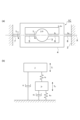
図1に示されるように、第1実施形態のミラー装置1Aは、支持部2と、第1可動部3と、第2可動部4と、一対の第1連結部5,6と、一対の第2連結部7,8と、磁界発生部9と、を備えている。支持部2、第1可動部3、第2可動部4、第1連結部5,6及び第2連結部7,8は、例えば、SOI(Silicon on Insulator)基板等の半導体基板によって一体的に形成されている。つまり、ミラー装置1Aは、MEMSデバイスとして構成されている。
As shown in FIG. 1, the
ミラー装置1Aでは、互いに直交するX軸(第1軸線)及びY軸(第1軸線に垂直な第2軸線)の各々の周りに、ミラー面(光学面)10を有する第1可動部3が揺動させられる。ミラー装置1Aは、例えば、光通信用光スイッチ、光スキャナ等に用いられ得る。磁界発生部9は、例えば、ハルバッハ配列がとられた永久磁石等によって構成されている。
In the
支持部2は、例えば、平面視において四角形状の外形を有し、枠状に形成されている。支持部2は、磁界発生部9に対してX軸及びY軸に垂直な方向における一方側に配置されている。第1可動部3は、磁界発生部9から離間した状態で、支持部2の内側に配置されている。なお、「平面視」とは、X軸及びY軸に垂直な方向から見た場合を意味し、換言すれば、支持部2、第1可動部3及び第2可動部4等が配置される平面に垂直な方向から見た場合を意味する。
The
第1可動部3は、本体部3aと、本体部3aを囲む枠部3bと、を有している。本体部3aは、例えば、平面視において楕円形状に形成されている。本体部3aにおける磁界発生部9とは反対側の表面には、例えば、円形状のミラー面10が設けられている。ミラー面10は、例えば、アルミニウム、アルミニウム系合金、銀、銀系合金、金、誘電体多層膜等からなる反射膜によって構成されている。枠部3bは、例えば、平面視において四角形状の外形を有し、枠状に形成されている。本体部3aは、Y軸上における両側において枠部3bに接続されている。
The first
第2可動部4は、例えば、平面視において八角形状の外形を有し、枠状に形成されている。第2可動部4は、磁界発生部9から離間した状態で、第1可動部3を囲むように支持部2の内側に配置されている。
The second
第1連結部5,6は、X軸上における第1可動部3の両側に配置されている。各第1連結部5,6は、第1可動部3がX軸周りに(X軸を中心線として)揺動可能となるように、X軸上において第1可動部3と第2可動部4とを互いに連結している。各第1連結部5,6は、第1可動部3がX軸周りに揺動する際に、X軸周りに捩れ変形する。各第1連結部5,6は、例えば、X軸に沿って直線状に延在している。各第1連結部5,6は、例えば、X軸及びY軸に垂直な平面に沿って延在する板状に形成されている。
The first connecting
第1連結部5は、X軸に沿って延在すると共に一定の幅を有する直線状部5aと、直線状部5aの両端に接続された一対の拡幅部5bと、を有している。平面視において、一方の拡幅部5bの幅は、第1可動部3に近づくほど広がっており、他方の拡幅部5bの幅は、第2可動部4に近づくほど広がっている。各拡幅部5bの一対の縁は、互いに向けて凸となるように湾曲している。
The first connecting
第1連結部6は、X軸に沿って延在すると共に一定の幅を有する直線状部6aと、直線状部6aの両端に接続された一対の拡幅部6bと、を有している。平面視において、一方の拡幅部6bの幅は、第1可動部3に近づくほど広がっており、他方の拡幅部6bの幅は、第2可動部4に近づくほど広がっている。各拡幅部6bの一対の縁は、互いに向けて凸となるように湾曲している。
The first connecting
第2連結部7,8は、Y軸上における第2可動部4の両側に配置されている。各第2連結部7,8は、第2可動部4がY軸周りに(Y軸を中心線として)揺動可能となるように、Y軸上において第2可動部4と支持部2とを互いに連結している。各第2連結部7,8は、第2可動部4がY軸周りに揺動する際に、Y軸周りに捩れ変形する。各第2連結部7,8は、平面視において蛇行して延在している。各第2連結部7,8は、複数の直線状部11aと、複数の折り返し部11bと、を有している。複数の直線状部11aは、それぞれY軸方向に沿って延在し、X軸方向に並んで配置されている。複数の折り返し部11bは、隣り合う直線状部11aの両端を交互に連結している。
The second connecting
X軸周りの各第2連結部7,8の捩りばね定数は、X軸周りの各第1連結部5,6の捩りばね定数よりも小さい。X軸周りの各第1連結部5,6の捩りばね定数とは、X軸周りの各第1連結部5,6の捩れ角度に対する、各第1連結部5,6に作用するX軸周りの捩りモーメントの比である。X軸周りの各第2連結部7,8の捩りばね定数とは、X軸周りの各第2連結部7,8の捩れ角度に対する、各第2連結部7,8に作用するX軸周りの捩りモーメントの比である。
The torsional spring constant of each
各第2連結部7,8の全長は、各第1連結部5,6の全長よりも長い。各第1連結部5,6の全長とは、各第1連結部5,6の延在方向(この例では、X軸に沿った方向)に沿っての全長である。第2連結部7の全長とは、第2連結部7の延在方向に沿っての全長であり、この例では、各直線状部11a及び各折り返し部11bを含む各部分の長さを足し合わせた総長さである。この点は、第2連結部8の全長についても同様である。
The total length of each second connecting
ミラー装置1Aは、コイル(駆動用コイル)21,22と、複数の配線12,13,14,15と、複数の電極パッド31,32,33,34と、を更に備えている。コイル21は、例えば、第1可動部3の枠部3bに埋め込まれており、平面視において渦巻き状に延在している。コイル22は、例えば、第2可動部4に埋め込まれており、平面視において渦巻き状に延在している。各コイル21,22は、例えば銅等の金属材料によって構成されている。図1では、コイル21,22の配置領域がハッチングで示されている。
The
複数の電極パッド31,32,33,34は、支持部2に設けられ、絶縁層23から外部に露出している。絶縁層23は、支持部2、第1可動部3、第2可動部4、第1連結部5,6及び第2連結部7,8の表面(磁界発生部9とは反対側の表面)を覆うように一体的に形成されている。絶縁層23は、例えば、二酸化シリコン、窒化シリコン等によって構成されている。
The
配線12は、コイル21の一端と電極パッド31とを電気的に接続している。配線12は、コイル21の一端から第1連結部5、第2可動部4及び第2連結部7を介して電極パッド31に延在している。配線13は、コイル21の他端と電極パッド32とを電気的に接続している。配線13は、コイル21の他端から第1連結部6、第2可動部4及び第2連結部8を介して電極パッド32に延在している。配線12,13のうち、第1連結部5,6を通る部分12a,13aは、例えば、タングステン等の金属材料によって構成されている。配線12,13の他の部分は、例えば、アルミニウム、アルミニウム系合金、銅等の金属材料によって構成されている。図1では、部分12a,13aがハッチングで示されている。
The
配線14は、コイル22の一端と電極パッド33とを電気的に接続している。配線14は、コイル22の一端から第2連結部7を介して電極パッド33に延在している。配線15は、コイル22の他端と電極パッド34とを電気的に接続している。配線15は、コイル22の他端から第2連結部8を介して電極パッド34に延在している。
The
以上のように構成されたミラー装置1Aでは、電極パッド33,34及び配線14,15を介してコイル22にリニア動作用の駆動信号が入力されると、磁界発生部9が発生する磁界との相互作用によってコイル22にローレンツ力が作用する。当該ローレンツ力と第2連結部7,8の弾性力とのつり合いを利用することで、Y軸周りにミラー面10(第1可動部3)を第2可動部4と共にリニア動作させることができる。
In the
一方、電極パッド31,32及び配線12,13を介してコイル21に共振動作用の駆動信号が入力されると、磁界発生部9が発生する磁界との相互作用によってコイル21にローレンツ力が作用する。当該ローレンツ力に加え、共振周波数での第1可動部3の共振を利用することで、X軸周りにミラー面10(第1可動部3)を共振動作させることができる。すなわち、ミラー装置1Aでは、コイル21と磁界発生部9とによって、第1可動部3に直接的に駆動力(ローレンツ力)を作用させる駆動部が構成されており、コイル22と磁界発生部9とによって、第2可動部4に直接的に駆動力(ローレンツ力)を作用させる駆動部が構成されている。
[第2実施形態]
On the other hand, when a drive signal for resonant operation is input to the
[Second embodiment]
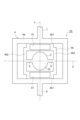
第1実施形態のミラー装置1Aでは、X軸及びY軸の各々の周りに第1可動部3が揺動させられたが、図2に示される第2実施形態のミラー装置1Bでは、X軸周りのみに第1可動部3が揺動させられる。ミラー装置1Bでは、第1可動部3の本体部3aは、平面視において円形状に形成されている。本体部3aは、X軸上における両側及びY軸上における両側において、枠部3bに接続されている。第2可動部4は、平面視において四角形状の外形を有している。
In the
第2連結部7,8は、X軸上における第2可動部4の両側に配置されている。第2連結部7,8は、第2可動部4を振動させることによってX軸周りに第1可動部3が揺動可能となるように、X軸上において第2可動部4と支持部2とを互いに連結している。各第2連結部7,8は、第2可動部4が振動する際に、X軸周りに捩れ変形する。
The second connecting
ミラー装置1Bは、コイル21、配線12,13及び電極パッド31,32を備えておらず、コイル22と、コイル(起電力モニタ用コイル、センシング用コイル)24と、複数の配線14,15,16,17と、複数の電極パッド33,34,35,36と、を備えている。コイル24は、例えば、第1可動部3の枠部3bに埋め込まれており、平面視において渦巻き状に延在している。コイル24は、例えば銅等の金属材料によって構成されている。
The
配線16は、コイル24の一端と電極パッド35とを電気的に接続している。配線17は、コイル24の一端から第1連結部5、第2可動部4及び第2連結部7を介して電極パッド35に延在している。配線17は、コイル24の他端と電極パッド36とを電気的に接続している。配線17は、コイル24の他端から第1連結部6、第2可動部4及び第2連結部8を介して電極パッド36に延在している。
The
ミラー装置1Bでは、電極パッド33,34及び配線14,15を介してコイル22に共振動作用の駆動信号が入力されると、磁界発生部9が発生する磁界との相互作用によってコイル22にローレンツ力が作用する。当該ローレンツ力に加え、共振周波数での第1可動部3の共振を利用することで、X軸周りにミラー面10(第1可動部3)を共振動作させることができる。具体的には、X軸周りの第1可動部3の共振周波数に等しい周波数の駆動信号がコイル22に入力されると、第2可動部4がX軸周りに当該周波数で僅かに振動する。この振動が第1連結部5,6を介して第1可動部3に伝わることにより、第1可動部3をX軸周りに当該周波数で揺動させることができる。
In the
また、ミラー装置1Bでは、第1可動部3の動作中に、磁界発生部9が発生する磁界との相互作用によってコイル24に起電力が発生する。そのため、配線16,17を介して電極パッド35,36から出力される信号をモニタすることで、第1可動部3の振れ角、すなわち、ミラー面10の振れ角を把握することができる。このように、コイル24は、起電力モニタ用コイルとして機能する。
In addition, in the
続いて、図2及び図3を参照しつつ、ミラー装置1Bの各部の構成について更に説明する。以下では、第1連結部5及び第2連結部7の周辺の構造を説明するが、第1連結部6及び第2連結部8についても同様に構成されている。
Next, the configuration of each part of the
第2連結部7は、第1部材7aと、一対の第2部材7bと、を有している。第1部材7a及び一対の第2部材7bは、それぞれ、X軸に沿って延在し、第2可動部4と支持部2とを互いに連結している。第1部材7a及び一対の第2部材7bは、例えば、Y軸に平行な方向に沿って並んで配置されている。第1部材7aは、X軸上に配置されており、一対の第2部材7bは、互いの間に第1部材7aを挟むように配置されている。第1部材7a及び一対の第2部材7bは、例えば、互いに近接するように、等間隔に並んで配置されている。第1部材7a及び一対の第2部材7bは、例えば、互いに同一の形状に形成されている。各第2部材7bは、X軸周りの第2可動部4の振動を抑制する振動抑制部として機能する。
The second connecting
支持部2には、X軸上に位置する凹部2aが設けられており、第1部材7a及び一対の第2部材7bは、凹部2aにおいて支持部2に接続されている。これにより、第1部材7a及び一対の第2部材7bの長さを確保しつつ、ミラー装置1Bの小型化を図ることができる。
The
X軸周りの第2連結部7の捩りばね定数は、X軸周りの第1連結部5の捩りばね定数よりも小さい。X軸周りの第2連結部7の捩りばね定数とは、第1部材7a及び一対の第2部材7bによって構成される第2連結部7の全体についてのX軸周りの捩りばね定数である。第2連結部7の全長は、第1連結部5の全長よりも短い。例えば、第2連結部7の全長は、第1連結部5の全長の1/2よりも短い。第2連結部7の全長とは、この例では、第1部材7a及び一対の第2部材7bの各々の長さを足し合わせた総長さである。この例では、第1部材7a及び一対の第2部材7bの長さは、互いに等しい。
The torsional spring constant of the second connecting
配線16のうち第1連結部5上に位置する部分は、半導体材料に不純物が拡散された拡散領域41によって構成されている。拡散領域41は、例えば、p型のシリコン基板の表面にn型の不純物を拡散することによって形成されている。配線16は、拡散領域41の一方の端部41aとコイル24とを電気的に接続する内側部分16aと、拡散領域41の他方の端部41bとコイル24とを電気的に接続する外側部分16bと、を更に有している。
The portion of the
拡散領域41は、第1連結部5から第1可動部3に延在しており、第1可動部3上において内側部分16aに接続されている。また、拡散領域41は、第1連結部5から第2可動部4に延在しており、第2可動部4上において外側部分16bに接続されている。外側部分16bは、第2連結部7の第1部材7aを通るように延在して、電極パッド35に接続されている。コイル22から延在する配線14についても同様に、第2連結部7の第1部材7aを通るように延在して、電極パッド33に接続されている。
The
端部41aの幅は、コイル24に近づくほど広がっており、端部41bの幅は、コイル22に近づくほど広がっている。端部41a,41bは、それぞれ、第1連結部5の一対の拡幅部5bに沿った外形状を有している。端部41aの幅W1及び端部41bの幅W2の各々は、第1連結部5の幅W3よりも広い。すなわち、幅W1,W2の各々は、第1連結部5上の拡散領域41の幅よりも広い。拡散領域41の各部の幅とは、平面視における最大幅であり、拡散領域41の延在方向に垂直な方向(この例では、Y軸に平行な方向)における幅である。第1連結部5の幅とは、平面視における最小幅であり、例えば、第1連結部5の延在方向に垂直な方向(この例では、Y軸に平行な方向)における直線状部5aの幅である。なお、第1連結部5は、第1可動部3がX軸周りに揺動する際にX軸周りに捩り変形する部分であり、ミラー装置1Bでは、第1連結部5は一対の拡幅部5bを含む。
The width of the
図4に示されるように、第1可動部3には、コイル24に対応する形状を有する溝42aが設けられており、第2可動部4には、コイル22に対応する形状を有する溝42bが設けられている。溝42a,42bの内面上には絶縁層43,44が設けられ、絶縁層44上には絶縁層45,46が設けられている。コイル24は、絶縁層43,44を介して溝42内に配置されている。
As shown in FIG. 4, the first
各絶縁層43~46は、例えば、二酸化シリコン、窒化シリコン等によって構成されている。配線16の内側部分16a及び外側部分16bは、絶縁層45上に配置されている。内側部分16a及び外側部分16bは、絶縁層43~45を貫通する開口47に入り込むように形成され、開口47において拡散領域41に接続されている。
Each of the insulating layers 43-46 is made of, for example, silicon dioxide, silicon nitride, etc. The
内側部分16a及び外側部分16bは、それぞれ、第1層48と、第1層48上に配置された第2層49と、を有している。第1層48は、拡散領域41に接触するコンタクト層として機能すると共に、第2層49に含まれる金属元素のシリコン基板への拡散を防止するバリア層としても機能する。第1層48は、例えば、タングステン、窒化チタン、モリブデン、タンタル、窒化タンタル等の金属材料によって構成されている。第2層49は、例えば、アルミニウム合金、銅等の金属材料によって構成されている。
The
拡散領域41と内側部分16aとの接触部分の幅W4、及び拡散領域41と外側部分16bとの接触部分の幅W5の各々は、第1連結部5の幅W3よりも広い。これらの接触部分の幅とは、平面視における第1連結部5の延在方向に垂直な方向(この例では、Y軸に平行な方向)における幅である。
[ミラー装置の製造方法]
Each of the width W4 of the contact portion between the
[Method of manufacturing the mirror device]
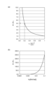
続いて、上述したようなミラー装置1A,1Bの製造方法(設計方法)について説明する。図5(a)は、駆動信号の角振動数(角周波数)と、第1可動部3及び第2可動部4のX軸周りの振れ角との関係の例を示す図であり、図5(b)は、当該関係の他の例を示す図である。図5(a)及び図5(b)では、第1可動部3の振れ角が実線で示されており、第2可動部4の振れ角が破線で示されている。
Next, a manufacturing method (design method) for the
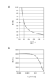
図5(a)及び図5(b)に示されるように、ミラー装置1A,1Bにおいて支持部2、第1可動部3、第2可動部4、第1連結部5,6及び第2連結部7,8によって構成される2自由度振動系は、X軸周りの振動について、2つの共振点A,Bを有する。ただし、この2自由度振動系では、X軸周りの振動のみが考慮されており、Y軸周りの振動については考慮されていない。共振点Aにおける固有角振動数ω1、及び共振点Bにおける固有角振動数ω2(ただしω1<ω2)は、X軸周りの第1可動部3及び第2可動部4の振動についての固有角振動数である。共振点Aは、比較的小さな周波数でミラー面10を動作させる場合に使用され得る。共振点Bは、比較的大きな周波数でミラー面10を動作させる場合に使用され得る。
As shown in Fig. 5(a) and Fig. 5(b), the two-degree-of-freedom vibration system in the
図5(a)の共振点Aでミラー面10を動作させる場合の第1可動部3及び第2可動部4の振れ角の関係は、図6(a)のように示すことができ、図5(a)の共振点Bでミラー面10を動作させる場合の第1可動部3及び第2可動部4の振れ角の関係は、図6(b)のように示すことができる。
The relationship between the deflection angles of the first
図6(a)に示されるように、図5(a)の共振点Aでミラー面10を動作させると、第1可動部3及び第2可動部4が同程度回転し、第1可動部3及び第2可動部4の振れ角の差が小さくなる。すなわち、第1連結部5,6が殆ど捩れ変形しない。図6(b)に示されるように、図5(a)の共振点Bでミラー面10を動作させると、第2可動部4が殆ど回転しない一方で第1可動部3が回転し、第1可動部3及び第2可動部4の振れ角の差が大きくなる。すなわち、第1連結部5,6が効率良く捩れ変形する。
As shown in FIG. 6(a), when the
図5(a)の例とは逆に、図5(b)の例では、共振点Aでミラー面10を動作させた場合に、第2可動部4が殆ど回転しない一方で第1可動部3が回転し、共振点Bでミラー面10を動作させた場合に、第1可動部3及び第2可動部4が同程度回転する。高効率化の観点からは、共振点A,Bのいずれでミラー面10を動作させる場合にも、第1可動部3の振れ角が大きい一方で第2可動部4の振れ角が小さいことが好ましい。すなわち、第2可動部4の振れ角に対する第1可動部3の振れ角の比(以下、「振幅比」という)を大きく確保することが好ましい。以下では、振幅比を大きく確保するためのミラー装置1A,1Bの製造方法を説明する。
[外側駆動の場合]
Contrary to the example of Fig. 5(a), in the example of Fig. 5(b), when the
[In the case of outer drive]
まず、ミラー装置1Bのように、第2可動部4に駆動力を作用させることによって第1可動部3を共振動作させる場合(外側駆動の場合)について説明する。図7(a)は、例示的なミラー装置1Cの模式平面図であり、図7(b)は、ミラー装置1Cの振動モデルを示す図である。図7(b)に示される振動モデルにより、X軸周りの第1可動部3及び第2可動部4の振動をモデル化することができる。X軸周りの第1可動部3及び第2可動部4の振動についての運動方程式は、以下の式(9)及び式(10)で表される。
![]()
![]()
上記式において、θiは第1可動部3の振れ角(各第1連結部5,6の捩れ角)(rad)であり、jiは第1可動部3の慣性モーメント(kgm2)であり、kiは第1連結部5,6の捩りばね定数(Nm/rad)であり、ciは第1可動部3の粘性減衰係数(Ns/m)であり、Tiは第1可動部3に作用するトルク(Nm)であり、θoは第2可動部4の振れ角(各第2連結部7,8の捩れ角)(rad)であり、joは第2可動部4の慣性モーメント(kgm2)であり、koは各第2連結部7,8の捩りばね定数(Nm/rad)であり、coは第2可動部4の粘性減衰係数(Ns/m)であり、Toは第2可動部4に作用するトルク(Nm)であり、ωは駆動信号の角振動数(rad/s)であり、tは時間(s)である。これらの各値は、X軸周りの振動についての値である。粘性減衰係数ci,coは、以下の式(11),(12)で表される。ただし、ζiは第1可動部3の減衰比であり、ζoは第2可動部4の減衰比である。
![]()
![]()
外側駆動の場合、第1可動部3には駆動力が作用しないため(すなわちTi=0のため)、式(9)の右辺はゼロとなる。
First, a case where the first
![]()
![]()
In the above formula, θ i is the deflection angle of the first movable part 3 (the torsion angle of each of the first connecting
![]()
![]()
In the case of outer driving, since no driving force acts on the first movable part 3 (that is, since T i =0), the right side of equation (9) becomes zero.
式(9)及び式(10)より、第1可動部3の振れ角θi、及び第2可動部4の振れ角θoが、以下の式(13)、(14)で表されるとおりに得られる。


ただし、
![]()
![]()


however,
![]()
![]()
このとき、振幅比θi/θoは、以下の式(20)で表される。なお、ζoは、例えば0.01以下であり、1よりも極めて小さい。

したがって、振幅比を5以上とするための条件は、以下の式(21)で表される。

共振点Aにおける固有角振動数ω1でミラー面10を動作させる場合(すなわち、ω=ω1の場合)、1-(ω1/ωii)2はゼロよりも大きいため、振幅比を5以上とするための条件は、以下の式(22)で表される。
![]()
![]()
共振点Bにおける固有角振動数ω2でミラー面10を動作させる場合(すなわち、ω=ω2の場合)、1-(ω2/ωii)2はゼロよりも小さいため、振幅比を5以上とするための条件は、以下の式(23)で表される。
![]()
![]()
すなわち、固有角振動数ω1でミラー面10を動作させる場合には、式(22)が満たされるようにミラー装置を設計及び製造することで、振幅比を5以上とすることができ、固有角振動数ω2でミラー面10を動作させる場合には、式(23)が満たされるようにミラー装置を設計及び製造することで、振幅比を5以上とすることができる。
In other words, when
図8(a)及び図8(b)は、外側駆動の場合において固有角振動数ω1でミラー面10を動作させる場合の数値間の関係を示すグラフである。図8(a)では、1-(ω1/ωii)2と振幅比θi/θoとの関係が示されており、図8(b)では、各第2連結部7,8の捩りばね定数koと振幅比θi/θoとの関係が示されている。図8(a)に示されるように、式(22)が満たされるようにミラー装置を設計及び製造することで、振幅比を5以上とすることができる。図8(b)に示されるように、捩りばね定数koが増加するほど、振幅比が増加する。したがって、捩りばね定数koを大きくすることで、振幅比を大きく確保することができる。
8(a) and 8(b) are graphs showing the relationship between values when the
図9(a)及び図9(b)は、外側駆動の場合において固有角振動数ω2でミラー面10を動作させる場合の数値間の関係を示すグラフである。図9(a)では、(ω2/ωii)2-1と振幅比θi/θoとの関係が示されており、図9(b)では、第2連結部7,8の捩りばね定数koと振幅比θi/θoとの関係が示されている。図9(a)に示されるように、式(23)が満たされるようにミラー装置を設計及び製造することで、振幅比を5以上とすることができる。図9(b)に示されるように、捩りばね定数koが増加するほど、振幅比が減少する。したがって、捩りばね定数koを小さくすることで、振幅比を大きく確保することができる。
9(a) and 9(b) are graphs showing the relationship between values when the
ここで、固有角振動数ω1,ω2の値同士が近く、固有角振動数ω1,ω2間の差が小さいと、式(22)及び式(23)の双方が満たされる。しかし、固有角振動数ω1,ω2間の差が小さい場合、例えば、固有角振動数ω1でミラー面10を動作させる際に固有角振動数ω2についての共振応答が生じてしまい、ミラー面10の動作が不安定になるおそれがある。そこで、本実施形態のミラー装置の製造方法では、外側駆動の場合、式(22)及び式(23)の一方のみが満たされ、他方は満たされないように、ミラー装置を設計及び製造する。これにより、固有角振動数ω1,ω2間の差を大きく確保することができ、不要な共振応答を抑制して動作を安定化することができる。この点は、固有角振動数ω1,ω2のいずれでミラー面10を動作させる場合にも共通する。
Here, if the values of the natural angular frequencies ω 1 and ω 2 are close to each other and the difference between the natural angular frequencies ω 1 and ω 2 is small, both the formula (22) and the formula (23) are satisfied. However, if the difference between the natural angular frequencies ω 1 and ω 2 is small, for example, when the
例えば、上記第2実施形態に係るミラー装置1Bでは、式(22)のみが満たされており、式(23)は満たされていない。したがって、固有角振動数ω1でミラー面10を動作させることにより、振幅比を5以上とすることができる。また、固有角振動数ω1,ω2間の差を大きく確保することができ、不要な共振応答を抑制して動作を安定化することができる。
[内側駆動の場合]
For example, in the
[Inner drive]
次に、ミラー装置1Aのように、第1可動部3に駆動力を作用させることによって第1可動部3を共振動作させる場合(内側駆動の場合)について説明する。この場合、X軸周りの第1可動部3及び第2可動部4の振動についての運動方程式は、以下の式(24)及び式(25)によって表される。
![]()
![]()
内側駆動の場合、第2可動部4には第1可動部3を駆動するための駆動力が作用しないため(すなわちTo=0のため)、式(25)の右辺はゼロとなる。
Next, a case where the first
![]()
![]()
In the case of inner driving, since no driving force for driving the first
式(24)及び式(25)より、第1可動部3の振れ角θi、及び第2可動部4の振れ角θoが、以下の式(26)、(27)で表されるとおりに得られる。


ただし、
![]()
![]()
however,
![]()
![]()
このとき、振幅比θi/θoは、以下の式(30)で表される。

したがって、振幅比を5以上とするための条件は、以下の式(31)で表される。

共振点Aにおける固有角振動数ω1でミラー面10を動作させる場合(すなわち、ω=ω1の場合)、1-(ωio/ωoo)2+(ω1/ωoo)2はゼロよりも大きいため、振幅比を5以上とするための条件は、以下の式(32)となる。
![]()
![]()
一方、共振点Bにおける固有角振動数ω2でミラー面10を動作させる場合(すなわち、ω=ω2の場合)、1-(ωio/ωoo)2+(ω2/ωoo)2はゼロよりも小さいため、振幅比を5以上とするための条件は、以下の式(33)となる。
![]()
![]()
すなわち、固有角振動数ω1でミラー面10を動作させる場合には、式(32)が満たされるようにミラー装置を設計及び製造することで、振幅比を5以上とすることができ、固有角振動数ω2でミラー面10を動作させる場合には、式(33)が満たされるようにミラー装置を設計及び製造することで、振幅比を5以上とすることができる。式(32)及び式(33)の一方のみが満たされ、他方は満たされないようにミラー装置を設計及び製造することで、固有角振動数ω1,ω2間の差を大きく確保することができ、不要な共振応答を抑制して動作を安定化することができる点は、外側駆動の場合と同様である。
That is, when the
図10(a)及び図10(b)は、内側駆動の場合の数値間の関係を示すグラフである。図10(a)では、固有角振動数ω1でミラー面10を動作させる場合の4ωio
2/(ωoo
2-ω1
2)と振幅比θi/θoとの関係が示されており、図10(b)では、固有角振動数ω2でミラー面10を動作させる場合の(ωoo
2-ω2
2)/ωio
2と振幅比θi/θoとの関係が示されている。
Figures 10(a) and 10(b) are graphs showing the relationship between values in the case of inward drive. Figure 10(a) shows the relationship between 4ωio2 /( ωoo2 - ω12 ) and the amplitude ratio θi /θo when the
図10(a)に示されるように、式(32)が満たされるようにミラー装置を設計及び製造することで、振幅比を5以上とすることができる。また、内側駆動の場合において固有角振動数ω1でミラー面10を動作させる場合、外側駆動の場合と同様に(図8(b))、捩りばね定数koが増加するほど、振幅比が増加する。したがって、捩りばね定数koを大きくすることで、振幅比を大きく確保することができる。
As shown in Fig. 10(a), by designing and manufacturing the mirror device so that formula (32) is satisfied, the amplitude ratio can be set to 5 or more. Furthermore, when the
図10(b)に示されるように、式(33)が満たされるようにミラー装置を設計及び製造することで、振幅比を5以上とすることができる。また、内側駆動の場合において固有角振動数ω2でミラー面10を動作させる場合、外側駆動の場合と同様に(図9(b))、捩りばね定数koが増加するほど、振幅比が減少する。したがって、捩りばね定数koを小さくすることで、振幅比を大きく確保することができる。
As shown in Fig. 10(b), by designing and manufacturing the mirror device so that formula (33) is satisfied, the amplitude ratio can be made 5 or more. Furthermore, when the
例えば、上記第1実施形態に係るミラー装置1Aでは、式(33)のみが満たされており、式(32)は満たされていない。したがって、固有角振動数ω2でミラー面10を動作させることにより、振幅比を5以上とすることができる。また、固有角振動数ω1,ω2間の差を大きく確保することができ、不要な共振応答を抑制して動作を安定化することができる。
[作用及び効果]
For example, in the
[Action and Effects]
以上説明したように、ミラー装置1Aでは、2つの固有角振動数ω1,ω2が式(33)(第1式)のみを満たしており、式(32)(第2式)を満たしていないため、固有角振動数ω2で第1可動部3及び第2可動部4を揺動させることにより、振幅比を5以上とすることができる。したがって、振幅比を大きく確保することができ、動作を高効率化することができる。更に、式(33)のみが満たされており、式(32)は満たされていないことにより、固有角振動数ω1,ω2間の差を大きく確保することができ、不要な共振応答を抑制して動作を安定化することができる。よって、ミラー装置1Aによれば、高効率かつ安定的な動作を実現することができる。
As described above, in the
ミラー装置1Bでは、2つの固有角振動数ω1,ω2が式(22)(第1式)のみを満たしており、式(23)(第2式)を満たしていないため、固有角振動数ω1で第1可動部3及び第2可動部4を揺動させることにより、振幅比を5以上とすることができる。したがって、振幅比を大きく確保することができ、動作を高効率化することができる。更に、式(22)のみが満たされており、式(23)は満たされていないことにより、固有角振動数ω1,ω2間の差を大きく確保することができ、不要な共振応答を抑制して動作を安定化することができる。よって、ミラー装置1Bによれば、高効率かつ安定的な動作を実現することができる。
In the
ミラー装置1Aでは、各第2連結部7,8が、Y軸周りに第2可動部4が揺動可能となるように、第2可動部4と支持部2とを互いに連結している。そのため、第2可動部4を第1可動部3と共にY軸周りに揺動させることができる。
In the
ミラー装置1Bでは、X軸周りの各第2連結部7,8の捩りばね定数が、X軸周りの各第1連結部5,6の捩りばね定数よりも大きい。そのため、振幅比を一層大きく確保することができる。
In the
ミラー装置1Bでは、各第2連結部7,8の全長が、各第1連結部5,6の全長よりも短い。そのため、第2連結部7,8の捩りばね定数を第1連結部5,6の捩りばね定数よりも好適に大きくすることができる。更に、第2連結部7,8の断面積を大きくするのではなく、長さを短くすることによって第2連結部7,8の捩りばね定数を大きくすることにより、ミラー装置1Bの小型化を図りつつ、振幅比を大きく確保することができる。
In the
ミラー装置1Bでは、第1部材7a及び一対の第2部材7b(複数の部材)が、Y軸に平行な方向に沿って並んで配置されている。そのため、第2連結部7,8の捩りばね定数を第1連結部5,6の捩りばね定数よりも一層好適に大きくすることができる。
In the
ミラー装置1Bでは、各第2連結部7,8が、X軸上に配置された第1部材7aと、互いの間に第1部材7aを挟むように配置された一対の第2部材7bと、を有している。そのため、第2連結部7,8の捩りばね定数を第1連結部5,6の捩りばね定数よりも一層好適に大きくすることができる。
In the
ミラー装置1Bでは、各配線14,16が、第1部材7aを通るように配置されている。第2部材7bと比べて第2可動部4の振動時に作用する応力が小さい第1部材7aを通るように配線14,16が配置されているため、第2連結部7における配線14,16の劣化を抑制することができる。
In the
ミラー装置1Aでは、X軸周りの各第2連結部7,8の捩りばね定数が、X軸周りの各第1連結部5,6の捩りばね定数よりも小さい。そのため、振幅比を一層大きく確保することができる。
In the
ミラー装置1Aでは、各第2連結部7,8の全長が、各第1連結部5,6の全長よりも長い。そのため、第2連結部7,8の捩りばね定数を第1連結部5,6の捩りばね定数よりも好適に小さくすることができる。
In the
ミラー装置1Aでは、各第2連結部7,8が蛇行して延在している。そのため、第2連結部7,8の捩りばね定数を第1連結部5,6の捩りばね定数よりも一層好適に小さくすることができる。更に、各第2連結部7,8が蛇行して延在していることにより、例えば各第2連結部7,8が直線状に延在している場合と比べて、耐衝撃性を向上することができる。
In the
ミラー装置1A,1Bでは、支持部2、第1可動部3、第2可動部4、第1連結部5,6及び第2連結部7,8が、半導体基板によって構成されている。このように構成されたミラー装置1A,1Bにおいても、高効率かつ安定的な動作を実現することができる。
In the
ミラー装置1Bでは、配線16のうち各第1連結部5,6上に位置する部分が、半導体材料に不純物が拡散された拡散領域41によって構成されている。配線16のうち第1連結部5,6上に位置する部分には第1可動部3の揺動時に比較的大きな応力が作用するが、当該部分が拡散領域41によって構成されているため、第1連結部5,6における配線の劣化を抑制することができる。すなわち、当該部分が拡散領域41によって構成されている場合、例えば当該部分が金属によって構成されている場合と比べて、金属疲労、割れ等を抑制することができ、信頼性を向上することができる。なお、配線16は起電力モニタ用のコイル24に接続されているため、例えば駆動用のコイルに接続される配線と比べて、配線16には比較的小さな電流が流れる。そのため、配線16については極端な低抵抗化の必要はない。
In the
ミラー装置1Bでは、第1可動部3及び第2可動部4における拡散領域41の幅(端部41aの幅W1及び端部41bの幅W2)が、第1連結部5,6における拡散領域41の幅よりも広い。そのため、配線16を低抵抗化することができる。
In the
ミラー装置1Bでは、配線16のうち、第1可動部3上に位置する内側部分16a及び第2可動部4上に位置する外側部分16bが、金属材料によって構成されている。そして、拡散領域41と内側部分16aとの接触部分の幅W4、及び拡散領域41と外側部分16bとの接触部分の幅W5の各々が、各第1連結部5,6の幅W3よりも広い。そのため、配線16を一層低抵抗化することができる。また、製造時等に位置ずれが生じたとしても、拡散領域41と内側部分16a及び外側部分16bの各々とを確実に電気的に接続することができる。
[変形例]
In the
[Modification]
以上、本開示の実施形態について説明したが、本開示は、上記実施形態に限られない。第1実施形態のミラー装置1Aにおいて、第2可動部4に駆動力を作用させることによって第1可動部3を共振動作させてもよい。すなわち、ミラー装置1Aの構造が外側駆動に用いられてもよい。この場合、第1可動部3にはコイル21が設けられず、第2可動部4には、コイル22に加えて、第1可動部3の共振動作用のコイルが設けられてもよい。ミラー装置1Bの場合と同様に、当該共振動作用のコイルと磁界発生部9が発生する磁界との相互作用によって発生するローレンツ力に加え、共振周波数での第1可動部3の共振を利用することで、X軸周りにミラー面10を共振動作させることができる。なお、共振動作用のコイルが設けられず、コイル22が、第2可動部4のリニア動作用及び第1可動部3の共振動作用のコイルとして用いられてもよい。このようなミラー装置は、上記式(23)のみが満たされ、式(22)は満たされないように設計及び製造される。これにより、固有角振動数ω2でミラー面10を動作させることで、振幅比を5以上とすることができる。また、固有角振動数ω1,ω2間の差を大きく確保することができ、不要な共振応答を抑制して動作を安定化することができる。
Although the embodiments of the present disclosure have been described above, the present disclosure is not limited to the above embodiments. In the
第2実施形態のミラー装置1Bにおいて、第1可動部3に駆動力を作用させることによって第1可動部3を共振動作させてもよい。すなわち、ミラー装置1Bの構造が内側駆動に用いられてもよい。この場合、第2可動部4にはコイル22が設けられず、第1可動部3には、コイル24に代えて又は加えて、駆動用のコイルが設けられてもよい。ミラー装置1Aの場合と同様に、当該駆動用のコイルと磁界発生部9が発生する磁界との相互作用によって発生するローレンツ力に加え、共振周波数での第1可動部3の共振を利用することで、X軸周りにミラー面10を共振動作させることができる。このようなミラー装置は、上記式(32)のみが満たされ、式(33)は満たされないように設計及び製造される。これにより、固有角振動数ω1でミラー面10を動作させることで、振幅比を5以上とすることができる。また、固有角振動数ω1,ω2間の差を大きく確保することができ、不要な共振応答を抑制して動作を安定化することができる。
In the
ミラー装置1A,1Bでは、ミラー面10の駆動が電磁力によって行われていたが、ミラー面10の駆動は、圧電素子又は静電力によって行われてもよい。この場合、コイルに代えて、圧電膜又は静電櫛歯等の他の駆動素子が設けられる。ミラー装置1Aにおいて、第2連結部7,8は、X軸に沿って延在し、X軸上において第2可動部4と支持部2とを互いに連結していてもよい。この場合でも、X軸及びY軸の各々の周りに第1可動部3を揺動させることができる。ミラー装置1Aにおいて、第2連結部7,8は、第1軸線と交差する第2軸線周りに第2可動部4が揺動可能となるように、第2可動部4と支持部2とを互いに連結していてもよい。すなわち、第2軸線は必ずしも第1軸線と直交していなくてもよい。ミラー装置1Bにおいて、第2部材7bは、X軸に対して傾斜して延在していてもよい。第2部材7bは、Y軸に平行な方向に沿って延在して第2可動部4と支持部2とを互いに連結していてもよい。上述した例では、振幅比の下限値が5に設定されていたが、下限値は10に設定されてもよい。ミラー装置1Bにおいて、コイル24は、温度検出用コイル(センシング用コイル)として用いられてもよい。
In the
ミラー装置1Aでは、第1可動部3に駆動力を作用させるための駆動部(コイル21、駆動素子)が第1可動部3に設けられていたが、当該駆動部は、第1可動部3及び/又は第1連結部5,6に設けられていればよく、例えば、各第1連結部5,6に設けられていてもよい。ミラー装置1A,1Bでは、第2可動部4に駆動力を作用させるための駆動部(コイル22、駆動素子)が第2可動部4に設けられていたが、当該駆動部は、第2可動部4及び/又は第2連結部7,8に設けられていればよく、例えば、各第2連結部7,8に設けられていてもよい。
In the
ミラー装置1A,1Bにおいて、第1可動部3及び/又は第1連結部5,6に、第1可動部3に直接的に駆動力を作用させるための第1駆動素子(例えばコイル)が設けられると共に、第2可動部4及び/又は第2連結部7,8に、第2可動部4に直接的に駆動力を作用させるための第2駆動素子(例えばコイル)が設けられてもよい。このような構成においては、第1駆動素子により第1可動部3に直接的に作用する駆動力、及び、第2駆動素子により第2可動部4を振動させることによって第1可動部3に間接的に作用する駆動力の双方を用いて(双方の協働により)、X軸周りにミラー面10(第1可動部3)を共振動作させることができる。ミラー装置1Aにおいて当該構成が採用される場合、例えば、第1可動部3には、X軸周りに第1可動部3を揺動させるためのコイルが設けられ、第2可動部4には、Y軸周りに第2可動部4を揺動させるためのコイルと、第2可動部4を振動させることよってX軸周りに第1可動部3を揺動させるためのコイルと、が設けられる。ミラー装置1Bにおいて当該構成が採用される場合、例えば、第1可動部3には、X軸周りに第1可動部3を揺動させるためのコイルが設けられ、第2可動部4には、第2可動部4を振動させることによってX軸周りに第1可動部3を揺動させるためのコイルが設けられる。なお、ミラー装置1Bにおいて当該構成が採用される場合、第1駆動素子により第1可動部3に直接的に作用する駆動力を用いてX軸周りにミラー面10(第1可動部3)を共振動作させると共に、第2駆動素子により第2可動部4に直接的に作用する駆動力を用いてX軸周りに第2可動部4を動作させることもできる(すなわち、内側駆動に適用することもできる)。
In the
各構成の材料及び形状には、上述した材料及び形状に限らず、様々な材料及び形状を採用することができる。第1可動部3及び第2可動部4は、平面視において略円形状、略楕円形状、略四角形状又は略菱形状等の任意の外形を有していてもよい。枠部3bが設けられず、第1連結部5,6が本体部3aに直接に接続されていてもよい。第1連結部5には、一対の拡幅部5bの少なくとも一方が設けられていなくてもよく、第1連結部6には、一対の拡幅部6bの少なくとも一方が設けられていなくてもよい。第1可動部3は、ミラー面10以外の光学面を有していてもよく、例えば回折格子面を有していてもよい。すなわち、本開示のアクチュエータ装置は、ミラー面10以外を駆動するための装置であってもよい。
The materials and shapes of each component are not limited to those described above, and various materials and shapes can be used. The first
図11に示される第1変形例のミラー装置1Dでは、互いに直交するX軸及びY軸の各々の周りに第1可動部3が揺動させられる。第1可動部3は、平面視において楕円形状に形成されている。第1連結部5,6はX軸に沿って直線状に延在している。第2連結部7,8はY軸に沿って直線状に延在している。第2可動部4は、第1可動部3を囲む枠状部4aと、枠状部4aに接続された中間部4bと、を有している。
In the
枠状部4aは、平面視において四角形状の外形を有している。中間部4bは、例えば、平面視において略四角形状の外形を有し、枠状に形成されている。中間部4bは、一対の第1部分4b1と、一対の第1部分4b1にそれぞれ接続された一対の第2部分4b2と、を有している。一対の第1部分4b1は、X軸に平行な方向に沿って延在し、Y軸方向において互いに向かい合っている。一対の第2部分4b2は、Y軸に平行な方向に沿って延在し、X軸方向において互いに向かい合っている。第1部分4b1の幅(Y軸方向における長さ)は、第2部分4b2の幅(X軸方向における長さ)よりも広い。中間部4bは、枠状部4aの内側に配置され、第1部分4b1において枠状部4aに接続されている。中間部4bは、第2部分4b2において第1連結部5,6に接続されている。
The frame-shaped
ミラー装置1Dでは、第1可動部3に駆動力を作用させるための駆動部として、一対の圧電膜51が設けられている。一対の圧電膜51は、それぞれ、中間部4bの一対の第1部分4b1に配置されている。各圧電膜51は、例えば、平面視において、X軸に平行な方向に沿った長辺を有する長方形状を呈している。
In the
ミラー装置1Dでは、電極パッド及び配線(図示省略)を介して圧電膜51に駆動信号が入力されると、圧電膜51が長手方向に撓み変形する。一対の圧電膜51の変形のタイミングを制御することで、中間部4b(第2可動部4)に駆動力を作用させることができる。例えば、一対の圧電膜51は、交互に撓み変形させられる。中間部4bの剛性は、枠状部4aの剛性よりも小さく、中間部4bは、枠状部4aよりも柔らかい。
In the
ミラー装置1Dにおける第1可動部3の駆動は、第2可動部4に駆動力を作用させることによって第1可動部3を共振動作させる外側駆動である。ミラー装置1Dにおいても、ミラー装置1Bと同様に、第1固有角振動数ω1でミラー面10を動作させる場合には、式(22)が満たされるようにミラー装置を設計及び製造することで、振幅比を5以上とすることができ、固有角振動数ω2でミラー面10を動作させる場合には、式(23)が満たされるようにミラー装置を設計及び製造することで、振幅比を5以上とすることができる。また、式(22)及び式(23)の一方のみが満たされ、他方は満たされないようにミラー装置を設計及び製造することで、固有角振動数ω1,ω2間の差を大きく確保することができ、不要な共振応答を抑制して動作を安定化することができる。ミラー装置1Dによっても、ミラー装置1Bと同様に、高効率かつ安定的な動作を実現することができる。
The driving of the first
図12に示される第2変形例のミラー装置1Eは、中間部4bの第2部分4b2に圧電膜51が配置されている点でミラー装置1Dと相違している。具体的には、一対の第2部分4b2の各々に、一対の圧電膜51がY軸に平行な方向に並んで配置されている。ミラー装置1Eにおいても、各圧電膜51の変形のタイミングを制御することで、中間部4b(第2可動部4)に駆動力を作用させることができる。ミラー装置1Eによっても、ミラー装置1Bと同様に、高効率かつ安定的な動作を実現することができる。
The
1A,1B,1C…ミラー装置(アクチュエータ装置)、2…支持部、3…第1可動部、4…第2可動部、5,6…第1連結部、7,8…第2連結部、7a…第1部材、7b…第2部材、9…磁界発生部(駆動部)、14,15,16,17…配線、16a…内側部分、16b…外側部分、41…拡散領域、21…コイル(駆動部)、22…コイル(駆動部)、24…コイル(起電力モニタ用コイル、センシング用コイル)。
Claims (13)
第1可動部と、
前記第1可動部を囲む枠状の第2可動部と、
第1軸線周りに前記第1可動部が揺動可能となるように、前記第1可動部と前記第2可動部とを互いに連結する第1連結部と、
前記第2可動部を振動させることによって前記第1軸線周りに前記第1可動部が揺動可能となるように、前記第2可動部と前記支持部とを互いに連結する第2連結部と、
前記第2可動部に駆動力を作用させる駆動部と、を備え、
前記第2連結部は、前記第1軸線と交差する第2軸線周りに前記第2可動部が揺動可能となるように、前記第2可動部と前記支持部とを互いに連結しており、
前記第2連結部は、蛇行して延在しており、
前記第1軸線周りの前記第1可動部及び前記第2可動部の振動についての2つの固有角振動数ω1,ω2(ただしω1<ω2)は、以下の第1式(1)及び第2式(2)の一方を満たし、他方を満たしていない、アクチュエータ装置。
上記式において、ωii=(ki/ji)1/2であり、kiは、前記第1軸線周りの前記第1連結部の捩りばね定数であり、jiは、前記第1軸線周りの前記第1可動部の慣性モーメントである。 A support portion;
A first movable part;
A frame-shaped second movable part surrounding the first movable part;
a first connecting portion connecting the first movable portion and the second movable portion to each other so that the first movable portion is pivotable around a first axis;
a second coupling portion coupling the second movable portion and the support portion to each other such that the first movable portion is swingable around the first axis by vibrating the second movable portion;
a drive unit that applies a drive force to the second movable unit,
the second connecting portion connects the second movable portion and the support portion to each other such that the second movable portion is swingable around a second axis line intersecting the first axis line,
The second connecting portion extends in a serpentine manner,
an actuator device, wherein two natural angular frequencies ω 1 , ω 2 (where ω 1 < ω 2 ) for vibration of the first movable part and the second movable part about the first axis satisfy one of the following first formula (1) and second formula (2), but do not satisfy the other:
In the above formula, ω ii =(k i /j i ) 1/2 , k i is the torsional spring constant of the first connecting part about the first axis, and j i is the moment of inertia of the first movable part about the first axis.
第1可動部と、
前記第1可動部を囲む枠状の第2可動部と、
第1軸線周りに前記第1可動部が揺動可能となるように、前記第1可動部と前記第2可動部とを互いに連結する第1連結部と、
前記第2可動部と前記支持部とを互いに連結する第2連結部と、
前記第1可動部及び前記第1連結部の少なくとも一方に設けられ、前記第1可動部に駆動力を作用させる駆動部と、を備え、
前記第2連結部は、前記第1軸線と交差する第2軸線周りに前記第2可動部が揺動可能となるように、前記第2可動部と前記支持部とを互いに連結しており、
前記第2連結部は、蛇行して延在しており、
前記第1軸線周りの前記第1可動部及び前記第2可動部の振動についての2つの固有角振動数ω1,ω2(ただしω1<ω2)は、以下の第1式(3)及び第2式(4)の一方を満たし、他方を満たしていない、アクチュエータ装置。
上記式において、ωio=(ki/jo)1/2であり、ωoo=(ko/jo)1/2であり、kiは、前記第1軸線周りの前記第1連結部の捩りばね定数であり、koは、前記第1軸線周りの前記第2連結部の捩りばね定数であり、joは、前記第1軸線周りの前記第2可動部の慣性モーメントである。 A support portion;
A first movable part;
A frame-shaped second movable part surrounding the first movable part;
a first connecting portion connecting the first movable portion and the second movable portion to each other so that the first movable portion is swingable around a first axis;
a second connecting portion connecting the second movable portion and the support portion to each other;
a drive unit provided on at least one of the first movable unit and the first connecting unit, and configured to apply a drive force to the first movable unit;
the second connecting portion connects the second movable portion and the support portion to each other such that the second movable portion is swingable around a second axis line intersecting the first axis line,
The second connecting portion extends in a serpentine manner,
an actuator device, wherein two natural angular frequencies ω 1 , ω 2 (where ω 1 < ω 2 ) for vibration of the first movable part and the second movable part about the first axis satisfy one of the following first formula (3) and second formula (4), but do not satisfy the other:
In the above formula, ωio = ( k / j ) 1/2 , ωoo = ( k / j ) 1/2 , k is the torsional spring constant of the first connecting part about the first axis, k is the torsional spring constant of the second connecting part about the first axis, and j is the moment of inertia of the second movable part about the first axis.
前記第1軸線周りの前記第2連結部の捩りばね定数は、前記第1軸線周りの前記第1連結部の捩りばね定数よりも大きい、請求項1又は2に記載のアクチュエータ装置。 The two natural angular frequencies satisfy the first formula but do not satisfy the second formula,
3 . The actuator device according to claim 1 , wherein a torsional spring constant of the second connecting portion about the first axis is greater than a torsional spring constant of the first connecting portion about the first axis.
前記第1軸線周りの前記第2連結部の捩りばね定数は、前記第1軸線周りの前記第1連結部の捩りばね定数よりも小さい、請求項1又は2に記載のアクチュエータ装置。 The two natural angular frequencies satisfy the second formula but do not satisfy the first formula,
3 . The actuator device according to claim 1 , wherein a torsional spring constant of the second connecting portion about the first axis is smaller than a torsional spring constant of the first connecting portion about the first axis.
前記第1連結部は、前記枠部に接続されている、請求項1~7のいずれか一項に記載のアクチュエータ装置。 The first movable portion has a main body portion provided with an optical surface and a frame portion surrounding the main body portion,
The actuator device according to claim 1 , wherein the first connecting portion is connected to the frame portion.
前記第2連結部上に設けられ、前記配線を覆う絶縁層と、を更に備える、請求項1~8のいずれか一項に記載のアクチュエータ装置。 a wiring extending from the second movable portion to the support portion via the second connecting portion;
The actuator device according to claim 1 , further comprising: an insulating layer provided on the second connecting portion and covering the wiring.
第1可動部と、
前記第1可動部を囲む枠状の第2可動部と、
第1軸線周りに前記第1可動部が揺動可能となるように、前記第1可動部と前記第2可動部とを互いに連結する第1連結部と、
前記第2可動部を振動させることによって前記第1軸線周りに前記第1可動部が揺動可能となるように、前記第2可動部と前記支持部とを互いに連結する第2連結部と、
前記第2可動部に駆動力を作用させる駆動部と、を備え、
前記第2連結部は、前記第1軸線と交差する第2軸線周りに前記第2可動部が揺動可能となるように、前記第2可動部と前記支持部とを互いに連結しており、
前記第2連結部は、蛇行して延在している、アクチュエータ装置の製造方法であって、
前記第1軸線周りの前記第1可動部及び前記第2可動部の振動についての2つの固有角振動数ω1,ω2(ただしω1<ω2)が、以下の式(5)及び式(6)の一方を満たし、他方を満たさないように、前記アクチュエータ装置を製造する、アクチュエータ装置の製造方法。
上記式において、ωii=(ki/ji)1/2であり、kiは、前記第1軸線周りの前記第1連結部の捩りばね定数であり、jiは、前記第1軸線周りの前記第1可動部の慣性モーメントである。 A support portion;
A first movable part;
A frame-shaped second movable part surrounding the first movable part;
a first connecting portion connecting the first movable portion and the second movable portion to each other so that the first movable portion is pivotable around a first axis;
a second coupling portion coupling the second movable portion and the support portion to each other such that the first movable portion is swingable around the first axis by vibrating the second movable portion;
a drive unit that applies a drive force to the second movable unit,
the second connecting portion connects the second movable portion and the support portion to each other such that the second movable portion is swingable around a second axis line intersecting the first axis line,
A method for manufacturing an actuator device, wherein the second connection portion extends in a serpentine manner,
A manufacturing method for an actuator device, comprising manufacturing the actuator device so that two natural angular frequencies ω1 , ω2 (where ω1 < ω2 ) for vibration of the first movable part and the second movable part about the first axis satisfy one of the following equations (5) and (6), but do not satisfy the other:
In the above formula, ω ii =(k i /j i ) 1/2 , k i is the torsional spring constant of the first connecting part about the first axis, and j i is the moment of inertia of the first movable part about the first axis.
第1可動部と、
前記第1可動部を囲む枠状の第2可動部と、
第1軸線周りに前記第1可動部が揺動可能となるように、前記第1可動部と前記第2可動部とを互いに連結する第1連結部と、
前記第2可動部と前記支持部とを互いに連結する第2連結部と、
前記第1可動部及び前記第1連結部の少なくとも一方に設けられ、前記第1可動部に駆動力を作用させる駆動部と、を備え、
前記第2連結部は、前記第1軸線と交差する第2軸線周りに前記第2可動部が揺動可能となるように、前記第2可動部と前記支持部とを互いに連結しており、
前記第2連結部は、蛇行して延在している、アクチュエータ装置の製造方法であって、
前記第1軸線周りの前記第1可動部及び前記第2可動部の振動についての2つの固有角振動数ω1,ω2(ただしω1<ω2)が、以下の式(7)及び式(8)の一方を満たし、他方を満たさないように、前記アクチュエータ装置を製造する、アクチュエータ装置の製造方法。
上記式において、ωio=(ki/jo)1/2であり、ωoo=(ko/jo)1/2であり、kiは、前記第1軸線周りの前記第1連結部の捩りばね定数であり、koは、前記第1軸線周りの前記第2連結部の捩りばね定数であり、joは、前記第1軸線周りの前記第2可動部の慣性モーメントである。
A support portion;
A first movable part;
A frame-shaped second movable part surrounding the first movable part;
a first connecting portion connecting the first movable portion and the second movable portion to each other so that the first movable portion is pivotable around a first axis;
a second connecting portion connecting the second movable portion and the support portion to each other;
a drive unit provided on at least one of the first movable unit and the first connecting unit, and configured to apply a drive force to the first movable unit;
the second connecting portion connects the second movable portion and the support portion to each other such that the second movable portion is swingable around a second axis line intersecting the first axis line,
A method for manufacturing an actuator device, wherein the second connection portion extends in a serpentine manner,
A manufacturing method for an actuator device, comprising manufacturing the actuator device so that two natural angular frequencies ω1 , ω2 (where ω1 < ω2 ) for vibration of the first movable part and the second movable part around the first axis satisfy one of the following equations (7) and (8), but do not satisfy the other:
In the above formula, ωio = ( k / j ) 1/2 , ωoo = ( k / j ) 1/2 , k is the torsional spring constant of the first connecting part about the first axis, k is the torsional spring constant of the second connecting part about the first axis, and j is the moment of inertia of the second movable part about the first axis.
Applications Claiming Priority (4)
| Application Number | Priority Date | Filing Date | Title |
|---|---|---|---|
| JP2018151230 | 2018-08-10 | ||
| JP2018151230 | 2018-08-10 | ||
| PCT/JP2019/031730 WO2020032274A1 (en) | 2018-08-10 | 2019-08-09 | Actuator device and method for manufacturing actuator device |
| JP2020535932A JP7425730B2 (en) | 2018-08-10 | 2019-08-09 | Actuator device and method for manufacturing the actuator device |
Related Parent Applications (1)
| Application Number | Title | Priority Date | Filing Date |
|---|---|---|---|
| JP2020535932A Division JP7425730B2 (en) | 2018-08-10 | 2019-08-09 | Actuator device and method for manufacturing the actuator device |
Publications (2)
| Publication Number | Publication Date |
|---|---|
| JP2024050649A JP2024050649A (en) | 2024-04-10 |
| JP7686810B2 true JP7686810B2 (en) | 2025-06-02 |
Family
ID=69413323
Family Applications (2)
| Application Number | Title | Priority Date | Filing Date |
|---|---|---|---|
| JP2020535932A Active JP7425730B2 (en) | 2018-08-10 | 2019-08-09 | Actuator device and method for manufacturing the actuator device |
| JP2024006912A Active JP7686810B2 (en) | 2018-08-10 | 2024-01-19 | Actuator device and method for manufacturing actuator device |
Family Applications Before (1)
| Application Number | Title | Priority Date | Filing Date |
|---|---|---|---|
| JP2020535932A Active JP7425730B2 (en) | 2018-08-10 | 2019-08-09 | Actuator device and method for manufacturing the actuator device |
Country Status (6)
| Country | Link |
|---|---|
| US (2) | US11970389B2 (en) |
| EP (1) | EP3835846B1 (en) |
| JP (2) | JP7425730B2 (en) |
| KR (1) | KR102845738B1 (en) |
| CN (1) | CN112567284B (en) |
| WO (1) | WO2020032274A1 (en) |
Families Citing this family (5)
| Publication number | Priority date | Publication date | Assignee | Title |
|---|---|---|---|---|
| CN112567284B (en) * | 2018-08-10 | 2023-07-18 | 浜松光子学株式会社 | Actuator device, and method of manufacturing the actuator device |
| CN115210626B (en) * | 2020-03-12 | 2024-04-16 | 三菱电机株式会社 | Optical scanning device, distance measuring device, and method for manufacturing optical scanning device |
| JP7587994B2 (en) | 2021-01-28 | 2024-11-21 | 浜松ホトニクス株式会社 | Method for manufacturing an actuator device |
| JP7562469B2 (en) * | 2021-04-13 | 2024-10-07 | 富士フイルム株式会社 | Micromirror device and optical scanning device |
| DE102021116121B3 (en) | 2021-06-22 | 2022-10-20 | OQmented GmbH | MICROSCANNER WITH MEANANDER SPRING-BASED MIRROR MOUNTING |
Citations (13)
| Publication number | Priority date | Publication date | Assignee | Title |
|---|---|---|---|---|
| JP2005208578A (en) | 2003-12-25 | 2005-08-04 | Canon Inc | Micro oscillator, optical deflector, image forming device |
| US20070008401A1 (en) | 2005-07-07 | 2007-01-11 | Lexmark International, Inc. | Multiharmonic galvanometric scanning device |
| JP2008040460A (en) | 2006-02-13 | 2008-02-21 | Canon Inc | Oscillator device and optical deflection device |
| JP2008076570A (en) | 2006-09-19 | 2008-04-03 | Seiko Epson Corp | Actuator, optical scanner, and image forming apparatus |
| JP2008310295A (en) | 2007-05-15 | 2008-12-25 | Konica Minolta Opto Inc | Image display apparatus |
| JP2009222900A (en) | 2008-03-14 | 2009-10-01 | Ricoh Co Ltd | Torsion beam, optical scanner and image forming apparatus |
| JP2010288435A (en) | 2009-05-11 | 2010-12-24 | Mitsumi Electric Co Ltd | Actuator and optical scanning device using the same |
| JP2012115981A (en) | 2011-12-09 | 2012-06-21 | Fujitsu Ltd | Micro-oscillation element |
| JP2013092744A (en) | 2011-10-25 | 2013-05-16 | Lemoptix Sa | Actuator |
| JP2015060105A (en) | 2013-09-19 | 2015-03-30 | 日本信号株式会社 | Actuator drive controller |
| JP2016012042A (en) | 2014-06-30 | 2016-01-21 | 浜松ホトニクス株式会社 | Mirror drive device and manufacturing method of the same |
| JP2017090638A (en) | 2015-11-09 | 2017-05-25 | 株式会社リコー | Optical deflection element, optical scanner, image forming apparatus, image projection device, and manufacturing method of optical deflection element |
| WO2017126290A1 (en) | 2016-01-21 | 2017-07-27 | 浜松ホトニクス株式会社 | Actuator device |
Family Cites Families (15)
| Publication number | Priority date | Publication date | Assignee | Title |
|---|---|---|---|---|
| KR100573709B1 (en) | 1996-04-26 | 2006-09-11 | 더 니뽄 시그널 컴파니, 리미티드 | Electronic actuator and its manufacturing method |
| JP4492252B2 (en) | 2003-09-05 | 2010-06-30 | セイコーエプソン株式会社 | Actuator |
| JP2005181394A (en) | 2003-12-16 | 2005-07-07 | Canon Inc | Torsional vibrator, optical deflector, and image forming apparatus |
| JP2007111847A (en) * | 2005-10-24 | 2007-05-10 | Olympus Corp | Actuator |
| JP2008134601A (en) * | 2006-11-01 | 2008-06-12 | Canon Inc | Image forming apparatus |
| JP2009122383A (en) * | 2007-11-14 | 2009-06-04 | Canon Inc | Oscillator device manufacturing method, optical deflector and optical apparatus constituted by an oscillator device manufactured by the manufacturing method |
| JP5347473B2 (en) | 2008-12-15 | 2013-11-20 | 船井電機株式会社 | Vibration mirror element |
| JP5509742B2 (en) | 2009-09-04 | 2014-06-04 | ミツミ電機株式会社 | Piezoelectric actuator and optical scanning device using the same |
| JPWO2011161943A1 (en) * | 2010-06-24 | 2013-08-19 | パナソニック株式会社 | Optical reflection element |
| CN102798386A (en) | 2011-05-25 | 2012-11-28 | 上海飞恩微电子有限公司 | Three-degree-of-freedom resonance silicon micromechanical gyroscope |
| DE102013223933B4 (en) | 2013-11-22 | 2021-12-02 | Fraunhofer-Gesellschaft zur Förderung der angewandten Forschung e.V. | Resonance micromirror assembly |
| EP2930557B1 (en) * | 2014-04-10 | 2018-07-04 | Samsung Display Co., Ltd. | Electric component |
| JP6531387B2 (en) | 2014-12-22 | 2019-06-19 | アイシン精機株式会社 | Damper device |
| DE102015222305A1 (en) | 2015-11-12 | 2017-05-18 | Robert Bosch Gmbh | Micromechanical component and method for adjusting an adjustable element |
| CN112567284B (en) * | 2018-08-10 | 2023-07-18 | 浜松光子学株式会社 | Actuator device, and method of manufacturing the actuator device |
-
2019
- 2019-08-09 CN CN201980052975.XA patent/CN112567284B/en active Active
- 2019-08-09 KR KR1020217002253A patent/KR102845738B1/en active Active
- 2019-08-09 WO PCT/JP2019/031730 patent/WO2020032274A1/en not_active Ceased
- 2019-08-09 US US17/267,144 patent/US11970389B2/en active Active
- 2019-08-09 JP JP2020535932A patent/JP7425730B2/en active Active
- 2019-08-09 EP EP19848562.5A patent/EP3835846B1/en active Active
-
2024
- 2024-01-19 JP JP2024006912A patent/JP7686810B2/en active Active
- 2024-03-19 US US18/609,082 patent/US12221338B2/en active Active
Patent Citations (13)
| Publication number | Priority date | Publication date | Assignee | Title |
|---|---|---|---|---|
| JP2005208578A (en) | 2003-12-25 | 2005-08-04 | Canon Inc | Micro oscillator, optical deflector, image forming device |
| US20070008401A1 (en) | 2005-07-07 | 2007-01-11 | Lexmark International, Inc. | Multiharmonic galvanometric scanning device |
| JP2008040460A (en) | 2006-02-13 | 2008-02-21 | Canon Inc | Oscillator device and optical deflection device |
| JP2008076570A (en) | 2006-09-19 | 2008-04-03 | Seiko Epson Corp | Actuator, optical scanner, and image forming apparatus |
| JP2008310295A (en) | 2007-05-15 | 2008-12-25 | Konica Minolta Opto Inc | Image display apparatus |
| JP2009222900A (en) | 2008-03-14 | 2009-10-01 | Ricoh Co Ltd | Torsion beam, optical scanner and image forming apparatus |
| JP2010288435A (en) | 2009-05-11 | 2010-12-24 | Mitsumi Electric Co Ltd | Actuator and optical scanning device using the same |
| JP2013092744A (en) | 2011-10-25 | 2013-05-16 | Lemoptix Sa | Actuator |
| JP2012115981A (en) | 2011-12-09 | 2012-06-21 | Fujitsu Ltd | Micro-oscillation element |
| JP2015060105A (en) | 2013-09-19 | 2015-03-30 | 日本信号株式会社 | Actuator drive controller |
| JP2016012042A (en) | 2014-06-30 | 2016-01-21 | 浜松ホトニクス株式会社 | Mirror drive device and manufacturing method of the same |
| JP2017090638A (en) | 2015-11-09 | 2017-05-25 | 株式会社リコー | Optical deflection element, optical scanner, image forming apparatus, image projection device, and manufacturing method of optical deflection element |
| WO2017126290A1 (en) | 2016-01-21 | 2017-07-27 | 浜松ホトニクス株式会社 | Actuator device |
Also Published As
| Publication number | Publication date |
|---|---|
| KR102845738B1 (en) | 2025-08-13 |
| US20210309509A1 (en) | 2021-10-07 |
| US20240246810A1 (en) | 2024-07-25 |
| CN112567284B (en) | 2023-07-18 |
| JPWO2020032274A1 (en) | 2021-08-26 |
| JP2024050649A (en) | 2024-04-10 |
| KR20210040047A (en) | 2021-04-12 |
| US11970389B2 (en) | 2024-04-30 |
| EP3835846B1 (en) | 2026-05-06 |
| EP3835846A4 (en) | 2022-04-27 |
| CN112567284A (en) | 2021-03-26 |
| JP7425730B2 (en) | 2024-01-31 |
| US12221338B2 (en) | 2025-02-11 |
| WO2020032274A1 (en) | 2020-02-13 |
| EP3835846A1 (en) | 2021-06-16 |
Similar Documents
| Publication | Publication Date | Title |
|---|---|---|
| JP7686810B2 (en) | Actuator device and method for manufacturing actuator device | |
| CN104272167B (en) | Optical reflection element | |
| JP5195028B2 (en) | Microelectromechanical element and microelectromechanical element array | |
| CN112602000A (en) | Optical reflection element | |
| US20240126070A1 (en) | Optical device | |
| US20240190695A1 (en) | Actuator device | |
| US9778549B2 (en) | Optical element | |
| JP2003195204A (en) | Light deflector and light deflector array | |
| JP7649965B2 (en) | Optical reflecting element and optical reflecting system | |
| JP2007326204A (en) | Actuator | |
| JP2012243974A (en) | Actuator |
Legal Events
| Date | Code | Title | Description |
|---|---|---|---|
| A621 | Written request for application examination |
Free format text: JAPANESE INTERMEDIATE CODE: A621 Effective date: 20240119 |
|
| A131 | Notification of reasons for refusal |
Free format text: JAPANESE INTERMEDIATE CODE: A131 Effective date: 20240910 |
|
| A601 | Written request for extension of time |
Free format text: JAPANESE INTERMEDIATE CODE: A601 Effective date: 20241030 |
|
| A521 | Request for written amendment filed |
Free format text: JAPANESE INTERMEDIATE CODE: A523 Effective date: 20241220 |
|
| A02 | Decision of refusal |
Free format text: JAPANESE INTERMEDIATE CODE: A02 Effective date: 20250204 |
|
| A521 | Request for written amendment filed |
Free format text: JAPANESE INTERMEDIATE CODE: A523 Effective date: 20250424 |
|
| TRDD | Decision of grant or rejection written | ||
| A01 | Written decision to grant a patent or to grant a registration (utility model) |
Free format text: JAPANESE INTERMEDIATE CODE: A01 Effective date: 20250520 |
|
| A61 | First payment of annual fees (during grant procedure) |
Free format text: JAPANESE INTERMEDIATE CODE: A61 Effective date: 20250521 |
|
| R150 | Certificate of patent or registration of utility model |
Ref document number: 7686810 Country of ref document: JP Free format text: JAPANESE INTERMEDIATE CODE: R150 |