JP7686800B2 - Noise-reducing door lock for vehicles - Google Patents
Noise-reducing door lock for vehicles Download PDFInfo
- Publication number
- JP7686800B2 JP7686800B2 JP2023577305A JP2023577305A JP7686800B2 JP 7686800 B2 JP7686800 B2 JP 7686800B2 JP 2023577305 A JP2023577305 A JP 2023577305A JP 2023577305 A JP2023577305 A JP 2023577305A JP 7686800 B2 JP7686800 B2 JP 7686800B2
- Authority
- JP
- Japan
- Prior art keywords
- lever
- door lock
- wedge
- connecting piece
- locking
- Prior art date
- Legal status (The legal status is an assumption and is not a legal conclusion. Google has not performed a legal analysis and makes no representation as to the accuracy of the status listed.)
- Active
Links
Images
Classifications
-
- E—FIXED CONSTRUCTIONS
- E05—LOCKS; KEYS; WINDOW OR DOOR FITTINGS; SAFES
- E05B—LOCKS; ACCESSORIES THEREFOR; HANDCUFFS
- E05B77/00—Vehicle locks characterised by special functions or purposes
- E05B77/36—Noise prevention; Anti-rattling means
- E05B77/38—Cushion elements, elastic guiding elements or holding elements, e.g. for cushioning or damping the impact of the bolt against the striker during closing of the wing
-
- E—FIXED CONSTRUCTIONS
- E05—LOCKS; KEYS; WINDOW OR DOOR FITTINGS; SAFES
- E05B—LOCKS; ACCESSORIES THEREFOR; HANDCUFFS
- E05B85/00—Details of vehicle locks not provided for in groups E05B77/00 - E05B83/00
- E05B85/20—Bolts or detents
- E05B85/24—Bolts rotating about an axis
- E05B85/26—Cooperation between bolts and detents
-
- E—FIXED CONSTRUCTIONS
- E05—LOCKS; KEYS; WINDOW OR DOOR FITTINGS; SAFES
- E05B—LOCKS; ACCESSORIES THEREFOR; HANDCUFFS
- E05B77/00—Vehicle locks characterised by special functions or purposes
- E05B77/36—Noise prevention; Anti-rattling means
-
- E—FIXED CONSTRUCTIONS
- E05—LOCKS; KEYS; WINDOW OR DOOR FITTINGS; SAFES
- E05B—LOCKS; ACCESSORIES THEREFOR; HANDCUFFS
- E05B85/00—Details of vehicle locks not provided for in groups E05B77/00 - E05B83/00
- E05B85/20—Bolts or detents
- E05B85/24—Bolts rotating about an axis
- E05B85/243—Bolts rotating about an axis with a bifurcated bolt
Landscapes
- Lock And Its Accessories (AREA)
Description
本発明は、車両用のドアロック、ならびにそのようなドアロックを備える車両に関する。 The present invention relates to a door lock for a vehicle, and to a vehicle equipped with such a door lock.
車両のドアロックは、機能上の理由からドアロック内部に遊びのある構造になっており、それによってドアロックの確実な動作を保証している。 For functional reasons, vehicle door locks are designed with some play inside the door lock to ensure that the door lock operates properly.
特許文献1は、この問題を軽減することに関係しており、特に閉位置および低シール圧において、走行中のフラップの動的荷重変動反応によって係止面が爪および回転ラッチから外れることを防止するために、改善されたロックを提供することを課題として提供している。解決策として、特許文献1は、特に自動車のバックレストまたはテールゲート用のロックを提案し、このロックは、閉要素を備える回転ラッチと、この回転ラッチと閉要素とが閉じるように連結されているロックの閉鎖位置に、回転ラッチを係止するために割り当てられている係止機構、特に爪と、この係止機構に連結されている静止位置レバーとを有しており、このとき、静止位置レバーは外部輪郭を有し、この外部輪郭は、ロックの閉鎖位置において閉要素をセルフロック式に回転ラッチ内に保持する。 WO 02/063636 is concerned with alleviating this problem and provides as its object the provision of an improved lock in order to prevent the dynamic load fluctuation reaction of the flap during travel from disengaging the locking surface from the pawl and the rotary latch, in particular in the closed position and at low sealing pressures. As a solution, WO 02/063636 proposes a lock, in particular for a backrest or tailgate of a motor vehicle, which has a rotary latch with a closing element, a locking mechanism, in particular a pawl, assigned to lock the rotary latch in a closed position of the lock in which the rotary latch and the closing element are connected to close, and a rest position lever connected to the locking mechanism, with the rest position lever having an external contour which holds the closing element in the rotary latch in a self-locking manner in the closed position of the lock.
この場合、静止位置レバーは、上述の課題を解決するための、特許文献1の重要な装置の特徴である。上述の係止機構がスムーズに回転ラッチの突出部に係合することができ、それによって回転ラッチが閉要素を形状結合的に保持し、この位置で係止された状態を維持するため、そのような突出部には、通常、多少の遊びがある。係止機構もまた、上述の遊びに伴って、基本的に回転ラッチのストッパまでは回転ラッチの周方向に保持されないので、回転ラッチは、この遊びによってさらに回転し続けることができる。これに対して、静止位置レバーは、例えば回転ラッチおよび係止機構とともに車両ドア内に配置されているドアロックの要素である。この静止位置レバーは、ドアロックの閉状態において、セルフロック式の押さえ機能によって閉要素を押え付けるため、場合によって生じるドアロックのカタカタ音が阻止される。これにより、ドアロックは、追加要素(静止位置レバー)によって固定され、前述の遊びは、静止位置レバーの機能によってそれ以上動けなくなる。従って、特許文献1により、上述の課題が解決され、これにより、特にドアロックの閉状態において、特にそのようなカタカタ音が阻止される。
静止位置レバーのセルフロック式押さえ機能は、特許文献1に記載されているように、例えば回転可能に支持された静止位置レバーによって実現することができ、この静止位置レバーは、その側面において、少なくともある程度の角度範囲にわたり径が大きくなる丸みを有する。静止位置レバーが回転してセルフロック位置に入る量が増えると、静止位置レバーのより大きな外側半径が第2の部品に接触する。この第2の部品は閉要素を押え付け、ボディなどに配置されている。この周方向セグメント上の増加半径は、勾配に相当する。この勾配の角度が、静止位置レバーのこの表面の最小半径を半径とする円セグメント形の仮想円周上の接線に対して大きすぎるように選択されると、セルフロック機能は保証されなくなり、機械的な励起があった場合(特に、閉要素が押し付けられた場合)、静止位置レバーのセルフロック位置が解除される可能性がある。しかしながら、さらに、このシステムは、その他のすべての機械式システムと同様に、継続的な磨耗を受けているため、静止位置レバーの回転角度は経年とともに大きくなることに留意しなければならない。すなわち、静止位置レバーのセルフロック位置に有効な実際の作用面は、磨耗が増加するにつれて、セルフロック作用が依然として可能である静止位置レバーの周方向セグメントの最終領域の方向へと常にずれることになる。それ以降、静止位置レバーが回転してドアロックの内部に最大まで入ると、セルフロック位置はもはや不可能になる。このことは、勾配角度が小さすぎると特に早く起こり、セルフロック喪失の危険という前述の理由から、勾配角度を任意に大きくすることはできない。
In this case, the rest position lever is an important device feature of the document DE 10 06 04 134 A1 for solving the above-mentioned problem. Such a protrusion usually has some play, so that the above-mentioned locking mechanism can smoothly engage with the protrusion of the rotary latch, so that the rotary latch holds the closing element in a form-locking manner and remains locked in this position. The locking mechanism also does not hold the rotary latch in the circumferential direction of the rotary latch up to the stop of the rotary latch due to the above-mentioned play, so that the rotary latch can continue to rotate further due to this play. In contrast, the rest position lever is an element of the door lock, which is arranged, for example, together with the rotary latch and the locking mechanism in the vehicle door. In the closed state of the door lock, this rest position lever presses the closing element by means of a self-locking holding function, so that any possible rattle of the door lock is prevented. The door lock is thus fixed by an additional element (rest position lever), and the above-mentioned play cannot be moved any further due to the function of the rest position lever. Thus, the above-mentioned problem is solved by DE 10 06 04 13 134 A1, so that such rattle is prevented, in particular in the closed state of the door lock.
The self-locking holding function of the rest position lever can be realized, for example, by a rotatably supported rest position lever, which has a radius of increasing diameter at least over a certain angular range, as described in DE 10 200 45 13 A1. As the rest position lever rotates more into the self-locking position, the larger outer radius of the rest position lever comes into contact with a second part, which holds down the closing element and is arranged on the body or the like. This increasing radius on the circumferential segment corresponds to a gradient. If the angle of this gradient is selected to be too large with respect to a tangent on an imaginary circumference of a circular segment shape whose radius is the minimum radius of this surface of the rest position lever, the self-locking function is no longer guaranteed and the self-locking position of the rest position lever may be released in the event of mechanical excitation (in particular if the closing element is pressed against it). However, it must also be noted that this system, like all other mechanical systems, is subject to continuous wear, so that the rotation angle of the rest position lever increases with age. That is to say, the actual effective working surface of the rest-position lever for the self-locking position will, as wear increases, always shift towards the last region of the circumferential segment of the rest-position lever, where the self-locking action is still possible. After that, when the rest-position lever has rotated to the maximum inside the door lock, the self-locking position is no longer possible. This happens particularly quickly if the gradient angle is too small, which cannot be made arbitrarily large for the aforementioned reason of the risk of losing the self-locking.
本発明の課題は、上述した問題を解決することであり、また特にそのような静止位置レバーの(以下では、「ウェッジシステム」の要素と一緒に説明され、特に「ウェッジレバー」によって説明される)機能を長持ちさせることによって、ドアロックの寿命を延ばすことである。 The object of the present invention is to solve the above-mentioned problems and in particular to extend the life of the door lock by prolonging the function of such a rest position lever (hereinafter described together with the elements of the "wedge system" and in particular by the "wedge lever").
本発明は、独立請求項の特徴から明らかになる。有利な発展形態及び実施形態は、従属請求項の主題である。 The invention emerges from the features of the independent claims. Advantageous developments and embodiments are the subject of the dependent claims.
本発明の第1の態様は車両用のドアロックに関し、このドアロックは、
-回転ラッチであって、ドアロックの閉状態において、閉要素の周りに係合、特に回転して係合することにより、閉要素を形状結合で保持するための、回転ラッチと、
-係止機構、特に爪であって、係止機構の閉動作後、ドアロックの閉状態において、閉要素と回転ラッチとの形状結合の解除に対して回転ラッチを係止するための、係止機構と、
-ウェッジシステムであって、ウェッジレバーと接続ピースとを備え、閉要素と回転ラッチとの間の相対運動を減少させるために、ウェッジレバーと接続ピースは、相対的に運動を実行することができ、そしてドアロックの閉状態のためのセルフロック接触位置に至ることができる、ウェッジシステムと、を備え、係止機構は、円弧状の周方向セグメントを介して、回転可能に支持されたアウトプットレバーの周囲と摩擦結合及び/又は形状結合で接触し、それにより係止機構の開動作時および閉動作時に、アウトプットレバーが係止機構の周方向セグメント上を転動することによって回転するものであり、このアウトプットレバーはキャッチレバーに連結されており、係止機構の開動作時におけるアウトプットレバーの回転により、キャッチレバーがウェッジレバーと接続ピースとの間のセルフロック接続を解除することを特徴とする。
A first aspect of the present invention relates to a door lock for a vehicle, the door lock comprising:
a rotary latch for engaging, in particular rotatingly engaging, around the closing element in the closed state of the door lock to hold the latter in a positive lock;
a locking mechanism, in particular a pawl, for locking the rotary latch against release of the positive coupling between the closing element and the rotary latch in the closed state of the door lock after a closing movement of the locking mechanism;
- a wedge system comprising a wedge lever and a connecting piece, which in order to reduce the relative movement between the closing element and the rotary latch can perform a relative movement and can reach a self-locking contact position for the closed state of the door lock, wherein the locking mechanism is in frictional and/or form-locking contact with the periphery of a rotatably supported output lever via an arc-shaped circumferential segment, whereby during opening and closing movements of the locking mechanism, the output lever rotates by rolling on the circumferential segment of the locking mechanism, which output lever is connected to a catch lever, characterized in that the rotation of the output lever during the opening movement of the locking mechanism causes the catch lever to release the self-locking connection between the wedge lever and the connecting piece.
上述の先行技術とは逆に、係止機構の円弧状周方向セグメントと駆動レバーの円弧状の周方向セグメントとの間の歯車作用、およびキャッチレバーに対する駆動レバーの作用により、時間の経過とともに摩耗によって生じる公差が補正される。作用様式の更なる詳細は、図2から図4に詳細に説明されている実施例に示されている。従って、本発明の有利な作用は、先行技術からの上述した問題と、それに関連する、周方向セグメントの偏心状の外側輪郭の大きすぎる勾配角度と小さすぎる勾配角度との間の達成困難な妥協とが解決されることであり、また摩耗が生じた場合でも、ウェッジレバー(上述の「静止位置レバー」に相当)が、少なくとも間接的に閉要素に対してクランプ力を作用させるために、十分に深く係合できることである。 Contrary to the above-mentioned prior art, the gear action between the arcuate circumferential segments of the locking mechanism and the arcuate circumferential segments of the drive lever and the action of the drive lever on the catch lever compensates for the tolerances caused by wear over time. Further details of the mode of action are shown in the embodiment described in detail in Figs. 2 to 4. Thus, an advantageous effect of the present invention is that the above-mentioned problems from the prior art and the associated difficult-to-achieve compromise between too large and too small slope angles of the eccentric outer contour of the circumferential segments are resolved, and that even in the event of wear, the wedge lever (corresponding to the above-mentioned "rest position lever") can engage deep enough to at least indirectly apply a clamping force to the closing element.
有利な実施形態によれば、キャッチレバー、アウトプットレバー、およびウェッジレバーは、互いに同心で回転可能に支持され、かつそれらの軸受内で互いに独立して回転可能である。従って、キャッチレバー、アウトプットレバー、およびウェッジレバーは、好適には共通の運動学的回転軸を有しているが、原理的にはドアロックのハウジング内に互いに独立して回転可能に支持されている。 According to an advantageous embodiment, the catch lever, the output lever and the wedge lever are supported rotatably concentrically with respect to one another and are independently rotatable in their bearings. Thus, the catch lever, the output lever and the wedge lever preferably have a common kinematic axis of rotation, but in principle are supported rotatably independently of one another in the housing of the door lock.
更なる有利な実施形態によれば、アウトプットレバーは、アウトプットレバーとともに回転するカムを有しており、このカムは、係止機構の開動作時にキャッチレバーの突起部に当たり、カムが突起部に当たった後、アウトプットレバーがキャッチレバーとともに回転する。カムは、特に、アウトプットレバーの丸い表面から突き出している突起部として構成されている。カムとキャッチレバーの突起部との間には、好適には、ドアロックが完全に閉じた状態において遊びが設けられており、これによって、係止機構の開動作が開始されてから一定時間遅れてウェッジシステムが開放される。 According to a further advantageous embodiment, the output lever has a cam which rotates together with the output lever, which cam hits a protrusion on the catch lever during the opening operation of the locking mechanism, and after the cam hits the protrusion, the output lever rotates together with the catch lever. The cam is in particular configured as a protrusion protruding from a rounded surface of the output lever. There is preferably a play between the cam and the protrusion on the catch lever when the door lock is fully closed, so that the wedge system opens after a certain delay after the opening operation of the locking mechanism is started.
さらなる有利な実施形態によれば、キャッチレバーとウェッジレバーとは開口ばねを介して連結されており、この開口ばねは、ウェッジレバーと接続ピースとの間のセルフロック接続を解除するために、ウェッジレバーをセルフロック接続から開放位置に押し出し、その際、開口ばねはキャッチレバーによって、アウトプットレバーから案内される形で、ばね力に対抗して圧力で荷重が加えられ、荷重が加えられた開口ばねは、開放位置に向かって回転方向にウェッジレバーを押え付ける。開口ばねは、有利には、固着したウェッジレバーが係止機構を詰まらせて、ロックが開かなくなるのを防ぐ働きがある。 According to a further advantageous embodiment, the catch lever and the wedge lever are connected via an opening spring which, in order to release the self-locking connection between the wedge lever and the connecting piece, pushes the wedge lever out of the self-locking connection into the open position, the opening spring being loaded by the catch lever and guided from the output lever against the spring force, the loaded opening spring pressing the wedge lever in the direction of rotation towards the open position. The opening spring advantageously serves to prevent a stuck wedge lever from jamming the locking mechanism and thus preventing the lock from opening.
さらに有利な実施形態によれば、この開口ばねは、キャッチレバーの円弧状ガイドの周りに巻かれた渦巻きばねである。 According to a further advantageous embodiment, the opening spring is a spiral spring wound around an arcuate guide of the catch lever.
さらなる有利な実施形態によれば、キャッチレバーは、閉口ばねに接続されており、この閉口ばねは、閉口ばねがキャッチレバーをウェッジレバーとともにセルフロック位置の方向に押し出すように配置され、プレテンションがかけられている。開口ばねと同様に、閉口ばねも、摩耗している状態でもウェッジレバーに追加付勢することができる。というのも、予想される摩耗の寸法を大きく上回るばねのたわみ量によって、そのような摩耗現象が補正されるからである。 According to a further advantageous embodiment, the catch lever is connected to a closing spring, which is arranged and pretensioned in such a way that it pushes the catch lever together with the wedge lever in the direction of the self-locking position. Like the opening spring, the closing spring can also provide additional force to the wedge lever in the worn state, since such a phenomenon of wear is compensated for by the spring deflection, which is significantly greater than the expected wear dimension.
さらなる有利な実施形態によれば、接続ピースは閉要素の領域にある。この実施形態によれば、接続ピースとウェッジレバーとの間のセルフロック接続は、閉要素に直接行われる。というのも、ここでは、ウェッジレバーと閉要素が互いに直接接触して、セルフロック接続を発生させるからである。 According to a further advantageous embodiment, the connecting piece is in the region of the closing element. According to this embodiment, the self-locking connection between the connecting piece and the wedge lever is made directly on the closing element, since here the wedge lever and the closing element are in direct contact with each other, generating the self-locking connection.
さらなる有利な実施形態によれば、接続ピースは回転可能に支持されており、接続ピースの第1の側面には、ウェッジレバーと相互作用する表面が、セルフロックを形成するために配置されており、接続ピースの第1の側面に対向する第2の側面は、ドアロックの閉状態において、ウェッジレバーの半径方向の力が接続ピースを介して閉要素に伝達されることによって、閉要素を押え付ける。接続ピースの可動ベアリングにより、ウェッジレバーと接続ピースとの間の最適なセルフロック接触作用が可能になり、この接続ピースは、さらにウェッジレバーと接続ピースとの間のスペーサとしても機能するため、ウェッジレバーをより短く実施することができる。 According to a further advantageous embodiment, the connecting piece is supported rotatably, a surface that interacts with the wedge lever is arranged on a first side of the connecting piece to form a self-locking, and a second side of the connecting piece opposite the first side presses against the closing element in the closed state of the door lock, by the radial force of the wedge lever being transmitted to the closing element via the connecting piece. The mobile bearing of the connecting piece allows an optimal self-locking contact action between the wedge lever and the connecting piece, which also serves as a spacer between the wedge lever and the connecting piece, so that the wedge lever can be implemented shorter.
さらなる有利な実施形態によれば、係止機構の円弧状の周方向セグメントはフェイススプラインを有している。このフェイススプラインは、仮にスリップが発生しても機能が損なわれるおそれがなく、係止機構とアウトプットレバーとの間でさらに高い力も伝達できる、特に信頼性の高い手段である。有利には、これに対応して、アウトプットレバーの回転する側面には、フェイススプラインが係合する歯付面がある。このことから、係止機構の円弧状の周方向セグメントによるアウトプットレバーの歯車作用が生じ、これにより、ウェッジレバーのより大きな調整角度が確保される。 According to a further advantageous embodiment, the arcuate circumferential segment of the locking mechanism has a face spline, which is a particularly reliable means for transmitting even higher forces between the locking mechanism and the output lever without risk of loss of function even in the event of slippage. Advantageously, the rotating side of the output lever has a corresponding toothed surface with which the face spline engages. This results in a gear action of the output lever with the arcuate circumferential segment of the locking mechanism, which ensures a larger adjustment angle of the wedge lever.
本発明のさらなる態様は、上述および後述のドアロックを備える車両に関し、閉要素は車両のボディに配置され、回転ラッチ、係止機構、ウェッジシステム、アウトプットレバー、およびキャッチレバーは車両のドアに配置されている。 A further aspect of the present invention relates to a vehicle having a door lock as described above and below, in which the closing element is located on the body of the vehicle and the rotary latch, the locking mechanism, the wedge system, the output lever, and the catch lever are located on the door of the vehicle.
提案されている車両の有利かつ好適な発展形態は、提案されているドアロックとの関連において上記でなされた説明の類似的、かつ意味に即した移行から生じる。 Advantageous and preferred developments of the proposed vehicle result from an analogous and meaningful transfer of the explanations given above in relation to the proposed door lock.
他の利点、特徴、及び詳細は、必要に応じて図面を参照しながら、少なくとも1つの実施例が詳しく説明される以下の記述から明らかになる。同一、類似、及び/又は機能的に同じ部品には、同じ参照符号が付されている。 Other advantages, features and details will become apparent from the following description in which at least one embodiment is described in detail, with reference to the drawings where appropriate. Identical, similar and/or functionally identical parts are provided with the same reference signs.
図は概略的なものであり、縮尺どおりには示されていない。 The diagram is schematic and not drawn to scale.
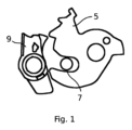
図1は、ドアロック1の部分的断面を示している(以下の図を参照)。回転ラッチ5は、ドアロック1の閉状態でドアを閉めたまま保持するために、閉要素7を形状結合で保持する役割を果たす。回転ラッチ5が閉要素7に係合すると、係止機構9が回転ラッチ5の突出部に係合し、この回転ラッチが緩んで外れないように保護する。これにより、回転ラッチ5は、閉要素7に係合している位置で係止されたまま留まっている。しかし、係止機構9が回転ラッチ5の突出部に係合するためには、回転ラッチ5の突出部を画定している端部と、係止機構9の角張った突起部との間に遊びのある間隙ができるまで、回転ラッチ5が時計回りに回転しなければならない。この遊びは、閉要素7と、回転ラッチ5の膨らみのある凹形の突出部との間の間隔にも現われる。この遊びは、オーバートラベルとも呼ばれ、走行中に刺激があった場合にドアロック1でカタカタ音が生じる原因となり得る。そのため、以下の図2から図4には、ウェッジレバー13によって閉要素7を追加的にクランプすることによって、この問題を防止する解決策が示されており、このとき、ウェッジレバー13およびその他の構成部品の摩耗が考慮される。
1 shows a partial cross-section of the door lock 1 (see the following figures). The
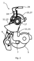
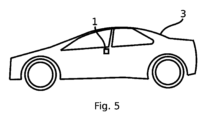
図2は、図5に示されているような車両3のドアロック1を示す。ドアロック1は、ドアロック1の閉状態において、閉要素7の周りに回転して係合することにより、閉要素7を形状結合で保持するための回転ラッチ5と、係止機構9の閉動作後、閉要素7と回転ラッチ5との形状結合の解除に対して回転ラッチ5を係止するための、ここでは爪として形成されている係止機構9とを有している。さらに、ドアロック1は、ウェッジレバー13と接続ピース15を備えるウェッジシステム11も有している。ウェッジレバー13と接続ピース15は、図2に示すように、相対的に運動を実行することができ、このときドアロック1の閉状態のためのセルフロック接触位置に至ることができるように、移動可能に支持されている。ウェッジレバー13は、図2において、時計回りに開放位置に回転することができる。ウェッジレバー13は、セルフロック位置において、回転可能に支持された接続ピース15を押え付け、この接続ピース15がさらに閉要素7を押え付け、これによって、閉要素7と回転ラッチ5との間の相対運動が減少する。係止機構9は、その正面の円弧状の周方向セグメントを介して、回転可能に支持されたアウトプットレバー17の周囲にフェイススプラインによって接触することにより、係止機構9の開動作時および閉動作時に、アウトプットレバー17が係止機構9の周方向セグメント上を転動することによって回転するものであり、このとき、アウトプットレバー17はキャッチレバー19に連結されており、係止機構9の開動作時におけるアウトプットレバー17の回転により、キャッチレバー19がウェッジレバー13と接続ピース15との間のセルフロック接続を解除する。キャッチレバー19、アウトプットレバー17、およびウェッジレバー13は、すべて互いに同心で回転可能に支持され、かつそれらの軸受内で原理的には互いに独立して回転可能である。しかし、キャッチレバー19とウェッジレバー13は、開口ばね25を介して連結されている。ウェッジレバー13と接続ピース15との間のセルフロック接続を解除するために、キャッチレバー19が開口ばね25を十分に圧縮すると、開口ばね25は、ウェッジレバー13をセルフロック接続から開放位置に追いやろうとする。図2において、開口ばね25は別個に描かれておらず、キャッチレバー19の円弧状ガイド27のみが示されており、この円弧状ガイド27の周りに、渦巻きばねとして形成されている開口ばね25が巻かれている。アウトプットレバー17とともに回転するカム21がキャッチレバー19の突起部23に当たり、その際、キャッチレバー19がともに回転すると、開口ばね25はキャッチレバー19によって圧縮される。キャッチレバー19が開口ばね25を押し縮めると、そのばね力でウェッジレバー13を押え付ける。キャッチレバー19を押え付ける閉口ばね29は、ドアロック1の閉鎖時に、キャッチレバー19がウェッジレバー13とともにセルフロック位置の方向に動くようにする。
2 shows a
ドアロック1の開プロセスは、以下のように説明できる。係止機構9は爪として実施されており、閉要素7はシャックルとして実施されている。さらに、爪9の円弧状の周方向セグメントはフェイススプラインとして実施されており、爪9の開動作であっても閉動作であっても、回転可能に支持されているアウトプットレバー17の周方向セグメントを爪9の各動作に伴って回転させるようになっている。このために、アウトプットレバー17は、回転可能にドアロック1の中に支持されており、これにより、爪9のフェイススプラインによって駆動される形でアウトプットレバー17が回転する。回転ラッチ5を開放するために、爪9がドアロック1の閉状態から出て、回転ラッチ5から離れる開動作へと移動する場合、回転ラッチ5は、シャックル7に係合しなくなり、アウトプットレバー17は、爪9のフェイススプラインの動きにより、アウトプットレバー17に配置されたカム21がキャッチレバー19の突起部に突き当たるまで回転する。この場合、キャッチレバー19、アウトプットレバー17、ウェッジレバー13は、すべて同心に支持されており、同一の運動学的軸を中心に互いに独立して回転することができる。上述したように、アウトプットレバー17のカム21がキャッチレバー19の突起部に突き当たると、アウトプットレバー17の回転運動に案内される形で、キャッチレバー19もともに回転する。キャッチレバー19は、開口ばね25によってウェッジレバー13の上側に連結されているので、キャッチレバー19のこの回転運動により、ウェッジレバー13とキャッチレバー19との間で開口ばね25が圧縮され、このとき、開口ばね25の拡張力が、ウェッジレバー13のこの上側に作用し、次に、ウェッジレバー13の反対側、すなわち接続ピース15に接触するウェッジレバー13の側を、セルフロック位置から外へ、すなわち、接続ピース15の領域でウェッジレバー13のより小さい半径に生じるウェッジレバー13の回転角度まで押し出し、それにより、ウェッジレバー13と接続ピース15との間のセルフロック接続が解除される。このとき、開口ばね25が、遊びと形状変化を補正するので、ウェッジレバー13の摩耗形成とは無関係に、メカニズムの機能が損なわれることはない。摩擦がセルフロック接続に打ち勝つと、ウェッジレバー13がキャッチレバー19のストッパに当たるまで、開口ばね25は緩められる。その後、ウェッジレバー13と接続ピース15との間のセルフロック作用が完全に解除されると、ウェッジレバー13はもはや接続ピース15に影響を及ぼさなくなり、接続ピース15もそれ以上シャックル7を押え付けないので、シャックル7は構造に由来する遊びを伴って回転ラッチ5の中にあるが、爪9の開きが十分にある場合、この回転ラッチ5によってシャックル7がそれ以上係合されることもない。この最終位置において、ドアロック1は開いており、接続ピース15も回転ラッチ5もシャックル7に接触していないため、ドアはもはやドアロック1での形状結合の係合によってシャックル7で保持されず、開けることができる。
The opening process of the
ドアロック1の閉プロセス時に、爪9は、回転ラッチ5がシャックル7に係合した後、上述した動作とは逆の動作を実行するので、シャックル7は、係合している回転ラッチ5によって形状結合で保持される。このとき、回転ラッチ5は、爪9によって保持されており、シャックル7を係合することができなくなるようにはそれ以上回転することはできず、これにより、回転ラッチ5は、シャックル7の周りで係合する位置に固定される。しかし、爪9の閉動作では、アウトプットレバー17が爪9のフェイススプラインによって再び駆動され、上述したドアロック1の開動作とは逆の回転方向にのみ回転する。このとき、アウトプットレバー17のカム21は、キャッチレバー19の突起部23から離れるので、キャッチレバー19もまた、閉口ばね29の拡張力によって駆動される形で、カム21の動きに僅かに追従することができる。ウェッジレバー13と接続ピース15との間にセルフロック摩擦が生じるように、ウェッジレバー13が接続ピース15上を移動することは、上述の勾配(円周にわたって増加する半径)を持つウェッジレバー13の偏心状の表面形状によって可能になるが、この移動を確実なものにするため、閉口ばね29がキャッチレバー19の上側に配置されており、この閉口ばね29がキャッチレバー19を押し、ウェッジレバー13、特に接続ピース15に接触するその表面と、ドアロック1のその他の構成部品とにおいてすでに生じている摩耗の程度とは無関係に、ウェッジレバー13が常にセルフロック位置に押し込まれるようにする。
During the closing process of the
特に、アウトプットレバー17と、それに加えて閉口ばね29と開口ばね25の作用様式により、ドアロック1の寿命が延びる。これは、摩耗とは無関係に両方のばねがその作用機構を確保しており、その動きによって、遊び、長さ、必要な角度等の変化を補正するからである。
In particular, the operating mode of the
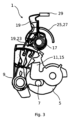
図3は、図2のドアロック1を示しているが、特に機能、および係止機構9とアウトプットレバー17との間の相互作用を説明するために、意図的にウェッジレバー13が取り外されている。アウトプットレバー17は、係止機構9が動くと、図3において係止機構9の上端にある周方向セグメント上を転動する。係止機構9の動きを分かりやすく説明するため、図3では、この係止機構9の開動作が複数の位置で示されている。係止機構9のフェイススプラインは、その円周上でアウトプットレバー17を捕らえているので、ドアロック1のハウジング内に支持されているアウトプットレバー17は歯車のように回転する。
Figure 3 shows the
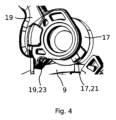
図4は、図2および図3の断面の拡大図であり、特にアウトプットレバー17を含んでいる。アウトプットレバー17は、係止機構9の開動作または閉動作を介して回転し、係止機構9において上側に配置されている係止機構9のフェイススプラインが、少なくとも一定の角度範囲にわたって歯車の動きを再現することにより、アウトプットレバー17の円周を動き、それによって、アウトプットレバー17は係止機構9の周方向セグメント上を転動する。このとき、アウトプットレバー17の周方向側の領域に配置されているカム21は、アウトプットレバー17の回転角が十分な場合、キャッチレバー19の突起部23に当たる。カム21は、キャッチレバー19に固定されている突起部23を押す。これにより、キャッチレバー19も回転する。
Figure 4 is an enlarged view of the cross section of Figures 2 and 3, including the
図5は、図2から図4によるドアロック1を備える車両3を示している。ここでは、閉要素7が車両3のボディに配置されている。これに対して、回転ラッチ5、係止機構9、ウェッジシステム11、アウトプットレバー17、およびキャッチレバー19は、すべて車両3のドアに配置されている。
Figure 5 shows a vehicle 3 equipped with a
本発明を好ましい実施例によってさらに詳細に詳しく図示及び説明したが、本発明は開示された実施例に限定されるものではなく、そこから当業者は本発明の保護範囲から逸脱することなく他の変形形態を導き出すことができる。従って、多数の可能な変形形態が存在することは明らかである。同様に、例示的に挙げられた実施形態は、実際のところ単なる例に過ぎず、どのような形であっても例えば本発明の保護範囲、適用可能性、又は構成を限定するものとして理解すべきでないことは明らかである。むしろ、前述の説明及び図の説明により、当業者は例示的な実施形態を具体的に実施することができ、その際、当業者は、開示された発明の思想を知ることで、請求項及びその法的均等物、例えば明細書中の十分な説明によって定義される保護範囲から逸脱することなしに、例えば例示的な実施形態に挙げられた個々の要素の機能又は配置に関して様々な変更を行うことができる。 Although the present invention has been illustrated and described in more detail by preferred embodiments, the present invention is not limited to the disclosed embodiments, from which those skilled in the art can derive other variations without departing from the scope of protection of the present invention. Thus, it is clear that there are many possible variations. Similarly, it is clear that the exemplary embodiments are merely examples in nature and should not be understood in any way as limiting, for example, the scope of protection, applicability, or configuration of the present invention. Rather, the above description and the illustrations allow those skilled in the art to specifically implement the exemplary embodiments, and in this case, those skilled in the art can make various changes, for example, in the function or arrangement of the individual elements listed in the exemplary embodiments, without departing from the scope of protection defined by the claims and their legal equivalents, for example, a sufficient description in the specification, by knowing the concept of the disclosed invention.
Claims (9)
-回転ラッチ(5)であって、前記ドアロック(1)の閉状態において、閉要素(7)の周りに係合することにより、前記閉要素(7)を形状結合で保持するための、前記回転ラッチ(5)と、
-係止機構(9)であって、前記係止機構(9)の閉動作後、前記ドアロック(1)の閉状態において、前記閉要素(7)と前記回転ラッチ(5)との前記形状結合の解除に対して前記回転ラッチ(5)を係止するための、前記係止機構(9)と、
-ウェッジシステム(11)であって、ウェッジレバー(13)と接続ピース(15)とを備え、前記閉要素(7)と前記回転ラッチ(5)との間の相対運動を減少させるために、前記ウェッジレバー(13)と前記接続ピース(15)は、相対的に運動を実行することができ、そして前記ドアロック(1)の閉状態のためのセルフロック位置に至ることができるように、移動可能に支持されており、前記ウェッジレバー(13)は、前記セルフロック位置において、回転可能に支持された前記接続ピース(15)を押え付け、前記接続ピース(15)がさらに前記閉要素(7)を押え付ける、前記ウェッジシステム(11)と、を備え、
前記係止機構(9)は、円弧状の周方向セグメントを介して、回転可能に支持されたアウトプットレバー(17)の周囲と摩擦結合及び/又は形状結合で接触し、それにより前記係止機構(9)の開動作時および閉動作時に、前記アウトプットレバー(17)が前記係止機構(9)の前記周方向セグメント上を転動することによって回転するものであり、前記アウトプットレバー(17)はキャッチレバー(19)に連結されており、前記係止機構(9)の開動作時における前記アウトプットレバー(17)の回転により、前記キャッチレバー(19)が前記ウェッジレバー(13)と前記接続ピース(15)との間の前記セルフロック位置における接続を解除することを特徴とする、前記ドアロック(1)。 A door lock (1) for a vehicle (3), comprising:
a rotary latch (5) for engaging around a closing element (7) in the closed state of the door lock (1) and thereby holding said closing element (7) in a form-locking manner;
a locking mechanism (9 ) for locking said rotary latch (5) against release of said positive coupling between said closing element (7) and said rotary latch (5) in the closed state of said door lock (1) after a closing movement of said locking mechanism (9),
a wedge system (11) comprising a wedge lever (13) and a connecting piece (15), the wedge lever (13) and the connecting piece (15) being movably supported so that they can perform a relative movement between the closing element (7) and the rotary latch (5) and can reach a self- locking position for the closed state of the door lock (1) , the wedge lever (13) pressing against the rotatably supported connecting piece (15) in the self-locking position, the connecting piece (15) further pressing against the closing element (7) ,
the locking mechanism (9) is in frictional and/or form-locking contact with the periphery of a rotatably supported output lever (17) via an arc-shaped circumferential segment, whereby during opening and closing operations of the locking mechanism (9), the output lever (17) rotates by rolling on the circumferential segment of the locking mechanism (9), the output lever (17) being connected to a catch lever (19), wherein the rotation of the output lever (17) during an opening operation of the locking mechanism (9) causes the catch lever (19) to release the connection between the wedge lever (13) and the connecting piece (15) in the self -locking position.
前記閉要素(7)は前記車両(3)のボディに配置され、前記回転ラッチ(5)、前記係止機構(9)、前記ウェッジシステム(11)、前記アウトプットレバー(17)、および前記キャッチレバー(19)は前記車両(3)のドアに配置されている、前記車両(3)。
A vehicle (3) equipped with a door lock (1) according to claim 1 or 2,
The closing element (7) is arranged on the body of the vehicle (3), and the rotating latch (5), the locking mechanism (9), the wedge system (11), the output lever (17), and the catch lever (19) are arranged on the door of the vehicle (3).
Applications Claiming Priority (3)
| Application Number | Priority Date | Filing Date | Title |
|---|---|---|---|
| DE102021003155.5 | 2021-06-18 | ||
| DE102021003155.5A DE102021003155A1 (en) | 2021-06-18 | 2021-06-18 | Door lock for a vehicle with reduced noise |
| PCT/EP2022/061566 WO2022263048A1 (en) | 2021-06-18 | 2022-04-29 | Door lock for a vehicle, with reduced noise generation |
Publications (2)
| Publication Number | Publication Date |
|---|---|
| JP2024523031A JP2024523031A (en) | 2024-06-25 |
| JP7686800B2 true JP7686800B2 (en) | 2025-06-02 |
Family
ID=81854597
Family Applications (1)
| Application Number | Title | Priority Date | Filing Date |
|---|---|---|---|
| JP2023577305A Active JP7686800B2 (en) | 2021-06-18 | 2022-04-29 | Noise-reducing door lock for vehicles |
Country Status (7)
| Country | Link |
|---|---|
| US (1) | US12442227B2 (en) |
| EP (1) | EP4355966A1 (en) |
| JP (1) | JP7686800B2 (en) |
| KR (1) | KR102841853B1 (en) |
| CN (1) | CN117500992B (en) |
| DE (1) | DE102021003155A1 (en) |
| WO (1) | WO2022263048A1 (en) |
Citations (3)
| Publication number | Priority date | Publication date | Assignee | Title |
|---|---|---|---|---|
| JP2008063908A (en) | 2006-09-11 | 2008-03-21 | Imasen Electric Ind Co Ltd | Vehicle locking device |
| JP2014201880A (en) | 2013-04-01 | 2014-10-27 | シロキ工業株式会社 | Locking device |
| DE102017205656A1 (en) | 2016-12-22 | 2018-06-28 | Witte Automotive Gmbh | Lock, in particular backrest or tailgate lock |
Family Cites Families (16)
| Publication number | Priority date | Publication date | Assignee | Title |
|---|---|---|---|---|
| DE1553470C3 (en) * | 1966-07-09 | 1974-09-26 | Fa. Carl Sievers, 5628 Heiligenhaus | Closure, especially for the rear storage of tilting cabs of trucks |
| DE3927445C2 (en) | 1989-08-19 | 2000-12-07 | Kiekert Ag | Motor vehicle door lock |
| US7325874B2 (en) * | 2004-10-14 | 2008-02-05 | Johnson Controls Technology Company | Latch mechanism |
| CN101133224B (en) * | 2005-03-04 | 2011-05-04 | 丰田纺织株式会社 | Lock device |
| WO2006132018A1 (en) * | 2005-06-08 | 2006-12-14 | Toyota Boshoku Kabushiki Kaisha | Lock device |
| JP4908114B2 (en) * | 2006-08-31 | 2012-04-04 | 三井金属アクト株式会社 | Automotive locking device |
| US8511723B2 (en) * | 2007-03-02 | 2013-08-20 | Toyota Boshoku Kabushiki Kaisha | Locking device |
| DE102007060915B4 (en) * | 2007-12-14 | 2023-11-09 | Kiekert Aktiengesellschaft | Locking device with end position protection |
| DE102008010002A1 (en) | 2008-02-19 | 2009-10-01 | BÖCO Böddecker & Co. GmbH & Co. KG | Device for locking two vehicle components, has rotary latch, rack element for rotary latch, and clamping element, where fork shoulder of rotary latch grips closing element, for example closing bracket bolt |
| JP5614332B2 (en) * | 2011-02-28 | 2014-10-29 | アイシン精機株式会社 | Vehicle locking device |
| DE102011101285B3 (en) * | 2011-05-06 | 2012-09-13 | Keiper Gmbh & Co. Kg | locking device |
| US8950810B2 (en) * | 2011-11-18 | 2015-02-10 | Toyo Seat Usa Corp. | Latch mechanism for automotive seat assembly |
| DE202012011372U1 (en) * | 2012-11-28 | 2014-03-05 | BROSE SCHLIEßSYSTEME GMBH & CO. KG | Motor vehicle lock |
| CN103867050B (en) * | 2014-03-31 | 2015-12-23 | 上海恩坦华汽车门系统有限公司 | A kind of automobile door lock actuator |
| KR101673705B1 (en) * | 2014-12-02 | 2016-11-07 | 현대자동차주식회사 | Door latch device for vehicle |
| DE102018126968A1 (en) * | 2018-10-18 | 2020-04-23 | Brose Schließsysteme GmbH & Co. Kommanditgesellschaft | Motor vehicle lock for a motor vehicle door |
-
2021
- 2021-06-18 DE DE102021003155.5A patent/DE102021003155A1/en active Pending
-
2022
- 2022-04-29 KR KR1020237042273A patent/KR102841853B1/en active Active
- 2022-04-29 CN CN202280042983.8A patent/CN117500992B/en active Active
- 2022-04-29 JP JP2023577305A patent/JP7686800B2/en active Active
- 2022-04-29 EP EP22726656.6A patent/EP4355966A1/en active Pending
- 2022-04-29 US US18/570,684 patent/US12442227B2/en active Active
- 2022-04-29 WO PCT/EP2022/061566 patent/WO2022263048A1/en not_active Ceased
Patent Citations (3)
| Publication number | Priority date | Publication date | Assignee | Title |
|---|---|---|---|---|
| JP2008063908A (en) | 2006-09-11 | 2008-03-21 | Imasen Electric Ind Co Ltd | Vehicle locking device |
| JP2014201880A (en) | 2013-04-01 | 2014-10-27 | シロキ工業株式会社 | Locking device |
| DE102017205656A1 (en) | 2016-12-22 | 2018-06-28 | Witte Automotive Gmbh | Lock, in particular backrest or tailgate lock |
Also Published As
| Publication number | Publication date |
|---|---|
| CN117500992B (en) | 2026-03-17 |
| KR20240005898A (en) | 2024-01-12 |
| DE102021003155A1 (en) | 2022-12-22 |
| KR102841853B1 (en) | 2025-08-07 |
| CN117500992A (en) | 2024-02-02 |
| US12442227B2 (en) | 2025-10-14 |
| EP4355966A1 (en) | 2024-04-24 |
| WO2022263048A1 (en) | 2022-12-22 |
| JP2024523031A (en) | 2024-06-25 |
| US20240229522A1 (en) | 2024-07-11 |
Similar Documents
| Publication | Publication Date | Title |
|---|---|---|
| US9151092B2 (en) | Lock unit having a multi-pawl locking mechanism | |
| CN104169510B (en) | Automobile door lock | |
| US8480138B2 (en) | Lock device having a multi-part pawl | |
| US6773042B2 (en) | Latch assembly | |
| JP4331409B2 (en) | Tightening roller type ratchet feed mechanism | |
| JP7501522B2 (en) | Car lock, particularly an electrically actuable car lock | |
| US8388068B2 (en) | Locking and releasing mechanism for vehicle seat | |
| JP4221691B2 (en) | Closing device for a closing function which can be carried out especially in vehicles | |
| US9574381B2 (en) | Door handle assembly for a motor vehicle | |
| KR20040103937A (en) | Lock, especially for automotive doors, flaps or the like | |
| US11821514B2 (en) | Parking lock, transmission, and drive installation | |
| JP2013525628A (en) | Car door lock | |
| US11841082B2 (en) | Solenoid actuated locking pawl with compliance mechanism | |
| JP2000515942A (en) | Car door locks, bonnet locks or similar | |
| KR20010102411A (en) | Device for receiving and holding an identification provider, such as an electronic key, especially for an ignition-starter switch | |
| JP7686800B2 (en) | Noise-reducing door lock for vehicles | |
| CN113833846A (en) | Electromechanical parking lock actuator | |
| JP2014510206A (en) | Flap or door lock | |
| JP4973297B2 (en) | Locking device | |
| CN113423911B (en) | Braking device | |
| JP3822953B2 (en) | Adjuster for disc brake device | |
| CN113574239A (en) | Door locks, especially motor vehicle door locks | |
| US6758012B2 (en) | Actuator for operating vehicle door | |
| CN113195854A (en) | Lock for a motor vehicle | |
| CN117280107B (en) | Motor vehicle locks |
Legal Events
| Date | Code | Title | Description |
|---|---|---|---|
| A521 | Request for written amendment filed |
Free format text: JAPANESE INTERMEDIATE CODE: A523 Effective date: 20240104 |
|
| A621 | Written request for application examination |
Free format text: JAPANESE INTERMEDIATE CODE: A621 Effective date: 20240104 |
|
| A977 | Report on retrieval |
Free format text: JAPANESE INTERMEDIATE CODE: A971007 Effective date: 20241121 |
|
| A131 | Notification of reasons for refusal |
Free format text: JAPANESE INTERMEDIATE CODE: A131 Effective date: 20241210 |
|
| A521 | Request for written amendment filed |
Free format text: JAPANESE INTERMEDIATE CODE: A523 Effective date: 20250303 |
|
| TRDD | Decision of grant or rejection written | ||
| A01 | Written decision to grant a patent or to grant a registration (utility model) |
Free format text: JAPANESE INTERMEDIATE CODE: A01 Effective date: 20250513 |
|
| A61 | First payment of annual fees (during grant procedure) |
Free format text: JAPANESE INTERMEDIATE CODE: A61 Effective date: 20250521 |
|
| R150 | Certificate of patent or registration of utility model |
Ref document number: 7686800 Country of ref document: JP Free format text: JAPANESE INTERMEDIATE CODE: R150 |