JP7685397B2 - Optical beam convergence/divergence control device - Google Patents
Optical beam convergence/divergence control device Download PDFInfo
- Publication number
- JP7685397B2 JP7685397B2 JP2021140877A JP2021140877A JP7685397B2 JP 7685397 B2 JP7685397 B2 JP 7685397B2 JP 2021140877 A JP2021140877 A JP 2021140877A JP 2021140877 A JP2021140877 A JP 2021140877A JP 7685397 B2 JP7685397 B2 JP 7685397B2
- Authority
- JP
- Japan
- Prior art keywords
- optical
- light
- section
- distribution element
- output
- Prior art date
- Legal status (The legal status is an assumption and is not a legal conclusion. Google has not performed a legal analysis and makes no representation as to the accuracy of the status listed.)
- Active
Links
Images


Landscapes
- Optical Integrated Circuits (AREA)
- Optical Modulation, Optical Deflection, Nonlinear Optics, Optical Demodulation, Optical Logic Elements (AREA)
Description
本発明は、光ビームパターンを制御するデバイスに係り、特に、光ビームを収束光にしたり発散光にしたりする光ビーム収束・発散制御デバイスに関する。 The present invention relates to a device for controlling a light beam pattern, and in particular to a light beam convergence/divergence control device for making a light beam convergent or divergent.
空間光通信や奥行センサ、レーダー、LiDAR(Light Detection And Ranging)、3次元映像表示装置などへの応用に向け、光ビームパターンを制御するデバイスの研究開発が進められている。特に、光の位相制御と多光束干渉を基本原理とする光フェーズドアレイ(Optical Phased Array;以下、OPA)は、機械的な可動部なしに光ビームパターンを自在に制御できるため、小型・軽量で耐久性の高い光ビーム走査デバイスや可変焦点光制御デバイスなどへの応用が期待されている(例えば特許文献1、非特許文献1参照)。
Research and development is underway on devices that control light beam patterns for applications in spatial optical communications, depth sensors, radar, LiDAR (Light Detection and Ranging), 3D image display devices, and the like. In particular, optical phased arrays (OPAs), which use optical phase control and multi-beam interference as their basic principles, can freely control light beam patterns without mechanical moving parts, and are therefore expected to be applied to small, lightweight, and highly durable light beam scanning devices and variable focus light control devices (see, for example,
図17は、光導波路を用いた一般的なOPAの構成を示す模式図である。OPA101は、基板102上に、光入力部103と、光分離部104と、マルチチャネル光導波路105と、を備えている。ここでは、一例として、マルチチャネル光導波路105と光出力部107のチャネル数nを8としている。マルチチャネル光導波路105は、チャネルごとに個別の位相制御部110に接続されており、各光導波路106の先端は、光出力部107として用いられる。なお、図17では、光導波路106として光導波路コアのみ図示しており、コア周囲のクラッド層の図示を省略している。
Figure 17 is a schematic diagram showing the configuration of a typical OPA using an optical waveguide. The
OPA101の光分離部104には、入射光を8本の光導波路106からなるマルチチャネル光導波路105に光を分配するために、1x2マルチモード干渉(Multi-Mode Interference;MMI)光スプリッタ20が7個配置されている。1x2 MMI光スプリッタ20は、1つの入射光を2つの光導波路に分配する素子である。チャネル数nが例えば16である場合、16本のマルチチャネル光導波路に分配するには、1x2 MMI光スプリッタ20を15個接続して配置すればよい。また、1つの入射光を2より多いN本の光導波路に分配する光分配素子として、1xN MMI光スプリッタやスターカプラなどを用いることも可能である。
In the
OPA101の位相制御部110には、外部からの電圧印加あるいはヒーター電極の通電に伴うジュール加熱などにより屈折率が変化する材料が使用される。このような材料には、例えば電気光学(EO)効果を有する材料(以下、EO材料と称す)や液晶(LC)材料、熱光学(TO)効果を有する材料(以下、TO材料と称す)などが従来利用されている。
The
OPAの基本動作は、入力光を光分離部104によりマルチチャネル光導波路105へ分配し、チャネルごとの光位相を位相制御部110により制御し、光出力部107より出射された複数の光の回折・干渉によって光ビームパターンを形成するものである(例えば非特許文献2参照)。OPAでは光導波路の出力端における光位相分布を適切に選ぶことにより、出力される光ビームのパターンを自在に制御することが可能である。特に収束・発散制御による焦点可変は情報取得や撮像・表示、工業用レーザーなどへの応用が期待できる。
The basic operation of the OPA is to distribute the input light to the multichannel
OPAでは、光導波路を通過する光の位相が位相制御部により電気的に制御される。したがって、図17の構成のように1つの出力光導波路106に対して1つの位相制御部110が接続される従来の構成では、チャネル数の増加に伴って位相制御部110の個数が増加し、制御回路の大規模化や消費電力増大の原因となる。
In an OPA, the phase of light passing through the optical waveguide is electrically controlled by a phase control section. Therefore, in a conventional configuration in which one
本発明は、以上のような問題点に鑑みてなされたものであり、消費電力を低減できる光ビーム収束・発散制御デバイスを提供することを課題とする。 The present invention was made in consideration of the above problems, and aims to provide a light beam convergence/divergence control device that can reduce power consumption.
前記課題を解決するために、本発明に係る光ビーム収束・発散制御デバイスは、1つの光入力部と、光出力部のチャネル数と同数の光導波路が並列配置されたマルチチャネル光導波路と、前記光入力部から入力する光を前記光導波路に分配する光分離部と、印加電圧もしくは電流供給により光の位相を制御する位相制御部と、を備え、前記光分離部は、1入力3出力の少なくとも1つの光分配素子と、前記光分配素子の1出力から出力される光を2つの光導波路に分配する1つのスプリッタと、を備え、前記光分配素子の1出力と前記スプリッタとの接続部に位相制御部が配置されており、前記光出力部のチャネル数を偶数の所定値nとして、4以上n以下の偶数を変数Nとしたとき、前記光分配素子は、N本分の光導波路の光強度を有する光を入力して3つに分岐して出力する素子であって、1xN MMI光スプリッタと、(N-2)x1 MMI光コンバイナとを近接配置して構成されており、かつ、前記光分配素子の3出力のうちの一側の出力端、中央の出力端、他側の出力端の光強度比は、1:(N-2):1であることとした。 In order to solve the above problems, the optical beam convergence/divergence control device according to the present invention comprises one optical input section, a multichannel optical waveguide in which the same number of optical waveguides as the number of channels of an optical output section are arranged in parallel, an optical separation section which distributes the light input from the optical input section to the optical waveguides, and a phase control section which controls the phase of the light by applying a voltage or supplying a current, the optical separation section comprises at least one optical distribution element with one input and three outputs, and one splitter which distributes the light output from one output of the optical distribution element to two optical waveguides, and a phase control section is disposed at a connection section between one output of the optical distribution element and the splitter , and when the number of channels of the optical output section is a predetermined even value n and an even number between 4 and n is a variable N, the optical distribution element is an element which inputs light having the optical intensity of N optical waveguides, branches it into three, and outputs it, and comprises a 1×N MMI optical splitter and an (N−2)×1 The optical distribution element is configured by arranging an MMI optical combiner in close proximity to one another, and the optical intensity ratio between one output end, a central output end, and the other output end of the three outputs of the optical distribution element is 1:(N-2):1 .
本発明によれば、位相制御部の個数を光出力部のチャネル数の半分よりも少なくして従来よりも位相制御部の電極の総面積を削減できるので、消費電力を低減できる光ビーム収束・発散制御デバイスを提供することができる。 According to the present invention, the number of phase control sections can be reduced to less than half the number of channels in the optical output section, thereby reducing the total area of the electrodes in the phase control sections compared to conventional cases, thereby providing an optical beam convergence/divergence control device that can reduce power consumption.
[光ビーム収束・発散制御デバイスの構成]
まず、光ビーム収束・発散制御デバイスの構成について図面を参照して説明する。なお、各図面に示される部材のサイズや位置関係は、説明を明確にするため誇張していることがある。また、図1では、光導波路コアのみ図示しており、コア周囲のクラッド層の図示を省略している。
[Configuration of optical beam convergence/divergence control device]
First, the configuration of the optical beam convergence/divergence control device will be described with reference to the drawings. Note that the size and positional relationship of the components shown in each drawing may be exaggerated for clarity of explanation. Also, in Fig. 1, only the optical waveguide core is shown, and the cladding layer around the core is omitted.
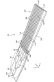
図1に示すように、光ビーム収束・発散制御デバイス1は、基板2上に、光導波路である1つの光入力部3と、光導波路の端部である光出力部7のチャネル数と同数の光導波路6が並列配置されたマルチチャネル光導波路5と、光入力部3から入力する光を光導波路6に分配する光分離部4と、位相制御部10と、を備えている。位相制御部10は、印加電圧もしくは電流供給により光の位相を制御する。すなわち、位相制御部10は、光導波路6の入出力面と直交しかつ対向する面それぞれに電極を備え、電極間の電界により光の位相を制御する、もしくは光導波路6の入出力面と直交する面に電極を備え、電極への電流供給に伴って発生するジュール熱により光の位相を制御する。光分離部4は、1入力3出力の少なくとも1つの光分配素子30と、1つのスプリッタ20と、を備えている。スプリッタ20は、光分配素子30Cの1出力から出力される光を2つの光導波路6に分配する。光分配素子30Cの1出力とスプリッタ20との接続部に位相制御部10Cが配置されている。
As shown in FIG. 1, the optical beam convergence/
光出力部7のチャネル数と光分配素子30の入力及び出力について一般化すると、光出力部7のチャネル数を偶数の所定値nとして、4以上n以下の偶数を変数Nとしたとき、光分配素子30は、N本分の光導波路6の光強度を有する光を入力して、(N-2)本分の光導波路6の光強度を有する光を1つと、1本分の光導波路6の光強度を有する光を2つの、合計3つに分岐して出力する素子であり、(N-2)本分の光導波路6の光強度を有する光が、位相制御部10に出力されることが好ましい。
そして、光分配素子30は、1xN MMI光スプリッタと、(N-2)x1 MMI光コンバイナとを近接配置して構成されており、かつ、光分配素子30の3出力のうちの一側の出力端、中央の出力端、他側の出力端の光強度比は、1:(N-2):1であることが好ましい。
Generalizing the number of channels of the optical output unit 7 and the input and output of the
The
図1では、一例として図17と対比させるため、マルチチャネル光導波路5のチャネル数nを8としている。この場合、前記変数Nは、8または6または4となる。
光分配素子30Aは、8本分の光導波路6の光強度を有する光を入力して3つに分岐して出力する素子であって、1x8 MMI光スプリッタと、6x1 MMI光コンバイナとを近接配置して構成されている。
光分配素子30Bは、6本分の光導波路6の光強度を有する光を入力して3つに分岐して出力する素子であって、1x6 MMI光スプリッタと、4x1 MMI光コンバイナとを近接配置して構成されている。
光分配素子30Cは、4本分の光導波路6の光強度を有する光を入力して3つに分岐して出力する素子であって、1x4 MMI光スプリッタと、2x1 MMI光コンバイナとを近接配置して構成されている。
1, as an example, the number of channels n of the multi-channel
The
The
The
また、Nの値が2つずつ異なる複数の光分配素子30が、光入力側からNの大きい順に縦列に配置され、Nの大きい側の光分配素子の中央の出力端と、Nの小さい側の光分配素子の入力との接続部に、位相制御部10が配置されていることが好ましい。
It is also preferable that a plurality of
光分配素子30は、N(N=4,6,8のいずれか)本分の光導波路6の光強度を有する光を入力して3つに分岐して出力する素子である。図1に示す例では、光分配素子30Aは8本分の光導波路6の光強度を有する光を入力して3つに分岐し、光分配素子30Bは6本分の光導波路6の光強度を有する光を入力して3つに分岐し、光分配素子30Cは4本分の光導波路6の光強度を有する光を入力して3つに分岐する。すなわち、光ビーム収束・発散制御デバイス1には、Nの値が2つずつ異なる複数の光分配素子30A,30B,30Cが、光入力側からNの大きい順に縦列に配置されている。そして、Nの大きい側の光分配素子の中央の出力端と、Nの小さい側の光分配素子の入力との接続部に、位相制御部10A,10Bがそれぞれ配置されている。ここでは、光分配素子30Aの中央の出力端と、光分配素子30Bの入力との接続部に位相制御部10Aが配置されており、光分配素子30Bの中央の出力端と、光分配素子30Cの入力との接続部に位相制御部10Bが配置されている。
The
[各部の構成例]
以下、各部の構成例について説明する。なお、光分配素子を区別しない場合、単に光分配素子30と表記し、また、位相制御部を区別しない場合、単に位相制御部10と表記する。
[Example of each part configuration]
An example of the configuration of each unit will be described below. When the light distribution elements are not differentiated, they will be simply referred to as
基板2は、様々な材料を用いて形成することができる。基板材料としては、シリコン基板のほか、ソーダガラスやパイレックス(登録商標)、溶解石英、ニオブ酸リチウム(LiNbO3)、タンタル酸リチウム(LiTaO3)、サファイア(Al2O3))等を用いてもよい。基板2の一方の面には、光入力部3と、光分離部4と、複数の電極線8と、が形成されている。
The
光入力部3は、外部の光源から光を光分離部4へ入射する光導波路から形成される。光源としては、レーザー光源や発光ダイオード(LED)等を適用することができる。光ビーム収束・発散制御デバイス1には、さらに必要に応じて、光源と光入力部3との間に、ボールレンズやシリンドリカルレンズ等を備えるようにしてもよい。
The
光出力部7は、光導波路6の端部であって、位相が制御された光を外部空間へ放射するものであり、光導波路の幅方向に並設されている。それぞれの光出力部7から放射された光は、それぞれの光位相の関係によって決まる干渉パターンを形成する。なお、光出力部7から出力する光ビームを上方に出射するために、光導波路に回折格子をさらに設けるようにしてもよい。さらに必要に応じて、光出力部7の外部かつ放射された光の照射範囲内に、ボールレンズやシリンドリカルレンズ等を備えるようにしてもよい。
The light output units 7 are the ends of the
光導波路6は、コアとクラッドから形成され、コアはクラッドに比較して屈折率が大きい。位相制御部10の光導波路を形成するコアの材料は、外部信号の印加により屈折率が変化する材料である。印加電圧によって屈折率が変化するLC材料やEO材料、あるいはヒーター電極の通電に伴うジュール加熱によって屈折率が変化するTO材料が利用できる。位相制御部10のコアの材料には、EO効果を有するLiNbO3やLiTaO3などの無機物のほか、EO効果を有するポリマー材料、あるいはEO効果を有する色素を混合したポリマー材料を用いることができる。位相制御部10以外の光導波路コアの材料には、酸化チタンなどの無機物のほか、EO効果を有さない一般的なポリマー材料を用いることができる。クラッドをなす誘電体材料には、酸化シリコン、五酸化タンタル、五酸化ニオブなどの無機誘電体材料に加え、PMMA(ポリメチルメタクリレート)等の有機ポリマー材料やSU-8等のエポキシ樹脂を適用できる。コア材料やクラッド材料は、光導波路の全体を通じて同じ材料でもよいし、各機能部に応じた異なる材料を用いるようにしてもよい。
The
光分離部4は、光入力部3を導波した光を、マルチチャネル光導波路5の各光導波路6に分配するものである。光分離部4は、入力光の強度を各光導波路6に等分配する。マルチチャネル光導波路5には光出力部7のチャネル数と同数の8本の光導波路6が並列配置されている。ここでは、図2において手前側から順に、チャネルch0,ch1,ch2,ch3,ch4,ch5,ch6,ch7とする。なお、光導波路6は、シングルモードで光の伝搬を行うことを前提としている。
The
光分離部4の光分配素子30Aは、光入力部3に接続されている。光分配素子30Aは、1つの入射光を光強度比1:6:1の3つに分配するものである。光分配素子30Aを、以下、1:6:1光分配素子30Aと称す。光分配素子30Aは、図5に示すように、入力端31と、一側の出力端32と、中央の出力端33と、他側の出力端34と、を備える。
The
ここでは、光入力部3が入力端31に接続されている。一側の出力端32から伸びる出力光導波路は、チャネルch7の光導波路6を構成している。他側の出力端34から伸びる出力光導波路は、チャネルch0の光導波路6を構成している。中央の出力端33から伸びる出力光導波路は、1:6:1光分配素子30Aの出力光導波路のうち強度が最大であり、これを以下、6/8出力光導波路6と称す。この6/8出力光導波路6には、図2に示すように光分配素子30Bが接続されている。
Here, the
光分配素子30Bは、1つの入射光を光強度比1:4:1の3つに分配するものである。光分配素子30Bを、以下、1:4:1光分配素子30Bと称す。1:4:1光分配素子30Bの出力光導波路のうち強度が最大のものを、以下、4/6出力光導波路6と称す。この4/6出力光導波路6に、光分配素子30Cが接続されている。光分配素子30Cは、1つの入射光を光強度比1:2:1の3つに分配するものである。光分配素子30Cを、以下、1:2:1光分配素子30Cと称す。1:2:1光分配素子30Cの出力光導波路のうち強度が最大のものを、以下、2/4出力光導波路6と称す。この2/4出力光導波路6に、1x2 MMI光スプリッタ20が接続されている。
The
6/8出力光導波路には位相制御部10Aが設けられている。位相制御部10Aを以下、6/8位相制御部10Aと称す。
4/6出力光導波路には位相制御部10Bが設けられている。位相制御部10Bを以下、4/6位相制御部10Bと称す。
2/4出力光導波路には位相制御部10Cが設けられている。位相制御部10Cを以下、2/4位相制御部10Cと称す。
なお、各位相制御部10は、図17に示すOPA101に備わる位相制御部110と同様の構造であり、電極面積も等しいものとする。
The 6/8 output optical waveguide is provided with a
The 4/6 output optical waveguide is provided with a
The 2/4 output optical waveguide is provided with a
It is to be noted that each
位相制御部10は、外部印加電圧等で生じる電界、あるいは電流供給により発生するジュール熱により屈折率が変化する材料を含んでいる。位相制御部10は、図1に示すように電極線8を介して送られる電気信号によって光導波路を形成するコアの屈折率を変化させる。つまり、位相制御部10は、電極線8から送られる電気信号によって、位相制御部10内を伝搬する光の位相が制御可能になっている。外部印加電圧で生じる電界により屈折率が変化する材料を含む位相制御部10には、電極(下部電極11、上部電極12:図3参照)が設けられている点が光出力部7等の光導波路とは異なっている。電流供給に伴うジュール熱により屈折率が変化する材料を含む位相制御部10には、図3における下部電極11もしくは上部電極12のうち1つないしは2つが設けられている。外部印加電圧で生じる電界により屈折率が変化する材料を含む位相制御部10の電極配置においては、電圧印加により生じる基板2と垂直な方向の電界成分の分布により屈折率分布が変化する。このため本構成例では、伝播する光として電界の振幅方向が基板2と垂直な方向であるTM(Transverse Magnetic)モードの偏光を用いる。ただし、後記するように電極をコアの側面に配置し、TE(Transverse Electric)モードの偏光を用いてもよい。
The
電極の材料としては、金、銀、銅、ニッケル、アルミニウム、クロムなどの金属、もしくは金属酸化物や窒化物が好適である。
複数の電極線8は、各位相制御部10の電極にそれぞれ電気的に接続されている。電極線8の材料としては、例えば、Al、Cu、Au、Ti、Crなどの金属を用いることができる。電極線8を透明電極としてもよく、その場合、材料としては、IZO(Indium Zinc Oxide:インジウム亜鉛酸化物)やITO(Indium Tin Oxide:インジウム-スズ酸化物)などを挙げることができる。
Suitable materials for the electrodes include metals such as gold, silver, copper, nickel, aluminum, and chromium, as well as metal oxides and nitrides.
The
ここで、位相制御部10の動作について、EO材料の一つであるEOポリマーをコアに適用した光導波路を例に挙げて説明する。外部電界Eを与えたとき、EOポリマーの屈折率nは、外部電圧印加のなき場合の屈折率n0に対して、次の式(1)にしたがって変化する。
n=n0-0.5r33n3E … 式(1)
この現象をEO効果(ポッケルス効果)と呼び、屈折率変化の大きさを示す物性値r33をEO係数と呼ぶ。
Here, the operation of the
n=n 0 -0.5r 33 n 3 E... Formula (1)
This phenomenon is called the EO effect (Pockels effect), and the physical value r 33 that indicates the magnitude of the change in refractive index is called the EO coefficient.
図3は、EOポリマーをコア61に、これよりも屈折率の低い材料をクラッド62に適用した光導波路6の位相制御部10における断面構造の一例である。図示するように、位相制御部10の下部電極11および上部電極12は電極線8を介して波形発生器81に接続されている。光ビーム収束・発散制御デバイス1の駆動時には、波形発生器81が、位相制御部10ごとに定められた波形の駆動電圧圧を該当の位相制御部10に印加する。上部電極12と下部電極11との間に電位差を与えると、コア61に電界が生じるため、EO効果によってコア61の屈折率が変化する。長さがLである位相制御部10に入射した波長λの光の位相は、位相制御部10を通過することにより、外部電圧印加のなき場合には2πn0L/λだけ変化する。これに対し、外部電圧により電界Eが生じたとき、光の位相は2π(n0-0.5r33n3E)L/λだけ変化する。したがって、外部電圧の大きさによる位相変化量の違いはπr33n3EL/λであり、これを用いることで、位相制御部10による光位相の制御が可能である。たとえば全ての位相制御部10への入射光の位相が同一であるとき、隣接する位相制御部10の電界がAだけ異なるように印加電圧を選ぶことにより、隣接する光出力部7における光の位相差Fを次の式(2)で設定することができる。
F=πr33n3AL/λ … 式(2)
3 is an example of a cross-sectional structure of the
F=πr 33 n 3 AL/λ... Formula (2)
[光ビーム収束・発散制御デバイスの動作]
次に、光ビーム収束・発散制御デバイス1による収束・発散の動作を説明する。
図1および図2に示す光ビーム収束・発散制御デバイス1において、チャネルch0を通る光の光出力部7における位相と、チャネルch7を通る光の光出力部7における位相とは、等しい。
同様に、チャネルch1を通る光の光出力部7における位相と、チャネルch6を通る光の光出力部7における位相とは、等しい。
また、チャネルch2を通る光の光出力部7における位相と、チャネルch5を通る光の光出力部7における位相とは、等しい。
さらに、チャネルch3を通る光の光出力部7における位相と、チャネルch4を通る光の光出力部7における位相とは、等しい。
[Operation of the optical beam convergence/divergence control device]
Next, the convergence/divergence operation by the light beam convergence/
In the optical beam convergence/
Similarly, the phase at the optical output section 7 of the light passing through the channel ch1 is equal to the phase at the optical output section 7 of the light passing through the channel ch6.
Furthermore, the phase at the optical output unit 7 of the light passing through the channel ch2 is equal to the phase at the optical output unit 7 of the light passing through the channel ch5.
Furthermore, the phase at the optical output unit 7 of the light passing through the channel ch3 is equal to the phase at the optical output unit 7 of the light passing through the channel ch4.
図2に示す1:6:1光分配素子30Aの最大強度を出力する6/8出力光導波路6に設けた6/8位相制御部10Aを動作させたとき、その作用は1:4:1光分配素子30Bに入射する光位相に影響を与え、チャネルch0,ch7をそれぞれ通る光の位相に影響を与えない。
When the 6/8
また、図2に示す1:4:1光分配素子30Bの最大強度を出力する4/6出力光導波路6に設けた4/6位相制御部10Bを動作させたとき、その作用は1:2:1光分配素子30Cに入射する光位相に影響を与え、チャネルch0,ch7及びチャネルch1,ch6をそれぞれ通る光の位相に影響を与えない。
In addition, when the 4/6
また、図2に示す1:2:1光分配素子30Cの最大強度を出力する2/4出力光導波路6に設けた2/4位相制御部10Cを動作させたとき、その作用は1x2MMI光スプリッタ20に入射する光位相に影響を与え、チャネルch0,ch7及びチャネルch1,ch6並びにチャネルch2,ch5をそれぞれ通る光の位相に影響を与えない。
In addition, when the 2/4
したがって、光ビーム収束・発散制御デバイス1において、光出力部7におけるチャネルch0,ch7の光位相に対し、チャネルch1,ch6の光位相は6/8位相制御部10Aにより制御できる。
また、光出力部7におけるチャネルch1,ch6の光位相に対し、チャネルch2,ch5の光位相は4/6位相制御部10Bにより制御できる。
さらに、光出力部7におけるチャネルch2,ch5の光位相に対し、チャネルch3,ch4の光位相は2/4位相制御部10Cにより制御できる。
Therefore, in the light beam convergence/
Further, with respect to the optical phases of channels ch1 and ch6 in the optical output unit 7, the optical phases of channels ch2 and ch5 can be controlled by the 4/6
Furthermore, with respect to the optical phases of channels ch2 and ch5 in the optical output unit 7, the optical phases of channels ch3 and ch4 can be controlled by the 2/4
そのため、図4(a)および図4(b)に示す光ビームの収束・発散制御が可能である。具体的には、チャネルch0,ch1,ch2,ch3(適宜図2参照)の互いに隣接する光出力部7における位相差が-Fであるとき、且つチャネルch4,ch5,ch6,ch7の互いに隣接する光出力部7における位相差が+Fであるとき、且つ、チャネルch3,ch4の光出力部7における位相差が0であるときに、光ビームの波面は図4(a)に示す収束波面となり、光ビームは収束光となる。なお、Fは、前記した式(2)で表される。 Therefore, it is possible to control the convergence and divergence of the light beam as shown in Figures 4(a) and 4(b). Specifically, when the phase difference between adjacent optical output units 7 of channels ch0, ch1, ch2, and ch3 (see Figure 2 as appropriate) is -F, and when the phase difference between adjacent optical output units 7 of channels ch4, ch5, ch6, and ch7 is +F, and when the phase difference between the optical output units 7 of channels ch3 and ch4 is 0, the wavefront of the light beam becomes the converging wavefront shown in Figure 4(a), and the light beam becomes a converging light. Note that F is expressed by the above-mentioned formula (2).
一方、チャネルch0,ch1,ch2,ch3の互いに隣接する光出力部7の位相差が+Fであるとき、且つ、チャネルch4,ch5,ch6,ch7の互いに隣接する光出力部7の位相差が-Fであるとき、且つ、チャネルch3,ch4の光出力部7における位相差が0であるときに、光ビームの波面は図4(b)に示す発散波面となり、光ビームは発散光となる。 On the other hand, when the phase difference between adjacent optical output units 7 of channels ch0, ch1, ch2, and ch3 is +F, and when the phase difference between adjacent optical output units 7 of channels ch4, ch5, ch6, and ch7 is -F, and when the phase difference between the optical output units 7 of channels ch3 and ch4 is 0, the wavefront of the light beam becomes a diverging wavefront as shown in FIG. 4(b), and the light beam becomes a diverging light.
また、例えば、基準とするチャネルch0,ch7の光位相に比べて、チャネルch1,ch6の光位相をF1だけ変化させ、且つ、チャネルch2,ch5の光位相をF2だけ変化させ、且つ、チャネルch3,ch4の光位相をF3だけ変化させたい場合には、次のように設定すればよい。すなわち、6/8位相制御部10Aによる位相制御量をF1に設定し、且つ、4/6位相制御部10Bによる位相制御量を(F2-F1)に設定し、且つ、2/4位相制御部10Cによる位相制御量を(F3-F2)とすれば、所望の位相制御が実現できる。
光ビーム収束・発散制御デバイス1によれば、光出力部7のチャネル数nの光ビームの出力は、n/2個より少ない位相制御部10に電圧印加することで実現されるので、図17のマルチチャネル光導波路105と比べて、半分より少ない消費電力を実現する効果を奏することができる。
Also, for example, when it is desired to change the optical phases of channels ch1 and ch6 by F1, the optical phases of channels ch2 and ch5 by F2, and the optical phases of channels ch3 and ch4 by F3, compared to the optical phases of channels ch0 and ch7 as references, the following settings may be made: That is, the phase control amount by the 6/8
According to the optical beam convergence/
光ビーム収束・発散制御デバイス1によれば、光出力部7のチャネル数nの光ビームの出力は、n/2個より少ない位相制御部10に電圧印加することで実現される。この結果、光ビーム収束・発散制御デバイス1は、図17のようにマルチチャネル光導波路105に個別の位相制御部110を有する従来のOPA101に比べて、半分より少ない消費電力を実現する効果を奏する。
According to the optical beam convergence/
[光分配素子の構造の設計例]
次に、光ビーム収束・発散制御デバイス1に用いる光分配素子30の構造について図5に示す1:6:1光分配素子30Aを例にとって説明する。
[Design example of the structure of the light distribution element]
Next, the structure of the
図5の1:6:1光分配素子30Aは、1x8スプリッタ部40Aと、6x1コンバイナ部50Aと、を隙間なく配置して備えている。
1x8スプリッタ部40Aは、幅Ws8(=pox8)、長さLs8なる光導波路である。
6x1コンバイナ部50Aは、幅Wc6(=pox6)、長さLc6なる光導波路である。
1:6:1光分配素子30Aには、入力部として、1x8スプリッタ部40Aに幅Wcの光導波路(光入力部3)が接続されている。
1:6:1光分配素子30Aには、出力部として、1x8スプリッタ部40Aに2本の光導波路6,6が接続されており、且つ、1x6コンバイナ部に1本の光導波路6が接続されている。
The 1:6:1
The
The
In the 1:6:1
In the 1:6:1
なお、Ws8、Ls8などのアルファベット2文字と数字1文字を組み合わせた符号においてアルファベットのLは長さ、Wは幅、sはスプリッタ、cはコンバイナを意味しており、数字は符号po(Output Pitch)で示す幅の係数を意味する。なお、poの具体例については後記する。 In addition, in codes that combine two letters and one number, such as Ws8 and Ls8, the letter L stands for length, W for width, s for splitter, and c for combiner, and the number is the coefficient of the width indicated by the code po (Output Pitch). Specific examples of po will be given later.
1x8スプリッタ部40Aは、幅の狭い光導波路に対して、幅が広い光導波路を接続したときに、幅の広い光導波路内で生じる現象であるマルチモード干渉に基づき、入力部から長さLs8の地点に8個の光強度ピークが発生するように設計されたマルチモード光導波路である。
The
1x8スプリッタ部40Aは、図6(a)に示す1x8 MMI光スプリッタの構成部品と等価な部品である。1x8 MMI光スプリッタは、1つの光導波路を入力部とし、且つ、8つの光導波路を等しい間隔(出力ピッチ)poで配置した出力部を有するとき、入力部より入射した光を8つの光導波路に分配する機能を有している。
The
図6(a)に示す1x8 MMI光スプリッタの設計においては、まず出力光導波路のピッチ(出力ピッチ)poと本数N(この場合はN=8)とによって、幅Ws8=8×poを定める。そして、入力部から光を入射した際に1x8スプリッタ部40A内に生じる光干渉パターンを、ビーム伝搬法などの数値シミュレーションによって求める。なお、光干渉パターンは解析式や近似式によって求めても構わない。得られる光干渉パターンは、伝搬長が特定の値と一致するとき、1つもしくは複数の光強度ピークをつくり、幅方向の強度分布は入力光導波路の延長線上を中心とする対称なものとなる。幅方向における光強度ピークが1つに収束する伝搬長の4/3倍の長さをLa8とすると、すなわち伝搬長が3La8/4のとき光強度ピークが一点に収束すると、前記の特定の値は、長さLa8の3a/b倍(ただしaとbは整数)となることが理論的に知られている(例えば下記参考文献参照)。
(参考文献)光導波路解析入門pp.176-198
なお、上記の長さLa8は、図6(a)に示す1x8 MMI光スプリッタの長さ(Ls8)に関連付けられた長さを意味する。
In designing the 1x8 MMI optical splitter shown in Fig. 6(a), first, the width Ws8 = 8 x po is determined based on the pitch (output pitch) po of the output optical waveguides and the number N (N = 8 in this case). Then, the optical interference pattern that occurs in the
(Reference) Introduction to optical waveguide analysis pp.176-198
The above length La8 means the length associated with the length (Ls8) of the 1×8 MMI optical splitter shown in FIG.
前記の理論によって求めた長さLa8を用いることにより、1x8スプリッタ部40Aの長さ(Ls8)は、Ls8=3La8/32の関係式によって決定される。なお、一般化した1xNスプリッタ部の設計において、出力ピッチpoや本数Nが異なるが、その場合も、それに合わせた長さLaの値を求めれば、1xNスプリッタ部の長さを、3La/(4N)の関係式によって決定することが可能である。
By using the length La8 calculated from the above theory, the length (Ls8) of the
例えば、図示しない1x6 MMI光スプリッタの設計や、図7(a)に示す1:4:1光分配素子30Bに用いる1x6スプリッタ部40Bの設計においては、幅方向における光強度ピークが一点に収束する伝搬長の4/3倍として長さLa6を求め、これを用いればよい。この場合、1:4:1光分配素子30Bの1x6スプリッタ部40Bの長さ(Ls6)は、Ls6=3La6/24の関係式によって決定することができる。なお、上記の長さLa6は、図示しない1x6 MMI光スプリッタの長さ(Ls6)に関連付けられた長さを意味する。
For example, when designing a 1x6 MMI optical splitter (not shown) or a
図5に戻って、1:6:1光分配素子30Aに用いる6x1コンバイナ部50Aの長さ(Lc6)は、1x6MMI光スプリッタの設計で求めた長さLa6に基づいて決定する。具体的には、伝搬長が1x6MMI光スプリッタの長さ(Ls6)と等しいときには、幅方向における光強度ピークが6個存在し、伝搬長がLa6と等しいときには一点に収束することから、次の式(3)で示される関係式とする。
Lc6=La6-Ls6 … 式(3)
この設計は、図6(b)に示す6x1 MMI光コンバイナを設計することと等価である。6x1 MMI光コンバイナは、6本の入力光導波路と1本の出力光導波路とを備えている。なお、6x1 MMI光コンバイナの幅(Wc6)には、Wc6=6×poの関係がある。
5, the length (Lc6) of the
Lc6=La6−Ls6… Formula (3)
This design is equivalent to designing a 6x1 MMI optical combiner shown in Fig. 6(b). The 6x1 MMI optical combiner has six input optical waveguides and one output optical waveguide. The width (Wc6) of the 6x1 MMI optical combiner has the relationship Wc6 = 6 x po.
上記のように決定された1x8MMI光スプリッタと、6x1MMI光コンバイナとを、中心軸を一致させて近接配置することにより、1:6:1光分配素子30Aを構成することができる。
上記の設計を要約すると、1:6:1光分配素子30Aは、長さLa8に基づいて1x8スプリッタ部40Aの長さ(Ls8)を求め、長さLa6に基づいて6x1コンバイナ部50Aの長さ(Lc6)を求め、これらを用いることによって設計される。
A 1:6:1
To summarize the above design, the 1:6:1
同様に、図7(a)に示す1:4:1光分配素子30Bは、長さLa6に基づいて1x6スプリッタ部40Bの長さ(Ls6)を求め、長さLa4に基づいて4x1コンバイナ部50Bの長さ(Lc4)を求め、これらを用いることによって設計される。
さらに、図7(b)に示す1:2:1光分配素子30Cは、長さLa4に基づいて1x4スプリッタ部40Cの長さ(Ls4)を求め、長さLa2に基づいて2x1コンバイナ部50Cの長さ(Lc2)を求め、これらを用いることによって設計される。
なお、チャネル数が多い場合、1:(N-2):1光分配素子30は、長さLaNに基づいて1xNスプリッタ部の長さ(LsN)を求め、長さ(La(N-2))に基づいて(N-2)x1コンバイナ部の長さ(Lc(N-2))を求めることで同様に設計される。
Similarly, the 1:4:1
Furthermore, the 1:2:1
In addition, when the number of channels is large, the 1:(N-2):1
例えば1:6:1光分配素子30Aには、1x8MMI光スプリッタと6x1MMI光コンバイナとをつなぐ導波路がなく、これらは一体で作られており、間をつなぐ導波路が存在しないことから光の損失が少なくなるメリットがある。同様に1:4:1光分配素子30Bは、1x6MMI光スプリッタと4x1MMI光コンバイナの組み合わせに比して光の損失が少ない。また、1:2:1光分配素子30Cは、1x4MMI光スプリッタと2x1MMI光コンバイナの組み合わせに比して光の損失が少ない。
For example, the 1:6:1
[変形例]
位相制御部10は、図3の断面図に示すように光導波路6を挟んで対向して配置された下部電極(第1電極)11および上部電極(第2電極)12を備えている。図3は、図2におけるBの領域のXY平面に平行な断面で切断した横断面図である。これに対して図2におけるBの領域のYZ平面に平行な断面で切断した縦断図の一例を図8(a)に示す。図8(a)に示す例では、下部電極11と上部電極12とが、対向する方向において完全に重なっている。位相制御部10の電極配置は、これに限るものではなく、図8(b)に示すような電極配置でも構わない。図8(b)に示す例では、下部電極11と上部電極12とが対向する方向において重複する重複領域R3は、上部電極12が配置された領域R2よりも狭い領域であり、且つ、下部電極11が配置された領域R1よりも狭い領域である。また、図示を省略するが、重複領域R3は、下部電極11が配置された領域R1と同じ広さであり、且つ、上部電極12が配置された領域R2よりも狭い領域であってもよい。あるいは、重複領域R3は、上部電極12が配置された領域R2と同じ広さであり、且つ、下部電極11が配置された領域R1よりも狭い領域であっても構わない。これらのように、下部電極11と上部電極12とが対向する方向において重なる領域R3を狭くすることで、電力消費に実質的に寄与する電極面積を低減したことになる。ゆえに、消費電力のさらなる低減を実現することができる。
[Modification]
The
位相制御部10の電極は、コアの上下方向に配置されるものに限らず、図9に示すようにコア61の側方に配置してもよい。図9は、図2におけるBの領域に対応した斜視図である。基板2の上に下部クラッドを介して電極11A,12Aおよびコア61が設けられ、電極11A,12Aおよびコア61の上に上部クラッドが設けられている。コア61の周囲のクラッド62Aは、電極11A,12Aの周囲の絶縁材料を兼ねている。なお、クラッドをなす誘電体材料と、電極11A,12Aの周囲の絶縁材料を別材料にしてもよい。図9に示す位相制御部10によれば、2つの電極11A,12Aがコア61を側方から挟み込むようにX軸方向に並んで配置されており、TEモードの偏光を用いることができる。図9には、電極11A,12Aおよびコア61の下面の位置は同じであり、電極11A,12Aの高さ(Y方向の長さ)は、コア61の高さ(Y方向の長さ)よりも低い形態を例示した。ただし、電極11A,12Aの位置や高さは、図示した形態に限定されるものではなく、コア61内の電界に基板2と並行な面内の成分があれば良い。例えば、電極11A、12Aの高さがコア61の高さと等しい、もしくは高くても良い。また、電極11A、12Aの下面の位置はコア61の下面の位置と異なっても良い。さらに、2つの電極11A、12Aの高さもしくは下面の位置は互いに異なっても良い。
なお、位相制御部10の電極がコアの上下方向(Y方向)に配置される場合、電極の幅(X方向の長さ)をコアの幅より細くすることで、電極の幅とコアの幅が同じである場合に比べて、電力消費に実質的に寄与する電極面積を低減することができる。
The electrodes of the
In addition, when the electrodes of the
前記実施形態に係る光ビーム収束・発散制御デバイス1において、チャネル数nを8であるものとして説明したが、チャネル数はこれに限らない。例えばチャネル数nを6にする場合、図10(a)に示す光分離部4Bのように、2段の光分配素子30B,30Cと、1つのスプリッタ20と、を備えていればよい。また、チャネル数nを4にして、図10(b)に示す光分離部4Cのように、1段の光分配素子30Cと、1つのスプリッタ20と、を備える構成であっても収束・発散制御を行うことができる。また、4段以上の光分配素子30を設けてもよく、チャネル数nを8以上の例えば60や120のようにしてもよい。なお、出力強度が低下する分は入力光の強度を増強して補うことができる。
In the light beam convergence/
以上、本発明の実施形態に係る光ビーム収束・発散制御デバイスについて説明したが、本発明の趣旨はこれらの記載に限定されるものではなく、特許請求の範囲の記載に基づいて広く解釈されなければならない。また、これらの記載に基づいて種々変更、改変などしたものも本発明の趣旨に含まれることはいうまでもない。 The above describes the optical beam convergence/divergence control device according to an embodiment of the present invention, but the scope of the present invention is not limited to these descriptions and must be interpreted broadly based on the claims. It goes without saying that various changes and modifications based on these descriptions are also included in the scope of the present invention.
チャネル数nを8とした場合の光ビーム収束・発散制御デバイス1の構成例について図1~図3を参照(適宜図5~図7参照)して説明する。
本実施例で用いる光導波路は、図3に示す断面構造を有する。作製においては、基板2としてシリコン基板を準備し、シリコン基板表面を焼成して厚さ3μmの酸化シリコン層により被膜を形成する。そして、基板2の被膜の上に、位相制御部10のパターンに合わせて厚さ0.1μmの導電性薄膜を形成して下部電極11を形成する。その上にクラッド62(下部クラッド)となる厚さ2.5μmの誘電体材料(屈折率1.48)と、コア61となる厚さ1.5μmのEO材料(屈折率1.62)を順次積層する。必要に応じてEO材料の配向処理を行ったのち、EO材料層を幅1.5μmの後記する光導波路パターンにエッチングする。光導波路パターンを形成したのち、その上にクラッド62(上部クラッド)となる厚さ2.5μmの誘電体材料(屈折率1.48)を積層する。その上に、位相制御部10のパターンに合わせて厚さ0.1μmの導電性材料で被覆し、上部電極12とする。
A configuration example of the light beam convergence/
The optical waveguide used in this embodiment has a cross-sectional structure shown in FIG. 3. In the fabrication, a silicon substrate is prepared as the
なお、酸化シリコン層は形成せずともよい。また、上部電極12および下部電極11は、位相制御部10である光導波路にのみ配置されるが、位相制御部10以外の光導波路にも、上部電極12および下部電極11の片方のみが配置されても構わない。また、EO材料を上部・下部クラッドのいずれか、もしくは両方に用いてもよいが、クラッド材料の屈折率はコア材料の屈折率に比して小さいものとする。また、コア材料に関し、位相制御部10以外の部分において、位相制御部10とは異なる誘電体材料を積層し、コアとしてパターニングしてもよい。
The silicon oxide layer does not have to be formed. The
図2に示すように、光ビーム収束・発散制御デバイス1の光導波路のパターンは次のような接続関係を有している。すなわち、光入力部3となる光導波路には、1:6:1光分配素子30Aが接続されている。1:6:1光分配素子30Aには、マルチチャネル光導波路5のチャネルch0,ch7と、6/8位相制御部10Aが接続されている。6/8位相制御部10Aには1:4:1光分配素子30Bが接続されている。1:4:1光分配素子30Bには、マルチチャネル光導波路5のチャネルch1,ch6と、4/6位相制御部10Bが接続されている。4/6位相制御部10Bには1:2:1光分配素子30Cが接続されている。1:2:1光分配素子30Cには、マルチチャネル光導波路5のチャネルch2,ch5と、1x2MMI光スプリッタ20が接続されている。1x2MMI光スプリッタ20には、マルチチャネル光導波路5のチャネルch3,ch4が接続されている。
As shown in FIG. 2, the pattern of the optical waveguide of the optical beam convergence/
光ビーム収束・発散制御デバイス1の各光部品のサイズは次の通りである。
光入力部3となる光導波路の長さは100μm以上とした。
1:6:1光分配素子30は、1x8スプリッタ部40Aと、6x1コンバイナ部50Aとを備えている。
1x8スプリッタ部40Aのサイズは、幅80μm、長さ826μmとした。
6x1コンバイナ部50Aのサイズは、幅60μm、長さ3106μmとした。
1x8スプリッタ部40Aには、幅方向の両端から各5μmの位置を中心として、マルチチャネル光導波路のチャネルch0,ch7がそれぞれ接続される。
6x1コンバイナ部50Aにおける幅方向の中心且つ長さ方向の終端部に、光導波路を介して長さ0.1mmの6/8位相制御部10Aが接続される。
The sizes of the optical components of the optical beam convergence/
The length of the optical waveguide serving as the
The 1:6:1
The size of the
The size of the
Channels ch0 and ch7 of the multi-channel optical waveguide are connected to
A 6/8
1:4:1光分配素子30Bは、1x6スプリッタ部40Bと、4x1コンバイナ部50Bとを備えている。
1x6スプリッタ部40Bのサイズは、幅60μm、長さ625μmとした。
4x1コンバイナ部50Bのサイズは、幅40μm、長さ1264μmとした。
1x6スプリッタ部40Bには、幅方向の両端から各5μmの位置を中心として、マルチチャネル光導波路のチャネルch1,ch6がそれぞれ接続される。
4x1コンバイナ部50Bにおける幅方向の中心且つ長さ方向の終端部に、光導波路を介して長さ0.1mmの4/6位相制御部10Bが接続される。
The 1:4:1
The size of the
The size of the
Channels ch1 and ch6 of the multi-channel optical waveguide are connected to
A 4/6
1:2:1光分配素子30Cは、1x4スプリッタ部40Cと、2x1コンバイナ部50Cとを備えている。
1x4スプリッタ部40Cのサイズは、幅40μm、長さ424μmとした。
2x1コンバイナ部50Cのサイズは、幅20μm、長さ222μmとした。
1x4スプリッタ部40Cには、幅方向の両端から各5μmの位置を中心として、マルチチャネル光導波路のチャネルch2,ch5がそれぞれ接続される。
2x1コンバイナ部50Cにおける幅方向の中心且つ長さ方向の終端部に、光導波路を介して長さ0.1mmの2/4位相制御部10Cが接続される。
The 1:2:1
The size of the
The size of the
Channels ch2 and ch5 of the multi-channel optical waveguide are connected to the
A 2/4
1x2MMI光スプリッタ20のサイズは、幅20μm、長さ223μmとした。
1x2MMI光スプリッタ20には、幅方向の中心から各5μmの位置を中心として、マルチチャネル光導波路のチャネルch3,ch4がそれぞれ接続される。
The size of the 1×2 MMI
The channels ch3 and ch4 of the multi-channel optical waveguide are connected to the 1x2 MMI
6/8位相制御部10Aと、4/6位相制御部10Bと、2/4位相制御部10Cは、同一の構造とした。位相制御部10のコア材料にはEO効果を有する色素を混合したEOポリマーを使用した。EOポリマーの屈折率は1.62であるが、EOポリマーに10Vの電圧を印加すると、色素の作用に基づくEO効果によって屈折率が1.618579に変化するものとした。
The 6/8
上記構造の光ビーム収束・発散制御デバイスについて行った数値シミュレーションについて図11を参照(適宜、図1、図2、図3および図5参照)して説明する。数値シミュレーションには、光学機器設計に実績のある、ビーム伝搬法シミュレーションソフトウェアOptiBPM(Optiwave社製)を使用した。また、数値シミュレーションにける入射光は、波長1.55μmのCW(Continuous Wave)レーザー光とした。 A numerical simulation performed on the optical beam convergence/divergence control device with the above structure will be described with reference to Figure 11 (and Figures 1, 2, 3, and 5 as appropriate). For the numerical simulation, beam propagation method simulation software OptiBPM (manufactured by Optiwave), which has a proven track record in optical equipment design, was used. The incident light in the numerical simulation was a CW (Continuous Wave) laser light with a wavelength of 1.55 μm.
図11は、図2の平面図に対応したシミュレーション結果の俯瞰図であり、光導波路パターンを基板上方から見た場合の光振幅分布である。図11の横軸の単位は、縦軸の単位と3桁異なっている。なお、図面上のサイズは、前記した部品サイズと同じとは限らず誇張している場合がある。ここでは、光導波路を通る光の振幅(振幅強度)の数値をカラー化して示している。振幅強度0は、青(濃淡で示すときには最も淡い白)に対応している。振幅強度0.391は、赤(濃淡で示すときには最も濃い黒)に対応している。振幅強度の数値が高くなるにつれて色は青→緑→黄色→赤のように変化する(濃淡で示すときには白から黒へ徐々に変化する)。図11によれば、マルチチャネル光導波路へ光が分配・入力され、光出力部まで伝搬していることが分かる。 Figure 11 is an overhead view of the simulation results corresponding to the plan view of Figure 2, showing the light amplitude distribution when the optical waveguide pattern is viewed from above the substrate. The units of the horizontal axis in Figure 11 are three orders of magnitude different from the units of the vertical axis. Note that the sizes on the drawing are not necessarily the same as the component sizes described above and may be exaggerated. Here, the numerical values of the amplitude (amplitude intensity) of the light passing through the optical waveguide are shown in color. An amplitude intensity of 0 corresponds to blue (the lightest white when shown in shading). An amplitude intensity of 0.391 corresponds to red (the darkest black when shown in shading). As the numerical value of the amplitude intensity increases, the color changes from blue to green to yellow to red (when shown in shading, it gradually changes from white to black). Figure 11 shows that light is distributed and input to the multichannel optical waveguide and propagates to the optical output section.
図11の干渉縞において、横軸Zの所定値のときに縦軸に沿って見てみると、光が強め合う箇所(ピーク)が光入力部側(左)に多数あり、それを横軸の値の大きくなる方向に沿って見てみると、ピークは1個ずつ減少していき、ピークの個数が8個になるところが、1x8スプリッタ部40Aと6x1コンバイナ部50Aとの境界になっている。あるいは、横軸Zの値が、およそ2.0×103μmの付近を縦軸に沿って見てみると、2個のピークがあり、入力側(左)にたどっていくとピークの個数が3個、4個、…、8個となっていることが分かる。すなわち、1x8スプリッタ部が8本分の光導波路6の光強度を有する光を入力して、そのうち6本分の光導波路6の光強度を有する光を6x1コンバイナ部50Aに入力し、そこで1つにまとめて後段に出力するという設計どおりの様子が分かる。
In the interference fringes in Fig. 11, when viewed along the vertical axis at a predetermined value of the horizontal axis Z, there are many points (peaks) where the light reinforces each other on the light input side (left), and when viewed along the direction in which the value of the horizontal axis increases, the peaks decrease one by one, and the point where the number of peaks becomes eight is the boundary between the
この数値シミュレーションでは、以下の実験1~実験5を行い、上記構造の光ビーム収束・発散制御デバイスを伝搬した光の光出力部における位相分布によって収束・発散の制御性を確認した。
実験1:位相制御部に電圧印加を行わない場合の光位相分布の確認
実験2:1つの位相制御部に電圧を印加した場合の光位相分布の確認
実験3:全ての位相制御部に電圧を印加した場合の光位相分布の確認
実験4:発散光となる光位相分布の確認
実験5:収束光となる光位相分布の確認
In this numerical simulation, the following
Experiment 1: Confirmation of optical phase distribution when no voltage is applied to the phase shifter Experiment 2: Confirmation of optical phase distribution when voltage is applied to one phase shifter Experiment 3: Confirmation of optical phase distribution when voltage is applied to all phase shifters Experiment 4: Confirmation of optical phase distribution resulting in divergent light Experiment 5: Confirmation of optical phase distribution resulting in convergent light
(実験1)
図12は、位相制御部に電圧印加を行わない場合の光出力部における光導波路断面の光位相分布を示す図である。ここでは、光入力部における光位相を基準(0)とした相対位相値をカラー化して示している。相対位相値-πは、青(濃淡で示すときには最も淡い白)に対応している。基準位相値(相対位相値0)は、緑(濃淡で示すときにはグレー)に対応している。相対位相値+πは、赤(濃淡で示すときには最も濃い黒)に対応している。また、図12において、等間隔で並ぶ8個の枠(Y軸方向を長手方向とする矩形状の枠)は、8チャネル分の光出力部の光導波路断面に相当する領域をそれぞれ示している。枠の下から2.5μmまでの範囲の下部クラッドと、その上の1.5μm厚のコアとが分かるように仕切り(水平の線)がついているが、その上の2.5μm厚の上部クラッド部は図示を省略している。これらの枠の幅は、光導波路の幅(1.5μm)であり、前記したEO材料層をエッチングにより幅1.5μmの光導波路パターンにすることに対応している。
(Experiment 1)
FIG. 12 is a diagram showing the optical phase distribution of the cross section of the optical waveguide in the optical output section when no voltage is applied to the phase control section. Here, the relative phase value with the optical phase in the optical input section as the reference (0) is shown in color. The relative phase value -π corresponds to blue (lightest white when shown in shading). The reference phase value (relative phase value 0) corresponds to green (gray when shown in shading). The relative phase value +π corresponds to red (darkest black when shown in shading). In addition, in FIG. 12, eight equally spaced frames (rectangular frames with the Y-axis direction as the longitudinal direction) each show an area corresponding to the cross section of the optical waveguide of the optical output section for eight channels. A partition (horizontal line) is provided so that the lower cladding in the range from the bottom of the frame to 2.5 μm and the 1.5 μm thick core above it can be seen, but the upper cladding part with a thickness of 2.5 μm above it is omitted from the illustration. The width of these frames is the width of the optical waveguide (1.5 μm), and corresponds to forming an optical waveguide pattern having a width of 1.5 μm by etching the EO material layer.
図12において、チャネルch0,ch1,ch2,ch3の相対位相は、それぞれ、-0.24,1.24,-2.24,2.69である。また、チャネルch4,ch5,ch6,ch7の相対位相は、それぞれ、チャネルch3,ch2,ch1,ch0の相対位相と等しいことが示されている。言い換えると、全8チャネルの中央に対して対称な位相分布を光に持たせていることが分かる。 In Figure 12, the relative phases of channels ch0, ch1, ch2, and ch3 are -0.24, 1.24, -2.24, and 2.69, respectively. It is also shown that the relative phases of channels ch4, ch5, ch6, and ch7 are equal to the relative phases of channels ch3, ch2, ch1, and ch0, respectively. In other words, it can be seen that the light has a symmetric phase distribution with respect to the center of all eight channels.
(実験2)
図13は、6/8位相制御部10Aに10.3Vの電圧を印加した場合の光出力部における光導波路断面の光位相分布を示す図である。なお、図の表示方法は図12と同様である。図13において、チャネルch0,ch1,ch2,ch3の相対位相は、それぞれ、-0.24,-0.24,2.46,1.12である。また、チャネルch4,ch5,ch6,ch7の相対位相は、それぞれ、チャネルch3,ch2,ch1,ch0の相対位相と等しいことが示されている。図13により、図12と比べると、6/8位相制御部10Aへの電圧印加によって、チャネルch0,h7を除くチャネルの相対位相を制御することができ、チャネルch0,ch1,ch0,ch7を等位相にできることが示された。よって、6/8位相制御部10Aが設計通りに機能することが示された。
(Experiment 2)
FIG. 13 is a diagram showing the optical phase distribution of the cross section of the optical waveguide in the optical output section when a voltage of 10.3 V is applied to the 6/8
(実験3)
図14は、6/8位相制御部10Aに10.3Vの電圧を印加し、4/6位相制御部10Bに7.7Vの電圧を印加し、2/4位相制御部10Cに3.1Vの電圧を印加した場合の光出力部における光導波路断面の光位相分布を示す図である。なお、図の表示方法は図12と同様である。
図14において、チャネルch0~ch7の相対位相は全て-0.24である。図14により、6/8位相制御部10A、4/6位相制御部10Bおよび2/4位相制御部10Cへの電圧印加によってチャネルch0~ch7の全チャネルを等位相にでき、正面から平行光を出せることが示された。
(Experiment 3)
14 is a diagram showing the optical phase distribution of the cross section of the optical waveguide in the optical output section when a voltage of 10.3 V is applied to the 6/8
In Fig. 14, the relative phases of all of the channels ch0 to ch7 are -0.24. Fig. 14 shows that by applying voltages to the 6/8
(実験4)
図15は、6/8位相制御部10Aに11.3Vの電圧を印加し、4/6位相制御部10Bに8.7Vの電圧を印加し、2/4位相制御部10Cに4.1Vの電圧を印加した場合の光出力部における光導波路断面の光位相分布を示す図である。なお、図の表示方法は図12と同様である。図15において、チャネルch0,ch1,ch2,ch3の相対位相は、それぞれ、-0.24,0.19,0.69,1.17である。チャネルch4,ch5,ch6,ch7の相対位相は、それぞれ、チャネルch3,ch2,ch1,ch0の相対位相と等しい。これは、中央部分から外側に向かって位相が遅れ、中央部分の方が進んでいて中央に対して対称な位相分布を光に持たせたこと(図4(b)参照)に相当する。図15により、チャネルch0~ch7の位相分布を発散波面にでき、発散光を出せることが示された。
(Experiment 4)
FIG. 15 is a diagram showing the optical phase distribution of the cross section of the optical waveguide in the optical output section when a voltage of 11.3V is applied to the 6/8
(実験5)
図16は、6/8位相制御部10Aに9.3Vの電圧を印加し、4/6位相制御部10Bに6.7Vの電圧を印加し、2/4位相制御部10Cに2.1Vの電圧を印加した場合の光出力部における光導波路断面の光位相分布を示す図である。なお、図の表示方法は図12と同様である。図16において、チャネルch0,ch1,ch2,ch3の相対位相は、それぞれ、-0.24,-0.68,-1.16,-1.63である。また、チャネルch4,ch5,ch6,ch7の相対位相は、それぞれ、チャネルch3,ch2,ch1,ch0の相対位相と等しい。これは、中央部分から外側に向かって位相が進み、中央部分の方が遅れていて中央に対して対称な位相分布を光に持たせたこと(図4(a)参照)に相当する。図16により、チャネルch0~ch7の位相分布を収束波面にでき、収束光を出せることが示された。
(Experiment 5)
FIG. 16 is a diagram showing the optical phase distribution of the cross section of the optical waveguide in the optical output section when a voltage of 9.3 V is applied to the 6/8
前記実験3~5に示した等位相波面、発散波面、収束波面を図17に示すOPA101により得るためには、チャネルch0~ch7に個別に備わる個別の位相制御部110で電圧印加を行うため、同一の条件であっても、2倍の消費電力が必要である。
To obtain the equiphase wavefront, diverging wavefront, and converging wavefront shown in
6/8位相制御部10Aは、図17の6個の位相制御部110で行う必要がある制御を単独で果たすことができる。
4/6位相制御部10Bは、図17の4個の位相制御部110で行う必要がある制御を単独で果たすことができる。
2/4位相制御部10Cは、図17の2個の位相制御部110で行う必要がある制御を単独で果たすことができる。
図17のOPA101が8個の位相制御部110を必要とするのに対し、上記構造の光ビーム収束・発散制御デバイスであれば、3個の位相制御部10しか必要としないため、消費電力は3/8で済む。
The 6/8
The 4/6
The 2/4
While the
本実施形態に係る光ビーム収束・発散制御デバイスは、光フェーズドアレイ、小惑星探査機の母船とその衛星との通信に使うアンテナ等の空間光通信、車載用レーダーに使うビームスキャン装置、奥行センサ、レーダー、LiDAR、可視光ビームスキャン装置、立体ディスプレイ等、種々の光制御デバイスに幅広く利用することができる。 The optical beam convergence/divergence control device according to this embodiment can be widely used in various optical control devices, such as optical phased arrays, spatial optical communications such as antennas used for communication between the mother ship of an asteroid probe and its satellite, beam scanning devices used in automotive radars, depth sensors, radars, LiDAR, visible light beam scanning devices, and 3D displays.
1 光ビーム収束・発散制御デバイス
2 基板
3 光入力部
4 光分離部
5 マルチチャネル光導波路
6 光導波路
7 光出力部
8 電極線
10 位相制御部
10A 6/8位相制御部(位相制御部)
10B 4/6位相制御部(位相制御部)
10C 2/4位相制御部(位相制御部)
11 下部電極(第1電極)
11A 電極(第1電極)
12 上部電極(第2電極)
12A 電極(第1電極)
20 1x2 MMI光スプリッタ(スプリッタ)
30 光分配素子
30A 1:6:1光分配素子(光分配素子)
30B 1:4:1光分配素子(光分配素子)
30C 1:2:1光分配素子(光分配素子)
31 入力端
32 一側の出力端
33 中央の出力端
34 他側の出力端
40A 1x8スプリッタ部
40B 1x6スプリッタ部
40C 1x4スプリッタ部
50A 6x1コンバイナ部
50B 4x1コンバイナ部
50C 2x1コンバイナ部
61 コア
62,62A クラッド
REFERENCE SIGNS
11 Lower electrode (first electrode)
11A electrode (first electrode)
12 Upper electrode (second electrode)
12A electrode (first electrode)
20 1x2 MMI Optical Splitter (Splitter)
30
30B 1:4:1 light distribution element (light distribution element)
30C 1:2:1 light distribution element (light distribution element)
31
Claims (3)
前記光分離部は、1入力3出力の少なくとも1つの光分配素子と、前記光分配素子の1出力から出力される光を2つの光導波路に分配する1つのスプリッタと、を備え、
前記光分配素子の1出力と前記スプリッタとの接続部に位相制御部が配置されており、
前記光出力部のチャネル数を偶数の所定値nとして、4以上n以下の偶数を変数Nとしたとき、
前記光分配素子は、N本分の光導波路の光強度を有する光を入力して3つに分岐して出力する素子であって、1xN MMI光スプリッタと、(N-2)x1 MMI光コンバイナとを近接配置して構成されており、かつ、
前記光分配素子の3出力のうちの一側の出力端、中央の出力端、他側の出力端の光強度比は、1:(N-2):1である
ことを特徴とする光ビーム収束・発散制御デバイス。 a multi-channel optical waveguide in which optical waveguides, the number of which is equal to the number of channels of an optical output section which is an end of the optical waveguide, are arranged in parallel; a light splitting section which distributes light inputted from the optical input section to the optical waveguides; and a phase control section which controls the phase of the light by applying a voltage or supplying a current;
the optical separation unit includes at least one optical distribution element having one input and three outputs, and one splitter that distributes light output from one output of the optical distribution element to two optical waveguides;
A phase control unit is disposed at a connection between one output of the optical distribution element and the splitter ,
When the number of channels of the optical output unit is an even number n, and an even number between 4 and n is a variable N,
The optical distribution element is an element that receives light having the optical intensity of N optical waveguides, branches it into three, and outputs it, and is configured by arranging a 1×N MMI optical splitter and an (N−2)×1 MMI optical combiner in close proximity, and
The light intensity ratio of one output end, a central output end, and the other output end of the three outputs of the light distribution element is 1:(N-2):1.
2. A device for controlling convergence and divergence of an optical beam.
ことを特徴とする請求項1に記載の光ビーム収束・発散制御デバイス。 The optical beam convergence/divergence control device according to claim 1, characterized in that a plurality of optical distribution elements, each having a value of N differing by two, are arranged in a vertical row from the optical input side in order of increasing N, and a phase control unit is arranged at the connection between the central output end of the optical distribution element on the side with the larger N and the input of the optical distribution element on the side with the smaller N.
前記第1電極と前記第2電極とが対向する方向において重複する重複領域は、前記第1電極と前記第2電極の一方が配置された領域と同じ広さであるかまたはそれよりも狭い領域であり、且つ、他方が配置された領域よりも狭い領域である
ことを特徴とする請求項1または請求項2に記載の光ビーム収束・発散制御デバイス。
the phase control section includes a first electrode and a second electrode disposed opposite to each other with an optical waveguide therebetween,
3. The optical beam convergence/divergence control device according to claim 1, characterized in that an overlapping region in which the first electrode and the second electrode overlap in the opposing direction is an area that is the same size as or narrower than the area in which one of the first electrode and the second electrode is arranged, and is narrower than the area in which the other is arranged.
Priority Applications (1)
| Application Number | Priority Date | Filing Date | Title |
|---|---|---|---|
| JP2021140877A JP7685397B2 (en) | 2021-08-31 | 2021-08-31 | Optical beam convergence/divergence control device |
Applications Claiming Priority (1)
| Application Number | Priority Date | Filing Date | Title |
|---|---|---|---|
| JP2021140877A JP7685397B2 (en) | 2021-08-31 | 2021-08-31 | Optical beam convergence/divergence control device |
Publications (2)
| Publication Number | Publication Date |
|---|---|
| JP2023034575A JP2023034575A (en) | 2023-03-13 |
| JP7685397B2 true JP7685397B2 (en) | 2025-05-29 |
Family
ID=85504326
Family Applications (1)
| Application Number | Title | Priority Date | Filing Date |
|---|---|---|---|
| JP2021140877A Active JP7685397B2 (en) | 2021-08-31 | 2021-08-31 | Optical beam convergence/divergence control device |
Country Status (1)
| Country | Link |
|---|---|
| JP (1) | JP7685397B2 (en) |
Families Citing this family (1)
| Publication number | Priority date | Publication date | Assignee | Title |
|---|---|---|---|---|
| JP2024058207A (en) * | 2022-10-14 | 2024-04-25 | Tdk株式会社 | Optical multiplexer and visible radiation light source module |
Citations (3)
| Publication number | Priority date | Publication date | Assignee | Title |
|---|---|---|---|---|
| JP2016508235A (en) | 2013-01-08 | 2016-03-17 | マサチューセッツ インスティテュート オブ テクノロジー | Optical phased array |
| US20180321569A1 (en) | 2017-05-04 | 2018-11-08 | The Charles Stark Draper Laboratory, Inc. | Chip scale optical systems |
| US20190056634A1 (en) | 2017-01-31 | 2019-02-21 | Analog Photonics LLC | Phase front shaping in one and two-dimensional optical phased arrays |
Family Cites Families (1)
| Publication number | Priority date | Publication date | Assignee | Title |
|---|---|---|---|---|
| GB8727212D0 (en) * | 1987-11-20 | 1987-12-23 | Secr Defence | Optical beam steering device |
-
2021
- 2021-08-31 JP JP2021140877A patent/JP7685397B2/en active Active
Patent Citations (3)
| Publication number | Priority date | Publication date | Assignee | Title |
|---|---|---|---|---|
| JP2016508235A (en) | 2013-01-08 | 2016-03-17 | マサチューセッツ インスティテュート オブ テクノロジー | Optical phased array |
| US20190056634A1 (en) | 2017-01-31 | 2019-02-21 | Analog Photonics LLC | Phase front shaping in one and two-dimensional optical phased arrays |
| US20180321569A1 (en) | 2017-05-04 | 2018-11-08 | The Charles Stark Draper Laboratory, Inc. | Chip scale optical systems |
Non-Patent Citations (2)
| Title |
|---|
| CHANG, C.-C. et al.,"A beam-shaping phased antenna array based on true-time delay technologies",Twenty Seventh International Conference on Infrared and Millimeter Waves,2020年,Vol. 12, No. 2,p.6600807-1- 6600807-7,DOI: 10.1109/ICIMW.2002.1076103 |
| HEATON, J.M. et al.,"A phased array optical scanning (PHAROS) device used as a 1-to-9 way switch",IEEE Journal of Quantum Electronics,1992年03月,Vol. 28, No. 3,p. 678-685,DOI: 10.1109/3.124993 |
Also Published As
| Publication number | Publication date |
|---|---|
| JP2023034575A (en) | 2023-03-13 |
Similar Documents
| Publication | Publication Date | Title |
|---|---|---|
| JP4986582B2 (en) | Liquid crystal light modulation device, liquid crystal light modulation device, and liquid crystal light modulation device driving method | |
| US8200055B2 (en) | Two-dimensional surface normal slow-light photonic crystal waveguide optical phased array | |
| US10185165B2 (en) | Optical waveguide device | |
| US6353690B1 (en) | Electrically adjustable diffraction grating | |
| JPWO2004083953A1 (en) | Optical switch, optical modulator, and tunable filter | |
| JP2003295153A (en) | Optical deflection apparatus and optical deflection method | |
| WO1988007220A1 (en) | Electro-optical switch | |
| US20050122566A1 (en) | Electronically modulated prism | |
| US20230350266A1 (en) | Electrically-reconfigurable high quality factor metasurfaces for dynamic wavefront shaping | |
| EP3108296B1 (en) | Polarization independent electro-optically induced waveguide | |
| JP7685397B2 (en) | Optical beam convergence/divergence control device | |
| Li et al. | Design of optical phased array with low-sidelobe beam steering in thin film lithium niobate | |
| US8270777B2 (en) | Optical modulator | |
| JP6023680B2 (en) | Phased array type optical switch | |
| JP7356918B2 (en) | Small control optical deflector | |
| JP2006284791A (en) | Multimode interference optical coupler | |
| US8606054B2 (en) | Electrically driven optical frequency shifter using coupled waveguides | |
| JP2005122162A (en) | Cascaded deflector for multi-channel optical switch, optical switching module and method with cascaded deflector | |
| JP7842399B2 (en) | Optical deflection element and method for manufacturing the same | |
| JP2024111452A (en) | Optical Control Device | |
| JP7598781B2 (en) | Hybrid arrayed waveguide optical deflector | |
| JP6233342B2 (en) | Light modulator | |
| EP2038697B1 (en) | A tuneable electro-optic modulator | |
| JP3936865B2 (en) | Light switch | |
| US20240255788A1 (en) | Programmable waveguide devices and methods |
Legal Events
| Date | Code | Title | Description |
|---|---|---|---|
| A621 | Written request for application examination |
Free format text: JAPANESE INTERMEDIATE CODE: A621 Effective date: 20240701 |
|
| A977 | Report on retrieval |
Free format text: JAPANESE INTERMEDIATE CODE: A971007 Effective date: 20241225 |
|
| A131 | Notification of reasons for refusal |
Free format text: JAPANESE INTERMEDIATE CODE: A131 Effective date: 20250128 |
|
| A521 | Request for written amendment filed |
Free format text: JAPANESE INTERMEDIATE CODE: A523 Effective date: 20250327 |
|
| TRDD | Decision of grant or rejection written | ||
| A01 | Written decision to grant a patent or to grant a registration (utility model) |
Free format text: JAPANESE INTERMEDIATE CODE: A01 Effective date: 20250422 |
|
| A61 | First payment of annual fees (during grant procedure) |
Free format text: JAPANESE INTERMEDIATE CODE: A61 Effective date: 20250519 |
|
| R150 | Certificate of patent or registration of utility model |
Ref document number: 7685397 Country of ref document: JP Free format text: JAPANESE INTERMEDIATE CODE: R150 |