JP7680903B2 - Draining device - Google Patents

Draining device Download PDF

Info

Publication number
JP7680903B2
JP7680903B2 JP2021126873A JP2021126873A JP7680903B2 JP 7680903 B2 JP7680903 B2 JP 7680903B2 JP 2021126873 A JP2021126873 A JP 2021126873A JP 2021126873 A JP2021126873 A JP 2021126873A JP 7680903 B2 JP7680903 B2 JP 7680903B2
Authority
JP
Japan
Prior art keywords
tubular member
draining device
locking
locking portion
outer tube
Prior art date
Legal status (The legal status is an assumption and is not a legal conclusion. Google has not performed a legal analysis and makes no representation as to the accuracy of the status listed.)
Active
Application number
JP2021126873A
Other languages
Japanese (ja)
Other versions
JP2023021789A (en
Inventor
隆 工藤
Current Assignee (The listed assignees may be inaccurate. Google has not performed a legal analysis and makes no representation or warranty as to the accuracy of the list.)
Nitori Holdings Co Ltd
Original Assignee
Nitori Holdings Co Ltd
Priority date (The priority date is an assumption and is not a legal conclusion. Google has not performed a legal analysis and makes no representation as to the accuracy of the date listed.)
Filing date
Publication date
Application filed by Nitori Holdings Co Ltd filed Critical Nitori Holdings Co Ltd
Priority to JP2021126873A priority Critical patent/JP7680903B2/en
Publication of JP2023021789A publication Critical patent/JP2023021789A/en
Application granted granted Critical
Publication of JP7680903B2 publication Critical patent/JP7680903B2/en
Active legal-status Critical Current
Anticipated expiration legal-status Critical

Links

Images

Landscapes

  • Washing And Drying Of Tableware (AREA)
  • Devices For Warming Or Keeping Food Or Tableware Hot (AREA)

Description

本開示は、水切り装置に関する。 This disclosure relates to a water draining device.

例えば特許文献1のように、複数個の線状材と、線状材の端部において複数個の線状材を相互に結合する端部材とを備える水切り装置が、従来から知られている。このような水切り装置は、例えば流し台などに置かれる。流し台に置かれた水切り装置の上に、濡れたものを置くことによって、水切り装置の上に置かれたものの水を切ることができる。水切り装置の上に置かれるものとしては、例えば食器、食材または調理器具などが挙げられる。 As shown in Patent Document 1, for example, a draining device that includes a plurality of linear members and end members that connect the plurality of linear members to each other at the ends of the linear members has been conventionally known. Such a draining device is placed, for example, on a sink. By placing wet items on the draining device placed on the sink, the water from the items placed on the draining device can be drained. Examples of items that can be placed on the draining device include tableware, food ingredients, and cooking utensils.

特許文献1に開示された水切り装置は、複数個の第一の線状材と、それぞれ第一の線状材に摺動自在に接続した複数個の第二の線状材とを有している。また、端部に位置する端部材が、折り曲げ可能となっている。特許文献1に開示された水切り装置は、第二の線状材を第一の線状材に対して摺動させ、端部材を折り曲げることによって、水切り装置を使用しないときに、水切り装置の寸法を小さくすることができる。 The draining device disclosed in Patent Document 1 has a plurality of first linear members and a plurality of second linear members each slidably connected to the first linear members. In addition, the end members located at the ends are bendable. The draining device disclosed in Patent Document 1 can reduce the dimensions of the draining device when not in use by sliding the second linear members against the first linear members and bending the end members.

実登第3156315号Real registration number 3156315

このような場合に、従来より寸法が小さくされた状態を安定的に維持できる水切り装置が求められていた。 In such cases, there was a demand for a draining device that could stably maintain a smaller size than before.

本開示は、このような事情を考慮してなされたもので、寸法が小さくされた状態を安定的に維持できる水切り装置を提供することを目的とする。 This disclosure was made in consideration of these circumstances, and aims to provide a draining device that can stably maintain its reduced dimensions.

本開示による水切り装置は、
細長状に延びる一対の取付具と、
前記一対の取付具に固定され、かつ前記一対の取付具間に延びる複数の管状部材とを備え、
各管状部材は、外管と、前記外管内に入子状に収納された内管とを含み、
各取付具は、柔軟材からなって折り曲げ可能となっており、
一の管状部材を他の管状部材に固定するロック部材が設けられ、
前記ロック部材は、前記一の管状部材の前記内管に固定された内管固定部と、前記内管固定部から前記管状部材の横方向に延びる連結部を介して連結されて前記他の管状部材を係止する係止部とを有し、
前記係止部は、前記他の管状部材の前記外管を係止可能な第1係止部と、前記他の管状部材の前記内管を係止可能な第2係止部とを有する。
The water draining device according to the present disclosure comprises:
A pair of elongated mounting fixtures;
a plurality of tubular members secured to the pair of fittings and extending between the pair of fittings;
Each tubular member includes an outer tube and an inner tube nested within the outer tube,
Each fixture is made of flexible material and is bendable.
a locking member is provided to secure one tubular member to the other tubular member;
the locking member has an inner pipe fixing portion fixed to the inner pipe of the one tubular member, and a locking portion connected to the inner pipe fixing portion via a connecting portion extending in a lateral direction of the tubular member to lock the other tubular member,
The locking portion has a first locking portion capable of locking the outer tube of the other tubular member, and a second locking portion capable of locking the inner tube of the other tubular member.

本開示による水切り装置において、
前記第1係止部と前記第2係止部とは、同軸上に延びてもよい。
In the water draining device according to the present disclosure,
The first engaging portion and the second engaging portion may extend coaxially.

本開示による水切り装置において、
前記一対の取付具の一方は、前記内管が取り付けられる内管取付具であり、前記一対の取付具の他方は、前記外管が取り付けられる外管取付具であり、
前記第2係止部は、前記第1係止部よりも前記内管取付具側に位置してもよい。
In the water draining device according to the present disclosure,
one of the pair of mounting fixtures is an inner pipe mounting fixture to which the inner pipe is attached, and the other of the pair of mounting fixtures is an outer pipe mounting fixture to which the outer pipe is attached,
The second locking portion may be located closer to the inner pipe attachment than the first locking portion.

本開示による水切り装置において、
前記一対の取付具の少なくとも一方には、前記水切り装置を吊り下げるための吊り下げ部が取り付けられていてもよい。
In the water draining device according to the present disclosure,
At least one of the pair of mounting fixtures may be provided with a hanging portion for suspending the draining device.

本開示によれば、寸法が小さくされた状態を安定的に維持できる水切り装置を提供することができる。 This disclosure provides a draining device that can stably maintain a reduced size.

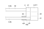
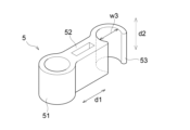
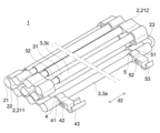
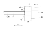
本実施の形態による使用状態の水切り装置の一例を示す斜視図。FIG. 1 is a perspective view showing an example of a draining device according to an embodiment of the present invention in a used state. 本実施の形態による使用状態の水切り装置の一例を示す平面図。FIG. 2 is a plan view showing an example of the draining device according to the present embodiment in use. 本実施の形態による使用状態の水切り装置の一例を示す正面図。FIG. 2 is a front view showing an example of the draining device according to the present embodiment in use. 本実施の形態によるロック部材の一例を示す斜視図。FIG. 4 is a perspective view showing an example of a locking member according to the embodiment. 本実施の形態による使用状態の水切り装置の一部を拡大して示す図。FIG. 2 is an enlarged view of a portion of the drainer in use according to the embodiment; 本実施の形態による補助ロック部材の一例を示す斜視図。FIG. 4 is a perspective view showing an example of an auxiliary locking member according to the embodiment. 本実施の形態による使用状態の水切り装置の使用例を示す平面図。FIG. 2 is a plan view showing an example of use of the draining device according to the present embodiment in a used state. 本実施の形態による水切り装置を収納状態とする作用を示す斜視図。FIG. 13 is a perspective view showing the operation of putting the drainer according to the embodiment into a stored state. 本実施の形態による水切り装置を収納状態とする作用を示す正面図。FIG. 4 is a front view showing the operation of putting the drainer according to the embodiment into a stored state. 本実施の形態による収納状態の水切り装置の一例を示す斜視図。FIG. 2 is a perspective view showing an example of the draining device in a stored state according to the present embodiment. 本実施の形態による収納状態の水切り装置の一例を示す正面図。FIG. 2 is a front view showing an example of the drainer in a stored state according to the present embodiment. 本実施の形態による収納状態の水切り装置の一部を拡大して示す図。FIG. 4 is an enlarged view of a portion of the drainer in the stored state according to the embodiment. 比較例による収納状態の水切り装置の一部を拡大して示す図。FIG. 13 is an enlarged view of a portion of the drainer in a stored state according to a comparative example.

以下、図1乃至12を参照し、本開示に係る組み立て式椅子の実施形態の一例について詳細に説明する。 Below, an example of an embodiment of an assembled chair according to the present disclosure will be described in detail with reference to Figures 1 to 12.

図1は、使用状態の水切り装置1を示す斜視図である。図2は、図1に示す水切り装置1を示す平面図である。図3は、図1に示す水切り装置1を示す正面図であり、図3において後述する一対の取付具2のうち外管取付具212が手前側、内管取付具211が奥側に示されている。本発明に係る水切り装置1は、図1~3に示すような食器などを置くことができる使用状態と、図10、11に示すような収納に適した後述する収納状態と、をとることが可能である。 Figure 1 is a perspective view of the draining device 1 in use. Figure 2 is a plan view of the draining device 1 shown in Figure 1. Figure 3 is a front view of the draining device 1 shown in Figure 1, in which of a pair of fittings 2 described later, an outer tube fitting 212 is shown at the front and an inner tube fitting 211 is shown at the back. The draining device 1 of the present invention can be in a use state in which dishes and the like can be placed as shown in Figures 1 to 3, and in a storage state suitable for storage as shown in Figures 10 and 11, which will be described later.

このような本開示による水切り装置1は、一対の取付具2と、一対の取付具2に固定され、かつ一対の取付具2間に延びる複数の管状部材3とを備える。本開示において、取付具2は柔軟材からなって折り曲げ可能となっている。また、管状部材3は、外管31と、外管31内に入子状に収納された内管32とを含む。内管32を外管31に対して摺動させて管状部材3の長さを変化させ、取付具2を折り曲げることによって、使用状態と収納状態とを自在に切り替えることができる。 The draining device 1 according to the present disclosure includes a pair of mounting fixtures 2 and a number of tubular members 3 fixed to the pair of mounting fixtures 2 and extending between the pair of mounting fixtures 2. In the present disclosure, the mounting fixtures 2 are made of a flexible material and are bendable. The tubular members 3 include an outer tube 31 and an inner tube 32 nested within the outer tube 31. The inner tube 32 is slid relative to the outer tube 31 to change the length of the tubular members 3, and the mounting fixtures 2 are bent, allowing the device to be freely switched between a use state and a storage state.

次に、水切り装置1の各構成要素について更に説明する。 Next, we will further explain each component of the water draining device 1.

まず、取付具2について述べる。上述のように、水切り装置1は、細長状に延びる一対の取付具2を備えている。図1~3に示す例において、取付具2は、使用状態の水切り装置1において第1延伸方向d1に延びる。一対の取付具2の一方は、管状部材3の内管32が取り付けられる内管取付具211である。一対の取付具2の他方は、管状部材3の外管31が取り付けられる外管取付具212である。 First, the mounting fixture 2 will be described. As described above, the draining device 1 is equipped with a pair of mounting fixtures 2 that extend in an elongated shape. In the example shown in Figures 1 to 3, the mounting fixtures 2 extend in the first extension direction d1 when the draining device 1 is in use. One of the pair of mounting fixtures 2 is an inner tube mounting fixture 211 to which the inner tube 32 of the tubular member 3 is attached. The other of the pair of mounting fixtures 2 is an outer tube mounting fixture 212 to which the outer tube 31 of the tubular member 3 is attached.

取付具2は、管状部材3の先端が取り付けられる複数の取付部21を有する。図1~3に示す例において、複数の取付部21は、それぞれ管状部材3の先端が挿入される凹部21aを有する。図1~3に示すように水切り装置1を使用状態に展開した場合に、複数の取付部21は、第1延伸方向d1に並ぶ。また、取付具2は、複数の取付部21同士を接続する接続部22を有する。図1~3に示すように水切り装置1を使用状態に展開した場合に、取付部21と接続部22は、第1延伸方向d1に交互に並び、取付部21は、第1延伸方向d1に等間隔に並ぶ。図1~3に示す例において、一対の取付具2は、それぞれ9つの取付部21と8つの接続部22とを有する。 The mounting fixture 2 has a plurality of mounting portions 21 to which the tips of the tubular members 3 are attached. In the example shown in Figs. 1 to 3, the plurality of mounting portions 21 each have a recess 21a into which the tip of the tubular member 3 is inserted. When the draining device 1 is deployed in a usable state as shown in Figs. 1 to 3, the plurality of mounting portions 21 are aligned in the first extension direction d1. The mounting fixture 2 also has a connection portion 22 that connects the plurality of mounting portions 21 together. When the draining device 1 is deployed in a usable state as shown in Figs. 1 to 3, the mounting portions 21 and the connection portions 22 are aligned alternately in the first extension direction d1, and the mounting portions 21 are aligned at equal intervals in the first extension direction d1. In the example shown in Figs. 1 to 3, each of the pair of mounting fixtures 2 has nine mounting portions 21 and eight connection portions 22.

各取付具2の構成材料について述べる。各取付具2は、柔軟材からなって折り曲げ可能となっている。換言すれば、各取付具2は、折り曲げ可能な程度に柔軟な柔軟材からなる。図1~3に示す取付具2は、取付部21よりも接続部22において厚みが小さくなっている。このため、取付具2は接続部22において折り曲げ可能となっている。一例として、接続部22は、接続部22を折り曲げることによって接続部22の両側に位置する2つの取付部21同士を接触させることができる程度の柔軟性を有する。取付具2の材料として用いられる柔軟材は、例えばシリコンゴムなどの柔軟性のある材料である。 The constituent material of each mounting fixture 2 will now be described. Each mounting fixture 2 is made of a flexible material and is bendable. In other words, each mounting fixture 2 is made of a flexible material that is flexible enough to be bendable. The mounting fixture 2 shown in Figures 1 to 3 has a smaller thickness at the connection portion 22 than at the mounting portion 21. For this reason, the mounting fixture 2 is bendable at the connection portion 22. As an example, the connection portion 22 has a flexibility that allows the two mounting portions 21 located on either side of the connection portion 22 to come into contact with each other by bending the connection portion 22. The flexible material used as the material for the mounting fixture 2 is, for example, a flexible material such as silicone rubber.

また、一対の取付具2の少なくとも一方には、水切り装置1を吊り下げるための吊り下げ部23が取り付けられている。図1~3に示す例においては、内管取付具211に吊り下げ部23が取り付けられ、外管取付具212には吊り下げ部23は取り付けられていない。図示はしないが、外管取付具212に吊り下げ部23が取り付けられ、内管取付具211には吊り下げ部23が取り付けられていなくてもよい。また、外管取付具212と内管取付具211の双方に、それぞれ吊り下げ部23が取り付けられていてもよい。 At least one of the pair of mounting fixtures 2 is fitted with a hanging part 23 for suspending the draining device 1. In the example shown in Figures 1 to 3, the hanging part 23 is fitted to the inner pipe mounting fixture 211, and the hanging part 23 is not fitted to the outer pipe mounting fixture 212. Although not shown, the hanging part 23 may be fitted to the outer pipe mounting fixture 212, and the hanging part 23 may not be fitted to the inner pipe mounting fixture 211. Also, the hanging part 23 may be fitted to both the outer pipe mounting fixture 212 and the inner pipe mounting fixture 211.

吊り下げ部23は、例えば家屋の壁に設けられたフックなどに引っ掛けられて、水切り装置1を家屋の壁に吊り下げることができる部分である。吊り下げ部23の形状は、フックなどに引っ掛けることができる限り、特に限られない。図1~3に示す例において、吊り下げ部23は、両端において取付部21に接続されている弧状の部分である。一例として、吊り下げ部23は、取付具2の取付部21及び接続部22と一体成形されている。 The hanging part 23 is a part that can be hung on a hook or the like provided on the wall of a house to hang the draining device 1 on the wall of the house. The shape of the hanging part 23 is not particularly limited as long as it can be hung on a hook or the like. In the example shown in Figures 1 to 3, the hanging part 23 is an arc-shaped part that is connected to the mounting part 21 at both ends. As one example, the hanging part 23 is molded integrally with the mounting part 21 and the connection part 22 of the mounting fixture 2.

次に、管状部材3について述べる。水切り装置1は、上述のように、一対の取付具2と、一対の取付具2に固定され、一対の取付具2間に延びる複数の管状部材3とを備える。管状部材3は、管状部材3の先端が取付具2の取付部21に取り付けられることで、取付具2に固定される。図1、2に示すように、複数の管状部材3は、互いに平行に配置され、各々の管状部材3は第2延伸方向d2に沿って延びている。 Next, the tubular member 3 will be described. As described above, the water draining device 1 comprises a pair of mounting fixtures 2 and a plurality of tubular members 3 fixed to the pair of mounting fixtures 2 and extending between the pair of mounting fixtures 2. The tubular members 3 are fixed to the mounting fixtures 2 by attaching the tips of the tubular members 3 to the mounting portions 21 of the mounting fixtures 2. As shown in Figures 1 and 2, the plurality of tubular members 3 are arranged parallel to one another, and each tubular member 3 extends along the second extension direction d2.

水切り装置1を使用状態に展開した場合、取付具2の延びる第1延伸方向d1と管状部材3の延びる第2延伸方向d2とが直交する。図1、2に示すように水切り装置1を使用状態に展開した場合、複数の管状部材3は、等間隔で並ぶ。この場合、水切り装置1は、9本の管状部材3を備える。使用状態の水切り装置1によれば、複数の管状部材3の上に濡れたものを置くことによって、濡れたものの水を切ることができる。 When the draining device 1 is deployed in a usable state, the first extension direction d1 in which the attachment 2 extends and the second extension direction d2 in which the tubular member 3 extends are perpendicular to each other. When the draining device 1 is deployed in a usable state as shown in Figures 1 and 2, the multiple tubular members 3 are arranged at equal intervals. In this case, the draining device 1 includes nine tubular members 3. With the draining device 1 in a usable state, wet items can be drained by placing them on the multiple tubular members 3.

各管状部材3は、上述のように、外管31と、外管31内に入子状に収納された内管32とを含む。内管32は、少なくとも一部が外管31内に収納されている状態を維持しつつ、外管31に対して摺動可能となっている。内管32を外管31に対して摺動させることによって、管状部材3の長さを変化させることができ、管状部材3の長さを変化させることによって、内管32を外管31から引き出して、第2延伸方向d2における水切り装置1の寸法を変化させることができる。 As described above, each tubular member 3 includes an outer tube 31 and an inner tube 32 nested within the outer tube 31. The inner tube 32 is slidable relative to the outer tube 31 while maintaining at least a portion of the inner tube 32 housed within the outer tube 31. By sliding the inner tube 32 relative to the outer tube 31, the length of the tubular member 3 can be changed, and by changing the length of the tubular member 3, the inner tube 32 can be pulled out from the outer tube 31 to change the dimensions of the water draining device 1 in the second extension direction d2.

図2に示すように、管状部材3の外管31は、外管31の中心を延びる軸線L1を有する。また、管状部材3の内管32は、内管32の中心を延びる軸線L2を有し、軸線L1と軸線L2とは第2延伸方向d2に沿って同一直線上に延びる。 As shown in FIG. 2, the outer tube 31 of the tubular member 3 has an axis L1 that extends through the center of the outer tube 31. The inner tube 32 of the tubular member 3 has an axis L2 that extends through the center of the inner tube 32, and the axis L1 and the axis L2 extend collinearly along the second extension direction d2.

本実施の形態に係る水切り装置1において、複数の管状部材3の少なくとも一つには、内管32が外管31から抜けることを防止する抜け防止部が設けられている。一例として、抜け防止部は、内管32の外面に設けられた突起と、外管31の内面に設けられた突起とを有する。この場合、内管32を外管31から一定の長さ以上引き出そうとすると、内管32の外面に設けられた突起が外管31の内面に設けられた突起に係止される。これによって、内管32が外管31から抜けることが防止される。 In the draining device 1 according to this embodiment, at least one of the multiple tubular members 3 is provided with a slip-out prevention part that prevents the inner tube 32 from slipping out of the outer tube 31. As an example, the slip-out prevention part has a protrusion provided on the outer surface of the inner tube 32 and a protrusion provided on the inner surface of the outer tube 31. In this case, when the inner tube 32 is pulled out of the outer tube 31 by more than a certain length, the protrusion provided on the outer surface of the inner tube 32 engages with the protrusion provided on the inner surface of the outer tube 31. This prevents the inner tube 32 from slipping out of the outer tube 31.

このように複数の管状部材3の少なくとも一つに抜け防止部が設けられている場合、内管32が抜け防止部により外管31から引き出せなくなる限界まで、内管32を外管31から引き出して使用してもよい。また、内管32を限界まで外管31から引き出すことなく使用してもよい。内管32が外管31から引き出される長さを調整することによって、使用状態での第2延伸方向d2における水切り装置1の寸法を調整することができる。これによって、例えば水切り装置1を流し台に置く際に、流し台の大きさに合わせて第2延伸方向d2における水切り装置1の寸法を調整することができる。 When at least one of the multiple tubular members 3 is provided with a slip-out prevention portion in this manner, the inner tube 32 may be pulled out from the outer tube 31 to the limit at which the inner tube 32 cannot be pulled out from the outer tube 31 due to the slip-out prevention portion. The inner tube 32 may also be used without being pulled out from the outer tube 31 to the limit. By adjusting the length by which the inner tube 32 is pulled out from the outer tube 31, the dimensions of the draining device 1 in the second extension direction d2 in the usage state can be adjusted. This allows, for example, when placing the draining device 1 on a sink, the dimensions of the draining device 1 in the second extension direction d2 to be adjusted to match the size of the sink.

管状部材3は、管状部材3の上に濡れたものを配置した際に、濡れたものの重さに耐えられる程度の強度を有する。管状部材3の材料は、例えばステンレスである。内管32及び外管31は、例えばステンレス製の丸棒である。 The tubular member 3 has a strength sufficient to withstand the weight of a wet object placed on the tubular member 3. The material of the tubular member 3 is, for example, stainless steel. The inner tube 32 and the outer tube 31 are, for example, stainless steel round bars.

本実施の形態において、水切り装置1は、ロック部材4をさらに備える。ロック部材4は、一の管状部材の内管32に固定された内管固定部41と、内管固定部41から管状部材3の横方向に延びる連結部42を介して連結されて他の管状部材を係止する係止部43とを有する。図1~3に示す例においては、複数の管状部材3のうち第1延伸方向d1において最も外方に位置する第1管状部材3aが、内管固定部41が固定される一の管状部材となっている。また、図1、2に示す例においては、複数の管状部材3のうち第1管状部材3aに隣接する第2管状部材3bが、係止部43に係止される他の管状部材となっている。 In this embodiment, the water draining device 1 further includes a locking member 4. The locking member 4 has an inner tube fixing portion 41 fixed to the inner tube 32 of one tubular member, and a locking portion 43 connected via a connecting portion 42 extending from the inner tube fixing portion 41 in the lateral direction of the tubular member 3 to lock the other tubular member. In the example shown in Figures 1 to 3, the first tubular member 3a located outermost in the first extension direction d1 among the multiple tubular members 3 is the one tubular member to which the inner tube fixing portion 41 is fixed. Also, in the example shown in Figures 1 and 2, the second tubular member 3b adjacent to the first tubular member 3a among the multiple tubular members 3 is the other tubular member locked to the locking portion 43.

図4は、ロック部材4を示す斜視図である。図4には、ロック部材4が使用状態の水切り装置1に組み入れられた場合の第1延伸方向d1及び第2延伸方向d2が示されている。図4において、内管固定部41は、筒状の形状を有する。筒状の形状を有する内管固定部41に第1管状部材3aの内管32が貫通し、第1管状部材3aの内管32に内管固定部41が固定される。本実施の形態において、ロック部材4は、内管固定部41によって第1管状部材3aに対して回転可能に固定されている。 Figure 4 is a perspective view showing the locking member 4. Figure 4 shows the first extension direction d1 and the second extension direction d2 when the locking member 4 is incorporated into the draining device 1 in use. In Figure 4, the inner tube fixing part 41 has a cylindrical shape. The inner tube 32 of the first tubular member 3a passes through the inner tube fixing part 41, which has a cylindrical shape, and the inner tube fixing part 41 is fixed to the inner tube 32 of the first tubular member 3a. In this embodiment, the locking member 4 is rotatably fixed to the first tubular member 3a by the inner tube fixing part 41.

図1~4に示す内管固定部41は、第2延伸方向d2に沿って、内管32に対してスライド可能に固定されている。図示はしないが、内管固定部41は、内管32に対してスライドすることができない構造を有していてもよい。 The inner tube fixing portion 41 shown in Figures 1 to 4 is fixed to the inner tube 32 so as to be slidable along the second extension direction d2. Although not shown, the inner tube fixing portion 41 may have a structure that does not allow it to slide relative to the inner tube 32.

また、ロック部材4は、内管固定部41から管状部材3の横方向に延びる連結部42を有する。図4に示す例において、連結部42は、第2延伸方向d2に対して直交する方向に延びている。 The locking member 4 also has a connecting portion 42 that extends from the inner tube fixing portion 41 in the lateral direction of the tubular member 3. In the example shown in FIG. 4, the connecting portion 42 extends in a direction perpendicular to the second extension direction d2.

係止部43は、内管固定部41が固定された第1管状部材3aに隣接する第2管状部材3bを係止する。係止部43が第2管状部材3bを係止することによって、内管固定部41が固定された第1管状部材3aと、第2管状部材3bとの位置関係が決定される。 The locking portion 43 locks the second tubular member 3b adjacent to the first tubular member 3a to which the inner pipe fixing portion 41 is fixed. By the locking portion 43 locking the second tubular member 3b, the positional relationship between the first tubular member 3a to which the inner pipe fixing portion 41 is fixed and the second tubular member 3b is determined.

係止部43は、管状部材3を挟むことができる形状を有する。図4に示す例において、係止部43は、筒状の形状の一部が欠けた形状を有する。筒状の形状の一部が欠けた形状を有する係止部43の内部に第2管状部材3bを進入させて、係止部43で第2管状部材3bを挟むことによって、係止部43が第2管状部材3bを係止することができる。 The locking portion 43 has a shape that can clamp the tubular member 3. In the example shown in FIG. 4, the locking portion 43 has a cylindrical shape with a portion of the cylindrical shape missing. The second tubular member 3b is inserted into the locking portion 43, which has a cylindrical shape with a portion of the cylindrical shape missing, and the locking portion 43 can clamp the second tubular member 3b, thereby locking the second tubular member 3b.

係止部43は、第2管状部材3bの外管31を係止可能な第1係止部431と、第2管状部材3bの内管32を係止可能な第2係止部432とを有する。図4に示す例において、第1係止部431は、内径w1をもつ筒状の形状の一部が欠けた形状を有する。また、第2係止部432は、内径w2をもつ筒状の形状の一部が欠けた形状を有する。第2係止部432は、第1係止部431よりも内管取付具211側に位置している。連結部42は、内管固定部41と、係止部43のうち第2係止部432と、を連結している。 The locking portion 43 has a first locking portion 431 capable of locking the outer tube 31 of the second tubular member 3b, and a second locking portion 432 capable of locking the inner tube 32 of the second tubular member 3b. In the example shown in FIG. 4, the first locking portion 431 has a cylindrical shape with an inner diameter w1 and a part of the cylindrical shape with an inner diameter w2 and a part of the cylindrical shape with an inner diameter w2. The second locking portion 432 is located closer to the inner pipe attachment 211 than the first locking portion 431. The connecting portion 42 connects the inner pipe fixing portion 41 and the second locking portion 432 of the locking portion 43.

第1係止部431の内径w1は、第1係止部431によって第2管状部材3bの外管31を挟むことができるように定められている。第2係止部432の内径w2は、第2係止部432によって第2管状部材3bの内管32を挟むことができるように定められている。図4に示す例において、第1係止部431の内径w1は、第2係止部432の内径w2よりも大きくなっている。これによって、第1係止部431が第2管状部材3bの外管31を挟むことができるとともに、第2係止部432が第2管状部材3bの外管31よりも細い第2管状部材3bの内管32を挟むことができる。 The inner diameter w1 of the first locking portion 431 is determined so that the first locking portion 431 can clamp the outer tube 31 of the second tubular member 3b. The inner diameter w2 of the second locking portion 432 is determined so that the second locking portion 432 can clamp the inner tube 32 of the second tubular member 3b. In the example shown in FIG. 4, the inner diameter w1 of the first locking portion 431 is larger than the inner diameter w2 of the second locking portion 432. This allows the first locking portion 431 to clamp the outer tube 31 of the second tubular member 3b, and the second locking portion 432 to clamp the inner tube 32 of the second tubular member 3b, which is thinner than the outer tube 31 of the second tubular member 3b.

図4には、第1係止部431に係止される第2管状部材3bの外管31の軸線L1が示されている。また、図4には、第2係止部432に係止される第2管状部材3bの内管32の軸線L2が示されている。 Figure 4 shows the axis L1 of the outer tube 31 of the second tubular member 3b that is engaged with the first engaging portion 431. Also, Figure 4 shows the axis L2 of the inner tube 32 of the second tubular member 3b that is engaged with the second engaging portion 432.

ここで、第1係止部431と第2係止部432とは、同軸上に延びる。第1係止部431と第2係止部432とが「同軸上に延びる」とは、図4に示すように、第1係止部431に係止される外管31の軸線L1と、第2係止部432に係止される内管32の軸線L2とが、同一直線上に延びていることを意味する。これによって、係止部43が外管31の軸線L1と内管32の軸線L2とが一致する管状部材3を係止する際に、第1係止部431が外管31を係止すると同時に第2係止部432が内管32を係止することができる。 Here, the first locking portion 431 and the second locking portion 432 extend coaxially. The first locking portion 431 and the second locking portion 432 "extending coaxially" means that, as shown in FIG. 4, the axis L1 of the outer tube 31 locked to the first locking portion 431 and the axis L2 of the inner tube 32 locked to the second locking portion 432 extend on the same straight line. This allows the first locking portion 431 to lock the outer tube 31 and the second locking portion 432 to lock the inner tube 32 at the same time when the locking portion 43 locks the tubular member 3 in which the axis L1 of the outer tube 31 and the axis L2 of the inner tube 32 coincide.

図5は、図1~3に示す使用状態に展開された水切り装置1において係止部43が第2管状部材3bを係止している部分を拡大して示す図である。図5においては、内管取付具211について、第1管状部材3aが固定される取付部21、第2管状部材3bが固定される取付部21、及びそれらの取付具2を接続する接続部22のみを図示し、それ以外の部分は図示を省略している。図5に示す例において、係止部43は、内管取付具211に接触している。また、係止部43の第2係止部432は、第2管状部材3bの内管32を係止している。一方で、係止部43の第1係止部431は、第2管状部材3bに接触せず、第2管状部材3bを係止していない。 Figure 5 is an enlarged view of the portion where the locking portion 43 locks the second tubular member 3b in the water draining device 1 deployed in the use state shown in Figures 1 to 3. In Figure 5, for the inner pipe attachment 211, only the attachment portion 21 to which the first tubular member 3a is fixed, the attachment portion 21 to which the second tubular member 3b is fixed, and the connection portion 22 that connects these attachments 2 are shown, and other portions are omitted. In the example shown in Figure 5, the locking portion 43 is in contact with the inner pipe attachment 211. In addition, the second locking portion 432 of the locking portion 43 locks the inner pipe 32 of the second tubular member 3b. On the other hand, the first locking portion 431 of the locking portion 43 does not contact the second tubular member 3b and does not lock the second tubular member 3b.

本実施の形態に係る水切り装置1は、補助ロック部材5をさらに備える。補助ロック部材5は、第1管状部材3aの外管31に固定された外管固定部51と、外管固定部51から管状部材3の横方向に延びる連結部52を介して連結されて第2管状部材3bを係止する補助係止部53とを有する。図1~3に示す例において、補助ロック部材5の外管固定部51は、ロック部材4の内管固定部41が固定された内管32を有する第1管状部材3aの外管31に固定されている。図示はしないが、補助ロック部材5の外管固定部51は、ロック部材4の内管固定部41が固定された内管32を有する第1管状部材3aとは異なる管状部材3の外管31に固定されていてもよい。また、図1、2に示す例において、補助係止部53は、複数の管状部材3のうち第1延伸方向d1において第1管状部材3aの隣に位置する第2管状部材3bを係止している。 The draining device 1 according to this embodiment further includes an auxiliary locking member 5. The auxiliary locking member 5 has an outer tube fixing portion 51 fixed to the outer tube 31 of the first tubular member 3a, and an auxiliary locking portion 53 that is connected to the outer tube fixing portion 51 via a connecting portion 52 extending laterally of the tubular member 3 to lock the second tubular member 3b. In the example shown in Figures 1 to 3, the outer tube fixing portion 51 of the auxiliary locking member 5 is fixed to the outer tube 31 of the first tubular member 3a having the inner tube 32 to which the inner tube fixing portion 41 of the locking member 4 is fixed. Although not shown, the outer tube fixing portion 51 of the auxiliary locking member 5 may be fixed to the outer tube 31 of a tubular member 3 other than the first tubular member 3a having the inner tube 32 to which the inner tube fixing portion 41 of the locking member 4 is fixed. In the example shown in Figures 1 and 2, the auxiliary locking portion 53 locks the second tubular member 3b, which is located next to the first tubular member 3a in the first extension direction d1, among the multiple tubular members 3.

図6は、補助ロック部材5を示す斜視図である。図6において、符号d1、d2が付された方向は、補助ロック部材5が使用状態の水切り装置1に組み入れられた場合の第1延伸方向d1及び第2延伸方向d2を意味する。補助ロック部材5の外管固定部51の形状は、ロック部材4の内管固定部41の形状と同様である。図1~3、6に示す外管固定部51は、管状部材3の延びる第2延伸方向d2に沿って、外管31に対して摺動させることができる。図示はしないが、外管固定部51は、外管31に対して摺動させることができない構造を有していてもよい。 Figure 6 is a perspective view showing the auxiliary locking member 5. In Figure 6, the directions marked with the symbols d1 and d2 refer to the first extension direction d1 and the second extension direction d2 when the auxiliary locking member 5 is incorporated into the draining device 1 in use. The shape of the outer tube fixing part 51 of the auxiliary locking member 5 is similar to the shape of the inner tube fixing part 41 of the locking member 4. The outer tube fixing part 51 shown in Figures 1 to 3 and 6 can slide relative to the outer tube 31 along the second extension direction d2 in which the tubular member 3 extends. Although not shown, the outer tube fixing part 51 may have a structure that prevents it from sliding relative to the outer tube 31.

補助ロック部材5の連結部52は、外管固定部51から管状部材3の横方向に延びている。 The connecting portion 52 of the auxiliary locking member 5 extends laterally from the outer tube fixing portion 51 to the tubular member 3.

補助係止部53は、連結部52を介して外管固定部51に連結される。補助係止部53は、管状部材3のうち外管31を挟むことができる形状を有する。図6に示す例において、補助係止部53は、筒状の形状の一部が欠けた形状を有する。補助係止部53の内径w3は、補助係止部53によって外管31を挟むことができるように定められている。筒状の形状の一部が欠けた形状を有する補助係止部53の内部に第2管状部材3bの外管31を進入させて、補助係止部53で第2管状部材3bの外管31を挟むことによって、補助係止部53が第2管状部材3bを係止することができる。 The auxiliary locking portion 53 is connected to the outer tube fixing portion 51 via the connecting portion 52. The auxiliary locking portion 53 has a shape that can hold the outer tube 31 of the tubular member 3. In the example shown in FIG. 6, the auxiliary locking portion 53 has a cylindrical shape with a portion missing. The inner diameter w3 of the auxiliary locking portion 53 is determined so that the auxiliary locking portion 53 can hold the outer tube 31. The auxiliary locking portion 53 can lock the second tubular member 3b by inserting the outer tube 31 of the second tubular member 3b into the auxiliary locking portion 53, which has a cylindrical shape with a portion missing, and holding the outer tube 31 of the second tubular member 3b with the auxiliary locking portion 53.

次に、このような構成からなる本実施の形態の作用について説明する。 Next, we will explain the operation of this embodiment with such a configuration.

(使用状態の作用)
まず、図1~3に示す使用状態の水切り装置1の作用について述べる。上述したように、図1~3に示す使用状態の水切り装置1において、一対の取付具2は第1延伸方向d1に延びている。また、第2延伸方向d2における複数の管状部材3の寸法は、外管31から内管32が引き出されることにより、水切り装置1を使用するのに適した長さに調整されている。また、ロック部材4の係止部43、及び補助ロック部材5の補助係止部53は、第2管状部材3bを係止している。使用状態の水切り装置1を流し台などに置いて、複数の管状部材3の上に濡れたものを配置することで、濡れたものの水を切ることができる。
(Effect of state of use)
First, the operation of the draining device 1 in use as shown in Figures 1 to 3 will be described. As described above, in the draining device 1 in use as shown in Figures 1 to 3, the pair of mounting fixtures 2 extend in the first extension direction d1. The dimensions of the multiple tubular members 3 in the second extension direction d2 are adjusted to a length suitable for using the draining device 1 by pulling out the inner tube 32 from the outer tube 31. The engaging portion 43 of the locking member 4 and the auxiliary engaging portion 53 of the auxiliary locking member 5 engage the second tubular member 3b. The draining device 1 in use can be placed on a sink or the like, and wet items can be placed on the multiple tubular members 3 to drain the water from the wet items.

なお、図1、2においては、使用状態の水切り装置1の使用例として、係止部43が内管取付具211に接触している例を示している。しかしながら、使用状態における係止部43の配置は、これに限られない。使用状態における係止部43は、図7に示すように、管状部材3のうち内管32と外管31とをまたぐ境界部分33において、管状部材3を係止してもよい。この場合は、ロック部材4の内管固定部41を第2延伸方向d2に沿って内管32に対して摺動させてロック部材4の第2管状部材3bに対する位置を調整する。このことによって、係止部43を、管状部材3のうち内管32と外管31とをまたぐ境界部分33まで移動させる。そして、この境界部分33において、係止部43により、管状部材3を係止する。 1 and 2 show an example in which the locking portion 43 is in contact with the inner pipe attachment 211 as an example of the use of the draining device 1 in use. However, the arrangement of the locking portion 43 in use is not limited to this. As shown in FIG. 7, the locking portion 43 in use may lock the tubular member 3 at the boundary portion 33 that straddles the inner pipe 32 and the outer pipe 31 of the tubular member 3. In this case, the inner pipe fixing portion 41 of the locking member 4 is slid along the second extension direction d2 relative to the inner pipe 32 to adjust the position of the locking member 4 relative to the second tubular member 3b. This moves the locking portion 43 to the boundary portion 33 that straddles the inner pipe 32 and the outer pipe 31 of the tubular member 3. Then, the locking portion 43 locks the tubular member 3 at this boundary portion 33.

(収納状態の作用)
次に、図1~3または図7に示す使用状態の水切り装置1を、図11、12に示す収納状態とする作用について述べる。まず、ロック部材4を回転させて、係止部43を第2管状部材3bから外す。また、補助ロック部材5を回転させて、補助係止部53を第2管状部材3bから外す。
(Operation in storage state)
Next, the operation of changing the draining device 1 from the use state shown in Figures 1 to 3 or 7 to the storage state shown in Figures 11 and 12 will be described. First, the locking member 4 is rotated to disengage the engaging portion 43 from the second tubular member 3b. Then, the auxiliary locking member 5 is rotated to disengage the auxiliary engaging portion 53 from the second tubular member 3b.

また、図7に示すように、係止部43が、内管32と外管31とをまたぐ境界部分33において、管状部材3を係止している場合には、ロック部材4を第1管状部材3aに対して摺動させて、ロック部材4が内管取付具211に接触するまで移動させる。 Also, as shown in FIG. 7, when the engaging portion 43 engages the tubular member 3 at the boundary portion 33 that straddles the inner tube 32 and the outer tube 31, the locking member 4 is slid relative to the first tubular member 3a until the locking member 4 comes into contact with the inner tube attachment 211.

次に、内管32を外管31に対して摺動させ、外管31内に内管32を収容して、各管状部材3の第2延伸方向d2における寸法を短くする。一例として、内管固定部41が外管31と内管取付具211との両方に接するまで、管状部材3の第2延伸方向d2における寸法を短くすることができる。 Next, the inner tube 32 is slid relative to the outer tube 31, and the inner tube 32 is housed within the outer tube 31, shortening the dimension of each tubular member 3 in the second extension direction d2. As an example, the dimension of the tubular member 3 in the second extension direction d2 can be shortened until the inner tube fixing portion 41 contacts both the outer tube 31 and the inner tube attachment 211.

次に、水切り装置1を巻き取る。水切り装置1を、例えば図8、9に示すように、第2延伸方向d2に平行な軸線を中心として巻き取ることができる。換言すれば、水切り装置1は、図9に示すように側面から見て渦を巻くように、巻き取られる。ただし、水切り装置1を巻き取る態様は、図8、9に示す態様に限られない。例えば、水切り装置1の全体が巻き取られてもよいし、水切り装置1の一部が巻き取られてもよい。また、水切り装置1は、巻き取られる代わりに、側面から見てZ字を描くように折り畳まれてもよい。 Next, the water draining device 1 is wound up. The water draining device 1 can be wound up around an axis parallel to the second extension direction d2, for example, as shown in Figures 8 and 9. In other words, the water draining device 1 is wound up so as to form a spiral when viewed from the side, as shown in Figure 9. However, the manner in which the water draining device 1 is wound up is not limited to the manner shown in Figures 8 and 9. For example, the entire water draining device 1 may be wound up, or only a portion of the water draining device 1 may be wound up. Moreover, instead of being wound up, the water draining device 1 may be folded up so as to form a Z shape when viewed from the side.

次に、ロック部材4を回転させて、係止部43により第1管状部材3a以外の管状部材3を係止する。また、補助ロック部材5を回転させて、補助係止部53により第1管状部材3a以外の管状部材3を係止する。このことによって、水切り装置1を図10、11に示す収納状態とすることができる。 Next, the locking member 4 is rotated to lock the tubular members 3 other than the first tubular member 3a with the locking portion 43. The auxiliary locking member 5 is also rotated to lock the tubular members 3 other than the first tubular member 3a with the auxiliary locking portion 53. This allows the draining device 1 to be placed in the stored state shown in Figures 10 and 11.

図10、11に示すように水切り装置1を収納状態とする際、係止部43及び補助係止部53により係止される管状部材3は、水切り装置1が巻き取られたり折り畳まれたりする態様に応じて、巻き取られたり折り畳まれたりした際の全体形状により定められる。一例として、水切り装置1を収納状態とした場合、係止部43及び補助係止部53が係止する管状部材3は、水切り装置1が収納状態を維持しやすくなるように定められる。図10、11に示す例において、係止部43は、第2管状部材3bとは異なる第3管状部材3cを係止している。図10、11に示す収納状態においては、第1管状部材3aが、内管固定部41が固定される一の管状部材となっているとともに、第3管状部材3cが、係止部43に係止される他の管状部材となっている。また、補助係止部53は、係止部43が係止している第3管状部材3cを同様に係止している。 10 and 11, when the draining device 1 is in the stored state, the tubular member 3 locked by the locking portion 43 and the auxiliary locking portion 53 is determined by the overall shape of the draining device 1 when it is wound or folded, depending on the manner in which the draining device 1 is wound or folded. As an example, when the draining device 1 is in the stored state, the tubular member 3 locked by the locking portion 43 and the auxiliary locking portion 53 is determined so that the draining device 1 can easily maintain the stored state. In the example shown in Figs. 10 and 11, the locking portion 43 locks a third tubular member 3c different from the second tubular member 3b. In the stored state shown in Figs. 10 and 11, the first tubular member 3a is one tubular member to which the inner tube fixing portion 41 is fixed, and the third tubular member 3c is another tubular member locked by the locking portion 43. Additionally, the auxiliary locking portion 53 similarly locks the third tubular member 3c that is locked by the locking portion 43.

図12は、図10、11示す収納状態の水切り装置1において係止部43が第3管状部材3cを係止している部分を拡大して示す図である。図12に示す例においては、内管32を外管31に対して摺動させて第3管状部材3cの第2延伸方向d2における寸法が短くなっている。この場合、内管固定部41は、外管31と内管取付具211との両方に接している。 Figure 12 is an enlarged view of the portion where the locking portion 43 locks the third tubular member 3c in the draining device 1 in the stored state shown in Figures 10 and 11. In the example shown in Figure 12, the inner tube 32 is slid relative to the outer tube 31 to shorten the dimension of the third tubular member 3c in the second extension direction d2. In this case, the inner tube fixing portion 41 is in contact with both the outer tube 31 and the inner tube attachment 211.

収納状態の水切り装置1は、吊り下げ部23に家屋の壁に設けられたフックなどに引っ掛けられることによって、一対の取付具2の一方を上方に向け、他方を下方に向けた状態で吊り下げられる。図10、11に示す収納状態の水切り装置1は、吊り下げ部23に家屋の壁に設けられたフックなどに引っ掛けられることによって、内管取付具211を下方に向け、外管取付具212を上方に向けた状態で吊り下げられる。 When the draining device 1 is in the stored state, it is hung with one of the pair of mounting fixtures 2 facing upward and the other facing downward by hanging the hanging part 23 on a hook or the like provided on the wall of the house. When the draining device 1 is in the stored state shown in Figures 10 and 11, it is hung with the inner pipe mounting fixture 211 facing downward and the outer pipe mounting fixture 212 facing upward by hanging the hanging part 23 on a hook or the like provided on the wall of the house.

次に、図10、11に示す収納状態の水切り装置1を、再び図1~3に示す使用状態とする作用について述べる。使用状態の作用は、基本的に上述した収納状態の作用と逆の手順をとる。 Next, we will describe how to return the drainer 1 in the stored state shown in Figures 10 and 11 to the usage state shown in Figures 1 to 3. The usage state basically follows the reverse procedure to the storage state described above.

まず、図10、11に示す収納状態の水切り装置1において、ロック部材4を回転させて、係止部43の第3管状部材3cへの係止を外す。また、補助ロック部材5を回転させて、補助係止部53の第3管状部材3cへの係止を外す。 First, in the draining device 1 in the stored state shown in Figures 10 and 11, the locking member 4 is rotated to release the engagement of the engagement portion 43 with the third tubular member 3c. In addition, the auxiliary locking member 5 is rotated to release the engagement of the auxiliary engagement portion 53 with the third tubular member 3c.

次に、巻き取られた状態の水切り装置1を、一対の取付具2が第1延伸方向d1に延ばされるように展開させる。 Next, the rolled-up draining device 1 is unfolded so that the pair of mounting fixtures 2 are extended in the first extension direction d1.

次に、ロック部材4を回転させて、係止部43に第2管状部材3bを係止させる。また、補助ロック部材5を回転させて、補助係止部53に第2管状部材3bを係止させる。これによって、水切り装置1を図1~3に示す使用状態とすることができる。 Next, the locking member 4 is rotated to lock the second tubular member 3b into the locking portion 43. The auxiliary locking member 5 is also rotated to lock the second tubular member 3b into the auxiliary locking portion 53. This allows the draining device 1 to be in the usage state shown in Figures 1 to 3.

以上のように、本実施の形態によれば、水切り装置1は、収納状態においてロック部材4の係止部43が管状部材3に係止することによって、水切り装置1の寸法が小さくされた収納状態で安定的に維持される。特に、水切り装置1は巻き取られた状態で安定的に維持される。 As described above, according to this embodiment, the draining device 1 is stably maintained in a stored state in which the dimensions of the draining device 1 are reduced by the engagement of the engagement portion 43 of the locking member 4 with the tubular member 3 in the stored state. In particular, the draining device 1 is stably maintained in a rolled-up state.

ここで、係止部43が第1係止部431と第2係止部432とを有することの効果について、比較例との比較から説明する。比較例として、係止部43が内管32を係止する部分を有し、外管31を係止する部分は有しないロック部材4を備える水切り装置1について考える。図13は、比較例の水切り装置1が収納状態をとり、係止部43が管状部材3を係止している部分を拡大して示す図である。 Here, the effect of the locking portion 43 having the first locking portion 431 and the second locking portion 432 will be explained by comparing with a comparative example. As a comparative example, consider a draining device 1 equipped with a locking member 4 in which the locking portion 43 has a portion that locks the inner tube 32, but does not have a portion that locks the outer tube 31. Figure 13 is an enlarged view of the draining device 1 of the comparative example in the stored state, showing the portion where the locking portion 43 locks the tubular member 3.

係止部43により管状部材3を安定的に係止するためには、係止部43を管状部材3に係止した際の係止部43と管状部材3との接触面積が大きいことが好ましい。このためには、第2延伸方向d2における係止部43の寸法が大きいことが好ましい。ここで、比較例での第2延伸方向d2における係止部43の寸法w4を大きくすると、係止部43の寸法w4が大きくなった分だけ、内管32のうち収納状態において外管31内に収容されない部分の第2延伸方向d2における寸法が大きくなり、管状部材3を縮めることが困難になる。 In order for the locking portion 43 to stably lock the tubular member 3, it is preferable that the contact area between the locking portion 43 and the tubular member 3 when the locking portion 43 is locked to the tubular member 3 is large. For this purpose, it is preferable that the dimension of the locking portion 43 in the second extension direction d2 is large. Here, if the dimension w4 of the locking portion 43 in the second extension direction d2 in the comparative example is increased, the dimension in the second extension direction d2 of the portion of the inner tube 32 that is not contained within the outer tube 31 in the stored state increases by the amount of the increase in the dimension w4 of the locking portion 43, making it difficult to shrink the tubular member 3.

これに対して、本実施の形態によれば、係止部43が、内管32を係止可能な第2係止部432を有するとともに、外管31を係止可能な第1係止部431を有することによって、図12に示す第2係止部432の第2延伸方向d2における寸法w5を、小さく抑えることができる。このため、収納状態において外管31内に収容される内管32の第2延伸方向d2における寸法を大きくすることができ、管状部材3を、より小さく縮めることができる。 In contrast, according to the present embodiment, the locking portion 43 has a second locking portion 432 capable of locking the inner tube 32, and a first locking portion 431 capable of locking the outer tube 31, so that the dimension w5 in the second extension direction d2 of the second locking portion 432 shown in FIG. 12 can be kept small. Therefore, the dimension in the second extension direction d2 of the inner tube 32 housed in the outer tube 31 in the stored state can be increased, and the tubular member 3 can be further compressed.

また、係止部43が第1係止部431と第2係止部432とを有する水切り装置1は、特に収納状態の水切り装置1を吊り下げ部23により吊り下げたときにも、ロック部材4によって、その収納状態が安定的に維持される。 In addition, the draining device 1, whose locking portion 43 has a first locking portion 431 and a second locking portion 432, is stably maintained in its stored state by the locking member 4, especially when the draining device 1 in the stored state is hung by the hanging portion 23.

特に、第1係止部431が外管31を係止する際に第1係止部431が外管31を挟む力を十分に強くし、第2係止部432が内管32を係止する際に第2係止部432が内管32を挟む力を十分に強くすることにより、収納状態において、係止部43を介して内管32と外管31との位置関係を定め、外管31に対する内管32の摺動を抑制することができる。すなわち、収納状態の水切り装置1を吊り下げ部23により吊り下げた場合でも、ロック部材4によって内管32と外管31とが固定されるため、下方に位置する内管32が外管31に対して降下してしまうことはない(図10参照)。 In particular, by making the clamping force of the first locking portion 431 on the outer tube 31 strong enough when the first locking portion 431 locks the outer tube 31, and by making the clamping force of the second locking portion 432 on the inner tube 32 strong enough when the second locking portion 432 locks the inner tube 32, the positional relationship between the inner tube 32 and the outer tube 31 can be determined via the locking portion 43 in the stored state, and the sliding of the inner tube 32 relative to the outer tube 31 can be suppressed. In other words, even when the draining device 1 in the stored state is hung by the hanging portion 23, the inner tube 32 and the outer tube 31 are fixed by the locking member 4, so that the inner tube 32 located below will not drop relative to the outer tube 31 (see FIG. 10).

また、本実施の形態によれば、水切り装置1では、使用状態において、ロック部材4の係止部43が第2管状部材3bを係止することによって、ロック部材4の管状部材3に対する位置を水切り装置1の使用を妨げない位置に定めることができる。 In addition, according to this embodiment, in the draining device 1, when in use, the engaging portion 43 of the locking member 4 engages the second tubular member 3b, so that the position of the locking member 4 relative to the tubular member 3 can be determined at a position that does not interfere with the use of the draining device 1.

特に、第1係止部431が外管31を係止する際に第1係止部431が外管31を挟む力を十分に強くし、第2係止部432が内管32を係止する際に第2係止部432が内管32を挟む力を十分に強くすることにより、使用状態において、係止部43を介して内管32と外管31との位置関係を定め、外管31に対する内管32の摺動を抑制することができる。 In particular, by making the clamping force of the first locking portion 431 on the outer tube 31 sufficiently strong when the first locking portion 431 locks the outer tube 31, and by making the clamping force of the second locking portion 432 on the inner tube 32 sufficiently strong when the second locking portion 432 locks the inner tube 32, the positional relationship between the inner tube 32 and the outer tube 31 can be determined via the locking portion 43 in the usage state, and sliding of the inner tube 32 relative to the outer tube 31 can be suppressed.

また、本実施の形態に係る水切り装置1は、ロック部材4とともに補助ロック部材5を備える。収納状態において、ロック部材4の係止部43が管状部材3を係止するとともに、補助ロック部材5の補助係止部53が管状部材3を係止することによって、水切り装置1の寸法が小さくされた収納状態を安定的に維持することができる。特に、水切り装置1が巻き取られた状態を安定的に維持することができる。 The draining device 1 according to this embodiment also includes an auxiliary locking member 5 in addition to the locking member 4. In the stored state, the locking portion 43 of the locking member 4 locks the tubular member 3, and the auxiliary locking portion 53 of the auxiliary locking member 5 locks the tubular member 3, so that the draining device 1 can be stably maintained in a stored state with reduced dimensions. In particular, the draining device 1 can be stably maintained in a rolled-up state.

また、本実施の形態に係る水切り装置1では、使用状態において、補助ロック部材5の補助係止部53が管状部材3を係止することによって、補助ロック部材5の管状部材3に対する位置を、水切り装置1の使用を妨げない位置に定めることができる。 In addition, in the draining device 1 according to this embodiment, when in use, the auxiliary locking portion 53 of the auxiliary locking member 5 locks the tubular member 3, so that the position of the auxiliary locking member 5 relative to the tubular member 3 can be set to a position that does not interfere with the use of the draining device 1.

本発明の態様は、上述した実施形態に限定されるものではなく、当業者が想到しうる種々の変形も含むものであり、本発明の効果も上述した内容に限定されない。すなわち、特許請求の範囲に規定された内容及びその均等物から導き出される本発明の概念的な思想と趣旨を逸脱しない範囲で種々の追加、変更及び部分的削除が可能である。 The aspects of the present invention are not limited to the above-described embodiment, but include various modifications that may be conceived by a person skilled in the art, and the effects of the present invention are not limited to the above-described contents. In other words, various additions, modifications, and partial deletions are possible within the scope that does not deviate from the conceptual idea and intent of the present invention derived from the contents defined in the claims and their equivalents.

1 水切り装置
2 取付具
21 取付部
22 接続部
23 吊り下げ部
211 内管取付具
212 外管取付具
3 管状部材
3a 第1管状部材
3b 第2管状部材
3c 第3管状部材
31 外管
32 内管
33 境界部分
4 ロック部材
41 内管固定部
42 連結部
43 係止部
431 第1係止部
432 第2係止部
5 補助ロック部材
51 外管固定部
52 連結部
53 補助係止部
REFERENCE SIGNS LIST 1 Draining device 2 Mounting fixture 21 Mounting portion 22 Connection portion 23 Hanging portion 211 Inner pipe mounting fixture 212 Outer pipe mounting fixture 3 Tubular member 3a First tubular member 3b Second tubular member 3c Third tubular member 31 Outer pipe 32 Inner pipe 33 Boundary portion 4 Locking member 41 Inner pipe fixing portion 42 Connecting portion 43 Locking portion 431 First locking portion 432 Second locking portion 5 Auxiliary locking member 51 Outer pipe fixing portion 52 Connecting portion 53 Auxiliary locking portion

Claims (4)

細長状に延びる一対の取付具と、
前記一対の取付具に固定され、かつ前記一対の取付具間に延びる複数の管状部材とを備え、
各管状部材は、外管と、前記外管内に入子状に収納された内管とを含み、
各取付具は、柔軟材からなって折り曲げ可能となっており、
一の管状部材を他の管状部材に固定するロック部材が設けられ、
前記ロック部材は、前記一の管状部材の前記内管に固定された内管固定部と、前記内管固定部から前記管状部材の横方向に延びる連結部を介して連結されて前記他の管状部材を係止する係止部とを有し、
前記係止部は、前記他の管状部材の前記外管を係止可能な第1係止部と、前記他の管状部材の前記内管を係止可能な第2係止部とを有する、水切り装置。
A pair of elongated mounting fixtures;
a plurality of tubular members secured to the pair of fittings and extending between the pair of fittings;
Each tubular member includes an outer tube and an inner tube nested within the outer tube,
Each fixture is made of flexible material and is bendable.
a locking member is provided to secure one tubular member to the other tubular member;
the locking member has an inner pipe fixing portion fixed to the inner pipe of the one tubular member, and a locking portion connected to the inner pipe fixing portion via a connecting portion extending in a lateral direction of the tubular member to lock the other tubular member,
The water draining device, wherein the locking portion has a first locking portion capable of locking the outer tube of the other tubular member, and a second locking portion capable of locking the inner tube of the other tubular member.
前記第1係止部と前記第2係止部とは、同軸上に延びる、請求項1に記載の水切り装置。 The draining device according to claim 1, wherein the first engaging portion and the second engaging portion extend coaxially. 前記一対の取付具の一方は、前記内管が取り付けられる内管取付具であり、前記一対の取付具の他方は、前記外管が取り付けられる外管取付具であり、
前記第2係止部は、前記第1係止部よりも前記内管取付具側に位置する、請求項1又は2に記載の水切り装置。
one of the pair of mounting fixtures is an inner pipe mounting fixture to which the inner pipe is attached, and the other of the pair of mounting fixtures is an outer pipe mounting fixture to which the outer pipe is attached,
The draining device according to claim 1 or 2, wherein the second engaging portion is located closer to the inner pipe attachment than the first engaging portion.
前記一対の取付具の少なくとも一方には、前記水切り装置を吊り下げるための吊り下げ部が取り付けられている、請求項1乃至3のいずれか一項に記載の水切り装置。 The draining device according to any one of claims 1 to 3, wherein at least one of the pair of mounting fixtures is provided with a hanging part for suspending the draining device.
JP2021126873A 2021-08-02 2021-08-02 Draining device Active JP7680903B2 (en)

Priority Applications (1)

Application Number Priority Date Filing Date Title
JP2021126873A JP7680903B2 (en) 2021-08-02 2021-08-02 Draining device

Applications Claiming Priority (1)

Application Number Priority Date Filing Date Title
JP2021126873A JP7680903B2 (en) 2021-08-02 2021-08-02 Draining device

Publications (2)

Publication Number Publication Date
JP2023021789A JP2023021789A (en) 2023-02-14
JP7680903B2 true JP7680903B2 (en) 2025-05-21

Family

ID=85201446

Family Applications (1)

Application Number Title Priority Date Filing Date
JP2021126873A Active JP7680903B2 (en) 2021-08-02 2021-08-02 Draining device

Country Status (1)

Country Link
JP (1) JP7680903B2 (en)

Citations (2)

* Cited by examiner, † Cited by third party
Publication number Priority date Publication date Assignee Title
JP3156315U (en) 2009-10-09 2009-12-24 株式会社内山産業 Multifunctional stand such as drainer
CN109106250A (en) 2018-10-17 2019-01-01 江门市祺昊不锈钢制品有限公司 Stainless steel draining rack

Family Cites Families (2)

* Cited by examiner, † Cited by third party
Publication number Priority date Publication date Assignee Title
JPS526427Y2 (en) * 1973-02-01 1977-02-10
JPS6114947U (en) * 1984-06-29 1986-01-28 ハラダ工業株式会社 cooking aids

Patent Citations (2)

* Cited by examiner, † Cited by third party
Publication number Priority date Publication date Assignee Title
JP3156315U (en) 2009-10-09 2009-12-24 株式会社内山産業 Multifunctional stand such as drainer
CN109106250A (en) 2018-10-17 2019-01-01 江门市祺昊不锈钢制品有限公司 Stainless steel draining rack

Also Published As

Publication number Publication date
JP2023021789A (en) 2023-02-14

Similar Documents

Publication Publication Date Title
US8763822B2 (en) Adjustable shelf assembly
US7958577B2 (en) Shower curtain hanging structure
CN102316768B (en) The roofbolt that tensioning is installed
US7004335B2 (en) Wire shelf having integrated hooks with hanger rod
TWI313163B (en) Side-release buckle assembly
US9730571B1 (en) Foldable dish rack
US7243806B2 (en) Bathroom rail
US8100305B2 (en) Automobile hanger
US20160198849A1 (en) Closet Storage Assemblies, Connectors, Brackets and Systems
US10077601B2 (en) Overturn structure of a footstep of a folding ladder
EP3162260A1 (en) Towel rack
JP7680903B2 (en) Draining device
US7188741B1 (en) Over the door support apparatus
US20250064293A1 (en) Combination drying mat, rack and storage container
US20080163451A1 (en) Suction Hose For a Vacuum Cleaner
KR20150019175A (en) Pants hanger
US1104180A (en) Portable garment-hanger.
CN210727261U (en) Novel chair is with side tray
KR20180093426A (en) One Touch Cloth Hanger
CN206080345U (en) Sanitary equipment and attaching in sanitary equipment's hook
US20170367544A1 (en) Suspended towel assembly
CN216220863U (en) Hanger for massage chair and massage chair
KR200287486Y1 (en) a assistance shelf for kitchen
KR200363248Y1 (en) Corner shelf for bathroom
CN209984122U (en) Bathroom hanging parts

Legal Events

Date Code Title Description
A621 Written request for application examination

Free format text: JAPANESE INTERMEDIATE CODE: A621

Effective date: 20240730

A977 Report on retrieval

Free format text: JAPANESE INTERMEDIATE CODE: A971007

Effective date: 20250312

TRDD Decision of grant or rejection written
A01 Written decision to grant a patent or to grant a registration (utility model)

Free format text: JAPANESE INTERMEDIATE CODE: A01

Effective date: 20250411

A61 First payment of annual fees (during grant procedure)

Free format text: JAPANESE INTERMEDIATE CODE: A61

Effective date: 20250509

R150 Certificate of patent or registration of utility model

Ref document number: 7680903

Country of ref document: JP

Free format text: JAPANESE INTERMEDIATE CODE: R150