JP7674792B2 - Vacuum line and method for controlling the vacuum line - Google Patents
Vacuum line and method for controlling the vacuum line Download PDFInfo
- Publication number
- JP7674792B2 JP7674792B2 JP2023501032A JP2023501032A JP7674792B2 JP 7674792 B2 JP7674792 B2 JP 7674792B2 JP 2023501032 A JP2023501032 A JP 2023501032A JP 2023501032 A JP2023501032 A JP 2023501032A JP 7674792 B2 JP7674792 B2 JP 7674792B2
- Authority
- JP
- Japan
- Prior art keywords
- gas
- vacuum
- vacuum line
- pressure
- pump
- Prior art date
- Legal status (The legal status is an assumption and is not a legal conclusion. Google has not performed a legal analysis and makes no representation as to the accuracy of the status listed.)
- Active
Links
Images


Classifications
-
- B—PERFORMING OPERATIONS; TRANSPORTING
- B01—PHYSICAL OR CHEMICAL PROCESSES OR APPARATUS IN GENERAL
- B01F—MIXING, e.g. DISSOLVING, EMULSIFYING OR DISPERSING
- B01F35/00—Accessories for mixers; Auxiliary operations or auxiliary devices; Parts or details of general application
- B01F35/20—Measuring; Control or regulation
- B01F35/22—Control or regulation
- B01F35/221—Control or regulation of operational parameters, e.g. level of material in the mixer, temperature or pressure
- B01F35/2211—Amount of delivered fluid during a period
-
- F—MECHANICAL ENGINEERING; LIGHTING; HEATING; WEAPONS; BLASTING
- F04—POSITIVE - DISPLACEMENT MACHINES FOR LIQUIDS; PUMPS FOR LIQUIDS OR ELASTIC FLUIDS
- F04C—ROTARY-PISTON, OR OSCILLATING-PISTON, POSITIVE-DISPLACEMENT MACHINES FOR LIQUIDS; ROTARY-PISTON, OR OSCILLATING-PISTON, POSITIVE-DISPLACEMENT PUMPS
- F04C25/00—Adaptations of pumps for special use of pumps for elastic fluids
- F04C25/02—Adaptations of pumps for special use of pumps for elastic fluids for producing high vacuum
-
- B—PERFORMING OPERATIONS; TRANSPORTING
- B01—PHYSICAL OR CHEMICAL PROCESSES OR APPARATUS IN GENERAL
- B01D—SEPARATION
- B01D53/00—Separation of gases or vapours; Recovering vapours of volatile solvents from gases; Chemical or biological purification of waste gases, e.g. engine exhaust gases, smoke, fumes, flue gases, aerosols
- B01D53/14—Separation of gases or vapours; Recovering vapours of volatile solvents from gases; Chemical or biological purification of waste gases, e.g. engine exhaust gases, smoke, fumes, flue gases, aerosols by absorption
-
- B—PERFORMING OPERATIONS; TRANSPORTING
- B01—PHYSICAL OR CHEMICAL PROCESSES OR APPARATUS IN GENERAL
- B01F—MIXING, e.g. DISSOLVING, EMULSIFYING OR DISPERSING
- B01F23/00—Mixing according to the phases to be mixed, e.g. dispersing or emulsifying
- B01F23/10—Mixing gases with gases
- B01F23/19—Mixing systems, i.e. flow charts or diagrams; Arrangements, e.g. comprising controlling means
- B01F23/191—Mixing systems, i.e. flow charts or diagrams; Arrangements, e.g. comprising controlling means characterised by the construction of the controlling means
-
- B—PERFORMING OPERATIONS; TRANSPORTING
- B01—PHYSICAL OR CHEMICAL PROCESSES OR APPARATUS IN GENERAL
- B01F—MIXING, e.g. DISSOLVING, EMULSIFYING OR DISPERSING
- B01F25/00—Flow mixers; Mixers for falling materials, e.g. solid particles
- B01F25/30—Injector mixers
-
- B—PERFORMING OPERATIONS; TRANSPORTING
- B01—PHYSICAL OR CHEMICAL PROCESSES OR APPARATUS IN GENERAL
- B01F—MIXING, e.g. DISSOLVING, EMULSIFYING OR DISPERSING
- B01F35/00—Accessories for mixers; Auxiliary operations or auxiliary devices; Parts or details of general application
- B01F35/20—Measuring; Control or regulation
- B01F35/21—Measuring
- B01F35/211—Measuring of the operational parameters
- B01F35/2113—Pressure
-
- F—MECHANICAL ENGINEERING; LIGHTING; HEATING; WEAPONS; BLASTING
- F04—POSITIVE - DISPLACEMENT MACHINES FOR LIQUIDS; PUMPS FOR LIQUIDS OR ELASTIC FLUIDS
- F04C—ROTARY-PISTON, OR OSCILLATING-PISTON, POSITIVE-DISPLACEMENT MACHINES FOR LIQUIDS; ROTARY-PISTON, OR OSCILLATING-PISTON, POSITIVE-DISPLACEMENT PUMPS
- F04C23/00—Combinations of two or more pumps, each being of rotary-piston or oscillating-piston type, specially adapted for elastic fluids; Pumping installations specially adapted for elastic fluids; Multi-stage pumps specially adapted for elastic fluids
- F04C23/005—Combinations of two or more pumps, each being of rotary-piston or oscillating-piston type, specially adapted for elastic fluids; Pumping installations specially adapted for elastic fluids; Multi-stage pumps specially adapted for elastic fluids of dissimilar working principle
- F04C23/006—Combinations of two or more pumps, each being of rotary-piston or oscillating-piston type, specially adapted for elastic fluids; Pumping installations specially adapted for elastic fluids; Multi-stage pumps specially adapted for elastic fluids of dissimilar working principle having complementary function
-
- F—MECHANICAL ENGINEERING; LIGHTING; HEATING; WEAPONS; BLASTING
- F04—POSITIVE - DISPLACEMENT MACHINES FOR LIQUIDS; PUMPS FOR LIQUIDS OR ELASTIC FLUIDS
- F04C—ROTARY-PISTON, OR OSCILLATING-PISTON, POSITIVE-DISPLACEMENT MACHINES FOR LIQUIDS; ROTARY-PISTON, OR OSCILLATING-PISTON, POSITIVE-DISPLACEMENT PUMPS
- F04C29/00—Component parts, details or accessories of pumps or pumping installations, not provided for in groups F04C18/00 - F04C28/00
- F04C29/0007—Injection of a fluid in the working chamber for sealing, cooling and lubricating
- F04C29/0014—Injection of a fluid in the working chamber for sealing, cooling and lubricating with control systems for the injection of the fluid
-
- F—MECHANICAL ENGINEERING; LIGHTING; HEATING; WEAPONS; BLASTING
- F04—POSITIVE - DISPLACEMENT MACHINES FOR LIQUIDS; PUMPS FOR LIQUIDS OR ELASTIC FLUIDS
- F04C—ROTARY-PISTON, OR OSCILLATING-PISTON, POSITIVE-DISPLACEMENT MACHINES FOR LIQUIDS; ROTARY-PISTON, OR OSCILLATING-PISTON, POSITIVE-DISPLACEMENT PUMPS
- F04C29/00—Component parts, details or accessories of pumps or pumping installations, not provided for in groups F04C18/00 - F04C28/00
- F04C29/0092—Removing solid or liquid contaminants from the gas under pumping, e.g. by filtering or deposition; Purging; Scrubbing; Cleaning
-
- B—PERFORMING OPERATIONS; TRANSPORTING
- B01—PHYSICAL OR CHEMICAL PROCESSES OR APPARATUS IN GENERAL
- B01F—MIXING, e.g. DISSOLVING, EMULSIFYING OR DISPERSING
- B01F2215/00—Auxiliary or complementary information in relation with mixing
- B01F2215/04—Technical information in relation with mixing
- B01F2215/0413—Numerical information
- B01F2215/0436—Operational information
- B01F2215/0468—Numerical pressure values
-
- F—MECHANICAL ENGINEERING; LIGHTING; HEATING; WEAPONS; BLASTING
- F04—POSITIVE - DISPLACEMENT MACHINES FOR LIQUIDS; PUMPS FOR LIQUIDS OR ELASTIC FLUIDS
- F04C—ROTARY-PISTON, OR OSCILLATING-PISTON, POSITIVE-DISPLACEMENT MACHINES FOR LIQUIDS; ROTARY-PISTON, OR OSCILLATING-PISTON, POSITIVE-DISPLACEMENT PUMPS
- F04C18/00—Rotary-piston pumps specially adapted for elastic fluids
- F04C18/08—Rotary-piston pumps specially adapted for elastic fluids of intermeshing-engagement type, i.e. with engagement of co-operating members similar to that of toothed gearing
- F04C18/12—Rotary-piston pumps specially adapted for elastic fluids of intermeshing-engagement type, i.e. with engagement of co-operating members similar to that of toothed gearing of other than internal-axis type
- F04C18/126—Rotary-piston pumps specially adapted for elastic fluids of intermeshing-engagement type, i.e. with engagement of co-operating members similar to that of toothed gearing of other than internal-axis type with radially from the rotor body extending elements, not necessarily co-operating with corresponding recesses in the other rotor, e.g. lobes, Roots type
-
- F—MECHANICAL ENGINEERING; LIGHTING; HEATING; WEAPONS; BLASTING
- F04—POSITIVE - DISPLACEMENT MACHINES FOR LIQUIDS; PUMPS FOR LIQUIDS OR ELASTIC FLUIDS
- F04C—ROTARY-PISTON, OR OSCILLATING-PISTON, POSITIVE-DISPLACEMENT MACHINES FOR LIQUIDS; ROTARY-PISTON, OR OSCILLATING-PISTON, POSITIVE-DISPLACEMENT PUMPS
- F04C2220/00—Application
- F04C2220/30—Use in a chemical vapor deposition [CVD] process or in a similar process
-
- F—MECHANICAL ENGINEERING; LIGHTING; HEATING; WEAPONS; BLASTING
- F04—POSITIVE - DISPLACEMENT MACHINES FOR LIQUIDS; PUMPS FOR LIQUIDS OR ELASTIC FLUIDS
- F04C—ROTARY-PISTON, OR OSCILLATING-PISTON, POSITIVE-DISPLACEMENT MACHINES FOR LIQUIDS; ROTARY-PISTON, OR OSCILLATING-PISTON, POSITIVE-DISPLACEMENT PUMPS
- F04C2240/00—Components
- F04C2240/80—Other components
- F04C2240/81—Sensor, e.g. electronic sensor for control or monitoring
-
- F—MECHANICAL ENGINEERING; LIGHTING; HEATING; WEAPONS; BLASTING
- F04—POSITIVE - DISPLACEMENT MACHINES FOR LIQUIDS; PUMPS FOR LIQUIDS OR ELASTIC FLUIDS
- F04C—ROTARY-PISTON, OR OSCILLATING-PISTON, POSITIVE-DISPLACEMENT MACHINES FOR LIQUIDS; ROTARY-PISTON, OR OSCILLATING-PISTON, POSITIVE-DISPLACEMENT PUMPS
- F04C2270/00—Control; Monitoring or safety arrangements
- F04C2270/18—Pressure
- F04C2270/185—Controlled or regulated
-
- F—MECHANICAL ENGINEERING; LIGHTING; HEATING; WEAPONS; BLASTING
- F04—POSITIVE - DISPLACEMENT MACHINES FOR LIQUIDS; PUMPS FOR LIQUIDS OR ELASTIC FLUIDS
- F04C—ROTARY-PISTON, OR OSCILLATING-PISTON, POSITIVE-DISPLACEMENT MACHINES FOR LIQUIDS; ROTARY-PISTON, OR OSCILLATING-PISTON, POSITIVE-DISPLACEMENT PUMPS
- F04C2280/00—Arrangements for preventing or removing deposits or corrosion
- F04C2280/02—Preventing solid deposits in pumps, e.g. in vacuum pumps with chemical vapour deposition [CVD] processes
Landscapes
- Engineering & Computer Science (AREA)
- Chemical & Material Sciences (AREA)
- Chemical Kinetics & Catalysis (AREA)
- Mechanical Engineering (AREA)
- General Engineering & Computer Science (AREA)
- General Chemical & Material Sciences (AREA)
- Analytical Chemistry (AREA)
- Oil, Petroleum & Natural Gas (AREA)
- Treating Waste Gases (AREA)
- Incineration Of Waste (AREA)
- Jet Pumps And Other Pumps (AREA)
- Physical Or Chemical Processes And Apparatus (AREA)
- Chemical Vapour Deposition (AREA)
- Waste-Gas Treatment And Other Accessory Devices For Furnaces (AREA)
- Compressors, Vaccum Pumps And Other Relevant Systems (AREA)
Description
本発明は、真空ライン及び真空ラインの制御方法に関する。 The present invention relates to a vacuum line and a method for controlling a vacuum line.
半導体、フラットパネルディスプレイ、および太陽電池の製造業界における製造方法では処理ガスを使用するが、この処理ガスは、通常、粗引き真空ポンプを通過した後、ガス処理装置によって処理される。
これらの製造方法の幾つかは、真空ラインで運ばれる処理ガスが可燃性および/または爆発性であるため、危険であると言われている。処理ガスの例として、水素、シラン、TEOSおよび水素化物を挙げることができる。
Manufacturing processes in the semiconductor, flat panel display, and solar cell manufacturing industries use process gases that are typically passed through a roughing vacuum pump and then processed by a gas processing system.
Some of these manufacturing processes are said to be hazardous because the process gases carried in the vacuum lines are flammable and/or explosive, examples of which include hydrogen, silane, TEOS and hydrides.
これらの危険なガス種に加えて、真空ラインには、還元された固体種、つまり、シリコン粉塵やポリシランポリマー等の酸化されていない固体種の堆積物が存在する可能性もある。これらの堆積物は、時間の経過とともに蓄積し、さらなる危険な状態の出現を促進する可能性がある。一部の非酸化堆積物は、とても燃えやすい。それらは、特に、突然のポンプ搬送による強力なガス流により、または単にメンテナンス中のオペレータによる管または真空ポンプの通気により、発火する可能性がある。
一部の爆発は、非常に大量のエネルギーが放出されるため、特に破壊的なものになる可能性がある。これは特に、連鎖爆発の場合である。その最初の爆発は、まず可燃性ガスによって開始される。そして、この爆発は、管内に潜在的に存在する還元された固体種の堆積物を掻き回し、これらの可燃性の固体堆積物は、爆発による衝撃波によってかき混ぜられ、順番に「超爆発」で爆発する。
したがって、人身事故や製造装置の損傷のリスクが非常に高くなる。
In addition to these dangerous gas species, vacuum lines may also contain deposits of reduced solid species, i.e. non-oxidized solid species such as silicon dust and polysilane polymers. These deposits can build up over time and promote the emergence of further hazardous conditions. Some non-oxidized deposits are highly flammable. They can be ignited, especially by strong gas flows from sudden pumping or simply by venting the lines or vacuum pump by the operator during maintenance.
Some explosions can be particularly destructive because of the extremely large amounts of energy released. This is especially the case in chain explosions, where an initial explosion is initiated by combustible gases that stir up deposits of reduced solid species potentially present in the tube, and these combustible solid deposits are stirred up by the shock wave from the explosion and in turn explode in a "super explosion".
Therefore, the risk of personal injury and damage to production equipment is extremely high.
この問題に関して現在使用されている対処方法は、ポンプ搬送されたガスを中性ガス、通常は窒素ガスで、継続的に希釈することである。中性ガスの流量は、最も好ましくないポンプ搬送状況にも対応できるように、安全マージンを加えて決定される。 The current approach to this problem is to continuously dilute the pumped gas with a neutral gas, usually nitrogen. The flow rate of the neutral gas is determined with a safety margin to accommodate the most unfavourable pumping conditions.
ただし、この解決策には多くの欠点がある。
第1に、真空ラインにおける大量の窒素ガスの供給には、このガス消費に伴う追加コストが発生し、そしてまた、大量の希釈ガスの流れを処理するために、真空ポンプ、加熱装置、およびガス処理装置のエネルギー消費が発生する。さらに、ガスの希釈によって引き起こされる真空ラインの冷却は、特に加熱要素のコストと故障のリスクという、他の欠点をもたらす。この大量の中性ガスの供給には、ガス処理装置と粗引き真空ポンプ装置の過剰評価も必要である。
希釈窒素はさらに、ガス処理装置内で、NO2等の、窒素酸化物または「NOx」の生成をもたらす。この窒素酸化物は毒性があり、処理が必要な大気汚染物質を構成する。
最後に、最近のいくつかの製造プロセスでは、真空ポンプの排気能力が不十分り、ガス処理装置の処理能力が不十分なため、希釈ガスの増加が不十分になりつつあるため、この解決策が限界に達していることが観察されている。これらの極端な動作条件では、真空ポンプまたはガス処理装置の信頼性に関する問題が発生する可能性がある。
However, this solution has many drawbacks.
Firstly, the supply of large amounts of nitrogen gas in the vacuum lines incurs additional costs associated with this gas consumption, and also the energy consumption of vacuum pumps, heating devices and gas handling equipment to handle the large dilution gas flows. Furthermore, the cooling of the vacuum lines caused by the gas dilution brings other drawbacks, especially the cost and risk of failure of the heating elements. The supply of large amounts of neutral gas also requires overrating of the gas handling equipment and roughing vacuum pump equipment.
Dilute nitrogen further leads to the production of nitrogen oxides or " NOx ", such as NO2 , in the gas treatment equipment, which are toxic and constitute air pollutants that must be treated.
Finally, it has been observed that in some recent manufacturing processes, this solution is reaching its limits as the pumping capacity of the vacuum pumps and the processing capacity of the gas handling equipment become insufficient to accommodate the increased amount of dilution gas. These extreme operating conditions can lead to problems with the reliability of the vacuum pumps or the gas handling equipment.
別の解決策は、特に前駆体の熱分解を防ぎ、化学反応を最小限に抑えるために、管と真空ポンプの温度を下げることである。ただし、結露による析出のリスクを防ぐために、高温を維持することも重要である。 Another solution is to reduce the temperature of the tubes and vacuum pumps, especially to prevent thermal decomposition of the precursors and to minimize chemical reactions. However, it is also important to maintain a high temperature to prevent the risk of precipitation due to condensation.
もう1つの問題は、一部の製造プロセス、特に半導体産業で、ますます不安定な前駆体を使用する傾向があることである。基板パターンはますます薄くなり、基板はますます厚くなる、すなわち、基板パターンは多くのプロセスステップで生成される多くの層を有している。基板のチップに損傷を与える危険性がある熱収支を下げるために、より低い温度で分解する新世代の分子が使用されている。その欠点は、それらが真空ラインに簡単に堆積することであり、これによりかなりの量の堆積物が生じる可能性がある。 Another problem is the trend in some manufacturing processes, especially in the semiconductor industry, to use more and more unstable precursors. The substrate patterns are becoming thinner and thinner, the substrates are becoming thicker, i.e. they have many layers produced in many process steps. To lower the thermal budget, which risks damaging the chips on the substrate, a new generation of molecules is being used that decompose at lower temperatures. The drawback is that they easily deposit in the vacuum lines, which can lead to significant amounts of deposits.
さらに、一部の使用済みの凝縮性ガス種は固化して固体の副生成物になり、特に層の形で、真空ポンプまたは管の可動部分または静的部分に堆積し、これが真空ラインの詰まりにつながる可能性がある。 In addition, some spent condensable gas species can solidify into solid by-products and deposit, especially in the form of layers, on moving or static parts of the vacuum pump or tubing, which can lead to blockages in the vacuum lines.
本発明の1つの目的は、可燃性ガスおよび/または爆発性ガスを搬送するポンプ装置および真空ラインの安全性を高めることである。
本発明の他の目的は、凝縮性種の堆積物の存在を減らすこと、または排気管やポンプ装置内において、低温で分解する前駆体の分解を遅らせる/最小限に抑えることである。
One object of the present invention is to increase the safety of pumping equipment and vacuum lines conveying flammable and/or explosive gases.
Another object of the present invention is to reduce the presence of deposits of condensable species or to retard/minimize the decomposition of precursors that decompose at low temperatures in exhaust lines and pumping equipment.
この目的のために、本発明の真空ラインは、ポンプ装置とガス処理装置とを備えており、
前記ポンプ装置は、大気圧でポンプ搬送されたガスを排出できるように構成された、少なくとも1つの粗引き真空ポンプ装置を含み、
前記ガス処理装置は、
大気圧で、前記粗引き真空ポンプ装置によってポンプ搬送されたガスを処理するように構成されたガス処理室と、
前記粗引き真空ポンプ装置の吐出口を前記ガス処理室の入口に接続する排気管を備えており、
前記ガス処理装置は、
前記排気管内の圧力を下げるように構成された少なくとも1つの補助ポンプ装置と、
前記粗引き真空ポンプ装置の吸入口の下流で、前記排気管および/または前記粗引き真空ポンプ装置および/または前記補助ポンプ装置等に、ポンプ搬送されたガスの流れに希釈ガスを注入するように構成された、希釈ガス注入装置とを備え、
前記真空ラインはさらに、
前記排気管内の圧力を測定するように構成された圧力センサと、
前記補助ポンプ装置および前記希釈ガス注入装置を制御するように構成された制御ユニットとを備え、
前記制御ユニットは、
前記排気管内の圧力が20,000Pa(200mbar)以下に維持されている第1の動作モードと、前記排気管内の圧力が20000Pa(200ミリバール)を超える第2の動作モードを有し、
前記制御ユニットは、前記第2の動作モードにおいて、前記希釈ガス注入装置による前記希釈ガスの注入を制御するように構成されている。
For this purpose, the vacuum line of the invention comprises a pumping device and a gas treatment device,
the pumping system includes at least one roughing vacuum pumping system configured to exhaust pumped gas at atmospheric pressure;
The gas treatment device comprises:
a gas processing chamber configured to process gas pumped by the roughing vacuum pumping apparatus at atmospheric pressure;
an exhaust pipe connecting an outlet of the roughing vacuum pump device to an inlet of the gas processing chamber;
The gas treatment device comprises:
at least one auxiliary pumping device configured to reduce pressure in the exhaust line;
a diluent gas injection device configured to inject a diluent gas into the pumped gas flow, downstream of the inlet of the roughing vacuum pumping device, into the exhaust line and/or into the roughing vacuum pumping device and/or into the backing pumping device, etc.;
The vacuum line further comprises:
a pressure sensor configured to measure a pressure in the exhaust pipe;
a control unit configured to control the auxiliary pumping device and the diluent gas injection device;
The control unit
a first mode of operation in which the pressure in the exhaust line is maintained at or below 200 mbar, and a second mode of operation in which the pressure in the exhaust line exceeds 20000 Pa (200 mbar);
The control unit is configured to control injection of the diluent gas by the diluent gas injection device in the second mode of operation.
前記希釈ガス注入装置は、例えば、前記希釈ガスを、前記排気管および/または前記粗引き真空ポンプ装置および/または前記補助ポンプ装置に注入するように構成されている。
したがって、最適な動作モードである前記第1の動作モードでは、デフォルトでは、排気管の圧力は、前記排気管内を運ばれる可燃性ガスの着火条件未満に維持される。前記第2の動作モードでは、可燃性のリスクは希釈によって管理できる。したがって、前記排気管内の圧力を下げると、前記希釈ガスの注入を、最も危険な状況時のみに制限することが可能になる。したがって、安全な操作条件を保ちながら、希釈ガスの消費量を減らすことができる。また、第2の動作モードでは、使用される希釈ガスの量が、従来技術に基づいて注入される希釈ガスの量と比較して少ないことに留意しなければならない。
The dilution gas injection device is configured, for example, to inject the dilution gas into the exhaust line and/or the roughing vacuum pumping device and/or the auxiliary pumping device.
Thus, in the first operating mode, which is the optimal operating mode, by default the pressure in the exhaust pipe is kept below the ignition conditions of the flammable gas carried in the exhaust pipe. In the second operating mode, the flammability risk can be managed by dilution. Reducing the pressure in the exhaust pipe thus makes it possible to limit the injection of the dilution gas only in the most dangerous situations. Thus, the consumption of dilution gas can be reduced while maintaining safe operating conditions. It must also be noted that in the second operating mode, the amount of dilution gas used is less compared to the amount of dilution gas injected according to the prior art.
本発明によれば、真空ラインを安全な状態に維持すると同時に、真空ラインの圧力を下げることで、排気管と粗引き真空ポンプ装置での凝縮性種の堆積を防ぐことができ、真空ラインの加熱要件を減らすことができる。真空ラインの加熱温度を下げると、熱分解を防ぐことができるため、粗引き真空ポンプ装置での前駆体の変換と化学活性の反応速度が低下し、望ましくない反応を減らすことができる。加熱温度を下げることで、潤滑剤の品質を維持し、粗引き真空ポンプ装置の機械部品、特にベアリングの信頼性を向上させることもできる。したがって、メンテナンス作業の間隔を延ばすことができる。
さらに、希釈ガスの消費量が制限され、これにより、粗引き真空ポンプ装置およびガス処理装置のエネルギー消費量を削減し、ガス処理装置内での窒素酸化物の形成を最小限に抑えるか、または排除することさえ可能になる。
真空ライン内の圧力を下げると、粗引き真空ポンプ装置内の圧力も下がり、これにより、粗引き真空ポンプ装置のサイズを縮小でき、強度が低くしたがって安価な材料を使用することが可能になる。
真空ラインは、さらに、以下に説明する特徴のうちの1つまたは複数を、単独でまたは組み合わせて備えることができる。
According to the present invention, the vacuum line pressure can be reduced to prevent the deposition of condensable species in the exhaust and roughing vacuum pumping equipment while maintaining the vacuum line in a safe state, and the heating requirements of the vacuum line can be reduced. The reduced heating temperature of the vacuum line can prevent thermal decomposition, thereby reducing the reaction rate of precursor conversion and chemical activity in the roughing vacuum pumping equipment, and reducing undesirable reactions. The reduced heating temperature can also maintain the quality of the lubricant and improve the reliability of the mechanical parts of the roughing vacuum pumping equipment, especially the bearings. Thus, the intervals between maintenance operations can be extended.
Furthermore, the consumption of dilution gas is limited, which reduces the energy consumption of the roughing vacuum pump system and the gas treatment equipment, and minimizes or even eliminates the formation of nitrogen oxides in the gas treatment equipment.
Reducing the pressure in the vacuum lines also reduces the pressure in the roughing vacuum pumping apparatus, which allows the size of the roughing vacuum pumping apparatus to be reduced and allows the use of weaker and therefore less expensive materials.
The vacuum line may further comprise one or more of the features described below, either alone or in combination.
前記制御ユニットは、前記第2の動作モードにおいて、前記粗引き真空ポンプ装置の前記吸入口の下流で、前記排気管内および/または前記粗引き真空ポンプ装置内および/または前記補助ポンプ装置内への、ポンプ搬送されるガスの流れに導入される希釈ガスの流量が、前記圧力センサによって測定された圧力の関数として決定され、かつ、点火によって生成される排気管内の圧力が、特に、化学量論的条件等、爆発が発生した場合の最も厳しい条件でも、160,000Pa(1,600mbar)未満に維持されるように、ポンプ搬送される前記可燃性ガスに関する情報の関数として決定される、ように構成されている。
前記希釈ガスには、燃料および/または中性ガスを含むことができる。
The control unit is configured such that in the second operating mode, the flow rate of dilution gas to be introduced into the flow of pumped gas downstream of the inlet of the roughing vacuum pumping device and into the exhaust pipe and/or into the roughing vacuum pumping device and/or into the auxiliary pumping device is determined as a function of the pressure measured by the pressure sensor and as a function of information about the pumped combustible gas such that the pressure in the exhaust pipe generated by ignition is kept below 160,000 Pa (1,600 mbar) even under the most adverse conditions in case of an explosion, in particular stoichiometric conditions.
The diluent gas may include a fuel and/or a neutral gas.
前記制御ユニットは、前記ガス処理室に導入される前記可燃性ガスに関する情報の関数として、燃料および中性ガスの量および割合を決定するように構成することができる。
前記制御ユニットは、測定圧力が50,000Pa(500mbar)を超える場合は、前記排気管、および/または前記粗引き真空ポンプ装置、および/または補助ポンプ装置のような、前記粗引き真空ポンプ装置の前記吸入口の下流で、前記ポンプ搬送されたガスの流れの中への高流量の希釈ガスの注入を制御するように構成することができる。
高流の希釈ガスは、可燃性ガス濃度が爆発下限界(LEL)の25%未満になるように、予め決定することができる。したがって、最も不利なポンプ搬送状況でも安全になり、安全マージンが追加される。これは、極端な状況で時折使用される緊急動作モードであり、この緊急動作モードは、先行技術において恒久的に実施され、過度の窒素消費をもたらしているモードに相当する。本発明によれば、最大の希釈は時折行われるだけである。
前記制御ユニットは、前記第1の動作モードにおいて前記粗引き真空ポンプ装置へのパージガスの注入をオフにするように構成することができる。
The control unit may be configured to determine the amounts and proportions of fuel and neutral gases as a function of information relating to the combustible gas introduced into the gas treatment chamber.
The control unit may be configured to control injection of a high flow rate of dilution gas into the pumped gas stream downstream of the inlet of the roughing vacuum pumping arrangement, such as the exhaust line, and/or the roughing vacuum pumping arrangement, and/or a backing pumping arrangement, when the measured pressure exceeds 500 mbar.
The high flow of dilution gas can be pre-determined so that the flammable gas concentration is less than 25% of the lower explosive limit (LEL), thus making it safe even in the most adverse pumping conditions and providing an additional safety margin. This is an emergency operation mode that is occasionally used in extreme conditions, which corresponds to the mode that is permanently implemented in the prior art, resulting in excessive nitrogen consumption. According to the present invention, maximum dilution is only occasionally performed.
The control unit may be configured to turn off injection of purge gas to the roughing vacuum pumping arrangement in the first mode of operation.
前記補助ポンプ装置は、ウォータージェットポンプおよび/またはベンチュリガスジェットポンプおよび/または液封ポンプおよび/またはドライ真空ポンプおよび/またはベーンポンプを含むことができる。
前記ガス処理室は、バーナー、および/または電気システム、および/またはプラズマ、および/または洗浄塔、および/または化学吸着式および/または物理吸着式のカートリッジを含むことができる。
前記補助ポンプ装置は、ベンチュリガスジェットポンプを含むことができ、その駆動ガスは、燃料および/または燃焼剤および/または中性ガスを含む。
前記補助ポンプ装置は、前記ガス処理室から来る情報の関数として、前記駆動ガスの燃料、燃焼ガスおよび中性ガスの量および割合を決定するように構成することができる。
前記ベンチュリガスジェットポンプは、前記駆動ガスを加熱するように構成された加熱要素を含むことができる。
The auxiliary pumping arrangement may include a water jet pump and/or a venturi gas jet pump and/or a liquid ring pump and/or a dry vacuum pump and/or a vane pump.
The gas treatment chamber may include burners, and/or electrical systems, and/or plasma, and/or scrubbers, and/or chemisorptive and/or physisorptive cartridges.
The auxiliary pumping arrangement may include a venturi gas jet pump, the drive gas of which includes a fuel and/or a combustible agent and/or a neutral gas.
The auxiliary pumping device may be configured to determine the amounts and proportions of fuel, combustion gas and neutral gas in the drive gas as a function of information coming from the gas processing chamber.
The venturi gas jet pump may include a heating element configured to heat the drive gas.
前記補助ポンプ装置は、前記ガス処理室の前記入口から1メートル未満、例えば50cm未満に配置することができる。
前記補助ポンプ装置は、ウォータージェットポンプおよび油圧ポンプを含むことができ、その吸入口は前記ガス処理装置の洗浄塔の洗浄槽の液体と連通して配置され、その出口は、前記ウォータージェットポンプに駆動液を供給するために、前記制御ユニットによって制御されるように構成されている。
前記真空ラインは、過圧の場合に前記補助ポンプ装置をバイパスするように構成されたバイパス管を含むことができる。
The auxiliary pumping arrangement may be located less than 1 metre, for example less than 50cm, from the inlet of the gas treatment chamber.
The auxiliary pump device may include a water jet pump and a hydraulic pump, the inlet of which is arranged in communication with the liquid in the washing tank of the washing tower of the gas treatment device, and the outlet of which is configured to be controlled by the control unit to supply driving liquid to the water jet pump.
The vacuum line may include a bypass conduit configured to bypass the auxiliary pumping arrangement in the event of overpressure.
本発明は、前記真空ラインを制御する方法にも関するものであり、前記補助ポンプ装置および前記希釈ガス注入装置は、第1の動作モードにおいて、前記排気管内の圧力が20,000Pa(200mbar)以下に維持されるように制御される。また、前記排気管内の圧力が20,000Paよりも高い第2の動作モードでは、前記粗引き真空ポンプ装置の前記吸入口の下流で、前記ポンプ搬送されたガスの流れの中への前記希釈ガスの注入が制御される。この第2の動作モードでは、前記希釈ガス注入装置を用いて、例えば、前記排気管および/または前記粗引き真空ポンプ装置および/または前記補助ポンプ装置内へ希釈ガスが注入される。
本発明のさらなる特徴および利点は、添付の図面を参照して、非限定的な例として与えられる以下の説明から明らかになるであろう。
The invention also relates to a method of controlling the vacuum line, in which the auxiliary pumping arrangement and the diluent gas injection arrangement are controlled in a first operating mode to maintain a pressure in the exhaust line below 200 mbar, and in a second operating mode in which the pressure in the exhaust line is higher than 20000 Pa, injection of the diluent gas into the pumped gas flow downstream of the inlet of the roughing vacuum pumping arrangement is controlled, in which mode diluent gas is injected, for example, into the exhaust line and/or the roughing vacuum pumping arrangement and/or the auxiliary pumping arrangement.
Further characteristics and advantages of the invention will become apparent from the following description, given by way of non-limiting example with reference to the attached drawings, in which:
各図において、同一の要素には同一の参照番号が付されている。
以下の実施形態は例示である。以下の説明は1つまたは複数の実施形態に言及しているが、これは、各言及が同じ実施形態に関連すること、または特徴が単一の実施形態のみに適用されることを必ずしも意味しない。異なる実施形態の個々の特徴を組み合わせたり交換したりして、他の実施形態を提供することもできる。
粗引き真空ポンプとは、気体を吸入し、移送し、大気圧で排出するように構成された容積式真空ポンプを意味する。粗引き真空ポンプのロータには、ルーツ、クロー、スクリュー、ベーン、またはスクロールの各タイプがある。粗引き真空ポンプは、大気圧でも起動できるように構成されている。
In each figure, identical elements are given the same reference numbers.
The following embodiments are illustrative. Although the following description refers to one or more embodiments, this does not necessarily mean that each reference relates to the same embodiment or that a feature applies only to a single embodiment. Individual features of different embodiments can also be combined or exchanged to provide other embodiments.
Roughing vacuum pump means a positive displacement vacuum pump configured to take in, pump, and exhaust gas at atmospheric pressure. Roughing vacuum pump rotors can be of Roots, Claw, Screw, Vane, or Scroll type. Roughing vacuum pumps are configured to operate at atmospheric pressure.
2つのルーツロータを使用して排気対象の気体を取り込み、移送し、排出するように構成された容積式真空ポンプは、ルーツまたはルーツブロワー真空ポンプとして定義される。ルーツ真空ポンプは、粗引き真空ポンプの上流に直列に取り付けられている。ロータは、ルーツ真空ポンプのモータによって回転する2つのシャフトに保持されている。
ルーツ真空ポンプは、主に、ポンプ搬送能力が高く、公差が大きいため、排気ステージの寸法が大きいという点、及び、ルーツ真空ポンプは大気圧では排出できないため、粗引き真空ポンプの上流に直列に取り付けて使用する必要があるという点で、粗引き真空ポンプとは異なる。
「上流」の構成要素は、ポンプ搬送されるガスの流れの方向に関して他の構成要素の前方に配置される構成要素であると見なされる。対照的に、「下流」の構成要素は、ポンプ搬送されるガスの流れの方向に関して後方に配置される構成要素であると考えられる。ポンプ搬送されるガスの流れは、真空ラインの管内のポンプ搬送操作によって運ばれるガスを表す。
A positive displacement vacuum pump configured to take in, transport and exhaust the gas to be pumped using two Roots rotors is defined as a Roots or Roots blower vacuum pump. The Roots vacuum pump is mounted in series upstream of the roughing vacuum pump. The rotors are carried by two shafts that are rotated by the Roots vacuum pump motor.
Roots vacuum pumps differ from roughing vacuum pumps primarily by the larger dimensions of their exhaust stage due to their higher pumping capacity and larger tolerances, and by the fact that Roots vacuum pumps cannot exhaust at atmospheric pressure and therefore must be installed in series upstream of a roughing vacuum pump.
An "upstream" component is considered to be a component that is disposed ahead of another component with respect to the direction of flow of the pumped gas. In contrast, a "downstream" component is considered to be a component that is disposed aft with respect to the direction of flow of the pumped gas. The flow of the pumped gas represents the gas that is carried by the pumping operation in the tube of the vacuum line.
生産設備1は、1つまたは複数の真空ライン4に接続された、1つまたは複数のプロセスチャンバ3を備える半導体製造装置2を含んでいる。プロセスチャンバ3は、半導体ウェーハ、フラットパネルディスプレイ、または光起電力パネル等の1つまたは複数の基板を受け入れるのに適している。
1つの真空ライン4は、少なくとも1つのプロセスチャンバ3に接続された1つまたは複数のポンプ装置5と、1つまたは複数のガス処理装置6とを含んでおり、このガス処理装置6は、少なくとも1つの粗引き真空ポンプ装置10の吐出口8をガス処理装置6のガス処理室26の入口9に接続する1つまたは複数の排気管7を含んでいる。図1の実施例では、1つの半導体製造装置2が示されており、そのプロセスチャンバ3は真空ライン4に接続されている。排気管7は、長さを変えることができる。粗引き真空ポンプ装置10の吐出口とガス処理室26の入口9との間で、排気管は1~4メートルの長さを有する。
The production facility 1 includes a semiconductor manufacturing device 2 having one or more process chambers 3 connected to one or more vacuum lines 4. The process chambers 3 are suitable for receiving one or more substrates, such as semiconductor wafers, flat panel displays, or photovoltaic panels.
A vacuum line 4 includes one or more pumping devices 5 connected to at least one process chamber 3 and one or more
ポンプ装置5は、少なくとも1つの粗引き真空ポンプ装置10を含み、ポンプ搬送されたガスを、吐出口8において、大気圧で、または大気圧よりも高い圧力、特に最大1,200mbar(120,000Pa)で排出できるように構成されており、また、粗引き真空ポンプ装置10は、ポンプ搬送されたガスを大気圧よりも低い圧力で排出することもできる。
ポンプ装置5はまた、プロセスチャンバ3と粗引き真空ポンプ装置10との間に介在する、ポンプ搬送されたガスの流れの方向で粗引き真空ポンプ装置10の上流に直列に配置された、1つの高真空ポンプ装置を含むことができる。この高真空ポンプ装置には、ルーツ真空ポンプ11および/またはターボ分子真空ポンプ12が含まれる。
ガス処理室26は、大気圧で、粗引き真空ポンプ装置10によってポンプ搬送されたガスを処理するように構成されている。
The pumping arrangement 5 comprises at least one roughing
The pumping arrangement 5 may also include one high vacuum pumping arrangement disposed in series upstream of the roughing
ガス処理室26は、それ自体既知の方法で、例えば、炭化水素の燃焼によって高温で熱反応を生成するように構成されたバーナー23、および/または、加熱抵抗器によって高温で熱反応を起こすように構成された電気システム、および/またはプラズマ、および/またはスクラバー、および/または化学吸着式および/または物理吸着式のカートリッジを含んでいる。
The
図1に示す例示的な実施形態によれば、ガス処理室26は、バーナー23と、ガスの流れ方向でバーナー23の下流に直列に配置された洗浄塔24とを含んでいる。バーナー23は、燃焼バーナー、電気バーナーまたはプラズマバーナーである。酸素または空気等の反応性ガスがポンプ搬送されたガスに追加され、バーナー23によって、非常に高い温度に加熱され、新しい化学反応性の可溶性種の形成が活性化され、その後洗浄塔24によって捕捉される。
解離した高温ガスを互いに再結合させたり、逆平衡に向けて反応させたりするのではなく、ガスを急速に冷却して化学平衡を遮断するために、水噴射ノズル(一般にクエンチノズルとしても知られている)によってバーナー23内にミストを発生させることができる。
洗浄塔24は、例えば、ポンプ搬送されたガスが水流に対して向流で上昇する充填カラムを含んでいる。ガス処理装置6の出口31で、ガスを大気中または製造プラントの中央洗浄塔に排出することができる。
According to the exemplary embodiment shown in Figure 1, the
Rather than allowing the dissociated hot gases to recombine with each other and react towards anti-equilibrium, mist can be generated within the
The
ガス処理装置6は、さらに、少なくとも1つの排気管7内の圧力を下げるように構成された、少なくとも1つの補助ポンプ装置13を含んでいる。
この補助ポンプ装置13は、任意のタイプのものとすることができる。これには、例えば、図1に示すようなウォータージェットポンプ(またはウォーターブラスト)のほかに、および/またはベンチュリガスジェットポンプ、および/または液封ポンプ、および/またはルーツ型、クロー型等のドライ真空ポンプ、および/またはスクリュー真空ポンプ、および/またはベーン型および/またはスクロール型および/またはメンブレン型またはダイアフラム型の各ポンプが含まれる。
補助ポンプ装置13がベンチュリガスジェットポンプを含む場合、圧力の低下を引き起こすために注入される駆動ガスには、窒素等の中性ガスを含めることができる。次いで、前記駆動ガスは、排気管7から来るポンプ搬送されたガスをさらに希釈することに寄与する。この駆動ガスには、メタン等の燃料および/または燃焼剤を含むことができる。駆動ガスはまた、ガス処理装置6のバーナー23の効率を低下させず、窒素酸化物を発生させることなく、排気管7から来るポンプ搬送されたガスをさらに希釈するのにも寄与する。
The
This
If the
ベンチュリガスジェットポンプは、駆動ガスを加熱するように構成された加熱要素を含むことができる。駆動ガスは、例えば500℃以上等の、50℃を超える温度まで加熱することができる。駆動ガスを加熱することにより、ガス処理装置6のバーナー23の効率を向上させ、ジェットポンプ出口での粉体の堆積を防止することができる。駆動ガスは、例えば、ガス処理室26またはポンプ装置5の高温部分と接触する熱交換器によって加熱することができ、これにより電力消費を低減することが可能になる。
ガスジェットポンプは電力を消費しないメリットがある。それはコンパクトで軽量であるため、ポンプ装置5またはガス処理装置6に容易に組み込むことができる(図2A参照)。
The venturi gas jet pump may include a heating element configured to heat the drive gas. The drive gas may be heated to a temperature above 50° C., for example to 500° C. or higher. Heating the drive gas may improve the efficiency of the
The gas jet pump has the advantage that it does not consume any power, it is compact and lightweight and can therefore be easily integrated into the pumping device 5 or gassing device 6 (see FIG. 2A).
補助ポンプ装置13がドライ真空ポンプを含む場合、補助ポンプ装置13のドライ真空ポンプのパージガスは、窒素等の中性ガス、および/またはメタン等の燃料、および/または燃焼剤を含むことができる。パージガスは、例えば、ガス処理室26またはポンプ装置5の高温部分と接触する熱交換器によって、500℃を超える等、50℃を超える温度までさらに加熱することができる。
少なくとも1つの補助ポンプ装置13は、好ましくは、ガス処理室26の入口9の近傍に、すなわち、例えば、1メートル未満、例えば50cm未満の距離に位置する。これは、バーナー23の入口9が一般に地面から1.50m以上離れた位置にあるので、補助ポンプ装置13を持ち上げる必要があるためである。
If the
The at least one
一般に、補助ポンプ装置13のポンプ能力は、粗引き真空ポンプ装置10のポンプ能力よりも小さいことが好ましく、例えば、5m3/hより大きく、および/または100m3/h未満である。これらの条件では、特にドライ真空ポンプまたは液封ポンプまたはベーンポンプを含む補助ポンプ装置13は、ガス処理室26の入口9のできるだけ近くに配置できる(図2A参照)ように十分に軽量であり、例えばガス処理室26内に配置しても(図2B参照)、何のリスクもなく、特別な取り扱い手段も必要としない。
ベンチュリガスジェットポンプタイプの補助ポンプ装置13は、例えば、ガス処理装置6のバーナー23のヘッドに取り付けられる(図2B参照)。駆動ガスの燃焼剤である燃料は、バーナー23の火炎を供給するガスである。
Generally, the pumping capacity of the
The
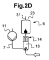
真空ライン4は、さらに、補助ポンプ装置13をバイパスするように構成されたバイパス管14を含むことができる(図2C参)。
このバイパス管14は、補助ポンプ装置13を迂回する管と、この管内に配置され、逆止弁/弁の両側の圧力差に応じて開閉するように構成された制御可能な弁または逆止弁とを含んでいる。このバイパス管14は、特に強力なガス流のポンプ搬送の場合、または補助ポンプ装置の故障の場合に、補助ポンプ装置13が引き起こす可能性のあるポンプ搬送能力の制限を防止するために、補助ポンプ装置13をバイパスすることを可能にする。
The vacuum line 4 may further include a
The
補助ポンプ装置13のドライ真空ポンプがベンチュリガスジェットポンプを含む場合、これはバイパス管14の逆止弁に組み込むことができる(図2D参照)。この逆止弁の可動シャッターには、ベンチュリ貫通通路がある。この逆止弁は、駆動ガスがベンチュリ通路の入口に注入されたときに、逆閉鎖位置をとることができる。この状態で、逆止弁は、補助ポンプ装置13のジェットポンプを形成する。逆止弁はまた、この逆止弁のいずれかの側の圧力差が逆止弁の負荷閾値よりも大きい場合、ポンプ搬送されたガスがベンチュリ貫通通路を迂回する開位置をとることもできる。
If the dry vacuum pump of the
図1に戻って、真空ライン4は、さらに、希釈ガス注入装置15、排気管7内の圧力を測定するように構成された圧力センサ16、および圧力センサ16に接続された制御ユニット17を含んでいる。
希釈ガス注入装置15は、窒素および/または燃料等の中性ガス等の希釈ガスを、粗引き真空ポンプ装置10の吸入口の下流で、ポンプ搬送されたガスの流れに注入するように構成されている。より具体的には、希釈ガスを、高真空ポンプ装置11、12の下流、設置可能な場合は、排気管7および/または粗引き真空ポンプ装置10および/または補助ポンプ装置13等へ、ポンプ搬送されたガスの流れに注入するように構成されている。この釈ガスは、例えば、粗引き真空ポンプ装置10の吸入口および/または吐出口8で注入され、及び/又は、粗引き真空ポンプ装置10の多段粗引き真空ポンプの最後の2つのポンプ段に注入され、および/または、補助ポンプ装置13の上流、下流または内部へ注入される。
Returning to FIG. 1, the vacuum line 4 further includes a dilution
The dilution
圧力センサ16は、例えば、粗引き真空ポンプ装置10の吐出口8付近に配置される。
制御ユニット17は、コントローラ、マイクロコントローラ、メモリ、および真空ラインを制御する方法を実施することを可能にするコンピュータプログラムを含む。これは、たとえば、コンピュータまたはプログラマブルロジックコントローラである。
制御ユニット17は、圧力センサ16によって測定された圧力の関数として、第1の動作モードまたは第2の動作モードにしたがって、補助ポンプ装置13および希釈ガス注入装置15を制御するように構成されている。
第1の動作モードでは、排気管7内の圧力は、200mbar(20,000Pa)以下に維持される。
The
The control unit 17 comprises a controller, a microcontroller, a memory and a computer program making it possible to implement the method for controlling the vacuum lines. It is for example a computer or a programmable logic controller.
The control unit 17 is configured to control the
In the first operating mode, the pressure in the
排気管7内の圧力を下げることができる補助ポンプ装置13は、連続的または断続的にポンプ搬送するように制御することができる。
例えば、補助ポンプ装置13は、ベンチュリガスジェットポンプを含み、制御ユニット17は、排気管内の圧力を下げるためにジェットポンプの駆動ガスを制御するように構成されている。
The
For example, the
他の例によれば、補助ポンプ装置13はウォータージェットポンプを含み、制御ユニット17は、排気管内の圧力を下げることを可能にするウォータージェットポンプの駆動液を制御するように構成されている(図1参照)。
この場合、一実施形態によれば、補助ポンプ装置13はさらに油圧ポンプ19を含み、この油圧ポンプの出口は、ウォータージェットポンプに駆動液を供給するために、制御ユニット17によって制御されるように構成されている。油圧ポンプ19の入口は、例えば、ガス処理装置6の洗浄塔24の洗浄槽22の液体と連通するようにして配置される。次に、ガス処理装置6は、補助ポンプ装置13のウォータージェットポンプとガス処理装置6のバーナー23の入口9との間に介在する、ガス/水分離器20を含むことができる。液体残留物は、プランジャーチューブ21を介して洗浄槽22に排出することができる。
According to another example, the
In this case, according to an embodiment, the
図3は、爆発前のさまざまな初期圧力値に対する水素の濃度C(空気中の分子分率)の関数として爆発圧力Pをmbar単位でグラフ化したものである。(記号は測定値を表し、実線は理論値を表している。)
白三角が100mbar(10,000Pa)、白四角が150mbar(15,000Pa)、白菱形が200mbar(20,000Pa)、黒丸形が300mbar(30,000Pa)、黒三角が500mbar(50,000Pa)、黒四角が750mbar(75,000Pa)、黒菱形が1,000mbar(100,000Pa)である。
最適な動作モードである第1の動作モードでは、デフォルトでは、排気管内の圧力は、排気管7内を搬送される殆どの可燃性ガスの発火条件よりも低く維持される。
これは、図3の例を参照するとよりよく理解できる。図3によれば、100mbar(10,000Pa)、150mbar(15,000Pa)、および200mbar(20,000Pa)の水素ガスの圧力に対して、化学量論的条件下での爆発圧力が、つまり、最も深刻な爆発につながる可能性がある場合の爆発圧力が、1,600mbar(160,000Pa)未満のままである。
このようにして、ガス爆発を防止することができる安全な条件のセットが、粗引き真空ポンプ装置10および排気管7内に確立される。排気管内が200mbar(20,000Pa)以下の圧力の場合、化学量論的条件下での点火によって発生する圧力(爆発圧力とも呼ばれる)は、容易に抑えることができる、すなわち、ポンプ装置5または配管に重大な機械的損傷を引き起こさない、と考えられている。
Figure 3 shows a graph of the detonation pressure P in mbar as a function of the concentration C of hydrogen (in molecular fraction in air) for various values of the initial pressure before the detonation (symbols represent measured values, solid line represents theoretical values).
The open triangles are 100 mbar (10,000 Pa), the open squares are 150 mbar (15,000 Pa), the open diamonds are 200 mbar (20,000 Pa), the black circles are 300 mbar (30,000 Pa), the black triangles are 500 mbar (50,000 Pa), the black squares are 750 mbar (75,000 Pa), and the black diamonds are 1,000 mbar (100,000 Pa).
In the first mode of operation, which is the optimum mode of operation, by default the pressure in the exhaust pipe is maintained below the ignition condition of most of the combustible gases carried in the
This can be better understood with reference to the example of Figure 3, which shows that for hydrogen gas pressures of 100 mbar (10,000 Pa), 150 mbar (15,000 Pa) and 200 mbar (20,000 Pa), the explosion pressure under stoichiometric conditions, i.e. the explosion pressure that may lead to the most severe explosion, remains below 1,600 mbar (160,000 Pa).
In this way, a set of safe conditions capable of preventing gas explosions is established in the roughing
図3は水素ガスに関する特定のケースに関するものであるが、同じ挙動がすべての可燃性ガスで観察される。すなわち、化学量論的条件下での爆発圧力、つまり、最も深刻な爆発につながる可能性のある爆発圧力が、1,600mbar(160,000Pa)未満に留まる。 Although Figure 3 is for the specific case of hydrogen gas, the same behavior is observed for all flammable gases: the explosion pressure under stoichiometric conditions, i.e. the explosion pressure that can lead to the most severe explosion, remains below 1,600 mbar (160,000 Pa).
さらに、第1の動作モードでは、200mbar(20,000Pa)以下の圧力の真空レベルによって安全性が確保されるため、可燃性および/または爆発条件の範囲外になるように希釈ガスを注入する必要はない。したがって、制御ユニット17は、希釈ガスの注入の停止を制御することができる。
制御ユニット17が、第1の動作モードにおいて粗引き真空ポンプ装置10へのパージガスの注入をオフにするように装置を構成することもできる。これにより、排気管7内を低圧に維持するのがより容易になる。
Furthermore, in the first operating mode, there is no need to inject dilution gas to be outside of flammable and/or explosive conditions, since the vacuum level of pressures below 200 mbar (20,000 Pa) ensures safety, and the control unit 17 can therefore control the stopping of the injection of dilution gas.
The control unit 17 may also configure the apparatus to turn off the injection of purge gas into the roughing
制御ユニット17は、排気管内の圧力を200mbar(20,000Pa)以下に下げることができない場合、第2の動作モードに切り替えるように構成されている。
この第2の動作モードでは、排気管7内の圧力は20,000Paより大きい。制御ユニット17はさらに、希釈ガス注入装置15による、排気管7および/または粗引き真空ポンプ装置10および/または補助ポンプ装置13への希釈ガスの注入を制御するように構成されている。この第2の動作モードは、「劣化した」動作モードと見なすことができ、可燃性のリスクは希釈によって制御できる。
制御ユニット17は、第2の動作モードにおいてポンプ搬送されるガスの流れに導入される希釈ガスの流量が、圧力センサ16によって測定された排気管内の圧力の関数として、および、ポンプ搬送される可燃性ガスに関する情報の関数として、点火(または爆発圧力)によって生成される圧力が特に化学量論的条件下、つまり、最も壊滅的な影響を引き起こす爆発的な状態に達する可燃性ガスの濃度条件下で、160,000Pa(1,600mbar)未満に留まるように、決定されるように構成することができる。
例えば、図3を参照すると、圧力センサ16によって測定された爆発前の初期圧力が300mbar(30,000Pa)(黒丸形)であるとき、化学量論的条件下での32%の[H2]濃度を、目標の[H2]濃度まで下げる必要がある。つまり、排気管内の圧力が1,600mbar(160,000Pa)の爆発圧力を超えないようにするために、中性ガスで希釈して[H2]濃度を15%まで下げる必要がある。
The control unit 17 is arranged to switch to the second operating mode if the pressure in the exhaust pipe cannot be reduced below 200 mbar (20,000 Pa).
In this second operating mode, the pressure in the
The control unit 17 can be configured to determine the flow rate of dilution gas introduced into the flow of pumped gas in the second operating mode as a function of the pressure in the exhaust pipe measured by the
For example, referring to Fig. 3, when the initial pressure before the explosion measured by the
図3の別の例によれば、圧力センサ16によって測定された排気管内の圧力が500mbar(50,000Pa)(黒三角形)であるとき、排気管内を爆発未満の1,600mbar(160,000Pa)の圧力に留めるために、化学量論的条件下での濃度を、希釈によって6~7%に低減されなければならない。
これらの例は、化学量論的条件での濃度の場合であるが、実際には、希釈前の可燃性ガス濃度は、プロセスチャンバ3内に導入される可燃性ガスの最大流量の値に基づいて、ユーザによって事前に決定される。
According to another example in FIG. 3, when the pressure in the exhaust pipe measured by
These examples are for concentrations under stoichiometric conditions, but in reality, the combustible gas concentration before dilution is determined in advance by the user based on the maximum flow rate of the combustible gas introduced into the process chamber 3.
可燃性ガスが複数存在する場合、中性ガスの希釈率は、プロセスチャンバ3に同時に注入される可燃性ガスの最大流量に基づいて決定される。
より具体的には、圧力センサ16によって測定された排気管内の圧力の関数として、図3のグラフによって示されるように、各ガスに固有のデータテーブルを使用して、各可燃性ガスについて希釈率が最初に別々に決定される。
データテーブルは、制御ユニット17に格納することができる。
次に、プロセスチャンバ3に同時に導入されるすべての可燃性ガスについて、各ガスの(得られるべき)希釈された目標濃度が再計算される。同時に注入されたすべてのガスは、それぞれの濃度の低下に相互に寄与する。
When multiple combustible gases are present, the dilution ratio of the neutral gas is determined based on the maximum flow rate of the combustible gases injected simultaneously into the process chamber 3 .
More specifically, the dilution ratio is first determined separately for each combustible gas using data tables specific to each gas as a function of the pressure in the exhaust pipe measured by
The data table may be stored in the control unit 17 .
The diluted target concentration (to be obtained) of each gas is then recalculated for all combustible gases simultaneously introduced into the process chamber 3. All simultaneously injected gases mutually contribute to the reduction of their respective concentrations.
したがって、希釈率は可燃性/爆発性ガスの量(または流量、圧力)の関数として調整され、点火によって生成される排気管内の圧力(または爆発圧力)が、160,000Pa(1,600mbar)未満に維持される。
制御ユニット17はさらに、測定された圧力が50,000Pa(500mbar)を超えた場合、粗引き真空ポンプ装置10の吸入口の下流、例えば排気管7および/または粗引き真空ポンプ装置10の中へ、および/または補助ポンプ装置13の中への、ポンプ搬送されたガスの流れへの高流量の希釈ガスの注入を制御するように構成することができる。この高流量の希釈ガスは、粗引き真空ポンプ装置10に優先的に注入することができ、場合によっては同時に排気管7に注入することもできる。
The dilution rate is therefore adjusted as a function of the amount (or flow rate, pressure) of flammable/explosive gas so that the pressure in the exhaust pipe (or explosion pressure) generated by ignition is kept below 160,000 Pa (1,600 mbar).
The control unit 17 may further be configured to control the injection of a high flow rate of dilution gas into the pumped gas stream downstream of the inlet of the roughing
高流量の希釈ガスの値は、例えば、プロセスチャンバ3に注入できる可燃性ガスの最大流量の関数として予め決定されている。この情報は、プロセスチャンバに導入された可燃性ガスの最大流量の値に基づいて、ユーザによって事前に決定される。高流量の希釈ガスは、例えば、可燃性ガス濃度が爆発下限界(LEL)の25%未満になるように予め定められる。
したがって、例えばプロセスチャンバ3内で実施されるレシピの最悪の条件の関数に加えて、さらに、LELの25%によって提供される安全マージンにより、最も不利なポンプ搬送状況であっても安全が確保される。これは、極端な状況で時折使用される緊急動作モードである。先行技術では、この緊急動作モードに相当するものが恒久的に実施され、過度の窒素消費をもたらしている。したがって、本実施例における最大希釈は不定期に実施されるものであり、希釈ガスの消費量とエネルギー予算を節約できる。
The value of the high flow rate of the dilution gas is, for example, predetermined as a function of the maximum flow rate of the flammable gas that can be injected into the process chamber 3. This information is predetermined by a user based on the value of the maximum flow rate of the flammable gas introduced into the process chamber. The high flow rate of the dilution gas is, for example, predetermined so that the flammable gas concentration is less than 25% of the lower explosion limit (LEL).
Thus, in addition to being a function of the worst-case conditions of the recipe implemented in, for example, process chamber 3, the safety margin provided by 25% of the LEL ensures safety even in the most adverse pumping conditions. This is an emergency mode of operation that is occasionally used in extreme situations. In the prior art, the equivalent of this emergency mode of operation is permanently implemented, resulting in excessive nitrogen consumption. Thus, maximum dilution in this embodiment is implemented on an irregular basis, which saves on dilution gas consumption and energy budgets.
図3を参照すると、水素圧力が500mbar(50,000Pa)を超えた場合、水素 [H2]の濃度は、排気管7内で1%未満の値、つまり、従来技術で推奨されている爆発限界(LEL)の25%未満の値まで減少する可能性がある。
したがって、制御ユニット17は、第1の動作モードでは、排気管7内の圧力を200mbar(20,000Pa)以下に維持する。
排気管7内で測定された圧力が200mbar(20,000Pa)以下のままである場合、制御ユニットは第1の動作モードのままである。
Referring to FIG. 3, if the hydrogen pressure exceeds 500 mbar (50,000 Pa), the concentration of hydrogen [ H2 ] can decrease in the
Thus, in the first operating mode, the control unit 17 maintains the pressure in the
If the pressure measured in the
補助ポンプ装置13で200mbar(20,000Pa)以下の圧力を維持することが不可能な場合、特に補助ポンプ装置13の容量が不十分なためにこの圧力を維持できない場合、制御ユニットは第2の動作モードに切り替わる。
第2の動作モードでは、制御ユニット17は、粗引き真空ポンプ装置10の吸入口の下流で、例えば、排気管7内へ、および/または粗引き真空ポンプ装置10内へ、および/または補助ポンプ装置13へ、ポンプ搬送されたガスの流れに対して、希釈ガスの注入の制御を行う。
圧力が200mbar(20,000Pa)と500mbar(50,000Pa)の間にある場合、圧力センサ16によって測定された排気管の圧力の関数として、およびプロセスチャンバ3に導入される可燃性ガスに関する情報の関数として、ポンプ搬送されたガスの流れに導入される希釈ガスの流量を決定できる。これにより、化学量論的条件等、爆発時の最も厳しい爆発条件下でも、爆発圧力が1,600mbar(160,000 Pa)未満に維持される。
If it is not possible to maintain a pressure below 200 mbar (20,000 Pa) with the
In a second operating mode, the control unit 17 controls the injection of diluent gas into the flow of pumped gas downstream of the inlet of the roughing
For pressures between 200 mbar (20,000 Pa) and 500 mbar (50,000 Pa), the flow rate of dilution gas introduced into the pumped gas stream can be determined as a function of the exhaust pressure measured by
したがって、排気管7内の圧力は、最初に補助ポンプ装置13の容量によって管理され、次に、排気管7内で測定された圧力が200mbar(20,000Pa)より大きく500mbar(50,000Pa)未満である場合には、排気管7内で測定された圧力の関数として、および、プロセスチャンバ3に導入される可燃性ガスに関する情報によって管理される。
もし、第2の動作モードで、測定された排気管内の圧力が200mbar(20,000Pa)以下に戻ると、制御ユニットは第1の動作モードに戻る。
もし、排気管の圧力が500mbar(50,000Pa)を超える場合、最も不利なポンプ搬送状況でも安全なものにするために、安全マージンを加えた所定の高流量の値の希釈ガスを、たとえば粗引き真空ポンプ装置10に直接注入することができる。
The pressure in the
If, in the second operating mode, the measured pressure in the exhaust pipe returns to below 200 mbar (20,000 Pa), the control unit reverts to the first operating mode.
If the exhaust line pressure exceeds 500 mbar (50,000 Pa), a dilution gas can be injected, for example, directly into the roughing
以上述べたことから、排気管7内の圧力を低下させることにより、希釈ガスの注入を、最も危険な状況にのみ制限することが可能になることが理解されるであろう。真空ライン4を安全なものにすると同時に、排気管の圧力を下げることにより、排気管7内の凝縮性種の堆積を防ぐことができ、その結果、真空ラインの加熱の要求を減らすことができる。さらに、真空ラインの加熱の要求を減らすことにより、熱分解を回避することも可能になり、したがって、粗引き真空ポンプ装置10内の熱に敏感な前駆体の変換を低減することが可能になる。
この低圧と低温の組み合わせにより、化学活性の動力学を低下させることも可能になり、それにより、真空ライン4の構成要素に対して腐食性であるか詰まらせる可能性があるかどうかにかかわらず、望ましくない化学反応を低下させることができる。加熱の要求を減らすことにより、潤滑剤の品質を維持し、粗引き真空ポンプ装置10の機械部品、特に軸受の信頼性を向上させることも可能になる。したがって、保守作業の間隔を大幅に延ばすことができ、これにより、真空ライン4の経済的収益性と生産設備の稼働時間が改善される。さらに、経済的な観点から、高価な貴金属の使用も減らすことができる。粗引き真空ポンプ装置10の構成要素は、設計および材料の両方に関して標準化することができ、それにより粗引き真空ポンプ装置の構成要素の提供が簡素化され、普遍的なものとなる。
From the above, it can be seen that by reducing the pressure in the
This combination of low pressure and low temperature also makes it possible to reduce the kinetics of chemical activity, and therefore of undesirable chemical reactions, whether corrosive or potentially clogging, for the components of the vacuum line 4. The reduced heating requirements also make it possible to maintain the quality of the lubricant and to improve the reliability of the mechanical components of the roughing
さらに、希釈ガスの消費量が制限され、これにより、粗引き真空ポンプ装置10のエネルギー消費量を削減することが可能になり、同時に、ガス処理装置6における窒素酸化物の形成を最小限に抑え、さらにはガス処理装置6内での窒素酸化物の形成を排除することさえ可能になる。
Furthermore, the consumption of dilution gas is limited, which makes it possible to reduce the energy consumption of the roughing
図1に示される例示的な実施形態によれば、ガス処理装置6はまた、排気管7と補助ポンプ装置13との間に介在する少なくとも1つのバイパス装置25を含むことができる。
このバイパス装置25は、排気管7に接続された入口ポート25aと、補助ポンプ装置13に接続され、さらにガス処理室26に接続された第1の出口ポート25bと、ガス処理室26をバイパスするように構成された第2の出口ポート25cと、入口ポート25aを第1の出口ポート25bと連通させ、あるいは第2の出口ポート25cと連通させるように構成された制御ユニットとを備えている。バイパス装置25は、例えば、制御可能な三方弁である。
このバイパス装置25は、ポンプ搬送されたガスを処理する必要がない場合にのみ、第2の出口ポート25cを介して補助ポンプ装置13およびガス処理室26をバイパスすることを可能にする。したがって、ガスを製造プラントの中央の洗浄塔に向けることができる。
According to the exemplary embodiment shown in FIG. 1, the
The
This
制御ユニットは手動部材とすることができる。保守オペレータは、保守中に制御ユニットを操作して、例えばガス処理室26の保守作業中に、ガスをこのガス処理室から迂回させることができる。このように、例えばバーナー23の故障またはメンテナンスの場合、ポンプ搬送されたガスはバイパス装置25によってその方向を変えることができる。
The control unit can be a manual element. A maintenance operator can operate the control unit during maintenance to, for example, divert gas from the
制御ユニットは、例えば、プロセスチャンバ3の状態(処理中、オフまたは待機中)、またはガスを処理する必要があるかどうかを示す情報項目等の、プロセスチャンバ3からの情報の項目に応じて、第1の出口ポート25bまたは第2の出口ポート25cを選択することができる。
したがって、例えば、オフまたは待機中のプロセスチャンバ3から来るガスは処理できず、バイパス装置25を介してバーナー23をバイパスすることができない。ドライ接点や空気圧制御などの情報により、制御ユニットの切り替えを直接制御できる。
例えば、プロセスチャンバ3ごとに1つのバイパス装置25があり、半導体製造装置2ごとに幾つかのプロセスチャンバ3がある。
幾つかのプロセスチャンバ3、したがって幾つかのバイパス装置25を、1つのガス処理室26に接続することができる。さらに、バイパス装置25の第2の出口ポート25cは、共通の管35に関連付けることができる。
The control unit can select the
Thus, for example, gas coming from an off or standby process chamber 3 cannot be processed and cannot bypass the
For example, there may be one
Several process chambers 3, and therefore
1 生産設備
2 半導体製造装置
3 プロセスチャンバ
4 真空ライン
5 ポンプ装置
6 ガス処理装置
7 排気管
8 吐出口
9 入口
10 粗引き真空ポンプ装置
11 高真空ポンプ装置(ルーツ真空ポンプ)
12 高真空ポンプ装置(ターボ分子真空ポンプ)
13 補助ポンプ装置
14 バイパス管
15 希釈ガス注入装置
16 圧力センサ
17 制御ユニット
19 油圧ポンプ
20 ガス/水分離器
21 プランジャーチューブ
22 槽
23 バーナー
24 洗浄塔
25 バイパス装置
26 ガス処理室
31 出口
Reference Signs List 1 Production equipment 2 Semiconductor manufacturing equipment 3 Process chamber 4 Vacuum line 5
12 High vacuum pump equipment (turbo molecular vacuum pump)
13
Claims (14)
前記ガス処理装置(6)は、
前記排気管(7)内の圧力を下げるように構成された少なくとも1つの補助ポンプ装置(13)と、
前記粗引き真空ポンプ装置の吸入口の下流の、前記排気管(7)内および/または前記粗引き真空ポンプ装置(10)内および/または前記補助ポンプ装置(13)内において、希釈ガスを、前記ポンプ搬送されたガスの流れに注入するように構成された希釈ガス注入装置(15)とを備え、
前記真空ライン(4)はさらに、
前記排気管(7)内の圧力を測定するように構成された圧力センサ(16)と、
前記補助ポンプ装置(13)および前記希釈ガス注入装置(15)を制御するように構成された制御ユニット(17)とを備え、
前記制御ユニット(17)は、
前記排気管(7)内の圧力が20,000Pa(200mbar)以下に維持されている第1の動作モードと、前記排気管(7)内の圧力が20000Pa(200ミリバール)を超える第2の動作モードを有し、
前記制御ユニット(17)は、前記第2の動作モードにおいて、前記希釈ガス注入装置(15)による前記希釈ガスの注入を制御するように構成されていることを特徴とする真空ライン。 A vacuum line (4) comprising a pumping device (5) and a gas treatment device (6), the pumping device including at least one roughing vacuum pumping device (10) configured to exhaust a pumped gas at atmospheric pressure, the gas treatment device (6) comprising a gas treatment chamber (26) configured to treat a gas pumped by the roughing vacuum pumping device (10) at atmospheric pressure, and an exhaust pipe (7) connecting an outlet (8) of the roughing vacuum pumping device (10) to an inlet (9) of the gas treatment chamber (26),
The gas treatment device (6) comprises:
at least one auxiliary pump device (13) configured to reduce the pressure in the exhaust pipe (7);
a dilution gas injection device (15) configured to inject a dilution gas into the pumped gas flow downstream of the inlet of the roughing vacuum pumping device, in the exhaust line (7) and/or in the roughing vacuum pumping device (10) and/or in the auxiliary pumping device (13),
The vacuum line (4) further comprises:
a pressure sensor (16) configured to measure the pressure in the exhaust pipe (7);
a control unit (17) configured to control the auxiliary pump device (13) and the dilution gas injection device (15);
The control unit (17)
a first operating mode in which the pressure in the exhaust pipe (7) is maintained below 20,000 Pa (200 mbar) and a second operating mode in which the pressure in the exhaust pipe (7) exceeds 20000 Pa (200 mbar);
The control unit (17) is configured to control the injection of the dilution gas by the dilution gas injection device (15) in the second operating mode.
前記制御ユニット(17)は、前記第2の動作モードにおいて、前記粗引き真空ポンプ装置(10)の前記吸入口の下流の、前記排気管(7)内および/または前記粗引き真空ポンプ装置(10)内および/または前記補助ポンプ装置(13)内において、前記ポンプ搬送されるガスの流れに導入される前記希釈ガスの流量が、前記圧力センサ(16)によって測定された圧力の関数として決定され、点火によって生成される前記排気管内の圧力が160,000Pa(1,600mbar)未満に維持されるように制御することを特徴とする真空ライン。 A vacuum line (4) according to claim 1,
the control unit (17) in the second operating mode determines a flow rate of the dilution gas introduced into the pumped gas flow in the exhaust line ( 7) downstream of the inlet of the roughing vacuum pumping device (10) and/or in the roughing vacuum pumping device (10) and/or in the auxiliary pumping device (13) as a function of the pressure measured by the pressure sensor (16) and controls such that the pressure in the exhaust line generated by ignition is maintained below 160,000 Pa (1,600 mbar).
前記希釈ガスが、燃料および/または中性ガスを含むことを特徴とする真空ライン。 A vacuum line (4) according to claim 1 or 2,
The vacuum line, wherein the diluent gas comprises a fuel and/or a neutral gas.
前記ポンプ装置(5)によって可燃性ガス及び/又は爆発性ガスがポンプ搬送される場合、
前記制御ユニット(17)は、測定された前記圧力が50,000Pa(500mbar)を超える場合は、前記排気管(7)内および/または前記粗引き真空ポンプ装置(10)内および/または前記補助ポンプ装置(13)内において、前記可燃性ガスおよび/または前記爆発性ガスの流量に応じて、前記ガスの爆発を避けるために、前記ポンプ搬送されたガスの流れへの高流量の前記希釈ガスの注入を制御するように構成されていることを特徴とする真空ライン。 A vacuum line (4) according to any one of claims 1 to 3,
When flammable and/or explosive gases are pumped by the pump device (5),
the control unit (17) is configured to control, depending on the flow rate of the flammable and/or explosive gas, in the exhaust pipe (7) and/or in the roughing vacuum pumping device (10) and/or in the auxiliary pumping device (13), a high flow rate of the dilution gas into the pumped gas flow in order to avoid an explosion of the gas if the measured pressure exceeds 50,000 Pa (500 mbar).
前記希釈ガスの前記高流量の値は、前記可燃性ガスの濃度が爆発下限の25%未満になるように事前に設定されていることを特徴とする真空ライン。 A vacuum line (4) according to claim 4 ,
A vacuum line, characterized in that the high flow rate value of the dilution gas is preset so that the concentration of the flammable gas is less than 25% of the lower explosion limit.
前記補助ポンプ装置がドライ真空ポンプを含み、前記ドライ真空ポンプのパージガスは、中性ガス、および/またはメタンの燃料、および/または燃焼剤を含み、
前記制御ユニット(17)は、前記第1の動作モードにおいて前記粗引き真空ポンプ装置(10)への前記パージガスの注入をオフにするように構成されていることを特徴とする真空ライン。 A vacuum line (4) according to any one of the preceding claims,
the auxiliary pumping device includes a dry vacuum pump, and the purge gas of the dry vacuum pump includes a neutral gas and/or a fuel and/or a combustible agent of methane;
The control unit (17) is configured to turn off the injection of the purge gas into the roughing vacuum pumping device (10) in the first operating mode.
前記補助ポンプ装置(13)は、ウォータージェットポンプおよび/またはベンチュリガスジェットポンプおよび/または液封ポンプおよび/またはドライ真空ポンプおよび/またはベーンポンプを含むことを特徴とする真空ライン。 A vacuum line (4) according to any one of the preceding claims,
The vacuum line, characterized in that the auxiliary pump device (13) includes a water jet pump and/or a venturi gas jet pump and/or a liquid ring pump and/or a dry vacuum pump and/or a vane pump.
前記ガス処理室(26)は、バーナー(23)、および/または電気システム、および/またはプラズマ、および/または洗浄塔(24)、および/または化学吸着式および/または物理吸着式のカートリッジを含むことを特徴とする真空ライン。 A vacuum line (4) according to any one of the preceding claims,
The gas treatment chamber (26) is characterized in that it comprises a burner (23), and/or an electrical system, and/or a plasma, and/or a scrubbing tower (24), and/or a chemisorption and/or physisorption cartridge, and/or a vacuum line.
前記補助ポンプ装置(13)はベンチュリガスジェットポンプを含み、その駆動ガスは燃料および/または燃焼ガスおよび/または中性ガスを含むことを特徴とする真空ライン。 A vacuum line (4) according to any one of the preceding claims,
The vacuum line, characterized in that the auxiliary pump device (13) includes a Venturi gas jet pump, the drive gas of which includes a fuel and/or a combustion gas and/or a neutral gas.
前記ベンチュリガスジェットポンプは、前記駆動ガスを加熱するように構成された加熱要素を含むことを特徴とする真空ライン。 A vacuum line (4) according to claim 9 ,
The venturi gas jet pump includes a heating element configured to heat the drive gas.
前記補助ポンプ装置(13)は、前記ガス処理室(26)の前記入口(9)から1メートル未満に位置することを特徴とする真空ライン。 A vacuum line (4) according to any one of the preceding claims,
The vacuum line, characterized in that the auxiliary pumping device (13) is located less than 1 meter from the inlet (9) of the gas treatment chamber (26).
前記補助ポンプ装置(13)は、ウォータージェットポンプと油圧ポンプ(19)とを含み、その入口は前記ガス処理装置(6)の洗浄塔(24)の洗浄槽(22)の液体と連通して配置され、その出口は、前記制御ユニット(17)によって制御され、前記ウォータージェットポンプに駆動液を供給するように構成されていることを特徴とする真空ライン。 A vacuum line (4) according to any one of the preceding claims,
The auxiliary pump device (13) includes a water jet pump and a hydraulic pump (19), the inlet of which is arranged in communication with the liquid in the washing tank (22) of the washing tower (24) of the gas treatment device (6), and the outlet of which is controlled by the control unit (17) and configured to supply driving liquid to the water jet pump.
過圧の場合に前記補助ポンプ装置(13)をバイパスするように構成されたバイパス管(14)を含むことを特徴とする真空ライン。 A vacuum line (4) according to any one of the preceding claims,
A vacuum line comprising a bypass pipe (14) arranged to bypass said auxiliary pump device (13) in case of overpressure.
前記補助ポンプ装置(13)および前記希釈ガス注入装置(15)は、前記排気管(7)内の圧力が20,000Pa(200ミリバール)以下に維持される、前記第1の動作モードにしたがって制御され、または、
前記排気管(7)内の圧力が20,000Paよりも高く、前記粗引き真空ポンプ装置の前記吸入口の下流で、前記ポンプ搬送されたガスの流れへの前記希釈ガスの注入が制御される前記第2の動作モードに従って制御され、
前記第2の動作モードでは、前記希釈ガス注入装置(15)を用いて、前記排気管(7)および/または前記粗引き真空ポンプ装置(10)および/または前記補助ポンプ装置(13)内へ前記希釈ガスが注入されることを特徴とする真空ラインを制御する方法。 A method for controlling the vacuum line (4) according to any one of claims 1 to 13, comprising the steps of:
the auxiliary pumping device (13) and the dilution gas injection device (15) are controlled according to the first operating mode in which the pressure in the exhaust pipe (7) is maintained below 200 mbar, or
according to the second mode of operation, in which the pressure in the exhaust line (7) is greater than 20,000 Pa and injection of the diluent gas into the pumped gas stream downstream of the inlet of the roughing vacuum pumping arrangement is controlled;
The method for controlling a vacuum line, characterized in that in the second operation mode, the dilution gas is injected into the exhaust pipe (7) and/or the roughing vacuum pump device (10) and/or the auxiliary pump device (13) using the dilution gas injection device (15).
Applications Claiming Priority (3)
| Application Number | Priority Date | Filing Date | Title |
|---|---|---|---|
| FR2007251 | 2020-07-09 | ||
| FR2007251A FR3112177B1 (en) | 2020-07-09 | 2020-07-09 | Vacuum line and method for controlling a vacuum line |
| PCT/EP2021/067177 WO2022008249A1 (en) | 2020-07-09 | 2021-06-23 | Vacuum line and method for controlling a vacuum line |
Publications (2)
| Publication Number | Publication Date |
|---|---|
| JP2023532775A JP2023532775A (en) | 2023-07-31 |
| JP7674792B2 true JP7674792B2 (en) | 2025-05-12 |
Family
ID=74045487
Family Applications (1)
| Application Number | Title | Priority Date | Filing Date |
|---|---|---|---|
| JP2023501032A Active JP7674792B2 (en) | 2020-07-09 | 2021-06-23 | Vacuum line and method for controlling the vacuum line |
Country Status (8)
| Country | Link |
|---|---|
| US (1) | US12496563B2 (en) |
| JP (1) | JP7674792B2 (en) |
| KR (1) | KR20230034409A (en) |
| CN (1) | CN115803527B (en) |
| DE (1) | DE112021003709T5 (en) |
| FR (1) | FR3112177B1 (en) |
| TW (1) | TW202219389A (en) |
| WO (1) | WO2022008249A1 (en) |
Families Citing this family (3)
| Publication number | Priority date | Publication date | Assignee | Title |
|---|---|---|---|---|
| FR3112177B1 (en) * | 2020-07-09 | 2022-07-08 | Pfeiffer Vacuum | Vacuum line and method for controlling a vacuum line |
| FR3129851A1 (en) * | 2021-12-08 | 2023-06-09 | Pfeiffer Vacuum | Vacuum line and installation comprising the vacuum line |
| GB202310266D0 (en) * | 2023-07-05 | 2023-08-16 | Edwards Ltd | Claw booster pump |
Citations (8)
| Publication number | Priority date | Publication date | Assignee | Title |
|---|---|---|---|---|
| JP2004140373A (en) | 2002-10-18 | 2004-05-13 | Boc Group Inc:The | Supply of fluorine to semiconductor processing chamber at lower than atmospheric conditions |
| JP2012054541A (en) | 2010-08-05 | 2012-03-15 | Ebara Corp | Exhaust system |
| JP2014175051A (en) | 2013-03-05 | 2014-09-22 | Tokyo Electron Ltd | Microwave waveguide device, plasma processing device, and plasma processing method |
| JP2018523567A (en) | 2015-07-22 | 2018-08-23 | エドワーズ リミテッド | Apparatus for exhausting a corrosive effluent gas stream from a processing chamber |
| WO2018221067A1 (en) | 2017-05-29 | 2018-12-06 | カンケンテクノ株式会社 | Exhaust gas decompression detoxification method and device therefor |
| WO2019017580A1 (en) | 2017-07-17 | 2019-01-24 | 장희수 | Waterjet ejector for transferring object |
| WO2019181539A1 (en) | 2018-03-22 | 2019-09-26 | 株式会社Kokusai Electric | Substrate processing apparatus, semiconductor device production method, and program |
| US20200105509A1 (en) | 2018-09-28 | 2020-04-02 | Lam Research Corporation | Vacuum pump protection against deposition byproduct buildup |
Family Cites Families (14)
| Publication number | Priority date | Publication date | Assignee | Title |
|---|---|---|---|---|
| FR626647A (en) * | 1925-12-22 | 1927-09-15 | La Mont Corp | Waste heat generation device |
| JP2574816Y2 (en) * | 1990-07-09 | 1998-06-18 | 三菱電機株式会社 | Exhaust gas abatement system |
| FR2878913B1 (en) | 2004-12-03 | 2007-01-19 | Cit Alcatel | CONTROL OF PARTIAL GAS PRESSURES FOR PROCESS OPTIMIZATION |
| GB0523947D0 (en) * | 2005-11-24 | 2006-01-04 | Boc Group Plc | Microwave plasma system |
| GB0525517D0 (en) * | 2005-12-15 | 2006-01-25 | Boc Group Plc | Apparatus for detecting a flammable atmosphere |
| FR2903122B1 (en) * | 2006-06-30 | 2008-09-12 | Stein Heurtey | DEVICE FOR SECURING AN OVEN EQUIPPED WITH FAST HEATING AND COOLING OPERATING UNDER CONTROLLED ATMOSPHERE. |
| EP2791508B1 (en) * | 2011-12-14 | 2019-03-06 | Sterling Industry Consult GmbH | Device and method for evacuating a chamber and purifying the gas extracted from said chamber |
| GB2533933A (en) * | 2015-01-06 | 2016-07-13 | Edwards Ltd | Improvements in or relating to vacuum pumping arrangements |
| CN108711660B (en) * | 2018-07-27 | 2024-07-16 | 清华大学 | Lithium Ion Battery |
| FR3092879B1 (en) * | 2019-02-14 | 2021-02-19 | Pfeiffer Vacuum | Dry type primary vacuum pump |
| FR3112177B1 (en) * | 2020-07-09 | 2022-07-08 | Pfeiffer Vacuum | Vacuum line and method for controlling a vacuum line |
| FR3112086B1 (en) * | 2020-07-09 | 2022-07-08 | Pfeiffer Vacuum | Gas treatment device and vacuum line |
| FR3129991B1 (en) * | 2021-12-08 | 2024-04-19 | Pfeiffer Vacuum | Vacuum line, pumping device intended to be connected to the vacuum line and installation comprising the vacuum line |
| FR3129851A1 (en) * | 2021-12-08 | 2023-06-09 | Pfeiffer Vacuum | Vacuum line and installation comprising the vacuum line |
-
2020
- 2020-07-09 FR FR2007251A patent/FR3112177B1/en active Active
-
2021
- 2021-06-15 TW TW110121648A patent/TW202219389A/en unknown
- 2021-06-23 JP JP2023501032A patent/JP7674792B2/en active Active
- 2021-06-23 DE DE112021003709.9T patent/DE112021003709T5/en active Pending
- 2021-06-23 WO PCT/EP2021/067177 patent/WO2022008249A1/en not_active Ceased
- 2021-06-23 US US18/004,252 patent/US12496563B2/en active Active
- 2021-06-23 CN CN202180044762.XA patent/CN115803527B/en active Active
- 2021-06-23 KR KR1020237004670A patent/KR20230034409A/en active Pending
Patent Citations (8)
| Publication number | Priority date | Publication date | Assignee | Title |
|---|---|---|---|---|
| JP2004140373A (en) | 2002-10-18 | 2004-05-13 | Boc Group Inc:The | Supply of fluorine to semiconductor processing chamber at lower than atmospheric conditions |
| JP2012054541A (en) | 2010-08-05 | 2012-03-15 | Ebara Corp | Exhaust system |
| JP2014175051A (en) | 2013-03-05 | 2014-09-22 | Tokyo Electron Ltd | Microwave waveguide device, plasma processing device, and plasma processing method |
| JP2018523567A (en) | 2015-07-22 | 2018-08-23 | エドワーズ リミテッド | Apparatus for exhausting a corrosive effluent gas stream from a processing chamber |
| WO2018221067A1 (en) | 2017-05-29 | 2018-12-06 | カンケンテクノ株式会社 | Exhaust gas decompression detoxification method and device therefor |
| WO2019017580A1 (en) | 2017-07-17 | 2019-01-24 | 장희수 | Waterjet ejector for transferring object |
| WO2019181539A1 (en) | 2018-03-22 | 2019-09-26 | 株式会社Kokusai Electric | Substrate processing apparatus, semiconductor device production method, and program |
| US20200105509A1 (en) | 2018-09-28 | 2020-04-02 | Lam Research Corporation | Vacuum pump protection against deposition byproduct buildup |
Also Published As
| Publication number | Publication date |
|---|---|
| US12496563B2 (en) | 2025-12-16 |
| FR3112177A1 (en) | 2022-01-07 |
| FR3112177B1 (en) | 2022-07-08 |
| CN115803527B (en) | 2025-04-18 |
| WO2022008249A1 (en) | 2022-01-13 |
| KR20230034409A (en) | 2023-03-09 |
| CN115803527A (en) | 2023-03-14 |
| TW202219389A (en) | 2022-05-16 |
| DE112021003709T5 (en) | 2023-08-10 |
| JP2023532775A (en) | 2023-07-31 |
| US20230294053A1 (en) | 2023-09-21 |
Similar Documents
| Publication | Publication Date | Title |
|---|---|---|
| JP7674792B2 (en) | Vacuum line and method for controlling the vacuum line | |
| EP2831423B2 (en) | Vacuum pump system | |
| EP3243005B1 (en) | Improvements in or relating to vacuum pumping arrangements | |
| JP7598441B2 (en) | Vacuum lines including gas treatment equipment | |
| KR102845866B1 (en) | A device for exhausting a corrosive exhaust gas stream from a processing chamber. | |
| TWI499450B (en) | Systems and methods for treating flammable effluent gases from manufacturing processes | |
| US9685352B2 (en) | Apparatus for conserving electronic device manufacturing resources including ozone | |
| CN115193234B (en) | NO remover and semiconductor tail gas treatment equipment | |
| US8394179B2 (en) | Method of treating a gas stream | |
| CN101460231A (en) | Method and system for atmosphere recycling | |
| CN214370252U (en) | Organic waste gas treatment and pretreatment equipment | |
| US6202667B1 (en) | Apparatus and method for stopping the propagation of ignited flammable gas in a conduit | |
| TWI701386B (en) | Dry vacuum pump with abatement function | |
| WO2009077777A1 (en) | Method of treating a gas stream | |
| KR20240123819A (en) | Pumping and processing devices and methods | |
| FR3129851A1 (en) | Vacuum line and installation comprising the vacuum line | |
| WO2024074922A1 (en) | Exhaust gas abatement system and method thereof | |
| KR20050089223A (en) | System for treating exhaust gas | |
| JP2007116196A (en) | Substrate processing apparatus and semiconductor device processing method | |
| KR20050015257A (en) | Pump power upgrade system |
Legal Events
| Date | Code | Title | Description |
|---|---|---|---|
| A621 | Written request for application examination |
Free format text: JAPANESE INTERMEDIATE CODE: A621 Effective date: 20240618 |
|
| A977 | Report on retrieval |
Free format text: JAPANESE INTERMEDIATE CODE: A971007 Effective date: 20241211 |
|
| A131 | Notification of reasons for refusal |
Free format text: JAPANESE INTERMEDIATE CODE: A131 Effective date: 20241217 |
|
| A521 | Request for written amendment filed |
Free format text: JAPANESE INTERMEDIATE CODE: A523 Effective date: 20250311 |
|
| TRDD | Decision of grant or rejection written | ||
| A01 | Written decision to grant a patent or to grant a registration (utility model) |
Free format text: JAPANESE INTERMEDIATE CODE: A01 Effective date: 20250325 |
|
| A61 | First payment of annual fees (during grant procedure) |
Free format text: JAPANESE INTERMEDIATE CODE: A61 Effective date: 20250421 |
|
| R150 | Certificate of patent or registration of utility model |
Ref document number: 7674792 Country of ref document: JP Free format text: JAPANESE INTERMEDIATE CODE: R150 |