JP7672139B2 - Combustion promoter for wood stoves - Google Patents
Combustion promoter for wood stoves Download PDFInfo
- Publication number
- JP7672139B2 JP7672139B2 JP2021166748A JP2021166748A JP7672139B2 JP 7672139 B2 JP7672139 B2 JP 7672139B2 JP 2021166748 A JP2021166748 A JP 2021166748A JP 2021166748 A JP2021166748 A JP 2021166748A JP 7672139 B2 JP7672139 B2 JP 7672139B2
- Authority
- JP
- Japan
- Prior art keywords
- combustion
- combustion promoter
- promoter
- openings
- firewood
- Prior art date
- Legal status (The legal status is an assumption and is not a legal conclusion. Google has not performed a legal analysis and makes no representation as to the accuracy of the status listed.)
- Active
Links
Images


Landscapes
- Solid-Fuel Combustion (AREA)
Description
本発明は、薪ストーブの炉内で薪などの固体燃料を効率良く燃焼させることができる薪ストーブの燃焼促進具に関する。 The present invention relates to a combustion promoter for a wood stove that can efficiently burn solid fuels such as firewood inside the furnace of the wood stove.
屋内或いは野外で使用する薪ストーブの炉内で用いる燃焼促進具は、薪に点火し燃焼させる際に薪の下方に置いて薪を支えつつ薪の相互の間及び炉内の床面との間に隙間を形成して空気の流通をよくして燃焼の促進を図るものである。このような薪ストーブの燃焼促進具の従来技術としては、特許文献1に示されるものがある。この従来技術の薪ストーブの燃焼促進具は、板状部材と、該板状部材に突設され、突設方向に沿って内部に貫通孔を有する複数の突起部とを備える。
A combustion promoter used in the furnace of a wood stove used indoors or outdoors is placed under the firewood when it is ignited and burned, supporting it while forming gaps between the logs and between the logs and the floor of the furnace, improving air circulation and promoting combustion. An example of a conventional technology for such a firewood stove combustion promoter is shown in
前記した特許文献1の従来技術の燃焼促進具を使用する際、燃焼促進具を薪ストーブ炉内の床面に置き、その上に固体燃焼材である薪を載せるが、床面によって前記貫通孔の一方の開口部が塞がれてしまうので、空気の流通が悪くなり、燃焼効率が低下するという問題点がある。また、突起部は板状部材の一面のみにしか突設されていないので、薪の載せ方によっては、空気の流通がうまくいかないので薪の燃焼が促進され難いという問題点がある。
When using the combustion promoter of the conventional technology described in
この発明は上記事情に鑑みなされたものであって、その手段とするところは、内部に中空部を有し少なくとも2つの面部に前記中空部と連通する開口部を具備する多面体同士を隣接する多面体の前記開口部を通じて前記隣接する多面体の中空部同士が連通するように連結固定してなり、6個の前記多面体が互いに連通した状態で十字型に配置され、前記開口部が互いに向かい合わせとなって連結空間が形成されると共に、前記連結空間を通じて6個の前記多面体の前記中空部、及び前記中空部を通じて全ての前記開口部が互いに連通される薪ストーブの燃焼促進具としたところにある。 This invention has been made in consideration of the above-mentioned circumstances, and its means resides in a device for promoting combustion in a wood stove, which is formed by connecting and fixing polyhedrons, each having a hollow portion therein and having openings in at least two faces that communicate with the hollow portions, so that the hollow portions of the adjacent polyhedrons communicate with each other through the openings of the adjacent polyhedrons, and six of the polyhedrons are arranged in a cross shape while communicating with each other, with the openings facing each other to form a connected space, and the hollow portions of the six polyhedrons and all of the openings communicating with each other through the connected space .
更に、前記多面体が金属材料からなることにある。又、前記多面体が可燃性材料からなることにある。更に又、前記多面体が直方体であることにある。 Furthermore, the polyhedron is made of a metal material. Also, the polyhedron is made of a flammable material. Furthermore, the polyhedron is a rectangular parallelepiped.
本発明の薪ストーブの燃焼促進具は多面体であるので、使用時に薪ストーブの炉内の床面に置くと、端縁部や稜部は必ずその床面から所定の高さを有している。その端縁部や稜部の上に薪などの燃料を置くと空気の流通が良くなり燃焼が早まる。燃焼促進具を複数個置いた時には、複数の端縁部や稜部が存在するので、その端縁部や稜部を跨って燃料である薪を安定して多数載せることが出来る。そして、燃えやすい紙などに薪の下方から点火すると、薪の下方と床面の間には多面体の高さ分の隙間が出来ており、且つ、多面体の内部は空洞部を有しているので、開口部からこの空洞部を通って燃焼に伴って生じる空気の上昇気流によって酸素の供給が促進されて薪がよく燃える。これによって部屋の温度上昇が早まることになる。開口部が多面体の少なくとも2面部に設けてあるので、空気の上昇気流が空洞部、開口部を通じて円滑に行われて、燃焼が一層促進される。 The combustion promoter for the wood stove of the present invention is a polyhedron, so when it is placed on the floor inside the furnace of the wood stove during use, the edge and ridge parts are always at a certain height from the floor. When fuel such as firewood is placed on the edge and ridge parts, air circulation improves and combustion is accelerated. When multiple combustion promoters are placed, multiple edge and ridge parts are present, so a large number of firewood fuels can be placed stably across the edge and ridge parts. When firewood is ignited from below on flammable paper or the like, a gap of the height of the polyhedron is created between the bottom of the firewood and the floor, and since the inside of the polyhedron has a hollow part, the supply of oxygen is promoted by the rising air current generated by the combustion from the opening through this hollow part, and the firewood burns well. This accelerates the temperature rise in the room. Since the opening is provided on at least two sides of the polyhedron, the rising air current flows smoothly through the hollow part and the opening, further promoting combustion.
上記の多面体からなる燃焼促進具同士を隣接する燃焼促進具の前記開口部を通じ燃焼促進具の空洞部同士が連通するように連結固定した燃焼促進具集合体である複合燃焼促進具としておくと、床面に1個ずつ適宜間隔を開けて載置する必要がなく、1回の載置で並べることができ載置作業の能率化を図ることが出来る。又、床面から上端迄の距離が大きくなるので、燃焼がより促進される。この場合、各燃焼促進具の空洞部が開口部を通じて連通しているので、燃焼に伴う空気の上昇気流が発生し易くまた上昇速度も早くなるので、より燃焼速度が速まり、結果として部屋の暖房が短時間で行える利点がある。 If the above-mentioned polyhedral combustion promoters are connected and fixed together so that the cavities of the combustion promoters communicate with each other through the openings of adjacent combustion promoters to form a composite combustion promoter, there is no need to place them one by one on the floor surface with an appropriate amount of space between them, and they can be lined up in one placement, making the placement work more efficient. In addition, the distance from the floor surface to the top end is greater, which further promotes combustion. In this case, since the cavities of each combustion promoter are connected through the openings, it is easier for an updraft of air to occur during combustion, and the rate of ascent is faster, which has the advantage of making it possible to heat a room in a shorter time.
又、前記の複合燃焼促進具を更に隣接する中空部が連通するようにして連結固定した連結複合燃焼促進具すれば、より早く燃焼前の準備が整えられる利点がある。更に、隣接する燃焼促進具、複合燃焼促進具、連結複合燃焼促進具は、高さ位置は揃えられているので、薪を置く場合には滑り落ちなどが発生し難く、早く準備作業が出来る。 In addition, if the composite combustion accelerators are connected and fixed so that adjacent hollow sections are connected to form a connected composite combustion accelerator, there is an advantage that preparations before combustion can be completed more quickly. Furthermore, since adjacent combustion accelerators, composite combustion accelerators, and connected composite combustion accelerators are all aligned in height, when placing firewood, it is less likely to slip off, and preparation work can be completed quickly.
燃焼促進具がステンレス鋼などの金属材料からなる場合には、繰り返し使用が可能であり、耐久性にも優れる利点がある。燃焼促進具が木材などの可燃焼部材であれば、燃料にもなるので薪の使用量がその分少なるのに加えて、後片付けの手数が省ける。更に、金属部材よりも軽いので、持ち運びが楽になる利点がある。 When the combustion promoter is made of a metal material such as stainless steel, it has the advantage of being reusable and highly durable. If the combustion promoter is made of a combustible material such as wood, it can also be used as fuel, so not only will less firewood be used, but it also saves the trouble of having to clean up afterwards. Another advantage is that it is lighter than metal materials, making it easier to carry.
この発明の実施形態について図に基づいて説明する。ここで多面体とは、4つ以上の平面で囲まれた多体のことをいい、複数の頂点の稜部を結ぶ直線の辺の端縁部と、この端縁部によって囲まれた厚みのある面部よって構成されたものである。具体的には、角錐、六面体、十二面体、五面体などをいう。中空部とは、前記多面体の面部によって囲まれた空間内部のことをいい、開口部とは、これら面部の一部または全部に開けた貫通孔のことを言うが、面部全部に開けた場合には実質的に面部はなくなるので、この場合には隣接した他の面部の端縁部によって囲まれた空間によって開口部が形成される。 The embodiment of the present invention will be described with reference to the drawings. Here, a polyhedron refers to a polyhedron surrounded by four or more planes, and is composed of the edges of straight lines connecting the ridges of multiple vertices, and thick faces surrounded by these edges. Specifically, it refers to pyramids, hexahedrons, dodecahedrons, pentahedrons, etc. The hollow portion refers to the inside of the space surrounded by the faces of the polyhedron, and the opening refers to a through hole opened in some or all of these faces, but if all the faces are opened, there will essentially be no faces, so in this case the opening is formed by the space surrounded by the edges of other adjacent faces.
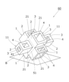
この発明の一実施形態の薪ストーブの燃焼促進具1(以下、単に「燃焼促進具1」と言う。)は、図1に示すように、多面体が6つの面部2を有する六面体である直方体を示し、内部に空洞部3を有すると共に、6つの面部2の内の図で上下方向に2つと横方向に1つの合計3つに開口部4が形成されている実施形態を示す。図1の上下2つの面部2の開口部4は面部2の全てが開口されたものであり、その開口部4の輪郭は周りを囲む4つの面部2の端縁部21によって四角形に形成されている。開口部4は少なくとも2つの面部2に設けられていればよいが、好ましくは3つの以上の面部2に設けられているのが良い。そうすれば、図9に示すように使用時において薪ストーブAの床面B上にどのような姿勢で載置しも、必ず2つの開口部4は床面Bに面していなくなるので、空洞部3と薪ストーブAの炉内の空気の流通が良くなり燃焼が促進される。開口部4が2つの場合には、床面Bに開口部4が面しないように載置すれば同様の効果が生じる。燃焼促進具1の床面B上への置き方は、前記したように一個ずつ丁寧に並べてその上方に薪Cを載置してもよいが、多数の燃焼促進具1を放り込むようにランダムに置いてその上に薪Cを置くようにしても、燃焼促進具1間で隙間が多くできると共に空洞部3、開口部4を通じて空気の上昇気流に伴う流通が良くなり、燃焼が促進される。
As shown in FIG. 1, the
燃焼促進具1が上記6面体以外の多面体の場合も同様である。多面体としたのは面部2が平面であるので相互に連結固定した複合燃焼促進具6を作成し易く、又、平面であるので安定して床面Bに載置できるからである。
The same applies when the
次に、図2~5に示す他の実施形態について説明する。この実施形態は、直方体とくに正方体からなる燃焼促進具1が6個集合して連結固定された複合燃焼促進具6を示す。各燃焼促進具1は、6つの面部2,1つの空洞部3,相対向する一組の2つの面部2が全面開口された2つの開口部4を有している例を示す。そして、それぞれの燃焼促進1は、それぞれの1つの開口部4の外周の端縁部21を囲む他の4つの燃焼促進具1の開口部4の端縁部21と相互に連結固定されている。この連結固定によって、図3に良く現れているように、6つの燃焼促進具1の開口部4が互いに向かい合わせとなって連結空間5が形成されると共に、この連結空間5を通じて6つの燃焼促進具1の中空部3、並びにこの中空部3を通じて全ての開口部4が互に連通された複合燃焼促進具6が形成されている。
Next, other embodiments shown in Figures 2 to 5 will be described. This embodiment shows a
この複合燃焼促進具6を薪ストーブAの床面B上に置いて使用する例について図2を参照しながら説明する。この使用例の場合には、連結空間5を中心にして6つの燃焼促進具1が6方向に突出しており、この内の下方の2つの燃焼促進具1の面部2の平行な端縁部21が床面B上に置かれて安定し、上方の2つの燃焼促進具1の面部2の平行な端縁部21が床面Bと略平行に位置している場合を示す。又、図4は、下方に位置する3つの燃焼促進具1の稜部22が床面Bに当たって複合燃焼促進具6の重さが稜部22の3点でバランス良く支えられて安定し、上方の3つの燃焼促進具1の稜部22が同じ高さ位置にあることを示している。更に、図5は、図2に示す複合燃焼促進具6を構成する燃焼促進具1の面部2の全面に開口部4を形成し端縁部21に切欠部23を形成した以外の他の面部2の中央部を刳り貫いて部分的な開口部4を形成したものである。
An example of using this
使用時においては、図2,図5に示すように平行な2つの端縁部21を床面B上への置き方であっても、図4に示すような稜部21の3点支持による置き方であっても良いし、その他の置き方であっても良い。図5は図2に示す燃焼促進具1の面部2の端縁部21に切欠部23を多数形成した複合燃焼促進具6を示す。
When in use, the device may be placed on the floor surface B with two
図6は、2つの端縁部21で床面に立てた2つの複合燃焼促進具6の上方に位置する2つの平行な端縁部21の上に薪Cの両端を載置して薪Cの下方に隙間を形成した例を示す。この場合には、燃えやすい紙などを薪Cの下方においてから点火すると、複合燃料促進具6の中空部3、開口部4、切欠部23を通じて空気の流通が良くなるので、薪Aの燃焼を促進する効果が得られる。切欠部23を形成すると空気の流通が更によくなるので、燃焼が更に促進される。
Figure 6 shows an example in which both ends of a firewood C are placed on the two
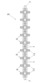
図7に示す実施形態は、図2~4に示す複合燃焼促進具6を長手方向に一列に連結棒7を用いて連結した連結複合燃焼促進具8を示す。連結棒7は、面部2の全面開口された開口部4の内径と略等しいか又は若干小さい外径を有する断面四角形状の細長い棒材であって、隣接する2つの複合燃焼促進具6の相対向する全面開口する開口部4、連結空間5を貫通して直列に連結された連結複合燃焼促進具8の実施形態を示している。
The embodiment shown in Figure 7 shows a connected
この実施形態の場合には、図8に示すように、床面B上に例えば2列に並べてから必要な数だけの薪Cの両端を並べて載置し、更にその薪Cの長手方向と直交する方向に必要な数の連結複合燃焼促進具8の両端を更に載置し、同様にして2段まで積層した実施形態を示す。この場合には、前記と同様に、燃えやすい紙などを積層した薪Cの下方においてから点火すると、薪Cと連結複合燃焼促進具8の隙間や燃焼促進具1の開口部4,空洞部3を通じて空気の上昇気流の流通が良くなるので、多数の薪Cを早く燃焼することが出来る結果、室内の温度を速やかに上昇させることが出来る。
In this embodiment, as shown in Figure 8, the required number of firewood C are placed on the floor surface B, for example, in two rows, and then both ends of the required number of connected
次に図10乃至14に示す他の実施形態について説明する。この実施形態は、燃焼促進具1が形状、大きさが異なる直方体6つをそれぞれの空洞部3が面部2に形成した開口部4を介して連通するように連結集合させた6方向に燃焼促進具1が突出部を具備する複合燃焼促進具60としたものである。図10乃至12に示す実施形態は、同一平面上に4方向に突出する4つの燃焼促進具1は、全面の開口部4を有する面部2の端部21同士が連結固定されて十字形を形成し、図11に良く現れているように、この十字形に連結された中心部の連結空間50を塞ぐ封鎖面部51の開口部40から直角方向に固定された形状、大きさが異なる2つの燃焼促進具11が開口部41を通じて他の4つの燃焼促進具1の空洞部3と連通するようにしたものである。
Next, other embodiments shown in Figures 10 to 14 will be described. In this embodiment, the
図13は、前記複合燃焼促進具60の対応する全面に開口した開口部4同士を向かい合わせて連結棒7を通して連結固定した横方向に長い連結複合燃焼促進具9を示す。図14は、形状、大きさが小さい前記燃焼促進具11を形状、大きさが大きい燃焼促進具1の開口部4の内部に挿入して横方向に長い連結複合燃焼促進具10としたものである。この実施形態の場合には、横方向の長手方向にある空洞部3は全て連通しているので、空気の流通は一層よくなり、薪Cの燃焼がより一層促進される。使用の仕方は前記した連結複合燃焼促進具8の実施形態と同様である。
Figure 13 shows a horizontally long connected
以上の説明における燃焼促進具1、複合燃焼促進具6,連結複合燃焼促進具8,9,10の材質は、ステンレスのような金属製である場合には、繰り返し使用でき利点がある。材質が木などの可燃性材料であれば燃料の一部として利用できると共に、使い切りあるのでそのまま炉内に灰として残存させておけるので片付けの手間が省ける。又、持ち運びが軽いので楽である。
In the above description, the
尚、図1の燃焼促進具1において、空洞部3、開口部4設けない多面体としたものを図2に示すような複合燃焼促進具とした場合にも、薪Aの下方や間に隙間を多くとることが出来るので、ある程度の燃焼促進効果を得ることが出来る。その場合の材質も金属製や木製のいずれであっても良い。
In addition, even if the
上記したことからも明らかなように、この発明の燃焼促進器具1、複合燃焼促進具6,連結複合燃焼促進具8,9,10によると、薪ストーブAの床面B上方に置いて使用すると、床面Bとの間に隙間が形成されると共にこの隙間が生じた燃焼促進器具1の上方に置いた薪Cとの間にも隙間が生じる。これによって床面Bから炉内上方への上昇気流が煙突Dを通って円滑に大気中に排気される。更に、各燃焼促進具1は空洞部3を有しているので、この空洞部3を通じても空気の流通が一層促進されて燃焼効率が向上して、家屋で使用した場合には室内の温度を上げ、暖を速やかに且つ効率よくとることができる。
As is clear from the above, when the
以上の実施形態においては、薪ストーブAの炉内の床面Bで使用する例について説明したが、バーべーキュウ,キャンプフィアーなどその他野外の薪などの燃焼物に点火する場合にも有効に使用できる。 In the above embodiment, an example of use on the floor surface B inside the furnace of the wood stove A has been described, but it can also be effectively used to ignite firewood and other combustible materials outdoors, such as for barbecues and campfires.
家庭における薪ストーブの薪への点火、或いはキャンプの必需品であるとも云える焚火等の薪への点火が簡単に行えしかも燃焼が早いので、多くの需要が見込まれものと期待できる。 It is easy to light firewood for a home wood stove, or for a bonfire, which is a camping necessity, and burns quickly, so we expect there will be a lot of demand for it.
1 燃焼促進具(多面体)
2 面部
21 端縁部
22 稜部
23 切欠部
3 空洞部
4、41 開口部
5 連結空間部
6、60 複合燃焼促進具
7 連結棒
8、9、10 連結複合燃焼促進具
A 薪ストーブ
B 床面
C 薪
D 煙突
1. Combustion promoter (polyhedron)
2 Face
Claims (4)
Priority Applications (1)
| Application Number | Priority Date | Filing Date | Title |
|---|---|---|---|
| JP2021166748A JP7672139B2 (en) | 2021-10-11 | 2021-10-11 | Combustion promoter for wood stoves |
Applications Claiming Priority (1)
| Application Number | Priority Date | Filing Date | Title |
|---|---|---|---|
| JP2021166748A JP7672139B2 (en) | 2021-10-11 | 2021-10-11 | Combustion promoter for wood stoves |
Publications (2)
| Publication Number | Publication Date |
|---|---|
| JP2023057306A JP2023057306A (en) | 2023-04-21 |
| JP7672139B2 true JP7672139B2 (en) | 2025-05-07 |
Family
ID=86006222
Family Applications (1)
| Application Number | Title | Priority Date | Filing Date |
|---|---|---|---|
| JP2021166748A Active JP7672139B2 (en) | 2021-10-11 | 2021-10-11 | Combustion promoter for wood stoves |
Country Status (1)
| Country | Link |
|---|---|
| JP (1) | JP7672139B2 (en) |
Citations (3)
| Publication number | Priority date | Publication date | Assignee | Title |
|---|---|---|---|---|
| JP3000893U (en) | 1994-02-09 | 1994-08-16 | 勇 伊藤 | Combustion material filling device |
| JP2007271221A (en) | 2006-03-31 | 2007-10-18 | Hoyu Sangyo Kk | Charcoal ignition/storage box and charcoal ignition/storage box structure |
| JP6797506B1 (en) | 2019-09-10 | 2020-12-09 | 渡辺金属工業株式会社 | Camping table |
-
2021
- 2021-10-11 JP JP2021166748A patent/JP7672139B2/en active Active
Patent Citations (3)
| Publication number | Priority date | Publication date | Assignee | Title |
|---|---|---|---|---|
| JP3000893U (en) | 1994-02-09 | 1994-08-16 | 勇 伊藤 | Combustion material filling device |
| JP2007271221A (en) | 2006-03-31 | 2007-10-18 | Hoyu Sangyo Kk | Charcoal ignition/storage box and charcoal ignition/storage box structure |
| JP6797506B1 (en) | 2019-09-10 | 2020-12-09 | 渡辺金属工業株式会社 | Camping table |
Also Published As
| Publication number | Publication date |
|---|---|
| JP2023057306A (en) | 2023-04-21 |
Similar Documents
| Publication | Publication Date | Title |
|---|---|---|
| KR20200078427A (en) | Partition wall assembly for stove | |
| CN210035585U (en) | Nesting stove | |
| US20090038606A1 (en) | Knockdown ventless shallow sheetmetal fireplace firebox | |
| US4131108A (en) | Andiron for supporting logs | |
| US20140123972A1 (en) | High efficiency wood-burning griddle cook stove | |
| US8061349B2 (en) | Gas-fired artificial log burners with heating chamber | |
| US9322547B2 (en) | Fire ignition system | |
| US4305375A (en) | Grate for burning newspapers | |
| US4215671A (en) | Fireplace grate | |
| JP7672139B2 (en) | Combustion promoter for wood stoves | |
| US9841193B2 (en) | Device for improving combustion in a fireplace | |
| JPH0246843B2 (en) | ||
| US4526159A (en) | Fireplace grate | |
| US20060027227A1 (en) | Volcano furnace | |
| CA1105790A (en) | Wood burning stove | |
| KR20100011008U (en) | Rectangular fire pot | |
| KR101700336B1 (en) | Fuel intake assembly for fire wood type hot blaster boiler | |
| US5645409A (en) | Slotted burner for gas fireplace | |
| KR102291476B1 (en) | Combustor for pellet stove | |
| JP2022019002A (en) | Ignition structure assembly kit | |
| CN217685124U (en) | Boiler with combustion promoting bricks | |
| KR101677250B1 (en) | A fuel wood boiler | |
| GB2228791A (en) | Gas fire | |
| JP3223011U (en) | Rocket stove | |
| JP3242582U (en) | Yakitori frame for stove |
Legal Events
| Date | Code | Title | Description |
|---|---|---|---|
| A621 | Written request for application examination |
Free format text: JAPANESE INTERMEDIATE CODE: A621 Effective date: 20240426 |
|
| A131 | Notification of reasons for refusal |
Free format text: JAPANESE INTERMEDIATE CODE: A131 Effective date: 20241224 |
|
| A977 | Report on retrieval |
Free format text: JAPANESE INTERMEDIATE CODE: A971007 Effective date: 20241225 |
|
| A521 | Request for written amendment filed |
Free format text: JAPANESE INTERMEDIATE CODE: A523 Effective date: 20250131 |
|
| TRDD | Decision of grant or rejection written | ||
| A01 | Written decision to grant a patent or to grant a registration (utility model) |
Free format text: JAPANESE INTERMEDIATE CODE: A01 Effective date: 20250318 |
|
| A61 | First payment of annual fees (during grant procedure) |
Free format text: JAPANESE INTERMEDIATE CODE: A61 Effective date: 20250415 |
|
| R150 | Certificate of patent or registration of utility model |
Ref document number: 7672139 Country of ref document: JP Free format text: JAPANESE INTERMEDIATE CODE: R150 |
|
| S201 | Request for registration of exclusive licence |
Free format text: JAPANESE INTERMEDIATE CODE: R314201 |
|
| R350 | Written notification of registration of transfer |
Free format text: JAPANESE INTERMEDIATE CODE: R350 |