JP7669552B2 - Image reading device and image forming device - Google Patents
Image reading device and image forming device Download PDFInfo
- Publication number
- JP7669552B2 JP7669552B2 JP2024035062A JP2024035062A JP7669552B2 JP 7669552 B2 JP7669552 B2 JP 7669552B2 JP 2024035062 A JP2024035062 A JP 2024035062A JP 2024035062 A JP2024035062 A JP 2024035062A JP 7669552 B2 JP7669552 B2 JP 7669552B2
- Authority
- JP
- Japan
- Prior art keywords
- rotating member
- sheet
- image reading
- tray
- reading apparatus
- Prior art date
- Legal status (The legal status is an assumption and is not a legal conclusion. Google has not performed a legal analysis and makes no representation as to the accuracy of the status listed.)
- Active
Links
Images


Landscapes
- Pile Receivers (AREA)
Description
本発明は、シートから画像を読み取る画像読取装置及び記録材に画像を形成する画像形成装置に関する。 The present invention relates to an image reading device that reads an image from a sheet and an image forming device that forms an image on a recording material.
複写機や複合機等の画像形成装置に搭載される画像読取装置は、原稿となるシートを1枚ずつ自動的に給送する自動原稿給送装置(以下、ADF:Auto Document Feederと呼ぶ)を備えている。ADFによって給送されるシートは、イメージセンサによって画像情報を読み取られた後、排出トレイ等のシート積載部に積載される。特許文献1には、シートが排出される排出トレイと、排出トレイから引き出し可能な延長トレイと、延長トレイに回動可能に支持される回動トレイと、を有する複合機のシート排出部が記載されている。
Image reading devices installed in image forming devices such as copiers and multifunction machines are equipped with an automatic document feeder (hereinafter referred to as an ADF: Auto Document Feeder) that automatically feeds original sheets one by one. After the image information of the sheets fed by the ADF is read by an image sensor, the sheets are loaded onto a sheet stacking section such as an ejection tray.
シート排出方向へのシートの移動を規制するように起立した位置と、シート排出方向へのシートの移動を許容するように下方に退避した位置と、の間で回動可能な回動部材を設けることが検討された。回動部材を設けるにあたり、回動部材によりシートの移動を規制しない場合に回動部材がシートの移動をより妨げにくくすることが求められていた。 It has been considered to provide a rotating member that can rotate between an upright position that restricts the movement of the sheet in the sheet discharge direction and a retracted position that allows the movement of the sheet in the sheet discharge direction. When providing the rotating member, it is required to make it less likely that the rotating member will hinder the movement of the sheet when the movement of the sheet is not restricted by the rotating member.
本発明は、回動部材によりシートの移動を規制しない場合に回動部材がシートの移動をより妨げにくい画像読取装置及び画像形成装置を提供することを目的とする。 SUMMARY OF THE PRESENT EMBODIMENT An object of the present invention is to provide an image reading device and an image forming device in which the rotating member is less likely to interfere with the movement of the sheet when the movement of the sheet is not restricted by the rotating member.
本発明の一態様は、シートが積載される給送トレイと、前記給送トレイに積載されたシートを搬送する搬送手段と、前記搬送手段により搬送されるシートの画像を読み取る読取手段と、前記読取手段により読み取られたシートをシート排出方向に排出する排出手段と、前記排出手段によって排出されたシートが積載されるシート積載部と、を備えた画像読取装置であって、前記シート積載部は、鉛直方向において上側から見たときに前記給送トレイと重なるように前記給送トレイの下方に配置され、前記排出手段によって排出されたシートを支持する排出トレイと、前記排出トレイに対して前記シート排出方向に移動可能、且つ、回動軸を中心に回動可能に設けられた回動部材であって、前記排出トレイに対して起立して、前記排出手段によって排出されるシートの前記シート排出方向への移動を規制する第1位置と、前記第1位置に比べて下方に退避した第2位置との間で回動する回動部材と、前記排出トレイの上面に前記シート排出方向に延びるように設けられ、前記シート排出方向に直交する幅方向において前記回動部材の両側に配置されたリブと、を有し、前記回動部材は、前記第1位置に位置するときに前記排出手段によって排出されるシートの先端が当接する当接部を有し、前記当接部は、前記回動部材が前記シート排出方向に移動可能な範囲の最も上流側で前記第2位置に位置する状態において、前記回動部材の上面に位置し、且つ、前記幅方向から見て前記リブの上面よりも下方に位置する、ことを特徴とする画像読取装置である。 One aspect of the present invention is an image reading device comprising a feed tray on which sheets are stacked, a transport means for transporting the sheets stacked on the feed tray, a reading means for reading an image of the sheet transported by the transport means, a discharge means for discharging the sheet read by the reading means in a sheet discharge direction, and a sheet stacking section on which the sheets discharged by the discharge means are stacked, the sheet stacking section being disposed below the feed tray so as to overlap with the feed tray when viewed from above in the vertical direction , a discharge tray for supporting the sheets discharged by the discharge means, and a rotating member that is movable in the sheet discharge direction relative to the discharge tray and rotatable about a rotation axis, the rotating member standing upright relative to the discharge tray and configured to be movable forward and rearward ... This image reading device has a rotating member that rotates between a first position that restricts the movement of a sheet discharged by the discharge means in the sheet discharge direction and a second position that is retracted downward compared to the first position, and ribs that are provided on the upper surface of the discharge tray and extend in the sheet discharge direction and are arranged on both sides of the rotating member in a width direction perpendicular to the sheet discharge direction, wherein the rotating member has an abutment portion that abuts against the leading edge of a sheet discharged by the discharge means when the rotating member is located at the first position , and the abutment portion is located on the upper surface of the rotating member and is located lower than the upper surface of the rib when viewed from the width direction when the rotating member is located at the second position at the most upstream side of the range in which the rotating member can move in the sheet discharge direction.
本発明によれば、回動部材によりシートの移動を規制しない場合に回動部材がシートの移動をより妨げにくい。 According to the present invention, when the movement of the seat is not restricted by the rotating member, the rotating member is less likely to hinder the movement of the seat .
以下、本発明を実施するための例示的な形態について、図面を参照しながら説明する。 Below, an exemplary embodiment of the present invention will be described with reference to the drawings.
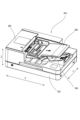
実施例1に係るシート排出装置を備えた画像読取装置及びこの画像読取装置を備えた画像形成装置について説明する。図1は本実施例の画像読取装置201を備えた画像形成装置200の概略図である。
The following describes an image reading device equipped with a sheet discharge device according to the first embodiment, and an image forming device equipped with this image reading device. Figure 1 is a schematic diagram of an
(画像形成装置)
画像形成装置200は、電子写真方式の複合機である。この画像形成装置200は、画像形成装置の一例に過ぎず、画像読取装置201を備えたファクシミリ装置や複合機も、本技術を適用可能な画像形成装置に含まれる。また、画像形成装置に搭載される画像形成手段は電子写真方式に限らず、例えばインクジェット方式の印刷ユニットを搭載したものであってもよい。
(Image forming apparatus)
The
図1に示すように、画像形成装置200は、画像形成装置本体202と、画像形成装置本体202の上部に装着される画像読取装置201とで構成される。画像形成装置本体202は、その略中央部に画像形成手段としての画像形成部3が配置され、その下方に給送カセット6を含む、記録材Sを給送するための給送手段が位置している。記録材Sとしては、普通紙及び厚紙等の紙、プラスチックフィルム、布、コート紙のような表面処理が施されたシート材、封筒やインデックス紙等の特殊形状のシート材等、サイズ及び材質の異なる多様なシートを使用可能である。画像形成装置本体202の上方には、原稿の画像を読み取るための画像読取手段としてのイメージセンサ409、410を備えた画像読取装置201が配置されている。
As shown in FIG. 1, the
画像形成装置本体202において、画像形成部3は電子写真方式によるプリントエンジンとして構成されている。本実施例の画像形成部3はタンデム型中間転写方式の構成であり、4つの画像形成ユニット10Y,10M,10C,10Kと、中間転写体としての中間転写ベルト23と、を備えている。
In the image forming device
画像形成ユニット10Yは、電子写真プロセスによってイエローのトナー像を形成する。即ち、感光体である感光ドラム11が回転し、帯電装置12がドラム表面を一様に帯電させる。レーザスキャナ13は、画像情報に基づいて変調されたレーザ光を感光ドラム11に照射し、ドラム表面に静電潜像を書き込む。現像装置14は感光ドラム11に帯電したトナー粒子を供給し、ドラム表面の静電潜像をトナー像に現像する。このトナー像は、一次転写ローラ15によって中間転写ベルト23へと一次転写される。中間転写ベルト23へと転写されずに感光ドラム11に残留した転写残トナー等の付着物は、ドラムクリーナ16によって除去される。以上のプロセスは各画像形成ユニット10Y~10Kにおいて並行して進められ、イエロー・マゼンタ・シアン・ブラックの各色のトナー像が形成される。
The
中間転写ベルト23は、二次転写内ローラ18を含む複数のローラに巻回され、感光ドラム11の回転方向に沿った方向(図中時計回り方向)に回転駆動される。画像形成ユニット10Y~10Kにおいて形成された各色のトナー像は、互いに重なり合うように一次転写され、中間転写ベルト23の上にフルカラーのトナー像が形成される。このトナー像は、中間転写ベルト23の回転により、二次転写内ローラ18とこれに対向する二次転写ローラ19との間に形成される二次転写部に搬送される。
The
画像形成装置200は、記録材Sを給送するシート給送装置としてカセット給送部4及び手差し給送部5を備えている。カセット給送部4は複数の給送カセット6を有し、給送ユニット7によっていずれかの給送カセット6から記録材Sを1枚ずつレジストレーションローラ17へ向けて給送する。また、画像形成装置本体202の側部に設けられた手差し給送部5は、給送ユニット8によって1枚ずつレジストレーションローラ17へ向けて記録材Sを給送する。給送ユニット7,8は、給送カセット6又は手差しトレイから記録材Sを送り出す給送ローラ等の給送部材と、給送部材によって搬送される記録材Sに重なる他の記録材Sに摩擦力を付与して重送を防ぐ分離ローラ又は分離パッド等の分離部材とを含む。
The
レジストレーションローラ17は、画像形成部3によるトナー像の形成動作と同期を取って二次転写部に記録材Sを送り込む。二次転写部において中間転写ベルト23からトナー像を二次転写された記録材Sは、定着装置21に搬送される。定着装置21は、記録材Sを挟持して搬送しながらシート上のトナー像に熱及び圧力を付与することで、トナー像を記録材Sに定着させる。両面印刷の場合、定着装置21を通過した記録材Sは反転パス26に案内され、スイッチバック搬送によって第1面と第2面とが反転した状態で再び画像形成部3に給送され、第2面に画像を形成される。片面印刷の場合、及び両面印刷における第2面の画像形成が終了した場合、定着装置21を通過した記録材Sは排出ローラ25によって画像形成装置本体202から排出される。
The
なお、図1では画像を形成された記録材が画像形成装置本体202の側面に配置される排出トレイ(又は画像形成装置本体202に連結されるシート処理装置)に排出される構成となっている。これに代えて、鉛直方向における画像読取装置201と画像形成装置本体202との間に空間を設けて、画像形成装置本体202で画像形成された記録材を排出積載するための本体排出部を形成する、いわゆる胴内排出型の構成としてもよい。
In FIG. 1, the recording material on which an image has been formed is discharged to a discharge tray (or a sheet processing device connected to the image forming device body 202) arranged on the side of the image forming
(画像読取装置)
次に、図2及び図3を用いて、画像読取装置201の概略構成について説明する。図2は画像読取装置201の斜視図である。図3は画像読取装置201の断面図である。
(Image reading device)
Next, a schematic configuration of the
図2に示すように、画像読取装置201は、ADF300及びリーダー部301によって構成される。ADF300は、原稿を搬送しながらイメージセンサによって原稿上の画像を読み取る流し読み動作を行う際に、複数枚の原稿を分離しながら1枚ずつ給送する装置である。リーダー部301は、流し読み動作においてADF300によって搬送される移動原稿の画像を読み取り、又は書籍など厚みのあるものを含めて静止原稿の画像を読み取るための装置である。原稿としては、普通紙及び厚紙等の紙、プラスチックフィルム、布、コート紙のような表面処理が施されたシート材、封筒やインデックス紙等の特殊形状のシート材等、サイズ及び材質の異なる多様なシートを使用可能である。
As shown in FIG. 2, the
ADF300には、原稿を載置するための給送トレイ302と、画像の読み取りが終了した原稿を排出するための排出トレイ100が設けられている。リーダー部301はADF300の下方にあり、ADF300を開閉可能に支持している。なお、本実施例ではリーダー部301が画像形成装置本体202の上部に固定されているが、画像読取装置201を画像形成装置とは独立した装置として使用することも可能である。
The
以下、図2に示す通り、ユーザ側(画像形成装置の正面側)から見て、画像読取装置201の左右方向をX方向とする。X方向とは直交する画像読取装置201の前奥方向をY方向(原稿の主走査方向、原稿の幅方向)とする。また、X方向及びY方向の両方に直交する、画像読取装置201の上下方向をZ方向(通常の使用状態における鉛直方向)とする。ADF300は、給送トレイ302に載置された原稿をX方向における一方側(給送方向X1とする)に向かって給送し、X方向における他方側(本実施例のシート排出方向、以下、原稿排出方向X2とする)に向かって排出トレイ100に排出する。
As shown in FIG. 2, the left-right direction of the
次に、Y方向から見た画像読取装置201の断面図である図3を用いて、画像読取装置201の内部構造に関して説明する。ADF300は、シートを搬送する搬送手段としてピックアップローラ401、分離ローラ対402及び複数の搬送ローラ対(403~406)を備えている。ピックアップローラ401は、給送トレイ302に載置された原稿400の最上位の原稿に当接し、分離ローラ対402に向けて繰り出す。分離ローラ対402は、ピックアップローラ401から受け取った原稿400を1枚ずつ分離した状態で搬送する。
Next, the internal structure of the
複数の搬送ローラ対は、原稿400を順に受渡しながら、読取位置(イメージセンサ409、410による原稿の走査位置)を介して搬送する。このうち、引抜ローラ対403は、分離ローラ対402から原稿を引き抜くようにして搬送する。第1リードローラ対404及び第2リードローラ対405は、イメージセンサ409、410の読取位置を通過させながら原稿400を搬送すると共に、読取位置における原稿400の位置を安定させて読取精度の向上に寄与する。排出ローラ対406は、読取位置を通過した原稿400を受け取って排出トレイ100に排出する。
The multiple transport roller pairs sequentially deliver the original 400 while transporting it through the reading position (the position where the original is scanned by the
リーダー部301の内部には、第1の読取手段としてのイメージセンサ409が設けられている。ADF300で搬送される原稿400の第1面から画像を読み取る際は、イメージセンサ409は流し読みガラス407と対向する位置(図の位置)で停止する。原稿台ガラス408上に載置された静止原稿から画像を読み取る際は、イメージセンサ409はリーダー部301内部に設けられたレール上を、副走査方向であるX方向に移動することで画像を読み取る。
Inside the
さらに、ADF300の内部には、第2の読取手段としてのイメージセンサ410がリーダー部301のイメージセンサ409と対向する位置に設けられている。従って、ADF300によって搬送される原稿400からは、2つのイメージセンサ409、410を用いて原稿の両面から同時に画像を読み取ることが可能である。なお、イメージセンサ409、410としては、CMOS等の撮像素子と等倍光学系とをモジュール化したコンタクトイメージセンサ(CIS)、及び電荷結合素子(CCD)と縮小光学系とを組合せたCCD方式のイメージセンサのいずれも使用可能である。
In addition, inside the
このように、本実施例のシート排出装置であるADF300は、画像の読み取りが終了した原稿を、シートを排出する排出手段としての排出ローラ対406と、排出されたシートが積載される排出トレイ100と、を備えている。
As described above, the
(揺動ガイド)
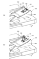
次に、本実施例のADF300に設けられた揺動ガイドについて、図4~図11を用いて説明する。図4はADF300に装着された揺動ガイド102の斜視図である。図5(a、b)は揺動ガイド102の表面及び裏面を示す斜視図である。図6は延長トレイ101の斜視図である。図7は揺動ガイド102及び延長トレイ101の断面図である。図8(a、b)は延長トレイ101に対する揺動ガイド102の取付け方法について説明するための断面図である。図9(a、b)及び図10(a、b)は、揺動ガイド102及び延長トレイ101の機能について説明するための図である。図11は揺動ガイド102と給送トレイ302の位置関係を説明するための図である。
(Swinging guide)
Next, the swing guide provided in the
図4に示すように、本実施例に係るADF300の排出トレイ100には、延長トレイ101が設けられている。延長トレイ101は、排出トレイ100に収納される収納位置と、排出トレイ100から原稿排出方向X2に突出する引出位置との間で、排出トレイ100に対してスライド可能である。延長トレイ101は、少なくとも引出位置にある状態で、排出ローラ対406によって排出された原稿の下面を排出トレイ100と共に支持することが可能である。即ち、排出トレイ100及び延長トレイ101は、本実施例のシート積載部を構成している。なお、本実施例の延長トレイ101は収納位置と引出位置のいずれかにある状態で使用することが想定されているが、3か所以上の使用位置の間で移動可能な構成としてもよい。
As shown in FIG. 4, the
延長トレイ101には、延長トレイ101に対して揺動可能な揺動部材としての揺動ガイド102が設けられている。揺動ガイド102は、原稿排出方向X2における原稿の先端に当接することで、排出ローラ対406から抜け出た原稿の原稿排出方向X2への移動を規制するストッパとしての機能を有する部材である。揺動ガイド102を設けることにより、排出ローラ対406による原稿の排出速度を高速化してADF300のスループット向上を可能としつつ、排出トレイ100における原稿の整合性が低下することを抑制可能となる。
The
揺動ガイド102は、延長トレイ101により揺動可能に支持されている。具体的に、揺動ガイド102は、延長トレイ101に対してZ方向上方側に突出する起立姿勢(図4、図9(a)、図10(a)の状態)と、起立姿勢に比べて下方に退避した倒伏姿勢(図9(b)、図10(b)の状態)との間で揺動可能である。起立姿勢にある揺動ガイド102は、シートに対する当接部(本実施例では後述の第2のリブ部506)によって原稿の原稿排出方向X2への移動を規制することが可能である。これに対し、倒伏姿勢にある揺動ガイド102は、当接部が起立姿勢に比べて下方に退避することで、原稿の移動を妨げない状態となる。揺動ガイド102の起立姿勢は本実施例の第1位置であり、倒伏姿勢は本実施例の第2位置である。
The
図4に示すように、排出トレイ100の上面には第1の開口部103が設けられている。第1開口部103は、排出トレイ100の原稿排出方向X2における下流端の一部が原稿排出方向X2の上流側に向かって凹んだ凹形状であり、Y方向に関して揺動ガイド102と対応する位置に設けられている。この第1の開口部103があることによって、延長トレイ101が収納位置にある図9(a、b)の状態で揺動ガイド102を起立姿勢と倒伏姿勢との間で揺動させることができる。図9(a、b)及び図10(a、b)の各状態における揺動ガイド102の機能については後述する。
As shown in FIG. 4, a
図5を用いて揺動ガイド102の詳細な構成を説明する。図5(a)は、揺動ガイド102を表側(揺動ガイド102のシートに対する当接部と同じ側)から見た斜視図である。図5(b)は、揺動ガイド102を裏側(揺動ガイド102のシートに対する当接部とは反対側、延長トレイ101に対向する側)から見た斜視図である。
The detailed configuration of the
揺動ガイド102は、揺動軸500、第1のリブ部502、第2のリブ部506、第1の面501、第2の面503、第3の面504、第4の面505及びスナップフィット形状510を有する。第1の面501、第2の面503、第3の面504、第4の面505の裏側にはそれぞれ背面511,513,514,515が設けられている。揺動ガイド102は、これらの各部を樹脂材料によって一体に成形したものを用いることができる。なお、揺動ガイド102は、Y方向における揺動ガイド102の中心位置を通るXZ面に関して実質的に対称な形状である。
The
揺動軸500は、延長トレイ101に組み付けられたときの姿勢でY方向に延びる略円柱状の部材である。揺動軸500,500が後述する延長トレイ101の軸受部に係合することで、揺動ガイド102は揺動軸500,500を通りY方向に延びる揺動軸線Y0を中心にして延長トレイ101に対して揺動する。つまり、揺動軸500は揺動軸線上に延びる軸部の例である。
The
以下、揺動軸線Y0を中心とする周方向のうち、揺動ガイド102が倒伏姿勢から起立姿勢に向かうときの揺動方向を第1揺動方向R1とし、揺動ガイド102が起立姿勢から倒伏姿勢に向かうときの揺動方向を第2揺動方向R2とする(図7参照)。
Hereinafter, the circumferential direction around the swing axis Y0 when the
第1のリブ部502,502は、第1の面501に対してY方向(前奥方向)の両側に設けられ、Y方向に対して略垂直に広がっている。揺動軸500,500は、両側の第1のリブ部502,502にそれぞれ設けられ、第1のリブ部502,502からY方向の外側に突出している。
The
第1の面501、第2の面503、第3の面504及び第4の面505は、この順で揺動軸線Y0から遠ざかるように配置されている。つまり、揺動ガイド102が第2位置にあるとき、原稿排出方向X2の上流から下流に向かって第1の面501、第2の面503、第3の面504、第4の面505の順に並ぶように配置されている。第2の面503と第3の面504、及び第3の面504と第4の面505は、原稿排出方向X2に隣接している。
The
第2のリブ部506,506は、第2の面503、第3の面504及び第4の面505に対してY方向(画像読取装置の前奥方向)の両側に設けられ、Y方向に対して略垂直に広がっている。揺動ガイド102が起立姿勢にある状態で原稿排出方向X2における揺動ガイド102の上流側の面を構成している(図7参照)。従って、第2のリブ部506,506は、原稿排出方向X2における原稿の先端に当接可能な本実施例の当接部として機能する。
The
そして、第2の面503、第3の面504、第4の面505及び第2のリブ部506,506によって第1の凹部519が形成されている。第1の凹部519は、揺動ガイド102が倒伏姿勢にある状態で、シートに対する当接部である第2のリブ部506,506の上端よりもZ方向で下方に凹んだ形状である。言い換えると、第1の凹部519は、2のリブ部506,506に対して、揺動ガイド102が起立姿勢から倒伏姿勢に向かうときの揺動方向(第2揺動方向R2)の下流側に凹んだ形状である。
The
この第1の凹部519は、揺動ガイド102が倒伏姿勢にある状態で、図9(a)に示す収納位置にある延長トレイ101を図10(a)に示す引出位置に引き出す際にユーザが指を掛けることが可能な指掛け部として機能する。特に、揺動ガイド102が倒伏姿勢にあるときに原稿排出方向X2に関して上流側を向く第3の面504は、ユーザの指が引出方向である原稿排出方向X2に揺動ガイド102を押圧する力を受ける押圧面となる。
This
さらに、第3の面504よりも原稿排出方向X2で下流側の第4の面505には、ユーザが第1の凹部519に指を掛けた際の滑り止め用の凹凸形状として機能する滑り止めリブ507が設けられている。滑り止めリブ507は、Y方向に見て第2のリブ部506から突出しないような高さで第4の面505から突出している(図7参照)。滑り止めリブ507は複数本設けられ、それぞれY方向に延びている。なお、滑り止めリブ507は滑り止めとして機能する凹凸形状の一例であり、例えば第4の面505に半球状の突起を格子状に配置したものを滑り止め用の凹凸形状としてもよい。
Furthermore, the
ここで、揺動軸500,500は、揺動ガイド102が倒伏姿勢にある状態で原稿排出方向X2における揺動ガイド102の上流側の端部に位置している。つまり、本実施例の揺動ガイド102が第2位置にあるとき、シートに対する当接部としての第2のリブ部506,506は揺動軸線Y0に対してシート排出方向の下流側に位置している。従って、揺動ガイド102は、揺動軸線Y0よりも原稿排出方向X2の下流にある第2のリブ部506,506が上方に向かって移動するようにして倒伏姿勢から起立姿勢に切り替わる。
The
言い換えると、揺動ガイド102が起立姿勢にある場合に、Y方向から見て第2のリブ部506が延びる方向の水平面に対する傾斜角度(図7のθ1)は、揺動ガイド102が倒伏姿勢にある場合の傾斜角度(図7のθ2)に比べて大きい。ただし、θ1、θ2は、原稿排出方向X2の下流に向かう直線を基準として、図中反時計回りの角度を表す。揺動ガイド102に原稿の先端に当接して原稿の整合性を維持する機能を持たせるためには、起立姿勢における傾斜角度θ1を例えば45度以上、より好ましくは60度以上とすると好適である。一方、揺動ガイド102が給送トレイ302のように排出トレイ100の上方の部材に干渉し、又はそのような部材に距離が近いことで揺動ガイド102の操作性が損なわれないようにするには、起立姿勢における傾斜角度θ1を90度以下とすると好適である。
In other words, when the
揺動ガイド102の原稿に対する当接部とは反対側には、揺動ガイド102を起立姿勢に保持する姿勢保持手段としてのスナップフィット形状510が設けられている。ただし、「当接部とは反対側」とは、揺動ガイド102のうち、起立姿勢において原稿排出方向X2における下流側を向いた側面を指す。つまり、当接部としての第2のリブ部506,506は、揺動ガイド102のうち、倒伏姿勢から起立姿勢に向かう第1揺動方向R1の面を構成している。また、係合部としてのスナップフィット形状510は、揺動ガイド102のうち、起立姿勢から倒伏姿勢に向かう第2揺動方向R2の面に設けられている。さらに言い換えると、スナップフィット形状510は、揺動ガイド102のうち延長トレイ101に対向する面に設けられている。
On the opposite side of the contact portion of the
本実施例のスナップフィット形状510は、第2の面503の背面513から第2揺動方向R2の下流側に突出する突起部であり、弾性変形可能な材料で形成されている。後述するように、スナップフィット形状510は、延長トレイ101に設けられた開口部の周縁部に係合することで揺動ガイド102の起立姿勢を保持するように構成されている。
The snap-
次に、図6~図8を用いて、延長トレイ101の詳細な構成及び延長トレイ101に対する揺動ガイド102の組み付け方法を説明する。
Next, the detailed configuration of the
図6に示すように、延長トレイ101には、軸受部600,600と、第2の開口部601と、凸形状603が設けられている。軸受部600,600は、揺動ガイド102の揺動軸500,500に係合し、揺動ガイド102を揺動軸線Y0を中心として揺動可能(回転可能)に支持する部分である。第2の開口部601は、原稿排出方向X2において軸受部600,600の下流に位置する。第2の開口部601は、揺動ガイド102が倒伏姿勢にある場合にスナップフィット形状510を受け入れて延長トレイ101との干渉を回避するための空間として機能する。
As shown in FIG. 6, the
そして、図7に示すように揺動ガイド102が起立姿勢にあるとき、スナップフィット形状510は、原稿排出方向X2における第2の開口部601の下流側の周縁部に設けられた受け部602に当接する。起立姿勢にある揺動ガイド102に第2揺動方向R2の力が作用した場合、受け部602がスナップフィット形状510を受け止めることで、揺動ガイド102の第2揺動方向R2への回動が規制される。つまり、被係合部としての受け部602は、係合部としてのスナップフィット形状510に係合されることにより、揺動部材である揺動ガイド102の揺動が規制されるように構成されている。
When the
起立姿勢にある揺動ガイド102が所定の閾値以上の力で第2揺動方向R2の力を受けると、スナップフィット形状510が弾性変形して受け部602から第2の開口部601の内側に離脱する。これにより、揺動ガイド102の第2揺動方向R2への揺動が許容されるため、揺動ガイド102は起立姿勢から倒伏姿勢に切り替わる。所定の閾値とは、第2のリブ部506に排出ローラ対406から排出された原稿が突き当たった際に揺動ガイド102が受ける力の想定値より大きく、かつ、ユーザが指で押圧することで実現できる程度に小さい値である。
When the
なお、ここでは係合部としてのスナップフィット形状510が突起部であり、被係合部としての受け部602が突起部を受け入れる開口部の周縁部に設けられている構成を説明した。しかし、延長トレイ101に被係合部としてのスナップフィット形状(突起部)を設け、揺動ガイド102に係合部としての受け部602を配置したものも、揺動ガイド102を起立姿勢に保持する機構として成立する。ただし、その場合、揺動ガイド102を倒伏姿勢とした場合にスナップフィット形状が揺動ガイド102より上方に突出しない構成とすることが望ましい。その他、揺動部材の姿勢を保持するために係合部と被係合部が係合する機構としては、弾性変形可能なスナップフィット形状以外のものを用いても構わない。
Here, the snap-
原稿排出方向X2における第2の開口部601の上流側の周縁部には、揺動規制部700が設けられている。揺動規制部700は、揺動ガイド102が起立姿勢にある場合に、第1のリブ部502,502に対して所定のクリアランスを挟んで対向するように配置された面(図7参照)である。揺動規制部700は、揺動ガイド102が起立姿勢からさらに第1揺動方向R1に揺動しようとした場合に第1のリブ部502,502に当接し、揺動ガイド102の揺動を規制する第2の規制部として機能する。
A
凸形状603は、第2の開口部601よりも原稿排出方向X2における下流側においてZ方向の上方側に向かって突出している。凸形状603の天面604は、揺動ガイド102が倒伏姿勢にあるときに第4の面505の背面515(図5(b))に当接する面である。揺動ガイド102の第4の面505の背面515が凸形状603の天面604に当接することで、揺動ガイド102は自重によって倒伏姿勢を維持する。つまり、凸形状603の天面604は、揺動ガイド102が倒伏姿勢からさらに第2揺動方向R2に揺動しようとすることを規制する第1の規制部として機能する。
The
さらに、凸形状603には、ユーザが倒伏姿勢にある揺動ガイド102を起立姿勢に起こす際に揺動ガイド102に指を掛けることを容易にするための第2の凹部605が形成されている。第2の凹部605は、Y方向における凸形状603の一部において、凸形状603の原稿排出方向X2における下流端が上流側に凹んだ凹形状である。揺動ガイド102が倒伏姿勢にあるとき、第4の面505の背面515の少なくとも一部が第2の凹部605の内側に露出する位置関係となっている。そのため、ユーザは第2の凹部605を介して指を下方から背面515に当てて揺動ガイド102を起立させることができる。
Furthermore, the
図8(a、b)は、延長トレイ101に対して揺動ガイド102を組み付ける際の様子を表している。揺動ガイド102を組み付ける際、第2の開口部601を通して揺動軸500,500を下方に移動させた後、原稿排出方向X2の上流側に移動させ、さらに上方に移動させることで、揺動軸500,500を軸受部600,600に嵌合させる。図8(a)における矢印Pは、このような組み込み動作における揺動軸500の移動軌跡の一例を表している。
Figures 8(a) and 8(b) show the state when the
ここで、各軸受部600は下方に向かって開放された形状となっており、組み付け状態における揺動軸500の位置よりも下方に、揺動軸500の脱落を防ぐ脱落防止手段としての突起形状800,800が設けられている。突起形状800,800は組み込み動作における揺動軸500の移動軌跡を挟んで配置され、揺動軸500が軸受部600に向かって通過可能な連通部を形成している。また、突起形状800,800の開口の幅(突起形状800,800の間の最小の間隔)は、揺動軸500の外径よりも若干小さく設定されている。そのため、軸受部600に揺動軸500を嵌合させる際には、軽圧入のようにして揺動軸500に突起形状800,800を通過させて嵌め込むことになる。軸受部600に嵌合した揺動軸500は、突起形状800,800によって軸受部600から下方に脱落することを阻止される。
Here, each bearing
(揺動ガイドの使用方法)
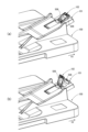
図9(a、b)及び図10(a、b)を用いて、揺動ガイド102及び延長トレイ101が取り得る状態と、各状態における揺動ガイド102の機能について説明する。
(How to use the swing guide)
9(a) and 9(b) and 10(a) and 10(b), possible states of the
図9(a)は、延長トレイ101が収納位置にあり、かつ、揺動ガイド102が倒伏姿勢にある状態(第1の状態)を表している。この状態では、揺動ガイド102の第2のリブ部506,506は排出トレイ100の上面よりも下方に位置する。具体的には、排出トレイ100には、Y方向に関して揺動ガイド102の両側、かつ、原稿排出方向X2に関して揺動ガイド102と重複する範囲においてシートの下面を支持するリブ100r,100rが設けられている。図9(a)の状態においてY方向から見たとき、揺動ガイド102の第2のリブ部506,506はリブ100r,100rの上面より下方に退避している。そのため、揺動ガイド102は、排出トレイ100に排出された原稿の原稿排出方向X2への移動を妨げない。
9A shows a state (first state) in which the
図9(b)は、延長トレイ101が収納位置にあり、かつ、揺動ガイド102が起立姿勢にある状態(第2の状態)を表している。この状態では、揺動ガイド102の第2のリブ部506,506の少なくとも一部が、排出トレイ100及び延長トレイ101の上面よりも上方に突出している。また、水平面に対する第2のリブ部506,506の傾斜角度(図7のθ1)は、倒伏姿勢における角度(図7のθ2)よりも垂直に近くなっている。そのため、揺動ガイド102は、排出ローラ対406によって原稿排出方向X2に排出される原稿の先端を第2のリブ部506,506で受け止めて原稿排出方向X2への移動を規制することが可能である。これにより、排出ローラ対406による原稿の排出速度が速い場合であっても、排出トレイ100における原稿の整合性を維持することができる。
9B shows a state (second state) in which the
ここで、図9(a)に示す第1の状態において、Z方向の上方側から見て、排出トレイ100に設けられた第1の開口部103を介して揺動ガイド102の略全体が露出している。そのため、延長トレイ101が収納位置に位置決めされた状態のままで、揺動ガイド102を起立姿勢(図9(a))と倒伏姿勢(図9(b))との間で姿勢変更することが可能である。
Here, in the first state shown in FIG. 9(a), when viewed from above in the Z direction, substantially the entire
図10(a)は、延長トレイ101が引出位置にあり、かつ、揺動ガイド102が倒伏姿勢にある状態(第3の状態)を表している。この状態では、揺動ガイド102の第2のリブ部506,506は延長トレイ101の上面より上方に突出しているが、水平面に対する第2のリブ部506,506の傾斜角度は比較的小さく抑えられている。そのため、揺動ガイド102は、排出トレイ100に排出された原稿の原稿排出方向X2への移動を妨げない。また、揺動ガイド102は、排出トレイ100よりも原稿排出方向X2の下流側で原稿の下面を支持することが可能である。
Figure 10 (a) shows a state (third state) in which the
図10(b)は、延長トレイ101が引出位置にあり、かつ、揺動ガイド102が起立姿勢にある状態(第4の状態)を表している。この状態では、揺動ガイド102の第2のリブ部506,506の少なくとも一部が、延長トレイ101の上面よりも上方に突出している。また、水平面に対する第2のリブ部506,506の傾斜角度(図7のθ1)は、倒伏姿勢における角度(図7のθ2)よりも垂直に近くなっている。そのため、揺動ガイド102は、排出ローラ対406によって原稿排出方向X2に排出される原稿の先端を第2のリブ部506,506で受け止めて原稿排出方向X2への移動を規制することが可能である。これにより、排出ローラ対406による原稿の排出速度が速い場合であっても、排出トレイ100における原稿の整合性を維持することができる。
Figure 10 (b) shows a state (fourth state) in which the
本実施例において、搬送方向の長さがA4Rサイズ以下の原稿を扱う場合は延長トレイ101を収納位置とし、搬送方向の長さがA4Rサイズより長い原稿(例えばリーガルサイズ)を扱う場合は延長トレイ101を引出位置とするように設定されている。ただし、原稿サイズに関する「R」の表記は、原稿の長辺と短辺のうち、長辺が搬送方向に延び、短辺が搬送方向と直交した方向に延びる向きで給送トレイ302にセットされた原稿であることを表している。
In this embodiment, when handling documents whose length in the transport direction is A4R size or less, the
このように、本実施例では、延長トレイ101を複数の位置の間で移動可能な構成において、少なくとも2つの位置において揺動ガイド102を起立姿勢とすることが可能である(図9(b)及び図10(b))。これにより、搬送方向の長さが異なる複数サイズの原稿の先端を揺動ガイド102によって規制して排出トレイ100における整合性を保つことができる。
In this way, in this embodiment, in a configuration in which the
なお、延長トレイ101が収納位置にあり、かつ、揺動ガイド102が倒伏姿勢にある図9(a)の状態では、鉛直方向上方から見て揺動ガイド102が排出トレイ100の内側に収納され、排出トレイ100から原稿排出方向X2の下流に突出しない。そのため、延長トレイ101及び揺動ガイド102の両方を使用しないときは、図9(a)の状態とすることでX方向に関する画像読取装置201の占有幅を抑えることができる。
When the
延長トレイ101が収納位置にある状態でも揺動ガイド102が十分に原稿の先端を規制可能となるように、排出トレイ100に対する第2のリブ部506の突出量を確保することが望ましい。例えば、延長トレイ101が収納位置にあり、揺動ガイド102が起立位置にある状態で、Y方向から見て第2のリブ部506の上端部から鉛直方向下方に引いた線分が排出トレイ100又は延長トレイ101と最初に交差する点までの長さを第1の突出量とする。また、延長トレイ101が引出位置にあり、揺動ガイド102が起立位置にある状態で、Y方向から見て第2のリブ部506の上端部から鉛直方向下方に引いた線分が延長トレイ101と交差する点までの長さを第2の突出量とする。このとき、例えば第1の突出量が第2の突出量の2分の1以上であれば、延長トレイ101が収納位置にある状態でも揺動ガイド102により原稿の先端を規制する機能を期待しやすい。また、例えば第1の突出量及び第2の突出量のいずれもが10mm以上であると好適である。
It is desirable to ensure that the
(給送トレイとの位置関係)
次に、図11を用いて、揺動ガイド102の揺動方向とその利点について説明する。上述した通り、揺動ガイド102は、倒伏姿勢において揺動軸線Y0に対して原稿排出方向の下流側に延びた状態となっている。そのため、揺動ガイド102を倒伏姿勢から起立姿勢に起こすときは、図11に示すように、揺動ガイド102をZ方向で上方かつ原稿排出方向X2の上流側に向かって移動させるように図中反時計回りの第1揺動方向R1に揺動させることになる。そして、揺動ガイド102が起立姿勢になると、揺動ガイド102のシートに対する当接部とは反対側に設けられたスナップフィット形状510が延長トレイ101の受け部602に当接することで、揺動ガイド102が起立姿勢に維持される。
(Positional relationship with the feeding tray)
Next, the swing direction of the
この構成では、揺動ガイド102の上方に給送トレイ302のような他の部材があったとしても、揺動ガイド102を倒伏姿勢と起立姿勢との間で揺動させる際に他の部材と干渉することを回避可能である。従って、狭い空間でも揺動ガイド102の姿勢を変更する操作を容易に行うことができる。
近年、画像読取装置にはより高いスループットが求められており、これに応えるためにシートの排出速度も高速化される傾向がある。そこで、シート積載部の上方に突出可能な揺動部材によってシートの排出方向への移動を規制してシート積載部におけるシートの整合性を保つことが検討された。
しかしながら、前述の特許文献1における回動トレイの回動構成では、回動軸線よりもシート排出方向の上流側に収納されている状態からシート排出方向の下流に突出する構成となっていた。そのため、回動トレイを回動させるために比較的大きな空間が必要であった。そして、例えば排出トレイの上方に位置する給送トレイを避けるために延長トレイを引き出した後でなければ回動トレイを回動させることができない等、操作性の改善が望まれていた。
In this configuration, even if there is another member such as the
In recent years, there has been a demand for higher throughput in image reading devices, and in order to meet this demand, there is a trend for the sheet discharge speed to be increased. Therefore, a study has been conducted on a method for maintaining the alignment of the sheets in the sheet stacking section by restricting the movement of the sheets in the discharge direction using a swinging member that can protrude above the sheet stacking section.
However, in the rotation configuration of the rotating tray in the above-mentioned
本実施例に対する代替構成として、揺動ガイド102が倒伏姿勢において揺動軸線Y0よりも原稿排出方向X2の上流側に延びており、揺動ガイド102を図中時計回りに揺動させることで図11と同じ角度の起立姿勢まで揺動可能とすることが考えられる。しかしながら、この代替構成では、揺動ガイド102を倒伏姿勢から起立姿勢まで揺動させるときの軌跡の最高点が、本実施例に比べて高くなる。その結果、給送トレイ302のように排出トレイ100の上方に位置する部材によって揺動ガイド102の操作が難しくなる懸念がある。これを回避するために給送トレイ302を上方に退避させた状態で揺動ガイド102を揺動させることにすると、揺動ガイド102の操作自体は容易になったとしても、給送トレイ302を退避させる手順が増えるため操作性の向上にはつながらない。
As an alternative configuration to this embodiment, it is possible to consider a configuration in which the
これに対し、本実施例の場合、延長トレイ101が収納位置にあるか引出位置にあるかに関わらず、ユーザは倒伏姿勢にある揺動ガイド102に指を掛けて上方に押圧する1動作によって揺動ガイド102を起立姿勢とすることができる。つまり、延長トレイ101を収納位置から引き出すことで揺動ガイド102の上方の空間を確保したり、給送トレイ302を上方に持ち上げることで揺動ガイド102の上方の空間を確保したりする必要はない点で、操作性の向上が可能である。
In contrast, in the present embodiment, regardless of whether the
本実施例の構成は、揺動ガイド102の揺動半径r1(揺動軸線Y0から、揺動ガイド102の揺動軸線Y0から遠い側の端部までの距離)が、揺動軸線Y0と給送トレイ302との間の最小の距離(図11のd1)よりも小さい場合に好適に適用できる。起立姿勢において第2のリブ部506が排出トレイ100及び延長トレイ101よりも上方に突出する突出量を確保しようとすると、揺動ガイド102の長さ、つまり揺動軌跡の半径は大きくなる。一方、画像読取装置201の高さ方向の小型化を図るためには、排出トレイ100と給送トレイ302をZ方向に可能な限り接近させることが好ましい。その結果、図11に示すように、揺動ガイド102の揺動半径r1が、揺動軸線Y0と給送トレイ302との間の最小距離d1よりも小さくなる場合がある。本実施例の構成によれば、このような配置関係の下であっても、揺動ガイド102を給送トレイ302に干渉することなく姿勢変更することが可能である。
The configuration of this embodiment can be suitably applied when the swing radius r1 of the swing guide 102 (the distance from the swing axis Y0 to the end of the
また、本実施例に対する他の代替構成として、揺動ガイド102の原稿に対する当接部と同じ側に、スナップフィット形状510のように揺動ガイド102の姿勢を保持するための係合部を配置することが考えられる。この代替構成は、当接部の機能を妨げないように係合部を配置することが問題となり得るところ、本実施例では、当接部とは反対側にスナップフィット形状510を配置する簡単な構成によって揺動ガイド102の姿勢を保持することが可能となっている。
As another alternative configuration to this embodiment, it is possible to arrange an engagement portion for maintaining the posture of the
なお、当接部と同じ側に係合部を配置する場合、当接部が原稿の先端を規制する機能を妨げないように、係合部を揺動軸線Y0の付近に配置することが考えられる。しかし、係合部が揺動軸線Y0の近くにあるほど、てこの原理により、揺動ガイド102の揺動を規制する際に係合部と被係合部との接触部に作用する力は大きくなる。従って、揺動ガイド102の揺動を十分に規制するためには、係合部及び被係合部の強度を確保する必要が生じてコスト増につながりやすく、また、姿勢変更の際に係合部が被係合部と強く擦れて摩耗が進む懸念がある。これに対し、本実施例では揺動軸線Y0から比較的離れた位置にスナップフィット形状510を配置することができ、例えば比較的小さなスナップフィット形状510を用いて揺動ガイド102の揺動を十分に規制することができる。
When the engaging portion is disposed on the same side as the abutting portion, it is possible to dispose the engaging portion near the swing axis Y0 so that the abutting portion does not interfere with the function of restricting the leading edge of the document. However, the closer the engaging portion is to the swing axis Y0, the greater the force acting on the contact portion between the engaging portion and the engaged portion when restricting the swing of the
(変形例)
上記の実施例1では、排出トレイ100に対して移動可能な延長トレイ101に揺動ガイド102が設けられた構成を例示したが、シート積載部が延長トレイ101を含まない構成に本技術を適用してもよい。例えば、排出トレイ100に本実施例の軸受部600、第2の開口部601、受け部602及び凸形状603等と同等の構成を設けて、本実施例において延長トレイ101が収納位置にある場合と同じ位置に揺動ガイド102が組み付けられるようにする。
(Modification)
In the above-described first embodiment, a configuration in which the
また、上記の実施例1では、揺動部材が設けられるシート積載部の上方に位置する部材として給送トレイ302を例示したが、本技術は、シート積載部の上方にある部材の如何によらず適用可能である。例えば、シート積載部の上方に他のシート積載部がある構成においても、本技術は狭い空間で揺動部材の姿勢を変更することを可能とする。また、シート積載部の上方に常に他の部材が存在する構成には限定されない。
In addition, in the
次に図12~図14を用いて、実施例2に係る揺動ガイド102Aの構成について説明する。本実施例は、揺動ガイド102Aの揺動軸が可撓性のある腕部に取り付けられており、腕部の弾性を利用して延長トレイに揺動ガイドが組み付けられる点で実施例1の揺動ガイド102と異なっている。以下、実施例1と共通の参照符号を付したものは、実施例1と実質的に同様の機能を有するものとして説明する。
Next, the configuration of the
図12(a)は本実施例における揺動ガイド102Aを表側から見た斜視図であり、図12(b)は揺動ガイド102Aを裏側から見た斜視図である。揺動ガイド102Aは、揺動軸500、リブ部506A、第1の面501、第2の面503、第3の面504、第4の面505及びスナップフィット形状510を有する。第1の面501、第2の面503、第3の面504、第4の面505の裏側にはそれぞれ背面511,513,514,515が設けられている。また、リブ部506A,506Aは、実施例1における第2のリブ部506,506と同様にY方向における揺動ガイド102Aの両側に設けられており、原稿に対する当接部として機能する。
Figure 12(a) is a perspective view of the
ここで、揺動ガイド102Aは、揺動軸線Y0に交差する方向に延びる腕部520,520を有し、揺動軸500,500は腕部520,520に設けられている。本実施例の腕部520,520は、Y方向から見てリブ部506A,506Aと略同方向に延びている。また、揺動ガイド102Aは、少なくとも腕部520,520をABS(アクリロニトリル・ブタジエン・スチレンの共重合体からなる樹脂)やPC+ABS(ポリカーボネートとABS樹脂のアロイ樹脂)などの樹脂材料によって成形される。また、腕部520,520と第2の面503との間にはスリット521,521が入っており、腕部520,520をユーザが手でY方向の内側に撓ませることができる程度の剛性に設定されている。
Here, the
図13は、本実施例の延長トレイ101を示す斜視図である。延長トレイ101には、軸受部600A,600Aと、第2の開口部601Aと、凸形状603とが設けられている。軸受部600A,600Aは、揺動ガイド102Aの揺動軸500,500に係合し、揺動ガイド102を揺動軸線Y0を中心として揺動可能(回動可能)に支持する部分である。第2の開口部601Aは、原稿排出方向X2において軸受部600,600の下流に位置する。第2の開口部601Aは、揺動ガイド102が倒伏姿勢にある場合にスナップフィット形状510を受け入れて延長トレイ101との干渉を回避するための空間として機能する。
Figure 13 is a perspective view showing the
ただし、本実施例における揺動ガイド102Aは、腕部520,520を撓ませた状態で、各揺動軸500が対応する軸受部600Aに対向する位置まで移動させた後、腕部520を解放することで各揺動軸500が軸受部600Aに嵌合する構成となっている。これに合わせて、軸受部600A,600Aは、Y方向の内側に開口する穴形状として形成され、Z方向の下方側が閉じられている。また、第2の開口部601Aは、実施例1における第1の開口部601(図6参照)に比べて小さく、揺動軸500,500が通過できない大きさに設定される。
However, in the present embodiment, the
図14は、延長トレイ101に組み付けられた状態の揺動ガイド102Aを示す斜視図である。延長トレイ101に組み付けられた後の揺動ガイド102Aの動作や機能は実施例1と同様であるため説明を省略する。従って、本実施例の揺動ガイド102Aを用いる場合も、実施例1と同様に狭い空間でも容易に揺動ガイドの姿勢を変更することが可能である。
Figure 14 is a perspective view showing the
(その他の実施形態)
上記の各実施例では、画像形成装置本体202の上部に取り付けられる画像読取装置201に本技術を適用した構成例を例示したが、画像形成装置とは独立した画像読取装置に本技術を適用してもよい。また、本技術は、画像読取装置を構成するADF以外のシート排出装置(例えば、画像形成装置において画像形成済みの記録材を排出する装置)にも適用可能である。
Other Embodiments
In the above embodiments, the present technology is applied to the
本開示には、少なくとも以下の各構成が含まれる。 This disclosure includes at least the following configurations:
(構成1)
シートをシート排出方向に排出する排出手段と、
前記排出手段によって排出されたシートが積載されるシート積載部と、
前記排出手段によって排出されるシートに当接可能な当接部を有し、前記排出手段によって排出されるシートの前記シート排出方向への移動を前記当接部によって規制する第1位置と、前記第1位置に比べて前記当接部が下方に移動した第2位置との間で揺動する揺動部材であって、前記第2位置にある状態で前記当接部よりも前記シート排出方向の上流に位置する揺動軸線を中心に揺動する揺動部材と、
前記シート積載部に設けられた被係合部と、
前記揺動部材の前記当接部とは反対側の面に設けられ、前記揺動部材が前記第1位置にある状態で、前記被係合部に係合することで前記揺動部材の前記第1位置から前記第2位置への揺動が規制されるように構成された係合部と、を備える、
ことを特徴とするシート排出装置。
(Configuration 1)
a discharge means for discharging the sheet in a sheet discharge direction;
a sheet stacking section on which the sheets discharged by the discharge means are stacked;
a swinging member having a contact portion capable of contacting a sheet discharged by the discharge means, the swinging member swinging between a first position where the contact portion restricts movement of the sheet discharged by the discharge means in the sheet discharge direction and a second position where the contact portion has moved downward compared to the first position, the swinging member swinging about a swing axis located upstream of the contact portion in the sheet discharge direction when in the second position;
an engaged portion provided on the sheet stacking portion;
an engaging portion provided on a surface of the swinging member opposite to the abutting portion, the engaging portion being configured to engage with the engaged portion when the swinging member is in the first position to restrict the swinging of the swinging member from the first position to the second position;
A sheet discharging device comprising:
(構成2)
前記シート積載部は、排出トレイと、前記排出トレイと共にシートを支持する延長トレイであって、前記排出トレイに収納される収納位置、及び、前記排出トレイから前記シート排出方向の下流に突出した引出位置の間で前記排出トレイに対して移動する延長トレイと、を含み、
前記揺動部材は、前記延長トレイによって揺動可能に支持され、
前記被係合部は、前記延長トレイに設けられている、
ことを特徴とする構成1に記載のシート排出装置。
(Configuration 2)
the sheet stacking unit includes a discharge tray and an extension tray that supports sheets together with the discharge tray, the extension tray moving relative to the discharge tray between a storage position where the extension tray is stored in the discharge tray and a pull-out position where the extension tray protrudes downstream in the sheet discharge direction from the discharge tray;
The swinging member is swingably supported by the extension tray,
The engaged portion is provided on the extension tray.
2. The sheet ejection device according to
(構成3)
前記排出トレイには、前記延長トレイが前記収納位置にある状態で前記揺動部材が前記第1位置と前記第2位置との間で揺動することを許容する第1の開口部が設けられている、
ことを特徴とする構成2に記載のシート排出装置。
(Configuration 3)
The ejection tray is provided with a first opening that allows the swinging member to swing between the first position and the second position when the extension tray is in the storage position.
3. The sheet ejection device according to configuration 2.
(構成4)
前記第1の開口部は、鉛直方向から見て、前記シート排出方向における前記排出トレイの下流端の一部が前記シート排出方向の上流側に凹んだ凹形状である、
ことを特徴とする構成3に記載のシート排出装置。
(Configuration 4)
the first opening has a concave shape in which a part of a downstream end of the discharge tray in the sheet discharge direction is concave toward the upstream side in the sheet discharge direction when viewed in a vertical direction;
4. The sheet ejection device according to configuration 3.
(構成5)
前記揺動部材の前記揺動軸線の方向から見たとき、前記延長トレイが前記収納位置にあり、前記揺動部材が前記第1位置にある場合に、前記当接部は前記排出トレイ及び前記延長トレイに対して第1の突出量で突出し、前記延長トレイが前記引出位置にあり、前記揺動部材が前記第1位置にある場合に、前記当接部は前記延長トレイに対して第2の突出量で突出し、
前記第1の突出量は前記第2の突出量の2分の1以上である、
ことを特徴とする構成3又は4に記載のシート排出装置。
(Configuration 5)
when viewed from the direction of the swing axis of the swing member, when the extension tray is in the storage position and the swing member is in the first position, the contact portion protrudes with respect to the discharge tray and the extension tray by a first protrusion amount, and when the extension tray is in the pull-out position and the swing member is in the first position, the contact portion protrudes with respect to the extension tray by a second protrusion amount,
The first protrusion amount is equal to or greater than half of the second protrusion amount.
5. The sheet ejection device according to claim 3 or 4.
(構成6)
前記揺動部材の前記揺動軸線は、前記シート排出方向における前記延長トレイの下流端よりも上流に設けられ、
前記延長トレイが前記収納位置にあり、前記揺動部材が前記第2位置にあるとき、鉛直方向から見て前記揺動部材は前記排出トレイの内側に位置する、
ことを特徴とする構成2乃至5のいずれか1つに記載のシート排出装置。
(Configuration 6)
the pivot axis of the pivot member is provided upstream of a downstream end of the extension tray in the sheet discharge direction,
When the extension tray is in the storage position and the swinging member is in the second position, the swinging member is located inside the discharge tray when viewed in a vertical direction.
6. The sheet ejection device according to any one of configurations 2 to 5.
(構成7)
前記揺動部材の前記当接部と同じ側の面には、前記揺動部材が前記第2位置にある状態で前記当接部に比べて下方に凹んだ第1の凹部が設けられ、
前記第1の凹部は、前記揺動部材が前記第2位置にある状態で前記シート排出方向の下流に押圧されることで前記延長トレイが前記収納位置から前記引出位置にスライドするように構成されている、
ことを特徴とする構成2乃至6のいずれか1つに記載のシート排出装置。
(Configuration 7)
a first recess that is recessed downward compared to the abutment portion when the swing member is in the second position is provided on a surface of the swing member on the same side as the abutment portion,
the first recess is configured to be pressed downstream in the sheet discharge direction when the swinging member is in the second position, thereby causing the extension tray to slide from the storage position to the pulled-out position.
7. The sheet ejection device according to any one of configurations 2 to 6.
(構成8)
前記揺動部材は、前記揺動部材が前記第2位置にある状態で前記シート排出方向における前記第1の凹部の下流側に、滑り止め用の凹凸形状を有している、
ことを特徴とする構成7に記載のシート排出装置。
(Configuration 8)
the rocking member has a non-slip concave/convex shape on the downstream side of the first concave portion in the sheet discharge direction when the rocking member is in the second position;
8. The sheet ejection device according to configuration 7.
(構成9)
前記係合部は、前記揺動部材の前記当接部とは反対側の面から、前記第1位置から前記第2位置へ向かう揺動方向の下流側に向かって突出する突起部である、
ことを特徴とする構成1乃至8のいずれか1つに記載のシート排出装置。
(Configuration 9)
the engaging portion is a protruding portion protruding from a surface of the pivot member opposite to the abutting portion toward a downstream side in a pivot direction from the first position to the second position,
9. The sheet ejection device according to any one of
(構成10)
前記シート積載部には、前記揺動部材が前記第2位置にある場合に前記突起部を受け入れる開口が形成されており、
前記被係合部は、前記開口の周縁部である、
ことを特徴とする構成9に記載のシート排出装置。
(Configuration 10)
an opening for receiving the protrusion when the swinging member is in the second position is formed in the sheet stacking portion;
The engaged portion is a peripheral portion of the opening.
10. The sheet ejection device according to configuration 9.
(構成11)
前記突起部は、弾性変形可能な材料で構成され、前記第1位置にある前記揺動部材が前記第2位置へ向かって閾値以上の力を受けた場合に前記被係合部から離脱し、前記揺動部材が前記第2位置へ揺動することを許容する、
ことを特徴とする構成9又は10に記載のシート排出装置。
(Configuration 11)
the protrusion is made of an elastically deformable material, and when the swinging member at the first position receives a force equal to or greater than a threshold value toward the second position, the protrusion disengages from the engaged portion, allowing the swinging member to swing to the second position.
11. The sheet ejection device according to configuration 9 or 10.
(構成12)
前記シート積載部は、前記揺動部材の前記当接部とは反対側の面に当接することで、前記第2位置にある状態の前記揺動部材が、前記第1位置から前記第2位置へ向かう揺動方向にさらに揺動することを規制する第1の規制部を有する、
ことを特徴とする構成1乃至11のいずれか1つに記載のシート排出装置。
(Configuration 12)
the sheet stacking portion has a first regulating portion that abuts against a surface of the swinging member opposite to the abutting portion, thereby regulating the swinging member in the second position from further swinging in a swinging direction from the first position to the second position.
12. The sheet ejection device according to any one of
(構成13)
前記第1の規制部には、前記揺動部材が前記第2位置にある状態で、前記揺動部材の前記当接部とは反対側の面の少なくとも一部が露出するように形成された第2の凹部が設けられている、
ことを特徴とする構成12に記載のシート排出装置。
(Configuration 13)
The first restricting portion is provided with a second recess formed so as to expose at least a part of a surface of the pivot member opposite to the abutment portion when the pivot member is in the second position.
13. The sheet ejection device according to
(構成14)
前記シート積載部は、前記揺動部材の前記当接部と同じ側の面に当接することで、前記第1位置にある状態の前記揺動部材が、前記第2位置から前記第1位置へ向かう揺動方向にさらに揺動することを規制する第2の規制部を有する、
ことを特徴とする構成1乃至13のいずれか1つに記載のシート排出装置。
(Configuration 14)
the sheet stacking portion has a second regulating portion that abuts against a surface of the swinging member on the same side as the abutting portion, thereby regulating the swinging member in the first position from further swinging in a swing direction from the second position to the first position.
14. The sheet ejection device according to any one of
(構成15)
前記揺動部材は、前記揺動軸線上に延びる軸部を有し、
前記シート積載部は、前記軸部を回転可能に支持する軸受部と、前記揺動軸線に交差する方向から前記軸受部に連通する開口を形成する連通部と、を有し、
前記連通部は、前記開口の幅が前記軸部の外径より小さく設定され、かつ、前記軸部が前記揺動軸線に交差する方向から押し込まれることで前記軸受部に嵌合するように構成される、
ことを特徴とする構成1乃至14のいずれか1つに記載のシート排出装置。
(Configuration 15)
The swing member has a shaft portion extending on the swing axis,
the sheet stacking portion has a bearing portion that rotatably supports the shaft portion, and a communication portion that forms an opening that communicates with the bearing portion from a direction intersecting the swing axis,
The communication portion is configured such that a width of the opening is set smaller than an outer diameter of the shaft portion, and the shaft portion is pushed in from a direction intersecting the oscillation axis to be fitted into the bearing portion.
15. The sheet ejection device according to any one of
(構成16)
前記揺動部材は、前記揺動軸線上に延びる軸部と、前記軸部を支持し、前記揺動軸線の方向に弾性変形可能な腕部とを有し、
前記シート積載部は、前記軸部を回転可能に支持する軸受部を有し、前記腕部を撓ませることで前記軸受部に前記軸部が嵌合するように構成されている、
ことを特徴とする構成1乃至14のいずれか1つに記載のシート排出装置。
(Configuration 16)
The swing member has a shaft portion extending on the swing axis line, and an arm portion supporting the shaft portion and elastically deformable in the direction of the swing axis line,
the sheet stacking portion has a bearing portion that rotatably supports the shaft portion, and is configured so that the shaft portion fits into the bearing portion by bending the arm portion.
15. The sheet ejection device according to any one of
(構成17)
シートが積載される給送トレイと、
前記給送トレイに積載されたシートを給送して搬送する搬送手段と、
前記搬送手段によって搬送されているシートを読取位置において走査して画像情報を読み取る読取手段と、
前記読取位置を通過したシートを排出する、構成1乃至16のいずれか1つに記載のシート排出装置と、を備える、
ことを特徴とする画像読取装置。
(Configuration 17)
A feed tray on which sheets are loaded;
a conveying means for feeding and conveying the sheets stacked on the feeding tray;
a reading means for reading image information by scanning the sheet being conveyed by the conveying means at a reading position;
and a sheet ejection device according to any one of
1. An image reading apparatus comprising:
(構成18)
前記シート積載部は、前記給送トレイの下方に配置され、
前記揺動軸線の方向に見て、前記揺動軸線に対する前記揺動部材の揺動半径は、前記揺動軸線から前記給送トレイまでの最小距離より大きく、かつ、前記揺動部材は前記第1位置と前記第2位置との間で前記給送トレイに接触せずに揺動する、
ことを特徴とする構成17に記載の画像読取装置。
(Configuration 18)
the sheet stacking unit is disposed below the feed tray,
a swing radius of the swing member with respect to the swing axis as viewed in the direction of the swing axis is greater than a minimum distance from the swing axis to the feeding tray, and the swing member swings between the first position and the second position without contacting the feeding tray.
18. The image reading apparatus according to
(構成19)
構成16乃至18のいずれか1つに記載の画像読取装置と、
前記画像読取装置によって読み取った画像情報に基づいて記録材に画像を形成する画像形成手段と、を備える、
ことを特徴とする画像形成装置。
(Configuration 19)
19. An image reading device according to any one of
and an image forming unit that forms an image on a recording material based on the image information read by the image reading device.
1. An image forming apparatus comprising:
3…画像形成手段(画像形成部)/100…シート積載部(排出トレイ)/101…シート積載部(延長トレイ)/102,102A…揺動部材(揺動ガイド)/103…第1の開口部/500…軸部/506,506A…当接部(第2のリブ部)/507…滑り止め用の凹凸形状(滑り止めリブ)/510…係合部(スナップフィット形状)/519…第1の凹部/520…腕部/600,600A…軸受部/601…第2の開口部/602…被係合部(受け部)/604…第1の規制部(凸形状の天面)/605…第2の凹部/700…第2の規制部(揺動規制部)/800…連通部(突起形状)/200…画像形成装置/201…画像読取装置/300…シート排出装置(ADF)/302…給送トレイ/406…排出手段(排出ローラ対)/409、410…読取手段(イメージセンサ)/Y0…揺動部材の揺動軸線 3...Image forming means (image forming section) / 100...Sheet stacking section (discharge tray) / 101...Sheet stacking section (extension tray) / 102, 102A...Swing member (swing guide) / 103...First opening / 500...Shaft section / 506, 506A...Abutment section (second rib section) / 507...Anti-slip uneven shape (anti-slip rib) / 510...Engagement section (snap-fit shape) / 519...First recess / 520...Arm section / 600, 600A...Bearing section / 6 01...second opening/602...engaged portion (receiving portion)/604...first regulating portion (convex top surface)/605...second recess/700...second regulating portion (swing regulating portion)/800...connecting portion (projection shape)/200...image forming device/201...image reading device/300...sheet discharge device (ADF)/302...feed tray/406...discharge means (pair of discharge rollers)/409, 410...reading means (image sensor)/Y0...swing axis of swinging member
Claims (13)
前記給送トレイに積載されたシートを搬送する搬送手段と、
前記搬送手段により搬送されるシートの画像を読み取る読取手段と、
前記読取手段により読み取られたシートをシート排出方向に排出する排出手段と、
前記排出手段によって排出されたシートが積載されるシート積載部と、
を備えた画像読取装置であって、
前記シート積載部は、
鉛直方向において上側から見たときに前記給送トレイと重なるように前記給送トレイの下方に配置され、前記排出手段によって排出されたシートを支持する排出トレイと、
前記排出トレイに対して前記シート排出方向に移動可能、且つ、回動軸を中心に回動可能に設けられた回動部材であって、前記排出トレイに対して起立して、前記排出手段によって排出されるシートの前記シート排出方向への移動を規制する第1位置と、前記第1位置に比べて下方に退避した第2位置との間で回動する回動部材と、
前記排出トレイの上面に前記シート排出方向に延びるように設けられ、前記シート排出方向に直交する幅方向において前記回動部材の両側に配置されたリブと、を有し、
前記回動部材は、前記第1位置に位置するときに前記排出手段によって排出されるシートの先端が当接する当接部を有し、
前記当接部は、前記回動部材が前記シート排出方向に移動可能な範囲の最も上流側で前記第2位置に位置する状態において、前記回動部材の上面に位置し、且つ、前記幅方向から見て前記リブの上面よりも下方に位置する、
ことを特徴とする画像読取装置。 A feed tray on which sheets are loaded;
a conveying means for conveying the sheets stacked on the feeding tray;
a reading means for reading an image on the sheet conveyed by the conveying means;
a discharge means for discharging the sheet read by the reading means in a sheet discharge direction;
a sheet stacking section on which the sheets discharged by the discharge means are stacked;
An image reading device comprising:
The sheet stacking unit includes:
a discharge tray that is disposed below the feed tray so as to overlap with the feed tray when viewed from above in the vertical direction and that supports the sheet discharged by the discharge means;
a rotating member that is movable in the sheet discharge direction relative to the discharge tray and rotatable about a rotation axis, the rotating member standing upright with respect to the discharge tray and rotating between a first position that restricts movement of the sheet discharged by the discharge means in the sheet discharge direction and a second position that is retreated downward compared to the first position;
a rib provided on an upper surface of the discharge tray so as to extend in the sheet discharge direction and disposed on both sides of the rotating member in a width direction perpendicular to the sheet discharge direction;
the rotating member has a contact portion against which a leading edge of a sheet discharged by the discharge means comes into contact when the rotating member is located at the first position,
the contact portion is located on an upper surface of the rotating member and is located below an upper surface of the rib as viewed in the width direction when the rotating member is located at the second position on the most upstream side of a range in which the rotating member can move in the sheet discharge direction.
1. An image reading apparatus comprising:
前記回動部材が前記第2位置に位置する状態において、前記被押圧面と、前記鉛直方向において前記被押圧面と対向する前記シート積載部の面との間に形成される空間を介して、前記シート排出方向の下流側に前記被押圧面が露出する、
ことを特徴とする請求項1に記載の画像読取装置。 the rotating member has a pressed surface that is pressed from below when the rotating member is moved from the second position to the first position,
When the rotating member is located at the second position, the pressed surface is exposed to a downstream side in the sheet discharge direction through a space formed between the pressed surface and a surface of the sheet stacking unit facing the pressed surface in the vertical direction.
2. The image reading apparatus according to claim 1, wherein the image reading apparatus comprises:
前記回動部材が前記シート排出方向に移動可能な範囲の最も上流側に位置し且つ前記回動部材が前記第2位置に位置する状態において、前記鉛直方向において上側から見たときに前記凹形状の内側に前記回動部材が露出しており、且つ、前記回動部材の全体が前記シート排出方向における前記排出トレイの前記下流端よりも上流側に位置している、
ことを特徴とする請求項1又は2に記載の画像読取装置。 the discharge tray has a concave shape extending from a downstream end of the discharge tray toward an upstream side in the sheet discharge direction when viewed from above in the vertical direction,
When the rotating member is located at the most upstream side of a range in which the rotating member can move in the sheet discharge direction and when the rotating member is located at the second position, the rotating member is exposed inside the concave shape when viewed from above in the vertical direction, and the entire rotating member is located upstream of the downstream end of the discharge tray in the sheet discharge direction.
3. The image reading apparatus according to claim 1, wherein the image reading apparatus is a digital camera.
ことを特徴とする請求項1乃至3のいずれか1項に記載の画像読取装置。 the sheet stacking section supports the rotation shaft so that the rotation member is rotatable, and includes a moving member that is movable together with the rotation member in the sheet discharge direction.
4. The image reading apparatus according to claim 1, wherein the image reading apparatus is a scanning apparatus.
前記保持手段は、
前記回動部材に設けられ、少なくとも一部が弾性変形可能な材料からなる被当接体と、
前記移動部材に設けられ、前記回動部材が前記第1位置と前記第2位置との間で回動する際に前記被当接体に当接して前記被当接体の前記少なくとも一部を弾性変形させる受け部と、を有する、
ことを特徴とする請求項4に記載の画像読取装置。 a holding means for holding the rotating member at the first position by restricting the rotating member from moving to the second position when the rotating member is located at the first position,
The holding means is
a contact body provided on the rotating member, at least a portion of which is made of an elastically deformable material;
a receiving portion provided on the moving member, the receiving portion contacting the contact object when the rotating member rotates between the first position and the second position to elastically deform at least the part of the contact object;
5. The image reading apparatus according to claim 4,
ことを特徴とする請求項5に記載の画像読取装置。 The abutted body is provided on the opposite side to the abutting portion.
6. The image reading apparatus according to claim 5,
前記回動部材は、前記移動部材が第3位置にある状態と、前記移動部材が第4位置にある状態と、の両方の状態において、前記第1位置と前記第2位置との間で回動可能である、
ことを特徴とする請求項4乃至6のいずれか1項に記載の画像読取装置。 the movable member is slidable between a third position located at the most upstream side of a range in which the rotating member can move in the sheet discharge direction and a fourth position located downstream of the third position in the sheet discharge direction,
the rotating member is rotatable between the first position and the second position in both a state in which the moving member is in a third position and a state in which the moving member is in a fourth position;
7. The image reading apparatus according to claim 4, wherein the image reading apparatus is a digital camera.
前記回動部材が前記第1位置にあるときの前記当接部の下端である端部は、前記回動部材が前記第1位置にある状態及び前記第2位置にある状態のそれぞれにおいて、前記シート排出方向において前記傾斜面よりも下流、且つ前記幅方向に見たときに前記傾斜面の延長線よりも下方に位置している、an end portion which is a lower end of the contact portion when the rotating member is at the first position is located downstream of the inclined surface in the sheet discharge direction and below an extension line of the inclined surface when viewed in the width direction, in each of a state in which the rotating member is at the first position and a state in which the rotating member is at the second position;
ことを特徴とする請求項4乃至7のいずれか1項に記載の画像読取装置。8. The image reading apparatus according to claim 4, wherein the image reading apparatus is a scanning apparatus.
前記回動規制部は、前記シート排出方向において前記傾斜面の下流側に設けられている、the rotation restriction portion is provided downstream of the inclined surface in the sheet discharge direction.
ことを特徴とする請求項8に記載の画像読取装置。9. The image reading apparatus according to claim 8,
ことを特徴とする請求項1乃至9のいずれか1項に記載の画像読取装置。 the rotation shaft is provided at a position that is a lower end of the rotation member that is located at the first position and is an upstream end in the sheet discharge direction of the rotation member that is located at the second position;
10. The image reading apparatus according to claim 1, wherein the image reading apparatus is a digital camera.
前記回動部材が前記シート排出方向に移動可能な範囲の最も上流側に位置する状態において、前記回動部材は前記給送トレイに干渉することなく前記第2位置から前記第1位置へ移動可能である、
ことを特徴とする請求項1乃至10のいずれか1項に記載の画像読取装置。 a direction in which the rotating member rotates from the second position to the first position is a direction toward an upstream side in the sheet discharge direction,
When the rotating member is located at the most upstream side of a range in which the rotating member can move in the sheet discharge direction, the rotating member is movable from the second position to the first position without interfering with the sheet feed tray.
11. The image reading apparatus according to claim 1, wherein the image reading apparatus is a digital camera.
ことを特徴とする請求項1乃至11のいずれか1項に記載の画像読取装置。 the sheet stacking portion has a rotation restricting portion that restricts the rotation member from further rotating from the first position toward the upstream side in the sheet discharging direction.
12. The image reading apparatus according to claim 1 , wherein the image reading apparatus is a digital camera.
前記読取手段が読み取った画像情報に基づいて記録材に画像を形成する画像形成手段と、を備える、
ことを特徴とする画像形成装置。 An image reading device according to any one of claims 1 to 12 ;
and an image forming means for forming an image on a recording material based on the image information read by the reading means.
1. An image forming apparatus comprising:
Priority Applications (2)
| Application Number | Priority Date | Filing Date | Title |
|---|---|---|---|
| JP2024035062A JP7669552B2 (en) | 2019-11-15 | 2024-03-07 | Image reading device and image forming device |
| JP2025066164A JP2025096555A (en) | 2019-11-15 | 2025-04-14 | Image reading device and image forming device |
Applications Claiming Priority (3)
| Application Number | Priority Date | Filing Date | Title |
|---|---|---|---|
| JP2019207497A JP7455555B2 (en) | 2019-11-15 | 2019-11-15 | Sheet discharge device, image reading device, and image forming device |
| JP2022175517A JP7455927B2 (en) | 2019-11-15 | 2022-11-01 | Image reading device and image forming device |
| JP2024035062A JP7669552B2 (en) | 2019-11-15 | 2024-03-07 | Image reading device and image forming device |
Related Parent Applications (1)
| Application Number | Title | Priority Date | Filing Date |
|---|---|---|---|
| JP2022175517A Division JP7455927B2 (en) | 2019-11-15 | 2022-11-01 | Image reading device and image forming device |
Related Child Applications (1)
| Application Number | Title | Priority Date | Filing Date |
|---|---|---|---|
| JP2025066164A Division JP2025096555A (en) | 2019-11-15 | 2025-04-14 | Image reading device and image forming device |
Publications (2)
| Publication Number | Publication Date |
|---|---|
| JP2024053056A JP2024053056A (en) | 2024-04-12 |
| JP7669552B2 true JP7669552B2 (en) | 2025-04-28 |
Family
ID=75964067
Family Applications (4)
| Application Number | Title | Priority Date | Filing Date |
|---|---|---|---|
| JP2019207497A Active JP7455555B2 (en) | 2019-11-15 | 2019-11-15 | Sheet discharge device, image reading device, and image forming device |
| JP2022175517A Active JP7455927B2 (en) | 2019-11-15 | 2022-11-01 | Image reading device and image forming device |
| JP2024035062A Active JP7669552B2 (en) | 2019-11-15 | 2024-03-07 | Image reading device and image forming device |
| JP2025066164A Pending JP2025096555A (en) | 2019-11-15 | 2025-04-14 | Image reading device and image forming device |
Family Applications Before (2)
| Application Number | Title | Priority Date | Filing Date |
|---|---|---|---|
| JP2019207497A Active JP7455555B2 (en) | 2019-11-15 | 2019-11-15 | Sheet discharge device, image reading device, and image forming device |
| JP2022175517A Active JP7455927B2 (en) | 2019-11-15 | 2022-11-01 | Image reading device and image forming device |
Family Applications After (1)
| Application Number | Title | Priority Date | Filing Date |
|---|---|---|---|
| JP2025066164A Pending JP2025096555A (en) | 2019-11-15 | 2025-04-14 | Image reading device and image forming device |
Country Status (1)
| Country | Link |
|---|---|
| JP (4) | JP7455555B2 (en) |
Citations (2)
| Publication number | Priority date | Publication date | Assignee | Title |
|---|---|---|---|---|
| JP2017190227A (en) | 2016-04-14 | 2017-10-19 | 京セラドキュメントソリューションズ株式会社 | Discharge sheet tray and image formation apparatus |
| JP2018039661A (en) | 2016-09-09 | 2018-03-15 | キヤノン電子株式会社 | Sheet transport device and image reading device |
Family Cites Families (8)
| Publication number | Priority date | Publication date | Assignee | Title |
|---|---|---|---|---|
| JP4071143B2 (en) * | 2003-04-09 | 2008-04-02 | シャープ株式会社 | Recording medium discharge mechanism and image forming apparatus provided with the recording medium discharge mechanism |
| JP2011088734A (en) * | 2009-10-26 | 2011-05-06 | Kyocera Mita Corp | Sheet accumulating mechanism and image forming device incorporating sheet accumulating mechanism |
| JP5183706B2 (en) * | 2010-09-14 | 2013-04-17 | 株式会社沖データ | Medium loading apparatus, medium reading apparatus, and composite apparatus |
| JP6197548B2 (en) * | 2013-09-30 | 2017-09-20 | ブラザー工業株式会社 | Sheet transport device |
| WO2017086478A1 (en) * | 2015-11-20 | 2017-05-26 | キヤノン電子株式会社 | Sheet transporting device |
| JP6459995B2 (en) * | 2016-01-28 | 2019-01-30 | 京セラドキュメントソリューションズ株式会社 | Image forming apparatus |
| JP6961982B2 (en) * | 2017-03-31 | 2021-11-05 | ブラザー工業株式会社 | Sheet transfer device |
| JP7434788B2 (en) * | 2019-09-30 | 2024-02-21 | 京セラドキュメントソリューションズ株式会社 | Sheet stop mechanism, image forming device |
-
2019
- 2019-11-15 JP JP2019207497A patent/JP7455555B2/en active Active
-
2022
- 2022-11-01 JP JP2022175517A patent/JP7455927B2/en active Active
-
2024
- 2024-03-07 JP JP2024035062A patent/JP7669552B2/en active Active
-
2025
- 2025-04-14 JP JP2025066164A patent/JP2025096555A/en active Pending
Patent Citations (2)
| Publication number | Priority date | Publication date | Assignee | Title |
|---|---|---|---|---|
| JP2017190227A (en) | 2016-04-14 | 2017-10-19 | 京セラドキュメントソリューションズ株式会社 | Discharge sheet tray and image formation apparatus |
| JP2018039661A (en) | 2016-09-09 | 2018-03-15 | キヤノン電子株式会社 | Sheet transport device and image reading device |
Also Published As
| Publication number | Publication date |
|---|---|
| JP2021080046A (en) | 2021-05-27 |
| JP2025096555A (en) | 2025-06-26 |
| JP7455555B2 (en) | 2024-03-26 |
| JP2024053056A (en) | 2024-04-12 |
| JP7455927B2 (en) | 2024-03-26 |
| JP2022190024A (en) | 2022-12-22 |
Similar Documents
| Publication | Publication Date | Title |
|---|---|---|
| US8985574B2 (en) | Image forming apparatus | |
| JP7612787B2 (en) | SHEET DISCHARGING DEVICE, IMAGE READING DEVICE, AND IMAGE FORMING APPARATUS | |
| US20170134598A1 (en) | Image forming apparatus incorporating automatic coupling device | |
| US20250313424A1 (en) | Image forming apparatus | |
| JP5823454B2 (en) | Paper feeding device and image forming apparatus | |
| JP6047600B2 (en) | Sheet conveying apparatus and image forming apparatus provided with the same | |
| JP7341733B2 (en) | Sheet discharge device, image reading device, and image forming device | |
| JP6338014B2 (en) | Image forming apparatus | |
| US20060051125A1 (en) | Image forming apparatus | |
| JP7669552B2 (en) | Image reading device and image forming device | |
| JP2009282345A (en) | Image forming apparatus | |
| JP2022042254A (en) | Document feeding device, and image forming apparatus | |
| CN118317025A (en) | Sheet feeding device, image reading device, and image forming apparatus | |
| CN105282377A (en) | Scanner device and image forming apparatus including the same | |
| JP3966530B2 (en) | Sheet stacking device | |
| JP7389965B2 (en) | Lock mechanism and image forming device | |
| JP6138433B2 (en) | Image reading apparatus, image forming apparatus, and document pressing apparatus | |
| JP2001226016A (en) | Image forming device | |
| US20240109743A1 (en) | Sheet conveyance apparatus, image reading apparatus, and image forming apparatus | |
| US8964199B2 (en) | Image forming apparatus | |
| JP7314640B2 (en) | Sheet feeding device, automatic document feeder and image forming device | |
| JP2019020740A (en) | Image reading apparatus and image forming apparatus | |
| JP4037296B2 (en) | Document feeder | |
| JP2019006566A (en) | Sheet loading device and image forming apparatus including the same | |
| JP2019089610A (en) | Sheet discharge apparatus and image reading apparatus |
Legal Events
| Date | Code | Title | Description |
|---|---|---|---|
| A521 | Request for written amendment filed |
Free format text: JAPANESE INTERMEDIATE CODE: A523 Effective date: 20240404 |
|
| A621 | Written request for application examination |
Free format text: JAPANESE INTERMEDIATE CODE: A621 Effective date: 20240404 |
|
| A977 | Report on retrieval |
Free format text: JAPANESE INTERMEDIATE CODE: A971007 Effective date: 20241125 |
|
| A131 | Notification of reasons for refusal |
Free format text: JAPANESE INTERMEDIATE CODE: A131 Effective date: 20241203 |
|
| A521 | Request for written amendment filed |
Free format text: JAPANESE INTERMEDIATE CODE: A523 Effective date: 20250203 |
|
| TRDD | Decision of grant or rejection written | ||
| A01 | Written decision to grant a patent or to grant a registration (utility model) |
Free format text: JAPANESE INTERMEDIATE CODE: A01 Effective date: 20250318 |
|
| A61 | First payment of annual fees (during grant procedure) |
Free format text: JAPANESE INTERMEDIATE CODE: A61 Effective date: 20250416 |
|
| R150 | Certificate of patent or registration of utility model |
Ref document number: 7669552 Country of ref document: JP Free format text: JAPANESE INTERMEDIATE CODE: R150 |