JP7662425B2 - Headlamp device for vehicle - Google Patents
Headlamp device for vehicle Download PDFInfo
- Publication number
- JP7662425B2 JP7662425B2 JP2021097976A JP2021097976A JP7662425B2 JP 7662425 B2 JP7662425 B2 JP 7662425B2 JP 2021097976 A JP2021097976 A JP 2021097976A JP 2021097976 A JP2021097976 A JP 2021097976A JP 7662425 B2 JP7662425 B2 JP 7662425B2
- Authority
- JP
- Japan
- Prior art keywords
- light
- vehicle
- lens
- optical axis
- light source
- Prior art date
- Legal status (The legal status is an assumption and is not a legal conclusion. Google has not performed a legal analysis and makes no representation as to the accuracy of the status listed.)
- Active
Links
Images


Classifications
-
- G—PHYSICS
- G01—MEASURING; TESTING
- G01M—TESTING STATIC OR DYNAMIC BALANCE OF MACHINES OR STRUCTURES; TESTING OF STRUCTURES OR APPARATUS, NOT OTHERWISE PROVIDED FOR
- G01M11/00—Testing of optical apparatus; Testing structures by optical methods not otherwise provided for
- G01M11/02—Testing optical properties
- G01M11/06—Testing the alignment of vehicle headlight devices
- G01M11/068—Testing the alignment of vehicle headlight devices with part of the measurements done from inside the vehicle
-
- F—MECHANICAL ENGINEERING; LIGHTING; HEATING; WEAPONS; BLASTING
- F21—LIGHTING
- F21S—NON-PORTABLE LIGHTING DEVICES; SYSTEMS THEREOF; VEHICLE LIGHTING DEVICES SPECIALLY ADAPTED FOR VEHICLE EXTERIORS
- F21S41/00—Illuminating devices specially adapted for vehicle exteriors, e.g. headlamps
- F21S41/60—Illuminating devices specially adapted for vehicle exteriors, e.g. headlamps characterised by a variable light distribution
- F21S41/68—Illuminating devices specially adapted for vehicle exteriors, e.g. headlamps characterised by a variable light distribution by acting on screens
- F21S41/683—Illuminating devices specially adapted for vehicle exteriors, e.g. headlamps characterised by a variable light distribution by acting on screens by moving screens
- F21S41/692—Shields, i.e. screens not creating an image meant to be projected
-
- F—MECHANICAL ENGINEERING; LIGHTING; HEATING; WEAPONS; BLASTING
- F21—LIGHTING
- F21S—NON-PORTABLE LIGHTING DEVICES; SYSTEMS THEREOF; VEHICLE LIGHTING DEVICES SPECIALLY ADAPTED FOR VEHICLE EXTERIORS
- F21S41/00—Illuminating devices specially adapted for vehicle exteriors, e.g. headlamps
- F21S41/10—Illuminating devices specially adapted for vehicle exteriors, e.g. headlamps characterised by the light source
- F21S41/14—Illuminating devices specially adapted for vehicle exteriors, e.g. headlamps characterised by the light source characterised by the type of light source
- F21S41/141—Light emitting diodes [LED]
-
- F—MECHANICAL ENGINEERING; LIGHTING; HEATING; WEAPONS; BLASTING
- F21—LIGHTING
- F21S—NON-PORTABLE LIGHTING DEVICES; SYSTEMS THEREOF; VEHICLE LIGHTING DEVICES SPECIALLY ADAPTED FOR VEHICLE EXTERIORS
- F21S41/00—Illuminating devices specially adapted for vehicle exteriors, e.g. headlamps
- F21S41/20—Illuminating devices specially adapted for vehicle exteriors, e.g. headlamps characterised by refractors, transparent cover plates, light guides or filters
- F21S41/25—Projection lenses
-
- F—MECHANICAL ENGINEERING; LIGHTING; HEATING; WEAPONS; BLASTING
- F21—LIGHTING
- F21S—NON-PORTABLE LIGHTING DEVICES; SYSTEMS THEREOF; VEHICLE LIGHTING DEVICES SPECIALLY ADAPTED FOR VEHICLE EXTERIORS
- F21S41/00—Illuminating devices specially adapted for vehicle exteriors, e.g. headlamps
- F21S41/30—Illuminating devices specially adapted for vehicle exteriors, e.g. headlamps characterised by reflectors
- F21S41/32—Optical layout thereof
- F21S41/33—Multi-surface reflectors, e.g. reflectors with facets or reflectors with portions of different curvature
Landscapes
- Engineering & Computer Science (AREA)
- General Engineering & Computer Science (AREA)
- Physics & Mathematics (AREA)
- Microelectronics & Electronic Packaging (AREA)
- Optics & Photonics (AREA)
- Chemical & Material Sciences (AREA)
- Analytical Chemistry (AREA)
- General Physics & Mathematics (AREA)
- Non-Portable Lighting Devices Or Systems Thereof (AREA)
Description
本発明は、車両用ヘッドランプ装置に関し、特に、レンズに照射光収束部を設け、ハイビーム用照射光の一部を収束させ、車両生産時の光軸調整用のマーキング光として用いることで、ロービームのカットラインに起因する明暗境界が緩和され、ドライバへの煩わしさを解消する車両用ヘッドランプ装置に関する。 The present invention relates to a vehicle headlamp device, and in particular to a vehicle headlamp device that provides a light converging portion on the lens, converges a portion of the high beam light, and uses it as marking light for adjusting the optical axis during vehicle production, thereby mitigating the light-dark boundary caused by the low beam cut line and eliminating annoyance for the driver.
従来の車両用ランプのエイミング調整方法の一例として、ロービーム用配光パターンを用いる方法が知られている。ロービームランプは、対向車を眩惑することがないように光軸を下方に向けた所望の配光パターンを有する。そして、日本のような左側通行では、ロービーム用配光パターンは、右側領域には水平なカットラインを有し、左側領域には左上方へと傾斜したカットラインを有する。 As an example of a conventional method for adjusting the aiming of vehicle lamps, a method using a low-beam light distribution pattern is known. Low-beam lamps have a desired light distribution pattern with the optical axis facing downward so as not to dazzle oncoming vehicles. In countries such as Japan where traffic is on the left side of the road, the low-beam light distribution pattern has a horizontal cut line in the right area and a cut line inclined upward and to the left in the left area.
これらの水平カットラインと斜めカットラインとの交点をエルボポイントと称して配光パターンの中心とする。そして、ヘッドライトテストを行う際には、このエルボポイントが所定の範囲内に存在しているか、否かを検出することで、ロービームランプの光軸が、規定の方向に向けられているか、否かを判定する(例えば、特許文献1参照。)。 The intersection of these horizontal and diagonal cut lines is called the elbow point and is the center of the light distribution pattern. When conducting a headlight test, whether or not the optical axis of the low beam lamp is directed in a specified direction is determined by detecting whether or not this elbow point is within a specified range (see, for example, Patent Document 1).
上述したように、従来の車両用ランプのエイミング調整方法では、エルボポイントが所定の範囲内に存在しているか、否かを検出する。そのため、上記ロービーム用配光パターンの水平カットライン及び傾斜カットラインでの明暗境界を際立たせることで、上記エルボポイントが明瞭となり、上記判定精度が向上する。つまり、従来の車両用ランプのエイミング調整方法では、ロービーム用配光パターンのカットラインでの明暗境界を際立たせている。 As described above, the conventional method for adjusting the aiming of vehicle lamps detects whether or not the elbow point is present within a specified range. Therefore, by highlighting the light-dark boundary at the horizontal cut line and the inclined cut line of the low beam light distribution pattern, the elbow point becomes clear and the accuracy of the determination is improved. In other words, the conventional method for adjusting the aiming of vehicle lamps highlights the light-dark boundary at the cut lines of the low beam light distribution pattern.
しかしながら、上記カットラインでの明暗境界を際立たせることで、車両の通常走行時に、ロービーム用配光パターンの光が路面や前方の車両に照射された際に、上記カットラインに起因する明暗境界がくっきりと見え過ぎてしまうことで車両前方が見難くなり、ドライバにとって煩わしいという課題がある。 However, by highlighting the light-dark boundary at the cut line, when the light of the low beam light distribution pattern is irradiated onto the road surface or a vehicle ahead during normal vehicle driving, the light-dark boundary caused by the cut line becomes too clearly visible, making it difficult to see ahead of the vehicle, which is annoying for the driver.
特に、走行中の車両が坂道の登り車線に差し掛かる直前では、ロービーム用配光パターンの光が、下り車線や平坦な車線よりも路面に対して多く照射され、その明暗境界がくっきりと見え過ぎてしまうことで車両の前方が見難くなり、ドライバが不安に感じ易いという課題がある。 In particular, when a traveling vehicle is about to enter an uphill lane on a slope, the light from the low beam light distribution pattern is projected more onto the road surface than on downhill or flat lanes, making the boundary between light and dark too clearly visible, making it difficult to see ahead of the vehicle and making the driver feel uneasy.
また、ロービーム用配光パターンの光のぼかし領域を低減したことで、車両の通常走行時における路面の照射領域が低減し、ドライバの視界が悪化するという課題がある。 In addition, by reducing the light blurring area of the low beam light distribution pattern, the illuminated area of the road surface during normal vehicle driving is reduced, resulting in a problem of reduced visibility for the driver.
本発明は、上記の事情に鑑みて成されたものであり、レンズに照射光収束部を設け、ハイビーム用照射光の一部を収束させ、車両生産時の光軸調整用のマーキング光として用いることで、ロービームのカットラインに起因する明暗境界が緩和され、ドライバへの煩わしさを解消する車両用ヘッドランプ装置を提供する。 The present invention was made in consideration of the above circumstances, and provides a vehicle headlamp device that provides an illumination light converging portion on the lens, converges a portion of the illumination light for high beams, and uses it as marking light for adjusting the optical axis during vehicle production, thereby mitigating the light-dark boundary caused by the low beam cut line and eliminating the annoyance for the driver.
本発明の一実施形態である車両用ヘッドランプ装置では、光源と、前記光源から照射された照射光が通過するレンズと、を備え、前記レンズは、前記照射光の一部が通過する際に収束する照射光収束部を有し、前記照射光収束部は、前記光源から照射されるハイビーム用照射光の通過領域であり、前記レンズの表面の一部を平坦面の所定形状として形成され、同一の前記光源から照射された前記照射光の一部が、前記所定形状の光軸調整用のマーキング光として、前記ハイビーム用照射光の中に含まれることを特徴とする。
A vehicle headlamp device according to one embodiment of the present invention includes a light source and a lens through which light emitted from the light source passes, the lens having an illumination light converging portion that converges as a portion of the illumination light passes through the lens, the illumination light converging portion being a passage area for high beam illumination light emitted from the light source, a portion of a surface of the lens being formed into a predetermined shape of a flat surface , and a portion of the illumination light emitted from the same light source is included in the high beam illumination light as marking light of the predetermined shape for adjusting the optical axis .
本発明の一実施形態である車両用ヘッドランプ装置では、ハイビーム用照射光の一部が、レンズの照射光収束部を通過する際に収束することで、車両生産時の光軸調整用のマーキング光が形成される。そして、ロービームのカットラインに起因する明暗境界が緩和され、車両走行時におけるドライバの煩わしさが解消される。 In one embodiment of the present invention, a vehicle headlamp device causes a portion of the high beam illumination light to converge as it passes through the illumination light converging portion of the lens, forming marking light for adjusting the optical axis during vehicle production. This reduces the light-dark boundary caused by the low beam cut line, eliminating annoyance for the driver when driving the vehicle.
最初に、本発明の一実施形態に係る車両用ヘッドランプ装置10について図面に基づき詳細に説明する。尚、本実施形態の説明の際には、同一の部材には原則として同一の符番を用い、繰り返しの説明は省略する。また、以下の説明では、上下方向は車両11の高さ方向を示し、左右方向は車両11の車幅方向を示し、前後方向は車両11の全長方向を示す。
First, a
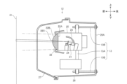
図1は、本実施形態の車両用ヘッドランプ装置10を説明するブロック図である。図2は、本実施形態の車両用ヘッドランプ装置10のヘッドランプユニット12を説明する断面図であり、車両11の高さ方向に沿った断面を示す。図3は、本実施形態の車両用ヘッドランプ装置10のヘッドランプユニット12を説明する断面図であり、車両11の車幅方向に沿った断面を示す。
Figure 1 is a block diagram illustrating a
図1に示す如く、車両用ヘッドランプ装置10は、主に、車両11の前端部に配設されるヘッドランプユニット12と、ヘッドランプユニット12に配設され、その光軸調整を行う光軸調整部13と、光源21(図2参照)からの照射光を車両11の前方側へと反射させるリフレクタ23(図2参照)と、リフレクタ23にて反射した照射光の一部を遮るシェード24(図2参照)と、リフレクタ23及びシェード24を可動させるアクチュエータ14と、照射光の照射領域に応じてアクチュエータ14を制御する制御部15と、を備える。
As shown in FIG. 1, the
アクチュエータ14は、例えば、ステッピングモータ等により構成され、ヘッドランプユニット12を構成するリフレクタ23及びシェード24と連結する。そして、アクチュエータ14は、制御部15による制御により、リフレクタ23やシェード24を適宜可動させることで、車両走行時のロービーム用照射領域44(図5参照)やハイビーム用照射領域45(図5参照)を調整する。
The
制御部15は、CPU(Central Processing Unit)、ROM(Read Only Memory)、RAM(Random Access Memory)等を有して構成され、車両用ヘッドランプ装置10を制御するための各種の演算等を実行する電子制御ユニット(ECU)である。
The
制御部15は、ロービーム用照射領域44及びハイビーム用照射領域45を形成するためのリフレクタ23やシェード24の位置データや角度データ等を記憶する。そして、制御部15は、ユーザのステアリング部(図示せず)の操作部(図示せず)における操作に応じて、アクチュエータ14を制御することで、ヘッドランプユニット12からロービーム用照射光やハイビーム用照射光33(図4参照)を照射させる。
The
図2及び図3に示す如く、ヘッドランプユニット12は、主に、光源21と、レンズ22と、光源21からの照射光の照射領域を調整するリフレクタ23及びシェード24と、光源21及びレンズ22を支持する筐体25と、光軸調整部13を支持する外形部26と、外形部26の前面に配設される前面カバー27と、を有する。尚、図3では、説明の都合上、その上方がリフレクタ23により覆われる光源21及びシェード24も実線にて示している。
2 and 3, the
本実施形態のヘッドランプユニット12は、ロービーム・ハイビーム一体型であり、光源21としては、例えば、1個の発光ダイオード(LED)が用いられる。発光ダイオードは回路基板(図示せず)に対して電気的に接続され、上記回路基板は、筐体25の内部の所望の位置に固定される。そして、光源21から照射された照射光は、リフレクタ23及びシェード24により調整されると共に、車両11の前方側に向けて、規定の光軸上を進行する。
The
レンズ22は、例えば、プロジェクタ式レンズであり、光源21よりも車両11の前方側であり、筐体25の前方の開口部を塞ぐように配設される。図示したように、レンズ22は、透明樹脂レンズであり、レンズ22の光源21側の面は、平レンズ面22Aであり、レンズ22のその反対側の面は、凸レンズ面22Bである。この構造により、光源21から照射された照射光は、直接、平レンズ面22Aからレンズ22内へと入光し、凸レンズ面22Bを通過する際に拡散されることで、ロービーム用の照射光やハイビーム用の照射光として車両11の前方側を照射する。
詳細は、図4及び図5を用いて後述するが、レンズ22の凸レンズ面22Bには、照射光収束部22Cが形成される。そして、照射光収束部22Cは、ハイビーム用照射光33が通過する領域の凸レンズ面22Bに形成される。図示したように、照射光収束部22Cは、例えば、凸レンズ面22Bの一部を平坦面として成形することで、照射光収束部22Cを通過するハイビーム用照射光33の一部は、車両11の前方へ向けて拡散することなく、収束して照射される。そして、照射光収束部22Cにて収束された照射光は、光軸調整用のマーキング光32(図4参照)として用いられる。
Details will be described later with reference to Figures 4 and 5, but an irradiation
リフレクタ23は、例えば、車両11の前方側へと湾曲したお椀形状であり、その内面にはメッキ加工または塗装加工が施され反射面部を有する。そして、リフレクタ23は、光源21から照射された照射光を車両11の前方へと向けて反射させる。一方、シェード24は、リフレクタ23の車両11の前方側へと配設され、リフレクタ23にて反射された照射光の一部を遮る。
The
上述したように、リフレクタ23及びシェード24は、制御部15に制御されたアクチュエータ14を介して可動することで、ヘッドランプユニット12からロービーム用照射光やハイビーム用照射光33を照射させる。
As described above, the
筐体25は、例えば、金属製の円筒形状であり、車両11の前方側が開口する。筐体25の車両11の後方側が、光軸調整部13の支持プレート13Aに対して所望の位置に固定される。そして、筐体25が、支持プレート13Aと一体に可動し、支持プレート13Aの向きを微調整することで、光源21からの照射光の光軸調整が行われる。
The
外形部26は、例えば、樹脂材料を射出成形して形成され、ヘッドランプユニット12の外形を構成する。外形部26には、光軸調整部13の4本の主柱部13B,13Cが組み付けられ、外形部26は、光軸調整部13を可動自在に支持する。そして、外形部26は、車両11の前端部の車体に対して組み付けられることで、ヘッドランプユニット12が、車両11へと固定される。
The
前面カバー27は、透明樹脂から形成され、外形部26の前面を塞ぐように組み付けられる。前面カバー27は、車両11の前端部の形状に合わせて所望の形状に加工され、車両11の意匠面を構成する。そして、光源21からの照射光は、レンズ22及び前面カバー27を通過して、車両11の前方を照射する。
The
図示したように、光軸調整部13は、主に、筐体25を支持する支持プレート13Aと、外形部26に対して車両11の前後方向にスライド可能に固定される4本の主柱部13B,13Cと、を有する。そして、主柱部13B,13Cは、例えば、ボルトとナットから構成され、外形部26の後端部26Aに対して固定される。
As shown in the figure, the optical
主柱部13B,13Cでは、ナットを一方向へと回転させることで、ボルトの先端側が車両11の前方へと前進し、一方、ナットを逆方向へと回転させることで、ボルトの先端側が車両11の後方へと後退する。詳細は後述するが、車両生産時の光軸調整工程において、作業者が、ナットを操作し、支持プレート13Aが車両11の前後方向や車幅方向に傾斜することで、筐体25の角度調整が成され、光源21からの照射光の光軸調整が行われる。
At the
図4は、本実施形態の車両用ヘッドランプ装置10の光軸調整工程を説明する概略図である。図5は、本実施形態の車両用ヘッドランプ装置10の配光パターンを説明する図である。
Figure 4 is a schematic diagram illustrating the optical axis adjustment process of the
図4では、車両11の生産工場内において、ヘッドランプユニット12の光軸調整工程の実施状況を示す。図示したように、検査用スクリーン31は、生産ラインに対して規定の位置に固定され、生産ラインにて搬送される車両11に対してヘッドランプユニット12の光軸調整が行われる。
Figure 4 shows the process of adjusting the optical axis of the
作業者は、検査用スクリーン31の前方であり、生産ラインの検査位置に停車した車両11に対して、光軸調整の検査条件に基づき種々の設定を行うと共に、制御部15に対して光軸診断装置(図示せず)を接続する。そして、光軸診断装置では、制御部15を介して光源21(図2参照)を制御し、光源21を構成する発光ダイオードを発光させる。作業者は、検査用スクリーン31に照射された光軸調整用のマーキング光32を確認し、そのマーキング光32が、検査用スクリーン31のターゲット(図示せず)と一致するように光軸調整を行う。
The worker performs various settings based on the inspection conditions for optical axis adjustment for the
ここで、上述したように、照射光収束部22Cは、ハイビーム用照射光33が通過する領域の凸レンズ面22Bに形成される。そのため、ヘッドランプユニット12の光軸調整工程では、作業者は、検査用スクリーン31に対してハイビーム用照射光33を照射させることで、その照射光の一部が、光軸調整用のマーキング光32として用いられる。本実施形態では、照射光収束部22Cが、レンズ22の凸レンズ面22Bに対して、車幅方向に渡り長方形形状に形成されることで、図示した形状のマーキング光32が、検査用スクリーン31に照射される。
As described above, the irradiation
図示したように、上記マーキング光32は、ハイビーム用照射光33の一部を利用して形成されるため、検査用スクリーン31には、ハイビーム用照射光33と上記マーキング光32とが照射される。そして、上記マーキング光32は、レンズ22の照射光収束部22Cにて収束されることで、その周囲の拡散されたハイビーム用照射光33よりも明瞭にその境界部が際立つ。特に、光源21として発光ダイオードを用いることで光の指向性が高くなり、上記境界部を際立たせることが出来る。
As shown in the figure, the marking
上述したように、作業者は、検査用スクリーン31に照射されたマーキング光32を確認しながら、光軸調整部13(図2参照)の主柱部13B,13Cを操作し、支持プレート13Aを車両11の前後方向や車幅方向に傾斜させることで、筐体25の角度調整が成され、光源21からの照射光の光軸調整が行われる。
As described above, while checking the marking light 32 projected onto the
尚、光軸調整用のマーキング光32としては、上記長方形形状に限定するものではなく、レンズ22の凸レンズ面22Bに成形可能な形状であれば良く、例えば、十字形状、円形状や正方形形状でも良く、任意の形状に設計変更が可能である。
The marking
図5は、実線41の枠はロービーム用照射領域44の一例を示し、実線42の枠はハイビーム用照射領域45の一例を示す。そして、光軸調整用照射領域43は、ハイビーム用照射領域45内に形成される。尚、上述したように、本実施形態では、制御部15が、アクチュエータ14を制御し、リフレクタ23及びシェード24を適宜可動させることで、ロービーム用照射領域44やハイビーム用照射領域45が調整される。
In FIG. 5, the frame enclosed by
本実施形態の車両用ヘッドランプ装置10では、ハイビーム用照射領域45の内部に光軸調整用照射領域43を形成することで、ロービーム用照射領域44のカットオフライン44Aの明暗境界を際立たせる必要がない。つまり、ロービーム用照射領域44では、そのカットオフライン44A周辺の明暗境界をぼかした状態とすることができる。
In the
その結果、車両11の通常走行時に、ヘッドランプユニット12からロービーム用照射光を照射するが、上記カットオフライン44A及びその近傍領域の光が曖昧な状態となる。そして、ロービーム用照射光のカットラインに起因する明暗境界が緩和されることで、ドライバは、走行中に路面での照度差によって生じる視認し難さを感じ難く、車両11の走行方向が見難くなる等の煩わしさを感じ難くなる。
As a result, when the
更には、車両11の通常走行時に坂道の登り車線に差し掛かる直前では、特に、上記カットオフライン44Aの照射光は、登り車線の路面に対して多く照射され、その明暗境界がくっきりと見え過ぎてしまう。しかしながら、本実施形態では、上述したように、上記カットオフライン44A及びその近傍領域の光が曖昧な状態となることで、ドライバは、車両11の前方の路面での照度差によって生じる視認し難さが低減され、不安や煩わしさを感じ難くなる。
Furthermore, immediately before the
更には、ロービーム用照射光のぼかし領域を低減し過ぎる必要がなく、車両11の通常走行時における路面の照射領域が確保され、ドライバの視界が確保されることで、車用11の走行安全性が向上される。
Furthermore, there is no need to reduce the blurred area of the low beam light too much, and the illuminated area of the road surface during normal driving of the
一方、ハイビーム用照射光33は、車両11の通常走行時に、車両11の斜め上方の空間に対して照射されるため、ロービーム用照射光よりも路面に照射される光の量は少なくなる。そして、上記光軸調整用のマーキング光32の明暗境界を明瞭に際立たせた場合でも、上記ハイビーム用照射光33の照射方向により、車両11の前方の路面に明暗境界が照射されないことで、ドライバが煩わしさを感じることが防止される。
On the other hand, the
その結果、上記光軸調整用のマーキング光32の明暗境界を明瞭に際立たせることで、ヘッドランプユニット12の光軸調整工程では、作業者は、検査用スクリーン31に対して明瞭に照射されたマーキング光32を認識し易くなり、光軸調整の作業効率を高めると共に、その調整精度を向上させることができる。
As a result, by clearly highlighting the light/dark boundary of the marking
尚、本実施形態では、プロジェクタ式レンズであるレンズ22に対して照射光収束部22Cが成形される場合について説明したが、この場合に限定するものではない。例えば、レンズ22の車両11の前方側に収束用レンズを配設することで、ハイビーム用照射光33の一部を収束させ、光軸調整用のマーキング光32として用いる場合でも良い。
In this embodiment, the case where the irradiated
また、光源21として1個の発光ダイオードを用いる場合について説明したが、この場合に限定するものではない。例えば、光源21としては、ハロゲンランプやHIDランプが用いられる場合でも、レンズ22の照射光収束部22Cを介して上記同様な効果が得られる。
Although the above description is directed to a case where one light-emitting diode is used as the
また、ヘッドランプユニット12では、リフレクタ23及びシェード24が用いられる構造について説明したが、この場合に限定するものではない。例えば、光源21が複数の発光ダイオードから成り、制御部15が、ハイビーム用配光パターン等に応じて上記複数の発光ダイオードを選択的に発光させるADB(Adaptive Driving Beam)制御を行うと共に、光源21からの照射光を直接レンズ22内へと入光させる場合でも、レンズ22の照射光収束部22Cを介して上記同様な効果が得られる。尚、その他、本発明の要旨を逸脱しない範囲にて種々の変更が可能である。
In addition, in the
10 車両用ヘッドランプ装置
11 車両
12 ヘッドランプユニット
13 光軸調整部
13A 支持プレート
13B,13C 主柱部
14 アクチュエータ
15 制御部
21 光源
22 レンズ
22A 平レンズ面
22B 凸レンズ面
22C 照射光収束部
23 リフレクタ
24 シェード
25 筐体
26 外形部
27 前面カバー
31 検査用スクリーン
32 マーキング光
33 ハイビーム用照射光
43 光軸調整用照射領域
44 ロービーム用照射領域
45 ハイビーム用照射領域
REFERENCE SIGNS
Claims (3)
前記レンズは、前記照射光の一部が通過する際に収束する照射光収束部を有し、
前記照射光収束部は、前記光源から照射されるハイビーム用照射光の通過領域であり、前記レンズの表面の一部を平坦面の所定形状として形成され、
同一の前記光源から照射された前記照射光の一部が、前記所定形状の光軸調整用のマーキング光として、前記ハイビーム用照射光の中に含まれることを特徴とする車両用ヘッドランプ装置。 A light source and a lens through which the light emitted from the light source passes,
the lens has an irradiation light converging portion that converges a portion of the irradiation light when the portion passes through the lens,
The illumination light converging portion is a passage area of the high beam illumination light emitted from the light source, and is formed by forming a part of the surface of the lens into a predetermined shape of a flat surface ,
A vehicle headlamp device, characterized in that a part of the light emitted from the same light source is included in the high beam light as marking light of the predetermined shape for adjusting the optical axis.
前記光源は、発光ダイオードであることを特徴とする請求項2に記載の車両用ヘッドランプ装置。
The lamp further includes a reflector that reflects the irradiated light, and a shade that blocks a part of the irradiated light reflected by the reflector,
3. The vehicle headlamp device according to claim 2, wherein the light source is a light emitting diode.
Priority Applications (2)
| Application Number | Priority Date | Filing Date | Title |
|---|---|---|---|
| JP2021097976A JP7662425B2 (en) | 2021-06-11 | 2021-06-11 | Headlamp device for vehicle |
| US17/826,739 US11686449B2 (en) | 2021-06-11 | 2022-05-27 | Vehicle headlamp device |
Applications Claiming Priority (1)
| Application Number | Priority Date | Filing Date | Title |
|---|---|---|---|
| JP2021097976A JP7662425B2 (en) | 2021-06-11 | 2021-06-11 | Headlamp device for vehicle |
Publications (2)
| Publication Number | Publication Date |
|---|---|
| JP2022189417A JP2022189417A (en) | 2022-12-22 |
| JP7662425B2 true JP7662425B2 (en) | 2025-04-15 |
Family
ID=84391275
Family Applications (1)
| Application Number | Title | Priority Date | Filing Date |
|---|---|---|---|
| JP2021097976A Active JP7662425B2 (en) | 2021-06-11 | 2021-06-11 | Headlamp device for vehicle |
Country Status (2)
| Country | Link |
|---|---|
| US (1) | US11686449B2 (en) |
| JP (1) | JP7662425B2 (en) |
Citations (4)
| Publication number | Priority date | Publication date | Assignee | Title |
|---|---|---|---|---|
| JP2016002866A (en) | 2014-06-17 | 2016-01-12 | トヨタ自動車株式会社 | Vehicle headlamp device |
| JP2016039020A (en) | 2014-08-07 | 2016-03-22 | 株式会社小糸製作所 | Vehicle lighting |
| US20190120457A1 (en) | 2017-10-24 | 2019-04-25 | Grote Industries, Llc | Dual high-beam and low-beam vehicle headlamp |
| US10890309B1 (en) | 2019-12-12 | 2021-01-12 | Valeo North America, Inc. | Method of aiming a high definition pixel light module |
Family Cites Families (2)
| Publication number | Priority date | Publication date | Assignee | Title |
|---|---|---|---|---|
| JP4494342B2 (en) | 2006-01-18 | 2010-06-30 | 株式会社小糸製作所 | Detection method of light distribution pattern center |
| EP3179158A4 (en) * | 2014-08-07 | 2018-03-21 | Koito Manufacturing Co., Ltd. | Lamp for vehicles |
-
2021
- 2021-06-11 JP JP2021097976A patent/JP7662425B2/en active Active
-
2022
- 2022-05-27 US US17/826,739 patent/US11686449B2/en active Active
Patent Citations (4)
| Publication number | Priority date | Publication date | Assignee | Title |
|---|---|---|---|---|
| JP2016002866A (en) | 2014-06-17 | 2016-01-12 | トヨタ自動車株式会社 | Vehicle headlamp device |
| JP2016039020A (en) | 2014-08-07 | 2016-03-22 | 株式会社小糸製作所 | Vehicle lighting |
| US20190120457A1 (en) | 2017-10-24 | 2019-04-25 | Grote Industries, Llc | Dual high-beam and low-beam vehicle headlamp |
| US10890309B1 (en) | 2019-12-12 | 2021-01-12 | Valeo North America, Inc. | Method of aiming a high definition pixel light module |
Also Published As
| Publication number | Publication date |
|---|---|
| US20220397257A1 (en) | 2022-12-15 |
| US11686449B2 (en) | 2023-06-27 |
| JP2022189417A (en) | 2022-12-22 |
Similar Documents
| Publication | Publication Date | Title |
|---|---|---|
| JP4970145B2 (en) | Vehicle headlamp | |
| EP2266838B1 (en) | Vehicle headlamp apparatus | |
| US6416210B1 (en) | Headlamp for a vehicle | |
| US20070041207A1 (en) | Vehicle lamp | |
| JP5398443B2 (en) | Vehicle headlamp device | |
| JP3939529B2 (en) | Vehicle headlamp | |
| CN102537807B (en) | Head lamp assembly and method for controlling the same | |
| JP5723417B2 (en) | Vehicle headlamp | |
| US6817744B2 (en) | Vehicle lamp | |
| JP2017191748A (en) | Vehicular lighting fixture and vehicle including the same | |
| US10180228B2 (en) | Vehicle lighting fixture | |
| JP2001325816A (en) | Vehicle headlights | |
| EP2154426B1 (en) | Vehicle headlamp apparatus | |
| JP2001236802A (en) | Vehicle headlights | |
| JP5814982B2 (en) | Vehicle headlamps for light distribution for passing light | |
| US6837601B2 (en) | Lighting system for vehicle | |
| US6821004B2 (en) | Headlamp for vehicle | |
| JP2020009683A (en) | Vehicular lamp and vehicle system | |
| JP7643944B2 (en) | Headlamp device for vehicle | |
| JP7662425B2 (en) | Headlamp device for vehicle | |
| JP6567175B2 (en) | In-vehicle headlamp and in-vehicle headlamp system | |
| JP5723418B2 (en) | Vehicle headlamp | |
| JP2003168307A (en) | Vehicle headlights | |
| JP4002099B2 (en) | Vehicle headlamp | |
| EP1236613A2 (en) | Head lamp for vehicle |
Legal Events
| Date | Code | Title | Description |
|---|---|---|---|
| A621 | Written request for application examination |
Free format text: JAPANESE INTERMEDIATE CODE: A621 Effective date: 20240509 |
|
| A977 | Report on retrieval |
Free format text: JAPANESE INTERMEDIATE CODE: A971007 Effective date: 20241113 |
|
| A131 | Notification of reasons for refusal |
Free format text: JAPANESE INTERMEDIATE CODE: A131 Effective date: 20241126 |
|
| A521 | Request for written amendment filed |
Free format text: JAPANESE INTERMEDIATE CODE: A523 Effective date: 20250121 |
|
| TRDD | Decision of grant or rejection written | ||
| A01 | Written decision to grant a patent or to grant a registration (utility model) |
Free format text: JAPANESE INTERMEDIATE CODE: A01 Effective date: 20250311 |
|
| A61 | First payment of annual fees (during grant procedure) |
Free format text: JAPANESE INTERMEDIATE CODE: A61 Effective date: 20250403 |
|
| R150 | Certificate of patent or registration of utility model |
Ref document number: 7662425 Country of ref document: JP Free format text: JAPANESE INTERMEDIATE CODE: R150 |