JP7658925B2 - Motor control device and motor control method - Google Patents
Motor control device and motor control method Download PDFInfo
- Publication number
- JP7658925B2 JP7658925B2 JP2022005670A JP2022005670A JP7658925B2 JP 7658925 B2 JP7658925 B2 JP 7658925B2 JP 2022005670 A JP2022005670 A JP 2022005670A JP 2022005670 A JP2022005670 A JP 2022005670A JP 7658925 B2 JP7658925 B2 JP 7658925B2
- Authority
- JP
- Japan
- Prior art keywords
- hall
- detection error
- counter value
- position detection
- value
- Prior art date
- Legal status (The legal status is an assumption and is not a legal conclusion. Google has not performed a legal analysis and makes no representation as to the accuracy of the status listed.)
- Active
Links
Images


Classifications
-
- H—ELECTRICITY
- H02—GENERATION; CONVERSION OR DISTRIBUTION OF ELECTRIC POWER
- H02P—CONTROL OR REGULATION OF ELECTRIC MOTORS, ELECTRIC GENERATORS OR DYNAMO-ELECTRIC CONVERTERS; CONTROLLING TRANSFORMERS, REACTORS OR CHOKE COILS
- H02P6/00—Arrangements for controlling synchronous motors or other dynamo-electric motors using electronic commutation dependent on the rotor position; Electronic commutators therefor
- H02P6/14—Electronic commutators
- H02P6/15—Controlling commutation time
-
- H—ELECTRICITY
- H02—GENERATION; CONVERSION OR DISTRIBUTION OF ELECTRIC POWER
- H02P—CONTROL OR REGULATION OF ELECTRIC MOTORS, ELECTRIC GENERATORS OR DYNAMO-ELECTRIC CONVERTERS; CONTROLLING TRANSFORMERS, REACTORS OR CHOKE COILS
- H02P21/00—Arrangements or methods for the control of electric machines by vector control, e.g. by control of field orientation
- H02P21/05—Arrangements or methods for the control of electric machines by vector control, e.g. by control of field orientation specially adapted for damping motor oscillations, e.g. for reducing hunting
-
- H—ELECTRICITY
- H02—GENERATION; CONVERSION OR DISTRIBUTION OF ELECTRIC POWER
- H02P—CONTROL OR REGULATION OF ELECTRIC MOTORS, ELECTRIC GENERATORS OR DYNAMO-ELECTRIC CONVERTERS; CONTROLLING TRANSFORMERS, REACTORS OR CHOKE COILS
- H02P21/00—Arrangements or methods for the control of electric machines by vector control, e.g. by control of field orientation
- H02P21/14—Estimation or adaptation of machine parameters, e.g. flux, current or voltage
- H02P21/18—Estimation of position or speed
-
- H—ELECTRICITY
- H02—GENERATION; CONVERSION OR DISTRIBUTION OF ELECTRIC POWER
- H02P—CONTROL OR REGULATION OF ELECTRIC MOTORS, ELECTRIC GENERATORS OR DYNAMO-ELECTRIC CONVERTERS; CONTROLLING TRANSFORMERS, REACTORS OR CHOKE COILS
- H02P21/00—Arrangements or methods for the control of electric machines by vector control, e.g. by control of field orientation
- H02P21/22—Current control, e.g. using a current control loop
-
- H—ELECTRICITY
- H02—GENERATION; CONVERSION OR DISTRIBUTION OF ELECTRIC POWER
- H02P—CONTROL OR REGULATION OF ELECTRIC MOTORS, ELECTRIC GENERATORS OR DYNAMO-ELECTRIC CONVERTERS; CONTROLLING TRANSFORMERS, REACTORS OR CHOKE COILS
- H02P6/00—Arrangements for controlling synchronous motors or other dynamo-electric motors using electronic commutation dependent on the rotor position; Electronic commutators therefor
- H02P6/14—Electronic commutators
- H02P6/16—Circuit arrangements for detecting position
Landscapes
- Engineering & Computer Science (AREA)
- Power Engineering (AREA)
- Control Of Motors That Do Not Use Commutators (AREA)
- Control Of Electric Motors In General (AREA)
Description
本発明は、モータ制御装置及びモータ制御方法に関する。 The present invention relates to a motor control device and a motor control method.
ブラシレスモータは、3相のコイルを有するステータと、界磁用の永久磁石を有するロータとを備え、ロータの回転軸には、ロータと共に回転するセンサマグネットが取り付けられている。センサマグネットは、回転方向にS極とN極が交互に着磁されており、センサマグネットの近傍には、回転位置を検出する3つのホールセンサが回転方向に所定間隔で、センサマグネットの磁極の切り替わりを検出できるように取り付けられている。 A brushless motor has a stator with a three-phase coil and a rotor with a permanent magnet for the field magnet, and a sensor magnet that rotates with the rotor is attached to the rotor's rotating shaft. The sensor magnet is magnetized with alternating south and north poles in the direction of rotation, and three hall sensors that detect the rotational position are attached near the sensor magnet at predetermined intervals in the direction of rotation so that they can detect the switching of the magnetic poles of the sensor magnet.
ブラシレスモータの駆動制御を行うモータ制御装置では、3つのホールセンサの切り替わり位置(ホールエッジ)を基準として、3つのホールセンサの出力である位置検出信号の電位の組合せで表される6個のホールステージに対応する通電パターンを、ブラシレスモータを駆動するインバータ回路に対して出力することで、ブラシレスモータを回転させる。 The motor control device that drives and controls the brushless motor rotates the brushless motor by outputting a current pattern corresponding to six Hall stages represented by a combination of the potentials of the position detection signals, which are the outputs of the three Hall sensors, to an inverter circuit that drives the brushless motor, based on the switching positions (Hall edges) of the three Hall sensors.
ここで、ブラシレスモータにおけるセンサマグネットの着磁ばらつき、ホールセンサの取り付け位置のばらつきなどにより、6個のホールステージ1~6のそれぞれを構成する2個のホールエッジの間の電気角での間隔が、ホールステージの設計上の電気角での間隔に一致しない場合がある。このような場合、ホールエッジ毎に駆動信号の出力を切り替えると、ブラシレスモータの動きに影響を与えて振動や異音の発生が生じてしまうことがある。
Due to variations in magnetization of the sensor magnet in the brushless motor and variations in the mounting position of the Hall sensor, the distance in electrical angle between the two Hall edges that make up each of the six
そこで、ホールステージの切り替わりを示すホールエッジ毎に位置検出信号を補正し、その補正された位置検出信号に基づいて通電パターンを切り替える構成を有するモータ制御装置が提案されている(例えば、特許文献1を参照)。 Therefore, a motor control device has been proposed that corrects the position detection signal for each Hall edge that indicates the switching of the Hall stage, and switches the current conduction pattern based on the corrected position detection signal (see, for example, Patent Document 1).
上述したモータ制御装置は、ホールエッジの位置検出信号が検出されたタイミングから遅延させたタイミングを、通電パターンの切り替わりタイミングとすることで、ブラシレスモータの動きを円滑化している。
しかしながら、上述したモータ制御装置において、3つのホールセンサの取り付け位置によっては、位置検出信号の補正量が負の値になる(つまり、タイミング補正のための遅延時間が負になる)ことがあり、通電パターンの切り替わりタイミングを制御できない場合があった。
The motor control device described above smoothes the operation of the brushless motor by setting the timing for switching the current supply pattern to a timing delayed from the timing at which the Hall edge position detection signal is detected.
However, in the above-mentioned motor control device, depending on the installation positions of the three Hall sensors, the correction amount of the position detection signal may become negative (i.e., the delay time for timing correction may become negative), and it may not be possible to control the timing of switching the current pattern.
本発明は、上述した事情に鑑みてなされたものであり、その目的は、ブラシレスモータの振動や異音の発生の抑制を精度良く行うことができるモータ制御装置及びモータ制御装置の制御方法を提供することである。 The present invention has been made in consideration of the above-mentioned circumstances, and its purpose is to provide a motor control device and a control method for a motor control device that can accurately suppress the generation of vibrations and abnormal noise in a brushless motor.
本発明の一態様は、ブラシレスモータの3相のコイルに通電制御を行って、ロータの回転制御を行うモータ制御装置において、前記コイルに流す電流を切り替え可能に配置された複数のスイッチング素子と、前記コイルのそれぞれに対応して設けられ、前記ロータの回転位置を検出する複数のセンサと、前記複数のセンサの出力である位置検出信号に基づいて前記スイッチング素子を切り替える駆動信号を出力する制御部と、を備え、前記制御部は、前記複数のセンサの出力である位置検出信号の電位の組合せで表される6個のホールステージのそれぞれを構成する補正されたホールエッジに基づいて前記スイッチング素子を切り替える駆動信号を出力するゲート制御電圧出力部と、前記ホールステージのそれぞれを構成する2個のホールエッジの間の時間で表される前記ホールステージの時間であるカウンタ値を、前記位置検出信号から取得するカウンタ値取得部と、前回のホールステージのそれぞれのカウンタ値と、予め設定された補正係数とを演算した値を、今回のホールエッジのそれぞれの遅延時間として、前記遅延時間で補正されたホールエッジのそれぞれに基づいて、前記ゲート制御電圧出力部に前記駆動信号を出力させる切り替え制御部と、を有し、前記補正係数は、前記カウンタ値取得部が取得した6個のホールステージのカウンタ値のうちの最小のカウンタ値である第1ホールステージを構成する2つのホールエッジのうち、前記ブラシレスモータの回転方向にホールエッジを広げることでカウンタ値が小さくなるホールエッジを第1基準ホールエッジとし、前記第1基準ホールエッジがある相に対応する前記位置検出信号を第1基準位置検出信号とし、前記カウンタ値取得部が取得した6個のホールステージのカウンタ値のうちの最大のカウンタ値と前記最小のカウンタ値との中間値である第2ホールステージを構成する2つのホールエッジのうち、前記ブラシレスモータの回転方向にホールエッジを広げることでカウンタ値が小さくなるホールエッジを第2基準ホールエッジとし、前記第2基準ホールエッジがある相に対応する前記位置検出信号を第2基準位置検出信号とし、前記ブラシレスモータの回転方向に連続する3個のホールステージ分のカウンタ値の平均値と、前記ホールステージそれぞれのカウンタ値との差分である検出誤差のうち、前記第1基準位置検出信号を基準とした場合の第1検出誤差と、前記第2基準位置検出信号を基準とした場合の第2検出誤差とについて、前記第1検出誤差と、前記第2検出誤差とが、負の値を含む否かに基づいて、前記第1検出誤差と前記第2検出誤差とのいずれか一方から算出された補正係数が選択されて設定されたものである。 One aspect of the present invention is a motor control device that controls the rotation of a rotor by controlling the energization of three-phase coils of a brushless motor, the motor control device comprising: a plurality of switching elements arranged to be able to switch the current flowing through the coils; a plurality of sensors provided corresponding to each of the coils and detecting the rotational position of the rotor; and a control unit that outputs a drive signal that switches the switching elements based on a position detection signal that is the output of the plurality of sensors. The control unit includes a gate control voltage output unit that outputs a drive signal that switches the switching elements based on a corrected hall edge that constitutes each of six hall stages represented by a combination of potentials of the position detection signals that are the output of the plurality of sensors; a counter value acquisition unit that acquires from the position detection signal a counter value that is the time of the hall stage represented by the time between two hall edges that constitute each of the hall stages; and a switching control unit that outputs the drive signal to the gate control voltage output unit based on each of the hall edges corrected by the delay time, the value being calculated by calculating each counter value of the previous hall stage and a preset correction coefficient as the delay time of each current hall edge, the correction coefficient being the counter value of the six hall stages acquired by the counter value acquisition unit. Among the two Hall edges constituting a first Hall stage having the smallest counter value among the six Hall stages, the Hall edge whose counter value becomes smaller when the Hall edge is widened in the rotation direction of the brushless motor is defined as a first reference Hall edge, the position detection signal corresponding to the phase in which the first reference Hall edge is located is defined as a first reference position detection signal, and among the two Hall edges constituting a second Hall stage having an intermediate value between the maximum counter value and the minimum counter value among the six Hall stage counter values acquired by the counter value acquisition unit, the Hall edge whose counter value becomes smaller when the Hall edge is widened in the rotation direction of the brushless motor is defined as a second reference position detection signal. 2 reference Hall edge, the position detection signal corresponding to the phase in which the second reference Hall edge is located is the second reference position detection signal, and among the detection errors which are the difference between the average value of the counter values for three consecutive Hall stages in the rotational direction of the brushless motor and the counter values of each of the Hall stages, a correction coefficient calculated from either the first detection error or the second detection error is selected and set for the first detection error when the first reference position detection signal is used as a reference and the second detection error when the second reference position detection signal is used as a reference based on whether the first detection error and the second detection error include negative values.
本発明の一態様は、ブラシレスモータの3相のコイルに通電制御を行って、ロータの回転制御を行うモータ制御装置において、前記コイルに流す電流を切り替え可能に配置された複数のスイッチング素子と、前記コイルのそれぞれに対応して設けられ、前記ロータの回転位置を検出する複数のセンサと、前記複数のセンサの出力である位置検出信号に基づいて前記スイッチング素子を切り替える駆動信号を出力する制御部と、を備え、前記制御部は、ゲート制御電圧出力部と、カウンタ値取得部と、切り替え制御部と、基準相選択部と、平均値算出部と、検出誤差算出部と、補正係数算出部と、記憶制御部と、を有するモータ制御方法であって、前記ゲート制御電圧出力部が、前記複数のセンサの出力である位置検出信号の電位の組合せで表される6個のホールステージのそれぞれを構成する補正されたホールエッジに基づいて前記スイッチング素子を切り替える駆動信号を出力するゲート制御電圧出力工程と、前記カウンタ値取得部が、前記ホールステージのそれぞれを構成する2個のホールエッジの間の時間で表される前記ホールステージの時間であるカウンタ値を、前記位置検出信号から取得するカウンタ値取得工程と、前記切り替え制御部が、前回のホールステージのそれぞれのカウンタ値に、予め設定された補正係数を乗じた値を、今回のホールエッジのそれぞれの遅延時間として、前記遅延時間で補正されたホールエッジのそれぞれに基づいて、前記ゲート制御電圧出力部に前記駆動信号を出力させる切り替え制御工程と、前記基準相選択部が、前記カウンタ値取得部が取得した6個のホールステージのカウンタ値のうち、最小のカウンタ値である第1ホールステージを構成する2つのホールエッジのうち、前記ブラシレスモータの回転方向にホールエッジを広げることでカウンタ値が小さくなるホールエッジを第1基準ホールエッジとし、前記第1基準ホールエッジがある相に対応する前記位置検出信号を第1基準位置検出信号とし、前記カウンタ値取得部が取得した6個のホールステージのカウンタ値のうち、最大のカウンタ値と前記最小のカウンタ値との中間値である第2ホールステージを構成する2つのホールエッジのうち、前記ブラシレスモータの回転方向にホールエッジを広げることでカウンタ値が小さくなるホールエッジを第2基準ホールエッジとし、前記第2基準ホールエッジがある相に対応する前記位置検出信号を第2基準位置検出信号とする基準相選択工程と、前記平均値算出部が、前記ブラシレスモータの回転方向に連続する3個のホールステージ分のカウンタ値の平均値を算出する平均値算出工程と、前記検出誤差算出部が、前記平均値と前記ホールステージそれぞれのカウンタ値との差分である検出誤差のうち、前記第1基準位置検出信号を基準とした場合の第1検出誤差と、前記第2基準位置検出信号を基準とした場合の第2検出誤差とをそれぞれ算出する検出誤差算出工程と、前記補正係数算出部が、前記第1検出誤差を前記平均値で除算した第1補正係数、又は前記第2検出誤差を前記平均値で除算した第2補正係数を算出する補正係数算出工程と、前記記憶制御部が、算出された前記第1検出誤差及び前記第2検出誤差が負の値を含む否かに基づいて、前記第1検出誤差と前記第2検出誤差とのいずれか一方から算出された前記補正係数を記憶させる記憶制御工程と、を有するモータ制御方法。 One aspect of the present invention is a motor control device that controls the rotation of a rotor by controlling the energization of three-phase coils of a brushless motor, the motor control device comprising: a plurality of switching elements arranged to be able to switch the current flowing through the coils; a plurality of sensors provided corresponding to each of the coils and detecting the rotational position of the rotor; and a control unit that outputs a drive signal for switching the switching elements based on position detection signals that are the output of the plurality of sensors, the control unit having a gate control voltage output unit, a counter value acquisition unit, a switching control unit, a reference phase selection unit, an average value calculation unit, a detection error calculation unit, a correction coefficient calculation unit, and a memory control unit, the gate control voltage output unit constitutes each of six Hall stages represented by a combination of potentials of the position detection signals that are the output of the plurality of sensors. a gate control voltage output step of outputting a drive signal for switching the switching element based on a corrected Hall edge that constitutes each of the Hall stages; a counter value acquisition step of the counter value acquisition unit acquiring, from the position detection signal, a counter value which is the Hall stage time represented by the time between two Hall edges that constitute each of the Hall stages; a switching control step of the switching control unit multiplying the counter value of each previous Hall stage by a preset correction coefficient as a delay time of each current Hall edge, and causing the gate control voltage output unit to output the drive signal based on each Hall edge corrected by the delay time; a reference phase selection step of selecting a hall edge of two hall edges constituting a stage, the hall edge of which counter value becomes smaller when the hall edge is expanded in the rotation direction of the brushless motor, the position detection signal corresponding to the phase in which the first reference hall edge is located, and a first reference position detection signal of the position detection signal corresponding to the phase in which the first reference hall edge is located; a second hall stage, which is an intermediate value between the maximum counter value and the minimum counter value among the counter values of the six hall stages acquired by the counter value acquisition unit, the hall edge of which counter value becomes smaller when the hall edge is expanded in the rotation direction of the brushless motor, and the position detection signal corresponding to the phase in which the second reference hall edge is located, and a reference phase selection step of selecting a hall edge of two hall edges constituting a second hall stage, the second hall stage being an intermediate value between the maximum counter value and the minimum counter value among the counter values of the six hall stages acquired by the counter value acquisition unit, the second reference hall edge of which counter value becomes smaller when the hall edge is expanded in the rotation direction of the brushless motor, and the position detection signal corresponding to the phase in which the second reference hall edge is located, and A motor control method having an average calculation process for calculating an average value of counter values for three hall stages; a detection error calculation process in which the detection error calculation unit calculates a first detection error when the first reference position detection signal is used as a reference and a second detection error when the second reference position detection signal is used as a reference, among the detection errors that are the differences between the average value and the counter values of the respective hall stages; a correction coefficient calculation process in which the correction coefficient calculation unit calculates a first correction coefficient by dividing the first detection error by the average value, or a second correction coefficient by dividing the second detection error by the average value; and a storage control process in which the storage control unit stores the correction coefficient calculated from either the first detection error or the second detection error based on whether the calculated first detection error and the calculated second detection error include negative values.
本発明によれば、ブラシレスモータの振動や異音の発生の抑制を精度良く行うことができる。 The present invention makes it possible to precisely suppress vibrations and abnormal noises in brushless motors.
[実施形態]
以下、本発明の一実施形態によるモータ制御装置及びモータ制御方法について、図面を参照して説明する。
[Embodiment]
DETAILED DESCRIPTION OF THE PREFERRED EMBODIMENTS A motor control device and a motor control method according to an embodiment of the present invention will now be described with reference to the drawings.
図1は、本実施形態によるモータ装置100の一例を示す図である。
図1に示すように、モータ装置100は、モータ2と、回転軸センサ23と、制御部6と、インバータ50とを備える。
本実施形態によるモータ装置100は、例えば、車両のウィンドウガラスを払拭するワイパー装置に利用される。
FIG. 1 is a diagram showing an example of a
As shown in FIG. 1 , the
The
[インバータの構成例]
インバータ50は、駆動信号生成部46が生成した駆動信号に基づいて、モータ2を回転駆動させる出力信号を出力する。すなわち、インバータ50は、駆動信号生成部46が生成した駆動信号に基づいて、スイッチング素子(51a~51f)を駆動させて、通電波形に基づく印加電圧を3相の電機子コイル(21u、21v、21w)に印加する。
なお、インバータ50は、バッテリ5から供給される直流電力により、印加電圧を生成する。
[Inverter configuration example]
The
The
インバータ50は、3相ブリッジ接続された6個のスイッチング素子51a~51fと、ダイオード52a~52fとを備える。
スイッチング素子51a~51fは、例えば、NチャネルMOSFET(Metal Oxide Semiconductor Field Effect Transistor)であり、3相のブリッジ回路を構成している。
The
The
スイッチング素子51aとスイッチング素子51dとは、バッテリ5の正極端子と負極端子との間に、直列に説明されて、U相のブリッジ回路を構成している。スイッチング素子51aは、ドレイン端子がバッテリ5の正極端子に、ソース端子がノードN1に、ゲート端子がU相の上側の駆動信号の信号線に、それぞれ接続されている。また、スイッチング素子51dは、ドレイン端子がノードN1に、ソース端子がバッテリ5の負極端子に、ゲート端子がU相の下側の駆動信号の信号線に、それぞれ接続されている。また、ノードN1は、モータ2の接続点21aに接続されている。
Switching
スイッチング素子51bとスイッチング素子51eとは、バッテリ5の正極端子と負極端子との間に、直列に説明されて、V相のブリッジ回路を構成している。スイッチング素子51bは、ドレイン端子がバッテリ5の正極端子に、ソース端子がノードN2に、ゲート端子がV相の上側の駆動信号の信号線に、それぞれ接続されている。また、スイッチング素子51eは、ドレイン端子がノードN2に、ソース端子がバッテリ5の負極端子に、ゲート端子がV相の下側の駆動信号の信号線に、それぞれ接続されている。また、ノードN2は、モータ2の接続点21bに接続されている。
Switching
スイッチング素子51cとスイッチング素子51fとは、バッテリ5の正極端子と負極端子との間に、直列に説明されて、W相のブリッジ回路を構成している。スイッチング素子51cは、ドレイン端子がバッテリ5の正極端子に、ソース端子がノードN3に、ゲート端子がW相の上側の駆動信号の信号線に、それぞれ接続されている。また、スイッチング素子51fは、ドレイン端子がノードN3に、ソース端子がバッテリ5の負極端子に、ゲート端子がW相の下側の駆動信号の信号線に、それぞれ接続されている。また、ノードN3は、モータ2の接続点21cに接続されている。
Switching
また、ダイオード52a~52fは、いずれもいわゆる還流ダイオードである。
なお、以下の説明において、スイッチング素子51a,51b,51c,51d,51e,51fのことを、スイッチング素子UH,VH,WH,UL,VL,WLとも記載する。
Moreover, the
In the following description, the
[モータの構成例]
モータ2は、例えば、3相4極形のブラシレスモータである。モータ2は、後述する駆動信号に基づいて、インバータ50が出力する出力信号により回転駆動する。
また、モータ2は、ステータ21と、ロータ22とを備える。
[Motor configuration example]
The
The
ステータ21は、モータ2のケースの内周に固定されている。ステータ21は、3相の電機子コイル(21u、21v、21w)を備える。ステータ21は、電機子コイル(21u、21v、21w)が巻装されている。例えば、3相の電機子コイル(21u、21v、21w)は、デルタ結線により接続される。
デルタ結線において、電機子コイル21uと、電機子コイル21wとが、接続点21aにより接続され、電機子コイル21vと、電機子コイル21wとが、接続点21bにより接続され、電機子コイル21uと、電機子コイル21vとが、接続点21cにより接続されている。
The
In the delta connection, the
ロータ22は、ステータ21の内側に設けられている。ロータ22は、例えば、ロータ軸22aと、ロータ軸22aに取り付けたセンサマグネット22bとを備える。モータ2のケース内には、複数の軸受(不図示)が設けられており、ロータ軸22aは、複数の軸受により回転可能に支持されている。
The
回転軸センサ23は、ロータ22の回転に応じた信号を検出する。回転軸センサ23は、例えば、3つのホールセンサ(23u、23v、23w)を備える。これらの3つのホールセンサ(23u、23v、23w)は、ロータ22が回転すると、それぞれ互いに約120度位相のずれたパルス信号を制御部6に対して出力する。すなわち、回転軸センサ23は、ロータ22の回転にともない、ロータ軸22aに配置された4極のセンサマグネット22bの磁極の変化に基づいたパルス信号を発生し、制御部6に出力する。各ホールセンサは、それぞれ電気角で約120度毎ずれた位置を検出する。
The rotating
[制御部(モータ制御装置)の構成例]
制御部6は、例えば、CPU(Central Processing Unit)などを含むプロセッサであり、モータ装置100を統括的に制御する。制御部6は、PWM(Pulse With Modulation:パルス幅変調)制御を行い、目標のロータ22の回転出力(例えば、目標回転数TRPM)に応じたデューティ比を設定し、設定したデューティ比に応じた駆動信号をインバータ50に出力する。また、制御部6は、インバータ50を介して、例えば、矩形波通電によりモータ2の駆動を制御する。
なお、制御部6のことをモータ制御装置ともいう。
[Configuration example of control unit (motor control device)]
The
The
制御部6は、ゲート制御電圧出力部61と、切り替え制御部62と、カウンタ値取得部63と、基準相選択部64と、平均値算出部65と、検出誤差算出部66と、補正係数算出部67と、記憶制御部68と、記憶部69とを備える。
The
ゲート制御電圧出力部61は、ホールセンサ23u,23v,23wの出力である位置検出信号Hu,Hv,Hwの電位の組合せで表される6個のホールステージのそれぞれを構成する補正されたホールエッジに基づいてスイッチング素子UH,VH,WH,UL,VL,WLを切り替えるPWM信号(駆動信号)を出力する。
The gate control
カウンタ値取得部63は、ホールステージ1~6のそれぞれを構成する2個のホールエッジの間の時間で表されるホールステージの時間であるカウンタ値を、ホールセンサ23u,23v,23wから入力される位置検出信号Hu,Hv,Hwから取得する。
The counter
切り替え制御部62は、ホールセンサ23u,23v,23wから入力される位置検出信号Hu,Hv,Hwに基づいて、ホールステージを認識し、記憶部69に記憶されたホールステージに対応する通電パターンを読み出す。切り替え制御部62は、前回の(電気角360度前の)ホールステージのそれぞれのカウンタ値に、予め設定された補正係数を乗じた値を、今回のホールエッジのそれぞれの遅延時間として、遅延時間で補正されたホールエッジのそれぞれに基づいて電気角60度の期間を有するPWM指令信号を、通電パターンから生成し、ゲート制御電圧出力部61に電気角60度の期間を有するPWM信号を出力させる。
The switching
これにより、スイッチング素子UH,VH,WH,UL,VL,WLは、PWM制御により駆動されて各通電パターンに対応する期間において、それぞれが断続的にオン・オフされる。 As a result, the switching elements UH, VH, WH, UL, VL, and WL are driven by PWM control and are each turned on and off intermittently during periods corresponding to each current conduction pattern.
[補正係数の設定]
補正係数は、モータ制御装置4の出荷前(例えば、製品組み立て後の調整工程や出荷検査工程など)において、次のようにして設定される。
[Correction coefficient setting]
The correction coefficient is set as follows before shipment of the motor control device 4 (for example, during an adjustment process after product assembly or a shipping inspection process).
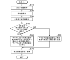
図2は、本実施形態における補正係数の設定手順の一例を示す図である。
(ステップS10)制御部6によってモータ2が回転駆動されている状態にする。この状態において、カウンタ値取得部63は、ホールステージ1~6のそれぞれを構成する2個のホールエッジの時間間隔(すなわち、カウンタ値)を取得する。基準相選択部64は、カウンタ値取得部63が取得するホールステージごとのカウンタ値に基づいて、U相、V相、W相のなかから、検出誤差の検出基準となる基準相を選択する。本実施形態の基準相選択部64は、第1基準相と、第2基準相との2種類の基準相を選択する。
FIG. 2 is a diagram showing an example of a procedure for setting the correction coefficient in this embodiment.
(Step S10) The
第1基準相とは、カウンタ値取得部が取得した6個のホールステージのカウンタ値のうちの最小のカウンタ値である第1ホールステージを構成する2つのホールエッジのうち、ブラシレスモータの回転方向にホールエッジを広げることでカウンタ値が小さくなるホールエッジを第1基準ホールエッジとした場合において、この第1基準ホールエッジがある相である。
第2基準相とは、カウンタ値取得部が取得した6個のホールステージのカウンタ値のうちの最大のカウンタ値と最小のカウンタ値との中間値である第2ホールステージを構成する2つのホールエッジのうち、ブラシレスモータの回転方向にホールエッジを広げることでカウンタ値が小さくなるホールエッジを第2基準ホールエッジとした場合において、この第2基準ホールエッジがある相である。なお、ここでいう「中間値」とは、最大のカウンタ値と最小のカウンタ値とのちょうど中間の値に限定されず、単に最大のカウンタ値未満かつ最小のカウンタ値より大きい値を指す。
第1基準相及び第2基準相について、図3を参照して、より具体的に説明する。
The first reference phase is the phase in which the first reference hall edge is located, when the first reference hall edge is the hall edge whose counter value becomes smaller by widening the hall edge in the rotation direction of the brushless motor, out of the two hall edges that constitute the first hall stage, which is the smallest counter value among the counter values of the six hall stages acquired by the counter value acquisition unit.
The second reference phase is the phase in which the second reference Hall edge is present, when the Hall edge whose counter value becomes smaller by widening the Hall edge in the rotation direction of the brushless motor is defined as the second reference Hall edge, which is the intermediate value between the maximum counter value and the minimum counter value among the counter values of the six Hall stages acquired by the counter value acquisition unit. Note that the "intermediate value" here is not limited to the exact intermediate value between the maximum counter value and the minimum counter value, but simply refers to a value less than the maximum counter value and greater than the minimum counter value.
The first reference phase and the second reference phase will be described in more detail with reference to FIG.
図3は、本実施形態のホールステージごとのカウンタ値の一例を示す図である。ここで、電気角0~60度をホールステージ1、電気角60~120度をホールステージ2、以下同様にして、電気角300~360度をホールステージ6とする。
同図に示す一例の場合、ホールステージ1のカウンタ値は1121、ホールステージ2のカウンタ値は1164、ホールステージ3のカウンタ値は1139、ホールステージ4のカウンタ値は1129、ホールステージ5のカウンタ値は1165、ホールステージ6のカウンタ値は1141である。
この一例の場合、上述の第1ホールステージ(すなわち、カウンタ値取得部が取得した6個のホールステージのカウンタ値のうちの最小のカウンタ値であるホールステージ)は、ホールステージ1である。
3 is a diagram showing an example of the counter value for each hall stage in this embodiment, where an electrical angle of 0 to 60 degrees is
In the example shown in the same figure, the counter value of
In this example, the first hall stage mentioned above (i.e., the hall stage having the smallest counter value among the counter values of the six hall stages acquired by the counter value acquisition unit) is
なお、カウンタ値は、電気角180度ごとに同様の傾向になる場合がある。例えば、ホールステージ1のカウンタ値が比較的小さくなる場合、電気角が180度ずれたホールステージ4も同様にカウンタ値が比較的小さくなる傾向がある。この場合において、カウンタ値が最小になるホールステージを電気角180度ごとに選定してもよい。例えば、電気角0~180度についてホールステージ1を第1ホールステージとし、電気角180~360度についてホールステージ4を第1ホールステージとしてもよい。
つまり、本実施形態において、6個のホールステージのうち「カウンタ値が最小になるホールステージ」とは、電気角0~360度の範囲においてカウンタ値が最小である1つのホールステージを意味する場合と、電気角0~180度の範囲においてカウンタ値が最小であるホールステージと電気角180~360度の範囲においてカウンタ値が最小であるホールステージとをあわせて意味する場合とがある。
The counter value may have a similar tendency for every 180 electrical degrees. For example, when the counter value of
In other words, in this embodiment, among the six hall stages, "the hall stage with the smallest counter value" may mean one hall stage with the smallest counter value in the range of electrical angles from 0 to 360 degrees, or may mean both the hall stage with the smallest counter value in the range of electrical angles from 0 to 180 degrees and the hall stage with the smallest counter value in the range of electrical angles from 180 to 360 degrees.
上述したように、第1基準相とは、第1基準ホールエッジがある相である。第1基準ホールエッジとは、第1ホールステージを構成する2つのホールエッジのうち、ブラシレスモータの回転方向にホールエッジを広げることでカウンタ値が小さくなるホールエッジである。
同図の一例では、第1ホールステージ(ホールステージ1)を構成する2つのホールエッジ(位置検出信号Huの立ち上がり位置と、位置検出信号Lwの立ち下がり位置)のうち、位置検出信号Huの立ち上がり位置をブラシレスモータの回転方向に広げることでホールステージ1のカウンタ値が「1121」よりも小さくなる。一方、位置検出信号Lwの立ち下がり位置をブラシレスモータの回転方向に広げることでホールステージ1のカウンタ値が「1121」よりも大きくなる。この場合、位置検出信号Huの立ち上がり位置が第1基準ホールエッジであり、第1基準相は、位置検出信号Huがある相、すなわちU相である。
As described above, the first reference phase is a phase in which the first reference Hall edge is located. The first reference Hall edge is, of the two Hall edges constituting the first Hall stage, a Hall edge that widens in the rotation direction of the brushless motor to reduce the counter value.
In one example of the figure, of the two Hall edges (the rising edge position of the position detection signal Hu and the falling edge position of the position detection signal Lw) constituting the first Hall stage (Hall stage 1), the counter value of
基準相選択部64は、カウンタ値取得部が取得した6個のホールステージのカウンタ値のうちの最小のカウンタ値である第1ホールステージを構成する2つのホールエッジのうち、ブラシレスモータの回転方向にホールエッジを広げることでカウンタ値が小さくなるホールエッジを第1基準ホールエッジとし、第1基準ホールエッジがある相に対応する位置検出信号を第1基準位置検出信号とする。
すなわち、この一例の場合、基準相選択部64は、U相を第1基準相とし、位置検出信号Huを第1基準位置検出信号として選択する。
The reference
That is, in this example, the reference
なお、基準相選択部64は、電気角180~360度の場合も上述と同様にして、U相を第1基準相とし、位置検出信号Luを第1基準位置検出信号として選択する。
In addition, when the electrical angle is between 180 and 360 degrees, the reference
次に、第2基準相について説明する。
同図に示す例の、電気角0~180度の範囲において、カウンタ値が最小となるのはホールステージ1(カウンタ値は1121)であり、カウンタ値が最大となるのはホールステージ2(カウンタ値は1164)である。つまり、ホールステージ1~3のうち、カウンタ値が中間値となるのはホールステージ3(カウンタ値は1139)である。
また、電気角180~360度の範囲において、カウンタ値が最小となるのはホールステージ4(カウンタ値は1129)であり、カウンタ値が最大となるのはホールステージ5(カウンタ値は1165)である。つまり、ホールステージ4~6のうち、カウンタ値が中間値となるのはホールステージ6(カウンタ値は1141)である。
この場合、第2ホールステージ(すなわち、カウンタ値取得部が取得した6個のホールステージのカウンタ値のうちの最大のカウンタ値と最小のカウンタ値との中間値であるホールステージ)は、電気角0~180度の範囲においてホールステージ3であり、電気角180~360度の範囲においてホールステージ6である。
Next, the second reference phase will be described.
In the example shown in the figure, in the range of electrical angles from 0 to 180 degrees, the counter value is smallest in Hall stage 1 (counter value is 1121), and the counter value is largest in Hall stage 2 (counter value is 1164). In other words, among Hall stages 1 to 3, the counter value is intermediate in Hall stage 3 (counter value is 1139).
In addition, in the range of electrical angles from 180 to 360 degrees, the counter value is smallest in Hall stage 4 (counter value is 1129), and the counter value is largest in Hall stage 5 (counter value is 1165). In other words, among Hall stages 4 to 6, the counter value is intermediate in Hall stage 6 (counter value is 1141).
In this case, the second hall stage (i.e., the hall stage which is the intermediate value between the maximum counter value and the minimum counter value among the six hall stage counter values acquired by the counter value acquisition unit) is
上述したように、第2基準相とは、第2基準ホールエッジがある相である。第2基準ホールエッジとは、第2ホールステージを構成する2つのホールエッジのうち、ブラシレスモータの回転方向にホールエッジを広げることでカウンタ値が小さくなるホールエッジである。
同図の一例では、電気角0~180度の範囲において第2ホールステージ(ホールステージ3)を構成する2つのホールエッジ(位置検出信号Hvの立ち上がり位置と、位置検出信号Luの立ち下がり位置)のうち、位置検出信号Hvの立ち上がり位置をブラシレスモータの回転方向に広げることでホールステージ3のカウンタ値が「1139」よりも小さくなる。一方、位置検出信号Luの立ち下がり位置をブラシレスモータの回転方向に広げることでホールステージ3のカウンタ値が「1139」よりも大きくなる。この場合、位置検出信号Hvの立ち上がり位置が第2基準ホールエッジであり、第2基準相は、位置検出信号Hvがある相、すなわちV相である。
また、電気角180~360度の範囲において第2ホールステージ(ホールステージ6)を構成する2つのホールエッジ(位置検出信号Lvの立ち下がり位置と、位置検出信号Huの立ち上がり位置)のうち、位置検出信号Lvの立ち下がり位置をブラシレスモータの回転方向に広げることでホールステージ6のカウンタ値が「1141」よりも小さくなる。一方、位置検出信号Huの立ち上がり位置をブラシレスモータの回転方向に広げることでホールステージ6のカウンタ値が「1141」よりも大きくなる。この場合、位置検出信号Lvの立ち下がり位置が第2基準ホールエッジであり、第2基準相は、位置検出信号Hvがある相、すなわちV相である。
As described above, the second reference phase is a phase in which the second reference Hall edge is located. The second reference Hall edge is a Hall edge that, of the two Hall edges constituting the second Hall stage, widens in the rotation direction of the brushless motor to reduce the counter value.
In one example of the figure, of the two Hall edges (the rising edge position of the position detection signal Hv and the falling edge position of the position detection signal Lu) that constitute the second Hall stage (Hall stage 3) in the range of electrical angles from 0 to 180 degrees, the counter value of
Furthermore, among the two Hall edges (the falling edge position of the position detection signal Lv and the rising edge position of the position detection signal Hu) constituting the second Hall stage (Hall stage 6) in the range of electrical angles of 180 to 360 degrees, by spreading the falling edge position of the position detection signal Lv in the rotation direction of the brushless motor, the counter value of the
基準相選択部64は、カウンタ値取得部が取得した6個のホールステージのカウンタ値のうちの最大のカウンタ値と最小のカウンタ値との中間値である第2ホールステージを構成する2つのホールエッジのうち、ブラシレスモータの回転方向にホールエッジを広げることでカウンタ値が小さくなるホールエッジを第2基準ホールエッジとし、第2基準ホールエッジがある相に対応する位置検出信号を第2基準位置検出信号とする。
すなわち、この一例の場合、基準相選択部64は、V相を第2基準相とし、位置検出信号Hvを第2基準位置検出信号として選択する。
The reference
That is, in this example, the reference
図2に戻り、補正係数の設定手順についての説明を続ける。
(ステップS20)平均値算出部65は、ブラシレスモータの回転方向に連続する3個のホールステージ分のカウンタ値の平均値を算出する。
図3に示す例では、基準相選択部64は、U相を第1基準相とし、位置検出信号Huを第1基準位置検出信号として選択している。この場合、平均値算出部65は、位置検出信号Huの立ち上がり位置(電気角0度の位置)から位置検出信号Luの立ち下がり位置(電気角180度の位置)までの、ホールステージ1~3を算出対象区間として、カウンタ値の平均値を算出する。
より具体的には、平均値算出部65は、ホールステージ1のカウンタ値1121、ホールステージ2のカウンタ値1164及びホールステージ3のカウンタ値1139を積算した積算値3424を得る。平均値算出部65は、積算値3424を、ホールステージ数(つまり、3)で除して第1平均値1141を得る。
Returning to FIG. 2, the procedure for setting the correction coefficient will be described further.
(Step S20) The average
3, the
More specifically, the average
平均値算出部65は、ホールステージ4~6についても同様にして、ホールステージ4のカウンタ値1129、ホールステージ5のカウンタ値1165及びホールステージ6のカウンタ値1141を積算した積算値3435を得る。平均値算出部65は、積算値3435を、ホールステージ数(つまり、3)で除して第1平均値1145を得る。
The average
また、平均値算出部65は、第2基準相(V相)についても、上述した第1基準相(U相)の場合と同様にしてカウンタ値の平均値を算出する。
同図に示す例では、基準相選択部64は、V相を第2基準相とし、位置検出信号Hvを第2基準位置検出信号として選択している。この場合、平均値算出部65は、位置検出信号Hvの立ち上がり位置(電気角120度の位置)から位置検出信号Lvの立ち下がり位置(電気角300度の位置)までの、ホールステージ3~5を算出対象区間として、カウンタ値の平均値を算出する。
より具体的には、平均値算出部65は、ホールステージ3のカウンタ値1139、ホールステージ4のカウンタ値1129及びホールステージ5のカウンタ値1165を積算した積算値3433を得る。平均値算出部65は、積算値3433を、ホールステージ数(つまり、3)で除して第2平均値1144を得る。
The average
In the example shown in the figure, the
More specifically, the average
平均値算出部65は、ホールステージ6~2についても同様にして、ホールステージ6のカウンタ値1141、ホールステージ1のカウンタ値1121及びホールステージ2のカウンタ値1164を積算した積算値3426を得る。平均値算出部65は、積算値3426を、ホールステージ数(つまり、3)で除して第2平均値1142を得る。
The average
(ステップS30)図2に戻り、検出誤差算出部66は、平均値とホールステージそれぞれのカウンタ値との差分である検出誤差のうち、第1基準位置検出信号を基準とした場合の第1検出誤差と、第2基準位置検出信号を基準とした場合の第2検出誤差とをそれぞれ算出する。
検出誤差算出部66が、第1平均値を用いて第1検出誤差を算出する具体例について図4を、第2平均値を用いて第2検出誤差を算出する具体例について図5を、それぞれ参照して説明する。
(Step S30) Returning to FIG. 2, the detection
A specific example in which the detection
図4は、本実施形態の第1平均値を用いた第1検出誤差の算出結果の一例を示す図である。
具体的には、ホールステージ1~3の範囲において、検出誤差算出部66は、第1平均値1141と、ホールステージ1のカウンタ値1121との差分+(プラス)20を、ホールステージ1とホールステージ2との切替わり位置(つまり、位置検出信号Lwの立ち下がり位置)の第1検出誤差として算出する。検出誤差算出部66は、第1平均値1141と、ホールステージ3のカウンタ値1139との差分-(マイナス)2を、ホールステージ2とホールステージ3の切替わり位置(つまり、位置検出信号Hvの立ち上がり位置)の第1検出誤差として算出する。
また、ホールステージ4~6の範囲において、検出誤差算出部66は、第1平均値1145と、ホールステージ4のカウンタ値1129との差分+16を、ホールステージ4とホールステージ5との切替わり位置(つまり、位置検出信号Hwの立ち上がり位置)の第1検出誤差として算出する。検出誤差算出部66は、第1平均値1145と、ホールステージ6のカウンタ値1141との差分-4を、ホールステージ5とホールステージ6の切替わり位置(つまり、位置検出信号Lvの立ち下がり位置)の第1検出誤差として算出する。
FIG. 4 is a diagram showing an example of a calculation result of the first detection error using the first average value according to the present embodiment.
Specifically, in the range of
Furthermore, in the range of
図5は、本実施形態の第2平均値を用いた第2検出誤差の算出結果の一例を示す図である。
具体的には、ホールステージ3~5の範囲において、検出誤差算出部66は、第2平均値1144と、ホールステージ3のカウンタ値1139との差分+5を、ホールステージ3とホールステージ4との切替わり位置(つまり、位置検出信号Luの立ち下がり位置)の第1検出誤差として算出する。検出誤差算出部66は、第2平均値1144と、ホールステージ5のカウンタ値1165との差分+21を、ホールステージ4とホールステージ5の切替わり位置(つまり、位置検出信号Hwの立ち上がり位置)の第2検出誤差として算出する。
また、ホールステージ6~2の範囲において、検出誤差算出部66は、第2平均値1142と、ホールステージ6のカウンタ値1141との差分+1を、ホールステージ6とホールステージ1との切替わり位置(つまり、位置検出信号Huの立ち上がり位置)の第2検出誤差として算出する。検出誤差算出部66は、第1平均値1142と、ホールステージ2のカウンタ値1164との差分+22を、ホールステージ1とホールステージ2の切替わり位置(つまり、位置検出信号Lwの立ち下がり位置)の第2検出誤差として算出する。
FIG. 5 is a diagram showing an example of a calculation result of the second detection error using the second average value according to the present embodiment.
Specifically, in the range of
Furthermore, in the range of
(ステップS40)図2に戻り、記憶制御部68は、算出された第1検出誤差及び第2検出誤差が負の値を含む否かを判定する。記憶制御部68は、第1検出誤差及び第2検出誤差がいずれも負の値を含むと判定した場合(ステップS40;YES)には、処理をステップS50に進める。記憶制御部68は、第1検出誤差及び第2検出誤差のうちいずれか一方が負の値を含まないと判定した場合(ステップS40;NO)には、処理をステップS60に進める。
(Step S40) Returning to FIG. 2, the
ここで、図3から図5に示した一例では、位置検出信号Lwの立ち下がり位置について第1検出誤差+20、位置検出信号Hvの立ち上がり位置について第1検出誤差-2、位置検出信号Hwの立ち上がり位置について第1検出誤差+16、位置検出信号Lvの立ち下がり位置について第1検出誤差-4である。すなわち、第1検出誤差は、負の値を含む。
また、位置検出信号Luの立ち下がり位置について第2検出誤差+5、位置検出信号Hwの立ち上がり位置について第2検出誤差+21、位置検出信号Huの立ち上がり位置について第2検出誤差+1、位置検出信号Lwの立ち下がり位置について第2検出誤差+22である。すなわち、第2検出誤差は、負の値を含まない。
この一例の場合には、記憶制御部68は、第1検出誤差及び第2検出誤差のうちいずれか一方が負の値を含まないと判定し、処理をステップS60に進める。
3 to 5, the first detection error for the falling edge position of the position detection signal Lw is +20, the first detection error for the rising edge position of the position detection signal Hv is -2, the first detection error for the rising edge position of the position detection signal Hw is +16, and the first detection error for the falling edge position of the position detection signal Lv is -4. That is, the first detection errors include negative values.
Further, the second detection error for the falling edge position of the position detection signal Lu is +5, the second detection error for the rising edge position of the position detection signal Hw is +21, the second detection error for the rising edge position of the position detection signal Hu is +1, and the second detection error for the falling edge position of the position detection signal Lw is +22. That is, the second detection errors do not include negative values.
In this example, the
一方、センサマグネットの着磁ばらつき、ホールセンサの取り付け位置のばらつきなどによっては、第1検出誤差及び第2検出誤差がいずれも負の値を含む場合がある。この場合には、記憶制御部68は、処理をステップS50に進める。
On the other hand, depending on the variation in magnetization of the sensor magnet, the variation in the mounting position of the Hall sensor, etc., both the first detection error and the second detection error may include negative values. In this case, the
(ステップS50)図2に戻り、記憶制御部68は、第1検出誤差と第2検出誤差とのうち負の値の絶対値が小さい方を補正値として選択する。例えば、第1検出誤差が-(マイナス)1を含み、第2検出誤差が-(マイナス)7を含む場合には、第1検出誤差の方が負の値の絶対値が小さい。この場合には、記憶制御部68は、第1検出誤差を補正値として選択する。
記憶制御部68は、検出誤差に含まれる負の値を0(ゼロ)に置き換える。例えば、第1検出誤差に含まれる-(マイナス)1を0(ゼロ)に置き換える。
記憶制御部68は、0(ゼロ)に置き換えたのちの補正値を、補正係数算出部67に供給する。
(Step S50) Returning to Fig. 2, the
The
The
(ステップS60)一方、第1検出誤差及び第2検出誤差のうちいずれか一方が負の値を含まない場合には、記憶制御部68は、第1検出誤差と第2検出誤差とのうち負の値を含まない方を補正値として選択する。例えば、第1検出誤差が負の値を含み、第2検出誤差が負の値を含まない場合には、記憶制御部68は、第2検出誤差を補正値として選択する。
記憶制御部68は、選択した補正値を、補正係数算出部67に供給する。
(Step S60) On the other hand, if either the first detection error or the second detection error does not include a negative value, the
The
(ステップS70)補正係数算出部67は、記憶制御部68が選択した補正値を上述した平均値で除算することにより、補正係数を算出する。
具体的には、第1検出誤差が補正値として供給された場合には、補正係数算出部67は、図4に示した、位置検出信号Lwの立ち下がり位置の第1検出誤差+20を第1平均値1141で除算した値、位置検出信号Hvの立ち上がり位置の第1検出誤差+16を第1平均値1145で除算した値、位置検出信号Lvの立ち下がり位置の第1検出誤差-4を第1平均値1145で除算した値、をそれぞれ第1補正係数として算出する。
また、第2検出誤差が補正値として供給されたされた場合には、補正係数算出部67は、図5に示した、位置検出信号Luの立ち下がり位置の第2検出誤差+5を第2平均値1144で除算した値、位置検出信号Hwの立ち上がり位置の第2検出誤差+21を第2平均値1144で除算した値、位置検出信号Huの立ち上がり位置の第2検出誤差+1を第2平均値1142で除算した値、位置検出信号Lwの立ち下がり位置の第2検出誤差+22を第2平均値1142で除算した値、をそれぞれ第2補正係数として算出する。
(Step S70) The correction
Specifically, when the first detection error is supplied as the correction value, the correction
In addition, when the second detection error is supplied as a correction value, the correction
すなわち、補正係数算出部67は、第1検出誤差を平均値で除算した第1補正係数又は、第2検出誤差を平均値で除算した第2補正係数を算出する。
記憶制御部68は、算出された補正係数を記憶部69に記憶させる。
That is, the correction
The
すなわち、記憶制御部68は、算出された第1補正係数及び第2補正係数が負の値を含む否かに基づいて、第1検出誤差と第2検出誤差とのいずれか一方から算出された補正係数を、ホールステージそれぞれの補正係数として記憶させる。
That is, the
また、ステップS50において説明したように、記憶制御部68は、算出された第1検出誤差と第2検出誤差とがいずれも負の値を含む場合には、第1検出誤差と第2検出誤差とのうち負の値の絶対値が小さい方から算出された補正係数を記憶部69に記憶させる。
Also, as explained in step S50, when the calculated first detection error and second detection error both contain negative values, the
また、ステップS60において説明したように、記憶制御部68は、算出された第1検出誤差と第2検出誤差とのうち一方が負の値を含まない場合には、第1検出誤差と第2検出誤差とのうち負の値を含まない方から算出された補正係数を記憶させる記憶部69に記憶させる。
Also, as explained in step S60, if one of the calculated first detection error and second detection error does not contain a negative value, the
このようにして記憶部69には、モータ制御装置の出荷前に行われる補正係数の算出による補正係数が記憶される。
In this way, the
これにより、切り替え制御部62は、前回のホールステージのそれぞれのカウンタ値に、予め設定された補正係数を乗じた値を、今回のホールエッジのそれぞれの遅延時間として、遅延時間で補正されたホールエッジのそれぞれに基づいて電気角60度の期間を有するPWM指令信号を生成し、ゲート制御電圧出力部61に電気角60度の期間を有するPWM信号を出力させ、モータ2の正逆転駆動制御を行う。
As a result, the switching
このように構成された本実施形態のモータ制御装置によれば、ホールステージの切り替わりを示すホールエッジ毎に位置検出信号を補正することができるため、振動や異音の発生の抑制を精度良く行うことができる。 The motor control device of this embodiment, configured in this way, can correct the position detection signal for each Hall edge that indicates the switching of the Hall stage, thereby enabling precise suppression of vibrations and abnormal noise.
ここで、モータ装置100をより小型化するためや、外部環境からの磁界の影響を低減するために、ホールセンサをセンサマグネット22bに比較的接近させた設計がなされる場合がある。このような場合、基板上に一列に配置された3つのホールセンサ(23u、23v、23w)どうしの配置間隔がより狭くなる(すなわち、ホールセンサピッチが狭小化する)ことがある。このような場合、センサマグネットの着磁ばらつき、ホールセンサの取り付け位置のばらつきが、ホールエッジ間の時間間隔(つまり、カウント値)の誤差に与える影響が比較的大きくなる。したがって、ホールセンサピッチを狭小化した場合、センサマグネットの着磁ばらつき、ホールセンサの取り付け位置のばらつきの状態によっては、ロータの回転方向を基準とした場合において、カウント値を補正する補正値が負の値になりやすい。
ロータの回転方向を基準とした場合において、補正値(すなわち、経過時間)が負の値であるということは、時間軸を過去に遡って補正することを意味している。したがって、補正値が負の値になってしまうと、補正が実現できないことになる。
Here, in order to make the
When the rotation direction of the rotor is used as a reference, a negative correction value (i.e., elapsed time) means that the correction is made by going back in time, so if the correction value becomes a negative value, the correction cannot be realized.
そこで、本実施形態のモータ制御装置は、補正値(すなわち、検出誤差)が負の値であるか否かを判定し、補正値が負にならないようにして補正係数が設定されている。このように構成された本実施形態のモータ制御装置によれば、ホールセンサピッチが狭小化した場合であっても、位置検出信号を補正することができるため、振動や異音の発生の抑制を精度良く行うことができる。 The motor control device of this embodiment therefore determines whether the correction value (i.e., the detection error) is a negative value, and sets the correction coefficient so that the correction value does not become negative. With the motor control device of this embodiment configured in this way, even if the Hall sensor pitch is narrowed, the position detection signal can be corrected, so that the occurrence of vibrations and abnormal noise can be suppressed with high precision.
また、本実施形態のモータ制御装置は、上述したように小型化できるため、低コストで製造することができ、また、製造に要する材料の量や廃棄物の量を低減することができる。したがって、本実施形態のモータ制御装置によれば、国連が主導する持続可能な開発目標(SDGs)の目標7「全ての人々の、安価かつ信頼できる持続可能な近代的エネルギーへのアクセスを確保する」、及び目標12「持続可能な方法で生産し、責任をもって消費する」の達成に寄与することができる。 Furthermore, because the motor control device of this embodiment can be miniaturized as described above, it can be manufactured at low cost and the amount of materials required for manufacturing and the amount of waste can be reduced. Therefore, the motor control device of this embodiment can contribute to achieving Goal 7 "Ensure access to affordable, reliable, sustainable and modern energy for all" and Goal 12 "Produce sustainably and consume responsibly" of the Sustainable Development Goals (SDGs) led by the United Nations.
なお、上述した実施形態では、制御部6が、カウンタ値取得部63と、基準相選択部64と、平均値算出部65と、検出誤差算出部66と、補正係数算出部67と、記憶制御部68と、記憶部69とを備える場合を一例にして説明したが、これに限られない。カウンタ値取得部63、基準相選択部64、平均値算出部65、検出誤差算出部66、補正係数算出部67、記憶制御部68、及び記憶部69は、モータ装置100が備える他の装置や、モータ装置100の外部にある試験装置などの装置に備えられていてもよい。
In the above embodiment, the
制御部6が有する機能の少なくとも一部は、LSI(Large Scale Integration)、ASIC(Application Specific Integrated Circuit)、FPGA(Field-Programmable Gate Array)、GPU(Graphics Processing Unit)等の回路部(circuitry)を含むハードウェアにより実現されてもよい。或いは、モータ制御装置30が有する機能の少なくとも一部は、ソフトウェアとハードウェアの協働により実現されてもよい。また、これらのハードウェアは、一つに統合されていてもよいし、複数に分かれていてもよい。
At least some of the functions of the
以上、本発明の実施形態について図面を参照しながら説明した。ただし、モータ制御装置及びモータ制御方法は、上述した実施形態に限られるものではなく、本発明の要旨を逸脱しない範囲内において種々の変形、置換、組み合わせ及び設計変更の少なくとも一つを加えることができる。 The above describes an embodiment of the present invention with reference to the drawings. However, the motor control device and motor control method are not limited to the above-described embodiment, and various modifications, substitutions, combinations, and/or design changes can be made without departing from the spirit of the present invention.
また、上述した本発明の実施形態の効果は、一例として説明した効果である。したがって、本発明の実施形態は、上述した効果以外にも上述した実施形態の記載から当業者が認識し得る他の効果も奏し得る。 The effects of the above-described embodiments of the present invention are merely examples. Therefore, in addition to the effects described above, the embodiments of the present invention may also have other effects that a person skilled in the art may recognize from the description of the above-described embodiments.
2…モータ、23…回転軸センサ、6…制御部、21…ステータ、21u,21v,21w…電機子コイル、50…インバータ、51a~51f…スイッチング素子、61…ゲート制御電圧出力部、62…切り替え制御部、63…カウンタ値取得部、64…基準相選択部、65…平均値算出部、66…検出誤差算出部、67…補正係数算出部、68…記憶制御部、69…記憶部、100…モータ装置 2...motor, 23...rotating shaft sensor, 6...control unit, 21...stator, 21u, 21v, 21w...armature coil, 50...inverter, 51a-51f...switching elements, 61...gate control voltage output unit, 62...switching control unit, 63...counter value acquisition unit, 64...reference phase selection unit, 65...average value calculation unit, 66...detection error calculation unit, 67...correction coefficient calculation unit, 68...storage control unit, 69...storage unit, 100...motor device
Claims (6)
前記コイルに流す電流を切り替え可能に配置された複数のスイッチング素子と、
前記コイルのそれぞれに対応して設けられ、前記ロータの回転位置を検出する複数のセンサと、
前記複数のセンサの出力である位置検出信号に基づいて前記スイッチング素子を切り替える駆動信号を出力する制御部と、を備え、
前記制御部は、
前記複数のセンサの出力である位置検出信号の電位の組合せで表される6個のホールステージのそれぞれを構成する補正されたホールエッジに基づいて前記スイッチング素子を切り替える駆動信号を出力するゲート制御電圧出力部と、
前記ホールステージのそれぞれを構成する2個のホールエッジの間の時間で表される前記ホールステージの時間であるカウンタ値を、前記位置検出信号から取得するカウンタ値取得部と、
前回のホールステージのそれぞれのカウンタ値と、予め設定された補正係数とを演算した値を、今回のホールエッジのそれぞれの遅延時間として、前記遅延時間で補正されたホールエッジのそれぞれに基づいて、前記ゲート制御電圧出力部に前記駆動信号を出力させる切り替え制御部と、
を有し、
前記補正係数は、
前記カウンタ値取得部が取得した6個のホールステージのカウンタ値のうちの最小のカウンタ値である第1ホールステージを構成する2つのホールエッジのうち、前記ブラシレスモータの回転方向にホールエッジを広げることでカウンタ値が小さくなるホールエッジを第1基準ホールエッジとし、前記第1基準ホールエッジがある相に対応する前記位置検出信号を第1基準位置検出信号とし、
前記カウンタ値取得部が取得した6個のホールステージのカウンタ値のうちの最大のカウンタ値と前記最小のカウンタ値との中間値である第2ホールステージを構成する2つのホールエッジのうち、前記ブラシレスモータの回転方向にホールエッジを広げることでカウンタ値が小さくなるホールエッジを第2基準ホールエッジとし、前記第2基準ホールエッジがある相に対応する前記位置検出信号を第2基準位置検出信号とし、
前記ブラシレスモータの回転方向に連続する3個のホールステージ分のカウンタ値の平均値と、前記ホールステージそれぞれのカウンタ値との差分である検出誤差のうち、前記第1基準位置検出信号を基準とした場合の第1検出誤差と、前記第2基準位置検出信号を基準とした場合の第2検出誤差とについて、
前記第1検出誤差と、前記第2検出誤差とが、負の値を含む否かに基づいて、前記第1検出誤差と前記第2検出誤差とのいずれか一方から算出された補正係数が選択されて設定されたものである
モータ制御装置。 A motor control device controls the rotation of a rotor by controlling the energization of three-phase coils of a brushless motor,
A plurality of switching elements arranged to be able to switch the current flowing through the coil;
a plurality of sensors provided corresponding to the coils, each of the sensors detecting a rotational position of the rotor;
a control unit that outputs a drive signal for switching the switching element based on position detection signals that are outputs of the plurality of sensors;
The control unit is
a gate control voltage output unit that outputs a drive signal for switching the switching element based on a corrected Hall edge constituting each of six Hall stages represented by a combination of potentials of the position detection signals that are outputs of the plurality of sensors;
a counter value acquiring unit that acquires a counter value, which is a time of the hall stage represented by a time between two hall edges constituting each of the hall stages, from the position detection signal;
a switching control unit that outputs the drive signal to the gate control voltage output unit based on each Hall edge corrected by the delay time, the delay time being calculated by calculating a counter value of each Hall stage of the previous time and a preset correction coefficient, and the gate control voltage output unit outputs the drive signal to the gate control voltage output unit based on each Hall edge corrected by the delay time;
having
The correction coefficient is
Among the two Hall edges constituting a first Hall stage having the smallest counter value among the counter values of the six Hall stages acquired by the counter value acquisition unit, the Hall edge whose counter value becomes smaller by expanding the Hall edge in the rotation direction of the brushless motor is defined as a first reference Hall edge, and the position detection signal corresponding to the phase in which the first reference Hall edge is located is defined as a first reference position detection signal;
Among the two Hall edges constituting a second Hall stage, which is an intermediate value between the maximum counter value and the minimum counter value among the counter values of the six Hall stages acquired by the counter value acquisition unit, the Hall edge whose counter value becomes smaller by expanding the Hall edge in the rotation direction of the brushless motor is defined as a second reference Hall edge, and the position detection signal corresponding to the phase in which the second reference Hall edge is located is defined as a second reference position detection signal;
Among the detection errors which are the differences between the average value of the counter values of three consecutive Hall stages in the rotational direction of the brushless motor and the counter values of the Hall stages, a first detection error when the first reference position detection signal is used as a reference and a second detection error when the second reference position detection signal is used as a reference are calculated as follows:
a correction coefficient calculated from either the first detection error or the second detection error is selected and set based on whether the first detection error or the second detection error includes a negative value.
前記位置検出信号の中から前記第1基準位置検出信号及び前記第2基準位置検出信号を選択する基準相選択部と、
前記平均値を算出する平均値算出部と、
前記第1検出誤差及び前記第2検出誤差を算出する検出誤差算出部と、
前記第1検出誤差を前記平均値で除算した第1補正係数及び前記第2検出誤差を前記平均値で除算した第2補正係数を算出する補正係数算出部と、
算出された前記第1検出誤差及び前記第2検出誤差が負の値を含む否かに基づいて、前記第1補正係数と前記第2補正係数とのいずれか一方を、前記ホールステージそれぞれの前記補正係数として記憶させる記憶制御部と、
を有する請求項1に記載のモータ制御装置。 The control unit is
a reference phase selection unit that selects the first reference position detection signal and the second reference position detection signal from the position detection signals;
an average value calculation unit for calculating the average value;
a detection error calculation unit that calculates the first detection error and the second detection error;
a correction coefficient calculation unit that calculates a first correction coefficient by dividing the first detection error by the average value and a second correction coefficient by dividing the second detection error by the average value;
a storage control unit that stores one of the first correction coefficient and the second correction coefficient as the correction coefficient for each of the hall stages based on whether the calculated first detection error and the calculated second detection error include negative values;
The motor control device according to claim 1 , further comprising:
算出された前記第1検出誤差と前記第2検出誤差とのうち一方が負の値を含まない場合には、前記第1検出誤差と前記第2検出誤差とのうち負の値を含まない方から算出された前記補正係数を記憶させる請求項2に記載のモータ制御装置。 The storage control unit,
3. The motor control device according to claim 2, wherein when one of the calculated first detection error and the calculated second detection error does not include a negative value, the correction coefficient calculated from the one of the first detection error and the second detection error that does not include a negative value is stored.
算出された前記第1検出誤差と前記第2検出誤差とがいずれも負の値を含む場合には、前記第1検出誤差と前記第2検出誤差とのうち負の値の絶対値が小さい方から算出された前記補正係数を記憶させる請求項2又は請求項3に記載のモータ制御装置。 The storage control unit,
4. The motor control device according to claim 2, wherein when the calculated first detection error and the calculated second detection error both include negative values, the correction coefficient calculated from the first detection error or the second detection error, whichever has the smaller absolute value of the negative value, is stored.
前記コイルに流す電流を切り替え可能に配置された複数のスイッチング素子と、
前記コイルのそれぞれに対応して設けられ、前記ロータの回転位置を検出する複数のセンサと、
前記複数のセンサの出力である位置検出信号に基づいて前記スイッチング素子を切り替える駆動信号を出力する制御部と、を備え、
前記制御部は、ゲート制御電圧出力部と、カウンタ値取得部と、切り替え制御部とを有するモータ制御方法であって、
前記ゲート制御電圧出力部が、前記複数のセンサの出力である位置検出信号の電位の組合せで表される6個のホールステージのそれぞれを構成する補正されたホールエッジに基づいて前記スイッチング素子を切り替える駆動信号を出力するゲート制御電圧出力工程と、
前記カウンタ値取得部が、前記ホールステージのそれぞれを構成する2個のホールエッジの間の時間で表される前記ホールステージの時間であるカウンタ値を、前記位置検出信号から取得するカウンタ値取得工程と、
前記切り替え制御部が、前回のホールステージのそれぞれのカウンタ値に、予め設定された補正係数を乗じた値を、今回のホールエッジのそれぞれの遅延時間として、前記遅延時間で補正されたホールエッジのそれぞれに基づいて、前記ゲート制御電圧出力部に前記駆動信号を出力させる切り替え制御工程と、
を有し、
前記補正係数は、
前記カウンタ値取得部が取得した6個のホールステージのカウンタ値のうちの最小のカウンタ値である第1ホールステージを構成する2つのホールエッジのうち、前記ブラシレスモータの回転方向にホールエッジを広げることでカウンタ値が小さくなるホールエッジを第1基準ホールエッジとし、前記第1基準ホールエッジがある相に対応する前記位置検出信号を第1基準位置検出信号とし、
前記カウンタ値取得部が取得した6個のホールステージのカウンタ値のうちの最大のカウンタ値と前記最小のカウンタ値との中間値である第2ホールステージを構成する2つのホールエッジのうち、前記ブラシレスモータの回転方向にホールエッジを広げることでカウンタ値が小さくなるホールエッジを第2基準ホールエッジとし、前記第2基準ホールエッジがある相に対応する前記位置検出信号を第2基準位置検出信号とし、
前記ブラシレスモータの回転方向に連続する3個のホールステージ分のカウンタ値の平均値と、前記ホールステージそれぞれのカウンタ値との差分である検出誤差のうち、前記第1基準位置検出信号を基準とした場合の第1検出誤差と、前記第2基準位置検出信号を基準とした場合の第2検出誤差とについて、
前記第1検出誤差と、前記第2検出誤差とが、負の値を含む否かに基づいて、前記第1検出誤差と前記第2検出誤差とのいずれか一方から算出された補正係数が選択されて設定されたものである
モータ制御方法。 A motor control device controls the rotation of a rotor by controlling the energization of three-phase coils of a brushless motor,
A plurality of switching elements arranged to be able to switch the current flowing through the coil;
a plurality of sensors provided corresponding to the coils, each of the sensors detecting a rotational position of the rotor;
a control unit that outputs a drive signal for switching the switching element based on position detection signals that are outputs of the plurality of sensors;
The control unit includes a gate control voltage output unit, a counter value acquisition unit, and a switching control unit,
a gate control voltage output step in which the gate control voltage output unit outputs a drive signal for switching the switching elements based on a corrected Hall edge constituting each of six Hall stages represented by a combination of potentials of the position detection signals which are outputs of the plurality of sensors;
a counter value acquiring step in which the counter value acquiring unit acquires a counter value, which is a time of the hall stage represented by a time between two hall edges constituting each of the hall stages, from the position detection signal;
a switching control step in which the switching control unit multiplies each counter value of the previous Hall stage by a preset correction coefficient, sets the value as the delay time of each Hall edge of the current Hall stage, and causes the gate control voltage output unit to output the drive signal based on each Hall edge corrected by the delay time;
having
The correction coefficient is
Among the two Hall edges constituting a first Hall stage having the smallest counter value among the counter values of the six Hall stages acquired by the counter value acquisition unit, the Hall edge whose counter value becomes smaller by expanding the Hall edge in the rotation direction of the brushless motor is defined as a first reference Hall edge, and the position detection signal corresponding to the phase in which the first reference Hall edge is located is defined as a first reference position detection signal;
Among the two Hall edges constituting a second Hall stage, which is an intermediate value between the maximum counter value and the minimum counter value among the counter values of the six Hall stages acquired by the counter value acquisition unit, the Hall edge whose counter value becomes smaller by expanding the Hall edge in the rotation direction of the brushless motor is defined as a second reference Hall edge, and the position detection signal corresponding to the phase in which the second reference Hall edge is located is defined as a second reference position detection signal;
Among the detection errors which are the differences between the average value of the counter values of three consecutive Hall stages in the rotational direction of the brushless motor and the counter values of the Hall stages, a first detection error when the first reference position detection signal is used as a reference and a second detection error when the second reference position detection signal is used as a reference are calculated as follows:
a correction coefficient calculated from either the first detection error or the second detection error is selected and set based on whether the first detection error or the second detection error includes a negative value.
Priority Applications (4)
| Application Number | Priority Date | Filing Date | Title |
|---|---|---|---|
| JP2022005670A JP7658925B2 (en) | 2022-01-18 | 2022-01-18 | Motor control device and motor control method |
| US17/978,977 US12074554B2 (en) | 2022-01-18 | 2022-11-02 | Motor control device and motor control method |
| CN202211360825.5A CN116505805A (en) | 2022-01-18 | 2022-11-02 | Motor control device and motor control method |
| DE102022129284.3A DE102022129284A1 (en) | 2022-01-18 | 2022-11-07 | ENGINE CONTROL DEVICE AND ENGINE CONTROL METHOD |
Applications Claiming Priority (1)
| Application Number | Priority Date | Filing Date | Title |
|---|---|---|---|
| JP2022005670A JP7658925B2 (en) | 2022-01-18 | 2022-01-18 | Motor control device and motor control method |
Publications (2)
| Publication Number | Publication Date |
|---|---|
| JP2023104583A JP2023104583A (en) | 2023-07-28 |
| JP7658925B2 true JP7658925B2 (en) | 2025-04-08 |
Family
ID=86990372
Family Applications (1)
| Application Number | Title | Priority Date | Filing Date |
|---|---|---|---|
| JP2022005670A Active JP7658925B2 (en) | 2022-01-18 | 2022-01-18 | Motor control device and motor control method |
Country Status (4)
| Country | Link |
|---|---|
| US (1) | US12074554B2 (en) |
| JP (1) | JP7658925B2 (en) |
| CN (1) | CN116505805A (en) |
| DE (1) | DE102022129284A1 (en) |
Families Citing this family (1)
| Publication number | Priority date | Publication date | Assignee | Title |
|---|---|---|---|---|
| CN119396207B (en) * | 2024-11-06 | 2025-06-20 | 广汽埃安新能源汽车股份有限公司 | A method, device, equipment and storage medium for position switching of a multi-way valve |
Citations (3)
| Publication number | Priority date | Publication date | Assignee | Title |
|---|---|---|---|---|
| JP2017121105A (en) | 2015-12-28 | 2017-07-06 | 株式会社ミツバ | Motor control device and method of controlling the same |
| JP2018133911A (en) | 2017-02-15 | 2018-08-23 | 株式会社ミツバ | Motor control device, and motor control device controlling method |
| JP2020068613A (en) | 2018-10-25 | 2020-04-30 | 株式会社ミツバ | Motor control device and control method for motor control device |
Family Cites Families (1)
| Publication number | Priority date | Publication date | Assignee | Title |
|---|---|---|---|---|
| US6081087A (en) * | 1997-10-27 | 2000-06-27 | Matsushita Electric Industrial Co., Ltd. | Motor control apparatus |
-
2022
- 2022-01-18 JP JP2022005670A patent/JP7658925B2/en active Active
- 2022-11-02 CN CN202211360825.5A patent/CN116505805A/en active Pending
- 2022-11-02 US US17/978,977 patent/US12074554B2/en active Active
- 2022-11-07 DE DE102022129284.3A patent/DE102022129284A1/en active Pending
Patent Citations (3)
| Publication number | Priority date | Publication date | Assignee | Title |
|---|---|---|---|---|
| JP2017121105A (en) | 2015-12-28 | 2017-07-06 | 株式会社ミツバ | Motor control device and method of controlling the same |
| JP2018133911A (en) | 2017-02-15 | 2018-08-23 | 株式会社ミツバ | Motor control device, and motor control device controlling method |
| JP2020068613A (en) | 2018-10-25 | 2020-04-30 | 株式会社ミツバ | Motor control device and control method for motor control device |
Also Published As
| Publication number | Publication date |
|---|---|
| JP2023104583A (en) | 2023-07-28 |
| US12074554B2 (en) | 2024-08-27 |
| CN116505805A (en) | 2023-07-28 |
| DE102022129284A1 (en) | 2023-07-20 |
| US20230231499A1 (en) | 2023-07-20 |
Similar Documents
| Publication | Publication Date | Title |
|---|---|---|
| US8278853B2 (en) | Brushless motor control apparatus, brushless motor and control method of brushless motor | |
| US8917041B2 (en) | Phase-shift detection device, motor drive device, brushless motor, and phase-shift detection method | |
| JP4100442B2 (en) | Motor drive control device and motor drive control system | |
| JP6695247B2 (en) | Motor control device and control method of motor control device | |
| EP3584924B1 (en) | Motor control device and method for controlling motor control device | |
| CN108432122B (en) | Motor control device and control method for motor control device | |
| JP6622249B2 (en) | Motor drive control device and motor drive control method | |
| JP2016021850A (en) | Method for detecting motor stall and electronic circuit | |
| CN109983688B (en) | Brushless motor control device and brushless motor control method | |
| JP2009240041A (en) | Brushless motor controller and brushless motor | |
| JP2020068613A (en) | Motor control device and control method for motor control device | |
| JP7658925B2 (en) | Motor control device and motor control method | |
| JP6619382B2 (en) | Motor drive control device and control method of motor drive control device | |
| JP5585341B2 (en) | Brushless motor drive device | |
| JP2020054030A (en) | Abnormality detection device, motor device, abnormality detection method, and motor drive control method | |
| JP7122917B2 (en) | Brushless motor and brushless motor control method | |
| JP6678136B2 (en) | Motor drive control device and motor drive control method | |
| JP2005304133A (en) | Motor driving method and motor driving apparatus | |
| JP7577519B2 (en) | Motor driving device and motor driving method | |
| JP2025030409A (en) | Motor Control Device | |
| US9722516B2 (en) | Motor drive circuit and method |
Legal Events
| Date | Code | Title | Description |
|---|---|---|---|
| A621 | Written request for application examination |
Free format text: JAPANESE INTERMEDIATE CODE: A621 Effective date: 20240731 |
|
| A977 | Report on retrieval |
Free format text: JAPANESE INTERMEDIATE CODE: A971007 Effective date: 20250217 |
|
| TRDD | Decision of grant or rejection written | ||
| A01 | Written decision to grant a patent or to grant a registration (utility model) |
Free format text: JAPANESE INTERMEDIATE CODE: A01 Effective date: 20250305 |
|
| A61 | First payment of annual fees (during grant procedure) |
Free format text: JAPANESE INTERMEDIATE CODE: A61 Effective date: 20250327 |
|
| R150 | Certificate of patent or registration of utility model |
Ref document number: 7658925 Country of ref document: JP Free format text: JAPANESE INTERMEDIATE CODE: R150 |