JP7658552B2 - Three-way valve for flow control and temperature control device - Google Patents

Three-way valve for flow control and temperature control device Download PDF

Info

Publication number
JP7658552B2
JP7658552B2 JP2020200612A JP2020200612A JP7658552B2 JP 7658552 B2 JP7658552 B2 JP 7658552B2 JP 2020200612 A JP2020200612 A JP 2020200612A JP 2020200612 A JP2020200612 A JP 2020200612A JP 7658552 B2 JP7658552 B2 JP 7658552B2
Authority
JP
Japan
Prior art keywords
valve
temperature
fluid
valve body
valve seat
Prior art date
Legal status (The legal status is an assumption and is not a legal conclusion. Google has not performed a legal analysis and makes no representation as to the accuracy of the status listed.)
Active
Application number
JP2020200612A
Other languages
Japanese (ja)
Other versions
JP2022088264A (en
Inventor
亮二 市山
克通 平岡
Current Assignee (The listed assignees may be inaccurate. Google has not performed a legal analysis and makes no representation or warranty as to the accuracy of the list.)
Shinwa Controls Co Ltd
Original Assignee
Shinwa Controls Co Ltd
Priority date (The priority date is an assumption and is not a legal conclusion. Google has not performed a legal analysis and makes no representation as to the accuracy of the date listed.)
Filing date
Publication date
Application filed by Shinwa Controls Co Ltd filed Critical Shinwa Controls Co Ltd
Priority to JP2020200612A priority Critical patent/JP7658552B2/en
Priority to TW110144111A priority patent/TWI902983B/en
Priority to CN202180080285.2A priority patent/CN116529513A/en
Priority to KR1020237021644A priority patent/KR20230108340A/en
Priority to PCT/JP2021/043724 priority patent/WO2022118805A1/en
Priority to US18/038,326 priority patent/US12305766B2/en
Publication of JP2022088264A publication Critical patent/JP2022088264A/en
Application granted granted Critical
Publication of JP7658552B2 publication Critical patent/JP7658552B2/en
Active legal-status Critical Current
Anticipated expiration legal-status Critical

Links

Images

Classifications

    • FMECHANICAL ENGINEERING; LIGHTING; HEATING; WEAPONS; BLASTING
    • F16ENGINEERING ELEMENTS AND UNITS; GENERAL MEASURES FOR PRODUCING AND MAINTAINING EFFECTIVE FUNCTIONING OF MACHINES OR INSTALLATIONS; THERMAL INSULATION IN GENERAL
    • F16KVALVES; TAPS; COCKS; ACTUATING-FLOATS; DEVICES FOR VENTING OR AERATING
    • F16K11/00Multiple-way valves, e.g. mixing valves; Pipe fittings incorporating such valves
    • F16K11/02Multiple-way valves, e.g. mixing valves; Pipe fittings incorporating such valves with all movable sealing faces moving as one unit
    • F16K11/08Multiple-way valves, e.g. mixing valves; Pipe fittings incorporating such valves with all movable sealing faces moving as one unit comprising only taps or cocks
    • F16K11/085Multiple-way valves, e.g. mixing valves; Pipe fittings incorporating such valves with all movable sealing faces moving as one unit comprising only taps or cocks with cylindrical plug
    • FMECHANICAL ENGINEERING; LIGHTING; HEATING; WEAPONS; BLASTING
    • F16ENGINEERING ELEMENTS AND UNITS; GENERAL MEASURES FOR PRODUCING AND MAINTAINING EFFECTIVE FUNCTIONING OF MACHINES OR INSTALLATIONS; THERMAL INSULATION IN GENERAL
    • F16KVALVES; TAPS; COCKS; ACTUATING-FLOATS; DEVICES FOR VENTING OR AERATING
    • F16K27/00Construction of housing; Use of materials therefor
    • F16K27/06Construction of housing; Use of materials therefor of taps or cocks
    • F16K27/065Construction of housing; Use of materials therefor of taps or cocks with cylindrical plugs
    • FMECHANICAL ENGINEERING; LIGHTING; HEATING; WEAPONS; BLASTING
    • F16ENGINEERING ELEMENTS AND UNITS; GENERAL MEASURES FOR PRODUCING AND MAINTAINING EFFECTIVE FUNCTIONING OF MACHINES OR INSTALLATIONS; THERMAL INSULATION IN GENERAL
    • F16KVALVES; TAPS; COCKS; ACTUATING-FLOATS; DEVICES FOR VENTING OR AERATING
    • F16K5/00Plug valves; Taps or cocks comprising only cut-off apparatus having at least one of the sealing faces shaped as a more or less complete surface of a solid of revolution, the opening and closing movement being predominantly rotary
    • F16K5/04Plug valves; Taps or cocks comprising only cut-off apparatus having at least one of the sealing faces shaped as a more or less complete surface of a solid of revolution, the opening and closing movement being predominantly rotary with plugs having cylindrical surfaces; Packings therefor
    • F16K5/0414Plug channel at 90 degrees to the inlet
    • FMECHANICAL ENGINEERING; LIGHTING; HEATING; WEAPONS; BLASTING
    • F16ENGINEERING ELEMENTS AND UNITS; GENERAL MEASURES FOR PRODUCING AND MAINTAINING EFFECTIVE FUNCTIONING OF MACHINES OR INSTALLATIONS; THERMAL INSULATION IN GENERAL
    • F16KVALVES; TAPS; COCKS; ACTUATING-FLOATS; DEVICES FOR VENTING OR AERATING
    • F16K5/00Plug valves; Taps or cocks comprising only cut-off apparatus having at least one of the sealing faces shaped as a more or less complete surface of a solid of revolution, the opening and closing movement being predominantly rotary
    • F16K5/04Plug valves; Taps or cocks comprising only cut-off apparatus having at least one of the sealing faces shaped as a more or less complete surface of a solid of revolution, the opening and closing movement being predominantly rotary with plugs having cylindrical surfaces; Packings therefor
    • F16K5/0457Packings
    • F16K5/0471Packings between housing and plug
    • FMECHANICAL ENGINEERING; LIGHTING; HEATING; WEAPONS; BLASTING
    • F16ENGINEERING ELEMENTS AND UNITS; GENERAL MEASURES FOR PRODUCING AND MAINTAINING EFFECTIVE FUNCTIONING OF MACHINES OR INSTALLATIONS; THERMAL INSULATION IN GENERAL
    • F16KVALVES; TAPS; COCKS; ACTUATING-FLOATS; DEVICES FOR VENTING OR AERATING
    • F16K5/00Plug valves; Taps or cocks comprising only cut-off apparatus having at least one of the sealing faces shaped as a more or less complete surface of a solid of revolution, the opening and closing movement being predominantly rotary
    • F16K5/04Plug valves; Taps or cocks comprising only cut-off apparatus having at least one of the sealing faces shaped as a more or less complete surface of a solid of revolution, the opening and closing movement being predominantly rotary with plugs having cylindrical surfaces; Packings therefor
    • F16K5/0457Packings
    • F16K5/0485Spindle sealing

Landscapes

  • Engineering & Computer Science (AREA)
  • General Engineering & Computer Science (AREA)
  • Mechanical Engineering (AREA)
  • Lift Valve (AREA)
  • Taps Or Cocks (AREA)
  • Multiple-Way Valves (AREA)
  • Temperature-Responsive Valves (AREA)
  • Valve Housings (AREA)

Description

本発明は、流量制御用三方弁及び温度制御装置に関する。 The present invention relates to a three-way valve for flow control and a temperature control device.

従来、流量制御用三方弁に関する技術として、本出願人は、特許文献1等に開示されたものを既に提案している。 The applicant has already proposed technology relating to a three-way valve for flow control, such as that disclosed in Patent Document 1.

特許文献1は、第1の流体が流入する断面矩形状の第1の弁口と第2の流体が流入する断面矩形状の第2の弁口が形成された円柱形状の空所からなる弁座を有する弁本体と、前記第1の弁口を閉状態から開状態に切り替えると同時に前記第2の弁口を開状態から閉状態に切り替えるよう前記弁本体の弁座内に回転自在に配置され、予め定められた中心角を有する半円筒形状に形成され且つ周方向に沿った両端面が曲面形状に形成された弁体と、前記弁体を回転駆動する駆動手段と、を備えるように構成したものである。 Patent Document 1 discloses a valve body having a valve seat consisting of a cylindrical cavity in which a first valve port having a rectangular cross section through which a first fluid flows and a second valve port having a rectangular cross section through which a second fluid flows; a valve element formed in a semi-cylindrical shape having a predetermined central angle and both end faces along the circumferential direction formed in a curved shape, which is rotatably disposed within the valve seat of the valve body so as to switch the first valve port from a closed state to an open state and at the same time switch the second valve port from an open state to a closed state; and a drive means for driving the valve body to rotate.

特許第6104443号公報Patent No. 6104443

本発明は、弁体の駆動手段側の端部を弁本体に対して回転可能に封止する手段であって、金属製のバネ部材により開く方向に付勢された断面略U字形状の合成樹脂からなる封止手段を備えない場合に比較して、-85℃程度の低温の流体に対して弁体を回転可能に封止する封止部におけるシール性を向上させた流量制御用三方弁及び温度制御装置を提供することを目的とする。 The present invention aims to provide a three-way flow control valve and temperature control device that has improved sealing performance in the sealing section that rotatably seals the valve body against low-temperature fluids of approximately -85°C, compared to a device that does not have a sealing means made of synthetic resin with a roughly U-shaped cross section that is biased in the opening direction by a metal spring member, and that rotatably seals the valve body against low-temperature fluids of approximately -85°C.

請求項1に記載された発明は、流体が流出する断面矩形状の第1の弁口と前記流体が流出する断面矩形状の第2の弁口が形成されるとともに、外部と前記第1及び第2の弁口をそれぞれ連通させる第1及び第2の流出口が形成された円柱形状の空所からなる弁座を有する弁本体と、
前記弁本体の弁座内に回転自在に配置され、前記第1の弁口を閉状態から開状態に切り替えると同時に前記第2の弁口を開状態から閉状態に切り替える開口部が形成された円筒形状の弁体と、
前記弁体を回転駆動する駆動手段と、
前記弁体の前記駆動手段側の端部を前記弁本体に対して回転可能に封止する手段であって、前記弁本体に設けられた前記弁体の前記駆動手段側の端部を回転可能に支持する円柱形状の支持用凹部に配置され、金属製のバネ部材により開く方向に付勢された断面略U字形状の合成樹脂からなる封止手段と、
を備え、
前記封止手段は、前記弁体の前記駆動手段側の端部に軸方向に沿って複数配置され、前記複数の封止手段の間に前記弁体の前記駆動手段側の端部を回転可能に支持する軸受部材が配置されることを特徴とする流量制御用三方弁である。
The invention described in claim 1 includes a valve body having a valve seat formed of a cylindrical cavity in which a first valve port having a rectangular cross section through which a fluid flows out and a second valve port having a rectangular cross section through which the fluid flows out are formed, and in which first and second outlets are formed to respectively connect the first and second valve ports to the outside;
a cylindrical valve body that is rotatably disposed within a valve seat of the valve body and has an opening that switches the first valve port from a closed state to an open state and simultaneously switches the second valve port from an open state to a closed state;
A driving means for rotationally driving the valve body;
a sealing means for rotatably sealing the end of the valve element on the drive means side relative to the valve body, the sealing means being disposed in a cylindrical support recess provided on the valve body for rotatably supporting the end of the valve element on the drive means side, the sealing means being made of synthetic resin and having a substantially U-shaped cross section and biased in an opening direction by a metal spring member;
Equipped with
The three-way flow control valve is characterized in that the sealing means is arranged in a plurality of axial directions at the end of the valve body on the drive means side, and a bearing member for rotatably supporting the end of the valve body on the drive means side is arranged between the plurality of sealing means .

請求項2に記載された発明は、第1の流体が流入する断面矩形状の第1の弁口と第2の流体が流入する断面矩形状の第2の弁口が形成されるとともに、外部と前記第1及び第2の弁口をそれぞれ連通させる第1及び第2の流入口が形成された円柱形状の空所からなる弁座を有する弁本体と、
前記弁本体の弁座内に回転自在に配置され、前記第1の弁口を閉状態から開状態に切り替えると同時に前記第2の弁口を開状態から閉状態に切り替える開口部が形成された円筒形状の弁体と、
前記弁体を回転駆動する駆動手段と、
前記弁体の前記駆動手段側の端部を前記弁本体に対して回転可能に封止する手段であって、前記弁本体に設けられた前記弁体の前記駆動手段側の端部を回転可能に支持する円柱形状の支持用凹部に配置され、金属製のバネ部材により開く方向に付勢された断面略U字形状の合成樹脂からなる封止手段と、
を備え、
前記封止手段は、前記弁体の前記駆動手段側の端部に軸方向に沿って複数配置され、前記複数の封止手段の間に前記弁体の前記駆動手段側の端部を回転可能に支持する軸受部材が配置されることを特徴とする流量制御用三方弁である。
The invention described in claim 2 provides a valve body having a valve seat formed of a cylindrical cavity in which a first valve port having a rectangular cross section through which a first fluid flows in and a second valve port having a rectangular cross section through which a second fluid flows in, and in which first and second inlets are formed to respectively connect the first and second valve ports to the outside;
a cylindrical valve body that is rotatably disposed within a valve seat of the valve body and has an opening that switches the first valve port from a closed state to an open state and simultaneously switches the second valve port from an open state to a closed state;
A driving means for rotationally driving the valve body;
a sealing means for rotatably sealing the end of the valve element on the drive means side relative to the valve body, the sealing means being disposed in a cylindrical support recess provided on the valve body for rotatably supporting the end of the valve element on the drive means side, the sealing means being made of synthetic resin and having a substantially U-shaped cross section and biased in an opening direction by a metal spring member;
Equipped with
The three-way flow control valve is characterized in that the sealing means is arranged in a plurality of axial directions at the end of the valve body on the drive means side, and a bearing member for rotatably supporting the end of the valve body on the drive means side is arranged between the plurality of sealing means .

請求項3に記載された発明は、前記軸受部材は、前記複数の封止手段と密着するよう配置される請求項1又は2に記載の流量制御用三方弁である。 A third aspect of the present invention provides a three-way flow rate control valve according to the first or second aspect , wherein the bearing member is disposed so as to come into close contact with the plurality of sealing means.

請求項4に記載された発明は、混合比が調整された低温側流体及び高温側流体からなる温度制御用流体が流れる温度制御用流路を有する温度制御手段と、
低温側の予め定められた第1の温度に調整された前記低温側流体を供給する第1の供給手段と、
高温側の予め定められた第2の温度に調整された前記高温側流体を供給する第2の供給手段と、
前記第1の供給手段と前記第2の供給手段に接続され、前記第1の供給手段から供給される前記低温側流体と前記第2の供給手段から供給される前記高温側流体とを混合して前記温度制御用流路に供給する混合手段と、
前記温度制御用流路を流通した温度制御用流体を前記第1の供給手段と前記第2の供給手段に流量を制御しつつ分配する流量制御弁と、
を備え、
前記流量制御弁として請求項1又は3に記載の流量制御用三方弁を用いたことを特徴とする温度制御装置である。
The invention described in claim 4 provides a temperature control means having a temperature control flow path through which a temperature control fluid consisting of a low-temperature side fluid and a high-temperature side fluid whose mixing ratio is adjusted flows;
a first supply means for supplying the low-temperature fluid adjusted to a predetermined first temperature on the low-temperature side;
a second supply means for supplying the high-temperature side fluid adjusted to a second predetermined temperature on the high-temperature side;
a mixing means connected to the first supply means and the second supply means, for mixing the low-temperature side fluid supplied from the first supply means and the high-temperature side fluid supplied from the second supply means and supplying the mixed fluid to the temperature control flow path;
a flow control valve that distributes the temperature control fluid that has flowed through the temperature control flow path to the first supply means and the second supply means while controlling the flow rate;
Equipped with
A temperature control device using the flow rate control three-way valve according to claim 1 or 3 as the flow rate control valve.

請求項5に記載された発明は、混合比が調整された低温側流体及び高温側流体からなる温度制御用流体が流れる温度制御用流路を有する温度制御手段と、
低温側の予め定められた第1の温度に調整された前記低温側流体を供給する第1の供給手段と、
高温側の予め定められた第2の温度に調整された前記高温側流体を供給する第2の供給手段と、
前記第1の供給手段と前記第2の供給手段に接続され、前記第1の供給手段から供給される前記低温側流体と前記第2の供給手段から供給される前記高温側流体とを混合比を調整して前記温度制御用流路に流す流量制御弁と、
を備え、
前記流量制御弁として請求項2又は3に記載の流量制御用三方弁を用いたことを特徴とする温度制御装置である。
The invention described in claim 5 provides a temperature control means having a temperature control flow path through which a temperature control fluid consisting of a low-temperature side fluid and a high-temperature side fluid whose mixing ratio is adjusted flows;
a first supply means for supplying the low-temperature fluid adjusted to a predetermined first temperature on the low-temperature side;
a second supply means for supplying the high-temperature side fluid adjusted to a second predetermined temperature on the high-temperature side;
a flow control valve connected to the first supply means and the second supply means, for adjusting a mixing ratio of the low-temperature side fluid supplied from the first supply means and the high-temperature side fluid supplied from the second supply means and flowing the fluid into the temperature control flow path;
Equipped with
4. A temperature control device comprising the flow rate control three-way valve according to claim 2 or 3 as the flow rate control valve.

本発明によれば、弁体の駆動手段側の端部を前記弁本体に対して回転可能に封止する手段であって、金属製のバネ部材により開く方向に付勢された断面略U字形状の合成樹脂からなる封止手段を備えない場合に比較して、-85℃程度の低温の流体に対して弁体を回転可能に封止する封止部におけるシール性を向上させた流量制御用三方弁及び温度制御装置を提供することができる。 The present invention provides a three-way flow control valve and a temperature control device that have improved sealing performance in the sealing portion that rotatably seals the valve body against low-temperature fluids of approximately -85°C compared to a case that does not include a sealing means that rotatably seals the end of the valve body on the drive means side relative to the valve body and is made of synthetic resin with a roughly U-shaped cross section that is biased in the opening direction by a metal spring member.

本発明の実施の形態1に係る流量制御用三方弁の一例としての三方弁型モータバルブを示す正面図、同右側面図及びアクチュエータ部の底面図である。1A and 1B are a front view, a right side view, and a bottom view of an actuator portion of a three-way valve type motor valve as an example of a flow rate control three-way valve according to a first embodiment of the present invention. 本発明の実施の形態1に係る流量制御用三方弁の一例としての三方弁型モータバルブを示す図1(b)のA-A線断面図である。2 is a cross-sectional view taken along line AA in FIG. 1(b) showing a three-way valve type motor valve as an example of a flow rate controlling three-way valve according to the first embodiment of the present invention. FIG. 本発明の実施の形態1に係る流量制御用三方弁の一例としての三方弁型モータバルブを示す図1(a)のB-B線断面図である。1A is a cross-sectional view taken along line BB in FIG. 1A showing a three-way valve type motor valve as an example of a flow rate controlling three-way valve according to the first embodiment of the present invention. FIG. 本発明の実施の形態1に係る流量制御用三方弁の一例としての三方弁型モータバルブを示す要部の断面斜視図である。1 is a cross-sectional perspective view of a main portion of a three-way valve type motor valve as an example of a flow rate control three-way valve according to a first embodiment of the present invention. FIG. バルブシートを示す構成図である。FIG. 2 is a diagram showing the configuration of a valve seat. バルブシートと弁軸との関係を示す構成図である。FIG. 2 is a diagram showing the relationship between a valve seat and a valve stem. ウェーブワッシャーを示す構成図である。FIG. 2 is a diagram showing the configuration of a wave washer. 調整リングを示す斜視構成図である。FIG. 2 is a perspective view showing an adjustment ring. 弁軸を示す構成図である。FIG. 弁軸の動作を示す構成図である。FIG. 4 is a configuration diagram showing the operation of a valve shaft. オムニシールを示す構成図である。FIG. 2 is a diagram showing the structure of an omniseal. オムニシールの装着状態を示す断面図である。FIG. 4 is a cross-sectional view showing the omni seal in an installed state. オムニシールの変形例を示す構成図である。FIG. 13 is a diagram showing a modified example of an omniseal; 弁軸の動作を示す構成図である。FIG. 4 is a configuration diagram showing the operation of a valve shaft. 本発明の実施の形態1に係る流量制御用三方弁の一例としての三方弁型モータバルブの動作を示す断面構成図である。1 is a cross-sectional configuration diagram showing the operation of a three-way valve type motor valve as an example of a flow rate controlling three-way valve according to a first embodiment of the present invention. FIG. 本発明の実施の形態2に係る流量制御用三方弁の一例としての三方弁型モータバルブを示す断面構成図である。FIG. 6 is a cross-sectional configuration diagram showing a three-way valve type motor valve as an example of a flow rate control three-way valve according to a second embodiment of the present invention. 本発明の実施の形態3に係る流量制御用三方弁の一例としての三方弁型モータバルブを示す断面構成図である。FIG. 11 is a cross-sectional configuration diagram showing a three-way valve type motor valve as an example of a flow rate control three-way valve according to a third embodiment of the present invention. 本発明の実施の形態1に係る流量制御用三方弁の一例としての三方弁型モータバルブを適用した恒温維持装置(チラー装置)を示す概念図である。1 is a conceptual diagram showing a constant temperature control device (chiller device) to which a three-way valve type motor valve is applied as an example of a flow rate control three-way valve according to a first embodiment of the present invention. FIG. 本発明の実施の形態2に係る流量制御用三方弁の一例としての三方弁型モータバルブを適用した恒温維持装置(チラー装置)を示す概念図である。FIG. 11 is a conceptual diagram showing a constant temperature control device (chiller device) to which a three-way valve type motor valve is applied as an example of a flow rate control three-way valve according to a second embodiment of the present invention.

以下に、本発明の実施の形態について図面を参照して説明する。 Below, an embodiment of the present invention will be described with reference to the drawings.

[実施の形態1]
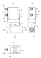
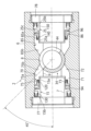
図1(a)(b)(c)は本発明の実施の形態1に係る流量制御用三方弁の一例としての三方弁型モータバルブを示す正面図、同左側面図及び同底面図、図2は図1(b)のA-A線断面図、図3は図1(a)のB-B線断面図、図4は三方弁型モータバルブの要部を示す断面斜視図である。
[Embodiment 1]
Figures 1(a), (b), and (c) are a front view, a left side view, and a bottom view of a three-way valve type motor valve as an example of a three-way valve for flow control in accordance with embodiment 1 of the present invention, Figure 2 is a cross-sectional view taken along line A-A in Figure 1(b), Figure 3 is a cross-sectional view taken along line B-B in Figure 1(a), and Figure 4 is a cross-sectional oblique view showing the main parts of the three-way valve type motor valve.

三方弁型モータバルブ1は、回転型3方向弁として構成されている。三方弁型モータバルブ1は、図1に示すように、大別して、下部に配置されたバルブ部2と、上部に配置されたアクチュエータ部3と、バルブ部2とアクチュエータ部3の間に配置されたシール部4及びカップリング部5から構成されている。 The three-way valve type motor valve 1 is configured as a rotary three-way valve. As shown in Figure 1, the three-way valve type motor valve 1 is broadly composed of a valve section 2 located at the bottom, an actuator section 3 located at the top, and a seal section 4 and a coupling section 5 located between the valve section 2 and the actuator section 3.

バルブ部2は、図2乃至図4に示すように、SUS等の金属により略直方体状に形成されたバルブ本体6を備えている。バルブ本体6には、図3に示すように、その一方の側面(図示例では、左側面)に流体が流出する第1の流出口7と、円柱形状の空所からなる弁座8に連通した流通口の一例である断面矩形状の第1の弁口9がそれぞれ設けられている。 As shown in Figures 2 to 4, the valve section 2 includes a valve body 6 formed into a substantially rectangular parallelepiped shape from a metal such as SUS. As shown in Figure 3, the valve body 6 is provided with a first outlet port 7 through which the fluid flows out on one side (the left side in the illustrated example), and a first valve port 9 with a rectangular cross section, which is an example of a flow port that communicates with a valve seat 8 consisting of a cylindrical cavity.

本実施の形態1では、第1の流出口7及び第1の弁口9をバルブ本体6に直接設けるのではなく、第1の弁口9を形成する第1の弁口形成部材の一例である第1のバルブシート70と、第1の流出口7を形成する第1の流路形成部材15をバルブ本体6に装着することにより、第1の流出口7及び第1の弁口9を設けている。 In the first embodiment, the first outlet 7 and the first valve port 9 are not provided directly on the valve body 6, but are provided by attaching a first valve seat 70, which is an example of a first valve port forming member that forms the first valve port 9, and a first flow path forming member 15 that forms the first outlet 7, to the valve body 6.

第1のバルブシート70は、図5に示すように、バルブ本体6の外側に配置される円筒形状に形成された円筒部71と、バルブ本体6の内側へ向けて先端の外径が小さくなるよう先細り形状に形成されたテーパー部72を一体的に備えている。第1のバルブシート70のテーパー部72の内部には、矩形状(本実施の形態1では、正方形状)の断面を有する角柱形状の第1の弁口9が形成されている。また、第1のバルブシート70の円筒部71の内部には、後述するように、第1の流出口7を形成する第1の流路形成部材15の一端部が密封(封止)された状態で挿入されるよう構成されている。 As shown in FIG. 5, the first valve seat 70 is integrally provided with a cylindrical portion 71 formed in a cylindrical shape and disposed on the outside of the valve body 6, and a tapered portion 72 formed in a tapered shape so that the outer diameter of the tip becomes smaller toward the inside of the valve body 6. Inside the tapered portion 72 of the first valve seat 70, a first valve port 9 is formed in a prism shape having a rectangular cross section (square in the present embodiment 1). In addition, inside the cylindrical portion 71 of the first valve seat 70, one end of the first flow path forming member 15 forming the first outlet 7 is inserted in a sealed (sealed) state, as described later.

第1のバルブシート70の材料としては、例えば、ポリイミド(PI)樹脂が用いられる。また、第1のバルブシート70の材料としては、例えば、所謂“スーパーエンジニアリングプラスチック”を用いることが可能である。スーパーエンジニアリングプラスチックは、通常のエンジニアリングプラスチックを上回る耐熱性や高温時の機械的強度を有するものである。スーパーエンジニアリングプラスチックとしては、ポリエーテルエーテルケトン(PEEK)、ポリフェニレンサルファイド(PPS)、ポリエーテルスルホン(PES)、ポリアミドイミド(PAI)、液晶ポリマー(LCP)、ポリテトラフルオロエチレン(PTFE)、ポリクロロトリフルオロエチレン(PCTFE)、ポリフッ化ビニリデン(PVDF)、あるいはこれらの複合材料などが挙げられる。また、第1のバルブシート70の材料としては、例えば、エンズィンガージャパン株式会社製の切削加工用PEEK樹脂素材である「TECAPEEK」(登録商標)、特に10%PTFEを配合して摺動性に優れた「TECAPEEK TF 10 blue」(商品名)なども使用可能である。 For example, polyimide (PI) resin is used as the material of the first valve seat 70. For example, so-called "super engineering plastics" can be used as the material of the first valve seat 70. Super engineering plastics have heat resistance and mechanical strength at high temperatures that exceed those of ordinary engineering plastics. Examples of super engineering plastics include polyetheretherketone (PEEK), polyphenylene sulfide (PPS), polyethersulfone (PES), polyamideimide (PAI), liquid crystal polymer (LCP), polytetrafluoroethylene (PTFE), polychlorotrifluoroethylene (PCTFE), polyvinylidene fluoride (PVDF), and composite materials thereof. For example, "TECAPEEK" (registered trademark), a PEEK resin material for cutting made by Ensinger Japan Co., Ltd., and especially "TECAPEEK TF 10 blue" (product name), which contains 10% PTFE and has excellent sliding properties, can also be used as the material of the first valve seat 70.

バルブ本体6には、図3に示すように、第1のバルブシート70の外形状に対応し当該バルブシート70と相似形状の凹所75が切削加工等により形成されている。凹所75は、第1のバルブシート70の円筒部71に対応した円筒部75aと、テーパー部72に対応したテーパー部75bとを備えている。バルブ本体6の円筒部75aは、第1のバルブシート70の円筒部71より長さが長く設定されている。バルブ本体6の円筒部75aは、後述するように、第1の圧力作用部94の一部を形成している。第1のバルブシート70は、バルブ本体6の凹所75に対して弁体としての弁軸34に接離する方向に移動可能に装着される。 As shown in FIG. 3, the valve body 6 is provided with a recess 75 formed by cutting or the like, which corresponds to the outer shape of the first valve seat 70 and has a shape similar to that of the valve seat 70. The recess 75 has a cylindrical portion 75a corresponding to the cylindrical portion 71 of the first valve seat 70, and a tapered portion 75b corresponding to the tapered portion 72. The cylindrical portion 75a of the valve body 6 is set to be longer than the cylindrical portion 71 of the first valve seat 70. The cylindrical portion 75a of the valve body 6 forms a part of the first pressure acting portion 94, as described later. The first valve seat 70 is attached to the recess 75 of the valve body 6 so as to be movable in a direction toward and away from the valve shaft 34 serving as a valve body.

第1のバルブシート70は、バルブ本体6の凹所75に装着された状態で、第1のバルブシート70の外周面とバルブ本体6の凹所75の内周面との間には、微小な間隙が形成されている。弁座8の内部に流入した流体は、第1のバルブシート70の外周の領域に微小な間隙を介して漏れて流入可能となっている。また、第1のバルブシート70の外周の領域へと漏れた流体は、当該第1のバルブシート70の円筒部71の外側に位置する空間からなる第1の圧力作用部94へと導入される。この第1の圧力作用部94は、流体の圧力を第1のバルブシート70の弁軸34と反対側の面70aに作用させるものである。弁座8の内部に流入する流体は、第1の弁口9を介して流出する流体の他、後述するように、第2の弁口18を介して流出する流体である。第1の圧力作用部94は、第1の流出口7との間が第1の流路形成部材15によって密封された状態で区画されている。 When the first valve seat 70 is attached to the recess 75 of the valve body 6, a small gap is formed between the outer peripheral surface of the first valve seat 70 and the inner peripheral surface of the recess 75 of the valve body 6. The fluid that flows into the inside of the valve seat 8 can leak into the outer peripheral region of the first valve seat 70 through the small gap. In addition, the fluid that leaks into the outer peripheral region of the first valve seat 70 is introduced into the first pressure application portion 94, which is a space located outside the cylindrical portion 71 of the first valve seat 70. This first pressure application portion 94 applies the pressure of the fluid to the surface 70a of the first valve seat 70 opposite the valve shaft 34. The fluid that flows into the inside of the valve seat 8 is the fluid that flows out through the first valve port 9, as well as the fluid that flows out through the second valve port 18, as described later. The first pressure acting portion 94 is partitioned in a state where the first pressure acting portion 94 is sealed from the first outlet port 7 by the first flow path forming member 15.

弁座8の内部に配置された弁軸34に作用する流体の圧力は、弁軸34の開閉度による流体の流量に依存する。弁座8の内部に流入する流体は、第1の弁口9と第2の弁口18を介して弁座8と弁軸34の外周面との間に形成される微小な間隙にも流れ込む(漏れ入る)。したがって、第1のバルブシート70に対応した第1の圧力作用部94には、第1の弁口9から流出する流体以外に、弁座8と弁軸34の外周面との間に形成される微小な間隙に流れ込んだ第2の弁口18から流出する流体も流れ込む(漏れ入る)。 The pressure of the fluid acting on the valve shaft 34 arranged inside the valve seat 8 depends on the flow rate of the fluid, which is determined by the opening and closing degree of the valve shaft 34. The fluid flowing into the inside of the valve seat 8 also flows (leaks) into the minute gap formed between the valve seat 8 and the outer circumferential surface of the valve shaft 34 via the first valve port 9 and the second valve port 18. Therefore, in addition to the fluid flowing out from the first valve port 9, the first pressure acting portion 94 corresponding to the first valve seat 70 also receives (leaks into) the fluid flowing out from the second valve port 18 that has flowed into the minute gap formed between the valve seat 8 and the outer circumferential surface of the valve shaft 34.

第1のバルブシート70のテーパー部72の先端には、図5(b)に示すように、バルブ本体6に形成された円柱形状の弁座8に対応した円柱形状の曲面の一部を成す平面円弧形状の間隙縮小部の一例としての凹部74が設けられている。凹部74の曲率半径Rは、弁座8の曲率半径又は弁軸34の曲率半径と略等しい値に設定される。バルブ本体6の弁座8は、当該弁座8の内部で回転する弁軸34の齧りを防止するため、弁軸34の外周面との間に僅かな間隙を形成している。第1のバルブシート70の凹部74は、図6に示すように、当該第1のバルブシート70をバルブ本体6に装着した状態でバルブ本体6の弁座8より弁軸34側に突出するように装着されるか、又は弁軸34の外周面に接触するよう装着される。その結果、弁軸34と当該弁軸34と対向する部材としてのバルブ本体6の弁座8の内面との間隙Gは、第1のバルブシート70の凹部74が突出した分だけ弁座8の他の部分に比較して部分的に縮小された値となる。このように、第1のバルブシート70の凹部74と弁軸34との間隙G1は、弁軸34と弁座8の内面との間隙G2より狭い(小さい)所要の値(G1<G2)に設定されている。なお、第1のバルブシート70の凹部74と弁軸34との間隙G1は、バルブシート70の凹部74が弁軸34に接触した状態、つまり間隙無しの状態(間隙G1=0)であっても良い。 As shown in FIG. 5B, the tip of the tapered portion 72 of the first valve seat 70 is provided with a recess 74 as an example of a gap reduction portion having a planar arc shape that forms a part of a cylindrical curved surface corresponding to the cylindrical valve seat 8 formed in the valve body 6. The radius of curvature R of the recess 74 is set to a value approximately equal to the radius of curvature of the valve seat 8 or the radius of curvature of the valve shaft 34. The valve seat 8 of the valve body 6 forms a small gap between the valve seat 8 and the outer peripheral surface of the valve shaft 34 to prevent the valve shaft 34 rotating inside the valve seat 8 from being worn. As shown in FIG. 6, the recess 74 of the first valve seat 70 is attached so as to protrude toward the valve shaft 34 side from the valve seat 8 of the valve body 6 when the first valve seat 70 is attached to the valve body 6, or is attached so as to contact the outer peripheral surface of the valve shaft 34. As a result, the gap G between the valve shaft 34 and the inner surface of the valve seat 8 of the valve body 6, which is the member facing the valve shaft 34, is partially reduced in value compared to other parts of the valve seat 8 by the amount of protrusion of the recess 74 of the first valve seat 70. In this way, the gap G1 between the recess 74 of the first valve seat 70 and the valve shaft 34 is set to a required value (G1 < G2) that is narrower (smaller) than the gap G2 between the valve shaft 34 and the inner surface of the valve seat 8. Note that the gap G1 between the recess 74 of the first valve seat 70 and the valve shaft 34 may be in a state where the recess 74 of the valve seat 70 is in contact with the valve shaft 34, that is, in a state where there is no gap (gap G1 = 0).

ただし、第1のバルブシート70の凹部74が弁軸34に接触する場合は、弁軸34を回転駆動する際に凹部74の接触抵抗によって弁軸34の駆動トルクが上昇する虞れがある。そのため、第1のバルブシート70の凹部74が弁軸34に接触する程度は、弁軸34の回転トルクを考慮して調整される。すなわち、弁軸34の駆動トルクが増加しないか、増加してもその増加量が小さく、弁軸34の回転に支障がない程度に調整される。 However, if the recess 74 of the first valve seat 70 comes into contact with the valve shaft 34, there is a risk that the drive torque of the valve shaft 34 will increase due to the contact resistance of the recess 74 when the valve shaft 34 is rotated. Therefore, the degree to which the recess 74 of the first valve seat 70 comes into contact with the valve shaft 34 is adjusted in consideration of the rotational torque of the valve shaft 34. In other words, it is adjusted so that the drive torque of the valve shaft 34 does not increase, or if it does increase, the increase is small and does not interfere with the rotation of the valve shaft 34.

第1の流路形成部材15は、図3及び図4に示すように、SUS等の金属、あるいはポリイミド(PI)樹脂等の合成樹脂によって円筒形状に形成されている。第1の流路形成部材15は、第1のバルブシート70の位置変動にかかわらず、第1の弁口9に連通した第1の流出口7を内部に形成している。第1の流路形成部材15は、第1のバルブシート70側に位置する約1/2の部分が相対的に薄肉円筒形状の薄肉円筒部15aとして形成されている。また、第1の流路形成部材15は、第1のバルブシート70と反対側に位置する約1/2の部分が薄肉の円筒形状の部分に比べて厚肉な円筒形状の厚肉円筒部15bとして形成されている。第1の流路形成部材15の内面は、円筒形状に貫通している。第1の流路形成部材15の外周には、薄肉円筒部15aと厚肉円筒部15bの間に、半径方向外方へ向けて比較的厚肉に形成された環状のフランジ部15cが設けられている。フランジ部15cの外周端は、凹所75の内周面に移動可能に接触するよう配置されている。 3 and 4, the first flow path forming member 15 is formed in a cylindrical shape from a metal such as SUS or a synthetic resin such as polyimide (PI) resin. The first flow path forming member 15 forms a first outlet 7 communicating with the first valve port 9 inside, regardless of the positional fluctuation of the first valve seat 70. About 1/2 of the first flow path forming member 15 located on the first valve seat 70 side is formed as a thin-walled cylindrical portion 15a having a relatively thin cylindrical shape. Also, about 1/2 of the first flow path forming member 15 located on the opposite side to the first valve seat 70 is formed as a thick-walled cylindrical portion 15b having a thicker cylindrical shape than the thin-walled cylindrical portion. The inner surface of the first flow path forming member 15 is penetrated in a cylindrical shape. On the outer periphery of the first flow path forming member 15, an annular flange portion 15c formed relatively thick toward the radially outward direction is provided between the thin-walled cylindrical portion 15a and the thick-walled cylindrical portion 15b. The outer peripheral end of the flange portion 15c is positioned so that it can moveably contact the inner peripheral surface of the recess 75.

第1のバルブシート70の円筒部71の軸方向に沿った外側には、当該第1のバルブシート70が弁軸34に対して接離する方向に変位するのを許容しつつ、当該第1のバルブシート70を弁軸34に対して接離する方向に弾性変形する弾性部材の一例としての第1のウェーブワッシャー(波状ワッシャー)16が設けられている。第1のウェーブワッシャー16は、図7に示すように、ステンレスや鉄、あるいは燐青銅などからなり、正面に投影した形状が所要の幅を有する円環状に形成されている。また、第1のウェーブワッシャー16は、側面形状がウェーブ状(波状)に形成されており、その厚さ方向に沿って弾性変形が可能となっている。第1のウェーブワッシャー16の弾性率は、厚さや材質、あるいは波の数等によって決定される。第1のウェーブワッシャー16は、第1の圧力作用部94に収容されている。 On the axial outer side of the cylindrical portion 71 of the first valve seat 70, a first wave washer (wavy washer) 16 is provided as an example of an elastic member that allows the first valve seat 70 to be displaced in the direction of approaching and separating from the valve shaft 34 while elastically deforming the first valve seat 70 in the direction of approaching and separating from the valve shaft 34. As shown in FIG. 7, the first wave washer 16 is made of stainless steel, iron, phosphor bronze, or the like, and is formed into a circular ring shape having a required width when projected on the front. In addition, the side shape of the first wave washer 16 is formed in a wave shape (wave shape), and elastic deformation is possible along the thickness direction. The elastic modulus of the first wave washer 16 is determined by the thickness, material, number of waves, etc. The first wave washer 16 is housed in the first pressure application portion 94.

さらに、第1のウェーブワッシャー16の外側には、当該第1のウェーブワッシャー16を介して弁軸34と第1のバルブシート70の凹部74との間隙G1を調整する環状の調整部材の一例である第1の調整リング77が配置される。第1の調整リング77は、図8に示すように、SUS等の金属又は耐熱性を有するポリイミド(PI)樹脂等の合成樹脂によって外周面に雄ネジ77aが形成された相対的に長さが短く設定された円筒形状の部材からなる。第1の調整リング77の外側の端面には、当該第1の調整リング77をバルブ本体6に設けられた雌ネジ部78に締め付けて装着する際、締付量を調整するための図示しない治具を係止して当該第1の調整リング77を回転させるための凹溝77bが180度対向する位置にそれぞれ設けられている。 In addition, a first adjustment ring 77, which is an example of an annular adjustment member that adjusts the gap G1 between the valve shaft 34 and the recess 74 of the first valve seat 70 via the first wave washer 16, is arranged on the outside of the first wave washer 16. As shown in FIG. 8, the first adjustment ring 77 is a relatively short cylindrical member made of a metal such as SUS or a synthetic resin such as a heat-resistant polyimide (PI) resin, with a male thread 77a formed on the outer circumferential surface. On the outer end surface of the first adjustment ring 77, grooves 77b are provided at positions facing each other by 180 degrees to engage a jig (not shown) for adjusting the amount of tightening and rotate the first adjustment ring 77 when the first adjustment ring 77 is tightened and attached to the female thread portion 78 provided on the valve body 6.

バルブ本体6には、図に示すように、第1の調整リング77を装着するための第1の雌ネジ部78が設けられている。バルブ本体6の開口端部には、第1の調整リング77の外径と略等しい外径を有する短い円筒部79が設けられている。また、バルブ本体6の第1の雌ネジ部78と円筒部75cとの間には、第1の雌ネジ部78を所要の長さにわたって加工することが可能となるよう、当該第1の雌ネジ部78より内径が大きい加工用円筒部75dが短く設けられている。 4 , the valve body 6 is provided with a first female thread portion 78 for mounting a first adjusting ring 77. A short cylindrical portion 79 having an outer diameter substantially equal to that of the first adjusting ring 77 is provided at the open end of the valve body 6. In addition, a short machining cylindrical portion 75d having an inner diameter larger than that of the first female thread portion 78 is provided between the first female thread portion 78 and the cylindrical portion 75c of the valve body 6 so that the first female thread portion 78 can be machined over the required length.

第1の調整リング77は、バルブ本体6の雌ネジ部78に対する締め込み量を調整することにより、当該第1の調整リング77が第1のウェーブワッシャー16を介して第1のバルブシート70を内側に向けて押動する量(距離)を調整するものである。第1の調整リング70の締め込み量を増加させると、第1のバルブシート70は、図6に示すように、第1の調整リング77によって第1のウェーブワッシャー16及び第1の受圧プレート76を介して押され、凹部74が弁座8の内周面から突出して弁軸34に近接する方向に変位し、当該凹部74と弁軸34との間隙G1が減少する。また、第1の調整リング77の締め込み量を予め少ない量に設定すると、第1のバルブシート70は、第1の調整リング77によって押動される距離が減少し、弁軸34から離間した位置に配置され、第1のバルブシート70の凹部74と弁軸34との間隙G1が相対的に増大する。第1の調整リング77の雄ネジ77a及びバルブ本体6の雌ネジ部78は、そのピッチが小さく設定されており、第1のバルブシート70の突出量を微調整可能に構成されている。 The first adjustment ring 77 adjusts the amount (distance) by which the first adjustment ring 77 pushes the first valve seat 70 inward through the first wave washer 16 by adjusting the amount of tightening of the first adjustment ring 77 against the female thread portion 78 of the valve body 6. When the amount of tightening of the first adjustment ring 70 is increased, the first valve seat 70 is pushed by the first adjustment ring 77 through the first wave washer 16 and the first pressure plate 76 as shown in FIG. 6, and the recess 74 protrudes from the inner surface of the valve seat 8 and displaces in a direction approaching the valve shaft 34, and the gap G1 between the recess 74 and the valve shaft 34 decreases. Also, when the amount of tightening of the first adjustment ring 77 is set to a small amount in advance, the distance by which the first valve seat 70 is pushed by the first adjustment ring 77 decreases, and the first valve seat 70 is positioned at a position away from the valve shaft 34, and the gap G1 between the recess 74 of the first valve seat 70 and the valve shaft 34 increases relatively. The male thread 77a of the first adjustment ring 77 and the female thread 78 of the valve body 6 are set to a small pitch, allowing fine adjustment of the amount of protrusion of the first valve seat 70.

また、バルブ本体6の一側面(左側面)には、図2に示すように、流体を流出させる図示しない配管等を接続するため接続部材の一例としての第1のフランジ部材10が4本の六角穴付きボルト11により取り付けられている。図1(b)中、符号11aは、六角穴付きボルト11が締結されるネジ孔を示している。第1のフランジ部材10は、バルブ本体6と同様にSUS等の金属により形成される。第1のフランジ部材10は、バルブ本体6の側面形状と略同一の側面矩形状に形成されたフランジ部12と、フランジ部12の内側面に円筒形状に短く突設された挿入部13と、フランジ部12の外側面に厚肉の略円筒形状に突設され、図示しない配管が接続される配管接続部14とを有している。第1のフランジ部材10のフランジ部12とバルブ本体6との間は、図2に示すように、オーシール13aによって密封されている。第1のフランジ部材10のフランジ部12の内周面には、オーシール13aを収容する凹溝13bが設けられている。配管接続部14の内周は、例えば、その口径が直径約21mmのテーパー付き雌ネジであるRc1/2や直径約0.58インチの雌ネジに設定されている。なお、配管接続部14の形状は、テーパー付き雌ネジ或いは雌ネジに限定されるものではなく、チューブを装着するチューブフィッティングなどでもよく、第1の流出口7から流体を流出可能なものであれば良い。 As shown in FIG. 2, a first flange member 10 is attached to one side (left side) of the valve body 6 by four hexagon socket bolts 11 as an example of a connecting member for connecting a pipe or the like (not shown) for discharging a fluid. In FIG. 1(b), reference numeral 11a indicates a screw hole into which the hexagon socket bolt 11 is fastened. The first flange member 10 is formed of a metal such as SUS, similar to the valve body 6. The first flange member 10 has a flange portion 12 formed in a rectangular shape on the side surface of the valve body 6, an insertion portion 13 protruding in a short cylindrical shape on the inner surface of the flange portion 12, and a pipe connection portion 14 protruding in a thick, approximately cylindrical shape on the outer surface of the flange portion 12, to which a pipe (not shown) is connected. As shown in FIG. 2, the gap between the flange portion 12 of the first flange member 10 and the valve body 6 is sealed by an O-seal 13a. The inner circumferential surface of the flange portion 12 of the first flange member 10 is provided with a groove 13b that accommodates the O-seal 13a. The inner circumferential surface of the pipe connection portion 14 is set to, for example, an Rc1/2 tapered female thread with a diameter of approximately 21 mm or a female thread with a diameter of approximately 0.58 inches. The shape of the pipe connection portion 14 is not limited to a tapered female thread or a female thread, and may be a tube fitting for attaching a tube, or the like, as long as it is capable of allowing the fluid to flow out of the first outlet 7.

ここで、オーシール13aは、断面円形又は楕円形の螺旋状に形成されたステンレス等の金属からなるバネ部材と、バネ部材の外周に被覆されたFEP(四フッ化エチレンと六フッ化プロピレンの共重合体)やPFA(四フッ化エチレンとパーフルオロアルコキシエチレンとの共重合体)等からなる弾性変形可能な合成樹脂で完全に被覆したOリング形状のシール部材である。オーシール13aは、極低温域において密封性を維持することが可能となっている。 Here, the O-seal 13a is an O-ring-shaped seal member that is completely coated with a spring member made of a metal such as stainless steel that is formed into a spiral shape with a circular or elliptical cross section, and an elastically deformable synthetic resin made of FEP (a copolymer of tetrafluoroethylene and hexafluoropropylene) or PFA (a copolymer of tetrafluoroethylene and perfluoroalkoxyethylene) that coats the outer periphery of the spring member. The O-seal 13a is capable of maintaining its sealing performance even in extremely low temperature ranges.

バルブ本体6には、図2に示すように、その他方の側面(図中、右側面)に流体が流出する第2の流出口17と、円柱形状の空所からなる弁座8に連通した流通口の一例である断面矩形状の第2の弁口18がそれぞれ設けられている。 As shown in FIG. 2, the valve body 6 is provided with a second outlet port 17 through which the fluid flows out on the other side (the right side in the figure), and a second valve port 18 with a rectangular cross section, which is an example of a flow port that communicates with the valve seat 8, which is a cylindrical cavity.

本実施の形態1では、第2の流出口17及び第2の弁口18をバルブ本体6に直接設けるのではなく、第2の弁口18を形成した弁口形成部材の一例としての第2のバルブシート80と、第2の流出口17を形成した第2の流路形成部材25とをバルブ本体6に装着することにより、第2の流出口17及び第2の弁口18を設けている。 In the first embodiment, the second outlet 17 and the second valve port 18 are not provided directly on the valve body 6, but are provided by attaching a second valve seat 80, which is an example of a valve port forming member that forms the second valve port 18, and a second flow path forming member 25 that forms the second outlet 17, to the valve body 6.

第2のバルブシート80は、図5に括弧付きの符号で示すように、第1のバルブシート70と同様に構成されている。すなわち、第2のバルブシート80は、バルブ本体6の外側に配置される円筒形状に形成された円筒部81と、バルブ本体6の内側へ向けて外径が小さくなるように形成されたテーパー部82を一体的に備えている。第2のバルブシート80のテーパー部82の内部には、矩形状(本実施の形態1では、正方形状)の断面を有する角柱形状の第2の弁口18が形成されている。また、第2のバルブシート80の円筒部81の内部には、第2の流出口17を形成する第2の流路形成部材25の一端部が密封された状態で挿入されるよう配置されている。 The second valve seat 80 is configured in the same manner as the first valve seat 70, as shown by the reference numerals in parentheses in FIG. 5. That is, the second valve seat 80 is integrally provided with a cylindrical portion 81 formed in a cylindrical shape and disposed on the outside of the valve body 6, and a tapered portion 82 formed so that the outer diameter decreases toward the inside of the valve body 6. Inside the tapered portion 82 of the second valve seat 80, a prismatic second valve port 18 having a rectangular cross section (square in the present embodiment 1) is formed. Inside the cylindrical portion 81 of the second valve seat 80, one end of the second flow passage forming member 25 forming the second outlet 17 is arranged to be inserted in a sealed state.

バルブ本体6には、図3に示されるように、第2のバルブシート80の外形状に対応し当該バルブシート80と相似形状の凹所85が切削加工等により形成されている。凹所85は、第2のバルブシート80の円筒部81に対応した円筒部85aと、テーパー部82に対応したテーパー部85bとを備えている。バルブ本体6の円筒部85aは、第2のバルブシート80の円筒部81より長さが長く設定されている。バルブ本体6の円筒部85aは、後述するように、第2の圧力作用部96を形成している。第2のバルブシート80は、バルブ本体6の凹所85に対して弁体としての弁軸34に接離する方向に移動可能に装着される。 As shown in FIG. 3, the valve body 6 is provided with a recess 85 formed by cutting or the like that corresponds to the outer shape of the second valve seat 80 and has a shape similar to that of the valve seat 80. The recess 85 has a cylindrical portion 85a that corresponds to the cylindrical portion 81 of the second valve seat 80, and a tapered portion 85b that corresponds to the tapered portion 82. The cylindrical portion 85a of the valve body 6 is set to be longer than the cylindrical portion 81 of the second valve seat 80. The cylindrical portion 85a of the valve body 6 forms a second pressure acting portion 96, as described later. The second valve seat 80 is attached to the recess 85 of the valve body 6 so as to be movable in a direction toward and away from the valve shaft 34 serving as a valve body.

第2のバルブシート80は、バルブ本体6の凹所85に装着された状態で、第2のバルブシート80とバルブ本体6の凹所85との間には、微小な間隙が形成されている。弁座8の内部に流入した流体は、微小な間隙を介して第2のバルブシート80の外周の領域に流入可能となっている。また、第2のバルブシート80の外周の領域へと流入した流体は、当該第2のバルブシート80の円筒部81の外側に位置する空間からなる第2の圧力作用部96へと導入される。この第2の圧力作用部96は、流体の圧力を第2のバルブシート80の弁軸34と反対側の面80aに作用させるものである。弁座8の内部に流入する流体は、第2の弁口18を介して流出する流体の他、第1の弁口9を介して流出する流体である。第2の圧力作用部96は、第2の流出口17との間が第2の流路形成部材25によって密封された状態で区画されている。 When the second valve seat 80 is attached to the recess 85 of the valve body 6, a small gap is formed between the second valve seat 80 and the recess 85 of the valve body 6. The fluid that has flowed into the inside of the valve seat 8 can flow into the outer peripheral region of the second valve seat 80 through the small gap. The fluid that has flowed into the outer peripheral region of the second valve seat 80 is introduced into a second pressure application portion 96 that is a space located outside the cylindrical portion 81 of the second valve seat 80. The second pressure application portion 96 applies the pressure of the fluid to a surface 80a of the second valve seat 80 on the opposite side to the valve shaft 34. The fluid that flows into the inside of the valve seat 8 includes the fluid that flows out through the second valve port 18 and the fluid that flows out through the first valve port 9. The second pressure application portion 96 is partitioned between the second pressure application portion 96 and the second outlet port 17 in a sealed state by the second flow path forming member 25.

弁座8の内部に配置された弁軸34に作用する流体の圧力は、弁軸34の開閉度による流体の流量に依存する。弁座8の内部に流入する流体は、第1の弁口9と第2の弁口18を介して弁座8と弁軸34の外周面との間に形成される微小な間隙にも流れ込む(漏れ入る)。したがって、第2のバルブシート80に対応した第2の圧力作用部96には、第2の弁口18から流出する流体以外に、弁座8と弁軸34の外周面との間に形成される微小な間隙に流れ込んだ第1の弁口9から流出する流体も流入する。なお、第2のバルブシート80は、第1のバルブシート70と同じ材料により形成されている。 The pressure of the fluid acting on the valve shaft 34 arranged inside the valve seat 8 depends on the flow rate of the fluid, which is determined by the opening and closing degree of the valve shaft 34. The fluid flowing into the inside of the valve seat 8 also flows (leaks into) the minute gap formed between the valve seat 8 and the outer circumferential surface of the valve shaft 34 via the first valve port 9 and the second valve port 18. Therefore, in addition to the fluid flowing out from the second valve port 18, the fluid flowing out from the first valve port 9 that has flowed into the minute gap formed between the valve seat 8 and the outer circumferential surface of the valve shaft 34 also flows into the second pressure acting portion 96 corresponding to the second valve seat 80. The second valve seat 80 is made of the same material as the first valve seat 70.

第2のバルブシート80のテーパー部82の先端には、図5(b)に示すように、バルブ本体6に形成された円柱形状の弁座8に対応した円柱形状の曲面の一部を成す平面円弧形状の間隙縮小部の一例としての凹部84が設けられている。凹部84の曲率半径Rは、弁座8の曲率半径又は弁軸34の曲率半径と略等しい値に設定される。バルブ本体6の弁座8は、後述するように、当該弁座8の内部で回転する弁軸34の齧りを防止するため、弁軸34の外周面との間に僅かな間隙を形成している。第2のバルブシート80の凹部84は、当該第2のバルブシート80をバルブ本体6に装着した状態でバルブ本体6の弁座8より弁軸34側に突出するように装着されるか、又は弁軸34の外周面に接触するように装着される。その結果、弁軸34と当該弁軸34と対向する部材としてのバルブ本体6の弁座8の内面との間隙Gは、第2のバルブシート80の凹部84が突出した分だけ弁座8の他の部分に比較して部分的に縮小された値に設定される。このように、第2のバルブシート80の凹部84と弁軸34との間隙G3は、弁軸34と弁座8の内面との間隙G2より狭い(小さい)所要の値(G3<G2)に設定されている。なお、第2のバルブシート80の凹部84と弁軸34との間隙G3は、バルブシート80の凹部84が弁軸34に接触した状態、つまり間隙無しの状態(間隙G3=0)であっても良い。 5B, a recess 84 is provided at the tip of the tapered portion 82 of the second valve seat 80 as an example of a gap reduction portion having a planar arc shape that forms a part of a cylindrical curved surface corresponding to the cylindrical valve seat 8 formed in the valve body 6. The radius of curvature R of the recess 84 is set to a value approximately equal to the radius of curvature of the valve seat 8 or the radius of curvature of the valve shaft 34. As described later, the valve seat 8 of the valve body 6 forms a small gap between the valve seat 8 and the outer peripheral surface of the valve shaft 34 to prevent the valve shaft 34 rotating inside the valve seat 8 from being worn. The recess 84 of the second valve seat 80 is attached so as to protrude toward the valve shaft 34 side from the valve seat 8 of the valve body 6 when the second valve seat 80 is attached to the valve body 6, or is attached so as to contact the outer peripheral surface of the valve shaft 34. As a result, the gap G between the valve shaft 34 and the inner surface of the valve seat 8 of the valve body 6, which is the member facing the valve shaft 34, is set to a value that is partially reduced compared to other parts of the valve seat 8 by the amount that the recess 84 of the second valve seat 80 protrudes. In this way, the gap G3 between the recess 84 of the second valve seat 80 and the valve shaft 34 is set to a required value (G3 < G2) that is narrower (smaller) than the gap G2 between the valve shaft 34 and the inner surface of the valve seat 8. Note that the gap G3 between the recess 84 of the second valve seat 80 and the valve shaft 34 may be in a state where the recess 84 of the valve seat 80 is in contact with the valve shaft 34, that is, in a state where there is no gap (gap G3 = 0).

ただし、第2のバルブシート80の凹部84が弁軸34に接触する場合には、弁軸34を回転駆動する際に凹部84の接触抵抗によって弁軸34の駆動トルクが上昇する虞れがある。そのため、第2のバルブシート70の凹部84が弁軸34に接触する程度は、初期的に、弁軸34の回転トルクを考慮して調整される。すなわち、弁軸34の駆動トルクが増加しないか、増加してもその増加量が小さく、弁軸34の回転に支障がない程度に調整される。 However, if the recess 84 of the second valve seat 80 comes into contact with the valve shaft 34, there is a risk that the drive torque of the valve shaft 34 will increase due to the contact resistance of the recess 84 when the valve shaft 34 is rotated. Therefore, the degree to which the recess 84 of the second valve seat 70 comes into contact with the valve shaft 34 is initially adjusted taking into account the rotational torque of the valve shaft 34. In other words, it is adjusted so that the drive torque of the valve shaft 34 does not increase, or if it does increase, the increase is small and does not interfere with the rotation of the valve shaft 34.

第2の流路形成部材25は、図3及び図4に示すように、SUS等の金属、あるいはポリイミド(PI)樹脂等の合成樹脂によって円筒形状に形成されている。第2の流路形成部材25は、第2のバルブシート80の位置変動にかかわらず、第2の弁口18に連通した第2の流出口17を内部に形成している。第2の流路形成部材25は、第2のバルブシート80側に位置する約1/2の部分が相対的に薄肉円筒形状の薄肉円筒部25aとして形成されている。また、第2の流路形成部材25は、第2のバルブシート80と反対側に位置する約1/2の部分が薄肉の円筒形状の部分に比べて厚肉な円筒形状の厚肉円筒部25bとして形成されている。第2の流路形成部材25の内面は、円筒形状に貫通している。第2の流路形成部材25の外周には、薄肉円筒部25aと厚肉円筒部25bの間に、半径方向外方へ向けて比較的厚肉に形成された環状のフランジ部25cが設けられている。フランジ部25cの外周端は、凹所85の内周面に移動可能に接触するよう配置されている。 3 and 4, the second flow path forming member 25 is formed in a cylindrical shape from a metal such as SUS or a synthetic resin such as polyimide (PI) resin. The second flow path forming member 25 forms a second outlet 17 connected to the second valve port 18 inside, regardless of the positional fluctuation of the second valve seat 80. About 1/2 of the second flow path forming member 25 located on the second valve seat 80 side is formed as a thin-walled cylindrical portion 25a having a relatively thin cylindrical shape. Also, about 1/2 of the second flow path forming member 25 located on the opposite side to the second valve seat 80 is formed as a thick-walled cylindrical portion 25b having a thick cylindrical shape compared to the thin-walled cylindrical portion. The inner surface of the second flow path forming member 25 is cylindrically penetrating. The outer periphery of the second flow path forming member 25 is provided with an annular flange portion 25c that is relatively thick toward the radially outward direction between the thin cylindrical portion 25a and the thick cylindrical portion 25b. The outer peripheral end of the flange portion 25c is arranged so as to movably contact the inner peripheral surface of the recess 85.

第2のバルブシート80の円筒部81の外側には、当該第2のバルブシート80が弁軸34に対して接離する方向に変位するのを許容しつつ、当該第2のバルブシート80を弁軸34に対して接触する方向に押動する弾性部材の一例としての第2のウェーブワッシャー(波形ワッシャー)26が設けられている。第2のウェーブワッシャー26は、図7に示すように、ステンレスや鉄、あるいは燐青銅などからなり、正面に投影した形状が所要の幅を有する円環状に形成されている。また、第2のウェーブワッシャー26は、側面形状がウェーブ状(波状)に形成されており、その厚さ方向に沿って弾性変形が可能となっている。第2のウェーブワッシャー26の弾性率は、厚さや材質、あるいは波の数等によって決定される。第2のウェーブワッシャー26としては、第1のウェーブワッシャー16と同一のものが使用される。 A second wave washer 26 is provided on the outside of the cylindrical portion 81 of the second valve seat 80 as an example of an elastic member that presses the second valve seat 80 in a direction to contact the valve shaft 34 while allowing the second valve seat 80 to be displaced in a direction to move toward and away from the valve shaft 34. As shown in FIG. 7, the second wave washer 26 is made of stainless steel, iron, phosphor bronze, or the like, and is formed into a ring shape with a required width when projected on the front. The second wave washer 26 has a wave-shaped side shape, and is elastically deformable along its thickness direction. The elastic modulus of the second wave washer 26 is determined by the thickness, material, number of waves, etc. The second wave washer 26 is the same as the first wave washer 16.

さらに、第2のウェーブワッシャー26の外側には、当該第2のウェーブワッシャー26を介して弁軸34と第2のバルブシート80の凹部84との間隙G3を調整する調整部材の一例としての第2の調整リング87が配置される。第2の調整リング87は、図8に示すように、耐熱性を有する合成樹脂又は金属によって外周面に雄ネジ87aが形成された相対的に長さが短く設定された円筒形状の部材からなる。第2の調整リング87の外側の端面には、当該第2の調整リング87をバルブ本体6に設けられた雌ネジ部88に締め付けて装着する際に、締付量を調整するための図示しない治具を係止して当該第2の調整リング87を回転させるための凹溝87bが180度対向する位置にそれぞれ設けられている。 A second adjustment ring 87 is disposed on the outside of the second wave washer 26 as an example of an adjustment member that adjusts the gap G3 between the valve shaft 34 and the recess 84 of the second valve seat 80 via the second wave washer 26. As shown in FIG. 8, the second adjustment ring 87 is a relatively short cylindrical member made of heat-resistant synthetic resin or metal with a male thread 87a formed on the outer circumferential surface. The outer end surface of the second adjustment ring 87 has grooves 87b at positions facing each other by 180 degrees to engage a jig (not shown) for adjusting the amount of tightening and rotate the second adjustment ring 87 when the second adjustment ring 87 is tightened and attached to the female thread portion 88 provided on the valve body 6.

バルブ本体6には、図3に示すように、第2の調整リング87を装着するための第2の雌ネジ部88が設けられている。バルブ本体6の開口端部には、第2の調整リング87の外径と略等しい外径を有する短い円筒部89が設けられている。また、バルブ本体6の第2の雌ネジ部88と円筒部85cとの間には、第2の雌ネジ部88を所要の長さにわたって加工することが可能となるよう、当該第2の雌ネジ部88より内径が大きい加工用円筒部85dが短く設けられている。 As shown in FIG. 3, the valve body 6 is provided with a second female threaded portion 88 for mounting the second adjustment ring 87. A short cylindrical portion 89 having an outer diameter approximately equal to the outer diameter of the second adjustment ring 87 is provided at the open end of the valve body 6. In addition, a short machining cylindrical portion 85d having an inner diameter larger than that of the second female threaded portion 88 is provided between the second female threaded portion 88 and the cylindrical portion 85c of the valve body 6 so that the second female threaded portion 88 can be machined over the required length.

第2の調整リング87は、バルブ本体6の雌ネジ部88に対する締め込み量を調整することにより、当該第2の調整リング87が第2のウェーブワッシャー26を介して第2のバルブシート80を内側に向けて押動する量(距離)を調整するものである。第2の調整リング87の締め込み量を増加させると、第2のバルブシート80は、図6に示すように、第2の調整リング87によって第2のウェーブワッシャー26を介して押され、凹部84が弁座8の内周面から突出して弁軸34に近接する方向に変位し、当該凹部84と弁軸34との間隙G3が減少する。また、第2の調整リング87の締め込み量を予め少ない量に設定すると、第2のバルブシート80は、第2の調整リング87によって押動される距離が減少し、弁軸34から離間した位置に配置され、第2のバルブシート80の凹部84と弁軸34との間隙G3が相対的に増大する。第2の調整リング87の雄ネジ87a及びバルブ本体6の雌ネジ部88は、そのピッチが小さく設定されており、第2のバルブシート80の突出量を微調整可能に構成されている。 The second adjusting ring 87 adjusts the amount (distance) by which the second adjusting ring 87 presses the second valve seat 80 inward via the second wave washer 26 by adjusting the amount of tightening of the second adjusting ring 87 relative to the female thread portion 88 of the valve body 6. When the amount of tightening of the second adjusting ring 87 is increased, the second valve seat 80 is pressed by the second adjusting ring 87 via the second wave washer 26 as shown in Fig. 6, and the recess 84 protrudes from the inner circumferential surface of the valve seat 8 and is displaced in a direction approaching the valve shaft 34, thereby reducing the gap G3 between the recess 84 and the valve shaft 34. When the amount of tightening of the second adjusting ring 87 is set to a small amount in advance, the distance by which the second valve seat 80 is pressed by the second adjusting ring 87 is reduced and the second valve seat 80 is positioned at a position away from the valve shaft 34, and the gap G3 between the recess 84 of the second valve seat 80 and the valve shaft 34 is relatively increased. The male thread 87 a of the second adjustment ring 87 and the female thread portion 88 of the valve body 6 are set to have a small pitch, so that the amount of protrusion of the second valve seat 80 can be finely adjusted.

バルブ本体6の他方の側面には、図2に示すように、流体を流出させる図示しない配管を接続するため接続部材の一例としての第2のフランジ部材19が4本の六角穴付きボルト20により取り付けられている。第2のフランジ部材19は、第1のフランジ部材10と同様にSUS等の金属により形成される。第2のフランジ部材19は、バルブ本体6の側面形状と同一の側面矩形状に形成されたフランジ部21と、フランジ部21の内側面に円筒形状に突設された挿入部22と、フランジ部21の外側面に厚肉の略円筒形状に突設され、図示しない配管が接続される配管接続部23とを有している。第2のフランジ部材19のフランジ部21とバルブ本体6との間は、図2に示すように、オーシール21aによって密封されている。第2のフランジ部材19のフランジ部21の内周面には、オーシール21aを収容する環状の凹溝21bが設けられている。配管接続部23の内周は、例えば、その口径が直径約21mmのテーパー付き雌ネジであるRc1/2や、直径約0.58インチの雌ネジに設定されている。なお、配管接続部23の形状は、配管接続部14と同様、テーパー付き雌ネジ或いは雌ネジに限定されるものではなく、チューブを装着するチューブフィッティングなどでもよく、第2の流出口17から流体を流出可能なものであれば良い。オーシール21aは、オーシール13aと同一のものである。 2, a second flange member 19 is attached to the other side of the valve body 6 by four hexagon socket bolts 20 as an example of a connecting member for connecting a pipe (not shown) for discharging a fluid. The second flange member 19 is made of metal such as SUS, similar to the first flange member 10. The second flange member 19 has a flange portion 21 formed in a rectangular shape on the side surface of the valve body 6, an insertion portion 22 protruding in a cylindrical shape on the inner surface of the flange portion 21, and a pipe connection portion 23 protruding in a thick, approximately cylindrical shape on the outer surface of the flange portion 21 to which a pipe (not shown) is connected. The gap between the flange portion 21 of the second flange member 19 and the valve body 6 is sealed by an O-seal 21a, as shown in FIG. 2. The inner peripheral surface of the flange portion 21 of the second flange member 19 is provided with an annular recessed groove 21b for accommodating the O-seal 21a. The inner circumference of the pipe connection part 23 is set to, for example, an Rc1/2 tapered female thread with a diameter of about 21 mm, or a female thread with a diameter of about 0.58 inches. The shape of the pipe connection part 23 is not limited to a tapered female thread or a female thread, as with the pipe connection part 14, and may be a tube fitting for attaching a tube, or the like, as long as it is capable of allowing fluid to flow out of the second outlet 17. The O-seal 21a is the same as the O-seal 13a.

ここで、流体(ブライン)としては、例えば、圧力が0~1MPa、-85~+120℃程度の温度範囲において適応可能なオプテオン(登録商標)(三井・ケマーズフロロプロダクツ社製)やノベック(登録商標)(3M社製)等のフッ素系不活性液体などが使用される。 The fluid (brine) used here is, for example, a fluorine-based inert liquid such as Opteon (registered trademark) (manufactured by Mitsui-Chemours Fluoroproducts) or Novec (registered trademark) (manufactured by 3M), which is suitable for pressures of 0 to 1 MPa and temperatures of approximately -85 to +120°C.

また、バルブ本体6には、図2に示すように、その下端面に流体が流入する第3の弁口として断面円形状の流入口26が開口されている。バルブ本体6の下端面には、流体を流入させる図示しない配管を接続するため接続部材の一例としての第3のフランジ部材27が4本の六角穴付きボルト28により取り付けられている。流入口26の下端部には、第3のフランジ部材27を装着するため流入口26より内径が大きい円筒部26aが開口されている。第3のフランジ部材27は、底面矩形状に形成されたフランジ部29と、フランジ部29の内側面に円筒形状に短く突設された挿入部30(図2参照)と、フランジ部29の外側面に厚肉の略円筒形状に突設され、図示しない配管が接続される配管接続部31とを有している。第3のフランジ部材27のフランジ部29とバルブ本体6との間は、オーシール29aによって密封されている。第3のフランジ部材27のフランジ部29の内周面には、オーシール29aを収容する凹溝29bが設けられている。配管接続部31の内周は、例えば、その口径が直径約21mmのテーパー付き雌ネジであるRc1/2や直径約0.58インチの雌ネジに設定されている。なお、配管接続部31の形状は、テーパー付き雌ネジ或いは雌ネジに限定されるものではなく、チューブを装着するチューブフィッティングなどでもよく、流入口26から流体を流入可能なものであれば良い。オーシール29aは、オーシール13aと同一のものである。 2, the valve body 6 has an inlet 26 with a circular cross section opened as a third valve port through which the fluid flows in at its lower end surface. A third flange member 27 as an example of a connecting member for connecting a pipe (not shown) through which the fluid flows in is attached to the lower end surface of the valve body 6 with four hexagon socket bolts 28. A cylindrical portion 26a having an inner diameter larger than that of the inlet 26 is opened at the lower end of the inlet 26 to attach the third flange member 27. The third flange member 27 has a flange portion 29 formed with a rectangular bottom surface, an insertion portion 30 (see FIG. 2) that protrudes in a short cylindrical shape from the inner surface of the flange portion 29, and a pipe connection portion 31 that protrudes in a thick, approximately cylindrical shape from the outer surface of the flange portion 29 and to which a pipe (not shown) is connected. The gap between the flange portion 29 of the third flange member 27 and the valve body 6 is sealed by an O-seal 29a. The inner circumferential surface of the flange portion 29 of the third flange member 27 is provided with a groove 29b that accommodates the O-seal 29a. The inner circumferential surface of the pipe connection portion 31 is set to, for example, an Rc1/2 tapered female thread with a diameter of approximately 21 mm or a female thread with a diameter of approximately 0.58 inches. The shape of the pipe connection portion 31 is not limited to a tapered female thread or a female thread, and may be a tube fitting for attaching a tube, or the like, as long as it allows fluid to flow in from the inlet 26. The O-seal 29a is the same as the O-seal 13a.

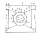
バルブ本体6の中央には、図3に示すように、第1及び第2のバルブシート70,80を装着することによって断面矩形状の第1の弁口9及び断面矩形状の第2の弁口18が設けられる弁座8を備えている。弁座8は、後述する弁体の外形状に対応した円柱形状に形成された空所からなる。また、弁座8の一部は、第1及び第2のバルブシート70,80によって形成されている。円柱形状に形成された弁座8は、バルブ本体6の上端面に貫通した状態で設けられる。バルブ本体6に設けられる第1の弁口9及び第2の弁口18は、図9に示すように、円柱形状に形成された弁座8の中心軸(回転軸)Cに対して軸対称に配置されている。更に説明すると、第1の弁口9及び第2の弁口18は、円柱形状に形成された弁座8に対して直交するように配置されており、第1の弁口9の一方の端縁は、中心軸Cを介して第2の弁口18の他方の端縁と対向する位置(180度異なる位置)に開口されている。また、第1の弁口9の他方の端縁は、中心軸Cを介して第2の弁口18の一方の端縁と対向する位置(180度異なる位置)に開口されている。なお、図9では、便宜上、弁座8と弁軸34との間隙は図示が省略されている。 3, the center of the valve body 6 is provided with a valve seat 8 in which a first valve orifice 9 having a rectangular cross section and a second valve orifice 18 having a rectangular cross section are provided by attaching first and second valve seats 70, 80. The valve seat 8 is a cylindrical cavity corresponding to the outer shape of the valve body described later. A part of the valve seat 8 is formed by the first and second valve seats 70, 80. The cylindrical valve seat 8 is provided in a state penetrating the upper end surface of the valve body 6. The first valve orifice 9 and the second valve orifice 18 provided in the valve body 6 are arranged symmetrically with respect to the central axis (rotation axis) C of the cylindrical valve seat 8 as shown in FIG. To explain further, the first valve port 9 and the second valve port 18 are arranged perpendicular to the cylindrical valve seat 8, and one edge of the first valve port 9 is opened at a position (180 degrees different) opposite the other edge of the second valve port 18 through the central axis C. The other edge of the first valve port 9 is opened at a position (180 degrees different) opposite the one edge of the second valve port 18 through the central axis C. For convenience, the gap between the valve seat 8 and the valve shaft 34 is omitted in FIG. 9.

また、第1の弁口9及び第2の弁口18は、図2に示すように、上記のごとく、バルブ本体6に第1及び第2のバルブシート70,80を装着することによって形成される断面正方形状等の断面矩形状に形成された開口部からなる。第1の弁口9及び第2の弁口18は、その一辺の長さが第1の流出口7及び第2の流出口17の直径より小さく設定されており、当該第1の流出口7及び第2の流出口17に内接する断面矩形の角筒形状に形成されている。 As shown in FIG. 2, the first valve port 9 and the second valve port 18 are formed as openings having a rectangular cross section, such as a square cross section, formed by attaching the first and second valve seats 70, 80 to the valve body 6 as described above. The first valve port 9 and the second valve port 18 have a side length set to be smaller than the diameters of the first outlet 7 and the second outlet 17, and are formed as a rectangular tube shape inscribed in the first outlet 7 and the second outlet 17.

弁体の一例としての弁軸34は、図9に示すように、SUS等の金属により外形が略円柱形状に形成されている。弁軸34は、大別して、弁体として機能する弁体部35と、当該弁体部35の上下にそれぞれ設けられて弁軸34を回転自在に支持する上下の軸支部36,37と、上軸支部36と同一の部分から構成されるシール部38と、シール部38の上部に設けられたカップリング部39とを一体的に備えている。 As shown in Figure 9, the valve shaft 34, which is an example of a valve body, is made of a metal such as SUS and has a generally cylindrical outer shape. The valve shaft 34 is roughly divided into a valve body portion 35 that functions as a valve body, upper and lower support portions 36, 37 that are provided above and below the valve body portion 35 and support the valve shaft 34 so that it can rotate freely, a seal portion 38 that is composed of the same parts as the upper support portion 36, and a coupling portion 39 that is provided above the seal portion 38.

上下の軸支部36,37は、弁体部35より外径が小さい円筒形状にそれぞれ形成されている。上下の軸支部36,37は、外径が同一又は異なる値に設定されている。下軸支部37は、図2に示すように、バルブ本体6に設けられた弁座8の下端部に軸受部材としてのベアリング41を介して回転可能に支持されている。弁座8の下部には、ベアリング41を支持する環状の支持部42が設けられている。ベアリング41、支持部42及び流入口26は、略同一の内径に設定されており、弁体部35の内部へと温度制御用流体が抵抗を殆ど生じることなく流入するよう構成されている。 The upper and lower journal parts 36, 37 are each formed in a cylindrical shape with an outer diameter smaller than that of the valve body part 35. The upper and lower journal parts 36, 37 are set to have the same or different outer diameters. As shown in FIG. 2, the lower journal part 37 is rotatably supported at the lower end of the valve seat 8 provided on the valve body 6 via a bearing 41 as a bearing member. An annular support part 42 that supports the bearing 41 is provided at the lower part of the valve seat 8. The bearing 41, support part 42, and inlet 26 are set to approximately the same inner diameter, and are configured so that the temperature control fluid flows into the inside of the valve body part 35 with almost no resistance.

また、弁体部35は、図2及び図9(b)に示すように、第1及び第2の弁口9,18の開口高H1より高さが低い開口高H2を有する略半円筒形状の開口部44が設けられた円筒形状に形成されている。弁体部35の開口部44が設けられた弁動作部45は、予め定められた中心角α(例えば、180度)を有する半円筒形状(円筒形状の部分のうち、開口部44を除いた略半円筒形状)に形成されている。弁動作部45は、開口部44の上下に位置する弁体部35を含めて第1の弁口9を閉状態から開状態に切り替えると同時に、第2の弁口18を逆方向の開状態から閉状態に切り替えるよう弁座8内に且つ弁座8の内周面に金属同士の齧りを防止するため微小な間隙を介して回転自在に配置されている。弁動作部45の上下に配置された上下の弁軸部46,47は、図9に示すように、弁動作部45と同一の外径を有する円筒形状に形成されており、弁座8の内周面に微小な間隙を介して回転自在となっている。弁動作部45及び上下の弁軸部46,47の内部には、円柱形状の空所48が下端部に向けて貫通した状態で設けられている。 As shown in Figs. 2 and 9(b), the valve body 35 is formed in a cylindrical shape with an approximately semi-cylindrical opening 44 having an opening height H2 lower than the opening height H1 of the first and second valve ports 9 and 18. The valve operating part 45 with the opening 44 of the valve body 35 is formed in a semi-cylindrical shape (approximately a semi-cylindrical shape excluding the opening 44) with a predetermined central angle α (for example, 180 degrees). The valve operating part 45 is rotatably arranged within the valve seat 8 and on the inner surface of the valve seat 8 through a small gap to prevent metals from galling each other so as to switch the first valve port 9, including the valve body 35 located above and below the opening 44, from a closed state to an open state, and at the same time switch the second valve port 18 from an open state in the opposite direction to a closed state. The upper and lower valve shafts 46, 47 arranged above and below the valve operating part 45 are formed in a cylindrical shape with the same outer diameter as the valve operating part 45, as shown in FIG. 9, and are rotatable through a small gap on the inner peripheral surface of the valve seat 8. Inside the valve operating part 45 and the upper and lower valve shafts 46, 47, a cylindrical cavity 48 is provided that penetrates toward the lower end.

また、弁動作部45は、周方向(回転方向)に沿った両端面45a,45bがその中心軸Cと交差する(直交する)方向に沿った断面形状が平面形状に形成されている。更に説明すると、弁動作部45は、図9に示すように、周方向に沿った両端部45a,45bの回転軸Cと交差する断面形状が開口部44に向けて平面形状に形成されている。両端部45a,45bの肉厚は、例えば、弁動作部45の厚さTと等しい値に設定される。 The valve operating portion 45 has both end faces 45a, 45b along the circumferential direction (rotation direction) formed in a planar cross section along a direction intersecting (perpendicular to) the central axis C. To explain further, as shown in FIG. 9, the valve operating portion 45 has both end faces 45a, 45b along the circumferential direction formed in a planar cross section intersecting the rotation axis C toward the opening 44. The thickness of both end faces 45a, 45b is set to, for example, a value equal to the thickness T of the valve operating portion 45.

弁動作部45は、周方向に沿った両端部45a,45bの回転軸Cと交差する断面形状が平面形状に限定されるものではなく、周方向(回転方向)に沿った両端面45a,45bが曲面形状に形成されても良い。 The cross-sectional shape of the valve operating portion 45 that intersects with the rotation axis C of both end surfaces 45a, 45b along the circumferential direction is not limited to a flat shape, and both end surfaces 45a, 45b along the circumferential direction (rotation direction) may be formed into a curved shape.

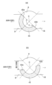
弁動作部45の周方向に沿った両端部45a,45bは、図10に示すように、弁軸34が回転駆動されて第1及び第2の弁口9,18を開閉する際に、流体の流れの中において、第1及び第2の弁口9,18の周方向に沿った端部から突出する又は退避するように移動(回転)することで第1及び第2の弁口9,18を開状態から閉状態あるいは閉状態から開状態へと移行させる。このとき、弁動作部45の周方向に沿った両端部45a,45bは、弁軸34の回転角度に対する第1及び第2の弁口9,18の開口面積をリニア(直線状)に変化させるため、断面形状が平面形状に形成されていることが望ましい。 As shown in FIG. 10, when the valve shaft 34 is rotated to open and close the first and second valve ports 9, 18, the circumferential ends 45a, 45b of the valve operating part 45 move (rotate) so as to protrude or retreat from the circumferential ends of the first and second valve ports 9, 18 in the flow of fluid, thereby transitioning the first and second valve ports 9, 18 from an open state to a closed state or from a closed state to an open state. At this time, it is desirable that the circumferential ends 45a, 45b of the valve operating part 45 have a planar cross-sectional shape in order to linearly change the opening area of the first and second valve ports 9, 18 with respect to the rotation angle of the valve shaft 34.

シール部4は、図2に示すように、弁軸34をバルブ本体6に対して回転可能となるよう液密状態に密封(封止)するものである。シール部4は、バルブ本体6と、弁軸34と、バルブ本体6と弁軸34との間に配置されて両者の間を液密状に封止する金属製のバネ部材により開く方向に付勢された断面略U字形状の合成樹脂からなる封止手段の一例としてのオムニシール160,170と、弁軸34をバルブ本体6に対して回転可能に支持する軸受部材180とを備えている。 As shown in FIG. 2, the seal unit 4 seals the valve shaft 34 in a liquid-tight state so that it can rotate relative to the valve body 6. The seal unit 4 includes the valve body 6, the valve shaft 34, omni seals 160, 170 as an example of a sealing means made of synthetic resin with a roughly U-shaped cross section and biased in an opening direction by a metal spring member that is disposed between the valve body 6 and the valve shaft 34 and provides a liquid-tight seal between them, and a bearing member 180 that supports the valve shaft 34 rotatably relative to the valve body 6.

バルブ本体6の上端部には、図2に示すように、弁軸34の上端部を回転可能に支持するため円柱形状に形成された支持用凹部51が設けられている。支持用凹部51の上端には、テーパー部51aを介して内径が大きな円筒部51bが形成されている。弁軸34は、上述したように、上方の上軸支部36及びシール部38が支持用凹部51に軸受部材の一例としてのベアリング180及びオムニシール160,170を介して回転可能かつ液密状に支持されている。 As shown in FIG. 2, the upper end of the valve body 6 is provided with a support recess 51 formed in a cylindrical shape to rotatably support the upper end of the valve shaft 34. A cylindrical portion 51b with a large inner diameter is formed at the upper end of the support recess 51 via a tapered portion 51a. As described above, the upper shaft support portion 36 and the seal portion 38 of the valve shaft 34 are rotatably and liquid-tightly supported in the support recess 51 via the bearing 180 and omni seals 160 and 170, which are examples of bearing members.

更に説明すると、本実施の形態1では、図2に示すように、弁軸34の上軸支部36及びシール部38と支持用凹部51との間に形成される間隙に、ベアリング180と第1及び第2のオムニシール160,170が配置されている。 To explain further, in this embodiment 1, as shown in FIG. 2, a bearing 180 and first and second omni seals 160, 170 are disposed in the gap formed between the upper shaft support portion 36 and the seal portion 38 of the valve shaft 34 and the support recess 51.

第1及び第2のオムニシール160,170は、同様に構成されている。ここでは、第1のオムニシール160を例に説明する。 The first and second omni seals 160, 170 are configured in the same way. Here, the first omni seal 160 will be used as an example.

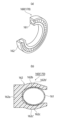
第1のオムニシール160は、図11に示すように、弁軸34の上軸支部36及びシール部38と支持用凹部51との間に形成される円筒形状の間隙の全周にわたり配置される環状(リング状)の部材である。オムニシール160は、断面略円形状又は断面楕円形状のステンレス等の金属からなるバネ部材161と、バネ部材161によって開く方向に付勢された断面略U字形状のポリテトラフルオロエチレン(PTFE)等の合成樹脂からなるシール部材162から構成されている。バネ部材161は、螺旋状に形成されたステンレス等の金属によって断面略円形状又は断面楕円形状に形成されている。バネ部材161は、その幅や肉厚などを適宜設定することにより弾性率が調整されている。シール部材162は、図12に示すように、封止する、弁軸34の上軸支部36及びシール部38と支持用凹部51との間に位置するよう封止する方向に沿って配置される基端部162aと、基端部162aの両端から封止する2つの部材の周面に沿った同一方向(第1のバルブシート70の軸方向に沿った外側)へ向けて互いに対向するよう平行に配置された2つのリップ部162b,162cを備えている。オムニシール160の開口部は、弁座8の内部に向かって開口されており、当該弁座8内に存在する流体の圧力を受ける。リップ部162b,162cの中間部162b’,162c’は、その外周面が中間から先端へ向けて半径方向外方へ向けて突出する円弧状に湾曲した湾曲形状に形成されている。リップ部162b,162cの中間部162b’,162c’は、弁軸34の上軸支部36及びシール部38の外周面と支持用凹部51の内周面に密着して密封度を高めている。 As shown in FIG. 11, the first omni-seal 160 is an annular (ring-shaped) member arranged around the entire circumference of the cylindrical gap formed between the upper shaft support 36 and the seal portion 38 of the valve shaft 34 and the support recess 51. The omni-seal 160 is composed of a spring member 161 made of a metal such as stainless steel having a substantially circular or elliptical cross section, and a seal member 162 made of a synthetic resin such as polytetrafluoroethylene (PTFE) having a substantially U-shaped cross section and biased in the opening direction by the spring member 161. The spring member 161 is formed of a metal such as stainless steel formed in a spiral shape and has a substantially circular or elliptical cross section. The elastic modulus of the spring member 161 is adjusted by appropriately setting its width, thickness, etc. As shown in Fig. 12, the seal member 162 has a base end 162a that is arranged along the sealing direction so as to be located between the upper shaft support portion 36 and the seal portion 38 of the valve shaft 34 and the support recess 51, and two lip portions 162b, 162c that are arranged in parallel to face each other in the same direction (outside along the axial direction of the first valve seat 70) along the peripheral surfaces of the two sealing members from both ends of the base end 162a. The opening of the omni-seal 160 opens toward the inside of the valve seat 8 and receives the pressure of the fluid present in the valve seat 8. The middle portions 162b', 162c' of the lip portions 162b, 162c are formed in a curved shape that is curved in an arc shape whose outer circumferential surface protrudes radially outward from the middle to the tip. The intermediate portions 162b', 162c' of the lip portions 162b, 162c are in close contact with the outer peripheral surfaces of the upper shaft support portion 36 and the seal portion 38 of the valve stem 34 and the inner peripheral surface of the support recess 51 to improve the degree of sealing.

なお、オムニシール160のバネ部材161は、断面略円形状又は断面略楕円形状に形成されたものに限定されるものではなく、図13に示すように、断面略U字形状に形成したものであっても良い。ただし、オムニシール160のバネ部材161は、断面略円形状又は断面略楕円形状に形成した方が圧縮変形された際の反発力が大きく、結果的にシール効果が高まるため、断面略円形状又は断面略楕円形状に形成した方が望ましい。 The spring member 161 of the omni-seal 160 is not limited to being formed with a substantially circular or elliptical cross section, and may be formed with a substantially U-shaped cross section as shown in Fig. 13. However, the spring member 161 of the omni-seal 160 is preferably formed with a substantially circular or elliptical cross section because the repulsive force generated when the spring member 161 is compressed and deformed is greater when the spring member 161 is formed with a substantially circular or elliptical cross section, resulting in a higher sealing effect.

オムニシール160は、流体の圧力が作用しないか又は流体の圧力が相対的に低いときは、バネ部材161の弾性復元力によって弁軸34の上軸支部36及びシール部38と支持用凹部51の間隙を密封する。一方、オムニシール160は、流体の圧力が相対的に高いときは、バネ部材161の弾性復元力及び流体の圧力によって弁軸34の上軸支部36及びシール部38と支持用凹部51の間隙を密封する。したがって、弁軸34の上軸支部36及びシール部38と支持用凹部51の間隙から流体が流入した場合においても、当該流体は、オムニシール160によって封止されて弁軸34の上軸支部36及びシール部38と支持用凹部51の間隙から外部に漏れることはない。 When no fluid pressure is applied or when the fluid pressure is relatively low, the omni-seal 160 seals the gap between the upper support portion 36 and seal portion 38 of the valve shaft 34 and the support recess 51 by the elastic restoring force of the spring member 161. On the other hand, when the fluid pressure is relatively high, the omni-seal 160 seals the gap between the upper support portion 36 and seal portion 38 of the valve shaft 34 and the support recess 51 by the elastic restoring force of the spring member 161 and the fluid pressure. Therefore, even if fluid flows in from the gap between the upper support portion 36 and seal portion 38 of the valve shaft 34 and the support recess 51, the fluid is sealed by the omni-seal 160 and does not leak out from the gap between the upper support portion 36 and seal portion 38 of the valve shaft 34 and the support recess 51 to the outside.

オムニシール160は、金属製のバネ部材161と合成樹脂製のシール部材162の組み合わせからなる。金属製のバネ部材161は勿論のこと、シール部材162を構成する合成樹脂であるポリテトラフルオロエチレン(PTFE)は、耐熱性に優れており、極低温域において長時間の使用に耐えることが可能となっている。 The omniseal 160 is made up of a combination of a metal spring member 161 and a synthetic resin seal member 162. The metal spring member 161 and the synthetic resin polytetrafluoroethylene (PTFE) that makes up the seal member 162 are both highly heat-resistant and can withstand long periods of use in extremely low temperatures.

本実施の形態1では、弁軸34の上軸支部36及びシール部38と支持用凹部51の間隙を封止するオムニシールが、軸受部材を挟んで二重に配置された第1及び第2のオムニシール160,170から構成されている。そのため、経時的に、下方に位置する第1のオムニシール160が摩耗した場合であっても、上方に位置する第2のオムニシール170により確実に封止することができ、流体が外部に漏れることを確実に阻止することが可能となる。 In this embodiment 1, the omni seal that seals the gap between the upper shaft support portion 36 and the seal portion 38 of the valve shaft 34 and the support recess 51 is composed of a first and a second omni seal 160, 170 arranged in double with a bearing member in between. Therefore, even if the first omni seal 160 located at the bottom wears out over time, it can be reliably sealed by the second omni seal 170 located at the top, and it is possible to reliably prevent the fluid from leaking to the outside.

軸受部材180は、断面楕円形状や断面矩形状などに形成されたポリイミド(PI)樹脂等の合成樹脂から構成されている。ポリイミド(PI)樹脂等の合成樹脂からなる軸受部材は、-60℃程度の低温においても良好な摺動性を発揮することが可能である。 The bearing member 180 is made of a synthetic resin such as polyimide (PI) resin formed into an elliptical or rectangular cross-section. Bearing members made of synthetic resin such as polyimide (PI) resin are capable of exhibiting good sliding properties even at low temperatures of around -60°C.

なお、軸受部材180は、第1及び第2のオムニシール160,170の間に配置される場合に限定されるものではなく、第2のオムニシール170の軸方向に沿った外側に配置しても良い。 The bearing member 180 is not limited to being disposed between the first and second omni seals 160, 170, but may be disposed on the outside along the axial direction of the second omni seal 170.

また、図2中、符号181は、ポリイミド(PI)等の合成樹脂からなるスラストワッシャを示している。 In addition, in FIG. 2, reference numeral 181 denotes a thrust washer made of a synthetic resin such as polyimide (PI).

また、図2及び図3において、第1及び第2のバルブシート70,80と第1及び第2の流路形成部材15,25との間隙、及び第1及び第2の流路形成部材15,25とバルブ本体6の間隙は、いずれもオムニシール110~150によって封止されている。なお、オムニシール110~150としては、バネ部材が断面略U字形状に形成したものが用いられている。第1及び第2のバルブシート70,80には、オムニシールを収容するための段差部73,83が設けられている。また、第1及び第2のバルブシート70,80の段差部73,83は、第1及び第2の受圧プレート76,86によって閉塞されている。 2 and 3, the gaps between the first and second valve seats 70, 80 and the first and second flow path forming members 15, 25, and the gaps between the first and second flow path forming members 15, 25 and the valve body 6 are all sealed by omni seals 110-150. The omni seals 110-150 are spring members formed into a generally U-shaped cross section. The first and second valve seats 70, 80 are provided with stepped portions 73, 83 for accommodating the omni seals. The stepped portions 73, 83 of the first and second valve seats 70, 80 are closed by the first and second pressure receiving plates 76, 86.

カップリング部5は、図1に示すように、シール部4が内蔵されたバルブ本体6とアクチュエータ部3との間に配置されている。カップリング部5は、弁軸34と当該弁軸34を一体に回転させる図示しない回転軸とを連結するためのものである。 As shown in FIG. 1, the coupling part 5 is disposed between the valve body 6, in which the seal part 4 is built, and the actuator part 3. The coupling part 5 is for connecting the valve shaft 34 to a rotating shaft (not shown) that rotates the valve shaft 34 together.

カップリング部5は、図1に示すように、シール部4とアクチュエータ部3の間に配置されたスペーサ部材59と、スペーサ部材59の上部に固定されたアダプタプレート60と、スペーサ部材59及びアダプタプレート60の内部に貫通状態で形成された円柱形状の空間61に収容され、弁軸34と図示しない回転軸とを連結するカップリング部材62とから構成されている。スペーサ部材59は、ポリイミド(PI)樹脂等の合成樹脂によりバルブ本体6の一部と略同一の平面形状を有する比較的高さが高い角筒状に形成されている。スペーサ部材59は、その下端に設けられたフランジ部59aがネジ59b止め等の手段によってバルブ本体6及びアダプタプレート60の双方に固定される。また、アダプタプレート60は、図1(c)に示すように、SUS等の金属により平面多角形の板状に形成されている。アダプタプレート60は、六角孔付きボルト63によりアクチュエータ部3の基盤64に固定した状態で取り付けられる。 1, the coupling section 5 is composed of a spacer member 59 arranged between the seal section 4 and the actuator section 3, an adaptor plate 60 fixed to the upper part of the spacer member 59, and a coupling member 62 housed in a cylindrical space 61 formed in a penetrating state inside the spacer member 59 and the adaptor plate 60, and connecting the valve shaft 34 and a rotating shaft (not shown). The spacer member 59 is made of a synthetic resin such as polyimide (PI) resin and has a relatively high rectangular tube shape having a planar shape substantially the same as a part of the valve body 6. The spacer member 59 is fixed to both the valve body 6 and the adaptor plate 60 by a means such as a screw 59b, with a flange portion 59a provided at the lower end. The adaptor plate 60 is formed into a planar polygonal plate shape made of a metal such as SUS, as shown in FIG. 1(c). The adaptor plate 60 is attached in a fixed state to the base 64 of the actuator section 3 by a hexagonal socket bolt 63.

弁軸34の上端には、図9(a)に示すように、水平方向に沿って貫通するように凹溝65が設けられている。そして、弁軸34は、カップリング部材62に設けられた凸部66を凹溝65に嵌合することによりカップリング部材62に連結固定されている。一方、カップリング部材62の上端には、水平方向に沿って貫通するように凹溝67が設けられている。図示しない回転軸は、カップリング部材62に設けられた凹溝67に図示しない凸部を嵌合することによりカップリング部材62に連結固定される。スペーサ部材59は、シール部4から液体が漏洩した際、液体がアクチュエータ部3に到達するのを阻止するオーシール190を上端部に備えている。 9(a), a groove 65 is provided at the upper end of the valve shaft 34 so as to penetrate horizontally. The valve shaft 34 is connected and fixed to the coupling member 62 by fitting a convex portion 66 provided on the coupling member 62 into the groove 65. Meanwhile, a groove 67 is provided at the upper end of the coupling member 62 so as to penetrate horizontally. The rotating shaft (not shown) is connected and fixed to the coupling member 62 by fitting a convex portion (not shown) into the groove 67 provided on the coupling member 62. The spacer member 59 has an O-seal 190 at its upper end, which prevents liquid from reaching the actuator portion 3 when liquid leaks from the seal portion 4.

アクチュエータ部3は、図1に示すように、平面矩形状に形成された基盤64を備えている。基盤64の上部には、ステッピングモータやエンコーダ等からなる駆動手段を内蔵した直方体形状の箱体として構成されたケーシング90がビス91止めにより装着されている。アクチュエータ部3の駆動手段は、制御信号に基づいて図示しない回転軸を所望の方向に所定の精度で回転可能なものであれば良く、その構成は限定されない。駆動手段は、ステッピングモータ及び当該ステッピングモータの回転駆動力をギア等の駆動力伝達手段を介して回転軸に伝達する駆動力伝達機構、並びに回転軸の回転角度を検出するエンコーダ等の角度センサにより構成される。 As shown in FIG. 1, the actuator unit 3 has a base 64 formed in a rectangular shape when viewed from above. A casing 90 configured as a rectangular box containing a drive means consisting of a stepping motor, an encoder, etc. is attached to the top of the base 64 with screws 91. The drive means of the actuator unit 3 may be any means capable of rotating a rotating shaft (not shown) in a desired direction with a predetermined accuracy based on a control signal, and its configuration is not limited. The drive means is composed of a stepping motor, a drive force transmission mechanism that transmits the rotational drive force of the stepping motor to the rotating shaft via a drive force transmission means such as a gear, and an angle sensor such as an encoder that detects the rotation angle of the rotating shaft.

なお、図1中、符号92はステッピングモータ側ケーブルを、93は角度センサ側ケーブルをそれぞれ示している。これらステッピングモータ側ケーブル92及び角度センサ側ケーブル93は、三方弁型モータバルブ1を制御する図示しない制御装置にそれぞれ接続される。 In FIG. 1, reference numeral 92 denotes a stepping motor side cable, and 93 denotes an angle sensor side cable. The stepping motor side cable 92 and the angle sensor side cable 93 are each connected to a control device (not shown) that controls the three-way valve type motor valve 1.

<環境条件>
本実施の形態1に係る三方弁型モータバルブ1は、上述したように、例えば、-85~+120℃程度の温度、特に-85℃程度の大幅に低い温度の流体に対して使用可能となるよう構成されている。そのため、三方弁型モータバルブ1を使用する周囲の環境条件は、-85~+120℃程度の温度範囲に対応したものであることが望ましい。すなわち、三方弁型モータバルブ1は、-85℃程度の流体を流した場合、弁本体自体が-85℃程度の流体と等しい温度となる。その結果、三方弁型モータバルブ1を使用する条件が空気中の水分である湿度を含む環境下では、空気中の水分が三方弁型モータバルブ1に付着して凍結し、三方弁型モータバルブ1に誤動作が生じる要因となると考えられる。
<Environmental conditions>
As described above, the three-way valve motor valve 1 according to the first embodiment is configured to be usable for fluids at temperatures of, for example, about -85 to +120°C, particularly at temperatures as low as about -85°C. Therefore, it is desirable that the environmental conditions in which the three-way valve motor valve 1 is used correspond to a temperature range of about -85 to +120°C. That is, when a fluid at about -85°C flows through the three-way valve motor valve 1, the valve body 6 itself becomes at a temperature equal to that of the fluid at about -85°C. As a result, when the conditions for using the three-way valve motor valve 1 are in an environment that includes humidity, which is moisture in the air, the moisture in the air adheres to the three-way valve motor valve 1 and freezes, which is considered to be a factor in causing the three-way valve motor valve 1 to malfunction.

そこで、本実施の形態1では、三方弁型モータバルブ1を使用する環境条件として、窒素(N2-)ガスによって置換された環境下において、周囲湿度(相対湿度)が0.10%以下、好ましくは0.01%程度であることが望ましい。 Therefore, in this embodiment 1, the environmental conditions for using the three-way valve type motor valve 1 are an environment replaced with nitrogen ( N2- ) gas, with the ambient humidity (relative humidity) being 0.10% or less, preferably approximately 0.01%.

<三方弁型モータバルブの動作>
本実施の形態1に係る三方弁型モータバルブ1では、-85℃程度の低温の流体を流通させた場合、次のようにして流体の流量が制御される。
<Operation of three-way motor valve>
In the three-way motor valve 1 according to the first embodiment, when a low-temperature fluid of about −85° C. is passed through, the flow rate of the fluid is controlled as follows.

三方弁型モータバルブ1は、図4に示すように、組立時又は使用する際の調整時に、第1及び第2のフランジ部材10,19がバルブ本体6から一旦取り外され、調整リング77,87が外部に露出した状態とされる。この状態で、図示しない治具を用いて調整リング77,87のバルブ本体6に対する締付量を調整することにより、図6に示すように、第1及び第2のバルブシート70,80におけるバルブ本体6の弁座8に対する突出量を変化させる。調整リング77,87のバルブ本体6に対する締付量を増加させた場合には、第1及び第2のバルブシート70,80の凹部74,84がバルブ本体6の弁座8の内周面から突出し、第1及び第2のバルブシート70,80の凹部74,84と弁軸34の外周面との間隙G1が減少して、第1及び第2のバルブシート70,80の凹部74,84と弁軸34の外周面とが接触するに至る。一方、調整リング77,87のバルブ本体6に対する締付量を減少させた場合には、第1及び第2のバルブシート70,80の凹部74,84がバルブ本体6の弁座8の内周面から突出する長さが減少し、第1及び第2のバルブシート70,80の凹部74,84と弁軸34の外周面との間隙G1が増加する。 As shown in FIG. 4, when the three-way valve type motor valve 1 is assembled or adjusted for use, the first and second flange members 10, 19 are temporarily removed from the valve body 6, and the adjustment rings 77, 87 are exposed to the outside. In this state, the amount of tightening of the adjustment rings 77, 87 to the valve body 6 is adjusted using a jig not shown, thereby changing the amount of protrusion of the first and second valve seats 70, 80 from the valve seat 8 of the valve body 6, as shown in FIG. 6. When the amount of tightening of the adjustment rings 77, 87 to the valve body 6 is increased, the recesses 74, 84 of the first and second valve seats 70, 80 protrude from the inner surface of the valve seat 8 of the valve body 6, and the gap G1 between the recesses 74, 84 of the first and second valve seats 70, 80 and the outer surface of the valve shaft 34 is reduced, and the recesses 74, 84 of the first and second valve seats 70, 80 come into contact with the outer surface of the valve shaft 34. On the other hand, when the amount of tightening of the adjustment rings 77, 87 to the valve body 6 is reduced, the length by which the recesses 74, 84 of the first and second valve seats 70, 80 protrude from the inner circumferential surface of the valve seat 8 of the valve body 6 decreases, and the gap G1 between the recesses 74, 84 of the first and second valve seats 70, 80 and the outer circumferential surface of the valve shaft 34 increases.

本実施の形態1では、例えば、第1及び第2のバルブシート70,80の凹部74,84と弁軸34の外周面との間隙G1が10μm未満に設定される。ただし、第1及び第2のバルブシート70,80の凹部74,84と弁軸34の外周面との間隙G1は、この値に限定されるものではなく、当該値より小さい値、例えば間隙G1=0μm(接触状態)であっても良く、10μm以上に設定しても良い。 In the first embodiment, for example, the gap G1 between the recesses 74, 84 of the first and second valve seats 70, 80 and the outer circumferential surface of the valve shaft 34 is set to less than 10 μm. However, the gap G1 between the recesses 74, 84 of the first and second valve seats 70, 80 and the outer circumferential surface of the valve shaft 34 is not limited to this value, and may be a value smaller than this value, for example, gap G1 = 0 μm (contact state), or may be set to 10 μm or more.

三方弁型モータバルブ1は、図1に示すように、第3のフランジ部材27を介して流体が図示しない配管を介して流入し、第1のフランジ部材10及び第2のフランジ部材19を介して流体が図示しない配管を介して流出する。また、三方弁型モータバルブ1は、図10(a)に示すように、例えば、動作を開始する前の初期状態において、弁軸34の弁動作部45が第1の弁口9を閉塞(全閉)すると同時に第2の弁口18を開放(全開)した状態とされる。 As shown in FIG. 1, in the three-way valve type motor valve 1, fluid flows in through the third flange member 27 via piping (not shown), and fluid flows out through the first flange member 10 and the second flange member 19 via piping (not shown). Also, as shown in FIG. 10(a), for example, in the initial state before starting operation, the three-way valve type motor valve 1 is in a state in which the valve operating portion 45 of the valve shaft 34 closes (fully closes) the first valve port 9 and simultaneously opens (fully opens) the second valve port 18.

三方弁型モータバルブ1は、図2に示すように、アクチュエータ部3に設けられた図示しないステッピングモータを所定量だけ回転駆動させると、ステッピングモータの回転量に応じて図示しない回転軸が回転駆動される。三方弁型モータバルブ1は、回転軸が回転駆動されると、当該回転軸に連結固定された弁軸34が回転軸の回転量(回転角)と同一の角度だけ回転する。弁軸34の回転に伴って弁動作部45が弁座8の内部において回転し、図14(a)に示すように、弁動作部45の周方向に沿った一端部45aが第1の弁口9を徐々に開放して、流入口26から流入した流体が弁座8の内部に流入するとともに、第1のハウジング部材10から第1の流出口7を介して流出する。 As shown in FIG. 2, when the stepping motor (not shown) provided in the actuator unit 3 is rotated by a predetermined amount, the three-way valve type motor valve 1 rotates a rotating shaft (not shown) according to the amount of rotation of the stepping motor. When the rotating shaft of the three-way valve type motor valve 1 is rotated, the valve shaft 34 connected and fixed to the rotating shaft rotates by the same angle as the amount of rotation (rotation angle) of the rotating shaft. As the valve shaft 34 rotates, the valve operating part 45 rotates inside the valve seat 8, and as shown in FIG. 14(a), one end 45a along the circumferential direction of the valve operating part 45 gradually opens the first valve port 9, and the fluid flowing in from the inlet 26 flows into the inside of the valve seat 8 and flows out from the first housing member 10 through the first outlet 7.

このとき、弁動作部45の周方向に沿った他端部45bは、図14(a)に示すように、第2の弁口18を開放しているため、流入口27から流入した流体が弁座8の内部に流
入して弁軸34の回転量に応じて分配されるととともに、第2のハウジング部材19から第2の流出口17を介して外部に流出する。
At this time, the other end 45b along the circumferential direction of the valve operating portion 45 opens the second valve port 18, as shown in Figure 14 (a), so that the fluid flowing in from the inlet 27 flows into the inside of the valve seat 8 and is distributed according to the amount of rotation of the valve shaft 34, and then flows out from the second housing member 19 to the outside through the second outlet 17.

三方弁型モータバルブ1は、図14(a)に示すように、弁軸34が回転駆動されて弁動作部45の周方向に沿った一端部45aが第1の弁口9を徐々に開放すると、弁座8並びに弁軸34の内部を通って流体が第1及び第2の弁口9,18を介して第1及び第2の流出口9,18を介して外部に供給される。 As shown in FIG. 14(a), when the valve shaft 34 is rotated and one end 45a of the valve operating part 45 along the circumferential direction gradually opens the first valve port 9, the fluid passes through the valve seat 8 and the inside of the valve shaft 34, and is supplied to the outside through the first and second valve ports 9, 18 and the first and second outlet ports 9, 18.

また、三方弁型モータバルブ1は、弁動作部45の周方向に沿った両端部45a,45bが断面曲面形状又は断面平面形状に形成されているため、弁軸34の回転角度に対して第1及び第2の弁口9,18の開口面積をリニア(直線状)に変化させることが可能となる。また、弁動作部45の両端部45a,45bによって流量が規制される流体が層流に近い状態で流動すると考えられ、第1の弁口9及び第2の弁口18の開口面積に応じて流体の分配比(流量)を精度良く制御することができる。 In addition, in the three-way valve type motor valve 1, both ends 45a, 45b along the circumferential direction of the valve operating part 45 are formed with a cross-sectional curved shape or a cross-sectional planar shape, so it is possible to change the opening area of the first and second valve ports 9, 18 linearly (straight-line) with respect to the rotation angle of the valve shaft 34. In addition, the fluid whose flow rate is regulated by both ends 45a, 45b of the valve operating part 45 is thought to flow in a state close to laminar flow, and the distribution ratio (flow rate) of the fluid can be precisely controlled according to the opening area of the first valve port 9 and the second valve port 18.

本実施の形態に係る三方弁型モータバルブ1では、上述したように、初期的に、弁軸34の弁動作部45が第1の弁口9を閉塞(全閉)すると同時に第2の弁口18を開放(全開)した状態とされる。 As described above, in the three-way valve type motor valve 1 according to this embodiment, initially, the valve operating portion 45 of the valve shaft 34 closes (fully closes) the first valve port 9 and simultaneously opens (fully opens) the second valve port 18.

このとき、三方弁型モータバルブ1は、弁軸34の弁動作部45が第1の弁口9を閉塞(全閉)すると、理想的には、流体の流量がゼロとなる筈である。 At this time, when the valve operating portion 45 of the valve shaft 34 of the three-way valve type motor valve 1 closes (fully closes) the first valve port 9, ideally the flow rate of the fluid should be zero.

しかしながら、三方弁型モータバルブ1は、図6に示すように、弁軸34が弁座8の内周面に対して金属同士の齧りを防止するために、弁軸34の外周面と弁座8の内周面との間に微小な間隙を介して非接触状態となるよう回転自在に配置されている。その結果、弁軸34の外周面と弁座8の内周面との間には、微小な間隙G2が形成されている。そのため、三方弁型モータバルブ1は、弁軸34の弁動作部45が第1の弁口9を閉塞(全閉)した場合であっても、流体の流量がゼロとならず、弁軸34の外周面と弁座8の内周面との間に存在する微小な間隙G2を介して流体が少量ながら第2の弁口18側へ流れ込もうとする。 However, as shown in FIG. 6, the three-way valve type motor valve 1 is arranged to be freely rotatable so that the valve shaft 34 is in a non-contact state with a small gap between the outer circumferential surface of the valve shaft 34 and the inner circumferential surface of the valve seat 8 in order to prevent metal-to-metal galling against the inner circumferential surface of the valve seat 8. As a result, a small gap G2 is formed between the outer circumferential surface of the valve shaft 34 and the inner circumferential surface of the valve seat 8. Therefore, in the three-way valve type motor valve 1, even when the valve operating part 45 of the valve shaft 34 closes (fully closes) the first valve port 9, the flow rate of the fluid does not become zero, and a small amount of fluid tries to flow into the second valve port 18 through the small gap G2 that exists between the outer circumferential surface of the valve shaft 34 and the inner circumferential surface of the valve seat 8.

ところで、本実施の形態に係る三方弁型モータバルブ1では、図6に示すように、第1及び第2のバルブシート70,80に凹部74,84が設けられており、当該凹部74,84が弁座8の内周面から弁軸34側に突出して、弁軸34の外周面と弁座8の内周面との間の間隙G1を部分的に縮小している。 In the three-way valve type motor valve 1 according to this embodiment, as shown in FIG. 6, the first and second valve seats 70, 80 are provided with recesses 74, 84, which protrude from the inner circumferential surface of the valve seat 8 toward the valve shaft 34, thereby partially reducing the gap G1 between the outer circumferential surface of the valve shaft 34 and the inner circumferential surface of the valve seat 8.

したがって、三方弁型モータバルブ1は、弁軸34が弁座8の内周面に対して金属同士の齧りを防止するため、弁軸34の外周面と弁座8の内周面との間に微小な間隙を介して非接触状態となるよう回転自在に配置されていても、流体が第1の弁口9から弁軸34の外周面と弁座8の内周面との間に存在する微小な間隙G2へ流れ込むことが、弁軸34の外周面と弁座8の内周面との間隙が部分的に縮小された領域である間隙G1により大幅に制限されて抑制される。 Thus, even though the three-way valve type motor valve 1 is arranged to rotate freely so that the valve shaft 34 is in a non-contact state with a small gap between the outer circumferential surface of the valve shaft 34 and the inner circumferential surface of the valve seat 8 in order to prevent metal-to-metal galling against the inner circumferential surface of the valve seat 8, the flow of fluid from the first valve port 9 into the small gap G2 that exists between the outer circumferential surface of the valve shaft 34 and the inner circumferential surface of the valve seat 8 is significantly restricted and suppressed by the gap G1, which is an area where the gap between the outer circumferential surface of the valve shaft 34 and the inner circumferential surface of the valve seat 8 is partially reduced.

そのため、三方弁型モータバルブ1では、弁軸34と当該弁軸34と対向する第1及び第2のバルブシート70,80との間隙を部分的に縮小するよう設けられた凹部74,84を備えない三方弁型モータバルブに比較して、当該三方弁型モータバルブ1の全閉時における流体の漏れを大幅に抑制することが可能となる。 Therefore, in the three-way valve type motor valve 1, it is possible to significantly reduce fluid leakage when the three-way valve type motor valve 1 is fully closed, compared to a three-way valve type motor valve that does not have recesses 74, 84 that are provided to partially reduce the gap between the valve shaft 34 and the first and second valve seats 70, 80 that face the valve shaft 34.

望ましくは、本実施の形態に係る三方弁型モータバルブ1は、第1及び第2のバルブシート70,80の凹部74,84を弁軸34の外周面と接触させることにより、間隙G1,G2を大幅に縮小することができ、当該三方弁型モータバルブ1の全閉時における流体の漏れが大幅に抑制される。 Desirably, the three-way valve type motor valve 1 according to this embodiment can significantly reduce the gaps G1 and G2 by bringing the recesses 74 and 84 of the first and second valve seats 70 and 80 into contact with the outer circumferential surface of the valve shaft 34, thereby significantly suppressing leakage of fluid when the three-way valve type motor valve 1 is fully closed.

また同様に、三方弁型モータバルブ1は、弁軸34の弁動作部45が第2の弁口18を閉塞(全閉)とした場合にも、流体が第2の弁口18を介して、他方の第1の弁口9側に漏れて流出するのを大幅に抑制することができる。 Similarly, even when the valve operating portion 45 of the valve shaft 34 blocks (fully closes) the second valve port 18, the three-way valve type motor valve 1 can significantly prevent fluid from leaking through the second valve port 18 to the other first valve port 9.

さらに、本実施の形態1では、図3に示すように、第1及び第2のバルブシート70,80の弁軸34と反対側の面70a,80aに、弁軸34の外周面と弁座8の内周面との間に微小な間隙を介して流体の圧力を作用させる第1及び第2の圧力作用部94,96が設けられている。そのため、三方弁型モータバルブ1は、図10(a)に示すように、開度0%つまり第1の弁口9が全閉の付近、及び開度100%つまり第1の弁口9が全開の付近において、第1及び第2の弁口9,18が全閉に近づくと、当該第1及び第2の弁口9,18から流出する流体の量が大幅に減少する。これに伴って、三方弁型モータバルブ1は、全閉状態に近づく弁口では、流出する流体の圧力が低下する。そのため、例えば開度0%つまり第1の弁口9が全閉のとき、流入口26から圧力700KPa程度の流体が流入し、略700KPaのまま第2の弁口18から流出する。このとき、全閉に近い状態である第1の弁口9側は、出口側の圧力が例えば100KPa程度まで低下する。その結果、第2の弁口18と第1の弁口9との間に600KPa程度の圧力差が生じることになる。 In addition, in this embodiment 1, as shown in Fig. 3, the first and second pressure acting portions 94, 96 that act on the fluid pressure through a small gap between the outer peripheral surface of the valve shaft 34 and the inner peripheral surface of the valve seat 8 are provided on the surfaces 70a, 80a of the first and second valve seats 70, 80 opposite the valve shaft 34. Therefore, as shown in Fig. 10(a), when the first and second valve ports 9, 18 approach full closure at 0% opening, i.e., the first valve port 9 is fully closed, and at 100% opening, i.e., the first valve port 9 is fully open, the amount of fluid flowing out of the first and second valve ports 9, 18 is significantly reduced. Accordingly, in the three-way valve type motor valve 1, the pressure of the flowing fluid decreases at the valve ports approaching the fully closed state. Therefore, for example, when the opening degree is 0%, that is, when the first valve orifice 9 is fully closed, a fluid with a pressure of about 700 KPa flows in from the inlet 26 and flows out from the second valve orifice 18 at approximately 700 KPa. At this time, the pressure on the outlet side of the first valve orifice 9, which is close to being fully closed, drops to, for example, about 100 KPa. As a result, a pressure difference of about 600 KPa occurs between the second valve orifice 18 and the first valve orifice 9.

したがって、対策を講じない三方弁型モータバルブ1では、第2の弁口18と第1の弁口9との間の圧力差によって弁軸34が相対的に圧力の低い第1の弁口9側に移動(変位)し、弁軸34がベアリング41に片当たりした状態となる。そのため、弁軸34を閉じる方向に回転駆動する際の駆動トルクが増大して、動作不良を生じる虞れがある。 Therefore, in a three-way valve type motor valve 1 where no countermeasures are taken, the pressure difference between the second valve port 18 and the first valve port 9 causes the valve shaft 34 to move (displace) toward the first valve port 9 where the pressure is relatively lower, resulting in the valve shaft 34 coming into partial contact with the bearing 41. As a result, the drive torque increases when the valve shaft 34 is rotated in the closing direction, which may cause malfunction.

これに対して、本実施の形態に係る三方弁型モータバルブ1では、図15に示すように、第1及び第2のバルブシート70,80の弁軸34と反対側の面に、弁軸34の外周面と弁座8の内周面との間に微小な間隙を介して漏れる流体の圧力を第1及び第2のバルブシート70,80に作用させる第1及び第2の圧力作用部94,96が設けられている。そのため、本実施の形態に係る三方弁型モータバルブ1では、第2の弁口18と第1の弁口9との間の圧力差が生じる場合であっても、相対的に圧力が高い側の流体の圧力が弁軸34の外周面と弁座8の内周面との微小な間隙を介して第1及び第2の圧力作用部94,96に作用する。その結果、相対的に100KPa程度と圧力が低い側の第1のバルブシート70は、当該第1の圧力作用部94に作用する相対的に圧力が100KPa程度と高い側の流体の圧力によって、弁軸34を適正な位置へと戻すように作用する。したがって、本実施の形態に係る三方弁型モータバルブ1では、第2の弁口18と第1の弁口9との間の圧力差によって弁軸34が相対的に圧力の低い第1の弁口9側に移動(変位)するのを防止乃至抑制し、弁軸34がベアリング41によって滑らかに支持された状態を維持することができ、弁軸34を閉じる方向に回転駆動する際の駆動トルクが増大するのを防止乃至抑制することができる。 15, in the three-way valve type motor valve 1 according to the present embodiment, first and second pressure action parts 94, 96 are provided on the surfaces of the first and second valve seats 70, 80 opposite the valve shaft 34, which act on the first and second valve seats 70, 80 with the pressure of the fluid leaking through a minute gap between the outer circumferential surface of the valve shaft 34 and the inner circumferential surface of the valve seat 8. Therefore, in the three-way valve type motor valve 1 according to the present embodiment, even if a pressure difference occurs between the second valve port 18 and the first valve port 9, the pressure of the fluid with the relatively higher pressure acts on the first and second pressure action parts 94, 96 through the minute gap between the outer circumferential surface of the valve shaft 34 and the inner circumferential surface of the valve seat 8. As a result, the first valve seat 70 on the side with a relatively low pressure of about 100 KPa acts to return the valve shaft 34 to an appropriate position by the pressure of the fluid on the side with a relatively high pressure of about 100 KPa acting on the first pressure acting portion 94. Therefore, in the three-way valve type motor valve 1 according to this embodiment, the valve shaft 34 is prevented or suppressed from moving (displacing) toward the first valve port 9 side with a relatively low pressure due to the pressure difference between the second valve port 18 and the first valve port 9, the valve shaft 34 can be maintained in a state where it is smoothly supported by the bearing 41, and an increase in the drive torque when the valve shaft 34 is rotated in the closing direction can be prevented or suppressed.

また、本実施の形態に係る三方弁型モータバルブ1では、第1の弁口9が全開の付近、つまり第2の弁口18が全閉状態に近いときにも同様に動作し、弁軸34を回転駆動する際の駆動トルクが増大するのを防止乃至抑制することができる。 The three-way valve type motor valve 1 according to this embodiment also operates in the same way when the first valve port 9 is close to being fully open, i.e., when the second valve port 18 is close to being fully closed, and can prevent or suppress an increase in the drive torque when driving the valve shaft 34 to rotate.

本実施の形態1に係る三方弁型モータバルブ1は、流体(ブライン)として、例えば、圧力が0~1MPa、-85~+120℃程度の温度範囲において適応可能なオプテオン(登録商標)(三井・ケマーズフロロプロダクツ社製)やノベック(登録商標)(3M社製)等のフッ素系不活性液体などが使用される。 The three-way valve type motor valve 1 according to the first embodiment uses, as the fluid (brine), a fluorine-based inert liquid such as Opteon (registered trademark) (manufactured by Mitsui-Chemours Fluoroproducts) or Novec (registered trademark) (manufactured by 3M), which is suitable for pressures of 0 to 1 MPa and temperatures of approximately -85 to +120°C.

三方弁型モータバルブ1は、-85℃程度の流体の流出量を切り替える場合、流体が流通する弁本体6自体が-85℃程度の温度となる。 When switching the outflow rate of a fluid at approximately -85°C, the three-way motor valve 1 causes the temperature of the valve body 6 through which the fluid flows to reach approximately -85°C.

三方弁型モータバルブ1は、弁軸34の上軸支部36及びシール部38と支持用凹部51の間隙を密封(封止)するため、第1及び第2のオムニシール160,170を使用している。また、第1及び第2のオムニシール160,170は、弁座8の内部へ向けて開口するようそれぞれ配置されている。また、第1のオムニシール160は、金属製のバネ部材161と合成樹脂製のシール部材162の組み合わせからなる。金属製のバネ部材161は勿論のこと、シール部材162を構成する合成樹脂であるポリテトラフルオロエチレン(PTFE)は、耐熱性に優れており、極低温域において長時間の使用に耐えることが可能となっている。なお、他の第2のオムニシール170についても同様である。 The three-way valve type motor valve 1 uses the first and second omni seals 160, 170 to seal the gap between the upper shaft support 36 and the seal portion 38 of the valve shaft 34 and the support recess 51. The first and second omni seals 160, 170 are arranged so that they open toward the inside of the valve seat 8. The first omni seal 160 is made of a combination of a metal spring member 161 and a synthetic resin seal member 162. The metal spring member 161 and the synthetic resin polytetrafluoroethylene (PTFE) that constitutes the seal member 162 have excellent heat resistance and can withstand long periods of use in extremely low temperature areas. The same is true for the other second omni seal 170.

そのため、本実施の形態1に係る三方弁型モータバルブ1は、弁軸34の上軸支部36及びシール部38と支持用凹部51の間隙を密封(封止)するため、金属製のバネ部材により開く方向に付勢された断面略U字形状の合成樹脂からなる封止手段としての第1及び第2のオムニシール160,170を使用している。よって、弁軸34の上軸支部36及びシール部38と支持用凹部51の間隙をOリングによって封止した場合に比較して、-85℃程度の低温の流体に対するシール性を向上させることが可能となる。 Therefore, the three-way valve type motor valve 1 according to the first embodiment uses first and second omni seals 160, 170 as sealing means made of synthetic resin with a roughly U-shaped cross section and biased in the opening direction by a metal spring member to seal (seal) the gap between the upper support part 36 and seal part 38 of the valve shaft 34 and the support recess 51. This makes it possible to improve the sealing performance against low-temperature fluids of around -85°C compared to when the gap between the upper support part 36 and seal part 38 of the valve shaft 34 and the support recess 51 is sealed with an O-ring.

すなわち、弁軸34の上軸支部36及びシール部38と支持用凹部51の間隙を、第1及び第2のオムニシール160,170を用いて封止することにより、-85℃程度の低温の流体に対しても高いシール性を発揮することができる。また、第1及び第2のオムニシール160,170は、弁軸34の上軸支部36及びシール部38と支持用凹部51の間隙において相対的に大きな接触面積を有しており、この点からも高いシール性を発揮することが可能となる。 That is, by sealing the gap between the upper support portion 36 and seal portion 38 of the valve shaft 34 and the support recess 51 using the first and second omni seals 160, 170, it is possible to achieve high sealing performance even against low-temperature fluids of about -85°C. In addition, the first and second omni seals 160, 170 have a relatively large contact area in the gap between the upper support portion 36 and seal portion 38 of the valve shaft 34 and the support recess 51, which also makes it possible to achieve high sealing performance.

[実施の形態2]
図16は本発明の実施の形態2に係る流量制御弁の一例としての三方弁型モータバルブを示すものである。
[Embodiment 2]
FIG. 16 shows a three-way motor valve as an example of a flow control valve according to the second embodiment of the present invention.

本実施の形態2に係る三方弁型モータバルブ1は、同一の流体を二つに分配するものではなく、異なる2種類の流体を混合する混合用の三方弁型モータバルブ1として構成されたものである。 The three-way valve type motor valve 1 according to the second embodiment is configured as a three-way valve type motor valve 1 for mixing two different types of fluids, rather than distributing the same fluid into two.

三方弁型モータバルブ1は、図16に示すように、バルブ本体6の一方の側面に第1の流体としての低温側流体が流入する第1の流入口7と、円柱形状の空所からなる弁座8に連通した断面矩形状の第1の弁口9がそれぞれ設けられている。本実施の形態では、第1の流出口7及び第1の弁口9をバルブ本体6に直接設けるのではなく、第1の弁口9を形成した弁口形成部材の一例としての第1のバルブシート70と、第1の流入口7を形成した第1の流路形成部材15とをバルブ本体6に装着することにより、第1の流入口17及び第1の弁口9を設けている。 As shown in FIG. 16, the three-way valve type motor valve 1 has a first inlet 7 through which a low-temperature fluid as a first fluid flows in on one side of the valve body 6, and a first valve port 9 with a rectangular cross section that communicates with a valve seat 8 consisting of a cylindrical cavity. In this embodiment, the first outlet 7 and the first valve port 9 are not provided directly on the valve body 6, but rather the first inlet 17 and the first valve port 9 are provided by attaching a first valve seat 70 as an example of a valve port forming member that forms the first valve port 9, and a first flow path forming member 15 that forms the first inlet 7 to the valve body 6.

また、三方弁型モータバルブ1は、バルブ本体6の他方の側面に第2の流体としての高温側流体が流入する第2の流入口17と、円柱形状の空所からなる弁座8に連通した断面矩形状の第2の弁口18がそれぞれ設けられている。本実施の形態では、第2の流出口17及び第2の弁口18をバルブ本体6に直接設けるのではなく、第2の弁口18を形成した弁口形成部材の一例としての第2のバルブシート80と、第2の流出口17を形成した第2の流路形成部材25とをバルブ本体6に装着することにより、第2の流出口17及び第2の弁口18を設けている。 The three-way valve type motor valve 1 is provided with a second inlet 17 through which the high temperature fluid as the second fluid flows in on the other side of the valve body 6, and a second valve port 18 with a rectangular cross section that communicates with a valve seat 8 consisting of a cylindrical cavity. In this embodiment, the second outlet 17 and the second valve port 18 are not provided directly on the valve body 6, but are provided by attaching a second valve seat 80 as an example of a valve port forming member that forms the second valve port 18, and a second flow path forming member 25 that forms the second outlet 17 to the valve body 6.

また、三方弁型モータバルブ1は、バルブ本体6の底面に第1及び第2の流体がバルブ本体6の内部で混合された混合流体である温度制御用流体が流出する流出口26が開口されている。 In addition, the three-way valve type motor valve 1 has an outlet 26 opened on the bottom surface of the valve body 6 through which the temperature control fluid, which is a mixed fluid formed by mixing the first and second fluids inside the valve body 6, flows out.

ここで、第1の流体としての低温側流体及び第2の流体としての高温側流体は、温度制御用に使用される流体であって相対的に温度が低い流体を低温側流体と称し、相対的に温度が高い流体を高温側流体と称している。したがって、低温側流体及び高温側流体は、相対的なものを意味し、絶対的に温度が低い低温の流体及び絶対的に温度が高い高温の流体を意味するものではない。低温側流体及び高温側流体としては、例えば、圧力が0~1MPa、-85~+120℃程度の温度範囲において、オプテオン(登録商標)(三井・ケマーズフロロプロダクツ社製)やノベック(登録商標)(3M社製)等のフッ素系不活性液体などが使用される。 Here, the low-temperature fluid as the first fluid and the high-temperature fluid as the second fluid are fluids used for temperature control, with the low-temperature fluid being a relatively low-temperature fluid and the high-temperature fluid being a relatively high-temperature fluid. Therefore, the low-temperature fluid and the high-temperature fluid are relative terms, and do not refer to an absolutely low-temperature fluid and an absolutely high-temperature fluid. For example, fluorine-based inert liquids such as Opteon (registered trademark) (manufactured by Mitsui-Chemours Fluoroproducts) and Novec (registered trademark) (manufactured by 3M) are used as the low-temperature fluid and the high-temperature fluid, in a pressure range of 0 to 1 MPa and a temperature range of about -85 to +120°C.

その他の構成及び作用は、前記実施の形態1と同様であるので、その説明を省略する。 The rest of the configuration and operation are the same as in the first embodiment, so their explanation will be omitted.

[実施の形態3]
図17は本発明の実施の形態3に係る流量制御弁の一例としての三方弁型モータバルブを示すものである。
[Embodiment 3]
FIG. 17 shows a three-way motor valve as an example of a flow control valve according to the third embodiment of the present invention.

本実施の形態3に係る三方弁型モータバルブ1は、図17に示すように、弁軸34の上軸支部36及びシール部38と支持用凹部51の間隙において、第1及び第2のオムニシール160,170の間に軸受部材180を配置するのではなく、第1及び第2のオムニシール160,170の軸方向に沿った上部に軸受部材180を配置するよう構成されている。 As shown in FIG. 17, the three-way valve type motor valve 1 according to the third embodiment is configured such that the bearing member 180 is not disposed between the first and second omni seals 160, 170 in the gap between the upper shaft support portion 36 and the seal portion 38 of the valve shaft 34 and the support recess 51, but is disposed above the first and second omni seals 160, 170 in the axial direction.

本実施の形態3に係る三方弁型モータバルブ1は、第1及び第2のオムニシール160,170を直列に接続した状態で配置しているため、より一層高いシール効果を発揮することが可能となる。 The three-way valve type motor valve 1 according to the third embodiment has the first and second omni seals 160, 170 connected in series, which allows for an even higher sealing effect.

その他の構成及び作用は、前記実施の形態1と同様であるので、その説明を省略する。 The rest of the configuration and operation are the same as in the first embodiment, so their explanation will be omitted.

[実施例1]
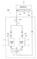
図18は本発明の実施の形態1に係る流量制御用三方弁を適用した恒温維持装置(チラー装置)を示す概念図である。
[Example 1]
FIG. 18 is a conceptual diagram showing a constant temperature controller (chiller device) to which the flow rate control three-way valve according to the first embodiment of the present invention is applied.

このチラー装置100は、例えば、プラズマエッチング処理などを伴う半導体製造装置に使用され、温度制御対象Wの一例としての半導体ウエハ等の温度を一定温度に維持するものである。半導体ウエハ等の温度制御対象Wは、プラズマエッチング処理等を受けると、プラズマの生成や放電等に伴って温度が上昇する場合がある。 This chiller device 100 is used, for example, in semiconductor manufacturing equipment that performs plasma etching processes, etc., and maintains the temperature of a semiconductor wafer, an example of a temperature-controlled object W, at a constant temperature. When a temperature-controlled object W, such as a semiconductor wafer, undergoes plasma etching processes, etc., the temperature may rise due to plasma generation, discharge, etc.

チラー装置100は、温度制御対象Wと接触するように配置される温度制御手段の一例としてのテーブル状に構成された温度制御部101を備える。温度制御部101は、混合比が調整された低温側流体及び高温側流体からなる温度制御用流体が流れる温度制御用流
路102を内部に有している。
The chiller device 100 includes a temperature control unit 101 configured in a table shape as an example of a temperature control means arranged so as to be in contact with a temperature-controlled object W. The temperature control unit 101 has therein a temperature control flow path 102 through which a temperature control fluid flows, the temperature control fluid being made up of a low-temperature side fluid and a high-temperature side fluid whose mixing ratio has been adjusted.

温度制御部101の温度制御用流路102には、開閉弁103を介して混合手段111が接続されている。混合手段111の一方には、予め定められた低温側の設定温度に調整された低温流体を貯蔵した低温側恒温槽104が接続されている。低温側恒温槽104からは、三方弁型モータバルブ1に第1のポンプ105により低温側流体が供給される。また、混合手段111の他方には、予め定められた高温側の設定温度に調整された高温流体を貯蔵した高温側恒温槽106が接続されている。高温側恒温槽106からは、三方弁型モータバルブ1に第2のポンプ107により高温側流体が供給される。混合手段111は、開閉弁103を介して温度制御部101の温度制御用流路102に接続されている。 The mixing means 111 is connected to the temperature control flow path 102 of the temperature control unit 101 via an on-off valve 103. A low-temperature side thermostatic chamber 104 storing a low-temperature fluid adjusted to a predetermined low-temperature side set temperature is connected to one side of the mixing means 111. The low-temperature side thermostatic chamber 104 supplies the low-temperature side fluid to the three-way valve type motor valve 1 by a first pump 105. The other side of the mixing means 111 is connected to a high-temperature side thermostatic chamber 106 storing a high-temperature fluid adjusted to a predetermined high-temperature side set temperature. The high-temperature side thermostatic chamber 106 supplies the high-temperature side fluid to the three-way valve type motor valve 1 by a second pump 107. The mixing means 111 is connected to the temperature control flow path 102 of the temperature control unit 101 via an on-off valve 103.

また、温度制御部101の温度制御用流路102の流出側には、帰還用の配管が設けられており、分配用の流量制御用三方弁1を介して低温側恒温槽104及び高温側恒温槽106にそれぞれ接続されている。 In addition, a return pipe is provided on the outlet side of the temperature control flow path 102 of the temperature control unit 101, and is connected to the low-temperature side thermostatic bath 104 and the high-temperature side thermostatic bath 106 via the distribution flow control three-way valve 1.

このチラー装置100は、温度制御部101の温度制御用流路102を流れた制御用流体を低温側恒温槽104と高温側恒温槽106とにそれぞれ分配するために三方弁型モータバルブ1を使用している。三方弁型モータバルブ1は、ステッピングモータ110によって弁軸34を回転駆動することにより、低温側恒温槽104と高温側恒温槽106とにそれぞれ分配する制御用流体の流量を制御する。 This chiller device 100 uses a three-way valve type motor valve 1 to distribute the control fluid that has flowed through the temperature control flow path 102 of the temperature control unit 101 to the low-temperature constant temperature bath 104 and the high-temperature constant temperature bath 106. The three-way valve type motor valve 1 controls the flow rate of the control fluid to be distributed to the low-temperature constant temperature bath 104 and the high-temperature constant temperature bath 106 by rotating the valve shaft 34 using a stepping motor 110.

低温側流体及び高温側流体としては、例えば、圧力が0~1MPa、-85~+120℃程度の温度範囲において、オプテオン(登録商標)(三井・ケマーズフロロプロダクツ社製)やノベック(登録商標)(3M社製)等のフッ素系不活性液体などが使用される。 For example, fluorine-based inert liquids such as Opteon (registered trademark) (manufactured by Mitsui-Chemours Fluoroproducts) and Novec (registered trademark) (manufactured by 3M) are used as the low-temperature fluid and high-temperature fluid, with a pressure of 0 to 1 MPa and a temperature range of approximately -85 to +120°C.

なお、低温側恒温槽104から第1のポンプ105により供給される低温側流体と、高温側恒温槽106から第2のポンプ107により供給される高温側流体との混合部111には、各低温側流体及び高温側流体の流量を制御した後に適宜混合する混合手段が用いられる。混合手段としては、上述したように、混合用の三方弁型モータバルブ1を用いても勿論良い。 The mixing section 111 for the low-temperature fluid supplied from the low-temperature constant-temperature bath 104 by the first pump 105 and the high-temperature fluid supplied from the high-temperature constant-temperature bath 106 by the second pump 107 uses a mixing means that controls the flow rate of each low-temperature fluid and high-temperature fluid and then mixes them appropriately. As the mixing means, a three-way valve type motor valve 1 for mixing may of course be used as described above.

[実施例2]
図19は本発明の実施の形態2に係る流量制御用三方弁を適用した恒温維持装置(チラー装置)を示す概念図である。
[Example 2]
FIG. 19 is a conceptual diagram showing a constant temperature controller (chiller device) to which a flow rate control three-way valve according to the second embodiment of the present invention is applied.

温度制御部101の温度制御用流路102には、開閉弁103を介して三方弁型モータバルブ1が接続されている。三方弁型モータバルブ1の第1のフランジ部10には、予め定められた低温側の設定温度に調整された低温流体を貯蔵した低温側恒温槽104が接続されている。低温側恒温槽104からは、三方弁型モータバルブ1に第1のポンプ105により低温側流体が供給される。また、三方弁型モータバルブ1の第2のフランジ部19には、予め定められた高温側の設定温度に調整された高温流体を貯蔵した高温側恒温槽106が接続されている。高温側恒温槽106からは、三方弁型モータバルブ1に第2のポンプ107により高温側流体が供給される。三方弁型モータバルブ1の第3のフランジ部27は、開閉弁103を介して温度制御部101の温度制御用流路102に接続されている。 The three-way valve type motor valve 1 is connected to the temperature control flow path 102 of the temperature control unit 101 via an on-off valve 103. A low-temperature side thermostatic chamber 104 storing a low-temperature fluid adjusted to a predetermined low-temperature side set temperature is connected to the first flange portion 10 of the three-way valve type motor valve 1. The low-temperature side thermostatic chamber 104 supplies the low-temperature side fluid to the three-way valve type motor valve 1 by a first pump 105. A high-temperature side thermostatic chamber 106 storing a high-temperature fluid adjusted to a predetermined high-temperature side set temperature is connected to the second flange portion 19 of the three-way valve type motor valve 1. The high-temperature side thermostatic chamber 106 supplies the high-temperature side fluid to the three-way valve type motor valve 1 by a second pump 107. The third flange portion 27 of the three-way valve type motor valve 1 is connected to the temperature control flow path 102 of the temperature control unit 101 via an on-off valve 103.

また、温度制御部101の温度制御用流路102の流出側には、帰還用の配管が設けられており、低温側恒温槽104及び高温側恒温槽106にそれぞれ接続されている。 Furthermore, a return pipe is provided on the outlet side of the temperature control flow path 102 of the temperature control unit 101, and is connected to the low-temperature side thermostatic chamber 104 and the high-temperature side thermostatic chamber 106, respectively.

三方弁型モータバルブ1は、弁軸34を回転駆動するステッピングモータ108を備えている。また、温度制御部101には、当該温度制御部101の温度を検知する温度センサ109が設けられている。温度センサ109は、図示しない制御装置に接続されており、制御装置は、三方弁型モータバルブ1のステッピングモータ108の駆動を制御する。 The three-way valve type motor valve 1 is equipped with a stepping motor 108 that rotates the valve shaft 34. The temperature control unit 101 is also provided with a temperature sensor 109 that detects the temperature of the temperature control unit 101. The temperature sensor 109 is connected to a control device (not shown), and the control device controls the driving of the stepping motor 108 of the three-way valve type motor valve 1.

チラー装置100は、図19に示すように、温度制御対象Wの温度を温度センサ109によって検知し、当該温度センサ109の検知結果に基いて制御装置によって三方弁型モータバルブ1のステッピングモータ108の回転を制御することにより、温度制御対象Wの温度を予め定められた設定温度と等しい温度となるよう制御する。 As shown in FIG. 19, the chiller device 100 detects the temperature of the temperature-controlled object W using a temperature sensor 109, and controls the rotation of the stepping motor 108 of the three-way valve type motor valve 1 using a control device based on the detection result of the temperature sensor 109, thereby controlling the temperature of the temperature-controlled object W to be equal to a predetermined set temperature.

三方弁型モータバルブ1は、ステッピングモータ108によって弁軸34を回転駆動することにより、低温側恒温槽104から第1のポンプ105により供給される低温側流体と、高温側恒温槽106から第2のポンプ107により供給される高温側流体との混合比を制御し、三方弁型モータバルブ1から開閉弁103を介して温度制御部101の温度制御用流路102に供給する低温側流体と高温側流体とが混合された温度制御用流体の温度を制御する。 Three-way valve type motor valve 1 controls the mixing ratio between the low-temperature side fluid supplied by the first pump 105 from the low-temperature side thermostatic bath 104 and the high-temperature side fluid supplied by the second pump 107 from the high-temperature side thermostatic bath 106 by rotating the valve shaft 34 with the stepping motor 108, and controls the temperature of the temperature control fluid, which is a mixture of the low-temperature side fluid and the high-temperature side fluid and is supplied from the three-way valve type motor valve 1 to the temperature control flow path 102 of the temperature control unit 101 via the on-off valve 103.

このとき、三方弁型モータバルブ1は、弁軸34の回転角に応じて低温側流体と高温側流体との混合比を高い精度で制御することができ、温度制御用流体の温度を微調整することが可能となる。そのため、本実施の形態に係る三方弁型モータバルブ1を使用したチラー装置100は、低温側流体と高温側流体との混合比が制御された所定の温度に調整された温度制御用流体を温度制御部101の温度制御用流路102に流すことにより、温度制御部101が接触する温度制御対象Wの温度を所望の温度に制御することができる。 At this time, the three-way valve type motor valve 1 can control the mixture ratio of the low-temperature fluid and the high-temperature fluid with high precision according to the rotation angle of the valve shaft 34, making it possible to finely adjust the temperature of the temperature control fluid. Therefore, the chiller device 100 using the three-way valve type motor valve 1 according to this embodiment can control the temperature of the temperature control object W that the temperature control unit 101 comes into contact with to a desired temperature by flowing a temperature control fluid, the temperature of which has been adjusted to a predetermined temperature by controlling the mixture ratio of the low-temperature fluid and the high-temperature fluid, through the temperature control flow path 102 of the temperature control unit 101.

低温側流体及び高温側流体としては、例えば、圧力が0~1MPa、-85~+120℃程度の温度範囲において、オプテオン(登録商標)(三井・ケマーズフロロプロダクツ社製)やノベック(登録商標)(3M社製)等のフッ素系不活性液体などが使用される。 For example, fluorine-based inert liquids such as Opteon (registered trademark) (manufactured by Mitsui-Chemours Fluoroproducts) and Novec (registered trademark) (manufactured by 3M) are used as the low-temperature fluid and high-temperature fluid, with a pressure of 0 to 1 MPa and a temperature range of approximately -85 to +120°C.

-85℃程度の低温の流体に対するシール性を向上させた流量制御用三方弁及び温度制御装置を提供することができる。 It is possible to provide a three-way valve for flow control and a temperature control device that has improved sealing properties for low-temperature fluids of around -85°C.

1…三方弁型モータバルブ
2…バルブ部
3…アクチュエータ部
4…シール部
5…カップリング部
6…バルブ本体
7…第1の流入口
8…弁座
9…第1の弁口
10…第1のフランジ部材
11…六角穴付きボルト
12…フランジ部
13…挿入部
14…配管接続部
15…第1の流路形成部材
16…第1のウェーブワッシャー
17…第2の流入口
18…第2の弁口
19…第2のフランジ部材
20…六角穴付きボルト
21…フランジ部
22…挿入部
23…配管接続部
25…第2の流路形成部材
34…弁軸
35…弁体部
45…弁動作部
45a,45b…両端部
70,80…第1及び第2のバルブシート
74,84…凹部
160,170…オムニシール
Reference Signs List 1... Three-way valve type motor valve 2... Valve section 3... Actuator section 4... Seal section 5... Coupling section 6... Valve body 7... First inlet 8... Valve seat 9... First valve port 10... First flange member 11... Hexagon socket bolt 12... Flange section 13... Insertion section 14... Pipe connection section 15... First flow path forming member 16... First wave washer
Reference Signs List 17...Second inlet 18...Second valve port 19...Second flange member 20...Hexagon socket head bolt 21...Flange portion 22...Insertion portion 23...Pipe connection portion 25...Second flow passage forming member 34...Valve shaft 35...Valve body portion 45...Valve operating portion 45a, 45b...Both ends 70, 80...First and second valve seats 74, 84...Recesses 160, 170...Omniseal

Claims (5)

流体が流出する断面矩形状の第1の弁口と前記流体が流出する断面矩形状の第2の弁口が形成されるとともに、外部と前記第1及び第2の弁口をそれぞれ連通させる第1及び第2の流出口が形成された円柱形状の空所からなる弁座を有する弁本体と、
前記弁本体の弁座内に回転自在に配置され、前記第1の弁口を閉状態から開状態に切り替えると同時に前記第2の弁口を開状態から閉状態に切り替える開口部が形成された円筒形状の弁体と、
前記弁体を回転駆動する駆動手段と、
前記弁体の前記駆動手段側の端部を前記弁本体に対して回転可能に封止する手段であって、前記弁本体に設けられた前記弁体の前記駆動手段側の端部を回転可能に支持する円柱形状の支持用凹部に配置され、金属製のバネ部材により開く方向に付勢された断面略U字形状の合成樹脂からなる封止手段と、
を備え、
前記封止手段は、前記弁体の前記駆動手段側の端部に軸方向に沿って複数配置され、前記複数の封止手段の間に前記弁体の前記駆動手段側の端部を回転可能に支持する軸受部材が配置されることを特徴とする流量制御用三方弁。
a valve body having a valve seat formed of a cylindrical cavity in which a first valve port having a rectangular cross section through which a fluid flows out and a second valve port having a rectangular cross section through which the fluid flows out are formed, and in which first and second outlets for connecting the first and second valve ports to the outside, respectively, are formed;
a cylindrical valve body that is rotatably disposed within a valve seat of the valve body and has an opening that switches the first valve port from a closed state to an open state and simultaneously switches the second valve port from an open state to a closed state;
A driving means for rotationally driving the valve body;
a sealing means for rotatably sealing the end of the valve element on the drive means side relative to the valve body, the sealing means being disposed in a cylindrical support recess provided on the valve body for rotatably supporting the end of the valve element on the drive means side, the sealing means being made of synthetic resin and having a substantially U-shaped cross section and biased in an opening direction by a metal spring member;
Equipped with
a valve body having a valve casing and a valve casing arranged in a casing for axial movement of the valve body; a valve member arranged between the valve body and the valve casing for axial movement of the valve body;
第1の流体が流入する断面矩形状の第1の弁口と第2の流体が流入する断面矩形状の第2の弁口が形成されるとともに、外部と前記第1及び第2の弁口をそれぞれ連通させる第1及び第2の流入口が形成された円柱形状の空所からなる弁座を有する弁本体と、
前記弁本体の弁座内に回転自在に配置され、前記第1の弁口を閉状態から開状態に切り替えると同時に前記第2の弁口を開状態から閉状態に切り替える開口部が形成された円筒形状の弁体と、
前記弁体を回転駆動する駆動手段と、
前記弁体の前記駆動手段側の端部を前記弁本体に対して回転可能に封止する手段であって、前記弁本体に設けられた前記弁体の前記駆動手段側の端部を回転可能に支持する円柱形状の支持用凹部に配置され、金属製のバネ部材により開く方向に付勢された断面略U字形状の合成樹脂からなる封止手段と、
を備え、
前記封止手段は、前記弁体の前記駆動手段側の端部に軸方向に沿って複数配置され、前記複数の封止手段の間に前記弁体の前記駆動手段側の端部を回転可能に支持する軸受部材が配置されることを特徴とする流量制御用三方弁。
a valve body having a valve seat formed of a cylindrical cavity in which a first valve port having a rectangular cross section through which a first fluid flows and a second valve port having a rectangular cross section through which a second fluid flows, and in which first and second inlets are formed to respectively connect the first and second valve ports with the outside;
a cylindrical valve body that is rotatably disposed within a valve seat of the valve body and has an opening that switches the first valve port from a closed state to an open state and simultaneously switches the second valve port from an open state to a closed state;
A driving means for rotationally driving the valve body;
a sealing means for rotatably sealing the end of the valve element on the drive means side relative to the valve body, the sealing means being disposed in a cylindrical support recess provided on the valve body for rotatably supporting the end of the valve element on the drive means side, the sealing means being made of synthetic resin and having a substantially U-shaped cross section and biased in an opening direction by a metal spring member;
Equipped with
a valve body having a valve casing and a valve casing arranged in a casing for axial movement of the valve body; a valve member arranged between the valve body and the valve casing for axial movement of the valve body;
前記軸受部材は、前記複数の封止手段と密着するよう配置される請求項1又は2に記載の流量制御用三方弁。 3. The flow rate control three-way valve according to claim 1 , wherein the bearing member is disposed so as to be in close contact with the plurality of sealing means. 混合比が調整された低温側流体及び高温側流体からなる温度制御用流体が流れる温度制御用流路を有する温度制御手段と、
低温側の予め定められた第1の温度に調整された前記低温側流体を供給する第1の供給手段と、
高温側の予め定められた第2の温度に調整された前記高温側流体を供給する第2の供給手段と、
前記第1の供給手段と前記第2の供給手段に接続され、前記第1の供給手段から供給される前記低温側流体と前記第2の供給手段から供給される前記高温側流体とを混合して前記温度制御用流路に供給する混合手段と、
前記温度制御用流路を流通した温度制御用流体を前記第1の供給手段と前記第2の供給手段に流量を制御しつつ分配する流量制御弁と、
を備え、
前記流量制御弁として請求項1又は3に記載の流量制御用三方弁を用いたことを特徴とする温度制御装置。
a temperature control means having a temperature control flow path through which a temperature control fluid, which is made of a low-temperature side fluid and a high-temperature side fluid whose mixing ratio has been adjusted, flows;
a first supply means for supplying the low-temperature fluid adjusted to a predetermined first temperature on the low-temperature side;
a second supply means for supplying the high-temperature side fluid adjusted to a second predetermined temperature on the high-temperature side;
a mixing means connected to the first supply means and the second supply means, for mixing the low-temperature side fluid supplied from the first supply means and the high-temperature side fluid supplied from the second supply means and supplying the mixed fluid to the temperature control flow path;
a flow control valve that distributes the temperature control fluid that has flowed through the temperature control flow path to the first supply means and the second supply means while controlling the flow rate;
Equipped with
4. A temperature control device, comprising a flow rate control three-way valve according to claim 1 or 3 as said flow rate control valve.
混合比が調整された低温側流体及び高温側流体からなる温度制御用流体が流れる温度制御用流路を有する温度制御手段と、
低温側の予め定められた第1の温度に調整された前記低温側流体を供給する第1の供給手段と、
高温側の予め定められた第2の温度に調整された前記高温側流体を供給する第2の供給手段と、
前記第1の供給手段と前記第2の供給手段に接続され、前記第1の供給手段から供給される前記低温側流体と前記第2の供給手段から供給される前記高温側流体とを混合比を調整して前記温度制御用流路に流す流量制御弁と、
を備え、
前記流量制御弁として請求項2又は3に記載の流量制御用三方弁を用いたことを特徴とする温度制御装置。
a temperature control means having a temperature control flow path through which a temperature control fluid, which is made of a low-temperature side fluid and a high-temperature side fluid whose mixing ratio has been adjusted, flows;
a first supply means for supplying the low-temperature fluid adjusted to a predetermined first temperature on the low-temperature side;
a second supply means for supplying the high-temperature side fluid adjusted to a second predetermined temperature on the high-temperature side;
a flow control valve connected to the first supply means and the second supply means, for adjusting a mixing ratio of the low-temperature side fluid supplied from the first supply means and the high-temperature side fluid supplied from the second supply means and flowing the fluid into the temperature control flow path;
Equipped with
4. A temperature control device, comprising a flow rate control three-way valve according to claim 2 or 3 as said flow rate control valve.
JP2020200612A 2020-12-02 2020-12-02 Three-way valve for flow control and temperature control device Active JP7658552B2 (en)

Priority Applications (6)

Application Number Priority Date Filing Date Title
JP2020200612A JP7658552B2 (en) 2020-12-02 2020-12-02 Three-way valve for flow control and temperature control device
TW110144111A TWI902983B (en) 2020-12-02 2021-11-26 Three-way valve for flow control and temperature control device
CN202180080285.2A CN116529513A (en) 2020-12-02 2021-11-30 Three-way valve for flow control and temperature control device
KR1020237021644A KR20230108340A (en) 2020-12-02 2021-11-30 Three-way valve for flow control and temperature control
PCT/JP2021/043724 WO2022118805A1 (en) 2020-12-02 2021-11-30 Flowrate control three-way valve and temperature control device
US18/038,326 US12305766B2 (en) 2020-12-02 2021-11-30 Three-way valve for flow rate control and temperature control device

Applications Claiming Priority (1)

Application Number Priority Date Filing Date Title
JP2020200612A JP7658552B2 (en) 2020-12-02 2020-12-02 Three-way valve for flow control and temperature control device

Publications (2)

Publication Number Publication Date
JP2022088264A JP2022088264A (en) 2022-06-14
JP7658552B2 true JP7658552B2 (en) 2025-04-08

Family

ID=81853933

Family Applications (1)

Application Number Title Priority Date Filing Date
JP2020200612A Active JP7658552B2 (en) 2020-12-02 2020-12-02 Three-way valve for flow control and temperature control device

Country Status (5)

Country Link
US (1) US12305766B2 (en)
JP (1) JP7658552B2 (en)
KR (1) KR20230108340A (en)
CN (1) CN116529513A (en)
WO (1) WO2022118805A1 (en)

Families Citing this family (1)

* Cited by examiner, † Cited by third party
Publication number Priority date Publication date Assignee Title
CN116857413B (en) * 2023-05-30 2025-07-08 北京国垦节水科技有限公司 A one-inlet and multiple-outlet intelligent irrigation electric valve

Citations (2)

* Cited by examiner, † Cited by third party
Publication number Priority date Publication date Assignee Title
JP2018204680A (en) 2017-06-02 2018-12-27 伸和コントロールズ株式会社 Three-way valve for controlling flow rate, and temperature control device using the same
JP2020063787A (en) 2018-10-17 2020-04-23 東フロコーポレーション株式会社 Ball valve

Family Cites Families (12)

* Cited by examiner, † Cited by third party
Publication number Priority date Publication date Assignee Title
JPS614443U (en) 1984-06-15 1986-01-11 日本電気株式会社 semiconductor integrated circuit
US5314165A (en) * 1993-07-14 1994-05-24 Bray International, Inc. Rotary valve
JP3152129B2 (en) * 1995-10-26 2001-04-03 松下電器産業株式会社 Valve device
JPH09210226A (en) * 1996-02-05 1997-08-12 Kitz Corp Opening/closing valve
WO2008127765A2 (en) * 2007-02-08 2008-10-23 Praxair Technology, Inc. Multi-output valve useful to promote non-stationary flame
US8714560B2 (en) * 2009-04-28 2014-05-06 Fisher Controls International Llc Bidirectional seal assembly for use with valves
CN105074301B (en) * 2013-03-21 2016-11-23 日立汽车系统株式会社 Flow control valve
EP3126581B1 (en) * 2014-04-04 2020-04-29 Volvo Construction Equipment AB Hydraulic system and method for controlling an implement of a working machine
US11428321B2 (en) * 2015-05-01 2022-08-30 Saint-Gobain Performance Plastics Corporation Seals
JP6104443B1 (en) 2016-08-26 2017-03-29 伸和コントロールズ株式会社 Three-way valve for flow control and temperature control device using the same
JP6144441B1 (en) * 2017-02-21 2017-06-07 伸和コントロールズ株式会社 Three-way valve for flow control and temperature control device using the same
CN113544357A (en) * 2019-03-20 2021-10-22 美国圣戈班性能塑料公司 Seals

Patent Citations (2)

* Cited by examiner, † Cited by third party
Publication number Priority date Publication date Assignee Title
JP2018204680A (en) 2017-06-02 2018-12-27 伸和コントロールズ株式会社 Three-way valve for controlling flow rate, and temperature control device using the same
JP2020063787A (en) 2018-10-17 2020-04-23 東フロコーポレーション株式会社 Ball valve

Also Published As

Publication number Publication date
US12305766B2 (en) 2025-05-20
KR20230108340A (en) 2023-07-18
CN116529513A (en) 2023-08-01
TW202229755A (en) 2022-08-01
WO2022118805A1 (en) 2022-06-09
JP2022088264A (en) 2022-06-14
US20240003441A1 (en) 2024-01-04

Similar Documents

Publication Publication Date Title
KR102478314B1 (en) Three-way valve for flow control and temperature control device using the same
JP6947532B2 (en) Flow control valve and temperature control device using it
JP6104443B1 (en) Three-way valve for flow control and temperature control device using the same
JP7658552B2 (en) Three-way valve for flow control and temperature control device
JP6963662B2 (en) Flow control valve, three-way valve for flow control and temperature control device
JP7602244B2 (en) Three-way valve for flow control and temperature control device
TWI905323B (en) Three-way valve for flow control and temperature control device
TWI902983B (en) Three-way valve for flow control and temperature control device
JP2022174577A (en) Flow rate control valve and temperature controller
US20240003442A1 (en) Three-way valve for flow rate control and temperature control device
WO2023233969A1 (en) Three-way valve for flow rate control, and temperature control device

Legal Events

Date Code Title Description
A621 Written request for application examination

Free format text: JAPANESE INTERMEDIATE CODE: A621

Effective date: 20231114

A131 Notification of reasons for refusal

Free format text: JAPANESE INTERMEDIATE CODE: A131

Effective date: 20240702

A521 Request for written amendment filed

Free format text: JAPANESE INTERMEDIATE CODE: A523

Effective date: 20240822

A131 Notification of reasons for refusal

Free format text: JAPANESE INTERMEDIATE CODE: A131

Effective date: 20241126

A521 Request for written amendment filed

Free format text: JAPANESE INTERMEDIATE CODE: A523

Effective date: 20241216

TRDD Decision of grant or rejection written
A01 Written decision to grant a patent or to grant a registration (utility model)

Free format text: JAPANESE INTERMEDIATE CODE: A01

Effective date: 20250311

A61 First payment of annual fees (during grant procedure)

Free format text: JAPANESE INTERMEDIATE CODE: A61

Effective date: 20250319

R150 Certificate of patent or registration of utility model

Ref document number: 7658552

Country of ref document: JP

Free format text: JAPANESE INTERMEDIATE CODE: R150