JP7655552B2 - Electrode pad attachment aid - Google Patents
Electrode pad attachment aid Download PDFInfo
- Publication number
- JP7655552B2 JP7655552B2 JP2021567677A JP2021567677A JP7655552B2 JP 7655552 B2 JP7655552 B2 JP 7655552B2 JP 2021567677 A JP2021567677 A JP 2021567677A JP 2021567677 A JP2021567677 A JP 2021567677A JP 7655552 B2 JP7655552 B2 JP 7655552B2
- Authority
- JP
- Japan
- Prior art keywords
- plate
- electrode pad
- shaped body
- shaped
- opening
- Prior art date
- Legal status (The legal status is an assumption and is not a legal conclusion. Google has not performed a legal analysis and makes no representation as to the accuracy of the status listed.)
- Active
Links
- 238000003780 insertion Methods 0.000 claims description 29
- 230000037431 insertion Effects 0.000 claims description 29
- 210000004705 lumbosacral region Anatomy 0.000 claims description 15
- 239000011111 cardboard Substances 0.000 claims description 10
- 229920005989 resin Polymers 0.000 claims description 10
- 239000011347 resin Substances 0.000 claims description 10
- 239000004033 plastic Substances 0.000 claims description 9
- 229920003023 plastic Polymers 0.000 claims description 9
- 210000003811 finger Anatomy 0.000 description 34
- 230000003014 reinforcing effect Effects 0.000 description 17
- 239000000853 adhesive Substances 0.000 description 16
- 230000001070 adhesive effect Effects 0.000 description 16
- 238000010586 diagram Methods 0.000 description 15
- 238000000034 method Methods 0.000 description 13
- 239000000463 material Substances 0.000 description 12
- 230000000638 stimulation Effects 0.000 description 12
- 210000000078 claw Anatomy 0.000 description 10
- 230000004936 stimulating effect Effects 0.000 description 9
- -1 polyethylene Polymers 0.000 description 5
- 238000002360 preparation method Methods 0.000 description 4
- 239000004698 Polyethylene Substances 0.000 description 3
- 238000005452 bending Methods 0.000 description 3
- 208000037265 diseases, disorders, signs and symptoms Diseases 0.000 description 3
- 238000004519 manufacturing process Methods 0.000 description 3
- 239000000123 paper Substances 0.000 description 3
- 229920000573 polyethylene Polymers 0.000 description 3
- 238000003825 pressing Methods 0.000 description 3
- 210000000707 wrist Anatomy 0.000 description 3
- 239000004743 Polypropylene Substances 0.000 description 2
- 239000004793 Polystyrene Substances 0.000 description 2
- 229910000831 Steel Inorganic materials 0.000 description 2
- 238000004026 adhesive bonding Methods 0.000 description 2
- 239000002390 adhesive tape Substances 0.000 description 2
- 238000005520 cutting process Methods 0.000 description 2
- WABPQHHGFIMREM-UHFFFAOYSA-N lead(0) Chemical compound [Pb] WABPQHHGFIMREM-UHFFFAOYSA-N 0.000 description 2
- 229920001155 polypropylene Polymers 0.000 description 2
- 229920002223 polystyrene Polymers 0.000 description 2
- 229920000915 polyvinyl chloride Polymers 0.000 description 2
- 239000004800 polyvinyl chloride Substances 0.000 description 2
- 238000004080 punching Methods 0.000 description 2
- 229920002050 silicone resin Polymers 0.000 description 2
- 239000010959 steel Substances 0.000 description 2
- 210000003813 thumb Anatomy 0.000 description 2
- 230000002485 urinary effect Effects 0.000 description 2
- 239000004925 Acrylic resin Substances 0.000 description 1
- 229920000178 Acrylic resin Polymers 0.000 description 1
- VGGSQFUCUMXWEO-UHFFFAOYSA-N Ethene Chemical compound C=C VGGSQFUCUMXWEO-UHFFFAOYSA-N 0.000 description 1
- 239000005977 Ethylene Substances 0.000 description 1
- XAGFODPZIPBFFR-UHFFFAOYSA-N aluminium Chemical compound [Al] XAGFODPZIPBFFR-UHFFFAOYSA-N 0.000 description 1
- 229910052782 aluminium Inorganic materials 0.000 description 1
- 210000001217 buttock Anatomy 0.000 description 1
- 238000000748 compression moulding Methods 0.000 description 1
- 230000013872 defecation Effects 0.000 description 1
- 238000013461 design Methods 0.000 description 1
- 238000011161 development Methods 0.000 description 1
- 201000010099 disease Diseases 0.000 description 1
- 239000004744 fabric Substances 0.000 description 1
- 239000010408 film Substances 0.000 description 1
- 239000003292 glue Substances 0.000 description 1
- 239000012770 industrial material Substances 0.000 description 1
- 239000011810 insulating material Substances 0.000 description 1
- 210000002988 lumbosacral plexus Anatomy 0.000 description 1
- 238000000465 moulding Methods 0.000 description 1
- 210000005036 nerve Anatomy 0.000 description 1
- 239000004745 nonwoven fabric Substances 0.000 description 1
- 238000005192 partition Methods 0.000 description 1
- 230000000149 penetrating effect Effects 0.000 description 1
- 239000002985 plastic film Substances 0.000 description 1
- 238000012545 processing Methods 0.000 description 1
- QQONPFPTGQHPMA-UHFFFAOYSA-N propylene Natural products CC=C QQONPFPTGQHPMA-UHFFFAOYSA-N 0.000 description 1
- 125000004805 propylene group Chemical group [H]C([H])([H])C([H])([*:1])C([H])([H])[*:2] 0.000 description 1
- 230000002787 reinforcement Effects 0.000 description 1
- 208000024891 symptom Diseases 0.000 description 1
- 230000008719 thickening Effects 0.000 description 1
- 230000037303 wrinkles Effects 0.000 description 1
Images


Classifications
-
- A—HUMAN NECESSITIES
- A61—MEDICAL OR VETERINARY SCIENCE; HYGIENE
- A61N—ELECTROTHERAPY; MAGNETOTHERAPY; RADIATION THERAPY; ULTRASOUND THERAPY
- A61N1/00—Electrotherapy; Circuits therefor
- A61N1/02—Details
- A61N1/04—Electrodes
-
- A—HUMAN NECESSITIES
- A61—MEDICAL OR VETERINARY SCIENCE; HYGIENE
- A61N—ELECTROTHERAPY; MAGNETOTHERAPY; RADIATION THERAPY; ULTRASOUND THERAPY
- A61N1/00—Electrotherapy; Circuits therefor
- A61N1/18—Applying electric currents by contact electrodes
- A61N1/32—Applying electric currents by contact electrodes alternating or intermittent currents
- A61N1/36—Applying electric currents by contact electrodes alternating or intermittent currents for stimulation
Landscapes
- Health & Medical Sciences (AREA)
- Engineering & Computer Science (AREA)
- Biomedical Technology (AREA)
- Nuclear Medicine, Radiotherapy & Molecular Imaging (AREA)
- Radiology & Medical Imaging (AREA)
- Life Sciences & Earth Sciences (AREA)
- Animal Behavior & Ethology (AREA)
- General Health & Medical Sciences (AREA)
- Public Health (AREA)
- Veterinary Medicine (AREA)
- Electrotherapy Devices (AREA)
Description
本発明は、人体の腰仙部の背面側に電極パッドを装着することを補助するための補助器具に関する。 The present invention relates to an auxiliary device for assisting in the attachment of an electrode pad to the dorsal side of the lumbosacral region of the human body.
特許文献1および2は、貼付剤貼付用補助器具を開示している。
たとえば、特許文献1の補助器具は、貼付剤が載置され保持される貼付剤保持部を有する板状体を備えるものであり、貼付剤保持部が、平担状と山形との間で折曲げ可能となっており、貼付剤保持部が山形に折り曲げられた状態を維持するための維持手段が設けられている。このような構成において、山形に折り曲げられた貼付剤保持部に貼付剤を載せた場合、山形の稜線部分にて剥離シートの切断線が押され、その剥離が容易となる。また、この際、貼付剤の支持体は貼付剤保持部にて保持されるため、シワが寄ることもない。For example, the auxiliary device in
特許文献2の補助器具は、貼付剤を保持する保持部と、保持部の両縁部に折曲げ可能に連設された持ち手部とからなり、保持部及び持ち手部のそれぞれに再剥離性の粘着部が設けられている。この構成では、持ち手部を保持部に重ねるよう折り曲げてその間に貼付剤を挟むと、持ち手部の粘着部が貼付剤の部分剥離シートに付着される。したがって、持ち手部を開くだけで、部分剥離シートを剥離することが可能となる。The auxiliary device in
ところで、人体の腰仙部に電気刺激を与えることによって、例えば排尿障害等の疾患の症状を緩和する方法がある。この場合、電気刺激用の電極パッドを人体の腰仙部の治療部に正確に装着する必要があるが、腕を背面側に回して装着しなければならず、装着作業が難しいという問題がある。特に、高齢者の患者や、腕を背面側に回すことが困難な患者にとっては、自分自身のみで電極パッドを治療部に装着することが困難である。There is a method for alleviating the symptoms of diseases such as urinary disorders by applying electrical stimulation to the lumbosacral region of the human body. In this case, it is necessary to accurately attach electrode pads for electrical stimulation to the treatment area in the lumbosacral region of the human body, but this requires turning one's arms behind one's back, making the attachment process difficult. In particular, it is difficult for elderly patients and patients who have difficulty turning their arms behind them to attach the electrode pads to the treatment area by themselves.
本発明の目的は、電気刺激のための治療部に電極パッドを簡単に装着することができる電極パッド装着用補助器具を提供することである。 The object of the present invention is to provide an electrode pad attachment aid that allows electrode pads to be easily attached to treatment areas for electrical stimulation.
本発明の一実施形態に係る電極パッド装着用補助器具は、人体の腰仙部の背面側に電極パッドを装着することを補助するための電極パッド装着用補助器具であって、第1面および前記第1面の反対側の第2面を有し、前記電極パッドを前記第1面に固定するための固定部を有する長尺状の板状本体と、前記板状本体の長手方向の端部に形成され、前記板状本体を把持するためのものであり、かつ使用者の手の指を引っ掛けるためのライン状の指掛け部を有する把持部とを含み、前記指掛け部は、前記板状本体の長手方向に交差する前記板状本体の上下方向に対して前記板状本体の内側に傾斜する方向に延びている。An electrode pad attachment aid according to one embodiment of the present invention is an electrode pad attachment aid for aiding in the attachment of an electrode pad to the dorsal side of the lumbosacral region of the human body, and includes an elongated plate-like body having a first surface and a second surface opposite to the first surface, and a fixing portion for fixing the electrode pad to the first surface, and a gripping portion formed at the longitudinal end of the plate-like body, for gripping the plate-like body, and having a linear finger hook portion for hooking the fingers of a user's hand, the finger hook portion extending in a direction inclined inward of the plate-like body with respect to the vertical direction of the plate-like body that intersects with the longitudinal direction of the plate-like body.
<本発明の実施形態>
まず、本発明の実施形態を列記して説明する。
<Embodiments of the present invention>
First, the embodiments of the present invention will be listed and described.
本発明の一実施形態に係る電極パッド装着用補助器具は、人体の腰仙部の背面側に電極パッドを装着することを補助するための電極パッド装着用補助器具であって、第1面および前記第1面の反対側の第2面を有し、前記電極パッドを前記第1面に固定するための固定部を有する長尺状の板状本体と、前記板状本体の長手方向の端部に形成され、前記板状本体を把持するためのものであり、かつ使用者の手の指を引っ掛けるためのライン状の指掛け部を有する把持部とを含み、前記指掛け部は、前記板状本体の長手方向に交差する前記板状本体の上下方向に対して前記板状本体の内側に傾斜する方向に延びている。An electrode pad attachment aid according to one embodiment of the present invention is an electrode pad attachment aid for aiding in the attachment of an electrode pad to the dorsal side of the lumbosacral region of the human body, and includes an elongated plate-like body having a first surface and a second surface opposite to the first surface, and a fixing portion for fixing the electrode pad to the first surface, and a gripping portion formed at the longitudinal end of the plate-like body, for gripping the plate-like body, and having a linear finger hook portion for hooking the fingers of a user's hand, the finger hook portion extending in a direction inclined inward of the plate-like body with respect to the vertical direction of the plate-like body that intersects with the longitudinal direction of the plate-like body.
この電極パッド装着用補助器具を用いて電極パッドを装着するには、例えば、板状本体の固定部を利用して板状本体に電極パッドを固定する。次に、電極パッド付きの補助器具を背面側に回し、かつ、腕を背面側に回して指掛け部に指を掛け、補助器具を把持する。次に、補助器具を持ち上げ、治療部に対して電極パッドの位置を合わせた後、例えば、腕を正面側に回すことによって、治療部と板状本体との間に電極パッドを挟み込んで電極パッドを装着する。なお、電極パッドには、人体の皮膚に貼着可能な導電性の粘着ゲル等を予め取り付けておけばよい。また、この取り付け方法はあくまでも一例である。例えば、後述するように、板状本体に発泡樹脂シートが形成されている場合は、最初に板状本体を、発泡樹脂シートを介して壁面に貼り付け、貼り付けた状態で、電極パッドの固定、補助器具の把持、電極パッドの装着の各作業を行ってもよい。To attach an electrode pad using this electrode pad attachment auxiliary tool, for example, the electrode pad is fixed to the plate-shaped main body using the fixing part of the plate-shaped main body. Next, the auxiliary tool with the electrode pad is turned to the back side, and the arm is turned to the back side to hook the finger on the finger hook part and grasp the auxiliary tool. Next, the auxiliary tool is lifted, the position of the electrode pad is adjusted to the treatment part, and then, for example, the arm is turned to the front side to sandwich the electrode pad between the treatment part and the plate-shaped main body and attach the electrode pad. Note that the electrode pad may be attached in advance with a conductive adhesive gel or the like that can be attached to the skin of the human body. This attachment method is merely one example. For example, as described later, in the case where a foamed resin sheet is formed on the plate-shaped main body, the plate-shaped main body may first be attached to the wall surface via the foamed resin sheet, and in the attached state, the operations of fixing the electrode pad, grasping the auxiliary tool, and attaching the electrode pad may be performed.
そして、本発明の一実施形態に係る電極パッド装着用補助器具によれば、指掛け部が板状本体の上下方向に対して傾斜しているので、腕を背面側に回して補助器具を把持する際に、手首をあまり捻らなくても補助器具を把持することができる。そのため、高齢者の患者や、腕を背面側に回すことが困難な患者にとっても力が入りやすく、電極パッドを簡単に装着することができる。 And, according to the electrode pad attachment aid of one embodiment of the present invention, the finger hook is inclined with respect to the up-down direction of the plate-shaped main body, so when turning the arm backward to grasp the aid, the aid can be grasped without twisting the wrist too much. Therefore, even elderly patients and patients who have difficulty turning their arm backward can easily apply force and easily attach the electrode pad.
本発明の一実施形態に係る電極パッド装着用補助器具では、前記板状本体の上下方向に対する前記指掛け部の傾斜角度は、30°~90°であってもよい。In one embodiment of the electrode pad attachment aid of the present invention, the inclination angle of the finger hook portion relative to the vertical direction of the plate-shaped body may be between 30° and 90°.
本発明の一実施形態に係る電極パッド装着用補助器具では、前記板状本体の前記端部には、細長い開口が形成されており、前記指掛け部は、前記開口の長手方向に沿う辺部を利用して形成されていてもよい。In an electrode pad attachment aid according to one embodiment of the present invention, a long, narrow opening is formed at the end of the plate-shaped body, and the finger hook portion may be formed by utilizing an edge portion along the longitudinal direction of the opening.
この構成によれば、板状本体の加工によって形成された細長い開口に指を引っ掛けて補助器具を直接把持できるので、電極パッドの装着に際して補助器具がぐらつくことを防止することができる。そのため、人体の治療部に対する電極パッドの位置合わせを正確にできるので、電極パッドを簡単に装着することができる。 With this configuration, the auxiliary device can be directly grasped by hooking a finger into the elongated opening formed by processing the plate-shaped body, preventing the auxiliary device from wobbling when attaching the electrode pad. This allows the electrode pad to be accurately aligned with the treatment area of the human body, making it easy to attach the electrode pad.
本発明の一実施形態に係る電極パッド装着用補助器具では、前記開口の長手方向に沿う前記辺部の長さL1に対する、前記開口の長手方向に直交する短手方向に沿う前記開口の辺部の長さL2の比(L2/L1)は、1/6~1/2.5であってもよい。
In the electrode pad attachment auxiliary device according to one embodiment of the present invention, the ratio (
本発明の一実施形態に係る電極パッド装着用補助器具では、前記板状本体には、使用者が前記電極パッドを腰仙部の背面側に装着する際に、使用者の腸骨稜に合わせることによって前記板状本体の前記上下方向の位置を合わせるための目印が形成されていてもよい。In one embodiment of the electrode pad attachment aid according to the present invention, the plate-shaped body may be provided with a mark for aligning the plate-shaped body in the vertical direction with the user's iliac crest when the user attaches the electrode pad to the back side of the lumbosacral region.
この構成によれば、使用者の腸骨稜に目印を合わせながら電極パッドを装着することによって、電極パッドの上下方向の位置を正確に合わせることができる。 With this configuration, the electrode pad can be attached while aligning the mark with the user's iliac crest, allowing the electrode pad to be accurately positioned in the vertical direction.
本発明の一実施形態に係る電極パッド装着用補助器具は、前記板状本体の前記第1面に形成され、前記電極パッドを配置するためのパッド配置部を含み、前記パッド配置部は、前記板状本体の長手方向における前記パッド配置部の両側の部分よりも厚く形成されていてもよい。An electrode pad attachment aid according to one embodiment of the present invention includes a pad placement portion formed on the first surface of the plate-shaped body for placing the electrode pad, and the pad placement portion may be formed thicker than both sides of the pad placement portion in the longitudinal direction of the plate-shaped body.
この構成によれば、腕を正面側に回して治療部と板状本体との間に電極パッドを挟み込む際に、板状本体のパッド配置部を除く部分に比べて、治療部に対して電極パッドを優先的に接触させることができる。これにより、板状本体からの挟み込みによる力を電極パッドに集中的に負荷できるので、電極パッドをより確実に装着することができる。 With this configuration, when the arm is turned to the front and the electrode pad is sandwiched between the treatment area and the plate-shaped body, the electrode pad can be brought into preferential contact with the treatment area compared to the portion of the plate-shaped body other than the pad placement portion. This allows the force of the plate-shaped body to be concentrated on the electrode pad, so the electrode pad can be attached more securely.
本発明の一実施形態に係る電極パッド装着用補助器具は、前記板状本体の前記第1面に形成され、前記電極パッドを配置するためのパッド配置部と、前記板状本体の長手方向において前記パッド配置部の両側に形成され、前記パッド配置部よりも厚く形成されたガイド部とを含んでいてもよい。An electrode pad attachment aid according to one embodiment of the present invention may include a pad placement portion formed on the first surface of the plate-shaped body for placing the electrode pad, and guide portions formed on both sides of the pad placement portion in the longitudinal direction of the plate-shaped body and thicker than the pad placement portion.
この構成によれば、電極パッドをパッド配置部に固定するときに、パッド配置部の両側のガイド部を利用して、電極パッドを簡単にセットすることができる。また、パッド配置部の両側のガイド部によって電極パッドが横方向(板状本体の長手方向)から挟まれるので、横方向における電極パッドの位置ずれを軽減することができる。 With this configuration, when fixing the electrode pad to the pad placement section, the electrode pad can be easily set using the guide sections on both sides of the pad placement section. In addition, since the electrode pad is sandwiched laterally (in the longitudinal direction of the plate-shaped body) by the guide sections on both sides of the pad placement section, it is possible to reduce the positional deviation of the electrode pad in the lateral direction.
本発明の一実施形態に係る電極パッド装着用補助器具は、開口が形成された取付け部を上端部に有する電極パッド用であり、前記固定部は、前記パッド配置部の上端部に形成され、前記取付け部の前記開口に差し込むことによって前記電極パッドを固定する差込み部を含んでいてもよい。An electrode pad attachment aid according to one embodiment of the present invention is for an electrode pad having an attachment portion at its upper end with an opening formed therein, and the fixing portion may be formed at the upper end of the pad placement portion and include an insertion portion for fixing the electrode pad by inserting it into the opening of the attachment portion.
この構成によれば、電極パッドの開口に板状本体の差込み部を差し込むだけで電極パッドを固定できるので、電極パッドの装着のための下準備を簡単にすることができる。 With this configuration, the electrode pad can be fixed simply by inserting the insertion portion of the plate-shaped body into the opening of the electrode pad, simplifying the preparation for attaching the electrode pad.
本発明の一実施形態に係る電極パッド装着用補助器具では、前記板状本体は、前記電極パッドを保持するセンター部と、前記板状本体の長手方向において前記センター部の両側に配置され、前記センター部に対して折り曲げ自在に一体的に接続された一対のサイド部とを含んでいてもよい。In one embodiment of the present invention, the plate-shaped body may include a center portion that holds the electrode pad, and a pair of side portions that are arranged on either side of the center portion in the longitudinal direction of the plate-shaped body and are integrally connected to the center portion so as to be freely foldable.
この構成によれば、使用しないときに一対のサイド部を折り畳むことによって、補助器具をコンパクトにすることができる。これにより、補助器具の収納性を向上することができる。 With this configuration, the assistive device can be made compact by folding the pair of side sections when not in use, which improves the storability of the assistive device.
本発明の一実施形態に係る電極パッド装着用補助器具では、前記一対のサイド部は、第1サイド部と、前記板状本体の上下方向において前記第1サイド部に対して段違いに配置された第2サイド部とを含み、前記第1サイド部および前記第2サイド部は、前記センター部上に折り畳んだ際に、互いに重ならない形状を有していてもよい。In an electrode pad attachment auxiliary device according to one embodiment of the present invention, the pair of side portions includes a first side portion and a second side portion arranged at a different level from the first side portion in the vertical direction of the plate-shaped body, and the first side portion and the second side portion may have shapes that do not overlap with each other when folded onto the center portion.
この構成によれば、第1サイド部および第2サイド部を、互いに重ならないように折り畳むことができるので、第1サイド部および第2サイド部の折り畳み後も、補助器具の厚さを比較的薄く維持することができる。これにより、補助器具の収納性をより向上することができる。 With this configuration, the first side section and the second side section can be folded so that they do not overlap each other, so that the thickness of the assistive device can be kept relatively thin even after the first side section and the second side section are folded. This can further improve the storability of the assistive device.
本発明の一実施形態に係る電極パッド装着用補助器具では、前記板状本体は、厚紙で形成されていてもよい。In one embodiment of the electrode pad attachment aid of the present invention, the plate-shaped body may be formed from cardboard.
この構成によれば、補助器具が厚紙で形成されて比較的軽量であるため、補助器具を利用して簡単に電極パッドを装着でき、また、補助器具を簡単に持ち運びすることができる。 With this configuration, the auxiliary device is made of cardboard and is relatively lightweight, so that the electrode pads can be easily attached using the auxiliary device, and the auxiliary device can also be easily carried.
本発明の一実施形態に係る電極パッド装着用補助器具は、開口が形成された取付け部を上端部に有する電極パッド用であり、前記板状本体に対して連結部を介して一体的に繋がり、前記板状本体の前記第1面側に折り返された折り返し部を含み、前記折り返し部は、前記電極パッドを配置するためのパッド配置部と、前記パッド配置部の上端部に形成され、前記取付け部の前記開口に差し込むことによって前記電極パッドを固定する差込み部とを含んでいてもよい。An electrode pad attachment aid according to one embodiment of the present invention is for an electrode pad having an attachment portion at its upper end with an opening formed therein, and includes a folded portion that is integrally connected to the plate-shaped main body via a connecting portion and folded back toward the first surface side of the plate-shaped main body, and the folded portion may include a pad placement portion for placing the electrode pad, and an insertion portion formed at the upper end of the pad placement portion and for fixing the electrode pad by inserting it into the opening in the attachment portion.
この構成によれば、折り返し部の折り返し構造によって、パッド配置部が、板状本体のパッド配置部を除く部分に比べて、第1面に対して高い位置に形成されている。そのため、腕を正面側に回して治療部と板状本体との間に電極パッドを挟み込む際に、板状本体のパッド配置部を除く部分に比べて、治療部に対して電極パッドを優先的に接触させることができる。これにより、板状本体からの挟み込みによる力を電極パッドに集中的に負荷できるので、電極パッドをより確実に装着することができる。また、電極パッドの開口に板状本体の差込み部を差し込むだけで電極パッドを固定できるので、電極パッドの装着のための下準備を簡単にすることができる。 According to this configuration, the folded-back structure of the folded-back portion causes the pad placement portion to be formed at a higher position relative to the first surface than the portion of the plate-shaped body excluding the pad placement portion. Therefore, when the arm is turned to the front side to sandwich the electrode pad between the treatment portion and the plate-shaped body, the electrode pad can be brought into preferential contact with the treatment portion compared to the portion of the plate-shaped body excluding the pad placement portion. This allows the force of the sandwiching from the plate-shaped body to be concentrated on the electrode pad, so the electrode pad can be attached more reliably. In addition, the electrode pad can be fixed simply by inserting the insertion portion of the plate-shaped body into the opening of the electrode pad, simplifying the preparation for attaching the electrode pad.
本発明の一実施形態に係る電極パッド装着用補助器具では、前記板状本体は、前記板状本体の長手方向に沿って前記板状本体の上縁に形成され、前記板状本体の他の部分とは異なる色で形成されたライン状の目印を含んでいてもよい。In one embodiment of the electrode pad attachment aid of the present invention, the plate-shaped body may include a line-shaped mark formed on the upper edge of the plate-shaped body along the longitudinal direction of the plate-shaped body and in a color different from that of other parts of the plate-shaped body.
この構成によれば、使用者の腸骨稜にライン状の目印を合わせながら電極パッドを装着することによって、電極パッドの上下方向の位置を正確に合わせることができる。また、ライン状の目印が板状本体の他の部分とは異なる色で形成され、かつ板状本体の上縁に形成されている。そのため、補助器具を把持した状態で、ライン状の目印を簡単に視認することができる。 With this configuration, the electrode pad can be attached while aligning the linear mark with the user's iliac crest, allowing the electrode pad to be accurately positioned in the vertical direction. In addition, the linear mark is formed in a different color from the other parts of the plate-shaped body, and is formed on the upper edge of the plate-shaped body. Therefore, the linear mark can be easily seen while holding the assistive device.
本発明の一実施形態に係る電極パッド装着用補助器具では、前記板状本体は、発泡プラスチックで形成されていてもよい。In one embodiment of the electrode pad attachment aid of the present invention, the plate-shaped body may be formed from foamed plastic.
この構成によれば、補助器具が発泡プラスチックで形成されて比較的軽量であるため、補助器具を利用して簡単に電極パッドを装着でき、また、補助器具を簡単に持ち運びすることができる。 With this configuration, the auxiliary device is made of foamed plastic and is relatively lightweight, so that the electrode pads can be easily attached using the auxiliary device, and the auxiliary device can also be easily carried.
本発明の一実施形態に係る電極パッド装着用補助器具は、前記板状本体の前記第2面に形成された発泡樹脂シートをさらに含んでいてもよい。The electrode pad attachment aid of one embodiment of the present invention may further include a foamed resin sheet formed on the second surface of the plate-shaped body.
この構成によれば、補助器具を壁面に貼り付けて固定できるので、使用者は、一人で簡単に、電極パッドを装着することができる。 With this configuration, the auxiliary device can be attached and fixed to a wall surface, allowing the user to easily attach the electrode pads by themselves.
本発明の一実施形態に係る電極パッド装着用補助器具では、前記板状本体の下端部に開孔が形成されており、当該開孔は、前記電極パッド装着用補助器具の床面からの高さを調節するための細長い高さ調節部材の取り付け用開孔を含んでいてもよい。In one embodiment of the electrode pad attachment aid according to the present invention, an opening is formed at the lower end of the plate-shaped body, and the opening may include an opening for attaching an elongated height adjustment member for adjusting the height of the electrode pad attachment aid from the floor surface.
この構成によれば、開孔に取り付けられた高さ調節部材(例えば、紐等の線状の部材)の端部を床面に合わせ、高さ調節部材の長さを調節することによって、次回以降、高さ調節部材の端部を床面に接するように高さを調節すれば、補助器具の高さを簡単に合わせることができる。
<本発明の実施形態の詳細な説明>
(第1実施形態)
次に、本発明の実施形態を、添付図面を参照して詳細に説明する。
According to this configuration, the height of the auxiliary device can be easily adjusted by aligning the end of the height adjustment member (for example, a linear member such as a string) attached to the opening with the floor surface and adjusting the length of the height adjustment member, and then adjusting the height so that the end of the height adjustment member touches the floor surface from the next time onwards.
Detailed Description of the Preferred Embodiments of the Invention
First Embodiment
Next, an embodiment of the present invention will be described in detail with reference to the accompanying drawings.
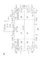
図1および図2は、本発明の第1実施形態に係る電極パッド2の装着用の補助器具100の模式的な斜視図である。図1が、電極パッド2が取り付けられた状態の補助器具100を示し、図2が、補助器具100単体を示している。図3は、補助器具100の模式的な正面図である。図4は、補助器具100の模式的な平面図である。図5は、補助器具100の模式的な側面図である。
Figures 1 and 2 are schematic perspective views of an
補助器具100は、例えば、電気刺激治療に使用される電極パッド2の装着を補助する。電極パッド2による電気刺激治療は、例えば、被治療者3(図9C~図9F参照)の仙骨神経叢や陰部神経に電気刺激を与えることによって、排尿障害や排便障害を治療することが挙げられる。したがって、電極パッド2は、被治療者3の腰仙部の背面側の仙骨に対向する一定の領域(後述する治療部4)に装着する必要がある。The
補助器具100は、第1面5および第1面5の反対側の第2面6を有する板状本体1を含む。第1面5が電極パッド2の配置面(被治療者3の治療部4に対向する面)であり、第2面6が板状本体1の外側の面である。板状本体1の第1面5および第2面6は、それぞれ、板状本体1の内面および外面と称してもよい。The
板状本体1は、シート状の各種工業材料で形成することができる。そのようなシート状材料としては、たとえば、紙ダンボールやコートボール紙等の厚紙、プラスチックシート、プラスチックダンボール、発泡樹脂シート等が挙げられる。この実施形態では、紙ダンボールからなる第1板部材7と第2板部材8との重ね合わせによって板状本体1が形成されている。第1板部材7の外面が板状本体1の第1面5を形成し、第2板部材8の外面が板状本体1の第2面6を形成している。第1板部材7および第2板部材8の内面同士は、互いに向き合っている。The plate-shaped
なお、板状本体1は、互いに異なる複数枚の上記工業シートを積層して形成してもよい。板状本体1の厚さは、電極パッド2の固定後に板状本体1の形状を保持できる強度を有する厚さであれば特に制限されず、例えば、3mm~15mm程度である。板状本体1の厚さは、この実施形態のように複数枚のシートを積層する場合には、複数枚のシートの総厚さであってもよい。例えば、この実施形態では、第1板部材7および第2板部材8のそれぞれの厚さが5mm程度であり、板状本体1の総厚さは10mm程度である。The plate-shaped
板状本体1は、横方向の長さが縦方向の長さに比べて長い長尺状に形成されており、被治療者3の腰仙部周りに板状本体1の長手方向X(横方向)を沿わせることによって使用される。使用時には板状本体1の短手方向(縦方向)が、被治療者3の脊椎方向A(図9C~図9F参照)とほぼ平行な上下方向Yとなるので、以下の説明では、板状本体1の短手方向を「板状本体1の上下方向Y」ということがある。板状本体1の長手方向Xの長さLaは、例えば80cm~100cmであり、板状本体1の上下方向Yの長さLbは、例えば15cm~30cmである。The plate-shaped
板状本体1は、この実施形態では、長手方向Xにおける両端部の上部がカットされた長尺帯状に形成されている。より具体的には、板状本体1は、互いに平行であり、かつ長手方向Xに沿う一対の長辺部9,10と、互いに平行であり、かつ上下方向Yに沿う一対の短辺部11とを有している。さらに、この実施形態では、一対の長辺部9,10が、相対的に短い上側の長辺部9と、上側の長辺部9よりも相対的に長い下側の長辺部10とを含み、上側の長辺部9と一対の短辺部11とを繋ぐ一対の斜辺部12とを含む。一対の斜辺部12は、例えば、短辺部11に対して30°~60°の角度θ1で傾斜している。
In this embodiment, the plate-
板状本体1の長手方向Xにおける両端部には、第1開口13が1つずつ形成されている。第1開口13は、第1板部材7および第2板部材8を貫通して形成されている。第1開口13と斜辺部12とで挟まれた板状本体1の部分は、把持部14である。A
被治療者3(補助器具100の使用者)は、第1開口13に手の四指を通して把持部14を握ることによって、補助器具100を保持することができる。この実施形態では、第1開口13は、細長い形状で形成されており、第1開口13の長手方向に沿う一対の長辺部15と、当該長手方向に直交する短手方向に沿う一対の短辺部16とによって区画されている。第1開口13の長辺部15の長さL1に対する、第1開口13の短辺部16の長さL2の比(L2/L1)は、例えば、1/6~1/2.5である。第1開口13が細長く形成されているので、被治療者3にとって補助器具100が持ちやすくなっている。
The person to be treated 3 (user of the auxiliary tool 100) can hold the
細長い第1開口13は、板状本体1の斜辺部12に沿って延びるように形成されている。言い換えれば、第1開口13の長手方向が、斜辺部12と平行もしくはほぼ平行となっている。より具体的には、第1開口13は、板状本体1の下側から上側に向かって延び、かつ下端(一方の短辺部16)から上端(他方の短辺部16)に向かうにつれて板状本体1の内側に傾くように形成されている。これにより、第1開口13の一対の長辺部15のうち、使用時に四指が掛けられる上側の長辺部15(指掛け部17)は、板状本体1の上下方向Yに対して板状本体1の内側に傾斜する方向に延びている。The elongated
指掛け部17は、板状本体1の短辺部11に対して30°~60°の角度θ2で傾斜している。この実施形態では、下側の長辺部10と各短辺部11とが直角で交わっており、電極パッド2の装着時に被治療者3の脊椎方向A(図9C~図9F参照)と短辺部11とがほぼ平行であるため、角度θ2は短辺部11を基準に定義している。
The
しかしながら、角度θ2は、短辺部11を基準に定義することに加え、板状本体1の上下方向Y(例えば、補助器具100を使用して電極パッド2を装着する際に、被治療者3の脊椎方向Aに平行な方向)に対して定義してもよい。例えば、図3に示すように、使用時に被治療者3の脊椎方向Aに平行となる仮想軸線18を設定し、当該仮想軸線18に対する角度θ2と定義してもよい。なお、角度θ2は、この実施形態では、30°~60°としているが、板状本体1の上下方向Yに対して傾斜(90°を含む)していれば、特に制限されない。
However, in addition to being defined based on the
板状本体1の第1面5には、板状本体1の上側の長辺部9で折り返され、上側の長辺部9に対して連結部20を介して一体的に繋がる折り返し部21が形成されている。The
折り返し部21は、板状本体1と一体的な板状である。これにより、板状本体1では、折り返し部21の配置領域が、板状本体1の長手方向Xにおける折り返し部21の両側の部分よりも厚く形成されている。なお、折り返し部21のような板状本体1を選択的に厚くする構成は、板状本体1と一体でなくとも、例えば、板状本体1の第1面5に接着等によって積層された工業シートであってもよい。また、当該積層された工業シートおよび折り返し部21は、板状本体1において選択的に突出する部分であるため、凸部と称してもよい。The folded
折り返し部21は、この実施形態では、パッド配置部22と、本発明の固定部の一例としての差込み部23とを一体的に有している。In this embodiment, the folded
パッド配置部22は、略四角板状に形成されており、その上端部の一部に連結部20が一体的に繋がっている。一方、差込み部23は、パッド配置部22の上端部の他の部分から、連結部20とは分離して延びている。この実施形態では、パッド配置部22の上端部の中央部から連結部20が延び、パッド配置部22の上端部の連結部20の両側から一対の差込み部23が延びている。連結部20は、板状本体1の長手方向Xにおいて、一対の差込み部23に挟まれている。また、連結部20と一対の差込み部23との間は、この実施形態では、ライン状の切れ込み24によって分離されている。The
パッド配置部22の下端部には、板状本体1の下側の長辺部10に形成された第2開口25に挿入された爪部26が一体的に形成されている。爪部26を第2開口25に挿入し、爪部26を上側に折り返して引っ掛けることによって、折り返し部21が板状本体1の第1面5から離れることを防止することができる。A
また、板状本体1は、センター部27と、センター部27に対して折り曲げ自在に一体的に接続された一対のサイド部28,29とを含む。一対のサイド部28,29は、板状本体1の長手方向Xにおいてセンター部27の両側に配置されており、例えば、正面視左側のサイド部が第1サイド部28であり、正面視右側のサイド部が第2サイド部29である。第1サイド部28および第2サイド部29は、センター部27の側辺部30の全体にわたって接続されており、センター部27に対して左右対称の形状を有している。折り返し部21はセンター部27に形成され、把持部14は各サイド部28,29に1つずつ形成されている。The plate-shaped
センター部27と一対のサイド部28,29との間には、板状本体1の上側の長辺部9および下側の長辺部10を繋ぐ第1折り線部31が形成されている。第1折り線部31は、センター部27の側辺部30に一致する。A first
第1折り線部31を境界にして、一対のサイド部28,29のそれぞれを、第1板部材7に向き合うように内側に折り畳むことができる。また、この実施形態では、板状本体1の長手方向Xにおけるセンター部27の長さLcは、各サイド部28,29の長さLsよりも長くなっている。例えば、センター部27の長さLcが29cm~34cmであり、各サイド部28,29の長さLsが25cm~30cmであってもよい。Each of the pair of
板状本体1の第1面5には、目印32が形成されている。目印32は、被治療者3が電極パッド2を腰仙部の背面側に装着する際に、被治療者3の腸骨稜33(図9D参照)に合わせることによって板状本体1の上下方向Yの位置を合わせるための指標である。A
この実施形態では、目印32は、板状本体1の長手方向Xに沿って各サイド部28,29上を延びるライン状(帯状)に形成されている。ライン状の目印32は、第1折り線部31から板状本体1の長手方向Xの両端部(この実施形態では、一対の斜辺部12)に至るように形成されている。したがって、被治療者3は、電極パッド2を装着する際に、斜辺部12近辺に見えるライン状の目印32を自身の腸骨稜33に合わせることによって、板状本体1の上下方向Yの位置を合わせることができる。In this embodiment, the
図6は、補助器具100の展開図である。次に、前述の補助器具100の作製方法を説明する。
Figure 6 is an exploded view of the
前述の補助器具100を作製するには、例えば、図6に示すように、互いに一体的に繋がった第1板部材7、第2板部材8および折り返し部21を含む1枚の材料シート34を準備する。材料シート34は、この実施形態では、紙ダンボールを所定の形状に打ち抜くことによって準備している。To manufacture the above-mentioned
次に、連結部20を折り曲げることによって、折り返し部21を第1板部材7の第1面5側に折り畳み、爪部26を第1板部材7の第2開口25に挿入して上側に折り返す。これにより、爪部26が第1板部材7に引っ掛かり、第1板部材7に対して折り返し部21が固定される。Next, by bending the connecting
次に、第1板部材7と第2板部材8との間の第2折り線部35を境界にして、第2板部材8を折り返し部21とは反対側に折り畳む。Next, the
最後に、折り返し部21の差込み部23を前方に折り曲げることによって、パッド配置部22の表面に対して差込み部23を直立させる。これにより、前述の補助器具100が得られる。Finally, the
図7は、電極パッド2の模式的な斜視図(正面側)である。図8は、電極パッド2の模式的な斜視図(背面側)である。次に、前述の補助器具100に使用可能な電極パッド2の一例を示す。
Figure 7 is a schematic perspective view (front side) of the
電極パッド2は、シート本体36と、不関電極37および一対の刺激電極38A,38Bとを含む。The
シート本体36は、被治療者3が屈曲(可動)したときに、その屈曲に合わせて湾曲可能な可撓性を有する材料からなる。この実施形態では、シート本体36は、絶縁性を有し、かつ被治療者3の皮膚に面する第1面39および第1面39の反対側の第2面40を有する平面形状のシート部材で構成されている。The
シート本体36の材料としては、例えば、樹脂フィルム、不織布、紙等の絶縁材料が挙げられる。これらは、単独または2種以上組み合わせて使用されてもよい。この実施形態では、シート本体36は、シリコーン樹脂からなる、一体の射出成形シートによって構成されている。
Materials for the
シート本体36の第1面39には、不関電極37および一対の刺激電極38A,38Bがそれぞれ設置される凹部41および凹部42A,42Bが形成されている。凹部41および凹部42A,42Bには、それぞれ、不関電極37および一対の刺激電極38A,38Bが配置されている。シート本体36の第1面39において、不関電極37および一対の刺激電極38A,38Bの周囲には、それぞれ、突出部43および突出部44A,44Bが形成されている。A
突出部43は、不関電極37の外縁に沿って適宜の箇所に形成されており、不関電極37を取り囲んでいる。これにより、不関電極37上に、突出部43で囲まれた領域45が形成されており、当該領域45に導電性粘着パッド(図示せず)を配置することができる。The
突出部44A,44Bは、それぞれ、刺激電極38A,38Bの外縁に沿って適宜の箇所に形成されており、刺激電極38A,38Bを取り囲んでいる。これにより、刺激電極38A,38B上に、突出部44A,44Bで囲まれた領域46A,46Bが形成されており、当該領域46A,46Bに導電性粘着パッド(図示せず)を配置することができる。The
シート本体36の第2面40には、第1端子47が一体的に設けられている。第1端子47は、例えば、図示しないリード線によって、シート本体36の第1面39側の不関電極37に導通している。また、シート本体36の第2面40には、第2端子48A,48Bが一体的に設けられている。第2端子48A,48Bは、例えば、図示しないリード線によって、シート本体36の第1面39側の一対の刺激電極38A,38Bに導通している。A
シート本体36の上端部には、取付け部49が一体的に設けられている。取付け部49は、シート本体36の上端部の両端に1つずつ、合計2つ設けられている。各取付け部49は、開口50を有する四角環状に形成されている。取付け部49の開口50に前述の補助器具100の差込み部23を差し込むことによって、電極パッド2を補助器具100に固定することができる。An
以上のような電極パッド2を作製するには、例えば、まず、不関電極37および一対の刺激電極38A,38Bをコンプレッション成形によって成形する。次に、得られた不関電極37および一対の刺激電極38A,38Bをインサート部材として金型に挿入し、シート本体36の材料(この実施形態では、シリコーン樹脂)を金型内に充填する。これにより、インサート成形品としての電極パッド2を得ることができる。To produce the
ただし、電極パッド2の作製方法は、上記のインサート成形に限らず、例えば、不関電極37および一対の刺激電極38A,38Bと、シート本体36とを別々の成形品として作製し、その後、シート本体36の凹部41および凹部42A,42Bに、それぞれ、不関電極37および一対の刺激電極38A,38Bを嵌め込む方法であってもよい。However, the method of manufacturing the
図9A~図9Fは、電極パッド2の装着用の補助器具100の使用手順を説明するための図である。図9Cおよび図9Eが、被治療者3の背面側を示し、図9Dおよび図9Fが、被治療者3の正面側を示している。
Figures 9A to 9F are diagrams for explaining the procedure for using the
前述の補助器具100を用いて電極パッド2を被治療者3に装着するには、例えば、まず、図9Aに示すように、折り返し部21の差込み部23を前方に折り曲げることによって、パッド配置部22の表面に対して差込み部23を直立させる。この作業は、補助器具100の組み立てのときに行ってもよく、その場合には、使用時に差込み部23を直立させることを省略することができる。To attach the
次に、図9Bに示すように、電極パッド2の取付け部49の開口50を補助器具100の差込み部23に差し込むことによって、電極パッド2を補助器具100に固定する。この際、電極パッド2の背面が板状本体1の第1面5に当たるまで、差込み部23の奥まで電極パッド2をしっかりと差し込む。電極パッド2は、その上端部において補助器具100に固定される一方、その下端部は補助器具100に対して分離可能にフリーとなっている。つまり、電極パッド2が補助器具100に引っ掛かった状態で固定されていてもよい。なお、電極パッド2には、電気刺激治療器(図示せず)に接続するためのケーブル(図示せず)を予め接続していてもよい。9B, the
このように、板状本体1の差込み部23に電極パッド2を差し込むだけで電極パッド2を固定できるので、電極パッド2の装着のための下準備を簡単にすることができる。なお、電極パッド2には、例えば、領域45,46A,46B(図8参照)に、被治療者3の皮膚に貼着可能な導電性の粘着ゲル等を予め取り付けておく。In this way, the
次に、図9Cに示すように、電極パッド2付きの補助器具100を、机等の台67に置き、腕を背面側に回して指掛け部17に四指51を掛けて把持部14を握り、補助器具100を把持する。Next, as shown in FIG. 9C, the
次に、図9Dに示すように、補助器具100を持ち上げ、補助器具100と臀部との間に空間66を設けた状態で、電気刺激の治療部4に対して電極パッド2の位置を合わせる。この実施形態では、ライン状の目印32を自身の腸骨稜33に合わせることによって、板状本体1の上下方向Yの位置を合わせる。被治療者3の腸骨稜33に目印32を合わせながら電極パッド2を装着することによって、電極パッド2の上下方向Yの位置を正確に合わせることができる。
Next, as shown in Figure 9D, the
次に、図9Eに示すように、一対のサイド部28,29を折り曲げて腰仙部に押し当て、被治療者3の脊椎方向Aの中心68とセンター部27の中心69とを一致させることによって、電極パッド2の左右方向Xの位置を合わせる。Next, as shown in Figure 9E, the pair of
次に、図9Fに示すように、腕を前方へ押し出すことによって補助器具100を前方に引き、治療部4と板状本体1との間に電極パッド2を挟み込んで電極パッド2を押さえつける。これにより、治療部4に電極パッド2を装着(貼着)する。9F, the arm is pushed forward to pull the
そして、この補助器具100によれば、主に図1~図3に示すように、指掛け部17が板状本体1の上下方向Yに対して傾斜しているので、図9C~図9Fに示すように腕を背面側に回して補助器具100を把持する際に、手首をあまり捻らなくても補助器具100を把持することができる。そのため、高齢者の患者や、腕を背面側に回すことが困難な患者にとっても力が入りやすく、電極パッド2を簡単に装着することができる。
According to this
また、板状本体1の打ち抜き加工によって形成された第1開口13に四指51を引っ掛けて補助器具100を直接把持できるので、電極パッド2の装着に際して補助器具100がぐらつくことを防止することができる。そのため、治療部4に対する電極パッド2の位置合わせを正確にできるので、電極パッド2を簡単に装着することができる。In addition, the
また、主に図1および図2に示すように、パッド配置部22が、板状本体1の第1面5において選択的に突出した凸部になっている。そのため、図9Fに示すように腕を前方に押し出して治療部4と板状本体1との間に電極パッド2を挟み込む際に、板状本体1のパッド配置部22を除く部分に比べて、治療部4に対して電極パッド2を優先的に接触させることができる。これにより、板状本体1からの挟み込みによる力を電極パッド2に集中的に負荷できるので、電極パッド2をより確実に装着することができる。
As shown mainly in Figures 1 and 2, the
また、主に図1~図3に示すように、板状本体1が、センター部27と、センター部27に対して折り曲げ自在に一体的に接続された一対のサイド部28,29とを含む。そのため、補助器具100を使用しないときに、例えば、第1サイド部28をセンター部27上に折り畳み、次に第2サイド部29をその第1サイド部28上に折り畳むことによって、補助器具100をコンパクトにすることができる。これにより、補助器具100の収納性を向上することができる。
As shown primarily in Figures 1 to 3, the plate-like
また、一対のサイド部28,29が左右同じ長さに形成されているため、図9Eに示すように一対のサイド部28,29を折り曲げて腰仙部に押し当てるだけで、被治療者3の脊椎方向Aの中心68とセンター部27の中心69とを簡単に一致させることができる。In addition, since the pair of
さらに、補助器具100が厚紙で形成されて比較的軽量であるため、補助器具100を利用して簡単に電極パッド2を装着でき、また、補助器具100を簡単に持ち運びすることができる。
(第2実施形態)
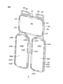
図10は、本発明の第2実施形態に係る電極パッド2の装着用の補助器具100の模式的な正面図である。図11は、図10の補助器具100の折り畳んだ状態を示す図である。
Furthermore, since the
Second Embodiment
Fig. 10 is a schematic front view of an
前述の実施形態では、第1サイド部28および第2サイド部29は、センター部27の側辺部30の全体にわたって接続されており、センター部27に対して左右対称の形状を有していた。In the above-described embodiment, the
これに対し、図10に示す補助器具100では、第1サイド部52および第2サイド部53は、板状本体1の上下方向Yにおいて、互いに段違いに配置されている。また、第1サイド部52および第2サイド部53は、センター部27上に折り畳んだ際に、互いに重ならない形状を有している。10, the
より具体的には、センター部27が、板状本体1の長手方向Xに沿う一対の長辺部54と、一対の長辺部54同士を繋ぐ一対の側辺部55,56とを有している。一対の側辺部55,56は、第1サイド部52側の第1側辺部55および第2サイド部53側の第2側辺部56を含む。More specifically, the
例えば、第1サイド部52が第1側辺部55の一部に接続されており、第2サイド部53が第2側辺部56において第1側辺部55に対向しない部分に接続されていることによって、第1サイド部52および第2サイド部53が段違いとなっている。この実施形態では、第1側辺部55の上側のほぼ半分に第1サイド部52が接続され、第2側辺部56の下側のほぼ半分に第2サイド部53が接続されている。第1サイド部52および第2サイド部53は、互いに同一の四角形状に形成されている。For example, the
これにより、図11に示すように、第1サイド部52および第2サイド部53それぞれをセンター部27上に折り畳んだ際に、互いに重ならないようになっている。そのため、第1サイド部52および第2サイド部53の折り畳み後の厚さが、前述の実施形態では材料シート34の3枚分であるのに対し、この実施形態では、材料シート34の2枚分となる。その結果、補助器具100の厚さを比較的薄く維持することができるので、補助器具100の収納性をより向上することができる。11, when the
しかも、第1サイド部52および第2サイド部53が段違いに配置されているため、板状本体1の上下方向Yにおいては第1サイド部52および第2サイド部53は重なってもよい。そのため、板状本体1の長手方向Xにおいて、第1サイド部52用の領域および第2サイド部53用の領域を、それぞれ、センター部27の第1側辺部55から第2側辺部56までの全長にわたって確保することができる。その結果、第1サイド部52および第2サイド部53の長さの自由度が高くなるので、被治療者3の体型や腕の可動域等に合わせて、第1サイド部52および第2サイド部53の長さを調節することができる。Moreover, since the
さらに、この場合、板状本体1の上下方向Yにおける第1サイド部52および第2サイド部53の側辺部57,58が、折り畳み時にセンター部27の第1側辺部55および第2側辺部56からはみ出てもよい。言い換えれば、前述の実施形態では、板状本体1の長手方向Xにおけるセンター部27の長さLcは、各サイド部28,29の長さLsよりも長くなっていたが、この実施形態では、各サイド部52,53の長さLsが、センター部27の長さLcよりも長くてもよい。Furthermore, in this case, the side edges 57, 58 of the
一方、第1サイド部52および第2サイド部53を互いに段違いに配置したことによって、板状本体1の上下方向Yにおける第1サイド部52および第2サイド部53の側辺部57,58の長さが、前述の実施形態における短辺部11および斜辺部12を合計した長さ(高さ)に比べて短くなっている。そこで、この実施形態では、各第1開口13を、板状本体1の長手方向Xに沿って長手な細長い形状に形成している。したがって、指掛け部17は、第1サイド部52および第2サイド部53の側辺部57,58に対して90°の角度θ2で傾斜していることとなる。
Meanwhile, by arranging the
第1サイド部52および第2サイド部53の側辺部57,58の長さに制約がある条件の下、第1開口13を板状本体1の長手方向Xに沿って形成することによって、被治療者3の四指を十分に挿入可能な大きさの第1開口13を形成することができる。
(第3実施形態)
図12は、本発明の第3実施形態に係る電極パッド2の装着用の補助器具100の模式的な斜視図である。
Under the condition that the lengths of the
Third Embodiment
FIG. 12 is a schematic perspective view of an
前述の実施形態では、パッド配置部22が、板状本体1の第1面5において選択的に突出した凸部となっていた。In the above-described embodiment, the
これに対し、図12に示す補助器具100では、板状本体1の第1面5に、互いに離れた一対の折り返し部59が形成されており、この一対の折り返し部59の間にパッド配置部60が形成されている。一対の折り返し部59は、例えば、図12に示すように板状本体1の上端部に一体的に接続されていてもよいし、板状本体1の第1面5に接着等によって形成されていてもよい。また、この場合、差込み部23は、一対の折り返し部59とは離れて、板状本体1の上端部に直接接続されていてもよい。12, a pair of
これにより、板状本体1では、一対の折り返し部59の配置領域がパッド配置部60よりも厚く形成されている。つまり、パッド配置部60が、板状本体1の第1面5において選択的に凹んだ凹部となっている。As a result, in the plate-shaped
これにより、電極パッド2をパッド配置部60に固定するときに、パッド配置部60の両側の折り返し部59をガイド部として、電極パッド2を簡単にセットすることができる。また、電極パッド2が、折り返し部59によって横方向(板状本体1の長手方向X)から挟まれるため、横方向における電極パッド2の位置ずれを軽減することができる。
(第4実施形態)
図13は、本発明の第4実施形態に係る電極パッド2の装着用の補助器具100の模式的な斜視図である。
As a result, when the
Fourth Embodiment
FIG. 13 is a schematic perspective view of an
前述の実施形態では、板状本体1の上下方向Yの位置合わせのための目印として、ライン状の目印32が形成されていた。In the above-described embodiment, a line-shaped
これに対し、図13に示す補助器具100では、ライン状目印32の各外側端部を切り欠くことによって、第2目印61が形成されている。被治療者3は、電極パッド2を装着する際に、例えば、第2目印61に親指を当て、当該親指を自身の腸骨稜33に合わせることによって、板状本体1の上下方向Yの位置を合わせることができる。なお、図13では、ライン状の目印32および第2目印61のいずれも形成されているが、第2目印61を形成する場合、ライン状目印32を省略してもよい。
(第5実施形態)
図14は、本発明の第5実施形態に係る電極パッド2の装着用の補助器具100の模式的な斜視図である。
In contrast, in the
Fifth Embodiment
FIG. 14 is a schematic perspective view of an
前述の実施形態では、板状本体1は、長手方向Xにおける両端部の上部がカットされた長尺帯状に形成されていた。In the above-described embodiment, the plate-shaped
これに対し、図14に示す補助器具100では、板状本体1は、両端部の上部がカットされておらず、長方形状に形成されている。このような構成によっても、指掛け部17が板状本体1の上下方向Yに対して傾斜しているので、図9C~図9Fに示すように腕を背面側に回して補助器具100を把持する際に、手首をあまり捻らなくても補助器具100を把持することができる。
(第6実施形態)
図15は、本発明の第6実施形態に係る電極パッド2の装着用の補助器具100の模式的な斜視図である。
In contrast, in the
Sixth Embodiment
FIG. 15 is a schematic perspective view of an
図15に示す補助器具100では、第1開口13の縁部に補強部材62が取り付けられている。補強部材62は、例えば、ポリエチレン、ポリプロピレン、ポリスチレン、ポリ塩化ビニル等の汎用プラスチック(樹脂)からなる成形品、例えば、布粘着テープのように補強に用いられるテープ等であってもよい。In the
成形品の場合、補強部材62は、第1開口13に合わせた環状に形成されており、その外周部全体にわたって溝が形成されている。この溝を第1開口13の辺部(長辺部15および短辺部16)に嵌め込むことによって、補強部材62を第1開口13に固定することができる。一方、テープの場合、テープを適切な形状に切断し、第1開口13の辺部の両面に渡るように貼り付ければよい。これにより、指掛け部17が補強部材62で覆われて補強される。この場合、被治療者3は、図9Cにおいて、補強部材62を介して指掛け部17に間接的に指を掛けることになる。
(第7実施形態)
図16は、本発明の第7実施形態に係る電極パッド2の装着用の補助器具100の模式的な平面図である。
In the case of a molded product, the reinforcing
Seventh Embodiment
FIG. 16 is a schematic plan view of an
図16に示す補助器具100では、第1板部材7の第1開口13の上側の長辺部15(指掛け部17)に、爪部19が一体的に形成されている。爪部19は、この実施形態では、第1開口13と同じ形状を有している。第1開口13を介して爪部19を第2板部材8の外側まで出し、爪部19を上側に折り返して引っ掛けることによって、第1板部材7と第2板部材8とが互いに離れることを防止することができる。
(第8実施形態)
図17は、本発明の第8実施形態に係る電極パッド2の装着用の補助器具100の模式的な斜視図である。
In the
Eighth embodiment
FIG. 17 is a schematic perspective view of an
図17に示す補助器具100では、板状本体1の第2面6(背面)に板状の磁石63が取り付けられている。板状の磁石63は、例えば、四角形状に形成されており、板状本体1に形成された4つの切れ込み65に板状の磁石63の各角部を挿入することによって、板状本体1に固定されている。これにより、例えば、補助器具100を使用しないときに、冷蔵庫やスチール棚等に、磁石63を介して補助器具100を貼り付けて収納しておくことができる。
(第9実施形態)
図18は、本発明の第9実施形態に係る電極パッド2の装着用の補助器具100の模式的な斜視図である。
17, a plate-shaped
Ninth embodiment
FIG. 18 is a schematic perspective view of an
図18に示す補助器具100では、板状本体1の第1面5(背面)に、補助器具100の使用手順64が取り付けられている。使用手順64には、例えば、図9A~図9Fに示した手順が図解されていてもよい。板状本体1の第1面5側に取り付けられているので、被治療者3は、使用手順64を見ながら電極パッド2を装着することができる。
(第10実施形態)
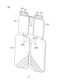
図19は、本発明の第10実施形態に係る電極パッド装着用の補助器具100の模式的な斜視図である。図20は、本発明の第10実施形態に係る電極パッド装着用の補助器具100の模式的な斜視図であって、差込み部23を折り曲げた状態を示している。図21は、図19の電極パッド装着用の補助器具100の正面図である。図22は、図19の電極パッド装着用の補助器具100の平面図である。図23は、図19の電極パッド装着用の補助器具100の側面図である。図24は、図19の電極パッド装着用の補助器具100の背面図である。
In the
Tenth embodiment
Fig. 19 is a schematic perspective view of the electrode pad attachment
図19~図24の補助器具100では、板状本体1は、板状の発泡プラスチックで形成されている。発泡プラスチックの材料としては、例えば、発泡プロピレン、発泡ポリエチレン等、第1折り線部31における折り曲げ加工が可能な各種発泡プラスチックが挙げられる。この実施形態では、板状本体1は、第1~第9実施形態のように板状本体1が第1板状部材7および第2板状部材8を含む構成とは異なり、単一の板状部材70で構成されている。
In the
板状本体1は、板状本体1の長手方向において、パッド配置部22が配置された第1領域71、把持部14が配置された第2領域72、および第1領域71と第2領域72との間の第3領域73を含んでいてもよい。第1領域71は、この実施形態では、センター部27であってもよい。The plate-shaped
第3領域73の上縁731は、第1領域71の上縁711および第2領域72の上縁721に対して、板状本体1の下端側に凹んでいる。他の言い方では、板状本体1の第1領域71および第2領域72は、それぞれ、第3領域73の上縁731に対して選択的に突出した第1凸部712および第2凸部722を有していてもよい。第3領域73は、第1領域71の上縁711および第2領域72の上縁721に対して選択的に凹んだ凹部732を有していてもよい。The
ライン状の目印32は、第3領域73の上縁731に形成されている。この実施形態では、ライン状の目印32は、板状本体1の第1面5側に選択的に形成されており、その上端部が第3領域73の上縁731に一致している。ライン状の目印32は、前述のように、被治療者3が電極パッド2を腰仙部の背面側に装着する際に、被治療者3の腸骨稜33に合わせることによって板状本体1の上下方向Yの位置を合わせるための指標である。一方で、腸骨稜33の高さ(目印32の高さ)は、被治療者3に装着された状態の電極パッド2の上端部(取付け部49の位置)の高さよりも低い位置にある。そこで、板状本体1の第3領域73に凹部732を形成することによって、ライン状の目印32を板状本体1の上縁の一部として露出させることができる。これにより、補助器具100を把持した状態でも、目印32を上から視認し易くすることができる。The line-shaped
また、ライン状の目印32は、板状本体1の他の部分とは異なる色で形成されていてもよい。板状本体1の他の部分は、例えば、板状部分1においてパッド配置部22や把持部14等の立体構造物が形成されていない平坦部分74を意味していてもよい。この実施形態では、平坦部分74が白色で形成され、目印32が青色で形成されている。In addition, the
また、補助器具100では、第1開口13の縁部に補強部材75が取り付けられている。補強部材75は、例えば、ポリエチレン、ポリプロピレン、ポリスチレン、ポリ塩化ビニル等の汎用プラスチック(樹脂)からなる成形品であってもよい。補強部材75は、第1開口13に合わせた環状に形成されており、その外周部全体にわたって溝が形成されている。この溝を第1開口13に嵌め込むことによって、補強部材75を第1開口13に固定することができる(図23参照)。補強部材75が設けられている場合、後述する図25Dにおいて、被治療者3は、補強部材75を介して指掛け部17に間接的に指を掛けることになる。また、補強部材75は、被治療者3が直接持つ部分であることから、持ち手と称してもよい。
In addition, in the
パッド配置部22の下端部には、開孔76が形成されている。開孔76は、後述する図25Cに示すように、補助器具100の床面からの高さを調節するための紐77の取り付け用の開孔である。An
図19~図24の補助器具100は、板状本体1の第2面6に形成された発泡粘着シート78をさらに含む。発泡粘着シート78としては、平滑面に対して繰り返し貼り付けたり取り外したりできる樹脂シートであれば、例えば、アクリル系樹脂、エチレン系樹脂等の公知の発泡粘着シートを使用することができる。なお、発泡粘着シートは、発泡吸着シートと称してもよい。この実施形態では、発泡粘着シート78は、図24に示すように、板状本体1のセンター部27の第2面6に形成されている。発泡粘着シート78は、板状本体1を挟んでパッド配置部22に対向している。
The
図25A~図25Fは、第10実施形態に係る補助器具100の使用手順を説明するための図である。
Figures 25A to 25F are figures for explaining the procedure for using the
第10実施形態に係る補助器具100を用いて電極パッド2を被治療者3に装着するには、例えば、まず、図25Aに示すように、折り返し部21の差込み部23を前方に折り曲げることによって、パッド配置部22の表面に対して差込み部23を直立させる。この作業は、補助器具100の組み立てのときに行ってもよく、その場合には、使用時に差込み部23を直立させることを省略することができる。To attach the
次に、図25Bに示すように、電極パッド2の取付け部49の開口50を補助器具100の差込み部23に差し込むことによって、電極パッド2を補助器具100に固定する。この際、電極パッド2の背面が板状本体1の第1面5に当たるまで、差込み部23の奥まで電極パッド2をしっかりと差し込む。電極パッド2は、その上端部において補助器具100に固定される一方、その下端部は補助器具100に対して分離可能にフリーとなっている。つまり、電極パッド2が補助器具100に引っ掛かった状態で固定されていてもよい。なお、電極パッド2には、電気刺激治療器(図示せず)に接続するためのケーブル(図示せず)を予め接続していてもよい。25B, the
このように、板状本体1の差込み部23に電極パッド2を差し込むだけで電極パッド2を固定できるので、電極パッド2の装着のための下準備を簡単にすることができる。なお、電極パッド2には、例えば、領域45,46A,46B(図8参照)に、被治療者3の皮膚に貼着可能な導電性の粘着ゲル等を予め取り付けておく。In this way, the
次に、図25Cに示すように、発泡粘着シート78を介して、電極パッド2付きの補助器具100を壁面79に貼り付けて固定する。壁面79は、補助器具100が落下しない程度に発泡粘着シート78の粘着できる平滑面を有していれば特に制限されず、例えば、アルミ製やスチール製の間仕切り壁の面であってもよいし、冷蔵庫の扉の面等であってもよい。この際、開孔76に紐77を通しておく。これにより、紐77の端部を床面80に合わせ、紐77の長さを調節することによって、次回以降、紐77の端部を床面80に接するように高さを調節すれば、補助器具100の高さを簡単に合わせることができる。補助器具100の固定位置は、被治療者3が起立した状態で、被治療者3の腸骨稜33(図25D参照)の高さとライン状の目印32の高さが一致する位置にすればよい。
Next, as shown in FIG. 25C, the
次に、図25Dに示すように、壁面79に補助器具100を固定した状態で、腕を背面側に回して補強部材75に四指51を掛けて把持部14を握り、補助器具100を把持する。Next, as shown in FIG. 25D, with the
次に、図25Eに示すように、一対のサイド部28,29を折り曲げて腰仙部に押し当て、被治療者3の脊椎方向Aの中心68とセンター部27の中心69とを一致させることによって、電極パッド2の左右方向の位置を合わせる。例えば、一対の補強部材75(持ち手)を腰に押し付けることによって、電極パッド2に対してずれずに、真ん中に立つことができる。この際、左右のライン状の目印32と腸骨稜33の高さを合わせることによって、上下方向の位置を合わせることができる(図25D参照)。Next, as shown in Figure 25E, the pair of
次に、図25Fに示すように、被治療者3が壁面79にもたれ掛かることによって、壁面79と被治療者3の治療部4との間に電極パッド2を挟み込んで電極パッド2を押さえつける。これにより、治療部4に対して電極パッド2の位置決めを行う。その後、補強部材75(持ち手)から手を離し、壁面79から体を離すことで、補助器具100から電極パッド2を取り外しつつ、治療部4に電極パッド2を装着することができる。以上より、治療部4に電極パッド2を装着(貼着)する。25F, the
以上、本発明の実施形態について説明したが、本発明は、他の形態で実施することもできる。 Although an embodiment of the present invention has been described above, the present invention can also be embodied in other forms.
例えば、前述の実施形態では、第1板部材7と第2板部材8との重ね合わせによって板状本体1が形成されていたが、板状本体1は、1枚の材料シートで形成されていてもよい。For example, in the above-described embodiment, the plate-shaped
また、前述の実施形態では、第1開口13の長辺部15を利用して指掛け部17が形成されていたが、例えば、板状本体1に、板状本体1の上下方向Yに対して傾斜する取っ手を取り付けることによって、当該取っ手に指を掛ける構成としてもよい。この場合、指掛け部および把持部が共通の構成となる。In addition, in the above-described embodiment, the
また、前述の実施形態では、1枚の材料シート34を折り曲げて組み立てることによって補助器具100が作製されていたが、例えば、板状本体1、折り返し部21(凸部)、差込み部23等を別々のシートで準備し、これらを粘着テープ、接着剤等で互いに固定したり、貼り合わせたりすることによって補助器具100を作製してもよい。In addition, in the above-described embodiment, the
また、前述の実施形態では、電極パッド2を固定するための部材として差込み部23を形成したが、例えば、電極パッド2に開口がない場合、板状本体1に別途固定部を設けてもよい。そのような固定部としては、例えば、両面テープ、電極パッド2を挟み込む爪部等であってもよい。また、差込み部23は、板状本体1の上端部のみに選択的に形成され、電極パッド2を引っ掛けるものであったが、例えば、板状本体1の下端部にも形成し、上下両方の差込み部23で電極パッド2を固定してもよい。In addition, in the above-described embodiment, the
その他、特許請求の範囲に記載された事項の範囲で種々の設計変更を施すことが可能である。 In addition, various design changes may be made within the scope of the claims.
本出願は、2019年12月27日に日本国特許庁に提出された特願2019-238034号に対応しており、この出願の全開示はここに引用により組み込まれるものとする。This application corresponds to Patent Application No. 2019-238034 filed with the Japan Patent Office on December 27, 2019, the entire disclosure of which is incorporated herein by reference.
1 板状本体
2 電極パッド
3 被治療者
4 治療部
5 (板状本体)第1面
6 (板状本体)第2面
13 第1開口
14 把持部
15 (第1開口)長辺部
16 (第1開口)短辺部
17 指掛け部
22 パッド配置部
23 差込み部
27 センター部
28 第1サイド部
29 第2サイド部
32 目印
33 腸骨稜
34 材料シート
49 取付け部
50 開口
52 第1サイド部
53 第2サイド部
59 折り返し部
60 パッド配置部
61 第2目印
70 板状部材
71 第1領域
72 第2領域
73 第3領域
74 平坦部分
75 補強部材
76 開孔
77 紐
78 発泡粘着シート
79 壁面
80 床面
100 補助器具
711 上縁
712 第1凸部
721 上縁
722 第2凸部
731 上縁
732 凹部
X (板状本体の)長手方向
Y (板状本体の)上下方向
θ2 傾斜角度
L1 長さ
L2 長さ
LIST OF
Claims (16)
第1面および前記第1面の反対側の第2面を有し、前記電極パッドを前記第1面に固定するための固定部を有する長尺状の板状本体と、
前記板状本体の長手方向の端部に形成され、前記板状本体を把持するためのものであり、かつ使用者の手の指を引っ掛けるためのライン状の指掛け部を有する把持部とを含み、
前記指掛け部は、前記板状本体の長手方向に交差する前記板状本体の上下方向に対して前記板状本体の内側に傾斜する方向に延びている、電極パッド装着用補助器具。 An electrode pad attachment aid for assisting in attaching an electrode pad to the back side of the lumbosacral region of a human body, comprising:
a long plate-like main body having a first surface and a second surface opposite to the first surface, the long plate-like main body having a fixing portion for fixing the electrode pad to the first surface;
a gripping portion formed at an end portion of the plate-shaped main body in the longitudinal direction, for gripping the plate-shaped main body, and having a linear finger hook portion for hooking the fingers of a user's hand;
The finger hook portion extends in a direction inclined toward the inside of the plate-shaped body with respect to the up-down direction of the plate-shaped body that intersects with the longitudinal direction of the plate-shaped body.
前記指掛け部は、前記開口の長手方向に沿う辺部を利用して形成されている、請求項1または2に記載の電極パッド装着用補助器具。 An elongated opening is formed at the end of the plate-like body,
3. The electrode pad attachment aid according to claim 1, wherein the finger hook portion is formed by utilizing a side portion along a longitudinal direction of the opening.
前記パッド配置部は、前記板状本体の長手方向における前記パッド配置部の両側の部分よりも厚く形成されている、請求項1~5のいずれか一項に記載の電極パッド装着用補助器具。 a pad placement portion formed on the first surface of the plate-shaped body, for placing the electrode pad thereon;
6. The electrode pad attachment aid according to claim 1, wherein the pad placement portion is formed to be thicker than both side portions of the pad placement portion in the longitudinal direction of the plate-like main body.
前記板状本体の長手方向において前記パッド配置部の両側に形成され、前記パッド配置部よりも厚く形成されたガイド部とを含む、請求項1~5のいずれか一項に記載の電極パッド装着用補助器具。 a pad placement portion formed on the first surface of the plate-shaped body, for placing the electrode pad;
An electrode pad attachment aid as described in any one of claims 1 to 5, comprising a guide portion formed on both sides of the pad placement portion in the longitudinal direction of the plate-shaped body and formed thicker than the pad placement portion.
前記固定部は、前記パッド配置部の上端部に形成され、前記取付け部の前記開口に差し込むことによって前記電極パッドを固定する差込み部を含む、請求項6または7に記載の電極パッド装着用補助器具。 The electrode pad attachment aid is for an electrode pad having an attachment part at an upper end part thereof with an opening formed therein,
8. The electrode pad attachment aid according to claim 6, wherein the fixing portion includes an insertion portion formed at an upper end of the pad placement portion and configured to fix the electrode pad by being inserted into the opening of the attachment portion.
前記第1サイド部および前記第2サイド部は、前記センター部上に折り畳んだ際に、互いに重ならない形状を有している、請求項9に記載の電極パッド装着用補助器具。 The pair of side portions includes a first side portion and a second side portion disposed at a different level from the first side portion in the up-down direction of the plate-like main body,
10. The electrode pad attachment aid according to claim 9, wherein the first side portion and the second side portion are shaped so as not to overlap each other when folded onto the center portion.
前記板状本体に対して連結部を介して一体的に繋がり、前記板状本体の前記第1面側に折り返された折り返し部を含み、
前記折り返し部は、前記電極パッドを配置するためのパッド配置部と、前記パッド配置部の上端部に形成され、前記取付け部の前記開口に差し込むことによって前記電極パッドを固定する差込み部とを含む、請求項1~4のいずれか一項に記載の電極パッド装着用補助器具。 The electrode pad attachment aid is for an electrode pad having an attachment part at an upper end part thereof with an opening formed therein,
A folded-back portion is integrally connected to the plate-shaped main body via a connecting portion and folded back toward the first surface side of the plate-shaped main body,
The electrode pad attachment auxiliary device according to any one of claims 1 to 4, wherein the folded portion includes a pad placement portion for placing the electrode pad, and an insertion portion formed at an upper end of the pad placement portion and for fixing the electrode pad by inserting it into the opening of the mounting portion.
Applications Claiming Priority (3)
| Application Number | Priority Date | Filing Date | Title |
|---|---|---|---|
| JP2019238034 | 2019-12-27 | ||
| JP2019238034 | 2019-12-27 | ||
| PCT/JP2020/048756 WO2021132573A1 (en) | 2019-12-27 | 2020-12-25 | Implement for assisting in mounting electrode pad |
Publications (2)
| Publication Number | Publication Date |
|---|---|
| JPWO2021132573A1 JPWO2021132573A1 (en) | 2021-07-01 |
| JP7655552B2 true JP7655552B2 (en) | 2025-04-02 |
Family
ID=76574326
Family Applications (1)
| Application Number | Title | Priority Date | Filing Date |
|---|---|---|---|
| JP2021567677A Active JP7655552B2 (en) | 2019-12-27 | 2020-12-25 | Electrode pad attachment aid |
Country Status (2)
| Country | Link |
|---|---|
| JP (1) | JP7655552B2 (en) |
| WO (1) | WO2021132573A1 (en) |
Citations (3)
| Publication number | Priority date | Publication date | Assignee | Title |
|---|---|---|---|---|
| JP2013514143A (en) | 2009-12-18 | 2013-04-25 | エシコン・インコーポレイテッド | Indwelling device and method for accurately positioning medical patch by patient at target position |
| JP5442112B2 (en) | 2010-04-30 | 2014-03-12 | 久光製薬株式会社 | Auxiliary device for patch application |
| WO2020183868A1 (en) | 2019-03-08 | 2020-09-17 | 大塚テクノ株式会社 | Electrode for electrical stimulation therapy and electrical stimulation therapeutic device |
Family Cites Families (2)
| Publication number | Priority date | Publication date | Assignee | Title |
|---|---|---|---|---|
| JP2008023115A (en) * | 2006-07-21 | 2008-02-07 | Omron Healthcare Co Ltd | Pad-sticking auxiliary tool |
| JP2012024405A (en) * | 2010-07-26 | 2012-02-09 | Lintec Corp | Electrode for electrostimulator and electrostimulator |
-
2020
- 2020-12-25 WO PCT/JP2020/048756 patent/WO2021132573A1/en not_active Ceased
- 2020-12-25 JP JP2021567677A patent/JP7655552B2/en active Active
Patent Citations (3)
| Publication number | Priority date | Publication date | Assignee | Title |
|---|---|---|---|---|
| JP2013514143A (en) | 2009-12-18 | 2013-04-25 | エシコン・インコーポレイテッド | Indwelling device and method for accurately positioning medical patch by patient at target position |
| JP5442112B2 (en) | 2010-04-30 | 2014-03-12 | 久光製薬株式会社 | Auxiliary device for patch application |
| WO2020183868A1 (en) | 2019-03-08 | 2020-09-17 | 大塚テクノ株式会社 | Electrode for electrical stimulation therapy and electrical stimulation therapeutic device |
Also Published As
| Publication number | Publication date |
|---|---|
| WO2021132573A1 (en) | 2021-07-01 |
| JPWO2021132573A1 (en) | 2021-07-01 |
Similar Documents
| Publication | Publication Date | Title |
|---|---|---|
| CN100553713C (en) | Electrode device | |
| US6932782B2 (en) | Flexible splint | |
| WO2017135474A1 (en) | Transdermal permeant application device | |
| JP2012024405A (en) | Electrode for electrostimulator and electrostimulator | |
| CN101437474B (en) | Nail shaper for ingrown nail and false nail | |
| JP7655552B2 (en) | Electrode pad attachment aid | |
| AU2004258931A1 (en) | Device for cutting or heating medical implants | |
| KR100970474B1 (en) | Spinal strengthening device | |
| WO2020183868A1 (en) | Electrode for electrical stimulation therapy and electrical stimulation therapeutic device | |
| US6728573B1 (en) | Ocular iontophoretic apparatus handle | |
| JP2014068858A (en) | Adhesive skin patch application aid | |
| US12472124B2 (en) | Medicine applicator, medicine application kit, and pressing tool for medicine applicator | |
| CN215273418U (en) | Multifunctional lateral position auxiliary device for operation | |
| JP2025511885A5 (en) | ||
| CN211096997U (en) | Acupoint positioning medicinal plaster | |
| CN217066416U (en) | Heart intracavity ultrasonic catheter external fixator | |
| CN207492792U (en) | Neurosurgery clamps | |
| JPH07136286A (en) | Low frequency therapy device and its conductor | |
| JPH09226782A (en) | Tote bag | |
| JP2001212249A (en) | Low frequency treatment device | |
| CN223969364U (en) | Muscle rehabilitation auxiliary device | |
| CN213963837U (en) | Ingrowing nail correction paste | |
| JP2011156053A (en) | Puncture aid | |
| CN215134733U (en) | Medical hinge fixing clamp | |
| CN210078047U (en) | Gel dressing plaster |
Legal Events
| Date | Code | Title | Description |
|---|---|---|---|
| A621 | Written request for application examination |
Free format text: JAPANESE INTERMEDIATE CODE: A621 Effective date: 20231221 |
|
| TRDD | Decision of grant or rejection written | ||
| A01 | Written decision to grant a patent or to grant a registration (utility model) |
Free format text: JAPANESE INTERMEDIATE CODE: A01 Effective date: 20250213 |
|
| A61 | First payment of annual fees (during grant procedure) |
Free format text: JAPANESE INTERMEDIATE CODE: A61 Effective date: 20250313 |
|
| R150 | Certificate of patent or registration of utility model |
Ref document number: 7655552 Country of ref document: JP Free format text: JAPANESE INTERMEDIATE CODE: R150 |