JP7655112B2 - 3D modeling equipment - Google Patents
3D modeling equipment Download PDFInfo
- Publication number
- JP7655112B2 JP7655112B2 JP2021104750A JP2021104750A JP7655112B2 JP 7655112 B2 JP7655112 B2 JP 7655112B2 JP 2021104750 A JP2021104750 A JP 2021104750A JP 2021104750 A JP2021104750 A JP 2021104750A JP 7655112 B2 JP7655112 B2 JP 7655112B2
- Authority
- JP
- Japan
- Prior art keywords
- unit
- modeling
- stage
- dimensional
- light
- Prior art date
- Legal status (The legal status is an assumption and is not a legal conclusion. Google has not performed a legal analysis and makes no representation as to the accuracy of the status listed.)
- Active
Links
Images


Classifications
-
- B—PERFORMING OPERATIONS; TRANSPORTING
- B29—WORKING OF PLASTICS; WORKING OF SUBSTANCES IN A PLASTIC STATE IN GENERAL
- B29C—SHAPING OR JOINING OF PLASTICS; SHAPING OF MATERIAL IN A PLASTIC STATE, NOT OTHERWISE PROVIDED FOR; AFTER-TREATMENT OF THE SHAPED PRODUCTS, e.g. REPAIRING
- B29C64/00—Additive manufacturing, i.e. manufacturing of three-dimensional [3D] objects by additive deposition, additive agglomeration or additive layering, e.g. by 3D printing, stereolithography or selective laser sintering
- B29C64/30—Auxiliary operations or equipment
- B29C64/386—Data acquisition or data processing for additive manufacturing
- B29C64/393—Data acquisition or data processing for additive manufacturing for controlling or regulating additive manufacturing processes
-
- B—PERFORMING OPERATIONS; TRANSPORTING
- B29—WORKING OF PLASTICS; WORKING OF SUBSTANCES IN A PLASTIC STATE IN GENERAL
- B29C—SHAPING OR JOINING OF PLASTICS; SHAPING OF MATERIAL IN A PLASTIC STATE, NOT OTHERWISE PROVIDED FOR; AFTER-TREATMENT OF THE SHAPED PRODUCTS, e.g. REPAIRING
- B29C64/00—Additive manufacturing, i.e. manufacturing of three-dimensional [3D] objects by additive deposition, additive agglomeration or additive layering, e.g. by 3D printing, stereolithography or selective laser sintering
- B29C64/10—Processes of additive manufacturing
- B29C64/106—Processes of additive manufacturing using only liquids or viscous materials, e.g. depositing a continuous bead of viscous material
- B29C64/118—Processes of additive manufacturing using only liquids or viscous materials, e.g. depositing a continuous bead of viscous material using filamentary material being melted, e.g. fused deposition modelling [FDM]
-
- B—PERFORMING OPERATIONS; TRANSPORTING
- B29—WORKING OF PLASTICS; WORKING OF SUBSTANCES IN A PLASTIC STATE IN GENERAL
- B29C—SHAPING OR JOINING OF PLASTICS; SHAPING OF MATERIAL IN A PLASTIC STATE, NOT OTHERWISE PROVIDED FOR; AFTER-TREATMENT OF THE SHAPED PRODUCTS, e.g. REPAIRING
- B29C64/00—Additive manufacturing, i.e. manufacturing of three-dimensional [3D] objects by additive deposition, additive agglomeration or additive layering, e.g. by 3D printing, stereolithography or selective laser sintering
- B29C64/20—Apparatus for additive manufacturing; Details thereof or accessories therefor
- B29C64/205—Means for applying layers
- B29C64/209—Heads; Nozzles
-
- B—PERFORMING OPERATIONS; TRANSPORTING
- B29—WORKING OF PLASTICS; WORKING OF SUBSTANCES IN A PLASTIC STATE IN GENERAL
- B29C—SHAPING OR JOINING OF PLASTICS; SHAPING OF MATERIAL IN A PLASTIC STATE, NOT OTHERWISE PROVIDED FOR; AFTER-TREATMENT OF THE SHAPED PRODUCTS, e.g. REPAIRING
- B29C64/00—Additive manufacturing, i.e. manufacturing of three-dimensional [3D] objects by additive deposition, additive agglomeration or additive layering, e.g. by 3D printing, stereolithography or selective laser sintering
- B29C64/20—Apparatus for additive manufacturing; Details thereof or accessories therefor
- B29C64/295—Heating elements
-
- B—PERFORMING OPERATIONS; TRANSPORTING
- B33—ADDITIVE MANUFACTURING TECHNOLOGY
- B33Y—ADDITIVE MANUFACTURING, i.e. MANUFACTURING OF THREE-DIMENSIONAL [3D] OBJECTS BY ADDITIVE DEPOSITION, ADDITIVE AGGLOMERATION OR ADDITIVE LAYERING, e.g. BY 3D PRINTING, STEREOLITHOGRAPHY OR SELECTIVE LASER SINTERING
- B33Y10/00—Processes of additive manufacturing
-
- B—PERFORMING OPERATIONS; TRANSPORTING
- B33—ADDITIVE MANUFACTURING TECHNOLOGY
- B33Y—ADDITIVE MANUFACTURING, i.e. MANUFACTURING OF THREE-DIMENSIONAL [3D] OBJECTS BY ADDITIVE DEPOSITION, ADDITIVE AGGLOMERATION OR ADDITIVE LAYERING, e.g. BY 3D PRINTING, STEREOLITHOGRAPHY OR SELECTIVE LASER SINTERING
- B33Y30/00—Apparatus for additive manufacturing; Details thereof or accessories therefor
-
- B—PERFORMING OPERATIONS; TRANSPORTING
- B33—ADDITIVE MANUFACTURING TECHNOLOGY
- B33Y—ADDITIVE MANUFACTURING, i.e. MANUFACTURING OF THREE-DIMENSIONAL [3D] OBJECTS BY ADDITIVE DEPOSITION, ADDITIVE AGGLOMERATION OR ADDITIVE LAYERING, e.g. BY 3D PRINTING, STEREOLITHOGRAPHY OR SELECTIVE LASER SINTERING
- B33Y50/00—Data acquisition or data processing for additive manufacturing
- B33Y50/02—Data acquisition or data processing for additive manufacturing for controlling or regulating additive manufacturing processes
-
- Y—GENERAL TAGGING OF NEW TECHNOLOGICAL DEVELOPMENTS; GENERAL TAGGING OF CROSS-SECTIONAL TECHNOLOGIES SPANNING OVER SEVERAL SECTIONS OF THE IPC; TECHNICAL SUBJECTS COVERED BY FORMER USPC CROSS-REFERENCE ART COLLECTIONS [XRACs] AND DIGESTS
- Y02—TECHNOLOGIES OR APPLICATIONS FOR MITIGATION OR ADAPTATION AGAINST CLIMATE CHANGE
- Y02P—CLIMATE CHANGE MITIGATION TECHNOLOGIES IN THE PRODUCTION OR PROCESSING OF GOODS
- Y02P10/00—Technologies related to metal processing
- Y02P10/25—Process efficiency
Landscapes
- Chemical & Material Sciences (AREA)
- Engineering & Computer Science (AREA)
- Materials Engineering (AREA)
- Manufacturing & Machinery (AREA)
- Physics & Mathematics (AREA)
- Mechanical Engineering (AREA)
- Optics & Photonics (AREA)
Description
本開示は、三次元造形装置に関する。 This disclosure relates to a three-dimensional modeling device.
三次元造形装置に関して、特許文献1には、造形中の造形層の温度を検知し、造形状況を監視しながら造形物を造形する技術が開示されている。 Regarding three-dimensional modeling devices, Patent Document 1 discloses a technology that detects the temperature of the modeling layer during modeling and models an object while monitoring the modeling status.
上記のような三次元造形装置において、先の造形物の造形完了後、先の造形物がステージ上に残っている状態で次の造形物の造形が開始される場合があり、先の造形物と装置との接触によって、先の造形物や装置が破損する虞があった。 In the above-mentioned three-dimensional printing device, after printing of a previous object is completed, printing of the next object may start while the previous object is still on the stage, and there is a risk that the previous object or the device may be damaged due to contact between the previous object and the device.
本開示の一形態によれば、三次元造形装置が提供される。この三次元造形装置は、ノズル開口を有し、前記ノズル開口から造形材料を吐出する吐出部と、前記吐出部から吐出された前記造形材料を支持する造形面を有するステージと、前記造形面に支持された前記造形材料を検知するセンサー部と、前記吐出部を制御して、前記造形材料を前記造形面に積層して三次元造形物を造形する制御部と、を備える。前記制御部は、前記三次元造形物の造形の開始に先立って、前記センサー部を制御して、前記造形面に残存する前記造形材料を検知する残存検知工程を実行する。 According to one embodiment of the present disclosure, a three-dimensional modeling device is provided. The three-dimensional modeling device includes a discharge unit having a nozzle opening and discharging modeling material from the nozzle opening, a stage having a modeling surface that supports the modeling material discharged from the discharge unit, a sensor unit that detects the modeling material supported on the modeling surface, and a control unit that controls the discharge unit to stack the modeling material on the modeling surface to form a three-dimensional object. Prior to starting modeling of the three-dimensional object, the control unit controls the sensor unit to execute a remaining detection process that detects the modeling material remaining on the modeling surface.
A.第1実施形態:
図1は、第1実施形態における三次元造形装置100の概略構成を示す第1の図である。図2は、第1実施形態における三次元造形装置100の概略構成を示す第2の図である。図1及び図2には、互いに直交するX,Y,Z方向に沿った矢印が表されている。X,Y,Z方向は、互いに直交する3つの空間軸であるX軸、Y軸、Z軸に沿った方向であり、それぞれ、X軸、Y軸、Z軸に沿う一方側の方向と、その反対方向とを、両方含む。X軸及びY軸は、水平面に沿った軸であり、Z軸は、鉛直線に沿った軸である。-Z方向は、鉛直方向であり、+Z方向は、鉛直方向とは逆向きの方向である。-Z方向のことを「下」ともいい、+Z方向のことを「上」ともいう。他の図においても、X,Y,Z方向に沿った矢印が、適宜、表されている。図1及び図2におけるX,Y,Z方向と、他の図におけるX,Y,Z方向とは、同じ方向を表している。また、本明細書中で、直交とは、90°±10°の範囲を含む。
A. First embodiment:
FIG. 1 is a first diagram showing a schematic configuration of a three-
図1及び図2に示すように、三次元造形装置100は、吐出部200と、ステージ300と、位置変更部400と、制御部500と、センサー部600と、加熱部700と、報知部800とを備える。
As shown in Figures 1 and 2, the three-
吐出部200は、制御部500の制御下で、固体状態の材料を溶融させてペースト状にした造形材料を、三次元造形物の基台となる造形用のステージ300上に吐出する。図2に示すように、吐出部200は、造形材料に転化される前の材料の供給源である材料供給部20と、材料を可塑化して造形材料を生成する可塑化部30と、生成された造形材料を吐出するノズル61とを備える。吐出部200のことを、ヘッドと呼ぶこともある。
Under the control of the
材料供給部20には、ペレットや粉末等の状態の材料が収容されている。本実施形態では、ペレット状に形成されたABS樹脂が材料として用いられる。本実施形態における材料供給部20は、ホッパーによって構成されている。材料供給部20の下方には、材料供給部20と可塑化部30との間を接続する供給路22が設けられている。材料供給部20は、供給路22を介して、可塑化部30に材料を供給する。
The
可塑化部30は、スクリューケース31と、駆動モーター32と、スクリュー40と、バレル50とを備えている。可塑化部30は、材料供給部20から供給された材料の少なくとも一部を可塑化し、流動性を有するペースト状の造形材料を生成して、ノズル61に供給する。「可塑化」とは、熱可塑性を有する材料に熱が加わり溶融することを意味する。「溶融」とは、熱可塑性を有する材料が融点以上の温度に加熱されて液状になることのみならず、熱可塑性を有する材料がガラス転移点以上の温度に加熱されることにより軟化し、流動性が発現することをも意味する。なお、本実施形態のスクリュー40は、いわゆるフラットスクリューであり、「スクロール」と呼ばれることもある。
The plasticizing
スクリューケース31は、スクリュー40を収容するための筐体である。スクリューケース31の下面には、バレル50が固定されており、スクリューケース31とバレル50とによって囲まれた空間に、スクリュー40が収容されている。スクリュー40は、バレル50に対向する面に、溝45が形成された溝形成面42を有している。スクリューケース31の上面には、駆動モーター32が固定されている。駆動モーター32の回転軸は、スクリュー40の上面41側に接続されている。なお、駆動モーター32は、直接、スクリュー40と接続されていなくてもよく、例えば、スクリュー40と駆動モーター32とは、減速機を介して接続されていてもよい。駆動モーター32は、制御部500の制御下で駆動される。
The
バレル50は、スクリュー40の下方に配置されている。バレル50は、スクリュー40の溝形成面42に対向するスクリュー対向面52を有している。バレル50には、スクリュー40の中心軸RX上に、後述するノズル61のノズル流路65に連通する連通孔56が設けられている。バレル50には、スクリュー40の溝45に対向する位置にヒーター58が内蔵されている。ヒーター58の温度は、制御部500によって制御される。
The
図3は、スクリュー40の溝形成面42側の構成を示す概略斜視図である。スクリュー40の溝形成面42の中央部47は、溝45の一端が接続されている窪みとして構成されている。中央部47は、図2に示したバレル50の連通孔56に対向する。中央部47は、中心軸RXと交差する。
Figure 3 is a schematic perspective view showing the configuration of the
溝45は、いわゆるスクロール溝を構成する。溝45は、中央部47から、スクリュー40の外周に向かって弧を描くように渦状に延びている。溝形成面42には、溝45の側壁部を構成し、各溝45に沿って延びている凸条部46が設けられている。溝45は、スクリュー40の側面43に形成された材料導入口44まで連続している。この材料導入口44は、材料供給部20の供給路22を介して供給された材料を受け入れる部分である。図2に示すように、本実施形態では、溝45は、凸条部46によって隔てられて3本分形成されている。なお、溝45の数は、3本に限られず、1本でもよいし、2本以上であってもよい。溝45は、渦状に限らず、螺旋状あるいはインボリュート曲線状であってもよいし、中央部47から外周に向かって弧を描くように延びる形状であってもよい。
The
図4は、バレル50のスクリュー対向面52側の構成を示す上面図である。上述したように、スクリュー対向面52の中央には、連通孔56が形成されている。スクリュー対向面52における連通孔56の周りには、複数の案内溝54が形成されている。それぞれの案内溝54は、その一端が連通孔56に接続され、連通孔56からスクリュー対向面52の外周に向かって渦状に延びている。それぞれの案内溝54は、造形材料を連通孔56に導く機能を有している。なお、案内溝54の一端が連通孔56に接続されていなくてもよい。また、バレル50には案内溝54が形成されていなくてもよい。
Figure 4 is a top view showing the configuration of the screw-facing
図2に示すように、ノズル61は、ノズル流路65と、ノズル開口62が設けられた先端面63とを備えている。ノズル流路65は、ノズル61内に形成された造形材料の流路であり、上述したバレル50の連通孔56に接続されている。先端面63は、ノズル61の、造形面311に向かって-Z方向に突出した先端部分を構成する面である。ノズル開口62は、ノズル流路65の大気に連通する側の端部に設けられた、ノズル流路65の流路断面が縮小された部分である。可塑化部30によって生成された造形材料は、連通孔56を介してノズル61へ供給され、ノズル流路65を介してノズル開口62から吐出される。
2, the
ステージ300は、ノズル61の先端面63に対向する位置に配置されている。ステージ300は、ステージ300の上面の少なくとも一部に、ノズル61のノズル開口62から吐出された造形材料が積層される造形面311を有している。本実施形態の造形面311は、X方向およびY方向に平行な矩形状の面として構成されている。三次元造形装置100は、ノズル61からステージ300の造形面311に向けて造形材料を吐出させ、造形材料の層を積層することによって三次元造形物を造形する。以下では、造形面311に造形材料が積層する方向のことを積層方向と呼ぶこともある。造形面311に沿った方向のことを第1方向と呼び、造形面311に沿った方向であって、かつ、第1方向と交差する方向のことを第2方向と呼ぶこともある。また、造形面311に垂直な方向を第3方向と呼ぶこともある。積層方向、第1方向、第2方向、および、第3方向は、それぞれ、同じ軸に沿う一方側の方向と、その反対方向とを両方含む。本実施形態では、積層方向および第3方向はZ方向であり、第1方向はX方向であり、第2方向はY方向である。
The
位置変更部400は、吐出部200とステージ300との相対的な位置を変化させる。本実施形態では、位置変更部400は、ステージ300をX方向およびY方向に移動させることによって、X方向およびY方向における吐出部200とステージ300との相対的な位置を変化させ、吐出部200をZ方向に沿って移動させることによって、Z方向における吐出部200とステージ300との相対的な位置を変化させる。図1に示すように、本実施形態では、位置変更部400は、ステージ300をX方向に沿って移動させる第1電動アクチュエーター410と、ステージ300と第1電動アクチュエーター410とをY方向に沿って移動させる第2電動アクチュエーター420と、吐出部200をZ方向に沿って移動させる第3電動アクチュエーター430とによって構成されている。各電動アクチュエーター410~430は、制御部500の制御下で駆動される。他の実施形態では、位置変更部400は、例えば、ステージ300をZ方向に移動させ、吐出部200をX方向およびY方向に沿って移動させてもよいし、吐出部200を移動させずにステージ300をX方向、Y方向およびZ方向に移動させてもよいし、ステージ300を移動させずに吐出部200をX方向、Y方向およびZ方向に移動させてもよい。
The
なお、以下では、ステージ300に対する吐出部200の相対的な位置の変化を、単に、吐出部200の移動と呼ぶこともある。本実施形態では、例えば、吐出部200に対してステージ300を+X方向に移動させたことを、吐出部200を-X方向に移動させたと言い換えることもできる。また、同様に、ステージ300に対するノズル61や、後述するセンサー部600、加熱部700の相対的な位置の変化を、単に、ノズル61や、センサー部600、加熱部700の移動と呼ぶこともある。
Note that, below, a change in the relative position of the
図1及び図2に示したセンサー部600は、造形面311に支持された造形材料を検知する。本実施形態では、センサー部600は、造形面311に支持された造形材料を光学的に検知する光学センサーによって構成されている。センサー部600は、検知光DRを放出する発光部610と、発光部610から放出された検知光DRを受光する受光部620とを有している。発光部610と受光部620とは、図示しない配線を介して、制御部500と電気的に接続されている。
The sensor unit 600 shown in Figures 1 and 2 detects the modeling material supported on the
本実施形態では、発光部610は、検知光DRとしてレーザー光を放出するレーザー発振器によって構成されている。図1に示すように、発光部610は、第1支持部601に支持されている。第1支持部601は、発光部610を支持する第1ホルダー602と、第1ホルダー602が固定される第1支柱603とを有している。第1支柱603は、その長手方向がZ方向に沿うように、ステージ300の+X方向の位置に配置されている。第1ホルダー602は、第1支柱603に対するZ方向における位置と、第1支柱603に対する角度とを調整可能に、第1支柱603に固定されている。本実施形態では、発光部610は、発光部610から放出される検知光DRが造形面311上を第1方向に沿って、より詳細には-X方向に進むように、第1支持部601に支持されている。なお、造形面311上とは、造形面311の上面、及び、造形面311の上面よりも上方の領域を指す。
In this embodiment, the light emitting unit 610 is composed of a laser oscillator that emits laser light as the detection light DR. As shown in FIG. 1, the light emitting unit 610 is supported by a
本実施形態では、受光部620は、レーザーダイオードによって構成され、検知光DRを受けて電気信号へと変換する。受光部620は、受光部620は、第1方向、つまり、X方向において発光部610と対向するように第2支持部604に支持されている。第2支持部604は、受光部620を支持する第2ホルダー605と、第2ホルダー605が固定される第2支柱606とを有している。第2支持部604は、発光部610ではなく受光部620を支持する点を除き、第1支持部601と同様に構成されている。第2支柱606は、その長手方向がZ方向に沿うように、かつ、第2支柱606のY方向における位置と第1支柱603のY方向における位置とが一致するように、ステージ300の-X方向の位置に配置されている。従って、本実施形態では、受光部620は、X方向において、造形面311を挟んで発光部610と対向している。
In this embodiment, the light receiving unit 620 is configured by a laser diode and receives the detection light DR and converts it into an electrical signal. The light receiving unit 620 is supported by the
本実施形態では、上述した位置変更部400は、センサー部600をステージ300に対して相対的にY方向に沿って移動させる第1移動部として機能する。より詳細には、位置変更部400の第2電動アクチュエーター420が、固定された発光部610および受光部620に対してステージ300をY方向に沿って移動させることによって、センサー部600がステージ300に対して相対的にY方向に沿って移動する。
In this embodiment, the
図1及び図2に示した加熱部700は、造形面311に積層された造形材料を加熱するための部材である。本実施形態の加熱部700は、ノズル61の外周に配置され、支持部205を介して吐出部200に固定されている。支持部205は、矩形板状の外形形状を有し、支持部205の中央には、ノズル61が挿通される貫通孔が設けられている。加熱部700は、造形面311に対して平行に配置されている。加熱部700は、位置変更部400によって移動する吐出部200に従って移動する。
The
本実施形態の加熱部700は、ヒーターによって構成され、造形面311の全域を均一に加熱可能に構成されている。より詳細には、加熱部700の面積は、造形面311の面積よりも広く、加熱部700の外周縁は、Z方向に沿って見た時に、吐出部200に対してステージ300が移動する領域の外側に配置されている。つまり、位置変更部400によって加熱部700とステージ300との相対的な位置がどのように変化させられても、ステージ300は、Z方向に沿って見た時に、加熱部700の外周縁よりも内側に配置される。加熱部700を構成するヒーターは、例えば、ハロゲンヒーターや、ニクロム線ヒーター、カーボンヒーターであってもよいし、熱風を送出するヒーターであってもよい。
The
また、本実施形態では、Z方向に沿って見た時に、加熱部700とセンサー部600とは、互いに重ならない位置に配置される。より詳細には、発光部610は、加熱部700の+X方向における端部よりも+X方向の位置に配置されている。受光部620は、加熱部700の-X方向における端部よりも-X方向の位置に配置されている。
In addition, in this embodiment, the
報知部800は、ユーザーに情報を報知する。本実施形態の報知部800は、制御部500に接続された液晶モニターによって構成され、視覚情報を液晶モニターに表示することによって情報を報知する。報知部800は、情報として、例えば、三次元造形装置100の制御状態等を報知する。報知部800は、例えば、吐出部200やステージ300が筐体内に設置されている場合、筐体の外部から視認可能なモニターとして筐体の外壁面に配置されてもよい。
The
制御部500は、三次元造形装置100全体の動作を制御する制御装置である。制御部500は、1つ、または、複数のプロセッサーと、メモリーと、外部との信号の入出力を行う入出力インターフェースとを備えるコンピューターによって構成されている。制御部500は、主記憶装置上に読み込んだプログラムや命令をプロセッサーが実行することによって、例えば、三次元造形物を造形するための三次元造形処理を実行する機能を発揮する。なお、制御部500は、コンピューターによって構成される代わりに、各機能の少なくとも一部を実現するための複数の回路を組み合わせた構成により実現されてもよい。
The
制御部500は、検知部510を備える。本実施形態の検知部510は、制御部500がプログラムを実行することによって実現される機能部である。検知部510として機能する制御部500は、三次元造形物の造形が開始されるのに先立って、残存検知工程を実行する。残存検知工程とは、上述したセンサー部600を制御して、造形面311に残存する造形材料である残存造形材料を検知する工程を指す。残存検知工程において検知される残存造形材料は、三次元造形物の造形が開始される前に既に造形面311に支持されている造形材料であり、例えば、造形面311に先に造形された三次元造形物や、その破片、先の三次元造形物が造形される際に吐出部200等から造形面311に落下した造形材料の残滓等である。残存検知工程の詳細については後述する。なお、他の実施形態では、検知部510は、例えば、制御部500と別体のコンピューター等によって構成されていてもよい。
The
三次元造形処理は、三次元造形物を造形するための処理を指す。三次元造形処理は、三次元造形装置100に設けられた操作パネルや、三次元造形装置100に接続されたコンピューターに対して、所定の開始操作がユーザーによって行われた場合に、制御部500によって実行される。なお、三次元造形処理のことを、単に造形処理と呼ぶこともある。制御部500は、例えば、図示しない入力部等を介してユーザーによる開始命令を受けた際に、三次元造形処理を開始する。
The three-dimensional modeling process refers to a process for forming a three-dimensional object. The three-dimensional modeling process is executed by the
図5は、三次元造形処理によって三次元造形物OBが造形される様子を模式的に示す図である。制御部500は、造形処理において、後述する造形データに従って吐出部200と図1に示した位置変更部400とを適宜制御して、ノズル61のノズル開口62からステージ300に向けて造形材料を吐出させ、造形面311上で造形材料を固化させつつ、造形材料の層をZ方向に積層することによって、三次元造形物OBを造形する。材料の固化とは、吐出された可塑化した材料が流動性を失うことを指す。本実施形態では、造形材料は、冷えることによって熱収縮するとともに可塑性を失って固化する。
Figure 5 is a schematic diagram showing how a three-dimensional object OB is formed by the three-dimensional modeling process. In the modeling process, the
より具体的には、制御部500は、造形処理において、図5に示すように、X方向およびY方向にノズル61を移動させながら、ノズル61から造形材料を吐出させる。ノズル61から吐出された造形材料は、ノズル61の移動方向に連続して堆積されていく。これによって、ノズル61の移動経路に沿って線状に延びる部位である線状部位LPが造形される。制御部500は、上記のノズル61による走査を繰り返して層MLを形成する。制御部500は、1つの層MLを形成した後、ステージ300に対するノズル61の位置をZ方向に移動させ、これまでに形成された層MLの上に、更に層MLを積み重ねることによって造形物を造形していく。従って、造形処理において、吐出部200やノズル61は、三次元造形物OBの第1層目L1が造形されている際に最も造形面311の近くに位置し、その後、より上の層が造形されるに従って造形面311から離れていく。
More specifically, in the modeling process, the
制御部500は、造形処理において、ノズル61と吐出目標との間の距離を保持したまま、ノズル61から造形材料を吐出させる。吐出目標は、造形面311上に造形材料を吐出する場合は造形面311であり、既に吐出された造形材料上に造形材料を吐出する場合は、既に吐出された造形材料の上面である。ノズル61と吐出目標との間の距離のことを、ギャップGpと呼ぶこともある。
In the modeling process, the
上述した線状部位LPの幅のことを線幅と呼び、高さのことを積層ピッチと呼ぶこともある。図5の例では、線幅は、線状部位LPのY方向における寸法に相当し、積層ピッチは、線状部位LPのZ方向における寸法に相当する。線幅および積層ピッチは、上述したギャップGpの大きさと、単位移動量あたりにノズル61から吐出される造形材料の量とによって定まる。例えば、ギャップGpが小さい場合、ギャップGpが大きい場合と比較して、ノズル61から吐出された造形材料がノズル61によってより吐出目標に押しつけられるため、積層ピッチが小さく、かつ、線幅が大きくなる。単位移動量あたりにノズル61から吐出される造形材料の量は、例えば、ノズル61の移動速度と、単位時間あたりにノズル61から吐出される造形材料の量とによって定まる。単位時間あたりにノズル61から吐出される造形材料の量は、例えば、ノズル開口62の径や、ノズル流路65内を流れる造形材料の流量等によって定まる。
The width of the linear portion LP described above is sometimes called the line width, and the height is sometimes called the layer pitch. In the example of FIG. 5, the line width corresponds to the dimension of the linear portion LP in the Y direction, and the layer pitch corresponds to the dimension of the linear portion LP in the Z direction. The line width and layer pitch are determined by the size of the gap Gp described above and the amount of modeling material discharged from the
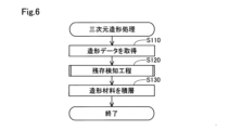
図6は、本実施形態における三次元造形処理のフローチャートである。ステップS110にて、制御部500は、外部のコンピューターや記録媒体などから造形データを取得する。造形データには、三次元造形物を形成する層毎に、ノズル61の移動経路を表す造形パスデータが含まれている。造形パスデータには、ノズル61から射出される材料の射出量を表す射出量データが関連付けられている。
Figure 6 is a flowchart of the three-dimensional modeling process in this embodiment. In step S110, the
ステップS120にて、制御部500は、残存検知工程を実行する。本実施形態では、制御部500は、残存検知工程において、発光部610から検知光DRを放出させながら、センサー部600をステージ300に対して第2方向、つまり、Y方向に沿って相対的に移動させることによって、残存造形材料を検知する。より詳細には、制御部500は、残存検知工程において、後述する残存検知処理を実行して、センサー部600を開始位置から終了位置に向かって、ステージ300に対して相対的に-Y方向に移動させることによって、残存造形材料を検知する。
In step S120, the
図7は、センサー部600が開始位置に位置している様子を示す上面図である。図8は、センサー部600が終了位置に位置している様子を示す上面図である。図7および図8は、ステージ300とセンサー部600とを上から見た時の様子を示している。図7および図8には、造形面311に支持された残存造形材料の例として、先に造形された三次元造形物である残存造形物RBが示されている。図7に示すように、本実施形態における開始位置は、Z方向に沿って見た時に、開始位置に位置する発光部610から放出される検知光DRが、造形面311のY方向における一端部Eg1と重なる位置である。図8に示すように、本実施形態における終了位置は、Z方向に沿って見た時に、終了位置に位置する発光部610から放出される検知光DRが、造形面311のY方向における他端部Eg2と重なる位置である。図7および図8に示すように、一端部Eg1は、他端部Eg2の-Y方向に位置している。
7 is a top view showing the sensor unit 600 positioned at the start position. FIG. 8 is a top view showing the sensor unit 600 positioned at the end position. FIG. 7 and FIG. 8 show the state when the
図9は、残存検知工程における検知光DRのY方向における軌跡Lcを説明する図である。図9には、ステージ300と上述した残存造形物RBとを、X方向に沿って見た時の様子が示されている。軌跡Lcは、残存検知工程において、-X方向に進む検知光DRを放出する発光部610が、位置変更部400によって、開始位置から終了位置に向かって+Y方向に移動することで描かれる。
Figure 9 is a diagram explaining the trajectory Lc in the Y direction of the detection light DR in the remaining detection process. Figure 9 shows the state of the
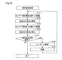
図10は、上述した図7のステップS120において実行される残存検知処理のフローチャートである。ステップS121にて、制御部500は、第1移動部として機能する位置変更部400を制御して、図7に示すように、センサー部600を開始位置へと移動させる。そして、ステップS122にて、制御部500は、発光部610から検知光DRの放出を開始する。次に、ステップS123にて、制御部500は、位置変更部400を制御してセンサー部600を+Y方向に移動させることによって、図8および図9に示すように、発光部610から検知光DRを放出させた状態で、センサー部600を終了位置まで移動させる。その後、ステップS124にて、制御部500は、検知光DRの放出を停止する。
Figure 10 is a flowchart of the remaining detection process executed in step S120 of Figure 7 described above. In step S121, the
ステップS125にて、制御部500は、造形面311に支持された残存造形材料を検知したか否かを判定する。残存検知工程において、図9に示すように、センサー部600が検知光DRによって軌跡Lcを描きながら開始位置から終了位置まで移動する期間のうち、検知光DRが残存造形物RBに照射される期間では、検知光DRが残存造形物RBに照射されない期間と比較して、受光部620によって受光される検知光DRの強度が小さくなる。一方で、例えば、造形面311上のいずれにも残存造形物RB等の残存造形材料が位置していない場合、センサー部600が開始位置から終了位置まで移動する期間、受光部620によって受光される検知光DRの強度は略一定となる。従って、制御部500は、図9のステップS125において、受光部620による検知光DRの検出値に基づいて、残存造形材料を検知できる。
In step S125, the
より詳細には、本実施形態では、制御部500は、ステップS125において、予め定められた判定期間に亘って、受光部620による検知光DRの検出値が、予め定められた基準値よりも小さくなった場合に、残存造形材料を検知したと判定する。検知光DRの基準値は、例えば、検知光DRが残存造形材料に照射されずに受光部620によって直接受光された場合の検出値に基づいて定められてもよいし、残存造形材料の誤検知を抑制できる程度に小さい値として定められてもよい。
More specifically, in this embodiment, in step S125, the
判定期間は、例えば、残存検知工程において検知したい造形材料の寸法に基づいて定められる。上述した検知光DRが残存造形物RBに照射される期間は、図7から図9に示した残存造形物RBのY方向における寸法Wと、センサー部600のY方向に沿った移動速度とによって定まる。そのため、センサー部600の移動速度が同じであれば、判定期間がより短い場合に、Y方向における寸法がより小さい造形材料が残存造形材料として検知され得る。従って、判定期間を、例えば、三次元造形物OBを造形する際の吐出部200等の動作に干渉しない程度に小さい造形材料を検知しない期間に定めることによって、残存検知工程において、そのように小さい造形材料を検知せずに無視できる。
The judgment period is determined, for example, based on the dimensions of the modeling material to be detected in the remaining detection process. The period during which the above-mentioned detection light DR is irradiated to the remaining object RB is determined by the dimension W in the Y direction of the remaining object RB shown in Figures 7 to 9 and the moving speed of the sensor unit 600 along the Y direction. Therefore, if the moving speed of the sensor unit 600 is the same, a modeling material with a smaller dimension in the Y direction can be detected as the remaining modeling material when the judgment period is shorter. Therefore, by determining the judgment period as a period during which modeling material that is small enough not to interfere with the operation of the
なお、発光部610および受光部620のZ方向における位置を変更し、検知光DRとステージ300との間の距離を変化させることによって、残存検知工程によって検知され得る造形材料のZ方向における寸法の下限を変化させることもできる。例えば、検知光DRとステージ300との間の距離をより近付けることによって、Z方向における寸法がより小さい造形材料が残存造形材料として検知され得る。そのため、例えば、検知光DRとステージ300との間の距離がギャップGpよりも小さい距離となるように、発光部610および受光部620の位置を決定することによって、三次元造形物OBを造形する際に吐出部200と接触する可能性が造形材料を残存造形材料として検知できる。また、判定期間を定める場合と同様に、三次元造形物OBを造形する際の吐出部200等の動作に干渉しない程度に小さい造形材料を無視できるように、検知光DRとステージ300との間の距離を決定してもよい。
It is also possible to change the lower limit of the dimension in the Z direction of the modeling material that can be detected by the remaining detection process by changing the positions of the light-emitting unit 610 and the light-receiving unit 620 in the Z direction and changing the distance between the detection light DR and the
図10のステップS125において、残存造形材料が検知された場合、制御部500は、ステップS126にて、報知部800によって、残存造形材料が検知されたことをユーザーに報知する。次に、ステップS127にて、制御部500は、三次元造形装置100を待機させる。ユーザーは、例えば、ステップS127で三次元造形装置100が待機している間、造形面311に残存している残存造形材料を、造形面311上から取り除くことができる。制御部500は、ステップS127において、例えば、所定の期間、三次元造形装置100を待機させてもよいし、ユーザーによって所定の再開動作が入力されるまで、三次元造形装置100を待機させてもよい。ステップS127の後、制御部500は、ステップS121へと処理を戻す。
If remaining modeling material is detected in step S125 of FIG. 10, the
ステップS125において、残存造形材料が検知されなかった場合、制御部500は、残存検知処理を終了させる。その後、図6のステップS130にて、制御部500は、吐出部200および位置変更部400を制御して、造形面311への造形材料の積層を開始することによって、三次元造形物の造形を開始する。つまり、本実施形態では、残存検知工程は、三次元造形物の造形に先立って実行され、図10の残存検知処理におけるステップS121からS124の工程は、ステップS125において残存造形材料が検知されなくなるまで、繰り返し実行される。そのため、造形面311に残存造形材料が検知されなくなるまで、三次元造形物の造形は開始されない。
If no remaining modeling material is detected in step S125, the
以上で説明した本実施形態の三次元造形装置100によれば、制御部500は、三次元造形物の造形に先立って、造形面311に支持された造形材料を検知するセンサー部600を制御して、残存造形材料を検知する残存検知工程を実行する。これによって、制御部500によって残存造形材料が検知された場合、三次元造形物の造形を開始する前に、造形面311から残存造形材料を取り除くことができる。そのため、三次元造形装置100の吐出部200等と残存造形材料との接触による、吐出部200等の破損を抑制できる。また、造形面311に先に造形された三次元造形物と吐出部200等との接触による、先に造形された三次元造形物の破損を抑制できる。
According to the three-
また、本実施形態では、センサー部600は、発光部610と、X方向において造形面311を挟んで発光部610と対向する受光部620とを有し、制御部500は、残存検知工程において、発光部610からX方向に検知光DRを放出させながら、センサー部600をステージ300に対してY方向に沿って相対的に移動させる。そのため、残存造形材料とセンサー部600とを接触させることなく、より簡易に残存造形材料を検知できる。特に、本実施形態では、開始位置は、Z方向に沿って見た時に、開始位置に位置する発光部610から放出される検知光DRが、造形面311のY方向における一端部Eg1と重なる位置であり、終了位置は、Z方向に沿って見た時に、終了位置に位置する発光部610から放出される検知光DRが、造形面311のY方向における他端部Eg2と重なる位置である。そのため、残存造形材料を、その造形面311上のX方向およびY方向における位置によることなく、より効率良く検知できる。
In addition, in this embodiment, the sensor unit 600 has a light-emitting unit 610 and a light-receiving unit 620 that faces the light-emitting unit 610 across the
また、本実施形態では、制御部500は、残存検知工程において、予め定められた判定期間に亘って受光部620による検知光DRの検出値が基準値よりも小さくなった場合に、残存造形材料を検知したと判定する。これによって、判定期間を、例えば、三次元造形物を造形する際の吐出部200等の動作に干渉しない程度に小さい造形材料を検知しない期間に定めることで、残存検知工程において、そのように小さい造形材料を検知せずに無視できる。そのため、先に造形された三次元造形物や吐出部200等の破損を抑制しつつ、より効率良く三次元造形物を造形できる。
In addition, in this embodiment, the
また、本実施形態では、制御部500は、残存検知工程において残存造形材料が検知されなかった場合に、三次元造形物の造形を開始する。そのため、先に造形された三次元造形物や吐出部200等の破損を抑制しつつ、三次元造形物を造形できる。
In addition, in this embodiment, the
また、本実施形態では、三次元造形装置100は、吐出部200の移動に従って移動する加熱部700を備え、ノズル開口62は、Z方向において、加熱部700と造形面311との間に位置する。これによって、加熱部700がZ方向においてノズル開口62と造形面311との間に位置する形態と比較して、三次元造形物の造形中に、造形面311に積層された造形材料と加熱部700とが接触する可能性が低いため、高精度に三次元造形物を造形できる可能性が高まる。また、制御部500によって、三次元造形物の造形が開始される前に残存検知工程が実行されるため、加熱部700と造形面311に残存する造形材料との接触による、加熱部700の破損を抑制できる。また、造形面311に先に造形された三次元造形物と加熱部700との接触による、先に造形された三次元造形物の破損を抑制できる。
In addition, in this embodiment, the three-
また、本実施形態では、Z方向に沿って見たときに、センサー部600は、加熱部700と重ならない位置に配置される。そのため、センサー部600に加熱部700の熱による影響が及ぶことが抑制される。なお、例えば、他の実施形態において、X方向およびY方向においてセンサー部600と加熱部700との位置関係を変化させることが可能に構成されている場合においても、センサー部600を、Z方向に沿って見たときに、位置変更部400によって加熱部700に対する相対的な位置がどのように変化させられても加熱部700と互いに重ならない位置に配置することによって、センサー部600に加熱部700の熱による影響が及ぶことを抑制できる。
In addition, in this embodiment, the sensor unit 600 is positioned so as not to overlap with the
また、本実施形態では、位置変更部400は、吐出部200をステージ300に対してZ方向に沿って移動させ、ステージ300を吐出部200に対してX方向およびY方向に移動させる。これによって、吐出部200に従って移動する加熱部700をステージ300に対してX方向およびY方向に移動させることなく、吐出部200とステージ300との相対的な位置を変更できる。そのため、吐出部200をステージ300に対してX方向およびY方向に移動させる場合と比較して、位置変更部400によって、吐出部200とステージ300との相対的な位置をより安定して変化させることができる。特に、例えば、造形面311を覆うために加熱部700がX方向およびY方向に大型化され、加熱部700の重量が増した場合であっても、吐出部200とステージ300との相対的な位置をより安定して変化させることができる。また、本実施形態のように、位置変更部400が第1移動部として機能する場合、位置変更部400が吐出部200をステージ300に対してZ方向に沿って移動させ、ステージ300を吐出部200に対してY方向に移動させることによって、センサー部600の位置を固定したまま、センサー部600をステージ300に対してY方向に沿って相対的に移動させることができる。そのため、センサー部600の位置や角度のずれが抑制され、残存検知工程における残存造形材料の検知精度が高まる。
In addition, in this embodiment, the
B.第2実施形態:
図11は、第2実施形態における三次元造形装置100bの概略構成を示す図である。本実施形態では、位置変更部400bは、第1実施形態と異なり、ステージ300を吐出部200に対してX方向、Y方向、および、Z方向に移動させることによって、吐出部200をステージ300に対して相対的に移動させる。位置変更部400bは、第1移動部として機能するのに加え、センサー部600を積層方向に沿って、つまり、Z方向に沿って、ステージ300に相対的に移動させる第2移動部としても機能する。また、本実施形態では、制御部500は、三次元造形物の寸法を測定する。三次元造形装置100bの構成のうち、特に説明しない部分については、第1実施形態と同様である。
B. Second embodiment:
FIG. 11 is a diagram showing a schematic configuration of a three-
本実施形態では、制御部500は、図6に示した造形処理において造形された後の三次元造形物、つまり、完成した三次元造形物のY方向およびZ方向における寸法を測定する。より詳細には、本実施形態では、制御部500は、造形処理において、図5で説明した線状部位LPに相当する三次元造形物を造形する。そして、制御部500は、造形処理の完了後、三次元造形物の寸法を測定する。
In this embodiment, the
制御部500は、センサー部600および第1移動部として機能する位置変更部400bを制御することによって、造形後の三次元造形物のY方向における寸法を測定する。より詳細には、制御部500は、発光部610から検知光DRを放出させながらセンサー部600をステージ300に対してY方向に沿って相対的に移動させることによって、造形後の三次元造形物のY方向における寸法を測定する。また、制御部500は、センサー部600および第2移動部として機能する位置変更部400bを制御することによって、造形後の三次元造形物のZ方向における寸法を測定する。より詳細には、制御部500は、発光部610から検知光DRを放出させながらセンサー部600をステージ300に対してZ方向に沿って相対的に移動させることによって、造形後の三次元造形物のZ方向における寸法を測定する。
The
図12は、寸法測定によって三次元造形物OB2のY方向における寸法W2が測定される様子の例を示す図である。図12には、検知光DRのY方向における軌跡Lc2が示されている。軌跡Lc2は、図9で説明した軌跡Lcと同様に、-X方向に進む検知光DRを放出する発光部610が、位置変更部400によって+Y方向に移動することで描かれる。図12に示した寸法W2は、三次元造形物OB2における造形材料の線幅に相当する。図12の例では、検知光DRが残存造形材料に照射される場合と同様に、センサー部600が+Y方向に移動する期間のうち、検知光DRが三次元造形物OB2に照射される期間、受光部620によって受光される検知光DRの強度が小さくなる。従って、制御部500は、受光部620によって受光される検知光DRの強度が小さくなった座標と、強度が再び大きくなった座標との差を算出することによって、三次元造形物OB2のY方向における寸法を測定できる。なお、他の実施形態では、制御部500は、例えば、受光部620によって受光される検知光DRの強度が小さくなる期間と、その間のセンサー部600のY方向に沿った移動速度とに基づいて、寸法W2を測定してもよい。
Figure 12 is a diagram showing an example of how the dimension W2 in the Y direction of the three-dimensional object OB2 is measured by dimensional measurement. Figure 12 shows the trajectory Lc2 of the detection light DR in the Y direction. Like the trajectory Lc described in Figure 9, the trajectory Lc2 is drawn by moving the light-emitting unit 610, which emits the detection light DR traveling in the -X direction, in the +Y direction by the
図13は、寸法測定によって三次元造形物OB2のZ方向における寸法Hが測定される様子の例を示す図である。図13には、寸法測定における検知光DRのZ方向における軌跡Lc3が示されている。軌跡Lc3は、-X方向に進む検知光DRを放出する発光部610が、位置変更部400によって+Z方向に移動することで描かれる。図13に示した寸法Hは、三次元造形物OB2における造形材料の積層ピッチに相当する。図13に示すように、本実施形態では、三次元造形物OB2のZ方向における寸法の測定が開始される際、検知光DRは、造形面311から距離Dだけ+Z方向側の位置を+Y方向に進んでいる。そのため、制御部500は、寸法Hを測定する際、受光される検知光DRの強度が小さくなった座標と強度が再び大きくなった座標との差に距離Dを加えた値を、寸法Hとして測定する。距離Dは、例えば、シクネスゲージ等を用いて予め測定される。また、他の実施形態では、例えば、三次元造形物OB2を、X方向やY方向において離間した2つの略等しい高さを有する土台に橋渡しされるように造形してもよい。この場合、三次元造形物OB2と造形面311との間に空間が形成されるため、単に、受光される検知光DRの強度が小さくなった座標と強度が再び大きくなった座標との差のみに基づいて、寸法Hを測定できる。なお、他の実施形態では、制御部500は、例えば、受光部620によって受光される検知光DRの強度が小さくなる期間と、その間のセンサー部600のZ方向に沿った移動速度とに基づいて、寸法Hを測定してもよい。
Figure 13 is a diagram showing an example of how the dimension H of the three-dimensional object OB2 in the Z direction is measured by dimension measurement. Figure 13 shows the trajectory Lc3 in the Z direction of the detection light DR in the dimension measurement. The trajectory Lc3 is drawn by moving the light emitting unit 610, which emits the detection light DR proceeding in the -X direction, in the +Z direction by the
制御部500は、例えば、報知部800を制御して、測定された各寸法をユーザーに報知してもよい。これによって、ユーザーは、例えば、三次元造形物OB2の寸法の予測値と測定値との間の差異を把握できる。また、制御部500は、三次元造形物OB2の各寸法の測定値と、可塑化部30や位置変更部400の制御値から予測される三次元造形物OB2の寸法の予測値とを比較し、比較結果に基づいて、次に実行される造形処理における可塑化部30や位置変更部400の制御値を変更してもよい。例えば、制御部500は、測定された寸法Hが、三次元造形物OB2のZ方向における寸法の予測値よりも小さい場合、図5で説明したギャップGpを大きくするように、位置変更部400bの制御値を変更してもよい。また、制御部500は、測定された寸法W2が、三次元造形物OB2のY方向における寸法の予測値よりも大きい場合、駆動モーター32の回転数を低下させることによって、ノズル開口62から吐出される造形材料の量を減少させてもよい。これによって、所望の寸法を有する三次元造形物を造形できる可能性が高まる。なお、他の実施形態において、例えば、吐出部200のノズル流路65に、ノズル開口62から吐出される造形材料の量を調節するバルブやプランジャー等が設けられている場合、制御部500は、寸法の比較結果に基づいて、バルブやプランジャー等の制御値を変更してもよい。
The
他の実施形態では、制御部500は、造形処理において三次元造形物を造形している途中に、造形中の三次元造形物の寸法を測定してもよい。例えば、三次元造形物を構成する1つの線状部位を造形した後に、図12や図13で説明したのと同様に、その線状部位の寸法を測定することによって、線状部位の寸法の予測値と測定値との比較結果に基づいて、その線状部位よりも後に造形される部分を造形する際の可塑化部30や位置変更部400の制御値を変更できる。これによって、本実施形態と同様に、所望の寸法を有する三次元造形物を造形できる可能性が高まる。また、制御部500は、例えば、造形後の三次元造形物全体の寸法を測定してもよい。この場合、三次元造形物全体の寸法の予測値と測定値との間の差異を把握できる。
In another embodiment, the
以上で説明した本実施形態の三次元造形装置100bによっても、先に造形された三次元造形物や吐出部200等の破損を抑制できる。特に、本実施形態では、センサー部600および第1移動部として機能する位置変更部400bを制御することによって、造形中又は造形後の三次元造形物のY方向における寸法を測定する。そのため、造形中又は造形後の三次元造形物のY方向における寸法を簡易に測定できる。
The three-
また、本実施形態では、制御部500は、センサー部600および第2移動部として機能する位置変更部400bを制御することによって、造形後の三次元造形物のZ方向における寸法を測定する。そのため、造形中又は造形後の三次元造形物のZ方向における寸法を簡易に測定できる。
In addition, in this embodiment, the
なお、他の実施形態では、制御部500は、例えば、造形中又は造形後の三次元造形物のZ方向における寸法のみを測定し、Y方向における寸法を測定しなくてもよいし、同様に、三次元造形物のY方向における寸法のみを測定し、Z方向における寸法を測定しなくてもよい。
In other embodiments, the
C.第3実施形態:
図14は、第3実施形態における三次元造形装置100cの概略構成を示す図である。本実施形態では、制御部500は、残存検知工程を実行するのに先立って、後述する検査工程を実行する。三次元造形装置100cの構成のうち、特に説明しない部分については、第1実施形態と同様である。
C. Third embodiment:
14 is a diagram showing a schematic configuration of a three-
図14に示すように、本実施形態のステージ300には、予め定められた高さHsを有する基準物320が載置されている。より詳細には、本実施形態では、基準物320として、第1基準物321と、第2基準物322とが、ステージ300の上面に載置され、固定されている。第1基準物321は、ステージ300の上面のうち、造形面311よりも-Y方向の位置に載置されている。第2基準物322は、ステージ300の上面のうち、Y方向において、造形面311を挟んで第1基準物321と反対側の位置に載置されている。つまり、造形面311は、Y方向において、第1基準物321と第2基準物322との間に位置している。
As shown in FIG. 14, a reference object 320 having a predetermined height Hs is placed on the
上述した検査工程とは、制御部500が、発光部610から検知光DRを放出させて、ステージ300に載置された基準物320を検知することによって、ステージ300の水平度合いを検知する工程を指す。本実施形態では、制御部500は、検査工程において、発光部610から検知光DRを放出させながら、センサー部600をステージ300に対してY方向に沿って相対的に移動させることによって、ステージ300に載置された基準物320を検知する。より詳細には、制御部500は、検査工程において、センサー部600を、Z方向に沿って見た時に、検知光DRがステージ300の-Y方向の端部Eg3と重なる位置から、検知光DRがステージ300の+Y方向の端部Eg4と重なる位置まで、ステージ300に対して相対的に移動させる。
The inspection process described above refers to a process in which the
上述したように、制御部500は、検査工程において、ステージ300の水平度合いを検知する。例えば、検査工程において、一方の基準物320のみが検知され、他方の基準物320が検知されなかった場合、制御部500は、ステージ300がY軸に対して傾いていることを検知する。なお、制御部500は、検査工程において、両方の基準物320が検知されなかった場合、検知光DRとステージ300の上面との間の距離が高さHsよりも大きいことを検知することもできる。
As described above, the
制御部500は、例えば、報知部800を制御して、ステージ300の水平度合いの検知結果を、ユーザーに報知してもよい。また、ステージ300がY軸に対して傾いていないと判定されるまで、検査工程を繰り返し実行してもよい。
The
以上で説明した本実施形態の三次元造形装置100cによっても、先に造形された三次元造形物や吐出部200等の破損を抑制できる。特に、本実施形態では、制御部500は、残存検知工程を実行するのに先立って、発光部610から検知光DRを放出させて、ステージ300に載置された基準物320を検知することによって、ステージ300の水平度合いを検知する検査工程を実行する。これによって、残存検知工程の開始や三次元造形物の造形の開始に先立って、センサー部600によって、ステージ300の水平度合いを検知できる。特に、本実施形態では、ステージ300のY方向に対する傾きがより小さい状態で残存検知工程を実行できる可能性が高まるため、残存検知工程における残存造形材料の検知精度が向上する可能性が高まる。
The three-
なお、他の実施形態では、基準物320は、ステージ300に固定されていなくてもよく、例えば、検査工程が実行される直前に、制御部500の制御下で動作するロボットや、手作業によって、ステージ300に載置されてもよい。この場合、例えば、検査工程を複数回実行し、検査工程を実行するごとに基準物320を載置するステージ300のX方向における位置を変化させることによって、ステージ300のX方向に対する傾きを検知することも可能である。より詳細には、例えば、ステージ300の上面のうち、造形面311よりも-X方向の位置に基準物320を載置した状態で、制御部500による検査工程を実行し、その後、ステージ300の上面のうち、X方向において造形面311を挟んで反対側の位置に基準物320を載置した状態で、制御部500による検査工程を実行することができる。このとき、一方の検査工程において基準物320が検知され、他方の検査工程において基準物320が検知されなかった場合、ステージ300は、検知光DRの進行方向であるX方向に対して傾いている。このように、制御部500は、ステージ300のX方向に対する傾きを検知できる。また、例えば、検査工程を複数回実行し、検査工程を実行するごとにそれぞれ異なる高さを有する基準物320をステージ300に載置することによって、検知光DRとステージ300の上面との間の距離を推定することも可能である。例えば、1回目の基準物検知で高さHs1を有する基準物320が検知されず、2回目の基準物検知で1回目と同じ位置に載置された、高さHs1よりも高い高さHs2を有する基準物320が検知された場合、制御部500は、検知光DRとステージ300の上面との間の距離が高さHs1よりも大きく、高さHs2以下であると推定できる。
In other embodiments, the reference object 320 does not have to be fixed to the
D.他の実施形態:
(D-1)上記実施形態では、センサー部600は、造形面311に支持された造形材料を検知する。これに対して、センサー部600は、造形面311に支持されたその他の残留物を検知しても良い。例えば、センサー部600は、残留物として、ユーザーによって造形面311に置き忘れられた工具等や、吐出部200等から造形面311に脱落したネジ等の部品等を検知してもよい。そして、制御部500は、三次元造形物の造形が開始されるのに先立って、センサー部600を制御して、造形面311に残存する残留物を検知してもよい。これによって、残留物が検知された場合、三次元造形物の造形を開始する前に、造形面311から残留物を取り除くことができる。そのため、三次元造形装置100の吐出部200等の各部と残留物との接触による、残留物や吐出部200等の破損を抑制できる。
D. Other embodiments:
(D-1) In the above embodiment, the sensor unit 600 detects the modeling material supported on the
(D-2)上記実施形態では、センサー部600は、光学センサーによって構成されている。これに対して、センサー部600は、他のセンサーであってもよい。例えば、センサー部600は、造形面311に支持された造形物の温度を検知する温度センサーであってもよく、赤外線放射温度計やサーマルカメラによって構成された非接触式の温度センサーであってもよいし、造形面311に設けられ造形面311に支持された造形物の温度を検知する接触式の温度センサーであってもよい。この場合、検知部510は、残存検知工程を、造形物の造形が開始される前に、かつ、残存造形材料が温度センサーによって検知できる程度の温度を有している間に実行すればよい。また、センサー部600は、例えば、ステージ300に積層された造形物の重量を測定する、ロードセル方式や電磁力平衡式等の重量センサーによって構成されていてもよい。
(D-2) In the above embodiment, the sensor unit 600 is configured with an optical sensor. However, the sensor unit 600 may be another sensor. For example, the sensor unit 600 may be a temperature sensor that detects the temperature of the object supported on the
(D-3)上記実施形態では、発光部610と受光部620とは、X方向において、互いに配向して配置されている。これに対して、発光部610と受光部620とは、互いに対向して配置されていなくてもよい。例えば、X方向において造形面311を挟んで発光部610と対向する位置に、発光部610から放出された検知光DRを反射する反射板が配置され、受光部620が反射板と対向して配置されてもよい。
(D-3) In the above embodiment, the light-emitting unit 610 and the light-receiving unit 620 are arranged oriented relative to each other in the X direction. In contrast, the light-emitting unit 610 and the light-receiving unit 620 do not have to be arranged opposite each other. For example, a reflector that reflects the detection light DR emitted from the light-emitting unit 610 may be arranged opposite the light-emitting unit 610 across the
(D-4)上記実施形態では、開始位置は、Z方向に沿って見た時に、開始位置に位置する発光部610から放出される検知光DRが、造形面311のY方向における一端部Eg1と重なる位置であり、終了位置は、Z方向に沿って見た時に、終了位置に位置する発光部610から放出される検知光DRが、造形面311のY方向における他端部Eg2と重なる位置である。これに対して、開始位置や終了位置は、上述した位置と異なる位置であってもよい。例えば、開始位置や終了位置は、Y方向において、造形面311から見て外側の位置であってもよい。この場合であっても、残存造形材料を、その造形面311上のX方向およびY方向における位置によることなく、より効率良く検知できる。また、開始位置は、例えば、造形面311のY方向における中心の位置であってもよい。この場合、制御部500は、残存検知工程において、例えば、センサー部600を-Y方向又は+Y方向に移動させた後、センサー部600を逆方向に移動させてもよいし、その後、更に、センサー部600をY方向における中心の位置に戻してセンサー部600の移動を終了させてもよい。また、制御部500は、残存検知工程において、例えば、センサー部600を開始位置から終了位置まで移動させている途中で残存造形材料を検知した場合、その時点でセンサー部600の移動を停止させてもよい。この場合、開始位置を、残存造形材料が残存している可能性がより高い位置、例えば、上述した造形面311のY方向における中心の位置とすることで、より効率良く残存造形材料を検知できる。
(D-4) In the above embodiment, the start position is a position where, when viewed along the Z direction, the detection light DR emitted from the light-emitting unit 610 located at the start position overlaps with one end Eg1 in the Y direction of the
(D-5)上記実施形態では、位置変更部400が第1移動部や第2移動部として機能している。これに対して、位置変更部400が第1移動部や第2移動部として機能しなくてもよい。例えば、発光部610と受光部620とを同時にステージ300に対してX方向やY方向、Z方向に移動させる移動部が、位置変更部400とは別体に設けられていてもよい。
(D-5) In the above embodiment, the
(D-6)上記実施形態では、検知部510は、残存検知工程において、予め定められた判定期間に亘って、受光部620による検知光DRの検出値が基準値よりも小さくなった場合に、残存造形材料を検知したと判定している。これに対して、判定期間が定められていなくてもよく、例えば、制御部500は、残存検知工程において、単に、受光部620が受光する検知光DRの強度が基準値よりも小さくなった場合に残存造形材料を検知したと判定してもよい。また、検知部510は、例えば、受光部620による検知光DRの検出値が0となった場合に、残存造形材料を検知したと判定してもよい。
(D-6) In the above embodiment, the
(D-7)上記実施形態では、加熱部700が設けられている。これに対して、加熱部700が設けられていなくてもよい。
(D-7) In the above embodiment, a
(D-8)上記実施形態では、Z方向に沿って見た時に、加熱部700とセンサー部600とは互いに重ならない位置に配置されている。これに対して、Z方向に沿って見た時に、加熱部700とセンサー部600とが互いに重なる位置に配置されていてもよい。
(D-8) In the above embodiment, the
(D-9)上記実施形態では、吐出部200の可塑化部30は、フラットスクリューによって材料を可塑化し、造形材料を生成している。これに対して可塑化部30は、例えば、インラインスクリューを回転させることによって材料を可塑化して造形材料を生成してもよい。また、吐出部200は、フィラメント状の材料を可塑化して吐出するヘッドとして構成されていてもよい。
(D-9) In the above embodiment, the
(D-10)上記実施形態では、材料供給部20に供給される原材料として、ペレット状のABS樹脂の材料が用いられる。これに対して、三次元造形装置100は、例えば、熱可塑性を有する材料や、金属材料、セラミック材料等の種々の材料を主材料として三次元造形物を造形することができる。ここで、「主材料」とは、三次元造形物の形状を形作っている中心となる材料を意味し、三次元造形物において50重量%以上の含有率を占める材料を意味する。上述した造形材料には、それらの主材料を単体で溶融したものや、主材料とともに含有される一部の成分が溶融してペースト状にされたものが含まれる。
(D-10) In the above embodiment, pellet-shaped ABS resin material is used as the raw material supplied to the
主材料として熱可塑性を有する材料を用いる場合には、可塑化部30において、当該材料が可塑化することによって造形材料が生成される。「可塑化」とは、熱可塑性を有する材料に熱が加わり溶融することを意味する。
When a thermoplastic material is used as the main material, the modeling material is generated by plasticizing the material in the
熱可塑性を有する材料としては、例えば、下記の熱可塑性樹脂材料を用いることができる。
<熱可塑性樹脂材料の例>
ポリプロピレン樹脂(PP)、ポリエチレン樹脂(PE)、ポリアセタール樹脂(POM)、ポリ塩化ビニル樹脂(PVC)、ポリアミド樹脂(PA)、アクリロニトリル・ブタジエン・スチレン樹脂(ABS)、ポリ乳酸樹脂(PLA)、ポリフェニレンサルファイド樹脂(PPS)、ポリエーテルエーテルケトン(PEEK)、ポリカーボネート(PC)、変性ポリフェニレンエーテル、ポリブチレンテレフタレート、ポリエチレンテレフタレートなどの汎用エンジニアリングプラスチック、ポリサルフォン、ポリエーテルサルフォン、ポリフェニレンサルファイド、ポリアリレート、ポリイミド、ポリアミドイミド、ポリエーテルイミド、ポリエーテルエーテルケトンなどのエンジニアリングプラスチック。
As the material having thermoplasticity, for example, the following thermoplastic resin materials can be used.
<Examples of thermoplastic resin materials>
General-purpose engineering plastics such as polypropylene resin (PP), polyethylene resin (PE), polyacetal resin (POM), polyvinyl chloride resin (PVC), polyamide resin (PA), acrylonitrile butadiene styrene resin (ABS), polylactic acid resin (PLA), polyphenylene sulfide resin (PPS), polyether ether ketone (PEEK), polycarbonate (PC), modified polyphenylene ether, polybutylene terephthalate, and polyethylene terephthalate; engineering plastics such as polysulfone, polyethersulfone, polyphenylene sulfide, polyarylate, polyimide, polyamideimide, polyetherimide, and polyether ether ketone.
熱可塑性を有する材料には、顔料や、金属、セラミック、その他に、ワックス、難燃剤、酸化防止剤、熱安定剤などの添加剤等が混入されていてもよい。熱可塑性を有する材料は、可塑化部30において、スクリュー40の回転とヒーター58の加熱によって可塑化されて溶融した状態に転化される。熱可塑性を有する材料の溶融によって生成された造形材料は、ノズル61から吐出された後、温度の低下によって硬化する。
The thermoplastic material may contain pigments, metals, ceramics, and other additives such as wax, flame retardants, antioxidants, and heat stabilizers. The thermoplastic material is plasticized in the
熱可塑性を有する材料は、そのガラス転移点以上に加熱されて完全に溶融した状態でノズル61から射出されることが望ましい。例えば、ABS樹脂は、ガラス転移点が約120℃であり、ノズル61からの射出時には約200℃であることが望ましい。
It is desirable for a thermoplastic material to be heated above its glass transition point and injected from the
三次元造形装置100では、上述した熱可塑性を有する材料の代わりに、例えば、以下の金属材料が主材料として用いられてもよい。この場合には、下記の金属材料を粉末状にした粉末材料に、造形材料の生成の際に溶融する成分が混合されて、原材料として可塑化部30に投入されることが望ましい。
<金属材料の例>
マグネシウム(Mg)、鉄(Fe)、コバルト(Co)やクロム(Cr)、アルミニウム(Al)、チタン(Ti)、銅(Cu)、ニッケル(Ni)の単一の金属、もしくはこれらの金属を1つ以上含む合金。
<前記合金の例>
マルエージング鋼、ステンレス、コバルトクロムモリブデン、チタニウム合金、ニッケル合金、アルミニウム合金、コバルト合金、コバルトクロム合金。
In the three-
<Examples of metal materials>
A single metal such as magnesium (Mg), iron (Fe), cobalt (Co), chromium (Cr), aluminum (Al), titanium (Ti), copper (Cu), or nickel (Ni), or an alloy containing one or more of these metals.
<Examples of the alloy>
Maraging steel, stainless steel, cobalt chrome molybdenum, titanium alloy, nickel alloy, aluminum alloy, cobalt alloy, cobalt chrome alloy.
三次元造形装置100においては、上記の金属材料の代わりに、セラミック材料を主材料として用いることが可能である。セラミック材料としては、例えば、二酸化ケイ素、二酸化チタン、酸化アルミニウム、酸化ジルコニウムなどの酸化物セラミックスや、窒化アルミニウムなどの非酸化物セラミックスなどが使用可能である。主材料として、上述したような金属材料やセラミック材料を用いる場合には、ステージ300に配置された造形材料はレーザーの照射や温風などによる焼結によって硬化されてもよい。
In the three-
材料供給部20に原材料として投入される金属材料やセラミック材料の粉末材料は、単一の金属の粉末や合金の粉末、セラミック材料の粉末を、複数種類、混合した混合材料であってもよい。また、金属材料やセラミック材料の粉末材料は、例えば、上で例示したような熱可塑性樹脂、あるいは、それ以外の熱可塑性樹脂によってコーティングされていてもよい。この場合には、可塑化部30において、その熱可塑性樹脂が溶融して流動性が発現されるものとしてもよい。
The powdered metallic or ceramic material fed into the
材料供給部20に原材料として投入される金属材料やセラミック材料の粉末材料には、例えば、以下のような溶剤を添加することもできる。溶剤は、下記の中から選択される1種または2種以上を組み合わせて用いることができる。
<溶剤の例>
水;エチレングリコールモノメチルエーテル、エチレングリコールモノエチルエーテル、プロピレングリコールモノメチルエーテル、プロピレングリコールモノエチルエーテル等の(ポリ)アルキレングリコールモノアルキルエーテル類;酢酸エチル、酢酸n-プロピル、酢酸iso-プロピル、酢酸n-ブチル、酢酸iso-ブチル等の酢酸エステル類;ベンゼン、トルエン、キシレン等の芳香族炭化水素類;メチルエチルケトン、アセトン、メチルイソブチルケトン、エチル-n-ブチルケトン、ジイソプロピルケトン、アセチルアセトン等のケトン類;エタノール、プロパノール、ブタノール等のアルコール類;テトラアルキルアンモニウムアセテート類;ジメチルスルホキシド、ジエチルスルホキシド等のスルホキシド系溶剤;ピリジン、γ-ピコリン、2,6-ルチジン等のピリジン系溶剤;テトラアルキルアンモニウムアセテート(例えば、テトラブチルアンモニウムアセテート等);ブチルカルビトールアセテート等のイオン液体等。
For example, the following solvents may be added to the powdered metal or ceramic material fed as raw material to the
<Examples of solvents>
water; (poly)alkylene glycol monoalkyl ethers such as ethylene glycol monomethyl ether, ethylene glycol monoethyl ether, propylene glycol monomethyl ether, and propylene glycol monoethyl ether; acetates such as ethyl acetate, n-propyl acetate, isopropyl acetate, n-butyl acetate, and isobutyl acetate; aromatic hydrocarbons such as benzene, toluene, and xylene; ketones such as methyl ethyl ketone, acetone, methyl isobutyl ketone, ethyl-n-butyl ketone, diisopropyl ketone, and acetylacetone; alcohols such as ethanol, propanol, and butanol; tetraalkylammonium acetates; sulfoxide-based solvents such as dimethyl sulfoxide and diethyl sulfoxide; pyridine-based solvents such as pyridine, γ-picoline, and 2,6-lutidine; tetraalkylammonium acetates (for example, tetrabutylammonium acetate, etc.); and ionic liquids such as butyl carbitol acetate.
その他に、材料供給部20に原材料として投入される金属材料やセラミック材料の粉末材料には、例えば、以下のようなバインダーを添加することもできる。
<バインダーの例>
アクリル樹脂、エポキシ樹脂、シリコーン樹脂、セルロース系樹脂或いはその他の合成樹脂又はPLA(ポリ乳酸)、PA(ポリアミド)、PPS(ポリフェニレンサルファイド)、PEEK(ポリエーテルエーテルケトン)或いはその他の熱可塑性樹脂。
In addition, for example, the following binders can be added to the powdered metal or ceramic material fed to the
<Example of binder>
Acrylic resin, epoxy resin, silicone resin, cellulose-based resin or other synthetic resin, or PLA (polylactic acid), PA (polyamide), PPS (polyphenylene sulfide), PEEK (polyether ether ketone) or other thermoplastic resin.
E.他の形態:
本開示は、上述した実施形態に限られるものではなく、その趣旨を逸脱しない範囲において種々の形態で実現することができる。例えば、本開示は、以下の形態によっても実現可能である。以下に記載した各形態中の技術的特徴に対応する上記実施形態中の技術的特徴は、本開示の課題の一部又は全部を解決するために、あるいは、本開示の効果の一部又は全部を達成するために、適宜、差し替えや、組み合わせを行うことが可能である。また、その技術的特徴が本明細書中に必須なものとして説明されていなければ、適宜、削除することが可能である。
E. Other Forms:
The present disclosure is not limited to the above-mentioned embodiment, and can be realized in various forms without departing from the spirit of the present disclosure. For example, the present disclosure can be realized in the following forms. The technical features in the above-mentioned embodiments corresponding to the technical features in each form described below can be appropriately replaced or combined in order to solve some or all of the problems of the present disclosure, or to achieve some or all of the effects of the present disclosure. Furthermore, if the technical feature is not described as essential in this specification, it can be appropriately deleted.
(1)本開示の一形態によれば、三次元造形装置が提供される。この三次元造形装置は、ノズル開口を有し、前記ノズル開口から造形材料を吐出する吐出部と、前記吐出部から吐出された前記造形材料を支持する造形面を有するステージと、前記造形面に支持された前記造形材料を検知するセンサー部と、前記吐出部を制御して、前記造形材料を前記造形面に積層して三次元造形物を造形する制御部と、を備える。前記制御部は、前記三次元造形物の造形の開始に先立って、前記センサー部を制御して、前記造形面に残存する前記造形材料を検知する残存検知工程を実行する。
このような形態によれば、造形面に残存する造形材料が検知された場合、三次元造形物の造形を開始する前に、造形面から造形材料を取り除くことができる。そのため、三次元造形装置の吐出部等の各部と造形面に残存する造形材料との接触による吐出部等の破損を抑制できる。また、造形面に先に造形された三次元造形物と吐出部等との接触による、先に造形された三次元造形物の破損を抑制できる。
(1) According to one aspect of the present disclosure, there is provided a three-dimensional modeling apparatus. The three-dimensional modeling apparatus includes: a discharge unit having a nozzle opening and discharging a modeling material from the nozzle opening; a stage having a modeling surface that supports the modeling material discharged from the discharge unit; a sensor unit that detects the modeling material supported on the modeling surface; and a control unit that controls the discharge unit to stack the modeling material on the modeling surface to form a three-dimensional object. Prior to starting modeling of the three-dimensional object, the control unit controls the sensor unit to execute a remaining detection step of detecting the modeling material remaining on the modeling surface.
According to this embodiment, when the remaining modeling material on the modeling surface is detected, the modeling material can be removed from the modeling surface before starting modeling of a three-dimensional object. This makes it possible to prevent damage to the discharge unit, etc., of the three-dimensional modeling device due to contact between the remaining modeling material on the modeling surface and each part of the three-dimensional modeling device, such as the discharge unit. It is also possible to prevent damage to a previously modeled three-dimensional object due to contact between the previously modeled three-dimensional object on the modeling surface and the discharge unit, etc.
(2)上記形態では、前記センサー部は、前記造形面に沿った第1方向に検知光を放出する発光部と、前記第1方向において前記造形面を挟んで前記発光部と対向し、前記検知光を受光する受光部と、を有し、前記センサー部を、前記造形面に沿った方向であって前記第1方向と交差する第2方向に沿って、前記ステージに対して相対的に移動させる第1移動部を更に備え、前記制御部は、前記残存検知工程において、前記発光部から前記検知光を放出させながら、前記センサー部を前記ステージに対して前記第2方向に沿って相対的に移動させてもよい。このような形態によれば、造形面に残存する造形材料とセンサー部とを接触させることなく、より簡易に残存造形材料を検知できる。 (2) In the above embodiment, the sensor unit has a light-emitting unit that emits detection light in a first direction along the modeling surface, and a light-receiving unit that faces the light-emitting unit across the modeling surface in the first direction and receives the detection light, and further includes a first moving unit that moves the sensor unit relative to the stage along a second direction that is along the modeling surface and intersects with the first direction, and the control unit may move the sensor unit relative to the stage along the second direction while emitting the detection light from the light-emitting unit in the remaining detection process. According to this embodiment, the remaining modeling material on the modeling surface can be detected more easily without contacting the sensor unit with the modeling material remaining on the modeling surface.
(3)上記形態では、前記検知部は、前記制御部は、前記残存検知工程において、予め定められた期間に亘って、前記受光部による前記検知光の検出値が予め定められた値よりも小さくなった場合に、前記造形面に残存する前記造形材料を検知したと判定してもよい。このような形態によれば、判定期間を、例えば、三次元造形物を造形する際の吐出部等の動作に干渉しない程度に小さい造形材料を検知しない期間に定めることで、残存検知工程において、そのように小さい造形材料を検知せずに無視できる。そのため、先に造形された三次元造形物や吐出部等の破損を抑制しつつ、より効率良く三次元造形物を造形できる。 (3) In the above embodiment, the detection unit and the control unit may determine that the remaining modeling material on the modeling surface has been detected when the detection value of the detection light by the light receiving unit becomes smaller than a predetermined value over a predetermined period in the remaining detection process. According to this embodiment, by setting the determination period to a period in which modeling material that is small enough not to interfere with the operation of a discharge unit or the like when forming a three-dimensional object is not detected, such small modeling material can be ignored without being detected in the remaining detection process. Therefore, a three-dimensional object can be more efficiently formed while suppressing damage to a previously formed three-dimensional object, the discharge unit, etc.
(4)上記形態では、前記制御部は、前記残存検知工程を実行するのに先立って、前記発光部から前記検知光を放出させて、前記ステージに載置された基準物を検知することによって、前記ステージの水平度合いを検知する検査工程を実行してもよい。このような形態によれば、残存検知工程の開始や三次元造形物の造形の開始に先立って、センサー部によって、ステージの水平度合いを検知できる。 (4) In the above embodiment, the control unit may execute an inspection step of detecting the levelness of the stage by emitting the detection light from the light-emitting unit and detecting a reference object placed on the stage prior to executing the remaining detection step. According to this embodiment, the levelness of the stage can be detected by the sensor unit prior to the start of the remaining detection step or the start of modeling of a three-dimensional object.
(5)上記形態では、前記制御部は、前記センサー部及び前記第1移動部を制御することによって、造形中又は造形後の前記三次元造形物の前記第2方向における寸法を測定してもよい。このような形態によれば、造形中又は造形後の三次元造形物の第2方向における寸法を簡易に測定できる。 (5) In the above embodiment, the control unit may measure the dimension of the three-dimensional object in the second direction during or after modeling by controlling the sensor unit and the first moving unit. According to this embodiment, it is possible to easily measure the dimension of the three-dimensional object in the second direction during or after modeling.
(6)上記形態では、前記センサー部を、前記造形材料の積層方向に沿って前記ステージに対して相対的に移動させる第2移動部を更に備え、前記検知部は、前記センサー部及び前記第2移動部を制御することによって、造形中又は造形後の前記三次元造形物の前記積層方向における寸法を測定してもよい。このような形態によれば、造形中又は造形後の三次元造形物の積層方向における寸法を簡易に測定できる。 (6) In the above embodiment, a second moving unit may be further provided that moves the sensor unit relative to the stage along the stacking direction of the modeling material, and the detection unit may measure the dimension of the three-dimensional object in the stacking direction during or after modeling by controlling the sensor unit and the second moving unit. According to this embodiment, it is possible to easily measure the dimension of the three-dimensional object in the stacking direction during or after modeling.
(7)上記形態では、前記制御部は、前記残存検知工程において前記造形面に残存する前記造形材料が検知されなかった場合に、前記三次元造形物の造形を開始してもよい。このような形態によれば、先に造形された三次元造形物や吐出部等の破損を抑制しつつ、三次元造形物を造形できる。 (7) In the above embodiment, the control unit may start forming the three-dimensional object when the remaining part of the forming material is not detected on the forming surface in the remaining part detection process. According to this embodiment, it is possible to form a three-dimensional object while suppressing damage to a previously formed three-dimensional object, a discharge part, etc.
(8)上記形態では、前記吐出部を前記ステージに対して相対的に移動させる位置変更部と、前記吐出部の移動に従って移動し、前記造形面に積層された前記造形材料を加熱するための加熱部と、を備え、前記ノズル開口は、前記造形面に垂直な第3方向において、前記加熱部と前記造形面との間に位置してもよい。このような形態によれば、加熱部が第3方向においてノズル開口と造形面との間に位置する形態と比較して、三次元造形物の造形中に、造形面に積層された造形材料と加熱部とが接触する可能性が低いため、高精度に三次元造形物を造形できる可能性が高まる。また、三次元造形物の造形が開始される前に残存検知工程が実行されるため、加熱部と造形面に残存する造形材料との接触による、加熱部の破損を抑制できる。また、造形面に先に造形された三次元造形物と加熱部との接触による、先に造形された三次元造形物の破損を抑制できる。 (8) In the above embodiment, the device includes a position change unit that moves the discharge unit relative to the stage, and a heating unit that moves in accordance with the movement of the discharge unit and heats the modeling material layered on the modeling surface, and the nozzle opening may be located between the heating unit and the modeling surface in a third direction perpendicular to the modeling surface. According to this embodiment, compared to a embodiment in which the heating unit is located between the nozzle opening and the modeling surface in the third direction, the possibility of the modeling material layered on the modeling surface coming into contact with the heating unit during modeling of the three-dimensional object is low, thereby increasing the possibility of modeling a three-dimensional object with high accuracy. In addition, since the remaining detection process is performed before modeling of the three-dimensional object is started, damage to the heating unit due to contact between the heating unit and the modeling material remaining on the modeling surface can be suppressed. In addition, damage to a previously modeled three-dimensional object due to contact between a three-dimensional object previously modeled on the modeling surface and the heating unit can be suppressed.
(9)上記形態では、前記第3方向に沿って見たときに、前記センサー部は、前記加熱部と重ならない位置に配置されてもよい。このような形態によれば、センサー部に加熱部の熱による影響が及ぶことが抑制される。 (9) In the above embodiment, the sensor unit may be disposed at a position that does not overlap with the heating unit when viewed along the third direction. This embodiment reduces the effect of heat from the heating unit on the sensor unit.
(10)上記形態では、前記位置変更部は、前記吐出部を前記ステージに対して前記第3方向に沿って移動させ、前記ステージを前記吐出部に対して前記第3方向と直交する方向に沿って移動させてもよい。このような形態によれば、吐出部に従って移動する加熱部をステージに対して第3方向と直交する方向に沿って移動させることなく、吐出部とステージとの相対的な位置を変更できる。そのため、吐出部をステージに対して第3方向と直交する方向に沿って移動させる場合と比較して、位置変更部によって、吐出部とステージとの相対的な位置をより安定して変化させることができる。 (10) In the above embodiment, the position change unit may move the discharge unit along the third direction relative to the stage, and move the stage along a direction perpendicular to the third direction relative to the discharge unit. According to this embodiment, the relative position between the discharge unit and the stage can be changed without moving the heating unit, which moves following the discharge unit, along a direction perpendicular to the third direction relative to the stage. Therefore, the position change unit can change the relative position between the discharge unit and the stage more stably than when the discharge unit is moved along a direction perpendicular to the third direction relative to the stage.
20…材料供給部、22…供給路、30…可塑化部、31…スクリューケース、32…駆動モーター、40…スクリュー、41…上面、42…溝形成面、43…側面、44…材料導入口、45…溝、46…凸条部、47…中央部、50…バレル、52…スクリュー対向面、54…案内溝、56…連通孔、58…ヒーター、61…ノズル、62…ノズル開口、63…先端面、65…ノズル流路、100,100b,100c…三次元造形装置、200…吐出部、205…支持部、300…ステージ、311…造形面、320…基準物、321…第1基準物、322…第2基準物、400,400b…位置変更部、410…第1電動アクチュエーター、420…第2電動アクチュエーター、430…第3電動アクチュエーター、500…制御部、510…検知部、600…センサー部、601…第1支持部、602…第1ホルダー、603…第1支柱、604…第2支持部、605…第2ホルダー、606…第2支柱、610…発光部、620…受光部、700…加熱部、800…報知部 20...material supply section, 22...supply path, 30...plasticization section, 31...screw case, 32...drive motor, 40...screw, 41...upper surface, 42...groove forming surface, 43...side surface, 44...material inlet, 45...groove, 46...ridge portion, 47...center portion, 50...barrel, 52...screw facing surface, 54...guide groove, 56...communication hole, 58...heater, 61...nozzle, 62...nozzle opening, 63...tip surface, 65...nozzle flow path, 100, 100b, 100c...three-dimensional modeling device, 200...discharge section, 205...support section, 300...stay 311...printing surface, 320...reference object, 321...first reference object, 322...second reference object, 400, 400b...position change unit, 410...first electric actuator, 420...second electric actuator, 430...third electric actuator, 500...control unit, 510...detection unit, 600...sensor unit, 601...first support unit, 602...first holder, 603...first support column, 604...second support unit, 605...second holder, 606...second support column, 610...light emitting unit, 620...light receiving unit, 700...heating unit, 800...notification unit
Claims (8)
前記吐出部から吐出された前記造形材料を支持する造形面を有するステージと、
前記造形面に沿った第1方向に検知光を放出する発光部と、前記第1方向において前記造形面を挟んで前記発光部と対向し前記検知光を受光する受光部を有し、前記造形面に支持された前記造形材料を検知するセンサー部と、
前記センサー部を、前記造形面に沿った方向であって前記第1方向と交差する第2方向に沿って、前記ステージに対して相対的に移動させる第1移動部と、
前記吐出部を制御して、前記造形材料を前記造形面に積層して三次元造形物を造形する制御部と、を備え、
前記制御部は、前記三次元造形物の造形の開始に先立って、前記センサー部を制御して、前記造形面に残存する前記造形材料を検知する残存検知工程を実行し、
前記残存検知工程において、前記発光部から前記検知光を放出させながら、前記センサー部を前記ステージに対して前記第2方向に沿って相対的に移動させ、予め定められた期間に亘って、前記受光部による前記検知光の検出値が予め定められた値よりも小さくなった場合に、前記造形面に残存する前記造形材料を検知したと判定する、三次元造形装置。 A discharge unit having a nozzle opening and discharging a modeling material from the nozzle opening;
a stage having a modeling surface for supporting the modeling material discharged from the discharge portion;
a sensor unit having a light-emitting unit that emits detection light in a first direction along the modeling surface, and a light-receiving unit that faces the light-emitting unit across the modeling surface in the first direction and receives the detection light, and detects the modeling material supported on the modeling surface;
a first moving unit that moves the sensor unit relatively to the stage along a second direction that is a direction along the modeling surface and intersects with the first direction;
a control unit that controls the discharge unit to deposit the modeling material on the modeling surface to model a three-dimensional object,
the control unit controls the sensor unit to execute a remaining detection step of detecting the modeling material remaining on the modeling surface prior to starting modeling of the three-dimensional object;
In the remaining detection process, the sensor unit is moved relative to the stage along the second direction while emitting the detection light from the light-emitting unit, and when the detection value of the detection light by the light-receiving unit becomes smaller than a predetermined value over a predetermined period of time, it is determined that the modeling material remaining on the modeling surface has been detected .
前記制御部は、前記残存検知工程を実行するのに先立って、前記発光部から前記検知光
を放出させて、前記ステージに載置された基準物を検知することによって、前記ステージ
の水平度合いを検知する検査工程を実行する、三次元造形装置。 The three-dimensional modeling apparatus according to claim 1 ,
The control unit, prior to executing the remaining detection process, executes an inspection process to detect the levelness of the stage by emitting the detection light from the light-emitting unit and detecting a reference object placed on the stage.
前記制御部は、前記センサー部及び前記第1移動部を制御することによって、造形中又は造形後の前記三次元造形物の前記第2方向における寸法を測定する、三次元造形装置。 The three-dimensional modeling apparatus according to claim 1 or 2 ,
The control unit controls the sensor unit and the first moving unit to measure a dimension of the three-dimensional object in the second direction during or after printing.
前記センサー部を、前記造形材料の積層方向に沿って前記ステージに対して相対的に移動させる第2移動部を更に備え、
前記制御部は、前記センサー部及び前記第2移動部を制御することによって、造形中又は造形後の前記三次元造形物の前記積層方向における寸法を測定する、三次元造形装置。 The three-dimensional modeling apparatus according to claim 1 ,
a second moving unit that moves the sensor unit relative to the stage along a stacking direction of the modeling material,
The control unit controls the sensor unit and the second moving unit to measure a dimension of the three-dimensional object in the stacking direction during or after modeling.
前記制御部は、前記残存検知工程において前記造形面に残存する前記造形材料が検知されなかった場合に、前記三次元造形物の造形を開始する、三次元造形装置。 The three -dimensional modeling apparatus according to claim 1 ,
The control unit starts printing of the three-dimensional object when the remaining part of the printing material is not detected on the printing surface in the remaining part detection process.
前記吐出部を前記ステージに対して相対的に移動させる位置変更部と、
前記吐出部の移動に従って移動し、前記造形面に積層された前記造形材料を加熱するための加熱部と、を備え、
前記ノズル開口は、前記造形面に垂直な第3方向において、前記加熱部と前記造形面との間に位置する、三次元造形装置。 The three-dimensional modeling apparatus according to claim 1 ,
a position changing unit that moves the discharge unit relative to the stage;
a heating unit that moves in accordance with the movement of the discharge unit and heats the modeling material that is layered on the modeling surface,
A three-dimensional printing device, wherein the nozzle opening is located between the heating unit and the printing surface in a third direction perpendicular to the printing surface.
前記第3方向に沿って見たときに、前記センサー部は、前記加熱部と重ならない位置に配置される、三次元造形装置。 The three-dimensional modeling apparatus according to claim 6 ,
A three-dimensional printing apparatus, wherein the sensor unit is disposed at a position not overlapping with the heating unit when viewed along the third direction.
前記位置変更部は、前記吐出部を前記ステージに対して前記第3方向に沿って移動させ、前記ステージを前記吐出部に対して前記第3方向と直交する方向に沿って移動させる、
三次元造形装置。 The three-dimensional modeling apparatus according to claim 6 or 7 ,
the position change unit moves the discharge unit relative to the stage along the third direction, and moves the stage relative to the discharge unit along a direction perpendicular to the third direction;
Three-dimensional modeling device.
Priority Applications (2)
| Application Number | Priority Date | Filing Date | Title |
|---|---|---|---|
| JP2021104750A JP7655112B2 (en) | 2021-06-24 | 2021-06-24 | 3D modeling equipment |
| US17/808,475 US12485620B2 (en) | 2021-06-24 | 2022-06-23 | Three-dimensional shaping apparatus |
Applications Claiming Priority (1)
| Application Number | Priority Date | Filing Date | Title |
|---|---|---|---|
| JP2021104750A JP7655112B2 (en) | 2021-06-24 | 2021-06-24 | 3D modeling equipment |
Publications (2)
| Publication Number | Publication Date |
|---|---|
| JP2023003589A JP2023003589A (en) | 2023-01-17 |
| JP7655112B2 true JP7655112B2 (en) | 2025-04-02 |
Family
ID=84542090
Family Applications (1)
| Application Number | Title | Priority Date | Filing Date |
|---|---|---|---|
| JP2021104750A Active JP7655112B2 (en) | 2021-06-24 | 2021-06-24 | 3D modeling equipment |
Country Status (2)
| Country | Link |
|---|---|
| US (1) | US12485620B2 (en) |
| JP (1) | JP7655112B2 (en) |
Families Citing this family (1)
| Publication number | Priority date | Publication date | Assignee | Title |
|---|---|---|---|---|
| US11712854B2 (en) * | 2021-09-07 | 2023-08-01 | Xerox Corporation | System and method for detecting errors during 3D printing |
Citations (4)
| Publication number | Priority date | Publication date | Assignee | Title |
|---|---|---|---|---|
| JP2012213972A (en) | 2011-04-01 | 2012-11-08 | Seiko Epson Corp | Composite shaping apparatus |
| JP2015196164A (en) | 2014-03-31 | 2015-11-09 | 三菱重工業株式会社 | Three-dimensional lamination apparatus and three-dimensional lamination method |
| JP2020011474A (en) | 2018-07-19 | 2020-01-23 | 株式会社リコー | Modeling apparatus and method of manufacturing modeled object |
| JP2021045902A (en) | 2019-09-19 | 2021-03-25 | 株式会社ミマキエンジニアリング | Printer and printing system |
Family Cites Families (10)
| Publication number | Priority date | Publication date | Assignee | Title |
|---|---|---|---|---|
| US20020113331A1 (en) * | 2000-12-20 | 2002-08-22 | Tan Zhang | Freeform fabrication method using extrusion of non-cross-linking reactive prepolymers |
| US9636871B2 (en) * | 2013-08-21 | 2017-05-02 | Microsoft Technology Licensing, Llc | Optimizing 3D printing using segmentation or aggregation |
| GB201317974D0 (en) * | 2013-09-19 | 2013-11-27 | Materialise Nv | System and method for calibrating a laser scanning system |
| US9782964B2 (en) * | 2015-04-02 | 2017-10-10 | Xerox Corporation | System and method for removing three-dimensional printed parts from a platen using inductive heating and gravity |
| US10178868B2 (en) * | 2016-07-21 | 2019-01-15 | BeeHex, LLC | 3D-print system with integrated CNC robot and automatic self-cleaning mechanism |
| JP7021458B2 (en) | 2017-04-28 | 2022-02-17 | セイコーエプソン株式会社 | 3D modeling equipment |
| US10882250B2 (en) * | 2018-09-17 | 2021-01-05 | Xerox Corporation | Additive manufacturing apparatus |
| JP2020151933A (en) | 2019-03-20 | 2020-09-24 | 株式会社リコー | Three-dimensional model manufacturing equipment, three-dimensional model manufacturing method, and three-dimensional model program |
| JP7310214B2 (en) * | 2019-03-28 | 2023-07-19 | セイコーエプソン株式会社 | Three-dimensional modeling apparatus and three-dimensional modeled object modeling method |
| EP4007691A4 (en) * | 2019-08-02 | 2023-11-08 | Origin Laboratories, Inc. | METHOD AND SYSTEM FOR INTERLAYER FEEDBACK CONTROL AND FAILURE DETECTION IN AN ADDITIVE MANUFACTURING PROCESS |
-
2021
- 2021-06-24 JP JP2021104750A patent/JP7655112B2/en active Active
-
2022
- 2022-06-23 US US17/808,475 patent/US12485620B2/en active Active
Patent Citations (4)
| Publication number | Priority date | Publication date | Assignee | Title |
|---|---|---|---|---|
| JP2012213972A (en) | 2011-04-01 | 2012-11-08 | Seiko Epson Corp | Composite shaping apparatus |
| JP2015196164A (en) | 2014-03-31 | 2015-11-09 | 三菱重工業株式会社 | Three-dimensional lamination apparatus and three-dimensional lamination method |
| JP2020011474A (en) | 2018-07-19 | 2020-01-23 | 株式会社リコー | Modeling apparatus and method of manufacturing modeled object |
| JP2021045902A (en) | 2019-09-19 | 2021-03-25 | 株式会社ミマキエンジニアリング | Printer and printing system |
Also Published As
| Publication number | Publication date |
|---|---|
| JP2023003589A (en) | 2023-01-17 |
| US20220410490A1 (en) | 2022-12-29 |
| US12485620B2 (en) | 2025-12-02 |
Similar Documents
| Publication | Publication Date | Title |
|---|---|---|
| US11999111B2 (en) | Method for manufacturing three-dimensional shaped object, three-dimensional shaping system, and information processing apparatus | |
| US11498266B2 (en) | Three-dimensional molding device and method for molding three-dimensional molded object | |
| CN114055771A (en) | Three-dimensional molding device, method for manufacturing three-dimensional molded object, and information processing device | |
| JP7655112B2 (en) | 3D modeling equipment | |
| US11697159B2 (en) | Three-dimensional shaping device and method for manufacturing three-dimensional shaped object | |
| JP7593100B2 (en) | 3D modeling equipment | |
| JP7388212B2 (en) | Three-dimensional object manufacturing method and three-dimensional printing device | |
| US20240326332A1 (en) | Three-dimensional shaping stage and three-dimensional shaping device | |
| JP7632026B2 (en) | Three-dimensional modeling apparatus and method for manufacturing a three-dimensional object, | |
| CN116619744A (en) | 3D modeling device | |
| JP7395894B2 (en) | A method for manufacturing a three-dimensional object, and a three-dimensional printing device | |
| US20240190074A1 (en) | Plasticizing Device, Three Dimensional Molding Device, And Injection Molding Device | |
| CN116476378A (en) | 3D modeling device | |
| US20230166456A1 (en) | Three-Dimensional Shaping Device | |
| JP7757786B2 (en) | 3D printing equipment | |
| US12304150B2 (en) | Three-dimensional molding device | |
| CN116394510B (en) | Three-dimensional modeling device | |
| JP7711504B2 (en) | Method for manufacturing three-dimensional object and three-dimensional modeling device | |
| US12122100B2 (en) | Three-dimensional shaping device | |
| US20240066805A1 (en) | Three-Dimensional Modeling System | |
| JP7718181B2 (en) | Method for manufacturing three-dimensional object and three-dimensional printing device | |
| CN120116472A (en) | Method for manufacturing three-dimensional object | |
| US20220332037A1 (en) | Method For Manufacturing Three-Dimensional Shaped Object And Three-Dimensional Shaping Apparatus | |
| JP2023062804A (en) | 3D printer | |
| JP2023069762A (en) | 3D printer |
Legal Events
| Date | Code | Title | Description |
|---|---|---|---|
| RD04 | Notification of resignation of power of attorney |
Free format text: JAPANESE INTERMEDIATE CODE: A7424 Effective date: 20210917 |
|
| RD03 | Notification of appointment of power of attorney |
Free format text: JAPANESE INTERMEDIATE CODE: A7423 Effective date: 20211104 |
|
| A621 | Written request for application examination |
Free format text: JAPANESE INTERMEDIATE CODE: A621 Effective date: 20240416 |
|
| A977 | Report on retrieval |
Free format text: JAPANESE INTERMEDIATE CODE: A971007 Effective date: 20241119 |
|
| A131 | Notification of reasons for refusal |
Free format text: JAPANESE INTERMEDIATE CODE: A131 Effective date: 20241126 |
|
| A521 | Request for written amendment filed |
Free format text: JAPANESE INTERMEDIATE CODE: A523 Effective date: 20250123 |
|
| TRDD | Decision of grant or rejection written | ||
| A01 | Written decision to grant a patent or to grant a registration (utility model) |
Free format text: JAPANESE INTERMEDIATE CODE: A01 Effective date: 20250218 |
|
| A61 | First payment of annual fees (during grant procedure) |
Free format text: JAPANESE INTERMEDIATE CODE: A61 Effective date: 20250303 |
|
| R150 | Certificate of patent or registration of utility model |
Ref document number: 7655112 Country of ref document: JP Free format text: JAPANESE INTERMEDIATE CODE: R150 |