JP7652007B2 - toner - Google Patents
toner Download PDFInfo
- Publication number
- JP7652007B2 JP7652007B2 JP2021128067A JP2021128067A JP7652007B2 JP 7652007 B2 JP7652007 B2 JP 7652007B2 JP 2021128067 A JP2021128067 A JP 2021128067A JP 2021128067 A JP2021128067 A JP 2021128067A JP 7652007 B2 JP7652007 B2 JP 7652007B2
- Authority
- JP
- Japan
- Prior art keywords
- particles
- toner
- external additive
- fluorine
- layer
- Prior art date
- Legal status (The legal status is an assumption and is not a legal conclusion. Google has not performed a legal analysis and makes no representation as to the accuracy of the status listed.)
- Active
Links
Images


Classifications
-
- G—PHYSICS
- G03—PHOTOGRAPHY; CINEMATOGRAPHY; ANALOGOUS TECHNIQUES USING WAVES OTHER THAN OPTICAL WAVES; ELECTROGRAPHY; HOLOGRAPHY
- G03G—ELECTROGRAPHY; ELECTROPHOTOGRAPHY; MAGNETOGRAPHY
- G03G9/00—Developers
- G03G9/08—Developers with toner particles
- G03G9/0819—Developers with toner particles characterised by the dimensions of the particles
-
- G—PHYSICS
- G03—PHOTOGRAPHY; CINEMATOGRAPHY; ANALOGOUS TECHNIQUES USING WAVES OTHER THAN OPTICAL WAVES; ELECTROGRAPHY; HOLOGRAPHY
- G03G—ELECTROGRAPHY; ELECTROPHOTOGRAPHY; MAGNETOGRAPHY
- G03G9/00—Developers
- G03G9/08—Developers with toner particles
- G03G9/0821—Developers with toner particles characterised by physical parameters
- G03G9/0823—Electric parameters
-
- G—PHYSICS
- G03—PHOTOGRAPHY; CINEMATOGRAPHY; ANALOGOUS TECHNIQUES USING WAVES OTHER THAN OPTICAL WAVES; ELECTROGRAPHY; HOLOGRAPHY
- G03G—ELECTROGRAPHY; ELECTROPHOTOGRAPHY; MAGNETOGRAPHY
- G03G9/00—Developers
- G03G9/08—Developers with toner particles
- G03G9/097—Plasticisers; Charge controlling agents
- G03G9/09708—Inorganic compounds
- G03G9/09725—Silicon-oxides; Silicates
-
- G—PHYSICS
- G03—PHOTOGRAPHY; CINEMATOGRAPHY; ANALOGOUS TECHNIQUES USING WAVES OTHER THAN OPTICAL WAVES; ELECTROGRAPHY; HOLOGRAPHY
- G03G—ELECTROGRAPHY; ELECTROPHOTOGRAPHY; MAGNETOGRAPHY
- G03G9/00—Developers
- G03G9/08—Developers with toner particles
- G03G9/097—Plasticisers; Charge controlling agents
- G03G9/09733—Organic compounds
- G03G9/09766—Organic compounds comprising fluorine
Landscapes
- Physics & Mathematics (AREA)
- General Physics & Mathematics (AREA)
- Chemical & Material Sciences (AREA)
- Inorganic Chemistry (AREA)
- Developing Agents For Electrophotography (AREA)
Description
本発明は、トナーに関する。 The present invention relates to a toner.
電子写真法による画像形成においては、例えば、非磁性一成分現像剤が用いられる。非磁性一成分現像剤は、トナー粒子を含むトナーを有する。トナーは、所望の画像濃度の画像を安定して形成し続ける性能(画像濃度安定性)、及び帯電安定性に優れることが要求される。また、電子写真法による画像形成においては、感光体ドラムの表面にトナー成分が付着することでフィルミングと呼ばれる画像不良が発生することがある。そのため、トナーは、フィルミングの発生を抑制できる性能(耐フィルミング性)に優れることが要求される。 In image formation by electrophotography, for example, a non-magnetic one-component developer is used. The non-magnetic one-component developer has a toner containing toner particles. The toner is required to have excellent performance in stably continuing to form an image of the desired image density (image density stability) and excellent charging stability. In addition, in image formation by electrophotography, toner components may adhere to the surface of the photosensitive drum, causing an image defect called filming. Therefore, the toner is required to have excellent performance in suppressing the occurrence of filming (filming resistance).
画像濃度安定性及び帯電安定性に優れるトナーとして、例えば、フッ素樹脂粒子を含むトナーが検討されている。フッ素樹脂粒子は、表面の接着性が低い。そのため、フッ素樹脂粒子を含むトナーは、流動性に優れ、帯電安定性に優れる傾向がある。フッ素樹脂粒子を用いたトナーとして、例えば、結着樹脂及び着色剤を含むトナー粒子と、トナー粒子表面に付着されたポリテトラフルオロエチレン粒子と、単分散球状シリカ粒子とを含むトナーが提案されている(特許文献1)。 As a toner with excellent image density stability and charge stability, for example, a toner containing fluororesin particles has been considered. Fluororesin particles have low surface adhesion. Therefore, toner containing fluororesin particles tends to have excellent fluidity and charge stability. As a toner using fluororesin particles, for example, a toner containing toner particles containing a binder resin and a colorant, polytetrafluoroethylene particles attached to the surface of the toner particles, and monodispersed spherical silica particles has been proposed (Patent Document 1).
しかし、特許文献1に記載のトナーによっても、画像濃度安定性、帯電安定性及び耐フィルミング性の全てを満足できるわけではない。 However, even the toner described in Patent Document 1 does not satisfy all of the image density stability, charging stability, and filming resistance.
本発明は、上述の課題に鑑みてなされたものであり、その目的は、画像濃度安定性、帯電安定性及び耐フィルミング性に優れるトナーを提供することである。 The present invention has been made in consideration of the above-mentioned problems, and its purpose is to provide a toner that has excellent image density stability, charging stability, and filming resistance.
本発明のトナーは、トナー粒子を含む。前記トナー粒子は、トナー母粒子と、前記トナー母粒子の表面に付着する外添剤とを備える。前記外添剤は、第1外添剤粒子と、フッ素含有粒子とを含む。前記第1外添剤粒子は、酸化アルミニウム粒子と、前記酸化アルミニウム粒子を被覆する導電層と、前記導電層を被覆する単層又は多層の保護層とを備える。前記導電層は、アンチモンドープ酸化スズを含有する。前記保護層は、チタネートカップリング剤に由来する成分を含有する層を有するか、又はメチロールメラミン、ウレタン樹脂又は水酸化アルミニウムを含有する内層と、シランカップリング剤に由来する成分を含有する外層とを有する。前記第1外添剤粒子の粉体比抵抗は、50Ω・cm以下である。前記第1外添剤粒子の個数平均1次粒子径は、60nm以上600nm以下である。 The toner of the present invention includes toner particles. The toner particles include toner base particles and an external additive attached to the surface of the toner base particles. The external additive includes first external additive particles and fluorine-containing particles. The first external additive particles include aluminum oxide particles, a conductive layer covering the aluminum oxide particles, and a single-layer or multi-layer protective layer covering the conductive layer. The conductive layer contains antimony-doped tin oxide. The protective layer has a layer containing a component derived from a titanate coupling agent, or has an inner layer containing methylol melamine, urethane resin, or aluminum hydroxide, and an outer layer containing a component derived from a silane coupling agent. The powder resistivity of the first external additive particles is 50 Ω·cm or less. The number-average primary particle diameter of the first external additive particles is 60 nm or more and 600 nm or less.
本発明のトナーは、画像濃度安定性、帯電安定性及び耐フィルミング性に優れる。 The toner of the present invention has excellent image density stability, charge stability and filming resistance.
以下、本発明の好適な実施形態について説明する。なお、トナーは、トナー粒子の集合体(例えば粉体)である。外添剤は、外添剤粒子の集合体(例えば粉体)である。粉体(より具体的には、トナー粒子の粉体、外添剤粒子の粉体等)に関する評価結果(形状、物性等を示す値)は、何ら規定していなければ、粉体から粒子を相当数選び取って、それら粒子の各々について測定した値の個数平均である。 The following describes a preferred embodiment of the present invention. The toner is an aggregate of toner particles (e.g., powder). The external additive is an aggregate of external additive particles (e.g., powder). Unless otherwise specified, the evaluation results (values indicating shape, physical properties, etc.) for the powder (more specifically, powder of toner particles, powder of external additive particles, etc.) are the number average of values measured for each of a considerable number of particles selected from the powder.
粉体の体積中位径(D50)の測定値は、何ら規定していなければ、ベックマン・コールター株式会社製「コールターカウンターマルチサイザー3」を用いてコールター原理(細孔電気抵抗法)に基づき測定した値である。 Unless otherwise specified, the measured value of the volume median diameter (D 50 ) of a powder is a value measured based on the Coulter principle (electrical pore resistance method) using a Coulter Counter Multisizer 3 manufactured by Beckman Coulter, Inc.
粉体の個数平均1次粒子径は、何ら規定していなければ、走査型電子顕微鏡を用いて測定した1次粒子の円相当径(ヘイウッド径:1次粒子の投影面積と同じ面積を有する円の直径)の個数平均値である。粉体の個数平均1次粒子径は、例えば100個の1次粒子の円相当径の個数平均値である。なお、粒子の個数平均1次粒子径は、特に断りがない限り、粉体中の粒子の個数平均1次粒子径を指す。 Unless otherwise specified, the number average primary particle diameter of a powder is the number average of the circle equivalent diameters of the primary particles (Heywood diameter: diameter of a circle having the same area as the projected area of the primary particles) measured using a scanning electron microscope. The number average primary particle diameter of a powder is, for example, the number average of the circle equivalent diameters of 100 primary particles. Note that the number average primary particle diameter of particles refers to the number average primary particle diameter of the particles in the powder unless otherwise specified.
帯電性は、何ら規定していなければ、摩擦帯電における帯電性を意味する。摩擦帯電における正帯電性の強さ(又は負帯電性の強さ)は、公知の帯電列などで確認できる。例えばトナーは、日本画像学会から提供される標準キャリア(負帯電性トナー用標準キャリア:N-01、正帯電性トナー用標準キャリア:P-01)と混ぜて攪拌することで、測定対象を摩擦帯電させる。摩擦帯電させる前と後とでそれぞれ、例えば帯電量測定装置(Q/mメーター)で測定対象の帯電量を測定し、摩擦帯電の前後での帯電量の変化が大きい測定対象ほど帯電性が強いことを示す。 Unless otherwise specified, chargeability refers to chargeability in triboelectric charging. The strength of positive chargeability (or negative chargeability) in triboelectric charging can be confirmed using a known triboelectric series. For example, the toner is mixed with a standard carrier provided by the Imaging Society of Japan (standard carrier for negatively charged toner: N-01, standard carrier for positively charged toner: P-01) and stirred to triboelectrically charge the measurement object. The charge amount of the measurement object is measured before and after triboelectric charging, for example, using a charge amount measuring device (Q/m meter), and the greater the change in charge amount before and after triboelectric charging, the stronger the chargeability of the measurement object.
材料の「主成分」は、何ら規定していなければ、質量基準で、その材料に最も多く含まれる成分を意味する。 Unless otherwise specified, the "major component" of a material means the component that is present in the largest amount in that material by mass.
疎水性の強さ(又は親水性の強さ)は、例えば水滴の接触角(水の濡れ易さ)で表すことができる。水滴の接触角が大きいほど疎水性が強い。 The strength of hydrophobicity (or hydrophilicity) can be expressed, for example, by the contact angle of a water droplet (ease of wetting with water). The larger the contact angle of the water droplet, the stronger the hydrophobicity.
以下、化合物名の後に「系」を付けて、化合物及びその誘導体を包括的に総称する場合がある。化合物名の後に「系」を付けて重合体名を表す場合には、重合体の繰り返し単位が化合物又はその誘導体に由来することを意味する。 Hereinafter, the compound name may be followed by "system" to collectively refer to the compound and its derivatives. When the compound name is followed by "system" to refer to the name of a polymer, it means that the repeating unit of the polymer is derived from the compound or its derivative.
<トナー>
本発明の実施形態に係るトナーは、トナー粒子を含む。トナー粒子は、トナー母粒子と、トナー母粒子の表面に付着する外添剤とを備える。外添剤は、第1外添剤粒子と、フッ素含有粒子とを含む。第1外添剤粒子は、酸化アルミニウム粒子と、酸化アルミニウム粒子を被覆する導電層と、導電層を被覆する単層又は多層の保護層とを備える。導電層は、アンチモンドープ酸化スズを含有する。保護層は、チタネートカップリング剤に由来する成分を含有する層を有するか、又はメチロールメラミン、ウレタン樹脂又は水酸化アルミニウムを含有する内層と、シランカップリング剤に由来する成分を含有する外層とを有する。第1外添剤粒子の粉体比抵抗は、50Ω・cm以下である。第1外添剤粒子の個数平均1次粒子径は、60nm以上600nm以下である。
<Toner>
The toner according to the embodiment of the present invention includes toner particles. The toner particles include toner base particles and an external additive attached to the surface of the toner base particles. The external additive includes first external additive particles and fluorine-containing particles. The first external additive particles include aluminum oxide particles, a conductive layer covering the aluminum oxide particles, and a single-layer or multi-layer protective layer covering the conductive layer. The conductive layer contains antimony-doped tin oxide. The protective layer has a layer containing a component derived from a titanate coupling agent, or has an inner layer containing methylol melamine, a urethane resin, or aluminum hydroxide, and an outer layer containing a component derived from a silane coupling agent. The powder resistivity of the first external additive particles is 50 Ω·cm or less. The number-average primary particle diameter of the first external additive particles is 60 nm or more and 600 nm or less.
本発明のトナーは、例えば正帯電性トナーとして、静電潜像の現像に好適に用いることができる。トナーは、1成分現像剤として使用できる。トナーは、1成分現像剤として使用する場合、現像装置内において現像剤担持体又はトナー帯電部材と摩擦することで例えば正に帯電する。トナー帯電部材としては、例えば、現像剤規制ブレードが挙げられる。以下、トナーの詳細について、適宜図面を参照しながら説明する。 The toner of the present invention can be suitably used, for example, as a positively charged toner for developing electrostatic latent images. The toner can be used as a one-component developer. When used as a one-component developer, the toner is, for example, positively charged by friction with a developer carrier or a toner charging member in a developing device. An example of a toner charging member is a developer regulating blade. Details of the toner will be described below with reference to the appropriate drawings.
本発明のトナーは、上述の構成を備えることにより、画像濃度安定性、帯電安定性及び耐フィルミング性に優れる。その理由を以下に説明する。本発明のトナーは、表面の接着性が低い粒子であるフッ素含有粒子を外添剤として含むため、流動性に優れる。そのため、本発明のトナーは、現像装置内において安定して帯電することができる。一方、フッ素含有粒子を含むトナーは、連続印刷を行った際に、現像剤担持体及びトナー帯電部材と、トナーとの間の電位差が過剰に大きくなることがある。詳しくは、フッ素含有粒子を含むトナーを用いて連続印刷を行うと、フッ素含有粒子の一部がトナーから脱離し、現像装置内の現像剤担持体及びトナー帯電部材に付着する。フッ素含有粒子は、負帯電性を有するため、フッ素含有粒子が付着した現像剤担持体及びトナー帯電部材は、負に帯電する。その結果、現像剤担持体及びトナー帯電部材と、トナーとの間の電位差が過剰に大きくなる。これにより、連続印刷の際に、現像剤担持体がトナーを搬送する量が次第に増加し、形成される画像の画像濃度が次第に増大する。 The toner of the present invention has excellent image density stability, charging stability, and filming resistance due to the above-mentioned configuration. The reason is explained below. The toner of the present invention has excellent fluidity because it contains fluorine-containing particles, which are particles with low surface adhesion, as an external additive. Therefore, the toner of the present invention can be stably charged in the developing device. On the other hand, when continuous printing is performed with a toner containing fluorine-containing particles, the potential difference between the developer carrier and the toner charging member and the toner may become excessively large. In detail, when continuous printing is performed using a toner containing fluorine-containing particles, a part of the fluorine-containing particles is detached from the toner and adheres to the developer carrier and the toner charging member in the developing device. Since the fluorine-containing particles have negative charging properties, the developer carrier and the toner charging member to which the fluorine-containing particles are attached are negatively charged. As a result, the potential difference between the developer carrier and the toner charging member and the toner becomes excessively large. As a result, the amount of toner transported by the developer carrier gradually increases during continuous printing, and the image density of the formed image gradually increases.
これに対して、本発明のトナーは、外添剤として、フッ素含有粒子に加え、第1外添剤粒子を含む。第1外添剤粒子は、アンチモンドープ酸化スズ(ATO)を含有する導電層を備えるため、導電性に優れる(粉体比抵抗が50Ω・cm以下)。本発明のトナーは、第1外添剤粒子を含むことで、現像剤担持体及びトナー帯電部材が負に帯電している場合においても、現像剤担持体及びトナー帯電部材とトナーとの間の電位差が過剰に大きくなることを抑制できる。その結果、本発明のトナーは、連続印刷した場合においても、形成される画像の画像濃度を一定に保つことができる。また、第1外添剤粒子が備える保護層は、疎水性が高く、強度に優れる。これにより、第1外添剤粒子は、長期に渡って上述の効果を発揮できる。そのため、本発明のトナーは、画像濃度安定性に優れる。更に、酸化アルミニウム粒子は、硬度が比較的高く、優れた研磨作用を有する。本発明のトナーは、酸化アルミニウム粒子を基体とする第1外添剤粒子を含むことで、感光体ドラムの表面を効率的にクリーニングできる。これにより、本発明のトナーは、感光体ドラムの表面に付着したトナー成分をクリーニングできるため、耐フィルミング性に優れる。更に、第1外添剤粒子は、適度な個数平均1次粒子径を有するため、上述の効果を安定して発揮することができる。 In contrast, the toner of the present invention contains, as an external additive, first external additive particles in addition to fluorine-containing particles. The first external additive particles have a conductive layer containing antimony-doped tin oxide (ATO), and therefore have excellent conductivity (powder resistivity of 50 Ω·cm or less). By containing the first external additive particles, the toner of the present invention can suppress the potential difference between the developer carrier and the toner charging member and the toner from becoming excessively large even when the developer carrier and the toner charging member are negatively charged. As a result, the toner of the present invention can maintain the image density of the formed image constant even when continuously printed. In addition, the protective layer of the first external additive particles is highly hydrophobic and has excellent strength. As a result, the first external additive particles can exert the above-mentioned effects over a long period of time. Therefore, the toner of the present invention has excellent image density stability. Furthermore, the aluminum oxide particles have a relatively high hardness and excellent abrasive action. The toner of the present invention can efficiently clean the surface of the photoconductor drum by containing the first external additive particles based on aluminum oxide particles. As a result, the toner of the present invention has excellent filming resistance because it can clean toner components adhering to the surface of the photoreceptor drum. Furthermore, since the first external additive particles have an appropriate number-average primary particle diameter, the above-mentioned effects can be stably achieved.
以下、本発明のトナーの詳細を更に説明する。なお、以下に記載する各成分については、特に断りのない限り、1種単独で用いてもよく、2種以上を組み合わせて用いてもよい。 The toner of the present invention will be described in further detail below. Note that, unless otherwise specified, each component described below may be used alone or in combination of two or more.
[トナー粒子]
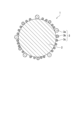
図1は、トナーに含まれるトナー粒子1の一例を示す。図1に示すトナー粒子1は、トナー母粒子2と、トナー母粒子2の表面に付着した外添剤3とを備える。外添剤3は、第1外添剤粒子3a、フッ素含有粒子3b及びシリカ粒子3cを含む。
[Toner particles]
Fig. 1 shows an example of a toner particle 1 contained in a toner. The toner particle 1 shown in Fig. 1 includes a
但し、本発明のトナーの含むトナー粒子は、図1に示すトナー粒子1とは異なる構造であってもよい。具体的には、トナー粒子は、外添剤として、少なくとも第1外添剤粒子及びフッ素含有粒子を含んでいればよい。また、トナー粒子は、外添剤として、第1外添剤粒子、フッ素含有粒子及びシリカ粒子以外の外添剤粒子(以下、その他の外添剤粒子と記載することがある)を更に含んでいてもよい。更に、トナー粒子は、シェル層を備えるトナー粒子(以下、カプセルトナー粒子と記載することがある)であってもよい。カプセルトナー粒子では、トナー母粒子が、例えば結着樹脂を含有するトナーコアと、トナーコアの表面を覆うシェル層とを備える。以上、本発明のトナーに含まれるトナー粒子の詳細について、図1を基に説明した。 However, the toner particles contained in the toner of the present invention may have a structure different from that of the toner particle 1 shown in FIG. 1. Specifically, the toner particles may contain at least the first external additive particles and fluorine-containing particles as external additives. The toner particles may further contain external additive particles other than the first external additive particles, the fluorine-containing particles, and the silica particles (hereinafter, sometimes referred to as other external additive particles) as external additives. Furthermore, the toner particles may be toner particles having a shell layer (hereinafter, sometimes referred to as capsule toner particles). In the capsule toner particles, the toner mother particles have, for example, a toner core containing a binder resin and a shell layer covering the surface of the toner core. The details of the toner particles contained in the toner of the present invention have been described above based on FIG. 1.
[第1外添剤粒子]
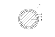
図2は、第1外添剤粒子3aの一例を示す。図2に示す第1外添剤粒子3aは、酸化アルミニウム粒子4と、酸化アルミニウム粒子4を被覆する導電層5と、導電層5を被覆する多層の保護層6とを備える。多層の保護層6は、導電層5を直接被覆する内層6aと、内層6aを被覆する外層6bとを備える。
[First external additive particles]
Fig. 2 shows an example of a first
図3は、第1外添剤粒子3aの図2とは別の一例を示す。図3に示す第1外添剤粒子3aは、酸化アルミニウム粒子4と、酸化アルミニウム粒子4を被覆する導電層5と、導電層5を被覆する単層の保護層7とを備える。図3に示す第1外添剤粒子3aは、図2に示す第1外添剤粒子3aと比較して、多層の保護層6の代わりに単層の保護層7を備えるという点で相違する。
Figure 3 shows another example of the first
以上、第1外添剤粒子の例について、図2及び図3に沿って説明した。但し、第1外添剤粒子の構造は、図2及び図3に限定されない。具体的には、第1外添剤粒子は、導電層及び保護層に加え、他の層を更に備えていてもよい。また、導電層は、単層であることが好ましいが、多層であってもよい。更に、保護層は、単層又は2層であることが好ましいが、3層以上であってもよい。以下、第1外添剤粒子の詳細を更に説明する。 Above, examples of the first external additive particles have been described with reference to Figures 2 and 3. However, the structure of the first external additive particles is not limited to Figures 2 and 3. Specifically, the first external additive particles may further include other layers in addition to the conductive layer and protective layer. The conductive layer is preferably a single layer, but may be multilayered. The protective layer is preferably a single layer or two layers, but may be three or more layers. The details of the first external additive particles will be further described below.
第1外添剤粒子の粉体比抵抗としては、50Ω・cm以下であり、30Ω・cm以下が好ましい。第1外添剤粒子の粉体比抵抗を50Ω・cm以下とすることで、本発明のトナーは、画像濃度安定性に優れる。第1外添剤粒子の粉体比抵抗は実施例に記載の方法又はこれに準拠した方法より測定される。 The powder resistivity of the first external additive particles is 50 Ω·cm or less, and preferably 30 Ω·cm or less. By making the powder resistivity of the first external additive particles 50 Ω·cm or less, the toner of the present invention has excellent image density stability. The powder resistivity of the first external additive particles is measured by the method described in the Examples or a method based thereon.
第1外添剤粒子の個数平均1次粒子径としては、60nm以上600nm以下が好ましく、150nm以上250nm以下がより好ましい。第1外添剤粒子の個数平均1次粒子径を60nm以上とすることで、トナー母粒子に第1外添剤粒子が埋没することを抑制できる。第1外添剤粒子の個数平均1次粒子径を600nm以下とすることで、トナー母粒子から第1外添剤粒子が脱離することを抑制できる。 The number average primary particle diameter of the first external additive particles is preferably 60 nm or more and 600 nm or less, and more preferably 150 nm or more and 250 nm or less. By making the number average primary particle diameter of the first external additive particles 60 nm or more, it is possible to prevent the first external additive particles from being embedded in the toner base particles. By making the number average primary particle diameter of the first external additive particles 600 nm or less, it is possible to prevent the first external additive particles from being detached from the toner base particles.
トナー粒子における第1外添剤粒子の含有量としては、トナー母粒子からの脱離を抑制しながらその機能を十分に発揮させる観点から、トナー母粒子100質量部に対して、0.1質量部以上5.0質量部以下が好ましく、0.3質量部以上2.0質量部以下がより好ましい。 The content of the first external additive particles in the toner particles is preferably 0.1 parts by weight or more and 5.0 parts by weight or less, and more preferably 0.3 parts by weight or more and 2.0 parts by weight or less, per 100 parts by weight of the toner base particles, from the viewpoint of suppressing detachment from the toner base particles while fully exerting its function.
(酸化アルミニウム粒子)
酸化アルミニウム粒子は、第1外添剤粒子の基体である。酸化アルミニウム粒子は、酸化アルミニウム(詳しくは、Al2O3)を含有する。酸化アルミニウム粒子における酸化アルミニウムの含有割合としては、80質量%以上が好ましく、95質量%以上がより好ましく、100質量%が更に好ましい。
(Aluminum oxide particles)
The aluminum oxide particles are the base of the first external additive particles. The aluminum oxide particles contain aluminum oxide (specifically, Al2O3 ). The content of aluminum oxide in the aluminum oxide particles is preferably 80 mass% or more, more preferably 95 mass% or more, and even more preferably 100 mass%.
酸化アルミニウム粒子は、例えば、水酸化アルミニウムを焼成した後に、粉砕機を用いて粉砕することにより得ることができる。 Aluminum oxide particles can be obtained, for example, by calcining aluminum hydroxide and then pulverizing it using a pulverizer.
(導電層)
導電層は、アンチモンドープ酸化スズ(ATO)を含有する。導電層におけるATOの含有割合としては、80質量%以上が好ましく、95質量%以上がより好ましく、100質量%が更に好ましい。
(Conductive Layer)
The conductive layer contains antimony-doped tin oxide (ATO). The content of ATO in the conductive layer is preferably 80% by mass or more, more preferably 95% by mass or more, and even more preferably 100% by mass.
アンチモンドープ酸化スズを含有する導電層で酸化アルミニウム粒子を被覆する方法について説明する。まず、酸化アルミニウム粒子を水系溶媒(例えば、水)に分散させる。次いで、酸化アルミニウム粒子を含む懸濁液に、塩化第二スズ(SnCl4)と三塩化アンチモン(SbCl3)とを塩酸に溶解させた酸水溶液と、アルカリ水溶液(例えば、アンモニア水溶液)とを添加する。これにより、酸化アルミニウム粒子の表面上に被覆層が形成される。その後、被覆層が形成された酸化アルミニウム粒子を焼成(例えば、加熱温度600℃以上800℃以下、加熱時間1時間以上4時間以下)することにより、アンチモンドープ酸化スズを含有する導電層で被覆された酸化アルミニウム粒子が得られる。上述の酸水溶液及びアルカリ水溶液の添加時には、懸濁液のpH及び温度を一定範囲(例えば、pH6.5以上9.0以下、かつ60℃以上80℃以下)に維持するとよい。 A method for coating aluminum oxide particles with a conductive layer containing antimony-doped tin oxide will be described. First, aluminum oxide particles are dispersed in an aqueous solvent (e.g., water). Next, an acid aqueous solution in which stannic chloride ( SnCl4 ) and antimony trichloride ( SbCl3 ) are dissolved in hydrochloric acid, and an alkaline aqueous solution (e.g., an aqueous ammonia solution) are added to the suspension containing aluminum oxide particles. This forms a coating layer on the surface of the aluminum oxide particles. Then, the aluminum oxide particles on which the coating layer is formed are fired (e.g., heating temperature 600°C to 800°C, heating time 1 hour to 4 hours), thereby obtaining aluminum oxide particles coated with a conductive layer containing antimony-doped tin oxide. When the above-mentioned acid aqueous solution and alkaline aqueous solution are added, it is preferable to maintain the pH and temperature of the suspension within a certain range (e.g., pH 6.5 to 9.0, and 60°C to 80°C).
(保護層)
保護層は、導電層の剥離を抑制する。保護層は、単層構造又は多層構造(例えば、2層構造)を有する。具体的には、保護層は、チタネートカップリング剤に由来する成分を含有する層を有するか、又はメチロールメラミン、ウレタン樹脂又は水酸化アルミニウムを含有する内層と、シランカップリング剤に由来する成分を含有する外層とを有する。保護層は、上述の層構造を有するため、疎水性が高く、強度に優れる。詳しくは、チタネートカップリング剤に由来する成分を含有する層は、疎水性が高く、強度に優れるため、単独で保護層としての機能を発揮する。メチロールメラミン、ウレタン樹脂又は水酸化アルミニウムを含有する内層は、強度に優れる。シランカップリング剤に由来する成分を含有する外層は、疎水性が高い。そのため、上述の内層及び外層を組み合わせることで、保護層としての機能を発揮する。
(Protective Layer)
The protective layer suppresses peeling of the conductive layer. The protective layer has a single layer structure or a multilayer structure (for example, a two-layer structure). Specifically, the protective layer has a layer containing a component derived from a titanate coupling agent, or has an inner layer containing methylol melamine, a urethane resin, or aluminum hydroxide, and an outer layer containing a component derived from a silane coupling agent. Since the protective layer has the above-mentioned layer structure, it has high hydrophobicity and excellent strength. In detail, the layer containing a component derived from a titanate coupling agent has high hydrophobicity and excellent strength, so that it functions as a protective layer by itself. The inner layer containing methylol melamine, a urethane resin, or aluminum hydroxide has excellent strength. The outer layer containing a component derived from a silane coupling agent has high hydrophobicity. Therefore, by combining the above-mentioned inner layer and outer layer, it functions as a protective layer.
保護層は、上述した各層に加え、他の層を更に有していてもよい。他の層としては、例えば、シリコーンオイルを含有する層が挙げられる。シリコーンオイルを含有する層は、シランカップリング剤に由来する成分を含有する外層と同様に、疎水性が高いため、外層として適している。 The protective layer may further include other layers in addition to the layers described above. Examples of other layers include a layer containing silicone oil. The layer containing silicone oil is suitable as an outer layer because it has high hydrophobicity, similar to the outer layer containing a component derived from a silane coupling agent.
(チタネートカップリング剤)
チタネートカップリング剤としては、イソプロピルトリイソステアロイルチタネート、イソプロピルトリス(ジオクチルパイロホスフェート)チタネート、イソプロピルトリ(N-アミノエチル-アミノエチル)チタネート、テトラオクチルビス(ジトリデシルホスファイト)チタネート、イソプロピルトリオクタノイルチタネート、イソプロピルジメタクリルイソステアロイルチタネート、イソプロピルトリドデシルベンゼンスルホニルチタネート、イソプロピルイソステアロイルジアクリルチタネート、又はイソプロピルトリ(ジオクチルホスフェート)チタネートが挙げられる。チタネートカップリング剤としては、イソプロピルトリイソステアロイルチタネートが好ましい。
(Titanate coupling agent)
Examples of titanate coupling agents include isopropyl triisostearoyl titanate, isopropyl tris(dioctyl pyrophosphate) titanate, isopropyl tri(N-aminoethyl-aminoethyl) titanate, tetraoctyl bis(ditridecyl phosphite) titanate, isopropyl trioctanoyl titanate, isopropyl dimethacryl isostearoyl titanate, isopropyl tridodecyl benzene sulfonyl titanate, isopropyl isostearoyl diacryl titanate, or isopropyl tri(dioctyl phosphate) titanate. As the titanate coupling agent, isopropyl triisostearoyl titanate is preferred.
(シランカップリング剤)
シランカップリング剤としては、アルキルアルコキシシランが挙げられる。アルキルアルコキシシランが有するアルキル基としては、炭素原子数3以上8以下のアルキル基が好ましい。
(Silane coupling agent)
The silane coupling agent may be an alkylalkoxysilane. The alkyl group contained in the alkylalkoxysilane is preferably an alkyl group having 3 to 8 carbon atoms.
アルキルアルコキシシランとしては、例えば、プロピルトリメトキシシラン(より具体的には、n-プロピルトリメトキシシラン、イソプロピルトリメトキシシラン等)、プロピルトリエトキシシラン(より具体的には、n-プロピルトリエトキシシラン、イソプロピルトリエトキシシラン等)、ブチルトリメトキシシラン(より具体的には、n-ブチルトリメトキシシラン、イソブチルトリメトキシシラン等)、ブチルトリエトキシシラン(より具体的には、n-ブチルトリエトキシシラン、イソブチルトリエトキシシラン等)、ヘキシルトリメトキシシラン(より具体的には、n-ヘキシルトリメトキシシラン等)、ヘキシルトリエトキシシラン(より具体的には、n-ヘキシルトリエトキシシラン等)、オクチルトリメトキシシラン(より具体的には、n-オクチルトリメトキシシラン等)、及びオクチルトリエトキシシラン(より具体的には、n-オクチルトリエトキシシラン等)が挙げられる。 Examples of alkylalkoxysilanes include propyltrimethoxysilane (more specifically, n-propyltrimethoxysilane, isopropyltrimethoxysilane, etc.), propyltriethoxysilane (more specifically, n-propyltriethoxysilane, isopropyltriethoxysilane, etc.), butyltrimethoxysilane (more specifically, n-butyltrimethoxysilane, isobutyltrimethoxysilane, etc.), butyltriethoxysilane (more specifically, n-butyltriethoxysilane, isobutyltriethoxysilane, etc.), hexyltrimethoxysilane (more specifically, n-hexyltrimethoxysilane, etc.), hexyltriethoxysilane (more specifically, n-hexyltriethoxysilane, etc.), octyltrimethoxysilane (more specifically, n-octyltrimethoxysilane, etc.), and octyltriethoxysilane (more specifically, n-octyltriethoxysilane, etc.).
シランカップリング剤としては、アルキルアルコキシシランが好ましく、モノアルキルトリアルコキシシランがより好ましく、イソブチルトリエトキシシランが更に好ましい。 As the silane coupling agent, alkylalkoxysilane is preferred, monoalkyltrialkoxysilane is more preferred, and isobutyltriethoxysilane is even more preferred.
(シリコーンオイル)
シリコーンオイルとしては、ストレートシリコーンオイル(より具体的には、ジメチルシリコーンオイル、メチルフェニルシリコーンオイル、及びメチルハイドロジェンシリコーンオイル等)、反応性の変性シリコーンオイル(より具体的には、アミノ変性シリコーンオイル、エポキシ変性シリコーンオイル、カルボキシル変性シリコーンオイル、メルカプト変性シリコーンオイル、メタクリル酸変性シリコーンオイル、フェノール変性シリコーンオイル、及びアルコール変性シリコーンオイル等)、及び非反応性の変性シリコーンオイル(より具体的には、アルキル変性シリコーンオイル、高級脂肪酸変性シリコーンオイル、フッ素変性シリコーンオイル、ポリエーテル変性シリコーンオイル、及びメチルスチリル変性シリコーンオイル等)が挙げられる。シリコーンオイルとしては、ストレートシリコーンオイルが好ましく、メチルハイドロジェンシリコーンオイルがより好ましい。
(Silicone oil)
Examples of silicone oils include straight silicone oils (more specifically, dimethyl silicone oil, methylphenyl silicone oil, and methylhydrogen silicone oil, etc.), reactive modified silicone oils (more specifically, amino modified silicone oil, epoxy modified silicone oil, carboxyl modified silicone oil, mercapto modified silicone oil, methacrylic acid modified silicone oil, phenol modified silicone oil, and alcohol modified silicone oil, etc.), and non-reactive modified silicone oils (more specifically, alkyl modified silicone oil, higher fatty acid modified silicone oil, fluorine modified silicone oil, polyether modified silicone oil, and methylstyryl modified silicone oil, etc.). As silicone oils, straight silicone oils are preferred, and methylhydrogen silicone oils are more preferred.
保護層を形成する方法としては、例えば、導電層で被覆された酸化アルミニウム粒子を含む溶液を攪拌しながら保護層の原料成分を滴下又は噴霧した後に加熱する方法、及び保護層の原料成分の溶液を攪拌しながらその溶液中に導電層で被覆された酸化アルミニウム粒子を添加した後に加熱する方法が挙げられる。 Methods for forming the protective layer include, for example, a method in which the raw material components of the protective layer are dropped or sprayed into a solution containing aluminum oxide particles coated with a conductive layer while stirring the solution, and then heated; and a method in which aluminum oxide particles coated with a conductive layer are added to a solution of the raw material components of the protective layer while stirring the solution, and then heated.
保護層の原料成分としては、ポリ塩化アルミニウムと塩基性溶液(例えば、水酸化ナトリウム水溶液)との組み合わせ、チタネートカップリング剤、メラミン樹脂、ウレタン樹脂、シランカップリング剤及びシリコーンオイルが挙げられる。なお、保護層の原料成分としてポリ塩化アルミニウム及び塩基性溶液の組み合わせを用いた場合、水酸化アルミニウムを含有する保護層が形成される。 The raw material components of the protective layer include a combination of polyaluminum chloride and a basic solution (e.g., an aqueous sodium hydroxide solution), a titanate coupling agent, a melamine resin, a urethane resin, a silane coupling agent, and a silicone oil. When a combination of polyaluminum chloride and a basic solution is used as the raw material components of the protective layer, a protective layer containing aluminum hydroxide is formed.
第1外添剤粒子における保護層の層構造としては、下記(A)~(C)が好ましい。
(A)チタネートカップリング剤に由来する成分を含有する層を含む単層構造。
(B)チタネートカップリング剤に由来する成分を含有する内層と、シランカップリング剤に由来する成分又はシリコーンオイルを含有する外層とを含む2層構造。
(C)メチロールメラミン、ウレタン樹脂又は水酸化アルミニウムを含有する内層と、シランカップリング剤に由来する成分を含有する外層とを含む2層構造。
The layer structure of the protective layer in the first external additive particles is preferably any of the following (A) to (C).
(A) A single layer structure including a layer containing a component derived from a titanate coupling agent.
(B) A two-layer structure including an inner layer containing a component derived from a titanate coupling agent and an outer layer containing a component derived from a silane coupling agent or a silicone oil.
(C) A two-layer structure including an inner layer containing methylol melamine, a urethane resin or aluminum hydroxide and an outer layer containing a component derived from a silane coupling agent.
第1外添剤粒子は、酸化アルミニウム粒子に対し、導電層及び保護層を上述の方法により順次被覆することにより調製できる。 The first external additive particles can be prepared by coating aluminum oxide particles with a conductive layer and a protective layer in sequence using the method described above.
[フッ素含有粒子]
フッ素含有粒子は、フッ素成分を含有する粒子である。フッ素成分としては、例えば、フッ素樹脂、フッ素含有シランカップリング剤に由来する成分、及びフッ素変性シリコーンオイルが挙げられる。
[Fluorine-containing particles]
The fluorine-containing particles are particles that contain a fluorine component, such as a fluorine resin, a component derived from a fluorine-containing silane coupling agent, or a fluorine-modified silicone oil.
フッ素含有粒子としては、フッ素樹脂粒子、又は第2外添剤粒子が好ましい。第2外添剤粒子は、基体と、基体を被覆するフッ素成分層とを含む。フッ素成分層は、フッ素含有シランカップリング剤に由来する成分又はフッ素変性シリコーンオイルを含有する。 The fluorine-containing particles are preferably fluororesin particles or second external additive particles. The second external additive particles include a substrate and a fluorine component layer that covers the substrate. The fluorine component layer contains a component derived from a fluorine-containing silane coupling agent or a fluorine-modified silicone oil.
図4は、フッ素含有粒子3bの一例を示す。図4に示すフッ素含有粒子3bは、フッ素樹脂粒子8である。図5は、フッ素含有粒子3bの図4とは別の一例を示す。図5に示すフッ素含有粒子3bは、基体9と、基体9を被覆するフッ素成分層10とを備える第2外添剤粒子である。
Figure 4 shows an example of a fluorine-containing
以上、フッ素含有粒子の例について、図面に沿って説明した。但し、フッ素含有粒子の構造は、図4及び図5に限定されない。具体的には、第2外添剤粒子は、フッ素成分層以外の他の層を更に備えていてもよい。また、フッ素成分層は、単層であることが好ましいが、多層であってもよい。以下、フッ素含有粒子の詳細を更に説明する。 Above, examples of fluorine-containing particles have been described with reference to the drawings. However, the structure of the fluorine-containing particles is not limited to those shown in Figs. 4 and 5. Specifically, the second external additive particles may further include layers other than the fluorine component layer. In addition, the fluorine component layer is preferably a single layer, but may be multilayered. Details of the fluorine-containing particles will be further described below.
(フッ素樹脂粒子)
フッ素樹脂粒子は、フッ素樹脂を含有する。フッ素樹脂粒子におけるフッ素樹脂の含有割合としては、80質量%以上が好ましく、95質量%以上がより好ましく、100質量%が更に好ましい。
(Fluororesin particles)
The fluororesin particles contain a fluororesin. The content of the fluororesin in the fluororesin particles is preferably 80% by mass or more, more preferably 95% by mass or more, and even more preferably 100% by mass.
フッ素樹脂としては、例えば、ポリテトラフルオロエチレン(PTFE)、パーフルオロアルコキシフッ素樹脂、ポリクロロトリフルオロエチレン、ポリフッ化ビニリデン、ポリジクロロジフルオロエチレン、テトラフルオロエチレn-パーフルオロアルキルビニルエーテル共重合体、テトラフルオロエチレン-ヘキサフルオロプロピレン共重合体、テトラフルオロエチレン-エチレン共重合体、テトラフルオロエチレン-ヘキサフルオロプロピレン-パーフルオロアルキルビニルエーテル共重合体、テトラフルオロエチレン-パーフルオロアルコキシエチレン共重合体が挙げられる。フッ素樹脂としては、ポリテトラフルオロエチレン又はパーフルオロアルコキシフッ素樹脂が好ましい。 Examples of fluororesins include polytetrafluoroethylene (PTFE), perfluoroalkoxy fluororesin, polychlorotrifluoroethylene, polyvinylidene fluoride, polydichlorodifluoroethylene, tetrafluoroethylene n-perfluoroalkyl vinyl ether copolymer, tetrafluoroethylene-hexafluoropropylene copolymer, tetrafluoroethylene-ethylene copolymer, tetrafluoroethylene-hexafluoropropylene-perfluoroalkyl vinyl ether copolymer, and tetrafluoroethylene-perfluoroalkoxy ethylene copolymer. As the fluororesin, polytetrafluoroethylene or perfluoroalkoxy fluororesin is preferred.
(第2外添剤粒子)
第2外添剤粒子は、基体と、基体を被覆するフッ素成分層とを含む。フッ素成分層は、フッ素含有シランカップリング剤に由来する成分又はフッ素変性シリコーンオイルを含有する。
(Second External Additive Particles)
The second external additive particle includes a substrate and a fluorine component layer covering the substrate. The fluorine component layer contains a component derived from a fluorine-containing silane coupling agent or a fluorine-modified silicone oil.
第2外添剤粒子において、基体100質量部に対するフッ素成分層の質量としては、1質量部以上40質量部以下が好ましく、5質量部以上20質量部以下がより好ましい。 In the second external additive particles, the mass of the fluorine component layer relative to 100 parts by mass of the base is preferably 1 part by mass or more and 40 parts by mass or less, and more preferably 5 parts by mass or more and 20 parts by mass or less.
フッ素成分層を形成する方法としては、例えば、基体を含む溶液を攪拌しながらフッ素成分層の原料成分を滴下又は噴霧した後に加熱する方法、及びフッ素成分層の原料成分の溶液を攪拌しながらその溶液中に基体を添加した後に加熱する方法が挙げられる。 Methods for forming a fluorine component layer include, for example, a method in which the raw material components of the fluorine component layer are dropped or sprayed into a solution containing a substrate while stirring the solution, and then heated; and a method in which the substrate is added to a solution of the raw material components of the fluorine component layer while stirring the solution, and then heated.
(基体)
第2外添剤粒子の基体としては、例えば、シリカ粒子、金属酸化物粒子(例えば、酸化アルミニウム粒子及び酸化チタン粒子)及び樹脂粒子が挙げられる。第2外添剤粒子の基体としては、シリカ粒子が好ましい。
(Base)
Examples of the substrate of the second external additive particles include silica particles, metal oxide particles (for example, aluminum oxide particles and titanium oxide particles), and resin particles. As the substrate of the second external additive particles, silica particles are preferred.
(フッ素含有シランカップリング剤)
フッ素含有シランカップリング剤としては、例えば、CF3(CH2)2Si(OCH3)3、C4F9CH2CH2Si(OCH3)3、C8F17CH2CH2Si(OCH3)3、C7F15COOCH2CH2CH2Si(OCH3)3、C7F15COSCH2CH2CH2Si(OCH3)3、C7F15CONHCH2CH2CH2Si(OC2H5)3、C7F15CONHCH2CH2CH2Si(OCH3)3、C8F17SO2NHCH2CH2CH2Si(OC2H5)3、C8F17CH2CH2SCH2CH2Si(OCH3)3、C10F21CH2CH2SCH2CH2Si(OCH3)3、C8F17CH2CH2SiCH3(OCH3)2、C8F17SO2N(CH2CH2CH3)CH2CH2CH2Si(OCH3)3、及びC8F17SO2NHCH2CH2N(SO2C8F17)CH2CH2CH2Si(OCH3)3が挙げられる。フッ素含有シランカップリング剤としては、CF3(CH2)2Si(OCH3)3が好ましい。
(Fluorine-containing silane coupling agent)
Examples of fluorine - containing silane coupling agents include CF3( CH2 ) 2Si ( OCH3) 3 , C4F9CH2CH2Si ( OCH3 ) 3 , C8F17CH2CH2Si ( OCH3 ) 3 , C7F15COOCH2CH2CH2Si ( OCH3 ) 3 , C7F15COSCH2CH2CH2Si ( OCH3 ) 3 , C7F15CONHCH2CH2CH2Si ( OC2H5 ) 3 , C7F15CONHCH2CH2CH2Si ( OCH3 ) 3 , C8F 17 SO2NHCH2CH2CH2Si ( OC2H5 ) 3 , C8F17CH2CH2SCH2CH2Si ( OCH3 ) 3 , C10F21CH2CH2SCH2CH2 Si ( OCH3 ) 3 , C8F17CH2CH2SiCH3 ( OCH3 ) 2 , C8F17SO2N ( CH2CH2CH3 ) CH2CH2CH2Si ( OCH3 ) 3 , and C8 F17SO2NHCH2CH2N ( SO2C8F17 ) CH2CH 2CH2Si ( OCH3 ) 3 is preferred. As the fluorine-containing silane coupling agent, CF3 ( CH2 ) 2Si ( OCH3 ) 3 is preferred.
(フッ素変性シリコーンオイル)
フッ素変性シリコーンオイルとしては、例えば、フルオロアルキル基を有するシリコーンオイル(例えば、信越化学工業株式会社製「FL-100」)が挙げられる。
(Fluorine modified silicone oil)
An example of the fluorine-modified silicone oil is a silicone oil having a fluoroalkyl group (eg, "FL-100" manufactured by Shin-Etsu Chemical Co., Ltd.).
フッ素含有粒子の個数平均1次粒子径としては、50nm以上300nm以下が好ましく、75nm以上150nm以下がより好ましい。フッ素含有粒子の個数平均1次粒子径を50nm以上とすることで、トナー母粒子にフッ素含有粒子が埋没することを抑制できる。フッ素含有粒子の個数平均1次粒子径を300nm以下とすることで、トナー母粒子からフッ素含有粒子が脱離することを抑制できる。 The number-average primary particle diameter of the fluorine-containing particles is preferably 50 nm or more and 300 nm or less, and more preferably 75 nm or more and 150 nm or less. By making the number-average primary particle diameter of the fluorine-containing particles 50 nm or more, it is possible to prevent the fluorine-containing particles from being embedded in the toner base particles. By making the number-average primary particle diameter of the fluorine-containing particles 300 nm or less, it is possible to prevent the fluorine-containing particles from being detached from the toner base particles.
トナー粒子におけるフッ素含有粒子の含有量としては、トナー母粒子からの脱離を抑制しながらその機能を十分に発揮させる観点から、トナー母粒子100質量部に対して、0.05質量部以上3.0質量部以下が好ましく、0.1質量部以上1.0質量部以下がより好ましい。 The content of the fluorine-containing particles in the toner particles is preferably 0.05 parts by weight or more and 3.0 parts by weight or less, and more preferably 0.1 parts by weight or more and 1.0 parts by weight or less, per 100 parts by weight of the toner base particles, from the viewpoint of suppressing detachment from the toner base particles while fully exerting its function.
[シリカ粒子]
外添剤粒子として用いるシリカ粒子としては、正帯電性を付与する表面処理が施されたシリカ粒子が好ましい。シリカ粒子の個数平均1次粒子径としては、10nm以上300nm以下が好ましく、15nm以上80nm以下がより好ましい。シリカ粒子の個数平均1次粒子径を10nm以上とすることで、トナー母粒子への埋没を抑制できる。シリカ粒子の個数平均1次粒子径を300nm以下とすることで、トナー母粒子からの脱離を抑制できる。
[Silica particles]
The silica particles used as the external additive particles are preferably silica particles that have been subjected to a surface treatment to impart positive charging properties. The number-average primary particle diameter of the silica particles is preferably 10 nm or more and 300 nm or less, and more preferably 15 nm or more and 80 nm or less. By making the number-average primary particle diameter of the
トナー母粒子からの脱離を抑制しながらシリカ粒子の機能を十分に発揮させる観点から、トナー粒子におけるシリカ粒子の含有量としては、トナー母粒子100質量部に対して、0.1質量部以上15.0質量部以下が好ましく、0.5質量部以上3.0質量部以下がより好ましい。 From the viewpoint of fully exerting the function of the silica particles while suppressing detachment from the toner base particles, the content of the silica particles in the toner particles is preferably 0.1 parts by weight or more and 15.0 parts by weight or less, and more preferably 0.5 parts by weight or more and 3.0 parts by weight or less, per 100 parts by weight of the toner base particles.
(その他の外添剤粒子)
その他の外添剤粒子としては、例えば、金属酸化物(具体的には、酸化アルミニウム、酸化マグネシウム、酸化亜鉛等)の粒子、脂肪酸金属塩(具体的には、ステアリン酸亜鉛等)のような有機酸化合物の粒子、及び樹脂粒子が挙げられる。
(Other external additive particles)
Other examples of external additive particles include particles of metal oxides (specifically, aluminum oxide, magnesium oxide, zinc oxide, etc.), particles of organic acid compounds such as fatty acid metal salts (specifically, zinc stearate, etc.), and resin particles.
[トナー母粒子]
トナー母粒子としては、特に限定されず、公知のトナーにおけるトナー母粒子を用いることができる。トナー母粒子は、例えば主成分として結着樹脂を含有する。トナー母粒子は、必要に応じて、内添剤(例えば、着色剤、離型剤及び電荷制御剤の少なくとも1つ)を更に含有してもよい。トナー母粒子の製造方法としては、粉砕法及び凝集法が挙げられ、粉砕法が好ましい。
[Toner Base Particles]
The toner base particles are not particularly limited, and toner base particles in known toners can be used. The toner base particles contain, for example, a binder resin as a main component. The toner base particles may further contain an internal additive (for example, at least one of a colorant, a release agent, and a charge control agent) as necessary. Methods for producing the toner base particles include a pulverization method and an aggregation method, and the pulverization method is preferred.
良好な画像を形成する観点から、トナー母粒子の体積中位径(D50)としては、4μm以上9μm以下が好ましい。 From the viewpoint of forming a good image, the volume median diameter (D 50 ) of the toner base particles is preferably 4 μm or more and 9 μm or less.
(結着樹脂)
低温定着性に優れたトナーを提供する観点から、トナー母粒子は、結着樹脂として熱可塑性樹脂を含有することが好ましく、結着樹脂全体の85質量%以上の割合で熱可塑性樹脂を含有することがより好ましい。熱可塑性樹脂としては、例えば、スチレン系樹脂、アクリル酸エステル系樹脂、オレフィン系樹脂(より具体的には、ポリエチレン樹脂、ポリプロピレン樹脂等)、ビニル樹脂(より具体的には、塩化ビニル樹脂、ポリビニルアルコール、ビニルエーテル樹脂、N-ビニル樹脂等)、ポリエステル樹脂、ポリアミド樹脂、及びウレタン樹脂が挙げられる。また、これら各樹脂の共重合体、すなわち上記樹脂中に任意の繰り返し単位が導入された共重合体(より具体的には、スチレン-アクリル酸エステル系樹脂、スチレン-ブタジエン系樹脂等)も、結着樹脂として使用できる。結着樹脂としては、ポリエステル樹脂が好ましい。
(Binder resin)
From the viewpoint of providing a toner having excellent low-temperature fixing properties, the toner base particles preferably contain a thermoplastic resin as a binder resin, and more preferably contain a thermoplastic resin in a proportion of 85% by mass or more of the total binder resin. Examples of the thermoplastic resin include styrene-based resins, acrylic acid ester-based resins, olefin-based resins (more specifically, polyethylene resins, polypropylene resins, etc.), vinyl resins (more specifically, vinyl chloride resins, polyvinyl alcohol, vinyl ether resins, N-vinyl resins, etc.), polyester resins, polyamide resins, and urethane resins. Copolymers of these resins, that is, copolymers in which any repeating unit is introduced into the above resins (more specifically, styrene-acrylic acid ester-based resins, styrene-butadiene-based resins, etc.), can also be used as the binder resin. As the binder resin, polyester resins are preferred.
トナー母粒子における結着樹脂の含有割合としては、60質量%以上95質量%以下が好ましく、75質量%以上90質量%以下がより好ましい。 The content of the binder resin in the toner base particles is preferably 60% by mass or more and 95% by mass or less, and more preferably 75% by mass or more and 90% by mass or less.
(着色剤)
トナー母粒子は、着色剤を含有していてもよい。着色剤としては、トナーの色に合わせて公知の顔料又は染料を用いることができる。トナーを用いて高画質な画像を形成する観点から、着色剤の含有量としては、結着樹脂100質量部に対して、1質量部以上20質量部以下が好ましい。
(Coloring Agent)
The toner base particles may contain a colorant. As the colorant, a known pigment or dye can be used in accordance with the color of the toner. From the viewpoint of forming a high-quality image using the toner, the content of the colorant is preferably 1 part by mass or more and 20 parts by mass or less with respect to 100 parts by mass of the binder resin.
トナー母粒子は、黒色着色剤を含有していてもよい。黒色着色剤の例としては、カーボンブラックが挙げられる。また、黒色着色剤は、イエロー着色剤、マゼンタ着色剤、及びシアン着色剤を用いて黒色に調色された着色剤であってもよい。 The toner base particles may contain a black colorant. An example of a black colorant is carbon black. The black colorant may also be a colorant that has been toned to black using a yellow colorant, a magenta colorant, and a cyan colorant.
トナー母粒子は、カラー着色剤を含有していてもよい。カラー着色剤としては、イエロー着色剤、マゼンタ着色剤、及びシアン着色剤が挙げられる。 The toner base particles may contain color colorants. Color colorants include yellow colorants, magenta colorants, and cyan colorants.
(離型剤)
トナー母粒子は、離型剤を含有していてもよい。離型剤は、例えば、トナーに耐オフセット性を付与する目的で使用される。トナーに充分な耐オフセット性を付与させる観点から、離型剤の含有量としては、結着樹脂100質量部に対して、1質量部以上20質量部以下が好ましい。
(Release Agent)
The toner base particles may contain a release agent. The release agent is used, for example, for the purpose of imparting offset resistance to the toner. From the viewpoint of imparting sufficient offset resistance to the toner, the content of the release agent is preferably 1 part by mass or more and 20 parts by mass or less with respect to 100 parts by mass of the binder resin.
離型剤としては、例えば、脂肪族炭化水素系ワックス、脂肪族炭化水素系ワックスの酸化物、植物系ワックス、動物系ワックス、鉱物系ワックス、脂肪酸エステルを主成分とするエステルワックス、及び脂肪酸エステルの一部又は全部が脱酸化したワックスが挙げられる。脂肪族炭化水素系ワックスとしては、例えば、低分子量ポリエチレン、低分子量ポリプロピレン、ポリオレフィン共重合体、ポリオレフィンワックス、マイクロクリスタリンワックス、パラフィンワックス及びフィッシャートロプシュワックスが挙げられる。脂肪族炭化水素系ワックスの酸化物としては、例えば、酸化ポリエチレンワックス、及び酸化ポリエチレンワックスのブロック共重合体が挙げられる。植物系ワックスとしては、例えば、キャンデリラワックス、カルナバワックス、木ろう、ホホバろう、及びライスワックスが挙げられる。動物系ワックスとしては、例えば、みつろう、ラノリン及び鯨ろうが挙げられる。鉱物系ワックスとしては、例えば、オゾケライト、セレシン、及びペトロラタムが挙げられる。脂肪酸エステルを主成分とするエステルワックスとしては、例えば、モンタン酸エステルワックス及びカスターワックスが挙げられる。脂肪酸エステルの一部又は全部が脱酸化したワックスとしては、例えば、脱酸カルナバワックスが挙げられる。離型剤としては、カルナバワックスが好ましい。 Examples of the release agent include aliphatic hydrocarbon waxes, oxides of aliphatic hydrocarbon waxes, vegetable waxes, animal waxes, mineral waxes, ester waxes mainly composed of fatty acid esters, and waxes in which some or all of the fatty acid esters have been deoxidized. Examples of the aliphatic hydrocarbon waxes include low molecular weight polyethylene, low molecular weight polypropylene, polyolefin copolymers, polyolefin waxes, microcrystalline waxes, paraffin waxes, and Fischer-Tropsch waxes. Examples of the oxides of aliphatic hydrocarbon waxes include oxidized polyethylene waxes and block copolymers of oxidized polyethylene waxes. Examples of the vegetable waxes include candelilla wax, carnauba wax, Japan wax, jojoba wax, and rice wax. Examples of the animal waxes include beeswax, lanolin, and spermaceti. Examples of the mineral waxes include ozokerite, ceresin, and petrolatum. Examples of the ester waxes mainly composed of fatty acid esters include montan acid ester wax and castor wax. An example of a wax in which the fatty acid esters have been partially or completely deoxidized is deoxidized carnauba wax. Carnauba wax is preferred as a release agent.
トナー母粒子が離型剤を含有する場合、結着樹脂と離型剤との相溶性を改善するために、相溶化剤をトナー母粒子に添加してもよい。 When the toner base particles contain a release agent, a compatibilizer may be added to the toner base particles to improve the compatibility between the binder resin and the release agent.
(電荷制御剤)
トナー母粒子は、電荷制御剤を含有してもよい。電荷制御剤は、例えば、優れた帯電安定性又は優れた帯電立ち上がり特性を有するトナーを提供する目的で使用される。トナーの帯電立ち上がり特性は、短時間で所定の帯電レベルにトナーを帯電させることができるか否かの指標になる。トナー母粒子に正帯電性の電荷制御剤を含有させることで、トナー母粒子のカチオン性を強めることができる。
(Charge Control Agent)
The toner base particles may contain a charge control agent. The charge control agent is used, for example, for the purpose of providing a toner having excellent charge stability or excellent charge rise characteristics. The charge rise characteristics of a toner are an index of whether or not the toner can be charged to a predetermined charge level in a short period of time. By incorporating a positively chargeable charge control agent in the toner base particles, the cationic nature of the toner base particles can be enhanced.
正帯電性の電荷制御剤としては、例えば、アジン化合物、直接染料、酸性染料、アルコキシル化アミン、アルキルアミド、4級アンモニウム塩、及び4級アンモニウムカチオン基を含む樹脂が挙げられる。電荷制御剤としては、4級アンモニウム塩、又は4級アンモニウムカチオン基を含む樹脂が好ましい。 Examples of positively charged charge control agents include azine compounds, direct dyes, acid dyes, alkoxylated amines, alkylamides, quaternary ammonium salts, and resins containing quaternary ammonium cationic groups. As charge control agents, quaternary ammonium salts or resins containing quaternary ammonium cationic groups are preferred.
帯電安定性に優れるトナーを得る観点から、電荷制御剤の含有量としては、結着樹脂100質量部に対して、0.1質量部以上30質量部以下が好ましく、3質量部以上10質量部以下がより好ましい。 From the viewpoint of obtaining a toner with excellent charging stability, the content of the charge control agent is preferably 0.1 parts by weight or more and 30 parts by weight or less, and more preferably 3 parts by weight or more and 10 parts by weight or less, per 100 parts by weight of the binder resin.
[トナーの製造方法]
トナーは、例えば、トナー母粒子の調製工程と、外添工程とを備える製造方法により製造できる。
[Toner manufacturing method]
The toner can be produced, for example, by a production method including a step of preparing toner base particles and a step of adding an external ingredient.
(トナー母粒子の調製工程)
トナー母粒子の調製工程では、例えば、凝集法又は粉砕法によりトナー母粒子を調製する。
(Toner Base Particle Preparation Process)
In the toner base particle preparation step, the toner base particles are prepared by, for example, an aggregation method or a pulverization method.
凝集法は、例えば、凝集工程及び合一化工程を含む。凝集工程では、トナー母粒子を構成する成分を含む微粒子を水性媒体中で凝集させて、凝集粒子を形成する。合一化工程では、凝集粒子に含まれる成分を水性媒体中で合一化させてトナー母粒子を形成する。 The aggregation method includes, for example, an aggregation step and a coalescence step. In the aggregation step, fine particles containing the components that make up the toner base particles are aggregated in an aqueous medium to form aggregated particles. In the coalescence step, the components contained in the aggregated particles are coalesced in the aqueous medium to form the toner base particles.
次に粉砕法を説明する。粉砕法によれば、比較的容易にトナー母粒子を調製できる上、製造コストの低減が可能である。粉砕法でトナー母粒子を調製する場合、トナー母粒子の調製工程は、例えば溶融混練工程と、粉砕工程とを備える。トナー母粒子の調製工程は、溶融混練工程の前に混合工程を更に備えてもよい。また、トナー母粒子の調製工程は、粉砕工程後に、微粉砕工程及び分級工程の少なくとも一方を更に備えてもよい。 Next, the pulverization method will be described. The pulverization method allows the preparation of toner base particles relatively easily and also allows for reduced manufacturing costs. When preparing toner base particles by the pulverization method, the preparation process of the toner base particles includes, for example, a melt-kneading process and a pulverization process. The preparation process of the toner base particles may further include a mixing process before the melt-kneading process. In addition, the preparation process of the toner base particles may further include at least one of a fine pulverization process and a classification process after the pulverization process.
混合工程では、結着樹脂と、必要に応じて添加する内添剤とを混合して、混合物を得る。溶融混練工程では、トナー材料を溶融及び混練して、溶融混練物を得る。トナー材料としては、例えば混合工程で得られる混合物が用いられる。粉砕工程では、得られた溶融混練物を、例えば室温(25℃)まで冷却した後、粉砕して粉砕物を得る。粉砕工程で得られた粉砕物の小径化が必要な場合は、粉砕物を更に粉砕する工程(微粉砕工程)を実施してもよい。また、粉砕物の粒径を揃える場合は、得られた粉砕物を分級する工程(分級工程)を実施してもよい。以上の工程により、粉砕物であるトナー母粒子が得られる。 In the mixing process, the binder resin is mixed with an internal additive that is added as necessary to obtain a mixture. In the melting and kneading process, the toner materials are melted and kneaded to obtain a molten and kneaded product. For example, the mixture obtained in the mixing process is used as the toner material. In the pulverizing process, the molten and kneaded product obtained is cooled, for example, to room temperature (25°C), and then pulverized to obtain a pulverized product. If it is necessary to reduce the diameter of the pulverized product obtained in the pulverizing process, a process of further pulverizing the pulverized product (fine pulverizing process) may be performed. In addition, if the particle size of the pulverized product is to be uniform, a process of classifying the pulverized product obtained (classifying process) may be performed. Through the above processes, the pulverized product, that is, the toner base particles, is obtained.
(外添工程)
本工程では、トナー母粒子の表面に第1外添剤粒子及びフッ素樹脂粒子を含む外添剤を付着させることでトナー粒子を得る。トナー母粒子の表面に外添剤を付着させる方法としては、特に限定されないが、例えば、トナー母粒子及び外添剤をミキサー等で攪拌する方法が挙げられる。
(External Addition Process)
In this process, the toner particles are obtained by adhering the external additive, which includes the first external additive particles and the fluororesin particles, to the surfaces of the toner base particles. The method for adhering the external additive to the surfaces of the toner base particles is not particularly limited, but may be, for example, a method in which the toner base particles and the external additive are stirred with a mixer or the like.
以下、実施例を用いて本発明を更に具体的に説明する。しかし、本発明は実施例の範囲に何ら限定されない。 The present invention will be described in more detail below using examples. However, the present invention is not limited to the scope of the examples.
(個数平均1次粒子径の測定)
外添剤粒子の個数平均1次粒子径は、以下の方法で測定した。まず、透過電子顕微鏡(TEM)(株式会社日立ハイテクノロジーズ製「H-7100FA」)を用いて、測定対象となる外添剤粒子を倍率1000000倍で観察して、100個以上の外添剤粒子のTEM写真を撮影した。得られたTEM写真の中から、100個の外添剤粒子のTEM写真を任意に選択した。任意に選択されたTEM写真について、画像解析ソフトウェア(三谷商事株式会社製「WinROOF」)を用いて、円相当径を測定した。測定された円相当径の個数平均値を算出した。算出された個数平均値を外添剤粒子の個数平均1次粒子径とした。
(Measurement of number average primary particle size)
The number average primary particle diameter of the external additive particles was measured by the following method. First, a transmission electron microscope (TEM) (Hitachi High-Technologies Corporation "H-7100FA") was used to observe the external additive particles to be measured at a magnification of 1,000,000 times, and TEM photographs of 100 or more external additive particles were taken. From the obtained TEM photographs, TEM photographs of 100 external additive particles were arbitrarily selected. For the arbitrarily selected TEM photographs, the circle equivalent diameter was measured using image analysis software (Mitani Shoji Co., Ltd. "WinROOF"). The number average value of the measured circle equivalent diameters was calculated. The calculated number average value was taken as the number average primary particle diameter of the external additive particles.
(粉体比抵抗の測定)
電気抵抗計(株式会社アドバンテスト製「R6561」)の円筒状の測定セルに測定対象(第1外添剤粒子)5gを投入した。なお、測定セルは、底面が金属製の電極であり、筒部がフッ素樹脂製であった。続けて、測定セルに充填した測定対象に電気抵抗計の電極(superscript:2、長さ25.4mm)を繋いだ。この電極に1kgの荷重をかけた。続けて、両電極間にDC電圧10Vを印加し、印加開始から1分後における測定対象の電気抵抗を測定した。なお、印加開始から測定終了までの間は1kgの荷重を電極にかけ続けた。測定は、温度25℃、湿度50%RHの環境下で行った。そして、測定された電気抵抗の値と、電気抵抗測定時における測定対象(詳しくは、測定セルに充填された測定対象)の寸法とに基づき、下記式に基づいて測定対象の粉体比抵抗(体積固有抵抗値)を求めた。
粉体比抵抗[Ω・cm]=電気抵抗値×電流路の断面積/電流路の長さ
(Measurement of powder resistivity)
5 g of the measurement object (first external additive particles) was put into a cylindrical measurement cell of an electrical resistance meter ("R6561" manufactured by Advantest Corporation). The bottom of the measurement cell was a metal electrode, and the cylindrical part was made of fluororesin. Then, the electrode (superscript: 2, length 25.4 mm) of the electrical resistance meter was connected to the measurement object filled in the measurement cell. A load of 1 kg was applied to this electrode. Then, a DC voltage of 10 V was applied between both electrodes, and the electrical resistance of the measurement object was measured 1 minute after the start of application. A load of 1 kg was applied to the electrode from the start of application to the end of measurement. The measurement was performed in an environment with a temperature of 25 ° C. and a humidity of 50% RH. Then, based on the measured electrical resistance value and the dimensions of the measurement object (specifically, the measurement object filled in the measurement cell) at the time of electrical resistance measurement, the powder resistivity (volume resistivity) of the measurement object was calculated based on the following formula.
Powder resistivity [Ω cm] = Electrical resistance value × Cross-sectional area of current path / Length of current path
(脱離Sn強度の測定)
ガラス瓶に、測定対象(第1外添剤粒子)5gと、エタノール25gとを投入し、沈殿物がなくなるまでハンドシェイクし、混合物を得た。次に、混合物に対して、卓上超音波分散機(株式会社エスエヌディ製「US-2KS」、出力:100W、発振周波数:28kHz)を用いて、超音波処理を1分間施した。次に、混合物に対して、エタノール10gを更に添加し、沈殿物がなくなるまでハンドシェイクした。次に、混合物に対して、超音波分散機(超音波工業株式会社製「ミニウェルダーUPW0128A1H」、出力:100W、発振周波数:28kHz)を用いて、超音波処理を5分間施した。次に、混合物を遠心管に移し、8000rpmで1分間の遠心分離処理を行った。次に、遠心分離後の混合物から上澄みを回収した。上述の上澄み1000μLを、X線測定用の微量粉末用容器(株式会社リガク製「3399O053」、外径20mm)に添加し、上澄みを乾燥させた。上澄みが添加された微量粉末用容器を用いて、以下の条件で蛍光X線分析を行った。これにより、測定対象にストレス(超音波処理)を加えた際にエタノールに脱離するSnの強度を測定した。
(Measurement of desorbed Sn intensity)
5 g of the measurement target (first external additive particles) and 25 g of ethanol were put into a glass bottle, and the mixture was shaken by hand until no precipitate was found, to obtain a mixture. Next, the mixture was subjected to ultrasonic treatment for 1 minute using a tabletop ultrasonic disperser ("US-2KS" manufactured by SND Co., Ltd., output: 100 W, oscillation frequency: 28 kHz). Next, 10 g of ethanol was further added to the mixture, and the mixture was shaken by hand until no precipitate was found. Next, the mixture was subjected to ultrasonic treatment for 5 minutes using an ultrasonic disperser ("Mini Welder UPW0128A1H" manufactured by Ultrasonic Industries Co., Ltd., output: 100 W, oscillation frequency: 28 kHz). Next, the mixture was transferred to a centrifuge tube, and centrifuged at 8000 rpm for 1 minute. Next, the supernatant was collected from the mixture after centrifugation. 1000 μL of the above-mentioned supernatant was added to a container for trace powder for X-ray measurement (Rigaku Corporation "3399O053", outer diameter 20 mm), and the supernatant was dried. Using the container for trace powder to which the supernatant was added, fluorescent X-ray analysis was performed under the following conditions. This allowed the measurement of the intensity of Sn desorbed into ethanol when stress (ultrasonic treatment) was applied to the measurement object.
(蛍光X線分析)
・分析装置:走査型蛍光X線分析装置(株式会社リガク製「ZSX」)
・X線管球(X線源):Rh(ロジウム)
・励起条件:管電圧50kV、管電流50mA
・測定領域(X線照射範囲):直径30mm
・測定元素:Sn
(X-ray fluorescence analysis)
・Analysis equipment: Scanning X-ray fluorescence analyzer ("ZSX" manufactured by Rigaku Corporation)
・X-ray tube (X-ray source): Rh (rhodium)
Excitation conditions: tube voltage 50 kV, tube current 50 mA
Measurement area (X-ray irradiation range): diameter 30 mm
Measurement element: Sn
<トナーの調製>
以下の方法により、実施例1~19及び比較例1~12のトナーを調製した。以下の説明において、「粉砕機」とは、日本ニューマチック工業株式会社製「ジェットミル(登録商標)I-2型」を示す。この粉砕機は、衝突板としてセラミック製の平板を使用した。「攪拌装置」とは、モーター(アズワン株式会社販売「アズワントルネードモーター1-5472-04」)に攪拌羽根(アズワン株式会社販売「アズワン攪拌羽根R-1345型」)を取り付けた装置を示す。
<Toner Preparation>
The toners of Examples 1 to 19 and Comparative Examples 1 to 12 were prepared by the following method. In the following description, the "pulverizer" refers to "Jet Mill (registered trademark) I-2 type" manufactured by Japan Pneumatic Mfg. Co., Ltd. This pulverizer used a ceramic flat plate as a collision plate. The "agitator" refers to a device in which an agitator blade ("AS ONE Agitator Blade R-1345 type" sold by AS ONE Corporation) is attached to a motor ("AS ONE Tornado Motor 1-5472-04" sold by AS ONE Corporation).
[フッ素含有粒子の調製]
まず、フッ素含有粒子(F-1)~(F-6)を調製した。フッ素含有粒子(F-1)~(F-6)の詳細を下記表1に示す。
[Preparation of fluorine-containing particles]
First, fluorine-containing particles (F-1) to (F-6) were prepared. Details of the fluorine-containing particles (F-1) to (F-6) are shown in Table 1 below.
(フッ素含有粒子(F-1)の調製)
ステンレス製アンカー型攪拌翼と、温度調節用ジャケットとを備えたオートクレーブを反応容器として用いた。反応容器に、脱イオン水(3.5L)、パーフルオロオクタン酸アンモニウム(5g)、及びパラフィンワックス(日本精蝋株式会社製「Paraffin Wax-115」、35g)を投入した。窒素ガス及びテトラフルオロエチレン(TFE)で反応容器内を置換した後に、TFEを反応容器に更に圧入し、攪拌速度250rpmで反応容器の内容物を攪拌しつつ、反応容器の内容物の温度が45℃となるように反応容器を加熱し、この温度を保持した。過硫酸アンモニム水溶液(濃度:1.6質量%)及びジコハク酸パーオキサイド水溶液(濃度:2.4質量%)を圧入しながら、反応容器内の圧力が一定(0.75MPa)になるようにTFEを供給し続けた。これにより、60分間の重合反応を行った。重合開始から60分後、TFEの供給及び反応容器の内容物の攪拌を停止し、重合反応を終了させた。重合反応により得られたラテックス状の反応生成物に、ハイドロパーフルオロノナン酸アンモニム水溶液(濃度:10質量%)(200g)を投入した。次に、反応生成物に温水を投入し、温度50℃に調整した。次に、反応生成物に硝酸(濃度:60質量%)(20mL)を添加すると同時に、反応生成物を攪拌速度600rpmで攪拌した。その結果、反応生成物からフッ素樹脂粒子が凝析し始めた。次に、反応生成物を1.5時間攪拌(攪拌時間X)し続けることにより、フッ素樹脂粒子と溶媒とを十分に分離させた。次に、フッ素樹脂粒子から溶媒を除去し、乾燥させた。得られたフッ素樹脂粒子(ポリテトラフルオロエチレン粒子、個数平均1次粒子径98nm)を、フッ素含有粒子(F-1)とした。
(Preparation of Fluorine-Containing Particles (F-1))
An autoclave equipped with a stainless steel anchor-type stirring blade and a temperature-controlling jacket was used as a reaction vessel. Deionized water (3.5 L), ammonium perfluorooctanoate (5 g), and paraffin wax (Nippon Seiro Co., Ltd. "Paraffin Wax-115", 35 g) were charged into the reaction vessel. After replacing the inside of the reaction vessel with nitrogen gas and tetrafluoroethylene (TFE), TFE was further pressurized into the reaction vessel, and the reaction vessel was heated so that the temperature of the contents of the reaction vessel was 45 ° C. while stirring the contents of the reaction vessel at a stirring speed of 250 rpm, and this temperature was maintained. While pressurizing an aqueous solution of ammonium persulfate (concentration: 1.6% by mass) and an aqueous solution of disuccinic acid peroxide (concentration: 2.4% by mass), TFE was continued to be supplied so that the pressure in the reaction vessel was constant (0.75 MPa). This allowed a polymerization reaction to be carried out for 60 minutes. 60 minutes after the start of polymerization, the supply of TFE and the stirring of the contents of the reaction vessel were stopped to terminate the polymerization reaction. An aqueous solution of ammonium hydroperfluorononanoate (concentration: 10% by mass) (200 g) was added to the latex-like reaction product obtained by the polymerization reaction. Next, hot water was added to the reaction product and the temperature was adjusted to 50° C. Next, nitric acid (concentration: 60% by mass) (20 mL) was added to the reaction product, and the reaction product was stirred at a stirring speed of 600 rpm at the same time. As a result, fluororesin particles began to coagulate from the reaction product. Next, the reaction product was stirred for 1.5 hours (stirring time X) to sufficiently separate the fluororesin particles and the solvent. Next, the solvent was removed from the fluororesin particles, and the mixture was dried. The obtained fluororesin particles (polytetrafluoroethylene particles, number average primary particle diameter 98 nm) were designated as fluorine-containing particles (F-1).
(フッ素含有粒子(F-2)~(F-3)の調製)
攪拌時間Xを下記表1に示す通りに変更した以外は、フッ素含有粒子(F-1)の調製と同様の方法により、フッ素含有粒子(F-2)~(F-3)を調製した。
(Preparation of Fluorine-Containing Particles (F-2) to (F-3))
Fluorine-containing particles (F-2) to (F-3) were prepared in the same manner as in the preparation of fluorine-containing particles (F-1), except that the stirring time X was changed as shown in Table 1 below.
(フッ素含有粒子(F-4)の準備)
パーフルオロアルコキシフッ素樹脂粒子(三井・ケマーズフロロプロダクツ株式会社製「PFA-945HP PLUS」)を用意し、これをフッ素含有粒子(F-4)とした。
(Preparation of Fluorine-Containing Particles (F-4))
Perfluoroalkoxy fluororesin particles ("PFA-945HP PLUS" manufactured by Mitsui-Chemours Fluoroproducts, Inc.) were prepared and used as fluorine-containing particles (F-4).
(フッ素含有粒子(F-5)の調製)
反応容器に、トルエン100mLを投入した後、フッ素含有シランカップリング剤(CF3(CH2)2Si(OCH3)3)15gを更に投入し、フッ素含有シランカップリング剤をトルエンに溶解させた。次に、反応容器に、シリカ粒子(扶桑化学工業株式会社製「クォートロン(登録商標)PL-10H」、個数平均1次粒子径90nm)100gを更に投入した。次に、反応容器の内容物を十分に攪拌した後、130℃で120分間加熱した。次に、反応容器の内容物をピンミル(株式会社奈良機械製作所製「サンプルミルSAM-0型」)で解砕した。これにより、フッ素含有粒子(F-5)(個数平均1次粒子径98nm)を得た。フッ素含有粒子(F-5)は、シリカ粒子と、フッ素含有シランカップリング剤に由来する成分を含有するフッ素成分層とを含んでいた。
(Preparation of Fluorine-Containing Particles (F-5))
After 100 mL of toluene was added to the reaction vessel, 15 g of a fluorine-containing silane coupling agent (CF 3 (CH 2 ) 2 Si (OCH 3 ) 3 ) was further added to dissolve the fluorine-containing silane coupling agent in toluene. Next, 100 g of silica particles (Fuso Chemical Co., Ltd.'s "Quatron (registered trademark) PL-10H", number average primary particle diameter 90 nm) were further added to the reaction vessel. Next, the contents of the reaction vessel were thoroughly stirred and then heated at 130°C for 120 minutes. Next, the contents of the reaction vessel were crushed with a pin mill (Nara Machinery Manufacturing Co., Ltd.'s "Sample Mill SAM-0 type"). This resulted in the production of fluorine-containing particles (F-5) (number average primary particle diameter 98 nm). The fluorine-containing particles (F-5) contained silica particles and a fluorine component layer containing a component derived from the fluorine-containing silane coupling agent.
(フッ素含有粒子(F-6)の調製)
ステンレス製の反応容器に、シリカ粒子(扶桑化学工業株式会社製「クォートロン(登録商標)PL-10H」、個数平均1次粒子径90nm)100gを投入した。反応容器内を窒素雰囲気にした後、室温にて反応容器の内容物を攪拌しながら、フッ素変性シリコーンオイル(信越化学工業株式会社製「FL-100」)15gと、n-ヘキサン10mLとを反応容器の内容物に噴霧した。噴霧終了後、窒素雰囲気を維持したまま、反応容器の内容物を更に室温で30分間攪拌した。次に、反応容器の内容物を100℃で50分間攪拌した後、更に200℃で1.5時間攪拌した。次に、反応容器の内容物を放冷することにより、フッ素含有粒子(F-6)(個数平均1次粒子径98nm)を得た。フッ素含有粒子(F-6)は、シリカ粒子と、フッ素変性シリコーンオイルを含有するフッ素成分層とを含んでいた。
(Preparation of Fluorine-Containing Particles (F-6))
100 g of silica particles ("Quartlon (registered trademark) PL-10H" manufactured by Fuso Chemical Co., Ltd., number average primary particle diameter 90 nm) was put into a stainless steel reaction vessel. After the reaction vessel was filled with nitrogen, 15 g of fluorine-modified silicone oil ("FL-100" manufactured by Shin-Etsu Chemical Co., Ltd.) and 10 mL of n-hexane were sprayed into the reaction vessel while stirring the contents of the reaction vessel at room temperature. After the spraying was completed, the contents of the reaction vessel were further stirred at room temperature for 30 minutes while maintaining the nitrogen atmosphere. Next, the contents of the reaction vessel were stirred at 100°C for 50 minutes, and then further stirred at 200°C for 1.5 hours. Next, the contents of the reaction vessel were allowed to cool, thereby obtaining fluorine-containing particles (F-6) (number average primary particle diameter 98 nm). The fluorine-containing particles (F-6) contained silica particles and a fluorine component layer containing fluorine-modified silicone oil.

[第1外添剤粒子の調製]
以下の方法により、第1外添剤粒子(A)~(T)を調製した。まず、調製において行った各保護層の形成処理についてまとめて説明する。なお、以下においては、各保護層の形成処理に供した粒子を「処理対象粒子」と記載する。
[Preparation of first external additive particles]
The first external additive particles (A) to (T) were prepared by the following method. First, the formation treatment of each protective layer performed in the preparation will be described. In the following, the particles subjected to the formation treatment of each protective layer will be referred to as "particles to be treated".
(保護層(TTS)の形成処理)
処理対象粒子300gと、下記表2の「量A」で示される量のチタネートカップリング剤(味の素株式会社製「プレンアクト(登録商標)TTS」、イソプロピルトリイソステアロイルチタネート)とを、混合装置(株式会社カワタ製「ナノパージョンピッコロ」)に投入し、80℃、1時間、6000rpmの条件で混合した。その後、得られた混合物を110℃で12時間乾燥させた。その後、乾燥後の混合物を、粉砕機を用いて粉砕圧0.6MPaで粉砕した。これにより、チタネートカップリング剤に由来する成分を含有する保護層で被覆された処理対象粒子を得た。
(Formation of protective layer (TTS))
300 g of the particles to be treated and the amount of titanate coupling agent (Ajinomoto Co., Inc.'s "Plenact (registered trademark) TTS", isopropyl triisostearoyl titanate) shown in "Amount A" in Table 2 below were charged into a mixer (Kawata Co., Ltd.'s "Nano Version Piccolo") and mixed under conditions of 80°C, 1 hour, and 6000 rpm. The resulting mixture was then dried at 110°C for 12 hours. The dried mixture was then pulverized using a pulverizer at a pulverization pressure of 0.6 MPa. This resulted in the production of particles to be treated that were coated with a protective layer containing a component derived from the titanate coupling agent.
(保護層(MM)の形成処理)
混合装置(プライミクス社製「T.K.ハイビスディスパーミックスHM-3D-5型」)を用い、イオン交換水1.5Lと、処理対象粒子300gとを、常温にて30分間、30rpmの条件で攪拌することで分散液を調製した。得られた分散液に、下記表2の「量A」で示される量のメチロールメラミン(日本カーバイド工業株式会社製「ニカレジン(登録商標)S-260」)を投入し、常温にて5分間、30rpmの条件で攪拌して混合した。混合後、混合装置の内容物を、温度計及び攪拌羽根を備えたセパラブルフラスコに移した。セパラブルフラスコの内容物を、攪拌装置を用いて200rpmの条件で攪拌しながら35℃から70℃まで5℃/15分の速度で昇温させた。次いで、温度を70℃に維持しつつ、30分間、回転数90rpmの条件で、セパラブルフラスコの内容物を攪拌した。これにより、処理対象粒子の表面に保護層を形成した。その後、セパラブルフラスコの内容物を、常温まで冷却した後、ブフナーロートを用いてろ取した。得られたウェットケーキ状のろ物をエタノール水溶液(エタノール50質量%)に分散させることでスラリーを調製した。得られたスラリーを連続式表面改質装置(フロイント産業株式会社製「コートマイザー(登録商標)」)に供給し、スラリーを乾燥させることで粗粉体を得た。連続式表面改質装置を用いた乾燥条件は、熱風温度45℃、ブロアー風量2m3/分とした。得られた粗粉体を、粉砕機を用いて粉砕圧0.6MPaで粉砕した。これにより、メチロールメラミン樹脂を含有する保護層で被覆された処理対象粒子を得た。
(Protective Layer (MM) Formation Treatment)
A dispersion was prepared by stirring 1.5 L of ion-exchanged water and 300 g of particles to be treated at room temperature for 30 minutes at 30 rpm using a mixing device (T.K. Hivis Dispermix HM-3D-5 manufactured by Primix Corporation). Methylolmelamine (Nikaresin (registered trademark) S-260 manufactured by Nippon Carbide Industries Co., Ltd.) in an amount shown in "Amount A" in Table 2 below was added to the obtained dispersion, and the mixture was stirred at room temperature for 5 minutes at 30 rpm. After mixing, the contents of the mixing device were transferred to a separable flask equipped with a thermometer and a stirring blade. The contents of the separable flask were heated from 35°C to 70°C at a rate of 5°C/15 minutes while stirring at 200 rpm using a stirring device. Next, the contents of the separable flask were stirred at a rotation speed of 90 rpm for 30 minutes while maintaining the temperature at 70°C. This formed a protective layer on the surface of the particles to be treated. The contents of the separable flask were then cooled to room temperature and filtered using a Buchner funnel. The wet cake-like residue obtained was dispersed in an aqueous ethanol solution (50% by mass of ethanol) to prepare a slurry. The obtained slurry was supplied to a continuous surface modification device ("Coatmizer (registered trademark)" manufactured by Freund Corporation) and dried to obtain a coarse powder. The drying conditions using the continuous surface modification device were a hot air temperature of 45°C and a blower air volume of 2 m3 /min. The obtained coarse powder was pulverized using a pulverizer at a pulverization pressure of 0.6 MPa. This resulted in the production of particles to be treated that were coated with a protective layer containing methylol melamine resin.
(保護層(sUR)の形成処理)
混合装置(プライミクス社製「T.K.ハイビスディスパーミックスHM-3D-5型」)を用い、イオン交換水1.5Lと、処理対象粒子300gとを、常温にて30分間、30rpmの条件で攪拌することで分散液を調製した。得られた分散液に、下記表2の「量A」で示される量の水溶性ウレタン樹脂(第一工業製薬株式会社製「スーパーフレックス(登録商標)170」、固形分濃度30質量%の水溶液)を投入し、常温にて5分間、30rpmの条件で攪拌して混合した。混合後、混合装置の内容物を、温度計及び攪拌羽根を備えたセパラブルフラスコに移した。セパラブルフラスコの内容物を、攪拌装置を用いて200rpmの条件で攪拌しながら35℃から70℃まで5℃/15分の速度で昇温させた。次いで、温度を70℃に維持しつつ、30分間、回転数90rpmの条件で、セパラブルフラスコの内容物を攪拌した。その後、セパラブルフラスコの内容物を、常温まで冷却した後、ブフナーロートを用いてろ取した。得られたウェットケーキ状のろ物をエタノール水溶液(エタノール50質量%)に分散させることでスラリーを調製した。得られたスラリーを連続式表面改質装置(フロイント産業株式会社製「コートマイザー(登録商標)」)に供給し、スラリーを乾燥させることで粗粉体を得た。連続式表面改質装置を用いた乾燥条件は、熱風温度45℃、ブロアー風量2m3/分とした。得られた粗粉体を、粉砕機を用いて粉砕圧0.6MPaで粉砕した。これにより、ウレタン樹脂を含有する保護層で被覆された処理対象粒子を得た。
(Protective Layer (sUR) Formation Treatment)
Using a mixer ("T.K. Hivis Dispermix HM-3D-5 type" manufactured by Primix Corporation), 1.5 L of ion-exchanged water and 300 g of particles to be treated were stirred at room temperature for 30 minutes at 30 rpm to prepare a dispersion. The amount of water-soluble urethane resin ("Superflex (registered trademark) 170" manufactured by Daiichi Kogyo Seiyaku Co., Ltd., an aqueous solution with a solid content concentration of 30% by mass) shown in "Amount A" in Table 2 below was added to the obtained dispersion, and the mixture was stirred at room temperature for 5 minutes at 30 rpm. After mixing, the contents of the mixer were transferred to a separable flask equipped with a thermometer and a stirring blade. The contents of the separable flask were heated from 35 ° C. to 70 ° C. at a rate of 5 ° C./15 minutes while stirring at 200 rpm using a stirring device. Next, the contents of the separable flask were stirred at a rotation speed of 90 rpm for 30 minutes while maintaining the temperature at 70 ° C. The contents of the separable flask were then cooled to room temperature and filtered using a Buchner funnel. The wet cake-like residue was dispersed in an aqueous ethanol solution (ethanol 50% by mass) to prepare a slurry. The obtained slurry was supplied to a continuous surface modification device ("Coatmizer (registered trademark)" manufactured by Freund Corporation) and dried to obtain a coarse powder. The drying conditions using the continuous surface modification device were a hot air temperature of 45°C and a blower air volume of 2 m3 /min. The obtained coarse powder was pulverized using a pulverizer at a pulverization pressure of 0.6 MPa. This resulted in the preparation of target particles coated with a protective layer containing a urethane resin.
(保護層(pAl)の形成処理)
混合装置(プライミクス社製「T.K.ハイビスディスパーミックスHM-3D-5型」)を用い、イオン交換水1.5Lと、処理対象粒子300gとを、常温にて30分間、30rpmの条件で攪拌することで分散液を調製した。得られた分散液を45℃に加熱した後、ポリ塩化アルミニウム水溶液(高杉製薬株式会社製、濃度61.3g/L)と、5N水酸化ナトリウム水溶液とを同時に滴下した。ポリ塩化アルミニウム水溶液の添加量は、有効成分(ポリ塩化アルミニウム)が下記表2の「量A」で示される量となるように調整した。滴下においては、分散液を45℃に保ち、かつ分散液のpHが6.0に保たれるように滴下量を調節した。滴下後の分散液を30℃に冷却した後、ブフナーロートを用いてろ取した。得られたウェットケーキ状のろ物を、エタノール水溶液(エタノール50質量%)に分散させてスラリーを調製した。得られたスラリーを連続式表面改質装置(フロイント産業株式会社製「コートマイザー(登録商標)」)に供給し、スラリーを乾燥させることで粗粉体を得た。連続式表面改質装置を用いた乾燥条件は、熱風温度45℃、ブロアー風量2m3/分とした。得られた粗粉体を、粉砕機を用いて粉砕圧0.6MPaで粉砕した。これにより、水酸化アルミニウムを含有する保護層で被覆された処理対象粒子を得た。
(Protective layer (pAl) formation treatment)
Using a mixing device ("T.K. Hivis Dispermix HM-3D-5 type" manufactured by Primix Corporation), 1.5 L of ion-exchanged water and 300 g of particles to be treated were stirred at room temperature for 30 minutes at 30 rpm to prepare a dispersion. After the obtained dispersion was heated to 45 ° C., an aqueous polyaluminum chloride solution (manufactured by Takasugi Pharmaceutical Co., Ltd., concentration 61.3 g / L) and a 5N aqueous sodium hydroxide solution were simultaneously dropped. The amount of the aqueous polyaluminum chloride solution added was adjusted so that the active ingredient (polyaluminum chloride) was the amount shown in "Amount A" in Table 2 below. During the dropwise addition, the amount of dropwise addition was adjusted so that the dispersion was kept at 45 ° C. and the pH of the dispersion was kept at 6.0. The dispersion after the dropwise addition was cooled to 30 ° C. and then filtered using a Buchner funnel. The obtained wet cake-like filtrate was dispersed in an aqueous ethanol solution (ethanol 50 mass %) to prepare a slurry. The obtained slurry was supplied to a continuous surface modification device ("Coatmizer (registered trademark)" manufactured by Freund Corporation) and dried to obtain a coarse powder. The drying conditions using the continuous surface modification device were a hot air temperature of 45°C and a blower air volume of 2 m3 /min. The obtained coarse powder was pulverized using a pulverizer at a pulverization pressure of 0.6 MPa. This resulted in the production of treatment target particles coated with a protective layer containing aluminum hydroxide.
(保護層(iBTMS)の形成処理)
処理対象粒子300gと、下記表2の「量A」で示される量のシランカップリング剤(東京化成工業株式会社製「イソブチルトリエトキシシラン」)と、エタノール水溶液(エタノール90質量%)50gとを混合した。得られた混合液を、混合装置(株式会社カワタ製「ナノパージョンピッコロ」)に投入し、80℃、1時間、6000rpmの条件で混合した。その後、得られた混合物を110℃で12時間乾燥させた。その後、乾燥後の混合物を、粉砕機を用いて粉砕圧0.6MPaで粉砕した。これにより、シランカップリング剤に由来する成分を含有する保護層で被覆された処理対象粒子を得た。
(Protective layer (iBTMS) formation process)
300 g of the particles to be treated, the amount of silane coupling agent (Tokyo Chemical Industry Co., Ltd.'s "isobutyltriethoxysilane") shown in "Amount A" in Table 2 below, and 50 g of an aqueous ethanol solution (ethanol 90% by mass) were mixed. The resulting mixture was put into a mixing device (Kawata Co., Ltd.'s "Nano Version Piccolo") and mixed at 80°C, 1 hour, and 6000 rpm. The resulting mixture was then dried at 110°C for 12 hours. The dried mixture was then pulverized using a pulverizer at a pulverization pressure of 0.6 MPa. This resulted in the particles to be treated coated with a protective layer containing a component derived from the silane coupling agent.
(保護層(SiO)の形成処理)
混合装置(プライミクス社製「T.K.ハイビスディスパーミックスHM-3D-5型」)に、n-ヘキサン(和光純薬工業株式会社製「n-ヘキサン一級」)1.5Lと、下記表2の「量A」で示される量のメチルハイドロジェンシリコーンオイル(信越化学工業株式会社製「KF-99」)とを投入して、メチルハイドロジェンシリコーンオイルをn-ヘキサンに溶解させた。次いで、混合装置内のn-ヘキサン溶液に、処理対象粒子300gを加えた。その後、常温にて30分間、30rpmの条件で、混合装置の内容物を攪拌した。攪拌後、混合装置の内容物を、温度計及び攪拌羽根を備えたセパラブルフラスコに移した。セパラブルフラスコの内容物を、攪拌装置を用いて200rpmの条件で攪拌しながら35℃から70℃まで5℃/15分の速度で昇温した。その後、セパラブルフラスコの内容物の温度を70℃に維持しつつ、減圧乾燥機にて乾燥させた(減圧乾燥処理)。減圧乾燥処理は、フラスコの内容物が完全に乾燥して質量が一定になるまで続けた。減圧乾燥処理後の内容物を電気炉に投入し、窒素雰囲気下、200℃で3時間の焼成を行った。焼成により得られた粗粉体を、粉砕機を用いて粉砕圧0.6MPaで粉砕した。これにより、シリコーンオイルを含有する保護層で被覆された処理対象粒子を得た。
(Protective layer (SiO) formation process)
1.5 L of n-hexane ("n-hexane first class" manufactured by Wako Pure Chemical Industries, Ltd.) and methyl hydrogen silicone oil ("KF-99" manufactured by Shin-Etsu Chemical Co., Ltd.) in an amount shown in "Amount A" in Table 2 below were added to a mixing device ("T.K. Hivis Dispermix HM-3D-5 type" manufactured by Primix Corporation) to dissolve the methyl hydrogen silicone oil in n-hexane. Next, 300 g of the particles to be treated were added to the n-hexane solution in the mixing device. Then, the contents of the mixing device were stirred at room temperature for 30 minutes at 30 rpm. After stirring, the contents of the mixing device were transferred to a separable flask equipped with a thermometer and a stirring blade. The contents of the separable flask were heated from 35 ° C. to 70 ° C. at a rate of 5 ° C./15 minutes while stirring at 200 rpm using a stirring device. Then, the contents of the separable flask were dried in a vacuum dryer while maintaining the temperature of the contents of the separable flask at 70 ° C. (vacuum drying treatment). The vacuum drying process was continued until the contents of the flask were completely dried and the mass was constant. The contents after the vacuum drying process were put into an electric furnace and baked at 200°C for 3 hours under a nitrogen atmosphere. The coarse powder obtained by baking was pulverized using a pulverizer at a pulverization pressure of 0.6 MPa. This resulted in obtaining treated particles coated with a protective layer containing silicone oil.
(第1外添剤粒子(A)の調製)
(酸化アルミニウム粒子の調製)
耐圧容器に、高速回転剪断攪拌機(エム・テクニック株式会社製「クレアミックス(登録商標)CLM-2.2S」、使用ローターの最長径57mm、最短径25mm、クリアランス0.3mm)を設置し、これを反応容器とした。反応容器に、アルミニウムイソプロポキシド及びイソプロピルアルコールの混合液A(アルミニウムイソプロポキシドの濃度:60質量%)と、水及びイソプロピルアルコールの混合液B(水の濃度:30質量%)とを用意した。反応容器に混合液A及びBを連続的に投入しながら反応容器の内容物を70℃で攪拌した。混合液A及びBの投入量は、アルミニウムイソプロポキシドに対する水のモル比(水/アルミニウムイソプロポキシド)が2.5となる量とした。攪拌においては、速度勾配を100000/秒に設定し、攪拌帯域の滞留時間を下記表2の「攪拌時間B」で示される時間とした。これにより、反応容器の内容物に対して加水分解反応を発生させ、水酸化アルミニウムを得た。得られた水酸化アルミニウムを800℃で3時間焼成することにより、酸化アルミニウムを得た。その後、粉砕機を用いて、粉砕圧0.9MPaで粉砕した。これにより、個数平均1次粒子径200nmの酸化アルミニウム粒子を得た。
(Preparation of First External Additive Particles (A))
(Preparation of Aluminum Oxide Particles)
A high-speed rotary shear agitator ("Clearmix (registered trademark) CLM-2.2S" manufactured by M Technique Co., Ltd., rotor used had a maximum diameter of 57 mm, a minimum diameter of 25 mm, and a clearance of 0.3 mm) was installed in a pressure-resistant vessel, which was used as a reaction vessel. A mixed solution A of aluminum isopropoxide and isopropyl alcohol (aluminum isopropoxide concentration: 60% by mass) and a mixed solution B of water and isopropyl alcohol (water concentration: 30% by mass) were prepared in the reaction vessel. The contents of the reaction vessel were stirred at 70°C while continuously feeding mixed solutions A and B into the reaction vessel. The amounts of mixed solutions A and B fed were such that the molar ratio of water to aluminum isopropoxide (water/aluminum isopropoxide) was 2.5. In the stirring, the velocity gradient was set to 100,000/sec, and the residence time in the stirring zone was set to the time shown in "Stirring time B" in Table 2 below. As a result, a hydrolysis reaction occurred in the contents of the reaction vessel, and aluminum hydroxide was obtained. The aluminum hydroxide thus obtained was calcined at 800° C. for 3 hours to obtain aluminum oxide, which was then pulverized at a pulverization pressure of 0.9 MPa using a pulverizer to obtain aluminum oxide particles having a number-average primary particle size of 200 nm.
(導電層の形成処理)
得られた酸化アルミニウム粒子300gをプライミクス株式会社製「ホモミクサーMARK II 2.5型」を用いて純水に分散させることにより、2Lの懸濁液を調製した。得られた懸濁液を70℃に加熱し、この温度を保持した。別途用意した2.4N塩酸750mLに、下記表2の「量C」に示す量の塩化第二スズ・5水和物(SnCl4・5H2O)と、下記表2の「量D」に示す量の三塩化アンチモン(SbCl3)とを溶解させ、酸溶液を調製した。上述の懸濁液に、5Nアンモニア水溶液及び上述の酸溶液を1.5時間かけて並行滴下した。並行滴下においては、懸濁液を70℃に保持し、かつ懸濁液のpHが7~8に保持されるように滴下量を調節した。その後、懸濁液をろ過した。得られたろ物に純水を添加した後、再度ろ過した(洗浄処理)。洗浄処理は、ろ液の導電率が50μS/cm以下になるまで繰り返し行った。洗浄後のろ物を110℃で15時間乾燥させた後、700℃の電気炉にて2時間焼成した。得られた焼成物を、粉砕機を用いて粉砕圧0.8MPaで粉砕した。これにより、酸化アルミニウム粒子と、ATOを含有する導電層とを備える第1粒子を得た。
(Conductive Layer Formation Treatment)
300 g of the obtained aluminum oxide particles were dispersed in pure water using a "Homomixer MARK II 2.5 type" manufactured by Primix Corporation to prepare 2 L of suspension. The obtained suspension was heated to 70°C and maintained at this temperature. Stannic chloride pentahydrate ( SnCl4.5H2O ) in an amount shown in "Amount C" in Table 2 below and antimony trichloride ( SbCl3 ) in an amount shown in "Amount D" in Table 2 below were dissolved in 750 mL of 2.4 N hydrochloric acid prepared separately to prepare an acid solution. 5 N aqueous ammonia solution and the above-mentioned acid solution were dropped in parallel to the above-mentioned suspension over 1.5 hours. In the parallel dropping, the suspension was kept at 70°C and the drop amount was adjusted so that the pH of the suspension was kept at 7 to 8. The suspension was then filtered. Pure water was added to the obtained filtrate, and the mixture was filtered again (washing treatment). The washing treatment was repeated until the conductivity of the filtrate was 50 μS/cm or less. The washed residue was dried at 110° C. for 15 hours and then fired in an electric furnace at 700° C. for 2 hours. The fired product was pulverized at a pulverization pressure of 0.8 MPa using a pulverizer. As a result, first particles including aluminum oxide particles and a conductive layer containing ATO were obtained.
(保護層の形成処理)
第1粒子に対して、上述の保護層(TTS)の形成処理を行った。これにより、酸化アルミニウム粒子と、ATOを含有する導電層と、保護層とを備える第1外添剤粒子(A)(個数平均1次粒子径204nm)を得た。保護層は、チタネートカップリング剤に由来する成分を含有する層を含む単層構造を有していた。
(Protective Layer Formation Treatment)
The first particles were subjected to the above-mentioned protective layer (TTS) forming treatment. As a result, first external additive particles (A) (number average primary particle diameter 204 nm) including aluminum oxide particles, a conductive layer containing ATO, and a protective layer were obtained. The protective layer had a single layer structure including a layer containing a component derived from a titanate coupling agent.
(第1外添剤粒子(T)の調製)
塩素法によって得た四塩化チタンと、酸素ガスとの混合物を気相酸化反応器に導入し、気相にて温度1000℃で3時間反応させることによってバルク状の酸化チタンを得た。このバルク状の酸化チタンをハンマーミルで粉砕し、得られた粉砕物を洗浄した後に110℃で乾燥させた。乾燥後の粉砕物を、超音速ジェット粉砕機(日本ニューマチック工業株式会社製「ジェットミルIDS-2」)を用いて解砕(圧力1.0MPa)することで、酸化チタン粒子(個数平均1次粒子径:204nm、結晶型:ルチル型)を得た。なお、酸化チタン粒子の個数平均1次粒子径は、ハンマーミルの設定によって調整した。
(Preparation of First External Additive Particles (T))
A mixture of titanium tetrachloride obtained by the chlorine method and oxygen gas was introduced into a gas phase oxidation reactor and reacted in the gas phase at a temperature of 1000°C for 3 hours to obtain bulk titanium oxide. This bulk titanium oxide was pulverized with a hammer mill, and the pulverized product obtained was washed and then dried at 110°C. The dried pulverized product was disintegrated (pressure 1.0 MPa) using a supersonic jet pulverizer ("Jet Mill IDS-2" manufactured by Nippon Pneumatic Mfg. Co., Ltd.) to obtain titanium oxide particles (number average primary particle diameter: 204 nm, crystal type: rutile type). The number average primary particle diameter of the titanium oxide particles was adjusted by the settings of the hammer mill.
酸化アルミニウム粒子300gの代わりに酸化チタン粒子300gを用いた以外は、第1外添剤粒子(A)における導電層の形成処理と同様の方法により、酸化チタン粒子に対する導電層の形成処理を行った。これにより、酸化チタン粒子と、ATOを含有する導電層とを備える第1粒子を得た。次に、この第1粒子に対して、上述の保護層(TTS)の形成処理を行った。これにより、酸化チタン粒子と、ATOを含有する導電層と、保護層とを備える第1外添剤粒子(T)を得た。保護層は、チタネートカップリング剤に由来する成分を含有する層を含む単層構造であった。 Except for using 300 g of titanium oxide particles instead of 300 g of aluminum oxide particles, a conductive layer was formed on the titanium oxide particles in the same manner as the conductive layer formed on the first external additive particles (A). This resulted in a first particle having titanium oxide particles and a conductive layer containing ATO. Next, the above-mentioned protective layer (TTS) was formed on the first particle. This resulted in a first external additive particle (T) having titanium oxide particles, a conductive layer containing ATO, and a protective layer. The protective layer had a single layer structure including a layer containing a component derived from a titanate coupling agent.
(第1外添剤粒子(B)~(S)の調製)
酸化アルミニウム粒子の調製における攪拌時間Bと、導電層の形成処理における塩化第二スズ・5水和物(SnCl4・5H2O)の量C及び三塩化アンチモン(SbCl3)の量Dと、保護層の形成処理とを下記表2に示す通りに変更した以外は、第1外添剤粒子(A)の調製と同様の方法により、第1外添剤粒子(B)~(S)を調製した。
(Preparation of First External Additive Particles (B) to (S))
The first external additive particles (B) to (S) were prepared in the same manner as the preparation of the first external additive particles (A), except that the stirring time B in the preparation of the aluminum oxide particles, the amount C of stannic chloride pentahydrate ( SnCl4.5H2O ) and the amount D of antimony trichloride ( SbCl3 ) in the conductive layer formation treatment, and the protective layer formation treatment were changed as shown in Table 2 below.
なお、下記表2において、「径」は、個数平均1次粒子径を示す。基体の「Al」及び「Ti」は、酸化アルミニウム粒子及び酸化チタン粒子を示す。保護層の「TTS」、「iBTMS」、「MM」、「sUR」、「pAl」及び「SiO」は、それぞれ、上述の「保護層(TTS)の形成処理」、「保護層(iBTMS)の形成処理」、「保護層(MM)の形成処理」、「保護層(sUR)の形成処理」、「保護層(pAl)の形成処理」及び「保護層(SiO)の形成処理」を行ったことを示す。 In Table 2 below, "diameter" refers to the number-average primary particle diameter. "Al" and "Ti" in the substrate refer to aluminum oxide particles and titanium oxide particles. "TTS", "iBTMS", "MM", "sUR", "pAl" and "SiO" in the protective layer respectively indicate that the above-mentioned "protective layer (TTS) formation process", "protective layer (iBTMS) formation process", "protective layer (MM) formation process", "protective layer (sUR) formation process", "protective layer (pAl) formation process" and "protective layer (SiO) formation process" were carried out.
例えば、下記表2において、第1外添剤粒子(D)は、酸化アルミニウム粒子に対して導電層形成処理を行った後、保護層(TTS)の形成処理及び保護層(iBTMS)の形成処理をこの順番で行ったことを示す。また、第1外添剤粒子(P)は、酸化アルミニウム粒子に対して、導電層形成処理を行わずに、保護層(TTS)の形成処理を行ったことを示す。 For example, in Table 2 below, the first external additive particles (D) indicate that the aluminum oxide particles were subjected to a conductive layer formation process, followed by a protective layer (TTS) formation process and a protective layer (iBTMS) formation process, in that order. Also, the first external additive particles (P) indicate that the aluminum oxide particles were subjected to a protective layer (TTS) formation process without a conductive layer formation process.

[トナー母粒子の調製]
ポリエステル樹脂(日本合成化学工業株式会社製「ポリエスター(登録商標)HP-313」)87.0質量部と、カーボンブラック(三菱化学株式会社製「MA100」)3.0質量部と、カルナバワックス(東亜化成株式会社製)4.0質量部と、電荷制御剤としてのアジン系化合物(オリヱント化学工業株式会社製「BONTRON(登録商標)N-71」)2.0質量部及びポリマー型正帯電性電荷制御剤(藤倉化成株式会社製「アクリベ-ス(登録商標)FCA-201-PS」)4.0質量部とを、FMミキサー(日本コークス工業株式会社製「FM-10B」)を用いて混合した。
[Preparation of toner base particles]
87.0 parts by mass of polyester resin ("Polyester (registered trademark) HP-313" manufactured by Nippon Synthetic Chemical Industry Co., Ltd.), 3.0 parts by mass of carbon black ("MA100" manufactured by Mitsubishi Chemical Corporation), 4.0 parts by mass of carnauba wax (manufactured by Toa Kasei Co., Ltd.), 2.0 parts by mass of an azine compound ("BONTRON (registered trademark) N-71" manufactured by Orient Chemical Industries Co., Ltd.) as a charge control agent, and 4.0 parts by mass of a polymer type positively charged charge control agent ("ACRYBASE (registered trademark) FCA-201-PS" manufactured by Fujikura Kasei Co., Ltd.) were mixed using an FM mixer ("FM-10B" manufactured by Nippon Coke and Engineering Co., Ltd.).
得られた混合物を、2軸押出機(東芝機械株式会社製「TEM-26SS」)を用いて、得られた混合物を溶融しながら混練して、混練物を得た。粉砕機(旧東亜機械製作所製「ロートプレックス(登録商標)16/8型」)を用いて、混練物が2mm程度の大きさになるまで、混練物を粗粉砕し、粗粉砕物を得た。粉砕機(フロイント・ターボ株式会社製「ターボミルRS型」)を用いて、粗粉砕物を更に粉砕して、微粉砕物を得た。微粉砕物を、分級機(日鉄鉱業株式会社製「エルボージェットEJ-LABO型」)を用いて分級した。その結果、トナー母粒子が得られた。トナー母粒子のD50は8.0μmであった。 The mixture obtained was kneaded while melting using a twin-screw extruder ("TEM-26SS" manufactured by Toshiba Machine Co., Ltd.) to obtain a kneaded product. The kneaded product was coarsely pulverized using a pulverizer ("Rotoplex (registered trademark) 16/8 type" manufactured by former Toa Machine Works, Ltd.) until the kneaded product had a size of about 2 mm to obtain a coarsely pulverized product. The coarsely pulverized product was further pulverized using a pulverizer ("Turbo Mill RS type" manufactured by Freund Turbo Corporation) to obtain a finely pulverized product. The finely pulverized product was classified using a classifier ("Elbow Jet EJ-LABO type" manufactured by Nittetsu Mining Co., Ltd.). As a result, toner base particles were obtained. The D50 of the toner base particles was 8.0 μm.
[外添処理]
FMミキサー(日本コークス工業株式会社製「FM-10B」)を用いて、100.0質量部のトナー母粒子と、1.5質量部のシリカ粒子(表面が疎水化処理されたフュームドシリカ粒子、キャボット社製「CAB-O-SIL(登録商標)TG-308F」)と、下記表3に示す種類及び量の外添剤粒子(詳しくは、フッ素含有粒子(F-1)~(F-6)の何れか、及び第1外添剤粒子(A)~(T)の何れか)を3500rpmで5分間混合した。これにより、トナー母粒子の表面に外添剤を付着させて、実施例1~19及び比較例1~12のトナーを得た。
[External Addition Treatment]
Using an FM mixer ("FM-10B" manufactured by Nippon Coke and Engineering Co., Ltd.), 100.0 parts by mass of the toner base particles, 1.5 parts by mass of silica particles (fumed silica particles with hydrophobic surfaces, "CAB-O-SIL (registered trademark) TG-308F" manufactured by Cabot Corporation), and external additive particles of the type and amount shown in Table 3 below (specifically, any of the fluorine-containing particles (F-1) to (F-6) and any of the first external additive particles (A) to (T)) were mixed at 3500 rpm for 5 minutes. In this way, the external additive was attached to the surfaces of the toner base particles, and the toners of Examples 1 to 19 and Comparative Examples 1 to 12 were obtained.
実施例1~19及び比較例1~12のトナーについて、第1外添剤粒子の脱離Sn強度及び粉体比抵抗を測定した。測定結果を下記表3に示す。 The detached Sn strength and powder resistivity of the first external additive particles were measured for the toners of Examples 1 to 19 and Comparative Examples 1 to 12. The measurement results are shown in Table 3 below.

<評価>
以下の方法により、実施例1~19及び比較例1~12のトナーについて、温度32.5℃、湿度80%RHの高温高湿環境下(HH環境下)でのかぶりの発生の有無、帯電量、及び耐フィルミング性と、温度10.0℃、湿度10%RHの低温低湿環境下(LL環境下)での帯電量、トナー搬送量、画像濃度安定性及びトナー回収性とを評価した。結果を下記表4~6に示す。なお、各評価は、各環境(HH環境下又はLL環境下)で下記の評価機を24時間静置後に行った。
<Evaluation>
The toners of Examples 1 to 19 and Comparative Examples 1 to 12 were evaluated by the following methods for the occurrence or absence of fogging, charge amount, and filming resistance in a high-temperature, high-humidity environment (HH environment) at a temperature of 32.5° C. and a humidity of 80% RH, and the charge amount, toner transport amount, image density stability, and toner recovery in a low-temperature, low-humidity environment (LL environment) at a temperature of 10.0° C. and a humidity of 10% RH. The results are shown in Tables 4 to 6 below. Each evaluation was performed after leaving the toner in each environment (HH environment or LL environment) for 24 hours using the following evaluation machine.
[評価機]
評価機として、非磁性一成分画像形成装置(ブラザー工業株式会社製「HL-1040」の改造機)を用いた。評価機の現像装置に評価対象(実施例1~19及び比較例1~12のトナーの何れか)を投入した。記録媒体として、A4サイズの普通紙(モンディ社製「ColorCopy(登録商標)」)を用いた。
[Evaluation unit]
A non-magnetic one-component image forming apparatus (modified version of "HL-1040" manufactured by Brother Industries, Ltd.) was used as the evaluation machine. The evaluation target (any of the toners of Examples 1 to 19 and Comparative Examples 1 to 12) was placed in the developing device of the evaluation machine. A4-sized plain paper ("ColorCopy (registered trademark)" manufactured by Mondi) was used as the recording medium.
[HH環境下でのかぶり]
HH環境下において、評価機を用いて、1枚のパターン画像(印字率5%)を記録媒体に形成した。反射濃度計(X-Rite社製「RD918」)を用いて、パターン画像を形成した記録媒体の白紙部の画像濃度を測定した。別途、未使用の記録媒体の画像濃度を測定した。下記式に基づいて、かぶり濃度(FD)を算出した。得られたかぶり濃度を、かぶりの評価値とした。かぶりは、以下の基準に沿って評価した。
FD=(白紙部の画像濃度)-(未使用の記録媒体の画像濃度)
[Fogging under high-temperature conditions]
Under an HH environment, one pattern image (
FD=(image density of blank area)−(image density of unused recording medium)
(HH環境下でのかぶりの基準)
A(良好):かぶり濃度が0.010以下
B(不良):かぶり濃度が0.010超
(Standard for fogging under HH environment)
A (good): fog density is 0.010 or less B (poor): fog density is more than 0.010
[HH環境下での帯電量]
HH環境下でのかぶりの評価後、評価機から現像装置を取り出した。Q/mメーター(トレック社製「MODEL 210HS-1」)を用い、現像装置の現像スリーブにおいて現像ニップ部の直前に相当する領域のトナー層からトナーを吸引してその帯電量[μC/g]を測定した。帯電量は、以下の基準に沿って評価した。
[Amount of charge under HH environment]
After the evaluation of fogging under the HH environment, the developing device was removed from the evaluation machine. Using a Q/m meter (Trek Model 210HS-1), toner was sucked from the toner layer in the area immediately before the development nip portion on the developing sleeve of the developing device, and the charge amount [μC/g] was measured. The charge amount was evaluated according to the following criteria.
(HH環境下での帯電量の基準)
A(良好):帯電量が10μC/g以上30μC/g以下
B(不良):帯電量が10μC/g未満、又は30μC/g超
(Standard for charge amount under HH environment)
A (good): Charge amount is 10 μC/g or more and 30 μC/g or less B (bad): Charge amount is less than 10 μC/g or more than 30 μC/g
[HH環境下での耐フィルミング性]
HH環境下において、評価機を用いて、2000枚のパターン画像(印字率5%)を記録媒体に形成した。次に、評価機から感光体ドラムを取り出し、感光体ドラムの表面をデジタルマイクロスコープ(株式会社キーエンス製「VHX-6000」)で観察した。観察においては、感光体ドラムの表面におけるトナー由来の固着物の有無を確認した。耐フィルミング性は、以下の基準に沿って評価した。
[Filming resistance under HH environment]
Under a high-temperature environment, 2,000 pattern images (
(HH環境下での耐フィルミング性の基準)
A(良好):固着物が観察されない
B(不良):固着物が観察される
(Criteria for filming resistance under HH environment)
A (good): No adhesions observed B (poor): Adhesion observed
[LL環境下での帯電量]
LL環境下において、評価機を用いて、1枚のパターン画像(印字率5%)を記録媒体に形成した。次に、評価機から現像装置を取り出した。上述のQ/mメーターを用い、現像装置の現像スリーブにおいて現像ニップ部の直前に相当する領域のトナー層からトナーを吸引してその帯電量[μC/g]を測定した。得られた値を初期帯電量とした。
[Charge amount under LL environment]
Under the LL environment, one pattern image (
次に、評価機を用いて、2000枚のパターン画像(印字率5%)を記録媒体に形成した。上述のQ/mメーターを用い、現像装置の現像スリーブにおいて現像ニップ部の直前に相当する領域のトナー層からトナーを吸引してその帯電量[μC/g]を測定した。得られた値を耐刷後帯電量とした。初期帯電量及び耐刷後帯電量は、以下の基準に沿って評価した。
Next, 2,000 pattern images (
(LL環境下での帯電量の基準)
A(良好):帯電量が10μC/g以上30μC/g以下
B(不良):帯電量が10μC/g未満、又は30μC/g超
(Standard for charge amount under LL environment)
A (good): Charge amount is 10 μC/g or more and 30 μC/g or less B (bad): Charge amount is less than 10 μC/g or more than 30 μC/g
[LL環境下でのトナー搬送量]
上述の「LL環境下での初期帯電量」の測定において、吸引されたトナーの質量[g]と、Q/mメーターによってトナーが吸引された現像スリーブの表面の面積[m2]とから、トナー搬送量を算出した。詳しくは、式「トナー搬送量=吸引されたトナーの質量/トナーが吸引された現像スリーブの表面の面積」から、初期トナー搬送量[g/m2]を算出した。同様に、上述の「LL環境下での耐刷後帯電量」の測定に基づいて、耐刷後トナー搬送量を算出した。初期トナー搬送量、及び耐刷後トナー搬送量は、以下の基準に沿って評価した。
[Toner transport amount under LL environment]
In the measurement of the above-mentioned "initial charge amount under LL environment", the toner transport amount was calculated from the mass [g] of the sucked toner and the surface area [ m2 ] of the developing sleeve where the toner was sucked by the Q/m meter. In detail, the initial toner transport amount [g/ m2 ] was calculated from the formula "toner transport amount = mass of sucked toner / surface area of the developing sleeve where the toner was sucked". Similarly, the toner transport amount after printing was calculated based on the measurement of the above-mentioned "charge amount after printing under LL environment". The initial toner transport amount and the toner transport amount after printing were evaluated according to the following criteria.
(LL環境下でのトナー搬送量の基準)
A(良好):トナー搬送量が3.5g/m2以上7.5g/m2以下
B(不良):トナー搬送量が3.5g/m2未満7.5g/m2超
(Standard for toner transport amount under LL environment)
A (good): toner transport amount is 3.5 g/ m2 or more and 7.5 g/ m2 or less B (poor): toner transport amount is less than 3.5 g/ m2 and more than 7.5 g/ m2
[LL環境下での画像濃度安定性]
LL環境下において、評価機を用いて、2000枚のソリッド画像を記録媒体に形成した。上述の反射濃度計を用いて、1枚目に形成したソリッド画像の画像濃度(初期画像濃度)と、2000枚目に形成したソリッド画像の画像濃度(耐刷後画像濃度)とを測定した。初期画像濃度及び耐刷後画像濃度の差の絶対値(ΔID)を算出した。初期画像濃度、耐刷後画像濃度及びΔIDは、以下の基準に沿って評価した。
[Image density stability under LL environment]
Under LL environment, 2000 solid images were formed on a recording medium using the evaluation machine. Using the above-mentioned reflection densitometer, the image density of the solid image formed on the first sheet (initial image density) and the image density of the solid image formed on the 2000th sheet (image density after printing) were measured. The absolute value (ΔID) of the difference between the initial image density and the image density after printing was calculated. The initial image density, the image density after printing, and ΔID were evaluated according to the following criteria.
(初期画像濃度及び耐刷後画像濃度の基準)
A(良好):1.3以上1.5以下
B(やや良好):1.2以上1.3未満
C(不良):1.2未満、又は1.5超
(Standards for initial image density and image density after repeated printing)
A (good): 1.3 to 1.5 B (fair): 1.2 to less than 1.3 C (poor): less than 1.2 or more than 1.5
(ΔIDの基準)
A(良好):0.1以下
B(やや良好):0.1超0.2以下
C(不良):0.2超
(ΔID criteria)
A (good): 0.1 or less B (fair): 0.1 or more and 0.2 or less C (poor): 0.2 or more
[トナー回収性]
トナー回収性の評価では、以下に説明する図6の評価画像を形成した。図6に示す評価画像Iは、評価機の感光体ドラムが2回転することで形成される。便宜上、評価画像Iにおいて、感光体ドラムの1回転目に形成される領域を第1領域X、感光体ドラムの2回転目に形成される領域を第2領域Yとする。第1領域Xは、幅方向中央に位置するソリッド画像Sと、幅方向両端部に位置する第1非印字部B1とを含む。ソリッド画像S及び第1非印字部B1の幅は同一である。第2領域Yは、幅方向中央に位置する第2非印字部B2と、幅方向両端部に位置する第3非印字部B3とを含む。ソリッド画像S及び第2非印字部B2は、感光体ドラムの表面の同一領域により形成される。つまり、感光体ドラムの幅方向中央付近の領域は、感光体ドラムの1回転目に第1領域Xを形成した後、感光体ドラムの2回転目に第2非印字部B2を形成する。同様に、第1非印字部B1及び第3非印字部B3は、感光体ドラムの表面の同一領域により形成される。つまり、感光体ドラムの幅方向両端部付近の領域は、感光体ドラムの1回転目に第1非印字部B1を形成した後、感光体ドラムの2回転目に第3非印字部B3を形成する。
[Toner recovery]
In the evaluation of toner recovery, an evaluation image shown in FIG. 6 was formed as described below. The evaluation image I shown in FIG. 6 was formed by two rotations of the photosensitive drum of the evaluation machine. For convenience, in the evaluation image I, the area formed in the first rotation of the photosensitive drum is called the first area X, and the area formed in the second rotation of the photosensitive drum is called the second area Y. The first area X includes a solid image S located in the widthwise center and a first non-printed area B1 located at both ends in the widthwise direction. The widths of the solid image S and the first non-printed area B1 are the same. The second area Y includes a second non-printed area B2 located in the widthwise center and a third non-printed area B3 located at both ends in the widthwise direction. The solid image S and the second non-printed area B2 are formed by the same area on the surface of the photosensitive drum. In other words, in the area near the widthwise center of the photosensitive drum, the first area X is formed in the first rotation of the photosensitive drum, and then the second non-printed area B2 is formed in the second rotation of the photosensitive drum. Similarly, the first non-printed portion B1 and the third non-printed portion B3 are formed in the same region on the surface of the photosensitive drum. That is, in the regions near both ends in the width direction of the photosensitive drum, the first non-printed portion B1 is formed during the first rotation of the photosensitive drum, and then the third non-printed portion B3 is formed during the second rotation of the photosensitive drum.
画像形成装置において、トナーの搬送量が過剰である場合、感光体ドラムに現像されたトナーの回収不良に起因してかぶりが発生することがある。詳しくは、画像形成装置においてトナーの搬送量が過剰であると、感光体ドラムの静電潜像上にトナーが過剰に現像される。感光体ドラムに過剰に現像されたトナーは、感光体の1回転目では記録媒体に全部が転写されず、一部が残余トナーとして感光体ドラムに残留する。感光体ドラムに残留した残余トナーの量が多い場合、画像形成装置のクリーニング部材によっても完全に残余トナーが回収されず、感光体ドラムの2回転目に残余トナーが記録媒体に転写される。これにより、残余トナーに起因するかぶりが発生する。 In an image forming device, if the amount of toner transported is excessive, fogging may occur due to poor recovery of the toner developed on the photosensitive drum. More specifically, if the amount of toner transported is excessive in an image forming device, an excess of toner is developed on the electrostatic latent image on the photosensitive drum. The toner that is excessively developed on the photosensitive drum is not all transferred to the recording medium on the first rotation of the photosensitive drum, and some remains on the photosensitive drum as residual toner. If the amount of residual toner remaining on the photosensitive drum is large, the residual toner is not completely recovered even by the cleaning member of the image forming device, and the residual toner is transferred to the recording medium on the second rotation of the photosensitive drum. This causes fogging due to the residual toner.
トナー回収性の評価では、残余トナーに起因するかぶりの発生の有無に基づいて、トナーの回収性を評価した。詳しくは、残余トナーに起因するかぶりが発生すると、第2非印字部B2において、ソリッド画像Sの形成時の残余トナーに起因するかぶりが発生する。そこで、第2非印字部B2におけるかぶり濃度を測定した。具体的には、上述の反射濃度計を用いて、第2非印字部B2における画像濃度と、未使用の記録媒体の画像濃度とを測定した。そして、下記式(1)に基づいて、第2非印字部B2におけるかぶり濃度(FDA)を算出した。なお、残余トナー以外に起因するかぶりの影響を排除するため、第3非印字部B3におけるかぶり濃度(FDB)も測定した。具体的には、上述の反射濃度計を用いて、第3非印字部B3における画像濃度と、未使用の記録媒体の画像濃度とを測定した。次に、下記式(2)に基づいて、第3非印字部B3におけるかぶり濃度(FDB)を算出した。そして、下記式(3)に基づいて、第2非印字部B2におけるかぶり濃度(FDA)から、残余トナー以外に起因するかぶり濃度(FDB)の影響を排除し、得られた値をトナー回収性の評価値とした。
FDA=(第2非印字部B2の画像濃度)-(未使用の記録媒体の画像濃度)・・・(1)
FDB=(第3非印字部B3の画像濃度)-(未使用の記録媒体の画像濃度)・・・(2)
評価値=FDA-FDB・・・(3)
In the evaluation of toner recovery, the recovery of toner was evaluated based on the presence or absence of fog caused by residual toner. More specifically, when fog caused by residual toner occurs, fog caused by the residual toner during the formation of the solid image S occurs in the second non-printed portion B2. Therefore, the fog density in the second non-printed portion B2 was measured. Specifically, the image density in the second non-printed portion B2 and the image density of the unused recording medium were measured using the above-mentioned reflection densitometer. Then, the fog density (FD A ) in the second non-printed portion B2 was calculated based on the following formula (1). In addition, in order to eliminate the influence of fog caused by factors other than the residual toner, the fog density (FD B ) in the third non-printed portion B3 was also measured. Specifically, the image density in the third non-printed portion B3 and the image density of the unused recording medium were measured using the above-mentioned reflection densitometer. Next, the fog density (FD B ) in the third non-printed portion B3 was calculated based on the following formula (2). Then, based on the following formula (3), the influence of the fog density (FD B ) caused by factors other than the residual toner was eliminated from the fog density (FD A ) in the second non-printed portion B2, and the obtained value was used as the evaluation value of the toner collectability.
FD A =(image density of the second non-printed portion B2)-(image density of an unused recording medium) (1)
FD B =(image density of the third non-printed portion B3)-(image density of an unused recording medium) (2)
Evaluation value = FDA - FDB (3)


実施例1~19のトナーは、各々、トナー粒子を含んでいた。トナー粒子は、トナー母粒子と、トナー母粒子の表面に付着する外添剤とを備えていた。外添剤は、第1外添剤粒子と、フッ素含有粒子とを含んでいた。第1外添剤粒子は、酸化アルミニウム粒子と、酸化アルミニウム粒子を被覆する導電層と、導電層を被覆する単層又は多層の保護層とを備えていた。導電層は、アンチモンドープ酸化スズを含有していた。保護層は、チタネートカップリング剤に由来する成分を含有する層を有するか、又はメチロールメラミン、ウレタン樹脂又は水酸化アルミニウムを含有する内層と、シランカップリング剤に由来する成分を含有する外層とを有していた。第1外添剤粒子の粉体比抵抗は、50Ω・cm以下であった。第1外添剤粒子の個数平均1次粒子径は、60nm以上600nm以下であった。表4~6に示すように、実施例1~19のトナーは、各々、画像濃度安定性、帯電安定性及び耐フィルミング性に優れていた。また、実施例1~19のトナーは、残余トナーに起因するかぶりの発生も抑制できた。 Each of the toners in Examples 1 to 19 contained toner particles. The toner particles contained toner base particles and an external additive attached to the surface of the toner base particles. The external additive contained first external additive particles and fluorine-containing particles. The first external additive particles contained aluminum oxide particles, a conductive layer covering the aluminum oxide particles, and a single-layer or multi-layer protective layer covering the conductive layer. The conductive layer contained antimony-doped tin oxide. The protective layer had a layer containing a component derived from a titanate coupling agent, or had an inner layer containing methylol melamine, urethane resin, or aluminum hydroxide, and an outer layer containing a component derived from a silane coupling agent. The powder resistivity of the first external additive particles was 50 Ω·cm or less. The number-average primary particle diameter of the first external additive particles was 60 nm or more and 600 nm or less. As shown in Tables 4 to 6, the toners in Examples 1 to 19 were each excellent in image density stability, charge stability, and filming resistance. Additionally, the toners of Examples 1 to 19 were able to suppress the occurrence of fogging caused by residual toner.
一方、比較例1~12のトナーは、各々、上述の構成を備えていなかったため、画像濃度安定性、帯電安定性及び耐フィルミング性のうち少なくとも1つが不良であった。 On the other hand, the toners in Comparative Examples 1 to 12 did not have the above-mentioned configuration, and therefore at least one of the image density stability, charge stability, and filming resistance was poor.
詳しくは、比較例1のトナーは、フッ素含有粒子を含まないため、画像濃度安定性が不良であった。 In more detail, the toner of Comparative Example 1 did not contain fluorine-containing particles, and therefore had poor image density stability.
比較例2のトナーは、第1外添剤粒子を含まないため、画像濃度安定性、帯電安定性及び耐フィルミング性が不良であった。 The toner of Comparative Example 2 did not contain the first external additive particles, and therefore had poor image density stability, charge stability, and filming resistance.
比較例3、4、9、10及び11のトナーは、第1外添剤粒子が所定の保護層を備えなかったため、帯電安定性又は画像濃度安定性が不良であった。 The toners of Comparative Examples 3, 4, 9, 10, and 11 had poor charging stability or image density stability because the first external additive particles did not have the specified protective layer.
比較例5及び6のトナーは、第1外添剤粒子の個数平均1次粒子径が過度に小さいか、又は過度に大きかった。その結果、比較例5及び6のトナーは、画像濃度安定性、帯電安定性又は耐フィルミング性が不良であった。 In the toners of Comparative Examples 5 and 6, the number average primary particle diameter of the first external additive particles was either excessively small or excessively large. As a result, the toners of Comparative Examples 5 and 6 had poor image density stability, charge stability, or filming resistance.
比較例7のトナーは、第1外添剤粒子の粉体比抵抗が大きかったため、帯電安定性及び画像濃度安定性が不良であった。 The toner of Comparative Example 7 had poor charging stability and image density stability because the powder resistivity of the first external additive particles was high.
比較例8のトナーは、第1外添剤粒子が導電層を備えなかったため、画像濃度安定性及び帯電安定性が不良であった。 The toner of Comparative Example 8 had poor image density stability and charging stability because the first external additive particles did not have a conductive layer.
比較例12のトナーは、第1外添剤粒子の基体が酸化アルミニウム粒子ではなく酸化チタン粒子であったため、帯電安定性が不良であった。 The toner of Comparative Example 12 had poor charging stability because the substrate of the first external additive particles was titanium oxide particles rather than aluminum oxide particles.
本発明のトナーは、例えば複写機、プリンター、又は複合機において画像を形成するために用いることができる。 The toner of the present invention can be used to form images in, for example, a copier, a printer, or a multifunction device.
1 トナー粒子
2 トナー母粒子
3 外添剤粒子
3a 第1外添剤粒子
3b フッ素含有粒子
3c シリカ粒子
4 酸化アルミニウム粒子
5 導電層
6 多層の保護層
6a 内層
6b 外層
7 単層の保護層
8 フッ素樹脂粒子
9 基体
10 フッ素成分層
Reference Signs List 1
Claims (6)
前記トナー粒子は、トナー母粒子と、前記トナー母粒子の表面に付着する外添剤とを備え、
前記外添剤は、第1外添剤粒子と、フッ素含有粒子とを含み、
前記第1外添剤粒子は、酸化アルミニウム粒子と、前記酸化アルミニウム粒子を被覆する導電層と、前記導電層を被覆する単層又は多層の保護層とを備え、
前記導電層は、アンチモンドープ酸化スズを含有し、
前記保護層は、
チタネートカップリング剤に由来する成分を含有する層を有するか、又は
メチロールメラミン、ウレタン樹脂又は水酸化アルミニウムを含有する内層と、シランカップリング剤に由来する成分を含有する外層とを有し、
前記第1外添剤粒子の粉体比抵抗は、50Ω・cm以下であり、
前記第1外添剤粒子の個数平均1次粒子径は、60nm以上600nm以下である、トナー。 A toner comprising toner particles,
The toner particles include toner base particles and an external additive attached to the surface of the toner base particles,
The external additive includes first external additive particles and fluorine-containing particles,
the first external additive particle includes an aluminum oxide particle, a conductive layer covering the aluminum oxide particle, and a single-layer or multi-layer protective layer covering the conductive layer;
the conductive layer contains antimony-doped tin oxide;
The protective layer is
or having an inner layer containing methylol melamine, a urethane resin or aluminum hydroxide and an outer layer containing a component derived from a silane coupling agent;
The powder resistivity of the first external additive particles is 50 Ω cm or less,
The toner, wherein the first external additive particles have a number average primary particle diameter of 60 nm or more and 600 nm or less.
チタネートカップリング剤に由来する成分を含有する層を含む単層構造、
チタネートカップリング剤に由来する成分を含有する内層と、シランカップリング剤に由来する成分又はシリコーンオイルを含有する外層とを含む2層構造、及び
メチロールメラミン、ウレタン樹脂又は水酸化アルミニウムを含有する内層と、シランカップリング剤に由来する成分を含有する外層とを含む2層構造のうち何れか1つを有する、請求項1に記載のトナー。 The protective layer is
A single layer structure including a layer containing a component derived from a titanate coupling agent;
2. The toner according to claim 1, having one of a two-layer structure including an inner layer containing a component derived from a titanate coupling agent and an outer layer containing a component derived from a silane coupling agent or a silicone oil, and a two-layer structure including an inner layer containing methylol melamine, a urethane resin or aluminum hydroxide and an outer layer containing a component derived from a silane coupling agent.
前記第2外添剤粒子は、基体と、前記基体を被覆するフッ素成分層とを含み、
前記フッ素成分層は、フッ素含有シランカップリング剤に由来する成分又はフッ素変性シリコーンオイルを含有する、請求項1~3の何れか一項に記載のトナー。 The fluorine-containing particles include fluorine resin particles or second external additive particles,
The second external additive particle includes a substrate and a fluorine component layer that covers the substrate,
4. The toner according to claim 1, wherein the fluorine component layer contains a component derived from a fluorine-containing silane coupling agent or a fluorine-modified silicone oil.
Priority Applications (3)
| Application Number | Priority Date | Filing Date | Title |
|---|---|---|---|
| JP2021128067A JP7652007B2 (en) | 2021-08-04 | 2021-08-04 | toner |
| CN202210925162.0A CN115705002A (en) | 2021-08-04 | 2022-08-03 | Toner and image forming apparatus |
| US17/817,266 US20230056825A1 (en) | 2021-08-04 | 2022-08-03 | Toner |
Applications Claiming Priority (1)
| Application Number | Priority Date | Filing Date | Title |
|---|---|---|---|
| JP2021128067A JP7652007B2 (en) | 2021-08-04 | 2021-08-04 | toner |
Publications (2)
| Publication Number | Publication Date |
|---|---|
| JP2023022946A JP2023022946A (en) | 2023-02-16 |
| JP7652007B2 true JP7652007B2 (en) | 2025-03-27 |
Family
ID=85181431
Family Applications (1)
| Application Number | Title | Priority Date | Filing Date |
|---|---|---|---|
| JP2021128067A Active JP7652007B2 (en) | 2021-08-04 | 2021-08-04 | toner |
Country Status (3)
| Country | Link |
|---|---|
| US (1) | US20230056825A1 (en) |
| JP (1) | JP7652007B2 (en) |
| CN (1) | CN115705002A (en) |
Families Citing this family (2)
| Publication number | Priority date | Publication date | Assignee | Title |
|---|---|---|---|---|
| CN117970755A (en) * | 2024-02-19 | 2024-05-03 | 广州携创办公用品有限公司 | Color carbon powder and preparation method thereof |
| KR20250155345A (en) * | 2024-04-23 | 2025-10-30 | (주)석경에이티 | Toner external additives for charge quantity control and toners using the same |
Citations (8)
| Publication number | Priority date | Publication date | Assignee | Title |
|---|---|---|---|---|
| JP2001013712A (en) | 1999-06-25 | 2001-01-19 | Kyocera Mita Corp | Nonmagnetic one-component toner |
| JP2007047607A (en) | 2005-08-11 | 2007-02-22 | Kao Corp | Method for producing toner for electrophotography |
| JP2009128778A (en) | 2007-11-27 | 2009-06-11 | Kao Corp | Positive charge type electrophotographic toner |
| JP2013200382A (en) | 2012-03-23 | 2013-10-03 | Fuji Xerox Co Ltd | Toner for electrostatic charge image development, electrostatic charge image developer, toner cartridge, developer cartridge, process cartridge, image forming apparatus, and image forming method |
| JP2019191484A (en) | 2018-04-27 | 2019-10-31 | 京セラドキュメントソリューションズ株式会社 | Positively charged toner, image forming apparatus, and image forming method |
| JP2020112649A (en) | 2019-01-10 | 2020-07-27 | 京セラドキュメントソリューションズ株式会社 | toner |
| JP2020129031A (en) | 2019-02-07 | 2020-08-27 | 京セラドキュメントソリューションズ株式会社 | Two-component developer |
| JP2020129029A (en) | 2019-02-07 | 2020-08-27 | 京セラドキュメントソリューションズ株式会社 | Two-component developer |
Family Cites Families (5)
| Publication number | Priority date | Publication date | Assignee | Title |
|---|---|---|---|---|
| JPH0368957A (en) * | 1989-08-08 | 1991-03-25 | Sharp Corp | Toner for electrophotography |
| JPH09249820A (en) * | 1996-03-15 | 1997-09-22 | Titan Kogyo Kk | White electroconductive powder and its production |
| CN101174111B (en) * | 2006-11-02 | 2012-09-05 | 花王株式会社 | Toner and two-component developer |
| JP6724530B2 (en) * | 2016-04-28 | 2020-07-15 | 富士ゼロックス株式会社 | Toner for developing electrostatic image, electrostatic image developer, toner cartridge, process cartridge, image forming apparatus, and image forming method |
| JP6915449B2 (en) * | 2017-08-21 | 2021-08-04 | コニカミノルタ株式会社 | Toner for electrostatic latent image development and two-component developer |
-
2021
- 2021-08-04 JP JP2021128067A patent/JP7652007B2/en active Active
-
2022
- 2022-08-03 CN CN202210925162.0A patent/CN115705002A/en active Pending
- 2022-08-03 US US17/817,266 patent/US20230056825A1/en active Pending
Patent Citations (8)
| Publication number | Priority date | Publication date | Assignee | Title |
|---|---|---|---|---|
| JP2001013712A (en) | 1999-06-25 | 2001-01-19 | Kyocera Mita Corp | Nonmagnetic one-component toner |
| JP2007047607A (en) | 2005-08-11 | 2007-02-22 | Kao Corp | Method for producing toner for electrophotography |
| JP2009128778A (en) | 2007-11-27 | 2009-06-11 | Kao Corp | Positive charge type electrophotographic toner |
| JP2013200382A (en) | 2012-03-23 | 2013-10-03 | Fuji Xerox Co Ltd | Toner for electrostatic charge image development, electrostatic charge image developer, toner cartridge, developer cartridge, process cartridge, image forming apparatus, and image forming method |
| JP2019191484A (en) | 2018-04-27 | 2019-10-31 | 京セラドキュメントソリューションズ株式会社 | Positively charged toner, image forming apparatus, and image forming method |
| JP2020112649A (en) | 2019-01-10 | 2020-07-27 | 京セラドキュメントソリューションズ株式会社 | toner |
| JP2020129031A (en) | 2019-02-07 | 2020-08-27 | 京セラドキュメントソリューションズ株式会社 | Two-component developer |
| JP2020129029A (en) | 2019-02-07 | 2020-08-27 | 京セラドキュメントソリューションズ株式会社 | Two-component developer |
Also Published As
| Publication number | Publication date |
|---|---|
| US20230056825A1 (en) | 2023-02-23 |
| CN115705002A (en) | 2023-02-17 |
| JP2023022946A (en) | 2023-02-16 |
Similar Documents
| Publication | Publication Date | Title |
|---|---|---|
| CN102608882B (en) | Toner, developer, toner Cartridge, handle box, imaging device and formation method | |
| JP7321884B2 (en) | Electrophotographic device, process cartridge and cartridge set | |
| JP5248511B2 (en) | Toner for electrophotography and method for producing the same | |
| CN112631093B (en) | Electrostatic image developing carrier, electrostatic image developer and processing box | |
| JP5453203B2 (en) | Toner for developing electrostatic image, developer for developing electrostatic image, and image forming apparatus | |
| JP7652007B2 (en) | toner | |
| US7459254B2 (en) | Toner and two-component developer | |
| CN111538217B (en) | two-component developer | |
| JP7669801B2 (en) | Electrostatic image developing carrier, electrostatic image developer, image forming method, and image forming apparatus | |
| JP5548642B2 (en) | Image forming method using toner for developing electrostatic image | |
| JP5197194B2 (en) | Magnetic carrier manufacturing method and magnetic carrier manufactured by the manufacturing method | |
| JP2020129031A (en) | Two-component developer | |
| JP2011141542A (en) | Carrier for electrostatic latent image development and developer for electrostatic latent image development | |
| JP3332741B2 (en) | Electrostatic image developing toner and image forming method | |
| JP2002341587A (en) | Non-magnetic one-component developing toner | |
| JP7230452B2 (en) | Two-component developer | |
| JP4385906B2 (en) | Image forming apparatus | |
| JP7200720B2 (en) | toner | |
| JP5549865B2 (en) | Coating coating solution for coating core material of electrophotographic carrier | |
| JP5111098B2 (en) | Electrophotographic carrier and developer, developer-containing container, process cartridge, image forming method and image forming apparatus | |
| JP2024065748A (en) | Toner and image forming apparatus | |
| JP3563939B2 (en) | Image forming method | |
| JP2009210795A (en) | Electrophotographic carrier, electrophotographic developer, developing device, image forming apparatus and image forming method | |
| JPH07271088A (en) | Toner for electrostatic image development | |
| JP5408538B2 (en) | Method for producing a coating coat for coating the core material of an electrophotographic carrier |
Legal Events
| Date | Code | Title | Description |
|---|---|---|---|
| RD03 | Notification of appointment of power of attorney |
Free format text: JAPANESE INTERMEDIATE CODE: A7423 Effective date: 20240612 |
|
| A621 | Written request for application examination |
Free format text: JAPANESE INTERMEDIATE CODE: A621 Effective date: 20240730 |
|
| TRDD | Decision of grant or rejection written | ||
| A01 | Written decision to grant a patent or to grant a registration (utility model) |
Free format text: JAPANESE INTERMEDIATE CODE: A01 Effective date: 20250212 |
|
| A977 | Report on retrieval |
Free format text: JAPANESE INTERMEDIATE CODE: A971007 Effective date: 20250212 |
|
| A61 | First payment of annual fees (during grant procedure) |
Free format text: JAPANESE INTERMEDIATE CODE: A61 Effective date: 20250225 |
|
| R150 | Certificate of patent or registration of utility model |
Ref document number: 7652007 Country of ref document: JP Free format text: JAPANESE INTERMEDIATE CODE: R150 |