JP7651908B2 - OCT equipment - Google Patents
OCT equipment Download PDFInfo
- Publication number
- JP7651908B2 JP7651908B2 JP2021058799A JP2021058799A JP7651908B2 JP 7651908 B2 JP7651908 B2 JP 7651908B2 JP 2021058799 A JP2021058799 A JP 2021058799A JP 2021058799 A JP2021058799 A JP 2021058799A JP 7651908 B2 JP7651908 B2 JP 7651908B2
- Authority
- JP
- Japan
- Prior art keywords
- oct
- optical
- imaging
- optical system
- light
- Prior art date
- Legal status (The legal status is an assumption and is not a legal conclusion. Google has not performed a legal analysis and makes no representation as to the accuracy of the status listed.)
- Active
Links
Images


Landscapes
- Eye Examination Apparatus (AREA)
Description
本開示は、OCT装置に関する。 This disclosure relates to an OCT device.
眼科分野では、被検眼の組織の断層画像を撮影する装置である、光干渉断層計(Optical Coherence Tomography:OCT)が知られている。 In the field of ophthalmology, optical coherence tomography (OCT) is a device that captures tomographic images of tissues in the subject's eye.
OCTデータを得る方式として、いくつかの方式が存在している。現状は、スペクトラルドメイン方式を採用した装置(SD-OCT;Spectral-domain OCT)が、広く眼科施設に普及している。 There are several methods for obtaining OCT data. Currently, devices that use the spectral domain method (SD-OCT; Spectral-domain OCT) are widely used in ophthalmology facilities.
SD-OCTは、広帯域なOCT光源と、スペクトロメータとしての分光光学系を備える。SD-OCTでは、被検眼へ照射された測定光の戻り光と参照光との干渉光が、分光光学系によってスペクトル信号(スペクトル干渉信号)として検出される。スペクトル干渉信号が処理された結果として、被検眼の深さ方向の情報としてOCTデータが取得される。 SD-OCT is equipped with a broadband OCT light source and a spectroscopic optical system that functions as a spectrometer. In SD-OCT, the interference light between the return light of the measurement light irradiated onto the test eye and the reference light is detected as a spectral signal (spectral interference signal) by the spectroscopic optical system. As a result of processing the spectral interference signal, OCT data is acquired as information on the depth direction of the test eye.
このとき、分光光学系は、グレーティングと呼ばれる光学素子、および、リニアイメージセンサ等の受光素子の他に、干渉光をコリメートしてグレーティングに導くためのコリメート系、および、グレーティングからの干渉光を受光素子上で結像させる結像系、を備える。 In this case, the spectroscopic optical system includes an optical element called a grating, a light receiving element such as a linear image sensor, a collimating system for collimating the interference light and directing it to the grating, and an imaging system for forming an image of the interference light from the grating on the light receiving element.
また、特許文献1には、分光光学系における光路長の熱による変化を抑制するための機構が開示されている。特許文献1に開示される分光光学系には、熱に応じて変形しても分光光学系の光路長の全長についての変化を抑制する、分光光学系の保持部が開示されている。 Patent Document 1 also discloses a mechanism for suppressing changes in the optical path length in a spectroscopic optical system due to heat. The spectroscopic optical system disclosed in Patent Document 1 includes a holder for the spectroscopic optical system that suppresses changes in the overall optical path length of the spectroscopic optical system even if it deforms due to heat.
depth rangeと呼ばれる深さ方向の撮影範囲を広げるために、より高画素な受光素子を用いる場合、分光光学系における光路長の全長の変化を抑制するだけでは、分光光学系の撮像面における干渉光のスポットサイズの温度変化を適正に抑制できず、温度変化による感度性能の低下が生じる。 When using a photodetector with higher pixel count to expand the imaging range in the depth direction, known as the depth range, simply suppressing the change in the overall optical path length in the spectroscopic optical system is not enough to adequately suppress the temperature change in the spot size of the interference light on the imaging surface of the spectroscopic optical system, resulting in a decrease in sensitivity performance due to temperature change.
これに対し、本開示は従来技術の問題点に鑑みてなされたものであり、温度変化による感度性能の低下を適切に抑制できる、OCT装置を提供することを技術課題とする。 In response to this, the present disclosure has been made in consideration of the problems with the conventional technology, and the technical objective is to provide an OCT device that can appropriately suppress deterioration in sensitivity performance due to temperature changes.
本開示の第1態様に係るOCT装置は、被検眼のOCTデータを取得するためのOCT光学系と、前記OCT光学系に設けられた分光光学系であって、被検眼に照射した測定光の戻り光と参照光との干渉光を導入する入射端、前記入射端から照射される干渉光をコリメートするコリメートレンズ、コリメートされた干渉光をスペクトル波長毎に分光する分散素子、2つの結像レンズを有し、スペクトル波長毎の干渉光を前記2つの結像レンズによって撮像面に結像させる結像系、および、撮像面に配置され、前記干渉光を分光検出する受光素子、を含む分光光学系と、前記結像系に含まれる2つの結像レンズのうち一方を保持する第1部材、前記結像系に含まれる2つの結像レンズのうち他方を保持する第2部材、および、前記第1部材と前記第2部材との両方に固定される第3部材と、を有する光学マウントと、を備え、前記光学マウントは、前記光学マウントの熱変形に起因する2つの前記結像レンズの保持間隔の変位を、前記第1部材、前記第2部材および前記第3部材の熱変形において前記第1部材、前記第2部材および前記第3部材の間で相殺させる。 An OCT device according to a first aspect of the present disclosure includes an OCT optical system for acquiring OCT data of a test eye, and a spectroscopic optical system provided in the OCT optical system, the spectroscopic optical system including an incident end that introduces interference light between return light of measurement light irradiated onto the test eye and reference light, a collimating lens that collimates the interference light irradiated from the incident end, a dispersion element that disperses the collimated interference light for each spectral wavelength, and two imaging lenses, and an imaging system that images the interference light for each spectral wavelength on an imaging plane using the two imaging lenses, and a spectroscopic detector that is disposed on the imaging plane and performs spectroscopic detection of the interference light. and an optical mount having a first member that holds one of two imaging lenses included in the imaging system , a second member that holds the other of the two imaging lenses included in the imaging system , and a third member fixed to both the first member and the second member, wherein the optical mount cancels out a displacement of the holding distance between the two imaging lenses caused by thermal deformation of the optical mount between the first member, the second member, and the third member due to thermal deformation of the first member, the second member, and the third member.
本開示によれば、温度変化による感度性能の低下を適切に抑制できるOCT装置を提供できる。 This disclosure provides an OCT device that can appropriately suppress deterioration of sensitivity performance due to temperature changes.
以下、図面を参照しつつ、本開示に係るOCT装置の例示的な実施形態を説明する。実施形態に係るOCT装置1は、SD-OCT(Spectral-domain OCT)である。OCT装置1は、被検眼のOCTデータを取得する。本実施形態のOCT装置1では、眼底のOCTデータと、前眼部のOCTデータとが、選択的に撮影される。図1に示すように、OCT装置1は、制御部70を有してもよく、制御部70によって、眼底撮影モードと前眼部撮影モードとの間で撮影モードが切り換えられてもよい。眼底撮影モードでは眼底OCTが撮影され、前眼部撮影モードでは前眼部OCTが撮影される。
Below, an exemplary embodiment of an OCT device according to the present disclosure will be described with reference to the drawings. The OCT device 1 according to the embodiment is a SD-OCT (Spectral-domain OCT). The OCT device 1 acquires OCT data of a test eye. In the OCT device 1 of this embodiment, fundus OCT data and anterior segment OCT data are selectively captured. As shown in FIG. 1, the OCT device 1 may have a
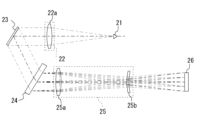
はじめに、図1を参照し、本実施形態に係るOCT装置1の光学系の概略構成を説明する。図1に示すように、OCT装置1は、OCT光学系(干渉光学系)100を備える。追加的に、OCT装置1は、導光光学系200、および、光路長調整部、を備えてもよい。
First, a schematic configuration of the optical system of the OCT device 1 according to this embodiment will be described with reference to FIG. 1. As shown in FIG. 1, the OCT device 1 includes an OCT optical system (interference optical system) 100. Additionally, the OCT device 1 may include a light-guiding
実施形態に係るOCT光学系100は、少なくとも分光光学系20を備える。追加的に、OCT光学系100は、OCT光源11、光分割器15、および、参照光学系30を備えてもよい。図1に示すように、各部は導光路としての光ファイバ17a~17dによって接続される。
The OCT
OCT光学系100は、被検眼へ照射された測定光の戻り光と参照光とのスペクトル干渉信号を、分光光学系20によって検出する。スペクトル干渉信号が画像処理器によって演算処理されることで、被検眼のOCTデータが取得(生成)される。
The OCT
本実施形態のOCT光源11は、低コヒーレントかつ広帯域な光を出射する。例えば、OCT光源11はSLD光源であって、OCT光源11から発せられる光は、近赤外光であってもよい。一例として、中心波長880nmの光がOCT光源11から照射されてもよい。
The OCT
光分割器15は、OCT光源11からの光を、測定光と参照光とに分割する。図1において、光分割器15はファイバカップラとして示す。図1に示すように、測定光は、導光光学系40を介して被検眼に照射される。また、被検眼の戻り光が、導光光学系40を遡って、分光光学系20に導かれる。参照光は、参照光学系30を経て分光光学系20へ導かれる。なお、図1において、測定光の戻り光と参照光とは、カップラ(例えば、図1においては光分割器15)で合波され、その後、分光光学系20へ導かれる。
The
導光光学系40は、図1に示すように、光スキャナ41および対物光学系45等を備えてもよい。光スキャナ41は、被検眼の組織上で測定光を走査するために利用される。光スキャナ41によって走査される測定光が、対物光学系45を介して被検眼の組織上で走査される。
As shown in FIG. 1, the light-guiding
眼底OCTを取得する際には、図1に示すように、対物光学系45を介した測定光は1点(旋回点という)を中心に旋回されてもよい。アライメントによって旋回点が前眼部に配置されることで、眼底OCTが取得される。
When obtaining fundus OCT, as shown in FIG. 1, the measurement light passing through the objective
前眼部OCTを取得する際には、図2に示すように、対物光学系45と被検眼Eとの間に前眼部アタッチメント50(アタッチメントレンズ50a)が挿入されてもよい。これにより、眼底OCTを取得する場合と、前眼部OCTを取得する場合との間で測定光の走査態様が変更されてもよい。アタッチメントレンズ50aが挿入されることで、テレセントリックに測定光が照射されて前眼部OCTが取得される。
When acquiring anterior segment OCT, as shown in FIG. 2, an anterior segment attachment 50 (
光路長調整部は、測定光と参照光との光路長差を調整する。眼底OCTを撮影する場合は、被検眼毎の眼軸長の個人差に応じて光路長差が補正されてもよい。また、前眼部OCTを撮影する場合は、予め定められた値に調整されてもよい。光路長調整部は、測定光路および参照光路のうち少なくともいずれかの光路長を変更する。図1では導光光学系40におけるファイバの出射端を光軸方向に移動させることによって、光路長が変更される。
The optical path length adjustment unit adjusts the optical path length difference between the measurement light and the reference light. When photographing fundus OCT, the optical path length difference may be corrected according to individual differences in the axial length of each subject eye. When photographing anterior segment OCT, the optical path length difference may be adjusted to a predetermined value. The optical path length adjustment unit changes the optical path length of at least one of the measurement optical path and the reference optical path. In FIG. 1, the optical path length is changed by moving the exit end of the fiber in the light-guiding
<分光光学系>
本実施形態の分光光学系20はスペクトロメータとして利用される。分光光学系20は、測定光の戻り光と参照光との干渉光を分光検出する。つまり、分光光学系20は、干渉光を周波数成分に分光し、周波数毎の干渉信号を検出する。
<Spectroscopic optical system>
The spectroscopic
図3に示すように、本実施形態において、分光光学系20は、コリメート系22、グレーティング(分散素子)24、結像系25、および、撮像素子(受光素子の一例)26を備える。追加的に、本実施形態の分光光学系20は、折り曲げミラー23を備える。
As shown in FIG. 3, in this embodiment, the spectroscopic
但し、分光光学系は、光路を折り曲げるためのミラーは必ずしも配置されていなくてもよい。例えば、光軸と交差する方向に関する寸法は、光路が折り曲げられないほうが有利となる。 However, the spectroscopic optical system does not necessarily need to include a mirror for bending the optical path. For example, it is more advantageous for the dimensions in the direction intersecting the optical axis not to bend the optical path.
測定光の戻り光と参照光との合成光束は、入射端21を介して分光光学系20に導かれる。ここでいう、入射端21は分光光学系20における見かけ上の干渉光の点光源となる。例えば、ファイバ17bの端部が入射端21として利用され得る。
The combined light beam of the return measurement light and the reference light is guided to the spectroscopic
コリメート系22は、入射端21からの干渉光をコリメートする。図3において、コリメート系22の焦点位置(物体側焦点位置)には入射端21が配置される。図3において、コリメートされた干渉光は、ミラー23によって折り曲げられて、グレーティング24に照射される。図3では、コリメート系22が、レンズ22a(コリメートレンズ)によって形成されている。
The
ミラー23は、干渉光を90°以上の角度で折り曲げる。これにより、分光光学系20の収容寸法が小型化される。ミラー23は、コリメート系22とグレーディング24との間に配置される。つまり、干渉光がコリメートされた領域に配置される。
The
グレーディング24は、干渉光を分光する。図3に示すように、グレーディング24は透過型の光学素子(例えば、回折格子)であってもよい。但し、グレーディング24は、反射型の光学素子に置き換えられてもよい。干渉光は、撮像素子26において画素が並べられた方向と一致する方向に、グレーディング24によって分光される。
The grading 24 splits the interference light. As shown in FIG. 3, the grading 24 may be a transmissive optical element (e.g., a diffraction grating). However, the grading 24 may be replaced with a reflective optical element. The interference light is split by the grading 24 in a direction that matches the direction in which the pixels are arranged in the
分光された干渉光は、結像系25に入射される。その結果、干渉光は、結像系25を介することで、撮像面において結像される。なお、図3においては、レンズ25aとレンズ25bとの2つのレンズによって結像系25は構成されている。但し、これは一例であって、結像系25には種々の代替的な構成を採用できる。
The dispersed interference light is incident on the
撮像素子26は、画素(素子)が一次元方向に配列されたラインセンサ(一次元撮像素子)である。撮像素子26は撮像面上、換言すれば、結像系25の焦点距離(像側焦点距離)の位置に配置される。
The
分光光学系20の光路のうち、コリメート系22とグレーディング24との間隔は性能に関係無いため、任意の値とすることができる。よって、分光光学系20の全長は、実質的には、コリメート系22の焦点距離f1および結像系25の焦点距離f2が支配的である。なお、本実施形態において、コリメート系22の焦点距離f1および結像系25の焦点距離f2を能動的に変化させるための機構を装置は備えない。つまり、f1およびf2は、いずれも固定である。つまり、本実施形態において、眼底OCTと前眼部OCTとをそれぞれ取得するときにスペクトロメータの条件は変化しない。
The distance between the collimating
ここで、SD-OCTにおける深さ方向分解能と、撮影される深さ範囲(depth range)との関係を説明する。なお、特に断りが無い限り、本実施形態におけるdepth rangeは、ゼロディレイを撮影範囲の一端としたときの他端までの深さである。つまり、本実施形態では、フルレンジ化技術に依らない光学系設計に基づく値を指す。 Here, we explain the relationship between the depth resolution in SD-OCT and the depth range to be imaged. Unless otherwise specified, the depth range in this embodiment is the depth to one end of the imaging range when the zero delay is the other end. In other words, in this embodiment, it refers to a value based on the optical system design that does not rely on full-range technology.
まず、OCTにおける深さ方向の分解能は、次の関係式で表すことができる。 First, the depth resolution in OCT can be expressed by the following relationship:

但し、δzは深さ方向の分解能、nは屈折率、Δλは総受光幅(スペクトル分布における半値全幅)、をそれぞれ示している。 where δz is the resolution in the depth direction, n is the refractive index, and Δλ is the total light receiving width (full width at half maximum in the spectral distribution).
また、深さ方向の撮影範囲(depth range)は、数2~数3示す関係式で表すことができる。 The imaging range in the depth direction (depth range) can be expressed by the relational expressions shown in Equations 2 and 3.


但し、zmaxはdepth range、Nは撮像素子における素子数、λ0は測定光の中心波長、aはグレーティングの格子定数、dλはサンプリング波長幅、Δxは撮像素子における一素子幅、θはグレーティングにおける回折角、mは回折次数、f2は結像系の焦点距離、をそれぞれ示している。数2~数4からは、depth range zmaxは、結像系の焦点距離f2と比例することが看て取れる。また、depth range zmaxは、画素数Nと比例し、一素子幅Δxと反比例するから、撮像素子の高画素化によって、depth range zmaxは増加することが看て取れる。 where z max is the depth range, N is the number of elements in the image sensor, λ 0 is the central wavelength of the measurement light, a is the lattice constant of the grating, dλ is the sampling wavelength width, Δx is the width of one element in the image sensor, θ is the diffraction angle in the grating, m is the diffraction order, and f2 is the focal length of the imaging system. From equations 2 to 4, it can be seen that the depth range z max is proportional to the focal length f2 of the imaging system. In addition, since the depth range z max is proportional to the number of pixels N and inversely proportional to the width Δx of one element, it can be seen that the depth range z max increases as the pixel density of the image sensor increases.
ここで、SD-OCTでは、結像系による結像面上では、干渉光のスペクトルが一方向に分布している。光源性能に由来した干渉光の分布の幅をソース帯域幅と称する。 Here, in SD-OCT, the spectrum of the interference light is distributed in one direction on the imaging plane of the imaging system. The width of the distribution of the interference light, which is derived from the light source performance, is called the source bandwidth.
図4Aに示すように、ソース帯域幅に対して、撮像素子によって検出される信号範囲が狭ければ、総受光幅Δλは小さくなり、深さ方向の分解能は低下する(δzが大きな値になる)。一方で、撮像素子は高密度に信号をサンプリングするため、サンプリング幅dλは小さくなる。よって、depth range zmaxは増大される。 As shown in Fig. 4A, if the signal range detected by the image sensor is narrow relative to the source bandwidth, the total light receiving width Δλ becomes small and the resolution in the depth direction decreases (δz becomes a large value). On the other hand, since the image sensor samples the signal at a high density, the sampling width dλ becomes small. Therefore, the depth range z max is increased.
図4Bでは、ソース帯域におけるスペクトル分布の幅に対して、撮像素子によって検出される信号範囲のバランスがとれている。従って、図4Aの場合に比べて、深さ方向の分解能は向上するものの、depth range zmaxは狭くなる。 In Fig. 4B, the signal range detected by the image sensor is balanced against the width of the spectral distribution in the source band, resulting in a narrower depth range zmax , although the resolution in the depth direction is improved, compared to Fig. 4A.
以上の検討の結果、従来設計と同様に眼底OCTに適した分解能(好ましくは、7μm以下)を維持しつつも、前眼部OCTに適した従来設計よりも広いdepth rangeを実現するためには、撮像素子の高画素化と共に、結像系の焦点距離f2を十分に長大化させることが必要となる。その際、角膜厚、および、前房深度は、それぞれ、0.5mmおよび2~3mm程度であるから、角膜頂点から水晶体前嚢までを撮影可能なdepth rangeとしては、好ましくは4mm以上である。 As a result of the above considerations, in order to achieve a wider depth range than the conventional design suitable for anterior segment OCT while maintaining a resolution suitable for fundus OCT (preferably 7 μm or less) like the conventional design, it is necessary to increase the pixel count of the image sensor and to sufficiently increase the focal length f2 of the imaging system. In this case, since the corneal thickness and anterior chamber depth are approximately 0.5 mm and 2 to 3 mm, respectively, the depth range capable of imaging from the corneal apex to the anterior lens capsule is preferably 4 mm or more.
ところで、スペクトロメータにおいて、分光された状態の干渉光は撮像面上で有限のスポットサイズで結像するものと考えることができる。一素子幅Δxに対してスポットサイズが大きい場合ほど、周波数毎の干渉信号を分解できずに、結果として、感度減衰が生じると考えられる。このとき、高周波領域側ほど(つまり、ゼロディレイから離れた位置ほど)、感度の低下は大きくなることが知られている。スポットサイズは、結像系の焦点距離f2に対して、コリメート系の焦点距離f1が同じか、それよりも長い場合に最小化される。 In a spectrometer, the dispersed interference light can be thought of as being imaged with a finite spot size on the imaging surface. The larger the spot size is relative to the width Δx of one element, the less likely it is that interference signals of each frequency can be resolved, resulting in attenuation of sensitivity. It is known that the sensitivity decreases more significantly toward the high frequency region (i.e., the farther away from zero delay). The spot size is minimized when the focal length f1 of the collimating system is the same as or longer than the focal length f2 of the imaging system.
これに対し、本実施形態では、コリメート系22の焦点距離f1が、結像系25の焦点距離f2に対して短い。つまり、f1<f2である。従って、スポットサイズは最小化されない。
In contrast, in this embodiment, the focal length f1 of the
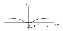
ところで、感度減衰については、以下のように、depth range zmaxを用いた関係式として表すことができる。 Incidentally, the sensitivity attenuation can be expressed as a relational expression using depth range z max as follows:

但し、R(z)は感度減衰、zは深さ位置、ωは角周波数、をそれぞれ示している。 where R(z) is the sensitivity attenuation, z is the depth position, and ω is the angular frequency.
図5に示すように、zmaxとR(z)との関係に着目すると、区間毎に以下の1)~3)の特徴が見て取れる。
1)原点付近の区間Aでは、zmaxに応じた変化はほぼ無い。
2)区間Aに対して値の大きな区間BではzmaxとR(z)との間に正の相関がある。但し、変極点を経てR(z)の傾きは減少傾向に転じる。
3)区間Cでは、R(z)は有限の値へ漸近する。zmaxに応じた変化は、ほぼ無くなる。
As shown in FIG. 5, when focusing on the relationship between z max and R(z), the following characteristics 1) to 3) can be seen for each section.
1) In section A near the origin, there is almost no change according to z max .
2) In section B, which has a larger value than section A, there is a positive correlation between z max and R(z). However, after passing an inflection point, the slope of R(z) starts to decrease.
3) In section C, R(z) asymptotically approaches a finite value. The change according to zmax almost disappears.
従って、一部の区間(区間B)に限って、depth range zmaxを拡張したときに感度減衰が抑制される。このため、当該区間であれば、depth range zmaxのスポットサイズが最小されないことで生じる感度減衰への影響の少なくとも一部を、depth range zmaxを拡張することによって相殺できると考えられる。 Therefore, sensitivity attenuation is suppressed when depth range z max is extended only in a certain section (section B). For this reason, it is considered that in this section, at least a part of the effect on sensitivity attenuation caused by the spot size of depth range z max not being minimized can be offset by extending depth range z max .
次に、図6に、depth range 3mmと4.2mmとの2種類についての、当該式に基づくシミュレーション結果である感度減衰曲線を示す。但し、図6におけるそれぞれの感度減衰曲線は、いずれもスポットサイズが最小化された状態を前提とする。 Next, Figure 6 shows the sensitivity decay curves, which are the simulation results based on this formula, for two depth ranges, 3 mm and 4.2 mm. Note that each sensitivity decay curve in Figure 6 is based on the assumption that the spot size is minimized.
図6からは、depth range 3mmと4.2mmとの間では、depth rangeが大きくなるほど、感度減衰のスロープが緩やかになることが看て取れる。例えば、図6においては、depth range 3mmのグラフにおける3mmでの位置での性能と、depth range4.2mmのグラフにおける4.2mmでの性能は同等である。 From Figure 6, it can be seen that the larger the depth range is between 3 mm and 4.2 mm, the gentler the slope of the sensitivity attenuation becomes. For example, in Figure 6, the performance at the 3 mm position in the graph with a depth range of 3 mm is equivalent to the performance at the 4.2 mm position in the graph with a depth range of 4.2 mm.
シミュレーション結果から、depth rangeを、従来のSD-OCTの範囲から、角膜頂点から水晶体前嚢までをワンショットで撮影するために要求される範囲へと拡張する場合に、感度減衰の抑制効果を享受できる、ことが確認される。よって、ゼロディレイから離れた領域においても感度的な余裕が生まれるため、その分については、コリメート系22の焦点距離f1を短縮可能となる。その結果、前眼部OCTと眼底OCTとの両方を良好に撮影可能であり、且つ、コンパクトなOCT装置が実現できる。
The simulation results confirm that the effect of suppressing sensitivity attenuation can be achieved when the depth range is expanded from the range of conventional SD-OCT to the range required to capture images from the corneal apex to the anterior lens capsule in one shot. Therefore, because there is a margin of sensitivity even in areas away from zero delay, the focal length f1 of the
但し、シミュレーション値だけで実際の装置の感度減衰を正確に予測できない。そこで、深さ方向の分解能δz:7μm以下、depth range zmax:4mm以上を実現するときの結像系25の焦点距離f2に対し、コリメート系22の焦点距離f1をf2よりも短くした光学系において、前眼部OCTおよび眼底OCTを撮影し、感度減衰の影響についての検証を行った。このとき、f1はf2の半分以下である。より詳細には、f1:f2の比は、およそ、1:3である。この場合、スポットサイズが最小化された状態と比べてスペクトロメータ全長が、最大6割程度に短縮される。
However, the sensitivity attenuation of the actual device cannot be accurately predicted by the simulation value alone. Therefore, in an optical system in which the focal length f1 of the
図7A,Bに、眼底OCTおよび前眼部OCTをそれぞれ示す。 Figures 7A and B show fundus OCT and anterior segment OCT, respectively.
図7Aは、横断方向のスキャン長(画角)を16mm(約画角50°)であるときの眼底のBスキャンを示している。眼底OCTにおいては、眼底は湾曲しているため、Bスキャンの中で描写される眼底組織には、横断方向に関して高低差が存在する。高低差は、被検眼毎の個体差があり、一般的には、強度近視眼等において高低差は顕著になる。また、Bスキャンにおけるスキャン長(画角)が増大することで、高低差が表れやすくなる。よって、眼底OCTでは、高周波側の領域(ゼロディレイから離れた領域)に眼底組織の一部が描写されることは避けられず、感度減衰は問題視されやすい。例えば、図7Aに示すように、中心固視で撮影した場合、眼底中心部が最も深い位置に描写されてしまう。特に、強度近視眼等の長眼軸長眼に対する影響が懸念される。しかしながら、検証結果としては、図7Aに示すように、-14Dという強度近視であっても、眼底中心部における形状、および、同じく網膜表層から脈絡膜表層までの主だった層構造を目視で識別可能であり、感度減衰による問題は見られなかった。 Figure 7A shows a B-scan of the fundus when the transverse scan length (angle of view) is 16 mm (approximately 50° angle of view). In fundus OCT, the fundus is curved, so the fundus tissue depicted in the B-scan has a height difference in the transverse direction. The height difference varies from eye to eye, and generally becomes more pronounced in severe myopic eyes. In addition, the height difference becomes more likely to appear as the scan length (angle of view) in the B-scan increases. Therefore, in fundus OCT, it is inevitable that part of the fundus tissue will be depicted in the high-frequency region (region far from zero delay), and sensitivity attenuation is likely to be a problem. For example, as shown in Figure 7A, when photographed with central fixation, the center of the fundus is depicted at the deepest position. In particular, there is concern about the impact on long-axis long eyes such as severe myopic eyes. However, the verification results showed that, as shown in Figure 7A, even with severe myopia of -14D, it was possible to visually identify the shape of the central part of the fundus, as well as the main layer structure from the retinal surface to the choroidal surface, and no problems due to sensitivity attenuation were observed.
また、図7Bに示すように、前眼部OCTにおいては、角膜頂点から水晶体前嚢および隅角組織をワンショットで撮影可能である。 Also, as shown in Figure 7B, in anterior segment OCT, it is possible to capture images of the anterior lens capsule and angle tissue from the corneal apex in a single shot.
以上のように、本開示によれば、コリメート系22の焦点距離f1が結像系25の焦点距離f2よりも短縮されたコンパクトなスペクトロメータであっても、深さ方向の撮影範囲を前眼部において複数の部位をまとめて撮影可能な程度まで確保しつつ、眼底OCTに必要な分解能を確保できる。
As described above, according to the present disclosure, even with a compact spectrometer in which the focal length f1 of the
なお、図7A,B等の撮影結果からの本発明者の見積りによれば、f1:f2の比が、およそ、1:4までの範囲であれば、必要な感度を享受しつつ、光学系を短縮できるものと考えられる。 In addition, according to the inventor's estimation based on the photographic results of Figures 7A and B, etc., it is believed that if the ratio of f1:f2 is in the range of approximately 1:4, it is possible to shorten the optical system while maintaining the necessary sensitivity.
<フルレンジ化技術の適用>
更に、OCTデータには、フルレンジ化技術が適用されてもよい。OCTデータにおいて虚像を除去する種々の手法が、フルレンジ化技術と呼ばれる。本実施形態では、いずれかのフルレンジ化技術を適用してもよく、これによって、虚像が選択的に除去された更に広範囲のOCTデータが取得可能であってもよい。フルレンジ化技術を用いた場合、ゼロディレイをまたいだ領域からOCTデータを取得できるため、実質的な深さ方向の撮影範囲を増加させることができる。
<Application of full-range technology>
Further, a full-range technique may be applied to the OCT data. Various methods for removing virtual images in OCT data are called full-range techniques. In this embodiment, any of the full-range techniques may be applied, and this may allow acquisition of a wider range of OCT data from which virtual images have been selectively removed. When the full-range technique is used, OCT data can be acquired from a region spanning zero delay, so that the effective imaging range in the depth direction can be increased.
なお、フルレンジ化技術の一例としては、追加のハードウェアにより虚像(鏡像ともいう)を除去する技術、追加のハードウェアを用いずにソフトウェアで補正する技術等を挙げることができる。また、スペクトル干渉信号を検出する際の光路長が異なる複数のOCTデータに基づいて、OCTデータにおける実像と虚像との重複領域に対して少なくとも補完処理を行い、補完処理が施されたOCTデータを生成する、更に別のフルレンジ化技術が提案されている。これらのいずれかが、本実施形態において適用されてもよい。 Examples of full-range techniques include a technique for removing virtual images (also called mirror images) using additional hardware, and a technique for correcting by software without using additional hardware. Another full-range technique has also been proposed, which performs at least an interpolation process on the overlapping area between the real image and the virtual image in the OCT data based on multiple OCT data sets with different optical path lengths when detecting the spectral interference signal, and generates OCT data that has been subjected to the interpolation process. Any of these may be applied in this embodiment.
<分光光学系における光学素子の固定方法>
次に、図8および図9を参照して、分光光学系を固定保持する構成を説明する。図8に示すように、本実施形態において、OCT装置1は、分光光学系20を、ベース250上に固定保持するための固定保持ユニット200を備えてもよい。
<Method of Fixing Optical Elements in Spectroscopic Optical System>
Next, a configuration for fixing and holding the spectroscopic optical system will be described with reference to Fig. 8 and Fig. 9. As shown in Fig. 8, in this embodiment, the OCT apparatus 1 may include a fixing and holding
本実施形態において、固定保持ユニット200には、少なくとも、第1光学マウント210、および、第2光学マウント220が含まれている。固定保持ユニット200は、追加的に、第3光学マウント230,第4光学マウント240を備えてもよい。
In this embodiment, the fixing and holding
第1,第2光学マウント210,220は、分光光学系20に含まれる複数の光学素子(入射端21、コリメートレンズ22a、グレーディング24、結像レンズ25a,25b、受光素子26)のうち、少なくとも2つずつを保持する。詳細には、光軸方向に関して隣り合う2つの光学素子が、第1,第2光学マウント210,220の1つによって保持される。第1,第2光学マウント210,220は、温度に応じた自らの変形による光学素子の保持間隔の変化を抑制するための構成を備える。
The first and second
ところで、撮像面における干渉光のスポットサイズは、各々の光学素子間の間隔が設計値からズレることによって拡大される。光学素子間の間隔が設計値からズレてしまうと、感度低下が生じ得る。そこで、分光光学系20における隣り合う光学素子の組合せ毎に、光学素子間の間隔の変化がスポットサイズに与える影響について検討したところ、1)~5)の順(降順)でスポットサイズへの影響が大きくなることが実験的に確認された。
The spot size of the interference light on the imaging plane increases when the spacing between each optical element deviates from the design value. If the spacing between optical elements deviates from the design value, a decrease in sensitivity can occur. Therefore, we investigated the effect of changes in the spacing between optical elements on the spot size for each combination of adjacent optical elements in the spectroscopic
1)入射端21とコリメートレンズ22a
2)結像レンズ25aと結像レンズ25b
3)結像レンズ25bと受光素子26
4)コリメートレンズ22aとグレーディング24
5)グレーディング24と第1の結像レンズ25a
より詳細には、1)と2)とのズレがスポットサイズに対して支配的である。3)のズレでは、スポットサイズに対して多少の影響が見られた。4)と5)のズレによるスポットサイズへの影響は、ほとんど見られなかった。
1)
2)
3)
4)
5)
More specifically, the deviation between 1) and 2) is dominant in terms of the spot size. The deviation between 3) has some effect on the spot size. The deviation between 4) and 5) has almost no effect on the spot size.
そこで、図8に示すように、本実施形態では、第1光学マウント210によって、入射端21およびコリメートレンズ22aが保持される。また、第2光学マウント220によって、2つの結像レンズ25a,25bが保持される。
As shown in FIG. 8, in this embodiment, the first
第1光学マウント210は、第1部材211(第1ホルダー)、第2部材212(第2ホルダー)、および、第3部材213(連結部材)を備える。第1部材211は、入射端21(ファイバ17bの端部)を保持する。第2部材212は、コリメートレンズ22aを保持する。第3部材213は、第1部材211と第2部材212との両方に固定される。
The first
同様に、第2光学マウント220は、第1部材221(第1ホルダー)、第2部材222(第2ホルダー)、および、第3部材223(連結部材)を備える。第2光学マウント220において、第1部材221は、結像系25に含まれる2つのレンズ25a,25bの一方を、第2部材222は他方を、それぞれ保持する。第3部材223は、第1部材221と第2部材222との両方に固定される。
Similarly, the second
第1,第2光学マウント210,220は、第1~第3部材211~213,221~223によって、複数箇所(本実施形態では2か所)の折り返し部B1,B2(図9参照)を有する入れ子構造が形成される。これにより、第1,第2光学マウント210,220は、各々が保持する2つの光学素子の保持間隔の変位であって、第1,第2光学マウント210,220の熱変形に起因する変位が、第1~第3部材211~213,221~223の熱変形において第1~第3部材211~213,221~223の間で相殺される。
The first and second
また、第1~第3部材211~213,221~223において互いが隣接(接触)する面は、旋盤加工にて形成されてもよい。加工精度が高い旋盤加工が利用されることで、第1,第2光学マウント210,220において、第1~第3部材211~213,221~223を密接に配置でき、第1,第2光学マウント210,220のそれぞれが保持する2つの光学素子の軸ズレが抑制される。
The surfaces of the first to
図9を参照して、第1,第2光学マウント210,220の構造を詳細に説明する。図9において、第1部材211,221および第3部材213,223は、光学素子の保持位置から、光軸に沿って、互いに向かって延びるように形成される。第2部材212,222は、第1部材211,221および第3部材213,223の両方と、少なくとも一部が光軸と交差する方向に重なるように配置される。
The structure of the first and second
図9において、符号p11は、第1部材211,221における光学素子の保持位置、p22は、第2部材212,222における光学素子の保持位置、をそれぞれ示す。また、符号q13は、第1部材211,221と第2部材212,222との固定位置、符号q23は、第1部材211,221と第2部材212,222との固定位置、をそれぞれ示す。
In FIG. 9, p11 indicates the holding position of the optical element in the
図9に示すように、固定位置q13は、固定位置q23に対して第2部材212,222の保持位置p22側(本実施形態では、分光光学系20の下流側)に配置される。固定位置q13の周りで、第1部材211,221と第3部材213,223とによる折り返し部B1が形成される。
As shown in FIG. 9, the fixed position q13 is disposed on the holding position p22 side of the
固定位置q23は、固定位置q13に対して第1部材211,221の保持位置p11側(本実施形態では、分光光学系20の上流側)に配置される。固定位置q23の周りで、第2部材212,222と第3部材213,223とによる折り返し部B2が形成される。
Fixed position q23 is disposed on the holding position p11 side of the
折り返し部から該折り返し部を形成する2つの部材を見たときに、2つの部材の熱変形の方向が一致される。よって、本実施形態では、第1部材211,221、および、第2部材212,222において、熱変形による寸法の変化が生じても、同等の寸法変化が第3部材213,223において生じれば、第1,第2光学マウント210,220による2つの光学素子の保持間隔が、温度変化の前後で維持される。
When the two members that form the folded portion are viewed from the folded portion, the directions of thermal deformation of the two members are aligned. Therefore, in this embodiment, even if dimensional changes due to thermal deformation occur in the
ここで、第1部材211,221における保持位置p11から固定位置q13までの距離をDx、第2部材212,222における保持位置p22から固定位置q23までの距離をDy、第3部材213,223における2つの固定位置q13,q23の間の距離をDzとして、それぞれ示す。本実施形態によって、第1部材211,221、第2部材212,222、第3部材213,223の光軸方向の熱変形に影響する寸法が、Dx,Dy,Dzとなる。
Here, the distance from the holding position p11 to the fixed position q13 in the
また、第1部材211,221、第2部材212,222、第3部材213,223のそれぞれにおける熱膨張率を、それぞれ、β1,β2,β3とする。温度が温度Tから温度Taへと変化する場合における光学素子の保持間隔の変化の許容誤差をEとすると、各部材の熱膨張の差を利用することによって、次の関係式を満たすように、各部材の材料およびDx,Dy,Dzが決定される。
The thermal expansion coefficients of the
![]()
![]()
つまり、本実施形態では、第1部材211,221、および、第2部材212,222における熱変形による寸法の変化量と、第3部材213,223における熱変形による寸法の変化量と、が略等しくなるように、各部材の材料およびDx,Dy,Dzが決定される。
In other words, in this embodiment, the materials and Dx, Dy, and Dz of each member are determined so that the amount of dimensional change due to thermal deformation in the
図9のように、Dx,Dy,Dzが近しければ、β1,β2<β3となるように、各部材の材料が選定される。例えば、第1部材211,221、および、第2部材212,222とは、同一材料であってもよい(つまり、β1=β2)。一例として、第1部材211,221および第2部材212,222に鉄、第3部材213,223をアルミニウムが用いられてもよい。もちろん、各部材は熱膨張率が互いに異なる異種材料も組み合わせであってもよい。
As shown in FIG. 9, if Dx, Dy, and Dz are close, the materials of each member are selected so that β1, β2 < β3. For example, the
以上のような第1,第2光学マウント210,220を備えることで、分光光学系20の撮像面上における干渉光のスポットサイズに関して影響が大きな光学素子間の間隔の変化(温度に応じた変化)を適正に抑制でき、各温度での感度性能を適切に維持できる。特に、上述のように、コリメート系22の焦点距離f1が、結像系25の焦点距離f2に対して短いという感度に関して不利な光学設計が採用されていても、温度変化による感度性能の低下を好適に抑制できる。
By providing the first and second
図8に戻って説明を続ける。図8の例において、第1光学マウント210および第2光学マウント220は、第3光学マウント230と連結される。また、第2光学マウント220は、下流側にて第4光学マウント240と連結される。第3光学マウント230は、ミラー23、グレーディング24を固定保持する。第4光学マウント240は、受光素子26を固定保持する。
Returning to FIG. 8, the explanation will continue. In the example of FIG. 8, the first
本実施例では、固定保持ユニット200の中で、第3光学マウント230および第4光学マウント240の各々がベース250と、ねじ等で直接的に連結されている。第3光学マウント230および第4光学マウント240のうち少なくともいずれかの連結箇所では、ワッシャー等によって、固定保持ユニット200が熱によって変形した場合の変形が吸収可能である。これにより、固定保持ユニット200に温度による変形が生じたときに機械的な負荷の集中を回避でき、光学系の劣化を抑制できる。
In this embodiment, in the fixing and holding
以上、実施形態に基づいて本開示を説明したが、本開示は上記実施形態に限定されるものではなく、種々の変形が可能である。 The present disclosure has been described above based on the embodiments, but the present disclosure is not limited to the above embodiments and various modifications are possible.
1 OCT装置
20 分光光学系
22 コリメート系
24 分散素子(グレーディング)
25 結像系
26 受光素子
210 第1光学マウント
220 第2光学マウント
211,221 第1部材
212,222 第2部材
213,223 第3部材
1
25
Claims (4)
前記OCT光学系に設けられた分光光学系であって、被検眼に照射した測定光の戻り光と参照光との干渉光を導入する入射端、前記入射端から照射される干渉光をコリメートするコリメートレンズ、コリメートされた干渉光をスペクトル波長毎に分光する分散素子、2つの結像レンズを有し、スペクトル波長毎の干渉光を前記2つの結像レンズによって撮像面に結像させる結像系、および、撮像面に配置され、前記干渉光を分光検出する受光素子、を含む分光光学系と、
前記結像系に含まれる2つの結像レンズのうち一方を保持する第1部材、前記結像系に含まれる2つの結像レンズのうち他方を保持する第2部材、および、前記第1部材と前記第2部材との両方に固定される第3部材と、を有する光学マウントと、を備え、
前記光学マウントは、前記光学マウントの熱変形に起因する2つの前記結像レンズの保持間隔の変位を、前記第1部材、前記第2部材および前記第3部材の熱変形において前記第1部材、前記第2部材および前記第3部材の間で相殺させる、OCT装置。 An OCT optical system for acquiring OCT data of a subject's eye;
a spectroscopic optical system provided in the OCT optical system, the spectroscopic optical system including : an incident end that introduces interference light between return light of the measurement light irradiated to the eye to be examined and a reference light; a collimating lens that collimates the interference light irradiated from the incident end; a dispersing element that disperses the collimated interference light for each spectral wavelength; an imaging system having two imaging lenses and that images the interference light for each spectral wavelength on an imaging plane using the two imaging lenses; and a light receiving element that is disposed on the imaging plane and spectrally detects the interference light;
an optical mount including a first member that holds one of two imaging lenses included in the imaging system , a second member that holds the other of the two imaging lenses included in the imaging system , and a third member that is fixed to both the first member and the second member;
An OCT device in which the optical mount offsets the displacement of the holding distance between the two imaging lenses caused by thermal deformation of the optical mount between the first member, the second member, and the third member through thermal deformation of the first member, the second member, and the third member.
前記第2光学マウントは、前記入射端を保持する第4部材、前記コリメートレンズを保持する第5部材、および、前記第4部材と前記第5部材との両方に固定される第6部材と、を有し、
前記第2光学マウントは、前記第2光学マウントの熱変形に起因する前記入射端および前記コリメートレンズの保持間隔の変位を、前記第4部材、前記第5部材および前記第6部材の熱変形において前記第4部材、前記第5部材および前記第6部材の間で相殺させる、請求項1記載のOCT装置。 a second optical mount formed separately from the optical mount;
the second optical mount has a fourth member that holds the incident end, a fifth member that holds the collimator lens, and a sixth member that is fixed to both the fourth member and the fifth member,
The OCT device of claim 1, wherein the second optical mount offsets displacement of the holding distance between the incident end and the collimating lens caused by thermal deformation of the second optical mount between the fourth member, the fifth member, and the sixth member in the thermal deformation of the fourth member, the fifth member, and the sixth member.
前記第1部材と前記第3部材との固定位置が前記第2部材と前記第3部材との固定位置よりも前記分光光学系における下流側に位置するように、前記第3部材は、前記第1部材と前記第2部材とそれぞれに固定される、請求項1又は2記載のOCT装置。 the one imaging lens is located upstream of the other imaging lens in the spectroscopic optical system,
3. The OCT device according to claim 1, wherein the third member is fixed to each of the first member and the second member such that a fixed position between the first member and the third member is located downstream in the spectroscopic optical system relative to a fixed position between the second member and the third member.
|Dx・β1(Ta-T)+Dy・β2(Ta-T)-Dz・β3(Ta-T)|<|E|
となるように前記第1部材、前記第2部材、および、前記第3部材の材料、および、前記寸法Dx,Dy,Dzが決定されていることを特徴とする請求項1から3のいずれかに記載のOCT装置。 When the temperature around the device changes from temperature T to temperature Ta, the allowable error of the change in the distance between the two imaging lenses is E, and the dimensions that affect the thermal expansion in the optical axis direction of the first member, the second member, and the third member are Dx, Dy, and Dz, respectively. By utilizing the difference in the thermal expansion coefficient,
|Dx・β1(Ta-T)+Dy・β2(Ta-T)−Dz・β3(Ta-T)|<|E|
4. The OCT apparatus according to claim 1 , wherein the materials of the first member, the second member, and the third member and the dimensions Dx, Dy, and Dz are determined so as to satisfy the following:
Priority Applications (3)
| Application Number | Priority Date | Filing Date | Title |
|---|---|---|---|
| JP2021058799A JP7651908B2 (en) | 2021-03-30 | 2021-03-30 | OCT equipment |
| US17/671,821 US12201358B2 (en) | 2021-03-30 | 2022-02-15 | OCT device |
| CN202210141624.XA CN115137290A (en) | 2021-03-30 | 2022-02-16 | OCT device |
Applications Claiming Priority (1)
| Application Number | Priority Date | Filing Date | Title |
|---|---|---|---|
| JP2021058799A JP7651908B2 (en) | 2021-03-30 | 2021-03-30 | OCT equipment |
Publications (2)
| Publication Number | Publication Date |
|---|---|
| JP2022155351A JP2022155351A (en) | 2022-10-13 |
| JP7651908B2 true JP7651908B2 (en) | 2025-03-27 |
Family
ID=83556962
Family Applications (1)
| Application Number | Title | Priority Date | Filing Date |
|---|---|---|---|
| JP2021058799A Active JP7651908B2 (en) | 2021-03-30 | 2021-03-30 | OCT equipment |
Country Status (1)
| Country | Link |
|---|---|
| JP (1) | JP7651908B2 (en) |
Citations (4)
| Publication number | Priority date | Publication date | Assignee | Title |
|---|---|---|---|---|
| US20060164639A1 (en) | 2005-01-21 | 2006-07-27 | Horn Jochen M M | Cross-dispersed spectrometer in a spectral domain optical coherence tomography system |
| JP2010035949A (en) | 2008-08-07 | 2010-02-18 | Nidek Co Ltd | Ophthalmic photographing apparatus |
| JP2019195378A (en) | 2018-05-07 | 2019-11-14 | キヤノン株式会社 | Optical interference tomographic apparatus |
| WO2020112521A1 (en) | 2018-11-29 | 2020-06-04 | Leica Microsystems Inc. | Compact diffraction limited near infrared (nir) spectrometers and related detectors |
Family Cites Families (1)
| Publication number | Priority date | Publication date | Assignee | Title |
|---|---|---|---|---|
| JPH08160276A (en) * | 1994-12-08 | 1996-06-21 | Fujitsu Ltd | Lens hug |
-
2021
- 2021-03-30 JP JP2021058799A patent/JP7651908B2/en active Active
Patent Citations (5)
| Publication number | Priority date | Publication date | Assignee | Title |
|---|---|---|---|---|
| US20060164639A1 (en) | 2005-01-21 | 2006-07-27 | Horn Jochen M M | Cross-dispersed spectrometer in a spectral domain optical coherence tomography system |
| JP2008528953A (en) | 2005-01-21 | 2008-07-31 | カール ツァイス メディテック アクチエンゲゼルシャフト | Cross dispersive spectrometer in spectral domain optical coherence tomography system |
| JP2010035949A (en) | 2008-08-07 | 2010-02-18 | Nidek Co Ltd | Ophthalmic photographing apparatus |
| JP2019195378A (en) | 2018-05-07 | 2019-11-14 | キヤノン株式会社 | Optical interference tomographic apparatus |
| WO2020112521A1 (en) | 2018-11-29 | 2020-06-04 | Leica Microsystems Inc. | Compact diffraction limited near infrared (nir) spectrometers and related detectors |
Also Published As
| Publication number | Publication date |
|---|---|
| JP2022155351A (en) | 2022-10-13 |
Similar Documents
| Publication | Publication Date | Title |
|---|---|---|
| EP3479753B1 (en) | Surgical microscopy system having an optical coherence tomography facility | |
| US8982357B2 (en) | Imaging device and imaging method | |
| US10028656B2 (en) | Optical coherence tomographic apparatus | |
| US9149180B2 (en) | Optical tomographic imaging apparatus | |
| KR101515034B1 (en) | Optical coherence tomographic imaging apparatus and control apparatus therefor | |
| US20120274904A1 (en) | Ophthalmic apparatus, method of controlling ophthalmic apparatus and storage medium | |
| CN102438501B (en) | Imaging device and imaging method | |
| US11129528B2 (en) | OCT apparatus | |
| JP7427444B2 (en) | Method and apparatus for high-resolution topography of the cornea of the eye | |
| JP2017064378A (en) | Optical interference tomographic device, control method thereof and optical interference tomographic system | |
| US20130003076A1 (en) | Tomographic imaging appratus and tomographic imaging method | |
| JP7707610B2 (en) | OCT device | |
| JP5637721B2 (en) | Tomographic imaging apparatus and tomographic imaging apparatus control apparatus | |
| US12201358B2 (en) | OCT device | |
| JP7651908B2 (en) | OCT equipment | |
| JP2019217406A (en) | Ophthalmography apparatus | |
| JP7329308B2 (en) | OCT device and optical attachment | |
| JP6556199B2 (en) | Imaging apparatus and imaging method |
Legal Events
| Date | Code | Title | Description |
|---|---|---|---|
| A621 | Written request for application examination |
Free format text: JAPANESE INTERMEDIATE CODE: A621 Effective date: 20240227 |
|
| A977 | Report on retrieval |
Free format text: JAPANESE INTERMEDIATE CODE: A971007 Effective date: 20240927 |
|
| A131 | Notification of reasons for refusal |
Free format text: JAPANESE INTERMEDIATE CODE: A131 Effective date: 20241008 |
|
| A601 | Written request for extension of time |
Free format text: JAPANESE INTERMEDIATE CODE: A601 Effective date: 20241128 |
|
| A521 | Request for written amendment filed |
Free format text: JAPANESE INTERMEDIATE CODE: A523 Effective date: 20241226 |
|
| A521 | Request for written amendment filed |
Free format text: JAPANESE INTERMEDIATE CODE: A523 Effective date: 20250124 |
|
| TRDD | Decision of grant or rejection written | ||
| A01 | Written decision to grant a patent or to grant a registration (utility model) |
Free format text: JAPANESE INTERMEDIATE CODE: A01 Effective date: 20250212 |
|
| A61 | First payment of annual fees (during grant procedure) |
Free format text: JAPANESE INTERMEDIATE CODE: A61 Effective date: 20250225 |
|
| R150 | Certificate of patent or registration of utility model |
Ref document number: 7651908 Country of ref document: JP Free format text: JAPANESE INTERMEDIATE CODE: R150 |