JP7648564B2 - Data collection device, data collection method and computer program - Google Patents
Data collection device, data collection method and computer program Download PDFInfo
- Publication number
- JP7648564B2 JP7648564B2 JP2022060589A JP2022060589A JP7648564B2 JP 7648564 B2 JP7648564 B2 JP 7648564B2 JP 2022060589 A JP2022060589 A JP 2022060589A JP 2022060589 A JP2022060589 A JP 2022060589A JP 7648564 B2 JP7648564 B2 JP 7648564B2
- Authority
- JP
- Japan
- Prior art keywords
- information
- network
- tag
- virtual network
- mapping table
- Prior art date
- Legal status (The legal status is an assumption and is not a legal conclusion. Google has not performed a legal analysis and makes no representation as to the accuracy of the status listed.)
- Active
Links
Images

Landscapes
- Data Exchanges In Wide-Area Networks (AREA)
Description
本発明は、データ収集装置、データ収集方法及びコンピュータプログラムに関する。 The present invention relates to a data collection device, a data collection method, and a computer program.
近年、仮想化技術の進展により、通信ネットワークの分野においても仮想化された通信ネットワーク(仮想ネットワーク)が普及しつつある。仮想ネットワークは、利用者の状況に応じて必要な時に必要な分だけネットワーク機能を拡充することができるという利点を持つ。一方で、仮想ネットワークは、ネットワーク構成要素が増え且つネットワーク構成が動的に変化するために、ネットワークの保守や運用面において安定的にネットワークを稼働させるためのネットワーク監視が課題である。仮想ネットワークは、仮想化基盤である物理サーバ上に仮想ネットワークインスタンスとしてネットワーク機能が構築されるため、物理サーバと仮想ネットワークインスタンスの両面から稼働状況を監視することが求められる。 In recent years, advances in virtualization technology have led to the spread of virtualized communication networks (virtual networks) in the field of communication networks. Virtual networks have the advantage of being able to expand network functions only when and as much as is needed, depending on the user's situation. However, because virtual networks have an increasing number of network components and the network configuration changes dynamically, network monitoring to ensure stable network operation is a challenge in terms of network maintenance and operation. In virtual networks, network functions are built as virtual network instances on a physical server, which is the virtualization infrastructure, so it is necessary to monitor the operation status from both the physical server and the virtual network instance perspectives.
特許文献1には、仮想ネットワークを監視するために、VNF(Virtual Network Function、仮想化ネットワーク機能)と当該VNFをサポートする基盤であるネットワーク機能仮想化インフラストラクチャ(NFVI)とから得られるデータに基づいて、オートスケール等のライフサイクル管理動作の必要性を判断する、仮想ネットワーク監視技術が記載されている。
しかし、上述した特許文献1に記載された仮想ネットワーク監視技術は、仮想マシン(VM)ベースの仮想化ネットワーク機能であるVNFが対象であるために、CNF(Cloud-native Network Function、クラウドネイティブネットワーク機能)を対象にすることが難しい。CNFは、VMベースのVNFとは異なるアーキテクチャであるコンテナベースの仮想化ネットワーク機能である。コンテナはクラウドコンピューティングサービスで広く利用されている技術であるため、CNFは今後特に普及が見込まれる。
However, the virtual network monitoring technology described in the above-mentioned
本発明は、このような事情を考慮してなされたものであり、その目的は、CNFが用いられた仮想ネットワークを対象にしたネットワーク監視に寄与することにある。 The present invention was made in consideration of these circumstances, and its purpose is to contribute to network monitoring targeting virtual networks that use CNF.
(1)本発明の一態様は、クラウドネイティブネットワーク機能(CNF)が用いられた監視対象の仮想ネットワークに関するマッピング情報及び前記監視対象の仮想ネットワークの構成情報に基づいて生成されたテーブルであって、監視単位毎に設けられたタグ情報と、前記監視対象の仮想ネットワークの仮想ネットワークインスタンス及び前記仮想ネットワークインスタンスが実行される仮想化基盤の情報処理装置から収集されるネットワーク情報を識別するための識別情報と、前記タグ情報を付加するためのタグ付加条件とが対応付けて格納されるマッピングテーブルと、前記仮想ネットワークインスタンス及び前記仮想化基盤の情報処理装置から収集されたネットワーク情報を受信するコレクタ部と、前記コレクタ部が受信したネットワーク情報に対して、前記マッピングテーブルに基づいて前記タグ情報を付加するマッピング部と、を備え、前記マッピング情報は、監視単位毎に、前記タグ情報、前記識別情報、前記タグ付加条件、及び前記タグ付加条件として前記監視対象の仮想ネットワークの構成情報の動的な情報が用いられる場合に前記動的な情報を取得するための付加情報を有し、前記付加情報は、前記動的な情報と前記動的な情報の取得先とを示す情報であり、前記マッピングテーブルは、各監視単位のタグ情報毎に、前記識別情報、前記タグ付加条件、及び前記タグ付加条件に合致した場合に付加されるタグ情報を格納し、前記動的な情報が用いられる前記タグ付加条件は、前記付加情報に基づいて取得された前記動的な情報が前記マッピングテーブルに格納される、データ収集装置である。
(2)本発明の一態様は、前記付加情報に示される取得先から、前記付加情報に示される前記動的な情報を取得し、取得した前記動的な情報を使用して前記マッピングテーブルを生成するマッピングテーブル生成部、をさらに備える上記(1)のデータ収集装置である。
(3)本発明の一態様は、前記マッピングテーブル生成部は、前記マッピング情報と前記監視対象の仮想ネットワークの構成とのうち少なくとも一方が変更された場合に、前記マッピング情報に基づいて、前記監視対象の仮想ネットワークの構成情報を再取得し、再取得した前記監視対象の仮想ネットワークの構成情報を使用して前記マッピングテーブルを更新する、上記(2)のデータ収集装置である。
(1) One aspect of the present invention is a mapping table generated based on mapping information related to a monitored virtual network using a cloud native network function (CNF) and configuration information of the monitored virtual network, the mapping table storing tag information provided for each monitoring unit, identification information for identifying network information collected from a virtual network instance of the monitored virtual network and an information processing device of a virtualization infrastructure on which the virtual network instance is executed, and a tag addition condition for adding the tag information in association with each other, a collector unit receiving the network information collected from the virtual network instance and the information processing device of the virtualization infrastructure, and a tag addition condition for adding the tag information. and a mapping unit which adds the tag information based on the mapping table, wherein the mapping information has, for each monitoring unit, the tag information, the identification information, the tag addition condition, and additional information for acquiring the dynamic information when dynamic information of the configuration information of the virtual network to be monitored is used as the tag addition condition, and the additional information is information which indicates the dynamic information and an acquisition source of the dynamic information, and the mapping table stores, for each tag information of each monitoring unit, the identification information, the tag addition condition, and the tag information to be added when the tag addition condition is satisfied, and the tag addition condition under which the dynamic information is used is such that the dynamic information acquired based on the additional information is stored in the mapping table .
(2) One aspect of the present invention is the data collection device of (1) above, further comprising a mapping table generation unit that acquires the dynamic information indicated in the additional information from a source indicated in the additional information, and generates the mapping table using the acquired dynamic information .
(3) One aspect of the present invention is the data collection device of (2) above, wherein when at least one of the mapping information and the configuration of the monitored virtual network is changed, the mapping table generation unit re-acquires configuration information of the monitored virtual network based on the mapping information, and updates the mapping table using the re-acquired configuration information of the monitored virtual network.
(4)本発明の一態様は、データ収集装置が、クラウドネイティブネットワーク機能(CNF)が用いられた監視対象の仮想ネットワークに関するマッピング情報及び前記監視対象の仮想ネットワークの構成情報に基づいて生成されたテーブルであって、監視単位毎に設けられたタグ情報と、前記監視対象の仮想ネットワークの仮想ネットワークインスタンス及び前記仮想ネットワークインスタンスが実行される仮想化基盤の情報処理装置から収集されるネットワーク情報を識別するための識別情報と、前記タグ情報を付加するためのタグ付加条件とが対応付けて格納されるマッピングテーブルを備え、前記データ収集装置が、前記仮想ネットワークインスタンス及び前記仮想化基盤の情報処理装置から収集されたネットワーク情報を受信するネットワーク情報受信ステップと、前記データ収集装置が、前記ネットワーク情報受信ステップで受信したネットワーク情報に対して、前記マッピングテーブルに基づいて前記タグ情報を付加するタグ付加ステップと、を含み、前記マッピング情報は、監視単位毎に、前記タグ情報、前記識別情報、前記タグ付加条件、及び前記タグ付加条件として前記監視対象の仮想ネットワークの構成情報の動的な情報が用いられる場合に前記動的な情報を取得するための付加情報を有し、前記付加情報は、前記動的な情報と前記動的な情報の取得先とを示す情報であり、前記マッピングテーブルは、各監視単位のタグ情報毎に、前記識別情報、前記タグ付加条件、及び前記タグ付加条件に合致した場合に付加されるタグ情報を格納し、前記動的な情報が用いられる前記タグ付加条件は、前記付加情報に基づいて取得された前記動的な情報が前記マッピングテーブルに格納される、データ収集方法である。 (4) One aspect of the present invention is a mapping table generated based on mapping information related to a virtual network to be monitored using a cloud native network function (CNF) and configuration information of the virtual network to be monitored, the mapping table storing tag information provided for each monitoring unit, identification information for identifying network information collected from a virtual network instance of the virtual network to be monitored and an information processing device of a virtualization platform on which the virtual network instance is executed, and a tag addition condition for adding the tag information, the mapping table storing tag information in association with each other, the network information receiving step in which the data collecting device receives the network information collected from the virtual network instance and the information processing device of the virtualization platform, and the network information receiving step in which the data collecting device receives the network information collected from the virtual network instance and the information processing device of the virtualization platform. and a tag addition step of adding the tag information to the network information received in the network information receiving step based on the mapping table, wherein the mapping information has, for each monitoring unit, the tag information, the identification information, the tag addition condition, and additional information for acquiring the dynamic information when dynamic information of the configuration information of the virtual network to be monitored is used as the tag addition condition, and the additional information is information indicating the dynamic information and an acquisition source of the dynamic information, and the mapping table stores, for each tag information of each monitoring unit, the identification information, the tag addition condition, and the tag information to be added when the tag addition condition is met, and the tag addition condition under which the dynamic information is used is such that the dynamic information acquired based on the additional information is stored in the mapping table .
(5)本発明の一態様は、コンピュータに、クラウドネイティブネットワーク機能(CNF)が用いられた監視対象の仮想ネットワークに関するマッピング情報及び前記監視対象の仮想ネットワークの構成情報に基づいて生成されたテーブルであって、監視単位毎に設けられたタグ情報と、前記監視対象の仮想ネットワークの仮想ネットワークインスタンス及び前記仮想ネットワークインスタンスが実行される仮想化基盤の情報処理装置から収集されるネットワーク情報を識別するための識別情報と、前記タグ情報を付加するためのタグ付加条件とが対応付けて格納されるマッピングテーブルを記憶するステップと、前記仮想ネットワークインスタンス及び前記仮想化基盤の情報処理装置から収集されたネットワーク情報を受信するネットワーク情報受信ステップと、前記ネットワーク情報受信ステップで受信したネットワーク情報に対して、前記マッピングテーブルに基づいて前記タグ情報を付加するタグ付加ステップと、を実行させるためのコンピュータプログラムであり、前記マッピング情報は、監視単位毎に、前記タグ情報、前記識別情報、前記タグ付加条件、及び前記タグ付加条件として前記監視対象の仮想ネットワークの構成情報の動的な情報が用いられる場合に前記動的な情報を取得するための付加情報を有し、前記付加情報は、前記動的な情報と前記動的な情報の取得先とを示す情報であり、前記マッピングテーブルは、各監視単位のタグ情報毎に、前記識別情報、前記タグ付加条件、及び前記タグ付加条件に合致した場合に付加されるタグ情報を格納し、前記動的な情報が用いられる前記タグ付加条件は、前記付加情報に基づいて取得された前記動的な情報が前記マッピングテーブルに格納される、コンピュータプログラムである。
(5) One aspect of the present invention is a method for storing, in a computer, a mapping table generated based on mapping information related to a virtual network to be monitored using a cloud native network function (CNF) and configuration information of the virtual network to be monitored, in which tag information provided for each monitoring unit, identification information for identifying network information collected from a virtual network instance of the virtual network to be monitored and an information processing device of a virtualization infrastructure on which the virtual network instance is executed, and a tag addition condition for adding the tag information are stored in association with each other; a network information receiving step of receiving the network information collected from the virtual network instance and the information processing device of the virtualization infrastructure; and and a tag addition step of adding the tag information to virtual network information based on the mapping table, wherein the mapping information has, for each monitoring unit, the tag information, the identification information, the tag addition condition, and additional information for acquiring the dynamic information when dynamic information of the configuration information of the virtual network to be monitored is used as the tag addition condition, and the additional information is information indicating the dynamic information and an acquisition source of the dynamic information, and the mapping table stores, for each tag information of each monitoring unit, the identification information, the tag addition condition, and the tag information to be added when the tag addition condition is met, and the tag addition condition under which the dynamic information is used is such that the dynamic information acquired based on the additional information is stored in the mapping table .
本発明によれば、CNFが用いられた仮想ネットワークを対象にしたネットワーク監視に寄与することができるという効果が得られる。 The present invention has the effect of contributing to network monitoring of virtual networks using CNF.
以下、図面を参照し、本発明の実施形態について説明する。
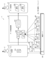
図1は、一実施形態に係るネットワーク監視システム1の構成例を示すブロック図である。図1において、ネットワーク監視システム1は、監視対象の仮想ネットワークからネットワーク情報を収集し、収集したネットワーク情報に基づいて監視対象の仮想ネットワークの状態を分析し、監視対象の仮想ネットワークの状態の分析結果を出力する。
Hereinafter, an embodiment of the present invention will be described with reference to the drawings.
Fig. 1 is a block diagram showing an example of the configuration of a
監視対象の仮想ネットワークは、CNF(クラウドネイティブネットワーク機能)が用いられた仮想ネットワークであって、複数のCNF_40とCNFオーケストレータ60とを備える。CNF_40は、仮想化基盤の情報処理装置である物理サーバ30上で実行される仮想ネットワークインスタンスとして構築される。CNFオーケストレータ60は、監視対象の仮想ネットワークに用いられるCNF_40のオーケストレーションを行う。
The virtual network to be monitored is a virtual network that uses CNF (Cloud Native Network Function), and includes multiple CNF_40 and a
CNF_40及び物理サーバ30には、監視エージェント50がインストールされている。監視エージェント50は、自己がインストールされたCNF_40又は物理サーバ30に関するネットワーク情報を収集するためのエージェントである。ネットワーク情報は、監視対象の仮想ネットワークの状態の分析に使用される情報であって、例えばネットワークリソースや計算リソース等の仮想ネットワーク性能状態を示す情報である。
A monitoring agent 50 is installed in the CNF_40 and the
ネットワーク監視システム1は、マッピングテーブル生成部11と、データ収集蓄積部12と、データ解析部13とを備える。本実施形態においては、マッピングテーブル生成部11とデータ収集蓄積部12とがデータ収集装置に対応する。
The
ネットワーク監視システム1の各機能は、ネットワーク監視システム1がCPU(Central Processing Unit:中央演算処理装置)及びメモリ等のコンピュータハードウェアを備え、CPUがメモリに格納されたコンピュータプログラムを実行することにより実現される。なお、ネットワーク監視システム1として、汎用のコンピュータ装置を使用して構成してもよく、又は、専用のハードウェア装置として構成してもよい。例えば、ネットワーク監視システム1は、インターネット等の通信ネットワークに接続されるサーバコンピュータを使用して構成されてもよい。また、ネットワーク監視システム1の各機能はクラウドコンピューティングにより実現されてもよい。また、ネットワーク監視システム1は、単独のコンピュータにより実現するものであってもよく、又はネットワーク監視システム1の機能を複数のコンピュータに分散させて実現するものであってもよい。また、ネットワーク監視システム1として、例えばWWWシステム等を利用してウェブサイトを開設するように構成してもよい。
The functions of the
マッピングテーブル生成部11は、ネットワーク管理者等のユーザが使用するユーザ端末3からマッピング情報を受信する。マッピング情報は、監視対象の仮想ネットワークに対する監視ポリシーを含む情報である。
The mapping
マッピングテーブル生成部11は、マッピング情報に含まれる監視ポリシーに基づいて監視対象の仮想ネットワークの構成情報を取得する。監視対象の仮想ネットワークの構成情報は、CNFオーケストレータ60や物理サーバ30から取得される。
The mapping
マッピングテーブル生成部11は、マッピング情報に含まれる監視ポリシーとCNFオーケストレータ60や物理サーバ30から取得された監視対象の仮想ネットワークの構成情報とに基づいて、マッピングテーブル110を生成する。マッピングテーブル110は、監視単位毎に設けられたタグ情報と、監視対象の仮想ネットワークのCNF_40及び物理サーバ30から収集されるネットワーク情報を識別するための識別情報と、タグ情報をネットワーク情報に付加するためのタグ付加条件とが対応付けて格納されたテーブルである。
The
マッピングテーブル生成部11は、生成したマッピングテーブル110をデータ収集蓄積部12へ送信する。
The mapping
またマッピングテーブル生成部11は、監視対象の仮想ネットワークに対する監視ポリシーと監視対象の仮想ネットワークの構成とのうち少なくとも一方が変更された場合に、最新の監視ポリシーに基づいて、監視対象の仮想ネットワークの構成情報を再取得し、再取得した監視対象の仮想ネットワークの構成情報を使用してマッピングテーブル110を更新する。マッピングテーブル生成部11は、更新したマッピングテーブル110をデータ収集蓄積部12へ送信する。
When at least one of the monitoring policy for the virtual network to be monitored and the configuration of the virtual network to be monitored is changed, the mapping
データ収集蓄積部12は、コレクタモジュール(コレクタ部)121と、マッピングモジュール(マッピング部)122と、データストア(データ記憶部)123とを備える。
The data collection and
コレクタモジュール121は、監視対象の仮想ネットワークのCNF_40及び物理サーバ30から各監視エージェント50により収集されたネットワーク情報を、各監視エージェント50から受信する。
The
マッピングモジュール122は、コレクタモジュール121が受信したネットワーク情報に対して、マッピングテーブル110に基づいて該当するタグ情報を付加する。
The
データストア123は、マッピングモジュール122によってタグ情報が付加されたネットワーク情報を格納する。データストア123に格納されたネットワーク情報は、タグ情報によって監視単位毎に分類される。データ収集蓄積部12は、データ解析部13からのデータ要求に応じて、データストア123内のタグ付ネットワーク情報をデータ解析部13へ返信する。
The
データ解析部13は、データ収集蓄積部12からタグ付ネットワーク情報を取得し、取得したタグ付ネットワーク情報のタグ情報で識別される監視単位毎のネットワーク情報に基づいて、監視単位毎に、監視対象の仮想ネットワークの性能解析を行う。この性能解析は、例えば、所定のアルゴリズムを用いて構築された機械学習モデルである各CNF_40に対応するCNFモデル130が用いられる。また、CNFモデル130に対しては、性能解析のための所定のデータ前処理が施されたネットワーク情報が使用される。
なお、データ解析部13が解析に用いる手法は機械学習に限定されず、その他のアルゴリズム等による解析手法が適用されてもよい。
The
The method used by the
データ解析部13は、監視対象の仮想ネットワークの監視単位毎の性能解析結果をユーザ端末3へ送信する。これにより、ネットワーク管理者等のユーザは、ユーザ端末3が受信した性能解析結果によって、監視対象の仮想ネットワークについて監視単位毎に性能状態を認識することができる。
The
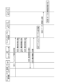
次に図2を参照して本実施形態に係るデータ収集方法及び仮想ネットワーク監視方法を説明する。図2は、本実施形態に係るデータ収集方法及び仮想ネットワーク監視方法の手順の例を示すシーケンス図である。 Next, the data collection method and virtual network monitoring method according to this embodiment will be described with reference to FIG. 2. FIG. 2 is a sequence diagram showing an example of the procedure of the data collection method and virtual network monitoring method according to this embodiment.
(ステップS1) ネットワーク管理者は、ユーザ端末3を使用して、マッピングテーブル生成部11へマッピング情報を入力する。当該入力されたマッピング情報(入力マッピング情報)には、監視単位毎にネットワーク情報を分類して監視単位毎のタグ情報を付加するための情報(監視ポリシー)が含められる。
(Step S1) The network administrator uses the
(ステップS2) マッピングテーブル生成部11は、入力マッピング情報に基づいて、CNFオーケストレータ60に対して、監視対象の仮想ネットワークの構成情報(監視対象仮想ネットワーク構成情報)のうち必要な監視対象仮想ネットワーク構成情報を要求する。
(Step S2) Based on the input mapping information, the mapping
(ステップS3) CNFオーケストレータ60は、マッピングテーブル生成部11からの要求に応じて、要求された監視対象仮想ネットワーク構成情報をマッピングテーブル生成部11へ返信する。
(Step S3) In response to a request from the mapping
(ステップS4) マッピングテーブル生成部11は、入力マッピング情報に基づいて、物理サーバ30に対して、必要な監視対象仮想ネットワーク構成情報を要求する。
(Step S4) Based on the input mapping information, the mapping
(ステップS5) 物理サーバ30は、マッピングテーブル生成部11からの要求に応じて、要求された監視対象仮想ネットワーク構成情報をマッピングテーブル生成部11へ返信する。
(Step S5) In response to a request from the mapping
(ステップS6) マッピングテーブル生成部11は、入力マッピング情報とCNFオーケストレータ60や物理サーバ30から取得された監視対象仮想ネットワーク構成情報とに基づいて、マッピングテーブル110を生成する。
(Step S6) The
(ステップS7) マッピングテーブル生成部11は、生成したマッピングテーブル110(テーブル情報)をマッピングモジュール122へ送信する。
(Step S7) The mapping
(ステップS8) マッピングモジュール122は、マッピングテーブル生成部11から受信したマッピングテーブル110(テーブル情報)をメモリに読み込み保持する。
(Step S8) The
上記のステップS1からステップS8によって、マッピングテーブル110が生成されマッピングモジュール122に設定される。次いで、データ収集段階として以降のステップが実行される。
By steps S1 to S8 above, the mapping table 110 is generated and set in the
(ステップS9) 物理サーバ30に事前にインストールされた監視エージェント50は、定期的に物理サーバ30からネットワーク情報を収集し、収集したネットワーク情報をコレクタモジュール121へ送信する。
(Step S9) The monitoring agent 50 pre-installed on the
(ステップS10) 監視対象の仮想ネットワークのCNF_40に事前にインストールされた監視エージェント50は、定期的にCNF_40からネットワーク情報を収集し、収集したネットワーク情報をコレクタモジュール121へ送信する。
(Step S10) The monitoring agent 50, which has been pre-installed in the CNF_40 of the virtual network to be monitored, periodically collects network information from the CNF_40 and transmits the collected network information to the
(ステップS11) コレクタモジュール121は、監視対象の仮想ネットワークのCNF_40及び物理サーバ30の各監視エージェント50から受信したネットワーク情報を、マッピングモジュール122へ転送する。
(Step S11) The
(ステップS12) マッピングモジュール122は、コレクタモジュール121から受信したネットワーク情報に対して、マッピングテーブル110に基づいて該当するタグ情報を付加する。
(Step S12) The
(ステップS13) データストア123は、マッピングモジュール122によってタグ情報が付加されたタグ付ネットワーク情報を格納する。
(Step S13) The
上記のステップS9からステップS13によって、タグ情報によって監視単位毎に分類されるネットワーク情報(タグ付ネットワーク情報)がデータストア123に蓄積される。次いで、データ解析段階として以降のステップが実行される。
By steps S9 to S13 above, network information (tagged network information) classified by monitoring unit based on tag information is stored in
(ステップS14) データ解析部13は、データストア123に対して、データ解析の対象のタグ付ネットワーク情報を要求する。例えば、データ解析部13は、データ解析の対象の監視単位に対応するタグ付ネットワーク情報をデータストア123に要求する。例えば、データ解析部13は、データ解析の対象の監視日時に収集されたタグ付ネットワーク情報をデータストア123に要求する。ネットワーク情報は、収集された日時を含んでいる。
(Step S14) The
(ステップS15) データストア123は、データ解析部13からの要求に応じて、要求されたタグ付ネットワーク情報をデータ解析部13へ返信する。
(Step S15) In response to a request from the
(ステップS16) データ解析部13は、事前に構築された機械学習モデルであるCNFモデル130を用いて、データストア123から取得したタグ付ネットワーク情報を解析する。
(Step S16) The
(ステップS17) データ解析部13は、解析結果をネットワーク管理者のユーザ端末3へ送信する。
(Step S17) The
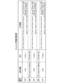
次に図3を参照して本実施形態に係るマッピングテーブル更新方法を説明する。図3は、本実施形態に係るマッピングテーブル更新方法の手順の例を示すシーケンス図である。 Next, the mapping table update method according to this embodiment will be described with reference to FIG. 3. FIG. 3 is a sequence diagram showing an example of the procedure of the mapping table update method according to this embodiment.
(ステップS31) ネットワーク管理者は、監視対象の仮想ネットワークに対する監視ポリシーを変更する場合、ユーザ端末3を使用して、マッピングテーブル生成部11へ、変更後のマッピング情報を入力する。当該入力された変更後のマッピング情報(入力マッピング情報_変更後)には、変更後の監視ポリシーが含められる。
(Step S31) When the network administrator changes the monitoring policy for the virtual network to be monitored, the network administrator uses the
(ステップS32) CNFオーケストレータ60は、オートスケール等により監視対象の仮想ネットワークの構成が変わった場合、マッピングテーブル生成部11に対して、監視対象の仮想ネットワークの構成の変更を通知する。
(Step S32) If the configuration of the virtual network to be monitored changes due to autoscaling or the like, the
(ステップS33) マッピングテーブル生成部11は、入力マッピング情報の変更ありの場合、入力マッピング情報_変更後に基づいて、CNFオーケストレータ60に対して、必要な監視対象仮想ネットワーク構成情報を要求する。
(Step S33) If the input mapping information has changed, the mapping
マッピングテーブル生成部11は、入力マッピング情報の変更なし且つ監視対象の仮想ネットワークの構成の変更ありの場合、入力マッピング情報に基づいて、CNFオーケストレータ60に対して、必要な監視対象仮想ネットワーク構成情報を要求する。
When there is no change in the input mapping information but there is a change in the configuration of the virtual network to be monitored, the mapping
マッピングテーブル生成部11は、入力マッピング情報の変更あり且つ監視対象の仮想ネットワークの構成の変更ありの場合、入力マッピング情報_変更後に基づいて、CNFオーケストレータ60に対して、必要な監視対象仮想ネットワーク構成情報を要求する。
When there is a change in the input mapping information and a change in the configuration of the virtual network to be monitored, the mapping
(ステップS34) CNFオーケストレータ60は、マッピングテーブル生成部11からの要求に応じて、要求された監視対象仮想ネットワーク構成情報をマッピングテーブル生成部11へ返信する。
(Step S34) In response to a request from the mapping
(ステップS35) マッピングテーブル生成部11は、入力マッピング情報の変更ありの場合、入力マッピング情報_変更後に基づいて、物理サーバ30に対して、必要な監視対象仮想ネットワーク構成情報を要求する。
(Step S35) If the input mapping information has been changed, the mapping
マッピングテーブル生成部11は、入力マッピング情報の変更なし且つ監視対象の仮想ネットワークの構成の変更ありの場合、入力マッピング情報に基づいて、物理サーバ30に対して、必要な監視対象仮想ネットワーク構成情報を要求する。
When there is no change in the input mapping information but there is a change in the configuration of the virtual network to be monitored, the mapping
マッピングテーブル生成部11は、入力マッピング情報の変更あり且つ監視対象の仮想ネットワークの構成の変更ありの場合、入力マッピング情報_変更後に基づいて、物理サーバ30に対して、必要な監視対象仮想ネットワーク構成情報を要求する。
When the input mapping information has changed and the configuration of the virtual network to be monitored has changed, the mapping
(ステップS36) 物理サーバ30は、マッピングテーブル生成部11からの要求に応じて、要求された監視対象仮想ネットワーク構成情報をマッピングテーブル生成部11へ返信する。
(Step S36) In response to a request from the mapping
(ステップS37) マッピングテーブル生成部11は、入力マッピング情報の変更ありの場合、入力マッピング情報_変更後とCNFオーケストレータ60や物理サーバ30から取得された監視対象仮想ネットワーク構成情報とに基づいて、マッピングテーブル110を更新する。
(Step S37) If the input mapping information has been changed, the
(ステップS38) マッピングテーブル生成部11は、更新後のマッピングテーブル110(テーブル情報)をマッピングモジュール122へ送信する。
(Step S38) The mapping
(ステップS39) マッピングモジュール122は、マッピングテーブル生成部11から受信した更新後のマッピングテーブル110(テーブル情報)をメモリに再読み込みし元のマッピングテーブル110に上書きし保持する。これにより、マッピングテーブル110が更新されマッピングモジュール122に設定される。
(Step S39) The
図4は、本実施形態に係るマッピング情報の具体的な構成例である。図4の例では、監視単位毎に、監視単位名、識別情報、条件及び付加情報が関連付けてマッピング情報に格納される。識別情報は、ネットワーク情報を識別するための識別情報である。条件は、タグ情報を付加するためのタグ付加条件である。付加情報は、条件として動的な情報が用いられる場合に、当該動的な情報(監視対象仮想ネットワーク構成情報)を取得するための情報である。マッピングテーブル生成部11は、条件として動的な情報が用いられる場合に、付加情報に示される監視対象仮想ネットワーク構成情報を、付加情報に示される取得先(物理サーバ30又はCNFオーケストレータ60)から取得する。
Figure 4 is a specific example of the configuration of mapping information according to this embodiment. In the example of Figure 4, for each monitoring unit, the monitoring unit name, identification information, conditions, and additional information are associated and stored in the mapping information. The identification information is identification information for identifying network information. The conditions are tagging conditions for adding tag information. The additional information is information for acquiring dynamic information (monitored virtual network configuration information) when dynamic information is used as a condition. When dynamic information is used as a condition, the mapping
図4の例では、pidns(PID名前空間)と「TCP source IP address(TCP送信元IPアドレス)」とが識別情報に使用されている。pidnsについては、付加情報に基づいて物理サーバ30から取得される動的な情報(監視対象仮想ネットワーク構成情報)が条件(タグ付加条件)として使用される。「TCP source IP address」については、ネットワーク管理者がマッピング情報として入力した値(静的情報)が条件(タグ付加条件)として使用される。
In the example of FIG. 4, pidns (PID namespace) and "TCP source IP address" are used as identification information. For pidns, dynamic information (monitored virtual network configuration information) obtained from the
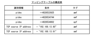
図5は、本実施形態に係るマッピングテーブル110の具体的な構成例である。図5の例は、図4のマッピング情報の例に基づいて生成されたものである。図5の例では、各監視単位のタグ情報毎に、識別情報、条件(タグ付加条件)及び条件(タグ付加条件)に合致した場合に付加されるタグ情報が対応付けてマッピングテーブル110に格納される。 Figure 5 is a specific example of the configuration of the mapping table 110 according to this embodiment. The example in Figure 5 is generated based on the example of mapping information in Figure 4. In the example in Figure 5, for each tag information of each monitoring unit, identification information, a condition (tag addition condition), and tag information to be added when the condition (tag addition condition) is met are stored in association with each other in the mapping table 110.
pidnsに関連付けられる条件(タグ付加条件)は、マッピング情報の付加情報に基づいて物理サーバ30から取得された動的な情報(監視対象仮想ネットワーク構成情報)がマッピングテーブル110に格納される。「TCP source IP address」に関連付けられる条件(タグ付加条件)は、ネットワーク管理者がマッピング情報として入力した値(静的情報)がマッピングテーブル110に格納される。
The conditions associated with pidns (tagging conditions) are dynamic information (monitored virtual network configuration information) obtained from the
マッピングモジュール122は、図5のマッピングテーブル110を使用し、コレクタモジュール121が受信したネットワーク情報において、例えば、識別情報「pidns」が条件(タグ付加条件)「4026533925」に合致した場合に、当該ネットワーク情報に対してタグ情報「amf」を付加する。また、マッピングモジュール122は、図5のマッピングテーブル110を使用し、コレクタモジュール121が受信したネットワーク情報において、例えば、識別情報「TCP source IP address」が条件(タグ付加条件)「192.168.13.81」に合致した場合に、当該ネットワーク情報に対してタグ情報「smf」を付加する。
The
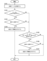
図6は、本実施形態に係るタグ付け方法の手順の例を示すフローチャートである。図6のフローチャートは、図5のマッピングテーブル110に対応する。 Figure 6 is a flowchart showing an example of the steps of a tagging method according to this embodiment. The flowchart in Figure 6 corresponds to the mapping table 110 in Figure 5.
(ステップS101) マッピングモジュール122は、コレクタモジュール121からネットワーク情報(収集データ)を受信する。
(Step S101) The
(ステップS102) マッピングモジュール122は、マッピングテーブル110に基づいて、コレクタモジュール121から受信したネットワーク情報に識別情報「pidns」が含まれているか否かを判断する。識別情報「pidns」が含まれている場合にはステップS103に進み、そうではない場合にはステップS105に進む。
(Step S102) The
(ステップS103) マッピングモジュール122は、ネットワーク情報に含まれている識別情報「pidns」が、マッピングテーブル110内の識別情報「pidns」の条件に合致するか否かを判断する。条件に合致する場合にはステップS104に進み、そうではない場合にはステップS105に進む。
(Step S103) The
(ステップS104) マッピングモジュール122は、ネットワーク情報に対して、合致した識別情報「pidns」の条件に該当するマッピングテーブル110内のタグ情報を付加する。
(Step S104) The
(ステップS105) マッピングモジュール122は、マッピングテーブル110に基づいて、コレクタモジュール121から受信したネットワーク情報に識別情報「TCP source IP address」が含まれているか否かを判断する。識別情報「TCP source IP address」が含まれている場合にはステップS106に進み、そうではない場合には図6の処理を終了する。
(Step S105) The
(ステップS106) マッピングモジュール122は、ネットワーク情報に含まれている識別情報「TCP source IP address」が、マッピングテーブル110内の識別情報「TCP source IP address」の条件に合致するか否かを判断する。条件に合致する場合にはステップS107に進み、そうではない場合には図6の処理を終了する。
(Step S106) The
(ステップS107) マッピングモジュール122は、ネットワーク情報に対して、合致した識別情報「TCP source IP address」の条件に該当するマッピングテーブル110内のタグ情報を付加する。
(Step S107) The
本実施形態によれば、CNFが用いられた仮想ネットワークを対象にしたネットワーク監視に寄与することができるという効果が得られる。 This embodiment has the effect of contributing to network monitoring of virtual networks that use CNF.
また、仮想ネットワークの監視において、CNF等の仮想ネットワークインスタンス及びその仮想化基盤から収集されるネットワーク情報に対してマッピングテーブルを用いて監視単位毎のタグ情報を付加し、タグ付ネットワーク情報を蓄積することによって、任意の監視単位毎に監視対象の仮想ネットワークの性能情報を集約して解析することができる。 In addition, when monitoring virtual networks, tag information for each monitoring unit is added to the network information collected from virtual network instances such as CNF and its virtualization infrastructure using a mapping table, and the tagged network information is accumulated, making it possible to aggregate and analyze performance information for the monitored virtual network for each arbitrary monitoring unit.
また、監視対象の仮想ネットワークに対する監視ポリシーや監視対象の仮想ネットワークの構成が変わった場合に、その変更の通知に応じてマッピングテーブルを更新することによって、監視対象の仮想ネットワークに関する環境の変化に追従しながら、任意の監視単位毎での監視対象の仮想ネットワークの監視を継続することができる。 In addition, if the monitoring policy for the monitored virtual network or the configuration of the monitored virtual network changes, the mapping table can be updated in response to notification of the change, allowing monitoring of the monitored virtual network at any monitoring unit to continue while keeping up with changes in the environment related to the monitored virtual network.
なお、これにより、例えばネットワーク監視システムにおける総合的なサービス品質の向上を実現することができることから、国連が主導する持続可能な開発目標(SDGs)の目標9「レジリエントなインフラを整備し、持続可能な産業化を推進するとともに、イノベーションの拡大を図る」に貢献することが可能となる。 As a result, it will be possible to improve the overall service quality of network monitoring systems, for example, and contribute to Goal 9 of the United Nations' Sustainable Development Goals (SDGs), which is to "build resilient infrastructure, promote sustainable industrialization and foster innovation."
以上、本発明の実施形態について図面を参照して詳述してきたが、具体的な構成はこの実施形態に限られるものではなく、本発明の要旨を逸脱しない範囲の設計変更等も含まれる。 The above describes an embodiment of the present invention in detail with reference to the drawings, but the specific configuration is not limited to this embodiment, and includes design modifications and the like that do not deviate from the gist of the present invention.
また、上述した各装置の機能を実現するためのコンピュータプログラムをコンピュータ読み取り可能な記録媒体に記録して、この記録媒体に記録されたプログラムをコンピュータシステムに読み込ませ、実行するようにしてもよい。なお、ここでいう「コンピュータシステム」とは、OSや周辺機器等のハードウェアを含むものであってもよい。また、「コンピュータシステム」は、WWWシステムを利用している場合であれば、ホームページ提供環境(あるいは表示環境)も含むものとする。
また、「コンピュータ読み取り可能な記録媒体」とは、フレキシブルディスク、光磁気ディスク、ROM、フラッシュメモリ等の書き込み可能な不揮発性メモリ、DVD(Digital Versatile Disc)等の可搬媒体、コンピュータシステムに内蔵されるハードディスク等の記憶装置のことをいう。
Also, a computer program for implementing the functions of each of the above-mentioned devices may be recorded on a computer-readable recording medium, and the program recorded on the recording medium may be read into a computer system and executed. Note that the "computer system" referred to here may include hardware such as an OS and peripheral devices. In addition, if a WWW system is used, the "computer system" also includes the home page providing environment (or display environment).
In addition, the term "computer-readable recording medium" refers to a storage device such as a flexible disk, a magneto-optical disk, a ROM, a writable non-volatile memory such as a flash memory, a portable medium such as a DVD (Digital Versatile Disc), or a hard disk built into a computer system.
さらに「コンピュータ読み取り可能な記録媒体」とは、インターネット等のネットワークや電話回線等の通信回線を介してプログラムが送信された場合のサーバやクライアントとなるコンピュータシステム内部の揮発性メモリ(例えばDRAM(Dynamic Random Access Memory))のように、一定時間プログラムを保持しているものも含むものとする。
また、上記プログラムは、このプログラムを記憶装置等に格納したコンピュータシステムから、伝送媒体を介して、あるいは、伝送媒体中の伝送波により他のコンピュータシステムに伝送されてもよい。ここで、プログラムを伝送する「伝送媒体」は、インターネット等のネットワーク(通信網)や電話回線等の通信回線(通信線)のように情報を伝送する機能を有する媒体のことをいう。
また、上記プログラムは、前述した機能の一部を実現するためのものであってもよい。さらに、前述した機能をコンピュータシステムにすでに記録されているプログラムとの組み合わせで実現できるもの、いわゆる差分ファイル(差分プログラム)であってもよい。
Furthermore, the term "computer-readable recording medium" includes devices that retain a program for a certain period of time, such as volatile memory (e.g., DRAM (Dynamic Random Access Memory)) within a computer system that serves as a server or client when a program is transmitted via a network such as the Internet or a communication line such as a telephone line.
The program may be transmitted from a computer system in which the program is stored in a storage device or the like to another computer system via a transmission medium, or by a transmission wave in the transmission medium. Here, the "transmission medium" that transmits the program refers to a medium that has a function of transmitting information, such as a network (communication network) such as the Internet or a communication line (communication line) such as a telephone line.
The program may be a program for implementing some of the above-mentioned functions, or may be a so-called differential file (differential program) that can implement the above-mentioned functions in combination with a program already recorded in the computer system.
1…ネットワーク監視システム、3…ユーザ端末、11…マッピングテーブル生成部、12…データ収集蓄積部、13…データ解析部、30…物理サーバ、40…CNF、50…監視エージェント、60…CNFオーケストレータ、110…マッピングテーブル、121…コレクタモジュール、122…マッピングモジュール、123…データストア、130…CNFモデル 1...Network monitoring system, 3...User terminal, 11...Mapping table generation unit, 12...Data collection and storage unit, 13...Data analysis unit, 30...Physical server, 40...CNF, 50...Monitoring agent, 60...CNF orchestrator, 110...Mapping table, 121...Collector module, 122...Mapping module, 123...Data store, 130...CNF model
Claims (5)
前記仮想ネットワークインスタンス及び前記仮想化基盤の情報処理装置から収集されたネットワーク情報を受信するコレクタ部と、
前記コレクタ部が受信したネットワーク情報に対して、前記マッピングテーブルに基づいて前記タグ情報を付加するマッピング部と、
を備え、
前記マッピング情報は、監視単位毎に、前記タグ情報、前記識別情報、前記タグ付加条件、及び前記タグ付加条件として前記監視対象の仮想ネットワークの構成情報の動的な情報が用いられる場合に前記動的な情報を取得するための付加情報を有し、
前記付加情報は、前記動的な情報と前記動的な情報の取得先とを示す情報であり、
前記マッピングテーブルは、各監視単位のタグ情報毎に、前記識別情報、前記タグ付加条件、及び前記タグ付加条件に合致した場合に付加されるタグ情報を格納し、
前記動的な情報が用いられる前記タグ付加条件は、前記付加情報に基づいて取得された前記動的な情報が前記マッピングテーブルに格納される、
データ収集装置。 a mapping table generated based on mapping information related to a monitored virtual network using a cloud native network function (CNF) and configuration information of the monitored virtual network, the mapping table storing tag information provided for each monitoring unit, identification information for identifying a virtual network instance of the monitored virtual network and network information collected from an information processing device of a virtualization infrastructure on which the virtual network instance is executed, and a tag addition condition for adding the tag information in association with each other;
a collector unit for receiving network information collected from the virtual network instance and the information processing device of the virtualization infrastructure;
a mapping unit that adds the tag information to the network information received by the collector unit based on the mapping table;
Equipped with
the mapping information includes, for each monitoring unit, the tag information, the identification information, the tagging condition, and additional information for acquiring dynamic information of configuration information of the virtual network to be monitored when the dynamic information is used as the tagging condition;
the additional information is information indicating the dynamic information and an acquisition source of the dynamic information,
the mapping table stores, for each tag information of each monitoring unit, the identification information, the tag addition condition, and tag information to be added when the tag addition condition is met;
The tagging condition in which the dynamic information is used is such that the dynamic information acquired based on the additional information is stored in the mapping table.
Data collection equipment.
をさらに備える請求項1に記載のデータ収集装置。 a mapping table generating unit that acquires the dynamic information indicated in the additional information from an acquisition source indicated in the additional information, and generates the mapping table using the acquired dynamic information ;
The data collection device of claim 1 further comprising:
請求項2に記載のデータ収集装置。 the mapping table generation unit, when at least one of the mapping information and a configuration of the virtual network to be monitored is changed, reacquires configuration information of the virtual network to be monitored based on the mapping information , and updates the mapping table using the reacquired configuration information of the virtual network to be monitored.
The data collection device of claim 2.
前記データ収集装置が、前記仮想ネットワークインスタンス及び前記仮想化基盤の情報処理装置から収集されたネットワーク情報を受信するネットワーク情報受信ステップと、
前記データ収集装置が、前記ネットワーク情報受信ステップで受信したネットワーク情報に対して、前記マッピングテーブルに基づいて前記タグ情報を付加するタグ付加ステップと、を含み、
前記マッピング情報は、監視単位毎に、前記タグ情報、前記識別情報、前記タグ付加条件、及び前記タグ付加条件として前記監視対象の仮想ネットワークの構成情報の動的な情報が用いられる場合に前記動的な情報を取得するための付加情報を有し、
前記付加情報は、前記動的な情報と前記動的な情報の取得先とを示す情報であり、
前記マッピングテーブルは、各監視単位のタグ情報毎に、前記識別情報、前記タグ付加条件、及び前記タグ付加条件に合致した場合に付加されるタグ情報を格納し、
前記動的な情報が用いられる前記タグ付加条件は、前記付加情報に基づいて取得された前記動的な情報が前記マッピングテーブルに格納される、
データ収集方法。 a data collection device includes a mapping table generated based on mapping information related to a monitored virtual network using a cloud native network function (CNF) and configuration information of the monitored virtual network, the mapping table storing tag information provided for each monitoring unit, identification information for identifying a virtual network instance of the monitored virtual network and network information collected from an information processing device of a virtualization infrastructure on which the virtual network instance is executed, and a tag addition condition for adding the tag information in association with each other;
a network information receiving step in which the data collection device receives network information collected from the virtual network instance and the information processing device of the virtualization infrastructure;
a tag addition step of adding the tag information to the network information received in the network information receiving step based on the mapping table by the data collection device ;
the mapping information includes, for each monitoring unit, the tag information, the identification information, the tagging condition, and additional information for acquiring dynamic information of configuration information of the virtual network to be monitored when the dynamic information is used as the tagging condition;
the additional information is information indicating the dynamic information and an acquisition source of the dynamic information,
the mapping table stores, for each tag information of each monitoring unit, the identification information, the tag addition condition, and tag information to be added when the tag addition condition is met;
The tagging condition in which the dynamic information is used is such that the dynamic information acquired based on the additional information is stored in the mapping table.
Data collection methods.
クラウドネイティブネットワーク機能(CNF)が用いられた監視対象の仮想ネットワークに関するマッピング情報及び前記監視対象の仮想ネットワークの構成情報に基づいて生成されたテーブルであって、監視単位毎に設けられたタグ情報と、前記監視対象の仮想ネットワークの仮想ネットワークインスタンス及び前記仮想ネットワークインスタンスが実行される仮想化基盤の情報処理装置から収集されるネットワーク情報を識別するための識別情報と、前記タグ情報を付加するためのタグ付加条件とが対応付けて格納されるマッピングテーブルを記憶するステップと、
前記仮想ネットワークインスタンス及び前記仮想化基盤の情報処理装置から収集されたネットワーク情報を受信するネットワーク情報受信ステップと、
前記ネットワーク情報受信ステップで受信したネットワーク情報に対して、前記マッピングテーブルに基づいて前記タグ情報を付加するタグ付加ステップと、
を実行させるためのコンピュータプログラムであり、
前記マッピング情報は、監視単位毎に、前記タグ情報、前記識別情報、前記タグ付加条件、及び前記タグ付加条件として前記監視対象の仮想ネットワークの構成情報の動的な情報が用いられる場合に前記動的な情報を取得するための付加情報を有し、
前記付加情報は、前記動的な情報と前記動的な情報の取得先とを示す情報であり、
前記マッピングテーブルは、各監視単位のタグ情報毎に、前記識別情報、前記タグ付加条件、及び前記タグ付加条件に合致した場合に付加されるタグ情報を格納し、
前記動的な情報が用いられる前記タグ付加条件は、前記付加情報に基づいて取得された前記動的な情報が前記マッピングテーブルに格納される、
コンピュータプログラム。 On the computer,
a step of storing a mapping table generated based on mapping information related to a monitored virtual network using a cloud native network function (CNF) and configuration information of the monitored virtual network, in which tag information provided for each monitoring unit, identification information for identifying a virtual network instance of the monitored virtual network and network information collected from an information processing device of a virtualization infrastructure on which the virtual network instance is executed, and a tag addition condition for adding the tag information are stored in association with each other;
a network information receiving step of receiving network information collected from the virtual network instance and the information processing device of the virtualization infrastructure;
a tag adding step of adding the tag information to the network information received in the network information receiving step based on the mapping table;
A computer program for executing
the mapping information includes, for each monitoring unit, the tag information, the identification information, the tagging condition, and additional information for acquiring dynamic information of configuration information of the virtual network to be monitored when the dynamic information is used as the tagging condition;
the additional information is information indicating the dynamic information and an acquisition source of the dynamic information,
the mapping table stores, for each tag information of each monitoring unit, the identification information, the tag addition condition, and tag information to be added when the tag addition condition is met;
The tagging condition in which the dynamic information is used is such that the dynamic information acquired based on the additional information is stored in the mapping table.
Computer program.
Priority Applications (1)
| Application Number | Priority Date | Filing Date | Title |
|---|---|---|---|
| JP2022060589A JP7648564B2 (en) | 2022-03-31 | 2022-03-31 | Data collection device, data collection method and computer program |
Applications Claiming Priority (1)
| Application Number | Priority Date | Filing Date | Title |
|---|---|---|---|
| JP2022060589A JP7648564B2 (en) | 2022-03-31 | 2022-03-31 | Data collection device, data collection method and computer program |
Publications (2)
| Publication Number | Publication Date |
|---|---|
| JP2023151142A JP2023151142A (en) | 2023-10-16 |
| JP7648564B2 true JP7648564B2 (en) | 2025-03-18 |
Family
ID=88327466
Family Applications (1)
| Application Number | Title | Priority Date | Filing Date |
|---|---|---|---|
| JP2022060589A Active JP7648564B2 (en) | 2022-03-31 | 2022-03-31 | Data collection device, data collection method and computer program |
Country Status (1)
| Country | Link |
|---|---|
| JP (1) | JP7648564B2 (en) |
Citations (4)
| Publication number | Priority date | Publication date | Assignee | Title |
|---|---|---|---|---|
| JP2002044125A (en) | 2000-07-19 | 2002-02-08 | Nippon Telegr & Teleph Corp <Ntt> | Packet network |
| WO2016117697A1 (en) | 2015-01-23 | 2016-07-28 | 日本電気株式会社 | Method, device, and program for management and orchestration of network functions virtualization |
| JP2021141481A (en) | 2020-03-06 | 2021-09-16 | Kddi株式会社 | Model learning device, model learning method, and computer program |
| US20210320878A1 (en) | 2020-04-14 | 2021-10-14 | Verizon Patent And Licensing Inc. | Systems and methods for transport based network slicing orchestration and management |
-
2022
- 2022-03-31 JP JP2022060589A patent/JP7648564B2/en active Active
Patent Citations (4)
| Publication number | Priority date | Publication date | Assignee | Title |
|---|---|---|---|---|
| JP2002044125A (en) | 2000-07-19 | 2002-02-08 | Nippon Telegr & Teleph Corp <Ntt> | Packet network |
| WO2016117697A1 (en) | 2015-01-23 | 2016-07-28 | 日本電気株式会社 | Method, device, and program for management and orchestration of network functions virtualization |
| JP2021141481A (en) | 2020-03-06 | 2021-09-16 | Kddi株式会社 | Model learning device, model learning method, and computer program |
| US20210320878A1 (en) | 2020-04-14 | 2021-10-14 | Verizon Patent And Licensing Inc. | Systems and methods for transport based network slicing orchestration and management |
Also Published As
| Publication number | Publication date |
|---|---|
| JP2023151142A (en) | 2023-10-16 |
Similar Documents
| Publication | Publication Date | Title |
|---|---|---|
| US10846137B2 (en) | Dynamic adjustment of application resources in a distributed computing system | |
| EP1825376B1 (en) | Content addressed storage device configured to maintain content address mapping | |
| US8832130B2 (en) | System and method for implementing on demand cloud database | |
| JP6357243B2 (en) | Data stream ingestion and persistence policy | |
| US8555252B2 (en) | Apparatus and method for loading and updating codes of cluster-based java application system | |
| US11392363B2 (en) | Implementing application entrypoints with containers of a bundled application | |
| US9251156B2 (en) | Information processing devices, method, and recording medium with regard to a distributed file system | |
| JP6188713B2 (en) | Autonomous network streaming | |
| US8706856B2 (en) | Service directory | |
| US11803448B1 (en) | Faster restart of task nodes using periodic checkpointing of data sources | |
| JP2004171547A (en) | Method and apparatus for managing memory system | |
| CN105187565A (en) | Method for utilizing network storage data | |
| JP7648564B2 (en) | Data collection device, data collection method and computer program | |
| JP6782219B2 (en) | Data utilization support device, data utilization support system, and data utilization support method | |
| US11582168B2 (en) | Fenced clone applications | |
| JP4713257B2 (en) | Data storage device and version management program | |
| JP6607044B2 (en) | Server device, distributed file system, distributed file system control method, and program | |
| US12399746B1 (en) | Dynamic task configuration without task restart | |
| US10860568B2 (en) | External data source linking to queries in memory | |
| JP6568232B2 (en) | Computer system and device management method | |
| JP7401776B2 (en) | Control method, control program and information processing device | |
| JP2011186616A (en) | Distributed file system, and server, method, and program for remote file processing | |
| US20250348366A1 (en) | Localization for asynchronous jobs | |
| CN113886409B (en) | A method for updating data and related equipment | |
| US11675626B2 (en) | Container image arrangement method and non-transitory computer-readable medium |
Legal Events
| Date | Code | Title | Description |
|---|---|---|---|
| A621 | Written request for application examination |
Free format text: JAPANESE INTERMEDIATE CODE: A621 Effective date: 20240123 |
|
| A977 | Report on retrieval |
Free format text: JAPANESE INTERMEDIATE CODE: A971007 Effective date: 20241120 |
|
| A131 | Notification of reasons for refusal |
Free format text: JAPANESE INTERMEDIATE CODE: A131 Effective date: 20241210 |
|
| A521 | Request for written amendment filed |
Free format text: JAPANESE INTERMEDIATE CODE: A523 Effective date: 20250207 |
|
| TRDD | Decision of grant or rejection written | ||
| A01 | Written decision to grant a patent or to grant a registration (utility model) |
Free format text: JAPANESE INTERMEDIATE CODE: A01 Effective date: 20250225 |
|
| A61 | First payment of annual fees (during grant procedure) |
Free format text: JAPANESE INTERMEDIATE CODE: A61 Effective date: 20250306 |
|
| R150 | Certificate of patent or registration of utility model |
Ref document number: 7648564 Country of ref document: JP Free format text: JAPANESE INTERMEDIATE CODE: R150 |