JP7648317B2 - Cord Winding Assembly, Actuation System and Window Shade - Google Patents
Cord Winding Assembly, Actuation System and Window Shade Download PDFInfo
- Publication number
- JP7648317B2 JP7648317B2 JP2023551727A JP2023551727A JP7648317B2 JP 7648317 B2 JP7648317 B2 JP 7648317B2 JP 2023551727 A JP2023551727 A JP 2023551727A JP 2023551727 A JP2023551727 A JP 2023551727A JP 7648317 B2 JP7648317 B2 JP 7648317B2
- Authority
- JP
- Japan
- Prior art keywords
- spool
- cord
- housing
- suspension
- gear
- Prior art date
- Legal status (The legal status is an assumption and is not a legal conclusion. Google has not performed a legal analysis and makes no representation as to the accuracy of the status listed.)
- Active
Links
Images


Classifications
-
- E—FIXED CONSTRUCTIONS
- E06—DOORS, WINDOWS, SHUTTERS, OR ROLLER BLINDS IN GENERAL; LADDERS
- E06B—FIXED OR MOVABLE CLOSURES FOR OPENINGS IN BUILDINGS, VEHICLES, FENCES OR LIKE ENCLOSURES IN GENERAL, e.g. DOORS, WINDOWS, BLINDS, GATES
- E06B9/00—Screening or protective devices for wall or similar openings, with or without operating or securing mechanisms; Closures of similar construction
- E06B9/24—Screens or other constructions affording protection against light, especially against sunshine; Similar screens for privacy or appearance; Slat blinds
- E06B9/26—Lamellar or like blinds, e.g. venetian blinds
- E06B9/28—Lamellar or like blinds, e.g. venetian blinds with horizontal lamellae, e.g. non-liftable
- E06B9/30—Lamellar or like blinds, e.g. venetian blinds with horizontal lamellae, e.g. non-liftable liftable
- E06B9/32—Operating, guiding, or securing devices therefor
- E06B9/322—Details of operating devices, e.g. pulleys, brakes, spring drums, drives
-
- E—FIXED CONSTRUCTIONS
- E06—DOORS, WINDOWS, SHUTTERS, OR ROLLER BLINDS IN GENERAL; LADDERS
- E06B—FIXED OR MOVABLE CLOSURES FOR OPENINGS IN BUILDINGS, VEHICLES, FENCES OR LIKE ENCLOSURES IN GENERAL, e.g. DOORS, WINDOWS, BLINDS, GATES
- E06B9/00—Screening or protective devices for wall or similar openings, with or without operating or securing mechanisms; Closures of similar construction
- E06B9/24—Screens or other constructions affording protection against light, especially against sunshine; Similar screens for privacy or appearance; Slat blinds
- E06B9/26—Lamellar or like blinds, e.g. venetian blinds
- E06B9/262—Lamellar or like blinds, e.g. venetian blinds with flexibly-interconnected horizontal or vertical strips; Concertina blinds, i.e. upwardly folding flexible screens
-
- E—FIXED CONSTRUCTIONS
- E06—DOORS, WINDOWS, SHUTTERS, OR ROLLER BLINDS IN GENERAL; LADDERS
- E06B—FIXED OR MOVABLE CLOSURES FOR OPENINGS IN BUILDINGS, VEHICLES, FENCES OR LIKE ENCLOSURES IN GENERAL, e.g. DOORS, WINDOWS, BLINDS, GATES
- E06B9/00—Screening or protective devices for wall or similar openings, with or without operating or securing mechanisms; Closures of similar construction
- E06B9/56—Operating, guiding or securing devices or arrangements for roll-type closures; Spring drums; Tape drums; Counterweighting arrangements therefor
- E06B9/68—Operating devices or mechanisms, e.g. with electric drive
- E06B9/72—Operating devices or mechanisms, e.g. with electric drive comprising an electric motor positioned inside the roller
-
- E—FIXED CONSTRUCTIONS
- E06—DOORS, WINDOWS, SHUTTERS, OR ROLLER BLINDS IN GENERAL; LADDERS
- E06B—FIXED OR MOVABLE CLOSURES FOR OPENINGS IN BUILDINGS, VEHICLES, FENCES OR LIKE ENCLOSURES IN GENERAL, e.g. DOORS, WINDOWS, BLINDS, GATES
- E06B9/00—Screening or protective devices for wall or similar openings, with or without operating or securing mechanisms; Closures of similar construction
- E06B9/24—Screens or other constructions affording protection against light, especially against sunshine; Similar screens for privacy or appearance; Slat blinds
- E06B9/26—Lamellar or like blinds, e.g. venetian blinds
- E06B9/262—Lamellar or like blinds, e.g. venetian blinds with flexibly-interconnected horizontal or vertical strips; Concertina blinds, i.e. upwardly folding flexible screens
- E06B2009/2625—Pleated screens, e.g. concertina- or accordion-like
-
- E—FIXED CONSTRUCTIONS
- E06—DOORS, WINDOWS, SHUTTERS, OR ROLLER BLINDS IN GENERAL; LADDERS
- E06B—FIXED OR MOVABLE CLOSURES FOR OPENINGS IN BUILDINGS, VEHICLES, FENCES OR LIKE ENCLOSURES IN GENERAL, e.g. DOORS, WINDOWS, BLINDS, GATES
- E06B9/00—Screening or protective devices for wall or similar openings, with or without operating or securing mechanisms; Closures of similar construction
- E06B9/24—Screens or other constructions affording protection against light, especially against sunshine; Similar screens for privacy or appearance; Slat blinds
- E06B9/26—Lamellar or like blinds, e.g. venetian blinds
- E06B9/262—Lamellar or like blinds, e.g. venetian blinds with flexibly-interconnected horizontal or vertical strips; Concertina blinds, i.e. upwardly folding flexible screens
- E06B2009/2627—Cellular screens, e.g. box or honeycomb-like
-
- E—FIXED CONSTRUCTIONS
- E06—DOORS, WINDOWS, SHUTTERS, OR ROLLER BLINDS IN GENERAL; LADDERS
- E06B—FIXED OR MOVABLE CLOSURES FOR OPENINGS IN BUILDINGS, VEHICLES, FENCES OR LIKE ENCLOSURES IN GENERAL, e.g. DOORS, WINDOWS, BLINDS, GATES
- E06B9/00—Screening or protective devices for wall or similar openings, with or without operating or securing mechanisms; Closures of similar construction
- E06B9/24—Screens or other constructions affording protection against light, especially against sunshine; Similar screens for privacy or appearance; Slat blinds
- E06B9/26—Lamellar or like blinds, e.g. venetian blinds
- E06B9/28—Lamellar or like blinds, e.g. venetian blinds with horizontal lamellae, e.g. non-liftable
- E06B9/30—Lamellar or like blinds, e.g. venetian blinds with horizontal lamellae, e.g. non-liftable liftable
- E06B9/32—Operating, guiding, or securing devices therefor
- E06B9/322—Details of operating devices, e.g. pulleys, brakes, spring drums, drives
- E06B2009/3222—Cordless, i.e. user interface without cords
-
- E—FIXED CONSTRUCTIONS
- E06—DOORS, WINDOWS, SHUTTERS, OR ROLLER BLINDS IN GENERAL; LADDERS
- E06B—FIXED OR MOVABLE CLOSURES FOR OPENINGS IN BUILDINGS, VEHICLES, FENCES OR LIKE ENCLOSURES IN GENERAL, e.g. DOORS, WINDOWS, BLINDS, GATES
- E06B9/00—Screening or protective devices for wall or similar openings, with or without operating or securing mechanisms; Closures of similar construction
- E06B9/24—Screens or other constructions affording protection against light, especially against sunshine; Similar screens for privacy or appearance; Slat blinds
- E06B9/26—Lamellar or like blinds, e.g. venetian blinds
- E06B9/28—Lamellar or like blinds, e.g. venetian blinds with horizontal lamellae, e.g. non-liftable
- E06B9/30—Lamellar or like blinds, e.g. venetian blinds with horizontal lamellae, e.g. non-liftable liftable
- E06B9/32—Operating, guiding, or securing devices therefor
- E06B9/322—Details of operating devices, e.g. pulleys, brakes, spring drums, drives
- E06B2009/3225—Arrangements to aid the winding of cords rollers
Landscapes
- Engineering & Computer Science (AREA)
- Structural Engineering (AREA)
- Architecture (AREA)
- Civil Engineering (AREA)
- Operating, Guiding And Securing Of Roll- Type Closing Members (AREA)
- Blinds (AREA)
- Flexible Shafts (AREA)
- Closing And Opening Devices For Wings, And Checks For Wings (AREA)
- Curtains And Furnishings For Windows Or Doors (AREA)
Description
関連出願の相互参照
本願は、その開示が参照により本願に組み込まれる、2021年4月6日に出願された米国仮特許出願第63/171344号の優先権を主張する。
CROSS-REFERENCE TO RELATED APPLICATIONS This application claims priority to U.S. Provisional Patent Application No. 63/171,344, filed April 6, 2021, the disclosure of which is incorporated herein by reference.
本発明は、窓シェードと、窓シェードで用いられるコード巻き取りアセンブリ及び作動システムとに関する。 The present invention relates to a window shade and a cord winding assembly and actuation system for use with the window shade.
市販の特定の窓シェードには、シェードの上げ下げを便利に行うことを可能にする電気モーターを備えたものがある。電気モーター及びその電源は、窓枠の上部に取り付けられるヘッドレール内に配置され得る。電気モーターは複数のコード巻き取りユニットに連結され、コード巻き取りユニットのそれぞれは、窓シェードの下部レールに固定される1つのサスペンションコードを有する。 Certain commercially available window shades are equipped with electric motors that allow the shade to be conveniently raised and lowered. The electric motor and its power source may be located in a headrail that is attached to the top of the window frame. The electric motor is coupled to a number of cord take-up units, each of which has one suspension cord that is secured to the bottom rail of the window shade.
前述の構成はコンパクトでなく、これは、2つの調節可能なレールを含む窓シェード等の構造がより複雑な窓シェードには適していない。 The above arrangement is not compact and is not suitable for window shades that have more complex structures, such as window shades that include two adjustable rails.
本願は、コンパクトで且つ設置が容易で、少なくとも前述の課題に対処可能な窓シェードのためのコード巻き取りアセンブリ及び作動システムを説明する。 This application describes a cord winding assembly and actuation system for window shades that is compact, easy to install, and can address at least the challenges discussed above.
一態様によれば、窓シェードのためのコード巻き取りアセンブリは、ハウジングと、第1及び第2のサスペンションコードにそれぞれ接続される第1及び第2のスプール部と、トランスミッションアクスルとを含む。ハウジングは、互いに反対にある第1の端部及び第2の端部と、該第1の端部と該第2の端部との間にある空洞とを有する。第1及び第2のスプール部はハウジングの空洞内に配置されている。トランスミッションアクスルは第1及び第2のスプール部に回転可能に連結され、少なくともハウジングの第1の端部でハウジングの外に延び、トランスミッションアクスルと、第1及び第2のスプール部とは、第1及び第2のサスペンションコードを第1及び第2のスプール部の周りにそれぞれ巻き取るための第1の方向と、第1及び第2のサスペンションコードを第1及び第2のスプール部からそれぞれ巻き出すための、該第1の方向とは反対の第2の方向とに、ハウジングに対して同時に回転可能である。 According to one aspect, a cord winding assembly for a window shade includes a housing, first and second spool portions connected to first and second suspension cords, respectively, and a transmission axle. The housing has first and second opposite ends and a cavity between the first and second ends. The first and second spool portions are disposed within the housing cavity. The transmission axle is rotatably coupled to the first and second spool portions and extends outside the housing at least at the first end of the housing, and the transmission axle and the first and second spool portions are simultaneously rotatable relative to the housing in a first direction for winding the first and second suspension cords around the first and second spool portions, respectively, and in a second direction opposite the first direction for unwinding the first and second suspension cords from the first and second spool portions, respectively.
別の態様によれば、本願は、窓シェードのための作動システムを説明する。一実施形態によれば、窓シェードのための作動システムは、電気モーターユニットと、コード巻き取りアセンブリとを含み、該電気モーターユニットは、コード巻き取りアセンブリのトランスミッションアクスルに連結されることにより、電気モーターユニットはトランスミッションアクスルを回転駆動するよう動作可能である。一実施形態によれば、窓シェードはヘッドレール、ボトムレール及びヘッドレールに組み付けられる前記作動システムを含み、第1及び第2のサスペンションコードはボトムレールに固定されている。 In another aspect, the present application describes an actuation system for a window shade. According to one embodiment, the actuation system for a window shade includes an electric motor unit and a cord take-up assembly, the electric motor unit coupled to a transmission axle of the cord take-up assembly such that the electric motor unit is operable to rotatably drive the transmission axle. According to one embodiment, a window shade includes a head rail, a bottom rail, and the actuation system assembled to the head rail, and first and second suspension cords are secured to the bottom rail.
別の実施形態によれば、窓シェードのための作動システムは、電気モーターユニットと、該電気モーターユニットの両側にそれぞれ配置される2つのコード巻き取りアセンブリとを含み、電気モーターユニットは、2つのコード巻き取りアセンブリのそれぞれのトランスミッションアクスルにそれぞれ連結されている。一実施形態によれば、窓シェードは、ヘッドレール、ボトムレール、ヘッドレールとボトムレールとの間に配置される中間レール、ボトムレールと中間レールとの間に配置されるシェード構造及びヘッドレールに組み付けられる前述の作動システムを含み、2つのコード巻き取りアセンブリのうちの一方の第1のサスペンションコード及び第2のサスペンションコードはボトムレールに固定され、2つのコード巻き取りアセンブリのうちの他方の第1のサスペンションコード及び第2のサスペンションコードは中間レールに固定されている。 According to another embodiment, an actuation system for a window shade includes an electric motor unit and two cord winding assemblies disposed on either side of the electric motor unit, the electric motor unit being coupled to a respective transmission axle of each of the two cord winding assemblies. According to one embodiment, a window shade includes a head rail, a bottom rail, a mid-rail disposed between the head rail and the bottom rail, a shade structure disposed between the bottom rail and the mid-rail, and the aforementioned actuation system assembled to the head rail, wherein the first suspension cord and the second suspension cord of one of the two cord winding assemblies are fixed to the bottom rail, and the first suspension cord and the second suspension cord of the other of the two cord winding assemblies are fixed to the mid-rail.
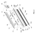
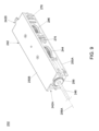
図1は窓シェード100の一実施形態を示す斜視図であり、図2は窓シェード100の分解図である。図1及び図2を参照して、窓シェード100は、ヘッドレール102、ボトムレール104、ヘッドレール102とボトムレール104との間に配置される中間レール106、ボトムレール104と中間レール106との間に配置されるシェード構造108及び作動システム110を含み得る。
Figure 1 is a perspective view of one embodiment of a
ヘッドレール102は窓枠の上部に取り付けられ、任意の所望の形状を有し得る。構造の一例によれば、ヘッドレール102は、窓シェード100の作動システム110を少なくとも部分的に受容するための空洞を含む細長い形状を有し得る。例えば、ヘッドレール102は、2つのエンドキャップ114で両端が閉じられた内部空洞を有するレール部112と、レール部112の前面に取り付けられるカバー116とを含み得る。
The
ボトムレール104は、少なくとも2つのサスペンションコード118及び120でヘッドレール102から吊り下げることができ、2つのサスペンションコード118及び120は、ボトムレール104に固定される端部118A及び120Aをそれぞれ有し得る。構造の一例によれば、ボトムレール104は、シェード構造108の取り付け部を受容するように適合されたチャネルを有し得る。
The
中間レール106は、ヘッドレール102とボトムレール104との間に配置でき、少なくとも2つの他のサスペンションコード118及び120でヘッドレール102から吊り下げることができ、他の2つのサスペンションコード118及び120は、中間レール106に固定される端部118B及び120Bをそれぞれ有し得る。中間レール106は、シェード構造108の取り付け部を受容するように適合されたチャネルを有する細長い形状を有し得る。さらに、中間レール106を介してボトムレール104に固定されるサスペンションコード118及び120の通過を容易にするために、複数のガイド要素122が中間レール106に設けられ得る。ガイド要素122は、中間レール106に取り付けられるグロメットを例示的に含み得る。
The
シェード構造108はセル構造を例示的に有することができ、セル構造は、限定されないが、ハニカム構造を含み得る。しかしながら、シェード構造108は、ボトムレール104と中間レール106との間で展開及び折り畳み可能な任意の適切な構造を有し得ることが理解されよう。シェード構造108は、中間レール106及びボトムレール104にそれぞれ隣接して配置される2つの端部108A及び108Bを有する。例えば、シェード構造108の端部108Aは、中間レール106にシェード構造108の端部108Aを取り付けるために中間レール106と係合するストリップ124を備え、シェード構造108の他端部108Bは、同様にストリップ126を介してボトムレール104に取り付けられる。2つのエンドキャップ128は、中間レール106内でストリップ124を拘束するように中間レール106の両端をそれぞれ閉じることができ、2つのエンドキャップ130は、ボトムレール104内でストリップ126を拘束するためにボトムレール104の両端をそれぞれ閉じ得る。
The
図1及び図2を参照して、ボトムレール104及び中間レール106のそれぞれは、窓シェード100を所望の構成に設定するために、ヘッドレール102に対して独立して垂直に移動可能である。例えば、ボトムレール104は、シェード構造108を広げるためにヘッドレール102及び中間レール106から離れるように下げられ得るか又はシェード構造108を折り畳むためにヘッドレール102及び中間レール106の方に上げられ得る。さらに、ボトムレール104及び中間レール106は、ヘッドレール102と中間レール106との間で光を通過させるための間隙を形成するためにヘッドレール102から離れるよう下げられ得る。ヘッドレール102に対するボトムレール104の垂直位置及び中間レール106の垂直位置は、作動システム110によって制御され得る。
1 and 2, each of the
図1及び図2を参照すると、作動システム110はヘッドレール102に組み付けられ、調整のためにボトムレール104及び中間レール106をヘッドレール102に対して変位させるように動作可能である。作動システム110は2つのコード巻き取りアセンブリ132A及び132B、電気モーターユニット134及び電源136を含み得る。コード巻き取りアセンブリ132Aは、ボトムレール104を昇降するためにボトムレール104に連結される2つのサスペンションコード118、120を巻き取り及び巻き出しするように動作可能である。コード巻き取りアセンブリ132Bは、中間レール106を昇降するために中間レール106に連結された他の2つのサスペンションコード118、120を巻き取り及び巻き出しするように動作可能である。
1 and 2, the
電気モーターユニット134は、2つのコード巻き取りアセンブリ132A、132Bのそれぞれに連結され、電源136に電気的に接続可能である。電気モーターユニット134は、2つのコード巻き取りアセンブリ132A、132Bのそれぞれを独立して駆動するように動作可能である。例えば、電気モーターユニット134は、2つのコード巻き取りアセンブリ132A、132Bにそれぞれ連結される2つのモーターを含んでもよく、2つのモーターのそれぞれは、2つのコード巻き取りアセンブリ132A、132Bの対応する1つを駆動するように独立して動作可能である。電源136は、電気モーターユニット134に電気的に接続でき、電気モーターユニット134を動作させるための電力を供給できる。構造の一例によれば、電源136はバッテリケース138及び電源アダプタ140を含み得る。バッテリケース138は1つ以上のバッテリセルを受容するように構成され、電気モーターユニット134に電気的に接続又は切断できる。電源アダプタ140はコンセントに差し込むことができ、電気モーターユニット134と電気的に接続又は切断できる。電気モーターユニット134はバッテリケース138の電池セルから又はコンセントに接続された電源アダプタ140を介して給電できる。
The
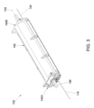
図2を参照して、2つのコード巻き取りアセンブリ132A及び132Bは、電気モーターユニット134の両側にそれぞれ配置できる。図2に関連して、図3は、窓シェード用のコード巻き取りアセンブリ132を示す斜視図であり、図4は、コード巻き取りアセンブリ132の一部の構造の詳細を示す分解図である。図2~図4を参照して、2つのコード巻き取りアセンブリ132A及び132Bのそれぞれは、図3及び図4に示すコード巻き取りアセンブリ132と同じ構成を有することができる。コード巻き取りアセンブリ132は、ハウジング142と、サスペンションコード118に接続されるスプール部144と、サスペンションコード120に接続されるスプール部146と、2つのスプール部144及び146に回転可能に連結されるトランスミッションアクスル148とを含み得る。
Referring to FIG. 2, the two
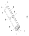
ハウジング142は、ハウジング142の両端142A及び142Bの間に位置し、2つのスプール部144及び146を受容するように構成された空洞を少なくとも部分的に画定するために、互いに固定接続可能な2つのケース部150A及び150Bを含み得る。ハウジング142は、ハウジング142に対して枢動軸154を中心に回転するよう2つのスプール部144及び146を支持可能な複数の取り付け面152を含み得る。図5は、ケース部150Aに設けられた取り付け面152に配置された2つのスプール部144及び146を示す斜視図である。
The
構成の一例によれば、2つのスプール部144及び146は、ハウジング142内で互いに隣接して配置可能な2つの独立した部品として設けられ得る。例えば、スプール部144は、軸方向に対向する2つのスプール端部144A及び144Bを有し、スプール端部144Bはフランジ構造156Aを有し、スプール部146は、軸方向に対向する2つのスプール端部146A及び146Bを有し、2つのスプール部144及び146は、2つのフランジ構造156A及び156Bが互いに係合してハウジング142内に配置され、2つのスプール部144及び146は互いに回転ロックされ、枢動軸154を中心に同時に回転できる。前述の構造は2つのスプール部144及び146の組み立てを促進し得る。しかしながら、2つのスプール部は単一の部品として一体的に形成され得ることが理解されよう。
According to one example of the configuration, the two
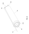
サスペンションコード118は、スプール端部144Bに隣接するスプール部144に固定でき、サスペンションコード120は、スプール端部146Aに隣接するスプール部146に固定できる。図6に示すように、スプール部144の外面はスプール端部144Bに隣接する開口158を有することができ、開口158を介してサスペンションコード118の端部を取り付けることにより、サスペンションコード118をスプール部144に固定できる。サスペンションコード120は同様にスプール部146に固定できる。サスペンションコード118は、ハウジング142の端部142Aで外側に延び、サスペンションコード120は、ハウジング142の反対側の端部142Bで外側に延びるように配置され得る。
The
トランスミッションアクスル148は、トランスミッションアクスル148及び2つのスプール部144及び146がハウジング142に対して同一の枢動軸154を中心に同時に回転できるように、2つのスプール部144及び146に回転可能に連結され、枢動軸154はトランスミッションアクスル148の長手軸に対応する。例えば、スプール部144のスプール端部144Aは、スプール部144の中空内部に接続される正方形又は長方形の孔を備える連結部160を有することができ、スプール部146のスプール端部146Bは、同様に、スプール部146の中空内部に接続される正方形又は長方形の孔を備える連結部164を有し得る。トランスミッションアクスル148は、連結部160及び164に設けられる孔と一致する断面形状を有し得る。トランスミッションアクスル148は、スプール部144の中空内部及びスプール部146の中空内部を介して配置でき、2つの連結部160及び164を介してそれぞれ2つのスプール部144及び146に回転可能に連結できる。組み立て後、トランスミッションアクスル148は、スプール部144の2つのスプール端部144A及び144Bと、スプール部146の2つのスプール端部146A及び146Bとを通って延び、両端142A及び142Bでハウジング142の外部に突出し得る。トランスミッションアクスル148及び2つのスプール部144及び146はハウジング142に対して、2つのサスペンションコード118及び120を2つのスプール部144及び146の周りにそれぞれ巻き付ける第1の方向と、2つのサスペンションコード118及び120を2つのスプール部144及び146からそれぞれ巻き出す、第1の方向と反対の第2の方向とに枢動軸154を中心に同時に回転できる。
The
図4及び図7を参照して、コード巻き取りアセンブリ132は、両端142A及び142Bに隣接してハウジング142にそれぞれ取り付けられる2つのコードガード168及び170をさらに含むことができる。コードガード168は、サスペンションコード118がハウジング142から出る位置でサスペンションコード118と接触可能であり、コードガード170はサスペンションコード120がハウジング142から出る位置でサスペンションコード120と接触可能である。2つのコードガード168及び170は保護を提供でき、2つのサスペンションコード118及び120の通過を促進できる。
4 and 7, the
図2~図7を参照して、2つのコード巻き取りアセンブリ132A及び132Bのそれぞれはコード巻き取りアセンブリ132と同じ構造を有することができ、電気モーターユニット134は、コード巻き取りアセンブリ132Aのトランスミッションアクスル148及びコード巻き取りアセンブリ132Bのトランスミッションアクスル148に両側でそれぞれ連結できる。これにより、電気モーターユニット134は、コード巻き取りアセンブリ132A及び132Bのそれぞれのトランスミッションアクスル148を回転駆動して、ボトムレール104及び中間レール106を所望に動かすことができる。組み立て後、コード巻き取りアセンブリ132Aの2つのサスペンションコード118及び120のうちの1つは、ヘッドレール102に沿って電気モーターユニット134及びコード巻き取りアセンブリ132Bを越えて延びることができるため、コード巻き取りアセンブリ132Aの2つのサスペンションコード118及び120は、ボトムレール104に連結するために電気モーターユニット134の両側でそれぞれ延びることができる。コード巻き取りアセンブリ132Bの2つのサスペンションコード118及び120は、中間レール106に連結するために同様に配置できる。
2 to 7, each of the two
図1及び図2は、それぞれボトムレール104及び中間レール106に連結された2つのコード巻き取りアセンブリ132A及び132Bを有する例を示すが、コード巻き取りアセンブリ132の構成は図示の適用例に限定されないことが理解されよう。図8は、電気モーターユニット134が中間レールを持たない窓シェードのボトムレールに連結され得る1つの単一コード巻き取りアセンブリ132にされ得る、作動システムの変形例を示す斜視図である。したがって、コード巻き取りアセンブリ132は様々な窓シェードでの使用に好適であり得る。
1 and 2 show an example having two cord take-up
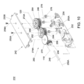
図9は、窓シェード用のコード巻き取りアセンブリ232の変形構造を示す斜視図であり、図10はコード巻き取りアセンブリ232の分解図である。図9及び図10を参照して、コード巻き取りアセンブリ232は、ハウジング242、(図10に2点鎖線で示す)サスペンションコード118に接続されるスプール部244、(図10に2点鎖線で示す)サスペンションコード120に接続されるスプール部246及び2つのスプール部244及び246に回転可能に連結されたトランスミッションアクスル248を含み得る。
Figure 9 is a perspective view showing a modified structure of a
ハウジング242は、ハウジング242の両端242A及び242Bの間に位置し、2つのスプール部244及び246を受容するように適合された空隙を少なくとも部分的に画定するために、互いに固定接続可能な2つのケース部250A及び250Bを含み得る。
The
スプール部244は、スプール部244がハウジング242に対して枢動軸252Aを中心に回転可能になるように、枢動軸252を中心にハウジング242に枢動可能に接続できる。スプール部246は、スプール部246がハウジング242に対して枢動軸254Aを中心に回転可能になるように、枢動軸254を中心にハウジング242に枢動可能に接続でき、枢動軸252A及び254Aは互いに平行で且つ離隔されている。トランスミッションアクスル248は、枢動軸252A及び254Aと実質的に直交する枢動軸256Aを中心にハウジング242に対して回転可能に配置され、枢動軸256Aはトランスミッションアクスル248の長手軸に対応する。例えば、トランスミッションアクスル248は、枢動軸256Aを中心に回転するためにハウジング242に組み付けられる連結部256に接続される端部を有し得る。連結部256はハウジング242の端部242Aに隣接して配置でき、トランスミッションアクスル248を連結部256に回転可能に連結するためにトランスミッションアクスル248の端部が係合する正方形又は長方形の孔を例示的に有し得る。組み立て後、トランスミッションアクスル248は、端部242Aでハウジング242の外に延び得る。スプール部244に接続されるサスペンションコード118は、端部242Aでハウジング242の外に延びるように配置され、スプール部246に接続されるサスペンションコード120は、反対の端部242Bでハウジング242の外に延びるように配置され得る。
The
図9及び図10を参照して、トランスミッションアクスル248は、複数のギア262、264、266、268及び270を含み得るギアトレーン260を介して2つのスプール部244及び246に回転可能に連結されている。ギア262は、ギア262及びスプール部244がハウジング242に対して枢動軸252Aを中心に同時に回転可能となるように、スプール部244に回転可能に固定されている。ギア264は、ギア264及びスプール部246がハウジング242に対して枢動軸254Aを中心に同時に回転可能となるようにスプール部246に回転可能に固定されている。ギア266は連結部256に固定接続されているため、ギア266及びトランスミッションアクスル248がハウジング242に対して枢動軸256Aを中心に同時に回転可能になるようにトランスミッションアクスル248に回転可能に固定されている。構成の一例によれば、ギア266はベベルギアであり得る。ギア268は、枢動軸272Aを中心として枢動可能にハウジング242に接続され、それぞれギア262、264と噛み合っている。ギア270は、枢動軸274Aを中心に枢動可能にハウジング242に接続され、それぞれギア262、266と噛み合っている。ギアトレーン260は、2つのスプール部244、246がトランスミッションアクスル248によって駆動され、サスペンションコード118、120をそれぞれ巻き取るための1つの方向(例えば、時計回り方向及び反時計回り方向のうちの)と、サスペンションコード118、120をそれぞれ巻き出すための他方の方向(例えば、時計回り方向及び反時計回り方向のうちの他方)とに同時に回転可能に構成されている。したがって、トランスミッションアクスル248及び2つのスプール部244、246は、2つのサスペンションコード118、120をそれぞれ巻き取り、巻き出すためにハウジング242に対して同時に回転できる。
9 and 10, the
図9及び図10を参照して、ハウジング242は、サスペンションコード118、120をハウジング242に通すのをガイドするための複数のコードガイド276をさらに備え得る。コードガイド276の例は、限定されないがプーリを含む。
9 and 10, the
図9及び図10に関連して、図11は、前述のコード巻き取りアセンブリ232と同じ構造を有する2つのコード巻き取りアセンブリ232A及び232Bを用いる窓シェード100を示す斜視図である。図9~図11を参照して、作動システム110はヘッドレール102に組み付けられ、ヘッドレール102に対してボトムレール104及び中間レール106を変位させるように動作可能である。図11に示す作動システム110は、2つのコード巻き取りアセンブリ132A及び132Bが2つのコード巻き取りアセンブリ232A及び232Bに置き換えられることを除いて、図2に示す以前の実施形態の構成と概ね同様であり得る。2つのコード巻き取りアセンブリ232A及び232Bのそれぞれは、図9及び10を参照して前述したコード巻き取りアセンブリ232と同じ構成を有し、コード巻き取りアセンブリ232Aの2つのサスペンションコード118及び120はボトムレール104に連結でき、コード巻き取りアセンブリ232Bの2つのサスペンションコード118及び120は中間レール106に連結できる。電気モーターユニット134は、コード巻き取りアセンブリ232Aのトランスミッションアクスル248及びコード巻き取りアセンブリ232Bのトランスミッションアクスル248にそれぞれ両側で連結できる。これにより、電気モーターユニット134は、コード巻き取りアセンブリ232A及び232Bのそれぞれはトランスミッションアクスル248を回転駆動して、ボトムレール104及び中間レール106を所望に回転移動させるように動作可能である。
9 and 10, FIG. 11 is a perspective view showing a
本願で説明した構造の利点は、コンパクトで、窓シェードの作動システムに容易に取り付けられるモジュールとして用いることができるコード巻き取りアセンブリを提供する能力を含む。 Advantages of the structure described herein include the ability to provide a cord winding assembly that is compact and can be used as a module that can be easily attached to a window shade actuation system.
構造の実現は、特定の実施形態の文脈でのみ説明されている。これらの実施形態は、例示的なものであって、限定的なものではない。多くの変形、修正、追加及び改良が可能である。したがって、本願で単一のインスタンスとして説明したコンポーネントに対して複数のインスタンスが提供され得る。例示的な構成で個別のコンポーネントとして提示される構造及び機能は、組み合わされた構造又はコンポーネントとして実施され得る。これら及び他の変形、修正、追加及び改良は、以下の特許請求の範囲に含まれる。
Structural implementations are described only in the context of specific embodiments. These embodiments are exemplary and not limiting. Many variations, modifications, additions, and improvements are possible. Thus, multiple instances may be provided for components described herein as single instances. Structures and functionality presented as separate components in exemplary configurations may be implemented as a combined structure or component. These and other variations, modifications, additions, and improvements are within the scope of the following claims.
Claims (18)
互いに反対にある第1の端部及び第2の端部と、該第1の端部と該第2の端部との間にある空洞とを有するハウジングと、
第1のサスペンションコードに接続される第1のスプール部及び第2のサスペンションコードに接続される第2のスプール部であって、該第1のスプール部及び該第2のスプール部は前記ハウジングの空洞内に配置されている、第1のスプール部及び第2のスプール部と、
前記第1のスプール部及び前記第2のスプール部に回転可能に連結され、少なくとも前記ハウジングの第1の端部で前記ハウジングの外に延びるトランスミッションアクスルであって、該トランスミッションアクスルと、前記第1のスプール部及び前記第2のスプール部とは、前記第1のサスペンションコード及び前記第2のサスペンションコードを前記第1のスプール部及び前記第2のスプール部の周りにそれぞれ巻き取るための第1の方向と、前記第1のサスペンションコード及び前記第2のサスペンションコードを前記第1のスプール部及び前記第2のスプール部からそれぞれ巻き出すための、該第1の方向とは反対の第2の方向とに、前記ハウジングに対して同時に回転可能である、トランスミッションアクスルと、
を含み、
前記第1のスプール部は、互いに対向する第1のスプール端部及び第2のスプール端部を有し、前記第2のスプール部は、互いに対向する第3のスプール端部及び第4のスプール端部を有し、前記第1のスプール部の第2のスプール端部は第1のフランジ構造を有し、前記第2のスプール部の第3のスプール端部は、該第1のフランジ構造と係合して、前記第1のスプール部を前記第2のスプール部に回転可能に係止させる第2のフランジ構造を有し、
前記トランスミッションアクスルは、前記第1のスプール部の第1のスプール端部及び第2のスプール端部を通り、前記第2のスプール部の第3のスプール端部及び第4のスプール端部を通って延びている、コード巻き取りアセンブリ。 1. A cord winding assembly for a window shade, comprising:
a housing having opposed first and second ends and a cavity between the first and second ends;
a first spool portion connected to a first suspension cord and a second spool portion connected to a second suspension cord, the first spool portion and the second spool portion being disposed within a cavity of the housing;
a transmission axle rotatably coupled to the first and second spool pieces and extending outside the housing at least at a first end of the housing, the transmission axle and the first and second spool pieces being simultaneously rotatable relative to the housing in a first direction for winding the first and second suspension cords around the first and second spool pieces, respectively, and in a second direction opposite the first direction for unwinding the first and second suspension cords from the first and second spool pieces, respectively;
Including ,
the first spool portion has opposed first and second spool ends, the second spool portion has opposed third and fourth spool ends, the second spool end of the first spool portion having a first flange structure, and the third spool end of the second spool portion having a second flange structure that engages with the first flange structure to rotatably lock the first spool portion to the second spool portion;
a cord take-up assembly, wherein the transmission axle extends through first and second spool ends of the first spool section and through third and fourth spool ends of the second spool section .
互いに反対にある第1の端部及び第2の端部と、該第1の端部と該第2の端部との間にある空洞とを有するハウジングと、a housing having opposed first and second ends and a cavity between the first and second ends;
第1のサスペンションコードに接続される第1のスプール部及び第2のサスペンションコードに接続される第2のスプール部であって、該第1のスプール部及び該第2のスプール部は前記ハウジングの空洞内に配置されている、第1のスプール部及び第2のスプール部と、a first spool portion connected to a first suspension cord and a second spool portion connected to a second suspension cord, the first spool portion and the second spool portion being disposed within a cavity of the housing;
前記第1のスプール部及び前記第2のスプール部に回転可能に連結され、少なくとも前記ハウジングの第1の端部で前記ハウジングの外に延びるトランスミッションアクスルであって、該トランスミッションアクスルと、前記第1のスプール部及び前記第2のスプール部とは、前記第1のサスペンションコード及び前記第2のサスペンションコードを前記第1のスプール部及び前記第2のスプール部の周りにそれぞれ巻き取るための第1の方向と、前記第1のサスペンションコード及び前記第2のサスペンションコードを前記第1のスプール部及び前記第2のスプール部からそれぞれ巻き出すための、該第1の方向とは反対の第2の方向とに、前記ハウジングに対して同時に回転可能である、トランスミッションアクスルと、a transmission axle rotatably coupled to the first and second spool pieces and extending outside the housing at least at a first end of the housing, the transmission axle and the first and second spool pieces being simultaneously rotatable relative to the housing in a first direction for winding the first and second suspension cords around the first and second spool pieces, respectively, and in a second direction opposite the first direction for unwinding the first and second suspension cords from the first and second spool pieces, respectively;
を含み、Including,
前記第1のスプール部は、互いに反対にある第1のスプール端部及び第2のスプール端部を有し、前記第2のスプール部は、互いに反対にある第3のスプール端部及び第4のスプール端部を有し、前記第1のスプール部の第2のスプール端部は前記第2のスプール部の第3のスプール端部に隣接して配置され、前記第1のサスペンションコードは、前記第1のスプール部の第2のスプール端部に隣接して前記第1のスプール部に固定され、前記第2のサスペンションコードは、前記第2のスプール部の第3のスプール端部に隣接して前記第2のスプール部に固定されている、コード巻き取りアセンブリ。the first spool section has a first spool end and a second spool end opposite each other, the second spool section has a third spool end and a fourth spool end opposite each other, the second spool end of the first spool section is disposed adjacent to the third spool end of the second spool section, the first suspension cord is secured to the first spool section adjacent to the second spool end of the first spool section, and the second suspension cord is secured to the second spool section adjacent to the third spool end of the second spool section.
互いに反対にある第1の端部及び第2の端部と、該第1の端部と該第2の端部との間にある空洞とを有するハウジングと、a housing having opposed first and second ends and a cavity between the first and second ends;
第1のサスペンションコードに接続される第1のスプール部及び第2のサスペンションコードに接続される第2のスプール部であって、該第1のスプール部及び該第2のスプール部は前記ハウジングの空洞内に配置されている、第1のスプール部及び第2のスプール部と、a first spool portion connected to a first suspension cord and a second spool portion connected to a second suspension cord, the first spool portion and the second spool portion being disposed within a cavity of the housing;
前記第1のスプール部及び前記第2のスプール部に回転可能に連結され、少なくとも前記ハウジングの第1の端部で前記ハウジングの外に延びるトランスミッションアクスルであって、該トランスミッションアクスルと、前記第1のスプール部及び前記第2のスプール部とは、前記第1のサスペンションコード及び前記第2のサスペンションコードを前記第1のスプール部及び前記第2のスプール部の周りにそれぞれ巻き取るための第1の方向と、前記第1のサスペンションコード及び前記第2のサスペンションコードを前記第1のスプール部及び前記第2のスプール部からそれぞれ巻き出すための、該第1の方向とは反対の第2の方向とに、前記ハウジングに対して同時に回転可能である、トランスミッションアクスルと、a transmission axle rotatably coupled to the first and second spool pieces and extending outside the housing at least at a first end of the housing, the transmission axle and the first and second spool pieces being simultaneously rotatable relative to the housing in a first direction for winding the first and second suspension cords around the first and second spool pieces, respectively, and in a second direction opposite the first direction for unwinding the first and second suspension cords from the first and second spool pieces, respectively;
を含み、Including,
前記第1のスプール部は、互いに反対にある第1のスプール端部及び第2のスプール端部を有し、前記第2のスプール部は、互いに反対にある第3のスプール端部及び第4のスプール端部を有し、前記第1のスプール部の第2のスプール端部は前記第2のスプール部の第3のスプール端部に回転可能に係止され、前記トランスミッションアクスルは前記第1のスプール部の第1のスプール端部と回転可能に係合し、前記第2のスプール部の第4のスプール端部と回転可能に係合する、コード巻き取りアセンブリ。the first spool section has a first spool end and a second spool end opposite each other, the second spool section has a third spool end and a fourth spool end opposite each other, the second spool end of the first spool section is rotatably engaged to the third spool end of the second spool section, and the transmission axle is rotatably engaged with the first spool end of the first spool section and is rotatably engaged with the fourth spool end of the second spool section.
互いに反対にある第1の端部及び第2の端部と、該第1の端部と該第2の端部との間にある空洞とを有するハウジングと、a housing having opposed first and second ends and a cavity between the first and second ends;
第1のサスペンションコードに接続される第1のスプール部及び第2のサスペンションコードに接続される第2のスプール部であって、該第1のスプール部及び該第2のスプール部は前記ハウジングの空洞内に配置されている、第1のスプール部及び第2のスプール部と、a first spool portion connected to a first suspension cord and a second spool portion connected to a second suspension cord, the first spool portion and the second spool portion being disposed within a cavity of the housing;
ギアトレーンを介して前記第1のスプール部及び前記第2のスプール部に回転可能に連結され、少なくとも前記ハウジングの第1の端部で前記ハウジングの外に延びるトランスミッションアクスルであって、該トランスミッションアクスルと、前記第1のスプール部及び前記第2のスプール部とは、前記第1のサスペンションコード及び前記第2のサスペンションコードを前記第1のスプール部及び前記第2のスプール部の周りにそれぞれ巻き取るための第1の方向と、前記第1のサスペンションコード及び前記第2のサスペンションコードを前記第1のスプール部及び前記第2のスプール部からそれぞれ巻き出すための、該第1の方向とは反対の第2の方向とに、前記ハウジングに対して同時に回転可能である、トランスミッションアクスルと、a transmission axle rotatably coupled to the first and second spool pieces via a gear train and extending outside the housing at least at a first end of the housing, the transmission axle and the first and second spool pieces being simultaneously rotatable relative to the housing in a first direction for winding the first and second suspension cords around the first and second spool pieces, respectively, and in a second direction opposite the first direction for unwinding the first and second suspension cords from the first and second spool pieces, respectively;
を含み、Including,
前記ギアトレーンは第1のギア、第2のギア、第3のギア、第4のギア及び第5のギアを含み、該第1のギアは、該第1のギア及び前記第1のスプール部が第1の枢動軸を中心に同時に回転可能となるように前記第1のスプール部に回転可能に係止され、該第2のギアは、該第2のギア及び前記第2のスプール部が第2の枢動軸を中心に同時に回転可能となるように前記第2のスプール部に回転可能に係止され、該第3のギアは、該第3のギア及び前記トランスミッションアクスルが、前記第1の枢動軸及び前記第2の枢動軸と実質的に直交する第3の枢動軸を中心に同時に回転可能となるように前記トランスミッションアクスルに回転可能に係止され、該第4のギアは前記第1のギア及び前記第2のギアのそれぞれと噛み合い、該第5のギアは前記第1のギア及び前記第3のギアのそれぞれと噛み合う、コード巻き取りアセンブリ。the gear train includes a first gear, a second gear, a third gear, a fourth gear, and a fifth gear, the first gear being rotatably engaged to the first spool portion such that the first gear and the first spool portion can simultaneously rotate about a first pivot axis, the second gear being rotatably engaged to the second spool portion such that the second gear and the second spool portion can simultaneously rotate about a second pivot axis, the third gear being rotatably engaged to the transmission axle such that the third gear and the transmission axle can simultaneously rotate about a third pivot axis substantially perpendicular to the first pivot axis and the second pivot axis, the fourth gear meshing with each of the first gear and the second gear, and the fifth gear meshing with each of the first gear and the third gear.
請求項15に記載の作動システムと、
を含む窓シェードであって、
前記作動システムは前記ヘッドレールに組み付けられ、前記第1のサスペンションコード及び前記第2のサスペンションコードは前記ボトムレールに固定されている、窓シェード。 A head rail and a bottom rail;
An actuation system according to claim 15 ;
1. A window shade comprising:
The window shade, wherein the actuation system is mounted to the head rail, and the first suspension cord and the second suspension cord are secured to the bottom rail.
ヘッドレール、ボトムレール、該ヘッドレールと該ボトムレールとの間に配置される中間レール及び該ボトムレールと該中間レールとの間に配置されるシェード構造と、
請求項17に記載の作動システムと、
を含み、
前記作動システムは前記ヘッドレールに組み付けられ、2つの前記コード巻き取りアセンブリのうちの一方の第1のサスペンションコード及び第2のサスペンションコードは前記ボトムレールに固定され、2つの前記コード巻き取りアセンブリのうちの他方の第1のサスペンションコード及び第2のサスペンションコードは前記中間レールに固定されている、窓シェード。 A window shade, comprising:
a head rail, a bottom rail, an intermediate rail disposed between the head rail and the bottom rail, and a shade structure disposed between the bottom rail and the intermediate rail;
An actuation system according to claim 17 ;
Including,
A window shade, wherein the actuation system is assembled to the head rail, a first suspension cord and a second suspension cord of one of the two cord take-up assemblies are secured to the bottom rail, and a first suspension cord and a second suspension cord of the other of the two cord take-up assemblies are secured to the mid rail.
Applications Claiming Priority (3)
| Application Number | Priority Date | Filing Date | Title |
|---|---|---|---|
| US202163171344P | 2021-04-06 | 2021-04-06 | |
| US63/171,344 | 2021-04-06 | ||
| PCT/US2022/022633 WO2022216501A1 (en) | 2021-04-06 | 2022-03-30 | Cord winding assembly, actuating system and window shade |
Publications (2)
| Publication Number | Publication Date |
|---|---|
| JP2024507933A JP2024507933A (en) | 2024-02-21 |
| JP7648317B2 true JP7648317B2 (en) | 2025-03-18 |
Family
ID=81392983
Family Applications (1)
| Application Number | Title | Priority Date | Filing Date |
|---|---|---|---|
| JP2023551727A Active JP7648317B2 (en) | 2021-04-06 | 2022-03-30 | Cord Winding Assembly, Actuation System and Window Shade |
Country Status (10)
| Country | Link |
|---|---|
| US (1) | US12421794B2 (en) |
| EP (1) | EP4320331B1 (en) |
| JP (1) | JP7648317B2 (en) |
| KR (1) | KR102875974B1 (en) |
| CN (1) | CN115199199A (en) |
| AU (1) | AU2022255475B2 (en) |
| CA (1) | CA3203197A1 (en) |
| MX (1) | MX2023009634A (en) |
| TW (1) | TWI795255B (en) |
| WO (1) | WO2022216501A1 (en) |
Families Citing this family (2)
| Publication number | Priority date | Publication date | Assignee | Title |
|---|---|---|---|---|
| FR3109171B1 (en) * | 2020-04-14 | 2022-04-22 | Somfy Activites Sa | Cloaking device |
| FI131683B1 (en) * | 2022-06-23 | 2025-09-15 | Suomen Visor Oy | BLINDS, TERRACE OR BALCONY GLAZING AND PROCEDURE FOR INSTALLING A BLINDS IN CONNECTION WITH TERRACE OR BALCONY GLAZING |
Citations (7)
| Publication number | Priority date | Publication date | Assignee | Title |
|---|---|---|---|---|
| US20070089838A1 (en) | 2005-10-26 | 2007-04-26 | Hunter Douglas Industries Bv | Bearing cradle |
| US20070144686A1 (en) | 2005-12-22 | 2007-06-28 | Hunter Douglas Inc. | Threaded lift cord spool for coverings for architectural openings |
| DE102009041699B3 (en) | 2009-09-16 | 2011-01-27 | Blöcker Zweigniederlassung der Hunter Douglas Holding GmbH & Co. KG | Curtain arrangement for an architectural opening |
| JP2015218567A (en) | 2014-05-21 | 2015-12-07 | 株式会社ニチベイ | Blind |
| JP2017096060A (en) | 2015-11-27 | 2017-06-01 | トーソー株式会社 | Twin type solar shading device |
| JP2020522626A (en) | 2017-09-25 | 2020-07-30 | テー ヨー カンパニー リミテッド | Shade for window and its spring drive system |
| DE202021100704U1 (en) | 2020-09-03 | 2021-02-18 | Ching Feng Home Fashions Co., Ltd. | Motorized window blinds or roller blinds with gear unit in the lower rail |
Family Cites Families (30)
| Publication number | Priority date | Publication date | Assignee | Title |
|---|---|---|---|---|
| US5515898A (en) * | 1994-12-23 | 1996-05-14 | A & C Products | Operating mechanism for aircraft window shades |
| US6536503B1 (en) * | 1999-03-23 | 2003-03-25 | Hunter Douglas Inc. | Modular transport system for coverings for architectural openings |
| EP1052365B1 (en) | 1999-05-11 | 2004-12-29 | Hunter Douglas Industries B.V. | Operating mechanism for a venetian blind |
| US6588480B2 (en) * | 2000-07-21 | 2003-07-08 | Hunter Douglas Inc. | Counter wrap cord drive |
| US6915831B2 (en) * | 2000-07-21 | 2005-07-12 | Hunter Douglas Inc. | Drum for wrapping a cord |
| US7143802B2 (en) * | 2003-03-20 | 2006-12-05 | Springs Window Fashions Lp | Cordless blinds |
| US6761203B1 (en) * | 2003-03-31 | 2004-07-13 | Tai-Long Huang | Balanced window blind having a spring motor for concealed pull cords thereof |
| US8752607B2 (en) * | 2007-10-22 | 2014-06-17 | Hunter Douglas Inc. | Covering for architectural openings including a rotation limiter |
| IL220779A (en) * | 2012-07-05 | 2016-08-31 | Holis Metal Ind Ltd | Multi-function blind |
| CN203161031U (en) * | 2013-03-26 | 2013-08-28 | 太仓敬富塑胶制品有限公司 | Rope coiling device of non-exposed-rope louver and with braking unit |
| KR101910719B1 (en) * | 2013-07-05 | 2018-12-28 | 데 요 컴퍼니 리미티드 | Window shade and actuating system and operating method thereof |
| TWI602531B (en) | 2014-01-10 | 2017-10-21 | Fu-Mei Fan | Curtain |
| TWI583858B (en) * | 2015-01-20 | 2017-05-21 | 德侑股份有限公司 | Window shade and control system thereof |
| EP3054076A1 (en) * | 2015-02-02 | 2016-08-10 | Springs Window Fashions, LLC | Brake device for lift shades |
| MX2016001493A (en) * | 2015-02-02 | 2016-11-16 | Springs Window Fashions Llc | Shade lift system and headrail arrangement. |
| TWM502735U (en) | 2015-04-02 | 2015-06-11 | Hsin Shu Interior Decoration Co Ltd | Two-stage curtain lighting adjustment device |
| CN107269203B (en) | 2016-04-06 | 2019-05-17 | 亿丰综合工业股份有限公司 | Curtain control mechanism and curtain system thereof |
| DE102017114406B3 (en) | 2017-06-28 | 2018-04-19 | Martha Lucia Castro Ortiz | darkening system |
| EP3434857B1 (en) * | 2017-07-25 | 2020-02-12 | Coulisse B.V. | Screen with head rail, bottom rail and middle rail and a first control unit for the middle rail and a second control unit for the bottom rail |
| US10954716B2 (en) | 2017-09-21 | 2021-03-23 | Hunter Douglas Inc. | Lift station for a covering for an architectural structure |
| NL2020367B1 (en) * | 2018-02-01 | 2019-08-12 | Vako B V | Operating device for a pleated blind |
| US20190343318A1 (en) * | 2018-05-14 | 2019-11-14 | Chen Tian Co., Ltd. | Curtain controller assembly structure |
| EP3832064A4 (en) * | 2018-07-31 | 2022-04-20 | Nichibei Co., Ltd. | PROTECTION DEVICE |
| AU2020201616B2 (en) | 2019-03-08 | 2025-08-14 | Levolor Inc. | Bottom rail assembly for a covering for an architectural structure and related assembly methods |
| TWI700424B (en) | 2019-07-18 | 2020-08-01 | 程田有限公司 | Roll control dual-purpose dual-pipe device |
| CN110541665A (en) * | 2019-08-26 | 2019-12-06 | 江苏二十六度节能科技有限公司 | Energy-saving pleated curtain capable of generating power |
| US11639631B2 (en) * | 2019-12-04 | 2023-05-02 | Teh Yor Co., Ltd. | Window shade and actuating system thereof |
| CN112211542B (en) | 2020-10-27 | 2024-12-10 | 广东创明遮阳科技有限公司 | Sunshade curtain with driving mechanism placed below |
| US20220145698A1 (en) * | 2020-11-12 | 2022-05-12 | Wei-Shun HONG | Folding/unfolding device for a window shade |
| TWI771181B (en) * | 2021-09-10 | 2022-07-11 | 慶豐富實業股份有限公司 | Winding assembly with reversing member and curtain using the same |
-
2022
- 2022-03-30 JP JP2023551727A patent/JP7648317B2/en active Active
- 2022-03-30 AU AU2022255475A patent/AU2022255475B2/en active Active
- 2022-03-30 KR KR1020237028394A patent/KR102875974B1/en active Active
- 2022-03-30 US US17/709,220 patent/US12421794B2/en active Active
- 2022-03-30 CA CA3203197A patent/CA3203197A1/en active Pending
- 2022-03-30 EP EP22719674.8A patent/EP4320331B1/en active Active
- 2022-03-30 MX MX2023009634A patent/MX2023009634A/en unknown
- 2022-03-30 WO PCT/US2022/022633 patent/WO2022216501A1/en not_active Ceased
- 2022-03-31 TW TW111112479A patent/TWI795255B/en active
- 2022-04-06 CN CN202210355616.5A patent/CN115199199A/en active Pending
Patent Citations (7)
| Publication number | Priority date | Publication date | Assignee | Title |
|---|---|---|---|---|
| US20070089838A1 (en) | 2005-10-26 | 2007-04-26 | Hunter Douglas Industries Bv | Bearing cradle |
| US20070144686A1 (en) | 2005-12-22 | 2007-06-28 | Hunter Douglas Inc. | Threaded lift cord spool for coverings for architectural openings |
| DE102009041699B3 (en) | 2009-09-16 | 2011-01-27 | Blöcker Zweigniederlassung der Hunter Douglas Holding GmbH & Co. KG | Curtain arrangement for an architectural opening |
| JP2015218567A (en) | 2014-05-21 | 2015-12-07 | 株式会社ニチベイ | Blind |
| JP2017096060A (en) | 2015-11-27 | 2017-06-01 | トーソー株式会社 | Twin type solar shading device |
| JP2020522626A (en) | 2017-09-25 | 2020-07-30 | テー ヨー カンパニー リミテッド | Shade for window and its spring drive system |
| DE202021100704U1 (en) | 2020-09-03 | 2021-02-18 | Ching Feng Home Fashions Co., Ltd. | Motorized window blinds or roller blinds with gear unit in the lower rail |
Also Published As
| Publication number | Publication date |
|---|---|
| CN115199199A (en) | 2022-10-18 |
| US12421794B2 (en) | 2025-09-23 |
| MX2023009634A (en) | 2023-08-28 |
| TWI795255B (en) | 2023-03-01 |
| WO2022216501A1 (en) | 2022-10-13 |
| AU2022255475A1 (en) | 2023-09-07 |
| AU2022255475B2 (en) | 2025-04-10 |
| US20220316272A1 (en) | 2022-10-06 |
| KR20230132848A (en) | 2023-09-18 |
| EP4320331B1 (en) | 2025-06-25 |
| KR102875974B1 (en) | 2025-10-29 |
| TW202240063A (en) | 2022-10-16 |
| JP2024507933A (en) | 2024-02-21 |
| EP4320331A1 (en) | 2024-02-14 |
| CA3203197A1 (en) | 2022-10-13 |
Similar Documents
| Publication | Publication Date | Title |
|---|---|---|
| JP7648317B2 (en) | Cord Winding Assembly, Actuation System and Window Shade | |
| CA2900959C (en) | Motorized window shade | |
| US9732555B2 (en) | Cordless shade lift system and headrail arrangement | |
| JP6924853B2 (en) | Window shades and their spring drive systems | |
| US20070163727A1 (en) | Window Blinds with Gears | |
| CN215424063U (en) | Electric curtain winding device | |
| CN213768228U (en) | Automobile skylight sunshade curtain with inhaul cable driving structure | |
| US11261655B2 (en) | Window shade and spring drive system thereof | |
| US20180283092A1 (en) | Battery-Powered Window Covering | |
| TWI648460B (en) | Window shade and its spring drive system | |
| CN113417558A (en) | Curtain capable of being installed positively and negatively | |
| US7562688B2 (en) | Bearing cradle | |
| US6283191B1 (en) | Motorized window blind | |
| KR101056786B1 (en) | Corrugated blinds | |
| CN215408385U (en) | Curtain capable of being installed positively and negatively | |
| CN217396179U (en) | Arc windshield sunshade curtain | |
| CN218400146U (en) | Object shielding curtain and vehicle | |
| EP4095344B1 (en) | Control device for lighting elements to be mounted on a roll-up cover installation | |
| JP3934035B2 (en) | shutter | |
| IT202300017724A1 (en) | DEVICE FOR INSTALLATION OF ROLLER COVERING. | |
| WO2024156557A1 (en) | Retractable blind assembly | |
| EP1780370B1 (en) | Bearing cradle | |
| JP2005030014A (en) | Opening apparatus |
Legal Events
| Date | Code | Title | Description |
|---|---|---|---|
| A621 | Written request for application examination |
Free format text: JAPANESE INTERMEDIATE CODE: A621 Effective date: 20230824 |
|
| A977 | Report on retrieval |
Free format text: JAPANESE INTERMEDIATE CODE: A971007 Effective date: 20240813 |
|
| A131 | Notification of reasons for refusal |
Free format text: JAPANESE INTERMEDIATE CODE: A131 Effective date: 20241008 |
|
| A521 | Request for written amendment filed |
Free format text: JAPANESE INTERMEDIATE CODE: A523 Effective date: 20241227 |
|
| TRDD | Decision of grant or rejection written | ||
| A01 | Written decision to grant a patent or to grant a registration (utility model) |
Free format text: JAPANESE INTERMEDIATE CODE: A01 Effective date: 20250204 |
|
| A61 | First payment of annual fees (during grant procedure) |
Free format text: JAPANESE INTERMEDIATE CODE: A61 Effective date: 20250304 |
|
| R150 | Certificate of patent or registration of utility model |
Ref document number: 7648317 Country of ref document: JP Free format text: JAPANESE INTERMEDIATE CODE: R150 |