JP7636552B2 - Batteries, battery packs including the same, and automobiles - Google Patents
Batteries, battery packs including the same, and automobiles Download PDFInfo
- Publication number
- JP7636552B2 JP7636552B2 JP2023536881A JP2023536881A JP7636552B2 JP 7636552 B2 JP7636552 B2 JP 7636552B2 JP 2023536881 A JP2023536881 A JP 2023536881A JP 2023536881 A JP2023536881 A JP 2023536881A JP 7636552 B2 JP7636552 B2 JP 7636552B2
- Authority
- JP
- Japan
- Prior art keywords
- battery
- cap
- current collector
- electrode assembly
- housing
- Prior art date
- Legal status (The legal status is an assumption and is not a legal conclusion. Google has not performed a legal analysis and makes no representation as to the accuracy of the status listed.)
- Active
Links
Images


Classifications
-
- H—ELECTRICITY
- H01—ELECTRIC ELEMENTS
- H01M—PROCESSES OR MEANS, e.g. BATTERIES, FOR THE DIRECT CONVERSION OF CHEMICAL ENERGY INTO ELECTRICAL ENERGY
- H01M50/00—Constructional details or processes of manufacture of the non-active parts of electrochemical cells other than fuel cells, e.g. hybrid cells
- H01M50/30—Arrangements for facilitating escape of gases
- H01M50/342—Non-re-sealable arrangements
- H01M50/3425—Non-re-sealable arrangements in the form of rupturable membranes or weakened parts, e.g. pierced with the aid of a sharp member
-
- H—ELECTRICITY
- H01—ELECTRIC ELEMENTS
- H01M—PROCESSES OR MEANS, e.g. BATTERIES, FOR THE DIRECT CONVERSION OF CHEMICAL ENERGY INTO ELECTRICAL ENERGY
- H01M50/00—Constructional details or processes of manufacture of the non-active parts of electrochemical cells other than fuel cells, e.g. hybrid cells
- H01M50/30—Arrangements for facilitating escape of gases
-
- H—ELECTRICITY
- H01—ELECTRIC ELEMENTS
- H01M—PROCESSES OR MEANS, e.g. BATTERIES, FOR THE DIRECT CONVERSION OF CHEMICAL ENERGY INTO ELECTRICAL ENERGY
- H01M10/00—Secondary cells; Manufacture thereof
- H01M10/04—Construction or manufacture in general
- H01M10/0431—Cells with wound or folded electrodes
-
- H—ELECTRICITY
- H01—ELECTRIC ELEMENTS
- H01M—PROCESSES OR MEANS, e.g. BATTERIES, FOR THE DIRECT CONVERSION OF CHEMICAL ENERGY INTO ELECTRICAL ENERGY
- H01M50/00—Constructional details or processes of manufacture of the non-active parts of electrochemical cells other than fuel cells, e.g. hybrid cells
- H01M50/10—Primary casings; Jackets or wrappings
- H01M50/102—Primary casings; Jackets or wrappings characterised by their shape or physical structure
- H01M50/107—Primary casings; Jackets or wrappings characterised by their shape or physical structure having curved cross-section, e.g. round or elliptic
-
- H—ELECTRICITY
- H01—ELECTRIC ELEMENTS
- H01M—PROCESSES OR MEANS, e.g. BATTERIES, FOR THE DIRECT CONVERSION OF CHEMICAL ENERGY INTO ELECTRICAL ENERGY
- H01M50/00—Constructional details or processes of manufacture of the non-active parts of electrochemical cells other than fuel cells, e.g. hybrid cells
- H01M50/10—Primary casings; Jackets or wrappings
- H01M50/131—Primary casings; Jackets or wrappings characterised by physical properties, e.g. gas permeability, size or heat resistance
-
- H—ELECTRICITY
- H01—ELECTRIC ELEMENTS
- H01M—PROCESSES OR MEANS, e.g. BATTERIES, FOR THE DIRECT CONVERSION OF CHEMICAL ENERGY INTO ELECTRICAL ENERGY
- H01M50/00—Constructional details or processes of manufacture of the non-active parts of electrochemical cells other than fuel cells, e.g. hybrid cells
- H01M50/10—Primary casings; Jackets or wrappings
- H01M50/147—Lids or covers
- H01M50/148—Lids or covers characterised by their shape
- H01M50/152—Lids or covers characterised by their shape for cells having curved cross-section, e.g. round or elliptic
-
- H—ELECTRICITY
- H01—ELECTRIC ELEMENTS
- H01M—PROCESSES OR MEANS, e.g. BATTERIES, FOR THE DIRECT CONVERSION OF CHEMICAL ENERGY INTO ELECTRICAL ENERGY
- H01M50/00—Constructional details or processes of manufacture of the non-active parts of electrochemical cells other than fuel cells, e.g. hybrid cells
- H01M50/10—Primary casings; Jackets or wrappings
- H01M50/172—Arrangements of electric connectors penetrating the casing
- H01M50/174—Arrangements of electric connectors penetrating the casing adapted for the shape of the cells
- H01M50/179—Arrangements of electric connectors penetrating the casing adapted for the shape of the cells for cells having curved cross-section, e.g. round or elliptic
-
- H—ELECTRICITY
- H01—ELECTRIC ELEMENTS
- H01M—PROCESSES OR MEANS, e.g. BATTERIES, FOR THE DIRECT CONVERSION OF CHEMICAL ENERGY INTO ELECTRICAL ENERGY
- H01M50/00—Constructional details or processes of manufacture of the non-active parts of electrochemical cells other than fuel cells, e.g. hybrid cells
- H01M50/10—Primary casings; Jackets or wrappings
- H01M50/183—Sealing members
- H01M50/186—Sealing members characterised by the disposition of the sealing members
- H01M50/188—Sealing members characterised by the disposition of the sealing members the sealing members being arranged between the lid and terminal
-
- H—ELECTRICITY
- H01—ELECTRIC ELEMENTS
- H01M—PROCESSES OR MEANS, e.g. BATTERIES, FOR THE DIRECT CONVERSION OF CHEMICAL ENERGY INTO ELECTRICAL ENERGY
- H01M50/00—Constructional details or processes of manufacture of the non-active parts of electrochemical cells other than fuel cells, e.g. hybrid cells
- H01M50/20—Mountings; Secondary casings or frames; Racks, modules or packs; Suspension devices; Shock absorbers; Transport or carrying devices; Holders
- H01M50/204—Racks, modules or packs for multiple batteries or multiple cells
- H01M50/207—Racks, modules or packs for multiple batteries or multiple cells characterised by their shape
- H01M50/213—Racks, modules or packs for multiple batteries or multiple cells characterised by their shape adapted for cells having curved cross-section, e.g. round or elliptic
-
- H—ELECTRICITY
- H01—ELECTRIC ELEMENTS
- H01M—PROCESSES OR MEANS, e.g. BATTERIES, FOR THE DIRECT CONVERSION OF CHEMICAL ENERGY INTO ELECTRICAL ENERGY
- H01M50/00—Constructional details or processes of manufacture of the non-active parts of electrochemical cells other than fuel cells, e.g. hybrid cells
- H01M50/30—Arrangements for facilitating escape of gases
- H01M50/342—Non-re-sealable arrangements
-
- H—ELECTRICITY
- H01—ELECTRIC ELEMENTS
- H01M—PROCESSES OR MEANS, e.g. BATTERIES, FOR THE DIRECT CONVERSION OF CHEMICAL ENERGY INTO ELECTRICAL ENERGY
- H01M50/00—Constructional details or processes of manufacture of the non-active parts of electrochemical cells other than fuel cells, e.g. hybrid cells
- H01M50/50—Current conducting connections for cells or batteries
- H01M50/502—Interconnectors for connecting terminals of adjacent batteries; Interconnectors for connecting cells outside a battery casing
- H01M50/507—Interconnectors for connecting terminals of adjacent batteries; Interconnectors for connecting cells outside a battery casing comprising an arrangement of two or more busbars within a container structure, e.g. busbar modules
-
- H—ELECTRICITY
- H01—ELECTRIC ELEMENTS
- H01M—PROCESSES OR MEANS, e.g. BATTERIES, FOR THE DIRECT CONVERSION OF CHEMICAL ENERGY INTO ELECTRICAL ENERGY
- H01M50/00—Constructional details or processes of manufacture of the non-active parts of electrochemical cells other than fuel cells, e.g. hybrid cells
- H01M50/50—Current conducting connections for cells or batteries
- H01M50/531—Electrode connections inside a battery casing
- H01M50/533—Electrode connections inside a battery casing characterised by the shape of the leads or tabs
-
- H—ELECTRICITY
- H01—ELECTRIC ELEMENTS
- H01M—PROCESSES OR MEANS, e.g. BATTERIES, FOR THE DIRECT CONVERSION OF CHEMICAL ENERGY INTO ELECTRICAL ENERGY
- H01M50/00—Constructional details or processes of manufacture of the non-active parts of electrochemical cells other than fuel cells, e.g. hybrid cells
- H01M50/50—Current conducting connections for cells or batteries
- H01M50/531—Electrode connections inside a battery casing
- H01M50/536—Electrode connections inside a battery casing characterised by the method of fixing the leads to the electrodes, e.g. by welding
-
- H—ELECTRICITY
- H01—ELECTRIC ELEMENTS
- H01M—PROCESSES OR MEANS, e.g. BATTERIES, FOR THE DIRECT CONVERSION OF CHEMICAL ENERGY INTO ELECTRICAL ENERGY
- H01M50/00—Constructional details or processes of manufacture of the non-active parts of electrochemical cells other than fuel cells, e.g. hybrid cells
- H01M50/50—Current conducting connections for cells or batteries
- H01M50/531—Electrode connections inside a battery casing
- H01M50/538—Connection of several leads or tabs of wound or folded electrode stacks
-
- H—ELECTRICITY
- H01—ELECTRIC ELEMENTS
- H01M—PROCESSES OR MEANS, e.g. BATTERIES, FOR THE DIRECT CONVERSION OF CHEMICAL ENERGY INTO ELECTRICAL ENERGY
- H01M50/00—Constructional details or processes of manufacture of the non-active parts of electrochemical cells other than fuel cells, e.g. hybrid cells
- H01M50/50—Current conducting connections for cells or batteries
- H01M50/543—Terminals
- H01M50/545—Terminals formed by the casing of the cells
-
- H—ELECTRICITY
- H01—ELECTRIC ELEMENTS
- H01M—PROCESSES OR MEANS, e.g. BATTERIES, FOR THE DIRECT CONVERSION OF CHEMICAL ENERGY INTO ELECTRICAL ENERGY
- H01M50/00—Constructional details or processes of manufacture of the non-active parts of electrochemical cells other than fuel cells, e.g. hybrid cells
- H01M50/50—Current conducting connections for cells or batteries
- H01M50/543—Terminals
- H01M50/547—Terminals characterised by the disposition of the terminals on the cells
- H01M50/548—Terminals characterised by the disposition of the terminals on the cells on opposite sides of the cell
-
- H—ELECTRICITY
- H01—ELECTRIC ELEMENTS
- H01M—PROCESSES OR MEANS, e.g. BATTERIES, FOR THE DIRECT CONVERSION OF CHEMICAL ENERGY INTO ELECTRICAL ENERGY
- H01M50/00—Constructional details or processes of manufacture of the non-active parts of electrochemical cells other than fuel cells, e.g. hybrid cells
- H01M50/50—Current conducting connections for cells or batteries
- H01M50/543—Terminals
- H01M50/564—Terminals characterised by their manufacturing process
- H01M50/567—Terminals characterised by their manufacturing process by fixing means, e.g. screws, rivets or bolts
-
- H—ELECTRICITY
- H01—ELECTRIC ELEMENTS
- H01M—PROCESSES OR MEANS, e.g. BATTERIES, FOR THE DIRECT CONVERSION OF CHEMICAL ENERGY INTO ELECTRICAL ENERGY
- H01M50/00—Constructional details or processes of manufacture of the non-active parts of electrochemical cells other than fuel cells, e.g. hybrid cells
- H01M50/50—Current conducting connections for cells or batteries
- H01M50/572—Means for preventing undesired use or discharge
- H01M50/574—Devices or arrangements for the interruption of current
- H01M50/583—Devices or arrangements for the interruption of current in response to current, e.g. fuses
-
- H—ELECTRICITY
- H01—ELECTRIC ELEMENTS
- H01M—PROCESSES OR MEANS, e.g. BATTERIES, FOR THE DIRECT CONVERSION OF CHEMICAL ENERGY INTO ELECTRICAL ENERGY
- H01M50/00—Constructional details or processes of manufacture of the non-active parts of electrochemical cells other than fuel cells, e.g. hybrid cells
- H01M50/50—Current conducting connections for cells or batteries
- H01M50/572—Means for preventing undesired use or discharge
- H01M50/584—Means for preventing undesired use or discharge for preventing incorrect connections inside or outside the batteries
- H01M50/586—Means for preventing undesired use or discharge for preventing incorrect connections inside or outside the batteries inside the batteries, e.g. incorrect connections of electrodes
-
- H—ELECTRICITY
- H01—ELECTRIC ELEMENTS
- H01M—PROCESSES OR MEANS, e.g. BATTERIES, FOR THE DIRECT CONVERSION OF CHEMICAL ENERGY INTO ELECTRICAL ENERGY
- H01M50/00—Constructional details or processes of manufacture of the non-active parts of electrochemical cells other than fuel cells, e.g. hybrid cells
- H01M50/50—Current conducting connections for cells or batteries
- H01M50/572—Means for preventing undesired use or discharge
- H01M50/584—Means for preventing undesired use or discharge for preventing incorrect connections inside or outside the batteries
- H01M50/588—Means for preventing undesired use or discharge for preventing incorrect connections inside or outside the batteries outside the batteries, e.g. incorrect connections of terminals or busbars
-
- H—ELECTRICITY
- H01—ELECTRIC ELEMENTS
- H01M—PROCESSES OR MEANS, e.g. BATTERIES, FOR THE DIRECT CONVERSION OF CHEMICAL ENERGY INTO ELECTRICAL ENERGY
- H01M10/00—Secondary cells; Manufacture thereof
- H01M10/05—Accumulators with non-aqueous electrolyte
- H01M10/058—Construction or manufacture
- H01M10/0587—Construction or manufacture of accumulators having only wound construction elements, i.e. wound positive electrodes, wound negative electrodes and wound separators
-
- H—ELECTRICITY
- H01—ELECTRIC ELEMENTS
- H01M—PROCESSES OR MEANS, e.g. BATTERIES, FOR THE DIRECT CONVERSION OF CHEMICAL ENERGY INTO ELECTRICAL ENERGY
- H01M2220/00—Batteries for particular applications
- H01M2220/20—Batteries in motive systems, e.g. vehicle, ship, plane
-
- H—ELECTRICITY
- H01—ELECTRIC ELEMENTS
- H01M—PROCESSES OR MEANS, e.g. BATTERIES, FOR THE DIRECT CONVERSION OF CHEMICAL ENERGY INTO ELECTRICAL ENERGY
- H01M50/00—Constructional details or processes of manufacture of the non-active parts of electrochemical cells other than fuel cells, e.g. hybrid cells
- H01M50/10—Primary casings; Jackets or wrappings
- H01M50/147—Lids or covers
- H01M50/166—Lids or covers characterised by the methods of assembling casings with lids
- H01M50/167—Lids or covers characterised by the methods of assembling casings with lids by crimping
-
- H—ELECTRICITY
- H01—ELECTRIC ELEMENTS
- H01M—PROCESSES OR MEANS, e.g. BATTERIES, FOR THE DIRECT CONVERSION OF CHEMICAL ENERGY INTO ELECTRICAL ENERGY
- H01M50/00—Constructional details or processes of manufacture of the non-active parts of electrochemical cells other than fuel cells, e.g. hybrid cells
- H01M50/20—Mountings; Secondary casings or frames; Racks, modules or packs; Suspension devices; Shock absorbers; Transport or carrying devices; Holders
- H01M50/249—Mountings; Secondary casings or frames; Racks, modules or packs; Suspension devices; Shock absorbers; Transport or carrying devices; Holders specially adapted for aircraft or vehicles, e.g. cars or trains
-
- H—ELECTRICITY
- H01—ELECTRIC ELEMENTS
- H01M—PROCESSES OR MEANS, e.g. BATTERIES, FOR THE DIRECT CONVERSION OF CHEMICAL ENERGY INTO ELECTRICAL ENERGY
- H01M50/00—Constructional details or processes of manufacture of the non-active parts of electrochemical cells other than fuel cells, e.g. hybrid cells
- H01M50/50—Current conducting connections for cells or batteries
- H01M50/543—Terminals
- H01M50/552—Terminals characterised by their shape
- H01M50/559—Terminals adapted for cells having curved cross-section, e.g. round, elliptic or button cells
-
- Y—GENERAL TAGGING OF NEW TECHNOLOGICAL DEVELOPMENTS; GENERAL TAGGING OF CROSS-SECTIONAL TECHNOLOGIES SPANNING OVER SEVERAL SECTIONS OF THE IPC; TECHNICAL SUBJECTS COVERED BY FORMER USPC CROSS-REFERENCE ART COLLECTIONS [XRACs] AND DIGESTS
- Y02—TECHNOLOGIES OR APPLICATIONS FOR MITIGATION OR ADAPTATION AGAINST CLIMATE CHANGE
- Y02E—REDUCTION OF GREENHOUSE GAS [GHG] EMISSIONS, RELATED TO ENERGY GENERATION, TRANSMISSION OR DISTRIBUTION
- Y02E60/00—Enabling technologies; Technologies with a potential or indirect contribution to GHG emissions mitigation
- Y02E60/10—Energy storage using batteries
-
- Y—GENERAL TAGGING OF NEW TECHNOLOGICAL DEVELOPMENTS; GENERAL TAGGING OF CROSS-SECTIONAL TECHNOLOGIES SPANNING OVER SEVERAL SECTIONS OF THE IPC; TECHNICAL SUBJECTS COVERED BY FORMER USPC CROSS-REFERENCE ART COLLECTIONS [XRACs] AND DIGESTS
- Y02—TECHNOLOGIES OR APPLICATIONS FOR MITIGATION OR ADAPTATION AGAINST CLIMATE CHANGE
- Y02P—CLIMATE CHANGE MITIGATION TECHNOLOGIES IN THE PRODUCTION OR PROCESSING OF GOODS
- Y02P70/00—Climate change mitigation technologies in the production process for final industrial or consumer products
- Y02P70/50—Manufacturing or production processes characterised by the final manufactured product
Landscapes
- Chemical & Material Sciences (AREA)
- Chemical Kinetics & Catalysis (AREA)
- Electrochemistry (AREA)
- General Chemical & Material Sciences (AREA)
- Engineering & Computer Science (AREA)
- Manufacturing & Machinery (AREA)
- Aviation & Aerospace Engineering (AREA)
- Connection Of Batteries Or Terminals (AREA)
- Gas Exhaust Devices For Batteries (AREA)
- Battery Mounting, Suspending (AREA)
- Sealing Battery Cases Or Jackets (AREA)
- Secondary Cells (AREA)
Description
本発明は、バッテリー、それを含むバッテリーパック及び自動車に関する。より具体的には、本発明は、電池ハウジングの一側開放部を覆うキャップがベンティングデバイスとしての機能及びCID(Current Interrupt Device)としての機能を同時に果たすことができる構造を有するバッテリー、それを含むバッテリーパック及び自動車に関する。 The present invention relates to a battery, a battery pack including the battery, and an automobile. More specifically, the present invention relates to a battery having a structure in which a cap covering one side opening of a battery housing can simultaneously function as a venting device and a CID (Current Interrupt Device), and to a battery pack and an automobile including the battery.
本出願は、2021年2月19日付け出願の韓国特許出願第10-2021-0022877号、2021年2月19日付け出願の韓国特許出願第10-2021-0022894号、2021年2月23日付け出願の韓国特許出願第10-2021-0024424号、2021年10月01日付け出願の韓国特許出願第10-2021-0131215号、2021年11月10日付け出願の韓国特許出願第10-2021-0154307号に基づく優先権を主張し、当該出願の明細書及び図面に開示された内容は、すべて本出願に組み込まれる。 This application claims priority to Korean Patent Application No. 10-2021-0022877 filed on February 19, 2021, Korean Patent Application No. 10-2021-0022894 filed on February 19, 2021, Korean Patent Application No. 10-2021-0024424 filed on February 23, 2021, Korean Patent Application No. 10-2021-0131215 filed on October 01, 2021, and Korean Patent Application No. 10-2021-0154307 filed on November 10, 2021, and the contents disclosed in the specifications and drawings of such applications are incorporated herein in their entirety.
通常、円筒形バッテリーを用いてバッテリーパックを製作する場合、複数の円筒形バッテリーをハウジング内に立設し、円筒形バッテリーの上端及び下端をそれぞれ正極端子及び負極端子として活用して複数の円筒形バッテリー同士を電気的に連結する。 Typically, when manufacturing a battery pack using cylindrical batteries, multiple cylindrical batteries are arranged upright in a housing, and the upper and lower ends of the cylindrical batteries are used as positive and negative terminals, respectively, to electrically connect the multiple cylindrical batteries together.
これは、円筒形バッテリーにおいて、電池ハウジングの内部に収納される電極組立体の負極無地部は下方に延長されて電池ハウジングの底面と電気的に連結され、正極無地部は上方に延長されてキャップと電気的に連結されるためである。すなわち、円筒形バッテリーにおいて、電池ハウジングの底面が負極端子として用いられ、電池ハウジングの上端開放部を覆うキャップが正極端子として用いられることが一般的である。 This is because in a cylindrical battery, the negative uncoated portion of the electrode assembly housed inside the battery housing extends downward and is electrically connected to the bottom of the battery housing, and the positive uncoated portion extends upward and is electrically connected to the cap. That is, in a cylindrical battery, it is common for the bottom of the battery housing to be used as the negative terminal, and the cap covering the upper open portion of the battery housing to be used as the positive terminal.
しかし、このように円筒形バッテリーの正極端子と負極端子とが反対側に位置する場合、複数の円筒形バッテリーを電気的に連結するためのバスバーなどの電気的接続部品が円筒形バッテリーの上部及び下部のすべてに適用されねばならず、バッテリーパックの電気的接続構造が複雑になる。 However, when the positive and negative terminals of a cylindrical battery are located on opposite sides in this manner, electrical connection components such as bus bars for electrically connecting multiple cylindrical batteries must be applied to both the upper and lower parts of the cylindrical batteries, making the electrical connection structure of the battery pack complicated.
さらに、このような構造では、絶縁のための部品及び防水性確保のための部品などがバッテリーパックの上部及び下部に別々に適用されねばならず、適用される部品数の増加及び構造の複雑化をもたらす。 Furthermore, in this type of structure, components for insulation and components for ensuring waterproofing must be applied separately to the top and bottom of the battery pack, resulting in an increase in the number of components to be applied and a complicated structure.
したがって、複数の円筒形バッテリーの電気的接続構造を単純化できるように、正極端子と負極端子とが同じ方向に適用された構造を有する円筒形バッテリーの開発が求められている。また、このような構造を有する円筒形バッテリーにおいて、正極端子及び負極端子が形成された一方向には正極端子及び負極端子を形成するための多くの部品が集中される。したがって、内圧増加によるベンティングのための構造及び過電流発生時の電流遮断のための構造は、正極端子及び負極端子が形成された方向の反対側に設けられる必要がある。 Therefore, there is a need to develop a cylindrical battery having a structure in which the positive and negative terminals are applied in the same direction so that the electrical connection structure of multiple cylindrical batteries can be simplified. Furthermore, in a cylindrical battery having such a structure, many parts for forming the positive and negative terminals are concentrated on one side where the positive and negative terminals are formed. Therefore, the structure for venting due to an increase in internal pressure and the structure for cutting off the current when an overcurrent occurs need to be provided on the opposite side of the direction in which the positive and negative terminals are formed.
本発明は、上述した問題点に鑑みてなされたものであり、電池ハウジングの開放部を覆うキャップがベンティングデバイスとしての機能及びCID(Current Interrupt Device)としての機能を同時に果たせるようにすることを目的とする。 The present invention was made in consideration of the above-mentioned problems, and aims to enable a cap covering the open part of a battery housing to simultaneously function as a venting device and a CID (Current Interrupt Device).
また、本発明は、複数のバッテリーの電気的接続構造を単純化することを他の目的とする。 Another object of the present invention is to simplify the electrical connection structure of multiple batteries.
また、本発明は、複数のバッテリーを電気的に接続する際、電気的接続のための部品とバッテリーとの間の接合面積を十分に確保することをさらに他の目的とする。 Another object of the present invention is to ensure sufficient bonding area between the battery and the electrical connection components when electrically connecting multiple batteries.
但し、本発明が解決しようとする技術的課題は上述した課題に制限されず、他の課題は下記の発明の説明から通常の技術者に明らかに理解できるであろう。 However, the technical problems that the present invention aims to solve are not limited to those mentioned above, and other problems will be clearly understood by those of ordinary skill in the art from the following description of the invention.
上述した課題を解決するため、本発明の一態様によるバッテリーは、第1電極と第2電極とこれらの間に介在された分離膜とが巻取軸を中心に巻き取られることでコア及び外周面を定義した電極組立体であって、前記第1電極及び第2電極はそれぞれ巻取方向に沿って活物質層がコーティングされていない第1無地部及び第2無地部を含む電極組立体と、一側に形成された開放部を通して前記電極組立体を収容する電池ハウジングと、周辺領域と比べて薄く構成されたベンティング部を備え、前記開放部を覆い、前記電池ハウジング及び第1無地部と電気的に接続されるキャップと、前記第2無地部と電気的に接続される電池端子と、を含む。 In order to solve the above-mentioned problems, a battery according to one aspect of the present invention is an electrode assembly in which a core and an outer circumferential surface are defined by winding a first electrode, a second electrode, and a separator interposed therebetween around a winding shaft, and the first electrode and the second electrode each include a first uncoated portion and a second uncoated portion that are not coated with an active material layer along the winding direction, respectively; a battery housing that accommodates the electrode assembly through an opening formed on one side; a cap that has a venting portion that is thinner than the surrounding area, covers the opening, and is electrically connected to the battery housing and the first uncoated portion; and a battery terminal that is electrically connected to the second uncoated portion.
前記電池ハウジングは、前記キャップを通じて前記第1無地部と電気的に接続され得る。 The battery housing may be electrically connected to the first uncoated portion through the cap.
前記キャップは、前記第1無地部との電気的接続のための接続部を備え得る。 The cap may have a connection portion for electrical connection with the first uncoated portion.
前記ベンティング部は閉ループを描きながら連続的に形成され得、前記接続部は前記閉ループ内に位置し得る。 The venting portion may be formed continuously while describing a closed loop, and the connection portion may be located within the closed loop.
前記ベンティング部は、前記キャップの外側面及び内側面の少なくともいずれか一面上に形成された溝形態を有し得る。 The venting portion may have a groove shape formed on at least one of the outer surface and the inner surface of the cap.
前記電池端子は、前記開放部の反対側に位置する前記電池ハウジングの閉鎖部を貫通して前記電池ハウジングの外側に露出し得る。 The battery terminal may be exposed to the outside of the battery housing by penetrating a closed portion of the battery housing located opposite the open portion.
前記電池端子は、前記閉鎖部の中心部を貫通し得る。 The battery terminal may pass through the center of the closure.
前記電池端子は、前記電池ハウジングと電気的に絶縁され得る。 The battery terminals may be electrically insulated from the battery housing.
前記バッテリーは、前記第1無地部と結合される第1集電体をさらに含み得る。 The battery may further include a first current collector coupled to the first uncoated portion.
前記第1集電体は、前記キャップと電気的に接続され得る。 The first current collector may be electrically connected to the cap.
前記第1集電体と前記キャップとは、リードタブを介して電気的に接続され得る。 The first collector and the cap may be electrically connected via a lead tab.
前記リードタブは、前記第1集電体と前記キャップとの間の距離よりも長い長さを有し得る。 The lead tab may have a length greater than the distance between the first collector and the cap.
前記バッテリーは、前記第2無地部と結合される第2集電体をさらに含み得る。 The battery may further include a second current collector coupled to the second uncoated portion.
前記第2集電体は、前記電池端子と結合され得る。 The second current collector may be coupled to the battery terminal.
前記バッテリーは、前記キャップと前記電池ハウジングとの間に介在されるシーリングガスケットをさらに含み得る。 The battery may further include a sealing gasket interposed between the cap and the battery housing.
前記電池ハウジングは、外周面の周りが押し込まれて形成されたビーディング(beading)部と、前記ビーディング部の下方において前記開放部を定義する終端が前記キャップの周縁を包むように延長されて折り曲げられたクリンピング(crimping)部と、を備え得る。 The battery housing may have a beading portion formed by pressing in around the outer periphery, and a crimping portion whose end defining the opening below the beading portion is extended and folded to wrap around the periphery of the cap.
前記シーリングガスケットは、前記クリンピング部が形成された領域において前記キャップと前記電池ハウジングとが接触する領域を除いた残りの領域に介在され得る。 The sealing gasket may be interposed in the remaining area of the area where the crimping portion is formed, excluding the area where the cap and the battery housing contact.
前記電池ハウジングは、外周面の周りが押し込まれて形成されたビーディング部と、前記ビーディング部の下方において前記開放部を定義する終端が前記キャップの周縁を包むように延長されて折り曲げられたクリンピング部と、を備え得る。 The battery housing may have a beading portion formed by pressing in around the outer periphery, and a crimping portion whose end defining the opening below the beading portion is extended and bent to wrap around the periphery of the cap.
前記第1集電体の周縁は、前記ビーディング部によって支持され得る。 The periphery of the first current collector may be supported by the beading portion.
対面する前記第1集電体の周縁と前記電池ハウジングのビーディング部との間には絶縁層が介在され得る。 An insulating layer may be interposed between the opposing periphery of the first current collector and the beading portion of the battery housing.
前記絶縁層は、前記第1集電体及び前記ビーディング部のいずれか一つの表面に形成された絶縁コーティング層であり得る。 The insulating layer may be an insulating coating layer formed on the surface of either the first collector or the beading portion.
前記バッテリーは、前記キャップと対面する前記電極組立体の下面を覆う絶縁体をさらに含み得る。 The battery may further include an insulator covering the underside of the electrode assembly that faces the cap.
前記絶縁体は、前記電極組立体の巻取中心に形成された孔に対応する位置に形成される孔を備え得る。 The insulator may have a hole formed at a position corresponding to a hole formed at the winding center of the electrode assembly.
前記第1集電体と前記キャップとは、リードタブを介して電気的に接続され得、前記絶縁体は、前記リードタブが通過する孔を備え得る。 The first collector and the cap may be electrically connected via a lead tab, and the insulator may have a hole through which the lead tab passes.
前記第1無地部の少なくとも一部は、前記電極組立体の巻取方向に沿って分割された複数の分切片を含み得、前記複数の分切片は、前記電極組立体の半径方向に沿って折り曲げられ得る。 At least a portion of the first uncoated portion may include a plurality of segments divided along the winding direction of the electrode assembly, and the plurality of segments may be folded along the radial direction of the electrode assembly.
折り曲げられた前記複数の分切片は、前記半径方向によって多重に重なり得る。 The folded segments may overlap in multiple layers in the radial direction.
前記電極組立体は、前記第1無地部の前記分切片の重畳数が前記電極組立体の半径方向に沿って一定に維持される領域である溶接ターゲット領域を備え得、前記第1集電体は、前記溶接ターゲット領域で前記第1無地部と結合され得る。 The electrode assembly may include a welding target area in which the overlapping number of the segments of the first uncoated portion is maintained constant along the radial direction of the electrode assembly, and the first current collector may be joined to the first uncoated portion at the welding target area.
前記第2無地部の少なくとも一部は、前記電極組立体の巻取方向に沿って分割された複数の分切片を含み得、前記複数の分切片は、前記電極組立体の半径方向に沿って折り曲げられ得る。 At least a portion of the second uncoated portion may include a plurality of segments divided along the winding direction of the electrode assembly, and the plurality of segments may be folded along the radial direction of the electrode assembly.
折り曲げられた前記複数の分切片は、前記半径方向に沿って多重に重なり得る。 The folded segments may overlap in multiple layers along the radial direction.
前記電極組立体は、前記第2無地部の前記分切片の重畳数が前記電極組立体の半径方向に沿って一定に維持される領域である溶接ターゲット領域を備え得、前記第2集電体は、前記溶接ターゲット領域で前記第2無地部と結合され得る。 The electrode assembly may include a welding target area in which the overlapping number of the segments of the second uncoated portion is maintained constant along the radial direction of the electrode assembly, and the second current collector may be joined to the second uncoated portion at the welding target area.
正極と負極との間で測定された抵抗が4mΩ以下であり得る。 The resistance measured between the positive and negative electrodes may be 4 mΩ or less.
前記バッテリーの直径を高さで除したフォームファクタ(form factor)の比が0.4よりも大きくなり得る。 The battery's form factor, or the ratio of its diameter divided by its height, may be greater than 0.4.
また、上述した課題を解決するため、本発明の他の一態様によるバッテリーパックは、上述した本発明のバッテリーを複数個含む。 In addition, to solve the above-mentioned problems, a battery pack according to another aspect of the present invention includes a plurality of the batteries of the present invention described above.
複数の前記バッテリーは、所定数の列で配列され、それぞれの前記バッテリーの前記電池端子及び電池ハウジングの閉鎖部の外側面は上部に向かって配置され得る。 The batteries may be arranged in a predetermined number of rows, with the battery terminals and the outer surface of the closure of the battery housing of each battery being positioned toward the top.
前記バッテリーパックは、複数の前記バッテリーを直列及び並列に連結する複数のバスバーを含み得、前記複数のバスバーは、前記複数のバッテリーの上部に配置され得る。このとき、前記複数のバスバーのそれぞれは、隣接するバッテリーの電池端子同士の間で延長されるボディ部と、前記ボディ部の一側に延びて前記一側に位置したバッテリーの電池端子に電気的に結合する複数の第1バスバー端子と、前記ボディ部の他側に延びて前記他側に位置したバッテリーの電池ハウジングの閉鎖部の外側面に電気的に結合する複数の第2バスバー端子と、を含み得る。 The battery pack may include a plurality of bus bars connecting the batteries in series and in parallel, and the plurality of bus bars may be disposed on the upper portion of the plurality of batteries. In this case, each of the plurality of bus bars may include a body portion extending between battery terminals of adjacent batteries, a plurality of first bus bar terminals extending to one side of the body portion and electrically connecting to the battery terminals of the battery located on the one side, and a plurality of second bus bar terminals extending to the other side of the body portion and electrically connecting to the outer surface of the closing portion of the battery housing of the battery located on the other side.
また、上述した課題を解決するため、本発明のさらに他の一態様による自動車は、上述した本発明のバッテリーパックを含む。 In addition, in order to solve the above-mentioned problems, a vehicle according to yet another aspect of the present invention includes the above-mentioned battery pack of the present invention.
本発明の一態様によれば、電池ハウジングの開放部を覆うキャップがベンティングデバイスとしての機能及びCIDとしての機能を同時に果たすことができる。 According to one aspect of the present invention, the cap that covers the open portion of the battery housing can simultaneously function as a venting device and a CID.
また、本発明の一態様によれば、複数のバッテリーの電気的接続がバッテリーの長手方向の一側で行われるため、電気的接続構造を単純化することができる。 In addition, according to one aspect of the present invention, the electrical connection structure can be simplified because the electrical connection of multiple batteries is performed on one side of the battery in the longitudinal direction.
また、本発明の一態様によれば、電気的接続のための部品とバッテリーとの間の接合面積が十分に確保されるため、電気抵抗を減少でき、結合強度を十分に確保することができる。 In addition, according to one aspect of the present invention, the bonding area between the battery and the parts for electrical connection is sufficiently secured, so that electrical resistance can be reduced and sufficient bonding strength can be secured.
但し、本発明によって奏される効果は上述した効果に制限されず、他の効果は後述する発明の説明から当業者に明確に理解できるであろう。 However, the effects achieved by the present invention are not limited to those described above, and other effects will be clearly understood by those skilled in the art from the description of the invention below.
本明細書に添付される次の図面は、本発明の望ましい実施形態を例示するものであり、発明の詳細な説明とともに本発明の技術的な思想をさらに理解させる役割のためのものであるため、本発明は図面に記載された事項だけに限定されて解釈されるものではない。 The following drawings attached to this specification are intended to illustrate preferred embodiments of the present invention and, together with the detailed description of the invention, serve to provide a better understanding of the technical concepts of the present invention. Therefore, the present invention should not be interpreted as being limited to only the matters depicted in the drawings.
以下、添付された図面を参照して本発明の望ましい実施形態を詳しく説明する。これに先立ち、本明細書及び特許請求の範囲において使用された用語や単語は通常的及び辞書的な意味に限定して解釈されるものではなく、発明者自らは発明を最善の方法で説明するために用語の概念を適切に定義できるという原則に則して本発明の技術的な思想に応ずる意味及び概念で解釈されるものである。 Hereinafter, a preferred embodiment of the present invention will be described in detail with reference to the attached drawings. Prior to this, the terms and words used in this specification and claims are not to be interpreted as being limited to their ordinary and dictionary meanings, but are to be interpreted as having meanings and concepts corresponding to the technical ideas of the present invention, in accordance with the principle that the inventor himself can appropriately define the concepts of terms in order to best describe the invention.
したがって、本明細書に記載された実施形態及び図面に示された構成は、本発明の最も望ましい一実施形態に過ぎず、本発明の技術的な思想のすべてを表すものではないため、本出願の時点においてこれらに代替できる多様な均等物及び変形例があり得ることを理解されたい。 Therefore, it should be understood that the embodiment described in this specification and the configuration shown in the drawings are merely the most preferred embodiment of the present invention and do not represent the entire technical idea of the present invention, and that there may be various equivalents and modifications that can be substituted for them at the time of this application.
また、発明の理解を助けるため、添付された図面は実際の縮尺通りに図示されず、一部構成要素の寸法を誇張して図示することがある。また、異なる実施形態における同じ構成要素に対しては同じ参照番号が付され得る。 In addition, to facilitate understanding of the invention, the accompanying drawings may not be drawn to scale, and the dimensions of some components may be exaggerated. Also, the same reference numbers may be used for the same components in different embodiments.
二つの比較対象が同一であるという表現は「実質的に同一である」ことを意味する。したがって、「実質的に同一」とは、当業界において低い水準と見なされる偏差、例えば5%以内の偏差を有する場合を含み得る。また、所定の領域においてあるパラメータが均一であるとは、該当領域において平均的な観点で均一であることを意味する。 The expression that two objects to be compared are identical means that they are "substantially identical." Therefore, "substantially identical" may include cases where there is a deviation that is considered to be a low level in the industry, for example, a deviation of 5% or less. In addition, the expression that a certain parameter is uniform in a given region means that the parameter is uniform from an average perspective in that region.
また、第1、第2などが多様な構成要素を示すために使用されているが、これら用語は構成要素を制限するためのものではない。これら用語は単に一つの構成要素を他の構成要素と区別するために使用されるものであり、特に言及しない限り、第1構成要素は第2構成要素にもなり得る。 In addition, although terms such as "first" and "second" are used to indicate various components, these terms are not intended to limit the components. These terms are merely used to distinguish one component from another, and unless otherwise specified, the first component can also be the second component.
明細書の全体において、特に言及しない限り、各構成要素は単数または複数であり得る。 Throughout the specification, each element may be singular or plural unless otherwise stated.
構成要素の「上部(または下部)」または構成要素の「上(または下)」に任意の構成が配置されるとは、任意の構成が該構成要素の上面(または下面)に接して配置されることだけでなく、前記構成要素と該構成要素の上に(または下に)配置された任意の構成との間に他の構成が介在され得ることを意味する。 When an arbitrary configuration is disposed "on (or under)" a component or "above (or below)" a component, this does not only mean that the arbitrary configuration is disposed in contact with the upper surface (or lower surface) of the component, but also that other configurations may be interposed between the component and the arbitrary configuration disposed above (or below) the component.
また、ある構成要素が他の構成要素に「連結」、「結合」または「接続」されるとするとき、構成要素が相互に直接的に連結されるかまたは接続される場合だけでなく、各構成要素の間に他の構成要素が「介在」されるか、または、各構成要素が他の構成要素を通じて「連結」、「結合」または「接続」されることも含む。 In addition, when a component is said to be "coupled," "coupled," or "connected" to another component, this does not only mean that the components are directly coupled or connected to each other, but also that other components are "interposed" between each component, or that each component is "coupled," "coupled," or "connected" through other components.
明細書の全体において、「A及び/またはB」とは、特に言及しない限り、A、B、またはA及びBを意味し、「C~D」とは、特に言及しない限り、C以上D以下を意味する。 Throughout the specification, "A and/or B" means A, B, or A and B, unless otherwise specified, and "C-D" means C or more and D or less, unless otherwise specified.
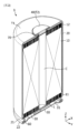
図1~図3b、及び図6を参照すると、本発明の一実施形態によるバッテリー1は、例えば円筒形バッテリーであり得る。前記円筒形バッテリー1は、電極組立体10、電池ハウジング20、キャップ30及び電池端子40を含む。前記円筒形バッテリー1は、上述した構成要素の他にも、第1集電体50及び/またはシーリングガスケット60及び/または絶縁ガスケット70及び/または第2集電体80及び/または絶縁体(第1絶縁体)90をさらに含み得る。本発明は、電池の形状によって制限されず、他の形状の電池、例えば角形電池にも適用可能である。
Referring to Figs. 1 to 3b and 6, a
前記電極組立体10は、第1無地部11及び第2無地部12を備える。前記電極組立体10は、第1極性を有する第1電極、第2極性を有する第2電極、及び第1電極と第2電極との間に介在される分離膜を含む。前記第1電極は負極または正極であり、第2電極は第1電極と反対極性を有する電極に該当する。
The
前記電極組立体10は、例えばゼリーロール(jelly-roll)構造を有し得る。すなわち、前記電極組立体10は、第1電極、分離膜、第2電極を順次に少なくとも1回積層して形成された積層体を巻き取ることで製造され得る。このようなゼリーロール型の電極組立体10は、巻取中心Cに形成されて高さ方向(Z軸方向)に沿って延在される巻取中心孔を備え得る。一方、前記電極組立体10の外周面上には電池ハウジング20との絶縁のために分離膜がさらに備えられ得る。
The
前記第1電極は、第1導電性基材、及び第1導電性基材の一面または両面上に塗布されて形成される第1電極活物質層を含む。前記第1導電性基材の幅方向(Z軸方向)の一側端部には第1電極活物質が塗布されていない第1無地部が存在する。前記第1無地部は、第1電極を広げた状態を基準にして、第1電極の長手方向に沿って一側端部から他側端部まで延長された形態を有する。前記第1無地部11は、第1電極タブとして機能することができる。前記第1無地部11は、電極組立体10の一面上に備えられる。より具体的には、前記第1無地部11は、電池ハウジング20内に収容された電極組立体10の高さ方向(Z軸方向)の下側に備えられる。
The first electrode includes a first conductive substrate and a first electrode active material layer formed by coating on one or both sides of the first conductive substrate. A first uncoated portion where the first electrode active material is not coated is present at one end of the width direction (Z-axis direction) of the first conductive substrate. The first uncoated portion has a shape that extends from one end to the other end along the length direction of the first electrode based on the first electrode being in an unfolded state. The first
前記第2電極は、第2導電性基材、及び第2導電性基材の一面または両面上に塗布されて形成される第2電極活物質層を含む。前記第2導電性基材の幅方向(Z軸方向)の他側端部には第2電極活物質が塗布されていない無地部が存在する。前記第2無地部は、第2電極を広げた状態を基準にして、第2電極の長手方向に沿って一側端部から他側端部まで延長された形態を有する。前記第2無地部12は、第2電極タブとして機能することができる。前記第2無地部12は、電極組立体10の他面上に備えられる。より具体的には、前記第2無地部12は、電池ハウジング20内に収容された電極組立体10の高さ方向(Z軸方向)の上側に備えられる。
The second electrode includes a second conductive substrate and a second electrode active material layer formed by coating on one or both sides of the second conductive substrate. An uncoated portion where the second electrode active material is not coated is present at the other end of the width direction (Z-axis direction) of the second conductive substrate. The second uncoated portion has a shape that extends from one end to the other end along the length direction of the second electrode based on the unfolded state of the second electrode. The second
すなわち、前記第1無地部11と第2無地部12とは、電極組立体10の高さ方向(Z軸方向)、すなわち円筒形バッテリー1の高さ方向に沿って反対方向に延長されて突出し、分離膜の外部に露出する。
That is, the first
一方、図7を参照すると、前記第1無地部11及び/または第2無地部12の少なくとも一部は、電極組立体10の巻取方向に沿って分割された複数の分切片Fを含み得る。この場合、前記複数の分切片は、電極組立体10の半径方向に沿って折り曲げられ得る。折り曲げられた前記複数の分切片は、多重に重なり得る。この場合、後述する第1集電体50及び/または第2集電体80は、複数の分切片Fが多重に重なっている領域に結合され得る。
Meanwhile, referring to FIG. 7, at least a portion of the first
一方、前記電極組立体10は、第1無地部11及び/または第2無地部12の分切片Fの重畳層数が電極組立体10の半径方向に沿って一定に維持される領域である溶接ターゲット領域を備え得る。溶接ターゲット領域では分切片Fの重畳層数が略最大に維持されるため、後述する第1集電体50と第1無地部11との溶接及び/または第2集電体80と第2無地部12との溶接は溶接ターゲット領域で行うことが有利である。これは、例えばレーザー溶接を適用する際、溶接品質を向上させるためレーザーの出力を高める場合、レーザービームが第1無地部11及び/または第2無地部12を貫通して電極組立体10を損傷させることを防止するためである。また、これは、溶接スパッタなどの異物が電極組立体10の内部に流入することを効果的に防止するためである。
Meanwhile, the
図1~図3bを参照すると、前記電池ハウジング20は、下側に開放部が形成された略円筒形の収容体であって、導電性を有する金属材質からなる。前記電池ハウジング20の側面と上面とは一体的に形成され得る。前記電池ハウジング20の上面、すなわち電池ハウジング20の閉鎖部の外側面は略扁平な形態を有する。前記電池ハウジング20は、その高さ方向(Z軸方向)の一側に形成された開放部から電極組立体10を収容し、電解質も一緒に収容する。
Referring to Figures 1 to 3b, the
前記電池ハウジング20は、その高さ方向(Z軸方向)の下端が開放され、上端が閉鎖された形態を有し得る。前記電池ハウジング20は、その下端部に形成されたビーディング部21及びクリンピング部22を備え得る。前記ビーディング部21は、電極組立体10の下部に形成される。前記ビーディング部21は、電池ハウジング20の外周面の周りを押し込んで形成され得る。前記ビーディング部21は、例えば電池ハウジング20の幅(直径)と対応するサイズを有する電極組立体10が電池ハウジング20の下端に形成された開放部から抜け出ないようにし、キャップ30が載置される支持部として機能することができる。さらに、前記ビーディング部21は、第1集電体50が載置される支持部としても機能できる。すなわち、前記第1集電体50の周縁はビーディング部21によって支持され得る。
The
前記クリンピング部22は、ビーディング部21の下側に形成される。前記クリンピング部22は、ビーディング部21の下側で電池ハウジング20の開放部を定義する終端がキャップ30の周縁を包むように延長されて折り曲げられた形態を有し得る。
The crimping
但し、本発明の電池ハウジング20は、ビーディング部21及び/またはクリンピング部22を備えなくてもよい。この場合、電極組立体10の固定及び/またはキャップ30の固定及び/または電池ハウジング20の密封は、例えば電極組立体10に対するストッパとして機能可能な部品の追加適用及び/またはキャップ30が載置可能な構造物の追加適用及び/または電池ハウジング20とキャップ30との間の溶接などを通じて実現し得る。
However, the
一方、前記電池ハウジング20は、下方に延長された第1無地部11と同じ極性を有する。前記電池ハウジング20は、キャップ30を通じて第1無地部11と電気的に接続される。前記電池ハウジング20の極性について詳しくは、キャップ30についての説明とともに後述する。
Meanwhile, the
図2~図5を参照すると、前記キャップ30は、電池ハウジング20の下端に形成された開放部を覆い、電池ハウジング20及び第1無地部11と電気的に接続される。前記キャップ30は、伝導性を有する金属材質からなる部品である。前記キャップ30は、内圧の増加によって破断して内部ガスを排出するベンティング部31、及び第1無地部11との電気的接続のための接続部Pを備える。前記キャップ30は、本発明の円筒形バッテリー1において、バッテリーの異常発生による内圧増加時にベンティング部材として機能し、また過電流の発生時に電流遮断部材として機能する。
Referring to Figs. 2 to 5, the
前記キャップ30は、電池ハウジング20の下端に形成された開放部に溶接によって結合され得る。これと異なり、前記キャップ30は、後述するシーリングガスケット60によって電池ハウジング20のクリンピング部22内に固定されてもよい。勿論、前記シーリングガスケット60が適用される場合にも、より高い固定力及び電気抵抗の減少のため、溶接による固定が並行され得る。
The
前記キャップ30は、電極組立体10の第1無地部11と電気的に接続される。前記電極組立体10の第1無地部11は、キャップ30の接続部Pに直接結合され得る。これと異なり、前記電極組立体10の第1無地部11は、後述する第1集電体50及び/またはリードタブLを通じてキャップ30の接続部Pに結合されてもよい。
The
前記ベンティング部31は、キャップ30において周辺領域と比べて剛性の面でより弱い領域に該当する。前記キャップ30の厚さ調節を通じてベンティング部31を形成する場合、ベンティング部31はキャップ30において周辺領域と比べてより薄い領域に該当する。例えば、前記ベンティング部31は、キャップ30の外側面及び/または内側面上に形成された溝形態を有し得る。前記キャップ30が全体的に同じ材質からなる場合、特定領域がより薄く形成されていると、電池ハウジング20の内圧が異常に大きく増加する場合、厚さの薄い領域が破断し、その部分から内部で生成されたガスが排出され得る。勿論、これと異なり、周辺領域と比べて強度及び/または融点などの面でより弱い材質を適用する方式でベンティング部31を形成してもよい。
The venting
本発明の一実施形態による円筒形バッテリー1は、後述するように、高さ方向(Z軸方向)の上部に電池端子40が備えられた構造を有し、これにより上部の構造が下部の構造よりも複雑である。したがって、ベンティングを通じた内部ガスの排出のため、円筒形バッテリー1の底面を成すキャップ30にベンティング部31が形成され得る。
As described below, the
一方、前記ベンティング部31は、閉ループを描きながら連続的に形成され、接続部Pはこのような閉ループ内に位置する。すなわち、電極組立体10の第1無地部11からキャップ30を通過して電池ハウジング20に移動する電流は必ずベンティング部31を通ることになる。これは前記キャップ30に、上述したベンティング部材としての機能の他にも、過電流の発生時に電流遮断部材としての機能も持たせるためである。前記接続部Pがベンティング部31の閉ループの外側に位置すると、電流の経路がベンティング部31を通過しなくなるため、ベンティング部31は電流遮断部材として機能することができない。また、前記接続部Pがベンティング部31が形成するルーフ内に位置しても、図5に示されたようにそのルーフが閉ループを形成せずに一部が開いた形態を有すると、電極組立体10からキャップ30に伝達された電流は開いた領域を通って流れるはずであるため、この場合にもベンティング部31は電流遮断部材として機能することができない。
Meanwhile, the venting
図1、図2及び図6を参照すると、前記電池端子40は、電池ハウジング20の一側に形成された開放部の反対側に位置する閉鎖部を貫通し得る。前記電池端子40は、電池ハウジング20内で電極組立体10の第2無地部12と電気的に接続される。前記電池端子40は、第2無地部12と直接結合され得るが、後述する第2集電体80を通じて電極組立体10と電気的に接続されてもよい。前記電池端子40は、伝導性を有する金属材質からなる部品である。前記電池端子40は、電池ハウジング20と電気的に絶縁される。
Referring to Figs. 1, 2 and 6, the
前記電池端子40と電池ハウジング20との絶縁は多様な方式によって実現可能である。例えば、絶縁は、絶縁ガスケット70の適用によって実現され得る。他の例として、絶縁は、電池端子40及び/または電池ハウジング20の少なくとも一部に絶縁のためのコーティングを施すことで実現され得る。さらに他の例として、絶縁は、絶縁のためのコーティングなどのような処理や別途の部品の適用なしに、電池端子40と電池ハウジング20との離隔状態が維持されるように電池端子40を堅固に固定することで実現されてもよい。
Insulation between the
前記電池端子40は、電池ハウジング20の上面(X-Y平面に平行な面)の略中心部を貫通し得る。前記電池端子40は、電池ハウジング20の内部に挿入された部分のうちの少なくとも一部が電極組立体10の第2無地部12または第2集電体80と溶接などによって結合され得る。また、前記電池端子40は、電池ハウジング20の内部に挿入された部分のうちの少なくとも一部が電池ハウジング20の上面側に曲がってリベッティングされ得る。すなわち、本発明の電池端子40は、電池ハウジング20を貫通して電池ハウジング20の内側面上にリベッティングによって結合されるリベット型の端子であり得る。
The
このように、本発明の円筒形バッテリー1は、第1無地部11と同じ極性を有する電池ハウジング20の上面、すなわち閉鎖部の外側面が第1電極端子T1として機能し、第2無地部12と同じ極性を有する電池端子40が第2電極端子T2として機能することができる。したがって、本発明の円筒形バッテリー1は、高さ方向の一側に一対の電極端子(第1電極端子T1、第2電極端子T2)がすべて備えられた構造を有し、これにより複数の円筒形バッテリー1を電気的に連結する際に、一方向にすべての電気的接続部品の配置が集中される構造を有する。このような構造は、バッテリーパックの製造において構造的簡素化をもたらし、これにより生産性の向上及びエネルギー密度の向上をもたらすことができる。
In this way, in the
また、本発明の円筒形バッテリー1は、電池ハウジング20の略扁平な上面のうち電池端子40が占める領域を除いた他の領域全体を第1電極端子T1として活用可能である。したがって、バスバーなどの電気的接続のための部品を第1電極端子T1に結合する際に十分な結合面積を確保でき、これにより大面積バスバーの適用時にも容易に結合可能であって結合部位における電気抵抗を減少させることができる。
In addition, the
図2~図3bを参照すると、前記第1集電体50は、電極組立体10の高さ方向(Z軸方向)の下端に結合され得る。前記第1集電体50は第1無地部11と結合され得る。前記第1集電体50はキャップ30と電気的に接続される。すなわち、前記円筒形バッテリー1が第1集電体50を備える場合、電極組立体10の第1無地部11は第1集電体50を通じてキャップ30と電気的に接続される。前記第1集電体50は、例えばリードタブLを通じてキャップ30と電気的に接続され得る。前記リードタブLは、第1集電体50と一体に形成された部品であってもよく、別個に提供されてその一側が第1集電体50に結合され、その他側がキャップ30に結合されてもよい。図2及び図3とともnい図5を参照すると、前記第1集電体50またはリードタブLはキャップ30の接続部Pに結合され、接続部Pはベンティング部31が形成する閉ループ内に位置する。これは、第1集電体50と電池ハウジング20との間を通過する電流がベンティング部31を必ず通るようにすることで、過電流の発生時にベンティング部31による迅速な過電流遮断を可能にするためである。
2 to 3b, the first
望ましくは、前記リードタブLの長さは、第1集電体50とキャップ30との間の距離よりも長く構成され得る。これは、前記リードタブLの延長長さが足りない場合、リードタブLによってベンティング部31の破断圧力が設計値よりも大きくなることを防止するためである。
Preferably, the length of the lead tab L can be configured to be longer than the distance between the
一方、前記第1集電体50は、電極組立体10の巻取中心Cに形成された孔と対応する位置に形成される集電体孔50aを備え得る。前記集電体孔50aは、電極組立体10の巻取中心Cに形成された孔と連通し、これにより電極組立体10の巻取中心孔から道具を挿入するかまたはレーザービームを照射することで、第1集電体50の反対側に位置する第2集電体80と電池端子40とを溶接することができる。前記集電体孔50aは、その他にも電解液を注入するための通路として機能することができる。
Meanwhile, the
図2~図3bを参照すると、前記シーリングガスケット60は、電池ハウジング20の高さ方向(Z軸方向)の下端開放部を覆うキャップ30による密封性を向上させるために適用される部品である。このような機能を考慮して、前記シーリングガスケット60の材質としては弾性を有する材質が適用され得る。前記シーリングガスケット60は、電池ハウジング20とキャップ30との間に部分的に介在される。上述したように、前記電池ハウジング20はキャップ30と接触して電気的に接続しなければならない。したがって、前記シーリングガスケット60が電池ハウジング20とキャップ30との間の接触を完全に遮断してはならない。そのために、前記シーリングガスケット60は、電池ハウジング20のクリンピング部22が形成された領域においてキャップ30と電池ハウジング20との間に介在されるが、キャップ30と電池ハウジング20とが接触する領域を除いた他の領域に介在され得る。
2 to 3b, the sealing
図1、図2及び図6を参照すると、前記絶縁ガスケット70は、電池ハウジング20と電池端子40との間に介在され、互いに反対極性を有する電池ハウジング20と電池端子40とが接触することを防止することができる。また、前記絶縁ガスケット70は、電池端子40の適用によって電池ハウジング20の密封性が低下することを防止することができる。このような機能を考慮して、前記絶縁ガスケット70の材質としては絶縁性及び弾性を有する材質が適用され得る。前記絶縁ガスケット70の一部は、電池端子40のリベッティング時に、電池ハウジング20の閉鎖部の内側面に向かって電池端子40のフランジ部とともに曲がり得る。これにより、絶縁ガスケット70の一部は、電池端子40のフランジ部と電池ハウジング20の閉鎖部の内側面との間に介在され得る。
1, 2 and 6, the insulating
図6を参照すると、前記第2集電体80は、電極組立体10の高さ方向(Z軸方向)の上端に結合される。これにより、前記第2集電体80は第2無地部12と結合される。前記第2集電体80は電池端子40と電気的に接続される。すなわち、前記円筒形バッテリー1が第2集電体80を備える場合、電極組立体10の第2無地部12は第2集電体80を通じて電池端子40と電気的に接続される。前記第2集電体80は電池端子40と直接結合され得る。これと異なり、前記第2集電体80は、上述した第1集電体50(図3参照)と同様に、リードタブ(図示せず)のような別個の部品を通じて電池端子40と電気的に接続されてもよい。この場合、前記リードタブは、第2集電体80と一体に形成された部品であってもよく、第2集電体80とは別個に提供されてその一側が第2集電体80に結合され、その他側が電池端子40に結合されてもよい。
Referring to FIG. 6, the second
一方、図8及び図9を参照すると、本発明に適用される集電体(第1集電体50、第2集電体80)と電極組立体10との結合構造が示されている。
Meanwhile, referring to Figures 8 and 9, the connection structure between the current collectors (first
まず、図8を参照すると、前記第2集電体80は、第2無地部12の端部が第2集電体80と略平行な方向に折り曲げられて形成された結合面上に結合され得る。前記第2無地部12と第2集電体80との間の結合は、例えばレーザー溶接によって行われ得る。前記レーザー溶接は、第2集電体80の母材を部分的に溶融させる方式で行われ得、第2集電体80と第2無地部12との間に溶接のための半田を介在させた状態で行われてもよい。この場合、前記半田は、第2集電体80及び第2無地部12と比べてさらに低い溶融点を有することが望ましい。
First, referring to FIG. 8, the second
図9を参照すると、前記第1集電体50は、第1無地部11の端部が第1集電体50と平行な方向に折り曲げられて形成された結合面上に結合され得る。前記第1無地部11の折曲方向は、例えば電極組立体10の巻取中心Cに向かう方向であり得る。
Referring to FIG. 9, the first
前記第1無地部11及び/または第2無地部12がこのように折り曲げられた形態を有する場合、第1無地部11及び/または第2無地部12が前記電極組立体10の高さ方向(Z軸方向)において占める空間が減少し、すなわち電極組立体10の高さ(Z軸方向の長さ)が減少して、エネルギー密度の向上をもたらすことができる。
When the first
図6を参照すると、前記絶縁体90は、電極組立体10の上端と電池ハウジング20の内側面との間、または、電極組立体10の上部に結合された第2集電体80と電池ハウジング20の内側面との間に介在される。前記絶縁体90は、電極組立体10の側面もさらに覆うように延長された形態を有し得る。前記絶縁体90は、第2無地部12と電池ハウジング20との接触または第2集電体80と電池ハウジング20との接触を防止する。
Referring to FIG. 6, the
本発明の円筒形バッテリー1が電極組立体10の上部に配置される絶縁体90を備える場合、電池端子40は電池ハウジング20の内部で絶縁体90を貫通して第2集電体80または第2無地部12と結合される。
When the
一方、図3に示されたように第1集電体50と電池ハウジング20とが直接接触する場合、本発明のキャップ30は過電流遮断部材としての機能を果たすことができない。前記キャップ30が過電流遮断部材として機能するためには、第1集電体50と電池ハウジング20との電気的接続がキャップ30を通じて成り立たねばならない。これは、第1集電体50から伝達された電流がキャップ30に形成されたベンティング部31を通過しないと、周辺よりも薄く構成されたベンティング部31が過電流によって破断して過電流を遮断することができないためである。
On the other hand, when the first
図3a及び図3bを参照すると、前記第1集電体50と電池ハウジング20とが直接接触する現象を防止するため、第1集電体50と電池ハウジング20との間には絶縁層CL及び/または絶縁体(第2絶縁体)ISが介在され得る。
Referring to Figures 3a and 3b, in order to prevent the first
前記絶縁層CLは、対面する第1集電体50の周縁と電池ハウジング20のビーディング部21との間に介在され得る。前記絶縁層CLは、例えば第1集電体50及び/またはビーディング部21のいずれか一つの表面に形成された絶縁コーティング層であり得る。
The insulating layer CL may be interposed between the peripheral edge of the first
前記絶縁体(第2絶縁体)ISは、キャップ30と対面する電極組立体10の下面を覆い得る。前記絶縁体ISは、確実な絶縁性のため、互いに対面する第1無地部11と電池ハウジング20の側壁部の内側面との間にも介在されるように延長された形態を有し得る。前記絶縁体ISは、電極組立体10の巻取中心Cに形成された孔に対応する位置に形成される孔を備え得る。この孔は、電解液を注入するための通路、及び/または、第2集電体80と電池端子40との溶接のための道具を挿入するかまたはレーザービームを通過させるための通路として機能することができる。一方、前記絶縁体ISは、第1集電体50とキャップ30とを電気的に接続するリードタブLが通過する孔を備え得る。
The insulator (second insulator) IS may cover the lower surface of the
上述した本発明の円筒形バッテリー1は、無地部(第1無地部11、第2無地部12)の折り曲げによって形成される結合面の形成による溶接面積の拡大、電池ハウジング20の閉鎖部の外側面を用いてバスバーを結合させることによる溶接面積の拡大などを通じて抵抗が最小化された構造を有する。正極と負極との間、電池端子40(第2電極端子T2)とその周辺の略扁平な面(第1電極端子T1)との間で抵抗測定器によって測定される円筒形バッテリー1のAC抵抗は、急速充電に適した約0.5mΩ~4mΩ、望ましくは約1mΩ~4mΩであり得る。
The
望ましくは、円筒形バッテリーは、例えばフォームファクタの比(円筒型バッテリーの直径を高さで除した値、すなわち高さ(H)対比直径(Φ)の比で定義される)が約0.4よりも大きい円筒形バッテリーであり得る。 Desirably, the cylindrical battery may be, for example, a cylindrical battery having a form factor ratio (defined as the diameter divided by the height of a cylindrical battery, i.e., the ratio of height (H) to diameter (Φ)) greater than about 0.4.
ここで、フォームファクタ(form factor)とは、円筒形バッテリーの直径及び高さを示す値を意味する。望ましくは、円筒形バッテリーの直径は約40mm~50mmであり得、高さは約60mm~130mmであり得る。本発明の一実施形態による円筒形バッテリーは、例えば46110バッテリー、4875バッテリー、48110バッテリー、4880バッテリー、4680バッテリーであり得る。フォームファクタを示す数値において、前方の二桁はバッテリーの直径を示し、残り数字はバッテリーの高さを示す。 Here, the form factor refers to a value indicating the diameter and height of a cylindrical battery. Preferably, the diameter of the cylindrical battery may be about 40 mm to 50 mm, and the height may be about 60 mm to 130 mm. A cylindrical battery according to an embodiment of the present invention may be, for example, a 46110 battery, a 4875 battery, a 48110 battery, a 4880 battery, or a 4680 battery. In the number indicating the form factor, the first two digits indicate the diameter of the battery, and the remaining digits indicate the height of the battery.
フォームファクタの比が0.4を超過する円筒形バッテリーにタブレス(tab-less)構造の電極組立体を適用する場合、無地部の折り曲げ時に半径方向に加えられる応力が大きく、無地部が破れ易い。また、無地部の折曲表面領域に集電体を溶接するとき、溶接強度を十分に確保して抵抗を下げるためには、折曲表面領域での無地部の積層数を十分に増加させなければならない。このような要求条件は、本発明の実施形態(変形例)による電極と電極組立体によって達成できる。 When a tab-less electrode assembly is applied to a cylindrical battery with a form factor ratio exceeding 0.4, the stress applied in the radial direction when the plain part is bent is large, making the plain part prone to tearing. In addition, when welding a current collector to the bent surface area of the plain part, the number of layers of the plain part in the bent surface area must be sufficiently increased to ensure sufficient weld strength and reduce resistance. These requirements can be achieved by the electrode and electrode assembly according to an embodiment (variant) of the present invention.
本発明の一実施形態によるバッテリーは、略円柱状のバッテリーであって、直径が約46mmであり、高さが約110mmであり、フォームファクタの比が約0.418である円筒形バッテリーであり得る。 The battery according to one embodiment of the present invention may be a cylindrical battery having a generally cylindrical shape with a diameter of about 46 mm, a height of about 110 mm, and a form factor ratio of about 0.418.
他の実施形態によるバッテリーは、略円柱状のバッテリーであって、直径が約48mmであり、高さが約75mmであり、フォームファクタの比が約0.640である円筒形バッテリーであり得る。 In another embodiment, the battery may be a generally cylindrical battery having a diameter of about 48 mm, a height of about 75 mm, and a form factor ratio of about 0.640.
さらに他の実施形態によるバッテリーは、略円柱状のバッテリーであって、直径が約48mmであり、高さが約110mmであり、フォームファクタの比が約0.418である円筒形バッテリーであり得る。 In yet another embodiment, the battery may be a generally cylindrical battery having a diameter of about 48 mm, a height of about 110 mm, and a form factor ratio of about 0.418.
さらに他の実施形態によるバッテリーは、略円柱状のバッテリーであって、直径が約48mmであり、高さが約80mmであり、フォームファクタの比が約0.600である円筒形バッテリーであり得る。 In yet another embodiment, the battery may be a generally cylindrical battery having a diameter of about 48 mm, a height of about 80 mm, and a form factor ratio of about 0.600.
さらに他の実施形態によるバッテリーは、略円柱状のバッテリーであって、直径が約46mmであり、高さが約80mmであり、フォームファクタの比が約0.575である円筒形バッテリーであり得る。 In yet another embodiment, the battery may be a generally cylindrical battery having a diameter of about 46 mm, a height of about 80 mm, and a form factor ratio of about 0.575.
従来、フォームファクタの比が約0.4以下であるバッテリーが用いられている。すなわち、従来は、例えば1865バッテリー、2170バッテリーなどが用いられている。1865バッテリーの場合、直径が約18mmであり、高さが約65mmであり、フォームファクタの比が約0.277である。2170バッテリーの場合、直径が約21mmであり、高さが約70mmであり、フォームファクタの比が約0.300である。 Conventionally, batteries with a form factor ratio of approximately 0.4 or less have been used. That is, conventionally, for example, 1865 batteries, 2170 batteries, etc. have been used. In the case of an 1865 battery, the diameter is approximately 18 mm, the height is approximately 65 mm, and the form factor ratio is approximately 0.277. In the case of a 2170 battery, the diameter is approximately 21 mm, the height is approximately 70 mm, and the form factor ratio is approximately 0.300.
図10を参照すると、複数の円筒形バッテリー1は、バスバー150を用いて円筒形バッテリー1の上部で直列及び並列に連結され得る。円筒形バッテリー1の個数はバッテリーパックの容量を考慮して増減可能である。
Referring to FIG. 10, multiple
各円筒形バッテリー1において、電池端子40(第2電極端子T2)は正の極性を有し、電池ハウジング20の閉鎖部の外側面(第1電極端子T1)は負の極性を有し得る。勿論、その反対も可能である。
In each
望ましくは、複数の円筒形バッテリー1は複数の列と行で配置され得る。列は地面を基準にして上下方向であり、行は地面を基準にして左右方向である。また、空間効率性を最大化するため、円筒形バッテリー1は最密パッキング構造(closest packing structure)で配置され得る。最密パッキング構造は、電池ハウジング20の外部に露出した電池端子40の中心同士を連結したとき、正三角形が描かれる場合に形成される。望ましくは、バスバー150は、複数の円筒形バッテリー1の上部、より望ましくは隣接する列同士の間に配置され得る。代案的には、バスバー150は、隣接する行同士の間に配置され得る。
Preferably, the
望ましくは、バスバー150は、同一列に配置されたバッテリー1を互いに並列に連結し、隣接する二つの列に配置された円筒形バッテリー1を互いに直列に連結する。
Preferably, the
望ましくは、バスバー150は、直列及び並列連結のため、ボディ部151、複数の第1バスバー端子152、及び複数の第2バスバー端子153を含み得る。
Preferably, the
前記ボディ部151は、隣接する円筒形バッテリー1の電池端子40同士の間で、望ましくは円筒形バッテリー1の列同士の間で延長され得る。代案的には、前記ボディ部151は、円筒形バッテリー1の列に沿って延長されるが、ジグザグ状のように規則的に折り曲げられてもよい。
The
複数の第1バスバー端子152は、ボディ部151の一側から各円筒形バッテリー1の電池端子40に向かって突出して延び、 電池端子40に電気的に結合され得る。第1バスバー端子152と電池端子40との電気的結合は、レーザー溶接、超音波溶接などで行われ得る。また、複数の第2バスバー端子153は、ボディ部151の他側から各円筒形バッテリー1の電池ハウジング20の閉鎖部の外側面T1に電気的に結合され得る。前記第2バスバー端子153と外側面T1との電気的結合は、レーザー溶接、超音波溶接などで行われ得る。
The
望ましくは、前記ボディ部151、複数の第1バスバー端子152、及び複数の第2バスバー端子153は、一つの導電性金属板から構成され得る。金属板は、例えばアルミニウム板または銅板であり得るが、本発明がこれに限定されることはない。変形例として、前記ボディ部151、複数の第1バスバー端子152、及び第2バスバー端子153を別個のピース単位で製作した後、それぞれを溶接などによって結合してもよい。
Preferably, the
本発明による円筒形バッテリー1は、正の極性を有する電池端子40と負の極性を有する電池ハウジング20の閉鎖部の外側面T1とが同じ方向に位置しているため、バスバー150を用いて円筒形バッテリー1同士の電気的接続を容易に具現することができる。
In the
また、円筒形バッテリー1の電池端子40及び電池ハウジング20の閉鎖部の外側面T1は面積が広いため、バスバー150の結合面積を十分に確保して円筒形バッテリー1を含むバッテリーパックの抵抗を十分に下げることができる。
In addition, the
一方、図11を参照すると、本発明の一実施形態によるバッテリーパック3は、上述した本発明の一実施形態による複数の円筒形バッテリー1が電気的に接続されたバッテリー集合体、及びそれを収容するパックハウジング2を含む。バスバーを通じた複数のバッテリー1の電気的接続構造については、図10を参照して例示的に上述した通りであり、その他の冷却ユニット、電力端子などの部品は図示の便宜上省略されている。
Meanwhile, referring to FIG. 11, a
図12を参照すると、本発明の一実施形態による自動車5は、例えば電気自動車であり得、本発明の一実施形態によるバッテリーパック3を含む。前記自動車5は、本発明の一実施形態によるバッテリーパック3から電力の供給を受けて動作する。
Referring to FIG. 12, an
以上のように、本発明を限定された実施形態と図面によって説明したが、本発明はこれに限定されるものではなく、本発明の属する技術分野で通常の知識を持つ者によって本発明の技術思想と特許請求の範囲の均等範囲内で多様な修正及び変形が可能であることは言うまでもない。 As described above, the present invention has been described using limited embodiments and drawings, but the present invention is not limited thereto, and it goes without saying that various modifications and variations are possible within the scope of the technical concept of the present invention and the scope of the claims by a person with ordinary skill in the art to which the present invention pertains.
5:自動車
3:バッテリーパック
2:パックハウジング
1:バッテリー
10:電極組立体
C:巻取中心
11:第1無地部
12:第2無地部
F:分切片
20:電池ハウジング
T1:第1電極端子
21:ビーディング部
22:クリンピング部
30:キャップ
31:ベンティング部
40:電池端子
T2:第2電極端子
50:第1集電体
L:リードタブ
60:シーリングガスケット
70:絶縁ガスケット
80:第2集電体
90:絶縁体(第1絶縁体)
IS:絶縁体(第2絶縁体)
CL:絶縁層
5: Automobile 3: Battery pack 2: Pack housing 1: Battery 10: Electrode assembly C: Winding center 11: First uncoated portion 12: Second uncoated portion F: Split piece 20: Battery housing T1: First electrode terminal 21: Beading portion 22: Crimping portion 30: Cap 31: Venting portion 40: Battery terminal T2: Second electrode terminal 50: First current collector L: Lead tab 60: Sealing gasket 70: Insulating gasket 80: Second current collector 90: Insulator (first insulator)
IS: insulator (second insulator)
CL: insulating layer
Claims (33)
一側に形成された開放部を通して前記電極組立体を収容する電池ハウジングと、
周辺領域と比べて薄く構成されたベンティング部を備え、前記開放部を覆い、前記電池ハウジング及び前記第1無地部と電気的に接続されるキャップと、
前記第2無地部と電気的に接続される電池端子と、
を含み、
前記電池ハウジングは、前記キャップを通じて前記第1無地部と電気的に接続されており、
前記電池端子は、前記開放部の反対側に位置する前記電池ハウジングの閉鎖部を貫通して前記電池ハウジングの外側に露出している、バッテリー。 an electrode assembly in which a first electrode, a second electrode and a separator interposed therebetween are wound around a winding shaft to define a core and an outer circumferential surface, the first electrode and the second electrode each including a first uncoated portion and a second uncoated portion that are not coated with an active material layer along a winding direction;
a battery housing that receives the electrode assembly through an opening formed on one side thereof;
a cap including a vent portion that is thinner than a surrounding area, the cap covering the opening and electrically connected to the battery housing and the first plain portion;
a battery terminal electrically connected to the second uncoated portion;
Including,
the battery housing is electrically connected to the first uncoated portion through the cap,
The battery , wherein the battery terminal penetrates a closed portion of the battery housing opposite the open portion and is exposed to the outside of the battery housing .
前記接続部は、前記閉ループ内に位置している、請求項2に記載のバッテリー。 The venting portion is formed continuously while describing a closed loop,
The battery of claim 2 , wherein the connection is located within the closed loop.
外周面の周りが押し込まれて形成されたビーディング部と、
前記ビーディング部の下方において前記開放部を定義する終端が前記キャップの周縁を包むように延長されて折り曲げられたクリンピング部と、
を備える、請求項14に記載のバッテリー。 The battery housing comprises:
A beading portion formed by pressing in the periphery of the outer circumferential surface;
a crimping portion, the end of which defines the opening below the beading portion and is extended and bent to wrap around the periphery of the cap;
15. The battery of claim 14 , comprising:
外周面の周りが押し込まれて形成されたビーディング部と、
前記ビーディング部の下方において前記開放部を定義する終端が前記キャップの周縁を包むように延長されて折り曲げられたクリンピング部と、
を備え、
前記第1集電体の周縁は、前記ビーディング部によって支持されている、請求項8に記載のバッテリー。 The battery housing comprises:
A beading portion formed by pressing in the periphery of the outer circumferential surface;
a crimping portion, the end of which defines the opening below the beading portion and is extended and bent to wrap around the periphery of the cap;
Equipped with
The battery according to claim 8 , wherein a periphery of the first current collector is supported by the beading portion.
前記絶縁体は、前記リードタブが通過する孔を備える、請求項20または21に記載のバッテリー。 the first current collector and the cap are electrically connected via a lead tab;
22. The battery of claim 20 or 21 , wherein the insulator includes a hole through which the lead tab passes.
前記複数の分切片は、前記電極組立体の半径方向に沿って折り曲げられている、請求項8に記載のバッテリー。 At least a portion of the first uncoated portion includes a plurality of segments separated along a winding direction of the electrode assembly,
The battery according to claim 8 , wherein the plurality of segments are folded along a radial direction of the electrode assembly.
前記第1集電体は、前記溶接ターゲット領域で前記第1無地部と結合されている、請求項24に記載のバッテリー。 the electrode assembly includes a welding target area, which is an area where an overlapping number of the plurality of segments of the first uncoated portion is maintained constant along a radial direction of the electrode assembly,
25. The battery of claim 24 , wherein the first current collector is joined to the first non-coating portion at the weld target area.
前記複数の分切片は、前記電極組立体の半径方向に沿って折り曲げられている、請求項12に記載のバッテリー。 At least a portion of the second uncoated portion includes a plurality of segments separated along a winding direction of the electrode assembly,
The battery according to claim 12 , wherein the plurality of segments are folded along a radial direction of the electrode assembly.
前記第2集電体は、前記溶接ターゲット領域で前記第2無地部と結合されている、請求項27に記載のバッテリー。 the electrode assembly includes a welding target area, which is an area where an overlapping number of the plurality of segments of the second uncoated portion is maintained constant along a radial direction of the electrode assembly,
28. The battery of claim 27 , wherein the second current collector is joined to the second non-coated portion at the weld target area.
それぞれの前記バッテリーの前記電池端子及び電池ハウジングの閉鎖部の外側面は上部に向かって配置されている、請求項30に記載のバッテリーパック。 The plurality of batteries are arranged in a predetermined number of rows;
31. The battery pack of claim 30 , wherein an outer surface of the battery terminals and battery housing closure of each of the batteries are disposed toward an upper portion.
前記複数のバスバーは、前記複数のバッテリーの上部に配置され、
前記複数のバスバーのそれぞれは、
隣接するバッテリーの電池端子同士の間で延長されるボディ部と、
前記ボディ部の一側に延びて前記一側に位置したバッテリーの電池端子に電気的に結合する複数の第1バスバー端子と、
前記ボディ部の他側に延びて前記他側に位置したバッテリーの電池ハウジングの閉鎖部の外側面に電気的に結合する複数の第2バスバー端子と、
を含む、請求項30または31に記載のバッテリーパック。 The battery pack includes a plurality of bus bars connecting the plurality of batteries in series and in parallel,
the bus bars are disposed on top of the batteries;
Each of the plurality of bus bars is
a body portion extending between the battery terminals of adjacent batteries;
a plurality of first bus bar terminals extending to one side of the body portion and electrically coupled to battery terminals of a battery located at the one side;
a plurality of second bus bar terminals extending to the other side of the body portion and electrically coupled to an outer surface of a closing portion of a battery cell housing of a battery located on the other side;
32. The battery pack of claim 30 or 31 , comprising:
Applications Claiming Priority (11)
| Application Number | Priority Date | Filing Date | Title |
|---|---|---|---|
| KR10-2021-0022877 | 2021-02-19 | ||
| KR10-2021-0022894 | 2021-02-19 | ||
| KR20210022894 | 2021-02-19 | ||
| KR20210022877 | 2021-02-19 | ||
| KR10-2021-0024424 | 2021-02-23 | ||
| KR20210024424 | 2021-02-23 | ||
| KR10-2021-0131215 | 2021-10-01 | ||
| KR20210131215 | 2021-10-01 | ||
| KR1020210154307A KR20220118893A (en) | 2021-02-19 | 2021-11-10 | Cylindrical secondary battery cell, and battery pack and vehicle including the same |
| KR10-2021-0154307 | 2021-11-10 | ||
| PCT/KR2022/002467 WO2022177376A1 (en) | 2021-02-19 | 2022-02-18 | Battery, and battery pack and vehicle comprising same |
Publications (2)
| Publication Number | Publication Date |
|---|---|
| JP2024500124A JP2024500124A (en) | 2024-01-04 |
| JP7636552B2 true JP7636552B2 (en) | 2025-02-26 |
Family
ID=82931011
Family Applications (1)
| Application Number | Title | Priority Date | Filing Date |
|---|---|---|---|
| JP2023536881A Active JP7636552B2 (en) | 2021-02-19 | 2022-02-18 | Batteries, battery packs including the same, and automobiles |
Country Status (8)
| Country | Link |
|---|---|
| US (1) | US20240234931A9 (en) |
| EP (1) | EP4246676A4 (en) |
| JP (1) | JP7636552B2 (en) |
| KR (2) | KR102846144B1 (en) |
| CN (2) | CN218005146U (en) |
| CA (1) | CA3202337A1 (en) |
| DE (1) | DE202022003211U1 (en) |
| WO (1) | WO2022177376A1 (en) |
Families Citing this family (3)
| Publication number | Priority date | Publication date | Assignee | Title |
|---|---|---|---|---|
| US20240234931A9 (en) * | 2021-02-19 | 2024-07-11 | Lg Energy Solution, Ltd. | Battery, and battery pack and vehicle including the same |
| CN215578778U (en) * | 2021-05-21 | 2022-01-18 | 湖北亿纬动力有限公司 | A new type of cylindrical battery |
| JP2022183445A (en) * | 2021-05-31 | 2022-12-13 | 工機ホールディングス株式会社 | Battery pack and electrical device |
Citations (5)
| Publication number | Priority date | Publication date | Assignee | Title |
|---|---|---|---|---|
| JP2002216716A (en) | 2000-05-24 | 2002-08-02 | Ngk Insulators Ltd | Lithium secondary cell and connection structure of lithium secondary cell |
| JP2004095487A (en) | 2002-09-04 | 2004-03-25 | Matsushita Electric Ind Co Ltd | Storage battery and method of manufacturing the same |
| JP2005216737A (en) | 2004-01-30 | 2005-08-11 | Fdk Energy Co Ltd | Alkaline dry battery |
| JP2016091711A (en) | 2014-10-31 | 2016-05-23 | 日立化成株式会社 | Secondary battery and method of manufacturing secondary battery |
| JP2016537799A (en) | 2013-10-17 | 2016-12-01 | テスラ モーターズ,インコーポレーテッド | Cell module assembly |
Family Cites Families (34)
| Publication number | Priority date | Publication date | Assignee | Title |
|---|---|---|---|---|
| GB2223348B (en) * | 1988-09-29 | 1992-02-12 | Sylva Ind Limited | Resealable pressure vent |
| JP3628899B2 (en) * | 1999-03-11 | 2005-03-16 | トヨタ自動車株式会社 | Stacked battery |
| FR2796205B1 (en) | 1999-07-08 | 2001-10-05 | Cit Alcatel | WATERPROOF ELECTROCHEMICAL ACCUMULATOR COMPRISING AN ALUMINUM RECOVERY DEVICE |
| KR100599749B1 (en) * | 2004-06-23 | 2006-07-12 | 삼성에스디아이 주식회사 | Secondary Battery and Electrode Assembly Used in the Same |
| KR100614376B1 (en) * | 2005-04-25 | 2006-08-22 | 삼성에스디아이 주식회사 | Can-type Lithium Secondary Battery |
| JP2009211952A (en) * | 2008-03-04 | 2009-09-17 | Toyota Motor Corp | Manufacturing method of battery |
| EP2347461B1 (en) * | 2008-11-21 | 2016-04-06 | Johnson Controls Saft Advanced Power Solutions LLC | Current collector for an electrochemical cell |
| KR101574082B1 (en) * | 2008-12-12 | 2015-12-04 | 삼성에스디아이 주식회사 | Rechargeable battery |
| JP4749513B2 (en) * | 2009-07-17 | 2011-08-17 | パナソニック株式会社 | Battery module and battery pack using the same |
| CN101694881B (en) * | 2009-10-19 | 2012-06-27 | 惠州亿纬锂能股份有限公司 | Safe cylindrical lithium-manganese dioxide battery |
| CN201781028U (en) | 2010-07-30 | 2011-03-30 | 比亚迪股份有限公司 | Secondary battery |
| CN201766130U (en) * | 2010-09-08 | 2011-03-16 | 徐敖奎 | Secondary lithium battery |
| US9324976B2 (en) | 2012-02-21 | 2016-04-26 | Johnson Controls Technology Company | Electrochemical cell having a fixed cell element |
| JP6112338B2 (en) | 2012-10-24 | 2017-04-12 | トヨタ自動車株式会社 | Secondary battery |
| US10347894B2 (en) * | 2017-01-20 | 2019-07-09 | Tesla, Inc. | Energy storage system |
| CN107112597A (en) * | 2014-12-25 | 2017-08-29 | 三洋电机株式会社 | Cylindrical shape rechargeable nonaqueous electrolytic battery |
| JP2016225014A (en) * | 2015-05-27 | 2016-12-28 | 日立オートモティブシステムズ株式会社 | Cylindrical secondary battery |
| US10193123B2 (en) * | 2016-03-01 | 2019-01-29 | Atieva, Inc. | Battery pack bus bar assembly with enlarged interconnect mounting platforms |
| JP7006683B2 (en) * | 2017-03-29 | 2022-01-24 | 三洋電機株式会社 | Cylindrical battery |
| KR102316488B1 (en) | 2017-05-25 | 2021-10-22 | 주식회사 엘지화학 | Cylindrical cell connection separated bus bar and battery module using the same and manufacturing method |
| EP3726617B1 (en) * | 2017-12-13 | 2025-01-08 | Samsung SDI Co., Ltd. | Cylindrical lithium ion secondary battery |
| KR102392396B1 (en) * | 2018-01-09 | 2022-04-29 | 주식회사 엘지에너지솔루션 | Cap Assembly Comprising Vent Having Two-Type Notches |
| KR102570969B1 (en) * | 2018-02-01 | 2023-08-25 | 삼성에스디아이 주식회사 | Cylindrical lithium ion secondary battery |
| JP7066450B2 (en) * | 2018-02-28 | 2022-05-13 | 三洋電機株式会社 | Non-aqueous electrolyte secondary battery |
| KR102618121B1 (en) * | 2019-05-22 | 2023-12-27 | 삼성에스디아이 주식회사 | Secondary Battery |
| KR102804868B1 (en) * | 2019-07-26 | 2025-05-09 | 삼성에스디아이 주식회사 | Secondary Battery |
| KR102226072B1 (en) | 2019-08-21 | 2021-03-11 | 에이엠티 주식회사 | Modular ic gripping device in chamber |
| KR102251234B1 (en) | 2019-08-21 | 2021-05-13 | 주식회사 시노펙스 | Force sensor switch with increased stroke distance |
| ES2917823T3 (en) | 2019-08-23 | 2022-07-11 | Asustek Comp Inc | Method and apparatus for configuring header compression for the side link radio bearer in a wireless communication system |
| US12475024B2 (en) | 2020-04-21 | 2025-11-18 | UiPath, Inc. | Test automation for robotic process automation |
| KR20210154307A (en) | 2020-06-11 | 2021-12-21 | (주)글로벌센서테크 | Touch monitor interlocking chemical leak detection system |
| CN212182379U (en) * | 2020-06-23 | 2020-12-18 | 江西远东电池有限公司 | An aluminum shell cylindrical battery with bottom directional pressure relief |
| CN111834557B (en) * | 2020-08-10 | 2023-09-01 | 惠州亿纬锂能股份有限公司 | Electronic device and manufacturing method thereof |
| US20240234931A9 (en) * | 2021-02-19 | 2024-07-11 | Lg Energy Solution, Ltd. | Battery, and battery pack and vehicle including the same |
-
2022
- 2022-02-18 US US18/277,848 patent/US20240234931A9/en active Pending
- 2022-02-18 CN CN202220339677.8U patent/CN218005146U/en active Active
- 2022-02-18 CN CN202210151589.XA patent/CN114976464A/en active Pending
- 2022-02-18 CA CA3202337A patent/CA3202337A1/en active Pending
- 2022-02-18 DE DE202022003211.0U patent/DE202022003211U1/en active Active
- 2022-02-18 EP EP22756574.4A patent/EP4246676A4/en active Pending
- 2022-02-18 WO PCT/KR2022/002467 patent/WO2022177376A1/en not_active Ceased
- 2022-02-18 KR KR1020220021772A patent/KR102846144B1/en active Active
- 2022-02-18 JP JP2023536881A patent/JP7636552B2/en active Active
-
2025
- 2025-08-08 KR KR1020250109928A patent/KR20250124082A/en active Pending
Patent Citations (5)
| Publication number | Priority date | Publication date | Assignee | Title |
|---|---|---|---|---|
| JP2002216716A (en) | 2000-05-24 | 2002-08-02 | Ngk Insulators Ltd | Lithium secondary cell and connection structure of lithium secondary cell |
| JP2004095487A (en) | 2002-09-04 | 2004-03-25 | Matsushita Electric Ind Co Ltd | Storage battery and method of manufacturing the same |
| JP2005216737A (en) | 2004-01-30 | 2005-08-11 | Fdk Energy Co Ltd | Alkaline dry battery |
| JP2016537799A (en) | 2013-10-17 | 2016-12-01 | テスラ モーターズ,インコーポレーテッド | Cell module assembly |
| JP2016091711A (en) | 2014-10-31 | 2016-05-23 | 日立化成株式会社 | Secondary battery and method of manufacturing secondary battery |
Also Published As
| Publication number | Publication date |
|---|---|
| CN218005146U (en) | 2022-12-09 |
| KR20250124082A (en) | 2025-08-19 |
| CA3202337A1 (en) | 2022-08-25 |
| WO2022177376A1 (en) | 2022-08-25 |
| CN114976464A (en) | 2022-08-30 |
| DE202022003211U1 (en) | 2025-06-26 |
| EP4246676A1 (en) | 2023-09-20 |
| KR102846144B1 (en) | 2025-08-14 |
| US20240136650A1 (en) | 2024-04-25 |
| JP2024500124A (en) | 2024-01-04 |
| KR20220118956A (en) | 2022-08-26 |
| EP4246676A4 (en) | 2025-07-09 |
| US20240234931A9 (en) | 2024-07-11 |
Similar Documents
| Publication | Publication Date | Title |
|---|---|---|
| JP7628612B2 (en) | Batteries, battery packs including the same, and automobiles | |
| JP7662762B2 (en) | Cylindrical battery cell, battery pack including same, and automobile | |
| CN217239523U (en) | Battery, current collector applied to battery, battery pack comprising current collector and automobile | |
| KR102917980B1 (en) | Sub cell and its manufacturing method, and cylindrical secondary battery, battery pack and vehicle including the sub cell | |
| EP4307446A1 (en) | Cylindrical battery cell, and battery pack and vehicle including same | |
| KR100599749B1 (en) | Secondary Battery and Electrode Assembly Used in the Same | |
| US9653722B2 (en) | Prismatic secondary battery | |
| JP7828339B2 (en) | Batteries, battery packs containing the same, and automobiles | |
| JP7636552B2 (en) | Batteries, battery packs including the same, and automobiles | |
| JP7622226B2 (en) | Cylindrical secondary battery, battery pack including same, and automobile | |
| JP7709587B2 (en) | Batteries, battery packs including the same, and automobiles | |
| KR100599713B1 (en) | Secondary Battery and Electrode Assembly Used in the Same | |
| US20250372841A1 (en) | Battery Cell, Battery Module, Battery Pack, and Vehicle Including Same | |
| KR20240105183A (en) | Battery cell, module, Battery pack and Vehicle comprising same | |
| JP7648789B2 (en) | Battery pack and automobile including same | |
| JP7743604B2 (en) | Cylindrical battery cell, and battery pack and automobile including the same | |
| JP7662891B2 (en) | Batteries, battery packs including the same, and automobiles | |
| KR100578815B1 (en) | Secondary Battery and Cap Assembly Used Here | |
| KR100578814B1 (en) | Secondary Battery and Cap Assembly Used Here |
Legal Events
| Date | Code | Title | Description |
|---|---|---|---|
| A521 | Request for written amendment filed |
Free format text: JAPANESE INTERMEDIATE CODE: A523 Effective date: 20230615 |
|
| A621 | Written request for application examination |
Free format text: JAPANESE INTERMEDIATE CODE: A621 Effective date: 20230615 |
|
| RD03 | Notification of appointment of power of attorney |
Free format text: JAPANESE INTERMEDIATE CODE: A7423 Effective date: 20230622 |
|
| RD04 | Notification of resignation of power of attorney |
Free format text: JAPANESE INTERMEDIATE CODE: A7424 Effective date: 20230623 |
|
| A977 | Report on retrieval |
Free format text: JAPANESE INTERMEDIATE CODE: A971007 Effective date: 20240606 |
|
| A131 | Notification of reasons for refusal |
Free format text: JAPANESE INTERMEDIATE CODE: A131 Effective date: 20240617 |
|
| A521 | Request for written amendment filed |
Free format text: JAPANESE INTERMEDIATE CODE: A523 Effective date: 20240917 |
|
| TRDD | Decision of grant or rejection written | ||
| A01 | Written decision to grant a patent or to grant a registration (utility model) |
Free format text: JAPANESE INTERMEDIATE CODE: A01 Effective date: 20250114 |
|
| A61 | First payment of annual fees (during grant procedure) |
Free format text: JAPANESE INTERMEDIATE CODE: A61 Effective date: 20250213 |
|
| R150 | Certificate of patent or registration of utility model |
Ref document number: 7636552 Country of ref document: JP Free format text: JAPANESE INTERMEDIATE CODE: R150 |