JP7635781B2 - Head-up display device - Google Patents
Head-up display device Download PDFInfo
- Publication number
- JP7635781B2 JP7635781B2 JP2022524406A JP2022524406A JP7635781B2 JP 7635781 B2 JP7635781 B2 JP 7635781B2 JP 2022524406 A JP2022524406 A JP 2022524406A JP 2022524406 A JP2022524406 A JP 2022524406A JP 7635781 B2 JP7635781 B2 JP 7635781B2
- Authority
- JP
- Japan
- Prior art keywords
- display
- light
- display unit
- optical element
- head
- Prior art date
- Legal status (The legal status is an assumption and is not a legal conclusion. Google has not performed a legal analysis and makes no representation as to the accuracy of the status listed.)
- Active
Links
Images


Classifications
-
- B—PERFORMING OPERATIONS; TRANSPORTING
- B60—VEHICLES IN GENERAL
- B60K—ARRANGEMENT OR MOUNTING OF PROPULSION UNITS OR OF TRANSMISSIONS IN VEHICLES; ARRANGEMENT OR MOUNTING OF PLURAL DIVERSE PRIME-MOVERS IN VEHICLES; AUXILIARY DRIVES FOR VEHICLES; INSTRUMENTATION OR DASHBOARDS FOR VEHICLES; ARRANGEMENTS IN CONNECTION WITH COOLING, AIR INTAKE, GAS EXHAUST OR FUEL SUPPLY OF PROPULSION UNITS IN VEHICLES
- B60K35/00—Instruments specially adapted for vehicles; Arrangement of instruments in or on vehicles
- B60K35/20—Output arrangements, i.e. from vehicle to user, associated with vehicle functions or specially adapted therefor
- B60K35/21—Output arrangements, i.e. from vehicle to user, associated with vehicle functions or specially adapted therefor using visual output, e.g. blinking lights or matrix displays
- B60K35/23—Head-up displays [HUD]
-
- G—PHYSICS
- G02—OPTICS
- G02B—OPTICAL ELEMENTS, SYSTEMS OR APPARATUS
- G02B27/00—Optical systems or apparatus not provided for by any of the groups G02B1/00 - G02B26/00, G02B30/00
- G02B27/01—Head-up displays
- G02B27/0101—Head-up displays characterised by optical features
-
- B—PERFORMING OPERATIONS; TRANSPORTING
- B60—VEHICLES IN GENERAL
- B60K—ARRANGEMENT OR MOUNTING OF PROPULSION UNITS OR OF TRANSMISSIONS IN VEHICLES; ARRANGEMENT OR MOUNTING OF PLURAL DIVERSE PRIME-MOVERS IN VEHICLES; AUXILIARY DRIVES FOR VEHICLES; INSTRUMENTATION OR DASHBOARDS FOR VEHICLES; ARRANGEMENTS IN CONNECTION WITH COOLING, AIR INTAKE, GAS EXHAUST OR FUEL SUPPLY OF PROPULSION UNITS IN VEHICLES
- B60K2360/00—Indexing scheme associated with groups B60K35/00 or B60K37/00 relating to details of instruments or dashboards
- B60K2360/60—Structural details of dashboards or instruments
- B60K2360/68—Features of instruments
- B60K2360/688—Frames or decorative parts
-
- B—PERFORMING OPERATIONS; TRANSPORTING
- B60—VEHICLES IN GENERAL
- B60K—ARRANGEMENT OR MOUNTING OF PROPULSION UNITS OR OF TRANSMISSIONS IN VEHICLES; ARRANGEMENT OR MOUNTING OF PLURAL DIVERSE PRIME-MOVERS IN VEHICLES; AUXILIARY DRIVES FOR VEHICLES; INSTRUMENTATION OR DASHBOARDS FOR VEHICLES; ARRANGEMENTS IN CONNECTION WITH COOLING, AIR INTAKE, GAS EXHAUST OR FUEL SUPPLY OF PROPULSION UNITS IN VEHICLES
- B60K35/00—Instruments specially adapted for vehicles; Arrangement of instruments in or on vehicles
- B60K35/20—Output arrangements, i.e. from vehicle to user, associated with vehicle functions or specially adapted therefor
- B60K35/21—Output arrangements, i.e. from vehicle to user, associated with vehicle functions or specially adapted therefor using visual output, e.g. blinking lights or matrix displays
- B60K35/23—Head-up displays [HUD]
- B60K35/231—Head-up displays [HUD] characterised by their arrangement or structure for integration into vehicles
-
- B—PERFORMING OPERATIONS; TRANSPORTING
- B60—VEHICLES IN GENERAL
- B60K—ARRANGEMENT OR MOUNTING OF PROPULSION UNITS OR OF TRANSMISSIONS IN VEHICLES; ARRANGEMENT OR MOUNTING OF PLURAL DIVERSE PRIME-MOVERS IN VEHICLES; AUXILIARY DRIVES FOR VEHICLES; INSTRUMENTATION OR DASHBOARDS FOR VEHICLES; ARRANGEMENTS IN CONNECTION WITH COOLING, AIR INTAKE, GAS EXHAUST OR FUEL SUPPLY OF PROPULSION UNITS IN VEHICLES
- B60K35/00—Instruments specially adapted for vehicles; Arrangement of instruments in or on vehicles
- B60K35/40—Instruments specially adapted for improving the visibility thereof to the user, e.g. fogging prevention or anti-reflection arrangements
- B60K35/425—Anti-reflection arrangements
-
- B—PERFORMING OPERATIONS; TRANSPORTING
- B60—VEHICLES IN GENERAL
- B60K—ARRANGEMENT OR MOUNTING OF PROPULSION UNITS OR OF TRANSMISSIONS IN VEHICLES; ARRANGEMENT OR MOUNTING OF PLURAL DIVERSE PRIME-MOVERS IN VEHICLES; AUXILIARY DRIVES FOR VEHICLES; INSTRUMENTATION OR DASHBOARDS FOR VEHICLES; ARRANGEMENTS IN CONNECTION WITH COOLING, AIR INTAKE, GAS EXHAUST OR FUEL SUPPLY OF PROPULSION UNITS IN VEHICLES
- B60K35/00—Instruments specially adapted for vehicles; Arrangement of instruments in or on vehicles
- B60K35/50—Instruments characterised by their means of attachment to or integration in the vehicle
-
- B—PERFORMING OPERATIONS; TRANSPORTING
- B60—VEHICLES IN GENERAL
- B60K—ARRANGEMENT OR MOUNTING OF PROPULSION UNITS OR OF TRANSMISSIONS IN VEHICLES; ARRANGEMENT OR MOUNTING OF PLURAL DIVERSE PRIME-MOVERS IN VEHICLES; AUXILIARY DRIVES FOR VEHICLES; INSTRUMENTATION OR DASHBOARDS FOR VEHICLES; ARRANGEMENTS IN CONNECTION WITH COOLING, AIR INTAKE, GAS EXHAUST OR FUEL SUPPLY OF PROPULSION UNITS IN VEHICLES
- B60K35/00—Instruments specially adapted for vehicles; Arrangement of instruments in or on vehicles
- B60K35/80—Arrangements for controlling instruments
- B60K35/81—Arrangements for controlling instruments for controlling displays
-
- G—PHYSICS
- G02—OPTICS
- G02B—OPTICAL ELEMENTS, SYSTEMS OR APPARATUS
- G02B27/00—Optical systems or apparatus not provided for by any of the groups G02B1/00 - G02B26/00, G02B30/00
- G02B27/01—Head-up displays
- G02B27/0101—Head-up displays characterised by optical features
- G02B2027/0118—Head-up displays characterised by optical features comprising devices for improving the contrast of the display / brillance control visibility
- G02B2027/012—Head-up displays characterised by optical features comprising devices for improving the contrast of the display / brillance control visibility comprising devices for attenuating parasitic image effects
Landscapes
- Engineering & Computer Science (AREA)
- Physics & Mathematics (AREA)
- Chemical & Material Sciences (AREA)
- Combustion & Propulsion (AREA)
- Transportation (AREA)
- Mechanical Engineering (AREA)
- General Physics & Mathematics (AREA)
- Optics & Photonics (AREA)
- Instrument Panels (AREA)
Description
本発明は、ヘッドアップディスプレイ装置に関する。 The present invention relates to a head-up display device.
画像を表す表示光を透光部材(例えば、車両のフロントガラス等)に向けて放射し、当該画像の虚像を表示するヘッドアップディスプレイ(HUD:Head-Up Display)装置が知られている。A head-up display (HUD) device is known that emits display light representing an image toward a translucent member (e.g., the windshield of a vehicle) and displays a virtual image of the image.
例えば、特許文献1には、表示光を発する表示素子と、虚像表示を行う上で不要な光(以下、「迷光」と呼ぶ。)を抑制するために表示素子から発せられた表示光の一部を遮る遮光部材と、を備えるHUD装置が記載されている。For example,
特許文献1のように、迷光を抑制するために専用の遮光部材を設けるだけでは、部品点数が増加して構成が複雑化する虞がある。Simply providing a dedicated light-shielding member to suppress stray light, as in
本発明は、上記実情に鑑みてなされたものであり、簡潔な構成で迷光を抑制できるヘッドアップディスプレイ装置を提供することを目的とする。The present invention has been made in consideration of the above-mentioned situation, and aims to provide a head-up display device that can suppress stray light with a simple configuration.
上記目的を達成するため、本発明に係るヘッドアップディスプレイ装置は、
画像を表す表示光を放射する表示部と、
前記表示部から放射された前記表示光を外部の透光部材に向けて反射させる反射部と、
前記表示部を収容する収容部、前記表示部から放射された前記表示光を通過させる通過口、及び、前記通過口から前記反射部へ至る前記表示光が表側を通過する底部を有するケースと、
前記表示部と前記通過口の間に位置する枠部、及び、前記底部の裏側に固定される板部を有する遮光部材と、を備え、
前記収容部は、前記表示部を表側から覆う覆い部を有し、
前記通過口は、前記覆い部と前記底部との間に形成され、
前記枠部は、前記通過口の縁に沿った形状をなし、
前記板部は、コードが掛けられるフック部を有し、
前記コードは、前記表示部と電気的に接続される表示用コードを含む。
In order to achieve the above object, a head-up display device according to the present invention comprises:
A display unit that emits display light representing an image;
a reflecting portion that reflects the display light emitted from the display portion toward an external light-transmitting member;
a case including a housing portion that houses the display portion, a passage opening through which the display light emitted from the display portion passes, and a bottom portion through which the display light from the passage opening to the reflector passes on a front side;
a frame portion located between the display portion and the passage opening, and a light-shielding member having a plate portion fixed to a back side of the bottom portion,
the housing portion has a cover portion that covers the display portion from a front side,
The passage opening is formed between the cover portion and the bottom portion,
The frame portion has a shape that conforms to an edge of the passage opening,
The plate portion has a hook portion to which a cord can be hung,
The cord includes a display cord electrically connected to the display unit.
本発明によれば、簡潔な構成で迷光を抑制できる。 According to the present invention, stray light can be suppressed with a simple configuration.
本発明の一実施形態について図面を参照して説明する。 One embodiment of the present invention is described with reference to the drawings.
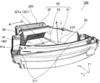
図1に示すように、本実施形態に係るヘッドアップディスプレイ(HUD:Head-Up Display)装置100は、例えば、車両1のダッシュボード2内に配設される。HUD装置100は、表示光Lをフロントガラス3(ウインドシールド)に向けて放射する。フロントガラス3で反射した表示光Lは、ユーザ4(主に車両1の運転者)に表示光Lが表す画像を虚像Vとして視認させる。虚像Vは、フロントガラス3を介して車両1の前方に表示される。これにより、ユーザ4は、前方風景に重畳して表示される虚像Vを視認することができる。虚像Vは、車両1に関する各種情報(以下、車両情報と言う。)を表示する。なお、車両情報は、車両1自体の情報のみならず、車両1の外部情報も含んでいてもよい。As shown in FIG. 1, a head-up display (HUD)
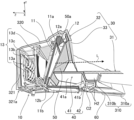
HUD装置100は、図2又は図3に示すように、表示ユニット10と、反射部20と、ケース30と、遮光部材40と、光学素子50と、回路基板60と、を備える。
なお、以下では、車両1の左右、上下、及び前後方向を用いて各構成を説明する場合がある。左右方向に沿うX軸、上下方向に沿うY軸、前後方向に沿うZ軸を各図に示した。また、ケース30の上方を「表側」、ケース30の下方を「裏側」と言う場合がある。
As shown in FIG. 2 or FIG. 3 , the
In the following, each configuration may be described using the left-right, up-down, and front-rear directions of the
表示ユニット10は、表示部11と、表示部11を保持するホルダ12と、表示部11を後方から照明する照明部13と、を有する。The
表示部11は、例えば、TFT(Thin Film Transistor)型の液晶パネルから構成され、前方に向く表示面11aに画像を表示する。表示部11は、図3に示すように、液晶パネルを駆動するための駆動回路などが実装された表示用基板11bと電気的に接続されている。表示用基板11bは、表示部11の下端部から前方に突出する格好で設けられている。The
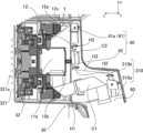
ホルダ12は、例えば樹脂から形成され、表示部11を保持する第1保持部12aと、表示用基板11bを保持する第2保持部12bと、を有する。第1保持部12aは、開口から表示面11aを露出させる枠状をなし、その前面に、光学素子50を固定するための固定部12cを有する。この実施形態では、固定部12cは、X方向で表示面11aを挟んで一対あり、各々に弾性部材Tが貼り付けられる。弾性部材Tについては後述する。第2保持部12bは、第1保持部12aの下端部から前方に突出している。これにより、第1保持部12a及び第2保持部12bからなるホルダ12の断面は、図3に示すように、L字状となる。図3、図5に示すように、第2保持部12bの裏側に表示用基板11bが固定されている。The
照明部13は、図3に示すように、光源13a、光源用基板13b、レンズ13c、筐体13d等を主要構成として有する。光源13aは、例えばLED(Light Emitting Diode)からなり、Z方向に光を発する。光源用基板13bは、光源13aが実装される基板であり、この実施形態では、主面がXY平面と平行で、主面の法線がZ軸と平行となるように設置されている。レンズ13cは、例えばコンデンサレンズからなり、光源13aから発せられた光を集光する。筐体13dは、光源用基板13b及びレンズ13cを保持するとともに、光源13aからの光を表示部11へと導く照明室を形成する。筐体13dは、例えば、複数の部材の組み合わせにより構成されている。表示部11は、照明部13によって照明されることで画像を表示面11aに表示する。これにより、画像を表す表示光Lが表示部11から放射される。As shown in FIG. 3, the
図2に示す反射部20は、例えば、凹面鏡からなり、表示部11からの表示光Lを図1に示すフロントガラス3に向けて反射させる。凹面鏡で反射した表示光Lにより、ユーザ4に視認される虚像Vは、表示部11に表示されている画像よりも拡大されたものとなる。なお、反射部20は、複数の鏡により構成されていてもよい。反射部20を構成する鏡の枚数は、設計に応じて任意に変更可能である。
The reflecting
ケース30は、図3に示すように、表示部11から放射された表示光Lの光路を形成する光路形成室31と、表示部11を収容する収容部32と、表示部11から放射された表示光Lを通過させる通過口33と、を有する。ケース30は、例えば金属から形成され、光路形成室31、収容部32及び通過口33が一体に形成されている。3, the
光路形成室31は、上方に開口した箱状をなし、底部310と、反射部20を支持する支持部311と、を有する。底部310は、図2、図3に示すように、表側において表示部11から反射部20へと至る表示光Lを通過させる。また、底部310は、図5に示すように、裏側において、回路基板60が配置される基板配置部310aと、基板配置部310aに隣接する隣接部310bと、を有する。隣接部310bには、遮光部材40の後述する板部42が設けられる。支持部311は、底部310のX方向における両端から上方向に立ち上がる一対の壁により構成されている。支持部311は、反射部20を保持するミラーホルダ(図示せず)を介して、反射部20を支持する。なお、反射部20は、概ねX方向に沿う軸線周りに回転可能に構成されていてもよい。The light
収容部32は、図3に示すように、底部310より上方に突出した部分を有して箱状に形成されている。収容部32は、下方に向かって開口し、その内部において表示部11を含む表示ユニット10の大部分を収容する。表示ユニット10は、収容部32に下方から挿入されている。収容部32は、表示ユニット10を表側(上方)から覆う覆い部320と、覆い部320の後方端部から垂れ下がる壁部321と、を有する。壁部321は、図3に示すように、照明部13の光源用基板13bと互いに対向する。また、壁部321は、図2、図3に示すように、ヒートシンク321aを有する。ヒートシンク321aは、壁部321の外側に向かって設けられた複数の放熱フィンを有する。3, the
通過口33は、図2、図3に示すように、覆い部320と底部310の間に形成されている。通過口33は、図2に示すように、矩形状に形成されている。2 and 3, the
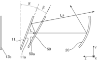
ここで、表示部11の姿勢について図7を参照して説明する。表示部11は、外光(図示せず)に起因する迷光の発生を抑制するために、表示面11aがXY平面に対して傾いて設けられている。外光がHUD装置100内に混入すると、反射部20で反射した外光が表示部11の表示面11aでさらに反射する場合がある。このように表示面11aで反射した外光が反射部20へ到達するのを抑制するために、表示面11aは、XY平面に対して角度α傾けて設定されている。角度αは、HUD装置100における光学系に応じて適切な値を任意に設定可能であるが、例えば10°~30°の範囲内で設定することができる。また、後述の光学素子50は、表示面11aと対向する対向面50aが、表示面11aに対して角度βだけ傾けて設けられている。この理由は、後述する。Here, the attitude of the
遮光部材40は、例えば樹脂により遮光性を有して形成され、図3、図6等に示すように、枠部41と、板部42と、を有する。The light-shielding
枠部41は、図2に示すように、通過口33の縁に沿った額縁状をなす。枠部41は、前述のように表示部11を傾けて配置することにより、表示部11と通過口33の間に生じる隙間を埋めるように、表示部11と通過口33の間に位置する。枠部41は、ケース30の底部310と上面が面一となる平板部41aを有する。図3に示すように、平板部41aの裏側(下方)に、ホルダ12の第2保持部12bが位置する。2, the
また、枠部41は、図6に示すように、その開口端部にZ方向に向かって突起する複数の突起部Pを有する。突起部Pは、円柱状をなし、この実施形態では三角形の各頂点に相当する箇所に設けられ、計3つある。3つの突起部Pは、光学素子50の一方の面(前述の対向面50aの反対面)に当接する。3つの突起部Pにより、光学素子50は、枠部41に対して位置決めされる。
As shown in Fig. 6, the
板部42は、ケース30の底部310の裏側に固定される板状の部分である。具体的に、板部42は、図3に示すように、枠部41の平板部41aと段状部41bを介して連結され、底部310の裏側へ至っている。板部42は、底部310の隣接部310bに固定される。The
また、板部42には、底部310の裏側に配られたコードが掛けられるフック部が形成されている。具体的に、板部42は、図5に示すように、表示用コードC1が掛けられる第1フック部H1と、光源用コードC2が掛けられる第2フック部H2と、を有する。ここで、表示用コードC1は、表示部11と回路基板60とを電気的に接続するFFC(Flexible Flat Cable)からなる。また、光源用コードC2は、光源用基板13bと回路基板60とを電気的に接続するリード線からなる。この実施形態では、第1フック部H1が1つ設けられ、第2フック部H2が複数設けられているが、第1フック部H1及び第2フック部H2の数、配置、形状は、コードの配設態様に応じて任意である。
The
光学素子50は、表示部11から反射部20へ向かう表示光Lを透過させる公知の光学部材であり、板状をなす。光学素子50は、図3に示すように、表示部11の通過口33側に位置する。光学素子50は、例えば、反射防止のために設けられ、λ/4板(1/4波長板とも呼ばれる。)等の位相差板から構成されている。なお、光学素子50は、AR(Anti?Reflection)フィルム又はAR膜を有する透明板材、ホットミラーなどであってもよい。The
光学素子50は、図3に示すように、対向面50aが表示部11の表示面11aに対して傾いた姿勢で、ホルダ12と遮光部材40の枠部41とに挟持される。具体的に、光学素子50は、図4に示すように、ホルダ12の固定部12cに貼り付けられた弾性部材Tを介して、ホルダ12に固定されている(図4では光学素子50を省略)。弾性部材Tは、板状をなし、例えば、弾性を有する両面テープから構成されている。弾性部材Tを介してホルダ12に固定された光学素子50は、対向面50aの反対面が枠部41に設けられた3つの突起部P(図6参照)によってZ方向に押圧される。このようにして、光学素子50は、ホルダ12と枠部41とに挟持される。As shown in FIG. 3, the
ここで、表示部11に対する光学素子50の傾きについて、図7を参照して説明する。表示面11aに対する対向面50aの角度βは、表示部11から放射される表示光Lのうち、対向面50aで反射した後に表示面11aでさらに反射した光である二次反射光Lsが反射部20に到達しない角度に設定されている。角度βは、HUD装置100における光学系に応じて適切な値を任意に設定可能であるが、例えば5°~15°の範囲内で設定することができる。Here, the inclination of the
回路基板60は、図5に示すように、底部310の基板配置部310aに配置され、固定されている。回路基板60は、各種回路が形成され、マイクロコンピュータからなる制御部が実装されたプリント回路板である。回路基板60は、表示用基板11b及び表示用コードC1を介して、表示部11と電気的に接続されている。また、回路基板60は、光源用コードC2を介して、光源用基板13bと電気的に接続されている。回路基板60に実装された制御部は、HUD装置100の全体動作を制御するものであり、表示部11の表示動作を制御するとともに、光源13aの発光動作を制御する。制御部は、車両1の各部を制御するECU(Electronic Control Unit)などのシステムと通信を行い、車両情報を示す画像を表示部11に表示させる。As shown in FIG. 5, the
ケース30の上方には、図示しないカバーガラスが設けられた上カバーが取り付けられる。反射部20で反射した表示光Lは、カバーガラスを透過して、フロントガラス3へ向かう。また、ケース30の下方には、回路基板60等を下方から覆う、図示しない下カバーが取り付けられる。An upper cover provided with a cover glass (not shown) is attached to the top of the
(1)以上に説明したHUD装置100は、画像を表す表示光Lを放射する表示部11と、表示部11から放射された表示光Lをフロントガラス3(外部の透光部材の一例)に向けて反射させる反射部20と、ケース30と、遮光部材40と、を備える。ケース30は、表示部11を収容する収容部32、表示部11から放射された表示光Lを通過させる通過口33、及び、通過口33から反射部20へ至る表示光Lが表側を通過する底部310を有する。遮光部材40は、表示部11と通過口33の間に位置する枠部41、及び、底部310の裏側に固定される板部42を有する。収容部32は、表示部11を表側から覆う覆い部320を有し、通過口33は、覆い部320と底部310との間に形成されている。また、枠部41は、通過口33の縁に沿った形状をなす。板部42は、コード(表示用コードC1、光源用コードC2)が掛けられるフック部(第1フック部H1、第2フックH2)を有する。そして、コードは、表示部11と電気的に接続される表示用コードC1を含む。
以上の構成によれば、表示部11と通過口33との間から、表示光Lが漏れ出すこと及び外光が入り込むことを抑制できるため、迷光を抑制できる。また、遮光部材40にコードを掛けるフック部を設け、遮光部材40に複数の機能を持たせるようにしたから、部品点数を削減することができ、構成を簡潔にすることができる。
(1) The
According to the above configuration, it is possible to suppress the display light L from leaking out and the outside light from entering between the
(2)また、HUD装置100は、底部310の裏側に設けられ、表示用コードC1によって前記表示部11と電気的に接続される回路基板60を備える。
この構成によれば、ケース30の裏側に位置する回路基板60へ至る表示用コードC1を、ケース30の裏側に位置するフック部に掛けて整理することができるため、ケース30の裏側における部品の組み付けが容易である。
(2) The
With this configuration, the display cord C1 leading to the
(3)また、HUD装置100は、収容部32内に位置し、表示部11を保持するホルダ12と、表示部11と通過口33の間に位置し、表示光Lが透過する光学素子50と、を備える。光学素子50は、表示部11と対向する対向面50aが、表示部11の表示面11aに対して傾いた姿勢で、ホルダ12と枠部41とに挟持される。
この構成によれば、遮光部材40にさらに機能を持たせることができるため、部品点数を削減することができる。また、傾いた光学素子50により、二次反射光Lsが迷光となることを抑制することができる。
(3) The
According to this configuration, the number of parts can be reduced because an additional function can be imparted to the
(4)二次反射光Lsが迷光となることを抑制するに当たっては、表示面11aに対する対向面50aの角度は、表示部11から放射される表示光Lのうち、対向面50aで反射した後に表示面11aでさらに反射した光である二次反射光Lsが反射部20に到達しない角度であることが好ましい。
(4) In order to prevent the secondary reflected light Ls from becoming stray light, it is preferable that the angle of the opposing
(5)また、迷光をより効果的に低減する観点からは、枠部41は、光学素子50と通過口33との間に生じる隙間を埋める形状を有していることが好ましい。(5) Furthermore, from the viewpoint of more effectively reducing stray light, it is preferable that the
(6)光学素子50は、ホルダ12に弾性部材Tを介して固定されている。
この構成により、光学素子50の緩衝性を高めることができる。
(6) The
This configuration can improve the cushioning properties of the
(7)また、枠部41は、光学素子50に向かって突起する複数の突起部Pを有し、光学素子50は、複数の突起部Pに押された状態でホルダ12と枠部41とに挟持されている。
この構成により、光学素子50を枠部41に対し、ほぼ点接触の状態で良好に位置決めすることができる。
(7) Furthermore, the
This configuration allows the
なお、本発明は以上の実施形態及び図面によって限定されるものではない。本発明の要旨を変更しない範囲で、適宜、変更(構成要素の削除も含む)を加えることが可能である。 Note that the present invention is not limited to the above-described embodiments and drawings. Appropriate modifications (including the deletion of components) may be made without departing from the spirit of the present invention.
第1フック部H1と第2フック部H2の少なくともいずれかに掛けられるコードには、リード線、FFCだけに限られず、FPC(Flexible Printed Circuit)が含まれていてもよい。The cord that is hung on at least one of the first hook portion H1 and the second hook portion H2 is not limited to a lead wire or FFC, but may also include an FPC (Flexible Printed Circuit).
弾性部材Tは、ホルダ12に固定することができれば、弾性を有する両面テープに限られず任意である。例えば、弾性部材Tは、接着等によりホルダ12に固定される、発泡ウレタン等のスポンジ材、ゴムを含むエラストマー等であってもよい。The elastic member T is not limited to elastic double-sided tape and may be any material as long as it can be fixed to the
以上では、表示ユニット10の表示部11が液晶パネルからなる例を示したが、表示部11及び表示ユニット10の構成は限定されるものでなく任意である。例えば、表示部11は、OLED(Organic Light-Emitting Diode)から構成されていてもよい。また、表示ユニット10は、DMD(Digital Micromirror Device)と、DMDによる反射光を受けて画像を表示する透過型スクリーンからなる表示部11と、を備えて構成されていてもよい。この場合、透過型スクリーンを表示面11aと考えることができる。
In the above, an example has been shown in which the
HUD装置100をユーザ4に向けて反射する透光部材は、車両1のフロントガラス3に限定されず、板状のハーフミラー、ホログラム素子等により構成されるコンバイナであってもよい。The translucent member that reflects the
HUD装置100が搭載される車両1の種類は限定されず、自動四輪車や、自動二輪車など様々な車両に適用可能である。また、HUD装置100は、航空機、船舶、スノーモービル等、車両1以外の乗り物に搭載されてもよい。The type of
以上の説明では、本発明の理解を容易にするために、公知の技術的事項の説明を適宜省略した。 In the above explanation, explanations of well-known technical matters have been omitted as appropriate in order to facilitate understanding of the present invention.
100…ヘッドアップディスプレイ(HUD)装置
10…表示ユニット
11…表示部、11a…表示面、11b…表示用基板
12…ホルダ、12a…第1保持部、12b…第2保持部
12c…固定部、T…弾性部材
13…照明部、13a…光源、13b…光源用基板、13c…レンズ、13d…筐体
20…反射部
30…ケース
31…光路形成室
310…底部、310a…基板配置部、310b…隣接部、311…支持部
32…収容部、320…覆い部、321…壁部、321a…ヒートシンク
33…通過口
40…遮光部材
41…枠部、41a…平板部、41b…段状部、P…突起部
42…板部
H1…第1フック部、H2…第2フック部
C1…表示用コード、C2…光源用コード
50…光学素子、50a…対向面
60…回路基板
1…車両、2…ダッシュボード、3…フロントガラス、4…ユーザ
L…表示光、V…虚像、Ls…二次反射光
100...Head-up display (HUD)
Claims (7)
前記表示部から放射された前記表示光を外部の透光部材に向けて反射させる反射部と、
前記表示部を収容する収容部、前記表示部から放射された前記表示光を通過させる通過口、及び、前記通過口から前記反射部へ至る前記表示光が表側を通過する底部を有するケースと、
前記表示部と前記通過口の間に位置する枠部、及び、前記底部の裏側に固定される板部を有する遮光部材と、を備え、
前記収容部は、前記表示部を表側から覆う覆い部を有し、
前記通過口は、前記覆い部と前記底部との間に形成され、
前記枠部は、前記通過口の縁に沿った形状をなし、
前記板部は、コードが掛けられるフック部を有し、
前記コードは、前記表示部と電気的に接続される表示用コードを含む、
ヘッドアップディスプレイ装置。 A display unit that emits display light representing an image;
a reflecting portion that reflects the display light emitted from the display portion toward an external light-transmitting member;
a case including a housing portion that houses the display portion, a passage opening through which the display light emitted from the display portion passes, and a bottom portion through which the display light from the passage opening to the reflector passes on a front side;
a frame portion located between the display portion and the passage opening, and a light-shielding member having a plate portion fixed to a back side of the bottom portion,
the housing portion has a cover portion that covers the display portion from a front side,
The passage opening is formed between the cover portion and the bottom portion,
The frame portion has a shape that conforms to an edge of the passage opening,
The plate portion has a hook portion to which a cord can be hung,
The cord includes a display cord electrically connected to the display unit.
Head-up display device.
請求項1に記載のヘッドアップディスプレイ装置。 A circuit board is provided on the back side of the bottom and is electrically connected to the display unit by the display cord.
The head-up display device according to claim 1 .
前記表示部と前記通過口の間に位置し、前記表示光が透過する光学素子と、を備え、
前記光学素子は、前記表示部と対向する対向面が、前記表示部の前記画像が表示される表示面に対して傾いた姿勢で、前記ホルダと前記枠部とに挟持される、
請求項1又は2に記載のヘッドアップディスプレイ装置。 a holder located within the housing and holding the display unit;
an optical element located between the display unit and the passage opening and through which the display light passes;
the optical element is sandwiched between the holder and the frame in such a manner that a surface facing the display unit is inclined with respect to a display surface on which the image of the display unit is displayed;
The head-up display device according to claim 1 or 2.
請求項3に記載のヘッドアップディスプレイ装置。 The angle of the opposing surface with respect to the display surface is an angle at which secondary reflected light, which is light of the display light emitted from the display unit that is reflected by the opposing surface and then further reflected by the display surface, does not reach the reflecting unit.
The head-up display device according to claim 3 .
請求項3又は4に記載のヘッドアップディスプレイ装置。 The frame portion has a shape that fills a gap that occurs between the optical element and the passage port.
The head-up display device according to claim 3 or 4.
請求項3乃至5のいずれか1項に記載のヘッドアップディスプレイ装置。 The optical element is fixed to the holder via an elastic member.
The head-up display device according to any one of claims 3 to 5.
前記光学素子は、前記複数の突起部に押された状態で前記ホルダと前記枠部とに挟持されている、
請求項3乃至6のいずれか1項に記載のヘッドアップディスプレイ装置。 the frame portion has a plurality of protrusions protruding toward the optical element,
the optical element is sandwiched between the holder and the frame in a state where the optical element is pressed by the plurality of protrusions;
The head-up display device according to any one of claims 3 to 6.
Applications Claiming Priority (3)
| Application Number | Priority Date | Filing Date | Title |
|---|---|---|---|
| JP2020087189 | 2020-05-19 | ||
| JP2020087189 | 2020-05-19 | ||
| PCT/JP2021/018005 WO2021235284A1 (en) | 2020-05-19 | 2021-05-12 | Head-up display device |
Publications (2)
| Publication Number | Publication Date |
|---|---|
| JPWO2021235284A1 JPWO2021235284A1 (en) | 2021-11-25 |
| JP7635781B2 true JP7635781B2 (en) | 2025-02-26 |
Family
ID=78707851
Family Applications (1)
| Application Number | Title | Priority Date | Filing Date |
|---|---|---|---|
| JP2022524406A Active JP7635781B2 (en) | 2020-05-19 | 2021-05-12 | Head-up display device |
Country Status (3)
| Country | Link |
|---|---|
| JP (1) | JP7635781B2 (en) |
| DE (1) | DE112021002886T5 (en) |
| WO (1) | WO2021235284A1 (en) |
Families Citing this family (1)
| Publication number | Priority date | Publication date | Assignee | Title |
|---|---|---|---|---|
| JP2024133960A (en) | 2023-03-20 | 2024-10-03 | 日本精機株式会社 | Head-up display device |
Citations (4)
| Publication number | Priority date | Publication date | Assignee | Title |
|---|---|---|---|---|
| JP2017171041A (en) | 2016-03-22 | 2017-09-28 | 日本精機株式会社 | Display device |
| JP2018075983A (en) | 2016-11-10 | 2018-05-17 | 日本精機株式会社 | Head-up display device |
| US20190187470A1 (en) | 2017-12-20 | 2019-06-20 | Volkswagen Aktiengesellschaft | Vehicle with a head-up display integrated into the dashboard |
| JP2020006889A (en) | 2018-07-11 | 2020-01-16 | 日本精機株式会社 | Vehicle display device |
Family Cites Families (1)
| Publication number | Priority date | Publication date | Assignee | Title |
|---|---|---|---|---|
| JP5556019B2 (en) | 2009-01-27 | 2014-07-23 | 日本精機株式会社 | Head-up display device |
-
2021
- 2021-05-12 WO PCT/JP2021/018005 patent/WO2021235284A1/en not_active Ceased
- 2021-05-12 JP JP2022524406A patent/JP7635781B2/en active Active
- 2021-05-12 DE DE112021002886.3T patent/DE112021002886T5/en active Pending
Patent Citations (4)
| Publication number | Priority date | Publication date | Assignee | Title |
|---|---|---|---|---|
| JP2017171041A (en) | 2016-03-22 | 2017-09-28 | 日本精機株式会社 | Display device |
| JP2018075983A (en) | 2016-11-10 | 2018-05-17 | 日本精機株式会社 | Head-up display device |
| US20190187470A1 (en) | 2017-12-20 | 2019-06-20 | Volkswagen Aktiengesellschaft | Vehicle with a head-up display integrated into the dashboard |
| JP2020006889A (en) | 2018-07-11 | 2020-01-16 | 日本精機株式会社 | Vehicle display device |
Also Published As
| Publication number | Publication date |
|---|---|
| JPWO2021235284A1 (en) | 2021-11-25 |
| DE112021002886T5 (en) | 2023-03-02 |
| WO2021235284A1 (en) | 2021-11-25 |
Similar Documents
| Publication | Publication Date | Title |
|---|---|---|
| CN104204903B (en) | Head-up display | |
| JP6216307B2 (en) | Head-up display device and backlight device | |
| EP4163700B1 (en) | Vehicular display device | |
| JP6845987B2 (en) | Head-up display device | |
| JP5888003B2 (en) | Head-up display device | |
| JP7416051B2 (en) | heads up display device | |
| JP5556019B2 (en) | Head-up display device | |
| JP7635781B2 (en) | Head-up display device | |
| JP7004217B2 (en) | Head-up display | |
| CN108363205B (en) | Display device and display device main body | |
| JP6969424B2 (en) | Plane mirror unit | |
| JP2017129433A (en) | Instrument casing | |
| JP7622740B2 (en) | Head-up display device | |
| CN113330352A (en) | Head-up display | |
| JP7704803B2 (en) | Display device and vehicle display device | |
| CN113302077A (en) | Head-up display device | |
| CN216927273U (en) | Head-up display device | |
| JP7643808B2 (en) | Display device | |
| JP7396351B2 (en) | heads up display device | |
| JP2024128395A (en) | Image projection device | |
| JP7245442B2 (en) | head up display | |
| JP2020038269A (en) | Display, and head-up display device including display | |
| JP2018197074A (en) | Head-up display device | |
| WO2025074885A1 (en) | Image projection device | |
| JP2024064884A (en) | Image display device and image projection device |
Legal Events
| Date | Code | Title | Description |
|---|---|---|---|
| RD03 | Notification of appointment of power of attorney |
Free format text: JAPANESE INTERMEDIATE CODE: A7423 Effective date: 20230126 |
|
| A621 | Written request for application examination |
Free format text: JAPANESE INTERMEDIATE CODE: A621 Effective date: 20240415 |
|
| TRDD | Decision of grant or rejection written | ||
| A01 | Written decision to grant a patent or to grant a registration (utility model) |
Free format text: JAPANESE INTERMEDIATE CODE: A01 Effective date: 20250114 |
|
| A61 | First payment of annual fees (during grant procedure) |
Free format text: JAPANESE INTERMEDIATE CODE: A61 Effective date: 20250127 |
|
| R150 | Certificate of patent or registration of utility model |
Ref document number: 7635781 Country of ref document: JP Free format text: JAPANESE INTERMEDIATE CODE: R150 |