JP7635705B2 - Gaming Machines - Google Patents
Gaming Machines Download PDFInfo
- Publication number
- JP7635705B2 JP7635705B2 JP2021210075A JP2021210075A JP7635705B2 JP 7635705 B2 JP7635705 B2 JP 7635705B2 JP 2021210075 A JP2021210075 A JP 2021210075A JP 2021210075 A JP2021210075 A JP 2021210075A JP 7635705 B2 JP7635705 B2 JP 7635705B2
- Authority
- JP
- Japan
- Prior art keywords
- jackpot
- display
- game
- state
- area
- Prior art date
- Legal status (The legal status is an assumption and is not a legal conclusion. Google has not performed a legal analysis and makes no representation as to the accuracy of the status listed.)
- Active
Links
- 230000008859 change Effects 0.000 claims description 337
- 238000001514 detection method Methods 0.000 claims description 264
- 230000033001 locomotion Effects 0.000 claims description 176
- 230000000007 visual effect Effects 0.000 claims description 6
- 238000012790 confirmation Methods 0.000 claims description 5
- 238000005034 decoration Methods 0.000 claims description 2
- 238000000034 method Methods 0.000 description 2019
- 230000008569 process Effects 0.000 description 2005
- 230000000694 effects Effects 0.000 description 847
- 230000000875 corresponding effect Effects 0.000 description 686
- 238000012545 processing Methods 0.000 description 439
- 238000011161 development Methods 0.000 description 214
- 239000000872 buffer Substances 0.000 description 198
- 238000003860 storage Methods 0.000 description 188
- 230000009471 action Effects 0.000 description 168
- 230000015654 memory Effects 0.000 description 151
- 238000010586 diagram Methods 0.000 description 136
- 230000006870 function Effects 0.000 description 106
- 230000001960 triggered effect Effects 0.000 description 102
- 239000004973 liquid crystal related substance Substances 0.000 description 96
- 230000004044 response Effects 0.000 description 86
- 230000007246 mechanism Effects 0.000 description 83
- 238000004891 communication Methods 0.000 description 67
- 239000011347 resin Substances 0.000 description 65
- 229920005989 resin Polymers 0.000 description 65
- 230000007704 transition Effects 0.000 description 59
- 230000001276 controlling effect Effects 0.000 description 54
- 238000012544 monitoring process Methods 0.000 description 50
- 230000001965 increasing effect Effects 0.000 description 49
- 239000000463 material Substances 0.000 description 41
- 230000002829 reductive effect Effects 0.000 description 39
- 238000006073 displacement reaction Methods 0.000 description 37
- 230000005540 biological transmission Effects 0.000 description 32
- 230000007423 decrease Effects 0.000 description 29
- 230000001681 protective effect Effects 0.000 description 28
- 238000003825 pressing Methods 0.000 description 27
- 238000011084 recovery Methods 0.000 description 25
- 230000004397 blinking Effects 0.000 description 22
- 239000011521 glass Substances 0.000 description 20
- 238000004364 calculation method Methods 0.000 description 18
- 230000002265 prevention Effects 0.000 description 17
- 230000002093 peripheral effect Effects 0.000 description 16
- 238000007789 sealing Methods 0.000 description 16
- 230000008901 benefit Effects 0.000 description 15
- 238000013461 design Methods 0.000 description 15
- 230000002441 reversible effect Effects 0.000 description 15
- 230000002730 additional effect Effects 0.000 description 14
- 238000010304 firing Methods 0.000 description 13
- 210000005252 bulbus oculi Anatomy 0.000 description 12
- 239000013256 coordination polymer Substances 0.000 description 12
- 230000005284 excitation Effects 0.000 description 12
- 210000000744 eyelid Anatomy 0.000 description 12
- 239000007769 metal material Substances 0.000 description 12
- 230000000903 blocking effect Effects 0.000 description 10
- 230000005611 electricity Effects 0.000 description 10
- 230000000717 retained effect Effects 0.000 description 10
- 230000003068 static effect Effects 0.000 description 10
- 230000005856 abnormality Effects 0.000 description 9
- 239000004020 conductor Substances 0.000 description 9
- 238000007599 discharging Methods 0.000 description 9
- PCHJSUWPFVWCPO-UHFFFAOYSA-N gold Chemical compound [Au] PCHJSUWPFVWCPO-UHFFFAOYSA-N 0.000 description 9
- 239000010931 gold Substances 0.000 description 9
- 229910052737 gold Inorganic materials 0.000 description 9
- 238000005286 illumination Methods 0.000 description 9
- 230000001795 light effect Effects 0.000 description 9
- 230000001174 ascending effect Effects 0.000 description 8
- 210000000887 face Anatomy 0.000 description 8
- 210000004279 orbit Anatomy 0.000 description 8
- 238000002834 transmittance Methods 0.000 description 8
- VYZAMTAEIAYCRO-UHFFFAOYSA-N Chromium Chemical compound [Cr] VYZAMTAEIAYCRO-UHFFFAOYSA-N 0.000 description 7
- 229920000122 acrylonitrile butadiene styrene Polymers 0.000 description 7
- 238000013459 approach Methods 0.000 description 7
- 230000002708 enhancing effect Effects 0.000 description 7
- 230000000670 limiting effect Effects 0.000 description 6
- 230000001360 synchronised effect Effects 0.000 description 6
- 230000006399 behavior Effects 0.000 description 5
- 210000001508 eye Anatomy 0.000 description 5
- 210000003128 head Anatomy 0.000 description 5
- 230000006872 improvement Effects 0.000 description 5
- 230000009467 reduction Effects 0.000 description 5
- 238000012384 transportation and delivery Methods 0.000 description 5
- 229910000838 Al alloy Inorganic materials 0.000 description 4
- 101150051106 SWEET11 gene Proteins 0.000 description 4
- FFBHFFJDDLITSX-UHFFFAOYSA-N benzyl N-[2-hydroxy-4-(3-oxomorpholin-4-yl)phenyl]carbamate Chemical compound OC1=C(NC(=O)OCC2=CC=CC=C2)C=CC(=C1)N1CCOCC1=O FFBHFFJDDLITSX-UHFFFAOYSA-N 0.000 description 4
- 238000007796 conventional method Methods 0.000 description 4
- 238000001125 extrusion Methods 0.000 description 4
- 230000002349 favourable effect Effects 0.000 description 4
- 230000007257 malfunction Effects 0.000 description 4
- 239000011159 matrix material Substances 0.000 description 4
- 230000003287 optical effect Effects 0.000 description 4
- 230000001105 regulatory effect Effects 0.000 description 4
- 238000004904 shortening Methods 0.000 description 4
- 229920000178 Acrylic resin Polymers 0.000 description 3
- 239000004925 Acrylic resin Substances 0.000 description 3
- 238000009825 accumulation Methods 0.000 description 3
- 230000003247 decreasing effect Effects 0.000 description 3
- 230000006866 deterioration Effects 0.000 description 3
- 238000003780 insertion Methods 0.000 description 3
- 230000037431 insertion Effects 0.000 description 3
- 238000004519 manufacturing process Methods 0.000 description 3
- 230000006386 memory function Effects 0.000 description 3
- 229910052751 metal Inorganic materials 0.000 description 3
- 239000002184 metal Substances 0.000 description 3
- 230000008450 motivation Effects 0.000 description 3
- 229920000515 polycarbonate Polymers 0.000 description 3
- 239000004417 polycarbonate Substances 0.000 description 3
- 238000012546 transfer Methods 0.000 description 3
- 239000012780 transparent material Substances 0.000 description 3
- 241000251468 Actinopterygii Species 0.000 description 2
- 241000283153 Cetacea Species 0.000 description 2
- 208000001613 Gambling Diseases 0.000 description 2
- 230000015572 biosynthetic process Effects 0.000 description 2
- 238000006243 chemical reaction Methods 0.000 description 2
- 239000003086 colorant Substances 0.000 description 2
- 230000002844 continuous effect Effects 0.000 description 2
- 238000009795 derivation Methods 0.000 description 2
- 238000009826 distribution Methods 0.000 description 2
- 230000005281 excited state Effects 0.000 description 2
- 238000000605 extraction Methods 0.000 description 2
- 230000001976 improved effect Effects 0.000 description 2
- 238000011835 investigation Methods 0.000 description 2
- 238000005259 measurement Methods 0.000 description 2
- 238000005498 polishing Methods 0.000 description 2
- 238000002360 preparation method Methods 0.000 description 2
- 238000005096 rolling process Methods 0.000 description 2
- 239000002023 wood Substances 0.000 description 2
- 206010047571 Visual impairment Diseases 0.000 description 1
- 239000000654 additive Substances 0.000 description 1
- 230000000996 additive effect Effects 0.000 description 1
- 239000007853 buffer solution Substances 0.000 description 1
- 239000002131 composite material Substances 0.000 description 1
- 230000001010 compromised effect Effects 0.000 description 1
- 230000008602 contraction Effects 0.000 description 1
- 238000012937 correction Methods 0.000 description 1
- 238000009429 electrical wiring Methods 0.000 description 1
- 238000009434 installation Methods 0.000 description 1
- JEIPFZHSYJVQDO-UHFFFAOYSA-N iron(III) oxide Inorganic materials O=[Fe]O[Fe]=O JEIPFZHSYJVQDO-UHFFFAOYSA-N 0.000 description 1
- 239000002932 luster Substances 0.000 description 1
- 230000014759 maintenance of location Effects 0.000 description 1
- 238000007726 management method Methods 0.000 description 1
- 230000000737 periodic effect Effects 0.000 description 1
- 238000007781 pre-processing Methods 0.000 description 1
- 230000003014 reinforcing effect Effects 0.000 description 1
- 230000000630 rising effect Effects 0.000 description 1
- 230000008054 signal transmission Effects 0.000 description 1
- 238000009987 spinning Methods 0.000 description 1
- 239000000126 substance Substances 0.000 description 1
- 230000008093 supporting effect Effects 0.000 description 1
- 210000003813 thumb Anatomy 0.000 description 1
- 238000011144 upstream manufacturing Methods 0.000 description 1
- 239000002699 waste material Substances 0.000 description 1
Images


Classifications
-
- Y—GENERAL TAGGING OF NEW TECHNOLOGICAL DEVELOPMENTS; GENERAL TAGGING OF CROSS-SECTIONAL TECHNOLOGIES SPANNING OVER SEVERAL SECTIONS OF THE IPC; TECHNICAL SUBJECTS COVERED BY FORMER USPC CROSS-REFERENCE ART COLLECTIONS [XRACs] AND DIGESTS
- Y02—TECHNOLOGIES OR APPLICATIONS FOR MITIGATION OR ADAPTATION AGAINST CLIMATE CHANGE
- Y02E—REDUCTION OF GREENHOUSE GAS [GHG] EMISSIONS, RELATED TO ENERGY GENERATION, TRANSMISSION OR DISTRIBUTION
- Y02E60/00—Enabling technologies; Technologies with a potential or indirect contribution to GHG emissions mitigation
- Y02E60/10—Energy storage using batteries
Landscapes
- Pinball Game Machines (AREA)
- Display Devices Of Pinball Game Machines (AREA)
Description
本発明は、パチンコ機等の遊技機に関するものである。 The present invention relates to gaming machines such as pachinko machines.
従来、遊技機の一種として、遊技球を遊技領域へ発射して遊技を行うパチンコ機が知られている。例えば所定の入球手段に遊技球が入球することに基づき抽選を行い、該抽選により所定の結果が得られた場合に、遊技者に有利な遊技状態が発生するパチンコ機が知られている。
このようなパチンコ機の中には、回転手段が回転することにより興趣を生じさせるものもある(例えば、特許文献1参照)。
A pachinko machine is known as a type of gaming machine in which a game is played by shooting a game ball into a game area. For example, a pachinko machine is known in which a lottery is held based on the entry of a game ball into a predetermined ball entry means, and when a predetermined result is obtained by the lottery, a game state advantageous to the player is generated.
Among such pachinko machines, there are some that generate interest by the rotation of the rotating means (for example, see Patent Document 1).
しかしながら、従来の遊技機においては、回転手段の構造等が複雑になりやすく、視覚的な変化も乏しいものであった。However, in conventional gaming machines, the structure of the rotating means tends to be complicated, and visual variation is poor.
本発明は、上記例示した問題点等を解決するためになされたものであり、その目的は、遊技盤に設けられる遊技領域において、遊技領域に設けられる回転手段によって容易に興趣を変化させ、2つの回転手段の相対位置関係によって視認性を変化させることが可能な遊技機を提供可能とすることである。 The present invention has been made to solve the problems exemplified above, and its purpose is to provide a gaming machine in which the interest can be easily changed by a rotation means provided in the gaming area of a gaming board, and visibility can be changed by the relative positional relationship between two rotation means.
上記の目的を達成するため、本発明に係る遊技機は、
遊技領域を前面側に有する遊技盤と、
遊技者による所定の遊技に基づいて所定の契機が成立した場合に抽選を行う抽選手段と、
前記抽選により当選結果が得られた場合に、所定の遊技価値を付与可能な遊技価値付与手段と、
前記遊技領域の所定領域において前後方向を軸方向として回転可能かつ少なくとも所定の回転状態と所定の停止状態とに状態が変化可能に構成され、後方側を視認可能な視認部を有した第1回転手段と、
前記遊技領域において、前記第1回転手段の前記後方側に設けられる所定の装飾手段と、を備えた遊技機において、
前記第1回転手段は、遊技者による前記所定の遊技に基づいて所定の条件が満たされた場合に、前記所定の停止状態から前記所定の回転状態に状態変化し得るよう構成され、
本遊技機は、
前記所定領域の正面視における前記第1回転手段と、前記遊技領域において移動可能かつ所定態様で回転可能な第2回転手段との相対位置関係が、前記第1回転手段の少なくとも一部と前記第2回転手段の少なくとも一部とが前記正面視において重ならない第1位置関係と、前記第1回転手段の少なくとも一部と前記第2回転手段の少なくとも一部とが前記正面視において重なる第2位置関係と、に変化可能に構成され、
前記第1位置関係においては、
前記正面視において前記第1回転手段の前記視認部を通して前記所定の装飾手段の少なくとも一部が視認可能となり、
前記第2位置関係においては、
前記正面視において前記第1回転手段の前記視認部と重なる前記第2回転手段の少なくとも一部が前記第1回転手段の前記視認部を通して視認可能となり、前記所定の装飾手段の少なくとも一部のうち前記第2回転手段によって遮られた領域が前記第1回転手段の前記視認部を通して視認不能となるよう構成され、
前記遊技盤は、その後方領域の少なくとも一部を前方より視認可能であり、
前記第1回転手段は、前記遊技盤の前方領域にて回転可能に構成され、
前記第2回転手段は、前記遊技盤の前記前方領域から前記後方領域へ移動可能に構成され、
本遊技機は、
前記所定領域において複数の前記第2回転手段が個別に移動可能に構成され、
前記複数の第2回転手段が前記第1回転手段に対して個別に近接可能に構成され、
本遊技機は、
前記第2回転手段に接触可能かつ該第2回転手段の動きに変化を生じさせ得る所定の可動部材を備え、
本遊技機は、
前記遊技領域において所定位置を通過した前記第2回転手段を検出可能な検出手段を備え、
前記第2回転手段が前記検出手段により検出されたことに基づき、所定の演出を実行可能に構成されていることをその要旨としている。
In order to achieve the above object, the gaming machine according to the present invention comprises:
A game board having a game area on a front side;
A lottery means for conducting a lottery when a predetermined opportunity occurs based on a predetermined game played by a player;
a game value awarding means for awarding a predetermined game value when a winning result is obtained by the lottery;
A first rotation means is configured to be rotatable around a front-rear direction as an axial direction in a predetermined area of the play area and to be able to change between at least a predetermined rotation state and a predetermined stop state, and has a visual confirmation part that allows the rear side to be visually confirmed;
a predetermined decoration means provided on the rear side of the first rotating means in the gaming area,
the first rotation means is configured to change from the predetermined stopped state to the predetermined rotation state when a predetermined condition is satisfied based on the predetermined game by a player;
This gaming machine is
A relative positional relationship between the first rotating means in a front view of the predetermined area and a second rotating means that is movable in the game area and rotatable in a predetermined manner is configured to be changeable between a first positional relationship in which at least a part of the first rotating means and at least a part of the second rotating means do not overlap in the front view, and a second positional relationship in which at least a part of the first rotating means and at least a part of the second rotating means overlap in the front view,
In the first positional relationship,
At least a part of the predetermined decorative means is visible through the visible portion of the first rotating means when viewed from the front,
In the second positional relationship,
At least a part of the second rotating means that overlaps with the visible portion of the first rotating means in the front view is visible through the visible portion of the first rotating means, and an area of at least a part of the predetermined decorative means that is blocked by the second rotating means is not visible through the visible portion of the first rotating means,
At least a part of the rear area of the game board is visible from the front,
The first rotating means is configured to be rotatable in a front area of the game board,
The second rotating means is configured to be movable from the front region to the rear region of the game board,
This gaming machine is
The second rotation means is configured to be movable individually in the predetermined region,
The plurality of second rotating means are configured to be individually accessible to the first rotating means,
This gaming machine is
a predetermined movable member capable of contacting the second rotating means and causing a change in the movement of the second rotating means;
This gaming machine is
A detection means capable of detecting the second rotating means passing a predetermined position in the game area,
The gist of the invention is that the second rotation means is configured to be able to execute a predetermined performance based on the detection by the detection means .
本発明の遊技機によれば、遊技盤に設けられる遊技領域において、遊技領域に設けられる回転手段によって容易に興趣を変化させ、2つの回転手段の相対位置関係によって視認性を変化させることが可能となる。 According to the gaming machine of the present invention, in the game area provided on the game board, the interest can be easily changed by the rotation means provided in the game area, and the visibility can be changed by the relative positional relationship between the two rotation means.
〔第1実施形態〕
以下、第1実施形態に係るパチンコ遊技機(以下、単に「パチンコ機」という)10について図面を参照して詳しく説明する。尚、本発明に係る遊技機(第1実施形態に係るパチンコ機10)は、本発明の「回転手段」としての「回転体」を備えている。
First Embodiment
A pachinko gaming machine (hereinafter, simply referred to as a "pachinko machine") 10 according to a first embodiment will be described in detail below with reference to the drawings. The gaming machine according to the present invention (the
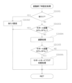
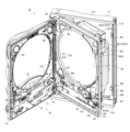
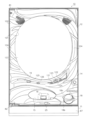
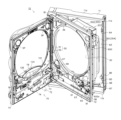
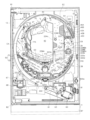
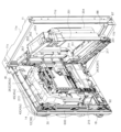
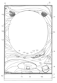
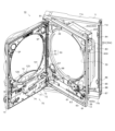
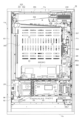
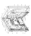
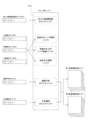
図1はパチンコ機10の正面図であり、図2は斜視図であり、図3は内枠12及び前面枠セット14を開放した状態を示す斜視図である。図4は内枠12及び遊技盤30等の構成を示す正面図である。図5はパチンコ機10の背面図であり、図6は内枠12及び裏パックユニット203等を開放した状態を示す斜視図である。但し、図3では便宜上、遊技盤30面上に配設される経路変更手段としての釘や各種役物、前面枠セット14に取付けられるガラスユニット137等を省略して示している。
Figure 1 is a front view of the
図3等に示すように、パチンコ機10は、該パチンコ機10の外郭を構成する外枠11を備えており、この外枠11の一側部に内枠12が開閉可能に支持されている。
As shown in FIG. 3 etc., the
外枠11は、図6等に示すように、上辺枠構成部11a及び下辺枠構成部11bが木製の板材により構成され、左辺枠構成部11c及び右辺枠構成部11dがアルミニウム合金製の押出成形材により構成され、これら各枠構成部11a~11dがネジ等の離脱可能な締結具により全体として矩形枠状に組み付けられている。
As shown in FIG. 6, the
左辺枠構成部11cの上下端部には、それぞれ上ヒンジ81及び下ヒンジ82が取着されている(図1参照)。該上ヒンジ81及び下ヒンジ82にて、内枠12の上下部が回動可能に支持されており、これにより内枠12が開閉可能となる。そして、外枠11の内側に形成される空間部に内枠12等が収容される。
An
また、右辺枠構成部11dには、その幅方向後端部近傍から外枠11内側へ向け突出した延出壁部83が形成されている。延出壁部83は、内枠12の右側部背面側に設けられる施錠装置600(図5参照)に対応する上下区間全域を内枠12の背面側から覆っている(図5参照)。加えて、図3に示すように、延出壁部83の前面側には、施錠装置600の係止部材が係止される上下一対の受部84,85が設けられている。また、下側の受部85には、後述する内枠開放検知スイッチ92に当接する押圧部86が、外枠11内側に向けて突設されている。
The
さらに、下辺枠構成部11bには樹脂製の幕板飾り87が取着されている。幕板飾り87の上面奥部には、上方に突出するリブ88が一体形成されている。これにより内枠12との間に隙間が形成されにくくなっている。
In addition, a
図3に示すように、内枠12の開閉軸線は、パチンコ機10の正面からみて左側において上下に沿って設定されており、この開閉軸線を軸心として内枠12が前方側に開放できるようになっている。内枠12は、外形が矩形状をなす樹脂ベース38を主体に構成されており、該樹脂ベース38の中央部には略楕円形状の窓孔39が形成されている。
As shown in FIG. 3, the opening/closing axis of the
また、内枠12の前面側には前面枠セット14が開閉可能に取付けられている。前面枠セット14は、内枠12と同様に、パチンコ機10の正面から見て左側において上下に沿って設定された開閉軸線を軸心として前方側に開放できるようになっている。
The front frame set 14 is attached to the front side of the
前面枠セット14は、内枠12と同様に外形が矩形状をなし、閉鎖状態においては内枠12の前面側ほぼ全域を覆う。前面枠セット14の中央部には略楕円形状の窓部101が形成されている。これにより、前面枠セット14の窓部101及び内枠12の窓孔39を介して、内枠12の後面に装着される遊技盤30(遊技領域)を外部から視認可能となる。遊技盤30の詳細な構成については後述する。
The front frame set 14 has a rectangular outer shape like the
図1に示すように、前面枠セット14の前面側には、その下部中央において球受皿としての下皿15が設けられており、排出口16より排出された遊技球が下皿15内に貯留可能になっている。また、下皿15の手前側には、下皿15内から遊技球を排出するための球抜きレバー25が設けられている。
As shown in FIG. 1, a
加えて、下皿15の左部には、遊技者が操作可能な操作手段としての演出ボタン125が設けられている。演出ボタン125は、遊技者が押圧操作(下方に向かって押す操作)可能に構成されている。また、下皿15の内部には、演出ボタン125の押圧操作を検出するための操作検出手段としての操作検出スイッチ(図示略)が設けられている。そして、演出ボタン125が押圧操作された場合には、前記操作検出スイッチから後述するサブ制御装置262へ操作検出信号が出力される。これにより、遊技者が演出ボタン125を押圧操作することで、後述するように演出表示装置42等において所定の演出が行われたり、演出内容が変更されたりする。
In addition, a
下皿15の右方には、手前側に突出した遊技球発射ハンドル(以下、単に「ハンドル」という。)18が設けられている。尚、遊技者が操作可能な操作手段としてのハンドル18は、例えば前面枠セット14に固定された基部、該基部に対して回動可能に組付けられた第1の操作部としての回転操作部、該回転操作部の操作量を検出する操作量検出手段としての可変抵抗器、遊技球を遊技領域へ発射させる否かを選択可能な第2の操作部としての発射停止スイッチなどを備えている。
A game ball launch handle (hereinafter simply referred to as the "handle") 18 is provided to the right of the
下皿15の上方には上皿19が設けられている。上皿19は、遊技球を一旦貯留し、一列に整列させながら後述する発射手段としての遊技球発射装置(以下、単に「発射装置」という。)60の方へ案内する球受皿である。尚、上皿19が遊技球で満杯になった状態では、払出される遊技球は、後述する下皿連通路71及び排出口16を介して、下皿15へと案内される。
An
上皿19には、遊技者が操作可能な操作手段として球貸しボタン121と返却ボタン122とが設けられている。これにより、遊技ホール等において、パチンコ機10の側方に配置されるカードユニット(球貸しユニット)に紙幣やカード等を投入した状態で球貸しボタン121が操作されると、その操作に応じて貸出球が上皿19に供給される。尚、遊技ホールで使用される遊技球には、その所有を明確にするため、該遊技ホールを特定可能な所定の情報が刻印等により記載されており、他の遊技ホールから持ち込んだ遊技球を使用する不正行為等を防止している。また、返却ボタン122は、カードユニットに挿入されたカード等の返却を求める際に操作される。但し、カードユニットを介さずに球貸し装置等から上皿19に遊技球が直接貸し出されるパチンコ機、いわゆる現金機では球貸しボタン121及び返却ボタン122は不要である。
The
さらに、上皿19には、遊技者が操作可能な操作手段として球抜きボタン123が設けられている。球抜きボタン123が押圧操作されることで、上皿19の球案内路の下流側に設けられ、下皿15に連通する連通孔(図示略)が開口し、上皿19に貯留されていた遊技球が下皿15へと案内される(落下する)。つまり、遊技者は、球抜きボタン123を操作することで、上皿19にある遊技球をいつでも下皿15に移すことができる。
Furthermore, the
また、前面枠セット14の前面にはその周囲に各種ランプ等の発光手段が設けられている。これら発光手段は、大当たり時や所定のリーチ時等における遊技状態の変化に応じて点灯、点滅といった発光態様が変更制御され遊技中の演出効果を高める役割を果たすものである。例えば、窓部101の周縁には、LED等の発光手段を内蔵した枠ランプ102が設けられている。また、該枠ランプ102の両側部には、所定のエラー時に点灯するエラー表示ランプ104が設けられている。尚、枠ランプ102のうち各エラー表示ランプ104の上方部位には、前面枠セット14の背面に設けられるスピーカSP(図3参照)に対応して細かな透孔が多数形成されている。
In addition, various light emitting means such as lamps are provided around the front of the front frame set 14. These light emitting means are controlled to change their light emission state, such as turning on or blinking, depending on changes in the game state, such as when a jackpot is hit or a specified reach is reached, and serve to enhance the presentation effect during play. For example,
前面枠セット14の背面側にはガラスユニット137が取付けられている。ガラスユニット137は、従来の前後一対の矩形状の板ガラスが前後対をなして別々に取着されるものではなく、全体として丸形をなし、アッセンブリ化された上で取付けられている。
A
また、図3に示すように、前面枠セット14の背面側には、窓部101の下方において、球通路ユニット70が設けられている。球通路ユニット70は、後述する払出機構部352から下皿15の排出口16へ繋がる下皿連通路71と、払出機構部352から上皿19へ繋がる上皿連通路73と備えている。
As shown in FIG. 3, a
加えて、球通路ユニット70には、下皿連通路71内に位置する遊技球を検知する満杯検知スイッチ(図示略)が設けられている。該満杯検知スイッチの存在により、下皿15が遊技球で満杯になっていること(下皿15が遊技球で満杯となり、下皿連通路71において遊技球が滞留していること)を把握することができる。
In addition, the
次に、内枠12について図4を参照して説明する。内枠12(樹脂ベース38)の前面下部、すなわち窓孔39(遊技盤30)の下方位置には、発射装置60及び該発射装置60より発射された直後の遊技球を案内する発射レール61が取付けられている。本実施形態では、発射装置60として、可動部材としてのプランジャを有したソレノイド式発射装置を採用している。
Next, the
尚、本実施形態では、上記満杯検知スイッチによって所定時間継続して遊技球が検知されることに基づき、発射装置60の打出しを禁止するといった制御が行われる。一方、下皿連通路71における遊技球の滞留が解消され、上記満杯検知スイッチにより遊技球が検知されなくなると(所定時間継続して検知されなくなると)発射装置60の打出しが許容される。
In this embodiment, when game balls are continuously detected by the full detection switch for a predetermined period of time, control is performed to prohibit the
発射装置60の上方には、球送り装置63が設けられている。球送り装置63は、ソレノイド等の駆動手段により、上皿19から案内される遊技球を1球ずつ発射装置60の発射位置へと案内する。
A
また、図3及び図4中の符号67は、後述する払出機構部352により払出された遊技球を内枠12の前方に案内するための払出通路であり、上皿連通路73(上皿19)に通じる通路と、下皿連通路71(下皿15)に通じる通路とに分かれている。
In addition, the
さらに、払出通路67の下方にはシャッタ68が設けられており、前面枠セット14を開放した状態では、バネ等の付勢力によりシャッタ68が前方に突出して払出通路67の出口をほぼ閉鎖するようになっている。
Furthermore, a
一方、前面枠セット14を閉じた状態では、下皿連通路71及び上皿連通路73の入口側後端部によってシャッタ68が押し開けられるようになっている。そして、前面枠セット14の閉状態においては、下皿連通路71及び上皿連通路73の各入口部と払出通路67とが所定距離だけ離間した状態で隣接し、両者間の隙間を遊技球が通過可能となっている。
On the other hand, when the front frame set 14 is closed, the
また、下皿連通路71の入口部と上皿連通路73の入口部とが隣接して設けられていることにより、上皿19及び上皿連通路73が遊技球で満杯となると、払出される遊技球が下皿連通路71側に流れ(下皿連通路71の入口側に溢れ)、下皿連通路71を通って下皿15に払出されることとなる。
In addition, because the entrance of the lower
上述した通り、内枠12(樹脂ベース38)には、窓孔39の後側において遊技盤30が装着されている。遊技盤30は、その周縁部が内枠12(樹脂ベース38)の裏側に当接した状態で取着されている。従って、遊技領域となる遊技盤30の前面部の略中央部分が樹脂ベース38の窓孔39を通じて内枠12の前面側に露出した状態となっている。
As described above, the
ここで、遊技盤30の構成について図4を参照して説明する。尚、本実施形態における遊技盤30は、例えばポリカーボネートやアクリル樹脂、ABS樹脂等の光透過性(透光性)を有する樹脂材料によって平板状に形成された透光性部材である透明板をベース(遊技盤本体)として構成されている。ここで「透明」とは、遊技盤30の後方領域に存在する物体を完全に透過した状態で視認し得ることのみを意味するものではなく、少なくとも一部の光を透過し物体の存在が分かる程度のいわゆる半透明の状態をも含むものであってもよい。
The structure of the
かかる構成により、遊技者は、遊技盤30の後方領域に配置されたランプや表示装置などの各種物体を、該遊技盤30を通して、遊技盤30の前方から視認可能となる。例えば本実施形態では、図4に示すように、遊技領域のうちの所定領域の後方位置において、発光手段として複数のLEDを実装したLED基板48A,48B,48Cが配置されており、遊技者は、該LEDから発せられる光を、遊技盤30を通して、遊技盤30の前方から視認可能となる。尚、LED基板48A等は、各種遊技演出に対応して所定の発光態様で点灯・点滅制御され、遊技中の演出効果を高める役割を果たす。
This configuration allows the player to see various objects such as lamps and display devices arranged in the rear area of the
また、遊技盤30には、帯状の金属板により形成された内レール構成部51及び外レール構成部52とからなり、発射装置60から発射された遊技球を遊技盤30上部へ案内する案内手段としてのレール50が取付けられている。これにより、ハンドル18の回動操作に伴い発射された遊技球は発射レール61及びレール50を通じて、遊技盤30とガラスユニット137との間に形成される遊技領域内に案内される。
The
内レール構成部51の先端部分(図4の左上部)には戻り球防止部材53が取着されている。これにより、一旦、レール50から遊技領域へと案内された遊技球が再度レール50内に戻ってしまうといった事態が防止される。また、外レール構成部52の略先端部(図4の右上部)には、返しゴム54が取着されている。これにより、所定以上の勢いで発射された遊技球は、移動規制手段としての返しゴム54に当たって遊技盤30の略中央部側へ戻されることとなる。
A return
本実施形態では、外レール構成部52が遊技盤30の右上部で途絶え、内レール構成部51が遊技盤30の右下部で途絶えている。このため、遊技領域は、レール50及び樹脂ベース38の窓孔39の内周面により画定される。但し、発射装置60にて打出された遊技球が、戻り規制手段としての戻り球防止部材53を通過するまでは、レール50を逆流する場合があるため、内外レール構成部51,52の並行部分は遊技領域から除かれる。
In this embodiment, the
また、内枠12に設けられた発射レール61とレール50(外レール構成部52)との間には所定間隔の隙間があり、球通路ユニット70には、前記隙間より落下した遊技球を下皿15へと案内するファール球通路72が形成されている。これにより、仮に、発射装置60から発射された遊技球が戻り球防止部材53まで至らずファール球としてレール50を逆戻りする場合には、そのファール球がファール球通路72を介して下皿15に排出される。
In addition, there is a gap of a predetermined distance between the
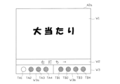
遊技盤30には、一般入賞口(一般入賞部)31、可変入賞装置(大入賞口)32、上始動入賞口33YA、下始動入賞口33YB、スルーゲート34、可変表示装置ユニット35、第1特別表示装置43L及び第2特別表示装置43R等が上記透明板に貫通形成された取付孔に対し嵌め込まれるようにして配設されている。
The
さらに、遊技盤30の前方領域、すなわち遊技盤30の前面側に形成される遊技領域内には、所定領域において遊技球の落下方向を振分けたり、所定位置へ遊技球を誘導したりするため、多数の釘49や風車57等が配設されている。風車57は、自身に対し相対移動する遊技球が接触することによって回転し遊技球の流下に作用する回転体であり、回転状態と停止状態とに状態変化する。例えば風車57は、遊技盤30に対し直接的又は間接的に後端側が固定された軸部材と、該軸部材の前端側が挿通される中央筒部と、該中央筒部から径方向外側へ向け延出形成された被作用部としての複数の接触片と、中央筒部の前端部に設けられた正面視円形板状の装飾円板部とを有し、接触片に対し遊技球が接触し外力を受けることにより、該外力によって前後方向を軸方向として回転する。勿論、風車57の構成は、これに限定されず他の構成を採用してもよい。
Furthermore, in the front area of the
遊技領域へ案内された遊技球は、それぞれ釘49等によって流下方向や回転方向を変えられながら様々な経路を通り流下していく。そして、遊技領域へ案内された複数の遊技球のうちのいくつかは、様々な経路を通り相対移動しながら風車57へ案内され、該風車57によって落下ルートが左右に振り分けられることとなる。ここで、遊技球が風車57の左側を通る第1の態様となり、遊技球が第1の近接状態で接触片に作用する場合には、風車57が第1の動作態様である反時計周り方向への回転動作を行う。一方、遊技球が風車57の右側を通る第2の態様となり、遊技球が第2の近接状態で接触片に作用する場合には、風車57が第2の動作態様である時計周り方向への回転動作を行う。
The game balls guided to the play area flow down various routes while their flow direction and rotation direction are changed by
かかる構成の下、例えば可変表示装置ユニット35の左側方領域に設けられた風車57(以下、左風車57という。)によって右側へ振分けられた遊技球は、該左風車57によって左側へ振分けられた遊技球に比べ、釘49等によって上始動入賞口33YAの方へ案内されやすくなる。一方、可変表示装置ユニット35の右側方領域に設けられた風車57(以下、右風車57という。)によって右側へ振分けられた遊技球は、該右風車57によって左側へ振分けられた遊技球に比べ、可変入賞装置32へ案内されやすくなる。
With this configuration, for example, a game ball diverted to the right by a windmill 57 (hereinafter referred to as the left windmill 57) provided in the left side area of the
また、本実施形態では、左風車57が反時計周り方向へ回転して遊技球が左風車57の左側を通り抜ける場合よりも、左風車57が時計周り方向へ回転して遊技球が左風車57の右側を通り抜ける場合の方が上始動入賞口33YAへ案内される遊技球の割合が多いなる一方、左風車57が時計周り方向へ回転して遊技球が左風車57の右側を通り抜ける場合よりも、左風車57が反時計周り方向へ回転して遊技球が左風車57の左側を通り抜ける場合の方が一般入賞口31へ案内される遊技球の割合は多くなる。
In addition, in this embodiment, a greater proportion of game balls are guided to the upper start winning opening 33YA when the
上述したように、本実施形態では、遊技領域が左右方向に広く拡張されている場合であっても、風車57等を備えることにより、遊技球を上始動入賞口33YAや可変入賞装置32等の方へと案内することが容易となるように構成されている。また、このように上始動入賞口33YAや可変入賞装置32等への入賞が適度な確率で発生するように、遊技盤30においては予め釘49等の調整が行われている。
As described above, in this embodiment, even if the game area is widely expanded in the left-right direction, the
尚、本実施形態では、可変表示装置ユニット35の左側方領域及び右側方領域にそれぞれ風車57が設けられた構成となっているが、これに限らず、左風車57又は右風車57の一方のみ備えた構成としてもよい。また、本実施形態のように、遊技盤30が透明板をベースに構成されている場合には、装飾円板部など風車57の少なくとも一部を透光性樹脂材料等によって透光部として構成してもよい。風車57と遊技球との相対位置関係は、風車57の少なくとも一部と遊技球の少なくとも一部とが重ならない非近接状態である第1位置関係と、風車57の少なくとも一部と遊技球の少なくとも一部とが重なる近接状態である第2位置関係とに変化する。そのため、透光部を備えた場合、遊技球が風車57を通過していない第1位置関係では、遊技盤30を透過した光が風車57の透光部を介して遊技者に視認可能されることとなる。一方、遊技球が風車57を通過している第2位置関係では、風車57の透光部と重なる遊技球の一部によって、遊技盤30を透過した光の一部が遮られると共に、透光部を通して遊技球の一部に対し前方から外光等の光が照射されることとなる。
In this embodiment, the
また、遊技盤30には、一般入賞口31等の各種入賞口(入球手段)に対応して、該各種入賞口へ入賞した遊技球を検出する検出手段としての入賞検出スイッチが設けられている。具体的には、図4に示すように、一般入賞口31に対応する位置には一般入賞スイッチ221が設けられ、可変入賞装置32にはカウントスイッチ223が設けられている。また、上始動入賞口33YAには第1始動入賞スイッチ224Aが設けられ、下始動入賞口33YBには第2始動入賞スイッチ224Bが設けられている。さらに、スルーゲート34に対応する位置にはスルーゲートスイッチ225が設けられている。
The
周知の通り一般入賞口31、可変入賞装置32、上始動入賞口33YA、下始動入賞口33YBなどの各種入賞口に遊技球が入賞(入球)すると、各種検出スイッチにより検出され、上皿19(又は下皿15)へ所定数の賞球が払い出される。例えば、上始動入賞口33YAへの入賞があった場合には3個、下始動入賞口33YBへの入賞があった場合には1個、一般入賞口31への入賞があった場合には10個、可変入賞装置32への入賞があった場合には15個の遊技球が上皿19(下皿15)に払出される。ここで、上始動入賞口33YAが第1始動入球手段を構成し、下始動入賞口33YBが第2始動入球手段を構成し、可変入賞装置32が特定入球手段を構成してもよい。また、上始動入賞口33YAなどの所定の入賞口に遊技球が入賞する状態を有利状態としてもよい。例えば上始動入賞口33YAへ遊技球が入賞し3個の賞球が払い出される状態を第1の有利状態とし、一般入賞口31へ遊技球が入賞し10個の賞球が払い出される状態を第2の有利状態としてもよい。その他に、遊技盤30にはアウト口36が設けられており、一般入賞口31等の各種入賞口に入賞しなかった遊技球は、このアウト口36を通って遊技領域外へと排出される。
As is well known, when a game ball enters (enters) various winning ports such as the general winning
可変入賞装置32は、遊技球が入賞可能な大入賞口(符号略)と、該大入賞口を開閉する開閉部材として矩形平板状の開閉板(大入賞口開閉部材)32aと、該開閉板32aを開閉駆動する大入賞口用ソレノイド(図示略)とを備えている。
The variable prize-winning
可変入賞装置32は、所定条件が成立していない通常時には、遊技球が大入賞口へ入賞不能な閉状態となっている一方、後述する大当たりや小当たりが発生した場合など、所定条件が成立した場合には、大入賞口用ソレノイドを励磁することにより、開閉板32aがその下辺を回動軸として前方へ傾倒し、遊技球が大入賞口へ入賞可能な開状態となる。
When the variable winning
上始動入賞口33YAは、遊技球が常時入賞可能となっている。これに対し、下始動入賞口33YBには、開閉式の入賞補助装置として開閉役物37Yが設けられている。
The upper start winning opening 33YA is always capable of receiving a winning ball. In contrast, the lower start winning opening 33YB is equipped with an opening/
開閉役物37Yは、下端側を軸として左右方向に回動変位する開閉部材としての左右一対の可動羽根37Yaと、該可動羽根37Yaを開閉駆動する始動入賞口用ソレノイド(図示略)とを備え、該可動羽根37Yaが所定条件の成立に応じて開閉動作することにより、遊技領域を流下する遊技球が下始動入賞口33YBへ入賞可能な開状態と、遊技球が下始動入賞口33YBへ入賞不能な閉状態との間で状態変化可能に構成されている。
The opening/
上述したように、上始動入賞口33YAや下始動入賞口33YBには、それぞれ入賞した遊技球を検出する検出手段としての第1始動入賞スイッチ224Aや第2始動入賞スイッチ224Bが設けられている。そして、該始動入賞スイッチ224A,224Bにて遊技球が検出された場合に、大当たり状態等を発生させるか否かの当否抽選が行われるとともに、特別表示装置43L、43Rや後述する演出表示装置42において変動表示や所定の演出が行われる構成となっている。ここで、当否抽選にて当選した場合には、大当たり状態等が付与される。
As described above, the upper start winning opening 33YA and the lower start winning opening 33YB are provided with the first
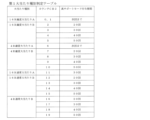
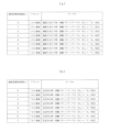
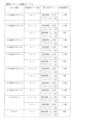
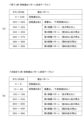
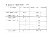
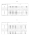
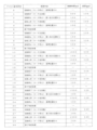
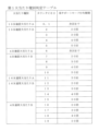
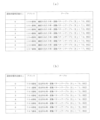
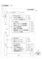
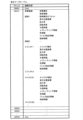
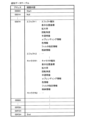
以下、本実施形態における大当たり種別について詳しく説明する。図37に示すように、本実施形態では、大当たり種別として、「16R確変大当たりA」、「16R確変大当たりB」、「4R確変大当たりA」、「4R確変大当たりB」、「16R通常大当たりA」、「16R通常大当たりB」、「4R通常大当たりA」、「4R通常大当たりB」及び「JUB(Jump Up Bonus)大当たり」がある。 The jackpot types in this embodiment will be described in detail below. As shown in FIG. 37, in this embodiment, the jackpot types include "16R special jackpot A", "16R special jackpot B", "4R special jackpot A", "4R special jackpot B", "16R regular jackpot A", "16R regular jackpot B", "4R regular jackpot A", "4R regular jackpot B" and "JUB (Jump Up Bonus) jackpot".
「16R確変大当たりA」の大当たり状態においては、「長開放」を1回の特賞状態として、これが16回(16ラウンド)繰り返し行われる。 In the "16R Special Jackpot A" jackpot state, a "long open" is counted as one special prize state, and this is repeated 16 times (16 rounds).
本実施形態において、「長開放」とは、可変入賞装置32の開閉板32aが閉状態から開状態へ切換えられた後、規定時間の30秒が経過すること又は可変入賞装置32に規定個数の10個の遊技球が入賞することを条件に閉状態となるまでの一開閉動作をいう。
In this embodiment, "long opening" refers to one opening/closing operation from when the opening/
「16R確変大当たりB」の大当たり状態においては、「長開放」を1回の特賞状態として、これが4回(4ラウンド)繰り返し行われた後、さらに「短開放」を1回の特賞状態として、これが12回(12ラウンド)繰り返し行われる。 In the "16R Special Jackpot B" jackpot state, a "long opening" is considered as one special prize state, and this is repeated four times (four rounds), after which a "short opening" is considered as one special prize state, and this is repeated 12 times (twelve rounds).
本実施形態において、「短開放」とは、可変入賞装置32の開閉板32aが閉状態から開状態へ切換えられた後、規定時間の0.4秒が経過すること又は可変入賞装置32に規定個数の3個の遊技球が入賞することを条件に閉状態となるまでの一開閉動作をいう。
In this embodiment, "short opening" refers to one opening/closing operation from when the opening/
尚、本実施形態では、遊技者のハンドル18の操作に基づき、発射装置60から「0.6秒」に1個の割合で遊技球が遊技領域に向けて発射される構成となっている。これに対して、上記「短開放」では、開閉板32aの開放規定時間が0.4秒となっている。つまり、「短開放」の場合には、遊技球の発射周期よりも1回の開閉板32aの開放時間が短くなっている。従って、1回の「短開放」だけでは、1個の遊技球すら入賞しない場合もある。このため、「短開放」に対応した上記2つの閉鎖条件のうち入賞個数に係る条件(入賞個数3個)に基づいて開閉板32aが閉鎖されることはほとんどなく、一旦開放された開閉板32aは、通常、規定時間(0.4秒)の経過に基づいて閉鎖されることとなる。これにより、「短開放」の実行期間においては、その都度、実行期間が変化することが回避されている。
In this embodiment, the launching
「4R確変大当たりA」及び「4R確変大当たりB」の大当たり状態においては、「長開放」を1回の特賞状態として、これが4回(4ラウンド)繰り返し行われる。 In the "4R Special Jackpot A" and "4R Special Jackpot B" jackpot states, a "long opening" is counted as one special prize state, and this is repeated four times (four rounds).
「16R通常大当たりA」の大当たり状態においては、「長開放」を1回の特賞状態として、これが8回(8ラウンド)繰り返し行われた後、さらに「短開放」を1回の特賞状態として、これが8回(8ラウンド)繰り返し行われる。 In the "16R Normal Jackpot A" jackpot state, a "long opening" is considered as one special prize state, and this is repeated eight times (eight rounds), after which a "short opening" is considered as one special prize state, and this is repeated eight times (eight rounds).
「16R通常大当たりB」の大当たり状態においては、「長開放」を1回の特賞状態として、これが4回(4ラウンド)繰り返し行われた後、さらに「短開放」を1回の特賞状態として、これが12回(12ラウンド)繰り返し行われる。 In the "16R Normal Jackpot B" jackpot state, a "long opening" is considered as one special prize state, and this is repeated four times (four rounds), after which a "short opening" is considered as one special prize state, and this is repeated 12 times (twelve rounds).
「4R通常大当たりA」及び「4R通常大当たりB」の大当たり状態においては、「長開放」を1回の特賞状態として、これが4回(4ラウンド)繰り返し行われる。 In the "4R Regular Jackpot A" and "4R Regular Jackpot B" jackpot states, a "long opening" is counted as one special prize state, and this is repeated four times (four rounds).
「JUB大当たり」の大当たり状態においては、「短開放」を1回の特賞状態として、これが5回繰り返し行われた後、さらに「長開放」を1回の特賞状態として、これが15回繰り返し行われる。換言すれば、1ラウンド目に5回の「短開放」が行われ、2ラウンド目~16ラウンド目にそれぞれ「長開放」が行われることとなる。 In the "JUB jackpot" jackpot state, a "short opening" is the special prize state, which is repeated five times, and then a "long opening" is the special prize state, which is repeated fifteen times. In other words, five "short openings" are performed in the first round, and a "long opening" is performed in each of the second through sixteenth rounds.
また、上記各種「確変大当たり」及び「JUB大当たり」が発生した場合には、その大当たり状態の終了後の抽選モードとして「高確率モード(高確率状態)」が付与される。一方、各種「通常大当たり」が発生した場合には、その大当たり状態の終了後に「低確率モード(低確率状態)」が付与される。 In addition, when any of the above-mentioned "variable jackpots" and "JUB jackpots" occur, the "high probability mode (high probability state)" is granted as the lottery mode after the jackpot state ends. On the other hand, when any of the "normal jackpots" occur, the "low probability mode (low probability state)" is granted after the jackpot state ends.
「高確率モード」とは、通常時に設定される「低確率モード」に比べ、大当たり確率がアップした状態をいう。大当たり終了後に設定された「高確率モード」は、次回の大当たり状態が発生するまで継続する。 "High Probability Mode" refers to a state in which the probability of a jackpot is increased compared to the "Low Probability Mode" that is normally set. The "High Probability Mode" that is set after a jackpot ends will continue until the next jackpot occurs.
また、上記各種大当たりの終了後には、特別表示装置43L、43Rにて所定回数の変動表示が行なわれる間、又は、次回の大当たり状態が発生するまでの間、開閉役物37Yに係る入賞サポートモードとして「高サポートモード(高入球状態)」が付与される。
After the various jackpots mentioned above have ended, the "high support mode (high ball entry state)" is granted as a winning support mode for the opening and
「高サポートモード」とは、通常時に設定される「低サポートモード(低入球状態)」に比べ、下始動入賞口33YBの開閉役物37Yにおける単位時間あたりの閉状態に対する開状態の割合が多くなった状態をいう。
"High support mode" refers to a state in which the ratio of open to closed states per unit time in the opening/
例えば「高サポートモード」としては、(1)後述の普通図柄表示装置41における変動表示時間が「低サポートモード」時よりも短い状態、(2)開閉役物37Yの可動羽根37Yaの一回の開放時間(規定時間)が「低サポートモード」時に比べて長い状態、(3)可動羽根37Yaの一回の開放につき入賞可能となる遊技球の規定個数が「低サポートモード」時に比べて多い状態、(4)スルーゲート34を遊技球が通過することに起因した開閉役物37Yの開放抽選により当選結果が得られた場合一回につき行う可動羽根37Yaの開閉処理の実行回数が「低サポートモード」時に比べて多い状態、(5)開閉役物37Yの開放抽選における当選確率が「低サポートモード」時の当選確率よりも高い状態とすることなどが挙げられる。本実施形態における高サポートモードでは、上記(1)、(2)、(5)の構成を採用している。勿論、これに限らず、「高サポートモード」として、構成(1)~(5)のいずれか1つ、又は、これら構成(1)~(5)の任意の組合せを採用してもよい。これにより、下始動入賞口33YBに対し遊技球が頻繁に入賞しやすくなり、大当たり抽選の実行される回数が増えると共に、球持ちのよい状態となる。
For example, the "high support mode" may be (1) a state in which the variable display time in the normal
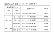
また、本実施形態では、「高サポートモード」が付与された状態では、後述するように変動パターンテーブルを「高サポートモード」用のテーブルに変更することで、第1及び第2特別表示装置43L、43R(演出表示装置42)における変動表示時間が「低サポートモード」時よりも短い状態となるように構成されている。
In addition, in this embodiment, when the "high support mode" is applied, the variation pattern table is changed to a table for the "high support mode" as described below, so that the variation display time on the first and second
本実施形態では、「16R確変大当たりA」及び「4R確変大当たりA」の終了後には、次回の大当たり状態が発生するまでの間、「高サポートモード」が付与される。該「高サポートモード」を以下、「次回まで・高サポートモード」という。 In this embodiment, after the end of the "16R Probable Big Win A" and "4R Probable Big Win A", a "high support mode" is granted until the next big win occurs. This "high support mode" is hereinafter referred to as the "Until Next Time High Support Mode".
「16R確変大当たりB」及び「4R確変大当たりB」の終了後には、特別表示装置43L、43Rにて「20回」、「30回」、「40回」又は「50回」の変動表示が行なわれる間、「高サポートモード」が付与される。該「高サポートモード」を以下、それぞれ「20回・高サポートモード」、「30回・高サポートモード」、「40回・高サポートモード」又は「50回・高サポートモード」という。
After the "16R High Success Big Win B" and "4R High Success Big Win B" end, a "high support mode" is granted while the
「16R通常大当たりA」及び「4R通常大当たりA」の終了後には、特別表示装置43L、43Rにて「30回」の変動表示が行なわれる間、「高サポートモード」が付与される。該「高サポートモード」を以下、「30回・高サポートモードS」という。
After the "16R normal jackpot A" and "4R normal jackpot A" end, the "high support mode" is granted while the "30 times" variable display is being performed on the
「16R通常大当たりB」及び「4R通常大当たりB」の終了後には、「20回・高サポートモード」、「30回・高サポートモード」、「40回・高サポートモード」又は「50回・高サポートモード」が付与される。 After the end of the "16R normal jackpot B" and "4R normal jackpot B", the "20 times high support mode", "30 times high support mode", "40 times high support mode" or "50 times high support mode" will be awarded.
「JUB大当たり」の終了後には、「次回まで・高サポートモード」が付与される。 After the "JUB jackpot" ends, the "Until next time - high support mode" will be granted.
本実施形態では、上記各種モードが組み合わさることで、様々な遊技状態が発生することとなる。 In this embodiment, various game states are generated by combining the various modes described above.
例えば「高確率モード」と「高サポートモード」が付与された状態となれば、いわゆる「確変状態(確率変動状態)」となる。 For example, if "high probability mode" and "high support mode" are applied, it will be in a so-called "high probability state (probability fluctuating state)."
「低確率モード」と「低サポートモード」とが付与された状態となれば、いわゆる「通常状態」となる。 When "low probability mode" and "low support mode" are applied, it becomes what is known as the "normal state."
「低確率モード」と「高サポートモード」が付与された状態となれば、いわゆる「時短状態(時間短縮状態)」となる。 When "low probability mode" and "high support mode" are applied, it will be in what is known as a "time-saving state."
「高確率モード」と「低サポートモード」とが付与された状態となれば、いわゆる「潜確状態(潜伏確変状態)」となる。つまり、「潜確状態」となると、単に大当たり確率が高められるだけで、表面上は「通常状態」の場合と何ら変わりのない状態となるため、「高確率モード」が付与されている状態を遊技者が認識しにくい状態となる。 When the "high probability mode" and "low support mode" are both applied, it becomes a so-called "latent probability state (latent probability change state)." In other words, when it becomes a "latent probability state," the probability of a jackpot is simply increased, and on the surface it is no different from the "normal state," so it becomes difficult for players to recognize that the "high probability mode" has been applied.
また、本実施形態では、上記各種「大当たり」とは別に、上記当否抽選にて所定の結果が得られた場合に「小当たり」が発生する構成となっている。小当たり状態においては、「短開放」を1回の特賞状態として、これが5回(5ラウンド)繰り返し行われる。但し、小当たり状態終了後に付与される抽選モード及び入賞サポートモードは、小当たり状態発生前の元のモードである。例えば、小当たり状態発生前の抽選モードが「高確率モード」であれば、小当たり状態終了後にも「高確率モード」が維持される。 In addition, in this embodiment, in addition to the various "big wins" mentioned above, a "small win" occurs when a predetermined result is obtained in the win/lose lottery. In the small win state, a "short opening" is considered as one special prize state, and this is repeated five times (five rounds). However, the lottery mode and winning support mode granted after the small win state ends are the original modes before the small win state occurred. For example, if the lottery mode before the small win state occurred was the "high probability mode," the "high probability mode" will be maintained even after the small win state ends.
尚、詳しくは後述するが、本実施形態では、遊技球が上始動入賞口33YAに入賞した場合と、下始動入賞口33YBに入賞した場合とで、当否抽選にて当選した場合に付与される大当たり種別の振分けが異なるようになっている。上始動入賞口33YAへの遊技球の入賞を契機とする当否抽選に当選した場合には、「16R確変大当たりA」、「16R確変大当たりB」、「4R確変大当たりA」、「4R確変大当たりB」、「16R通常大当たりA」、「16R通常大当たりB」及び「4R通常大当たりB」のいずれかに振分けられ、下始動入賞口33YBへの遊技球の入賞を契機とする当否抽選に当選した場合には、「16R確変大当たりA」、「4R確変大当たりA」、「4R通常大当たりA」及び「JUB大当たり」のいずれかに振分けられることとなる。また、「小当たり」に関しても、下始動入賞口33YBへの遊技球の入賞を契機とする当否抽選に当選した場合のみ発生する構成となっている。 In this embodiment, the allocation of the jackpot type that is awarded in the case of winning the winning/losing lottery is different depending on whether the game ball enters the upper start winning hole 33YA or the lower start winning hole 33YB, as will be described in detail later. If the winning/losing lottery triggered by the game ball entering the upper start winning hole 33YA is won, the jackpot type is allocated to one of "16R certainty variable jackpot A", "16R certainty variable jackpot B", "4R certainty variable jackpot A", "4R certainty variable jackpot B", "16R normal jackpot A", "16R normal jackpot B" and "4R normal jackpot B", and if the winning/losing lottery triggered by the game ball entering the lower start winning hole 33YB is won, the jackpot type is allocated to one of "16R certainty variable jackpot A", "4R certainty variable jackpot A", "4R normal jackpot A" and "JUB jackpot". In addition, the "small win" will only occur if the player wins the lottery triggered by the game ball entering the lower start winning hole 33YB.
第1及び第2特別表示装置43L、43Rは、それぞれ2つのセグメント表示装置により構成され、遊技盤30の下部に設置されている。各セグメント表示装置には、それぞれ8個の表示用セグメントが設けられている。各表示用セグメントは、LEDからなる個別の光源を有しており、それら個別の光源がオンオフ制御されることで、任意の1個の表示用セグメントのみを点灯させることができるとともに、任意の組み合わせの表示用セグメントを点灯させることができる。これにより、各セグメント表示装置には、それぞれ個別に所定の記号(アルファベットや数字を含む)が表示されることとなる。
The first and second
そして、上始動入賞口33YAへの遊技球の入賞を契機として第1特別表示装置43Lにて変動表示が行われ、下始動入賞口33YBへの遊技球の入賞を契機として第2特別表示装置43Rにて変動表示が行われる構成となっている。尚、特別表示装置43L、43Rは、後述する主制御装置261によって表示内容が直接的に制御される。
When a game ball enters the upper start winning opening 33YA, a variable display is displayed on the first
また、第1及び第2特別表示装置43L、43Rにて変動表示が行われた後、該変動表示が停止したときの表示態様により、大当たり抽選に当選したか否か等が確定的に表示される。例えば、上始動入賞口33YAに遊技球が入賞すると、対応する第1特別表示装置43Lにて高速で変動表示がなされ、所定時間が経過すると、いずれかの表示態様を停止表示(例えば数秒間停止)する。そして、大当たり抽選に当選した場合には、各種大当たりに対応する数値等(図37参照)が変動停止時に表示され、大当たり状態が発生する。
After the first and second
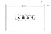
図37に示すように、例えば「16R確変大当たりA」に当選した場合には、第1又は第2特別表示装置43L、43Rにおいて「9-」が停止表示され、「50回・高サポートモード」付きの「16R確変大当たりB」に当選した場合には、第1又は第2特別表示装置43L、43Rにおいて「84」が停止表示される。また、「JUB大当たり」に当選した場合には、第1又は第2特別表示装置43L、43Rにおいて「1.-」が停止表示され、「小当たり」に当選した場合には、第1又は第2特別表示装置43L、43Rにおいて「1-」が停止表示される。ここで、「JUB大当たり」に係る停止態様「1.-」と、「小当たり」に係る停止態様「1-」のように、「JUB大当たり」の演出効果を高める上では、両者の停止態様が紛らわしい構成となっていることが好ましい。
As shown in FIG. 37, for example, when the "16R certain jackpot A" is won, "9-" is displayed on the first or second
勿論、各種当たりに対応する特別表示装置43L、43Rの停止態様は、上記態様に限定されるものではない。例えば、1つの当たり種別を示す第1又は第2特別表示装置43L、43Rの停止態様が1つではなく複数存在してもよい。例えば「16R確変大当たりA」に当選した場合には、第1又は第2特別表示装置43L、43Rにおいて「91」,「92」,「93」,・・・のいずれかが選択されて停止表示される構成としてもよい。
Of course, the stop modes of the
尚、1つの当たり種別を示す第1又は第2特別表示装置43L、43Rの停止態様が複数存在している場合においても、「JUB大当たり」に係る複数の停止態様と、「小当たり」に係る複数の停止態様とが紛らわしい構成となっていることが好ましい。例えば、「JUB大当たり」に係る複数の停止態様として「-1.」,「-2」,「-3.」,「-4」,・・・のいずれかが停止表示され、「小当たり」に係る複数の停止態様として「-1」,「-2.」,「-3」,「-4.」,・・・のいずれかが停止表示される構成してもよい。かかる構成では、所定の表示用セグメント(ここでは「.」)が点灯した特定記号(ここでは「1」,「2」,「3」,・・・)と、点灯していない特定記号のペアのうちの一方が「JUB大当たり」に係る複数の停止態様に含まれ、他方が「小当たり」に係る複数の停止態様に含まれると共に、それらが交互に入れ違いになった構成となっている。
Even if there are multiple stop modes of the first or second
また、任意又は全ての表示用セグメントにおいて表示される色を適宜変更可能な構成としてもよい。 The color displayed in any or all of the display segments may also be configured to be changeable as appropriate.
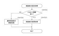
また、第1又は第2特別表示装置43L、43Rの変動表示中に新たに遊技球が始動入賞口33YA,33YBに入賞した場合には、その分の変動表示は、その時点で行われている変動表示の終了後に行われる構成となっている。つまり、変動表示が待機(保留)されることとなる。この保留される変動表示の最大回数は、パチンコ機の機種毎に決められているが、本実施形態では、上始動入賞口33YAに入賞した遊技球、及び下始動入賞口33YBに入賞した遊技球に対応して、それぞれ4回までの変動表示(合計8回の変動表示)が保留される。また、その保留回数が第1保留ランプ46a、第2保留ランプ46bにて点灯表示されるようになっている。尚、大当たり状態中に新たに遊技球が始動入賞口33YA,33YBに入賞した場合、その分の変動表示についても保留される。
In addition, if a new game ball enters the start winning hole 33YA, 33YB during the variable display of the first or second
尚、基本的に、上始動入賞口33YAへの入賞を契機とする変動表示は、対応する遊技球が上始動入賞口33YAへ入賞した順に記憶されるとともに入賞した順に消化され、下始動入賞口33YBへの入賞を契機とする変動表示は、対応する遊技球が下始動入賞口33YBへ入賞した順に記憶されるとともに入賞した順に消化される。但し、上始動入賞口33YAへの入賞を契機とする変動表示、及び、下始動入賞口33YBへの入賞を契機とする変動表示の両方が保留されている場合(第1保留ランプ46a及び第2保留ランプ46bがそれぞれ1つ以上点灯している場合)には、下始動入賞口33YBへの入賞を契機とする変動表示が優先的に消化される。すなわち、下始動入賞口33YBへの入賞を契機とする変動表示が全て消化された状態でなければ、上始動入賞口33YAへの入賞を契機とする変動表示が行われない構成となっている。例えば、第1保留ランプ46aが1つ点灯している状態において、下始動入賞口33YBに遊技球が入賞し、第2保留ランプ46bが1つ点灯した場合、上始動入賞口33YAへの入賞を契機とする変動表示が後回しにされ、先に下始動入賞口33YBへの入賞を契機とする変動表示が行われることとなる。以下、説明の便宜上、上始動入賞口33YAへの入賞を契機とする変動表示を「第1変動表示」とも称し、下始動入賞口33YBへの入賞を契機とする変動表示を「第2変動表示」とも称する。
In addition, basically, the variable display triggered by the entry into the upper start winning opening 33YA is stored in the order in which the corresponding game balls entered the upper start winning opening 33YA and is consumed in the order in which they entered, and the variable display triggered by the entry into the lower start winning opening 33YB is stored in the order in which the corresponding game balls entered the lower start winning opening 33YB and is consumed in the order in which they entered. However, if both the variable display triggered by the entry into the upper start winning opening 33YA and the variable display triggered by the entry into the lower start winning opening 33YB are reserved (if one or more of the first
また、スルーゲート34は、遊技領域を流下する遊技球が1球ずつ通過可能に構成されている。詳しくは後述するが、スルーゲート34は、該スルーゲート34を通過する遊技球を検出可能なスルーゲートスイッチ225を備えており、該スルーゲートスイッチ225にて遊技球が検出された場合に、開閉役物37Y(下始動入賞口33YB)を開状態とするか否かの開放抽選が行われるとともに、普通図柄表示装置41にて変動表示が行われる構成となっている。そして、開放抽選にて当選した場合には、開閉役物37Yが規定時間だけ開状態とされる。
The through
可変表示装置ユニット35には、スルーゲート34の通過を契機として変動表示する普通図柄表示装置41と、第1及び第2特別表示装置43L、43Rによる変動表示に合わせて変動表示する演出表示装置42とが設けられている。
The
さらに、可変表示装置ユニット35には、演出表示装置42にて行われている変動表示が上始動入賞口33YA及び下始動入賞口33YBのうちどちらの入賞に対応するものであるかを示す変動特定ランプ40が設けられている。
Furthermore, the
普通図柄表示装置41は、普通図柄として「○」又は「×」を点灯表示可能に構成されており、遊技球がスルーゲート34を通過する毎に例えば普通図柄を「○」→「×」→「○」→・・・という具合に高速で変動表示する。そして、その変動表示が「○」図柄(当選図柄)で数秒間停止した場合には、下始動入賞口33YBの開閉役物37Yが所定時間だけ開状態となる。この普通図柄表示装置41は、後述する主制御装置261によって直接的に表示内容が制御される。
The normal
また、普通図柄表示装置41の変動表示中に、新たに遊技球がスルーゲート34を通過した場合には、その分の変動表示は、その時点で行われている変動表示の終了後に行われる構成となっている。つまり、変動表示が待機(保留)されることとなる。この保留される変動表示の最大回数は、パチンコ機の機種毎に決められているが、本実施形態では4回まで保留され、その保留回数が保留ランプ44にて点灯表示されるようになっている。
In addition, if a new game ball passes through the through
演出表示装置42は液晶表示装置により構成されており、後述するサブ制御装置262及び表示制御装置45によって表示内容が制御される。すなわち、演出表示装置42においては、第1及び第2特別表示装置43L、43Rにて表示される結果に対応させるように、主制御装置261からのコマンドに基づき、サブ制御装置262によって補助的な表示内容が決定され、後述する表示制御装置45によって表示が行われる。
The
演出表示装置42には、図43に示すように、例えば上、中及び下の3つの図柄表示領域が設けられ、各図柄表示領域において複数種類の図柄(数字)が順次表示され(変動表示され)、その後、図柄表示領域毎に順番に(例えば、上図柄表示領域→下図柄表示領域→中図柄表示領域の順に)図柄が停止表示されるようになっている。例えば、主制御装置261にて上記各種「確変大当たり」又は各種「通常大当たり」が確定すると、第1又は第2特別表示装置43L、43Rにて大当たりに対応する表示がなされるとともに、演出表示装置42にて図柄が大当たりに対応する組合わせで停止表示され(例えば、上図柄表示領域、中図柄表示領域、及び下図柄表示領域にて停止表示される図柄が同一となり)、大当たり状態が開始される。なお、「JUB大当たり」又は「小当たり」の場合、後述するように演出表示装置42にて停止表示される図柄の組合わせは、大当たりに対応するものではない。
As shown in FIG. 43, the
また、図柄が大当たりに対応する組合わせで停止表示される場合には、その前段階として、例えば、上図柄表示領域及び下図柄表示領域において同一の図柄が停止表示されることとなる。このように上図柄表示領域及び下図柄表示領域にて同一図柄が停止表示されるとともに、中図柄表示領域において未だ変動表示が行われている状態がリーチ状態である。 Also, when the symbols are displayed in a combination that corresponds to a big win, the first step is to display the same symbol in the upper and lower symbol display areas. This state in which the same symbol is displayed in the upper and lower symbol display areas while the middle symbol display area is still displaying a changing pattern is called a reach state.
尚、リーチ状態が発生しても、大当たり状態が発生しない場合には、上図柄表示領域及び下図柄表示領域において停止表示された図柄とは異なる図柄が中図柄表示領域において停止表示される。また、各種「確変大当たり」又は各種「通常大当たり」となる場合には、上記のように演出表示装置42においてゾロ目の数字が停止表示されるのではあるが、本実施形態では 停止表示された図柄の種類によっては、大当たり終了後に付与される遊技状態(「高確率モード」か否か等)が判別不能となっている。
In addition, if a reach state occurs but a jackpot state does not occur, a pattern different from the pattern displayed in the upper pattern display area and the lower pattern display area is displayed in the middle pattern display area. Also, in the case of various "probable jackpots" or various "normal jackpots", a repeated number is displayed in the
また、「JUB大当たり」又は「小当たり」となる場合には、ゾロ目ではなく、予め定められた特定の数字の組合わせ(以下、チャンス図柄と称する)が停止表示される。例えば、本実施形態では、上・中・下図柄表示領域において、「3」・「4」・「1」が停止表示される。これにより、遊技者は、チャンス図柄が停止表示された場合に、より遊技者に有利な「JUB大当たり」と、それほど有利ではない「小当たり」との区別をつけることができず、「JUB大当たり」が発生することの期待を抱くことができるので、遊技者の趣向低下を抑制することができる。 In addition, when a "JUB jackpot" or "small jackpot" occurs, a predetermined combination of specific numbers (hereinafter referred to as a chance symbol) is displayed instead of a repeating number. For example, in this embodiment, "3", "4", and "1" are displayed in the upper, middle, and lower symbol display areas. This means that when a chance symbol is displayed, the player cannot distinguish between a "JUB jackpot", which is more advantageous to the player, and a "small jackpot", which is not so advantageous, and can have hope that a "JUB jackpot" will occur, thereby preventing a decline in the player's interest.
勿論、「JUB大当たり」となる場合と、「小当たり」となる場合とで、上・中・下図柄表示領域に停止表示される特定の数字の組合わせが異なる構成としてもよい。また、「JUB大当たり」又は「小当たり」となる場合に、予め定められた特定の数字の組合わせではなく、表面上、外れ時と同様に、ランダムな外れの組合わせで停止表示されるようにしてもよい。 Of course, the specific number combinations displayed in the upper, middle, and lower pattern display areas may be different for a "JUB jackpot" and a "small jackpot". Also, when a "JUB jackpot" or a "small jackpot" is reached, instead of a specific predetermined number combination, a random miss combination may be displayed, as in the case of a miss.
また、演出表示装置42では、上記保留ランプ46a,46bに対応して、特別表示装置43L,43Rにおける変動表示の保留数が表示される構成となっている(図43等参照)。
In addition, the
尚、本実施形態では、前面枠セット14を閉鎖した際、該前面枠セット14によって特別表示装置43L,43R及び保留ランプ46a,46bが覆われた状態となり、遊技者によって視認不能な状態となる。従って、遊技者は、専ら演出表示装置42の表示内容(図柄表示や保留表示等)によって遊技状態や抽選結果等を把握することとなる。
In this embodiment, when the front frame set 14 is closed, the
勿論、特別表示装置43L,43R及び保留ランプ46L,46Rの構成は、このような構成に限定されるものではなく、他の構成を採用してもよい。例えば、特別表示装置43L,43R等が視認可能な構成となっていてもよい。但し、特別表示装置43L、43Rは、上記のように遊技領域の下隅といった遊技者の目につきにくい目立たない場所に設けられるとともに、その表示部の大きさも小さく、判別用の文字が停止表示される時間も比較的短い。従って、特別表示装置43L、43Rから目を離さず、注意深く観察していなければ、付与さえる遊技状態を把握することは実質的に不可能である。
Of course, the configuration of the
変動特定ランプ40は、発光色が青色のLED及び発光色が赤色のLEDを備えており、演出表示装置42において、上始動入賞口33YAへの入賞を契機とする変動表示が行われている場合には青色に発光し、下始動入賞口33YBへの入賞を契機とする変動表示が行われている場合には赤色に発光する。
The
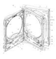
次に可変表示装置ユニット35の構成について詳しく説明する。本実施形態では、図218に示すように、センターフレーム47が遊技盤30の前面側に固定され、フレームカバー213が遊技盤30の裏面に固定されることによって、可変表示装置ユニット35として一体化される構成となっている。
Next, the configuration of the
フレームカバー213には、その中央部に矩形状の開口部213a(図6参照)が形成されており、その背面側に液晶表示装置たる演出表示装置42が着脱自在に取付けられている。演出表示装置42の液晶表示部42aは、発光手段としてのバックライトの前面側に、各種透光性部材が積層されてなる液晶パネルが配設された公知のものである。
A
センターフレーム47は、その中央に略円形状の開口部751が形成された枠体形状をなし、該開口部751を介して演出表示装置42の液晶表示部42aが視認可能となる。
The
尚、センターフレーム47は、単一部材から構成されているわけではなく、例えばベース部材に対し、メッキ等の施された各種装飾部材や、LED等の光を透過する透明樹脂製のレンズ部材などが組付けられてなる。
The
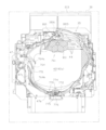
センターフレーム47の下辺部47bの上面には、左右方向に沿ってステージ部770が設けられている。ステージ部770には、左右方向に沿って緩やかな起伏が形成されている。
A
ステージ部770の後壁部772の中央部には、前方に向け開口し、遊技球が落下可能な落下孔774が形成されている。また、ステージ部770の中央部の下方(内部)には、前記落下孔774に通じる連通路775が設けられている。連通路775の他方側は、センターフレーム47の下辺部47bの前側に開口し、落下孔774へ落下した遊技球を遊技盤30面上へ排出するための排出口776となっている。なお、センターフレーム47が遊技盤30に配設された状態では、図4に示すように、排出口776は上始動入賞口33YAの上方に位置する。
A
ステージ部770の中央部には、落下孔774の前方位置において、奥側へ緩やかに下り傾斜となった誘導溝778が形成されている。これにより、ステージ部770から落下孔774へ遊技球が落下可能な構成となっている。
In the center of the
センターフレーム47の左辺部47cには、その内部に、遊技球を通過させる球通路(ワープ流路)764が形成されている。球通路764の入口部764aは、センターフレーム47の左辺部47cの上下方向略中央部に開口している一方、出口部764bは、センターフレーム47の下辺部47bの上面(ステージ部770)に向け開口している。この球通路764により、遊技盤30面上を流下する遊技球をセンターフレーム47内のステージ部770上へ案内することができる。
A ball passage (warp flow path) 764 is formed inside the
ステージ部770上に案内された遊技球は、ステージ部770上を転動した後、前方から遊技盤30面上に転落したり、上述した落下孔774へ落下したりする。このうち、落下孔774へ落下した遊技球は、連通路775を介して遊技盤30面上へ案内される。排出口776から排出された遊技球は比較的高い確率で上始動入賞口33YAに入球する。
The game ball guided onto the
また、可変表示装置ユニット35には、センターフレーム47とフレームカバー213との間において、上部演出役物ユニット761及び下部演出役物ユニット762が配設されている。
In addition, an
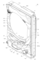
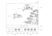
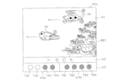
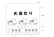
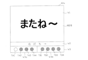
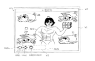
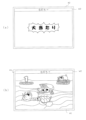
具体的に、上部演出役物ユニット761は、センターフレーム47の上辺部47a裏側に配設されており、通常時(図7参照)には、上辺部47a等によって、そのほぼ全体が覆われ、一部のみが遊技者に視認可能な状態となっている。
Specifically, the upper
また、下部演出役物ユニット762は、センターフレーム47の下辺部47b裏側に配設されており、通常時(図7参照)には、下辺部47b等によって、そのほぼ全体が覆われ、一部のみが遊技者に視認可能な状態となっている。
The lower
ここで、上部演出役物ユニット761及び下部演出役物ユニット762の構成について詳しく説明する。まず上部演出役物ユニット761について図面を参照して詳しく説明する。
Here, we will explain in detail the configuration of the
図7~図9に示すように、上部演出役物ユニット761は、センターフレーム47の上辺部47aの裏側に設けられている。
As shown in Figures 7 to 9, the
上部演出役物ユニット761は、フレームカバー213の前面上部に配設されたユニットベース部810と、該ユニットベース部810に対し揺動可能に設けられた上可動役物811と、該上可動役物811を揺動させるための揺動駆動機構812とを備えている。
The
揺動駆動機構812は、上可動役物811を支持する支持アーム814と、該支持アーム814を駆動させる駆動源となる揺動用モータ815とを備えている。
The
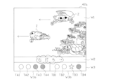
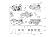
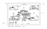
そして、揺動用モータ815の駆動に基づき、支持アーム814が回動変位することにより、上可動役物811は、その大部分がセンターフレーム47の上辺部47a裏側に位置し遊技者に視認困難な待機状態(図7参照)と、その大部分が演出表示装置42の表示部42aの前面側に位置し遊技者に視認容易な露出状態(図9参照)との間で揺動変位可能となる。演出表示装置42の液晶表示部42aの前方領域が本実施形態における演出領域(所定領域)を構成する。
Then, as the
上記揺動用モータ815は、印加される駆動パルス信号によって回転制御されるステッピングモータであり、駆動パルス信号を調整することにより、上可動役物811(支持アーム814)の回動変位量を制御できる。同時に、入力される駆動パルス信号数を監視することによって基準位置からの上可動役物811(支持アーム814)の回動変位量を把握することができる。尚、図示は省略するが、揺動駆動機構812には、支持アーム814の回動位置を検出するための位置検出センサなどが設けられている。
The
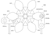
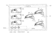
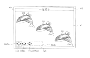
ここで、上可動役物811について図52~図56を参照して詳しく説明する。上可動役物811は、支持アーム814の先端部に固定されたベース部817と、該ベース部817の前面側において回転可能に支持された上回転体820とを備えている。上回転体820は演出用の回転体であり、第1回転手段としての第1回転体を構成する。
The upper
ベース部817は、正面視略円形状をなし、その中央部には支軸部818が前方へ向け突出形成されている。支軸部818は、前面側が閉塞しかつ背面側が開口した略円筒状に形成されている。
The
ベース部817の裏側には、上回転体用駆動モータ821が取付固定されている。上回転体用駆動モータ821の回動軸821aの前端部には、ピニオン歯車821bが取付固定されている。そして、ピニオン歯車821bを介して上回転体用駆動モータ821の駆動力が上回転体820へ伝達される。
The upper
ベース部817の前面部には、円環状のカバー体822が取付固定されている。カバー体822の中央部には、円形状の開口部822aが形成されている。
A
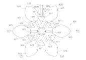
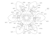
上回転体820は、主に回転基板823と、その前面側にて環状配置された6個の可動片825とからなる。
The upper
回転基板823は、前後方向に延びる円筒部826と、該円筒部826の外周壁部から径方向外側に向け放射状に延出形成された6本の延出片827とを有している。6本の延出片827は、円筒部826の周方向に等間隔(60°間隔)で設けられている。
The rotating
円筒部826は、ベース部817の支軸部818に外嵌されている。これにより、回転基板823は、ベース部817に対し回転可能に軸支された状態となる。尚、図示は省略するが、円筒部826又は支軸部818には、ベース部817(支軸部818)からの回転基板823(円筒部826)の脱落を防止するための規制手段が設けられている。
The
各延出片827には、前後方向に貫通しかつ回転基板823の径方向に沿って形成されたスリット829が開口形成されている。各延出片827の先端部近傍裏面には、それぞれ円柱状のピニオン支軸830が後方へ向け突出形成されている。
Each
回転基板823の円筒部826には、円環状の中央歯車部材831が後方から外嵌されている。
A circular
中央歯車部材831には、その前側に設けられた大径歯車部831aと、後側に設けられた小径歯車部831bが前後に段をなすように一体的に形成されている。
The
また、ピニオン支軸830には、それぞれピニオン歯車832が外嵌され、中央歯車部材831の大径歯車部831aに噛合されている。
In addition, pinion gears 832 are fitted onto the
さらに、回転基板823の裏側には、円環状の押え板835が取付けられている(図56参照)。押え板835の円形開口部835aは、中央歯車部材831の小径歯車部831bより僅かに大径で該小径歯車部831bを挿通し得るとともに、大径歯車部831aよりも小径となっている。
In addition, an annular
これにより、押え板835が、上記6個のピニオン歯車832及び大径歯車部831aを後方から覆うとともに小径歯車部831bを挿通しながら、ピニオン支軸830の先端に固定されている。これにより、中央歯車部材831が回転基板823の円筒部826の周りに回転自在に保持された状態となる。
As a result, the
中央歯車部材831の小径歯車部831bには、上回転体用駆動モータ821のピニオン歯車821bが噛合されている。これにより、上回転体用駆動モータ821の回転が中央歯車部材831に伝達される。
The
つまり、ピニオン歯車821b、中央歯車部材831、ピニオン歯車832等により、上記上回転体用駆動モータ821の動力を上回転体820に伝達して可動片825をスライド動作させると共に回転基板823を回転させるように駆動する主動力伝達機構が構成される。
In other words, the
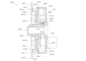
さらに、回転基板823の円筒部826の後端には第2駆動ギア841が取付固定されている。図56に示すように、第2駆動ギア841には、第2伝達ギア842に噛合されている。第2伝達ギア842は、オイルダンパ843に連結されている。オイルダンパ843には、後方から支持部材844が嵌着され、該支持部材844は、ベース部817に取付固定されている。
Furthermore, a
これにより、回転基板823が所定レベル以下の低トルクでは回転しないように制動される構成となっている。ここで、第2駆動ギア841や第2伝達ギア842等により、オイルダンパ843の力を上回転体820に伝達して上回転体820の動作を規制する規制動力伝達機構が構成される。
This brakes the rotating
尚、上記規制動力伝達機構は、上記主動力伝達機構とは連結されておらず、回転基板823を介することなく、上回転体用駆動モータ821とオイルダンパ843との間で、直接的に動力が伝達されないよう構成されている。
The restrictive power transmission mechanism is not connected to the main power transmission mechanism, and is configured so that power is not transmitted directly between the upper
図52等を見て分かるとおり、上回転体820は、1つの花をモチーフとして形成されたものであり、各可動片825は、それぞれ1枚の花弁を模して形成されている。
As can be seen from Figure 52, the upper
各可動片825は、透光性を有する透明樹脂材料により形成されている。但し、各可動片825の一般部(後述する拡大レンズ部828を除く部分)の表面には、図示しない微細な凹凸部が形成されている。これにより、可動片825の一般部は、後方に位置する演出表示装置42の表示部(液晶表示部)42aから発せられる光を拡散して透過し全体が均一に面発光した状態となる一方、該可動片825の一般部を介して、表示部42aに表示された表示対象(対象物)を識別することは困難な構成となっている。
Each
これに対し、6枚の可動片825のうち、1つの可動片825には、拡大レンズ部828が形成されている。これ以降、拡大レンズ部828を有した可動片825を他の可動片825と区別する場合には、「特定可動片825A」と称することもある。可動片825や拡大レンズ部828が本実施形態における透光部を構成する。
In contrast, one of the six
特定可動片825Aの拡大レンズ部828は、後方に位置する対象物を拡大表示して遊技者に視認させることができる。例えば遊技者は、演出表示装置42の表示部42aに表示される文字やキャラクタ等の表示対象を、拡大レンズ部828を介して拡大して視認することができる。
The magnifying
可動片825の裏面には、直線状に延びるラック部838が一体形成されている。ラック部838は、回転基板823の延出片827のスリット829に挿し込まれている。これにより、可動片825が回転基板823の径方向(延出片827の延在方向)に沿ってスライド可能となる。尚、図示は省略するが、ラック部838又はスリット829には、回転基板823からの可動片825の脱落を防止するための規制手段が設けられている。
A
可動片825のラック部838は、延出片827の裏面にてピニオン歯車832と噛合されている。これにより、可動片825は、上回転体用駆動モータ821の動力が主動力伝達機構を介して伝達されることで、延出片827のスリット829に沿って、すなわち回転基板823の径方向に沿ってスライド変位可能となる。
The
かかる構成の下、上回転体820は、待機状態にある通常時においては、放射状に並ぶ6個の延出片827においてそれぞれ可動片825が径方向最内側までスライド変位した縮径状態となっている(図52,102参照)。
With this configuration, when the
尚、上回転体820の縮径状態では、6個の可動片825の基端部がそれぞれ回転基板823の円筒部826の外周部に略当接した状態となっていると共に、各可動片825の基端側の両側縁部がそれぞれ隣接する可動片825の基端側側縁部と略当接した状態となっている。
When the upper
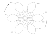
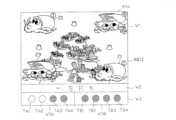
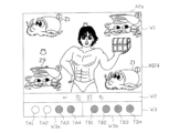
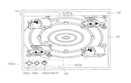
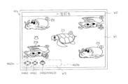
一方、所定の演出が実行される際、上回転体820は、放射状に並ぶ6個の延出片827においてそれぞれ可動片825が同時に径方向外側に向けて放射状にスライド変位することにより拡径する(図54,104参照)。
On the other hand, when a specific performance is being performed, the upper
また、ベース部817の背面側には、サブ制御装置262からの指示を受けて、上回転体用駆動モータ821を制御するモータ制御基板(モータドライバ)845が取付けられている。
In addition, a motor control board (motor driver) 845 is attached to the rear side of the
上回転体用駆動モータ821は、モータ制御基板845を介して印加される駆動パルス信号によって回転制御されるステッピングモータであり、入力パルス数に応じて回転角度が変化する。つまり、駆動パルス信号を調整することにより、上回転体820の回動変位量や回転速度を制御できる。同時に、入力される駆動パルス信号数を監視することによって基準位置からの上回転体820の回動変位量を把握することができる。
The upper
より詳しくは、図56に示すように、ベース部817の前面に、上回転体820(回転基板823)の回転位置を検出するための位置検出センサ846が取着されている。本実施形態では、位置検出センサ846として、発光素子と受光素子とを離間して対向配置した公知のフォトセンサを採用している。
More specifically, as shown in FIG. 56, a
これに対応して、回転基板823(本実施形態では第2駆動ギア841)の背面側には遮光片847が突出形成されている。そして、位置検出センサ846により遮光片847が検出されることにより、上回転体820が基準位置にあることが把握される。
Correspondingly, a
本実施形態では、図52に示すように、上回転体820の正面視において、特定可動片825Aが水平方向右側に配置される位置が基準位置となる。
In this embodiment, as shown in FIG. 52, when viewed from the front of the upper
また、図示は省略するが、ベース部817には、サブ制御装置262からの指示を受けて、位置検出センサ846の監視制御などを行う上部役物制御基板が配設されている。
Although not shown in the figure, the
かかる構成の下、360パルスの励磁信号(駆動パルス信号)で上回転体用駆動モータ821が1回転すると仮定した場合、1パルスの励磁信号に基づく角度変化(1ステップあたりの角度変化)は1°となる。つまり、本実施形態ではタイマ割込みが2msecに設定されているため、上回転体用駆動モータ821が1回転するには、最短で720msec(=2msec×360パルス)を要することとなる。
Assuming that the upper
さらに、上回転体用駆動モータ821のピニオン歯車821bと、中央歯車部材831の小径歯車部831bのギヤ比(歯車比)を1:4と仮定した場合、上記のように上回転体用駆動モータ821が360パルスの励磁信号で1回転する構成の下では、上回転体820は、最短で2880msec(=2msec×360パルス×4)で1回転することとなる。
Furthermore, assuming that the gear ratio (gear ratio) between the
但し、1パルスの励磁信号に基づく角度変化量や、ピニオン歯車821bと小径歯車部831bとのギヤ比などは、上記例示した値に限定されるものではなく、異なる構成を採用してもよい。
However, the amount of angle change based on a one-pulse excitation signal and the gear ratio between the
尚、図54等に示すように、上回転体820の回転停止時において、6つの可動片825が、それぞれ上回転体820の回転方向(本実施形態では時計回り方向)6箇所に設定された所定の停止位置EA1~EA6(具体的には、上回転体820の右側に位置する第1停止位置EA1、右斜め下側に位置する第2停止位置EA2、左斜め下側に位置する第3停止位置EA3、左側に位置する第4停止位置EA4、左斜め上側に位置する第5停止位置EA5、又は、右斜め上側に位置する第6停止位置EA6)のいずれかに停止するように構成されている。
As shown in FIG. 54 etc., when the upper
ここで、上記のように構成された上回転体820の動作態様について説明する。図52,図53等に示すように、役物演出が行われない通常時は、6枚の可動片825がそれぞれ上回転体820の径方向内側スライド限界位置に位置した状態となっている。つまり、上回転体820が最も縮径した状態となっている。
Here, we will explain the operation of the upper
かかる状態において、上回転体用駆動モータ821を正回転させると、ピニオン歯車821bを介して、まず中央歯車部材831が正面視時計回り方向へ回転をはじめる。
In this state, when the upper
尚、回転開始当初は、上記規制動力伝達機構を介して回転基板823に対し、オイルダンパ843の制動力が加えられているため、回転基板823は停止したまま動かない。
When rotation first begins, the braking force of the
一方、中央歯車部材831が正面視時計回り方向へ回転することで、大径歯車部831aに噛合された6個のピニオン歯車832がそれぞれ回転する。そして、これら各ピニオン歯車832と噛合されたラック部838を介して6個の可動片825に対しそれぞれ動力が伝達され、該6個の可動片825がそれぞれ延出片827のスリット829に沿って、上回転体820の径方向外側に向け放射状にスライド変位しいく。つまり、上回転体820が拡径していく。
Meanwhile, as the
そして、図54,図55等に示すように、6枚の可動片825がそれぞれ上回転体820の径方向外側スライド限界位置まで達し、上回転体820が最も拡径した状態となると、回転基板823に対し回転動力が伝達されることとなる。そして、そのトルクが所定レベルを超えると、回転基板823が正面視時計回り方向へ回転をはじめる。
As shown in Figures 54 and 55, when each of the six
その後、上回転体用駆動モータ821が停止すると、上回転体820は停止し、6つの可動片825が、それぞれ上記停止位置EA1~EA6のいずれかに停止する。
After that, when the upper
また、役物演出が終了し、通常時へ戻る際には、まず上回転体用駆動モータ821を逆回転させ、ピニオン歯車821bを介して、中央歯車部材831を正面視反時計回り方向へ回転させる。
When the gimmick performance ends and normal operation resumes, the upper rotating
尚、かかる場合においても、中央歯車部材831の回転開始当初は、上記規制動力伝達機構を介して回転基板823に対し、オイルダンパ843の制動力が加えられているため、回転基板823は停止したまま動かず、可動片825のみが動作する。
Even in this case, when the
これにより、中央歯車部材831の大径歯車部831aに噛合された6個のピニオン歯車832がそれぞれ回転する。そして、これら各ピニオン歯車832と噛合されたラック部838を介して6個の可動片825に対しそれぞれ動力が伝達され、該6個の可動片825がそれぞれ延出片827のスリット829に沿って、上回転体820の径方向内側に向けスライド変位しいき、上回転体820が縮径していく。
As a result, each of the six pinion gears 832 meshed with the large
その後、6枚の可動片825がそれぞれ上回転体820の径方向内側スライド限界位置までスライド変位した段階で上回転体用駆動モータ821を停止させる。これにより、上回転体820が通常時の縮径状態に戻る。
Then, when each of the six
次に下部演出役物ユニット762について図面を参照して詳しく説明する。図7~図9に示すように、下部演出役物ユニット762は、センターフレーム47の下辺部47bの裏側に設けられている。
Next, the
下部演出役物ユニット762は、フレームカバー213の前面下部を覆うように配設されたユニットベース部850と、該ユニットベース部850の裏面側において上下動可能に設けられた下可動役物851と、該下可動役物851を上下動させるための上下駆動機構852とを備えている。
The
下可動役物851は、上下方向に沿って変位可能に設けられたスライドベース部853と、該スライドベース部853から上方に向け突出形成された左右一対の支柱部854A,854Bと、該支柱部854A,854Bの上端部にそれぞれ設けられた下回転体用駆動モータ855A,855B〔図58参照〕と、該駆動モータ855A,855Bの回転軸の前端部に取付固定された正面視略長方形状の下回転体856A,856Bと、該駆動モータ855A,855Bの背面側に設けられたモータ制御基板(モータドライバ)857A,857B〔図58参照〕とを備えている。下回転体856A,856Bはそれぞれ演出用の回転体であり、第2回転手段としての第2回転体を構成する。
The lower
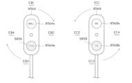
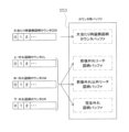
図57に示すように、左側の下回転体856A(以下、「左下回転体856A」という。)には、その長手方向一端側において正面視円形状の第1情報記載部856Aaが設けられ、その長手方向他端側において正面視円形状の第2情報記載部856Abが設けられている。情報記載部856Aa,856Abは本実施形態における被作用部を構成する。
As shown in FIG. 57, the
両情報記載部856Aa,856Abは、透光性を有する素材により構成されており、後方に位置する演出表示装置42の表示部(液晶表示部)42aから発せられる光を所定の透過率で透過可能に構成されている。
Both information sections 856Aa, 856Ab are made of a translucent material and are configured to transmit light emitted from the display section (liquid crystal display section) 42a of the
本実施形態の第1情報記載部856Aaには、比較的光透過率が高く色鮮やかな有色透明(例えばレインボー柄)の背景構成部に対しくっきりとした文字で「SMALL」と記載され(以下、かかる記載を「強・SMALL」と称する場合もある。)、第2情報記載部856Abには、比較的光透過率が低い暗色半透明の背景構成部に対しくすんだ文字で「SMALL」と記載されている(以下、かかる記載を「弱・SMALL」と称する場合もある。)。 In this embodiment, the first information section 856Aa has "SMALL" written in clear letters against a colorful, transparent (e.g., rainbow-patterned) background component with a relatively high light transmittance (hereinafter, such writing may be referred to as "strong SMALL"). The second information section 856Ab has "SMALL" written in dull letters against a dark, semi-transparent background component with a relatively low light transmittance (hereinafter, such writing may be referred to as "weak SMALL").
一方、両情報記載部856Aa,856Abを除く、左下回転体856Aの一般部は、透光性を有しない素材により被覆されており、演出表示装置42の表示部42aから発せられる光を透過させない遮光部となっている。
On the other hand, the general part of the lower left
また、上記左下回転体856Aと同様に、右側の下回転体856B(以下、「右下回転体856B」という。)には、図57に示すように、その長手方向一端側において正面視円形状の第1情報記載部856Baが設けられ、その長手方向他端側において正面視円形状の第2情報記載部856Bbが設けられている。情報記載部856Ba,856Bbは本実施形態における被作用部を構成する。
Similarly to the lower-left
上記左下回転体856Aに係る両情報記載部856Aa,856Abと同様、右下回転体856Bに係る両情報記載部856Ba,856Bbは、透光性を有する素材により構成されており、後方に位置する演出表示装置42の表示部(液晶表示部)42aから発せられる光を所定の透過率で透過可能に構成されている。
Similar to the two information display sections 856Aa, 856Ab of the lower-left
本実施形態の第1情報記載部856Baには、比較的光透過率が高く色鮮やかな有色透明(例えばレインボー柄)の背景構成部に対しくっきりとした文字で「BIG」と記載され(以下、かかる記載を「強・BIG」と称する場合もある。)、第2情報記載部856Bbには、比較的光透過率が低い暗色半透明の背景構成部に対しくすんだ文字で「BIG」と記載されている(以下、かかる記載を「弱・BIG」と称する場合もある。)。 In this embodiment, the first information section 856Ba has "BIG" written in clear letters against a colorful, transparent (e.g., rainbow-patterned) background component with a relatively high light transmittance (hereinafter, such writing may be referred to as "Strong BIG"). The second information section 856Bb has "BIG" written in dull letters against a dark, semi-transparent background component with a relatively low light transmittance (hereinafter, such writing may be referred to as "Weak BIG").
一方、両情報記載部856Ba,856Bbを除く、右下回転体856Bの一般部は、透光性を有しない素材により被覆されており、演出表示装置42の表示部42aから発せられる光を透過させない遮光部となっている。
On the other hand, the general part of the lower right
尚、下回転体用駆動モータ855A,855Bは、それぞれ印加される駆動パルス信号によって回転制御されるステッピングモータであり、駆動パルス信号を調整することにより、下回転体856A,856Bの回転量を制御できる。同時に、入力される駆動パルス信号数を監視することによって基準位置からの下回転体856A,856Bの回転変位量を把握することができる。
The lower
より詳しくは、図58に示すように、下回転体用駆動モータ855A,855Bの下面に、下回転体856A,856Bの回転位置を検出するための位置検出センサ858A,858Bが取着されている。本実施形態では、位置検出センサ858A,858Bとして、発光素子と受光素子とを離間して対向配置した公知のフォトセンサを採用している。
More specifically, as shown in FIG. 58,
これに対応して、下回転体856A,856Bの背面側(側縁部近傍)には遮光片859A,859Bが突出形成されている。そして、位置検出センサ858A,858Bにより遮光片859A,859Bが検出されることにより、下回転体856A,856Bが基準位置にあることが把握される。
Correspondingly,
本実施形態では、図57に示すように、下回転体856A,856Bの長手方向が上下方向に沿い、かつ、第1情報記載部856Aa,856Ba側が第2情報記載部856Ab,856Bb側よりも上位となる位置が基準位置となる。
In this embodiment, as shown in FIG. 57, the reference position is where the longitudinal direction of the
さて、上下駆動機構852は、ユニットベース部850に配設された上下駆動用モータ860と、スライドベース部853の右側縁部に設けられたラック部861とにより構成されている。そして、上下駆動用モータ860の回転軸に取付固定されたピニオン歯車860aと、スライドベース部853のラック部861と噛合されている。
The
尚、図示は省略するが、ユニットベース部850には、上下方向に沿って延びる案内溝部が形成され、スライドベース部853には前記案内溝部に組付けられる突条部が形成されている。これにより、スライドベース部853が上下動する際の左右方向への位置ズレが規制されている。つまり、前記案内溝部及び前記突条部により、下可動役物851(下回転体856A,856B)を案内する案内手段が構成されることとなる。
Although not shown in the figure, the
かかる構成の下、上下駆動用モータ860が回転することで、下可動役物851が上下方向に沿ってスライド変位可能となる。
With this configuration, the
通常時、下可動役物851は、下回転体856A,856Bの大部分がセンターフレーム47の下辺部47b裏側の待機位置に位置し遊技者に視認困難な待機状態(図7参照)となっている。そして、上下駆動用モータ860が正回転して、スライドベース部853が上方向に向かってスライド変位することにより、下可動役物851は、下回転体856A,856Bの全体が演出表示装置42の表示部42aの前面側に位置し遊技者に視認容易な露出状態(図9参照)となる。
Under normal circumstances, the lower
また、この状態から、上下駆動用モータ860が逆回転して、スライドベース部853が下方向に向かってスライド変位することにより、下可動役物851は、通常時の待機状態に戻る。
Also, from this state, the
尚、上下駆動用モータ860は、印加される駆動パルス信号によって回転制御されるステッピングモータであり、駆動パルス信号を調整することにより、下可動役物851(下回転体856A,856B)の上下移動量を制御できる。同時に、入力される駆動パルス信号数を監視することによって基準位置からの下可動役物851の上下変位量を把握することができる。
The
より詳しくは、ユニットベース部850には、下可動役物851の上下位置を検出するための位置検出センサ863が取着されている。本実施形態では、位置検出センサ863として、発光素子と受光素子とを離間して対向配置した公知のフォトセンサを採用している。
More specifically, a
これに対応して、スライドベース部853には、ラック部861の下端部において遮光片864が突出形成されている。そして、位置検出センサ863により遮光片864が検出されることにより、下可動役物851(スライドベース部853)が基準位置にあることが把握される。本実施形態では、図7に示すように、下可動役物851が上記待機状態となる位置が基準位置(待機位置)となる。
Correspondingly, a
ここで、図示は省略するが、下可動役物851(下回転体856A,856B)の所定量以上の移動を規制可能なストッパ等の移動規制手段を備えた構成としてもよい。
Here, although not shown in the figure, the lower movable part 851 (lower
また、図示は省略するが、ユニットベース部850には、サブ制御装置262からの指示を受けて、上下駆動用モータ860の駆動制御や位置検出センサ863の監視制御などを行う下部役物制御基板が配設されている。
Although not shown in the figure, the
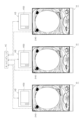
かかる構成の下、本実施形態では、上回転体820及び下回転体856A,856Bがそれぞれ回転しながら又は停止時において、上回転体820と左下回転体856A又は右下回転体856Bとの位置関係が、上回転体820の少なくとも一部と左下回転体856A又は右下回転体856Bの少なくとも一部とが重ならない第1位置関係(非近接状態)と、上回転体820の少なくとも一部と左下回転体856A又は右下回転体856Bの少なくとも一部とが重なる第2位置関係(近接状態)とに変化するように構成されている。そして、後述するように、所定条件の成立時(高サポートモードが継続する場合)には、非成立時に比べ、上回転体820と下回転体856A,856Bとが第2位置関係(近接状態)となる割合が多くなるように構成されている。
In this embodiment, while the
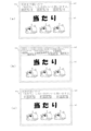
具体的に、左下回転体856Aの回転停止時において、第1情報記載部856Aa(強・SMALL)及び第2情報記載部856Ab(弱・SMALL)が、それぞれ左下回転体856Aの回転方向(本実施形態では時計回り方向)4箇所に設定された所定の停止位置EB1~EB4(具体的には、図57に示すように、左下回転体856Aの上側に位置する第1停止位置EB1、右側に位置する第2停止位置EB2、下側に位置する第3停止位置EB3、又は、左側に位置する第4停止位置EB4)のいずれかに停止するように構成されている。
Specifically, when the lower-left
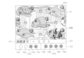
そして、第1情報記載部856Aa(強・SMALL)又は第2情報記載部856Ab(弱・SMALL)が第1停止位置EB1に停止し、かつ、上回転体820の特定可動片825Aが第4停止位置EA4に停止した場合には、該特定可動片825Aの拡大レンズ部828を介して、第1停止位置EB1に停止した第1情報記載部856Aa(強・SMALL)又は第2情報記載部856Ab(弱・SMALL)が拡大表示されて、遊技者に視認されることとなる(図61,図62参照)。
When the first information section 856Aa (strong, small size) or the second information section 856Ab (weak, small size) stops at the first stop position EB1 and the specific
このような上回転体820と左下回転体856Aの相対位置関係が本実施形態における第1の第2位置関係に相当する。また、拡大レンズ部828が第1情報記載部856Aa(強・SMALL)又は第2情報記載部856Ab(弱・SMALL)を拡大表示する態様が本実施形態における第1の態様に相当し、上回転体820の特定可動片825Aを第4停止位置EA4に停止させる上回転体820の動作態様が本実施形態における第1の動作態様に相当する。
This relative positional relationship between the
また、右下回転体856Bの回転停止時において、第1情報記載部856Ba(強・BIG)及び第2情報記載部856Bb(弱・BIG)が、それぞれ右下回転体856Bの回転方向(本実施形態では反時計回り方向)4箇所に設定された所定の停止位置EC1~EC4(具体的には、図57に示すように、右下回転体856Bの上側に位置する第1停止位置EC1、左側に位置する第2停止位置EC2、下側に位置する第3停止位置EC3、又は、右側に位置する第4停止位置EC4)のいずれかに停止するように構成されている。
When the lower right
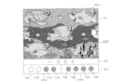
そして、第1情報記載部856Ba(強・BIG)又は第2情報記載部856Bb(弱・BIG)が第1停止位置EC1に停止し、かつ、上回転体820の特定可動片825Aが第1停止位置EA1に停止した場合には、該特定可動片825Aの拡大レンズ部828を介して、第1停止位置EC1に停止した第1情報記載部856Ba(強・BIG)又は第2情報記載部856Bb(弱・BIG)が拡大表示されて、遊技者に視認されることとなる(図63,図64参照)。
When the first information section 856Ba (Strong/BIG) or the second information section 856Bb (Weak/BIG) stops at the first stop position EC1 and the specific
このような上回転体820と右下回転体856Bの相対位置関係が本実施形態における第2の第2位置関係に相当する。また、拡大レンズ部828が第1情報記載部856Ba(強・BIG)又は第2情報記載部856Bb(弱・BIG)を拡大表示する態様が本実施形態における第2の態様に相当し、上回転体820の特定可動片825Aを第1停止位置EA1に停止させる上回転体820の動作態様が本実施形態における第2の動作態様に相当する。
This relative positional relationship between the
尚、本実施形態では、各種テーブル構成により、第1情報記載部856Aa(強・SMALL)又は第2情報記載部856Ab(弱・SMALL)が第1停止位置EB1に停止し、かつ、上回転体820の特定可動片825Aが第4停止位置EA4に停止した場合、つまり特定可動片825Aの拡大レンズ部828を介して、第1停止位置EB1に停止した第1情報記載部856Aa(強・SMALL)又は第2情報記載部856Ab(弱・SMALL)が拡大表示された場合よりも、第1情報記載部856Ba(強・BIG)又は第2情報記載部856Bb(弱・BIG)が第1停止位置EC1に停止し、かつ、上回転体820の特定可動片825Aが第1停止位置EA1に停止した場合、つまり特定可動片825Aの拡大レンズ部828を介して、第1停止位置EC1に停止した第1情報記載部856Ba(強・BIG)又は第2情報記載部856Bb(弱・BIG)が拡大表示された場合には、後述するように、高サポートモードの継続といった、遊技者に有利な所定の有利状態となる割合が多くなるように構成されている。さらには、遊技者に有利な第1の有利状態(高サポートモードの「+10回」継続)よりも、該第1の有利状態よりも遊技者に有利な第2の有利状態(高サポートモードの「次回まで」継続)となる割合が多くなるように構成されている。
In this embodiment, due to the various table configurations, when the first information portion 856Aa (strong, SMALL) or the second information portion 856Ab (weak, SMALL) stops at the first stop position EB1 and the specific
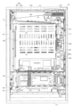
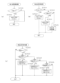
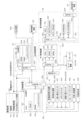
次に、パチンコ機10の背面構成について図5、図6等を参照して説明する。パチンコ機10の背面には、各種制御基板が上下左右に並べられるようにして、一部前後に重ねられるようにして配置されており、さらに、遊技球を供給する遊技球供給装置(払出機構)や樹脂製の保護カバー等が取り付けられている。払出機構及び保護カバーは1ユニットとして一体化されており、一般に樹脂部分を裏パックと称することもあるため、ここではそのユニットを「裏パックユニット203」と称する。
Next, the rear configuration of the
まず、遊技盤30の背面構成について図6等を参照して説明する。上述したように、遊技盤30中央の貫通孔に対応して配設された可変表示装置ユニット35(図4参照)の背面側には、センターフレーム47を背後から覆う樹脂製のフレームカバー213が後方に突出して設けられている。また、フレームカバー213の背面側には、フレームカバー213の開口部から前方に臨む液晶表示装置たる演出表示装置42、表示制御装置45及びサブ制御装置262が前後に重ねられた状態で着脱可能に取り付けられている。
First, the rear structure of the
演出表示装置42は、該演出表示装置42の表示部(液晶画面)をパチンコ機10の前面側に露出させるための開口部が形成された収容ボックス(符号略)に収容されてフレームカバー213の背面側に固定されている。表示制御装置45は基板ボックス45aに収容されて演出表示装置42(収容ボックス)の背面側に固定されている。サブ制御装置262は基板ボックス262aに収容されて表示制御装置45(基板ボックス45a)の背面側に固定されている。基板ボックス45a,262aは透明樹脂材料等により構成され、内部が視認可能となっている。尚、フレームカバー213内には、センターフレーム47に内蔵されたLED等を駆動するLED制御基板等が配設されている。
The
フレームカバー213の下方には裏枠セット215が、一般入賞口31、可変入賞装置32、始動入賞口33YA,33YB等を背後から覆うようにして遊技盤30に取付けられている。裏枠セット215は、上記各種入賞口やアウト口36など異なる経路を通って遊技盤30の前面側から背面側へ移動した遊技球を回収するための球回収機構を備えている(図示略)。この球回収機構により回収された遊技球は、後述する排出通路部217に案内され、排出通路部217の排出シュートからパチンコ機10外部に排出される。
Below the
また、図示は省略するが、裏枠セット215には、一般入賞スイッチ221、カウントスイッチ223及びスルーゲートスイッチ225とケーブルコネクタを介して電気的に接続される第1盤面中継基板が設けられている。この第1盤面中継基板は、一般入賞スイッチ221等と、主制御装置261とを中継するものであり、ケーブルコネクタを介して主制御装置261と電気的に接続されている。
Although not shown in the figure, the back frame set 215 is provided with a first board relay board that is electrically connected to the general winning
これに対し、始動入賞口33YA,33YBへの入賞を検出する始動入賞スイッチ224A,224Bは中継基板を経ることなくコネクタケーブルを介して直接主制御装置261に接続されている。
In contrast, the
各種入賞検出スイッチにて各々検出された検出結果は、主制御装置261に取り込まれる。そして、該主制御装置261よりその都度の入賞状況に応じた払出指令(遊技球の払出個数)が払出制御装置311に送信され、該払出制御装置311からの出力信号に基づき所定数の遊技球の払出しが実施される(スルーゲートスイッチ225により検出された場合を除く。)
また、本実施形態では、裏枠セット215が主制御装置261の取付台として機能する。より詳しくは、主制御装置261を搭載した基板ボックス263が、裏枠セット215に対し回動可能に軸支され、後方に開放可能となっている。
The detection results detected by the various winning detection switches are input to the
In this embodiment, the back frame set 215 also functions as a mounting base for the
主制御装置261は透明樹脂材料等よりなる基板ボックス263に収容されている。基板ボックス263は、ボックスベースと該ボックスベースの開口部を覆うボックスカバーとを備え、これらボックスベースとボックスカバーとが封印部材によって連結されている。封印部材によって連結された基板ボックス263は、所定の痕跡を残さなければ開封できない構成となっている。これにより、基板ボックス263が不正に開封された旨を容易に発見することができる。
The
次に、裏パックユニット203の構成を説明する。図5に示すように、裏パックユニット203は、樹脂成形された裏パック351と、遊技球の払出機構部352とを一体化したものである。また、裏パックユニット203は、内枠12の左側部(図5では右側)に対して開閉可能に支持されており、上下方向に沿って延びる開閉軸線を軸心として後方に開放できるようになっている。加えて、裏パックユニット203の左上部(図5では右上部)には外部中継端子板240が設けられている。
Next, the configuration of the
外部中継端子板240は、遊技ホールのホールコンピュータなどへの各種情報送信を中継するためのものであり、複数の外部接続端子が設けられている。便宜上、符号は付さないが、例えば現在の遊技状態(大当たり状態や高確率モード等)に関する情報を出力するための端子、後述する開放検知スイッチ91,92によって検出される前面枠セット14や内枠12の開放に関する情報を出力するための端子、入賞エラー、下皿満タンエラー、タンク球無しエラー、払出しエラーなど各種エラー状態に関する情報を出力するための端子、払出制御装置311から払出される賞球数に関する情報を出力するための端子などが設けられている。
The external
但し、本実施形態においては、「小当たり」に関する情報を出力するための端子は設けられておらず、「小当たり」の発生情報が出力されない構成となっている。本実施形態では、「高サポートモード」中は、「小当たり」が比較的頻繁に発生しやすくなっているため、「小当たり」が発生する度に、常に、発生情報を出力していては、出力信号の著しい増加を招くおそれがある。従って、例えば「低サポートモード」中など、このような不具合が比較的起きにくい場合には、「小当たり」の発生情報を出力するような構成としてもよい。 However, in this embodiment, there is no terminal for outputting information about a "small win", and the configuration is such that information about the occurrence of a "small win" is not output. In this embodiment, since "small wins" tend to occur relatively frequently during "high support mode", constantly outputting occurrence information every time a "small win" occurs may result in a significant increase in the output signal. Therefore, when such problems are relatively unlikely to occur, such as during "low support mode", the configuration may be such that information about the occurrence of a "small win" is output.
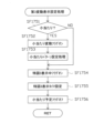
また、「JUB大当たり」の発生情報の出力は、例えば「JUB大当たり」に係る5回の「短開放」の終了後、すなわち「小当たり」の場合と区別ができない状況を脱した後に、例えば後述するオープニングコマンドの出力(大当たり報知演出)等を行うタイミングにおいて、「JUB大当たり」の発生が確定した状態で行うことが好ましい。未だ「小当たり」の場合と区別ができない状況において、「JUB大当たり」の発生情報だけが先に出力されてしまうと、パチンコ機10に対応してホールの島設備に設置された情報表示機器等を見て、遊技者が事前に「JUB大当たり」の発生を把握してしまい、「JUB大当たり」の演出効果が薄れるおそれがある。
In addition, it is preferable to output the occurrence information of a "JUB jackpot" when the occurrence of the "JUB jackpot" is confirmed, for example, after the five "short openings" related to the "JUB jackpot" have ended, that is, after the situation in which it is impossible to distinguish it from a "small jackpot" has been overcome, at the timing of outputting an opening command (jackpot notification performance) described below. If only the occurrence information of the "JUB jackpot" is output in advance when it is still impossible to distinguish it from a "small jackpot," the player may see the information display device installed in the island equipment of the hall corresponding to the
裏パック351は例えばABS樹脂により一体成形されており、パチンコ機10の後方に突出して略直方体形状をなす保護カバー部354を備えている。保護カバー部354は左右側面及び上面が閉塞され且つ下面のみが開放された形状をなし、少なくともフレームカバー213を覆うのに十分な大きさを有する。但し、本実施形態では、保護カバー部354が基板ボックス263の上部及び右部(図5では左側の部位)も合わせて覆う構成となっている。これにより、裏パックユニット203の閉鎖状態において、基板ボックス263の右部に設けられた封印部材、及び主制御装置261の上縁部に沿って設けられた端子部(基板側コネクタ)が覆われることとなる。
The
払出機構部352は、保護カバー部354を迂回するようにして配設されている。すなわち、保護カバー部354の上方には、上側に開口したタンク355が設けられており、このタンク355には遊技ホールの島設備から供給される遊技球が逐次補給される。タンク355の下方には、例えば遊技球を横向きに流下させる2列の球通路を有し下流側に向けて緩やかに傾斜するタンクレール356が連結され、さらにタンクレール356の下流側には遊技球を縦向きに流下させるケースレール357が連結されている。払出装置358はケースレール357の最下流部に設けられ、払出モータ等の所定の電気的構成により必要個数の遊技球の払出が適宜行われる。そして、払出装置358より払出された遊技球は上皿19等に供給される。
The
また、払出機構部352には、払出制御装置311から払出装置358への払出指令の信号を中継する払出中継基板381が設置されると共に、外部より主電源を取り込む電源スイッチ基板382が設置されている。電源スイッチ基板382には、電圧変換器を介して例えば交流24Vの主電源が供給され、電源スイッチ382aの切替操作により電源ON又は電源OFFされる。
The
裏パックユニット203(基板ボックス263)の下方には、内枠12の左側部(図5では右側)にて軸支され、後方に開放可能な下枠セット251が設けられている。図6に示すように、下枠セット251には、上述した球回収機構により回収された遊技球が流入する後方案内手段としての排出通路部217が形成され、該排出通路部217の最下流部には、遊技球をパチンコ機10外部へ排出する排出シュート(図示略)が形成されている。遊技球は遊技領域を流下する回転体である。遊技球は遊技領域において釘49や風車57等に接触して影響を受けながら回転して流下する。そして、一般入賞口31等の各入賞口に入賞した遊技球は、裏枠セット215の球回収機構を介して集合し、さらに排出通路部217の排出シュートを通じてパチンコ機10外部に排出される。なお、アウト口36も同様に排出通路部217に通じており、何れの入賞口にも入賞しなかった遊技球も排出シュートを介してパチンコ機10外部に排出される。尚、本実施形態では、裏パックユニット203と下枠セット251とが別体として構成され、それぞれ独立して開閉可能であるが、裏パックユニット203と下枠セット251とが一体的に形成されることとしてもよい。
Below the back pack unit 203 (base box 263), a lower frame set 251 is provided, which is supported on the left side (right side in FIG. 5) of the
また、図5に示すように、下枠セット251の背面側には、払出制御手段としての払出制御装置311、発射制御装置312、電源装置313及びカードユニット接続基板314が前後に重ねられた状態で着脱可能に取り付けられている。
As shown in FIG. 5, the
発射制御装置312及び電源装置313は基板ボックス313aに収容されて下枠セット251の背面側に固定されている。尚、発射制御装置312及び電源装置313は、便宜上それぞれ独立した制御装置として説明するが、実際には1つの基板(プリント基板)により構成される。
The
また、払出制御装置311は、基板ボックス311aに収容されて、基板ボックス313a(発射制御装置312及び電源装置313)の背面側に固定されている。尚、払出制御装置311が収容される基板ボックス311aには、上述した主制御装置261が収容される基板ボックス263と同様に封印部材が設けられ、基板ボックス311aの開封された痕跡が残るようになっている。
The dispensing
加えて、カードユニット接続基板314は、基板ボックス314aに収容されて、基板ボックス313a(発射制御装置312及び電源装置313)の背面側に固定されている。
In addition, the card
なお、上記各基板ボックス311a,313a,314aは透明樹脂材料等により構成されており、内部が視認可能となっている。
The
また、払出制御装置311には基板ボックス311aから外方に突出する状態復帰スイッチ321が設けられている。例えば、払出モータ部の球詰まり等、払出エラーの発生時において状態復帰スイッチ321が押下されると、払出モータが正逆回転され、球詰まりの解消(正常状態への復帰)が図られる。
The
さらに、電源装置313には基板ボックス313aから外方に突出するRAM消去スイッチ323が設けられている。本パチンコ機10はバックアップ機能を有しており、万一停電が発生した際でも停電時の状態を保持し、停電からの復帰(復電)の際には停電時の状態に復帰させることができる。従って、通常手順で(例えば遊技ホールの営業終了時に)電源遮断すると電源遮断前の状態が記憶保持されることから、電源投入時に初期状態に戻したい場合には、RAM消去スイッチ323を押しながら電源を投入する。
The
また、図6に示すように、内枠12の右側部背面側には施錠装置600が設けられている。施錠装置600は、前面枠セット14の前面側に露出するシリンダ錠600a(図1等参照)を備えており、該シリンダ錠600aの鍵穴に鍵を挿入し、一方に回動操作することで内枠12を解錠でき、他方に回動操作することで前面枠セット14を解錠できるようになっている。本実施形態では、内枠12は外枠11に対し施錠され、前面枠セット14は内枠12に対し施錠される。
As shown in FIG. 6, a
尚、上記のように、外枠11の右辺枠構成部11dには、施錠装置600に対応する上下区間全域を内枠12の背面側から覆う延出壁部83が形成されている(図5参照)。これにより、外枠11の背面側から線材等を進入させ、該線材等により施錠装置600を操作することが困難となる。結果として、防御性能の向上を図ることができる。さらに、延出壁部83は、裏パックユニット203及び下枠セット251の右端部(図5では左側の端部)を背面側から覆う構成となっており、内枠12の閉状態においては、裏パックユニット203及び下枠セット251を開放できない構成となっている。
As described above, the
また、本実施形態では、前面枠セット14の補強フレームや、施錠装置600、レール構成部51,52、左右の枠構成部11c,11dなど、導電性金属材料等により形成された各種導電部材をはじめ、タンク355やタンクレール356、ケースレール357など、導電性樹脂材料等により形成された各種導電部材が図示しない所定のアース端子に対し電気的に接続されている。尚、一般に遊技球は金属材料よりなり、その表面に研磨加工やメッキ加工が施され、光を反射する光沢を有していると共に、導電性を有している。従って、遊技球が前記各種導電部材に接触することにより、遊技球に帯電した静電気を逃がすことができる。
In addition, in this embodiment, various conductive members formed of conductive metal materials, such as the reinforcing frame of the front frame set 14, the
また、図4に示すように、内枠12の前面側右下部(発射装置60の右側)には、前面枠セット14の開放を検知するための前面枠開放検知スイッチ91が設けられ、図5に示すように、内枠12の背面側右下部(図5では左下)には、内枠12の開放を検知するための内枠開放検知スイッチ92が設けられている。前面枠開放検知スイッチ91及び内枠開放検知スイッチ92は、それぞれスイッチ本体部に対して出没可能な検知部を備えており、前面枠開放検知スイッチ91は検知部が前方に向くように設けられ、内枠開放検知スイッチ92は検知部が後方へ向くように設けられる。そして、検知部がスイッチ本体部から突出した状態にある場合にはオン信号を主制御装置261に出力し、検知部がスイッチ本体部側に押圧され、スイッチ本体部に没入した状態ではオフ信号を主制御装置261に出力する構成となっている。つまり、前面枠開放検知スイッチ91は前面枠セット14の閉鎖時において検知部が前面枠セット14の背面で押圧されてオフ状態となり、前面枠セット14の開放時には、検知部が突出状態に戻ってオン状態となる。同様に、内枠開放検知スイッチ92は内枠12の閉鎖時において検知部が外枠11の受部85に一体形成された押圧部86によって押圧されてオフ状態となり、内枠12の開放時には検知部が突出状態に戻ってオン状態となる。
As shown in FIG. 4, a front frame
次に、パチンコ機10の電気的構成について説明する。図10は、本パチンコ機10の電気的構成を示すブロック図である。主制御装置261(主基板)には、演算装置である1チップマイコンとしてのCPU501が搭載されている。CPU501には、該CPU501により実行される各種の制御プログラムや固定値データを記憶したROM502と、そのROM502内に記憶される制御プログラムの実行に際して各種のデータ等を一時的に記憶するメモリであるRAM503と、割込回路やタイマ回路、データ送受信回路などの各種回路等が内蔵されている。但し、CPU、ROM及びRAMが1チップ化されておらず、それぞれの機能毎にチップ化されている構成であってもよい。
Next, the electrical configuration of the
RAM503は、CPU501の内部レジスタの内容やCPU501により実行される制御プログラムの戻り先番地などが記憶されるスタックエリアと、各種フラグ及びカウンタ、I/O等の値が記憶される作業エリア(作業領域)と、バックアップエリア503aとを備えている。
また、RAM503は、パチンコ機10の電源のオフ後においても電源装置313からバックアップ電圧が供給されてデータを保持(バックアップ)できる構成となっており、スタックエリア、作業エリア及びバックアップエリア503aに記憶されるすべてのデータがバックアップされるようになっている。
In addition, the
バックアップエリア503aは、停電などの発生により電源が切断された場合において、電源の再入時にパチンコ機10の状態を電源切断前の状態に復帰させるべく、電源切断時(停電発生時を含む。以下同様)のスタックポインタや、各レジスタ、I/O等の値を記憶しておくエリアである。バックアップエリア503aへの書き込みは、メイン処理によって電源切断時に実行され、逆にバックアップエリア503aに書き込まれた各値の復帰は、電源入時(停電解消による電源入を含む。以下同様)のメイン処理において実行される。なお、CPU501のNMI端子(ノンマスカブル割込端子)には、停電等の発生による電源断時に、後述する停電監視回路542から出力される停電信号SK1が入力されるように構成されており、停電の発生により、停電処理(NMI割込み処理)が即座に実行される。
The
なお、少なくともスタックエリアとバックアップエリア503aとに記憶されるデータをバックアップすれば、必ずしもすべてのエリアに記憶されるデータをバックアップする必要はない。例えば、スタックエリアとバックアップエリア503aとに記憶されるデータをバックアップし、作業エリアに記憶されるデータをバックアップしない構成としてもよい。
Note that as long as data stored in at least the stack area and
かかるROM502及びRAM503を内蔵したCPU501には、アドレスバス及びデータバス等で構成されるバスライン504を介して入出力ポート505が接続されている。入出力ポート505には、後述するRAM消去スイッチ回路543、払出制御装置311、サブ制御装置262、第1及び第2特別表示装置43L、43R、普通図柄表示装置41等が接続されている。この構成により、上述した特別表示装置43L、43R及び普通図柄表示装置41は、主制御装置261により直接的に制御される。一方、表示手段としての演出表示装置42は、サブ制御装置262を介して制御される。サブ制御装置262が本実施形態における発光制御手段を構成する。
An input/
その他、便宜上、各種中継基板等の図示は省略するが、入出力ポート505には、一般入賞スイッチ221、カウントスイッチ223、始動入賞ユニットスイッチ224A,224B、スルーゲートスイッチ225などの各種検出スイッチや、各種基板などの各種電気部品が接続されている。つまり、主制御装置261には、各種ケーブルコネクタのコネクタを接続するための複数の端子部(基板側コネクタ)が設けられているが、これら端子部等により、入出力ポート505が構成される。
For convenience, various relay boards and the like are not shown, but various detection switches such as the general winning
サブ制御装置262(サブ制御基板)は、演算装置であるCPU551、該CPU551により実行される各種の制御プログラムや固定値データを記憶したROM552、該ROM552内に記憶される制御プログラムの実行に際して各種のデータ等を一時的に記憶するメモリであるRAM553、入出力ポート554、バスライン555を備えるとともに、その他にも図示しない割込回路やタイマ回路、データ送受信回路などの各種回路等を備えている。RAM553は、CPU551による各種プログラムの実行時に使用されるワークデータやフラグを一時的に記憶するメモリである。
The sub-control device 262 (sub-control board) includes a
入出力ポート554には、バスライン555を介してCPU551、ROM552、RAM553が接続されるとともに、表示制御装置45が接続されている。さらに、入出力ポート554には、スピーカSP、演出ボタン125、演出役物ユニット761,762、各種電飾部及びランプ102,104が接続されている。
The input/
サブ制御装置262のCPU551は、例えば主制御装置261から送信されるコマンド(例えば変動パターンコマンド)に基づいて表示制御装置45に表示制御を実行させ、演出表示装置42に表示させる。なお、上記のように、本実施形態では、主制御装置261が制御する第1及び第2特別表示装置43L、43Rにて大当たりか否か等を表示するようになっており、サブ制御装置262が制御する演出表示装置42では、前記特別表示装置43L、43Rの表示に合わせた表示が行われる。また、サブ制御装置262は、上部演出役物ユニット761及び下部演出役物ユニット762の駆動制御を行う。
The
また、払出制御装置311は、払出装置358により賞球や貸し球の払出制御を行うものである。演算装置であるCPU511は、そのCPU511により実行される制御プログラムや固定値データ等を記憶したROM512と、ワークメモリ等として使用されるRAM513とを備えている。
The
払出制御装置311のRAM513は、主制御装置261のRAM503と同様に、CPU511の内部レジスタの内容やCPU511により実行される制御プログラムの戻り先番地などが記憶されるスタックエリアと、各種フラグ及びカウンタ、I/O等の値が記憶される作業エリア(作業領域)と、バックアップエリア513aとを備えている。
The
RAM513は、パチンコ機10の電源のオフ後においても電源装置313からバックアップ電圧が供給されてデータを保持(バックアップ)できる構成となっており、スタックエリア、作業エリア及びバックアップエリア513aに記憶されるすべてのデータがバックアップされるようになっている。なお、少なくともスタックエリアとバックアップエリア513aとに記憶されるデータをバックアップすれば、必ずしもすべてのエリアに記憶されるデータをバックアップする必要はない。例えば、スタックエリアとバックアップエリア513aとに記憶されるデータをバックアップし、作業エリアに記憶されるデータをバックアップしない構成としてもよい。
バックアップエリア513aは、停電などの発生により電源が切断された場合において、電源の再入時にパチンコ機10の状態を電源切断前の状態に復帰させるべく、電源切断時のスタックポインタや、各レジスタ、I/O等の値を記憶しておくエリアである。このバックアップエリア513aへの書き込みは、メイン処理によって電源切断時に実行され、バックアップエリア513aに書き込まれた各値の復帰は電源入時のメイン処理において実行される。なお、主制御装置261のCPU501と同様、CPU511のNMI端子にも、停電等の発生による電源遮断時に停電監視回路542から停電信号SK1が入力されるように構成されており、その停電信号SK1がCPU511へ入力されると、停電時処理としてのNMI割込み処理が即座に実行される。
The
作業エリアには、払出制御装置311による賞球の払出許可が設定される払出許可フラグと、主制御装置261から送信されたコマンドを受信した場合に設定されるコマンド受信フラグと、主制御装置261から送信されたコマンドが記憶されるコマンドバッファとが設けられている。
The working area is provided with a payout permission flag that sets permission for the
払出許可フラグは、賞球の払出許可を設定するフラグであり、主制御装置261から賞球の払出を許可する特定のコマンドが送信され、その特定のコマンドを受信した場合にオンされ、初期設定の処理又は電源遮断前へ復帰された場合にオフされる。本実施形態では、特定のコマンドは、払出制御装置311のRAM513の初期処理の指示をする払出初期化コマンドと、賞球の払出を指示する賞球コマンドと、主制御装置261が復電された場合に送信される払出復帰コマンドの3つである。
The payout permission flag is a flag that sets permission to pay out prize balls; a specific command to permit the payout of prize balls is sent from the
コマンド受信フラグは、払出制御装置311がコマンドを受信したか否かを確認するフラグであり、いずれかのコマンドを受信した場合にオンされ、払出許可フラグと同様に、初期設定の処理又は電源遮断前へ復帰された場合にオフされるとともに、コマンド判定処理により受信されたコマンドの判定が行われた場合にオフされる。
The command reception flag is a flag that checks whether the dispensing
コマンドバッファは、主制御装置261から送信されるコマンドを一時的に記憶するリングバッファで構成されている。
The command buffer consists of a ring buffer that temporarily stores commands sent from the
かかるROM512及びRAM513を内蔵したCPU511には、アドレスバス及びデータバスで構成されるバスライン514を介して入出力ポート515が接続されている。入出力ポート515には、RAM消去スイッチ回路543、主制御装置261、発射制御装置312、払出装置358等がそれぞれ接続されている。
The
カードユニット接続基板314は、パチンコ機10前面の貸球操作部(球貸しボタン121及び返却ボタン122)と、遊技ホール等にてパチンコ機10の側方に配置されるカードユニット(球貸しユニット)とにそれぞれ電気的に接続され、遊技者による球貸し操作の指令を取り込んでそれをカードユニットに出力するものである。なお、カードユニットを介さずに球貸し装置等から上皿19に遊技球が直接貸し出される現金機では、カードユニット接続基板314を省略することも可能である。
The card
発射制御装置312は、発射装置60による遊技球の発射を許可又は禁止するものであり、発射装置60は、所定条件が整っている場合に駆動が許可される。具体的には、払出制御装置311から発射許可信号が出力されていること、遊技者がハンドル18をタッチしていることをセンサ信号により検出していること、発射を停止させる発射停止スイッチが操作されていないことを条件に、発射装置60が駆動され、ハンドル18の操作量に応じた強度で遊技球が発射される。これにより、遊技者は、遊技領域へ案内される遊技球の移動量や動作態様を変化させることができる。
The
表示制御装置45は、サブ制御装置262からの指示に従い、演出表示装置42における装飾図柄の変動表示を実行するものである。この表示制御装置45は、CPU521と、プログラムROM522と、ワークRAM523と、ビデオRAM524と、キャラクタROM525と、ビデオディスプレイプロセッサ(VDP)526と、入力ポート527と、出力ポート529と、バスライン530,531とを備えている。入力ポート527にはサブ制御装置262の入出力ポート554が接続されている。また、入力ポート527には、バスライン530を介して、CPU521、プログラムROM522、ワークRAM523、VDP526が接続されている。また、VDP526にはバスライン531を介して出力ポート529が接続されており、その出力ポート529には液晶表示装置たる演出表示装置42が接続されている。
The
表示制御装置45のCPU521は、サブ制御装置262から送信される表示コマンドを、入力ポート527を介して受信するとともに、受信コマンドを解析し又は受信コマンドに基づき所定の演算処理を行ってVDP526の制御(具体的にはVDP526に対する内部コマンドの生成)を実施する。これにより、演出表示装置42における表示制御を行う。
The
プログラムROM522は、そのCPU521により実行される各種の制御プログラムや固定値データを記憶するメモリであり、ワークRAM523は、CPU521による各種プログラムの実行時に使用されるワークデータやフラグを一時的に記憶するメモリである。
The
ビデオRAM524は、演出表示装置42に表示される表示データを記憶するメモリであり、このビデオRAM524の内容を書き替えることにより、演出表示装置42の表示内容が変更される。キャラクタROM525は、演出表示装置42に表示される図柄などのキャラクタデータを記憶するメモリである。
VDP526は、演出表示装置42に組み込まれたLCDドライバ(液晶駆動回路)を直接操作する一種の描画回路である。VDP526はICチップ化されているため「描画チップ」とも呼ばれ、その実体は、描画処理専用のファームウェアを内蔵したマイコンチップとでも言うべきものである。VDP526は、CPU521、ビデオRAM524等のそれぞれのタイミングを調整してデータの読み書きに介在するとともに、ビデオRAM524に記憶される表示データを所定のタイミングで読み出して演出表示装置42に表示させる。
The
また、電源装置313は、パチンコ機10の各部に電力を供給する電源部541と、停電等による電源遮断を監視する停電監視回路542と、RAM消去スイッチ323に接続されてなるRAM消去スイッチ回路543とを備えている。
The
電源部541は、図示しない電源経路を通じて、主制御装置261や払出制御装置311等に対して各々に必要な動作電源を供給する。その概要としては、電源部541は、外部より供給される交流24ボルト電源を取り込み、各種スイッチやモータ等を駆動する+12V電源、ロジック用の+5V電源、RAMバックアップ用のバックアップ電源などを生成し、これら+12V電源、+5V電源及びバックアップ電源を主制御装置261や払出制御装置311等に対して供給する。なお、発射制御装置312に対しては払出制御装置311を介して動作電源(+12V電源、+5V電源等)が供給される。同様に、各種スイッチやモータ等には、これらが接続される制御装置を介して動作電源が供給されることとなる。
The
停電監視回路542は、停電等の発生による電源断時に、主制御装置261のCPU501及び払出制御装置311のCPU511の各NMI端子へ停電信号SK1を出力する回路である。停電監視回路542は、電源部541から出力される最大電圧である直流安定24ボルトの電圧を監視し、この電圧が22ボルト未満になった場合に停電(電源断)の発生と判断して、停電信号SK1を主制御装置261及び払出制御装置311へ出力する。この停電信号SK1の出力によって、主制御装置261及び払出制御装置311は、停電の発生を認識し、停電時処理(NMI割込み処理)を実行する。
The power
なお、電源部541は、直流安定24ボルトの電圧が22ボルト未満になった後においても、かかる停電時処理の実行に充分な時間の間、制御系の駆動電圧である5ボルトの出力を正常値に維持するように構成されている。よって、主制御装置261及び払出制御装置311は、停電時処理を正常に実行し完了することができる。
The
RAM消去スイッチ回路543は、RAM消去スイッチ323のスイッチ信号を取り込み、そのスイッチ323の状態に応じて主制御装置261のRAM503及び払出制御装置311のRAM513のバックアップデータをクリアする回路である。RAM消去スイッチ323が押下された際、RAM消去スイッチ回路543は、RAM消去信号SK2を主制御装置261及び払出制御装置311に出力する。RAM消去スイッチ323が押下された状態でパチンコ機10の電源が投入されると(停電解消による電源入を含む)、主制御装置261及び払出制御装置311においてそれぞれのRAM503,513のデータがクリアされる。
The RAM
次に、上記の如く構成されたパチンコ機10の動作について説明する。
Next, we will explain the operation of the
本実施形態では、主制御装置261に設けられたCPU501は、遊技に際し各種カウンタ情報を用いて抽選を行うこととしている。具体的には、図11に示すように、大当たり状態を発生させるか否かの大当たり抽選(当否抽選)に使用する大当たり乱数カウンタCB1と、大当たり種別の決定に使用する大当たり種別決定カウンタCB2と、演出表示装置42を外れ変動させる際にリーチ状態を発生させるか否かの決定や、発生させるリーチの種別の決定等に使用するリーチ選択カウンタCB3と、大当たり乱数カウンタCB1の初期値設定に使用する初期値乱数カウンタCINIと、第1及び第2特別表示装置43L、43R(演出表示装置42)の変動表示時間の決定や、演出表示装置42における変動パターン(演出パターン)の決定等に使用する変動種別カウンタCS1,CS2と、普通図柄表示装置41の抽選(下始動入賞口33YBの開閉役物37Yを開状態とするか否かの開放抽選)に使用する普通図柄乱数カウンタCB4とを用いることとしている。
In this embodiment, the
カウンタCB1,CB2,CB3,CINI,CS1,CS2,CB4は、その更新の都度前回値に1が加算され、上限値に達した後、下限値である0に戻るループカウンタとなっている。各カウンタは定期的に更新され、その更新値がRAM503の所定領域に設定されたカウンタ用バッファに適宜格納される(乱数初期値カウンタCINIを除く)。 Counters CB1, CB2, CB3, CINI, CS1, CS2, and CB4 are loop counters that add 1 to the previous value each time they are updated, and return to the lower limit of 0 after reaching the upper limit. Each counter is updated periodically, and the updated value is appropriately stored in a counter buffer set in a specified area of RAM 503 (except for the random number initial value counter CINI).
RAM503には、大当たり乱数カウンタCB1、大当たり種別決定カウンタCB2、及びリーチ選択カウンタCB3の各値が記憶される特別変動保留エリアと、普通図柄乱数カウンタCB4の値が記憶される普通変動保留エリアとが設けられている。普通変動保留エリアは、1つの実行エリアと4つの保留エリア(保留第1~保留第4エリア)とを備えている。
RAM503 has a special variable reserve area in which the values of the jackpot random number counter CB1, the jackpot type determination counter CB2, and the reach selection counter CB3 are stored, and a normal variable reserve area in which the value of the normal pattern random number counter CB4 is stored. The normal variable reserve area has one execution area and four reserve areas (
また、特別変動保留エリアは、それぞれ4つの保留エリア(保留第1~保留第4エリア)を備える第1特別変動保留エリア及び第2特別変動保留エリアと、1つの実行エリアとを備えている。
The special variable reserved area also includes a first special variable reserved area and a second special variable reserved area, each of which has four reserved areas (
第1特別変動保留エリアの各保留エリアには、上始動入賞口33YAへの遊技球の入賞履歴に合わせて、大当たり乱数カウンタCB1、大当たり種別決定カウンタCB2、及びリーチ選択カウンタCB3の各値が時系列的に格納される。 In each holding area of the first special variable holding area, the values of the jackpot random number counter CB1, the jackpot type determination counter CB2, and the reach selection counter CB3 are stored in chronological order according to the winning history of game balls into the upper start winning slot 33YA.
第2特別変動保留エリアの各保留エリアには、下始動入賞口33YBへの遊技球の入賞履歴に合わせて、大当たり乱数カウンタCB1、大当たり種別決定カウンタCB2、及びリーチ選択カウンタCB3の各値が時系列的に格納される。 In each holding area of the second special variable holding area, the values of the jackpot random number counter CB1, the jackpot type determination counter CB2, and the reach selection counter CB3 are stored in chronological order according to the winning history of game balls into the lower start winning slot 33YB.
普通変動保留エリアの各保留エリアには、スルーゲート34への遊技球の通過履歴に合わせて、普通図柄乱数カウンタCB4の値が時系列的に格納される。
In each holding area of the normal variable holding area, the value of the normal pattern random number counter CB4 is stored in chronological order according to the passage history of the game ball through the through
かかる構成を採用することで、上記のように特別表示装置43L、43R及び普通図柄表示装置41における変動表示をそれぞれ4回まで保留可能としている。
By adopting this configuration, it is possible to hold the variable display on the
各カウンタについて詳しく説明すると、大当たり乱数カウンタCB1は、例えば0~599の範囲内で順に1ずつ加算され、終値としての上限値(つまり599)に達した後、始値としての下限値である0に戻る構成となっている。通常、大当たり乱数カウンタCB1が1周した場合、その時点の初期値乱数カウンタCINIの値が該大当たり乱数カウンタCB1の次の初期値として読み込まれる。なお、初期値乱数カウンタCINIは、大当たり乱数カウンタCB1と同様のループカウンタであり(値=0~599)、タイマ割込み毎に1回更新されると共に通常処理の残余時間内で繰り返し更新される。一方、大当たり乱数カウンタCB1は定期的に(本実施形態ではタイマ割込み毎に1回)更新され、大当たり乱数カウンタCB1の値が大当たり乱数カウンタバッファに格納される。そして、遊技球が上始動入賞口33YA又は下始動入賞口33YBに入賞したタイミングで、大当たり乱数カウンタバッファに格納されている大当たり乱数カウンタCB1の値が、第1特別変動保留エリア又は第2特別変動保留エリアに格納される。従って、かかる処理が各種抽選の一部を構成することとなる。 To explain each counter in detail, the jackpot random number counter CB1 is configured to increment by one within the range of, for example, 0 to 599, and after reaching the upper limit value as the closing value (i.e., 599), it returns to the lower limit value of 0 as the opening value. Normally, when the jackpot random number counter CB1 goes around once, the value of the initial value random number counter CINI at that time is read as the next initial value of the jackpot random number counter CB1. Note that the initial value random number counter CINI is a loop counter similar to the jackpot random number counter CB1 (value = 0 to 599), and is updated once for each timer interrupt and is repeatedly updated within the remaining time of normal processing. Meanwhile, the jackpot random number counter CB1 is updated periodically (once for each timer interrupt in this embodiment), and the value of the jackpot random number counter CB1 is stored in the jackpot random number counter buffer. Then, when the game ball enters the upper start winning hole 33YA or the lower start winning hole 33YB, the value of the jackpot random number counter CB1 stored in the jackpot random number counter buffer is stored in the first special variable reserve area or the second special variable reserve area. Therefore, this process forms part of the various lotteries.
大当たりとなる乱数の値は、「低確率モード」と「高確率モード」とで2種類設定されており、本実施形態では、「低確率モード」であれば大当たりとなる乱数の値の数は2つで、その値は「7、307」であり、「高確率モード」であれば大当たりとなる乱数の値の数は20で、その値は「7~16、307~316」である。すなわち、「低確率モード」においては1/300の確率で当否抽選に当選し(大当たり状態が発生し)、「高確率モード」においては1/30の確率で当否抽選に当選することとなる。 Two types of random number values are set for the jackpot: "low probability mode" and "high probability mode". In this embodiment, in "low probability mode", there are two random number values for the jackpot, with the values being "7, 307", and in "high probability mode", there are 20 random number values for the jackpot, with the values being "7 to 16, 307 to 316". In other words, in "low probability mode", there is a 1/300 chance of winning the lottery (a jackpot state occurs), and in "high probability mode", there is a 1/30 chance of winning the lottery.
本実施形態では、ROM502に対し、大当たり乱数カウンタCB1の値が大当たりに対応するか否かの判定を行う際に参照される当否判定テーブルが設けられている。尚、本実施形態では、当否判定テーブルが2つ存在し、「7、307」を記憶した第1当否判定テーブルと、「7~16、307~316」を記憶した第2当否判定テーブルとがある。
In this embodiment, a win/lose determination table is provided in
また、本実施形態では、大当たり乱数カウンタCB1の値は、「小当たり」を判定する場合にも使用される。「小当たり」となる乱数の値の数は50で、その値は「101~125、401~425」である。すなわち、1/12の確率で当否抽選に当選(小当たり状態が発生)することとなる。 In this embodiment, the value of the jackpot random number counter CB1 is also used to determine a "small jackpot." The number of random numbers that result in a "small jackpot" is 50, and the values are "101 to 125, 401 to 425." In other words, there is a 1/12 probability of winning the lottery (a small jackpot occurs).
大当たり種別決定カウンタCB2は、例えば0~19の範囲内で順に1ずつ加算され、上限値(つまり19)に達した後、下限値である0に戻る構成となっている。本実施形態では、大当たり種別決定カウンタCB2によって、大当たり種別、すなわち「16R確変大当たりA」、「16R確変大当たりB」、「4R確変大当たりA」、「4R確変大当たりB」、「16R通常大当たりA」、「16R通常大当たりB」、「4R通常大当たりA」、「4R通常大当たりB」又は「JUB大当たり」のいずれを付与するかが決定されるようになっている。 The jackpot type determination counter CB2 is configured to increment by one within the range of, for example, 0 to 19, and after reaching the upper limit (i.e., 19), it returns to the lower limit, 0. In this embodiment, the jackpot type determination counter CB2 determines the jackpot type to be awarded, i.e., "16R special jackpot A", "16R special jackpot B", "4R special jackpot A", "4R special jackpot B", "16R regular jackpot A", "16R regular jackpot B", "4R regular jackpot A", "4R regular jackpot B" or "JUB jackpot".
尚、ROM502には、大当たり種別決定カウンタCB2の値がいずれの大当たりに対応するかの判定を行う際に参照される大当たり種別判定テーブルが設けられている。また、上記のように、本実施形態では、遊技球が上始動入賞口33YAへ入賞した場合と、下始動入賞口33YBへ入賞した場合とで、大当たり種別の振り分けが異なっている。すなわち、本実施形態では、大当たり種別判定テーブルが2つ存在し、遊技球が上始動入賞口33YAへ入賞した場合に参酌される第1大当たり種別判定テーブルと、遊技球が下始動入賞口33YBへ入賞した場合に参酌される第2大当たり種別判定テーブルとがある。
The
具体的には、遊技球が上始動入賞口33YAへ入賞した場合、第1大当たり種別判定テーブル(図38参照)を参酌して、大当たり種別決定カウンタCB2の値が「0,1」であれば「16R確変大当たりA」の付与が決定される。 Specifically, when the game ball enters the upper start winning hole 33YA, the first jackpot type determination table (see FIG. 38) is taken into consideration, and if the value of the jackpot type determination counter CB2 is "0,1", it is determined that a "16R guaranteed jackpot A" will be awarded.
また、大当たり種別決定カウンタCB2の値が「2」であれば、「20回・高サポートモード」付き「16R確変大当たりB」の付与が決定され、「3」であれば「30回・高サポートモード」付き「16R確変大当たりB」の付与が決定され、「4」であれば「40回・高サポートモード」付き「16R確変大当たりB」の付与が決定され、「5」であれば「50回・高サポートモード」付き「16R確変大当たりB」の付与が決定される。 In addition, if the value of the jackpot type determination counter CB2 is "2", it is determined that a "16R sure-change jackpot B" with "20 times, high support mode" will be awarded, if it is "3", it is determined that a "16R sure-change jackpot B" with "30 times, high support mode" will be awarded, if it is "4", it is determined that a "16R sure-change jackpot B" with "40 times, high support mode" will be awarded, and if it is "5", it is determined that a "16R sure-change jackpot B" with "50 times, high support mode" will be awarded.
大当たり種別決定カウンタCB2の値が「6」であれば「4R確変大当たりA」の付与が決定される。 If the value of the jackpot type determination counter CB2 is "6", it is determined that a "4R special jackpot A" will be awarded.
大当たり種別決定カウンタCB2の値が「7」であれば、「20回・高サポートモード」付き「4R確変大当たりB」の付与が決定され、「8」であれば「30回・高サポートモード」付き「4R確変大当たりB」の付与が決定され、「9」であれば「40回・高サポートモード」付き「4R確変大当たりB」の付与が決定され、「10」であれば「50回・高サポートモード」付き「4R確変大当たりB」の付与が決定される。 If the value of the jackpot type determination counter CB2 is "7", it is determined that a "4R certain variable jackpot B" with "20 times, high support mode" will be awarded, if it is "8", it is determined that a "4R certain variable jackpot B" with "30 times, high support mode" will be awarded, if it is "9", it is determined that a "4R certain variable jackpot B" with "40 times, high support mode" will be awarded, and if it is "10", it is determined that a "4R certain variable jackpot B" with "50 times, high support mode" will be awarded.
大当たり種別決定カウンタCB2の値が「11」であれば「16R通常大当たりA」の付与が決定される。 If the value of the jackpot type determination counter CB2 is "11", it is determined that a "16R normal jackpot A" will be awarded.
大当たり種別決定カウンタCB2の値が「12」であれば、「20回・高サポートモード」付き「16R通常大当たりB」の付与が決定され、「13」であれば「30回・高サポートモード」付き「16R通常大当たりB」の付与が決定され、「14」であれば「40回・高サポートモード」付き「16R通常大当たりB」の付与が決定され、「15」であれば「50回・高サポートモード」付き「16R通常大当たりB」の付与が決定される。 If the value of the jackpot type determination counter CB2 is "12", it is determined that a "16R normal jackpot B" with "20 times, high support mode" will be awarded; if it is "13", it is determined that a "16R normal jackpot B" with "30 times, high support mode" will be awarded; if it is "14", it is determined that a "16R normal jackpot B" with "40 times, high support mode" will be awarded; if it is "15", it is determined that a "16R normal jackpot B" with "50 times, high support mode" will be awarded.
大当たり種別決定カウンタCB2の値が「16」であれば、「20回・高サポートモード」付き「4R通常大当たりB」の付与が決定され、「17」であれば「30回・高サポートモード」付き「4R通常大当たりB」の付与が決定され、「18」であれば「40回・高サポートモード」付き「4R通常大当たりB」の付与が決定され、「19」であれば「50回・高サポートモード」付き「4R通常大当たりB」の付与が決定される。 If the value of the jackpot type determination counter CB2 is "16", it is determined that a "4R normal jackpot B" with "20 times, high support mode" will be awarded; if it is "17", it is determined that a "4R normal jackpot B" with "30 times, high support mode" will be awarded; if it is "18", it is determined that a "4R normal jackpot B" with "40 times, high support mode" will be awarded; if it is "19", it is determined that a "4R normal jackpot B" with "50 times, high support mode" will be awarded.
すなわち、上始動入賞口33YAへの入賞を契機とする当否抽選に当選した場合には、10%の確率で「16R確変大当たりA」となり、20%の確率で「16R確変大当たりB」となり、5%の確率で「4R確変大当たりA」となり、20%の確率で「4R確変大当たりB」となり、5%の確率で「16R通常大当たりA」となり、20%の確率で「16R通常大当たりB」となり、20%の確率で「4R通常大当たりB」となる。 In other words, if you win the lottery triggered by winning the upper start winning slot 33YA, there is a 10% chance of a "16R special jackpot A", a 20% chance of a "16R special jackpot B", a 5% chance of a "4R special jackpot A", a 20% chance of a "4R special jackpot B", a 5% chance of a "16R regular jackpot A", a 20% chance of a "16R regular jackpot B", a 20% chance of a "4R regular jackpot B", a 5% chance of a "16R regular jackpot A", a 20% chance of a "16R regular jackpot B", and a 20% chance of a "4R regular jackpot B".
一方、遊技球が下始動入賞口33YBへ入賞した場合には、第2大当たり種別判定テーブル(図39参照)を参酌して、大当たり種別決定カウンタCB2の値が「0~9」であれば「16R確変大当たりA」の付与が決定され、「10,11」であれば「4R確変大当たりA」の付与が決定され、「12,13」であれば「4R通常大当たりA」の付与が決定され、「14」であれば、「20回・高サポートモード」付き「4R通常大当たりB」の付与が決定され、「15」であれば「30回・高サポートモード」付き「4R通常大当たりB」の付与が決定され、「16」であれば「40回・高サポートモード」付き「4R通常大当たりB」の付与が決定され、「17」であれば「50回・高サポートモード」付き「4R通常大当たりB」の付与が決定され、「18,19」であれば「JUB大当たり」の付与が決定される。 On the other hand, when the game ball enters the lower start winning hole 33YB, the second jackpot type determination table (see FIG. 39) is taken into consideration, and if the value of the jackpot type determination counter CB2 is "0-9", it is determined that a "16R certain jackpot A" will be awarded, if it is "10, 11", it is determined that a "4R certain jackpot A" will be awarded, if it is "12, 13", it is determined that a "4R normal jackpot A" will be awarded, and if it is "14", it is determined that a "20 times high support mode" will be awarded. If the number is "15", then a "4R normal jackpot B" with "30 times and high support mode" will be awarded, if the number is "16", then a "4R normal jackpot B" with "40 times and high support mode" will be awarded, if the number is "17", then a "4R normal jackpot B" with "50 times and high support mode" will be awarded, and if the number is "18, 19", then a "JUB jackpot" will be awarded.
すなわち、下始動入賞口33YBへの入賞を契機とする当否抽選に当選した場合には、50%の確率で「16R確変大当たりA」となり、10%の確率で「4R確変大当たりA」となり、10%の確率で「4R通常大当たりA」となり、20%の確率で「4R通常大当たりB」となり、10%の確率で「JUB大当たり」となる。 In other words, if you win the lottery triggered by winning the lower start winning slot 33YB, there is a 50% chance of a "16R special jackpot A", a 10% chance of a "4R special jackpot A", a 10% chance of a "4R regular jackpot A", a 20% chance of a "4R regular jackpot B", and a 10% chance of a "JUB jackpot".
尚、大当たり種別決定カウンタCB2は定期的に(本実施形態ではタイマ割込み毎に1回)更新され、大当たり種別決定カウンタCB2の値が大当たり種別決定カウンタバッファに格納される。そして、遊技球が上始動入賞口33YA又は下始動入賞口33YBに入賞したタイミングで、大当たり種別決定カウンタバッファに格納されている大当たり種別決定カウンタCB2の値がRAM503の特別変動保留エリア(第1特別変動保留エリア又は第2特別変動保留エリア)に格納される。
The jackpot type determination counter CB2 is updated periodically (in this embodiment, once for each timer interrupt), and the value of the jackpot type determination counter CB2 is stored in the jackpot type determination counter buffer. Then, when the game ball enters the upper start winning hole 33YA or the lower start winning hole 33YB, the value of the jackpot type determination counter CB2 stored in the jackpot type determination counter buffer is stored in the special variable reserve area (first special variable reserve area or second special variable reserve area) of
また、リーチ選択カウンタCB3は、例えば0~238の範囲内で順に1ずつ加算され、上限値(つまり238)に達した後、下限値である0に戻る構成となっている。本実施形態では、リーチ選択カウンタCB3によって、装飾図柄に関してリーチが発生した後、最終停止図柄がリーチ図柄の前後に1つだけずれて停止する「前後外れリーチ」と、同じくリーチ発生した後最終停止図柄がリーチ図柄の前後以外で停止する「前後外れ以外リーチ」と、リーチが発生しない「完全外れ」とを抽選することとしている。本実施形態では、ROM502に対し、リーチ選択カウンタCB3の値がリーチ状態の発生に対応する値であるか否か及びいずれのリーチに対応するかの判定を行う際に参照されるリーチ判定テーブルが設けられている。リーチ判定テーブルには「0~238」の値が記憶され、CB3=0,1が前後外れリーチに該当し、CB3=2~21が前後外れ以外リーチに該当し、CB3=22~238が完全外れに該当する構成となっている。
The reach selection counter CB3 is configured to be incremented by one within a range of, for example, 0 to 238, and to return to the lower limit of 0 after reaching the upper limit (i.e., 238). In this embodiment, the reach selection counter CB3 is used to select one of the following: a "reach before or after miss" in which the final stopping symbol stops one space before or after the reach symbol after a reach occurs for the decorative symbol; a "reach other than a reach before or after miss" in which the final stopping symbol stops other than before or after the reach symbol after a reach occurs; and a "complete miss" in which no reach occurs. In this embodiment, a reach determination table is provided in
リーチ選択カウンタCB3は定期的に(本実施形態ではタイマ割込み毎に1回)更新され、リーチ選択カウンタバッファにリーチ選択カウンタCB3の値が格納される。そして、遊技球が上始動入賞口33YA又は下始動入賞口33YBに入賞したタイミングで、リーチ選択カウンタバッファに格納されているリーチ選択カウンタCB3の値がRAM503の特別変動保留エリア(第1特別変動保留エリア又は第2特別変動保留エリア)に格納される。
The reach selection counter CB3 is updated periodically (in this embodiment, once per timer interrupt), and the value of the reach selection counter CB3 is stored in the reach selection counter buffer. Then, when the game ball enters the upper start winning hole 33YA or the lower start winning hole 33YB, the value of the reach selection counter CB3 stored in the reach selection counter buffer is stored in the special variable reserve area (first special variable reserve area or second special variable reserve area) of
また、2つの変動種別カウンタCS1,CS2のうち、一方の変動種別カウンタCS1は、例えば0~198の範囲内で順に1ずつ加算され、上限値(つまり198)に達した後、下限値である0に戻る構成となっており、他方の変動種別カウンタCS2は、例えば0~240の範囲内で順に1ずつ加算され、上限値(つまり240)に達した後、下限値である0に戻る構成となっている。以下の説明では、CS1を「第1変動種別カウンタ」、CS2を「第2変動種別カウンタ」ともいう。図11中でもこのように表記した。 Of the two fluctuation type counters CS1 and CS2, one of the fluctuation type counters CS1 is configured to increment by one within a range of, for example, 0 to 198, and return to the lower limit of 0 after reaching the upper limit (i.e., 198), while the other fluctuation type counter CS2 is configured to increment by one within a range of, for example, 0 to 240, and return to the lower limit of 0 after reaching the upper limit (i.e., 240). In the following description, CS1 is also referred to as the "first fluctuation type counter" and CS2 as the "second fluctuation type counter." This is also shown in Figure 11.
例えば通常状態に係る確変大当たり時・変動パターンテーブル(図41参照)においては、第1変動種別カウンタCS1によって、いわゆるノーマルリーチ、スーパーリーチ、プレミアムリーチ等、装飾図柄のリーチ種別やその他大まかな変動態様が決定され、第2変動種別カウンタCS2によって、変動時間など、より細かな変動態様が決定される。従って、これらの変動種別カウンタCS1,CS2を組合わせることで、変動パターンの多様化を容易に実現することができる。勿論、第1変動種別カウンタCS1だけで変動態様を決定したり等することも可能である。 For example, in the normal state probability jackpot fluctuation pattern table (see FIG. 41), the first fluctuation type counter CS1 determines the reach type of the decorative pattern, such as normal reach, super reach, premium reach, etc., and other general fluctuation modes, while the second fluctuation type counter CS2 determines more detailed fluctuation modes, such as fluctuation time. Therefore, by combining these fluctuation type counters CS1 and CS2, it is easy to diversify the fluctuation patterns. Of course, it is also possible to determine the fluctuation mode using only the first fluctuation type counter CS1.
尚、ノーマルリーチは、装飾図柄の変動以外には特段の演出表示がなされないリーチパターンである。スーパーリーチは、装飾図柄の変動表示中(リーチ状態成立後)において、装飾図柄以外にも、演出表示装置42にキャラクタ等が表示され、これにより遊技者に対し期待感を抱かせるリーチパターンである。プレミアムリーチは、大当たり状態が発生する際にのみ導出され得る演出態様であり、装飾図柄の変動表示中(リーチ状態成立後)において、装飾図柄以外に、スーパーリーチとは異なるパターンのキャラクタ等が表示される態様で行われ、これにより遊技者に対し期待感を抱かせるリーチパターンである。
The normal reach is a reach pattern in which no special effects are displayed other than the changing decorative symbols. The super reach is a reach pattern in which, while the changing decorative symbols are being displayed (after the reach state is established), characters and the like are displayed on the
また、変動種別カウンタCS1,CS2は、後述する通常処理が1回実行される毎に1回更新され、該通常処理の残余時間内でも繰り返し更新される。そして、演出表示装置42による装飾図柄の変動開始時における変動パターン決定に際してCS1,CS2のバッファ値が取得される。
The variation type counters CS1 and CS2 are updated once each time the normal processing described below is executed, and are repeatedly updated during the remaining time of the normal processing. The buffer values of CS1 and CS2 are acquired when the variation pattern is determined at the start of the decorative pattern variation by the
なお、各カウンタの大きさや範囲は一例にすぎず任意に変更できる。但し、大当たり乱数カウンタCB1、リーチ選択カウンタCB3、変動種別カウンタCS1,CS2の大きさは何れも異なる素数とし、いかなる場合にも同期しない数値としておくのが望ましい。 The size and range of each counter are merely examples and can be changed as desired. However, it is desirable to use different prime numbers for the jackpot random number counter CB1, reach selection counter CB3, and variation type counters CS1 and CS2, and to use numbers that are not synchronized under any circumstances.
また、普通図柄乱数カウンタCB4は、例えば0~9の範囲内で順に1ずつ加算され、上限値(つまり9に達した後、下限値である0に戻るループカウンタとして構成されている。普通図柄乱数カウンタCB4は定期的に(本実施形態ではタイマ割込み毎に1回)更新され、遊技球がスルーゲート34を通過した時に普通図柄乱数カウンタCB4の値が取得される。
The normal symbol random number counter CB4 is configured as a loop counter that increments by one within the range of 0 to 9, and returns to the lower limit of 0 after reaching the upper limit (i.e., 9). The normal symbol random number counter CB4 is updated periodically (in this embodiment, once for each timer interrupt), and the value of the normal symbol random number counter CB4 is obtained when the game ball passes through the through
そして、当選となる普通図柄乱数カウンタCB4の値が取得された場合、普通図柄表示装置41において変動表示が所定時間行われた後、当選に対応する図柄(本例では「○」)が停止表示され、下始動入賞口33YBの開閉役物37Yが所定時間の間、開状態となる。
When a winning value is obtained from the normal symbol random number counter CB4, the normal
本実施形態では、「低サポートモード」において、当選となる乱数の値は「0,1」の2個である。一方、「高サポートモード」において、当選となる乱数の値は、「0~7」の8個である。つまり、「低サポートモード」時には1/5の確率で開閉役物37Yが開状態となり、「高サポートモード」時には4/5の確率で開閉役物37Yが開状態となる。
In this embodiment, in the "low support mode", the winning random number value is two, "0, 1". On the other hand, in the "high support mode", the winning random number value is eight, "0 to 7". In other words, in the "low support mode", there is a 1/5 probability that the opening and
次いで、主制御装置261内のCPU501により実行される各制御処理を、フローチャートを参照しながら説明する。かかるCPU501の処理としては大別して、電源投入に伴い起動されるメイン処理と、定期的に(本実施形態では2msec周期で)起動されるタイマ割込み処理と、NMI端子(ノンマスカブル端子)への停止信号の入力により起動されるNMI割込み処理とがあり、説明の便宜上ここでは、先ずタイマ割込み処理とNMI割込み処理とを説明し、その後でメイン処理を説明する。
Next, each control process executed by the
NMI割込み処理は、主制御装置261のCPU501により停電の発生等によるパチンコ機10の電源断時に実行される。このNMI割込みにより、電源断時の主制御装置261の状態がRAM503のバックアップエリア503aに記憶される。
The NMI interrupt process is executed by the
すなわち、停電の発生等によりパチンコ機10の電源が遮断されると、停電信号SK1が停電監視回路542から主制御装置261内のCPU501のNMI端子に出力される。すると、CPU501は実行中の制御を中断してNMI割込み処理を開始し、電源断の発生情報の設定として電源断の発生情報をRAM503のバックアップエリア503aに記憶してNMI割込み処理を終了する。
In other words, when the power supply to the
尚、上記のNMI割込み処理は払出制御装置311でも同様に実行され、かかるNMI割込みにより、電源断の発生情報がRAM513のバックアップエリア513aに記憶される。すなわち、停電の発生等によりパチンコ機10の電源が遮断されると、停電信号SK1が停電監視回路542から払出制御装置311内のCPU511のNMI端子に出力され、CPU511は実行中の制御を中断してNMI割込み処理を開始する。その内容は上記説明の通りである。
The above-mentioned NMI interrupt processing is also executed in the
図14は、タイマ割込み処理を示すフローチャートであり、本処理は主制御装置261のCPU501により例えば2msec毎に実行される。
Figure 14 is a flowchart showing timer interrupt processing, which is executed by the
図14において、先ずステップSB301では、各種入賞検出スイッチの読み込み処理を実行する。ここでは主制御装置261に接続されている各種入賞検出スイッチ(一般入賞スイッチ221、カウントスイッチ223、始動入賞スイッチ224A,224B、スルーゲートスイッチ225)の状態を読み込むと共に、該スイッチの状態を判定して検知情報を保存する。
In FIG. 14, first, in step SB301, the process of reading the various winning detection switches is executed. Here, the state of the various winning detection switches (general winning
ステップSB302では乱数初期値更新処理を実行する。具体的には、乱数初期値カウンタCINIを1インクリメントすると共に、そのカウンタ値が上限値(本例では599)に達した際0にクリアする。 In step SB302, the random number initial value update process is executed. Specifically, the random number initial value counter CINI is incremented by 1, and when the counter value reaches the upper limit value (599 in this example), it is cleared to 0.
また、ステップSB303では乱数更新処理を実行する。具体的には、大当たり乱数カウンタCB1、大当たり種別決定カウンタCB2、リーチ選択カウンタCB3及び普通図柄乱数カウンタCB4をそれぞれ1インクリメントすると共に、それらのカウンタ値が上限値に達した際それぞれ0にクリアする。そして、各カウンタCB1,CB2,CB3,CB4の更新値を、RAM503の該当するバッファ領域に格納する。
In addition, in step SB303, a random number update process is executed. Specifically, the jackpot random number counter CB1, the jackpot type determination counter CB2, the reach selection counter CB3, and the normal pattern random number counter CB4 are each incremented by 1, and when the counter values reach their upper limit values, they are each cleared to 0. Then, the updated values of each counter CB1, CB2, CB3, and CB4 are stored in the corresponding buffer area of
その後、ステップSB304では、始動入賞口33YA,33YBへの入賞に伴う始動入賞処理を実行し、ステップSB305では、スルーゲート34への遊技球の通過に伴うスルーゲート通過処理を実行する。その後、タイマ割込み処理を一旦終了する。
After that, in step SB304, the start winning process is executed in response to the winning of the start winning openings 33YA, 33YB, and in step SB305, the through gate passing process is executed in response to the passage of the game ball through the through
ここで、ステップSB304の始動入賞処理について図15のフローチャートを参照して説明する。尚、特別変動保留エリアの実行エリア及び各保留エリアには、大当たり乱数カウンタCB1の値を記憶する大当たり乱数記憶エリア、大当たり種別決定カウンタCB2の値を記憶する大当たり種別乱数記憶エリア、リーチ選択カウンタCB3の値を記憶するリーチ乱数記憶エリアが設けられている。 Here, the start winning process of step SB304 will be explained with reference to the flowchart in FIG. 15. The execution area of the special variable reserve area and each reserve area are provided with a jackpot random number memory area that stores the value of the jackpot random number counter CB1, a jackpot type random number memory area that stores the value of the jackpot type determination counter CB2, and a reach random number memory area that stores the value of the reach selection counter CB3.
先ず、ステップSB501では、遊技球が下始動入賞口33YBに入賞したか否かを第2始動入賞スイッチ224Bの検知情報に基づき判定する。該ステップSB501で肯定判定された場合、ステップSB502において、下始動入賞口33YBへの入賞を契機とする変動表示の保留数をカウントする下保留カウンタNbの値が上限値(本実施形態では「4」)未満であるか否かを判定する。該ステップSB502で否定判定された場合には、ステップSB509へ移行する。一方、ステップSB502で肯定判定された場合には、ステップSB503に進み、下保留カウンタNbを1インクメントする。
First, in step SB501, it is determined whether or not a game ball has entered the lower start winning hole 33YB based on the detection information of the second
続くステップSB504では、上記ステップSB303の乱数更新処理で更新した大当たり乱数カウンタCB1、大当たり種別決定カウンタCB2、及びリーチ選択カウンタCB3の各値を、第2特別変動保留エリアの空いている保留エリアのうち最初のエリアに格納する。ステップSB504の後、ステップSB505に移行する。 In the following step SB504, the values of the jackpot random number counter CB1, the jackpot type determination counter CB2, and the reach selection counter CB3 updated in the random number update process in step SB303 are stored in the first empty reserved area in the second special variable reserved area. After step SB504, the process proceeds to step SB505.
ステップSB505では、新たに第2特別変動保留エリアに記憶された大当たり乱数カウンタCB1の値が大当たりに対応する値であるか否かを判定する大当たり判定処理を行う。尚、大当たり判定処理の詳細については後述する。 In step SB505, a jackpot determination process is performed to determine whether the value of the jackpot random number counter CB1 newly stored in the second special variable reserve area corresponds to a jackpot. The details of the jackpot determination process will be described later.
続くステップSB506では、ステップSB505で大当たり乱数カウンタCB1の値が大当たりに対応する値であると判定された場合に、新たに第2特別変動保留エリアに記憶された大当たり種別決定カウンタCB2の値に基づいて、大当たりの種別を判定する第2大当たり種別判定処理を行う。 In the following step SB506, if it is determined in step SB505 that the value of the jackpot random number counter CB1 is a value corresponding to a jackpot, a second jackpot type determination process is performed to determine the type of jackpot based on the value of the jackpot type determination counter CB2 newly stored in the second special variable reserve area.
ここでは、先ず直前に行われた大当たり判定処理にて、大当たり当選フラグが設定されたか否かを判定し、否定判定された場合には、そのまま本処理を終了する。一方、肯定判定された場合には、上記第2大当たり種別判定テーブルを参酌し、新たに第2特別変動保留エリアに記憶された大当たり種別決定カウンタCB2の値が、「16R確変大当たりA」に対応する値「0~9」のいずれかであった場合には、「16R確変大当たりAフラグ」をオンにし、「4R確変大当たりA」に対応する値「10,11」のいずれかであった場合には、「4R確変大当たりAフラグ」をオンにし、「4R通常大当たりA」に対応する値「12,13」のいずれかであった場合には、「4R通常大当たりAフラグ」をオンにし、「4R通常大当たりB」に対応する値「14~17」のいずれかであった場合には「4R通常大当たりBフラグ」をオンにし、「JUB大当たり」に対応する値「18,19」のいずれかであった場合には、「JUB大当たりフラグ」をオンにする。 Here, first, in the jackpot determination process performed immediately before, it is determined whether or not the jackpot winning flag was set, and if the result is negative, this process is terminated as it is. On the other hand, if the result is positive, the second jackpot type determination table is taken into consideration, and if the value of the jackpot type determination counter CB2 newly stored in the second special variable reserve area is any of the values "0 to 9" corresponding to "16R variable jackpot A", the "16R variable jackpot A flag" is turned on, if the value is any of the values "10, 11" corresponding to "4R variable jackpot A", the "4R variable jackpot A flag" is turned on, if the value is any of the values "12, 13" corresponding to "4R normal jackpot A", the "4R normal jackpot A flag" is turned on, if the value is any of the values "14 to 17" corresponding to "4R normal jackpot B", the "4R normal jackpot B flag" is turned on, and if the value is any of the values "18, 19" corresponding to "JUB jackpot", the "JUB jackpot flag" is turned on.
尚、ここで「16R確変大当たりA」、「4R確変大当たりA」又は「JUB大当たり」に当選した場合、すなわち大当たり終了後に「次回まで・高サポートモード」が付与される場合には、大当たり終了後の所定期間(本実施形態では変動表示20回分)、付与された「高サポートモード」が「次回まで・高サポートモード」であることを報知しない非報知演出を行なうか否かの演出抽選が例えば1/100程度の抽選確率で行なわれる。そして、抽選結果として、非報知演出が行なわれることが決定された場合には、非報知演出実行フラグがオンにされる。 Here, if a "16R High-Speed Jackpot A", "4R High-Speed Jackpot A" or "JUB Jackpot" is won, i.e. if a "High Support Mode Until Next Time" is granted after the jackpot ends, a lottery is held with a probability of, for example, about 1/100 to determine whether or not a non-notification effect will be performed that does not notify the player that the granted "High Support Mode" is the "High Support Mode Until Next Time". If the lottery result indicates that a non-notification effect will be performed, the non-notification effect execution flag is turned on.
続くステップSB507では、ステップSB505で大当たり乱数カウンタCB1の値が大当たりに対応する値ではないと判定された場合に、新たに第2特別変動保留エリアに記憶されたリーチ選択カウンタCB3の値に基づいて、リーチの種別を判定するリーチ判定処理を行う。尚、リーチ判定処理の詳細については後述する。 In the next step SB507, if it is determined in step SB505 that the value of the jackpot random number counter CB1 is not a value corresponding to a jackpot, a reach determination process is performed to determine the type of reach based on the value of the reach selection counter CB3 newly stored in the second special variable reserve area. The reach determination process will be described in detail later.
さらに続くステップSB508では、保留制御コマンドの設定処理を行う。保留制御コマンドとは、第2特別変動保留エリアに保留記憶された各種保留情報(変動表示の内容を決定するために使用される情報)を事前にサブ制御装置262に対して知らせるためのコマンドである。本処理にて設定された保留制御コマンドは、次回の外部出力処理(ステップSB201参照)にてサブ制御装置262に出力される。保留制御コマンドには、例えば保留情報として、上記大当たり判定処理や大当たり種別判定処理の結果を示す情報、始動入賞口33YA,33YBどちらの入賞を契機とする変動表示であるかを示す情報などが含まれる。
Then, in the next step SB508, a process for setting a hold control command is performed. A hold control command is a command for notifying the
ここで、ステップSB505の大当たり判定処理の詳細について、図16を参照して説明する。 Here, the details of the jackpot determination process in step SB505 will be explained with reference to FIG. 16.
先ず、ステップSB5101では、新たに第2特別変動保留エリアに記憶された大当たり乱数カウンタCB1の値が、第1当否判定テーブルに記憶された大当たりに対応する値「7」、「307」のどちらかと一致するか否かを判定する。尚、図16では便宜上、該ステップSB5101の処理を簡略化して記載しているが、実際には、大当たり乱数カウンタCB1の値が「7」であるか否かを判定するとともに、該判定で否定判定された場合には、大当たり乱数カウンタCB1の値が「307」であるか否かを判定し、これらどちらかの判定で肯定判定された場合に、該ステップSB5101で肯定判定され、どちらの判定においても否定判定された場合に、該ステップSB5101で否定判定されることとなる。 First, in step SB5101, it is determined whether the value of the jackpot random number counter CB1 newly stored in the second special variable reserve area matches either of the values "7" or "307" corresponding to the jackpot stored in the first hit/miss judgment table. Note that for convenience in FIG. 16, the processing of step SB5101 is described in a simplified manner, but in reality, it is determined whether the value of the jackpot random number counter CB1 is "7", and if the judgment is negative, it is determined whether the value of the jackpot random number counter CB1 is "307", and if either of these judgments is positive, a positive judgment is made in step SB5101, and if both judgments are negative, a negative judgment is made in step SB5101.
ステップSB5101で肯定判定された場合、すなわち大当たり状態が発生すると判定された場合には、ステップSB5102において大当たり当選フラグをオンにした後、ステップSB5105へ移行する。ステップSB5102において第1の遊技価値(第1の特別遊技状態)に相当する大当たり状態を発生させる主制御装置261の機能により本実施形態における第1の遊技価値付与手段(第1の特別遊技状態発生手段)が構成される。
If a positive judgment is made in step SB5101, i.e., if it is judged that a jackpot state will occur, the jackpot winning flag is turned on in step SB5102, and then the process proceeds to step SB5105. The first game value imparting means (first special game state generating means) in this embodiment is constituted by the function of the
一方、ステップSB5101で否定判定された場合には、ステップSB5103において、後述する抽選モードフラグの値を基に、「高確率モード」中であるか否かを判定する。 On the other hand, if the result of step SB5101 is negative, then in step SB5103, it is determined whether or not the game is in "high probability mode" based on the value of the lottery mode flag described below.
ステップSB5103で肯定判定された場合、すなわち「高確率モード」中である場合には、ステップSB5104において、新たに第2特別変動保留エリアに記憶された大当たり乱数カウンタCB1の値が、第2当否判定テーブルに記憶された大当たりに対応する値のうち、上記「7」、「307」を除く、「8~16、308~316」のいずれかであるか否かを判定する。尚、該判定処理に際しても、実際には、上記のように大当たり乱数カウンタCB1の値と大当たりに対応する各値とが一致するか否かを1つずつ判定する。 If the result of step SB5103 is positive, i.e., if the game is in "high probability mode", step SB5104 determines whether the value of the jackpot random number counter CB1 newly stored in the second special variable reserve area is one of the values corresponding to the jackpot stored in the second win/loss determination table, excluding the above-mentioned "7" and "307", namely "8 to 16, 308 to 316". Note that even during this determination process, it is actually determined one by one whether the value of the jackpot random number counter CB1 matches each value corresponding to the jackpot, as described above.
該ステップSB5104で肯定判定された場合、すなわち「高確率モード」中においては大当たり状態が発生すると判定された場合には、ステップSB5102において大当たり当選フラグをオンにした後、そのまま本処理を終了する。 If the answer is yes in step SB5104, i.e. if it is determined that a jackpot will occur during the "high probability mode", the jackpot winning flag is turned on in step SB5102, and then the process ends.
ステップSB5101やステップSB5104の判定処理が本実施形態における第1の抽選を構成し、これを実行する主制御装置261の機能により第1の抽選手段が構成される。
The judgment process of steps SB5101 and SB5104 constitutes the first lottery in this embodiment, and the function of the
ステップSB5103又はステップSB5104で否定判定された場合、すなわち「大当たり」でない場合には、ステップSB5105へ移行する。 If the result of step SB5103 or step SB5104 is negative, i.e., if it is not a "jackpot," proceed to step SB5105.
また、ステップSB5105では、新たに第2特別変動保留エリアに記憶された大当たり乱数カウンタCB1の値が、小当たりに対応する値「101~125、401~425」と一致するか否かを判定する。 In addition, in step SB5105, it is determined whether the value of the jackpot random number counter CB1 newly stored in the second special variable reserve area matches the value "101 to 125, 401 to 425" corresponding to the small jackpot.
ステップSB5105で肯定判定された場合、すなわち小当たり状態が発生すると判定された場合には、ステップSB5106において小当たり当選フラグをオンにした後、本処理を終了する。一方、ステップSB5105で否定判定された場合には、そのまま本処理を終了する。 If the result of step SB5105 is positive, i.e., if it is determined that a small win state will occur, the small win flag is turned on in step SB5106, and then this process ends. On the other hand, if the result of step SB5105 is negative, this process ends as is.
ステップSB5105の判定処理が本実施形態における第2の抽選を構成し、これを実行する主制御装置261の機能により第2の抽選手段が構成される。また、ステップSB5106において第2の遊技価値(第2の特別遊技状態)に相当する小当たり状態を発生させる主制御装置261の機能により本実施形態における第2の遊技価値付与手段(第2の特別遊技状態発生手段)が構成される。
The judgment process in step SB5105 constitutes the second lottery in this embodiment, and the function of the
次に、ステップSB507のリーチ判定処理について図17を参照して説明する。 Next, the reach determination process of step SB507 will be explained with reference to FIG. 17.
先ず、ステップSB5301では、直前に行われた大当たり判定処理にて、当選フラグ(大当たり当選フラグ又は小当たり当選フラグ)が設定されたか否かを判定する。ステップSB5301で肯定判定された場合、すなわち大当たり状態又は小当たり状態が発生する場合には、そのまま本処理を終了する。 First, in step SB5301, it is determined whether or not a win flag (a big win win flag or a small win win flag) was set in the big win determination process performed immediately before. If the determination in step SB5301 is positive, i.e., if a big win state or a small win state occurs, this process ends.
一方、ステップSB5301で肯定判定された場合、すなわち当たり状態が発生しない場合には、ステップSB5302において、リーチ判定テーブルを参酌し、新たに第2特別変動保留エリアに記憶されたリーチ選択カウンタCB3の値が、「前後外れリーチ」に対応する値「0、1」のどちらかと一致するか否かを判定する。ステップSB5302で肯定判定された場合には、ステップSB5303において、前後外れリーチの発生を示す前後外れフラグをオンにした後、本処理を終了する。 On the other hand, if the determination in step SB5301 is positive, i.e., if a winning state does not occur, then in step SB5302, the reach determination table is referred to and it is determined whether the value of the reach selection counter CB3 newly stored in the second special variable pending area matches either the value "0" or "1" corresponding to a "front or rear miss reach." If the determination in step SB5302 is positive, then in step SB5303, the front or rear miss flag indicating the occurrence of a front or rear miss reach is turned on, and then this process is terminated.
一方、ステップSB5302で否定判定された場合には、ステップSB5304において、リーチ判定テーブルを参酌し、新たに第2特別変動保留エリアに記憶されたリーチ選択カウンタCB3の値が、「前後外れ以外リーチ」に対応する値「2~21」のいずれかと一致するか否かを判定する。該ステップSB5304で肯定判定された場合には、ステップSB5305において前後外れ以外フラグをオンにした後、本処理を終了する。 On the other hand, if the result of step SB5302 is negative, then in step SB5304, the reach determination table is referred to and it is determined whether the value of the reach selection counter CB3 newly stored in the second special variable pending area matches any of the values "2 to 21" corresponding to a "reach other than a front or rear miss." If the result of step SB5304 is positive, then in step SB5305, the non-front or rear miss flag is turned on, and this process is terminated.
また、ステップSB5304で否定判定された場合、すなわち「完全外れ」となる場合には、そのまま本処理を終了する。 Also, if the result of step SB5304 is negative, i.e., if the result is a "complete miss," the process ends.
図15の説明に戻り、ステップSB508の処理の後、又は、ステップSB501で否定判定された場合には、ステップSB509において、遊技球が上始動入賞口33YAに入賞したか否かを第1始動入賞スイッチ224Aの検出情報に基づき判定する。該ステップSB509で否定判定された場合には、そのまま本処理を終了する。一方、肯定判定された場合には、ステップSB510において、上始動入賞口33YAへの入賞を契機とする変動表示の保留数をカウントする上保留カウンタNaの値が上限値(本実施形態では「4」)未満であるか否かを判定する。該ステップSB510で否定判定された場合には、そのまま本処理を終了する。一方、ステップSB510で肯定判定された場合には、ステップSB511に進み、上保留カウンタNaを1インクメントする。
Returning to the explanation of FIG. 15, after the processing of step SB508, or if a negative judgment is made in step SB501, in step SB509, it is judged whether or not the game ball has entered the upper start winning hole 33YA based on the detection information of the first
続くステップSB512では、大当たり乱数カウンタCB1、大当たり種別決定カウンタCB2、及びリーチ選択カウンタCB3の各値を、第1特別変動保留エリアの空いている保留エリアのうち最初のエリアに格納する。ステップSB512の後、ステップSB513に移行する。 In the following step SB512, the values of the jackpot random number counter CB1, the jackpot type determination counter CB2, and the reach selection counter CB3 are stored in the first empty reserved area of the first special variable reserved area. After step SB512, the process proceeds to step SB513.
ステップSB513では、新たに第1特別変動保留エリアに記憶された大当たり乱数カウンタCB1の値が大当たりに対応する値であるか否かを判定する大当たり判定処理を行う。尚、ステップSB513の大当たり判定処理は、小当たり判定を除き、上記ステップSB505の大当たり判定処理と同様であり、処理の対象となる変動表示に関する情報が、上始動入賞口33YAへの入賞に基づくものであるといった点が異なるだけであるため、便宜上、詳細な説明は省略する。 In step SB513, a jackpot determination process is performed to determine whether the value of the jackpot random number counter CB1 newly stored in the first special variable reserve area corresponds to a jackpot. The jackpot determination process in step SB513 is the same as the jackpot determination process in step SB505, except for the small jackpot determination, and the only difference is that the information on the variable display to be processed is based on winning at the upper start winning port 33YA. For convenience, a detailed description will be omitted.
続くステップSB514では、ステップSB513で大当たり乱数カウンタCB1の値が大当たりに対応する値であると判定された場合に、新たに第1特別変動保留エリアに記憶された大当たり種別決定カウンタCB2の値に基づいて、大当たりの種別を判定する第1大当たり種別判定処理を行う。 In the following step SB514, if it is determined in step SB513 that the value of the jackpot random number counter CB1 is a value corresponding to a jackpot, a first jackpot type determination process is performed to determine the type of jackpot based on the value of the jackpot type determination counter CB2 newly stored in the first special variable reserve area.
ここでは、先ず直前に行われた大当たり判定処理にて、大当たり当選フラグが設定されたか否かを判定し、否定判定された場合には、そのまま本処理を終了する。一方、肯定判定された場合には、上記第1大当たり種別判定テーブルを参酌し、新たに第1特別変動保留エリアに記憶された大当たり種別決定カウンタCB2の値が、「16R確変大当たりA」に対応する値「0,1」のいずれかであった場合には「16R確変大当たりAフラグ」をオンにし、「16R確変大当たりB」に対応する値「2~5」のいずれかであった場合には「16R確変大当たりBフラグ」をオンにし、「4R確変大当たりA」に対応する値「6」であった場合には「4R確変大当たりAフラグ」をオンにし、「4R確変大当たりB」に対応する値「7~10」のいずれかであった場合には「4R確変大当たりBフラグ」をオンにし、「16R通常大当たりA」に対応する値「11」であった場合には「16R通常大当たりAフラグ」をオンにし、「16R通常大当たりB」に対応する値「12~15」のいずれかであった場合には「16R通常大当たりBフラグ」をオンにし、「4R通常大当たりB」に対応する値「16~19」のいずれかであった場合には「4R通常大当たりBフラグ」をオンにする。 Here, first, it is determined whether or not the jackpot winning flag was set in the jackpot determination process performed immediately before, and if the determination is negative, this process is terminated as is. On the other hand, if the determination is positive, the above-mentioned first jackpot type determination table is taken into consideration, and if the value of the jackpot type determination counter CB2 newly stored in the first special variable reserve area is either the value "0, 1" corresponding to "16R certain variable jackpot A", the "16R certain variable jackpot A flag" is turned on, if it is either the value "2-5" corresponding to "16R certain variable jackpot B", the "16R certain variable jackpot B flag" is turned on, and if it is the value "6" corresponding to "4R certain variable jackpot A", the "4R certain variable jackpot A flag" is turned on. " is turned on, and if the value is any of "7-10" corresponding to "4R special jackpot B", the "4R special jackpot B flag" is turned on, if the value is "11" corresponding to "16R normal jackpot A", the "16R normal jackpot A flag" is turned on, if the value is any of "12-15" corresponding to "16R normal jackpot B", the "16R normal jackpot B flag" is turned on, and if the value is any of "16-19" corresponding to "4R normal jackpot B", the "4R normal jackpot B flag" is turned on.
尚、ここで「16R確変大当たりA」又は「4R確変大当たりA」に当選した場合、すなわち大当たり終了後に「次回まで・高サポートモード」が付与される場合には、ステップSB506と同様、上記非報知演出を行なうか否かの演出抽選が行なわれる。そして、抽選結果として、非報知演出が行なわれることが決定された場合には、非報知演出実行フラグがオンにされる。 If the "16R High-Speed Jackpot A" or "4R High-Speed Jackpot A" is won, that is, if the "Until Next Time High Support Mode" is granted after the jackpot ends, a lottery is held to determine whether or not the non-notification effect will be performed, as in step SB506. If the lottery result indicates that a non-notification effect will be performed, the non-notification effect execution flag is turned on.
続くステップSB515では、ステップSB513で大当たり乱数カウンタCB1の値が大当たりに対応する値ではないと判定された場合に、新たに第1特別変動保留エリアに記憶されたリーチ選択カウンタCB3の値に基づいて、リーチの種別を判定するリーチ判定処理を行う。尚、ステップSB515のリーチ判定処理は、上記ステップSB507のリーチ判定処理と同様であり、処理の対象となる変動表示に関する情報が、上始動入賞口33YAへの球に基づくものであるといった点が異なるだけであるため、便宜上、詳細な説明は省略する。 In the following step SB515, if it is determined in step SB513 that the value of the jackpot random number counter CB1 is not a value corresponding to a jackpot, a reach determination process is performed to determine the type of reach based on the value of the reach selection counter CB3 newly stored in the first special variable reserve area. Note that the reach determination process in step SB515 is the same as the reach determination process in step SB507 above, and the only difference is that the information on the variable display to be processed is based on the ball to the upper start winning hole 33YA, so for convenience, a detailed explanation will be omitted.
さらに続くステップSB516では、保留制御コマンドの設定処理を行う。その後、本処理を終了する。尚、ステップSB516の保留制御コマンドの設定処理は、上記ステップSB508の保留制御コマンドの設定処理と同様であり、処理の対象となる変動表示に関する情報が、上始動入賞口33YAへの球に基づくものであるといった点が異なるだけであるため、便宜上、詳細な説明は省略する。 Then, in the next step SB516, a process for setting the reserved control command is performed. After that, this process ends. Note that the process for setting the reserved control command in step SB516 is similar to the process for setting the reserved control command in step SB508 above, and the only difference is that the information on the variable display that is the subject of the process is based on the ball into the upper start winning hole 33YA. For the sake of simplicity, a detailed explanation will be omitted.
次に、ステップSB305のスルーゲート通過処理について図18のフローチャートを参照して説明する。 Next, the through gate passing process in step SB305 will be explained with reference to the flowchart in Figure 18.
ステップSB601では、遊技球がスルーゲート34を通過したか否かをスルーゲートスイッチ225の検出情報により判定する。
In step SB601, it is determined whether the game ball has passed through the through
ステップSB601で否定判定された場合、そのまま本処理を終了する。一方、ステップSB601にて肯定判定された場合、すなわち、遊技球がスルーゲート34を通過したと判定されると、ステップSB602において、普通図柄表示装置41にて行われる変動表示の保留数をカウントする普通保留カウンタNcの値が上限値(本実施形態では4)未満であるか否かを判定する。ここで否定判定された場合には、そのまま本処理を終了する。一方、ステップSB602で肯定判定された場合、すなわち、スルーゲート34への遊技球の通過が確認され、且つ、普通保留カウンタNcの値<4であることを条件にステップSB603に進み、普通保留カウンタNcを1インクリメントする。
If the result of step SB601 is negative, the process ends. On the other hand, if the result of step SB601 is positive, that is, if it is determined that the game ball has passed through the through
また、続くステップSB604では、当否に関わる乱数を取得する。具体的には、上記ステップSB303の乱数更新処理で更新した普通図柄乱数カウンタCB4の値を、RAM503の普通変動保留エリアの空き記憶エリアのうち最初のエリアに格納する。その後、スルーゲート通過処理を終了する。従って、ステップSB604の処理が第3当否抽選の一部を構成することとなる。 Then, in the following step SB604, a random number related to the win/lose is obtained. Specifically, the value of the normal symbol random number counter CB4 updated in the random number update process in step SB303 above is stored in the first free memory area of the normal variable reserve area of RAM503. After that, the through gate passing process ends. Therefore, the process of step SB604 forms part of the third win/lose lottery.
次に、主制御装置261内のCPU501により実行されるメイン処理の流れを図12のフローチャートを参照しながら説明する。このメイン処理は電源投入時のリセットに伴い起動される。
Next, the flow of the main processing executed by the
先ず、ステップSB101では、電源投入に伴う初期設定処理を実行する。具体的には、スタックポインタに予め決められた所定値を設定すると共に、サブ側の制御装置(サブ制御装置262,払出制御装置311等)が動作可能な状態になるのを待つために例えば1秒程度、ウエイト処理を実行する。続くステップSB102では、RAMアクセスを許可する。
First, in step SB101, the initial setting process associated with power-on is executed. Specifically, a predetermined value is set in the stack pointer, and a wait process is executed for, for example, about one second to wait for the sub-side control devices (
その後、CPU501内のRAM503に関してデータバックアップの処理を実行する。つまり、ステップSB103では、電源装置313に設けたRAM消去スイッチ323が押下(ON)されているか否かを判定し、押下されていれば、バックアップデータをクリア(消去)するべく、ステップSB112へ移行する。一方、RAM消去スイッチ323が押下されていなければ、続くステップSB104で、RAM503のバックアップエリア503aに電源断の発生情報が設定されているか否かを判定する。ここで、設定されていなければ、バックアップデータは記憶されていないので、この場合もステップSB112へ移行する。バックアップエリア503aに電源断の発生情報が設定されていれば、ステップSB105でRAM判定値を算出し、続くステップSB106では、そのRAM判定値が電源断時に保存したRAM判定値と一致するか否か、すなわちバックアップの有効性を判定する。ここで算出したRAM判定値が電源断時に保存したRAM判定値と一致しなければ、バックアップされたデータは破壊されているので、この場合もステップSB112へ移行する。
Then, data backup processing is performed on the
ステップSB112の処理では、サブ側の制御装置となるサブ制御装置262及び払出制御装置311等を初期化するために、初期化コマンドを送信する。なお、初期化コマンドを受信したサブ制御装置262は、後述するように自身の初期化処理を実行し、初期設定である「通常状態」に対応する遊技状態判定値Xjの値「0」を遊技状態格納エリアに記憶する。
In the processing of step SB112, an initialization command is sent to initialize the
その後、RAMの初期化処理(ステップSB113等)に移行する。なお、RAM判定値は、例えばRAM503の作業領域アドレスにおけるチェックサム値である。このRAM判定値に代えて、RAM503の所定のエリアに書き込まれたキーワードが正しく保存されているか否かによりバックアップの有効性を判断することも可能である。
Then, the process proceeds to RAM initialization (step SB113, etc.). The RAM judgment value is, for example, a checksum value at the working area address of
上述したように、本パチンコ機10では、例えばホールの営業開始時など、電源投入時に初期状態に戻したい場合にはRAM消去スイッチ323を押しながら電源が投入される。従って、RAM消去スイッチ323がONされていれば、RAMの初期化処理(ステップSB113等)に移行する。また、電源断の発生情報が設定されていない場合や、RAM判定値(チェックサム値等)によりバックアップの異常が確認された場合も同様にRAM503の初期化処理(ステップSB113等)に移行する。つまり、ステップSB113ではRAM503の使用領域を0にクリアし、続くステップSB114ではRAM503の初期値を設定する。その後、ステップSB115で割込み許可を設定し、後述する通常処理に移行する。
As described above, in this
一方、RAM消去スイッチ323が押されていない場合(ステップSB103:NO)には、電源断の発生情報が設定されていること、及びRAM判定値(チェックサム値等)が正常であることを条件に、復電時の処理(電源断復旧時の処理)を実行する。つまり、ステップSB107では、電源断前のスタックポインタを復帰させ、ステップSB108では、電源断の発生情報をクリアする。
On the other hand, if the RAM erase
ステップSB109では、RAM503に記憶された電源断時の遊技状態を把握するための遊技状態チェック処理を実行する。
In step SB109, a game status check process is executed to ascertain the game status at the time of power outage that is stored in
続くステップSB110では、サブ側の制御装置となるサブ制御装置262及び払出制御装置311等を電源断時の遊技状態に復帰させる復帰コマンドを送信する。尚、サブ制御装置262に送信する復帰コマンドには、上記遊技状態チェック処理にて特定した電源断時の遊技状態に係る情報(後述する遊技状態判定値Xj)が含まれる。
In the next step SB110, a recovery command is sent to the
ステップSB111では、使用レジスタをRAM503のバックアップエリア503aから復帰させる。その後、ステップSB115で割込み許可を設定し、後述する通常処理に移行する。
In step SB111, the registers in use are restored from the
ここで、ステップSB109の遊技状態チェック処理について図面を参照して説明する。図19は、遊技状態チェック処理を示すフローチャートであり、図20は、後述する抽選モードフラグ、サポートモードフラグ、遊技状態特定カウンタKj及び遊技状態判定値Xjの対応関係を示す説明図である。尚、遊技状態チェック処理は、後述する変動表示設定処理(ステップSB807)や、当たり終了設定処理(ステップSB1216)においても実行される。 The game status check process of step SB109 will now be described with reference to the drawings. FIG. 19 is a flowchart showing the game status check process, and FIG. 20 is an explanatory diagram showing the correspondence between the lottery mode flag, support mode flag, game status identification counter Kj, and game status determination value Xj, which will be described later. The game status check process is also executed in the variable display setting process (step SB807) and the winning end setting process (step SB1216), which will be described later.
図19に示すように、ステップSB1901では、RAM503にバックアップ記憶された電源断時の遊技状態に係る各種情報の読込み処理を実行する。具体的には、抽選モードフラグの値、サポートモードフラグの値、及び、遊技状態特定カウンタKjの値をそれぞれRAM503から読み込む。
As shown in FIG. 19, in step SB1901, a process of reading various information related to the game state at the time of power outage that is backed up and stored in
抽選モードフラグとは、抽選モードが「低確率モード」又は「高確率モード」のどちらであるかを判定するための状態判定情報であり、そのフラグ値として、抽選モードが「低確率モード」の場合には「50(H)」が設定され、「高確率モード」の場合には「53(H)」が設定される。尚、抽選モードフラグにおける上位4ビットの値「5」は、ノイズ対策用に一律に付加されたものあって、特に遊技状態を判別するためのものではない。 The lottery mode flag is state determination information for determining whether the lottery mode is the "low probability mode" or the "high probability mode". The flag value is set to "50 (H)" when the lottery mode is the "low probability mode" and to "53 (H)" when the lottery mode is the "high probability mode". Note that the value "5" of the upper 4 bits of the lottery mode flag is added uniformly as a noise countermeasure and is not intended to determine the game state in particular.
サポートモードフラグとは、入賞サポートモードがどのような状態にあるかを判定するための状態判定情報であり、そのフラグ値として、入賞サポートモードが「低サポートモード」である場合には「A0(H)」が設定される。尚、サポートモードフラグにおける上位4ビットの値「A」は、ノイズ対策用に一律に付加されたものあって、特に遊技状態を判別するためのものではない。 The support mode flag is state determination information used to determine the state of the winning support mode, and the flag value is set to "A0 (H)" if the winning support mode is "low support mode." Note that the value "A" of the upper 4 bits of the support mode flag is added uniformly for noise prevention purposes and is not intended to determine the game state in particular.
また、入賞サポートモードが「20回・高サポートモード」、「30回・高サポートモード」、「40回・高サポートモード」又は「50回・高サポートモード」である場合には、フラグ値として「A1(H)」が設定される。 In addition, if the winning support mode is "20 times high support mode", "30 times high support mode", "40 times high support mode" or "50 times high support mode", the flag value is set to "A1 (H)".
また、入賞サポートモードが「30回・高サポートモードS」の場合には、フラグ値として「A2(H)」が設定され、「次回まで・高サポートモード」である場合には、フラグ値として「A3(H)」が設定される。 In addition, if the winning support mode is "30 times/high support mode S", the flag value is set to "A2 (H)", and if it is "Until next time/high support mode", the flag value is set to "A3 (H)".
遊技状態特定カウンタKjとは、大当たり終了後の変動表示の実行回数を計数し、遊技状態の切替えタイミングを特定するための状態判定情報であり、大当たり終了時に所定の初期値が設定され、変動表示が1回行われる毎に1ずつ減算される。例えば、後述するように遊技状態特定カウンタKjの初期値として「50」が設定され、その後、該カウンタKjの値が「31」となっていれば、その時点の変動表示は、大当たり終了後、20回目の変動表示であると特定することができる。 The game state identification counter Kj is state determination information that counts the number of times a variable display is executed after the end of a jackpot and identifies the timing of switching of the game state. A predetermined initial value is set when the jackpot ends, and one is subtracted each time a variable display is executed. For example, as described below, if the initial value of the game state identification counter Kj is set to "50", and the value of the counter Kj then becomes "31", the variable display at that time can be identified as the 20th variable display after the end of a jackpot.
本実施形態では、「16R確変大当たりB」、「4R確変大当たりB」、「16R通常大当たりB」又は「4R通常大当たりB」に当選した場合、すなわち大当たり終了後に「20回・高サポートモード」、「30回・高サポートモード」、「40回・高サポートモード」又は「50回・高サポートモード」が付与される場合には、初期値として「50」が設定される。 In this embodiment, if a "16R sure-change jackpot B", "4R sure-change jackpot B", "16R normal jackpot B" or "4R normal jackpot B" is won, i.e., if "20 times high support mode", "30 times high support mode", "40 times high support mode" or "50 times high support mode" is awarded after the jackpot ends, the initial value is set to "50".
また、「16R通常大当たりA」又は「4R通常大当たりA」に当選した場合、すなわち大当たり終了後に「30回・高サポートモードS」が付与される場合には、初期値として「30」が設定される。 In addition, if you win a "16R normal jackpot A" or a "4R normal jackpot A", that is, if you are awarded the "30 times high support mode S" after the jackpot ends, the initial value will be set to "30".
また、「16R確変大当たりA」、「4R確変大当たりA」又は「JUB大当たり」に当選した場合、すなわち大当たり終了後に「次回まで・高サポートモード」が付与される場合には、初期値として「0」が設定される。但し、上記非報知演出実行フラグがオンとされ、非報知演出が実行される場合には、初期値として「30」が設定される。非報知演出実行フラグは、初期値設定後、オフとされる。 In addition, if a "16R High-Speed Jackpot A", "4R High-Speed Jackpot A" or "JUB Jackpot" is won, i.e. if the "Until Next Time High Support Mode" is granted after the jackpot ends, the initial value is set to "0". However, if the non-notification performance execution flag is turned on and a non-notification performance is executed, the initial value is set to "30". The non-notification performance execution flag is turned off after the initial value is set.
図19の説明に戻り、ステップSB1902では、ステップSB1901にて読み込んだ抽選モードフラグの値と、サポートモードフラグの値とを加算する。 Returning to the explanation of FIG. 19, in step SB1902, the value of the lottery mode flag read in step SB1901 is added to the value of the support mode flag.
続くステップSB1903では、ステップSB1902にて算出した加算値と、所定のマスク値(本実施形態では「07(H)」)との論理積をとって、下位3ビットのデータを取出し、所定の作業エリアに遊技状態判定値Xjとしてセットする。 In the following step SB1903, the sum calculated in step SB1902 is ANDed with a predetermined mask value (in this embodiment, "07(H)") to extract the lowest 3 bits of data, which are set in a predetermined working area as the game status determination value Xj.
ステップSB1904では、遊技状態判定値Xjの値が「1」か否かを判定する。すなわち抽選モードが「低確率モード」で、かつ、入賞サポートモードが「20回・高サポートモード」、「30回・高サポートモード」、「40回・高サポートモード」又は「50回・高サポートモード」の状態であるか否かを判定する。 In step SB1904, it is determined whether the value of the game state determination value Xj is "1". In other words, it is determined whether the lottery mode is the "low probability mode" and the winning support mode is the "20 times high support mode", "30 times high support mode", "40 times high support mode", or "50 times high support mode".
ここで否定判定された場合には、ステップSB1905へ移行し、遊技状態判定値Xjの値が「4」か否かを判定する。すなわち抽選モードが「高確率モード」で、かつ、入賞サポートモードが「20回・高サポートモード」、「30回・高サポートモード」、「40回・高サポートモード」又は「50回・高サポートモード」の状態であるか否かを判定する。 If the result here is negative, the process proceeds to step SB1905, where it is determined whether the value of the game state determination value Xj is "4". In other words, it is determined whether the lottery mode is the "high probability mode" and the winning support mode is the "20 times high support mode", "30 times high support mode", "40 times high support mode", or "50 times high support mode".
ステップSB1904、又は、ステップSB1905で肯定判定された場合には、ステップSB1909へ移行する。一方、ステップSB1905で否定判定された場合には、ステップSB1906へ移行する。 If the determination in step SB1904 or step SB1905 is affirmative, the process proceeds to step SB1909. On the other hand, if the determination in step SB1905 is negative, the process proceeds to step SB1906.
ステップSB1906では、遊技状態判定値Xjの値が「2」か否かを判定する。すなわち抽選モードが「低確率モード」で、かつ、入賞サポートモードが「30回・高サポートモードS」の状態であるか否かを判定する。 In step SB1906, it is determined whether the value of the game state determination value Xj is "2". In other words, it is determined whether the lottery mode is the "low probability mode" and the winning support mode is the "30 times/high support mode S" state.
ここで否定判定された場合には、ステップSB1907へ移行し、遊技状態判定値Xjの値が「5」か否かを判定する。すなわち抽選モードが「高確率モード」で、かつ、入賞サポートモードが「30回・高サポートモードS」の状態であるか否かを判定する。 If the result here is negative, the process proceeds to step SB1907, where it is determined whether the value of the game state determination value Xj is "5". In other words, it is determined whether the lottery mode is the "high probability mode" and the winning support mode is the "30 times high support mode S" state.
ステップSB1906、又は、ステップSB1907で肯定判定された場合には、ステップSB1912へ移行する。一方、ステップSB1907で否定判定された場合には、ステップSB1908へ移行する。 If the determination in step SB1906 or step SB1907 is affirmative, the process proceeds to step SB1912. On the other hand, if the determination in step SB1907 is negative, the process proceeds to step SB1908.
ステップSB1908では、遊技状態判定値Xjの値が「6」か否かを判定する。すなわち抽選モードが「高確率モード」で、かつ、入賞サポートモードが「次回まで・高サポートモード」の状態であるか否かを判定する。 In step SB1908, it is determined whether the value of the game state determination value Xj is "6". In other words, it is determined whether the lottery mode is the "high probability mode" and the winning support mode is the "until next time, high support mode".
ここで肯定判定された場合には、ステップSB1914へ移行する。一方、否定判定された場合には、ステップSB1916へ移行し、この遊技状態判定値Xjの値「6」をRAM503の所定エリアに記憶して、本処理を終了する。
If the result here is positive, the process proceeds to step SB1914. On the other hand, if the result here is negative, the process proceeds to step SB1916, where the value "6" of the game state determination value Xj is stored in a specified area of
さて上記ステップSB1904、又は、ステップSB1905で肯定判定され、移行したステップSB1909では、遊技状態特定カウンタKjの値が「31」であるか否かを判定する。すなわち大当たり終了後の変動表示が20回目であるか否かを判定する。ここで肯定判定された場合にはステップSB1913へ移行し、否定判定された場合にはステップSB1910へ移行する。 Now, in step SB1909, which is reached when a positive judgment is made in step SB1904 or step SB1905, it is determined whether the value of the game state identification counter Kj is "31". In other words, it is determined whether the variable display after the end of the jackpot has been performed for the 20th time. If the judgment is positive here, the process proceeds to step SB1913, and if the judgment is negative, the process proceeds to step SB1910.
ステップSB1910では、遊技状態特定カウンタKjの値が「21」であるか否かを判定する。すなわち大当たり終了後の変動表示が30回目であるか否かを判定する。ここで肯定判定された場合にはステップSB1913へ移行し、否定判定された場合には、ステップSB1911へ移行する。 In step SB1910, it is determined whether the value of the game state identification counter Kj is "21". In other words, it is determined whether the variable display after the end of the jackpot is the 30th time. If the determination is affirmative, the process proceeds to step SB1913, and if the determination is negative, the process proceeds to step SB1911.
ステップSB1911では、遊技状態特定カウンタKjの値が「11」であるか否かを判定する。すなわち大当たり終了後の変動表示が40回目であるか否かを判定する。ここで肯定判定された場合にはステップSB1913へ移行し、否定判定された場合にはステップSB1912へ移行する。 In step SB1911, it is determined whether the value of the game state identification counter Kj is "11". In other words, it is determined whether the variable display after the end of the jackpot is the 40th time. If the determination is affirmative, the process proceeds to step SB1913, and if the determination is negative, the process proceeds to step SB1912.
ステップSB1912では、遊技状態特定カウンタKjの値が「1」であるか否かを判定する。すなわち「50回目(初期値「50」の場合)」又は「30回目(初期値「30」の場合)」であるか否かを判定する。 In step SB1912, it is determined whether the value of the game state identification counter Kj is "1". In other words, it is determined whether it is the "50th time (if the initial value is "50")" or the "30th time (if the initial value is "30")".
ここで否定判定された場合にはステップSB1916へ移行し、遊技状態判定値Xjの値(「1」、「4」、「2」又は「5」)をRAM503の所定エリアに記憶して、本処理を終了する。
If the result here is negative, the process proceeds to step SB1916, where the value of the game state determination value Xj ("1", "4", "2", or "5") is stored in a specified area of
一方、ステップSB1912にて肯定判定された場合、すなわち遊技状態特定カウンタKjの値が「1」である場合には、ステップSB1913へ移行し、遊技状態判定値Xjの値を「7」に変更する。その後、ステップSB1916へ移行し、この遊技状態判定値Xjの値「7」をRAM503の所定エリアに記憶して、本処理を終了する。
On the other hand, if the result of step SB1912 is a positive determination, i.e., if the value of the game state determination counter Kj is "1", the process proceeds to step SB1913, where the value of the game state determination value Xj is changed to "7". After that, the process proceeds to step SB1916, where the value "7" of the game state determination value Xj is stored in a specified area of
さて上記ステップSB1908で肯定判定され、移行したステップSB1914では、遊技状態特定カウンタKjの値が「0」であるか否かを判定する。すなわち入賞サポートモードが、上記非報知演出の行われない「次回まで・高サポートモード」であるか否かを判定する。ここで肯定判定された場合には、遊技状態判定値Xjの値「6」をRAM503の所定エリアに記憶して、本処理を終了する。
Now, if a positive judgment is made in the above step SB1908, the process proceeds to step SB1914, where it is determined whether the value of the game state identification counter Kj is "0". In other words, it is determined whether the winning support mode is the "Until next time, high support mode" in which the above non-notification performance is not performed. If a positive judgment is made here, the value of the game state judgment value Xj, "6", is stored in a specified area of
一方、ステップSB1914にて否定判定された場合、すなわち非報知演出が行われる「次回まで・高サポートモード」である場合には、ステップSB1915へ移行し、遊技状態判定値Xjの値を「5」に変更する。その後、ステップSB1916へ移行し、この遊技状態判定値Xjの値「5」をRAM503の所定エリアに記憶して、本処理を終了する。これにより、「次回まで・高サポートモード」の状態であっても所定回数(本実施形態では20回)の間は、抽選モードが「高確率モード」で、かつ、入賞サポートモードが「30回・高サポートモードS」の状態と同様の演出が行われることとなる。
On the other hand, if the result of step SB1914 is negative, i.e., if the mode is "Until next time, high support mode" in which a non-notification effect is performed, the process proceeds to step SB1915, where the value of the game state determination value Xj is changed to "5". After that, the process proceeds to step SB1916, where the value of this game state determination value Xj, "5", is stored in a predetermined area of
次に、通常処理の流れを図13のフローチャートを参照しながら説明する。この通常処理では遊技の主要な処理が実行される。その概要として、ステップSB201~SB210の処理が4msec周期の定期処理として実行され、その残余時間でステップSB211,ステップSB212のカウンタ更新処理が実行される構成となっている。 Next, the flow of normal processing will be explained with reference to the flowchart in Figure 13. In this normal processing, the main processing of the game is executed. In summary, the processing of steps SB201 to SB210 is executed as a regular process with a cycle of 4 msec, and the counter update processing of steps SB211 and SB212 is executed in the remaining time.
先ずステップSB201では、前回の処理で更新された特別表示装置43L、43Rや開閉役物37Y等の制御内容に基づいた制御信号を各装置に送信したり、コマンド等の出力データをサブ側の各制御装置に送信したりする外部出力処理を実行する。以下により詳しい具体例をいくつか挙げる。
First, in step SB201, external output processing is performed to transmit control signals based on the control contents of the
例えば、上記各種検出スイッチの検知情報を基に、一般入賞口31など各種入賞口への遊技球の入賞の有無を判定し、入賞有りの場合には該入賞に対応した個数に対応する賞球払出コマンドを払出制御装置311に対して送信する。
For example, based on the detection information of the various detection switches described above, it is determined whether or not game balls have entered various winning ports, such as the general winning
また、エラー表示ランプ104を点滅させるためのコマンドなどが設定されている場合には、サブ制御装置262に対し該コマンドを出力する。
In addition, if a command is set to blink the
また、外部出力処理では、上記抽選モードフラグや後述する大当たり中フラグなど各種情報を参酌して、遊技状態を把握させるための情報が遊技ホールのホールコンピュータへ外部出力される。さらには、ホールコンピュータへのエラー情報などの出力もこの出力処理において実行される。 In addition, in the external output process, information for understanding the game status is output to the hall computer of the gaming hall, taking into consideration various information such as the lottery mode flag and the jackpot flag described below. Furthermore, the output of error information and the like to the hall computer is also performed in this output process.
例えば、入賞エラーが検出された場合には、外部中継端子板240の所定の端子を介して、遊技ホールのホールコンピュータへオン信号(パルス信号)が出力され、入賞エラーがない場合には、オフ信号が出力される。
For example, if a winning error is detected, an ON signal (pulse signal) is output to the hall computer of the gaming hall via a specified terminal of the external
また、演出表示装置42による装飾図柄の変動表示に際して、変動パターンコマンド、図柄コマンド等をサブ制御装置262に送信する。これに対し、変動パターンコマンド、図柄コマンド等を入力したサブ制御装置262は、かかる各種コマンドに基づいて、演出表示装置42の変動態様を決定し、該変動態様を演出表示装置42において表示(変動表示)するように表示制御装置45に対し指示を出す。
When the decorative pattern is changed and displayed by the
ステップSB202では、変動種別カウンタCS1,CS2の更新を実行する。より具体的には、他のカウンタと同様に、変動種別カウンタCS1,CS2を1インクリメントすると共に、それらのカウンタ値が上限値(本実施形態では198,240)に達した際、それぞれ0にクリアする。そして、変動種別カウンタCS1,CS2の更新値を、RAM503の該当するバッファ領域に格納する。
In step SB202, the fluctuation type counters CS1 and CS2 are updated. More specifically, like the other counters, the fluctuation type counters CS1 and CS2 are incremented by 1, and when their counter values reach their upper limit values (198 and 240 in this embodiment), they are cleared to 0. The updated values of the fluctuation type counters CS1 and CS2 are then stored in the corresponding buffer areas of
続くステップSB203では、払出制御装置311より受信した賞球計数信号を読み込む。次に、ステップSB204では、払出制御装置311より受信した払出異常信号を読み込む。
In the next step SB203, the prize ball count signal received from the
その後、ステップSB205では、第1表示制御処理を実行する。この処理では、第1及び第2特別表示装置43L、43Rにおいてどのような制御を行うか該特別表示装置43L、43Rの制御内容の設定が行われると共に、大当たり判定や演出表示装置42における装飾図柄の変動パターンの設定などが行われる。この第1表示制御処理の詳細は後述する。
Then, in step SB205, the first display control process is executed. In this process, the control contents of the first and second
ステップSB206では、可変入賞装置制御処理を実行する。この処理では、可変入賞装置32においてどのような制御を行うか該可変入賞装置32の制御内容の設定が行われる。これにより、大当たり状態や小当たり状態となった場合には、可変入賞装置32の開閉板32aの開閉処理が所定回数繰り返し実行される。可変入賞装置制御処理の詳細は後述する。
In step SB206, the variable winning device control process is executed. In this process, the control contents of the variable winning
ステップSB207では、第2表示制御処理を実行する。この処理では、普通図柄表示装置41おいてどのような制御を行うか該普通図柄表示装置41の制御内容の設定などが行われる。この第2表示制御処理の詳細は後述する。
In step SB207, the second display control process is executed. In this process, the control contents of the normal
ステップSB208では、開閉役物制御処理を実行する。この処理では、開閉役物37Yにおいてどのような制御を行うか該開閉役物37Yの制御内容の設定が行われる。この開閉役物制御処理の詳細は後述する。
In step SB208, the opening and closing device control process is executed. In this process, the control content of the opening and
その後は、ステップSB209において、RAM503のバックアップエリア503aに電源断の発生情報が設定されているか否かを判定する。ここでバックアップエリア503aに電源断の発生情報が設定されていなければ、ステップSB210で、次の通常処理の実行タイミングに至ったか否か、すなわち前回の通常処理の開始から所定時間(本実施の形態では4msec)が経過したか否かを判定する。そして、既に所定時間が経過していれば、ステップSB201へ移行し、上記ステップSB201以降の処理を繰り返し実行する。
Then, in step SB209, it is determined whether or not power failure occurrence information has been set in the
一方、前回の通常処理の開始から未だに所定時間が経過していなければ、次の通常処理の実行タイミングに至るまでの残余時間内において、乱数初期値カウンタCINI及び変動種別カウンタCS1,CS2の更新を繰り返し実行する(ステップSB211,ステップSB212)。 On the other hand, if the specified time has not yet elapsed since the start of the previous normal processing, the random number initial value counter CINI and the fluctuation type counters CS1 and CS2 are repeatedly updated within the remaining time until the timing of the next normal processing execution (step SB211, step SB212).
つまり、ステップSB211では、乱数初期値カウンタCINIの更新を実行する。具体的には、乱数初期値カウンタCINIを1インクリメントすると共に、そのカウンタ値が上限値(本例では599)に達した際0にクリアする。 That is, in step SB211, the random number initial value counter CINI is updated. Specifically, the random number initial value counter CINI is incremented by 1, and when the counter value reaches the upper limit value (599 in this example), it is cleared to 0.
また、ステップSB212では、変動種別カウンタCS1,CS2の更新を実行する(前記ステップSB202と同様)。具体的には、変動種別カウンタCS1,CS2を1インクリメントすると共に、それらのカウンタ値が上限値(本例では198,240)に達した際それぞれ0にクリアする。そして、変動種別カウンタCS1,CS2の変更値を、RAM503の該当するバッファ領域に格納する。
In addition, in step SB212, the fluctuation type counters CS1 and CS2 are updated (similar to step SB202). Specifically, the fluctuation type counters CS1 and CS2 are incremented by 1, and when their counter values reach their upper limit values (198 and 240 in this example), they are cleared to 0. The changed values of the fluctuation type counters CS1 and CS2 are then stored in the corresponding buffer areas of
ここで、ステップSB201~SB209の各処理の実行時間は遊技の状態に応じて変化するため、次の通常処理の実行タイミングに至るまでの残余時間は一定ではなく変動する。故に、かかる残余時間を使用して乱数初期値カウンタCINIの更新を繰り返し実行することにより、乱数初期値カウンタCINI(すなわち大当たり乱数カウンタCB1の初期値)をランダムに更新することができ、同様に変動種別カウンタCS1,CS2についてもランダムに更新することができる。 Here, the execution time of each process in steps SB201 to SB209 changes depending on the game state, so the remaining time until the execution timing of the next normal process is not constant but fluctuates. Therefore, by repeatedly updating the random number initial value counter CINI using this remaining time, the random number initial value counter CINI (i.e., the initial value of the jackpot random number counter CB1) can be randomly updated, and similarly, the variation type counters CS1 and CS2 can also be randomly updated.
さて、RAM503のバックアップエリア503aに電源断の発生情報が設定されていれば(ステップSB209:YES)、電源が遮断されたことになるので、電源断時の停電処理としてステップSB213以降の処理が行われる。停電処理は、まずステップSB213において各割込み処理の発生を禁止し、ステップSB214において、CPU501が使用している各レジスタの内容をスタックエリアに退避し、ステップSB215において、スタックポインタの値をバックアップエリア503aに記憶する。その後、ステップSB216において、電源が遮断されたことを示す電源断通知コマンドを他の制御装置(払出制御装置311等)に対して送信する。そして、ステップSB217でRAM判定値を算出し、バックアップエリア503aに保存する。RAM判定値は、例えば、RAM503の作業領域アドレスにおけるチェックサム値である。その後、ステップSB218でRAMアクセスを禁止して、電源が完全に遮断して処理が実行できなくなるまで無限ループを継続する。
Now, if the power failure occurrence information is set in the
なお、ステップSB209の処理は、ステップSB201~SB208で行われる遊技の状態変化に対応した一連の処理の終了時、又は、残余時間内に行われるステップSB211,SB212の処理の1サイクルの終了時となるタイミングで実行されている。よって、主制御装置261の通常処理において、各処理の終了時に電源断の発生情報を確認しているので、各処理が途中の場合と比較してRAM503のバックアップエリア503aに記憶するデータ量が少なくなり、容易に記憶することができる。また、電源遮断前の状態に復帰する場合には、バックアップエリア503aに記憶されているデータ量が少ないので、容易に復帰させることができ、主制御装置261の処理の負担を軽減することができる。さらに、データの記憶前に割込み処理の発生を禁止(ステップSB213)するので、電源が遮断されたときのデータが変更されることを防止でき、電源遮断前の状態を確実に記憶することができる。
The processing of step SB209 is executed at the end of a series of processing corresponding to changes in the game state performed in steps SB201 to SB208, or at the end of one cycle of processing in steps SB211 and SB212 performed within the remaining time. Therefore, in the normal processing of the
次に、前記ステップSB205の第1表示制御処理について図21のフローチャートを参照して説明する。 Next, the first display control process of step SB205 will be described with reference to the flowchart in FIG. 21.
図21において、ステップSB801では、詳しくは後述する各種当たり中フラグ(大当たり中フラグ及び小当たり中フラグ)を参照し、今現在、当たり中(大当たり状態中又は小当たり状態中)であるか否かを判定する。尚、当たり状態(大当たり状態及び小当たり状態)中には、当たり状態の最中と当たり状態終了後の所定時間とが含まれる。ここで言う当たり状態終了後の所定時間とは、当たり状態終了後、通常遊技(特別表示装置43L、43Rにおける変動表示)が開始されるまでの時間であり、一般にこの時間帯は、演出表示装置42にて当たり状態の終了や当たり後に付与される各種遊技状態や各種モードを示す表示などが行われる。また、特別表示装置43L、43R、及び演出表示装置42にて変動表示が当たりに対応する態様にて停止表示されてから可変入賞装置32が開放されるまでの間の期間(一般にこの時間帯は演出表示装置42にて当たり状態の開始を示す表示が行われる)についても当たり中に含まれる。
In FIG. 21, in step SB801, the various winning flags (big win flag and small win flag) described in detail later are referenced to determine whether or not the current state is a winning state (big win state or small win state). The winning state (big win state and small win state) includes a predetermined time during the winning state and after the winning state ends. The predetermined time after the winning state ends here is the time from the winning state ends to the start of normal play (variable display on the
ステップSB801で肯定判定された場合、すなわち当たり状態中である場合には、そのまま本処理を終了する、一方、ステップSB801で否定判定された場合には、ステップSB802において、詳しくは後述する第1表示中フラグの設定状況を見て、第1又は第2特別表示装置43L、43R(演出表示装置42)にて変動表示中であるか否かを判定する。詳しくは、第1表示中フラグが設定されている場合(オン状態の場合)には変動表示中とみなされ、第1表示中フラグが解除されている場合(オフ状態の場合)には、変動表示が停止した状態にあたる停止表示中であるとみなされる。尚、詳しくは後述するが、第1表示中フラグは、第1及び第2特別表示装置43L、43Rの変動表示を開始する際(ステップSB920参照、ステップSB807参照)にオンにされ、第1及び第2特別表示装置43L、43Rの変動表示が停止表示される際(ステップSB814参照)にオフにされる。
If the result of the judgment in step SB801 is positive, i.e., if the winning state is reached, the process is terminated. On the other hand, if the result of the judgment in step SB801 is negative, in step SB802, the setting status of the first display flag, which will be described in detail later, is checked to determine whether or not the first or second
そして、ステップSB802で否定判定された場合、すなわち、当たり状態中でなくさらに変動表示中でもない場合には、ステップSB803に進み、下始動入賞口33YBへの入賞を契機とする変動表示(第2変動表示)の保留数をカウントする下保留カウンタNbの値が0よりも大きいか否かを判定する。 If the result of step SB802 is negative, i.e., if the winning state is not occurring and the variable display is not in progress, the process proceeds to step SB803, where it is determined whether the value of the lower pending counter Nb, which counts the number of pending variable displays (second variable display) triggered by winning at the lower start winning port 33YB, is greater than 0.
ステップSB803で肯定判定された場合、すなわち、第2変動表示が1つでも保留記憶されている場合には、ステップSB804において、下保留カウンタNbから1を減算する。尚、本実施形態では、ステップSB803の判定処理により、第2変動表示が保留記憶されている場合には、第1変動表示を実行することなく第2変動表示を実行することとなる。つまり、第2変動表示よりも第1変動表示の方が早くに保留記憶された場合であっても、第2変動表示を優先して消化する(第1変動表示を後回しにする)構成となっている。 If the answer is yes in step SB803, that is, if at least one second change display is stored as pending, then in step SB804, 1 is subtracted from the lower pending counter Nb. Note that in this embodiment, if the second change display is stored as pending due to the determination process in step SB803, the second change display is executed without executing the first change display. In other words, even if the first change display is stored as pending earlier than the second change display, the second change display is consumed first (the first change display is postponed).
続くステップSB805では、第2特別変動保留エリアに格納されたデータをシフトさせる処理を実行する。このデータシフト処理は、第2特別変動保留エリアの保留第1~第4エリアに格納されているデータを実行エリア側に順にシフトさせる処理であって、保留第1エリア→実行エリア、保留第2エリア→保留第1エリア、保留第3エリア→保留第2エリア、保留第4エリア→保留第3エリアといった具合に各エリア内のデータがシフトされる。ステップSB805の後、ステップSB806において、第2保留ランプ46bを点灯・消灯させる処理や、変動特定ランプ40を赤色に発光させる処理を行ってから、ステップSB807に移行する。
In the next step SB805, a process is executed to shift the data stored in the second special variable pending area. This data shift process is a process of shifting the data stored in the first to fourth pending areas of the second special variable pending area to the execution area side in sequence, and the data in each area is shifted in the following order: pending
また、ステップSB803で否定判定された場合、すなわち、第2変動表示が1つも保留記憶されていない場合には、ステップSB808において、上始動入賞口33YAへの入賞を契機とする変動表示(第1変動表示)の保留数をカウントする上保留カウンタNaが0よりも大きいか否かを判定する。該ステップSB808で否定判定された場合には、そのまま本処理を終了する。 If the result of step SB803 is negative, i.e., if no second variable display is stored as pending, then in step SB808, it is determined whether the upper pending counter Na, which counts the number of pending variable displays (first variable displays) triggered by winning at the upper start winning port 33YA, is greater than 0. If the result of step SB808 is negative, this process is terminated.
一方、ステップSB808で肯定判定された場合には、ステップSB809において、上保留カウンタNaから1を減算する。続くステップSB810では、第1特別変動保留エリアに格納されたデータをシフトさせる処理を実行する。このデータシフト処理は、第1特別変動保留エリアの保留第1~第4エリアに格納されているデータを実行エリア側に順にシフトさせる処理であって、保留第1エリア→実行エリア、保留第2エリア→保留第1エリア、保留第3エリア→保留第2エリア、保留第4エリア→保留第3エリアといった具合に各エリア内のデータがシフトされる。ステップSB810の後、ステップSB811において、第1保留ランプ46aを点灯・消灯させる処理や、変動特定ランプ40を青色に発光させる処理を行ってから、ステップSB807に移行する。尚、本実施形態では、特別変動保留エリアの実行エリアは1つであり、第1特別変動保留エリア及び第2特別変動保留エリアに格納されているデータは、該データに基づく変動表示を行う際に、共通の実行エリアにシフトされることとなる。
On the other hand, if the result of step SB808 is positive, in step SB809, 1 is subtracted from the upper reserved counter Na. In the following step SB810, a process of shifting the data stored in the first special variable reserved area is executed. This data shift process is a process of shifting the data stored in the
ステップSB807では変動表示設定処理が行われる。ここで、変動表示設定処理の詳細について、図23を参照して説明する。 In step SB807, the variable display setting process is performed. Details of the variable display setting process are explained below with reference to FIG. 23.
先ずステップSB900において遊技状態チェック処理を実行する。尚、該遊技状態チェック処理は、上記ステップSB109の遊技状態チェック処理(図19参照)と同様の処理であるため、詳細な説明は省略する。 First, in step SB900, a game status check process is executed. Note that this game status check process is the same as the game status check process in step SB109 (see FIG. 19) described above, so a detailed description is omitted.
続いて、ステップSB901では、上記小当たり当選フラグがオンであるか否かを判定することで、変動表示が小当たりに対応するものであるか否かを判定する。 Next, in step SB901, it is determined whether the small win flag is on, thereby determining whether the variable display corresponds to a small win.
ここで小当たりに対応するものであると判断された場合にはステップSB910へ移行する。一方、小当たりでないと判断された場合には、ステップSB902へ移行する。 If it is determined that the winning combination corresponds to a small win, the process proceeds to step SB910. On the other hand, if it is determined that the winning combination does not correspond to a small win, the process proceeds to step SB902.
ステップSB902では、上記大当たり当選フラグがオンであるか否かを判定することで、変動表示が大当たりに対応するものであるか否かを判定する。 In step SB902, it is determined whether the jackpot winning flag is on, thereby determining whether the variable display corresponds to a jackpot.
ここで大当たりに対応するものであると判断された場合にはステップSB903へ移行する。一方、大当たりでも小当たりでもないと判断された場合、すなわち外れである場合には、ステップSB912へ移行する。 If it is determined that the winning combination corresponds to a big win, the process proceeds to step SB903. On the other hand, if it is determined that the winning combination is neither a big win nor a small win, i.e., if the winning combination is a miss, the process proceeds to step SB912.
ステップSB903では、上記各種確変大当たりフラグ(「16R確変大当たりAフラグ」、「16R確変大当たりBフラグ」、「4R確変大当たりAフラグ」、「4R確変大当たりBフラグ」)のいずれかがオンであるか否かを判定することで、変動表示が「確変大当たり」に対応したものであるか否かを判定する。 In step SB903, it is determined whether any of the various probability variable jackpot flags ("16R probability variable jackpot A flag", "16R probability variable jackpot B flag", "4R probability variable jackpot A flag", "4R probability variable jackpot B flag") are on, thereby determining whether the variable display corresponds to a "probability variable jackpot".
ステップSB903で肯定判定された場合、すなわち「確変大当たり」である場合には、ステップSB904にて「確変大当たり」に対応する変動パターンテーブルを参酌して変動パターンを決定し、変動パターンコマンドに設定する。続けて、ステップSB905にて「確変大当たり」に対応する図柄テーブルを参酌して大当たり図柄(本実施形態では奇数図柄か偶数図柄であるか)を決定し、これに対応する図柄コマンド(本実施形態では、後述する「BZ1」又は「BZ2」)を設定する。その後、ステップSB920へ移行する。 If the result of step SB903 is positive, i.e., if it is a "high probability jackpot", then in step SB904, the system refers to the variation pattern table corresponding to the "high probability jackpot" to determine the variation pattern and sets it in the variation pattern command. Next, in step SB905, the system refers to the symbol table corresponding to the "high probability jackpot" to determine the jackpot symbol (in this embodiment, an odd number symbol or an even number symbol), and sets the corresponding symbol command (in this embodiment, "BZ1" or "BZ2" described later). Then, the system proceeds to step SB920.
ステップSB903で否定判定された場合には、ステップSB906に移行し、上記各種通常大当たりフラグ(「16R通常大当たりAフラグ」、「16R通常大当たりBフラグ」、「4R通常大当たりAフラグ」、「4R通常大当たりBフラグ」)のいずれかがオンであるか否かを判定することで、変動表示が「通常大当たり」に対応したものであるか否かを判定する。該ステップSB906で肯定判定された場合、すなわち「通常大当たり」である場合には、ステップSB907にて「通常大当たり」に対応する変動パターンテーブルを参酌して変動パターンを決定し、変動パターンコマンドに設定する。続けて、ステップSB908にて「通常大当たり」に対応する図柄テーブルを参酌して大当たり図柄(本実施形態では奇数図柄か偶数図柄であるか)を決定し、これに対応する図柄コマンド(本実施形態では、後述する「BZ1」又は「BZ2」)を設定する。その後、ステップSB920へ移行する。 If the result of the negative judgment in step SB903 is negative, the process proceeds to step SB906, where it is judged whether any of the above-mentioned various normal jackpot flags ("16R normal jackpot A flag", "16R normal jackpot B flag", "4R normal jackpot A flag", "4R normal jackpot B flag") is on, thereby judging whether the variable display corresponds to a "normal jackpot". If the result of the positive judgment in step SB906 is positive, that is, if it is a "normal jackpot", the variable pattern is determined in step SB907 by referring to the variable pattern table corresponding to the "normal jackpot" and set in the variable pattern command. Next, in step SB908, the jackpot pattern (whether it is an odd pattern or an even pattern in this embodiment) is determined by referring to the pattern table corresponding to the "normal jackpot", and the corresponding pattern command (in this embodiment, "BZ1" or "BZ2" described later) is set. Then, the process proceeds to step SB920.
但し、本実施形態では、上述したように演出表示装置42において停止表示された図柄の種類によっては、大当たり終了後に付与される抽選モード等の遊技状態が判別不能となっている。つまり、「確変大当たり」であれば「奇数図柄」が停止表示され、「通常大当たり」であれば「偶数図柄」が停止表示されるといったように、変動パターンや停止図柄と、大当たり種別との関係が明確に対応付けられているわけではなく、本実施形態では、あくまでも上記各種テーブルにより、例えば「確変大当たり」であれば「奇数図柄」で停止表示されやすいなど、各種大当たりの種別によって所定の変動パターンや図柄の出現率が異なるようにテーブル分けされているだけである。従って、例えば大当たり時には「確変大当たり」や「通常大当たり」などの大当たり種別に関係なく、1つの大当たりテーブルを基に変動パターンや停止図柄を選出する構成としてもよい。
However, in this embodiment, as described above, depending on the type of symbol displayed on the
また、ステップSB906で否定判定された場合には、ステップSB909に移行し、JUB大当たりフラグがオンであるか否かを判定することで、変動表示が「JUB大当たり」に対応したものであるか否かを判定する。該ステップSB909で肯定判定された場合、すなわち「JUB大当たり」である場合には、ステップSB910へ移行する。 If the result of step SB906 is negative, the process proceeds to step SB909, where the process determines whether the JUB jackpot flag is on, thereby determining whether the variable display corresponds to a "JUB jackpot." If the result of step SB909 is positive, i.e., if the display is a "JUB jackpot," the process proceeds to step SB910.
ステップSB910においては、「JUB大当たり」及び「小当たり」に対応する変動パターンテーブルを参酌して変動パターンを決定し、変動パターンコマンドに設定する。その後、ステップSB911にてチャンス図柄に対応する図柄コマンド(本実施形態では、後述する「BZ6」)を設定して、ステップSB920へ移行する。 In step SB910, the fluctuation pattern is determined by referring to the fluctuation pattern table corresponding to the "JUB big win" and "small win", and is set in the fluctuation pattern command. After that, in step SB911, a symbol command corresponding to the chance symbol (in this embodiment, "BZ6" described later) is set, and the process proceeds to step SB920.
また、ステップSB902で否定判定された場合、すなわち「外れ」である場合には、ステップSB912において、前後外れフラグがオンであるか否かを判定する。 If the result of step SB902 is negative, i.e., if the result is a miss, then step SB912 determines whether the front/rear miss flag is on.
ステップSB912で肯定判定された場合、すなわち、「前後外れリーチ」である場合には、ステップSB913にて「前後外れリーチ」に対応する変動パターンテーブルを参酌して変動パターンを決定し、変動パターンコマンドに設定するとともに前後外れフラグをオフする。続けてステップSB914にて前後外れ図柄に対応する図柄コマンド(本実施形態では、後述する「BZ3」)に設定する。その後、ステップSB920へ移行する。 If the determination in step SB912 is positive, i.e., if it is a "front or rear miss reach", then in step SB913, the fluctuation pattern is determined by referring to the fluctuation pattern table corresponding to the "front or rear miss reach", and is set in the fluctuation pattern command, and the front or rear miss flag is turned off. Then, in step SB914, it is set in the pattern command corresponding to the front or rear miss pattern (in this embodiment, "BZ3" described later). Then, the process proceeds to step SB920.
一方、ステップ912で否定判定された場合、ステップSB915において、前後外れ以外フラグがオンであるか否かを判定する。該ステップSB915で肯定判定された場合、すなわち、「前後外れ以外リーチ」である場合には、ステップSB916にて「前後外れ以外リーチ」に対応する変動パターンテーブルを参酌して変動パターンを決定し、変動パターンコマンドに設定するとともに前後外れ以外フラグをオフする。続けて、ステップSB917にて前後外れ以外図柄に対応する図柄コマンド(本実施形態では、後述する「BZ4」)に設定する。その後、ステップSB920へ移行する。 On the other hand, if the determination in step 912 is negative, then in step SB915 it is determined whether the non-front/back miss flag is on. If the determination in step SB915 is positive, i.e., if it is a "reach other than front/back miss", then in step SB916 the fluctuation pattern is determined by referring to the fluctuation pattern table corresponding to the "reach other than front/back miss", and is set in the fluctuation pattern command, and the non-front/back miss flag is turned off. Next, in step SB917 it is set to the pattern command corresponding to the non-front/back miss pattern (in this embodiment, "BZ4" described later). Then, the process proceeds to step SB920.
また、ステップSB915で否定判定された場合、すなわち「完全外れ」である場合には、ステップSB918にて「完全外れ」に対応する変動パターンテーブルを参酌して外れ変動パターンを決定し、変動パターンコマンドに設定する。続けて、ステップSB919にて完全外れ図柄に対応する図柄コマンド(本実施形態では、後述する「BZ5」)に設定する。その後、ステップSB920へ移行する。 Also, if the result of step SB915 is negative, i.e., if it is a "complete miss", then in step SB918, the miss variation pattern is determined by referring to the variation pattern table corresponding to a "complete miss" and set in the variation pattern command. Then, in step SB919, it is set in the pattern command corresponding to the complete miss pattern (in this embodiment, "BZ5" described later). Then, the process proceeds to step SB920.
ここで、便宜上、変動パターンテーブル及び変動パターンコマンドについて説明する。本実施形態では、上述した「確変大当たり」に対応する変動パターンテーブル(以下、確変大当たり時・変動パターンテーブルという)、「通常大当たり」に対応する変動パターンテーブル、「JUB大当たり」及び「小当たり」に対応する変動パターンテーブル、「前後外れリーチ」に対応する変動パターンテーブル、「前後外れ以外リーチ」に対応する変動パターンテーブル、並びに、「完全外れ」に対応する変動パターンテーブル(以下、完全外れ時・変動パターンテーブルという)がそれぞれ遊技状態(遊技状態判定値Xjの値「0」~「7」)に応じて複数設けられている。 For convenience, the variation pattern table and the variation pattern command will be explained here. In this embodiment, a variation pattern table corresponding to the above-mentioned "probable jackpot" (hereinafter referred to as the "probable jackpot variation pattern table"), a variation pattern table corresponding to a "normal jackpot", a variation pattern table corresponding to a "JUB jackpot" and a "small jackpot", a variation pattern table corresponding to a "reach for a miss before or after", a variation pattern table corresponding to a "reach for a non-reach for a miss before or after", and a variation pattern table corresponding to a "complete miss" (hereinafter referred to as the "complete miss variation pattern table") are provided in multiple locations according to the game state (the game state determination value Xj has a value of "0" to "7").
例えば、確変大当たり時・変動パターンテーブルに関しては、図40(a)に示すように、基準アドレスとなる「100番地」において、遊技状態判定値Xjの値が「0」の「通常状態」に対応する確変大当たり時・変動パターンテーブルが記憶されている。 For example, as shown in FIG. 40(a), in the reference address "100", the probability variable jackpot time fluctuation pattern table corresponding to the "normal state" where the game state determination value Xj is "0" is stored.
同様に「101番地」において、遊技状態判定値Xjの値が「1」に対応する確変大当たり時・変動パターンテーブルが記憶され、「102番地」において、遊技状態判定値Xjの値が「2」に対応する確変大当たり時・変動パターンテーブルが記憶され、「103番地」において、遊技状態判定値Xjの値が「3」に対応する確変大当たり時・変動パターンテーブルが記憶され、「104番地」において、遊技状態判定値Xjの値が「4」に対応する確変大当たり時・変動パターンテーブルが記憶され、「105番地」において、遊技状態判定値Xjの値が「5」に対応する確変大当たり時・変動パターンテーブルが記憶され、「106番地」において、遊技状態判定値Xjの値が「6」に対応する確変大当たり時・変動パターンテーブルが記憶され、「107番地」において、遊技状態判定値Xjの値が「7」に対応する確変大当たり時・変動パターンテーブルが記憶されている。
Similarly, at
また、完全外れ時・変動パターンテーブルに関しては、図40(b)に示すように、基準アドレスとなる「700番地」において、遊技状態判定値Xjの値が「0」の「通常状態」に対応する完全外れ時・変動パターンテーブルが記憶されている。 As for the fluctuation pattern table for complete misses, as shown in FIG. 40(b), the reference address "700" stores the fluctuation pattern table for complete misses corresponding to the "normal state" where the game state determination value Xj is "0."
同様に「701番地」において、遊技状態判定値Xjの値が「1」に対応する完全外れ時・変動パターンテーブルが記憶され、「702番地」において、遊技状態判定値Xjの値が「2」に対応する完全外れ時・変動パターンテーブルが記憶され、「703番地」において、遊技状態判定値Xjの値が「3」に対応する完全外れ時・変動パターンテーブルが記憶され、「704番地」において、遊技状態判定値Xjの値が「4」に対応する完全外れ時・変動パターンテーブルが記憶され、「705番地」において、遊技状態判定値Xjの値が「5」に対応する完全外れ時・変動パターンテーブルが記憶され、「706番地」において、遊技状態判定値Xjの値が「6」に対応する完全外れ時・変動パターンテーブルが記憶され、「707番地」において、遊技状態判定値Xjの値が「7」に対応する完全外れ時・変動パターンテーブルが記憶されている。 Similarly, at address 701, a complete miss pattern table corresponding to a game state determination value Xj of "1" is stored, at address 702, a complete miss pattern table corresponding to a game state determination value Xj of "2", at address 703, a complete miss pattern table corresponding to a game state determination value Xj of "3", at address 704, a complete miss pattern table corresponding to a game state determination value Xj of "4", at address 705, a complete miss pattern table corresponding to a game state determination value Xj of "5", at address 706, a complete miss pattern table corresponding to a game state determination value Xj of "6", and at address 707, a complete miss pattern table corresponding to a game state determination value Xj of "7".
図示は省略するが、その他の上記「通常大当たり」に対応する変動パターンテーブル、「JUB大当たり」及び「小当たり」に対応する変動パターンテーブル、「前後外れリーチ」に対応する変動パターンテーブル、並びに、「前後外れ以外リーチ」に対応する変動パターンテーブルに関しても、上記確変大当たり時・変動パターンテーブル、及び、完全外れ時・変動パターンテーブルの場合と同様に、遊技状態判定値Xjの値「0」~「7」対応する複数のテーブル群が所定の基準アドレスから連番で格納されている。 Although not shown in the figures, for the other fluctuation pattern tables corresponding to the above-mentioned "normal jackpot", the fluctuation pattern tables corresponding to the "JUB jackpot" and "small jackpot", the fluctuation pattern table corresponding to the "reach before or after miss", and the fluctuation pattern table corresponding to the "reach other than the return before or after miss", similar to the above-mentioned fluctuation pattern table for the special jackpot and the fluctuation pattern table for the complete miss, multiple table groups corresponding to the game state determination value Xj values "0" to "7" are stored in consecutive numbers from a predetermined reference address.
従って、上記ステップSB904、ステップSB907、ステップSB910、ステップSB913、ステップSB916、ステップSB918において変動パターンを決定する際には、まず上記遊技状態チェック処理(ステップSB900)において特定した遊技状態判定値Xjを基に、複数のテーブル群の中から所定の遊技状態(遊技状態判定値Xjの値「0」~「7」)に対応するテーブルを選出する処理を行う。この際、基準アドレス(例えば確変大当たり時・変動パターンテーブルの場合には「100番地」)に対し、遊技状態判定値Xjの値を加算することで、選出すべきテーブルの格納されたアドレスを特定することができる。つまり、遊技状態判定値Xjの値がそのままオフセット値の役割を果たす。 Therefore, when determining the fluctuation pattern in the above steps SB904, SB907, SB910, SB913, SB916, and SB918, a process is first performed to select a table corresponding to a predetermined gaming state (the gaming state judgment value Xj has a value of "0" to "7") from among a group of multiple tables based on the gaming state judgment value Xj identified in the above gaming state check process (step SB900). At this time, the address in which the table to be selected is stored can be identified by adding the value of the gaming state judgment value Xj to a reference address (for example, "100" in the case of a table for a sure-variable jackpot/fluctuation pattern). In other words, the value of the gaming state judgment value Xj itself serves as an offset value.
そして、選択された変動パターンテーブル(例えば、「100番地」に格納された「通常状態(Xj=0)」に対応する確変大当たり時・変動パターンテーブル:図41参照)を基に変動パターンを決定し、これに対応する変動パターンコマンドを設定する。
Then, a fluctuation pattern is determined based on the selected fluctuation pattern table (for example, the fluctuation pattern table for the guaranteed jackpot corresponding to the "normal state (Xj = 0)" stored in "
本実施形態における変動パターンコマンドは、2バイト構成からなり、上位バイトにおける上位4ビットが、遊技状態を特定する情報によって構成されている。本実施形態では、上記遊技状態判定値Xjの値がそのまま設定される。また、上位バイトの下位4ビットが、大当たり種別などを特定する情報によって構成されて、下位バイトの8ビットが、変動パターン(変動時間やリーチ種別等)を特定する情報によって構成されている。 In this embodiment, the fluctuation pattern command is composed of two bytes, and the upper four bits of the upper byte are composed of information that specifies the game state. In this embodiment, the value of the game state determination value Xj is set as is. In addition, the lower four bits of the upper byte are composed of information that specifies the jackpot type, etc., and the lower eight bits of the lower byte are composed of information that specifies the fluctuation pattern (fluctuation time, reach type, etc.).
例えば、通常状態(Xj=0)に係る確変大当たり時・変動パターンテーブル〔図40(a)参照〕を参照して判るとおり、通常状態に係る確変大当たり時・変動パターンコマンドでは、上位バイトにおける上位4ビットに遊技状態判定値Xjの値である「0」が設定され、続く下位4ビットに「確変大当たり」を示す「F」が設定されている。そして、残りの下位バイトの8ビットに対し、RAM503のカウンタ用バッファに格納されている変動種別カウンタCS1,CS2の値に対応した変動パターンを特定する値が設定される。尚、サブ制御装置262には、これらの変動パターンコマンドと装飾図柄の変動態様(演出パターン)との関係がテーブルで記憶されており、変動パターンコマンドを受信すると、該変動パターンコマンドに対応する変動パターン(演出パターン)が実行可能となる。
For example, as can be seen by referring to the probability jackpot fluctuation pattern table for the normal state (Xj = 0) [see Figure 40 (a)], in the probability jackpot fluctuation pattern command for the normal state, the upper four bits of the upper byte are set to "0", which is the value of the game state determination value Xj, and the following lower four bits are set to "F", which indicates a "probability jackpot". Then, the remaining eight bits of the lower byte are set to a value that specifies the fluctuation pattern corresponding to the values of the fluctuation type counters CS1 and CS2 stored in the counter buffer of
次に、図柄コマンドについて詳しく説明する。図柄コマンドは、サブ制御装置262に停止図柄を決定させるためのコマンドである。本実施形態では、奇数大当たり図柄の組合わせ、偶数大当たり図柄の組合わせ、前後外れ図柄の組合わせ、前後外れ以外図柄の組合わせ、完全外れ図柄の組合わせ、チャンス図柄の組合わせという6つの区分を指定するものである。これらの区分は、例えば、「BZ1」,「BZ2」,「BZ3」,「BZ4」,「BZ5」,「BZ6」で示され、この内のいずれかが図柄コマンドとして設定される。一方、サブ制御装置262には、これらのコマンドと停止図柄との関係がテーブルで記憶されている。そして、サブ制御装置262は、図柄コマンドに対応する停止図柄を表示する。 Next, the symbol command will be described in detail. The symbol command is a command for causing the sub-controller 262 to determine the stop symbol. In this embodiment, six categories are specified: a combination of odd jackpot symbols, a combination of even jackpot symbols, a combination of miss symbols at the beginning and end, a combination of symbols other than miss symbols at the beginning and end, a combination of complete miss symbols, and a combination of chance symbols. These categories are indicated, for example, by "BZ1", "BZ2", "BZ3", "BZ4", "BZ5", and "BZ6", and any one of these is set as the symbol command. Meanwhile, the sub-controller 262 stores the relationship between these commands and the stop symbols in a table. The sub-controller 262 then displays the stop symbols corresponding to the symbol commands.
奇数大当たり図柄の組合わせは、1,3,5,7,9の数字のゾロ目からなる図柄の組合わせであり、奇数大当たり図柄の組合わせに対応する図柄コマンドには「BZ1」が設定される。そして、サブ制御装置262は、図柄コマンドに奇数大当たり図柄を示す「BZ1」が設定されている場合、1,3,5,7,9の数字のゾロ目からなる図柄の組合わせのうちの一つを停止図柄として決定する。
The odd jackpot symbol combination is a symbol combination consisting of the repeated
偶数大当たり図柄の組合わせは、0,2,4,6,8の数字のゾロ目からなる図柄の組合わせであり、偶数大当たり図柄の組合わせに対応する図柄コマンドには「BZ2」が設定される。そして、サブ制御装置262は、図柄コマンドに偶数大当たり図柄を示す「BZ2」が設定されている場合、0,2,4,6,8の数字のゾロ目からなる図柄の組合わせのうちの一つを停止図柄として決定する。
The even jackpot symbol combination is a combination of symbols consisting of the repeated
前後外れ図柄の組合わせは、リーチ発生した後、最終停止図柄がリーチ図柄の前後に1つだけずれて停止する「前後外れリーチ」に対応するものであり、前後外れ図柄の組合わせに対応する図柄コマンドには「BZ3」が設定される。 The combination of front and rear miss patterns corresponds to a "reach with a miss" in which the final stopping pattern stops one pattern before or after the reach pattern after the reach occurs, and the pattern command corresponding to the combination of front and rear miss patterns is set to "BZ3".
前後外れ以外図柄の組合わせは、リーチ発生した後、最終停止図柄がリーチ図柄の前後以外で停止する「前後外れ以外リーチ」に対応するものであり、前後外れ以外図柄の組合わせに対応する図柄コマンドには「BZ4」が設定される。 A combination of symbols other than front and rear misses corresponds to a "reach other than front and rear miss" in which the final stopping symbol stops other than before or after the reach symbol after the reach occurs, and the symbol command corresponding to the combination of symbols other than front and rear misses is set to "BZ4".
完全外れ図柄の組合わせは、リーチ発生しない「完全外れ」に対応するものであり、完全外れ図柄の組合わせに対応する図柄コマンドには「BZ5」が設定される。 A complete miss symbol combination corresponds to a "complete miss" that does not result in a reach, and the symbol command corresponding to a complete miss symbol combination is set to "BZ5."
また、チャンス図柄の組合わせに対応する図柄コマンドには「BZ6」が設定される。ちなみに、チャンス図柄は1種類であり、本例では、上述したように各図柄表示領域にて停止表示される装飾図柄が上から「3」・「4」・「1」となっている。 The symbol command corresponding to the chance symbol combination is set to "BZ6". Incidentally, there is only one type of chance symbol, and in this example, the decorative symbols stopped and displayed in each symbol display area are "3", "4", and "1" from the top, as described above.
なお、詳しくは後述するが、図柄コマンドに「BZ3」~「BZ5」が設定されている場合、サブ制御装置262は、対応するRAM553のカウンタ用バッファに格納されている図柄の組合わせを停止図柄として決定する。具体的には、前後外れ図柄の組合わせを示す「BZ3」が図柄コマンドに設定されると、該図柄コマンドを受信したサブ制御装置262は、RAM553の前後外れリーチ図柄バッファに格納されている前後外れリーチに対応する図柄の組合わせを停止図柄として決定する。前後外れ以外図柄の組合わせを示す「BZ4」が図柄コマンドに設定されると、RAM553の前後外れ以外リーチ図柄バッファに格納されている前後外れ以外リーチに対応する図柄の組合わせを、サブ制御装置262が停止図柄として決定する。完全外れ図柄の組合わせを示す「BZ5」が図柄コマンドに設定されると、RAM553の完全外れ図柄バッファに格納されている完全外れに対応する図柄の組合わせを、サブ制御装置262が停止図柄として決定する。
When "BZ3" to "BZ5" are set in the pattern command, the sub-controller 262 determines the combination of patterns stored in the corresponding counter buffer of
また、図柄コマンドに「BZ6」が設定されている場合、サブ制御装置262は、装飾図柄の組合わせとしてチャンス図柄を選択する。
Also, if the symbol command is set to "BZ6", the
尚、上述したように設定された変動パターンコマンド及び図柄コマンドは、後述する外部出力処理(ステップSB201)において出力される。そして、これらのコマンドを入力したサブ制御装置262は、かかるコマンドに基づいて、演出表示装置42の変動態様を決定し、該変動態様を演出表示装置42において表示(変動表示)するように表示制御装置45に対し指示を出す。
The variation pattern command and design command set as described above are output in the external output process (step SB201) described below. The
さて、ステップSB920では、特別表示装置43L、43Rにおいて変動表示を行う条件が成立したことを示す開始設定処理を行う。この開始設定処理では、特別表示装置43L、43Rにて変動表示中であるか否かを示す第1表示中フラグがオンにされるとともに、第1表示タイマの設定処理が行われる。
Now, in step SB920, a start setting process is performed to indicate that the conditions for performing a variable display on the
第1表示タイマとは、特別表示装置43L、43Rにおける変動時間(変動表示の残余時間)を計測する手段であり、変動表示開始から所定時間が経過したか否かを判定する際に参酌される。
The first display timer is a means for measuring the change time (remaining time of the change display) in the
本実施形態における特別表示装置43L、43Rの変動表示時間は、上記変動種別カウンタCS1,CS2により選出される装飾図柄の変動パターンに対応した値が設定される。このような第1表示タイマの設定に基づき、次回の通常処理の外部出力処理において、特別表示装置43L、43Rに対し変動表示を開始する旨の制御信号が出力された場合には、特別表示装置43L、43Rにおいて変動表示が開始される。そして、ステップSB920の終了後、変動表示設定処理を終了する。
In this embodiment, the variable display time of the
図21の説明に戻り、ステップSB802で肯定判定された場合、すなわち変動表示中である場合には、ステップSB812に進み、第1表示タイマ減算処理を行う。この処理が1回行われる毎に第1表示タイマの値が4msecずつ減算されていく。例えば変動時間が10秒(10000msec)の場合には、第1表示タイマに対して「2500」が設定され、4msec毎に1減算される。 Returning to the explanation of FIG. 21, if the judgment in step SB802 is affirmative, i.e., if the display is changing, the process proceeds to step SB812, where a first display timer subtraction process is performed. Each time this process is performed, the value of the first display timer is subtracted by 4 msec. For example, if the change time is 10 seconds (10,000 msec), the first display timer is set to "2500", and is subtracted by 1 every 4 msec.
続いてステップSB813に進み、上記減算後の第1表示タイマの値を参酌して所定の変動時間が経過したか否かを判定する。このとき、所定の変動時間が経過した時すなわち第1表示タイマの値が「0」となった時にステップSB813が肯定判定される。 Then, the process proceeds to step SB813, where the value of the first display timer after the subtraction is taken into consideration to determine whether or not a predetermined variation time has elapsed. At this time, when the predetermined variation time has elapsed, i.e., when the value of the first display timer becomes "0", step SB813 is judged to be positive.
ステップSB813で否定判定された場合には、ステップSB817において、特別表示装置43L、43Rの変動表示を継続して行うための切替表示設定を行い、本処理を終了する。尚、切替表示設定の設定内容に基づき、次回の通常処理における外部出力処理において、特別表示装置43L、43Rに対し切替表示を行う旨の制御信号が出力される。これによって、第1表示制御処理のタイミング、すなわち4ms毎に特別表示装置43L、43Rの切替表示(変動表示)が実現される。
If the result of step SB813 is negative, then in step SB817, a display switching setting is made to continue the variable display of the
一方、ステップSB813で肯定判定された場合には、ステップSB814において第1表示中フラグを解除(オフ)し、ステップSB815において特別表示装置43L、43Rにて停止表示を行うための停止表示設定を行う。
On the other hand, if the determination in step SB813 is affirmative, the first display flag is cleared (turned off) in step SB814, and the stop display setting is performed in step SB815 to display a stop display on the
尚、上記停止表示設定の設定内容に基づき、次回の通常処理における外部出力処理において、特別表示装置43L、42Rに対し停止表示を行う旨の制御信号が出力される。例えば、「16R確変大当たりA」である場合には「9-」を停止表示(例えば数秒間だけ点灯)させる。
In addition, based on the settings of the stop display settings, a control signal to display a stop is output to the
続いて、ステップSB816において変動終了時設定処理を行った後、本処理を終了する。ここで、変動終了時設定処理について、図22を参照して説明する。 Next, in step SB816, the process for setting the end of the fluctuation is performed, and then this process is terminated. The process for setting the end of the fluctuation is now described with reference to FIG. 22.
先ず、ステップSB1001において、上記大当たり当選フラグ及び小当たり当選フラグを参酌し、停止表示が大当たり又は小当たりに対応するか否かを判定する。ここで、大当たり又は小当たりに対応する場合には、ステップSB1002へ移行し、当たり設定を行う。具体的には、大当たり中フラグ、小当たり中フラグ、第1可変フラグ、第1可変タイマ、開放数カウンタ及び入賞カウンタVx等の設定処理を行う。そして、ステップSB1002の終了後、変動終了時設定処理を終了する。 First, in step SB1001, the jackpot winning flag and the small jackpot winning flag are taken into consideration to determine whether the stopped display corresponds to a jackpot or a small jackpot. If it corresponds to a jackpot or a small jackpot, the process proceeds to step SB1002, where a win is set. Specifically, the process performs setting processes for the jackpot mid-flag, the small jackpot mid-flag, the first variable flag, the first variable timer, the opening count counter, and the winning counter Vx. After step SB1002 is completed, the process for setting the end of the fluctuation is completed.
大当たり中フラグとは、大当たり状態中か否かを判定するための状態判定情報であり、ここでは大当たり状態の発生を示す「1」がフラグ値として設定される(オンされる)。 The jackpot flag is state determination information for determining whether or not a jackpot state is occurring, and in this case, the flag value is set to "1" (turned on), indicating the occurrence of a jackpot state.
小当たり中フラグとは、小当たり状態中か否かを判定するための状態判定情報であり、ここでは大当たり中フラグと同様、小当たり状態の発生を示す「1」がフラグ値として設定される(オンされる)。 The small win flag is state determination information for determining whether or not a small win state is occurring, and here, like the big win flag, the flag value is set to "1" (turned on), indicating the occurrence of a small win state.
第1可変フラグとは、可変入賞装置32が開状態中であるか否かを判定するための状態判定情報である。
The first variable flag is state determination information for determining whether the variable winning
第1可変タイマとは、可変入賞装置32の開放時間(特賞状態の発生時間)や各特賞状態間のインターバル等を計測するための計測手段であり、開閉板32aの開放開始又は開放終了から規定時間が経過したか否かを判定する際等に参酌される。ステップSB1002の当たり設定処理では、開閉パターン制御テーブル(図42参照)を参酌して、各種当たりに対応した所定値が設定される。例えば、「16R確変大当たりA」のように初回が上記「長開放」の場合には、第1可変タイマに「7500」が設定され、「JUB大当たり」のように初回が上記「短開放」の場合には、第1可変タイマに「100」が設定される。これにより、開閉板32aの1開閉動作あたりの最大開放時間(規定時間)が「30秒」又は「0.4秒」に設定されることとなる。
The first variable timer is a measuring means for measuring the opening time of the variable winning device 32 (the time when the special prize state occurs) and the interval between each special prize state, and is taken into consideration when determining whether a specified time has passed since the opening start or end of the
尚、開閉パターン制御テーブルには、図42に示すように、各種当たり状態における特賞状態の発生回数(ラウンド数)、各特賞状態(各ラウンド)における開閉板32aの開放時間、各特賞状態間のインターバル時間などが予め設定されている。
In addition, as shown in Figure 42, the opening and closing pattern control table pre-sets the number of times the special prize state occurs in each winning state (number of rounds), the opening time of the opening and
開放数カウンタとは、大当たり状態中又は小当たり状態中に実行される特賞状態の発生回数、つまり可変入賞装置32の開閉処理(「長開放」又は「短開放」)の実行回数を判定するための状態判定情報である。ステップSB1002の当たり設定処理では、開閉パターン制御テーブルを参酌して、各種当たりに対応した初期値が設定される。例えば、「16R確変大当たりA」の場合には、16回を示す「16」が設定され、「JUB大当たり」の場合には、5回の「短開放」と15回の「長開放」の合計である20回を示す「20」が初期値として設定される。
The opening number counter is state determination information for determining the number of times the special prize state occurs during a big win state or a small win state, that is, the number of times the opening and closing process ("long opening" or "short opening") of the variable winning
入賞カウンタVxとは、可変入賞装置32へ入賞した遊技球の数を計数する入賞計数手段である。本実施形態では、タイマ割込み処理のスイッチ読み込み処理(図14参照)に際して、可変入賞装置32への入賞があったか否かをカウントスイッチ223の検出情報に基づき判定し、可変入賞装置32への入賞があったと判定されると、入賞カウンタVxの値が1加算される。
The winning counter Vx is a winning counting means that counts the number of game balls that have won the variable winning
また、ステップSB1002の当たり設定処理では、開閉パターン制御テーブルを参酌して、開閉板32aの1開閉動作(一回の特賞状態)あたりの可変入賞装置32への最大入賞予定数である規定個数K1の設定を行う。規定個数K1は、上述したとおり、「長開放」又は「短開放」といった開放種別(一回の開閉動作に係る開閉部材の動作態様)ごとに予め定められている。例えば「長開放」であれば規定個数K1として「10」、「短開放」であれば規定個数K1として「3」が設定される。
In addition, in the winning setting process of step SB1002, the opening and closing pattern control table is used to set the specified number K1, which is the maximum number of expected winnings in the variable winning
ステップSB1002の当たり設定処理では、大当たり又は小当たりの開始を告げるオープニングコマンドの設定なども行われる。但し、「JUB大当たり」の場合には、5回の「短開放」の終了後(後述するステップSB1217の特賞状態開始処理等)にオープニングコマンドの設定が行われる。これにより、「JUB大当たり」の場合には、5回の「短開放」の終了後に大当たり報知演出等が行われることとなり、ここまでは、小当たりの場合と区別ができないようになっている。 In the hit setting process of step SB1002, the opening command that announces the start of a big hit or small hit is also set. However, in the case of a "JUB big hit", the opening command is set after five "short openings" have ended (such as the special prize state start process of step SB1217 described later). As a result, in the case of a "JUB big hit", the big hit notification performance, etc. is performed after five "short openings" have ended, and up to this point, it is indistinguishable from the case of a small hit.
さて、ステップSB1001において、大当たり又は小当たりに対応しない、すなわち上記大当たり当選フラグ及び小当たり当選フラグがオフであると判定された場合には、ステップSB1003へ移行する。 Now, in step SB1001, if it is determined that the result does not correspond to a big win or a small win, i.e., the big win flag and the small win flag are off, the process proceeds to step SB1003.
ステップSB1003では、サポート回数カウンタのカウンタ値が「0」か否かを判定する。サポート回数カウンタとは、「高サポートモード」の継続期間(変動表示何回分か)を計測するための手段であり、後述するように大当たり終了後に、各種大当たりに対応する値がカウンタ値として設定される。 In step SB1003, it is determined whether the counter value of the support count counter is "0". The support count counter is a means for measuring the duration of the "high support mode" (the number of variable displays), and as described below, after the end of a jackpot, a value corresponding to each type of jackpot is set as the counter value.
ここで、サポート回数カウンタのカウンタ値が「0」の場合には、そのまま本処理を終了する。一方、サポート回数カウンタが設定されている場合(カウンタ値が「0」以外の場合)には、高サポートモードの設定中とみなし、ステップSB1004において、サポート回数カウンタの値を1減算する処理を行う。ステップSB1004では、上記遊技状態特定カウンタKjの値を1減算する処理も併せて行う。その後、ステップSB1005へ移行する。 If the counter value of the support count counter is "0", this process ends. On the other hand, if the support count counter is set (if the counter value is other than "0"), it is assumed that high support mode is set, and in step SB1004, the process of subtracting 1 from the support count counter is performed. In step SB1004, the process of subtracting 1 from the value of the game state specification counter Kj is also performed. Then, the process proceeds to step SB1005.
ステップSB1005では、サポート回数カウンタのカウンタ値が「0」か否かを判定する。つまり、今回の変動表示が、大当たり終了後(高サポートモードの付与後)、所定回数目の変動表示であったか否かを判定する。ここで、サポート回数カウンタの値が「0」であれば、ステップSB1006においてサポートモードフラグの値を「低サポートモード」を示す「A0(H)」に切替える処理を行い、本処理を終了する。 In step SB1005, it is determined whether the counter value of the support count counter is "0". In other words, it is determined whether the current variable display is the specified number of variable displays after the end of the jackpot (after the high support mode is granted). If the value of the support count counter is "0", then in step SB1006, the value of the support mode flag is switched to "A0 (H)", which indicates "low support mode", and this process ends.
一方、ステップSB1005で、サポート回数カウンタのカウンタ値が「0」でないと判定された場合には、そのまま本処理を終了する。 On the other hand, if it is determined in step SB1005 that the counter value of the support count counter is not "0", this process ends.
次に、上記ステップSB206の可変入賞装置制御処理について図24のフローチャートを参照して説明する。 Next, the variable prize-winning device control process in step SB206 will be explained with reference to the flowchart in FIG. 24.
まずステップSB1201において大当たり中フラグ又は小当たり中フラグがオンであるか否かを判定する。ここで否定判定された場合には、本処理をそのまま終了する。 First, in step SB1201, it is determined whether the big win flag or the small win flag is on. If the determination is negative, the process ends.
ステップSB1202で肯定判定された場合には、続くステップSB1202において、上記第1可変タイマのカウント値を1減算する。 If the answer is yes in step SB1202, the count value of the first variable timer is decremented by 1 in the following step SB1202.
続くステップSB1203では、第1可変フラグがオンであるか否かを判定する。ここで肯定判定された場合、すなわち可変入賞装置32が開状態である場合には、ステップSB1204に進み、第1可変タイマのカウント値が「0」であるか否か、すなわち開閉板32aの1開閉動作(「長開放」又は「短開放」)あたりの開放時間(規定時間「30秒」又は「0.4秒」)が残されているか否かを判定する。
In the next step SB1203, it is determined whether the first variable flag is on. If the determination is affirmative, i.e., if the variable winning
ステップSB1204にて否定判定された場合には、ステップSB1205に進み、入賞カウンタVxの値が規定個数K1以上であるか否か、すなわち1回の特賞状態で可変入賞装置32へ入賞した遊技球の球数が最大入賞予定数(規定個数「10個」又は「3個」)に達したか否かを判定する。ステップSB1205にて否定判定された場合、すなわち可変入賞装置32を閉状態とするタイミング(特賞状態終了のタイミング)が未だ到来していない場合には、そのまま本処理を終了する。
If the result of step SB1204 is negative, the process proceeds to step SB1205, where it is determined whether the value of the winning counter Vx is equal to or greater than the specified number K1, i.e., whether the number of game balls that have won the variable winning
一方、ステップSB1204又はステップSB1205にて肯定判定された場合には、ステップSB1206に進み、第1可変タイマの設定処理を行う。 On the other hand, if a positive judgment is made in step SB1204 or step SB1205, the process proceeds to step SB1206, where the first variable timer is set.
ここで、第1可変タイマには、特賞状態の終了から所定時間が経過したか否か(例えば大当たりや小当たりの終了から所定時間が経過したか否か、所定の特賞状態の終了から次の特賞状態が開始されるまでのインターバルが経過したか否か等)を判定するため、上記開閉パターン制御テーブルを参酌して、所定値(例えば「3秒」に相当する値「750」、又は、「1秒」に相当する「250」)がセットされる。 Here, the first variable timer is set to a predetermined value (for example, a value of "750" equivalent to "3 seconds", or "250" equivalent to "1 second") with reference to the opening and closing pattern control table to determine whether a predetermined time has elapsed since the end of the special prize state (for example, whether a predetermined time has elapsed since the end of a big win or small win, or whether an interval has elapsed between the end of a predetermined special prize state and the start of the next special prize state, etc.).
その後、ステップSB1207に進み、開放数カウンタのカウンタ値が「0」であるか否か、すなわち特賞状態(「長開放」や「短開放」)の実行回数が規定回数に達したか否かを判定する。 Then, proceed to step SB1207 and determine whether the counter value of the opening count counter is "0", i.e., whether the number of times the special prize state ("long opening" or "short opening") has been executed has reached a specified number of times.
ステップSB1207で肯定判定された場合には、ステップSB1210において開放終了設定処理を行い、本処理を終了する。ステップSB1210の終了設定処理では、第1可変フラグをオフするとともに、当たり終了フラグをオンする。 If the result of step SB1207 is positive, the release end setting process is performed in step SB1210, and this process ends. In the end setting process of step SB1210, the first variable flag is turned off and the winning end flag is turned on.
ステップSB1207で否定判定された場合、すなわち特賞状態(「長開放」や「短開放」)の実行回数が規定回数に達していない場合には、ステップSB1211において、特賞送り処理を行い、本処理を終了する。 If the result of step SB1207 is negative, i.e., if the number of times the special prize state ('long opening' or 'short opening') has been executed has not reached the specified number of times, the special prize transfer process is performed in step SB1211, and this process is terminated.
ステップSB1211の特賞送り処理では、開放数カウンタの値を1減算すると共に、第1可変フラグをオフにする。これにより、特賞状態の実行回数が上記規定回数に達するまで上記開閉処理が繰り返し行われることとなる。 In the special prize sending process of step SB1211, the value of the opening count counter is decremented by 1 and the first variable flag is turned off. This causes the above opening and closing process to be repeated until the number of times the special prize state has been executed reaches the specified number of times.
さて、上記ステップSB1203にて否定判定された場合、すなわち特賞状態終了後の所定時間内(当たり終了後の所定時間内、又は、特賞状態間のインターバル中)である場合には、ステップSB1212に進み、第1可変タイマの値が「0」であるか否かを判定する。 Now, if the above step SB1203 returns a negative judgment, i.e., if it is within a predetermined time after the special prize state ends (within a predetermined time after the end of a win, or during an interval between special prize states), proceed to step SB1212 and judge whether the value of the first variable timer is "0".
ステップSB1212にて肯定判定された場合、すなわち特賞状態の終了から所定時間が経過し、次の過程(次の特賞状態の開始、又は、通常遊技の開始)へ移行するタイミングに至った場合には、ステップSB1215へ移行する。一方、ステップSB1212にて否定判定された場合には、そのまま本処理を終了する。 If step SB1212 returns a positive result, i.e., a predetermined time has elapsed since the end of the special prize state and it is time to move on to the next process (the start of the next special prize state or the start of normal play), the process proceeds to step SB1215. On the other hand, if step SB1212 returns a negative result, the process ends.
ステップSB1215では、上記当たり終了フラグを参酌して、大当たり状態又は小当たり状態を終了するか否かを判定する。 In step SB1215, the above-mentioned winning end flag is used to determine whether to end the big win state or the small win state.
ステップSB1215で肯定判定された場合には、ステップSB1216において当たり終了設定処理を行った後、本処理を終了する。 If the result of step SB1215 is positive, step SB1216 performs the winning end setting process, and then this process ends.
一方、ステップSB1215で否定判定された場合には、ステップSB1217において特賞状態開始処理を行った後、本処理を終了する。 On the other hand, if a negative judgment is made in step SB1215, the special prize state start process is performed in step SB1217, and then this process is terminated.
ステップSB1216の当たり終了設定処理では、大当たり中フラグ又は小当たり中フラグをオフするとともに、抽選モードフラグの切替処理、サポートモードフラグの切替処理、サポート回数カウンタの設定処理、遊技状態通知コマンドの設定処理、大当たり又は小当たりの終了を告げるエンディングコマンドの設定処理などが行われる。 In the win end setting process of step SB1216, the big win flag or small win flag is turned off, and the lottery mode flag is switched, the support mode flag is switched, the support count counter is set, the game status notification command is set, and an ending command that notifies the end of the big win or small win is set.
抽選モードフラグの切替処理では、上述した各種大当たりフラグに基づいて、抽選モードフラグの切替設定が行われる。これにより、大当たり終了後に「高確率モード」が設定される場合(各種「確変大当たりフラグ」又は「JUB大当たりフラグ」がオン)には、「高確率モード」の発生を示す「53(H)」がフラグ値として設定される。一方、「低確率モード」が設定される場合(各種「通常大当たりフラグ」がオン)には、「低確率モード」の発生を示す「50(H)」がフラグ値として設定される。 In the lottery mode flag switching process, the lottery mode flag is switched and set based on the various jackpot flags described above. As a result, when the "high probability mode" is set after the jackpot ends (when the various "variable jackpot flags" or "JUB jackpot flags" are on), the flag value is set to "53 (H)," which indicates the occurrence of the "high probability mode." On the other hand, when the "low probability mode" is set (when the various "normal jackpot flags" are on), the flag value is set to "50 (H)," which indicates the occurrence of the "low probability mode."
但し、小当たり当選フラグがオンの場合には、抽選モードフラグの切替処理は行われず、元のモードに係るフラグ値がそのまま設定される。例えば小当たり状態の発生前に「高確率モード」が設定されている場合(抽選モードフラグのフラグ値「53(H)」)には、小当たり終了後も、そのまま「高確率モード(抽選モードフラグのフラグ値「53(H)」)が設定される。 However, if the small win flag is on, the lottery mode flag is not switched and the flag value for the original mode remains set. For example, if the "high probability mode" is set before the small win occurs (the lottery mode flag's flag value is "53 (H)"), the "high probability mode" (the lottery mode flag's flag value is "53 (H)") remains set even after the small win ends.
サポートモードフラグの切替処理では、上述した各種大当たりフラグに基づいて、サポートモードフラグの切替設定が行なわれる。これにより、大当たり終了後に「20回・高サポートモード」、「30回・高サポートモード」、「40回・高サポートモード」又は「50回・高サポートモード」が付与される場合にはフラグ値として「A1(H)」が設定され、「30回・高サポートモードS」の場合にはフラグ値として「A2(H)」が設定され、「次回まで・高サポートモード」である場合にはフラグ値として「A3(H)」が設定される。 In the support mode flag switching process, the support mode flag is switched and set based on the various jackpot flags described above. As a result, if "20 times high support mode", "30 times high support mode", "40 times high support mode" or "50 times high support mode" is granted after the jackpot ends, the flag value is set to "A1 (H)", if "30 times high support mode S" is granted the flag value is set to "A2 (H)", and if "until next time high support mode" is granted the flag value is set to "A3 (H)".
サポート回数カウンタの設定処理では、上述した各種大当たりフラグに基づいて、サポート回数カウンタの切換設定が行われる。これにより、大当たり終了後に「20回・高サポートモード」、「30回・高サポートモード」、「40回・高サポートモード」又は「50回・高サポートモード」が付与される場合には、サポート回数カウンタの値としてそれぞれ変動表示20回分に相当する「20」、変動表示30回分に相当する「30」、変動表示40回分に相当する「40」又は変動表示50回分に相当する「50」が設定される。また、「30回・高サポートモードS」が付与される場合には、サポート回数カウンタの値として変動表示30回分に相当する「30」が設定される。「次回まで・高サポートモード」が付与される場合には、サポート回数カウンタの値に、事実上到達し得ない値(例えば、変動表示99999回分に相当する「99999」)が設定される。 In the setting process of the support count counter, the support count counter is switched based on the various jackpot flags described above. As a result, when the "20 times high support mode", "30 times high support mode", "40 times high support mode" or "50 times high support mode" is granted after the jackpot, the value of the support count counter is set to "20", which corresponds to 20 times of fluctuation display, "30", which corresponds to 30 times of fluctuation display, "40", which corresponds to 40 times of fluctuation display, or "50", which corresponds to 50 times of fluctuation display. When the "30 times high support mode S" is granted, the value of the support count counter is set to "30", which corresponds to 30 times of fluctuation display. When the "Until next time high support mode" is granted, the value of the support count counter is set to a value that cannot be reached practically (for example, "99999", which corresponds to 99999 times of fluctuation display).
遊技状態通知コマンドとは、サブ制御装置262に対し、大当たり終了後に設定される遊技状態を通知するためのコマンドである。該コマンドを設定するにあたり、まず遊技状態チェック処理を行う。該遊技状態チェック処理は上記ステップSB109の遊技状態チェック処理(図19参照)と同様であるため、ここでの詳細な説明は省略する。
The game status notification command is a command for notifying the
そして、遊技状態通知コマンドには、上記遊技状態チェック処理により把握された新たな遊技状態に係る遊技状態判定値Xjが含まれる。後述するように、これを受信したサブ制御装置262は、自身の把握している遊技状態(遊技状態判定値Xj)を新たな遊技状態(遊技状態判定値Xj)に切換える。尚、遊技状態通知コマンドを省略し、これに代えて、例えば大当たり状態の終了を告げるエンディングコマンド等に遊技状態判定値Xjが含まれる構成としてもよい。
The game status notification command includes a game status judgment value Xj relating to the new game status identified by the game status check process. As described below, the
尚、大当たり当選フラグ、小当たり当選フラグ、各種「大当たりフラグ」に関しては、上記抽選モードフラグの切替処理など各種処理の終了後、オフされる。また、図22の変動終了時設定処理において当たり設定(ステップSB1002)が行われた場合に、抽選モードフラグを一度リセットし(「50(H)」を設定する)、大当たり中又は小当たり中は「高確率モード」が中断する構成としてもよい。 The big win flag, small win flag, and various "big win flags" are turned off after various processes such as the lottery mode flag switching process are completed. Also, when a win is set (step SB1002) in the end-of-variation setting process in FIG. 22, the lottery mode flag may be reset once (set to "50 (H)"), and the "high probability mode" may be interrupted during a big win or small win.
ステップSB1217の特賞状態開始処理では、第1可変フラグをオンにするとともに、上記開閉パターン制御テーブルを参酌して、次の特賞状態に係る開放時間(「7500」又は「100」)を第1可変タイマに設定すると共に、次の特賞状態に係る規定個数K1の設定を行なう。さらに入賞カウンタVxの値を「0」にリセットする。 In the special prize state start process of step SB1217, the first variable flag is turned on, and the opening time for the next special prize state ("7500" or "100") is set in the first variable timer with reference to the opening and closing pattern control table, and the specified number K1 for the next special prize state is set. In addition, the value of the prize counter Vx is reset to "0".
尚、第1可変フラグのオンオフ状況に基づき、次回の通常処理の外部出力処理において、可変入賞装置32に対し各種制御信号が出力される。第1可変フラグがオンの場合には可変入賞装置32に対し開閉板32aを開放する旨の制御信号が出力され、大入賞口が開状態となる。一方、第1可変フラグがオフの場合には可変入賞装置32に対し開閉板32aを閉鎖する旨の制御信号が出力され、大入賞口が閉状態となる。
In addition, based on the on/off status of the first variable flag, various control signals are output to the variable winning
次に、前記ステップSB207の第2表示制御処理について図25のフローチャートを参照して説明する。 Next, the second display control process of step SB207 will be described with reference to the flowchart in FIG. 25.
図25において、ステップSB2101では、普通図柄表示装置41にて変動表示中であるか否かを示す第2表示中フラグの設定状況を見て普通図柄表示装置41による変動表示中であるか否かを判定する。詳しくは、第2表示中フラグがオンである場合には普通図柄表示装置41において変動表示中であるとみなされ、第2表示中フラグがオフである場合には、普通図柄表示装置41において変動表示が停止した状態にあたる停止表示中であるとみなされる。
In FIG. 25, in step SB2101, the setting status of the second display flag, which indicates whether or not a changing display is being performed on the normal
ステップSB2101で否定判定された場合には、ステップSB2102に進み、普通保留カウンタNcの値が0よりも大きいか否かを判定する。このとき、普通保留カウンタNcの値が0である場合には、そのまま本処理を終了する。 If the result of step SB2101 is negative, the process proceeds to step SB2102, where it is determined whether the value of the normal hold counter Nc is greater than 0. At this time, if the value of the normal hold counter Nc is 0, the process ends.
また、変動表示中でなく且つ普通保留カウンタNcの値>0であれば、ステップSB2103に進む。ステップSB2103では、普通保留カウンタNcから1を減算する。ステップSB2104では、普通変動保留エリアに格納されたデータをシフトさせる処理を実行する。このデータシフト処理は、普通変動保留エリアの保留第1~第4エリアに格納されているデータを実行エリア側に順にシフトさせる処理であって、保留第1エリア→実行エリア、保留第2エリア→保留第1エリア、保留第3エリア→保留第2エリア、保留第4エリア→保留第3エリアといった具合に各エリア内のデータがシフトされる。
Also, if the change is not being displayed and the value of the normal hold counter Nc is >0, proceed to step SB2103. In step SB2103, 1 is subtracted from the normal hold counter Nc. In step SB2104, a process is executed to shift the data stored in the normal change hold area. This data shift process is a process of shifting the data stored in the first to fourth hold areas of the normal change hold area to the execution area side in sequence, and the data in each area is shifted in the following order: hold
その後、ステップSB2105では、開始設定処理を実行する。この処理では、普通図柄表示装置41において変動表示を行う条件が成立したことを示す処理を行う。詳しくは、第2表示中フラグをオンにするとともに、第2表示タイマの設定処理が行われる。第2表示タイマとは、普通図柄表示装置41にて行われる変動表示の変動時間(残余時間)を計測する手段であり、変動表示開始から所定時間が経過したか否かを判定する際に参酌される。
After that, in step SB2105, a start setting process is executed. In this process, a process is performed to indicate that the conditions for performing a variable display on the normal
本実施形態では、「低サポートモード」中において、普通図柄表示装置41にて行われる変動表示の変動時間が2秒と設定されているため、第2表示タイマには「500」が設定される。また、「高サポートモード」中においては、普通図柄表示装置41にて行われる変動表示の変動時間が0.4秒と設定されているため、第2表示タイマに「100」が設定される。
In this embodiment, in the "low support mode", the change time of the variable display performed by the normal
該開始設定処理における設定に基づき、次回の通常処理の外部出力処理において、普通図柄表示装置41に対し変動表示を開始する旨の制御信号が出力された場合には、普通図柄表示装置41において変動表示が開始される。上述したように普通図柄表示装置41は、普通図柄として「○」又は「×」を点灯表示するように構成されており、表示されているのが「○」であれば「×」、「×」であれば「○」へ切換え表示する。そして、ステップSB2105の終了後、第2表示制御処理を終了する。
Based on the settings in the start setting process, when a control signal to start a variable display is output to the normal
さて、ステップSB2101で肯定判定された場合、すなわち普通図柄表示装置41にて変動表示中である場合には、ステップSB2106に進み、第2表示タイマ減算処理を行う。この処理が1回行われる毎に第2表示タイマのカウント値が1減算される。
Now, if the judgment in step SB2101 is positive, i.e., if the normal
続いてステップSB2107に進み、第2表示タイマのカウント値が「0」であるか否か、すなわち、変動時間が経過したか否かを判定する。ステップSB2107で肯定判定された場合には、ステップSB2108において第2表示中フラグをオフし、ステップSB2109において普通図柄表示装置41にて停止表示を行うための普通図柄停止表示設定を行う。そして、この普通図柄停止表示設定の設定内容に基づき、次回の通常処理における外部出力処理において、普通図柄表示装置41に対し停止表示を行う旨の制御信号が出力される。すなわち、当選である場合には「○」図柄(当選図柄)を停止表示(例えば数秒間だけ点灯)させ、外れである場合には「×」図柄を停止表示させる。
Then, the process proceeds to step SB2107, where it is determined whether the count value of the second display timer is "0", i.e., whether the variable time has elapsed. If the determination is affirmative in step SB2107, the second display flag is turned off in step SB2108, and a normal pattern stop display setting is performed in step SB2109 to perform a stop display on the normal
なお、上述したように、普通変動保留エリアの実行エリアに格納されている普通図柄乱数カウンタCB4の値に基づいて当選か否かが判定される。 As mentioned above, whether or not a win has been made is determined based on the value of the normal symbol random number counter CB4 stored in the execution area of the normal variable pending area.
具体的には、普通図柄乱数カウンタCB4の数値0~9のうち、当選値は「低サポートモード」において「0,1」の2個であり、「高サポートモード」において「0~7」の8個である。
Specifically, of the
続いてステップSB2110に進み、変動終了時設定処理を行い、本処理を終了する。この処理において、停止表示が当選に対応する場合には、開閉役物37Yの開閉処理を行うための設定処理を行う。具体的には、第2可変フラグをオンにして、第2可変タイマに開放時間を設定する。
Then, the process proceeds to step SB2110, where a setting process is performed at the end of the variation, and the process ends. In this process, if the stopped display corresponds to a win, a setting process is performed to open and close the opening and
第2可変フラグとは、開閉役物37Yが開状態中であるか否かを判定するための状態判定情報である。
The second variable flag is state determination information for determining whether the opening/
第2可変タイマとは、開閉役物37Yの開放時間(残余時間)を計測する手段であり、開放開始から規定時間が経過したか否かを判定する際に参酌される。尚、本実施形態では、「高サポートモード」と「低サポートモード」とで開閉役物37Yの開放時間が異なり、「高サポートモード」においては、第2可変タイマに対して「1000」が設定され、「低サポートモード」においては、第2可変タイマに対して「100」が設定される。
The second variable timer is a means for measuring the opening time (remaining time) of the opening/
一方、ステップSB2107で否定判定された場合には、ステップSB2111において、普通図柄表示装置41の変動表示を継続して行うための切替表示設定を行い、本処理を終了する。そして、この切替表示設定の設定内容に基づき、次回の通常処理における外部出力処理において、普通図柄表示装置41に対し切替表示を行う旨の制御信号が出力される。具体的には、現在の点灯が「○」であれば「×」、「×」であれば「○」へ切換え表示する。これによって、第2表示制御処理のタイミング、すなわち4ms毎に普通図柄表示装置41の変動表示が実現される。
On the other hand, if a negative judgment is made in step SB2107, a switch display setting is made in step SB2111 to continue the variable display of the normal
次に上記ステップSB208の開閉役物制御処理について図26のフローチャートを参照して説明する。 Next, the opening and closing feature control process of step SB208 will be explained with reference to the flowchart in Figure 26.
まず、ステップSB2201において開閉役物37Yが開状態であるか否かを示す第2可変フラグがオンであるか否かを判定する。ここで、第2可変フラグがオンではない(開閉役物37Yが閉状態である)と判定された場合、そのまま本処理を終了する。
First, in step SB2201, it is determined whether the second variable flag, which indicates whether the opening/
一方、上記ステップSB2201において肯定判定された場合、すなわち第2可変フラグがオンである場合は開閉役物37Yが開状態であるとみなし、ステップSB2202において第2可変タイマ減算処理を行う。この処理が1回行われる毎に第2可変タイマの値が1ずつ減算されていく。
On the other hand, if the above step SB2201 is judged to be positive, i.e., if the second variable flag is on, the opening/
続いてステップSB2203に進み、上記減算後の第2可変タイマの値を参酌して、規定された開放時間が経過したか否かを判定する。ここでは、規定された開放時間を経過した時、すなわち第2可変タイマの値が「0」となった時にステップSB2203が肯定判定される。ここで否定判定された場合には、そのまま本処理を終了する。 Then, the process proceeds to step SB2203, where the value of the second variable timer after the above subtraction is taken into consideration to determine whether or not the specified open time has elapsed. Here, when the specified open time has elapsed, i.e., when the value of the second variable timer becomes "0", step SB2203 is judged as positive. If the judgment here is negative, the process is terminated.
一方、ステップSB2203で肯定判定された場合にはステップSB2204へ移行し、ステップSB2204にて終了設定処理を行ってから、本処理を終了する。ステップSB2204の終了設定処理では、第2可変フラグをオフする処理が行われる。 On the other hand, if the answer is YES in step SB2203, the process proceeds to step SB2204, where the end setting process is performed, and then the process ends. In the end setting process in step SB2204, the second variable flag is turned off.
尚、第2可変フラグのオンオフ状況に基づき、次回の通常処理の外部出力処理において、開閉役物37Yに対し各種制御信号が出力される。第2可変フラグがオンの場合には開閉役物37Yに対し可動羽根37Yaを開放する旨の制御信号が出力され、開閉役物37Yが開状態となる。一方、第2可変フラグがオフの場合には開閉役物37Yに対し可動羽根37Yaを閉鎖する旨の制御信号が出力され、開閉役物37Yが閉状態となる。これにより、下始動入賞口33YBへの遊技球の入賞が不可能となる。
In addition, based on the on/off status of the second variable flag, various control signals are output to the opening/
次に、払出制御装置311内のCPU511により実行される払出制御について説明する。説明の便宜上、まず図27を参照して受信割込み処理を説明し、その後、図28を参照してメイン処理を説明する。
Next, we will explain the payout control executed by the
図27は、払出制御装置311により実行される受信割込み処理を示すフローチャートである。受信割込み処理は、主制御装置261から送信されるコマンドを払出制御装置311が受信した場合に割り込んで実行される処理である。主制御装置261から送信されたコマンドが受信されたことを払出制御装置311が確認すると、払出制御装置311内のCPU511により実行される他の処理を一端待機させ、受信割込み処理が実行される。受信割込み処理が実行されると、まずステップSB3001において主制御装置261から送信されたコマンドをRAM513のコマンドバッファに記憶し、ステップSB3002において主制御装置261からコマンドが送信されたことを記憶するためにコマンド受信フラグをオンして、本受信割込み処理を終了する。上述したように、コマンドがコマンドバッファに記憶される場合には、記憶ポインタが参照されて所定の記憶領域に記憶されると共に、次に受信したコマンドを次の記憶領域に記憶させるために記憶ポインタが更新される。
Figure 27 is a flowchart showing the reception interrupt process executed by the dispensing
なお、本実施形態では、主制御装置261から送信されるコマンドの受信処理は、そのコマンドが受信されたときに実行される割込処理で行われるものとしたが、例えば、図29に示したタイマ割込処理において、コマンド判定処理(ステップSB3201)が行われる前に、コマンドが受信されたか否かを確認し、コマンドが受信されている場合にはそのコマンドをRAM513のコマンドバッファへ記憶してコマンド受信フラグをオンするとともに、コマンドが受信されていない場合にはコマンド判定処理へ移行するものとしてもよい。かかる場合には、所定間隔毎に入出力ポートのコマンド入力に対応するポートを確認することで、コマンドが受信されたか否かを確認する。
In this embodiment, the reception process of the command sent from the
次に、払出制御装置311のメイン処理について図28を参照して説明する。図28は、払出制御装置311のメイン処理を示すフローチャートであり、このメイン処理は電源投入時のリセットに伴い起動される。
Next, the main processing of the dispensing
先ず始めに、ステップSB3101では、電源投入に伴う初期設定処理を実行する。具体的には、スタックポインタに予め決められた所定値を設定すると共に、割込みモードを設定する。そして、ステップSB3103でRAMアクセスを許可すると共に、ステップSB3104で外部割込みベクタの設定を行う。 First, in step SB3101, the initial setting process associated with power-on is executed. Specifically, a predetermined value is set in the stack pointer, and an interrupt mode is set. Then, in step SB3103, RAM access is permitted, and in step SB3104, an external interrupt vector is set.
その後、ステップSB3106では、RAM513のバックアップエリア513aに電源断の発生情報が設定されているか否かを判定する。そして、バックアップエリア513aに電源断の発生情報が設定されていれば、ステップSB3107でRAM判定値を算出し、続くステップSB3108で、そのRAM判定値が電源断時に保存したRAM判定値と一致するか否か、すなわちバックアップの有効性を判定する。RAM判定値は、例えばRAM513の作業領域アドレスにおけるチェックサム値である。なお、RAM513の所定のエリアに書き込まれたキーワードが正しく保存されているか否かによりバックアップの有効性を判断することも可能である。
Then, in step SB3106, it is determined whether or not power failure occurrence information has been set in
ステップSB3106で電源断の発生情報が設定されていない場合や、ステップSB3108でRAM判定値(チェックサム値等)によりバックアップの異常が確認された場合には、ステップSB3115以降のRAM513の初期化処理へ移行する。
If power outage information is not set in step SB3106, or if a backup abnormality is confirmed based on the RAM judgment value (checksum value, etc.) in step SB3108, the process proceeds to initialization of
ステップSB3115ではRAM513の全領域を0にクリアし、ステップSB3116ではRAM513の初期値を設定する。その後、ステップSB3117ではCPU周辺デバイスの初期設定を行い、ステップSB3114へ移行して割込みを許可する。
In step SB3115, all areas of
一方、ステップSB3106で電源断の発生情報が設定されていること、及びステップSB3108でRAM判定値(チェックサム値等)が正常であることを条件に、復電時の処理(電源断復旧時の処理)を実行する。つまり、ステップSB3109で電源断前のスタックポインタを復帰させ、ステップSB3110で電源断の発生情報をクリアし、ステップSB3111で賞球の払出を許可する払出許可フラグをクリアする。また、ステップSB3112では、CPU周辺デバイスの初期設定を行い、ステップSB3113では、使用レジスタをRAM513のバックアップエリア513aから復帰させる。さらに、ステップSB3114では、割込みを許可する。
On the other hand, if the power failure information has been set in step SB3106 and the RAM judgment value (checksum value, etc.) is normal in step SB3108, processing at the time of power recovery (processing at the time of power failure recovery) is executed. That is, the stack pointer before the power failure is restored in step SB3109, the power failure information is cleared in step SB3110, and the payout permission flag that permits the payout of prize balls is cleared in step SB3111. Also, in step SB3112, the CPU peripheral devices are initialized, and in step SB3113, the registers in use are restored from the
ステップSB3114で割込みが許可された後は、ステップSB3122の処理において、バックアップエリア513aに電源断の発生情報が設定されているか否かを判定する。ここで、電源断の発生情報が設定されていれば、電源が遮断されたことになるので、電源断時の停電処理としてステップSB3123以降の処理が行われる。停電処理は、まずステップSB3123において各割込み処理の発生を禁止し、次のステップSB3124において後述するコマンド判定処理を実行する。その後、ステップSB3125でCPU511が使用している各レジスタの内容をスタックエリアに退避し、ステップSB3126でスタックポインタの値をバックアップエリア513aに記憶し、ステップSB3127でRAM判定値を算出してバックアップエリア513aに保存し、ステップSB3128でRAMアクセスを禁止して、電源が完全に遮断して処理が実行できなくなるまで無限ループを継続する。ここで、RAM判定値は、例えば、RAM513のバックアップされるスタックエリア及び作業エリアにおけるチェックサム値である。
After the interrupt is permitted in step SB3114, in the process of step SB3122, it is determined whether or not power interruption information is set in the
なお、ステップSB3122の処理は、電源投入時に行われる処理の終了後に電源断の発生情報を確認しているので、各処理が途中の場合と比較してRAM513のバックアップエリア513aに記憶するデータ量が少なくなり、容易に記憶することができる。また、電源遮断前の状態に復帰する場合には、バックアップエリア513aに記憶されているデータ量が少ないので、容易に復帰させることができ、払出制御装置311の処理の負担を軽減することができる。
In addition, since the processing of step SB3122 checks for information on the occurrence of a power outage after the processing performed when the power is turned on is completed, the amount of data stored in the
次に、図29のフローチャートを参照して、払出制御装置311のタイマ割込み処理を説明する。このタイマ割込み処理は、定期的に(本実施形態では2msec周期で)起動される。
Next, the timer interrupt process of the dispensing
タイマ割込み処理では、まず、主制御装置261からのコマンドを取得し、そのコマンドの判定処理を行う(ステップSB3201)。このコマンド判定処理について図30を参照して以下に説明する。
In the timer interrupt process, first, a command is obtained from the
図30は、払出制御装置311により行われるコマンド判定処理を示すフローチャートである。コマンド判定処理(ステップSB3124,SB3201)では、まず、ステップSB3301においてコマンド受信フラグがオンされているか否かを判定する。コマンド受信フラグは、上述した受信割込み処理(図27参照)において主制御装置261から送信されたコマンドを受信したときにオンされる。
Figure 30 is a flowchart showing the command determination process performed by the dispensing
ステップSB3301においてコマンド受信フラグがオフと判定されれば、新たなコマンドを主制御装置261から受信していないので、そのまま本処理を終了する。一方、ステップSB3301でコマンド受信フラグがオンと判定されれば、ステップSB3302において、その受信したコマンドをRAM513から読み出し、ステップSB3303においてコマンド受信フラグをオフする。ステップSB3303においてコマンド受信フラグをオフすることにより、新たにコマンドが受信されるまで、ステップSB3302~ステップSB3311の処理をスキップできるので、払出制御装置311の制御を軽減することもできる。
If it is determined in step SB3301 that the command reception flag is off, no new command has been received from the
ステップSB3304~ステップSB3306の処理でRAM513から読み出されたコマンドの種類が判定される。ステップSB3304では主制御装置261から送信されたコマンドが払出初期化コマンドであるか否かが判定され、ステップSB3305では払出復帰コマンドであるか否かが判定され、ステップSB3306では賞球コマンドであるか否かが判定される。
The type of command read from
主制御装置261から送信されたコマンドが払出初期化コマンドであれば、ステップSB3307で既に払出許可フラグがオンされているか否かが判定され、払出許可フラグがオフされていれば、電源投入時に主制御装置261からRAM513の初期化が指示されていることになるので、ステップSB3308でRAM513のスタックエリア以外となる作業領域(エリア)を0にクリアし、ステップSB3309でRAM513の初期値を設定する。その後、ステップSB3311で払出許可フラグをオンして、賞球の払出許可が設定される。
If the command sent from the
上述したように、主制御装置261は、払出初期化コマンドを送信した後に、RAM503の初期化処理を行っており、払出制御装置311は、払出初期化コマンドを受信した後に、RAM513の初期化処理を行っているので、RAM503が初期化されるタイミングと、RAM513が初期化されるタイミングとが略同時期となる。よって、初期化のタイミングがずれることにより、主制御装置261から送信されるコマンドを払出制御装置311が受信したとしても、RAM513が初期化されてしまい、受信したコマンドに対応する制御が行えない等の弊害の発生を防止することができる。また、RAM513が初期化された後に、払出許可フラグをオンするので、賞球の払出許可を確実に設定することができる。
As described above, the
一方、ステップSB3307で既に払出許可フラグがオンされていれば、RAM513の作業領域のクリアと、RAM513の初期化処理とを行わずに、本コマンド判定処理を終了する。すなわちステップSB3307の処理は、払出許可フラグが設定された状態でRAM513が初期化されることを禁止している。なお、払出初期化コマンドは、電源投入時にRAM消去スイッチ323がオンされている場合のみ送信されるコマンドであるので、払出許可フラグがオンされた状態で受信することはなく、かかる場合には、ノイズなどの影響によって払出制御装置311が払出初期化コマンドとして認識してしまったことが考えられる。よって、払出許可フラグがオンされている状態で、RAM513の作業領域のクリア(ステップSB3308)と、RAM513の初期値設定(ステップSB3309)を実行すると、賞球が残っている場合に払出されないなどの弊害が生じて遊技者に損失を与えてしまうが、払出許可フラグがオンされている状態で、RAM513が初期化されることを防止しているので、遊技者に損失を与えることを防止できる。
On the other hand, if the payout permission flag is already on in step SB3307, the command judgment process is terminated without clearing the working area of
また、主制御装置261から送信されたコマンドが払出復帰コマンドであれば(ステップSB3304:NO、ステップSB3305:YES)、主制御装置261及び払出制御装置311が電源遮断前の状態に復帰するので、賞球の払出を許可するためにステップSB3311で払出許可フラグをオンする。すなわち、電源断の発生情報があり、主制御装置261と払出制御装置311が電源遮断前の状態に復帰した場合には、賞球の払出が許可される。ステップSB3311の処理において払出許可フラグがオンされると、コマンドバッファの所定の記憶領域に記憶されたコマンドに基づく処理が終わったことになるので、読出ポインタが次の記憶領域に対応した読出ポインタに更新される。
Also, if the command sent from the
さらに、主制御装置261から送信されたコマンドが賞球コマンドであれば(ステップSB3305:NO、ステップSB3306:YES)、ステップSB3310において、受信した賞球個数を総賞球個数に加算して記憶し、賞球の払出を許可するためにステップSB3311で払出許可フラグをオンする。この際、払出制御装置311は、コマンドバッファ(リングバッファ)に記憶された賞球コマンドを順次読み出し、該コマンドに対応する賞球個数を、所定のバッファ領域に記憶される総賞球個数に加算して記憶する。主制御装置261から送信される賞球コマンドに基づいて賞球個数に対応した賞球の払出しが行われるので、賞球コマンドは、賞球コマンドは賞球の払出しを指示する払出指示コマンドである。また、賞球コマンドが受信された場合には、即座に払出許可が設定されるので、入賞に対して早期に賞球の払出しを行うことができる。ステップSB3311の処理において払出許可フラグがオンされると、コマンドバッファの所定の記憶領域に記憶されたコマンドに基づく処理が終わったことになるので、読出ポインタが次の記憶領域に対応した読出ポインタに更新される。
Furthermore, if the command sent from the
なお、主制御装置261から送信されたコマンドが払出初期化コマンドでもなく(ステップSB3304:NO)、払出復帰コマンドでもなく(ステップSB3305:NO)、賞球コマンドでもなければ(ステップSB3306:NO)、払出許可フラグをオンすることなく、コマンド判定処理を終了する。
If the command sent from the
ここで、図29のフローチャートに戻って説明する。コマンド判定処理が終わると、ステップSB3202において、コマンド判定処理で払出許可フラグがオンされたか否かが判定される。ここで、払出許可フラグがオンされていなければ、そのまま本処理を終了する。つまり、主制御装置261からコマンドが送信される前に賞球の払出しが行われることを防止することができる。
Now, let us return to the flowchart in Figure 29 for further explanation. Once the command determination process is complete, in step SB3202, it is determined whether or not the payout permission flag has been turned on in the command determination process. If the payout permission flag has not been turned on, this process is terminated. In other words, it is possible to prevent prize balls from being paid out before a command is sent from the
一方、ステップSB3202で肯定判定されれば、ステップSB3203で発射制御装置312に対して発射許可の設定を行い、ステップSB3204で状態復帰スイッチ321をチェックして、状態復帰動作開始と判定した場合に状態復帰動作を実行する。この処理により、例えば払出モータの球詰まり等、払出エラーの発生時において状態復帰スイッチ321が押下されると、払出モータが正逆回転され、球詰まりの解消(正常状態への復帰)が図られる。
On the other hand, if the result of step SB3202 is positive, step SB3203 sets the
その後、ステップSB3205では、下皿15の状態の変化に応じて下皿満タン状態又は下皿満タン解除状態の設定を実行する。すなわち、下皿満タンスイッチの検出信号により下皿15の満タン状態を判定し、下皿満タンになった時、下皿満タン状態の設定を実行し、下皿満タンでなくなった時、下皿満タン解除状態の設定を実行する。また、ステップSB3206では、タンク球の状態の変化に応じてタンク球無し状態(球切れ状態)又はタンク球無し解除状態(球有り状態)の設定を実行する。すなわち、タンク球無しスイッチの検出信号によりタンク球無し状態を判定し、タンク球無しになった特、タンク球無し状態の設定を実行し、タンク球無しでなくなった特、タンク球無し解除状態の設定を実行する。
After that, in step SB3205, the
その後、ステップSB3207では、例えばエラー状態のように報知すべき状態の有無を判定し、報知すべき状態が有る場合には報知する。 Then, in step SB3207, it is determined whether there is a condition that should be notified, such as an error condition, and if there is a condition that should be notified, the condition is notified.
続いて賞球及び貸球の払出制御処理を実行する。詳しくは、ステップSB3208で払出個数設定処理を行い、ステップSB3209においてモータ制御状態取得処理を行い、ステップSB3210においてモータ駆動処理を行う。 Next, the payout control process for the prize balls and loan balls is executed. In detail, the payout number setting process is executed in step SB3208, the motor control status acquisition process is executed in step SB3209, and the motor drive process is executed in step SB3210.
ステップSB3211では、状態復帰スイッチ321をチェックして球抜き不可状態でないこと、及び球抜き動作開始でないことを条件に、払出モータ358aを駆動させ球抜き処理を実行する。続くステップSB3212では、球詰まり状態であることを条件にバイブレータ360の制御(バイブモータ制御)を実行する。その後、本タイマ割込み処理の先頭に戻る。
In step SB3211, the
次に、サブ制御装置262の通常処理について図31を参照しつつ説明する。尚、この通常処理は、定期的に(本実施形態では2msec周期で)起動されるタイマ割込み処理である。 Next, the normal processing of the sub-controller 262 will be described with reference to FIG. 31. Note that this normal processing is a timer interrupt processing that is started periodically (every 2 msec in this embodiment).
この通常処理では、先ずステップSB3901において、入出力ポート554のコマンド入力に対応するポートを確認し、主制御装置261から送信されたコマンドが受信されているか否かを判定する。
In this normal process, first in step SB3901, the port corresponding to the command input of the I/
コマンドが受信されている場合には、ステップSB3902においてそのコマンドをRAM553のコマンドバッファへ記憶する。RAM553のコマンドバッファは、主制御装置261から送信されるコマンドを一時的に記憶するリングバッファで構成されている。
If a command has been received, in step SB3902, the command is stored in the command buffer of
尚、リングバッファは所定の記憶領域を有しており、その記憶領域の始端から終端に至るまで規則性をもってコマンドが記憶され、全ての記憶領域にコマンドが記憶された場合には、記憶領域の始端に戻りコマンドが更新されるよう構成されている。よって、コマンドが記憶された場合及びコマンドが読み出された場合に、コマンドバッファにおける記憶ポインタ及び読出ポインタが更新され、その各ポインタに基づきコマンドの記憶と読み出しとが行われる。 The ring buffer has a specified storage area, and commands are stored in a regular pattern from the beginning to the end of the storage area. When commands have been stored in all of the storage area, the storage area returns to the beginning and the commands are updated. Therefore, when a command is stored or read, the storage pointer and read pointer in the command buffer are updated, and commands are stored and read based on these pointers.
続くステップSB3903では、コマンド判定処理を行う。ここで、コマンド判定処理について図34を参照して説明する。 Then, in step SB3903, command determination processing is performed. Here, the command determination processing is explained with reference to FIG. 34.
まずステップSB4101において、その受信したコマンドをRAM553のコマンドバッファから読み出す。続くステップSB4102では該コマンドが初期化コマンドであるか否かが判定され、ステップSB4103では復帰コマンドであるか否かが判定され、ステップSB4104では保留制御コマンドであるか否かが判定され、ステップSB4110では遊技状態通知コマンドであるか否かが判定され、ステップSB4111では変動パターンコマンドであるか否かが判定され、ステップSB4112では図柄コマンドであるか否かが判定される。
First, in step SB4101, the received command is read from the command buffer in
主制御装置261から送信されたコマンドが初期化コマンドであれば、電源投入時に主制御装置261からRAM553の初期化が指示されていることになるので、ステップSB4105でRAM553をクリアし、ステップSB4106でRAM553の初期値を設定する。これにより、RAM553の遊技状態情報格納エリアには、初期設定である「通常状態」に対応する遊技状態判定値Xjの値「0」が記憶される。その後、本処理を終了する。
If the command sent from the
また、主制御装置261から送信されたコマンドが復帰コマンドであれば(ステップSB4102:NO、ステップSB4103:YES)、主制御装置261が電源遮断前の状態に復帰するので、バックアップ機能を持たないサブ制御装置262は、ステップSB4107にて、該復帰コマンドに含まれる遊技状態判定値Xjの値(「0」~「7」のいずれか)を読み出し、RAM553の遊技状態情報格納エリアに記憶する。その後、本処理を終了する。
Also, if the command sent from the
さらに、主制御装置261から送信されたコマンドが保留制御コマンドであれば(ステップSB4103:NO、ステップSB4104:YES)、ステップSB4108において、該保留制御コマンドに含まれる各種情報(大当たり判定情報や大当たり種別情報、始動入賞口33YA,33YBどちらの入賞を契機とする変動表示であるかを示す情報など)をサブ変動保留エリアに格納する格納処理を行い、本処理を終了する。
Furthermore, if the command sent from the
サブ変動保留エリアは、主制御装置261の特別変動保留エリアに対応して設けられている。つまり、サブ変動保留エリアは、上始動入賞口33YAに対応する第1サブ変動保留エリア及び下始動入賞口33YBに対応する第2サブ変動保留エリアと、1つのサブ実行エリアとを備え、該2つのサブ変動保留エリアは、それぞれ4つの保留エリア(保留第1~保留第4エリア)を備えている。
The sub-variable reserve areas are provided in correspondence with the special variable reserve areas of the
各保留エリアには、保留制御コマンドの受信履歴(受信順序)や、該保留制御コマンドに含まれる遊技球の入賞履歴(始動入賞口33YA,33YBどちらへの入賞に基づくものなのか等)に従って、演出表示装置42にて実行される変動表示に関連する情報(大当たり判定情報や大当たり種別情報など)が時系列的に格納される。これにより、サブ制御装置262は、変動表示の保留数やその内容を把握することができる。
In each pending area, information related to the variable display executed by the performance display device 42 (such as jackpot determination information and jackpot type information) is stored in chronological order according to the reception history (reception order) of the pending control commands and the winning history of the game balls included in the pending control commands (such as whether the winning was based on entering the starting winning slot 33YA or 33YB). This allows the
主制御装置261から送信されたコマンドが遊技状態通知コマンドであれば(ステップSB4104:NO、ステップSB4110:YES)、ステップSB4107にて、該遊技状態通知コマンドに含まれる遊技状態判定値Xjの値(「0」~「7」のいずれか)を読み出し、RAM553の遊技状態情報格納エリアに記憶する。その後、本処理を終了する。
If the command sent from the
主制御装置261から送信されたコマンドが変動パターンコマンドであれば(ステップSB4110:NO、ステップSB4111:YES)、演出表示装置42にて変動表示を開始するタイミングであるので、ステップSB4113にて開始設定処理を行い、ステップSB4114へ移行する。
If the command sent from the
ステップSB4113の開始設定処理では、演出表示装置42にて行う変動表示に係る各種設定を行う。
In the start setting process of step SB4113, various settings related to the variable display performed by the
この開始設定処理では、まず主制御装置261の特別変動保留エリアの場合と同様、サブ変動保留エリアに格納されたデータをサブ実行エリア側へ順にシフトさせる処理を実行する。続いて、上記受信した変動パターンコマンドに対応する変動時間を変動表示タイマに設定する。変動表示タイマは、演出表示装置42における変動時間(変動表示の残余時間)を計測する手段であり、変動表示開始から所定時間が経過したか否かを判定する際に参酌される。
In this start setting process, first, as in the case of the special variation pending area of the
また、開始設定処理では、演出表示装置42にて変動表示中であるか否かを判定する際に参酌される変動表示中フラグがオンされる。
In addition, during the start setting process, the variable display in progress flag, which is taken into consideration when determining whether or not a variable display is in progress on the
本実施形態では、変動パターンコマンドに記憶された変動パターン情報に基づき、装飾図柄の変動表示に係る演出パターンを選出し、当たり種別情報(「外れ」を含む)に基づき、変動時間経過後に停止表示する停止図柄(停止図柄の組合わせ)を決定する。ここで決定された演出パターンや停止図柄に関する情報は、サブ変動保留エリアのサブ実行エリアに追記される。尚、変動時間情報と演出パターンとの対応関係や、大当たり種別情報と停止図柄との対応関係は、サブ制御装置262のROM552にテーブルで記憶されている。
In this embodiment, a presentation pattern for the display of decorative symbols is selected based on the variation pattern information stored in the variation pattern command, and the stop pattern (combination of stop patterns) to be displayed after the variation time has elapsed is determined based on the hit type information (including "miss"). Information on the presentation pattern and stop patterns determined here is added to the sub-execution area of the sub-variation pending area. The correspondence between the variation time information and the presentation pattern, and the correspondence between the jackpot type information and the stop patterns are stored in a table in the
尚、サブ制御装置262においても、主制御装置261と同様、「確変大当たり」に対応する変動パターン、「通常大当たり」に対応する変動パターン、「JUB大当たり」及び「小当たり」に対応する変動パターン、「前後外れリーチ」に対応する変動パターン、「前後外れ以外リーチ」に対応する変動パターン、並びに、「完全外れ」に対応する変動パターンに関して、それぞれ遊技状態判定値Xjの値「0」~「7」対応する複数のテーブル群が所定の基準アドレスから連番で格納されている。
In addition, in the sub-controller 262, as in the
つまり、サブ制御装置262は、演出表示装置42における表示態様の決定に際し、変動パターンコマンドに含まれる遊技状態判定値Xjを基に、複数のテーブル群の中から所定の遊技状態(遊技状態判定値Xjの値「0」~「7」)に対応するテーブルを選出することとなる。この際、基準アドレスに対し、遊技状態判定値Xjの値を加算することで、選出すべきテーブルの格納されたアドレスを特定することに関しては、上記変動パターンテーブルを選出する際と同様である。
In other words, when the
主制御装置261から送信されたコマンドが図柄コマンドであれば(ステップSB4111:NO、ステップSB4112:YES)、ステップSB4116において図柄設定処理を行い、本処理を終了する。
If the command sent from the
ステップSB4116の図柄設定処理では、サブ変動保留エリアの保留エリアに記憶された当たり種別情報に基づいて、後述するRAM553のカウンタ用バッファ(図32参照)に格納された図柄を、演出表示装置42に停止表示させる停止図柄として、上記サブ実行エリアに設定する。
In the pattern setting process of step SB4116, the pattern stored in the counter buffer (see FIG. 32) of
より詳しくは、図柄コマンドに「BZ1」が設定されている場合、1,3,5,7,9のゾロ目のいずれかの図柄の組合わせを停止図柄として決定する。一方、図柄コマンドに「BZ2」が設定されている場合、0,2,4,6,8のゾロ目のいずれかの図柄の組合わせを停止図柄として決定する。また、図柄コマンドに「BZ3」が設定されている場合、前後外れリーチ図柄バッファに格納されている図柄の組合わせを停止図柄として決定する。図柄コマンドに「BZ4」が設定されている場合、前後外れ以外リーチ図柄バッファに格納されている図柄の組合わせを停止図柄として決定する。図柄コマンドに「BZ5」が設定されている場合、完全外れ図柄バッファに格納されている図柄の組合わせを停止図柄として決定する。図柄コマンドに「BZ6」が設定されている場合、演出表示装置42の上・中・下図柄表示領域に対応して「3」・「4」・「1」の図柄の組合わせを停止図柄として決定する。
More specifically, when the symbol command is set to "BZ1", any of the combinations of 1, 3, 5, 7, and 9 are determined as the stopping symbol. On the other hand, when the symbol command is set to "BZ2", any of the combinations of 0, 2, 4, 6, and 8 are determined as the stopping symbol. Also, when the symbol command is set to "BZ3", the combination of symbols stored in the front and rear miss reach symbol buffer is determined as the stopping symbol. When the symbol command is set to "BZ4", the combination of symbols stored in the front and rear non-miss reach symbol buffer is determined as the stopping symbol. When the symbol command is set to "BZ5", the combination of symbols stored in the complete miss symbol buffer is determined as the stopping symbol. When the symbol command is set to "BZ6", the combination of symbols "3", "4", and "1" is determined as the stopping symbol corresponding to the upper, middle, and lower symbol display areas of the
さて、ステップSB4114では、変動パターンコマンドに含まれる遊技状態判定値Xjの値と、RAM553の遊技状態情報格納エリアに格納された遊技状態判定値Xjの値とが一致するか否かを判定する。ここで、両者の値が一致していれば、そのまま処理を終了する。
Now, in step SB4114, it is determined whether or not the value of the game state determination value Xj included in the variation pattern command matches the value of the game state determination value Xj stored in the game state information storage area of
一方、両者の値が異なっていれば、ステップSB4115にて状態エラーフラグをオンすると共に、ステップSB4117にて、新たに受信した変動パターンコマンドに含まれる遊技状態判定値Xjの値を適正値とみなし、該遊技状態判定値Xjの値を遊技状態情報格納エリアに記憶する。その後、本処理を終了する。状態エラーフラグがオンされることにより、両者の値が異なっている場合には、その旨がエラー表示ランプ104などにより報知されることとなる。勿論、エラー報知手段は、エラー表示ランプ104に限られるものではなく、演出表示装置42やスピーカSP等によりエラー報知を行う構成としてもよい。
On the other hand, if the two values are different, the status error flag is turned on in step SB4115, and the value of the game status determination value Xj included in the newly received variation pattern command is deemed to be the correct value in step SB4117, and the value of the game status determination value Xj is stored in the game status information storage area. After that, this process ends. When the status error flag is turned on and the two values are different, this fact is notified by the
尚、近年の遊技機は主制御装置等がバックアップ機能を備えていることから、停電等により電源が遮断された場合においても、その時の遊技モード(遊技状態)等をはじめとする各種データが記憶保持できるため、仮に高確率モード中に電源が遮断されてしまったとしても、電源復旧時には、遊技者は高確率モードのまま遊技を再開することができる。 In addition, recent gaming machines are equipped with backup functions for the main control device, etc., so even if the power is cut off due to a power outage, etc., various data including the game mode (game state) at that time can be stored and retained. Therefore, even if the power is cut off during high probability mode, the player can resume playing in high probability mode when the power is restored.
しかしながら、上記バックアップ機能を利用すると、遊技ホールにおいて、営業開始時から遊技機を高確率モードに設定しておく行為、俗に言う「モーニング」が可能となる。このような行為は、遊技ホールとって営業開始時の集客力を高めるために行われるのであるが、遊技者の射幸心を悪戯に仰ぐおそれがある。上記行為の設定方法としては種々の方法が考えられるが、一例としては、前日の営業終了時点で遊技モードが高確率モードであった遊技機を初期化リセットしない方法が挙げられる。また、本実施形態のように、パチンコ機の電源投入時等において、サブ制御装置に対し主制御装置から遊技モードに関する情報(遊技状態判定値Xj)が復帰コマンド等により送信される構成においては、電源投入時等において、主制御装置とサブ制御装置とを繋ぐケーブルコネクタを取外しておけば、サブ制御装置は、主制御装置により設定される実際の遊技モードを把握できず、初期設定の遊技モードすなわち「通常モード」に係る制御を行うこととなる。 However, by using the backup function, it becomes possible for amusement halls to set gaming machines to high probability mode from the start of business, commonly known as "morning". This is done to attract more customers at the start of business, but it may mischievously appeal to players' gambling greed. There are various methods for setting the above-mentioned behavior, and one example is a method in which a gaming machine whose gaming mode was in high probability mode at the end of business on the previous day is not reset to its initial state. In addition, in a configuration in which the main control unit transmits information about the gaming mode (gaming state determination value Xj) to the sub-control unit by a return command or the like when the power is turned on for the pachinko machine, as in this embodiment, if the cable connector connecting the main control unit and the sub-control unit is removed when the power is turned on, the sub-control unit will not be able to grasp the actual gaming mode set by the main control unit, and will instead control the initial gaming mode, i.e., "normal mode".
一般的な遊技機では、液晶表示装置等の表示演出手段において演出を行うにあたり、その表示態様(例えば背景色など)を通常モード中と高確率モード中とで異ならせることにより、遊技者等が現状の遊技モードを把握することを容易にしている。 In general gaming machines, when a display or presentation is performed on a liquid crystal display or other display means, the display format (e.g. background color, etc.) is made different between normal mode and high probability mode, making it easy for players to understand the current game mode.
また、一般的に、液晶表示装置等を制御するサブ制御装置はバックアップ機能を備えていないため、電源が切れると、初期設定の遊技モード(「通常モード」)に係る制御を行うこととなる。 In addition, sub-control devices that control liquid crystal displays and the like generally do not have a backup function, so when the power is turned off, control is performed for the initial setting game mode ("normal mode").
従って、これを利用すれば、主制御装置により設定される実際の遊技モードが高確率モードにも拘らず、液晶表示装置の表示態様等を通常モード中のものとすることが可能となる。そうなると、現在の遊技モードを、液晶表示装置等を一目見ただけでは容易に判断できなくなるため、所定の調査等による本行為の確認も実質的に困難となる。 Therefore, by utilizing this, it is possible to make the display state of the LCD display device appear as if it were in normal mode, even if the actual game mode set by the main control device is a high probability mode. In that case, the current game mode cannot be easily determined at a glance by looking at the LCD display device, etc., and it becomes substantially difficult to confirm this behavior through prescribed investigations, etc.
特に、本実施形態の「潜伏確変状態」のように、「通常モード」と表面上、区別し難い高確率モードが設定される遊技機では、該高確率モードが上記行為により遊技ホールの営業開始時から設定されてしまうと、液晶表示装置の表示態様等からは実際の遊技モードが判別不能となってしまう。 In particular, in gaming machines that have a high probability mode that is difficult to distinguish from the "normal mode" on the surface, such as the "latent probability change state" of this embodiment, if the high probability mode is set from the time the gaming hall opens for business due to the above-mentioned actions, the actual gaming mode cannot be distinguished from the display state of the liquid crystal display device, etc.
これに対し、本実施形態では、上述したように、変動パターンコマンドに含まれる遊技状態判定値Xjの値と、RAM553の遊技状態情報格納エリアに格納された遊技状態判定値Xjの値とが異なっていれば、その旨をエラー報知すると共に、新たに受信した変動パターンコマンドに含まれる遊技状態判定値Xjの値を遊技状態情報格納エリアに記憶する。つまり、サブ制御装置262は、その時点の適切な遊技モードを把握することができることができる。これにより、仮に上記「モーニング」等の行為が行われ、主制御装置261により設定される実際の遊技モードが高確率モードにも拘らず、サブ制御装置262における演出態様が通常モード中の態様となっていたとしても、変動パターンコマンドを受信した場合には、遊技モードが違っていることが報知され、該変動パターンコマンドに含まれる遊技状態判定値Xjに対応する演出態様となる。結果として、遊技ホールによる上記「モーニング」等の行為を抑制することができる。
In contrast, in this embodiment, as described above, if the value of the game state judgment value Xj included in the variation pattern command is different from the value of the game state judgment value Xj stored in the game state information storage area of the
図31の説明に戻り、ステップSB3903の後又はステップSB3901で否定判定された場合には、ステップSB3904へと移行し、次の通常処理の実行タイミングに至ったか否か、すなわち前回の通常処理の開始から所定時間(本例では1msec)が経過したか否かを判定する。そして、既に所定時間が経過していればステップSB3905へ移行し、一方、前回の通常処理の開始から未だに所定時間が経過していなければ、ステップSB3912へと移行する。 Returning to the explanation of FIG. 31, after step SB3903 or if a negative judgment is made in step SB3901, the process proceeds to step SB3904, where it is judged whether or not the timing for executing the next normal processing has arrived, i.e., whether or not a predetermined time (1 msec in this example) has elapsed since the start of the previous normal processing. If the predetermined time has already elapsed, the process proceeds to step SB3905, whereas if the predetermined time has not yet elapsed since the start of the previous normal processing, the process proceeds to step SB3912.
ステップSB3905では、各種カウンタの更新処理を実行する。サブ制御装置262のCPU551は、装飾図柄の表示に際し各種カウンタ情報を用いる。具体的には、図32に示すように、大当たり時装飾図柄カウンタCB5と、役物演出カウンタCB8と、上図柄表示領域、中図柄表示領域、及び下図柄表示領域の各外れ図柄の設定に使用する上・中・下の各外れ図柄カウンタCL,CM,CRとを用いることとしている。
In step SB3905, various counters are updated. The
外れ図柄カウンタCL,CM,CRは、CPU551内のRレジスタ(リフレッシュレジスタ)を用いてレジスタ値が加算され、結果的に数値がランダムに変化する構成となっている。これらカウンタの値は適宜、RAM553のカウンタ用バッファに格納される。
The losing symbol counters CL, CM, and CR are configured so that the register values are added using the R register (refresh register) in the
大当たり時装飾図柄カウンタCB5は、大当たり(「確変大当たり」又は「通常大当たり」)の際、演出表示装置42に停止表示される図柄(大当たり図柄)を決定するためのものである。本実施形態では、大当たり図柄として、5通りの奇数図柄と、5通りの偶数図柄が設定されている。従って、大当たり時装飾図柄カウンタCB5としては、5個(0~4)のカウンタ値が用意されている。すなわち、大当たり時装飾図柄カウンタCB5は、0~4の範囲内で順に1ずつ加算され、上限値(つまり4)に達した後0に戻る構成となっている。そして、主制御装置261から送信された図柄コマンドが奇数大当たり図柄の組合わせを示す「BZ1」である場合、図示しないテーブル(カウンタ値と装飾図柄とを対応付けるテーブル)に基づいて、例えば、カウンタ値が0であれば「1」(のゾロ目)、1であれば「3」(のゾロ目)、2であれば「5」(のゾロ目)、3であれば「7」(のゾロ目)、4であれば「9」(のゾロ目)という具合に、奇数大当たり図柄の組合わせを決定する。
The jackpot decorative pattern counter CB5 is used to determine the pattern (jackpot pattern) that is stopped and displayed on the
また、図柄コマンドが偶数大当たり図柄の組合わせを示す「BZ2」である場合、図示しないテーブル(カウンタ値と装飾図柄とを対応付けるテーブル)に基づいて、例えば、カウンタ値が0であれば「0」(のゾロ目)、1であれば「2」(のゾロ目)、2であれば「4」(のゾロ目)、3であれば「6」(のゾロ目)、4であれば「8」(のゾロ目)という具合に偶数大当たり図柄の組合わせを決定する。 In addition, if the symbol command is "BZ2", which indicates a combination of even-numbered jackpot symbols, the combination of even-numbered jackpot symbols is determined based on a table (not shown) (a table that associates counter values with decorative symbols) in the following manner: if the counter value is 0, it is "0" (double number of 1); if it is 1, it is "2" (double number of 2); if it is 2, it is "4" (double number of 3); if it is 3, it is "6" (double number of 4); if it is 4, it is "8" (double number of 8).
大当たり時装飾図柄カウンタCB5は、ステップSB3905のカウンタ更新処理にて定期的に更新され、上述したようにサブ制御装置262が図柄コマンドを受信するタイミングでRAM553のカウンタ用バッファから読み出す。なお、本実施形態では大当たり時装飾図柄カウンタCB5はRAM553の大当たり時装飾図柄カウンタバッファに格納されるものとしたが、バッファに格納せず、図柄コマンドを受信したタイミングなどでカウンタ値を参照するようにしてもよい。
The jackpot decorative pattern counter CB5 is periodically updated by the counter update process of step SB3905, and is read from the counter buffer of
役物演出カウンタCB8は、後述する役物演出(付加演出)の実行の有無及びその種別を決定するためのものである。役物演出カウンタCB8としては、400個(0~399)のカウンタ値が用意されている。すなわち、役物演出カウンタCB8は、0~399の範囲内で順に1ずつ加算され、上限値(つまり399)に達した後0に戻る構成となっている。 The special feature counter CB8 is used to determine whether or not a special feature (additional feature) will be executed and what type it will be. The special feature counter CB8 has 400 counter values (0 to 399). In other words, the special feature counter CB8 is configured to increment by 1 within the range of 0 to 399, and to return to 0 after it reaches the upper limit (i.e. 399).
役物演出カウンタCB8は、ステップSB3905のカウンタ更新処理にて定期的に更新され、RAM553の役物演出カウンタバッファに格納される。そして、後述するステップSB3910の役物演出設定処理において参酌される。
The reel effect counter CB8 is periodically updated by the counter update process of step SB3905 and stored in the reel effect counter buffer of
上・中・下の各外れ図柄カウンタCL,CM,CRは、大当たり抽選が「外れ」となった場合に上・中・下の図柄表示領域の各停止図柄(外れ図柄の組合わせ)を決定するものであり、各列では10個の装飾図柄の何れかが表示されることから、各々に10個(0~9)のカウンタ値が用意されている。上・外れ図柄カウンタCLにより上図柄表示領域の停止図柄が決定され、中・外れ図柄カウンタCMにより中図柄表示領域の停止図柄が決定され、下・外れ図柄カウンタCRにより下図柄表示領域の停止図柄が決定される。 The top, middle and bottom losing symbol counters CL, CM and CR determine the stopping symbols (combinations of losing symbols) in the top, middle and bottom symbol display areas if the jackpot lottery results in a "miss". Since one of ten decorative symbols is displayed in each column, ten counter values (0 to 9) are prepared for each. The top/losing symbol counter CL determines the stopping symbol in the top symbol display area, the middle/losing symbol counter CM determines the stopping symbol in the middle symbol display area, and the bottom/losing symbol counter CR determines the stopping symbol in the bottom symbol display area.
本実施形態では、CPU551に内蔵のRレジスタの数値を用いることにより各カウンタCL,CM,CRの値をランダムに更新する構成としている。すなわち、各外れ図柄カウンタCL,CM,CRの更新時には、前回値にRレジスタの下位3ビットの値が加算され、その加算結果が上限値を超えた場合に10減算されて今回値が決定される。各外れ図柄カウンタCL,CM,CRは更新時期が重ならないようにして更新され、それら外れ図柄カウンタCL,CM,CRの組合わせが、RAM553の前後外れリーチ図柄バッファ、前後外れ以外リーチ図柄バッファ及び完全外れ図柄バッファの何れかに格納される。
In this embodiment, the values of the counters CL, CM, and CR are randomly updated using the value of the R register built into the
ここで、各外れ図柄カウンタCL,CM,CRの更新処理を詳しく説明する。図33に示すように、ステップSB4001では、上・外れ図柄カウンタCLの更新時期か否かを判定し、ステップSB4002では、中・外れ図柄カウンタCMの更新時期か否かを判定する。なお、上・中・下の各外れ図柄カウンタCL,CM,CRが1回の更新処理で1つずつ順に更新されるように構成する。したがって、前回の更新処理において下・外れ図柄カウンタCRが更新されている場合、ステップSB4001で肯定判断されることになる。また、前回の更新処理において上・外れ図柄カウンタCLが更新されている場合、ステップSB4002で肯定判断されることになる。そして、上・外れ図柄カウンタCLの更新時期(ステップSB4001がYES)であればステップSB4003に進み、上・外れ図柄カウンタCLを更新する。また、中・外れ図柄カウンタCMの更新時期(ステップSB4002がYES)であればステップSB4004に進み、中・外れ図柄カウンタCMを更新する。さらに、下・外れ図柄カウンタCRの更新時期(ステップSB4001、SB4002が共にNO)であればステップSB4005に進み、下・外れ図柄カウンタCRを更新する。ステップSB4003~SB4005の外れ図柄カウンタCL,CM,CRの更新では、前回のカウンタ値にRレジスタの下位3ビットの値を加算すると共にその加算結果が上限値を超えた場合に10を減算して、その演算結果を、外れ図柄カウンタCL,CM,CRの今回値とする。 Here, the update process of each losing symbol counter CL, CM, CR will be explained in detail. As shown in FIG. 33, in step SB4001, it is determined whether it is time to update the top/losing symbol counter CL, and in step SB4002, it is determined whether it is time to update the middle/losing symbol counter CM. The top, middle, and bottom losing symbol counters CL, CM, CR are configured to be updated one by one in one update process. Therefore, if the bottom/losing symbol counter CR has been updated in the previous update process, a positive judgment is made in step SB4001. Also, if the top/losing symbol counter CL has been updated in the previous update process, a positive judgment is made in step SB4002. Then, if it is time to update the top/losing symbol counter CL (step SB4001 is YES), proceed to step SB4003 and update the top/losing symbol counter CL. Also, if it is time to update the center/miss pattern counter CM (step SB4002 is YES), proceed to step SB4004 and update the center/miss pattern counter CM. Furthermore, if it is time to update the bottom/miss pattern counter CR (steps SB4001 and SB4002 are both NO), proceed to step SB4005 and update the bottom/miss pattern counter CR. When updating the missing pattern counters CL, CM, and CR in steps SB4003 to SB4005, the value of the lowest 3 bits of the R register is added to the previous counter value, and if the result of this addition exceeds the upper limit, 10 is subtracted, and the result of this calculation becomes the current value of the missing pattern counters CL, CM, and CR.
上記CL,CM,CRの更新処理によれば、上・中・下の各外れ図柄カウンタCL,CM,CRが1回の更新処理で1つずつ順に更新され、各カウンタ値の更新時期が重なることはない。これにより、更新処理を3回実行する毎に外れ図柄カウンタCL,CM,CRの1セット分が更新されるようになっている。 According to the above CL, CM, and CR update process, the top, middle, and bottom losing symbol counters CL, CM, and CR are updated one by one in one update process, and the update times of each counter value do not overlap. This allows one set of losing symbol counters CL, CM, and CR to be updated every time the update process is performed three times.
その後、ステップSB4006では、上記更新した外れ図柄カウンタCL,CM,CRの組合わせがリーチ図柄の組合わせ(上図柄表示領域の図柄と下図柄表示領域の図柄とが同じで、上下の図柄表示領域の図柄と中図柄表示領域の図柄とが異なっている)になっているか否かを判定し、リーチ図柄の組合わせである場合(ステップSB4006がYES)、さらにステップSB4007では、それが前後外れリーチであるか否かを判定する。外れ図柄カウンタCL,CM,CRが前後外れリーチ(前後外れ図柄)の組合わせである場合(ステップSB4007がYES)、ステップSB4008に進み、そのときの外れ図柄カウンタCL,CM,CRの組合わせをRAM553の前後外れリーチ図柄バッファに格納する。外れ図柄カウンタCL,CM,CRが前後外れ以外リーチ(前後外れ以外図柄)の組合わせである場合(ステップSB4007がNO)には、ステップSB4009に進み、そのときの外れ図柄カウンタCL,CM,CRの組合わせをRAM553の前後外れ以外リーチ図柄バッファに格納する。 Then, in step SB4006, it is determined whether the combination of the updated losing symbol counters CL, CM, and CR is a combination of reach symbols (the symbols in the upper symbol display area and the lower symbol display area are the same, and the symbols in the upper and lower symbol display areas and the symbols in the center symbol display area are different), and if it is a reach symbol combination (step SB4006 is YES), it is further determined in step SB4007 whether it is a front and rear missing reach. If the losing symbol counters CL, CM, and CR are a combination of front and rear missing reach (front and rear missing symbols) (step SB4007 is YES), it proceeds to step SB4008, and the combination of the losing symbol counters CL, CM, and CR at that time is stored in the front and rear missing reach symbol buffer of RAM553. If the losing symbol counters CL, CM, and CR are a combination of a reach other than a front or rear miss (a pattern other than a front or rear miss) (step SB4007 is NO), proceed to step SB4009 and store the combination of the losing symbol counters CL, CM, and CR at that time in the reach pattern buffer other than a front or rear miss in RAM553.
また、リーチ図柄以外の組合わせである場合(ステップSB4006がNO)、ステップSB4010に進み、外れ図柄カウンタCL,CM,CRの組合わせが外れ図柄の組合わせになっているか否かを判定し、外れ図柄(完全外れ図柄)の組合わせになっていれば(ステップSB4010がYES)、ステップSB4011に進み、そのときの外れ図柄カウンタCL,CM,CRの組合わせをRAM553の完全外れ図柄バッファに格納する。なお、ステップSB4006、ステップSB4010が共にNOの場合は、上・中・下で図柄が揃っている、すなわち大当たり図柄の組合わせに相当するが、かかる場合、外れ図柄カウンタCL,CM,CRをバッファに格納することなくそのまま本処理を終了する。
If the combination is other than the reach pattern (step SB4006 is NO), proceed to step SB4010 to determine whether the combination of the losing pattern counters CL, CM, and CR is a losing pattern combination. If the combination is a losing pattern (completely losing pattern) (step SB4010 is YES), proceed to step SB4011 to store the combination of the losing pattern counters CL, CM, and CR at that time in the complete losing pattern buffer of
尚、本実施形態において、「JUB大当たり」の場合に停止表示されるチャンス図柄は、装飾図柄の組合わせが1パターン(「3」・「4」・「1」)であるため、装飾図柄の表示に際しカウンタ情報を用いる必要はない。 In this embodiment, the chance symbol that stops when a "JUB jackpot" occurs has one combination of decorative symbols ("3", "4", and "1"), so there is no need to use counter information when displaying the decorative symbols.
図31の説明に戻り、ステップSB3907では演出表示装置42にて各種表示を行うための表示設定処理を行う。該表示設定処理では、主として演出表示装置42にて装飾図柄の変動表示等を行うための変動表示設定処理や、保留表示を行うための保留表示設定処理などが行われる。
Returning to the explanation of FIG. 31, in step SB3907, a display setting process is performed to perform various displays on the
まず変動表示設定処理について図35を参照して説明する。図35に示すように、ステップSB4301では、上記変動表示中フラグの設定状況を見て、演出表示装置42にて変動表示中であるか否かを判定する。詳しくは、変動表示中フラグが設定されている場合(オン状態の場合)には変動表示中とみなされ、変動表示中フラグが解除されている場合(オフ状態の場合)には、変動表示が停止した状態にあたる停止表示中であるとみなされる。尚、変動表示中フラグは、上述したとおり演出表示装置42の変動表示を開始する際(ステップSB4113の開始設定処理)にオンにされ、演出表示装置42の変動表示が停止表示される際(ステップSB4305参照)にオフにされる。
First, the change display setting process will be described with reference to FIG. 35. As shown in FIG. 35, in step SB4301, the setting status of the change display flag is checked to determine whether or not a change display is in progress on the
ここで肯定判定された場合、すなわち変動開始時又は変動中である場合には、ステップSB4302に進み、否定判定された場合には、そのまま本処理を終了する。 If the answer here is positive, i.e. if the fluctuation has started or is still occurring, proceed to step SB4302; if the answer is negative, terminate this process.
ステップSB4302では、変動表示タイマ減算処理を行う。この処理が1回行われる毎に表示タイマの値が4msecずつ減算されていく。例えば変動時間が10秒(10000msec)の場合には、変動表示タイマに対して「2500」が設定され、4msec毎に1減算される。 In step SB4302, a variable display timer subtraction process is performed. Each time this process is performed, the value of the display timer is subtracted by 4 msec. For example, if the variable time is 10 seconds (10,000 msec), the variable display timer is set to "2500" and is subtracted by 1 every 4 msec.
続いてステップSB4303に進み、上記減算後の変動表示タイマの値を参酌して所定の変動時間が経過したか否かを判定する。このとき、所定の変動時間が経過した時すなわち変動表示タイマの値が「0」となった時にステップSB4303が肯定判定される。 Then, the process proceeds to step SB4303, where the value of the fluctuation display timer after the subtraction is taken into consideration to determine whether or not a predetermined fluctuation time has elapsed. At this time, when the predetermined fluctuation time has elapsed, i.e., when the value of the fluctuation display timer becomes "0", step SB4303 is judged to be positive.
ステップSB4303で否定判定された場合には、ステップSB4304において、演出表示装置42の変動表示を実行するための変動実行処理を行い、本処理を終了する。
If a negative judgment is made in step SB4303, in step SB4304, a change execution process is performed to execute a change display on the
この変動実行処理では、例えばRAM553のサブ変動保留エリアの実行エリアに格納された各種情報に基づき、表示制御装置45へ出力する表示コマンドを生成する等の各種の演算処理及びコマンドの出力設定を行う。
In this change execution process, various calculation processes and command output settings are performed, such as generating display commands to be output to the
これによって、表示制御装置45は、サブ制御装置262からの指令に応じて描画処理を行い、演出表示装置42での図柄の変動表示を開始する。そして、主制御装置261から変動パターンコマンドが一旦受信されると、該変動パターンコマンドに対応する変動表示の変動時間が経過するまで(ステップSB4113の開始設定処理で設定された変動表示タイマの値が「0」になるまで)の間、サブ制御装置262と表示制御装置45との協働のもとに図柄の変動表示が継続される。
As a result, the
一方、ステップSB4303で肯定判定された場合、すなわち変動表示タイマの値が「0」であると判定された場合には、ステップSB4305において演出表示装置42にて停止表示を行うための停止表示設定を行い、本処理を終了する。該停止表示設定では、変動表示中フラグを解除(オフ)すると共に、表示制御装置45に対し演出表示装置42における変動表示の停止を指示する停止コマンドの設定等が行われる。
On the other hand, if the result of step SB4303 is positive, i.e., if the value of the variable display timer is determined to be "0", then in step SB4305, a stop display setting is made to perform a stop display on the
尚、ステップSB4304の変動実行処理では、演出表示装置42における表示態様を遊技状態の種別に応じた態様(演出モード)で行うための演出モード切換設定処理も合わせて行なわれる。
The variable execution process in step SB4304 also includes a presentation mode switching setting process for changing the display mode on the
本実施形態における演出モードは、遊技状態(遊技状態判定値Xjの値)に応じて、「高サポートモード」が付与されていない「通常モード」、「高サポートモード」が付与された状態であって、かつ、その継続期間が不明な「チャンスモード」、「次回まで・高サポートモード」が付与された状態であって、かつ、それを遊技者に対し明示的に報知する「ゴールドモード」の間で切替設定される。 In this embodiment, the presentation mode is switched between "normal mode" where "high support mode" is not applied, "high support mode" where "chance mode" is applied and the duration is unknown, and "gold mode" where "until next time high support mode" is applied and the player is explicitly notified of this, depending on the game state (the value of game state determination value Xj).
より詳しくは、RAM553の遊技状態情報格納エリアに格納された遊技状態判定値Xjの値が「0」の場合、すなわち「低確率モード」と「低サポートモード」とが付与されている状態では、演出表示装置42における演出モードが「通常モード」に設定される(図43参照)。
More specifically, when the value of the game state determination value Xj stored in the game state information storage area of
また、遊技状態判定値Xjの値が「3」の場合、すなわち所定期間の「高サポートモード」の終了後、「高確率モード」と「低サポートモード」とが付与された状態には、いわゆる「潜確状態」となるため、かかる場合にも、表面上は「通常状態」の場合と何ら変わりのない状態とするため、演出表示装置42における演出モードが「通常モード」に設定される。
In addition, when the value of the game state judgment value Xj is "3", that is, after the end of the "high support mode" for a specified period, the state in which the "high probability mode" and the "low support mode" are applied becomes a so-called "latent state", so that even in such a case, the state appears to be no different from the "normal state", so the presentation mode in the
RAM553の遊技状態情報格納エリアに格納された遊技状態判定値Xjの値が「1」、「2」、「4」、「5」又は「7」の場合、すなわち「20回・高サポートモード」、「30回・高サポートモード」、「40回・高サポートモード」、「50回・高サポートモード」、「30回・高サポートモードS」、「次回まで・高サポートモード」の非報知演出、又は、後述する「サポート継続演出」の期間中には、演出表示装置42における演出モードが「チャンスモード」に設定される(図45参照)。
When the value of the game status judgment value Xj stored in the game status information storage area of
RAM553の遊技状態情報格納エリアに格納された遊技状態判定値Xjの値が「6」の場合、すなわち「次回まで・高サポートモード」が付与されている状態(非報知演出期間を除く)には、演出表示装置42における演出モードが「ゴールドモード」に設定される(図46参照)。
When the value of the game status judgment value Xj stored in the game status information storage area of
次に、保留表示設定処理について図36を参照して詳しく説明する。まずステップSB4501において、サブ変動保留エリアのうち、下始動入賞口33YBに対応する第2サブ変動保留エリアの保留第1~第4エリアに格納された当たり種別情報が小当たりに対応する情報(小当たり情報)であるか否かを判定する。 Next, the hold display setting process will be described in detail with reference to FIG. 36. First, in step SB4501, it is determined whether the winning type information stored in the first to fourth reserve areas of the second sub-variable reserve area corresponding to the lower start winning slot 33YB among the sub-variable reserve areas is information corresponding to a small win (small win information).
ここで否定判別された場合、すなわち小当たり情報が含まれていない場合には、ステップSB4502において、通常保留表示更新処理を行う。図43に示すように、通常の保留表示では、第1保留表示領域W3a及び第2保留表示領域W3bにおいて、それぞれ4つの保留エリア(保留第1~保留第4エリア)に対応する保留画像TA1~TA4,TB1~TB4が表示される。通常は、各保留画像TA1~TA4,TB1~TB4として、円形状の保留ランプを模した「保留ランプ画像」が表示される構成となっている。 If the result here is negative, i.e. if small win information is not included, then in step SB4502, normal hold display update processing is performed. As shown in FIG. 43, in the normal hold display, hold images TA1-TA4, TB1-TB4 corresponding to the four hold areas (hold areas 1-4) are displayed in the first hold display area W3a and the second hold display area W3b, respectively. Normally, a "hold lamp image" that resembles a circular hold lamp is displayed as each of the hold images TA1-TA4, TB1-TB4.
そして、ステップSB4502の通常保留表示更新処理では、サブ変動保留エリアにおける保留数の増減に応じて、点灯態様又は消灯態様で表示される保留画像TA1~TA4,TB1~TB4の数を増減させる表示更新処理を行うこととなる。 Then, in the normal hold display update process of step SB4502, a display update process is performed to increase or decrease the number of hold images TA1 to TA4, TB1 to TB4 displayed in a lit or unlit state depending on the increase or decrease in the number of holds in the sub-variable hold area.
一方、ステップSB4501において肯定判別された場合、すなわち第2サブ変動保留エリアの保留第1~第4エリアのいずれかに小当たり情報が含まれている場合には、ステップSB4503において、保留表示変更処理を行い、その後、本処理を終了する。 On the other hand, if a positive judgment is made in step SB4501, i.e., if small win information is contained in any of the first to fourth reserved areas of the second sub-variable reserved area, a reserved display change process is performed in step SB4503, and then this process is terminated.
ステップSB4503の保留表示変更処理が行われることにより、第2保留表示領域W3bに表示される4つの保留画像TB1~TB4のうち、上記小当たり情報を含む保留エリアに対応する保留画像TB1~TB4のいずれかが、通常保留表示時の「保留ランプ画像」から「星型画像」に差し替えられる。例えば図48に示した例では、第3保留画像TB3が「星型画像」に変更されている。 By performing the hold display change process of step SB4503, one of the four hold images TB1 to TB4 displayed in the second hold display area W3b that corresponds to the hold area containing the small win information is replaced with a "star-shaped image" from the "hold lamp image" displayed during normal hold display. For example, in the example shown in Figure 48, the third hold image TB3 has been changed to a "star-shaped image."
図31の説明に戻り、ステップSB3908のランプ設定処理では、演出表示装置42で行われる表示演出に同期させるべく、ランプ・電飾類の点灯パターンを設定する。
Returning to the explanation of FIG. 31, in the lamp setting process of step SB3908, the lighting pattern of the lamps and decorative lights is set to synchronize with the display performance performed by the
ステップSB3909の音声設定処理では、演出表示装置42で行われる表示演出に同期させるべく、スピーカSPの出力パターンを設定する。また、エラー発生の報知等、音声に関するコマンドが主制御装置261から送信されてきた場合には、これらの制御を行うための設定もステップSB3909で行われる。
In the audio setting process of step SB3909, the output pattern of the speaker SP is set to synchronize with the display performance performed by the
ステップSB3910では、役物演出設定処理を実行する。役物演出設定処理では、上部演出役物ユニット761や下部演出役物ユニット762を用いた役物演出に関する各種設定を行う。尚、役物演出設定処理は、後述するサポート継続演出(ルーレット演出)が行なわれる際に、付加演出として行われる処理であり、サポート継続演出(ルーレット演出)が実行される場合においてのみ実行される処理である。ステップSB3910の役物演出設定処理の詳細については後述する。
In step SB3910, a reel performance setting process is executed. In the reel performance setting process, various settings are made regarding the reel performance using the upper
ステップSB3911では、客待ち演出(例えば演出表示装置42の変動表示が行われていない状態で所定時間が経過すると表示されるように設定されているデモ画面表示)の制御設定等その他の処理を行う。 In step SB3911, control settings for customer waiting performance (for example, a demo screen display that is set to be displayed after a predetermined time has elapsed while no variable display is being performed on the performance display device 42) and other processing are performed.
ステップ3912では、上記ステップSB3905~SB3911の設定内容に基づいた制御信号を各装置に送信する外部出力処理を実行する。例えば、演出表示装置42による装飾図柄の変動表示に際して表示コマンドを表示制御装置45に送信する。また、役物演出を実行する際には、演出役物ユニット761,762等に対しモータ制御信号(駆動パルス信号)など各種制御信号を出力する。
In step 3912, external output processing is performed to transmit control signals to each device based on the settings in steps SB3905 to SB3911. For example, a display command is transmitted to the
1msec毎に行われるステップSB3905~SB3912の処理が実行された後、又は、上記ステップSB3904で否定判定された場合には、ステップSB3913に移行し、RAM553に電源断の発生情報が記憶されているか否かを判定する。尚、電源断の発生情報は、主制御装置261から電源断コマンドを受信した場合に記憶される。
After the processing of steps SB3905 to SB3912, which is performed every 1 msec, is executed, or if a negative judgment is made in step SB3904, the process proceeds to step SB3913, where it is judged whether or not information on the occurrence of a power outage is stored in
電源断の発生情報が記憶されていない場合には、ステップSB3914に進み、RAM553が破壊されているか否かが判定される。ここでRAM553が破壊されていなければ、ステップSB3901の処理へ戻り、繰り返し通常処理が実行される。一方、RAM553が破壊されていれば、以降の処理の実行を停止させるために、処理を無限ループする。
If no information about the power outage is stored, the process proceeds to step SB3914, where it is determined whether or not RAM 553 has been corrupted. If
一方、ステップSB3913で電源断の発生情報が記憶されると判定された場合、ステップSB3915において電源断処理を実行する。電源断処理では、割り込み処理の発生を禁止すると共に、各出力ポートをオフする。また、電源断の発生情報の記憶も消去する。電源断処理の実行後は、処理を無限ループする。 On the other hand, if it is determined in step SB3913 that the power failure occurrence information is to be stored, power failure processing is executed in step SB3915. In the power failure processing, the occurrence of interrupt processing is prohibited and each output port is turned off. In addition, the stored information on the power failure occurrence is erased. After the power failure processing is executed, the processing is looped infinitely.
次に演出表示装置42の表示部42aにおける表示態様等について、遊技者による遊技の流れと共に説明する。
Next, the display mode on the
演出表示装置42の表示部42aには、通常状態(遊技状態判定値Xjの値が「0」の場合)において、上、中及び下の3つの図柄表示領域からなる変動表示領域W1が設定されている(図43参照)。また、変動表示領域W1の下側には、遊技者に対し遊技球の発射態様を指示(推奨)する指示表示領域W2が設定されると共に、さらにその下側には変動表示の保留数を示す保留表示領域W3が設定されている。
In the normal state (when the value of the game state determination value Xj is "0"), a variable display area W1 consisting of three pattern display areas, upper, middle, and lower, is set on the
保留表示領域W3は、サブ変動保留エリアに対応して設定されている。つまり、保留表示領域W3は、第1サブ変動保留エリア及び第2サブ変動保留エリアに対応して、第1保留表示領域W3a及び第2保留表示領域W3bとに区分けされている。そして、各保留表示領域W3a,W3bには、それぞれ4つの保留エリア(保留第1~保留第4エリア)に対応する保留画像TA1~TA4,TB1~TB4が表示される(図43参照)。
The pending display area W3 is set to correspond to the sub-variable pending area. In other words, the pending display area W3 is divided into a first pending display area W3a and a second pending display area W3b corresponding to the first sub-variable pending area and the second sub-variable pending area. Each pending display area W3a, W3b displays pending images TA1 to TA4, TB1 to TB4 corresponding to the four pending areas (pending
保留画像TA1~TA4,TB1~TB4は、通常時(非保留時)には、消灯態様で表示されており(網掛け部分参照)、所定の保留エリアに変動表示が保留された場合に、該保留エリアに対応する保留画像TA1~TA4,TB1~TB4が点灯態様に切替表示される構成となっている(白抜き部分参照)。 The pending images TA1-TA4, TB1-TB4 are normally (non-pending) displayed in an off state (see shaded area), and when a variable display is pending in a specific pending area, the pending images TA1-TA4, TB1-TB4 corresponding to that pending area are switched to a lit state (see white area).
図43に示す例では、第1保留表示領域W3aの第1保留画像TA1及び第2保留画像TA2が点灯態様で表示され、残りの保留画像TA3,TA4,TB1~TB4が消灯態様で表示された状態が示されている。すなわち、第1サブ変動保留エリアの保留第1エリアと保留第2エリアに変動表示が保留され、現在の変動表示の保留数が上始動入賞口33YAに係る「2」個の状態であることが示されている。 In the example shown in Figure 43, the first pending image TA1 and the second pending image TA2 in the first pending display area W3a are displayed in a lit state, and the remaining pending images TA3, TA4, TB1 to TB4 are displayed in an unlit state. In other words, it shows that a variable display is reserved in the first pending area and the second pending area of the first sub-variable pending area, and the current number of pending variable displays is "2" related to the upper start winning slot 33YA.
通常状態においては、遊技者が可変表示装置ユニット35の左側方領域に向けて遊技球を発射する行為(かかる行為を以下、「左打ち」という)を推奨するように指示表示領域W2に「←左打ち」と表示される。これに従い、遊技者は「左打ち」して遊技を行う。 In the normal state, "←Hit to the left" is displayed in the instruction display area W2 to encourage the player to shoot the game ball toward the left area of the variable display unit 35 (such an action will be referred to as "Hit to the left" below). In response to this, the player plays the game by "hitting to the left".
「左打ち」した場合、遊技球の多くは、上記釘等によって、可変表示装置ユニット35の下側に位置する上始動入賞口33YAの方へと誘導される。そのうち、いくつの遊技球が上始動入賞口33YAへ入賞することとなる。
When "hitting from the left", most of the game balls are guided by the nails and the like toward the upper start winning opening 33YA located on the lower side of the
尚、本実施形態では、下始動入賞口33YB(開閉役物37Y)の開放契機となるスルーゲート34が、可変表示装置ユニット35の右側方領域、すなわち可変表示装置ユニット35の左側方領域を流下した遊技球が到達不能な位置に配置されているため、遊技者が「左打ち」を続けた場合、開閉役物37Yが開放されることはなく、遊技球が下始動入賞口33YBへ入賞することはない。
In this embodiment, the through
つまり、通常状態においては、「左打ち」して遊技を行った方が、遊技をより有利に進めることができるよう設定されている。 In other words, under normal circumstances, the game is set up so that players who play by hitting with the left hand have a greater advantage in the game.
遊技球が上始動入賞口33YAへ入賞すると、演出表示装置42の変動表示領域W1においては、上記各図柄表示領域毎に複数種類の装飾図柄が変動表示される。本実施形態では、「1」~「9」の数字の付された装飾図柄Zが表示される。各種装飾図柄Zは、数字の昇順又は降順に周期性をもって右から左へとスクロール変動表示される、これにより一連の図柄列が構成されている。
When a game ball enters the upper start winning hole 33YA, multiple types of decorative patterns are displayed in a variable display area W1 of the
かかる場合、上図柄表示領域においては、各種装飾図柄Zが降順(付された数字が減る順)に表示され、中図柄表示領域及び下図柄表示領域においては、同じく各種装飾図柄Zが昇順(付された数字が増える順)に表示される。そして、所定時間が経過すると、上図柄表示領域→下図柄表示領域→中図柄表示領域の順に変動表示が停止し、各図柄表示領域に装飾図柄Zが停止表示される。 In such a case, in the upper pattern display area, the various decorative patterns Z are displayed in descending order (in order of decreasing numbers), and in the middle and lower pattern display areas, the various decorative patterns Z are displayed in ascending order (in order of increasing numbers). Then, after a predetermined time has elapsed, the varying display stops in the order of upper pattern display area → lower pattern display area → middle pattern display area, and the decorative patterns Z are displayed stationary in each pattern display area.
上始動入賞口33YAへの遊技球の入賞に基づき、大当たり抽選に当選した場合には、リーチ状態を経て、所定の大当たりライン上に、大当たりの組合わせの装飾図柄Zが停止表示される。尚、本実施形態の通常状態では、上記大当たりラインは、左・中・右の縦ライン及び斜めの2本のラインによって構成されている(5ラインと称される)。従って、上・中・下図柄表示領域において、大当たりの組合わせの装飾図柄Zが前記5つのラインのいずれかのライン上に3つ並んで停止表示されると、大当たり状態の発生が確定する。 If the jackpot lottery is won based on the entry of a game ball into the upper start winning hole 33YA, the player will go through a reach state, and then a decorative pattern Z of the jackpot combination will be displayed stopped on a specified jackpot line. In the normal state of this embodiment, the jackpot line is composed of left, center, and right vertical lines and two diagonal lines (called five lines). Therefore, when three decorative patterns Z of the jackpot combination are displayed stopped in a row on any of the five lines in the top, middle, and bottom pattern display areas, the occurrence of a jackpot state is confirmed.
大当たり状態が発生した場合には、可変入賞装置32の開閉板32aが開放し、大入賞口へ遊技球が入賞可能な状態となると共に、演出表示装置42の表示部42aにおいて所定の大当たり演出が開始される。ここで、大当たりラウンド数が表示されるようにしてもよい。
When a jackpot state occurs, the opening and
但し、本実施形態では、可変入賞装置32が、可変表示装置ユニット35の右側方領域(可変表示装置ユニット35の左側方領域を流下した遊技球が到達不能な位置)に配置されているため、遊技者が「左打ち」を続けた場合、可変入賞装置32へ遊技球を入賞させることができない。そのため、図44に示すように、大当たり演出が開始されると、指示表示領域W2には、遊技者が可変表示装置ユニット35の右側方領域に向けて遊技球を発射する行為(かかる行為を以下、「右打ち」という)を推奨するように、「右打ち→」と表示される。これに従い、遊技者は、遊技球が可変表示装置ユニット35の上方を通過し、可変表示装置ユニット35の右側方領域へ向かうよう、「左打ち」から「右打ち」に切替えて大当たり遊技を行う。
However, in this embodiment, since the variable winning
ここで「右打ち」した場合、遊技球の多くは、上記釘等によって、可変入賞装置32の方へと誘導され、可変入賞装置32へ入賞することとなる。これにより、遊技者はより多くの遊技球を獲得することができる。
If the player hits the ball from the right, most of the balls will be guided by the nails and other elements toward the variable winning
一方、可変入賞装置32へ入賞せず、該可変入賞装置32を素通りした遊技球は、上記釘等によって、上始動入賞口33YAや下始動入賞口33YBへ向けて流下することとなる。
On the other hand, game balls that do not enter the variable winning
また、可変表示装置ユニット35の右側方領域には、可変入賞装置32までの流下途中において、下始動入賞口33YB(開閉役物37Y)の開放契機となるスルーゲート34が設けられており、いくつの遊技球がスルーゲート34を通過することとなる。
In addition, a through
ここで、遊技球がスルーゲート34を通過することに起因して行われる開放抽選に当選した場合には、開閉役物37Yが開状態となり、下始動入賞口33YBへ遊技球が入賞することが可能となる。
If the game ball wins the opening lottery that is held when it passes through the through
大当たり終了後は、特別表示装置43L、43R(演出表示装置42)にて所定回数の変動表示が行なわれる間、又は、次回の大当たり状態が発生するまでの間、開閉役物37Yに係る入賞サポートモードとして「高サポートモード」が付与される。
After the big win ends, the "high support mode" is applied as a winning support mode for the opening/
これに伴い、演出表示装置42の表示部42aでは、「高サポートモード」に係る所定のサポート演出(「チャンスモード」演出、又は「ゴールドモード」演出)が行われると共に、変動表示領域W1が縮小表示される。なお、縮小された変動表示領域W1では、上記上・中・下の図柄表示領域が、左・中・右の図柄表示領域に切替り、大当たりラインが1ラインとなる。
In response to this, the
また、かかるサポート演出中、演出表示装置42の表示部42aにおいては、サポート回数表示領域W4が設定される(図45,図46参照)。サポート回数表示領域W4には、見かけ上、付与することが確定しているサポート回数が表示される。従って、例えば内部抽選では「50回」のサポート回数の付与が確定している場合であっても、演出上、当初は「20回」と表示される。
During this support effect, a support count display area W4 is set on the
より具体的には、「16R通常大当たりB」又は「4R通常大当たりB」に当選し、「20回・高サポートモード」、「30回・高サポートモード」、「40回・高サポートモード」又は「50回・高サポートモード」が付与される場合、すなわち遊技状態判定値Xjの値が「1」の場合には、サポート回数表示領域W4には当初、「20回」と表示される。そして、変動表示が1回行われる毎に、その値が1ずつ減算表示されていく。 More specifically, when a "16R normal jackpot B" or a "4R normal jackpot B" is won and "20 times high support mode", "30 times high support mode", "40 times high support mode" or "50 times high support mode" is awarded, that is, when the value of the game state determination value Xj is "1", the support count display area W4 initially displays "20 times". Then, each time the variable display is performed, the value is decremented by one.
同様に、「16R確変大当たりB」又は「4R確変大当たりB」に当選し、「20回・高サポートモード」、「30回・高サポートモード」、「40回・高サポートモード」又は「50回・高サポートモード」が付与される場合、すなわち遊技状態判定値Xjの値が「4」の場合にも、サポート回数表示領域W4には当初、「20回」と表示される。そして、変動表示が1回行われる毎に、その値が1ずつ減算表示されていく。 Similarly, when a "16R High-Speed Jackpot B" or a "4R High-Speed Jackpot B" is won and "20 Times High Support Mode", "30 Times High Support Mode", "40 Times High Support Mode" or "50 Times High Support Mode" is awarded, i.e., when the game state determination value Xj has a value of "4", the support count display area W4 initially displays "20 times". Then, each time the variable display is performed, the value is decremented by one.
一方、「16R通常大当たりA」又は「4R通常大当たりA」に当選し、「30回・高サポートモードS」が付与される場合、すなわち遊技状態判定値Xjの値が「2」又は「5」の場合(非報知演出の場合のXj=「5」を除く)には、サポート回数表示領域W4には当初、「30回」と表示される。そして、変動表示が1回行われる毎に、その値が1ずつ減算表示されていく。 On the other hand, if a "16R normal jackpot A" or "4R normal jackpot A" is won and "30 times high support mode S" is awarded, that is, if the game state determination value Xj is "2" or "5" (excluding Xj = "5" in the case of non-notification effects), the support count display area W4 initially displays "30 times." Then, each time the variable display is performed, the value is decremented by one.
また、「16R確変大当たりA」、「4R確変大当たりA」又は「JUB大当たり」に当選し、「次回まで・高サポートモード」が付与される場合には、すなわち遊技状態判定値Xjの値が「6」の場合には、サポート回数表示領域W4には当初から「次回まで」と表示される。但し、上記非報知演出が行われる場合には、サポート回数表示領域W4には当初、「30回」と表示される。そして、変動表示が1回行われる毎に、その値が1ずつ減算表示されていく。 In addition, if the "16R High-Speed Jackpot A", "4R High-Speed Jackpot A" or "JUB Jackpot" is won and the "Until Next Time High Support Mode" is granted, that is, if the game state determination value Xj has a value of "6", the support count display area W4 will initially display "Until Next Time". However, if the non-notification performance is performed, the support count display area W4 will initially display "30 times". Then, each time the variable display is performed, the value is decremented by one.
上述したとおり、「高サポートモード」が付与されている間は、遊技球が下始動入賞口33YBへ入賞しやすい状態となるため、大当たり遊技が終了した場合であっても、遊技者は開閉役物37Yの開放契機を得るべく、「右打ち」を継続して行うことが好ましい。つまり、「高サポートモード」中は、「右打ち」して遊技を行った方が、遊技をより有利に進めることができるよう設定されている。従って、「高サポートモード」中の演出表示装置42の指示表示領域W2には、遊技者に対し「右打ち」を推奨すべく、「右打ち→」と表示される。
As mentioned above, while the "high support mode" is in effect, the game ball is more likely to enter the lower start winning hole 33YB, so even if the jackpot game has ended, it is preferable for the player to continue "hitting to the right" in order to get an opportunity to open the opening and
尚、本実施形態では、「高サポートモード」の一般回変動時(サポート回数表示領域W4における回数表示が終了値の「1回」となっていない変動時)、すなわち遊技状態判定値Xjの値が「1」、「2」、「4」、「5」の場合における変動時間が、各遊技状態判定値Xjに基づき選択される変動パターンテーブルによって「1秒」と設定されている(大当たり時を除く)。そして、サポート演出中の演出表示装置42の表示部42aでは、これに合せた表示演出がサブ制御装置262により決定され、実行される。
In this embodiment, the change time during normal times fluctuation in "high support mode" (when the number of times displayed in the support times display area W4 is not the final value of "1 time"), i.e., when the game state determination value Xj has a value of "1", "2", "4", or "5", is set to "1 second" by the change pattern table selected based on each game state determination value Xj (except for a jackpot). Then, on the
また、「高サポートモード」の特定回変動時(サポート回数表示領域W4における回数表示が終了値の「1回」となっている変動時、つまり大当たり終了後から「20回目」、「30回目」、「40回目」又は「50回目」にあたる変動時)、すなわち遊技状態判定値Xjの値が「7」の場合における変動時間が、該遊技状態判定値Xjの値「7」に基づき選択される変動パターンテーブルによって「25秒」と設定されている(大当たり時を除く)。そして、サポート演出中の演出表示装置42の表示部42aでは、これに合せた表示演出がサブ制御装置262により決定され、実行される。
In addition, the change time during a specific number of times in the "high support mode" (when the number of times displayed in the support number display area W4 reaches the final value of "1 time", i.e., when the number of times corresponds to the "20th time", "30th time", "40th time" or "50th time" since the end of a jackpot), i.e., when the value of the game state determination value Xj is "7", is set to "25 seconds" by the change pattern table selected based on the value "7" of the game state determination value Xj (except during a jackpot). Then, on the
上記特定回変動時(25秒変動)の演出表示装置42の表示部42aでは、「高サポートモード」が継続するか否かを抽選で決定するような、遊技者の興趣を盛り上げるサポート継続演出が行なわれる。
When the specific number of changes occurs (25-second change), the
例えば本実施形態では、上記特定回変動時の表示演出(サポート継続演出)として、ルーレット演出が行われる。該ルーレット演出では、図47に示すように、ルーレット図柄TRが表示される。ルーレット図柄TRには、サポート回数がここで終了することを示す「終了」、サポート回数がさらに10回が加算されることを示す「+10回」、サポート回数が次回大当たりまで続くことを示す「次回まで」といった項目が記載されている。 For example, in this embodiment, a roulette effect is performed as the display effect (support continuation effect) when the specific number of times changes. In this roulette effect, as shown in FIG. 47, a roulette pattern TR is displayed. The roulette pattern TR includes items such as "End", which indicates that the support number of times ends here, "+10 times", which indicates that the support number of times will be added by another 10 times, and "Until next time", which indicates that the support number of times will continue until the next big win.
ルーレット演出では、ルーレット図柄TRが回転し、矢印TYの示す位置に停止した項目により、その後の遊技状態が決定されるといった演出がなされる。 In the roulette presentation, the roulette symbol TR spins, and the item that stops at the position indicated by the arrow TY determines the subsequent game state.
ここで、いずれの項目に停止するかは、大当たり抽選時に決定された「高サポートモード」の付与数(「20回」、「30回」、「40回」、「50回」又は「次回まで」)と、その時点のサポート付与回数(サポート回数カウンタの値)によって決定される。そして、決定された項目がサポート回数表示領域W4に表示される。 Which item the ball will land on is determined by the number of times the "high support mode" has been awarded ("20 times", "30 times", "40 times", "50 times", or "until next time") determined at the time of the big win lottery, and the number of times support has been awarded at that time (the value of the support count counter).The item that has been determined is then displayed in the support count display area W4.
例えば、「50回・高サポートモード」付きの「16R通常大当たりB」に当選し、サポート回数表示領域W4に当初「20回」と表示された後、該ルーレット演出に至った場合には、上限が「次回まで」ではなく、サポート付与回数は残り「30回」あるので、「+10回」の項目が選択される。 For example, if you win a "16R normal jackpot B" with "50 times, high support mode" and the support count display area W4 initially shows "20 times," and then the roulette effect appears, the upper limit is not "until next time," and there are "30 times" of support remaining, so the "+10 times" option is selected.
また、例えば「30回・高サポートモード」付きの「4R通常大当たりA」に当選し、サポート回数表示領域W4に当初「30回」と表示された後、該ルーレット演出に至った場合には、上限が「次回まで」ではなく、サポート付与回数の残りがないため、「終了」の項目が選択される。 For example, if you win a "4R normal jackpot A" with "30 times high support mode" and the support count display area W4 initially displays "30 times," and then the roulette presentation appears, the upper limit is not "until next time," and there are no support counts remaining, so the "End" option is selected.
また、例えば「次回まで・高サポートモード」付きの「16R確変大当たりA」に当選し、非報知演出が行われ(遊技状態判定値Xjの値が「5」となり)、サポート回数表示領域W4に当初「30回」と表示された後、該ルーレット演出に至った場合には、上限が「次回まで」であるので、「次回まで」の項目が選択される。 For example, if a "16R guaranteed jackpot A" with "Until next time, high support mode" is won, a non-notification effect is performed (the value of the game state determination value Xj becomes "5"), and after "30 times" is initially displayed in the support count display area W4, if the roulette effect is reached, the "Until next time" option is selected since the upper limit is "Until next time".
さて「高サポートモード」が終了し、「低サポートモード」に戻ると、演出表示装置42の表示部42aにおける表示態様は、通常状態と同様の状態に戻る(図43参照)。従って、表示部42aの指示表示領域W2には「←左打ち」と表示される。
Now, when the "high support mode" ends and returns to the "low support mode," the display state on the
但し、本実施形態では、「高サポートモード」中に小当たり当選し、下始動入賞口33YBに係る第2サブ変動保留エリアのいずれかの保留エリアに小当たり情報が格納されている場合には、第2保留表示領域W3bに表示されている保留画像TB1~TB4のうち、小当たり情報を格納した保留エリアに対応する保留画像TB1~TB4の表示態様が、通常態様とは異なる態様の画像に変更される(図48参照)。図48に示した例では、第3保留画像TB3が「星型画像」に変更されている。本実施形態では、これと共に、指示表示領域W2において「右打ち→」と表示される。 However, in this embodiment, when a small win is won during "high support mode" and small win information is stored in one of the reserve areas of the second sub-variable reserve area related to the lower start winning port 33YB, the display mode of the reserve image TB1-TB4 displayed in the second reserve display area W3b that corresponds to the reserve area storing the small win information is changed to an image with a different mode from the normal mode (see FIG. 48). In the example shown in FIG. 48, the third reserve image TB3 has been changed to a "star-shaped image." In this embodiment, together with this, "Hit right →" is displayed in the instruction display area W2.
このため、「高サポートモード」が終了し、「低サポートモード」に戻った場合でも、保留エリアに小当たり情報が格納されていれば、上記表示が行われ、遊技者に対して小当たりが発生することが示唆されることとなる。 Therefore, even if the "high support mode" ends and returns to the "low support mode," if small win information is stored in the reserved area, the above display will be displayed, suggesting to the player that a small win will occur.
上述したとおり、小当たり状態における可変入賞装置32の開放時間は極めて短いため、「左打ち」している状態から、小当たり発生後に「右打ち」へ切換えていたのでは間に合わず、可変入賞装置32へ遊技球を入賞させるためには、予め「右打ち」しておく必要がある。この点、本実施形態では、上記小当たり示唆により、遊技者は、小当たりが発生することを把握できるため、予め準備ができ、小当たりの取りこぼしが少なくなる。
As mentioned above, the opening time of the variable winning
尚、上述したように、上記サポート継続演出(ルーレット演出)が行われる場合には、付加演出として上部演出役物ユニット761や下部演出役物ユニット762を用いた役物演出が行われる場合もある。
As mentioned above, when the support continuation effect (roulette effect) is performed, a special effect may be performed using the upper effect
ここで、ステップSB3910の役物演出設定処理について図49,図50のフローチャートを参照して説明する。 Here, the role object performance setting process of step SB3910 will be explained with reference to the flowcharts in Figures 49 and 50.
まずステップSB6001において、上記遊技状態判定値Xjの値を参酌して、今回の変動回がルーレット演出(サポート継続演出)の実行回であるか否かを判別する。 First, in step SB6001, the game state determination value Xj is taken into consideration to determine whether the current change is an execution of a roulette effect (support continuation effect).
ここで、否定判別された場合、すなわちルーレット演出の実行回でない場合には、ステップSB6002において、後述する演出状態フラグJFの値を「0」にリセットして、そのまま本処理を終了する。 If the result is negative, i.e., if the roulette effect is not being executed, in step SB6002, the value of the effect status flag JF, which will be described later, is reset to "0," and the process ends.
演出状態フラグJFは、付加演出(主に演出役物ユニット761,762を用いた役物演出)の演出状態を判別するための判別情報である。
The performance status flag JF is discrimination information for determining the performance status of additional performances (mainly role performances using
一方、ステップSB6001において肯定判別された場合、すなわち今回の変動回がルーレット演出の実行回である場合には、ステップSB6003へ移行する。 On the other hand, if the result of step SB6001 is positive, i.e., if the current variation is a roulette effect execution time, the process proceeds to step SB6003.
ステップSB6003では、演出状態フラグJFの値を参酌して、現在、付加演出の開始前段階(JF=0)であるか否かを判別する。ここで、否定判別された場合、すなわち付加演出の開始後(JF≧1)である場合には、ステップSB6006へ移行する。 In step SB6003, the value of the performance status flag JF is taken into consideration to determine whether or not the current stage is before the start of additional performance (JF = 0). If the determination is negative, i.e., if the current stage is after the start of additional performance (JF ≥ 1), the process proceeds to step SB6006.
一方、ステップSB6003において肯定判別された場合、すなわち付加演出の開始前段階である場合には、ステップSB6004へ移行する。 On the other hand, if the answer is yes in step SB6003, i.e., if it is before the start of additional performance, the process proceeds to step SB6004.
ステップSB6004では、RAM553の役物演出カウンタバッファに格納された上記役物演出カウンタCB8の値を基に、役物演出の実行の有無及びその種別を決定する演出決定処理を行う。 In step SB6004, a performance determination process is performed to determine whether or not a special feature performance will be executed and the type of the special feature performance, based on the value of the special feature performance counter CB8 stored in the special feature performance counter buffer of RAM553.
役物演出カウンタCB8の値と、役物演出の実行の有無及びその種別との対応関係は、役物演出パターン決定テーブルとして、サブ制御装置262のROM552に記憶されている。
The correspondence between the value of the reel effect counter CB8 and whether or not a reel effect is being executed and its type is stored in the
本実施形態では、演出表示装置42のルーレット演出において、最終的に矢印TYの示す位置に停止するルーレット図柄TRの確定表示項目に対応して、複数の役物演出パターン決定テーブルが設定されている。
In this embodiment, in the roulette performance of the
具体的には、サポート回数がここで終了することを示す「終了」、サポート回数がさらに10回が加算されることを示す「+10回」、サポート回数が次回大当たりまで続くことを示す「次回まで」といった3つの確定表示項目に対応して、「終了」時・役物演出パターン決定テーブル、「+10回」時・役物演出パターン決定テーブル、「次回まで」時・役物演出パターン決定テーブルの3つのテーブルが用意されている。 Specifically, three tables are provided to correspond to three confirmed display items: "End", which indicates that the number of support times ends here; "+10 times", which indicates that the number of support times will be increased by another 10 times; and "Until next time", which indicates that the number of support times will continue until the next big win; a "End" reel performance pattern determination table; a "+10 times" reel performance pattern determination table; and a "Until next time" reel performance pattern determination table.
尚、各テーブルにおいて、各種演出パターン等が選択される割合は、「終了」時に対応するものか、「+10回」時に対応するものか、「次回まで」時に対応するものかによって異なる。そして、サポート回数が継続される場合、さらには「次回まで」時に対応したものである場合には、「終了」時の場合よりも、役物演出の実行の有無、さらには後述する発展演出パターンが行われる割合が高まるように、各種テーブルは構成されている。 In addition, the rate at which various presentation patterns are selected in each table varies depending on whether it corresponds to the "end", "+10 times", or "until next time". If the number of support times continues, and if it corresponds to the "until next time", the various tables are configured so that the probability of a special feature presentation being performed, and the rate at which a development presentation pattern, which will be described later, is performed, are higher than in the "end" case.
例えばルーレット演出における確定表示項目が「終了」となる場合には、図51(a)に示すような『「終了」時・役物演出パターン決定テーブル』が参照される。この場合、役物演出カウンタCB8の値がCB8=0~249の場合には「役物演出なし」が選択され、付加演出として役物演出は行われない。 For example, when the confirmed display item in the roulette effect is "End", the "End time feature effect pattern determination table" shown in FIG. 51(a) is referenced. In this case, if the value of the feature effect counter CB8 is CB8 = 0 to 249, "no feature effect" is selected, and no feature effect is performed as an additional effect.
一方、役物演出カウンタCB8の値がCB8=250~399の場合には、「役物演出あり」が選択され、付加演出として役物演出が実行される。このうち、CB8=250~299の場合には「発展なしパターン」の役物演出が実行され、CB8=300~329の場合には「第1発展パターン」の役物演出が実行され、CB8=330~359の場合には「第2発展パターン」の役物演出が実行され、CB8=360~379の場合には「第3発展パターン」の役物演出が実行され、CB8=380~389の場合には「第4発展パターン」の役物演出が実行され、CB8=390~399の場合には「第5発展パターン」の役物演出が実行される。尚、これら第1~第5発展パターンの役物演出の詳細については後述する。 On the other hand, when the value of the special feature counter CB8 is CB8 = 250 to 399, "Special feature with special feature" is selected, and special feature is executed as an additional effect. Among these, when CB8 = 250 to 299, the special feature of "no development pattern" is executed, when CB8 = 300 to 329, the special feature of "first development pattern" is executed, when CB8 = 330 to 359, the special feature of "second development pattern" is executed, when CB8 = 360 to 379, the special feature of "third development pattern" is executed, when CB8 = 380 to 389, the special feature of "fourth development pattern" is executed, and when CB8 = 390 to 399, the special feature of "fifth development pattern" is executed. Details of the special feature of the first to fifth development patterns will be described later.
また、ルーレット演出における確定表示項目が「次回まで」となる場合には、図51(b)に示すような『「次回まで」時・役物演出パターン決定テーブル』が参照される。この場合、役物演出カウンタCB8の値がCB8=0~9の場合には「役物演出なし」が選択され、付加演出として役物演出は行われない。 In addition, when the confirmed display item in the roulette effect is "Until next time", the "Until next time - feature effect pattern determination table" shown in FIG. 51(b) is referenced. In this case, if the value of the feature effect counter CB8 is CB8 = 0 to 9, "No feature effect" is selected, and no feature effect is performed as an additional effect.
一方、役物演出カウンタCB8の値がCB8=10~399の場合には、「役物演出あり」が選択され、付加演出として役物演出が実行される。このうち、CB8=10~99の場合には「発展なしパターン」の役物演出が実行され、CB8=100~199の場合には「第1発展パターン」の役物演出が実行され、CB8=200~249の場合には「第2発展パターン」の役物演出が実行され、CB8=250~299の場合には「第3発展パターン」の役物演出が実行され、CB8=300~349の場合には「第4発展パターン」の役物演出が実行され、CB8=350~399の場合には「第5発展パターン」の役物演出が実行される。 On the other hand, when the value of the special feature counter CB8 is CB8 = 10 to 399, "Special feature with special feature" is selected, and a special feature is executed as an additional effect. Among these, when CB8 = 10 to 99, a special feature without development is executed, when CB8 = 100 to 199, a special feature with a "first development pattern" is executed, when CB8 = 200 to 249, a special feature with a "second development pattern" is executed, when CB8 = 250 to 299, a special feature with a "third development pattern" is executed, when CB8 = 300 to 349, a special feature with a "fourth development pattern" is executed, and when CB8 = 350 to 399, a special feature with a "fifth development pattern" is executed.
尚、ルーレット演出における確定表示項目が「+10回」となる場合に参照される『「+10回」時・役物演出パターン決定テーブル』の具体的な内容については、図示を省略するが、上述した『「終了」時・役物演出パターン決定テーブル』や『「次回まで」時・役物演出パターン決定テーブル』とは内容の異なるテーブルが設定されている。 The specific contents of the "+10 Times Reel Performance Pattern Determination Table" that is referenced when the confirmed display item in the roulette performance is "+10 Times" are not shown in the figure, but a table with different contents is set up from the above-mentioned "End Time Reel Performance Pattern Determination Table" and "Until Next Time Reel Performance Pattern Determination Table."
ここで、上記「役物演出なし」が選択された場合には、役物演出パターンフラグPFの値に「0」を設定する。役物演出パターンフラグPFは、役物演出パターンを判別するための判別情報である。 Here, if the above "No reel effect" is selected, the value of the reel effect pattern flag PF is set to "0". The reel effect pattern flag PF is discrimination information for discriminating the reel effect pattern.
同様に、「発展なしパターン」の役物演出が選択された場合には、役物演出パターンフラグPFの値に「1」を設定する。「第1発展パターン」の役物演出が選択された場合には、役物演出パターンフラグPFの値に「2」を設定する。「第2発展パターン」の役物演出が選択された場合には、役物演出パターンフラグPFの値に「3」を設定する。「第3発展パターン」の役物演出が選択された場合には、役物演出パターンフラグPFの値に「4」を設定する。「第4発展パターン」の役物演出が選択された場合には、役物演出パターンフラグPFの値に「5」を設定する。「第5発展パターン」の役物演出が選択された場合には、役物演出パターンフラグPFの値に「6」を設定する。 Similarly, if a "no development pattern" reel performance is selected, the value of the reel performance pattern flag PF is set to "1". If a "first development pattern" reel performance is selected, the value of the reel performance pattern flag PF is set to "2". If a "second development pattern" reel performance is selected, the value of the reel performance pattern flag PF is set to "3". If a "third development pattern" reel performance is selected, the value of the reel performance pattern flag PF is set to "4". If a "fourth development pattern" reel performance is selected, the value of the reel performance pattern flag PF is set to "5". If a "fifth development pattern" reel performance is selected, the value of the reel performance pattern flag PF is set to "6".
従って、サブ制御装置262は、ステップSB6004の演出決定処理を行う際には、まず上記ルーレット演出における確定表示項目に係る情報を基に、上記複数の役物演出パターン決定テーブル群の中から所定の確定表示項目に対応する役物演出パターン決定テーブルを選出し、該選出したテーブルを基に役物演出パターンを決定することとなる。この際、決定された結果は、RAM553内の所定の記憶エリアに記憶される。
Therefore, when the
そして、続くステップSB6005において開始要求設定処理を行った後、本処理を終了する。 Then, in the following step SB6005, the start request setting process is performed, and then this process is terminated.
ステップSB6005の開始要求設定処理においては、演出状態フラグJFの値として、役物演出の開始要求期間中であることを示す「1」を設定すると共に、操作有効タイマSTの値に所定値(本実施形態では5秒)を設定する。 In the start request setting process of step SB6005, the value of the performance status flag JF is set to "1", indicating that the start request period for the reel performance is in progress, and the value of the operation validity timer ST is set to a predetermined value (5 seconds in this embodiment).
尚、操作有効タイマSTは、上記演出ボタン125の操作有効期間を計測するためのタイマである。
The operation validity timer ST is a timer for measuring the operation validity period of the
さらに、この開始要求設定処理においては、演出表示装置42の表示部42aにおいて開始要求表示演出を行うための表示設定処理を行う。
Furthermore, in this start request setting process, a display setting process is performed to perform a start request display performance on the
かかる表示設定処理が行われることで、演出表示装置42の表示部42aにおいては、ルーレット演出に加えて、例えば「ボタンを押してください」等の文字が表示されるなど、遊技者に演出ボタン125の操作を促す表示演出が実行される。
By carrying out this display setting process, in addition to the roulette effect, the
さて、上記ステップSB6003にて否定判定されて移行するステップSB6006においては、演出状態フラグJFの値を参酌して、現在、役物演出の開始要求期間中(JF=1)であるか否かを判別する。ここで、否定判別された場合、すなわち役物演出の開始要求期間中でない場合(JF≧2)には、ステップSB6012へ移行する。 Now, in step SB6006, which is reached when a negative judgment is made in step SB6003, the value of the performance status flag JF is taken into consideration to determine whether or not the current period is one in which a request to start a reel performance is being made (JF = 1). If a negative judgment is made here, i.e., if the current period is not one in which a request to start a reel performance is being made (JF ≥ 2), the process moves to step SB6012.
一方、ステップSB6006において肯定判別された場合、すなわち現在、役物演出の開始要求期間中である場合には、ステップSB6007において、上記操作有効タイマSTの値が「0」であるか否かを判別する。 On the other hand, if the result of step SB6006 is a positive judgment, i.e., if the current period is one in which a request to start a special feature performance is being made, then in step SB6007, it is judged whether the value of the above-mentioned operation validity timer ST is "0".
ここで、肯定判別された場合、すなわち操作有効タイマSTの値が「0」である場合には、役物演出の開始要求期間中に遊技者が演出ボタン125を押圧操作せず、操作有効期間が経過したとして、ステップSB6008に移行する。
If the answer is yes, i.e., if the value of the operation validity timer ST is "0", the player does not press the
ステップSB6008においては、演出状態フラグJFの値として、役物演出がこれ以上進展しないことを意味する「9」を設定して、本処理を終了する。 In step SB6008, the value of the performance status flag JF is set to "9", which means that the reel performance will not progress any further, and this process ends.
一方、ステップSB6007において否定判別された場合、すなわち操作有効タイマSTの値が「0」でない場合には、ステップSB6009に移行する。 On the other hand, if the result of step SB6007 is negative, i.e., if the value of the operation validity timer ST is not "0", the process proceeds to step SB6009.
ステップSB6009においては、ボタン操作フラグBFの値を参酌して、役物演出の開始要求期間中(操作有効期間中)に遊技者が演出ボタン125を押圧操作した(BF=1)か否かを判別する。 In step SB6009, the value of the button operation flag BF is taken into consideration to determine whether the player pressed the effect button 125 (BF=1) during the period when the start of the gimmick effect is requested (the operation valid period).
ボタン操作フラグBFは、操作有効期間中に演出ボタン125が押圧操作されたか否かを判別するための判別情報であり、操作有効期間中に押圧操作された場合には、その値が「1」に設定され、押圧操作されていない間は、その値が「0」に維持される。
The button operation flag BF is discrimination information for determining whether the
ステップSB6009において否定判別された場合、すなわち演出ボタン125が押圧操作されていない場合には、そのまま本処理を終了する。一方、肯定判別された場合、すなわち演出ボタン125が押圧操作された場合には、ステップSB6010において演出パターン設定処理を行う。
If the result of step SB6009 is negative, i.e., if the
ステップSB6010の演出パターン設定処理においては、演出状態フラグJFの値として、上記ステップSB6004の演出決定処理において選出された演出パターンに対応する値を設定する。 In the presentation pattern setting process of step SB6010, the presentation status flag JF is set to a value corresponding to the presentation pattern selected in the presentation determination process of step SB6004.
具体的には、役物演出パターンフラグPFの値を参酌して、「役物演出なし」が選択された場合には、演出状態フラグJFの値に「2」を設定する。一方、「役物演出あり(発展なしパターン、第1発展パターン、第2発展パターン、第3発展パターン、第4発展パターン又は第5発展パターン)」が選択された場合には、演出状態フラグJFの値に「3」を設定する。 Specifically, taking into consideration the value of the reel effect pattern flag PF, if "no reel effect" is selected, the value of the effect status flag JF is set to "2". On the other hand, if "reel effect (no development pattern, first development pattern, second development pattern, third development pattern, fourth development pattern, or fifth development pattern)" is selected, the value of the effect status flag JF is set to "3".
その後、ステップSB6011において、ボタン操作フラグBFの値を「0」にリセットし、本処理を終了する。 Then, in step SB6011, the value of the button operation flag BF is reset to "0" and this process ends.
さて、上記ステップSB6006にて否定判別され移行するステップSB6012においては、演出状態フラグJFの値を参酌して、付加演出の演出パターンが「役物演出なし(JF=2)」であるか否かを判別する。 Now, in step SB6012, which is reached when a negative judgment is made in step SB6006, the value of the performance status flag JF is taken into consideration to judge whether the performance pattern of the additional performance is "no special effects (JF = 2)" or not.
ここで、肯定判別された場合、すなわち演出パターンが「役物演出なし」である場合には、ステップSB6013において報知設定処理を行う。 If the result is positive, i.e., if the presentation pattern is "no special effects," notification setting processing is performed in step SB6013.
かかる報知設定処理が行われることで、演出表示装置42の表示部42aにおいては、例えば「動かず残念」等の文字が表示されるなど、役物演出が行われない旨を報知する報知演出が実行される。
By carrying out this notification setting process, a notification effect is executed on the
その後、ステップSB6014において、演出状態フラグJFの値として、役物演出がこれ以上進展しないことを意味する「9」を設定して、本処理を終了する。 Then, in step SB6014, the value of the performance status flag JF is set to "9", which means that the reel performance will not progress any further, and this process ends.
一方、ステップSB6012において否定判別された場合には、ステップSB6015へ移行し、演出状態フラグJFの値が「3」であるか否かを判別する。 On the other hand, if the answer is NO in step SB6012, the process proceeds to step SB6015, where it is determined whether the value of the performance status flag JF is "3".
ここで肯定判別された場合には、演出パターンが「役物演出あり(JF=3)」であるが、現在は役物駆動演出の開始前段階であるとみなし、ステップSB6016において上役物駆動設定処理を行い、本処理を終了する。 If the result here is positive, the presentation pattern is "with special feature presentation (JF = 3)", but it is considered that the current stage is before the start of the special feature drive presentation, and the upper special feature drive setting process is performed in step SB6016, and this process ends.
ステップSB6016の上役物駆動設定処理において、サブ制御装置262は、まずROM552から、上役物演出の動作進行プロセスを規定した上役物演出制御データを読出し、これをRAM553の所定エリアに格納する。
In the upper role drive setting process of step SB6016, the
その後、本処理が行われる毎に、サブ制御装置262は、上役物演出制御データに含まれる複数の動作プロセスデータをタイムテーブルに則して順次読出すと共に、該動作プロセスデータにより規定される動作時間を所定のプロセスタイマに設定し、該プロセスタイマの値を基に動作時間を管理しつつ、該動作プロセスデータに対応する処理を実行していく。
After that, each time this process is performed, the
複数の動作プロセスデータには、例えば上部演出役物ユニット761の揺動駆動機構812(揺動用モータ815)を駆動制御して、上可動役物811を降下させたり、上昇させたり、停止させたりする等の動作プロセスを規定したデータや、上回転体用駆動モータ821を駆動制御して、上回転体820を回転させたり停止させたりする等の動作プロセスを規定したデータなどが含まれている。
The multiple operation process data include, for example, data that specifies an operation process such as driving and controlling the swing drive mechanism 812 (swing motor 815) of the
これにより、本実施形態においては、演出パターンが「役物演出あり」の場合、遊技者が演出ボタン125を押圧操作することで、まず上可動役物811が待機位置(センターフレーム47の上辺部47a裏側)から下方の演出位置へ降下する動作を行う(図7,図9参照)。
As a result, in this embodiment, when the presentation pattern is "with special feature presentation," the player presses the
そして、上可動役物811が演出位置へ降下し、演出表示装置42の表示部42aの一部を覆うように停止した後、上回転体820が回転を開始する。本実施形態では、上回転体820が時計回り方向に一定速度で回転するように設定されている。
Then, the upper
同時に、表示部42aにおいて、上記ルーレット図柄TR(図47参照)は縮小表示され、上回転体820の背後に隠れた状態となり、遊技者に視認困難な状態となる。
At the same time, the roulette symbol TR (see Figure 47) is displayed in a reduced size on the
さらに、図59に示すように、表示部42aには、上記ルーレット図柄TRの周囲において、特定可動片825Aの拡大レンズ部828の旋回軌道EFに沿って各種表示対象が表示される。例えば図59に示す例では、拡大レンズ部828の旋回軌道EFに沿って、複数の星型発光点EGが点滅しながら表示されている。これにより、拡大レンズ部828が通過する位置にある表示対象(例えば星型発光点EG)は、該拡大レンズ部828を介して拡大表示されて、遊技者に視認されることとなる。勿論、ここで表示される表示対象は、図59に例示した星型発光点EGに限定されるものではなく、異なる他の表示対象が表示される構成としてもよい。
Furthermore, as shown in FIG. 59, on the
尚、ここで上回転体820が回転を開始する際には、所定のプロセスタイマの値に、上記各種演出パターン(動作プロセスデータ)に基づいた所定の値が設定される。そして、一旦、上回転体820が回転を開始すると、プロセスタイマの値が「0」になるまでの間、回転が継続される。尚、プロセスタイマの減算処理は、上記通常処理内のその他の処理(ステップSB3911)にて別途行われる。
When the upper
上回転体820が定速回転状態となってから所定時間経過後(一連の回転開始動作の終了後)、サブ制御装置262は、演出状態フラグJFの値として、役物演出の実行開始後であることを示す「4」を設定すると共に、操作有効タイマSTの値に所定値(本実施形態では5秒)を設定する。
After a predetermined time has elapsed since the upper
同時に、演出表示装置42の表示部42aにおいて発展要求表示演出を行うための表示設定処理を行う。
At the same time, a display setting process is performed on the
かかる表示設定処理が行われることで、演出表示装置42の表示部42aにおいては、上記表示対象等に加えて、例えば「ボタンを押してください」等の文字が表示されるなど、遊技者に演出ボタン125の操作を促す表示演出が実行される。
By carrying out this display setting process, the
さて、上記ステップSB6015にて否定判別され移行したステップSB6017においては、演出状態フラグJFの値を参酌して、現在、役物演出の実行開始後かつ演出発展前段階の演出初期状態(JF=4)であるか否かを判別する。 Now, in step SB6017, which is reached when a negative judgment is made in step SB6015 above, the value of the performance state flag JF is taken into consideration to judge whether or not the current state is the initial performance state (JF=4) after the start of the execution of the reel performance and before the performance development stage.
尚、本実施形態では、役物演出の実行開始後かつ演出発展前段階の演出初期状態における演出態様は、「第1発展パターン」、「第2発展パターン」、「第3発展パターン」、「第4発展パターン」又は「第5発展パターン」のいずれが設定された場合においても同一となっている。 In this embodiment, the presentation mode in the initial presentation state after the start of the execution of the role device presentation and before the presentation development stage is the same regardless of whether the "first development pattern," "second development pattern," "third development pattern," "fourth development pattern," or "fifth development pattern" is set.
ここで、否定判別された場合、すなわち役物演出の演出初期状態でない場合(JF≧5)には、ステップSB6030へ移行する。 If the result is negative, i.e., if the reel effect is not in its initial state (JF≧5), the process moves to step SB6030.
一方、ステップSB6017において肯定判別された場合、すなわち役物演出の初期状態(上回転体820の単独回転状態)である場合には、ステップSB6018において、上記操作有効タイマSTの値が「0」であるか否かを判別する。
On the other hand, if the result of step SB6017 is a positive judgment, i.e., if the device is in the initial state of the reel performance (the upper
ここで、肯定判別された場合、すなわち操作有効タイマSTの値が「0」である場合には、役物演出の初期状態中に遊技者が演出ボタン125を押圧操作せず、操作有効期間が経過したとして、ステップSB6019に移行する。
If the answer is yes, i.e., if the value of the operation validity timer ST is "0", the player does not press the
ステップSB6019においては、演出状態フラグJFの値として、役物演出がこれ以上進展しないことを意味する「9」を設定して、本処理を終了する。 In step SB6019, the value of the performance status flag JF is set to "9", which means that the reel performance will not progress any further, and this process ends.
一方、ステップSB6018において否定判別された場合、すなわち操作有効タイマSTの値が「0」でない場合には、ステップSB6020に移行する。 On the other hand, if the result of step SB6018 is negative, i.e., if the value of the operation validity timer ST is not "0", the process proceeds to step SB6020.
ステップSB6020においては、ボタン操作フラグBFの値を参酌して、役物演出の初期状態中(操作有効期間中)に遊技者が演出ボタン125を押圧操作した(BF=1)か否かを判別する。 In step SB6020, the value of the button operation flag BF is taken into consideration to determine whether the player pressed the effect button 125 (BF=1) during the initial state of the gimmick effect (during the valid operation period).
ステップSB6020において否定判別された場合、すなわち演出ボタン125が押圧操作されていない場合には、そのまま本処理を終了する。一方、肯定判別された場合、すなわち演出ボタン125が押圧操作された場合には、ステップSB6021において、役物演出パターンフラグPFの値が「発展なしパターン(下役物演出なしパターン)」に対応する「1」であるか否かを判別する。
If the result of step SB6020 is negative, i.e., if the
ここで肯定判別された場合、すなわち演出パターンが「発展なしパターン」である場合には、ステップSB6022において発展なし演出設定処理を行う。 If the result here is positive, i.e., if the presentation pattern is a "no development pattern," then no development presentation setting processing is performed in step SB6022.
かかる発展なし演出設定処理が行われることで、演出表示装置42の表示部42aにおいては、例えば「発展せず残念」等の文字が表示されるなど、発展演出が行われない旨を報知する報知演出が実行される。
When this no-development performance setting process is performed, a notification performance is executed on the
その後、ステップSB6023において、演出状態フラグJFの値として、役物演出がこれ以上進展しないことを意味する「9」を設定して、本処理を終了する。 Then, in step SB6023, the value of the performance status flag JF is set to "9", which means that the reel performance will not progress any further, and this process ends.
さて、ステップSB6021において否定判別された場合には、ステップSB6024へ移行し、役物演出パターンフラグPFの値が「第1発展パターン(拡大停止なしパターン)」に対応する「2」であるか否かを判別する。 Now, if the answer is negative in step SB6021, the process proceeds to step SB6024, where it is determined whether the value of the reel performance pattern flag PF is "2", which corresponds to the "first development pattern (pattern without expansion stop)".
ここで肯定判別された場合、すなわち発展演出パターンが「第1発展パターン」である場合には、ステップSB6025において第1発展演出設定処理を行い、本処理を終了する。 If the result here is positive, i.e., if the development performance pattern is the "first development pattern," the first development performance setting process is performed in step SB6025, and this process is terminated.
第1発展演出設定処理において、サブ制御装置262は、まず演出状態フラグJFの値として、役物演出の発展後を意味する「7」を設定する。
In the first development performance setting process, the
続いて、サブ制御装置262は、ROM552から、第1発展パターンに対応した上可動役物811(上回転体820)及び下可動役物851(左右の下回転体856A,856B)の動作進行プロセスを規定した第1発展演出制御データを読出し、これをRAM553の所定エリアに格納する。
Next, the
その後、本処理が行われる毎に、サブ制御装置262は、第1発展演出制御データに含まれる複数の動作プロセスデータをタイムテーブルに則して順次読出すと共に、該動作プロセスデータにより規定される動作時間を所定のプロセスタイマに設定し、該プロセスタイマの値を基に動作時間を管理しつつ、該動作プロセスデータに対応する処理を実行していく。
After that, each time this process is performed, the
尚、以下の各種発展演出パターンにおいても同様であるが、複数の動作プロセスデータには、例えば上回転体用駆動モータ821を駆動制御して、上回転体820を回転させたり停止させたりする等の動作プロセスを規定したデータや、下部演出役物ユニット762の上下駆動機構852(上下駆動用モータ860)を駆動制御して、下可動役物851を上昇させたり、降下させたり、停止させたりする等の動作プロセスを規定したデータ、下回転体用駆動モータ855A,855Bを駆動制御して、下回転体856A,856Bを回転させたり停止させたりする等の動作プロセスを規定したデータなどが含まれている。
The same is true for the various development performance patterns described below, but the multiple operation process data include data that specifies an operation process such as driving and controlling the upper rotating
つまり、サブ制御装置262は、前記第1発展演出制御データに基づき、上回転体820及び左右の下回転体856A,856Bの回転位置情報(駆動パルス信号数に基づく回転変位量)並びに上記プロセスタイマの値などを参酌しつつ、第1発展パターンに対応した上可動役物811及び下可動役物851の動作制御を実行していくこととなる。
In other words, the
尚、以下の各種発展演出パターンにおいても同様であるが、上記プロセスタイマの減算処理は、上記通常処理内のその他の処理(ステップSB3911)にて別途行われる。また、本処理において行われた各種設定処理の内容に基づき、次回の外部出力処理(ステップ3912)において、上可動役物811や下可動役物851に対し順次、制御信号が出力され、上可動役物811や下可動役物851に係る各種制御が行われることとなる。そして、各種発展演出パターンに対応した上可動役物811及び下可動役物851の動作制御が開始されると、上記プロセスタイマの値が「0」になるまでの間、該動作制御が継続して行われることとなる。
The same is true for the various development performance patterns described below, but the subtraction process of the process timer is performed separately in other processes (step SB3911) within the normal processing described above. Based on the contents of the various setting processes performed in this process, control signals are output sequentially to the upper
かかる構成の下、本実施形態において第1発展演出パターンが実行された場合(以下の各種発展演出パターンが実行された場合においても同様)には、まず特定可動片825Aの拡大レンズ部828を視認可能な程度に、上回転体820の回転速度を低下させる制御が行われる。同時に、発展報知演出として、スピーカSPから所定の音声(例えば「ビッグ・オア・スモール」等と叫ぶ音声)の出力処理を実行するための設定処理を行う。かかる設定処理に基づき、上記ステップSB3909の音声設定処理によってスピーカSPの出力制御処理が行われる。
In this configuration, when the first development performance pattern is executed in this embodiment (the same applies when the various development performance patterns described below are executed), first, the rotational speed of the upper
続いて、下可動役物851を、センターフレーム47の下辺部47b裏側の待機位置(図7参照)から上昇させつつ、左右の下回転体856A,856Bを回転させる制御が行われる。
Next, the lower
ここで、左下回転体856Aは時計回り方向に一定速度で回転し、右下回転体856Bは反時計回り方向に一定速度で回転するように構成されている。また、下回転体856A,856Bの回転速度は、遊技者が上記各情報記載部856Aa,856Ab,856Ba,856Bbに記載された「SMALL」や「BIG」の文字等を視認可能な程度に、比較的低速に設定されている。
The lower left
その後、左右の下回転体856A,856Bが演出表示装置42の表示部42a前方の所定の演出位置まで到達すると、下回転体856A,856Bの回転動作を維持したまま、下可動役物851の上昇動作のみを停止させる。これにより、回転する上回転体820の可動片825の旋回軌道よりも後方位置において、左右の下回転体856A,856Bがそれぞれ回転している状態となる(図9等参照)。
After that, when the left and right lower
かかる状態において、上回転体820及び下回転体856A,856Bはそれぞれ回転しながら、上回転体820と左下回転体856A又は右下回転体856Bとの位置関係が、上回転体820の少なくとも一部と左下回転体856A又は右下回転体856Bの少なくとも一部とが重ならない状態と、上回転体820の少なくとも一部と左下回転体856A又は右下回転体856Bの少なくとも一部とが重なる状態とに変化する。
In this state, while the
そして、第1発展演出パターンでは、図60に示すように、最終的に上回転体820の特定可動片825Aの拡大レンズ部828の停止位置が、左下回転体856Aの第1情報記載部856Aa(強・SMALL)及び第2情報記載部856Ab(弱・SMALL)のいずれの停止位置とも一致せず、かつ、右下回転体856Bの第1情報記載部856Ba(強・BIG)及び第2情報記載部856Bb(弱・BIG)のいずれの停止位置とも一致しない状態(以下、かかる状態を「拡大表示なし停止状態」という。)となるように、上回転体820及び左右の下回転体856A,856Bが停止し、演出を終える。
Then, in the first development performance pattern, as shown in FIG. 60, the upper
但し、「拡大表示なし停止状態」となる上回転体820及び左右の下回転体856A,856Bの停止態様の組合せは、図60に例示した組合せに限定されるものではなく、これとは異なる組合せで上回転体820及び左右の下回転体856A,856Bが停止する構成としてもよい。この際、これらの停止態様の組合せパターンを、上記役物演出カウンタCB8の値に基づき決定するようにしてもよい。
However, the combination of stopping modes of the upper
さて、ステップSB6024において否定判別された場合には、ステップSB6026へ移行し、役物演出パターンフラグPFの値が「第2発展パターン(弱・SMALL拡大停止パターン)」に対応する「3」であるか否かを判別する。 Now, if the answer is negative in step SB6024, the process proceeds to step SB6026, where it is determined whether the value of the reel performance pattern flag PF is "3", which corresponds to the "second development pattern (weak/small expansion stop pattern)".
ここで肯定判別された場合、すなわち発展演出パターンが「第2発展パターン」である場合には、ステップSB6027において第2発展演出設定処理を行い、本処理を終了する。 If the result here is positive, i.e., if the development performance pattern is the "second development pattern," the second development performance setting process is performed in step SB6027, and this process is terminated.
第2発展演出設定処理において、サブ制御装置262は、まず演出状態フラグJFの値として、役物演出の発展後を意味する「7」を設定する。
In the second development performance setting process, the
続いて、サブ制御装置262は、ROM552から、第2発展パターンに対応した上可動役物811(上回転体820)及び下可動役物851(左右の下回転体856A,856B)の動作進行プロセスを規定した第2発展演出制御データを読出し、これをRAM553の所定エリアに格納する。
Next, the
その後、本処理が行われる毎に、サブ制御装置262は、第2発展演出制御データに含まれる複数の動作プロセスデータをタイムテーブルに則して順次読出すと共に、該動作プロセスデータにより規定される動作時間を所定のプロセスタイマに設定し、該プロセスタイマの値を基に動作時間を管理しつつ、該動作プロセスデータに対応する処理を実行していく。
After that, each time this process is performed, the
つまり、サブ制御装置262は、前記第2発展演出制御データに基づき、上回転体820及び左右の下回転体856A,856Bの回転位置情報(駆動パルス信号数に基づく回転変位量)並びに上記プロセスタイマの値などを参酌しつつ、第2発展パターンに対応した上可動役物811及び下可動役物851の動作制御を実行していくこととなる。
In other words, the
かかる構成の下、本実施形態において第2発展動作パターンが実行された場合には、上記第1発展演出パターンが実行された場合と同様の動作制御が行われた後、図61に示すように、最終的に上回転体820の特定可動片825Aの停止位置と、左下回転体856Aの第2情報記載部856Ab(弱・SMALL)の停止位置とが一致した状態、すなわち上回転体820の特定可動片825Aが第4停止位置EA4に停止し、かつ、左下回転体856Aの第2情報記載部856Ab(弱・SMALL)が第1停止位置EB1に停止した状態(以下、かかる状態を「弱・SMALL拡大停止状態」という。)となるように、上回転体820及び左右の下回転体856A,856Bが停止し、演出を終える。
In this configuration, when the second development operation pattern is executed in this embodiment, the same operation control as when the first development performance pattern is executed is performed, and then, as shown in FIG. 61, the upper
但し、「弱・SMALL拡大停止状態」となる場合における右下回転体856Bの停止態様は、図61に例示した態様に限定されるものではなく、これとは異なる態様で右下回転体856Bが停止する構成としてもよい。この際、この停止態様を上記役物演出カウンタCB8の値に基づき決定するようにしてもよい。
However, the stopping manner of the right-lower
さて、ステップSB6026において否定判別された場合には、ステップSB6028へ移行し、役物演出パターンフラグPFの値が「第3発展パターン(強・SMALL拡大停止パターン)」に対応する「4」であるか否かを判別する。 Now, if the answer is negative in step SB6026, the process proceeds to step SB6028, where it is determined whether the value of the reel performance pattern flag PF is "4", which corresponds to the "third development pattern (strong/small expansion stop pattern)".
ここで肯定判別された場合、すなわち発展演出パターンが「第3発展パターン」である場合には、ステップSB6029において第3発展演出設定処理を行い、本処理を終了する。 If the result here is positive, i.e., if the development performance pattern is the "third development pattern," the third development performance setting process is performed in step SB6029, and this process is terminated.
第3発展演出設定処理において、サブ制御装置262は、まず演出状態フラグJFの値として、役物演出の発展後を意味する「7」を設定する。
In the third development performance setting process, the
続いて、サブ制御装置262は、ROM552から、第3発展パターンに対応した上可動役物811(上回転体820)及び下可動役物851(左右の下回転体856A,856B)の動作進行プロセスを規定した第3発展演出制御データを読出し、これをRAM553の所定エリアに格納する。
Next, the
その後、本処理が行われる毎に、サブ制御装置262は、第3発展演出制御データに含まれる複数の動作プロセスデータをタイムテーブルに則して順次読出すと共に、該動作プロセスデータにより規定される動作時間を所定のプロセスタイマに設定し、該プロセスタイマの値を基に動作時間を管理しつつ、該動作プロセスデータに対応する処理を実行していく。
After that, each time this process is performed, the
つまり、サブ制御装置262は、前記第3発展演出制御データに基づき、上回転体820及び左右の下回転体856A,856Bの回転位置情報(駆動パルス信号数に基づく回転変位量)並びに上記プロセスタイマの値などを参酌しつつ、第3発展パターンに対応した上可動役物811及び下可動役物851の動作制御を実行していくこととなる。
In other words, the
かかる構成の下、本実施形態において第3発展動作パターンが実行された場合には、上記第1発展演出パターンが実行された場合と同様の動作制御が行われた後、図62に示すように、最終的に上回転体820の特定可動片825Aの停止位置と、左下回転体856Aの第1情報記載部856Aa(強・SMALL)の停止位置とが一致した状態、すなわち上回転体820の特定可動片825Aが第4停止位置EA4に停止し、かつ、左下回転体856Aの第1情報記載部856Aa(強・SMALL)が第1停止位置EB1に停止した状態(以下、かかる状態を「強・SMALL拡大停止状態」という。)となるように、上回転体820及び左右の下回転体856A,856Bが停止し、演出を終える。
In this configuration, when the third development operation pattern is executed in this embodiment, the same operation control as when the first development performance pattern is executed is performed, and then, as shown in FIG. 62, the upper
但し、「強・SMALL拡大停止状態」となる場合における右下回転体856Bの停止態様は、図62に例示した態様に限定されるものではなく、これとは異なる態様で右下回転体856Bが停止する構成としてもよい。この際、この停止態様を上記役物演出カウンタCB8の値に基づき決定するようにしてもよい。
However, the stopping manner of the right-
さて、ステップSB6028において否定判別された場合には、ステップSB6030へ移行し、役物演出パターンフラグPFの値が「第4発展パターン(弱・BIG拡大停止パターン)」に対応する「5」であるか否かを判別する。 Now, if the result of step SB6028 is negative, the process proceeds to step SB6030, where it is determined whether the value of the reel performance pattern flag PF is "5", which corresponds to the "fourth development pattern (weak/BIG expansion stop pattern)".
ここで肯定判別された場合、すなわち発展演出パターンが「第4発展パターン」である場合には、ステップSB6031において第4発展演出設定処理を行い、本処理を終了する。 If the result here is positive, i.e., if the development performance pattern is the "fourth development pattern," the fourth development performance setting process is performed in step SB6031, and this process is terminated.
第4発展演出設定処理において、サブ制御装置262は、まず演出状態フラグJFの値として、役物演出の発展後を意味する「7」を設定する。
In the fourth development performance setting process, the
続いて、サブ制御装置262は、ROM552から、第4発展パターンに対応した上可動役物811(上回転体820)及び下可動役物851(左右の下回転体856A,856B)の動作進行プロセスを規定した第4発展演出制御データを読出し、これをRAM553の所定エリアに格納する。
Next, the
その後、本処理が行われる毎に、サブ制御装置262は、第4発展演出制御データに含まれる複数の動作プロセスデータをタイムテーブルに則して順次読出すと共に、該動作プロセスデータにより規定される動作時間を所定のプロセスタイマに設定し、該プロセスタイマの値を基に動作時間を管理しつつ、該動作プロセスデータに対応する処理を実行していく。
After that, each time this process is performed, the
つまり、サブ制御装置262は、前記第4発展演出制御データに基づき、上回転体820及び左右の下回転体856A,856Bの回転位置情報(駆動パルス信号数に基づく回転変位量)並びに上記プロセスタイマの値などを参酌しつつ、第4発展パターンに対応した上可動役物811及び下可動役物851の動作制御を実行していくこととなる。
In other words, the
かかる構成の下、本実施形態において第4発展動作パターンが実行された場合には、上記第1発展演出パターンが実行された場合と同様の動作制御が行われた後、図63に示すように、最終的に上回転体820の特定可動片825Aの停止位置と、右下回転体856Bの第2情報記載部856Bb(弱・BIG)の停止位置とが一致した状態、すなわち上回転体820の特定可動片825Aが第1停止位置EA1に停止し、かつ、右下回転体856Bの第2情報記載部856Bb(弱・BIG)が第1停止位置EC1に停止した状態(以下、かかる状態を「弱・BIG拡大停止状態」という。)となるように、上回転体820及び左右の下回転体856A,856Bが停止し、演出を終える。
In this configuration, when the fourth development operation pattern is executed in this embodiment, the same operation control as when the first development performance pattern is executed is performed, and then, as shown in FIG. 63, the upper
但し、「弱・BIG拡大停止状態」となる場合における左下回転体856Aの停止態様は、図63に例示した態様に限定されるものではなく、これとは異なる態様で左下回転体856Aが停止する構成としてもよい。この際、この停止態様を上記役物演出カウンタCB8の値に基づき決定するようにしてもよい。
However, the stopping mode of the lower left
さて、ステップSB6030において否定判別された場合には、ステップSB6032へ移行し、役物演出パターンフラグPFの値が「第5発展パターン(強・BIG拡大停止パターン)」に対応する「6」であるか否かを判別する。 Now, if the result of step SB6030 is negative, the process proceeds to step SB6032, where it is determined whether the value of the reel performance pattern flag PF is "6", which corresponds to the "5th development pattern (strong/BIG expansion stop pattern)".
ここで肯定判別された場合、すなわち発展演出パターンが「第5発展パターン」である場合には、ステップSB6033において第5発展演出設定処理を行い、本処理を終了する。 If the result here is positive, i.e., if the development performance pattern is the "fifth development pattern," the fifth development performance setting process is performed in step SB6033, and this process is terminated.
第5発展演出設定処理において、サブ制御装置262は、まず演出状態フラグJFの値として、役物演出の発展後を意味する「7」を設定する。
In the fifth development performance setting process, the
続いて、サブ制御装置262は、ROM552から、第5発展パターンに対応した上可動役物811(上回転体820)及び下可動役物851(左右の下回転体856A,856B)の動作進行プロセスを規定した第5発展演出制御データを読出し、これをRAM553の所定エリアに格納する。
Next, the
その後、本処理が行われる毎に、サブ制御装置262は、第5発展演出制御データに含まれる複数の動作プロセスデータをタイムテーブルに則して順次読出すと共に、該動作プロセスデータにより規定される動作時間を所定のプロセスタイマに設定し、該プロセスタイマの値を基に動作時間を管理しつつ、該動作プロセスデータに対応する処理を実行していく。
After that, each time this process is performed, the
つまり、サブ制御装置262は、前記第5発展演出制御データに基づき、上回転体820及び左右の下回転体856A,856Bの回転位置情報(駆動パルス信号数に基づく回転変位量)並びに上記プロセスタイマの値などを参酌しつつ、第5発展パターンに対応した上可動役物811及び下可動役物851の動作制御を実行していくこととなる。
In other words, the
かかる構成の下、本実施形態において第5発展動作パターンが実行された場合には、上記第1発展演出パターンが実行された場合と同様の動作制御が行われた後、図64に示すように、最終的に上回転体820の特定可動片825Aの停止位置と、右下回転体856Bの第1情報記載部856Ba(強・BIG)の停止位置とが一致した状態、すなわち上回転体820の特定可動片825Aが第1停止位置EA1に停止し、かつ、右下回転体856Bの第1情報記載部856Ba(強・BIG)が第1停止位置EC1に停止した状態(以下、かかる状態を「強・BIG拡大停止状態」という。)となるように、上回転体820及び左右の下回転体856A,856Bが停止し、演出を終える。
In this configuration, when the fifth development operation pattern is executed in this embodiment, the same operation control as when the first development performance pattern is executed is performed, and then, as shown in FIG. 64, the upper
但し、「強・BIG拡大停止状態」となる場合における左下回転体856Aの停止態様は、図64に例示した態様に限定されるものではなく、これとは異なる態様で左下回転体856Aが停止する構成としてもよい。この際、この停止態様を上記役物演出カウンタCB8の値に基づき決定するようにしてもよい。
However, the stopping mode of the lower left
さて、上記ステップSB6017にて否定判別され移行したステップSB6035においては、演出状態フラグJFの値を参酌して、現在、役物演出の発展状態中(JF=5)であるか否かを判別する。ここで否定判別された場合には、そのまま本処理を終了する。 Now, in step SB6035, which is reached when a negative judgment is made in step SB6017, the value of the performance status flag JF is taken into consideration to judge whether or not the gimmick performance is currently in a developing state (JF = 5). If a negative judgment is made here, this process ends as is.
一方、ステップSB6035において肯定判別された場合、すなわち役物演出の発展状態中(上回転体820及び左右の下回転体856A,856Bの動作中)である場合には、ステップSB6036へ移行する。
On the other hand, if the result of step SB6035 is positive, i.e., if the reel performance is in the development state (upper
ステップSB6036においては、上記プロセスタイマの値が「0」であるか否かを判別する。ここで否定判別された場合には、そのまま本処理を終了する。 In step SB6036, it is determined whether the value of the process timer is "0". If the determination is negative, the process ends.
一方、ステップSB6036において肯定判別された場合、すなわち役物演出の終了タイミングである場合には、ステップSB6037において終了設定処理を行い、本処理を終了する。 On the other hand, if the result of step SB6036 is positive, i.e., if it is time for the reel performance to end, the end setting process is performed in step SB6037, and this process ends.
ステップSB6037の終了設定処理において、サブ制御装置262は、まず演出状態フラグJFの値として、役物演出がこれ以上進展しないことを意味する「9」を設定する。
In the end setting process of step SB6037, the
続いて、サブ制御装置262は、ROM552から、役物演出の終了プロセスを規定した役物演出終了制御データを読出し、これをRAM553の所定エリアに格納する。
Next, the
これに基づき、上回転体820(上回転体用駆動モータ821)の停止処理、下回転体856A,856B(下回転体用駆動モータ855A,855B)の停止処理、上可動役物811を待機位置へ上昇させる動作設定処理、下可動役物851を待機位置へ降下させる動作設定処理などが順次行われ、役物演出が終了する。
Based on this, the upper rotating body 820 (drive
以上詳述したように、本実施形態によれば、所定領域において移動可能かつ所定態様で回転可能な第2回転体が第1回転体に対し相対移動可能に構成されると共に、所定領域正面視における第1回転体と第2回転体との相対位置関係が、第1回転体の少なくとも一部と第2回転体の少なくとも一部とが重ならない第1位置関係と、第1回転体の少なくとも一部と第2回転体の少なくとも一部とが重なる第2位置関係とに変化可能な構成の下、第1位置関係においては、第1回転体の透光部を通して発光手段から出射された光の少なくとも一部が視認可能となり、第2位置関係においては、第1回転体の透光部と重なる第2回転体の少なくとも一部によって発光手段から出射された光の少なくとも一部が遮蔽可能となるよう構成されている。 As described above in detail, according to this embodiment, the second rotating body, which is movable in a predetermined region and rotatable in a predetermined manner, is configured to be movable relative to the first rotating body, and the relative positional relationship between the first rotating body and the second rotating body in a front view of the predetermined region can be changed between a first positional relationship in which at least a part of the first rotating body does not overlap with at least a part of the second rotating body, and a second positional relationship in which at least a part of the first rotating body overlaps with at least a part of the second rotating body. In the first positional relationship, at least a part of the light emitted from the light emitting means is visible through the light-transmitting portion of the first rotating body, and in the second positional relationship, at least a part of the light emitted from the light emitting means can be blocked by at least a part of the second rotating body that overlaps with the light-transmitting portion of the first rotating body.
このように、相対位置関係が変化する2つの回転体(第1回転体と第2回転体)が重なり合ったり、離間したりする動作を行うことで、より躍動感のある遊技演出を実行することが可能となる。 In this way, by having the two rotating bodies (the first rotating body and the second rotating body) whose relative positional relationship changes overlap and move apart, it is possible to create a more dynamic game presentation.
特に本実施形態では、第1回転体と第2回転体の相対位置関係の変化により、発光手段から出射された光の少なくとも一部を透過させたり、遮蔽したりすることができる。つまり、発光手段を点灯・点滅させる制御等を行うことなく、発光手段から出射された光の視認態様を変化させることができる。 In particular, in this embodiment, by changing the relative positional relationship between the first rotating body and the second rotating body, at least a portion of the light emitted from the light-emitting means can be transmitted or blocked. In other words, the visibility of the light emitted from the light-emitting means can be changed without controlling the light-emitting means to turn on or blink.
これにより、第1回転体及び第2回転体の動作演出と共に、光による演出を行うことができる。結果として、遊技演出の多様化を図り、遊技者にとっての興趣の飛躍的な向上を図ることができる。 This allows for light effects to be produced in addition to the motion effects of the first and second rotating bodies. As a result, it is possible to diversify the game effects and dramatically increase the interest of players.
尚、上述した実施形態の記載内容に限定されず、例えば次のように実施してもよい。ここで、以下の各構成を個別に上記実施形態に対して適用してもよく、一部又は全部を任意に組み合わせて上記実施形態に対して適用してもよい。また、上記実施形態に示した各種構成の全て又は一部を任意に組み合わせることも可能である。 The present invention is not limited to the above-described embodiments, and may be implemented, for example, as follows. Each of the following configurations may be applied individually to the above-described embodiments, or may be applied to the above-described embodiments in any combination of all or part. It is also possible to combine all or part of the various configurations shown in the above-described embodiments in any combination.
(a)上記実施形態に係るパチンコ機10は、始動入賞口33YA,33YBへの入球に基づく当否抽選にて大当たり当選した場合に、可変入賞装置32が開閉する大当たり状態が発生する第1タイプの遊技機である。
(a) The
これに限らず、所定の遊技価値が付与される他のタイプのパチンコ機として実施してもよい。尚、遊技価値には、例えば遊技者に払出される賞球等の遊技媒体、大当たり中に付与される特賞状態(ラウンド)、大当たり終了後に付与される高確率モード等の遊技モードなどが含まれる。また、パチンコ機以外にも、アレンジボール機、雀球等の各種遊技機として実施することも可能である。 It is not limited to this, and may be implemented as other types of pachinko machines in which a predetermined gaming value is awarded. The gaming value may include, for example, gaming media such as prize balls paid out to the player, a special prize state (round) awarded during a jackpot, and gaming modes such as a high probability mode awarded after the jackpot ends. In addition to pachinko machines, it may also be implemented as various gaming machines such as arrange ball machines and mahjong ball machines.
例えば所定の始動入賞部への入球に基づく当否抽選にて小当たり当選した場合に開状態となる可変入賞装置を備え、該可変入賞装置内に入球した遊技球が所定の特別入賞部(V入賞口)に入球して大当たり状態が発生する第2タイプの遊技機として実施してもよい。ここで、始動入賞部へ遊技球が入球した場合に所定の抽選処理を行うことなく(又は当選確率100%の抽選処理を行ってもよい。)、始動入賞部への入球に基づき、可変入賞装置が開状態となり、該可変入賞装置内に入球した遊技球がV入賞口等に入球して大当たり状態が発生する構成としてもよい。 For example, the second type of gaming machine may be provided with a variable winning device that opens when a small jackpot is won in a winning/losing lottery based on the ball entering a specified starting winning section, and the game ball that entered the variable winning device enters a specified special winning section (V winning port) to generate a jackpot state. Here, the game machine may be configured so that, when a game ball enters the starting winning section, no specified lottery process is performed (or lottery process with a 100% winning probability may be performed), and the variable winning device opens based on the ball entering the starting winning section, and the game ball that entered the variable winning device enters the V winning port or the like to generate a jackpot state.
また、上記第1タイプの遊技機の機能と、上記第2タイプの遊技機の機能とを兼ね備えた第3タイプの遊技機(例えば、いわゆる1種2種混合機)として実施してもよい。
It may also be implemented as a third type of gaming machine (for example, a so-called
尚、パチンコ機に係る各種抽選(ソフト的な抽選処理や機械的機構による抽選など)に係る当選確率については、機種毎に適宜設定されるものであり、任意の値を採用することができる。また、後述するように遊技盤30の盤面構成等についても適宜、変更可能であることはいうまでもない。
The probability of winning in various lotteries related to pachinko machines (such as software lottery processing or mechanical lotteries) is set appropriately for each model, and any value can be used. It goes without saying that the board configuration of the
また、遊技球を遊技機内で循環させる等して遊技者に対し直接的に払い出さないタイプの遊技機、いわゆる封入式のパチンコ機として実施してもよい。 It may also be implemented as a type of gaming machine in which the gaming balls are circulated within the gaming machine and not directly paid out to the player, i.e. a so-called sealed-in type pachinko machine.
(b)大当たりの種別(ラウンド数や構成内容など)は、上記実施形態に限定されるものではなく、異なる構成を採用してもよい。 (b) The type of jackpot (number of rounds, configuration, etc.) is not limited to the above embodiment, and may have a different configuration.
例えば上記実施形態では、16回の特賞状態(ラウンド)が行われる16R大当たりや、4回の特賞状態(ラウンド)が行われる4R大当たりなどが設定されているが、これに限らず、ラウンド数が異なる他の大当たり状態が発生する構成としてもよい。 For example, in the above embodiment, a 16R jackpot in which 16 special prize states (rounds) occur, or a 4R jackpot in which 4 special prize states (rounds) occur, are set, but the present invention is not limited to this, and other jackpot states with different numbers of rounds may also be configured to occur.
勿論、複数種別の大当たり状態が発生可能な遊技機ではなく、大当たり状態が1種別(例えば15R大当たり)だけしか発生しない遊技機として実施してもよい。 Of course, it may be implemented as a gaming machine that can only generate one type of jackpot state (for example, a 15R jackpot), rather than a gaming machine that can generate multiple types of jackpot states.
(c)大当たり状態の終了後に付与される遊技モードの構成(付与期間や構成内容など)は、上記実施形態に限定されるものではなく、異なる構成を採用してもよい。 (c) The configuration of the game mode granted after the end of the jackpot state (such as the granting period and configuration content) is not limited to the above embodiment, and a different configuration may be adopted.
例えば上記実施形態では、大当たり種別に関係なく、大当たり終了後に「高サポートモード」が必ず付与される構成となっているが、これに限らず、大当たり種別によって「高サポートモード」が付与されない構成としてもよい。 For example, in the above embodiment, the "high support mode" is always granted after the end of a jackpot regardless of the type of jackpot, but the present invention is not limited to this, and the "high support mode" may not be granted depending on the type of jackpot.
また、抽選モード(「高確率モード」又は「低確率モード」)の切替えが行われず、入賞サポートモード(「高サポートモード」又は「低サポートモード」)の切替えのみが行われるパチンコ機として実施してもよい。また、賞球の払出しに、代えて又は加えて、遊技者が獲得した賞球に相当するポイントを磁気カード等の記憶媒体に付与する構成のパチンコ機として実施してもよい。高サポートモードや高確率モードなど特定の遊技モードを特別遊技状態としてもよい。 It may also be implemented as a pachinko machine in which the lottery mode ("high probability mode" or "low probability mode") is not switched, and only the winning support mode ("high support mode" or "low support mode") is switched. It may also be implemented as a pachinko machine in which, instead of or in addition to paying out prize balls, points equivalent to the prize balls won by the player are granted to a storage medium such as a magnetic card. A specific game mode such as the high support mode or high probability mode may be a special game state.
(d)遊技盤に関連する構成は、上記実施形態に限定されるものではない。例えば上記実施形態に係る遊技盤30は、透光性部材である透明板をベースとして構成されているが、これに限らず、透光性を有しない木材等の不透明部材により構成されていてもよい。
(d) The configuration related to the game board is not limited to the above embodiment. For example, the
(d-1)上記実施形態では、遊技領域のうちの所定領域の後方位置において、複数のLEDを実装したLED基板48A,48B,48Cが配置され、各種発光演出を実行可能な構成となっている。これに限らず、LED基板48A等に代えて又は加えて、遊技盤30の後方位置において、ランプや液晶表示装置など他の発光手段を配置した構成としてもよい。
(d-1) In the above embodiment,
(d-2)上記実施形態に代えて又は加えて、遊技盤30の上下左右の各端面のうちの少なくとも1箇所において、該端面に相対向するようにランプやLED等の発光手段を配置し、該発光手段から発せられた光が遊技盤30内に入射されると共に、その光の一部が遊技盤30の前面部の所定位置から出射され、遊技者に視認可能となるような構成としてもよい。つまり、遊技盤30を発光部材や導光部材として機能させる構成としてもよい。勿論、遊技盤30の前面部(又は後面部)の正面視第1位置から入射した光の一部が遊技盤30の前面部の正面視第2位置から出射され、遊技者に視認可能となるような構成としてもよい。
(d-2) Instead of or in addition to the above embodiment, light emitting means such as lamps or LEDs may be arranged at least at one of the top, bottom, left and right end faces of the
(d-3)上記実施形態に係る演出表示装置42の表示部42aに代えて、遊技盤30の後方位置において、遊技領域の裏側略全域又は遊技盤30の裏側略全域にわたる大きさの表示画面を有する表示装置を備えた構成としてもよい。
(d-3) Instead of the
また、遊技盤30において、演出表示装置42取付用の開口部を設けることなく、該演出表示装置42の表示部42aの前面側を覆うように遊技盤30が配設された構成としてもよい。この際、演出表示装置42の前方領域となる遊技盤30の前面部に釘等を配置して、ここを遊技球が流下可能な領域としてもよい。勿論、ここを遊技球が流下不能な領域としてもよい。
In addition, the
(e)第1回転手段の構成は、上記実施形態の第1回転体としての上回転体820に限定されるものではない。
(e) The configuration of the first rotating means is not limited to the upper rotating
(e―1)例えば上記実施形態では、第1回転手段(第1回転体)である上回転体820が演出領域(所定領域)となる演出表示装置42の表示部(液晶表示部)42aの前面側において回転動作を行うように構成されているが、第1回転手段が回転動作を行う領域は、これに限定されるものではない。
(e-1) For example, in the above embodiment, the upper rotating
例えば、センターフレーム47の前面領域において、第1回転手段が回転動作を行う構成を採用してもよい。ここで、第1回転手段の回動軸が固定された構成としてもよいし、第1回転手段の回転軸の位置が変位可能な構成を採用してもよい。
For example, a configuration may be adopted in which the first rotating means performs a rotating operation in the front region of the
また、可変入賞装置32等の各種入賞装置の内部領域において、第1回転手段が回転動作を行う構成を採用してもよい。ここで、第1回転手段の回動軸が固定された構成としてもよいし、第1回転手段の回転軸の位置が変位可能な構成を採用してもよい。
In addition, a configuration may be adopted in which the first rotation means performs a rotational operation in the internal area of various winning devices such as the variable winning
また、遊技盤30の前面領域(遊技領域)において、第1回転手段が回転動作を行う構成を採用してもよい。ここで、第1回転手段の回動軸が固定された構成としてもよいし、第1回転手段の回転軸の位置が変位可能な構成を採用してもよい。
Also, a configuration may be adopted in which the first rotating means performs a rotating operation in the front area (play area) of the
(e―2)第1回転手段(第1回転体)の移動機構は上記実施形態に限定されるものではない。例えば上記実施形態では、支持アーム814が揺動変位することにより、上回転体820(上可動役物811)が、センターフレーム47の上辺部47a裏側の待機位置と、演出表示装置42の表示部42a前面側の演出位置とに変位する構成となっている。
(e-2) The movement mechanism of the first rotating means (first rotating body) is not limited to the above embodiment. For example, in the above embodiment, the upper rotating body 820 (upper movable role 811) is displaced between a standby position on the back side of the
これに限らず、例えば上回転体820(上可動役物811)の位置が上下方向や左右方向など直線的に待機位置と演出位置との間を変位する構成としてもよいし、直線的動作や曲線的動作など複数の動きを組み合わせて待機位置と演出位置との間を変位する構成としてもよい。勿論、移動することなく、第1回転手段が所定位置において回転可能に軸支(固定)された構成としてもよい。 In addition to this, for example, the position of the upper rotating body 820 (upper movable role 811) may be configured to move linearly between the standby position and the performance position, such as in the vertical or horizontal directions, or may be configured to move between the standby position and the performance position by combining multiple movements, such as linear and curvilinear movements. Of course, the first rotating means may be configured to be rotatably supported (fixed) at a predetermined position without moving.
(e―3)第1回転手段(第1回転体)の形状や、透光部に係る構成は上記実施形態に限定されるものではない。例えば上記実施形態では、上回転体820が、透光部として花弁を模した6個の可動片825を備えた構成となっているが、透光部の数や配置、形状等は、これに限定されるものではなく、他の構成を採用してもよい。透光部を1つだけ備えた構成としてもよい。
(e-3) The shape of the first rotating means (first rotating body) and the configuration related to the light-transmitting portion are not limited to the above embodiment. For example, in the above embodiment, the upper rotating
また、上記実施形態では、透光部である可動片825が上回転体820の径方向にスライド変位して、該上回転体820が拡径したり縮径したりする構成となっているが、これに限らず、透光部が、第1回転手段の径方向に変位しない構成、つまり第1回転手段の大きさが変化しない構成としてもよい。例えば第1回転手段を正面視円形状の円盤体としてもよい。
In addition, in the above embodiment, the
また、上記実施形態では、各可動片825の一般部が、表示部42aに表示される表示対象を識別困難な半透明部材により構成されているが、これに限らず、表示部42aに表示される表示対象を識別可能な透明部材により構成してもよい。
In addition, in the above embodiment, the general part of each
また、可動片825を透光素材により形成する必要はなく、可動片825を遮光素材により形成した構成としてもよい。かかる場合、各特定可動片825において、光を透過(視認)可能な貫通孔や切欠き部が形成された構成としてもよい。また、正面視円形状の円盤体の周方向に等間隔で透光部となる所定個数の貫通孔等が形成された第1回転手段を採用してもよい。つまり、光の透過率の異なる部位が存在する第1回転手段であってもよい。
(e―4)上記実施形態では、第2回転手段(第2回転体)である左右の下回転体856A,856Bの被作用部(情報記載部856Aa,856Ab,856Ba,856Bb)に対し作用する作用部として、6枚の可動片825のうち、1つの可動片825(特定可動片825A)において、拡大レンズ部828が形成されている。
(e-4) In the above embodiment, a
これに限らず、拡大レンズ部828を省略した構成としてもよい。また、拡大レンズ部828に代えて又は加えて、作用部として縮小レンズ部を備えた構成としてもよい。これを用いて、例えば左右の下回転体856A,856Bの被作用部(情報記載部856Aa,856Ab,856Ba,856Bb)が縮小表示されるような外れ演出等を行う構成としてもよい。
This is not a limitation, and the configuration may omit the
(e―5)第1回転手段(第1回転体)の回転駆動源は上記実施形態に限定されるものではない。例えば上記実施形態では、上回転体820が上回転体用駆動モータ821を駆動源として回転する構成となっているが、これに限らず、回転駆動源として、ソレノイド等の他のアクチュエータを採用してもよい。
(e-5) The rotation drive source of the first rotating means (first rotating body) is not limited to the above embodiment. For example, in the above embodiment, the upper rotating
また、遊技領域へ打ち込まれる遊技球を利用して回転する構成を採用してもよい。例えばアウト口36内に水車のような回転駆動部材を配置すると共に、該回転駆動部材の力を第1回転手段に対し伝達する駆動伝達機構を配置し、アウト口36から頻繁に排出されるアウト球を利用して、第1回転手段を回転駆動する構成としてもよい。また、遊技領域の所定位置を流下する遊技球を利用して、第1回転手段が回転する構成としてもよい。要するに、発射手段により遊技領域内へ発射された遊技球を利用して第1回転手段が回転可能となる構成であれば、どのような構成であってもよい。
A configuration may also be adopted in which the game means rotates using game balls that are shot into the game area. For example, a rotation drive member such as a waterwheel may be placed inside the
(f)第2回転手段の構成は、上記実施形態の第2回転体としての左下回転体856Aや右下回転体856Bに限定されるものではない。
(f) The configuration of the second rotating means is not limited to the lower left rotating
(f-1)例えば上記実施形態では、第2回転手段(第2回転体)として正面視略長方形状の板状の下回転体856A,856Bを採用しているが、第2回転手段の数や形状、情報記載部に係る構成などは、上記実施形態に限定されるものではない。
(f-1) For example, in the above embodiment, plate-shaped
例えば左下回転体856A又は右下回転体856Bのいずれか一方を省略し、第2回転手段を1つだけ備えた構成としてもよい。また、第2回転手段を3つ以上備えた構成としてもよい。
For example, either the lower left rotating
第2回転手段として、例えば前後方向を軸方向として回転可能な正面視円形状の回転体を備え、該回転体に1又は3つ以上の情報記載部を備えた構成としてもよい。 The second rotation means may be, for example, a rotating body that is circular when viewed from the front and can rotate around its axial direction, and the rotating body may be provided with one or three or more information-writing sections.
(f-2)第2回転手段として、例えば球状など異なる他の形状の回転体を採用してもよい。 (f-2) The second rotating means may be a rotating body of a different shape, such as a sphere.
例えば図65に示すように、第2回転手段(第2回転体)に係る可動役物として、図示しない移動用駆動手段により移動可能に設けられた所定の支柱部880と、該支柱部880の上端部に設けられた収容部881と、該収容部881内に収容された球状の第2回転手段(球状体)としての球部材882と、該球部材882の姿勢や向きなどを制御するための複数のアクチュエータ(図示略)等からなる回転用駆動手段とを備えた可動役物を採用してもよい。
For example, as shown in FIG. 65, a movable part for the second rotating means (second rotating body) may be adopted, which includes a
図65に例示した可動役物においては、収容体881の前面部に開口形成された開口部883を介して、球部材882の表面の複数箇所(例えば4箇所)に設けられた情報記載部884のうちの1つが視認可能となる。かかる情報記載部884には、例えば「アタリ」や「ハズレ」等といった文字情報が記載されていてもよい。
In the movable gadget exemplified in FIG. 65, one of the
ここで、上記球部材882を透光性部材により構成してもよい。そして、収容部881後方に配置された所定の発光手段から出射された光が、収容部881の背面開口部(図示略)を介して球部材882内に入射し、開口部883を介して遊技者に視認可能となるようにしてもよい。
Here, the
又は、球部材882を金属素材により構成してもよいし、球部材882の表面にメッキ加工等を施した構成としてもよい。そして、所定の発光手段から出射された光(窓部101を介してパチンコ機10の外部から入射する光などを含む。)が、開口部883を介して前方から球部材882に照射され、ここで反射された光を遊技者が視認可能となる構成としてもよい。
Alternatively, the
(f―3)上記実施形態では、下回転体856A,856Bが前後方向を軸方向として回転可能に構成されているが、第2回転手段の回転軸方向は、これに限定されるものではない。
(f-3) In the above embodiment, the
例えば図65に例示した第2回転手段としての球部材882において、上下方向や水平方向、斜め方向を回転軸方向として回転させる構成としてもよい。さらに、第2回転手段の回転軸方向(姿勢)が変化可能な構成としてもよい。例えば図65に示した例において、収容部881の8つのコーナー部に球部材882を支持可能な球受け部材(図示略)を備え、該球受け部材を制御することにより、該球受け部材を介して球部材882の三次元的な姿勢制御を行う構成としてもよい。
For example, the
(f―4)上記実施形態における下回転体856A,856Bの情報記載部856Aa,856Ab,856Ba,856Bbは、透光性を有する素材により構成され、後方に位置する演出表示装置42の表示部42aから発せられる光を所定の透過率で透過可能に構成されている。
(f-4) In the above embodiment, the information display sections 856Aa, 856Ab, 856Ba, and 856Bb of the lower
これに限らず、少なくとも情報記載部856Aa等(下回転体856A,856B全体でもよい。)が、透光性を有しない不透明材料(例えば金属材料)により構成されていてもよい。さらに、情報記載部856Aa等に対し研磨加工やメッキ加工等が行われることで、光を反射可能な反射部としてもよい。
In addition, at least the information writing portion 856Aa etc. (which may be the entire
そして、所定の発光手段から出射された光(窓部101を介してパチンコ機10の外部から入射する光などを含む。)が、上回転体820の可動片825を介して前方から情報記載部856Aa等に照射される構成としてもよい。
The light emitted from a specified light emitting means (including light entering from outside the
さらに、拡大レンズ部828を介して、情報記載部856Aa等に記載された情報を遊技者が視認可能となる構成としてもよい。
Furthermore, the information written in the information writing section 856Aa, etc. may be made visible to the player through the magnifying
また、情報記載部856Aa等が、外側に向け凸となるように球面状に湾曲形成されている構成としてもよい。かかる構成とすれば、パチンコ機10の前面側から入射する光のみならず、遊技盤30の側方など多方向から照射される光をパチンコ機10の前面側へ反射させることができる。
In addition, the information writing section 856Aa etc. may be configured to be curved in a spherical shape so that it is convex outward. With such a configuration, not only the light incident from the front side of the
(f―5)第2回転手段(第2回転体)の移動機構は上記実施形態に限定されるものではない。例えば上記実施形態では、下可動役物851を上下動させる上下駆動機構852を備え、下回転体856A,856Bが、センターフレーム47の下辺部47b裏側の待機位置と、演出表示装置42の表示部42a前面側の演出位置との間を上下方向に変位する構成となっている。
(f-5) The movement mechanism of the second rotating means (second rotating body) is not limited to the above embodiment. For example, in the above embodiment, a
これに限らず、例えば下回転体856A,856B(下可動役物851)の位置が上下方向のみならず、左右方向や前後方向などにも移動可能な構成としてもよい。
Without being limited to this, for example, the position of the lower
加えて、前後方向へ移動可能な構成の下では、例えば下回転体856A,856B(下可動役物851)が、遊技盤30の前方領域から後方領域へ移動可能な構成としてもよい。さらに、下回転体856A,856B(下可動役物851)が、遊技盤30の後方領域において、上下方向や左右方向へ移動可能な構成としてもよい。この際、遊技盤30の後方領域へ移動した下回転体856A,856Bを所定位置まで案内可能な後方案内手段としてのガイド部材を備えた構成としてもよい。
In addition, in a configuration that allows movement in the forward and backward directions, for example, the lower
さらに、左下回転体856A及び右下回転体856Bがそれぞれ独立して個別に移動可能かつ両者が相対移動可能な構成としてもよい。勿論、それぞれが個別に上下方向や左右方向、前後方向等へ移動可能な構成としてもよい。また、それぞれが個別に遊技盤30の前方領域から後方領域へ移動可能な構成としてもよいし、それぞれが個別に遊技盤30の後方領域にて移動可能に構成されていてもよい。
Furthermore, the lower left
また、下回転体856A,856Bの移動経路や移動速度、回転速度などが複数通り(複数パターン)設定され、下回転体856A,856Bの移動経路や移動速度、回転速度などが適宜変化する構成としてもよい。加えて、下回転体856A,856Bが移動する経路を変更する処理を実行可能な経路変更手段を備えた構成としてもよい。例えば移動経路を変更するための所定の抽選を行い、この抽選の結果に基づき、下回転体856A,856Bの移動経路を決定する構成としてもよい。
Also, the configuration may be such that the movement path, movement speed, rotation speed, etc. of the lower
(f―6)第2回転手段(第2回転体)の回転駆動源は上記実施形態に限定されるものではない。例えば上記実施形態では、下回転体856A,856Bが下回転体用駆動モータ855A,855Bを駆動源として回転する構成となっているが、これに限らず、回転駆動源として、例えばソレノイドなど他のアクチュエータを採用してもよい。
(f-6) The rotation drive source of the second rotating means (second rotating body) is not limited to the above embodiment. For example, in the above embodiment, the lower
また、下回転体856A,856Bに接触可能かつ下回転体856A,856Bの動きに変化を生じさせ得る所定の可動部材を備え、該可動部材から受ける力により、下回転体856A,856Bが移動する構成としてもよい。
Also, a specific movable member that can contact the
例えば停止状態にある下回転体856A,856Bに対し、所定の可動部材(例えばハンマー型役物など)を衝突させることにより、下回転体856A,856Bの移動動作や回転動作が開始するような構成としてもよい。
For example, the
(f―7)上記実施形態では、第2回転手段である下回転体856A,856Bが演出領域(所定領域)となる演出表示装置42の表示部(液晶表示部)42aの前面側において回転動作を行うように構成されているが、第1回転手段と同様、第2回転手段が回転動作を行う領域は、これに限定されるものではない。
(f-7) In the above embodiment, the lower
例えばセンターフレーム47の前面領域や、可変入賞装置32等の各種入賞装置の内部領域、遊技盤30の前面領域(遊技領域)において、第2回転手段が回転可能かつ移動可能な構成を採用してもよい。また、遊技盤30の後方領域において、第2回転手段が回転動作を行う構成としてもよい。
For example, the second rotation means may be configured to be rotatable and movable in the front area of the
(g)第1回転手段及び第2回転手段(上回転体820及び下回転体856A,856B)を用いた回転体演出が行われる時期など、回転体演出に係る構成は、上記実施形態に限定されるものではなく、他の構成を採用してもよい。
(g) The configuration related to the rotating body performance, such as the time when the rotating body performance using the first rotating means and the second rotating means (upper
(g-1)上記実施形態では、サポート継続演出(ルーレット演出)が行われる場合の付加演出として上回転体820及び下回転体856A,856Bを用いた回転体演出が行われる構成となっているが、これに限らず、例えばリーチ演出の付加演出など、異なる場面で上回転体820及び下回転体856A,856Bを用いた回転体演出が行われる構成としてもよい。
(g-1) In the above embodiment, a rotating body effect using the upper
例えば上記発展なしパターン(下役物演出なしの上回転体820のみの回転演出)を、遊技者に大当たり抽選の当選を告知する一発告知演出等に使用してもよい。
For example, the no-development pattern (spinning effect of only the upper
(g-2)上記実施形態では、大当たり終了後のサポートモードの継続の有無の抽選(サポート回数)の抽選演出を行う構成となっているが、これに限らず、大当たり抽選と同時に又は大当たり中において、所定の入球手段への入球を契機として、これに基づいて大当たり状態の種別(ラウンド数)を決定する種別抽選が行われるとともに、当該抽選の結果を教示するための演出として、例えば上記各種発展演出パターン(上回転体820及び下回転体856A,856Bを用いた演出)のような回転体演出が行われる構成としてもよい。
(g-2) In the above embodiment, a lottery is performed to determine whether or not the support mode will continue after the end of the jackpot (the number of support rounds), but the present invention is not limited to this. At the same time as the jackpot lottery or during the jackpot lottery, a type lottery is performed to determine the type of jackpot state (number of rounds) based on the ball entering a specified ball entry means, and a rotating body effect such as the various development effect patterns described above (effects using upper
また、大当たり状態中又はその最後に回転体演出を行う場合において、例えば大当たり状態中に所定の入球手段へ入球した際に保留された抽選結果が大当たり当選結果を含むものである場合(いわゆる保留連が発生する場合)には、左下回転体856Aの両情報記載部856Aa,856Ab(又は右下回転体856Bの両情報記載部856Ba,856Bb)のうち、第1情報記載部856Aaの「強・SMALL」(又は第1情報記載部856Baの「強・BIG」)が拡大停止表示される構成、若しくは、拡大停止表示されやすくなる構成としてもよい。一方、保留された抽選結果に大当たり当選結果が含まれない場合(いわゆる保留連が発生しない場合)には、第2情報記載部856Abの「弱・SMALL」(又は第2情報記載部856Bbの「弱・BIG」)が拡大停止表示される構成、若しくは、拡大停止表示されやすくなる構成としてもよい。
In addition, when performing a rotating body performance during or at the end of a jackpot state, for example, if the lottery results reserved when the ball enters a predetermined ball entry means during a jackpot state include a jackpot winning result (when a so-called reserved streak occurs), the first information section 856Aa's "Strong/SMALL" (or the first information section 856Ba's "Strong/BIG") of both information sections 856Aa, 856Ab (or the information sections 856Ba, 856Bb) of the lower left
(g-3)上記実施形態では、高サポートモードの付与が継続される期待度(遊技価値が付与され得る期待度)に応じて、役物演出、さらには発展演出(上回転体820及び下回転体856A,856Bを用いた回転体演出)が行われる割合が変化するように構成されている。
(g-3) In the above embodiment, the rate at which the special effects and further development effects (rotating body effects using the upper
これに限らず、例えば所定の抽選処理により当選結果が得られた場合(大当たりや小当たり、高確率モード、高サポートモードなどの遊技価値が付与される旨の結果)が得られた場合には、当選結果が得られない場合よりも、役物演出、さらには発展演出(上回転体820及び下回転体856A,856Bを用いた回転体演出)が行われる割合が多くなる構成としてもよい。
In addition to this, for example, if a winning result is obtained through a predetermined lottery process (a result that indicates that a game value such as a big win, a small win, a high probability mode, or a high support mode is awarded), the configuration may be such that the rate at which a special device performance or even an advanced performance (a rotating body performance using the upper
また、高サポートモードの付与が継続される場合(遊技価値が付与される場合)のみ、又は、所定の抽選処理により当選結果が得られた場合(大当たりや小当たり、高確率モード、高サポートモードなどの遊技価値が付与される旨の結果)が得られた場合にのみ、役物演出又はその発展演出(上回転体820及び下回転体856A,856Bを用いた回転体演出)が確定演出として行われる構成としてもよい。
In addition, the configuration may be such that the role effect or its developed effect (rotating body effect using upper
(h)上記実施形態では、第2回転手段である左右の下回転体856A,856Bの被作用部(情報記載部856Aa,856Ab,856Ba,856Bb)に対し、第1回転手段である上回転体820の作用部(拡大レンズ部828)が作用する構成となっているが、第1回転手段と第2回転手段とが互いに作用する構成は、これに限定されるものではなく、他の構成を採用してもよい。
(h) In the above embodiment, the acting portion (magnifying lens portion 828) of the upper
(h-1)例えば第1回転手段である上回転体820の被作用部に対し、第2回転手段である下回転体856A,856Bが作用する構成としてもよい。具体的な構成として、例えば上回転体820において、「拡大レンズ部828」に代えて被作用部として「特定情報記載部(例えば「当たり」等の文字)」を設け、左下回転体856Aにおいて、「第1情報記載部856Aa」に代えて第1の作用部として「縮小レンズ部」を設けると共に、「第2情報記載部856Ab」に代えて第2の作用部として「拡大レンズ部」を設けた構成の下、上回転体820よりも前方位置にて左下回転体856Aが回転及び停止するよう構成し、上回転体820及び左下回転体856Aの停止時において、前記特定情報記載部(「当たり」等の文字)が「拡大レンズ部」によって拡大表示されたり、「縮小レンズ部」によって縮小表示されるような演出を行う構成としてもよい。
(h-1) For example, the lower
さらに、ここで第1の態様で作用する場合(「縮小レンズ部」によって縮小表示される場合)よりも、第2の態様で作用する場合(「拡大レンズ部」によって拡大表示される場合)の方が、遊技者に有利な所定の有利状態となる割合が多くなる構成としてもよい。又は、第1の態様で作用する場合よりも、第2の態様で作用する場合の方が、第1の有利状態よりも遊技者に有利な第2の有利状態となる割合が多くなるように構成してもよい。 Furthermore, the configuration may be such that the probability of a predetermined advantageous state being achieved that is advantageous to the player is higher when the display acts in the second manner (when the display is enlarged by the "magnifying lens unit") than when the display acts in the first manner (when the display is reduced by the "reducing lens unit"). Alternatively, the configuration may be such that the probability of a second advantageous state being achieved that is more advantageous to the player than the first advantageous state is higher when the display acts in the second manner than when the display acts in the first manner.
(h-2)上記実施形態では、特に言及していないが、第1回転手段である上回転体820と、第2回転手段である左右の下回転体856A,856Bとが近接状態においても互いに離間した状態を維持するように構成されている。
(h-2) Although not specifically mentioned in the above embodiment, the upper
これに限らず、例えば第1回転手段である上回転体820と、第2回転手段である左右の下回転体856A,856Bとが近接状態において接触可能となった構成としてもよい。
In addition to this, for example, the upper
例えば上回転体820及び下回転体856A,856Bの停止時において、下回転体856A,856Bの情報記載部856Aa等の周縁部に対し、上回転体820の作用部(拡大レンズ部828)の周縁部が接触する構成としてもよい。これにより、下回転体856A,856Bの情報記載部856Aa等の周縁部と、上回転体820の作用部(拡大レンズ部828)の周縁部との間に隙間が生じにくくなる。結果として、該隙間から光が漏れて、該漏れた光によって情報記載部856Aa等が視認しづらくなったり、情報記載部856Aa等の輝度が低下するなどの不具合の発生を抑制することができる。
For example, when the
(i)上記実施形態では、演出用の操作手段としての遊技者が押圧操作可能な演出ボタン125が設けられている。操作手段の構成及びこれを用いた演出は、上記実施形態に限定されるものではない。
(i) In the above embodiment, a
(i-1)上記実施形態では、遊技者により演出ボタン125が操作されたことを契機として、第2回転手段である下回転体856A,856Bが動作を開始し、発展演出(上回転体820及び下回転体856A,856Bを用いた回転体演出)が行われる構成となっている。これに限らず、操作手段が操作されたことを契機とすることなく、所定の演出プログラムに則して発展演出が開始される構成としてもよい。
(i-1) In the above embodiment, when the player operates the
(i-2)遊技者が操作した操作手段の操作態様に応じて、下回転体856A,856Bの動作態様が変化可能な構成としてもよい。
(i-2) The operating mode of the lower
例えば下回転体856A,856Bの左右方向の移動量を調節可能な第1の操作部としてスライドレバーを備えると共に、下回転体856A,856Bの上昇動作の開始タイミング及び停止タイミングを決定可能な第2の操作部として演出ボタン125とを備え、下回転体856A,856Bが回転動作を行う座標位置を上下左右2次元的に調整可能な構成としてもよい。
For example, a slide lever may be provided as a first operating unit capable of adjusting the amount of left-right movement of the lower
また、上記発展演出を行う段階において、下回転体856A,856Bが上昇する動作に絡めて、表示部42aにキャラクタを表示しつつ、下回転体856A,856Bを下方へ押し下げて発展演出の実行を阻止しようとする表示演出を行うとともに、これに対抗して、該下方へ押し下げられそうになっている下回転体856A,856Bを、遊技者が演出ボタン125を連打することにより、くい止めるような演出を行う構成としてもよい。
In addition, in the stage where the above-mentioned development performance is performed, a display performance may be performed in which, in conjunction with the rising action of the lower
(i-3)演出領域へ案内された下回転体856A,856Bが所定領域外(待機位置)へ戻ることを規制可能な戻り規制手段(例えばラチェット機構)を備えた構成としてもよい。これにより、演出領域において、下回転体856A,856Bがより安定して動作することができるようになる。
(i-3) The lower
(j)上記実施形態では、所定の演出プログラムに則して、上回転体820及び下回転体856A,856Bの動作制御(モータ制御等)を行うことにより、回転体演出に係る種々の演出が行われる構成となっている。
(j) In the above embodiment, various performances related to the rotating body performance are performed by controlling the operation (motor control, etc.) of the upper
これに限らず、演出領域(所定領域)において所定位置を通過する下回転体856A,856Bを検出可能な検出手段を備え、下回転体856A,856Bが前記検出手段により検出されることに基づき、回転体演出に係る種々の演出を実行可能な構成としてもよい。
In addition to this, a detection means may be provided that can detect the lower
例えば上述したように下回転体856A,856Bが回転動作を行う座標位置を遊技者が上下左右2次元的に決定可能な構成とした場合において、遊技者によって決定された下回転体856A,856Bの座標位置を複数の検出手段により特定し、該特定された座標位置に合わせて、上回転体820の回転態様や拡大レンズ部828の停止位置を変更可能な構成としてもよい。
For example, in the case where the player is able to determine the coordinate positions at which the lower
尚、検出手段としては、下回転体856A,856Bを検出可能なものであれば、どのようなタイプのものでも可能であるが、演出領域が遊技者の視認可能な領域であることを考慮して、例えば測距センサなど、下回転体856A,856Bの有無を非接触で検出可能なタイプのものであることが好ましい。
The detection means can be of any type as long as it is capable of detecting the lower
(k)上記実施形態では、特に言及していないが、上回転体820や下回転体856A,856Bなどの回転体においては、回転時の摩擦等により静電気が帯電するおそれがある。これに鑑み、上回転体820や下回転体856A,856Bなどに帯電した静電気を逃がすアース構造を備えた構成としてもよい。
(k) Although not specifically mentioned in the above embodiment, there is a risk that static electricity may be charged in rotors such as the
例えば上回転体820や下回転体856A,856Bにおいて、導電性を有する導電部を備えると共に、センターフレーム47等など演出領域(所定領域)外において、導電性を有する所定の導電部材を備え、上回転体820や下回転体856A,856Bの待機状態等において、上回転体820や下回転体856A,856Bの導電部が、センターフレーム47等の導電部材に接触する構成としてもよい。そして、センターフレーム47等の導電部材を図示しない所定のアース端子に対し電気的に接続しておくことにより、上回転体820や下回転体856A,856Bに帯電する静電気を除去することができる。
For example, the upper
ここで、比較的簡素に構成されている下回転体856A,856Bに関しては、少なくとも一部又は全部を導電性金属材料により形成した構成としてもよい。これに代えて又は加えて、下回転体856A,856Bの表面にメッキ加工等を施した構成としてもよい。
Here, the
また、下回転体856A,856Bが所定の待機位置から前記演出領域(所定領域)へ移動する経路の一部に沿って、導電性材料よりなる長尺状の導電部材が配設されている構成としてもよい。
In addition, a long conductive member made of a conductive material may be arranged along part of the path along which the lower
さらに、下回転体856A,856Bのうち、少なくとも導電部材と接触する導電部については、外側に凸となるように球面状に湾曲形成された構成としてもよい。つまり半球凸状の導電部を備えた構成としてもよい。
Furthermore, at least the conductive portion of the
[付記]
以下、上記実施形態から把握できる技術的思想について、その効果とともに記載する。
[Additional Notes]
The technical ideas that can be understood from the above-described embodiments will be described below together with their effects.
従来課題VA.従来、遊技機の一種として、遊技球を遊技領域へ発射して遊技を行うパチンコ機が知られている。例えば所定の入球手段に遊技球が入球することに基づき抽選を行い、該抽選により所定の結果が得られた場合に、遊技者に有利な遊技状態が発生するパチンコ機が知られている。 Conventional Issue VA. Conventionally, as one type of gaming machine, there is known a pachinko machine in which a game is played by shooting a gaming ball into a gaming area. For example, there is known a pachinko machine in which a lottery is held based on the entry of a gaming ball into a predetermined ball entry means, and when a predetermined result is obtained by the lottery, a gaming state advantageous to the player is generated.
このようなパチンコ機の中には、回転手段が回転することにより演出効果を生じさせるものもある(例えば特開2015-100385号公報参照)。 Some of these pachinko machines create dramatic effects by rotating the rotating means (see, for example, JP 2015-100385 A).
しかしながら、従来の遊技機においては、例えば回転手段が1つだけ設けられ、該回転手段に搭載された発光手段が、回転手段の回転に合わせて点灯・点滅するだけで、回転手段の演出が単調になりやすく、さらなる興趣の向上が望まれていた。 However, in conventional gaming machines, for example, only one rotating means is provided, and the light-emitting means mounted on the rotating means simply lights up and blinks in accordance with the rotation of the rotating means, so the presentation of the rotating means tends to be monotonous, and there is a demand for further improvements in entertainment value.
本発明は、上記例示した問題点等を解決するためになされたものであり、その目的は、興趣の向上を図ることのできる遊技機を提供することにある。 The present invention was made to solve the problems exemplified above, and its purpose is to provide a gaming machine that can increase entertainment value.
手段VA1.遊技領域を前面側に有する遊技盤と、
所定の契機に基づき抽選を行う抽選手段と、
前記抽選により当選結果が得られた場合に、所定の遊技価値を付与可能な遊技価値付与手段とを備えた遊技機において、
所定領域において前後方向(遊技者の視線方向)を軸方向として回転可能かつ少なくとも所定の回転状態と所定の停止状態とに状態変化可能に構成され、光を透過可能な透光部を有した第1回転手段と、
所定の光を出射可能な発光手段とを備え、
前記所定領域において移動可能かつ所定態様で回転可能な第2回転手段が前記第1回転手段に対し相対移動可能に構成され、
所定領域正面視における前記第1回転手段と前記第2回転手段との相対位置関係が、
前記第1回転手段の少なくとも一部と前記第2回転手段の少なくとも一部とが重ならない第1位置関係(非近接状態)と、前記第1回転手段の少なくとも一部と前記第2回転手段の少なくとも一部とが重なる第2位置関係(近接状態)とに変化可能に構成され、
前記第1位置関係においては、
前記第1回転手段の透光部を通して前記発光手段から出射された光の少なくとも一部が視認可能となり、
前記第2位置関係においては、
前記第1回転手段の透光部と重なる前記第2回転手段の少なくとも一部によって前記発光手段から出射された光の少なくとも一部が遮蔽可能となるよう構成されていることを特徴とする遊技機。
Means VA1. A game board having a play area on the front side;
A lottery means for conducting a lottery based on a predetermined opportunity;
and a game value providing means for providing a predetermined game value when a winning result is obtained by the lottery.
A first rotating means is configured to be rotatable in a predetermined area with the front-rear direction (the line of sight of the player) as an axial direction and to be able to change between at least a predetermined rotating state and a predetermined stopped state, and has a light transmitting portion that can transmit light;
A light emitting means capable of emitting a predetermined light,
A second rotating means is configured to be movable in the predetermined area and to rotate in a predetermined manner relative to the first rotating means,
A relative positional relationship between the first rotation means and the second rotation means in a front view of a predetermined area is
a first positional relationship (non-proximate state) in which at least a part of the first rotation means and at least a part of the second rotation means do not overlap, and a second positional relationship (proximate state) in which at least a part of the first rotation means and at least a part of the second rotation means overlap,
In the first positional relationship,
At least a part of the light emitted from the light emitting means is visible through the light transmitting portion of the first rotating means,
In the second positional relationship,
A gaming machine characterized in that it is configured so that at least a portion of the light emitted from the light-emitting means can be blocked by at least a portion of the second rotating means that overlaps with the light-transmitting portion of the first rotating means.
尚、上記「所定の契機」としては、例えば「遊技領域内に設けられた所定の入球手段へ遊技球が入球すること」等が態様例として挙げられる(以下の各種手段においても同様)。 The above-mentioned "predetermined trigger" may be, for example, "a game ball entering a predetermined ball entry means provided within the game area" (the same applies to the various means described below).
また、「遊技価値」を付与することには、例えば賞球等の遊技媒体の払出しを行うことや、遊技者に有利な特別遊技状態(当たり状態や遊技モードなど)を付与することなどが含まれる(以下の各種手段でも同様)。 Also, granting "game value" includes, for example, paying out game media such as prize balls, and granting a special game state (such as a winning state or game mode) that is advantageous to the player (the same applies to the various means described below).
また、第2回転手段が「所定態様で回転可能」な構成には、例えば第1回転手段と同様、第2回転手段が前後方向を軸方向として回転可能な構成が含まれる(以下の各種手段でも同様)。勿論、これとは異なる態様で第2回転手段が回転可能な構成としてもよい(以下の各種手段でも同様)。例えば、第2回転手段が左右方向を軸方向として回転可能な構成としてもよい。 In addition, the configuration in which the second rotating means is "rotatable in a predetermined manner" includes, for example, a configuration in which the second rotating means is rotatable around the front-to-rear direction as an axial direction, similar to the first rotating means (this also applies to the various means described below). Of course, the second rotating means may be configured to be rotatable in a different manner (this also applies to the various means described below). For example, the second rotating means may be configured to be rotatable around the left-to-right direction as an axial direction.
また、「第2回転手段が第1回転手段に対し相対移動可能」な構成とは、例えば前後方向に見た所定領域正面視(遊技盤正面視)において、第1回転手段の中心位置(回転軸の位置)を基準として、第2回転手段の中心位置(回転軸の位置)が上下方向や左右方向などへ移動可能な構成を意味している(以下の各種手段でも同様)。従って、所定領域正面視において、第1回転手段の中心位置と第2回転手段の中心位置の位置関係が変化しないもの、つまり2つの回転手段の中心が前後方向同一軸線上に並ぶように配設され、正面視における位置関係が固定され、2つの回転手段の相対位置関係が周方向へのみ変化するような構成のものは含まれない。 In addition, a configuration in which "the second rotating means is movable relative to the first rotating means" means a configuration in which, for example, when viewed from the front of a specified area in the front-to-back direction (when viewed from the front of the game board), the center position (position of the rotation axis) of the second rotating means is movable in the up-down direction, left-to-right direction, etc., with the center position (position of the rotation axis) of the first rotating means as a reference (the same applies to the various means described below). Therefore, it does not include a configuration in which the positional relationship between the center positions of the first rotating means and the second rotating means does not change when viewed from the front of a specified area, in other words, a configuration in which the centers of the two rotating means are arranged so that they are aligned on the same axis in the front-to-back direction, the positional relationship when viewed from the front is fixed, and the relative positional relationship between the two rotating means changes only in the circumferential direction.
上記手段VA1によれば、相対位置関係が変化する2つの回転手段(第1回転手段と第2回転手段)が重なり合ったり、離間したりする動作を行うことで、より躍動感のある遊技演出を実行することが可能となる。 By using the above-mentioned means VA1, the two rotation means (first rotation means and second rotation means) whose relative positional relationship changes can overlap and separate, making it possible to produce a more dynamic game presentation.
特に本手段では、第1回転手段と第2回転手段の相対位置関係の変化により、発光手段から出射された光の少なくとも一部を透過させたり、遮蔽したりすることができる。つまり、発光手段を点灯・点滅させる制御等を行うことなく、発光手段から出射された光の視認態様を変化させることができる。 In particular, with this means, by changing the relative positional relationship between the first rotating means and the second rotating means, at least a portion of the light emitted from the light emitting means can be transmitted or blocked. In other words, the visibility of the light emitted from the light emitting means can be changed without controlling the light emitting means to turn on or blink.
これにより、第1回転手段及び第2回転手段の動作演出と共に、光による演出を行うことができる。結果として、遊技演出の多様化を図り、遊技者にとっての興趣の飛躍的な向上を図ることができる。 This allows for light effects to be produced in addition to the motion effects of the first and second rotating means. As a result, it is possible to diversify the game effects and dramatically increase the interest of players.
尚、回転手段を用いて遊技演出を行う演出装置の1つとして、回転手段に複数の発光手段を搭載し、該回転手段を回転させながら、発光手段を所定のパターンで点滅させることにより、残像として文字や図形などを表示させるバーサライタ等が知られている。 One type of presentation device that uses a rotating means to create a game presentation is a versawriter, which is equipped with multiple light-emitting means and displays letters, figures, and the like as afterimages by flashing the light-emitting means in a predetermined pattern while rotating the rotating means.
ところが、バーサライタ等のように、回転手段に複数の発光手段を搭載する構成では、回転手段が大型化・重量化してしまい、回転手段の動作性が低下するおそれがある。 However, in configurations where multiple light emitting means are mounted on a rotating means, such as a versa writer, the rotating means becomes larger and heavier, which may reduce the operability of the rotating means.
さらに、回転駆動される回転手段に複数の発光手段を搭載する場合には、通常、回転手段に搭載された発光手段と、回転手段の外部に設置された制御機器との間を接続する信号線や動力線をスリップリング等を介して電気的に接続しなければならず、配線や制御が複雑化するおそれがある。 Furthermore, when multiple light emitting means are mounted on a rotating means that is driven to rotate, the signal lines and power lines connecting the light emitting means mounted on the rotating means to a control device installed outside the rotating means must usually be electrically connected via slip rings or the like, which can complicate the wiring and control.
このため、このような演出装置においては、回転手段の動作性が低く、回転手段の動作演出が単調になりやすかった。 As a result, in such devices, the operability of the rotation means is low, and the performance of the rotation means' movements tends to be monotonous.
これに対し、本手段によれば、2つの回転手段の相対位置関係の変化により、発光手段から出射される光の視認態様を変化させることができるため、回転手段に発光手段を搭載することなく、回転手段の大型化や重量化を抑制し、各回転手段の動作性を高めることができる。 In contrast, according to the present invention, the visibility of the light emitted from the light emitting means can be changed by changing the relative positional relationship between the two rotating means, so that it is possible to prevent the rotating means from becoming larger and heavier without mounting a light emitting means on the rotating means, and to improve the operability of each rotating means.
尚、仮に1つの回転手段を用いて、光の視認態様の切換え速度(回転手段の外周部の速度)を速めるために、回転手段の径を大きくした場合には、慣性等の影響により、回転手段やモータ等に係る負荷が大きくなるおそれがある。 If a single rotating means is used and the diameter of the rotating means is increased in order to increase the speed at which the light visibility state is changed (the speed of the outer periphery of the rotating means), there is a risk that the load on the rotating means, motor, etc. will increase due to the effects of inertia, etc.
これに対し、本手段によれば、2つの回転手段を重ねることで、回転手段やモータ等に係る負荷を増大させることなく、光の視認態様の切換え速度を速めることが可能となる。結果として、回転手段やモータ等の耐久性の向上を図ることができる。 In contrast, according to the present invention, by overlapping two rotating means, it is possible to increase the speed at which the light visibility state can be switched without increasing the load on the rotating means, motor, etc. As a result, it is possible to improve the durability of the rotating means, motor, etc.
手段VA2.前記第1回転手段と前記第2回転手段とが第1の前記第2位置関係(近接状態)となった場合よりも、
前記第1回転手段と前記第2回転手段とが第2の前記第2位置関係(近接状態)となった場合の方が、
遊技者に有利な所定の有利状態となる割合が多くなるように構成されていることを特徴とする手段VA1に記載の遊技機。
Means VA2. The first rotation means and the second rotation means are in the first positional relationship (close proximity state),
When the first rotation means and the second rotation means are in the second positional relationship (close proximity state),
A gaming machine described in means VA1, characterized in that it is configured to increase the rate at which a predetermined advantageous state that is advantageous to the player occurs.
上記手段VA2によれば、2つの回転手段の位置関係(近接状態)の違いにより、所定の有利状態となる割合が変化するといった遊技演出を行うことができる。 By using the above-mentioned means VA2, it is possible to produce a game presentation in which the probability of achieving a predetermined advantageous state changes depending on the difference in the positional relationship (proximity state) between the two rotation means.
結果として、遊技者が期待感を持って第2回転手段の動作等を注視するようになり、遊技者にとっての興趣の向上を図ることができる。 As a result, the player will be more likely to pay close attention to the operation of the second rotation means with anticipation, which will increase the player's interest.
手段VA3.遊技者に有利な第1の有利状態と、該第1の有利状態よりも遊技者に有利な第2の有利状態とが発生可能に構成され、
前記第1回転手段と前記第2回転手段とが第1の前記第2位置関係(近接状態)となった場合よりも、
前記第1回転手段と前記第2回転手段とが第2の前記第2位置関係(近接状態)となった場合の方が、
前記第1の有利状態よりも前記第2の有利状態となる割合が多くなるように構成されていることを特徴とする手段VA1に記載の遊技機。
Means VA3. A first advantageous state advantageous to a player and a second advantageous state advantageous to a player more advantageous than the first advantageous state are configured to be generated;
than when the first rotation means and the second rotation means are in the first second positional relationship (close proximity state),
When the first rotation means and the second rotation means are in the second positional relationship (close proximity state),
A gaming machine described in means VA1, characterized in that it is configured so that the probability of the second advantageous state being reached is higher than the probability of the first advantageous state being reached.
上記手段VA3によれば、上記手段VA2と同様の作用効果が奏される。 The above-mentioned means VA3 provides the same effect as the above-mentioned means VA2.
手段VA4.所定条件の成立時には、非成立時に比べ、
前記第1回転手段と前記第2回転手段とが前記第2位置関係(近接状態)となる割合(頻度)が多くなるよう構成されていることを特徴とする手段VA1乃至手段VA3のいずれかに記載の遊技機。
Means VA4. When a predetermined condition is satisfied, compared with when the condition is not satisfied,
A gaming machine described in any of means VA1 to VA3, characterized in that the first rotation means and the second rotation means are configured to increase the proportion (frequency) of being in the second positional relationship (close proximity state).
上記手段VA4によれば、所定条件の成立時(例えば所定の抽選処理により当選結果が得られた場合)には、非成立時(例えば所定の抽選処理により当選結果が得られない場合)に比べ、第1回転手段と第2回転手段とが第2位置関係(近接状態)となる割合が多くなる。 According to the above-mentioned means VA4, when a predetermined condition is met (for example, when a winning result is obtained by a predetermined lottery process), the first rotation means and the second rotation means are more likely to be in the second positional relationship (close proximity state) than when the predetermined condition is not met (for example, when a winning result is not obtained by the predetermined lottery process).
つまり、遊技状況に応じて、第1回転手段と第2回転手段とが第2位置関係となる割合が変化することとなる。結果として、遊技にメリハリができ、遊技者にとっての興趣の向上を図ることができる。 In other words, the ratio at which the first rotation means and the second rotation means are in the second positional relationship changes depending on the game situation. As a result, the game becomes more interesting and the player's interest is enhanced.
手段VA5.前記所定領域において複数の前記第2回転手段が個別に移動可能かつ前記複数の第2回転手段同士が相対移動可能に構成され、
前記複数の第2回転手段が前記第1回転手段に対し個別に作用可能(第1回転手段の少なくとも一部と第2回転手段の少なくとも一部とが個別に近接可能)に構成されていることを特徴とする手段VA1乃至VA4のいずれかに記載の遊技機。
Means VA5. The plurality of second rotation means are configured to be individually movable in the predetermined area and the plurality of second rotation means are configured to be relatively movable with each other;
A gaming machine described in any of means VA1 to VA4, characterized in that the multiple second rotation means are configured to be able to act individually on the first rotation means (at least a part of the first rotation means and at least a part of the second rotation means can be individually close to each other).
上記手段VA5によれば、互いに相対移動可能な複数の第2回転手段を備えると共に、これらが第1回転手段に対し個別に作用可能に構成されていることにより、遊技演出のさらなる多様化を図ることができる。結果として、遊技者にとってのさらなる興趣の向上を図ることができる。 According to the above-mentioned means VA5, by providing a plurality of second rotation means that are movable relative to each other and being configured so that these can act individually on the first rotation means, it is possible to further diversify the game presentation. As a result, it is possible to further increase the interest of the player.
ここで、例えば複数の第2回転手段のうちの所定の第2回転手段が他の第2回転手段に対し作用可能な構成としてもよい。これにより、遊技演出のさらなる多様化を図ることができる。 Here, for example, a specific second rotation means among the multiple second rotation means may be configured to be able to act on the other second rotation means. This allows for further diversification of game presentations.
手段VA6.前記第1回転手段は、所定個数N個(Nは1以上の整数)の前記透光部が、該第1回転手段の周方向に所定間隔をあけて等間隔(例えば回転軸を中心に所定角度360°/N個の等角度間隔)に配置され、
前記発光手段を制御可能な発光制御手段を備え、
前記発光制御手段は、前記発光手段の点滅制御を実行可能に構成されていることを特徴とする手段VA1乃至VA5のいずれかに記載の遊技機。
Means VA6. The first rotating means has a predetermined number N (N is an integer of 1 or more) of the light transmitting portions arranged at equal intervals (for example, at equal angular intervals of a
A light emission control means capable of controlling the light emission means,
A gaming machine according to any one of means VA1 to VA5, wherein the light emission control means is configured to be able to execute blinking control of the light emission means.
上記手段VA6によれば、第1回転手段の回転周期や発光手段の点滅周期を調整(変更)することにより、ストロボ現象(ワゴンホイール効果)等を利用した回転手段演出を行うことが可能となり、回転手段(透光部)の見かけ上の動作態様を変化させることができる。結果として、遊技演出の多様化を図ることができ、遊技者にとっての興趣の向上を図ることができる。 According to the above-mentioned means VA6, by adjusting (changing) the rotation period of the first rotating means and the blinking period of the light emitting means, it is possible to perform a rotating means presentation that utilizes a stroboscopic phenomenon (wagon wheel effect) or the like, and it is possible to change the apparent operating mode of the rotating means (translucent portion). As a result, it is possible to diversify the game presentation and increase the interest of the player.
ここで、「点滅制御」とは、発光手段が点灯状態と消灯状態とを周期的に繰り返す制御をいう。 Here, "blinking control" refers to control in which the light-emitting means periodically repeats an on state and an off state.
例えばN個の透光部が前記所定間隔分の距離を移動する透光部移動周期(透光部が1形成ピッチ間隔分だけ移動する周期)よりも、発光手段の点滅周期が短くなる点滅制御を実行した場合には、所定のタイミングで発光手段が点灯して遊技者が視認した透光部は、次に発光手段が点灯するタイミングにおいては、未だ1形成ピッチ間隔分の距離に到達していない手前側位置で視認されることとなる。 For example, if blinking control is executed such that the blinking period of the light-emitting means is shorter than the light-transmitting section movement period in which N light-transmitting sections move the distance of the predetermined interval (the period in which the light-transmitting sections move by one formation pitch interval), the light-transmitting section that is viewed by the player when the light-emitting means lights up at a predetermined timing will be viewed at a position closer to the player that has not yet reached the distance of one formation pitch interval when the light-emitting means next lights up.
かかる構成とすれば、見かけ上、回転手段(透光部)が実際の回転方向とは逆方向へ回転しているように見えるストロボ現象(ワゴンホイール効果)を生じさせることができる。これにより、例えば正方向へ回転している回転手段が突然、急反転したかのように遊技者に錯覚させる視覚的効果などを生じさせることができる。 This configuration can create a strobe phenomenon (wagon wheel effect) in which the rotating means (translucent portion) appears to be rotating in the opposite direction to its actual direction. This can create a visual effect that gives the player the illusion that the rotating means, which is rotating in the forward direction, has suddenly reversed direction.
尚、モータ等を用いた回転手段の回転駆動制御には機械的な限界がある。このため、動作態様等によっては、その動作が緩慢に見えてしまい、遊技者の興趣を低下させるおそれがある。 In addition, there are mechanical limitations to the control of the rotation drive of the rotating means using a motor, etc. For this reason, depending on the operating mode, the operation may appear slow, which may reduce the interest of the player.
例えば正方向へ回転している回転手段(モータ)の回転方向を、減速期間を設けることなく逆方向へ急反転させる駆動制御を行うことは、慣性等の影響より極めて難しい。加えて、回転手段(モータ)の回転方向を急反転させた場合には、回転手段やモータ等に係る負荷が著しく大きくなるおそれがある。ひいては、回転手段とモータの組付け状態にガタツキが生じるなど、耐久性が低下するおそれがある。 For example, it is extremely difficult to perform drive control to suddenly reverse the direction of rotation of a rotating means (motor) that is rotating in a forward direction without a deceleration period due to the effects of inertia, etc. In addition, if the direction of rotation of the rotating means (motor) is suddenly reversed, the load on the rotating means and motor, etc. may become significantly large. This may result in a decrease in durability, such as a rattle occurring in the assembled state of the rotating means and motor.
これに対し、上記構成によれば、回転手段やモータ等に係る負荷を増やすことなく、例えば正方向へ回転している回転手段が突然、急反転したかのような演出を行うことができる。結果として、遊技演出の多様化を図ることができ、遊技者にとっての興趣の向上を図ることができる。 In contrast, with the above configuration, it is possible to produce an effect in which, for example, a rotating means rotating in the forward direction suddenly reverses direction without increasing the load on the rotating means, motor, etc. As a result, it is possible to diversify the game effects and increase the interest of the player.
手段VA7.所定領域正面視における前記第2回転手段の径が、少なくとも前記第1回転手段の径より小さくなっていることを特徴とする手段VA1乃至VA6のいずれかに記載の遊技機。 Means VA7. A gaming machine described in any one of means VA1 to VA6, characterized in that the diameter of the second rotating means in a front view of a specified area is at least smaller than the diameter of the first rotating means.
仮に所定領域を移動する第2回転手段の径が比較的大きい場合には、慣性等の影響により、駆動機構等に係る負荷が大きくなると共に、第2回転手段の移動制御を行いにくくなるおそれがある。 If the diameter of the second rotating means moving within the specified area is relatively large, the load on the drive mechanism, etc., may increase due to the influence of inertia, and it may become difficult to control the movement of the second rotating means.
この点、上記手段VA7によれば、制動性を高め、上記不具合の発生を抑制することができる。 In this regard, the above-mentioned means VA7 can improve braking performance and suppress the occurrence of the above-mentioned problems.
手段VA8.前記第2回転手段は、照射された光を反射可能な反射部を少なくとも一部に有し(第2回転手段の少なくとも一部が光を反射可能に構成され)、
前記第2位置関係においては、
前記第1回転手段の透光部と重なる前記第2回転手段の反射部の少なくとも一部に対し、前記第1回転手段の透光部を通して前方から光(遊技機外部から照射される光を含む)が照射可能に構成されていることを特徴とする手段VA1乃至VA7のいずれかに記載の遊技機。
Means VA8. The second rotating means has at least a part of a reflecting portion capable of reflecting the irradiated light (at least a part of the second rotating means is configured to be able to reflect light);
In the second positional relationship,
A gaming machine described in any of means VA1 to VA7, characterized in that light (including light irradiated from outside the gaming machine) can be irradiated from the front through the light-transmitting portion of the first rotating means to at least a portion of the reflective portion of the second rotating means that overlaps with the light-transmitting portion of the first rotating means.
手段VA8によれば、手段VB1と同様の作用効果が奏される。 Measure VA8 provides the same effect as measure VB1.
ここで、手段VA8に係る構成の下、手段VB3と同様、「前記第1回転手段は、光を透過可能な所定の透光性部材の前面側において回転可能に設けられていること」としてもよい。これにより、手段VB3と同様の作用効果が奏される。 Here, under the configuration related to means VA8, similar to means VB3, "the first rotating means may be rotatably provided on the front side of a predetermined light-transmitting member that is capable of transmitting light." This provides the same effect as means VB3.
ここで、手段VA8に係る構成の下、手段VB4と同様、「少なくとも前記反射部(前記第2回転手段の少なくとも一部)は、金属材料により構成されていること」としてもよい。これにより、手段VB4と同様の作用効果が奏される。 Here, under the configuration related to means VA8, as in means VB4, "at least the reflecting portion (at least a part of the second rotating means) may be made of a metal material." This provides the same effect as means VB4.
ここで、手段VA8に係る構成の下、手段VB5と同様、「少なくとも前記反射部(前記第2回転手段の少なくとも一部)は、研磨加工が施されていること」としてもよい。これにより、手段VB5と同様の作用効果が奏される。 Here, under the configuration related to means VA8, as in means VB5, "at least the reflecting portion (at least a part of the second rotating means) may be polished." This provides the same effect as means VB5.
ここで、手段VA8に係る構成の下、手段VB6と同様、「少なくとも前記反射部(前記第2回転手段の少なくとも一部)は、メッキ加工(例えばクロムメッキ等)が施されていること」としてもよい。これにより、手段VB6と同様の作用効果が奏される。 Here, under the configuration related to means VA8, as in means VB6, "at least the reflecting portion (at least a part of the second rotating means) may be plated (e.g., chrome plated, etc.)." This provides the same effect as means VB6.
ここで、手段VA8に係る構成の下、手段VB7と同様、「少なくとも前記反射部(前記第2回転手段の少なくとも一部)は、(外側に凸となる球面状に)湾曲形成されていること」としてもよい。これにより、手段VB7と同様の作用効果が奏される。 Here, under the configuration related to means VA8, as in means VB7, "at least the reflecting portion (at least a part of the second rotating means) may be curved (in a spherical shape that is convex outward)." This provides the same effect as means VB7.
ここで、手段VA8に係る構成の下、手段VB8と同様、「少なくとも前記反射部(前記第2回転手段の少なくとも一部)は、所定の情報(文字等)が記載された情報記載部を備えていること」としてもよい。これにより、手段VB8と同様の作用効果が奏される。 Here, under the configuration related to means VA8, similar to means VB8, "at least the reflecting portion (at least a part of the second rotating means) may have an information inscription portion on which predetermined information (characters, etc.) is inscribed." This provides the same effect as means VB8.
手段VA9.遊技者が操作可能な操作手段を備え、
遊技者が操作した前記操作手段の操作態様に応じて、前記第2回転手段の動作態様が変化可能に構成されていることを特徴とする手段VA1乃至VA8のいずれかに記載の遊技機。
Means VA9. Equipped with an operation means operable by a player,
A gaming machine described in any one of means VA1 to VA8, characterized in that the operating mode of the second rotation means is configured to be changeable depending on the operating mode of the operating means operated by the player.
手段VA9によれば、手段VC1と同様の作用効果が奏される。 Measure VA9 provides the same effect as measure VC1.
ここで、手段VA9に係る構成の下、手段VC2と同様、「遊技者により前記操作手段が操作されることに基づき、前記第2回転手段が所定の動作を開始すること」としてもよい。これにより、手段VC2と同様の作用効果が奏される。 Here, under the configuration related to means VA9, similar to means VC2, "the second rotation means may start a predetermined operation based on the operation of the operation means by the player." This provides the same effect as means VC2.
ここで、手段VA9に係る構成の下、手段VC3と同様、「少なくとも前記操作手段の操作変位量に基づき、前記第2回転手段の移動量(上下方向への移動量及び左右方向への移動量)が変化可能に構成されていること」としてもよい。これにより、手段VC3と同様の作用効果が奏される。 Here, under the configuration related to means VA9, similar to means VC3, "the movement amount (the amount of movement in the vertical direction and the amount of movement in the horizontal direction) of the second rotation means may be configured to be changeable based on at least the amount of operational displacement of the operating means." This provides the same effect as means VC3.
ここで、手段VA9に係る構成の下、手段VC4と同様、「前記第2回転手段の所定量以上の移動を規制可能な移動規制手段を備えたこと」としてもよい。これにより、手段VC4と同様の作用効果が奏される。 Here, under the configuration related to means VA9, similar to means VC4, "a movement restriction means capable of restricting the movement of the second rotation means to a predetermined amount or more may be provided. This provides the same effect as means VC4.
ここで、手段VA9に係る構成の下、手段VC5と同様、「前記第2回転手段を前記所定領域へ案内する案内手段を備えていること」としてもよい。これにより、手段VC5と同様の作用効果が奏される。 Here, under the configuration related to means VA9, similar to means VC5, "guiding means for guiding the second rotating means to the predetermined area may be provided." This provides the same effect as means VC5.
ここで、手段VA9に係る構成の下、手段VC6と同様、「前記所定領域へ案内された前記第2回転手段が前記所定領域外(待機位置)へ戻ることを規制可能な戻り規制手段を備えていること」としてもよい。これにより、手段VC6と同様の作用効果が奏される。 Here, under the configuration related to means VA9, similar to means VC6, "the second rotating means guided to the predetermined area may be provided with a return restriction means capable of restricting the second rotating means from returning outside the predetermined area (to a standby position)." This provides the same effect as means VC6.
ここで、手段VA9に係る構成の下、手段VC7と同様、「前記操作手段は、少なくとも前記第2回転手段の移動量を変更可能な第1の操作部と、前記第2回転手段に所定の動作を実行させるか否かを選択可能な第2の操作部とを備えていること」としてもよい。これにより、手段VC7と同様の作用効果が奏される。 Here, under the configuration related to means VA9, similar to means VC7, "the operation means may include at least a first operation unit capable of changing the amount of movement of the second rotation means, and a second operation unit capable of selecting whether or not to cause the second rotation means to perform a predetermined operation." This provides the same effect as means VC7.
手段VA10.前記所定領域において、
所定位置を通過した前記第2回転手段を検出可能な検出手段を備え、
前記第2回転手段が前記検出手段により検出されたことに基づき、所定の演出を実行可能に構成されていることを特徴とする手段VA1乃至VA9のいずれかに記載の遊技機。
Means VA10. In the predetermined area,
a detection means for detecting the second rotating means passing a predetermined position;
A gaming machine described in any one of means VA1 to VA9, characterized in that it is configured to be able to execute a predetermined presentation based on the second rotation means being detected by the detection means.
手段VA10によれば、手段VD1と同様の作用効果が奏される。 Measure VA10 provides the same effect as measure VD1.
ここで、手段VA10に係る構成の下、手段VD2と同様、「所定の光を出射可能な発光手段を備え、前記検出手段により前記第2回転手段が検出されたことに基づき、前記発光手段の発光態様を変更可能な構成としたこと」としてもよい。これにより、手段VD2と同様の作用効果が奏される。 Here, under the configuration related to means VA10, similar to means VD2, "a light-emitting means capable of emitting a predetermined light is provided, and the light-emitting mode of the light-emitting means can be changed based on the detection of the second rotation means by the detection means." This provides the same effect as means VD2.
加えて、手段VD3と同様、「前記発光手段として所定の表示手段を備え、前記発光手段の発光態様として、前記表示手段の表示態様を変更可能な構成としたこと」としてもよい。これにより、手段VD3と同様の作用効果が奏される。 In addition, similar to means VD3, "the light-emitting means may be provided with a predetermined display means, and the display mode of the display means may be changeable as the light-emitting mode of the light-emitting means." This provides the same effect as means VD3.
ここで、手段VA10に係る構成の下、手段VD5と同様、「前記所定領域において前記検出手段を複数箇所に備え、前記複数箇所の検出手段のいずれに前記第2回転手段が検出されたかによって、異なる演出を実行可能に構成されていること」としてもよい。これにより、手段VD5と同様の作用効果が奏される。 Here, under the configuration related to means VA10, similar to means VD5, "the detection means may be provided at a plurality of locations in the predetermined area, and different effects may be executed depending on which of the plurality of detection means detects the second rotation means." This provides the same effect as means VD5.
ここで、手段VA10に係る構成の下、手段VD6と同様、「前記所定領域において複数の前記第2回転手段が個別に移動可能かつ個別に前記所定位置を通過可能に構成されていること」としてもよい。これにより、手段VD6と同様の作用効果が奏される。 Here, under the configuration related to means VA10, similar to means VD6, "the plurality of second rotation means may be configured to be individually movable in the predetermined area and to be able to pass through the predetermined position individually." This provides the same effect as means VD6.
手段VA11.前記第2回転手段は、導電性を有する導電部を少なくとも一部に有し(前記第2回転手段の少なくとも一部が導電性材料により構成され)、
前記第2位置関係(近接状態)において、前記第1回転手段の少なくとも一部と前記第2回転手段の少なくとも一部とが接触可能又は近接可能に構成され、
前記第1位置関係(非近接状態)において、前記第2回転手段の導電部が、導電性を有する所定の導電部材と接触可能に構成されていることを特徴とする手段VA1乃至VA10のいずれかに記載の遊技機。
Means VA11. The second rotating means has at least a part of a conductive portion having electrical conductivity (at least a part of the second rotating means is made of a conductive material);
In the second positional relationship (proximity state), at least a part of the first rotation means and at least a part of the second rotation means are configured to be able to come into contact with or be close to each other,
A gaming machine described in any of means VA1 to VA10, characterized in that in the first positional relationship (non-proximity state), the conductive portion of the second rotation means is configured to be able to come into contact with a specific conductive member having conductivity.
手段VA11によれば、手段VE1と同様の作用効果が奏される。 Measure VA11 provides the same effect as measure VE1.
ここで、手段VA11に係る構成の下、手段VE2と同様、「前記導電部材を前記所定領域とは異なる領域(所定領域外)に備えたこと」としてもよい。これにより、手段VE2と同様の作用効果が奏される。 Here, under the configuration related to means VA11, similar to means VE2, "the conductive member may be provided in a region different from the predetermined region (outside the predetermined region)." This provides the same effect as means VE2.
ここで、手段VA11に係る構成の下、手段VE3と同様、「前記第2回転手段が所定の待機位置から前記所定領域へ移動する経路の一部に沿って、前記導電部材が配設されていること」としてもよい。これにより、手段VE3と同様の作用効果が奏される。 Here, under the configuration related to means VA11, similar to means VE3, "the conductive member may be disposed along a part of the path along which the second rotating means moves from a predetermined standby position to the predetermined area." This provides the same effect as means VE3.
ここで、手段VA11に係る構成の下、手段VE4と同様、「前記導電部材は、前記第2回転手段が移動する経路の少なくとも所定区間に沿って配設された長尺状部材であること」としてもよい。これにより、手段VE4と同様の作用効果が奏される。 Here, under the configuration related to means VA11, similar to means VE4, "the conductive member may be an elongated member disposed along at least a predetermined section of the path along which the second rotating means moves." This provides the same effect as means VE4.
ここで、手段VA11に係る構成の下、手段VE5と同様、「少なくとも前記導電部(前記第2回転手段の少なくとも一部)は、(外側に凸となる球面状に)湾曲形成されていること」としてもよい。これにより、手段VE5と同様の作用効果が奏される。 Here, under the configuration related to means VA11, as in means VE5, "at least the conductive portion (at least a part of the second rotating means) may be curved (in a spherical shape that is convex outward)." This provides the same effect as means VE5.
手段VA12.前記第1回転手段及び前記第2回転手段のうちの一方の回転手段は、他方の回転手段から作用を受ける被作用部を少なくとも1つ備え、
前記他方の回転手段が前記一方の回転手段の被作用部に対し所定の態様で作用する場合には、該所定の態様に応じた動作態様で前記一方の回転手段が所定の動作を実行可能に構成されていることを特徴とする手段VA1乃至VA11のいずれかに記載の遊技機。
Means VA12. One of the first and second rotating means has at least one acted upon portion that is acted upon by the other rotating means;
A gaming machine described in any of means VA1 to VA11, characterized in that when the other rotation means acts on the acted upon part of one of the rotation means in a predetermined manner, the one of the rotation means is configured to be able to perform a predetermined operation in an operating manner corresponding to the predetermined manner.
手段VA12によれば、手段VF1と同様の作用効果が奏される。 Measure VA12 provides the same effect as measure VF1.
ここで、手段VA12に係る構成の下、手段VF2と同様、「前記一方の回転手段は、前記他方の回転手段が前記被作用部に対し第1の態様で作用する場合には、該第1の態様に応じた第1の動作態様で動作を行い、前記他方の回転手段が前記被作用部に対し第2の態様で作用する場合には、該第2の態様に応じた第2の動作態様で動作を行うよう構成されていること」としてもよい。これにより、手段VF2と同様の作用効果が奏される。 Here, under the configuration related to means VA12, similar to means VF2, "the one rotating means may be configured to operate in a first operating mode corresponding to the first operating mode when the other rotating means acts on the acted portion in a first operating mode, and to operate in a second operating mode corresponding to the second operating mode when the other rotating means acts on the acted portion in a second operating mode." This provides the same effect as means VF2.
ここで、手段VA12に係る構成の下、手段VF3と同様、「前記一方の回転手段が前記第1の動作態様で動作を行う場合よりも、前記一方の回転手段が前記第2の動作態様で動作を行う場合の方が、遊技者に有利な所定の有利状態となる割合が多くなるように構成されていること」としてもよい。これにより、手段VF3と同様の作用効果が奏される。 Here, under the configuration related to means VA12, similar to means VF3, "the configuration may be such that the rate at which a predetermined advantageous state advantageous to the player is achieved is higher when the one of the rotation means operates in the second operating mode than when the one of the rotation means operates in the first operating mode." This provides the same effect as means VF3.
ここで、手段VA12に係る構成の下、手段VF4と同様、「遊技者に有利な第1の有利状態と、該第1の有利状態よりも遊技者に有利な第2の有利状態とが発生可能に構成され、前記一方の回転手段が前記第1の動作態様で動作を行う場合よりも、前記一方の回転手段が前記第2の動作態様で動作を行う場合の方が、前記第1の有利状態よりも前記第2の有利状態となる割合が多くなるように構成されていること」としてもよい。これにより、手段VF4と同様の作用効果が奏される。 Here, under the configuration related to means VA12, similarly to means VF4, "a first advantageous state that is advantageous to the player and a second advantageous state that is more advantageous to the player than the first advantageous state are configured to be able to occur, and the second advantageous state is more likely to occur than the first advantageous state when one of the rotation means operates in the second operating mode than when one of the rotation means operates in the first operating mode." This provides the same effect as means VF4.
ここで、手段VA12に係る構成の下、手段VF5と同様、「前記他方の回転手段が、前記一方の回転手段の被作用部に対し接触可能に構成されていること」としてもよい。これにより、手段VF5と同様の作用効果が奏される。 Here, under the configuration related to means VA12, similar to means VF5, "the other rotating means may be configured to be able to contact the acted-on portion of the one rotating means." This provides the same effect as means VF5.
ここで、手段VA12に係る構成の下、手段VF6と同様、「前記第2回転手段に接触可能かつ該第2回転手段の動きに変化を生じさせ得る所定の可動部材を備えたこと」としてもよい。これにより、手段VF6と同様の作用効果が奏される。 Here, under the configuration related to means VA12, similar to means VF6, "a predetermined movable member that can come into contact with the second rotating means and cause a change in the movement of the second rotating means may be provided." This provides the same effect as means VF6.
手段VA13.前記遊技盤は、透光性部材により構成され、その後方領域の少なくとも一部を前方より視認可能に構成され、
前記第1回転手段は、前記遊技盤の前方領域にて回転可能に構成され、
前記第2回転手段は、前記遊技盤の前方領域から後方領域へ移動可能、かつ、前記遊技盤の後方領域にて移動可能に構成されていることを特徴とする手段VA1乃至VA12のいずれかに記載の遊技機。
Means VA13. The game board is made of a translucent material, and at least a part of the rear area thereof is configured to be visible from the front,
The first rotating means is configured to be rotatable in a front area of the game board,
A gaming machine described in any of means VA1 to VA12, characterized in that the second rotation means is configured to be movable from a front region to a rear region of the gaming board and to be movable in the rear region of the gaming board.
手段VA13によれば、手段VG1と同様の作用効果が奏される。 Measure VA13 provides the same effect as measure VG1.
ここで、手段VA13に係る構成の下、手段VG2と同様、「前記所定領域において複数の前記第2回転手段が個別に移動可能かつ前記複数の第2回転手段同士が相対移動可能に構成され、前記複数の第2回転手段が個別に前記遊技盤の前方領域から後方領域へ移動可能、かつ、前記遊技盤の後方領域にて移動可能に構成されていること」としてもよい。これにより、手段VG2と同様の作用効果が奏される。 Here, under the configuration related to means VA13, similar to means VG2, "the second rotation means are configured to be individually movable in the specified area and to be movable relative to each other, and the second rotation means are configured to be individually movable from the front area to the rear area of the game board and to be movable in the rear area of the game board." This provides the same effect as means VG2.
ここで、手段VA13に係る構成の下、手段VG3と同様、「前記第2回転手段が前記遊技盤の前方領域から後方領域へ移動可能な経路が複数設けられていること」としてもよい。これにより、手段VG3と同様の作用効果が奏される。 Here, under the configuration related to means VA13, similar to means VG3, "multiple paths may be provided along which the second rotation means can move from the front region to the rear region of the game board." This provides the same effect as means VG3.
ここで、手段VA13に係る構成の下、手段VG4と同様、「前記遊技盤の前方領域において、前記第2回転手段が移動する経路を変更可能な経路変更手段を備えたこと」としてもよい。これにより、手段VG4と同様の作用効果が奏される。 Here, under the configuration related to means VA13, similar to means VG4, "path changing means may be provided in the front area of the game board that can change the path along which the second rotating means moves." This provides the same effect as means VG4.
ここで、手段VA13に係る構成の下、手段VG5と同様、「前記遊技盤の後方領域へ移動した前記第2回転手段を所定位置まで案内可能な後方案内手段を備えていること」としてもよい。これにより、手段VG5と同様の作用効果が奏される。 Here, under the configuration related to means VA13, similar to means VG5, "a rear guide means may be provided that can guide the second rotating means that has moved to the rear area of the game board to a predetermined position." This provides the same effect as means VG5.
ここで、手段VA13に係る構成の下、手段VG6と同様、「前記第2回転手段の回転軸方向が変化可能に構成されていること」としてもよい。これにより、手段VG6と同様の作用効果が奏される。 Here, under the configuration related to means VA13, similar to means VG6, "the second rotating means may be configured so that the direction of the rotation axis can be changed." This provides the same effect as means VG6.
従来課題VB.従来、遊技機の一種として、遊技球を遊技領域へ発射して遊技を行うパチンコ機が知られている。例えば所定の入球手段に遊技球が入球することに基づき抽選を行い、該抽選により所定の結果が得られた場合に、遊技者に有利な遊技状態が発生するパチンコ機が知られている。 Conventional problem VB. Conventionally, as one type of gaming machine, there is known a pachinko machine in which a game is played by shooting a gaming ball into a gaming area. For example, there is known a pachinko machine in which a lottery is held based on the entry of a gaming ball into a predetermined ball entry means, and when a predetermined result is obtained by the lottery, a gaming state advantageous to the player is generated.
このようなパチンコ機の中には、回転手段が回転することにより演出効果を生じさせるものもある(例えば特開2015-100385号公報参照)。例えば回転手段を回転させながら、該回転手段に搭載した発光手段を点灯・点滅等させる演出を行うものがある。 Some of these pachinko machines create effects by rotating the rotating means (see, for example, JP 2015-100385 A). For example, some create effects by turning on or blinking the light-emitting means mounted on the rotating means while the rotating means is rotating.
これに代えて、例えば回転手段と発光手段とを別々に設け、発光手段の前方位置にて回転手段を回転させて種々の遊技演出を行う構成とすることも考えられる。 Alternatively, for example, the rotating means and the light emitting means may be provided separately, and the rotating means may be rotated in front of the light emitting means to produce various game effects.
しかしながら、かかる構成の下、仮に回転手段の少なくとも一部が、光を通さない遮光材料により形成されている場合、遊技者の目には、当該部分の前面側意匠面が暗く映り、当該意匠面が視認しづらくなるおそれがある。 However, under this configuration, if at least a part of the rotating means is made of a light-blocking material that does not transmit light, the design surface on the front side of that part may appear dark to the player's eyes, making it difficult to see the design surface.
結果として、回転手段の意匠性が低下し、ひいては遊技者にとっての興趣が低下するおそれがある。 As a result, the design of the rotation means may be compromised, which may reduce the interest of players.
本発明は、上記例示した問題点等を解決するためになされたものであり、その目的は、興趣の向上を図ることのできる遊技機を提供することにある。 The present invention was made to solve the problems exemplified above, and its purpose is to provide a gaming machine that can increase entertainment value.
手段VB1.遊技領域を前面側に有する遊技盤と、
所定の契機に基づき抽選を行う抽選手段と、
前記抽選により当選結果が得られた場合に、所定の遊技価値を付与可能な遊技価値付与手段とを備えた遊技機において、
所定領域において前後方向(遊技者の視線方向)を軸方向として回転可能かつ少なくとも所定の回転状態と所定の停止状態とに状態変化可能に構成され、光を透過可能な透光部を有した第1回転手段を備え、
前記所定領域において移動可能かつ所定態様で回転可能な第2回転手段が前記第1回転手段に対し相対移動可能に構成され、
所定領域正面視(遊技盤正面視)における前記第1回転手段と前記第2回転手段との相対位置関係が、
前記第1回転手段の少なくとも一部と前記第2回転手段の少なくとも一部とが重ならない第1位置関係(非近接状態)と、前記第1回転手段の少なくとも一部と前記第2回転手段の少なくとも一部とが重なる第2位置関係(近接状態)とに変化可能に構成され、
前記第2回転手段は、照射された光を反射可能な反射部を少なくとも一部に有し(第2回転手段の少なくとも一部が光を反射可能に構成され)、
前記第2位置関係においては、
前記第1回転手段の透光部と重なる前記第2回転手段の反射部の少なくとも一部に対し、前記第1回転手段の透光部を通して前方から光(遊技機外部から照射される光を含む)が照射可能に構成されていることを特徴とする遊技機。
Means VB1. A game board having a play area on the front side;
A lottery means for conducting a lottery based on a predetermined opportunity;
and a game value providing means for providing a predetermined game value when a winning result is obtained by the lottery.
a first rotating means configured to be rotatable in a predetermined area with a front-rear direction (the line of sight of a player) as an axial direction and to be able to change between at least a predetermined rotating state and a predetermined stopped state, the first rotating means having a light transmitting portion capable of transmitting light;
A second rotating means is configured to be movable in the predetermined area and to rotate in a predetermined manner relative to the first rotating means,
The relative positional relationship between the first rotation means and the second rotation means in a front view of a predetermined area (front view of a game board) is
a first positional relationship (non-proximate state) in which at least a part of the first rotation means and at least a part of the second rotation means do not overlap, and a second positional relationship (proximate state) in which at least a part of the first rotation means and at least a part of the second rotation means overlap,
the second rotating means has at least a part of a reflecting portion capable of reflecting the irradiated light (at least a part of the second rotating means is configured to be able to reflect light);
In the second positional relationship,
A gaming machine characterized in that light (including light irradiated from outside the gaming machine) can be irradiated from the front through the light-transmitting portion of the first rotating means to at least a portion of the reflective portion of the second rotating means that overlaps with the light-transmitting portion of the first rotating means.
上記手段VB1によれば、相対位置関係が変化する2つの回転手段(第1回転手段と第2回転手段)が重なり合ったり、離間したりする動作を行うことで、より躍動感のある遊技演出を実行することが可能となる。 According to the above-mentioned means VB1, the two rotation means (first rotation means and second rotation means) whose relative positional relationship changes can overlap and separate, making it possible to execute a more dynamic game presentation.
さらに、本手段によれば、第1回転手段の少なくとも一部と第2回転手段の少なくとも一部とが重なる第2位置関係(近接状態)においては、第1回転手段の透光部と重なる第2回転手段の反射部の少なくとも一部に対し、第1回転手段の透光部を通して前方から光(遊技機外部から照射される光を含む)が照射される構成となっている。 Furthermore, according to this means, in the second positional relationship (proximity state) in which at least a portion of the first rotating means and at least a portion of the second rotating means overlap, light (including light irradiated from outside the gaming machine) is irradiated from the front through the light-transmitting portion of the first rotating means to at least a portion of the reflective portion of the second rotating means that overlaps with the light-transmitting portion of the first rotating means.
これにより、仮に第2回転手段の少なくとも一部が、光を通さない遮光材料により形成されている場合であっても、遊技者の目に、当該部分の前面側意匠面が暗く映り、当該意匠面が視認しづらくなるといった不具合は発生しにくくなる。 As a result, even if at least a portion of the second rotating means is made of a light-blocking material that does not transmit light, the front design surface of that portion will appear dark to the player's eyes, making it difficult to see the design surface, and other problems will be less likely to occur.
結果として、意匠性の低下抑制を図り、ひいては遊技者にとっての興趣の向上を図ることができる。 As a result, it is possible to prevent a decline in design quality and ultimately increase the interest of players.
手段VB2.所定の光を出射可能な発光手段を備え、
前記第1位置関係(非近接状態)においては、
前記第1回転手段の透光部を通して前記発光手段から出射された光の少なくとも一部が視認可能となり、
前記第2位置関係(近接状態)においては、
前記第1回転手段の透光部と重なる前記第2回転手段の少なくとも一部によって前記発光手段から出射された光の少なくとも一部が遮蔽可能となるよう構成されていることを特徴とする手段VB1に記載の遊技機。
Means VB2. Equipped with light emitting means capable of emitting a predetermined light,
In the first positional relationship (non-proximity state),
At least a part of the light emitted from the light emitting means is visible through the light transmitting portion of the first rotating means,
In the second positional relationship (proximity state),
The gaming machine described in means VB1 is characterized in that it is configured so that at least a portion of the light emitted from the light-emitting means can be blocked by at least a portion of the second rotating means that overlaps with the translucent portion of the first rotating means.
上記手段VB2によれば、第1回転手段と第2回転手段の相対位置関係の変化により、発光手段から出射された光の少なくとも一部を透過させたり、遮蔽したりすることができる。つまり、発光手段を点灯・点滅させる制御等を行うことなく、発光手段から出射された光の視認態様を変化させることができる。 According to the above-mentioned means VB2, by changing the relative positional relationship between the first rotating means and the second rotating means, at least a part of the light emitted from the light emitting means can be transmitted or blocked. In other words, the visibility of the light emitted from the light emitting means can be changed without controlling the light emitting means to turn on or blink.
これにより、第1回転手段及び第2回転手段の動作演出と共に、光による演出を行うことができる。結果として、遊技演出の多様化を図り、遊技者にとっての興趣の飛躍的な向上を図ることができる。 This allows for light effects to be produced in addition to the motion effects of the first and second rotating means. As a result, it is possible to diversify the game effects and dramatically increase the interest of players.
ここで、手段VB2に係る構成の下、手段VA2と同様、「前記第1回転手段と前記第2回転手段とが第1の前記第2位置関係(近接状態)となった場合よりも、前記第1回転手段と前記第2回転手段とが第2の前記第2位置関係(近接状態)となった場合の方が、遊技者に有利な所定の有利状態となる割合が多くなるように構成されていること」としてもよい。これにより、手段VA2と同様の作用効果が奏される。 Here, under the configuration related to means VB2, similar to means VA2, "the configuration may be such that the rate of a predetermined advantageous state advantageous to the player is higher when the first rotation means and the second rotation means are in the second second positional relationship (close proximity state) than when the first rotation means and the second rotation means are in the first second positional relationship (close proximity state)." This provides the same effect as means VA2.
ここで、手段VB2に係る構成の下、手段VA3と同様、「遊技者に有利な第1の有利状態と、該第1の有利状態よりも遊技者に有利な第2の有利状態とが発生可能に構成され、前記第1回転手段と前記第2回転手段とが第1の前記第2位置関係(近接状態)となった場合よりも、前記第1回転手段と前記第2回転手段とが第2の前記第2位置関係(近接状態)となった場合の方が、前記第1の有利状態よりも前記第2の有利状態となる割合が多くなるように構成されていること」としてもよい。これにより、手段VA3と同様の作用効果が奏される。 Here, under the configuration related to means VB2, similarly to means VA3, "a first advantageous state advantageous to the player and a second advantageous state more advantageous to the player than the first advantageous state are configured to be able to occur, and the second advantageous state is more likely to occur than the first advantageous state when the first rotation means and the second rotation means are in the second second positional relationship (close proximity state) than when the first rotation means and the second rotation means are in the first second positional relationship (close proximity state)." This provides the same effect as means VA3.
ここで、手段VB2に係る構成の下、手段VA4と同様、「所定条件の成立時には、非成立時に比べ、前記第1回転手段と前記第2回転手段とが前記第2位置関係(近接状態)となる割合(頻度)が多くなるよう構成されていること」としてもよい。これにより、手段VA4と同様の作用効果が奏される。 Here, under the configuration related to means VB2, similarly to means VA4, "the first rotation means and the second rotation means may be configured to be in the second positional relationship (close proximity state) at a higher rate (frequency) when a predetermined condition is satisfied compared to when the condition is not satisfied." This provides the same effect as means VA4.
ここで、手段VB2に係る構成の下、手段VA5と同様、「前記所定領域において複数の前記第2回転手段が個別に移動可能かつ前記複数の第2回転手段同士が相対移動可能に構成され、前記複数の第2回転手段が前記第1回転手段に対し個別に作用可能(第1回転手段の少なくとも一部と第2回転手段の少なくとも一部とが個別に近接可能)に構成されていること」としてもよい。これにより、手段VA5と同様の作用効果が奏される。 Here, under the configuration related to means VB2, similarly to means VA5, "the second rotation means are configured to be individually movable in the specified area and to be movable relative to each other, and the second rotation means are configured to be able to act individually on the first rotation means (at least a part of the first rotation means and at least a part of the second rotation means are able to approach each other individually)" may be configured. This provides the same effect as means VA5.
ここで、手段VB2に係る構成の下、手段VA6と同様、「前記第1回転手段は、所定個数N個(Nは1以上の整数)の前記透光部が、該第1回転手段の周方向に所定間隔をあけて等間隔(例えば回転軸を中心に所定角度360°/N個の等角度間隔)に配置され、前記発光手段を制御可能な発光制御手段を備え、前記発光制御手段は、前記発光手段の点滅制御を実行可能に構成されていること」としてもよい。これにより、手段VA6と同様の作用効果が奏される。
Here, under the configuration related to means VB2, similar to means VA6, "the first rotating means has a predetermined number N (N is an integer equal to or greater than 1) of the light-transmitting sections arranged at equal intervals (e.g., at equal angular intervals of a
ここで、手段VB2に係る構成の下、手段VA7と同様、「所定領域正面視における前記第2回転手段の径が、少なくとも前記第1回転手段の径より小さくなっていること」としてもよい。これにより、手段VA7と同様の作用効果が奏される。 Here, under the configuration related to means VB2, as in means VA7, "the diameter of the second rotating means in a front view of a predetermined area may be smaller than the diameter of the first rotating means." This provides the same effect as means VA7.
手段VB3.前記第1回転手段は、光を透過可能な所定の透光性部材の前面側において回転可能に設けられていることを特徴とする手段VB1又はVB2に記載の遊技機。 Means VB3. The gaming machine described in means VB1 or VB2, characterized in that the first rotation means is rotatably provided on the front side of a predetermined translucent member that is capable of transmitting light.
発光手段と第1回転手段との間に透光性部材が配設されている場合、発光手段から出射される光の輝度は、透光性部材を通過することにより低下する。 When a light-transmitting member is disposed between the light-emitting means and the first rotating means, the brightness of the light emitted from the light-emitting means decreases as the light passes through the light-transmitting member.
例えば電飾装置のように、発光手段としてのLED等の前面側において、カバー部材等の透光性部材が配設された構成においては、LED等から出射される光の輝度は、カバー部材等を通過することにより低下する。 For example, in a configuration in which a translucent member such as a cover member is arranged on the front side of an LED or other light-emitting means, such as an illumination device, the brightness of the light emitted from the LED or other light source decreases as the light passes through the cover member or other member.
同様に、液晶表示装置のように、発光手段としてのバックライトの前面側に、各種透光性部材が積層されてなる液晶パネルが配設された構成においては、バックライトから出射される光の輝度は、各種透光性部材を通過することにより低下する。 Similarly, in a configuration such as a liquid crystal display device in which a liquid crystal panel made of various translucent members is arranged on the front side of a backlight serving as a light-emitting means, the brightness of the light emitted from the backlight decreases as it passes through the various translucent members.
従って、本手段VB3に係る構成の下においては、上記手段VB1等の作用効果がより奏功することとなる。 Therefore, under the configuration related to this means VB3, the effects of the above means VB1 etc. will be more effective.
手段VB4.少なくとも前記反射部(前記第2回転手段の少なくとも一部)は、金属材料により構成されていることを特徴とする手段VB1乃至VB3のいずれかに記載の遊技機。 Means VB4. A gaming machine described in any one of means VB1 to VB3, characterized in that at least the reflecting portion (at least a part of the second rotating means) is made of a metal material.
上記手段VB4によれば、第2回転手段の剛性を高め、耐久性や耐摩耗性を高めることができる。さらに、第2回転手段の所定部位を研磨加工するだけで、反射部を形成することができ、製造工程の簡素化を図ることができる。また、反射部(第2回転手段の少なくとも一部)に錆止め処理等が行われた構成としてもよい。 The above-mentioned means VB4 can increase the rigidity of the second rotating means, and can improve its durability and wear resistance. Furthermore, the reflecting portion can be formed simply by polishing a specific portion of the second rotating means, simplifying the manufacturing process. In addition, the reflecting portion (at least a part of the second rotating means) may be configured to have been subjected to rust prevention treatment, etc.
手段VB5.少なくとも前記反射部(前記第2回転手段の少なくとも一部)は、研磨加工が施されていることを特徴とする手段VB1乃至VB4のいずれかに記載の遊技機。 Means VB5. A gaming machine described in any one of means VB1 to VB4, characterized in that at least the reflecting portion (at least a part of the second rotating means) is polished.
上記手段VB5によれば、研磨加工(鏡面仕上げ)が行われることで、より光沢のある反射部を形成することができる。結果として、上記手段VB1等の作用効果をより高めることができる。 According to the above-mentioned means VB5, a more lustrous reflecting portion can be formed by polishing (mirror finishing). As a result, the effect of the above-mentioned means VB1, etc. can be further enhanced.
手段VB6.少なくとも前記反射部(前記第2回転手段の少なくとも一部)は、メッキ加工(例えばクロムメッキ等)が施されていることを特徴とする手段VB1乃至VB5のいずれかに記載の遊技機。 Means VB6. A gaming machine described in any one of means VB1 to VB5, characterized in that at least the reflecting portion (at least a part of the second rotating means) is plated (e.g., chrome plated, etc.).
上記手段VB6によれば、反射部における光の反射率を高めることができ、上記手段VB1等の作用効果をより高めることができる。 The above-mentioned means VB6 can increase the reflectance of light at the reflective portion, thereby further enhancing the effect of the above-mentioned means VB1, etc.
手段VB7.少なくとも前記反射部(前記第2回転手段の少なくとも一部)は、(外側に凸となる球面状に)湾曲形成されていることを特徴とする手段VB1乃至VB6のいずれかに記載の遊技機。 Means VB7. A gaming machine described in any one of means VB1 to VB6, characterized in that at least the reflecting portion (at least a part of the second rotating means) is curved (in an outwardly convex spherical shape).
上記手段VB7によれば、遊技機前面側(遊技機外部)から照射される光のみならず、遊技盤の側方など多方向から照射される光を遊技機前面側へ反射させることができる。結果として、上記手段VB1等の作用効果をより高めることができる。 The above-mentioned means VB7 can reflect not only light irradiated from the front side of the gaming machine (outside the gaming machine), but also light irradiated from multiple directions, such as the sides of the gaming board, to the front side of the gaming machine. As a result, the effect of the above-mentioned means VB1 etc. can be further improved.
手段VB8.少なくとも前記反射部(前記第2回転手段の少なくとも一部)は、所定の情報(文字等)が記載された情報記載部を備えていることを特徴とする手段VB1乃至VB7のいずれかに記載の遊技機。 Means VB8. A gaming machine as described in any one of means VB1 to VB7, characterized in that at least the reflecting section (at least a part of the second rotating means) is provided with an information display section on which predetermined information (characters, etc.) is displayed.
上記手段VB8によれば、反射部の情報記載部に記載された所定の情報を、遊技者が、第1回転手段の透光部を通して視認可能となる。 By using the above-mentioned means VB8, the player can view the specified information written on the information writing section of the reflective section through the light-transmitting section of the first rotating means.
これにより、2つの回転手段(第1回転手段と第2回転手段)を用いた遊技演出を、さらに多様化することができ、上記手段VB1の作用効果をより高めることができる。 This allows for further diversification of game presentations using two rotation means (first rotation means and second rotation means), further enhancing the effect of the above-mentioned means VB1.
手段VB9.遊技者が操作可能な操作手段を備え、
遊技者が操作した前記操作手段の操作態様に応じて、前記第2回転手段の動作態様が変化可能に構成されていることを特徴とする手段VB1乃至VB8のいずれかに記載の遊技機。
Means VB9. Equipped with an operation means operable by a player,
A gaming machine described in any one of means VB1 to VB8, characterized in that the operating mode of the second rotation means is configured to be changeable depending on the operating mode of the operating means operated by the player.
手段VB9によれば、手段VC1と同様の作用効果が奏される。 Measure VB9 provides the same effect as measure VC1.
ここで、手段VB9に係る構成の下、手段VC2と同様、「遊技者により前記操作手段が操作されることに基づき、前記第2回転手段が所定の動作を開始すること」としてもよい。これにより、手段VC2と同様の作用効果が奏される。 Here, under the configuration related to means VB9, similar to means VC2, "the second rotation means may start a predetermined operation based on the operation of the operation means by the player." This provides the same effect as means VC2.
ここで、手段VB9に係る構成の下、手段VC3と同様、「少なくとも前記操作手段の操作変位量に基づき、前記第2回転手段の移動量(上下方向への移動量及び左右方向への移動量)が変化可能に構成されていること」としてもよい。これにより、手段VC3と同様の作用効果が奏される。 Here, under the configuration related to means VB9, similar to means VC3, "the movement amount (the amount of movement in the vertical direction and the amount of movement in the horizontal direction) of the second rotation means may be configured to be changeable based on at least the amount of operational displacement of the operating means." This provides the same effect as means VC3.
ここで、手段VB9に係る構成の下、手段VC4と同様、「前記第2回転手段の所定量以上の移動を規制可能な移動規制手段を備えたこと」としてもよい。これにより、手段VC4と同様の作用効果が奏される。 Here, under the configuration related to means VB9, similar to means VC4, "a movement restriction means capable of restricting the movement of the second rotation means to a predetermined amount or more may be provided. This provides the same effect as means VC4.
ここで、手段VB9に係る構成の下、手段VC5と同様、「前記第2回転手段を前記所定領域へ案内する案内手段を備えていること」としてもよい。これにより、手段VC5と同様の作用効果が奏される。 Here, under the configuration related to means VB9, similar to means VC5, "guiding means for guiding the second rotating means to the predetermined area may be provided." This provides the same effect as means VC5.
ここで、手段VB9に係る構成の下、手段VC6と同様、「前記所定領域へ案内された前記第2回転手段が前記所定領域外(待機位置)へ戻ることを規制可能な戻り規制手段を備えていること」としてもよい。これにより、手段VC6と同様の作用効果が奏される。 Here, under the configuration related to means VB9, similar to means VC6, "the second rotating means guided to the predetermined area may be provided with a return restriction means capable of restricting the second rotating means from returning outside the predetermined area (to a standby position)." This provides the same effect as means VC6.
ここで、手段VB9に係る構成の下、手段VC7と同様、「前記操作手段は、少なくとも前記第2回転手段の移動量を変更可能な第1の操作部と、前記第2回転手段に所定の動作を実行させるか否かを選択可能な第2の操作部とを備えていること」としてもよい。これにより、手段VC7と同様の作用効果が奏される。 Here, under the configuration related to means VB9, similar to means VC7, "the operation means may include at least a first operation unit capable of changing the amount of movement of the second rotation means, and a second operation unit capable of selecting whether or not to cause the second rotation means to perform a predetermined operation." This provides the same effect as means VC7.
手段VB10.前記所定領域において、
所定位置を通過した前記第2回転手段を検出可能な検出手段を備え、
前記第2回転手段が前記検出手段により検出されたことに基づき、所定の演出を実行可能に構成されていることを特徴とする手段VB1乃至VB9のいずれかに記載の遊技機。
Means VB10. In the predetermined area,
a detection means for detecting the second rotating means passing a predetermined position;
A gaming machine described in any one of means VB1 to VB9, characterized in that it is configured to be able to execute a predetermined presentation based on the second rotation means being detected by the detection means.
手段VB10によれば、手段VD1と同様の作用効果が奏される。 Means VB10 provides the same effects as means VD1.
ここで、手段VB10に係る構成の下、手段VD2と同様、「所定の光を出射可能な発光手段を備え、前記検出手段により前記第2回転手段が検出されたことに基づき、前記発光手段の発光態様を変更可能な構成としたこと」としてもよい。これにより、手段VD2と同様の作用効果が奏される。 Here, under the configuration related to means VB10, similar to means VD2, "a light emitting means capable of emitting a predetermined light is provided, and the light emitting mode of the light emitting means can be changed based on the detection of the second rotation means by the detection means." This provides the same effect as means VD2.
加えて、手段VD3と同様、「前記発光手段として所定の表示手段を備え、前記発光手段の発光態様として、前記表示手段の表示態様を変更可能な構成としたこと」としてもよい。これにより、手段VD3と同様の作用効果が奏される。 In addition, similar to means VD3, "the light-emitting means may be provided with a predetermined display means, and the display mode of the display means may be changeable as the light-emitting mode of the light-emitting means." This provides the same effect as means VD3.
ここで、手段VB10に係る構成の下、手段VD5と同様、「前記所定領域において前記検出手段を複数箇所に備え、前記複数箇所の検出手段のいずれに前記第2回転手段が検出されたかによって、異なる演出を実行可能に構成されていること」としてもよい。これにより、手段VD5と同様の作用効果が奏される。 Here, under the configuration related to means VB10, similar to means VD5, "the detection means may be provided at a plurality of locations in the predetermined area, and different effects may be executed depending on which of the plurality of detection means detects the second rotation means." This provides the same effect as means VD5.
ここで、手段VB10に係る構成の下、手段VD6と同様、「前記所定領域において複数の前記第2回転手段が個別に移動可能かつ個別に前記所定位置を通過可能に構成されていること」としてもよい。これにより、手段VD6と同様の作用効果が奏される。 Here, under the configuration related to means VB10, similar to means VD6, "the plurality of second rotation means may be configured to be individually movable in the predetermined region and to be able to pass through the predetermined position individually." This provides the same effect as means VD6.
手段VB11.前記第2回転手段は、導電性を有する導電部を少なくとも一部に有し(前記第2回転手段の少なくとも一部が導電性材料により構成され)、
前記第2位置関係(近接状態)において、前記第1回転手段の少なくとも一部と前記第2回転手段の少なくとも一部とが接触可能又は近接可能に構成され、
前記第1位置関係(非近接状態)において、前記第2回転手段の導電部が、導電性を有する所定の導電部材と接触可能に構成されていることを特徴とする手段VB1乃至VB10のいずれかに記載の遊技機。
Means VB11. The second rotating means has at least a part of a conductive portion having electrical conductivity (at least a part of the second rotating means is made of a conductive material);
In the second positional relationship (proximity state), at least a part of the first rotation means and at least a part of the second rotation means are configured to be able to come into contact with or be close to each other,
A gaming machine described in any of means VB1 to VB10, characterized in that in the first positional relationship (non-proximity state), the conductive portion of the second rotation means is configured to be able to come into contact with a specific conductive member having conductivity.
手段VB11によれば、手段VE1と同様の作用効果が奏される。 Means VB11 provides the same effect as means VE1.
ここで、手段VB11に係る構成の下、手段VE2と同様、「前記導電部材を前記所定領域とは異なる領域(所定領域外)に備えたこと」としてもよい。これにより、手段VE2と同様の作用効果が奏される。 Here, under the configuration related to means VB11, similar to means VE2, "the conductive member may be provided in a region different from the predetermined region (outside the predetermined region)." This provides the same effect as means VE2.
ここで、手段VB11に係る構成の下、手段VE3と同様、「前記第2回転手段が所定の待機位置から前記所定領域へ移動する経路の一部に沿って、前記導電部材が配設されていること」としてもよい。これにより、手段VE3と同様の作用効果が奏される。 Here, under the configuration related to means VB11, similar to means VE3, "the conductive member may be disposed along a part of the path along which the second rotating means moves from a predetermined standby position to the predetermined area." This provides the same effect as means VE3.
ここで、手段VB11に係る構成の下、手段VE4と同様、「前記導電部材は、前記第2回転手段が移動する経路の少なくとも所定区間に沿って配設された長尺状部材であること」としてもよい。これにより、手段VE4と同様の作用効果が奏される。 Here, under the configuration related to means VB11, similar to means VE4, "the conductive member may be an elongated member disposed along at least a predetermined section of the path along which the second rotating means moves." This provides the same effect as means VE4.
ここで、手段VB11に係る構成の下、手段VE5と同様、「少なくとも前記導電部(前記第2回転手段の少なくとも一部)は、(外側に凸となる球面状に)湾曲形成されていること」としてもよい。これにより、手段VE5と同様の作用効果が奏される。 Here, under the configuration related to means VB11, as in means VE5, "at least the conductive portion (at least a part of the second rotating means) may be curved (in a spherical shape that is convex outward)." This provides the same effect as means VE5.
手段VB12.前記第1回転手段及び前記第2回転手段のうちの一方の回転手段は、他方の回転手段から作用を受ける被作用部を少なくとも1つ備え、
前記他方の回転手段が前記一方の回転手段の被作用部に対し所定の態様で作用する場合には、該所定の態様に応じた動作態様で前記一方の回転手段が所定の動作を実行可能に構成されていることを特徴とする手段VB1乃至VB11のいずれかに記載の遊技機。
Means VB12. One of the first and second rotating means has at least one acted portion that is acted on by the other rotating means;
A gaming machine described in any of means VB1 to VB11, characterized in that when the other rotating means acts on the acted upon portion of one of the rotating means in a predetermined manner, the one of the rotating means is configured to be able to perform a predetermined operation in an operating manner corresponding to the predetermined manner.
手段VB12によれば、手段VF1と同様の作用効果が奏される。 Means VB12 provides the same effect as means VF1.
ここで、手段VB12に係る構成の下、手段VF2と同様、「前記一方の回転手段は、前記他方の回転手段が前記被作用部に対し第1の態様で作用する場合には、該第1の態様に応じた第1の動作態様で動作を行い、前記他方の回転手段が前記被作用部に対し第2の態様で作用する場合には、該第2の態様に応じた第2の動作態様で動作を行うよう構成されていること」としてもよい。これにより、手段VF2と同様の作用効果が奏される。 Here, under the configuration related to means VB12, similar to means VF2, "the one rotating means may be configured to operate in a first operating mode corresponding to the first operating mode when the other rotating means acts on the acted portion in a first operating mode, and to operate in a second operating mode corresponding to the second operating mode when the other rotating means acts on the acted portion in a second operating mode." This provides the same effect as means VF2.
ここで、手段VB12に係る構成の下、手段VF3と同様、「前記一方の回転手段が前記第1の動作態様で動作を行う場合よりも、前記一方の回転手段が前記第2の動作態様で動作を行う場合の方が、遊技者に有利な所定の有利状態となる割合が多くなるように構成されていること」としてもよい。これにより、手段VF3と同様の作用効果が奏される。 Here, under the configuration related to means VB12, similar to means VF3, "the configuration may be such that the rate of a predetermined advantageous state advantageous to the player is higher when the one of the rotation means operates in the second operating mode than when the one of the rotation means operates in the first operating mode." This provides the same effect as means VF3.
ここで、手段VB12に係る構成の下、手段VF4と同様、「遊技者に有利な第1の有利状態と、該第1の有利状態よりも遊技者に有利な第2の有利状態とが発生可能に構成され、前記一方の回転手段が前記第1の動作態様で動作を行う場合よりも、前記一方の回転手段が前記第2の動作態様で動作を行う場合の方が、前記第1の有利状態よりも前記第2の有利状態となる割合が多くなるように構成されていること」としてもよい。これにより、手段VF4と同様の作用効果が奏される。 Here, under the configuration related to means VB12, similarly to means VF4, "a first advantageous state that is advantageous to the player and a second advantageous state that is more advantageous to the player than the first advantageous state are configured to be able to occur, and the second advantageous state is more likely to occur than the first advantageous state when one of the rotation means operates in the second operating mode than when one of the rotation means operates in the first operating mode." This provides the same effect as means VF4.
ここで、手段VB12に係る構成の下、手段VF5と同様、「前記他方の回転手段が、前記一方の回転手段の被作用部に対し接触可能に構成されていること」としてもよい。これにより、手段VF5と同様の作用効果が奏される。 Here, under the configuration related to means VB12, similar to means VF5, "the other rotating means may be configured to be able to contact the acted-on portion of the one rotating means." This provides the same effect as means VF5.
ここで、手段VB12に係る構成の下、手段VF6と同様、「前記第2回転手段に接触可能かつ該第2回転手段の動きに変化を生じさせ得る所定の可動部材を備えたこと」としてもよい。これにより、手段VF6と同様の作用効果が奏される。 Here, under the configuration related to means VB12, similar to means VF6, "a predetermined movable member that can come into contact with the second rotating means and cause a change in the movement of the second rotating means may be provided." This provides the same effect as means VF6.
手段VB13.前記遊技盤は、透光性部材により構成され、その後方領域の少なくとも一部を前方より視認可能に構成され、
前記第1回転手段は、前記遊技盤の前方領域にて回転可能に構成され、
前記第2回転手段は、前記遊技盤の前方領域から後方領域へ移動可能、かつ、前記遊技盤の後方領域にて移動可能に構成されていることを特徴とする手段VB1乃至VB12のいずれかに記載の遊技機。
Means VB13. The game board is made of a light-transmitting member, and at least a part of the rear area thereof is configured to be visible from the front,
The first rotating means is configured to be rotatable in a front area of the game board,
A gaming machine described in any of means VB1 to VB12, characterized in that the second rotation means is configured to be movable from the front region to the rear region of the gaming board and to be movable in the rear region of the gaming board.
手段VB13によれば、手段VG1と同様の作用効果が奏される。 Measure VB13 provides the same effect as measure VG1.
ここで、手段VB13に係る構成の下、手段VG2と同様、「前記所定領域において複数の前記第2回転手段が個別に移動可能かつ前記複数の第2回転手段同士が相対移動可能に構成され、前記複数の第2回転手段が個別に前記遊技盤の前方領域から後方領域へ移動可能、かつ、前記遊技盤の後方領域にて移動可能に構成されていること」としてもよい。これにより、手段VG2と同様の作用効果が奏される。 Here, under the configuration related to means VB13, similar to means VG2, "the second rotation means may be configured to be individually movable in the specified area and to be movable relative to each other, and the second rotation means may be configured to be individually movable from the front area to the rear area of the game board and to be movable in the rear area of the game board." This provides the same effect as means VG2.
ここで、手段VB13に係る構成の下、手段VG3と同様、「前記第2回転手段が前記遊技盤の前方領域から後方領域へ移動可能な経路が複数設けられていること」としてもよい。これにより、手段VG3と同様の作用効果が奏される。 Here, under the configuration related to means VB13, similar to means VG3, "multiple paths may be provided along which the second rotation means can move from the front region to the rear region of the game board." This provides the same effect as means VG3.
ここで、手段VB13に係る構成の下、手段VG4と同様、「前記遊技盤の前方領域において、前記第2回転手段が移動する経路を変更可能な経路変更手段を備えたこと」としてもよい。これにより、手段VG4と同様の作用効果が奏される。 Here, under the configuration related to means VB13, similar to means VG4, "path changing means may be provided in the front area of the game board that can change the path along which the second rotating means moves." This provides the same effect as means VG4.
ここで、手段VB13に係る構成の下、手段VG5と同様、「前記遊技盤の後方領域へ移動した前記第2回転手段を所定位置まで案内可能な後方案内手段を備えていること」としてもよい。これにより、手段VG5と同様の作用効果が奏される。 Here, under the configuration related to means VB13, similar to means VG5, "a rear guide means may be provided that can guide the second rotating means that has moved to the rear area of the game board to a predetermined position." This provides the same effect as means VG5.
ここで、手段VB13に係る構成の下、手段VG6と同様、「前記第2回転手段の回転軸方向が変化可能に構成されていること」としてもよい。これにより、手段VG6と同様の作用効果が奏される。 Here, under the configuration related to means VB13, similar to means VG6, "the second rotating means may be configured so that the direction of the rotation axis can be changed." This provides the same effect as means VG6.
従来課題VC.従来、遊技機の一種として、遊技球を遊技領域へ発射して遊技を行うパチンコ機が知られている。例えば所定の入球手段に遊技球が入球することに基づき抽選を行い、該抽選により所定の結果が得られた場合に、遊技者に有利な遊技状態が発生するパチンコ機が知られている。 Conventional Issue VC. Conventionally, as one type of gaming machine, there is known a pachinko machine in which a game is played by shooting a gaming ball into a gaming area. For example, there is known a pachinko machine in which a lottery is held based on the entry of a gaming ball into a predetermined ball entry means, and when a predetermined result is obtained by the lottery, a gaming state advantageous to the player is generated.
このようなパチンコ機の中には、回転手段が回転することにより演出効果を生じさせるものもある(例えば特開2015-100385号公報参照)。 Some of these pachinko machines create dramatic effects by rotating the rotating means (see, for example, JP 2015-100385 A).
しかしながら、従来の遊技機においては、例えば所定の演出条件が成立した場合に、予め設定された動作で回転手段が回転動作を行う構成となっていた。このため、回転手段の演出が単調になりやすく、回転手段が動作することに対する遊技者の興味が薄れがちであった。かかる点で、さらなる興趣の向上が望まれていた。 However, in conventional gaming machines, for example, when a certain performance condition is met, the rotation means rotates in a preset manner. This means that the performance of the rotation means tends to be monotonous, and players tend to lose interest in the operation of the rotation means. In this respect, there is a demand for further improvements in entertainment value.
本発明は、上記例示した問題点等を解決するためになされたものであり、その目的は、興趣の向上を図ることのできる遊技機を提供することにある。 The present invention was made to solve the problems exemplified above, and its purpose is to provide a gaming machine that can increase the player's interest.
手段VC1.遊技領域を前面側に有する遊技盤と、
所定の契機に基づき抽選を行う抽選手段と、
前記抽選により当選結果が得られた場合に、所定の遊技価値を付与可能な遊技価値付与手段とを備えた遊技機において、
所定領域において前後方向(遊技者の視線方向)を軸方向として回転可能かつ少なくとも所定の回転状態と所定の停止状態とに状態変化可能に構成された第1回転手段を備え、
前記所定領域において移動可能かつ所定態様で回転可能な第2回転手段が前記第1回転手段に対し相対移動可能に構成され、
所定領域正面視(遊技盤正面視)における前記第1回転手段と前記第2回転手段との相対位置関係が、
前記第1回転手段の少なくとも一部と前記第2回転手段の少なくとも一部とが重ならない第1位置関係(非近接状態)と、前記第1回転手段の少なくとも一部と前記第2回転手段の少なくとも一部とが重なる第2位置関係(近接状態)とに変化可能に構成され、
遊技者が操作可能な操作手段を備え、
遊技者が操作した前記操作手段の操作態様に応じて、前記第2回転手段の動作態様が変化可能に構成されていることを特徴とする遊技機。
Means VC1. A game board having a play area on the front side;
A lottery means for conducting a lottery based on a predetermined opportunity;
and a game value providing means for providing a predetermined game value when a winning result is obtained by the lottery.
A first rotating means is provided that is rotatable in a predetermined area with a front-rear direction (a line of sight of a player) as an axial direction and is configured to be able to change between at least a predetermined rotating state and a predetermined stopped state;
A second rotating means is configured to be movable in the predetermined area and to rotate in a predetermined manner relative to the first rotating means,
The relative positional relationship between the first rotation means and the second rotation means in a front view of a predetermined area (front view of a game board) is
a first positional relationship (non-proximate state) in which at least a part of the first rotation means and at least a part of the second rotation means do not overlap, and a second positional relationship (proximate state) in which at least a part of the first rotation means and at least a part of the second rotation means overlap,
The game machine includes an operating means operable by a player,
A gaming machine characterized in that the operation mode of the second rotation means is changeable in response to the operation mode of the operation means operated by a player.
上記手段VC1によれば、相対位置関係が変化する2つの回転手段(第1回転手段と第2回転手段)が重なり合ったり、離間したりする動作を行うことで、より躍動感のある遊技演出を実行することが可能となる。 According to the above-mentioned means VC1, it is possible to perform a more dynamic game presentation by performing the operation of overlapping and separating two rotation means (first rotation means and second rotation means) whose relative positional relationship changes.
さらに、本手段によれば、遊技者が操作した操作手段の操作態様に応じて、第2回転手段の動作態様が変化するよう構成されている。ひいては、第1回転手段と第2回転手段の相対位置関係を変化させることができる。結果として、遊技者は自身が遊技に能動的に参加しているという意識を強め、興趣の向上を図ることができる。 Furthermore, according to this means, the operating mode of the second rotation means is configured to change according to the operating mode of the operating means operated by the player. As a result, the relative positional relationship between the first rotation means and the second rotation means can be changed. As a result, the player can feel more aware that he or she is actively participating in the game, which can increase the player's interest.
ここで、「操作手段の操作態様」には、例えば操作回数や操作変位量などが含まれる。例えばボタン式操作手段を押下操作した操作回数や、ジョグダイヤルやスライドレバー等の可動式操作手段の操作変位量などが含まれる。 Here, the "operation mode of the operation means" includes, for example, the number of operations and the amount of operation displacement. For example, it includes the number of times a button-type operation means is pressed, and the amount of operation displacement of a movable operation means such as a jog dial or slide lever.
手段VC2.遊技者により前記操作手段が操作されることに基づき、前記第2回転手段が所定の動作を開始することを特徴とする手段VC1に記載の遊技機。 Means VC2. The gaming machine described in means VC1, characterized in that the second rotation means starts a predetermined operation based on the operation of the operation means by the player.
上記手段VC2によれば、それまで待機状態にあった第2回転手段の動作開始タイミングを遊技者自身が決定できるようになる。これにより、遊技者は自身が遊技に能動的に参加しているという意識を強め、さらなる興趣の向上を図ることができる。 By using the above-mentioned means VC2, the player himself can decide the timing to start the operation of the second rotation means, which had been in a standby state until then. This strengthens the player's awareness that he is actively participating in the game, further increasing the player's interest.
手段VC3.少なくとも前記操作手段の操作変位量に基づき、前記第2回転手段の移動量(上下方向への移動量及び左右方向への移動量)が変化可能に構成されていることを特徴とする手段VC1又はVC2に記載の遊技機。 Means VC3. A gaming machine described in means VC1 or VC2, characterized in that the amount of movement of the second rotation means (amount of movement in the vertical direction and amount of movement in the horizontal direction) is configured to be changeable based on at least the amount of operational displacement of the operating means.
上記手段VC3によれば、遊技者は第2回転手段の移動量を操作手段の操作変位量に基づき変化させることができるようになる。これにより、遊技者は自身が遊技に能動的に参加しているという意識を強め、さらなる興趣の向上を図ることができる。 By using the above-mentioned means VC3, the player can change the amount of movement of the second rotation means based on the amount of operational displacement of the operating means. This makes the player feel more aware that he or she is actively participating in the game, further increasing the player's interest.
手段VC4.前記第2回転手段の所定量以上の移動を規制可能な移動規制手段を備えたことを特徴とする手段VC1乃至VC3のいずれかに記載の遊技機。 Means VC4. A gaming machine described in any one of means VC1 to VC3, characterized in that it is provided with a movement restriction means capable of restricting the movement of the second rotation means to a predetermined amount or more.
上記手段VC1等に係る構成の下、仮に第2回転手段の移動量を遊技者が思ったとおりに変化させることができる構成とした場合には、開発者が予定していた移動量以上に第2回転手段を移動させようとする遊技者が現れるおそれがある。第2回転手段を所定量以上、移動させようとした場合には、第2回転手段が所定部位に衝突し該第2回転手段又は該所定部位が破損等してしまうおそれがある。 Under the configuration related to the above means VC1, etc., if the player were able to change the amount of movement of the second rotation means as desired, there is a risk that some players will attempt to move the second rotation means more than the amount of movement intended by the developer. If an attempt is made to move the second rotation means more than the predetermined amount, there is a risk that the second rotation means will collide with a specified part, causing damage to the second rotation means or the specified part.
これに対し、上記手段VC4によれば、上記移動規制手段を備えることにより、上述したような不具合の発生を低減することができる。 In response to this, the above-mentioned means VC4 is provided with the movement restriction means, which can reduce the occurrence of the above-mentioned problems.
手段VC5.前記第2回転手段を前記所定領域へ案内する案内手段を備えていることを特徴とする手段VC1乃至VC4のいずれかに記載の遊技機。 Means VC5. A gaming machine described in any one of means VC1 to VC4, characterized in that it is provided with a guide means for guiding the second rotation means to the predetermined area.
上記手段VC1等に係る構成の下、仮に第2回転手段の移動量を遊技者が思ったとおりに変化させることができる構成とした場合には、第1回転手段の演出領域となる所定領域へ第2回転手段が適切に案内されないおそれがある。 Under the configuration related to the above means VC1, etc., if the amount of movement of the second rotation means were to be changed as the player desired, there is a risk that the second rotation means would not be properly guided to the specified area that serves as the presentation area of the first rotation means.
これに対し、上記手段VC5によれば、上記案内手段を備えることにより、上述したような不具合の発生を低減することができる。 In response to this, the above-mentioned means VC5 is provided with the above-mentioned guide means, which makes it possible to reduce the occurrence of the above-mentioned problems.
手段VC6.前記所定領域へ案内された前記第2回転手段が前記所定領域外(待機位置)へ戻ることを規制可能な戻り規制手段を備えていることを特徴とする手段VC3乃至VC5のいずれかに記載の遊技機。 Means VC6. A gaming machine described in any one of means VC3 to VC5, characterized in that it is provided with a return restriction means capable of restricting the second rotating means guided to the specified area from returning outside the specified area (to a standby position).
上記手段VC1等に係る構成の下、仮に第2回転手段を遊技者が思ったとおりに動作させることができる構成とした場合には、一旦、所定領域へ案内された前記第2回転手段が再び所定領域外(待機位置)へ戻ってしまい、回転手段演出が適切に行われないといった事態が発生するおそれがある。 Under the configuration related to the above-mentioned means VC1, if the second rotation means were configured to operate as the player intended, there is a risk that the second rotation means, once guided into a specified area, may return to outside the specified area (standby position), resulting in a situation in which the rotation means presentation is not performed properly.
これに対し、上記手段VC6によれば、上記戻り規制手段を備えることにより、上述したような不具合の発生を低減することができる。 In response to this, the above-mentioned means VC6 is provided with the return restriction means, which can reduce the occurrence of the above-mentioned problems.
手段VC7.前記操作手段は、少なくとも前記第2回転手段の移動量を変更可能な第1の操作部と、前記第2回転手段に所定の動作を実行させるか否かを選択可能な第2の操作部とを備えていることを特徴とする手段VC1乃至VC6のいずれかに記載の遊技機。 Means VC7. A gaming machine described in any one of means VC1 to VC6, characterized in that the operation means includes at least a first operation unit capable of changing the amount of movement of the second rotation means, and a second operation unit capable of selecting whether or not to cause the second rotation means to perform a predetermined operation.
上記手段VC7によれば、遊技者は自身で多くの動作決定を行うことができるようになり、自身が遊技に能動的に参加しているという意識をさらに強め、さらなる興趣の向上を図ることができる。 By using the above-mentioned means VC7, the player is able to make many of the decisions on his/her own, which further strengthens the player's awareness that he/she is actively participating in the game, and can further increase the interest of the player.
手段VC8.所定の光を出射可能な発光手段を備え、
前記第1回転手段は、光を透過可能な透光部を備え、
前記第1位置関係(非近接状態)においては、
前記第1回転手段の透光部を通して前記発光手段から出射された光の少なくとも一部が視認可能となり、
前記第2位置関係(近接状態)においては、
前記第1回転手段の透光部と重なる前記第2回転手段の少なくとも一部によって前記発光手段から出射された光の少なくとも一部が遮蔽可能となるよう構成されていることを特徴とする手段VC1乃至VC7のいずれかに記載の遊技機。
Means VC8. Equipped with light emitting means capable of emitting a predetermined light,
the first rotating means includes a light transmitting portion capable of transmitting light;
In the first positional relationship (non-proximity state),
At least a part of the light emitted from the light emitting means is visible through the light transmitting portion of the first rotating means,
In the second positional relationship (proximity state),
A gaming machine described in any of means VC1 to VC7, characterized in that at least a portion of the light emitted from the light-emitting means is configured to be blocked by at least a portion of the second rotating means that overlaps with the translucent portion of the first rotating means.
上記手段VC8によれば、第1回転手段と第2回転手段の相対位置関係の変化により、発光手段から出射された光の少なくとも一部を透過させたり、遮蔽したりすることができる。つまり、発光手段を点灯・点滅させる制御等を行うことなく、発光手段から出射された光の視認態様を変化させることができる。 According to the above-mentioned means VC8, by changing the relative positional relationship between the first rotating means and the second rotating means, at least a part of the light emitted from the light emitting means can be transmitted or blocked. In other words, the visibility of the light emitted from the light emitting means can be changed without controlling the light emitting means to turn on or blink.
これにより、第1回転手段及び第2回転手段の動作演出と共に、光による演出を行うことができる。結果として、遊技演出の多様化を図り、遊技者にとっての興趣の飛躍的な向上を図ることができる。 This allows for light effects to be produced in addition to the motion effects of the first and second rotation means. As a result, it is possible to diversify the game effects and dramatically increase the interest of players.
ここで、手段VC8に係る構成の下、手段VA2と同様、「前記第1回転手段と前記第2回転手段とが第1の前記第2位置関係(近接状態)となった場合よりも、前記第1回転手段と前記第2回転手段とが第2の前記第2位置関係(近接状態)となった場合の方が、遊技者に有利な所定の有利状態となる割合が多くなるように構成されていること」としてもよい。これにより、手段VA2と同様の作用効果が奏される。 Here, under the configuration related to means VC8, similar to means VA2, "the configuration may be such that the rate of a predetermined advantageous state advantageous to the player is higher when the first rotation means and the second rotation means are in the second second positional relationship (close proximity state) than when the first rotation means and the second rotation means are in the first second positional relationship (close proximity state)." This provides the same effect as means VA2.
ここで、手段VC8に係る構成の下、手段VA3と同様、「遊技者に有利な第1の有利状態と、該第1の有利状態よりも遊技者に有利な第2の有利状態とが発生可能に構成され、前記第1回転手段と前記第2回転手段とが第1の前記第2位置関係(近接状態)となった場合よりも、前記第1回転手段と前記第2回転手段とが第2の前記第2位置関係(近接状態)となった場合の方が、前記第1の有利状態よりも前記第2の有利状態となる割合が多くなるように構成されていること」としてもよい。これにより、手段VA3と同様の作用効果が奏される。 Here, under the configuration related to means VC8, similarly to means VA3, "a first advantageous state advantageous to the player and a second advantageous state more advantageous to the player than the first advantageous state are configured to be able to occur, and the second advantageous state is more likely to occur than the first advantageous state when the first rotation means and the second rotation means are in the second second positional relationship (close proximity state) than when the first rotation means and the second rotation means are in the first second positional relationship (close proximity state)." This provides the same effect as means VA3.
ここで、手段VC8に係る構成の下、手段VA4と同様、「所定条件の成立時には、非成立時に比べ、前記第1回転手段と前記第2回転手段とが前記第2位置関係(近接状態)となる割合(頻度)が多くなるよう構成されていること」としてもよい。これにより、手段VA4と同様の作用効果が奏される。 Here, under the configuration related to means VC8, similar to means VA4, "the first rotation means and the second rotation means may be configured to be in the second positional relationship (close proximity state) at a higher rate (frequency) when a predetermined condition is satisfied compared to when the condition is not satisfied." This provides the same effect as means VA4.
ここで、手段VC8に係る構成の下、手段VA5と同様、「前記所定領域において複数の前記第2回転手段が個別に移動可能かつ前記複数の第2回転手段同士が相対移動可能に構成され、前記複数の第2回転手段が前記第1回転手段に対し個別に作用可能(第1回転手段の少なくとも一部と第2回転手段の少なくとも一部とが個別に近接可能)に構成されていること」としてもよい。これにより、手段VA5と同様の作用効果が奏される。 Here, under the configuration related to means VC8, similar to means VA5, "the second rotation means are configured to be individually movable in the specified area and to be movable relative to each other, and the second rotation means are configured to be able to act individually on the first rotation means (at least a part of the first rotation means and at least a part of the second rotation means are able to approach each other individually)" may be configured. This provides the same effect as means VA5.
ここで、手段VC8に係る構成の下、手段VA6と同様、「前記第1回転手段は、所定個数N個(Nは1以上の整数)の前記透光部が、該第1回転手段の周方向に所定間隔をあけて等間隔(例えば回転軸を中心に所定角度360°/N個の等角度間隔)に配置され、前記発光手段を制御可能な発光制御手段を備え、前記発光制御手段は、前記発光手段の点滅制御を実行可能に構成されていること」としてもよい。これにより、手段VA6と同様の作用効果が奏される。
Here, under the configuration of means VC8, similar to means VA6, "the first rotating means has a predetermined number N (N is an integer equal to or greater than 1) of the light-transmitting sections arranged at equal intervals (e.g., at equal angular intervals of a
ここで、手段VC8に係る構成の下、手段VA7と同様、「所定領域正面視における前記第2回転手段の径が、少なくとも前記第1回転手段の径より小さくなっていること」としてもよい。これにより、手段VA7と同様の作用効果が奏される。 Here, under the configuration related to means VC8, as in means VA7, "the diameter of the second rotating means in a front view of a predetermined area may be smaller than the diameter of the first rotating means." This provides the same effect as means VA7.
手段VC9.前記第1回転手段は、光を透過可能な透光部を備え、
前記第2回転手段は、照射された光を反射可能な反射部を少なくとも一部に有し(第2回転手段の少なくとも一部が光を反射可能に構成され)、
前記第2位置関係においては、
前記第1回転手段の透光部と重なる前記第2回転手段の反射部の少なくとも一部に対し、前記第1回転手段の透光部を通して前方から光(遊技機外部から照射される光を含む)が照射可能に構成されていることを特徴とする手段VC1乃至VC8のいずれかに記載の遊技機。
Means VC9. The first rotating means has a light transmitting portion capable of transmitting light,
The second rotation means has at least a part of a reflecting portion capable of reflecting the irradiated light (at least a part of the second rotation means is configured to be able to reflect light),
In the second positional relationship,
A gaming machine described in any of means VC1 to VC8, characterized in that light (including light irradiated from outside the gaming machine) can be irradiated from the front through the light-transmitting portion of the first rotating means to at least a portion of the reflective portion of the second rotating means that overlaps with the light-transmitting portion of the first rotating means.
手段VC9によれば、手段VB1と同様の作用効果が奏される。 Measure VC9 provides the same effect as measure VB1.
ここで、手段VC9に係る構成の下、手段VB3と同様、「前記第1回転手段は、光を透過可能な所定の透光性部材の前面側において回転可能に設けられていること」としてもよい。これにより、手段VB3と同様の作用効果が奏される。 Here, under the configuration related to means VC9, similar to means VB3, "the first rotating means may be rotatably provided on the front side of a predetermined light-transmitting member that is capable of transmitting light." This provides the same effect as means VB3.
ここで、手段VC9に係る構成の下、手段VB4と同様、「少なくとも前記反射部(前記第2回転手段の少なくとも一部)は、金属材料により構成されていること」としてもよい。これにより、手段VB4と同様の作用効果が奏される。 Here, under the configuration related to means VC9, as in means VB4, "at least the reflecting portion (at least a part of the second rotating means) may be made of a metal material." This provides the same effect as means VB4.
ここで、手段VC9に係る構成の下、手段VB5と同様、「少なくとも前記反射部(前記第2回転手段の少なくとも一部)は、研磨加工が施されていること」としてもよい。これにより、手段VB5と同様の作用効果が奏される。 Here, under the configuration related to means VC9, as in means VB5, "at least the reflecting portion (at least a part of the second rotating means) may be polished." This provides the same effect as means VB5.
ここで、手段VC9に係る構成の下、手段VB6と同様、「少なくとも前記反射部(前記第2回転手段の少なくとも一部)は、メッキ加工(例えばクロムメッキ等)が施されていること」としてもよい。これにより、手段VB6と同様の作用効果が奏される。 Here, under the configuration related to means VC9, as in means VB6, "at least the reflecting portion (at least a part of the second rotating means) may be plated (e.g., chrome plated, etc.)." This provides the same effect as means VB6.
ここで、手段VC9に係る構成の下、手段VB7と同様、「少なくとも前記反射部(前記第2回転手段の少なくとも一部)は、(外側に凸となる球面状に)湾曲形成されていること」としてもよい。これにより、手段VB7と同様の作用効果が奏される。 Here, under the configuration related to means VC9, as in means VB7, "at least the reflecting portion (at least a part of the second rotating means) may be curved (in a spherical shape that is convex outward)." This provides the same effect as means VB7.
ここで、手段VC9に係る構成の下、手段VB8と同様、「少なくとも前記反射部(前記第2回転手段の少なくとも一部)は、所定の情報(文字等)が記載された情報記載部を備えていること」としてもよい。これにより、手段VB8と同様の作用効果が奏される。 Here, under the configuration related to means VC9, similar to means VB8, "at least the reflecting portion (at least a part of the second rotating means) may be provided with an information-indicating portion on which predetermined information (characters, etc.) is inscribed." This provides the same effect as means VB8.
手段VC10.前記所定領域において、
所定位置を通過した前記第2回転手段を検出可能な検出手段を備え、
前記第2回転手段が前記検出手段により検出されたことに基づき、所定の演出を実行可能に構成されていることを特徴とする手段VC1乃至VC9のいずれかに記載の遊技機。
Means VC10. In the predetermined area,
a detection means for detecting the second rotating means passing a predetermined position;
A gaming machine described in any one of means VC1 to VC9, characterized in that it is configured to be able to execute a predetermined presentation based on the second rotation means being detected by the detection means.
手段VC10によれば、手段VD1と同様の作用効果が奏される。 Means VC10 provides the same effects as means VD1.
ここで、手段VC10に係る構成の下、手段VD2と同様、「所定の光を出射可能な発光手段を備え、前記検出手段により前記第2回転手段が検出されたことに基づき、前記発光手段の発光態様を変更可能な構成としたこと」としてもよい。これにより、手段VD2と同様の作用効果が奏される。 Here, under the configuration related to means VC10, similar to means VD2, "a light-emitting means capable of emitting a predetermined light is provided, and the light-emitting mode of the light-emitting means can be changed based on the detection of the second rotation means by the detection means." This provides the same effect as means VD2.
加えて、手段VD3と同様、「前記発光手段として所定の表示手段を備え、前記発光手段の発光態様として、前記表示手段の表示態様を変更可能な構成としたこと」としてもよい。これにより、手段VD3と同様の作用効果が奏される。 In addition, similar to means VD3, "the light-emitting means may be provided with a predetermined display means, and the display mode of the display means may be changeable as the light-emitting mode of the light-emitting means." This provides the same effect as means VD3.
ここで、手段VC10に係る構成の下、手段VD5と同様、「前記所定領域において前記検出手段を複数箇所に備え、前記複数箇所の検出手段のいずれに前記第2回転手段が検出されたかによって、異なる演出を実行可能に構成されていること」としてもよい。これにより、手段VD5と同様の作用効果が奏される。 Here, under the configuration related to means VC10, similar to means VD5, "the detection means may be provided at a plurality of locations in the predetermined area, and different effects may be executed depending on which of the plurality of detection means detects the second rotation means." This provides the same effect as means VD5.
ここで、手段VC10に係る構成の下、手段VD6と同様、「前記所定領域において複数の前記第2回転手段が個別に移動可能かつ個別に前記所定位置を通過可能に構成されていること」としてもよい。これにより、手段VD6と同様の作用効果が奏される。 Here, under the configuration related to means VC10, similar to means VD6, "the plurality of second rotation means may be configured to be individually movable in the predetermined region and to be able to pass through the predetermined position individually." This provides the same effect as means VD6.
手段VC11.前記第2回転手段は、導電性を有する導電部を少なくとも一部に有し(前記第2回転手段の少なくとも一部が導電性材料により構成され)、
前記第2位置関係(近接状態)において、前記第1回転手段の少なくとも一部と前記第2回転手段の少なくとも一部とが接触可能又は近接可能に構成され、
前記第1位置関係(非近接状態)において、前記第2回転手段の導電部が、導電性を有する所定の導電部材と接触可能に構成されていることを特徴とする手段VC1乃至VC10のいずれかに記載の遊技機。
Means VC11. The second rotating means has at least a part of a conductive portion having electrical conductivity (at least a part of the second rotating means is made of a conductive material);
In the second positional relationship (proximity state), at least a part of the first rotation means and at least a part of the second rotation means are configured to be able to come into contact with or be close to each other,
A gaming machine described in any of means VC1 to VC10, characterized in that in the first positional relationship (non-proximity state), the conductive portion of the second rotation means is configured to be able to come into contact with a specific conductive member having conductivity.
手段VC11によれば、手段VE1と同様の作用効果が奏される。 Measure VC11 provides the same effect as measure VE1.
ここで、手段VC11に係る構成の下、手段VE2と同様、「前記導電部材を前記所定領域とは異なる領域(所定領域外)に備えたこと」としてもよい。これにより、手段VE2と同様の作用効果が奏される。 Here, under the configuration related to means VC11, similar to means VE2, "the conductive member may be provided in a region different from the predetermined region (outside the predetermined region)." This provides the same effect as means VE2.
ここで、手段VC11に係る構成の下、手段VE3と同様、「前記第2回転手段が所定の待機位置から前記所定領域へ移動する経路の一部に沿って、前記導電部材が配設されていること」としてもよい。これにより、手段VE3と同様の作用効果が奏される。 Here, under the configuration related to means VC11, similar to means VE3, "the conductive member may be disposed along a part of the path along which the second rotating means moves from a predetermined standby position to the predetermined area." This provides the same effect as means VE3.
ここで、手段VC11に係る構成の下、手段VE4と同様、「前記導電部材は、前記第2回転手段が移動する経路の少なくとも所定区間に沿って配設された長尺状部材であること」としてもよい。これにより、手段VE4と同様の作用効果が奏される。 Here, under the configuration related to means VC11, similar to means VE4, "the conductive member may be an elongated member disposed along at least a predetermined section of the path along which the second rotating means moves." This provides the same effect as means VE4.
ここで、手段VC11に係る構成の下、手段VE5と同様、「少なくとも前記導電部(前記第2回転手段の少なくとも一部)は、(外側に凸となる球面状に)湾曲形成されていること」としてもよい。これにより、手段VE5と同様の作用効果が奏される。 Here, under the configuration related to means VC11, as in means VE5, "at least the conductive portion (at least a part of the second rotating means) may be curved (in a spherical shape that is convex outward)." This provides the same effect as means VE5.
手段VC12.前記第1回転手段及び前記第2回転手段のうちの一方の回転手段は、他方の回転手段から作用を受ける被作用部を少なくとも1つ備え、
前記他方の回転手段が前記一方の回転手段の被作用部に対し所定の態様で作用する場合には、該所定の態様に応じた動作態様で前記一方の回転手段が所定の動作を実行可能に構成されていることを特徴とする手段VC1乃至VC11のいずれかに記載の遊技機。
Means VC12. One of the first rotating means and the second rotating means has at least one acted portion that is acted on by the other rotating means;
A gaming machine described in any of means VC1 to VC11, characterized in that when the other rotating means acts on the acted upon part of one of the rotating means in a predetermined manner, the one of the rotating means is configured to be able to perform a predetermined operation in an operating manner corresponding to the predetermined manner.
手段VC12によれば、手段VF1と同様の作用効果が奏される。 Measure VC12 provides the same effect as measure VF1.
ここで、手段VC12に係る構成の下、手段VF2と同様、「前記一方の回転手段は、前記他方の回転手段が前記被作用部に対し第1の態様で作用する場合には、該第1の態様に応じた第1の動作態様で動作を行い、前記他方の回転手段が前記被作用部に対し第2の態様で作用する場合には、該第2の態様に応じた第2の動作態様で動作を行うよう構成されていること」としてもよい。これにより、手段VF2と同様の作用効果が奏される。 Here, under the configuration of means VC12, similar to means VF2, "the one rotating means may be configured to operate in a first operating mode corresponding to the first operating mode when the other rotating means acts on the acted portion in a first operating mode, and to operate in a second operating mode corresponding to the second operating mode when the other rotating means acts on the acted portion in a second operating mode." This provides the same effect as means VF2.
ここで、手段VC12に係る構成の下、手段VF3と同様、「前記一方の回転手段が前記第1の動作態様で動作を行う場合よりも、前記一方の回転手段が前記第2の動作態様で動作を行う場合の方が、遊技者に有利な所定の有利状態となる割合が多くなるように構成されていること」としてもよい。これにより、手段VF3と同様の作用効果が奏される。 Here, under the configuration related to means VC12, similar to means VF3, "the configuration may be such that the rate at which a predetermined advantageous state advantageous to the player is achieved is higher when the one of the rotation means operates in the second operating mode than when the one of the rotation means operates in the first operating mode." This provides the same effect as means VF3.
ここで、手段VC12に係る構成の下、手段VF4と同様、「遊技者に有利な第1の有利状態と、該第1の有利状態よりも遊技者に有利な第2の有利状態とが発生可能に構成され、前記一方の回転手段が前記第1の動作態様で動作を行う場合よりも、前記一方の回転手段が前記第2の動作態様で動作を行う場合の方が、前記第1の有利状態よりも前記第2の有利状態となる割合が多くなるように構成されていること」としてもよい。これにより、手段VF4と同様の作用効果が奏される。 Here, under the configuration related to means VC12, similarly to means VF4, "a first advantageous state that is advantageous to the player and a second advantageous state that is more advantageous to the player than the first advantageous state are configured to be able to occur, and the second advantageous state is more likely to occur than the first advantageous state when one of the rotation means operates in the second operating mode than when one of the rotation means operates in the first operating mode." This provides the same effect as means VF4.
ここで、手段VC12に係る構成の下、手段VF5と同様、「前記他方の回転手段が、前記一方の回転手段の被作用部に対し接触可能に構成されていること」としてもよい。これにより、手段VF5と同様の作用効果が奏される。 Here, under the configuration related to means VC12, similar to means VF5, "the other rotating means may be configured to be able to contact the acted-on portion of the one rotating means." This provides the same effect as means VF5.
ここで、手段VC12に係る構成の下、手段VF6と同様、「前記第2回転手段に接触可能かつ該第2回転手段の動きに変化を生じさせ得る所定の可動部材を備えたこと」としてもよい。これにより、手段VF6と同様の作用効果が奏される。 Here, under the configuration related to means VC12, similar to means VF6, "a predetermined movable member that can come into contact with the second rotating means and cause a change in the movement of the second rotating means may be provided." This provides the same effect as means VF6.
手段VC13.前記遊技盤は、透光性部材により構成され、その後方領域の少なくとも一部を前方より視認可能に構成され、
前記第1回転手段は、前記遊技盤の前方領域にて回転可能に構成され、
前記第2回転手段は、前記遊技盤の前方領域から後方領域へ移動可能、かつ、前記遊技盤の後方領域にて移動可能に構成されていることを特徴とする手段VC1乃至VC12のいずれかに記載の遊技機。
Means VC13. The game board is made of a translucent material, and at least a part of the rear area thereof is configured to be visible from the front,
The first rotating means is configured to be rotatable in a front area of the game board,
A gaming machine described in any of means VC1 to VC12, characterized in that the second rotation means is configured to be movable from the front region to the rear region of the gaming board and to be movable in the rear region of the gaming board.
手段VC13によれば、手段VG1と同様の作用効果が奏される。 Measure VC13 provides the same effect as measure VG1.
ここで、手段VC13に係る構成の下、手段VG2と同様、「前記所定領域において複数の前記第2回転手段が個別に移動可能かつ前記複数の第2回転手段同士が相対移動可能に構成され、前記複数の第2回転手段が個別に前記遊技盤の前方領域から後方領域へ移動可能、かつ、前記遊技盤の後方領域にて移動可能に構成されていること」としてもよい。これにより、手段VG2と同様の作用効果が奏される。 Here, under the configuration related to means VC13, similar to means VG2, "the second rotation means may be configured to be individually movable in the specified area and to be movable relative to each other, and the second rotation means may be configured to be individually movable from the front area to the rear area of the game board and to be movable in the rear area of the game board." This provides the same effect as means VG2.
ここで、手段VC13に係る構成の下、手段VG3と同様、「前記第2回転手段が前記遊技盤の前方領域から後方領域へ移動可能な経路が複数設けられていること」としてもよい。これにより、手段VG3と同様の作用効果が奏される。 Here, under the configuration related to means VC13, similar to means VG3, "multiple paths may be provided along which the second rotation means can move from the front region to the rear region of the game board." This provides the same effect as means VG3.
ここで、手段VC13に係る構成の下、手段VG4と同様、「前記遊技盤の前方領域において、前記第2回転手段が移動する経路を変更可能な経路変更手段を備えたこと」としてもよい。これにより、手段VG4と同様の作用効果が奏される。 Here, under the configuration related to means VC13, similar to means VG4, "path changing means may be provided in the front area of the game board that can change the path along which the second rotating means moves." This provides the same effect as means VG4.
ここで、手段VC13に係る構成の下、手段VG5と同様、「前記遊技盤の後方領域へ移動した前記第2回転手段を所定位置まで案内可能な後方案内手段を備えていること」としてもよい。これにより、手段VG5と同様の作用効果が奏される。 Here, under the configuration related to means VC13, similar to means VG5, "a rear guide means may be provided that can guide the second rotating means that has moved to the rear area of the game board to a predetermined position." This provides the same effect as means VG5.
ここで、手段VC13に係る構成の下、手段VG6と同様、「前記第2回転手段の回転軸方向が変化可能に構成されていること」としてもよい。これにより、手段VG6と同様の作用効果が奏される。 Here, under the configuration related to means VC13, similar to means VG6, "the second rotating means may be configured so that the direction of the rotation axis can be changed." This provides the same effect as means VG6.
従来課題VD.従来、遊技機の一種として、遊技球を遊技領域へ発射して遊技を行うパチンコ機が知られている。例えば所定の入球手段に遊技球が入球することに基づき抽選を行い、該抽選により所定の結果が得られた場合に、遊技者に有利な遊技状態が発生するパチンコ機が知られている。 Conventional Issue VD. Conventionally, as one type of gaming machine, there is known a pachinko machine in which a game is played by shooting a gaming ball into a gaming area. For example, there is known a pachinko machine in which a lottery is held based on the entry of a gaming ball into a predetermined ball entry means, and when a predetermined result is obtained by the lottery, a gaming state advantageous to the player is generated.
このようなパチンコ機の中には、回転手段が回転することにより演出効果を生じさせるものもある(例えば特開2015-100385号公報参照)。 Some of these pachinko machines create dramatic effects by rotating the rotating means (see, for example, JP 2015-100385 A).
しかしながら、従来の遊技機においては、例えば回転手段が1つだけ設けられ、該回転手段が所定の回転動作を行ったり、該回転手段に搭載された発光手段が点灯・点滅するだけであった。このため、回転手段の演出が単調になりやすく、さらなる興趣の向上が望まれていた。 However, in conventional gaming machines, for example, only one rotating means is provided, and the rotating means performs a predetermined rotating operation, and the light-emitting means mounted on the rotating means simply lights up or flashes. For this reason, the presentation of the rotating means tends to be monotonous, and there is a demand for further improvements in entertainment value.
これに鑑み、例えば回転手段を含む複数の可動体を連動させる演出を行うことが考えられるが、このような構成とした場合には、複数の可動体の動作ズレ等により、複数の可動体を、遊技者に視認させたい演出態様で連動させたり停止させたりすることができない状態が生じるおそれがある。このような状態が生じた場合には、遊技者にとっての興趣が著しく低下するおそれがある。 In light of this, it is conceivable to create an effect in which multiple movable bodies, including a rotating means, are linked together. However, with such a configuration, there is a risk that a situation will arise in which the multiple movable bodies cannot be linked together or stopped in the effect that the player wants to see due to misalignment of the movements of the multiple movable bodies. If such a situation occurs, there is a risk that the interest of the player will be significantly reduced.
本発明は、上記例示した問題点等を解決するためになされたものであり、その目的は、興趣の向上を図ることのできる遊技機を提供することにある。 The present invention was made to solve the problems exemplified above, and its purpose is to provide a gaming machine that can increase the player's interest.
手段VD1.遊技領域を前面側に有する遊技盤と、
所定の契機に基づき抽選を行う抽選手段と、
前記抽選により当選結果が得られた場合に、所定の遊技価値を付与可能な遊技価値付与手段とを備えた遊技機において、
所定領域において前後方向(遊技者の視線方向)を軸方向として回転可能かつ少なくとも所定の回転状態と所定の停止状態とに状態変化可能に構成された第1回転手段を備え、
前記所定領域において移動可能かつ所定態様で回転可能な第2回転手段が前記第1回転手段に対し相対移動可能に構成され、
所定領域正面視(遊技盤正面視)における前記第1回転手段と前記第2回転手段との相対位置関係が、
前記第1回転手段の少なくとも一部と前記第2回転手段の少なくとも一部とが重ならない第1位置関係(非近接状態)と、前記第1回転手段の少なくとも一部と前記第2回転手段の少なくとも一部とが重なる第2位置関係(近接状態)とに変化可能に構成され、
前記所定領域において、
所定位置を通過した前記第2回転手段を検出可能な検出手段を備え、
前記第2回転手段が前記検出手段により検出されたことに基づき、所定の演出を実行可能に構成されていることを特徴とする遊技機。
Means VD1. A game board having a play area on the front side;
A lottery means for conducting a lottery based on a predetermined opportunity;
and a game value providing means for providing a predetermined game value when a winning result is obtained by the lottery.
A first rotating means is provided that is rotatable in a predetermined area with a front-rear direction (a line of sight of a player) as an axial direction and is configured to be able to change between at least a predetermined rotating state and a predetermined stopped state;
A second rotating means is configured to be movable in the predetermined area and to rotate in a predetermined manner relative to the first rotating means,
The relative positional relationship between the first rotation means and the second rotation means in a front view of a predetermined area (front view of a game board) is
a first positional relationship (non-proximate state) in which at least a part of the first rotation means and at least a part of the second rotation means do not overlap, and a second positional relationship (proximate state) in which at least a part of the first rotation means and at least a part of the second rotation means overlap,
In the predetermined region,
a detection means for detecting the second rotating means passing a predetermined position;
A gaming machine characterized in that the gaming machine is configured to be able to execute a predetermined presentation based on the second rotation means being detected by the detection means.
上記手段VD1によれば、相対位置関係が変化する2つの回転手段(第1回転手段と第2回転手段)が重なり合ったり、離間したりする動作を行うことで、より躍動感のある遊技演出を実行することが可能となる。 According to the above-mentioned means VD1, the two rotation means (first rotation means and second rotation means) whose relative positional relationship changes can overlap and separate, making it possible to execute a more dynamic game presentation.
但し、第2回転手段が所定領域を移動する構成の下では、組付け誤差や経年劣化等により、該第2回転手段が位置ズレを起こすおそれがある。このような位置ズレが生じた場合には、第1回転手段と第2回転手段との相対位置関係が適切な位置関係とならず、上述したような演出効果が適切に生じないおそれがある。 However, in a configuration in which the second rotation means moves within a specified area, there is a risk that the second rotation means may become misaligned due to assembly errors, deterioration over time, etc. If such a misalignment occurs, the relative positional relationship between the first rotation means and the second rotation means will not be appropriate, and there is a risk that the performance effect described above will not be properly achieved.
尚、従来では、可動体の位置を把握するため、待機位置(基準位置)にある可動体を検出する検出手段が設けられている場合が多い。しかし、かかる構成だけでは、実際に演出が行われる演出領域(所定領域)における可動体の位置を把握することができないため、上記課題で述べたような不具合が発生するおそれがある。 In the past, in order to grasp the position of the movable body, a detection means for detecting the movable body in a standby position (reference position) was often provided. However, with only this configuration, it is not possible to grasp the position of the movable body in the performance area (predetermined area) where the performance is actually performed, and there is a risk of the problems described above occurring.
これに対し、上記手段VD1によれば、演出領域となる所定領域において、所定位置を通過した第2回転手段を検出可能な検出手段を備え、該検出手段により第2回転手段が検出されたことに基づき、所定の演出を実行可能な構成となっている。 In response to this, the above-mentioned means VD1 is configured to include a detection means capable of detecting the second rotation means that has passed a predetermined position in a predetermined area that is the performance area, and is capable of executing a predetermined performance based on the detection of the second rotation means by the detection means.
これにより、所定領域における演出実行時おいて、回転手段の動作態様と所定の演出の開始タイミング等とにタイムラグが生じにくくなり、上記不具合の発生を抑制することできる。 This makes it less likely that a time lag will occur between the operation of the rotation means and the start timing of a specified performance when the performance is being performed in a specified area, thereby preventing the occurrence of the above-mentioned problems.
結果として、遊技者にとっての興趣の低下抑制を図ることができる。 As a result, it is possible to prevent players from losing interest.
手段VD2.所定の光を出射可能な発光手段を備え、
前記検出手段により前記第2回転手段が検出されたことに基づき、前記発光手段の発光態様を変更可能な構成としたことを特徴とする手段VC1に記載の遊技機。
Means VD2. Equipped with light emitting means capable of emitting a predetermined light,
The gaming machine described in means VC1 is characterized in that the light emission mode of the light emission means can be changed based on the detection of the second rotation means by the detection means.
上記手段VD2によれば、発光手段の発光態様が変更されるといった視覚的効果が生じる演出を適切なタイミングで実行することができる。 By using the above-mentioned means VD2, it is possible to execute a performance that produces a visual effect, such as changing the light emission mode of the light-emitting means, at an appropriate timing.
手段VD3.前記発光手段として所定の表示手段を備え、
前記発光手段の発光態様として、前記表示手段の表示態様を変更可能な構成としたことを特徴とする手段VD2に記載の遊技機。
Means VD3. The light emitting means is provided with a predetermined display means,
The gaming machine described in means VD2 is characterized in that the display mode of the display means is changeable as the light emission mode of the light emitting means.
上記手段VD3によれば、表示手段の表示態様が変更されるといった視覚的効果が生じる演出を適切なタイミングで実行することができる。 By using the above-mentioned means VD3, it is possible to execute a performance that produces a visual effect, such as changing the display mode of the display means, at an appropriate timing.
手段VD4.前記第1回転手段は、光を透過可能な透光部を備え、
前記第1位置関係(非近接状態)においては、
前記第1回転手段の透光部を通して前記発光手段から出射された光の少なくとも一部が視認可能となり、
前記第2位置関係(近接状態)においては、
前記第1回転手段の透光部と重なる前記第2回転手段の少なくとも一部によって前記発光手段から出射された光の少なくとも一部が遮蔽可能となるよう構成されていることを特徴とする手段VD2又はVD3のいずれかに記載の遊技機。
Means VD4. The first rotating means has a light transmitting portion capable of transmitting light,
In the first positional relationship (non-proximity state),
At least a part of the light emitted from the light emitting means is visible through the light transmitting portion of the first rotating means,
In the second positional relationship (proximity state),
A gaming machine described in either means VD2 or VD3, characterized in that at least a portion of the second rotating means that overlaps with the translucent portion of the first rotating means is configured to be able to block at least a portion of the light emitted from the light emitting means.
上記手段VD4によれば、第1回転手段と第2回転手段の相対位置関係の変化により、発光手段から出射された光の少なくとも一部を透過させたり、遮蔽したりすることができる。つまり、発光手段を点灯・点滅させる制御等を行うことなく、発光手段から出射された光の視認態様を変化させることができる。 According to the above-mentioned means VD4, by changing the relative positional relationship between the first rotating means and the second rotating means, at least a part of the light emitted from the light emitting means can be transmitted or blocked. In other words, the visibility of the light emitted from the light emitting means can be changed without controlling the light emitting means to turn on or blink.
これにより、第1回転手段及び第2回転手段の動作演出と共に、光による演出を行うことができる。結果として、遊技演出の多様化を図り、遊技者にとっての興趣の飛躍的な向上を図ることができる。 This allows for light effects to be produced in addition to the motion effects of the first and second rotating means. As a result, it is possible to diversify the game effects and dramatically increase the interest of players.
ここで、手段VD4に係る構成の下、手段VA2と同様、「前記第1回転手段と前記第2回転手段とが第1の前記第2位置関係(近接状態)となった場合よりも、前記第1回転手段と前記第2回転手段とが第2の前記第2位置関係(近接状態)となった場合の方が、遊技者に有利な所定の有利状態となる割合が多くなるように構成されていること」としてもよい。これにより、手段VA2と同様の作用効果が奏される。 Here, under the configuration related to means VD4, similar to means VA2, "the configuration may be such that the rate of a predetermined advantageous state advantageous to the player is higher when the first rotation means and the second rotation means are in the second second positional relationship (close proximity state) than when the first rotation means and the second rotation means are in the first second positional relationship (close proximity state)." This provides the same effect as means VA2.
ここで、手段VD4に係る構成の下、手段VA3と同様、「遊技者に有利な第1の有利状態と、該第1の有利状態よりも遊技者に有利な第2の有利状態とが発生可能に構成され、前記第1回転手段と前記第2回転手段とが第1の前記第2位置関係(近接状態)となった場合よりも、前記第1回転手段と前記第2回転手段とが第2の前記第2位置関係(近接状態)となった場合の方が、前記第1の有利状態よりも前記第2の有利状態となる割合が多くなるように構成されていること」としてもよい。これにより、手段VA3と同様の作用効果が奏される。 Here, under the configuration related to means VD4, similarly to means VA3, "a first advantageous state advantageous to the player and a second advantageous state more advantageous to the player than the first advantageous state are configured to be able to occur, and the second advantageous state is more likely to occur than the first advantageous state when the first rotation means and the second rotation means are in the second second positional relationship (close proximity state) than when the first rotation means and the second rotation means are in the first second positional relationship (close proximity state)." This provides the same effect as means VA3.
ここで、手段VD4に係る構成の下、手段VA4と同様、「所定条件の成立時には、非成立時に比べ、前記第1回転手段と前記第2回転手段とが前記第2位置関係(近接状態)となる割合(頻度)が多くなるよう構成されていること」としてもよい。これにより、手段VA4と同様の作用効果が奏される。 Here, under the configuration related to means VD4, similar to means VA4, "the first rotation means and the second rotation means may be configured to be in the second positional relationship (close proximity state) at a higher rate (frequency) when a predetermined condition is satisfied compared to when the condition is not satisfied." This provides the same effect as means VA4.
ここで、手段VD4に係る構成の下、手段VA5と同様、「前記所定領域において複数の前記第2回転手段が個別に移動可能かつ前記複数の第2回転手段同士が相対移動可能に構成され、前記複数の第2回転手段が前記第1回転手段に対し個別に作用可能(第1回転手段の少なくとも一部と第2回転手段の少なくとも一部とが個別に近接可能)に構成されていること」としてもよい。これにより、手段VA5と同様の作用効果が奏される。 Here, under the configuration related to means VD4, similarly to means VA5, "the second rotation means are configured to be individually movable in the specified area and to be movable relative to each other, and the second rotation means are configured to be able to act individually on the first rotation means (at least a part of the first rotation means and at least a part of the second rotation means are able to approach each other individually)." This provides the same effect as means VA5.
ここで、手段VD4に係る構成の下、手段VA6と同様、「前記第1回転手段は、所定個数N個(Nは1以上の整数)の前記透光部が、該第1回転手段の周方向に所定間隔をあけて等間隔(例えば回転軸を中心に所定角度360°/N個の等角度間隔)に配置され、前記発光手段を制御可能な発光制御手段を備え、前記発光制御手段は、前記発光手段の点滅制御を実行可能に構成されていること」としてもよい。これにより、手段VA6と同様の作用効果が奏される。
Here, under the configuration according to means VD4, similar to means VA6, "the first rotating means has a predetermined number N (N is an integer equal to or greater than 1) of the light-transmitting sections arranged at equal intervals (e.g., at equal angular intervals of a
ここで、手段VD4に係る構成の下、手段VA7と同様、「所定領域正面視における前記第2回転手段の径が、少なくとも前記第1回転手段の径より小さくなっていること」としてもよい。これにより、手段VA7と同様の作用効果が奏される。 Here, under the configuration related to means VD4, as in means VA7, "the diameter of the second rotating means in a front view of a predetermined area may be smaller than the diameter of the first rotating means." This provides the same effect as means VA7.
手段VD5.前記所定領域において前記検出手段を複数箇所に備え、
前記複数箇所の検出手段のいずれに前記第2回転手段が検出されたかによって、異なる演出を実行可能に構成されていることを特徴とする手段VD1乃至VD4のいずれかに記載の遊技機。
Means VD5. The detection means is provided at a plurality of locations in the predetermined area;
A gaming machine described in any one of means VD1 to VD4, characterized in that it is configured to be able to execute different presentations depending on which of the multiple detection means detects the second rotation means.
上記手段VD5によれば、遊技演出を多様化することができ、さらなる興趣の向上を図ることができる。 By using the above-mentioned means VD5, it is possible to diversify the game presentation and further increase the interest.
手段VD6.前記所定領域において複数の前記第2回転手段が個別に移動可能かつ個別に前記所定位置を通過可能に構成されていることを特徴とする手段VD1乃至VD5のいずれかに記載の遊技機。 Means VD6. A gaming machine described in any one of means VD1 to VD5, characterized in that the second rotation means are configured to be individually movable and individually pass through the predetermined position in the predetermined area.
上記手段VD6によれば、遊技演出を多様化することができ、さらなる興趣の向上を図ることができる。 By using the above-mentioned means VD6, it is possible to diversify the game presentation and further increase the interest.
手段VD7.前記第1回転手段は、光を透過可能な透光部を備え、
前記第2回転手段は、照射された光を反射可能な反射部を少なくとも一部に有し(第2回転手段の少なくとも一部が光を反射可能に構成され)、
前記第2位置関係においては、
前記第1回転手段の透光部と重なる前記第2回転手段の反射部の少なくとも一部に対し、前記第1回転手段の透光部を通して前方から光(遊技機外部から照射される光を含む)が照射可能に構成されていることを特徴とする手段VD1乃至VD6のいずれかに記載の遊技機。
Means VD7. The first rotating means has a light transmitting portion capable of transmitting light,
the second rotating means has at least a part of a reflecting portion capable of reflecting the irradiated light (at least a part of the second rotating means is configured to be able to reflect light);
In the second positional relationship,
A gaming machine described in any of means VD1 to VD6, characterized in that light (including light irradiated from outside the gaming machine) can be irradiated from the front through the light-transmitting portion of the first rotating means to at least a portion of the reflective portion of the second rotating means that overlaps with the light-transmitting portion of the first rotating means.
手段VD7によれば、手段VB1と同様の作用効果が奏される。 Measure VD7 provides the same effect as measure VB1.
ここで、手段VD7に係る構成の下、手段VB3と同様、「前記第1回転手段は、光を透過可能な所定の透光性部材の前面側において回転可能に設けられていること」としてもよい。これにより、手段VB3と同様の作用効果が奏される。 Here, under the configuration related to means VD7, similar to means VB3, "the first rotating means may be rotatably provided on the front side of a predetermined light-transmitting member that is capable of transmitting light." This provides the same effect as means VB3.
ここで、手段VD7に係る構成の下、手段VB4と同様、「少なくとも前記反射部(前記第2回転手段の少なくとも一部)は、金属材料により構成されていること」としてもよい。これにより、手段VB4と同様の作用効果が奏される。 Here, under the configuration related to means VD7, as in means VB4, "at least the reflecting portion (at least a part of the second rotating means) may be made of a metal material." This provides the same effect as means VB4.
ここで、手段VD7に係る構成の下、手段VB5と同様、「少なくとも前記反射部(前記第2回転手段の少なくとも一部)は、研磨加工が施されていること」としてもよい。これにより、手段VB5と同様の作用効果が奏される。 Here, under the configuration related to means VD7, as in means VB5, "at least the reflecting portion (at least a part of the second rotating means) may be polished." This provides the same effect as means VB5.
ここで、手段VD7に係る構成の下、手段VB6と同様、「少なくとも前記反射部(前記第2回転手段の少なくとも一部)は、メッキ加工(例えばクロムメッキ等)が施されていること」としてもよい。これにより、手段VB6と同様の作用効果が奏される。 Here, under the configuration related to means VD7, as in means VB6, "at least the reflecting portion (at least a part of the second rotating means) may be plated (e.g., chrome plated, etc.)." This provides the same effect as means VB6.
ここで、手段VD7に係る構成の下、手段VB7と同様、「少なくとも前記反射部(前記第2回転手段の少なくとも一部)は、(外側に凸となる球面状に)湾曲形成されていること」としてもよい。これにより、手段VB7と同様の作用効果が奏される。 Here, under the configuration related to means VD7, as in means VB7, "at least the reflecting portion (at least a part of the second rotating means) may be curved (in a spherical shape that is convex outward)." This provides the same effect as means VB7.
ここで、手段VD7に係る構成の下、手段VB8と同様、「少なくとも前記反射部(前記第2回転手段の少なくとも一部)は、所定の情報(文字等)が記載された情報記載部を備えていること」としてもよい。これにより、手段VB8と同様の作用効果が奏される。 Here, under the configuration related to means VD7, as in means VB8, "at least the reflecting portion (at least a part of the second rotating means) may have an information-inscribed portion on which predetermined information (characters, etc.) is inscribed." This provides the same effect as means VB8.
手段VD8.遊技者が操作可能な操作手段を備え、
遊技者が操作した前記操作手段の操作態様に応じて、前記第2回転手段の動作態様が変化可能に構成されていることを特徴とする手段VD1乃至VD7のいずれかに記載の遊技機。
Means VD8. Equipped with an operation means operable by a player,
A gaming machine described in any one of means VD1 to VD7, characterized in that the operating mode of the second rotation means is configured to be changeable depending on the operating mode of the operating means operated by the player.
手段VD8によれば、手段VC1と同様の作用効果が奏される。 Measure VD8 provides the same effect as measure VC1.
ここで、手段VD8に係る構成の下、手段VC2と同様、「遊技者により前記操作手段が操作されることに基づき、前記第2回転手段が所定の動作を開始すること」としてもよい。これにより、手段VC2と同様の作用効果が奏される。 Here, under the configuration related to means VD8, similar to means VC2, "the second rotation means may start a predetermined operation based on the operation of the operation means by the player." This provides the same effect as means VC2.
ここで、手段VD8に係る構成の下、手段VC3と同様、「少なくとも前記操作手段の操作変位量に基づき、前記第2回転手段の移動量(上下方向への移動量及び左右方向への移動量)が変化可能に構成されていること」としてもよい。これにより、手段VC3と同様の作用効果が奏される。 Here, under the configuration related to means VD8, similar to means VC3, "the movement amount (the amount of movement in the vertical direction and the amount of movement in the horizontal direction) of the second rotation means may be configured to be changeable based on at least the amount of operational displacement of the operating means." This provides the same effect as means VC3.
ここで、手段VD8に係る構成の下、手段VC4と同様、「前記第2回転手段の所定量以上の移動を規制可能な移動規制手段を備えたこと」としてもよい。これにより、手段VC4と同様の作用効果が奏される。 Here, under the configuration related to means VD8, similar to means VC4, "a movement restriction means capable of restricting the movement of the second rotation means to a predetermined amount or more may be provided. This provides the same effect as means VC4.
ここで、手段VD8に係る構成の下、手段VC5と同様、「前記第2回転手段を前記所定領域へ案内する案内手段を備えていること」としてもよい。これにより、手段VC5と同様の作用効果が奏される。 Here, under the configuration related to means VD8, similar to means VC5, "guiding means for guiding the second rotating means to the predetermined area may be provided." This provides the same effect as means VC5.
ここで、手段VD8に係る構成の下、手段VC6と同様、「前記所定領域へ案内された前記第2回転手段が前記所定領域外(待機位置)へ戻ることを規制可能な戻り規制手段を備えていること」としてもよい。これにより、手段VC6と同様の作用効果が奏される。 Here, under the configuration related to means VD8, similar to means VC6, "the second rotating means guided to the predetermined area may be provided with a return restriction means capable of restricting the second rotating means from returning outside the predetermined area (to a standby position)." This provides the same effect as means VC6.
ここで、手段VD8に係る構成の下、手段VC7と同様、「前記操作手段は、少なくとも前記第2回転手段の移動量を変更可能な第1の操作部と、前記第2回転手段に所定の動作を実行させるか否かを選択可能な第2の操作部とを備えていること」としてもよい。これにより、手段VC7と同様の作用効果が奏される。 Here, under the configuration related to means VD8, similar to means VC7, "the operation means may include at least a first operation unit capable of changing the amount of movement of the second rotation means, and a second operation unit capable of selecting whether or not to cause the second rotation means to perform a predetermined operation." This provides the same effect as means VC7.
手段VD9.前記第2回転手段は、導電性を有する導電部を少なくとも一部に有し(前記第2回転手段の少なくとも一部が導電性材料により構成され)、
前記第2位置関係(近接状態)において、前記第1回転手段の少なくとも一部と前記第2回転手段の少なくとも一部とが接触可能又は近接可能に構成され、
前記第1位置関係(非近接状態)において、前記第2回転手段の導電部が、導電性を有する所定の導電部材と接触可能に構成されていることを特徴とする手段VD1乃至VD8のいずれかに記載の遊技機。
Means VD9. The second rotating means has at least a part of a conductive portion having electrical conductivity (at least a part of the second rotating means is made of a conductive material);
In the second positional relationship (proximity state), at least a part of the first rotation means and at least a part of the second rotation means are configured to be able to come into contact with or be close to each other,
A gaming machine described in any of means VD1 to VD8, characterized in that in the first positional relationship (non-proximity state), the conductive portion of the second rotation means is configured to be able to come into contact with a specific conductive member having conductivity.
手段VD9によれば、手段VE1と同様の作用効果が奏される。 Measure VD9 provides the same effect as measure VE1.
ここで、手段VD9に係る構成の下、手段VE2と同様、「前記導電部材を前記所定領域とは異なる領域(所定領域外)に備えたこと」としてもよい。これにより、手段VE2と同様の作用効果が奏される。 Here, under the configuration related to means VD9, similar to means VE2, "the conductive member may be provided in a region different from the predetermined region (outside the predetermined region)." This provides the same effect as means VE2.
ここで、手段VD9に係る構成の下、手段VE3と同様、「前記第2回転手段が所定の待機位置から前記所定領域へ移動する経路の一部に沿って、前記導電部材が配設されていること」としてもよい。これにより、手段VE3と同様の作用効果が奏される。 Here, under the configuration related to means VD9, similar to means VE3, "the conductive member may be disposed along a part of the path along which the second rotating means moves from a predetermined standby position to the predetermined area." This provides the same effect as means VE3.
ここで、手段VD9に係る構成の下、手段VE4と同様、「前記導電部材は、前記第2回転手段が移動する経路の少なくとも所定区間に沿って配設された長尺状部材であること」としてもよい。これにより、手段VE4と同様の作用効果が奏される。 Here, under the configuration related to means VD9, similar to means VE4, "the conductive member may be an elongated member disposed along at least a predetermined section of the path along which the second rotating means moves." This provides the same effect as means VE4.
ここで、手段VD9に係る構成の下、手段VE5と同様、「少なくとも前記導電部(前記第2回転手段の少なくとも一部)は、(外側に凸となる球面状に)湾曲形成されていること」としてもよい。これにより、手段VE5と同様の作用効果が奏される。 Here, under the configuration related to means VD9, as in means VE5, "at least the conductive portion (at least a part of the second rotating means) may be curved (in a spherical shape that is convex outward)." This provides the same effect as means VE5.
手段VD10.前記第1回転手段及び前記第2回転手段のうちの一方の回転手段は、他方の回転手段から作用を受ける被作用部を少なくとも1つ備え、
前記他方の回転手段が前記一方の回転手段の被作用部に対し所定の態様で作用する場合には、該所定の態様に応じた動作態様で前記一方の回転手段が所定の動作を実行可能に構成されていることを特徴とする手段VD1乃至VD9のいずれかに記載の遊技機。
Means VD10. One of the first and second rotating means has at least one acted-up portion that is acted on by the other rotating means;
A gaming machine described in any of means VD1 to VD9, characterized in that when the other rotating means acts on the acted upon portion of one of the rotating means in a predetermined manner, the one of the rotating means is configured to be able to perform a predetermined operation in an operating manner corresponding to the predetermined manner.
手段VD10によれば、手段VF1と同様の作用効果が奏される。 Means VD10 provides the same effects as means VF1.
ここで、手段VD10に係る構成の下、手段VF2と同様、「前記一方の回転手段は、前記他方の回転手段が前記被作用部に対し第1の態様で作用する場合には、該第1の態様に応じた第1の動作態様で動作を行い、前記他方の回転手段が前記被作用部に対し第2の態様で作用する場合には、該第2の態様に応じた第2の動作態様で動作を行うよう構成されていること」としてもよい。これにより、手段VF2と同様の作用効果が奏される。 Here, under the configuration of means VD10, similar to means VF2, "the one rotating means may be configured to operate in a first operating mode corresponding to the first operating mode when the other rotating means acts on the acted portion in a first operating mode, and to operate in a second operating mode corresponding to the second operating mode when the other rotating means acts on the acted portion in a second operating mode." This provides the same effect as means VF2.
ここで、手段VD10に係る構成の下、手段VF3と同様、「前記一方の回転手段が前記第1の動作態様で動作を行う場合よりも、前記一方の回転手段が前記第2の動作態様で動作を行う場合の方が、遊技者に有利な所定の有利状態となる割合が多くなるように構成されていること」としてもよい。これにより、手段VF3と同様の作用効果が奏される。 Here, under the configuration related to means VD10, similar to means VF3, "the configuration may be such that the rate of a predetermined advantageous state advantageous to the player is higher when the one of the rotation means operates in the second operating mode than when the one of the rotation means operates in the first operating mode." This provides the same effect as means VF3.
ここで、手段VD10に係る構成の下、手段VF4と同様、「遊技者に有利な第1の有利状態と、該第1の有利状態よりも遊技者に有利な第2の有利状態とが発生可能に構成され、前記一方の回転手段が前記第1の動作態様で動作を行う場合よりも、前記一方の回転手段が前記第2の動作態様で動作を行う場合の方が、前記第1の有利状態よりも前記第2の有利状態となる割合が多くなるように構成されていること」としてもよい。これにより、手段VF4と同様の作用効果が奏される。 Here, under the configuration related to means VD10, similarly to means VF4, "a first advantageous state that is advantageous to the player and a second advantageous state that is more advantageous to the player than the first advantageous state are configured to be able to occur, and the second advantageous state is more likely to occur than the first advantageous state when one of the rotation means operates in the second operating mode than when one of the rotation means operates in the first operating mode." This provides the same effect as means VF4.
ここで、手段VD10に係る構成の下、手段VF5と同様、「前記他方の回転手段が、前記一方の回転手段の被作用部に対し接触可能に構成されていること」としてもよい。これにより、手段VF5と同様の作用効果が奏される。 Here, under the configuration related to means VD10, similar to means VF5, "the other rotating means may be configured to be able to contact the acted-on portion of the one rotating means." This provides the same effect as means VF5.
ここで、手段VD10に係る構成の下、手段VF6と同様、「前記第2回転手段に接触可能かつ該第2回転手段の動きに変化を生じさせ得る所定の可動部材を備えたこと」としてもよい。これにより、手段VF6と同様の作用効果が奏される。 Here, under the configuration related to means VD10, similar to means VF6, "a predetermined movable member that can contact the second rotating means and cause a change in the movement of the second rotating means may be provided." This provides the same effect as means VF6.
手段VD11.前記遊技盤は、透光性部材により構成され、その後方領域の少なくとも一部を前方より視認可能に構成され、
前記第1回転手段は、前記遊技盤の前方領域にて回転可能に構成され、
前記第2回転手段は、前記遊技盤の前方領域から後方領域へ移動可能、かつ、前記遊技盤の後方領域にて移動可能に構成されていることを特徴とする手段VD1乃至VD10のいずれかに記載の遊技機。
Means VD11. The game board is made of a translucent material, and at least a part of the rear area thereof is configured to be visible from the front,
The first rotating means is configured to be rotatable in a front area of the game board,
A gaming machine described in any of means VD1 to VD10, characterized in that the second rotation means is configured to be movable from the front region to the rear region of the gaming board and to be movable in the rear region of the gaming board.
手段VD11によれば、手段VG1と同様の作用効果が奏される。 Measure VD11 provides the same effect as measure VG1.
ここで、手段VD11に係る構成の下、手段VG2と同様、「前記所定領域において複数の前記第2回転手段が個別に移動可能かつ前記複数の第2回転手段同士が相対移動可能に構成され、前記複数の第2回転手段が個別に前記遊技盤の前方領域から後方領域へ移動可能、かつ、前記遊技盤の後方領域にて移動可能に構成されていること」としてもよい。これにより、手段VG2と同様の作用効果が奏される。 Here, under the configuration related to means VD11, similar to means VG2, "the second rotation means are configured to be individually movable in the specified area and to be movable relative to each other, and the second rotation means are configured to be individually movable from the front area to the rear area of the game board and to be movable in the rear area of the game board." This provides the same effect as means VG2.
ここで、手段VD11に係る構成の下、手段VG3と同様、「前記第2回転手段が前記遊技盤の前方領域から後方領域へ移動可能な経路が複数設けられていること」としてもよい。これにより、手段VG3と同様の作用効果が奏される。 Here, under the configuration related to means VD11, similar to means VG3, "multiple paths may be provided along which the second rotation means can move from the front region to the rear region of the game board." This provides the same effect as means VG3.
ここで、手段VD11に係る構成の下、手段VG4と同様、「前記遊技盤の前方領域において、前記第2回転手段が移動する経路を変更可能な経路変更手段を備えたこと」としてもよい。これにより、手段VG4と同様の作用効果が奏される。 Here, under the configuration related to means VD11, similar to means VG4, "path changing means may be provided in the front area of the game board that can change the path along which the second rotating means moves." This provides the same effect as means VG4.
ここで、手段VD11に係る構成の下、手段VG5と同様、「前記遊技盤の後方領域へ移動した前記第2回転手段を所定位置まで案内可能な後方案内手段を備えていること」としてもよい。これにより、手段VG5と同様の作用効果が奏される。 Here, under the configuration related to means VD11, similar to means VG5, "a rear guide means may be provided that can guide the second rotating means that has moved to the rear area of the game board to a predetermined position." This provides the same effect as means VG5.
ここで、手段VD11に係る構成の下、手段VG6と同様、「前記第2回転手段の回転軸方向が変化可能に構成されていること」としてもよい。これにより、手段VG6と同様の作用効果が奏される。 Here, under the configuration related to means VD11, similar to means VG6, "the second rotating means may be configured so that the direction of the rotation axis can be changed." This provides the same effect as means VG6.
従来課題VE.従来、遊技機の一種として、遊技球を遊技領域へ発射して遊技を行うパチンコ機が知られている。例えば所定の入球手段に遊技球が入球することに基づき抽選を行い、該抽選により所定の結果が得られた場合に、遊技者に有利な遊技状態が発生するパチンコ機が知られている。 Conventional Issues VE. Conventionally, as one type of gaming machine, there is known a pachinko machine in which a game is played by shooting a gaming ball into a gaming area. For example, there is known a pachinko machine in which a lottery is held based on the entry of a gaming ball into a predetermined ball entry means, and when a predetermined result is obtained by the lottery, a gaming state advantageous to the player is generated.
このようなパチンコ機の中には、回転手段が回転することにより演出効果を生じさせるものもある(例えば特開2015-100385号公報参照)。 Some of these pachinko machines create dramatic effects by rotating the rotating means (see, for example, JP 2015-100385 A).
しかしながら、回転手段においては、回転時の摩擦等により静電気が帯電するおそれがある。そして、この回転手段が移動可能に構成されている場合には、該回転手段が他の電気機器(他の回転手段を含む)と接触又は近接した場合に、該電気機器に対し静電気が流れ、該電気機器自体は勿論のこと、遊技機に対し多大な影響を与えるおそれがある。 However, there is a risk that the rotating means will become charged with static electricity due to friction during rotation. If the rotating means is configured to be movable, and the rotating means comes into contact with or close to other electrical equipment (including other rotating means), static electricity may flow to the electrical equipment, causing a significant impact on the gaming machine as well as the electrical equipment itself.
例えば表示装置の画面の乱れや、制御信号へのノイズ混入等などが懸念されると共に、ひどい場合には、電気機器が損傷を受けたり、電気機器等が誤動作するといった種々の不具合が発生するおそれがある。 For example, there are concerns that the display screen may be distorted or that noise may be mixed into the control signal, and in severe cases, various problems may occur, such as damage to electrical equipment or malfunction of electrical equipment.
結果として、遊技演出が適切に行われず、遊技者にとっての興趣が低下するおそれがある。 As a result, the game presentation may not be performed properly, which may reduce the player's interest.
本発明は、上記例示した問題点等を解決するためになされたものであり、その目的は、興趣の向上を図ることのできる遊技機を提供することにある。 The present invention was made to solve the problems exemplified above, and its purpose is to provide a gaming machine that can increase entertainment value.
手段VE1.遊技領域を前面側に有する遊技盤と、
所定の契機に基づき抽選を行う抽選手段と、
前記抽選により当選結果が得られた場合に、所定の遊技価値を付与可能な遊技価値付与手段とを備えた遊技機において、
所定領域において前後方向(遊技者の視線方向)を軸方向として回転可能かつ少なくとも所定の回転状態と所定の停止状態とに状態変化可能に構成された第1回転手段を備え、
前記所定領域において移動可能かつ所定態様で回転可能な第2回転手段が前記第1回転手段に対し相対移動可能に構成され、
所定領域正面視(遊技盤正面視)における前記第1回転手段と前記第2回転手段との相対位置関係が、
前記第1回転手段の少なくとも一部と前記第2回転手段の少なくとも一部とが重ならない第1位置関係(非近接状態)と、前記第1回転手段の少なくとも一部と前記第2回転手段の少なくとも一部とが重なる第2位置関係(近接状態)とに変化可能に構成され、
前記第2回転手段は、導電性を有する導電部を少なくとも一部に有し(前記第2回転手段の少なくとも一部が導電性材料により構成され)、
前記第2位置関係(近接状態)において、前記第1回転手段の少なくとも一部と前記第2回転手段の少なくとも一部とが接触可能又は近接可能に構成され、
前記第1位置関係(非近接状態)において、前記第2回転手段の導電部が、導電性を有する所定の導電部材と接触可能に構成されていることを特徴とする遊技機。
Means VE1. A game board having a play area on the front side;
A lottery means for conducting a lottery based on a predetermined opportunity;
and a game value providing means for providing a predetermined game value when a winning result is obtained by the lottery.
A first rotating means is provided that is rotatable in a predetermined area with a front-rear direction (a line of sight of a player) as an axial direction and is configured to be able to change between at least a predetermined rotating state and a predetermined stopped state;
A second rotating means is configured to be movable in the predetermined area and to rotate in a predetermined manner relative to the first rotating means,
The relative positional relationship between the first rotation means and the second rotation means in a front view of a predetermined area (front view of a game board) is
a first positional relationship (non-proximate state) in which at least a part of the first rotation means and at least a part of the second rotation means do not overlap, and a second positional relationship (proximate state) in which at least a part of the first rotation means and at least a part of the second rotation means overlap,
The second rotating means has at least a part of a conductive portion having electrical conductivity (at least a part of the second rotating means is made of a conductive material),
In the second positional relationship (proximity state), at least a part of the first rotation means and at least a part of the second rotation means are configured to be able to come into contact with or be close to each other,
A gaming machine characterized in that, in the first positional relationship (non-proximity state), the conductive portion of the second rotation means is configured to be able to come into contact with a predetermined conductive member having conductivity.
上記手段VE1によれば、相対位置関係が変化する2つの回転手段(第1回転手段と第2回転手段)が重なり合ったり、離間したりする動作を行うことで、より躍動感のある遊技演出を実行することが可能となる。 According to the above-mentioned means VE1, it is possible to perform a more dynamic game presentation by performing the operation of overlapping and separating two rotation means (first rotation means and second rotation means) whose relative positional relationship changes.
さらに、本手段によれば、第2回転手段が導電部を少なくとも一部に有し、該第2回転手段の導電部と接触可能な導電部材(アース部材)を備えた構成となっている。 Furthermore, according to this means, the second rotating means has at least a part that is conductive, and is configured to include a conductive member (earth member) that can come into contact with the conductive portion of the second rotating means.
これにより、第2回転手段に帯電した静電気を導電部材を介して逃がすことができ、静電気に起因した上記種々の不具合の発生を抑制することができる。 This allows the static electricity stored in the second rotating means to escape via the conductive member, thereby preventing the occurrence of the various problems caused by static electricity.
ひいては、可動役物や表示装置など各種演出装置の誤作動を抑制することができ、遊技者にとっての興趣の低下抑制を図ることができる。 In turn, this can prevent malfunctions of various presentation devices such as movable props and display devices, and prevent a decline in interest for players.
手段VE2.前記導電部材を前記所定領域とは異なる領域(所定領域外)に備えたことを特徴とする手段VE1に記載の遊技機。 Means VE2. The gaming machine described in means VE1, characterized in that the conductive member is provided in an area different from the predetermined area (outside the predetermined area).
仮に演出領域となる所定領域内に上記導電部材を配設した場合には、該導電部材が遊技者の目に触れてしまうため、意匠性が低下するおそれがある。 If the conductive material were placed within a specific area that would be the performance area, it would be visible to the player, which could reduce the design quality.
これに対し、上記手段VE2によれば、このような不具合の発生を抑制することができる。 In response to this, the above-mentioned means VE2 can prevent such problems from occurring.
手段VE3.前記第2回転手段が所定の待機位置から前記所定領域へ移動する経路の一部に沿って、前記導電部材が配設されていることを特徴とする手段VE1又はVE2に記載の遊技機。 Means VE3. The gaming machine described in means VE1 or VE2, characterized in that the conductive member is disposed along a portion of the path along which the second rotating means moves from a predetermined standby position to the predetermined area.
上記手段VE3によれば、第1回転手段と接触等し得る前段階の移動途中において、第2回転手段に帯電した静電気を逃がすことができ、上記手段VE1等の作用効果をより高めることができる。 The above-mentioned means VE3 allows static electricity charged to the second rotating means to escape during the movement in the previous stage where it may come into contact with the first rotating means, thereby further enhancing the effect of the above-mentioned means VE1, etc.
手段VE4.前記導電部材は、前記第2回転手段が移動する経路の少なくとも所定区間に沿って配設された長尺状部材であることを特徴とする手段VE1乃至VE3のいずれかに記載の遊技機。 VE4. A gaming machine according to any one of VE1 to VE3, characterized in that the conductive member is an elongated member arranged along at least a predetermined section of the path along which the second rotating means moves.
上記手段VE4によれば、第2回転手段が導電部材に接触しやすくなり、より確実に静電気を逃がすことができる。 The above-mentioned means VE4 allows the second rotating means to easily come into contact with the conductive member, and allows static electricity to be more reliably discharged.
手段VE5.少なくとも前記導電部(前記第2回転手段の少なくとも一部)は、(外側に凸となる球面状に)湾曲形成されていることを特徴とする手段VE1乃至VE4のいずれかに記載の遊技機。 VE5. A gaming machine described in any one of VE1 to VE4, characterized in that at least the conductive portion (at least a part of the second rotating means) is curved (in a spherical shape that is convex outward).
上記手段VE5によれば、第2回転手段の導電部と、所定の導電部材との接触面積を小さくし、第2回転手段の移動時における摩擦抵抗を小さくすることができる。結果として、第2回転手段を円滑に移動させることができ、遊技者にとっての興趣の低下抑制を図ることができる。 By using the above-mentioned means VE5, the contact area between the conductive part of the second rotating means and a specific conductive member can be reduced, and the frictional resistance during movement of the second rotating means can be reduced. As a result, the second rotating means can be moved smoothly, and the decrease in interest for the player can be prevented.
手段VE6.所定の光を出射可能な発光手段を備え、
前記第1回転手段は、光を透過可能な透光部を備え、
前記第1位置関係(非近接状態)においては、
前記第1回転手段の透光部を通して前記発光手段から出射された光の少なくとも一部が視認可能となり、
前記第2位置関係(近接状態)においては、
前記第1回転手段の透光部と重なる前記第2回転手段の少なくとも一部によって前記発光手段から出射された光の少なくとも一部が遮蔽可能となるよう構成されていることを特徴とする手段VE1乃至VE5のいずれかに記載の遊技機。
Means VE6. Equipped with light emitting means capable of emitting a predetermined light,
the first rotating means includes a light transmitting portion capable of transmitting light;
In the first positional relationship (non-proximity state),
At least a part of the light emitted from the light emitting means is visible through the light transmitting portion of the first rotating means,
In the second positional relationship (proximity state),
A gaming machine described in any of means VE1 to VE5, characterized in that at least a portion of the second rotating means that overlaps with the translucent portion of the first rotating means is configured to be able to block at least a portion of the light emitted from the light-emitting means.
上記手段VE6によれば、第1回転手段と第2回転手段の相対位置関係の変化により、発光手段から出射された光の少なくとも一部を透過させたり、遮蔽したりすることができる。つまり、発光手段を点灯・点滅させる制御等を行うことなく、発光手段から出射された光の視認態様を変化させることができる。 According to the above-mentioned means VE6, by changing the relative positional relationship between the first rotating means and the second rotating means, at least a part of the light emitted from the light emitting means can be transmitted or blocked. In other words, the visibility of the light emitted from the light emitting means can be changed without controlling the light emitting means to turn on or blink.
これにより、第1回転手段及び第2回転手段の動作演出と共に、光による演出を行うことができる。結果として、遊技演出の多様化を図り、遊技者にとっての興趣の飛躍的な向上を図ることができる。 This allows for light effects to be produced in addition to the motion effects of the first and second rotating means. As a result, it is possible to diversify the game effects and dramatically increase the interest of players.
ここで、手段VE6に係る構成の下、手段VA2と同様、「前記第1回転手段と前記第2回転手段とが第1の前記第2位置関係(近接状態)となった場合よりも、前記第1回転手段と前記第2回転手段とが第2の前記第2位置関係(近接状態)となった場合の方が、遊技者に有利な所定の有利状態となる割合が多くなるように構成されていること」としてもよい。これにより、手段VA2と同様の作用効果が奏される。 Here, under the configuration related to means VE6, similar to means VA2, "the configuration may be such that the rate of a predetermined advantageous state advantageous to the player is higher when the first rotation means and the second rotation means are in the second second positional relationship (close proximity state) than when the first rotation means and the second rotation means are in the first second positional relationship (close proximity state)." This provides the same effect as means VA2.
ここで、手段VE6に係る構成の下、手段VA3と同様、「遊技者に有利な第1の有利状態と、該第1の有利状態よりも遊技者に有利な第2の有利状態とが発生可能に構成され、前記第1回転手段と前記第2回転手段とが第1の前記第2位置関係(近接状態)となった場合よりも、前記第1回転手段と前記第2回転手段とが第2の前記第2位置関係(近接状態)となった場合の方が、前記第1の有利状態よりも前記第2の有利状態となる割合が多くなるように構成されていること」としてもよい。これにより、手段VA3と同様の作用効果が奏される。 Here, under the configuration related to means VE6, similarly to means VA3, "a first advantageous state advantageous to the player and a second advantageous state more advantageous to the player than the first advantageous state are configured to be able to occur, and the second advantageous state is more likely to occur than the first advantageous state when the first rotation means and the second rotation means are in the second second positional relationship (close proximity state) than when the first rotation means and the second rotation means are in the first second positional relationship (close proximity state)." This provides the same effect as means VA3.
ここで、手段VE6に係る構成の下、手段VA4と同様、「所定条件の成立時には、非成立時に比べ、前記第1回転手段と前記第2回転手段とが前記第2位置関係(近接状態)となる割合(頻度)が多くなるよう構成されていること」としてもよい。これにより、手段VA4と同様の作用効果が奏される。 Here, under the configuration related to means VE6, similar to means VA4, "the first rotation means and the second rotation means may be configured to be in the second positional relationship (close proximity state) at a higher rate (frequency) when a predetermined condition is satisfied compared to when the condition is not satisfied." This provides the same effect as means VA4.
ここで、手段VE6に係る構成の下、手段VA5と同様、「前記所定領域において複数の前記第2回転手段が個別に移動可能かつ前記複数の第2回転手段同士が相対移動可能に構成され、前記複数の第2回転手段が前記第1回転手段に対し個別に作用可能(第1回転手段の少なくとも一部と第2回転手段の少なくとも一部とが個別に近接可能)に構成されていること」としてもよい。これにより、手段VA5と同様の作用効果が奏される。 Here, under the configuration related to means VE6, similar to means VA5, "the second rotation means are configured to be individually movable in the specified area and to be movable relative to each other, and the second rotation means are configured to be able to act individually on the first rotation means (at least a part of the first rotation means and at least a part of the second rotation means can be brought into close proximity to each other)" may be configured. This provides the same effect as means VA5.
ここで、手段VE6に係る構成の下、手段VA6と同様、「前記第1回転手段は、所定個数N個(Nは1以上の整数)の前記透光部が、該第1回転手段の周方向に所定間隔をあけて等間隔(例えば回転軸を中心に所定角度360°/N個の等角度間隔)に配置され、前記発光手段を制御可能な発光制御手段を備え、前記発光制御手段は、前記発光手段の点滅制御を実行可能に構成されていること」としてもよい。これにより、手段VA6と同様の作用効果が奏される。
Here, under the configuration of means VE6, similar to means VA6, "the first rotating means has a predetermined number N (N is an integer equal to or greater than 1) of the light-transmitting sections arranged at equal intervals (e.g., at equal angular intervals of a
ここで、手段VE6に係る構成の下、手段VA7と同様、「所定領域正面視における前記第2回転手段の径が、少なくとも前記第1回転手段の径より小さくなっていること」としてもよい。これにより、手段VA7と同様の作用効果が奏される。 Here, under the configuration related to means VE6, as in means VA7, "the diameter of the second rotating means in a front view of a predetermined area may be smaller than the diameter of the first rotating means." This provides the same effect as means VA7.
手段VE7.前記第1回転手段は、光を透過可能な透光部を備え、
前記第2回転手段は、照射された光を反射可能な反射部を少なくとも一部に有し(第2回転手段の少なくとも一部が光を反射可能に構成され)、
前記第2位置関係においては、
前記第1回転手段の透光部と重なる前記第2回転手段の反射部の少なくとも一部に対し、前記第1回転手段の透光部を通して前方から光(遊技機外部から照射される光を含む)が照射可能に構成されていることを特徴とする手段VE1乃至VE6のいずれかに記載の遊技機。
Means VE7. The first rotating means has a light transmitting portion capable of transmitting light,
the second rotating means has at least a part of a reflecting portion capable of reflecting the irradiated light (at least a part of the second rotating means is configured to be able to reflect light);
In the second positional relationship,
A gaming machine described in any of means VE1 to VE6, characterized in that light (including light irradiated from outside the gaming machine) can be irradiated from the front through the light-transmitting portion of the first rotating means to at least a portion of the reflective portion of the second rotating means that overlaps with the light-transmitting portion of the first rotating means.
手段VE7によれば、手段VB1と同様の作用効果が奏される。 Measure VE7 provides the same effect as measure VB1.
ここで、手段VE7に係る構成の下、手段VB3と同様、「前記第1回転手段は、光を透過可能な所定の透光性部材の前面側において回転可能に設けられていること」としてもよい。これにより、手段VB3と同様の作用効果が奏される。 Here, under the configuration related to means VE7, similar to means VB3, "the first rotating means may be rotatably provided on the front side of a predetermined light-transmitting member that is capable of transmitting light." This provides the same effect as means VB3.
ここで、手段VE7に係る構成の下、手段VB4と同様、「少なくとも前記反射部(前記第2回転手段の少なくとも一部)は、金属材料により構成されていること」としてもよい。これにより、手段VB4と同様の作用効果が奏される。 Here, under the configuration related to means VE7, as in means VB4, "at least the reflecting portion (at least a part of the second rotating means) may be made of a metal material." This provides the same effect as means VB4.
ここで、手段VE7に係る構成の下、手段VB5と同様、「少なくとも前記反射部(前記第2回転手段の少なくとも一部)は、研磨加工が施されていること」としてもよい。これにより、手段VB5と同様の作用効果が奏される。 Here, under the configuration related to means VE7, as in means VB5, "at least the reflecting portion (at least a part of the second rotating means) may be polished." This provides the same effect as means VB5.
ここで、手段VE7に係る構成の下、手段VB6と同様、「少なくとも前記反射部(前記第2回転手段の少なくとも一部)は、メッキ加工(例えばクロムメッキ等)が施されていること」としてもよい。これにより、手段VB6と同様の作用効果が奏される。 Here, under the configuration related to means VE7, as in means VB6, "at least the reflecting portion (at least a part of the second rotating means) may be plated (e.g., chrome plated, etc.)." This provides the same effect as means VB6.
ここで、手段VE7に係る構成の下、手段VB7と同様、「少なくとも前記反射部(前記第2回転手段の少なくとも一部)は、(外側に凸となる球面状に)湾曲形成されていること」としてもよい。これにより、手段VB7と同様の作用効果が奏される。 Here, under the configuration related to means VE7, as in means VB7, "at least the reflecting portion (at least a part of the second rotating means) may be curved (in a spherical shape that is convex outward)." This provides the same effect as means VB7.
ここで、手段VE7に係る構成の下、手段VB8と同様、「少なくとも前記反射部(前記第2回転手段の少なくとも一部)は、所定の情報(文字等)が記載された情報記載部を備えていること」としてもよい。これにより、手段VB8と同様の作用効果が奏される。 Here, under the configuration related to means VE7, as in means VB8, "at least the reflecting portion (at least a part of the second rotating means) may be provided with an information-indicating portion on which predetermined information (characters, etc.) is inscribed." This provides the same effect as means VB8.
手段VE8.遊技者が操作可能な操作手段を備え、
遊技者が操作した前記操作手段の操作態様に応じて、前記第2回転手段の動作態様が変化可能に構成されていることを特徴とする手段VE1乃至VE7のいずれかに記載の遊技機。
Means VE8. Equipped with an operation means operable by a player,
A gaming machine described in any one of means VE1 to VE7, characterized in that the operating mode of the second rotation means is configured to be changeable depending on the operating mode of the operating means operated by the player.
手段VE8によれば、手段VC1と同様の作用効果が奏される。 Measure VE8 provides the same effect as measure VC1.
ここで、手段VE8に係る構成の下、手段VC2と同様、「遊技者により前記操作手段が操作されることに基づき、前記第2回転手段が所定の動作を開始すること」としてもよい。これにより、手段VC2と同様の作用効果が奏される。 Here, under the configuration related to means VE8, similar to means VC2, "the second rotation means may start a predetermined operation based on the operation of the operation means by the player." This provides the same effect as means VC2.
ここで、手段VE8に係る構成の下、手段VC3と同様、「少なくとも前記操作手段の操作変位量に基づき、前記第2回転手段の移動量(上下方向への移動量及び左右方向への移動量)が変化可能に構成されていること」としてもよい。これにより、手段VC3と同様の作用効果が奏される。 Here, under the configuration related to means VE8, similar to means VC3, "the movement amount (the amount of movement in the vertical direction and the amount of movement in the horizontal direction) of the second rotation means may be configured to be changeable based on at least the amount of operational displacement of the operating means." This provides the same effect as means VC3.
ここで、手段VE8に係る構成の下、手段VC4と同様、「前記第2回転手段の所定量以上の移動を規制可能な移動規制手段を備えたこと」としてもよい。これにより、手段VC4と同様の作用効果が奏される。 Here, under the configuration related to means VE8, similar to means VC4, "a movement restriction means capable of restricting the movement of the second rotation means to a predetermined amount or more may be provided. This provides the same effect as means VC4.
ここで、手段VE8に係る構成の下、手段VC5と同様、「前記第2回転手段を前記所定領域へ案内する案内手段を備えていること」としてもよい。これにより、手段VC5と同様の作用効果が奏される。 Here, under the configuration related to means VE8, similar to means VC5, "guiding means for guiding the second rotating means to the predetermined area may be provided." This provides the same effect as means VC5.
ここで、手段VE8に係る構成の下、手段VC6と同様、「前記所定領域へ案内された前記第2回転手段が前記所定領域外(待機位置)へ戻ることを規制可能な戻り規制手段を備えていること」としてもよい。これにより、手段VC6と同様の作用効果が奏される。 Here, under the configuration related to means VE8, similar to means VC6, "the second rotating means guided to the predetermined area may be provided with a return restriction means capable of restricting the second rotating means from returning outside the predetermined area (to a standby position)." This provides the same effect as means VC6.
ここで、手段VE8に係る構成の下、手段VC7と同様、「前記操作手段は、少なくとも前記第2回転手段の移動量を変更可能な第1の操作部と、前記第2回転手段に所定の動作を実行させるか否かを選択可能な第2の操作部とを備えていること」としてもよい。これにより、手段VC7と同様の作用効果が奏される。 Here, under the configuration related to means VE8, similar to means VC7, "the operation means may include at least a first operation unit capable of changing the amount of movement of the second rotation means, and a second operation unit capable of selecting whether or not to cause the second rotation means to perform a predetermined operation." This provides the same effect as means VC7.
手段VE9.前記所定領域において、
所定位置を通過した前記第2回転手段を検出可能な検出手段を備え、
前記第2回転手段が前記検出手段により検出されたことに基づき、所定の演出を実行可能に構成されていることを特徴とする手段VE1乃至VE8のいずれかに記載の遊技機。
Means VE9. In the predetermined area,
a detection means capable of detecting the second rotating means passing a predetermined position;
A gaming machine described in any of means VE1 to VE8, characterized in that it is configured to be able to execute a predetermined presentation based on the second rotation means being detected by the detection means.
手段VE9によれば、手段VD1と同様の作用効果が奏される。 Measure VE9 provides the same effect as measure VD1.
ここで、手段VE9に係る構成の下、手段VD2と同様、「所定の光を出射可能な発光手段を備え、前記検出手段により前記第2回転手段が検出されたことに基づき、前記発光手段の発光態様を変更可能な構成としたこと」としてもよい。これにより、手段VD2と同様の作用効果が奏される。 Here, under the configuration related to means VE9, similar to means VD2, "a light-emitting means capable of emitting a predetermined light is provided, and the light-emitting mode of the light-emitting means can be changed based on the detection of the second rotation means by the detection means." This provides the same effect as means VD2.
加えて、手段VD3と同様、「前記発光手段として所定の表示手段を備え、前記発光手段の発光態様として、前記表示手段の表示態様を変更可能な構成としたこと」としてもよい。これにより、手段VD3と同様の作用効果が奏される。 In addition, similar to means VD3, "the light-emitting means may be provided with a predetermined display means, and the display mode of the display means may be changeable as the light-emitting mode of the light-emitting means." This provides the same effect as means VD3.
ここで、手段VE9に係る構成の下、手段VD5と同様、「前記所定領域において前記検出手段を複数箇所に備え、前記複数箇所の検出手段のいずれに前記第2回転手段が検出されたかによって、異なる演出を実行可能に構成されていること」としてもよい。これにより、手段VD5と同様の作用効果が奏される。 Here, under the configuration related to means VE9, similar to means VD5, "the detection means may be provided at a plurality of locations in the predetermined area, and different effects may be executed depending on which of the plurality of detection means detects the second rotation means." This provides the same effect as means VD5.
ここで、手段VE9に係る構成の下、手段VD6と同様、「前記所定領域において複数の前記第2回転手段が個別に移動可能かつ個別に前記所定位置を通過可能に構成されていること」としてもよい。これにより、手段VD6と同様の作用効果が奏される。 Here, under the configuration related to means VE9, similar to means VD6, "the plurality of second rotation means may be configured to be individually movable in the predetermined region and to be able to pass through the predetermined position individually." This provides the same effect as means VD6.
手段VE10.前記第1回転手段及び前記第2回転手段のうちの一方の回転手段は、他方の回転手段から作用を受ける被作用部を少なくとも1つ備え、
前記他方の回転手段が前記一方の回転手段の被作用部に対し所定の態様で作用する場合には、該所定の態様に応じた動作態様で前記一方の回転手段が所定の動作を実行可能に構成されていることを特徴とする手段VE1乃至VE9のいずれかに記載の遊技機。
Means VE10. One of the first and second rotating means has at least one acted upon portion that is acted upon by the other rotating means;
A gaming machine described in any of means VE1 to VE9, characterized in that when the other rotation means acts on the acted upon portion of one of the rotation means in a predetermined manner, the one of the rotation means is configured to be able to perform a predetermined operation in an operating manner corresponding to the predetermined manner.
手段VE10によれば、手段VF1と同様の作用効果が奏される。 Means VE10 provides the same effects as means VF1.
ここで、手段VE10に係る構成の下、手段VF2と同様、「前記一方の回転手段は、前記他方の回転手段が前記被作用部に対し第1の態様で作用する場合には、該第1の態様に応じた第1の動作態様で動作を行い、前記他方の回転手段が前記被作用部に対し第2の態様で作用する場合には、該第2の態様に応じた第2の動作態様で動作を行うよう構成されていること」としてもよい。これにより、手段VF2と同様の作用効果が奏される。 Here, under the configuration of means VE10, similar to means VF2, "the one rotating means may be configured to operate in a first operating mode corresponding to the first operating mode when the other rotating means acts on the acted portion in a first operating mode, and to operate in a second operating mode corresponding to the second operating mode when the other rotating means acts on the acted portion in a second operating mode." This provides the same effect as means VF2.
ここで、手段VE10に係る構成の下、手段VF3と同様、「前記一方の回転手段が前記第1の動作態様で動作を行う場合よりも、前記一方の回転手段が前記第2の動作態様で動作を行う場合の方が、遊技者に有利な所定の有利状態となる割合が多くなるように構成されていること」としてもよい。これにより、手段VF3と同様の作用効果が奏される。 Here, under the configuration related to means VE10, similar to means VF3, "the configuration may be such that the rate at which a predetermined advantageous state advantageous to the player is achieved is higher when the one of the rotation means operates in the second operating mode than when the one of the rotation means operates in the first operating mode." This provides the same effect as means VF3.
ここで、手段VE10に係る構成の下、手段VF4と同様、「遊技者に有利な第1の有利状態と、該第1の有利状態よりも遊技者に有利な第2の有利状態とが発生可能に構成され、前記一方の回転手段が前記第1の動作態様で動作を行う場合よりも、前記一方の回転手段が前記第2の動作態様で動作を行う場合の方が、前記第1の有利状態よりも前記第2の有利状態となる割合が多くなるように構成されていること」としてもよい。これにより、手段VF4と同様の作用効果が奏される。 Here, under the configuration related to means VE10, similar to means VF4, "a first advantageous state that is advantageous to the player and a second advantageous state that is more advantageous to the player than the first advantageous state are configured to be able to occur, and the second advantageous state is more likely to occur than the first advantageous state when one of the rotation means operates in the second operating mode than when one of the rotation means operates in the first operating mode." This provides the same effect as means VF4.
ここで、手段VE10に係る構成の下、手段VF5と同様、「前記他方の回転手段が、前記一方の回転手段の被作用部に対し接触可能に構成されていること」としてもよい。これにより、手段VF5と同様の作用効果が奏される。 Here, under the configuration related to means VE10, similar to means VF5, "the other rotating means may be configured to be able to contact the acted-on portion of the one rotating means." This provides the same effect as means VF5.
ここで、手段VE10に係る構成の下、手段VF6と同様、「前記第2回転手段に接触可能かつ該第2回転手段の動きに変化を生じさせ得る所定の可動部材を備えたこと」としてもよい。これにより、手段VF6と同様の作用効果が奏される。 Here, under the configuration related to means VE10, similar to means VF6, "a predetermined movable member that can come into contact with the second rotating means and cause a change in the movement of the second rotating means may be provided." This provides the same effect as means VF6.
手段VE11.前記遊技盤は、透光性部材により構成され、その後方領域の少なくとも一部を前方より視認可能に構成され、
前記第1回転手段は、前記遊技盤の前方領域にて回転可能に構成され、
前記第2回転手段は、前記遊技盤の前方領域から後方領域へ移動可能、かつ、前記遊技盤の後方領域にて移動可能に構成されていることを特徴とする手段VE1乃至VE10のいずれかに記載の遊技機。
Means VE11. The game board is made of a translucent material, and at least a part of the rear area thereof is configured to be visible from the front,
The first rotating means is configured to be rotatable in a front area of the game board,
A gaming machine described in any of means VE1 to VE10, characterized in that the second rotation means is configured to be movable from the front region to the rear region of the gaming board, and to be movable in the rear region of the gaming board.
手段VE11によれば、手段VG1と同様の作用効果が奏される。 Measure VE11 provides the same effect as measure VG1.
ここで、手段VE11に係る構成の下、手段VG2と同様、「前記所定領域において複数の前記第2回転手段が個別に移動可能かつ前記複数の第2回転手段同士が相対移動可能に構成され、前記複数の第2回転手段が個別に前記遊技盤の前方領域から後方領域へ移動可能、かつ、前記遊技盤の後方領域にて移動可能に構成されていること」としてもよい。これにより、手段VG2と同様の作用効果が奏される。 Here, under the configuration related to means VE11, similar to means VG2, "the second rotation means may be configured to be individually movable in the specified area and to be movable relative to each other, and the second rotation means may be configured to be individually movable from the front area to the rear area of the game board and to be movable in the rear area of the game board." This provides the same effect as means VG2.
ここで、手段VE11に係る構成の下、手段VG3と同様、「前記第2回転手段が前記遊技盤の前方領域から後方領域へ移動可能な経路が複数設けられていること」としてもよい。これにより、手段VG3と同様の作用効果が奏される。 Here, under the configuration related to means VE11, similar to means VG3, "multiple paths may be provided along which the second rotation means can move from the front region to the rear region of the game board." This provides the same effect as means VG3.
ここで、手段VE11に係る構成の下、手段VG4と同様、「前記遊技盤の前方領域において、前記第2回転手段が移動する経路を変更可能な経路変更手段を備えたこと」としてもよい。これにより、手段VG4と同様の作用効果が奏される。 Here, under the configuration related to means VE11, similar to means VG4, "path changing means may be provided in the front area of the game board that can change the path along which the second rotating means moves." This provides the same effect as means VG4.
ここで、手段VE11に係る構成の下、手段VG5と同様、「前記遊技盤の後方領域へ移動した前記第2回転手段を所定位置まで案内可能な後方案内手段を備えていること」としてもよい。これにより、手段VG5と同様の作用効果が奏される。 Here, under the configuration related to means VE11, similar to means VG5, "a rear guide means may be provided that can guide the second rotating means that has moved to the rear area of the game board to a predetermined position." This provides the same effect as means VG5.
ここで、手段VE11に係る構成の下、手段VG6と同様、「前記第2回転手段の回転軸方向が変化可能に構成されていること」としてもよい。これにより、手段VG6と同様の作用効果が奏される。 Here, under the configuration related to means VE11, similar to means VG6, "the second rotating means may be configured so that the direction of the rotation axis can be changed." This provides the same effect as means VG6.
従来課題VF.従来、遊技機の一種として、遊技球を遊技領域へ発射して遊技を行うパチンコ機が知られている。例えば所定の入球手段に遊技球が入球することに基づき抽選を行い、該抽選により所定の結果が得られた場合に、遊技者に有利な遊技状態が発生するパチンコ機が知られている。 Conventional Issues VF. Conventionally, as one type of gaming machine, there is known a pachinko machine in which a game is played by shooting a gaming ball into a gaming area. For example, there is known a pachinko machine in which a lottery is held based on the entry of a gaming ball into a predetermined ball entry means, and when a predetermined result is obtained by the lottery, a gaming state advantageous to the player is generated.
このようなパチンコ機の中には、回転手段が回転することにより演出効果を生じさせるものもある(例えば特開2015-100385号公報参照)。 Some of these pachinko machines create dramatic effects by rotating the rotating means (see, for example, JP 2015-100385 A).
しかしながら、従来の遊技機においては、例えば回転手段が1つだけ設けられ、該回転手段に搭載された発光手段が、回転手段の回転に合わせて点灯・点滅するだけで、回転手段の演出が単調になりやすく、さらなる興趣の向上が望まれていた。 However, in conventional gaming machines, for example, only one rotating means is provided, and the light-emitting means mounted on the rotating means simply lights up and blinks in accordance with the rotation of the rotating means, so the presentation of the rotating means tends to be monotonous, and there is a demand for further improvements in entertainment value.
これに対し、複数の回転手段を設けることも考えられるが、これらが互いに影響を及ぼすことなく無関係に、単に回転等しているだけであると、回転手段の演出が単調になりやすく、さらなる興趣の向上が望まれていた。 In response to this, it is possible to provide multiple rotation means, but if these simply rotate independently without affecting each other, the presentation of the rotation means can easily become monotonous, and there is a need to further increase interest.
本発明は、上記例示した問題点等を解決するためになされたものであり、その目的は、興趣の向上を図ることのできる遊技機を提供することにある。 The present invention was made to solve the problems exemplified above, and its purpose is to provide a gaming machine that can increase entertainment value.
手段VF1.遊技領域を前面側に有する遊技盤と、
所定の契機に基づき抽選を行う抽選手段と、
前記抽選により当選結果が得られた場合に、所定の遊技価値を付与可能な遊技価値付与手段とを備えた遊技機において、
所定領域において前後方向(遊技者の視線方向)を軸方向として回転可能かつ少なくとも所定の回転状態と所定の停止状態とに状態変化可能に構成された第1回転手段を備え、
前記所定領域において移動可能かつ所定態様で回転可能な第2回転手段が前記第1回転手段に対し相対移動可能に構成され、
所定領域正面視(遊技盤正面視)における前記第1回転手段と前記第2回転手段との相対位置関係が、
前記第1回転手段の少なくとも一部と前記第2回転手段の少なくとも一部とが重ならない第1位置関係(非近接状態)と、前記第1回転手段の少なくとも一部と前記第2回転手段の少なくとも一部とが重なる第2位置関係(近接状態)とに変化可能に構成され、
前記第1回転手段及び前記第2回転手段のうちの一方の回転手段は、他方の回転手段から作用を受ける被作用部を少なくとも1つ備え、
前記他方の回転手段が前記一方の回転手段の被作用部に対し所定の態様で作用する場合には、該所定の態様に応じた動作態様で前記一方の回転手段が所定の動作を実行可能に構成されていることを特徴とする遊技機。
Means VF1. A game board having a play area on the front side;
A lottery means for conducting a lottery based on a predetermined opportunity;
and a game value providing means for providing a predetermined game value when a winning result is obtained by the lottery.
A first rotating means is provided that is rotatable in a predetermined area with a front-rear direction (a line of sight of a player) as an axial direction and is configured to be able to change between at least a predetermined rotating state and a predetermined stopped state;
A second rotating means is configured to be movable in the predetermined area and to rotate in a predetermined manner relative to the first rotating means,
The relative positional relationship between the first rotation means and the second rotation means in a front view of a predetermined area (front view of a game board) is
a first positional relationship (non-proximate state) in which at least a part of the first rotation means and at least a part of the second rotation means do not overlap, and a second positional relationship (proximate state) in which at least a part of the first rotation means and at least a part of the second rotation means overlap,
One of the first and second rotating means includes at least one acted-on portion that is acted on by the other rotating means,
A gaming machine characterized in that, when the other rotating means acts on the acted-on portion of one of the rotating means in a predetermined manner, the one of the rotating means is configured to be able to perform a predetermined operation in an operating manner corresponding to the predetermined manner.
上記手段VF1によれば、相対位置関係が変化する2つの回転手段(第1回転手段と第2回転手段)が重なり合ったり、離間したりする動作を行うことで、より躍動感のある遊技演出を実行することが可能となる。 By using the above-mentioned means VF1, it is possible to perform a more dynamic game presentation by having two rotation means (first rotation means and second rotation means) whose relative positional relationship changes, overlapping and separating.
さらに、本手段VF1によれば、一方の回転手段(例えば第2回転手段)の被作用部に対し、他方の回転手段(例えば第1回転手段)が所定の態様で作用する場合には、該所定の態様に応じた動作態様で前記一方の回転手段が所定の動作を実行可能に構成されている。 Furthermore, according to this means VF1, when one rotating means (e.g., the first rotating means) acts on the acted part of the other rotating means (e.g., the second rotating means) in a predetermined manner, the one rotating means is configured to be able to perform a predetermined operation in an operating manner corresponding to the predetermined manner.
つまり、一方の回転手段の被作用部に対し他方の回転手段が作用する態様の違いにより、一方の回転手段が異なる態様で動作することとなる。 In other words, one rotating means operates in a different manner depending on the manner in which the other rotating means acts on the acted portion of the other rotating means.
結果として、2つの回転手段(第1回転手段と第2回転手段)の動作態様の多様化を図ることができ、遊技者にとっての興趣の向上を図ることができる。 As a result, it is possible to diversify the operating modes of the two rotation means (first rotation means and second rotation means), thereby increasing the interest of the player.
手段VF2.前記一方の回転手段は、
前記他方の回転手段が前記被作用部に対し第1の態様で作用する場合には、該第1の態様に応じた第1の動作態様で動作を行い、
前記他方の回転手段が前記被作用部に対し第2の態様で作用する場合には、該第2の態様に応じた第2の動作態様で動作を行うよう構成されていることを特徴とする手段VF1に記載の遊技機。
Means VF2. The one rotating means is
When the other rotating means acts on the acted portion in a first manner, the other rotating means operates in a first operating manner corresponding to the first manner,
The gaming machine described in means VF1 is characterized in that when the other rotation means acts on the acted upon portion in a second manner, it is configured to operate in a second operating manner corresponding to the second manner.
上記手段VF2によれば、上記手段VF1の作用効果をより高めることができる。 The above-mentioned means VF2 can further enhance the effect of the above-mentioned means VF1.
手段VF3.前記一方の回転手段が前記第1の動作態様で動作を行う場合よりも、前記一方の回転手段が前記第2の動作態様で動作を行う場合の方が、
遊技者に有利な所定の有利状態となる割合が多くなるように構成されていることを特徴とする手段VF2に記載の遊技機。
Means VF3. When the one rotating means operates in the second operating mode, the one rotating means operates in the first operating mode,
A gaming machine described in means VF2, characterized in that it is configured to increase the rate at which a predetermined advantageous state advantageous to the player occurs.
上記手段VF3によれば、回転手段の動作態様の違いにより、所定の有利状態となる割合が変化するといった遊技演出を行うことができる。結果として、遊技者が期待感を持って回転手段の動作等を注視するようになり、遊技者にとっての興趣の向上を図ることができる。 By using the above-mentioned means VF3, it is possible to produce a game presentation in which the rate of a predetermined advantageous state changes depending on the operating mode of the rotation means. As a result, the player will be able to pay close attention to the operation of the rotation means with a sense of expectation, which can increase the player's interest.
手段VF4.遊技者に有利な第1の有利状態と、該第1の有利状態よりも遊技者に有利な第2の有利状態とが発生可能に構成され、
前記一方の回転手段が前記第1の動作態様で動作を行う場合よりも、前記一方の回転手段が前記第2の動作態様で動作を行う場合の方が、
前記第1の有利状態よりも前記第2の有利状態となる割合が多くなるように構成されていることを特徴とする手段VF2に記載の遊技機。
Means VF4. A first advantageous state advantageous to a player and a second advantageous state advantageous to a player more advantageous than the first advantageous state are configured to be generated;
When the one rotating means operates in the second operating mode, the one rotating means operates in the first operating mode.
A gaming machine described in means VF2, characterized in that it is configured so that the probability of the second advantageous state occurring is higher than the probability of the first advantageous state occurring.
上記手段VF4によれば、上記手段VF3と同様の作用効果が奏される。 The above-mentioned means VF4 provides the same effect as the above-mentioned means VF3.
手段VF5.前記他方の回転手段が、前記一方の回転手段の被作用部に対し接触可能に構成されていることを特徴とする手段VF1乃至VF4のいずれかに記載の遊技機。 Means VF5. A gaming machine described in any one of means VF1 to VF4, characterized in that the other rotating means is configured to be able to contact the acted-on portion of the one rotating means.
仮に被作用部が光を透過可能な透光部として構成されている場合において、他方の回転手段と一方の回転手段の被作用部との間に隙間が生じてしまうと、該隙間から光が漏れてしまい、該漏れた光によって被作用部が視認しづらくなったり、被作用部自身の輝度が低下するなどの不具合が発生するおそれがある。 If the acted upon portion is configured as a light-transmitting portion that can transmit light, and a gap occurs between the other rotating means and the acted upon portion of one rotating means, light will leak from the gap, and the leaked light may cause problems such as making the acted upon portion difficult to see or reducing the brightness of the acted upon portion itself.
これに対し、上記手段VF5によれば、このような不具合の発生を抑制することができる。 In response to this, the above-mentioned method VF5 can prevent such problems from occurring.
手段VF6.前記第2回転手段に接触可能かつ該第2回転手段の動きに変化を生じさせ得る所定の可動部材を備えたことを特徴とする手段VF1乃至VF5のいずれかに記載の遊技機。 Means VF6. A gaming machine described in any one of means VF1 to VF5, characterized in that it is provided with a predetermined movable member that can contact the second rotating means and cause a change in the movement of the second rotating means.
上記手段VF6によれば、可動体が第2回転手段に接触することにより、第2回転手段の動作態様が変化するよう構成されている。結果として、回転手段等の動作態様が多様化し、遊技者にとっての興趣の向上を図ることができる。 According to the above-mentioned means VF6, the operating mode of the second rotating means is changed when the movable body comes into contact with the second rotating means. As a result, the operating modes of the rotating means, etc. are diversified, which can increase the interest of the player.
例えば停止状態にある第2回転手段に対し、所定の可動部材(例えばハンマー型役物)を作用させることを契機として、第2回転手段が動作を開始するような構成としてもよい。 For example, the second rotating means may be configured to start operating when a specific movable member (e.g., a hammer-type device) acts on the second rotating means, which is in a stopped state.
手段VF7.所定の光を出射可能な発光手段を備え、
前記第1回転手段は、光を透過可能な透光部を備え、
前記第1位置関係(非近接状態)においては、
前記第1回転手段の透光部を通して前記発光手段から出射された光の少なくとも一部が視認可能となり、
前記第2位置関係(近接状態)においては、
前記第1回転手段の透光部と重なる前記第2回転手段の少なくとも一部によって前記発光手段から出射された光の少なくとも一部が遮蔽可能となるよう構成されていることを特徴とする手段VF1乃至VF6のいずれかに記載の遊技機。
Means VF7. Equipped with light emitting means capable of emitting a predetermined light,
the first rotating means includes a light transmitting portion capable of transmitting light;
In the first positional relationship (non-proximity state),
At least a part of the light emitted from the light emitting means is visible through the light transmitting portion of the first rotating means,
In the second positional relationship (proximity state),
A gaming machine described in any of means VF1 to VF6, characterized in that at least a portion of the second rotating means that overlaps with the translucent portion of the first rotating means is configured to be able to block at least a portion of the light emitted from the light emitting means.
上記手段VF7によれば、第1回転手段と第2回転手段の相対位置関係の変化により、発光手段から出射された光の少なくとも一部を透過させたり、遮蔽したりすることができる。つまり、発光手段を点灯・点滅させる制御等を行うことなく、発光手段から出射された光の視認態様を変化させることができる。 According to the above-mentioned means VF7, by changing the relative positional relationship between the first rotating means and the second rotating means, at least a part of the light emitted from the light emitting means can be transmitted or blocked. In other words, it is possible to change the visibility of the light emitted from the light emitting means without controlling the light emitting means to turn on or blink.
これにより、第1回転手段及び第2回転手段の動作演出と共に、光による演出を行うことができる。結果として、遊技演出の多様化を図り、遊技者にとっての興趣の飛躍的な向上を図ることができる。 This allows for light effects to be produced in addition to the motion effects of the first and second rotating means. As a result, it is possible to diversify the game effects and dramatically increase the interest of players.
ここで、手段VF7に係る構成の下、手段VA2と同様、「前記第1回転手段と前記第2回転手段とが第1の前記第2位置関係(近接状態)となった場合よりも、前記第1回転手段と前記第2回転手段とが第2の前記第2位置関係(近接状態)となった場合の方が、遊技者に有利な所定の有利状態となる割合が多くなるように構成されていること」としてもよい。これにより、手段VA2と同様の作用効果が奏される。 Here, under the configuration related to means VF7, similar to means VA2, "the configuration may be such that the ratio of a predetermined advantageous state advantageous to the player being achieved is higher when the first rotation means and the second rotation means are in the second second positional relationship (close proximity state) than when the first rotation means and the second rotation means are in the first second positional relationship (close proximity state)." This provides the same effect as means VA2.
ここで、手段VF7に係る構成の下、手段VA3と同様、「遊技者に有利な第1の有利状態と、該第1の有利状態よりも遊技者に有利な第2の有利状態とが発生可能に構成され、前記第1回転手段と前記第2回転手段とが第1の前記第2位置関係(近接状態)となった場合よりも、前記第1回転手段と前記第2回転手段とが第2の前記第2位置関係(近接状態)となった場合の方が、前記第1の有利状態よりも前記第2の有利状態となる割合が多くなるように構成されていること」としてもよい。これにより、手段VA3と同様の作用効果が奏される。 Here, under the configuration related to means VF7, similar to means VA3, "a first advantageous state advantageous to the player and a second advantageous state more advantageous to the player than the first advantageous state are configured to be able to occur, and the second advantageous state is more likely to occur than the first advantageous state when the first rotation means and the second rotation means are in the second second positional relationship (close proximity state) than when the first rotation means and the second rotation means are in the first second positional relationship (close proximity state)." This provides the same effect as means VA3.
ここで、手段VF7に係る構成の下、手段VA4と同様、「所定条件の成立時には、非成立時に比べ、前記第1回転手段と前記第2回転手段とが前記第2位置関係(近接状態)となる割合(頻度)が多くなるよう構成されていること」としてもよい。これにより、手段VA4と同様の作用効果が奏される。 Here, under the configuration related to means VF7, similar to means VA4, "the first rotation means and the second rotation means may be configured to be in the second positional relationship (close proximity state) at a higher rate (frequency) when a predetermined condition is satisfied compared to when the condition is not satisfied." This provides the same effect as means VA4.
ここで、手段VF7に係る構成の下、手段VA5と同様、「前記所定領域において複数の前記第2回転手段が個別に移動可能かつ前記複数の第2回転手段同士が相対移動可能に構成され、前記複数の第2回転手段が前記第1回転手段に対し個別に作用可能(第1回転手段の少なくとも一部と第2回転手段の少なくとも一部とが個別に近接可能)に構成されていること」としてもよい。これにより、手段VA5と同様の作用効果が奏される。 Here, under the configuration related to means VF7, similarly to means VA5, "the second rotation means are configured to be individually movable in the specified area and to be movable relative to each other, and the second rotation means are configured to be able to act individually on the first rotation means (at least a part of the first rotation means and at least a part of the second rotation means are able to approach each other individually)." This provides the same effect as means VA5.
ここで、手段VF7に係る構成の下、手段VA6と同様、「前記第1回転手段は、所定個数N個(Nは1以上の整数)の前記透光部が、該第1回転手段の周方向に所定間隔をあけて等間隔(例えば回転軸を中心に所定角度360°/N個の等角度間隔)に配置され、前記発光手段を制御可能な発光制御手段を備え、前記発光制御手段は、前記発光手段の点滅制御を実行可能に構成されていること」としてもよい。これにより、手段VA6と同様の作用効果が奏される。
Here, under the configuration related to means VF7, similar to means VA6, "the first rotating means has a predetermined number N (N is an integer equal to or greater than 1) of the light-transmitting sections arranged at equal intervals (e.g., at equal angular intervals of a
ここで、手段VF7に係る構成の下、手段VA7と同様、「所定領域正面視における前記第2回転手段の径が、少なくとも前記第1回転手段の径より小さくなっていること」としてもよい。これにより、手段VA7と同様の作用効果が奏される。 Here, under the configuration related to means VF7, as in means VA7, "the diameter of the second rotating means in a front view of a predetermined area may be smaller than the diameter of the first rotating means." This provides the same effect as means VA7.
手段VF8.前記第1回転手段は、光を透過可能な透光部を備え、
前記第2回転手段は、照射された光を反射可能な反射部を少なくとも一部に有し(第2回転手段の少なくとも一部が光を反射可能に構成され)、
前記第2位置関係においては、
前記第1回転手段の透光部と重なる前記第2回転手段の反射部の少なくとも一部に対し、前記第1回転手段の透光部を通して前方から光(遊技機外部から照射される光を含む)が照射可能に構成されていることを特徴とする手段VF1乃至VF7のいずれかに記載の遊技機。
Means VF8. The first rotating means has a light transmitting portion capable of transmitting light,
the second rotating means has at least a part of a reflecting portion capable of reflecting the irradiated light (at least a part of the second rotating means is configured to be able to reflect light);
In the second positional relationship,
A gaming machine described in any of means VF1 to VF7, characterized in that light (including light irradiated from outside the gaming machine) can be irradiated from the front through the light-transmitting portion of the first rotating means to at least a portion of the reflective portion of the second rotating means that overlaps with the light-transmitting portion of the first rotating means.
手段VF8によれば、手段VB1と同様の作用効果が奏される。 Measure VF8 provides the same effect as measure VB1.
ここで、手段VF8に係る構成の下、手段VB3と同様、「前記第1回転手段は、光を透過可能な所定の透光性部材の前面側において回転可能に設けられていること」としてもよい。これにより、手段VB3と同様の作用効果が奏される。 Here, under the configuration related to means VF8, similar to means VB3, "the first rotating means may be rotatably provided on the front side of a predetermined light-transmitting member that is capable of transmitting light." This provides the same effect as means VB3.
ここで、手段VF8に係る構成の下、手段VB4と同様、「少なくとも前記反射部(前記第2回転手段の少なくとも一部)は、金属材料により構成されていること」としてもよい。これにより、手段VB4と同様の作用効果が奏される。 Here, under the configuration related to means VF8, as in means VB4, "at least the reflecting portion (at least a part of the second rotating means) may be made of a metal material." This provides the same effect as means VB4.
ここで、手段VF8に係る構成の下、手段VB5と同様、「少なくとも前記反射部(前記第2回転手段の少なくとも一部)は、研磨加工が施されていること」としてもよい。これにより、手段VB5と同様の作用効果が奏される。 Here, under the configuration related to means VF8, as in means VB5, "at least the reflecting portion (at least a part of the second rotating means) may be polished." This provides the same effect as means VB5.
ここで、手段VF8に係る構成の下、手段VB6と同様、「少なくとも前記反射部(前記第2回転手段の少なくとも一部)は、メッキ加工(例えばクロムメッキ等)が施されていること」としてもよい。これにより、手段VB6と同様の作用効果が奏される。 Here, under the configuration related to means VF8, as in means VB6, "at least the reflecting portion (at least a part of the second rotating means) may be plated (e.g., chrome plated, etc.)." This provides the same effect as means VB6.
ここで、手段VF8に係る構成の下、手段VB7と同様、「少なくとも前記反射部(前記第2回転手段の少なくとも一部)は、(外側に凸となる球面状に)湾曲形成されていること」としてもよい。これにより、手段VB7と同様の作用効果が奏される。 Here, under the configuration related to means VF8, as in means VB7, "at least the reflecting portion (at least a part of the second rotating means) may be curved (in a spherical shape that is convex outward)." This provides the same effect as means VB7.
ここで、手段VF8に係る構成の下、手段VB8と同様、「少なくとも前記反射部(前記第2回転手段の少なくとも一部)は、所定の情報(文字等)が記載された情報記載部を備えていること」としてもよい。これにより、手段VB8と同様の作用効果が奏される。 Here, under the configuration related to means VF8, similar to means VB8, "at least the reflecting portion (at least a part of the second rotating means) may have an information-indicating portion on which predetermined information (characters, etc.) is inscribed." This provides the same effect as means VB8.
手段VF9.遊技者が操作可能な操作手段を備え、
遊技者が操作した前記操作手段の操作態様に応じて、前記第2回転手段の動作態様が変化可能に構成されていることを特徴とする手段VF1乃至VF8のいずれかに記載の遊技機。
Means VF9. Equipped with an operation means operable by a player,
A gaming machine described in any one of means VF1 to VF8, characterized in that the operating mode of the second rotation means is configured to be changeable depending on the operating mode of the operating means operated by the player.
手段VF9によれば、手段VC1と同様の作用効果が奏される。 Measure VF9 provides the same effect as measure VC1.
ここで、手段VF9に係る構成の下、手段VC2と同様、「遊技者により前記操作手段が操作されることに基づき、前記第2回転手段が所定の動作を開始すること」としてもよい。これにより、手段VC2と同様の作用効果が奏される。 Here, under the configuration related to means VF9, similar to means VC2, "the second rotation means may start a predetermined operation based on the operation of the operation means by the player." This provides the same effect as means VC2.
ここで、手段VF9に係る構成の下、手段VC3と同様、「少なくとも前記操作手段の操作変位量に基づき、前記第2回転手段の移動量(上下方向への移動量及び左右方向への移動量)が変化可能に構成されていること」としてもよい。これにより、手段VC3と同様の作用効果が奏される。 Here, under the configuration related to means VF9, similar to means VC3, "the movement amount (the amount of movement in the vertical direction and the amount of movement in the horizontal direction) of the second rotation means may be configured to be changeable based on at least the amount of operational displacement of the operating means." This provides the same effect as means VC3.
ここで、手段VF9に係る構成の下、手段VC4と同様、「前記第2回転手段の所定量以上の移動を規制可能な移動規制手段を備えたこと」としてもよい。これにより、手段VC4と同様の作用効果が奏される。 Here, under the configuration related to means VF9, similar to means VC4, "a movement restriction means capable of restricting the movement of the second rotation means to a predetermined amount or more may be provided. This provides the same effect as means VC4.
ここで、手段VF9に係る構成の下、手段VC5と同様、「前記第2回転手段を前記所定領域へ案内する案内手段を備えていること」としてもよい。これにより、手段VC5と同様の作用効果が奏される。 Here, under the configuration related to means VF9, similar to means VC5, "guiding means for guiding the second rotating means to the predetermined area may be provided." This provides the same effect as means VC5.
ここで、手段VF9に係る構成の下、手段VC6と同様、「前記所定領域へ案内された前記第2回転手段が前記所定領域外(待機位置)へ戻ることを規制可能な戻り規制手段を備えていること」としてもよい。これにより、手段VC6と同様の作用効果が奏される。 Here, under the configuration related to means VF9, similar to means VC6, "the second rotating means guided to the predetermined area may be provided with a return restriction means capable of restricting the second rotating means from returning outside the predetermined area (to a standby position)." This provides the same effect as means VC6.
ここで、手段VF9に係る構成の下、手段VC7と同様、「前記操作手段は、少なくとも前記第2回転手段の移動量を変更可能な第1の操作部と、前記第2回転手段に所定の動作を実行させるか否かを選択可能な第2の操作部とを備えていること」としてもよい。これにより、手段VC7と同様の作用効果が奏される。 Here, under the configuration related to means VF9, similar to means VC7, "the operation means may include at least a first operation unit capable of changing the amount of movement of the second rotation means, and a second operation unit capable of selecting whether or not to cause the second rotation means to perform a predetermined operation." This provides the same effect as means VC7.
手段VF10.前記所定領域において、
所定位置を通過した前記第2回転手段を検出可能な検出手段を備え、
前記第2回転手段が前記検出手段により検出されたことに基づき、所定の演出を実行可能に構成されていることを特徴とする手段VF1乃至VF9のいずれかに記載の遊技機。
Means VF10. In the predetermined area,
a detection means for detecting the second rotating means passing a predetermined position;
A gaming machine described in any one of means VF1 to VF9, characterized in that it is configured to be able to execute a predetermined presentation based on the second rotation means being detected by the detection means.
手段VF10によれば、手段VD1と同様の作用効果が奏される。 Means VF10 provides the same effects as means VD1.
ここで、手段VF10に係る構成の下、手段VD2と同様、「所定の光を出射可能な発光手段を備え、前記検出手段により前記第2回転手段が検出されたことに基づき、前記発光手段の発光態様を変更可能な構成としたこと」としてもよい。これにより、手段VD2と同様の作用効果が奏される。 Here, under the configuration related to means VF10, similar to means VD2, "a light emitting means capable of emitting a predetermined light is provided, and the light emitting mode of the light emitting means can be changed based on the detection of the second rotation means by the detection means." This provides the same effect as means VD2.
加えて、手段VD3と同様、「前記発光手段として所定の表示手段を備え、前記発光手段の発光態様として、前記表示手段の表示態様を変更可能な構成としたこと」としてもよい。これにより、手段VD3と同様の作用効果が奏される。 In addition, similar to means VD3, "the light-emitting means may be provided with a predetermined display means, and the display mode of the display means may be changeable as the light-emitting mode of the light-emitting means." This provides the same effect as means VD3.
ここで、手段VF10に係る構成の下、手段VD5と同様、「前記所定領域において前記検出手段を複数箇所に備え、前記複数箇所の検出手段のいずれに前記第2回転手段が検出されたかによって、異なる演出を実行可能に構成されていること」としてもよい。これにより、手段VD5と同様の作用効果が奏される。 Here, under the configuration related to means VF10, similar to means VD5, "the detection means may be provided at a plurality of locations in the predetermined area, and different effects may be executed depending on which of the plurality of detection means detects the second rotation means." This provides the same effect as means VD5.
ここで、手段VF10に係る構成の下、手段VD6と同様、「前記所定領域において複数の前記第2回転手段が個別に移動可能かつ個別に前記所定位置を通過可能に構成されていること」としてもよい。これにより、手段VD6と同様の作用効果が奏される。 Here, under the configuration related to means VF10, similar to means VD6, "the plurality of second rotation means may be configured to be individually movable in the predetermined region and to be able to pass through the predetermined position individually." This provides the same effect as means VD6.
手段VF11.前記第2回転手段は、導電性を有する導電部を少なくとも一部に有し(前記第2回転手段の少なくとも一部が導電性材料により構成され)、
前記第2位置関係(近接状態)において、前記第1回転手段の少なくとも一部と前記第2回転手段の少なくとも一部とが接触可能又は近接可能に構成され、
前記第1位置関係(非近接状態)において、前記第2回転手段の導電部が、導電性を有する所定の導電部材と接触可能に構成されていることを特徴とする手段VF1乃至VF10のいずれかに記載の遊技機。
Means VF11. The second rotating means has at least a part of a conductive portion having electrical conductivity (at least a part of the second rotating means is made of a conductive material);
In the second positional relationship (proximity state), at least a part of the first rotation means and at least a part of the second rotation means are configured to be able to come into contact with or be close to each other,
A gaming machine described in any of means VF1 to VF10, characterized in that in the first positional relationship (non-proximity state), the conductive portion of the second rotation means is configured to be able to come into contact with a specific conductive member having conductivity.
手段VF11によれば、手段VE1と同様の作用効果が奏される。 Means VF11 provides the same effect as means VE1.
ここで、手段VF11に係る構成の下、手段VE2と同様、「前記導電部材を前記所定領域とは異なる領域(所定領域外)に備えたこと」としてもよい。これにより、手段VE2と同様の作用効果が奏される。 Here, under the configuration related to means VF11, similar to means VE2, "the conductive member may be provided in a region different from the predetermined region (outside the predetermined region)." This provides the same effect as means VE2.
ここで、手段VF11に係る構成の下、手段VE3と同様、「前記第2回転手段が所定の待機位置から前記所定領域へ移動する経路の一部に沿って、前記導電部材が配設されていること」としてもよい。これにより、手段VE3と同様の作用効果が奏される。 Here, under the configuration related to means VF11, similar to means VE3, "the conductive member may be disposed along a part of the path along which the second rotating means moves from a predetermined standby position to the predetermined area." This provides the same effect as means VE3.
ここで、手段VF11に係る構成の下、手段VE4と同様、「前記導電部材は、前記第2回転手段が移動する経路の少なくとも所定区間に沿って配設された長尺状部材であること」としてもよい。これにより、手段VE4と同様の作用効果が奏される。 Here, under the configuration related to means VF11, similar to means VE4, "the conductive member may be an elongated member disposed along at least a predetermined section of the path along which the second rotating means moves." This provides the same effect as means VE4.
ここで、手段VF11に係る構成の下、手段VE5と同様、「少なくとも前記導電部(前記第2回転手段の少なくとも一部)は、(外側に凸となる球面状に)湾曲形成されていること」としてもよい。これにより、手段VE5と同様の作用効果が奏される。 Here, under the configuration related to means VF11, as in means VE5, "at least the conductive portion (at least a part of the second rotating means) may be curved (in a spherical shape that is convex outward)." This provides the same effect as means VE5.
手段VF12.前記遊技盤は、透光性部材により構成され、その後方領域の少なくとも一部を前方より視認可能に構成され、
前記第1回転手段は、前記遊技盤の前方領域にて回転可能に構成され、
前記第2回転手段は、前記遊技盤の前方領域から後方領域へ移動可能、かつ、前記遊技盤の後方領域にて移動可能に構成されていることを特徴とする手段VF1乃至VF11のいずれかに記載の遊技機。
Means VF12. The game board is made of a light-transmitting member, and at least a part of the rear area thereof is configured to be visible from the front;
The first rotating means is configured to be rotatable in a front area of the game board,
A gaming machine described in any of means VF1 to VF11, characterized in that the second rotation means is configured to be movable from the front region to the rear region of the gaming board and to be movable in the rear region of the gaming board.
手段VF12によれば、手段VG1と同様の作用効果が奏される。 Means VF12 provides the same effects as means VG1.
ここで、手段VF12に係る構成の下、手段VG2と同様、「前記所定領域において複数の前記第2回転手段が個別に移動可能かつ前記複数の第2回転手段同士が相対移動可能に構成され、前記複数の第2回転手段が個別に前記遊技盤の前方領域から後方領域へ移動可能、かつ、前記遊技盤の後方領域にて移動可能に構成されていること」としてもよい。これにより、手段VG2と同様の作用効果が奏される。 Here, under the configuration related to means VF12, similar to means VG2, "the second rotation means may be configured to be individually movable in the specified area and to be movable relative to each other, and the second rotation means may be configured to be individually movable from the front area to the rear area of the game board and to be movable in the rear area of the game board." This provides the same effect as means VG2.
ここで、手段VF12に係る構成の下、手段VG3と同様、「前記第2回転手段が前記遊技盤の前方領域から後方領域へ移動可能な経路が複数設けられていること」としてもよい。これにより、手段VG3と同様の作用効果が奏される。 Here, under the configuration related to means VF12, similar to means VG3, "multiple paths may be provided along which the second rotation means can move from the front region to the rear region of the game board." This provides the same effect as means VG3.
ここで、手段VF12に係る構成の下、手段VG4と同様、「前記遊技盤の前方領域において、前記第2回転手段が移動する経路を変更可能な経路変更手段を備えたこと」としてもよい。これにより、手段VG4と同様の作用効果が奏される。 Here, under the configuration related to means VF12, similar to means VG4, "path changing means may be provided in the front area of the game board that can change the path along which the second rotating means moves." This provides the same effect as means VG4.
ここで、手段VF12に係る構成の下、手段VG5と同様、「前記遊技盤の後方領域へ移動した前記第2回転手段を所定位置まで案内可能な後方案内手段を備えていること」としてもよい。これにより、手段VG5と同様の作用効果が奏される。 Here, under the configuration related to means VF12, similar to means VG5, "a rear guide means may be provided that can guide the second rotating means that has moved to the rear area of the game board to a predetermined position." This provides the same effect as means VG5.
ここで、手段VF12に係る構成の下、手段VG6と同様、「前記第2回転手段の回転軸方向が変化可能に構成されていること」としてもよい。これにより、手段VG6と同様の作用効果が奏される。 Here, under the configuration related to means VF12, similar to means VG6, "the second rotating means may be configured so that the direction of the rotation axis can be changed." This provides the same effect as means VG6.
従来課題VG.従来、遊技機の一種として、遊技球を遊技領域へ発射して遊技を行うパチンコ機が知られている。例えば所定の入球手段に遊技球が入球することに基づき抽選を行い、該抽選により所定の結果が得られた場合に、遊技者に有利な遊技状態が発生するパチンコ機が知られている。 Conventional Issues VG. Conventionally, as one type of gaming machine, there is known a pachinko machine in which a game is played by shooting a gaming ball into a gaming area. For example, there is known a pachinko machine in which a lottery is held based on the entry of a gaming ball into a predetermined ball entry means, and when a predetermined result is obtained by the lottery, a gaming state advantageous to the player is generated.
このようなパチンコ機の中には、回転手段が回転することにより演出効果を生じさせるものもある(例えば特開2015-100385号公報参照)。 Some of these pachinko machines create dramatic effects by rotating the rotating means (see, for example, JP 2015-100385 A).
しかしながら、従来の遊技機においては、例えば回転手段が1つだけ設けられ、該回転手段が所定の回転動作を行ったり、該回転手段に搭載された発光手段が点灯・点滅するだけであった。このため、回転手段の演出が単調になりやすく、さらなる興趣の向上が望まれていた。 However, in conventional gaming machines, for example, only one rotating means is provided, and the rotating means performs a predetermined rotating operation, and the light-emitting means mounted on the rotating means simply lights up or flashes. For this reason, the presentation of the rotating means tends to be monotonous, and there is a demand for further improvements in entertainment value.
これに鑑み、相対変位可能な複数の回転手段を用いて演出を行うことが考えられるが、このような構成とした場合には、1つの回転手段の配置や動作によって、他の回転手段の動作が制限され、ダイナミックな演出を行うことが困難となるおそれがある。 In light of this, it is conceivable to create a performance using multiple rotation means that can be displaced relative to one another; however, in such a configuration, the positioning and operation of one rotation means may limit the operation of the other rotation means, making it difficult to create a dynamic performance.
結果として、回転手段を用いた演出が単調になりやすく、さらなる興趣の向上が望まれていた。 As a result, the effects using rotational devices tended to become monotonous, and there was a need to further improve the entertainment value.
本発明は、上記例示した問題点等を解決するためになされたものであり、その目的は、興趣の向上を図ることのできる遊技機を提供することにある。 The present invention was made to solve the problems exemplified above, and its purpose is to provide a gaming machine that can increase entertainment value.
手段VG1.遊技領域を前面側に有する遊技盤と、
所定の契機に基づき抽選を行う抽選手段と、
前記抽選により当選結果が得られた場合に、所定の遊技価値を付与可能な遊技価値付与手段とを備えた遊技機において、
所定領域において前後方向(遊技者の視線方向)を軸方向として回転可能かつ少なくとも所定の回転状態と所定の停止状態とに状態変化可能に構成された第1回転手段を備え、
前記所定領域において移動可能かつ所定態様で回転可能な第2回転手段が前記第1回転手段に対し相対移動可能に構成され、
所定領域正面視における前記第1回転手段と前記第2回転手段との相対位置関係が、
前記第1回転手段の少なくとも一部と前記第2回転手段の少なくとも一部とが重ならない第1位置関係(非近接状態)と、前記第1回転手段の少なくとも一部と前記第2回転手段の少なくとも一部とが重なる第2位置関係(近接状態)とに変化可能に構成され、
前記遊技盤は、透光性部材により構成され、その後方領域の少なくとも一部を前方より視認可能に構成され、
前記第1回転手段は、前記遊技盤の前方領域にて回転可能に構成され、
前記第2回転手段は、前記遊技盤の前方領域から後方領域へ移動可能、かつ、前記遊技盤の後方領域にて移動可能に構成されていることを特徴とする遊技機。
Means VG1. A game board having a play area on the front side;
A lottery means for conducting a lottery based on a predetermined opportunity;
and a game value providing means for providing a predetermined game value when a winning result is obtained by the lottery.
A first rotating means is provided that is rotatable in a predetermined area with a front-rear direction (a line of sight of a player) as an axial direction and is configured to be able to change between at least a predetermined rotating state and a predetermined stopped state;
A second rotating means is configured to be movable in the predetermined area and to rotate in a predetermined manner relative to the first rotating means,
A relative positional relationship between the first rotation means and the second rotation means in a front view of a predetermined area is
a first positional relationship (non-proximate state) in which at least a part of the first rotation means and at least a part of the second rotation means do not overlap, and a second positional relationship (proximate state) in which at least a part of the first rotation means and at least a part of the second rotation means overlap,
The game board is made of a light-transmitting member, and at least a part of the rear area thereof is configured to be visible from the front,
The first rotating means is configured to be rotatable in a front area of the game board,
The second rotation means is configured to be movable from a front region to a rear region of the game board and to be movable within the rear region of the game board.
上記手段VG1によれば、相対位置関係が変化する2つの回転手段(第1回転手段と第2回転手段)が重なり合ったり、離間したりする動作を行うことで、より躍動感のある遊技演出を実行することが可能となる。 With the above-mentioned means VG1, the two rotation means (first rotation means and second rotation means) whose relative positional relationship changes can overlap and separate, making it possible to produce a more dynamic game presentation.
尚、ここで仮に第1回転手段と第2回転手段の両者を遊技盤の前方領域(又は後方領域)にまとめて配置した場合には、前後スペースの関係で両回転手段をすれ違わせることができないなど、両回転手段の動作に制限がかかるおそれがある。 Note that if the first and second rotation means were placed together in the front (or rear) area of the game board, there is a risk that the operation of both rotation means would be restricted, such as not being able to pass each other due to the space between the front and rear.
この点、本手段VG1によれば、第2回転手段が、遊技盤の前方領域から後方領域へ移動可能、かつ、遊技盤の後方領域にて移動可能に構成されているため、遊技盤の前方領域に配置された第1回転手段によって制約を受けることなく、第2回転手段を、遊技盤の後方位置にて自由に動作させることができる。 In this regard, according to the present method VG1, the second rotation means is configured to be movable from the front region to the rear region of the game board, and also movable in the rear region of the game board, so that the second rotation means can be freely operated in the rear position of the game board without being restricted by the first rotation means arranged in the front region of the game board.
また、このような第2回転手段の動作を、遊技者は、透光性部材よりなる遊技盤を介して視認することができる。 In addition, the player can visually observe the operation of this second rotation means through the game board, which is made of a translucent material.
結果として、よりダイナミックでかつより多彩な遊技演出を行うことが可能となり、遊技者にとってのさらなる興趣の向上を図ることができる。 As a result, it becomes possible to create more dynamic and diverse gameplay effects, further increasing the excitement for players.
手段VG2.前記所定領域において複数の前記第2回転手段が個別に移動可能かつ前記複数の第2回転手段同士が相対移動可能に構成され、
前記複数の第2回転手段が個別に前記遊技盤の前方領域から後方領域へ移動可能、かつ、前記遊技盤の後方領域にて移動可能に構成されていることを特徴とする手段VG1に記載の遊技機。
Means VG2. The plurality of second rotation means are configured to be individually movable in the predetermined region and the plurality of second rotation means are configured to be relatively movable with each other;
The gaming machine described in means VG1, characterized in that the multiple second rotation means are individually movable from the front area to the rear area of the gaming board and are configured to be movable within the rear area of the gaming board.
上記手段VG2によれば、互いに相対移動可能な複数の第2回転手段を備えると共に、これらが個別に遊技盤の後方領域へ移動可能に構成されていることにより、遊技演出のさらなる多様化を図ることができる。結果として、遊技者にとってのさらなる興趣の向上を図ることができる。 The above-mentioned means VG2 is provided with multiple second rotation means that can move relative to each other, and these are configured to be able to move individually to the rear area of the game board, which further diversifies the game presentation. As a result, it is possible to further increase the interest of the player.
手段VG3.前記第2回転手段が前記遊技盤の前方領域から後方領域へ移動可能な経路が複数設けられていることを特徴とする手段VG1又はVG2に記載の遊技機。 Means VG3. A gaming machine as described in means VG1 or VG2, characterized in that a plurality of paths are provided along which the second rotating means can move from the front region to the rear region of the gaming board.
上記手段VG3によれば、第2回転手段の動作態様が多様化し、さらなる興趣の向上を図ることができる。 By using the above-mentioned means VG3, the operating modes of the second rotation means can be diversified, further increasing the interest.
手段VG4.前記遊技盤の前方領域において、前記第2回転手段が移動する経路を変更可能な経路変更手段を備えたことを特徴とする手段VG1乃至VG3のいずれかに記載の遊技機。 Means VG4. A gaming machine described in any one of means VG1 to VG3, characterized in that it is provided with a path changing means capable of changing the path along which the second rotating means moves in the front area of the gaming board.
上記手段VG4によれば、第2回転手段の動作態様をさらに多様化することができ、さらなる興趣の向上を図ることができる。 By using the above-mentioned means VG4, the operating mode of the second rotation means can be further diversified, further increasing the interest.
手段VG5.前記遊技盤の後方領域へ移動した前記第2回転手段を所定位置まで案内可能な後方案内手段を備えていることを特徴とする手段VG1乃至VG4のいずれかに記載の遊技機。 Means VG5. A gaming machine described in any one of means VG1 to VG4, characterized in that it is provided with a rear guide means capable of guiding the second rotating means that has moved to the rear area of the gaming board to a predetermined position.
遊技盤の後方領域には、表示装置や演出装置など多くの機器が配設されているため、遊技盤の前方領域に比べ、可動体を移動させるためのスペースに限りがあり、より正確に第2回転手段を移動させることが求められる。 Since many devices, such as display devices and presentation devices, are arranged in the rear area of the game board, there is limited space for moving the movable body compared to the front area of the game board, and it is therefore necessary to move the second rotation means more accurately.
これに対し、上記手段VG5によれば、上記後方案内手段を備えることにより、第2回転手段を所定位置まで正確に案内することができる。 In contrast, the above-mentioned means VG5 is provided with the rear guide means, so that the second rotation means can be accurately guided to a predetermined position.
手段VG6.前記第2回転手段の回転軸方向が変化可能に構成されていることを特徴とする手段VG1乃至VG5のいずれかに記載の遊技機。 Means VG6. A gaming machine described in any one of means VG1 to VG5, characterized in that the direction of the rotation axis of the second rotation means is configured to be changeable.
仮に回転軸方向が固定され、単に回転方向が変化する演出が行われるだけでは遊技演出が単調となるおそれがある。 If the direction of the rotation axis were fixed and the only effect was one in which the direction of rotation changed, the game presentation would be monotonous.
これに対し、上記手段VG6によれば、回転軸方向が変化可能に構成されていることで、より多様な演出を実行可能となり、さらなる興趣の向上を図ることができる。 In contrast, with the above-mentioned means VG6, the rotation axis direction is made changeable, making it possible to implement a wider variety of effects, further increasing the interest.
手段VG7.所定の光を出射可能な発光手段を備え、
前記第1回転手段は、光を透過可能な透光部を備え、
前記第1位置関係(非近接状態)においては、
前記第1回転手段の透光部を通して前記発光手段から出射された光の少なくとも一部が視認可能となり、
前記第2位置関係(近接状態)においては、
前記第1回転手段の透光部と重なる前記第2回転手段の少なくとも一部によって前記発光手段から出射された光の少なくとも一部が遮蔽可能となるよう構成されていることを特徴とする手段VG1乃至VG6のいずれかに記載の遊技機。
Means VG7. Equipped with light emitting means capable of emitting a predetermined light,
the first rotating means includes a light transmitting portion capable of transmitting light;
In the first positional relationship (non-proximity state),
At least a part of the light emitted from the light emitting means is visible through the light transmitting portion of the first rotating means,
In the second positional relationship (proximity state),
A gaming machine described in any of means VG1 to VG6, characterized in that at least a portion of the second rotating means that overlaps with the translucent portion of the first rotating means is configured to be able to block at least a portion of the light emitted from the light-emitting means.
上記手段VG7によれば、第1回転手段と第2回転手段の相対位置関係の変化により、発光手段から出射された光の少なくとも一部を透過させたり、遮蔽したりすることができる。つまり、発光手段を点灯・点滅させる制御等を行うことなく、発光手段から出射された光の視認態様を変化させることができる。 According to the above-mentioned means VG7, by changing the relative positional relationship between the first rotating means and the second rotating means, at least a part of the light emitted from the light emitting means can be transmitted or blocked. In other words, it is possible to change the visibility of the light emitted from the light emitting means without performing control such as turning on or blinking the light emitting means.
これにより、第1回転手段及び第2回転手段の動作演出と共に、光による演出を行うことができる。結果として、遊技演出の多様化を図り、遊技者にとっての興趣の飛躍的な向上を図ることができる。 This allows for light effects to be produced in addition to the motion effects of the first and second rotating means. As a result, it is possible to diversify the game effects and dramatically increase the interest of players.
ここで、手段VG7に係る構成の下、手段VA2と同様、「前記第1回転手段と前記第2回転手段とが第1の前記第2位置関係(近接状態)となった場合よりも、前記第1回転手段と前記第2回転手段とが第2の前記第2位置関係(近接状態)となった場合の方が、遊技者に有利な所定の有利状態となる割合が多くなるように構成されていること」としてもよい。これにより、手段VA2と同様の作用効果が奏される。 Here, under the configuration related to means VG7, similar to means VA2, "the configuration may be such that the ratio of a predetermined advantageous state advantageous to the player being achieved is higher when the first rotation means and the second rotation means are in the second second positional relationship (close proximity state) than when the first rotation means and the second rotation means are in the first second positional relationship (close proximity state)." This provides the same effect as means VA2.
ここで、手段VG7に係る構成の下、手段VA3と同様、「遊技者に有利な第1の有利状態と、該第1の有利状態よりも遊技者に有利な第2の有利状態とが発生可能に構成され、前記第1回転手段と前記第2回転手段とが第1の前記第2位置関係(近接状態)となった場合よりも、前記第1回転手段と前記第2回転手段とが第2の前記第2位置関係(近接状態)となった場合の方が、前記第1の有利状態よりも前記第2の有利状態となる割合が多くなるように構成されていること」としてもよい。これにより、手段VA3と同様の作用効果が奏される。 Here, under the configuration related to means VG7, similar to means VA3, "a first advantageous state advantageous to the player and a second advantageous state more advantageous to the player than the first advantageous state are configured to be able to occur, and the second advantageous state is more likely to occur than the first advantageous state when the first rotation means and the second rotation means are in the second second positional relationship (close proximity state) than when the first rotation means and the second rotation means are in the first second positional relationship (close proximity state)." This provides the same effect as means VA3.
ここで、手段VG7に係る構成の下、手段VA4と同様、「所定条件の成立時には、非成立時に比べ、前記第1回転手段と前記第2回転手段とが前記第2位置関係(近接状態)となる割合(頻度)が多くなるよう構成されていること」としてもよい。これにより、手段VA4と同様の作用効果が奏される。 Here, under the configuration related to means VG7, similar to means VA4, "the first rotation means and the second rotation means may be configured to be in the second positional relationship (close proximity state) at a higher rate (frequency) when a predetermined condition is satisfied compared to when the condition is not satisfied." This provides the same effect as means VA4.
ここで、手段VG7に係る構成の下、手段VA5と同様、「前記所定領域において複数の前記第2回転手段が個別に移動可能かつ前記複数の第2回転手段同士が相対移動可能に構成され、前記複数の第2回転手段が前記第1回転手段に対し個別に作用可能(第1回転手段の少なくとも一部と第2回転手段の少なくとも一部とが個別に近接可能)に構成されていること」としてもよい。これにより、手段VA5と同様の作用効果が奏される。 Here, under the configuration related to means VG7, similar to means VA5, "the second rotation means are configured to be individually movable in the specified area and to be movable relative to each other, and the second rotation means are configured to be able to act individually on the first rotation means (at least a part of the first rotation means and at least a part of the second rotation means are able to approach each other individually)." This provides the same effect as means VA5.
ここで、手段VG7に係る構成の下、手段VA6と同様、「前記第1回転手段は、所定個数N個(Nは1以上の整数)の前記透光部が、該第1回転手段の周方向に所定間隔をあけて等間隔(例えば回転軸を中心に所定角度360°/N個の等角度間隔)に配置され、前記発光手段を制御可能な発光制御手段を備え、前記発光制御手段は、前記発光手段の点滅制御を実行可能に構成されていること」としてもよい。これにより、手段VA6と同様の作用効果が奏される。
Here, under the configuration related to means VG7, similar to means VA6, "the first rotating means has a predetermined number N (N is an integer equal to or greater than 1) of the light-transmitting sections arranged at equal intervals (e.g., at equal angular intervals of a
ここで、手段VG7に係る構成の下、手段VA7と同様、「所定領域正面視における前記第2回転手段の径が、少なくとも前記第1回転手段の径より小さくなっていること」としてもよい。これにより、手段VA7と同様の作用効果が奏される。 Here, under the configuration related to means VG7, as in means VA7, "the diameter of the second rotating means in a front view of a predetermined area may be at least smaller than the diameter of the first rotating means." This provides the same effect as means VA7.
手段VG8.前記第1回転手段は、光を透過可能な透光部を備え、
前記第2回転手段は、照射された光を反射可能な反射部を少なくとも一部に有し(第2回転手段の少なくとも一部が光を反射可能に構成され)、
前記第2位置関係においては、
前記第1回転手段の透光部と重なる前記第2回転手段の反射部の少なくとも一部に対し、前記第1回転手段の透光部を通して前方から光(遊技機外部から照射される光を含む)が照射可能に構成されていることを特徴とする手段VG1乃至VG7のいずれかに記載の遊技機。
Means VG8. The first rotating means has a light transmitting portion capable of transmitting light;
the second rotating means has at least a part of a reflecting portion capable of reflecting the irradiated light (at least a part of the second rotating means is configured to be able to reflect light);
In the second positional relationship,
A gaming machine described in any of means VG1 to VG7, characterized in that light (including light irradiated from outside the gaming machine) can be irradiated from the front through the light-transmitting portion of the first rotating means to at least a portion of the reflective portion of the second rotating means that overlaps with the light-transmitting portion of the first rotating means.
手段VG8によれば、手段VB1と同様の作用効果が奏される。 Measure VG8 provides the same effect as measure VB1.
ここで、手段VG8に係る構成の下、手段VB3と同様、「前記第1回転手段は、光を透過可能な所定の透光性部材の前面側において回転可能に設けられていること」としてもよい。これにより、手段VB3と同様の作用効果が奏される。 Here, under the configuration related to means VG8, similar to means VB3, "the first rotating means may be rotatably provided on the front side of a predetermined light-transmitting member that is capable of transmitting light." This provides the same effect as means VB3.
ここで、手段VG8に係る構成の下、手段VB4と同様、「少なくとも前記反射部(前記第2回転手段の少なくとも一部)は、金属材料により構成されていること」としてもよい。これにより、手段VB4と同様の作用効果が奏される。 Here, under the configuration related to means VG8, as in means VB4, "at least the reflecting portion (at least a part of the second rotating means) may be made of a metal material." This provides the same effect as means VB4.
ここで、手段VG8に係る構成の下、手段VB5と同様、「少なくとも前記反射部(前記第2回転手段の少なくとも一部)は、研磨加工が施されていること」としてもよい。これにより、手段VB5と同様の作用効果が奏される。 Here, under the configuration related to means VG8, as in means VB5, "at least the reflecting portion (at least a part of the second rotating means) may be polished." This provides the same effect as means VB5.
ここで、手段VG8に係る構成の下、手段VB6と同様、「少なくとも前記反射部(前記第2回転手段の少なくとも一部)は、メッキ加工(例えばクロムメッキ等)が施されていること」としてもよい。これにより、手段VB6と同様の作用効果が奏される。 Here, under the configuration related to means VG8, as in means VB6, "at least the reflecting portion (at least a part of the second rotating means) may be plated (e.g., chrome plated, etc.)." This provides the same effect as means VB6.
ここで、手段VG8に係る構成の下、手段VB7と同様、「少なくとも前記反射部(前記第2回転手段の少なくとも一部)は、(外側に凸となる球面状に)湾曲形成されていること」としてもよい。これにより、手段VB7と同様の作用効果が奏される。 Here, under the configuration related to means VG8, as in means VB7, "at least the reflecting portion (at least a part of the second rotating means) may be curved (in a spherical shape that is convex outward)." This provides the same effect as means VB7.
ここで、手段VG8に係る構成の下、手段VB8と同様、「少なくとも前記反射部(前記第2回転手段の少なくとも一部)は、所定の情報(文字等)が記載された情報記載部を備えていること」としてもよい。これにより、手段VB8と同様の作用効果が奏される。 Here, under the configuration related to means VG8, similar to means VB8, "at least the reflecting portion (at least a part of the second rotating means) may be provided with an information-inscribed portion on which predetermined information (characters, etc.) is inscribed." This provides the same effect as means VB8.
手段VG9.遊技者が操作可能な操作手段を備え、
遊技者が操作した前記操作手段の操作態様に応じて、前記第2回転手段の動作態様が変化可能に構成されていることを特徴とする手段VG1乃至VG8のいずれかに記載の遊技機。
Means VG9. Equipped with an operation means operable by a player,
A gaming machine described in any one of means VG1 to VG8, characterized in that the operating mode of the second rotation means is configured to be changeable depending on the operating mode of the operating means operated by the player.
手段VG9によれば、手段VC1と同様の作用効果が奏される。 Measure VG9 provides the same effect as measure VC1.
ここで、手段VG9に係る構成の下、手段VC2と同様、「遊技者により前記操作手段が操作されることに基づき、前記第2回転手段が所定の動作を開始すること」としてもよい。これにより、手段VC2と同様の作用効果が奏される。 Here, under the configuration related to means VG9, similar to means VC2, "the second rotation means may start a predetermined operation based on the operation of the operation means by the player." This provides the same effect as means VC2.
ここで、手段VG9に係る構成の下、手段VC3と同様、「少なくとも前記操作手段の操作変位量に基づき、前記第2回転手段の移動量(上下方向への移動量及び左右方向への移動量)が変化可能に構成されていること」としてもよい。これにより、手段VC3と同様の作用効果が奏される。 Here, under the configuration related to means VG9, similar to means VC3, "the movement amount (the amount of movement in the vertical direction and the amount of movement in the horizontal direction) of the second rotation means may be configured to be changeable based on at least the amount of operational displacement of the operating means." This provides the same effect as means VC3.
ここで、手段VG9に係る構成の下、手段VC4と同様、「前記第2回転手段の所定量以上の移動を規制可能な移動規制手段を備えたこと」としてもよい。これにより、手段VC4と同様の作用効果が奏される。 Here, under the configuration related to means VG9, similar to means VC4, "a movement restriction means capable of restricting the movement of the second rotation means to a predetermined amount or more may be provided. This provides the same effect as means VC4.
ここで、手段VG9に係る構成の下、手段VC5と同様、「前記第2回転手段を前記所定領域へ案内する案内手段を備えていること」としてもよい。これにより、手段VC5と同様の作用効果が奏される。 Here, under the configuration related to means VG9, similar to means VC5, "guiding means for guiding the second rotating means to the predetermined area may be provided." This provides the same effect as means VC5.
ここで、手段VG9に係る構成の下、手段VC6と同様、「前記所定領域へ案内された前記第2回転手段が前記所定領域外(待機位置)へ戻ることを規制可能な戻り規制手段を備えていること」としてもよい。これにより、手段VC6と同様の作用効果が奏される。 Here, under the configuration related to means VG9, similar to means VC6, "the second rotating means guided to the predetermined area may be provided with a return restriction means capable of restricting the second rotating means from returning outside the predetermined area (to a standby position)." This provides the same effect as means VC6.
ここで、手段VG9に係る構成の下、手段VC7と同様、「前記操作手段は、少なくとも前記第2回転手段の移動量を変更可能な第1の操作部と、前記第2回転手段に所定の動作を実行させるか否かを選択可能な第2の操作部とを備えていること」としてもよい。これにより、手段VC7と同様の作用効果が奏される。 Here, under the configuration related to means VG9, similar to means VC7, "the operation means may include at least a first operation unit capable of changing the amount of movement of the second rotation means, and a second operation unit capable of selecting whether or not to cause the second rotation means to perform a predetermined operation." This provides the same effect as means VC7.
手段VG10.前記所定領域において、
所定位置を通過した前記第2回転手段を検出可能な検出手段を備え、
前記第2回転手段が前記検出手段により検出されたことに基づき、所定の演出を実行可能に構成されていることを特徴とする手段VG1乃至VG9のいずれかに記載の遊技機。
Means VG10. In the predetermined area,
a detection means capable of detecting the second rotating means passing a predetermined position;
A gaming machine described in any one of means VG1 to VG9, characterized in that it is configured to be able to execute a predetermined presentation based on the second rotation means being detected by the detection means.
手段VG10によれば、手段VD1と同様の作用効果が奏される。 Means VG10 provides the same effects as means VD1.
ここで、手段VG10に係る構成の下、手段VD2と同様、「所定の光を出射可能な発光手段を備え、前記検出手段により前記第2回転手段が検出されたことに基づき、前記発光手段の発光態様を変更可能な構成としたこと」としてもよい。これにより、手段VD2と同様の作用効果が奏される。 Here, under the configuration related to means VG10, similar to means VD2, "a light-emitting means capable of emitting a predetermined light is provided, and the light-emitting mode of the light-emitting means can be changed based on the detection of the second rotation means by the detection means." This provides the same effect as means VD2.
加えて、手段VD3と同様、「前記発光手段として所定の表示手段を備え、前記発光手段の発光態様として、前記表示手段の表示態様を変更可能な構成としたこと」としてもよい。これにより、手段VD3と同様の作用効果が奏される。 In addition, similar to means VD3, "the light-emitting means may be provided with a predetermined display means, and the display mode of the display means may be changeable as the light-emitting mode of the light-emitting means." This provides the same effect as means VD3.
ここで、手段VG10に係る構成の下、手段VD5と同様、「前記所定領域において前記検出手段を複数箇所に備え、前記複数箇所の検出手段のいずれに前記第2回転手段が検出されたかによって、異なる演出を実行可能に構成されていること」としてもよい。これにより、手段VD5と同様の作用効果が奏される。 Here, under the configuration related to means VG10, similar to means VD5, "the detection means may be provided at a plurality of locations in the predetermined area, and different effects may be executed depending on which of the plurality of detection means detects the second rotation means." This provides the same effect as means VD5.
ここで、手段VG10に係る構成の下、手段VD6と同様、「前記所定領域において複数の前記第2回転手段が個別に移動可能かつ個別に前記所定位置を通過可能に構成されていること」としてもよい。これにより、手段VD6と同様の作用効果が奏される。 Here, under the configuration related to means VG10, similar to means VD6, "the plurality of second rotation means may be configured to be individually movable in the predetermined region and to be able to pass through the predetermined position individually." This provides the same effect as means VD6.
手段VG11.前記第2回転手段は、導電性を有する導電部を少なくとも一部に有し(前記第2回転手段の少なくとも一部が導電性材料により構成され)、
前記第2位置関係(近接状態)において、前記第1回転手段の少なくとも一部と前記第2回転手段の少なくとも一部とが接触可能又は近接可能に構成され、
前記第1位置関係(非近接状態)において、前記第2回転手段の導電部が、導電性を有する所定の導電部材と接触可能に構成されていることを特徴とする手段VG1乃至VG10のいずれかに記載の遊技機。
Means VG11. The second rotating means has at least a part of a conductive portion having electrical conductivity (at least a part of the second rotating means is made of a conductive material);
In the second positional relationship (proximity state), at least a part of the first rotation means and at least a part of the second rotation means are configured to be able to come into contact with or be close to each other,
A gaming machine described in any of means VG1 to VG10, characterized in that in the first positional relationship (non-proximity state), the conductive portion of the second rotation means is configured to be able to come into contact with a specific conductive member having conductivity.
手段VG11によれば、手段VE1と同様の作用効果が奏される。 Means VG11 provides the same effects as means VE1.
ここで、手段VG11に係る構成の下、手段VE2と同様、「前記導電部材を前記所定領域とは異なる領域(所定領域外)に備えたこと」としてもよい。これにより、手段VE2と同様の作用効果が奏される。 Here, under the configuration related to means VG11, similar to means VE2, "the conductive member may be provided in a region different from the predetermined region (outside the predetermined region)." This provides the same effect as means VE2.
ここで、手段VG11に係る構成の下、手段VE3と同様、「前記第2回転手段が所定の待機位置から前記所定領域へ移動する経路の一部に沿って、前記導電部材が配設されていること」としてもよい。これにより、手段VE3と同様の作用効果が奏される。 Here, under the configuration related to means VG11, similar to means VE3, "the conductive member may be disposed along a part of the path along which the second rotating means moves from a predetermined standby position to the predetermined area." This provides the same effect as means VE3.
ここで、手段VG11に係る構成の下、手段VE4と同様、「前記導電部材は、前記第2回転手段が移動する経路の少なくとも所定区間に沿って配設された長尺状部材であること」としてもよい。これにより、手段VE4と同様の作用効果が奏される。 Here, under the configuration related to means VG11, similar to means VE4, "the conductive member may be an elongated member disposed along at least a predetermined section of the path along which the second rotating means moves." This provides the same effect as means VE4.
ここで、手段VG11に係る構成の下、手段VE5と同様、「少なくとも前記導電部(前記第2回転手段の少なくとも一部)は、(外側に凸となる球面状に)湾曲形成されていること」としてもよい。これにより、手段VE5と同様の作用効果が奏される。 Here, under the configuration related to means VG11, as in means VE5, "at least the conductive portion (at least a part of the second rotating means) may be curved (in a spherical shape that is convex outward)." This provides the same effect as means VE5.
手段VG12.前記第1回転手段及び前記第2回転手段のうちの一方の回転手段は、他方の回転手段から作用を受ける被作用部を少なくとも1つ備え、
前記他方の回転手段が前記一方の回転手段の被作用部に対し所定の態様で作用する場合には、該所定の態様に応じた動作態様で前記一方の回転手段が所定の動作を実行可能に構成されていることを特徴とする手段VG1乃至VG11のいずれかに記載の遊技機。
Means VG12. One of the first rotating means and the second rotating means has at least one acted-on portion that is acted on by the other rotating means;
A gaming machine described in any of means VG1 to VG11, characterized in that when the other rotation means acts on the acted upon part of one of the rotation means in a predetermined manner, the one of the rotation means is configured to be able to perform a predetermined operation in an operating manner corresponding to the predetermined manner.
手段VG12によれば、手段VF1と同様の作用効果が奏される。 Means VG12 provides the same effects as means VF1.
ここで、手段VG12に係る構成の下、手段VF2と同様、「前記一方の回転手段は、前記他方の回転手段が前記被作用部に対し第1の態様で作用する場合には、該第1の態様に応じた第1の動作態様で動作を行い、前記他方の回転手段が前記被作用部に対し第2の態様で作用する場合には、該第2の態様に応じた第2の動作態様で動作を行うよう構成されていること」としてもよい。これにより、手段VF2と同様の作用効果が奏される。 Here, under the configuration related to means VG12, similar to means VF2, "the one rotating means may be configured to operate in a first operating mode corresponding to the first operating mode when the other rotating means acts on the acted part in a first operating mode, and to operate in a second operating mode corresponding to the second operating mode when the other rotating means acts on the acted part in a second operating mode." This provides the same effect as means VF2.
ここで、手段VG12に係る構成の下、手段VF3と同様、「前記一方の回転手段が前記第1の動作態様で動作を行う場合よりも、前記一方の回転手段が前記第2の動作態様で動作を行う場合の方が、遊技者に有利な所定の有利状態となる割合が多くなるように構成されていること」としてもよい。これにより、手段VF3と同様の作用効果が奏される。 Here, under the configuration related to means VG12, similar to means VF3, "the configuration may be such that the rate at which a predetermined advantageous state advantageous to the player is achieved is higher when the one of the rotation means operates in the second operating mode than when the one of the rotation means operates in the first operating mode." This provides the same effect as means VF3.
ここで、手段VG12に係る構成の下、手段VF4と同様、「遊技者に有利な第1の有利状態と、該第1の有利状態よりも遊技者に有利な第2の有利状態とが発生可能に構成され、前記一方の回転手段が前記第1の動作態様で動作を行う場合よりも、前記一方の回転手段が前記第2の動作態様で動作を行う場合の方が、前記第1の有利状態よりも前記第2の有利状態となる割合が多くなるように構成されていること」としてもよい。これにより、手段VF4と同様の作用効果が奏される。 Here, under the configuration related to means VG12, similarly to means VF4, "a first advantageous state that is advantageous to the player and a second advantageous state that is more advantageous to the player than the first advantageous state are configured to be able to occur, and the second advantageous state is more likely to occur than the first advantageous state when one of the rotation means operates in the second operating mode than when one of the rotation means operates in the first operating mode." This provides the same effect as means VF4.
ここで、手段VG12に係る構成の下、手段VF5と同様、「前記他方の回転手段が、前記一方の回転手段の被作用部に対し接触可能に構成されていること」としてもよい。これにより、手段VF5と同様の作用効果が奏される。 Here, under the configuration related to means VG12, similar to means VF5, "the other rotating means may be configured to be able to contact the acted-on portion of the one rotating means." This provides the same effect as means VF5.
ここで、手段VG12に係る構成の下、手段VF6と同様、「前記第2回転手段に接触可能かつ該第2回転手段の動きに変化を生じさせ得る所定の可動部材を備えたこと」としてもよい。これにより、手段VF6と同様の作用効果が奏される。 Here, under the configuration related to means VG12, similar to means VF6, "a predetermined movable member that can come into contact with the second rotating means and cause a change in the movement of the second rotating means may be provided." This provides the same effect as means VF6.
尚、上記手段VA1~手段VA13のいずれかの一部又は全部の構成を有した遊技機に対し、上記手段VA1~手段VA13のいずれかの一部又は全部の構成、上記手段VB1~手段VB13のいずれかの一部又は全部の構成、上記手段VC1~手段VC13のいずれかの一部又は全部の構成、上記手段VD1~手段VD11のいずれかの一部又は全部の構成、上記手段VE1~手段VE11のいずれかの一部又は全部の構成、上記手段VF1~手段VF12のいずれかの一部又は全部の構成、及び、上記手段VG1~手段VG12のいずれかの一部又は全部の構成のうちのいずれか少なくとも1つの構成を任意に組み合わせて実施してもよい。 In addition, a gaming machine having a part or all of the configuration of any of the above means VA1 to VA13 may be implemented by arbitrarily combining at least one of the following: a part or all of the configuration of any of the above means VA1 to VA13, a part or all of the configuration of any of the above means VB1 to VB13, a part or all of the configuration of any of the above means VC1 to VC13, a part or all of the configuration of any of the above means VD1 to VD11, a part or all of the configuration of any of the above means VE1 to VE11, a part or all of the configuration of any of the above means VF1 to VF12, and a part or all of the configuration of any of the above means VG1 to VG12.
同様に、上記手段VB1~手段VB13のいずれかの一部又は全部の構成を有した遊技機に対し、上記手段VA1~手段VA13のいずれかの一部又は全部の構成、上記手段VB1~手段VB13のいずれかの一部又は全部の構成、上記手段VC1~手段VC13のいずれかの一部又は全部の構成、上記手段VD1~手段VD11のいずれかの一部又は全部の構成、上記手段VE1~手段VE11のいずれかの一部又は全部の構成、上記手段VF1~手段VF12のいずれかの一部又は全部の構成、及び、上記手段VG1~手段VG12のいずれかの一部又は全部の構成のうちのいずれか少なくとも1つの構成を任意に組み合わせて実施してもよい。 Similarly, a gaming machine having a part or all of the configuration of any of the above means VB1 to VB13 may be implemented by arbitrarily combining at least one of the following: a part or all of the configuration of any of the above means VA1 to VA13, a part or all of the configuration of any of the above means VB1 to VB13, a part or all of the configuration of any of the above means VC1 to VC13, a part or all of the configuration of any of the above means VD1 to VD11, a part or all of the configuration of any of the above means VE1 to VE11, a part or all of the configuration of any of the above means VF1 to VF12, and a part or all of the configuration of any of the above means VG1 to VG12.
同様に、上記手段VC1~手段VC13のいずれかの一部又は全部の構成を有した遊技機に対し、上記手段VA1~手段VA13のいずれかの一部又は全部の構成、上記手段VB1~手段VB13のいずれかの一部又は全部の構成、上記手段VC1~手段VC13のいずれかの一部又は全部の構成、上記手段VD1~手段VD11のいずれかの一部又は全部の構成、上記手段VE1~手段VE11のいずれかの一部又は全部の構成、上記手段VF1~手段VF12のいずれかの一部又は全部の構成、及び、上記手段VG1~手段VG12のいずれかの一部又は全部の構成のうちのいずれか少なくとも1つの構成を任意に組み合わせて実施してもよい。 Similarly, a gaming machine having a part or all of the configuration of any of the above means VC1 to VC13 may be implemented by arbitrarily combining at least one of the following: a part or all of the configuration of any of the above means VA1 to VA13, a part or all of the configuration of any of the above means VB1 to VB13, a part or all of the configuration of any of the above means VC1 to VC13, a part or all of the configuration of any of the above means VD1 to VD11, a part or all of the configuration of any of the above means VE1 to VE11, a part or all of the configuration of any of the above means VF1 to VF12, and a part or all of the configuration of any of the above means VG1 to VG12.
同様に、上記手段VD1~手段VD11のいずれかの一部又は全部の構成を有した遊技機に対し、上記手段VA1~手段VA13のいずれかの一部又は全部の構成、上記手段VB1~手段VB13のいずれかの一部又は全部の構成、上記手段VC1~手段VC13のいずれかの一部又は全部の構成、上記手段VD1~手段VD11のいずれかの一部又は全部の構成、上記手段VE1~手段VE11のいずれかの一部又は全部の構成、上記手段VF1~手段VF12のいずれかの一部又は全部の構成、及び、上記手段VG1~手段VG12のいずれかの一部又は全部の構成のうちのいずれか少なくとも1つの構成を任意に組み合わせて実施してもよい。 Similarly, a gaming machine having a part or all of the configuration of any of the above means VD1 to VD11 may be implemented by arbitrarily combining at least one of the following: a part or all of the configuration of any of the above means VA1 to VA13, a part or all of the configuration of any of the above means VB1 to VB13, a part or all of the configuration of any of the above means VC1 to VC13, a part or all of the configuration of any of the above means VD1 to VD11, a part or all of the configuration of any of the above means VE1 to VE11, a part or all of the configuration of any of the above means VF1 to VF12, and a part or all of the configuration of any of the above means VG1 to VG12.
同様に、上記手段VE1~手段VE11のいずれかの一部又は全部の構成を有した遊技機に対し、上記手段VA1~手段VA13のいずれかの一部又は全部の構成、上記手段VB1~手段VB13のいずれかの一部又は全部の構成、上記手段VC1~手段VC13のいずれかの一部又は全部の構成、上記手段VD1~手段VD11のいずれかの一部又は全部の構成、上記手段VE1~手段VE11のいずれかの一部又は全部の構成、上記手段VF1~手段VF12のいずれかの一部又は全部の構成、及び、上記手段VG1~手段VG12のいずれかの一部又は全部の構成のうちのいずれか少なくとも1つの構成を任意に組み合わせて実施してもよい。 Similarly, a gaming machine having a part or all of the configuration of any of the above means VE1 to VE11 may be implemented by arbitrarily combining at least one of the following: a part or all of the configuration of any of the above means VA1 to VA13, a part or all of the configuration of any of the above means VB1 to VB13, a part or all of the configuration of any of the above means VC1 to VC13, a part or all of the configuration of any of the above means VD1 to VD11, a part or all of the configuration of any of the above means VE1 to VE11, a part or all of the configuration of any of the above means VF1 to VF12, and a part or all of the configuration of any of the above means VG1 to VG12.
同様に、上記手段VF1~手段VF12のいずれかの一部又は全部の構成を有した遊技機に対し、上記手段VA1~手段VA13のいずれかの一部又は全部の構成、上記手段VB1~手段VB13のいずれかの一部又は全部の構成、上記手段VC1~手段VC13のいずれかの一部又は全部の構成、上記手段VD1~手段VD11のいずれかの一部又は全部の構成、上記手段VE1~手段VE11のいずれかの一部又は全部の構成、上記手段VF1~手段VF12のいずれかの一部又は全部の構成、及び、上記手段VG1~手段VG12のいずれかの一部又は全部の構成のうちのいずれか少なくとも1つの構成を任意に組み合わせて実施してもよい。 Similarly, a gaming machine having a part or all of the configuration of any of the above means VF1 to VF12 may be implemented by arbitrarily combining at least one of the following: a part or all of the configuration of any of the above means VA1 to VA13, a part or all of the configuration of any of the above means VB1 to VB13, a part or all of the configuration of any of the above means VC1 to VC13, a part or all of the configuration of any of the above means VD1 to VD11, a part or all of the configuration of any of the above means VE1 to VE11, a part or all of the configuration of any of the above means VF1 to VF12, and a part or all of the configuration of any of the above means VG1 to VG12.
同様に、上記手段VG1~手段VG12のいずれかの一部又は全部の構成を有した遊技機に対し、上記手段VA1~手段VA13のいずれかの一部又は全部の構成、上記手段VB1~手段VB13のいずれかの一部又は全部の構成、上記手段VC1~手段VC13のいずれかの一部又は全部の構成、上記手段VD1~手段VD11のいずれかの一部又は全部の構成、上記手段VE1~手段VE11のいずれかの一部又は全部の構成、上記手段VF1~手段VF12のいずれかの一部又は全部の構成、及び、上記手段VG1~手段VG12のいずれかの一部又は全部の構成のうちのいずれか少なくとも1つの構成を任意に組み合わせて実施してもよい。 Similarly, a gaming machine having a part or all of the configuration of any of the above means VG1 to VG12 may be implemented by arbitrarily combining at least one of the following: a part or all of the configuration of any of the above means VA1 to VA13, a part or all of the configuration of any of the above means VB1 to VB13, a part or all of the configuration of any of the above means VC1 to VC13, a part or all of the configuration of any of the above means VD1 to VD11, a part or all of the configuration of any of the above means VE1 to VE11, a part or all of the configuration of any of the above means VF1 to VF12, and a part or all of the configuration of any of the above means VG1 to VG12.
以下に、上記各手段が適用される各種遊技機の基本構成を示す。 The basic configuration of various gaming machines to which the above means are applied is shown below.
(イ)上記各手段における前記遊技機は弾球遊技機であること。より詳しい態様例としては、「遊技者が操作する操作手段(発射ハンドル等)と、該操作手段の操作に基づいて遊技球を弾いて発射する発射手段(発射装置等)と、該発射された遊技球が案内される遊技領域(遊技盤等)と、該遊技領域へ案内される複数の遊技球のうちのいずれかが入球可能な所定の入球手段(一般入賞口、可変入賞装置、始動入賞口等)とを備え、前記遊技領域を流下する遊技球を視認可能に構成されてなる弾球遊技機」が挙げられる。 (a) The gaming machine in each of the above means is a pinball gaming machine. A more detailed example of the form is "a pinball gaming machine that includes an operating means (launch handle, etc.) operated by a player, a launching means (launching device, etc.) that bounces and launches gaming balls based on the operation of the operating means, a gaming area (game board, etc.) to which the launched gaming balls are guided, and a predetermined ball entry means (general entry port, variable entry device, start-up entry port, etc.) into which any of a plurality of gaming balls guided to the gaming area can enter, and is configured so that the gaming balls flowing down the gaming area can be visually observed."
(ロ)上記各手段における前記遊技機、又は、上記各弾球遊技機は、パチンコ機又はパチンコ機に準ずる遊技機であること。 (b) The gaming machine in each of the above means or each of the pinball gaming machines is a pachinko machine or a gaming machine equivalent to a pachinko machine.
〔第2実施形態〕
以下、第2実施形態に係るパチンコ遊技機(以下、単に「パチンコ機」という)10について図面を参照して詳しく説明する。但し、上述した第1実施形態と重複する部分(同一の構成要素や同一の処理内容等)については、同一の部材名称、同一の符号を用いて説明する。
Second Embodiment
A pachinko gaming machine (hereinafter, simply referred to as a "pachinko machine") 10 according to the second embodiment will be described in detail below with reference to the drawings. However, the same components and the same processing contents as those of the first embodiment will be described using the same component names and the same reference numerals.
尚、本発明に係る遊技機(第2実施形態に係るパチンコ機10)は、本発明の第1計数手段としての第1計数機能部、本発明の第2計数手段としての第2計数機能部、本発明の減算手段としての減算機能部、本発明の情報設定手段としての情報設定機能部、本発明の演出実行手段としての演出実行機能部、本発明の更新手段としての更新機能部、本発明の継続手段としての継続機能部、本発明の特定対応表示実行手段としての特定対応表示実行機能部を有する。
The gaming machine according to the present invention (the
「所定遊技状態」は、第2遊技回動作が行われ得る遊技状態であればよく、本発明の主旨を実現可能であれば、例えば通常状態、遊技者に有利な小当たり状態又はその間に所定数を上限として保留された所定の抽選を行う権利に基づきその終了後に実行され得る所定期間の通常状態、遊技者に有利な大当たり状態又はその間に所定数を上限として保留された所定の抽選を行う権利に基づきその終了後に実行され得る所定期間の通常状態、変動表示時間が通常状態よりも短くかつ所定の入球手段へ遊技球が入球可能又は入球容易となる入球サポート付き時間短縮状態又はその間に所定数を上限として保留された所定の抽選を行う権利に基づきその終了後に実行され得る所定期間の通常状態、変動表示時間が通常状態よりも短くかつ所定の入球手段へ遊技球が入球不能又は入球困難となる入球サポートなし時間短縮状態又はその間に所定数を上限として保留された所定の抽選を行う権利に基づきその終了後に実行され得る所定期間の通常状態、抽選確率が通常状態よりも高くなる高確率状態又はその間に所定数を上限として保留された所定の抽選を行う権利に基づきその終了後に実行され得る所定期間の通常状態又は時間短縮状態など、いかなるものであってもよい。 The "predetermined game state" may be any game state in which the second game operation can be performed, and may be, as long as it is possible to realize the gist of the present invention, a normal state, a small win state advantageous to the player, or a normal state for a predetermined period that may be executed after the end of a predetermined lottery based on the right to hold a predetermined lottery with a maximum of a predetermined number reserved during that time, a big win state advantageous to the player, or a normal state for a predetermined period that may be executed after the end of a predetermined lottery based on the right to hold a predetermined lottery with a maximum of a predetermined number reserved during that time, a time-shortened state with ball entry support in which the variable display time is shorter than that of the normal state and the game ball can or easily enters a predetermined ball entry means, or a time-shortened state during that time in which the variable display time is shorter than that of the normal state and the game ball can or easily enters a predetermined ball entry means, or ... during that time in which the variable display time is shorter than that of the normal state and the game ball can or It may be any state, such as a normal state for a specified period that can be executed after the end of a right to hold a specified lottery with a maximum number of reserved balls, a time-shortened state without ball entry support in which the variable display time is shorter than the normal state and game balls cannot or have difficulty entering the specified ball entry means, or a normal state for a specified period that can be executed after the end of a right to hold a specified lottery with a maximum number of reserved balls during that time, a high probability state in which the lottery probability is higher than the normal state, or a normal state or time-shortened state for a specified period that can be executed after the end of a right to hold a specified lottery with a maximum number of reserved balls during that time.
「第1計数手段」は、第2遊技回動作に対応して設定された数値を基に計数が可能なものであればよく、本発明の主旨を実現可能であれば、例えば電気的な記憶領域としてのRAM、バッファ等に設定されたカウンタ、複数のアドレスからなるエリア、ポインタ、機械式の計数装置など、いかなるものであってもよい。 The "first counting means" may be anything capable of counting based on a value set in response to the second game operation, and may be anything that can realize the gist of the present invention, such as a RAM as an electrical storage area, a counter set in a buffer, an area consisting of multiple addresses, a pointer, a mechanical counting device, etc.
勿論、「減算手段」は、これらに設定された数値情報を減算可能であればよく、本発明の主旨を実現可能であれば、いかなるものであってもよい。 Of course, the "subtraction means" may be anything that can subtract the numerical information set therein and can achieve the gist of the present invention.
「減算条件」は、その条件が成立することに基づいて第1計数手段に設定された数値を減算させるものであればよく、本発明の主旨を実現可能であれば、例えば第2遊技回動作が停止すること、第2遊技回動作の停止が確定すること、第2遊技回動作の停止後所定期間が経過することなど、いかなるものであってもよい。 The "subtraction condition" may be any condition that causes the numerical value set in the first counting means to be subtracted based on the condition being satisfied, and may be any condition that allows the gist of the present invention to be realized, such as the second game operation stopping, the second game operation being confirmed as stopped, or a predetermined period of time having passed since the second game operation stopped, etc.
「特定条件」は、その条件が成立することに基づいて対応する特定遊技状態を発生させるものであればよく、本発明の主旨を実現可能であれば、いかなるものであってもよい。また、その条件としては、所定の入賞領域に遊技球が入球すること、その入球に基づいて所定の確率で抽選を行い所定の結果となること、その抽選を行う権利を所定数を上限として保留しその保留された権利において所定の結果となること、遊技者が所定の操作手段に所定操作を行うこと、その操作に基づいて所定の確率で抽選を行い所定の結果となること、所定の入球領域に複数の遊技球が入球すること、所定の遊技回動作が行われること、所定期間が経過すること、所定の演出が所定回数行われること、所定の計数値が上限値に達することなど、いかなるものであってもよい。 The "specific condition" may be anything that generates a corresponding specific game state based on the fulfillment of that condition, and may be anything that can realize the gist of the present invention. The condition may be anything, such as a game ball entering a specific winning area, a lottery being held based on that ball entering with a specific probability and resulting in a specific result, a right to hold that lottery being reserved up to a specific number and a specific result being obtained with the reserved right, a player performing a specific operation on a specific operating means, a lottery being held based on that operation with a specific probability and resulting in a specific result, multiple game balls entering a specific ball entry area, a specific game action being performed, a specific period of time passing, a specific presentation being performed a specific number of times, a specific count value reaching an upper limit, etc.
「第2計数手段」は、設定された数値を基に計数が可能なものであればよく、本発明の主旨を実現可能であれば、電気的な記憶領域としてのRAM、バッファ等に設定されたカウンタ、複数のアドレスからなるエリア、ポインタ、機械式の計数装置など、いかなるものであってもよい。また、そこに記憶される数値情報としては、複数回の遊技回数に対応した数値情報、外れ変動の実行回数に対応した数値情報、リーチ変動の実行回数に対応した数値情報、複数回の遊技条件の成立に対応した数値情報、所定期間の時間情報に対応した数値情報、遊技に使用された所定の遊技球数に対応した数値情報、所定の入球手段に入球した遊技球数に対応した数値情報、所定の操作手段の操作回数に対応した数値情報、払出しが行われた遊技球数に対応した数値情報など、いかなるものであってもよい。 The "second counting means" may be anything capable of counting based on a set numerical value, and may be anything, such as a RAM as an electrical storage area, a counter set in a buffer, an area consisting of multiple addresses, a pointer, a mechanical counting device, etc., so long as it is possible to realize the gist of the present invention. In addition, the numerical information stored therein may be any information, such as numerical information corresponding to the number of times a game is played, numerical information corresponding to the number of times a miss variation is performed, numerical information corresponding to the number of times a reach variation is performed, numerical information corresponding to the establishment of multiple game conditions, numerical information corresponding to time information of a predetermined period, numerical information corresponding to a predetermined number of game balls used in a game, numerical information corresponding to the number of game balls that have entered a predetermined ball entry means, numerical information corresponding to the number of times a predetermined operation means is operated, numerical information corresponding to the number of game balls that have been paid out, etc.
勿論、「情報設定手段」及び「更新手段」は、これらの数値情報を設定又は更新可能なものであればよく、本発明の主旨を実現可能であれば、いかなるものであってもよい。また、「特定対応表示実行手段」は、これらの数値情報に対応した特定対応表示を実行可能なものであればよく、本発明の主旨を実現可能であれば、例えばアニメーション表示、キャラクタ表示、アイコン表示、静止画表示など、いかなるものであってもよい。 Of course, the "information setting means" and "update means" may be anything that can set or update this numerical information, and may be anything that can achieve the gist of the present invention. Also, the "specific response display execution means" may be anything that can execute specific response displays that correspond to this numerical information, and may be anything that can achieve the gist of the present invention, such as animation display, character display, icon display, still image display, etc.
「更新条件」は、その条件が成立することに基づいて第2計数手段に設定された数値を更新させるものであればよく、本発明の主旨を実現可能であれば、例えば遊技回動作が停止すること、遊技回動作の停止が確定すること、遊技回動作の停止後所定期間が経過すること、遊技回動作が終了すること、遊技回動作が始動すること、遊技回動作の始動条件が成立すること、所定時間が経過すること、所定数の遊技球が発射又は払い出されること、所定の入球手段に所定数の遊技球が入球すること、所定の操作手段が所定回数操作されることなど、いかなるものであってもよい。 The "update condition" may be any condition that updates the numerical value set in the second counting means based on the fulfillment of that condition, and may be anything, such as the game operation stopping, the stop of the game operation being confirmed, a predetermined period of time having passed since the game operation stopped, the game operation ending, the game operation starting, the start condition of the game operation being fulfilled, a predetermined time having passed, a predetermined number of game balls being fired or paid out, a predetermined number of game balls entering a predetermined ball entry means, or a predetermined operation means being operated a predetermined number of times, so long as the gist of the present invention can be realized.
さて、図68等に示すように、パチンコ機10は、該パチンコ機10の外郭を構成する外枠11を備えており、この外枠11の一側部に内枠12が開閉可能に支持されている。但し、図68では便宜上、遊技盤30面上に配設される遊技部材(釘や役物等)や、前面枠14に取付けられるガラスユニット137等を省略して示している。
As shown in Figure 68, etc., the
外枠11は、図71等に示すように、上辺枠構成部11a及び下辺枠構成部11bが木製の板材により構成され、左辺枠構成部11c及び右辺枠構成部11dがアルミニウム合金製の押出成形材により構成され、これら各枠構成部11a~11dがネジ等の離脱可能な締結具により全体として矩形枠状に組み付けられている。
As shown in FIG. 71, the
左辺枠構成部11cの上下端部には、それぞれ上ヒンジ81及び下ヒンジ82が取着されている(図66参照)。該上ヒンジ81及び下ヒンジ82にて、内枠12の上下部が回動可能に支持されており、これにより内枠12が開閉可能となる。そして、外枠11の内側に形成される空間部に内枠12等が収容される。
An
右辺枠構成部11dには、その幅方向後端部近傍から外枠11内側へ向け突出した延出壁部83が形成されている。延出壁部83は、内枠12の右側部背面側に設けられる施錠装置600(図71参照)に対応する上下区間全域を内枠12の背面側から覆っている(図70参照)。加えて、図68に示すように、延出壁部83の前面側には、施錠装置600の係止部材が係止される上下一対の受部84,85が設けられている。また、下側の受部85には、後述する内枠開放検知スイッチ92に当接する押圧部86が、外枠11内側に向けて突設されている。
The
下辺枠構成部11bには樹脂製の幕板飾り87が取着されている。幕板飾り87の上面奥部には、上方に突出するリブ88が一体形成されている。これにより内枠12との間に隙間が形成されにくくなる。
A
図68に示すように、内枠12の開閉軸線は、パチンコ機10の正面からみて左側において上下に沿って設定されており、この開閉軸線を軸心として内枠12が前方側に開放できるようになっている。内枠12は、外形が矩形状をなす樹脂ベース38を主体に構成されており、該樹脂ベース38の中央部には略楕円形状の窓孔39が形成されている。
As shown in Figure 68, the opening/closing axis of the
内枠12の前面側には前面枠14が開閉可能に取付けられている。前面枠14は、内枠12と同様に、パチンコ機10の正面から見て左側において上下に沿って設定された開閉軸線を軸心として前方側に開放できるようになっている。尚、前面枠14は、内枠12を介してではなく、外枠11に直接開放可能に支持されるように構成してもよい。
The
前面枠14は、内枠12と同様に外形が矩形状をなし、閉鎖状態においては内枠12の前面側ほぼ全域を覆う。前面枠14の中央部には略楕円形状の窓部101が形成されている。これにより、前面枠14の窓部101及び内枠12の窓孔39を介して、内枠12の後面に装着される遊技盤30(遊技領域)を外部から視認可能となる。遊技盤30の詳細については後述する。
The
図66等に示すように、前面枠14の前面側には、その下部中央において球受皿としての下皿15が設けられており、下払出口16より排出された遊技球が下皿15内に貯留可能になっている。また、下皿15の手前側には、下皿15内から遊技球を排出するための球抜きレバー25が設けられている。
As shown in Figure 66, etc., a
下皿15の右方には、手前側に突出した操作手段としての遊技球発射ハンドル(以下、単に「ハンドル」と称する。)18が設けられている。尚、ハンドル18には、遊技者が回転操作可能な回転操作部18aをはじめ、ハンドル18に人手が触れたことを検知可能なタッチセンサ(図示略)や、回転操作部18aの操作量を検知するための可変抵抗器(図示略)などが設けられている。かかる構成の下、回転操作部18aが右回りに回動操作されると、該回動操作量に応じた強さで、後述する発射装置60によって遊技球が発射される。
To the right of the
また、ハンドル18には、回転操作部18aを握った右手の親指で押圧操作可能なストップレバー18bが設けられている。該ストップレバー18bを押圧した状態においては、ハンドル18を握っていたとしても、発射装置60による遊技球の発射が禁止される。このため、遊技球の発射を禁止しつつ回転操作部18aの回動操作を行ったり、ハンドル18を握った状態で、一時的に遊技球の発射を止めたりすることができる。
The
図67に示すように、下皿15の上方には、遊技球を貯留可能な上皿19が設けられている。上皿19は、上払出口17から払出された遊技球を一旦貯留し、一列に整列させながら発射装置60の方へ案内する球受皿である。尚、上皿19が遊技球で満杯になった状態で払出される遊技球は、後述する下皿連通路71及び下払出口16を介して、下皿15へと案内される。
As shown in FIG. 67, an
上皿19の前縁部上面には、貸出スイッチ121、返却スイッチ122、及び、残高表示部124が設けられている。通常、遊技ホール等においては、パチンコ機10の左側方にCRユニット(図示略)が配置される。そして、CRユニットに対して残高のある遊技カードが挿入された状態で貸出スイッチ121が操作されると、その操作に応じて貸出球が上皿19に供給される。一方、返却スイッチ122は、CRユニットに挿入されたカード等の返却を求める際に操作される。また、残高表示部124では、CRユニットに挿入されているカードの残高がいくらあるのかが表示される。
A
さらに、上皿19の前縁部上面には、球抜きボタン123が設けられている。球抜きボタン123は、出没可能に構成されており、常には図示しない付勢手段によって上方へと付勢されている。かかる構成の下、球抜きボタン123が押圧操作されることで、上皿19と下皿15との間が開通し、上皿19に貯留されていた遊技球が下皿15へと案内されるようになっている。つまり、遊技者は、球抜きボタン123を操作することで、上皿19にある遊技球をいつでも下皿15に移すことができる。
Furthermore, a
加えて、上皿19の前縁部上面には、演出ボタン125及び十字ボタン126が設けられている。演出ボタン125や十字ボタン126を操作することで、後述する演出表示装置42等において、所定の演出が行われたり、表示内容が変更されたりする。
In addition, a
前面枠14の前面には、各種ランプ等の発光手段が設けられている。これら発光手段は、遊技状態の変化等に応じて発光態様が変更制御され遊技中の演出効果を高める役割を果たすものである。例えば、窓部101の周縁には、LED等の発光手段を内蔵した電飾部102が設けられている。また、電飾部102の両側部には、所定のエラー時に点灯するエラー表示ランプ104が設けられている。尚、電飾部102の上部には、前面枠14の背面に設けられるスピーカSP(図68参照)に対応した微細な透孔が多数形成されている。
Light-emitting means such as various lamps are provided on the front of the
前面枠14の背面側には、ガラスユニット137が取付けられている。ガラスユニット137は、従来の前後一対の矩形状の板ガラスが前後対をなして別々に取着されるものではなく、全体として丸形をなし、アッセンブリ化された上で取付けられている。
A
次に、内枠12について図69を参照して説明する。上述した通り、内枠12には、窓孔39の後側において、遊技盤30が装着されている。遊技盤30は、その周縁部が樹脂ベース38の裏側に当接した状態で取着されている。従って、遊技領域となる遊技盤30の前面部の略中央部分が樹脂ベース38の窓孔39を通じて内枠12の前面側に露出した状態となっている。
Next, the
また、内枠12(樹脂ベース38)の前面下部、すなわち窓孔39の下方位置には、発射手段としての発射装置60、及び、該発射装置60によって発射された直後の遊技球を案内する発射レール61が取付けられている。本実施形態では、発射装置60としてソレノイド式発射装置を採用している。さらに、発射装置60の上方には、上皿19から案内される遊技球を1球ずつ発射装置60の発射位置へと案内する球送り装置63が設けられている。
Attached to the lower front part of the inner frame 12 (resin base 38), i.e., below the
次に、遊技盤30(遊技領域)の構成について図69を参照して説明する。遊技盤30には、発射装置60から発射された遊技球を遊技盤30上部へ案内するレール50が取付けられている。これにより、ハンドル18の回動操作に伴い発射された遊技球は、発射レール61及びレール50を通じて、遊技盤30とガラスユニット137との間に形成される遊技領域内に案内される。レール50は、内レール構成部51と外レール構成部52とからなる。
Next, the structure of the game board 30 (play area) will be described with reference to Figure 69. A
内レール構成部51の先端部分(図69の左上部)には戻り球防止部材53が取着されている。これにより、一旦、レール50から遊技領域へと案内された遊技球が再度レール50内に戻ってしまうといった事態が防止される。また、外レール構成部52の略先端部(図69の右上部)には、返しゴム54が取着されている。これにより、所定以上の勢いで発射された遊技球は、返しゴム54に当たって例えば遊技盤30の略中央部側へ戻されることとなる。
A return
本実施形態では、外レール構成部52が遊技盤30の右上部で途絶え、内レール構成部51が遊技盤30の右下部で途絶えている。このため、遊技領域は、レール50及び樹脂ベース38の窓孔39の内周面により画定される。但し、発射装置60にて打出された遊技球が、戻り球防止部材53を通過するまでは、レール50を逆流する場合があるため、内外レール構成部51,52の並行部分は遊技領域から除かれる。
In this embodiment, the
遊技領域には、左一般入賞部31A,右一般入賞部31B、第1特別可変入球手段としての第1可変入賞装置(大当たり可変入賞装置)32A、第2特別可変入球手段としての第2可変入賞装置(小当たり可変入賞装置)32B、第1始動入球手段としての第1始動入賞部33WA、第2始動入球手段としての第2始動入賞部33WB、契機入球手段としてのスルーゲート34、可変表示装置ユニット35等が配設されている。以下、詳しく説明する。
In the game area, there are arranged a left general winning section 31A, a right general winning
遊技領域の略中央部には、可変表示装置ユニット35が配設され、その下方位置には、第1始動入賞部33WAが配設されている。
The
可変表示装置ユニット35には、各種表示演出を行う演出表示手段としての演出表示装置42が設けられると共に、該演出表示装置42を囲むようにセンターフレーム47が設けられている。センターフレーム47は、その中央に開口部が形成された枠体形状をなし、該開口部を介して演出表示装置42の表示部が視認可能となる。
The
センターフレーム47の下辺部上面には、遊技球が転動可能なステージ部770が設けられている。ステージ部770の中央部には、前方へ向け緩やかに下方傾斜した案内溝774が形成されている。図69に示すように、センターフレーム47が遊技盤30に配設された状態において、案内溝774は第1始動入賞部33WAの直上方に位置している。
A
センターフレーム47の左辺部には、その内部に、遊技球を通過させる球通路(ワープ流路)775が形成されている。球通路775の入口部は、センターフレーム47の左辺部中央左側(遊技盤30面側)に開口形成されている。一方、球通路775の出口部は、センターフレーム47の左辺部下端右側(ステージ部770側)に開口形成されている。かかる球通路775により、遊技盤30面上を流下する遊技球をセンターフレーム47内のステージ部770上へ案内することができる。
A ball passage (warp flow path) 775 is formed inside the left side of the
球通路775等を介して、ステージ部770上に案内された遊技球は、ステージ部770上を転動した後、ステージ部770の前縁部から遊技盤30面上に転落したり、案内溝774を介して遊技盤30面上へ排出されたりする。このうち、案内溝774を介して排出された遊技球は、比較的高い確率で第1始動入賞部33WAに入球可能となる。
The game ball guided onto the
第1始動入賞部33WAは、遊技盤30の前面部から前方へ突出するように設けられ、その上側に遊技球が常時入球可能な入賞口(第1始動入賞口)が開口している。また、第1始動入賞部33WAに対応する位置には、第1始動入賞口から入球した遊技球を検知可能な第1始動入賞スイッチ224aが設けられている。
The first start winning section 33WA is provided so as to protrude forward from the front part of the
かかる構成の下、第1始動入賞部33WAに遊技球が入球し、第1始動入賞スイッチ224aにより遊技球が検知された場合には、大当たり状態を発生させるか否かの第1当否抽選(大当たり抽選)等が行われると共に、後述する第1特別図柄表示装置43Aにて変動表示が行われる。
With this configuration, when a game ball enters the first start winning section 33WA and is detected by the first
本実施形態では、第1始動入賞部33WAに遊技球が入球し第1始動入賞スイッチ224aにより遊技球が検知されることが「第1始動条件の成立」に相当し、これに基づき第1特別図柄表示装置43Aにて変動表示が行われることが「第1遊技回動作」に相当し、これらの制御を行う後述する主制御装置261の機能により「第1実行手段」が構成される。
In this embodiment, the entry of a game ball into the first start winning section 33WA and detection of the game ball by the first
第1始動入賞部33WAの下方位置には、第1可変入賞装置32Aが配設されている。第1可変入賞装置32Aは、遊技球が入球可能な大入賞口32Aaと、該大入賞口32Aaを開閉する大入賞口シャッタ32Abと、該大入賞口シャッタ32Abを開閉駆動する大入賞口用ソレノイド(図示略)と、大入賞口32Aaに入球した遊技球を検知可能な大入賞口カウントスイッチ222とを備えている。
A first variable winning
かかる構成の下、第1可変入賞装置32Aは、通常時、大入賞口シャッタ32Abが上下に沿って大入賞口32Aaを閉塞し、遊技領域を流下する遊技球が大入賞口32Aaへ入球不能な閉状態となっている。また、かかる閉状態においては、大入賞口シャッタ32Abの前方を遊技球が流下可能となっている。
Under this configuration, the first variable winning
一方、大当たり状態が発生した場合には、第1可変入賞装置32Aは、大入賞口シャッタ32Abがその下辺を回動軸として前方へ傾倒し、遊技領域を流下する遊技球が大入賞口32Aaへ入球可能な開状態となる。尚、本実施形態では、大当たり状態が発生した場合に第1可変入賞装置32Aを開閉制御する主制御装置261の機能により「第1開閉制御手段」が構成される。
On the other hand, when a jackpot state occurs, the first variable winning
遊技領域の左側領域(可変表示装置ユニット35の左下方)には、遊技領域の周縁部に沿って複数の左一般入賞部31Aが配設されている。左一般入賞部31Aは、遊技盤30の前面部から前方へ突出するように設けられ、その上側に遊技球が常時入球可能な入賞口(一般入賞口)が開口している。また、左一般入賞部31Aに対応する位置には、一般入賞口から入球した遊技球を検知可能な左一般入賞スイッチ221aが設けられている。
In the left area of the game area (below and to the left of the variable display unit 35), multiple left general winning sections 31A are arranged along the periphery of the game area. The left general winning sections 31A are provided to protrude forward from the front of the
遊技領域の右側領域(可変表示装置ユニット35の右側方)には、該領域を流下する遊技球が1球ずつ通過可能なスルーゲート34が設けられている。スルーゲート34には、ここを通過する遊技球を検知可能なスルーゲートスイッチ225が設けられている。尚、本実施形態では、遊技領域の左側領域が第1の領域を構成し、遊技領域の右側領域が第2の領域を構成する。
A through
そして、スルーゲート34を遊技球が通過した場合(スルーゲートスイッチ225にて遊技球が検知された場合)には、第2始動入賞部33WBを開状態とするか否かの始動入球サポート抽選が行われると共に、後述する普通図柄表示装置41にて該始動入球サポート抽選の結果を教示するための変動表示が行われる。ここで、始動入球サポート抽選にて当選した場合には、該変動表示の終了後に第2始動入賞部33WBが規定時間だけ開状態とされる。 When a game ball passes through the through gate 34 (when a game ball is detected by the through gate switch 225), a start-entry support lottery is held to determine whether or not the second start-entry support section 33WB will be opened, and a variable display is displayed on the normal pattern display device 41 (described later) to inform the player of the result of the start-entry support lottery. Here, if the start-entry support lottery is won, the second start-entry support section 33WB will be opened for a specified period of time after the variable display ends.
さらに、遊技領域の右側領域(可変表示装置ユニット35の右側方)には、スルーゲート34よりも下流側領域において、右一般入賞部31Bが配設されている。右一般入賞部31Bは、遊技盤30の前面部から前方へ突出するように設けられ、その上側に遊技球が常時入球可能な入賞口(一般入賞口)が開口している。また、右一般入賞部31Bに対応する位置には、一般入賞口から入球した遊技球を検知可能な右一般入賞スイッチ221bが設けられている。
Furthermore, in the right area of the game area (to the right of the variable display unit 35), a right general winning
また、遊技領域の右側領域下方(可変表示装置ユニット35の右下方)には、右一般入賞部31Bよりも下流側において、第2始動入賞部33WBが配設されている。本実施形態における第2始動入賞部33WBは、遊技球が入球可能な開状態と、遊技球が入球不能な閉状態とに状態変化する可変入賞装置である。
In addition, a second start winning section 33WB is disposed downstream of the right general winning
詳しくは、第2始動入賞部33WBは、遊技球が入球可能な第2始動入賞口33WBaと、該第2始動入賞口33WBaの左右両側にそれぞれ設けられた開閉部材としての左右一対の羽根部材33WBbと、該一対の羽根部材33WBbを開閉駆動する始動入賞口用ソレノイド(図示略)と、該第2始動入賞口33WBaに入球した遊技球を検知可能な第2始動入賞スイッチ224bとを備えている。
In more detail, the second start winning section 33WB is equipped with a second start winning opening 33WBa through which a game ball can enter, a pair of left and right blade members 33WBb as opening and closing members provided on the left and right sides of the second start winning opening 33WBa, a start winning opening solenoid (not shown) that drives the pair of blade members 33WBb to open and close, and a second
一対の羽根部材33WBbはそれぞれ回動可能に軸支されており、通常時には、互いに近接した閉位置(閉状態)に維持されている。また、第2始動入賞部33WBの直上方位置には、閉状態にある一対の羽根部材33WBb間への遊技球の進入を防止する進入防止部材145が設けられている。これにより、通常時、第2始動入賞部33WBは、遊技領域を流下する遊技球が第2始動入賞口33WBaへ入球不能な閉状態となっている。
The pair of blade members 33WBb are each supported on a pivot so that they can rotate, and are normally maintained in a closed position (closed state) close to each other. In addition, an
一方、後述するように所定の開放条件が成立した場合には、一対の羽根部材33WBbがそれぞれ、互いの先端部が離間するように回動変位して開位置(開状態)となる。これにより、進入防止部材145と各羽根部材33WBbの先端部との間に遊技球が通過可能な隙間が形成され、第2始動入賞部33WBは、遊技領域を流下する遊技球が第2始動入賞口33WBaへ入球可能な開状態となる。
On the other hand, as described below, when a predetermined opening condition is met, the pair of blade members 33WBb are rotated and displaced so that their tips move away from each other to an open position (open state). This creates a gap between the
かかる構成の下、開状態となった第2始動入賞部33WBに遊技球が入球し、第2始動入賞スイッチ224bにより遊技球が検知された場合には、大当たり状態を発生させるか否かの第1当否抽選(大当たり抽選)や、小当たり状態を発生させるか否かの第2当否抽選(小当たり抽選)等が行われると共に、後述する第2特別図柄表示装置43Bにて変動表示が行われる。つまり、第2当否抽選(小当たり抽選)は、第2始動入賞部33WBへ遊技球が入球した場合のみ行われる。
Under this configuration, when a game ball enters the second start winning section 33WB, which is in the open state, and the game ball is detected by the second
本実施形態では、第2始動入賞部33WBに遊技球が入球し第2始動入賞スイッチ224bにより遊技球が検知されることが「第2始動条件の成立」に相当し、これに基づき第2特別図柄表示装置43Bにて変動表示が行われることが「第2遊技回動作」に相当し、これらの制御を行う後述する主制御装置261の機能により「第2実行手段」が構成される。
In this embodiment, the entry of a game ball into the second start winning section 33WB and detection of the game ball by the second
また、第1特別遊技状態としての大当たり状態を発生させる主制御装置261の機能により「第1特別遊技状態発生手段」が構成され、第2特別遊技状態としての小当たり状態を発生させる主制御装置261の機能により「第2特別遊技状態発生手段」が構成される。このうち、後述する特定入球部320cへの遊技球の入賞を契機に大当たりを発生させる主制御装置261の機能により「特定入球部第1特別遊技状態発生手段」が構成される。
The function of the
以下、説明の便宜上、第1始動入賞部33WA又は第2始動入賞部33WBへの入球を契機に発生する大当たりを「直撃大当たり」と称する場合もある。また、第1始動入賞部33WAへの入球を契機とする変動表示を「第1変動表示」とも称し、第2始動入賞部33WBへの入球を契機とする変動表示を「第2変動表示」とも称する。また、第1変動表示の変動時間を「第1変動時間」と称し、第2変動表示の変動時間を「第2変動時間」と称する。 For ease of explanation, hereafter, a jackpot triggered by a ball entering the first start winning section 33WA or the second start winning section 33WB may be referred to as a "direct hit jackpot." The changing display triggered by a ball entering the first start winning section 33WA is also referred to as the "first changing display," and the changing display triggered by a ball entering the second start winning section 33WB is also referred to as the "second changing display." The changing time of the first changing display is also referred to as the "first changing time," and the changing time of the second changing display is also referred to as the "second changing time."
遊技領域の右側領域下方(可変表示装置ユニット35の右下方)には、第2始動入賞部33WBよりも下流側において、第2可変入賞装置32Bが配設されている。
The second variable winning
第2可変入賞装置32Bは、その一部が遊技盤30の前面部から前方へ突出するように設けられ、該突出部分の上面部において、内部領域320aへ遊技球を入球させるための入球開口部320bが形成されている。本実施形態における第2可変入賞装置32Bの前面カバー部材(符号略)は、透明部材で形成されており、遊技者が内部領域320aを視認可能となっている。
The second variable winning
また、第2可変入賞装置32Bは、入球開口部320bを開閉させる開閉部材318と、該開閉部材318を開閉動作させるソレノイド(図示略)とを備え、該ソレノイドを駆動制御し開閉部材318を開閉させることで、遊技領域を流下する遊技球が内部領域320aへ入球可能な開状態と、遊技領域を流下する遊技球が内部領域320aへ入球不能な閉状態とに状態変化可能に構成されている。
The second variable winning
本実施形態では、通常時、第2可変入賞装置32Bは閉状態に維持され、後述する小当たり状態が発生した場合に、開状態へ状態変化可能に構成されている。尚、本実施形態では、小当たり状態が発生した場合に第2可変入賞装置32Bを開閉制御する主制御装置261の機能により「第2開閉制御手段」が構成される。
In this embodiment, the second variable winning
開閉部材318は、前後方向にスライド変位可能に設けられている。開閉部材318の上面は、右から左に向かって下方傾斜しており、開閉部材318が閉位置にあり、入球開口部320bが閉鎖された状態においては、開閉部材318の上面部が遊技球を左方(遊技盤30中央側)へ誘導する誘導路となる。
The opening/closing
ここで、該誘導路を転動する遊技球を減速させるための減速手段(例えば誘導路を挟む前後の壁部において複数の突起が交互に突出形成された構成など)を設けた構成としてもよい。これにより、小当たり発生時に、より多くの遊技球を内部領域320aへ入球させることが可能となる。
Here, a deceleration means for decelerating the game balls rolling along the guideway (for example, a configuration in which multiple protrusions are formed alternately on the front and rear walls of the guideway) may be provided. This makes it possible to allow more game balls to enter the
そして、開閉部材318が閉位置にある通常時には、遊技球が開閉部材318の上面(誘導路)を右から左へ転動し、左端から遊技盤32面上へ落下し、第1可変入賞装置32Aの方へ流下する。
When the opening/closing
一方、開閉部材318が開位置へ退避し、入球開口部320bが開放状態となった場合には、遊技領域を流下する遊技球や誘導路上を転動している遊技球が内部領域320aへ入球可能となる。
On the other hand, when the opening/closing
第2可変入賞装置32Bの内部領域320aには、所定の流下経路に沿って、内部領域320aに入球した全ての遊技球を検知可能な入球カウントスイッチ223aと、該入球カウントスイッチ223aに検知された遊技球が入球可能な特定入球部(V入賞領域)320cと、特定入球部320cに入球した遊技球を検知する特定入球検知スイッチ(V入賞スイッチ)223bと、特定入球部320cを開閉可能な開閉弁319と、開閉弁319を開閉動作させるソレノイド(図示略)と、特定入球部320cへ入球しなかった遊技球が案内される非特定入球部320dと、非特定入球部320dに入球した遊技球を検知する非特定入球検知スイッチ223cとを備えている。
The
開閉弁319は、回動可能に軸支され、特定入球部320cへの入球を規制する閉位置と、特定入球部320cへの入球を許容する開位置とに変位可能に構成されている。
The opening/
かかる構成の下、内部領域320aに入球した遊技球が、特定入球部320cの位置まで流下した際、開閉弁319が開位置にあり特定入球部320cが開状態となっていれば、該遊技球は特定入球部320c内に落下する。
With this configuration, when a game ball that has entered the
一方、内部領域320aに入球した遊技球が、特定入球部320cの位置まで流下した際、開閉弁319が閉位置にあり特定入球部320cが閉状態となっていれば、該遊技球は特定入球部320cに落下することなく、開閉弁319上を通過して、非特定入球部320dへと案内される。
On the other hand, when a game ball that has entered the
そして、小当たり状態が発生した際に、第2可変入賞装置32Bの内部領域320aに入球した遊技球が特定入球部320cに入球した場合には、第1可変入賞装置32Aが開状態とされる大当たり状態が発生するようになっている。以下、特定入球部(V入賞領域)320cへの遊技球の入賞(V入賞)を契機に発生する大当たりを「V入賞大当たり」と称する場合もある。
When a small win state occurs, if the game ball that entered the
尚、本実施形態において、第2可変入賞装置32Bの特定入球部320cは、基本的に開放状態とされており、第2可変入賞装置32Bの入球開口部320bが開放される小当たり状態において、1個の遊技球が特定入球部320c内に入球し、その遊技球が特定入球検知スイッチ223bにより検出されると、開閉弁319が閉鎖状態に駆動制御され、これ以降に特定入球部320c上に誘導された遊技球は、非特定入球部320dへ誘導されることとなる。非特定入球部320dに入球した遊技球は、非特定入球部320dに設けられた非特定入球検知スイッチ223cにより検出される。
In this embodiment, the specific
小当たり状態において開放された第2可変入賞装置32Bは、特定入球検知スイッチ223bおよび非特定入球検知スイッチ223cにより検出された球の合計個数が4個に達すると、開閉部材318により入球開口部320bが閉鎖され、遊技球が入球不能な閉状態とされる。特定入球部320cと非特定入球部320dとは、下方において合流する構成とされており、その合流された排出通路を通り、第2可変入賞装置32Bの内部領域320aに流入した遊技球は、遊技盤30裏側へ排出される。
When the total number of balls detected by the specific ball
尚、本実施形態では、小当り状態が発生して第2可変入賞装置32Bの入球開口部320bが開放される期間中においては、平均4個程度の遊技球が第2可変入賞装置32B内に進入可能なように設計されている。そして、第2可変入賞装置32B内に遊技球が進入可すると、遊技球が必ず(ほぼ100%)特定入球部320cに進入するように設計されている。従って、遊技者が遊技球を発射しない場合、及び、遊技者が右打ちしない場合を除き、右打ちをすれば、ほぼ100%の確率で遊技球が特定入球部320cに入賞して大当りが発生することとなる。
In this embodiment, during the period when a small win state occurs and the ball entry opening 320b of the second variable winning
周知の通り、一般入賞部31A,31B、可変入賞装置32A,32B、始動入賞部33WA,33WB等の各種入賞部に遊技球が入球(入賞)すると、各種入賞スイッチにより検知され、上皿19(又は下皿15)へ所定数の賞球が払い出される。
As is well known, when a game ball enters (wins) one of the various winning sections, such as the general winning
本実施形態では、左一般入賞部31Aへ入球した場合には10個、右一般入賞部31Bへ入球した場合には3個、第1可変入賞装置32A(大入賞口32Aa)へ入球した場合には15個、第2可変入賞装置32B(特定入球部320c又は非特定入球部320d)へ入球した場合には5個、第1始動入賞部33WAへ入球した場合には3個、第2始動入賞部33WBへ入球した場合には3個の遊技球(賞球)が払出されるように構成されている。
In this embodiment, 10 game balls (prize balls) are paid out when the ball enters the left general winning
その他に、遊技盤30には、遊技領域の最下部に対応してアウト口36が設けられており、一般入賞部31a,31b等の各種入賞部に入賞しなかった遊技球は、このアウト口36を通って遊技領域外(遊技盤30裏側)へと排出される。また、遊技盤30には、遊技球の落下方向を適宜分散、調整等するために多数の釘や、風車等の各種部材が配設されている。
In addition, the
ここで、本実施形態のパチンコ機10における各種遊技状態について説明する。先ず本実施形態における大当たりの種別について説明する。本実施形態では、大当たり種別として、「15ラウンド大当たり」、「8ラウンド大当たり」及び「4ラウンド大当たり」が設定されている。
Here, various game states in the
以下、「15ラウンド大当たり」を「15R大当たり」と言い、図面では簡略化して「15RS」と記載する。同様に、「8ラウンド大当たり」を「8R大当たり」と言い、図面では簡略化して「8RS」と記載する。また、「4ラウンド大当たり」を「4R大当たり」と言い、図面では簡略化して「4RS」と記載する。 Hereinafter, a "15-round jackpot" will be referred to as a "15R jackpot" and will be abbreviated to "15RS" in the drawings. Similarly, an "8-round jackpot" will be referred to as an "8R jackpot" and will be abbreviated to "8RS" in the drawings. Furthermore, a "4-round jackpot" will be referred to as a "4R jackpot" and will be abbreviated to "4RS" in the drawings.
「15R大当たり」の大当たり状態においては、大当たり開放動作が15回(15ラウンド)繰り返し行われる。尚、「大当たり開放動作」とは、例えば第1可変入賞装置32Aの大入賞口シャッタ32Abが閉状態から開状態へ切替えられた後、規定時間の30秒が経過すること又は第1可変入賞装置32Aに規定個数の8個の遊技球が入賞することを条件に閉状態となるまでの一開閉動作をいう(以下同様)。
In the "15R jackpot" jackpot state, the jackpot opening operation is repeated 15 times (15 rounds). Note that the "jackpot opening operation" refers to, for example, one opening/closing operation after the large prize opening shutter 32Ab of the first variable prize-winning
「8R大当たり」の大当たり状態においては、大当たり開放動作が8回(8ラウンド)繰り返し行われ、「4R大当たり」の大当たり状態においては、大当たり開放動作が4回(4ラウンド)繰り返し行われる。 In the "8R jackpot" state, the jackpot opening operation is repeated eight times (8 rounds), and in the "4R jackpot" state, the jackpot opening operation is repeated four times (4 rounds).
但し、詳しくは後述するが、本実施形態に係る「V入賞大当たり」については、第2可変入賞装置32Bが開状態となる小当たり状態が第1ラウンドに相当することから、上記「大当たり開放動作(第1可変入賞装置32Aの開放)」は、それぞれ1ラウンド分、少なくなる。つまり「V入賞大当たり」により「15R大当たり」が発生した場合には上記「大当たり開放動作」が「14回」設定され、「8R大当たり」が発生した場合には上記「大当たり開放動作」が「7回」設定され、「4R大当たり」が発生した場合には上記「大当たり開放動作」が「3回」設定される。
However, as will be described in detail later, for the "V winning jackpot" according to this embodiment, the small winning state in which the second variable winning
また、本実施形態では、遊技球が第1始動入賞部33WAに入賞した場合と、第2始動入賞部33WBに入賞した場合とで、当否抽選にて当選した場合に付与される大当たり種別の振分けが異なる。第1始動入賞部33WAへの入球を契機とする当否抽選に当選した場合には、「15R大当たり」又は「4R大当たり」のどちらかに振分けられる(後述する時短Bモード中は除く)。また、第2始動入賞部33WBへの入球を契機とする当否抽選に当選した場合には、「15R大当たり」、「8R大当たり」又は「4R大当たり」のいずれかに振分けられることとなる。 In addition, in this embodiment, the type of jackpot awarded in the winning lottery differs depending on whether the game ball enters the first start winning section 33WA or the second start winning section 33WB. If the winning lottery triggered by the ball entering the first start winning section 33WA is won, the jackpot is assigned to either a "15R jackpot" or a "4R jackpot" (excluding during the time-saving B mode described below). If the winning lottery triggered by the ball entering the second start winning section 33WB is won, the jackpot is assigned to either a "15R jackpot", "8R jackpot", or "4R jackpot".
次に第2始動入賞部33WBに係る始動入球サポート状態について説明する。本実施形態における始動入球サポート状態は、第2始動入賞部33WBの羽根部材33WBbが比較的頻繁に開放され、遊技球が第2始動入賞部33WBへ入球し易くなる「高入球状態(高サポート状態)」と、該「高入球状態」よりも羽根部材33WBbが開放される割合が少なく、遊技球が第2始動入賞部33WBへ入球し難くなる「低入球状態(低サポート状態)」とに切替え設定される。 Next, the start ball entry support state related to the second start ball entry section 33WB will be described. In this embodiment, the start ball entry support state is switched between a "high ball entry state (high support state)" in which the blade member 33WBb of the second start ball entry section 33WB is opened relatively frequently, making it easier for the game ball to enter the second start ball entry section 33WB, and a "low ball entry state (low support state)" in which the blade member 33WBb is opened less frequently than in the "high ball entry state," making it more difficult for the game ball to enter the second start ball entry section 33WB.
尚、「高入球状態」としては、(1)普通図柄表示装置41における変動表示時間が「低入球状態」時よりも短い状態、(2)第2始動入賞部33WBの一回の開放時間(規定時間)が「低入球状態」時に比べて長い状態、(3)第2始動入賞部33WBの一回の開放につき入球可能となる遊技球の規定個数が「低入球状態」時に比べて多い状態、(4)始動入球サポート抽選の当選一回あたりの第2始動入賞部33WBの開放回数が「低入球状態」時に比べて多い状態、(5)始動入球サポート抽選の当選確率が「低入球状態」時よりも高い状態とすることなどが挙げられる。本実施形態における「高入球状態」は、上記(1)、(2)、(5)の構成を採用している。勿論、これに限らず、「高入球状態」として、構成(1)~(5)のいずれか1つ、又は、これら構成(1)~(5)の任意の組合せを採用してもよい。
The "high ball entry state" may be, for example, (1) a state in which the variable display time in the normal
具体的に、本実施形態では、始動入球サポート抽選に当選した場合の第2始動入賞部33WBの開放が、「低入球状態」では0.2秒×2回であり、「高入球状態」では1.8秒×2回である。これにより、「高入球状態」では、第2始動入賞部33WBに対し遊技球が頻繁に入賞しやすくなる。 Specifically, in this embodiment, when the start ball entry support lottery is won, the second start ball entry section 33WB opens 0.2 seconds x 2 times in the "low ball entry state" and 1.8 seconds x 2 times in the "high ball entry state." This makes it easier for game balls to frequently enter the second start ball entry section 33WB in the "high ball entry state."
尚、本実施形態では、「高入球状態」が「第2始動条件の成立を容易にする第1補助状態」に相当し、「低入球状態」が「第2始動条件の成立を困難にする第2補助状態」に相当し、第2始動入賞部33WBの羽根部材33WBb及びこれらを駆動制御する主制御装置261の機能により「補助手段」が構成される。
In this embodiment, the "high ball entry state" corresponds to the "first auxiliary state that makes it easier to achieve the second starting condition," and the "low ball entry state" corresponds to the "second auxiliary state that makes it difficult to achieve the second starting condition," and the "auxiliary means" is constituted by the functions of the blade members 33WBb of the second starting winning section 33WB and the
次に、特別図柄表示装置43a,43bの変動表示が行われる際の各種遊技状態(各種遊技モード)について説明する。 Next, we will explain the various game states (various game modes) when the special pattern display devices 43a and 43b perform variable display.
本実施形態では、所定遊技状態である遊技モードとして、「通常モード」、「始動入球サポートあり変動時間短縮モード(以下、「時短Aモード」という。)」、及び、「始動入球サポートなし変動時間短縮モード(以下、「時短Bモード」という。)」の3つの遊技モードが切替え設定される構成となっている。 In this embodiment, the game mode, which is the predetermined game state, is configured to be switched between three game modes: "normal mode," "variable time-shortening mode with starting ball-scoring support (hereinafter referred to as "time-shortening mode A")," and "variable time-shortening mode without starting ball-scoring support (hereinafter referred to as "time-shortening mode B")."
「通常モード」では、特別図柄表示装置43A,43Bの変動表示が通常時間で行われる「通常変動状態」となり、かつ、始動入球サポート状態が「低入球状態」となる。
In "normal mode," the special
「時短Aモード」では、特別図柄表示装置43A,43Bの変動表示が通常時間よりも短い時間で行われる「変動時間短縮状態」となり、かつ、始動入球サポート状態が「高入球状態」となる。また、「通常変動状態」と「変動時間短縮状態」は、後述するように変動時間決定テーブルを変更することで切替えられる。
In "Time-saving A mode", the special
「時短Aモード」は、大当たり状態の終了後に付与される遊技モードであり、特別図柄表示装置43A,43Bにおける変動表示(主として第2特別図柄表示装置43Bにおける第2変動表示)が予め設定された所定回数だけ行われると終了し、その後、「通常モード」に移行する。
The "Time-saving A mode" is a game mode that is granted after the end of the jackpot state, and ends when the variable display on the special
尚、本実施形態では、「15R大当たり」、「8R大当たり」又は「4R大当たり」のいずれの大当たり状態が発生した場合においても、該大当たり状態の終了後に、所定回数の「時短Aモード」が付与される構成となっている。具体的には、「15R大当たり」又は「8R大当たり」の終了後には、継続期間が変動表示7回分の「時短Aモード」が付与され、「4R大当たり」の終了後には、継続期間が変動表示1回分の「時短Aモード」が付与される。 In this embodiment, regardless of whether a "15R jackpot", "8R jackpot", or "4R jackpot" occurs, a predetermined number of "time-saving A mode" events are granted after the jackpot state ends. Specifically, after a "15R jackpot" or "8R jackpot", a "time-saving A mode" event with a duration of 7 variable display events is granted, and after a "4R jackpot", a "time-saving A mode" event with a duration of 1 variable display event is granted.
「時短Bモード」では、特別図柄表示装置43A,43Bの変動表示が通常時間よりも短い時間で行われる「変動時間短縮状態」となり、かつ、始動入球サポート状態が「低入球状態」となる。本実施形態では、「時短Bモード」に設定されている状態が特定遊技状態に相当する。
In "Time-saving B mode", the special
「時短Bモード」は、第2始動入賞部33WBへの入球に基づき「通常モード」中に行われる第3当否抽選(時短当たり抽選)に当選した場合に付与される遊技モードであり、特別図柄表示装置43A,43Bにおける変動表示(主として第1特別図柄表示装置43Aにおける第1変動表示)が予め設定された所定回数だけ行われると終了し、その後、「通常モード」に移行する。
"Time-saving B mode" is a game mode that is granted when the player wins the third win/lose lottery (time-saving win lottery) held during "normal mode" based on a ball entering the second start winning section 33WB, and ends when the variable display on the special
但し、上述したとおり、「通常モード」及び「時短Bモード」においては、第2始動入賞部33WBに係る始動入球サポート状態が「高入球状態」とならず、遊技球が第2始動入賞部33WBへ入球し難い「低入球状態」となるため、第2当否抽選(小当たり抽選)の結果に基づく小当たり状態は実質的には発生しないようになっている。仮に、小当たり状態が発生したとしても、後述するように「通常モード」及び「時短Bモード」における第2可変入賞装置32Bの小当たり開放動作は、0.1秒の開放が2回行われるだけであるため、実質的に遊技球が第2可変入賞装置32Bへ入球することは困難となる。
However, as described above, in "normal mode" and "time-saving B mode", the start ball entry support state for the second start ball entry section 33WB is not a "high ball entry state", but a "low ball entry state" in which it is difficult for the game ball to enter the second start ball entry section 33WB, so that a small win state based on the result of the second win/lose lottery (small win lottery) does not actually occur. Even if a small win state occurs, as described below, the small win opening operation of the second variable winning
また、詳しくは後述するが、本実施形態では、演出表示装置42において、現在の遊技状態(遊技モード)に対応した各種表示演出が行われる。例えば「通常モード」において第1始動入賞部33WAへの入球に基づき行われる「通常ステージ演出」、継続期間が変動表示1回分の「時短Aモード」が付与されている場合に行われる「バトルステージ演出」、継続期間が変動表示7回分の「時短Aモード」が付与されている場合に行われる「ラッシュステージ演出」、「時短Aモード(バトルステージ演出又はラッシュステージ演出)」の終了後に行われ得る「継続チャンスステージ演出」、「時短Bモード」が付与されている場合において第1始動入賞部33WAへの入球に基づき行われる「ラッキーステージ演出」などがある。
In addition, in this embodiment, the
図69に示すように、遊技領域の右上部外側には、スルーゲート34への遊技球の通過に基づいて行われる始動入球サポート抽選の結果を教示するための普通表示手段としての普通図柄表示装置41と、第1始動入賞部33WAへの入球を契機として行われる第1当否抽選(大当たり抽選)の結果を教示するための第1特別表示手段としての第1特別図柄表示装置43Aと、第2始動入賞部33WBへの入球を契機として行われる第1当否抽選(大当たり抽選)、第2当否抽選(小当たり抽選)及び第3当否抽選(時短当たり抽選)の結果を教示するための第2特別表示手段としての第2特別図柄表示装置43Bとが、パチンコ機10の前方から視認可能に設けられている。
As shown in FIG. 69, on the outer upper right corner of the game area, a normal
普通図柄表示装置41は、2個のLED(普図ランプ)により構成されている。普通図柄表示装置41では、スルーゲート34への遊技球の通過を契機として、例えば右側の普図ランプが点滅表示(変動表示)される。そして、普通図柄表示装置41にて変動表示が所定時間行われた後、始動入球サポート抽選の結果に基づいて、変動表示を停止させる。つまり、変動表示が停止したときの点灯態様(点灯している普図ランプの組合わせ)と、始動入球サポート抽選の各種結果とが対応付けられており、変動表示が停止したときの点灯態様により、始動入球サポート抽選の結果が確定的に表示される。例えば、左右の普図ランプを両方とも点灯させることで「当選」を示し、左側の普図ランプのみを点灯させることで「外れ」を示す。
The normal
第1特別図柄表示装置43Aは、4個のLED(第1特図ランプ)により構成されている。第1特別図柄表示装置43Aでは、第1始動入賞部33WAへの入球を契機として、第1特図ランプの切替表示(第1変動表示)が行われる。
The first special
そして、第1特別図柄表示装置43Aにて特定遊技である第1変動表示が所定時間行われる特定遊技状態が発生した後、第1当否抽選(大当たり抽選)の結果に基づいて、第1変動表示が停止されることとなる。つまり、第1変動表示が停止したときの点灯態様(点灯している特図ランプの組合わせ)と、第1当否抽選(大当たり抽選)の各種結果とが対応付けられており、第1変動表示が停止したときの点灯態様により、第1当否抽選(大当たり抽選)の結果、すなわち「大当たり」又は「外れ」であることが確定的に表示される。
After the specific game state occurs in which the first variable display, which is a specific game, is displayed for a predetermined time on the first special
第2特別図柄表示装置43Bは、4個のLED(第2特図ランプ)により構成されている。第2特別図柄表示装置43Bでは、第2始動入賞部33WBへの入球を契機として、第2特図ランプの切替表示(第2変動表示)が行われる。
The second special
そして、第2特別図柄表示装置43Bにて特定遊技である第2変動表示が所定時間行われる特定遊技状態が発生した後、第1当否抽選(大当たり抽選)、第2当否抽選(小当たり抽選)又は第3当否抽選(時短当たり抽選)の結果に基づいて、第2変動表示が停止されることとなる。つまり、第2変動表示が停止したときの点灯態様(点灯している特図ランプの組合わせ)と、第1~第3当否抽選の各種結果とが対応付けられており、第2変動表示が停止したときの点灯態様により、第1~第3当否抽選の結果、すなわち「大当たり」、「小当たり」、「時短当たり」又は「外れ」であることが確定的に表示される。本実施形態では、第2変動表示が停止することが所定の更新条件の成立に相当し、「時短当たり」に当選した場合が特定条件が成立した場合に相当する。
After the occurrence of a specific game state in which the second variable display, which is a specific game, is performed for a predetermined time on the second special
さらに、第1特別図柄表示装置43A及び第2特別図柄表示装置43Bにおいては、停止させる点灯態様(停止態様)によって、大当たり種別(「15R大当たり」、「8R大当たり」、及び、「4R大当たり」のうちいずれであるか)についても教示される。また、第2特別図柄表示装置43Bにおいては、停止させる点灯態様(停止態様)によって、時短当たり種別(「30回時短当たり」、「40回時短当たり」、及び、「50回時短当たり」のうちいずれであるか)についても教示される。尚、各種大当たりや小当たり、各種時短当たり、外れであることをそれぞれ教示する特別図柄表示装置43A,43Bの停止態様は1つではなく複数存在し、それらのいずれかが選択されて停止表示される。
Furthermore, in the first special
また、第1特別図柄表示装置43A及び第2特別図柄表示装置43Bにおける停止表示は規定時間維持され、その期間(変動インターバル)の経過後、次の変動表示を開始可能に構成されている。
In addition, the stationary display on the first special
さらに、第1特別図柄表示装置43A又は第2特別図柄表示装置43Bにおける停止表示後、規定時間が経過しても、次の変動表示が行われない場合には、該第1特別図柄表示装置43A又は第2特別図柄表示装置43Bにおいて、当否抽選の結果を示す点灯態様から、変動表示が行われていない待機状態であることを示す点灯態様へと切替えられるように構成されている。これに限らず、当否抽選の結果を示す点灯態様がそのまま維持される構成としてもよい。
Furthermore, if the next variable display is not made even after a specified time has elapsed after the first special
さらに、本実施形態では、第1変動表示の実行中に、特定条件や更新条件となる第1始動入賞部33WAへの遊技球の入球があった場合には、該入球に対応する第1変動表示が保留記憶され、実行中の第1変動表示の停止表示後に、保留記憶されていた第1変動表示が開始されるようになっている。同様に、第2変動表示の実行中に、特定条件や更新条件となる第2始動入賞部33WBへの遊技球の入球があった場合には、該入球に対応する第2変動表示が保留記憶され、実行中の第2変動表示の停止表示後に、保留記憶されていた第2変動表示が開始されるようになっている。 Furthermore, in this embodiment, if a game ball enters the first start winning section 33WA, which satisfies a specific condition or an update condition, while the first variable display is being executed, the first variable display corresponding to the ball is reserved and stored, and the reserved first variable display is started after the running first variable display is stopped. Similarly, if a game ball enters the second start winning section 33WB, which satisfies a specific condition or an update condition, while the second variable display is being executed, the reserved second variable display corresponding to the ball is reserved and stored, and the reserved second variable display is started after the running second variable display is stopped.
加えて、普通図柄表示装置41における変動表示中にスルーゲート34への遊技球の通過があった場合には、該通過に対応する変動表示が保留記憶され、実行中の変動表示の停止表示後に、保留記憶されていた変動表示が開始されるようになっている。
In addition, if a game ball passes through the through
また、本実施形態では、普通図柄表示装置41、第1特別図柄表示装置43A、及び、第2特別図柄表示装置43Bに隣接するようにして、普通図柄表示装置41の変動表示が保留記憶されていることを示す普通保留表示装置44と、第1変動表示が保留記憶されていること(第1変動表示を実行させる権利を得ていること)を報知又は示唆可能な第1保留表示手段としての第1保留表示装置46Aと、第2変動表示が保留記憶されていること(第2変動表示を実行させる権利を得ていること)を報知又は示唆可能な第2保留表示手段としての第2保留表示装置46Bとが設けられている。本実施形態では、第1特別図柄表示装置43A、第2特別図柄表示装置43B、第1保留表示装置46A、第2保留表示装置46B、普通図柄表示装置41、及び、普通保留表示装置44は、後述する主制御手段としての主制御装置261により直接的に表示制御される。
In this embodiment, adjacent to the normal
普通保留表示装置44は、2個のLED(普通保留ランプ)により構成されている。本実施形態では、スルーゲート34への遊技球の通過に基づいて行われる普通図柄表示装置41の変動表示を4回分まで保留記憶可能に構成されている。例えば、普通図柄表示装置41の変動表示が1回分保留されている場合には、左側の普通保留ランプが点灯し、2回分保留されている場合には、左右の普通保留ランプが点灯し、3回分保留されている場合には、左側の普通保留ランプが点滅するとともに、右側の普通保留ランプが点灯し、4回分保留されている場合には、左右の普通保留ランプが点滅する。尚、大当たり状態中に新たに遊技球がスルーゲート34を通過した場合、その分の変動表示についても保留され得る。
The normal
第1保留表示装置46Aは、2個のLED(第1保留ランプ)によって構成されている。本実施形態では、第1始動入賞部33WAへの遊技球の入球に基づく第1変動表示を4回分まで保留記憶可能に構成されている。例えば、第1変動表示が1回分保留されている場合には、左側の第1保留ランプが点灯し、第1変動表示が2回分保留されている場合には、左右の第1保留ランプが点灯し、第1変動表示が3回分保留されている場合には、左側の第1保留ランプが点滅するとともに、右側の第1保留ランプが点灯し、第1変動表示が4回分保留されている場合には、左右の第1保留ランプが点滅する。第1変動表示が複数保留記憶されている場合には、保留記憶された順番で(先に保留されたものから)第1変動表示が順次消化されることとなる。
The first
第2保留表示装置46Bは、2個のLED(第2保留ランプ)によって構成されている。本実施形態では、第2始動入賞部33WBへの遊技球の入球に基づく第2変動表示を4回分まで保留記憶可能に構成されている。例えば、第2変動表示が1回分保留されている場合には、左側の第2保留ランプが点灯し、第2変動表示が2回分保留されている場合には、左右の第2保留ランプが点灯し、第2変動表示が3回分保留されている場合には、左側の第2保留ランプが点滅するとともに、右側の第2保留ランプが点灯し、第2変動表示が4回分保留されている場合には、左右の第2保留ランプが点滅する。第2変動表示が複数保留記憶されている場合には、保留記憶された順番で(先に保留されたものから)第2変動表示が順次消化されることとなる。
The second
尚、大当たり状態中に新たに遊技球が始動入賞部33Wa,33Wbに入賞した場合、その分の変動表示についても保留される。但し、本実施形態では、後述するように大当たり状態においては、「右打ち」を行うとともに、遊技領域の右側領域下方位置に設けられた第2始動入賞部33WBには遊技球が比較的入球し易くなっていることから、基本的に、大当たり状態終了後は、第2変動表示が保留記憶された状態となる。 In addition, if a new game ball enters the start winning section 33Wa, 33Wb during the jackpot state, the corresponding variable display is also reserved. However, in this embodiment, as described below, in the jackpot state, a "right hit" is performed, and since it is relatively easy for a game ball to enter the second start winning section 33WB located at the lower right side of the play area, the second variable display is basically reserved and stored after the jackpot state ends.
上述したように、基本的には、第1始動入賞部33WAへの入球を契機とする第1変動表示は、対応する遊技球が第1始動入賞部33WAへ入賞した順に記憶されるとともに入賞した順に消化され、第2始動入賞部33WBへの入球を契機とする第2変動表示は、対応する遊技球が第2始動入賞部33WBへ入賞した順に記憶されるとともに入賞した順に消化される。但し、第1始動入賞部33WAへの入球を契機とする第1変動表示、及び、第2始動入賞部33WBへの入球を契機とする第2変動表示の両方が保留されている場合(第1保留ランプ及び第2保留ランプがそれぞれ1つ以上点灯している場合)には、第2始動入賞部33WBへの入球を契機とする第2変動表示が優先的に消化される。すなわち、第2始動入賞部33WBへの入球を契機とする第2変動表示が全て消化された状態でなければ、第1始動入賞部33WAへの入球を契機とする第1変動表示が行われない構成となっている。例えば、第1保留表示装置46Aの第1保留ランプが1つ点灯している状態において、第2始動入賞部33WBに遊技球が入賞し、第2保留表示装置46Bの第2保留ランプが1つ点灯した場合、第1始動入賞部33WAへの入球を契機とする第1変動表示が後回しにされ、先に第2始動入賞部33WBへの入球を契機とする第2変動表示が行われることとなる。
As described above, basically, the first variable display triggered by a ball entering the first start winning section 33WA is stored in the order in which the corresponding game balls entered the first start winning section 33WA and is consumed in the order in which they entered, and the second variable display triggered by a ball entering the second start winning section 33WB is stored in the order in which the corresponding game balls entered the second start winning section 33WB and is consumed in the order in which they entered. However, if both the first variable display triggered by a ball entering the first start winning section 33WA and the second variable display triggered by a ball entering the second start winning section 33WB are on hold (if one or more of the first hold lamps and one or more of the second hold lamps are on), the second variable display triggered by a ball entering the second start winning section 33WB is consumed preferentially. In other words, the first variable display triggered by the ball entering the first start winning section 33WA will not be displayed unless all second variable displays triggered by the ball entering the second start winning section 33WB have been consumed. For example, if one first reserved lamp of the first
また、可変表示装置ユニット35の演出表示装置42は、液晶表示部を有する液晶表示装置により構成されており、後述するサブ制御装置262及び表示制御装置45によって表示内容が制御される。すなわち、演出表示装置42においては、特別図柄表示装置43A,43B等にて表示される結果に対応させるように、主制御装置261からのコマンドに基づき、サブ制御装置262によって補助的な表示内容が決定され、後述する表示制御装置45によって表示が行われる。本実施形態では、演出表示装置42並びにこれを制御するサブ制御装置262及び表示制御装置45により「特定対応表示実行機能部」が構成される。
The
演出表示装置42は、第1特別図柄表示装置43A及び第2特別図柄表示装置43Bによる変動表示に合わせた変動対応演出表示としての演出変動表示(装飾図柄の変動表示)を実行可能に構成されている。
The
例えば本実施形態では、図110に示すように、演出表示装置42には、上、中、下の3つの図柄表示領域(上図柄表示領域、中図柄表示領域、下図柄表示領域)が設けられ、各図柄表示領域において複数種類の装飾図柄(1~9の数字が付された図柄)が順次表示され(変動表示され)、その後、図柄表示領域毎に順番に(例えば上図柄表示領域→下図柄表示領域→中図柄表示領域の順に)装飾図柄が停止表示されるようになっている。
For example, in this embodiment, as shown in FIG. 110, the
そして、主制御装置261にて大当たり状態の発生が確定すると、第1又は第2特別図柄表示装置43A,43Bにて大当たりに対応する表示がなされるとともに、演出表示装置42にて装飾図柄が大当たりに対応する組合わせで停止表示され(例えば、上図柄表示領域、中図柄表示領域、及び下図柄表示領域において所定の有効ライン上に同一の装飾図柄が並ぶようにして停止表示され)、大当たり状態が開始される。
When the occurrence of a jackpot state is confirmed by the
また、装飾図柄が大当たりに対応する組合わせで停止表示される場合には、その前段階として、例えば、上図柄表示領域及び下図柄表示領域において同一の装飾図柄が所定の有効ライン上に停止表示されることとなる。このように上図柄表示領域及び下図柄表示領域にて所定の有効ライン上に同一図柄が停止表示されるとともに、中図柄表示領域において未だ変動表示が行われている状態がリーチ状態である。勿論、リーチ状態が発生したからといって、必ずしも大当たり状態となるわけではなく、外れる場合もある。 Also, when decorative symbols are displayed in a combination that corresponds to a jackpot, the first step is, for example, to display the same decorative symbols on a specified active line in the upper and lower symbol display areas. This state in which the same symbols are displayed on a specified active line in the upper and lower symbol display areas, while the middle symbol display area is still displaying a variable pattern, is called a reach state. Of course, the occurrence of a reach state does not necessarily mean that a jackpot state will occur, and there are cases in which it will not occur.
本実施形態では、リーチ状態が発生した後、中図柄表示領域において、上図柄表示領域及び下図柄表示領域において停止表示された装飾図柄(リーチ図柄)と同じ装飾図柄が同じ有効ライン上に停止表示された場合(同じ数字のゾロ目の装飾図柄が停止表示された場合)に、大当たり状態が付与される。但し、本実施形態では 停止表示された装飾図柄の種類によっては、大当たりの種別は判別不能となっている。 In this embodiment, after a reach state occurs, if the same decorative pattern as the reach pattern displayed in the upper and lower pattern display areas is displayed on the same active line in the middle pattern display area (if a decorative pattern with the same number as the repeating number is displayed), a jackpot state is awarded. However, in this embodiment, the type of jackpot cannot be determined depending on the type of decorative pattern displayed.
尚、「小当たり」又は「時短当たり」の場合、演出表示装置42にて停止表示される図柄の組合わせは、大当たりに対応するもの(同じ数字のゾロ目)とは異なる。例えば各図柄表示領域にて停止表示される装飾図柄の数字が「3・4・1」など、外れ図柄のように見える組合せとなっている。これにより、停止表示された装飾図柄の組合せでは、「小当たり」や「時短当たり」と判別できない構成となっている。勿論、これに限らず、「小当たり」又は「時短当たり」の場合に、演出表示装置42にて停止表示される図柄の組合わせが同じ数字のゾロ目であってもよい。
In addition, in the case of a "small win" or "time-saving win", the combination of symbols stopped and displayed on the
図68に示すように、前面枠14の背面側には、窓部101の下方において、球通路ユニット70が設けられている。球通路ユニット70は、後述する払出機構部352から下皿15の下払出口16へ繋がる下皿連通路71と、払出機構部352から上皿19へ繋がる上皿連通路73と備えている。また、内枠12の前面側に設けられた発射レール61とレール50(外レール構成部52)との間には所定間隔の隙間があり、前面枠14の球通路ユニット70には、前記隙間より落下した遊技球を下皿15へと案内するファール球通路72が形成されている。これにより、仮に発射装置60から発射された遊技球が戻り球防止部材53まで至らずファール球としてレール50を逆戻りする場合には、そのファール球がファール球通路72を介して下皿15に排出される。
As shown in FIG. 68, a
さらに、上皿19と、球送り装置63との間を連通させ、上皿19に貯留された遊技球を球送り装置63へと案内する発射球通路74が設けられている。加えて、発射球通路74には、下皿連通路71と連通する連通孔(図示略)が形成されるとともに、該連通孔を開閉させる第1シャッタ(図示略)が設けられている。第1シャッタは、図示しない付勢手段によって常には連通孔を閉鎖する閉位置側へと付勢されている。さらに、第1シャッタは、上記球抜きボタン123と連動し、球抜きボタン123が押圧操作された場合には、連通孔を開口させる開位置へと変位するように構成されている。
Furthermore, a launching
図67に示すように、下皿15には、下皿15に貯留されている遊技球をパチンコ機10の外部へと排出可能な排出口15aが形成されるとともに、該排出口15aを開閉させる第2シャッタ15bが設けられている。第2シャッタ15bは、図示しない付勢手段によって常には排出口15aを閉鎖する閉位置側へと付勢されている。さらに、第2シャッタ15bは、球抜きレバー25と連動するように構成されており、例えば球抜きレバー25が左方へスライド操作された場合には、排出口15aを開口させる開位置へと変位するように構成されている。
As shown in FIG. 67, the
図68及び図69中の符号67は後述する払出機構部352により払出された遊技球を内枠12の前方に案内するための払出通路であり、上皿連通路73(上皿19)に通じる通路と、下皿連通路71(下皿15)に通じる通路とに分かれている。
The
さらに、払出通路67の下方にはシャッタ68が設けられており、前面枠14を開放した状態では、バネ等の付勢力によりシャッタ68が前方に突出して払出通路67の出口をほぼ閉鎖するようになっている。
Furthermore, a
一方、前面枠14を閉じた状態では、下皿連通路71の入口側後端部によってシャッタ68が押し開けられるようになっている。また、下皿連通路71の入口部(球流入部)と上皿連通路73の入口部(球流入部)が隣接して設けられている。さらに、前面枠14の閉状態において前記両入口部と払出通路67とが所定距離だけ離間しており、両者間の隙間を遊技球が通過可能となっている。このため、上皿19及び上皿連通路73が遊技球で満杯となると、払出される遊技球が下皿連通路71側に流れ(下皿連通路71の入口側に溢れ)、下皿連通路71を通って下皿15に払出されることとなる。
On the other hand, when the
加えて、球通路ユニット70には、下皿連通路71内に位置する遊技球を検知する満杯検知スイッチ(図示略)が設けられている。該満杯検知スイッチの存在により、下皿15が遊技球で満杯になっていること(下皿15が遊技球で満杯となり、下皿連通路71において遊技球が滞留していること)を把握することができる。本実施形態では、満杯検知スイッチによって所定時間継続して遊技球が検知されることに基づき、演出表示装置42における表示や音声等を用いて下皿15が満杯であることを教示するエラー報知の制御が行われる。尚、下皿連通路71における遊技球の滞留が解消され、満杯検知スイッチにより遊技球が検知されなくなると(所定時間継続して検知されなくなると)エラー報知の状態が解除される。
In addition, the
次に、パチンコ機10の背面構成について図70,図71等を参照して説明する。パチンコ機10の背面には、各種制御基板が上下左右に並べられるようにして、一部前後に重ねられるようにして配置されており、さらに、遊技球を供給する遊技球供給装置(払出機構)や樹脂製の保護カバー等が取り付けられている。払出機構及び保護カバーは1ユニットとして一体化されており、一般に樹脂部分を裏パックと称することもあるため、ここではそのユニットを「裏パックユニット203」と称する。
Next, the rear structure of the
まず、遊技盤30の背面構成について説明する。図71に示すように、遊技盤30中央の貫通孔に対応して配設された可変表示装置ユニット35(図69参照)の背面側には、センターフレーム47を背後から覆う樹脂製のフレームカバー213が後方に突出して設けられている。また、フレームカバー213の背面側には、フレームカバー213の開口部から前方に臨む液晶表示装置たる演出表示装置42、表示制御装置45及びサブ制御装置262が前後に重ねられた状態で着脱可能に取り付けられている。
First, the rear structure of the
演出表示装置42は、該演出表示装置42の液晶表示部をパチンコ機10の前面側に露出させるための開口部が形成された収容ボックス42aに収容されてフレームカバー213の背面側に固定されている。表示制御装置45は基板ボックス45aに収容されて演出表示装置42(収容ボックス42a)の背面側に固定されている。サブ制御装置262は基板ボックス262aに収容されて表示制御装置45(基板ボックス45a)の背面側に固定されている。尚、フレームカバー213内には、センターフレーム47に内蔵されたLED等を駆動するLED制御基板等が配設されている。また、収容ボックス42a及び基板ボックス45a,262aは透明樹脂材料等により構成され、内部が視認可能となっている。
The
フレームカバー213の下方には裏枠セット215が、一般入賞部31A,31B、可変入賞装置32A,32B、及び、始動入賞部33WA,33WB等を背後から覆うようにして遊技盤30に取付けられている。裏枠セット215は、各種入賞部に入賞した遊技球を回収するための球回収機構を備えている(図示略)。この球回収機構により回収された遊技球は、後述する排出通路部217に案内され、排出通路部217の排出シュートからパチンコ機10外部に排出される。
Below the
また、本実施形態では、裏枠セット215が主制御装置261の取付台として機能する。より詳しくは、主制御装置261を搭載した基板ボックス263が、裏枠セット215に対し回動可能に軸支され、後方に開放可能となっている。
In addition, in this embodiment, the back frame set 215 functions as a mounting base for the
主制御装置261は透明樹脂材料等よりなる基板ボックス263に収容されている。基板ボックス263は、ボックスベースと該ボックスベースの開口部を覆うボックスカバーとを備え、これらボックスベースとボックスカバーとが封印部材によって連結されている。封印部材によって連結された基板ボックス263は、所定の痕跡を残さなければ開封できない構成となっている。これにより、基板ボックス263が不正に開封された旨を容易に発見することができる。
The
また、図示は省略するが、裏枠セット215には、一般入賞スイッチ221a,221b、大入賞口カウントスイッチ222、入球カウントスイッチ223a、特定入球検知スイッチ223b、非特定入球検知スイッチ223c、始動入賞スイッチ224a,224b、及び、スルーゲートスイッチ225とケーブルコネクタを介して電気的に接続される第1盤面中継基板が設けられている。この第1盤面中継基板は、一般入賞スイッチ221a,221b等と、主制御装置261とを中継するものであり、ケーブルコネクタを介して主制御装置261と電気的に接続されている。これに対し、始動入賞部33WA,WBへの入賞を検知する始動入賞スイッチ224a,224bは、中継基板を経ることなくコネクタケーブルを介して直接、主制御装置261に接続されている。
Although not shown, the rear frame set 215 is provided with a first board relay board that is electrically connected to the general winning
各種入球検知スイッチにて各々検知された検知結果は、主制御装置261に取り込まれる。そして、該主制御装置261よりその都度の入賞状況に応じた払出指令(遊技球の払出個数)が払出制御装置311に送信され、該払出制御装置311からの出力信号に基づき所定数の遊技球の払出しが実施される(スルーゲートスイッチ225により検知された場合を除く)。
The detection results detected by the various ball entry detection switches are input into the
この他、図示は省略するが、遊技盤30の裏面には、各種モータやソレノイドと主制御装置261とを中継する第2盤面中継基板なども設けられている。
In addition, although not shown, the back surface of the
次に、裏パックユニット203の構成を説明する。図70に示すように、裏パックユニット203は、樹脂成形された裏パック351と、遊技球の払出機構部352とを一体化したものである。また、裏パックユニット203は、内枠12の左側部(図70では右側)に対して開閉可能に支持されており、上下方向に沿って延びる開閉軸線を軸心として後方に開放できるようになっている。加えて、裏パックユニット203の左上部(図70では右上部)には外部端子板240が設けられている。
Next, the configuration of the
外部端子板240は、遊技ホールのホールコンピュータなどへの各種情報送信を中継するためのものであり、複数の外部接続端子が設けられている。便宜上、符号は付さないが、例えば大当たり状態の発生など現在の遊技状態に関する各種情報を出力するための端子、後述する開放検知スイッチ91、92によって検知される前面枠14や内枠12の開放に関する情報を出力するための端子、入球エラー、下皿満タンエラー、タンク球無しエラー、払出しエラーなど各種エラー状態に関する情報を出力するための端子、払出制御装置311から払出される賞球数に関する情報を出力するための端子などが設けられている。
The external
裏パック351は例えばABS樹脂により一体成形されており、パチンコ機10の後方に突出して略直方体形状をなす保護カバー部354を備えている。保護カバー部354は左右側面及び上面が閉塞され且つ下面のみが開放された形状をなし、少なくともフレームカバー213を覆うのに十分な大きさを有する。但し、本実施形態では、保護カバー部354が基板ボックス263の上部及び右部(図70では左側の部位)も合わせて覆う構成となっている。これにより、裏パックユニット203の閉鎖状態において、基板ボックス263の右部に設けられた封印部材、及び主制御装置261の上縁部に沿って設けられた端子部(基板側コネクタ)が覆われることとなる。
The
払出機構部352は、保護カバー部354を迂回するようにして配設されている。すなわち、保護カバー部354の上方には、上側に開口したタンク355が設けられており、このタンク355には遊技ホールの島設備から供給される遊技球が逐次補給される。タンク355の下方には、例えば横方向2列の球通路を有し下流側に向けて緩やかに傾斜するタンクレール356が連結され、タンクレール356の下流側には縦向きにケースレール357が連結されている。払出装置358はケースレール357の最下流部に設けられ、払出モータ等の所定の電気的構成により必要個数の遊技球の払出が適宜行われる。そして、払出装置358より払出された遊技球は上皿19等に供給される。
The
また、払出機構部352には、払出制御装置311から払出装置358への払出指令の信号を中継する払出中継基板381が設置されると共に、外部より主電源を取り込む電源スイッチ基板382が設置されている。電源スイッチ基板382には、電圧変換器を介して例えば交流24Vの主電源が供給され、電源スイッチ382aの切替操作により電源ON又は電源OFFされる。
The
裏パックユニット203(基板ボックス263)の下方には、内枠12の左側部(図70では右側)にて軸支され、後方に開放可能な下枠セット251が設けられている。図71に示すように、下枠セット251には、上述した球回収機構により回収された遊技球が流入する排出通路部217が形成され、該排出通路部217の最下流部には、遊技球をパチンコ機10外部へ排出する排出シュート(図示略)が形成されている。つまり、一般入賞部31a等の各入賞部に入賞した遊技球は、裏枠セット215の球回収機構を介して集合し、さらに排出通路部217の排出シュートを通じてパチンコ機10外部に排出される。なお、アウト口36も同様に排出通路部217に通じており、何れの入賞部にも入賞しなかった遊技球も排出シュートを介してパチンコ機10外部に排出される。尚、本実施形態では、裏パックユニット203と下枠セット251とが別体として構成され、それぞれ独立して開閉可能であるが、裏パックユニット203と下枠セット251とが一体的に形成されることとしてもよい。
Below the back pack unit 203 (base box 263), a lower frame set 251 is provided, which is supported on the left side (right side in FIG. 70) of the
また、図70に示すように、下枠セット251の背面側には、電源・発射制御装置310、払出制御装置311、及び、CRユニット接続基板314が前後に重ねられた状態で着脱可能に取り付けられている。電源・発射制御装置310は、発射制御回路312と、電源回路313とを備え、基板ボックス313aに収容されて下枠セット251の背面側に固定されている。
Also, as shown in FIG. 70, the power supply/
また、払出制御装置311は、基板ボックス311aに収容されて、基板ボックス313a(電源・発射制御装置310)の背面側に固定されている。払出制御装置311が収容される基板ボックス311aには、上述した主制御装置261が収容される基板ボックス263と同様に封印部材が設けられ、基板ボックス311aの開封された痕跡が残るようになっている。
The dispensing
加えて、CRユニット接続基板314は、基板ボックス314aに収容されて、基板ボックス313a(電源・発射制御装置310)の背面側に固定されている。なお、上記各基板ボックス311a,313a,314aは透明樹脂材料等により構成されており、内部が視認可能となっている。
In addition, the CR
また、払出制御装置311には基板ボックス311aから外方に突出する状態復帰スイッチ321が設けられている。例えば、払出モータの球詰まり等、払出エラーの発生時において状態復帰スイッチ321が押下されると、払出モータが正逆回転され、球詰まりの解消(正常状態への復帰)が図られる。
The
さらに、電源回路313には基板ボックス313aから外方に突出するRAM消去スイッチ323が設けられている。本パチンコ機10はバックアップ機能を有しており、万一停電が発生した際でも停電時の状態を保持し、停電からの復帰(復電)の際には停電時の状態に復帰させることができる。従って、通常手順で(例えば遊技ホールの営業終了時に)電源遮断すると電源遮断前の状態が記憶保持されることから、電源投入時に初期状態に戻したい場合には、RAM消去スイッチ323を押しながら電源を投入する。
The
また、図71に示すように、内枠12の右側部背面側には施錠装置600が設けられている。施錠装置600は、前面枠14の前面側に露出するシリンダ錠600a(図66等参照)を備えており、該シリンダ錠600aの鍵穴に鍵を挿入し、一方に回動操作することで内枠12を解錠でき、他方に回動操作することで前面枠14を解錠できるようになっている。本実施形態では、内枠12は外枠11に対し施錠され、前面枠14は内枠12に対し施錠される。
As shown in FIG. 71, a
尚、上記のように、外枠11の右辺枠構成部11dには、施錠装置600に対応する上下区間全域を内枠12の背面側から覆う延出壁部83が形成されている(図70参照)。これにより、外枠11の背面側から線材等を進入させ、該線材等により施錠装置600を操作することが困難となる。結果として、防御性能の向上を図ることができる。さらに、延出壁部83は、裏パックユニット203及び下枠セット251の右端部(図70では左側の端部)を背面側から覆う構成となっており、内枠12の閉状態においては、裏パックユニット203及び下枠セット251を開放できない構成となっている。
As described above, the
また、図69に示すように、内枠12の前面側右下部(発射装置60の右側)には、前面枠14の開放を検知するための前面枠開放検知スイッチ91が設けられ、図70に示すように、内枠12の背面側右下部(図70では左下)には、内枠12の開放を検知するための内枠開放検知スイッチ92が設けられている。前面枠開放検知スイッチ91及び内枠開放検知スイッチ92は、それぞれスイッチ本体部に対して出没可能な検知部を備えており、前面枠開放検知スイッチ91は検知部が前方に向くように設けられ、内枠開放検知スイッチ92は検知部が後方へ向くように設けられる。そして、検知部がスイッチ本体部から突出した状態にある場合にはオン信号を主制御装置261に出力し、検知部がスイッチ本体部側に押圧され、スイッチ本体部に没入した状態ではオフ信号を主制御装置261に出力する構成となっている。つまり、前面枠開放検知スイッチ91は前面枠14の閉鎖時において検知部が前面枠14の背面で押圧されてオフ状態となり、前面枠14の開放時には、検知部が突出状態に戻ってオン状態となる。同様に、内枠開放検知スイッチ92は内枠12の閉鎖時において検知部が外枠11の受部85に一体形成された押圧部86によって押圧されてオフ状態となり、内枠12の開放時には検知部が突出状態に戻ってオン状態となる。
As shown in FIG. 69, a front frame
次に、パチンコ機10の電気的構成について説明する。図72は、本パチンコ機10の電気的構成を示すブロック図である。主制御装置261には、演算装置である1チップマイコンとしてのCPU501が搭載されている。CPU501には、該CPU501により実行される各種の制御プログラムや固定値データを記憶したROM502と、そのROM502内に記憶される制御プログラムの実行に際して各種のデータ等を一時的に記憶するメモリであるRAM503と、割込回路やタイマ回路、データ送受信回路などの各種回路等が内蔵されている。但し、CPU、ROM及びRAMが1チップ化されておらず、それぞれの機能毎にチップ化されている構成であってもよい。
Next, the electrical configuration of the
RAM503は、CPU501の内部レジスタの内容やCPU501により実行される制御プログラムの戻り先番地などが記憶されるスタックエリアと、各種フラグ及びカウンタ、I/O等の値が記憶される作業エリア(作業領域)と、バックアップエリア503aとを備えている。
また、RAM503は、パチンコ機10の電源のオフ後においても、電源回路313からバックアップ電圧が供給されてデータを保持(バックアップ)できる構成となっており、スタックエリア、作業エリア及びバックアップエリア503aに記憶されるすべてのデータがバックアップされるようになっている。
In addition, the
バックアップエリア503aは、停電などの発生により電源が切断された場合において、電源の再入時にパチンコ機10の状態を電源切断前の状態に復帰させるべく、電源切断時(停電発生時を含む。以下同様)のスタックポインタや、各レジスタ、I/O等の値を記憶しておくエリアである。バックアップエリア503aへの書き込みは、メイン処理によって電源切断時に実行され、逆にバックアップエリア503aに書き込まれた各値の復帰は、電源入時(停電解消による電源入を含む。以下同様)のメイン処理において実行される。なお、CPU501のNMI端子(ノンマスカブル割込端子)には、停電等の発生による電源断時に、後述する停電監視回路542から出力される停電信号SK1が入力されるように構成されており、停電の発生により、停電処理(NMI割込み処理)が即座に実行される。
The
なお、少なくともスタックエリアとバックアップエリア503aとに記憶されるデータをバックアップすれば、必ずしもすべてのエリアに記憶されるデータをバックアップする必要はない。例えば、スタックエリアとバックアップエリア503aとに記憶されるデータをバックアップし、作業エリアに記憶されるデータをバックアップしない構成としてもよい。
Note that as long as data stored in at least the stack area and
かかるROM502及びRAM503を内蔵したCPU501には、アドレスバス及びデータバス等で構成されるバスライン504を介して入出力ポート505が接続されている。入出力ポート505には、後述するRAM消去スイッチ回路543、払出制御装置311、サブ制御装置262、特別図柄表示装置43A,43B、普通図柄表示装置41等が接続されている。この構成により、上述した特別図柄表示装置43A,43B及び普通図柄表示装置41は、主制御装置261により直接的に制御される。一方、演出表示装置42は、サブ制御装置262を介して制御される。
An input/
その他、便宜上、各種中継基板等の図示は省略するが、入出力ポート505には、一般入賞スイッチ221a,221b、大入賞口カウントスイッチ222、入球カウントスイッチ223a、特定入球検知スイッチ223b、非特定入球検知スイッチ223c、始動入賞スイッチ224a,224b、スルーゲートスイッチ225等の各種検知スイッチや、電源・発射制御装置310、払出制御装置311、サブ制御装置262等の各種基板や、保留表示装置46A,46B、普通保留表示装置44等の情報表示装置や、可変入賞装置32A,32Bに設けられた各種ソレノイド、第2始動入賞部33WBを動作させるソレノイド等の各種電気部品が接続されている。つまり、主制御装置261には、各種ケーブルコネクタのコネクタを接続するための複数の端子部(基板側コネクタ)が設けられているが、これら端子部等により、入出力ポート505が構成される。
For convenience, various relay boards and the like are not shown, but the input/
サブ制御手段としてのサブ制御装置262(サブ制御基板)は、演算装置であるCPU551、該CPU551により実行される各種の制御プログラムや固定値データを記憶したROM552、該ROM552内に記憶される制御プログラムの実行に際して各種のデータ等を一時的に記憶するメモリであるRAM553、入出力ポート554、バスライン555を備えるとともに、その他にも図示しない割込回路やタイマ回路、データ送受信回路などの各種回路等を備えている。RAM553は、CPU551による各種プログラムの実行時に使用されるワークデータやフラグを一時的に記憶するメモリである。
The sub-control device 262 (sub-control board) as a sub-control means comprises a
入出力ポート554には、バスライン555を介してCPU551、ROM552、RAM553が接続されるとともに、表示制御装置45が接続されている。さらに、入出力ポート554には、スピーカSP、演出ボタン125、十字ボタン126、電飾部102、及び、エラー表示ランプ104等が接続されている。
The input/
サブ制御装置262のCPU551は、例えば主制御装置261から送信される指令信号(例えば変動パターンコマンド)に基づいて表示制御装置45に表示制御を実行させ、演出表示装置42に表示させる。なお、上記のように、本実施形態では、主制御装置261が制御する特別図柄表示装置43A,43Bにて大当たりに当選したことを教示するようになっており、サブ制御装置262が制御する演出表示装置42では、特別図柄表示装置43A,43Bにおける特別図柄の変動表示に合わせて、演出表示として装飾図柄の変動表示等が行われる。
The
また、払出制御装置311は、払出装置358により賞球や貸し球の払出制御を行うものである。演算装置であるCPU511は、そのCPU511により実行される制御プログラムや固定値データ等を記憶したROM512と、ワークメモリ等として使用されるRAM513とを備えている。
The
払出制御装置311のRAM513は、主制御装置261のRAM503と同様に、CPU511の内部レジスタの内容やCPU511により実行される制御プログラムの戻り先番地などが記憶されるスタックエリアと、各種フラグ及びカウンタ、I/O等の値が記憶される作業エリア(作業領域)と、バックアップエリア513aとを備えている。
The
RAM513は、パチンコ機10の電源のオフ後においても電源回路313からバックアップ電圧が供給されてデータを保持(バックアップ)できる構成となっており、スタックエリア、作業エリア及びバックアップエリア513aに記憶されるすべてのデータがバックアップされるようになっている。なお、少なくともスタックエリアとバックアップエリア513aとに記憶されるデータをバックアップすれば、必ずしもすべてのエリアに記憶されるデータをバックアップする必要はない。例えば、スタックエリアとバックアップエリア513aとに記憶されるデータをバックアップし、作業エリアに記憶されるデータをバックアップしない構成としてもよい。
バックアップエリア513aは、停電などの発生により電源が切断された場合において、電源の再入時にパチンコ機10の状態を電源切断前の状態に復帰させるべく、電源切断時のスタックポインタや、各レジスタ、I/O等の値を記憶しておくエリアである。このバックアップエリア513aへの書き込みは、メイン処理によって電源切断時に実行され、バックアップエリア513aに書き込まれた各値の復帰は電源入時のメイン処理において実行される。なお、主制御装置261のCPU501と同様、CPU511のNMI端子にも、停電等の発生による電源遮断時に停電監視回路542から停電信号SK1が入力されるように構成されており、その停電信号SK1がCPU511へ入力されると、停電時処理としてのNMI割込み処理が即座に実行される。
The
作業エリアには、払出制御装置311による賞球の払出許可が設定される払出許可フラグと、主制御装置261から送信されたコマンドを受信した場合に設定されるコマンド受信フラグと、主制御装置261から送信されたコマンドが記憶されるコマンドバッファとが設けられている。
The working area is provided with a payout permission flag that sets permission for the
払出許可フラグは、賞球の払出許可を設定するフラグであり、主制御装置261から賞球の払出を許可する特定のコマンドが送信され、その特定のコマンドを受信した場合にオンされ、初期設定の処理又は電源遮断前へ復帰された場合にオフされる。本実施形態では、特定のコマンドは、払出制御装置311のRAM513の初期処理の指示をする払出初期化コマンドと、賞球の払出を指示する賞球コマンドと、主制御装置261が復電された場合に送信される払出復帰コマンドの3つである。
The payout permission flag is a flag that sets permission to pay out prize balls; a specific command to permit the payout of prize balls is sent from the
コマンド受信フラグは、払出制御装置311がコマンドを受信したか否かを確認するフラグであり、いずれかのコマンドを受信した場合にオンされ、払出許可フラグと同様に、初期設定の処理又は電源遮断前へ復帰された場合にオフされるとともに、コマンド判定処理により受信されたコマンドの判定が行われた場合にオフされる。
The command reception flag is a flag that checks whether the dispensing
コマンドバッファは、主制御装置261から送信されるコマンドを一時的に記憶するリングバッファで構成されている。リングバッファは所定の記憶領域を有しており、その記憶領域の始端から終端に至るまで規則性をもってコマンドが記憶され、全ての記憶領域にコマンドが記憶された場合には、記憶領域の始端に戻りコマンドが更新されるよう構成されている。よって、コマンドが記憶された場合及びコマンドが読み出された場合に、コマンドバッファにおける記憶ポインタ及び読出ポインタが更新され、その各ポインタに基づきコマンドの記憶と読み出しとが行われる。
The command buffer is composed of a ring buffer that temporarily stores commands sent from the
かかるROM512及びRAM513を内蔵したCPU511には、アドレスバス及びデータバスで構成されるバスライン514を介して入出力ポート515が接続されている。入出力ポート515には、RAM消去スイッチ回路543、主制御装置261、電源・発射制御装置310(発射制御回路312)、払出装置358、CRユニット接続基板314等がそれぞれ接続されている。
The
CRユニット接続基板314は、パチンコ機10前面の貸球操作部(貸出スイッチ121及び返却スイッチ122)と、遊技ホール等にてパチンコ機10の側方に配置されるCRユニット(カードリーダーユニット、球貸しユニット)と、払出制御装置311とにそれぞれ電気的に接続されている。そして、遊技者による貸球操作部、又は、CRユニットへの球貸し操作に関する情報がCRユニットに入力され、かつ、CRユニットに挿入されている記録媒体であるカードに遊技価値の残高が記憶されている場合には、カードの残高が減算されるとともに、減算に対応する数の遊技球の払出要求信号が払出制御装置311に出力される。なお、CRユニットの記録媒体は、カードタイプに限定されず、コインタイプやスティックタイプのものであってもよい。
The CR
また、払出制御装置311は、CRユニット接続基板314と、CRユニットとが電気的に接続されていることを示すCRユニット接続信号を電源・発射制御装置310の発射制御回路312に対して定期的(例えば、2msec毎)に出力するように構成されている。
The
電源・発射制御装置310の発射制御回路312は、発射装置60による遊技球の発射を許可又は禁止するものである。発射制御回路312には、ハンドル18、払出制御装置311、主制御装置261が電気的に接続されている。また、発射制御回路312は、ハンドル18から、回転操作部18aの回動操作量(回転角度)を示す可変抵抗器からのダイヤル位置信号と、遊技者がハンドル18をタッチしていることを示すタッチセンサからのタッチ信号と、遊技者がストップレバー18bを操作していないことを示す発射スイッチ信号とを入力可能に構成されている。さらに、発射制御回路312は、払出制御装置311から、CRユニット接続基板314と、CRユニットとが電気的に接続されていることを示すCRユニット接続信号を入力可能に構成されている。
The
そして、発射制御回路312は、タッチ信号、発射スイッチ信号、及び、CRユニット接続信号が入力されていることを条件に、発射状態信号を主制御装置261に出力し、主制御装置261では、発射状態信号が入力されていることを条件に、発射許可信号、及び、球送り信号を発射制御回路312に出力する。主制御装置261は、発射状態信号が入力されている状態において、0.6秒間隔で、発射許可信号が出力されるようになっている。
Then, the
また、発射制御回路312は、球送り信号が入力された場合に、球送り装置63を駆動させ、遊技球を発射位置に送るように構成されている。尚、球送り装置63に設けられ、発射位置に遊技球が存在するか否かを検知可能な準備球検知センサによって発射位置に既に遊技球が存在すると検知される状態においては、球送り装置63を駆動させない(球送り信号を受信しても、遊技球を発射位置に送らない)ようになっている。
The
さらに、発射制御回路312は、タッチ信号、発射スイッチ信号、CRユニット接続信号、ダイヤル位置信号、及び、発射許可信号が入力されていることを条件に、発射装置60(発射ソレノイド)を駆動させるように構成されている。これにより、発射位置にセットされた遊技球が、発射装置60により、ダイヤル位置信号に基づく強さで打ち出されるようになっている。
Furthermore, the
また、電源回路313は、パチンコ機10の各部に電力を供給する電源部541と、停電等による電源遮断を監視する停電監視回路542と、RAM消去スイッチ323に接続されてなるRAM消去スイッチ回路543とを備えている。
The
電源部541は、図示しない電源経路を通じて、主制御装置261や払出制御装置311等に対して各々に必要な動作電源を供給する。その概要としては、電源部541は、外部より供給される交流24ボルト電源を取り込み、各種スイッチやモータ等を駆動する+12V電源、ロジック用の+5V電源、RAMバックアップ用のバックアップ電源などを生成し、これら+12V電源、+5V電源及びバックアップ電源を主制御装置261や払出制御装置311等に対して供給する。なお、各種スイッチやモータ等には、これらが接続される制御装置を介して動作電源が供給されることとなる。
The
停電監視回路542は、停電等の発生による電源断時に、主制御装置261のCPU501及び払出制御装置311のCPU511の各NMI端子へ停電信号SK1を出力する回路である。停電監視回路542は、電源部541から出力される最大電圧である直流安定24ボルトの電圧を監視し、この電圧が22ボルト未満になった場合に停電(電源断)の発生と判断して、停電信号SK1を主制御装置261及び払出制御装置311へ出力する。この停電信号SK1の出力によって、主制御装置261及び払出制御装置311は、停電の発生を認識し、停電時処理(NMI割込み処理)を実行する。
The power
なお、電源部541は、直流安定24ボルトの電圧が22ボルト未満になった後においても、かかる停電時処理の実行に充分な時間の間、制御系の駆動電圧である5ボルトの出力を正常値に維持するように構成されている。よって、主制御装置261及び払出制御装置311は、停電時処理を正常に実行し完了することができる。
The
RAM消去スイッチ回路543は、RAM消去スイッチ323のスイッチ信号を取り込み、そのスイッチ323の状態に応じて主制御装置261のRAM503及び払出制御装置311のRAM513のバックアップデータをクリアする回路である。RAM消去スイッチ323が押下された際、RAM消去スイッチ回路543は、RAM消去信号SK2を主制御装置261及び払出制御装置311に出力する。RAM消去スイッチ323が押下された状態でパチンコ機10の電源が投入されると(停電解消による電源入を含む)、主制御装置261及び払出制御装置311においてそれぞれのRAM503,513のデータがクリアされる。
The RAM
表示制御装置45は、サブ制御装置262からの指示に従い、演出表示装置42における装飾図柄の変動表示を実行するものである。この表示制御装置45は、CPU521と、プログラムROM522と、ワークRAM523と、ビデオRAM524と、キャラクタROM525と、ビデオディスプレイプロセッサ(VDP)526と、入力ポート527と、出力ポート529と、バスライン530,531とを備えている。入力ポート527にはサブ制御装置262の入出力ポート554が接続されている。また、入力ポート527には、バスライン530を介して、CPU521、プログラムROM522、ワークRAM523、VDP526が接続されている。また、VDP526にはバスライン531を介して出力ポート529が接続されており、その出力ポート529には液晶表示装置たる演出表示装置42が接続されている。
The
表示制御装置45のCPU521は、サブ制御装置262から送信される表示コマンドを、入力ポート527を介して受信するとともに、受信コマンドを解析し又は受信コマンドに基づき所定の演算処理を行ってVDP526の制御(VDP526に対する内部コマンドの生成)を実施する。これにより、演出表示装置42における表示制御を行う。
The
プログラムROM522は、そのCPU521により実行される各種の制御プログラムや固定値データを記憶するメモリであり、ワークRAM523は、CPU521による各種プログラムの実行時に使用されるワークデータやフラグを一時的に記憶するメモリである。
The
ビデオRAM524は、演出表示装置42に表示される表示データを記憶するメモリであり、このビデオRAM524の内容を書き替えることにより、演出表示装置42の表示内容が変更される。キャラクタROM525は、演出表示装置42に表示される図柄などのキャラクタデータを記憶するメモリである。
VDP526は、演出表示装置42に組み込まれたLCDドライバ(液晶駆動回路)を直接操作する一種の描画回路である。VDP526はICチップ化されているため「描画チップ」とも呼ばれ、その実体は、描画処理専用のファームウェアを内蔵したマイコンチップとでも言うべきものである。VDP526は、CPU521、ビデオRAM524等のそれぞれのタイミングを調整してデータの読み書きに介在するとともに、ビデオRAM524に記憶される表示データを所定のタイミングで読み出して演出表示装置42に表示させる。
The
次に、上記の如く構成されたパチンコ機10の動作について説明する。本実施形態では、主制御装置261に設けられたCPU501は、遊技に際し各種カウンタ情報を用いて抽選を行うこととしている。具体的には、図73に示すように、大当たり状態等を発生させるか否かの当否抽選に使用する当否乱数生成手段としての当否乱数カウンタCC1と、大当たり種別の決定(種別抽選)に使用する種別決定カウンタCC2と、演出表示装置42においてリーチ状態を発生させるか否かの決定等に使用する変動選択カウンタCC3と、当否乱数カウンタCC1の初期値設定に使用する初期値乱数カウンタCINIと、特別図柄表示装置43A,43B(演出表示装置42)の変動表示時間の決定等に使用する第1変動種別カウンタCS1及び第2変動種別カウンタCS2と、第2始動入賞部33WBを開状態とさせるか否かの始動入球サポート抽選に使用する普通図柄乱数カウンタCC4とを用いることとしている。尚、変動選択カウンタCC3は、演出表示装置42の装飾図柄を外れ変動させる際のリーチパターンの抽選にも使用される。また、変動種別カウンタCS1、CS2は、演出表示装置42における演出パターン選択(装飾図柄の変動パターン選択など)にも使用される。
Next, the operation of the
カウンタCC1,CC2,CC3,CINI,CS1,CS2,CC4は、その更新の都度前回値に1が加算され、上限値に達した後、下限値である0に戻るループカウンタとなっている。各カウンタは定期的に更新され、その更新値がRAM503の所定領域に設定されたカウンタ用バッファに適宜格納される(乱数初期値カウンタCINIを除く)。 Counters CC1, CC2, CC3, CINI, CS1, CS2, and CC4 are loop counters that add 1 to the previous value each time they are updated, and return to the lower limit of 0 after reaching the upper limit. Each counter is updated periodically, and the updated value is appropriately stored in a counter buffer set in a specified area of RAM 503 (except for the random number initial value counter CINI).
RAM503には、当否乱数カウンタCC1、種別決定カウンタCC2、及び、変動選択カウンタCC3の各値が記憶される保留記憶手段としての特別変動保留エリアと、普通図柄乱数カウンタCC4の値が記憶される普通変動保留エリアとが設けられている。 RAM503 is provided with a special variable reserve area as a reserve storage means in which the values of the win/lose random number counter CC1, the type determination counter CC2, and the variable selection counter CC3 are stored, and a normal variable reserve area in which the value of the normal pattern random number counter CC4 is stored.
特別変動保留エリアは、それぞれ4つの保留エリア(保留第1~保留第4エリア)を備える第1特別変動保留エリア及び第2特別変動保留エリアと、1つの実行エリアとを備えている。
The special variable pending area includes a first special variable pending area and a second special variable pending area, each of which has four pending areas (pending
第1特別変動保留エリアの各保留エリアには、第1始動入賞部33WAへの入賞履歴に合わせて、当否乱数カウンタCC1、種別決定カウンタCC2、及び変動選択カウンタCC3の各値が時系列的に格納される。本実施形態では、主制御装置261のRAM503に設けられた第1特別変動保留エリアが「第1始動条件の成立を所定の上限値(4つ)まで記憶可能な第1記憶手段(第1保留手段)」を構成する。
In each reserve area of the first special variable reserve area, the values of the win/lose random number counter CC1, the type determination counter CC2, and the variable selection counter CC3 are stored in chronological order according to the winning history in the first start winning section 33WA. In this embodiment, the first special variable reserve area provided in the
第2特別変動保留エリアの各保留エリアには、第2始動入賞部33WBへの入賞履歴に合わせて、当否乱数カウンタCC1、種別決定カウンタCC2、及び変動選択カウンタCC3の各値が時系列的に格納される。本実施形態では、主制御装置261のRAM503に設けられた第2特別変動保留エリアが「第2始動条件の成立を所定の上限値(4つ)まで記憶可能な第2記憶手段(第2保留手段)」を構成する。
In each reserve area of the second special variable reserve area, the values of the win/lose random number counter CC1, the type determination counter CC2, and the variable selection counter CC3 are stored in chronological order according to the winning history in the second start winning section 33WB. In this embodiment, the second special variable reserve area provided in the
尚、本実施形態では、特別変動保留エリアの実行エリアは1つであり、第1特別変動保留エリア及び第2特別変動保留エリアに格納されているデータは、該データに基づく変動表示を行う際に、共通の実行エリアにシフトされることとなる。 In this embodiment, the special variable pending area has one execution area, and the data stored in the first special variable pending area and the second special variable pending area is shifted to a common execution area when a variable display based on that data is performed.
普通変動保留エリアは、4つの保留エリア(保留第1~保留第4エリア)と、1つの実行エリアとを備えている。普通変動保留エリアの各保留エリアには、スルーゲート34への遊技球の通過履歴に合わせて、普通図柄乱数カウンタCC4の値が時系列的に格納される。
The normal variable reserve area has four reserve areas (
かかる構成を採用することで、第1特別図柄表示装置43Aにおける第1変動表示、第2特別図柄表示装置43Bにおける第2変動表示、及び、普通図柄表示装置41における変動表示をそれぞれ4回まで保留可能としている。
By adopting this configuration, the first variable display on the first special
各カウンタについて詳しく説明すると、当否乱数カウンタCC1は、例えば0~599の範囲内で順に1ずつ加算され、終値としての上限値(つまり599)に達した後、始値としての下限値である0に戻る構成となっている。通常、当否乱数カウンタCC1が1周した場合、その時点の初期値乱数カウンタCINIの値が該当否乱数カウンタCC1の次の初期値として読み込まれる。なお、初期値乱数カウンタCINIは、当否乱数カウンタCC1と同様のループカウンタであり(値=0~599)、タイマ割込み毎に1回更新されると共に通常処理の残余時間内で繰り返し更新される。一方、当否乱数カウンタCC1は定期的に(本実施形態ではタイマ割込み毎に1回)更新され、当否乱数カウンタCC1の値が当否乱数カウンタバッファに格納される。そして、遊技球が第1始動入賞部33WA又は第2始動入賞部33WBに入賞したタイミングで、当否乱数カウンタバッファに格納されている当否乱数カウンタCC1の値が特別変動保留エリア(第1特別変動保留エリア又は第2特別変動保留エリア)に格納される。 To explain each counter in detail, the win/no-win random number counter CC1 is configured to increment by one within the range of, for example, 0 to 599, and after reaching the upper limit value as the closing value (i.e., 599), it returns to the lower limit value of 0 as the opening value. Normally, when the win/no-win random number counter CC1 goes through one cycle, the value of the initial value random number counter CINI at that time is read as the next initial value of the win/no-win random number counter CC1. Note that the initial value random number counter CINI is a loop counter similar to the win/no-win random number counter CC1 (value = 0 to 599), and is updated once for each timer interrupt and repeatedly updated within the remaining time of normal processing. Meanwhile, the win/no-win random number counter CC1 is updated periodically (once for each timer interrupt in this embodiment), and the value of the win/no-win random number counter CC1 is stored in the win/no-win random number counter buffer. Then, when the game ball enters the first start winning section 33WA or the second start winning section 33WB, the value of the win/loss random number counter CC1 stored in the win/loss random number counter buffer is stored in the special variable reserve area (first special variable reserve area or second special variable reserve area).
本実施形態では、第1当否抽選(大当たり抽選)の当選確率が遊技モード(「通常モード」、「時短Aモード」及び「時短Bモード」のいずれかの遊技モード)に応じて変化するようなことはなく、大当たり状態となる当否乱数カウンタCC1の値の数は3つで、その値は「7,207,407」である。すなわち、第1の当選確率である1/200の確率で第1当否抽選(大当たり抽選)に当選し、大当たり状態が発生することとなる。尚、本実施形態では、第1当否抽選(大当たり抽選)を行う主制御装置261の機能により「第1抽選手段」が構成される。
In this embodiment, the winning probability of the first win/lose lottery (jackpot lottery) does not change depending on the game mode (either the "normal mode", "time-saving A mode" or "time-saving B mode"), and the number of values of the win/lose random number counter CC1 that will result in a jackpot state is three, and the value is "7,207,407". In other words, there is a first winning probability of 1/200 for winning the first win/lose lottery (jackpot lottery), and a jackpot state occurs. In this embodiment, the "first lottery means" is constituted by the function of the
同様に、第2当否抽選(小当たり抽選)の当選確率が遊技モード(「通常モード」、「時短Aモード」及び「時短Bモード」のいずれかの遊技モード)に応じて変化するようなことはなく、小当たりとなる当否乱数カウンタCC1の値の数は84個で、その値は「9~50,409~450」である。すなわち第2の当選確率である84/600(≒約1/7)の確率で第2当否抽選(小当たり抽選)に当選し、小当たり状態が発生することとなる。尚、本実施形態では、第2当否抽選(小当たり抽選)を行う主制御装置261の機能により「第2抽選手段」が構成される。
Similarly, the winning probability of the second win/lose lottery (small win lottery) does not change depending on the game mode (either the "normal mode", "time-saving A mode" or "time-saving B mode"), and the number of values of the win/lose random number counter CC1 that result in a small win is 84, with values of "9 to 50, 409 to 450". In other words, there is a second winning probability of 84/600 (≒ approximately 1/7) for winning the second win/lose lottery (small win lottery), and a small win state occurs. In this embodiment, the "second lottery means" is constituted by the function of the
また、第3当否抽選(時短当たり抽選)は、第2始動入賞部33WBへの遊技球の入球に基づき「通常モード」中にのみ行われるものである。つまり、第3当否抽選(時短当たり抽選)は、実質的に「時短Aモード」終了時に保留記憶されている残りの第2変動表示の実行中(残り保留消化中)にのみ行われるものである。従って、本実施形態では、「時短Aモード(バトルステージ演出又はラッシュステージ演出)」の終了後に「第2変動表示の残り保留消化(継続チャンスステージ演出)」が行われている状態が「所定遊技状態」に相当する。 The third win/loss lottery (time-saving win lottery) is only conducted during the "normal mode" based on the entry of a game ball into the second start winning section 33WB. In other words, the third win/loss lottery (time-saving win lottery) is only conducted while the remaining second variable display stored in reserve at the end of the "time-saving A mode" is being executed (while the remaining reserved data is being consumed). Therefore, in this embodiment, the state in which the "remaining reserved data of the second variable display is being consumed (continuation chance stage presentation)" after the end of the "time-saving A mode (battle stage presentation or rush stage presentation)" corresponds to the "predetermined game state".
時短当たりとなる当否乱数カウンタCC1の値の数は60個で、その値は「211~230,311~330,511~530」である。すなわち1/10の確率で第3当否抽選(時短当たり抽選)に当選し、「時短Bモード」が発生する権利が得られることとなる。 The number of values of the win/lose random number counter CC1 that will result in a time-saving win is 60, and the values are "211-230, 311-330, 511-530." In other words, there is a 1/10 probability of winning the third win/lose lottery (time-saving win lottery), and gaining the right to trigger "Time-saving B mode."
より詳しくは、当否乱数カウンタCC1の値が「211~230」である場合は、「30回時短当たり」が発生し、当否乱数カウンタCC1の値が「311~330」である場合は、「40回時短当たり」が発生し、当否乱数カウンタCC1の値が「511~530」である場合は、「50回時短当たり」が発生する。 More specifically, if the value of the win/loss random number counter CC1 is between 211 and 230, a "30-time time-saving win" occurs, if the value of the win/loss random number counter CC1 is between 311 and 330, a "40-time time-saving win" occurs, and if the value of the win/loss random number counter CC1 is between 511 and 530, a "50-time time-saving win" occurs.
尚、後述するように、第3当否抽選(時短当たり抽選)は、第2始動入賞部33WBへの入球に基づいて行われる第1当否抽選(大当たり抽選)及び第2当否抽選(小当たり抽選)にて当選しなかった場合に実行される。 As described below, the third winning/losing lottery (time-saving winning lottery) is held if the first winning/losing lottery (big winning lottery) and the second winning/losing lottery (small winning lottery), which are held based on the ball entering the second start winning section 33WB, are not won.
ROM502には、当否乱数カウンタCC1の値がいずれかの当たりに対応するか否かの判定を行う際に参照される当否判定テーブルが設けられている。本実施形態では、第1始動入賞部33WAへの入球に対応した第1当否判定テーブル(「通常モード」、「時短Aモード」及び「時短Bモード」共通の第1当否判定テーブル)と、第2始動入賞部33WBへの入球に対応した第2当否判定テーブル(「時短Aモード」及び「時短Bモード」共通の小当たり判定を含む第2当否判定テーブル、並びに、「通常モード」用の小当たり判定及び時短当たり判定を含む第2当否判定テーブル)とがある。
種別決定カウンタCC2は、例えば0~19の範囲内で順に1ずつ加算され、上限値(つまり19)に達した後、下限値である0に戻る構成となっている。 The type determination counter CC2 is configured to increment by one within the range of, for example, 0 to 19, and after reaching the upper limit (i.e., 19), it returns to the lower limit, 0.
ROM502には、種別決定カウンタCC2の値がいずれの大当たり種別に対応するかの判定を行う際に参照される種別判定テーブルが設けられている。本実施形態では、第1始動入賞部33WAへの入球に対応した第1種別判定テーブルと、第2始動入賞部33WBへの入球に対応した第2種別判定テーブルとが設けられている。
そして、当否抽選にて大当たりに当選した場合に、種別決定カウンタCC2の値に基づいて付与される大当たり状態の種別が決定され(種別抽選が行われ)、決定された種別の大当たり状態が付与されることとなる。 If the player wins the jackpot in the win/lose lottery, the type of jackpot state to be granted is determined based on the value of the type determination counter CC2 (a type lottery is held), and the player is granted the determined type of jackpot state.
本実施形態では、「通常モード(時短Aモードについても同様)」において、第1始動入賞部33WAへの入球を契機とする第1当否抽選(大当たり抽選)にて直撃大当たり当選した場合には、5%の割合で「15R大当たり」となり、95%の割合で「4R大当たり」となる。 In this embodiment, in "normal mode (same for time-saving A mode)," if a direct hit jackpot is won in the first hit/miss lottery (jackpot lottery) triggered by the ball entering the first start-up winning section 33WA, there is a 5% chance of a "15R jackpot" and a 95% chance of a "4R jackpot."
一方、「時短Bモード」において、第1始動入賞部33WAへの入球を契機とする第1当否抽選(大当たり抽選)にて直撃大当たり当選した場合には、100%の割合で「15R大当たり」となる(「4R大当たり」の割合は0%)。 On the other hand, in "Time-saving B mode," if a direct hit jackpot is won in the first win/lose lottery (jackpot lottery) triggered by the ball entering the first start winning section 33WA, there is a 100% chance of a "15R jackpot" (the chance of a "4R jackpot" is 0%).
これに対し、遊技モードに関係なく、第2始動入賞部33WBへの入球を契機とする第1当否抽選(大当たり抽選)にて直撃大当たり当選した場合、及び、小当たりを経由して第2可変入賞装置32Bの特定入球部(V入賞領域)320cへの入球に基づいてV入賞大当たりが発生する場合には、40%の割合で「15R大当たり」となり、10%の割合で「8R大当たり」となり、50%の割合で「4R大当たり」となる。
In contrast, regardless of the game mode, if a direct jackpot is won in the first win/lose lottery (jackpot lottery) triggered by a ball entering the second start-up winning section 33WB, and if a V-winning jackpot occurs based on a ball entering the specific winning section (V-winning area) 320c of the second variable winning
尚、種別決定カウンタCC2は定期的に(本実施形態ではタイマ割込み毎に1回)更新され、種別決定カウンタCC2の値が種別決定カウンタバッファに格納される。そして、遊技球が第1始動入賞部33WA又は第2始動入賞部33WBに入賞したタイミングで、種別決定カウンタバッファに格納されている種別決定カウンタCC2の値がRAM503の特別変動保留エリア(第1特別変動保留エリア又は第2特別変動保留エリア)に格納される。
The type determination counter CC2 is updated periodically (in this embodiment, once per timer interrupt), and the value of the type determination counter CC2 is stored in the type determination counter buffer. Then, when the game ball enters the first start winning section 33WA or the second start winning section 33WB, the value of the type determination counter CC2 stored in the type determination counter buffer is stored in the special variable reserve area (first special variable reserve area or second special variable reserve area) of
変動選択カウンタCC3は、例えば0~238の範囲内で順に1ずつ加算され、上限値(つまり238)に達した後、下限値である0に戻る構成となっている。本実施形態では、変動選択カウンタCC3によって、装飾図柄に関してリーチ状態が発生した後、最終停止図柄がリーチ図柄の前後に1つだけずれて停止する「前後外れリーチ」と、同じくリーチ状態が発生した後、最終停止図柄がリーチ図柄の前後以外で停止する「前後外れ以外リーチ」と、リーチ状態が発生しない「外れ(完全外れ)」とを抽選することとしている。 The variable selection counter CC3 is configured to be incremented by one within a range of, for example, 0 to 238, and to return to the lower limit of 0 after reaching the upper limit (i.e., 238). In this embodiment, the variable selection counter CC3 is configured to select one of three possibilities: a "reach before or after miss" in which the final stopping pattern stops just one space before or after the reaching pattern after a reaching state occurs for the decorative pattern; a "reach other than a miss before or after" in which the final stopping pattern stops anywhere other than before or after the reaching pattern after the reaching state occurs; or a "miss (complete miss)" in which no reaching state occurs.
ROM502には、変動選択カウンタCC3の値と各種リーチパターンとの対応関係を記憶しているリーチ判定テーブルが設けられている。
変動選択カウンタCC3は定期的に(本実施形態ではタイマ割込み毎に1回)更新され、変動選択カウンタバッファに変動選択カウンタCC3の値が格納される。そして、遊技球が第1始動入賞部33WA又は第2始動入賞部33WBに入賞したタイミングで、変動選択カウンタバッファに格納されている変動選択カウンタCC3の値がRAM503の特別変動保留エリア(第1特別変動保留エリア又は第2特別変動保留エリア)に格納される。 The variable selection counter CC3 is updated periodically (in this embodiment, once per timer interrupt), and the value of the variable selection counter CC3 is stored in the variable selection counter buffer. Then, when the game ball enters the first start winning section 33WA or the second start winning section 33WB, the value of the variable selection counter CC3 stored in the variable selection counter buffer is stored in the special variable reserve area of RAM 503 (the first special variable reserve area or the second special variable reserve area).
また、2つの変動種別カウンタCS1、CS2のうち、一方の変動種別カウンタCS1は、例えば0~255の範囲内で順に1ずつ加算され、上限値(つまり255)に達した後、下限値である0に戻る構成となっており、他方の変動種別カウンタCS2は、例えば0~31の範囲内で順に1ずつ加算され、上限値(つまり31)に達した後、下限値である0に戻る構成となっている。 Of the two fluctuation type counters CS1 and CS2, the fluctuation type counter CS1 is configured to increment by one within a range of, for example, 0 to 255, and return to the lower limit of 0 after reaching the upper limit (i.e., 255), while the other fluctuation type counter CS2 is configured to increment by one within a range of, for example, 0 to 31, and return to the lower limit of 0 after reaching the upper limit (i.e., 31).
加えて、特別図柄表示装置43A,43Bにおける変動表示の変動時間と、演出表示装置42における変動表示の大まかな変動パターン(ノーマルリーチ、スーパーリーチ、プレミアムリーチ等のリーチパターン)とが変動パターンテーブルによって対応付けられており、特別図柄表示装置43A,43Bの変動時間が決まれば、演出表示装置42の変動パターンも決まるようになっている。
In addition, the change time of the change display on the special
例えば、第1変動種別カウンタCS1に基づいて変動時間が決定され、第2変動種別カウンタCS2によって、特別図柄表示装置43A,43Bにおける停止表示態様が決定されるように構成してもよい。例えば「15R大当たり」に対応する場合には、「15R大当たり」に対応する停止表示態様のうちいずれかを決定する。尚、変動時間や変動パターンを決定するために使用されるカウンタ等は、上記構成に限定されるものではなく、機種毎に適宜変更可能である。
For example, the change time may be determined based on the first change type counter CS1, and the stop display mode on the special
また、変動種別カウンタCS1,CS2は、後述する通常処理が1回実行される毎に1回更新され、該通常処理の残余時間内でも繰り返し更新される。本実施形態では、変動種別カウンタCS1,CS2の値に関しても、遊技球が第1始動入賞部33WA又は第2始動入賞部33WBに入賞したタイミングで、RAM503の変動種別カウンタ用バッファに格納されている変動種別カウンタCS1,CS2の値が、RAM503の特別変動保留エリアに格納される。
The variation type counters CS1 and CS2 are updated once each time the normal processing described below is executed, and are repeatedly updated during the remaining time of the normal processing. In this embodiment, the values of the variation type counters CS1 and CS2 stored in the variation type counter buffer of
このように、始動入賞のタイミングで、変動種別カウンタCS1,CS2の値を取得しておくことで、保留記憶された第1変動表示の第1変動時間、及び、第2変動表示の第2変動時間を、変動開始前に把握する(先読みする)ことができ、該情報を利用して、各種演出等を行うことが可能となる。尚、変動時間を先読みして演出を行うといった構成を必要としない場合には、演出表示装置42による装飾図柄の変動開始時における変動パターン決定に際して変動種別カウンタCS1,CS2のバッファ値が取得されることとしてもよい。
In this way, by acquiring the values of the fluctuation type counters CS1 and CS2 at the timing of the start winning, the first fluctuation time of the first fluctuation display and the second fluctuation time of the second fluctuation display that are reserved and stored can be grasped (pre-read) before the fluctuation starts, and various effects can be performed using this information. Note that, if there is no need for a configuration in which the fluctuation time is read in advance to perform an effect, the buffer values of the fluctuation type counters CS1 and CS2 may be acquired when the
なお、各カウンタの大きさや範囲は一例にすぎず任意に変更できる。但し、当否乱数カウンタCC1、種別決定カウンタCC2、変動選択カウンタCC3、変動種別カウンタCS1、CS2の大きさは何れも異なる素数とし、いかなる場合にも同期しない数値としておくのが望ましい。 The size and range of each counter are merely examples and can be changed as desired. However, it is desirable to use different prime numbers for the sizes of the win/lose random number counter CC1, type determination counter CC2, variation selection counter CC3, and variation type counters CS1 and CS2, and to use numbers that are not synchronized under any circumstances.
また、普通図柄乱数カウンタCC4は、例えば0~29の範囲内で順に1ずつ加算され、上限値(つまり29)に達した後、下限値である0に戻るループカウンタとして構成されている。普通図柄乱数カウンタCC4は定期的に(本実施形態ではタイマ割込み毎に1回)更新され、遊技球がスルーゲート34を通過した時に普通図柄乱数カウンタCC4の値が取得される。
The normal symbol random number counter CC4 is configured as a loop counter that increments by one within the range of 0 to 29, and returns to the lower limit of 0 after reaching the upper limit (i.e., 29). The normal symbol random number counter CC4 is updated periodically (in this embodiment, once for each timer interrupt), and the value of the normal symbol random number counter CC4 is obtained when the game ball passes through the through
そして、当選となる普通図柄乱数カウンタCC4の値が取得された場合、普通図柄表示装置41において変動表示が所定時間行われた後(普通図柄表示装置41を構成する普図ランプが交互に点滅した後)、当選に対応する態様(点灯パターン)で停止表示され、第2始動入賞部33WBがそのときの遊技モードに応じたパターンで開放される。
When a winning value is obtained from the normal symbol random number counter CC4, the normal
本実施形態では、「低入球状態」において、当選となる乱数の値は「0,1」の2個である。一方、「高入球状態」において、当選となる乱数の値は、「0~27」の28個である。つまり、「低入球状態」時には1/15の確率で第2始動入賞部33WBが開状態となり、「高入球状態」時には14/15の確率で第2始動入賞部33WBが開状態となる。 In this embodiment, in a "low ball entry state", the winning random number values are two, "0" and "1". On the other hand, in a "high ball entry state", the winning random number values are 28, "0 to 27". In other words, in a "low ball entry state", there is a 1/15 probability that the second start entry section 33WB will be open, and in a "high ball entry state", there is a 14/15 probability that the second start entry section 33WB will be open.
ROM502には、普通図柄乱数カウンタCC4の値が当選に対応するか否かの判定を行う際に参照されるサポート判定テーブルが設けられている。本実施形態では、「低入球状態」に対応した第1サポート判定テーブルと、「高入球状態」に対応した第2サポート判定テーブルとが設定されている。 ROM502 is provided with a support judgment table that is referenced when determining whether the value of the normal symbol random number counter CC4 corresponds to a winning combination. In this embodiment, a first support judgment table corresponding to a "low ball winning state" and a second support judgment table corresponding to a "high ball winning state" are set.
次いで、主制御装置261内のCPU501により実行される各制御処理を、フローチャートを参照しながら説明する。かかるCPU501の処理としては大別して、電源投入に伴い起動されるメイン処理と、定期的に(本実施形態では2msec周期で)起動されるタイマ割込み処理と、NMI端子(ノンマスカブル端子)への停止信号の入力により起動されるNMI割込み処理とがあり、説明の便宜上ここでは、先ずタイマ割込み処理とNMI割込み処理とを説明し、その後でメイン処理を説明する。
Next, each control process executed by the
図76は、タイマ割込み処理を示すフローチャートであり、本処理は主制御装置261のCPU501により例えば2msec毎に実行される。先ずステップSC301では、各種入賞スイッチの読み込み処理を実行する。すなわち、主制御装置261に接続されている各種スイッチ(但し、RAM消去スイッチ323を除く)の状態を読み込むと共に、該スイッチの状態を判定して検知情報(入賞検知情報)を保存する。一方、検知情報がない場合には、そのまま次の処理に移行する。
Figure 76 is a flow chart showing timer interrupt processing, which is executed by the
尚、各種入賞スイッチの検知情報があった場合、対応する賞球カウンタの値を加算する。また、後述する通常処理の外部出力処理において、各賞球カウンタの値に基づく賞球コマンドが払出制御装置311へ出力され、賞球コマンドに基づいて賞球が付与される(遊技球が払出される)。さらに、この賞球コマンドの出力に際して、各賞球カウンタの値がリセットされる。
When there is detection information from various winning switches, the value of the corresponding prize ball counter is incremented. In addition, in the external output process of the normal process described below, a prize ball command based on the value of each prize ball counter is output to the
ステップSC302では乱数初期値更新処理を実行する。具体的には、乱数初期値カウンタCINIを1インクリメントすると共に、そのカウンタ値が最大値に達した際0にクリアする。 In step SC302, the random number initial value update process is executed. Specifically, the random number initial value counter CINI is incremented by 1, and when the counter value reaches its maximum value, it is cleared to 0.
また、ステップSC303では乱数更新処理を実行する。具体的には、当否乱数カウンタCC1、種別決定カウンタCC2、変動選択カウンタCC3、及び普通図柄乱数カウンタCC4をそれぞれ1インクリメントすると共に、それらのカウンタ値が最大値に達した際それぞれ0にクリアする。そして、各カウンタCC1,CC2,CC3,CC4の更新値を、RAM503の該当するバッファ領域に格納する。 In addition, in step SC303, a random number update process is executed. Specifically, the win/lose random number counter CC1, the type determination counter CC2, the variable selection counter CC3, and the normal pattern random number counter CC4 are each incremented by 1, and when their counter values reach their maximum values, they are each cleared to 0. The updated values of each counter CC1, CC2, CC3, and CC4 are then stored in the corresponding buffer area of RAM503.
その後、ステップSC304では、第1始動入賞部33WAや第2始動入賞部33WBへの遊技球の入球(入賞)に伴う始動入賞処理を実行し、ステップSC305では、スルーゲート34への遊技球の通過に伴うスルーゲート通過処理を実行する。続くステップSC306では、電源・発射制御装置310の発射制御回路312に対して発射許可信号を送信する等の処理を行うための発射許可コマンド設定処理を行う。さらに、ステップSC307では、第2可変入賞装置32Bの内部領域320aに遊技球が残存しているか否かの確認を行う残存球監視処理を行う。その後、タイマ割込み処理を一旦終了する。
After that, in step SC304, a start winning process is executed in response to the entry (winning) of the game ball into the first start winning section 33WA or the second start winning section 33WB, and in step SC305, a through gate passing process is executed in response to the passage of the game ball through the through
ここで、ステップSC304の始動入賞処理について図78のフローチャートを参照して説明する。尚、RAM503には、第1始動入賞部33WAへの入球を契機とする第1変動表示の保留数をカウントする第1保留カウンタNa、及び、第2始動入賞部33WBへの入球を契機とする第2変動表示の保留数をカウントする第2保留カウンタNbが設けられている。
Here, the start winning process of step SC304 will be explained with reference to the flowchart in FIG. 78. The
また、特別変動保留エリアの実行エリア及び各保留エリアには、当否乱数カウンタCC1の値を記憶する当否乱数記憶エリア、種別決定カウンタCC2の値を記憶する当選種別乱数記憶エリア、変動選択カウンタCC3の値を記憶するリーチ乱数記憶エリア、第1変動種別カウンタCS1の値を記憶する第1変動種別乱数記憶エリア、第2変動種別カウンタCS2の値を記憶する第2変動種別乱数記憶エリア、及び、変動表示開始時における遊技モードを特定するための遊技モード情報を記憶するモード記憶エリアなど各種記憶エリアが設けられている。 In addition, the execution area of the special variable pending area and each pending area are provided with various memory areas, such as a win/lose random number memory area that stores the value of the win/lose random number counter CC1, a win type random number memory area that stores the value of the type determination counter CC2, a reach random number memory area that stores the value of the variable selection counter CC3, a first variable type random number memory area that stores the value of the first variable type counter CS1, a second variable type random number memory area that stores the value of the second variable type counter CS2, and a mode memory area that stores game mode information for identifying the game mode at the start of the variable display.
先ず、ステップSC501では、遊技球が第2始動入賞部33WBに入賞したか否かを第2始動入賞スイッチ224bの検知情報により判別する。該ステップSC501で肯定判別された場合、ステップSC502において、第1計数機能部である第2保留カウンタNbの値が上限値(本実施形態では「4」)未満であるか否かを判別する。ステップSC501又はSC502で否定判別された場合には、ステップSC510に移行する。一方、ステップSC502で肯定判別された場合には、ステップSC503に進み、第2保留カウンタNbを1インクメントする。
First, in step SC501, it is determined whether or not a game ball has entered the second start winning section 33WB based on the detection information of the second
続くステップSC504では、第2変動表示の保留数が1つ増えたことに対応する第2保留表示装置46B(第2保留ランプ)の加算表示処理を行う。つまり、第2保留ランプが消灯状態であった場合には点灯させるための処理を行う。
In the next step SC504, an additional display process is performed on the second
ステップSC504の後、情報設定機能部であるステップSC505の処理において、当否乱数カウンタCC1、種別決定カウンタCC2、変動選択カウンタCC3、及び、変動種別カウンタCS1,CS2の各値(当否乱数カウンタバッファ、種別決定カウンタバッファ、変動選択カウンタバッファ、及び、各変動種別カウンタバッファに記憶されている各値)を、第2特別変動保留エリアの空いている保留エリアのうち最初の保留エリア(当否乱数記憶エリア、当選種別乱数記憶エリア、リーチ乱数記憶エリア、並びに、第1及び第2変動種別乱数記憶エリア)に格納する。同時に、この第2変動表示が開始される際の遊技モードを特定し、その遊技モード情報をモード記憶エリアに格納する。ステップSC505の後、ステップSC506に移行する。 After step SC504, in the processing of step SC505 which is the information setting function section, the values of the win/lose random number counter CC1, the type determination counter CC2, the variation selection counter CC3, and the variation type counters CS1 and CS2 (the values stored in the win/lose random number counter buffer, the type determination counter buffer, the variation selection counter buffer, and each variation type counter buffer) are stored in the first of the empty holding areas in the second special variation holding area (win/lose random number memory area, winning type random number memory area, reach random number memory area, and first and second variation type random number memory area). At the same time, the game mode when this second variation display starts is identified, and the game mode information is stored in the mode memory area. After step SC505, proceed to step SC506.
ステップSC506では、新たに第2特別変動保留エリアに記憶された当否乱数カウンタCC1の値が各種当たり(大当たり、小当たり、時短当たり)に対応する値であるか否かを判別する第2当否判定処理を行う。 In step SC506, a second win/loss determination process is performed to determine whether the value of the win/loss random number counter CC1 newly stored in the second special variable pending area corresponds to a type of win (big win, small win, time-saving win).
ここで、ステップSC506の第2当否判定処理の詳細について、図79(b)を参照して説明する。 Here, the details of the second correctness determination process in step SC506 are explained with reference to FIG. 79(b).
先ず、ステップSC5111では、遊技モードに対応する第2当否判定テーブルを参酌して、新たに第2特別変動保留エリアに記憶された当否乱数カウンタCC1の値が、大当たりに対応する値「7」,「207」,「407」のいずれかと一致するか否かを判別する。ステップSC5111で肯定判別された場合には、ステップSC5112において、第2特別変動保留エリアのうち対応する保留エリアの大当たり予定フラグをオンにした後、本処理を終了する。 First, in step SC5111, the second win/loss determination table corresponding to the game mode is consulted to determine whether the value of the win/loss random number counter CC1 newly stored in the second special variable reserve area matches any of the values "7", "207", or "407" corresponding to a jackpot. If a positive determination is made in step SC5111, the jackpot expected flag of the corresponding reserve area in the second special variable reserve area is turned on in step SC5112, and then this process is terminated.
一方、ステップSC5111で否定判別された場合には、ステップSC5113において、遊技モードに対応する第2当否判定テーブルを参酌して、新たに第2特別変動保留エリアに記憶された当否乱数カウンタCC1の値が、小当たりに対応する値「9~50,409~450」のいずれかと一致するか否かを判別する。ステップSC5113で肯定判別された場合には、ステップSC5114において、第2特別変動保留エリアのうち対応する保留エリアの小当たり予定フラグをオンにした後、本処理を終了する。 On the other hand, if the result of step SC5111 is negative, then in step SC5113, the second win/loss determination table corresponding to the game mode is referred to, and it is determined whether the value of the win/loss random number counter CC1 newly stored in the second special variable reserve area matches any of the values "9-50, 409-450" corresponding to a small win. If the result of step SC5113 is positive, then in step SC5114, the small win scheduled flag of the corresponding reserve area in the second special variable reserve area is turned on, and then this process is terminated.
一方、ステップSC5113で否定判別された場合には、ステップSC5115において時短当否判定処理を実行した後、本処理を終了する。 On the other hand, if the result of step SC5113 is negative, step SC5115 is executed to determine whether the time reduction is valid, and then the process ends.
ここで、ステップSC5115の時短当否判定処理の詳細について、図79(c)を参照して説明する。 Here, the details of the time-saving approval/disapproval determination process in step SC5115 are explained with reference to FIG. 79(c).
先ず、ステップSC5121において、新たに第2特別変動保留エリアに記憶された変動情報が「通常モード」にて行われる変動表示であるか否かを判定する。ステップSC5121において否定判別された場合には、そのまま本処理を終了する。 First, in step SC5121, it is determined whether the change information newly stored in the second special change pending area is a change display performed in "normal mode." If the result of step SC5121 is negative, this process is terminated.
ステップSC5121で肯定判別された場合、すなわち「通常モード」で行われる第2変動表示である場合には、ステップSC5122へ移行する。 If the result of step SC5121 is positive, i.e., if the second variable display is performed in "normal mode," proceed to step SC5122.
ステップSC5122では、「通常モード」に対応する第2当否判定テーブルを参酌して、新たに第2特別変動保留エリアに記憶された当否乱数カウンタCC1の値が、「30回時短当たり」に対応する値「211~230」のいずれかと一致するか否かを判別する。 In step SC5122, the second win/loss determination table corresponding to the "normal mode" is consulted to determine whether the value of the win/loss random number counter CC1 newly stored in the second special variable pending area matches any of the values "211 to 230" corresponding to a "30-time time-saving win."
ステップSC5122で肯定判別された場合には、ステップSC5123において、第2特別変動保留エリアのうち対応する保留エリアの30回時短当たり予定フラグをオンにした後、本処理を終了する。 If the result of step SC5122 is positive, the 30-time time-saving hit scheduled flag for the corresponding reserved area among the second special variable reserved areas is turned on in step SC5123, and then this process is terminated.
ステップSC5122で否定判別された場合には、ステップSC5124において、「通常モード」に対応する第2当否判定テーブルを参酌して、新たに第2特別変動保留エリアに記憶された当否乱数カウンタCC1の値が、「40回時短当たり」に対応する値「311~330」のいずれかと一致するか否かを判別する。 If the result of step SC5122 is negative, step SC5124 refers to the second win/loss determination table corresponding to the "normal mode" to determine whether the value of the win/loss random number counter CC1 newly stored in the second special variable pending area matches any of the values "311 to 330" corresponding to a "40-time time-saving win."
ステップSC5124で肯定判別された場合には、ステップSC5125において、第2特別変動保留エリアのうち対応する保留エリアの40回時短当たり予定フラグをオンにした後、本処理を終了する。 If the result of step SC5124 is positive, the process ends after turning on the 40-time time-saving hit scheduled flag for the corresponding reserved area in the second special variable reserved area in step SC5125.
ステップSC5124で否定判別された場合には、ステップSC5126において、「通常モード」に対応する第2当否判定テーブルを参酌して、新たに第2特別変動保留エリアに記憶された当否乱数カウンタCC1の値が、「50回時短当たり」に対応する値「511~530」のいずれかと一致するか否かを判別する。 If the result of step SC5124 is negative, then in step SC5126, the second win/loss determination table corresponding to the "normal mode" is referred to determine whether the value of the win/loss random number counter CC1 newly stored in the second special variable pending area matches any of the values "511 to 530" corresponding to a "50-time time-saving win."
ステップSC5126で肯定判別された場合には、ステップSC5127において、第2特別変動保留エリアのうち対応する保留エリアの50回時短当たり予定フラグをオンにした後、本処理を終了する。一方、ステップSC5126で否定判定された場合には、そのまま本処理を終了する。 If the answer is YES in step SC5126, the process ends after turning on the 50-time time-saving planned flag for the corresponding reserved area in the second special variable reserved area in step SC5127. On the other hand, if the answer is NO in step SC5126, the process ends.
図78の説明に戻り、ステップSC506に続くステップSC507では、ステップSC506で当否乱数カウンタCC1の値が大当たりに対応する値であると判定された場合に、新たに第2特別変動保留エリアに記憶された種別決定カウンタCC2の値に基づいて、大当たり種別を判別する第2種別判定処理を行う。 Returning to the explanation of FIG. 78, in step SC507 following step SC506, if it is determined in step SC506 that the value of the win/lose random number counter CC1 is a value corresponding to a jackpot, a second type determination process is performed to determine the type of jackpot based on the value of the type determination counter CC2 newly stored in the second special variable reserve area.
ここで、ステップSC507の第2種別判定処理について、図80(b)を参照して説明する。第2種別判定処理では、先ずステップSC5300では、直前に行われた第2当否判定処理にて、大当たり予定フラグがオン設定されたか否かを判別する。ステップSC5300で否定判別された場合には、そのまま本処理を終了する。 The second type determination process in step SC507 will now be described with reference to FIG. 80(b). In the second type determination process, first in step SC5300, it is determined whether or not the jackpot expected flag was set to on in the immediately preceding second win/loss determination process. If a negative determination is made in step SC5300, this process is terminated.
一方、ステップSC5300で肯定判別された場合には、ステップSC5301において、第2種別判定テーブルを参酌して、新たに第2特別変動保留エリアに記憶された種別決定カウンタCC2の値が、「15R大当たり」に対応する値「0~7」と一致するか否かを判別する。ステップSC5301で肯定判別された場合には、ステップSC5302において、第2特別変動保留エリアのうち対応する保留エリアの15R大当たりフラグをオンにしてから、本処理を終了する。 On the other hand, if the result of step SC5300 is affirmative, then in step SC5301, the second type determination table is referred to to determine whether the value of the type determination counter CC2 newly stored in the second special variable reserve area matches the value "0 to 7" corresponding to a "15R jackpot." If the result of step SC5301 is affirmative, then in step SC5302, the 15R jackpot flag of the corresponding reserve area in the second special variable reserve area is turned on, and then this process is terminated.
一方、ステップSC5301で否定判別された場合には、ステップSC5303において、第2種別判定テーブルを参酌して、新たに第2特別変動保留エリアに記憶された種別決定カウンタCC2の値が、「8R大当たり」に対応する「8~17」であるか否かを判別する。ステップSC5303で肯定判別された場合には、ステップSC5304において、第2特別変動保留エリアのうち対応する保留エリアの8R大当たりフラグをオンにしてから、本処理を終了する。 On the other hand, if the result of step SC5301 is negative, then in step SC5303, the second type determination table is referred to to determine whether the value of the type determination counter CC2 newly stored in the second special variable reserve area is "8 to 17", which corresponds to an "8R jackpot". If the result of step SC5303 is positive, then in step SC5304, the 8R jackpot flag of the corresponding reserve area in the second special variable reserve area is turned on, and then this process is terminated.
一方、ステップSC5303で否定判別された場合、すなわち、種別決定カウンタCC2の値が「18,19」である場合には、ステップSC5305において、第2種別判定テーブルを参酌して、新たに第2特別変動保留エリアに記憶された第2特別変動保留エリアのうち対応する保留エリアの4R大当たりフラグをオンにしてから、本処理を終了する。 On the other hand, if the result of step SC5303 is negative, i.e., if the value of the type determination counter CC2 is "18, 19", then in step SC5305, the second type determination table is taken into consideration and the 4R jackpot flag of the corresponding reserved area among the second special variable reserved areas newly stored in the second special variable reserved area is turned on, and then this process is terminated.
図78の説明に戻り、ステップSC507に続くステップSC508では、第2変動表示の第2変動時間を判定する第2変動時間判定処理を行う。ここで、該第2変動変動表示開始時の遊技モードが「通常モード」である場合には、「通常モード」用の第2通常変動時間決定テーブルを参照し、第1変動種別カウンタCS1の値に基づいて第2変動時間を把握する。該第2変動変動表示開始時の遊技モードが「時短Aモード」である場合には、「時短Aモード」用の第2短縮変動時間決定テーブルを参照し、第1変動種別カウンタCS1の値に基づいて第2変動時間を把握する。また、該第2変動変動表示開始時の遊技モードが「時短Bモード」である場合には、「時短Bモード」用の第2短縮変動時間決定テーブルを参照し、第1変動種別カウンタCS1の値に基づいて第2変動時間を把握する。ここで把握された変動時間は、第2特別変動保留エリアのうち対応する保留エリアに記憶される。但し、ここで同保留エリアの第1変動種別カウンタCS1の値は消去しない。 Returning to the explanation of FIG. 78, in step SC508 following step SC507, a second fluctuation time determination process is performed to determine the second fluctuation time of the second fluctuation display. Here, if the game mode at the start of the second fluctuation display is "normal mode", the second normal fluctuation time determination table for "normal mode" is referenced, and the second fluctuation time is grasped based on the value of the first fluctuation type counter CS1. If the game mode at the start of the second fluctuation display is "time-saving A mode", the second shortened fluctuation time determination table for "time-saving A mode" is referenced, and the second fluctuation time is grasped based on the value of the first fluctuation type counter CS1. Also, if the game mode at the start of the second fluctuation display is "time-saving B mode", the second shortened fluctuation time determination table for "time-saving B mode" is referenced, and the second fluctuation time is grasped based on the value of the first fluctuation type counter CS1. The fluctuation time grasped here is stored in the corresponding holding area of the second special fluctuation holding area. However, the value of the first fluctuation type counter CS1 in the same holding area is not erased here.
尚、本実施形態では、上述した「通常モード」用の第2通常変動時間決定テーブル、並びに、「時短Aモード」用の第2短縮変動時間決定テーブル、及び「時短Bモード」用の第2短縮変動時間決定テーブルとして、それぞれ「大当たり用」、「小当たり用」、「時短当たり用」及び「外れ用」のテーブルが設けられている。 In this embodiment, the second normal variable time determination table for the above-mentioned "normal mode", the second shortened variable time determination table for the "time-saving A mode", and the second shortened variable time determination table for the "time-saving B mode" are provided as tables for "big win", "small win", "time-saving win", and "miss", respectively.
さらに、本実施形態では、主制御装置261のRAM503において、遊技モードの判定に際して参照するモード記憶エリアが設けられている。モード記憶エリアには、「通常モード」に対応する「11」、「時短Aモード」に対応する「21」、「時短Bモード」に対応する「31」のいずれかの値が記憶される。
Furthermore, in this embodiment, the
これに対応して、サブ制御装置262のRAM553においても、サブ制御装置262が遊技モードの判定に際して参照するモード記憶エリアが設けられている。主制御装置261において設定された遊技モード情報は、遊技モードが切替え設定される毎に次回の外部出力処理(ステップSC201参照)にてサブ制御装置262に出力される。
Correspondingly, the
ステップSC508に続くステップSC509では、先発コマンドの設定処理を行う。尚、この先発コマンドには、第2当否判定処理、第2種別判定処理、及び、第2変動時間判定処理の結果を示す変動情報(変動表示の内容を決定するために使用される情報)や、第1始動入賞部33WA又は第2始動入賞部33WBのどちらへの入球を契機とする変動情報であるのかを示す情報、第2変動表示開始時における遊技モードを特定するための遊技モード情報などが含まれ、次回の外部出力処理(ステップSC201参照)にてサブ制御装置262に出力される。
In step SC509 following step SC508, a start command setting process is performed. This start command includes fluctuation information (information used to determine the content of the fluctuation display) showing the results of the second win/loss determination process, the second type determination process, and the second fluctuation time determination process, information showing whether the fluctuation information was triggered by a ball entering the first start winning section 33WA or the second start winning section 33WB, and game mode information for identifying the game mode at the start of the second fluctuation display, and is output to the
ステップSC509の処理の後、又は、ステップSC501、或いは、ステップSC502で否定判別された場合には、ステップSC510において、遊技球が第1始動入賞部33WAに入賞したか否かを第1始動入賞スイッチ224aの検知情報により判別する。該ステップSC510で否定判別された場合には、そのまま本処理を終了する。
After processing in step SC509, or if a negative judgment is made in step SC501 or step SC502, in step SC510, it is determined whether or not the game ball has entered the first start winning section 33WA based on the detection information of the first
一方、ステップSC510で肯定判別された場合には、ステップSC511において、第1始動入賞部33WAへの入球を契機とする第1変動表示の保留数をカウントする第2計数機能部である第1保留カウンタNaの値が上限値(本実施形態では「4」)未満であるか否かを判別する。該ステップSC511で否定判別された場合には、そのまま本処理を終了する。一方、ステップSC511で肯定判別された場合には、ステップSC512に進み、第1保留カウンタNaを1インクメントする。 On the other hand, if the answer is positive in step SC510, then in step SC511, it is determined whether the value of the first pending counter Na, which is the second counting function unit that counts the number of pending first variable displays triggered by a ball entering the first start winning section 33WA, is less than the upper limit value ("4" in this embodiment). If the answer is negative in step SC511, then this process ends. On the other hand, if the answer is positive in step SC511, then the process proceeds to step SC512, where the first pending counter Na is incremented by 1.
続くステップSC513では、数値情報(特定数値情報)である第1変動表示の保留数が1つ増えたことに対応する第1保留表示装置46A(第1保留ランプ)の加算表示処理を行う。つまり、左右一対の第1保留ランプが両方とも消灯状態であった場合には左側の第1保留ランプを点灯させ、左側の第1保留ランプが点灯状態であり右側の第1保留ランプが消灯状態であった場合には左右両方の第1保留ランプを点灯させ、左右両方の第1保留ランプが点灯状態であった場合には右側の第1保留ランプを点灯させたまま左側の第1保留ランプを点滅させ、左側の第1保留ランプが点滅状態であり右側の第1保留ランプが点灯状態であった場合には左右両方の第1保留ランプを点滅させるための処理を行う。
In the next step SC513, an additive display process is performed on the first
ステップSC513の後、情報設定機能部であるステップSC514の処理において、当否乱数カウンタCC1、種別決定カウンタCC2、変動選択カウンタCC3、及び、変動種別カウンタCS1,CS2の各値を、第1特別変動保留エリアの空いている保留エリア(当否乱数記憶エリア、当選種別乱数記憶エリア、リーチ乱数記憶エリア、及び、第1及び第2変動種別乱数記憶エリア)に格納する。同時に、現在の変動回数カウンタA,Bの値等を基に、この第1変動表示が開始される際の遊技モードを特定し、その遊技モード情報をモード記憶エリアに格納する。ステップSC514の後、ステップSC515に移行する。 After step SC513, in the processing of step SC514, which is the information setting function section, the values of the win/lose random number counter CC1, the type determination counter CC2, the variation selection counter CC3, and the variation type counters CS1 and CS2 are stored in the empty holding areas of the first special variation holding area (win/lose random number memory area, win type random number memory area, reach random number memory area, and first and second variation type random number memory area). At the same time, based on the current values of the variation count counters A and B, the game mode when this first variation display starts is identified, and the game mode information is stored in the mode memory area. After step SC514, the process proceeds to step SC515.
ステップSC515では、新たに第1特別変動保留エリアに記憶された当否乱数カウンタCC1の値が大当たりに対応する値であるか否かを判別する第1当否判定処理を行う。 In step SC515, the first win/loss determination process is performed to determine whether the value of the win/loss random number counter CC1 newly stored in the first special variable pending area corresponds to a jackpot.
ここで、ステップSC515の第1当否判定処理の詳細について、図79(a)を参照して説明する。 Here, the details of the first correctness determination process in step SC515 are explained with reference to FIG. 79(a).
先ず、ステップSC5101では、第1当否判定テーブルを参酌して、新たに第1特別変動保留エリアに記憶された当否乱数カウンタCC1の値が、大当たりに対応する値「7」,「207」,「407」のいずれかと一致するか否かを判別する。ステップSC5101で肯定判別された場合には、ステップSC5102において、第1特別変動保留エリアのうち対応する保留エリアの大当たり予定フラグをオンにした後、本処理を終了する。一方、ステップSC5101で否定判別された場合には、そのまま本処理を終了する。 First, in step SC5101, the first win/loss determination table is consulted to determine whether the value of the win/loss random number counter CC1 newly stored in the first special variable pending area matches any of the values "7", "207", or "407" corresponding to a jackpot. If a positive determination is made in step SC5101, then in step SC5102, the jackpot expected flag for the corresponding pending area in the first special variable pending area is turned on, and then this process ends. On the other hand, if a negative determination is made in step SC5101, this process ends as is.
図78の説明に戻り、ステップSC515に続くステップSC516では、ステップSC515で当否乱数カウンタCC1の値が大当たりに対応する値であると判定された場合に、新たに第1特別変動保留エリアに記憶された種別決定カウンタCC2の値に基づいて、大当たり種別を判別する第1種別判定処理を行う。 Returning to the explanation of FIG. 78, in step SC516 following step SC515, if it is determined in step SC515 that the value of the win/lose random number counter CC1 is a value corresponding to a jackpot, a first type determination process is performed to determine the type of jackpot based on the value of the type determination counter CC2 newly stored in the first special variable reserve area.
ここで、ステップSC516の第1種別判定処理について、図80(a)を参照して説明する。先ず、ステップSC5201では、直前に行われた第1当否判定処理にて、大当たり予定フラグがオン設定されたか否かを判別する。ステップSC5201で否定判別された場合には、そのまま本処理を終了する。 Here, the first type determination process of step SC516 will be explained with reference to FIG. 80(a). First, in step SC5201, it is determined whether or not the jackpot expected flag was set to ON in the first hit/miss determination process performed immediately before. If a negative determination is made in step SC5201, this process is terminated.
一方、ステップSC5201で肯定判別された場合には、ステップSC5202において、第1種別判定テーブルを参酌し、新たに第1特別変動保留エリアに記憶された種別決定カウンタCC2の値が、「15R大当たり」に対応する値「0」と一致するか否かを判別する。ステップSC5202で肯定判別された場合には、ステップSC5203において15R大当たりフラグをオンにしてから、本処理を終了する。 On the other hand, if the result of step SC5201 is affirmative, then in step SC5202, the first type determination table is referred to and it is determined whether the value of the type determination counter CC2 newly stored in the first special variable reserve area matches the value "0" corresponding to "15R jackpot". If the result of step SC5202 is affirmative, then in step SC5203, the 15R jackpot flag is turned on and the process is terminated.
一方、ステップSC5202で否定判別された場合には、ステップSC5204において、4R大当たりフラグをオンにしてから、本処理を終了する。 On the other hand, if the result of step SC5202 is negative, the 4R jackpot flag is turned on in step SC5204, and then the process ends.
図78の説明に戻り、ステップSC516に続くステップSC517では、ステップSC515で当否乱数カウンタCC1の値が大当たりに対応する値ではない(外れである)と判定された場合に、新たに第1特別変動保留エリアに記憶された変動選択カウンタCC3の値に基づいて、リーチの種別を判別するリーチ判定処理を行う。 Returning to the explanation of FIG. 78, in step SC517 following step SC516, if it is determined in step SC515 that the value of the hit/miss random number counter CC1 is not a value corresponding to a jackpot (it is a miss), a reach determination process is performed to determine the type of reach based on the value of the variable selection counter CC3 newly stored in the first special variable reserve area.
ここで、ステップSC517のリーチ判定処理について、図81を参照して説明する。先ず、ステップSC5401では、直前に行われた第1当否判定処理にて、大当たり予定フラグが設定されたか否かを判別する。ステップSC5401で肯定判別された場合には、そのまま本処理を終了する。 Now, the reach determination process of step SC517 will be explained with reference to FIG. 81. First, in step SC5401, it is determined whether or not a jackpot expected flag was set in the first hit/miss determination process performed immediately before. If a positive determination is made in step SC5401, this process is terminated.
一方、ステップSC5401で否定判別された場合、すなわち、外れとなる場合には、ステップSC5402において、リーチ判定テーブルを参酌し、新たに特別変動保留エリアに記憶された変動選択カウンタCC3の値が、「前後外れリーチ」に対応する値「0、1」のどちらかと一致するか否かを判別する。ステップSC5402で肯定判別された場合には、ステップSC5403において、前後外れリーチの発生を示す前後フラグをオンにした後、本処理を終了する。 On the other hand, if the result of step SC5401 is negative, i.e., if it is a miss, then in step SC5402, the reach determination table is referred to and it is determined whether the value of the fluctuation selection counter CC3 newly stored in the special fluctuation pending area matches either the value "0" or "1" corresponding to a "front or rear miss reach". If the result of step SC5402 is positive, then in step SC5403, the front or rear flag indicating the occurrence of a front or rear miss reach is turned on, and then this process is terminated.
一方、ステップSC5402で否定判別された場合には、ステップSC5404において、リーチ判定テーブルを参酌し、新たに特別変動保留エリアに記憶された変動選択カウンタCC3の値が、「前後外れ以外リーチ」に対応する値「2~21」のいずれかと一致するか否かを判別する。該ステップSC5404で肯定判別された場合には、ステップSC5405において前後以外フラグをオンにした後、本処理を終了する。 On the other hand, if the result of step SC5402 is negative, then in step SC5404, the reach determination table is referred to and it is determined whether the value of the fluctuation selection counter CC3 newly stored in the special fluctuation pending area matches any of the values "2 to 21" corresponding to a "reach other than a miss before or after". If the result of step SC5404 is positive, then in step SC5405, the non-front or back flag is turned on and the process is terminated.
また、ステップSC5404で否定判別された場合、すなわち、リーチ状態を経ることなく変動表示が終了する「完全外れ」となる場合には、そのまま本処理を終了する。 Also, if the result of step SC5404 is negative, i.e., if the variable display ends without going through a reach state and it is a "complete miss," this process ends.
図78の説明に戻り、ステップSC517に続くステップSC518では、第1変動表示の第1変動時間を判定する第1変動時間判定処理を行う。つまり、該第1変動変動表示開始時の遊技モードが「通常モード」である場合には、「通常モード」用の第1通常変動時間決定テーブルを参照して、第1変動種別カウンタCS1の値に基づいて第1変動時間を把握する。該第1変動変動表示開始時の遊技モードが「時短Aモード」である場合には、「時短Aモード」用の第1短縮変動時間決定テーブルを参照し、第1変動種別カウンタCS1の値に基づいて第1変動時間を把握する。該第1変動変動表示開始時の遊技モードが「時短Bモード」である場合には、「時短Bモード」用の第1短縮変動時間決定テーブルを参照し、第1変動種別カウンタCS1の値に基づいて第1変動時間を把握する。ここで把握された変動時間は、第1特別変動保留エリアのうち対応する保留エリアに記憶される。但し、ここで同保留エリアの第1変動種別カウンタCS1の値は消去しない。 Returning to the explanation of FIG. 78, in step SC518 following step SC517, a first fluctuation time determination process is performed to determine the first fluctuation time of the first fluctuation display. That is, if the game mode at the start of the first fluctuation display is "normal mode", the first normal fluctuation time determination table for "normal mode" is referenced to determine the first fluctuation time based on the value of the first fluctuation type counter CS1. If the game mode at the start of the first fluctuation display is "time-saving A mode", the first shortened fluctuation time determination table for "time-saving A mode" is referenced to determine the first fluctuation time based on the value of the first fluctuation type counter CS1. If the game mode at the start of the first fluctuation display is "time-saving B mode", the first shortened fluctuation time determination table for "time-saving B mode" is referenced to determine the first fluctuation time based on the value of the first fluctuation type counter CS1. The fluctuation time determined here is stored in the corresponding reserve area among the first special fluctuation reserve areas. However, the value of the first fluctuation type counter CS1 in the reserve area is not erased here.
尚、本実施形態では、上述した「通常モード」用の第1通常変動時間決定テーブル、並びに、「時短Aモード」用の第1短縮変動時間決定テーブル、及び「時短Bモード」用の第1短縮変動時間決定テーブルとして、それぞれ「大当たり用」、「前後外れリーチ用」、「前後以外外れリーチ用」及び「完全外れ用」のテーブルが設けられている。また、例えば「完全外れ用」の変動時間決定テーブルに関して、「保留数1個及び2個用(通常変動時間)」、「保留数3個用(短縮変動時間)」、「保留数4個用(短縮変動時間)」などの変動時間決定テーブルを設け、第1特別変動保留エリアに保留記憶された変動表示の保留数に応じて、参照する変動時間決定テーブル(変動時間)を変更する構成としてもよい。これにより、保留記憶された第1変動表示が順次実行されている状態においては、その時点で保留記憶されている実行予定の第1変動表示の数に応じて、外れ時用の第1変動表示の短縮時間を設定することができる。ここで、例えば所定の変動表示を実行する際に「保留数4個用」の変動時間決定テーブルを参照する状況において、該変動表示が大当たり等の各種当たりに対応する変動表示である場合には、「大当たり用」の変動時間決定テーブルを優先する構成としてもよい。 In this embodiment, the first normal variable time determination table for the above-mentioned "normal mode", the first shortened variable time determination table for the "time-saving A mode", and the first shortened variable time determination table for the "time-saving B mode" are provided with tables for "jackpot", "front and rear miss reach", "non-front and rear miss reach", and "complete miss". For example, for the "complete miss" variable time determination table, variable time determination tables such as "for 1 and 2 reserved items (normal variable time)", "for 3 reserved items (shortened variable time)", and "for 4 reserved items (shortened variable time)" may be provided, and the variable time determination table (variable time) to be referenced may be changed according to the number of reserved variable displays stored in the first special variable reserved area. In this way, when the reserved first variable displays are being executed sequentially, the shortened time of the first variable display for miss can be set according to the number of reserved first variable displays scheduled to be executed that are stored at that time. Here, for example, in a situation where a "4 reserved items" change time determination table is referenced when executing a specific change display, if the change display corresponds to a variety of wins such as a jackpot, the change time determination table for the "jackpot" may be configured to take priority.
ステップSC518の後、ステップSC519において、先発コマンドの設定処理を行い、本処理を終了する。尚、この先発コマンドには、第1当否判定処理、第1種別判定処理、リーチ判定処理、及び、第1変動時間判定処理の結果を示す変動情報(変動表示の内容を決定するために使用される情報)や、第1始動入賞部33WA又は第2始動入賞部33WBのどちらへの入球を契機とする変動情報であるのかを示す情報、第1変動表示開始時における遊技モードを特定するための遊技モード情報などが含まれ、次回の外部出力処理(ステップSC201参照)にてサブ制御装置262に出力される。
After step SC518, in step SC519, the advance command is set and the process is terminated. The advance command includes fluctuation information (information used to determine the content of the fluctuation display) indicating the results of the first hit/miss determination process, the first type determination process, the reach determination process, and the first fluctuation time determination process, information indicating whether the fluctuation information was triggered by a ball entering the first start winning section 33WA or the second start winning section 33WB, and game mode information for identifying the game mode at the start of the first fluctuation display, and is output to the
尚、本実施形態では、第1始動入賞部33WA又は第2始動入賞部33WBに遊技球が入球すると、当否乱数カウンタCC1の値等が直接、特別変動保留エリアに記憶され、その後、当否判定処理等が実行される構成となっているが、特にこのような構成に限定されるものではない。例えば、当否乱数カウンタCC1の値等を取得した際にこれらのカウンタ値を一時的に記憶する仮記憶エリアを設け、該仮記憶エリアに記憶された情報に関し、当否判定処理等を実行した後、対応する特別変動保留エリアの保留エリアに記憶する構成を採用してもよい。 In this embodiment, when a game ball enters the first start winning section 33WA or the second start winning section 33WB, the value of the win/lose random number counter CC1, etc. is directly stored in the special variable hold area, and then the win/lose determination process, etc. is executed, but this is not limited to a particular configuration. For example, a temporary memory area may be provided to temporarily store the counter values of the win/lose random number counter CC1 when they are acquired, and the information stored in the temporary memory area may be stored in the hold area of the corresponding special variable hold area after the win/lose determination process, etc. is executed.
次に、ステップSC305のスルーゲート通過処理について図82のフローチャートを参照して説明する。 Next, the through gate passing process in step SC305 will be explained with reference to the flowchart in Figure 82.
ステップSC601では、遊技球がスルーゲート34を通過したか否かをスルーゲートスイッチ225の検知情報により判別する。ステップSC601で否定判別された場合、そのまま本処理を終了する。
In step SC601, it is determined whether the game ball has passed through the through
一方、ステップSC601にて肯定判別された場合、すなわち、遊技球がスルーゲート34を通過したと判別されると、ステップSC602において、普通図柄表示装置41にて行われる変動表示の保留数をカウントする普通保留カウンタNcの値が上限値(本実施形態では4)未満であるか否かを判別する。ここで否定判別された場合には、そのまま本処理を終了する。一方、ステップSC602で肯定判別された場合、すなわち、スルーゲート34への遊技球の通過が確認され、且つ、普通保留カウンタNcの値<4であることを条件にステップSC603に進み、普通保留カウンタNcを1インクリメントする。
On the other hand, if the answer is YES in step SC601, that is, if it is determined that the game ball has passed through the through
また、続くステップSC604では、普通図柄表示装置41における変動表示の保留数が1つ増えたことに対応する普通保留表示装置44(普通保留ランプ)の加算表示処理を行う。つまり、左右一対の普通保留ランプが両方とも消灯状態であった場合には左側の普通保留ランプを点灯させ、左側の普通保留ランプが点灯状態であり右側の普通保留ランプが消灯状態であった場合には左右両方の普通保留ランプを点灯させ、左右両方の普通保留ランプが点灯状態であった場合には右側の普通保留ランプを点灯させたまま左側の普通保留ランプを点滅させ、左側の普通保留ランプが点滅状態であり右側の普通保留ランプが点灯状態であった場合には左右両方の普通保留ランプを点滅させるための処理を行う。
In the next step SC604, an addition display process is performed on the normal hold display device 44 (normal hold lamps) corresponding to the increase of the hold number of the variable display on the normal
ステップSC604の後、ステップSC605において、当否に関わる乱数を取得する。具体的には、上記ステップSC303の乱数更新処理で更新した普通図柄乱数カウンタCC4の値を、RAM503の普通変動保留エリアの空き記憶エリアのうち最初のエリアに格納する。その後、スルーゲート通過処理を終了する。 After step SC604, in step SC605, a random number related to the win or loss is obtained. Specifically, the value of the normal symbol random number counter CC4 updated in the random number update process in step SC303 above is stored in the first free memory area of the normal variable reserve area of RAM503. After that, the through gate passing process is terminated.
次に、ステップSC306の発射許可コマンド設定処理について、図83を参照して説明する。 Next, the launch permission command setting process in step SC306 will be explained with reference to FIG. 83.
先ず、ステップSC701では、発射制御回路312から発射状態信号を受信している状態であることを示す発射許可フラグがオン設定されているか否かを判別する。尚、発射状態信号は、発射制御回路312が、ハンドル18からのタッチ信号、及び、発射スイッチ信号と、払出制御装置311からのCRユニット接続信号とを受信している場合に、発射制御回路312から主制御装置261に送信されるようになっている。
First, in step SC701, it is determined whether or not the firing permission flag, which indicates that a firing status signal is being received from the firing
ステップSC701で肯定判別された場合には、ステップSC702において、発射状態信号を受信しているか否かを判別する。ステップSC702で否定判別された場合、ステップSC703において、発射許可フラグをオフしてから、本処理を終了する。 If the answer is YES in step SC701, then in step SC702, it is determined whether or not a launch state signal has been received. If the answer is NO in step SC702, then in step SC703, the launch permission flag is turned off and the process ends.
一方、ステップSC702で肯定判別された場合には、ステップSC704において、遊技球の発射間隔を計るために使用される発射タイマの値が「0」であるか否かを判別する。ステップSC704で否定判別された場合には、ステップSC707において、発射タイマの値を1減算してから、本処理を終了する。 On the other hand, if the result of step SC702 is affirmative, then in step SC704, it is determined whether the value of the launch timer used to measure the interval between launches of the game balls is "0". If the result of step SC704 is negative, then in step SC707, the value of the launch timer is decremented by 1, and then this process is terminated.
一方、ステップSC704で肯定判別された場合には、ステップSC705において、主制御装置261から、発射制御回路312に対して発射許可信号を送信する。続くステップSC706では、発射許可フラグをオフする。ステップSC706の後、本処理を終了する。
On the other hand, if the answer is YES in step SC704, then in step SC705, the
また、ステップSC701で否定判別された場合には、ステップSC708において、発射状態信号を受信しているか否かを判別する。ステップSC708で否定判別された場合には、そのまま本処理を終了する。一方、ステップSC708で肯定判別された場合には、ステップSC709において、発射許可フラグをオン設定する。 If the result of step SC701 is negative, then in step SC708 it is determined whether or not a launch state signal has been received. If the result of step SC708 is negative, then this process ends. On the other hand, if the result of step SC708 is positive, then in step SC709 the launch permission flag is set to ON.
続くステップSC710では、発射制御回路312に対して球送り信号を送信する。さらに、ステップSC711において、発射タイマに対して0.6秒に相当する「300」を設定する。これにより、球送り装置63により遊技球が発射位置に確実にセットされてから、遊技球が発射装置60により打出されるように構成されるとともに、主制御装置261が発射制御回路312から発射状態信号を受信し続けている状態において、主制御装置261から発射許可信号が0.6秒間隔で送信され、0.6秒間隔で遊技球が発射装置60により発射されるようになっている。ステップSC711の後、本処理を終了する。
In the next step SC710, a ball feed signal is sent to the
尚、発射制御回路312では、主制御装置261から発射許可信号を受信した場合に、ハンドル18、及び、払出制御装置311から、タッチ信号、発射スイッチ信号、及び、CRユニット接続信号の全てを受信しているか否かを判別し、肯定判別された場合に、発射装置60(発射ソレノイド)を駆動させ、遊技球を発射させるための発射処理が行われるようになっている。尚、発射制御回路312は、ダイヤル位置信号に基づいて、遊技球の発射強さ(発射速度)に関する発射装置60の調節制御を行う。これにより、遊技球が、調節された強さで発射装置60により打ち出されるようになっている。
When the
また、発射制御回路312は、主制御装置261から球送り信号を受信した場合に、発射レール61のうち発射装置60にて遊技球が発射されることとなる発射位置に遊技球がセットされていることを検知する準備球検知センサを確認し、発射位置に遊技球がセットされていないことが確認された場合には、球送り装置63を駆動させ、遊技球を発射位置にセットするための球送り処理を行う。
When the
図77は、NMI割込み処理を示すフローチャートであり、本処理は、主制御装置261のCPU501により停電の発生等によるパチンコ機10の電源断時に実行される。このNMI割込みにより、電源断時の主制御装置261の状態がRAM503のバックアップエリア503aに記憶される。
Figure 77 is a flowchart showing the NMI interrupt process. This process is executed by the
すなわち、停電の発生等によりパチンコ機10の電源が遮断されると、停電信号SK1が停電監視回路542から主制御装置261内のCPU501のNMI端子に出力される。すると、CPU501は実行中の制御を中断してNMI割込み処理を開始し、ステップSC401において、電源断の発生情報の設定として電源断の発生情報をRAM503のバックアップエリア503aに記憶してNMI割込み処理を終了する。
In other words, when the power supply to the
なお、上記のNMI割込み処理は払出制御装置311でも同様に実行され、かかるNMI割込みにより、電源断の発生情報がRAM513のバックアップエリア513aに記憶される。すなわち、停電の発生等によりパチンコ機10の電源が遮断されると、停電信号SK1が停電監視回路542から払出制御装置311内のCPU511のNMI端子に出力され、CPU511は実行中の制御を中断してNMI割込み処理を開始する。その内容は上記説明の通りである。
The above-mentioned NMI interrupt processing is also executed in the
次に、主制御装置261内のCPU501により実行されるメイン処理の流れを図74のフローチャートを参照しながら説明する。このメイン処理は電源投入時のリセットに伴い起動される。
Next, the flow of the main processing executed by the
先ず、ステップSC101では、電源投入に伴う初期設定処理を実行する。具体的には、スタックポインタに予め決められた所定値を設定すると共に、サブ側の制御装置(サブ制御装置262,払出制御装置311等)が動作可能な状態になるのを待つために例えば1秒程度、ウェイト処理を実行する。続くステップSC102では、RAMアクセスを許可する。
First, in step SC101, the initial setting process associated with power-on is executed. Specifically, a predetermined value is set in the stack pointer, and a wait process is executed for, for example, about one second to wait for the sub-controllers (
その後、CPU501内のRAM503に関してデータバックアップの処理を実行する。つまり、ステップSC103では、電源・発射制御装置310の電源回路313に設けたRAM消去スイッチ323が押下(ON)されているか否かを判別し、押下されていれば、バックアップデータをクリア(消去)するべく、ステップSC112へ移行する。一方、RAM消去スイッチ323が押下されていなければ、続くステップSC104で、RAM503のバックアップエリア503aに電源断の発生情報が設定されているか否かを判別する。ここで、設定されていなければ、バックアップデータは記憶されていないので、この場合もステップSC112へ移行する。バックアップエリア503aに電源断の発生情報が設定されていれば、ステップSC105でRAM判定値を算出し、続くステップSC106では、そのRAM判定値が電源断時に保存したRAM判定値と一致するか否か、すなわちバックアップの有効性を判別する。ここで算出したRAM判定値が電源断時に保存したRAM判定値と一致しなければ、バックアップされたデータは破壊されているので、この場合もステップSC112へ移行する。
Then, data backup processing is performed on the
ステップSC112の処理では、サブ制御装置262及び払出制御装置311等を初期化するために、初期化コマンドを送信する。その後、RAMの初期化処理(ステップSC113等)に移行する。なお、RAM判定値は、例えばRAM503の作業領域アドレスにおけるチェックサム値である。このRAM判定値に代えて、RAM503の所定のエリアに書き込まれたキーワードが正しく保存されているか否かによりバックアップの有効性を判断することも可能である。
In the processing of step SC112, an initialization command is sent to initialize the
上述したように、本パチンコ機10では、例えばホールの営業開始時など、電源投入時に初期状態に戻したい場合にはRAM消去スイッチ323を押しながら電源が投入される。従って、RAM消去スイッチ323がONされていれば、RAMの初期化処理(ステップSC113等)に移行する。また、電源断の発生情報が設定されていない場合や、RAM判定値(チェックサム値等)によりバックアップの異常が確認された場合も同様にRAM503の初期化処理(ステップSC113等)に移行する。つまり、ステップSC113ではRAM503の使用領域を0にクリアし、続くステップSC114ではRAM503の初期値を設定する。その後、ステップSC111で割込み許可を設定し、後述する通常処理に移行する。
As described above, in this
一方、RAM消去スイッチ323が押されていない場合(ステップSC103:NO)には、電源断の発生情報が設定されていること、及びRAM判定値(チェックサム値等)が正常であることを条件に、復電時の処理(電源断復旧時の処理)を実行する。つまり、ステップSC107では、電源断前のスタックポインタを復帰させ、ステップSC108では、電源断の発生情報をクリアする。
On the other hand, if the RAM erase
ステップSC109では、サブ側の制御装置を電源断時の遊技状態に復帰させるコマンドを送信する。ステップSC110では、使用レジスタをRAM503のバックアップエリア503aから復帰させる。その後、ステップSC111で割込み許可を設定し、後述する通常処理に移行する。
In step SC109, a command is sent to restore the sub-control device to the gaming state it was in when the power was turned off. In step SC110, the usage registers are restored from the
次に、通常処理の流れを図75のフローチャートを参照しながら説明する。この通常処理では遊技の主要な処理が実行される。その概要として、ステップSC201~SC211の処理が4msec周期の定期処理として実行され、その残余時間でステップSC212,ステップSC213のカウンタ更新処理が実行される構成となっている。 Next, the flow of normal processing will be explained with reference to the flowchart in Figure 75. In this normal processing, the main processing of the game is executed. In summary, the processing of steps SC201 to SC211 is executed as periodic processing with a cycle of 4 msec, and the counter update processing of steps SC212 and SC213 is executed in the remaining time.
先ずステップSC201では、前回の通常処理で更新された特別図柄表示装置43A,43Bや第2始動入賞部33WB等の設定内容に基づいた制御信号を各装置に送信したり、コマンド等の出力データをサブ側の各制御装置に送信したりする外部出力処理を実行する。
First, in step SC201, external output processing is performed to transmit control signals to each device based on the settings of the special
例えば、特別図柄表示装置43A,43Bにおける変動表示を開始させる場合に、演出表示装置42における装飾図柄の変動表示等による演出を開始させるべく、変動パターンコマンドをサブ制御装置262に送信する。変動パターンコマンドを入力したサブ制御装置262は、かかる各種コマンドに基づいて、演出表示装置42の表示態様(変動時間や演出パターンなど)を決定し、該表示態様を演出表示装置42において表示するように表示制御装置45に対し指示を出す。
For example, when starting a variable display on the special
変動パターンコマンドには、ノーマルリーチ、スーパーリーチ、プレミアムリーチといった装飾図柄の変動パターンを特定する情報が含まれている。一方、サブ制御装置262には、これらの変動パターンコマンドと装飾図柄の変動パターンとの関係がテーブルで記憶されている。そして、サブ制御装置262は、変動パターンコマンドに基づいて、装飾図柄の変動パターン等を決定し、表示制御装置45や音声等の制御を行う。
The variation pattern command includes information that specifies the variation pattern of the decorative symbols, such as normal reach, super reach, and premium reach. Meanwhile, the
ここで、装飾図柄の変動パターンについて説明する。「ノーマルリーチ」は、装飾図柄の変動表示以外には特段の演出表示がされないリーチパターンである。「スーパーリーチ」は、装飾図柄の変動表示中(リーチ状態成立後)において、装飾図柄以外にも、演出表示装置42にキャラクタ等が表示され、これにより遊技者に対し期待感を抱かせるリーチパターンである。「プレミアムリーチ」は、大当たり状態が発生する際にのみ導出され得る演出態様であり、装飾図柄の変動表示中(リーチ状態成立後)において、装飾図柄以外に、スーパーリーチとは異なるパターンのキャラクタ等が表示される態様で行われ、これにより遊技者に対し期待感を抱かせるリーチパターンである。加えて、「完全外れ」は、いずれのリーチ状態にもならずに、装飾図柄の変動表示が停止表示される変動パターンである。
Here, the decorative symbol variation patterns will be explained. "Normal reach" is a reach pattern in which no special effects are displayed other than the decorative symbol variation display. "Super reach" is a reach pattern in which characters and the like are displayed on the
また、サブ制御装置262は、変動パターンコマンドに含まれる変動パターン、及び、変動時間の情報に基づき、演出表示装置42における装飾図柄の変動表示の停止図柄(停止図柄の組合わせ)を決定して、変動時間経過後に停止表示させる。つまり、大当たり(「15R大当たり」、「8R大当たり」、「4R大当たり」)に当選した場合には、1~9のいずれか同じ数字のゾロ目からなる装飾図柄の組合わせ(大当たり図柄の組合わせ)で変動表示が停止表示される。
The
前後外れ図柄の組合わせは、リーチ発生した後、最終停止図柄がリーチ図柄の前後に1つだけずれて停止する「前後外れリーチ」に対応するものである。前後外れ以外図柄の組合わせは、リーチ発生した後、最終停止図柄がリーチ図柄の前後以外で停止する「前後外れ以外リーチ」に対応するものである。完全外れ図柄の組合わせは、リーチすら発生しない「完全外れ」に対応するものである。 A combination of symbols that miss before and after corresponds to a "reach that misses before and after", where after a reach occurs, the final stopping symbol stops just one symbol before or after the reach symbol. A combination of symbols that are not miss before and after corresponds to a "reach that is not miss before and after", where after a reach occurs, the final stopping symbol stops other than before or after the reach symbol. A combination of symbols that are complete miss corresponds to a "complete miss", where no reach even occurs.
尚、主制御装置261において、大当たり図柄の組合わせ、前後外れ図柄の組合わせ、前後外れ以外図柄の組合わせ、及び、完全外れ図柄の組合わせのいずれかを指定する図柄コマンドを設定し、変動パターンコマンドとともにサブ制御装置262に出力するような構成としてもよい。
The
図75の説明に戻り、ステップSC202では、変動種別カウンタCS1、CS2の更新を実行する。より具体的には、他のカウンタと同様に、変動種別カウンタCS1、CS2を1インクリメントすると共に、それらのカウンタ値が上限値(本実施形態では255、31)に達した際、それぞれ0にクリアする。そして、変動種別カウンタCS1,CS2の更新値を、RAM503の該当するバッファ領域に格納する。
Returning to the explanation of FIG. 75, in step SC202, the fluctuation type counters CS1 and CS2 are updated. More specifically, like the other counters, the fluctuation type counters CS1 and CS2 are incremented by 1, and when their counter values reach their upper limit values (255 and 31 in this embodiment), they are cleared to 0, respectively. The updated values of the fluctuation type counters CS1 and CS2 are then stored in the corresponding buffer areas of
続くステップSC203では、払出制御装置311より受信した賞球計数信号を読み込む。次に、ステップSC204では、払出制御装置311より受信した払出異常信号を読み込む。
In the next step SC203, the prize ball count signal received from the
その後、ステップSC205では、第2特別表示制御処理を実行する。この処理では、第2特別図柄表示装置43Bに関する制御が行われると共に、各種当たり(大当たり、小当たり、時短当たり)の判定や、第2特別図柄表示装置43B及び演出表示装置42における変動表示の設定などが行われる。この第2特別表示制御処理の詳細は後述する。
Then, in step SC205, a second special display control process is executed. In this process, control is performed on the second special
さらに、ステップSC206では、第1特別表示制御処理を実行する。この処理では、第1特別図柄表示装置43Aに関する制御が行われると共に、大当たりの判定や第1特別図柄表示装置43A及び演出表示装置42における変動表示(演出表示装置42における装飾図柄の変動パターン)の設定などが行われる。この第1特別表示制御処理の詳細は後述する。
Furthermore, in step SC206, a first special display control process is executed. In this process, control is performed regarding the first special
ステップSC207では、可変入賞装置制御処理を実行する。この処理では、第1可変入賞装置32A及び第2可変入賞装置32Bに関する制御が行われる。可変入賞装置制御処理の詳細は後述する。
In step SC207, a variable winning device control process is executed. In this process, control is performed on the first variable winning
ステップSC208では、普通表示制御処理を実行する。この処理では、普通図柄表示装置41に関する制御が行われる。この普通表示制御処理の詳細は後述する。
In step SC208, normal display control processing is executed. In this processing, control is performed regarding the normal
ステップSC209では、始動入賞部制御処理を実行する。この処理では、開閉する羽根部材33WBbを具備する第2始動入賞部33WBに関する制御が行われる。この始動入賞部制御処理の詳細は後述する。 In step SC209, the start winning section control process is executed. In this process, control is performed on the second start winning section 33WB, which has a blade member 33WBb that opens and closes. The start winning section control process will be described in detail later.
その後は、ステップSC210において、RAM503のバックアップエリア503aに電源断の発生情報が設定されているか否かを判別する。ここでバックアップエリア503aに電源断の発生情報が設定されていなければ、ステップSC211で、次の通常処理の実行タイミングに至ったか否か、すなわち前回の通常処理の開始から所定時間(本例では4msec)が経過したか否かを判別する。そして、既に所定時間が経過していれば、ステップSC201へ移行し、上記ステップSC201以降の処理を繰り返し実行する。
Then, in step SC210, it is determined whether or not power failure occurrence information has been set in the
一方、前回の通常処理の開始から未だに所定時間が経過していなければ、次の通常処理の実行タイミングに至るまでの残余時間内において、乱数初期値カウンタCINI及び変動種別カウンタCS1、CS2の更新を繰り返し実行する(ステップSC212、ステップSC213)。 On the other hand, if the specified time has not yet elapsed since the start of the previous normal processing, the random number initial value counter CINI and the fluctuation type counters CS1 and CS2 are repeatedly updated within the remaining time until the timing of the next normal processing execution (step SC212, step SC213).
つまり、ステップSC212では、乱数初期値カウンタCINIの更新を実行する。具体的には、乱数初期値カウンタCINIを1インクリメントすると共に、そのカウンタ値が最大値(本例では599)に達した際0にクリアする。 That is, in step SC212, the random number initial value counter CINI is updated. Specifically, the random number initial value counter CINI is incremented by 1, and when the counter value reaches the maximum value (599 in this example), it is cleared to 0.
また、ステップSC213では、変動種別カウンタCS1、CS2の更新を実行する(前記ステップSC202と同様)。具体的には、変動種別カウンタCS1,CS2を1インクリメントすると共に、それらのカウンタ値が最大値(本例では255,31)に達した際それぞれ0にクリアする。そして、変動種別カウンタCS1,CS2の変更値を、RAM503の該当するバッファ領域に格納する。
In addition, in step SC213, the fluctuation type counters CS1 and CS2 are updated (similar to step SC202). Specifically, the fluctuation type counters CS1 and CS2 are incremented by 1, and when their counter values reach their maximum values (255 and 31 in this example), they are cleared to 0, respectively. The changed values of the fluctuation type counters CS1 and CS2 are then stored in the corresponding buffer areas of
ここで、ステップSC201~SC210の各処理の実行時間は遊技の状態に応じて変化するため、次の通常処理の実行タイミングに至るまでの残余時間は一定ではなく変動する。故に、かかる残余時間を使用して乱数初期値カウンタCINIの更新を繰り返し実行することにより、乱数初期値カウンタCINI(すなわち当否乱数カウンタCC1の初期値)をランダムに更新することができ、同様に変動種別カウンタCS1、CS2についてもランダムに更新することができる。 Here, the execution time of each process of steps SC201 to SC210 changes depending on the game state, so the remaining time until the next normal process is executed is not constant but fluctuates. Therefore, by repeatedly updating the random number initial value counter CINI using this remaining time, the random number initial value counter CINI (i.e., the initial value of the win/lose random number counter CC1) can be randomly updated, and similarly, the variation type counters CS1 and CS2 can also be randomly updated.
また、RAM503のバックアップエリア503aに電源断の発生情報が設定されていれば(ステップSC210:YES)、電源が遮断されたことになるので、電源断時の停電処理としてステップSC214以降の処理が行われる。停電処理は、まずステップSC214において各割込み処理の発生を禁止し、ステップSC215において、CPU501が使用している各レジスタの内容をスタックエリアに退避し、ステップSC216において、スタックポインタの値をバックアップエリア503aに記憶する。
If power outage information is set in
その後、ステップSC217において、電源が遮断されたことを示す電源断通知コマンドを他の制御装置(払出制御装置311等)に対して送信する。そして、ステップSC218でRAM判定値を算出し、バックアップエリア503aに保存する。RAM判定値は、例えば、RAM503の作業領域アドレスにおけるチェックサム値である。その後、ステップSC219でRAMアクセスを禁止して、電源が完全に遮断して処理が実行できなくなるまで無限ループを継続する。
After that, in step SC217, a power-off notification command indicating that the power has been cut off is sent to other control devices (such as the dispensing control device 311). Then, in step SC218, a RAM judgment value is calculated and stored in the
なお、ステップSC210の処理は、ステップSC201~SC209で行われる遊技の状態変化に対応した一連の処理の終了時、又は、残余時間内に行われるステップSC212、SC213の処理の1サイクルの終了時となるタイミングで実行されている。よって、主制御装置261の通常処理において、各処理の終了時に電源断の発生情報を確認しているので、各処理が途中の場合と比較してRAM503のバックアップエリア503aに記憶するデータ量が少なくなり、容易に記憶することができる。また、電源遮断前の状態に復帰する場合には、バックアップエリア503aに記憶されているデータ量が少ないので、容易に復帰させることができ、主制御装置261の処理の負担を軽減することができる。さらに、データの記憶前に割込み処理の発生を禁止(ステップSC214)するので、電源が遮断されたときのデータが変更されることを防止でき、電源遮断前の状態を確実に記憶することができる。
The processing of step SC210 is executed at the end of a series of processing corresponding to changes in the game state performed in steps SC201 to SC209, or at the end of one cycle of processing in steps SC212 and SC213 performed within the remaining time. Therefore, in the normal processing of the
次に、前記ステップSC206の第1特別表示制御処理について図84のフローチャートを参照して説明する。 Next, the first special display control process of step SC206 will be explained with reference to the flowchart in FIG. 84.
先ず、ステップSC800では、第1特別図柄表示装置43Aの第1変動表示の後に設定される変動インターバルの残り時間を計測するための変動インターバルタイマの値が「0」であるか否かを判別する。
First, in step SC800, it is determined whether the value of the variable interval timer for measuring the remaining time of the variable interval set after the first variable display of the first special
ステップSC800で否定判別された場合、すなわち、変動インターバルの期間内である場合には、ステップSC819において、変動インターバルタイマの値を減算してから、本処理を終了する。つまり、例えば変動インターバルを1秒(1000msec)として、変動インターバルタイマに「249(ステップSC800の前にステップSC819が行われる構成とする場合には「250」)」が設定されていた場合には、該処理において、4msec毎に変動インターバルタイマの値が「1」減算され、1秒後に「0」となる。 If the result of step SC800 is negative, i.e., if it is within the variable interval period, then in step SC819, the value of the variable interval timer is subtracted, and then this process ends. That is, for example, if the variable interval is 1 second (1000 msec) and the variable interval timer is set to "249" (or "250" if step SC819 is configured to be performed before step SC800), then in this process, the value of the variable interval timer is subtracted by "1" every 4 msec, and becomes "0" after 1 second.
一方、ステップSC800で肯定判別された場合、すなわち、変動インターバルではない場合には、ステップSC801において、詳しくは後述する当たり状況記憶エリアを参照し、今現在、大当たり状態及び小当たり状態以外の状態であるか否かを判別する。 On the other hand, if the result of step SC800 is positive, i.e., if the interval is not a variable interval, step SC801 refers to the win status memory area, which will be described in detail later, and determines whether the current state is other than a big win state or a small win state.
尚、大当たり状態中には、第1特別図柄表示装置43A、又は、第2特別図柄表示装置43Bにおいて大当たりに対応する表示態様が停止表示されてから第1可変入賞装置32Aが開放されるまでの間のオープニング期間と、第1可変入賞装置32Aが開状態とされるラウンド期間と、ラウンド期間とラウンド期間の間において第1可変入賞装置32Aが閉状態とされるインターバル期間と、最終ラウンドの後、第1特別図柄表示装置43A又は第2特別図柄表示装置43Bにて変動表示が開始可能となるまでのエンディング期間とが含まれる。
The jackpot state includes an opening period from when the display mode corresponding to the jackpot is stopped and displayed on the first special
また、小当たり状態中には、第2可変入賞装置32Bが開状態とされるラウンド期間と、ラウンド期間とラウンド期間の間において第2可変入賞装置32Bが閉状態とされるインターバル期間とが含まれる。
The small win state also includes round periods during which the second variable winning
本実施形態の当たり状況記憶エリアは、大当たり状態や小当たり状態以外の状態のときには「0」が記憶されており、大当たり状態においては、オープニング期間及びインターバル期間のときに「1」、ラウンド期間のときに「2」、エンディング期間のときに「3」が記憶されている。また、小当たり状態においては、第1ラウンドのときに「4」、第1ラウンドの後のインターバル期間のときに「5」、第2ラウンドのときに「6」が記憶されている。すなわち、該ステップSC801では、当たり状況記憶エリアに「0」が記憶されているか否かを判別して、大当たり状態中又は小当たり状態中であるか否かを判別する。 In this embodiment, the hit status memory area stores "0" when in a state other than the big hit state or small hit state, and in the big hit state, stores "1" during the opening period and interval period, "2" during the round period, and "3" during the ending period. In addition, in the small hit state, stores "4" during the first round, "5" during the interval period after the first round, and "6" during the second round. In other words, in step SC801, it is determined whether "0" is stored in the hit status memory area to determine whether the state is in the big hit state or small hit state.
ステップSC801で否定判別された場合、すなわち、大当たり状態又は小当たり状態中である場合には、そのまま本処理を終了する。一方、ステップSC801で肯定判別された場合には、ステップSC802において、第2特別図柄表示装置43Bにて第2変動表示中であることを示す特図2表示中フラグがオン設定されているか否かを判別する。ステップSC802で肯定判別された場合には、そのまま本処理を終了する。
If the result of step SC801 is negative, i.e., if the player is in a big win or small win state, this process ends. On the other hand, if the result of step SC801 is positive, then in step SC802, it is determined whether or not the
ステップSC802で否定判別された場合には、ステップSC803に進み、第2始動入賞部33WBへの入球を契機とする第2変動表示の保留数をカウントする第2保留カウンタNbが0よりも大きいか否かを判別する。 If the result of step SC802 is negative, the process proceeds to step SC803, where it is determined whether the second pending counter Nb, which counts the number of pending second variable displays triggered by a ball entering the second start winning section 33WB, is greater than 0.
ステップSC803で否定判別された場合には、ステップSC804において、第1特別図柄表示装置43Aにて第1変動表示中であることを示す特図1表示中フラグがオン設定されているか否かを判別する。
If the result of step SC803 is negative, step SC804 determines whether the
ステップSC804で否定判別された場合、すなわち大当たり状態又は小当たり状態中ではなく、さらに第1変動表示中又は第2変動表示中でもなく、第2変動表示が1つも保留記憶されていない場合に、ステップSC805に進み、第1始動入賞部33WAへの入球を契機とする第1変動表示の保留数をカウントする第1保留カウンタNaが0よりも大きいか否かを判別する。 If the result of step SC804 is negative, i.e., the state is not a big win or small win state, and the first or second change display is not in progress, and no second change display is pending storage, the process proceeds to step SC805, where it is determined whether the first pending counter Na, which counts the number of pending first change displays triggered by a ball entering the first start winning section 33WA, is greater than 0.
つまり、第2特別図柄表示装置43Bにて第2変動表示中である場合、又は、第2変動表示が1つでも保留記憶されている場合には、第1特別図柄表示装置43Aにおいて新たに第1変動表示を開始させることができないように構成されている。
In other words, if the second special
そして、ステップSC805で肯定判別された場合には、更新機能部又は減算機能部となるステップSC806の処理において、第1保留カウンタNaから1を減算する。続くステップSC807では、第1特別変動保留エリアに格納されたデータをシフトさせる処理を実行する。このデータシフト処理は、第1特別変動保留エリアの保留第1~第4エリアに格納されているデータを実行エリア側に順にシフトさせる処理であって、保留第1エリア→実行エリア、保留第2エリア→保留第1エリア、保留第3エリア→保留第2エリア、保留第4エリア→保留第3エリアといった具合に各エリア内のデータがシフトされる。
If the result of step SC805 is positive, then in the process of step SC806, which serves as the update function unit or the subtraction function unit, 1 is subtracted from the first reserved counter Na. In the following step SC807, a process is executed to shift the data stored in the first special variable reserved area. This data shift process is a process to shift the data stored in the
ステップSC807の後、ステップSC808において、第1変動表示の保留数が1つ減ったことに対応する第1保留表示装置46A(第1保留ランプ)の減算表示処理を行う。つまり、左右一対の第1保留ランプが両方とも点滅状態であった場合には左側の第1保留ランプを点滅させたまま右側の第1保留ランプを点灯させ、左側の第1保留ランプが点滅状態であり右側の第1保留ランプが点灯状態であった場合には左右両方の第1保留ランプを点灯させ、左右両方の第1保留ランプが点灯状態であった場合には左側の第1保留ランプを点灯させたまま右側の第1保留ランプを消灯させ、左側の第1保留ランプが点灯状態であり右側の第1保留ランプが消灯状態であった場合には左右両方の第1保留ランプを消灯させるための処理を行う。ステップSC808の後、ステップSC809において第1変動表示設定処理を行ってから、本処理を終了する。
After step SC807, in step SC808, a subtraction display process is performed on the first
一方、上記ステップSC805で否定判別された場合には、ステップSC811において、第1特別図柄表示装置43A及び第2特別図柄表示装置43Bの両方において、それぞれ変動表示が行われていない変動待機状態であることに対応する表示態様(例えば、下列の右から1番目及び2番目の第1特図ランプ、又は、第2特図ランプのみが点灯する態様)を導出するための待機表示設定(サブ制御装置262へ出力する待機表示コマンドの設定等)を行った後、本処理を終了する。
On the other hand, if a negative judgment is made in step SC805, in step SC811, standby display settings (such as setting a standby display command to be output to the sub-control device 262) are made to derive a display mode corresponding to a standby state in which no change display is being performed in both the first special
つまり、本実施形態の第1特別図柄表示装置43A及び第2特別図柄表示装置43Bは、変動停止後、その停止態様が変動インターバルの間は(当否抽選の結果を示す態様で)維持されることとなるが、変動インターバルが終了すると、変動待機状態であることを示す表示態様に切替えられるようになっている。
In other words, after the first special
尚、演出表示装置42において変動待機状態であることを示す表示態様には、第1待機表示態様と、第2待機表示態様とがあり、待機表示コマンドを受けたサブ制御装置262は、先ず、演出表示装置42の明るさが保たれたまま、装飾図柄の変動表示の停止表示態様がほぼそのまま維持される第1待機表示態様とするとともに、第1待機表示態様が導出されてからの時間を計測する待機時間計測タイマに対し、所定時間に対応する値(例えば、30秒に対応する値)を設定するように構成してもよい。さらに、待機時間計測タイマの値が所定時間毎に減算されて「0」になった場合に、演出表示装置42の明るさが暗くされ、表示態様も簡略化される(例えば、装飾図柄が表示されない等)第2待機表示態様とされるように構成してもよい。
The display modes indicating that the
ここで、ステップSC809の第1変動表示設定処理の詳細について図85を参照して説明する。 Here, the details of the first variable display setting process in step SC809 are explained with reference to FIG. 85.
先ず、ステップSC900では、特別変動保留エリアの実行エリアに記憶されている当否乱数カウンタCC1の値が大当たりに対応する「7」であるか否かを判別する。尚、ステップSC900において、特別変動保留エリアの実行エリアの大当たり予定フラグがオン設定されているか否かを判別することで、大当たりに対応する第1変動表示であるか否かを判別することとしてもよい。 First, in step SC900, it is determined whether the value of the win/lose random number counter CC1 stored in the execution area of the special variable pending area is "7", which corresponds to a jackpot. In addition, in step SC900, it may be determined whether the first variable display corresponds to a jackpot by determining whether the jackpot scheduled flag of the execution area of the special variable pending area is set to on.
ステップSC900で肯定判別された場合には、ステップSC901において、モード記憶エリアに、「時短Bモード」に対応する「31」が記憶されているか否かを判別する。 If the answer is yes in step SC900, then in step SC901, it is determined whether "31," which corresponds to "time-saving B mode," is stored in the mode storage area.
ステップSC901で肯定判別された場合には、ステップSC902において、特別変動保留エリアの実行エリアに15R大当たりフラグをオンにしてから、ステップSC903へ移行する。 If the result of step SC901 is positive, the 15R jackpot flag is turned on in the execution area of the special variable pending area in step SC902, and then the process proceeds to step SC903.
ステップSC901で否定判別された場合には、ステップSC904に移行し、特別変動保留エリアの実行エリアにおいて、既に15R大当たりフラグがオン設定されているか否か判別する。ステップSC904において、肯定判別された場合にはステップSC903へ移行する。 If the result of step SC901 is negative, the process proceeds to step SC904, where it is determined whether or not the 15R jackpot flag has already been set to on in the execution area of the special variable pending area. If the result of step SC904 is positive, the process proceeds to step SC903.
ステップSC903においては、15R大当たりパターン設定処理を行う。15R大当たりパターン設定処理は、第1特別図柄表示装置43A及び演出表示装置42において、実行エリアに記憶された変動情報に対応する変動表示及び演出表示を実行させるための処理である(後述する各種パターン設定処理についても同様)。ここでは、15R大当たりに対応する変動パターンテーブルを参酌して、第1特別図柄表示装置43A及び演出表示装置42の変動パターン(変動表示時間、停止態様、演出パターン等)を決定し、変動パターンコマンドの設定等を行う。
In step SC903, a 15R jackpot pattern setting process is performed. The 15R jackpot pattern setting process is a process for executing a variable display and a performance display corresponding to the variable information stored in the execution area in the first special
具体的に、ステップSC903の15R大当たりパターン設定処理(後述するステップSC905,SC907,SC909,SC910の各種パターン設定処理においても同様)では、先ずモード記憶エリアを確認して遊技モードを把握する。ここでモード記憶エリアに、「通常モード」に対応する「11」が記憶されている場合には、第1変動時間の設定に際して参照される第1変動時間決定テーブルとして、該パターン設定処理に対応する「通常モード」用の第1通常変動時間決定テーブルが選択される。また、「時短Aモード」に対応する「21」が記憶されている場合には、該パターン設定処理に対応する「時短Aモード」用の第1短縮変動時間決定テーブルが選択される。「時短Bモード」に対応する「31」が記憶されている場合には、該パターン設定処理に対応する「時短Bモード」用の第1短縮変動時間決定テーブルが選択される。 Specifically, in the 15R jackpot pattern setting process in step SC903 (the same applies to the various pattern setting processes in steps SC905, SC907, SC909, and SC910 described later), the mode memory area is first checked to determine the game mode. If "11" corresponding to "normal mode" is stored in the mode memory area, the first normal variable time determination table for "normal mode" corresponding to the pattern setting process is selected as the first variable time determination table to be referenced when setting the first variable time. Also, if "21" corresponding to "time-saving A mode" is stored, the first shortened variable time determination table for "time-saving A mode" corresponding to the pattern setting process is selected. If "31" corresponding to "time-saving B mode" is stored, the first shortened variable time determination table for "time-saving B mode" corresponding to the pattern setting process is selected.
そして、選択された第1変動時間決定テーブルを参照し、特別変動保留エリアの実行エリアに記憶されている第1変動種別カウンタCS1の値に基づいて、第1変動時間を決定する。決定された第1変動時間は、特別変動保留エリアの実行エリアに対応付けて記憶される。 Then, the selected first variable time determination table is referenced, and the first variable time is determined based on the value of the first variable type counter CS1 stored in the execution area of the special variable pending area. The determined first variable time is stored in association with the execution area of the special variable pending area.
さらに、第1変動時間と変動パターンとに基づいてリーチパターンを決定する。例えば大当たり用の第1通常変動時間決定テーブルが参照され、第1変動時間が22秒に決定された場合にはノーマルリーチが設定され、30秒又は35秒に決定された場合には、スーパーリーチが設定され、40秒に決定された場合には、プレミアムリーチが設定される。 Furthermore, a reach pattern is determined based on the first fluctuation time and the fluctuation pattern. For example, the first normal fluctuation time determination table for a big win is referenced, and if the first fluctuation time is determined to be 22 seconds, a normal reach is set, if it is determined to be 30 or 35 seconds, a super reach is set, and if it is determined to be 40 seconds, a premium reach is set.
そして、第1変動表示であること、15R大当たりであること、決定されたリーチパターン、遊技モード情報、及び、変動時間などを含む各種情報を変動パターンコマンドに設定する。また、15R大当たりパターン設定処理では、大当たりに対応する第1変動表示が行われていることを示す特図1大当たり変動フラグをオン設定する。
Then, various information including the first variable display, the 15R jackpot, the determined reach pattern, game mode information, and the variable time are set in the variable pattern command. Also, in the 15R jackpot pattern setting process, the
また、本実施形態では、主制御装置261側で演出表示装置42のリーチパターンを決定しているが、主制御装置261の負担軽減を図るべく、主制御装置261ではリーチパターンを決定せず、変動パターンコマンドに、第1変動表示又は第2変動表示のどちらであるかの情報や、変動パターンを示す情報(15R大当たり、8R大当たり、4R大当たり、小当たり、前後外れリーチ、前後以外外れリーチ、完全外れのいずれであるかの判別がつく情報)、変動時間を示す情報などが含まれるよう構成し、サブ制御装置262側で演出表示装置42のリーチパターンを決定する構成としてもよい。
In addition, in this embodiment, the
ステップSC903の後、ステップSC911において、第1特別図柄表示装置43Aにおける第1変動表示中であること示す特図1表示中フラグをオン設定し、ステップSC912において、第1変動表示の残り時間を計測する特図1表示タイマに対し、第1変動時間に対応する値を設定してから、本処理を終了する。
After step SC903, in step SC911, a
また、ステップSC904で否定判別された場合には、ステップSC905において、4R大当たりパターン設定処理を行う。ここでは、4R大当たりに対応する変動パターンテーブルを参酌して、第1特別図柄表示装置43A及び演出表示装置42の変動パターン(変動表示時間、停止態様、演出パターン等)を決定し、変動パターンコマンドの設定等を行う。また、4R大当たりパターン設定処理では、大当たりに対応する第1変動表示が行われていることを示す特図1大当たり変動フラグをオン設定する。
If the result of step SC904 is negative, then in step SC905, a 4R jackpot pattern setting process is performed. Here, the change pattern (change display time, stop mode, effect pattern, etc.) of the first special
ステップSC905の後、ステップSC911において、特図1表示中フラグをオン設定し、ステップSC912において、特図1表示タイマに対し第1変動時間に対応する値を設定してから、本処理を終了する。
After step SC905, in step SC911, the
また、ステップSC900で否定判別された場合には、ステップSC906において、特別変動保留エリアの実行エリアを参酌し、前後フラグ(図81のリーチ判定処理参照)がオンであるか否かを判別する。ステップSC906で肯定判別された場合、すなわち、「前後外れリーチ」である場合には、ステップSC907にて前後リーチパターン設定処理(変動パターンコマンドの設定等)を行った後、ステップSC911、ステップSC912を経て、本処理を終了する。 If the result of step SC900 is negative, step SC906 takes into consideration the execution area of the special variable pending area and determines whether the front/rear flag (see reach determination process in FIG. 81) is on. If the result of step SC906 is positive, i.e., if it is a "front/rear miss reach," then step SC907 performs front/rear reach pattern setting process (setting of variable pattern command, etc.), and then step SC911 and step SC912 are performed, after which this process ends.
また、ステップSC906で否定判別された場合には、ステップSC908において、特別変動保留エリアの実行エリアを参酌し、前後以外フラグがオンであるか否かを判別する。ステップSC908で肯定判別された場合、すなわち、「前後外れ以外リーチ」である場合には、ステップSC909にて前後以外リーチパターン設定処理(変動パターンコマンドの設定等)を行った後、ステップSC911、ステップSC912を経て、本処理を終了する。 If the result of step SC906 is negative, step SC908 takes into consideration the execution area of the special variable pending area and determines whether the non-front/back flag is on. If the result of step SC908 is positive, that is, if it is a "non-front/back miss reach," step SC909 performs non-front/back reach pattern setting processing (setting of variable pattern command, etc.), and then step SC911 and step SC912 are performed, after which this processing ends.
また、ステップSC908で否定判別された場合、すなわち「完全外れ」である場合には、ステップSC910にて外れ変動パターン設定処理(変動パターンコマンドの設定等)を行った後、ステップSC911、ステップSC912を経て、本処理を終了する。 Also, if the result of step SC908 is negative, i.e., if the result is a "complete miss," then step SC910 performs a miss fluctuation pattern setting process (setting a fluctuation pattern command, etc.), and then step SC911 and step SC912 are performed, after which the process ends.
尚、上述したように、本実施形態では、第1始動入賞部33WAへの入球に基づいて、大当たりとなるか否かの第1当否抽選(大当たり抽選)が行われるものの、小当たりとなるか否かの第2当否抽選(小当たり抽選)や時短当たりとなるか否かの第3当否抽選(時短当たり抽選)は行われないように構成されている。 As mentioned above, in this embodiment, a first winning/losing lottery (jackpot lottery) to determine whether or not a big win will occur is conducted based on the ball entering the first start winning section 33WA, but a second winning/losing lottery to determine whether or not a small win will occur (small win lottery) and a third winning/losing lottery to determine whether or not a time-saving win will occur (time-saving win lottery) are not conducted.
図84の説明に戻り、ステップSC804で肯定判別された場合、すなわち第1変動表示中である場合には、ステップSC812に進み、特図1表示タイマの減算処理を行う。この処理が1回行われる毎に特図1表示タイマの値が4msec分ずつ減算されていく。例えば変動時間が6秒(6000msec)の場合には、特図1表示タイマに対して「1500」が設定され、4msec毎に1減算される。
Returning to the explanation of FIG. 84, if a positive judgment is made in step SC804, i.e., if the first variable display is in progress, the process proceeds to step SC812, where a subtraction process is performed on the
続いてステップSC813に進み、上記減算後の特図1表示タイマの値を参酌して所定の変動時間が経過したか否かを判別する。このとき、所定の変動時間が経過した時すなわち特図1表示タイマの値が「0」となった場合にステップSC813が肯定判別される。
Then, proceed to step SC813, and determine whether or not the predetermined change time has elapsed by taking into consideration the value of the
ステップSC813で否定判別された場合には、ステップSC818において、第1特別図柄表示装置43Aの切替表示(変動表示)を継続して行うための切替表示設定を行う。尚、切替表示設定の設定内容に基づき、次回の通常処理における外部出力処理において、第1特別図柄表示装置43Aに対し切替表示を行う旨の制御信号が出力される。これによって、第1特別表示制御処理のタイミング、すなわち4ms毎に第1特別図柄表示装置43Aの切替表示(変動表示)が実現される。ステップSC818の後、本処理を終了する。
If a negative judgment is made in step SC813, in step SC818, a switch display setting is made to continue the switch display (variable display) of the first special
一方、ステップSC813で肯定判別された場合には、ステップSC814において特図1表示中フラグをオフし、ステップSC815において第1特別図柄表示装置43Aにて停止表示を行うための特図1停止表示設定を行う。この特図1停止表示設定の設定内容に基づき、次回の通常処理における外部出力処理において、第1特別図柄表示装置43Aに対し停止表示を行う旨の制御信号が出力される。すなわち、第1特別図柄表示装置43Aにおいて、第1変動表示設定処理にて設定された各大当たり種別や外れ等に対応する態様が停止表示されることとなる。
On the other hand, if the result of step SC813 is affirmative, the
また、ステップSC815の後、ステップSC816において、サブ制御装置262に対して、演出表示装置42の停止表示を行わせる特図1停止コマンドの設定を行う。これにより、第1特別図柄表示装置43A及び演出表示装置42の停止タイミングの同期が確実に図られる。但し、演出表示装置42の停止態様については変動表示の開始時に出力された変動パターンコマンドによって既にサブ制御装置262で決定されているため、再度演出表示装置42の停止態様に関する情報を付加する必要はない。また、繰り返しとなるが、特別図柄表示装置43A,43Bによる停止表示が主となる表示であり、演出表示装置42による装飾図柄の表示はあくまでも補助的なもの(演出用)となっている。
Furthermore, after step SC815, in step SC816, a
続いて、ステップSC817において、当たり状態の初期設定や遊技モードの切替設定を行うための特図1判別情報設定処理を行ってから、本処理を終了する。
Next, in step SC817, a
ここで、ステップSC817の特図1判別情報設定処理について、図86を参照して説明する。
Here, the
先ず、ステップSC1001において、特別変動保留エリアの実行エリアを参照し、特図1大当たり変動フラグがオン設定されているか否かを判別する。
First, in step SC1001, the execution area of the special variation pending area is referenced to determine whether the
ステップSC1001で肯定判別された場合には、ステップSC1002において特図1大当たり変動フラグをオフし、ステップSC1003において大当たり状態中であることを示す大当たり中フラグ(第1特別変動保留エリアに記憶されていた第1変動表示で大当たりしたことを示す特図1大当たり中フラグ)をオンする。
If the result of step SC1001 is affirmative, the
さらに、ステップSC1004において、大当たり状態中に実行されるラウンドの回数(第1可変入賞装置32Aの開放回数)を判別するためのラウンド数カウンタに対し、特別変動保留エリアの実行エリアに設定された各種大当たりフラグに対応する値(15R大当たりに対応する「15」、又は、4R大当たりに対応する「4」)を設定する。
Furthermore, in step SC1004, a value corresponding to the various jackpot flags set in the execution area of the special variable reserve area ("15" corresponding to a 15R jackpot, or "4" corresponding to a 4R jackpot) is set to a round number counter for determining the number of rounds executed during the jackpot state (the number of times the first variable winning
続くステップSC1005では、当たり状況記憶エリアに対して「1」を設定する。さらに、ステップSC1006では、当たり状態中の制御(第1可変入賞装置32Aの開閉制御)に用いられる特別可変タイマに対して所定値(本実施形態では8秒のオープニング期間に対応する値「2000」)を設定する。続いて、ステップSC1007では、第1可変入賞装置32Aに入球した遊技球の数をカウントするための第1入賞カウンタに対して、1ラウンドあたりの最大入球個数である8個を示す「8」を設定する。
In the next step SC1005, a "1" is set in the winning status memory area. Furthermore, in step SC1006, a predetermined value (in this embodiment, a value "2000" corresponding to an opening period of 8 seconds) is set in the special variable timer used for control during the winning state (opening and closing control of the first variable winning
尚、第1入賞カウンタの値は、タイマ割込み処理のスイッチ読み込み処理(図76参照)に際して、第1可変入賞装置32Aへの入球があったか否かを大入賞口カウントスイッチ222の検知情報により判別し、第1可変入賞装置32Aへの入球があったと判別されると1減算される。
The value of the first winning counter is determined during the switch reading process (see FIG. 76) of the timer interrupt process by determining whether or not a ball has entered the first variable winning
それから、ステップSC1008において、サブ制御装置262に対して当たり状態の開始を伝えるためのオープニングコマンドを設定した後、本処理を終了する。尚、オープニングコマンドには、当たり種別の情報等が含まれ、サブ制御装置262でも当たり状態の全ラウンド数等が把握できるようになっている。
Then, in step SC1008, an opening command is set to inform the
また、ステップSC1001で否定判別された場合には、ステップSC1013において、変動インターバルタイマに対して変動インターバル(例えば、1秒)に相当する値を設定する。尚、演出表示装置42では、基本的に、特別図柄表示装置43A,43Bの変動表示の停止表示のタイミングで装飾図柄の変動表示が停止表示され、変動インターバルが終わるまで(次回の特別図柄表示装置43A,43Bの変動表示が開始されるまで)は、停止表示された装飾図柄が表示され続ける。そして、変動インターバルが終わり、変動表示が保留記憶されている場合には、特別図柄表示装置43A,43Bにおける変動表示と、演出表示装置42における変動表示とが同時に開始される。一方、変動インターバルが終わっても、変動表示が保留記憶されていない場合には、演出表示装置42における停止図柄がしばらく導出され続け、その後、遊技を待機する表示(デモ画面表示)に切替わる。
If the result of step SC1001 is negative, a value equivalent to the change interval (for example, 1 second) is set for the change interval timer in step SC1013. In addition, in the
ステップSC1013の後、ステップSC1014において、モード記憶エリアに「21」が記憶されているか否か、すなわち「時短Aモード」中であるか否かを判別する。 After step SC1013, in step SC1014, it is determined whether "21" is stored in the mode storage area, i.e., whether the device is in "time-saving A mode."
ステップSC1014で肯定判別された場合には、ステップSC1015において、第1変動回数カウンタAの値を1減算する。第1変動回数カウンタAは、「時短Aモード」の継続期間(上限となるまでの残りの変動回数)を計測するためのものである。 If the answer is YES in step SC1014, the value of the first fluctuation count counter A is decremented by 1 in step SC1015. The first fluctuation count counter A is used to measure the duration of the "time-saving A mode" (the number of fluctuations remaining until the upper limit is reached).
尚、本実施形態では、後述するように、全ての種別の大当たり終了後に、「時短Aモード」が変動表示1回分又は7回分の期間付与されることから、大当たり終了時に、第1変動回数カウンタAに対して「1」又は「7」が設定される。 In this embodiment, as described below, after the end of all types of jackpots, the "Time-saving A mode" is granted for a period of one or seven variable display cycles, so that the first variable count counter A is set to "1" or "7" when the jackpot ends.
続くステップSC1016では、第1変動回数カウンタAの値が「0」であるか否かを判別する。ステップSC1016で否定判別された場合には、そのまま本処理を終了する。一方、ステップSC1016で肯定判別された場合には、ステップSC1017において、モード記憶エリアに対し、「通常モード」であることを示す「11」を設定する。すなわち、第1特別図柄表示装置43A及び第2特別図柄表示装置43Bにおいて行われた第1変動表示及び第2変動表示の実行回数の合計が「1回」又は「7回」となった時点で「時短Aモード」が終了し、「通常モード」へと移行することとなるようになっている。
In the next step SC1016, it is determined whether the value of the first change count counter A is "0". If the result of step SC1016 is negative, the process ends. On the other hand, if the result of step SC1016 is positive, then in step SC1017, "11" is set in the mode memory area, indicating "normal mode". In other words, when the total number of times the first and second change displays have been performed on the first special
ステップSC1017の後、ステップSC1018において、サブ制御装置262に対して「通常モード」への移行(「時短Aモード」の終了)を知らせる時短Aモード終了コマンドの設定を行う。継続機能部であるサブ制御装置262の機能により「時短Aモード」が付与されている期間中、ラッシュステージ演出やバトルステージ演出を継続して実行する構成としてもよい。その後、本処理を終了する。
After step SC1017, in step SC1018, a time-saving A mode end command is set to notify the
また、ステップSC1014で否定判別された場合には、ステップSC1019において、モード記憶エリアに「31」が記憶されているか否か、すなわち「時短Bモード」中であるか否かを判別する。 If the answer is NO in step SC1014, step SC1019 determines whether "31" is stored in the mode storage area, i.e., whether the device is in "time-saving B mode."
ステップSC1019で肯定判別された場合には、ステップSC1020において、第2変動回数カウンタBの値を1減算する。第2変動回数カウンタBは、「時短Bモード」の継続期間(上限となるまでの残りの変動回数)を計測するためのものである。 If the answer is YES in step SC1019, the value of the second fluctuation count counter B is decremented by 1 in step SC1020. The second fluctuation count counter B is used to measure the duration of the "time-saving B mode" (the number of fluctuations remaining until the upper limit is reached).
尚、本実施形態では、時短当たりが発生した場合に、「時短Bモード」が変動表示「30回」分、「40回」分又は「50回」分の期間付与されることから、時短当たり時に、第2変動回数カウンタBに対して特定数値情報として「30」、「40」又は「50」が設定される。かかる機能により本実施形態における情報設定機能部が構成される。 In this embodiment, when a time-saving hit occurs, the "Time-saving B mode" is given for a period of "30 times", "40 times", or "50 times" of the variable display, so that "30", "40", or "50" is set as specific numerical information for the second variable count counter B when a time-saving hit occurs. This function constitutes the information setting function section in this embodiment.
続くステップSC1021では、第2変動回数カウンタBの値が「0」であるか否かを判別する。ステップSC1021で否定判別された場合には、そのまま本処理を終了する。一方、ステップSC1021で肯定判別された場合には、ステップSC1022において、モード記憶エリアに対し、「通常モード」であることを示す「11」を設定する。すなわち、第1特別図柄表示装置43A及び第2特別図柄表示装置43Bにおいて行われた第1変動表示及び第2変動表示の実行回数の合計が「30回」、「40回」又は「50回」となった時点で「時短Bモード」が終了し、「通常モード」へと移行するようになっている。
In the next step SC1021, it is determined whether the value of the second variation counter B is "0". If the result of step SC1021 is negative, the process ends. On the other hand, if the result of step SC1021 is positive, then in step SC1022, "11" is set in the mode memory area, indicating "normal mode". In other words, when the total number of times the first and second variation displays have been performed on the first special
ステップSC1022の後、ステップSC1023において、サブ制御装置262に対して「通常モード」への移行(「時短Bモード」の終了)を知らせる時短Bモード終了コマンドの設定を行った後、本処理を終了する。
After step SC1022, in step SC1023, a time-saving B mode end command is set to notify the
次に、通常処理(図75参照)の第2特別表示制御処理(ステップSC205)について、図87を参照して説明する。尚、本実施形態では、第2特別図柄表示装置43Bに関しては、第2変動表示の変動インターバルは設定されないように構成されている。勿論、第2変動表示の変動インターバルが設定される構成としてもよい。
Next, the second special display control process (step SC205) of the normal process (see FIG. 75) will be described with reference to FIG. 87. In this embodiment, the second special
先ず、ステップSC1601では、当たり状況記憶エリアの値が「0」であるか否か、すなわち、大当たり状態及び小当たり状態以外の状態であるか否かを判別する。ステップSC1601で否定判別された場合、すなわち、大当たり状態又は小当たり状態中である場合には、そのまま本処理を終了する。 First, in step SC1601, it is determined whether the value in the winning status storage area is "0", i.e., whether the state is other than a big win or a small win. If the determination in step SC1601 is negative, i.e., if the state is a big win or a small win, this process ends.
一方、ステップSC1601で肯定判別された場合には、ステップSC1603において、第2特別図柄表示装置43Bにて第2変動表示中であることを示す特図2表示中フラグがオン設定されているか否かを判別する。
On the other hand, if the answer is yes in step SC1601, then in step SC1603, it is determined whether or not the
ステップSC1603で否定判別された場合、すなわち大当たり状態又は小当たり状態中ではなく、さらに第2変動表示中でもない場合には、ステップSC1604に進み、第2始動入賞部33WBへの入球を契機とする第2変動表示の保留数をカウントする第2保留カウンタNbが0よりも大きいか否かを判別する。つまり、第2保留カウンタNbの値が減算されて「0」となるまでの所定状態中は第2変動表示に係る表示演出が継続して行われることとなる。該ステップSC1604で否定判別された場合には、そのまま本処理を終了する。 If the result of step SC1603 is negative, i.e., the ball is not in a big win or small win state, and the second variable display is not in progress, the process proceeds to step SC1604, where it is determined whether the second pending counter Nb, which counts the number of pending second variable displays triggered by a ball entering the second start winning section 33WB, is greater than 0. In other words, the display performance related to the second variable display will continue during the specified state until the value of the second pending counter Nb is subtracted and becomes "0". If the result of step SC1604 is negative, the process ends.
一方、ステップSC1604で肯定判別された場合には、更新機能部又は減算機能部となるステップSC1605の処理において、第2保留カウンタNbから1を減算する。続くステップSC1606では、第2特別変動保留エリアに格納されたデータをシフトさせる処理を実行する。このデータシフト処理は、第2特別変動保留エリアの保留第1~第4エリアに格納されているデータを実行エリア側に順にシフトさせる処理であって、保留第1エリア→実行エリア、保留第2エリア→保留第1エリア、保留第3エリア→保留第2エリア、保留第4エリア→保留第3エリアといった具合に各エリア内のデータがシフトされる。
On the other hand, if the result of step SC1604 is positive, then in the process of step SC1605, which serves as the update function unit or the subtraction function unit, 1 is subtracted from the second reserved counter Nb. In the following step SC1606, a process is executed to shift the data stored in the second special variable reserved area. This data shift process is a process to shift the data stored in the
ステップSC1606の後、ステップSC1607において、第2変動表示の保留数が1つ減ったことに対応する第2保留表示装置46B(第2保留ランプ)の減算表示処理を行う。つまり、第2保留ランプを消灯させるための処理を行う。ステップSC1607の後、ステップSC1608において第2変動表示設定処理を行ってから、本処理を終了する。
After step SC1606, in step SC1607, a subtraction display process is performed on the second
ここで、ステップSC1608の第2変動表示設定処理の詳細について、図88を参照して説明する。 Here, the details of the second variable display setting process in step SC1608 are explained with reference to FIG. 88.
先ず、ステップSC1701では、特別変動保留エリアの実行エリアに記憶されている当否乱数カウンタCC1の値が大当たりに対応する「7」であるか否かを判別する。尚、ステップSC1701において、特別変動保留エリアの実行エリアの大当たり予定フラグがオン設定されているか否かを判別することで、大当たりに対応する第2変動表示であるか否かを判別することとしてもよい。 First, in step SC1701, it is determined whether the value of the win/lose random number counter CC1 stored in the execution area of the special variable pending area is "7", which corresponds to a jackpot. In addition, in step SC1701, it may be determined whether the second variable display corresponds to a jackpot by determining whether the jackpot expected flag of the execution area of the special variable pending area is set to on.
ステップSC1701で肯定判別された場合には、ステップSC1702において、大当たりに対応する第2変動表示が行われていることを示す特図2大当たり変動フラグをオン設定する。続くステップSC1703では、特別変動保留エリアの実行エリアに15R大当たりフラグがオン設定されているか否かを判別する。ステップSC1703で肯定判別された場合には、ステップSC1704で15R大当たりパターン設定処理を行う。
If the result of step SC1701 is positive, the
また、ステップSC1703で否定判別された場合には、ステップSC1705で、8R大当たりフラグがオン設定されているか否かを判別する。ステップSC1705で肯定判別された場合には、ステップSC1706において、8R大当たりパターン設定処理を行い、ステップSC1705で否定判別された場合には、ステップSC1707において、4R大当たりパターン設定処理を行う。 If the result of step SC1703 is negative, step SC1705 determines whether the 8R jackpot flag is set to on. If the result of step SC1705 is positive, step SC1706 performs 8R jackpot pattern setting processing, and if the result of step SC1705 is negative, step SC1707 performs 4R jackpot pattern setting processing.
上記第1変動表示設定処理の場合と同様、各種パターン設定処理は、第2特別図柄表示装置43B及び演出表示装置42において、実行エリアに記憶された変動情報に対応する変動表示及び演出表示を実行させるための処理であり、ここでは、各種当たりに対応する変動パターンテーブルを参酌して、第2特別図柄表示装置43B及び演出表示装置42の変動パターン(変動表示時間、停止態様、演出パターン等)を決定し、変動パターンコマンドの設定等を行う。
As with the first variable display setting process described above, the various pattern setting process is a process for executing a variable display and a performance display corresponding to the variable information stored in the execution area in the second special
つまり、ステップSC1704、ステップSC1706、ステップSC1707に係る各パターン設定処理においては、第2変動時間の設定に際して参照される第2変動時間決定テーブルとして、モード記憶エリアに「通常モード」に対応する「11」が記憶されている場合には、該パターン設定処理に対応する「通常モード」用の第2通常変動時間決定テーブルが選択される。また、「時短Aモード」に対応する「21」が記憶されている場合には、該パターン設定処理に対応する「時短Aモード」用の第2短縮変動時間決定テーブルが選択される。「時短Bモード」に対応する「31」が記憶されている場合には、該パターン設定処理に対応する「時短Bモード」用の第2短縮変動時間決定テーブルが選択される。 In other words, in each pattern setting process related to step SC1704, step SC1706, and step SC1707, if "11" corresponding to "normal mode" is stored in the mode storage area as the second variable time determination table referenced when setting the second variable time, the second normal variable time determination table for the "normal mode" corresponding to the pattern setting process is selected. Also, if "21" corresponding to "time-saving A mode" is stored, the second shortened variable time determination table for the "time-saving A mode" corresponding to the pattern setting process is selected. If "31" corresponding to "time-saving B mode" is stored, the second shortened variable time determination table for the "time-saving B mode" corresponding to the pattern setting process is selected.
続いて、選択された第2変動時間決定テーブルを参照し、特別変動保留エリアの実行エリアに記憶されている第1変動種別カウンタCS1の値に基づいて、第2変動時間を決定する。決定された第2変動時間は、特別変動保留エリアの実行エリアに対応付けて記憶される。 Then, the selected second variable time determination table is referenced, and the second variable time is determined based on the value of the first variable type counter CS1 stored in the execution area of the special variable pending area. The determined second variable time is stored in association with the execution area of the special variable pending area.
そして、第2変動表示であること、大当たり種別情報、遊技モード情報、及び、変動時間などを含む各種情報を変動パターンコマンドに設定する。 Then, various information including the fact that it is the second variation display, jackpot type information, game mode information, and variation time are set in the variation pattern command.
尚、本実施形態では、演出表示装置42において、第2変動表示に対応するリーチ演出等は行われないようになっている。但し、上記のとおり、第2始動入賞部33WBへの入賞履歴に合わせて、第2特別変動保留エリアの各保留エリアに変動選択カウンタCC3の値を格納しているため、第1変動表示に対応する場合と同様に、演出表示装置42において、第2変動表示に対応するリーチ演出等が実行される構成としてもよい。例えば操作手段を用いた遊技者の選択によりリーチ演出等が実行されるか否かを決定する構成としてもよい。
In this embodiment, the
ステップSC1704、ステップSC1706、又は、ステップSC1707の後、ステップSC1710において、第2特別図柄表示装置43Bにおける第2変動表示中であること示す特図2表示中フラグをオン設定し、ステップSC1711において、第2変動表示の残り時間を計測する特図2表示タイマに対し、第2変動時間に対応する値を設定してから、本処理を終了する。
After step SC1704, step SC1706, or step SC1707, in step SC1710, a
また、ステップSC1701で否定判別された場合には、ステップSC1712において、特別変動保留エリアの実行エリアに記憶されている当否乱数カウンタCC1の値が小当たりに対応する値であるか否かを判別する。尚、ステップSC1712において、特別変動保留エリアの実行エリアの小当たり予定フラグがオン設定されているか否かを判別することで、小当たりに対応する第2変動表示であるか否かを判別することとしてもよい。 If the result of step SC1701 is negative, step SC1712 determines whether the value of the win/lose random number counter CC1 stored in the execution area of the special variable pending area is a value corresponding to a small win. Note that step SC1712 may also be used to determine whether the second variable display corresponds to a small win by determining whether the small win scheduled flag in the execution area of the special variable pending area is set to on.
ステップSC1712で肯定判別された場合には、ステップSC1713において、小当たりに対応する第2変動表示が行われていることを示す小当たり変動フラグをオン設定する。そして、続くステップSC1709において、小当たりパターン設定処理(変動パターンコマンドの設定等)を行った後、ステップSC1710、ステップSC1711を経て、本処理を終了する
小当たりパターン設定処理では、第2変動時間の設定に際して参照される第2変動時間決定テーブルとして、モード記憶エリアに「通常モード」に対応する「11」が記憶されている場合には、該小当たりパターン設定処理に対応する「通常モード」用の第2通常変動時間決定テーブルが選択される。また、モード記憶エリアに「時短Aモード」に対応する「21」が記憶されている場合には、該小当たりパターン設定処理に対応する「時短Aモード」用の第2短縮変動時間決定テーブルが選択される。モード記憶エリアに「時短Bモード」に対応する「31」が記憶されている場合には、該小当たりパターン設定処理に対応する「時短Bモード」用の第2短縮変動時間決定テーブルが選択される。
If the result of the positive determination in step SC1712 is positive, in step SC1713, a small win fluctuation flag indicating that the second fluctuation display corresponding to the small win is being performed is set to ON. Then, in the following step SC1709, a small win pattern setting process (setting of a fluctuation pattern command, etc.) is performed, and then this process is terminated through steps SC1710 and SC1711. In the small win pattern setting process, if "11" corresponding to "normal mode" is stored in the mode memory area as the second fluctuation time determination table referred to when setting the second fluctuation time, the second normal fluctuation time determination table for "normal mode" corresponding to the small win pattern setting process is selected. Also, if "21" corresponding to "time-saving A mode" is stored in the mode memory area, the second shortened fluctuation time determination table for "time-saving A mode" corresponding to the small win pattern setting process is selected. If "31" corresponding to "time-saving B mode" is stored in the mode memory area, the second shortened fluctuation time determination table for "time-saving B mode" corresponding to the small win pattern setting process is selected.
そして、選択された第2変動時間決定テーブルを参照し、特別変動保留エリアの実行エリアに記憶されている第1変動種別カウンタCS1の値に基づいて、第2変動時間を決定する。決定された第2変動時間は、特別変動保留エリアの実行エリアに対応付けて記憶される。さらに、第2変動表示であること、変動パターン(小当たりであること)を示す情報、遊技モード情報、及び、変動時間を含む情報を変動パターンコマンドに設定する。 Then, the selected second variation time determination table is referenced, and the second variation time is determined based on the value of the first variation type counter CS1 stored in the execution area of the special variation pending area. The determined second variation time is stored in association with the execution area of the special variation pending area. Furthermore, information indicating that it is the second variation display, the variation pattern (that it is a small win), game mode information, and information including the variation time are set in the variation pattern command.
また、ステップSC1712で否定判別された場合には、ステップSC1717において、特別変動保留エリアの実行エリアに記憶されている当否乱数カウンタCC1の値が時短当たりに対応する値であるか否かを判別する。尚、ステップSC1717において、特別変動保留エリアの実行エリアの時短当たり予定フラグがオン設定されているか否かを判別することで、時短当たりに対応する第2変動表示であるか否かを判別することとしてもよい。 If the result of step SC1712 is negative, step SC1717 determines whether the value of the win/lose random number counter CC1 stored in the execution area of the special variable pending area is a value corresponding to a time-saving win. Note that step SC1717 may also be used to determine whether the second variable display corresponds to a time-saving win by determining whether the time-saving win scheduled flag of the execution area of the special variable pending area is set to on.
ステップSC1717で肯定判別された場合には、ステップSC1718において、時短当たりに対応する第2変動表示が行われていることを示す時短当たり変動フラグをオン設定する。そして、続くステップSC1719において、時短当たりパターン設定処理(変動パターンコマンドの設定等)を行った後、ステップSC1710、ステップSC1711を経て、本処理を終了する。 If the result of step SC1717 is positive, then in step SC1718, a time-saving hit fluctuation flag is set to ON, indicating that a second fluctuation display corresponding to a time-saving hit is being performed. Then, in the following step SC1719, a time-saving hit pattern setting process (setting of a fluctuation pattern command, etc.) is performed, and then this process is terminated via step SC1710 and step SC1711.
時短当たりパターン設定処理では、第2変動時間の設定に際して参照される第2変動時間決定テーブルとして、モード記憶エリアに「通常モード」に対応する「11」が記憶されている場合には、該時短当たりパターン設定処理に対応する「通常モード」用の第2通常変動時間決定テーブルが選択される。また、モード記憶エリアに「時短Aモード」に対応する「21」が記憶されている場合には、該時短当たりパターン設定処理に対応する「時短Aモード」用の第2短縮変動時間決定テーブルが選択される。モード記憶エリアに「時短Bモード」に対応する「31」が記憶されている場合には、該時短当たりパターン設定処理に対応する「時短Bモード」用の第2短縮変動時間決定テーブルが選択される。 In the time-saving pattern setting process, if "11" corresponding to "normal mode" is stored in the mode memory area as the second variable time determination table referenced when setting the second variable time, the second normal variable time determination table for "normal mode" corresponding to the time-saving pattern setting process is selected. Also, if "21" corresponding to "time-saving A mode" is stored in the mode memory area, the second shortened variable time determination table for "time-saving A mode" corresponding to the time-saving pattern setting process is selected. If "31" corresponding to "time-saving B mode" is stored in the mode memory area, the second shortened variable time determination table for "time-saving B mode" corresponding to the time-saving pattern setting process is selected.
そして、選択された第2変動時間決定テーブルを参照し、特別変動保留エリアの実行エリアに記憶されている第1変動種別カウンタCS1の値に基づいて、第2変動時間を決定する。決定された第2変動時間は、特別変動保留エリアの実行エリアに対応付けて記憶される。さらに、第2変動表示であること、変動パターン(時短当たりであること)を示す情報、遊技モード情報、及び、変動時間を含む情報を変動パターンコマンドに設定する。 Then, the selected second variation time determination table is referenced, and the second variation time is determined based on the value of the first variation type counter CS1 stored in the execution area of the special variation pending area. The determined second variation time is stored in association with the execution area of the special variation pending area. Furthermore, information indicating that it is the second variation display, the variation pattern (a time-saving hit), game mode information, and information including the variation time are set in the variation pattern command.
図87の説明に戻り、ステップSC1603で肯定判別された場合、すなわち第2変動表示中である場合には、ステップSC1609に進み、特図2表示タイマの減算処理を行う。
Returning to the explanation of FIG. 87, if a positive judgment is made in step SC1603, i.e., if the second variable display is in progress, the process proceeds to step SC1609, where the decrement process of the
続いてステップSC1610に進み、上記減算後の特図2表示タイマの値を参酌して所定の変動時間が経過したか否かを判別する。このとき、所定の変動時間が経過した時すなわち特図2表示タイマの値が「0」となった場合にステップSC1610が肯定判別される。
Then, proceed to step SC1610, and determine whether or not the predetermined change time has elapsed by taking into consideration the value of the
ステップSC1610で否定判別された場合には、ステップSC1615において、第2特別図柄表示装置43Bの切替表示(第2変動表示)を継続して行うための切替表示設定を行う。尚、切替表示設定の設定内容に基づき、次回の通常処理における外部出力処理において、第2特別図柄表示装置43Bに対し切替表示を行う旨の制御信号が出力される。これによって、第2特別表示制御処理のタイミング、すなわち4ms毎に第2特別図柄表示装置43Bの切替表示(変動表示)が実現される。ステップSC1615の後、本処理を終了する。
If a negative judgment is made in step SC1610, in step SC1615, a switch display setting is made to continue the switch display (second variable display) of the second special
一方、ステップSC1610で肯定判別された場合には、ステップSC1611において特図2表示中フラグをオフし、ステップSC1612において第2特別図柄表示装置43Bにて停止表示を行うための特図2停止表示設定を行う。この特図2停止表示設定の設定内容に基づき、次回の通常処理における外部出力処理において、第2特別図柄表示装置43Bに対し停止表示を行う旨の制御信号が出力される。すなわち、第2特別図柄表示装置43Bにおいて、第2変動表示設定処理にて設定された各種大当たりや小当たり、各種時短当たり、外れ等に対応する態様が停止表示されることとなる。
On the other hand, if the result of step SC1610 is affirmative, the
また、ステップSC1612の後、ステップSC1613において、サブ制御装置262に対して、演出表示装置42の停止表示を行わせる特図2停止コマンドの設定を行う。これにより、第2特別図柄表示装置43B及び演出表示装置42の停止タイミングの同期が確実に図られる。
Furthermore, after step SC1612, in step SC1613, a
続いて、ステップSC1614において、当たり状態の初期設定や遊技モードの切替設定を行うための特図2判別情報設定処理を行ってから、本処理を終了する。
Next, in step SC1614, a
ここで、ステップSC1614の特図2判別情報設定処理について、図89を参照して説明する。先ず、ステップSC1801において、特別変動保留エリアの実行エリアを参照し、小当たり変動フラグがオン設定されているか否かを判別する。ステップSC1801で肯定判別された場合には、ステップSC1802において小当たり変動フラグをオフし、ステップSC1803において小当たり状態中であることを示す小当たり中フラグをオンする。さらに、ステップSC1804において、小当たり状態中に実行されるラウンドの回数(第2可変入賞装置32Bの開放回数)を判別するためのラウンド数カウンタに「2」を設定する。
The
続くステップSC1805では、当たり状況記憶エリアに対して小当たり状態の第1ラウンド中であることを示す「4」を設定する。さらに、ステップSC1806では、モード記憶エリアに記憶されている値が「21」であるか否かを判別する。ステップSC1806で肯定判別された場合、すなわち、「時短Aモード」である場合(高入球状態である場合)には、ステップSC1807において、当たり状態中の制御(可変入賞装置32A,32Bの開閉制御)に用いられる特別可変タイマに対して、1.6秒の開放期間に対応する値「400」を設定する。一方、ステップSC1806で否定判別された場合(低入球状態である場合)には、ステップSC1808において、特別可変タイマに対し、0.1秒の開放時間に対応する値「25」を設定する。
In the following step SC1805, the hit status memory area is set to "4" indicating that the first round of the small hit state is in progress. Furthermore, in step SC1806, it is determined whether the value stored in the mode memory area is "21". If the determination in step SC1806 is positive, that is, if the mode is "time-saving A mode" (if the high ball entry state is in effect), in step SC1807, the special variable timer used for control during the hit state (opening and closing control of variable winning
ステップSC1807又はステップSC1808の後、ステップSC1809では、第2可変入賞装置32Bに入球した遊技球の数をカウントするための第2入賞カウンタに対して、1ラウンドあたりの最大入球個数である4個を示す「4」を設定する。
After step SC1807 or step SC1808, in step SC1809, the second winning counter for counting the number of game balls that have entered the second variable winning
尚、第2入賞カウンタの値は、タイマ割込み処理のスイッチ読み込み処理(図76参照)に際して、第2可変入賞装置32Bへの入球があったか否かを入球カウントスイッチ223aの検知情報により判別し、第2可変入賞装置32Bへの入球があったと判別されると1減算される。
The value of the second winning counter is determined by the detection information of the
続くステップSC1810では、第2可変入賞装置32Bを開放させるための第2開放処理を行う。
In the next step SC1810, a second opening process is performed to open the second variable winning
さらに、ステップSC1811では、変動回数カウンタの減算処理を行う。本実施形態では、小当たりに当選しただけでは遊技モードの変更はないことから、「時短Aモード」又は「時短Bモード」が設定されている場合には、この減算処理によって、小当たりの変動表示が終了した段階でも「時短Aモード」又は「時短Bモード」の残り継続回数を1回分減らす処理を行う。 Furthermore, in step SC1811, a subtraction process is performed on the fluctuation count counter. In this embodiment, since the game mode does not change just because a small win has been won, if "Time-saving A mode" or "Time-saving B mode" is set, this subtraction process reduces the remaining number of times that "Time-saving A mode" or "Time-saving B mode" continues by one even when the fluctuation display of the small win has ended.
尚、この変動回数カウンタの減算処理は、現在の遊技モードが「通常モード」である場合(モード記憶エリアに「11」が記憶されている場合)に行われず、スキップされるように構成されている。 The decrement process of the fluctuation counter is skipped if the current game mode is "normal mode" (if "11" is stored in the mode memory area).
つまり、この変動回数カウンタの減算処理では、まずモード記憶エリアに「21」又は「31」が記憶されているか否か、すなわち現在の遊技モードが「時短Aモード」又は「時短Bモード」であるか否かを判定し、肯定判別された場合にのみ、変動回数カウンタ(第1変動回数カウンタA又は第2変動回数カウンタB)の値を1減算する処理を実行することとなる。 In other words, in the process of decrementing the fluctuation counter, it is first determined whether or not "21" or "31" is stored in the mode storage area, i.e., whether or not the current game mode is "time-saving A mode" or "time-saving B mode", and only if a positive determination is made is the process of decrementing the value of the fluctuation counter (first fluctuation counter A or second fluctuation counter B) by 1.
続くステップSC1812では、サブ制御装置262に対して小当たり状態の開始を伝えるための小当たり開始コマンドを設定する。その後、本処理を終了する。この小当たり開始コマンドには、小当たりに関する各種情報(例えばV大当たり状態が発生した場合の大当たり種別など)等が含まれ、サブ制御装置262でも小当たり状態の進行状況が把握できるようになっている。
In the next step SC1812, a small win start command is set to inform the
ステップSC1801で否定判別された場合には、ステップSC1813において、特別変動保留エリアの実行エリアを参照し、特図2大当たり変動フラグがオン設定されているか否かを判別する。
If the result of step SC1801 is negative, step SC1813 refers to the execution area of the special variation pending area and determines whether the
ステップSC1813で肯定判別された場合には、ステップSC1814において特図2大当たり変動フラグをオフし、ステップSC1815において大当たり状態中であることを示す大当たり中フラグ(第2特別変動保留エリアに記憶されていた第2変動表示で大当たりしたことを示す特図2大当たり中フラグ)をオンする。
If the result of step SC1813 is affirmative, the
続くステップSC1816において、特別変動保留エリアの実行エリアに設定された各種大当たりフラグを参照して、大当たり状態中に実行されるラウンドの回数(第1可変入賞装置32Aの開放回数)を判別するためのラウンド数カウンタに、各種大当たりに対応する値を設定する。
In the next step SC1816, the various jackpot flags set in the execution area of the special variable pending area are referenced to set values corresponding to the various jackpots in a round number counter for determining the number of rounds executed during the jackpot state (the number of times the first
例えば15R大当たりフラグがオン設定されている場合には、ラウンド数カウンタに「15」を設定する。8R大当たりフラグがオン設定されている場合には、ラウンド数カウンタに「8」を設定する。4R大当たりフラグがオン設定されている場合には、ラウンド数カウンタに「4」を設定する。 For example, if the 15R jackpot flag is set to on, the round number counter is set to "15". If the 8R jackpot flag is set to on, the round number counter is set to "8". If the 4R jackpot flag is set to on, the round number counter is set to "4".
その後、ステップSC1817において、当たり状況記憶エリアに対して「1」を設定する。さらに、ステップSC1818では、特別可変タイマに対して、例えば8秒のオープニング期間に対応する値「2000」を設定する。続いて、ステップSC1819では、第1可変入賞装置32Aに入球した遊技球の数をカウントするための第1入賞カウンタに対して「8」を設定する。それから、ステップSC1820において、オープニングコマンドを設定し、本処理を終了する。
Then, in step SC1817, a "1" is set in the winning status memory area. Furthermore, in step SC1818, a value "2000" corresponding to an opening period of, for example, 8 seconds is set in the special variable timer. Next, in step SC1819, "8" is set in the first winning counter for counting the number of game balls that have entered the first
一方、ステップSC1813で否定判別された場合には、ステップSC1821において、特別変動保留エリアの実行エリアを参照し、時短当たり変動フラグがオン設定されているか否かを判別する。 On the other hand, if the result of step SC1813 is negative, step SC1821 refers to the execution area of the special variation pending area and determines whether the time-saving variation flag is set to on.
ステップSC1821で肯定判別された場合には、ステップSC1822において時短当たり変動フラグをオフし、ステップSC1823においてモード記憶エリアに対して「時短Bモード」に対応する値「31」を設定する。これにより、遊技モードが内部的に「通常モード」から「時短Bモード」へ切替設定されることとなる。 If the result of step SC1821 is affirmative, the time-saving per-play fluctuation flag is turned off in step SC1822, and the value "31" corresponding to "time-saving B mode" is set in the mode memory area in step SC1823. This causes the game mode to be internally switched from "normal mode" to "time-saving B mode."
続くステップSC1824では、「時短Bモード」の継続期間(上限となるまでの残りの変動回数)の計測に用いられる第2変動回数カウンタBに対し、当選した時短当たり種別に対応する値を設定する。 In the next step SC1824, a value corresponding to the selected time-saving winning type is set for the second fluctuation count counter B, which is used to measure the duration of the "time-saving B mode" (the number of remaining fluctuations until the upper limit is reached).
詳しくは、特別変動保留エリアの実行エリアに設定された各種時短当たり予定フラグを参酌して、「30回時短当たり」に当選した場合には、第2変動回数カウンタBの値に「30」と設定し、「40回時短当たり」に当選した場合には、第2変動回数カウンタBの値に「40」と設定し、「50回時短当たり」に当選した場合には、第2変動回数カウンタBの値に「50」と設定する。 In more detail, taking into consideration the various time-saving hit schedule flags set in the execution area of the special time-saving pending area, if a "30-time time-saving hit" is won, the value of the second time-saving counter B is set to "30", if a "40-time time-saving hit" is won, the value of the second time-saving counter B is set to "40", and if a "50-time time-saving hit" is won, the value of the second time-saving counter B is set to "50".
その後、本処理を終了する。尚、本実施形態では、この段階においては、サブ制御装置262に対して「時短Bモード」を発生させる旨のコマンド等を送信しない構成となっている。つまり、この段階においては、演出表示装置42等において、「時短Bモード」に係る演出を行うことなく、「時短Bモード」が付与された旨を遊技者は認知困難な構成となっている。
After that, this process ends. Note that in this embodiment, at this stage, the configuration is such that no command to generate the "time-saving B mode" is sent to the
また、ステップSC1821で否定判別された場合には、ステップSC1827において、モード記憶エリアに「21」が記憶されているか否か、すなわち現在の遊技モードが「時短Aモード」であるか否かを判別する。 If the result of step SC1821 is negative, step SC1827 determines whether "21" is stored in the mode memory area, i.e., whether the current game mode is "time-saving A mode."
ステップSC1827で肯定判別された場合には、ステップSC1828において、「時短Aモード」の継続期間(上限となるまでの残りの変動回数)の計測に用いられる第1変動回数カウンタAの値を1減算する。 If the result of step SC1827 is positive, step SC1828 subtracts 1 from the value of the first fluctuation count counter A, which is used to measure the duration of the "time-saving A mode" (the number of remaining fluctuations until the upper limit is reached).
尚、本実施形態における第1変動回数カウンタAは、「時短Aモード」終了時に保留記憶されている残りの第2変動表示の実行期間(残り保留消化期間、最大で4回)の計測にも用いられる。 In addition, in this embodiment, the first change count counter A is also used to measure the remaining execution period (remaining reserved consumption period, up to 4 times) of the second change display that is reserved and stored when the "time-saving A mode" ends.
続くステップSC1829では、第1変動回数カウンタAの値が「0」であるか否かを判別する。ステップSC1829で否定判別された場合には、そのまま本処理を終了する。 In the next step SC1829, it is determined whether the value of the first change count counter A is "0". If the result of step SC1829 is negative, the process ends.
一方、ステップSC1829で肯定判別された場合には、ステップSC1830において、モード記憶エリアに対し、「通常モード」であることを示す「11」を設定する。すなわち、第1特別図柄表示装置43A及び第2特別図柄表示装置43Bにて行われた第1変動表示及び第2変動表示の実行回数の合計が「1回」又は「7回」となった時点で「時短Aモード」が終了し、「通常モード」へと移行することとなる。
On the other hand, if the result of step SC1829 is affirmative, then in step SC1830, "11" is set in the mode memory area, indicating "normal mode." In other words, when the total number of times the first and second variable displays have been executed on the first special
ステップSC1830の後、ステップSC1831において、第2保留カウンタNbの値が「0」よりも大きいか否かを判別する。つまり、第2特別変動保留エリアに第2変動表示が保留記憶されているか否かを判別する。 After step SC1830, in step SC1831, it is determined whether the value of the second pending counter Nb is greater than "0". In other words, it is determined whether the second variable display is reserved and stored in the second special variable pending area.
ステップSC1831で否定判別された場合、すなわち第2特別変動保留エリアに第2変動表示が保留されていない場合には、ステップSC1832において、サブ制御装置262に対して「通常モード」への移行(「時短Aモード」の終了)を知らせる「時短Aモード」終了コマンドの設定を行ってから、本処理を終了する。
If a negative judgment is made in step SC1831, i.e., if the second change display is not reserved in the second special change reservation area, in step SC1832, a "time-saving A mode" end command is set to notify the
一方、ステップSC1831において肯定判別された場合、すなわち第2特別変動保留エリアに第2変動表示が保留されている場合には、ステップSC1833へ移行し、第1変動回数カウンタAに対し、現在の第2保留カウンタNbの値(現在の第2特別変動保留エリアに保留記憶された第2変動表示の保留数、最大で「4」)を設定する。これにより、「継続チャンスステージ演出」が連続して実行される期間(変動表示回数)が設定される。 On the other hand, if the result of step SC1831 is positive, i.e., if the second variable display is reserved in the second special variable reserve area, the process proceeds to step SC1833, and the current value of the second reserved counter Nb (the number of second variable displays currently reserved and stored in the second special variable reserve area, up to a maximum of "4") is set for the first variable count counter A. This sets the period (number of variable displays) during which the "continuation chance stage performance" is executed continuously.
従って、本実施形態では「継続チャンスステージ演出」が「特定演出」に相当し、「継続チャンスステージ演出」を実行するサブ制御装置262の機能により「演出実行機能部」が構成される。また、本実施形態では、第1変動回数カウンタAの値が減算されて特定値「0」となるまでの残り保留消化期間中が「所定状態中」に相当し、この期間中に「継続チャンスステージ演出」を継続して実行するサブ制御装置262の機能により「継続機能部」が構成されることとなる。
Therefore, in this embodiment, the "continuation chance stage presentation" corresponds to the "specific presentation", and the "presentation execution function section" is constituted by the function of the
続くステップSC1834において、「継続チャンスステージ演出」に係る演出開始設定処理(例えばサブ制御装置262に対して「継続チャンスステージ演出」を実行させるための演出開始コマンドの設定など)を行ってから、本処理を終了する。
In the next step SC1834, a performance start setting process for the "continuation chance stage performance" (such as setting a performance start command for causing the
また、ステップSC1827で否定判別された場合には、ステップSC1835において、モード記憶エリアに「31」が記憶されているか否か、すなわち現在の遊技モードが「時短Bモード」であるか否かを判別する。 If the result of step SC1827 is negative, step SC1835 determines whether "31" is stored in the mode memory area, i.e., whether the current game mode is "time-saving B mode."
ステップSC1835で肯定判別された場合には、ステップSC1836において、第2変動回数カウンタBの値を1減算した後(時短Bモードの継続期間を内部的に更新した後)、ステップSC1837へ移行する。一方、ステップSC1835で否定判別された場合には、そのままステップSC1837へ移行する。本実施形態では、かかる第2変動回数カウンタBを減算する処理機能により「更新機能部」が構成される。 If the answer is YES in step SC1835, the value of the second fluctuation count counter B is decremented by 1 in step SC1836 (after the duration of the time-saving B mode is updated internally), and then the process proceeds to step SC1837. On the other hand, if the answer is NO in step SC1835, the process proceeds directly to step SC1837. In this embodiment, the "update function unit" is configured by the processing function of decrementing the second fluctuation count counter B.
ステップSC1837では、第1変動回数カウンタAの値が0より大きいか否か、すなわち現在の遊技モードが「通常モード」であるか「時短Bモード」であるかを問わず、「継続チャンスステージ演出」中であるか否か判別する。ここで否定判別された場合には、そのまま本処理を終了する。 In step SC1837, it is determined whether the value of the first fluctuation count counter A is greater than 0, i.e., whether the "continuation chance stage presentation" is in progress, regardless of whether the current game mode is "normal mode" or "time-saving B mode." If a negative determination is made here, this process is terminated.
一方、ステップSC1837において肯定判別された場合には、ステップSC1838において、第1変動回数カウンタAの値を1減算した後、ステップSC1839へ移行する。 On the other hand, if the answer is YES in step SC1837, the value of the first fluctuation count counter A is decremented by 1 in step SC1838, and the process proceeds to step SC1839.
ステップSC1839では、第1変動回数カウンタAの値が「0」であるか否かを判別する。ステップSC1839において、否定判別された場合には、そのまま本処理を終了する。 In step SC1839, it is determined whether the value of the first change count counter A is "0". If the result of step SC1839 is negative, this process ends.
一方、ステップSC1839で肯定判別された場合、すなわち「継続チャンスステージ演出」の終了タイミングである場合には、「継続チャンスステージ演出」に係る演出終了設定処理(例えばサブ制御装置262に対して「継続チャンスステージ演出」を終了させるための演出終了コマンドの設定など)を行ってから、本処理を終了する。
On the other hand, if a positive judgment is made in step SC1839, i.e., if it is time to end the "continuation chance stage presentation", a presentation end setting process related to the "continuation chance stage presentation" (such as setting a presentation end command to the
本実施形態では、第1変動回数カウンタA及びこれに係る各種機能により第1計数機能部が構成され、第2変動回数カウンタB及びこれに係る各種機能により第2計数機能部が構成される。 In this embodiment, the first counting function unit is constituted by the first fluctuation count counter A and various functions related thereto, and the second counting function unit is constituted by the second fluctuation count counter B and various functions related thereto.
また、本実施形態では、第2特別図柄表示装置43Bの第2変動表示の終了が所定の減算条件の成立に相当し、第1変動回数カウンタAを減算する処理機能により減算機能部が構成される。
In addition, in this embodiment, the end of the second variable display of the second special
次に、第1可変入賞装置32A及び第2可変入賞装置32Bを開閉させるための上記ステップSC207の可変入賞装置制御処理について図90のフローチャートを参照して説明する。
Next, the variable winning device control process of step SC207 for opening and closing the first
まず、ステップSC1201では、当たり状況記憶エリアに設定されている値が「0」であるか否かを判別することで、当たり状態以外の状態であるか否かを判別する。ステップSC1201で肯定判別された場合、すなわち当たり状態ではない場合には、そのまま本処理を終了する。ちなみに、大当たり状態又は小当たり状態の開始時にあっては、上記特図1判別情報設定処理及び特図2判別情報設定処理にて、当たり状況記憶エリアに「1」又は「4」が設定されている。
First, in step SC1201, it is determined whether the value set in the hit status memory area is "0" or not, thereby determining whether the state is other than a hit state. If the determination in step SC1201 is positive, i.e., if the state is not a hit state, this process ends as it is. Incidentally, at the start of a big hit state or a small hit state, "1" or "4" is set in the hit status memory area in the
一方、ステップSC1201で否定判別された場合、すなわち当たり状態中である場合(当たり状況記憶エリアに「1」~「6」のいずれかが設定されている場合)には、ステップSC1202に移行し、特別可変タイマの値を1減算する。続くステップSC1203では、特別可変タイマの値が「0」であるか否かを判別する。ステップSC1203で肯定判別された場合には、ステップSC1204において、当たり状況記憶エリアにおいて「1」が設定されているか否かを判別する。 On the other hand, if the result of step SC1201 is negative, i.e., if the game is in a winning state (if the winning status memory area is set to any of "1" to "6"), the process proceeds to step SC1202, where the value of the special variable timer is decremented by 1. In the following step SC1203, it is determined whether the value of the special variable timer is "0". If the result of step SC1203 is positive, it is determined in step SC1204 whether "1" is set in the winning status memory area.
ステップSC1204で肯定判別された場合には、ステップSC1205において、当たり状況記憶エリアに対して「2」を設定する。続くステップSC1206では、特別可変タイマに対して、第1可変入賞装置32Aの開状態を維持する時間(30秒)に対応する値「7500」を設定する。
If the result of step SC1204 is positive, then in step SC1205, the winning status memory area is set to "2". In the following step SC1206, the special variable timer is set to a value of "7500", which corresponds to the time (30 seconds) that the first
ステップSC1206の後、ステップSC1207では、第1可変入賞装置32Aを開状態とさせる第1開放処理を行い、ステップSC1208では、サブ制御装置262に対してラウンドを開始する旨の情報を伝えるラウンドコマンドを設定する。その後、本処理を終了する。
After step SC1206, in step SC1207, a first opening process is performed to open the first variable winning
また、ステップSC1204で否定判別された場合には、ステップSC1209において、当たり状況記憶エリアにおいて「5」が設定されているか否かを判別する。尚、本実施形態では、小当たり状態の第1ラウンドと、第2ラウンドとの間のインターバル期間において当たり状況記憶エリアに「5」が設定されている。 If the result of step SC1204 is negative, step SC1209 determines whether or not "5" is set in the win status memory area. In this embodiment, "5" is set in the win status memory area during the interval period between the first round and the second round in the small win state.
ステップSC1209で否定判別された場合には、ステップSC1210において、当たり状況記憶エリアにおいて「3」が設定されているか否かを判別する。尚、詳しくは後述するが、大当たり状態における全ラウンドが終了し、エンディング期間が開始される際に、当たり状況記憶エリアに対して「3」が設定されることとなる。ステップSC1210で否定判別された場合、すなわち未だ大当たり状態を終了させる時期ではない場合には、ステップSC1211において、当たり状況記憶エリアにおいて「6」が設定されているか否かを判別する。本実施形態では、小当たり状態の第2ラウンドにおいて当たり状況記憶エリアに「6」が設定されている。 If a negative judgment is made in step SC1209, then in step SC1210, it is judged whether or not "3" is set in the hit status memory area. Note that, as will be described in detail later, when all rounds in the big win state end and the ending period begins, "3" is set in the hit status memory area. If a negative judgment is made in step SC1210, that is, when it is not yet time to end the big win state, then in step SC1211, it is judged whether or not "6" is set in the hit status memory area. In this embodiment, "6" is set in the hit status memory area in the second round of the small win state.
ステップSC1211で否定判別された場合、ステップSC1212において、ラウンド数カウンタの値を1減算する。続くステップSC1213では、ラウンド数カウンタの値が「0」であるか否かを判別する。ステップSC1213で否定判別された場合、すなわち未だ実行するべきラウンドが残されている場合には、ステップSC1214において、当たり状況記憶エリアにおいて「4」が設定されているか否かを判別する。本実施形態では、小当たり状態の第1ラウンドにおいて当たり状況記憶エリアに「4」が設定されている。 If the result of step SC1211 is negative, then in step SC1212, the value of the round number counter is decremented by 1. In the following step SC1213, it is determined whether the value of the round number counter is "0". If the result of step SC1213 is negative, i.e., if there are still rounds remaining to be executed, then in step SC1214, it is determined whether "4" is set in the win status memory area. In this embodiment, "4" is set in the win status memory area in the first round of the small win state.
ステップSC1214で否定判別された場合、すなわち当たり状況記憶エリアに「2」が設定されている場合には、ステップSC1215に移行し、当たり状況記憶エリアに対して「1」を設定する。その後、ステップSC1216において、特別可変タイマに対してインターバルの時間(1秒)に対応する値「250」を設定する。 If the result of step SC1214 is negative, i.e., if "2" is set in the hit status memory area, the process proceeds to step SC1215, where "1" is set in the hit status memory area. Then, in step SC1216, the special variable timer is set to a value of "250" corresponding to the interval time (1 second).
続くステップSC1217では、第1入賞カウンタに対して「8」を設定する。さらに、ステップSC1218において、第1可変入賞装置32Aを閉状態とさせる第1閉鎖処理を行い、ステップSC1219において、サブ制御装置262に対してインターバルを開始する旨の情報を伝えるインターバルコマンドを設定する。その後、本処理を終了する。
In the following step SC1217, the first winning counter is set to "8". Furthermore, in step SC1218, a first closing process is performed to close the first variable winning
また、ステップSC1214で肯定判別された場合、すなわち小当たり状態の第1ラウンドが終了した場合には、ステップSC1220において、当たり状況記憶エリアに対して「5」を設定する。その後、ステップSC1221において、特別可変タイマに対してインターバルの時間(0.1秒)に対応する値「25」を設定する。 If the result of step SC1214 is affirmative, i.e., the first round of the small win state has ended, then in step SC1220, the win status memory area is set to "5". Then, in step SC1221, the special variable timer is set to a value of "25", which corresponds to the interval time (0.1 seconds).
続くステップSC1222では、第2入賞カウンタに対して「4」を設定する。さらに、ステップSC1223において、第2可変入賞装置32Bを閉状態とさせる第2閉鎖処理を行ってから、本処理を終了する。
In the next step SC1222, the second winning counter is set to "4". Then, in step SC1223, a second closing process is performed to close the second variable winning
また、ステップSC1203で否定判別された場合、すなわち第1可変入賞装置32A又は第2可変入賞装置32Bの開状態又は閉状態を維持するべき時間(開放時間又は閉鎖時間)が残っている場合には、ステップSC1224に移行し、第2可変入賞装置32Bの内部領域320aに設けられた特定入球部320cに遊技球が入球したか否かを判別する。尚、詳しくは後述するが、該処理では、特定入球部320cに入球した遊技球を検知する特定入球検知スイッチ223bによる検知が行われた場合にオン設定される特定入賞フラグがオン設定されているか否かを判別することで、特定入球部320cに遊技球が入球したか否かの判別を行っている。
Also, if the result of step SC1203 is negative, i.e., if there is still time (open time or closed time) remaining for the first variable winning
ステップSC1224で否定判別された場合、ステップSC1225において、現在の当たり状態中の可変入賞装置32A,32Bに対応する入賞カウンタ(大当たり状態中である場合には第1入賞カウンタ、小当たり状態中である場合には第2入賞カウンタ)の値が「0」であるか否かを判別する。尚、上述したように、各入賞カウンタには、当たり状態の開始時又はインターバルの開始時において、1回のラウンドあたりの入賞数の上限値(規定個数「8」個又は「4」個)が設定される。そして、可変入賞装置32A,32Bに遊技球が1つ入球する毎に1減算される。
If the result of step SC1224 is negative, step SC1225 determines whether the value of the winning counter (the first winning counter if in a big win state, or the second winning counter if in a small win state) corresponding to the
ステップSC1225で否定判別された場合には、そのまま本処理を終了する。一方、ステップSC1225で肯定判別された場合、すなわちラウンドの設定期間の経過を待たずにラウンドの終了契機が訪れた場合には、上記ステップSC1211に移行する。これにより、1回のラウンド中に第1可変入賞装置32A又は第2可変入賞装置32Bに対して遊技球が上限まで(8個又は4個)入球した場合には、開放期間の上限(30秒、1.6秒、又は、0.1秒)が経過していなくてもその時点で速やかにラウンドが終了することとなる。
If the result of step SC1225 is negative, the process ends. On the other hand, if the result of step SC1225 is positive, i.e., if the trigger for ending the round occurs without waiting for the set period of the round to elapse, the process proceeds to step SC1211. As a result, if the game balls enter the first variable winning
また、ステップSC1224で肯定判別された場合、すなわち小当たり状態において、遊技球が特定入球部320cに入球することを契機としてV入賞大当たりが発生するような場合には、ステップSC1226において、大当たり状態に継続させるための特定入賞処理を行ってから、本処理を終了する。尚、特定入賞処理の詳細については後述する。
In addition, if the result of step SC1224 is a positive judgment, i.e., if a V-entry jackpot occurs when the game ball enters the
また、ステップSC1213で肯定判別された場合、すなわち大当たり状態における全ラウンドが消化された場合には、ステップSC1227に移行し、当たり状況記憶エリアに対して「3」を設定する。その後、ステップSC1228において、特別可変タイマに対してエンディングの時間(10秒)に対応する値「2500」を設定する。 If step SC1213 returns a positive result, i.e., all rounds in the jackpot state have been played, the process moves to step SC1227, where the hit status memory area is set to "3." Then, in step SC1228, the special variable timer is set to a value of "2500," which corresponds to the ending time (10 seconds).
ステップSC1228の後、ステップSC1229において、第1入賞カウンタに対して「7」を設定する。尚、ステップSC1225で肯定判別された後の流れでステップSC1227以降のエンディングを設定する処理が行われる場合、第1入賞カウンタの値は「0」になっている。そして、エンディング期間の開始時に第1入賞カウンタの値をそのまま「0」にしておくと、4msec後の可変入賞装置制御処理において、いきなりステップSC1225で肯定判別されてしまい、エンディング期間を全うさせることができない。このため、ステップSC1229で第1入賞カウンタに対して「0」以外の仮の数値(本例では「7」)を入れておくことで、エンディング期間を全うさせるようになっている。勿論、別の方法で、エンディング期間を全うさせるように構成してもよい。
After step SC1228, in step SC1229, the first winning counter is set to "7". When the process of setting the ending from step SC1227 onwards is carried out in the flow following the positive decision in step SC1225, the value of the first winning counter is set to "0". If the value of the first winning counter is left at "0" at the start of the ending period, the variable winning
ステップSC1229の後、ステップSC1230では、第1可変入賞装置32Aを閉状態とさせる第1閉鎖処理を行い、続くステップSC1231では、サブ制御装置262に対してエンディングを開始する旨の情報を伝えるエンディングコマンドを設定する。その後、本処理を終了する。
After step SC1229, in step SC1230, a first closing process is performed to close the first variable winning
また、ステップSC1210で肯定判別された場合、すなわちエンディング期間が終了して大当たり状態を終了させる時期が到来した場合には、ステップSC1232に移行し、終了設定処理を行う。 Also, if step SC1210 returns a positive result, i.e., the ending period has ended and it is time to end the jackpot state, the process moves to step SC1232, where the end setting process is performed.
ここで、終了設定処理について、図92を参照して説明する。先ず、ステップSC1401では、大当たり中フラグ(特図1大当たり中フラグ、特図2大当たり中フラグ又は後述するV入賞大当たり中フラグのいずれか)がオン設定されているか否かを判別する。ステップSC1401で肯定判別された場合には、ステップSC1403において、モード記憶エリアに対して「時短Aモード」に対応する値「21」を記憶する。これにより、大当たり状態終了後に「時短Aモード」が付与されることとなる。
The end setting process will now be described with reference to FIG. 92. First, in step SC1401, it is determined whether or not a jackpot flag (either the
続くステップSC1404では、サブ制御装置262に対して「時短Aモード」を開始させること(「ラッシュステージ演出」又は「バトルステージ演出」への移行)を伝える時短Aモード開始コマンドを設定する。演出実行機能部としてのサブ制御装置262の演出実行処理により、特定演出としてラッシュステージ演出やバトルステージ演出を実行する構成としてもよい。ステップSC1404の後、ステップSC1407において、オン設定されている大当たり中フラグ(特図1大当たり中フラグ、特図2大当たり中フラグ又はV入賞大当たり中フラグのいずれか)をオフする。
In the next step SC1404, a time-saving A mode start command is set to inform the
続くステップSC1408では、当たり状況記憶エリアに対して当たり状態以外の状態であることを示す値「0」を設定する。さらに、ステップSC1409において、サブ制御装置262に対して大当たり状態が終了することを伝える大当たり終了コマンドを設定する。その後、ステップSC1410において、第1変動回数カウンタAに対して、大当たり種別に対応した「時短Aモード」の上限となる変動回数値「1」又は「7」を設定してから、本処理を終了する。
In the next step SC1408, the value "0" is set in the winning status memory area, indicating that the state is not a winning state. Furthermore, in step SC1409, a jackpot end command is set to inform the
また、ステップSC1401で否定判別された場合、すなわち、小当たり状態であった場合には、ステップSC1411において、第2可変入賞装置32Bの内部領域320aに存在する遊技球の数を計数する入球カウンタを確認し、内部領域320aに存在する遊技球が「0」であるか否かを判別する。
If the result of step SC1401 is negative, i.e., if a small win has occurred, then in step SC1411, the ball entry counter that counts the number of game balls present in the
ステップSC1411で肯定判別された場合、ステップSC1412において、小当たり中フラグをオフし、ステップSC1413において、当たり状況記憶エリアに対して「0」を設定し、ステップSC1414において、サブ制御装置262に対して小当たり状態が終了することを伝える小当たり終了コマンドを設定する。
If the result of step SC1411 is positive, the small win in progress flag is turned off in step SC1412, the win status memory area is set to "0" in step SC1413, and a small win end command is set in step SC1414 to inform the
その後、ステップSC1415において、第1変動回数カウンタAの値が「0」であるか否かを判別する。尚、「時短Aモード」の継続期間は、第1変動表示及び第2変動表示が合計で「1回」若しくは「7回」行われるまで、又は、大当たり状態が発生するまでとなっているため、小当たりに対応する第2変動表示が終了し、小当たりが開始される際に、第1変動回数カウンタAの値が1減算されている(ステップSC1811参照)。該ステップSC1415では、「時短Aモード」の変動回数の上限に達したか(「1回」若しくは「7回」が終了したか)否かの判別を行っている。 Then, in step SC1415, it is determined whether the value of the first fluctuation count counter A is "0". The duration of the "time-saving A mode" is until the first and second fluctuation displays are performed "once" or "seven times" in total, or until a big win occurs, so when the second fluctuation display corresponding to a small win ends and a small win starts, the value of the first fluctuation count counter A is decremented by 1 (see step SC1811). In step SC1415, it is determined whether the upper limit of the number of fluctuations in the "time-saving A mode" has been reached (whether "one time" or "seven times" have ended).
ステップSC1415で肯定判別された場合には、ステップSC1416において、モード記憶エリアに対して「通常モード」に対応する値「11」を設定し、ステップSC1417において時短Aモード終了コマンドを設定してから、本処理を終了する。 If the result of step SC1415 is positive, then in step SC1416, the mode storage area is set to the value "11" corresponding to "normal mode", and in step SC1417, a command to end the time-saving A mode is set, and then this process is terminated.
一方、ステップSC1415で否定判別された場合には、ステップSC1420において、第2変動回数カウンタBの値が「0」であるか否かを判別する。尚、「時短Bモード」の継続期間は、第1変動表示及び第2変動表示が合計で「30回」、「40」若しくは「50回」行われるまで、又は、大当たり状態が発生するまでとなっているため、小当たりに対応する第2変動表示が終了し、小当たりが開始される際に、第2変動回数カウンタBの値が1減算されている(ステップSC1811参照)。該ステップSC1420では、「時短Bモード」の変動回数の上限に達したか(「30回」、「40」若しくは「50回」が終了したか)否かの判別を行っている。 On the other hand, if the result of step SC1415 is negative, then in step SC1420 it is determined whether the value of the second fluctuation count counter B is "0". The duration of the "time-saving B mode" is until the first and second fluctuation displays have been displayed a total of "30", "40", or "50", or until a big win occurs, so when the second fluctuation display corresponding to a small win ends and a small win starts, the value of the second fluctuation count counter B is decremented by 1 (see step SC1811). In step SC1420, it is determined whether the upper limit of the number of fluctuations in the "time-saving B mode" has been reached (whether "30", "40", or "50" have been completed).
ステップSC1420で肯定判別された場合には、ステップSC1421において、モード記憶エリアに対して「通常モード」に対応する値「11」を設定し、ステップSC1422において時短Bモード終了コマンドを設定してから、本処理を終了する。 If the result of step SC1420 is positive, then in step SC1421, the mode storage area is set to the value "11" corresponding to "normal mode", and in step SC1422, a time-saving B mode end command is set, and then this process is terminated.
また、ステップSC1411で否定判別された場合には、ステップSC1418において、第2可変入賞装置32Bの内部領域320aにおける遊技球の監視を引き続き行うための残球監視フラグをオン設定してから、本処理を終了する。つまり、内部領域320aに遊技球が残存している場合には、小当たり状態(の第2ラウンド)が終了するタイミングとなっても、小当たり状態が終了しないように構成されている。
If the result of step SC1411 is negative, then in step SC1418, a remaining ball monitoring flag is set to ON to continue monitoring the game balls in the
ここで、タイマ割込み処理(図76参照)の残存球監視処理(ステップSC307)について、図93を参照して説明する。 Here, the remaining ball monitoring process (step SC307) of the timer interrupt process (see FIG. 76) will be explained with reference to FIG. 93.
先ず、ステップSC1301では、第2可変入賞装置32Bの内部領域320aに遊技球が入球したか否かを、内部領域320aの入球開口部320bの近傍に設置された入球カウントスイッチ223aの検知情報に基づいて判別する。ステップSC1301で肯定判別された場合には、ステップSC1302において、内部領域320aに存在する遊技球を計数する入球カウンタの値を1加算する。
First, in step SC1301, whether or not a game ball has entered the
続くステップSC1303では、残存球監視処理に使用される監視タイマに対し、只今、入球カウントスイッチ223aに検知された遊技球が内部領域320aから排出されていて当然となるだけの予め定められた時間に対応する値を設定する。本実施形態では、内部領域320aに入球した遊技球が内部領域320aから排出までに不具合がなければ2秒を超えることがないように構成されており、ステップSC1303では、監視タイマに対し、3秒に相当する「750」が設定される。
In the next step SC1303, a monitoring timer used in the remaining ball monitoring process is set to a value corresponding to a predetermined time during which the game ball currently detected by the ball
ステップSC1303の後、又は、ステップSC1301で否定判別された場合には、ステップSC1304において、特定入球部320cに遊技球が入球したか否かを、特定入球検知スイッチ223bの検知情報に基づいて判別する。ステップSC1304で肯定判別された場合には、ステップSC1305において、特定入賞フラグをオン設定する。続くステップSC1306では、入球カウンタの値を1減算する。
After step SC1303, or if a negative judgment is made in step SC1301, in step SC1304, it is judged whether or not a game ball has entered the specific
ステップSC1306の後、又は、ステップSC1304で否定判別された場合には、ステップSC1307において、非特定入球部320dに遊技球が入球したか否かを、非特定入球検知スイッチ223cの検知情報に基づいて判別する。ステップSC1307で肯定判別された場合には、ステップSC1308において、入球カウンタの値を1減算する。
After step SC1306, or if a negative judgment is made in step SC1304, in step SC1307, it is judged whether or not a game ball has entered the non-specific
ステップSC1308の後、又は、ステップSC1307で否定判別された場合には、ステップSC1309において、入球カウンタの値が「0」であるか否かを判別する。ステップSC1309で否定判別された場合には、ステップSC1310において、監視タイマの値が「0」であるか否かを判別する。ステップSC1310において否定判別された場合には、ステップSC1311において、監視タイマの値を1減算してから、本処理を終了する。 After step SC1308, or if a negative judgment is made in step SC1307, in step SC1309, it is judged whether the value of the ball entry counter is "0". If a negative judgment is made in step SC1309, in step SC1310, it is judged whether the value of the monitoring timer is "0". If a negative judgment is made in step SC1310, in step SC1311, the value of the monitoring timer is decremented by 1, and then this process is terminated.
一方、ステップSC1310において肯定判別された場合、すなわち、第2可変入賞装置32Bの内部領域320aから全ての遊技球が排出されている筈のタイミングになっても、未だに遊技球が残存していると判別される場合には、ステップSC1312においてエラー処理(例えば、エラー表示ランプ104の点灯、データランプのエラー表示、ホールコンピュータへの通報など)を行ってから、本処理を終了する。
On the other hand, if the answer is yes in step SC1310, that is, if it is determined that there are still game balls remaining even when all game balls should have been discharged from the
また、ステップSC1309で肯定判別された場合には、ステップSC1313において、小当たり状態を終了させる際に設定される場合がある残球監視フラグがオンされているか否かを判別する。ステップSC1313で否定判別された場合には、そのまま本処理を終了する。 If the answer is YES in step SC1309, then in step SC1313, it is determined whether the remaining ball monitoring flag, which may be set when ending the small win state, is ON. If the answer is NO in step SC1313, then this process is terminated.
一方、ステップSC1313で肯定判別された場合には、ステップSC1314において、残球監視フラグをオフする。続くステップSC1315では、大当たり中フラグ(V入賞大当たり中フラグ)がオン設定されているか否かを判別する。ステップSC1315で肯定判別された場合、すなわち小当たり状態において特定入球部320cに遊技球が入球してV入賞大当たりが発生している場合には、そのまま本処理を終了する。
On the other hand, if the answer is YES in step SC1313, the remaining ball monitoring flag is turned off in step SC1314. In the following step SC1315, it is determined whether or not the jackpot flag (V winning jackpot flag) is set ON. If the answer is YES in step SC1315, that is, if a game ball has entered the specific
一方、ステップSC1315で否定判別された場合には、小当たり状態を終了させる処理が未だ行われていないことから、ステップSC1316において小当たり中フラグをオフし、ステップSC1317において当たり状況記憶エリアに対して「0」を記憶し、ステップSC1318において小当たり終了コマンドを設定する。 On the other hand, if the result of step SC1315 is negative, the process to end the small win state has not yet been performed, so the small win in progress flag is turned off in step SC1316, "0" is stored in the win status storage area in step SC1317, and a small win end command is set in step SC1318.
その後、ステップSC1319において、第1変動回数カウンタAの値が「0」であるか否かを判別する。ステップSC1319で肯定判別された場合には、ステップSC1320において、モード記憶エリアに対して「通常モード」に対応する値「11」を設定し、ステップSC1321において時短Aモード終了コマンドを設定してから、本処理を終了する。 Then, in step SC1319, it is determined whether the value of the first fluctuation count counter A is "0". If the determination in step SC1319 is affirmative, in step SC1320, the value "11" corresponding to the "normal mode" is set in the mode storage area, and in step SC1321, a time-saving A mode end command is set, and then this process is terminated.
一方、ステップSC1319で否定判別された場合には、ステップSC1325において、第2変動回数カウンタBの値が「0」であるか否かを判別する。ステップSC1325で肯定判別された場合には、ステップSC1326において、モード記憶エリアに対して「通常モード」に対応する値「11」を設定し、ステップSC1327において時短Bモード終了コマンドを設定してから、本処理を終了する。また、ステップSC1325で否定判別された場合には、そのまま本処理を終了する。 On the other hand, if the answer is negative in step SC1319, then in step SC1325 it is determined whether the value of the second fluctuation count counter B is "0". If the answer is positive in step SC1325, then in step SC1326 the value "11" corresponding to "normal mode" is set in the mode memory area, and in step SC1327 a time-saving B mode end command is set, and then this process ends. If the answer is negative in step SC1325, then this process ends.
図90の可変入賞装置制御処理の説明に戻り、ステップSC1209で肯定判別された場合、すなわち、小当たり状態の第1ラウンド終了後のインターバル期間が終了した場合には、ステップSC1233において、当たり状況記憶エリアに対して小当たり状態の第2ラウンドに対応する値「6」を設定し、ステップSC1234において、特別可変タイマに対して、第2可変入賞装置32Bの開放時間に対応する値を設定する。ここで、遊技モードが「時短Aモード」である場合には開放時間「1.6秒」に対応する値「400」を設定し、遊技モードが「通常モード」又は「時短Bモード」である場合には、開放時間「0.1秒」に対応する値「25」を設定する。さらに、ステップSC1235において、第2可変入賞装置32Bを開状態とさせる第2開放処理を行ってから、本処理を終了する。
Returning to the explanation of the variable winning device control process in FIG. 90, if the result of step SC1209 is affirmative, that is, if the interval period following the end of the first round in the small winning state has ended, in step SC1233, the value "6" corresponding to the second round in the small winning state is set in the winning status memory area, and in step SC1234, a value corresponding to the opening time of the second variable winning
また、ステップSC1211で肯定判別された場合、すなわち、小当たり状態の第2ラウンド(最終ラウンド)が終了した場合には、ステップSC1236において、第2可変入賞装置32Bを閉状態とさせる第2閉鎖処理を行う。その後、ステップSC1232において、終了設定処理を行ってから、本処理を終了する。
Also, if the result of step SC1211 is positive, i.e., if the second round (final round) of the small win state has ended, then in step SC1236, a second closing process is performed to close the second variable winning
次に、可変入賞装置制御処理(図90)のステップSC1224で、特定入球部320cへの入球があったことを示す特定入賞フラグがオン設定されていると判別された場合に行われる特定入賞処理(ステップSC1226)について、図91を参照して説明する。
Next, the specific winning process (step SC1226) that is performed when it is determined in step SC1224 of the variable winning device control process (Figure 90) that the specific winning flag, indicating that a ball has entered the
先ず、ステップSC1901では、特定入賞フラグをオフする。続くステップSC1902では、大当たり中フラグがオン設定されているか否か(本例では小当たり状態中に特定入球部320cに遊技球が2球続けて入る等した場合に、V入賞大当たり中フラグがオンされている可能性がある)を判別する。ステップSC1902で肯定判別された場合には、そのまま本処理を終了する。
First, in step SC1901, the specific winning flag is turned off. In the following step SC1902, it is determined whether the jackpot flag is set to on (in this example, if two game balls enter the specific
一方、ステップSC1902で否定判別された場合には、ステップSC1903において、第2可変入賞装置32Bを閉鎖させる第2閉鎖処理を行う。さらに、ステップSC1904において、小当たり中フラグをオフし、ステップSC1905において大当たり中フラグ(V入賞大当たり中フラグ)をオンする。つまり、小当たり状態中に特定入球部320cに遊技球が入球した場合、直ちに小当たり状態を終了させるとともに、大当たり状態を開始させるようになっている。
On the other hand, if the result of step SC1902 is negative, a second closing process is performed in step SC1903 to close the second variable winning
その後、ステップSC1906において、大当たり種別に対応する値をラウンド数カウンタに設定するラウンド数カウンタ設定処理を行う。この処理では、まず大当たり種別決定処理を行う。大当たり種別決定処理では、上記ステップSC507の第2種別判定処理に用いられた第2種別判定テーブルを参酌して、第2可変入賞装置32Bの特定入球部320cへの入球に基づいて取得された種別決定カウンタCC2の値が、「15R大当たり」に対応する値「0~7」、「8R大当たり」に対応する「8~17」、「4R大当たり」に対応する「18,19」のいずれであるかを判別し、大当たり種別を決定する。
After that, in step SC1906, a round number counter setting process is performed to set the round number counter to a value corresponding to the jackpot type. In this process, first, a jackpot type determination process is performed. In the jackpot type determination process, the second type determination table used in the second type determination process in step SC507 is taken into consideration to determine whether the value of the type determination counter CC2 obtained based on the ball entering the specific
そして、決定された大当たり種別に対応するラウンド数を、ラウンド数カウンタにラウンド数が設定する。但し、本実施形態では、小当たり状態が第1ラウンドに相当することから、ここではラウンド数カウンタに対し残りのラウンド数が設定される。 Then, the number of rounds corresponding to the determined big win type is set in the round number counter. However, in this embodiment, since the small win state corresponds to the first round, the remaining number of rounds is set in the round number counter.
例えば、決定された大当たり種別が「15R大当たり」である場合にはラウンド数カウンタに「14」を設定し、「8R大当たり」である場合にはラウンド数カウンタに「7」を設定し、「4R大当たり」である場合にはラウンド数カウンタに「3」を設定する。 For example, if the determined jackpot type is a "15R jackpot," the round number counter is set to "14," if it is an "8R jackpot," the round number counter is set to "7," and if it is a "4R jackpot," the round number counter is set to "3."
尚、本実施形態では、小当たり当選し、開状態とされた第2可変入賞装置32Bに入球した遊技球が特定入球部320cに入球することで、第2ラウンド以降の第1可変入賞装置32Aが開状態とされる大当たり状態に継続する構成となっているため、特定入球部320cに遊技球が入球することなく小当たり状態が終了した場合には、大当たり状態は付与されず、大当たり状態後の遊技モードの変更も行われないようになっている。
In this embodiment, when a game ball enters the second variable winning
ステップSC1906の後、ステップSC1909において、当たり状況記憶エリアに対して「1」を設定する。さらに、ステップSC1910において、特別可変タイマに対して大当たり状態の発生を教示するためのオープニング期間に相当する「500」を設定する。その後、ステップSC1911において、第1入賞カウンタに「8」を設定し、ステップSC1912において、サブ制御装置262に対して、特定入球部320cに遊技球が入球したことでV入賞大当たり状態が発生することを伝える特定入賞コマンドを設定してから、本処理を終了する。
After step SC1906, in step SC1909, "1" is set in the winning status memory area. Furthermore, in step SC1910, "500" is set in the special variable timer, which corresponds to the opening period for instructing the occurrence of a jackpot state. After that, in step SC1911, the first winning counter is set to "8", and in step SC1912, a specific winning command is set to the
次に、通常処理(図75参照)のステップSC208の普通表示制御処理について図94を参照して説明する。 Next, the normal display control process of step SC208 of the normal process (see FIG. 75) will be explained with reference to FIG. 94.
先ず、ステップSC2101では、普通図柄表示装置41の変動表示の後に設定されるインターバル(普図インターバル)の残り時間を計測するための普図インターバルタイマの値が「0」であるか否かを判別する。ステップSC2101で否定判別された場合、すなわち、普図インターバルである場合には、ステップSC2116において、普図インターバルタイマの値を減算してから、本処理を終了する。つまり、例えば、普図インターバルを1秒(1000msec)として、普図インターバルタイマに「249(ステップSC2101の前にステップSC2116が行われる構成とする場合には「250」)」が設定されていた場合には、該処理において、4msec毎に普図インターバルタイマの値が「1」減算され、1秒後に「0」となる。
First, in step SC2101, it is determined whether the value of the normal pattern interval timer, which is used to measure the remaining time of the interval (normal pattern interval) set after the variable display of the normal
一方、ステップSC2101で肯定判別された場合、すなわち、普図インターバル期間ではない場合には、ステップSC2102において、第2始動入賞部33WB(羽根部材33WBb)の開閉制御の最中であることを示すサポート期間中フラグがオン設定されているか否かを判別する。ステップSC2102で肯定判別された場合には、そのまま本処理を終了する。 On the other hand, if the result of step SC2101 is positive, i.e., if it is not the normal interval period, then in step SC2102, it is determined whether or not the support period flag, which indicates that the second start winning section 33WB (blade member 33WBb) is in the middle of opening and closing control, is set to on. If the result of step SC2102 is positive, then this process is terminated.
一方、ステップSC2102で否定判別された場合には、ステップSC2103において、普通図柄表示装置41にて変動表示中であるか否かを示す普図表示中フラグがオンであるか否かを判別する。尚、普図表示中フラグがオンである場合には普通図柄表示装置41において変動表示中であるとみなされる。
On the other hand, if the result of step SC2102 is negative, then in step SC2103, it is determined whether a normal pattern display flag, which indicates whether a changing display is in progress on the normal
ステップSC2103で否定判別された場合には、ステップSC2104に進み、普通保留カウンタNcの値が0よりも大きいか否かを判別する。ステップSC2104で否定判別された場合、すなわち、普通図柄表示装置41の変動表示が1つも保留されていない場合には、そのまま本処理を終了する。尚、例えば、ステップSC2104で否定判別された場合に、普通図柄表示装置41において、変動表示が行われていない変動待機状態であることに対応する表示態様を導出するための待機表示設定を行うこととしてもよい。つまり、普通図柄表示装置41は、変動停止後、その停止態様が普図インターバル期間の間は(始動入球サポート抽選の結果を示す態様で)維持されることとなるが、普図インターバル期間が終了すると、変動待機状態であることを示す表示態様に切替えられるように構成してもよい。
If the result of step SC2103 is negative, the process proceeds to step SC2104 to determine whether the value of the normal hold counter Nc is greater than 0. If the result of step SC2104 is negative, that is, if no change display of the normal
一方、ステップSC2104で肯定判別された場合には、更新機能部又は減算機能部となるステップSC2105の処理において、普通保留カウンタNcから1を減算する。続くステップSC2106では、普通変動保留エリアに格納されたデータをシフトさせる処理を実行する。このデータシフト処理は、普通変動保留エリアの保留第1~第4エリアに格納されているデータを実行エリア側に順にシフトさせる処理であって、保留第1エリア→実行エリア、保留第2エリア→保留第1エリア、保留第3エリア→保留第2エリア、保留第4エリア→保留第3エリアといった具合に各エリア内のデータがシフトされる。
On the other hand, if the result of step SC2104 is positive, then in the process of step SC2105, which serves as the update function unit or the subtraction function unit, 1 is subtracted from the normal pending counter Nc. In the following step SC2106, a process is executed to shift the data stored in the normal variable pending area. This data shift process is a process in which the data stored in the first to fourth pending areas of the normal variable pending area is shifted sequentially to the execution area side, and the data in each area is shifted in the following order: pending
その後、ステップSC2107では、普通図柄表示装置41の変動表示を設定し、開始させるための普図変動設定処理を実行する。
Then, in step SC2107, a normal pattern change setting process is executed to set and start the change display of the normal
ここで、普図変動設定処理について、図95を参照して説明する。先ず、ステップSC2301では、普通図柄表示装置41における普通図柄の変動表示中であることを示す普図表示中フラグをオン設定する。続くステップSC2302では、当たり状況記憶エリアを参照し、「0」が記憶されているか否か、すなわち、今現在、当たり状態以外の状態であるか否かを判別する。ステップSC2302で肯定判別された場合、つまり当たり状態ではない場合には、ステップSC2303において、モード記憶エリアに「21」の値が記憶されているか否か、すなわち「時短Aモード(高入球状態)」であるか否かを判別する。
Now, the normal pattern change setting process will be explained with reference to FIG. 95. First, in step SC2301, a normal pattern display flag is set to ON, which indicates that the normal
ステップSC2303で肯定判別された場合には、ステップSC2304において、普通図柄表示装置41にて行われる変動表示の変動時間(残余時間)を計測する普図表示タイマに対し、普通図柄の変動表示時間を0.4秒にするべく「100」を設定する。
If the result of step SC2303 is positive, then in step SC2304, the normal pattern display timer, which measures the time (remaining time) of the variable display performed by the normal
一方、ステップSC2302、又は、ステップSC2303で否定判別された場合、つまり当たり状態である場合又は高入球状態でない場合には、ステップSC2307において、普図表示タイマに対し、普通図柄の変動表示時間を6秒にするために「1500」を設定する。 On the other hand, if the result of step SC2302 or step SC2303 is negative, that is, if the player is in a winning state or is not in a high ball entry state, then in step SC2307, the normal symbol display timer is set to "1500" to set the normal symbol variable display time to 6 seconds.
その後、ステップSC2305において、普通変動保留エリアの実行エリアの普通図柄乱数カウンタCC4が当選値(「低入球状態」の場合には「0,1」、「高入球状態」の場合には「0~27」)であるか否かを判別する。ステップSC2305で否定判別された場合には、そのまま本処理を終了する。 Then, in step SC2305, it is determined whether the normal pattern random number counter CC4 in the execution area of the normal variable pending area is the winning value ("0, 1" in the "low ball entry state" and "0 to 27" in the "high ball entry state"). If the determination in step SC2305 is negative, this process is terminated.
一方、ステップSC2305で肯定判別された場合、すなわち第2始動入賞部33WBを開状態とするか否かの始動入球サポート抽選に当選した場合には、ステップSC2306において、始動入球サポート抽選に当選したことを示す入球サポートフラグをオン設定する。ステップSC2306の後、本処理を終了する。 On the other hand, if the result of step SC2305 is positive, i.e., if the start-going ball support lottery for deciding whether or not to open the second start-going ball section 33WB is won, then in step SC2306, a ball-going ball support flag is set to ON, indicating that the start-going ball support lottery has been won. After step SC2306, this process is terminated.
図94の説明に戻り、ステップSC2107の後、ステップSC2108において、普通図柄表示装置41の変動表示の保留数が1つ減ったことに対応する普通保留表示装置44(普通保留ランプ)の減算表示処理を行う。つまり、左右一対の普通保留ランプが両方とも点滅状態であった場合には左側の普通保留ランプを点滅させたまま右側の普通保留ランプを点灯させ、左側の普通保留ランプが点滅状態であり右側の普通保留ランプが点灯状態であった場合には左右両方の普通保留ランプを点灯させ、左右両方の普通保留ランプが点灯状態であった場合には左側の普通保留ランプを点灯させたまま右側の普通保留ランプを消灯させ、左側の普通保留ランプが点灯状態であり右側の普通保留ランプが消灯状態であった場合には左右両方の普通保留ランプを消灯させるための処理を行う。ステップSC2108の後、本処理を終了する。
Returning to the explanation of FIG. 94, after step SC2107, in step SC2108, a subtraction display process is performed on the normal hold display device 44 (normal hold lamp) corresponding to the reduction of the hold number of the variable display of the normal
また、ステップSC2103で肯定判別された場合、すなわち普通図柄表示装置41にて変動表示中である場合には、ステップSC2109に進み、普図表示タイマを減算する処理を行う。この処理が1回行われる毎に普図表示タイマのカウント値が1減算される。
Also, if the result of step SC2103 is positive, i.e., if the normal
続いてステップSC2110に進み、普図表示タイマのカウント値が「0」であるか否か、すなわち変動時間が経過したか否かを判別する。ステップSC2110で肯定判別された場合には、ステップSC2111において普図表示中フラグをオフし、ステップSC2112において普通図柄表示装置41にて停止表示を行うための普図停止表示設定を行う。つまり、始動入球サポート抽選に当選した場合(入球サポートフラグがオン設定されている場合)には、普通図柄表示装置41の左右一対の普図ランプの両方を点灯させ、外れである場合には左側の普図ランプのみを点灯させる。
Then, proceed to step SC2110 and determine whether the count value of the normal map display timer is "0", i.e., whether the variation time has elapsed. If a positive determination is made in step SC2110, the normal map display flag is turned off in step SC2111, and a normal map stop display setting is made to display a stop on the normal
続いてステップSC2113に進み、普図判別情報設定処理を行う。ここで、普図判別情報設定処理について、図96を参照して説明する。 Then, the process proceeds to step SC2113, where the general map discrimination information setting process is performed. The general map discrimination information setting process is now explained with reference to FIG. 96.
先ず、ステップSC2401では、入球サポートフラグがオン設定されているか否かを判別する。ステップSC2401で否定判別された場合には、そのまま本処理を終了する。一方、ステップSC2401で肯定判別された場合には、ステップSC2402において、第2始動入賞部33WBが開状態中であるか否かを判別するための普通可変フラグをオン設定する。 First, in step SC2401, it is determined whether or not the winning support flag is set to ON. If the result of step SC2401 is NO, the process ends. On the other hand, if the result of step SC2401 is YES, in step SC2402, the normal variable flag is set to ON to determine whether or not the second start winning section 33WB is in the open state.
続くステップSC2403では、モード記憶エリアにおいて「21」が記憶されているか否か、すなわち「時短Aモード(高入球状態)」であるか否かを判別する。ステップSC2403で肯定判別された場合には、ステップSC2404において、第2始動入賞部33WBの開放時間(残余時間)を計測するための普通可変タイマに対し、第2始動入賞部33WBの開放時間を1.8秒にするべく「450」を設定する。 In the following step SC2403, it is determined whether or not "21" is stored in the mode memory area, i.e., whether or not the mode is "Time-saving A mode (high ball entry state)". If a positive determination is made in step SC2403, in step SC2404, the normal variable timer for measuring the opening time (remaining time) of the second start winning section 33WB is set to "450" so that the opening time of the second start winning section 33WB is 1.8 seconds.
さらに、ステップSC2405では、第2始動入賞部33WBを開放させる回数(残り回数)を計数する開放回数カウンタに対し、第2始動入賞部33WBを2回開放させるべく「2」を設定する。 Furthermore, in step SC2405, the opening count counter, which counts the number of times (remaining times) the second start winning section 33WB is opened, is set to "2" so that the second start winning section 33WB is opened twice.
一方、ステップSC2403で否定判別された場合、すなわち「時短Aモード(高入球状態)」でない場合には、ステップSC2406において、普通可変タイマに対し、第2始動入賞部33WBの開放時間を0.2秒にするべく「50」を設定する。続く、ステップSC2407では、開放回数カウンタに対し、第2始動入賞部33WBを2回開放させるべく「2」を設定する。 On the other hand, if the result of step SC2403 is negative, i.e., if the mode is not "Time-saving A mode (high ball entry state)", then in step SC2406, the normal variable timer is set to "50" so that the opening time of the second start winning section 33WB is 0.2 seconds. In the following step SC2407, the opening count counter is set to "2" so that the second start winning section 33WB is opened twice.
ステップSC2405の後、又は、ステップSC2407の後、ステップSC2408において、入球サポートフラグをオフし、ステップSC2409において、サポート期間中フラグをオンにする。さらに、ステップSC2410において、第2始動入賞部33WBを開状態とする設定を行ってから、本処理を終了する。 After step SC2405 or after step SC2407, in step SC2408, the winning support flag is turned off, and in step SC2409, the support period flag is turned on. Furthermore, in step SC2410, the second start winning section 33WB is set to an open state, and then this process is terminated.
図94の説明に戻り、ステップSC2113の後、ステップSC2114において、普図インターバルタイマに対して普図インターバル期間(例えば、1秒)に相当する値を設定してから、本処理を終了する。 Returning to the explanation of FIG. 94, after step SC2113, in step SC2114, the GPIO interval timer is set to a value equivalent to the GPIO interval period (e.g., 1 second), and then the process ends.
また、ステップSC2110で否定判別された場合には、ステップSC2115において、普通図柄表示装置41の変動表示(左右一対の普図ランプを交互に点灯させる切替表示)を継続して行うための切替表示設定を行う。尚、切替表示設定の設定内容に基づき、次回の通常処理における外部出力処理において、普通図柄表示装置41に対し切替表示を行う旨の制御信号が出力される。これによって、普通表示制御処理のタイミング、すなわち4ms毎に普通図柄表示装置41の切替表示(変動表示)が実現される。ステップSC2115の後、本処理を終了する。
If a negative judgment is made in step SC2110, a switching display setting is made in step SC2115 to continue the variable display of the normal pattern display device 41 (a switching display in which a pair of normal lamps on the left and right are alternately lit). Based on the contents of the switching display setting, a control signal to perform a switching display is output to the normal
次に、通常処理(図75参照)のステップSC209の始動入賞部制御処理について図97のフローチャートを参照して説明する。 Next, the start prize section control process of step SC209 of the normal process (see FIG. 75) will be explained with reference to the flowchart in FIG. 97.
先ず、ステップSC2201では、サポート期間中フラグがオンであるか否かを判別する。ステップSC2201で否定判別された場合にはそのまま本処理を終了する。一方、ステップSC2201で肯定判別された場合には、ステップSC2202において、普通可変タイマの値を1減算する。 First, in step SC2201, it is determined whether the support period flag is on. If the result of step SC2201 is negative, the process ends. On the other hand, if the result of step SC2201 is positive, the value of the normal variable timer is decremented by 1 in step SC2202.
続くステップSC2203では、普通可変タイマの値が「0」であるか否かを判別する。ステップSC2203で否定判別された場合、すなわち第2始動入賞部33WBの開閉の状態を維持する期間である場合には、そのまま本処理を終了する。 In the next step SC2203, it is determined whether the value of the normal variable timer is "0". If the determination is negative in step SC2203, that is, if it is the period during which the second start winning section 33WB is to be kept open or closed, this process is terminated.
一方、ステップSC2203で肯定判別された場合には、ステップSC2204において、普通可変フラグがオンであるか否かを判別する。ステップSC2204で肯定判別された場合、すなわち現在、第2始動入賞部33WBが開状態にあって、閉状態とするタイミングが到来した場合には、ステップSC2205において、普通可変フラグをオフする。続くステップSC2206では、開放回数カウンタの値を1減算し、ステップSC2207では、第2始動入賞部33WBを閉状態とする設定を行う。 On the other hand, if the answer is positive in step SC2203, then in step SC2204 it is determined whether the normal variable flag is on. If the answer is positive in step SC2204, i.e., if the second start winning section 33WB is currently in the open state and the time has come to close it, then in step SC2205 the normal variable flag is turned off. In the following step SC2206, the value of the opening count counter is decremented by 1, and in step SC2207 the second start winning section 33WB is set to the closed state.
その後、ステップSC2208において、開放回数カウンタの値が「0」であるか否かを判別する。ステップSC2208で肯定判別された場合には、ステップSC2209においてサポート期間中フラグをオフしてから、本処理を終了する。 Then, in step SC2208, it is determined whether the value of the opening count counter is "0". If the determination in step SC2208 is affirmative, in step SC2209, the support period flag is turned off, and then this process is terminated.
一方、ステップSC2208で否定判別された場合、すなわち、第2始動入賞部33WBが複数回開放されるうちの残り回数がある場合には、ステップSC2210で普通可変タイマに対してインターバル時間に相当する値(例えば「250」)を設定してから、本処理を終了する。 On the other hand, if the result of step SC2208 is negative, i.e., if there are remaining times among the multiple times the second start winning section 33WB has been opened, then in step SC2210 a value equivalent to the interval time (e.g., "250") is set for the normal variable timer, and then this process is terminated.
また、ステップSC2204で否定判別された場合、すなわち第2始動入賞部33WBが複数回開放される間のインターバル期間(第2始動入賞部33WBは閉状態)にあって、インターバル期間を終了させるタイミングが到来した場合には、ステップSC2211で普通可変フラグをオン設定する。さらに、ステップSC2212において、モード記憶エリアに「21」が記憶されているか否かを判別する。ステップSC2212で肯定判別された場合には、ステップSC2213において、普通可変タイマに対して1.8秒の開放時間に相当する値「450」を設定する。一方、ステップSC2212で否定判別された場合には、ステップSC2214において、普通可変タイマに対して0.2秒の開放時間に相当する値「50」を設定する。 Also, if the result of step SC2204 is negative, that is, if the second start winning section 33WB is in an interval period during which it is opened multiple times (the second start winning section 33WB is in a closed state) and the timing for ending the interval period has arrived, the normal variable flag is set to ON in step SC2211. Furthermore, in step SC2212, it is determined whether or not "21" is stored in the mode memory area. If the result of step SC2212 is positive, in step SC2213, the normal variable timer is set to a value of "450" corresponding to an opening time of 1.8 seconds. On the other hand, if the result of step SC2212 is negative, in step SC2214, the normal variable timer is set to a value of "50" corresponding to an opening time of 0.2 seconds.
ステップSC2213、又は、ステップSC2214の後、ステップSC2215において、第2始動入賞部33WBを開状態とする設定を行う。その後、本処理を終了する。尚、第2始動入賞部33WBが開状態とされている場合に、第2始動入賞部33WBに対して遊技球が規定数(例えば4個)入球した場合には、第2始動入賞部33WBが直ちに閉状態とされるように構成してもよい。 After step SC2213 or step SC2214, in step SC2215, the second start winning section 33WB is set to the open state. Then, this process ends. Note that if the second start winning section 33WB is set to the open state and a specified number of game balls (e.g., four balls) enter the second start winning section 33WB, the second start winning section 33WB may be configured to immediately close.
次に、払出制御装置311内のCPU511により実行される払出制御について説明する。説明の便宜上、まず図98を参照して受信割込み処理を説明し、その後、図99を参照してメイン処理を説明する。
Next, we will explain the payout control executed by the
図98は、払出制御装置311により実行される受信割込み処理を示すフローチャートである。受信割込み処理は、主制御装置261から送信されるコマンドを払出制御装置311が受信した場合に割り込んで実行される処理である。主制御装置261から送信されたコマンドが受信されたことを払出制御装置311が確認すると、払出制御装置311内のCPU511により実行される他の処理を一端待機させ、受信割込み処理が実行される。
Figure 98 is a flowchart showing the reception interrupt processing executed by the dispensing
受信割込み処理が実行されると、まずステップSC3001において主制御装置261から送信されたコマンドをRAM513のコマンドバッファに記憶し、ステップSC3002において主制御装置261からコマンドが送信されたことを記憶するためにコマンド受信フラグをオンして、本受信割込み処理を終了する。上述したように、コマンドがコマンドバッファに記憶される場合には、記憶ポインタが参照されて所定の記憶領域に記憶されると共に、次に受信したコマンドを次の記憶領域に記憶させるために記憶ポインタが更新される。
When the reception interrupt process is executed, first in step SC3001, the command sent from the
なお、本実施形態では、主制御装置261から送信されるコマンドの受信処理は、そのコマンドが受信されたときに実行される割込処理で行われるものとしたが、例えば、図100に示したタイマ割込処理において、コマンド判定処理(ステップSC3201)が行われる前に、コマンドが受信されたか否かを確認し、コマンドが受信されている場合にはそのコマンドをRAM513のコマンドバッファへ記憶してコマンド受信フラグをオンするとともに、コマンドが受信されていない場合にはコマンド判定処理へ移行するものとしてもよい。かかる場合には、所定間隔毎に入出力ポートのコマンド入力に対応するポートを確認することで、コマンドが受信されたか否かを確認する。
In this embodiment, the reception process of the command sent from the
次に、払出制御装置311のメイン処理について図99を参照して説明する。図99は、払出制御装置311のメイン処理を示すフローチャートであり、このメイン処理は電源投入時のリセットに伴い起動される。
Next, the main processing of the dispensing
先ず始めに、ステップSC3101では、電源投入に伴う初期設定処理を実行する。具体的には、スタックポインタに予め決められた所定値を設定すると共に、割込みモードを設定する。そして、ステップSC3103でRAMアクセスを許可すると共に、ステップSC3104で外部割込みベクタの設定を行う。 First, in step SC3101, the initial setting process associated with power-on is executed. Specifically, a predetermined value is set in the stack pointer, and an interrupt mode is set. Then, in step SC3103, RAM access is permitted, and in step SC3104, an external interrupt vector is set.
その後、ステップSC3106では、RAM513のバックアップエリア513aに電源断の発生情報が設定されているか否かを判別する。そして、バックアップエリア513aに電源断の発生情報が設定されていれば、ステップSC3107でRAM判定値を算出し、続くステップSC3108で、そのRAM判定値が電源断時に保存したRAM判定値と一致するか否か、すなわちバックアップの有効性を判別する。RAM判定値は、例えばRAM513の作業領域アドレスにおけるチェックサム値である。なお、RAM513の所定のエリアに書き込まれたキーワードが正しく保存されているか否かによりバックアップの有効性を判断することも可能である。
Then, in step SC3106, it is determined whether or not power failure occurrence information is set in
ステップSC3106で電源断の発生情報が設定されていない場合や、ステップSC3108でRAM判定値(チェックサム値等)によりバックアップの異常が確認された場合には、ステップSC3115以降のRAM513の初期化処理へ移行する。
If power outage information is not set in step SC3106, or if a backup abnormality is confirmed based on the RAM judgment value (checksum value, etc.) in step SC3108, the process proceeds to initialization of
ステップSC3115ではRAM513の全領域を0にクリアし、ステップSC3116ではRAM513の初期値を設定する。その後、ステップSC3117ではCPU周辺デバイスの初期設定を行い、ステップSC3114へ移行して割込みを許可する。 In step SC3115, the entire area of RAM513 is cleared to 0, and in step SC3116, the initial values of RAM513 are set. Then, in step SC3117, the CPU peripheral devices are initialized, and the process proceeds to step SC3114 to enable interrupts.
一方、ステップSC3106で電源断の発生情報が設定されていること、及びステップSC3108でRAM判定値(チェックサム値等)が正常であることを条件に、復電時の処理(電源断復旧時の処理)を実行する。つまり、ステップSC3109で電源断前のスタックポインタを復帰させ、ステップSC3110で電源断の発生情報をクリアし、ステップSC3111で賞球の払出を許可する払出許可フラグをクリアする。また、ステップSC3112では、CPU周辺デバイスの初期設定を行い、ステップSC3113では、使用レジスタをRAM513のバックアップエリア513aから復帰させる。さらに、ステップSC3114では、割込みを許可する。
On the other hand, if the power failure occurrence information has been set in step SC3106 and the RAM judgment value (checksum value, etc.) is normal in step SC3108, processing at the time of power recovery (processing at the time of power failure recovery) is executed. That is, the stack pointer before the power failure is restored in step SC3109, the power failure occurrence information is cleared in step SC3110, and the payout permission flag that permits the payout of prize balls is cleared in step SC3111. Furthermore, in step SC3112, the CPU peripheral devices are initialized, and in step SC3113, the registers in use are restored from the
ステップSC3114で割込みが許可された後は、ステップSC3122の処理において、バックアップエリア513aに電源断の発生情報が設定されているか否かを判別する。ここで、電源断の発生情報が設定されていれば、電源が遮断されたことになるので、電源断時の停電処理としてステップSC3123以降の処理が行われる。停電処理は、まずステップSC3123において各割込み処理の発生を禁止し、次のステップSC3124において後述するコマンド判定処理を実行する。その後、ステップSC3125でCPU511が使用している各レジスタの内容をスタックエリアに退避し、ステップSC3126でスタックポインタの値をバックアップエリア513aに記憶し、ステップSC3127でRAM判定値を算出してバックアップエリア513aに保存し、ステップSC3128でRAMアクセスを禁止して、電源が完全に遮断して処理が実行できなくなるまで無限ループを継続する。ここで、RAM判定値は、例えば、RAM513のバックアップされるスタックエリア及び作業エリアにおけるチェックサム値である。
After the interrupt is permitted in step SC3114, in the process of step SC3122, it is determined whether or not power interruption information is set in the
なお、ステップSC3122の処理は、電源投入時に行われる処理の終了後に電源断の発生情報を確認しているので、各処理が途中の場合と比較してRAM513のバックアップエリア513aに記憶するデータ量が少なくなり、容易に記憶することができる。また、電源遮断前の状態に復帰する場合には、バックアップエリア513aに記憶されているデータ量が少ないので、容易に復帰させることができ、払出制御装置311の処理の負担を軽減することができる。
In addition, since the processing of step SC3122 checks for information on the occurrence of a power outage after the processing performed when the power is turned on is completed, the amount of data stored in the
次に、図100のフローチャートを参照して、払出制御装置311のタイマ割込み処理を説明する。このタイマ割込み処理は、定期的に(本実施形態では2msec周期で)起動される。
Next, the timer interrupt process of the dispensing
タイマ割込み処理では、まず、主制御装置261からのコマンドを取得し、そのコマンドの判定処理を行う(ステップSC3201)。このコマンド判定処理について図101を参照して以下に説明する。
In the timer interrupt process, first, a command is obtained from the
図101は、払出制御装置311により行われるコマンド判定処理を示すフローチャートである。コマンド判定処理(ステップSC3124,SC3201)では、まず、ステップSC3301においてコマンド受信フラグがオンされているか否かを判別する。コマンド受信フラグは、上述した受信割込み処理(図98参照)において主制御装置261から送信されたコマンドを受信したときにオンされる。
Figure 101 is a flowchart showing the command determination process performed by the dispensing
ステップSC3301においてコマンド受信フラグがオフと判別されれば、新たなコマンドを主制御装置261から受信していないので、そのまま本処理を終了する。一方、ステップSC3301でコマンド受信フラグがオンと判別されれば、ステップSC3302において、その受信したコマンドをRAM513から読み出し、ステップSC3303においてコマンド受信フラグをオフする。ステップSC3303においてコマンド受信フラグをオフすることにより、新たにコマンドが受信されるまで、ステップSC3302~ステップSC3311の処理をスキップできるので、払出制御装置311の制御を軽減することもできる。
If it is determined in step SC3301 that the command reception flag is off, no new command has been received from the
ステップSC3304~ステップSC3306の処理でRAM513から読み出されたコマンドの種類が判別される。ステップSC3304では主制御装置261から送信されたコマンドが払出初期化コマンドであるか否かが判別され、ステップSC3305では払出復帰コマンドであるか否かが判別され、ステップSC3306では賞球コマンドであるか否かが判別される。
The type of command read from
主制御装置261から送信されたコマンドが払出初期化コマンドであれば、ステップSC3307で既に払出許可フラグがオンされているか否かが判別され、払出許可フラグがオフされていれば、電源投入時に主制御装置261からRAM513の初期化が指示されていることになるので、ステップSC3308でRAM513のスタックエリア以外となる作業領域(エリア)を0にクリアし、ステップSC3309でRAM513の初期値を設定する。その後、ステップSC3311で払出許可フラグをオンして、賞球の払出許可が設定される。
If the command sent from the
上述したように、主制御装置261は、払出初期化コマンドを送信した後に、RAM503の初期化処理を行っており、払出制御装置311は、払出初期化コマンドを受信した後に、RAM513の初期化処理を行っているので、RAM503が初期化されるタイミングと、RAM513が初期化されるタイミングとが略同時期となる。よって、初期化のタイミングがずれることにより、主制御装置261から送信されるコマンドを払出制御装置311が受信したとしても、RAM513が初期化されてしまい、受信したコマンドに対応する制御が行えない等の弊害の発生を防止することができる。また、RAM513が初期化された後に、払出許可フラグをオンするので、賞球の払出許可を確実に設定することができる。
As described above, the
一方、ステップSC3307で既に払出許可フラグがオンされていれば、RAM513の作業領域のクリアと、RAM513の初期化処理とを行わずに、本コマンド判定処理を終了する。すなわちステップSC3307の処理は、払出許可フラグが設定された状態でRAM513が初期化されることを禁止している。なお、払出初期化コマンドは、電源投入時にRAM消去スイッチ323がオンされている場合のみ送信されるコマンドであるので、払出許可フラグがオンされた状態で受信することはなく、かかる場合には、ノイズなどの影響によって払出制御装置311が払出初期化コマンドとして認識してしまったことが考えられる。よって、払出許可フラグがオンされている状態で、RAM513の作業領域のクリア(ステップSC3308)と、RAM513の初期値設定(ステップSC3309)を実行すると、賞球が残っている場合に払出されないなどの弊害が生じて遊技者に損失を与えてしまうが、払出許可フラグがオンされている状態で、RAM513が初期化されることを防止しているので、遊技者に損失を与えることを防止できる。
On the other hand, if the payout permission flag is already on in step SC3307, the command judgment process is terminated without clearing the working area of RAM513 and initializing RAM513. That is, the process of step SC3307 prohibits the initialization of RAM513 with the payout permission flag set. Note that the payout initialization command is a command that is sent only when the RAM erase
また、主制御装置261から送信されたコマンドが払出復帰コマンドであれば(ステップSC3304:NO、ステップSC3305:YES)、主制御装置261及び払出制御装置311が電源遮断前の状態に復帰するので、賞球の払出を許可するためにステップSC3311で払出許可フラグをオンする。すなわち、電源断の発生情報があり、主制御装置261と払出制御装置311が電源遮断前の状態に復帰した場合には、賞球の払出が許可される。ステップSC3311の処理において払出許可フラグがオンされると、コマンドバッファの所定の記憶領域に記憶されたコマンドに基づく処理が終わったことになるので、読出ポインタが次の記憶領域に対応した読出ポインタに更新される。
Furthermore, if the command sent from the
さらに、主制御装置261から送信されたコマンドが賞球コマンドであれば(ステップSC3305:NO、ステップSC3306:YES)、ステップSC3310において、受信した賞球個数を総賞球個数に加算して記憶し、賞球の払出を許可するためにステップSC3311で払出許可フラグをオンする。この際、払出制御装置311は、コマンドバッファ(リングバッファ)に記憶された賞球コマンドを順次読み出し、該コマンドに対応する賞球個数を、所定のバッファ領域に記憶される総賞球個数に加算して記憶する。主制御装置261から送信される賞球コマンドに基づいて賞球個数に対応した賞球の払出しが行われるので、賞球コマンドは、賞球コマンドは賞球の払出しを指示する払出指示コマンドである。また、賞球コマンドが受信された場合には、即座に払出許可が設定されるので、入賞に対して早期に賞球の払出しを行うことができる。ステップSC3311の処理において払出許可フラグがオンされると、コマンドバッファの所定の記憶領域に記憶されたコマンドに基づく処理が終わったことになるので、読出ポインタが次の記憶領域に対応した読出ポインタに更新される。
Furthermore, if the command sent from the
なお、主制御装置261から送信されたコマンドが払出初期化コマンドでもなく(ステップSC3304:NO)、払出復帰コマンドでもなく(ステップSC3305:NO)、賞球コマンドでもなければ(ステップSC3306:NO)、払出許可フラグをオンすることなく、コマンド判定処理を終了する。
If the command sent from the
ここで、図100のフローチャートに戻って説明する。コマンド判定処理が終わると、ステップSC3202において、CRユニット接続基板314から、CRユニットと電気的に接続されていることを示すCRユニット接続信号を受信しているか否かを判別する。ステップSC3202で肯定判別された場合には、ステップSC3203において、CRユニットと電気的に接続されていることを示すCRユニット接続信号を電源・発射制御装置310の発射制御回路312に送信する。
Now, let us return to the flowchart in FIG. 100 for further explanation. Once the command determination process is complete, in step SC3202, it is determined whether or not a CR unit connection signal indicating that the CR unit is electrically connected has been received from the CR
ステップSC3203の後、又は、ステップSC3202で否定判別された場合には、ステップSC3204において、コマンド判定処理で払出許可フラグがオンされたか否かが判別される。ここで、払出許可フラグがオンされていなければ、そのまま本処理を終了する。つまり、主制御装置261からコマンドが送信される前に賞球の払出しが行われることを防止することができる。
After step SC3203, or if a negative judgment is made in step SC3202, in step SC3204, it is judged whether or not the payout permission flag has been turned on in the command judgment process. If the payout permission flag has not been turned on, this process is terminated. In other words, it is possible to prevent prize balls from being paid out before a command is sent from the
一方、ステップSC3204で肯定判別されれば、ステップSC3205で状態復帰スイッチ321をチェックして、状態復帰動作開始と判定した場合に状態復帰動作を実行する。この処理により、例えば払出モータの球詰まり等、払出エラーの発生時において状態復帰スイッチ321が押下されると、払出モータが正逆回転され、球詰まりの解消(正常状態への復帰)が図られる。
On the other hand, if the result of step SC3204 is positive, step SC3205 checks the
その後、ステップSC3206では、下皿15の状態の変化に応じて下皿満タン状態又は下皿満タン解除状態の設定を実行する。すなわち、満杯検知スイッチの検知信号により下皿15の満タン状態を判別し、下皿満タンになった時、下皿満タン状態の設定を実行し、下皿満タンでなくなった時、下皿満タン解除状態の設定を実行する。また、ステップSC3207では、タンク球の状態の変化に応じてタンク球無し状態(球切れ状態)又はタンク球無し解除状態(球有り状態)の設定を実行する。すなわち、タンク球無しスイッチの検知信号によりタンク球無し状態を判別し、タンク球無しになった特、タンク球無し状態の設定を実行し、タンク球無しでなくなった特、タンク球無し解除状態の設定を実行する。
After that, in step SC3206, the
その後、ステップSC3208では、例えばエラー状態のように報知すべき状態の有無を判別し、報知すべき状態が有る場合には報知する。 Then, in step SC3208, it is determined whether there is a condition that should be notified, such as an error condition, and if there is a condition that should be notified, the condition is notified.
続いて賞球及び貸球の払出制御処理を実行する。詳しくは、ステップSC3209で払出個数設定処理を行い、ステップSC3210においてモータ制御状態取得処理を行い、ステップSC3211においてモータ駆動処理を行う。 Next, the payout control process for the prize balls and loan balls is executed. In detail, the payout number setting process is executed in step SC3209, the motor control status acquisition process is executed in step SC3210, and the motor drive process is executed in step SC3211.
ステップSC3212では、状態復帰スイッチ321をチェックして球抜き不可状態でないこと、及び球抜き動作開始でないことを条件に、払出モータを駆動させ球抜き処理を実行する。続くステップSC3213では、球詰まり状態であることを条件にバイブレータの制御(バイブモータ制御)を実行する。その後、本タイマ割込み処理の先頭に戻る。
In step SC3212, the
次に、サブ制御装置262の通常処理ついて図102を参照しつつ説明する。先ずステップSC3901では、入出力ポート554のコマンド入力に対応するポートを確認し、主制御装置261から送信されたコマンドが受信されているか否かを判別する。
Next, the normal processing of the sub-controller 262 will be described with reference to FIG. 102. First, in step SC3901, the port corresponding to the command input of the input/
コマンドが受信されている場合には、ステップSC3902においてそのコマンドをRAM553のコマンドバッファへ記憶する。RAM553のコマンドバッファは、主制御装置261から送信されるコマンドを一時的に記憶するリングバッファで構成されている。
If a command has been received, in step SC3902, the command is stored in the command buffer of
尚、リングバッファは所定の記憶領域を有しており、その記憶領域の始端から終端に至るまで規則性をもってコマンドが記憶され、全ての記憶領域にコマンドが記憶された場合には、記憶領域の始端に戻りコマンドが更新されるよう構成されている。よって、コマンドが記憶された場合及びコマンドが読み出された場合に、コマンドバッファにおける記憶ポインタ及び読出ポインタが更新され、その各ポインタに基づきコマンドの記憶と読み出しとが行われる。 The ring buffer has a specified storage area, and commands are stored in a regular pattern from the beginning to the end of the storage area. When commands have been stored in all of the storage area, the storage area returns to the beginning and the commands are updated. Therefore, when a command is stored or read, the storage pointer and read pointer in the command buffer are updated, and commands are stored and read based on these pointers.
続くステップSC3903では、主制御装置261から出力された先発コマンドの情報を、サブ制御装置262のRAM553に設けられた保留情報記憶エリアに格納する保留情報格納処理を行う。尚、先発コマンドには、上記のように、第1始動入賞部33WA又は第2始動入賞部33WBのいずれの入球を契機とする変動表示であるかを示す情報、大当たりや小当たりに対応する変動情報であるかを示す情報、大当たり種別を示す情報、リーチの種別を示す情報、変動表示開始時における遊技モードを特定するための遊技モード情報、及び、変動時間を示す情報等が含まれる。
In the next step SC3903, a pending information storage process is performed to store the information of the advance command output from the
サブ制御装置262の保留情報記憶エリアは、主制御装置261の特別変動保留エリア(第1特別変動保留エリア及び第2特別変動保留エリア)と同様に、それぞれ4つの保留エリア(保留第1~保留第4エリア)を備える第1保留情報記憶エリア及び第2保留情報記憶エリアと、1つの実行エリアとを備えている。
The pending information storage area of the sub-controller 262 includes a first pending information storage area and a second pending information storage area each having four pending areas (pending
第1保留情報記憶エリアには、第1変動表示(第1特別変動保留エリアに記憶された情報)に基づく先発コマンドの受信履歴に合わせて、大当たりか否かの情報、大当たり種別、リーチパターン、遊技モード情報、及び、変動時間等の変動表示に関する情報(変動情報)が時系列的に格納される。また、第2保留情報記憶エリアには、第2変動表示(第2特別変動保留エリアに記憶された情報)に基づく先発コマンドの受信履歴に合わせて、大当たりか否かの情報、大当たり種別、小当たりか否かの情報、時短当たりか否かの情報、遊技モード情報、及び、変動時間等の変動表示に関する情報(変動情報)が時系列的に格納される。かかる構成を採用することで、第1始動入賞部33WAへの入球を契機とする第1変動表示に関する変動情報、及び、第2始動入賞部33WBへの入球を契機とする第2変動表示に関する変動情報をそれぞれ保留記憶することができる。結果的に、主制御装置261の特別変動保留エリアの実行エリアだけでなく、第1及び第2特別変動保留エリアの各保留エリアに記憶された変動情報についても、サブ制御装置262において把握することが可能となっている。
In the first pending information storage area, information (variation information) on the variable display such as information on whether or not it is a jackpot, the jackpot type, the reach pattern, the game mode information, and the variable time is stored in chronological order in accordance with the reception history of the advance command based on the first variable display (information stored in the first special variable pending area). In addition, in the second pending information storage area, information (variation information) on the variable display such as information on whether or not it is a jackpot, the jackpot type, the information on whether or not it is a small win, the information on whether or not it is a time-saving win, the game mode information, and the variable time is stored in chronological order in accordance with the reception history of the advance command based on the second variable display (information stored in the second special variable pending area). By adopting such a configuration, it is possible to reserve and store the variable information on the first variable display triggered by the ball entering the first start winning section 33WA and the variable information on the second variable display triggered by the ball entering the second start winning section 33WB, respectively. As a result, the sub-controller 262 is able to grasp not only the execution area of the special variable pending area of the
ここで保留情報格納処理について、図105を参照して説明する。先ず、ステップSC4101では、第1変動表示の先発コマンドを受信したか否か(第1変動表示の先発コマンドがRAM553のコマンドバッファに記憶されたか否か)を判別する。 The pending information storage process will now be described with reference to FIG. 105. First, in step SC4101, it is determined whether or not a leading command for the first variable display has been received (whether or not a leading command for the first variable display has been stored in the command buffer of RAM 553).
ステップSC4101で肯定判別された場合には、ステップSC4102において、第1保留情報記憶エリアに保留記憶されている変動情報の保留数をカウントする第1変動保留カウンタNdを1インクメントする。 If the answer is yes in step SC4101, in step SC4102, the first pending variable counter Nd, which counts the number of pending variable information stored in the first pending information storage area, is incremented by one.
続くステップSC4103では、先発コマンドに含まれる大当たりか否かの情報、大当たり種別の情報、リーチパターン、遊技モード情報、第1変動時間の情報等を、第1保留情報記憶エリアの空いている保留エリアのうち最初のエリアに記憶する。 In the next step SC4103, the information included in the starting command as to whether or not it is a jackpot, the type of jackpot, the reach pattern, the game mode information, the first variable time information, etc. are stored in the first of the available reserved areas in the first reserved information storage area.
また、続くステップSC4104では、予告情報格納処理を行う。すなわち本実施形態では、連続する複数の変動表示において互いに関連する演出表示を意図的に導出する(所謂、「連続予告」が行われる)場合がある。ここでは、連続予告を行うか否かを決定するための連続予告カウンタの値、及び、連続予告の種別を決定するための予告種別カウンタの値を取得し、該カウンタ値を第1保留情報記憶エリアのうち上記ステップSC4103にて変動情報を新たに記憶した保留エリアに記憶する。 Then, in the next step SC4104, a preview information storage process is performed. That is, in this embodiment, there are cases where related performance displays are intentionally derived from multiple consecutive variable displays (so-called "consecutive previews" are performed). Here, the value of a consecutive preview counter for determining whether or not to perform a consecutive preview, and the value of a preview type counter for determining the type of consecutive preview are obtained, and the counter values are stored in the reserved area of the first reserved information storage area where the variable information was newly stored in step SC4103 above.
連続予告カウンタは、例えば0~49の範囲内で順に1ずつ加算され、上限値(つまり49)に達した後、下限値である0に戻るループカウンタとして構成されている。連続予告カウンタは定期的に更新され、その都度、対応するカウンタバッファ(連続予告カウンタバッファ)に連続予告カウンタの値が記憶される。 The continuous notice counter is configured as a loop counter that increments by one within the range of, for example, 0 to 49, and returns to the lower limit of 0 after reaching the upper limit (i.e., 49). The continuous notice counter is periodically updated, and each time the value of the continuous notice counter is stored in the corresponding counter buffer (continuous notice counter buffer).
予告種別カウンタは、例えば0~9の範囲内で順に1ずつ加算され、上限値(つまり9)に達した後、下限値である0に戻るループカウンタとして構成されている。予告種別カウンタは定期的に更新され、その都度、対応するカウンタバッファ(予告種別カウンタバッファ)に予告種別カウンタの値が記憶される。 The notice type counter is configured as a loop counter that increments by one within the range of, for example, 0 to 9, and returns to the lower limit of 0 after reaching the upper limit (i.e., 9). The notice type counter is periodically updated, and each time the value of the notice type counter is updated, the corresponding counter buffer (notice type counter buffer) is used to store the counter value.
そして、該予告情報格納処理において、保留情報記憶エリアに変動情報が格納されると、連続予告カウンタバッファ及び予告種別カウンタバッファに記憶されている連続予告カウンタの値及び予告種別カウンタの値が取得されることとなる。さらに、保留情報記憶エリアの各保留エリア及び実行エリアには、連続予告が導出されることが決定された場合にオンされる連続予告フラグがそれぞれ設けられている。 When variable information is stored in the pending information storage area in the pending information storage process, the value of the continuous preview counter and the value of the preview type counter stored in the continuous preview counter buffer and the preview type counter buffer are acquired. Furthermore, each pending area and execution area in the pending information storage area is provided with a continuous preview flag that is turned on when it is determined that a continuous preview is to be derived.
また、本実施形態では、ROM552に対し、連続予告を行うか否かの決定に際して参酌される予告当否判定テーブルと、連続予告の態様の決定に際して参酌される予告テーブルとが設けられている。予告当否判定テーブル及び予告テーブルはそれぞれ複数設けられており、変動情報に応じて、参酌される予告当否判定テーブル及び予告テーブルが選択される。
In addition, in this embodiment, the
ステップSC4104の後、ステップSC4105では、連続予告を実行するか否かを決定する連続予告抽選処理を行う。ステップSC4105の連続予告抽選処理では、既に連続予告フラグがオン設定された保留エリアが存在するか否かを確認する。そこで連続予告フラグが設定された保留エリアの存在が確認されない場合であって、さらに、保留第1エリアにおいて完全外れ(リーチ状態が発生しない外れ)に対応する変動情報のみが記憶されている場合に、連続予告の抽選を行うようになっている。その一方で、連続予告フラグが設定された保留エリアの存在が確認された場合には、連続予告の抽選を行わないようになっている。 After step SC4104, in step SC4105, a continuous preview lottery process is performed to determine whether or not to execute a continuous preview. In the continuous preview lottery process in step SC4105, it is confirmed whether or not there is a reserved area with the continuous preview flag already set on. If it is not confirmed that there is a reserved area with the continuous preview flag set, and further, only variable information corresponding to a complete miss (a miss that does not result in a reach state) is stored in the first reserved area, a lottery for a continuous preview is performed. On the other hand, if it is confirmed that there is a reserved area with the continuous preview flag set, a lottery for a continuous preview is not performed.
尚、ステップSC4105の連続予告抽選処理では、第1変動保留カウンタNdの値が「2」以上である場合に、第1保留情報記憶エリアに新たに記憶された連続予告カウンタの値に基づいて、大当たり種別やリーチパターンや遊技モードにそれぞれ対応する予告当否判定テーブル(大当たりに対応するものの方が外れに対応するものよりも当選し易い)を参照し、連続予告を実行するか否かを決定する。さらに、連続予告を実行することが決定された場合には、第1保留情報記憶エリアに新たに記憶された予告種別カウンタの値に基づいて、大当たり種別やリーチパターンや遊技モードに対応する予告テーブルを参照し、連続予告を実行するか否かを決定する。加えて、第1保留情報記憶エリアの保留エリアのうち変動情報が記憶されている全ての保留エリアの連続予告フラグをオンにする。但し、実行エリアの連続予告フラグはオンにしない。 In the continuous notice lottery process of step SC4105, if the value of the first variable pending counter Nd is "2" or more, the system refers to the notice win/loss judgment table (those corresponding to a jackpot are more likely to win than those corresponding to a miss) corresponding to each of the jackpot types, reach patterns, and game modes based on the value of the continuous notice counter newly stored in the first pending information storage area to determine whether or not to execute a continuous notice. Furthermore, if it is decided to execute a continuous notice, the system refers to the notice table corresponding to the jackpot type, reach pattern, and game mode based on the value of the notice type counter newly stored in the first pending information storage area to determine whether or not to execute a continuous notice. In addition, the continuous notice flag is turned on for all pending areas in which variable information is stored among the pending areas in the first pending information storage area. However, the continuous notice flag for the execution area is not turned on.
ステップSC4105の後、ステップSC4106では、演出表示装置42において第1変動表示が保留記憶されていることを示す特定対応表示である保留アイコンを1つ追加表示するための保留アイコン設定処理を行う。詳しくは後述するが、本実施形態では、演出表示装置42に、「浮き輪」を模した保留アイコンH461(図110等参照)が表示される。一方、本実施形態では、第2変動表示に対応する保留アイコンは表示されない構成となっている。
After step SC4105, in step SC4106, a hold icon setting process is performed to additionally display one hold icon, which is a specific corresponding display indicating that the first variable display is stored on hold, on the
また、保留アイコンH461は、対応する第1変動表示の大当たり期待度を示唆する態様で導出される場合がある。以下、かかる態様の保留アイコンH461を「先読み保留アイコンH463」とも称する。本実施形態の先読み保留アイコンH463(図110等参照)は、キャラクタが「浮き輪」を使用している態様で導出される。さらに、先読み保留アイコンH463のキャラクタは複数種類用意されており、先読み保留アイコンH463のパターンと、大当たり状態発生への当選期待度(大当たり期待度)とが対応付けられている。これにより、先読み保留アイコンH463は、その態様によって大当たり期待度に関するランク付けがなされることとなり、先読み保留アイコンH463を導出させることによって、大当たり期待度を示唆する(先読み保留予告演出を行う)ように構成されている。 The reserved icon H461 may be derived in a manner that suggests the jackpot probability of the corresponding first variable display. Hereinafter, the reserved icon H461 in such a manner is also referred to as a "pre-reading reserved icon H463". The pre-reading reserved icon H463 of this embodiment (see FIG. 110, etc.) is derived in a manner in which the character is using a "lifebuoy". Furthermore, multiple types of characters are prepared for the pre-reading reserved icon H463, and the pattern of the pre-reading reserved icon H463 is associated with the probability of winning (jackpot probability) for the occurrence of a jackpot state. As a result, the pre-reading reserved icon H463 is ranked in terms of jackpot probability depending on its manner, and is configured to suggest the jackpot probability by deriving the pre-reading reserved icon H463 (performing a pre-reading reserved notice performance).
また、先読み保留アイコンH463が導出される場合には、該先読み保留アイコンH463に対応する第1変動表示が消化されるまでの間に、該先読み保留アイコンH463のパターンが変化する(保留変化演出が導出される)場合がある。つまり、ステップSC4106の保留アイコン設定処理では、先読み保留アイコンH463を導出させるか否かの抽選が行われ、否当選の場合には、保留アイコンH461のパターンがデフォルト(浮き輪のみ)のものに決定される。一方、当選の場合には、保留変化演出を行うか否かの抽選が行われ、当選の場合には、対応する保留エリアの保留変化フラグをオン設定するとともに、先読み保留アイコンH463のパターンとして、最終的に表示される可能性のある上限パターンと、上限パターンよりも大当たり期待度の低い(低ランクの)態様であって、最初に表示される仮パターンとを決定する。尚、仮パターンでは、最初はデフォルトの保留アイコンH461を表示するにとどめるといった選択肢が存在するように構成してもよい。一方、否当選の場合には、先読み保留アイコンH463のパターンとして1つのパターンを決定する。 In addition, when the pre-reading hold icon H463 is derived, the pattern of the pre-reading hold icon H463 may change (a hold change effect may be derived) until the first variable display corresponding to the pre-reading hold icon H463 is consumed. That is, in the hold icon setting process of step SC4106, a lottery is performed to determine whether or not to derive the pre-reading hold icon H463, and in the case of a non-winning result, the pattern of the hold icon H461 is determined to be the default (only a lifebuoy). On the other hand, in the case of a winning result, a lottery is performed to determine whether or not to perform a hold change effect, and in the case of a winning result, the hold change flag of the corresponding hold area is set to ON, and as the pattern of the pre-reading hold icon H463, an upper limit pattern that may be displayed eventually and a provisional pattern that has a lower expectation of a jackpot (low rank) than the upper limit pattern and is displayed initially are determined. Note that the provisional pattern may be configured to have an option of initially only displaying the default hold icon H461. On the other hand, in the case of a non-winning result, one pattern is determined as the pattern of the pre-reading hold icon H463.
そして、基本的には、演出表示装置42の保留表示領域HW3に表示されている保留アイコンH461のうち一番右側のものの右側に並ばせるようにして、決定されたパターンの保留アイコンH461を表示させるといった処理が行われる。また、本実施形態では、ステップSC4106において、保留表示領域HW3に先読み保留アイコンH463が導出される場合に、先読み保留演出中フラグがオン設定されるようになっている。
Then, basically, a process is performed in which the hold icon H461 of the determined pattern is displayed to the right of the rightmost hold icon H461 displayed in the hold display area HW3 of the
ステップSC4106の後、又は、ステップSC4101で否定判別された場合には、ステップSC4107において、第2変動表示の先発コマンドを受信したか否か(第2変動表示の先発コマンドがRAM553のコマンドバッファに記憶されたか否か)を判別する。ステップSC4107で否定判別された場合には、そのまま本処理を終了する。 After step SC4106, or if a negative judgment is made in step SC4101, in step SC4107, it is judged whether or not a first command for the second variable display has been received (whether or not a first command for the second variable display has been stored in the command buffer of RAM553). If a negative judgment is made in step SC4107, this process is terminated.
一方、ステップSC4107で肯定判別された場合には、ステップSC4108において、第2保留情報記憶エリアに保留記憶されている第2変動情報の保留数をカウントする第2変動保留カウンタNeを1インクリメントする。 On the other hand, if the answer is yes in step SC4107, in step SC4108, the second variable pending counter Ne, which counts the number of pending second variable information stored in the second pending information storage area, is incremented by 1.
その後、ステップSC4109では、先発コマンドに含まれる大当たりか否かの情報、大当たり種別の情報、小当たりか否かの情報、時短当たりか否かの情報、遊技モード情報、及び、第2変動時間の情報等を、第2保留情報記憶エリアの空いている保留エリアのうち最初のエリアに記憶する。ステップSC4109の後、本処理を終了する。 After that, in step SC4109, the information included in the starting command as to whether or not it is a jackpot, information on the type of jackpot, information on whether or not it is a small jackpot, information on whether or not it is a time-saving jackpot, game mode information, and information on the second variable time, etc., are stored in the first available reserved area in the second reserved information storage area. After step SC4109, this process ends.
図102の説明に戻り、ステップSC3903の後又はステップSC3901で否定判別された場合には、ステップSC3904へと移行し、次の通常処理の実行タイミングに至ったか否か、すなわち前回の通常処理の開始から所定時間(本例では2msec)が経過したか否かを判別する。そして、既に所定時間が経過していればステップSC3905へ移行し、一方、前回の通常処理の開始から未だに所定時間が経過していなければ、ステップSC3913へと移行する。 Returning to the explanation of FIG. 102, after step SC3903 or if a negative judgment is made in step SC3901, the process proceeds to step SC3904, where it is judged whether or not the timing for executing the next normal processing has arrived, i.e., whether or not a predetermined time (2 msec in this example) has elapsed since the start of the previous normal processing. If the predetermined time has already elapsed, the process proceeds to step SC3905, whereas if the predetermined time has not yet elapsed since the start of the previous normal processing, the process proceeds to step SC3913.
ステップSC3905では、各種カウンタの更新処理を実行する。サブ制御装置262のCPU551は、装飾図柄の表示に際し各種カウンタ情報を用いる。具体的には、図103に示すように、大当たり時装飾図柄カウンタCOと、上図柄表示領域、中図柄表示領域及び下図柄表示領域の各外れ図柄の設定に使用する上・中・下の各図柄カウンタCL,CM,CRとを用いることとしている。図柄カウンタCL,CM,CRは、CPU551内のRレジスタ(リフレッシュレジスタ)を用いてレジスタ値が加算され、結果的に数値がランダムに変化する構成となっている。これらカウンタの値は適宜、RAM553のカウンタ用バッファに格納される。
In step SC3905, various counters are updated. The
大当たり時装飾図柄カウンタCOは、大当たり状態が発生する際に、演出表示装置42に停止表示される図柄(大当たり図柄)を決定するためのものである。本実施形態では、大当たり時装飾図柄カウンタCOとして、9個(0~8)のカウンタ値が用意されている。すなわち、大当たり時装飾図柄カウンタCOは、0~8の範囲内で順に1ずつ加算され、上限値(つまり8)に達した後0に戻る構成となっている。
The jackpot decorative pattern counter CO is used to determine the pattern (jackpot pattern) that is stopped and displayed on the
そして、主制御装置261から大当たりに対応する変動パターンコマンドを受信した場合、カウンタ値と装飾図柄とを対応付けるテーブルに基づいて、例えばカウンタ値が0であれば「1」(のゾロ目)、1であれば「2」(のゾロ目)という具合に、大当たり図柄の組合わせを決定する。
When a variation pattern command corresponding to a jackpot is received from the
この大当たり時装飾図柄カウンタCOはステップSC3905のカウンタ更新処理にて定期的に更新され、後述するようにサブ制御装置262が変動パターンコマンドを受信するタイミングでRAM553のカウンタ用バッファから読み出す。尚、本実施形態では大当たり時装飾図柄カウンタCOはRAM553の大当たり時装飾図柄カウンタバッファに格納されるものとしたが、バッファに格納せず、変動パターンコマンドを受信したタイミングなどでカウンタ値を参照するようにしてもよい。
This jackpot decorative pattern counter CO is periodically updated by the counter update process of step SC3905, and is read from the counter buffer of RAM553 when the
上・中・下の各図柄カウンタCL,CM,CRは、当否抽選が外れとなったときに、上・中・下の図柄表示領域の各停止図柄の組合わせを決定するものであり、各列では9個の装飾図柄の何れかが表示されることから、各々に9個(0~8)のカウンタ値が用意されている。上図柄カウンタCLにより上図柄表示領域の停止図柄が決定され、中図柄カウンタCMにより中図柄表示領域の停止図柄が決定され、下図柄カウンタCRにより下図柄表示領域の停止図柄が決定される。 The top, middle and bottom pattern counters CL, CM and CR determine the combination of symbols that will stop in the top, middle and bottom pattern display areas when the winning/losing lottery is a losing one, and since one of nine decorative symbols is displayed in each column, nine counter values (0 to 8) are prepared for each. The top pattern counter CL determines the symbol that will stop in the top pattern display area, the middle pattern counter CM determines the symbol that will stop in the middle pattern display area, and the bottom pattern counter CR determines the symbol that will stop in the bottom pattern display area.
本実施形態では、CPU551に内蔵のRレジスタの数値を用いることにより各カウンタCL,CM,CRの値をランダムに更新する構成としている。すなわち各図柄カウンタCL,CM,CRの更新時には、前回値にRレジスタの下位3ビットの値が加算され、その加算結果が上限値を超えた場合に8減算されて今回値が決定される。各図柄カウンタCL,CM,CRは更新時期が重ならないようにして更新され、それら図柄カウンタCL,CM,CRの組合わせが、RAM553の前後外れリーチ図柄バッファ、前後外れ以外リーチ図柄バッファ、及び完全外れ図柄バッファの何れかに格納される。
In this embodiment, the values of the counters CL, CM, and CR are randomly updated using the value of the R register built into the
ここで、各図柄カウンタCL,CM,CRの更新処理を詳しく説明する。図104に示すように、ステップSC4001では、上図柄カウンタCLの更新時期か否かを判別し、ステップSC4002では、中図柄カウンタCMの更新時期か否かを判別する。なお、上・中・下の各図柄カウンタCL,CM,CRが1回の更新処理で1つずつ順に更新されるように構成する。したがって、前回の更新処理において下図柄カウンタCRが更新されている場合、ステップSC4001で肯定判断されることになる。また、前回の更新処理において上図柄カウンタCLが更新されている場合、ステップSC4002で肯定判断されることになる。そして、上図柄カウンタCLの更新時期(ステップSC4001がYES)であればステップSC4003に進み、上図柄カウンタCLを更新する。また、中図柄カウンタCMの更新時期(ステップSC4002がYES)であればステップSC4004に進み、中図柄カウンタCMを更新する。さらに、下図柄カウンタCRの更新時期(ステップSC4001、S4002が共にNO)であればステップSC4005に進み、下図柄カウンタCRを更新する。ステップSC4003~SC4005の図柄カウンタCL,CM,CRの更新では、前回のカウンタ値にRレジスタの下位3ビットの値を加算すると共にその加算結果が上限値を超えた場合に8を減算して、その演算結果を、図柄カウンタCL,CM,CRの今回値とする。 Here, the update process of each pattern counter CL, CM, CR will be explained in detail. As shown in FIG. 104, in step SC4001, it is determined whether it is time to update the upper pattern counter CL, and in step SC4002, it is determined whether it is time to update the middle pattern counter CM. The upper, middle, and lower pattern counters CL, CM, CR are configured to be updated one by one in one update process. Therefore, if the lower pattern counter CR has been updated in the previous update process, a positive judgment is made in step SC4001. Also, if the upper pattern counter CL has been updated in the previous update process, a positive judgment is made in step SC4002. Then, if it is time to update the upper pattern counter CL (step SC4001 is YES), proceed to step SC4003 and update the upper pattern counter CL. Also, if it is time to update the middle pattern counter CM (step SC4002 is YES), proceed to step SC4004 and update the middle pattern counter CM. Furthermore, if it is time to update the lower pattern counter CR (steps SC4001 and SC4002 are both NO), proceed to step SC4005 and update the lower pattern counter CR. When updating the pattern counters CL, CM, and CR in steps SC4003 to SC4005, the value of the lowest 3 bits of the R register is added to the previous counter value, and if the result of this addition exceeds the upper limit value, 8 is subtracted, and the result of this calculation becomes the current value of the pattern counters CL, CM, and CR.
上記CL,CM,CRの更新処理によれば、上・中・下の各図柄カウンタCL,CM,CRが1回の更新処理で1つずつ順に更新され、各カウンタ値の更新時期が重なることはない。これにより、更新処理を3回実行する毎に図柄カウンタCL,CM,CRの1セット分が更新されるようになっている。 According to the above CL, CM, and CR update process, the top, middle, and bottom pattern counters CL, CM, and CR are updated one by one in one update process, and the update times of each counter value do not overlap. This allows one set of pattern counters CL, CM, and CR to be updated every time the update process is performed three times.
その後、ステップSC4006では、上記更新した図柄カウンタCL,CM,CRの組合わせが、当たり図柄の組合わせ(上下の図柄表示領域の図柄と中図柄表示領域の図柄とが同じとなる大当たり図柄の組合わせや、所定の小当たり図柄の組合せ、所定の時短当たり図柄の組合せ)であるか否かを判別する。ステップSC4006で肯定判別された場合には、図柄カウンタCL,CM,CRの組合わせをRAM553に記憶することなく、そのまま本処理を終了する。 Then, in step SC4006, it is determined whether the combination of the updated symbol counters CL, CM, and CR is a winning symbol combination (a big winning symbol combination in which the symbols in the upper and lower symbol display areas are the same as the symbol in the center symbol display area, a predetermined small winning symbol combination, or a predetermined time-saving winning symbol combination). If the determination in step SC4006 is affirmative, the process ends without storing the symbol counters CL, CM, and CR combination in RAM553.
一方、ステップSC4006で否定判別された場合には、ステップSC4007において、上記更新した図柄カウンタCL,CM,CRの組合わせがリーチ図柄の組合わせ(上図柄表示領域の図柄と下図柄表示領域の図柄とが同じで、上下の図柄表示領域の図柄と中図柄表示領域の図柄とが異なっている)になっているか否かを判別し、リーチ図柄の組合わせである場合(ステップSC4007がYES)には、ステップSC4008において、図柄カウンタCL,CM,CRの組合わせが前後外れ図柄(前後外れリーチ)の組合わせであるか否かを判別する。図柄カウンタCL,CM,CRが前後外れ図柄の組合わせである場合(ステップSC4008がYES)、ステップSC4009に進み、そのときの図柄カウンタCL,CM,CRの組合わせをRAM553の前後外れリーチ図柄バッファに格納して、本処理を終了する。図柄カウンタCL,CM,CRが前後外れ以外図柄(前後外れ以外リーチ)の組合わせである場合(ステップSC4008がNO)には、ステップSC4010に進み、そのときの図柄カウンタCL,CM,CRの組合わせをRAM553の前後外れ以外リーチ図柄バッファに格納して、本処理を終了する。 On the other hand, if the result of step SC4006 is negative, step SC4007 determines whether the combination of the updated pattern counters CL, CM, and CR is a combination of reach patterns (the patterns in the upper pattern display area and the lower pattern display area are the same, and the patterns in the upper and lower pattern display areas and the middle pattern display area are different), and if it is a reach pattern combination (step SC4007 is YES), step SC4008 determines whether the combination of the pattern counters CL, CM, and CR is a combination of front and rear miss patterns (front and rear miss reach). If the pattern counters CL, CM, and CR are a combination of front and rear miss patterns (step SC4008 is YES), the process proceeds to step SC4009, and the combination of the pattern counters CL, CM, and CR at that time is stored in the front and rear miss reach pattern buffer of RAM553, and this process ends. If the pattern counters CL, CM, and CR are a combination of patterns other than front and rear misses (reach other than front and rear misses) (step SC4008 is NO), proceed to step SC4010, store the combination of the pattern counters CL, CM, and CR at that time in the reach pattern buffer other than front and rear misses in RAM553, and end this process.
また、リーチ図柄以外の組合わせである場合(ステップSC4007がNO)には、図柄カウンタCL,CM,CRの組合わせが外れ図柄(完全外れ図柄)の組合わせになっているため、ステップSC4011において、そのときの図柄カウンタCL,CM,CRの組合わせをRAM553の完全外れ図柄バッファに格納して、本処理を終了する。 Also, if the combination is other than a reach pattern (step SC4007 is NO), the combination of the pattern counters CL, CM, and CR is a combination of a losing pattern (a completely losing pattern), so in step SC4011, the combination of the pattern counters CL, CM, and CR at that time is stored in the completely losing pattern buffer of RAM553, and this process ends.
図102の説明に戻り、ステップSC3906では保留処理を行う。以下、保留処理について図106を参照して説明する。 Returning to the explanation of FIG. 102, in step SC3906, the hold process is performed. The hold process is explained below with reference to FIG. 106.
先ず、ステップSC4201では、第1変動表示の変動パターンコマンドを受信したか否か(第1変動表示の変動パターンコマンドがRAM553のコマンドバッファに記憶されたか否か)を判別する。ステップSC4201で肯定判別された場合には、更新機能部又は減算機能部となるステップSC4202の処理において、第2計数機能部である第1変動保留カウンタNdの値を1減算する。 First, in step SC4201, it is determined whether or not a fluctuation pattern command for the first fluctuation display has been received (whether or not the fluctuation pattern command for the first fluctuation display has been stored in the command buffer of RAM553). If a positive determination is made in step SC4201, the value of the first fluctuation pending counter Nd, which is the second counting function unit, is decremented by 1 in the processing of step SC4202, which is the update function unit or the subtraction function unit.
続くステップSC4203では、第1保留情報記憶エリアに格納されたデータをシフトさせる処理を実行する。このデータシフト処理は、第1保留情報記憶エリアの保留第1~第4エリアに格納されているデータ(連続予告フラグも含む)を実行エリア側に順にシフトさせる処理であって、保留第1エリア→実行エリア、保留第2エリア→保留第1エリア、保留第3エリア→保留第2エリア、保留第4エリア→保留第3エリアといった具合に各エリア内のデータがシフトされる。
In the next step SC4203, a process is executed to shift the data stored in the first pending information storage area. This data shift process shifts the data (including the consecutive preview flag) stored in the first to fourth pending areas of the first pending information storage area to the execution area in sequence, with the data in each area being shifted in the following order: pending area 1 -> execution area, pending area 2 ->
ステップSC4203の後、ステップSC4204において、連続予告に使用される表示演出の種別を決定する予告設定処理が行われる。ステップSC4204の予告設定処理では、保留情報記憶エリアの実行エリアの連続予告フラグ(ステップSC4105の連続予告抽選処理参照)がオンであるか否かを判別し、否定判別された場合には、連続予告は行われないため、そのまま本処理を終了する。一方、肯定判別された場合には、変動パターンコマンドの変動情報に基づき、大当たりか否か、大当たりの場合には種別は何か、大当たりではない場合には、リーチパターンは何か、遊技モードは何か等を判別し、それぞれに対応するテーブルを参照して、連続予告の種別を決定する。ここで決定された種別の連続予告は、対応する変動表示に際して所期のタイミングで導出されることとなる。 After step SC4203, in step SC4204, a preview setting process is performed to determine the type of display effect to be used for the continuous preview. In the preview setting process in step SC4204, it is determined whether the continuous preview flag (see the continuous preview lottery process in step SC4105) in the execution area of the pending information storage area is on or not, and if it is determined to be negative, no continuous preview is performed, so this process is terminated. On the other hand, if it is determined to be positive, it is determined based on the fluctuation information of the fluctuation pattern command whether or not there is a jackpot, and if there is a jackpot, what the type is, and if there is no jackpot, what the reach pattern is, what the game mode is, etc., and the type of continuous preview is determined by referring to the corresponding table. The type of continuous preview determined here will be derived at the expected timing when the corresponding variable display is performed.
ステップSC4204の後、ステップSC4205において、演出表示装置42に表示されている保留アイコンH461をシフトさせるための保留アイコンシフト処理を行う。尚、保留情報記憶エリアの各保留エリア、及び、実行エリアには、保留アイコンH461の種別を記憶する保留アイコン記憶エリアが設けられており、該保留アイコンH461に関する情報についても、上記した保留情報記憶エリアのデータシフト処理にてシフトされるようになっている。
After step SC4204, in step SC4205, a pending icon shift process is performed to shift the pending icon H461 displayed on the
該保留アイコンシフト処理は、かかるデータシフトに応じて保留アイコンH461を再描画させるための処理であり、演出表示装置42では、第1変動表示が1つ消化される(実行される)毎に、最も左に位置していた保留アイコンH461が消去されるとともに、その右側に配置されていた保留アイコンH461が一つ左にシフトされる(表示場所が移動する)ようになっている。
The pending icon shift process is a process for redrawing the pending icon H461 in accordance with the data shift, and in the
尚、本実施形態では、ステップSC4205において、保留アイコンH461を再描画する処理に先立って、保留変化フラグがオン設定されている保留エリアが存在する場合には、先読み保留アイコンH463の保留変化演出を行うか否かの抽選が行われ、当選した場合に、先読み保留アイコンH463のパターンを高ランクのものに変化させる(但し、上限パターンのランクは越えない)ようになっている。加えて、保留変化フラグがオン設定されている保留エリアが存在しないと判別される場合には、先読み保留演出中フラグがオフされる。さらに、先読み保留アイコンH463のパターンを変化させることで、該先読み保留アイコンH463が上限パターンに達した場合には、先読み保留演出中フラグがオフされるとともに、保留変化フラグがオフされるようになっている。 In this embodiment, in step SC4205, prior to the process of redrawing the reserved icon H461, if there is a reserved area in which the reserved change flag is set to on, a lottery is held to determine whether or not to perform a reserved change performance of the pre-reading reserved icon H463, and if the lottery is won, the pattern of the pre-reading reserved icon H463 is changed to a higher rank (however, the rank of the upper limit pattern is not exceeded). In addition, if it is determined that there is no reserved area in which the reserved change flag is set to on, the pre-reading reserved performance in progress flag is turned off. Furthermore, by changing the pattern of the pre-reading reserved icon H463, if the pre-reading reserved icon H463 reaches the upper limit pattern, the pre-reading reserved performance in progress flag is turned off and the reserved change flag is turned off.
ステップSC4205の後、又は、ステップSC4201で否定判別された場合には、ステップSC4206において、第2変動表示の変動パターンコマンドを受信したか否か(第2変動表示の変動パターンコマンドがRAM553のコマンドバッファに記憶されたか否か)を判別する。ステップSC4206で否定判別された場合には、そのまま本処理を終了する。 After step SC4205, or if a negative judgment is made in step SC4201, in step SC4206, it is judged whether or not a fluctuation pattern command for the second fluctuation display has been received (whether or not a fluctuation pattern command for the second fluctuation display has been stored in the command buffer of RAM553). If a negative judgment is made in step SC4206, this process is terminated.
一方、ステップSC4206で肯定判別された場合には、更新機能部又は減算機能部となるステップSC4207の処理において、第1計数機能部である第2変動保留カウンタNeの値を1減算する。続くステップSC4208では、第2保留情報記憶エリアに格納されたデータをシフトさせる処理を実行する。このデータシフト処理は、第2保留情報記憶エリアの保留第1エリアに格納されているデータを実行エリアにシフトさせる。ステップSC4208の後、本処理を終了する。 On the other hand, if the result of step SC4206 is positive, the process of step SC4207, which is the update function unit or the subtraction function unit, subtracts 1 from the value of the second variable pending counter Ne, which is the first counting function unit. In the following step SC4208, a process is executed to shift the data stored in the second pending information storage area. This data shift process shifts the data stored in the first pending area of the second pending information storage area to the execution area. After step SC4208, this process is terminated.
図102の説明に戻り、ステップSC3907では表示設定処理を行う。ここでは、RAM553のコマンドバッファに格納された情報に基づき、表示制御装置45へ出力する表示コマンドを生成する等の各種の演算処理及びコマンドの出力設定を行う。つまり、ここで、演出表示装置42において表示する表示態様が決定される。例えば変動パターンコマンドを受信した場合、サブ制御装置262は、変動種別、変動時間、及び停止図柄等に基づいて、対応するテーブルを参照し、装飾図柄の変動表示の表示パターン等を決定する。そして、決定事項を表示コマンドとして表示制御装置45に出力する等の制御を行う。
Returning to the explanation of FIG. 102, in step SC3907, display setting processing is performed. Here, various calculation processes such as generating a display command to be output to the
尚、表示制御装置45は、サブ制御装置262からの指令に応じて描画処理を行い、演出表示装置42での装飾図柄の変動表示等を開始する。また、主制御装置261から変動パターンコマンドが一旦受信されると、該変動パターンに対応する変動時間が経過するまでの間、サブ制御装置262と表示制御装置45との協働のもとに装飾図柄の変動表示(演出変動表示)等が継続される。
The
また、第1変動表示に対応する演出変動表示を開始させる際には、保留情報記憶エリアの実行エリアの連続予告フラグがオンである場合に、変動パターンコマンドの変動情報に基づき、各状況に対応するテーブルを参照して、第1変動表示に対応する演出変動表示に導出させる連続予告の種別を決定したり、連続予告とは別の予告演出の導出を決定したり、演出ボタン125等の操作に対応する表示を行ったりする。さらに、該ステップSC3907の表示設定処理では、大当たり中の演出制御を行う処理(当たり表示処理)についても行われる。
In addition, when starting the performance change display corresponding to the first change display, if the continuous notice flag in the execution area of the pending information storage area is on, the type of continuous notice to be derived in the performance change display corresponding to the first change display is determined based on the change information of the change pattern command, by referring to a table corresponding to each situation, and the derivation of a notice effect other than the continuous notice is determined, or a display corresponding to the operation of the
ここで、ステップSC3907の表示設定処理において行われる変動表示設定処理について、図108を参照して説明する。本実施形態の演出表示装置42では、基本的に、第1特別図柄表示装置43Aの第1変動表示に対応する第1演出変動表示(第1変動対応演出表示)、又は、第2特別図柄表示装置43Bの第2変動表示に対応する第2演出変動表示(第2変動対応演出表示)が行われる。
Here, the variable display setting process performed in the display setting process of step SC3907 will be described with reference to FIG. 108. In the
先ず、ステップSC4501では、第2変動表示に対応する変動パターンコマンド(以下、第2変動パターンコマンドという。)を受信したか否かを判別する。尚、第1変動パターンコマンド及び第2変動パターンコマンドに含まれる各種変動情報は、対応する保留情報記憶エリアの実行エリアに記憶されるように構成してもよいし、別途の記憶エリアに記憶されるように構成してもよい。さらに、例えば保留処理(図106参照)において第2変動パターンコマンドを受信したことに対応する処理を行った場合に第2変動受信フラグをオンし、ステップSC4501で肯定判別された場合に、第2変動受信フラグがオフされるような構成とし、ステップSC4501では、第2変動受信フラグを確認することで、第2変動パターンコマンドを受信したか否かの判別を行うこととしてもよい。 First, in step SC4501, it is determined whether or not a variation pattern command corresponding to the second variation display (hereinafter referred to as the second variation pattern command) has been received. The various variation information contained in the first variation pattern command and the second variation pattern command may be configured to be stored in the execution area of the corresponding pending information storage area, or may be configured to be stored in a separate storage area. Furthermore, for example, when a process corresponding to the reception of the second variation pattern command is performed in the pending process (see FIG. 106), the second variation reception flag may be turned on, and when a positive determination is made in step SC4501, the second variation reception flag may be turned off, and in step SC4501, it may be determined whether or not the second variation pattern command has been received by checking the second variation reception flag.
ステップSC4501で肯定判別された場合には、ステップSC4502において、モード記憶エリアに「21」が記憶されているか否か、すなわち現在(変動開始時)の遊技モードが「時短Aモード」であるか否かを判別する。 If step SC4501 returns a positive result, step SC4502 determines whether "21" is stored in the mode memory area, i.e., whether the current (at the start of the change) game mode is "Time-saving A mode."
ステップSC4502で肯定判別された場合には、ステップSC4503において、第2変動パターンコマンドに含まれる各種情報(例えば大当たりか否かの情報、小当たりか否かの情報、大当たり種別、遊技モード情報、及び、第2変動時間等)に基づいて、演出パターン(第2演出変動表示のパターン)を決定する特別第2演出変動表示設定処理を行い、ステップSC4506へ移行する。特別第2演出変動表示設定処理では、図112,162に示す「ラッシュステージ演出」や「バトルステージ演出」に対応する表示設定処理が行われる。 If a positive judgment is made in step SC4502, in step SC4503, a special second performance change display setting process is performed to determine the performance pattern (pattern of the second performance change display) based on various information included in the second change pattern command (e.g., information on whether it is a big win or not, information on whether it is a small win or not, the big win type, game mode information, and the second change time, etc.), and the process proceeds to step SC4506. In the special second performance change display setting process, display setting processes corresponding to the "rush stage performance" and "battle stage performance" shown in Figures 112 and 162 are performed.
また、ステップSC4502で否定判別された場合には、ステップSC4504において、継続演出フラグがオン設定されているか否かを判別する。尚、継続演出フラグは、サブ制御装置262が主制御装置261から「継続チャンスステージ演出」に係る演出開始コマンドを受信した際にオン設定され、「継続チャンスステージ演出」に係る演出終了コマンドを受信した際にオフ設定される。
If the result of step SC4502 is negative, step SC4504 determines whether the continuation performance flag is set to ON. The continuation performance flag is set to ON when the
ステップSC4504において否定判別された場合には、そのまま、ステップSC4506へ移行する。 If the answer is negative in step SC4504, proceed directly to step SC4506.
一方、ステップSC4504において肯定判別された場合、すなわち「継続チャンスステージ演出」の実行中(開始時を含む)である場合には、ステップSC4505において、第2変動パターンコマンドに含まれる各種情報(例えば大当たりか否かの情報、大当たり種別、小当たりか否かの情報、時短当たりか否かの情報、時短当たり種別、遊技モード情報、及び、第2変動時間等)に基づいて、演出パターン(第2演出変動表示のパターン)を決定する通常第2演出変動表示設定処理を行い、ステップSC4506へ移行する。通常第2演出変動表示設定処理では、図114に示す「継続チャンスステージ演出」に対応する表示設定処理が行われる。尚、本実施形態では、「通常モード」において第2変動表示が行われた場合には、演出表示装置42において、「通常ステージ演出」が行われることとなる。
On the other hand, if the result of step SC4504 is positive, i.e., if the "continuation chance stage presentation" is being performed (including the start), then in step SC4505, a normal second presentation variation display setting process is performed to determine the presentation pattern (pattern of the second presentation variation display) based on various information included in the second variation pattern command (e.g., information on whether or not it is a big win, the big win type, information on whether or not it is a small win, information on whether or not it is a time-saving win, the time-saving win type, game mode information, and the second variation time, etc.), and the process proceeds to step SC4506. In the normal second presentation variation display setting process, a display setting process corresponding to the "continuation chance stage presentation" shown in FIG. 114 is performed. In this embodiment, when the second variation display is performed in the "normal mode", the "normal stage presentation" is performed on the
その後、ステップSC4506において、第1変動表示に対応する変動パターンコマンド(以下、第1変動パターンコマンドという。)を受信したか否かを判別する。ステップSC4506で否定判別された場合には、そのまま本処理を終了する。 Then, in step SC4506, it is determined whether or not a variation pattern command corresponding to the first variation display (hereinafter referred to as the first variation pattern command) has been received. If the determination in step SC4506 is negative, this process is terminated.
一方、ステップSC4506で肯定判別された場合には、ステップSC4507において、モード記憶エリアに「31」が記憶されているか否か、すなわち現在(変動開始時)の遊技モードが「時短Bモード」であるか否かを判別する。 On the other hand, if step SC4506 returns a positive answer, step SC4507 determines whether "31" is stored in the mode memory area, i.e., whether the current (at the start of the change) game mode is "Time-saving B mode."
ステップSC4507で肯定判別された場合には、ステップSC4508において、第1変動パターンコマンドに含まれる各種情報(例えば大当たりか否かの情報、大当たり種別、遊技モード情報、及び、第1変動時間等)に基づいて、第1演出変動表示のパターンを決定する特別第1演出変動表示設定処理を行い、本処理を終了する。特別第1演出変動表示設定処理では、図115に示す「ラッキーステージ演出」に対応する表示設定処理が行われる。本実施形態では「ラッキーステージ演出」が「特定対応表示」に相当し、「ラッキーステージ演出」中の「時短Bモード」で行われる遊技が「特定遊技」を構成する。 If a positive judgment is made in step SC4507, in step SC4508, a special first performance change display setting process is performed to determine the pattern of the first performance change display based on various information included in the first change pattern command (e.g., information on whether or not there is a jackpot, the type of jackpot, game mode information, and the first change time, etc.), and this process ends. In the special first performance change display setting process, a display setting process corresponding to the "Lucky Stage Performance" shown in FIG. 115 is performed. In this embodiment, the "Lucky Stage Performance" corresponds to the "specific response display", and the game played in the "Time-saving B mode" during the "Lucky Stage Performance" constitutes the "specific game".
また、ステップSC4507で否定判別された場合には、ステップSC4510において、第1変動パターンコマンドに含まれる各種情報(例えば大当たりか否かの情報、大当たり種別、遊技モード情報、及び、第1変動時間等)に基づいて、第1演出変動表示のパターンを決定する通常第1演出変動表示設定処理を行い、そのまま本処理を終了する。通常第1演出変動表示設定処理では、図110に示す「通常ステージ演出」に対応する表示設定処理が行われる。 If a negative judgment is made in step SC4507, in step SC4510, a normal first performance variation display setting process is performed to determine the pattern of the first performance variation display based on various information included in the first variation pattern command (e.g., information on whether or not there is a jackpot, the type of jackpot, game mode information, and the first variation time, etc.), and this process is then terminated. In the normal first performance variation display setting process, a display setting process corresponding to the "normal stage performance" shown in FIG. 110 is performed.
尚、本実施形態では、「時短Aモード」において第1変動表示が行われた場合には、第1変動回数カウンタAの減算処理など内部処理は行われるものの、演出表示装置42において「ラッシュステージ演出」や「バトルステージ演出」は行われず、「通常ステージ演出」が行われることとなる。
In this embodiment, when the first change display is performed in the "time-saving A mode", internal processing such as the decrement process of the first change count counter A is performed, but the
次に、ステップSC3907の表示設定処理において行われる当たり表示処理について、図107を参照して説明する。 Next, the winning display process performed in the display setting process of step SC3907 will be explained with reference to FIG. 107.
先ず、ステップSC4701では、主制御装置261から大当たり状態の開始を告げるオープニングコマンドを受信したか否かを判別する。ステップSC4701で肯定判別された場合には、ステップSC4702において、残りのラウンド数を把握するためのラウンド把握カウンタに対し、オープニングコマンドに含まれる大当たり種別情報に基づいて、「15R大当たり」であれば「15」を設定し、「8R大当たり」であれば「8」を設定し、「4R大当たり」であれば「4」を設定する。
First, in step SC4701, it is determined whether or not an opening command indicating the start of a jackpot state has been received from the
その後、ステップSC4703において、オープニング演出の設定(演出表示装置42の画像、スピーカSPの音声、各種ランプの点灯態様の設定)を行ってから、本処理を終了する。本実施形態では、ラウンド把握カウンタの値が「15」、「8」又は「4」の場合には8秒間のオープニング演出を行うこととなる。尚、サブ制御装置262には、大当たり種別と、残りラウンド数と、大当たり状態中の各種演出態様との対応関係を記憶するテーブル等が設けられており、該テーブルを参照して対応する演出を選択し、それを実行させることとなる。
After that, in step SC4703, the opening effect is set (setting the image of the
また、ステップSC4701で否定判別された場合には、ステップSC4704において特定入賞コマンドを受信したか否かを判別する。ステップSC4704で肯定判別された場合、すなわち第2可変入賞装置32Bの特定入球部320cへの入球に基づいて大当たり状態が発生する場合には、ステップSC4702において、ラウンド把握カウンタに対し、特定入賞コマンドに含まれる大当たり種別情報に基づいて、「15R大当たり」であれば「14」を設定し、「8R大当たり」であれば「7」を設定し、「4R大当たり」であれば「3」を設定する。
If the result of step SC4701 is negative, then in step SC4704 it is determined whether or not a specific winning command has been received. If the result of step SC4704 is positive, i.e., if a jackpot state occurs based on a ball entering the
その後、ステップSC4703において、オープニング演出の設定を行ってから、本処理を終了する。本実施形態では、ラウンド把握カウンタの値が「14」、「7」又は「3」の場合には2秒間のオープニング演出を行うこととなる。 Then, in step SC4703, the opening performance is set and the process ends. In this embodiment, if the round grasp counter value is "14", "7", or "3", a 2-second opening performance will be performed.
また、ステップSC4704で否定判別された場合には、ステップSC4705において、ラウンドコマンドを受信したか否かを判別する。ステップSC4705で肯定判別された場合、ステップSC4706において、最大で30秒になるラウンド中の演出の設定を行ってから、本処理を終了する。 If a negative judgment is made in step SC4704, then in step SC4705, it is judged whether or not a round command has been received. If a positive judgment is made in step SC4705, then in step SC4706, the effects during the round, which may last up to 30 seconds, are set, and then this process is terminated.
ステップSC4705で否定判別された場合、ステップSC4707において、インターバルコマンドを受信したか否かを判別する。ステップSC4707で肯定判別された場合、ステップSC4708でラウンド把握カウンタを1減算し、ステップSC4709で4秒のインターバル中の演出の設定を行ってから、本処理を終了する。 If a negative determination is made in step SC4705, then in step SC4707 it is determined whether or not an interval command has been received. If a positive determination is made in step SC4707, then in step SC4708 the round grasp counter is decremented by 1, and in step SC4709 the performance during the 4 second interval is set, after which this process ends.
ステップSC4707で否定判別された場合、ステップSC4710においてエンディングコマンドを受信したか否かを判別する。ステップSC4710で肯定判別された場合、ステップSC4711でラウンド把握カウンタを1減算し、ステップSC4712で10秒のエンディング演出の設定を行ってから、本処理を終了する。 If a negative judgment is made in step SC4707, then in step SC4710 it is judged whether or not an ending command has been received. If a positive judgment is made in step SC4710, then in step SC4711 the round grasp counter is decremented by 1, and in step SC4712 a 10-second ending performance is set, after which this process ends.
ステップSC4710で否定判別された場合、ステップSC4713において大当たり終了コマンドを受信したか否かを判別する。ステップSC4713で肯定判別された場合には、ステップSC4714において、大当たり表示終了処理を行い、本処理を終了する。 If the result of step SC4710 is negative, then in step SC4713 it is determined whether or not a jackpot end command has been received. If the result of step SC4713 is positive, then in step SC4714 jackpot display end processing is performed, and this processing ends.
大当たり表示終了処理では、エンディング表示を直ちに終了させるとともに、このタイミングで、時短Aモード開始コマンドを受信しているので、かかるコマンドに基づいて、「時短Aモード」に対応する「ラッシュステージ演出」又は「バトルステージ演出」の開始設定処理が行われる。 During the jackpot display end process, the ending display is immediately ended, and since the time-saving A mode start command is received at this timing, the start setting process for the "rush stage effect" or "battle stage effect" corresponding to the "time-saving A mode" is performed based on this command.
また、ステップSC4713で否定判別された場合には、ステップSC4715において、小当たり開始コマンドを受信したか否かを判別する。ステップSC4715で肯定判別された場合には、ステップSC4716において、小当たり状態中の演出表示等を導出するための小当たり演出設定を行ってから、本処理を終了する。 If the result of step SC4713 is negative, step SC4715 determines whether a small win start command has been received. If the result of step SC4715 is positive, step SC4716 performs small win presentation settings to derive presentation displays during the small win state, and then ends this process.
ステップSC4715で否定判別された場合には、ステップSC4717において、小当たり終了コマンドを受信したか否かを判別する。ステップSC4717で否定判別された場合には、そのまま本処理を終了する。一方、ステップSC4717で肯定判別された場合には、ステップSC4718において、小当たり演出表示を直ちに終了させる小当たり表示終了処理を行う。ステップSC4718の後、本処理を終了する。 If a negative judgment is made in step SC4715, then in step SC4717 it is judged whether or not a small win end command has been received. If a negative judgment is made in step SC4717, then this process ends. On the other hand, if a positive judgment is made in step SC4717, then in step SC4718 a small win display end process is performed to immediately end the small win presentation display. After step SC4718, this process ends.
図102の説明に戻り、ステップSC3908では、演出表示装置42の変動表示の停止に関する変動停止処理を実行する。ここで、変動停止処理について、図109を参照して説明する。
Returning to the explanation of FIG. 102, in step SC3908, a change stop process is executed to stop the change display of the
先ず、ステップSC4401では、特図2停止コマンドを受信したか否かを判別する。ステップSC4401で肯定判別された場合には、ステップSC4402において、第2演出変動表示の導出中であるか否かを判別する。ステップSC4402で肯定判別された場合、ステップSC4403において、第2演出変動表示を停止表示させる処理を行う。ステップSC4403の後、後述するステップSC4407に移行する。一方、ステップSC4402で否定判別された場合には、そのままステップSC4407に移行する。
First, in step SC4401, it is determined whether or not a
また、ステップSC4401で否定判別された場合には、ステップSC4404において、特図1停止コマンドを受信したか否かを判別する。ステップSC4404で肯定判別された場合には、ステップSC4405において、第1演出変動表示の導出中であるか否かを判別する。ステップSC4405で肯定判別された場合には、ステップSC4406において、第1演出変動表示を停止させる処理を行う。ステップSC4406の後、ステップSC4407に移行する。一方、ステップSC4405で否定判別された場合には、そのままステップSC4407に移行する。
Furthermore, if a negative judgment is made in step SC4401, then in step SC4404 it is judged whether or not a
ステップSC4403若しくはステップSC4406の後、又は、ステップSC4404で否定判別された場合には、ステップSC4407において、時短Aモード終了コマンド又は時短Bモード終了コマンドを受信したか否かを判別する。ステップSC4407で否定判別された場合には、そのまま本処理を終了する。 After step SC4403 or step SC4406, or if a negative judgment is made in step SC4404, in step SC4407, it is judged whether or not a time-saving A mode end command or a time-saving B mode end command has been received. If a negative judgment is made in step SC4407, this process is terminated.
一方、ステップSC4407で肯定判別された場合、すなわち「時短Aモード」又は「時短Bモード」における第1変動表示及び第2変動表示の実行回数の合計が所定回数に達した場合には、ステップSC4408において、演出表示装置42にて行われている表示演出を通常モードに対応する「通常ステージ演出」に変更させる処理を行う。その後、本処理を終了する。
On the other hand, if the result of step SC4407 is positive, that is, if the total number of times the first and second variable displays have been executed in the "time-saving A mode" or "time-saving B mode" has reached a predetermined number of times, then in step SC4408, a process is performed to change the display performance being performed by the
次に、遊技の進行に伴う演出表示装置42における演出表示態様の変化等について、遊技者が行う遊技の流れと共に説明する。演出表示装置42の表示画面には、現在の遊技状態(遊技モード等)に対応した各種表示演出が行われる。
Next, we will explain how the display mode of the effects on the
通常状態(「通常モード」において第1始動入賞部33WAへの入球に基づき第1変動表示が行われ得る遊技状態)では、演出表示装置42において「通常ステージ演出」が行われる。
In the normal state (a game state in which the first variable display may be performed based on a ball entering the first start winning section 33WA in "normal mode"), the "normal stage performance" is performed on the
図110に示すように、「通常ステージ演出」では、演出表示装置42の表示画面の大部分において、装飾図柄が変動表示される変動表示領域HW1が設定されている。
As shown in FIG. 110, in the "normal stage performance," a variable display area HW1 in which decorative patterns are displayed in a variable manner is set up over most of the display screen of the
上述したように、本実施形態では、この変動表示領域HW1において、上、中、下の3つの図柄表示領域(上図柄表示領域、中図柄表示領域、下図柄表示領域)が設定され、各図柄表示領域において複数種類の装飾図柄(1~9の数字が付された図柄)がスクロール変動表示される。 As described above, in this embodiment, three pattern display areas, top, middle, and bottom (top pattern display area, middle pattern display area, bottom pattern display area) are set in this variable display area HW1, and multiple types of decorative patterns (patterns numbered 1 to 9) are displayed in a scrolling manner in each pattern display area.
変動表示領域HW1の上側には、遊技者に対し遊技球の発射態様を指示(推奨)する指示表示領域HW2が設定されると共に、変動表示領域HW1の下側には、変動表示の保留数を明示する保留表示領域HW3が設定されている。 Above the variable display area HW1 is an instruction display area HW2 that instructs (recommends) the player on how to launch the game ball, and below the variable display area HW1 is a pending display area HW3 that clearly shows the number of pending variable displays.
通常状態においては、遊技者が可変表示装置ユニット35の左側領域に向けて遊技球を発射する行為(かかる行為を以下、「左打ち」という。)を推奨するように指示表示領域HW2に「←左打ち」と表示される。これに従い、遊技者は「左打ち」して遊技を行う。 In the normal state, "←Hit to the left" is displayed in the instruction display area HW2 to encourage the player to shoot the game ball toward the left area of the variable display unit 35 (such an action will be referred to as "Hit to the left" below). In response, the player plays the game by "hitting to the left".
また、保留表示領域HW3には、「浮き輪」を模した保留アイコンH461が表示される。本実施形態の保留表示領域HW3は、保留情報記憶エリアの実行エリアに対応する実行対応エリアH462aと、第1保留情報記憶エリアの各保留エリアに対応する保留対応エリアH462bとを備えており、最大で5つの保留アイコンH461を表示可能となっている。 The hold display area HW3 also displays a hold icon H461 resembling a lifebuoy. The hold display area HW3 of this embodiment includes an execution corresponding area H462a corresponding to the execution area of the hold information storage area, and a hold corresponding area H462b corresponding to each hold area of the first hold information storage area, and is capable of displaying up to five hold icons H461.
遊技者が「左打ち」した場合、遊技球の多くは、上記釘等によって、可変表示装置ユニット35の下側に位置する第1始動入賞部33WAの方へと誘導される。そのうち、いくつかの遊技球が第1始動入賞部33WAへ入賞することとなる。
When a player "hits left," most of the game balls are guided by the nails and the like toward the first start winning section 33WA, which is located below the
尚、本実施形態では、第2始動入賞部33WB、及び、その一対の羽根部材33WBbの開放契機となるスルーゲート34が、可変表示装置ユニット35の右側領域に配置されている。つまり、可変表示装置ユニット35の左側領域を流下した遊技球が到達不能な位置に第2始動入賞部33WB及びスルーゲート34が配置されているため、遊技者が「左打ち」を続けた場合、一対の羽根部材33WBbが開放されることはなく、遊技球が第2始動入賞部33WBへ入賞することはない。
In this embodiment, the second start winning section 33WB and the through
また、仮に通常状態において、遊技者が可変表示装置ユニット35の右側領域に向けて遊技球を発射する行為(かかる行為を以下、「右打ち」という)をしたとしても、上述した本実施形態に係る構成の下では、遊技球が第2始動入賞部33WBに入賞する可能性はほとんどない。つまり、本実施形態に係るパチンコ機10は、通常状態において、遊技者が「左打ち」して遊技を行った方が、遊技をより有利に進めることができるように構成されている。
In addition, even if, in the normal state, the player shoots the game ball toward the right area of the variable display unit 35 (such an action will be referred to as "right hit" hereafter), with the configuration of this embodiment described above, there is almost no possibility that the game ball will enter the second start winning section 33WB. In other words, the
遊技球が第1始動入賞部33WAへ入賞すると、演出表示装置42の変動表示領域HW1においては、上記各図柄表示領域に複数種類の装飾図柄が変動表示される。本実施形態では、「1」~「9」の数字の付された装飾図柄が表示される。各種装飾図柄は、数字の昇順又は降順に周期性をもって右から左へとスクロール変動表示される、これにより一連の図柄列が構成されている。
When a game ball enters the first start winning section 33WA, multiple types of decorative patterns are displayed in the variable display area HW1 of the
上図柄表示領域においては、各種装飾図柄が降順(付された数字が減る順)に表示され、中図柄表示領域及び下図柄表示領域においては、同じく各種装飾図柄が昇順(付された数字が増える順)に表示される。そして、所定時間が経過すると、上図柄表示領域→下図柄表示領域→中図柄表示領域の順に変動表示が停止し、各図柄表示領域に装飾図柄が停止表示される。 In the upper pattern display area, the various decorative patterns are displayed in descending order (in order of decreasing numbers), and in the middle and lower pattern display areas, the various decorative patterns are displayed in ascending order (in order of increasing numbers). After a predetermined time has passed, the varying display stops in the order of upper pattern display area → lower pattern display area → middle pattern display area, and the decorative patterns are displayed stationary in each pattern display area.
そして、第1始動入賞部33WAへの入球に基づき、大当たり抽選に当選した場合には、リーチ状態を経て、所定の大当たりライン上に、大当たりの組合わせの装飾図柄が停止表示される。尚、本実施形態の通常状態では、上記大当たりラインは、左・中・右の縦ライン及び斜めの2本のラインによって構成されている(5ラインと称される)。従って、上・中・下図柄表示領域において、大当たりの組合わせの装飾図柄が前記5つのラインのいずれかのライン上に3つ並んで停止表示されると、大当たり状態の発生が確定する。 If the jackpot lottery is won based on the ball entering the first start winning section 33WA, the player will go through a reach state, and the decorative symbols of the jackpot combination will be displayed on a specified jackpot line. In the normal state of this embodiment, the jackpot line is composed of left, center, and right vertical lines and two diagonal lines (called five lines). Therefore, when three decorative symbols of the jackpot combination are displayed in a line on any of the five lines in the top, middle, and bottom pattern display areas, the occurrence of the jackpot state is confirmed.
大当たり状態が発生した場合には、第1可変入賞装置32Aの大入賞口シャッタ32Abが開放し、大入賞口32Aaへ遊技球が入球可能な状態となると共に、演出表示装置42において所定の大当たり演出が開始される(図111参照)。
When a jackpot condition occurs, the large prize opening shutter 32Ab of the first variable prize-winning
但し、ここで、仮に遊技者が「左打ち」を続けた場合、第1可変入賞装置32Aへ向け遊技球を流下させ入賞させることは可能であるものの、大当たり種別に拘わらず大当たり終了後に付与される「時短Aモード」の開始時には、第2始動入賞部33WBへの入球に基づく第2変動表示の保留記憶が全くなく、大当たり終了後に第1変動表示が開始されたしまうこととなる。
However, if the player continues to "hit left", it is possible for the game ball to flow down toward the first variable winning
上述したように、本実施形態では、第1変動表示で直撃大当たりに当選するよりも、第2変動表示で直撃大当たりに当選する方が遊技者にとって有利な遊技状態が付与されやすくなると共に、比較的当選しやすくV入賞大当たりの発生契機となる小当たり状態の抽選が第2始動入賞部33WBへの入球に基づく第2変動表示のみで行われる構成となっているため、大当たり終了後の「時短Aモード」において第1変動表示が行われてしまうと、遊技者にとって不利益となる。 As described above, in this embodiment, a player is more likely to be given a favorable game state if he or she wins a direct jackpot on the second variable display than if he or she wins a direct jackpot on the first variable display, and the selection of the small win state, which is relatively easy to win and is the trigger for a V-winning jackpot, is performed only on the second variable display based on the ball entering the second start winning section 33WB. Therefore, if the first variable display is displayed in the "time-saving A mode" after the jackpot ends, it will be disadvantageous to the player.
そのため、本実施形態では、図111に示すように、大当たり演出が開始されると、指示表示領域HW2には、遊技者に対し「右打ち」を推奨するように、「右打ち→」と表示される。これに従い、遊技者は、遊技球が可変表示装置ユニット35の上方を通過し、可変表示装置ユニット35の右側領域へ向かうよう、遊技球の発射態様を「左打ち」から「右打ち」に切替えて大当たり遊技を行う。
Therefore, in this embodiment, as shown in FIG. 111, when the big win effect starts, the instruction display area HW2 displays "Right Hit →" to encourage the player to "hit right". In response to this, the player plays the big win game by switching the game ball launch mode from "left hit" to "right hit" so that the game ball passes above the
ここで遊技者が「右打ち」した場合、多くの遊技球は、上記釘等によって案内されつつ、第1可変入賞装置32Aの方へと流下し、第1可変入賞装置32Aへ入賞することとなる。これにより、遊技者はより多くの遊技球を獲得することができる。
If the player hits the ball to the right, many of the balls will be guided by the nails and will flow down toward the first variable winning
また、可変表示装置ユニット35の右側領域には、第1可変入賞装置32Aまでの流下経路途中において、スルーゲート34や第2始動入賞部33WBなどが設けられており、大当たり状態中において、いくつの遊技球がスルーゲート34を通過したり、該通過を契機に開放される第2始動入賞部33WBへ入賞したりすることとなる。
In addition, in the right area of the
本実施形態では、遊技球がスルーゲート34を通過することに基づき行われる始動入球サポート抽選に当選した場合に、一対の羽根部材33WBbが開状態となり、第2始動入賞部33WBへ遊技球が入球可能となる。
In this embodiment, if the game ball wins the start ball entry support lottery, which is held based on the game ball passing through the through
これにより、大当たり状態中に第2変動表示が保留記憶され、大当たり終了後の「時短Aモード」の開始時において、第1変動表示よりも優先して、第2変動表示が直に開始され得る状態となる。 As a result, the second variable display is reserved and stored during the jackpot state, and when the "Time-saving A mode" starts after the jackpot ends, the second variable display can be started immediately, taking priority over the first variable display.
ここで、本実施形態では、第1始動入賞部33WAへの入球に基づく「通常モード」中の当否抽選により「15R大当たり」に当選した場合には、該「15R大当たり」の終了後に「変動表示7回分の時短Aモード」が付与される。そして、「変動表示7回分の時短Aモード」が付与される場合には、図112に示すように、演出表示装置42では「ラッシュステージ演出」が行われる。
In this embodiment, if a "15R jackpot" is won by a winning/losing lottery during "normal mode" based on a ball entering the first start winning section 33WA, a "time-saving A mode for 7 variable displays" is granted after the end of the "15R jackpot". And, if the "time-saving A mode for 7 variable displays" is granted, a "rush stage performance" is performed on the
一方、第1始動入賞部33WAへの入球に基づく「通常モード」中の当否抽選により「4R大当たり」に当選した場合には、該「4R大当たり」の終了後に「変動表示1回分の時短Aモード」が付与される。そして、「変動表示1回分の時短Aモード」が付与される場合には、図113に示すように、演出表示装置42では「バトルステージ演出」が行われる。
On the other hand, if a "4R jackpot" is won by a winning/losing lottery during "normal mode" based on a ball entering the first start winning section 33WA, a "time-saving A mode for one variable display" is granted after the end of the "4R jackpot". And if the "time-saving A mode for one variable display" is granted, a "battle stage performance" is performed on the
「ラッシュステージ演出」及び「バトルステージ演出」では、変動表示領域HW1が下方へ縮小表示される。尚、縮小された変動表示領域HW1では、上記上・中・下の図柄表示領域が、左・中・右の図柄表示領域に切替り、大当たりラインが1ラインとなる。そして、その背景画面には、各種キャラクタ等が表示されるなど、「ラッシュステージ演出」や「バトルステージ演出」に係る各種表示演出が行われる。 In the "Rush Stage Presentation" and "Battle Stage Presentation", the variable display area HW1 is displayed in a reduced size downwards. In the reduced variable display area HW1, the top, middle and bottom pattern display areas are switched to the left, middle and right pattern display areas, and there is one big win line. Various characters and other items are displayed on the background screen, and various display presentations related to the "Rush Stage Presentation" and "Battle Stage Presentation" are performed.
例えば「ラッシュステージ演出」では、図112に示すように、その継続期間中(7回分の変動表示が実行される期間中)、連続して海中を進むアニメーション(連続演出)が導出されるとともに、魚群が通り過ぎたり、翻ったりするような表示態様によって「小当たり」を教示したり、クジラ等の大きな生物の登場、宝箱の発見等の表示態様によって「大当たり」を教示するようになっている。 For example, in the "rush stage performance," as shown in FIG. 112, during its duration (the period during which seven variable displays are executed), a continuous animation (continuous performance) of moving through the ocean is generated, and a "small win" is indicated by a display mode such as a school of fish passing by or flopping about, and a "big win" is indicated by a display mode such as the appearance of a large creature such as a whale or the discovery of a treasure chest.
また、「バトルステージ演出」では、図113に示すように、人型キャラクタが登場し、敵と戦うアニメーションが導出されるとともに、その戦いに勝利したり、敗北したりすることにより、「小当たり」や「大当たり」に当選したか否か教示するようになっている。 In addition, in the "Battle Stage Presentation," as shown in FIG. 113, a humanoid character appears and an animation of him fighting an enemy is generated, and the player is informed of whether he has won a "small win" or a "big win" by winning or losing the battle.
尚、「ラッシュステージ演出」及び「バトルステージ演出」においては、上記各種演出により「小当たり」や「大当たり」に当選したことが教示されるため、縮小された変動表示領域HW1をも省略し、装飾図柄が変動表示されない構成としてもよい。また、「ラッシュステージ演出」及び「バトルステージ演出」においては、装飾図柄が表示される図柄演出モードと、装飾図柄が表示されないアニメ演出モードとを、遊技者が選択可能な構成としてもよい。 In addition, in the "Rush Stage Presentation" and "Battle Stage Presentation", since the various presentations described above inform the player that they have won a "small win" or a "big win", the reduced variable display area HW1 may also be omitted, and the decorative patterns may not be displayed in a variable manner. Also, in the "Rush Stage Presentation" and "Battle Stage Presentation", the player may be able to select between a pattern presentation mode in which decorative patterns are displayed, and an animation presentation mode in which decorative patterns are not displayed.
また、「ラッシュステージ演出」及び「バトルステージ演出」においては、より多くの遊技球を第2始動入賞部33WBへ入賞させ、より多くの第2変動表示を保留記憶させるべく、指示表示領域HW2には、大当たり時と同様、遊技者に対し「右打ち」を推奨するように、「右打ち→」と表示される。 In addition, in the "Rush Stage Presentation" and "Battle Stage Presentation," in order to allow more game balls to enter the second start winning section 33WB and to reserve and store more second variable displays, the instruction display area HW2 displays "Right Hit →," recommending that the player "hit to the right," just as in the case of a jackpot.
尚、「ラッシュステージ演出」及び「バトルステージ演出」では、演出表示装置42に保留表示領域HW3は設定されず、第2保留表示装置46B(第2変動表示)に対応する保留表示(保留アイコンの導出)は行われない構成となっている。
In addition, in the "Rush Stage Performance" and "Battle Stage Performance", the hold display area HW3 is not set in the
ここで、仮に保留記憶された第1変動表示が存在したとしても、かかる第1変動表示に対応する保留アイコンも表示されない。上述したように、第2変動表示の実行中に、特定条件となる第1始動入賞部33WAへの遊技球の入球があった場合には、該入球に対応する第1変動表示が保留記憶されると共に、主制御装置261からサブ制御装置262へ第1変動表示に係る先発コマンドが送信され、サブ制御装置262の第1保留情報記憶エリアに第1変動表示に関する情報が格納されるが、「ラッシュステージ演出」等の期間中は、第1変動表示に対応する保留アイコンも表示されない。但し、ここで第1変動表示に対応する保留アイコンが表示はされていないものの、更新条件となる次なる第1始動入賞部33WAへの遊技球の入球があった場合には、第1保留情報記憶エリアのデータの更新処理は実行される。そして、「ラッシュステージ演出」等が終了し、「通常モード」に戻ると、その時点で第1保留情報記憶エリアに格納されている第1変動表示に係る保留アイコンが表示されることとなる。
Here, even if the reserved first variable display exists, the reserved icon corresponding to the first variable display is not displayed. As described above, when a game ball enters the first start winning section 33WA, which is a specific condition, during the execution of the second variable display, the first variable display corresponding to the ball is reserved and stored, and a start command related to the first variable display is transmitted from the
また、「ラッシュステージ演出」及び「バトルステージ演出」の実行中においては、小当たり状態が発生し得る「時短Aモード」中に行われるものであり、その間は、第2可変入賞装置32Bの特定入球部320cへ遊技球を入球させることで大当たり状態の発生を狙うといった遊技性であることから、基本的に、第1当否抽選(大当たり抽選)で大当たりに当選したか否かを示唆する装飾図柄を表示しないようになっている。その代わりに、簡易的な表示で小当たりの当選を教示してもよいし、該教示はランプの発光態様や音声態様で行い、演出表示装置42では、第2変動表示の消化に応じて、時短Aモードの残り回数のカウント表示を更新するのみとしてもよい。加えて、第2変動表示で直撃大当たりに当選した場合には、第2演出変動表示として装飾図柄が表示され、大当たり図柄の組合わせで停止表示される構成としてもよい。
In addition, during the execution of the "rush stage performance" and the "battle stage performance", they are performed during the "time-saving A mode" in which a small win state can occur, and during that time, the game is played by aiming to generate a big win state by having the game ball enter the specific
「時短Aモード(ラッシュステージ演出又はバトルステージ演出)」中において、遊技球が第2始動入賞部33WBへ入球した場合には、第1当否抽選(大当たり抽選)及び第2当否抽選(小当たり抽選)が行われ、その結果が、縮小された変動表示領域HW1に表示される。 When the game ball enters the second start winning section 33WB during "Time-saving A mode (rush stage performance or battle stage performance)", a first winning/losing lottery (big winning lottery) and a second winning/losing lottery (small winning lottery) are held, and the results are displayed in the reduced variable display area HW1.
尚、「時短Aモード(ラッシュステージ演出又はバトルステージ演出)」中において、遊技者が「右打ち」している間は、遊技球が第1始動入賞部33WAへ入球することがほとんどない一方、高入球状態にある第2始動入賞部33WBに対しては短期間のうちに多くの遊技球が入球しやすく、第2変動表示の保留記憶数がすぐに上限に達しやすい。そのため、遊技者の中には、第2変動表示の保留記憶数が上限に達している状態で、例えばリーチ演出など比較的、演出時間の長い第2変動表示が開始されると、遊技球の発射態様を「右打ち」から「左打ち」に切替え、その間に第1始動入賞部33WAへ遊技球を入球させる者もいる。このため、遊技者の関心の度合いが高く遊技価値の高い「時短Aモード」中において、第1変動表示の保留記憶といった、遊技者の関心の度合いが低く、あまり遊技価値の高くない状態も重ねて発生し得る。勿論、第2変動表示の実行中に第1変動表示が開始されることはないが、この間に第1変動表示を保留記憶させておくことで、「継続チャンスステージ演出」の終了後に、すぐに保留記憶された第1変動表示が開始されるため、演出を途切れさせないようにすることができる。 In addition, during the "Time-saving A mode (rush stage presentation or battle stage presentation)", while the player is "hitting to the right", the game ball rarely enters the first start winning section 33WA, while many game balls tend to enter the second start winning section 33WB in a short period of time, which is in a high ball entry state, and the number of reserved memories in the second variable display tends to reach the upper limit quickly. Therefore, when the number of reserved memories in the second variable display reaches the upper limit and a second variable display with a relatively long presentation time, such as a reach presentation, is started, some players switch the launch mode of the game ball from "hitting to the right" to "hitting to the left", and during that time, the game ball enters the first start winning section 33WA. For this reason, during the "Time-saving A mode" in which the player's interest is high and the play value is high, a state in which the player's interest is low and the play value is not very high, such as the reserved memory in the first variable display, may occur repeatedly. Of course, the first variable display will not start while the second variable display is being executed, but by storing the first variable display on hold during this time, the first variable display that has been stored on hold will start immediately after the "continuation chance stage performance" ends, so the performance can be continued without interruption.
そして、比較的当選しやすい小当たり状態に当選した場合には、第2可変入賞装置32Bの入球開口部320bが開放され、遊技球が内部領域320aへ入球可能な開状態となる。さらに、第2可変入賞装置32Bの内部領域320aに入球した遊技球が特定入球部320cに入球した場合には、V入賞大当たりが発生し、第1可変入賞装置32Aが開状態とされると共に、上記同様、演出表示装置42において所定の大当たり演出が開始される(図111参照)。
If a small win state, which is relatively easy to win, is won, the ball entry opening 320b of the second variable winning
一方、図116(a)に示すように、「時短Aモード(ラッシュステージ演出又はバトルステージ演出)」中に、大当たり状態が発生することなく、「時短Aモード」が終了し、遊技モードが「通常モード」に切替わると、演出表示装置42においては、「ラッシュステージ演出」又は「バトルステージ演出」が終了し、「時短Aモード」中において第2始動入賞部33WBへの入球に基づき保留記憶された第2変動表示に基づく「継続チャンスステージ演出」が開始される(図114参照)。
On the other hand, as shown in FIG. 116(a), if a jackpot state does not occur during the "Time-saving A mode (Rush stage presentation or Battle stage presentation)", the "Time-saving A mode" ends and the game mode switches to the "Normal mode", the "Rush stage presentation" or "Battle stage presentation" ends in the
ここで、仮に「時短Aモード(ラッシュステージ演出又はバトルステージ演出)」の終了時において、第2始動入賞部33WBへの入球に基づく第2変動表示が1つも保留記憶されていない場合には、「継続チャンスステージ演出」は実行されない。また、「継続チャンスステージ演出」の継続期間は、「時短Aモード(ラッシュステージ演出又はバトルステージ演出)」の終了時に保留記憶されている第2変動表示の保留数に応じて異なる。従って、本実施形態では、最大で変動表示4回分の継続期間が付与され得ることとなる。 Here, if at the end of the "Time-saving A mode (Rush stage presentation or Battle stage presentation)" there is not a single second variable display based on a ball entering the second start winning section 33WB that is reserved and stored, the "Continuation Chance Stage Presentation" will not be executed. Also, the duration of the "Continuation Chance Stage Presentation" differs depending on the number of reserved second variable displays that are reserved and stored at the end of the "Time-saving A mode (Rush stage presentation or Battle stage presentation)". Therefore, in this embodiment, a duration of up to four variable displays can be granted.
例えば「継続チャンスステージ演出」では、図114に示すように、「ラッシュステージ演出」と同様、その継続期間中(最大で4回分の変動表示が実行される期間中)、連続して海中を進むアニメーション(連続演出)が導出されるとともに、魚群が通り過ぎたり、翻ったりするような表示態様によって「小当たり」を教示したり、クジラ等の大きな生物の登場、宝箱の発見等の表示態様によって「大当たり」を教示するようになっている。 For example, in the "continuous chance stage performance," as shown in FIG. 114, during the duration (the period during which a maximum of four changing displays are executed) similar to the "rush stage performance," an animation (continuous performance) of moving continuously through the ocean is generated, and a "small win" is indicated by a display mode such as a school of fish passing by or flopping about, and a "big win" is indicated by a display mode such as the appearance of a large creature such as a whale or the discovery of a treasure chest.
また、「継続チャンスステージ演出」が開始されると、「時短Aモード(高入球状態)」が終了するため、遊技者に「左打ち」を推奨するように、指示表示領域HW2には「←左打ち」と表示される。これにより、遊技者は、「時短Aモード(ラッシュステージ演出又はバトルステージ演出)」の終了と共に、遊技態様を変更することが可能となり、遊技球を無駄に消費してしまう等の不具合の発生を抑制することができる。 In addition, when the "Continuation Chance Stage Presentation" begins, the "Time-saving A Mode (high ball entry state)" ends, so "←Hit Left" is displayed in the instruction display area HW2 to encourage the player to "Hit Left". This allows the player to change the game mode when the "Time-saving A Mode (Rush Stage Presentation or Battle Stage Presentation)" ends, preventing the occurrence of problems such as wasting game balls.
上述したように、本実施形態において「ラッシュステージ演出」が行われる場合には、変動表示7回分の「ラッシュステージ演出」と、最大で保留数4回分の「継続チャンスステージ演出」とが実行される期間内において、最大で変動表示11回分(7回+4回)の小当たり抽選が行われる。 As described above, when the "Rush Stage Presentation" is performed in this embodiment, during the period in which the "Rush Stage Presentation" for 7 variable displays and the "Continuation Chance Stage Presentation" for a maximum of 4 reserved displays are executed, a maximum of 11 variable display (7 + 4) small prize draws are performed.
一方、「バトルステージ演出」が行われる場合には、変動表示1回分の「バトルステージ演出」と、最大で保留数4回分の「継続チャンスステージ演出」とが実行される期間内において、最大で変動表示5回分(1回+4回)の小当たり抽選が行われる。 On the other hand, when the "Battle Stage Presentation" is performed, during the period in which the "Battle Stage Presentation" for one variable display and the "Continuation Chance Stage Presentation" for a maximum of four reserved displays are executed, a maximum of five small prize draws (1 + 4) will be performed.
尚、上述したように、本実施形態では、小当たり当選確率が約1/7に設定されると共に、「時短Aモード」中に小当たり状態が発生し、第2可変入賞装置32Bが開状態となれば、ほぼ100%の確率で、遊技球が特定入球部320cに入球可能となるため、「ラッシュステージ演出(15R大当たり又は8R大当たり)」が実行される場合には、次回の大当たりを続けて獲得可能な遊技者に有利な状態となりやすい一方、「バトルステージ演出(4R大当たり)」が実行された場合には、次回の大当たりを続けて獲得することが困難な遊技者にあまり有利でない状態となりやすい。
As mentioned above, in this embodiment, the probability of winning a small jackpot is set to approximately 1/7, and if a small jackpot state occurs during the "Time-saving A mode" and the second variable winning
但し、本実施形態では、「継続チャンスステージ演出」の実行期間中において、すなわち通常状態での第2変動表示の残り保留の消化中において、大当たり抽選にも、小当たり抽選にも当選しなかった場合には、時短当たり抽選が行われる構成となっている。 However, in this embodiment, if neither the big win lottery nor the small win lottery is won during the execution period of the "continuation chance stage performance", that is, while the remaining reserved amount of the second variable display in the normal state is being consumed, a time-saving win lottery will be held.
ここで、時短当たりに当選した場合には、遊技モードが内部的に「通常モード」から、当選した時短当たり種別(「30回時短当たり」、「40回時短当たり」又は「50回時短当たり」)に対応した回数の「時短Bモード」に切替え設定される。 If a time-saving win is won, the game mode will be internally switched from "normal mode" to "time-saving B mode" for the number of times corresponding to the type of time-saving win that was won ("30-time time-saving win," "40-time time-saving win," or "50-time time-saving win").
しかしながら、「時短Bモード」は「高入球状態」とならない遊技モードであり、大当たりや小当たりなど比べて遊技者にとって関心の度合いの低い遊技状態である。そのため、「継続チャンスステージ演出」の実行中において「時短Bモード」に当選した場合であっても、この時点における遊技者の関心は、主に次回の大当たり状態を獲得できるか否かにあるため、「継続チャンスステージ演出」を中断して又は「継続チャンスステージ演出」に割り込むように、「継続チャンスステージ演出」よりも優先して「時短Bモード」に当選した旨を報知する報知演出が行われる構成となっている場合には、遊技者にとっての興趣が低下するおそれがある。 However, the "Time-saving B mode" is a game mode that does not result in a "high ball entry state," and is a game state that is of less interest to players than a big win or a small win. Therefore, even if the "Time-saving B mode" is won while the "Continuation Chance Stage Presentation" is being executed, the player's interest at this point is mainly in whether or not they will be able to achieve the next big win state, so if the notification presentation that notifies the player that they have won the "Time-saving B mode" is given priority over the "Continuation Chance Stage Presentation," interrupting or interrupting the "Continuation Chance Stage Presentation," there is a risk that the interest of the player will decrease.
そのため、本実施形態では、図116(b)に示すように、「継続チャンスステージ演出」の実行中において「時短Bモード」に当選し、遊技モードが内部的に「通常モード」から「時短Bモード」に切替ったとしても、その旨は、第2変動表示の残り保留がすべて消化されるまでは、演出表示装置42においては報知されず、「継続チャンスステージ演出」が継続して行われる。
Therefore, in this embodiment, as shown in FIG. 116(b), even if the "Time-saving B mode" is won during the execution of the "Continuation Chance Stage Presentation" and the game mode is internally switched from "Normal Mode" to "Time-saving B Mode", this fact will not be notified on the
但し、第2変動表示の残り保留の消化に合わせて、上記時短当たり種別に対応して設定された回数の「時短Bモード」の設定値が減算(更新)される。例えば「時短Bモード」が設定された後、第2変動表示が1回行われると、その設定値は1減算された値となる。 However, in accordance with the consumption of the remaining reserved time in the second variation display, the set value of "Time-saving B mode" is subtracted (updated) by the number of times set in accordance with the above-mentioned time-saving type. For example, after "Time-saving B mode" is set, if the second variation display is performed once, the set value will be reduced by 1.
そして、大当たり状態を獲得することなく、「継続チャンスステージ演出」が終了した場合に、遊技モードが「通常モード」であれば、演出表示装置42においては、「通常ステージ演出」が実行される。
If the "continuation chance stage presentation" ends without a jackpot state being achieved, and the game mode is "normal mode," the
一方、「継続チャンスステージ演出」が終了した場合に、遊技モードが「時短Bモード」であれば、図115に示すように、演出表示装置42において「ラッキーステージ演出」が実行される。
On the other hand, when the "Continuation Chance Stage Presentation" ends, if the game mode is "Time-saving B Mode", the "Lucky Stage Presentation" is executed on the
尚、本実施形態では、「継続チャンスステージ演出」の終了後に、「通常ステージ演出」へ移行するのか、又は、「ラッキーステージ演出」へ移行するのかといった、遊技を盛り上げるための振分け演出が行われる構成となっている。 In this embodiment, after the "continuation chance stage presentation" ends, a selection presentation is performed to liven up the game, such as transitioning to a "normal stage presentation" or a "lucky stage presentation."
さらに、ここで「継続チャンスステージ演出」中の時短当たり抽選において当選せず、「継続チャンスステージ演出」終了後に「通常モード(通常ステージ演出)」へ移行する場合と、時短当たり抽選において当選し、「継続チャンスステージ演出」終了後に「時短Bモード(ラッキーステージ演出)」へ移行する場合とで異なる演出が実行される構成となっている。例えば時短当たり抽選に当選している場合には、「復活モード」など、遊技を盛り上げる演出を介して、「ラッキーステージ演出」へ移行するような演出が行われる。 Furthermore, different effects are executed depending on whether the player does not win the time-saving lottery during the "Continuation Chance Stage Presentation" and transitions to "Normal Mode (Normal Stage Presentation)" after the "Continuation Chance Stage Presentation" ends, or whether the player wins the time-saving lottery and transitions to "Time-saving B Mode (Lucky Stage Presentation)" after the "Continuation Chance Stage Presentation" ends. For example, if the player wins the time-saving lottery, a transition to the "Lucky Stage Presentation" is executed via a presentation that adds excitement to the game, such as a "Revival Mode."
かかる構成により、仮に「ラッシュステージ演出」等によって遊技者に有利な状態に移行しなかった場合でも、遊技者に新たな希望を抱かせ、遊技意欲の向上を図ることができる。結果として、遊技者に期待感を持たせる演出を段階的に行うことができ、遊技者にとっての興趣の向上を図ることができる。 With this configuration, even if the player does not transition to a favorable state through a "rush stage effect" or the like, it is possible to give the player new hope and increase his or her motivation to play. As a result, it is possible to gradually create effects that give the player a sense of expectation, thereby increasing the player's interest.
「ラッキーステージ演出」では、演出表示装置42において変動表示領域HW1が設定され、基本的に「通常モード」と同じ装飾図柄の変動表示となっており、背景表示のみが異なるようになっている。つまり、変動表示領域HW1の上側の指示表示領域HW2には、「←左打ち」と表示される。
In the "Lucky Stage Production", a variable display area HW1 is set in the
また、変動表示領域HW1の下側の保留表示領域HW3には、第1変動表示の保留数に対応した数の保留アイコンH461が明示される。尚、「継続チャンスステージ演出」が終了した時点で第1変動表示が保留記憶されている場合、変動表示領域HW1における表示態様は、装飾図柄が変動表示される変動演出態様となり、第1変動表示が保留記憶されていない場合、変動表示領域HW1における表示態様は、装飾図柄が停止表示された停止演出態様となる。 In addition, the pending display area HW3 below the variable display area HW1 clearly displays a number of pending icons H461 corresponding to the number of pending first variable displays. If the first variable display is pending when the "continuation chance stage performance" ends, the display mode in the variable display area HW1 becomes a variable performance mode in which the decorative pattern is displayed in a variable manner, and if the first variable display is not pending, the display mode in the variable display area HW1 becomes a stopped performance mode in which the decorative pattern is displayed in a stopped manner.
また、「ラッキーステージ演出」では、演出表示装置42において回数表示領域HW4が設定される(図115参照)。回数表示領域HW4には、現時点における「ラッキーステージ演出」の残り継続期間に相当する変動表示回数(第2変動回数カウンタBの数値)が明示されている。従って、第2変動回数カウンタBの値が「28」である場合には、回数表示領域HW4には「あと28回」と表示される。 In addition, in the "Lucky Stage Presentation", a count display area HW4 is set in the presentation display device 42 (see FIG. 115). The count display area HW4 clearly shows the number of variable display times (the value of the second variable count counter B) that corresponds to the remaining duration of the "Lucky Stage Presentation" at the current time. Therefore, when the value of the second variable count counter B is "28", the count display area HW4 shows "28 times remaining".
これにより、遊技者は、「ラッキーステージ演出」において回数表示領域HW4に明示された数値を見ることにより、「時短Bモード」を発生させた特定条件が、どのタイミングの第2変動表示において成立していたかを逆算により把握することが可能となる。結果として、遊技者にとっての興趣の低下抑制を図ることができる。 By looking at the numerical value displayed in the count display area HW4 during the "Lucky Stage Presentation", the player can work backwards to determine at what point in the second variable display the specific condition that triggered the "Time-saving B Mode" was met. As a result, it is possible to prevent the player's interest from declining.
そして、第1変動表示が1回行われる毎に、その値(第2変動回数カウンタBの数値)が1ずつ減算表示されていく。その後、設定された変動表示回数(第2変動回数カウンタBの数値)が0となると、「「ラッキーステージ演出」が終了し、「通常モード(図110参照)」に戻る。 Then, each time the first variation display is performed, its value (the value of the second variation counter B) is decremented by one. When the set number of variation displays (the value of the second variation counter B) thereafter reaches 0, the "Lucky Stage Presentation" ends and the mode returns to "Normal Mode (see FIG. 110)."
一方、「時短Bモード(ラッキーステージ演出)」中において、第1始動入賞部33WAへの遊技球の入賞に基づき大当たり当選した場合には、必ず「15R大当たり」が付与される。ひいては、該「15R大当たり」の終了後に「ラッシュステージ演出(変動表示7回分の「時短Aモード」)」が付与される。 On the other hand, if a jackpot is won based on a game ball entering the first start winning section 33WA during the "Time-saving B mode (Lucky stage presentation)", a "15R jackpot" is always awarded. Furthermore, after the end of the "15R jackpot", a "Rush stage presentation (7 variable display times of "Time-saving A mode")" is awarded.
図102の説明に戻り、ステップSC3909のランプ設定処理では、演出表示装置42で行われる表示演出に同期させるべく、ランプ・電飾類の点灯パターンを設定する。
Returning to the explanation of FIG. 102, in the lamp setting process of step SC3909, the lighting pattern of the lamps and decorative lights is set to synchronize with the display performance performed by the
ステップSC3910の音声設定処理では、演出表示装置42で行われる演出表示に同期させるべく、スピーカSPの出力パターンを設定する。また、エラー発生の報知等、音声に関するコマンドが主制御装置261から送信されてきた場合には、これらの制御を行うための設定もステップSC3910で行われる。
In the audio setting process of step SC3910, the output pattern of the speaker SP is set to synchronize with the performance display performed by the
ステップSC3911では、客待ち演出の制御設定等その他の処理を行う。つまり、遊技者が遊技していない状態が規定時間継続した場合に、客寄せモード又は省エネモードに移行する構成であって、演出表示装置42では、客待ち演出として、装飾図柄が表示されない(代わりに一連の動画が表示される、或いは、静止画が表示される)、画面が暗めになる等するデモ画面表示が導出されるようになっている。
In step SC3911, other processes such as control settings for customer waiting effects are performed. In other words, if a state in which a player is not playing continues for a specified time, the device is configured to switch to a customer attraction mode or an energy saving mode, and the
ステップSC3912では、上記ステップSC3905~SC3911の設定内容に基づいた制御信号を各装置に送信する外部出力処理を実行する。例えば、演出表示装置42による装飾図柄の変動表示に際して表示コマンドを表示制御装置45に送信する。
In step SC3912, an external output process is executed to transmit a control signal based on the settings in steps SC3905 to SC3911 to each device. For example, a display command is transmitted to the
2msec毎に行われるステップSC3905~SC3912の処理が実行された後、又は、上記ステップSC3904で否定判別された場合には、ステップSC3913に移行し、RAM553に電源断の発生情報が記憶されているか否かを判別する。尚、電源断の発生情報は、主制御装置261から電源断コマンドを受信した場合に記憶される。
After steps SC3905 to SC3912 are executed every 2 msec, or if a negative judgment is made in step SC3904, the process proceeds to step SC3913, where it is judged whether or not information on the occurrence of a power outage is stored in
電源断の発生情報が記憶されていない場合には、ステップSC3914に進み、RAM553が破壊されているか否かが判別される。ここでRAM553が破壊されていなければ、ステップSC3901の処理へ戻り、繰り返し通常処理が実行される。一方、RAM553が破壊されていれば、以降の処理の実行を停止させるために、処理を無限ループする。
If no information about the power outage is stored, the process proceeds to step SC3914, where it is determined whether or not RAM 553 has been corrupted. If
一方、ステップSC3913で電源断の発生情報が記憶されると判別された場合、ステップSC3915において電源断処理を実行する。電源断処理では、割り込み処理の発生を禁止すると共に、各出力ポートをオフする。また、電源断の発生情報の記憶も消去する。電源断処理の実行後は、処理を無限ループする。 On the other hand, if it is determined in step SC3913 that the power failure occurrence information is to be stored, power failure processing is executed in step SC3915. In the power failure processing, the occurrence of interrupt processing is prohibited and each output port is turned off. In addition, the stored information on the power failure occurrence is erased. After the power failure processing is executed, the processing is looped infinitely.
以上詳述したように、パチンコ機等の遊技機においては、遊技者にとって有利度合いが異なる複数の遊技状態があり、それらが重複して発生した場合には、それを遊技者へ好適に報知することが求められる。 As described above in detail, in gaming machines such as pachinko machines, there are multiple game states that are different in the degree of advantage to the player, and when these occur at the same time, it is necessary to notify the player appropriately.
一例として、本実施形態のような所謂1種2種混合機と称されるパチンコ機10では、第2始動入賞部33WBへ遊技球を入球させることが困難な通常状態(低入球状態)においては、左打ちして第1始動入賞部33WAに遊技球を入球させて、大当たり状態を狙うといった遊技性となる。
As an example, in a
一方、大当たり状態の終了後に付与され得る、第2始動入賞部33WBへ遊技球を入球させやすい高入球状態においては、右打ちして第2始動入賞部33WBに遊技球を入球させて小当たり状態を発生させ、開放された第2可変入賞装置32B内の特定入球部320cへ遊技球を入球させ、大当たり状態を狙うといった遊技性となる。
On the other hand, in a high ball entry state that can be granted after the end of the big win state, where it is easy to get the game ball to enter the second start winning section 33WB, the player hits the ball from the right to make the game ball enter the second start winning section 33WB, generating a small win state, and then aims to get the game ball to enter the specific
かかる構成の下、本実施形態では、さらに大当たり状態の終了後の高入球状態(時短Aモード)において、演出表示装置42において所定の演出(ラッシュステージ演出等)を実行すると共に、該高入球状態の終了後、該高入球状態中に第2始動入賞部33WBへ入球し保留記憶された第2変動表示の実行中(第2変動表示の残り保留の消化中)において、演出表示装置42において継続演出(継続チャンスステージ演出)を実行して、遊技者の興趣の向上を図っている。
In this embodiment, under such a configuration, in the high ball entry state (time-saving A mode) after the end of the jackpot state, a predetermined effect (such as a rush stage effect) is executed on the
さらに、本実施形態では、さらなる興趣の向上を図るべく、継続演出を実行している間に、大当たりや小当たり、高入球状態等よりも遊技者に有利とは言えない特定遊技状態(高入球状態とならない時短Bモード)を発生させる抽選を行う構成となっている。 Furthermore, in this embodiment, in order to further increase the interest, a lottery is held during the continuation performance to generate a specific game state (time-saving B mode that does not result in a high ball entry state) that is less advantageous to the player than a big win, small win, or high ball entry state.
しかしながら、かかる特定遊技状態(時短Bモード)は、大当たりや小当たり等と比べて遊技者にとって関心の度合いの低い遊技状態であるため、仮に継続演出の実行中において特定遊技状態(時短Bモード)に当選した場合であっても、該継続演出(継続チャンスステージ演出)よりも優先して(例えば該継続演出を中断して又は該継続演出に割り込むようにして)特定遊技状態に当選した旨を報知する報知演出が行われる構成としてしまうと、遊技者にとっての興趣が低下するおそれがある。 However, since this specific game state (time-saving B mode) is a game state that is of less interest to players than a big win, a small win, etc., even if a specific game state (time-saving B mode) is won while a continuation effect is being executed, if a notification effect is executed to notify the player that a specific game state has been won in priority over the continuation effect (continuation chance stage effect) (for example, by interrupting or interrupting the continuation effect), there is a risk that the interest of the player will decrease.
これに対し、本実施形態では、本実施形態では、「ラッシュステージ演出」終了後の「継続チャンスステージ演出」の実行期間中において、大当たり抽選にも、小当たり抽選にも当選しなかった場合には、「時短Bモード」を発生可能な時短当たり抽選が行われる構成となっている。 In contrast to this, in this embodiment, if neither the big prize lottery nor the small prize lottery is won during the execution period of the "continuation chance stage performance" after the end of the "rush stage performance", a time-saving prize lottery that can trigger the "time-saving B mode" is held.
そして、「時短Bモード(ラッキーステージ演出)」中において、第1始動入賞部33WAへの遊技球の入賞に基づき大当たり当選した場合には、必ず「15R大当たり」が付与され、ひいては、その終了後に「ラッシュステージ演出(変動表示7回分の「時短Aモード」)」が付与される構成となっている。 If a jackpot is won based on a game ball entering the first start winning section 33WA during the "Time-saving B mode (Lucky Stage Presentation)", a "15R jackpot" is always awarded, and after the end of this, a "Rush Stage Presentation (Time-saving A mode with 7 variable displays)" is awarded.
これにより、大当たり当選や小当たり当選しなかった場合においても、少なくとも「通常モード」より遊技者に有利な「時短Bモード」が付与され得ることで、遊技者の落胆を軽減すると共に、遊技者に新たな希望を抱かせ、遊技意欲の向上を図ることができる。結果として、遊技者にとっての興趣の向上を図ることができる。 As a result, even if the player does not win either the big or small prize, the player can be granted the "Time-saving B mode," which is more advantageous to the player than the "Normal mode," thereby reducing the player's disappointment and giving the player new hope and increasing his or her motivation to play. As a result, the player's interest can be increased.
加えて、本実施形態では、「継続チャンスステージ演出」を実行中の第2変動表示の実行中(第2変動表示の残り保留記憶消化中など)において、「時短Bモード」の時短当たり抽選に当選した場合であっても、「時短Bモード」の継続期間を計測するための第2変動回数カウンタBの減算処理を行うなど、内部的には「時短Bモード」を進行させるが、これに対応する報知表示などを演出表示装置42においては実行せず、「継続チャンスステージ演出」の終了後に、その時点における残り回数分の「時短Bモード」に対応する「ラッキーステージ演出」を実行する構成となっている。
In addition, in this embodiment, even if a player wins the lottery for the time-saving B mode while the second variable display is being executed (e.g., while the remaining reserved memory of the second variable display is being consumed) while the "continuation chance stage performance" is being executed, the "time-saving B mode" is internally advanced by performing a subtraction process on the second variable count counter B for measuring the duration of the "time-saving B mode", but no corresponding notification display is executed on the
結果として、遊技者にとって、より関心の度合いの高い「継続チャンスステージ演出」を優先して行うことができ、遊技者にとっての興趣の低下抑制を図ることができる。 As a result, it is possible to prioritize the "continuation chance stage presentation" that is of greater interest to players, and to prevent a decline in the interest of players.
また、本実施形態では、「継続チャンスステージ演出」を実行中の第2変動表示の実行中(第2変動表示の残り保留記憶消化中など)において、時短当たり抽選に当選せず、「継続チャンスステージ演出」の終了後に「通常モード(通常ステージ演出)」に移行する場合の遊技態様(遊技球の発射態様:左打ち)と、時短当たり抽選に当選し、「継続チャンスステージ演出」の終了後に「時短Bモード(ラッキーステージ演出)」に移行する場合の遊技態様(遊技球の発射態様:左打ち)とが同一となっている。これにより、遊技者は、時短当たり当選したか否かに拘わらず、「継続チャンスステージ演出」の終了と共に、遊技態様を決定(変更)することが可能となり、遊技球を無駄に消費してしまう等の不具合の発生を抑制することができる。結果として、興趣の低下抑制を図ることができる。 In addition, in this embodiment, during the execution of the second variable display during the execution of the "continuation chance stage presentation" (e.g., while the remaining reserved memory of the second variable display is being consumed), the game mode (game ball launch mode: left hit) when the time-saving winning lottery is not won and the game mode transitions to "normal mode (normal stage presentation)" after the end of the "continuation chance stage presentation" is the same as the game mode (game ball launch mode: left hit) when the time-saving winning lottery is won and the game mode transitions to "time-saving B mode (lucky stage presentation)" after the end of the "continuation chance stage presentation". This allows the player to determine (change) the game mode when the "continuation chance stage presentation" ends, regardless of whether or not the time-saving winning lottery is won, and it is possible to prevent the occurrence of problems such as the waste of game balls. As a result, it is possible to prevent a decrease in interest.
尚、上述した実施形態の記載内容に限定されず、例えば次のように実施してもよい。ここで、以下の各構成を個別に上記実施形態に対して適用してもよく、一部又は全部を任意に組み合わせて上記実施形態に対して適用してもよい。また、上記実施形態に示した各種構成の全て又は一部を任意に組み合わせることも可能である。 The present invention is not limited to the above-described embodiments, and may be implemented, for example, as follows. Each of the following configurations may be applied individually to the above-described embodiments, or may be applied to the above-described embodiments in any combination of all or part. It is also possible to combine all or part of the various configurations shown in the above-described embodiments in any combination.
(a)上記実施形態に係るパチンコ機10とは異なるタイプのパチンコ機として実施してもよい。また、パチンコ機以外にも、アレンジボール機、雀球等の各種遊技機として実施することも可能である。
(a) It may be implemented as a type of pachinko machine different from the
例えば上記実施形態では、始動入球サポート状態(高入球状態又は低入球状態)の切替えが行われるパチンコ機となっている。これに代えて又は加えて、抽選モード(高確率モード又は低確率モード)の切替えが行われるパチンコ機として実施してもよい。また、賞球の払出しに、代えて又は加えて、遊技者が獲得した賞球に相当するポイントを磁気カード等の記憶媒体に付与する構成のパチンコ機として実施してもよい。 For example, in the above embodiment, the pachinko machine is one in which the starting ball entry support state (high ball entry state or low ball entry state) can be switched. Alternatively or in addition to this, the pachinko machine may be one in which the lottery mode (high probability mode or low probability mode) can be switched. Also, instead of or in addition to the payout of prize balls, the pachinko machine may be one in which points equivalent to the prize balls won by the player are granted to a storage medium such as a magnetic card.
また、遊技球を遊技機内で循環させる等して遊技者に対し直接的に払い出さないタイプの遊技機、いわゆる封入式のパチンコ機として実施してもよい。 It may also be implemented as a type of gaming machine in which the gaming balls are circulated within the gaming machine and not directly paid out to the player, i.e. a so-called sealed-in type pachinko machine.
(b)遊技盤30の盤面上の構成(可変入賞装置32A,32B、始動入賞部33WA,33WB、スルーゲート34等の配置や数など)は上記実施形態に限定されるものではなく、異なる他の構成を採用してもよい。
(b) The configuration on the surface of the game board 30 (such as the arrangement and number of variable winning
例えば上記実施形態では、スルーゲート34や第2始動入賞部33WBが、可変表示装置ユニット35の右側領域(可変表示装置ユニット35の左側領域を流下した遊技球が到達不能な位置)に配置されているが、これに限らず、例えば第2始動入賞部33WBを第1始動入賞部33WAの下方位置に配置した構成としてもよい。
For example, in the above embodiment, the through
また、可変表示装置ユニット35の右側領域を流下した遊技球が到達不能な位置に第1始動入賞部33WAを配置した構成としてもよいし、可変表示装置ユニット35の左側領域を流下した遊技球が到達不能な位置に第1可変入賞装置32Aや第2可変入賞装置32Bを配置した構成としてもよい。
The first start winning section 33WA may be arranged in a position that cannot be reached by a game ball that has flowed down the right area of the
また、スルーゲート34や第2始動入賞部33WB、第1可変入賞装置32A、第2可変入賞装置32Bの上下位置関係は、上記実施形態に限定されるものではなく、異なる配置構成を採用してもよい。例えば第2始動入賞部33WBの上流側に第1可変入賞装置32Aを配置した構成としてもよい。
In addition, the vertical positional relationship of the through
また、可変表示装置ユニット35の右側領域に設けられた右一般入賞部31Bを省略した構成としてもよい。
The right general winning
(c)第2可変入賞装置32Bの構成は、上記実施形態に限定されるものではなく、他の構成を採用してもよい。
(c) The configuration of the second variable winning
例えば上記実施形態では、小当り状態が発生して第2可変入賞装置32Bの入球開口部320bが開放されると、ほぼ100%の割合で遊技球が特定入球部320cに入賞して大当りが発生する構成となっているが、これに限らず、第2可変入賞装置32Bの内部に所定の振分け機構を設け、第2可変入賞装置32Bへ遊技球が入球した場合でも、所定の割合で特定入球部320cへ入賞せず、外れが発生する構成としてもよい。
For example, in the above embodiment, when a small win occurs and the ball entry opening 320b of the second variable winning
(d)各種当たり(大当たり、小当たり、時短当たり)に係る構成は、上記実施形態に限定されるものではなく、他の異なる構成を採用してもよい。 (d) The configurations relating to the various types of winning (big winning, small winning, time-saving winning) are not limited to the above-described embodiment, and other different configurations may be adopted.
例えば上記実施形態では、「15R大当たり」、「8R大当たり」及び「4R大当たり」の3種類の大当たりが設定されているが、これに限らず、ラウンド数や開放時間、終了後に付与される遊技モードなどが異なる他の大当たり状態が発生する構成としてもよい。 For example, in the above embodiment, three types of jackpots are set: "15R jackpot", "8R jackpot", and "4R jackpot", but the invention is not limited to these and other jackpot states may occur with different numbers of rounds, opening times, game modes awarded after the end, etc.
また、上記実施形態では、遊技球が第1始動入賞部33WAに入賞した場合と、第2始動入賞部33WBに入賞した場合とで、当否抽選にて当選した場合に付与される大当たり種別の振分けが異なる構成となっているが、その割合は上記実施形態に限定されるものではなく、異なる振分け割合であってもよい。 In addition, in the above embodiment, the allocation of the jackpot type awarded in the event of winning the lottery is different when the game ball enters the first start winning section 33WA and when the game ball enters the second start winning section 33WB, but the ratio is not limited to that in the above embodiment and may be a different allocation ratio.
また、遊技球が第1始動入賞部33WAに入賞した場合と、第2始動入賞部33WBに入賞した場合とで、当否抽選にて当選した場合に付与される大当たり種別の振分け割合が同じ構成であってもよい。 In addition, the allocation ratio of the jackpot type awarded in the event of winning the lottery may be the same when the game ball enters the first start winning section 33WA and when the game ball enters the second start winning section 33WB.
勿論、複数種別の大当たり状態が発生可能な遊技機ではなく、大当たり状態が1種別(例えば15R大当たり)だけしか発生しない遊技機として実施してもよい。 Of course, it may be implemented as a gaming machine that can only generate one type of jackpot state (for example, a 15R jackpot), rather than a gaming machine that can generate multiple types of jackpot states.
また、小当たりに関して、ラウンド数や開放時間などが異なる複数種別の小当たり状態が発生可能な遊技機としてもよい。 In addition, the gaming machine may be capable of generating multiple types of small win states with different numbers of rounds, opening times, etc.
また、時短当たりに関して、上記実施形態では「30回時短当たり」、「40回時短当たり」及び「50回時短当たり」の3種類の時短当たりが設定されているが、これに限らず、付与される時短回数などが異なる他の時短当たりが設定されていてもよい。 In addition, in the above embodiment, three types of time-saving prizes are set for the time-saving prize of "30 times time-saving prize", "40 times time-saving prize", and "50 times time-saving prize", but the present invention is not limited to these, and other types of time-saving prizes with different numbers of time-saving prizes awarded may be set.
また、上記実施形態では、時短当たり抽選を行うにあたり、大当たり抽選や小当たり抽選で用いられる当否乱数カウンタCC1を使用する構成となっているが、これに限らず、時短当たり抽選用の乱数カウンタを設け、大当たり抽選や小当たり抽選に当選しなかった場合に、別途、時短当たり抽選を行う構成としてもよい。また、時短当たりの当否抽選と、種別抽選とを別々に行う構成としてもよい。 In addition, in the above embodiment, the winning/losing random number counter CC1 used in the big win lottery and small win lottery is used to draw the lottery for the time-saving win, but this is not limited to the above. A random number counter for the time-saving win lottery may be provided, and if the big win lottery or small win lottery is not won, a lottery for the time-saving win may be drawn separately. Also, the lottery for the winning/losing time-saving win and the lottery for the type may be drawn separately.
尚、パチンコ機おける各種抽選(ソフト的な抽選処理や機械的機構による抽選など)に係る当選確率については、機種毎に適宜設定されるものであり、任意の値を採用することができる。 The probability of winning in various lotteries in pachinko machines (such as software lottery processing or mechanical lotteries) is set appropriately for each model, and any value can be used.
(e)各種遊技モード(通常モード、時短Aモード、時短Bモード)に係る構成は、上記実施形態に限定されるものではなく、他の異なる構成を採用してもよい。 (e) The configurations related to the various game modes (normal mode, time-saving A mode, time-saving B mode) are not limited to the above embodiment, and other different configurations may be adopted.
例えば上記実施形態では、大当たり種別に関係なく、大当たり終了後に「時短Aモード(始動入球サポートあり変動時間短縮モード)」が必ず付与される構成となっているが、これに限らず、大当たり種別によっては、「時短Aモード」が付与されず、「通常モード」や「時短Bモード(始動入球サポートなし変動時間短縮モード)」が付与される構成としてもよい。 For example, in the above embodiment, regardless of the type of jackpot, the "Time-saving A mode (variable time-saving mode with starting ball entry support)" is always granted after the end of the jackpot, but this is not limited to the above, and depending on the type of jackpot, the "Time-saving A mode" may not be granted, and instead "Normal mode" or "Time-saving B mode (variable time-saving mode without starting ball entry support)" may be granted.
また、上記実施形態では、入賞サポートモード(「高サポートモード」又は「低サポートモード」)の切替えのみが行われる構成となっているが、これに代えて又は加えて、抽選モード(「高確率モード」又は「低確率モード」)の切替えが行われる構成としてもよい。 In addition, in the above embodiment, only the winning support mode ("high support mode" or "low support mode") is switched, but instead of or in addition to this, the lottery mode ("high probability mode" or "low probability mode") may be switched.
(f)各種演出表示(例えば通常ステージ演出、バトルステージ演出、ラッシュステージ演出、継続チャンスステージ演出、ラッキーステージ演出など)に係る構成は、上記実施形態に限定されるものではなく、他の異なる構成を採用してもよい。 (f) The configurations relating to the various effect displays (e.g., normal stage effects, battle stage effects, rush stage effects, continuation chance stage effects, lucky stage effects, etc.) are not limited to the above-described embodiment, and other different configurations may be adopted.
例えば「ラッキーステージ演出」において、「ラッシュステージ演出」のように、複数回の変動表示に跨る連続演出を実行する構成としてもよい。 For example, the "Lucky Stage Performance" may be configured to execute a continuous performance spanning multiple variable displays, like the "Rush Stage Performance."
また、上記実施形態では、特に言及していないが、複数回の変動表示に跨る連続演出を実行する場合において、各回の変動パターン抽選等を行うことなく、該連続演出の継続期間中の一連の変動パターン(例えば変動表示30回分の外れ変動用の変動パターン)を定めた変動パターンテーブルを用いて、演出変動表示を行う構成としてもよい。 In addition, although not specifically mentioned in the above embodiment, when executing a continuous performance spanning multiple variable displays, the performance variable display may be configured to be performed using a variable pattern table that defines a series of variable patterns during the duration of the continuous performance (for example, a variable pattern for a miss variable for 30 variable displays) without drawing a lottery for the variable pattern for each display.
より詳しくは、連続演出の継続期間中における各変動表示の動作時間を定めた変動パターンテーブル(例えば第1変動回の変動時間「5秒」、第2変動回の変動時間「7秒」、・・・、第30変動回の変動時間「10秒」などと変動表示30回分の変動時間を定めた変動パターンテーブル)を用いて、一連の演出変動表示を行う構成としてもよい。つまり、実行予定の変動表示の数に応じて、所定の変動表示の時間(外れ変動用の変動時間)を設定する構成としてもよい。 More specifically, a series of performance variation displays may be configured to be performed using a variation pattern table that defines the operation time of each variation display during the duration of the continuous performance (for example, a variation pattern table that defines the variation times for 30 variation displays, such as the variation time for the first variation of "5 seconds," the variation time for the second variation of "7 seconds," ..., the variation time for the 30th variation of "10 seconds," etc.). In other words, a configuration may be used in which a predetermined variation display time (variation time for miss variations) is set according to the number of variation displays scheduled to be executed.
そして、この一連の演出変動表示が行われている期間中の所定回の変動表示において、大当たりに当選した場合には、上記変動表示30回分の外れ変動用の変動パターンを定めた変動パターンテーブルを無視して、大当たり用の変動パターンテーブルを参酌して取得した変動パターンで変動表示を実行する構成としてもよい。 Then, if a jackpot is won in a predetermined number of variable displays during the period in which this series of performance variable displays is being performed, the variable display may be configured to ignore the variable pattern table that defines the variable patterns for miss variables for the above 30 variable displays, and to execute the variable display with a variable pattern obtained by taking into consideration the variable pattern table for jackpots.
(g)上記実施形態では、「継続チャンスステージ演出」の終了後に、「通常ステージ演出」へ移行するのか、又は、「ラッキーステージ演出」へ移行するのかといった、遊技を盛り上げるための振分け演出が行われる構成となっているが、これに限らず、振分け演出を省略した構成としてもよい。 (g) In the above embodiment, after the "continuation chance stage effect" ends, a distribution effect is performed to liven up the game, such as transitioning to a "normal stage effect" or a "lucky stage effect." However, this is not limited to this, and the distribution effect may be omitted.
また、上記実施形態では、ここで「継続チャンスステージ演出」中の時短当たり抽選において当選せず、「継続チャンスステージ演出」終了後に「通常モード(通常ステージ演出)」へ移行する場合と、時短当たり抽選において当選し、「継続チャンスステージ演出」終了後に「時短Bモード(ラッキーステージ演出)」へ移行する場合とで異なる演出が実行される構成となっているが、これに限らず、「継続チャンスステージ演出」終了後に「通常モード(通常ステージ演出)」へ移行する場合と、「時短Bモード(ラッキーステージ演出)」へ移行する場合で同一の演出が実行される構成としてもよい。 In addition, in the above embodiment, different effects are executed in the case where the time-saving lottery during the "continuation chance stage presentation" is not won and the game transitions to "normal mode (normal stage presentation)" after the "continuation chance stage presentation" ends, and in the case where the time-saving lottery is won and the game transitions to "time-saving B mode (lucky stage presentation)" after the "continuation chance stage presentation" ends. However, this is not limited to this, and the same effect may be executed in the case where the game transitions to "normal mode (normal stage presentation)" after the "continuation chance stage presentation" ends and in the case where the game transitions to "time-saving B mode (lucky stage presentation)".
(h)特定演出に係る構成は、上記実施形態に限定されるものではなく、他の構成を採用してもよい。例えば上記実施形態における特定演出としての「継続チャンスステージ演出」では、その継続期間中(最大で4回分の変動表示が実行される期間中)、連続して海中を進むアニメーション(連続演出)が導出される構成となっている。 (h) The configuration of the special effects is not limited to the above embodiment, and other configurations may be adopted. For example, in the "continuous chance stage effect" as a special effect in the above embodiment, an animation (continuous effect) of moving continuously through the sea is generated during the duration (the period during which a maximum of four variable displays are executed).
これに限らず、特定演出は、少なくとも遊技者がその期間であると認識できればよく、例えば文字による示唆や、特定画像(各種キャラクタや背景画像)の表示などであってもよい。 In no way limited to this, the special effect only needs to be recognizable by the player as being in that period, and may be, for example, a textual indication or the display of a special image (various characters or background images).
また、特定演出の終了に基づいて行われる「ラッキーステージ演出」は、特定演出が終了したら直ちに実行されてもよいし、所定期間の間に特定演出の終了に係る各種処理を実行した後に実行される構成としてもよい。 The "lucky stage effect" that is performed based on the end of a specific effect may be executed immediately after the specific effect ends, or may be configured to be executed after various processes related to the end of the specific effect are performed within a specified period of time.
(i)各種計数手段(第1計数手段、第2計数手段)の構成は上記実施形態に限定されるものではなく、他の構成を採用してもよい。 (i) The configurations of the various counting means (first counting means, second counting means) are not limited to the above embodiment, and other configurations may be adopted.
例えば上記実施形態では、各変動回数カウンタA,Bに対し数値データを設定し、これを減算することにより、残り変動回数を把握する構成となっているが、これに限らず、各種計数対象を計数可能な構成であれば、いかなる構成を採用してもよい。例えば変動表示が1回行われる毎にフラグを立て、そのフラグの数を計数することにより、各種計数対象の数を把握可能な構成としてもよい。 For example, in the above embodiment, numerical data is set for each fluctuation counter A and B, and the remaining number of fluctuations is ascertained by subtracting this data, but the present invention is not limited to this, and any configuration that can count various counting objects may be adopted. For example, a flag may be set each time a fluctuation display is performed, and the number of flags may be counted to ascertain the number of various counting objects.
また、上記実施形態における第1変動回数カウンタAは、「時短Aモード」の継続期間(上限となるまでの残りの変動回数)の計測、及び、「時短Aモード」終了時に保留記憶されている残りの第2変動表示の実行期間(残り保留消化期間、最大で4回)の計測に兼用される構成となっているが、それぞれ別々の計数カウンタを設けてもよい。 In addition, the first change count counter A in the above embodiment is configured to be used both to measure the duration of the "time-saving A mode" (the number of changes remaining until the upper limit is reached) and to measure the execution period of the remaining second change display that is reserved and stored when the "time-saving A mode" ends (the remaining reserved consumption period, up to four times), but separate counting counters may be provided for each.
また、上記実施形態では、「時短Bモード」の継続期間(上限となるまでの残りの変動回数)を計測するにあたり、第2変動回数カウンタBに所定の上限値(例えば30回)を設定し、これを減算することで、残り変動回数を把握する構成となっているが、これに限らず、第2変動回数カウンタBの値を加算していき、所定の上限値(例えば30回)と比較することで、残りの変動回数を把握する構成としてもよい。かかる場合、所定の記憶エリアに記憶された設定値(上限値)が、第2変動表示が行われる毎に更新(減算)されることとなる。そして、「時短Aモード」の終了時に設定値が0よりも大きければ「ラッキーステージ演出」を実行し、0よりも小さければ実行しない構成としてもよい。 In the above embodiment, when measuring the duration of the "Time-saving B mode" (the number of remaining fluctuations until the upper limit is reached), a predetermined upper limit value (e.g., 30 times) is set in the second fluctuation counter B, and the remaining number of fluctuations is grasped by subtracting this value. However, without being limited to this, the remaining number of fluctuations may be grasped by incrementing the value of the second fluctuation counter B and comparing it with a predetermined upper limit value (e.g., 30 times). In such a case, the set value (upper limit value) stored in a predetermined memory area is updated (subtracted) each time the second fluctuation display is performed. Then, if the set value is greater than 0 at the end of the "Time-saving A mode", a "lucky stage performance" may be executed, and if it is less than 0, it may not be executed.
(j)上記実施形態に加えて、「時短当たり」に当選した場合に、演出表示装置42とは別に、その旨を報知又は示唆する手段を備えた構成としてもよい。例えば「時短当たり」が発生する旨の示唆を枠ランプ102などによって行う構成としてもよい。これにより、「時短当たり」に発展するのではないかという期待感を遊技者に抱かせることができ、遊技者にとってのさらなる興趣の向上を図ることができる。また、音声発生手段としてのスピーカSPを用いて示唆等する構成としてもよい。
(j) In addition to the above embodiment, when a "time-saving win" is won, a configuration may be provided that includes a means for notifying or suggesting this fact, separate from the
[付記]
以下、上記実施形態から把握できる技術的思想について、その効果とともに記載する。
[Additional Notes]
The technical ideas that can be understood from the above-described embodiments will be described below together with their effects.
従来課題WA.従来、遊技機には、複数の有利度合いの異なる遊技状態があり、各々の発生条件が成立すると、それに応じた遊技状態が発生する。 Conventional Issues WA. Conventionally, gaming machines have multiple game states with different degrees of advantage, and when the conditions for each occurrence are met, the corresponding game state occurs.
遊技機の一種として、遊技球を遊技領域へ発射して遊技を行い、所定の入球手段に遊技球が入球することに基づき抽選を行い、該抽選により所定の結果が得られた場合に、遊技者に有利な遊技状態が発生するパチンコ機が知られている(例えば特開2013-31769号公報参照)。 A type of gaming machine known is a pachinko machine in which a game is played by shooting a gaming ball into a gaming area, a lottery is held based on the gaming ball entering a predetermined ball entry means, and if a predetermined result is obtained by the lottery, a gaming state advantageous to the player is created (see, for example, JP 2013-31769 A).
パチンコ機における通常状態、電サポ(電チューサポート)付き時短状態、電サポなし時短状態、時短付き確変状態、時短なし確変状態などの遊技状態は、基本的に単独で成立していて、その間に条件が成立することで、より上位の遊技状態に移行又は下位の遊技状態に移行するものである。 In pachinko machines, the game states such as the normal state, the time-saving state with electric support (electric chute support), the time-saving state without electric support, the special chance state with time-saving, and the special chance state without time-saving basically exist independently, and when certain conditions are met between them, the machine will transition to a higher or lower game state.
また、遊技機によっては、所定の遊技状態の実行中に、より上位の遊技状態が重複して発生する場合もある。 In addition, depending on the gaming machine, a higher level gaming state may occur simultaneously while a specific gaming state is being executed.
この場合、より上位の遊技状態が発生することは、遊技者にとって望ましいことなので、より上位の遊技状態に対応した報知又はより上位の遊技状態と重複した旨を示す報知を行えば、遊技者により高い興趣を提供することができる。 In this case, since the occurrence of a higher-level game state is desirable for the player, a notification corresponding to the higher-level game state or a notification indicating that a higher-level game state has overlapped can provide greater interest to the player.
しかし、より下位の遊技状態が途中で重複する遊技機は前例がなく、かかる遊技機においては、遊技者の興趣を低下させることなく好適な報知を行うことが必要となる。 However, there is no precedent for a gaming machine in which lower game states overlap midway through, and in such a gaming machine, it is necessary to provide appropriate notifications without reducing the player's interest.
例えばパチンコ機の一種として、1種2種混合機と称されるパチンコ機が知られている。かかるパチンコ機は、例えば遊技球を遊技領域の左側領域へ発射(左打ち)して狙う第1始動入球手段と、該第1始動入球手段への遊技球の入球に基づいて第1変動表示を行う第1表示装置と、該第1変動表示を所定回数保留可能な第1保留手段と、遊技球を遊技領域の右側領域へ発射(右打ち)して狙う第2始動入球手段と、該第2始動入球手段への遊技球の入球に基づいて第2変動表示を行う第2表示装置と、該第2変動表示を所定回数保留可能な第2保留手段と、第2始動入球手段へ遊技球が入球可能な開状態と入球不能な閉状態とに変化する開閉部材とを備え、第1始動入球手段又は第2始動入球手段への遊技球の入球に基づいて大当たり抽選を行い、該抽選により所定の結果が得られた場合に、遊技者に有利な大当たり状態を発生可能に構成されると共に、第2始動入球手段への遊技球の入球に基づいて小当たり抽選を行い、該抽選により所定の結果が得られた場合に、所定の可変入賞装置が開放する小当たり状態を発生可能に構成され、該可変入賞装置へ入球した遊技球が特定入球手段(V入賞口)へ入球した場合に大当たり状態を発生可能に構成されている。
For example, one type of pachinko machine known as a
一般に、このようなパチンコ機では、第2始動入球手段へ遊技球を入球させることが困難な通常状態(低サポート状態)においては、左打ちして第1始動入球手段に遊技球を入球させて、大当たり状態を狙うといった遊技性となる。 Generally, in such pachinko machines, in the normal state (low support state) where it is difficult to get the game ball to enter the second starting ball entry means, the gameplay is such that the player hits the ball from the left to get the game ball to enter the first starting ball entry means, aiming for a jackpot state.
一方、大当たり状態の終了後に付与され得る、第2始動入球手段へ遊技球を入球させやすい高サポート状態においては、右打ちして第2始動入球手段に遊技球を入球させて小当たり状態を発生させ、開放された可変入賞装置内の特定入球手段(V入賞口)へ遊技球を入球させ、大当たり状態を狙うといった遊技性となる。 On the other hand, in the high support state that can be granted after the end of the big win state, in which it is easier to get the game ball to enter the second start ball entry means, hitting from the right hand side causes the game ball to enter the second start ball entry means, generating a small win state, and then aiming to get the game ball to enter the specific ball entry means (V entry port) in the opened variable winning device, resulting in a big win state.
かかる構成の下、近年では、大当たり状態の終了後の高サポート状態において、可変表示手段において所定の演出(ラッシュ演出等)を実行すると共に、該高サポート状態の終了後、該高サポート状態中に第2始動入球手段へ入球し保留記憶された第2変動表示の実行中(第2変動表示の残り保留の消化中)において、可変表示手段において継続演出(継続チャンス演出等)を実行して、遊技者の興趣の向上を図っている遊技機も見受けられる。 In recent years, with this configuration, gaming machines have been seen that execute a predetermined effect (such as a rush effect) on the variable display means in the high support state after the end of the jackpot state, and execute a continuation effect (such as a continuation chance effect) on the variable display means during the execution of the second variable display (while the remaining reserved portion of the second variable display is being consumed) after the end of the high support state, while the second variable display that entered the second start ball entry means and was reserved and stored during the high support state is being executed, thereby increasing the interest of the player.
さらに、さらなる興趣の向上を図るべく、継続演出を実行している間に、大当たりや小当たり、高サポート状態等よりも遊技者に有利とは言えない特定遊技状態(例えば高サポート状態とならない時間短縮モードなど)を発生させる抽選を行う構成を付加することも考えられる。 Furthermore, in order to further increase interest, it is also conceivable to add a configuration in which a lottery is conducted during the continuation performance to generate a specific game state (such as a time-saving mode that does not result in a high support state) that is less advantageous to the player than a big win, small win, high support state, etc.
しかしながら、かかる特定遊技状態は、大当たりや小当たり等と比べて遊技者にとって関心の度合いの低い遊技状態であるため、仮に継続演出の実行中において特定遊技状態に当選した場合であっても、該継続演出よりも優先して(例えば該継続演出を中断して又は該継続演出に割り込むようにして)特定遊技状態に当選した旨を報知する報知演出が行われる構成としてしまうと、遊技者にとっての興趣が低下するおそれがある。 However, since such a specific game state is one that is of less interest to players than a big win, a small win, etc., even if a specific game state is won while a continuation presentation is being executed, if a notification presentation that notifies the player that a specific game state has been won is given priority over the continuation presentation (for example, by interrupting or interrupting the continuation presentation), there is a risk that the interest of the player will decrease.
そのため、従来のパチンコ機においては、遊技者にとってのさらなる興趣の向上が求められている。 As a result, there is a demand for conventional pachinko machines to provide greater excitement for players.
本発明は、上記例示した問題点等を解決するためになされたものであり、その目的は、有利度合いの異なる遊技状態が重複した場合に好適な報知を行うことができ、さらに遊技者にとっての興趣の向上等を図ることのできる遊技機を提供することにある。 The present invention was made to solve the problems exemplified above, and its purpose is to provide a gaming machine that can provide appropriate notification when game states with different degrees of advantage overlap, and can also increase the player's interest.
手段WA1.第1始動条件の成立で第1遊技回動作を実行可能な第1実行手段と、
前記第1始動条件とは異なる第2始動条件の成立で第2遊技回動作を実行可能な第2実行手段と、
前記第1始動条件の成立を所定の上限値まで記憶可能な第1記憶手段と、
前記第2始動条件の成立を所定の上限値まで記憶可能な第2記憶手段と、
前記第2始動条件の成立を容易にする第1補助状態と前記第2始動条件の成立を困難にする第2補助状態とに状態を切替え可能な補助手段と、を備えた遊技機であって、
所定遊技状態における前記第2遊技回動作に対応した計数を実行可能な第1計数手段と、
所定の減算条件の成立に基づいて前記第1計数手段の所定数値情報を減算可能な減算手段と、
前記所定遊技状態における前記第2遊技回動作の実行中に、対応する演出として特定演出を実行可能な演出実行手段と、
前記特定演出を実行中の前記第2遊技回動作の実行中において、特定遊技を実行可能な特定遊技状態を発生可能な特定条件が成立した場合に、前記特定遊技に対応した計数を実行可能な第2計数手段に特定数値情報を設定可能な情報設定手段と、
所定の更新条件の成立に基づいて前記第2計数手段の特定数値情報を更新する更新手段と、
前記特定演出を実行中の前記第2遊技回動作の実行中において、前記特定条件が成立した場合に、少なくとも前記第1計数手段が減算されて特定値になるまでの所定状態中は前記特定演出を継続して実行可能な継続手段と、
前記特定演出を実行中の前記第2遊技回動作の実行中において前記特定条件が成立した場合に前記第2計数手段に特定数値情報を設定するが該設定された前記第2計数手段の特定数値情報に対応した特定対応表示を実行せず、前記特定演出を実行中の前記第2遊技回動作の実行中において前記更新条件が成立した場合に前記第2計数手段の特定数値情報を更新するが該更新された前記第2計数手段の特定数値情報に対応した特定対応表示を実行せず、前記特定演出の終了に基づいてその時点の前記第2計数手段の数値情報に対応した前記特定対応表示を実行する特定対応表示実行手段と、を備えたことを特徴とする遊技機。
Means WA1. A first execution means capable of executing a first game rotation operation when a first start condition is established;
A second execution means for executing a second game operation when a second start condition different from the first start condition is satisfied;
a first storage means for storing the satisfaction of the first starting condition up to a predetermined upper limit value;
A second storage means for storing the satisfaction of the second starting condition up to a predetermined upper limit value;
and an auxiliary means capable of switching a state between a first auxiliary state that makes it easier to establish the second starting condition and a second auxiliary state that makes it difficult to establish the second starting condition,
A first counting means capable of executing a count corresponding to the second game rotation operation in a predetermined game state;
a subtraction means capable of subtracting a predetermined numerical value of the first counting means based on the establishment of a predetermined subtraction condition;
A performance execution means capable of executing a specific performance as a corresponding performance during execution of the second game rotation operation in the predetermined game state;
information setting means for setting specific numerical information to a second counting means capable of executing a count corresponding to the specific game when a specific condition capable of generating a specific game state capable of executing the specific game is established during the execution of the second game operation during the execution of the specific performance;
an update means for updating the specific numerical value information of the second counting means when a predetermined update condition is satisfied;
A continuation means for continuously executing the specific performance during a predetermined state until the first counting means is decremented to a specific value when the specific condition is established during the execution of the second game operation while the specific performance is being executed;
a specific corresponding display execution means for setting specific numerical information in the second counting means when the specific condition is satisfied during the execution of the second game operation while the specific presentation is being executed, but not executing a specific corresponding display corresponding to the set specific numerical information of the second counting means, for updating the specific numerical information of the second counting means when the update condition is satisfied during the execution of the second game operation while the specific presentation is being executed, but not executing a specific corresponding display corresponding to the updated specific numerical information of the second counting means, and for executing the specific corresponding display corresponding to the numerical information of the second counting means at that time based on the end of the specific presentation.
上記手段WA1によれば、特定演出(継続チャンス演出など)を実行中の第2遊技回動作の実行中(第2遊技回動作の残り保留記憶消化中など)において、特定遊技を実行可能な特定遊技状態(例えば高サポート状態とならない時間短縮モードなど)を発生可能な特定条件が成立した場合であっても、特定遊技状態に係る第2遊技回動作の計数を開始するなど、内部的には特定遊技状態を進行させるが、これに対応する報知演出などの特定対応表示は実行せず、特定演出の終了後に、その時点における残り回数分の特定対応表示を実行する構成となっている。 According to the above means WA1, even if a specific condition is met that can generate a specific game state in which a specific game can be executed (such as a time-saving mode that does not result in a high support state) during the execution of a second game operation (such as while the remaining reserved memory of the second game operation is being consumed) while a specific effect (such as a continuation chance effect) is being executed, the specific game state is internally advanced by starting to count the second game operation related to the specific game state, but a specific corresponding display such as a notification effect corresponding to this is not executed, and after the specific effect ends, a specific corresponding display is executed for the number of times remaining at that time.
結果として、より下位の遊技状態が途中で重複する場合においても、遊技者にとって、より関心の度合いの高い特定演出を優先して行うことができ、遊技者にとっての興趣の低下抑制を図りつつ好適な報知を行うことができる。 As a result, even if lower-level game states overlap midway, the specific presentation that is of greater interest to the player can be given priority, making it possible to provide appropriate notifications while preventing a decline in the player's interest.
手段WA2.遊技球を発射する発射手段と、
発射された遊技球が案内される遊技領域と、
前記遊技領域のうち、少なくとも第1の領域を通過するように前記発射手段によって発射(例えば「左打ち」)された遊技球が到達可能な位置において、該遊技球が入球可能に設けられた第1始動入球手段と、
前記遊技領域のうち、少なくとも第2の領域を通過するように前記発射手段によって発射(例えば「右打ち」)された遊技球が到達可能な位置において、該遊技球が入球可能に設けられた第2始動入球手段と、
前記第1始動入球手段又は第2始動入球手段への遊技球の入球に起因して第1の当選確率で第1当否抽選(例えば大当たり抽選)を行う第1抽選手段と、
前記第2始動入球手段への遊技球の入球に起因して、前記第1の当選確率より高い第2の当選確率で第2当否抽選(例えば小当たり抽選)を行う第2抽選手段と、
前記第1遊技回動作としての第1変動表示を行った後、前記第1始動条件の成立となる前記第1始動入球手段への遊技球の入球に起因した前記第1当否抽選の抽選結果に基づく特定態様で停止表示を行う前記第1実行手段としての第1特別表示手段と、
前記第2遊技回動作としての第2変動表示を行った後、前記第2始動条件の成立となる前記第2始動入球手段への遊技球の入球に起因した前記第1当否抽選又は前記第2当否抽選の抽選結果に基づく特定態様で停止表示を行う前記第2実行手段としての第2特別表示手段と、
前記第1当否抽選により当選結果が得られた場合に、遊技者に有利な第1特別遊技状態(例えば遊技者が多数個の遊技球を取得する大当たり状態)を発生させる第1特別遊技状態発生手段と、
前記第2当否抽選により当選結果が得られた場合に、前記第1特別遊技状態よりも遊技者に有利でない第2特別遊技状態(例えば小当たり状態)を発生させる第2特別遊技状態発生手段と、
少なくとも前記第2の領域を通過するように前記発射手段によって発射された遊技球が到達可能な位置に設けられると共に、該第2の領域を流下する遊技球が入球可能な開状態と、遊技球が入球不能な閉状態との間で変位可能な少なくとも1つの開閉部材を有した第1特別可変入球手段(例えば大当たり入賞装置)と、
少なくとも前記第2の領域を通過するように前記発射手段によって発射された遊技球が到達可能な位置に設けられると共に、該第2の領域を流下する遊技球が入球可能な開状態と、遊技球が入球不能な閉状態との間で変位可能な少なくとも1つの開閉部材を有した第2特別可変入球手段(例えば小当たり入賞装置)と、
前記第1特別遊技状態が発生した場合において、前記第1特別可変入球手段を開閉制御する第1開閉制御手段と、
前記第2特別遊技状態が発生した場合において、前記第2特別可変入球手段を開閉制御する第2開閉制御手段と、
前記第2特別可変入球手段に入球した遊技球が入球可能な特定入球部と、
前記特定入球部へ遊技球が入球した場合に、前記第1特別遊技状態を発生させる特定入球部第1特別遊技状態発生手段とを備えたことを特徴とする手段WA1に記載の遊技機。
Means WA2. A launching means for launching a game ball;
a play area to which the launched game ball is guided;
A first starting ball entry means is provided so that the game ball can enter the first area of the game area at a position where the game ball can reach the position where the game ball is shot (e.g., "shot to the left") by the launching means so as to pass through at least the first area of the game area;
A second starting ball entry means is provided so that the game ball can enter the game area at a position where the game ball can reach the game ball that is shot (e.g., "shot to the right") by the launching means so as to pass through at least the second area of the game area;
A first lottery means for conducting a first winning/losing lottery (for example, a big win lottery) with a first winning probability due to a game ball entering the first start ball entry means or the second start ball entry means;
A second lottery means for performing a second winning/losing lottery (for example, a small winning lottery) with a second winning probability higher than the first winning probability due to the game ball entering the second start ball entry means;
a first special display means as the first execution means for performing a stop display in a specific manner based on a lottery result of the first winning/losing lottery caused by the entry of a game ball into the first start ball entry means, which is the establishment of the first starting condition, after performing a first variable display as the first game rotation operation;
a second special display means as the second execution means for performing a stop display in a specific manner based on the result of the first winning/losing lottery or the second winning/losing lottery caused by the entry of a game ball into the second start ball entry means, which is the establishment of the second start condition, after performing a second variable display as the second game rotation operation;
a first special game state generating means for generating a first special game state (for example, a jackpot state in which the player obtains a large number of game balls) advantageous to the player when a winning result is obtained by the first win/lose lottery;
a second special game state generating means for generating a second special game state (e.g., a small win state) that is less advantageous to a player than the first special game state when a winning result is obtained by the second win/lose lottery;
a first special variable ball entry means (e.g., a big win winning device) that is provided at a position reachable by the game balls launched by the launching means so as to pass through at least the second area, and has at least one opening/closing member that can be displaced between an open state in which the game balls flowing down the second area can enter and a closed state in which the game balls cannot enter;
a second special variable ball entry means (e.g., a small prize winning device) that is provided at a position reachable by the game balls launched by the launching means so as to pass through at least the second area, and has at least one opening/closing member that can be displaced between an open state in which the game balls flowing down the second area can enter and a closed state in which the game balls cannot enter;
a first opening/closing control means for controlling the opening/closing of the first special variable ball entry means when the first special game state occurs;
A second opening/closing control means for controlling the opening/closing of the second special variable ball entry means when the second special game state occurs;
A specific ball entry section into which the game ball that has entered the second special variable ball entry means can enter;
The gaming machine described in means WA1 is characterized in that it is equipped with a specific ball entry section first special game state generating means for generating the first special game state when a game ball enters the specific ball entry section.
上記手段WA2によれば、通常時、遊技者は、第1の領域(第1始動入球手段)に向けて遊技球を発射する第1の発射態様で遊技を行いつつ、第1特別遊技状態が発生した以降は、第2の領域(第2始動入球手段)に向けて遊技球を発射する第2の発射態様に切替えて遊技を行うといったように、遊技状態に応じて遊技者に発射態様を変更させる構成となっている。 According to the above-mentioned means WA2, during normal play, the player plays in a first firing mode in which the game ball is fired toward a first area (first starting ball entry means), but after the first special game state occurs, the player switches to a second firing mode in which the game ball is fired toward a second area (second starting ball entry means), allowing the player to change the firing mode depending on the game state.
これにより、上記手段WA1に係る構成をより簡素化な構成で実現できると共に、遊技の多様化を図ることができる。結果として、遊技者にとっての興趣の向上を図ることができる。 This allows the configuration related to the above-mentioned means WA1 to be realized with a simpler configuration and allows for greater diversity in the game. As a result, it is possible to increase the interest of the player.
手段WA3.前記第2の領域を通過するように前記発射手段によって発射された遊技球のみが到達可能な位置に設けられた契機入球手段(例えばスルーゲート)を備え、
前記補助手段は、
前記契機入球手段への遊技球の入球又は通過に起因して所定開放条件が成立した場合に、前記第2補助状態(低サポート状態)として、遊技球が入球不能又は入球困難な閉状態と、前記第1補助状態(高サポート状態)として、遊技球が入球可能又は入球容易な開状態との間で変位可能な少なくとも1つの開閉部材であることを特徴とする手段WA2に記載の遊技機。
Means WA3. A trigger ball entry means (e.g., a through gate) is provided at a position where only the game ball launched by the launching means can reach so as to pass through the second area,
The auxiliary means is
The gaming machine described in means WA2 is characterized in that, when a predetermined opening condition is met due to the entry or passage of a gaming ball into the trigger ball entry means, the trigger ball entry means has at least one opening/closing member that can be displaced between a closed state in which the gaming ball cannot or has difficulty entering, as the second auxiliary state (low support state), and an open state in which the gaming ball can or has difficulty entering, as the first auxiliary state (high support state).
上記手段WA3によれば、第2の領域を通過するように発射手段によって発射された遊技球のみが到達可能な位置において契機入球手段が設けられることで、上記手段WA2の作用効果をより確実なものとすることができる。 According to the above-mentioned means WA3, the trigger ball entry means is provided at a position that can only be reached by the game ball launched by the launching means so as to pass through the second area, thereby making the effect of the above-mentioned means WA2 more reliable.
手段WA4.前記第1特別遊技状態発生手段は、
遊技者に対し付与される遊技価値(例えば高サポート状態、サポート回数、ラウンド数等)の異なる複数種類の前記第1特別遊技状態を発生可能に構成され、
前記第1始動入球手段への遊技球の入球に起因した前記第1当否抽選に基づき発生する前記第1特別遊技状態よりも、前記第2始動入球手段への遊技球の入球に起因した前記第1当否抽選に基づき発生する前記第1特別遊技状態、及び、前記特定入球部への遊技球の入球に起因して発生する前記第1特別遊技状態の方が、遊技者により有利な遊技価値(例えば高サポート状態)の付与される割合が大きくなるよう構成されていることを特徴とする手段WA2又は手段WA3に記載の遊技機。
Means WA4. The first special game state generating means is
A plurality of types of the first special game states having different game values (e.g., high support state, number of support, number of rounds, etc.) to be granted to a player can be generated,
A gaming machine described in means WA2 or WA3, characterized in that the first special gaming state generated based on the first win/lose lottery caused by a gaming ball entering the second start entry means, and the first special gaming state generated by a gaming ball entering the specific entry section, are configured so that the proportion of more advantageous gaming value (e.g., a high support state) being awarded to the player is greater than the first special gaming state generated based on the first win/lose lottery caused by a gaming ball entering the first start entry means.
上記手段WA4によれば、第1始動入球手段へ遊技球が入球した場合よりも、第2始動入球手段へ遊技球が入球した場合及び特定入球部へ遊技球が入球した場合の方が、より遊技価値の高い第1特別遊技状態に当選する確率(振分確率)が高くなる。 According to the above-mentioned means WA4, the probability (allocation probability) of winning the first special game state with a higher game value is higher when the game ball enters the second start ball entry means and when the game ball enters the specific ball entry section than when the game ball enters the first start ball entry means.
結果として、所定開放条件が成立している場合においては、より多くの遊技球を第2始動入球手段へ入球させやすい状態となるため、遊技者は、より有利な遊技価値を有する第1特別遊技状態をより多く得ることが可能となる。 As a result, when the specified opening condition is met, it becomes easier to cause more game balls to enter the second starting ball entry means, allowing the player to obtain more of the first special game state, which has a more advantageous game value.
手段WA5.前記第1記憶手段として、前記第1始動入球手段への遊技球の入球に起因した前記第1当否抽選の抽選結果を記憶し、該抽選結果に基づき前記第1特別表示手段にて実行される第1変動表示を、すでに実行されている第1変動表示の終了後まで待機させる第1保留手段と、
前記第2記憶手段として、前記第2始動入球手段への遊技球の入球に起因した前記第1当否抽選又は前記第2当否抽選の抽選結果を記憶し、該抽選結果に基づき前記第2特別表示手段にて実行される第2変動表示を、すでに実行されている第2変動表示の終了後まで待機させる第2保留手段とを備え、
前記第1保留手段及び前記第2保留手段により待機される変動表示がある場合には、前記第2保留手段により待機される変動表示を優先して実行することを特徴とする手段WA2乃至手段WA4のいずれかに記載の遊技機。
Means WA5. As the first storage means, a first hold means for storing the result of the first winning/losing lottery caused by the entry of a game ball into the first start ball entry means, and making the first variable display executed by the first special display means wait until the end of the first variable display that has already been executed based on the lottery result;
The second storage means is provided with a second holding means for storing a result of the first winning/losing lottery or the second winning/losing lottery caused by the entry of a game ball into the second start ball entry means, and making the second variable display executed by the second special display means based on the lottery result wait until the second variable display already executed is finished;
A gaming machine described in any of means WA2 to WA4, characterized in that when there are variable displays waiting to be held by the first holding means and the second holding means, the variable display waiting to be held by the second holding means is executed as a priority.
上記手段WA5によれば、第2の領域(第2始動入球手段)に向けて遊技球を発射する第2の発射態様で遊技を行っている場合において、より短期間により多くの遊技球を第2始動入球手段へ入球させ、より短期間により多くの第1当否抽選及び第2当否抽選を実行することができる。結果として、さらなる興趣の向上を図ることができる。 According to the above-mentioned means WA5, when playing in the second launch mode in which the game ball is launched toward the second area (second start ball entry means), more game balls can be entered into the second start ball entry means in a shorter period of time, and more first win/lose lotteries and second win/lose lotteries can be executed in a shorter period of time. As a result, it is possible to further increase the interest.
手段WA6.前記特定対応表示実行手段は、前記特定対応表示を実行する場合において、その時点の前記第2計数手段の数値情報に対応した数値を明示することを特徴とする手段WA1乃至WA5のいずれかに記載の遊技機。 Means WA6. A gaming machine described in any one of means WA1 to WA5, characterized in that the specific response display execution means, when executing the specific response display, clearly displays a numerical value corresponding to the numerical information of the second counting means at that time.
上記手段WA6によれば、後述する手段WB1と同様の作用効果が奏される。 The above-mentioned means WA6 provides the same effect as the means WB1 described below.
手段WA7.前記特定演出を実行中の前記第2遊技回動作の実行中において、前記特定条件が成立した場合における前記特定演出の終了後の遊技態様と、前記特定演出を実行中の前記第2遊技回動作の実行中において、前記特定条件が成立しなかった場合における前記特定演出の終了後の遊技態様とが同一であることを特徴とする手段WA1乃至WA6のいずれかに記載の遊技機。 Means WA7. A gaming machine described in any one of means WA1 to WA6, characterized in that the game mode after the end of the specific performance when the specific condition is established during the execution of the second game operation while the specific performance is being executed is the same as the game mode after the end of the specific performance when the specific condition is not established during the execution of the second game operation while the specific performance is being executed.
上記手段WA7によれば、後述する手段WC1と同様の作用効果が奏される。 The above-mentioned means WA7 provides the same effect as the means WC1 described below.
手段WA8.前記特定演出を実行中の前記第2遊技回動作の実行中において、前記特定条件が成立した場合と、前記特定条件が成立しなかった場合とで、前記特定演出の終了後の演出表示態様が異なるように構成されていることを特徴とする手段WA1乃至WA7のいずれかに記載の遊技機。 Means WA8. A gaming machine described in any one of means WA1 to WA7, characterized in that the presentation display mode after the end of the specific presentation is different when the specific condition is met and when the specific condition is not met during the execution of the second game operation while the specific presentation is being executed.
上記手段WA8によれば、後述する手段WD1と同様の作用効果が奏される。 The above-mentioned means WA8 provides the same effect as means WD1 described below.
手段WA9.前記特定遊技状態中においては、実行予定の遊技回動作の数に応じて所定の遊技回動作の時間を設定することを特徴とする手段WA1乃至WA8のいずれかに記載の遊技機。 Means WA9. A gaming machine according to any one of means WA1 to WA8, characterized in that during the specific gaming state, the time of a predetermined gaming operation is set according to the number of gaming operations to be executed.
上記段WA9によれば、後述する手段WE1と同様の作用効果が奏される。 The above-mentioned stage WA9 provides the same effect as the means WE1 described below.
手段WA10.前記特定演出を実行中の前記第2遊技回動作の実行中において、前記特定条件が成立した場合に、前記特定対応表示とは別に、その旨を報知又は示唆可能な手段、を備えたことを特徴とする手段WA1乃至WA9のいずれかに記載の遊技機。 Means WA10. A gaming machine according to any one of means WA1 to WA9, characterized in that it is provided with a means capable of notifying or suggesting, in addition to the specific response display, that the specific condition is established during the execution of the second game rotation operation while the specific performance is being executed.
上記WA10によれば、後述する手段WF1と同様の作用効果が奏される。 The above WA10 provides the same effect as means WF1 described below.
従来課題WB.従来、遊技機には、複数の有利度合いの異なる遊技状態があり、各々の発生条件が成立すると、それに応じた遊技状態が発生する。 Conventional problem WB. Conventionally, gaming machines have multiple game states with different degrees of advantage, and when the conditions for each occurrence are met, the corresponding game state occurs.
遊技機の一種として、遊技球を遊技領域へ発射して遊技を行い、所定の入球手段に遊技球が入球することに基づき抽選を行い、該抽選により所定の結果が得られた場合に、遊技者に有利な遊技状態が発生するパチンコ機が知られている(例えば特開2013-31769号公報参照)。 A type of gaming machine known is a pachinko machine in which a game is played by shooting a gaming ball into a gaming area, a lottery is held based on the gaming ball entering a predetermined ball entry means, and if a predetermined result is obtained by the lottery, a gaming state advantageous to the player is created (see, for example, JP 2013-31769 A).
パチンコ機における通常状態、電サポ(電チューサポート)付き時短状態、電サポなし時短状態、時短付き確変状態、時短なし確変状態などの遊技状態は、基本的に単独で成立していて、その間に条件が成立することで、より上位の遊技状態に移行又は下位の遊技状態に移行するものである。 In pachinko machines, the game states such as the normal state, the time-saving state with electric support (electric chute support), the time-saving state without electric support, the special chance state with time-saving, and the special chance state without time-saving basically exist independently, and when certain conditions are met between them, the machine will transition to a higher or lower game state.
また、遊技機によっては、所定の遊技状態の実行中に、より上位の遊技状態が重複して発生する場合もある。 In addition, depending on the gaming machine, a higher level gaming state may occur simultaneously while a specific gaming state is being executed.
この場合、より上位の遊技状態が発生することは、遊技者にとって望ましいことなので、より上位の遊技状態に対応した報知又はより上位の遊技状態と重複した旨を示す報知を行えば、遊技者により高い興趣を提供することができる。 In this case, since the occurrence of a higher-level game state is desirable for the player, a notification corresponding to the higher-level game state or a notification indicating that a higher-level game state has overlapped can provide greater interest to the player.
しかし、より下位の遊技状態が途中で重複する遊技機は前例がなく、かかる遊技機においては、遊技者の興趣を低下させることなく好適な報知を行うことが必要となる。 However, there is no precedent for a gaming machine in which lower game states overlap midway through, and in such a gaming machine, it is necessary to provide appropriate notifications without reducing the player's interest.
例えば、上記従来課題WAに記載した1種2種混合機に係る構成の下、近年では、大当たり状態の終了後の高サポート状態において、可変表示手段において所定の演出(ラッシュ演出等)を実行すると共に、該高サポート状態の終了後、該高サポート状態中に第2始動入球手段へ入球し保留記憶された第2変動表示の実行中(第2変動表示の残り保留の消化中)において、可変表示手段において継続演出(継続チャンス演出等)を実行して、遊技者の興趣の向上を図っている遊技機も見受けられる。
For example, in recent years, under the configuration related to the
さらに、さらなる興趣の向上を図るべく、継続演出を実行している間に、大当たりや小当たり、高サポート状態等よりも遊技者に有利とは言えない特定遊技状態(例えば高サポート状態とならない時間短縮モードなど)を発生させる抽選を行う構成を付加することも考えられる。 Furthermore, in order to further increase interest, it is also conceivable to add a configuration in which a lottery is conducted during the continuation performance to generate a specific game state (such as a time-saving mode that does not result in a high support state) that is less advantageous to the player than a big win, small win, high support state, etc.
しかしながら、かかる特定遊技状態は、大当たりや小当たり等と比べて遊技者にとって関心の度合いの低い遊技状態であるため、仮に継続演出の実行中において特定遊技状態に当選した場合であっても、該継続演出よりも優先して(例えば該継続演出を中断して又は該継続演出に割り込むようにして)特定遊技状態に当選した旨を報知する報知演出が行われる構成としてしまうと、遊技者にとっての興趣が低下するおそれがある。 However, since such a specific game state is one that is of less interest to players than a big win, a small win, etc., even if a specific game state is won while a continuation presentation is being executed, if a notification presentation that notifies the player that a specific game state has been won is given priority over the continuation presentation (for example, by interrupting or interrupting the continuation presentation), there is a risk that the interest of the player will decrease.
これに対し、例えば継続演出(継続チャンス演出など)を実行中の第2変動表示の実行中(第2変動表示の残り保留記憶消化中など)において、特定遊技状態(例えば高サポート状態とならない時間短縮モードなど)を発生可能な特定条件が成立した場合に、特定遊技状態に係る第2変動表示の計数を開始するなど、内部的には特定遊技状態を進行させるが、これに対応する報知演出などの特定対応表示は実行せず、継続演出の終了後に、その時点における残り回数分の特定対応表示を実行する構成とした場合には、継続演出の終了後、唐突に特定対応表示が開始される構成となってしまうおそれがある。 In response to this, for example, when a specific condition that can cause a specific game state (such as a time-saving mode that does not result in a high support state) is met during the execution of the second variable display (such as while the remaining reserved memory of the second variable display is being consumed) while a continuation effect (such as a continuation chance effect) is being executed, the specific game state is progressed internally, for example by starting to count the second variable display related to the specific game state, but a specific corresponding display such as a notification effect corresponding to this is not executed, and if a configuration is configured to execute a specific corresponding display for the number of times remaining at that time after the continuation effect ends, there is a risk that the specific corresponding display will suddenly start after the continuation effect ends.
また、仮に特定対応表示において、更新された計数手段の数値情報(例えば「29」)に対応した数値ではない偽りの値を表示する演出等(例えば「残り10回?」等の表示演出)を行う構成となっている場合には、遊技者は、特定遊技状態を発生させた特定条件が、どのタイミングの第2変動表示において成立していたか把握できず、不信感を抱くおそれがある。 Furthermore, if the specific response display is configured to display a false value (such as "10 times remaining?") that does not correspond to the updated numerical information of the counting means (e.g. "29"), the player will not be able to grasp at what point in the second variable display the specific condition that generated the specific game state was met, which may lead to distrust.
そのため、従来のパチンコ機においては、遊技者にとってのさらなる興趣の向上が求められている。 As a result, there is a demand for conventional pachinko machines to provide greater excitement for players.
本発明は、上記例示した問題点等を解決するためになされたものであり、その目的は、有利度合いの異なる遊技状態が重複した場合に好適な報知を行うことができ、さらに遊技者にとっての興趣の向上等を図ることのできる遊技機を提供することにある。 The present invention has been made to solve the problems exemplified above, and its purpose is to provide a gaming machine that can provide appropriate notification when game states with different degrees of advantage overlap, and can also increase the player's interest.
手段WB1.第1始動条件の成立で第1遊技回動作を実行可能な第1実行手段と、
前記第1始動条件とは異なる第2始動条件の成立で第2遊技回動作を実行可能な第2実行手段と、
前記第1始動条件の成立を所定の上限値まで記憶可能な第1記憶手段と、
前記第2始動条件の成立を所定の上限値まで記憶可能な第2記憶手段と、
前記第2始動条件の成立を容易にする第1補助状態と前記第2始動条件の成立を困難にする第2補助状態とに状態を切替え可能な補助手段と、を備えた遊技機であって、
所定遊技状態における前記第2遊技回動作に対応した計数を実行可能な第1計数手段と、
所定の減算条件の成立に基づいて前記第1計数手段の所定数値情報を減算可能な減算手段と、
前記所定遊技状態における前記第2遊技回動作の実行中に、対応する演出として特定演出を実行可能な演出実行手段と、
前記特定演出を実行中の前記第2遊技回動作の実行中において、特定遊技を実行可能な特定遊技状態を発生可能な特定条件が成立した場合に、前記特定遊技に対応した計数を実行可能な第2計数手段に特定数値情報を設定可能な情報設定手段と、
所定の更新条件の成立に基づいて前記第2計数手段の特定数値情報を更新する更新手段と、
前記特定演出を実行中の前記第2遊技回動作の実行中において、前記特定条件が成立した場合に、少なくとも前記第1計数手段が減算されて特定値になるまでの所定状態中は前記特定演出を継続して実行可能な継続手段と、
前記特定演出を実行中の前記第2遊技回動作の実行中において前記特定条件が成立した場合に前記第2計数手段に特定数値情報を設定するが該設定された前記第2計数手段の特定数値情報に対応した特定対応表示を実行せず、前記特定演出を実行中の前記第2遊技回動作の実行中において前記更新条件が成立した場合に前記第2計数手段の特定数値情報を更新するが該更新された前記第2計数手段の特定数値情報に対応した特定対応表示を実行せず、前記特定演出の終了に基づいてその時点の前記第2計数手段の数値情報に対応した前記特定対応表示を実行する特定対応表示実行手段と、を備え、
前記特定対応表示実行手段は、前記特定対応表示を実行する場合において、その時点の前記第2計数手段の数値情報に対応した数値を明示することを特徴とする遊技機。
Means WB1. A first execution means capable of executing a first game rotation operation when a first start condition is established;
A second execution means for executing a second game operation when a second start condition different from the first start condition is satisfied;
a first storage means for storing the satisfaction of the first starting condition up to a predetermined upper limit value;
A second storage means for storing the satisfaction of the second starting condition up to a predetermined upper limit value;
and an auxiliary means capable of switching a state between a first auxiliary state that makes it easier to establish the second starting condition and a second auxiliary state that makes it difficult to establish the second starting condition,
A first counting means capable of executing a count corresponding to the second game rotation operation in a predetermined game state;
a subtraction means capable of subtracting a predetermined numerical value of the first counting means based on the establishment of a predetermined subtraction condition;
A performance execution means capable of executing a specific performance as a corresponding performance during execution of the second game rotation operation in the predetermined game state;
information setting means for setting specific numerical information to a second counting means capable of executing a count corresponding to the specific game when a specific condition capable of generating a specific game state capable of executing the specific game is established during the execution of the second game operation during the execution of the specific presentation;
an update means for updating the specific numerical value information of the second counting means when a predetermined update condition is satisfied;
A continuation means for continuously executing the specific performance during a predetermined state until the first counting means is decremented to a specific value when the specific condition is established during the execution of the second game operation while the specific performance is being executed;
a specific correspondence display execution means for, when the specific condition is established during the execution of the second game operation while the specific presentation is being performed, setting specific numerical information in the second counting means, but not executing a specific correspondence display corresponding to the set specific numerical information of the second counting means, updating the specific numerical information of the second counting means, when the update condition is established during the execution of the second game operation while the specific presentation is being performed, but not executing a specific correspondence display corresponding to the updated specific numerical information of the second counting means, and executing the specific correspondence display corresponding to the numerical information of the second counting means at that time based on the end of the specific presentation,
The specific correspondence display executing means, when executing the specific correspondence display, displays a numerical value corresponding to the numerical information of the second counting means at that time.
上記手段WB1によれば、上記手段WA1と同様の作用効果が奏される。加えて、本手段では、特定対応表示を実行する場合において、更新された第2計数手段の数値情報(例えば「29」)に対応した数値を明示する(例えば「残り29回」等の表示演出を行う)構成となっている。 The above-mentioned means WB1 provides the same effect as the above-mentioned means WA1. In addition, this means is configured to clearly display a numerical value corresponding to the updated numerical information (e.g., "29") of the second counting means when a specific corresponding display is executed (for example, a display such as "29 times remaining" is displayed).
これにより、遊技者は、特定対応表示において明示された数値を見ることにより、特定遊技状態を発生させた特定条件が、どのタイミングの第2遊技回動作において成立していたかを逆算により把握することが可能となる。結果として、遊技者にとっての興趣の低下抑制を図ることができる。 By looking at the numerical value displayed in the specific response display, the player can calculate backwards to determine at what point in the second game operation the specific condition that generated the specific game state was met. As a result, it is possible to prevent the player's interest from declining.
手段WB2.遊技球を発射する発射手段と、
発射された遊技球が案内される遊技領域と、
前記遊技領域のうち、少なくとも第1の領域を通過するように前記発射手段によって発射(例えば「左打ち」)された遊技球が到達可能な位置において、該遊技球が入球可能に設けられた第1始動入球手段と、
前記遊技領域のうち、少なくとも第2の領域を通過するように前記発射手段によって発射(例えば「右打ち」)された遊技球が到達可能な位置において、該遊技球が入球可能に設けられた第2始動入球手段と、
前記第1始動入球手段又は第2始動入球手段への遊技球の入球に起因して第1の当選確率で第1当否抽選(例えば大当たり抽選)を行う第1抽選手段と、
前記第2始動入球手段への遊技球の入球に起因して、前記第1の当選確率より高い第2の当選確率で第2当否抽選(例えば小当たり抽選)を行う第2抽選手段と、
前記第1遊技回動作としての第1変動表示を行った後、前記第1始動条件の成立となる前記第1始動入球手段への遊技球の入球に起因した前記第1当否抽選の抽選結果に基づく特定態様で停止表示を行う前記第1実行手段としての第1特別表示手段と、
前記第2遊技回動作としての第2変動表示を行った後、前記第2始動条件の成立となる前記第2始動入球手段への遊技球の入球に起因した前記第1当否抽選又は前記第2当否抽選の抽選結果に基づく特定態様で停止表示を行う前記第2実行手段としての第2特別表示手段と、
前記第1当否抽選により当選結果が得られた場合に、遊技者に有利な第1特別遊技状態(例えば遊技者が多数個の遊技球を取得する大当たり状態)を発生させる第1特別遊技状態発生手段と、
前記第2当否抽選により当選結果が得られた場合に、前記第1特別遊技状態よりも遊技者に有利でない第2特別遊技状態(例えば小当たり状態)を発生させる第2特別遊技状態発生手段と、
少なくとも前記第2の領域を通過するように前記発射手段によって発射された遊技球が到達可能な位置に設けられると共に、該第2の領域を流下する遊技球が入球可能な開状態と、遊技球が入球不能な閉状態との間で変位可能な少なくとも1つの開閉部材を有した第1特別可変入球手段(例えば大当たり入賞装置)と、
少なくとも前記第2の領域を通過するように前記発射手段によって発射された遊技球が到達可能な位置に設けられると共に、該第2の領域を流下する遊技球が入球可能な開状態と、遊技球が入球不能な閉状態との間で変位可能な少なくとも1つの開閉部材を有した第2特別可変入球手段(例えば小当たり入賞装置)と、
前記第1特別遊技状態が発生した場合において、前記第1特別可変入球手段を開閉制御する第1開閉制御手段と、
前記第2特別遊技状態が発生した場合において、前記第2特別可変入球手段を開閉制御する第2開閉制御手段と、
前記第2特別可変入球手段に入球した遊技球が入球可能な特定入球部と、
前記特定入球部へ遊技球が入球した場合に、前記第1特別遊技状態を発生させる特定入球部第1特別遊技状態発生手段とを備えたことを特徴とする手段WA1に記載の遊技機。
Means WB2. A launching means for launching a game ball;
a play area to which the launched game ball is guided;
A first starting ball entry means is provided so that the game ball can enter the first area of the game area at a position where the game ball can reach the position where the game ball is shot (for example, "shot to the left") by the launching means so as to pass through at least the first area of the game area;
A second starting ball entry means is provided so that the game ball can enter the game area at a position where the game ball can reach the position where the game ball is shot (e.g., "shot to the right") by the launching means so as to pass through at least the second area of the game area;
A first lottery means for conducting a first winning/losing lottery (for example, a big win lottery) with a first winning probability due to a game ball entering the first start ball entry means or the second start ball entry means;
A second lottery means for performing a second winning/losing lottery (for example, a small winning lottery) with a second winning probability higher than the first winning probability due to the game ball entering the second start ball entry means;
a first special display means as the first execution means for performing a stop display in a specific manner based on a lottery result of the first winning/losing lottery caused by the entry of a game ball into the first start ball entry means, which is the establishment of the first starting condition, after performing a first variable display as the first game rotation operation;
a second special display means as the second execution means for performing a stop display in a specific manner based on the result of the first winning/losing lottery or the second winning/losing lottery caused by the entry of a game ball into the second start ball entry means, which is the establishment of the second start condition, after performing a second variable display as the second game rotation operation;
a first special game state generating means for generating a first special game state (for example, a jackpot state in which the player obtains a large number of game balls) advantageous to the player when a winning result is obtained by the first win/lose lottery;
a second special game state generating means for generating a second special game state (e.g., a small win state) that is less advantageous to a player than the first special game state when a winning result is obtained by the second win/lose lottery;
a first special variable ball entry means (e.g., a big win winning device) that is provided at a position reachable by the game balls launched by the launching means so as to pass through at least the second area, and has at least one opening/closing member that can be displaced between an open state in which the game balls flowing down the second area can enter and a closed state in which the game balls cannot enter;
a second special variable ball entry means (e.g., a small prize winning device) that is provided at a position reachable by the game balls launched by the launching means so as to pass through at least the second area, and has at least one opening/closing member that can be displaced between an open state in which the game balls flowing down the second area can enter and a closed state in which the game balls cannot enter;
a first opening/closing control means for controlling the opening/closing of the first special variable ball entry means when the first special game state occurs;
A second opening/closing control means for controlling the opening/closing of the second special variable ball entry means when the second special game state occurs;
A specific ball entry section into which the game ball that has entered the second special variable ball entry means can enter;
The gaming machine described in means WA1 is characterized in that it is equipped with a specific ball entry section first special game state generating means for generating the first special game state when a game ball enters the specific ball entry section.
上記手段WB2によれば、上記手段WA2と同様の作用効果が奏される。 The above-mentioned means WB2 provides the same effect as the above-mentioned means WA2.
手段WB3.前記第2の領域を通過するように前記発射手段によって発射された遊技球のみが到達可能な位置に設けられた契機入球手段(例えばスルーゲート)を備え、
前記補助手段は、
前記契機入球手段への遊技球の入球又は通過に起因して所定開放条件が成立した場合に、前記第2補助状態(低サポート状態)として、遊技球が入球不能又は入球困難な閉状態と、前記第1補助状態(高サポート状態)として、遊技球が入球可能又は入球容易な開状態との間で変位可能な少なくとも1つの開閉部材であることを特徴とする手段WB2に記載の遊技機。
Means WB3. A trigger ball entry means (e.g., a through gate) is provided at a position where only the game ball launched by the launching means can reach so as to pass through the second area,
The auxiliary means is
The gaming machine described in means WB2 is characterized in that, when a predetermined opening condition is met due to the entry or passage of a gaming ball into the trigger ball entry means, the trigger ball entry means has at least one opening/closing member that can be displaced between a closed state in which the gaming ball cannot or has difficulty entering, as the second auxiliary state (low support state), and an open state in which the gaming ball can or has difficulty entering, as the first auxiliary state (high support state).
上記手段WB3によれば、上記手段WA3と同様の作用効果が奏される。 The above-mentioned means WB3 provides the same effect as the above-mentioned means WA3.
手段WB4.前記第1特別遊技状態発生手段は、
遊技者に対し付与される遊技価値(例えば高サポート状態、サポート回数、ラウンド数等)の異なる複数種類の前記第1特別遊技状態を発生可能に構成され、
前記第1始動入球手段への遊技球の入球に起因した前記第1当否抽選に基づき発生する前記第1特別遊技状態よりも、前記第2始動入球手段への遊技球の入球に起因した前記第1当否抽選に基づき発生する前記第1特別遊技状態、及び、前記特定入球部への遊技球の入球に起因して発生する前記第1特別遊技状態の方が、遊技者により有利な遊技価値(例えば高サポート状態)の付与される割合が大きくなるよう構成されていることを特徴とする手段WB2又は手段WB3に記載の遊技機。
Means WB4. The first special game state generating means is
A plurality of types of the first special game states having different game values (e.g., high support state, number of support, number of rounds, etc.) to be granted to a player can be generated,
A gaming machine described in means WB2 or WB3, characterized in that the first special gaming state generated based on the first win/lose lottery caused by a gaming ball entering the second start entry means, and the first special gaming state generated by a gaming ball entering the specific entry section, are configured so that the proportion of more advantageous gaming value (e.g., a high support state) being awarded to the player is greater than the first special gaming state generated based on the first win/lose lottery caused by a gaming ball entering the first start entry means.
上記手段WB4によれば、上記手段WA4と同様の作用効果が奏される。 The above-mentioned means WB4 provides the same effect as the above-mentioned means WA4.
手段WB5.前記第1記憶手段として、前記第1始動入球手段への遊技球の入球に起因した前記第1当否抽選の抽選結果を記憶し、該抽選結果に基づき前記第1特別表示手段にて実行される第1変動表示を、すでに実行されている第1変動表示の終了後まで待機させる第1保留手段と、
前記第2記憶手段として、前記第2始動入球手段への遊技球の入球に起因した前記第1当否抽選又は前記第2当否抽選の抽選結果を記憶し、該抽選結果に基づき前記第2特別表示手段にて実行される第2変動表示を、すでに実行されている第2変動表示の終了後まで待機させる第2保留手段とを備え、
前記第1保留手段及び前記第2保留手段により待機される変動表示がある場合には、前記第2保留手段により待機される変動表示を優先して実行することを特徴とする手段WB2乃至手段WB4のいずれかに記載の遊技機。
Means WB5. As the first storage means, a first holding means for storing the result of the first winning/losing lottery caused by the entry of a game ball into the first starting ball entry means, and making the first variable display executed by the first special display means wait until the end of the first variable display that has already been executed based on the lottery result;
The second storage means is provided with a second holding means for storing a result of the first winning/losing lottery or the second winning/losing lottery caused by the entry of a game ball into the second start ball entry means, and making the second variable display executed by the second special display means based on the lottery result wait until the second variable display already executed is finished;
A gaming machine described in any of means WB2 to WB4, characterized in that when there are variable displays waiting to be held by the first holding means and the second holding means, the variable display waiting to be held by the second holding means is executed as a priority.
上記手段WB5によれば、上記手段WA5と同様の作用効果が奏される。 The above-mentioned means WB5 provides the same effect as the above-mentioned means WA5.
手段WB6.前記特定演出を実行中の前記第2遊技回動作の実行中において、前記特定条件が成立した場合における前記特定演出の終了後の遊技態様と、前記特定演出を実行中の前記第2遊技回動作の実行中において、前記特定条件が成立しなかった場合における前記特定演出の終了後の遊技態様とが同一であることを特徴とする手段WB1乃至WB5のいずれかに記載の遊技機。 Means WB6. A gaming machine described in any one of means WB1 to WB5, characterized in that the game mode after the end of the specific performance when the specific condition is met during the execution of the second game operation while the specific performance is being executed is the same as the game mode after the end of the specific performance when the specific condition is not met during the execution of the second game operation while the specific performance is being executed.
上記手段WB6によれば、後述する手段WC1と同様の作用効果が奏される。 The above-mentioned means WB6 provides the same effect as the means WC1 described below.
手段WB7.前記特定演出を実行中の前記第2遊技回動作の実行中において、前記特定条件が成立した場合と、前記特定条件が成立しなかった場合とで、前記特定演出の終了後の演出表示態様が異なるように構成されていることを特徴とする手段WB1乃至WB6のいずれかに記載の遊技機。 Means WB7. A gaming machine described in any one of means WB1 to WB6, characterized in that the presentation display mode after the end of the specific presentation is different when the specific condition is met and when the specific condition is not met during the execution of the second game operation while the specific presentation is being executed.
上記手段WB7によれば、後述する手段WD1と同様の作用効果が奏される。 The above-mentioned means WB7 provides the same effect as the means WD1 described below.
手段WB8.前記特定遊技状態中においては、実行予定の遊技回動作の数に応じて所定の遊技回動作の時間を設定することを特徴とする手段WB1乃至WB7のいずれかに記載の遊技機。 Means WB8. A gaming machine described in any one of means WB1 to WB7, characterized in that during the specific gaming state, the time of a predetermined gaming operation is set according to the number of gaming operations to be executed.
上記段WB8によれば、後述する手段WE1と同様の作用効果が奏される。 The above-mentioned stage WB8 provides the same effect as the means WE1 described below.
手段WB9.前記特定演出を実行中の前記第2遊技回動作の実行中において、前記特定条件が成立した場合に、前記特定対応表示とは別に、その旨を報知又は示唆可能な手段、を備えたことを特徴とする手段WB1乃至WB8のいずれかに記載の遊技機。 Means WB9. A gaming machine according to any one of means WB1 to WB8, characterized in that it is provided with a means capable of notifying or suggesting, in addition to the specific response display, that the specific condition is established during the execution of the second game rotation operation while the specific performance is being executed.
上記WB9によれば、後述する手段WF1と同様の作用効果が奏される。 The above WB9 provides the same effect as means WF1, which will be described later.
従来課題WC.従来、遊技機には、複数の有利度合いの異なる遊技状態があり、各々の発生条件が成立すると、それに応じた遊技状態が発生する。 Conventional Issues WC. Conventionally, gaming machines have multiple game states with different degrees of advantage, and when the conditions for each occurrence are met, the corresponding game state occurs.
遊技機の一種として、遊技球を遊技領域へ発射して遊技を行い、所定の入球手段に遊技球が入球することに基づき抽選を行い、該抽選により所定の結果が得られた場合に、遊技者に有利な遊技状態が発生するパチンコ機が知られている(例えば特開2013-31769号公報参照)。 A type of gaming machine known is a pachinko machine in which a game is played by shooting a gaming ball into a gaming area, a lottery is held based on the gaming ball entering a predetermined ball entry means, and if a predetermined result is obtained by the lottery, a gaming state advantageous to the player is created (see, for example, JP 2013-31769 A).
パチンコ機における通常状態、電サポ(電チューサポート)付き時短状態、電サポなし時短状態、時短付き確変状態、時短なし確変状態などの遊技状態は、基本的に単独で成立していて、その間に条件が成立することで、より上位の遊技状態に移行又は下位の遊技状態に移行するものである。 In pachinko machines, the game states such as the normal state, the time-saving state with electric support (electric chute support), the time-saving state without electric support, the special chance state with time-saving, and the special chance state without time-saving basically exist independently, and when certain conditions are met between them, the machine will transition to a higher or lower game state.
また、遊技機によっては、所定の遊技状態の実行中に、より上位の遊技状態が重複して発生する場合もある。 In addition, depending on the gaming machine, a higher level gaming state may occur simultaneously while a specific gaming state is being executed.
この場合、より上位の遊技状態が発生することは、遊技者にとって望ましいことなので、より上位の遊技状態に対応した報知又はより上位の遊技状態と重複した旨を示す報知を行えば、遊技者により高い興趣を提供することができる。 In this case, since the occurrence of a higher-level game state is desirable for the player, a notification corresponding to the higher-level game state or a notification indicating that a higher-level game state has overlapped can provide greater interest to the player.
しかし、より下位の遊技状態が途中で重複する遊技機は前例がなく、かかる遊技機においては、遊技者の興趣を低下させることなく好適な報知を行うことが必要となる。 However, there is no precedent for a gaming machine in which lower game states overlap midway through, and in such a gaming machine, it is necessary to provide appropriate notifications without reducing the player's interest.
例えば、上記従来課題WAに記載した1種2種混合機に係る構成の下、近年では、大当たり状態の終了後の高サポート状態において、可変表示手段において所定の演出(ラッシュ演出等)を実行すると共に、該高サポート状態の終了後、該高サポート状態中に第2始動入球手段へ入球し保留記憶された第2変動表示の実行中(第2変動表示の残り保留の消化中)において、可変表示手段において継続演出(継続チャンス演出等)を実行して、遊技者の興趣の向上を図っている遊技機も見受けられる。
For example, in recent years, under the configuration related to the
さらに、さらなる興趣の向上を図るべく、継続演出を実行している間に、大当たりや小当たり、高サポート状態等よりも遊技者に有利とは言えない特定遊技状態(例えば高サポート状態とならない時間短縮モードなど)を発生させる抽選を行う構成を付加することも考えられる。 Furthermore, in order to further increase interest, it is also conceivable to add a configuration in which a lottery is conducted during the continuation performance to generate a specific game state (such as a time-saving mode that does not result in a high support state) that is less advantageous to the player than a big win, small win, high support state, etc.
しかしながら、かかる特定遊技状態は、大当たりや小当たり等と比べて遊技者にとって関心の度合いの低い遊技状態であるため、仮に継続演出の実行中において特定遊技状態に当選した場合であっても、該継続演出よりも優先して(例えば該継続演出を中断して又は該継続演出に割り込むようにして)特定遊技状態に当選した旨を報知する報知演出が行われる構成としてしまうと、遊技者にとっての興趣が低下するおそれがある。 However, since such a specific game state is one that is of less interest to players than a big win, a small win, etc., even if a specific game state is won while a continuation presentation is being executed, if a notification presentation that notifies the player that a specific game state has been won is given priority over the continuation presentation (for example, by interrupting or interrupting the continuation presentation), there is a risk that the interest of the player will decrease.
加えて、例えば継続演出(継続チャンス演出等)を実行中の第2変動表示の実行中(第2変動表示の残り保留記憶消化中など)において、特定遊技状態(例えば高サポート状態とならない時間短縮モードなど)を発生可能な特定条件が成立した場合と、特定条件が成立しなかった場合とで、継続演出の終了後の遊技態様(例えば遊技球の発射態様)が異なる場合には、遊技者は、継続演出の終了と共に、遊技態様を決定(変更)することができず、遊技球を無駄に消費してしまう等の不具合の発生するおそれがある。 In addition, for example, when a second variable display is being executed (such as while the remaining reserved memory of the second variable display is being consumed) during a continuation effect (such as a continuation chance effect), if a specific condition that can generate a specific game state (such as a time-saving mode that does not result in a high support state) is met and the game mode (such as the mode in which game balls are launched) after the continuation effect ends is different when the specific condition is not met, the player will not be able to determine (change) the game mode when the continuation effect ends, which could result in a malfunction such as wasting game balls.
そのため、従来のパチンコ機においては、遊技者にとってのさらなる興趣の向上が求められている。 As a result, there is a demand for conventional pachinko machines to provide greater excitement for players.
本発明は、上記例示した問題点等を解決するためになされたものであり、その目的は、有利度合いの異なる遊技状態が重複した場合に好適な報知を行うことができ、さらに遊技者にとっての興趣の向上等を図ることのできる遊技機を提供することにある。 The present invention was made to solve the problems exemplified above, and its purpose is to provide a gaming machine that can provide appropriate notification when game states with different degrees of advantage overlap, and can also increase the player's interest.
手段WC1.第1始動条件の成立で第1遊技回動作を実行可能な第1実行手段と、
前記第1始動条件とは異なる第2始動条件の成立で第2遊技回動作を実行可能な第2実行手段と、
前記第1始動条件の成立を所定の上限値まで記憶可能な第1記憶手段と、
前記第2始動条件の成立を所定の上限値まで記憶可能な第2記憶手段と、
前記第2始動条件の成立を容易にする第1補助状態と前記第2始動条件の成立を困難にする第2補助状態とに状態を切替え可能な補助手段と、を備えた遊技機であって、
所定遊技状態における前記第2遊技回動作に対応した計数を実行可能な第1計数手段と、
所定の減算条件の成立に基づいて前記第1計数手段の所定数値情報を減算可能な減算手段と、
前記所定遊技状態における前記第2遊技回動作の実行中に、対応する演出として特定演出を実行可能な演出実行手段と、
前記特定演出を実行中の前記第2遊技回動作の実行中において、特定遊技を実行可能な特定遊技状態を発生可能な特定条件が成立した場合に、前記特定遊技に対応した計数を実行可能な第2計数手段に特定数値情報を設定可能な情報設定手段と、
所定の更新条件の成立に基づいて前記第2計数手段の特定数値情報を更新する更新手段と、
前記特定演出を実行中の前記第2遊技回動作の実行中において、前記特定条件が成立した場合に、少なくとも前記第1計数手段が減算されて特定値になるまでの所定状態中は前記特定演出を継続して実行可能な継続手段と、
前記特定演出を実行中の前記第2遊技回動作の実行中において前記特定条件が成立した場合に前記第2計数手段に特定数値情報を設定するが該設定された前記第2計数手段の特定数値情報に対応した特定対応表示を実行せず、前記特定演出を実行中の前記第2遊技回動作の実行中において前記更新条件が成立した場合に前記第2計数手段の特定数値情報を更新するが該更新された前記第2計数手段の特定数値情報に対応した特定対応表示を実行せず、前記特定演出の終了に基づいてその時点の前記第2計数手段の数値情報に対応した前記特定対応表示を実行する特定対応表示実行手段と、を備え、
前記特定演出を実行中の前記第2遊技回動作の実行中において、前記特定条件が成立した場合における前記特定演出の終了後の遊技態様と、前記特定演出を実行中の前記第2遊技回動作の実行中において、前記特定条件が成立しなかった場合における前記特定演出の終了後の遊技態様とが同一であることを特徴とする遊技機。
Means WC1. A first execution means capable of executing a first game rotation operation when a first start condition is established;
A second execution means for executing a second game operation when a second start condition different from the first start condition is satisfied;
a first storage means for storing the satisfaction of the first starting condition up to a predetermined upper limit value;
A second storage means for storing the satisfaction of the second starting condition up to a predetermined upper limit value;
and an auxiliary means capable of switching a state between a first auxiliary state that makes it easier to establish the second starting condition and a second auxiliary state that makes it difficult to establish the second starting condition,
A first counting means capable of executing a count corresponding to the second game rotation operation in a predetermined game state;
a subtraction means capable of subtracting a predetermined numerical value of the first counting means based on the establishment of a predetermined subtraction condition;
A performance execution means capable of executing a specific performance as a corresponding performance during execution of the second game rotation operation in the predetermined game state;
information setting means for setting specific numerical information to a second counting means capable of executing a count corresponding to the specific game when a specific condition capable of generating a specific game state capable of executing the specific game is established during the execution of the second game operation during the execution of the specific performance;
an update means for updating the specific numerical value information of the second counting means when a predetermined update condition is satisfied;
A continuation means for continuously executing the specific performance during a predetermined state until the first counting means is decremented to a specific value when the specific condition is established during the execution of the second game operation while the specific performance is being executed;
a specific correspondence display execution means for, when the specific condition is established during the execution of the second game operation while the specific presentation is being performed, setting specific numerical information in the second counting means, but not executing a specific correspondence display corresponding to the set specific numerical information of the second counting means, for updating the specific numerical information of the second counting means, when the update condition is established during the execution of the second game operation while the specific presentation is being performed, but not executing a specific correspondence display corresponding to the updated specific numerical information of the second counting means, and for executing the specific correspondence display corresponding to the numerical information of the second counting means at that time based on the end of the specific presentation,
A gaming machine characterized in that the gaming mode after the end of the specific presentation when the specific condition is met during the execution of the second gaming operation while the specific presentation is being executed is the same as the gaming mode after the end of the specific presentation when the specific condition is not met during the execution of the second gaming operation while the specific presentation is being executed.
上記手段WC1によれば、上記手段WA1と同様の作用効果が奏される。加えて、本手段では、特定演出を実行中の第2遊技回動作の実行中において、特定条件が成立した場合における特定演出の終了後の遊技態様(例えば遊技球の発射態様)と、特定条件が成立しなかった場合における特定演出の終了後の遊技態様とが同一となっている。 The above-mentioned means WC1 provides the same effect as the above-mentioned means WA1. In addition, in this means, when the second game operation is being performed while the specific presentation is being performed, the game mode (e.g., the launch mode of the game ball) after the end of the specific presentation when the specific condition is met is the same as the game mode after the end of the specific presentation when the specific condition is not met.
これにより、遊技者は、特定条件が成立しているか否かに拘わらず、特定演出の終了と共に、遊技態様を決定(変更)することが可能となり、遊技球を無駄に消費してしまう等の不具合の発生を抑制することができる。結果として、興趣の低下抑制を図ることができる。 This allows the player to decide (change) the game mode when the specific presentation ends, regardless of whether the specific condition is met or not, and prevents the occurrence of problems such as the unnecessary consumption of game balls. As a result, it is possible to prevent a decline in interest.
手段WC2.遊技球を発射する発射手段と、
発射された遊技球が案内される遊技領域と、
前記遊技領域のうち、少なくとも第1の領域を通過するように前記発射手段によって発射(例えば「左打ち」)された遊技球が到達可能な位置において、該遊技球が入球可能に設けられた第1始動入球手段と、
前記遊技領域のうち、少なくとも第2の領域を通過するように前記発射手段によって発射(例えば「右打ち」)された遊技球が到達可能な位置において、該遊技球が入球可能に設けられた第2始動入球手段と、
前記第1始動入球手段又は第2始動入球手段への遊技球の入球に起因して第1の当選確率で第1当否抽選(例えば大当たり抽選)を行う第1抽選手段と、
前記第2始動入球手段への遊技球の入球に起因して、前記第1の当選確率より高い第2の当選確率で第2当否抽選(例えば小当たり抽選)を行う第2抽選手段と、
前記第1遊技回動作としての第1変動表示を行った後、前記第1始動条件の成立となる前記第1始動入球手段への遊技球の入球に起因した前記第1当否抽選の抽選結果に基づく特定態様で停止表示を行う前記第1実行手段としての第1特別表示手段と、
前記第2遊技回動作としての第2変動表示を行った後、前記第2始動条件の成立となる前記第2始動入球手段への遊技球の入球に起因した前記第1当否抽選又は前記第2当否抽選の抽選結果に基づく特定態様で停止表示を行う前記第2実行手段としての第2特別表示手段と、
前記第1当否抽選により当選結果が得られた場合に、遊技者に有利な第1特別遊技状態(例えば遊技者が多数個の遊技球を取得する大当たり状態)を発生させる第1特別遊技状態発生手段と、
前記第2当否抽選により当選結果が得られた場合に、前記第1特別遊技状態よりも遊技者に有利でない第2特別遊技状態(例えば小当たり状態)を発生させる第2特別遊技状態発生手段と、
少なくとも前記第2の領域を通過するように前記発射手段によって発射された遊技球が到達可能な位置に設けられると共に、該第2の領域を流下する遊技球が入球可能な開状態と、遊技球が入球不能な閉状態との間で変位可能な少なくとも1つの開閉部材を有した第1特別可変入球手段(例えば大当たり入賞装置)と、
少なくとも前記第2の領域を通過するように前記発射手段によって発射された遊技球が到達可能な位置に設けられると共に、該第2の領域を流下する遊技球が入球可能な開状態と、遊技球が入球不能な閉状態との間で変位可能な少なくとも1つの開閉部材を有した第2特別可変入球手段(例えば小当たり入賞装置)と、
前記第1特別遊技状態が発生した場合において、前記第1特別可変入球手段を開閉制御する第1開閉制御手段と、
前記第2特別遊技状態が発生した場合において、前記第2特別可変入球手段を開閉制御する第2開閉制御手段と、
前記第2特別可変入球手段に入球した遊技球が入球可能な特定入球部と、
前記特定入球部へ遊技球が入球した場合に、前記第1特別遊技状態を発生させる特定入球部第1特別遊技状態発生手段とを備えたことを特徴とする手段WC1に記載の遊技機。
Means WC2. A launching means for launching a game ball;
a play area to which the launched game ball is guided;
A first starting ball entry means is provided so that the game ball can enter the first area of the game area at a position where the game ball can reach the position where the game ball is shot (for example, "shot to the left") by the launching means so as to pass through at least the first area of the game area;
A second starting ball entry means is provided so that the game ball can enter the game area at a position where the game ball can reach the position where the game ball is shot (e.g., "shot to the right") by the launching means so as to pass through at least the second area of the game area;
A first lottery means for conducting a first winning/losing lottery (for example, a big win lottery) with a first winning probability due to a game ball entering the first start ball entry means or the second start ball entry means;
A second lottery means for performing a second winning/losing lottery (for example, a small winning lottery) with a second winning probability higher than the first winning probability due to the game ball entering the second start ball entry means;
a first special display means as the first execution means for performing a stop display in a specific manner based on a lottery result of the first winning/losing lottery caused by the entry of a game ball into the first start ball entry means, which is the establishment of the first starting condition, after performing a first variable display as the first game rotation operation;
a second special display means as the second execution means for performing a stop display in a specific manner based on the result of the first winning/losing lottery or the second winning/losing lottery caused by the entry of a game ball into the second start ball entry means, which is the establishment of the second start condition, after performing a second variable display as the second game rotation operation;
a first special game state generating means for generating a first special game state advantageous to a player (for example, a jackpot state in which the player obtains a large number of game balls) when a winning result is obtained by the first win/lose lottery;
a second special game state generating means for generating a second special game state (e.g., a small win state) that is less advantageous to a player than the first special game state when a winning result is obtained by the second win/lose lottery;
a first special variable ball entry means (e.g., a big win winning device) that is provided at a position reachable by the game balls launched by the launching means so as to pass through at least the second area, and has at least one opening/closing member that can be displaced between an open state in which the game balls flowing down the second area can enter and a closed state in which the game balls cannot enter;
a second special variable ball entry means (e.g., a small prize winning device) that is provided at a position reachable by the game balls launched by the launching means so as to pass through at least the second area, and has at least one opening/closing member that can be displaced between an open state in which the game balls flowing down the second area can enter and a closed state in which the game balls cannot enter;
a first opening/closing control means for controlling the opening/closing of the first special variable ball entry means when the first special game state occurs;
A second opening/closing control means for controlling the opening/closing of the second special variable ball entry means when the second special game state occurs;
A specific ball entry section into which the game ball that has entered the second special variable ball entry means can enter;
The gaming machine described in means WC1 is characterized in that it is equipped with a specific ball entry section first special game state generating means for generating the first special game state when a game ball enters the specific ball entry section.
上記手段WC2によれば、上記手段WA2と同様の作用効果が奏される。 The above-mentioned means WC2 has the same effect as the above-mentioned means WA2.
手段WC3.前記第2の領域を通過するように前記発射手段によって発射された遊技球のみが到達可能な位置に設けられた契機入球手段(例えばスルーゲート)を備え、
前記補助手段は、
前記契機入球手段への遊技球の入球又は通過に起因して所定開放条件が成立した場合に、前記第2補助状態(低サポート状態)として、遊技球が入球不能又は入球困難な閉状態と、前記第1補助状態(高サポート状態)として、遊技球が入球可能又は入球容易な開状態との間で変位可能な少なくとも1つの開閉部材であることを特徴とする手段WC2に記載の遊技機。
Means WC3. A trigger ball entry means (e.g., a through gate) is provided at a position where only the game ball launched by the launching means can reach so as to pass through the second area,
The auxiliary means is
The gaming machine described in means WC2 is characterized in that, when a predetermined opening condition is met due to the entry or passage of a gaming ball into the trigger ball entry means, the trigger ball entry means has at least one opening/closing member that can be displaced between a closed state in which the gaming ball cannot or has difficulty entering, as the second auxiliary state (low support state), and an open state in which the gaming ball can or has difficulty entering, as the first auxiliary state (high support state).
上記手段WC3によれば、上記手段WA3と同様の作用効果が奏される。 The above-mentioned means WC3 provides the same effect as the above-mentioned means WA3.
手段WC4.前記第1特別遊技状態発生手段は、
遊技者に対し付与される遊技価値(例えば高サポート状態、サポート回数、ラウンド数等)の異なる複数種類の前記第1特別遊技状態を発生可能に構成され、
前記第1始動入球手段への遊技球の入球に起因した前記第1当否抽選に基づき発生する前記第1特別遊技状態よりも、前記第2始動入球手段への遊技球の入球に起因した前記第1当否抽選に基づき発生する前記第1特別遊技状態、及び、前記特定入球部への遊技球の入球に起因して発生する前記第1特別遊技状態の方が、遊技者により有利な遊技価値(例えば高サポート状態)の付与される割合が大きくなるよう構成されていることを特徴とする手段WC2又は手段WC3に記載の遊技機。
Means WC4. The first special game state generating means is
A plurality of types of the first special game states having different game values (e.g., high support state, number of support, number of rounds, etc.) to be granted to a player can be generated,
A gaming machine described in means WC2 or WC3, characterized in that the first special gaming state generated based on the first win/lose lottery caused by a gaming ball entering the second start entry means, and the first special gaming state generated by a gaming ball entering the specific entry section, are configured so that the proportion of more advantageous gaming value (e.g., a high support state) being awarded to the player is greater than the first special gaming state generated based on the first win/lose lottery caused by a gaming ball entering the first start entry means.
上記手段WC4によれば、上記手段WA4と同様の作用効果が奏される。 The above-mentioned means WC4 provides the same effect as the above-mentioned means WA4.
手段WC5.前記第1記憶手段として、前記第1始動入球手段への遊技球の入球に起因した前記第1当否抽選の抽選結果を記憶し、該抽選結果に基づき前記第1特別表示手段にて実行される第1変動表示を、すでに実行されている第1変動表示の終了後まで待機させる第1保留手段と、
前記第2記憶手段として、前記第2始動入球手段への遊技球の入球に起因した前記第1当否抽選又は前記第2当否抽選の抽選結果を記憶し、該抽選結果に基づき前記第2特別表示手段にて実行される第2変動表示を、すでに実行されている第2変動表示の終了後まで待機させる第2保留手段とを備え、
前記第1保留手段及び前記第2保留手段により待機される変動表示がある場合には、前記第2保留手段により待機される変動表示を優先して実行することを特徴とする手段WC2乃至手段WC4のいずれかに記載の遊技機。
Means WC5. As the first storage means, a first holding means for storing the result of the first winning/losing lottery caused by the entry of a game ball into the first starting ball entry means, and making the first variable display executed by the first special display means wait until the end of the first variable display that has already been executed based on the lottery result;
The second storage means is provided with a second holding means for storing a result of the first winning/losing lottery or the second winning/losing lottery caused by the entry of a game ball into the second start ball entry means, and making the second variable display executed by the second special display means based on the lottery result wait until the second variable display already executed is finished;
A gaming machine described in any of means WC2 to WC4, characterized in that when there are variable displays waiting to be held by the first holding means and the second holding means, the variable display waiting to be held by the second holding means is executed as a priority.
上記手段WC5によれば、上記手段WA5と同様の作用効果が奏される。 The above-mentioned means WC5 provides the same effect as the above-mentioned means WA5.
手段WC6.前記特定対応表示実行手段は、前記特定対応表示を実行する場合において、その時点の前記第2計数手段の数値情報に対応した数値を明示することを特徴とする手段WC1乃至WC5のいずれかに記載の遊技機。 Means WC6. A gaming machine described in any one of means WC1 to WC5, characterized in that the specific response display execution means, when executing the specific response display, clearly displays a numerical value corresponding to the numerical information of the second counting means at that time.
上記手段WC6によれば、上記手段WB1と同様の作用効果が奏される。 The above-mentioned means WC6 achieves the same effect as the above-mentioned means WB1.
手段WC7.前記特定演出を実行中の前記第2遊技回動作の実行中において、前記特定条件が成立した場合と、前記特定条件が成立しなかった場合とで、前記特定演出の終了後の演出表示態様が異なるように構成されていることを特徴とする手段WC1乃至WC6のいずれかに記載の遊技機。 Means WC7. A gaming machine described in any one of means WC1 to WC6, characterized in that the presentation display mode after the end of the specific presentation is different when the specific condition is met and when the specific condition is not met during the execution of the second game operation while the specific presentation is being executed.
上記手段WC7によれば、後述する手段WD1と同様の作用効果が奏される。 The above-mentioned means WC7 provides the same effect as means WD1 described below.
手段WC8.前記特定遊技状態中においては、実行予定の遊技回動作の数に応じて所定の遊技回動作の時間を設定することを特徴とする手段WC1乃至WC7のいずれかに記載の遊技機。 Means WC8. A gaming machine described in any one of means WC1 to WC7, characterized in that during the specific gaming state, the time of a predetermined gaming operation is set according to the number of gaming operations to be executed.
上記段WC8によれば、後述する手段WE1と同様の作用効果が奏される。 The above-mentioned stage WC8 provides the same effect as the means WE1 described below.
手段WC9.前記特定演出を実行中の前記第2遊技回動作の実行中において、前記特定条件が成立した場合に、前記特定対応表示とは別に、その旨を報知又は示唆可能な手段、を備えたことを特徴とする手段WC1乃至WC8のいずれかに記載の遊技機。 Means WC9. A gaming machine according to any one of means WC1 to WC8, characterized in that it is provided with a means capable of notifying or suggesting, in addition to the specific response display, that the specific condition is established during the execution of the second game rotation operation while the specific performance is being executed.
上記WC9によれば、後述する手段WF1と同様の作用効果が奏される。 The above WC9 provides the same effect as the means WF1 described below.
従来課題WD.従来、遊技機には、複数の有利度合いの異なる遊技状態があり、各々の発生条件が成立すると、それに応じた遊技状態が発生する。 Conventional problem WD. Conventionally, gaming machines have multiple game states with different degrees of advantage, and when the conditions for each occurrence are met, the corresponding game state occurs.
遊技機の一種として、遊技球を遊技領域へ発射して遊技を行い、所定の入球手段に遊技球が入球することに基づき抽選を行い、該抽選により所定の結果が得られた場合に、遊技者に有利な遊技状態が発生するパチンコ機が知られている(例えば特開2013-31769号公報参照)。 A type of gaming machine known is a pachinko machine in which a game is played by shooting a gaming ball into a gaming area, a lottery is held based on the gaming ball entering a predetermined ball entry means, and if a predetermined result is obtained by the lottery, a gaming state advantageous to the player is created (see, for example, JP 2013-31769 A).
パチンコ機における通常状態、電サポ(電チューサポート)付き時短状態、電サポなし時短状態、時短付き確変状態、時短なし確変状態などの遊技状態は、基本的に単独で成立していて、その間に条件が成立することで、より上位の遊技状態に移行又は下位の遊技状態に移行するものである。 In pachinko machines, the game states such as the normal state, the time-saving state with electric support (electric chute support), the time-saving state without electric support, the special chance state with time-saving, and the special chance state without time-saving basically exist independently, and when certain conditions are met between them, the machine will transition to a higher or lower game state.
また、遊技機によっては、所定の遊技状態の実行中に、より上位の遊技状態が重複して発生する場合もある。 In addition, depending on the gaming machine, a higher level gaming state may occur simultaneously while a specific gaming state is being executed.
この場合、より上位の遊技状態が発生することは、遊技者にとって望ましいことなので、より上位の遊技状態に対応した報知又はより上位の遊技状態と重複した旨を示す報知を行えば、遊技者により高い興趣を提供することができる。 In this case, since the occurrence of a higher-level game state is desirable for the player, a notification corresponding to the higher-level game state or a notification indicating that a higher-level game state has overlapped can provide greater interest to the player.
しかし、より下位の遊技状態が途中で重複する遊技機は前例がなく、かかる遊技機においては、遊技者の興趣を低下させることなく好適な報知を行うことが必要となる。 However, there is no precedent for a gaming machine in which lower game states overlap midway through, and in such a gaming machine, it is necessary to provide appropriate notifications without reducing the player's interest.
例えば、上記従来課題WAに記載した1種2種混合機に係る構成の下、近年では、大当たり状態の終了後の高サポート状態において、可変表示手段において所定の演出(ラッシュ演出等)を実行すると共に、該高サポート状態の終了後、該高サポート状態中に第2始動入球手段へ入球し保留記憶された第2変動表示の実行中(第2変動表示の残り保留の消化中)において、可変表示手段において継続演出(継続チャンス演出等)を実行して、遊技者の興趣の向上を図っている遊技機も見受けられる。
For example, in recent years, under the configuration related to the
さらに、さらなる興趣の向上を図るべく、継続演出を実行している間に、大当たりや小当たり、高サポート状態等よりも遊技者に有利とは言えない特定遊技状態(例えば高サポート状態とならない時間短縮モードなど)を発生させる抽選を行う構成を付加することも考えられる。 Furthermore, in order to further increase interest, it is also conceivable to add a configuration in which a lottery is conducted during the continuation performance to generate a specific game state (such as a time-saving mode that does not result in a high support state) that is less advantageous to the player than a big win, small win, high support state, etc.
しかしながら、かかる特定遊技状態は、大当たりや小当たり等と比べて遊技者にとって関心の度合いの低い遊技状態であるため、仮に継続演出の実行中において特定遊技状態に当選した場合であっても、該継続演出よりも優先して(例えば該継続演出を中断して又は該継続演出に割り込むようにして)特定遊技状態に当選した旨を報知する報知演出が行われる構成としてしまうと、遊技者にとっての興趣が低下するおそれがある。 However, since such a specific game state is one that is of less interest to players than a big win, a small win, etc., even if a specific game state is won while a continuation presentation is being executed, if a notification presentation that notifies the player that a specific game state has been won is given priority over the continuation presentation (for example, by interrupting or interrupting the continuation presentation), there is a risk that the interest of the player will decrease.
これに対し、例えば継続演出(継続チャンス演出など)を実行中の第2変動表示の実行中(第2変動表示の残り保留記憶消化中など)において、特定遊技状態(例えば高サポート状態とならない時間短縮モードなど)を発生可能な特定条件が成立した場合に、特定遊技状態に係る第2変動表示の計数を開始するなど、内部的には特定遊技状態を進行させるが、これに対応する報知演出などの特定対応表示は実行せず、継続演出の終了後に、その時点における残り回数分の特定対応表示を実行する構成とした場合には、継続演出の終了後、何の前触れもなく唐突に特定対応表示が開始される構成となってしまうおそれがある。 In response to this, for example, if a specific condition that can cause a specific game state (such as a time-saving mode that does not result in a high support state) is met during the execution of the second variable display (such as while the remaining reserved memory of the second variable display is being consumed) while a continuation effect (such as a continuation chance effect) is being executed, the specific game state will progress internally, such as by starting to count the second variable display related to the specific game state, but if a specific corresponding display such as a corresponding notification effect is not executed and a specific corresponding display is executed for the number of times remaining at that time after the continuation effect ends, there is a risk that the specific corresponding display will suddenly start without any warning after the continuation effect ends.
そのため、従来のパチンコ機においては、遊技者にとってのさらなる興趣の向上が求められている。 As a result, there is a demand for conventional pachinko machines to provide greater excitement for players.
本発明は、上記例示した問題点等を解決するためになされたものであり、その目的は、有利度合いの異なる遊技状態が重複した場合に好適な報知を行うことができ、さらに遊技者にとっての興趣の向上等を図ることのできる遊技機を提供することにある。 The present invention was made to solve the problems exemplified above, and its purpose is to provide a gaming machine that can provide appropriate notification when game states with different degrees of advantage overlap, and can also increase the player's interest.
手段WD1.第1始動条件の成立で第1遊技回動作を実行可能な第1実行手段と、
前記第1始動条件とは異なる第2始動条件の成立で第2遊技回動作を実行可能な第2実行手段と、
前記第1始動条件の成立を所定の上限値まで記憶可能な第1記憶手段と、
前記第2始動条件の成立を所定の上限値まで記憶可能な第2記憶手段と、
前記第2始動条件の成立を容易にする第1補助状態と前記第2始動条件の成立を困難にする第2補助状態とに状態を切替え可能な補助手段と、を備えた遊技機であって、
所定遊技状態における前記第2遊技回動作に対応した計数を実行可能な第1計数手段と、
所定の減算条件の成立に基づいて前記第1計数手段の所定数値情報を減算可能な減算手段と、
前記所定遊技状態における前記第2遊技回動作の実行中に、対応する演出として特定演出を実行可能な演出実行手段と、
前記特定演出を実行中の前記第2遊技回動作の実行中において、特定遊技を実行可能な特定遊技状態を発生可能な特定条件が成立した場合に、前記特定遊技に対応した計数を実行可能な第2計数手段に特定数値情報を設定可能な情報設定手段と、
所定の更新条件の成立に基づいて前記第2計数手段の特定数値情報を更新する更新手段と、
前記特定演出を実行中の前記第2遊技回動作の実行中において、前記特定条件が成立した場合に、少なくとも前記第1計数手段が減算されて特定値になるまでの所定状態中は前記特定演出を継続して実行可能な継続手段と、
前記特定演出を実行中の前記第2遊技回動作の実行中において前記特定条件が成立した場合に前記第2計数手段に特定数値情報を設定するが該設定された前記第2計数手段の特定数値情報に対応した特定対応表示を実行せず、前記特定演出を実行中の前記第2遊技回動作の実行中において前記更新条件が成立した場合に前記第2計数手段の特定数値情報を更新するが該更新された前記第2計数手段の特定数値情報に対応した特定対応表示を実行せず、前記特定演出の終了に基づいてその時点の前記第2計数手段の数値情報に対応した前記特定対応表示を実行する特定対応表示実行手段と、
前記特定演出を実行中の前記第2遊技回動作の実行中において、前記特定条件が成立した場合と、前記特定条件が成立しなかった場合とで、前記特定演出の終了後の演出表示態様が異なるように構成されていることを特徴とする遊技機。
Means WD1. A first execution means capable of executing a first game rotation operation when a first start condition is established;
A second execution means for executing a second game operation when a second start condition different from the first start condition is satisfied;
a first storage means for storing the satisfaction of the first starting condition up to a predetermined upper limit value;
A second storage means for storing the satisfaction of the second starting condition up to a predetermined upper limit value;
and an auxiliary means capable of switching a state between a first auxiliary state that makes it easier to establish the second starting condition and a second auxiliary state that makes it difficult to establish the second starting condition,
A first counting means capable of executing a count corresponding to the second game rotation operation in a predetermined game state;
a subtraction means capable of subtracting a predetermined numerical value of the first counting means based on the establishment of a predetermined subtraction condition;
A performance execution means capable of executing a specific performance as a corresponding performance during execution of the second game rotation operation in the predetermined game state;
information setting means for setting specific numerical information to a second counting means capable of executing a count corresponding to the specific game when a specific condition capable of generating a specific game state capable of executing the specific game is established during the execution of the second game operation during the execution of the specific performance;
an update means for updating the specific numerical value information of the second counting means when a predetermined update condition is satisfied;
A continuation means for continuously executing the specific performance during a predetermined state until the first counting means is decremented to a specific value when the specific condition is established during the execution of the second game operation while the specific performance is being executed;
a specific correspondence display execution means for setting specific numerical information in the second counting means when the specific condition is established during execution of the second game operation while the specific presentation is being executed, but not executing a specific correspondence display corresponding to the set specific numerical information of the second counting means, for updating the specific numerical information of the second counting means when the update condition is established during execution of the second game operation while the specific presentation is being executed, but not executing a specific correspondence display corresponding to the updated specific numerical information of the second counting means, and for executing the specific correspondence display corresponding to the numerical information of the second counting means at that time based on the end of the specific presentation;
A gaming machine characterized in that, during execution of the second game operation while the specific presentation is being executed, the presentation display mode after the end of the specific presentation is configured to differ depending on whether the specific condition is met or not.
上記手段WD1によれば、上記手段WA1と同様の作用効果が奏される。加えて、本手段では、特定演出の終了時における特定条件の成立の有無により、該特定演出の終了後の演出表示態様が異なるように構成されている。 The above-mentioned means WD1 provides the same effect as the above-mentioned means WA1. In addition, this means is configured so that the presentation display mode after the end of a specific presentation differs depending on whether or not a specific condition is met at the end of the specific presentation.
かかる構成が、遊技者にとっては、特定演出の終了後に特定遊技状態へ移行するか否かといった表示演出となり得るため、仮に特定演出によって遊技者に有利な状態に移行しなかった場合でも、遊技者に新たな希望を抱かせ、遊技意欲の向上を図ることができる。結果として、遊技者に期待感を持たせる演出を段階的に行うことができ、遊技者にとっての興趣の向上を図ることができる。 This configuration can be used as an indication to the player as to whether or not a transition to a specific game state will occur after the specific effect ends, so that even if the specific effect does not transition the player to a state advantageous to him or her, it can give the player new hope and increase motivation to play. As a result, it is possible to gradually carry out effects that give the player a sense of expectation, thereby increasing the player's interest.
手段WD2.遊技球を発射する発射手段と、
発射された遊技球が案内される遊技領域と、
前記遊技領域のうち、少なくとも第1の領域を通過するように前記発射手段によって発射(例えば「左打ち」)された遊技球が到達可能な位置において、該遊技球が入球可能に設けられた第1始動入球手段と、
前記遊技領域のうち、少なくとも第2の領域を通過するように前記発射手段によって発射(例えば「右打ち」)された遊技球が到達可能な位置において、該遊技球が入球可能に設けられた第2始動入球手段と、
前記第1始動入球手段又は第2始動入球手段への遊技球の入球に起因して第1の当選確率で第1当否抽選(例えば大当たり抽選)を行う第1抽選手段と、
前記第2始動入球手段への遊技球の入球に起因して、前記第1の当選確率より高い第2の当選確率で第2当否抽選(例えば小当たり抽選)を行う第2抽選手段と、
前記第1遊技回動作としての第1変動表示を行った後、前記第1始動条件の成立となる前記第1始動入球手段への遊技球の入球に起因した前記第1当否抽選の抽選結果に基づく特定態様で停止表示を行う前記第1実行手段としての第1特別表示手段と、
前記第2遊技回動作としての第2変動表示を行った後、前記第2始動条件の成立となる前記第2始動入球手段への遊技球の入球に起因した前記第1当否抽選又は前記第2当否抽選の抽選結果に基づく特定態様で停止表示を行う前記第2実行手段としての第2特別表示手段と、
前記第1当否抽選により当選結果が得られた場合に、遊技者に有利な第1特別遊技状態(例えば遊技者が多数個の遊技球を取得する大当たり状態)を発生させる第1特別遊技状態発生手段と、
前記第2当否抽選により当選結果が得られた場合に、前記第1特別遊技状態よりも遊技者に有利でない第2特別遊技状態(例えば小当たり状態)を発生させる第2特別遊技状態発生手段と、
少なくとも前記第2の領域を通過するように前記発射手段によって発射された遊技球が到達可能な位置に設けられると共に、該第2の領域を流下する遊技球が入球可能な開状態と、遊技球が入球不能な閉状態との間で変位可能な少なくとも1つの開閉部材を有した第1特別可変入球手段(例えば大当たり入賞装置)と、
少なくとも前記第2の領域を通過するように前記発射手段によって発射された遊技球が到達可能な位置に設けられると共に、該第2の領域を流下する遊技球が入球可能な開状態と、遊技球が入球不能な閉状態との間で変位可能な少なくとも1つの開閉部材を有した第2特別可変入球手段(例えば小当たり入賞装置)と、
前記第1特別遊技状態が発生した場合において、前記第1特別可変入球手段を開閉制御する第1開閉制御手段と、
前記第2特別遊技状態が発生した場合において、前記第2特別可変入球手段を開閉制御する第2開閉制御手段と、
前記第2特別可変入球手段に入球した遊技球が入球可能な特定入球部と、
前記特定入球部へ遊技球が入球した場合に、前記第1特別遊技状態を発生させる特定入球部第1特別遊技状態発生手段とを備えたことを特徴とする手段WD1に記載の遊技機。
Means WD2. A launching means for launching a game ball;
a play area to which the launched game ball is guided;
A first starting ball entry means is provided so that the game ball can enter the first area of the game area at a position where the game ball can reach the position where the game ball is shot (for example, "shot to the left") by the launching means so as to pass through at least the first area of the game area;
A second starting ball entry means is provided so that the game ball can enter the game area at a position where the game ball can reach the position where the game ball is shot (e.g., "shot to the right") by the launching means so as to pass through at least the second area of the game area;
A first lottery means for conducting a first winning/losing lottery (for example, a big win lottery) with a first winning probability due to a game ball entering the first start ball entry means or the second start ball entry means;
A second lottery means for performing a second winning/losing lottery (for example, a small winning lottery) with a second winning probability higher than the first winning probability due to the game ball entering the second start ball entry means;
a first special display means as the first execution means for performing a stop display in a specific manner based on a lottery result of the first winning/losing lottery caused by the entry of a game ball into the first start ball entry means, which is the establishment of the first starting condition, after performing a first variable display as the first game rotation operation;
a second special display means as the second execution means for performing a stop display in a specific manner based on the result of the first winning/losing lottery or the second winning/losing lottery caused by the entry of a game ball into the second start ball entry means, which is the establishment of the second start condition, after performing a second variable display as the second game rotation operation;
a first special game state generating means for generating a first special game state (for example, a jackpot state in which the player obtains a large number of game balls) advantageous to the player when a winning result is obtained by the first win/lose lottery;
a second special game state generating means for generating a second special game state (e.g., a small win state) that is less advantageous to a player than the first special game state when a winning result is obtained by the second win/lose lottery;
a first special variable ball entry means (e.g., a big win winning device) that is provided at a position reachable by the game balls launched by the launching means so as to pass through at least the second area, and has at least one opening/closing member that can be displaced between an open state in which the game balls flowing down the second area can enter and a closed state in which the game balls cannot enter;
a second special variable ball entry means (e.g., a small prize winning device) that is provided at a position reachable by the game balls launched by the launching means so as to pass through at least the second area, and has at least one opening/closing member that can be displaced between an open state in which the game balls flowing down the second area can enter and a closed state in which the game balls cannot enter;
a first opening/closing control means for controlling the opening/closing of the first special variable ball entry means when the first special game state occurs;
A second opening/closing control means for controlling the opening/closing of the second special variable ball entry means when the second special game state occurs;
A specific ball entry section into which the game ball that has entered the second special variable ball entry means can enter;
The gaming machine described in means WD1 is characterized in that it is equipped with a specific ball entry section first special game state generating means for generating the first special game state when a game ball enters the specific ball entry section.
上記手段WD2によれば、上記手段WA2と同様の作用効果が奏される。 The above-mentioned means WD2 has the same effect as the above-mentioned means WA2.
手段WD3.前記第2の領域を通過するように前記発射手段によって発射された遊技球のみが到達可能な位置に設けられた契機入球手段(例えばスルーゲート)を備え、
前記補助手段は、
前記契機入球手段への遊技球の入球又は通過に起因して所定開放条件が成立した場合に、前記第2補助状態(低サポート状態)として、遊技球が入球不能又は入球困難な閉状態と、前記第1補助状態(高サポート状態)として、遊技球が入球可能又は入球容易な開状態との間で変位可能な少なくとも1つの開閉部材であることを特徴とする手段WC2に記載の遊技機。
Means WD3. A trigger ball entry means (e.g., a through gate) is provided at a position where only the game ball launched by the launching means can reach so as to pass through the second area,
The auxiliary means is
The gaming machine described in means WC2 is characterized in that, when a predetermined opening condition is met due to the entry or passage of a gaming ball into the trigger ball entry means, the trigger ball entry means has at least one opening/closing member that can be displaced between a closed state in which the gaming ball cannot or has difficulty entering, as the second auxiliary state (low support state), and an open state in which the gaming ball can or has difficulty entering, as the first auxiliary state (high support state).
上記手段WD3によれば、上記手段WA3と同様の作用効果が奏される。 The above-mentioned means WD3 provides the same effect as the above-mentioned means WA3.
手段WD4.前記第1特別遊技状態発生手段は、
遊技者に対し付与される遊技価値(例えば高サポート状態、サポート回数、ラウンド数等)の異なる複数種類の前記第1特別遊技状態を発生可能に構成され、
前記第1始動入球手段への遊技球の入球に起因した前記第1当否抽選に基づき発生する前記第1特別遊技状態よりも、前記第2始動入球手段への遊技球の入球に起因した前記第1当否抽選に基づき発生する前記第1特別遊技状態、及び、前記特定入球部への遊技球の入球に起因して発生する前記第1特別遊技状態の方が、遊技者により有利な遊技価値(例えば高サポート状態)の付与される割合が大きくなるよう構成されていることを特徴とする手段WD2又は手段WD3に記載の遊技機。
Means WD4. The first special game state generating means is
A plurality of types of the first special game states having different game values (e.g., high support state, number of support, number of rounds, etc.) to be granted to a player can be generated,
A gaming machine described in means WD2 or WD3, characterized in that the first special gaming state generated based on the first win/lose lottery caused by a gaming ball entering the second start entry means and the first special gaming state generated by a gaming ball entering the specific entry section are configured so that the proportion of more advantageous gaming value (e.g., a high support state) being awarded to the player is greater than the first special gaming state generated based on the first win/lose lottery caused by a gaming ball entering the first start entry means.
上記手段WD4によれば、上記手段WA4と同様の作用効果が奏される。 The above-mentioned means WD4 has the same effect as the above-mentioned means WA4.
手段WD5.前記第1記憶手段として、前記第1始動入球手段への遊技球の入球に起因した前記第1当否抽選の抽選結果を記憶し、該抽選結果に基づき前記第1特別表示手段にて実行される第1変動表示を、すでに実行されている第1変動表示の終了後まで待機させる第1保留手段と、
前記第2記憶手段として、前記第2始動入球手段への遊技球の入球に起因した前記第1当否抽選又は前記第2当否抽選の抽選結果を記憶し、該抽選結果に基づき前記第2特別表示手段にて実行される第2変動表示を、すでに実行されている第2変動表示の終了後まで待機させる第2保留手段とを備え、
前記第1保留手段及び前記第2保留手段により待機される変動表示がある場合には、前記第2保留手段により待機される変動表示を優先して実行することを特徴とする手段WD2乃至手段WD4のいずれかに記載の遊技機。
Means WD5. As the first storage means, a first holding means for storing the result of the first winning/losing lottery caused by the entry of a game ball into the first starting ball entry means, and making the first variable display executed by the first special display means wait until the end of the first variable display that has already been executed based on the lottery result;
The second storage means is provided with a second holding means for storing a result of the first winning/losing lottery or the second winning/losing lottery caused by the entry of a game ball into the second start ball entry means, and making the second variable display executed by the second special display means based on the lottery result wait until the second variable display already executed is finished;
A gaming machine described in any of means WD2 to WD4, characterized in that when there are variable displays pending by the first holding means and the second holding means, the variable display pending by the second holding means is executed as a priority.
上記手段WD5によれば、上記手段WA5と同様の作用効果が奏される。 The above-mentioned means WD5 provides the same effect as the above-mentioned means WA5.
手段WD6.前記特定対応表示実行手段は、前記特定対応表示を実行する場合において、その時点の前記第2計数手段の数値情報に対応した数値を明示することを特徴とする手段WD1乃至WD5のいずれかに記載の遊技機。 Means WD6. A gaming machine described in any one of means WD1 to WD5, characterized in that the specific response display execution means, when executing the specific response display, clearly displays a numerical value corresponding to the numerical information of the second counting means at that time.
上記手段WD6によれば、上記手段WB1と同様の作用効果が奏される。 The above-mentioned means WD6 provides the same effect as the above-mentioned means WB1.
手段WD7.前記特定演出を実行中の前記第2遊技回動作の実行中において、前記特定条件が成立した場合における前記特定演出の終了後の遊技態様と、前記特定演出を実行中の前記第2遊技回動作の実行中において、前記特定条件が成立しなかった場合における前記特定演出の終了後の遊技態様とが同一であることを特徴とする手段WD1乃至WD6のいずれかに記載の遊技機。 Means WD7. A gaming machine described in any one of means WD1 to WD6, characterized in that the game mode after the end of the specific performance when the specific condition is met during the execution of the second game operation while the specific performance is being executed is the same as the game mode after the end of the specific performance when the specific condition is not met during the execution of the second game operation while the specific performance is being executed.
上記手段WD7によれば、上記手段WC1と同様の作用効果が奏される。 The above-mentioned means WD7 provides the same effect as the above-mentioned means WC1.
手段WD8.前記特定遊技状態中においては、実行予定の遊技回動作の数に応じて所定の遊技回動作の時間を設定することを特徴とする手段WD1乃至WD7のいずれかに記載の遊技機。 Means WD8. A gaming machine described in any one of means WD1 to WD7, characterized in that during the specific gaming state, the time of a predetermined gaming operation is set according to the number of gaming operations to be executed.
上記段WD8によれば、後述する手段WE1と同様の作用効果が奏される。 The above-mentioned stage WD8 provides the same effect as the means WE1 described below.
手段WD9.前記特定演出を実行中の前記第2遊技回動作の実行中において、前記特定条件が成立した場合に、前記特定対応表示とは別に、その旨を報知又は示唆可能な手段、を備えたことを特徴とする手段WD1乃至WD8のいずれかに記載の遊技機。 Means WD9. A gaming machine according to any one of means WD1 to WD8, characterized in that it is provided with a means capable of notifying or suggesting, in addition to the specific response display, that the specific condition is established during the execution of the second game rotation operation while the specific performance is being executed.
上記WD9によれば、後述する手段WF1と同様の作用効果が奏される。 The above WD9 provides the same effect as the means WF1 described below.
従来課題WE.従来、遊技機には、複数の有利度合いの異なる遊技状態があり、各々の発生条件が成立すると、それに応じた遊技状態が発生する。 Conventional Issues WE. Conventionally, gaming machines have multiple game states with different degrees of advantage, and when the conditions for each occurrence are met, the corresponding game state occurs.
遊技機の一種として、遊技球を遊技領域へ発射して遊技を行い、所定の入球手段に遊技球が入球することに基づき抽選を行い、該抽選により所定の結果が得られた場合に、遊技者に有利な遊技状態が発生するパチンコ機が知られている(例えば特開2013-31769号公報参照)。 A type of gaming machine known is a pachinko machine in which a game is played by shooting a gaming ball into a gaming area, a lottery is held based on the gaming ball entering a predetermined ball entry means, and if a predetermined result is obtained by the lottery, a gaming state advantageous to the player is created (see, for example, JP 2013-31769 A).
パチンコ機における通常状態、電サポ(電チューサポート)付き時短状態、電サポなし時短状態、時短付き確変状態、時短なし確変状態などの遊技状態は、基本的に単独で成立していて、その間に条件が成立することで、より上位の遊技状態に移行又は下位の遊技状態に移行するものである。 In pachinko machines, the game states such as the normal state, the time-saving state with electric support (electric chute support), the time-saving state without electric support, the special chance state with time-saving, and the special chance state without time-saving basically exist independently, and when certain conditions are met between them, the machine will transition to a higher or lower game state.
また、遊技機によっては、所定の遊技状態の実行中に、より上位の遊技状態が重複して発生する場合もある。 In addition, depending on the gaming machine, a higher level gaming state may occur simultaneously while a specific gaming state is being executed.
この場合、より上位の遊技状態が発生することは、遊技者にとって望ましいことなので、より上位の遊技状態に対応した報知又はより上位の遊技状態と重複した旨を示す報知を行えば、遊技者により高い興趣を提供することができる。 In this case, since the occurrence of a higher-level game state is desirable for the player, a notification corresponding to the higher-level game state or a notification indicating that a higher-level game state has overlapped can provide greater interest to the player.
しかし、より下位の遊技状態が途中で重複する遊技機は前例がなく、かかる遊技機においては、遊技者の興趣を低下させることなく好適な報知を行うことが必要となる。 However, there is no precedent for a gaming machine in which lower game states overlap midway through, and in such a gaming machine, it is necessary to provide appropriate notifications without reducing the player's interest.
例えば、上記従来課題WAに記載した1種2種混合機に係る構成の下、近年では、大当たり状態の終了後の高サポート状態において、可変表示手段において所定の演出(ラッシュ演出等)を実行すると共に、該高サポート状態の終了後、該高サポート状態中に第2始動入球手段へ入球し保留記憶された第2変動表示の実行中(第2変動表示の残り保留の消化中)において、可変表示手段において継続演出(継続チャンス演出等)を実行して、遊技者の興趣の向上を図っている遊技機も見受けられる。
For example, in recent years, under the configuration related to the
さらに、さらなる興趣の向上を図るべく、継続演出を実行している間に、大当たりや小当たり、高サポート状態等よりも遊技者に有利とは言えない特定遊技状態(例えば高サポート状態とならない時間短縮モードなど)を発生させる抽選を行う構成を付加することも考えられる。 Furthermore, in order to further increase interest, it is also conceivable to add a configuration in which a lottery is conducted during the continuation performance to generate a specific game state (such as a time-saving mode that does not result in a high support state) that is less advantageous to the player than a big win, small win, high support state, etc.
しかしながら、かかる特定遊技状態は、大当たりや小当たり等と比べて遊技者にとって関心の度合いの低い遊技状態であるため、仮に継続演出の実行中において特定遊技状態に当選した場合であっても、該継続演出よりも優先して(例えば該継続演出を中断して又は該継続演出に割り込むようにして)特定遊技状態に当選した旨を報知する報知演出が行われる構成としてしまうと、遊技者にとっての興趣が低下するおそれがある。 However, since such a specific game state is one that is of less interest to players than a big win, a small win, etc., even if a specific game state is won while a continuation presentation is being executed, if a notification presentation that notifies the player that a specific game state has been won is given priority over the continuation presentation (for example, by interrupting or interrupting the continuation presentation), there is a risk that the interest of the player will decrease.
これに対し、例えば継続演出(継続チャンス演出など)を実行中の第2変動表示の実行中(第2変動表示の残り保留記憶消化中など)において、特定遊技状態(例えば高サポート状態とならない時間短縮モードなど)を発生可能な特定条件が成立した場合に、特定遊技状態に係る第2変動表示の計数を開始するなど、内部的には特定遊技状態を進行させるが、これに対応する報知演出などの特定対応表示は実行せず、継続演出の終了後に、その時点における残り回数分の特定対応表示を実行する構成とした場合には、特定遊技状態の継続期間中において、多彩な演出を行おうとした場合には、処理が複雑化するおそれがある。 In contrast to this, for example, if a specific condition that can cause a specific game state (such as a time-saving mode that does not result in a high support state) is met during the execution of the second variable display (such as while the remaining reserved memory of the second variable display is being consumed) while a continuation effect (such as a continuation chance effect) is being executed, the specific game state will progress internally, such as by starting to count the second variable display related to the specific game state, but a specific corresponding display such as a notification effect corresponding to this will not be executed, and after the continuation effect ends, the specific corresponding display will be executed for the number of times remaining at that time. This could complicate processing if a variety of effects are attempted during the duration of the specific game state.
そのため、従来のパチンコ機においては、遊技者にとってのさらなる興趣の向上が求められている。 As a result, there is a demand for conventional pachinko machines to provide greater excitement for players.
本発明は、上記例示した問題点等を解決するためになされたものであり、その目的は、有利度合いの異なる遊技状態が重複した場合に好適な報知を行うことができ、さらに遊技者にとっての興趣の向上等を図ることのできる遊技機を提供することにある。 The present invention has been made to solve the problems exemplified above, and its purpose is to provide a gaming machine that can provide appropriate notification when game states with different degrees of advantage overlap, and can also increase the player's interest.
手段WE1.第1始動条件の成立で第1遊技回動作を実行可能な第1実行手段と、
前記第1始動条件とは異なる第2始動条件の成立で第2遊技回動作を実行可能な第2実行手段と、
前記第1始動条件の成立を所定の上限値まで記憶可能な第1記憶手段と、
前記第2始動条件の成立を所定の上限値まで記憶可能な第2記憶手段と、
前記第2始動条件の成立を容易にする第1補助状態と前記第2始動条件の成立を困難にする第2補助状態とに状態を切替え可能な補助手段と、を備えた遊技機であって、
所定遊技状態における前記第2遊技回動作に対応した計数を実行可能な第1計数手段と、
所定の減算条件の成立に基づいて前記第1計数手段の所定数値情報を減算可能な減算手段と、
前記所定遊技状態における前記第2遊技回動作の実行中に、対応する演出として特定演出を実行可能な演出実行手段と、
前記特定演出を実行中の前記第2遊技回動作の実行中において、特定遊技を実行可能な特定遊技状態を発生可能な特定条件が成立した場合に、前記特定遊技に対応した計数を実行可能な第2計数手段に特定数値情報を設定可能な情報設定手段と、
所定の更新条件の成立に基づいて前記第2計数手段の特定数値情報を更新する更新手段と、
前記特定演出を実行中の前記第2遊技回動作の実行中において、前記特定条件が成立した場合に、少なくとも前記第1計数手段が減算されて特定値になるまでの所定状態中は前記特定演出を継続して実行可能な継続手段と、
前記特定演出を実行中の前記第2遊技回動作の実行中において前記特定条件が成立した場合に前記第2計数手段に特定数値情報を設定するが該設定された前記第2計数手段の特定数値情報に対応した特定対応表示を実行せず、前記特定演出を実行中の前記第2遊技回動作の実行中におい、前記更新条件が成立した場合に前記第2計数手段の特定数値情報を更新するが該更新された前記第2計数手段の特定数値情報に対応した特定対応表示を実行せず、前記特定演出の終了に基づいてその時点の前記第2計数手段の数値情報に対応した前記特定対応表示を実行する特定対応表示実行手段と、を備え、
前記特定遊技状態中においては、実行予定の遊技回動作の数に応じて所定の遊技回動作の時間を設定することを特徴とする遊技機。
Means WE1. A first execution means capable of executing a first game rotation operation when a first start condition is established;
A second execution means for executing a second game operation when a second start condition different from the first start condition is satisfied;
a first storage means for storing the satisfaction of the first starting condition up to a predetermined upper limit value;
A second storage means for storing the satisfaction of the second starting condition up to a predetermined upper limit value;
and an auxiliary means capable of switching a state between a first auxiliary state that makes it easier to establish the second starting condition and a second auxiliary state that makes it difficult to establish the second starting condition,
A first counting means capable of executing a count corresponding to the second game rotation operation in a predetermined game state;
a subtraction means capable of subtracting a predetermined numerical value of the first counting means based on the establishment of a predetermined subtraction condition;
A performance execution means capable of executing a specific performance as a corresponding performance during execution of the second game rotation operation in the predetermined game state;
information setting means for setting specific numerical information to a second counting means capable of executing a count corresponding to the specific game when a specific condition capable of generating a specific game state capable of executing the specific game is established during the execution of the second game operation during the execution of the specific presentation;
an update means for updating the specific numerical value information of the second counting means when a predetermined update condition is satisfied;
A continuation means for continuously executing the specific performance during a predetermined state until the first counting means is decremented to a specific value when the specific condition is established during the execution of the second game operation while the specific performance is being executed;
a specific correspondence display execution means for setting specific numerical information in the second counting means when the specific condition is established during execution of the second game operation while the specific presentation is being performed, but not executing a specific correspondence display corresponding to the set specific numerical information of the second counting means, for updating the specific numerical information of the second counting means when the update condition is established during execution of the second game operation while the specific presentation is being performed, but not executing a specific correspondence display corresponding to the updated specific numerical information of the second counting means, and for executing the specific correspondence display corresponding to the numerical information of the second counting means at that time based on the end of the specific presentation,
A gaming machine characterized in that, during the specific gaming state, a time for a predetermined gaming operation is set according to the number of gaming operations to be executed.
上記手段WE1によれば、上記手段WA1と同様の作用効果が奏される。加えて、本手段では、特定遊技状態中においては、実行予定の遊技回動作の数に応じて所定の遊技回動作の時間を設定する構成となっている。 The above-mentioned means WE1 provides the same effect as the above-mentioned means WA1. In addition, this means is configured to set the time of a predetermined game operation according to the number of game operations to be executed during a specific game state.
かかる構成は、特定遊技状態の継続期間中における各遊技回動作の動作時間を定めた動作パターンテーブル(例えば第1遊技回動作時間「5秒」、第2遊技回動作時間「7秒」、・・・、第30遊技回動作時間「10秒」などと遊技回動作30回分の動作時間等を定めた動作パターンテーブルなど)を設けることで実現することができる。 This configuration can be realized by providing an operation pattern table that defines the operation time of each game operation during the duration of a specific game state (for example, an operation pattern table that defines the operation times for 30 game operations, such as a first game operation time of "5 seconds", a second game operation time of "7 seconds", ..., a 30th game operation time of "10 seconds", etc.).
これにより、特定遊技状態の継続期間中における複数回の遊技回動作に跨る一連の演出(連続演出)を実行することができる。結果として、遊技者にとっての興趣の向上を図ることができる。また、各遊技回動作を実行する毎に動作時間を決定する処理等を行う必要がないため、処理の簡素化を図ることができる。 This makes it possible to execute a series of effects (continuous effects) that span multiple play operations during the duration of a specific play state. As a result, it is possible to increase the interest of the player. In addition, since there is no need to perform processing such as determining the operation time each time a play operation is executed, it is possible to simplify the processing.
手段WE2.遊技球を発射する発射手段と、
発射された遊技球が案内される遊技領域と、
前記遊技領域のうち、少なくとも第1の領域を通過するように前記発射手段によって発射(例えば「左打ち」)された遊技球が到達可能な位置において、該遊技球が入球可能に設けられた第1始動入球手段と、
前記遊技領域のうち、少なくとも第2の領域を通過するように前記発射手段によって発射(例えば「右打ち」)された遊技球が到達可能な位置において、該遊技球が入球可能に設けられた第2始動入球手段と、
前記第1始動入球手段又は第2始動入球手段への遊技球の入球に起因して第1の当選確率で第1当否抽選(例えば大当たり抽選)を行う第1抽選手段と、
前記第2始動入球手段への遊技球の入球に起因して、前記第1の当選確率より高い第2の当選確率で第2当否抽選(例えば小当たり抽選)を行う第2抽選手段と、
前記第1遊技回動作としての第1変動表示を行った後、前記第1始動条件の成立となる前記第1始動入球手段への遊技球の入球に起因した前記第1当否抽選の抽選結果に基づく特定態様で停止表示を行う前記第1実行手段としての第1特別表示手段と、
前記第2遊技回動作としての第2変動表示を行った後、前記第2始動条件の成立となる前記第2始動入球手段への遊技球の入球に起因した前記第1当否抽選又は前記第2当否抽選の抽選結果に基づく特定態様で停止表示を行う前記第2実行手段としての第2特別表示手段と、
前記第1当否抽選により当選結果が得られた場合に、遊技者に有利な第1特別遊技状態(例えば遊技者が多数個の遊技球を取得する大当たり状態)を発生させる第1特別遊技状態発生手段と、
前記第2当否抽選により当選結果が得られた場合に、前記第1特別遊技状態よりも遊技者に有利でない第2特別遊技状態(例えば小当たり状態)を発生させる第2特別遊技状態発生手段と、
少なくとも前記第2の領域を通過するように前記発射手段によって発射された遊技球が到達可能な位置に設けられると共に、該第2の領域を流下する遊技球が入球可能な開状態と、遊技球が入球不能な閉状態との間で変位可能な少なくとも1つの開閉部材を有した第1特別可変入球手段(例えば大当たり入賞装置)と、
少なくとも前記第2の領域を通過するように前記発射手段によって発射された遊技球が到達可能な位置に設けられると共に、該第2の領域を流下する遊技球が入球可能な開状態と、遊技球が入球不能な閉状態との間で変位可能な少なくとも1つの開閉部材を有した第2特別可変入球手段(例えば小当たり入賞装置)と、
前記第1特別遊技状態が発生した場合において、前記第1特別可変入球手段を開閉制御する第1開閉制御手段と、
前記第2特別遊技状態が発生した場合において、前記第2特別可変入球手段を開閉制御する第2開閉制御手段と、
前記第2特別可変入球手段に入球した遊技球が入球可能な特定入球部と、
前記特定入球部へ遊技球が入球した場合に、前記第1特別遊技状態を発生させる特定入球部第1特別遊技状態発生手段とを備えたことを特徴とする手段WE1に記載の遊技機。
Means WE2. A launching means for launching a game ball;
a play area to which the launched game ball is guided;
A first starting ball entry means is provided so that the game ball can enter the first area of the game area at a position where the game ball can reach the position where the game ball is shot (for example, "shot to the left") by the launching means so as to pass through at least the first area of the game area;
A second starting ball entry means is provided so that the game ball can enter the game area at a position where the game ball can reach the position where the game ball is shot (e.g., "shot to the right") by the launching means so as to pass through at least the second area of the game area;
A first lottery means for conducting a first winning/losing lottery (for example, a big win lottery) with a first winning probability due to a game ball entering the first start ball entry means or the second start ball entry means;
A second lottery means for performing a second winning/losing lottery (for example, a small winning lottery) with a second winning probability higher than the first winning probability due to the game ball entering the second start ball entry means;
a first special display means as the first execution means for performing a stop display in a specific manner based on a lottery result of the first winning/losing lottery caused by the entry of a game ball into the first start ball entry means, which is the establishment of the first starting condition, after performing a first variable display as the first game rotation operation;
a second special display means as the second execution means for performing a stop display in a specific manner based on the result of the first winning/losing lottery or the second winning/losing lottery caused by the entry of a game ball into the second start ball entry means, which is the establishment of the second start condition, after performing a second variable display as the second game rotation operation;
a first special game state generating means for generating a first special game state (for example, a jackpot state in which the player obtains a large number of game balls) advantageous to the player when a winning result is obtained by the first win/lose lottery;
a second special game state generating means for generating a second special game state (e.g., a small win state) that is less advantageous to a player than the first special game state when a winning result is obtained by the second win/lose lottery;
a first special variable ball entry means (e.g., a big win winning device) that is provided at a position reachable by the game balls launched by the launching means so as to pass through at least the second area, and has at least one opening/closing member that can be displaced between an open state in which the game balls flowing down the second area can enter and a closed state in which the game balls cannot enter;
a second special variable ball entry means (e.g., a small prize winning device) that is provided at a position reachable by the game balls launched by the launching means so as to pass through at least the second area, and has at least one opening/closing member that can be displaced between an open state in which the game balls flowing down the second area can enter and a closed state in which the game balls cannot enter;
a first opening/closing control means for controlling the opening/closing of the first special variable ball entry means when the first special game state occurs;
A second opening/closing control means for controlling the opening/closing of the second special variable ball entry means when the second special game state occurs;
A specific ball entry section into which the game ball that has entered the second special variable ball entry means can enter;
The gaming machine described in means WE1 is characterized in that it is equipped with a specific ball entry section first special game state generating means for generating the first special game state when a game ball enters the specific ball entry section.
上記手段WE2によれば、上記手段WA2と同様の作用効果が奏される。 The above-mentioned means WE2 provides the same effect as the above-mentioned means WA2.
手段WE3.前記第2の領域を通過するように前記発射手段によって発射された遊技球のみが到達可能な位置に設けられた契機入球手段(例えばスルーゲート)を備え、
前記補助手段は、
前記契機入球手段への遊技球の入球又は通過に起因して所定開放条件が成立した場合に、前記第2補助状態(低サポート状態)として、遊技球が入球不能又は入球困難な閉状態と、前記第1補助状態(高サポート状態)として、遊技球が入球可能又は入球容易な開状態との間で変位可能な少なくとも1つの開閉部材であることを特徴とする手段WC2に記載の遊技機。
Means WE3. A trigger ball entry means (e.g., a through gate) is provided at a position where only the game ball launched by the launching means can reach so as to pass through the second area,
The auxiliary means is
The gaming machine described in means WC2 is characterized in that, when a predetermined opening condition is met due to the entry or passage of a gaming ball into the trigger ball entry means, the trigger ball entry means has at least one opening/closing member that can be displaced between a closed state in which the gaming ball cannot or has difficulty entering, as the second auxiliary state (low support state), and an open state in which the gaming ball can or has difficulty entering, as the first auxiliary state (high support state).
上記手段WE3によれば、上記手段WA3と同様の作用効果が奏される。 The above-mentioned means WE3 provides the same effect as the above-mentioned means WA3.
手段WE4.前記第1特別遊技状態発生手段は、
遊技者に対し付与される遊技価値(例えば高サポート状態、サポート回数、ラウンド数等)の異なる複数種類の前記第1特別遊技状態を発生可能に構成され、
前記第1始動入球手段への遊技球の入球に起因した前記第1当否抽選に基づき発生する前記第1特別遊技状態よりも、前記第2始動入球手段への遊技球の入球に起因した前記第1当否抽選に基づき発生する前記第1特別遊技状態、及び、前記特定入球部への遊技球の入球に起因して発生する前記第1特別遊技状態の方が、遊技者により有利な遊技価値(例えば高サポート状態)の付与される割合が大きくなるよう構成されていることを特徴とする手段WE2又は手段WE3に記載の遊技機。
Means WE4. The first special game state generating means is
A plurality of types of the first special game states having different game values (e.g., high support state, number of support, number of rounds, etc.) to be granted to a player can be generated,
A gaming machine described in means WE2 or WE3, characterized in that the first special gaming state generated based on the first win/lose lottery caused by a gaming ball entering the second start entry means, and the first special gaming state generated by a gaming ball entering the specific entry section, are configured so that the proportion of more advantageous gaming value (e.g., a high support state) being awarded to the player is greater than the first special gaming state generated based on the first win/lose lottery caused by a gaming ball entering the first start entry means.
上記手段WE4によれば、上記手段WA4と同様の作用効果が奏される。 The above-mentioned means WE4 provides the same effect as the above-mentioned means WA4.
手段WE5.前記第1記憶手段として、前記第1始動入球手段への遊技球の入球に起因した前記第1当否抽選の抽選結果を記憶し、該抽選結果に基づき前記第1特別表示手段にて実行される第1変動表示を、すでに実行されている第1変動表示の終了後まで待機させる第1保留手段と、
前記第2記憶手段として、前記第2始動入球手段への遊技球の入球に起因した前記第1当否抽選又は前記第2当否抽選の抽選結果を記憶し、該抽選結果に基づき前記第2特別表示手段にて実行される第2変動表示を、すでに実行されている第2変動表示の終了後まで待機させる第2保留手段とを備え、
前記第1保留手段及び前記第2保留手段により待機される変動表示がある場合には、前記第2保留手段により待機される変動表示を優先して実行することを特徴とする手段WE2乃至手段WE4のいずれかに記載の遊技機。
Means WE5. A first holding means for storing the result of the first winning/losing lottery caused by the entry of a game ball into the first starting ball entry means as the first storage means, and for making the first variable display executed by the first special display means wait until the end of the first variable display that has already been executed based on the lottery result;
The second storage means is provided with a second holding means for storing a result of the first winning/losing lottery or the second winning/losing lottery caused by the entry of a game ball into the second start ball entry means, and making the second variable display executed by the second special display means based on the lottery result wait until the second variable display already executed is finished;
A gaming machine described in any of means WE2 to WE4, characterized in that when there are variable displays pending by the first holding means and the second holding means, the variable display pending by the second holding means is executed as a priority.
上記手段WE5によれば、上記手段WA5と同様の作用効果が奏される。 The above-mentioned means WE5 provides the same effect as the above-mentioned means WA5.
手段WE6.前記特定対応表示実行手段は、前記特定対応表示を実行する場合において、その時点の前記第2計数手段の数値情報に対応した数値を明示することを特徴とする手段WE1乃至WE5のいずれかに記載の遊技機。 Means WE6. A gaming machine described in any one of means WE1 to WE5, characterized in that the specific response display execution means, when executing the specific response display, clearly displays a numerical value corresponding to the numerical information of the second counting means at that time.
上記手段WE6によれば、上記手段WB1と同様の作用効果が奏される。 The above-mentioned means WE6 provides the same effect as the above-mentioned means WB1.
手段WE7.前記特定演出を実行中の前記第2遊技回動作の実行中において、前記特定条件が成立した場合における前記特定演出の終了後の遊技態様と、前記特定演出を実行中の前記第2遊技回動作の実行中において、前記特定条件が成立しなかった場合における前記特定演出の終了後の遊技態様とが同一であることを特徴とする手段WE1乃至WE6のいずれかに記載の遊技機。 Means WE7. A gaming machine described in any one of means WE1 to WE6, characterized in that the game mode after the end of the specific performance when the specific condition is met during the execution of the second game operation while the specific performance is being executed is the same as the game mode after the end of the specific performance when the specific condition is not met during the execution of the second game operation while the specific performance is being executed.
上記手段WE7によれば、上記手段WC1と同様の作用効果が奏される。 The above-mentioned means WE7 provides the same effect as the above-mentioned means WC1.
手段WE8.前記特定演出を実行中の前記第2遊技回動作の実行中において、前記特定条件が成立した場合と、前記特定条件が成立しなかった場合とで、前記特定演出の終了後の演出表示態様が異なるように構成されていることを特徴とする手段WE1乃至WE7のいずれかに記載の遊技機。 Means WE8. A gaming machine described in any one of means WE1 to WE7, characterized in that the presentation display mode after the end of the specific presentation is different when the specific condition is met and when the specific condition is not met during the execution of the second game rotation operation while the specific presentation is being executed.
上記手段WE8によれば、上記手段WD1と同様の作用効果が奏される。 The above-mentioned means WE8 provides the same effect as the above-mentioned means WD1.
手段WE9.前記特定演出を実行中の前記第2遊技回動作の実行中において、前記特定条件が成立した場合に、前記特定対応表示とは別に、その旨を報知又は示唆可能な手段、を備えたことを特徴とする手段WE1乃至WE8のいずれかに記載の遊技機。 Means WE9. A gaming machine described in any one of means WE1 to WE8, characterized in that it is provided with a means capable of notifying or suggesting, in addition to the specific response display, that the specific condition is established during the execution of the second game rotation operation while the specific presentation is being executed.
上記WE9によれば、後述する手段WF1と同様の作用効果が奏される。 The above WE9 provides the same effect as the means WF1 described below.
従来課題WF.従来、遊技機には、複数の有利度合いの異なる遊技状態があり、各々の発生条件が成立すると、それに応じた遊技状態が発生する。 Conventional problem WF. Conventionally, gaming machines have multiple game states with different degrees of advantage, and when the conditions for each occurrence are met, the corresponding game state occurs.
遊技機の一種として、遊技球を遊技領域へ発射して遊技を行い、所定の入球手段に遊技球が入球することに基づき抽選を行い、該抽選により所定の結果が得られた場合に、遊技者に有利な遊技状態が発生するパチンコ機が知られている(例えば特開2013-31769号公報参照)。 A type of gaming machine known is a pachinko machine in which a game is played by shooting a gaming ball into a gaming area, a lottery is held based on the gaming ball entering a predetermined ball entry means, and if a predetermined result is obtained by the lottery, a gaming state advantageous to the player is created (see, for example, JP 2013-31769 A).
パチンコ機における通常状態、電サポ(電チューサポート)付き時短状態、電サポなし時短状態、時短付き確変状態、時短なし確変状態などの遊技状態は、基本的に単独で成立していて、その間に条件が成立することで、より上位の遊技状態に移行又は下位の遊技状態に移行するものである。 In pachinko machines, the game states such as the normal state, the time-saving state with electric support (electric chute support), the time-saving state without electric support, the special chance state with time-saving, and the special chance state without time-saving basically exist independently, and when certain conditions are met between them, the machine will transition to a higher or lower game state.
また、遊技機によっては、所定の遊技状態の実行中に、より上位の遊技状態が重複して発生する場合もある。 In addition, depending on the gaming machine, a higher level gaming state may occur simultaneously while a specific gaming state is being executed.
この場合、より上位の遊技状態が発生することは、遊技者にとって望ましいことなので、より上位の遊技状態に対応した報知又はより上位の遊技状態と重複した旨を示す報知を行えば、遊技者により高い興趣を提供することができる。 In this case, since the occurrence of a higher-level game state is desirable for the player, a notification corresponding to the higher-level game state or a notification indicating that a higher-level game state has overlapped can provide greater interest to the player.
しかし、より下位の遊技状態が途中で重複する遊技機は前例がなく、かかる遊技機においては、遊技者の興趣を低下させることなく好適な報知を行うことが必要となる。 However, there is no precedent for a gaming machine in which lower game states overlap midway through, and in such a gaming machine, it is necessary to provide appropriate notifications without reducing the player's interest.
例えば、上記従来課題WAに記載した1種2種混合機に係る構成の下、近年では、大当たり状態の終了後の高サポート状態において、可変表示手段において所定の演出(ラッシュ演出等)を実行すると共に、該高サポート状態の終了後、該高サポート状態中に第2始動入球手段へ入球し保留記憶された第2変動表示の実行中(第2変動表示の残り保留の消化中)において、可変表示手段において継続演出(継続チャンス演出等)を実行して、遊技者の興趣の向上を図っている遊技機も見受けられる。
For example, in recent years, under the configuration related to the
さらに、さらなる興趣の向上を図るべく、継続演出を実行している間に、大当たりや小当たり、高サポート状態等よりも遊技者に有利とは言えない特定遊技状態(例えば高サポート状態とならない時間短縮モードなど)を発生させる抽選を行う構成を付加することも考えられる。 Furthermore, in order to further increase interest, it is also conceivable to add a configuration in which a lottery is conducted during the continuation performance to generate a specific game state (such as a time-saving mode that does not result in a high support state) that is less advantageous to the player than a big win, small win, high support state, etc.
しかしながら、かかる特定遊技状態は、大当たりや小当たり等と比べて遊技者にとって関心の度合いの低い遊技状態であるため、仮に継続演出の実行中において特定遊技状態に当選した場合であっても、該継続演出よりも優先して(例えば該継続演出を中断して又は該継続演出に割り込むようにして)特定遊技状態に当選した旨を報知する報知演出が行われる構成としてしまうと、遊技者にとっての興趣が低下するおそれがある。 However, since such a specific game state is one that is of less interest to players than a big win, a small win, etc., even if a specific game state is won while a continuation presentation is being executed, if a notification presentation that notifies the player that a specific game state has been won is given priority over the continuation presentation (for example, by interrupting or interrupting the continuation presentation), there is a risk that the interest of the player will decrease.
これに対し、例えば継続演出(継続チャンス演出など)を実行中の第2変動表示の実行中(第2変動表示の残り保留記憶消化中など)において、特定遊技状態(例えば高サポート状態とならない時間短縮モードなど)を発生可能な特定条件が成立した場合に、特定遊技状態に係る第2変動表示の計数を開始するなど、内部的には特定遊技状態を進行させるが、これに対応する報知演出などの特定対応表示は実行せず、継続演出の終了後に、その時点における残り回数分の特定対応表示を実行する構成とした場合には、継続演出の終了後、何の前触れもなく唐突に特定対応表示が開始される構成となってしまうおそれがある。 In response to this, for example, if a specific condition that can cause a specific game state (such as a time-saving mode that does not result in a high support state) is met during the execution of the second variable display (such as while the remaining reserved memory of the second variable display is being consumed) while a continuation effect (such as a continuation chance effect) is being executed, the specific game state will progress internally, such as by starting to count the second variable display related to the specific game state, but if a specific corresponding display such as a corresponding notification effect is not executed and a specific corresponding display is executed for the number of times remaining at that time after the continuation effect ends, there is a risk that the specific corresponding display will suddenly start without any warning after the continuation effect ends.
そのため、従来のパチンコ機においては、遊技者にとってのさらなる興趣の向上が求められている。 Therefore, there is a demand for conventional pachinko machines to provide greater excitement for players.
本発明は、上記例示した問題点等を解決するためになされたものであり、その目的は、有利度合いの異なる遊技状態が重複した場合に好適な報知を行うことができ、さらに遊技者にとっての興趣の向上等を図ることのできる遊技機を提供することにある。 The present invention was made to solve the problems exemplified above, and its purpose is to provide a gaming machine that can provide appropriate notification when game states with different degrees of advantage overlap, and can also increase the player's interest.
手段WF1.第1始動条件の成立で第1遊技回動作を実行可能な第1実行手段と、
前記第1始動条件とは異なる第2始動条件の成立で第2遊技回動作を実行可能な第2実行手段と、
前記第1始動条件の成立を所定の上限値まで記憶可能な第1記憶手段と、
前記第2始動条件の成立を所定の上限値まで記憶可能な第2記憶手段と、
前記第2始動条件の成立を容易にする第1補助状態と前記第2始動条件の成立を困難にする第2補助状態とに状態を切替え可能な補助手段と、を備えた遊技機であって、
所定遊技状態における前記第2遊技回動作に対応した計数を実行可能な第1計数手段と、
所定の減算条件の成立に基づいて前記第1計数手段の所定数値情報を減算可能な減算手段と、
前記所定遊技状態における前記第2遊技回動作の実行中に、対応する演出として特定演出を実行可能な演出実行手段と、
前記特定演出を実行中の前記第2遊技回動作の実行中において、特定遊技を実行可能な特定遊技状態を発生可能な特定条件が成立した場合に、前記特定遊技に対応した計数を実行可能な第2計数手段に特定数値情報を設定可能な情報設定手段と、
所定の更新条件の成立に基づいて前記第2計数手段の特定数値情報を更新する更新手段と、
前記特定演出を実行中の前記第2遊技回動作の実行中において、前記特定条件が成立した場合に、少なくとも前記第1計数手段が減算されて特定値になるまでの所定状態中は前記特定演出を継続して実行可能な継続手段と、
前記特定演出を実行中の前記第2遊技回動作の実行中において前記特定条件が成立した場合に前記第2計数手段に特定数値情報を設定するが該設定された前記第2計数手段の特定数値情報に対応した特定対応表示を実行せず、前記特定演出を実行中の前記第2遊技回動作の実行中において前記更新条件が成立した場合に前記第2計数手段の特定数値情報を更新するが該更新された前記第2計数手段の特定数値情報に対応した特定対応表示を実行せず、前記特定演出の終了に基づいてその時点の前記第2計数手段の数値情報に対応した前記特定対応表示を実行する特定対応表示実行手段と、
前記特定演出を実行中の前記第2遊技回動作の実行中において、前記特定条件が成立した場合に、前記特定対応表示とは別に、その旨を報知又は示唆可能な手段と、を備えたことを特徴とする遊技機。
Means WF1. A first execution means capable of executing a first game rotation operation when a first starting condition is satisfied;
A second execution means for executing a second game operation when a second start condition different from the first start condition is satisfied;
a first storage means for storing the satisfaction of the first starting condition up to a predetermined upper limit value;
A second storage means for storing the satisfaction of the second starting condition up to a predetermined upper limit value;
and an auxiliary means capable of switching a state between a first auxiliary state that makes it easier to establish the second starting condition and a second auxiliary state that makes it difficult to establish the second starting condition,
A first counting means capable of executing a count corresponding to the second game rotation operation in a predetermined game state;
a subtraction means capable of subtracting a predetermined numerical value of the first counting means based on the establishment of a predetermined subtraction condition;
A performance execution means capable of executing a specific performance as a corresponding performance during execution of the second game rotation operation in the predetermined game state;
information setting means for setting specific numerical information to a second counting means capable of executing a count corresponding to the specific game when a specific condition capable of generating a specific game state capable of executing the specific game is established during the execution of the second game operation during the execution of the specific performance;
an update means for updating the specific numerical value information of the second counting means when a predetermined update condition is satisfied;
A continuation means for continuously executing the specific performance during a predetermined state until the first counting means is decremented to a specific value when the specific condition is established during the execution of the second game operation while the specific performance is being executed;
a specific correspondence display execution means for setting specific numerical information in the second counting means when the specific condition is established during execution of the second game operation while the specific presentation is being executed, but not executing a specific correspondence display corresponding to the set specific numerical information of the second counting means, for updating the specific numerical information of the second counting means when the update condition is established during execution of the second game operation while the specific presentation is being executed, but not executing a specific correspondence display corresponding to the updated specific numerical information of the second counting means, and for executing the specific correspondence display corresponding to the numerical information of the second counting means at that time based on the end of the specific presentation;
A gaming machine characterized in that it is provided with a means for notifying or suggesting that the specific condition is met, separate from the specific response display, when the specific condition is met during the execution of the second game rotation operation while the specific presentation is being executed.
上記手段WF1によれば、上記手段WA1と同様の作用効果が奏される。加えて、本手段では、特定演出を実行中の第2遊技回動作の実行中において、特定条件が成立した場合に、特定対応表示(表示手段)とは別に、その旨を報知又は示唆可能な手段(例えば所定の発光手段や音出力を行う手段等)を備えた構成となっている。 The above-mentioned means WF1 provides the same effect as the above-mentioned means WA1. In addition, this means is configured to include a means (such as a predetermined light-emitting means or a means for outputting sound) that can notify or suggest that a specific condition is met during the execution of the second game rotation operation in which a specific presentation is being executed, in addition to the specific response display (display means).
これにより、遊技者は、特定演出の終了前に、特定条件が成立していることを予測可能となり、遊技者は特定演出の終了後の準備を行うことができる。結果として、遊技球を無駄に消費してしまう等の不具合の発生を抑制することができ、遊技者にとっての興趣の低下抑制を図ることができる。 This allows the player to predict that the specific condition will be met before the end of the specific effect, allowing the player to prepare for after the specific effect ends. As a result, it is possible to prevent the occurrence of problems such as the unnecessary consumption of game balls, and to prevent a decline in the interest of the player.
手段WF2.遊技球を発射する発射手段と、
発射された遊技球が案内される遊技領域と、
前記遊技領域のうち、少なくとも第1の領域を通過するように前記発射手段によって発射(例えば「左打ち」)された遊技球が到達可能な位置において、該遊技球が入球可能に設けられた第1始動入球手段と、
前記遊技領域のうち、少なくとも第2の領域を通過するように前記発射手段によって発射(例えば「右打ち」)された遊技球が到達可能な位置において、該遊技球が入球可能に設けられた第2始動入球手段と、
前記第1始動入球手段又は第2始動入球手段への遊技球の入球に起因して第1の当選確率で第1当否抽選(例えば大当たり抽選)を行う第1抽選手段と、
前記第2始動入球手段への遊技球の入球に起因して、前記第1の当選確率より高い第2の当選確率で第2当否抽選(例えば小当たり抽選)を行う第2抽選手段と、
前記第1遊技回動作としての第1変動表示を行った後、前記第1始動条件の成立となる前記第1始動入球手段への遊技球の入球に起因した前記第1当否抽選の抽選結果に基づく特定態様で停止表示を行う前記第1実行手段としての第1特別表示手段と、
前記第2遊技回動作としての第2変動表示を行った後、前記第2始動条件の成立となる前記第2始動入球手段への遊技球の入球に起因した前記第1当否抽選又は前記第2当否抽選の抽選結果に基づく特定態様で停止表示を行う前記第2実行手段としての第2特別表示手段と、
前記第1当否抽選により当選結果が得られた場合に、遊技者に有利な第1特別遊技状態(例えば遊技者が多数個の遊技球を取得する大当たり状態)を発生させる第1特別遊技状態発生手段と、
前記第2当否抽選により当選結果が得られた場合に、前記第1特別遊技状態よりも遊技者に有利でない第2特別遊技状態(例えば小当たり状態)を発生させる第2特別遊技状態発生手段と、
少なくとも前記第2の領域を通過するように前記発射手段によって発射された遊技球が到達可能な位置に設けられると共に、該第2の領域を流下する遊技球が入球可能な開状態と、遊技球が入球不能な閉状態との間で変位可能な少なくとも1つの開閉部材を有した第1特別可変入球手段(例えば大当たり入賞装置)と、
少なくとも前記第2の領域を通過するように前記発射手段によって発射された遊技球が到達可能な位置に設けられると共に、該第2の領域を流下する遊技球が入球可能な開状態と、遊技球が入球不能な閉状態との間で変位可能な少なくとも1つの開閉部材を有した第2特別可変入球手段(例えば小当たり入賞装置)と、
前記第1特別遊技状態が発生した場合において、前記第1特別可変入球手段を開閉制御する第1開閉制御手段と、
前記第2特別遊技状態が発生した場合において、前記第2特別可変入球手段を開閉制御する第2開閉制御手段と、
前記第2特別可変入球手段に入球した遊技球が入球可能な特定入球部と、
前記特定入球部へ遊技球が入球した場合に、前記第1特別遊技状態を発生させる特定入球部第1特別遊技状態発生手段とを備えたことを特徴とする手段WF1に記載の遊技機。
Means WF2. A launching means for launching a game ball;
a play area to which the launched game ball is guided;
A first starting ball entry means is provided so that the game ball can enter the first area of the game area at a position where the game ball can reach the position where the game ball is shot (for example, "shot to the left") by the launching means so as to pass through at least the first area of the game area;
A second starting ball entry means is provided so that the game ball can enter the game area at a position where the game ball can reach the position where the game ball is shot (e.g., "shot to the right") by the launching means so as to pass through at least the second area of the game area;
A first lottery means for conducting a first winning/losing lottery (for example, a big win lottery) with a first winning probability due to a game ball entering the first start ball entry means or the second start ball entry means;
A second lottery means for performing a second winning/losing lottery (for example, a small winning lottery) with a second winning probability higher than the first winning probability due to the game ball entering the second start ball entry means;
a first special display means as the first execution means for performing a stop display in a specific manner based on a lottery result of the first winning/losing lottery caused by the entry of a game ball into the first start ball entry means, which is the establishment of the first starting condition, after performing a first variable display as the first game rotation operation;
a second special display means as the second execution means for performing a stop display in a specific manner based on the result of the first winning/losing lottery or the second winning/losing lottery caused by the entry of a game ball into the second start ball entry means, which is the establishment of the second start condition, after performing a second variable display as the second game rotation operation;
a first special game state generating means for generating a first special game state (for example, a jackpot state in which the player obtains a large number of game balls) advantageous to the player when a winning result is obtained by the first win/lose lottery;
a second special game state generating means for generating a second special game state (e.g., a small win state) that is less advantageous to a player than the first special game state when a winning result is obtained by the second win/lose lottery;
a first special variable ball entry means (e.g., a big win winning device) that is provided at a position reachable by the game balls launched by the launching means so as to pass through at least the second area, and has at least one opening/closing member that can be displaced between an open state in which the game balls flowing down the second area can enter and a closed state in which the game balls cannot enter;
a second special variable ball entry means (e.g., a small prize winning device) that is provided at a position reachable by the game balls launched by the launching means so as to pass through at least the second area, and has at least one opening/closing member that can be displaced between an open state in which the game balls flowing down the second area can enter and a closed state in which the game balls cannot enter;
a first opening/closing control means for controlling the opening/closing of the first special variable ball entry means when the first special game state occurs;
A second opening/closing control means for controlling the opening/closing of the second special variable ball entry means when the second special game state occurs;
A specific ball entry section into which the game ball that has entered the second special variable ball entry means can enter;
A gaming machine as described in means WF1, characterized in that it is provided with a specific ball entry section first special gaming state generating means for generating the first special gaming state when a gaming ball enters the specific ball entry section.
上記手段WF2によれば、上記手段WA2と同様の作用効果が奏される。 The above-mentioned means WF2 provides the same effect as the above-mentioned means WA2.
手段WF3.前記第2の領域を通過するように前記発射手段によって発射された遊技球のみが到達可能な位置に設けられた契機入球手段(例えばスルーゲート)を備え、
前記補助手段は、
前記契機入球手段への遊技球の入球又は通過に起因して所定開放条件が成立した場合に、前記第2補助状態(低サポート状態)として、遊技球が入球不能又は入球困難な閉状態と、前記第1補助状態(高サポート状態)として、遊技球が入球可能又は入球容易な開状態との間で変位可能な少なくとも1つの開閉部材であることを特徴とする手段WC2に記載の遊技機。
Means WF3. A trigger ball entry means (e.g., a through gate) is provided at a position where only the game ball launched by the launching means can reach so as to pass through the second area,
The auxiliary means is
The gaming machine described in means WC2 is characterized in that, when a predetermined opening condition is met due to the entry or passage of a gaming ball into the trigger ball entry means, the trigger ball entry means has at least one opening/closing member that can be displaced between a closed state in which the gaming ball cannot or has difficulty entering, as the second auxiliary state (low support state), and an open state in which the gaming ball can or has difficulty entering, as the first auxiliary state (high support state).
上記手段WF3によれば、上記手段WA3と同様の作用効果が奏される。 The above-mentioned means WF3 provides the same effect as the above-mentioned means WA3.
手段WF4.前記第1特別遊技状態発生手段は、
遊技者に対し付与される遊技価値(例えば高サポート状態、サポート回数、ラウンド数等)の異なる複数種類の前記第1特別遊技状態を発生可能に構成され、
前記第1始動入球手段への遊技球の入球に起因した前記第1当否抽選に基づき発生する前記第1特別遊技状態よりも、前記第2始動入球手段への遊技球の入球に起因した前記第1当否抽選に基づき発生する前記第1特別遊技状態、及び、前記特定入球部への遊技球の入球に起因して発生する前記第1特別遊技状態の方が、遊技者により有利な遊技価値(例えば高サポート状態)の付与される割合が大きくなるよう構成されていることを特徴とする手段WF2又は手段WF3に記載の遊技機。
Means WF4. The first special game state generating means is
A plurality of types of the first special game states having different game values (e.g., high support state, number of support, number of rounds, etc.) to be granted to a player can be generated,
A gaming machine described in means WF2 or WF3, characterized in that the first special gaming state generated based on the first win/lose lottery caused by a gaming ball entering the second start entry means, and the first special gaming state generated by a gaming ball entering the specific entry section, are configured so that the proportion of more advantageous gaming value (e.g., a high support state) being awarded to the player is greater than the first special gaming state generated based on the first win/lose lottery caused by a gaming ball entering the first start entry means.
上記手段WF4によれば、上記手段WA4と同様の作用効果が奏される。 The above-mentioned means WF4 provides the same effect as the above-mentioned means WA4.
手段WF5.前記第1記憶手段として、前記第1始動入球手段への遊技球の入球に起因した前記第1当否抽選の抽選結果を記憶し、該抽選結果に基づき前記第1特別表示手段にて実行される第1変動表示を、すでに実行されている第1変動表示の終了後まで待機させる第1保留手段と、
前記第2記憶手段として、前記第2始動入球手段への遊技球の入球に起因した前記第1当否抽選又は前記第2当否抽選の抽選結果を記憶し、該抽選結果に基づき前記第2特別表示手段にて実行される第2変動表示を、すでに実行されている第2変動表示の終了後まで待機させる第2保留手段とを備え、
前記第1保留手段及び前記第2保留手段により待機される変動表示がある場合には、前記第2保留手段により待機される変動表示を優先して実行することを特徴とする手段WF2乃至手段WF4のいずれかに記載の遊技機。
Means WF5. As the first storage means, a first hold means for storing the result of the first winning/losing lottery caused by the entry of a game ball into the first start ball entry means, and making the first variable display executed by the first special display means wait until the end of the first variable display that has already been executed based on the lottery result;
The second storage means is provided with a second holding means for storing a result of the first winning/losing lottery or the second winning/losing lottery caused by the entry of a game ball into the second start ball entry means, and making the second variable display executed by the second special display means based on the lottery result wait until the second variable display already executed is finished;
A gaming machine described in any of means WF2 to WF4, characterized in that when there are variable displays waiting to be held by the first holding means and the second holding means, the variable display waiting to be held by the second holding means is executed as a priority.
上記手段WF5によれば、上記手段WA5と同様の作用効果が奏される。 The above-mentioned means WF5 provides the same effect as the above-mentioned means WA5.
手段WF6.前記特定対応表示実行手段は、前記特定対応表示を実行する場合において、その時点の前記第2計数手段の数値情報に対応した数値を明示することを特徴とする手段WF1乃至WF5のいずれかに記載の遊技機。 Means WF6. A gaming machine described in any one of means WF1 to WF5, characterized in that when the specific response display execution means executes the specific response display, it clearly displays a numerical value corresponding to the numerical information of the second counting means at that time.
上記手段WF6によれば、上記手段WB1と同様の作用効果が奏される。 The above-mentioned means WF6 provides the same effect as the above-mentioned means WB1.
手段WF7.前記特定演出を実行中の前記第2遊技回動作の実行中において、前記特定条件が成立した場合における前記特定演出の終了後の遊技態様と、前記特定演出を実行中の前記第2遊技回動作の実行中において、前記特定条件が成立しなかった場合における前記特定演出の終了後の遊技態様とが同一であることを特徴とする手段WF1乃至WF6のいずれかに記載の遊技機。 Means WF7. A gaming machine described in any one of means WF1 to WF6, characterized in that the game mode after the end of the specific performance when the specific condition is met during the execution of the second game operation while the specific performance is being executed is the same as the game mode after the end of the specific performance when the specific condition is not met during the execution of the second game operation while the specific performance is being executed.
上記手段WF7によれば、上記手段WC1と同様の作用効果が奏される。 The above-mentioned means WF7 provides the same effect as the above-mentioned means WC1.
手段WF8.前記特定演出を実行中の前記第2遊技回動作の実行中において、前記特定条件が成立した場合と、前記特定条件が成立しなかった場合とで、前記特定演出の終了後の演出表示態様が異なるように構成されていることを特徴とする手段WF1乃至WF7のいずれかに記載の遊技機。 Means WF8. A gaming machine described in any one of means WF1 to WF7, characterized in that the presentation display mode after the end of the specific presentation is different when the specific condition is met and when the specific condition is not met during the execution of the second game operation while the specific presentation is being executed.
上記手段WF8によれば、上記手段WD1と同様の作用効果が奏される。 The above-mentioned means WF8 provides the same effect as the above-mentioned means WD1.
手段WF9.前記特定遊技状態中においては、実行予定の遊技回動作の数に応じて所定の遊技回動作の時間を設定することを特徴とする手段WF1乃至WF8のいずれかに記載の遊技機。 Means WF9. A gaming machine described in any one of means WF1 to WF8, characterized in that during the specific gaming state, the time of a predetermined gaming operation is set according to the number of gaming operations to be executed.
上記段WF9によれば、上記手段WE1と同様の作用効果が奏される。 The above-mentioned stage WF9 provides the same effect as the above-mentioned means WE1.
尚、上記手段WA1~手段WA10のいずれかの一部又は全部の構成を有した遊技機に対し、上記手段WA1~手段WA10のいずれかの一部又は全部の構成、上記手段WB1~手段WB9のいずれかの一部又は全部の構成、上記手段WC1~手段WC9のいずれかの一部又は全部の構成、上記手段WD1~手段WD9のいずれかの一部又は全部の構成、上記手段WE1~手段WE9のいずれかの一部又は全部の構成、及び、上記手段WF1~手段WF9のいずれかの一部又は全部の構成のうちのいずれか少なくとも1つの構成を任意に組み合わせて実施してもよい。 In addition, a gaming machine having a part or all of the configuration of any of the above means WA1 to WA10 may be implemented by arbitrarily combining at least one of the following: a part or all of the configuration of any of the above means WA1 to WA10, a part or all of the configuration of any of the above means WB1 to WB9, a part or all of the configuration of any of the above means WC1 to WC9, a part or all of the configuration of any of the above means WD1 to WD9, a part or all of the configuration of any of the above means WE1 to WE9, and a part or all of the configuration of any of the above means WF1 to WF9.
同様に、上記手段WB1~手段WB9のいずれかの一部又は全部の構成を有した遊技機に対し、上記手段WA1~手段WA10のいずれかの一部又は全部の構成、上記手段WB1~手段WB9のいずれかの一部又は全部の構成、上記手段WC1~手段WC9のいずれかの一部又は全部の構成、上記手段WD1~手段WD9のいずれかの一部又は全部の構成、上記手段WE1~手段WE9のいずれかの一部又は全部の構成、及び、上記手段WF1~手段WF9のいずれかの一部又は全部の構成のうちのいずれか少なくとも1つの構成を任意に組み合わせて実施してもよい。 Similarly, a gaming machine having a part or all of the configuration of any of the above means WB1 to WB9 may be implemented by arbitrarily combining at least one of the following: a part or all of the configuration of any of the above means WA1 to WA10, a part or all of the configuration of any of the above means WB1 to WB9, a part or all of the configuration of any of the above means WC1 to WC9, a part or all of the configuration of any of the above means WD1 to WD9, a part or all of the configuration of any of the above means WE1 to WE9, and a part or all of the configuration of any of the above means WF1 to WF9.
同様に、上記手段WC1~手段WC9のいずれかの一部又は全部の構成を有した遊技機に対し、上記手段WA1~手段WA10のいずれかの一部又は全部の構成、上記手段WB1~手段WB9のいずれかの一部又は全部の構成、上記手段WC1~手段WC9のいずれかの一部又は全部の構成、上記手段WD1~手段WD9のいずれかの一部又は全部の構成、上記手段WE1~手段WE9のいずれかの一部又は全部の構成、及び、上記手段WF1~手段WF9のいずれかの一部又は全部の構成のうちのいずれか少なくとも1つの構成を任意に組み合わせて実施してもよい。 Similarly, a gaming machine having a part or all of the configuration of any of the above means WC1 to WC9 may be implemented by arbitrarily combining at least one of the following: a part or all of the configuration of any of the above means WA1 to WA10, a part or all of the configuration of any of the above means WB1 to WB9, a part or all of the configuration of any of the above means WC1 to WC9, a part or all of the configuration of any of the above means WD1 to WD9, a part or all of the configuration of any of the above means WE1 to WE9, and a part or all of the configuration of any of the above means WF1 to WF9.
同様に、上記手段WD1~手段WD9のいずれかの一部又は全部の構成を有した遊技機に対し、上記手段WA1~手段WA10のいずれかの一部又は全部の構成、上記手段WB1~手段WB9のいずれかの一部又は全部の構成、上記手段WC1~手段WC9のいずれかの一部又は全部の構成、上記手段WD1~手段WD9のいずれかの一部又は全部の構成、上記手段WE1~手段WE9のいずれかの一部又は全部の構成、及び、上記手段WF1~手段WF9のいずれかの一部又は全部の構成のうちのいずれか少なくとも1つの構成を任意に組み合わせて実施してもよい。 Similarly, a gaming machine having a part or all of the configuration of any of the above means WD1 to WD9 may be implemented by arbitrarily combining at least one of the following: a part or all of the configuration of any of the above means WA1 to WA10, a part or all of the configuration of any of the above means WB1 to WB9, a part or all of the configuration of any of the above means WC1 to WC9, a part or all of the configuration of any of the above means WD1 to WD9, a part or all of the configuration of any of the above means WE1 to WE9, and a part or all of the configuration of any of the above means WF1 to WF9.
同様に、上記手段WE1~手段WE9のいずれかの一部又は全部の構成を有した遊技機に対し、上記手段WA1~手段WA10のいずれかの一部又は全部の構成、上記手段WB1~手段WB9のいずれかの一部又は全部の構成、上記手段WC1~手段WC9のいずれかの一部又は全部の構成、上記手段WD1~手段WD9のいずれかの一部又は全部の構成、上記手段WE1~手段WE9のいずれかの一部又は全部の構成、及び、上記手段WF1~手段WF9のいずれかの一部又は全部の構成のうちのいずれか少なくとも1つの構成を任意に組み合わせて実施してもよい。 Similarly, a gaming machine having a part or all of the configuration of any of the above means WE1 to WE9 may be implemented by arbitrarily combining at least one of the following: a part or all of the configuration of any of the above means WA1 to WA10, a part or all of the configuration of any of the above means WB1 to WB9, a part or all of the configuration of any of the above means WC1 to WC9, a part or all of the configuration of any of the above means WD1 to WD9, a part or all of the configuration of any of the above means WE1 to WE9, and a part or all of the configuration of any of the above means WF1 to WF9.
同様に、上記手段WF1~手段WF9のいずれかの一部又は全部の構成を有した遊技機に対し、上記手段WA1~手段WA10のいずれかの一部又は全部の構成、上記手段WB1~手段WB9のいずれかの一部又は全部の構成、上記手段WC1~手段WC9のいずれかの一部又は全部の構成、上記手段WD1~手段WD9のいずれかの一部又は全部の構成、上記手段WE1~手段WE9のいずれかの一部又は全部の構成、及び、上記手段WF1~手段WF9のいずれかの一部又は全部の構成のうちのいずれか少なくとも1つの構成を任意に組み合わせて実施してもよい。 Similarly, a gaming machine having a part or all of the configuration of any of the above means WF1 to WF9 may be implemented by arbitrarily combining at least one of the following: a part or all of the configuration of any of the above means WA1 to WA10, a part or all of the configuration of any of the above means WB1 to WB9, a part or all of the configuration of any of the above means WC1 to WC9, a part or all of the configuration of any of the above means WD1 to WD9, a part or all of the configuration of any of the above means WE1 to WE9, and a part or all of the configuration of any of the above means WF1 to WF9.
以下に、上記各手段が適用される各種遊技機の基本構成を示す。 The basic configuration of various gaming machines to which the above means are applied is shown below.
(イ)上記各手段における前記遊技機は弾球遊技機であること。より詳しい態様例としては、「遊技者が操作する操作手段(発射ハンドル等)と、該操作手段の操作に基づいて遊技球を弾いて発射する発射手段(発射装置等)と、該発射された遊技球が案内される遊技領域(遊技盤等)と、該遊技領域に配置された各入球手段(一般入賞口、可変入賞装置、始動入賞口等)とを備えた弾球遊技機」が挙げられる。 (a) The gaming machine in each of the above means is a pinball gaming machine. A more detailed example of the form is "a pinball gaming machine equipped with an operating means (launch handle, etc.) operated by a player, a launching means (launching device, etc.) that bounces and launches gaming balls based on the operation of the operating means, a gaming area (game board, etc.) to which the launched gaming balls are guided, and each ball entry means (general entry port, variable entry device, start entry port, etc.) arranged in the gaming area."
(ロ)上記各手段における前記遊技機、又は、上記各弾球遊技機は、パチンコ機又はパチンコ機に準ずる遊技機であること。 (b) The gaming machine in each of the above means or each of the pinball gaming machines is a pachinko machine or a gaming machine equivalent to a pachinko machine.
〔第3実施形態〕
以下、第3実施形態に係るパチンコ遊技機(以下、単に「パチンコ機」という)10について図面を参照して詳しく説明する。但し、上述した第1乃至第2実施形態と重複する部分(同一の構成要素や同一の処理内容等)については、同一の部材名称、同一の符号を用いて説明する。
Third Embodiment
Hereinafter, a pachinko gaming machine (hereinafter, simply referred to as a "pachinko machine") 10 according to the third embodiment will be described in detail with reference to the drawings. However, for parts that overlap with those of the first and second embodiments (such as the same components and the same processing contents), the same names and symbols will be used.
尚、本発明に係る遊技機(第3実施形態に係るパチンコ機10)は、本発明の可動手段としての可動体、本発明の表示制御手段としての表示制御部、本発明の可動制御手段としての可動制御部、本発明の判定手段としての判定機能部、本発明の終了手段としての終了機能部を有する。
The gaming machine according to the present invention (the
「表示手段」は、遊技領域に設けられ、各種の抽選の結果に対応して複数の演出表示態様の中から決定した一の特定演出を実行可能であればよく、本発明の主旨を実現可能であれば、いかなるものであってもよい。例えば遊技領域を構成する遊技盤に取付けられたセンターフレームに設けられたもの、透光性を有する遊技盤の背面側に設けられたものなど、遊技機を正面から視た正面視で少なくとも遊技領域の範囲内に設けられたものであればよい。 The "display means" may be any device that is provided in the play area and is capable of executing one specific effect selected from among a number of different display modes in response to the results of various lotteries, and that can realize the gist of the present invention. For example, it may be provided in a center frame attached to the play board that constitutes the play area, or on the back side of a translucent play board, or it may be provided at least within the range of the play area when viewed from the front of the gaming machine.
「特定演出」は、表示手段で実行され得る表示演出であればよく、本発明の主旨を実現可能であれば、いかなるものであってもよい。例えば図柄が変動表示される図柄変動演出、リーチ状態にて行われる各種リーチ演出又はその発展演出、遊技者に有利な大当たり状態又は小当たり状態の当選を報知する当選報知演出、大当たり状態又は小当たり状態の種別を確定させる当たり種別確定演出又は昇格演出、大当たり状態又は小当たり状態の開始時に行われるオープニング演出、大当たり状態又は小当たり状態のラウンド中に行われるラウンド演出又は昇格演出若しくは継続演出、大当たり状態中又は小当たり状態中の複数ラウンドにわたって行われる当たり演出、大当たり状態又は小当たり状態の終了時に行われるエンディング演出、大当たり状態の終了後に付与される遊技モードの種別を決定するためのモード決定演出、遊技者に有利なサポートモードが継続するか否かを決定するサポート継続演出などであってもよい。 The "specific effect" may be any display effect that can be executed by the display means, and may be any effect that can realize the gist of the present invention. For example, it may be a pattern change effect in which a pattern is displayed in a changing manner, various reach effects or their development effects performed in a reach state, a winning notification effect that notifies the player of a winning jackpot state or a small win state that is advantageous to the player, a win type determination effect or promotion effect that determines the type of jackpot state or small win state, an opening effect performed at the start of a jackpot state or a small win state, a round effect, promotion effect or continuation effect performed during a round in a jackpot state or a small win state, a winning effect performed over multiple rounds during a jackpot state or a small win state, an ending effect performed at the end of a jackpot state or a small win state, a mode determination effect for determining the type of game mode to be granted after the end of a jackpot state, a support continuation effect for determining whether a support mode advantageous to the player will continue, etc.
「可動手段」は、遊技領域に設けられ、表示手段での特定演出の表示中に、複数の可動態様の中から決定した一の可動態様を実行可能であればよく、その形状や大きさ、配置位置、可動態様などを問わず、本発明の主旨を実現可能であれば、いかなるものであってもよい。例えば遊技領域を構成する遊技盤に取付けられた表示装置又はそれを囲むセンターフレームに配置されたもの、遊技盤に取付けられた装飾部材に配置されたもの、遊技盤に取付けられた可変入賞装置又はその内部領域に配置されたもの、透光性を有する遊技盤の背面側に配置されたものなど、遊技機を正面から視た正面視で少なくとも遊技領域の範囲内に設けられたものであればよい。 The "moving means" may be any means provided in the play area that is capable of executing one moving mode selected from among multiple moving modes while a specific performance is being displayed on the display means, regardless of its shape, size, location, moving mode, etc., as long as it is capable of realizing the gist of the present invention. For example, it may be a display device attached to the play board that constitutes the play area or a center frame surrounding it, a decorative member attached to the play board, a variable winning device attached to the play board or an internal area thereof, or a back side of a translucent play board, etc., provided that it is provided at least within the range of the play area when viewed from the front of the gaming machine.
「一連の特定動作」は、可動手段が、初期位置側である第1位置と、最も可動された位置である第2位置との間において、第1位置又はその近傍に位置させる所定動作を複数回実行するものであればよく、本発明の主旨を実現可能であれば、いかなるものであってもよい。例えば上下、左右、前後又は斜め方向にスライド可能又は振動可能な可動手段が第1位置と第2位置との間を行き来する動作を複数回実行するもの、上下、左右、前後又は斜め方向を軸心として回動可能、揺動可能又は傾動可能な可動手段が第1位置と第2位置との間を行き来する動作を複数回実行するものなどであってもよい。 The "series of specific actions" may be any action that the movable means performs multiple times to position itself at or near the first position between the first position, which is the initial position, and the second position, which is the most moved position, as long as the gist of the present invention can be realized. For example, it may be an action in which movable means that can slide or vibrate in up/down, left/right, front/back or diagonal directions performs multiple actions to move back and forth between the first position and the second position, or an action in which movable means that can rotate, swing or tilt around an axis in up/down, left/right, front/back or diagonal directions performs multiple actions to move back and forth between the first position and the second position.
「作動条件」は、その条件が成立することに基づいて、可動手段に一連の特定動作を行わせるものであればよく、本発明の主旨を実現可能であれば、例えば所定の変動表示演出が行われること、変動表示が開始すること、変動表示の開始後所定期間が経過すること、所定の演出が所定回数行われること、所定の入球領域に遊技球が入球すること又は所定数の遊技球が入球すること、その入球に基づいて所定の確率で抽選を行い所定の結果となること、所定の操作手段が操作されること又は所定回数操作されること、その操作に基づいて所定の確率で抽選を行い所定の結果となること、所定の計数値が上限値に達することなど、いかなるものであってもよい。 An "operation condition" may be anything that causes the movable means to perform a series of specific actions based on the condition being met, and may be anything, so long as it is possible to realize the gist of the present invention, such as a predetermined variable display presentation being performed, a variable display starting, a predetermined period of time having passed since the start of the variable display, a predetermined presentation being performed a predetermined number of times, a game ball entering a predetermined ball entry area or a predetermined number of game balls entering the area, a lottery being held with a predetermined probability based on the balls entering the area and resulting in a predetermined result, a predetermined operating means being operated or being operated a predetermined number of times, a lottery being held with a predetermined probability based on the operation and resulting in a predetermined result, a predetermined count value reaching an upper limit, etc.
「特定情報」は、一の可動態様に対応して設定され、これに基づいて可動手段に一連の特定動作を実行させることができればよく、本発明の主旨を実現可能であれば、例えば設定情報として、動作方向を定めた情報、動作距離を定めた情報、動作時間を定めた情報、動作の実行回数を定めた情報、動作の終了条件を定めた情報などの各種設定情報群又はそれらをテーブル構成で記憶した情報など、いかなるものであってもよい。 The "specific information" is set in accordance with one movable mode, and it is sufficient if the movable means can be caused to execute a series of specific actions based on this. As long as the gist of the present invention can be realized, the setting information may be any type of setting information, such as information defining the direction of movement, information defining the distance of movement, information defining the time of movement, information defining the number of times the movement is performed, information defining the conditions for ending the movement, or information in which such setting information is stored in a table format.
「終了条件」は、その条件が成立することに基づいて可動手段を可動停止して一連の特定動作を終了させるものであればよく、本発明の主旨を実現可能であれば、例えば所定の操作手段が操作されること又は所定回数操作されること、所定期間が経過すること、変動表示が停止すること、変動表示の停止が確定すること、変動表示の停止後所定期間が経過すること、所定の入球領域に遊技球が入球すること又は所定数の遊技球が入球すること、所定動作が所定回数終了すること、所定数の遊技球が発射又は払い出されることなど、いかなるものであってもよい。 The "termination condition" may be any condition that, when met, stops the movement of the movable means and ends a series of specific actions, and may be anything, so long as it is possible to realize the gist of the present invention, such as a specified operating means being operated or being operated a specified number of times, a specified period of time passing, the changing display stopping, the stopping of the changing display being confirmed, a specified period of time passing after the stopping of the changing display, a game ball entering a specified ball entry area or a specified number of game balls entering, a specified action being completed a specified number of times, or a specified number of game balls being launched or paid out.
従来、可動体に複数種類の可動態様を行わせる遊技機がある。可動体を一の可動態様で動作させる場合に、一の可動態様における各々の動作毎に、対応する動作データを事前に読み込む場合は、可動態様によっては膨大な回数の読込みが必要となり、制御の負担が大きい。それを解消するため、一連の動作に対応した動作データをセットし、その動作データに基づいて一連の動作を実行する場合は制御の負担は軽減されるが好適な一連の動作の終了判定が求められる。 Conventionally, there are gaming machines that allow a movable body to perform multiple types of movement modes. When operating a movable body in one movement mode, if corresponding movement data is pre-loaded for each movement in one movement mode, depending on the movement mode, a huge number of reads may be required, placing a large burden on control. To solve this problem, movement data corresponding to a series of movements is set, and the series of movements is executed based on that movement data. This reduces the burden on control, but requires an appropriate determination of the end of the series of movements.
さて、図117はパチンコ機10の正面図であり、図118は斜視図であり、図119は内枠12及び前面枠セット14を開放した状態を示す斜視図である。図120は内枠12及び遊技盤30等の構成を示す正面図である。図121はパチンコ機10の背面図であり、図122は内枠12及び裏パックユニット203等を開放した状態を示す斜視図である。但し、図119では便宜上、遊技盤30面上に配設される釘や各種役物、前面枠セット14に取付けられるガラスユニット137等を省略して示している。
Now, Figure 117 is a front view of the
図119等に示すように、パチンコ機10は、該パチンコ機10の外郭を構成する外枠11を備えており、この外枠11の一側部に内枠12が開閉可能に支持されている。
As shown in FIG. 119 etc., the
外枠11は、図122等に示すように、上辺枠構成部11a及び下辺枠構成部11bが木製の板材により構成され、左辺枠構成部11c及び右辺枠構成部11dがアルミニウム合金製の押出成形材により構成され、これら各枠構成部11a~11dがネジ等の離脱可能な締結具により全体として矩形枠状に組み付けられている。
As shown in FIG. 122, the
左辺枠構成部11cの上下端部には、それぞれ上ヒンジ81及び下ヒンジ82が取着されている(図117参照)。該上ヒンジ81及び下ヒンジ82にて、内枠12の上下部が回動可能に支持されており、これにより内枠12が開閉可能となる。そして、外枠11の内側に形成される空間部に内枠12等が収容される。
An
また、右辺枠構成部11dには、その幅方向後端部近傍から外枠11内側へ向け突出した延出壁部83が形成されている。延出壁部83は、内枠12の右側部背面側に設けられる施錠装置600(図122参照)に対応する上下区間全域を内枠12の背面側から覆っている(図121参照)。加えて、図119に示すように、延出壁部83の前面側には、施錠装置600の係止部材が係止される上下一対の受部84,85が設けられている。また、下側の受部85には、後述する内枠開放検知スイッチ92に当接する押圧部86が、外枠11内側に向けて突設されている。
The
さらに、下辺枠構成部11bには樹脂製の幕板飾り87が取着されている。幕板飾り87の上面奥部には、上方に突出するリブ88が一体形成されている。これにより内枠12との間に隙間が形成されにくくなっている。
In addition, a
図119に示すように、内枠12の開閉軸線は、パチンコ機10の正面からみて左側において上下に沿って設定されており、この開閉軸線を軸心として内枠12が前方側に開放できるようになっている。内枠12は、外形が矩形状をなす樹脂ベース38を主体に構成されており、該樹脂ベース38の中央部には略楕円形状の窓孔39が形成されている。
As shown in FIG. 119, the opening/closing axis of the
また、内枠12の前面側には前面枠セット14が開閉可能に取付けられている。前面枠セット14は、内枠12と同様に、パチンコ機10の正面から見て左側において上下に沿って設定された開閉軸線を軸心として前方側に開放できるようになっている。
The front frame set 14 is attached to the front side of the
前面枠セット14は、内枠12と同様に外形が矩形状をなし、閉鎖状態においては内枠12の前面側ほぼ全域を覆う。前面枠セット14の中央部には略楕円形状の窓部101が形成されている。これにより、前面枠セット14の窓部101及び内枠12の窓孔39を介して、内枠12の後面に装着される遊技盤30(遊技領域)を外部から視認可能となる。遊技盤30の詳細な構成については後述する。
The front frame set 14 has a rectangular outer shape like the
図117に示すように、前面枠セット14の前面側には、その下部中央において球受皿としての下皿15が設けられており、排出口16より排出された遊技球が下皿15内に貯留可能になっている。また、下皿15の手前側には、下皿15内から遊技球を排出するための球抜きレバー25が設けられている。
As shown in FIG. 117, a
加えて、下皿15の左部には、遊技者が操作可能な操作手段としての演出ボタン125が設けられている。演出ボタン125は、遊技者が押圧操作(下方に向かって押す操作)可能に構成されている。また、下皿15の内部には、演出ボタン125の押圧操作を検出するための操作検出手段としての操作検出スイッチ(図示略)が設けられている。そして、演出ボタン125が押圧操作された場合には、前記操作検出スイッチから後述するサブ制御装置262へ操作検出信号が出力される。これにより、遊技者が演出ボタン125を押圧操作することで、後述するように制御対象としての演出表示装置42やスピーカSP、LED基板48A,48B,48C等において所定の演出が行われたり、演出内容が変更されたりする。
In addition, a
下皿15の右方には、手前側に突出した遊技球発射ハンドル(以下、単に「ハンドル」という。)18が設けられている。尚、遊技者が操作可能な操作手段としてのハンドル18は、例えば前面枠セット14に固定された基部、該基部に対して回動可能に組付けられた第1の操作部としての回転操作部、該回転操作部の操作量を検出する操作量検出手段としての可変抵抗器、遊技球を遊技領域へ発射させる否かを選択可能な第2の操作部としての発射停止スイッチなどを備えている。
A game ball launch handle (hereinafter simply referred to as the "handle") 18 is provided to the right of the
下皿15の上方には上皿19が設けられている。上皿19は、遊技球を一旦貯留し、一列に整列させながら後述する発射手段としての遊技球発射装置(以下、単に「発射装置」という。)60の方へ案内する球受皿である。尚、上皿19が遊技球で満杯になった状態では、払出される遊技球は、後述する下皿連通路71及び排出口16を介して、下皿15へと案内される。
An
上皿19には、遊技者が操作可能な操作手段として球貸しボタン121と返却ボタン122とが設けられている。これにより、遊技ホール等において、パチンコ機10の側方に配置されるカードユニット(球貸しユニット)に紙幣やカード等を投入した状態で球貸しボタン121が操作されると、その操作に応じて貸出球が上皿19に供給される。また、返却ボタン122は、カードユニットに挿入されたカード等の返却を求める際に操作される。但し、カードユニットを介さずに球貸し装置等から上皿19に遊技球が直接貸し出されるパチンコ機、いわゆる現金機では球貸しボタン121及び返却ボタン122は不要である。
The
さらに、上皿19には、遊技者が操作可能な操作手段として球抜きボタン123が設けられている。球抜きボタン123が押圧操作されることで、上皿19の球案内路の下流側に設けられ、下皿15に連通する連通孔(図示略)が開口し、上皿19に貯留されていた遊技球が下皿15へと案内される(落下する)。つまり、遊技者は、球抜きボタン123を操作することで、上皿19にある遊技球をいつでも下皿15に移すことができる。
Furthermore, the
また、前面枠セット14の前面にはその周囲に各種ランプ等の発光手段が設けられている。これら発光手段は、大当たり時や所定のリーチ時等における遊技状態の変化に応じて点灯、点滅といった発光態様が変更制御され遊技中の演出効果を高める役割を果たすものである。例えば、窓部101の周縁には、LED等の発光手段を内蔵した枠ランプ102が設けられている。また、該枠ランプ102の両側部には、所定のエラー時に点灯するエラー表示ランプ104が設けられている。尚、枠ランプ102のうち各エラー表示ランプ104の上方部位には、前面枠セット14の背面に設けられるスピーカSP(図119参照)に対応して細かな透孔が多数形成されている。
In addition, various light-emitting means such as lamps are provided around the front of the front frame set 14. These light-emitting means are controlled to change their light emission state, such as turning on or blinking, depending on changes in the game state, such as when a jackpot is hit or a specified reach is reached, and serve to enhance the presentation effect during play. For example, a
前面枠セット14の背面側にはガラスユニット137が取付けられている。ガラスユニット137は、従来の前後一対の矩形状の板ガラスが前後対をなして別々に取着されるものではなく、全体として丸形をなし、アッセンブリ化された上で取付けられている。
A
また、図119に示すように、前面枠セット14の背面側には、窓部101の下方において、球通路ユニット70が設けられている。球通路ユニット70は、後述する払出機構部352から下皿15の排出口16へ繋がる下皿連通路71と、払出機構部352から上皿19へ繋がる上皿連通路73と備えている。
Also, as shown in FIG. 119, a
加えて、球通路ユニット70には、下皿連通路71内に位置する遊技球を検知する満杯検知スイッチ(図示略)が設けられている。該満杯検知スイッチの存在により、下皿15が遊技球で満杯になっていること(下皿15が遊技球で満杯となり、下皿連通路71において遊技球が滞留していること)を把握することができる。
In addition, the
次に、内枠12について図120を参照して説明する。内枠12(樹脂ベース38)の前面下部、すなわち窓孔39(遊技盤30)の下方位置には、発射装置60及び該発射装置60より発射された直後の遊技球を案内する発射レール61が取付けられている。本実施形態では、発射装置60として、駆動部材となるプランジャを有したソレノイド式発射装置を採用している。
Next, the
尚、本実施形態では、上記満杯検知スイッチによって所定時間継続して遊技球が検知されることに基づき、発射装置60の打出しを禁止するといった制御が行われる。一方、下皿連通路71における遊技球の滞留が解消され、上記満杯検知スイッチにより遊技球が検知されなくなると(所定時間継続して検知されなくなると)発射装置60の打出しが許容される。
In this embodiment, when game balls are continuously detected by the full detection switch for a predetermined period of time, control is performed to prohibit the
発射装置60の上方には、球送り装置63が設けられている。球送り装置63は、ソレノイド等の駆動手段により、上皿19から案内される遊技球を1球ずつ発射装置60の発射位置へと案内する。
A
また、図119及び図120中の符号67は、後述する払出機構部352により払出された遊技球を内枠12の前方に案内するための払出通路であり、上皿連通路73(上皿19)に通じる通路と、下皿連通路71(下皿15)に通じる通路とに分かれている。
In addition, the
さらに、払出通路67の下方にはシャッタ68が設けられており、前面枠セット14を開放した状態では、バネ等の付勢力によりシャッタ68が前方に突出して払出通路67の出口をほぼ閉鎖するようになっている。
Furthermore, a
一方、前面枠セット14を閉じた状態では、下皿連通路71及び上皿連通路73の入口側後端部によってシャッタ68が押し開けられるようになっている。そして、前面枠セット14の閉状態においては、下皿連通路71及び上皿連通路73の各入口部と払出通路67とが所定距離だけ離間した状態で隣接し、両者間の隙間を遊技球が通過可能となっている。
On the other hand, when the front frame set 14 is closed, the
また、下皿連通路71の入口部と上皿連通路73の入口部とが隣接して設けられていることにより、上皿19及び上皿連通路73が遊技球で満杯となると、払出される遊技球が下皿連通路71側に流れ(下皿連通路71の入口側に溢れ)、下皿連通路71を通って下皿15に払出されることとなる。
In addition, because the entrance of the lower
上述した通り、内枠12(樹脂ベース38)には、窓孔39の後側において遊技盤30が装着されている。遊技盤30は、その周縁部が内枠12(樹脂ベース38)の裏側に当接した状態で取着されている。従って、遊技領域となる遊技盤30の前面部の略中央部分が樹脂ベース38の窓孔39を通じて内枠12の前面側に露出した状態となっている。
As described above, the
ここで、遊技盤30の構成について図120を参照して説明する。尚、本実施形態における遊技盤30は、例えばポリカーボネートやアクリル樹脂、ABS樹脂等の光透過性(透光性)を有する樹脂材料によって平板状に形成された透光性部材である透明板をベース(遊技盤本体)として構成されている。ここで「透明」とは、遊技盤30の後方領域に存在する物体を完全に透過した状態で視認し得ることのみを意味するものではなく、少なくとも一部の光を透過し物体の存在が分かる程度のいわゆる半透明の状態をも含むものであってもよい。
The structure of the
かかる構成により、遊技者は、遊技盤30の後方領域に配置されたランプや表示装置などの各種物体を、該遊技盤30を通して、遊技盤30の前方から視認可能となる。例えば本実施形態では、図120に示すように、遊技領域のうちの所定領域の後方位置において、発光手段として複数のLEDを実装したLED基板48A,48B,48Cが配置されており、遊技者は、該LEDから発せられる光を、遊技盤30を通して、遊技盤30の前方から視認可能となる。尚、LED基板48A等は、各種遊技演出に対応して所定の発光態様で点灯・点滅制御され、遊技中の演出効果を高める役割を果たす。
This configuration allows the player to see various objects such as lamps and display devices arranged in the rear area of the
また、遊技盤30には、帯状の金属板により形成された内レール構成部51及び外レール構成部52とからなり、発射装置60から発射された遊技球を遊技盤30上部へ案内するレール50が取付けられている。これにより、ハンドル18の回動操作に伴い発射された遊技球は発射レール61及びレール50を通じて、遊技盤30とガラスユニット137との間に形成される遊技領域内に案内される。
The
内レール構成部51の先端部分(図120の左上部)には戻り球防止部材53が取着されている。これにより、一旦、レール50から遊技領域へと案内された遊技球が再度レール50内に戻ってしまうといった事態が防止される。また、外レール構成部52の略先端部(図120の右上部)には、返しゴム54が取着されている。これにより、所定以上の勢いで発射された遊技球は返しゴム54に当たって遊技盤30の略中央部側へ戻されることとなる。
A return
本実施形態では、外レール構成部52が遊技盤30の右上部で途絶え、内レール構成部51が遊技盤30の右下部で途絶えている。このため、遊技領域は、レール50及び樹脂ベース38の窓孔39の内周面により画定される。但し、発射装置60にて打出された遊技球が戻り球防止部材53を通過するまでは、レール50を逆流する場合があるため、内外レール構成部51,52の並行部分は遊技領域から除かれる。
In this embodiment, the
また、内枠12に設けられた発射レール61とレール50(外レール構成部52)との間には所定間隔の隙間があり、球通路ユニット70には、前記隙間より落下した遊技球を下皿15へと案内するファール球通路72が形成されている。これにより、仮に、発射装置60から発射された遊技球が戻り球防止部材53まで至らずファール球としてレール50を逆戻りする場合には、そのファール球がファール球通路72を介して下皿15に排出される。
In addition, there is a gap of a predetermined distance between the
遊技盤30には、一般入賞口(一般入賞部)31、可変入賞装置32、上始動入賞口33YA、下始動入賞口33YB、スルーゲート34、可変表示装置ユニット35、第1特別表示装置43L及び第2特別表示装置43R等が上記透明板に貫通形成された取付孔に対し嵌め込まれるようにして配設されている。
The
さらに、遊技盤30の前方領域、すなわち遊技盤30の前面側に形成される遊技領域内には、所定領域において遊技球の落下方向を振分けたり、所定位置へ遊技球を誘導したりするため、多数の釘49や風車57等が配設されている。
Furthermore, in the front area of the
遊技領域へ案内された遊技球は、それぞれ釘49等によって流下方向や回転方向を変えられながら様々な経路を通り流下していく。そして、遊技領域へ案内された複数の遊技球のうちのいくつかは、様々な経路を通り相対移動しながら風車57へ案内され、該風車57によって落下ルートが左右に振り分けられることとなる。
The game balls guided to the play area flow down various routes while their direction of flow and rotation is changed by
上述したように、本実施形態では、遊技領域が左右方向に広く拡張されている場合であっても、風車57等を備えることにより、遊技球を上始動入賞口33YAや可変入賞装置32等の方へと案内することが容易となるように構成されている。また、このように上始動入賞口33YAや可変入賞装置32等への入賞が適度な確率で発生するように、遊技盤30においては予め釘49等の調整が行われている。
As described above, in this embodiment, even if the game area is widely expanded in the left-right direction, the
また、遊技盤30には、一般入賞口31等の各種入賞口(入球手段)に対応して、該各種入賞口へ入賞した遊技球を検出する入球検出手段としての入賞検出スイッチが設けられている。具体的には、図120に示すように、一般入賞口31に対応する位置には一般入賞スイッチ221が設けられ、可変入賞装置32にはカウントスイッチ223が設けられている。また、上始動入賞口33YAには第1始動入賞スイッチ224Aが設けられ、下始動入賞口33YBには第2始動入賞スイッチ224Bが設けられている。さらに、スルーゲート34に対応する位置にはスルーゲートスイッチ225が設けられている。
The
周知の通り一般入賞口31、可変入賞装置32、上始動入賞口33YA、下始動入賞口33YBなどの各種入賞口に遊技球が入賞(入球)すると、各種検出スイッチにより検出され、上皿19(又は下皿15)へ所定数の賞球が払い出される。例えば、上始動入賞口33YAへの入賞があった場合には3個、下始動入賞口33YBへの入賞があった場合には1個、一般入賞口31への入賞があった場合には10個、可変入賞装置32への入賞があった場合には15個の遊技球が上皿19(下皿15)に払出される。ここで、上始動入賞口33YAや下始動入賞口33YBが本実施形態における始動入球手段を構成する。その他に、遊技盤30にはアウト口36が設けられており、一般入賞口31等の各種入賞口に入賞しなかった遊技球は、このアウト口36を通って遊技領域外へと排出される。
As is well known, when a game ball enters various winning ports such as the general winning
可変入賞装置32は、遊技球が入球可能な大入賞口32aと、傾動可能に軸支され大入賞口32aを開閉する可動体としての矩形平板状の開閉シャッタ32bと、該開閉シャッタ32bを開閉駆動する駆動手段としての大入賞口用ソレノイド32cとを備え、後述する主制御装置261により制御される。ここで、大入賞口用ソレノイド32cは、その本体部に対し出没可能な駆動部材としてのプランジャ及び付勢手段としてのコイルばね等を有している。
The
かかる構成の下、可変入賞装置32は、所定条件が成立していない通常時(大入賞口用ソレノイド32cの非励磁状態)においては、前記コイルばねの付勢力により前記プランジャが前記本体部から突出した状態となることで、開閉シャッタ32bが上下に沿った垂直状態となると共に、大入賞口32aの周縁内部に設けられた図示しない被当接部に当接した状態となる。これにより、可変入賞装置32は、開閉シャッタ32bが大入賞口32aを閉鎖する初期位置側である第1位置としての閉鎖位置に位置し大入賞口32a奥側の所定領域を視認不能又は困難とする第1の状態となり、遊技領域を流下する遊技球が大入賞口32aへ入球不能な閉状態となる。
Under this configuration, in the normal state when the specified conditions are not met (the large
一方、後述する大当たりや小当たりが発生した場合など、所定条件が成立した場合には、大入賞口用ソレノイド32cが励磁状態となり、前記コイルばねの付勢力に抗して前記プランジャが前記本体部内へ没入した状態となることで、開閉シャッタ32bがその下辺を回動軸として前方へ傾動し、大入賞口32aの周縁外部に設けられた所定の被当接部に略水平状態で当接した状態となる。これにより、可変入賞装置32は、開閉シャッタ32bが大入賞口32aを開放する第2位置としての開放位置に位置し大入賞口32a奥側の所定領域を視認可能又は容易とする第2の状態となり、遊技領域を流下する遊技球が大入賞口32aへ入球可能な開状態となる。
On the other hand, when a certain condition is met, such as when a big win or a small win occurs, the
上始動入賞口33YAは、遊技球が常時入賞可能となっている。これに対し、下始動入賞口33YBには、開閉式の入賞補助装置として開閉役物37Yが設けられている。
The upper start winning opening 33YA is always capable of receiving a winning ball. In contrast, the lower start winning opening 33YB is equipped with an opening/
開閉役物37Yは、下端側を軸として左右方向に回動変位する可動体としての左右一対の可動羽根37Yaと、該可動羽根37Yaを開閉駆動する駆動手段としての始動入賞口用ソレノイド37Ybとを備え、該可動羽根37Yaが所定条件の成立に応じて開閉動作することにより、遊技領域を流下する遊技球が下始動入賞口33YBへ入賞可能な開状態と、遊技球が下始動入賞口33YBへ入賞不能な閉状態との間で状態変化可能に構成されている。
The opening and
上述したように、上始動入賞口33YAや下始動入賞口33YBには、それぞれ入賞した遊技球を検出する入球検出手段としての第1始動入賞スイッチ224Aや第2始動入賞スイッチ224Bが設けられている。そして、該始動入賞スイッチ224A,224Bにて遊技球が検出された場合に、大当たり状態等を発生させるか否かの当否抽選など各種の抽選が行われるとともに、特別表示装置43L、43Rや後述する演出表示装置42において変動表示や所定の演出が行われる構成となっている。ここで、当否抽選にて当選した場合には、大当たり状態等が付与される。
As described above, the upper start winning opening 33YA and the lower start winning opening 33YB are provided with the first
以下、本実施形態における大当たり種別について詳しく説明する。図154に示すように、本実施形態では、大当たり種別として、「16R確変大当たりA」、「16R確変大当たりB」、「4R確変大当たりA」、「4R確変大当たりB」、「16R通常大当たりA」、「16R通常大当たりB」、「4R通常大当たりA」、「4R通常大当たりB」及び「JUB(Jump Up Bonus)大当たり」がある。 The types of jackpots in this embodiment will be described in detail below. As shown in FIG. 154, in this embodiment, the types of jackpots include "16R special jackpot A", "16R special jackpot B", "4R special jackpot A", "4R special jackpot B", "16R regular jackpot A", "16R regular jackpot B", "4R regular jackpot A", "4R regular jackpot B" and "JUB (Jump Up Bonus) jackpot".
「16R確変大当たりA」の大当たり状態においては、「長開放」を1回の特賞状態(1ラウンド)として、これが16回(16ラウンド)繰り返す一連の特定動作が行われる。 In the "16R Special Big Win A" big win state, a "long open" is considered to be one special prize state (one round), and a series of specific actions is performed that repeats this 16 times (16 rounds).
本実施形態において、「長開放」とは、可変入賞装置32の開閉シャッタ32bが第1位置となる閉状態から第2位置となる開状態へ切換えられ停止制御された後、第2の制御期間である規定時間30秒が経過すること又は大入賞口32aに規定個数の10個の遊技球が入賞することを条件に、開閉シャッタ32bが第1位置又はその近傍へ戻り閉状態となるまでの所定動作である一開閉動作をいう。
In this embodiment, "long opening" refers to a predetermined opening/closing operation in which the opening/
「16R確変大当たりB」の大当たり状態においては、「長開放」を1回の特賞状態(1ラウンド)として、これが4回(4ラウンド)繰り返し行われた後、さらに「短開放」を1回の特賞状態(1ラウンド)として、これが12回(12ラウンド)繰り返す一連の特定動作が行われる。 In the "16R Special Big Win B" big win state, a "long opening" is performed as one special prize state (one round), and this is repeated four times (four rounds), after which a "short opening" is performed as one special prize state (one round), and this is repeated twelve times (twelve rounds), in a series of specific actions.
本実施形態において、「短開放」とは、可変入賞装置32の開閉シャッタ32bが第1位置となる閉状態から第2位置となる開状態へ切換えられ停止制御された後、第1の制御期間である規定時間0.4秒が経過すること又は大入賞口32aに規定個数の3個の遊技球が入賞することを条件に、開閉シャッタ32bが第1位置又はその近傍へ戻り閉状態となるまでの所定動作である一開閉動作をいう。
In this embodiment, "short opening" refers to a single opening/closing operation, which is a predetermined operation in which the opening/
尚、本実施形態では、遊技者のハンドル18の操作に基づき、発射装置60から「0.6秒」に1個の割合で遊技球が遊技領域に向けて発射される構成となっている。これに対して、上記「短開放」では、開閉シャッタ32bの開放規定時間が0.4秒となっている。つまり、「短開放」の場合には、遊技球の発射周期よりも1回の開閉シャッタ32bの開放時間が短くなっている。従って、1回の「短開放」だけでは、1個の遊技球すら入賞しない場合もある。このため、「短開放」に対応した上記2つの閉鎖条件のうち入賞個数に係る条件(入賞個数3個)に基づいて開閉シャッタ32bが閉鎖されることはほとんどなく、一旦開放された開閉シャッタ32bは、通常、規定時間(0.4秒)の経過に基づいて閉鎖されることとなる。これにより、「短開放」の実行期間においては、その都度、実行期間が変化することが回避されている。
In this embodiment, the launching
「4R確変大当たりA」及び「4R確変大当たりB」の大当たり状態においては、「長開放」を1回の特賞状態(1ラウンド)として、これを4回(4ラウンド)繰り返す一連の特定動作が行われる。 In the "4R Special Jackpot A" and "4R Special Jackpot B" jackpot states, a "long opening" is considered to be one special prize state (one round), and a series of specific actions is performed that repeats this four times (four rounds).
「16R通常大当たりA」の大当たり状態においては、「長開放」を1回の特賞状態(1ラウンド)として、これを8回(8ラウンド)繰り返した後、さらに「短開放」を1回の特賞状態(1ラウンド)として、これを8回(8ラウンド)繰り返す一連の特定動作が行われる。 In the "16R Regular Jackpot A" jackpot state, a "long opening" is considered to be one special prize state (one round), and this is repeated eight times (eight rounds), after which a "short opening" is considered to be one special prize state (one round), and a series of specific actions is performed in which this is repeated eight times (eight rounds).
「16R通常大当たりB」の大当たり状態においては、「長開放」を1回の特賞状態(1ラウンド)として、これを4回(4ラウンド)繰り返した後、さらに「短開放」を1回の特賞状態(1ラウンド)として、これを12回(12ラウンド)繰り返す一連の特定動作が行われる。 In the "16R Normal Big Win B" big win state, a "long opening" is considered as one special prize state (one round), and this is repeated four times (four rounds), after which a "short opening" is considered as one special prize state (one round), and a series of specific actions is performed that repeats this twelve times (twelve rounds).
「4R通常大当たりA」及び「4R通常大当たりB」の大当たり状態においては、「長開放」を1回の特賞状態(1ラウンド)として、これを4回(4ラウンド)繰り返す一連の特定動作が行われる。 In the "4R Regular Jackpot A" and "4R Regular Jackpot B" jackpot states, a "long opening" is considered to be one special prize state (one round), and a series of specific actions is performed that repeats this four times (four rounds).
「JUB大当たり」の大当たり状態においては、「短開放」を1回の特賞状態(1ラウンド)として、これを5回繰り返した後、さらに「長開放」を1回の特賞状態(1ラウンド)として、これを15回繰り返す一連の特定動作が行われる。尚、1ラウンド目に5回の「短開放」が行われ、2ラウンド目~16ラウンド目にそれぞれ「長開放」が行われる構成としてもよい。 In the "JUB jackpot" jackpot state, a "short opening" is considered as one special prize state (one round), and this is repeated five times, after which a "long opening" is considered as one special prize state (one round), and a series of specific actions are performed, repeating this 15 times. Note that it is also possible to configure the game so that five "short openings" are performed in the first round, and "long openings" are performed in each of the second to sixteenth rounds.
また、上記各種「確変大当たり」及び「JUB大当たり」が発生した場合には、その大当たり状態の終了後の抽選モードとして「高確率モード(高確率状態)」が付与される。一方、各種「通常大当たり」が発生した場合には、その大当たり状態の終了後に「低確率モード(低確率状態)」が付与される。 In addition, when any of the above-mentioned "variable jackpots" and "JUB jackpots" occur, the "high probability mode (high probability state)" is granted as the lottery mode after the jackpot state ends. On the other hand, when any of the "normal jackpots" occur, the "low probability mode (low probability state)" is granted after the jackpot state ends.
「高確率モード」とは、通常時に設定される「低確率モード」に比べ、大当たり確率がアップした状態をいう。大当たり終了後に設定された「高確率モード」は、次回の大当たり状態が発生するまで継続する。 "High Probability Mode" refers to a state in which the probability of a jackpot is increased compared to the "Low Probability Mode" that is normally set. The "High Probability Mode" that is set after a jackpot ends will continue until the next jackpot occurs.
また、上記各種大当たりの終了後には、特別表示装置43L、43Rにて所定回数の変動表示が行なわれる間、又は、次回の大当たり状態が発生するまでの間、開閉役物37Yに係る入賞サポートモードとして「高サポートモード(高入球状態)」が付与される。
After the various jackpots mentioned above have ended, the "high support mode (high ball entry state)" is granted as a winning support mode for the opening and
「高サポートモード」とは、通常時に設定される「低サポートモード(低入球状態)」に比べ、下始動入賞口33YBの開閉役物37Yにおける単位時間あたりの閉状態に対する開状態の割合が多くなった状態をいう。
"High support mode" refers to a state in which the ratio of open to closed states per unit time in the opening/
例えば「高サポートモード」としては、(1)後述の普通図柄表示装置41における変動表示時間が「低サポートモード」時よりも短い状態、(2)開閉役物37Yの可動羽根37Yaの一回の開放時間(規定時間)が「低サポートモード」時に比べて長い状態、(3)可動羽根37Yaの一回の開放につき入賞可能となる遊技球の規定個数が「低サポートモード」時に比べて多い状態、(4)スルーゲート34を遊技球が通過することに起因した開閉役物37Yの開放抽選により当選結果が得られた場合一回につき行う可動羽根37Yaの開閉処理の実行回数が「低サポートモード」時に比べて多い状態、(5)開閉役物37Yの開放抽選における当選確率が「低サポートモード」時の当選確率よりも高い状態とすることなどが挙げられる。本実施形態における高サポートモードでは、上記(1)、(2)、(5)の構成を採用している。勿論、これに限らず、「高サポートモード」として、構成(1)~(5)のいずれか1つ、又は、これら構成(1)~(5)の任意の組合せを採用してもよい。これにより、下始動入賞口33YBに対し遊技球が頻繁に入賞しやすくなり、大当たり抽選の実行される回数が増えると共に、球持ちのよい状態となる。
For example, the "high support mode" may be (1) a state in which the variable display time in the normal
また、本実施形態では、「高サポートモード」が付与された状態では、後述するように変動パターンテーブルを「高サポートモード」用のテーブルに変更することで、第1及び第2特別表示装置43L、43R(演出表示装置42)における変動表示時間が「低サポートモード」時よりも短い状態となるように構成されている。
In addition, in this embodiment, when the "high support mode" is applied, the variation pattern table is changed to a table for the "high support mode" as described below, so that the variation display time on the first and second
本実施形態では、「16R確変大当たりA」及び「4R確変大当たりA」の終了後には、次回の大当たり状態が発生するまでの間、「高サポートモード」が付与される。該「高サポートモード」を以下、「次回まで・高サポートモード」という。 In this embodiment, after the end of the "16R Probable Big Win A" and "4R Probable Big Win A", a "high support mode" is granted until the next big win occurs. This "high support mode" is hereinafter referred to as the "Until Next Time High Support Mode".
「16R確変大当たりB」及び「4R確変大当たりB」の終了後には、特別表示装置43L、43Rにて「20回」、「30回」、「40回」又は「50回」の変動表示が行なわれる間、「高サポートモード」が付与される。該「高サポートモード」を以下、それぞれ「20回・高サポートモード」、「30回・高サポートモード」、「40回・高サポートモード」又は「50回・高サポートモード」という。
After the "16R High Success Big Win B" and "4R High Success Big Win B" end, a "high support mode" is granted while the
「16R通常大当たりA」及び「4R通常大当たりA」の終了後には、特別表示装置43L、43Rにて「30回」の変動表示が行なわれる間、「高サポートモード」が付与される。該「高サポートモード」を以下、「30回・高サポートモードS」という。
After the "16R normal jackpot A" and "4R normal jackpot A" end, the "high support mode" is granted while the "30 times" variable display is being performed on the
「16R通常大当たりB」及び「4R通常大当たりB」の終了後には、「20回・高サポートモード」、「30回・高サポートモード」、「40回・高サポートモード」又は「50回・高サポートモード」が付与される。 After the end of the "16R normal jackpot B" and "4R normal jackpot B", the "20 times high support mode", "30 times high support mode", "40 times high support mode" or "50 times high support mode" will be awarded.
「JUB大当たり」の終了後には、「次回まで・高サポートモード」が付与される。 After the "JUB jackpot" ends, the "Until next time - high support mode" will be granted.
本実施形態では、上記各種モードが組み合わさることで、様々な遊技状態が発生することとなる。 In this embodiment, various game states are generated by combining the various modes described above.
例えば「高確率モード」と「高サポートモード」が付与された状態となれば、いわゆる「確変状態(確率変動状態)」となる。 For example, if "high probability mode" and "high support mode" are applied, it will be in a so-called "high probability state (probability fluctuating state)."
「低確率モード」と「低サポートモード」とが付与された状態となれば、いわゆる「通常状態」となる。 When "low probability mode" and "low support mode" are applied, it becomes what is known as the "normal state."
「低確率モード」と「高サポートモード」が付与された状態となれば、いわゆる「時短状態(時間短縮状態)」となる。 When "low probability mode" and "high support mode" are applied, it will be in what is known as a "time-saving state."
「高確率モード」と「低サポートモード」とが付与された状態となれば、いわゆる「潜確状態(潜伏確変状態)」となる。つまり、「潜確状態」となると、単に大当たり確率が高められるだけで、表面上は「通常状態」の場合と何ら変わりのない状態となるため、「高確率モード」が付与されている状態を遊技者が認識しにくい状態となる。 When the "high probability mode" and "low support mode" are both applied, it becomes a so-called "latent probability state (latent probability change state)." In other words, when it becomes a "latent probability state," the probability of a jackpot is simply increased, and on the surface it is no different from the "normal state," so it becomes difficult for players to recognize that the "high probability mode" has been applied.
また、本実施形態では、上記各種「大当たり」とは別に、上記当否抽選にて所定の結果が得られた場合に「小当たり」が発生する構成となっている。小当たり状態においては、「短開放」を1回の特賞状態(1ラウンド)として、これを5回(5ラウンド)繰り返す一連の特定動作が行われる。但し、小当たり状態終了後に付与される抽選モード及び入賞サポートモードは、小当たり状態発生前の元のモードである。例えば、小当たり状態発生前の抽選モードが「高確率モード」であれば、小当たり状態終了後にも「高確率モード」が維持される。 In addition, in this embodiment, in addition to the various "big wins" mentioned above, a "small win" occurs when a predetermined result is obtained in the win/lose lottery. In the small win state, a series of specific actions is performed in which a "short opening" is considered to be one special prize state (one round), and this is repeated five times (five rounds). However, the lottery mode and winning support mode granted after the small win state ends are the original modes before the small win state occurred. For example, if the lottery mode before the small win state occurred was the "high probability mode," the "high probability mode" will be maintained even after the small win state ends.
尚、詳しくは後述するが、本実施形態では、遊技球が上始動入賞口33YAに入賞した場合と、下始動入賞口33YBに入賞した場合とで、当否抽選にて当選した場合に付与される大当たり種別の振分けが異なるようになっている。上始動入賞口33YAへの遊技球の入賞を契機とする当否抽選に当選した場合には、「16R確変大当たりA」、「16R確変大当たりB」、「4R確変大当たりA」、「4R確変大当たりB」、「16R通常大当たりA」、「16R通常大当たりB」及び「4R通常大当たりB」のいずれかに振分けられ、下始動入賞口33YBへの遊技球の入賞を契機とする当否抽選に当選した場合には、「16R確変大当たりA」、「4R確変大当たりA」、「4R通常大当たりA」及び「JUB大当たり」のいずれかに振分けられることとなる。また、「小当たり」に関しても、下始動入賞口33YBへの遊技球の入賞を契機とする当否抽選に当選した場合のみ発生する構成となっている。 In this embodiment, the allocation of the jackpot type that is awarded in the case of winning the winning/losing lottery is different depending on whether the game ball enters the upper start winning hole 33YA or the lower start winning hole 33YB, as will be described in detail later. If the winning/losing lottery triggered by the game ball entering the upper start winning hole 33YA is won, the jackpot type is allocated to one of "16R certainty variable jackpot A", "16R certainty variable jackpot B", "4R certainty variable jackpot A", "4R certainty variable jackpot B", "16R normal jackpot A", "16R normal jackpot B" and "4R normal jackpot B", and if the winning/losing lottery triggered by the game ball entering the lower start winning hole 33YB is won, the jackpot type is allocated to one of "16R certainty variable jackpot A", "4R certainty variable jackpot A", "4R normal jackpot A" and "JUB jackpot". In addition, the "small win" will only occur if the player wins the lottery triggered by the game ball entering the lower start winning hole 33YB.
第1及び第2特別表示装置43L、43Rは、それぞれ2つのセグメント表示装置により構成され、遊技盤30の下部に設置されている。各セグメント表示装置には、それぞれ8個の表示用セグメントが設けられている。各表示用セグメントは、LEDからなる個別の光源を有しており、それら個別の光源がオンオフ制御されることで、任意の1個の表示用セグメントのみを点灯させることができるとともに、任意の組み合わせの表示用セグメントを点灯させることができる。これにより、各セグメント表示装置には、それぞれ個別に所定の記号(アルファベットや数字を含む)が表示されることとなる。
The first and second
そして、上始動入賞口33YAへの遊技球の入賞を契機として第1特別表示装置43Lにて変動表示が行われ、下始動入賞口33YBへの遊技球の入賞を契機として第2特別表示装置43Rにて変動表示が行われる構成となっている。尚、特別表示装置43L、43Rは、後述する主制御装置261によって表示内容が直接的に制御される。
When a game ball enters the upper start winning opening 33YA, a variable display is displayed on the first
また、第1及び第2特別表示装置43L、43Rにて変動表示が行われた後、該変動表示が停止したときの表示態様により、大当たり抽選に当選したか否か等が確定的に表示される。例えば、上始動入賞口33YAに遊技球が入賞すると、対応する第1特別表示装置43Lにて高速で変動表示がなされ、所定時間が経過すると、いずれかの表示態様を停止表示(例えば数秒間停止)する。そして、大当たり抽選に当選した場合には、各種大当たりに対応する数値等(図154参照)が変動停止時に表示され、大当たり状態が発生する。
After the first and second
図154に示すように、例えば「16R確変大当たりA」に当選した場合には、第1又は第2特別表示装置43L、43Rにおいて「9-」が停止表示され、「50回・高サポートモード」付きの「16R確変大当たりB」に当選した場合には、第1又は第2特別表示装置43L、43Rにおいて「84」が停止表示される。また、「JUB大当たり」に当選した場合には、第1又は第2特別表示装置43L、43Rにおいて「1.-」が停止表示され、「小当たり」に当選した場合には、第1又は第2特別表示装置43L、43Rにおいて「1-」が停止表示される。ここで、「JUB大当たり」に係る停止態様「1.-」と、「小当たり」に係る停止態様「1-」のように、「JUB大当たり」の演出効果を高める上では、両者の停止態様が紛らわしい構成となっていることが好ましい。
As shown in FIG. 154, for example, when the "16R certain jackpot A" is won, "9-" is displayed on the first or second
勿論、各種当たりに対応する特別表示装置43L、43Rの停止態様は、上記態様に限定されるものではない。例えば、1つの当たり種別を示す第1又は第2特別表示装置43L、43Rの停止態様が1つではなく複数存在してもよい。例えば「16R確変大当たりA」に当選した場合には、第1又は第2特別表示装置43L、43Rにおいて「91」,「92」,「93」,・・・のいずれかが選択されて停止表示される構成としてもよい。
Of course, the stop modes of the
尚、1つの当たり種別を示す第1又は第2特別表示装置43L、43Rの停止態様が複数存在している場合においても、「JUB大当たり」に係る複数の停止態様と、「小当たり」に係る複数の停止態様とが紛らわしい構成となっていることが好ましい。例えば、「JUB大当たり」に係る複数の停止態様として「-1.」,「-2」,「-3.」,「-4」,・・・のいずれかが停止表示され、「小当たり」に係る複数の停止態様として「-1」,「-2.」,「-3」,「-4.」,・・・のいずれかが停止表示される構成してもよい。かかる構成では、所定の表示用セグメント(ここでは「.」)が点灯した特定記号(ここでは「1」,「2」,「3」,・・・)と、点灯していない特定記号のペアのうちの一方が「JUB大当たり」に係る複数の停止態様に含まれ、他方が「小当たり」に係る複数の停止態様に含まれると共に、それらが交互に入れ違いになった構成となっている。
Even if there are multiple stop modes of the first or second
また、任意又は全ての表示用セグメントにおいて表示される色を適宜変更可能な構成としてもよい。 The color displayed in any or all of the display segments may also be configured to be changeable as appropriate.
また、第1又は第2特別表示装置43L、43Rの変動表示中に新たに遊技球が始動入賞口33YA,33YBに入賞した場合には、その分の変動表示は、その時点で行われている変動表示の終了後に行われる構成となっている。つまり、変動表示が待機(保留)されることとなる。この保留される変動表示の最大回数は、パチンコ機の機種毎に決められているが、本実施形態では、上始動入賞口33YAに入賞した遊技球、及び下始動入賞口33YBに入賞した遊技球に対応して、それぞれ4回までの変動表示(合計8回の変動表示)が保留される。また、その保留回数が第1保留ランプ46a、第2保留ランプ46bにて点灯表示されるようになっている。尚、大当たり状態中に新たに遊技球が始動入賞口33YA,33YBに入賞した場合、その分の変動表示についても保留される。
In addition, if a new game ball enters the start winning hole 33YA, 33YB during the variable display of the first or second
尚、基本的に、上始動入賞口33YAへの入賞を契機とする変動表示は、対応する遊技球が上始動入賞口33YAへ入賞した順に記憶されるとともに入賞した順に消化され、下始動入賞口33YBへの入賞を契機とする変動表示は、対応する遊技球が下始動入賞口33YBへ入賞した順に記憶されるとともに入賞した順に消化される。但し、上始動入賞口33YAへの入賞を契機とする変動表示、及び、下始動入賞口33YBへの入賞を契機とする変動表示の両方が保留されている場合(第1保留ランプ46a及び第2保留ランプ46bがそれぞれ1つ以上点灯している場合)には、下始動入賞口33YBへの入賞を契機とする変動表示が優先的に消化される。すなわち、下始動入賞口33YBへの入賞を契機とする変動表示が全て消化された状態でなければ、上始動入賞口33YAへの入賞を契機とする変動表示が行われない構成となっている。例えば、第1保留ランプ46aが1つ点灯している状態において、下始動入賞口33YBに遊技球が入賞し、第2保留ランプ46bが1つ点灯した場合、上始動入賞口33YAへの入賞を契機とする変動表示が後回しにされ、先に下始動入賞口33YBへの入賞を契機とする変動表示が行われることとなる。以下、説明の便宜上、上始動入賞口33YAへの入賞を契機とする変動表示を「第1変動表示」とも称し、下始動入賞口33YBへの入賞を契機とする変動表示を「第2変動表示」とも称する。
In addition, basically, the variable display triggered by the entry into the upper start winning opening 33YA is stored in the order in which the corresponding game balls entered the upper start winning opening 33YA and is consumed in the order in which they entered, and the variable display triggered by the entry into the lower start winning opening 33YB is stored in the order in which the corresponding game balls entered the lower start winning opening 33YB and is consumed in the order in which they entered. However, if both the variable display triggered by the entry into the upper start winning opening 33YA and the variable display triggered by the entry into the lower start winning opening 33YB are reserved (if one or more of the first
また、スルーゲート34は、遊技領域を流下する遊技球が1球ずつ通過可能に構成されている。詳しくは後述するが、スルーゲート34は、該スルーゲート34を通過する遊技球を検出可能なスルーゲートスイッチ225を備えており、該スルーゲートスイッチ225にて遊技球が検出された場合に、開閉役物37Y(下始動入賞口33YB)を開状態とするか否かの開放抽選が行われるとともに、普通図柄表示装置41にて変動表示が行われる構成となっている。そして、開放抽選にて当選した場合には、開閉役物37Yが規定時間だけ開状態とされる。
The through
可変表示装置ユニット35には、スルーゲート34の通過を契機として変動表示する普通図柄表示装置41と、第1及び第2特別表示装置43L、43Rによる変動表示に合わせて変動表示する演出表示装置42とが設けられている。
The
さらに、可変表示装置ユニット35には、演出表示装置42にて行われている変動表示が上始動入賞口33YA及び下始動入賞口33YBのうちどちらの入賞に対応するものであるかを示す変動特定ランプ40が設けられている。
Furthermore, the
普通図柄表示装置41は、普通図柄として「○」又は「×」を点灯表示可能に構成されており、遊技球がスルーゲート34を通過する毎に例えば普通図柄を「○」→「×」→「○」→・・・という具合に高速で変動表示する。そして、その変動表示が「○」図柄(当選図柄)で数秒間停止した場合には、下始動入賞口33YBの開閉役物37Yが所定時間だけ開状態となる。この普通図柄表示装置41は、後述する主制御装置261によって直接的に表示内容が制御される。
The normal
また、普通図柄表示装置41の変動表示中に、新たに遊技球がスルーゲート34を通過した場合には、その分の変動表示は、その時点で行われている変動表示の終了後に行われる構成となっている。つまり、変動表示が待機(保留)されることとなる。この保留される変動表示の最大回数は、パチンコ機の機種毎に決められているが、本実施形態では4回まで保留され、その保留回数が保留ランプ44にて点灯表示されるようになっている。
In addition, if a new game ball passes through the through
演出表示装置42は液晶表示装置により構成されており、後述するサブ制御装置262及び表示制御装置45によって表示内容が制御される。すなわち、演出表示装置42においては、第1及び第2特別表示装置43L、43Rにて表示される結果に対応させるように、主制御装置261からのコマンドに基づき、サブ制御装置262によって補助的な表示内容が決定され、後述する表示制御装置45によって表示が行われる。
The
演出表示装置42には、図160に示すように、例えば上、中及び下の3つの図柄表示領域が設けられ、各図柄表示領域において複数種類の図柄(数字)が順次表示され(変動表示され)、その後、図柄表示領域毎に順番に(例えば、上図柄表示領域→下図柄表示領域→中図柄表示領域の順に)図柄が停止表示されるようになっている。例えば、主制御装置261にて上記各種「確変大当たり」又は各種「通常大当たり」が確定すると、第1又は第2特別表示装置43L、43Rにて大当たりに対応する表示がなされるとともに、演出表示装置42にて図柄が大当たりに対応する組合わせで停止表示され(例えば、上図柄表示領域、中図柄表示領域、及び下図柄表示領域にて停止表示される図柄が同一となり)、大当たり状態が開始される。なお、「JUB大当たり」又は「小当たり」の場合、後述するように演出表示装置42にて停止表示される図柄の組合わせは、大当たりに対応するものではない。
As shown in FIG. 160, the
また、図柄が大当たりに対応する組合わせで停止表示される場合には、その前段階として、例えば、上図柄表示領域及び下図柄表示領域において同一の図柄が停止表示されることとなる。このように上図柄表示領域及び下図柄表示領域にて同一図柄が停止表示されるとともに、中図柄表示領域において未だ変動表示が行われている状態がリーチ状態である。 Also, when the symbols are displayed in a combination that corresponds to a big win, the first step is to display the same symbol in the upper and lower symbol display areas. This state in which the same symbol is displayed in the upper and lower symbol display areas while the middle symbol display area is still displaying a changing pattern is called a reach state.
尚、リーチ状態が発生しても、大当たり状態が発生しない場合には、上図柄表示領域及び下図柄表示領域において停止表示された図柄とは異なる図柄が中図柄表示領域において停止表示される。また、各種「確変大当たり」又は各種「通常大当たり」となる場合には、上記のように演出表示装置42においてゾロ目の数字が停止表示されるのではあるが、本実施形態では 停止表示された図柄の種類によっては、大当たり終了後に付与される遊技状態(「高確率モード」か否か等)が判別不能となっている。
In addition, if a reach state occurs but a jackpot state does not occur, a pattern different from the pattern displayed in the upper pattern display area and the lower pattern display area is displayed in the middle pattern display area. Also, in the case of various "probable jackpots" or various "normal jackpots", a repeated number is displayed in the
また、「JUB大当たり」又は「小当たり」となる場合には、ゾロ目ではなく、予め定められた特定の数字の組合わせ(以下、チャンス図柄と称する)が停止表示される。例えば、本実施形態では、上・中・下図柄表示領域において、「3」・「4」・「1」が停止表示される。これにより、遊技者は、チャンス図柄が停止表示された場合に、より遊技者に有利な「JUB大当たり」と、それほど有利ではない「小当たり」との区別をつけることができず、「JUB大当たり」が発生することの期待を抱くことができるので、遊技者の趣向低下を抑制することができる。 In addition, when a "JUB jackpot" or "small jackpot" occurs, a predetermined combination of specific numbers (hereinafter referred to as a chance symbol) is displayed instead of a repeating number. For example, in this embodiment, "3", "4", and "1" are displayed in the upper, middle, and lower symbol display areas. This means that when a chance symbol is displayed, the player cannot distinguish between a "JUB jackpot", which is more advantageous to the player, and a "small jackpot", which is not so advantageous, and can have hope that a "JUB jackpot" will occur, thereby preventing a decline in the player's interest.
勿論、「JUB大当たり」となる場合と、「小当たり」となる場合とで、上・中・下図柄表示領域に停止表示される特定の数字の組合わせが異なる構成としてもよい。また、「JUB大当たり」又は「小当たり」となる場合に、予め定められた特定の数字の組合わせではなく、表面上、外れ時と同様に、ランダムな外れの組合わせで停止表示されるようにしてもよい。 Of course, the specific number combinations displayed in the upper, middle, and lower pattern display areas may be different for a "JUB jackpot" and a "small jackpot". Also, when a "JUB jackpot" or a "small jackpot" is reached, instead of a specific predetermined number combination, a random miss combination may be displayed, as in the case of a miss.
また、演出表示装置42では、上記保留ランプ46a,46bに対応して、特別表示装置43L,43Rにおける変動表示の保留数が表示される構成となっている(図160等参照)。
In addition, the
尚、本実施形態では、前面枠セット14を閉鎖した際、該前面枠セット14によって特別表示装置43L,43R及び保留ランプ46a,46bが覆われた状態となり、遊技者によって視認不能な状態となる。従って、遊技者は、専ら演出表示装置42の表示内容(図柄表示や保留表示等)によって遊技状態や抽選結果等を把握することとなる。
In this embodiment, when the front frame set 14 is closed, the
勿論、特別表示装置43L,43R及び保留ランプ46L,46Rの構成は、このような構成に限定されるものではなく、他の構成を採用してもよい。例えば、特別表示装置43L,43R等が視認可能な構成となっていてもよい。但し、特別表示装置43L、43Rは、上記のように遊技領域の下隅といった遊技者の目につきにくい目立たない場所に設けられるとともに、その表示部の大きさも小さく、判別用の文字が停止表示される時間も比較的短い。従って、特別表示装置43L、43Rから目を離さず、注意深く観察していなければ、付与さえる遊技状態を把握することは実質的に不可能である。
Of course, the configuration of the
変動特定ランプ40は、発光色が青色のLED及び発光色が赤色のLEDを備えており、演出表示装置42において、上始動入賞口33YAへの入賞を契機とする変動表示が行われている場合には青色に発光し、下始動入賞口33YBへの入賞を契機とする変動表示が行われている場合には赤色に発光する。
The
次に可変表示装置ユニット35の構成について詳しく説明する。本実施形態では、図123,173に示すように、センターフレーム47が遊技盤30の前面側に固定され、フレームカバー213が遊技盤30の裏面に固定されることによって、可変表示装置ユニット35として一体化される構成となっている。
Next, the configuration of the
フレームカバー213には、その中央部に矩形状の開口部213a(図122参照)が形成されており、その背面側に液晶表示装置たる演出表示装置42が着脱自在に取付けられている。演出表示装置42の液晶表示部42aは、発光手段としてのバックライトの前面側に、各種透光性部材が積層されてなる液晶パネルが配設された公知のものである。
A
センターフレーム47は、その中央に略円形状の開口部751が形成された枠体形状をなし、該開口部751を介して演出表示装置42の液晶表示部42aが視認可能となる。
The
尚、センターフレーム47は、単一部材から構成されているわけではなく、例えばベース部材に対し、メッキ等の施された各種装飾部材や、LED等の光を透過する透明樹脂製のレンズ部材などが組付けられてなる。
The
センターフレーム47の下辺部47bの上面には、左右方向に沿ってステージ部770が設けられている。ステージ部770には、左右方向に沿って緩やかな起伏が形成されている。
A
ステージ部770の後壁部772の中央部には、前方に向け開口し、遊技球が落下可能な落下孔774が形成されている。また、ステージ部770の中央部の下方(内部)には、前記落下孔774に通じる連通路775が設けられている。連通路775の他方側は、センターフレーム47の下辺部47bの前側に開口し、落下孔774へ落下した遊技球を遊技盤30面上へ排出するための排出口776となっている。なお、センターフレーム47が遊技盤30に配設された状態では、図120に示すように、排出口776は上始動入賞口33YAの上方に位置する。
A
ステージ部770の中央部には、落下孔774の前方位置において、奥側へ緩やかに下り傾斜となった誘導溝(図示略)が形成されている。これにより、ステージ部770から落下孔774へ遊技球が落下可能な構成となっている。
A guide groove (not shown) that slopes gently downward toward the back is formed in the center of the
センターフレーム47の左辺部47cには、その内部に、遊技球を通過させる球通路(ワープ流路)764が形成されている。球通路764の入口部764aは、センターフレーム47の左辺部47cの上下方向略中央部に開口している一方、出口部764bは、センターフレーム47の下辺部47bの上面(ステージ部770)に向け開口している。この球通路764により、遊技盤30面上を流下する遊技球をセンターフレーム47内のステージ部770上へ案内することができる。
A ball passage (warp flow path) 764 is formed inside the
ステージ部770上に案内された遊技球は、ステージ部770上を転動した後、前方から遊技盤30面上に転落したり、上述した落下孔774へ落下したりする。このうち、落下孔774へ落下した遊技球は、連通路775を介して遊技盤30面上へ案内される。排出口776から排出された遊技球は比較的高い確率で上始動入賞口33YAに入球する。
The game ball guided onto the
また、可変表示装置ユニット35には、センターフレーム47とフレームカバー213との間において、上部演出役物ユニット761が配設されている。ここで、上部演出役物ユニット761の構成について図面を参照して詳しく説明する。
The
図123,図124に示すように、上部演出役物ユニット761は、センターフレーム47の上辺部47a裏側に設けられており、通常時(図123参照)には、その大部分が上辺部47a等によって覆われ、遊技者が視認困難な状態となっている。
As shown in Figures 123 and 124, the upper
上部演出役物ユニット761は、フレームカバー213の前面上部に配設されたユニットベース部810と、該ユニットベース部810に対し上下動可能に設けられた可動体としての可動役物811と、該可動役物811を上下動させるための上下駆動機構1812とを備えている。
The
図125(a),(b)に示すように、上下駆動機構1812は、可動役物811を支持する支持部1814と、該支持部1814を駆動させる駆動手段としての上下駆動用モータ1815とを備えている。
As shown in Figures 125(a) and (b), the
尚、図示は省略するが、ユニットベース部810には、上下方向に沿って延びる案内溝部が形成され、支持部1814には前記案内溝部に組付けられる突条部が形成されている。これにより、支持部1814は、上下方向に沿ってスライド変位可能となると共に、上下動する際の左右方向への位置ズレが規制されている。
Although not shown in the figure, the
また、支持部1814の右側縁部にはラック部1814aが形成されている。そして、この支持部1814のラック部1814aと、上下駆動用モータ1815の回転軸に取付固定されたピニオン歯車1815aとが噛合されている。
A
かかる構成の下、上下駆動用モータ1815が回転することで、可動役物811が上下方向に沿ってスライド変位可能となる。
With this configuration, the
通常時、可動役物811は、その大部分がセンターフレーム47の上辺部47a裏側の待機位置に位置し遊技者に視認困難な待機状態(図123、図125(a)参照)となっている。そして、上下駆動用モータ1815が正回転して、支持部1814が下方向に向かってスライド変位することにより、可動役物811は、その全体が演出表示装置42の表示部42aの前面側に位置し遊技者に視認可能な露出状態(図124、図125(b)参照)となる。
Under normal circumstances, the majority of the
また、この状態から、上下駆動用モータ1815が逆回転して、支持部1814が上方向に向かってスライド変位することにより、可動役物811は、通常時の待機状態に戻る。
Also, from this state, the
尚、上下駆動用モータ1815は、印加される駆動パルス信号によって回転制御されるステッピングモータである。つまり、駆動パルス信号を調整することにより、可動役物811の上下移動量や移動速度を制御できる。同時に、入力される駆動パルス信号数を監視することによって基準位置からの可動役物811の上下変位量を把握することができる。
The
より詳しくは、ユニットベース部810には、可動役物811の上下位置を検出するための位置検出センサ1816が取着されている。本実施形態では、位置検出センサ1816として、発光素子と受光素子とを離間して対向配置した公知のフォトセンサを採用している。
More specifically, a
これに対応して、支持部1814には、その下端部近傍において遮光片1814bが突出形成されている。そして、位置検出センサ1816により遮光片1814bが検出されることにより、可動役物811(支持部1814)が基準位置にあることが把握される。尚、本実施形態では、図123に示すように、可動役物811が待機状態となる待機位置が基準位置となる。
Correspondingly, a
ここで、図示は省略するが、ユニットベース部810には、サブ制御装置262からの指示を受けて、上下駆動用モータ1815の駆動制御や位置検出センサ1816の監視制御などを行う役物制御基板が配設されている。
Although not shown here, the
ここで、可動役物811について図166~図170を参照して詳しく説明する。可動役物811は、支持部1814の下端に固定されたベース部817と、該ベース部817の前面側において回転可能に支持された回転体820とを備えている。
Here, the
ベース部817は、正面視略円形状をなし、その中央部には支軸部818が前方へ向け突出形成されている。支軸部818は、前面側が閉塞しかつ背面側が開口した略円筒状に形成されている。
The
ベース部817の裏側には、回転体用駆動モータ821が取付固定されている。回転体用駆動モータ821の回動軸821aの前端部には、ピニオン歯車821bが取付固定されている。そして、ピニオン歯車821bを介して回転体用駆動モータ821の駆動力が回転体820へ伝達される。
A rotating
ベース部817の前面部には、円環状のカバー体822が取付固定されている。カバー体822の中央部には、円形状の開口部822aが形成されている。
A
回転体820は、主に回転基板823と、その前面側にて環状配置された6個の可動片825とからなる。
The
回転基板823は、前後方向に延びる円筒部826と、該円筒部826の外周壁部から径方向外側に向け放射状に延出形成された6本の延出片827とを有している。6本の延出片827は、円筒部826の周方向に等間隔(60°間隔)で設けられている。
The rotating
円筒部826は、ベース部817の支軸部818に外嵌されている。これにより、回転基板823は、ベース部817に対し回転可能に軸支された状態となる。尚、図示は省略するが、円筒部826又は支軸部818には、ベース部817(支軸部818)からの回転基板823(円筒部826)の脱落を防止するための規制手段が設けられている。
The
各延出片827には、前後方向に貫通しかつ回転基板823の径方向に沿って形成されたスリット829が開口形成されている。各延出片827の先端部近傍裏面には、それぞれ円柱状のピニオン支軸830が後方へ向け突出形成されている。
Each
回転基板823の円筒部826には、円環状の中央歯車部材831が後方から外嵌されている。
A circular
中央歯車部材831には、その前側に設けられた大径歯車部831aと、後側に設けられた小径歯車部831bが前後に段をなすように一体的に形成されている。
The
また、ピニオン支軸830には、それぞれピニオン歯車832が外嵌され、中央歯車部材831の大径歯車部831aに噛合されている。
In addition, pinion gears 832 are fitted onto the
さらに、回転基板823の裏側には、円環状の押え板835が取付けられている(図170参照)。押え板835の円形開口部835aは、中央歯車部材831の小径歯車部831bより僅かに大径で該小径歯車部831bを挿通し得るとともに、大径歯車部831aよりも小径となっている。
In addition, an annular
これにより、押え板835が、上記6個のピニオン歯車832及び大径歯車部831aを後方から覆うとともに小径歯車部831bを挿通しながら、ピニオン支軸830の先端に固定されている。これにより、中央歯車部材831が回転基板823の円筒部826の周りに回転自在に保持された状態となる。
As a result, the
中央歯車部材831の小径歯車部831bには、回転体用駆動モータ821のピニオン歯車821bが噛合されている。これにより、回転体用駆動モータ821の回転が中央歯車部材831に伝達される。
The small
つまり、ピニオン歯車821b、中央歯車部材831、ピニオン歯車832等により、上記回転体用駆動モータ821の動力を回転体820に伝達して可動片825をスライド動作させると共に回転基板823を回転させるように駆動する主動力伝達機構が構成される。
In other words, the
さらに、回転基板823の円筒部826の後端には第2駆動ギア841が取付固定されている。図170に示すように、第2駆動ギア841には、第2伝達ギア842に噛合されている。第2伝達ギア842は、オイルダンパ843に連結されている。オイルダンパ843には、後方から支持部材844が嵌着され、該支持部材844は、ベース部817に取付固定されている。
Furthermore, a
これにより、回転基板823が所定レベル以下の低トルクでは回転しないように制動される構成となっている。ここで、第2駆動ギア841や第2伝達ギア842等により、オイルダンパ843の力を回転体820に伝達して回転体820の動作を規制する規制動力伝達機構が構成される。
This brakes the rotating
尚、上記規制動力伝達機構は、上記主動力伝達機構とは連結されておらず、回転基板823を介することなく、回転体用駆動モータ821とオイルダンパ843との間で、直接的に動力が伝達されないよう構成されている。
The restrictive power transmission mechanism is not connected to the main power transmission mechanism, and is configured so that power is not transmitted directly between the rotating
図166等を見て分かるとおり、回転体820は、1つの花をモチーフとして形成されたものであり、各可動片825は、それぞれ1枚の花弁を模して形成されている。
As can be seen from FIG. 166, the
各可動片825は、透光性を有する透明樹脂材料により形成されている。但し、各可動片825の一般部の表面には、図示しない微細な凹凸部が形成されている。これにより、可動片825の一般部は、後方に位置する演出表示装置42の表示部(液晶表示部)42aから発せられる光を拡散して透過し全体が均一に面発光した状態となる。
Each
可動片825の裏面には、直線状に延びるラック部838が一体形成されている。ラック部838は、回転基板823の延出片827のスリット829に挿し込まれている。これにより、可動片825が回転基板823の径方向(延出片827の延在方向)に沿ってスライド可能となる。尚、図示は省略するが、ラック部838又はスリット829には、回転基板823からの可動片825の脱落を防止するための規制手段が設けられている。
A
可動片825のラック部838は、延出片827の裏面にてピニオン歯車832と噛合されている。これにより、可動片825は、回転体用駆動モータ821の動力が主動力伝達機構を介して伝達されることで、延出片827のスリット829に沿って、すなわち回転基板823の径方向に沿ってスライド変位可能となる。
The
かかる構成の下、回転体820は、待機状態にある通常時においては、放射状に並ぶ6個の延出片827においてそれぞれ可動片825が径方向最内側までスライド変位した縮径状態となっている(図166,図167参照)。
When the
尚、回転体820の縮径状態では、6個の可動片825の基端部がそれぞれ回転基板823の円筒部826の外周部に略当接した状態となっていると共に、各可動片825の基端側の両側縁部がそれぞれ隣接する可動片825の基端側側縁部と略当接した状態となっている。
When the
一方、所定の演出が実行される際、回転体820は、放射状に並ぶ6個の延出片827においてそれぞれ可動片825が同時に径方向外側に向けて放射状にスライド変位することにより拡径する(図168,図169参照)。
On the other hand, when a specific performance is being performed, the
また、ベース部817の背面側には、サブ制御装置262からの指示を受けて、回転体用駆動モータ821を制御するモータ制御基板(モータドライバ)845が取付けられている。
In addition, a motor control board (motor driver) 845 is attached to the rear side of the
回転体用駆動モータ821は、モータ制御基板845を介して印加される駆動パルス信号によって回転制御されるステッピングモータであり、入力パルス数に応じて回転角度が変化する。つまり、駆動パルス信号を調整することにより、回転体820の回動変位量や回転速度を制御できる。同時に、入力される駆動パルス信号数を監視することによって基準位置からの回転体820の回動変位量を把握することができる。
The rotating
より詳しくは、図170に示すように、ベース部817の前面に、回転体820(回転基板823)の回転位置を検出するための位置検出センサ846が取着されている。本実施形態では、位置検出センサ846として、発光素子と受光素子とを離間して対向配置した公知のフォトセンサを採用している。
More specifically, as shown in FIG. 170, a
これに対応して、回転基板823(本実施形態では第2駆動ギア841)の背面側には遮光片847が突出形成されている。そして、位置検出センサ846により遮光片847が検出されることにより、回転体820が基準位置にあることが把握される。
Correspondingly, a
本実施形態では、図166に示すように、回転体820の正面視において、所定の可動片825が水平方向に沿って配置される位置が基準位置となる。
In this embodiment, as shown in FIG. 166, the reference position is the position where a specific
また、図示は省略するが、ベース部817には、サブ制御装置262からの指示を受けて、位置検出センサ846の監視制御などを行う制御基板が配設されている。
Although not shown in the figure, the
かかる構成の下、360パルスの励磁信号(駆動パルス信号)で回転体用駆動モータ821が1回転すると仮定した場合、1パルスの励磁信号に基づく角度変化(1ステップあたりの角度変化)は1°となる。
With this configuration, assuming that the
また、回転体用駆動モータ821のピニオン歯車821bと、中央歯車部材831の小径歯車部831bのギヤ比(歯車比)を1:4と仮定した場合、上記のように回転体用駆動モータ821が360パルスの励磁信号で1回転する構成の下では、回転体820は、1440パルス(=360パルス×4)で1回転することとなる。
In addition, assuming that the gear ratio between the
但し、1パルスの励磁信号に基づく角度変化量や、ピニオン歯車821bと小径歯車部831bとのギヤ比などは、上記例示した値に限定されるものではなく、異なる構成を採用してもよい。
However, the amount of angle change based on a one-pulse excitation signal and the gear ratio between the
尚、図168等に示すように、回転体820の回転停止時において、6つの可動片825が、それぞれ回転体820の回転方向(本実施形態では時計回り方向)6箇所に設定された所定の停止位置EA1~EA6(具体的には、回転体820の右側に位置する第1停止位置EA1、右斜め下側に位置する第2停止位置EA2、左斜め下側に位置する第3停止位置EA3、左側に位置する第4停止位置EA4、左斜め上側に位置する第5停止位置EA5、又は、右斜め上側に位置する第6停止位置EA6)のいずれかに停止するように構成されている。
As shown in FIG. 168 etc., when the
ここで、上記のように構成された回転体820の動作態様について説明する。図166,図167等に示すように、役物演出が行われない通常時は、6枚の可動片825がそれぞれ回転体820の径方向内側スライド限界位置に位置した状態となっている。つまり、回転体820が最も縮径した状態となっている。
Here, we will explain the operation of the
かかる状態において、回転体用駆動モータ821を正回転させると、ピニオン歯車821bを介して、まず中央歯車部材831が正面視時計回り方向へ回転をはじめる。
In this state, when the rotating
尚、回転開始当初は、上記規制動力伝達機構を介して回転基板823に対し、オイルダンパ843の制動力が加えられているため、回転基板823は停止したまま動かない。
When rotation first begins, the braking force of the
一方、中央歯車部材831が正面視時計回り方向へ回転することで、大径歯車部831aに噛合された6個のピニオン歯車832がそれぞれ回転する。そして、これら各ピニオン歯車832と噛合されたラック部838を介して6個の可動片825に対しそれぞれ動力が伝達され、該6個の可動片825がそれぞれ延出片827のスリット829に沿って、回転体820の径方向外側に向け放射状にスライド変位しいく。つまり、回転体820が拡径していく。
Meanwhile, as the
そして、図168,図169等に示すように、6枚の可動片825がそれぞれ回転体820の径方向外側スライド限界位置まで達し、回転体820が最も拡径した状態となると、回転基板823に対し回転動力が伝達されることとなる。そして、そのトルクが所定レベルを超えると、回転基板823が正面視時計回り方向へ回転をはじめる。
As shown in Figures 168 and 169, when each of the six
その後、回転体用駆動モータ821が停止すると、回転体820は停止し、6つの可動片825が、それぞれ上記停止位置EA1~EA6のいずれかに停止する。
After that, when the rotating
また、役物演出が終了し、通常時へ戻る際には、まず回転体用駆動モータ821を逆回転させ、ピニオン歯車821bを介して、中央歯車部材831を正面視反時計回り方向へ回転させる。
When the gimmick performance ends and normal operation resumes, the rotating
尚、かかる場合においても、中央歯車部材831の回転開始当初は、上記規制動力伝達機構を介して回転基板823に対し、オイルダンパ843の制動力が加えられているため、回転基板823は停止したまま動かず、可動片825のみが動作する。
Even in this case, when the
これにより、中央歯車部材831の大径歯車部831aに噛合された6個のピニオン歯車832がそれぞれ回転する。そして、これら各ピニオン歯車832と噛合されたラック部838を介して6個の可動片825に対しそれぞれ動力が伝達され、該6個の可動片825がそれぞれ延出片827のスリット829に沿って、回転体820の径方向内側に向けスライド変位しいき、回転体820が縮径していく。
As a result, each of the six pinion gears 832 meshed with the large
その後、6枚の可動片825がそれぞれ回転体820の径方向内側スライド限界位置までスライド変位した段階で回転体用駆動モータ821を停止させる。これにより、回転体820が通常時の縮径状態に戻る。
Then, when each of the six
次に、パチンコ機10の背面構成について図121、図122等を参照して説明する。パチンコ機10の背面には、各種制御基板が上下左右に並べられるようにして、一部前後に重ねられるようにして配置されており、さらに、遊技球を供給する遊技球供給装置(払出機構)や樹脂製の保護カバー等が取り付けられている。払出機構及び保護カバーは1ユニットとして一体化されており、一般に樹脂部分を裏パックと称することもあるため、ここではそのユニットを「裏パックユニット203」と称する。
Next, the rear configuration of the
まず、遊技盤30の背面構成について図122等を参照して説明する。上述したように、遊技盤30中央の貫通孔に対応して配設された可変表示装置ユニット35(図120参照)の背面側には、センターフレーム47を背後から覆う樹脂製のフレームカバー213が後方に突出して設けられている。また、フレームカバー213の背面側には、フレームカバー213の開口部から前方に臨む液晶表示装置たる演出表示装置42、表示制御装置45及びサブ制御装置262が前後に重ねられた状態で着脱可能に取り付けられている。
First, the rear structure of the
演出表示装置42は、該演出表示装置42の表示部(液晶画面)をパチンコ機10の前面側に露出させるための開口部が形成された収容ボックス(符号略)に収容されてフレームカバー213の背面側に固定されている。表示制御装置45は基板ボックス45aに収容されて演出表示装置42(収容ボックス)の背面側に固定されている。サブ制御装置262は基板ボックス262aに収容されて表示制御装置45(基板ボックス45a)の背面側に固定されている。基板ボックス45a,262aは透明樹脂材料等により構成され、内部が視認可能となっている。尚、フレームカバー213内には、センターフレーム47に内蔵されたLED等を駆動するLED制御基板等が配設されている。
The
フレームカバー213の下方には裏枠セット215が、一般入賞口31、可変入賞装置32、始動入賞口33YA,33YB等を背後から覆うようにして遊技盤30に取付けられている。裏枠セット215は、上記各種入賞口やアウト口36など異なる経路を通って遊技盤30の前面側から背面側へ移動した遊技球を回収するための球回収機構を備えている(図示略)。この球回収機構により回収された遊技球は、後述する排出通路部217に案内され、排出通路部217の排出シュートからパチンコ機10外部に排出される。
Below the
また、図示は省略するが、裏枠セット215には、一般入賞スイッチ221、カウントスイッチ223及びスルーゲートスイッチ225とケーブルコネクタを介して電気的に接続される第1盤面中継基板が設けられている。この第1盤面中継基板は、一般入賞スイッチ221等と、主制御装置261とを中継するものであり、ケーブルコネクタを介して主制御装置261と電気的に接続されている。
Although not shown in the figure, the back frame set 215 is provided with a first board relay board that is electrically connected to the general winning
これに対し、始動入賞口33YA,33YBへの入賞を検出する始動入賞スイッチ224A,224Bは中継基板を経ることなくコネクタケーブルを介して直接主制御装置261に接続されている。
In contrast, the
各種入賞検出スイッチにて各々検出された検出結果は、主制御装置261に取り込まれる。そして、該主制御装置261よりその都度の入賞状況に応じた払出指令(遊技球の払出個数)が払出制御装置311に送信され、該払出制御装置311からの出力信号に基づき所定数の遊技球の払出しが実施される(スルーゲートスイッチ225により検出された場合を除く。)
また、本実施形態では、裏枠セット215が主制御装置261の取付台として機能する。より詳しくは、主制御装置261を搭載した基板ボックス263が、裏枠セット215に対し回動可能に軸支され、後方に開放可能となっている。
The detection results detected by the various winning detection switches are input to the
In this embodiment, the back frame set 215 also functions as a mounting base for the
主制御装置261は透明樹脂材料等よりなる基板ボックス263に収容されている。基板ボックス263は、ボックスベースと該ボックスベースの開口部を覆うボックスカバーとを備え、これらボックスベースとボックスカバーとが封印部材によって連結されている。封印部材によって連結された基板ボックス263は、所定の痕跡を残さなければ開封できない構成となっている。これにより、基板ボックス263が不正に開封された旨を容易に発見することができる。
The
次に、裏パックユニット203の構成を説明する。図121に示すように、裏パックユニット203は、樹脂成形された裏パック351と、遊技球の払出機構部352とを一体化したものである。また、裏パックユニット203は、内枠12の左側部(図121では右側)に対して開閉可能に支持されており、上下方向に沿って延びる開閉軸線を軸心として後方に開放できるようになっている。加えて、裏パックユニット203の左上部(図121では右上部)には外部中継端子板240が設けられている。
Next, the configuration of the
外部中継端子板240は、遊技ホールのホールコンピュータなどへの各種情報送信を中継するためのものであり、複数の外部接続端子が設けられている。便宜上、符号は付さないが、例えば現在の遊技状態(大当たり状態や高確率モード等)に関する情報を出力するための端子、後述する開放検知スイッチ91,92によって検出される前面枠セット14や内枠12の開放に関する情報を出力するための端子、入賞エラー、下皿満タンエラー、タンク球無しエラー、払出しエラーなど各種エラー状態に関する情報を出力するための端子、払出制御装置311から払出される賞球数に関する情報を出力するための端子などが設けられている。
The external
但し、本実施形態においては、「小当たり」に関する情報を出力するための端子は設けられておらず、「小当たり」の発生情報が出力されない構成となっている。本実施形態では、「高サポートモード」中は、「小当たり」が比較的頻繁に発生しやすくなっているため、「小当たり」が発生する度に、常に、発生情報を出力していては、出力信号の著しい増加を招くおそれがある。従って、例えば「低サポートモード」中など、このような不具合が比較的起きにくい場合には、「小当たり」の発生情報を出力するような構成としてもよい。 However, in this embodiment, there is no terminal for outputting information about a "small win", and the configuration is such that information about the occurrence of a "small win" is not output. In this embodiment, since "small wins" tend to occur relatively frequently during "high support mode", constantly outputting occurrence information every time a "small win" occurs may result in a significant increase in the output signal. Therefore, when such problems are relatively unlikely to occur, such as during "low support mode", the configuration may be such that information about the occurrence of a "small win" is output.
また、「JUB大当たり」の発生情報の出力は、例えば「JUB大当たり」に係る5回の「短開放」の終了後、すなわち「小当たり」の場合と区別ができない状況を脱した後に、例えば後述するオープニングコマンドの出力(大当たり報知演出)等を行うタイミングにおいて、「JUB大当たり」の発生が確定した状態で行うことが好ましい。未だ「小当たり」の場合と区別ができない状況において、「JUB大当たり」の発生情報だけが先に出力されてしまうと、パチンコ機10に対応してホールの島設備に設置された情報表示機器等を見て、遊技者が事前に「JUB大当たり」の発生を把握してしまい、「JUB大当たり」の演出効果が薄れるおそれがある。
In addition, it is preferable to output the occurrence information of a "JUB jackpot" when the occurrence of the "JUB jackpot" is confirmed, for example, after the five "short openings" related to the "JUB jackpot" have ended, that is, after the situation in which it is impossible to distinguish it from a "small jackpot" has been overcome, at the timing of outputting an opening command (jackpot notification performance) described below. If only the occurrence information of the "JUB jackpot" is output in advance when it is still impossible to distinguish it from a "small jackpot," the player may see the information display device installed in the island equipment of the hall corresponding to the
裏パック351は例えばABS樹脂により一体成形されており、パチンコ機10の後方に突出して略直方体形状をなす保護カバー部354を備えている。保護カバー部354は左右側面及び上面が閉塞され且つ下面のみが開放された形状をなし、少なくともフレームカバー213を覆うのに十分な大きさを有する。但し、本実施形態では、保護カバー部354が基板ボックス263の上部及び右部(図121では左側の部位)も合わせて覆う構成となっている。これにより、裏パックユニット203の閉鎖状態において、基板ボックス263の右部に設けられた封印部材、及び主制御装置261の上縁部に沿って設けられた端子部(基板側コネクタ)が覆われることとなる。
The
払出機構部352は、保護カバー部354を迂回するようにして配設されている。すなわち、保護カバー部354の上方には、上側に開口したタンク355が設けられており、このタンク355には遊技ホールの島設備から供給される遊技球が逐次補給される。タンク355の下方には、例えば遊技球を横向きに流下させる2列の球通路を有し下流側に向けて緩やかに傾斜するタンクレール356が連結され、さらにタンクレール356の下流側には遊技球を縦向きに流下させるケースレール357が連結されている。払出装置358はケースレール357の最下流部に設けられ、払出モータ等の所定の電気的構成により必要個数の遊技球の払出が適宜行われる。そして、払出装置358より払出された遊技球は上皿19等に供給される。
The
また、払出機構部352には、払出制御装置311から払出装置358への払出指令の信号を中継する払出中継基板381が設置されると共に、外部より主電源を取り込む電源スイッチ基板382が設置されている。電源スイッチ基板382には、電圧変換器を介して例えば交流24Vの主電源が供給され、電源スイッチ382aの切替操作により電源ON又は電源OFFされる。
The
裏パックユニット203(基板ボックス263)の下方には、内枠12の左側部(図121では右側)にて軸支され、後方に開放可能な下枠セット251が設けられている。図122に示すように、下枠セット251には、上述した球回収機構により回収された遊技球が流入する排出通路部217が形成され、該排出通路部217の最下流部には、遊技球をパチンコ機10外部へ排出する排出シュート(図示略)が形成されている。遊技球は遊技領域において釘49や風車57等に接触して影響を受けながら回転して流下する。そして、一般入賞口31等の各入賞口に入賞した遊技球は、裏枠セット215の球回収機構を介して集合し、さらに排出通路部217の排出シュートを通じてパチンコ機10外部に排出される。なお、アウト口36も同様に排出通路部217に通じており、何れの入賞口にも入賞しなかった遊技球も排出シュートを介してパチンコ機10外部に排出される。尚、本実施形態では、裏パックユニット203と下枠セット251とが別体として構成され、それぞれ独立して開閉可能であるが、裏パックユニット203と下枠セット251とが一体的に形成されることとしてもよい。
Below the back pack unit 203 (base box 263), a lower frame set 251 is provided, which is supported on the left side (right side in FIG. 121) of the
また、図121に示すように、下枠セット251の背面側には、払出制御手段としての払出制御装置311、発射制御装置312、電源装置313及びカードユニット接続基板314が前後に重ねられた状態で着脱可能に取り付けられている。
Also, as shown in FIG. 121, the
発射制御装置312及び電源装置313は基板ボックス313aに収容されて下枠セット251の背面側に固定されている。尚、発射制御装置312及び電源装置313は、便宜上それぞれ独立した制御装置として説明するが、実際には1つの基板(プリント基板)により構成される。
The
また、払出制御装置311は、基板ボックス311aに収容されて、基板ボックス313a(発射制御装置312及び電源装置313)の背面側に固定されている。尚、払出制御装置311が収容される基板ボックス311aには、上述した主制御装置261が収容される基板ボックス263と同様に封印部材が設けられ、基板ボックス311aの開封された痕跡が残るようになっている。
The dispensing
加えて、カードユニット接続基板314は、基板ボックス314aに収容されて、基板ボックス313a(発射制御装置312及び電源装置313)の背面側に固定されている。
In addition, the card
なお、上記各基板ボックス311a,313a,314aは透明樹脂材料等により構成されており、内部が視認可能となっている。
The
また、払出制御装置311には基板ボックス311aから外方に突出する状態復帰スイッチ321が設けられている。例えば、払出モータ部の球詰まり等、払出エラーの発生時において状態復帰スイッチ321が押下されると、払出モータが正逆回転され、球詰まりの解消(正常状態への復帰)が図られる。
The
さらに、電源装置313には基板ボックス313aから外方に突出するRAM消去スイッチ323が設けられている。本パチンコ機10はバックアップ機能を有しており、万一停電が発生した際でも停電時の状態を保持し、停電からの復帰(復電)の際には停電時の状態に復帰させることができる。従って、通常手順で(例えば遊技ホールの営業終了時に)電源遮断すると電源遮断前の状態が記憶保持されることから、電源投入時に初期状態に戻したい場合には、RAM消去スイッチ323を押しながら電源を投入する。
The
また、図122に示すように、内枠12の右側部背面側には施錠装置600が設けられている。施錠装置600は、前面枠セット14の前面側に露出するシリンダ錠600a(図117等参照)を備えており、該シリンダ錠600aの鍵穴に鍵を挿入し、一方に回動操作することで内枠12を解錠でき、他方に回動操作することで前面枠セット14を解錠できるようになっている。本実施形態では、内枠12は外枠11に対し施錠され、前面枠セット14は内枠12に対し施錠される。
Also, as shown in FIG. 122, a
尚、上記のように、外枠11の右辺枠構成部11dには、施錠装置600に対応する上下区間全域を内枠12の背面側から覆う延出壁部83が形成されている(図121参照)。これにより、外枠11の背面側から線材等を進入させ、該線材等により施錠装置600を操作することが困難となる。結果として、防御性能の向上を図ることができる。さらに、延出壁部83は、裏パックユニット203及び下枠セット251の右端部(図121では左側の端部)を背面側から覆う構成となっており、内枠12の閉状態においては、裏パックユニット203及び下枠セット251を開放できない構成となっている。
As described above, the
また、図120に示すように、内枠12の前面側右下部(発射装置60の右側)には、前面枠セット14の開放を検知するための前面枠開放検知スイッチ91が設けられ、図121に示すように、内枠12の背面側右下部(図121では左下)には、内枠12の開放を検知するための内枠開放検知スイッチ92が設けられている。前面枠開放検知スイッチ91及び内枠開放検知スイッチ92は、それぞれスイッチ本体部に対して出没可能な検知部を備えており、前面枠開放検知スイッチ91は検知部が前方に向くように設けられ、内枠開放検知スイッチ92は検知部が後方へ向くように設けられる。そして、検知部がスイッチ本体部から突出した状態にある場合にはオン信号を主制御装置261に出力し、検知部がスイッチ本体部側に押圧され、スイッチ本体部に没入した状態ではオフ信号を主制御装置261に出力する構成となっている。つまり、前面枠開放検知スイッチ91は前面枠セット14の閉鎖時において検知部が前面枠セット14の背面で押圧されてオフ状態となり、前面枠セット14の開放時には、検知部が突出状態に戻ってオン状態となる。同様に、内枠開放検知スイッチ92は内枠12の閉鎖時において検知部が外枠11の受部85に一体形成された押圧部86によって押圧されてオフ状態となり、内枠12の開放時には検知部が突出状態に戻ってオン状態となる。
As shown in FIG. 120, a front frame
次に、パチンコ機10の電気的構成について説明する。図126は、本パチンコ機10の電気的構成を示すブロック図である。主制御装置261(主基板)には、演算装置である1チップマイコンとしてのCPU501が搭載されている。CPU501には、該CPU501により実行される各種の制御プログラムや固定値データを記憶したROM502と、そのROM502内に記憶される制御プログラムの実行に際して各種のデータ等を一時的に記憶するメモリであるRAM503と、割込回路やタイマ回路、データ送受信回路などの各種回路等が内蔵されている。但し、CPU、ROM及びRAMが1チップ化されておらず、それぞれの機能毎にチップ化されている構成であってもよい。
Next, the electrical configuration of the
RAM503は、CPU501の内部レジスタの内容やCPU501により実行される制御プログラムの戻り先番地などが記憶されるスタックエリアと、各種フラグ及びカウンタ、I/O等の値が記憶される作業エリア(作業領域)と、バックアップエリア503aとを備えている。
また、RAM503は、パチンコ機10の電源のオフ後においても電源装置313からバックアップ電圧が供給されてデータを保持(バックアップ)できる構成となっており、スタックエリア、作業エリア及びバックアップエリア503aに記憶されるすべてのデータがバックアップされるようになっている。
In addition, the
バックアップエリア503aは、停電などの発生により電源が切断された場合において、電源の再入時にパチンコ機10の状態を電源切断前の状態に復帰させるべく、電源切断時(停電発生時を含む。以下同様)のスタックポインタや、各レジスタ、I/O等の値を記憶しておくエリアである。バックアップエリア503aへの書き込みは、メイン処理によって電源切断時に実行され、逆にバックアップエリア503aに書き込まれた各値の復帰は、電源入時(停電解消による電源入を含む。以下同様)のメイン処理において実行される。なお、CPU501のNMI端子(ノンマスカブル割込端子)には、停電等の発生による電源断時に、後述する停電監視回路542から出力される停電信号SK1が入力されるように構成されており、停電の発生により、停電処理(NMI割込み処理)が即座に実行される。
The
なお、少なくともスタックエリアとバックアップエリア503aとに記憶されるデータをバックアップすれば、必ずしもすべてのエリアに記憶されるデータをバックアップする必要はない。例えば、スタックエリアとバックアップエリア503aとに記憶されるデータをバックアップし、作業エリアに記憶されるデータをバックアップしない構成としてもよい。
Note that as long as data stored in at least the stack area and
かかるROM502及びRAM503を内蔵したCPU501には、アドレスバス及びデータバス等で構成されるバスライン504を介して入出力ポート505が接続されている。入出力ポート505には、後述するRAM消去スイッチ回路543、払出制御装置311、サブ制御装置262、第1及び第2特別表示装置43L、43R、普通図柄表示装置41等が接続されている。この構成により、上述した特別表示装置43L、43R及び普通図柄表示装置41は、主制御装置261により直接的に制御される。一方、表示手段としての演出表示装置42は、サブ制御装置262を介して制御される。サブ制御装置262が本実施形態における発光制御手段を構成する。
An input/
その他、便宜上、各種中継基板等の図示は省略するが、入出力ポート505には、一般入賞スイッチ221、カウントスイッチ223、始動入賞ユニットスイッチ224A,224B、スルーゲートスイッチ225などの各種検出スイッチや、各種基板などの各種電気部品が接続されている。つまり、主制御装置261には、各種ケーブルコネクタのコネクタを接続するための複数の端子部(基板側コネクタ)が設けられているが、これら端子部等により、入出力ポート505が構成される。
For convenience, various relay boards and the like are not shown, but various detection switches such as the general winning
サブ制御装置262(サブ制御基板)は、演算装置であるCPU551、該CPU551により実行される各種の制御プログラムや固定値データを記憶したROM552、該ROM552内に記憶される制御プログラムの実行に際して各種のデータ等を一時的に記憶するメモリであるRAM553、入出力ポート554、バスライン555を備えるとともに、その他にも図示しない割込回路やタイマ回路、データ送受信回路などの各種回路等を備えている。RAM553は、CPU551による各種プログラムの実行時に使用されるワークデータやフラグを一時的に記憶するメモリである。
The sub-control device 262 (sub-control board) includes a
入出力ポート554には、バスライン555を介してCPU551、ROM552、RAM553が接続されるとともに、表示制御装置45が接続されている。さらに、入出力ポート554には、スピーカSP、演出ボタン125、演出役物ユニット761、各種電飾部及びランプ102,104が接続されている。
The input/
サブ制御装置262のCPU551は、例えば主制御装置261から送信されるコマンド(例えば変動パターンコマンド)に基づいて表示制御装置45に表示制御を実行させ、演出表示装置42に表示させる。なお、上記のように、本実施形態では、主制御装置261が制御する第1及び第2特別表示装置43L、43Rにて大当たりか否か等を表示するようになっており、サブ制御装置262が制御する演出表示装置42では、前記特別表示装置43L、43Rの表示に合わせた表示が行われる。また、サブ制御装置262は、上部演出役物ユニット761の駆動制御を行う。
The
また、払出制御装置311は、払出装置358により賞球や貸し球の払出制御を行うものである。演算装置であるCPU511は、そのCPU511により実行される制御プログラムや固定値データ等を記憶したROM512と、ワークメモリ等として使用されるRAM513とを備えている。
The
払出制御装置311のRAM513は、主制御装置261のRAM503と同様に、CPU511の内部レジスタの内容やCPU511により実行される制御プログラムの戻り先番地などが記憶されるスタックエリアと、各種フラグ及びカウンタ、I/O等の値が記憶される作業エリア(作業領域)と、バックアップエリア513aとを備えている。
The
RAM513は、パチンコ機10の電源のオフ後においても電源装置313からバックアップ電圧が供給されてデータを保持(バックアップ)できる構成となっており、スタックエリア、作業エリア及びバックアップエリア513aに記憶されるすべてのデータがバックアップされるようになっている。なお、少なくともスタックエリアとバックアップエリア513aとに記憶されるデータをバックアップすれば、必ずしもすべてのエリアに記憶されるデータをバックアップする必要はない。例えば、スタックエリアとバックアップエリア513aとに記憶されるデータをバックアップし、作業エリアに記憶されるデータをバックアップしない構成としてもよい。
バックアップエリア513aは、停電などの発生により電源が切断された場合において、電源の再入時にパチンコ機10の状態を電源切断前の状態に復帰させるべく、電源切断時のスタックポインタや、各レジスタ、I/O等の値を記憶しておくエリアである。このバックアップエリア513aへの書き込みは、メイン処理によって電源切断時に実行され、バックアップエリア513aに書き込まれた各値の復帰は電源入時のメイン処理において実行される。なお、主制御装置261のCPU501と同様、CPU511のNMI端子にも、停電等の発生による電源遮断時に停電監視回路542から停電信号SK1が入力されるように構成されており、その停電信号SK1がCPU511へ入力されると、停電時処理としてのNMI割込み処理が即座に実行される。
The
作業エリアには、払出制御装置311による賞球の払出許可が設定される払出許可フラグと、主制御装置261から送信されたコマンドを受信した場合に設定されるコマンド受信フラグと、主制御装置261から送信されたコマンドが記憶されるコマンドバッファとが設けられている。
The working area is provided with a payout permission flag that sets permission for the
払出許可フラグは、賞球の払出許可を設定するフラグであり、主制御装置261から賞球の払出を許可する特定のコマンドが送信され、その特定のコマンドを受信した場合にオンされ、初期設定の処理又は電源遮断前へ復帰された場合にオフされる。本実施形態では、特定のコマンドは、払出制御装置311のRAM513の初期処理の指示をする払出初期化コマンドと、賞球の払出を指示する賞球コマンドと、主制御装置261が復電された場合に送信される払出復帰コマンドの3つである。
The payout permission flag is a flag that sets permission to pay out prize balls; a specific command to permit the payout of prize balls is sent from the
コマンド受信フラグは、払出制御装置311がコマンドを受信したか否かを確認するフラグであり、いずれかのコマンドを受信した場合にオンされ、払出許可フラグと同様に、初期設定の処理又は電源遮断前へ復帰された場合にオフされるとともに、コマンド判定処理により受信されたコマンドの判定が行われた場合にオフされる。
The command reception flag is a flag that checks whether the dispensing
コマンドバッファは、主制御装置261から送信されるコマンドを一時的に記憶するリングバッファで構成されている。
The command buffer consists of a ring buffer that temporarily stores commands sent from the
かかるROM512及びRAM513を内蔵したCPU511には、アドレスバス及びデータバスで構成されるバスライン514を介して入出力ポート515が接続されている。入出力ポート515には、RAM消去スイッチ回路543、主制御装置261、発射制御装置312、払出装置358等がそれぞれ接続されている。
The
カードユニット接続基板314は、パチンコ機10前面の貸球操作部(球貸しボタン121及び返却ボタン122)と、遊技ホール等にてパチンコ機10の側方に配置されるカードユニット(球貸しユニット)とにそれぞれ電気的に接続され、遊技者による球貸し操作の指令を取り込んでそれをカードユニットに出力するものである。なお、カードユニットを介さずに球貸し装置等から上皿19に遊技球が直接貸し出される現金機では、カードユニット接続基板314を省略することも可能である。
The card
発射制御装置312は、発射装置60による遊技球の発射を許可又は禁止するものであり、発射装置60は、所定条件が整っている場合に駆動が許可される。具体的には、払出制御装置311から発射許可信号が出力されていること、遊技者がハンドル18をタッチしていることをセンサ信号により検出していること、発射を停止させる発射停止スイッチが操作されていないことを条件に、発射装置60が駆動され、ハンドル18の操作量に応じた強度で遊技球が発射される。これにより、遊技者は、遊技領域へ案内される遊技球の移動量や動作態様を変化させることができる。
The
表示制御装置45は、サブ制御装置262からの指示に従い、演出表示装置42における装飾図柄の変動表示を実行するものである。この表示制御装置45は、CPU521と、プログラムROM522と、ワークRAM523と、ビデオRAM524と、キャラクタROM525と、ビデオディスプレイプロセッサ(VDP)526と、入力ポート527と、出力ポート529と、バスライン530,531とを備えている。入力ポート527にはサブ制御装置262の入出力ポート554が接続されている。また、入力ポート527には、バスライン530を介して、CPU521、プログラムROM522、ワークRAM523、VDP526が接続されている。また、VDP526にはバスライン531を介して出力ポート529が接続されており、その出力ポート529には液晶表示装置たる演出表示装置42が接続されている。
The
表示制御装置45のCPU521は、サブ制御装置262から送信される表示コマンドを、入力ポート527を介して受信するとともに、受信コマンドを解析し又は受信コマンドに基づき所定の演算処理を行ってVDP526の制御(具体的にはVDP526に対する内部コマンドの生成)を実施する。これにより、演出表示装置42における表示制御を行う。
The
プログラムROM522は、そのCPU521により実行される各種の制御プログラムや固定値データを記憶するメモリであり、ワークRAM523は、CPU521による各種プログラムの実行時に使用されるワークデータやフラグを一時的に記憶するメモリである。
The
ビデオRAM524は、演出表示装置42に表示される表示データを記憶するメモリであり、このビデオRAM524の内容を書き替えることにより、演出表示装置42の表示内容が変更される。キャラクタROM525は、演出表示装置42に表示される図柄などのキャラクタデータを記憶するメモリである。
VDP526は、演出表示装置42に組み込まれたLCDドライバ(液晶駆動回路)を直接操作する一種の描画回路である。VDP526はICチップ化されているため「描画チップ」とも呼ばれ、その実体は、描画処理専用のファームウェアを内蔵したマイコンチップとでも言うべきものである。VDP526は、CPU521、ビデオRAM524等のそれぞれのタイミングを調整してデータの読み書きに介在するとともに、ビデオRAM524に記憶される表示データを所定のタイミングで読み出して演出表示装置42に表示させる。
The
また、電源装置313は、パチンコ機10の各部に電力を供給する電源部541と、停電等による電源遮断を監視する停電監視回路542と、RAM消去スイッチ323に接続されてなるRAM消去スイッチ回路543とを備えている。
The
電源部541は、図示しない電源経路を通じて、主制御装置261や払出制御装置311等に対して各々に必要な動作電源を供給する。その概要としては、電源部541は、外部より供給される交流24ボルト電源を取り込み、各種スイッチやモータ等を駆動する+12V電源、ロジック用の+5V電源、RAMバックアップ用のバックアップ電源などを生成し、これら+12V電源、+5V電源及びバックアップ電源を主制御装置261や払出制御装置311等に対して供給する。なお、発射制御装置312に対しては払出制御装置311を介して動作電源(+12V電源、+5V電源等)が供給される。同様に、各種スイッチやモータ等には、これらが接続される制御装置を介して動作電源が供給されることとなる。
The
停電監視回路542は、停電等の発生による電源断時に、主制御装置261のCPU501及び払出制御装置311のCPU511の各NMI端子へ停電信号SK1を出力する回路である。停電監視回路542は、電源部541から出力される最大電圧である直流安定24ボルトの電圧を監視し、この電圧が22ボルト未満になった場合に停電(電源断)の発生と判断して、停電信号SK1を主制御装置261及び払出制御装置311へ出力する。この停電信号SK1の出力によって、主制御装置261及び払出制御装置311は、停電の発生を認識し、停電時処理(NMI割込み処理)を実行する。
The power
なお、電源部541は、直流安定24ボルトの電圧が22ボルト未満になった後においても、かかる停電時処理の実行に充分な時間の間、制御系の駆動電圧である5ボルトの出力を正常値に維持するように構成されている。よって、主制御装置261及び払出制御装置311は、停電時処理を正常に実行し完了することができる。
The
RAM消去スイッチ回路543は、RAM消去スイッチ323のスイッチ信号を取り込み、そのスイッチ323の状態に応じて主制御装置261のRAM503及び払出制御装置311のRAM513のバックアップデータをクリアする回路である。RAM消去スイッチ323が押下された際、RAM消去スイッチ回路543は、RAM消去信号SK2を主制御装置261及び払出制御装置311に出力する。RAM消去スイッチ323が押下された状態でパチンコ機10の電源が投入されると(停電解消による電源入を含む)、主制御装置261及び払出制御装置311においてそれぞれのRAM503,513のデータがクリアされる。
The RAM
次に、上記の如く構成されたパチンコ機10の動作について説明する。
Next, we will explain the operation of the
本実施形態では、主制御装置261に設けられたCPU501は、遊技に際し各種カウンタ情報を用いて抽選を行うこととしている。具体的には、図127に示すように、大当たり状態を発生させるか否かの大当たり抽選(当否抽選)に使用する大当たり乱数カウンタCD1と、大当たり種別の決定(抽選)に使用する大当たり種別決定カウンタCD2と、演出表示装置42を外れ変動させる際にリーチ状態を発生させるか否かの決定(抽選)や、発生させるリーチの種別の決定(抽選)等に使用するリーチ選択カウンタCD3と、大当たり乱数カウンタCD1の初期値設定に使用する初期値乱数カウンタCINIと、第1及び第2特別表示装置43L、43R(演出表示装置42)の変動表示時間の決定(抽選)や、演出表示装置42における変動パターン(演出パターン)の決定(抽選)等に使用する変動種別カウンタCS1,CS2と、普通図柄表示装置41の抽選(下始動入賞口33YBの開閉役物37Yを開状態とするか否かの開放抽選)に使用する普通図柄乱数カウンタCD4とを用いることとしている。
In this embodiment, the
カウンタCD1,CD2,CD3,CINI,CS1,CS2,CD4は、その更新の都度前回値に1が加算され、上限値に達した後、下限値である0に戻るループカウンタとなっている。各カウンタは定期的に更新され、その更新値がRAM503の所定領域に設定されたカウンタ用バッファに適宜格納される(乱数初期値カウンタCINIを除く)。 Counters CD1, CD2, CD3, CINI, CS1, CS2, and CD4 are loop counters that add 1 to the previous value each time they are updated, and return to the lower limit of 0 after reaching the upper limit. Each counter is updated periodically, and the updated value is appropriately stored in a counter buffer set in a specified area of RAM 503 (except for the random number initial value counter CINI).
RAM503には、大当たり乱数カウンタCD1、大当たり種別決定カウンタCD2、及びリーチ選択カウンタCD3の各値が記憶される特別変動保留エリアと、普通図柄乱数カウンタCD4の値が記憶される普通変動保留エリアとが設けられている。普通変動保留エリアは、1つの実行エリアと4つの保留エリア(保留第1~保留第4エリア)とを備えている。
RAM503 has a special variable reserve area in which the values of the jackpot random number counter CD1, the jackpot type determination counter CD2, and the reach selection counter CD3 are stored, and a normal variable reserve area in which the value of the normal pattern random number counter CD4 is stored. The normal variable reserve area has one execution area and four reserve areas (
また、特別変動保留エリアは、それぞれ4つの保留エリア(保留第1~保留第4エリア)を備える第1特別変動保留エリア及び第2特別変動保留エリアと、1つの実行エリアとを備えている。
The special variable reserved area also includes a first special variable reserved area and a second special variable reserved area, each of which has four reserved areas (
第1特別変動保留エリアの各保留エリアには、上始動入賞口33YAへの遊技球の入賞履歴に合わせて、大当たり乱数カウンタCD1、大当たり種別決定カウンタCD2、及びリーチ選択カウンタCD3の各値が時系列的に格納される。 In each holding area of the first special variable holding area, the values of the jackpot random number counter CD1, the jackpot type determination counter CD2, and the reach selection counter CD3 are stored in chronological order according to the winning history of game balls into the upper start winning slot 33YA.
第2特別変動保留エリアの各保留エリアには、下始動入賞口33YBへの遊技球の入賞履歴に合わせて、大当たり乱数カウンタCD1、大当たり種別決定カウンタCD2、及びリーチ選択カウンタCD3の各値が時系列的に格納される。 In each holding area of the second special variable holding area, the values of the jackpot random number counter CD1, the jackpot type determination counter CD2, and the reach selection counter CD3 are stored in chronological order according to the winning history of game balls into the lower start winning slot 33YB.
普通変動保留エリアの各保留エリアには、スルーゲート34への遊技球の通過履歴に合わせて、普通図柄乱数カウンタCD4の値が時系列的に格納される。
In each holding area of the normal variable holding area, the value of the normal pattern random number counter CD4 is stored in chronological order according to the passage history of the game ball through the through
かかる構成を採用することで、上記のように特別表示装置43L、43R及び普通図柄表示装置41における変動表示をそれぞれ4回まで保留可能としている。
By adopting this configuration, it is possible to hold the variable display on the
各カウンタについて詳しく説明すると、大当たり乱数カウンタCD1は、例えば0~599の範囲内で順に1ずつ加算され、終値としての上限値(つまり599)に達した後、始値としての下限値である0に戻る構成となっている。通常、大当たり乱数カウンタCD1が1周した場合、その時点の初期値乱数カウンタCINIの値が該大当たり乱数カウンタCD1の次の初期値として読み込まれる。なお、初期値乱数カウンタCINIは、大当たり乱数カウンタCD1と同様のループカウンタであり(値=0~599)、タイマ割込み毎に1回更新されると共に通常処理の残余時間内で繰り返し更新される。一方、大当たり乱数カウンタCD1は定期的に(本実施形態ではタイマ割込み毎に1回)更新され、大当たり乱数カウンタCD1の値が大当たり乱数カウンタバッファに格納される。そして、遊技球が上始動入賞口33YA又は下始動入賞口33YBに入賞したタイミングで、大当たり乱数カウンタバッファに格納されている大当たり乱数カウンタCD1の値が、第1特別変動保留エリア又は第2特別変動保留エリアに格納される。従って、かかる処理が各種の抽選の一部を構成することとなる。 To explain each counter in detail, the jackpot random number counter CD1 is configured to increment by one within the range of, for example, 0 to 599, and after reaching the upper limit value as the closing value (i.e., 599), it returns to the lower limit value of 0 as the opening value. Normally, when the jackpot random number counter CD1 goes around once, the value of the initial value random number counter CINI at that time is read as the next initial value of the jackpot random number counter CD1. Note that the initial value random number counter CINI is a loop counter similar to the jackpot random number counter CD1 (value = 0 to 599), and is updated once for each timer interrupt and repeatedly updated within the remaining time of normal processing. Meanwhile, the jackpot random number counter CD1 is updated periodically (once for each timer interrupt in this embodiment), and the value of the jackpot random number counter CD1 is stored in the jackpot random number counter buffer. Then, when the game ball enters the upper start winning hole 33YA or the lower start winning hole 33YB, the value of the jackpot random number counter CD1 stored in the jackpot random number counter buffer is stored in the first special variable reserve area or the second special variable reserve area. Therefore, this process forms part of various lotteries.
大当たりとなる乱数の値は、「低確率モード」と「高確率モード」とで2種類設定されており、本実施形態では、「低確率モード」であれば大当たりとなる乱数の値の数は2つで、その値は「7、307」であり、「高確率モード」であれば大当たりとなる乱数の値の数は20で、その値は「7~16、307~316」である。すなわち、「低確率モード」においては1/300の確率で当否抽選に当選し(大当たり状態が発生し)、「高確率モード」においては1/30の確率で当否抽選に当選することとなる。 Two types of random number values are set for the jackpot: "low probability mode" and "high probability mode". In this embodiment, in "low probability mode", there are two random number values for the jackpot, with the values being "7, 307", and in "high probability mode", there are 20 random number values for the jackpot, with the values being "7 to 16, 307 to 316". In other words, in "low probability mode", there is a 1/300 chance of winning the lottery (a jackpot state occurs), and in "high probability mode", there is a 1/30 chance of winning the lottery.
本実施形態では、ROM502に対し、大当たり乱数カウンタCD1の値が大当たりに対応するか否かの判定を行う際に参照される当否判定テーブルが設けられている。尚、本実施形態では、当否判定テーブルが2つ存在し、「7、307」を記憶した第1当否判定テーブルと、「7~16、307~316」を記憶した第2当否判定テーブルとがある。
In this embodiment, the
また、本実施形態では、大当たり乱数カウンタCD1の値は、「小当たり」を判定する場合にも使用される。「小当たり」となる乱数の値の数は50で、その値は「101~125、401~425」である。すなわち、1/12の確率で当否抽選に当選(小当たり状態が発生)することとなる。 In this embodiment, the value of the jackpot random number counter CD1 is also used to determine a "small jackpot." The number of random numbers that result in a "small jackpot" is 50, and the values are "101 to 125, 401 to 425." In other words, there is a 1/12 probability of winning the lottery (a small jackpot occurs).
大当たり種別決定カウンタCD2は、例えば0~19の範囲内で順に1ずつ加算され、上限値(つまり19)に達した後、下限値である0に戻る構成となっている。本実施形態では、大当たり種別決定カウンタCD2によって、大当たり種別、すなわち「16R確変大当たりA」、「16R確変大当たりB」、「4R確変大当たりA」、「4R確変大当たりB」、「16R通常大当たりA」、「16R通常大当たりB」、「4R通常大当たりA」、「4R通常大当たりB」又は「JUB大当たり」のいずれを付与するかが決定されるようになっている。 The jackpot type determination counter CD2 is configured to increment by one within the range of, for example, 0 to 19, and after reaching the upper limit (i.e., 19), return to the lower limit, 0. In this embodiment, the jackpot type determination counter CD2 determines the jackpot type to be awarded, i.e., "16R special jackpot A", "16R special jackpot B", "4R special jackpot A", "4R special jackpot B", "16R regular jackpot A", "16R regular jackpot B", "4R regular jackpot A", "4R regular jackpot B", or "JUB jackpot".
尚、ROM502には、大当たり種別決定カウンタCD2の値がいずれの大当たりに対応するかの判定を行う際に参照される大当たり種別判定テーブルが設けられている。また、上記のように、本実施形態では、遊技球が上始動入賞口33YAへ入賞した場合と、下始動入賞口33YBへ入賞した場合とで、大当たり種別の振り分けが異なっている。すなわち、本実施形態では、大当たり種別判定テーブルが2つ存在し、遊技球が上始動入賞口33YAへ入賞した場合に参酌される第1大当たり種別判定テーブルと、遊技球が下始動入賞口33YBへ入賞した場合に参酌される第2大当たり種別判定テーブルとがある。
The
具体的には、遊技球が上始動入賞口33YAへ入賞した場合、第1大当たり種別判定テーブル(図155参照)を参酌して、大当たり種別決定カウンタCD2の値が「0,1」であれば「16R確変大当たりA」の付与が決定される。 Specifically, when the game ball enters the upper start winning hole 33YA, the first jackpot type determination table (see FIG. 155) is taken into consideration, and if the value of the jackpot type determination counter CD2 is "0,1", it is determined that a "16R guaranteed jackpot A" will be awarded.
また、大当たり種別決定カウンタCD2の値が「2」であれば、「20回・高サポートモード」付き「16R確変大当たりB」の付与が決定され、「3」であれば「30回・高サポートモード」付き「16R確変大当たりB」の付与が決定され、「4」であれば「40回・高サポートモード」付き「16R確変大当たりB」の付与が決定され、「5」であれば「50回・高サポートモード」付き「16R確変大当たりB」の付与が決定される。 In addition, if the value of the jackpot type determination counter CD2 is "2", it is determined that a "16R sure-change jackpot B" with "20 times, high support mode" will be awarded, if it is "3", it is determined that a "16R sure-change jackpot B" with "30 times, high support mode" will be awarded, if it is "4", it is determined that a "16R sure-change jackpot B" with "40 times, high support mode" will be awarded, and if it is "5", it is determined that a "16R sure-change jackpot B" with "50 times, high support mode" will be awarded.
大当たり種別決定カウンタCD2の値が「6」であれば「4R確変大当たりA」の付与が決定される。 If the value of the jackpot type determination counter CD2 is "6", it is determined that a "4R special jackpot A" will be awarded.
大当たり種別決定カウンタCD2の値が「7」であれば、「20回・高サポートモード」付き「4R確変大当たりB」の付与が決定され、「8」であれば「30回・高サポートモード」付き「4R確変大当たりB」の付与が決定され、「9」であれば「40回・高サポートモード」付き「4R確変大当たりB」の付与が決定され、「10」であれば「50回・高サポートモード」付き「4R確変大当たりB」の付与が決定される。 If the value of the jackpot type determination counter CD2 is "7", it is determined that a "4R certain jackpot B" with "20 times, high support mode" will be awarded, if it is "8", it is determined that a "4R certain jackpot B" with "30 times, high support mode" will be awarded, if it is "9", it is determined that a "4R certain jackpot B" with "40 times, high support mode" will be awarded, and if it is "10", it is determined that a "4R certain jackpot B" with "50 times, high support mode" will be awarded.
大当たり種別決定カウンタCD2の値が「11」であれば「16R通常大当たりA」の付与が決定される。 If the value of the jackpot type determination counter CD2 is "11", it is determined that a "16R normal jackpot A" will be awarded.
大当たり種別決定カウンタCD2の値が「12」であれば、「20回・高サポートモード」付き「16R通常大当たりB」の付与が決定され、「13」であれば「30回・高サポートモード」付き「16R通常大当たりB」の付与が決定され、「14」であれば「40回・高サポートモード」付き「16R通常大当たりB」の付与が決定され、「15」であれば「50回・高サポートモード」付き「16R通常大当たりB」の付与が決定される。 If the value of the jackpot type determination counter CD2 is "12", it is determined that a "16R normal jackpot B" with "20 times, high support mode" will be awarded; if it is "13", it is determined that a "16R normal jackpot B" with "30 times, high support mode" will be awarded; if it is "14", it is determined that a "16R normal jackpot B" with "40 times, high support mode" will be awarded; if it is "15", it is determined that a "16R normal jackpot B" with "50 times, high support mode" will be awarded.
大当たり種別決定カウンタCD2の値が「16」であれば、「20回・高サポートモード」付き「4R通常大当たりB」の付与が決定され、「17」であれば「30回・高サポートモード」付き「4R通常大当たりB」の付与が決定され、「18」であれば「40回・高サポートモード」付き「4R通常大当たりB」の付与が決定され、「19」であれば「50回・高サポートモード」付き「4R通常大当たりB」の付与が決定される。 If the value of the jackpot type determination counter CD2 is "16", it is determined that a "4R normal jackpot B" with "20 times, high support mode" will be awarded; if it is "17", it is determined that a "4R normal jackpot B" with "30 times, high support mode" will be awarded; if it is "18", it is determined that a "4R normal jackpot B" with "40 times, high support mode" will be awarded; if it is "19", it is determined that a "4R normal jackpot B" with "50 times, high support mode" will be awarded.
すなわち、上始動入賞口33YAへの入賞を契機とする当否抽選に当選した場合には、10%の確率で「16R確変大当たりA」となり、20%の確率で「16R確変大当たりB」となり、5%の確率で「4R確変大当たりA」となり、20%の確率で「4R確変大当たりB」となり、5%の確率で「16R通常大当たりA」となり、20%の確率で「16R通常大当たりB」となり、20%の確率で「4R通常大当たりB」となる。 In other words, if you win the lottery triggered by winning the upper start winning slot 33YA, there is a 10% chance of a "16R special jackpot A", a 20% chance of a "16R special jackpot B", a 5% chance of a "4R special jackpot A", a 20% chance of a "4R special jackpot B", a 5% chance of a "16R regular jackpot A", a 20% chance of a "16R regular jackpot B", a 20% chance of a "4R regular jackpot B", a 5% chance of a "16R regular jackpot A", a 20% chance of a "16R regular jackpot B", and a 20% chance of a "4R regular jackpot B".
一方、遊技球が下始動入賞口33YBへ入賞した場合には、第2大当たり種別判定テーブル(図156参照)を参酌して、大当たり種別決定カウンタCD2の値が「0~9」であれば「16R確変大当たりA」の付与が決定され、「10,11」であれば「4R確変大当たりA」の付与が決定され、「12,13」であれば「4R通常大当たりA」の付与が決定され、「14」であれば、「20回・高サポートモード」付き「4R通常大当たりB」の付与が決定され、「15」であれば「30回・高サポートモード」付き「4R通常大当たりB」の付与が決定され、「16」であれば「40回・高サポートモード」付き「4R通常大当たりB」の付与が決定され、「17」であれば「50回・高サポートモード」付き「4R通常大当たりB」の付与が決定され、「18,19」であれば「JUB大当たり」の付与が決定される。 On the other hand, when the game ball enters the lower start winning hole 33YB, the second jackpot type determination table (see FIG. 156) is taken into consideration, and if the value of the jackpot type determination counter CD2 is "0-9", it is determined that a "16R certain jackpot A" will be awarded, if it is "10, 11", it is determined that a "4R certain jackpot A" will be awarded, if it is "12, 13", it is determined that a "4R normal jackpot A" will be awarded, and if it is "14", it is determined that a "20 times high support mode" will be awarded. If the number is "15", then a "4R normal jackpot B" with "30 times and high support mode" will be awarded, if the number is "16", then a "4R normal jackpot B" with "40 times and high support mode" will be awarded, if the number is "17", then a "4R normal jackpot B" with "50 times and high support mode" will be awarded, and if the number is "18, 19", then a "JUB jackpot" will be awarded.
すなわち、下始動入賞口33YBへの入賞を契機とする当否抽選に当選した場合には、50%の確率で「16R確変大当たりA」となり、10%の確率で「4R確変大当たりA」となり、10%の確率で「4R通常大当たりA」となり、20%の確率で「4R通常大当たりB」となり、10%の確率で「JUB大当たり」となる。 In other words, if you win the lottery triggered by winning the lower start winning slot 33YB, there is a 50% chance of a "16R special jackpot A", a 10% chance of a "4R special jackpot A", a 10% chance of a "4R regular jackpot A", a 20% chance of a "4R regular jackpot B", and a 10% chance of a "JUB jackpot".
尚、大当たり種別決定カウンタCD2は定期的に(本実施形態ではタイマ割込み毎に1回)更新され、大当たり種別決定カウンタCD2の値が大当たり種別決定カウンタバッファに格納される。そして、遊技球が上始動入賞口33YA又は下始動入賞口33YBに入賞したタイミングで、大当たり種別決定カウンタバッファに格納されている大当たり種別決定カウンタCD2の値がRAM503の特別変動保留エリア(第1特別変動保留エリア又は第2特別変動保留エリア)に格納される。従って、かかる処理が各種の抽選の一部を構成することとなる。
The jackpot type determination counter CD2 is updated periodically (in this embodiment, once for each timer interrupt), and the value of the jackpot type determination counter CD2 is stored in the jackpot type determination counter buffer. Then, when the game ball enters the upper start winning hole 33YA or the lower start winning hole 33YB, the value of the jackpot type determination counter CD2 stored in the jackpot type determination counter buffer is stored in the special variable reserve area (first special variable reserve area or second special variable reserve area) of
また、リーチ選択カウンタCD3は、例えば0~238の範囲内で順に1ずつ加算され、上限値(つまり238)に達した後、下限値である0に戻る構成となっている。本実施形態では、リーチ選択カウンタCD3によって、装飾図柄に関してリーチが発生した後、最終停止図柄がリーチ図柄の前後に1つだけずれて停止する「前後外れリーチ」と、同じくリーチ発生した後最終停止図柄がリーチ図柄の前後以外で停止する「前後外れ以外リーチ」と、リーチが発生しない「完全外れ」とを抽選することとしている。本実施形態では、ROM502に対し、リーチ選択カウンタCD3の値がリーチ状態の発生に対応する値であるか否か及びいずれのリーチに対応するかの判定を行う際に参照されるリーチ判定テーブルが設けられている。リーチ判定テーブルには「0~238」の値が記憶され、CD3=0,1が前後外れリーチに該当し、CD3=2~21が前後外れ以外リーチに該当し、CD3=22~238が完全外れに該当する構成となっている。
The reach selection counter CD3 is configured to be incremented by one within a range of, for example, 0 to 238, and to return to the lower limit of 0 after reaching the upper limit (i.e., 238). In this embodiment, the reach selection counter CD3 is configured to select one of the following: a "reach before or after miss" in which the final stopping pattern stops just one space before or after the reach pattern after a reach occurs for the decorative pattern; a "reach other than a reach before or after miss" in which the final stopping pattern stops other than before or after the reach pattern after the reach occurs; and a "complete miss" in which no reach occurs. In this embodiment, a reach determination table is provided in the
リーチ選択カウンタCD3は定期的に(本実施形態ではタイマ割込み毎に1回)更新され、リーチ選択カウンタバッファにリーチ選択カウンタCD3の値が格納される。そして、遊技球が上始動入賞口33YA又は下始動入賞口33YBに入賞したタイミングで、リーチ選択カウンタバッファに格納されているリーチ選択カウンタCD3の値がRAM503の特別変動保留エリア(第1特別変動保留エリア又は第2特別変動保留エリア)に格納される。従って、かかる処理が各種の抽選の一部を構成することとなる。
The reach selection counter CD3 is updated periodically (in this embodiment, once per timer interrupt), and the value of the reach selection counter CD3 is stored in the reach selection counter buffer. Then, when the game ball enters the upper start winning hole 33YA or the lower start winning hole 33YB, the value of the reach selection counter CD3 stored in the reach selection counter buffer is stored in the special variable reserve area (first special variable reserve area or second special variable reserve area) of
また、2つの変動種別カウンタCS1,CS2のうち、一方の変動種別カウンタCS1は、例えば0~198の範囲内で順に1ずつ加算され、上限値(つまり198)に達した後、下限値である0に戻る構成となっており、他方の変動種別カウンタCS2は、例えば0~240の範囲内で順に1ずつ加算され、上限値(つまり240)に達した後、下限値である0に戻る構成となっている。以下の説明では、CS1を「第1変動種別カウンタ」、CS2を「第2変動種別カウンタ」ともいう。図127中でもこのように表記した。 Of the two fluctuation type counters CS1 and CS2, one of the fluctuation type counters CS1 is configured to increment by one within a range of, for example, 0 to 198, and return to the lower limit of 0 after reaching the upper limit (i.e., 198), while the other fluctuation type counter CS2 is configured to increment by one within a range of, for example, 0 to 240, and return to the lower limit of 0 after reaching the upper limit (i.e., 240). In the following description, CS1 is also referred to as the "first fluctuation type counter" and CS2 as the "second fluctuation type counter." This is also expressed in Figure 127.
例えば通常状態に係る確変大当たり時・変動パターンテーブル(図158参照)においては、第1変動種別カウンタCS1によって、いわゆるノーマルリーチ、スーパーリーチ、プレミアムリーチ等、装飾図柄のリーチ種別やその他大まかな変動態様が決定され、第2変動種別カウンタCS2によって、変動時間など、より細かな変動態様が決定される。従って、これらの変動種別カウンタCS1,CS2を組合わせることで、変動パターンの多様化を容易に実現することができる。勿論、第1変動種別カウンタCS1だけで変動態様を決定したり等することも可能である。 For example, in the normal state probability jackpot fluctuation pattern table (see FIG. 158), the first fluctuation type counter CS1 determines the reach type of the decorative pattern, such as normal reach, super reach, premium reach, etc., and other general fluctuation modes, while the second fluctuation type counter CS2 determines more detailed fluctuation modes, such as fluctuation time. Therefore, by combining these fluctuation type counters CS1 and CS2, it is easy to diversify the fluctuation patterns. Of course, it is also possible to determine the fluctuation mode using only the first fluctuation type counter CS1.
尚、ノーマルリーチは、装飾図柄の変動以外には特段の演出表示がなされないリーチパターンである。スーパーリーチは、装飾図柄の変動表示中(リーチ状態成立後)において、装飾図柄以外にも、演出表示装置42にキャラクタ等が表示され、これにより遊技者に対し期待感を抱かせるリーチパターンである。プレミアムリーチは、大当たり状態が発生する際にのみ導出され得る演出態様であり、装飾図柄の変動表示中(リーチ状態成立後)において、装飾図柄以外に、スーパーリーチとは異なるパターンのキャラクタ等が表示される態様で行われ、これにより遊技者に対し期待感を抱かせるリーチパターンである。
The normal reach is a reach pattern in which no special effects are displayed other than the changing decorative symbols. The super reach is a reach pattern in which, while the changing decorative symbols are being displayed (after the reach state is established), characters and the like are displayed on the
また、変動種別カウンタCS1,CS2は、後述する通常処理が1回実行される毎に1回更新され、該通常処理の残余時間内でも繰り返し更新される。そして、演出表示装置42による装飾図柄の変動開始時における変動パターン決定に際してCS1,CS2のバッファ値が取得される。
The variation type counters CS1 and CS2 are updated once each time the normal processing described below is executed, and are repeatedly updated during the remaining time of the normal processing. The buffer values of CS1 and CS2 are acquired when the variation pattern is determined at the start of the decorative pattern variation by the
なお、各カウンタの大きさや範囲は一例にすぎず任意に変更できる。但し、大当たり乱数カウンタCD1、リーチ選択カウンタCD3、変動種別カウンタCS1,CS2の大きさは何れも異なる素数とし、いかなる場合にも同期しない数値としておくのが望ましい。 The size and range of each counter are merely examples and can be changed as desired. However, it is desirable to use different prime numbers for the jackpot random number counter CD1, reach selection counter CD3, and variation type counters CS1 and CS2, and to use numbers that are not synchronized under any circumstances.
また、普通図柄乱数カウンタCD4は、例えば0~9の範囲内で順に1ずつ加算され、上限値(つまり9に達した後、下限値である0に戻るループカウンタとして構成されている。普通図柄乱数カウンタCD4は定期的に(本実施形態ではタイマ割込み毎に1回)更新され、遊技球がスルーゲート34を通過した時に普通図柄乱数カウンタCD4の値が取得される。
The normal symbol random number counter CD4 is configured as a loop counter that increments by one within the range of 0 to 9, and returns to the lower limit of 0 after reaching the upper limit (i.e., 9). The normal symbol random number counter CD4 is updated periodically (in this embodiment, once for each timer interrupt), and the value of the normal symbol random number counter CD4 is obtained when the game ball passes through the through
そして、当選となる普通図柄乱数カウンタCD4の値が取得された場合、普通図柄表示装置41において変動表示が所定時間行われた後、当選に対応する図柄(本例では「○」)が停止表示され、下始動入賞口33YBの開閉役物37Yが所定時間の間、開状態となる。
When a winning value is obtained from the normal symbol random number counter CD4, the normal
本実施形態では、「低サポートモード」において、当選となる乱数の値は「0,1」の2個である。一方、「高サポートモード」において、当選となる乱数の値は、「0~7」の8個である。つまり、「低サポートモード」時には1/5の確率で開閉役物37Yが開状態となり、「高サポートモード」時には4/5の確率で開閉役物37Yが開状態となる。
In this embodiment, in the "low support mode", the winning random number value is two, "0, 1". On the other hand, in the "high support mode", the winning random number value is eight, "0 to 7". In other words, in the "low support mode", there is a 1/5 probability that the opening and
次いで、主制御装置261内のCPU501により実行される各制御処理を、フローチャートを参照しながら説明する。かかるCPU501の処理としては大別して、電源投入に伴い起動されるメイン処理と、定期的に(本実施形態では2msec周期で)起動されるタイマ割込み処理と、NMI端子(ノンマスカブル端子)への停止信号の入力により起動されるNMI割込み処理とがあり、説明の便宜上ここでは、先ずタイマ割込み処理とNMI割込み処理とを説明し、その後でメイン処理を説明する。
Next, each control process executed by the
NMI割込み処理は、主制御装置261のCPU501により停電の発生等によるパチンコ機10の電源断時に実行される。このNMI割込みにより、電源断時の主制御装置261の状態がRAM503のバックアップエリア503aに記憶される。
The NMI interrupt process is executed by the
すなわち、停電の発生等によりパチンコ機10の電源が遮断されると、停電信号SK1が停電監視回路542から主制御装置261内のCPU501のNMI端子に出力される。すると、CPU501は実行中の制御を中断してNMI割込み処理を開始し、電源断の発生情報の設定として電源断の発生情報をRAM503のバックアップエリア503aに記憶してNMI割込み処理を終了する。
In other words, when the power supply to the
尚、上記のNMI割込み処理は払出制御装置311でも同様に実行され、かかるNMI割込みにより、電源断の発生情報がRAM513のバックアップエリア513aに記憶される。すなわち、停電の発生等によりパチンコ機10の電源が遮断されると、停電信号SK1が停電監視回路542から払出制御装置311内のCPU511のNMI端子に出力され、CPU511は実行中の制御を中断してNMI割込み処理を開始する。その内容は上記説明の通りである。
The above-mentioned NMI interrupt processing is also executed in the
図130は、タイマ割込み処理を示すフローチャートであり、本処理は主制御装置261のCPU501により例えば2msec毎に実行される。
Figure 130 is a flowchart showing timer interrupt processing, which is executed by the
図130において、先ずステップSD301では、各種入賞検出スイッチの読込み処理を実行する。ここでは主制御装置261に接続されている各種入賞検出スイッチ(一般入賞スイッチ221、カウントスイッチ223、始動入賞スイッチ224A,224B、スルーゲートスイッチ225)の状態を読み込むと共に、該スイッチの状態を判定して検知情報を保存する。
In FIG. 130, first, in step SD301, the process of reading the various winning detection switches is executed. Here, the state of the various winning detection switches (general winning
ステップSD302では乱数初期値更新処理を実行する。具体的には、乱数初期値カウンタCINIを1インクリメントすると共に、そのカウンタ値が上限値(本例では599)に達した際0にクリアする。 In step SD302, the random number initial value update process is executed. Specifically, the random number initial value counter CINI is incremented by 1, and when the counter value reaches the upper limit value (599 in this example), it is cleared to 0.
また、ステップSD303では乱数更新処理を実行する。具体的には、大当たり乱数カウンタCD1、大当たり種別決定カウンタCD2、リーチ選択カウンタCD3及び普通図柄乱数カウンタCD4をそれぞれ1インクリメントすると共に、それらのカウンタ値が上限値に達した際それぞれ0にクリアする。そして、各カウンタCD1,CD2,CD3,CD4の更新値を、RAM503の該当するバッファ領域に格納する。
In addition, in step SD303, a random number update process is executed. Specifically, the jackpot random number counter CD1, the jackpot type determination counter CD2, the reach selection counter CD3, and the normal pattern random number counter CD4 are each incremented by 1, and when their counter values reach their upper limit values, they are each cleared to 0. Then, the updated values of each counter CD1, CD2, CD3, and CD4 are stored in the corresponding buffer area of
その後、ステップSD304では、始動入賞口33YA,33YBへの入賞に伴う始動入賞処理を実行し、ステップSD305では、スルーゲート34への遊技球の通過に伴うスルーゲート通過処理を実行する。その後、タイマ割込み処理を一旦終了する。
After that, in step SD304, a start winning process is executed in response to the winning of the start winning openings 33YA and 33YB, and in step SD305, a through gate passing process is executed in response to the passage of the game ball through the through
ここで、ステップSD304の始動入賞処理について図131のフローチャートを参照して説明する。尚、特別変動保留エリアの実行エリア及び各保留エリアには、大当たり乱数カウンタCD1の値を記憶する大当たり乱数記憶エリア、大当たり種別決定カウンタCD2の値を記憶する大当たり種別乱数記憶エリア、リーチ選択カウンタCD3の値を記憶するリーチ乱数記憶エリアが設けられている。 Here, the start winning process of step SD304 will be explained with reference to the flowchart in FIG. 131. The execution area of the special variable reserve area and each reserve area are provided with a jackpot random number memory area that stores the value of the jackpot random number counter CD1, a jackpot type random number memory area that stores the value of the jackpot type determination counter CD2, and a reach random number memory area that stores the value of the reach selection counter CD3.
先ず、ステップSD501では、遊技球が下始動入賞口33YBに入賞したか否かを第2始動入賞スイッチ224Bの検知情報に基づき判定する。該ステップSD501で肯定判定された場合、ステップSD502において、下始動入賞口33YBへの入賞を契機とする変動表示の保留数をカウントする下保留カウンタNbの値が上限値(本実施形態では「4」)未満であるか否かを判定する。該ステップSD502で否定判定された場合には、ステップSD509へ移行する。一方、ステップSD502で肯定判定された場合には、ステップSD503に進み、下保留カウンタNbを1インクメントする。
First, in step SD501, it is determined whether or not a game ball has entered the lower start winning hole 33YB based on the detection information of the second
続くステップSD504では、上記ステップSD303の乱数更新処理で更新した大当たり乱数カウンタCD1、大当たり種別決定カウンタCD2、及びリーチ選択カウンタCD3の各値を、第2特別変動保留エリアの空いている保留エリアのうち最初のエリアに格納する。ステップSD504の後、ステップSD505に移行する。 In the following step SD504, the values of the jackpot random number counter CD1, the jackpot type determination counter CD2, and the reach selection counter CD3 updated in the random number update process in step SD303 are stored in the first empty reserved area in the second special variable reserved area. After step SD504, the process proceeds to step SD505.
ステップSD505では、新たに第2特別変動保留エリアに記憶された大当たり乱数カウンタCD1の値が大当たりに対応する値であるか否かを判定する大当たり判定処理を行う。尚、大当たり判定処理の詳細については後述する。 In step SD505, a jackpot determination process is performed to determine whether the value of the jackpot random number counter CD1 newly stored in the second special variable reserve area corresponds to a jackpot. The details of the jackpot determination process will be described later.
続くステップSD506では、ステップSD505で大当たり乱数カウンタCD1の値が大当たりに対応する値であると判定された場合に、新たに第2特別変動保留エリアに記憶された大当たり種別決定カウンタCD2の値に基づいて、大当たりの種別を判定する第2大当たり種別判定処理を行う。 In the next step SD506, if it is determined in step SD505 that the value of the jackpot random number counter CD1 is a value corresponding to a jackpot, a second jackpot type determination process is performed to determine the type of jackpot based on the value of the jackpot type determination counter CD2 newly stored in the second special variable reserve area.
ここでは、先ず直前に行われた大当たり判定処理にて、大当たり予定フラグが設定されたか否かを判定し、否定判定された場合には、そのまま本処理を終了する。一方、肯定判定された場合には、上記第2大当たり種別判定テーブルを参酌し、新たに第2特別変動保留エリアに記憶された大当たり種別決定カウンタCD2の値が、「16R確変大当たりA」に対応する値「0~9」のいずれかであった場合には、「16R確変大当たりAフラグ」をオンにし、「4R確変大当たりA」に対応する値「10,11」のいずれかであった場合には、「4R確変大当たりAフラグ」をオンにし、「4R通常大当たりA」に対応する値「12,13」のいずれかであった場合には、「4R通常大当たりAフラグ」をオンにし、「4R通常大当たりB」に対応する値「14~17」のいずれかであった場合には「4R通常大当たりBフラグ」をオンにし、「JUB大当たり」に対応する値「18,19」のいずれかであった場合には、「JUB大当たりフラグ」をオンにする。 Here, first, in the jackpot determination process performed immediately before, it is determined whether or not the jackpot scheduled flag was set, and if the determination is negative, this process is terminated as it is. On the other hand, if the determination is positive, the second jackpot type determination table is taken into consideration, and if the value of the jackpot type determination counter CD2 newly stored in the second special variable reserve area is any of the values "0 to 9" corresponding to "16R variable jackpot A", the "16R variable jackpot A flag" is turned on, if the value is any of the values "10, 11" corresponding to "4R variable jackpot A", the "4R variable jackpot A flag" is turned on, if the value is any of the values "12, 13" corresponding to "4R normal jackpot A", the "4R normal jackpot A flag" is turned on, if the value is any of the values "14 to 17" corresponding to "4R normal jackpot B", the "4R normal jackpot B flag" is turned on, and if the value is any of the values "18, 19" corresponding to "JUB jackpot", the "JUB jackpot flag" is turned on.
尚、ここで「16R確変大当たりA」、「4R確変大当たりA」又は「JUB大当たり」に当選した場合、すなわち大当たり終了後に「次回まで・高サポートモード」が付与される場合には、大当たり終了後の所定期間(本実施形態では変動表示20回分)、付与された「高サポートモード」が「次回まで・高サポートモード」であることを報知しない非報知演出を行なうか否かの演出抽選が例えば1/100程度の抽選確率で行なわれる。そして、抽選結果として、非報知演出が行なわれることが決定された場合には、非報知演出実行フラグがオンにされる。 Here, if a "16R High-Speed Jackpot A", "4R High-Speed Jackpot A" or "JUB Jackpot" is won, i.e. if a "High Support Mode Until Next Time" is granted after the jackpot ends, a lottery is held with a probability of, for example, about 1/100 to determine whether or not a non-notification effect will be performed that does not notify the player that the granted "High Support Mode" is the "High Support Mode Until Next Time". If the lottery result indicates that a non-notification effect will be performed, the non-notification effect execution flag is turned on.
続くステップSD507では、ステップSD505で大当たり乱数カウンタCD1の値が大当たりに対応する値ではないと判定された場合に、新たに第2特別変動保留エリアに記憶されたリーチ選択カウンタCD3の値に基づいて、リーチの種別を判定するリーチ判定処理を行う。尚、リーチ判定処理の詳細については後述する。 In the next step SD507, if it is determined in step SD505 that the value of the jackpot random number counter CD1 is not a value corresponding to a jackpot, a reach determination process is performed to determine the type of reach based on the value of the reach selection counter CD3 newly stored in the second special variable reserve area. The reach determination process will be described in detail later.
さらに続くステップSD508では、保留制御コマンドの設定処理を行う。保留制御コマンドとは、第2特別変動保留エリアに保留記憶された各種保留情報(変動表示の内容を決定するために使用される情報)を事前にサブ制御装置262に対して知らせるためのコマンドである。本処理にて設定された保留制御コマンドは、次回の外部出力処理(ステップSD201参照)にてサブ制御装置262に出力される。保留制御コマンドには、例えば保留情報として、上記大当たり判定処理や大当たり種別判定処理の結果を示す情報、始動入賞口33YA,33YBどちらの入賞を契機とする変動表示であるかを示す情報などが含まれる。
Then, in step SD508, a process for setting a hold control command is performed. A hold control command is a command for notifying the
ここで、ステップSD505の大当たり判定処理の詳細について、図132を参照して説明する。 Here, the details of the jackpot determination process in step SD505 are explained with reference to FIG. 132.
先ず、ステップSD5101では、新たに第2特別変動保留エリアに記憶された大当たり乱数カウンタCD1の値が、第1当否判定テーブルに記憶された大当たりに対応する値「7」、「307」のどちらかと一致するか否かを判定する。尚、図132では便宜上、該ステップSD5101の処理を簡略化して記載しているが、実際には、大当たり乱数カウンタCD1の値が「7」であるか否かを判定するとともに、該判定で否定判定された場合には、大当たり乱数カウンタCD1の値が「307」であるか否かを判定し、これらどちらかの判定で肯定判定された場合に、該ステップSD5101で肯定判定され、どちらの判定においても否定判定された場合に、該ステップSD5101で否定判定されることとなる。 First, in step SD5101, it is determined whether the value of the jackpot random number counter CD1 newly stored in the second special variable reserve area matches either of the values "7" or "307" corresponding to the jackpot stored in the first hit/miss judgment table. Note that for convenience in FIG. 132, the processing of step SD5101 is described in a simplified manner, but in reality, it is determined whether the value of the jackpot random number counter CD1 is "7", and if the judgment is negative, it is determined whether the value of the jackpot random number counter CD1 is "307", and if either of these judgments is positive, a positive judgment is made in step SD5101, and if both judgments are negative, a negative judgment is made in step SD5101.
ステップSD5101で肯定判定された場合、すなわち大当たり状態が発生すると判定された場合には、ステップSD5102において大当たり予定フラグをオンにした後、本処理を終了する。 If the result of step SD5101 is positive, i.e., if it is determined that a jackpot state will occur, the jackpot expected flag is turned on in step SD5102, and then this process ends.
一方、ステップSD5101で否定判定された場合には、ステップSD5103において、後述する抽選モードフラグの値を基に、「高確率モード」中であるか否かを判定する。 On the other hand, if the result of step SD5101 is negative, then in step SD5103, it is determined whether or not the game is in "high probability mode" based on the value of the lottery mode flag described below.
ステップSD5103で肯定判定された場合、すなわち「高確率モード」中である場合には、ステップSD5104において、新たに第2特別変動保留エリアに記憶された大当たり乱数カウンタCD1の値が、第2当否判定テーブルに記憶された大当たりに対応する値のうち、上記「7」、「307」を除く、「8~16、308~316」のいずれかであるか否かを判定する。尚、該判定処理に際しても、実際には、上記のように大当たり乱数カウンタCD1の値と大当たりに対応する各値とが一致するか否かを1つずつ判定する。 If step SD5103 returns a positive result, i.e., if the game is in "high probability mode", step SD5104 determines whether the value of the jackpot random number counter CD1 newly stored in the second special variable reserve area is one of the values corresponding to the jackpot stored in the second win/loss determination table, excluding the above-mentioned "7" and "307", namely, "8 to 16, 308 to 316". Note that even during this determination process, it is actually determined one by one whether the value of the jackpot random number counter CD1 matches each value corresponding to the jackpot, as described above.
該ステップSD5104で肯定判定された場合、すなわち「高確率モード」中においては大当たり状態が発生すると判定された場合には、ステップSD5102において大当たり予定フラグをオンにした後、本処理を終了する。 If the determination in step SD5104 is affirmative, i.e., if it is determined that a jackpot state will occur during the "high probability mode," the jackpot expected flag is turned on in step SD5102, and then this process is terminated.
ステップSD5103又はステップSD5104で否定判定された場合、すなわち「大当たり」でない場合には、ステップSD5105へ移行する。 If the result of step SD5103 or step SD5104 is negative, i.e., if it is not a "jackpot," the process proceeds to step SD5105.
また、ステップSD5105では、新たに第2特別変動保留エリアに記憶された大当たり乱数カウンタCD1の値が、小当たりに対応する値「101~125、401~425」と一致するか否かを判定する。 In addition, in step SD5105, it is determined whether the value of the jackpot random number counter CD1 newly stored in the second special variable reserve area matches the value "101 to 125, 401 to 425" corresponding to the small jackpot.
ステップSD5105で肯定判定された場合、すなわち小当たり状態が発生すると判定された場合には、ステップSD5106において小当たり予定フラグをオンにした後、本処理を終了する。一方、ステップSD5105で否定判定された場合には、そのまま本処理を終了する。 If the result of step SD5105 is positive, i.e., if it is determined that a small win state will occur, the small win scheduled flag is turned on in step SD5106, and then this process ends. On the other hand, if the result of step SD5105 is negative, this process ends as is.
次に、ステップSD507のリーチ判定処理について図133を参照して説明する。 Next, the reach determination process of step SD507 will be explained with reference to FIG. 133.
先ず、ステップSD5301では、直前に行われた大当たり判定処理にて、当たり予定フラグ(大当たり予定フラグ又は小当たり予定フラグ)が設定されたか否かを判定する。ステップSD5301で肯定判定された場合、すなわち大当たり状態又は小当たり状態が発生する場合には、そのまま本処理を終了する。 First, in step SD5301, it is determined whether or not a hit scheduled flag (a big hit scheduled flag or a small hit scheduled flag) was set in the big hit determination process performed immediately before. If the determination is positive in step SD5301, that is, if a big hit state or a small hit state occurs, this process is terminated.
一方、ステップSD5301で否定判定された場合、すなわち当たり状態が発生しない場合には、ステップSD5302において、リーチ判定テーブルを参酌し、新たに第2特別変動保留エリアに記憶されたリーチ選択カウンタCD3の値が、「前後外れリーチ」に対応する値「0、1」のどちらかと一致するか否かを判定する。ステップSD5302で肯定判定された場合には、ステップSD5303において、前後外れリーチの発生を示す前後外れフラグをオンにした後、本処理を終了する。 On the other hand, if the determination in step SD5301 is negative, i.e., if a winning state does not occur, then in step SD5302, the reach determination table is referred to and it is determined whether the value of the reach selection counter CD3 newly stored in the second special variable pending area matches either the value "0" or "1" corresponding to a "front or rear miss reach." If the determination in step SD5302 is positive, then in step SD5303, the front or rear miss flag indicating the occurrence of a front or rear miss reach is turned on, and then this process is terminated.
一方、ステップSD5302で否定判定された場合には、ステップSD5304において、リーチ判定テーブルを参酌し、新たに第2特別変動保留エリアに記憶されたリーチ選択カウンタCD3の値が、「前後外れ以外リーチ」に対応する値「2~21」のいずれかと一致するか否かを判定する。該ステップSD5304で肯定判定された場合には、ステップSD5305において前後外れ以外フラグをオンにした後、本処理を終了する。 On the other hand, if the determination in step SD5302 is negative, then in step SD5304, the reach determination table is referred to and it is determined whether the value of the reach selection counter CD3 newly stored in the second special variable pending area matches any of the values "2 to 21" corresponding to a "reach other than a front or rear miss." If the determination in step SD5304 is positive, then in step SD5305, the non-front or rear miss flag is turned on, and then this process is terminated.
また、ステップSD5304で否定判定された場合、すなわち「完全外れ」となる場合には、そのまま本処理を終了する。 Also, if the result of step SD5304 is negative, i.e., if the result is a "complete miss," the process ends.
図131の説明に戻り、ステップSD508の処理の後、又は、ステップSD501で否定判定された場合には、ステップSD509において、遊技球が上始動入賞口33YAに入賞したか否かを第1始動入賞スイッチ224Aの検出情報に基づき判定する。該ステップSD509で否定判定された場合には、そのまま本処理を終了する。一方、肯定判定された場合には、ステップSD510において、上始動入賞口33YAへの入賞を契機とする変動表示の保留数をカウントする上保留カウンタNaの値が上限値(本実施形態では「4」)未満であるか否かを判定する。該ステップSD510で否定判定された場合には、そのまま本処理を終了する。一方、ステップSD510で肯定判定された場合には、ステップSD511に進み、上保留カウンタNaを1インクメントする。
Returning to the explanation of FIG. 131, after the processing of step SD508, or if a negative judgment is made in step SD501, in step SD509, it is judged whether or not the game ball has entered the upper start winning hole 33YA based on the detection information of the first
続くステップSD512では、大当たり乱数カウンタCD1、大当たり種別決定カウンタCD2、及びリーチ選択カウンタCD3の各値を、第1特別変動保留エリアの空いている保留エリアのうち最初のエリアに格納する。ステップSD512の後、ステップSD513に移行する。 In the following step SD512, the values of the jackpot random number counter CD1, the jackpot type determination counter CD2, and the reach selection counter CD3 are stored in the first empty reserved area of the first special variable reserved area. After step SD512, the process proceeds to step SD513.
ステップSD513では、新たに第1特別変動保留エリアに記憶された大当たり乱数カウンタCD1の値が大当たりに対応する値であるか否かを判定する大当たり判定処理を行う。尚、ステップSD513の大当たり判定処理は、小当たり判定を除き、上記ステップSD505の大当たり判定処理と同様であり、処理の対象となる変動表示に関する情報が、上始動入賞口33YAへの入賞に基づくものであるといった点が異なるだけであるため、便宜上、詳細な説明は省略する。 In step SD513, a jackpot determination process is performed to determine whether the value of the jackpot random number counter CD1 newly stored in the first special variable reserve area corresponds to a jackpot. The jackpot determination process in step SD513 is the same as the jackpot determination process in step SD505 above, except for the small jackpot determination, and the only difference is that the information on the variable display that is the subject of the processing is based on winning at the upper start winning port 33YA. For convenience, a detailed explanation will be omitted.
続くステップSD514では、ステップSD513で大当たり乱数カウンタCD1の値が大当たりに対応する値であると判定された場合に、新たに第1特別変動保留エリアに記憶された大当たり種別決定カウンタCD2の値に基づいて、大当たりの種別を判定する第1大当たり種別判定処理を行う。 In the next step SD514, if it is determined in step SD513 that the value of the jackpot random number counter CD1 is a value corresponding to a jackpot, a first jackpot type determination process is performed to determine the type of jackpot based on the value of the jackpot type determination counter CD2 newly stored in the first special variable reserve area.
ここでは、先ず直前に行われた大当たり判定処理にて、大当たり予定フラグが設定されたか否かを判定し、否定判定された場合には、そのまま本処理を終了する。一方、肯定判定された場合には、上記第1大当たり種別判定テーブルを参酌し、新たに第1特別変動保留エリアに記憶された大当たり種別決定カウンタCD2の値が、「16R確変大当たりA」に対応する値「0,1」のいずれかであった場合には「16R確変大当たりAフラグ」をオンにし、「16R確変大当たりB」に対応する値「2~5」のいずれかであった場合には「16R確変大当たりBフラグ」をオンにし、「4R確変大当たりA」に対応する値「6」であった場合には「4R確変大当たりAフラグ」をオンにし、「4R確変大当たりB」に対応する値「7~10」のいずれかであった場合には「4R確変大当たりBフラグ」をオンにし、「16R通常大当たりA」に対応する値「11」であった場合には「16R通常大当たりAフラグ」をオンにし、「16R通常大当たりB」に対応する値「12~15」のいずれかであった場合には「16R通常大当たりBフラグ」をオンにし、「4R通常大当たりB」に対応する値「16~19」のいずれかであった場合には「4R通常大当たりBフラグ」をオンにする。 Here, first, it is determined whether or not the jackpot planned flag was set in the jackpot determination process performed immediately before, and if the determination is negative, this process is terminated as is. On the other hand, if the determination is positive, the above-mentioned first jackpot type determination table is taken into consideration, and if the value of the jackpot type determination counter CD2 newly stored in the first special variable reserve area is either the value "0, 1" corresponding to "16R certain variable jackpot A", the "16R certain variable jackpot A flag" is turned on, if it is either the value "2-5" corresponding to "16R certain variable jackpot B", the "16R certain variable jackpot B flag" is turned on, and if it is the value "6" corresponding to "4R certain variable jackpot A", the "4R certain variable jackpot A flag" is turned on. " is turned on, and if the value is any of "7-10" corresponding to "4R special jackpot B", the "4R special jackpot B flag" is turned on, if the value is "11" corresponding to "16R normal jackpot A", the "16R normal jackpot A flag" is turned on, if the value is any of "12-15" corresponding to "16R normal jackpot B", the "16R normal jackpot B flag" is turned on, and if the value is any of "16-19" corresponding to "4R normal jackpot B", the "4R normal jackpot B flag" is turned on.
尚、ここで「16R確変大当たりA」又は「4R確変大当たりA」に当選した場合、すなわち大当たり終了後に「次回まで・高サポートモード」が付与される場合には、ステップSD506と同様、上記非報知演出を行なうか否かの演出抽選が行なわれる。そして、抽選結果として、非報知演出が行なわれることが決定された場合には、非報知演出実行フラグがオンにされる。 If the "16R High-Speed Jackpot A" or "4R High-Speed Jackpot A" is won, that is, if the "Until Next Time High Support Mode" is granted after the jackpot ends, a lottery is held to determine whether or not the non-notification effect will be performed, as in step SD506. If the lottery result indicates that a non-notification effect will be performed, the non-notification effect execution flag is turned on.
続くステップSD515では、ステップSD513で大当たり乱数カウンタCD1の値が大当たりに対応する値ではないと判定された場合に、新たに第1特別変動保留エリアに記憶されたリーチ選択カウンタCD3の値に基づいて、リーチの種別を判定するリーチ判定処理を行う。尚、ステップSD515のリーチ判定処理は、上記ステップSD507のリーチ判定処理と同様であり、処理の対象となる変動表示に関する情報が、上始動入賞口33YAへの球に基づくものであるといった点が異なるだけであるため、便宜上、詳細な説明は省略する。 In the following step SD515, if it is determined in step SD513 that the value of the jackpot random number counter CD1 is not a value corresponding to a jackpot, a reach determination process is performed to determine the type of reach based on the value of the reach selection counter CD3 newly stored in the first special variable reserve area. Note that the reach determination process in step SD515 is the same as the reach determination process in step SD507 above, and the only difference is that the information on the variable display to be processed is based on the ball to the upper start winning hole 33YA, so for convenience, a detailed explanation will be omitted.
さらに続くステップSD516では、保留制御コマンドの設定処理を行う。その後、本処理を終了する。尚、ステップSD516の保留制御コマンドの設定処理は、上記ステップSD508の保留制御コマンドの設定処理と同様であり、処理の対象となる変動表示に関する情報が、上始動入賞口33YAへの球に基づくものであるといった点が異なるだけであるため、便宜上、詳細な説明は省略する。 In the next step SD516, a process for setting the reserved control command is performed. After that, this process ends. Note that the process for setting the reserved control command in step SD516 is similar to the process for setting the reserved control command in step SD508 above, and the only difference is that the information on the variable display that is the subject of the process is based on the ball into the upper start winning hole 33YA. For the sake of simplicity, a detailed explanation will be omitted.
次に、ステップSD305のスルーゲート通過処理について図134のフローチャートを参照して説明する。 Next, the through gate passing process in step SD305 will be explained with reference to the flowchart in Figure 134.
ステップSD601では、遊技球がスルーゲート34を通過したか否かをスルーゲートスイッチ225の検出情報により判定する。
In step SD601, it is determined whether the game ball has passed through the through
ステップSD601で否定判定された場合、そのまま本処理を終了する。一方、ステップSD601にて肯定判定された場合、すなわち、遊技球がスルーゲート34を通過したと判定されると、ステップSD602において、普通図柄表示装置41にて行われる変動表示の保留数をカウントする普通保留カウンタNcの値が上限値(本実施形態では4)未満であるか否かを判定する。ここで否定判定された場合には、そのまま本処理を終了する。一方、ステップSD602で肯定判定された場合、すなわち、スルーゲート34への遊技球の通過が確認され、且つ、普通保留カウンタNcの値<4であることを条件にステップSD603に進み、普通保留カウンタNcを1インクリメントする。
If the result of step SD601 is negative, the process ends. On the other hand, if the result of step SD601 is positive, that is, if it is determined that the game ball has passed through the through
また、続くステップSD604では、当否に関わる乱数を取得する。具体的には、上記ステップSD303の乱数更新処理で更新した普通図柄乱数カウンタCD4の値を、RAM503の普通変動保留エリアの空き記憶エリアのうち最初のエリアに格納する。その後、スルーゲート通過処理を終了する。 Then, in the next step SD604, a random number related to the winning or losing is obtained. Specifically, the value of the normal symbol random number counter CD4 updated in the random number update process in step SD303 above is stored in the first free memory area of the normal variable reserve area of RAM503. After that, the through gate passing process is terminated.
次に、主制御装置261内のCPU501により実行されるメイン処理の流れを図128のフローチャートを参照しながら説明する。このメイン処理は電源投入時のリセットに伴い起動される。
Next, the flow of the main processing executed by the
先ず、ステップSD101では、電源投入に伴う初期設定処理を実行する。具体的には、スタックポインタに予め決められた所定値を設定すると共に、サブ側の制御装置(サブ制御装置262,払出制御装置311等)が動作可能な状態になるのを待つために例えば1秒程度、ウエイト処理を実行する。続くステップSD102では、RAMアクセスを許可する。
First, in step SD101, the initial setting process associated with power-on is executed. Specifically, a predetermined value is set in the stack pointer, and a wait process is executed for, for example, about one second to wait for the sub-side control devices (
その後、CPU501内のRAM503に関してデータバックアップの処理を実行する。つまり、ステップSD103では、電源装置313に設けたRAM消去スイッチ323が押下(ON)されているか否かを判定し、押下されていれば、バックアップデータをクリア(消去)するべく、ステップSD112へ移行する。一方、RAM消去スイッチ323が押下されていなければ、続くステップSD104で、RAM503のバックアップエリア503aに電源断の発生情報が設定されているか否かを判定する。ここで、設定されていなければ、バックアップデータは記憶されていないので、この場合もステップSD112へ移行する。バックアップエリア503aに電源断の発生情報が設定されていれば、ステップSD105でRAM判定値を算出し、続くステップSD106では、そのRAM判定値が電源断時に保存したRAM判定値と一致するか否か、すなわちバックアップの有効性を判定する。ここで算出したRAM判定値が電源断時に保存したRAM判定値と一致しなければ、バックアップされたデータは破壊されているので、この場合もステップSD112へ移行する。
After that, data backup processing is performed on the
ステップSD112の処理では、サブ側の制御装置となるサブ制御装置262及び払出制御装置311等を初期化するために、初期化コマンドを送信する。なお、初期化コマンドを受信したサブ制御装置262は、後述するように自身の初期化処理を実行し、初期設定である「通常状態」に対応する遊技状態判定値Xjの値「0」を遊技状態格納エリアに記憶する。
In the processing of step SD112, an initialization command is sent to initialize the
その後、RAMの初期化処理(ステップSD113等)に移行する。なお、RAM判定値は、例えばRAM503の作業領域アドレスにおけるチェックサム値である。このRAM判定値に代えて、RAM503の所定のエリアに書き込まれたキーワードが正しく保存されているか否かによりバックアップの有効性を判断することも可能である。
Then, the process proceeds to RAM initialization (step SD113, etc.). The RAM judgment value is, for example, a checksum value at the working area address of
上述したように、本パチンコ機10では、例えばホールの営業開始時など、電源投入時に初期状態に戻したい場合にはRAM消去スイッチ323を押しながら電源が投入される。従って、RAM消去スイッチ323がONされていれば、RAMの初期化処理(ステップSD113等)に移行する。また、電源断の発生情報が設定されていない場合や、RAM判定値(チェックサム値等)によりバックアップの異常が確認された場合も同様にRAM503の初期化処理(ステップSD113等)に移行する。つまり、ステップSD113ではRAM503の使用領域を0にクリアし、続くステップSD114ではRAM503の初期値を設定する。その後、ステップSD115で割込み許可を設定し、後述する通常処理に移行する。
As described above, in this
一方、RAM消去スイッチ323が押されていない場合(ステップSD103:NO)には、電源断の発生情報が設定されていること、及びRAM判定値(チェックサム値等)が正常であることを条件に、復電時の処理(電源断復旧時の処理)を実行する。つまり、ステップSD107では、電源断前のスタックポインタを復帰させ、ステップSD108では、電源断の発生情報をクリアする。
On the other hand, if the RAM erase
ステップSD109では、RAM503に記憶された電源断時の遊技状態を把握するための遊技状態チェック処理を実行する。
In step SD109, a game status check process is executed to ascertain the game status at the time of power outage that is stored in
続くステップSD110では、サブ側の制御装置となるサブ制御装置262及び払出制御装置311等を電源断時の遊技状態に復帰させる復帰コマンドを送信する。尚、サブ制御装置262に送信する復帰コマンドには、上記遊技状態チェック処理にて特定した電源断時の遊技状態に係る情報(後述する遊技状態判定値Xj)が含まれる。
In the next step SD110, a recovery command is sent to the
ステップSD111では、使用レジスタをRAM503のバックアップエリア503aから復帰させる。その後、ステップSD115で割込み許可を設定し、後述する通常処理に移行する。
In step SD111, the registers in use are restored from the
ここで、ステップSD109の遊技状態チェック処理について図135,図136を参照して説明する。図135は、遊技状態チェック処理を示すフローチャートであり、図136は、後述する抽選モードフラグ、サポートモードフラグ、遊技状態特定カウンタKj及び遊技状態判定値Xjの対応関係を示す説明図である。尚、遊技状態チェック処理は、後述する変動表示設定処理(ステップSD807)やエンディング終了設定処理(ステップSD1214)においても実行される。 The game status check process of step SD109 will now be described with reference to Figures 135 and 136. Figure 135 is a flowchart showing the game status check process, and Figure 136 is an explanatory diagram showing the correspondence between the lottery mode flag, support mode flag, game status identification counter Kj, and game status determination value Xj, which will be described later. The game status check process is also executed in the variable display setting process (step SD807) and the ending completion setting process (step SD1214), which will be described later.
図135に示すように、ステップSD1901では、RAM503にバックアップ記憶された電源断時の遊技状態に係る各種情報の読込み処理を実行する。具体的には、抽選モードフラグの値、サポートモードフラグの値、及び、遊技状態特定カウンタKjの値をそれぞれRAM503から読み込む。
As shown in FIG. 135, in step SD1901, a process of reading various information related to the game state at the time of power outage that is backed up and stored in
抽選モードフラグとは、抽選モードが「低確率モード」又は「高確率モード」のどちらであるかを判別するための状態判別情報であり、そのフラグ値として、抽選モードが「低確率モード」の場合には「50(H)」が設定され、「高確率モード」の場合には「53(H)」が設定される。尚、抽選モードフラグにおける上位4ビットの値「5」は、ノイズ対策用に一律に付加されたものあって、特に遊技状態を判別するためのものではない。 The lottery mode flag is status discrimination information for determining whether the lottery mode is "low probability mode" or "high probability mode". The flag value is set to "50 (H)" when the lottery mode is "low probability mode" and "53 (H)" when the lottery mode is "high probability mode". Note that the value "5" of the upper 4 bits of the lottery mode flag is added uniformly as a noise countermeasure and is not intended to distinguish the game status in particular.
サポートモードフラグとは、入賞サポートモードがどのような状態にあるかを判別するための状態判別情報であり、そのフラグ値として、入賞サポートモードが「低サポートモード」である場合には「A0(H)」が設定される。尚、サポートモードフラグにおける上位4ビットの値「A」は、ノイズ対策用に一律に付加されたものあって、特に遊技状態を判別するためのものではない。 The support mode flag is state discrimination information used to determine the state of the winning support mode, and the flag value is set to "A0 (H)" if the winning support mode is "low support mode." Note that the value "A" of the upper 4 bits of the support mode flag is added uniformly for noise prevention purposes and is not intended to determine the game state in particular.
また、入賞サポートモードが「20回・高サポートモード」、「30回・高サポートモード」、「40回・高サポートモード」又は「50回・高サポートモード」である場合には、フラグ値として「A1(H)」が設定される。 In addition, if the winning support mode is "20 times high support mode", "30 times high support mode", "40 times high support mode" or "50 times high support mode", the flag value is set to "A1 (H)".
また、入賞サポートモードが「30回・高サポートモードS」の場合には、フラグ値として「A2(H)」が設定され、「次回まで・高サポートモード」である場合には、フラグ値として「A3(H)」が設定される。 In addition, if the winning support mode is "30 times/high support mode S", the flag value is set to "A2 (H)", and if it is "Until next time/high support mode", the flag value is set to "A3 (H)".
遊技状態特定カウンタKjとは、大当たり終了後の変動表示の実行回数を計数し、遊技状態の切替えタイミングを特定するための状態判別情報であり、大当たり終了時に所定の初期値が設定され、変動表示が1回行われる毎に1ずつ減算される。例えば、後述するように遊技状態特定カウンタKjの初期値として「50」が設定され、その後、該カウンタKjの値が「31」となっていれば、その時点の変動表示は、大当たり終了後、20回目の変動表示であると特定することができる。 The game state identification counter Kj is state discrimination information that counts the number of times a variable display is executed after the end of a jackpot and identifies the timing of switching of the game state. A predetermined initial value is set when the jackpot ends, and one is subtracted each time a variable display is executed. For example, as described below, if the initial value of the game state identification counter Kj is set to "50", and the value of the counter Kj then becomes "31", the variable display at that time can be identified as the 20th variable display after the end of a jackpot.
本実施形態では、「16R確変大当たりB」、「4R確変大当たりB」、「16R通常大当たりB」又は「4R通常大当たりB」に当選した場合、すなわち大当たり終了後に「20回・高サポートモード」、「30回・高サポートモード」、「40回・高サポートモード」又は「50回・高サポートモード」が付与される場合には、初期値として「50」が設定される。 In this embodiment, if a "16R sure-change jackpot B", "4R sure-change jackpot B", "16R normal jackpot B" or "4R normal jackpot B" is won, i.e., if "20 times high support mode", "30 times high support mode", "40 times high support mode" or "50 times high support mode" is awarded after the jackpot ends, the initial value is set to "50".
また、「16R通常大当たりA」又は「4R通常大当たりA」に当選した場合、すなわち大当たり終了後に「30回・高サポートモードS」が付与される場合には、初期値として「30」が設定される。 In addition, if you win a "16R normal jackpot A" or a "4R normal jackpot A", that is, if you are awarded the "30 times high support mode S" after the jackpot ends, the initial value will be set to "30".
また、「16R確変大当たりA」、「4R確変大当たりA」又は「JUB大当たり」に当選した場合、すなわち大当たり終了後に「次回まで・高サポートモード」が付与される場合には、初期値として「0」が設定される。但し、上記非報知演出実行フラグがオンとされ、非報知演出が実行される場合には、初期値として「30」が設定される。非報知演出実行フラグは、初期値設定後、オフとされる。 In addition, if a "16R High-Speed Jackpot A", "4R High-Speed Jackpot A" or "JUB Jackpot" is won, i.e. if the "Until Next Time High Support Mode" is granted after the jackpot ends, the initial value is set to "0". However, if the non-notification performance execution flag is turned on and a non-notification performance is executed, the initial value is set to "30". The non-notification performance execution flag is turned off after the initial value is set.
図135の説明に戻り、ステップSD1902では、ステップSD1901にて読み込んだ抽選モードフラグの値と、サポートモードフラグの値とを加算する。 Returning to the explanation of FIG. 135, in step SD1902, the value of the lottery mode flag read in step SD1901 is added to the value of the support mode flag.
続くステップSD1903では、ステップSD1902にて算出した加算値と、所定のマスク値(本実施形態では「07(H)」)との論理積をとって、下位3ビットのデータを取出し、所定の作業エリアに遊技状態判定値Xjとしてセットする。 In the following step SD1903, the sum calculated in step SD1902 is ANDed with a predetermined mask value (in this embodiment, "07(H)") to extract the lowest 3 bits of data, which are then set in a predetermined working area as the game status determination value Xj.
ステップSD1904では、遊技状態判定値Xjの値が「1」か否かを判定する。すなわち抽選モードが「低確率モード」で、かつ、入賞サポートモードが「20回・高サポートモード」、「30回・高サポートモード」、「40回・高サポートモード」又は「50回・高サポートモード」の状態であるか否かを判定する。 In step SD1904, it is determined whether the value of the game state determination value Xj is "1". In other words, it is determined whether the lottery mode is the "low probability mode" and the winning support mode is the "20 times high support mode", "30 times high support mode", "40 times high support mode", or "50 times high support mode".
ここで否定判定された場合には、ステップSD1905へ移行し、遊技状態判定値Xjの値が「4」か否かを判定する。すなわち抽選モードが「高確率モード」で、かつ、入賞サポートモードが「20回・高サポートモード」、「30回・高サポートモード」、「40回・高サポートモード」又は「50回・高サポートモード」の状態であるか否かを判定する。 If the result here is negative, the process proceeds to step SD1905, where it is determined whether the value of the game state determination value Xj is "4". In other words, it is determined whether the lottery mode is the "high probability mode" and the winning support mode is the "20 times high support mode", "30 times high support mode", "40 times high support mode", or "50 times high support mode".
ステップSD1904、又は、ステップSD1905で肯定判定された場合には、ステップSD1909へ移行する。一方、ステップSD1905で否定判定された場合には、ステップSD1906へ移行する。 If the determination at step SD1904 or step SD1905 is affirmative, the process proceeds to step SD1909. On the other hand, if the determination at step SD1905 is negative, the process proceeds to step SD1906.
ステップSD1906では、遊技状態判定値Xjの値が「2」か否かを判定する。すなわち抽選モードが「低確率モード」で、かつ、入賞サポートモードが「30回・高サポートモードS」の状態であるか否かを判定する。 In step SD1906, it is determined whether the value of the game state determination value Xj is "2". In other words, it is determined whether the lottery mode is the "low probability mode" and the winning support mode is the "30 times/high support mode S" state.
ここで否定判定された場合には、ステップSD1907へ移行し、遊技状態判定値Xjの値が「5」か否かを判定する。すなわち抽選モードが「高確率モード」で、かつ、入賞サポートモードが「30回・高サポートモードS」の状態であるか否かを判定する。 If the result here is negative, the process proceeds to step SD1907, where it is determined whether the value of the game state determination value Xj is "5". In other words, it is determined whether the lottery mode is the "high probability mode" and the winning support mode is the "30 times/high support mode S" state.
ステップSD1906、又は、ステップSD1907で肯定判定された場合には、ステップSD1912へ移行する。一方、ステップSD1907で否定判定された場合には、ステップSD1908へ移行する。 If the determination in step SD1906 or step SD1907 is affirmative, the process proceeds to step SD1912. On the other hand, if the determination in step SD1907 is negative, the process proceeds to step SD1908.
ステップSD1908では、遊技状態判定値Xjの値が「6」か否かを判定する。すなわち抽選モードが「高確率モード」で、かつ、入賞サポートモードが「次回まで・高サポートモード」の状態であるか否かを判定する。 In step SD1908, it is determined whether the value of the game state determination value Xj is "6". In other words, it is determined whether the lottery mode is the "high probability mode" and the winning support mode is the "until next time, high support mode".
ここで肯定判定された場合には、ステップSD1914へ移行する。一方、否定判定された場合には、ステップSD1916へ移行し、この遊技状態判定値Xjの値「6」をRAM503の所定エリアに記憶して、本処理を終了する。
If the result is positive, the process proceeds to step SD1914. On the other hand, if the result is negative, the process proceeds to step SD1916, where the game state determination value Xj of "6" is stored in a specified area of
さて上記ステップSD1904、又は、ステップSD1905で肯定判定され、移行したステップSD1909では、遊技状態特定カウンタKjの値が「31」であるか否かを判定する。すなわち大当たり終了後の変動表示が20回目であるか否かを判定する。ここで肯定判定された場合にはステップSD1913へ移行し、否定判定された場合にはステップSD1910へ移行する。 Now, in step SD1909, which is reached when a positive judgment is made in step SD1904 or step SD1905, it is determined whether the value of the game state identification counter Kj is "31". In other words, it is determined whether the variable display after the end of the jackpot has been performed for the 20th time. If the judgment is positive here, the process proceeds to step SD1913, and if the judgment is negative, the process proceeds to step SD1910.
ステップSD1910では、遊技状態特定カウンタKjの値が「21」であるか否かを判定する。すなわち大当たり終了後の変動表示が30回目であるか否かを判定する。ここで肯定判定された場合にはステップSD1913へ移行し、否定判定された場合には、ステップSD1911へ移行する。 In step SD1910, it is determined whether the value of the game state identification counter Kj is "21". In other words, it is determined whether the variable display after the end of the jackpot is the 30th time. If the determination is affirmative, the process proceeds to step SD1913, and if the determination is negative, the process proceeds to step SD1911.
ステップSD1911では、遊技状態特定カウンタKjの値が「11」であるか否かを判定する。すなわち大当たり終了後の変動表示が40回目であるか否かを判定する。ここで肯定判定された場合にはステップSD1913へ移行し、否定判定された場合にはステップSD1912へ移行する。 In step SD1911, it is determined whether the value of the game state identification counter Kj is "11". In other words, it is determined whether the variable display after the end of the jackpot has been counted for the 40th time. If the determination is affirmative, the process proceeds to step SD1913, and if the determination is negative, the process proceeds to step SD1912.
ステップSD1912では、遊技状態特定カウンタKjの値が「1」であるか否かを判定する。すなわち「50回目(初期値「50」の場合)」又は「30回目(初期値「30」の場合)」であるか否かを判定する。 In step SD1912, it is determined whether the value of the game state identification counter Kj is "1". In other words, it is determined whether it is the "50th time (if the initial value is "50")" or the "30th time (if the initial value is "30")".
ここで否定判定された場合にはステップSD1916へ移行し、遊技状態判定値Xjの値(「1」、「4」、「2」又は「5」)をRAM503の所定エリアに記憶して、本処理を終了する。
If the result here is negative, the process proceeds to step SD1916, where the value of the game state determination value Xj ("1", "4", "2", or "5") is stored in a specified area of
一方、ステップSD1912にて肯定判定された場合、すなわち遊技状態特定カウンタKjの値が「1」である場合には、ステップSD1913へ移行し、遊技状態判定値Xjの値を「7」に変更する。その後、ステップSD1916へ移行し、この遊技状態判定値Xjの値「7」をRAM503の所定エリアに記憶して、本処理を終了する。
On the other hand, if the result of step SD1912 is positive, i.e., if the value of the game state determination counter Kj is "1", the process proceeds to step SD1913, where the value of the game state determination value Xj is changed to "7". After that, the process proceeds to step SD1916, where the value "7" of the game state determination value Xj is stored in a specified area of
さて上記ステップSD1908で肯定判定され、移行したステップSD1914では、遊技状態特定カウンタKjの値が「0」であるか否かを判定する。すなわち入賞サポートモードが、上記非報知演出の行われない「次回まで・高サポートモード」であるか否かを判定する。ここで肯定判定された場合には、遊技状態判定値Xjの値「6」をRAM503の所定エリアに記憶して、本処理を終了する。
Now, if a positive judgment is made in step SD1908, the process proceeds to step SD1914, where it is determined whether the value of the game state identification counter Kj is "0". In other words, it is determined whether the winning support mode is the "Until next time, high support mode" in which the non-notification performance is not performed. If a positive judgment is made here, the value of the game state judgment value Xj, "6", is stored in a specified area of
一方、ステップSD1914にて否定判定された場合、すなわち非報知演出が行われる「次回まで・高サポートモード」である場合には、ステップSD1915へ移行し、遊技状態判定値Xjの値を「5」に変更する。その後、ステップSD1916へ移行し、この遊技状態判定値Xjの値「5」をRAM503の所定エリアに記憶して、本処理を終了する。これにより、「次回まで・高サポートモード」の状態であっても所定回数(本実施形態では20回)の間は、抽選モードが「高確率モード」で、かつ、入賞サポートモードが「30回・高サポートモードS」の状態と同様の演出が行われることとなる。
On the other hand, if the result of step SD1914 is negative, i.e., if the mode is "Until next time, high support mode" in which a non-notification effect is performed, the process proceeds to step SD1915, where the value of the game state determination value Xj is changed to "5". After that, the process proceeds to step SD1916, where the value of this game state determination value Xj, "5", is stored in a predetermined area of
次に、通常処理の流れを図129のフローチャートを参照しながら説明する。この通常処理では遊技の主要な処理が実行される。その概要として、ステップSD201~SD210の処理が4msec周期の定期処理として実行され、その残余時間でステップSD211,ステップSD212のカウンタ更新処理が実行される構成となっている。 Next, the flow of normal processing will be explained with reference to the flowchart in Figure 129. In this normal processing, the main processing of the game is executed. In summary, the processing of steps SD201 to SD210 is executed as a regular process with a cycle of 4 msec, and the counter update processing of steps SD211 and SD212 is executed in the remaining time.
先ずステップSD201では、前回の処理で更新された特別表示装置43L、43Rや可変入賞装置32、開閉役物37Y等の制御内容に基づいた制御信号を各装置に送信したり、コマンド等の出力データをサブ側の各制御装置に送信したりする外部出力処理を実行する。以下により詳しい具体例をいくつか挙げる。
First, in step SD201, external output processing is executed to transmit control signals based on the control contents of the
例えば、上記各種検出スイッチの検知情報を基に、一般入賞口31など各種入賞口への遊技球の入賞の有無を判定し、入賞有りの場合には該入賞に対応した個数に対応する賞球払出コマンドを払出制御装置311に対して送信する。
For example, based on the detection information of the various detection switches described above, it is determined whether or not game balls have entered various winning ports, such as the general winning
また、エラー表示ランプ104を点滅させるためのコマンドなどが設定されている場合には、サブ制御装置262に対し該コマンドを出力する。
In addition, if a command is set to blink the
また、外部出力処理では、上記抽選モードフラグや後述する大当たり中フラグなど各種情報を参酌して、遊技状態を把握させるための情報が遊技ホールのホールコンピュータへ外部出力される。さらには、ホールコンピュータへのエラー情報などの出力もこの出力処理において実行される。 In addition, in the external output process, information for understanding the game status is output to the hall computer of the gaming hall, taking into consideration various information such as the lottery mode flag and the jackpot flag described below. Furthermore, the output of error information and the like to the hall computer is also performed in this output process.
例えば、入賞エラーが検出された場合には、外部中継端子板240の所定の端子を介して、遊技ホールのホールコンピュータへオン信号(パルス信号)が出力され、入賞エラーがない場合には、オフ信号が出力される。
For example, if a winning error is detected, an ON signal (pulse signal) is output to the hall computer of the gaming hall via a specified terminal of the external
また、演出表示装置42による装飾図柄の変動表示に際して、変動パターンコマンド、図柄コマンド等をサブ制御装置262に送信する。これに対し、変動パターンコマンド、図柄コマンド等を入力したサブ制御装置262は、かかる各種コマンドに基づいて、演出表示装置42の変動態様を決定し、該変動態様を演出表示装置42において表示(変動表示)するように表示制御装置45に対し指示を出す。
When the decorative pattern is changed and displayed by the
ステップSD202では、変動種別カウンタCS1,CS2の更新を実行する。より具体的には、他のカウンタと同様に、変動種別カウンタCS1,CS2を1インクリメントすると共に、それらのカウンタ値が上限値(本実施形態では198,240)に達した際、それぞれ0にクリアする。そして、変動種別カウンタCS1,CS2の更新値を、RAM503の該当するバッファ領域に格納する。
In step SD202, the fluctuation type counters CS1 and CS2 are updated. More specifically, like the other counters, the fluctuation type counters CS1 and CS2 are incremented by 1, and when their counter values reach their upper limit values (198 and 240 in this embodiment), they are cleared to 0. The updated values of the fluctuation type counters CS1 and CS2 are then stored in the corresponding buffer areas of
続くステップSD203では、払出制御装置311より受信した賞球計数信号を読み込む。次に、ステップSD204では、払出制御装置311より受信した払出異常信号を読み込む。
In the next step SD203, the prize ball count signal received from the
その後、ステップSD205では、第1表示制御処理を実行する。この処理では、第1及び第2特別表示装置43L、43Rにおいてどのような制御を行うか該特別表示装置43L、43Rの制御内容の設定が行われると共に、大当たり判定や演出表示装置42における装飾図柄の変動パターンの設定などが行われる。この第1表示制御処理の詳細は後述する。
Then, in step SD205, the first display control process is executed. In this process, the control contents of the first and second
ステップSD206では、可変入賞装置制御処理を実行する。この処理では、可変入賞装置32においてどのような制御を行うか該可変入賞装置32の制御内容の設定が行われる。これにより、大当たり状態や小当たり状態となった場合には、可変入賞装置32の開閉シャッタ32bの開閉処理が所定回数繰り返し実行される。可変入賞装置制御処理の詳細は後述する。
In step SD206, the variable winning device control process is executed. In this process, the control contents of the variable winning
ステップSD207では、第2表示制御処理を実行する。この処理では、普通図柄表示装置41おいてどのような制御を行うか該普通図柄表示装置41の制御内容の設定などが行われる。この第2表示制御処理の詳細は後述する。
In step SD207, the second display control process is executed. In this process, the control contents of the normal
ステップSD208では、開閉役物制御処理を実行する。この処理では、開閉役物37Yにおいてどのような制御を行うか該開閉役物37Yの制御内容の設定が行われる。この開閉役物制御処理の詳細は後述する。
In step SD208, the opening and closing device control process is executed. In this process, the control content of the opening and
その後は、ステップSD209において、RAM503のバックアップエリア503aに電源断の発生情報が設定されているか否かを判定する。ここでバックアップエリア503aに電源断の発生情報が設定されていなければ、ステップSD210で、次の通常処理の実行タイミングに至ったか否か、すなわち前回の通常処理の開始から所定時間(本実施の形態では4msec)が経過したか否かを判定する。そして、既に所定時間が経過していれば、ステップSD201へ移行し、上記ステップSD201以降の処理を繰り返し実行する。
Then, in step SD209, it is determined whether or not power failure occurrence information has been set in the
一方、前回の通常処理の開始から未だに所定時間が経過していなければ、次の通常処理の実行タイミングに至るまでの残余時間内において、乱数初期値カウンタCINI及び変動種別カウンタCS1,CS2の更新を繰り返し実行する(ステップSD211,ステップSD212)。 On the other hand, if the specified time has not yet elapsed since the start of the previous normal processing, the random number initial value counter CINI and the fluctuation type counters CS1 and CS2 are repeatedly updated within the remaining time until the timing of the next normal processing execution (step SD211, step SD212).
つまり、ステップSD211では、乱数初期値カウンタCINIの更新を実行する。具体的には、乱数初期値カウンタCINIを1インクリメントすると共に、そのカウンタ値が上限値(本例では599)に達した際0にクリアする。 That is, in step SD211, the random number initial value counter CINI is updated. Specifically, the random number initial value counter CINI is incremented by 1, and when the counter value reaches the upper limit value (599 in this example), it is cleared to 0.
また、ステップSD212では、変動種別カウンタCS1,CS2の更新を実行する(前記ステップSD202と同様)。具体的には、変動種別カウンタCS1,CS2を1インクリメントすると共に、それらのカウンタ値が上限値(本例では198,240)に達した際それぞれ0にクリアする。そして、変動種別カウンタCS1,CS2の変更値を、RAM503の該当するバッファ領域に格納する。
In addition, in step SD212, the fluctuation type counters CS1 and CS2 are updated (similar to step SD202). Specifically, the fluctuation type counters CS1 and CS2 are incremented by 1, and when their counter values reach their upper limit values (198 and 240 in this example), they are cleared to 0. The changed values of the fluctuation type counters CS1 and CS2 are then stored in the corresponding buffer areas of
ここで、ステップSD201~SD209の各処理の実行時間は遊技の状態に応じて変化するため、次の通常処理の実行タイミングに至るまでの残余時間は一定ではなく変動する。故に、かかる残余時間を使用して乱数初期値カウンタCINIの更新を繰り返し実行することにより、乱数初期値カウンタCINI(すなわち大当たり乱数カウンタCD1の初期値)をランダムに更新することができ、同様に変動種別カウンタCS1,CS2についてもランダムに更新することができる。 Here, the execution time of each process of steps SD201 to SD209 changes depending on the game state, so the remaining time until the execution timing of the next normal process is not constant but fluctuates. Therefore, by repeatedly updating the random number initial value counter CINI using this remaining time, the random number initial value counter CINI (i.e., the initial value of the jackpot random number counter CD1) can be randomly updated, and similarly, the variation type counters CS1 and CS2 can also be randomly updated.
さて、RAM503のバックアップエリア503aに電源断の発生情報が設定されていれば(ステップSD209:YES)、電源が遮断されたことになるので、電源断時の停電処理としてステップSD213以降の処理が行われる。停電処理は、まずステップSD213において各割込み処理の発生を禁止し、ステップSD214において、CPU501が使用している各レジスタの内容をスタックエリアに退避し、ステップSD215において、スタックポインタの値をバックアップエリア503aに記憶する。その後、ステップSD216において、電源が遮断されたことを示す電源断通知コマンドを他の制御装置(払出制御装置311等)に対して送信する。そして、ステップSD217でRAM判定値を算出し、バックアップエリア503aに保存する。RAM判定値は、例えば、RAM503の作業領域アドレスにおけるチェックサム値である。その後、ステップSD218でRAMアクセスを禁止して、電源が完全に遮断して処理が実行できなくなるまで無限ループを継続する。
Now, if the power failure occurrence information is set in the
なお、ステップSD209の処理は、ステップSD201~SD208で行われる遊技の状態変化に対応した一連の処理の終了時、又は、残余時間内に行われるステップSD211,SD212の処理の1サイクルの終了時となるタイミングで実行されている。よって、主制御装置261の通常処理において、各処理の終了時に電源断の発生情報を確認しているので、各処理が途中の場合と比較してRAM503のバックアップエリア503aに記憶するデータ量が少なくなり、容易に記憶することができる。また、電源遮断前の状態に復帰する場合には、バックアップエリア503aに記憶されているデータ量が少ないので、容易に復帰させることができ、主制御装置261の処理の負担を軽減することができる。さらに、データの記憶前に割込み処理の発生を禁止(ステップSD213)するので、電源が遮断されたときのデータが変更されることを防止でき、電源遮断前の状態を確実に記憶することができる。
The processing of step SD209 is executed at the end of a series of processing corresponding to changes in the game state performed in steps SD201 to SD208, or at the end of one cycle of processing of steps SD211 and SD212 performed within the remaining time. Therefore, in the normal processing of the
次に、前記ステップSD205の第1表示制御処理について図137のフローチャートを参照して説明する。 Next, the first display control process of step SD205 will be explained with reference to the flowchart in FIG. 137.
図137において、ステップSD801では、後述する各種当たり中フラグ(大当たり中フラグ及び小当たり中フラグ)を参照し、今現在、当たり状態中(大当たり状態中又は小当たり状態中)であるか否かを判定する。 In FIG. 137, in step SD801, the various winning flags (large winning flag and small winning flag) described below are referenced to determine whether or not the current state is a winning state (large winning state or small winning state).
尚、当たり状態中(大当たり状態中、小当たり状態中)には、可変入賞装置32が開状態となるラウンド期間と、ラウンド期間とラウンド期間の間において可変入賞装置32が閉状態となるインターバル期間と、第1ラウンド開始前のオープニング期間(第1特別表示装置43L又は第2特別表示装置43Rにおいて変動表示が当たり(大当たり又は小当たり)に対応する態様で停止表示されてから可変入賞装置32にて第1ラウンドが開始されるまでの間の所定期間)、最終ラウンド終了後のエンディング期間(最終ラウンドが終了し、可変入賞装置32が閉状態となった後、第1特別表示装置43L又は第2特別表示装置43Rにて変動表示が開始可能となるまでの間の所定期間)とが含まれる。
The winning state (big win state, small win state) includes a round period during which the variable winning
ステップSD801で肯定判定された場合、すなわち当たり状態中である場合には、そのまま本処理を終了する、一方、ステップSD801で否定判定された場合には、ステップSD802において、詳しくは後述する第1表示中フラグの設定状況を見て、第1又は第2特別表示装置43L、43R(演出表示装置42)にて変動表示中であるか否かを判定する。詳しくは、第1表示中フラグが設定されている場合(オン状態の場合)には変動表示中とみなされ、第1表示中フラグが解除されている場合(オフ状態の場合)には、変動表示が停止した状態にあたる停止表示中であるとみなされる。尚、詳しくは後述するが、第1表示中フラグは、第1及び第2特別表示装置43L、43Rの変動表示を開始する際(ステップSD920参照、ステップSD807参照)にオンにされ、第1及び第2特別表示装置43L、43Rの変動表示が停止表示される際(ステップSD814参照)にオフにされる。
If the determination in step SD801 is affirmative, i.e., if the winning state is occurring, this process is terminated. On the other hand, if the determination in step SD801 is negative, in step SD802, the setting status of the first display flag, which will be described in detail later, is checked to determine whether or not the first or second
そして、ステップSD802で否定判定された場合、すなわち、当たり状態中でなくさらに変動表示中でもない場合には、ステップSD803に進み、下始動入賞口33YBへの入賞を契機とする変動表示(第2変動表示)の保留数をカウントする下保留カウンタNbの値が0よりも大きいか否かを判定する。 If the result of step SD802 is negative, i.e., if the winning state is not occurring and the variable display is not in progress, the process proceeds to step SD803, where it is determined whether the value of the lower pending counter Nb, which counts the number of pending variable displays (second variable display) triggered by winning at the lower start winning port 33YB, is greater than 0.
ステップSD803で肯定判定された場合、すなわち、第2変動表示が1つでも保留記憶されている場合には、ステップSD804において、下保留カウンタNbから1を減算する。尚、本実施形態では、ステップSD803の判定処理により、第2変動表示が保留記憶されている場合には、第1変動表示を実行することなく第2変動表示を実行することとなる。つまり、第2変動表示よりも第1変動表示の方が早くに保留記憶された場合であっても、第2変動表示を優先して消化する(第1変動表示を後回しにする)構成となっている。 If the answer is yes in step SD803, that is, if at least one second change display is stored as pending, then in step SD804, 1 is subtracted from the lower pending counter Nb. Note that in this embodiment, if the second change display is stored as pending as a result of the determination process in step SD803, the second change display is executed without executing the first change display. In other words, even if the first change display is stored as pending earlier than the second change display, the second change display is consumed first (the first change display is postponed).
続くステップSD805では、第2特別変動保留エリアに格納されたデータをシフトさせる処理を実行する。このデータシフト処理は、第2特別変動保留エリアの保留第1~第4エリアに格納されているデータを実行エリア側に順にシフトさせる処理であって、保留第1エリア→実行エリア、保留第2エリア→保留第1エリア、保留第3エリア→保留第2エリア、保留第4エリア→保留第3エリアといった具合に各エリア内のデータがシフトされる。ステップSD805の後、ステップSD806において、第2保留ランプ46bを点灯・消灯させる処理や、変動特定ランプ40を赤色に発光させる処理を行ってから、ステップSD807に移行する。
In the next step SD805, a process is executed to shift the data stored in the second special variable pending area. This data shift process shifts the data stored in the first to fourth pending areas of the second special variable pending area to the execution area side in sequence, with the data in each area being shifted in the following order: pending area 1 -> execution area, pending area 2 ->
また、ステップSD803で否定判定された場合、すなわち、第2変動表示が1つも保留記憶されていない場合には、ステップSD808において、上始動入賞口33YAへの入賞を契機とする変動表示(第1変動表示)の保留数をカウントする上保留カウンタNaが0よりも大きいか否かを判定する。該ステップSD808で否定判定された場合には、そのまま本処理を終了する。 If the result of step SD803 is negative, i.e., if no second variable display is stored as pending, then in step SD808, it is determined whether the upper pending counter Na, which counts the number of pending variable displays (first variable displays) triggered by winning at the upper start winning port 33YA, is greater than 0. If the result of step SD808 is negative, this process is terminated.
一方、ステップSD808で肯定判定された場合には、ステップSD809において、上保留カウンタNaから1を減算する。続くステップSD810では、第1特別変動保留エリアに格納されたデータをシフトさせる処理を実行する。このデータシフト処理は、第1特別変動保留エリアの保留第1~第4エリアに格納されているデータを実行エリア側に順にシフトさせる処理であって、保留第1エリア→実行エリア、保留第2エリア→保留第1エリア、保留第3エリア→保留第2エリア、保留第4エリア→保留第3エリアといった具合に各エリア内のデータがシフトされる。ステップSD810の後、ステップSD811において、第1保留ランプ46aを点灯・消灯させる処理や、変動特定ランプ40を青色に発光させる処理を行ってから、ステップSD807に移行する。尚、本実施形態では、特別変動保留エリアの実行エリアは1つであり、第1特別変動保留エリア及び第2特別変動保留エリアに格納されているデータは、該データに基づく変動表示を行う際に、共通の実行エリアにシフトされることとなる。
On the other hand, if the result of step SD808 is affirmative, in step SD809, 1 is subtracted from the upper reserved counter Na. In the following step SD810, a process of shifting the data stored in the first special variable reserved area is executed. This data shift process is a process of shifting the data stored in the
ステップSD807では変動表示設定処理が行われる。ここで、変動表示設定処理の詳細について、図138を参照して説明する。先ずステップSD900の前処理において、小当たり判定処理や大当たり判定処理、遊技状態チェック処理などを実行する。 In step SD807, the variable display setting process is performed. Details of the variable display setting process will be explained with reference to FIG. 138. First, in the pre-processing of step SD900, a small win determination process, a big win determination process, a game status check process, etc. are executed.
小当たり判定処理では、特別変動保留エリアの実行エリアに記憶されている大当たり乱数カウンタCD1の値が小当たりに対応する値であるか否かを判定し、小当たりに対応する値である場合には、小当たり当選フラグをオン設定する。尚、ここで特別変動保留エリアの実行エリアの小当たり予定フラグがオン設定されているか否かを判定することで、小当たりに対応する変動表示であるか否かを判定することとしてもよい。また、小当たり予定フラグに関しては、上記小当たり当選フラグのオン設定後、オフされる。 In the small win determination process, it is determined whether the value of the big win random number counter CD1 stored in the execution area of the special variable pending area is a value corresponding to a small win, and if it is a value corresponding to a small win, the small win winning flag is set to ON. Here, it may be determined whether the variable display corresponds to a small win by determining whether the small win scheduled flag in the execution area of the special variable pending area is set to ON. In addition, the small win scheduled flag is turned OFF after the small win winning flag is set to ON.
同様に、大当たり判定処理では、特別変動保留エリアの実行エリアに記憶されている大当たり乱数カウンタCD1の値が大当たりに対応する値であるか否かを判定し、大当たりに対応する値である場合には、大当たり当選フラグをオン設定する。尚、ここで特別変動保留エリアの実行エリアの大当たり予定フラグがオン設定されているか否かを判別することで、大当たりに対応する変動表示であるか否かを判別することとしてもよい。また、大当たり予定フラグに関しては、上記大当たり当選フラグのオン設定後、オフされる。 Similarly, in the jackpot determination process, it is determined whether the value of the jackpot random number counter CD1 stored in the execution area of the special variable pending area is a value corresponding to a jackpot, and if it is a value corresponding to a jackpot, the jackpot winning flag is set to ON. Here, it may be possible to determine whether the variable display corresponds to a jackpot by determining whether the jackpot scheduled flag of the execution area of the special variable pending area is set to ON. Furthermore, the jackpot scheduled flag is turned OFF after the jackpot winning flag is set to ON.
上記小当たり判定処理や大当たり判定処理、大当たり種別判定処理、リーチ判定処理などが本実施形態における各種の抽選の一部を構成し、これを実行する主制御装置261の機能により抽選手段の一部が構成される。
The above-mentioned small win determination process, big win determination process, big win type determination process, reach determination process, etc. constitute part of the various lotteries in this embodiment, and the function of the
遊技状態チェック処理は、上記ステップSD109の遊技状態チェック処理(図135参照)と同様の処理であるため、詳細な説明は省略する。 The game status check process is similar to the game status check process in step SD109 (see FIG. 135) described above, so a detailed explanation will be omitted.
続くステップSD901では、上記小当たり当選フラグがオンであるか否かを判定することで、変動表示が小当たりに対応するものであるか否かを判定する。 In the next step SD901, it is determined whether the small win flag is on, thereby determining whether the variable display corresponds to a small win.
ここで小当たりに対応するものであると判断された場合にはステップSD910へ移行する。一方、小当たりでないと判断された場合には、ステップSD902へ移行する。 If it is determined that this corresponds to a small win, the process proceeds to step SD910. On the other hand, if it is determined that this is not a small win, the process proceeds to step SD902.
ステップSD902では、上記大当たり当選フラグがオンであるか否かを判定することで、変動表示が大当たりに対応するものであるか否かを判定する。 In step SD902, it is determined whether the jackpot winning flag is on, thereby determining whether the variable display corresponds to a jackpot.
ここで大当たりに対応するものであると判断された場合にはステップSD903へ移行する。一方、大当たりでも小当たりでもないと判断された場合、すなわち外れである場合には、ステップSD912へ移行する。 If it is determined that the winning combination corresponds to a big win, the process proceeds to step SD903. On the other hand, if it is determined that the winning combination is neither a big win nor a small win, i.e., if the winning combination is a miss, the process proceeds to step SD912.
ステップSD903では、特別変動保留エリアの実行エリアに記憶された上記各種確変大当たりフラグ(「16R確変大当たりAフラグ」、「16R確変大当たりBフラグ」、「4R確変大当たりAフラグ」、「4R確変大当たりBフラグ」)のいずれかがオンであるか否かを判定することで、変動表示が「確変大当たり」に対応したものであるか否かを判定する。 In step SD903, it is determined whether any of the various types of guaranteed jackpot flags ("16R guaranteed jackpot A flag", "16R guaranteed jackpot B flag", "4R guaranteed jackpot A flag", "4R guaranteed jackpot B flag") stored in the execution area of the special variable pending area is on, thereby determining whether the variable display corresponds to a "guaranteed jackpot".
ステップSD903で肯定判定された場合、すなわち「確変大当たり」である場合には、ステップSD904にて「確変大当たり」に対応する変動パターンテーブルを参酌して変動パターンを決定し、変動パターンコマンドに設定する。続けて、ステップSD905にて「確変大当たり」に対応する図柄テーブルを参酌して大当たり図柄(本実施形態では奇数図柄か偶数図柄であるか)を決定し、これに対応する図柄コマンド(本実施形態では、後述する「BZ1」又は「BZ2」)を設定する。その後、ステップSD920へ移行する。 If the result of step SD903 is positive, i.e., if it is a "high probability jackpot", then in step SD904, the variation pattern is determined by referring to the variation pattern table corresponding to the "high probability jackpot" and set in the variation pattern command. Next, in step SD905, the jackpot pattern (whether an odd number pattern or an even number pattern in this embodiment) is determined by referring to the pattern table corresponding to the "high probability jackpot", and the corresponding pattern command (in this embodiment, "BZ1" or "BZ2" described later) is set. Then, the process proceeds to step SD920.
ステップSD903で否定判定された場合には、ステップSD906に移行し、上記各種通常大当たりフラグ(「16R通常大当たりAフラグ」、「16R通常大当たりBフラグ」、「4R通常大当たりAフラグ」、「4R通常大当たりBフラグ」)のいずれかがオンであるか否かを判定することで、変動表示が「通常大当たり」に対応したものであるか否かを判定する。該ステップSD906で肯定判定された場合、すなわち「通常大当たり」である場合には、ステップSD907にて「通常大当たり」に対応する変動パターンテーブルを参酌して変動パターンを決定し、変動パターンコマンドに設定する。続けて、ステップSD908にて「通常大当たり」に対応する図柄テーブルを参酌して大当たり図柄(本実施形態では奇数図柄か偶数図柄であるか)を決定し、これに対応する図柄コマンド(本実施形態では、後述する「BZ1」又は「BZ2」)を設定する。その後、ステップSD920へ移行する。 If the result of the negative judgment in step SD903 is negative, the process proceeds to step SD906, where it is judged whether any of the above-mentioned various normal jackpot flags ("16R normal jackpot A flag", "16R normal jackpot B flag", "4R normal jackpot A flag", "4R normal jackpot B flag") is on, thereby judging whether the variable display corresponds to a "normal jackpot". If the result of the positive judgment in step SD906 is positive, that is, if it is a "normal jackpot", then in step SD907, the variable pattern is determined by referring to the variable pattern table corresponding to the "normal jackpot" and set in the variable pattern command. Next, in step SD908, the jackpot pattern (whether it is an odd number pattern or an even number pattern in this embodiment) is determined by referring to the pattern table corresponding to the "normal jackpot", and the corresponding pattern command (in this embodiment, "BZ1" or "BZ2" described later) is set. Then, the process proceeds to step SD920.
但し、本実施形態では、上述したように演出表示装置42において停止表示された図柄の種類によっては、大当たり終了後に付与される抽選モード等の遊技状態が判別不能となっている。つまり、「確変大当たり」であれば「奇数図柄」が停止表示され、「通常大当たり」であれば「偶数図柄」が停止表示されるといったように、変動パターンや停止図柄と、大当たり種別との関係が明確に対応付けられているわけではなく、本実施形態では、あくまでも上記各種テーブルにより、例えば「確変大当たり」であれば「奇数図柄」で停止表示されやすいなど、各種大当たりの種別によって所定の変動パターンや図柄の出現率が異なるようにテーブル分けされているだけである。従って、例えば大当たり時には「確変大当たり」や「通常大当たり」などの大当たり種別に関係なく、1つの大当たりテーブルを基に変動パターンや停止図柄を選出する構成としてもよい。
However, in this embodiment, as described above, depending on the type of symbol displayed on the
また、ステップSD906で否定判定された場合には、ステップSD909に移行し、JUB大当たりフラグがオンであるか否かを判定することで、変動表示が「JUB大当たり」に対応したものであるか否かを判定する。該ステップSD909で肯定判定された場合、すなわち「JUB大当たり」である場合には、ステップSD910へ移行する。 If the determination in step SD906 is negative, the process proceeds to step SD909, where it is determined whether the JUB jackpot flag is on, thereby determining whether the variable display corresponds to a "JUB jackpot." If the determination in step SD909 is positive, i.e., if the display is a "JUB jackpot," the process proceeds to step SD910.
ステップSD910においては、「JUB大当たり」及び「小当たり」に対応する変動パターンテーブルを参酌して変動パターンを決定し、変動パターンコマンドに設定する。その後、ステップSD911にてチャンス図柄に対応する図柄コマンド(本実施形態では、後述する「BZ6」)を設定して、ステップSD920へ移行する。 In step SD910, the fluctuation pattern is determined by referring to the fluctuation pattern table corresponding to the "JUB big win" and "small win", and is set in the fluctuation pattern command. After that, in step SD911, a symbol command corresponding to the chance symbol (in this embodiment, "BZ6" described later) is set, and the process proceeds to step SD920.
また、ステップSD902で否定判定された場合、すなわち「外れ」である場合には、ステップSD912において、前後外れフラグがオンであるか否かを判定する。 If the result of step SD902 is negative, i.e., if the result is a miss, then step SD912 determines whether the front/rear miss flag is on.
ステップSD912で肯定判定された場合、すなわち、「前後外れリーチ」である場合には、ステップSD913にて「前後外れリーチ」に対応する変動パターンテーブルを参酌して変動パターンを決定し、変動パターンコマンドに設定するとともに前後外れフラグをオフする。続けてステップSD914にて前後外れ図柄に対応する図柄コマンド(本実施形態では、後述する「BZ3」)に設定する。その後、ステップSD920へ移行する。 If the determination in step SD912 is positive, i.e., if it is a "front or rear miss reach", then in step SD913, the fluctuation pattern is determined by referring to the fluctuation pattern table corresponding to the "front or rear miss reach", and is set in the fluctuation pattern command, and the front or rear miss flag is turned off. Then, in step SD914, it is set in the pattern command corresponding to the front or rear miss pattern (in this embodiment, "BZ3" described later). Then, the process proceeds to step SD920.
一方、ステップ912で否定判定された場合、ステップSD915において、前後外れ以外フラグがオンであるか否かを判定する。該ステップSD915で肯定判定された場合、すなわち、「前後外れ以外リーチ」である場合には、ステップSD916にて「前後外れ以外リーチ」に対応する変動パターンテーブルを参酌して変動パターンを決定し、変動パターンコマンドに設定するとともに前後外れ以外フラグをオフする。続けて、ステップSD917にて前後外れ以外図柄に対応する図柄コマンド(本実施形態では、後述する「BZ4」)に設定する。その後、ステップSD920へ移行する。 On the other hand, if the determination in step SD912 is negative, then in step SD915 it is determined whether the non-front/back miss flag is on. If the determination in step SD915 is positive, i.e., if the result is a "non-front/back miss reach", then in step SD916 the fluctuation pattern is determined by referring to the fluctuation pattern table corresponding to the "non-front/back miss reach", and is set in the fluctuation pattern command, and the non-front/back miss flag is turned off. Next, in step SD917 it is set to the pattern command corresponding to the non-front/back miss pattern (in this embodiment, "BZ4" described later). Then, the process proceeds to step SD920.
また、ステップSD915で否定判定された場合、すなわち「完全外れ」である場合には、ステップSD918にて「完全外れ」に対応する変動パターンテーブルを参酌して外れ変動パターンを決定し、変動パターンコマンドに設定する。続けて、ステップSD919にて完全外れ図柄に対応する図柄コマンド(本実施形態では、後述する「BZ5」)に設定する。その後、ステップSD920へ移行する。 Also, if the result of step SD915 is negative, i.e., if it is a "complete miss", then in step SD918, the miss variation pattern is determined by referring to the variation pattern table corresponding to a "complete miss" and set in the variation pattern command. Then, in step SD919, it is set in the pattern command corresponding to the complete miss pattern (in this embodiment, "BZ5" described later). Then, the process proceeds to step SD920.
ここで、便宜上、変動パターンテーブル及び変動パターンコマンドについて説明する。本実施形態では、上述した「確変大当たり」に対応する変動パターンテーブル(以下、確変大当たり時・変動パターンテーブルという)、「通常大当たり」に対応する変動パターンテーブル、「JUB大当たり」及び「小当たり」に対応する変動パターンテーブル、「前後外れリーチ」に対応する変動パターンテーブル、「前後外れ以外リーチ」に対応する変動パターンテーブル、並びに、「完全外れ」に対応する変動パターンテーブル(以下、完全外れ時・変動パターンテーブルという)がそれぞれ遊技状態(遊技状態判定値Xjの値「0」~「7」)に応じて複数設けられている。 For convenience, the variation pattern table and the variation pattern command will be explained here. In this embodiment, a variation pattern table corresponding to the above-mentioned "probable jackpot" (hereinafter referred to as the "probable jackpot variation pattern table"), a variation pattern table corresponding to a "normal jackpot", a variation pattern table corresponding to a "JUB jackpot" and a "small jackpot", a variation pattern table corresponding to a "reach for a miss before or after", a variation pattern table corresponding to a "reach for a non-reach for a miss before or after", and a variation pattern table corresponding to a "complete miss" (hereinafter referred to as the "complete miss variation pattern table") are provided in multiple locations according to the game state (the game state determination value Xj has a value of "0" to "7").
例えば、確変大当たり時・変動パターンテーブルに関しては、図157(a)に示すように、基準アドレスとなる「100番地」において、遊技状態判定値Xjの値が「0」の「通常状態」に対応する確変大当たり時・変動パターンテーブルが記憶されている。 For example, as shown in FIG. 157(a), in regard to the probability of a jackpot and fluctuation pattern table, the probability of a jackpot and fluctuation pattern table corresponding to the "normal state" where the game state determination value Xj is "0" is stored in the reference address "100".
同様に「101番地」において、遊技状態判定値Xjの値が「1」に対応する確変大当たり時・変動パターンテーブルが記憶され、「102番地」において、遊技状態判定値Xjの値が「2」に対応する確変大当たり時・変動パターンテーブルが記憶され、「103番地」において、遊技状態判定値Xjの値が「3」に対応する確変大当たり時・変動パターンテーブルが記憶され、「104番地」において、遊技状態判定値Xjの値が「4」に対応する確変大当たり時・変動パターンテーブルが記憶され、「105番地」において、遊技状態判定値Xjの値が「5」に対応する確変大当たり時・変動パターンテーブルが記憶され、「106番地」において、遊技状態判定値Xjの値が「6」に対応する確変大当たり時・変動パターンテーブルが記憶され、「107番地」において、遊技状態判定値Xjの値が「7」に対応する確変大当たり時・変動パターンテーブルが記憶されている。
Similarly, at
また、完全外れ時・変動パターンテーブルに関しては、図157(b)に示すように、基準アドレスとなる「700番地」において、遊技状態判定値Xjの値が「0」の「通常状態」に対応する完全外れ時・変動パターンテーブルが記憶されている。 As for the fluctuation pattern table for a complete miss, as shown in FIG. 157(b), a fluctuation pattern table for a complete miss corresponding to the "normal state" where the game state determination value Xj is "0" is stored at the reference address "700".
同様に「701番地」において、遊技状態判定値Xjの値が「1」に対応する完全外れ時・変動パターンテーブルが記憶され、「702番地」において、遊技状態判定値Xjの値が「2」に対応する完全外れ時・変動パターンテーブルが記憶され、「703番地」において、遊技状態判定値Xjの値が「3」に対応する完全外れ時・変動パターンテーブルが記憶され、「704番地」において、遊技状態判定値Xjの値が「4」に対応する完全外れ時・変動パターンテーブルが記憶され、「705番地」において、遊技状態判定値Xjの値が「5」に対応する完全外れ時・変動パターンテーブルが記憶され、「706番地」において、遊技状態判定値Xjの値が「6」に対応する完全外れ時・変動パターンテーブルが記憶され、「707番地」において、遊技状態判定値Xjの値が「7」に対応する完全外れ時・変動パターンテーブルが記憶されている。 Similarly, at address 701, a complete miss pattern table corresponding to a game state determination value Xj of "1" is stored, at address 702, a complete miss pattern table corresponding to a game state determination value Xj of "2", at address 703, a complete miss pattern table corresponding to a game state determination value Xj of "3", at address 704, a complete miss pattern table corresponding to a game state determination value Xj of "4", at address 705, a complete miss pattern table corresponding to a game state determination value Xj of "5", at address 706, a complete miss pattern table corresponding to a game state determination value Xj of "6", and at address 707, a complete miss pattern table corresponding to a game state determination value Xj of "7".
図示は省略するが、その他の上記「通常大当たり」に対応する変動パターンテーブル、「JUB大当たり」及び「小当たり」に対応する変動パターンテーブル、「前後外れリーチ」に対応する変動パターンテーブル、並びに、「前後外れ以外リーチ」に対応する変動パターンテーブルに関しても、上記確変大当たり時・変動パターンテーブル、及び、完全外れ時・変動パターンテーブルの場合と同様に、遊技状態判定値Xjの値「0」~「7」対応する複数のテーブル群が所定の基準アドレスから連番で格納されている。 Although not shown in the figures, for the other fluctuation pattern tables corresponding to the above-mentioned "normal jackpot", the fluctuation pattern tables corresponding to the "JUB jackpot" and "small jackpot", the fluctuation pattern table corresponding to the "reach before or after miss", and the fluctuation pattern table corresponding to the "reach other than the return before or after miss", similar to the above-mentioned fluctuation pattern table for the special jackpot and the fluctuation pattern table for the complete miss, multiple table groups corresponding to the game state determination value Xj values "0" to "7" are stored in consecutive numbers from a predetermined reference address.
従って、上記ステップSD904、ステップSD907、ステップSD910、ステップSD913、ステップSD916、ステップSD918において変動パターンを決定する際には、まず上記遊技状態チェック処理(ステップSD900)において特定した遊技状態判定値Xjを基に、複数のテーブル群の中から所定の遊技状態(遊技状態判定値Xjの値「0」~「7」)に対応するテーブルを選出する処理を行う。この際、基準アドレス(例えば確変大当たり時・変動パターンテーブルの場合には「100番地」)に対し、遊技状態判定値Xjの値を加算することで、選出すべきテーブルの格納されたアドレスを特定することができる。つまり、遊技状態判定値Xjの値がそのままオフセット値の役割を果たす。 Therefore, when determining the fluctuation pattern in the above steps SD904, SD907, SD910, SD913, SD916, and SD918, a process is first performed to select a table corresponding to a predetermined gaming state (the gaming state judgment value Xj has a value of "0" to "7") from among a group of multiple tables based on the gaming state judgment value Xj identified in the above gaming state check process (step SD900). At this time, the address in which the table to be selected is stored can be identified by adding the value of the gaming state judgment value Xj to a reference address (for example, "100" in the case of a table for a sure-variable jackpot/fluctuation pattern). In other words, the value of the gaming state judgment value Xj itself serves as an offset value.
そして、選択された変動パターンテーブル(例えば、「100番地」に格納された「通常状態(Xj=0)」に対応する確変大当たり時・変動パターンテーブル:図158参照)を基に変動パターンを決定し、これに対応する変動パターンコマンドを設定する。
Then, a fluctuation pattern is determined based on the selected fluctuation pattern table (for example, the fluctuation pattern table for the special jackpot corresponding to the "normal state (Xj = 0)" stored in "
本実施形態における変動パターンコマンドは、2バイト構成からなり、上位バイトにおける上位4ビットが、遊技状態を特定する情報によって構成されている。本実施形態では、上記遊技状態判定値Xjの値がそのまま設定される。また、上位バイトの下位4ビットが、大当たり種別などを特定する情報によって構成されて、下位バイトの8ビットが、変動パターン(変動時間やリーチ種別等)を特定する情報によって構成されている。 In this embodiment, the fluctuation pattern command is composed of two bytes, and the upper four bits of the upper byte are composed of information that specifies the game state. In this embodiment, the value of the game state determination value Xj is set as is. In addition, the lower four bits of the upper byte are composed of information that specifies the jackpot type, etc., and the lower eight bits of the lower byte are composed of information that specifies the fluctuation pattern (fluctuation time, reach type, etc.).
例えば、通常状態(Xj=0)に係る確変大当たり時・変動パターンテーブル(図158参照)を参照して判るとおり、通常状態に係る確変大当たり時・変動パターンコマンドでは、上位バイトにおける上位4ビットに遊技状態判定値Xjの値である「0」が設定され、続く下位4ビットに「確変大当たり」を示す「F」が設定されている。そして、残りの下位バイトの8ビットに対し、RAM503のカウンタ用バッファに格納されている変動種別カウンタCS1,CS2の値に対応した変動パターンを特定する値が設定される。尚、サブ制御装置262には、これらの変動パターンコマンドと装飾図柄の変動態様(演出パターン)との関係がテーブルで記憶されており、変動パターンコマンドを受信すると、該変動パターンコマンドに対応する変動パターン(演出パターン)が実行可能となる。
For example, as can be seen by referring to the probability jackpot fluctuation pattern table (see FIG. 158) for the normal state (Xj=0), in the probability jackpot fluctuation pattern command for the normal state, the upper four bits of the upper byte are set to "0", which is the value of the game state determination value Xj, and the following lower four bits are set to "F", which indicates a "probability jackpot". Then, in the remaining eight bits of the lower byte, a value is set that specifies the fluctuation pattern corresponding to the values of the fluctuation type counters CS1 and CS2 stored in the counter buffer of
次に、図柄コマンドについて詳しく説明する。図柄コマンドは、サブ制御装置262に停止図柄を決定させるためのコマンドである。本実施形態では、奇数大当たり図柄の組合わせ、偶数大当たり図柄の組合わせ、前後外れ図柄の組合わせ、前後外れ以外図柄の組合わせ、完全外れ図柄の組合わせ、チャンス図柄の組合わせという6つの区分を指定するものである。これらの区分は、例えば、「BZ1」,「BZ2」,「BZ3」,「BZ4」,「BZ5」,「BZ6」で示され、この内のいずれかが図柄コマンドとして設定される。一方、サブ制御装置262には、これらのコマンドと停止図柄との関係がテーブルで記憶されている。そして、サブ制御装置262は、図柄コマンドに対応する停止図柄を表示する。 Next, the symbol command will be described in detail. The symbol command is a command for causing the sub-controller 262 to determine the stop symbol. In this embodiment, six categories are specified: a combination of odd jackpot symbols, a combination of even jackpot symbols, a combination of miss symbols at the beginning and end, a combination of symbols other than miss symbols at the beginning and end, a combination of complete miss symbols, and a combination of chance symbols. These categories are indicated, for example, by "BZ1", "BZ2", "BZ3", "BZ4", "BZ5", and "BZ6", and any one of these is set as the symbol command. Meanwhile, the sub-controller 262 stores the relationship between these commands and the stop symbols in a table. The sub-controller 262 then displays the stop symbols corresponding to the symbol commands.
奇数大当たり図柄の組合わせは、1,3,5,7,9の数字のゾロ目からなる図柄の組合わせであり、奇数大当たり図柄の組合わせに対応する図柄コマンドには「BZ1」が設定される。そして、サブ制御装置262は、図柄コマンドに奇数大当たり図柄を示す「BZ1」が設定されている場合、1,3,5,7,9の数字のゾロ目からなる図柄の組合わせのうちの一つを停止図柄として決定する。
The odd jackpot symbol combination is a symbol combination consisting of the repeated
偶数大当たり図柄の組合わせは、0,2,4,6,8の数字のゾロ目からなる図柄の組合わせであり、偶数大当たり図柄の組合わせに対応する図柄コマンドには「BZ2」が設定される。そして、サブ制御装置262は、図柄コマンドに偶数大当たり図柄を示す「BZ2」が設定されている場合、0,2,4,6,8の数字のゾロ目からなる図柄の組合わせのうちの一つを停止図柄として決定する。
The even jackpot symbol combination is a combination of symbols consisting of the repeated
前後外れ図柄の組合わせは、リーチ発生した後、最終停止図柄がリーチ図柄の前後に1つだけずれて停止する「前後外れリーチ」に対応するものであり、前後外れ図柄の組合わせに対応する図柄コマンドには「BZ3」が設定される。 The combination of front and rear miss patterns corresponds to a "reach with a miss" in which the final stopping pattern stops one pattern before or after the reach pattern after the reach occurs, and the pattern command corresponding to the combination of front and rear miss patterns is set to "BZ3".
前後外れ以外図柄の組合わせは、リーチ発生した後、最終停止図柄がリーチ図柄の前後以外で停止する「前後外れ以外リーチ」に対応するものであり、前後外れ以外図柄の組合わせに対応する図柄コマンドには「BZ4」が設定される。 A combination of symbols other than front and rear misses corresponds to a "reach other than front and rear miss" in which the final stopping symbol stops other than before or after the reach symbol after the reach occurs, and the symbol command corresponding to the combination of symbols other than front and rear misses is set to "BZ4".
完全外れ図柄の組合わせは、リーチ発生しない「完全外れ」に対応するものであり、完全外れ図柄の組合わせに対応する図柄コマンドには「BZ5」が設定される。 A complete miss symbol combination corresponds to a "complete miss" that does not result in a reach, and the symbol command corresponding to a complete miss symbol combination is set to "BZ5."
また、チャンス図柄の組合わせに対応する図柄コマンドには「BZ6」が設定される。ちなみに、チャンス図柄は1種類であり、本例では、上述したように各図柄表示領域にて停止表示される装飾図柄が上から「3」・「4」・「1」となっている。 The symbol command corresponding to the chance symbol combination is set to "BZ6". Incidentally, there is only one type of chance symbol, and in this example, the decorative symbols stopped and displayed in each symbol display area are "3", "4", and "1" from the top, as described above.
なお、詳しくは後述するが、図柄コマンドに「BZ3」~「BZ5」が設定されている場合、サブ制御装置262は、対応するRAM553のカウンタ用バッファに格納されている図柄の組合わせを停止図柄として決定する。具体的には、前後外れ図柄の組合わせを示す「BZ3」が図柄コマンドに設定されると、該図柄コマンドを受信したサブ制御装置262は、RAM553の前後外れリーチ図柄バッファに格納されている前後外れリーチに対応する図柄の組合わせを停止図柄として決定する。前後外れ以外図柄の組合わせを示す「BZ4」が図柄コマンドに設定されると、RAM553の前後外れ以外リーチ図柄バッファに格納されている前後外れ以外リーチに対応する図柄の組合わせを、サブ制御装置262が停止図柄として決定する。完全外れ図柄の組合わせを示す「BZ5」が図柄コマンドに設定されると、RAM553の完全外れ図柄バッファに格納されている完全外れに対応する図柄の組合わせを、サブ制御装置262が停止図柄として決定する。
When "BZ3" to "BZ5" are set in the pattern command, the sub-controller 262 determines the combination of patterns stored in the corresponding counter buffer of
また、図柄コマンドに「BZ6」が設定されている場合、サブ制御装置262は、装飾図柄の組合わせとしてチャンス図柄を選択する。
Also, if the symbol command is set to "BZ6", the
尚、上述したように設定された変動パターンコマンド及び図柄コマンドは、後述する外部出力処理(ステップSD201)において出力される。そして、これらのコマンドを入力したサブ制御装置262は、かかるコマンドに基づいて、演出表示装置42の変動態様を決定し、該変動態様を演出表示装置42において表示(変動表示)するように表示制御装置45に対し指示を出す。
The variation pattern command and design command set as described above are output in the external output process (step SD201) described below. The
さて、ステップSD920では、特別表示装置43L、43Rにおいて変動表示を行う条件が成立したことを示す開始設定処理を行う。この開始設定処理では、特別表示装置43L、43Rにて変動表示中であるか否かを示す第1表示中フラグがオンにされるとともに、第1表示タイマの設定処理が行われる。
Now, in step SD920, a start setting process is performed to indicate that the conditions for performing a variable display on the
第1表示タイマとは、特別表示装置43L、43Rにおける変動時間(変動表示の残余時間)を計測する手段であり、変動表示開始から所定時間が経過したか否かを判定する際に参酌される。
The first display timer is a means for measuring the change time (remaining time of the change display) in the
本実施形態における特別表示装置43L、43Rの変動表示時間は、上記変動種別カウンタCS1,CS2により選出される装飾図柄の変動パターンに対応した値が設定される。このような第1表示タイマの設定に基づき、次回の通常処理の外部出力処理において、特別表示装置43L、43Rに対し変動表示を開始する旨の制御信号が出力された場合には、特別表示装置43L、43Rにおいて変動表示が開始される。そして、ステップSD920の終了後、変動表示設定処理を終了する。
In this embodiment, the variable display time of the
図137の説明に戻り、ステップSD802で肯定判定された場合、すなわち変動表示中である場合には、ステップSD812に進み、第1表示タイマ減算処理を行う。この処理が1回行われる毎に第1表示タイマの値が4msecずつ減算されていく。例えば変動時間が10秒(10000msec)の場合には、第1表示タイマに対して「2500」が設定され、4msec毎に1減算される。 Returning to the explanation of FIG. 137, if the determination in step SD802 is affirmative, i.e., if the display is changing, the process proceeds to step SD812, where a first display timer subtraction process is performed. Each time this process is performed, the value of the first display timer is subtracted by 4 msec. For example, if the change time is 10 seconds (10,000 msec), the first display timer is set to "2500", and is subtracted by 1 every 4 msec.
続いてステップSD813に進み、上記減算後の第1表示タイマの値を参酌して所定の変動時間が経過したか否かを判定する。このとき、所定の変動時間が経過した時すなわち第1表示タイマの値が「0」となった時にステップSD813が肯定判定される。 Then, the process proceeds to step SD813, where the value of the first display timer after the subtraction is taken into consideration to determine whether or not the predetermined variable time has elapsed. At this time, when the predetermined variable time has elapsed, i.e., when the value of the first display timer becomes "0", step SD813 is judged to be positive.
ステップSD813で否定判定された場合には、ステップSD817において、特別表示装置43L、43Rの変動表示を継続して行うための切替表示設定を行い、本処理を終了する。尚、切替表示設定の設定内容に基づき、次回の通常処理における外部出力処理において、特別表示装置43L、43Rに対し切替表示を行う旨の制御信号が出力される。これによって、第1表示制御処理のタイミング、すなわち4ms毎に特別表示装置43L、43Rの切替表示(変動表示)が実現される。
If the determination in step SD813 is negative, in step SD817, a switching display setting is made to continue the variable display of the
一方、ステップSD813で肯定判定された場合には、ステップSD814において第1表示中フラグを解除(オフ)し、ステップSD815において特別表示装置43L、43Rにて停止表示を行うための停止表示設定を行う。
On the other hand, if the determination in step SD813 is affirmative, the first display flag is cleared (turned off) in step SD814, and the stop display setting is performed in step SD815 to display a stop display on the
尚、上記停止表示設定の設定内容に基づき、次回の通常処理における外部出力処理において、特別表示装置43L、42Rに対し停止表示を行う旨の制御信号が出力される。例えば、「16R確変大当たりA」である場合には「9-」を停止表示(例えば数秒間だけ点灯)させる。
In addition, based on the settings of the stop display settings, a control signal to display a stop is output to the
続いて、ステップSD816において変動終了時設定処理を行った後、本処理を終了する。ここで、変動終了時設定処理について、図139を参照して説明する。 Next, in step SD816, the process ends after performing the end-of-variation setting process. The end-of-variation setting process is now described with reference to FIG. 139.
先ず、ステップSD1001において、上記大当たり当選フラグ及び小当たり当選フラグを参酌し、停止表示が大当たり又は小当たりに対応するか否かを判定する。ここで、大当たり又は小当たりに対応する場合には、所定の作動条件の成立とみなしステップSD1002へ移行し、当たり設定を行う。 First, in step SD1001, the jackpot winning flag and the small jackpot winning flag are taken into consideration to determine whether the stopped display corresponds to a jackpot or a small jackpot. If it corresponds to a jackpot or a small jackpot, it is deemed that a predetermined operating condition has been met, and the process proceeds to step SD1002, where a win is set.
具体的には、大当たり中フラグ、小当たり中フラグ、オープニングフラグ、第1開放中フラグ、第1可変タイマ、ラウンド数カウンタRx及び入賞カウンタVx等の設定処理を行うと共に、大当たり又は小当たりの開始及び当たり種別を告げるオープニングコマンドの設定処理なども行われる。そして、ステップSD1002の終了後、変動終了時設定処理を終了する。 Specifically, the setting process is performed for the big win flag, small win flag, opening flag, first open flag, first variable timer, round number counter Rx, and winning counter Vx, as well as the setting process for the opening command that notifies the start of a big win or small win and the type of win. Then, after step SD1002 is completed, the variable end setting process is completed.
大当たり中フラグとは、大当たり状態中か否かを判定するための状態判別情報であり、ここでは大当たり状態の発生を示す「1」がフラグ値として設定される(オンされる)。尚、大当たり中フラグに代えて、大当たり用のラウンド数カウンタRxの値が0よりも大きいか否かを判別することにより、大当たり中であるか否かを判別する構成としてもよい。また、大当たり当選フラグに関しては、大当たり中フラグのオン設定後、オフされる。 The jackpot flag is state determination information for determining whether or not a jackpot state is occurring, and here, the flag value is set to "1" (turned on), indicating the occurrence of a jackpot state. Note that instead of the jackpot flag, it is also possible to determine whether or not a jackpot is occurring by determining whether or not the value of the jackpot round number counter Rx is greater than 0. In addition, the jackpot winning flag is turned off after the jackpot flag is set on.
小当たり中フラグとは、小当たり状態中か否かを判定するための状態判別情報であり、ここでは大当たり中フラグと同様、小当たり状態の発生を示す「1」がフラグ値として設定される(オンされる)。尚、小当たり当選フラグに関しては、小当たり中フラグのオン設定後、オフされる。 The small win flag is state discrimination information for determining whether or not a small win state is occurring. Here, like the big win flag, the flag value is set to "1" (turned on), indicating the occurrence of a small win state. Note that the small win flag is turned off after the small win flag is set on.
オープニングフラグとは、オープニング期間中か否かを判定するための状態判別情報であり、ここではオープニング期間中であることを示す「1」がフラグ値として設定される(オンされる)。 The opening flag is state determination information for determining whether or not the device is in the opening period. In this case, the flag value is set to "1" (turned on), indicating that the device is in the opening period.
第1開放中フラグとは、可変入賞装置32が開状態中(ラウンド期間中)であるか否かを判定するための状態判別情報である。
The first open flag is state discrimination information for determining whether the variable winning
第1可変タイマとは、可変入賞装置32の開放時間(ラウンド期間)や、ラウンド間のインターバル期間等を計測するための計測手段であり、開閉シャッタ32bの開放開始又は開放終了から規定時間が経過したか否かを判定する際等に参酌される。ステップSD1002の当たり設定処理では、開閉パターン制御テーブル(図159参照)を参酌して、各種当たりに対応した所定値が設定される。
The first variable timer is a measuring means for measuring the opening time (round period) of the variable winning
例えば、「16R確変大当たりA」のように初回が上記「長開放」の場合には、第1可変タイマに「7500」が設定され、「JUB大当たり」のように初回が上記「短開放」の場合には、第1可変タイマに「100」が設定される。これにより、開閉シャッタ32bの1開閉動作あたりの最大開放時間(規定時間)が「30秒」又は「0.4秒」に設定されることとなる。つまり、可動制御部としての主制御装置261は、大当たり演出中に可動する開閉シャッタ32bの一の可動態様である開閉パターンを、開閉パターン制御テーブルに記憶した複数の開閉パターン(ラウンド数)の中から決定して実行することとなる。
For example, if the first time is the "long opening" as in the case of a "16R special jackpot A", the first variable timer is set to "7500", and if the first time is the "short opening" as in the case of a "JUB jackpot", the first variable timer is set to "100". This sets the maximum opening time (prescribed time) per opening/closing operation of the opening/
尚、図159に示すように、特定情報としての開閉パターン制御テーブルには、設定情報として、各種当たり状態における特賞状態の発生回数(ラウンド数)や、各特賞状態(各ラウンド)における開閉シャッタ32bの開放時間、各特賞状態間のインターバル時間などが予め設定されている。
As shown in FIG. 159, the opening/closing pattern control table as specific information has preset setting information such as the number of times the special prize state occurs in various winning states (number of rounds), the opening time of the opening/
ラウンド数カウンタRxとは、大当たり状態中又は小当たり状態中に実行される特賞状態(ラウンド)の発生回数、つまり可変入賞装置32の開閉処理(「長開放」又は「短開放」)の実行回数を判定するための状態判別情報である。ステップSD1002の当たり設定処理では、開閉パターン制御テーブル(図159参照)を参酌して、各種当たりに対応した初期値が設定される。例えば「16R確変大当たりA」の場合には第2の特定期間である16回を示す情報として「16」が設定され、「4R確変大当たりA」の場合には第1の特定期間である4回を示す情報として「4」が設定される。また、「JUB大当たり」の場合には、5回の「短開放」と15回の「長開放」の合計である20回を示す情報として「20」が初期値として設定される。尚、上記大当たり種別判定処理によりラウンド数が決定され、該ラウンド数を示す情報が初期値として最初にセットされた後は、該セットされた情報が途中で増加することなく、該セットされた情報に基づき終了判定が行われることとなる。
The round number counter Rx is state discrimination information for determining the number of times the special prize state (round) occurs during a big win state or a small win state, that is, the number of times the opening and closing process ("long opening" or "short opening") of the variable winning
入賞カウンタVxとは、可変入賞装置32へ入賞した遊技球の数を計数する入賞計数手段である。本実施形態では、タイマ割込み処理のスイッチ読込み処理(図130参照)に際して、可変入賞装置32への入賞があったか否かをカウントスイッチ223の検出情報に基づき判定し、可変入賞装置32への入賞があったと判定されると、入賞カウンタVxの値が1加算される。
The winning counter Vx is a winning counting means that counts the number of game balls that have won the variable winning
加えて、ステップSD1002の当たり設定処理では、開閉パターン制御テーブル(図159参照)を参酌して、開閉シャッタ32bの1開閉動作(1ラウンド)あたりの可変入賞装置32への最大入賞予定数である規定個数Voの設定を行う。規定個数Voは、上述したとおり、「長開放」又は「短開放」といった開放種別(一回の開閉動作に係る開閉部材の動作態様)ごとに予め定められている。例えば「長開放」であれば規定個数Voとして「10」、「短開放」であれば規定個数Voとして「3」が設定される。
In addition, in the winning setting process of step SD1002, the opening and closing pattern control table (see FIG. 159) is consulted to set the specified number Vo, which is the maximum number of planned winnings in the variable winning
さて、ステップSD1001において、停止表示が大当たり又は小当たりに対応しないと判定された場合には、ステップSD1003へ移行する。 Now, if it is determined in step SD1001 that the stopped display does not correspond to a big win or a small win, the process proceeds to step SD1003.
ステップSD1003では、サポート回数カウンタのカウンタ値が「0」か否かを判定する。サポート回数カウンタとは、「高サポートモード」の継続期間(変動表示何回分か)を計測するための手段であり、後述するように大当たり終了後に、各種大当たりに対応する値がカウンタ値として設定される。 In step SD1003, it is determined whether the counter value of the support count counter is "0". The support count counter is a means for measuring the duration of the "high support mode" (the number of variable displays), and as described below, after the end of a jackpot, a value corresponding to each type of jackpot is set as the counter value.
ここで、サポート回数カウンタのカウンタ値が「0」の場合には、そのまま本処理を終了する。一方、サポート回数カウンタが設定されている場合(カウンタ値が「0」以外の場合)には、高サポートモードの設定中とみなし、ステップSD1004において、サポート回数カウンタの値を1減算する処理を行う。ステップSD1004では、上記遊技状態特定カウンタKjの値を1減算する処理も併せて行う。その後、ステップSD1005へ移行する。 If the counter value of the support count counter is "0", this process ends. On the other hand, if the support count counter is set (if the counter value is other than "0"), it is assumed that high support mode is set, and in step SD1004, the process of subtracting 1 from the support count counter is performed. In step SD1004, the process of subtracting 1 from the game state specification counter Kj is also performed. Then, the process proceeds to step SD1005.
ステップSD1005では、サポート回数カウンタのカウンタ値が「0」か否かを判定する。つまり、今回の変動表示が、大当たり終了後(高サポートモードの付与後)、所定回数目の変動表示であったか否かを判定する。ここで、サポート回数カウンタの値が「0」であれば、ステップSD1006においてサポートモードフラグの値を「低サポートモード」を示す「A0(H)」に切替える処理を行い、本処理を終了する。 In step SD1005, it is determined whether the counter value of the support count counter is "0". In other words, it is determined whether the current variable display is the specified number of variable displays after the end of the jackpot (after the high support mode is granted). If the value of the support count counter is "0", then in step SD1006, the value of the support mode flag is switched to "A0 (H)" which indicates "low support mode", and this process ends.
一方、ステップSD1005で、サポート回数カウンタのカウンタ値が「0」でないと判定された場合には、そのまま本処理を終了する。 On the other hand, if it is determined in step SD1005 that the counter value of the support count counter is not "0", this process ends.
次に、上記ステップSD206の可変入賞装置制御処理について図140のフローチャートを参照して説明する。 Next, the variable prize-winning device control process in step SD206 will be explained with reference to the flowchart in FIG. 140.
まずステップSD1201において各種当たり中フラグ(大当たり中フラグ及び小当たり中フラグ)を参照し、今現在、当たり状態中(大当たり状態中又は小当たり状態中)であるか否かを判定する。ここで否定判定された場合には、本処理をそのまま終了する。 First, in step SD1201, the various winning flags (big win flag and small win flag) are referenced to determine whether or not the current state is a winning state (big win state or small win state). If the determination here is negative, this process ends as is.
ステップSD1201で肯定判定された場合には、続くステップSD1202において、上記第1可変タイマの値を1減算する。 If the answer is yes in step SD1201, the value of the first variable timer is decremented by 1 in the following step SD1202.
続くステップSD1203では、第1開放中フラグがオンであるか否か、すなわちラウンド期間中であるか否かを判定する。ここで肯定判定された場合には、ステップSD1204に進み、第1可変タイマの値が「0」であるか否か、すなわちラウンド期間(「長開放」の場合は「30秒」、「短開放」の場合は「0.4秒」)の終了タイミングであるか否かを判定する。 In the next step SD1203, it is determined whether the first open flag is on, i.e., whether the round period is in progress. If the determination is affirmative, the process proceeds to step SD1204, where it is determined whether the value of the first variable timer is "0", i.e., whether the round period ("30 seconds" for "long open" and "0.4 seconds" for "short open") has ended.
ステップSD1204にて否定判定された場合には、ステップSD1205に進み、入賞カウンタVxの値が規定個数Vo以上であるか否か、すなわちラウンド期間中に可変入賞装置32へ入賞した遊技球の球数が最大入賞予定数である規定個数Vo(「長開放」の場合は「10個」、「短開放」の場合は「3個」)に達したか否かを判定する。ステップSD1205にて否定判定された場合、すなわち可変入賞装置32を閉状態とするタイミング(ラウンド期間の終了タイミング)が未だ到来していない場合には、そのまま本処理を終了する。
If the result of step SD1204 is negative, the process proceeds to step SD1205, where it is determined whether the value of the winning counter Vx is equal to or greater than the specified number Vo, i.e., whether the number of game balls that have won the variable winning
一方、ステップSD1204又はステップSD1205にて肯定判定された場合、すなわちラウンド期間の終了タイミングである場合には、ステップSD1206に進み、ラウンド数カウンタRxの値を1減算する。 On the other hand, if the answer is yes in step SD1204 or step SD1205, i.e., if it is the end time of the round period, proceed to step SD1206 and decrement the value of the round number counter Rx by 1.
その後、ステップSD1207に進み、ラウンド数カウンタRxの値が「0」であるか否か、すなわちラウンド(「長開放」や「短開放」)の実行回数が規定回数に達したか否かを判定機能部により判定する。つまり、当たり状態における一連のラウンド開閉動作の終了条件が成立しているか否かを判定する。 Then, proceed to step SD1207, where the judgment function unit judges whether the value of the round number counter Rx is "0", i.e., whether the number of rounds ("long opening" or "short opening") that have been performed has reached a specified number. In other words, it judges whether the end condition for the series of round opening and closing operations in the hit state is met.
尚、各ラウンド期間の終了タイミングは、遊技者がハンドル18を操作して発射される遊技球の挙動や遊技領域に配設された釘49等の状態によって変化する。そのため、各ラウンド期間は、その規定時間(「長開放」の場合は「30秒」、「短開放」の場合は「0.4秒」)が経過して終了することもあれば、該規定時間が経過する前に大入賞口32aに規定個数(「長開放」の場合は「10個」、「短開放」の場合は「3個」)の遊技球が入賞することを条件に終了することもある。つまり、当たり状態の終了条件の少なくとも1つは、遊技者による球発射操作に基づいて成立し得ると共に、その成立タイミングが変化することとなる。
The timing of the end of each round period varies depending on the behavior of the game balls that are launched by the player operating the
また、上記構成に代えて、上記ステップSD1002の当たり設定処理において、ラウンド数カウンタRxの値に初期値「0」を設定すると共に、上記ステップSD1206においてラウンド数カウンタRxの値を1加算する処理を行い、上記ステップSD1207において、ラウンド数カウンタRxの値が各種当たりに対応したラウンドの規定回数(例えば「16R確変大当たりA」の場合には「16」)に達したか否かを判定する構成としてもよい。 Instead of the above configuration, in the hit setting process of step SD1002, the value of the round number counter Rx may be set to an initial value of "0", and in step SD1206, the value of the round number counter Rx may be incremented by 1, and in step SD1207, it may be determined whether the value of the round number counter Rx has reached a specified number of rounds corresponding to each type of hit (for example, "16" in the case of a "16R special jackpot A").
但し、本実施形態では、大入賞口32aの閉鎖時(開閉シャッタ32bが初期位置にある場合)にしか終了条件が成立しているか否かを判定しない構成となっている。これは、大入賞口32aの開放時には終了条件が成立し得ず、このタイミングで終了条件が成立しているか否かを判定することは非合理的で、結局は終了条件が成立し得るタイミングでの判定が必要となるためである。
However, in this embodiment, the configuration is such that it is only determined whether the end condition is met when the
ステップSD1207で肯定判定された場合には、ステップSD1208においてエンディング設定処理を行い、本処理を終了する。つまり、閉鎖位置(初期位置)に位置する開閉シャッタ32bの可動をそのまま停止させ一連のラウンド開閉動作を終了機能部により終了させる。
If the determination in step SD1207 is affirmative, the ending setting process is performed in step SD1208, and this process ends. In other words, the movement of the opening/
尚、ステップSD1208のエンディング設定処理では、第1開放中フラグをオフ、エンディングフラグをオンにすると共に、サブ制御装置262に対してエンディングを開始する旨の情報を伝えるエンディングコマンドの設定や、第1可変タイマに対し所定のエンディング期間(大当たり用のエンディング期間、又は、小当たり用のエンディング期間)に対応する値を設定する処理などを行う。
The ending setting process in step SD1208 turns off the first open flag and turns on the ending flag, and also performs processes such as setting an ending command that informs the
一方、ステップSD1207で否定判定された場合、すなわちラウンドの実行回数が規定回数に達していない場合には、ステップSD1209において、停止制御となるインターバル設定処理を行い、本処理を終了する。 On the other hand, if a negative judgment is made in step SD1207, i.e., if the number of times the round has been performed has not reached the specified number, an interval setting process that serves as a stop control is performed in step SD1209, and this process ends.
尚、ステップSD1209のインターバル設定処理では、第1開放中フラグをオフにすると共に、サブ制御装置262に対してインターバルを開始する旨の情報を伝えるインターバルコマンドの設定や、上記開閉パターン制御テーブル(図159参照)を参酌して、第1可変タイマに対し所定のインターバル期間(「3秒」又は「1秒」)に対応する値を設定する処理などを行う。 The interval setting process in step SD1209 turns off the first open flag, sets an interval command to inform the sub-controller 262 that an interval has started, and sets a value corresponding to a predetermined interval period ("3 seconds" or "1 second") for the first variable timer by referring to the opening/closing pattern control table (see FIG. 159).
さて、上記ステップSD1203にて否定判定された場合、すなわちラウンド期間中以外の所定期間(オープニング期間、インターバル期間、又は、エンディング期間)である場合には、ステップSD1210に進み、第1可変タイマの値が「0」であるか否かを判定する。すなわち、前記所定期間(オープニング期間、インターバル期間、又は、エンディング期間)の終了タイミングであるか否かを判定する。 Now, if the above step SD1203 returns a negative judgment, i.e., if it is a predetermined period other than a round period (opening period, interval period, or ending period), the process proceeds to step SD1210, where it is judged whether the value of the first variable timer is "0". In other words, it is judged whether it is the end timing of the predetermined period (opening period, interval period, or ending period).
ステップSD1210にて否定判定された場合には、そのまま本処理を終了する。一方、ステップSD1210にて肯定判定された場合には、ステップSD1211においてオープニングフラグ(ステップSD1002参照)がオンされているか否かを判定する。 If the determination in step SD1210 is negative, this process ends. On the other hand, if the determination in step SD1210 is positive, step SD1211 determines whether the opening flag (see step SD1002) is on.
ステップSD1211で肯定判定された場合、すなわちオープニング期間の終了タイミングである場合には、ステップSD1212において、オープニング終了設定処理を行った後、本処理を終了する。 If the determination in step SD1211 is positive, i.e., if it is time for the opening period to end, in step SD1212, the opening end setting process is performed, and then this process ends.
ステップSD1212のオープニング終了設定処理では、オープニングフラグをオフ、第1開放中フラグをオンすると共に、サブ制御装置262に対してラウンドを開始する旨の情報を伝えるラウンドコマンドの設定や、上記開閉パターン制御テーブル(図159参照)を参酌して、第1可変タイマに対し所定のラウンド期間(「長開放」の場合は「30秒」、「短開放」の場合は「0.4秒」)に対応する値を設定する処理などを行う。
The opening end setting process in step SD1212 turns off the opening flag and turns on the first open flag, and also performs processes such as setting a round command that informs the
一方、ステップSD1211で否定判定された場合には、ステップSD1213においてエンディングフラグ(ステップSD1208参照)がオンされているか否かを判定する。ステップSD1213で肯定判定された場合、すなわちエンディング期間の終了タイミングである場合には、ステップSD1214において、エンディング終了設定処理(当たり状態の終了設定)を行い、本処理を終了する。 On the other hand, if the result of step SD1211 is negative, then in step SD1213 it is determined whether the ending flag (see step SD1208) is on. If the result of step SD1213 is positive, i.e., if it is the end timing of the ending period, then in step SD1214, an ending end setting process (setting the end of the winning state) is performed, and this process ends.
ステップSD1214のエンディング終了設定処理では、当たり中フラグ(大当たり中フラグ又は小当たり中フラグ)及びエンディングフラグをオフすると共に、サブ制御装置262に対して当たり状態が終了する旨の情報を伝える当たり終了コマンド(大当たり状態が終了する旨の情報を伝える大当たり終了コマンド、又は、小当たり状態が終了する旨の情報を伝える小当たり終了コマンド)を設定する処理などを行う。
The ending end setting process in step SD1214 turns off the winning flag (big win flag or small win flag) and the ending flag, and also performs processes such as setting a winning end command that informs the
さらに、該エンディング終了設定処理では、抽選モードフラグの切替処理、サポートモードフラグの切替処理、サポート回数カウンタの設定処理、遊技状態通知コマンドの設定処理などが行われる。 Furthermore, the ending completion setting process includes switching the lottery mode flag, switching the support mode flag, setting the support count counter, setting the game status notification command, etc.
抽選モードフラグの切替処理では、上述した各種大当たりフラグに基づいて、抽選モードフラグの切替設定が行われる。これにより、大当たり終了後に「高確率モード」が設定される場合(各種「確変大当たりフラグ」又は「JUB大当たりフラグ」がオン)には、「高確率モード」の発生を示す「53(H)」がフラグ値として設定される。一方、「低確率モード」が設定される場合(各種「通常大当たりフラグ」がオン)には、「低確率モード」の発生を示す「50(H)」がフラグ値として設定される。 In the lottery mode flag switching process, the lottery mode flag is switched and set based on the various jackpot flags described above. As a result, when the "high probability mode" is set after the jackpot ends (when the various "variable jackpot flags" or "JUB jackpot flags" are on), the flag value is set to "53 (H)," which indicates the occurrence of the "high probability mode." On the other hand, when the "low probability mode" is set (when the various "normal jackpot flags" are on), the flag value is set to "50 (H)," which indicates the occurrence of the "low probability mode."
但し、小当たり中フラグがオンの場合(大当たり中フラグがオフの場合)には、抽選モードフラグの切替処理は行われず、元のモードに係るフラグ値がそのまま設定される。例えば小当たり状態の発生前に「高確率モード」が設定されている場合(抽選モードフラグのフラグ値「53(H)」)には、小当たり終了後も、そのまま「高確率モード(抽選モードフラグのフラグ値「53(H)」)が設定される。 However, if the small win flag is on (if the big win flag is off), the lottery mode flag switching process is not performed, and the flag value for the original mode remains set. For example, if the "high probability mode" was set before the small win occurred (lottery mode flag flag value "53 (H)"), the "high probability mode" (lottery mode flag flag value "53 (H)") will remain set even after the small win ends.
サポートモードフラグの切替処理では、上述した各種大当たりフラグに基づいて、サポートモードフラグの切替設定が行なわれる。これにより、大当たり終了後に「20回・高サポートモード」、「30回・高サポートモード」、「40回・高サポートモード」又は「50回・高サポートモード」が付与される場合にはフラグ値として「A1(H)」が設定され、「30回・高サポートモードS」の場合にはフラグ値として「A2(H)」が設定され、「次回まで・高サポートモード」である場合にはフラグ値として「A3(H)」が設定される。 In the support mode flag switching process, the support mode flag is switched and set based on the various jackpot flags described above. As a result, if "20 times high support mode", "30 times high support mode", "40 times high support mode" or "50 times high support mode" is granted after the jackpot ends, the flag value is set to "A1 (H)", if "30 times high support mode S" is granted the flag value is set to "A2 (H)", and if "until next time high support mode" is granted the flag value is set to "A3 (H)".
サポート回数カウンタの設定処理では、上述した各種大当たりフラグに基づいて、サポート回数カウンタの切換設定が行われる。これにより、大当たり終了後に「20回・高サポートモード」、「30回・高サポートモード」、「40回・高サポートモード」又は「50回・高サポートモード」が付与される場合には、サポート回数カウンタの値としてそれぞれ変動表示20回分に相当する「20」、変動表示30回分に相当する「30」、変動表示40回分に相当する「40」又は変動表示50回分に相当する「50」が設定される。また、「30回・高サポートモードS」が付与される場合には、サポート回数カウンタの値として変動表示30回分に相当する「30」が設定される。「次回まで・高サポートモード」が付与される場合には、サポート回数カウンタの値に、事実上到達し得ない値(例えば、変動表示99999回分に相当する「99999」)が設定される。 In the setting process of the support count counter, the support count counter is switched based on the various jackpot flags described above. As a result, when the "20 times high support mode", "30 times high support mode", "40 times high support mode" or "50 times high support mode" is granted after the jackpot, the value of the support count counter is set to "20", which corresponds to 20 times of fluctuation display, "30", which corresponds to 30 times of fluctuation display, "40", which corresponds to 40 times of fluctuation display, or "50", which corresponds to 50 times of fluctuation display. When the "30 times high support mode S" is granted, the value of the support count counter is set to "30", which corresponds to 30 times of fluctuation display. When the "Until next time high support mode" is granted, the value of the support count counter is set to a value that cannot be reached practically (for example, "99999", which corresponds to 99999 times of fluctuation display).
遊技状態通知コマンドとは、サブ制御装置262に対し、大当たり終了後に設定される遊技状態を通知するためのコマンドである。該コマンドを設定するにあたり、まず遊技状態チェック処理を行う。該遊技状態チェック処理は上記ステップSD109の遊技状態チェック処理(図135参照)と同様であるため、ここでの詳細な説明は省略する。
The game status notification command is a command for notifying the
そして、遊技状態通知コマンドには、上記遊技状態チェック処理により把握された新たな遊技状態に係る遊技状態判定値Xjが含まれる。後述するように、これを受信したサブ制御装置262は、自身の把握している遊技状態(遊技状態判定値Xj)を新たな遊技状態(遊技状態判定値Xj)に切換える。尚、遊技状態通知コマンドを省略し、これに代えて、例えば大当たり状態の終了を告げる大当たり終了コマンド等に遊技状態判定値Xjが含まれる構成としてもよい。
The game status notification command includes a game status judgment value Xj relating to the new game status identified by the game status check process. As described below, the
尚、各種「大当たりフラグ」に関しては、上記抽選モードフラグの切替処理など各種処理の終了後、オフされる。また、図139の変動終了時設定処理において当たり設定(ステップSD1002)が行われた場合に、抽選モードフラグを一度リセットし(「50(H)」を設定する)、大当たり中又は小当たり中は「高確率モード」が中断する構成としてもよい。 The various "big win flags" are turned off after various processes, such as the lottery mode flag switching process, are completed. Also, when a win is set (step SD1002) in the end-of-variation setting process in FIG. 139, the lottery mode flag may be reset once (set to "50 (H)"), and the "high probability mode" may be interrupted during a big win or small win.
ステップSD1213で否定判定された場合、すなわちインターバル期間の終了タイミングである場合には、ステップSD1215においてラウンド開始処理を行った後、本処理を終了する。 If the determination in step SD1213 is negative, i.e., if it is the end of the interval period, the round start process is performed in step SD1215, and then this process ends.
ステップSD1215のラウンド開始処理では、第1開放中フラグをオンすると共に、サブ制御装置262に対してラウンドを開始する旨の情報を伝えるラウンドコマンドの設定を行う。
In the round start process of step SD1215, the first open flag is turned on and a round command is set to inform the
さらに、該ラウンド開始処理では、上記開閉パターン制御テーブル(図159参照)を参酌して、次のラウンドに係る開放時間(「長開放」の場合は「30秒」、「短開放」の場合は「0.4秒」)に対応する値を第1可変タイマに設定する処理や、次のラウンドに係る規定個数Vo(「長開放」の場合は「10個」、「短開放」の場合は「3」)を設定する処理、入賞カウンタVxの値を「0」にリセットする処理などが行われる。 Furthermore, in the round start process, the opening and closing pattern control table (see FIG. 159) is consulted to set the first variable timer to a value corresponding to the opening time for the next round (30 seconds for a long opening, 0.4 seconds for a short opening), set the specified number Vo for the next round (10 for a long opening, 3 for a short opening), and reset the value of the winning counter Vx to 0.
尚、第1開放中フラグのオンオフ状況に基づき、次回の通常処理の外部出力処理において、可変入賞装置32に対し各種制御信号が出力される。第1開放中フラグがオンの場合には可変入賞装置32に対し開閉シャッタ32bを開放する旨の制御信号が出力され、大入賞口32aが開状態となる。同時に、大入賞口32a内に設けられたLED等の発光手段を発光させる制御を行い、遊技者に大入賞口32aを視認しやすくする。一方、第1開放中フラグがオフの場合には可変入賞装置32に対し開閉シャッタ32bを閉鎖する旨の制御信号が出力され、大入賞口32aが閉状態となる。同時に、前記LED等の発光手段を消灯させる制御を行う。
In addition, based on the on/off status of the first open flag, various control signals are output to the variable winning
次に、前記ステップSD207の第2表示制御処理について図141のフローチャートを参照して説明する。 Next, the second display control process of step SD207 will be described with reference to the flowchart in FIG. 141.
図141において、ステップSD2101では、普通図柄表示装置41にて変動表示中であるか否かを示す第2表示中フラグの設定状況を見て普通図柄表示装置41による変動表示中であるか否かを判定する。詳しくは、第2表示中フラグがオンである場合には普通図柄表示装置41において変動表示中であるとみなされ、第2表示中フラグがオフである場合には、普通図柄表示装置41において変動表示が停止した状態にあたる停止表示中であるとみなされる。
In FIG. 141, in step SD2101, the setting status of the second display flag, which indicates whether or not a variable display is being performed on the normal
ステップSD2101で否定判定された場合には、ステップSD2102に進み、普通保留カウンタNcの値が0よりも大きいか否かを判定する。このとき、普通保留カウンタNcの値が0である場合には、そのまま本処理を終了する。 If the result of step SD2101 is negative, the process proceeds to step SD2102, where it is determined whether the value of the normal hold counter Nc is greater than 0. If the value of the normal hold counter Nc is 0, the process ends.
また、変動表示中でなく且つ普通保留カウンタNcの値>0であれば、ステップSD2103に進む。ステップSD2103では、普通保留カウンタNcから1を減算する。ステップSD2104では、普通変動保留エリアに格納されたデータをシフトさせる処理を実行する。このデータシフト処理は、普通変動保留エリアの保留第1~第4エリアに格納されているデータを実行エリア側に順にシフトさせる処理であって、保留第1エリア→実行エリア、保留第2エリア→保留第1エリア、保留第3エリア→保留第2エリア、保留第4エリア→保留第3エリアといった具合に各エリア内のデータがシフトされる。
Also, if the change is not being displayed and the value of the normal hold counter Nc is >0, proceed to step SD2103. In step SD2103, 1 is subtracted from the normal hold counter Nc. In step SD2104, a process is executed to shift the data stored in the normal change hold area. This data shift process is a process of shifting the data stored in the first to fourth hold areas of the normal change hold area to the execution area side in sequence, and the data in each area is shifted in the following order: hold
その後、ステップSD2105では、開始設定処理を実行する。この処理では、普通図柄表示装置41において変動表示を行う条件が成立したことを示す処理を行う。詳しくは、第2表示中フラグをオンにするとともに、第2表示タイマの設定処理が行われる。第2表示タイマとは、普通図柄表示装置41にて行われる変動表示の変動時間(残余時間)を計測する手段であり、変動表示開始から所定時間が経過したか否かを判定する際に参酌される。
After that, in step SD2105, a start setting process is executed. In this process, a process is performed to indicate that the conditions for performing a variable display on the normal
本実施形態では、「低サポートモード」中において、普通図柄表示装置41にて行われる変動表示の変動時間が2秒と設定されているため、第2表示タイマには「500」が設定される。また、「高サポートモード」中においては、普通図柄表示装置41にて行われる変動表示の変動時間が0.4秒と設定されているため、第2表示タイマに「100」が設定される。
In this embodiment, in the "low support mode", the change time of the variable display performed by the normal
該開始設定処理における設定に基づき、次回の通常処理の外部出力処理において、普通図柄表示装置41に対し変動表示を開始する旨の制御信号が出力された場合には、普通図柄表示装置41において変動表示が開始される。上述したように普通図柄表示装置41は、普通図柄として「○」又は「×」を点灯表示するように構成されており、表示されているのが「○」であれば「×」、「×」であれば「○」へ切換え表示する。そして、ステップSD2105の終了後、第2表示制御処理を終了する。
Based on the settings in the start setting process, when a control signal to start a variable display is output to the normal
さて、ステップSD2101で肯定判定された場合、すなわち普通図柄表示装置41にて変動表示中である場合には、ステップSD2106に進み、第2表示タイマ減算処理を行う。この処理が1回行われる毎に第2表示タイマの値が1減算される。
Now, if the judgment in step SD2101 is positive, i.e., if the normal
続いてステップSD2107に進み、第2表示タイマの値が「0」であるか否か、すなわち、変動時間が経過したか否かを判定する。ステップSD2107で肯定判定された場合には、ステップSD2108において第2表示中フラグをオフし、ステップSD2109において普通図柄表示装置41にて停止表示を行うための普通図柄停止表示設定を行う。そして、この普通図柄停止表示設定の設定内容に基づき、次回の通常処理における外部出力処理において、普通図柄表示装置41に対し停止表示を行う旨の制御信号が出力される。すなわち、当選である場合には「○」図柄(当選図柄)を停止表示(例えば数秒間だけ点灯)させ、外れである場合には「×」図柄を停止表示させる。
Then, the process proceeds to step SD2107, where it is determined whether the value of the second display timer is "0", i.e., whether the variable time has elapsed. If the determination is affirmative in step SD2107, the second display flag is turned off in step SD2108, and a normal pattern stop display setting is performed in step SD2109 to perform a stop display on the normal
なお、上述したように、普通変動保留エリアの実行エリアに格納されている普通図柄乱数カウンタCD4の値に基づいて当選か否かが判定される。 As mentioned above, whether or not a win has been made is determined based on the value of the normal pattern random number counter CD4 stored in the execution area of the normal variable pending area.
具体的には、普通図柄乱数カウンタCD4の数値0~9のうち、当選値は「低サポートモード」において「0,1」の2個であり、「高サポートモード」において「0~7」の8個である。
Specifically, of the
続いてステップSD2110に進み、変動終了時設定処理を行い、本処理を終了する。この処理において、停止表示が当選に対応する場合には、開閉役物37Yの開閉処理を行うための設定処理を行う。具体的には、第2開放中フラグをオンにして、第2可変タイマに開放時間を設定する。
Then, proceed to step SD2110, perform setting processing at the end of the variation, and end this process. In this process, if the stopped display corresponds to a win, perform setting processing to perform opening and closing processing of the opening and
第2開放中フラグとは、開閉役物37Yが開状態中であるか否かを判定するための状態判別情報である。
The second open flag is state determination information for determining whether the opening/
第2可変タイマとは、開閉役物37Yの開放時間(残余時間)を計測する手段であり、開放開始から規定時間が経過したか否かを判定する際に参酌される。尚、本実施形態では、「高サポートモード」と「低サポートモード」とで開閉役物37Yの開放時間が異なり、「高サポートモード」においては、第2可変タイマに対して「1000」が設定され、「低サポートモード」においては、第2可変タイマに対して「100」が設定される。
The second variable timer is a means for measuring the opening time (remaining time) of the opening/
一方、ステップSD2107で否定判定された場合には、ステップSD2111において、普通図柄表示装置41の変動表示を継続して行うための切替表示設定を行い、本処理を終了する。そして、この切替表示設定の設定内容に基づき、次回の通常処理における外部出力処理において、普通図柄表示装置41に対し切替表示を行う旨の制御信号が出力される。具体的には、現在の点灯が「○」であれば「×」、「×」であれば「○」へ切換え表示する。これによって、第2表示制御処理のタイミング、すなわち4ms毎に普通図柄表示装置41の変動表示が実現される。
On the other hand, if a negative judgment is made in step SD2107, a switch display setting is made in step SD2111 to continue the variable display of the normal
次に上記ステップSD208の開閉役物制御処理について図142のフローチャートを参照して説明する。 Next, the opening and closing feature control process in step SD208 will be explained with reference to the flowchart in Figure 142.
まず、ステップSD2201において開閉役物37Yが開状態であるか否かを示す第2開放中フラグがオンであるか否かを判定する。ここで、第2開放中フラグがオンではない(開閉役物37Yが閉状態である)と判定された場合、そのまま本処理を終了する。
First, in step SD2201, it is determined whether the second open flag, which indicates whether the opening/
一方、上記ステップSD2201において肯定判定された場合、すなわち第2開放中フラグがオンである場合は開閉役物37Yが開状態であるとみなし、ステップSD2202において第2可変タイマ減算処理を行う。この処理が1回行われる毎に第2可変タイマの値が1ずつ減算されていく。
On the other hand, if the above step SD2201 is judged to be positive, i.e., if the second open flag is on, the opening/
続いてステップSD2203に進み、上記減算後の第2可変タイマの値を参酌して、規定された開放時間が経過したか否かを判定する。ここでは、規定された開放時間を経過した時、すなわち第2可変タイマの値が「0」となった時にステップSD2203が肯定判定される。ここで否定判定された場合には、そのまま本処理を終了する。 Then, the process proceeds to step SD2203, where the value of the second variable timer after the above subtraction is taken into consideration to determine whether or not the specified open time has elapsed. Here, when the specified open time has elapsed, i.e., when the value of the second variable timer becomes "0", step SD2203 is judged as positive. If the judgment here is negative, the process is terminated.
一方、ステップSD2203で肯定判定された場合にはステップSD2204へ移行し、ステップSD2204にて終了設定処理を行ってから、本処理を終了する。ステップSD2204の終了設定処理では、第2開放中フラグをオフする処理が行われる。 On the other hand, if the determination in step SD2203 is affirmative, the process proceeds to step SD2204, where the end setting process is performed, and then the process ends. In the end setting process in step SD2204, the second open flag is turned off.
尚、第2開放中フラグのオンオフ状況に基づき、次回の通常処理の外部出力処理において、開閉役物37Yに対し各種制御信号が出力される。第2開放中フラグがオンの場合には開閉役物37Yに対し可動羽根37Yaを開放する旨の制御信号が出力され、開閉役物37Yが開状態となる。一方、第2開放中フラグがオフの場合には開閉役物37Yに対し可動羽根37Yaを閉鎖する旨の制御信号が出力され、開閉役物37Yが閉状態となる。これにより、下始動入賞口33YBへの遊技球の入賞が不可能となる。
In addition, depending on the on/off status of the second open flag, various control signals are output to the opening/
次に、払出制御装置311内のCPU511により実行される払出制御について説明する。説明の便宜上、まず図143を参照して受信割込み処理を説明し、その後、図144を参照してメイン処理を説明する。
Next, we will explain the payout control executed by the
図143は、払出制御装置311により実行される受信割込み処理を示すフローチャートである。受信割込み処理は、主制御装置261から送信されるコマンドを払出制御装置311が受信した場合に割り込んで実行される処理である。主制御装置261から送信されたコマンドが受信されたことを払出制御装置311が確認すると、払出制御装置311内のCPU511により実行される他の処理を一端待機させ、受信割込み処理が実行される。受信割込み処理が実行されると、まずステップSD3001において主制御装置261から送信されたコマンドをRAM513のコマンドバッファに記憶し、ステップSD3002において主制御装置261からコマンドが送信されたことを記憶するためにコマンド受信フラグをオンして、本受信割込み処理を終了する。上述したように、コマンドがコマンドバッファに記憶される場合には、記憶ポインタが参照されて所定の記憶領域に記憶されると共に、次に受信したコマンドを次の記憶領域に記憶させるために記憶ポインタが更新される。
Figure 143 is a flowchart showing the reception interrupt process executed by the dispensing
なお、本実施形態では、主制御装置261から送信されるコマンドの受信処理は、そのコマンドが受信されたときに実行される割込処理で行われるものとしたが、例えば、図145に示したタイマ割込処理において、コマンド判定処理(ステップSD3201)が行われる前に、コマンドが受信されたか否かを確認し、コマンドが受信されている場合にはそのコマンドをRAM513のコマンドバッファへ記憶してコマンド受信フラグをオンするとともに、コマンドが受信されていない場合にはコマンド判定処理へ移行するものとしてもよい。かかる場合には、所定間隔毎に入出力ポートのコマンド入力に対応するポートを確認することで、コマンドが受信されたか否かを確認する。
In this embodiment, the reception process of the command sent from the
次に、払出制御装置311のメイン処理について図144を参照して説明する。図144は、払出制御装置311のメイン処理を示すフローチャートであり、このメイン処理は電源投入時のリセットに伴い起動される。
Next, the main processing of the dispensing
先ず始めに、ステップSD3101では、電源投入に伴う初期設定処理を実行する。具体的には、スタックポインタに予め決められた所定値を設定すると共に、割込みモードを設定する。そして、ステップSD3103でRAMアクセスを許可すると共に、ステップSD3104で外部割込みベクタの設定を行う。 First, in step SD3101, the initial setting process associated with power-on is executed. Specifically, a predetermined value is set in the stack pointer, and an interrupt mode is set. Then, in step SD3103, RAM access is permitted, and in step SD3104, an external interrupt vector is set.
その後、ステップSD3106では、RAM513のバックアップエリア513aに電源断の発生情報が設定されているか否かを判定する。そして、バックアップエリア513aに電源断の発生情報が設定されていれば、ステップSD3107でRAM判定値を算出し、続くステップSD3108で、そのRAM判定値が電源断時に保存したRAM判定値と一致するか否か、すなわちバックアップの有効性を判定する。RAM判定値は、例えばRAM513の作業領域アドレスにおけるチェックサム値である。なお、RAM513の所定のエリアに書き込まれたキーワードが正しく保存されているか否かによりバックアップの有効性を判断することも可能である。
Then, in step SD3106, it is determined whether or not power failure occurrence information has been set in
ステップSD3106で電源断の発生情報が設定されていない場合や、ステップSD3108でRAM判定値(チェックサム値等)によりバックアップの異常が確認された場合には、ステップSD3115以降のRAM513の初期化処理へ移行する。
If power outage information is not set in step SD3106, or if a backup abnormality is confirmed based on the RAM judgment value (checksum value, etc.) in step SD3108, the process proceeds to initialization of
ステップSD3115ではRAM513の全領域を0にクリアし、ステップSD3116ではRAM513の初期値を設定する。その後、ステップSD3117ではCPU周辺デバイスの初期設定を行い、ステップSD3114へ移行して割込みを許可する。
In step SD3115, the entire area of
一方、ステップSD3106で電源断の発生情報が設定されていること、及びステップSD3108でRAM判定値(チェックサム値等)が正常であることを条件に、復電時の処理(電源断復旧時の処理)を実行する。つまり、ステップSD3109で電源断前のスタックポインタを復帰させ、ステップSD3110で電源断の発生情報をクリアし、ステップSD3111で賞球の払出を許可する払出許可フラグをクリアする。また、ステップSD3112では、CPU周辺デバイスの初期設定を行い、ステップSD3113では、使用レジスタをRAM513のバックアップエリア513aから復帰させる。さらに、ステップSD3114では、割込みを許可する。
On the other hand, if the power failure occurrence information has been set in step SD3106 and the RAM judgment value (checksum value, etc.) is normal in step SD3108, processing at the time of power recovery (processing at the time of power failure recovery) is executed. That is, the stack pointer before the power failure is restored in step SD3109, the power failure occurrence information is cleared in step SD3110, and the payout permission flag that permits the payout of prize balls is cleared in step SD3111. Also, in step SD3112, the CPU peripheral devices are initialized, and in step SD3113, the registers in use are restored from the
ステップSD3114で割込みが許可された後は、ステップSD3122の処理において、バックアップエリア513aに電源断の発生情報が設定されているか否かを判定する。ここで、電源断の発生情報が設定されていれば、電源が遮断されたことになるので、電源断時の停電処理としてステップSD3123以降の処理が行われる。停電処理は、まずステップSD3123において各割込み処理の発生を禁止し、次のステップSD3124において後述するコマンド判定処理を実行する。その後、ステップSD3125でCPU511が使用している各レジスタの内容をスタックエリアに退避し、ステップSD3126でスタックポインタの値をバックアップエリア513aに記憶し、ステップSD3127でRAM判定値を算出してバックアップエリア513aに保存し、ステップSD3128でRAMアクセスを禁止して、電源が完全に遮断して処理が実行できなくなるまで無限ループを継続する。ここで、RAM判定値は、例えば、RAM513のバックアップされるスタックエリア及び作業エリアにおけるチェックサム値である。
After the interrupt is permitted in step SD3114, in the process of step SD3122, it is determined whether or not power interruption information is set in the
なお、ステップSD3122の処理は、電源投入時に行われる処理の終了後に電源断の発生情報を確認しているので、各処理が途中の場合と比較してRAM513のバックアップエリア513aに記憶するデータ量が少なくなり、容易に記憶することができる。また、電源遮断前の状態に復帰する場合には、バックアップエリア513aに記憶されているデータ量が少ないので、容易に復帰させることができ、払出制御装置311の処理の負担を軽減することができる。
In addition, since the processing of step SD3122 checks for information on the occurrence of a power outage after the processing performed when the power is turned on is completed, the amount of data stored in the
次に、図145のフローチャートを参照して、払出制御装置311のタイマ割込み処理を説明する。このタイマ割込み処理は、定期的に(本実施形態では2msec周期で)起動される。
Next, the timer interrupt process of the dispensing
タイマ割込み処理では、まず、主制御装置261からのコマンドを取得し、そのコマンドの判定処理を行う(ステップSD3201)。このコマンド判定処理について図146を参照して以下に説明する。
In the timer interrupt process, first, a command is obtained from the
図146は、払出制御装置311により行われるコマンド判定処理を示すフローチャートである。コマンド判定処理(ステップSD3124,SD3201)では、まず、ステップSD3301においてコマンド受信フラグがオンされているか否かを判定する。コマンド受信フラグは、上述した受信割込み処理(図143参照)において主制御装置261から送信されたコマンドを受信したときにオンされる。
Figure 146 is a flowchart showing the command determination process performed by the dispensing
ステップSD3301においてコマンド受信フラグがオフと判定されれば、新たなコマンドを主制御装置261から受信していないので、そのまま本処理を終了する。一方、ステップSD3301でコマンド受信フラグがオンと判定されれば、ステップSD3302において、その受信したコマンドをRAM513から読み出し、ステップSD3303においてコマンド受信フラグをオフする。ステップSD3303においてコマンド受信フラグをオフすることにより、新たにコマンドが受信されるまで、ステップSD3302~ステップSD3311の処理をスキップできるので、払出制御装置311の制御を軽減することもできる。
If it is determined in step SD3301 that the command reception flag is off, no new command has been received from the
ステップSD3304~ステップSD3306の処理でRAM513から読み出されたコマンドの種類が判別される。ステップSD3304では主制御装置261から送信されたコマンドが払出初期化コマンドであるか否かが判定され、ステップSD3305では払出復帰コマンドであるか否かが判定され、ステップSD3306では賞球コマンドであるか否かが判定される。
The type of command read from
主制御装置261から送信されたコマンドが払出初期化コマンドであれば、ステップSD3307で既に払出許可フラグがオンされているか否かが判定され、払出許可フラグがオフされていれば、電源投入時に主制御装置261からRAM513の初期化が指示されていることになるので、ステップSD3308でRAM513のスタックエリア以外となる作業領域(エリア)を0にクリアし、ステップSD3309でRAM513の初期値を設定する。その後、ステップSD3311で払出許可フラグをオンして、賞球の払出許可が設定される。
If the command sent from the
上述したように、主制御装置261は、払出初期化コマンドを送信した後に、RAM503の初期化処理を行っており、払出制御装置311は、払出初期化コマンドを受信した後に、RAM513の初期化処理を行っているので、RAM503が初期化されるタイミングと、RAM513が初期化されるタイミングとが略同時期となる。よって、初期化のタイミングがずれることにより、主制御装置261から送信されるコマンドを払出制御装置311が受信したとしても、RAM513が初期化されてしまい、受信したコマンドに対応する制御が行えない等の弊害の発生を防止することができる。また、RAM513が初期化された後に、払出許可フラグをオンするので、賞球の払出許可を確実に設定することができる。
As described above, the
一方、ステップSD3307で既に払出許可フラグがオンされていれば、RAM513の作業領域のクリアと、RAM513の初期化処理とを行わずに、本コマンド判定処理を終了する。すなわちステップSD3307の処理は、払出許可フラグが設定された状態でRAM513が初期化されることを禁止している。なお、払出初期化コマンドは、電源投入時にRAM消去スイッチ323がオンされている場合のみ送信されるコマンドであるので、払出許可フラグがオンされた状態で受信することはなく、かかる場合には、ノイズなどの影響によって払出制御装置311が払出初期化コマンドとして認識してしまったことが考えられる。よって、払出許可フラグがオンされている状態で、RAM513の作業領域のクリア(ステップSD3308)と、RAM513の初期値設定(ステップSD3309)を実行すると、賞球が残っている場合に払出されないなどの弊害が生じて遊技者に損失を与えてしまうが、払出許可フラグがオンされている状態で、RAM513が初期化されることを防止しているので、遊技者に損失を与えることを防止できる。
On the other hand, if the payout permission flag is already on in step SD3307, the command judgment process is terminated without clearing the working area of RAM513 and initializing RAM513. That is, the process of step SD3307 prohibits the initialization of RAM513 with the payout permission flag set. Note that the payout initialization command is a command that is sent only when the RAM erase
また、主制御装置261から送信されたコマンドが払出復帰コマンドであれば(ステップSD3304:NO、ステップSD3305:YES)、主制御装置261及び払出制御装置311が電源遮断前の状態に復帰するので、賞球の払出を許可するためにステップSD3311で払出許可フラグをオンする。すなわち、電源断の発生情報があり、主制御装置261と払出制御装置311が電源遮断前の状態に復帰した場合には、賞球の払出が許可される。ステップSD3311の処理において払出許可フラグがオンされると、コマンドバッファの所定の記憶領域に記憶されたコマンドに基づく処理が終わったことになるので、読出ポインタが次の記憶領域に対応した読出ポインタに更新される。
Furthermore, if the command sent from the
さらに、主制御装置261から送信されたコマンドが賞球コマンドであれば(ステップSD3305:NO、ステップSD3306:YES)、ステップSD3310において、受信した賞球個数を総賞球個数に加算して記憶し、賞球の払出を許可するためにステップSD3311で払出許可フラグをオンする。この際、払出制御装置311は、コマンドバッファ(リングバッファ)に記憶された賞球コマンドを順次読み出し、該コマンドに対応する賞球個数を、所定のバッファ領域に記憶される総賞球個数に加算して記憶する。主制御装置261から送信される賞球コマンドに基づいて賞球個数に対応した賞球の払出しが行われるので、賞球コマンドは、賞球コマンドは賞球の払出しを指示する払出指示コマンドである。また、賞球コマンドが受信された場合には、即座に払出許可が設定されるので、入賞に対して早期に賞球の払出しを行うことができる。ステップSD3311の処理において払出許可フラグがオンされると、コマンドバッファの所定の記憶領域に記憶されたコマンドに基づく処理が終わったことになるので、読出ポインタが次の記憶領域に対応した読出ポインタに更新される。
Furthermore, if the command sent from the
なお、主制御装置261から送信されたコマンドが払出初期化コマンドでもなく(ステップSD3304:NO)、払出復帰コマンドでもなく(ステップSD3305:NO)、賞球コマンドでもなければ(ステップSD3306:NO)、払出許可フラグをオンすることなく、コマンド判定処理を終了する。
If the command sent from the
ここで、図145のフローチャートに戻って説明する。コマンド判定処理が終わると、ステップSD3202において、コマンド判定処理で払出許可フラグがオンされたか否かが判定される。ここで、払出許可フラグがオンされていなければ、そのまま本処理を終了する。つまり、主制御装置261からコマンドが送信される前に賞球の払出しが行われることを防止することができる。
Now, let us return to the flowchart in Figure 145 for further explanation. When the command determination process is completed, in step SD3202, it is determined whether or not the payout permission flag has been turned on in the command determination process. If the payout permission flag has not been turned on, this process is terminated. In other words, it is possible to prevent prize balls from being paid out before a command is sent from the
一方、ステップSD3202で肯定判定されれば、ステップSD3203で発射制御装置312に対して発射許可の設定を行い、ステップSD3204で状態復帰スイッチ321をチェックして、状態復帰動作開始と判定した場合に状態復帰動作を実行する。この処理により、例えば払出モータの球詰まり等、払出エラーの発生時において状態復帰スイッチ321が押下されると、払出モータが正逆回転され、球詰まりの解消(正常状態への復帰)が図られる。
On the other hand, if the result of step SD3202 is positive, then in step SD3203, permission to launch is set for the
その後、ステップSD3205では、下皿15の状態の変化に応じて下皿満タン状態又は下皿満タン解除状態の設定を実行する。すなわち、下皿満タンスイッチの検出信号により下皿15の満タン状態を判定し、下皿満タンになった時、下皿満タン状態の設定を実行し、下皿満タンでなくなった時、下皿満タン解除状態の設定を実行する。また、ステップSD3206では、タンク球の状態の変化に応じてタンク球無し状態(球切れ状態)又はタンク球無し解除状態(球有り状態)の設定を実行する。すなわち、タンク球無しスイッチの検出信号によりタンク球無し状態を判定し、タンク球無しになった特、タンク球無し状態の設定を実行し、タンク球無しでなくなった特、タンク球無し解除状態の設定を実行する。
After that, in step SD3205, the
その後、ステップSD3207では、例えばエラー状態のように報知すべき状態の有無を判定し、報知すべき状態が有る場合には報知する。 Then, in step SD3207, it is determined whether there is a condition that should be notified, such as an error condition, and if there is a condition that should be notified, the condition is notified.
続いて賞球及び貸球の払出制御処理を実行する。詳しくは、ステップSD3208で払出個数設定処理を行い、ステップSD3209においてモータ制御状態取得処理を行い、ステップSD3210においてモータ駆動処理を行う。 Next, the payout control process for the prize balls and loan balls is executed. In detail, the payout number setting process is executed in step SD3208, the motor control status acquisition process is executed in step SD3209, and the motor drive process is executed in step SD3210.
ステップSD3211では、状態復帰スイッチ321をチェックして球抜き不可状態でないこと、及び球抜き動作開始でないことを条件に、払出モータ358aを駆動させ球抜き処理を実行する。続くステップSD3212では、球詰まり状態であることを条件にバイブレータ360の制御(バイブモータ制御)を実行する。その後、本タイマ割込み処理の先頭に戻る。
In step SD3211, the
次に、サブ制御装置262の通常処理について図147を参照しつつ説明する。尚、この通常処理は、定期的に(本実施形態では2msec周期で)起動されるタイマ割込み処理である。 Next, the normal processing of the sub-controller 262 will be described with reference to FIG. 147. Note that this normal processing is a timer interrupt processing that is started periodically (every 2 msec in this embodiment).
この通常処理では、先ずステップSD3901において、入出力ポート554のコマンド入力に対応するポートを確認し、主制御装置261から送信されたコマンドが受信されているか否かを判定する。
In this normal process, first in step SD3901, the port corresponding to the command input of the input/
コマンドが受信されている場合には、ステップSD3902においてそのコマンドをRAM553のコマンドバッファへ記憶する。RAM553のコマンドバッファは、主制御装置261から送信されるコマンドを一時的に記憶するリングバッファで構成されている。
If a command has been received, in step SD3902, the command is stored in the command buffer of
尚、リングバッファは所定の記憶領域を有しており、その記憶領域の始端から終端に至るまで規則性をもってコマンドが記憶され、全ての記憶領域にコマンドが記憶された場合には、記憶領域の始端に戻りコマンドが更新されるよう構成されている。よって、コマンドが記憶された場合及びコマンドが読み出された場合に、コマンドバッファにおける記憶ポインタ及び読出ポインタが更新され、その各ポインタに基づきコマンドの記憶と読み出しとが行われる。 The ring buffer has a specified storage area, and commands are stored in a regular pattern from the beginning to the end of the storage area. When commands have been stored in all of the storage area, the storage area returns to the beginning and the commands are updated. Therefore, when a command is stored or read, the storage pointer and read pointer in the command buffer are updated, and commands are stored and read based on these pointers.
続くステップSD3903では、コマンド判定処理を行う。ここで、コマンド判定処理について図150を参照して説明する。 Then, in step SD3903, command determination processing is performed. Here, the command determination processing is explained with reference to FIG. 150.
まずステップSD4101において、その受信したコマンドをRAM553のコマンドバッファから読み出す。続くステップSD4102では該コマンドが初期化コマンドであるか否かが判定され、ステップSD4103では復帰コマンドであるか否かが判定され、ステップSD4104では保留制御コマンドであるか否かが判定され、ステップSD4110では遊技状態通知コマンドであるか否かが判定され、ステップSD4111では変動パターンコマンドであるか否かが判定され、ステップSD4112では図柄コマンドであるか否かが判定される。
First, in step SD4101, the received command is read from the command buffer in
尚、当たり演出に関連するコマンド(オープニングコマンド、ラウンドコマンド、インターバルコマンド、エンディングコマンド、大当たり終了コマンド、小当たり終了コマンドなど)に関しては、ステップSD3903のコマンド判定処理において、コマンド判定は行われるものの、これに対応する処理は実行されず、後述するステップSD3907の表示設定処理(当たり中表示処理)において、これらのコマンドに対応する処理が行われる。 In regards to commands related to winning effects (opening command, round command, interval command, ending command, big win end command, small win end command, etc.), although command determination is performed in the command determination process of step SD3903, the corresponding processing is not executed, and the processing corresponding to these commands is executed in the display setting process (win display process) of step SD3907 described later.
主制御装置261から送信されたコマンドが初期化コマンドであれば、電源投入時に主制御装置261からRAM553の初期化が指示されていることになるので、ステップSD4105でRAM553をクリアし、ステップSD4106でRAM553の初期値を設定する。これにより、RAM553の遊技状態情報格納エリアには、初期設定である「通常状態」に対応する遊技状態判定値Xjの値「0」が記憶される。その後、本処理を終了する。
If the command sent from the
また、主制御装置261から送信されたコマンドが復帰コマンドであれば(ステップSD4102:NO、ステップSD4103:YES)、主制御装置261が電源遮断前の状態に復帰するので、バックアップ機能を持たないサブ制御装置262は、ステップSD4107にて、該復帰コマンドに含まれる遊技状態判定値Xjの値(「0」~「7」のいずれか)を読み出し、RAM553の遊技状態情報格納エリアに記憶する。その後、本処理を終了する。
Also, if the command sent from the
さらに、主制御装置261から送信されたコマンドが保留制御コマンドであれば(ステップSD4103:NO、ステップSD4104:YES)、ステップSD4108において、該保留制御コマンドに含まれる各種情報(大当たり判別情報や大当たり種別情報、始動入賞口33YA,33YBどちらの入賞を契機とする変動表示であるかを示す情報など)をサブ変動保留エリアに格納する格納処理を行い、本処理を終了する。
Furthermore, if the command sent from the
サブ変動保留エリアは、主制御装置261の特別変動保留エリアに対応して設けられている。つまり、サブ変動保留エリアは、上始動入賞口33YAに対応する第1サブ変動保留エリア及び下始動入賞口33YBに対応する第2サブ変動保留エリアと、1つのサブ実行エリアとを備え、該2つのサブ変動保留エリアは、それぞれ4つの保留エリア(保留第1~保留第4エリア)を備えている。
The sub-variable reserve areas are provided in correspondence with the special variable reserve areas of the
各保留エリアには、保留制御コマンドの受信履歴(受信順序)や、該保留制御コマンドに含まれる遊技球の入賞履歴(始動入賞口33YA,33YBどちらへの入賞に基づくものなのか等)に従って、演出表示装置42にて実行される変動表示に関連する情報(大当たり判別情報や大当たり種別情報など)が時系列的に格納される。これにより、サブ制御装置262は、変動表示の保留数やその内容を把握することができる。
In each pending area, information related to the variable display executed by the performance display device 42 (such as jackpot determination information and jackpot type information) is stored in chronological order according to the reception history (reception order) of the pending control commands and the winning history of the game balls included in the pending control commands (such as whether the winning was based on entering the starting winning slot 33YA or 33YB). This allows the
主制御装置261から送信されたコマンドが遊技状態通知コマンドであれば(ステップSD4104:NO、ステップSD4110:YES)、ステップSD4107にて、該遊技状態通知コマンドに含まれる遊技状態判定値Xjの値(「0」~「7」のいずれか)を読み出し、RAM553の遊技状態情報格納エリアに記憶する。その後、本処理を終了する。
If the command sent from the
主制御装置261から送信されたコマンドが変動パターンコマンドであれば(ステップSD4110:NO、ステップSD4111:YES)、演出表示装置42にて変動表示を開始するタイミングであるので、ステップSD4113にて開始設定処理を行い、ステップSD4114へ移行する。
If the command sent from the
ステップSD4113の開始設定処理では、演出表示装置42にて行う変動表示に係る各種設定を行う。
In the start setting process of step SD4113, various settings related to the variable display performed by the
この開始設定処理では、まず主制御装置261の特別変動保留エリアの場合と同様、サブ変動保留エリアに格納されたデータをサブ実行エリア側へ順にシフトさせる処理を実行する。続いて、上記受信した変動パターンコマンドに対応する変動時間を変動表示タイマに設定する。変動表示タイマは、演出表示装置42における変動時間(変動表示の残余時間)を計測する手段であり、変動表示開始から所定時間が経過したか否かを判定する際に参酌される。
In this start setting process, first, as in the case of the special variation pending area of the
また、開始設定処理では、演出表示装置42にて変動表示中であるか否かを判定する際に参酌される変動表示中フラグがオンされる。
In addition, during the start setting process, the variable display in progress flag, which is taken into consideration when determining whether or not a variable display is in progress on the
本実施形態では、変動パターンコマンドに記憶された変動パターン情報に基づき、装飾図柄の変動表示に係る演出パターンを選出し、当たり種別情報(「外れ」を含む)に基づき、変動時間経過後に停止表示する停止図柄(停止図柄の組合わせ)を決定する。ここで決定された演出パターンや停止図柄に関する情報は、サブ変動保留エリアのサブ実行エリアに追記される。尚、変動時間情報と演出パターンとの対応関係や、大当たり種別情報と停止図柄との対応関係は、サブ制御装置262のROM552にテーブルで記憶されている。
In this embodiment, a presentation pattern for the display of decorative symbols is selected based on the variation pattern information stored in the variation pattern command, and the stop pattern (combination of stop patterns) to be displayed after the variation time has elapsed is determined based on the hit type information (including "miss"). Information on the presentation pattern and stop patterns determined here is added to the sub-execution area of the sub-variation pending area. The correspondence between the variation time information and the presentation pattern, and the correspondence between the jackpot type information and the stop patterns are stored in a table in the
尚、サブ制御装置262においても、主制御装置261と同様、「確変大当たり」に対応する変動パターン、「通常大当たり」に対応する変動パターン、「JUB大当たり」及び「小当たり」に対応する変動パターン、「前後外れリーチ」に対応する変動パターン、「前後外れ以外リーチ」に対応する変動パターン、並びに、「完全外れ」に対応する変動パターンに関して、それぞれ遊技状態判定値Xjの値「0」~「7」対応する複数のテーブル群が所定の基準アドレスから連番で格納されている。
In addition, in the sub-controller 262, as in the
つまり、サブ制御装置262は、演出表示装置42における表示態様の決定に際し、変動パターンコマンドに含まれる遊技状態判定値Xjを基に、複数のテーブル群の中から所定の遊技状態(遊技状態判定値Xjの値「0」~「7」)に対応するテーブルを選出することとなる。この際、基準アドレスに対し、遊技状態判定値Xjの値を加算することで、選出すべきテーブルの格納されたアドレスを特定することに関しては、上記変動パターンテーブルを選出する際と同様である。
In other words, when the
従って、サブ制御装置262が、本実施形態における表示制御部を構成し、主制御装置261による当たり抽選結果に応じて、演出表示装置42で実行する一の特定演出である装飾図柄の変動表示に係る演出パターンを複数の演出表示態様の中から決定して実行することとなる。
Therefore, the
主制御装置261から送信されたコマンドが図柄コマンドであれば(ステップSD4111:NO、ステップSD4112:YES)、ステップSD4116において図柄設定処理を行い、本処理を終了する。
If the command sent from the
ステップSD4116の図柄設定処理では、サブ変動保留エリアの保留エリアに記憶された当たり種別情報に基づいて、後述するRAM553のカウンタ用バッファ(図148参照)に格納された図柄を、演出表示装置42に停止表示させる停止図柄として、上記サブ実行エリアに設定する。
In the pattern setting process of step SD4116, the pattern stored in the counter buffer (see FIG. 148) of
より詳しくは、図柄コマンドに「BZ1」が設定されている場合、1,3,5,7,9のゾロ目のいずれかの図柄の組合わせを停止図柄として決定する。一方、図柄コマンドに「BZ2」が設定されている場合、0,2,4,6,8のゾロ目のいずれかの図柄の組合わせを停止図柄として決定する。また、図柄コマンドに「BZ3」が設定されている場合、前後外れリーチ図柄バッファに格納されている図柄の組合わせを停止図柄として決定する。図柄コマンドに「BZ4」が設定されている場合、前後外れ以外リーチ図柄バッファに格納されている図柄の組合わせを停止図柄として決定する。図柄コマンドに「BZ5」が設定されている場合、完全外れ図柄バッファに格納されている図柄の組合わせを停止図柄として決定する。図柄コマンドに「BZ6」が設定されている場合、演出表示装置42の上・中・下図柄表示領域に対応して「3」・「4」・「1」の図柄の組合わせを停止図柄として決定する。
More specifically, when the symbol command is set to "BZ1", any of the combinations of 1, 3, 5, 7, and 9 are determined as the stopping symbol. On the other hand, when the symbol command is set to "BZ2", any of the combinations of 0, 2, 4, 6, and 8 are determined as the stopping symbol. Also, when the symbol command is set to "BZ3", the combination of symbols stored in the front and rear miss reach symbol buffer is determined as the stopping symbol. When the symbol command is set to "BZ4", the combination of symbols stored in the front and rear non-miss reach symbol buffer is determined as the stopping symbol. When the symbol command is set to "BZ5", the combination of symbols stored in the complete miss symbol buffer is determined as the stopping symbol. When the symbol command is set to "BZ6", the combination of symbols "3", "4", and "1" is determined as the stopping symbol corresponding to the upper, middle, and lower symbol display areas of the
さて、ステップSD4114では、変動パターンコマンドに含まれる遊技状態判定値Xjの値と、RAM553の遊技状態情報格納エリアに格納された遊技状態判定値Xjの値とが一致するか否かを判定する。ここで、両者の値が一致していれば、そのまま処理を終了する。
Now, in step SD4114, it is determined whether or not the value of the game state determination value Xj included in the variation pattern command matches the value of the game state determination value Xj stored in the game state information storage area of
一方、両者の値が異なっていれば、ステップSD4115にて状態エラーフラグをオンすると共に、ステップSD4117にて、新たに受信した変動パターンコマンドに含まれる遊技状態判定値Xjの値を適正値とみなし、該遊技状態判定値Xjの値を遊技状態情報格納エリアに記憶する。その後、本処理を終了する。状態エラーフラグがオンされることにより、両者の値が異なっている場合には、その旨がエラー表示ランプ104などにより報知されることとなる。勿論、報知手段は、エラー表示ランプ104に限られるものではなく、演出表示装置42やスピーカSP等によりエラー報知を行う構成としてもよい。
On the other hand, if the two values are different, the status error flag is turned on in step SD4115, and the value of the game status determination value Xj included in the newly received variation pattern command is deemed to be the correct value in step SD4117, and the value of the game status determination value Xj is stored in the game status information storage area. Then, this process ends. When the status error flag is turned on and the two values are different, this fact is notified by the
尚、近年の遊技機は主制御装置等がバックアップ機能を備えていることから、停電等により電源が遮断された場合においても、その時の遊技モード(遊技状態)等をはじめとする各種データが記憶保持できるため、仮に高確率モード中に電源が遮断されてしまったとしても、電源復旧時には、遊技者は高確率モードのまま遊技を再開することができる。 In addition, recent gaming machines are equipped with backup functions for the main control device, etc., so even if the power is cut off due to a power outage, etc., various data including the game mode (game state) at that time can be stored and retained. Therefore, even if the power is cut off during high probability mode, the player can resume playing in high probability mode when the power is restored.
しかしながら、上記バックアップ機能を利用すると、遊技ホールにおいて、営業開始時から遊技機を高確率モードに設定しておく行為、俗に言う「モーニング」が可能となる。このような行為は、遊技ホールとって営業開始時の集客力を高めるために行われるのであるが、遊技者の射幸心を悪戯に仰ぐおそれがある。上記行為の設定方法としては種々の方法が考えられるが、一例としては、前日の営業終了時点で遊技モードが高確率モードであった遊技機を初期化リセットしない方法が挙げられる。また、本実施形態のように、パチンコ機の電源投入時等において、サブ制御装置に対し主制御装置から遊技モードに関する情報(遊技状態判定値Xj)が復帰コマンド等により送信される構成においては、電源投入時等において、主制御装置とサブ制御装置とを繋ぐケーブルコネクタを取外しておけば、サブ制御装置は、主制御装置により設定される実際の遊技モードを把握できず、初期設定の遊技モードすなわち「通常モード」に係る制御を行うこととなる。 However, by using the backup function, it becomes possible for amusement halls to set gaming machines to high probability mode from the start of business, commonly known as "morning". This is done to attract more customers at the start of business, but it may mischievously appeal to players' gambling greed. There are various methods for setting the above-mentioned behavior, and one example is a method in which a gaming machine whose gaming mode was in high probability mode at the end of business on the previous day is not reset to its initial state. In addition, in a configuration in which the main control unit transmits information about the gaming mode (gaming state determination value Xj) to the sub-control unit by a return command or the like when the power is turned on for the pachinko machine, as in this embodiment, if the cable connector connecting the main control unit and the sub-control unit is removed when the power is turned on, the sub-control unit will not be able to grasp the actual gaming mode set by the main control unit, and will instead control the initial gaming mode, i.e., "normal mode".
一般的な遊技機では、液晶表示装置等の表示演出手段において演出を行うにあたり、その表示態様(例えば背景色など)を通常モード中と高確率モード中とで異ならせることにより、遊技者等が現状の遊技モードを把握することを容易にしている。 In general gaming machines, when a display or presentation is performed on a liquid crystal display or other display means, the display format (e.g. background color, etc.) is made different between normal mode and high probability mode, making it easy for players to understand the current game mode.
また、一般的に、液晶表示装置等を制御するサブ制御装置はバックアップ機能を備えていないため、電源が切れると、初期設定の遊技モード(「通常モード」)に係る制御を行うこととなる。 In addition, sub-control devices that control liquid crystal displays and the like generally do not have a backup function, so when the power is turned off, control is performed for the initial setting game mode ("normal mode").
従って、これを利用すれば、主制御装置により設定される実際の遊技モードが高確率モードにも拘らず、液晶表示装置の表示態様等を通常モード中のものとすることが可能となる。そうなると、現在の遊技モードを、液晶表示装置等を一目見ただけでは容易に判断できなくなるため、所定の調査等による本行為の確認も実質的に困難となる。 Therefore, by utilizing this, it is possible to make the display state of the LCD display device appear as if it were in normal mode, even if the actual game mode set by the main control device is a high probability mode. In that case, the current game mode cannot be easily determined at a glance by looking at the LCD display device, etc., and it becomes substantially difficult to confirm this behavior through prescribed investigations, etc.
特に、本実施形態の「潜伏確変状態」のように、「通常モード」と表面上、区別し難い高確率モードが設定される遊技機では、該高確率モードが上記行為により遊技ホールの営業開始時から設定されてしまうと、液晶表示装置の表示態様等からは実際の遊技モードが判別不能となってしまう。 In particular, in gaming machines that have a high probability mode that is difficult to distinguish from the "normal mode" on the surface, such as the "latent probability change state" of this embodiment, if the high probability mode is set from the time the gaming hall opens for business due to the above-mentioned actions, the actual gaming mode cannot be distinguished from the display state of the liquid crystal display device, etc.
これに対し、本実施形態では、上述したように、変動パターンコマンドに含まれる遊技状態判定値Xjの値と、RAM553の遊技状態情報格納エリアに格納された遊技状態判定値Xjの値とが異なっていれば、その旨をエラー報知すると共に、新たに受信した変動パターンコマンドに含まれる遊技状態判定値Xjの値を遊技状態情報格納エリアに記憶する。つまり、サブ制御装置262は、その時点の適切な遊技モードを把握することができることができる。これにより、仮に上記「モーニング」等の行為が行われ、主制御装置261により設定される実際の遊技モードが高確率モードにも拘らず、サブ制御装置262における演出態様が通常モード中の態様となっていたとしても、変動パターンコマンドを受信した場合には、遊技モードが違っていることが報知され、該変動パターンコマンドに含まれる遊技状態判定値Xjに対応する演出態様となる。結果として、遊技ホールによる上記「モーニング」等の行為を抑制することができる。
In contrast, in this embodiment, as described above, if the value of the game state judgment value Xj included in the variation pattern command is different from the value of the game state judgment value Xj stored in the game state information storage area of the
図147の説明に戻り、ステップSD3903の後又はステップSD3901で否定判定された場合には、ステップSD3904へと移行し、次の通常処理の実行タイミングに至ったか否か、すなわち前回の通常処理の開始から所定時間(本例では1msec)が経過したか否かを判定する。そして、既に所定時間が経過していればステップSD3905へ移行し、一方、前回の通常処理の開始から未だに所定時間が経過していなければ、ステップSD3912へと移行する。 Returning to the explanation of FIG. 147, after step SD3903 or if a negative judgment is made in step SD3901, the process proceeds to step SD3904, where it is judged whether or not it is time to execute the next normal process, i.e., whether or not a predetermined time (1 msec in this example) has passed since the start of the previous normal process. If the predetermined time has already passed, the process proceeds to step SD3905, whereas if the predetermined time has not yet passed since the start of the previous normal process, the process proceeds to step SD3912.
ステップSD3905では、各種カウンタの更新処理を実行する。サブ制御装置262のCPU551は、装飾図柄の表示に際し各種カウンタ情報を用いる。具体的には、図148に示すように、大当たり時装飾図柄カウンタCD5と、決定カウンタとしての役物演出カウンタCD8と、上図柄表示領域、中図柄表示領域、及び下図柄表示領域の各外れ図柄の設定に使用する上・中・下の各外れ図柄カウンタCL,CM,CRとを用いることとしている。
In step SD3905, various counters are updated. The
外れ図柄カウンタCL,CM,CRは、CPU551内のRレジスタ(リフレッシュレジスタ)を用いてレジスタ値が加算され、結果的に数値がランダムに変化する構成となっている。これらカウンタの値は適宜、RAM553のカウンタ用バッファに格納される。
The losing symbol counters CL, CM, and CR are configured so that the register values are added using the R register (refresh register) in the
大当たり時装飾図柄カウンタCD5は、大当たり(「確変大当たり」又は「通常大当たり」)の際、演出表示装置42に停止表示される図柄(大当たり図柄)を決定するためのものである。本実施形態では、大当たり図柄として、5通りの奇数図柄と、5通りの偶数図柄が設定されている。従って、大当たり時装飾図柄カウンタCD5としては、5個(0~4)のカウンタ値が用意されている。すなわち、大当たり時装飾図柄カウンタCD5は、0~4の範囲内で順に1ずつ加算され、上限値(つまり4)に達した後0に戻る構成となっている。そして、主制御装置261から送信された図柄コマンドが奇数大当たり図柄の組合わせを示す「BZ1」である場合、図示しないテーブル(カウンタ値と装飾図柄とを対応付けるテーブル)に基づいて、例えば、カウンタ値が0であれば「1」(のゾロ目)、1であれば「3」(のゾロ目)、2であれば「5」(のゾロ目)、3であれば「7」(のゾロ目)、4であれば「9」(のゾロ目)という具合に、奇数大当たり図柄の組合わせを決定する。
The jackpot decorative pattern counter CD5 is used to determine the pattern (jackpot pattern) that is stopped and displayed on the
また、図柄コマンドが偶数大当たり図柄の組合わせを示す「BZ2」である場合、図示しないテーブル(カウンタ値と装飾図柄とを対応付けるテーブル)に基づいて、例えば、カウンタ値が0であれば「0」(のゾロ目)、1であれば「2」(のゾロ目)、2であれば「4」(のゾロ目)、3であれば「6」(のゾロ目)、4であれば「8」(のゾロ目)という具合に偶数大当たり図柄の組合わせを決定する。 In addition, if the symbol command is "BZ2", which indicates a combination of even-numbered jackpot symbols, the combination of even-numbered jackpot symbols is determined based on a table (not shown) (a table that associates counter values with decorative symbols) in the following manner: if the counter value is 0, it is "0" (double number of 1); if it is 1, it is "2" (double number of 2); if it is 2, it is "4" (double number of 3); if it is 3, it is "6" (double number of 4); if it is 4, it is "8" (double number of 8).
大当たり時装飾図柄カウンタCD5は、ステップSD3905のカウンタ更新処理にて定期的に更新され、上述したようにサブ制御装置262が図柄コマンドを受信するタイミングでRAM553のカウンタ用バッファから読み出す。なお、本実施形態では大当たり時装飾図柄カウンタCD5はRAM553の大当たり時装飾図柄カウンタバッファに格納されるものとしたが、バッファに格納せず、図柄コマンドを受信したタイミングなどでカウンタ値を参照するようにしてもよい。
The jackpot decorative pattern counter CD5 is periodically updated by the counter update process in step SD3905, and is read from the counter buffer in RAM553 when the
役物演出カウンタCD8は、後述する役物演出(付加演出)の実行の有無及びその種別を決定するためのものである。役物演出カウンタCD8としては、400個(0~399)のカウンタ値が用意されている。すなわち、役物演出カウンタCD8は、0~399の範囲内で順に1ずつ加算され、上限値(つまり399)に達した後0に戻る構成となっている。 The special feature counter CD8 is used to determine whether or not a special feature (additional feature) will be executed and what type it will be. The special feature counter CD8 has 400 counter values (0 to 399). In other words, the special feature counter CD8 is configured to increment by 1 within the range of 0 to 399, and to return to 0 after it reaches the upper limit (i.e. 399).
役物演出カウンタCD8は、ステップSD3905のカウンタ更新処理にて定期的に更新され、RAM553の役物演出カウンタバッファに格納される。そして、後述するステップSD3910の役物演出設定処理において参酌される。
The reel effect counter CD8 is periodically updated by the counter update process in step SD3905 and stored in the reel effect counter buffer in
上・中・下の各外れ図柄カウンタCL,CM,CRは、大当たり抽選が「外れ」となった場合に上・中・下の図柄表示領域の各停止図柄(外れ図柄の組合わせ)を決定するものであり、各列では10個の装飾図柄の何れかが表示されることから、各々に10個(0~9)のカウンタ値が用意されている。上・外れ図柄カウンタCLにより上図柄表示領域の停止図柄が決定され、中・外れ図柄カウンタCMにより中図柄表示領域の停止図柄が決定され、下・外れ図柄カウンタCRにより下図柄表示領域の停止図柄が決定される。 The top, middle and bottom losing symbol counters CL, CM and CR determine the stopping symbols (combinations of losing symbols) in the top, middle and bottom symbol display areas if the jackpot lottery results in a "miss". Since one of ten decorative symbols is displayed in each column, ten counter values (0 to 9) are prepared for each. The top/losing symbol counter CL determines the stopping symbol in the top symbol display area, the middle/losing symbol counter CM determines the stopping symbol in the middle symbol display area, and the bottom/losing symbol counter CR determines the stopping symbol in the bottom symbol display area.
本実施形態では、CPU551に内蔵のRレジスタの数値を用いることにより各カウンタCL,CM,CRの値をランダムに更新する構成としている。すなわち、各外れ図柄カウンタCL,CM,CRの更新時には、前回値にRレジスタの下位3ビットの値が加算され、その加算結果が上限値を超えた場合に10減算されて今回値が決定される。各外れ図柄カウンタCL,CM,CRは更新時期が重ならないようにして更新され、それら外れ図柄カウンタCL,CM,CRの組合わせが、RAM553の前後外れリーチ図柄バッファ、前後外れ以外リーチ図柄バッファ及び完全外れ図柄バッファの何れかに格納される。
In this embodiment, the values of the counters CL, CM, and CR are randomly updated using the value of the R register built into the
ここで、各外れ図柄カウンタCL,CM,CRの更新処理を詳しく説明する。図149に示すように、ステップSD4001では、上・外れ図柄カウンタCLの更新時期か否かを判定し、ステップSD4002では、中・外れ図柄カウンタCMの更新時期か否かを判定する。なお、上・中・下の各外れ図柄カウンタCL,CM,CRが1回の更新処理で1つずつ順に更新されるように構成する。したがって、前回の更新処理において下・外れ図柄カウンタCRが更新されている場合、ステップSD4001で肯定判断されることになる。また、前回の更新処理において上・外れ図柄カウンタCLが更新されている場合、ステップSD4002で肯定判断されることになる。そして、上・外れ図柄カウンタCLの更新時期(ステップSD4001がYES)であればステップSD4003に進み、上・外れ図柄カウンタCLを更新する。また、中・外れ図柄カウンタCMの更新時期(ステップSD4002がYES)であればステップSD4004に進み、中・外れ図柄カウンタCMを更新する。さらに、下・外れ図柄カウンタCRの更新時期(ステップSD4001、SD4002が共にNO)であればステップSD4005に進み、下・外れ図柄カウンタCRを更新する。ステップSD4003~SD4005の外れ図柄カウンタCL,CM,CRの更新では、前回のカウンタ値にRレジスタの下位3ビットの値を加算すると共にその加算結果が上限値を超えた場合に10を減算して、その演算結果を、外れ図柄カウンタCL,CM,CRの今回値とする。 Here, the update process of each losing symbol counter CL, CM, CR will be explained in detail. As shown in FIG. 149, in step SD4001, it is determined whether it is time to update the top/losing symbol counter CL, and in step SD4002, it is determined whether it is time to update the middle/losing symbol counter CM. The top, middle, and bottom losing symbol counters CL, CM, CR are configured to be updated one by one in one update process. Therefore, if the bottom/losing symbol counter CR has been updated in the previous update process, a positive judgment is made in step SD4001. Also, if the top/losing symbol counter CL has been updated in the previous update process, a positive judgment is made in step SD4002. Then, if it is time to update the top/losing symbol counter CL (step SD4001 is YES), proceed to step SD4003 and update the top/losing symbol counter CL. Also, if it is time to update the center/missing symbol counter CM (step SD4002 is YES), proceed to step SD4004 and update the center/missing symbol counter CM. Furthermore, if it is time to update the bottom/missing symbol counter CR (steps SD4001 and SD4002 are both NO), proceed to step SD4005 and update the bottom/missing symbol counter CR. When updating the losing symbol counters CL, CM, and CR in steps SD4003 to SD4005, the value of the lowest 3 bits of the R register is added to the previous counter value, and if the result of this addition exceeds the upper limit, 10 is subtracted, and the result of this calculation becomes the current value of the losing symbol counters CL, CM, and CR.
上記CL,CM,CRの更新処理によれば、上・中・下の各外れ図柄カウンタCL,CM,CRが1回の更新処理で1つずつ順に更新され、各カウンタ値の更新時期が重なることはない。これにより、更新処理を3回実行する毎に外れ図柄カウンタCL,CM,CRの1セット分が更新されるようになっている。 According to the above CL, CM, and CR update process, the top, middle, and bottom losing symbol counters CL, CM, and CR are updated one by one in one update process, and the update times of each counter value do not overlap. This allows one set of losing symbol counters CL, CM, and CR to be updated every time the update process is performed three times.
その後、ステップSD4006では、上記更新した外れ図柄カウンタCL,CM,CRの組合わせがリーチ図柄の組合わせ(上図柄表示領域の図柄と下図柄表示領域の図柄とが同じで、上下の図柄表示領域の図柄と中図柄表示領域の図柄とが異なっている)になっているか否かを判定し、リーチ図柄の組合わせである場合(ステップSD4006がYES)、さらにステップSD4007では、それが前後外れリーチであるか否かを判定する。外れ図柄カウンタCL,CM,CRが前後外れリーチ(前後外れ図柄)の組合わせである場合(ステップSD4007がYES)、ステップSD4008に進み、そのときの外れ図柄カウンタCL,CM,CRの組合わせをRAM553の前後外れリーチ図柄バッファに格納する。外れ図柄カウンタCL,CM,CRが前後外れ以外リーチ(前後外れ以外図柄)の組合わせである場合(ステップSD4007がNO)には、ステップSD4009に進み、そのときの外れ図柄カウンタCL,CM,CRの組合わせをRAM553の前後外れ以外リーチ図柄バッファに格納する。 Then, in step SD4006, it is determined whether the combination of the updated losing symbol counters CL, CM, and CR is a reach symbol combination (the symbol in the upper symbol display area is the same as the symbol in the lower symbol display area, and the symbol in the upper and lower symbol display areas is different from the symbol in the center symbol display area), and if it is a reach symbol combination (step SD4006 is YES), it is further determined in step SD4007 whether it is a front and rear missing reach. If the losing symbol counters CL, CM, and CR are a front and rear missing reach (front and rear missing symbols) combination (step SD4007 is YES), the process proceeds to step SD4008, and the combination of the losing symbol counters CL, CM, and CR at that time is stored in the front and rear missing reach symbol buffer in RAM553. If the losing symbol counters CL, CM, and CR are a combination of a reach other than a front or rear miss (a pattern other than a front or rear miss) (step SD4007 is NO), proceed to step SD4009 and store the combination of the losing symbol counters CL, CM, and CR at that time in the reach pattern buffer other than a front or rear miss in RAM553.
また、リーチ図柄以外の組合わせである場合(ステップSD4006がNO)、ステップSD4010に進み、外れ図柄カウンタCL,CM,CRの組合わせが外れ図柄の組合わせになっているか否かを判定し、外れ図柄(完全外れ図柄)の組合わせになっていれば(ステップSD4010がYES)、ステップSD4011に進み、そのときの外れ図柄カウンタCL,CM,CRの組合わせをRAM553の完全外れ図柄バッファに格納する。なお、ステップSD4006、ステップSD4010が共にNOの場合は、上・中・下で図柄が揃っている、すなわち大当たり図柄の組合わせに相当するが、かかる場合、外れ図柄カウンタCL,CM,CRをバッファに格納することなくそのまま本処理を終了する。
If the combination is other than the reach pattern (step SD4006 is NO), the process proceeds to step SD4010, where it is determined whether the combination of the losing pattern counters CL, CM, and CR is a losing pattern combination. If the combination is a losing pattern (completely losing pattern) (step SD4010 is YES), the process proceeds to step SD4011, where the combination of the losing pattern counters CL, CM, and CR at that time is stored in the complete losing pattern buffer of
尚、本実施形態において、「JUB大当たり」の場合に停止表示されるチャンス図柄は、装飾図柄の組合わせが1パターン(「3」・「4」・「1」)であるため、装飾図柄の表示に際しカウンタ情報を用いる必要はない。 In this embodiment, the chance symbol that stops when a "JUB jackpot" occurs has one combination of decorative symbols ("3", "4", and "1"), so there is no need to use counter information when displaying the decorative symbols.
図147の説明に戻り、ステップSD3907では演出表示装置42にて各種表示を行うための表示設定処理を行う。該表示設定処理では、主として演出表示装置42にて、装飾図柄の変動表示等を行うための変動表示設定処理や、保留表示を行うための保留表示設定処理、当たり状態中の演出表示等を行うための当たり中表示処理などが行われる。
Returning to the explanation of FIG. 147, in step SD3907, a display setting process is performed to perform various displays on the
まず変動表示設定処理について図151を参照して説明する。図151に示すように、ステップSD4301では、上記変動表示中フラグの設定状況を見て、演出表示装置42にて変動表示中であるか否かを判定する。詳しくは、変動表示中フラグが設定されている場合(オン状態の場合)には変動表示中とみなされ、変動表示中フラグが解除されている場合(オフ状態の場合)には、変動表示が停止した状態にあたる停止表示中であるとみなされる。尚、変動表示中フラグは、上述したとおり演出表示装置42の変動表示を開始する際(ステップSD4113の開始設定処理)にオンにされ、演出表示装置42の変動表示が停止表示される際(ステップSD4305参照)にオフにされる。
First, the change display setting process will be described with reference to FIG. 151. As shown in FIG. 151, in step SD4301, the setting status of the change display flag is checked to determine whether or not a change display is in progress on the
ここで肯定判定された場合、すなわち変動開始時又は変動中である場合には、ステップSD4302に進み、否定判定された場合には、そのまま本処理を終了する。 If the answer here is positive, i.e. if the fluctuation has started or is still occurring, proceed to step SD4302; if the answer is negative, terminate this process.
ステップSD4302では、変動表示タイマ減算処理を行う。この処理が1回行われる毎に表示タイマの値が4msecずつ減算されていく。例えば変動時間が10秒(10000msec)の場合には、変動表示タイマに対して「2500」が設定され、4msec毎に1減算される。 In step SD4302, a variable display timer subtraction process is performed. Each time this process is performed, the value of the display timer is subtracted by 4 msec. For example, if the variable time is 10 seconds (10,000 msec), the variable display timer is set to "2500" and is subtracted by 1 every 4 msec.
続いてステップSD4303に進み、上記減算後の変動表示タイマの値を参酌して所定の変動時間が経過したか否かを判定する。このとき、所定の変動時間が経過した時すなわち変動表示タイマの値が「0」となった時にステップSD4303が肯定判定される。 Then, the process proceeds to step SD4303, where the value of the fluctuation display timer after the subtraction is taken into consideration to determine whether or not the predetermined fluctuation time has elapsed. At this time, when the predetermined fluctuation time has elapsed, i.e., when the value of the fluctuation display timer becomes "0", step SD4303 is judged to be positive.
ステップSD4303で否定判定された場合には、ステップSD4304において、演出表示装置42の変動表示を実行するための変動実行処理を行い、本処理を終了する。
If a negative judgment is made in step SD4303, in step SD4304, a change execution process is performed to execute a change display on the
この変動実行処理では、例えばRAM553のサブ変動保留エリアの実行エリアに格納された各種情報に基づき、表示制御装置45へ出力する表示コマンドを生成する等の各種の演算処理及びコマンドの出力設定を行う。
In this change execution process, various calculation processes and command output settings are performed, such as generating display commands to be output to the
これによって、表示制御装置45は、サブ制御装置262からの指令に応じて描画処理を行い、演出表示装置42での図柄の変動表示を開始する。そして、主制御装置261から変動パターンコマンドが一旦受信されると、該変動パターンコマンドに対応する変動表示の変動時間が経過するまで(ステップSD4113の開始設定処理で設定された変動表示タイマの値が「0」になるまで)の間、サブ制御装置262と表示制御装置45との協働のもとに図柄の変動表示が継続される。
As a result, the
一方、ステップSD4303で肯定判定された場合、すなわち変動表示タイマの値が「0」であると判定された場合には、ステップSD4305において演出表示装置42にて停止表示を行うための停止表示設定を行い、本処理を終了する。該停止表示設定では、変動表示中フラグを解除(オフ)すると共に、表示制御装置45に対し演出表示装置42における変動表示の停止を指示する停止コマンドの設定等が行われる。
On the other hand, if the result of step SD4303 is affirmative, i.e., if the value of the variable display timer is determined to be "0", then in step SD4305, a stop display setting is made to perform a stop display on the
尚、ステップSD4304の変動実行処理では、演出表示装置42における表示態様を遊技状態の種別に応じた態様(演出モード)で行うための演出モード切換設定処理も合わせて行なわれる。
The variable execution process in step SD4304 also includes a presentation mode switching setting process for changing the display mode on the
本実施形態における演出モードは、遊技状態(遊技状態判定値Xjの値)に応じて、「高サポートモード」が付与されていない「通常モード」、「高サポートモード」が付与された状態であって、かつ、その継続期間が不明な「チャンスモード」、「次回まで・高サポートモード」が付与された状態であって、かつ、それを遊技者に対し明示的に報知する「ゴールドモード」の間で切替設定される。 In this embodiment, the presentation mode is switched between "normal mode" where "high support mode" is not applied, "high support mode" where "chance mode" is applied and the duration is unknown, and "gold mode" where "until next time high support mode" is applied and the player is explicitly notified of this, depending on the game state (the value of game state determination value Xj).
より詳しくは、RAM553の遊技状態情報格納エリアに格納された遊技状態判定値Xjの値が「0」の場合、すなわち「低確率モード」と「低サポートモード」とが付与されている状態では、演出表示装置42における演出モードが「通常モード」に設定される(図160参照)。
More specifically, when the value of the game status judgment value Xj stored in the game status information storage area of
また、遊技状態判定値Xjの値が「3」の場合、すなわち所定期間の「高サポートモード」の終了後、「高確率モード」と「低サポートモード」とが付与された状態には、いわゆる「潜確状態」となるため、かかる場合にも、表面上は「通常状態」の場合と何ら変わりのない状態とするため、演出表示装置42における演出モードが「通常モード」に設定される。
In addition, when the value of the game state judgment value Xj is "3", that is, after the end of the "high support mode" for a specified period, the state in which the "high probability mode" and the "low support mode" are applied becomes a so-called "latent state", so that even in such a case, the state appears to be no different from the "normal state", so the presentation mode in the
RAM553の遊技状態情報格納エリアに格納された遊技状態判定値Xjの値が「1」、「2」、「4」、「5」又は「7」の場合、すなわち「20回・高サポートモード」、「30回・高サポートモード」、「40回・高サポートモード」、「50回・高サポートモード」、「30回・高サポートモードS」、「次回まで・高サポートモード」の非報知演出、又は、後述する「サポート継続演出」の期間中には、演出表示装置42における演出モードが「チャンスモード」に設定される(図162参照)。
When the value of the game status judgment value Xj stored in the game status information storage area of
RAM553の遊技状態情報格納エリアに格納された遊技状態判定値Xjの値が「6」の場合、すなわち「次回まで・高サポートモード」が付与されている状態(非報知演出期間を除く)には、演出表示装置42における演出モードが「ゴールドモード」に設定される(図163参照)。
When the value of the game status judgment value Xj stored in the game status information storage area of
次に、保留表示設定処理について図152を参照して詳しく説明する。まずステップSD4501において、サブ変動保留エリアのうち、下始動入賞口33YBに対応する第2サブ変動保留エリアの保留第1~第4エリアに格納された当たり種別情報が小当たりに対応する情報(小当たり情報)であるか否かを判定する。 Next, the hold display setting process will be described in detail with reference to FIG. 152. First, in step SD4501, it is determined whether the winning type information stored in the first to fourth reserve areas of the second sub-variable reserve area corresponding to the lower start winning slot 33YB among the sub-variable reserve areas is information corresponding to a small win (small win information).
ここで否定判定された場合、すなわち小当たり情報が含まれていない場合には、ステップSD4502において、通常保留表示更新処理を行う。図160に示すように、通常の保留表示では、第1保留表示領域W3a及び第2保留表示領域W3bにおいて、それぞれ4つの保留エリア(保留第1~保留第4エリア)に対応する保留画像TA1~TA4,TB1~TB4が表示される。通常は、各保留画像TA1~TA4,TB1~TB4として、円形状の保留ランプを模した「保留ランプ画像」が表示される構成となっている。 If the result here is negative, i.e. if the small win information is not included, then in step SD4502, normal hold display update processing is performed. As shown in FIG. 160, in the normal hold display, hold images TA1-TA4, TB1-TB4 corresponding to the four hold areas (hold areas 1-4) are displayed in the first hold display area W3a and the second hold display area W3b, respectively. Normally, a "hold lamp image" that resembles a circular hold lamp is displayed as each of the hold images TA1-TA4, TB1-TB4.
そして、ステップSD4502の通常保留表示更新処理では、サブ変動保留エリアにおける保留数の増減に応じて、点灯態様又は消灯態様で表示される保留画像TA1~TA4,TB1~TB4の数を増減させる表示更新処理を行うこととなる。 Then, in the normal hold display update process of step SD4502, a display update process is performed to increase or decrease the number of hold images TA1 to TA4, TB1 to TB4 displayed in a lit or unlit state depending on the increase or decrease in the number of holds in the sub-variable hold area.
一方、ステップSD4501において肯定判定された場合、すなわち第2サブ変動保留エリアの保留第1~第4エリアのいずれかに小当たり情報が含まれている場合には、ステップSD4503において、保留表示変更処理を行い、その後、本処理を終了する。 On the other hand, if a positive judgment is made in step SD4501, i.e., if small win information is contained in any of the first to fourth reserved areas of the second sub-variable reserved area, a reserved display change process is performed in step SD4503, and then this process is terminated.
ステップSD4503の保留表示変更処理が行われることにより、第2保留表示領域W3bに表示される4つの保留画像TB1~TB4のうち、上記小当たり情報を含む保留エリアに対応する保留画像TB1~TB4のいずれかが、通常保留表示時の「保留ランプ画像」から「星型画像」に差し替えられる。例えば図165に示した例では、第3保留画像TB3が「星型画像」に変更されている。 By performing the hold display change process of step SD4503, one of the four hold images TB1 to TB4 displayed in the second hold display area W3b that corresponds to the hold area containing the small win information is replaced with a "star-shaped image" from the "hold lamp image" displayed during normal hold display. For example, in the example shown in Figure 165, the third hold image TB3 has been changed to a "star-shaped image."
次に、ステップSD3907の表示設定処理において行われる当たり中表示処理について、図153を参照して説明する。 Next, the winning display process performed in the display setting process of step SD3907 will be explained with reference to FIG. 153.
先ず、ステップSD4701では、主制御装置261から当たり状態(大当たり状態又は小当たり状態)の開始を告げるオープニングコマンドを受信したか否かを判別する。
First, in step SD4701, it is determined whether an opening command has been received from the
ステップSD4701で肯定判定された場合には、ステップSD4702において、残りのラウンド数を把握するためのラウンド把握カウンタに対し、オープニングコマンドに含まれる当たり種別情報に基づいて、各種当たりに対応した初期値が設定される。例えば、「16R確変大当たりA」の場合には、16回を示す「16」が初期値として設定され、「JUB大当たり」の場合には、5回の「短開放」と15回の「長開放」の合計である20回を示す「20」が初期値として設定され、「小当たり」の場合には、5回を示す「5」が初期値として設定される。 If the determination in step SD4701 is affirmative, in step SD4702, an initial value corresponding to each type of win is set for the round count counter for counting the remaining number of rounds, based on the win type information included in the opening command. For example, in the case of a "16R sure-variable jackpot A", "16" indicating 16 times is set as the initial value, in the case of a "JUB jackpot", "20" indicating 20 times, which is the sum of 5 "short openings" and 15 "long openings", is set as the initial value, and in the case of a "small jackpot", "5" indicating 5 times is set as the initial value.
その後、報知手段であるステップSD4703において、オープニング演出の設定(演出表示装置42の画像、スピーカSPの音声、各種ランプの点灯態様の設定)を行ってから、本処理を終了する。
Then, in step SD4703, which is the notification means, the opening performance is set (setting the image of the
尚、サブ制御装置262には、当たり種別と、残りラウンド数と、当たり状態中の各種演出態様との対応関係を記憶するテーブル等が設けられており、該テーブルを参照して対応する演出を選択し、それを実行させることとなる。つまり、サブ制御装置262は、主制御装置261による各種の抽選の結果(例えば確変大当たりか通常大当たりか等の当たり種別)や、当選時の遊技状態(例えば高サポートモードか低サポートモードか等のモード種別)、残りのラウンド数などに基づき、前記テーブルを参照し、演出表示装置42で実行する特定演出としてのオープニング演出や大当たり中のラウンド演出の内容を複数の演出表示態様の中から一つ決定し実行することとなる。
The sub-controller 262 is provided with a table or the like that stores the correspondence between the type of win, the number of remaining rounds, and various presentation modes during the win state, and refers to the table to select the corresponding presentation and execute it. In other words, the sub-controller 262 refers to the table based on the results of various lotteries by the main controller 261 (for example, the type of win, such as a guaranteed jackpot or a normal jackpot), the game state at the time of the win (for example, the mode type, such as high support mode or low support mode), and the number of remaining rounds, and determines and executes one of the multiple presentation display modes for the opening presentation or the round presentation during the jackpot as a specific presentation to be executed by the
また、ステップSD4701で否定判定された場合には、ステップSD4705において、ラウンドコマンドを受信したか否かを判別する。ステップSD4705で肯定判定された場合、報知手段であるステップSD4706において、ラウンド数の表示などラウンド中の演出設定を行ってから、本処理を終了する。 If a negative determination is made in step SD4701, then in step SD4705, it is determined whether or not a round command has been received. If a positive determination is made in step SD4705, then in step SD4706, which is the notification means, settings for effects during the round, such as displaying the number of rounds, are performed, and then this processing ends.
ここで、「長開放」の各ラウンドでは、ラウンド毎に最大で30秒になる演出設定が行われる一方、「短開放」の各ラウンドでは、開閉シャッタ32bの開放規定時間が0.4秒と短いことから、複数回のラウンド期間(後述するインターバル期間を含む)に跨って連続する一連の演出設定が行われる。勿論、「短開放」の場合においても、ラウンド毎に個別の演出設定が行われる構成としてもよい。また、「長開放」の場合においても、複数回のラウンド期間(後述するインターバル期間を含む)に跨って連続する一連の演出設定が行われる構成としてもよい。換言すれば、第1ラウンドの開始時(オープニング演出の終了時)から最終ラウンドの終了時(エンディング演出の開始時)までの間の複数回のラウンド期間に跨る大当たり演出の実行中に開閉シャッタ32bが複数回開閉する構成としてもよい。
Here, in each round of "long opening", a maximum of 30 seconds per round is set, whereas in each round of "short opening", the opening time of the opening/
ステップSD4705で否定判定された場合、ステップSD4707において、インターバルコマンドを受信したか否かを判別する。ステップSD4707で肯定判定された場合、ステップSD4708でラウンド把握カウンタを1減算し、ステップSD4709でインターバル中の演出の設定を行ってから、本処理を終了する。 If a negative determination is made in step SD4705, then in step SD4707, it is determined whether or not an interval command has been received. If a positive determination is made in step SD4707, then in step SD4708, the round grasp counter is decremented by 1, and in step SD4709, the performance during the interval is set, and then this process ends.
ここで、「長開放」の各ラウンド間のインターバル期間では、インターバル毎に3秒になる演出設定が行われる一方、「短開放」の各ラウンドのインターバル期間では、上述したように複数回のラウンド演出と連続した一連の演出設定が行われる。 In the interval period between each round of "long opening", a performance setting is made so that each interval is 3 seconds, while in the interval period between each round of "short opening", multiple round performances and a continuous series of performance settings are made as described above.
ステップSD4707で否定判定された場合、ステップSD4710においてエンディングコマンドを受信したか否かを判別する。ステップSD4710で肯定判定された場合、ステップSD4711でラウンド把握カウンタを1減算し、ステップSD4712でエンディング演出の設定を行ってから、本処理を終了する。尚、エンディング演出の設定処理において、複数のエンディング演出パターンの中から一のエンディング演出パターンを選出し実行する構成としてもよい。勿論、第1の特定制御としての第1のエンディング表示制御が実行される場合と、第2の特定制御としての第2のエンディング表示制御が実行される場合のどちらの場合であっても、これらの制御は、開閉シャッタ32bが大入賞口32aを閉鎖する閉鎖位置に位置した状態で行われる。
If a negative judgment is made in step SD4707, then in step SD4710 it is determined whether or not an ending command has been received. If a positive judgment is made in step SD4710, then in step SD4711 the round grasp counter is decremented by 1, and in step SD4712 the ending performance is set, and then this process ends. Note that in the process of setting the ending performance, one ending performance pattern may be selected from a plurality of ending performance patterns and executed. Of course, in either case, whether the first ending display control is executed as the first specific control, or the second ending display control is executed as the second specific control, these controls are performed with the opening/
ステップSD4710で否定判定された場合、ステップSD4713において当たり終了コマンド(大当たり終了コマンド又は小当たり終了コマンド)を受信したか否かを判別する。ステップSD4713で肯定判定された場合には、ステップSD4714において、エンディング表示を終了させる当たり表示終了処理を行い、本処理を終了する。ステップSD4713で否定判定された場合には、そのまま本処理を終了する。 If the determination in step SD4710 is negative, then in step SD4713 it is determined whether or not a win end command (big win end command or small win end command) has been received. If the determination in step SD4713 is positive, then in step SD4714 a win display end process is performed to end the ending display, and this process ends. If the determination in step SD4713 is negative, then this process ends.
図147の説明に戻り、ステップSD3908のランプ設定処理では、演出表示装置42で行われる表示演出に同期させるべく、ランプ・電飾類の点灯パターンを設定する。
Returning to the explanation of FIG. 147, in the lamp setting process of step SD3908, the lighting pattern of the lamps and decorative lights is set to synchronize with the display performance performed by the
ステップSD3909の音声設定処理では、演出表示装置42で行われる表示演出に同期させるべく、スピーカSPの出力パターンを設定する。また、エラー発生の報知等、音声に関するコマンドが主制御装置261から送信されてきた場合には、これらの制御を行うための設定もステップSD3909で行われる。
In the audio setting process of step SD3909, the output pattern of the speaker SP is set to synchronize with the display performance performed by the
ステップSD3910では、役物演出設定処理を実行する。役物演出設定処理では、上部演出役物ユニット761を用いた役物演出に関する各種設定を行う。尚、役物演出設定処理は、後述するサポート継続演出(ルーレット演出)が行なわれる際に、付加演出として行われる処理であり、サポート継続演出(ルーレット演出)が実行される場合においてのみ実行される処理である。ステップSD3910の役物演出設定処理の詳細については後述する。
In step SD3910, a reel effect setting process is executed. In the reel effect setting process, various settings are made regarding the reel effect using the upper
ステップSD3911では、客待ち演出(例えば演出表示装置42の変動表示が行われていない状態で所定時間が経過すると表示されるように設定されているデモ画面表示)の制御設定等その他の処理を行う。 In step SD3911, control settings for customer waiting performance (for example, a demo screen display that is set to be displayed after a predetermined time has elapsed while no variable display is being performed on the performance display device 42) and other processing are performed.
ステップSD3912では、上記ステップSD3905~SD3911の設定内容に基づいた制御信号を各装置に送信する外部出力処理を実行する。例えば、演出表示装置42による装飾図柄の変動表示に際して表示コマンドを表示制御装置45に送信する。また、役物演出を実行する際には、上部演出役物ユニット761の役物制御基板等に対し各種制御信号を出力する。
In step SD3912, external output processing is performed to transmit control signals based on the settings in steps SD3905 to SD3911 to each device. For example, a display command is transmitted to the
1msec毎に行われるステップSD3905~SD3912の処理が実行された後、又は、上記ステップSD3904で否定判定された場合には、ステップSD3913に移行し、RAM553に電源断の発生情報が記憶されているか否かを判定する。尚、電源断の発生情報は、主制御装置261から電源断コマンドを受信した場合に記憶される。
After the processing of steps SD3905 to SD3912, which is performed every 1 msec, is executed, or if a negative determination is made in step SD3904, the process proceeds to step SD3913, where it is determined whether or not information on the occurrence of a power outage is stored in
電源断の発生情報が記憶されていない場合には、ステップSD3914に進み、RAM553が破壊されているか否かが判定される。ここでRAM553が破壊されていなければ、ステップSD3901の処理へ戻り、繰り返し通常処理が実行される。一方、RAM553が破壊されていれば、以降の処理の実行を停止させるために、処理を無限ループする。
If no information about the power outage is stored, the process proceeds to step SD3914, where it is determined whether
一方、ステップSD3913で電源断の発生情報が記憶されると判定された場合、ステップSD3915において電源断処理を実行する。電源断処理では、割り込み処理の発生を禁止すると共に、各出力ポートをオフする。また、電源断の発生情報の記憶も消去する。電源断処理の実行後は、処理を無限ループする。 On the other hand, if it is determined in step SD3913 that the power failure occurrence information is to be stored, power failure processing is executed in step SD3915. In the power failure processing, interrupt processing is prohibited from occurring and each output port is turned off. The stored information on the power failure occurrence is also erased. After the power failure processing is executed, the processing is looped infinitely.
次に演出表示装置42の表示部42aにおける表示態様等について、遊技者による遊技の流れと共に説明する。
Next, the display mode on the
演出表示装置42の表示部42aには、通常状態(遊技状態判定値Xjの値が「0」の場合)において、上、中及び下の3つの図柄表示領域からなる変動表示領域W1が設定されている(図160参照)。また、変動表示領域W1の下側には、遊技者に対し遊技球の発射態様を指示(推奨)する指示表示領域W2が設定されると共に、さらにその下側には変動表示の保留数を示す保留表示領域W3が設定されている。
In the normal state (when the value of the game state determination value Xj is "0"), a variable display area W1 consisting of three pattern display areas, upper, middle, and lower, is set on the
保留表示領域W3は、サブ変動保留エリアに対応して設定されている。つまり、保留表示領域W3は、第1サブ変動保留エリア及び第2サブ変動保留エリアに対応して、第1保留表示領域W3a及び第2保留表示領域W3bとに区分けされている。そして、各保留表示領域W3a,W3bには、それぞれ4つの保留エリア(保留第1~保留第4エリア)に対応する保留画像TA1~TA4,TB1~TB4が表示される(図160参照)。
The pending display area W3 is set to correspond to the sub-variable pending area. In other words, the pending display area W3 is divided into a first pending display area W3a and a second pending display area W3b corresponding to the first sub-variable pending area and the second sub-variable pending area. Each pending display area W3a, W3b displays pending images TA1 to TA4, TB1 to TB4 corresponding to the four pending areas (pending
保留画像TA1~TA4,TB1~TB4は、通常時(非保留時)には、消灯態様で表示されており(網掛け部分参照)、所定の保留エリアに変動表示が保留された場合に、該保留エリアに対応する保留画像TA1~TA4,TB1~TB4が点灯態様に切替表示される構成となっている(白抜き部分参照)。 The pending images TA1-TA4, TB1-TB4 are normally (non-pending) displayed in an off state (see shaded area), and when a variable display is pending in a specific pending area, the pending images TA1-TA4, TB1-TB4 corresponding to that pending area are switched to a lit state (see white area).
図160に示す例では、第1保留表示領域W3aの第1保留画像TA1及び第2保留画像TA2が点灯態様で表示され、残りの保留画像TA3,TA4,TB1~TB4が消灯態様で表示された状態が示されている。すなわち、第1サブ変動保留エリアの保留第1エリアと保留第2エリアに変動表示が保留され、現在の変動表示の保留数が上始動入賞口33YAに係る「2」個の状態であることが示されている。 In the example shown in FIG. 160, the first pending image TA1 and the second pending image TA2 in the first pending display area W3a are displayed in a lit state, and the remaining pending images TA3, TA4, TB1 to TB4 are displayed in an unlit state. In other words, it shows that a variable display is reserved in the first pending area and the second pending area of the first sub-variable pending area, and the current number of pending variable displays is "2" related to the upper start winning slot 33YA.
通常状態においては、遊技者が可変表示装置ユニット35の左側方領域に向けて遊技球を発射する行為(かかる行為を以下、「左打ち」という)を推奨するように指示表示領域W2に「←左打ち」と表示される。これに従い、遊技者は「左打ち」して遊技を行う。 In the normal state, "←Hit to the left" is displayed in the instruction display area W2 to encourage the player to shoot the game ball toward the left area of the variable display unit 35 (such an action will be referred to as "Hit to the left" below). In response to this, the player plays the game by "hitting to the left".
「左打ち」した場合、遊技球の多くは、上記釘等によって、可変表示装置ユニット35の下側に位置する上始動入賞口33YAの方へと誘導される。そのうち、いくつの遊技球が上始動入賞口33YAへ入賞することとなる。
When "hitting from the left", most of the game balls are guided by the nails and the like toward the upper start winning opening 33YA located on the lower side of the
尚、本実施形態では、下始動入賞口33YB(開閉役物37Y)の開放契機となるスルーゲート34が、可変表示装置ユニット35の右側方領域、すなわち可変表示装置ユニット35の左側方領域を流下した遊技球が到達不能な位置に配置されているため、遊技者が「左打ち」を続けた場合、開閉役物37Yが開放されることはなく、遊技球が下始動入賞口33YBへ入賞することはない。
In this embodiment, the through
つまり、通常状態においては、「左打ち」して遊技を行った方が、遊技をより有利に進めることができるよう設定されている。 In other words, under normal circumstances, the game is set up so that players who play by hitting with the left hand have a greater advantage in the game.
遊技球が上始動入賞口33YAへ入賞すると、演出表示装置42の変動表示領域W1においては、上記各図柄表示領域毎に複数種類の装飾図柄が変動表示される。本実施形態では、「1」~「9」の数字の付された装飾図柄Zが表示される。各種装飾図柄Zは、数字の昇順又は降順に周期性をもって右から左へとスクロール変動表示される、これにより一連の図柄列が構成されている。
When a game ball enters the upper start winning hole 33YA, multiple types of decorative patterns are displayed in a variable display area W1 of the
かかる場合、上図柄表示領域においては、各種装飾図柄Zが降順(付された数字が減る順)に表示され、中図柄表示領域及び下図柄表示領域においては、同じく各種装飾図柄Zが昇順(付された数字が増える順)に表示される。そして、所定時間が経過すると、上図柄表示領域→下図柄表示領域→中図柄表示領域の順に変動表示が停止し、各図柄表示領域に装飾図柄Zが停止表示される。 In such a case, in the upper pattern display area, the various decorative patterns Z are displayed in descending order (in order of decreasing numbers), and in the middle and lower pattern display areas, the various decorative patterns Z are displayed in ascending order (in order of increasing numbers). Then, after a predetermined time has elapsed, the varying display stops in the order of upper pattern display area → lower pattern display area → middle pattern display area, and the decorative patterns Z are displayed stationary in each pattern display area.
上始動入賞口33YAへの遊技球の入賞に基づき、大当たり抽選に当選した場合には、リーチ状態を経て、所定の大当たりライン上に、大当たりの組合わせの装飾図柄Zが停止表示される。尚、本実施形態の通常状態では、上記大当たりラインは、左・中・右の縦ライン及び斜めの2本のラインによって構成されている(5ラインと称される)。従って、上・中・下図柄表示領域において、大当たりの組合わせの装飾図柄Zが前記5つのラインのいずれかのライン上に3つ並んで停止表示されると、大当たり状態の発生が確定する。 If the jackpot lottery is won based on the entry of a game ball into the upper start winning hole 33YA, the player will go through a reach state, and then a decorative pattern Z of the jackpot combination will be displayed stopped on a specified jackpot line. In the normal state of this embodiment, the jackpot line is composed of left, center, and right vertical lines and two diagonal lines (called five lines). Therefore, when three decorative patterns Z of the jackpot combination are displayed stopped in a row on any of the five lines in the top, middle, and bottom pattern display areas, the occurrence of a jackpot state is confirmed.
大当たり状態が発生した場合には、可変入賞装置32の開閉シャッタ32bが開放し、大入賞口32aへ遊技球が入賞可能な状態となると共に、演出表示装置42の表示部42aにおいて所定の大当たり演出が開始される。ここで、大当たりラウンド数が表示されるようにしてもよい。
When a jackpot state occurs, the opening/
但し、本実施形態では、可変入賞装置32が、可変表示装置ユニット35の右側方領域(可変表示装置ユニット35の左側方領域を流下した遊技球が到達不能な位置)に配置されているため、遊技者が「左打ち」を続けた場合、可変入賞装置32へ遊技球を入賞させることができない。そのため、図161に示すように、大当たり演出が開始されると、指示表示領域W2には、遊技者が可変表示装置ユニット35の右側方領域に向けて遊技球を発射する行為(かかる行為を以下、「右打ち」という)を推奨するように、「右打ち→」と表示される。これに従い、遊技者は、遊技球が可変表示装置ユニット35の上方を通過し、可変表示装置ユニット35の右側方領域へ向かうよう、「左打ち」から「右打ち」に切替えて大当たり遊技を行う。
However, in this embodiment, since the variable winning
ここで「右打ち」した場合、遊技球の多くは、上記釘等によって、可変入賞装置32の方へと誘導され、可変入賞装置32へ入賞することとなる。これにより、遊技者はより多くの遊技球を獲得することができる。
If the player hits the ball from the right, most of the balls will be guided by the nails and other elements toward the variable winning
一方、可変入賞装置32へ入賞せず、該可変入賞装置32を素通りした遊技球は、上記釘等によって、上始動入賞口33YAや下始動入賞口33YBへ向けて流下することとなる。
On the other hand, game balls that do not enter the variable winning
また、可変表示装置ユニット35の右側方領域には、可変入賞装置32までの流下途中において、下始動入賞口33YB(開閉役物37Y)の開放契機となるスルーゲート34が設けられており、いくつの遊技球がスルーゲート34を通過することとなる。
In addition, a through
ここで、遊技球がスルーゲート34を通過することに起因して行われる開放抽選に当選した場合には、開閉役物37Yが開状態となり、下始動入賞口33YBへ遊技球が入賞することが可能となる。
If the game ball wins the opening lottery that is held when it passes through the through
大当たり終了後は、特別表示装置43L、43R(演出表示装置42)にて所定回数の変動表示が行なわれる間、又は、次回の大当たり状態が発生するまでの間、開閉役物37Yに係る入賞サポートモードとして「高サポートモード」が付与される。
After the big win ends, the "high support mode" is applied as a winning support mode for the opening/
これに伴い、演出表示装置42の表示部42aでは、「高サポートモード」に係る所定のサポート演出(「チャンスモード」演出、又は「ゴールドモード」演出)が行われると共に、変動表示領域W1が縮小表示される。なお、縮小された変動表示領域W1では、上記上・中・下の図柄表示領域が、左・中・右の図柄表示領域に切替り、大当たりラインが1ラインとなる。
In response to this, the
また、かかるサポート演出中、演出表示装置42の表示部42aにおいては、サポート回数表示領域W4が設定される(図162,図163参照)。サポート回数表示領域W4には、見かけ上、付与することが確定しているサポート回数が表示される。従って、例えば内部抽選では「50回」のサポート回数の付与が確定している場合であっても、演出上、当初は「20回」と表示される。
During this support effect, a support count display area W4 is set on the
より具体的には、「16R通常大当たりB」又は「4R通常大当たりB」に当選し、「20回・高サポートモード」、「30回・高サポートモード」、「40回・高サポートモード」又は「50回・高サポートモード」が付与される場合、すなわち遊技状態判定値Xjの値が「1」の場合には、サポート回数表示領域W4には当初、「20回」と表示される。そして、変動表示が1回行われる毎に、その値が1ずつ減算表示されていく。 More specifically, when a "16R normal jackpot B" or a "4R normal jackpot B" is won and "20 times high support mode", "30 times high support mode", "40 times high support mode" or "50 times high support mode" is awarded, that is, when the value of the game state determination value Xj is "1", the support count display area W4 initially displays "20 times". Then, each time the variable display is performed, the value is decremented by one.
同様に、「16R確変大当たりB」又は「4R確変大当たりB」に当選し、「20回・高サポートモード」、「30回・高サポートモード」、「40回・高サポートモード」又は「50回・高サポートモード」が付与される場合、すなわち遊技状態判定値Xjの値が「4」の場合にも、サポート回数表示領域W4には当初、「20回」と表示される。そして、変動表示が1回行われる毎に、その値が1ずつ減算表示されていく。 Similarly, when a "16R High-Speed Jackpot B" or a "4R High-Speed Jackpot B" is won and "20 Times High Support Mode", "30 Times High Support Mode", "40 Times High Support Mode" or "50 Times High Support Mode" is awarded, i.e., when the game state determination value Xj has a value of "4", the support count display area W4 initially displays "20 times". Then, each time the variable display is performed, the value is decremented by one.
一方、「16R通常大当たりA」又は「4R通常大当たりA」に当選し、「30回・高サポートモードS」が付与される場合、すなわち遊技状態判定値Xjの値が「2」又は「5」の場合(非報知演出の場合のXj=「5」を除く)には、サポート回数表示領域W4には当初、「30回」と表示される。そして、変動表示が1回行われる毎に、その値が1ずつ減算表示されていく。 On the other hand, if a "16R normal jackpot A" or "4R normal jackpot A" is won and "30 times high support mode S" is awarded, that is, if the game state determination value Xj is "2" or "5" (excluding Xj = "5" in the case of non-notification effects), the support count display area W4 initially displays "30 times." Then, each time the variable display is performed, the value is decremented by one.
また、「16R確変大当たりA」、「4R確変大当たりA」又は「JUB大当たり」に当選し、「次回まで・高サポートモード」が付与される場合には、すなわち遊技状態判定値Xjの値が「6」の場合には、サポート回数表示領域W4には当初から「次回まで」と表示される。但し、上記非報知演出が行われる場合には、サポート回数表示領域W4には当初、「30回」と表示される。そして、変動表示が1回行われる毎に、その値が1ずつ減算表示されていく。 In addition, if the "16R High-Speed Jackpot A", "4R High-Speed Jackpot A" or "JUB Jackpot" is won and the "Until Next Time High Support Mode" is granted, that is, if the game state determination value Xj has a value of "6", the support count display area W4 will initially display "Until Next Time". However, if the non-notification performance is performed, the support count display area W4 will initially display "30 times". Then, each time the variable display is performed, the value is decremented by one.
上述したとおり、「高サポートモード」が付与されている間は、遊技球が下始動入賞口33YBへ入賞しやすい状態となるため、大当たり遊技が終了した場合であっても、遊技者は開閉役物37Yの開放契機を得るべく、「右打ち」を継続して行うことが好ましい。つまり、「高サポートモード」中は、「右打ち」して遊技を行った方が、遊技をより有利に進めることができるよう設定されている。従って、「高サポートモード」中の演出表示装置42の指示表示領域W2には、遊技者に対し「右打ち」を推奨すべく、「右打ち→」と表示される。
As mentioned above, while the "high support mode" is in effect, the game ball is more likely to enter the lower start winning hole 33YB, so even if the jackpot game has ended, it is preferable for the player to continue "hitting to the right" in order to get an opportunity to open the opening and
尚、本実施形態では、「高サポートモード」の一般回変動時(サポート回数表示領域W4における回数表示が終了値の「1回」となっていない変動時)、すなわち遊技状態判定値Xjの値が「1」、「2」、「4」、「5」の場合における変動時間が、各遊技状態判定値Xjに基づき選択される変動パターンテーブルによって「1秒」と設定されている(大当たり時を除く)。そして、サポート演出中の演出表示装置42の表示部42aでは、これに合せた表示演出がサブ制御装置262により決定され、実行される。
In this embodiment, the change time during normal times fluctuation in "high support mode" (when the number of times displayed in the support times display area W4 is not the final value of "1 time"), i.e., when the game state determination value Xj has a value of "1", "2", "4", or "5", is set to "1 second" by the change pattern table selected based on each game state determination value Xj (except for a jackpot). Then, on the
また、「高サポートモード」の特定回変動時(サポート回数表示領域W4における回数表示が終了値の「1回」となっている変動時、つまり大当たり終了後から「20回目」、「30回目」、「40回目」又は「50回目」にあたる変動時)、すなわち遊技状態判定値Xjの値が「7」の場合における変動時間が、該遊技状態判定値Xjの値「7」に基づき選択される変動パターンテーブルによって「25秒」と設定されている(大当たり時を除く)。そして、サポート演出中の演出表示装置42の表示部42aでは、これに合せた表示演出がサブ制御装置262により決定され、実行される。
In addition, the change time during a specific number of times in the "high support mode" (when the number of times displayed in the support number display area W4 reaches the final value of "1 time", i.e., when the number of times corresponds to the "20th time", "30th time", "40th time" or "50th time" since the end of a jackpot), i.e., when the value of the game state determination value Xj is "7", is set to "25 seconds" by the change pattern table selected based on the value "7" of the game state determination value Xj (except during a jackpot). Then, on the
上記特定回変動時(25秒変動)の演出表示装置42の表示部42aでは、「高サポートモード」が継続するか否かを抽選で決定するような、遊技者の興趣を盛り上げるサポート継続演出が行なわれる。
When the specific number of changes occurs (25-second change), the
例えば本実施形態では、上記特定回変動時の表示演出(サポート継続演出)として、ルーレット演出が行われる。該ルーレット演出では、図164に示すように、ルーレット図柄TRが表示される。ルーレット図柄TRには、サポート回数がここで終了することを示す「終了」、サポート回数がさらに10回が加算されることを示す「+10回」、サポート回数が次回大当たりまで続くことを示す「次回まで」といった項目が記載されている。 For example, in this embodiment, a roulette effect is performed as the display effect (support continuation effect) when the specific number of times changes. In this roulette effect, as shown in FIG. 164, a roulette pattern TR is displayed. The roulette pattern TR includes items such as "End", which indicates that the support number of times ends here, "+10 times", which indicates that the support number of times will be added by another 10 times, and "Until next time", which indicates that the support number of times will continue until the next big win.
ルーレット演出では、ルーレット図柄TRが回転し、矢印TYの示す位置に停止した項目により、その後の遊技状態が決定されるといった演出がなされる。 In the roulette presentation, the roulette symbol TR spins, and the item that stops at the position indicated by the arrow TY determines the subsequent game state.
ここで、いずれの項目に停止するかは、大当たり抽選時に決定された「高サポートモード」の付与数(「20回」、「30回」、「40回」、「50回」又は「次回まで」)と、その時点のサポート付与回数(サポート回数カウンタの値)によって決定される。そして、決定された項目がサポート回数表示領域W4に表示される。 Which item the ball will land on is determined by the number of times the "high support mode" has been awarded ("20 times", "30 times", "40 times", "50 times", or "until next time") determined at the time of the big win lottery, and the number of times support has been awarded at that time (the value of the support count counter).The item that has been determined is then displayed in the support count display area W4.
例えば、「50回・高サポートモード」付きの「16R通常大当たりB」に当選し、サポート回数表示領域W4に当初「20回」と表示された後、該ルーレット演出に至った場合には、上限が「次回まで」ではなく、サポート付与回数は残り「30回」あるので、「+10回」の項目が選択される。 For example, if you win a "16R normal jackpot B" with "50 times, high support mode" and the support count display area W4 initially shows "20 times," and then the roulette effect appears, the upper limit is not "until next time," and there are "30 times" of support remaining, so the "+10 times" option is selected.
また、例えば「30回・高サポートモード」付きの「4R通常大当たりA」に当選し、サポート回数表示領域W4に当初「30回」と表示された後、該ルーレット演出に至った場合には、上限が「次回まで」ではなく、サポート付与回数の残りがないため、「終了」の項目が選択される。 For example, if you win a "4R normal jackpot A" with "30 times high support mode" and the support count display area W4 initially displays "30 times," and then the roulette presentation appears, the upper limit is not "until next time," and there are no support counts remaining, so the "End" option is selected.
また、例えば「次回まで・高サポートモード」付きの「16R確変大当たりA」に当選し、非報知演出が行われ(遊技状態判定値Xjの値が「5」となり)、サポート回数表示領域W4に当初「30回」と表示された後、該ルーレット演出に至った場合には、上限が「次回まで」であるので、「次回まで」の項目が選択される。 For example, if a "16R guaranteed jackpot A" with "Until next time, high support mode" is won, a non-notification effect is performed (the value of the game state determination value Xj becomes "5"), and after "30 times" is initially displayed in the support count display area W4, if the roulette effect is reached, the "Until next time" option is selected since the upper limit is "Until next time".
さて「高サポートモード」が終了し、「低サポートモード」に戻ると、演出表示装置42の表示部42aにおける表示態様は、通常状態と同様の状態に戻る(図160参照)。従って、表示部42aの指示表示領域W2には「←左打ち」と表示される。
Now, when the "high support mode" ends and returns to the "low support mode," the display state on the
但し、本実施形態では、「高サポートモード」中に小当たり当選し、下始動入賞口33YBに係る第2サブ変動保留エリアのいずれかの保留エリアに小当たり情報が格納されている場合には、第2保留表示領域W3bに表示されている保留画像TB1~TB4のうち、小当たり情報を格納した保留エリアに対応する保留画像TB1~TB4の表示態様が、通常態様とは異なる態様の画像に変更される(図165参照)。図165に示した例では、第3保留画像TB3が「星型画像」に変更されている。本実施形態では、これと共に、指示表示領域W2において「右打ち→」と表示される。 However, in this embodiment, when a small win is won during "high support mode" and small win information is stored in one of the reserve areas of the second sub-variable reserve area related to the lower start winning port 33YB, the display mode of the reserve image TB1-TB4 displayed in the second reserve display area W3b that corresponds to the reserve area storing the small win information is changed to an image with a different mode from the normal mode (see FIG. 165). In the example shown in FIG. 165, the third reserve image TB3 has been changed to a "star-shaped image." In this embodiment, together with this, "Hit right →" is displayed in the instruction display area W2.
このため、「高サポートモード」が終了し、「低サポートモード」に戻った場合でも、保留エリアに小当たり情報が格納されていれば、上記表示が行われ、遊技者に対して小当たりが発生することが示唆されることとなる。 Therefore, even if the "high support mode" ends and returns to the "low support mode," if small win information is stored in the reserved area, the above display will be displayed, suggesting to the player that a small win will occur.
上述したとおり、小当たり状態における可変入賞装置32の開放時間は極めて短いため、「左打ち」している状態から、小当たり発生後に「右打ち」へ切換えていたのでは間に合わず、可変入賞装置32へ遊技球を入賞させるためには、予め「右打ち」しておく必要がある。この点、本実施形態では、上記小当たり示唆により、遊技者は、小当たりが発生することを把握できるため、予め準備ができ、小当たりの取りこぼしが少なくなる。
As mentioned above, the opening time of the variable winning
尚、上述したように、上記サポート継続演出(ルーレット演出)が行われる場合には、付加演出として上部演出役物ユニット761を用いた役物演出が行われる場合もある。
As mentioned above, when the support continuation effect (roulette effect) is performed, a special effect using the
ここで、ステップSD3910の役物演出設定処理について図172,図173のフローチャートを参照して説明する。 Here, the reel effect setting process in step SD3910 will be explained with reference to the flowcharts in Figures 172 and 173.
まずステップSD6001において、上記遊技状態判定値Xjの値を参酌して、今回の変動回がルーレット演出(サポート継続演出)の実行回であるか否かを判定する。 First, in step SD6001, the game state determination value Xj is taken into consideration to determine whether the current change is a roulette effect (support continuation effect) execution time.
ここで、否定判定された場合、すなわちルーレット演出の実行回でない場合には、ステップSD6002において、後述する演出状態フラグJFの値を「0」にリセットして、そのまま本処理を終了する。 If the result is negative, i.e., if the roulette effect is not being executed, in step SD6002, the value of the effect status flag JF, which will be described later, is reset to "0", and the process ends.
演出状態フラグJFは、付加演出(主に上部演出役物ユニット761を用いた役物演出)の演出状態を判別するための判別情報である。 The performance status flag JF is discrimination information for determining the performance status of additional performances (mainly role performances using the upper performance role unit 761).
一方、ステップSD6001において肯定判定された場合、すなわち今回の変動回がルーレット演出の実行回である場合には、ステップSD6003へ移行する。 On the other hand, if the result of step SD6001 is positive, i.e., if the current variation is a roulette effect execution, the process proceeds to step SD6003.
ステップSD6003では、演出状態フラグJFの値を参酌して、現在、付加演出の開始前段階(JF=0)であるか否かを判定する。ここで、否定判定された場合、すなわち付加演出の開始後(JF≧1)である場合には、ステップSD6006へ移行する。 In step SD6003, the value of the performance status flag JF is taken into consideration to determine whether or not the current stage is before the start of additional performance (JF = 0). If the determination is negative, i.e., if the current stage is after the start of additional performance (JF ≥ 1), the process proceeds to step SD6006.
一方、ステップSD6003において肯定判定された場合、すなわち付加演出の開始前段階である場合には、ステップSD6004へ移行する。 On the other hand, if the determination in step SD6003 is positive, i.e., if it is before the start of additional performance, the process proceeds to step SD6004.
ステップSD6004では、RAM553の役物演出カウンタバッファに格納された上記役物演出カウンタCD8の値を基に、役物演出の実行の有無及びその種別を決定する演出決定処理を行う。 In step SD6004, a performance determination process is performed to determine whether or not a special feature performance will be executed and the type of the special feature performance, based on the value of the special feature performance counter CD8 stored in the special feature performance counter buffer of RAM553.
役物演出カウンタCD8の値と、役物演出の実行の有無及びその種別との対応関係は、役物演出パターン決定テーブルとして、サブ制御装置262のROM552に記憶されている。
The relationship between the value of the reel effect counter CD8 and the presence or absence of a reel effect and its type is stored in the
本実施形態では、演出表示装置42のルーレット演出において、最終的に矢印TYの示す位置に停止するルーレット図柄TRの確定表示項目に対応して、複数の役物演出パターン決定テーブルが設定されている。
In this embodiment, in the roulette performance of the
具体的には、サポート回数がここで終了することを示す「終了」、サポート回数がさらに10回が加算されることを示す「+10回」、サポート回数が次回大当たりまで続くことを示す「次回まで」といった3つの確定表示項目に対応して、「終了」時・役物演出パターン決定テーブル、「+10回」時・役物演出パターン決定テーブル、「次回まで」時・役物演出パターン決定テーブルの3つのテーブルが用意されている。 Specifically, three tables are provided to correspond to three confirmed display items: "End", which indicates that the number of support times ends here; "+10 times", which indicates that the number of support times will be increased by another 10 times; and "Until next time", which indicates that the number of support times will continue until the next big win; a "End" reel performance pattern determination table; a "+10 times" reel performance pattern determination table; and a "Until next time" reel performance pattern determination table.
尚、各テーブルにおいて、各種演出パターン等が選択される割合は、「終了」時に対応するものか、「+10回」時に対応するものか、「次回まで」時に対応するものかによって異なる。そして、サポート回数が継続される場合、さらには「次回まで」時に対応したものである場合には、「終了」時の場合よりも、役物演出の実行の有無、さらには後述する発展演出パターンが行われる割合が高まるように、各種テーブルは構成されている。 In addition, the rate at which various presentation patterns are selected in each table varies depending on whether it corresponds to the "end", "+10 times", or "until next time". If the number of support times continues, and if it corresponds to the "until next time", the various tables are configured so that the probability of a special feature presentation being performed, and the rate at which a development presentation pattern, which will be described later, is performed, are higher than in the "end" case.
例えばルーレット演出における確定表示項目が「終了」となる場合には、図174(a)に示すような『「終了」時・役物演出パターン決定テーブル』が参照される。この場合、役物演出カウンタCD8の値がCD8=0~249の場合には「役物演出なし」が選択され、付加演出として役物演出は行われない。 For example, when the confirmed display item in the roulette effect is "End", the "End time feature effect pattern determination table" shown in FIG. 174(a) is referenced. In this case, when the value of the feature effect counter CD8 is CD8=0 to 249, "no feature effect" is selected, and no feature effect is performed as an additional effect.
一方、役物演出カウンタCD8の値がCD8=250~399の場合には、「役物演出あり」が選択され、付加演出として役物演出が実行される。このうち、CD8=250~329の場合には「発展なしパターン」の役物演出が実行され、CD8=330~379の場合には「第1発展パターン」の役物演出が実行され、CD8=380~399の場合には「第2発展パターン」の役物演出が実行される。尚、これら各種役物演出の詳細については後述する。 On the other hand, when the value of the reel effect counter CD8 is CD8 = 250 to 399, "with reel effect" is selected, and a reel effect is executed as an additional effect. Of these, when CD8 = 250 to 329, a "no development pattern" reel effect is executed, when CD8 = 330 to 379, a "first development pattern" reel effect is executed, and when CD8 = 380 to 399, a "second development pattern" reel effect is executed. Details of these various reel effect types will be described later.
また、ルーレット演出における確定表示項目が「次回まで」となる場合には、図174(b)に示すような『「次回まで」時・役物演出パターン決定テーブル』が参照される。この場合、役物演出カウンタCD8の値がCD8=0~9の場合には「役物演出なし」が選択され、付加演出として役物演出は行われない。 In addition, when the confirmed display item in the roulette effect is "Until next time", the "Until next time - feature effect pattern determination table" as shown in FIG. 174(b) is referenced. In this case, when the value of the feature effect counter CD8 is CD8 = 0 to 9, "no feature effect" is selected, and no feature effect is performed as an additional effect.
一方、役物演出カウンタCD8の値がCD8=10~399の場合には、「役物演出あり」が選択され、付加演出として役物演出が実行される。このうち、CD8=10~199の場合には「発展なしパターン」の役物演出が実行され、CD8=200~299の場合には「第1発展パターン」の役物演出が実行され、CD8=300~399の場合には「第2発展パターン」の役物演出が実行される。 On the other hand, when the value of the reel effect counter CD8 is CD8 = 10 to 399, "with reel effect" is selected, and a reel effect is executed as an additional effect. Of these, when CD8 = 10 to 199, a "no development pattern" reel effect is executed, when CD8 = 200 to 299, a "first development pattern" reel effect is executed, and when CD8 = 300 to 399, a "second development pattern" reel effect is executed.
尚、ルーレット演出における確定表示項目が「+10回」となる場合に参照される『「+10回」時・役物演出パターン決定テーブル』の具体的な内容については、図示を省略するが、上述した『「終了」時・役物演出パターン決定テーブル』や『「次回まで」時・役物演出パターン決定テーブル』とは内容の異なるテーブルが設定されている。 The specific contents of the "+10 Times Reel Performance Pattern Determination Table" that is referenced when the confirmed display item in the roulette performance is "+10 Times" are not shown in the figure, but a table with different contents is set up from the above-mentioned "End Time Reel Performance Pattern Determination Table" and "Until Next Time Reel Performance Pattern Determination Table."
ここで、上記「役物演出なし」が選択された場合には、役物演出パターンフラグPFの値に「0」を設定する。役物演出パターンフラグPFは、役物演出パターンを判別するための判別情報である。 Here, if the above "No reel effect" is selected, the value of the reel effect pattern flag PF is set to "0". The reel effect pattern flag PF is discrimination information for discriminating the reel effect pattern.
同様に、「発展なしパターン(回転演出なし)」の役物演出が選択された場合には、役物演出パターンフラグPFの値に「1」を設定する。「第1発展パターン(低速回転)」の役物演出が選択された場合には、役物演出パターンフラグPFの値に「2」を設定する。「第2発展パターン(高速回転)」の役物演出が選択された場合には、役物演出パターンフラグPFの値に「3」を設定する。 Similarly, if the "no development pattern (no rotation)" reel effect is selected, the value of the reel effect pattern flag PF is set to "1". If the "first development pattern (slow rotation)" reel effect is selected, the value of the reel effect pattern flag PF is set to "2". If the "second development pattern (high speed rotation)" reel effect is selected, the value of the reel effect pattern flag PF is set to "3".
従って、サブ制御装置262は、ステップSD6004の演出決定処理を行う際には、まず上記ルーレット演出における確定表示項目に係る情報を基に、上記複数の役物演出パターン決定テーブル群の中から所定の確定表示項目に対応する役物演出パターン決定テーブルを選出し、該選出したテーブルを基に役物演出パターンを決定することとなる。この際、決定された結果は、RAM553内の所定の記憶エリアに記憶される。
Therefore, when the
つまり、本実施形態では、可動制御部としてのサブ制御装置262が、表示手段としての演出表示装置42において特定演出としてのルーレット演出の表示中に、可動体としての可動役物811(回転体820)に係る一の可動態様(役物演出パターン)を複数の可動態様の中から決定して実行することとなる。
In other words, in this embodiment, the
そして、続くステップSD6005において開始要求設定処理を行った後、本処理を終了する。 Then, in the following step SD6005, the start request setting process is performed, and then this process is terminated.
ステップSD6005の開始要求設定処理においては、演出状態フラグJFの値として、役物演出の開始要求期間中であることを示す「1」を設定すると共に、操作有効タイマSTの値に所定値(本実施形態では5秒)を設定する。 In the start request setting process of step SD6005, the value of the performance status flag JF is set to "1", indicating that the start request period for the reel performance is in progress, and the value of the operation validity timer ST is set to a predetermined value (5 seconds in this embodiment).
尚、操作有効タイマSTは、上記演出ボタン125の操作有効期間を計測するためのタイマである。
The operation validity timer ST is a timer for measuring the operation validity period of the
さらに、この開始要求設定処理においては、演出表示装置42の表示部42aにおいて開始要求表示演出を行うための表示設定処理を行う。
Furthermore, in this start request setting process, a display setting process is performed to perform a start request display performance on the
かかる表示設定処理が行われることで、演出表示装置42の表示部42aにおいては、ルーレット演出に加えて、例えば「ボタンを押してください」等の文字が表示されるなど、遊技者に演出ボタン125の操作を促す表示演出が実行される。
By carrying out this display setting process, in addition to the roulette effect, the
さて、上記ステップSD6003にて否定判定されて移行するステップSD6006においては、演出状態フラグJFの値を参酌して、現在、役物演出の開始要求期間中(JF=1)であるか否かを判定する。ここで、否定判定された場合、すなわち役物演出の開始要求期間中でない場合(JF≧2)には、ステップSD6012へ移行する。 Now, in step SD6006, which is reached when a negative judgment is made in step SD6003, the value of the performance status flag JF is taken into consideration to judge whether or not the current period is one in which a request to start a reel performance is being made (JF = 1). If a negative judgment is made here, i.e., if the current period is not one in which a request to start a reel performance is being made (JF ≥ 2), the process moves to step SD6012.
一方、ステップSD6006において肯定判定された場合、すなわち現在、役物演出の開始要求期間中である場合には、ステップSD6007において、上記操作有効タイマSTの値が「0」であるか否かを判定する。 On the other hand, if the determination in step SD6006 is positive, i.e., if the current period is one in which a request to start a reel performance is being made, then in step SD6007, it is determined whether the value of the above-mentioned operation validity timer ST is "0".
ここで、肯定判定された場合、すなわち操作有効タイマSTの値が「0」である場合には、役物演出の開始要求期間中に遊技者が演出ボタン125を押圧操作せず、操作有効期間が経過したとして、ステップSD6008に移行する。
If the result is positive, i.e., if the value of the operation validity timer ST is "0", the player does not press the
ステップSD6008においては、演出状態フラグJFの値として、役物演出がこれ以上進展しないことを意味する「9」を設定して、本処理を終了する。 In step SD6008, the value of the performance status flag JF is set to "9", which means that the reel performance will not progress any further, and this process ends.
一方、ステップSD6007において否定判定された場合、すなわち操作有効タイマSTの値が「0」でない場合には、ステップSD6009に移行する。 On the other hand, if the result of step SD6007 is negative, i.e., if the value of the operation validity timer ST is not "0", the process proceeds to step SD6009.
ステップSD6009においては、ボタン操作フラグBFの値を参酌して、役物演出の開始要求期間中(操作有効期間中)に遊技者が演出ボタン125を押圧操作した(BF=1)か否かを判定する。 In step SD6009, the value of the button operation flag BF is taken into consideration to determine whether the player pressed the effect button 125 (BF=1) during the period when the start of the gimmick effect is requested (the operation valid period).
ボタン操作フラグBFは、操作有効期間中に演出ボタン125が押圧操作されたか否かを判別するための判別情報であり、操作有効期間中に押圧操作された場合には、その値が「1」に設定され、押圧操作されていない間は、その値が「0」に維持される。
The button operation flag BF is discrimination information for determining whether the
ステップSD6009において否定判定された場合、すなわち演出ボタン125が押圧操作されていない場合には、そのまま本処理を終了する。一方、肯定判定された場合、すなわち演出ボタン125が押圧操作された場合には、ステップSD6010において演出パターン設定処理を行う。
If the determination in step SD6009 is negative, i.e., if the
ステップSD6010の演出パターン設定処理においては、演出状態フラグJFの値として、上記ステップSD6004の演出決定処理において選出された演出パターンに対応する値を設定する。 In the effect pattern setting process of step SD6010, the value of the effect status flag JF is set to a value corresponding to the effect pattern selected in the effect determination process of step SD6004 above.
具体的には、役物演出パターンフラグPFの値を参酌して、「役物演出なし」が選択された場合には、演出状態フラグJFの値に「2」を設定する。一方、「役物演出あり(発展なしパターン、第1発展パターン、第2発展パターン)」が選択された場合には、演出状態フラグJFの値に「3」を設定する。 Specifically, taking into consideration the value of the reel effect pattern flag PF, if "no reel effect" is selected, the value of the effect status flag JF is set to "2". On the other hand, if "reel effect (no development pattern, first development pattern, second development pattern)" is selected, the value of the effect status flag JF is set to "3".
その後、ステップSD6011において、ボタン操作フラグBFの値を「0」にリセットし、本処理を終了する。 Then, in step SD6011, the value of the button operation flag BF is reset to "0" and this process ends.
さて、上記ステップSD6006にて否定判定され移行するステップSD6012においては、演出状態フラグJFの値を参酌して、付加演出の演出パターンが「役物演出なし(JF=2)」であるか否かを判定する。 Now, in step SD6012, which is reached when a negative judgment is made in step SD6006, the value of the performance status flag JF is taken into consideration to judge whether the performance pattern of the additional performance is "no special effects (JF = 2)".
ここで、肯定判定された場合、すなわち演出パターンが「役物演出なし」である場合には、ステップSD6013において報知設定処理を行う。 If the result is positive, i.e., if the presentation pattern is "no special effects," notification setting processing is performed in step SD6013.
かかる報知設定処理が行われることで、演出表示装置42の表示部42aにおいては、例えば「動かず残念」等の文字が表示されるなど、役物演出が行われない旨を報知する報知演出が実行される。
By carrying out this notification setting process, a notification effect is executed on the
その後、ステップSD6014において、演出状態フラグJFの値として、役物演出がこれ以上進展しないことを意味する「9」を設定して、本処理を終了する。 Then, in step SD6014, the value of the performance status flag JF is set to "9", which means that the reel performance will not progress any further, and this process ends.
一方、ステップSD6012において否定判定された場合には、ステップSD6015へ移行し、演出状態フラグJFの値が「3」であるか否かを判定する。 On the other hand, if the result of step SD6012 is negative, the process proceeds to step SD6015, where it is determined whether the value of the performance status flag JF is "3".
ここで肯定判定された場合には、演出パターンが「役物演出あり(JF=3)」であるが、現在は役物駆動演出の開始前段階である所定の作動条件の成立とみなし、ステップSD6016において役物出現設定処理を行い、本処理を終了する。 If the result here is positive, the presentation pattern is "with special feature presentation (JF = 3)", but it is currently considered that the specified operating conditions have been met, which is the stage before the start of the special feature driving presentation, and the special feature appearance setting process is performed in step SD6016, and this process ends.
尚、本実施形態では、役物出現時(役物演出の実行開始後かつ演出発展前段階の演出初期状態)における演出態様は、「発展なしパターン(PF=1)」、「第1発展パターン(PF=2)」又は「第2発展パターン(PF=3)」のいずれが設定された場合においても同一となっている。 In this embodiment, the presentation mode when the reel appears (the initial presentation state after the reel presentation has started and before the presentation development stage) is the same regardless of whether the "no development pattern (PF = 1)", "first development pattern (PF = 2)" or "second development pattern (PF = 3)" is set.
勿論、これに限らず、「発展なしパターン(PF=1)」、「第1発展パターン(PF=2)」又は「第2発展パターン(PF=3)」のいずれが設定されるかによって、役物出現時における演出態様(動作時間など)が異なる構成としてもよい。 Of course, this is not limited to the above, and the presentation style (operation time, etc.) when the reel appears may be different depending on whether the "no development pattern (PF = 1)", "first development pattern (PF = 2)" or "second development pattern (PF = 3)" is set.
ここで、ステップSD6016の役物出現設定処理について図175を参照して詳しく説明する。サブ制御装置262は、まずステップSD8001において、出現動作中フラグMFの値が「1」であるか否かを判定する。
Here, the reel appearance setting process in step SD6016 will be explained in detail with reference to FIG. 175. First, in step SD8001, the
尚、出現動作中フラグMFとは、可動役物811が出現動作中であるか否かを判定するための状態判別情報であり、可動役物811が出現動作中である場合には、その値が「1」に設定(オン)され、可動役物811が出現動作中でない場合は、その値が「0」に設定(オフ)される。可動役物811の出現動作が本実施形態における可動体の一連の特定動作に相当する。
The appearing operation flag MF is state determination information for determining whether or not the
ステップSD8001において否定判定された場合には、ステップSD8002へ移行し、ROM552から特定情報としての役物出現動作制御テーブル(図176参照)を一回の処理で読出し、RAM553の所定エリアに一回の処理でセットする。つまり、一回の処理で読出されセットされた情報で一連の動作を実行可能となっている。
If a negative judgment is made in step SD8001, the process proceeds to step SD8002, where a special information control table for appearance of special characters (see FIG. 176) is read from
図176に示すように、役物出現動作制御テーブルには、可動役物811の出現動作の動作プロセス(上下駆動用モータ1815のモータ制御)などを規定した複数の制御プロセスデータが実行順序に則して時系列で記憶されている。
As shown in FIG. 176, the reel appearance operation control table stores multiple control process data that stipulate the operation process of the
各制御プロセスデータには、例えば上部演出役物ユニット761の上下駆動機構1812(上下駆動用モータ1815)を駆動制御して、可動役物811を降下させたり上昇させたりする動作プロセスを規定したデータなど、サブ制御装置262が実行する制御処理の内容が規定されている。
Each control process data specifies the contents of the control processing executed by the
例えば上下駆動用モータ1815の駆動制御に係る制御プロセスデータには、設定情報として、上下駆動用モータ1815の回転方向(可動役物811の移動方向)、上下駆動用モータ1815の回転速度(可動役物811の移動速度)、上下駆動用モータ1815の励磁時間(可動役物811の動作時間)、上下駆動用モータ1815の非励磁時間(可動役物811の停止時間)などが規定されている。
For example, the control process data relating to the drive control of the
従来、可動体に複数種類の可動態様を行わせる遊技機がある。可動体を一の可動態様で動作させる場合に、一の可動態様における各々の動作毎に、対応する動作データを事前に読み込む場合は、可動態様によっては膨大な回数の読込みが必要となり、制御の負担が大きい。それを解消するため、一連の動作に対応した動作データをセットし、その動作データに基づいて一連の動作を順次実行する場合は制御の負担は軽減されるが、該一連の動作を途中で終了させ、次の動作を実行する場合には好適な一連の動作の終了判定が求められる。 Conventionally, there are gaming machines that allow a movable body to perform multiple types of movement modes. When operating a movable body in one movement mode, if corresponding movement data is pre-loaded for each action in one movement mode, depending on the movement mode, a huge number of reads may be required, placing a large burden on control. To solve this problem, movement data corresponding to a series of actions may be set, and the series of actions may be executed sequentially based on that movement data, reducing the burden on control. However, if the series of actions is to be terminated midway and the next action executed, an appropriate determination of the end of the series of actions is required.
その一例として、可動体としての可動役物811に一連の動作を行わせる場合、サブ制御装置262は、該一連の動作に係る各種動作プロセスを時系列で定めた動作制御テーブル(動作プロセスデータ群)をROM552から読み出しRAM553にセットした後、該動作制御テーブルから順次、動作プロセスデータを読み出し可動役物811の一連の動作制御を実行していくこととなる。
As an example, when the
例えば図180に示すような従来の役物出現演出用の動作制御テーブルに基づき役物出現演出を実行した場合、可動役物811は、まず基準位置H0から第1高さ位置H1まで降下し再び基準位置H0まで戻る所定動作(第1動作)を2回行った後、基準位置H0から第2高さ位置H2まで降下し再び基準位置H0まで戻る所定動作(第2動作)を2回行い、さらにその後、基準位置H0から第3高さ位置H3まで降下し再び基準位置H0まで戻る所定動作(第3動作)を2回行うといった一連の動作を行うこととなる。
For example, when a reel appearance performance is executed based on a conventional action control table for reel appearance performance as shown in FIG. 180, the
そして、上記一連の動作の後、次の段階へ移行する。例えば役物演出の発展条件が成立してない場合には、そのまま役物演出を終了する。一方、役物演出の発展条件が成立している場合、サブ制御装置262は、次に実行する各種動作プロセスを時系列で定めた発展演出用の動作制御テーブルを新たにROM552から読み出しRAM553にセットした後、該動作制御テーブルから順次、動作プロセスデータを読み出し可動役物の発展演出を実行していくこととなる。
Then, after the above series of operations, the game moves to the next stage. For example, if the conditions for the development of the reel performance are not met, the reel performance ends. On the other hand, if the conditions for the development of the reel performance are met, the
しかしながら、可動役物811の一連の動作の途中で該一連の動作の終了条件が成立した場合には、該一連の動作を好適に終了させることが望まれる。
However, if the condition for terminating a series of movements of the
例えば上記役物出現演出中に遊技者が演出ボタン125を操作すると、役物演出が次の段階へ移行(発展又は終了)する演出を行おうとした場合、仮に遊技者が演出ボタン125を操作したタイミングで操作判定フラグをオン設定したとしても、従来の構成の下では、役物出現用の動作制御テーブルに定められた一連の動作プロセスを全て終了した後でしか、フラグ判定処理を実行することができず、操作タイミングによっては、遊技者が演出ボタン125を操作した後、速やかに役物演出が次の段階へ移行しないおそれがある。
For example, if a player operates the
結果として、間延びした演出となってしまい、遊技者にとっての興趣が低下するおそれがある。 As a result, the presentation may become drawn out and the player may lose interest.
また、図180に示すような、途中に終了判定プロセスのない従来の動作制御テーブルでは、該動作制御テーブルを複数通りの一連の特定動作の動作制御に流用することが難しい。 In addition, with a conventional action control table that does not have an end determination process in between, as shown in Figure 180, it is difficult to use the action control table to control a series of specific actions in multiple ways.
尚、上記不具合に対し、例えば図180に示した従来の動作制御テーブルを複数のテーブル(例えば上記2回分の第1動作の動作プロセスを定めた第1動作制御テーブル、上記2回分の第2動作の動作プロセスを定めた第2動作制御テーブル、及び、上記2回分の第3動作の動作プロセスを定めた第3動作制御テーブル)に分割して設定しておき、これらを個別の動作制御として順次実行する構成とすることも考えられるが、かかる構成とした場合、各テーブルの読出し処理等の実行頻度が多くなり、制御負担が著しく増大するおそれがある。 To address the above problem, it is conceivable to divide the conventional operation control table shown in FIG. 180 into multiple tables (for example, a first operation control table that defines the operation process for the two first operations, a second operation control table that defines the operation process for the two second operations, and a third operation control table that defines the operation process for the two third operations) and configure these to be executed sequentially as separate operation controls. However, such a configuration would increase the frequency of read processes for each table, which could significantly increase the control burden.
これに対し、本実施形態では、一例として、可動体としての可動役物811に一連の動作を行わせる場合において、サブ制御装置262が、該一連の動作に係る各種動作プロセスを時系列で定めた役物出現動作制御テーブル(図176参照)をROM552から一回の処理で読出し、RAM553の所定エリアに一回の処理でセットする構成となっている。
In contrast, in this embodiment, as an example, when a series of operations is performed on the
これにより、例えば一連の動作における各々の動作プロセス毎に、対応する動作プロセスデータを事前に読み込む構成に比べて、膨大な回数の読込み処理を必要とせず、制御負担を軽減することができる。 This makes it possible to reduce the control burden without requiring a huge number of read processes compared to a configuration in which the corresponding operation process data is pre-loaded for each operation process in a series of operations, for example.
さらに、上記のように一回の処理で読出されセットされた役物出現動作制御テーブルに基づき、可動役物811が昇降動作を複数回繰り返す役物出現動作の実行中において、可動役物811が基準位置H0に戻ったタイミングで毎回、該役物出現動作を終了させる条件が成立しているか否かを判定する処理を実行すると共に、次の動作を基準位置H0から開始する構成となっている。
Furthermore, based on the reel appearance operation control table that is read and set in a single process as described above, during the reel appearance operation in which the
つまり、該役物出現動作の実行途中であっても、該役物出現動作の終了条件が成立している場合には、速やかに該役物出現動作を終了させ、次の動作へ移行することができる。一方、終了条件が成立していない場合には、そのまま該役物出現動作を継続させることができる。 In other words, even if the reel appearance action is in the middle of being performed, if the termination condition for the reel appearance action is met, the reel appearance action can be terminated quickly and the next action can be started. On the other hand, if the termination condition is not met, the reel appearance action can be continued as is.
特に本実施形態では、役物出現動作の終了条件が成立しているか否かを判定するタイミングが、可動役物811が基準位置H0に戻ったタイミングとなるため、該役物出現動作の終了後、速やかに可動役物811を初期状態に復帰させる又は次の動作へ移行させることができる。
In particular, in this embodiment, the timing for determining whether the end condition for the reel appearance operation is met is the timing when the
結果として、可動役物811の制御を好適に行うと共に、演出が間延びせず、遊技者にとっての興趣の向上を図ることができる。
As a result, the
さらに、図176等に示した役物出現動作制御テーブルは、該動作制御テーブルを複数回繰り返し参照して、該動作制御テーブルに定められた一連の特定動作を複数セット繰り返し実行する構成を容易に実現することができる。結果として、一の動作制御テーブルを複数通りの一連の特定動作の動作制御に流用することが可能となり、汎用性を高めることができる。ひいては、予めROM等の記憶手段に記憶しておくべきデータ容量を削減し、記憶容量に限りのあるROM等の記憶手段の有効活用を図ることができる。 Furthermore, the role appearance action control table shown in FIG. 176 etc. can easily realize a configuration in which the action control table is repeatedly referenced multiple times to repeatedly execute multiple sets of a series of specific actions defined in the action control table. As a result, it becomes possible to use one action control table to control a series of multiple specific actions, thereby improving versatility. In turn, it is possible to reduce the amount of data that needs to be stored in advance in a storage means such as a ROM, and to effectively utilize storage means such as a ROM with limited storage capacity.
加えて、本実施形態によれば、例えば可動役物811の役物出現動作に係る上記役物出現動作制御テーブルを細分化して設定した複数のテーブルを用いて該複数のテーブルに係る動作制御を順次実行する構成等に比べて、テーブル読出し処理等の実行頻度を低減し、制御負担を軽減することができる。
In addition, according to this embodiment, the frequency of table readout processing and the like can be reduced, and the control burden can be reduced, compared to a configuration in which the above-mentioned reel appearance operation control table related to the reel appearance operation of the
上記ステップSD8002に続いて、ステップSD8003にて出現動作中フラグMFの値に「1」を設定(オン)すると共に、ステップSD8004にてボタン操作フラグBFの値を「0」にリセットし、ステップSD8005にて指示表示設定処理を行う。その後、ステップSD8006へ移行する。 Following step SD8002, step SD8003 sets the value of the appearing operation flag MF to "1" (ON), step SD8004 resets the value of the button operation flag BF to "0", and step SD8005 performs instruction display setting processing. Then, the process proceeds to step SD8006.
尚、ステップSD8005にて指示表示設定処理が行われることで、演出表示装置42の表示部42aにおいては、例えば「アタック!!」等の文字が表示されるなど、遊技者に演出ボタン125の操作を促す指示表示演出が実行される。
In addition, by performing the instruction display setting process in step SD8005, an instruction display effect is executed on the
ステップSD8006においては、プロセスポインタCPの値に1を加算する。尚、プロセスポインタCPとは、役物出現動作制御テーブル(図176参照)に規定された各種制御プロセスデータを特定するための判別情報である。後述するように、サブ制御装置262は、該プロセスポインタCPにより指定されたプロセス番号PNに係る制御プロセスデータを読出し、その内容に沿って制御処理を実行する。また、役物出現設定処理の開始時、プロセスポインタCPの値は「0」に設定されており、制御プロセスが進行する毎に1ずつ加算されていく。
In step SD8006, 1 is added to the value of the process pointer CP. The process pointer CP is discrimination information for identifying various control process data defined in the reel appearance operation control table (see FIG. 176). As will be described later, the
尚、これに代えて、役物出現設定処理の開始時にプロセスポインタCPの値に所定値を設定し、制御プロセスが進行する毎に1ずつ減算していき、役物出現動作制御テーブルの制御プロセスデータを把握する構成としてもよい。 Alternatively, the process pointer CP may be set to a predetermined value when the reel appearance setting process starts, and decremented by one each time the control process progresses, to grasp the control process data of the reel appearance operation control table.
続くステップSD8007においては、現在のプロセスポインタCPの値が、役物出現動作制御テーブルにおけるプロセス番号PNの最大値PNmax(図176に示す本例では「30」)を超えているか否かを判定する。すなわち役物出現動作制御テーブルに規定された制御プロセスが全て終了したか否かを判定する。 In the next step SD8007, it is determined whether the value of the current process pointer CP exceeds the maximum value PNmax of the process number PN in the reel appearance operation control table ("30" in this example shown in FIG. 176). In other words, it is determined whether all the control processes specified in the reel appearance operation control table have ended.
ステップSD8007において肯定判定された場合には、ステップSD8012へ移行する。一方、ステップSD8007において否定判定された場合には、ステップSD8008へ移行し、RAM553に設定された役物出現動作制御テーブル(図176参照)を参酌して、現在のプロセスポインタCPの値により指定されたプロセス番号PNに対応する制御プロセスデータを読み出す。
If the determination in step SD8007 is affirmative, the process proceeds to step SD8012. On the other hand, if the determination in step SD8007 is negative, the process proceeds to step SD8008, where the control process data corresponding to the process number PN specified by the current value of the process pointer CP is read out, taking into consideration the reel appearance operation control table (see FIG. 176) set in
尚、役物出現動作制御テーブルをRAM553にセットする上記ステップSD8002の処理を省略し、ステップSD8008において、ROM552に記憶された役物出現動作制御テーブルから直接、現在のプロセスポインタCPの値により指定されたプロセス番号PNに対応する制御プロセスデータを読み出す構成としてもよい。
In addition, the process of step SD8002 in which the reel appearance operation control table is set in
続くステップSD8009では、ステップSD8008にて読み出した制御プロセスデータを基に、今回の制御プロセスが可動役物811の出現動作の終了判定処理を実行する終了判定プロセスであるか否かを判定する。
In the following step SD8009, based on the control process data read in step SD8008, it is determined whether the current control process is an end determination process that executes the end determination process for the appearance operation of the
ステップSD8009で否定判定された場合、すなわち今回の制御プロセスが終了判定プロセスではなく、上下駆動用モータ1815に係る通常の動作プロセスであった場合には、ステップSD8010へ移行する。
If the determination in step SD8009 is negative, i.e., if the current control process is not an end determination process but a normal operation process related to the
ステップSD8010では、ステップSD8008にて読み出した制御プロセスデータ(上下駆動用モータ1815の動作プロセスデータ等)を基に、可動役物811の出現動作設定処理を行う。その後、本処理を終了する。
In step SD8010, the appearance operation setting process for the
具体的に、ステップSD8010の出現動作設定処理では、制御プロセスデータに規定された時間(図176参照)を出現動作プロセスタイマPTに設定する処理を行う。例えば制御プロセスデータに規定された動作時間が1000msecの場合には、出現動作プロセスタイマPTに対して「250」が設定される。そして、この出現動作プロセスタイマPTの値は、4msec毎に後述する減算処理にて1ずつ減算される。 Specifically, the appearance operation setting process in step SD8010 performs a process of setting the time specified in the control process data (see FIG. 176) to the appearance operation process timer PT. For example, if the operation time specified in the control process data is 1000 msec, the appearance operation process timer PT is set to "250". The value of this appearance operation process timer PT is then decremented by 1 every 4 msec using the decrement process described below.
また、ステップSD8010の出現動作設定処理では、制御プロセスデータに規定された内容通りに上下駆動用モータ1815を駆動制御するためのモータ制御信号(励磁制御データ)等の出力設定処理などを行う。これにより、所定のタイミング(ステップSD3912の外部出力処理)で順次、上部演出役物ユニット761の役物制御基板(モータドライバ)等に対しモータ制御信号が出力される。その結果、役物制御基板が、モータ制御信号により指定された励磁相への通電処理を行い、励磁処理がなされることにより、上下駆動用モータ1815が駆動制御される。
In addition, the appearance operation setting process in step SD8010 performs output setting processes such as motor control signals (excitation control data) for driving and controlling the
一方、ステップSD8009で肯定判定された場合、すなわち今回の制御プロセスが終了判定プロセスである場合には、判定機能部であるステップSD8011へ移行する。ステップSD8011においては、ボタン操作フラグBFの値を参酌して、可動役物811の出現動作中に遊技者が演出ボタン125を押圧操作した(BF=1)か否かを判定することで、可動役物811の出現動作の終了条件が成立しているか否かを判定する。
On the other hand, if step SD8009 returns a positive result, i.e., if the current control process is an end determination process, the process proceeds to step SD8011, which is a determination function section. In step SD8011, the value of the button operation flag BF is taken into consideration to determine whether the player has pressed the performance button 125 (BF=1) during the appearance operation of the
ステップSD8011で否定判定された場合、すなわち可動役物811の出現動作中に演出ボタン125が押圧操作されていない場合には、ステップSD8006へ戻り、プロセスポインタCPの値に1を加算し、次の制御プロセスへ移行する。
If the result of step SD8011 is negative, i.e., if the
一方、ステップSD8011において肯定判定された場合、すなわち可動役物811の出現動作中に演出ボタン125が押圧操作された場合には、ステップSD8012へ移行する。
On the other hand, if the result of step SD8011 is positive, i.e., if the
ステップSD8012においては、役物演出パターンフラグPFの値が「発展なしパターン」に対応する「1」であるか否かを判定する。 In step SD8012, it is determined whether the value of the reel performance pattern flag PF is "1", which corresponds to a "no development pattern".
ステップSD8012にて肯定判定された場合、すなわち役物演出がこれ以上進展しない場合には、終了機能部であるステップSD8013へ移行し、役物演出終了設定処理を行った後、本処理を終了する。 If the determination in step SD8012 is positive, i.e., if the reel performance does not progress any further, the process proceeds to step SD8013, which is the end function section, and after performing the reel performance end setting process, this process ends.
ステップSD8013の役物演出終了設定処理では、演出状態フラグJFの値として、役物演出がこれ以上進展しないことを意味する「9」を設定すると共に、出現動作中フラグMF及びボタン操作フラグBFの値を「0」にリセットし、本処理を終了する。 In the reel performance end setting process in step SD8013, the value of the performance status flag JF is set to "9", which means that the reel performance will not progress any further, and the values of the appearance operation in progress flag MF and the button operation flag BF are reset to "0", and this process ends.
尚、ステップSD8013の役物演出終了設定処理が行われることで、演出表示装置42の表示部42aにおいては、例えば「発展せず残念」等の文字が表示されるなど、発展演出が行われない旨を報知する報知演出が実行される。また、出現動作終了設定処理を行うにあたり、可動役物811の初期位置を位置合わせする位置調整処理を行う構成としてもよい。
When the reel performance end setting process of step SD8013 is performed, a notification display is executed on the
一方、ステップSD8012にて否定判定された場合、すなわち演出パターンが「第1発展パターン(PF=2)」又は「第2発展パターン(PF=3)」へ発展する場合(PF≧2)には、終了機能部であるステップSD8014へ移行する。 On the other hand, if a negative judgment is made in step SD8012, i.e., if the presentation pattern develops into the "first development pattern (PF = 2)" or the "second development pattern (PF = 3)" (PF ≧ 2), the process proceeds to step SD8014, which is the end function unit.
ステップSD8014の発展演出移行設定処理において、サブ制御装置262は、まず演出状態フラグJFの値として、役物演出の発展移行期間であることを示す「4」を設定する。
In the advanced performance transition setting process of step SD8014, the
続いて、サブ制御装置262は、ROM552から、役物演出の発展移行動作に対応した可動役物811(回転体820)の動作プロセスを規定した発展移行動作制御テーブルを読出し、これをRAM553の所定エリアに格納する。
Next, the
尚、本実施形態では、発展移行期間中における演出態様は、「第1発展パターン」又は「第2発展パターン」のいずれが設定された場合においても同様となっている。勿論、これに限らず、「第1発展パターン」又は「第2発展パターン」のいずれが設定されるかによって、発展移行期間における演出態様(動作時間など)が異なる構成としてもよい。 In this embodiment, the presentation mode during the development transition period is the same regardless of whether the "first development pattern" or the "second development pattern" is set. Of course, this is not limited to this, and the presentation mode (operation time, etc.) during the development transition period may be different depending on whether the "first development pattern" or the "second development pattern" is set.
その後、本処理が行われる毎に、サブ制御装置262は、発展移行動作制御テーブルに含まれる複数の動作プロセスデータを実行順序に則して順次読出すと共に、該動作プロセスデータにより規定される動作時間を発展移行動作用プロセスタイマに設定し、該発展移行動作用プロセスタイマの値を基に動作時間を管理しつつ、該動作プロセスデータに対応する処理を実行していく。
After that, each time this process is performed, the
尚、上記発展移行動作用プロセスタイマの減算処理は、上記通常処理内のその他の処理(ステップSD3911)にて別途行われる。また、発展移行動作制御テーブルに規定された動作プロセスデータには、例えば上下駆動用モータ1815を駆動制御して可動役物811を降下させる動作プロセスや、回転体用駆動モータ821を駆動制御して回転体820を拡縮動作させる動作プロセスなどを規定したデータなどが含まれている。
The decrement process of the process timer for the development transition operation is performed separately in other processing (step SD3911) within the normal processing. The operation process data specified in the development transition operation control table includes data that specifies, for example, an operation process for driving and controlling the up/down
つまり、サブ制御装置262は、発展移行動作制御テーブルに基づき、上記プロセスタイマの値などを参酌しつつ、可動役物811の発展移行動作制御を実行していくこととなる。
In other words, the
また、ステップSD8014の発展演出移行設定処理においては、出現動作中フラグMF及びボタン操作フラグBFの値を「0」にリセットすると共に、操作有効タイマSTの値に所定値(本実施形態では5秒)を設定する。 In addition, in the advanced performance transition setting process of step SD8014, the values of the appearance operation in progress flag MF and the button operation flag BF are reset to "0", and the value of the operation validity timer ST is set to a predetermined value (5 seconds in this embodiment).
さらに、サブ制御装置262は、可動役物811の発展移行動作に係る効果音をスピーカSPから出力するための音声出力設定処理を行う。かかる音声出力設定処理が行われることで、例えば「シャキ~ン」などの効果音が出力される。
Furthermore, the
同時に、演出表示装置42の表示部42aにおいて発展要求表示演出を行うための表示設定処理を行う。かかる表示設定処理が行われることで、演出表示装置42の表示部42aにおいては、例えば「ボタンを押せ!!」等の文字が表示されるなど、遊技者に演出ボタン125の操作を促す指示表示演出が実行される。
At the same time, a display setting process is performed on the
上記一連の設定処理により、可動役物811の発展移行動作が行われた場合には、上記出現動作を終えてセンターフレーム47の上辺部47a裏側(基準位置H0)へ一旦戻った可動役物811が、上記効果音と共に急降下して登場し、所定の演出位置にて停止する。尚、かかる演出位置は、可動役物811の出現動作の最下点である後述する第3高さ位置H3であってもよいし、該第3高さ位置H3よりも、さらに下方位置である第4高さ位置H4であってもよい。
When the above-mentioned series of setting processes results in the development transition operation of the
続いて、演出位置に停止した回転体820は、各可動片825が回転体820の径方向外側に向け放射状にスライド変位する動作(回転体820が拡径する動作)や、各可動片825が回転体820の径方向内側に向けスライド変位する動作(回転体820が縮径する動作)を交互に行う拡縮状態となる。
Then, the
さらに、演出表示装置42の表示部42aにおいては、上記ルーレット図柄TR(図164参照)は縮小表示され、回転体820の背後に隠れた状態となり、遊技者に視認困難な状態となると共に、上述した「ボタンを押せ!!」等の指示表示演出が実行される。
Furthermore, on the
さて、上記ステップSD8001において肯定判定された場合、すなわち可動役物811の出現動作中である場合には、ステップSD8020へ移行する。ステップSD8020においては出現動作プロセスタイマPTの値を1減算する。
Now, if the above step SD8001 is judged to be positive, i.e., if the
尚、ステップSD8020の処理を省略し、ステップSD8020に係る出現動作プロセスタイマPTの減算処理を、他の各種プロセスタイマと同様、上記通常処理内のその他の処理(ステップSD3911)等にて別途行うようにしてもよい。 In addition, the processing of step SD8020 may be omitted, and the subtraction processing of the appearance action process timer PT related to step SD8020 may be performed separately in other processing within the above-mentioned normal processing (step SD3911), etc., in the same manner as for various other process timers.
続くステップSD8021においては、出現動作プロセスタイマPTの値が「0」であるか否かを判定する。 The next step, step SD8021, determines whether the value of the appearance action process timer PT is "0".
ステップSD8021において否定判定された場合、すなわち出現動作プロセスタイマPTの値が「0」でない場合には、そのまま本処理を終了する。一方、ステップSD8021において肯定判定された場合、すなわち出現動作プロセスタイマPTの値が「0」である場合には、上記ステップSD8006へ戻り、プロセスポインタCPの値に1を加算し、次の制御プロセスへ移行する。 If the determination in step SD8021 is negative, i.e., if the value of the appearance operation process timer PT is not "0", this process ends. On the other hand, if the determination in step SD8021 is positive, i.e., if the value of the appearance operation process timer PT is "0", the process returns to step SD8006, increments the value of the process pointer CP by 1, and proceeds to the next control process.
ここで、上記ステップSD6016の役物出現設定処理に基づき実行される可動役物811の出現動作態様について説明する。
Here, we will explain the appearance operation mode of the
図176に示す役物出現動作制御テーブルに基づき、可動役物811の出現動作を実行した場合には、図177に示すように、可動役物811が、まず初期位置である基準位置H0(プロセス0)から第1高さ位置H1まで降下し(プロセス1:500ms)、第1高さ位置H1にて一旦停止した後(プロセス2:100ms)、再び基準位置H0まで上昇し(プロセス3:500ms)、基準位置H0にて一旦停止する(プロセス4:100ms)。
When the appearance operation of the
そして、この初期位置側へ戻ったタイミングで、可動役物811の出現動作の終了判定処理を実行する(プロセス5)。
Then, when it returns to this initial position, a process for determining the end of the appearance operation of the
このタイミングで終了条件が成立している場合(演出ボタン125が押圧操作されている場合)には、可動役物811の出現動作を直ちに終了し、次の段階(演出終了又は演出発展)へ早期に移行する。
If the end condition is met at this timing (if the
一方、このタイミングで終了条件が成立していない場合には、続いて可動役物811が、基準位置H0から第1高さ位置H1まで降下し(プロセス6:500ms)、第1高さ位置H1にて一旦停止した後(プロセス7:100ms)、再び基準位置H0まで上昇し(プロセス8:500ms)、基準位置H0にて一旦停止する(プロセス9:100ms)。
On the other hand, if the termination condition is not met at this timing, the
そして、この初期位置側へ戻ったタイミングで、再び可動役物811の出現動作の終了判定処理を実行する(プロセス10)。このタイミングで終了条件が成立している場合には、上記同様、可動役物811の出現動作を直ちに終了し、次の段階へ早期に移行する。
Then, when the
一方、このタイミングで終了条件が成立していない場合には、続いて可動役物811が、基準位置H0から第2高さ位置H2まで降下し(プロセス11:1000ms)、第2高さ位置H2にて一旦停止した後(プロセス12:100ms)、再び基準位置H0まで上昇し(プロセス13:1000ms)、基準位置H0にて一旦停止する(プロセス14:100ms)。
On the other hand, if the termination condition is not met at this timing, the
尚、本実施形態において、第1高さ位置H1まで降下し(プロセス1:500ms)、第1高さ位置H1にて一旦停止する期間(プロセス2:100ms)を第1の制御期間と見た場合には、第2高さ位置H2まで降下し(プロセス11:1000ms)、第2高さ位置H2にて一旦停止する期間(プロセス12:100ms)が前記第1の制御期間よりも長い第2の制御期間に相当することとなる。 In this embodiment, if the period during which the actuator descends to the first height position H1 (process 1: 500 ms) and stops temporarily at the first height position H1 (process 2: 100 ms) is considered to be the first control period, then the period during which the actuator descends to the second height position H2 (process 11: 1000 ms) and stops temporarily at the second height position H2 (process 12: 100 ms) corresponds to the second control period, which is longer than the first control period.
そして、この初期位置側へ戻ったタイミングで、再び可動役物811の出現動作の終了判定処理を実行する(プロセス15)。このタイミングで終了条件が成立している場合には、上記同様、可動役物811の出現動作を直ちに終了し、次の段階へ早期に移行する。
Then, when the
一方、このタイミングで終了条件が成立していない場合には、続いて可動役物811が、基準位置H0から第2高さ位置H2まで降下し(プロセス16:1000ms)、第2高さ位置H2にて一旦停止した後(プロセス17:100ms)、再び基準位置H0まで上昇し(プロセス18:1000ms)、基準位置H0にて一旦停止する(プロセス19:100ms)。
On the other hand, if the termination condition is not met at this timing, the
そして、この初期位置側へ戻ったタイミングで、再び可動役物811の出現動作の終了判定処理を実行する(プロセス20)。このタイミングで終了条件が成立している場合には、上記同様、可動役物811の出現動作を直ちに終了し、次の段階へ早期に移行する。
Then, when the
一方、このタイミングで終了条件が成立していない場合には、続いて可動役物811が、基準位置H0から第3高さ位置H3まで降下し(プロセス21:1500ms)、第3高さ位置H3にて一旦停止した後(プロセス22:100ms)、再び基準位置H0まで上昇し(プロセス23:1500ms)、基準位置H0にて一旦停止する(プロセス24:100ms)。
On the other hand, if the termination condition is not met at this timing, the
尚、本実施形態において、上記第2高さ位置H2まで降下し(プロセス11:1000ms)、第2高さ位置H2にて一旦停止する期間(プロセス12:100ms)を第1の制御期間と見た場合には、第3高さ位置H3まで降下し(プロセス21:1500ms)、第3高さ位置H3にて一旦停止する期間(プロセス22:100ms)が前記第1の制御期間よりも長い第2の制御期間に相当することとなる。 In this embodiment, if the period during which the actuator descends to the second height position H2 (process 11: 1000 ms) and stops temporarily at the second height position H2 (process 12: 100 ms) is considered to be the first control period, then the period during which the actuator descends to the third height position H3 (process 21: 1500 ms) and stops temporarily at the third height position H3 (process 22: 100 ms) corresponds to the second control period, which is longer than the first control period.
そして、この初期位置側へ戻ったタイミングで、再び可動役物811の出現動作の終了判定処理を実行する(プロセス25)。このタイミングで終了条件が成立している場合には、上記同様、可動役物811の出現動作を直ちに終了し、次の段階へ早期に移行する。
Then, when the
一方、このタイミングで終了条件が成立していない場合には、続いて可動役物811が、基準位置H0から第3高さ位置H3まで降下し(プロセス26:1500ms)、第3高さ位置H3にて一旦停止した後(プロセス27:100ms)、再び基準位置H0まで上昇し(プロセス28:1500ms)、基準位置H0にて一旦停止する(プロセス29:100ms)。
On the other hand, if the termination condition is not met at this timing, the
そして、この初期位置側へ戻ったタイミングで、再び可動役物811の出現動作の終了判定処理を実行する(プロセス30)。このタイミングで終了条件が成立している場合には、上記同様、可動役物811の出現動作を直ちに終了し、次の段階へ早期に移行する。
Then, when the
一方、このタイミングは、役物出現動作制御テーブルに定められた一連の制御プロセスが全て終了する役物出現動作の完了タイミングとなるため、このタイミングで終了条件が成立していない場合には、該役物出現動作の完了判定処理(ステップSD8007)を経て次の段階へ移行していくこととなる。 However, this timing is the completion timing of the reel appearance operation, when the entire series of control processes defined in the reel appearance operation control table is completed, so if the end condition is not met at this timing, the reel appearance operation completion determination process (step SD8007) will be performed and the next stage will be started.
尚、図176に示す役物出現動作制御テーブルは、汎用性を高めるため、該テーブルを複数回繰り返し参照して、該テーブルに定められた一連の動作プロセス(プロセス1~30)を複数セット繰り返し実行可能なように、最終プロセス(プロセス30)に終了判定処理を組み込み、そのタイミングにおいても終了判定処理を実行可能な構成となっている。勿論、これに限らず、最終プロセスに終了判定処理が組み込まれていない役物出現動作制御テーブルを採用してもよい。
In addition, in order to enhance versatility, the reel appearance operation control table shown in FIG. 176 incorporates an end determination process in the final process (process 30) so that the series of operation processes (
上述したとおり、本実施形態では、上記一降下動作及び一上昇動作からなる一回の昇降動作(例えばプロセス1~4、プロセス6~9、プロセス11~14、プロセス16~19、プロセス21~24、プロセス26~29)が「所定動作」を構成し、基準位置H0が「初期位置側である第1位置」を構成し、第3高さ位置H3が「最も可動された位置である第2位置」を構成する。尚、初期位置(待機位置)となる基準位置H0とは異なる位置(例えば基準位置H0よりも下方位置)を、役物出現動作の動作起点となる第1位置としてもよい。 As described above, in this embodiment, one ascending/descending operation consisting of one descending operation and one ascending operation (e.g., processes 1-4, 6-9, 11-14, 16-19, 21-24, and 26-29) constitutes a "predetermined operation", the reference position H0 constitutes the "first position on the initial position side", and the third height position H3 constitutes the "second position which is the most movable position". Note that a position different from the reference position H0 which is the initial position (standby position) (e.g., a position lower than the reference position H0) may be the first position which is the starting point of the reel appearance operation.
また、役物出現動作の終了後に行われる「発展なしパターン」の役物演出に係る制御、「第1発展パターン」の役物演出に係る制御、「第2発展パターン」の役物演出に係る制御のうちのいずれか1つが本実施形態における第1の特定制御に相当し、これとは異なる他の制御が第2の特定制御に相当する。 In addition, any one of the control related to the "no development pattern" reel presentation that is performed after the reel appearance operation is completed, the control related to the "first development pattern" reel presentation, and the control related to the "second development pattern" reel presentation corresponds to the first specific control in this embodiment, and the other control different from this corresponds to the second specific control.
さて、図172の説明に戻り、上記ステップSD6015にて否定判定され移行したステップSD6017においては、演出状態フラグJFの値を参酌して、現在、役物演出の発展移行期間中(JF=4)であるか否かを判定する。 Returning to the explanation of FIG. 172, in step SD6017, which is reached when a negative judgment is made in step SD6015, the value of the performance status flag JF is taken into consideration to judge whether or not the character performance is currently in the development transition period (JF=4).
ステップSD6017で否定判定された場合、すなわち役物演出の発展移行期間中でない場合(JF≧5)には、ステップSD6025へ移行する。 If the determination in step SD6017 is negative, i.e., if the character is not in the development transition period of the reel performance (JF≧5), the process proceeds to step SD6025.
一方、ステップSD6017において肯定判定された場合、すなわち役物演出の発展移行期間中である場合には、ステップSD6018において、上記操作有効タイマSTの値が「0」であるか否かを判定する。 On the other hand, if the determination in step SD6017 is positive, i.e., if the character performance is in the development transition period, then in step SD6018, it is determined whether the value of the above-mentioned operation validity timer ST is "0".
ここで、肯定判定された場合、すなわち操作有効タイマSTの値が「0」である場合には、役物演出の発展移行期間中に遊技者が演出ボタン125を押圧操作せず、操作有効期間が経過したとして、ステップSD6019に移行する。
If the result is positive, i.e., if the value of the operation validity timer ST is "0", the player does not press the
ステップSD6019においては、演出状態フラグJFの値として、役物演出がこれ以上進展しないことを意味する「9」を設定して、本処理を終了する。 In step SD6019, the value of the performance status flag JF is set to "9", which means that the reel performance will not progress any further, and this process ends.
一方、ステップSD6018において否定判定された場合、すなわち操作有効タイマSTの値が「0」でない場合には、ステップSD6020に移行する(図173参照)。 On the other hand, if the result of step SD6018 is negative, i.e., if the value of the operation validity timer ST is not "0", the process proceeds to step SD6020 (see FIG. 173).
図173に示すように、ステップSD6020においては、ボタン操作フラグBFの値を参酌して、役物演出の発展移行期間中(操作有効期間中)に遊技者が演出ボタン125を押圧操作した(BF=1)か否かを判定する。 As shown in FIG. 173, in step SD6020, the value of the button operation flag BF is taken into consideration to determine whether or not the player has pressed the effect button 125 (BF=1) during the development transition period of the role effect (operation valid period).
ステップSD6020において否定判別された場合、すなわち演出ボタン125が押圧操作されていない場合には、そのまま本処理を終了する。一方、肯定判別された場合、すなわち演出ボタン125が押圧操作された場合には、ステップSD6021へ移行し、役物演出パターンフラグPFの値が「第1発展パターン(低速回転)」に対応する「2」であるか否かを判定する。
If the result of step SD6020 is negative, i.e., if the
ここで肯定判定された場合、すなわち発展演出パターンが「第1発展パターン」である場合には、ステップSD6022において第1発展演出設定処理を行い、本処理を終了する。 If the result here is positive, i.e., if the development performance pattern is the "first development pattern," the first development performance setting process is performed in step SD6022, and this process is terminated.
第1発展演出設定処理において、サブ制御装置262は、まず演出状態フラグJFの値として、役物演出の発展後を意味する「5」を設定する。
In the first development performance setting process, the
続いて、サブ制御装置262は、ROM552から、第1発展パターンに対応した可動役物811(回転体820)の動作プロセスを規定した第1発展演出制御テーブルを読出し、これをRAM553の所定エリアに格納する。
Next, the
その後、本処理が行われる毎に、サブ制御装置262は、第1発展演出制御テーブルに含まれる複数の動作プロセスデータを実行順序に則して順次読出すと共に、該動作プロセスデータにより規定される動作時間を第1発展演出用プロセスタイマに設定し、該第1発展演出用プロセスタイマの値を基に動作時間を管理しつつ、該動作プロセスデータに対応する処理を実行していく。
After that, each time this process is performed, the
尚、他の発展演出パターンにおいても同様であるが、複数の動作プロセスデータには、例えば回転体用駆動モータ821を駆動制御して、回転体820を回転させたり停止させたりする等の動作プロセスを規定したデータなどが含まれている。
As is the case with other development performance patterns, the multiple operation process data includes data that specifies an operation process, such as controlling the
つまり、サブ制御装置262は、前記第1発展演出制御テーブルに基づき、回転体820の回転位置情報(駆動パルス信号数に基づく回転変位量)並びに上記第1発展演出用プロセスタイマの値などを参酌しつつ、第1発展パターンに対応した可動役物811の動作制御を実行していくこととなる。尚、上記第1発展演出用プロセスタイマの減算処理は、上記通常処理内のその他の処理(ステップSD3911)にて別途行われる。
In other words, the
また、本処理において行われた各種設定処理の内容に基づき、次回の外部出力処理(ステップ3912)において、可動役物811に対し順次、制御信号が出力され、可動役物811に係る各種制御が行われることとなる。そして、第1発展パターンに対応した可動役物811の動作制御が開始されると、上記第1発展演出用プロセスタイマの値が「0」になるまでの間、該動作制御が継続して行われることとなる。
In addition, based on the contents of the various setting processes performed in this process, in the next external output process (step 3912), control signals are output sequentially to the
かかる構成の下、本実施形態において第1発展演出パターンが実行された場合には、演出表示装置42の表示部42aの前面側(演出位置)において、図171に示すように、回転体820が時計回り方向に低速で回転する制御が行われる。
When the first development performance pattern is executed in this embodiment under such a configuration, the
さて、ステップSD6021において否定判定された場合には、ステップSD6023へ移行し、役物演出パターンフラグPFの値が「第2発展パターン(高速回転)」に対応する「3」であるか否かを判定する。 Now, if the result of the determination in step SD6021 is negative, the process proceeds to step SD6023, where it is determined whether the value of the reel performance pattern flag PF is "3", which corresponds to the "second development pattern (high speed rotation)".
ここで肯定判定された場合、すなわち発展演出パターンが「第2発展パターン」である場合には、ステップSD6024において第2発展演出設定処理を行い、本処理を終了する。 If the result here is positive, i.e., if the development presentation pattern is the "second development pattern," the second development presentation setting process is performed in step SD6024, and this process is terminated.
第2発展演出設定処理において、サブ制御装置262は、まず演出状態フラグJFの値として、役物演出の発展後を意味する「5」を設定する。
In the second development performance setting process, the
続いて、サブ制御装置262は、ROM552から、第2発展パターンに対応した可動役物811(回転体820)の動作プロセスを規定した第2発展演出制御テーブルを読出し、これをRAM553の所定エリアに格納する。
Next, the
その後、本処理が行われる毎に、サブ制御装置262は、第2発展演出制御テーブルに含まれる複数の動作プロセスデータを実行順序に則して順次読出すと共に、該動作プロセスデータにより規定される動作時間を第2発展演出用プロセスタイマに設定し、該第2発展演出用プロセスタイマの値を基に動作時間を管理しつつ、該動作プロセスデータに対応する処理を実行していく。
After that, each time this process is performed, the
つまり、サブ制御装置262は、前記第2発展演出制御テーブルに基づき、回転体820の回転位置情報(駆動パルス信号数に基づく回転変位量)並びに上記第2発展演出用プロセスタイマの値などを参酌しつつ、第2発展パターンに対応した可動役物811の動作制御を実行していくこととなる。尚、上記第2発展演出用プロセスタイマの減算処理は、上記通常処理内のその他の処理(ステップSD3911)にて別途行われる。
In other words, the
また、本処理において行われた各種設定処理の内容に基づき、次回の外部出力処理(ステップ3912)において、可動役物811に対し順次、制御信号が出力され、可動役物811に係る各種制御が行われることとなる。そして、第2発展パターンに対応した可動役物811の動作制御が開始されると、上記第2発展演出用プロセスタイマの値が「0」になるまでの間、該動作制御が継続して行われることとなる。
In addition, based on the contents of the various setting processes performed in this process, in the next external output process (step 3912), control signals are output sequentially to the
かかる構成の下、本実施形態において第2発展演出パターンが実行された場合には、演出表示装置42の表示部42aの前面側(演出位置)において、図171に示すように、回転体820が時計回り方向に高速で回転する制御が行われる。
When the second development performance pattern is executed in this embodiment under such a configuration, the
さて、上記ステップSD6017にて否定判定され移行したステップSD6025においては、演出状態フラグJFの値を参酌して、現在、役物演出の発展状態中(JF=5)であるか否かを判定する。ここで否定判定された場合には、そのまま本処理を終了する。 Now, in step SD6025, which is reached when a negative judgment is made in step SD6017, the value of the performance status flag JF is taken into consideration to judge whether or not the gimmick performance is currently in a developing state (JF=5). If a negative judgment is made here, this process ends as is.
一方、ステップSD6025において肯定判定された場合、すなわち役物演出の発展状態中である場合には、ステップSD6026へ移行する。 On the other hand, if the determination in step SD6025 is positive, i.e., if the reel performance is in the development state, the process proceeds to step SD6026.
ステップSD6026においては、上記各種発展演出制御テーブルを参酌して、現在、役物発展演出の終了タイミングであるか否かを判定する。ここで否定判定された場合には、そのまま本処理を終了する。 In step SD6026, the various development control tables are consulted to determine whether or not it is time for the character development to end. If the determination is negative, the process ends.
一方、ステップSD6026において肯定判定された場合、すなわち役物発展演出の終了タイミングである場合には、ステップSD6027において終了設定処理を行い、本処理を終了する。 On the other hand, if the result of step SD6026 is positive, i.e., if it is time for the character development performance to end, then in step SD6027, an end setting process is performed, and this process ends.
ステップSD6027の終了設定処理において、サブ制御装置262は、まず演出状態フラグJFの値として、役物演出がこれ以上進展しないことを意味する「9」を設定する。
In the end setting process of step SD6027, the
続いて、サブ制御装置262は、ROM552から、役物発展演出の終了プロセスを規定した役物演出終了制御テーブルを読出し、これをRAM553の所定エリアに格納する。
Next, the
これに基づき、回転体820(回転体用駆動モータ821)の停止処理、可動役物811を待機位置へ上昇させる動作設定処理などが順次行われ、役物演出が終了する。
Based on this, the process of stopping the rotating body 820 (rotating body drive motor 821), the operation setting process of raising the
以上詳述したように、本実施形態では、一例として、可動体としての可動役物811に一連の動作を行わせる場合において、サブ制御装置262が、該一連の動作に係る各種動作プロセスを時系列で定めた役物出現動作制御テーブル(図176参照)をROM552から一回の処理で読出し、RAM553の所定エリアに一回の処理でセットする構成となっている。
As described above in detail, in this embodiment, as an example, when the
これにより、例えば一連の動作における各々の動作プロセス毎に、対応する動作プロセスデータを事前に読み込む構成に比べて、膨大な回数の読込み処理を必要とせず、制御負担を軽減することができる。 This makes it possible to reduce the control burden without requiring a huge number of read processes compared to a configuration in which the corresponding operation process data is pre-loaded for each operation process in a series of operations, for example.
さらに、上記のように一回の処理で読出されセットされた役物出現動作制御テーブルに基づき、可動役物811が昇降動作を複数回繰り返す役物出現動作の実行中において、可動役物811が基準位置H0に戻ったタイミングで毎回、該役物出現動作を終了させる条件が成立しているか否かを判定する処理を実行すると共に、次の動作を基準位置H0から開始する構成となっている。
Furthermore, based on the reel appearance operation control table that is read and set in a single process as described above, during the reel appearance operation in which the
つまり、該役物出現動作の実行途中であっても、該役物出現動作の終了条件が成立している場合には、速やかに該役物出現動作を終了させ、次の動作へ移行することができる。一方、終了条件が成立していない場合には、そのまま該役物出現動作を継続させることができる。 In other words, even if the reel appearance action is in the middle of being performed, if the termination condition for the reel appearance action is met, the reel appearance action can be terminated quickly and the next action can be started. On the other hand, if the termination condition is not met, the reel appearance action can be continued as is.
特に本実施形態では、役物出現動作の終了条件が成立しているか否かを判定するタイミングが、可動役物811が基準位置H0に戻ったタイミングとなるため、該役物出現動作の終了後、速やかに可動役物811を初期状態に復帰させる又は次の動作へ移行させることができる。
In particular, in this embodiment, the timing for determining whether the end condition for the reel appearance operation is met is the timing when the
結果として、可動役物811の制御を好適に行うと共に、演出が間延びせず、遊技者にとっての興趣の向上を図ることができる。
As a result, the
加えて、本実施形態によれば、例えば可動役物811の役物出現動作に係る上記役物出現動作制御テーブルを細分化して設定した複数のテーブルを用いて該複数のテーブルに係る動作制御を順次実行する構成等に比べて、テーブル読出し処理等の実行頻度を低減し、制御負担を軽減することができる。
In addition, according to this embodiment, the frequency of table readout processing and the like can be reduced, and the control burden can be reduced, compared to a configuration in which the above-mentioned reel appearance operation control table related to the reel appearance operation of the
また、本実施形態では、可動役物811が昇降動作を複数回繰り返す一連の役物出現動作を実行するにあたり、可動役物811を初期位置側に位置させる上昇動作を行った後、及び、可動役物811を演出位置側に位置させる降下動作を行った後において、それぞれ可動役物811を停止させる所定の停止制御(プロセス2,4など)を実行する構成となっている。これにより、可動役物811の動作方向が急反転し該可動役物811等に係る負荷を低減させ、可動役物811等の耐久性の向上を図ることができる。
In addition, in this embodiment, when the
尚、上述した実施形態の記載内容に限定されず、例えば次のように実施してもよい。ここで、以下の各構成を個別に上記実施形態に対して適用してもよく、一部又は全部を任意に組み合わせて上記実施形態に対して適用してもよい。また、上記実施形態に示した各種構成の全て又は一部を任意に組み合わせることも可能である。 The present invention is not limited to the above-described embodiments, and may be implemented, for example, as follows. Each of the following configurations may be applied individually to the above-described embodiments, or may be applied to the above-described embodiments in any combination of all or part. It is also possible to combine all or part of the various configurations shown in the above-described embodiments in any combination.
(a)上記実施形態に係るパチンコ機10は、始動入賞口33YA,33YBへの入球に基づく当否抽選にて大当たり当選した場合に、可変入賞装置32が開閉する大当たり状態が発生する第1タイプの遊技機である。
(a) The
これに限らず、所定の遊技価値が付与される他のタイプのパチンコ機として実施してもよい。尚、遊技価値には、例えば遊技者に払出される賞球等の遊技媒体、大当たり中に付与される特賞状態(ラウンド)、大当たり終了後に付与される高確率モード等の遊技モードなどが含まれる。また、パチンコ機以外にも、アレンジボール機、雀球等の各種遊技機として実施することも可能である。 It is not limited to this, and may be implemented as other types of pachinko machines in which a predetermined gaming value is awarded. The gaming value may include, for example, gaming media such as prize balls paid out to the player, a special prize state (round) awarded during a jackpot, and gaming modes such as a high probability mode awarded after the jackpot ends. In addition to pachinko machines, it may also be implemented as various gaming machines such as arrange ball machines and mahjong ball machines.
(a―1)例えば所定の始動入賞部への入球に基づく当否抽選にて小当たり当選した場合に開状態となる可変入賞装置を備え、該可変入賞装置内に入球した遊技球が所定の特別入賞部(V入賞口)に入球して大当たり状態が発生する第2タイプの遊技機として実施してもよい。ここで、始動入賞部へ遊技球が入球した場合に所定の抽選処理を行うことなく(又は当選確率100%の抽選処理を行ってもよい。)、始動入賞部への入球に基づき、可変入賞装置が開状態となり、該可変入賞装置内に入球した遊技球がV入賞口等に入球して大当たり状態が発生する構成としてもよい。 (a-1) For example, it may be implemented as a second type of gaming machine that is provided with a variable winning device that opens when a small jackpot is won in a win/lose lottery based on the ball entering a specified starting winning section, and the gaming ball that entered the variable winning device enters a specified special winning section (V winning port) to generate a jackpot state. Here, when the gaming ball enters the starting winning section, a specified lottery process is not performed (or a lottery process with a 100% winning probability may be performed), and the variable winning device opens based on the ball entering the starting winning section, and the gaming ball that entered the variable winning device enters the V winning port or the like to generate a jackpot state.
(a―2)また、上記第1タイプの遊技機の機能と、上記第2タイプの遊技機の機能とを兼ね備えた第3タイプの遊技機(例えば、いわゆる1種2種混合機)として実施してもよい。
(a-2) It may also be implemented as a third type of gaming machine (for example, a so-called
尚、パチンコ機に係る各種抽選(ソフト的な抽選処理や機械的機構による抽選など)に係る当選確率については、機種毎に適宜設定されるものであり、任意の値を採用することができる。また、後述するように遊技盤30の盤面構成等についても適宜、変更可能であることはいうまでもない。つまり、遊技盤30に設けられた可変入賞装置32等の各種装置の設置位置や可動態様など各種構成は、上記実施形態に限定されるものではなく、異なる構成を採用してもよい。例えば開閉シャッタが前後方向にスライド変位して入賞口を開閉する可変入賞装置を備えた構成としてもよい。
The probability of winning in the various lotteries related to pachinko machines (such as software lottery processing or mechanical lottery) is set appropriately for each model, and any value can be used. It goes without saying that the board configuration of the
(a―3)また、遊技球を遊技機内で循環させる等して遊技者に対し直接的に払い出さないタイプの遊技機、いわゆる封入式のパチンコ機として実施してもよい。 (a-3) It may also be implemented as a type of gaming machine in which gaming balls are circulated within the gaming machine and not directly paid out to the player, i.e., a so-called sealed-in type pachinko machine.
(b)大当たりの種別(ラウンド数や構成内容など)は、上記実施形態に限定されるものではなく、異なる構成を採用してもよい。 (b) The type of jackpot (number of rounds, configuration, etc.) is not limited to the above embodiment, and may have a different configuration.
例えば上記実施形態では、16回の特賞状態(ラウンド)が行われる16R大当たりや、4回の特賞状態(ラウンド)が行われる4R大当たりなどが設定されているが、これに限らず、ラウンド数が異なる他の大当たり状態が発生する構成としてもよい。 For example, in the above embodiment, a 16R jackpot in which 16 special prize states (rounds) occur, or a 4R jackpot in which 4 special prize states (rounds) occur, are set, but the present invention is not limited to this, and other jackpot states with different numbers of rounds may also be configured to occur.
勿論、複数種別の大当たり状態が発生可能な遊技機ではなく、大当たり状態が1種別(例えば15R大当たり)だけしか発生しない遊技機として実施してもよい。 Of course, it may be implemented as a gaming machine that can only generate one type of jackpot state (for example, a 15R jackpot), rather than a gaming machine that can generate multiple types of jackpot states.
(c)大当たり状態の終了後に付与される遊技モードの構成(付与期間や構成内容など)は、上記実施形態に限定されるものではなく、異なる構成を採用してもよい。 (c) The configuration of the game mode granted after the end of the jackpot state (such as the granting period and configuration content) is not limited to the above embodiment, and a different configuration may be adopted.
例えば上記実施形態では、大当たり種別に関係なく、大当たり終了後に「高サポートモード」が必ず付与される構成となっているが、これに限らず、大当たり種別によって「高サポートモード」が付与されない構成としてもよい。 For example, in the above embodiment, the "high support mode" is always granted after the end of a jackpot regardless of the type of jackpot, but the present invention is not limited to this, and the "high support mode" may not be granted depending on the type of jackpot.
また、抽選モード(「高確率モード」又は「低確率モード」)の切替えが行われず、入賞サポートモード(「高サポートモード」又は「低サポートモード」)の切替えのみが行われるパチンコ機として実施してもよい。また、賞球の払出しに、代えて又は加えて、遊技者が獲得した賞球に相当するポイントを磁気カード等の記憶媒体に付与する構成のパチンコ機として実施してもよい。 Also, the present invention may be implemented as a pachinko machine in which the lottery mode ("high probability mode" or "low probability mode") is not switched, and only the winning support mode ("high support mode" or "low support mode") is switched. Also, the present invention may be implemented as a pachinko machine in which, instead of or in addition to the payout of prize balls, points equivalent to the prize balls won by the player are granted to a storage medium such as a magnetic card.
勿論、大当たり状態の終了後に時間短縮モードや高確率モード等が付与されない構成の遊技機として実施してもよい。 Of course, it may be implemented as a gaming machine configured so that the time-saving mode or high-probability mode is not provided after the big win state ends.
(d)遊技盤に関連する構成は、上記実施形態に限定されるものではない。例えば上記実施形態に係る遊技盤30は、透光性部材である透明板をベースとして構成されているが、これに限らず、透光性を有しない木材等の不透明部材により構成されていてもよい。
(d) The configuration related to the game board is not limited to the above embodiment. For example, the
(d-1)上記実施形態では、遊技領域のうちの所定領域の後方位置において、複数のLEDを実装したLED基板48A,48B,48Cが配置され、各種発光演出を実行可能な構成となっている。これに限らず、LED基板48A等に代えて又は加えて、遊技盤30の後方位置において、ランプや液晶表示装置など他の発光手段を配置した構成としてもよい。
(d-1) In the above embodiment,
(d-2)上記実施形態に係る演出表示装置42の表示部42aに代えて、遊技盤30の後方位置において、遊技領域の裏側略全域又は遊技盤30の裏側略全域にわたる大きさの表示画面を有する表示装置を備えた構成としてもよい。
(d-2) Instead of the
また、遊技盤30において、演出表示装置42取付用の開口部を設けることなく、該演出表示装置42の表示部42aの前面側を覆うように遊技盤30が配設された構成としてもよい。この際、演出表示装置42の前方領域となる遊技盤30の前面部に釘等を配置して、ここを遊技球が流下可能な領域としてもよい。勿論、ここを遊技球が流下不能な領域としてもよい。
In addition, the
(e)可動手段に係る構成は、上記実施形態に限定されるものではなく、他の異なる構成を採用してもよい。 (e) The configuration of the movable means is not limited to the above embodiment, and other different configurations may be adopted.
(e―1)例えば上記実施形態では、可動手段である可動役物811が演出表示装置42の表示部42aの前面側において動作を行うように構成されているが、可動手段が動作を行う領域は、これに限定されるものではない。
(e-1) For example, in the above embodiment, the
例えば、センターフレーム47において可動手段が動作を行う構成としてもよい。遊技盤30に取付けられた装飾部材において可動手段が動作を行う構成としてもよい。所定の入賞装置の内部領域において可動手段が動作を行う構成としてもよい。遊技盤30の前面領域(遊技領域)において可動手段が動作を行う構成としてもよい。遊技盤30に形成された孔部又は凹部に前面側から嵌め込まれる等して演出表示装置42よりも下方位置において可動手段が動作を行う構成としてもよい。透光性を有する遊技盤30の背面側において可動手段が動作を行う構成としてもよい。
For example, the movable means may be configured to operate in the
(e―2)可動手段の形状や大きさ、材質などは、上記実施形態に限定されるものではなく、他の異なる構成を採用してもよい。 (e-2) The shape, size, material, etc. of the movable means are not limited to those in the above embodiment, and other different configurations may be adopted.
上記実施形態に係る可動役物811は、6個の可動片825を有した回転体820を備えた構成となっている。これに限らず、例えば可動役物811が単なる球状部材や板状部材などで構成されたものであってもよい。
The
(e―3)上記実施形態では、可動役物811が昇降動作を行う構成となっているが、可動手段の可動態様は、これに限定されるものではなく、他の異なる構成を採用してもよい。
(e-3) In the above embodiment, the
例えば可動役物811が左右方向や前後方向にスライド変位して、第1位置である待機位置と第2位置である演出位置との間を複数回往復する一連の特定動作を行う構成としてもよい。また、可動役物811(又は支持部1814)が上下、左右、前後又は斜め方向を軸心として回動、揺動又は傾動可能に軸支され、可動役物811が第1位置である待機位置と第2位置である演出位置との間を複数回往復する一連の特定動作を行う構成としてもよい。勿論、直線的動作や曲線的動作など複数の動きを組み合わせて待機位置と演出位置との間を変位する構成としてもよい。
For example, the
尚、可動手段が、前後方向への変位を含む動作を行う場合には、該可動手段の少なくとも一部が遊技盤30の前面部よりも前方へ突出した状態となる構成としてもよい。これにより、可動手段が遊技盤30の前面部を超え、遊技者により近い位置まで迫る接近動作を行う構成となるため、よりダイナミックで迫力のある演出を行うことが可能となり、遊技者にとっての興趣の向上を図ることができる。
When the movable means performs an action that includes displacement in the forward and backward directions, the movable means may be configured so that at least a part of the movable means protrudes forward beyond the front part of the
(e―4)可動役物811等の可動手段が、第1位置である待機位置に位置する場合において所定領域(例えば演出表示装置42の表示部42aの一部)を視認不能又は視認困難とする第1の状態となり、第2位置である演出位置に位置する場合において前記所定領域を視認可能又は視認容易とする第2の状態となる構成としてもよい。
(e-4) A movable means such as the
例えば龍頭を模した龍役物に設けられた所定領域としての眼孔内に眼球体を配置した構成の下、通常時は、可動手段として瞼部材が眼球体(眼孔内)を視認不能又は視認困難となるように覆い隠し、龍役物の瞼が閉じた第1の状態となっている一方、所定の作動条件が成立した場合には、龍役物の瞼部材が複数回瞬きをした後、龍役物の眼球体(眼孔内)が視認可能又は視認容易となるように、龍役物の瞼部材が開いた第2の状態となるような構成ととしてもよい。 For example, under a configuration in which an eyeball is placed inside an eye socket as a predetermined area provided in a dragon part that resembles a dragon's head, under normal circumstances, an eyelid member as a movable means covers and conceals the eyeball (inside the eye socket) so that it is not visible or difficult to see, and the eyelids of the dragon part are in a first state with the eyelids closed, while when a predetermined operating condition is met, the eyelid member of the dragon part blinks multiple times and then enters a second state in which the eyeball (inside the eye socket) of the dragon part is visible or easy to see.
(e―5)可動役物811等の可動手段が、第2位置である演出位置に位置する場合に点灯しかつ第1位置である待機位置に位置する場合に消灯する発光手段を備えた構成としてもよい。
(e-5) The movable means such as the
例えば所定領域としての上記龍役物の眼孔内に、発光手段としてのLEDを備えた眼球体を配置し、龍役物の瞼が閉じた第1の状態(通常時)では、前記眼球体(LED)が消灯状態となる一方、所定の作動条件が成立し、龍役物の瞼部材が開いた第2の状態となった場合には、前記眼球体(LED)が点灯状態となる構成としてもよい。勿論、発光手段が設けられる位置は、上記所定領域内に限定されるものではなく、例えば所定領域内を外部から照明可能な位置など他の位置であってもよい。 For example, an eyeball equipped with an LED as a light-emitting means may be placed in the eye socket of the dragon part as the specified area, and in a first state (normal) when the eyelids of the dragon part are closed, the eyeball (LED) is turned off, whereas when a specified operating condition is met and the eyelids of the dragon part are opened in a second state, the eyeball (LED) is turned on. Of course, the position at which the light-emitting means is provided is not limited to within the specified area, and may be in another position, such as a position where the specified area can be illuminated from outside.
(f)可動手段を駆動する駆動手段は、上記実施形態に限定されるものではなく、他の異なる構成を採用してもよい。 (f) The driving means for driving the movable means is not limited to the above embodiment, and may have a different configuration.
(f―1)例えば上記実施形態の上下駆動機構1812では、駆動手段となる上下駆動用モータ1815としてステッピングモータを用いている。これに限らず、上下駆動用モータ1815としてサーボモータやDCモータ、リニアモータなど他のモータを採用してもよい。
(f-1) For example, in the
また、モータに限らず、駆動手段としてソレノイド等の他のアクチュエータを用いた構成としてもよいし、モータやソレノイドを組み合わせた機構などを用いた構成としてもよい。ソレノイドを用いる場合も、上記実施形態に係るモータ制御と同様に動作制御テーブルを用いて制御を行うことができる。勿論、モータやソレノイドの数も1つに限らず、複数用いた構成としてもよい。 In addition, the driving means is not limited to a motor, and may be other actuators such as a solenoid, or may be a mechanism that combines a motor and a solenoid. When a solenoid is used, control can be performed using an operation control table, similar to the motor control according to the above embodiment. Of course, the number of motors and solenoids is not limited to one, and multiple motors and solenoids may be used.
(f―2)可動役物811が第1位置である基準位置H0にある場合において、可動役物811(又は支持部1814)の一部が、ユニットベース部810に設けられた第1の被当接部(ストッパ部)に当接する構成としてもよい。
(f-2) When the
同様に、可動役物811が動作最下点となる第2位置(第3高さ位置H3又は第4高さ位置H4)にある場合において、可動役物811(又は支持部1814)の一部が、ユニットベース部810に設けられた第2の被当接部(ストッパ部)に当接する構成としてもよい。
Similarly, when the
かかる構成とすることにより、可動役物811が所定位置に位置しているかチェックする処理や、可動役物811の位置を修正する処理などを省略することが可能となり、制御負担を軽減することができる。
By adopting such a configuration, it is possible to omit processes such as checking whether the
(f―3)可動役物811(又は支持部1814)を基準位置H0側へ付勢するコイルばね等の付勢手段を備えた構成としてもよい。 (f-3) The movable part 811 (or the support part 1814) may be configured to include a biasing means such as a coil spring that biases the movable part 811 (or the support part 1814) toward the reference position H0.
可動役物811の組付け誤差や経年劣化等により、可動役物811が待機する位置が予め設定した基準位置H0からずれてしまうと、可動役物811に係る動作制御に支障をきたすおそれがある。また、表示演出と可動役物811の動作にズレが生じ、遊技者にとっての興趣が低下するおそれがある。
If the position where the
これに対し、上記構成とすることにより、可動役物811の位置ズレ、ひいては動作ズレを抑制することができる。ひいては、遊技者にとっての興趣の低下抑制を図ることができる。
In response to this, the above configuration can prevent misalignment of the
(g)操作手段の形状や機能、配置構成など、操作手段に係る構成は、上記実施形態に限定されるものではなく、他の異なる構成を採用してもよい。 (g) The configuration of the operating means, such as the shape, function, and layout of the operating means, is not limited to the above embodiment, and other different configurations may be adopted.
(g-1)上記実施形態では、演出用の操作手段として、遊技者が押圧操作可能な演出ボタン125が設けられている。これに限らず、ジョグダイヤルやスライドレバー等の可動式操作手段を備えた構成としてもよい。
(g-1) In the above embodiment, a
(g-2)上記実施形態では、遊技者により演出ボタン125が操作されたことを契機として、可動役物811が動作を停止したり、発展演出が開始される構成となっている。これに限らず、操作手段が操作されたことを契機とすることなく、所定の演出プログラムに則して発展演出が開始される構成としてもよい。
(g-2) In the above embodiment, the
(g-3)遊技者が操作した操作手段の操作態様に応じて、可動役物811の可動態様が変化可能な構成としてもよい。ここで、「操作手段の操作態様」には、操作回数や操作変位量などが含まれる。例えばボタン式操作手段を押下操作した操作回数や、ジョグダイヤルやスライドレバー等の可動式操作手段の操作変位量などが含まれる。
(g-3) The movable state of the
例えば遊技者が操作した所定の操作手段の操作態様に応じて、可動役物811等の可動手段の一連の特定動作の終了条件が成立する時期が変化する構成としてもよい。一例として、可動役物811が降下する動作に絡めて、表示部42aにキャラクタを表示しつつ、可動役物811を上方へ押し上げて発展演出の実行を阻止しようとする表示演出を行うとともに、これに対抗して、該上方へ押し上げられそうになっている可動役物811を、遊技者が演出ボタン125を連打することにより、くい止めるような演出を行う構成としてもよい。
For example, the timing at which the end condition for a series of specific actions of movable means such as the
(h)可動手段を用いた演出が行われる時期、すなわち演出表示装置42にて特定演出が行われる時期は、上記実施形態に限定されるものではなく、他の構成を採用してもよい。
(h) The time when the performance using the movable means is performed, i.e., the time when a specific performance is performed by the
(h-1)上記実施形態では、遊技者に有利なサポートモードが継続するか否かを決定するサポート継続演出(ルーレット演出)が演出表示装置42にて行われる場合の付加演出として可動役物811を用いた役物演出が行われる構成となっている。
(h-1) In the above embodiment, when the support continuation effect (roulette effect) that determines whether or not a support mode advantageous to the player will continue is performed by the
これに限らず、例えば図柄が変動表示される図柄変動演出、リーチ状態にて行われる各種リーチ演出又はその発展演出、遊技者に有利な大当たり状態又は小当たり状態の当選を報知する当選報知演出、大当たり状態又は小当たり状態の種別を確定させる当たり種別確定演出又は昇格演出、大当たり状態又は小当たり状態の開始時に行われるオープニング演出、大当たり状態又は小当たり状態のラウンド中に行われるラウンド演出又は昇格演出若しくは継続演出、大当たり状態中又は小当たり状態中の複数ラウンドにわたって行われる当たり演出、大当たり状態又は小当たり状態の終了時に行われるエンディング演出、大当たり状態の終了後に付与される遊技モードの種別を決定するためのモード決定演出などが、演出表示装置42にて行われる場合に、可動役物811等の可動手段が動作する構成としてもよい。
In addition to the above, the movable means such as the
(h-2)上記実施形態では、高サポートモードの付与が継続される期待度(遊技価値が付与され得る期待度)に応じて、可動役物811を用いた役物演出、さらには発展演出が行われる割合が変化するように構成されている。
(h-2) In the above embodiment, the rate at which the reel effects using the
これに限らず、例えば所定の抽選処理により当選結果が得られた場合(大当たりや小当たり、高確率モード、高サポートモードなどの遊技価値が付与される旨の結果)が得られた場合には、当選結果が得られない場合よりも、可動役物811を用いた役物演出、さらには発展演出が行われる割合が多くなる構成としてもよい。
In addition to this, for example, if a winning result is obtained through a predetermined lottery process (a result indicating that a game value such as a big win, a small win, a high probability mode, or a high support mode is awarded), the configuration may be such that the rate at which a role presentation using the
また、高サポートモードの付与が継続される場合(遊技価値が付与される場合)のみ、又は、所定の抽選処理により当選結果が得られた場合(大当たりや小当たり、高確率モード、高サポートモードなどの遊技価値が付与される旨の結果)が得られた場合にのみ、可動役物811を用いた役物演出、さらには発展演出が確定演出として行われる構成としてもよい。
In addition, the configuration may be such that only when the high support mode continues to be awarded (when game value is awarded), or only when a winning result is obtained through a predetermined lottery process (a result indicating that game value such as a big win, a small win, a high probability mode, or a high support mode will be awarded), a game effect using the
(h-3)可動手段が一連の特定動作を行う作動条件、及び、可動手段が一連の特定動作を終了する終了条件は、上記実施形態に限定されるものではなく、他の異なる構成を採用してもよい。 (h-3) The operating conditions under which the movable means performs a series of specific operations and the end conditions under which the movable means ends the series of specific operations are not limited to the above embodiment, and other different configurations may be adopted.
例えば上記実施形態では、可動役物811を用いた役物演出(変動表示演出)が実行されることを作動条件として、一連の特定動作として可動役物811の出現動作が実行され、この可動役物811の出現動作中に遊技者が演出ボタン125を押圧操作した場合、又は、役物出現動作制御テーブルに定められた全ての動作プロセス(プロセス1~30)が終了した場合に、終了条件が成立し、可動役物811の出現動作が終了する構成となっている。
For example, in the above embodiment, the operating condition is that a reel performance (variable display performance) using the
これに限らず、例えば変動表示が開始すること、変動表示の開始後所定期間が経過すること、所定の演出が所定回数行われること、所定の入球領域に遊技球が入球すること又は所定数の遊技球が入球すること、その入球に基づいて所定の確率で抽選を行い所定の結果となること、所定の操作手段が操作されること又は所定回数操作されること、その操作に基づいて所定の確率で抽選を行い所定の結果となること、所定の計数値が上限値に達することなどを、作動条件として、可動役物811等の可動手段が一連の特定動作を行う構成としてもよい。
In addition to this, the movable means such as the
また、例えば所定の操作手段が所定回数操作されること、所定期間が経過すること、変動表示が停止すること、変動表示の停止が確定すること、変動表示の停止後所定期間が経過すること、所定の入球領域に遊技球が入球すること又は所定数の遊技球が入球すること、所定動作が所定回数終了すること、所定数の遊技球が発射又は払い出されることなどを、終了条件として、可動役物811等の可動手段が一連の特定動作を終了する構成としてもよい。
In addition, the movable means such as the
(i)役物出現動作制御テーブルの構成、すなわち可動役物811の出現動作態様は、図176、図177に示す上記実施形態に限定されるものではなく、これとは異なる他の構成を採用してもよい。
(i) The configuration of the reel appearance operation control table, i.e., the appearance operation mode of the
(i-1)例えば図178に示す役物出現動作制御テーブルに基づき、図179に示すような動作態様で可動役物811の出現動作を実行する構成としてもよい。
(i-1) For example, the configuration may be such that the appearance operation of the
かかる構成においては、可動役物811が、まず初期位置である基準位置H0(プロセス0)から第1高さ位置H1まで降下し(プロセス1:500ms)、第1高さ位置H1にて一旦停止した後(プロセス2:100ms)、再び基準位置H0まで上昇し(プロセス3:500ms)、基準位置H0にて一旦停止する(プロセス4:100ms)。
In this configuration, the
そして、この初期位置側へ戻ったタイミングで、可動役物811の出現動作の終了判定処理を実行する(プロセス5)。このタイミングで終了条件が成立している場合(演出ボタン125が押圧操作されている場合)には、可動役物811の出現動作を直ちに終了し、次の段階(演出終了又は演出発展)へ早期に移行する。
Then, when the game returns to the initial position, a process for determining the end of the appearance operation of the
一方、このタイミングで終了条件が成立していない場合には、続いて可動役物811が、基準位置H0から第1高さ位置H1まで降下し(プロセス6:500ms)、第1高さ位置H1にて一旦停止した後(プロセス7:100ms)、再び基準位置H0まで上昇し(プロセス8:500ms)、基準位置H0にて一旦停止する(プロセス9:100ms)。
On the other hand, if the termination condition is not met at this timing, the
そして、この初期位置側へ戻ったタイミングで、再び可動役物811の出現動作の終了判定処理を実行する(プロセス10)。このタイミングで終了条件が成立している場合には、上記同様、可動役物811の出現動作を直ちに終了し、次の段階へ早期に移行する。
Then, when the
一方、このタイミングで終了条件が成立していない場合には、続いて可動役物811が、基準位置H0から第2高さ位置H2まで降下し(プロセス11:1000ms)、第2高さ位置H2にて一旦停止した後(プロセス12:100ms)、第1高さ位置H1まで上昇し(プロセス13:500ms)、第1高さ位置H1にて一旦停止する(プロセス14:100ms)。
On the other hand, if the termination condition is not met at this timing, the
そして、この初期位置側へ戻ったタイミングで、再び可動役物811の出現動作の終了判定処理を実行する(プロセス15)。このタイミングで終了条件が成立している場合には、上記同様、可動役物811の出現動作を直ちに終了し、次の段階へ早期に移行する。
Then, when the
一方、このタイミングで終了条件が成立していない場合には、続いて可動役物811が、第1高さ位置H1から第2高さ位置H2まで降下し(プロセス16:500ms)、第2高さ位置H2にて一旦停止した後(プロセス17:100ms)、第1高さ位置H1まで上昇し(プロセス18:500ms)、第1高さ位置H1にて一旦停止する(プロセス19:100ms)。
On the other hand, if the termination condition is not met at this timing, the
そして、この初期位置側へ戻ったタイミングで、再び可動役物811の出現動作の終了判定処理を実行する(プロセス20)。このタイミングで終了条件が成立している場合には、上記同様、可動役物811の出現動作を直ちに終了し、次の段階へ早期に移行する。
Then, when the
一方、このタイミングで終了条件が成立していない場合には、続いて可動役物811が、第1高さ位置H1から第3高さ位置H3まで降下し(プロセス21:1000ms)、第3高さ位置H3にて一旦停止した後(プロセス22:100ms)、第2高さ位置H2まで上昇し(プロセス23:500ms)、第2高さ位置H2にて一旦停止する(プロセス24:100ms)。
On the other hand, if the termination condition is not met at this timing, the
そして、この初期位置側へ戻ったタイミングで、再び可動役物811の出現動作の終了判定処理を実行する(プロセス25)。このタイミングで終了条件が成立している場合には、上記同様、可動役物811の出現動作を直ちに終了し、次の段階へ早期に移行する。
Then, when the
一方、このタイミングで終了条件が成立していない場合には、続いて可動役物811が、第2高さ位置H2から第3高さ位置H3まで降下し(プロセス26:500ms)、第3高さ位置H3にて一旦停止した後(プロセス27:100ms)、再び基準位置H0まで上昇し(プロセス28:1500ms)、基準位置H0にて一旦停止する(プロセス29:100ms)。
On the other hand, if the termination condition is not met at this timing, the
そして、この初期位置側へ戻ったタイミングで、再び可動役物811の出現動作の終了判定処理を実行する(プロセス30)。このタイミングで終了条件が成立している場合には、上記同様、可動役物811の出現動作を直ちに終了し、次の段階へ早期に移行する。
Then, when the
一方、このタイミングは、役物出現動作制御テーブルに定められた一連の制御プロセスが全て終了する役物出現動作の完了タイミングとなるため、このタイミングで終了条件が成立していない場合には、該役物出現動作の完了判定処理(ステップSD8007)を経て次の段階へ移行していくこととなる。 However, this timing is the completion timing of the reel appearance operation, when the entire series of control processes defined in the reel appearance operation control table is completed, so if the end condition is not met at this timing, the reel appearance operation completion determination process (step SD8007) will be performed and the next stage will be started.
尚、図176、図178に示した役物出現動作制御テーブルでは、各種変位動作(プロセス1,3など)の合間に一旦停止期間(プロセス2,4など)が設定された構成となっているが、このような停止期間を省略したテーブル構成(動作態様)としてもよい。
In addition, in the character appearance operation control table shown in Figures 176 and 178, a pause period (
(i-2)上記実施形態では、タイマ割込み毎に減算される出現動作プロセスタイマPTの値が「0」になる毎に、プロセスポインタCP(プロセス番号PN)の値を1つずつ加算していくことで、役物出現動作制御テーブルに時系列で規定された制御プロセスを順次実行していく構成となっているが、これに限らず、出現動作プロセスタイマPTを省略し、タイマ割込み毎にプロセスポインタCP(プロセス番号PN)の値を1つずつ加算していくことで、役物出現動作制御テーブルにタイマ割込み毎の時系列で規定された制御プロセスを順次実行していく構成としてもよい。 (i-2) In the above embodiment, the value of the appearance operation process timer PT, which is subtracted at each timer interrupt, is set to "0", and the value of the process pointer CP (process number PN) is incremented by one to sequentially execute the control processes defined in the reel appearance operation control table in chronological order for each timer interrupt. However, this is not limiting, and the appearance operation process timer PT may be omitted, and the value of the process pointer CP (process number PN) may be incremented by one at each timer interrupt to sequentially execute the control processes defined in the reel appearance operation control table in chronological order for each timer interrupt.
(i-3)特定情報としての役物出現動作制御テーブルに定められる設定情報は、上記実施形態に限定されるものではなく、他の異なる構成を採用してもよい。例えば一連の特定動作において実行する所定動作の実行回数を定めた回数情報や、所定動作の終了条件を定めた条件情報などが設定情報として設定された構成としてもよい。 (i-3) The setting information defined in the reel appearance action control table as specific information is not limited to the above embodiment, and other different configurations may be adopted. For example, the setting information may be configured to include count information that defines the number of times a specific action is to be performed in a series of specific actions, or condition information that defines the end conditions for a specific action.
尚、「特定情報」は、これに基づいて可動役物811の出現動作など、可動手段に一連の特定動作を実行させることができるように記憶されていればよく、必ずしもROM等においてテーブル構成で記憶されていなくてもよい。
The "specific information" need only be stored so that the movable means can execute a series of specific actions, such as the appearance action of the
(i-4)上記実施形態では、図176に示した役物出現動作制御テーブルに基づき、可動役物811の出現動作態様が1パターンのみ実行され得る構成となっている。これに限らず、可動役物811の出現動作態様が複数パターン設定された構成としてもよい。
(i-4) In the above embodiment, the
例えば可動役物811の出現動作など、可動手段の一連の特定動作を実行する期間として、少なくとも第1の特定期間と、それよりも長い第2の特定期間とを備えた構成としてもよい。
For example, the period during which a series of specific operations of the movable means, such as the appearance operation of the
この際、例えば図176、図178に示した役物出現動作制御テーブルなど、一の動作制御テーブルを複数回繰り返し参照して、該動作制御テーブルに定められた一連の特定動作を複数セット繰り返し実行する構成としてもよい。 In this case, a single action control table, such as the character appearance action control table shown in Figures 176 and 178, may be repeatedly referenced multiple times, and a series of specific actions defined in the action control table may be repeatedly executed multiple sets.
例えば第1の特定期間(例えば10秒)の一連の特定動作を定めた一の動作制御テーブルの中間位置(例えば5秒位置)と最終位置(例えば10秒位置)に終了判定処理を設定しておくことにより、例えば該動作制御テーブルを2回半繰り返し参照して、第2の特定期間(例えば25秒)の一連の特定動作を実行し終了させることができる。 For example, by setting an end determination process at an intermediate position (e.g., the 5 second position) and a final position (e.g., the 10 second position) of an action control table that defines a series of specific actions for a first specific period (e.g., 10 seconds), it is possible to execute and end a series of specific actions for a second specific period (e.g., 25 seconds) by repeatedly referring to the action control table two and a half times.
結果として、一の動作制御テーブルを複数通りの一連の特定動作の動作制御に流用することが可能となり、汎用性を高めることができる。 As a result, it becomes possible to use a single motion control table to control a series of multiple specific motions, thereby increasing versatility.
加えて、予めROM等の記憶手段に記憶しておくべきデータ容量を削減し、記憶容量に限りのあるROM等の記憶手段の有効活用を図ることができる。さらに、ROM等の記憶手段からのテーブル読出し処理等も一回で済み、制御負担の軽減を図ることができる。 In addition, the amount of data that needs to be stored in advance in a storage means such as a ROM can be reduced, and storage means such as a ROM with limited storage capacity can be used more effectively. Furthermore, table read processing from a storage means such as a ROM can be performed only once, reducing the control burden.
(i-5)図176、図178に示した役物出現動作制御テーブルでは、可動役物811が初期位置側へ戻ったタイミングで実行されるプロセスとして、可動役物811の出現動作の終了判定処理が設定された構成となっている。これに限らず、少なくともこのタイミングで、可動役物811の出現動作を直ちに終了可能な構成となっていればよく、図176等に示したテーブルとは異なる役物出現動作制御テーブルを用いてもよい。
(i-5) In the reel appearance operation control table shown in FIG. 176 and FIG. 178, the process executed when the
一例として役物出現動作制御テーブルに係る処理とは別に、可動役物811の出現動作の終了条件が成立した否かを判定する終了判定処理が行われると共に、ここで終了条件が成立した場合にオンとなる終了フラグを備え、役物出現動作制御テーブルにおいては、可動役物811が初期位置側へ戻ったタイミングで実行されるプロセスとして、前記終了フラグがオンとなっているか否かを判定するフラグ判定処理が設定された構成としてもよい。そして、役物出現動作制御テーブルに係る処理として前記フラグ判定処理を実行し、終了フラグがオンとなっていれば、可動役物811の出現動作を直ちに終了し、次の段階へ早期に移行する。同時に終了フラグをオフとする。一方、終了フラグがオンとなっていなければ、役物出現動作制御テーブルに係る処理を継続する。
As an example, separate from the processing related to the reel appearance operation control table, an end determination process is performed to determine whether the end condition for the appearance operation of the
(j)上記実施形態では、特に言及していないが、可動役物811等の可動手段の動作に関連して各種報知を行う構成としてもよい。
(j) Although not specifically mentioned in the above embodiment, the configuration may be such that various notifications are given in relation to the operation of the movable means such as the
(j―1)例えば所定の作動条件の成立に基づいて、可動役物811等の可動手段が一連の特定動作を開始する前段階において、その旨を報知する報知手段(開始報知手段)を備えた構成としてもよい。
(j-1) For example, the configuration may include a notification means (start notification means) that notifies the user before a series of specific actions are started by a movable means such as the
仮に可動手段が突然、何の前触れもなく作動した場合、それまで可動手段を注視していなかった遊技者は、状況を把握できずに混乱するおそれがある。これに対し、上記報知手段を備えることで、事前に可動手段が一連の特定動作を行うことを遊技者に対し認識させることができる。結果として、可動手段を用いた遊技演出の注目度を高め、遊技者にとってのさらなる興趣の向上を図ることができる。 If the movable means were to suddenly operate without any warning, a player who had not been paying close attention to the movable means would be unable to grasp the situation and would be at risk of becoming confused. In contrast, by providing the above-mentioned notification means, the player can be made aware in advance that the movable means will perform a series of specific actions. As a result, it is possible to increase the attention to the game presentation using the movable means, further increasing the interest of the player.
(j―2)例えば一連の特定動作において、可動役物811等の可動手段が実行した所定動作の実行回数を報知可能な報知手段(回数報知手段)を備えた構成としてもよい。
(j-2) For example, in a series of specific actions, the device may be configured to include a notification means (number of times notification means) capable of notifying the number of times a specific action has been performed by a movable means such as the
上記報知手段を備えることにより、遊技者は一連の特定動作における現時点の状況を認識しやすくなる。結果として、遊技者にとっての興趣の向上を図ることができる。 By providing the above-mentioned notification means, it becomes easier for the player to recognize the current situation in a series of specific actions. As a result, it is possible to increase the interest of the player.
例えば表示手段にてキャラクタが発電機を動かし電気機器を充電する演出表示を行いつつ、可動手段が上下動する動作演出を行い、該可動手段が一往復する毎に充電ゲージ(充電量%の数値)が増加していくような演出を行う構成としてもよい。 For example, the display means may display a character operating a generator to charge an electrical device, while the moving means moves up and down, and the charging gauge (the percentage of charge) may increase with each movement of the moving means.
尚、報知手段(開始報知手段や回数報知手段)としては、例えば所定の表示手段による報知表示や、所定の音声手段による音声報知、各種発光手段による発光報知などを一例として挙げることができる。 Note that examples of the notification means (start notification means and count notification means) include notification display using a specified display means, audio notification using a specified audio means, and light notification using various light emitting means.
[付記]
以下、上記実施形態から把握できる技術的思想について、その効果とともに記載する。
[Additional Notes]
The technical ideas that can be understood from the above-described embodiments will be described below together with their effects.
従来課題XA.従来、パチンコ機など、遊技球を遊技領域へ発射して遊技を行う遊技機が知られている。例えば所定の入球手段に遊技球が入球することに基づき抽選を行い、該抽選により所定の結果が得られた場合に、遊技者に有利な遊技状態が発生するパチンコ機が知られている。 Conventional problem XA. Conventionally, gaming machines such as pachinko machines are known in which gaming balls are launched into a gaming area to play a game. For example, there is known a pachinko machine in which a lottery is held based on a gaming ball entering a predetermined ball entry means, and when a predetermined result is obtained by the lottery, a gaming state advantageous to the player is generated.
遊技機の中には、所定動作(例えば揺動や振動、往復動作など)を複数回繰り返す一連の動作を可動手段(可動体)に実行させるものがある(例えば特開2010-184066号公報参照)。 Some gaming machines cause a movable means (movable body) to execute a series of predetermined actions (such as rocking, vibrating, or reciprocating motion) that are repeated multiple times (see, for example, JP 2010-184066 A).
このような可動手段の一連の動作は、予めROM等の記憶手段に記憶された設定情報に基づき実行される。 This series of movements of the movable means is carried out based on setting information previously stored in a storage means such as a ROM.
例えば主制御装置からの指令に基づき、サブ制御装置が可動役物(可動手段)を用いた役物演出制御を実行するに際し、該可動役物に一連の動作を行わせる場合、例えばサブ制御装置は、該一連の動作に係る各種動作プロセスを時系列で定めた特定情報としての動作制御テーブル(動作プロセスデータ群)をROMから読み出しRAMにセットした後、該動作制御テーブルから順次、動作プロセスデータを読み出し可動役物の一連の動作制御を実行していくこととなる。 For example, when the sub-controller executes a series of operations to control the performance of a movable prop (moving means) based on a command from the main control unit, the sub-controller reads out from the ROM an operation control table (a group of operation process data) as specific information that defines the various operation processes related to the series of operations in chronological order, sets it in the RAM, and then sequentially reads out the operation process data from the operation control table to execute the series of operation control of the movable prop.
例えば図180に示すような従来の役物出現演出用の動作制御テーブルに基づき役物出現演出を実行した場合、可動役物は、まず基準位置H0から第1高さ位置H1まで降下し再び基準位置H0まで戻る所定動作(第1動作)を2回行った後、基準位置H0から第2高さ位置H2まで降下し再び基準位置H0まで戻る所定動作(第2動作)を2回行い、さらにその後、基準位置H0から第3高さ位置H3まで降下し再び基準位置H0まで戻る所定動作(第3動作)を2回行うといった一連の動作を行うこととなる。 For example, when a reel appearance performance is executed based on a conventional action control table for reel appearance performance as shown in FIG. 180, the movable reel first performs a predetermined action (first action) of descending from the reference position H0 to the first height position H1 and returning to the reference position H0 twice, then performs a predetermined action (second action) of descending from the reference position H0 to the second height position H2 and returning to the reference position H0 twice, and then performs a predetermined action (third action) of descending from the reference position H0 to the third height position H3 and returning to the reference position H0 twice.
そして、上記一連の動作の後、次の段階へ移行する。例えば役物演出の発展条件が成立してない場合には、そのまま役物演出を終了する。一方、役物演出の発展条件が成立している場合、サブ制御装置は、次に実行する各種動作プロセスを時系列で定めた発展演出用の動作制御テーブルを新たにROMから読み出しRAMにセットした後、該動作制御テーブルから順次、動作プロセスデータを読み出し可動役物の発展演出を実行していくこととなる。 Then, after the above series of operations, the game moves to the next stage. For example, if the conditions for the development of the reel performance are not met, the reel performance ends. On the other hand, if the conditions for the development of the reel performance are met, the sub-control device reads from the ROM a new action control table for the development performance, which defines the various action processes to be executed next in chronological order, and sets it in the RAM. It then reads the action process data from the action control table in sequence and executes the development performance of the movable reel.
しかしながら、可動役物(可動手段)の一連の動作の途中で該一連の動作の終了条件が成立した場合には、該一連の動作を好適に終了させることが望まれる。 However, if the conditions for terminating a series of movements of the movable part (moving means) are met midway through the series of movements, it is desirable to end the series of movements in an appropriate manner.
例えば上記役物出現演出中に遊技者が演出ボタンを操作すると、役物演出が次の段階へ移行(発展又は終了)する演出を行おうとした場合、仮に遊技者が演出ボタンを操作したタイミングで操作判定フラグをオン設定したとしても、従来の構成の下では、役物出現用の動作制御テーブルに定められた一連の動作プロセスを全て終了した後でしか、フラグ判定処理を実行することができず、操作タイミングによっては、遊技者が演出ボタンを操作した後、速やかに役物演出が次の段階へ移行しないおそれがある。 For example, if a player operates a performance button during the above-mentioned special feature appearance performance to transition (develop or end) to the next stage, even if the operation determination flag is set to on when the player operates the performance button, under the conventional configuration, the flag determination process can only be executed after the entire series of operation processes defined in the operation control table for special feature appearance has been completed, and depending on the operation timing, there is a risk that the special feature performance will not transition promptly to the next stage after the player operates the performance button.
結果として、間延びした演出となってしまい、遊技者にとっての興趣が低下するおそれがある。 As a result, the presentation may become drawn out and the player may lose interest.
尚、上記不具合に対し、例えば図180に示した従来の動作制御テーブルを複数のテーブル(例えば上記2回分の第1動作の動作プロセスを定めた第1動作制御テーブル、上記2回分の第2動作の動作プロセスを定めた第2動作制御テーブル、及び、上記2回分の第3動作の動作プロセスを定めた第3動作制御テーブル)に分割して設定しておき、これらを個別の動作制御として順次実行する構成とすることも考えられるが、かかる構成とした場合、各テーブルの読出し処理等の実行頻度が多くなり、制御負担が著しく増大するおそれがある。 To address the above problem, it is conceivable to divide the conventional operation control table shown in FIG. 180 into multiple tables (for example, a first operation control table that defines the operation process for the two first operations, a second operation control table that defines the operation process for the two second operations, and a third operation control table that defines the operation process for the two third operations) and configure these to be executed sequentially as separate operation controls. However, such a configuration would increase the frequency of read processes for each table, which could significantly increase the control burden.
本発明は、上記例示した問題点等を解決するためになされたものであり、その目的は、可動手段の制御を好適に行うと共に、遊技者にとっての興趣の向上を図ることのできる遊技機を提供することにある。 The present invention has been made to solve the problems exemplified above, and its purpose is to provide a gaming machine that can optimally control the moving means and increase the player's interest.
手段XA1.遊技領域に設けられた始動入球手段と、
前記始動入球手段に遊技球が入球した場合に各種の抽選を実行可能な抽選手段と、
前記抽選の結果に対応して前記遊技領域に設けられた表示手段で実行する一の特定演出(例えば変動表示に係る演出態様)を複数の演出表示態様の中から決定して実行可能な表示制御手段と、
前記遊技領域に設けられ、前記表示手段での前記特定演出の表示中に動作可能な可動手段の一の可動態様を複数の可動態様の中から決定して実行可能な可動制御手段と、を備えた遊技機であって、
前記可動制御手段は、所定の作動条件の成立に基づいて、前記複数の可動態様の中から決定された一の前記可動態様に対応して設定した特定情報に基づいて前記可動手段に一連の特定動作を行わせるものであり、
前記可動手段は、前記一連の特定動作において初期位置側である第1位置と、最も可動された位置である第2位置との間で可動制御され、
前記一連の特定動作は、前記可動手段を前記第1位置又はその近傍に位置させる所定動作を複数回実行可能に構成され、
前記可動制御手段は、
前記所定動作を実行した場合に、該一連の特定動作の終了条件が成立しているか否かを判定可能な判定手段と、
前記判定手段によって前記終了条件が成立していると判定された場合に、前記第1位置又はその近傍に位置する前記可動手段を可動停止して前記一連の特定動作を終了可能な終了手段と、を備えていることを特徴とする遊技機。
Means XA1. A starting ball entry means provided in the game area;
A lottery means for executing various lotteries when a game ball enters the starting ball entry means;
A display control means for determining one specific effect (e.g., an effect mode related to a variable display) to be executed by a display means provided in the game area in response to the result of the lottery from among a plurality of effect display modes, and executing the determined effect;
A gaming machine including: a movement control means provided in the game area, capable of determining one of a plurality of movement modes of a movable means operable during the display of the specific performance on the display means, and executing the determined movement mode;
the movement control means causes the moving means to perform a series of specific actions based on specific information set in correspondence with one of the moving modes determined from among the plurality of moving modes, based on the establishment of a predetermined operating condition;
the movable means is controlled to be movable between a first position which is an initial position side and a second position which is a most moved position in the series of specific operations,
The series of specific actions is configured to be able to execute a predetermined action of positioning the movable means at or near the first position a plurality of times,
The movable control means is
A determination means for determining whether or not a termination condition for a series of specific actions is satisfied when the predetermined action is executed;
and a termination means for stopping the movable means located at or near the first position to terminate the series of specific actions when the determination means determines that the termination condition is satisfied.
上記手段XA1によれば、例えば1つの動作制御テーブル等として、予めROM等の記憶手段に記憶された特定情報(動作態様、動作時間、動作回数、動作順序、動作終了条件などの各種設定情報群)に基づき、可動手段が所定動作を複数回繰り返す一連の特定動作(一の動作制御テーブルで定められた一連の動作)を実行するようにし、特定情報に基づいて、可動手段が第1位置(初期位置若しくは動作起点)又はその近傍に位置するタイミングで該一連の特定動作を終了させる条件が成立しているか否かを判定する処理を実行する。 According to the above-mentioned means XA1, the movable means executes a series of specific operations (a series of operations defined in one operation control table) in which a predetermined operation is repeated multiple times based on specific information (a group of various setting information such as operation mode, operation time, number of operations, operation sequence, operation end condition, etc.) previously stored in a storage means such as a ROM as, for example, a single operation control table, and executes a process of determining whether or not a condition for ending the series of specific operations is satisfied when the movable means is located at or near a first position (initial position or operation starting point) based on the specific information.
つまり、特定情報に基づく一連の特定動作の実行途中であっても、該一連の特定動作の終了条件が成立している場合には、速やかに該一連の特定動作を終了させることができる。一方、終了条件が成立していない場合には、そのまま該一連の特定動作を継続させることができる。 In other words, even if a series of specific actions based on specific information is in the middle of being executed, if the end condition for the series of specific actions is met, the series of specific actions can be ended promptly. On the other hand, if the end condition is not met, the series of specific actions can be continued as is.
尚、仮に可動手段が第2位置側に位置したタイミングで一連の特定動作の終了条件が成立しているか否かを判定する構成とした場合には、可動手段が初期位置側へ戻るまでに所定時間を要するため、可動手段が次の動作等を開始するまでにタイムラグが生じることとなる。 If the configuration were to determine whether or not the end condition for a series of specific operations is met when the movable means is positioned at the second position, a certain amount of time would be required for the movable means to return to the initial position, resulting in a time lag before the movable means begins the next operation, etc.
これに対し、本手段では、一連の特定動作の終了条件が成立しているか否かを判定するタイミングが、可動手段が初期位置側である第1位置又はその近傍に位置するタイミングとなるため、該一連の特定動作の終了後、速やかに可動手段を初期状態に復帰させる又は次の動作へ移行させることができる。 In contrast, in the present method, the timing for determining whether the end condition for the series of specific operations is met is the timing when the movable means is located at or near the first position, which is the initial position side, so that after the series of specific operations is completed, the movable means can be quickly returned to the initial state or transitioned to the next operation.
結果として、可動手段の制御を好適に行うと共に、演出が間延びせず、遊技者にとっての興趣の向上を図ることができる。 As a result, the moving means can be controlled optimally, the presentation does not drag on, and the excitement for the player can be increased.
加えて、本手段によれば、例えば上記一連の特定動作に係る一の動作制御テーブルを細分化して設定した複数のテーブルを用いて該複数のテーブルに係る動作制御を順次実行する構成等に比べて、テーブル読出し処理等の実行頻度を低減し、制御負担を軽減することができる。 In addition, according to this means, the frequency of table read processing and the like can be reduced, and the control burden can be lightened, compared to a configuration in which, for example, a single operation control table relating to the above-mentioned series of specific operations is subdivided into multiple tables and operation control relating to the multiple tables is executed sequentially.
尚、前記可動制御手段は、例えば前記可動態様(可動パターン)の決定に用いられる所定の決定カウンタと、前記各種の抽選の結果と前記始動入球手段への入球に起因して取得される前記決定カウンタの値とに基づき、前記複数の可動態様の中から一の可動態様を決定するための所定の制御テーブルとを備えた構成としてもよい。 The movement control means may be configured to include, for example, a predetermined determination counter used to determine the movement mode (movement pattern) and a predetermined control table for determining one of the plurality of movement modes based on the results of the various lotteries and the value of the determination counter obtained as a result of a ball entering the starting ball entry means.
手段XA2.前記一連の特定動作を実行する期間として、少なくとも第1の特定期間と、それよりも長い第2の特定期間とを備えていることを特徴とする手段XA1に記載の遊技機。 Means XA2. The gaming machine described in means XA1, characterized in that the period during which the series of specific actions is executed includes at least a first specific period and a second specific period that is longer than the first specific period.
上記手段XA2によれば、可動手段の一連の特定動作に係る演出を多様化させ、遊技者にとってのさらなる興趣の向上を図ることができる。 By using the above-mentioned means XA2, it is possible to diversify the presentation related to the series of specific actions of the movable means, thereby further increasing the interest of the player.
尚、上記手段XA2のように、長さ(期間)の異なる複数通りの一連の特定動作を実行しようとした場合、従来では、長さの異なる複数通り一連の特定動作の内容を定めた動作制御テーブルをそれぞれ別々に用意しておく必要がる。例えば第1の特定期間(例えば10秒)の一連の特定動作を定めた第1の動作制御テーブルと、第2の特定期間(例えば15秒)の一連の特定動作を定めた第2の動作制御テーブルを予め用意しておく必要がある。このため、従来では、予めROM等の記憶手段に記憶しておくべきデータ容量が増大するおそれがある。 When attempting to execute a series of specific actions with different lengths (periods) as in the above-mentioned means XA2, conventionally it has been necessary to prepare separate action control tables that define the content of the series of specific actions with different lengths. For example, it is necessary to prepare in advance a first action control table that defines a series of specific actions for a first specific period (e.g., 10 seconds) and a second action control table that defines a series of specific actions for a second specific period (e.g., 15 seconds). For this reason, conventionally there has been a risk of an increase in the amount of data that needs to be stored in advance in a storage means such as a ROM.
これに対し、本手段によれば、一の動作制御テーブルを複数回繰り返し参照して、該動作制御テーブルに定められた一連の特定動作を複数セット繰り返し実行可能となる。例えば第1の特定期間(例えば10秒)の一連の特定動作を定めた一の動作制御テーブルの中間位置(例えば5秒位置)と最終位置(例えば10秒位置)に終了判定処理を設定しておくことにより、例えば該動作制御テーブルを2回半繰り返し参照して、第2の特定期間(例えば25秒)の一連の特定動作を実行し終了させることができる。 In contrast, according to the present invention, a single motion control table can be repeatedly referenced multiple times, and a series of specific motions defined in the motion control table can be repeatedly executed multiple sets. For example, by setting an end determination process at an intermediate position (e.g., the 5 second position) and a final position (e.g., the 10 second position) of a single motion control table that defines a series of specific motions for a first specific period (e.g., 10 seconds), the motion control table can be repeatedly referenced two and a half times, for example, to execute and terminate a series of specific motions for a second specific period (e.g., 25 seconds).
結果として、一の動作制御テーブルを複数通りの一連の特定動作の動作制御に流用することが可能となり、汎用性を高めることができる。 As a result, it becomes possible to use a single motion control table to control a series of multiple specific motions, thereby increasing versatility.
加えて、予めROM等の記憶手段に記憶しておくべきデータ容量を削減し、記憶容量に限りのあるROM等の記憶手段の有効活用を図ることができる。さらに、ROM等の記憶手段からのテーブル読出し処理等も一回で済み、制御負担の軽減を図ることができる。 In addition, the amount of data that needs to be stored in advance in a storage means such as a ROM can be reduced, and storage means such as a ROM with limited storage capacity can be used more effectively. Furthermore, table read processing from a storage means such as a ROM can be performed only once, reducing the control burden.
また、本手段のように、長さが異なり終了タイミングが異なる複数通りの一連の特定動作を実行する構成においては、上記手段XA1の作用効果がより奏功することとなる。 Furthermore, in a configuration in which a series of specific actions, each of which has a different length and different end timing, is executed as in this means, the effect of the above-mentioned means XA1 becomes even more effective.
手段XA3.前記判定手段は、前記可動手段が前記第2位置側に制御されている期間(少なくとも第2位置側にて停止制御されている停止期間を含む)において、前記一連の特定動作の終了条件が成立しているか否か判定しないことを特徴とする手段XA1又は手段XA2に記載の遊技機。 Means XA3. The gaming machine described in means XA1 or means XA2, characterized in that the determination means does not determine whether or not the end condition of the series of specific actions is satisfied during the period in which the movable means is controlled to the second position side (including at least the stop period in which it is controlled to stop at the second position side).
仮に可動手段が第2位置側に制御されている期間において、一連の特定動作の終了条件が成立しているか否かを判定可能な構成とした場合には、該判定から可動手段が初期位置側へ戻るまでに所定時間を要するため、可動手段が次の動作等を開始するまでにタイムラグが生じ、可動手段の動作が不自然となるおそれがある。結果として、遊技者に違和感を抱かせ、興趣が低下するおそれがある。 If it were possible to determine whether or not the end condition for a series of specific actions is met during the period when the movable means is controlled to the second position, a certain amount of time would be required from the time of this determination until the movable means returns to the initial position, which could result in a time lag before the movable means starts the next action, etc., making the action of the movable means unnatural. As a result, this could cause a feeling of discomfort to the player, reducing interest.
これに対し、上記手段XA3によれば、可動手段を第2位置側に制御している期間中は、一連の特定動作の終了条件が成立しているか否か判定せず、上記手段XA1に係る構成の下、可動手段が第1位置側へ戻ったタイミングで終了条件を判定することで、該判定から可動手段が初期位置に戻るまでのタイムラグを低減し、その後の演出への影響などを低減することができる。結果として、上記手段XA1の作用効果を高めることができる。 In response to this, according to the above-mentioned means XA3, while the movable means is controlled to the second position, it is not judged whether or not the end condition of the series of specific actions is met, and under the configuration related to the above-mentioned means XA1, the end condition is judged at the timing when the movable means returns to the first position, thereby reducing the time lag from the judgment until the movable means returns to the initial position, and reducing the impact on the subsequent performance, etc. As a result, the effect of the above-mentioned means XA1 can be enhanced.
手段XA4.前記可動手段が前記第2位置側に制御されている期間(少なくとも第2位置側にて停止制御されている停止期間を含む)として、少なくとも第1の制御期間と、それよりも長い第2の制御期間とを備えていることを特徴とする手段XA1乃至手段XA3のいずれかに記載の遊技機。 Means XA4. A gaming machine described in any one of means XA1 to XA3, characterized in that the period during which the movable means is controlled to the second position (including at least a stop period during which the movable means is controlled to stop at the second position) includes at least a first control period and a second control period that is longer than the first control period.
仮に可動手段が毎回、同じ動作を行う構成となっている場合には、可動手段の一連の特定動作に係る演出が単調となるおそれがある。これに対し、上記手段XA4によれば、可動手段の一連の特定動作に係る演出を多様化させ、遊技者にとってのさらなる興趣の向上を図ることができる。 If the movable means were configured to perform the same action each time, the presentation related to the series of specific actions of the movable means would be monotonous. In contrast, by using the above-mentioned means XA4, it is possible to diversify the presentation related to the series of specific actions of the movable means, thereby further increasing the interest of the player.
尚、上記手段XA4のように、初期位置側である第1位置から最も離れた第2位置側へ制御されている期間を複数通り設定した構成の下、仮に可動手段が第2位置側に位置したタイミングで一連の特定動作の終了条件が成立しているか否かを判定する構成とした場合には、可動手段が第2位置側へ制御されている期間の長短によって、該判定から可動手段が初期位置に戻るまでの時間、ひいては可動手段が次の動作を開始するまでの時間にバラツキが生じる。このようなバラツキが生じると、可動手段の一連の特定動作に係る演出と、表示手段で実行される特定演出との間にもズレが生じるおそれがある。 In addition, as in the above-mentioned means XA4, in a configuration in which multiple periods during which the movable means is controlled from the first position, which is the initial position, to the second position, which is the furthest position, are set, and if a determination is made as to whether or not the end condition for the series of specific actions is met at the timing when the movable means is positioned on the second position side, then depending on the length of the period during which the movable means is controlled to the second position side, there will be variation in the time from the determination until the movable means returns to the initial position, and ultimately the time until the movable means starts the next action. If such variation occurs, there is a risk of a discrepancy occurring between the presentation related to the series of specific actions of the movable means and the specific presentation executed by the display means.
これに対し、本手段では、可動手段が第2位置側へ制御されている期間の長短にかかわらず、上記手段XA1に係る構成の下、可動手段が第1位置側へ戻ったタイミングで終了条件を判定することで、該判定から可動手段が初期位置に戻るまでの時間、ひいては可動手段が次の動作を開始するまでの時間にバラツキが生じるといった不具合に発生を抑制することができる。 In response to this, in this means, regardless of the length of time during which the movable means is controlled to the second position, under the configuration of the above-mentioned means XA1, the end condition is determined at the timing when the movable means returns to the first position, thereby making it possible to prevent problems such as variations in the time from the determination until the movable means returns to the initial position, and ultimately the time until the movable means starts the next operation.
手段XA5.前記一連の特定動作を終了した後に実行される制御として、少なくとも第1の特定制御と、該第1の特定制御とは異なる第2の特定制御とを実行可能に構成され、
前記第1の特定制御が実行される場合と、前記第2の特定制御が実行される場合のどちらの場合であっても、前記可動手段を前記第1位置側に位置させた状態で実行することを特徴とする手段XA1乃至手段XA4のいずれかに記載の遊技機。
Means XA5. As a control to be executed after the series of specific operations is completed, at least a first specific control and a second specific control different from the first specific control are configured to be executable;
A gaming machine described in any of means XA1 to XA4, characterized in that, regardless of whether the first specific control is executed or the second specific control is executed, the movable means is executed in a state positioned on the first position side.
上記手段XA5によれば、一連の特定動作を終了した後に第1の特定制御を実行する場合と、第2の特定制御を実行する場合のどちらであっても、両者とも共通して可動手段を起点となる第1位置側に位置させた状態で実行する構成となっているため、可動手段をスムーズに次の制御へ移行させることができる。 According to the above-mentioned means XA5, whether the first specific control is executed after the series of specific operations is completed or the second specific control is executed, both are configured to be executed with the movable means positioned at the first position side, which is the starting point, so that the movable means can be smoothly transitioned to the next control.
手段XA6.前記一連の特定動作の終了条件の少なくとも1つは、遊技者が所定の操作手段を操作したことに基づいて成立し得ることを特徴とする手段XA1乃至手段XA5のいずれかに記載の遊技機。 Means XA6. A gaming machine described in any one of means XA1 to XA5, characterized in that at least one of the conditions for ending the series of specific actions can be met based on the player operating a predetermined operating means.
上記手段XA6によれば、遊技者が操作可能な操作手段を備えることにより、遊技者が可動手段の一連の特定動作に係る演出に能動的に参加することができ、遊技者にとってのさらなる興趣の向上を図ることができる。 By providing an operating means that can be operated by the player, the above-mentioned means XA6 allows the player to actively participate in the presentation related to a series of specific actions of the movable means, thereby further increasing the interest of the player.
尚、上記手段XA6のように、一連の特定動作の終了条件の成立タイミングが、遊技者による操作手段の操作といった、いつ成立するか分からない事象である場合には、上記手段XA1の作用効果がより奏功することとなる。 In addition, as with the above-mentioned means XA6, when the timing at which the end condition for a series of specific actions is met is an event whose occurrence is uncertain, such as the player operating an operating means, the effect of the above-mentioned means XA1 will be even more effective.
手段XA7.遊技者が操作した所定の操作手段の操作態様に応じて、前記一連の特定動作の終了条件が成立する時期が変化するよう構成されていることを特徴とする手段XA1乃至手段XA6のいずれかに記載の遊技機。 Means XA7. A gaming machine described in any one of means XA1 to XA6, characterized in that the time when the end condition of the series of specific actions is met is changed according to the manner in which a predetermined operating means is operated by the player.
上記手段XA7によれば、遊技者が操作可能な操作手段を備えることにより、遊技者が可動手段の一連の特定動作に係る演出に能動的に参加することができ、遊技者にとってのさらなる興趣の向上を図ることができる。 According to the above-mentioned means XA7, by providing an operating means that can be operated by the player, the player can actively participate in the presentation related to a series of specific actions of the movable means, thereby further increasing the interest of the player.
例えば可動手段が降下する動作に絡めて、表示手段にキャラクタを表示しつつ、可動手段を上方へ押し上げて発展演出の実行を阻止しようとする表示演出を行うとともに、これに対抗して、該上方へ押し上げられそうになっている可動手段を、遊技者が操作手段を連打することにより、くい止めるような演出を行う構成としてもよい。 For example, in conjunction with the downward movement of the movable means, a character may be displayed on the display means, and a display effect may be performed in which the movable means is pushed upward to prevent the execution of the development effect, and in response, an effect may be performed in which the player repeatedly taps the operating means to stop the movable means from being pushed upward.
ここで、「操作手段の操作態様」には、操作回数や操作変位量などが含まれる。例えばボタン式操作手段を押下操作した操作回数や、ジョグダイヤルやスライドレバー等の可動式操作手段の操作変位量などが含まれる。 Here, the "operation mode of the operating means" includes the number of operations and the amount of operation displacement. For example, it includes the number of times a button-type operating means is pressed, and the amount of operation displacement of a movable operating means such as a jog dial or slide lever.
手段XA8.前記一連の特定動作を終了した後に実行される制御として、前記可動手段とは異なる所定の制御対象(例えば上記表示手段や各種ランプ、スピーカ等)に係る制御が含まれることを特徴とする手段XA1乃至手段XA7のいずれかに記載の遊技機。 Means XA8. A gaming machine described in any one of means XA1 to XA7, characterized in that the control executed after the series of specific actions is completed includes control of a predetermined control object other than the movable means (e.g., the display means, various lamps, speakers, etc.).
上記手段XA8によれば、可動手段とは異なる所定の制御対象を備えることにより、可動手段の一連の特定動作に係る演出に加え、前記制御対象を用いた演出を行うことができ、遊技者にとってのさらなる興趣の向上を図ることができる。 By providing a specific control object that is different from the movable means, the above-mentioned means XA8 can perform effects using the control object in addition to effects related to a series of specific actions of the movable means, thereby further increasing the interest of the player.
尚、仮に上記手段XA8のように、可動手段の一連の特定動作に係る第1の制御と、所定の制御対象に係る第2の制御を合わせて実行する構成においては、両制御の実行タイミングにズレ(タイムラグ)が生じるおそれがある。 In addition, if a configuration is used in which a first control relating to a series of specific operations of the movable means and a second control relating to a specific control target are executed together, as in the above-mentioned means XA8, there is a risk of a time lag occurring in the execution timing of the two controls.
これに対し、本手段XA8によれば、異なる制御によって作動する2種類の制御対象(可動手段と所定の制御対象)間における動作ズレ等を低減することができる。 In contrast, this means XA8 can reduce operational discrepancies between two types of control objects (movable means and a specified control object) that operate under different controls.
手段XA9.前記判定手段は、前記一連の特定動作において複数回実行される前記所定動作のうちの最後の所定動作を実行した後、前記一連の特定動作の終了条件が成立しているか否かの判定を実行可能に構成されていることを特徴とする手段XA1乃至手段XA8のいずれかに記載の遊技機。 Means XA9. A gaming machine described in any one of means XA1 to means XA8, characterized in that the determination means is configured to be able to determine whether or not a termination condition for the series of specific actions is met after executing a final predetermined action among the predetermined actions that are executed multiple times in the series of specific actions.
上記手段XA9によれば、例えば一連の特定動作を定めた動作制御テーブルであって、最後の所定動作を実行した後に一連の特定動作の終了条件が成立しているか否かの判定を実行可能な動作制御テーブルを用いることにより、該動作制御テーブルを複数回繰り返し参照して、該動作制御テーブルに定められた一連の特定動作を複数セット繰り返し実行可能となる。 According to the above-mentioned means XA9, for example, by using an action control table that defines a series of specific actions and that is capable of executing a determination as to whether or not the end condition of the series of specific actions is satisfied after the execution of the last predetermined action, the action control table can be repeatedly referenced multiple times, and multiple sets of the series of specific actions defined in the action control table can be repeatedly executed.
結果として、一の動作制御テーブルを複数の動作制御に流用することが可能となり、汎用性を高めると共に、予めROM等の記憶手段において記憶すべきデータを削減し、記憶容量に限りのあるROM等の記憶手段の有効活用を図ることができる。 As a result, it becomes possible to use a single operation control table for multiple operation controls, which increases versatility and reduces the amount of data that needs to be stored in advance in storage means such as ROM, making effective use of storage means such as ROM with limited storage capacity.
手段XA10.前記可動手段は、前記第1位置に位置する場合において所定領域(例えば所定の表示手段の一部など)を視認不能又は視認困難とする第1の状態となり、前記第2位置に位置する場合において前記所定領域を視認可能又は視認容易とする第2の状態となることを特徴とする手段XA1乃至手段XA9のいずれかに記載の遊技機。 Means XA10. A gaming machine described in any one of means XA1 to XA9, characterized in that the movable means, when located at the first position, is in a first state in which a predetermined area (e.g., a part of a predetermined display means) is invisible or difficult to see, and when located at the second position, is in a second state in which the predetermined area is visible or easy to see.
上記手段XA10によれば、可動手段の演出効果を高め、遊技者にとってのさらなる興趣の向上を図ることができる。 The above-mentioned means XA10 can enhance the presentation effect of the moving means, further increasing the interest of the player.
例えば龍頭を模した龍役物に設けられた所定領域としての眼孔内に眼球体を配置した構成の下、通常時は、可動手段として瞼部材が眼球体(眼孔内)を視認不能又は視認困難となるように覆い隠し、龍役物の瞼が閉じた第1の状態となっている一方、所定の作動条件が成立した場合には、龍役物の瞼部材が複数回瞬きをした後、龍役物の眼球体(眼孔内)が視認可能又は視認容易となるように、龍役物の瞼部材が開いた第2の状態となるような構成ととしてもよい。勿論、「所定領域」は、これに限定されるものではなく、例えば表示画面の一部など他の領域であってもよい。 For example, under a configuration in which an eyeball is placed in an eye socket as a predetermined area provided in a dragon part that resembles a dragon's head, under normal circumstances, an eyelid member as a moving means covers and conceals the eyeball (inside the eye socket) so that it is not visible or difficult to see, and the eyelids of the dragon part are in a first state with the eyelids closed, while when a predetermined operating condition is met, the eyelid member of the dragon part blinks multiple times and then enters a second state in which the eyeball (inside the eye socket) of the dragon part is open so that it is visible or easy to see. Of course, the "predetermined area" is not limited to this, and may be another area, such as a part of a display screen.
手段XA11.前記可動手段が前記第2位置に位置する場合に点灯可能かつ前記可動手段が前記第1位置に位置する場合に消灯可能な発光手段を備えたことを特徴とする手段XA1乃至手段XA10のいずれかに記載の遊技機。 Means XA11. A gaming machine according to any one of means XA1 to XA10, characterized in that it is provided with a light emitting means that can be turned on when the movable means is located at the second position and can be turned off when the movable means is located at the first position.
上記手段XA11によれば、可動手段の動作演出と共に、光による演出を行うことができる。結果として、可動手段の演出効果を高め、遊技者にとってのさらなる興趣の向上を図ることができる。 By using the above-mentioned means XA11, it is possible to perform a light effect in addition to the motion of the movable means. As a result, it is possible to enhance the effect of the movable means and further increase the interest of the player.
例えば所定領域としての上記龍役物の眼孔内に、発光手段としてのLEDを備えた眼球体を配置し、龍役物の瞼が閉じた第1の状態(通常時)では、前記眼球体(LED)が消灯状態となる一方、所定の作動条件が成立し、龍役物の瞼部材が開いた第2の状態となった場合には、前記眼球体(LED)が点灯状態となる構成としてもよい。勿論、発光手段が設けられる位置は、上記所定領域内に限定されるものではなく、例えば所定領域内を外部から照明可能な位置など他の位置であってもよい。 For example, an eyeball equipped with an LED as a light-emitting means may be placed in the eye socket of the dragon part as the specified area, and in a first state (normal) when the eyelids of the dragon part are closed, the eyeball (LED) is turned off, whereas when a specified operating condition is met and the eyelids of the dragon part are opened in a second state, the eyeball (LED) is turned on. Of course, the position at which the light-emitting means is provided is not limited to within the specified area, and may be in another position, such as a position where the specified area can be illuminated from outside.
手段XA12.前記可動手段を前記初期位置側(第1位置側)へ付勢するための付勢手段(例えばコイルばね)を備えていることを特徴とする手段XA1乃至手段XA11のいずれかに記載の遊技機。 Means XA12. A gaming machine according to any one of means XA1 to XA11, characterized in that it is provided with a biasing means (e.g., a coil spring) for biasing the movable means toward the initial position (first position).
可動手段の組付け誤差や経年劣化等により、可動手段が待機する位置が予め設定した初期位置(基準位置)からずれてしまうと、可動手段に係る動作制御に支障をきたすおそれがある。また、表示演出と可動手段の動作にズレが生じ、遊技者にとっての興趣が低下するおそれがある。 If the standby position of the movable means deviates from the preset initial position (reference position) due to assembly errors or deterioration of the movable means, this may cause problems in controlling the operation of the movable means. In addition, there may be a mismatch between the display performance and the operation of the movable means, which may reduce the interest of the player.
これに対し、上記手段XA12によれば、可動手段の位置ズレ、ひいては動作ズレを抑制することができる。ひいては、遊技者にとっての興趣の低下抑制を図ることができる。 In response to this, the above-mentioned means XA12 can suppress positional deviations of the movable means, and thus operational deviations. This in turn can suppress a decline in the interest of the player.
尚、付勢手段が設けられる位置は、特に限定されるものではなく、例えば可動手段側に設けられてもよいし、該可動手段を駆動する駆動手段側に設けられていてもよい。 The position at which the biasing means is provided is not particularly limited, and may be provided, for example, on the movable means side, or on the drive means side that drives the movable means.
手段XA13.前記可動制御手段は、前記一連の特定動作を実行するにあたり、前記可動手段を前記第1位置又はその近傍に位置させる所定動作を1回実行した後、前記可動手段を停止させる所定の停止制御を実行可能に構成されていることを特徴とする手段XA1乃至手段XA12のいずれかに記載の遊技機。 Means XA13. A gaming machine according to any one of means XA1 to XA12, characterized in that the movement control means is configured to execute a predetermined stop control to stop the moving means after executing a predetermined operation to position the moving means at or near the first position once when executing the series of specific operations.
可動手段が第1位置側へ戻る所定動作を1回実行した後は、可動手段の動作方向が第2位置側へ反転することとなる。そのため、仮に上記停止制御を実行しない場合には、可動手段の動作方向が急反転することとなり、慣性等の影響により、可動手段やそれを駆動する駆動手段等に対し多大な負荷がかかるおそれがある。ひいては、可動手段と駆動手段の組付け状態にガタツキが生じるなど、耐久性が低下するおそれがある。 After the movable means performs a predetermined operation to return to the first position once, the direction of movement of the movable means reverses to the second position. Therefore, if the above-mentioned stop control is not performed, the direction of movement of the movable means will suddenly reverse, and there is a risk that a large load will be applied to the movable means and the drive means that drives it due to the influence of inertia, etc. Ultimately, there is a risk that the assembled state of the movable means and the drive means will become loose, reducing durability.
これに対し、上記手段XA13によれば、上記停止制御を行うことで、可動手段や駆動手段等に係る負荷を低減させ、可動手段や駆動手段等の耐久性の向上を図ることができる。 In response to this, the above-mentioned means XA13 performs the above-mentioned stop control, thereby reducing the load on the movable means, driving means, etc., and improving the durability of the movable means, driving means, etc.
手段XA14.前記可動制御手段は、前記一連の特定動作を実行するにあたり、前記可動手段を前記第2位置にて停止させる所定の停止制御を実行可能に構成されていることを特徴とする手段XA1乃至手段XA13のいずれかに記載の遊技機。 Means XA14. A gaming machine described in any one of means XA1 to XA13, characterized in that the movement control means is configured to be capable of executing a predetermined stop control that stops the moving means at the second position when executing the series of specific actions.
上記手段XA14によれば、上記手段XA13と同様の作用効果が奏されることとなる。 Means XA14 above provides the same effect as means XA13 above.
手段XA15.前記所定動作は、前記可動手段の前後方向への変位を含む動作であり、
少なくとも前記可動手段が前記第2位置に位置した場合において、該可動手段の少なくとも一部が、前記遊技領域を構成する遊技盤の前面部よりも突出した状態となることを特徴とする手段XA1乃至手段XA14のいずれかに記載の遊技機。
Means XA15. The predetermined operation includes a displacement of the movable means in the forward and backward directions,
A gaming machine described in any one of means XA1 to XA14, characterized in that when at least the movable means is positioned at the second position, at least a portion of the movable means protrudes beyond the front portion of the gaming board that constitutes the gaming area.
上記手段XA15によれば、可動手段が遊技盤の前面部を超え、遊技者により近い位置まで迫る接近動作を行う構成となるため、よりダイナミックで迫力のある演出を行うことが可能となり、遊技者にとっての興趣の向上を図ることができる。 The above-mentioned means XA15 allows the movable means to move beyond the front part of the game board and approach closer to the player, making it possible to produce a more dynamic and powerful performance, thereby increasing the interest of the player.
尚、「可動手段の前後方向への変位を含む動作」には、前後方向へのスライド変位を含む動作や、上下方向や左右方向を回動軸とした前後方向への姿勢変位(回動、揺動、傾動など)を含む動作などが含まれる。 Note that "movements involving forward and backward displacement of the movable means" include movements involving sliding displacement in the forward and backward directions, and movements involving posture displacement (rotation, swinging, tilting, etc.) in the forward and backward directions around the vertical or horizontal directions as the rotation axis.
手段XA16.前記可動手段は、前記表示手段よりも下方位置に設けられていることを特徴とする手段XA1乃至手段XA15のいずれかに記載の遊技機。 Means XA16. A gaming machine described in any one of means XA1 to XA15, characterized in that the movable means is located below the display means.
通常、パチンコ機等の遊技機において、遊技領域に表示手段が設けられている場合には、該表示手段の下方位置に始動入球手段が設けられている。そのため、遊技者は、表示手段を見ながら遊技を行いつつも、その視線は頻繁に、遊技領域内へ発射された遊技球が向かう始動入球手段が設けられた表示手段下方位置に向くこととなる。従って、仮に可動手段を表示手段よりも上方位置に設けた場合には、該可動手段による演出が行われたとしても、該演出が遊技者にほとんど気づかれないおそれがある。 In gaming machines such as pachinko machines, when a display means is provided in the game area, a starting ball entry means is provided below the display means. Therefore, while a player plays the game while looking at the display means, his or her line of sight frequently turns to the position below the display means where the starting ball entry means is provided, toward which the game ball launched into the game area is headed. Therefore, if the movable means is provided above the display means, there is a risk that even if a performance is performed by the movable means, the performance will go almost unnoticed by the player.
これに対し、上記手段XA16によれば、遊技者が頻繁に見る表示手段下方位置に可動手段を設けることにより、該可動手段の変化に遊技者が気づきやすくなる。結果として、可動手段による演出を遊技者が見逃すようなことはなくなり、遊技者にとっての興趣の向上を図ることができる。 In response to this, according to the above-mentioned means XA16, by providing the movable means below the display means where the player frequently looks, the player can easily notice the changes in the movable means. As a result, the player will not miss the effects of the movable means, and the player's interest can be improved.
尚、「表示手段よりも下方位置に設けられていること」としては、例えば透明遊技盤の背面側位置に設けられていることや、遊技盤に形成された孔部又は凹部に前面側から嵌め込まれていることなどが一例として挙げられる。 In addition, examples of "being located below the display means" include being located at the rear side of the transparent game board, or being fitted from the front side into a hole or recess formed in the game board.
手段XA17.前記可動手段は、前記第1位置に位置する場合において、所定の被当接部(ストッパ部)に当接するように構成されていることを特徴とする手段XA1乃至手段XA16のいずれかに記載の遊技機。 Means XA17. A gaming machine described in any one of means XA1 to XA16, characterized in that the movable means is configured to abut against a predetermined abutment portion (stopper portion) when located at the first position.
仮に可動手段が第1位置に戻った際に所定の被当接部に当接しない構成となっている場合には、可動手段が予め設定した初期位置に戻っているか否か分からないため、可動手段が初期位置に戻っているか否かチェック処理を行う必要があると共に、位置ズレしている場合には、可動手段の位置を初期位置に修正する処理を実行する必要がある。 If the movable means is configured not to abut against the specified abutment portion when it returns to the first position, it is not possible to know whether the movable means has returned to the preset initial position, so it is necessary to carry out a process to check whether the movable means has returned to the initial position, and if the movable means has shifted out of position, it is necessary to carry out a process to correct the position of the movable means to the initial position.
これに対し、本手段によれば、可動手段を所定の被当接部に当接するように制御すればよく、所定動作後の位置チェック処理や位置修正処理などを省略することが可能となり、可動制御手段の処理負担を軽減することができる。 In contrast, with this method, it is only necessary to control the movable means so that it abuts against a specified abutment portion, making it possible to omit position check processing and position correction processing after a specified operation, thereby reducing the processing burden on the movable control means.
手段XA18.前記可動手段は、前記第2位置に位置する場合において、所定の被当接部(ストッパ部)に当接するように構成されていることを特徴とする手段XA1乃至手段XA17のいずれかに記載の遊技機。 Means XA18. A gaming machine described in any one of means XA1 to XA17, characterized in that the movable means is configured to abut against a predetermined abutment portion (stopper portion) when located in the second position.
上記手段XA18によれば、上記手段XA17と同様の作用効果が奏される。 Means XA18 above provides the same effect as means XA17 above.
手段XA19.前記作動条件の成立に基づいて、前記可動手段が前記一連の特定動作を開始する前段階において、その旨を報知する報知手段(開始報知手段)を備えていることを特徴とする手段XA1乃至手段XA18のいずれかに記載の遊技機。 Means XA19. A gaming machine according to any one of means XA1 to XA18, characterized in that it is provided with a notification means (start notification means) that notifies the movable means of starting the series of specific actions based on the establishment of the operating condition, prior to the start of the series of specific actions.
仮に可動手段が突然、何の前触れもなく作動した場合、それまで可動手段を注視していなかった遊技者は、状況を把握できずに混乱するおそれがある。 If the moving means were to suddenly operate without any warning, players who had not been paying close attention to the moving means until then would be unable to grasp the situation and would be at risk of becoming confused.
これに対し、上記手段XA19によれば、上記報知手段を備えることで、事前に可動手段が一連の特定動作を行うことを遊技者に対し認識させることができる。結果として、可動手段を用いた遊技演出の注目度を高め、遊技者にとってのさらなる興趣の向上を図ることができる。 In response to this, the above-mentioned means XA19, by providing the above-mentioned notification means, can make the player aware in advance that the movable means will perform a series of specific actions. As a result, it is possible to increase the attention to the game presentation using the movable means, and further increase the interest of the player.
尚、報知手段(開始報知手段)としては、例えば所定の表示手段による報知表示や、所定の音声手段による音声報知、各種発光手段による発光報知などを一例として挙げることができる。 Note that examples of the notification means (start notification means) include a notification display using a specified display means, an audio notification using a specified audio means, and a light notification using various light emitting means.
手段XA20.前記一連の特定動作において、前記可動手段が実行した前記所定動作の実行回数を報知可能な報知手段(回数報知手段)を備えていることを特徴とする手段XA1乃至手段XA19のいずれかに記載の遊技機。 Means XA20. A gaming machine according to any one of means XA1 to XA19, characterized in that it is provided with a notification means (number notification means) capable of notifying the number of times the predetermined action has been performed by the movable means in the series of specific actions.
上記手段XA20によれば、上記報知手段を備えることにより、遊技者は一連の特定動作における現時点の状況を認識しやすくなる。結果として、遊技者にとっての興趣の向上を図ることができる。 According to the above-mentioned means XA20, by providing the above-mentioned notification means, the player can easily recognize the current situation in a series of specific actions. As a result, the interest of the player can be increased.
例えば表示手段にてキャラクタが発電機を動かし電気機器を充電する演出表示を行いつつ、可動手段が上下動する動作演出を行い、該可動手段が一往復する毎に充電ゲージ(充電量%の数値)が増加していくような演出を行う構成としてもよい。 For example, the display means may display a character operating a generator to charge an electrical device, while the moving means moves up and down, and the charging gauge (the percentage of charge) may increase with each movement of the moving means.
尚、報知手段(回数報知手段)としては、例えば所定の表示手段による報知表示や、所定の音声手段による音声報知、各種発光手段による発光報知などを一例として挙げることができる。 Note that examples of the notification means (count notification means) include a notification display using a specified display means, a sound notification using a specified sound means, and a light notification using various light emitting means.
以下に、上記各手段が適用される各種遊技機の基本構成を示す。 The basic configuration of various gaming machines to which the above means are applied is shown below.
(イ)上記各手段における前記遊技機は弾球遊技機であること。より詳しい態様例としては、「遊技者が操作する操作手段(発射ハンドル等)と、該操作手段の操作に基づいて遊技球を弾いて発射する発射手段(発射装置等)と、該発射された遊技球が案内される遊技領域(遊技盤等)と、該遊技領域へ案内される遊技球が入球可能な所定の入球手段(一般入賞口、可変入賞装置、始動入賞口等)とを備えた弾球遊技機」が挙げられる。 (a) The gaming machine in each of the above means is a pinball gaming machine. A more detailed example of the form is "a pinball gaming machine equipped with an operating means (launch handle, etc.) operated by a player, a launching means (launching device, etc.) that bounces and launches gaming balls based on the operation of the operating means, a gaming area (game board, etc.) to which the launched gaming balls are guided, and a predetermined ball entry means (general entry opening, variable entry device, start-up entry opening, etc.) into which the gaming balls guided to the gaming area can enter."
(ロ)上記各手段における前記遊技機、又は、上記各弾球遊技機は、パチンコ機又はパチンコ機に準ずる遊技機であること。 (b) The gaming machine in each of the above means or each of the pinball gaming machines is a pachinko machine or a gaming machine equivalent to a pachinko machine.
〔第4実施形態〕
以下、第4実施形態に係るパチンコ遊技機(以下、単に「パチンコ機」という)10について図面を参照して詳しく説明する。但し、上述した第1乃至第3実施形態と重複する部分(同一の構成要素や同一の処理内容等)については、同一の部材名称、同一の符号を用いて説明する。
Fourth Embodiment
A pachinko gaming machine (hereinafter, simply referred to as a "pachinko machine") 10 according to the fourth embodiment will be described in detail below with reference to the drawings. However, the same components and the same processing contents as those of the first to third embodiments will be described using the same component names and the same reference numerals.
従来の遊技機において、遊技性の向上のために所定の始動口への入賞確率を変化可能な補助部材が設けられている。 In conventional gaming machines, auxiliary components are provided that can change the probability of winning at a specific starting hole to improve gameplay.
補助部材は遊技における所定の条件の成立に基づいて入賞容易期間となり、所定の始動入賞に対する変動が所定回数行われた場合等に入賞容易期間が終了される。 The auxiliary member enters an easy-to-win period based on the establishment of a specified condition during play, and the easy-to-win period ends when a specified number of changes to a specified initial win have occurred, etc.
入賞容易期間中は、ホールコンピュータ等に対して識別可能な信号を出力することでホール設備による演出やデータの表示を行っている。 During the period when it is easy to win, the hall equipment displays effects and data by outputting identifiable signals to the hall computer, etc.
しかし、従来の遊技機においては入賞容易期間の終了時点における補助部材に基づく始動保留に対しては何らの対策も取られておらず、遊技状態各種の識別性能に対して、より好適な機能が求められている。 However, in conventional gaming machines, no measures have been taken to prevent the start hold based on the auxiliary component at the end of the easy-to-win period, and a more suitable function is required for the ability to distinguish various game states.
本遊技機の目的は、遊技状態に対する識別性能を向上させることで、遊技の興趣を向上させることである。 The purpose of this gaming machine is to improve the ability to distinguish between game states, thereby increasing the enjoyment of the game.
これに対し、具体的には、例えば本発明に係る遊技機は、
所定の始動入球手段への遊技球の入球を契機として遊技者に有利な所定の特別遊技が実行される特別遊技状態に移行するか否かを判定する判定手段と、
前記判定手段により前記特別遊技状態に移行するか否かの判定が実行される場合に、所定の図柄の変動表示を実行する変動表示手段と、
前記変動表示手段により実行される前記所定の図柄の変動表示を実行する権利を保留する保留手段と、
を備え、
前記所定の始動入球手段は、第1始動入球手段と、遊技球の入球が制限される不利状態と遊技球の入球が前記不利状態より容易となる有利状態とが切り替えられる前記第1始動入球手段とは異なる第2始動入球手段と、を含み、
前記所定の特別遊技の終了後に、所定の条件が成立するまで前記有利状態が実行される遊技機であって、
当該遊技機外部に対して、少なくとも前記有利状態において、当該状態を識別可能な所定の識別情報を継続して出力する第1出力手段と、
前記有利状態の終了に基づいて、終了条件の成立で前記第1出力手段による前記所定の識別情報の出力を停止する出力停止手段と、
前記有利状態の終了時の前記第2始動入球手段への遊技球の入球を契機とする前記所定の図柄の変動表示を実行する権利の保留数を記憶可能な記憶手段と、
前記有利状態の終了後に、少なくとも前記記憶手段に前記第2始動入球手段への遊技球の入球を契機とする前記権利の保留数が記憶されている場合に前記記憶手段に記憶されている保留された前記権利に対応する前記所定の図柄の所定の変動表示を実行可能な期間であることを識別可能な特定の識別情報を所定期間継続して出力可能な第2出力手段と、
を備え、
前記第2出力手段は、前記第1出力手段による前記所定の識別情報の出力態様とは異なる出力態様で前記特定の識別情報を継続して出力することを特徴とすることにより、
遊技状態に対する識別性能を向上させることで、遊技の興趣を向上させることができる。
In contrast, specifically, for example, the gaming machine according to the present invention is as follows:
a determination means for determining whether or not a transition to a special game state in which a predetermined special game advantageous to a player is executed is to occur upon the game ball entering a predetermined start ball entry means;
A variable display means for displaying a variable display of a predetermined symbol when the determination means determines whether or not to transition to the special game state;
A reservation means for reserving the right to execute the variable display of the predetermined pattern executed by the variable display means;
Equipped with
The predetermined starting ball entry means includes a first starting ball entry means and a second starting ball entry means different from the first starting ball entry means for switching between an unfavorable state in which the entry of the game ball is restricted and an advantageous state in which the entry of the game ball is easier than the unfavorable state,
A gaming machine in which the advantageous state is executed until a predetermined condition is satisfied after the predetermined special game is ended,
a first output means for continuously outputting, to an outside of the gaming machine, predetermined identification information capable of identifying the advantageous state at least in the advantageous state;
an output stop means for stopping the output of the predetermined identification information by the first output means when a termination condition is satisfied based on the termination of the advantageous state;
A storage means capable of storing the reserved number of rights to execute the variable display of the predetermined pattern triggered by the entry of a game ball into the second start ball entry means at the end of the advantageous state;
a second output means for continuously outputting, for a predetermined period of time, specific identification information for identifying that a period is a period during which a predetermined variable display of the predetermined symbols corresponding to the reserved rights stored in the storage means can be executed when at least the reserved number of the rights triggered by the entrance of a game ball into the second start entrance means is stored in the storage means after the end of the advantageous state;
Equipped with
The second output means continuously outputs the specific identification information in an output mode different from the output mode of the predetermined identification information by the first output means,
By improving the ability to distinguish between game states, the interest in the game can be increased.
より具体的には、例えば本発明に係る遊技機は、
所定の始動入賞口への遊技球の入球を契機として遊技者に有利な大当たり遊技(開放される可変入賞装置の大入賞口へ遊技球を入球させる遊技)が実行される大当たり状態に移行するか否かを判定する判定機能と、
前記判定機能により大当たり状態に移行するか否かの判定が実行される場合に、所定の図柄の変動表示を実行する演出表示装置と、
前記演出表示装置により実行される図柄の変動表示を実行する権利を保留する特別変動保留エリアと、を備え、
前記所定の始動入賞口は、上始動入賞口と、遊技球の入球が制限される低サポートモードと遊技球の入球が前記低サポートモードより容易となる高サポートモードとが切り替えられる上始動入賞口は異なる下始動入賞口と、を含み、
大当たり遊技の終了後に、変動表示の実行回数が所定回数に達するまで高サポートモードが実行されるパチンコ機であって、
パチンコ機外部に対して、少なくとも高サポートモードにおいて、当該高サポートモードを識別可能な大当たり信号2(ハイレベル信号)を継続して出力する出力端子及び信号出力機能と、
高サポートモードの終了に基づいて、大当たり信号2の出力を停止する信号停止機能と、
高サポートモードの終了時の下始動入賞口への遊技球の入球を契機とする所定の図柄の変動表示を実行する権利の保留数を記憶可能な残り保留数レジスタと、
高サポートモードの終了後に、少なくとも残り保留数レジスタに下始動入賞口への遊技球の入球を契機とする権利の保留数が記憶されている場合に残り保留数レジスタに記憶されている前記権利に対応する所定の図柄変動表示を実行可能な期間であることを識別可能なパターン信号を所定期間継続して出力可能な出力端子及び信号出力機能と、を備え、
前記パターン信号を大当たり信号2とは異なる出力態様で継続して出力することを特徴とすることにより、
遊技状態に対する識別性能を向上させることで、遊技の興趣を向上させることができる。
More specifically, for example, the gaming machine according to the present invention includes:
A determination function that determines whether or not a transition to a jackpot state will occur in which a jackpot game advantageous to a player (a game in which a game ball is caused to enter a jackpot opening of a variable winning device that is opened) is executed when a game ball enters a predetermined start winning opening;
When the determination function determines whether or not the game will transition to a jackpot state, a performance display device that displays a predetermined pattern variation;
A special variation reservation area that reserves the right to execute the variable display of the pattern executed by the performance display device,
The predetermined start winning opening includes an upper start winning opening, and a lower start winning opening that is different from the upper start winning opening and that can be switched between a low support mode in which the entry of the game ball is restricted and a high support mode in which the entry of the game ball is easier than in the low support mode;
A pachinko machine in which a high support mode is executed until the number of times the variable display is executed reaches a predetermined number after the end of a big win game,
An output terminal and a signal output function for continuously outputting a jackpot signal 2 (high level signal) capable of identifying the high support mode at least in the high support mode to the outside of the pachinko machine;
A signal stop function that stops the output of the
A remaining reserved number register capable of storing the reserved number of rights to execute a variable display of a predetermined pattern triggered by the entry of a game ball into the lower start winning hole at the end of the high support mode;
and an output terminal and a signal output function capable of continuously outputting a pattern signal for a predetermined period of time that can be identified as a period during which a predetermined pattern variation display corresponding to a right stored in the remaining reserved number register can be executed when at least the reserved number of rights triggered by the entry of a game ball into a lower start winning port is stored in the remaining reserved number register after the high support mode is terminated,
The pattern signal is continuously output in a manner different from the
By improving the ability to distinguish between game states, the interest in the game can be increased.
本発明において、「遊技者に有利な所定の特別遊技が実行される特別遊技状態」は、本発明の主旨を実現可能であれば、例えば通常状態よりも遊技者に有利な小当たり状態、通常状態や小当たり状態よりも遊技者に有利な大当たり状態(より詳細には、終了後に有利状態が付与される大当たり状態、終了後に有利状態が付与されない大当たり状態、判定手段により特別遊技状態に移行する旨の判定がなされる確率が通常状態よりも高くなる高確率状態が終了後に付与される大当たり状態、高確率状態が終了後に付与されない大当たり状態)など、いかなるものであってもよい。 In the present invention, the "special game state in which a predetermined special game advantageous to the player is executed" may be anything, so long as it is possible to realize the gist of the present invention, such as, for example, a small win state that is more advantageous to the player than the normal state, a jackpot state that is more advantageous to the player than the normal state or the small win state (more specifically, a jackpot state in which an advantageous state is granted after completion, a jackpot state in which an advantageous state is not granted after completion, a jackpot state in which a high probability state in which the probability of a determination by the determination means to transition to a special game state is higher than in the normal state, a jackpot state in which a high probability state is not granted after completion), etc.
本発明において、「変動表示手段」は、特別遊技状態に移行するか否かの判定が実行される場合に所定の図柄の変動表示を実行するものであればよく、本発明の主旨を実現可能であれば、例えば遊技領域を構成する遊技盤に設けられた表示手段、遊技盤に取付けられるセンターフレームに設けられた表示手段、透光性を有する遊技盤の背面側に設けられた表示手段、遊技盤が取付けられる取付枠に設けられた表示手段など、いかなるものであってもよい。 In the present invention, the "variable display means" may be anything that displays a variable pattern when a determination is made as to whether or not to transition to a special game state, and may be anything that can realize the gist of the present invention, such as a display means provided on the game board that constitutes the game area, a display means provided on a center frame attached to the game board, a display means provided on the back side of a translucent game board, or a display means provided on a mounting frame to which the game board is attached.
本発明において、「保留手段」は、所定の図柄の変動表示を実行する権利を保留するものであればよく、本発明の主旨を実現可能であれば、例えば電気的な記憶領域としてのRAMやバッファ、複数のアドレスからなるエリアなど、いかなるものであってもよい。 In the present invention, the "reservation means" may be anything that reserves the right to execute the variable display of a predetermined pattern, and may be anything that can realize the gist of the present invention, such as a RAM or buffer as an electrical storage area, or an area consisting of multiple addresses.
本発明において、「所定の条件」は、所定の特別遊技の終了後にその条件が成立するまで有利状態が実行されるものであればよく、本発明の主旨を実現可能であれば、例えば所定期間が経過すること、変動表示が規定回数行われること、所定の変動表示(例えば特別遊技状態の発生に係る変動表示)の開始条件が成立すること、所定の変動表示が開始すること、所定の変動表示の開始後所定期間が経過すること、所定の変動表示が停止すること、所定の変動表示の停止が確定すること、所定の変動表示の停止後所定期間が経過すること、所定の入球領域に遊技球が入球すること若しくは所定数の遊技球が入球すること又はそれに基づいて所定の確率で抽選を行い所定の結果となること、所定の操作手段が操作されること若しくは所定回数操作されること又はそれに基づいて所定の確率で抽選を行い所定の結果となること、保留手段に保留された権利に所定の情報又は結果が含まれること、所定の演出が行われること若しくは所定の演出が所定回数行われること、所定数の遊技球が発射又は払い出されること、所定の入球手段に遊技球が入球すること若しくは所定数の遊技球が入球すること、所定の計数値が上限値に達することなど、いかなるものであってもよい。 In the present invention, the "predetermined condition" may be any condition under which an advantageous state is maintained until the condition is established after the end of a predetermined special game, and may be, so long as it is possible to realize the gist of the present invention, any of the following conditions may be satisfied: a predetermined period of time has passed, a variable display has been performed a specified number of times, a condition for starting a predetermined variable display (for example, a variable display related to the occurrence of a special game state) has been established, the predetermined variable display has started, a predetermined period of time has passed since the start of the predetermined variable display, the predetermined variable display has stopped, the stop of the predetermined variable display has been confirmed, a predetermined period of time has passed since the stop of the predetermined variable display, a game ball has entered a predetermined ball entry area, or Or it could be anything, such as a predetermined number of game balls entering the game, or a lottery based on that being held with a predetermined probability and resulting in a predetermined result, a predetermined operating means being operated or being operated a predetermined number of times, or a lottery based on that being held with a predetermined probability and resulting in a predetermined result, the rights reserved in the reservation means containing predetermined information or results, a predetermined performance being performed or a predetermined performance being performed a predetermined number of times, a predetermined number of game balls being fired or paid out, game balls entering a predetermined ball entry means or a predetermined number of game balls entering the game, or a predetermined count value reaching an upper limit.
本発明において、「第1出力手段」は、少なくとも有利状態において当該状態を識別可能な所定の識別情報を継続して出力するものであればよく、本発明の主旨を実現可能であれば、例えば主制御装置、サブ制御装置、表示制御装置、払出制御装置など、所定の情報出力処理を実行可能な制御基板及び情報出力用の端子やポートを備えた各種制御装置や、これら各種制御装置とそこから出力される情報を中継して出力可能な外部端子板などの各種中継基板との組み合わせなど、いかなる構成のものであってもよい。 In the present invention, the "first output means" only needs to be capable of continuously outputting predetermined identification information capable of identifying at least an advantageous state, and may be of any configuration so long as it is capable of realizing the gist of the present invention, such as a main control device, a sub-control device, a display control device, a payout control device, or any other control device having a control board capable of executing a predetermined information output process and a terminal or port for outputting information, or a combination of these various control devices with various relay boards such as an external terminal board capable of relaying and outputting the information output from them.
ここで「所定の識別情報」は、少なくとも有利状態において当該状態を識別可能な識別情報であればよく、本発明の主旨を実現可能であれば、例えばハイレベル信号やローレベル信号など所定期間一定レベルで出力されるレベル信号、所定のパルス幅で断続的に出力されるパルス信号、モールス信号など所定のパターンで出力レベルが切替えられるパターン信号などの各種電気信号、所定の発光により情報出力される信号、所定の音により情報出力される信号、所定の電磁波により情報出力される信号、所定の画像により情報出力される信号、又は、これらを組み合わせたものであって、いかなるものであってもよい。 The "predetermined identification information" here may be any identification information capable of identifying at least an advantageous state, and may be any type of information, so long as it is capable of realizing the gist of the present invention, such as a level signal that is output at a constant level for a predetermined period of time, such as a high-level signal or a low-level signal, a pulse signal that is output intermittently with a predetermined pulse width, a pattern signal such as a Morse code whose output level is switched in a predetermined pattern, a signal that outputs information by a predetermined light emission, a signal that outputs information by a predetermined sound, a signal that outputs information by a predetermined electromagnetic wave, a signal that outputs information by a predetermined image, or a combination of these.
また、「継続して」とは、送信側機器から出力される識別情報(電気信号等)を受信する受信側機器において、該識別情報が実質的に所定期間継続して出力されていると判定できればよく、所定期間途切れることなく一定レベルで連続して識別情報が出力されている場合は勿論のこと、本発明の主旨を実現可能であれば、例えばパルス信号が断続的に出力される場合や、識別情報の出力態様が途中で変化する場合など、所定期間中において識別情報の出力レベルが定期的に又は不定期に切替えられる場合なども含まれる。従って、「継続して」とは、出力信号が全く途切れないわけではなく、例えば変動表示中は出力されず、少なくとも変動表示が停止した際に出力されている状態であればよい。つまり、変動表示が停止した際に該変動表示に係る特別遊技状態が連チャン回数にカウントできるか否か判断できるようになっていればよい。 "Continuously" means that the receiving device that receives the identification information (electrical signal, etc.) output from the transmitting device can determine that the identification information is being output continuously for a predetermined period of time, and includes not only cases where the identification information is output continuously at a constant level for a predetermined period of time without interruption, but also cases where the output level of the identification information is switched periodically or irregularly during a predetermined period, such as cases where a pulse signal is output intermittently or where the output mode of the identification information changes midway, so long as the gist of the present invention can be realized. Therefore, "continuously" does not mean that the output signal is not interrupted at all, and may be in a state where it is not output during the variable display, and is at least output when the variable display stops. In other words, it is sufficient that it is possible to determine whether or not the special game state related to the variable display can be counted toward the number of consecutive wins when the variable display stops.
本発明において、「出力停止手段」は、有利状態の終了に基づいて終了条件の成立で第1出力手段による所定の識別情報の出力を停止するものであればよく、本発明の主旨を実現可能であれば、例えば主制御装置、サブ制御装置、表示制御装置、払出制御装置など、所定の情報出力停止処理を実行可能な制御基板を備えた各種制御装置や、これら各種制御装置とそこから出力される情報の中継を停止する機能を有する外部端子板などの各種中継基板との組み合わせなど、いかなる構成のものであってもよい。 In the present invention, the "output stopping means" may be anything that stops the output of the specified identification information by the first output means when a termination condition is met based on the end of the advantageous state, and may be of any configuration as long as it is possible to realize the gist of the present invention, such as various control devices equipped with a control board capable of executing a specified information output stopping process, such as a main control device, a sub-control device, a display control device, or a payout control device, or a combination of these various control devices with various relay boards such as an external terminal board that has the function of stopping the relay of information output from them.
本発明において、「終了条件」は、有利状態の終了に基づいて成立し、その条件の成立で第1出力手段による所定の識別情報の出力を停止するものであればよく、本発明の主旨を実現可能であれば、例えば有利状態の終了時に対応する所定の変動表示が停止すること、有利状態の終了時に対応する所定の変動表示の停止が確定すること、有利状態の終了時に対応する所定の変動表示の停止後又は確定後所定期間が経過すること、有利状態の終了時に対応する所定の変動表示の次の変動表示の開始条件が成立すること、有利状態の終了時に対応する所定の変動表示の次の変動表示が開始すること、有利状態の終了時に対応する所定の変動表示の次の変動表示の開始後所定期間が経過すること、有利状態の終了時に対応する所定の変動表示の次の変動表示が停止すること、有利状態の終了時に対応する所定の変動表示の次の変動表示の停止後所定期間が経過すること、所定の入球領域に遊技球が入球すること若しくは所定数の遊技球が入球すること又はそれに基づいて所定の確率で抽選を行い所定の結果となること、所定の操作手段が操作されること若しくは所定回数操作されること又はそれに基づいて所定の確率で抽選を行い所定の結果となること、保留手段に保留された権利に所定の情報又は結果が含まれること、所定期間が経過すること、所定の演出が行われること若しくは所定の演出が所定回数行われること、所定数の遊技球が発射又は払い出されること、所定の入球手段に遊技球が入球すること若しくは所定数の遊技球が入球すること、所定の計数値が上限値に達することなど、いかなるものであってもよい。 In the present invention, the "termination condition" is any condition that is established based on the end of an advantageous state and that stops the output of the specified identification information by the first output means upon establishment of the condition, and so long as it is possible to realize the gist of the present invention, it may be, for example, the stopping of a specified change display corresponding to the end of an advantageous state, the confirmation of the stopping of a specified change display corresponding to the end of an advantageous state, the passage of a specified period of time after the stopping or confirmation of a specified change display corresponding to the end of an advantageous state, the establishment of a condition for starting the next change display of a specified change display corresponding to the end of an advantageous state, the start of the next change display of a specified change display corresponding to the end of an advantageous state, the passage of a specified period of time after the start of the next change display of a specified change display corresponding to the end of an advantageous state, the stopping of the next change display of a specified change display corresponding to the end of an advantageous state, etc. It may be anything, such as a predetermined period of time having passed since the next variable display following a predetermined variable display corresponding to the end of an advantageous state has stopped, a game ball entering a predetermined ball entry area or a predetermined number of game balls entering, or a lottery based on that being held with a predetermined probability and resulting in a predetermined result, a predetermined operating means being operated or being operated a predetermined number of times, or a lottery based on that being held with a predetermined probability and resulting in a predetermined result, the rights reserved in the reservation means containing predetermined information or results, a predetermined period of time having passed, a predetermined performance being performed or a predetermined performance being performed a predetermined number of times, a predetermined number of game balls being fired or paid out, a game ball entering a predetermined ball entry means or a predetermined number of game balls entering, or a predetermined count value reaching an upper limit.
本発明において、「記憶手段」は、有利状態の終了時の第2始動入球手段への遊技球の入球を契機とする所定の図柄の変動表示を実行する権利の保留数を記憶可能なものであればよく、本発明の主旨を実現可能であれば、例えば電気的な記憶領域としてのRAMやレジスタ、バッファ等に設定されたカウンタ、複数のアドレスからなるエリア、ポインタ、機械式の計数装置など、いかなるものであってもよい。 In the present invention, the "storage means" may be anything that can store the reserved number of rights to execute the variable display of a specified pattern triggered by the entry of a gaming ball into the second starting ball entry means at the end of the advantageous state, and may be anything that can realize the gist of the present invention, such as a counter set in an electrical storage area such as RAM, a register, or a buffer, an area consisting of multiple addresses, a pointer, or a mechanical counting device.
本発明において、「第2出力手段」は、有利状態の終了後に少なくとも前記記憶手段に記憶されている保留された権利に対応する前記所定の図柄の所定の変動表示を実行可能な期間であることを識別可能な特定の識別情報を所定期間継続して出力するものであればよく、本発明の主旨を実現可能であれば、例えば主制御装置、サブ制御装置、表示制御装置、払出制御装置など、所定の情報出力処理を実行可能な制御基板及び情報出力用の端子やポートを備えた各種制御装置や、これら各種制御装置とそこから出力される情報を中継して出力可能な外部端子板などの各種中継基板との組み合わせなど、いかなる構成のものであってもよい。 In the present invention, the "second output means" only needs to be something that continuously outputs specific identification information for a predetermined period of time after the end of the advantageous state, which can identify that it is a period during which a predetermined variable display of the predetermined pattern corresponding to the reserved right stored in the storage means can be executed, and as long as it can realize the gist of the present invention, it may be of any configuration, such as a main control device, a sub-control device, a display control device, a payout control device, or any other control device equipped with a control board capable of executing a predetermined information output process and a terminal or port for information output, or a combination of these various control devices with various relay boards such as an external terminal board that can relay and output the information output from them.
ここで「特定の識別情報」は、有利状態の終了後に少なくとも前記記憶手段に記憶されている保留された権利に対応する前記所定の図柄の所定の変動表示を実行可能な期間であることを識別可能な識別情報であればよく、本発明の主旨を実現可能であれば、例えばハイレベル信号やローレベル信号など所定期間一定レベルで出力されるレベル信号、所定のパルス幅で断続的に出力されるパルス信号、モールス信号など所定のパターンで出力レベルが切替えられるパターン信号などの各種電気信号、所定の発光により情報出力される信号、所定の音により情報出力される信号、所定の電磁波により情報出力される信号、所定の画像により情報出力される信号、又は、これらを組み合わせたものであって、いかなるものであってもよい。 The "specific identification information" here may be any identification information that can identify that a period after the end of an advantageous state is when a specific variable display of the specific pattern corresponding to the reserved right stored in the storage means can be executed, and may be any type of information, so long as it can realize the gist of the present invention, such as a level signal that is output at a constant level for a specific period of time, such as a high level signal or a low level signal, a pulse signal that is output intermittently with a specific pulse width, a pattern signal such as a Morse code whose output level is switched in a specific pattern, a signal that outputs information by a specific light emission, a signal that outputs information by a specific sound, a signal that outputs information by a specific electromagnetic wave, a signal that outputs information by a specific image, or a combination of these.
本発明において、「所定の識別情報の出力態様」と「特定の識別情報の出力態様」の違いは、送信側機器から出力される識別情報(電気信号等)を受信する受信側機器において、これらの識別情報の出力態様の違いを判定できるものであればよく、本発明の主旨を実現可能であれば、例えば所定期間中連続して一定レベルで出力されるレベル信号と所定期間中に断続して出力されるパルス信号との違いによるもの、所定期間中に断続して出力されるパルス信号のパルス間隔(連続オフ時間)及び/又はパルス幅(連続オン時間)の違いによるもの、所定期間中に断続して出力されるパルス信号の数の違いによるもの、所定期間中に定期的に出力されるパルス信号と所定期間中に所定のパターンで出力レベルが切替えられるパターン信号との違いによるもの、所定期間中に連続して一定レベルで出力されるレベル信号と所定期間中に所定のパターンで出力レベルが切替えられるパターン信号との違いによるもの、所定期間中に所定のパターンで出力レベルが切替えられるパターン信号のパターンの違いによるもの、並びに、これら各種の組み合わせなど、いかなるものであってもよい。そもそも出力方法が違うもの、例えば電気信号と光信号の違いによるもの、光と音の違いによるもの、音と画像の違いによるもの、画像と電気信号の違いによるものなど、いかなるものであってもよい。 In the present invention, the difference between the "output mode of a predetermined identification information" and the "output mode of a particular identification information" may be any difference that can be determined in the receiving device receiving the identification information (electrical signal, etc.) output from the transmitting device, and so long as the gist of the present invention can be realized, such as a difference between a level signal that is output at a constant level continuously during a predetermined period and a pulse signal that is output intermittently during a predetermined period, a difference in the pulse interval (continuous off time) and/or pulse width (continuous on time) of a pulse signal that is output intermittently during a predetermined period, a difference in the number of pulse signals that are output intermittently during a predetermined period, a difference between a pulse signal that is output periodically during a predetermined period and a pattern signal whose output level is switched in a predetermined pattern during a predetermined period, a difference between a level signal that is output at a constant level continuously during a predetermined period and a pattern signal whose output level is switched in a predetermined pattern during a predetermined period, a difference in the pattern of a pattern signal whose output level is switched in a predetermined pattern during a predetermined period, or any combination of these. In the first place, the output methods can be anything, such as differences between electrical signals and optical signals, between light and sound, between sound and images, or between images and electrical signals.
以下、本発明に係るパチンコ機10の具体的な構成について詳しく説明していく。以下詳述する本発明に係る遊技機(第4実施形態に係るパチンコ機10)は、上述した本発明の判定手段としての判定機能、本発明の変動表示手段としての変動表示部、本発明の保留手段としての保留機能、本発明の第1出力手段としての所定情報出力機能部、本発明の出力停止手段としての出力停止機能、本発明の記憶手段としての記憶機能部、本発明の第2出力手段としての特定情報出力機能部、本発明のパターン情報記憶手段としてのパターン記憶部、本発明のパターン情報抽出手段としての抽出機能を有する。
The specific configuration of the
図181はパチンコ機10の正面図であり、図182は斜視図であり、図183は内枠12及び前面枠セット14を開放した状態を示す斜視図である。図184は内枠12及び遊技盤30等の構成を示す正面図である。図185はパチンコ機10の背面図であり、図186は内枠12及び裏パックユニット203等を開放した状態を示す斜視図である。但し、図183では便宜上、遊技盤30面上に配設される釘や各種役物、前面枠セット14に取付けられるガラスユニット137等を省略して示している。
Figure 181 is a front view of the
図183等に示すように、パチンコ機10は、該パチンコ機10の外郭を構成する外枠11を備えており、この外枠11の一側部に内枠12が開閉可能に支持されている。
As shown in FIG. 183, etc., the
外枠11は、図186等に示すように、上辺枠構成部11a及び下辺枠構成部11bが木製の板材により構成され、左辺枠構成部11c及び右辺枠構成部11dがアルミニウム合金製の押出成形材により構成され、これら各枠構成部11a~11dがネジ等の離脱可能な締結具により全体として矩形枠状に組み付けられている。
As shown in FIG. 186, the
左辺枠構成部11cの上下端部には、それぞれ上ヒンジ81及び下ヒンジ82が取着されている(図181参照)。該上ヒンジ81及び下ヒンジ82にて、内枠12の上下部が回動可能に支持されており、これにより内枠12が開閉可能となる。そして、外枠11の内側に形成される空間部に内枠12等が収容される。
An
また、右辺枠構成部11dには、その幅方向後端部近傍から外枠11内側へ向け突出した延出壁部83が形成されている。延出壁部83は、内枠12の右側部背面側に設けられる施錠装置600(図186参照)に対応する上下区間全域を内枠12の背面側から覆っている(図185参照)。加えて、図183に示すように、延出壁部83の前面側には、施錠装置600の係止部材が係止される上下一対の受部84,85が設けられている。また、下側の受部85には、後述する内枠開放検知スイッチ92に当接する押圧部86が、外枠11内側に向けて突設されている。
The
さらに、下辺枠構成部11bには樹脂製の幕板飾り87が取着されている。幕板飾り87の上面奥部には、上方に突出するリブ88が一体形成されている。これにより内枠12との間に隙間が形成されにくくなっている。
In addition, a
図183に示すように、内枠12の開閉軸線は、パチンコ機10の正面からみて左側において上下に沿って設定されており、この開閉軸線を軸心として内枠12が前方側に開放できるようになっている。内枠12は、外形が矩形状をなす樹脂ベース38を主体に構成されており、該樹脂ベース38の中央部には略楕円形状の窓孔39が形成されている。
As shown in Figure 183, the opening/closing axis of the
また、内枠12の前面側には前面枠セット14が開閉可能に取付けられている。前面枠セット14は、内枠12と同様に、パチンコ機10の正面から見て左側において上下に沿って設定された開閉軸線を軸心として前方側に開放できるようになっている。
The front frame set 14 is attached to the front side of the
前面枠セット14は、内枠12と同様に外形が矩形状をなし、閉鎖状態においては内枠12の前面側ほぼ全域を覆う。前面枠セット14の中央部には略楕円形状の窓部101が形成されている。これにより、前面枠セット14の窓部101及び内枠12の窓孔39を介して、内枠12の後面に装着される遊技盤30(遊技領域)を外部から視認可能となる。遊技盤30の詳細な構成については後述する。
The front frame set 14 has a rectangular outer shape like the
図181に示すように、前面枠セット14の前面側には、その下部中央において球受皿としての下皿15が設けられており、排出口16より排出された遊技球が下皿15内に貯留可能になっている。また、下皿15の手前側には、下皿15内から遊技球を排出するための球抜きレバー25が設けられている。
As shown in FIG. 181, a
加えて、下皿15の左部には、遊技者が操作可能な操作手段としての演出ボタン125が設けられている。演出ボタン125は、遊技者が押圧操作(下方に向かって押す操作)可能に構成されている。また、下皿15の内部には、演出ボタン125の押圧操作を検出するための操作検出手段としての操作検出スイッチ(図示略)が設けられている。そして、演出ボタン125が押圧操作された場合には、前記操作検出スイッチから後述するサブ制御装置262へ操作検出信号が出力される。これにより、遊技者が演出ボタン125を押圧操作することで、後述する演出手段としての演出表示装置42やスピーカSP、LED基板48A,48B,48C等において所定の演出が行われたり、演出内容が変更されたりする。
In addition, a
下皿15の右方には、手前側に突出した遊技球発射ハンドル(以下、単に「ハンドル」という。)18が設けられている。尚、遊技者が操作可能な操作手段としてのハンドル18は、例えば前面枠セット14に固定された基部、該基部に対して回動可能に組付けられた第1の操作部としての回転操作部、該回転操作部の操作量を検出する操作量検出手段としての可変抵抗器、遊技球を遊技領域へ発射させる否かを選択可能な第2の操作部としての発射停止スイッチなどを備えている。
A game ball launch handle (hereinafter simply referred to as the "handle") 18 is provided to the right of the
下皿15の上方には上皿19が設けられている。上皿19は、遊技球を一旦貯留し、一列に整列させながら後述する発射手段としての遊技球発射装置(以下、単に「発射装置」という。)60の方へ案内する球受皿である。尚、上皿19が遊技球で満杯になった状態では、払出される遊技球は、後述する下皿連通路71及び排出口16を介して、下皿15へと案内される。
An
上皿19には、遊技者が操作可能な操作手段として球貸しボタン121と返却ボタン122とが設けられている。これにより、遊技ホール等において、パチンコ機10の側方に配置されるカードユニット(球貸しユニット)に紙幣やカード等を投入した状態で球貸しボタン121が操作されると、その操作に応じて貸出球が上皿19に供給される。また、返却ボタン122は、カードユニットに挿入されたカード等の返却を求める際に操作される。但し、カードユニットを介さずに球貸し装置等から上皿19に遊技球が直接貸し出されるパチンコ機、いわゆる現金機では球貸しボタン121及び返却ボタン122は不要である。
The
さらに、上皿19には、遊技者が操作可能な操作手段として球抜きボタン123が設けられている。球抜きボタン123が押圧操作されることで、上皿19の球案内路の下流側に設けられ、下皿15に連通する連通孔(図示略)が開口し、上皿19に貯留されていた遊技球が下皿15へと案内される(落下する)。つまり、遊技者は、球抜きボタン123を操作することで、上皿19にある遊技球をいつでも下皿15に移すことができる。
Furthermore, the
また、前面枠セット14の前面にはその周囲に各種ランプ等の発光手段が設けられている。これら発光手段は、大当たり時や所定のリーチ時等における遊技状態の変化に応じて点灯、点滅といった発光態様が変更制御され遊技中の演出効果を高める役割を果たすものである。例えば、窓部101の周縁には、LED等の発光手段を内蔵した枠ランプ102が設けられている。また、該枠ランプ102の両側部には、所定のエラー時に点灯するエラー表示ランプ104が設けられている。尚、枠ランプ102のうち各エラー表示ランプ104の上方部位には、前面枠セット14の背面に設けられるスピーカSP(図183参照)に対応して細かな透孔が多数形成されている。
In addition, various light emitting means such as lamps are provided around the front of the front frame set 14. These light emitting means are controlled to change their light emission state, such as turning on or blinking, depending on changes in the game state, such as when a jackpot is hit or a specified reach is reached, and serve to enhance the presentation effect during play. For example, a
前面枠セット14の背面側にはガラスユニット137が取付けられている。ガラスユニット137は、従来の前後一対の矩形状の板ガラスが前後対をなして別々に取着されるものではなく、全体として丸形をなし、アッセンブリ化された上で取付けられている。
A
また、図183に示すように、前面枠セット14の背面側には、窓部101の下方において、球通路ユニット70が設けられている。球通路ユニット70は、後述する払出機構部352から下皿15の排出口16へ繋がる下皿連通路71と、払出機構部352から上皿19へ繋がる上皿連通路73と備えている。
Also, as shown in FIG. 183, a
加えて、球通路ユニット70には、下皿連通路71内に位置する遊技球を検知する満杯検知スイッチ(図示略)が設けられている。該満杯検知スイッチの存在により、下皿15が遊技球で満杯になっていること(下皿15が遊技球で満杯となり、下皿連通路71において遊技球が滞留していること)を把握することができる。
In addition, the
次に、内枠12について図184を参照して説明する。内枠12(樹脂ベース38)の前面下部、すなわち窓孔39(遊技盤30)の下方位置には、発射装置60及び該発射装置60より発射された直後の遊技球を案内する発射レール61が取付けられている。本実施形態では、発射装置60として、駆動部材となるプランジャを有したソレノイド式発射装置を採用している。
Next, the
尚、本実施形態では、上記満杯検知スイッチによって所定時間継続して遊技球が検知されることに基づき、発射装置60の打出しを禁止するといった制御が行われる。一方、下皿連通路71における遊技球の滞留が解消され、上記満杯検知スイッチにより遊技球が検知されなくなると(所定時間継続して検知されなくなると)発射装置60の打出しが許容される。
In this embodiment, when game balls are continuously detected by the full detection switch for a predetermined period of time, control is performed to prohibit the
発射装置60の上方には、球送り装置63が設けられている。球送り装置63は、ソレノイド等の駆動手段により、上皿19から案内される遊技球を1球ずつ発射装置60の発射位置へと案内する。
A
また、図183及び図184中の符号67は、後述する払出機構部352により払出された遊技球を内枠12の前方に案内するための払出通路であり、上皿連通路73(上皿19)に通じる通路と、下皿連通路71(下皿15)に通じる通路とに分かれている。
In addition, the
さらに、払出通路67の下方にはシャッタ68が設けられており、前面枠セット14を開放した状態では、バネ等の付勢力によりシャッタ68が前方に突出して払出通路67の出口をほぼ閉鎖するようになっている。
Furthermore, a
一方、前面枠セット14を閉じた状態では、下皿連通路71及び上皿連通路73の入口側後端部によってシャッタ68が押し開けられるようになっている。そして、前面枠セット14の閉状態においては、下皿連通路71及び上皿連通路73の各入口部と払出通路67とが所定距離だけ離間した状態で隣接し、両者間の隙間を遊技球が通過可能となっている。
On the other hand, when the front frame set 14 is closed, the
また、下皿連通路71の入口部と上皿連通路73の入口部とが隣接して設けられていることにより、上皿19及び上皿連通路73が遊技球で満杯となると、払出される遊技球が下皿連通路71側に流れ(下皿連通路71の入口側に溢れ)、下皿連通路71を通って下皿15に払出されることとなる。
In addition, because the entrance of the lower
上述した通り、取付枠としての内枠12(樹脂ベース38)には、窓孔39の後側において遊技盤30が装着されている。遊技盤30は、その周縁部が内枠12(樹脂ベース38)の裏側に当接した状態で取着されている。従って、遊技領域となる遊技盤30の前面部の略中央部分が樹脂ベース38の窓孔39を通じて内枠12の前面側に露出した状態となっている。
As described above, the
ここで、遊技盤30の構成について図184を参照して説明する。尚、本実施形態における遊技盤30は、例えばポリカーボネートやアクリル樹脂、ABS樹脂等の光透過性(透光性)を有する樹脂材料によって平板状に形成された透光性部材である透明板をベース(遊技盤本体)として構成されている。ここで「透明」とは、遊技盤30の後方領域に存在する物体を完全に透過した状態で視認し得ることのみを意味するものではなく、少なくとも一部の光を透過し物体の存在が分かる程度のいわゆる半透明の状態をも含むものであってもよい。
Here, the configuration of the
かかる構成により、遊技者は、遊技盤30の後方領域に配置されたランプや表示装置などの各種物体を、該遊技盤30を通して、遊技盤30の前方から視認可能となる。例えば本実施形態では、図184に示すように、遊技領域のうちの所定領域の後方位置において、発光手段として複数のLEDを実装したLED基板48A,48B,48Cが配置されており、遊技者は、該LEDから発せられる光を、遊技盤30を通して、遊技盤30の前方から視認可能となる。尚、LED基板48A等は、各種遊技演出に対応して所定の発光態様で点灯・点滅制御され、遊技中の演出効果を高める役割を果たす。
This configuration allows the player to view various objects such as lamps and display devices arranged in the rear area of the
また、遊技盤30には、帯状の金属板により形成された内レール構成部51及び外レール構成部52とからなり、発射装置60から発射された遊技球を遊技盤30上部へ案内するレール50が取付けられている。これにより、ハンドル18の回動操作に伴い発射された遊技球は発射レール61及びレール50を通じて、遊技盤30とガラスユニット137との間に形成される遊技領域内に案内される。
The
内レール構成部51の先端部分(図184の左上部)には戻り球防止部材53が取着されている。これにより、一旦、レール50から遊技領域へと案内された遊技球が再度レール50内に戻ってしまうといった事態が防止される。また、外レール構成部52の略先端部(図184の右上部)には、返しゴム54が取着されている。これにより、所定以上の勢いで発射された遊技球は返しゴム54に当たって遊技盤30の略中央部側へ戻されることとなる。
A return
本実施形態では、外レール構成部52が遊技盤30の右上部で途絶え、内レール構成部51が遊技盤30の右下部で途絶えている。このため、遊技領域は、レール50及び樹脂ベース38の窓孔39の内周面により画定される。但し、発射装置60にて打出された遊技球が戻り球防止部材53を通過するまでは、レール50を逆流する場合があるため、内外レール構成部51,52の並行部分は遊技領域から除かれる。
In this embodiment, the
また、内枠12に設けられた発射レール61とレール50(外レール構成部52)との間には所定間隔の隙間があり、球通路ユニット70には、前記隙間より落下した遊技球を下皿15へと案内するファール球通路72が形成されている。これにより、仮に、発射装置60から発射された遊技球が戻り球防止部材53まで至らずファール球としてレール50を逆戻りする場合には、そのファール球がファール球通路72を介して下皿15に排出される。
In addition, there is a gap of a predetermined distance between the
遊技盤30には、一般入賞口(一般入賞部)31、可変入賞装置32、上始動入賞口33YA、下始動入賞口33YB、スルーゲート34、可変表示装置ユニット35、第1特別表示装置43L及び第2特別表示装置43R等が上記透明板に貫通形成された取付孔に対し嵌め込まれるようにして配設されている。
The
さらに、遊技盤30の前方領域、すなわち遊技盤30の前面側に形成される遊技領域内には、所定領域において遊技球の落下方向を振分けたり、所定位置へ遊技球を誘導したりするため、多数の釘49や風車57等が配設されている。
Furthermore, in the front area of the
遊技領域へ案内された遊技球は、それぞれ釘49等によって流下方向や回転方向を変えられながら様々な経路を通り流下していく。そして、遊技領域へ案内された複数の遊技球のうちのいくつかは、様々な経路を通り相対移動しながら風車57へ案内され、該風車57によって落下ルートが左右に振り分けられることとなる。
The game balls guided to the play area flow down various routes while their direction of flow and rotation is changed by
上述したように、本実施形態では、遊技領域が左右方向に広く拡張されている場合であっても、風車57等を備えることにより、遊技球を上始動入賞口33YAや可変入賞装置32等の方へと案内することが容易となるように構成されている。また、このように上始動入賞口33YAや可変入賞装置32等への入賞が適度な確率で発生するように、遊技盤30においては予め釘49等の調整が行われている。
As described above, in this embodiment, even if the game area is widely expanded in the left-right direction, the
また、遊技盤30には、一般入賞口31等の各種入賞口(入球手段)に対応して、該各種入賞口へ入賞した遊技球を検出する入球検出手段としての入賞検出スイッチが設けられている。具体的には、図184に示すように、一般入賞口31に対応する位置には一般入賞スイッチ221が設けられ、可変入賞装置32にはカウントスイッチ223が設けられている。また、上始動入賞口33YAには第1始動入賞スイッチ224Aが設けられ、下始動入賞口33YBには第2始動入賞スイッチ224Bが設けられている。さらに、スルーゲート34に対応する位置にはスルーゲートスイッチ225が設けられている。
The
周知の通り一般入賞口31、可変入賞装置32、上始動入賞口33YA、下始動入賞口33YBなどの各種入賞口に遊技球が入賞(入球)すると、各種検出スイッチにより検出され、上皿19(又は下皿15)へ所定数の賞球が払い出される。例えば、上始動入賞口33YAへの入賞があった場合には3個、下始動入賞口33YBへの入賞があった場合には1個、一般入賞口31への入賞があった場合には10個、可変入賞装置32への入賞があった場合には15個の遊技球が上皿19(下皿15)に払出される。ここで、上始動入賞口33YAや下始動入賞口33YBが本実施形態における始動入球手段を構成する。特に上始動入賞口33YAが第1始動入球手段を構成し、下始動入賞口33YBが第2始動入球手段を構成する。その他に、遊技盤30にはアウト口36が設けられており、一般入賞口31等の各種入賞口に入賞しなかった遊技球は、このアウト口36を通って遊技領域外へと排出される。
As is well known, when a game ball enters various winning ports such as the general winning
可変入賞装置32は、遊技球が入球可能な大入賞口32aと、傾動可能に軸支され大入賞口32aを開閉する矩形平板状の開閉シャッタ32bと、該開閉シャッタ32bを開閉駆動する駆動手段としての大入賞口用ソレノイド32cとを備え、後述する主制御装置261により制御される。ここで、大入賞口用ソレノイド32cは、その本体部に対し出没可能な駆動部材としてのプランジャ及び付勢手段としてのコイルばね等を有している。
The
かかる構成の下、可変入賞装置32は、所定条件が成立していない通常時(大入賞口用ソレノイド32cの非励磁状態)においては、前記コイルばねの付勢力により前記プランジャが前記本体部から突出した状態となることで、開閉シャッタ32bが上下に沿った垂直状態となる。これにより、可変入賞装置32は、開閉シャッタ32bが大入賞口32aを閉鎖した状態となり、遊技領域を流下する遊技球が大入賞口32aへ入球不能な閉状態となる。
Under this configuration, when the variable winning
一方、後述する大当たりや小当たりが発生した場合など、所定条件が成立した場合には、大入賞口用ソレノイド32cが励磁状態となり、前記コイルばねの付勢力に抗して前記プランジャが前記本体部内へ没入した状態となることで、開閉シャッタ32bがその下辺を回動軸として前方へ傾動し略水平状態となる。これにより、可変入賞装置32は、開閉シャッタ32bが大入賞口32aを開放した状態となり、遊技領域を流下する遊技球が大入賞口32aへ入球可能な開状態となる。
On the other hand, when a certain condition is met, such as when a big win or small win occurs (described later), the
上始動入賞口33YAは、遊技球が常時入賞可能となっている。これに対し、下始動入賞口33YBには、開閉式の入賞補助装置として開閉役物37Yが設けられている。
The upper start winning opening 33YA is always capable of receiving a winning ball. In contrast, the lower start winning opening 33YB is equipped with an opening/
開閉役物37Yは、下端側を軸として左右方向に回動変位する左右一対の可動羽根37Yaと、該可動羽根37Yaを開閉駆動する駆動手段としての始動入賞口用ソレノイド37Ybとを備え、該可動羽根37Yaが所定条件の成立に応じて開閉動作することにより、遊技領域を流下する遊技球が下始動入賞口33YBへ入賞可能な開状態と、遊技球が下始動入賞口33YBへ入賞不能な閉状態との間で状態変化可能に構成されている。つまり、下始動入賞口33YBは、遊技球の入球が制限される不利状態と遊技球の入球が前記不利状態より容易となる有利状態とが切り替えられる。
The opening and
上述したように、上始動入賞口33YAや下始動入賞口33YBには、それぞれ入賞した遊技球を検出する入球検出手段としての第1始動入賞スイッチ224Aや第2始動入賞スイッチ224Bが設けられている。そして、該始動入賞スイッチ224A,224Bにて遊技球が検出された場合に、大当たり状態等を発生させるか否かの当否抽選など各種の抽選が行われるとともに、変動表示部としての特別表示装置43L、43Rや後述する変動表示部としての演出表示装置42において所定の図柄の変動表示や所定の演出が行われる構成となっている。ここで、当否抽選にて当選した場合には、大当たり状態等が付与される。つまり、特別遊技状態としての大当たり状態に移行するか否かを判定する当否抽選を行う機能により本実施形態における判定機能が構成される。
As described above, the upper start winning opening 33YA and the lower start winning opening 33YB are provided with the first
以下、本実施形態における大当たり種別について詳しく説明する。図215に示すように、本実施形態では、大当たり種別として、「16R確変大当たりA」、「16R確変大当たりB」、「4R確変大当たりA」、「4R確変大当たりB」、「16R通常大当たりA」、「16R通常大当たりB」、「4R通常大当たりA」、「4R通常大当たりB」及び「JUB(Jump Up Bonus)大当たり」がある。 The jackpot types in this embodiment will be described in detail below. As shown in FIG. 215, in this embodiment, the jackpot types include "16R special jackpot A", "16R special jackpot B", "4R special jackpot A", "4R special jackpot B", "16R regular jackpot A", "16R regular jackpot B", "4R regular jackpot A", "4R regular jackpot B" and "JUB (Jump Up Bonus) jackpot".
「16R確変大当たりA」の大当たり状態においては、「長開放」を1回の特賞状態(1ラウンド)として、これが16回(16ラウンド)繰り返す一連の動作が行われる。 In the "16R Special Big Win A" big win state, a "long open" is counted as one special prize state (one round), and this sequence is repeated 16 times (16 rounds).
本実施形態において、「長開放」とは、可変入賞装置32の開閉シャッタ32bが閉状態から開状態へ切換えられた後、規定時間30秒が経過すること又は大入賞口32aに規定個数の10個の遊技球が入賞することを条件に、開閉シャッタ32bが閉状態となるまでの一開閉動作をいう。尚、開放される可変入賞装置32の大入賞口32aへ遊技球を入球させる遊技、すなわち大当たり遊技が本実施形態における特別遊技に相当する。
In this embodiment, "long opening" refers to one opening and closing operation until the opening and
「16R確変大当たりB」の大当たり状態においては、「長開放」を1回の特賞状態(1ラウンド)として、これが4回(4ラウンド)繰り返し行われた後、さらに「短開放」を1回の特賞状態(1ラウンド)として、これが12回(12ラウンド)繰り返す一連の動作が行われる。 In the "16R Special Jackpot B" jackpot state, a "long opening" is considered to be one special prize state (one round), and this is repeated four times (four rounds), after which a "short opening" is considered to be one special prize state (one round), and this series of actions is repeated twelve times (twelve rounds).
本実施形態において、「短開放」とは、可変入賞装置32の開閉シャッタ32bが閉状態から開状態へ切換えられた後、規定時間0.4秒が経過すること又は大入賞口32aに規定個数の3個の遊技球が入賞することを条件に、開閉シャッタ32bが閉状態となるまでの一開閉動作をいう。
In this embodiment, "short opening" refers to one opening/closing operation until the opening/
尚、本実施形態では、遊技者のハンドル18の操作に基づき、発射装置60から「0.6秒」に1個の割合で遊技球が遊技領域に向けて発射される構成となっている。これに対して、上記「短開放」では、開閉シャッタ32bの開放規定時間が0.4秒となっている。つまり、「短開放」の場合には、遊技球の発射周期よりも1回の開閉シャッタ32bの開放時間が短くなっている。従って、1回の「短開放」だけでは、1個の遊技球すら入賞しない場合もある。このため、「短開放」に対応した上記2つの閉鎖条件のうち入賞個数に係る条件(入賞個数3個)に基づいて開閉シャッタ32bが閉鎖されることはほとんどなく、一旦開放された開閉シャッタ32bは、通常、規定時間(0.4秒)の経過に基づいて閉鎖されることとなる。これにより、「短開放」の実行期間においては、その都度、実行期間が変化することが回避されている。
In this embodiment, the launching
「4R確変大当たりA」及び「4R確変大当たりB」の大当たり状態においては、「長開放」を1回の特賞状態(1ラウンド)として、これを4回(4ラウンド)繰り返す一連の動作が行われる。 In the "4R Special Jackpot A" and "4R Special Jackpot B" jackpot states, a "long open" is counted as one special prize state (one round), and a series of actions is performed that repeats this four times (four rounds).
「16R通常大当たりA」の大当たり状態においては、「長開放」を1回の特賞状態(1ラウンド)として、これを8回(8ラウンド)繰り返した後、さらに「短開放」を1回の特賞状態(1ラウンド)として、これを8回(8ラウンド)繰り返す一連の動作が行われる。 In the "16R Normal Jackpot A" jackpot state, a "long opening" is considered to be one special prize state (one round), and this is repeated eight times (eight rounds), after which a "short opening" is considered to be one special prize state (one round), and this is repeated eight times (eight rounds) in a series of actions.
「16R通常大当たりB」の大当たり状態においては、「長開放」を1回の特賞状態(1ラウンド)として、これを4回(4ラウンド)繰り返した後、さらに「短開放」を1回の特賞状態(1ラウンド)として、これを12回(12ラウンド)繰り返す一連の動作が行われる。 In the "16R Normal Big Win B" big win state, a "long opening" is considered as one special prize state (one round), and this is repeated four times (four rounds), after which a "short opening" is considered as one special prize state (one round), and this is repeated twelve times (twelve rounds).
「4R通常大当たりA」及び「4R通常大当たりB」の大当たり状態においては、「長開放」を1回の特賞状態(1ラウンド)として、これを4回(4ラウンド)繰り返す一連の動作が行われる。 In the "4R Regular Jackpot A" and "4R Regular Jackpot B" jackpot states, a "long opening" is counted as one special prize state (one round), and a series of actions is performed that repeats this four times (four rounds).
「JUB大当たり」の大当たり状態においては、「短開放」を1回の特賞状態(1ラウンド)として、これを5回繰り返した後、さらに「長開放」を1回の特賞状態(1ラウンド)として、これを15回繰り返す一連の動作が行われる。尚、1ラウンド目に5回の「短開放」が行われ、2ラウンド目~16ラウンド目にそれぞれ「長開放」が行われる構成としてもよい。 In the "JUB jackpot" jackpot state, a "short opening" is considered as one special prize state (one round), and this is repeated five times, after which a "long opening" is considered as one special prize state (one round), and this series of operations is repeated 15 times. Note that it is also possible to configure the system so that five "short openings" are performed in the first round, and "long openings" are performed in each of the second to sixteenth rounds.
また、上記各種「確変大当たり」及び「JUB大当たり」が発生した場合には、その大当たり状態の終了後の抽選モードとして「高確率モード(高確率状態)」が付与される。一方、各種「通常大当たり」が発生した場合には、その大当たり状態の終了後に「低確率モード(低確率状態)」が付与される。 In addition, when any of the above-mentioned "variable jackpots" and "JUB jackpots" occur, the "high probability mode (high probability state)" is granted as the lottery mode after the jackpot state ends. On the other hand, when any of the "normal jackpots" occur, the "low probability mode (low probability state)" is granted after the jackpot state ends.
「高確率モード」とは、通常時に設定される「低確率モード」に比べ、大当たり確率がアップした状態をいう。大当たり終了後に設定された「高確率モード」は、次回の大当たり状態が発生するまで継続する。 "High Probability Mode" refers to a state in which the probability of a jackpot is increased compared to the "Low Probability Mode" that is normally set. The "High Probability Mode" that is set after a jackpot ends will continue until the next jackpot occurs.
また、上記各種大当たりの終了後には、特別表示装置43L、43Rにて所定回数の変動表示が行なわれる間、又は、次回の大当たり状態が発生するまでの間、開閉役物37Yに係る入賞サポートモードとして、有利状態としての「高サポートモード(高入球状態)」が付与される。
After the various jackpots mentioned above have ended, a "high support mode (high ball winning state)" is granted as an advantageous state as a winning support mode for the opening and
「高サポートモード」とは、通常時に設定される不利状態としての「低サポートモード(低入球状態)」に比べ、下始動入賞口33YBの開閉役物37Yにおける単位時間あたりの閉状態に対する開状態の割合が多くなった状態をいう。
"High support mode" refers to a state in which the ratio of open to closed per unit time in the opening/
例えば「高サポートモード」としては、(1)後述の普通図柄表示装置41における変動表示時間が「低サポートモード」時よりも短い状態、(2)開閉役物37Yの可動羽根37Yaの一回の開放時間(規定時間)が「低サポートモード」時に比べて長い状態、(3)可動羽根37Yaの一回の開放につき入賞可能となる遊技球の規定個数が「低サポートモード」時に比べて多い状態、(4)スルーゲート34を遊技球が通過することに起因した開閉役物37Yの開放抽選により当選結果が得られた場合一回につき行う可動羽根37Yaの開閉処理の実行回数が「低サポートモード」時に比べて多い状態、(5)開閉役物37Yの開放抽選における当選確率が「低サポートモード」時の当選確率よりも高い状態とすることなどが挙げられる。本実施形態における高サポートモードでは、上記(1)、(2)、(5)の構成を採用している。勿論、これに限らず、「高サポートモード」として、構成(1)~(5)のいずれか1つ、又は、これら構成(1)~(5)の任意の組合せを採用してもよい。これにより、下始動入賞口33YBに対し遊技球が頻繁に入賞しやすくなり、大当たり抽選の実行される回数が増えると共に、球持ちのよい状態となる。
For example, the "high support mode" may be (1) a state in which the variable display time in the normal
また、本実施形態では、「高サポートモード」が付与された状態では、後述するように変動パターンテーブルを「高サポートモード」用のテーブルに変更することで、第1及び第2特別表示装置43L、43R(演出表示装置42)における変動表示時間が「低サポートモード」時よりも短い状態となるように構成されている。
In addition, in this embodiment, when the "high support mode" is applied, the variation pattern table is changed to a table for the "high support mode" as described below, so that the variation display time on the first and second
本実施形態では、「16R確変大当たりA」及び「4R確変大当たりA」の終了後には、次回の大当たり状態が発生するまでの間、「高サポートモード」が付与される。該「高サポートモード」を以下、「次回まで・高サポートモード」という。 In this embodiment, after the end of the "16R Probable Big Win A" and "4R Probable Big Win A", a "high support mode" is granted until the next big win occurs. This "high support mode" is hereinafter referred to as the "Until Next Time High Support Mode".
「16R確変大当たりB」及び「4R確変大当たりB」の終了後には、特別表示装置43L、43Rにて「20回」、「30回」、「40回」又は「50回」の変動表示が行なわれる間、「高サポートモード」が付与される。該「高サポートモード」を以下、それぞれ「20回・高サポートモード」、「30回・高サポートモード」、「40回・高サポートモード」又は「50回・高サポートモード」という。
After the "16R High Success Big Win B" and "4R High Success Big Win B" end, a "high support mode" is granted while the
「16R通常大当たりA」及び「4R通常大当たりA」の終了後には、特別表示装置43L、43Rにて「30回」の変動表示が行なわれる間、「高サポートモード」が付与される。該「高サポートモード」を以下、「30回・高サポートモードS」という。
After the "16R normal jackpot A" and "4R normal jackpot A" end, the "high support mode" is granted while the "30 times" variable display is being performed on the
「16R通常大当たりB」及び「4R通常大当たりB」の終了後には、「20回・高サポートモード」、「30回・高サポートモード」、「40回・高サポートモード」又は「50回・高サポートモード」が付与される。 After the end of the "16R normal jackpot B" and "4R normal jackpot B", the "20 times high support mode", "30 times high support mode", "40 times high support mode" or "50 times high support mode" will be awarded.
尚、上記のように「高サポートモード」の付与期間に上限が設定された回数制限付き(本実施形態では「20回」、「30回」、「40回」、「50回」)の高サポートモード付き大当たり状態に係る大当たり遊技が所定の特別遊技に相当する。そして、該大当たり遊技の終了後、「高サポートモード」の付与期間(変動表示実行回数)が所定の上限値に達することが本実施形態における所定の条件の成立に相当する。換言すれば、高サポートモード付き大当たり状態の終了後、変動表示が所定回数実行されるまでの間、高サポートモードが付与されることとなる。 As described above, a jackpot game related to a jackpot state with a high support mode, in which the period during which the "high support mode" is granted has a maximum number of times set (in this embodiment, "20 times," "30 times," "40 times," or "50 times"), corresponds to a specified special game. After the jackpot game ends, the period during which the "high support mode" is granted (the number of times the variable display is executed) reaches a specified maximum value, which corresponds to the establishment of a specified condition in this embodiment. In other words, after the end of a jackpot state with high support mode, the high support mode is granted until the variable display is executed a specified number of times.
「JUB大当たり」の終了後には、「次回まで・高サポートモード」が付与される。 After the "JUB jackpot" ends, the "Until next time - high support mode" will be granted.
本実施形態では、上記各種モードが組み合わさることで、様々な遊技状態が発生することとなる。 In this embodiment, various game states are generated by combining the various modes described above.
例えば「高確率モード」と「高サポートモード」が付与された状態となれば、いわゆる「確変状態(確率変動状態)」となる。 For example, if "high probability mode" and "high support mode" are applied, it will be in a so-called "high probability state (probability fluctuating state)."
「低確率モード」と「低サポートモード」とが付与された状態となれば、いわゆる「通常状態」となる。 When "low probability mode" and "low support mode" are applied, it becomes what is known as the "normal state."
「低確率モード」と「高サポートモード」が付与された状態となれば、いわゆる「時短状態(時間短縮状態)」となる。 When "low probability mode" and "high support mode" are applied, it will be in what is known as a "time-saving state."
「高確率モード」と「低サポートモード」とが付与された状態となれば、いわゆる「潜確状態(潜伏確変状態)」となる。つまり、「潜確状態」となると、単に大当たり確率が高められるだけで、表面上は「通常状態」の場合と何ら変わりのない状態となるため、「高確率モード」が付与されている状態を遊技者が認識しにくい状態となる。 When the "high probability mode" and "low support mode" are both applied, it becomes a so-called "latent probability state (latent probability change state)." In other words, when it becomes a "latent probability state," the probability of a jackpot is simply increased, and on the surface it is no different from the "normal state," so it becomes difficult for players to recognize that the "high probability mode" has been applied.
また、本実施形態では、上記各種「大当たり」とは別に、上記当否抽選にて所定の結果が得られた場合に「小当たり」が発生する構成となっている。小当たり状態においては、「短開放」を1回の特賞状態(1ラウンド)として、これを5回(5ラウンド)繰り返す一連の動作が行われる。但し、小当たり状態終了後に付与される抽選モード及び入賞サポートモードは、小当たり状態発生前の元のモードである。例えば、小当たり状態発生前の抽選モードが「高確率モード」であれば、小当たり状態終了後にも「高確率モード」が維持される。 In addition, in this embodiment, in addition to the various "big wins" mentioned above, a "small win" occurs when a predetermined result is obtained in the win/lose lottery. In the small win state, a series of operations is carried out in which a "short opening" is considered as one special prize state (one round), and this is repeated five times (five rounds). However, the lottery mode and winning support mode granted after the small win state ends are the original modes before the small win state occurred. For example, if the lottery mode before the small win state occurred was the "high probability mode," the "high probability mode" will be maintained even after the small win state ends.
尚、詳しくは後述するが、本実施形態では、遊技球が上始動入賞口33YAに入賞した場合と、下始動入賞口33YBに入賞した場合とで、当否抽選にて当選した場合に付与される大当たり種別の振分けが異なるようになっている。上始動入賞口33YAへの遊技球の入賞を契機とする当否抽選に当選した場合には、「16R確変大当たりA」、「16R確変大当たりB」、「4R確変大当たりA」、「4R確変大当たりB」、「16R通常大当たりA」、「16R通常大当たりB」及び「4R通常大当たりB」のいずれかに振分けられ、下始動入賞口33YBへの遊技球の入賞を契機とする当否抽選に当選した場合には、「16R確変大当たりA」、「4R確変大当たりA」、「4R通常大当たりA」及び「JUB大当たり」のいずれかに振分けられることとなる。また、「小当たり」に関しても、下始動入賞口33YBへの遊技球の入賞を契機とする当否抽選に当選した場合のみ発生する構成となっている。 In this embodiment, the allocation of the jackpot type that is awarded in the case of winning the winning/losing lottery is different depending on whether the game ball enters the upper start winning hole 33YA or the lower start winning hole 33YB, as will be described in detail later. If the winning/losing lottery triggered by the game ball entering the upper start winning hole 33YA is won, the jackpot type is allocated to one of "16R certainty variable jackpot A", "16R certainty variable jackpot B", "4R certainty variable jackpot A", "4R certainty variable jackpot B", "16R normal jackpot A", "16R normal jackpot B" and "4R normal jackpot B", and if the winning/losing lottery triggered by the game ball entering the lower start winning hole 33YB is won, the jackpot type is allocated to one of "16R certainty variable jackpot A", "4R certainty variable jackpot A", "4R normal jackpot A" and "JUB jackpot". In addition, the "small win" will only occur if the player wins the lottery triggered by the game ball entering the lower start winning hole 33YB.
第1及び第2特別表示装置43L、43Rは、それぞれ2つのセグメント表示装置により構成され、遊技盤30の下部に設置されている。各セグメント表示装置には、それぞれ8個の表示用セグメントが設けられている。各表示用セグメントは、LEDからなる個別の光源を有しており、それら個別の光源がオンオフ制御されることで、任意の1個の表示用セグメントのみを点灯させることができるとともに、任意の組み合わせの表示用セグメントを点灯させることができる。これにより、各セグメント表示装置には、それぞれ個別に図柄となる所定の記号(アルファベットや数字を含む)が表示されることとなる。
The first and second
そして、上始動入賞口33YAへの遊技球の入賞を契機として第1特別表示装置43Lにて変動表示が行われ、下始動入賞口33YBへの遊技球の入賞を契機として第2特別表示装置43Rにて変動表示が行われる構成となっている。尚、特別表示装置43L、43Rは、後述する主制御装置261によって表示内容が直接的に制御される。
When a game ball enters the upper start winning opening 33YA, a variable display is displayed on the first
また、第1及び第2特別表示装置43L、43Rにて変動表示が行われた後、該変動表示が停止したときの表示態様により、大当たり抽選に当選したか否か等が確定的に表示される。例えば、上始動入賞口33YAに遊技球が入賞すると、対応する第1特別表示装置43Lにて高速で変動表示がなされ、所定時間が経過すると、いずれかの表示態様を停止表示(例えば数秒間停止)する。そして、大当たり抽選に当選した場合には、各種大当たりに対応する数値等(図215参照)が変動停止時に表示され、大当たり状態が発生する。
After the first and second
図215に示すように、例えば「16R確変大当たりA」に当選した場合には、第1又は第2特別表示装置43L、43Rにおいて「9-」が停止表示され、「50回・高サポートモード」付きの「16R確変大当たりB」に当選した場合には、第1又は第2特別表示装置43L、43Rにおいて「84」が停止表示される。また、「JUB大当たり」に当選した場合には、第1又は第2特別表示装置43L、43Rにおいて「1.-」が停止表示され、「小当たり」に当選した場合には、第1又は第2特別表示装置43L、43Rにおいて「1-」が停止表示される。ここで、「JUB大当たり」に係る停止態様「1.-」と、「小当たり」に係る停止態様「1-」のように、「JUB大当たり」の演出効果を高める上では、両者の停止態様が紛らわしい構成となっていることが好ましい。
As shown in FIG. 215, for example, when the "16R certain jackpot A" is won, "9-" is displayed on the first or second
勿論、各種当たりに対応する特別表示装置43L、43Rの停止態様は、上記態様に限定されるものではない。例えば、1つの当たり種別を示す第1又は第2特別表示装置43L、43Rの停止態様が1つではなく複数存在してもよい。例えば「16R確変大当たりA」に当選した場合には、第1又は第2特別表示装置43L、43Rにおいて「91」,「92」,「93」,・・・のいずれかが選択されて停止表示される構成としてもよい。
Of course, the stop modes of the
尚、1つの当たり種別を示す第1又は第2特別表示装置43L、43Rの停止態様が複数存在している場合においても、「JUB大当たり」に係る複数の停止態様と、「小当たり」に係る複数の停止態様とが紛らわしい構成となっていることが好ましい。例えば、「JUB大当たり」に係る複数の停止態様として「-1.」,「-2」,「-3.」,「-4」,・・・のいずれかが停止表示され、「小当たり」に係る複数の停止態様として「-1」,「-2.」,「-3」,「-4.」,・・・のいずれかが停止表示される構成してもよい。かかる構成では、所定の表示用セグメント(ここでは「.」)が点灯した特定記号(ここでは「1」,「2」,「3」,・・・)と、点灯していない特定記号のペアのうちの一方が「JUB大当たり」に係る複数の停止態様に含まれ、他方が「小当たり」に係る複数の停止態様に含まれると共に、それらが交互に入れ違いになった構成となっている。
Even if there are multiple stop modes of the first or second
また、任意又は全ての表示用セグメントにおいて表示される色を適宜変更可能な構成としてもよい。 The color displayed in any or all of the display segments may also be configured to be changeable as appropriate.
また、第1又は第2特別表示装置43L、43Rの変動表示中に新たに遊技球が始動入賞口33YA,33YBに入賞した場合には、その分の変動表示は、その時点で行われている変動表示の終了後に行われる構成となっている。つまり、変動表示を実行する権利が待機(保留)されることとなる。この保留される変動表示の最大回数は、パチンコ機の機種毎に決められているが、本実施形態では、上始動入賞口33YAに入賞した遊技球、及び下始動入賞口33YBに入賞した遊技球に対応して、それぞれ4回までの変動表示(合計8回の変動表示)を実行する権利が保留される。また、その保留回数が第1保留ランプ46a、第2保留ランプ46bにて点灯表示されるようになっている。尚、大当たり状態中に新たに遊技球が始動入賞口33YA,33YBに入賞した場合、その分の変動表示を実行する権利についても保留される。
In addition, if a new game ball enters the start winning hole 33YA, 33YB during the variable display of the first or second
尚、基本的に、上始動入賞口33YAへの入賞を契機とする変動表示は、対応する遊技球が上始動入賞口33YAへ入賞した順に記憶されるとともに入賞した順に消化され、下始動入賞口33YBへの入賞を契機とする変動表示は、対応する遊技球が下始動入賞口33YBへ入賞した順に記憶されるとともに入賞した順に消化される。但し、上始動入賞口33YAへの入賞を契機とする変動表示、及び、下始動入賞口33YBへの入賞を契機とする変動表示の両方が保留されている場合(第1保留ランプ46a及び第2保留ランプ46bがそれぞれ1つ以上点灯している場合)には、下始動入賞口33YBへの入賞を契機とする変動表示が優先的に消化される。すなわち、下始動入賞口33YBへの入賞を契機とする変動表示が全て消化された状態でなければ、上始動入賞口33YAへの入賞を契機とする変動表示が行われない構成となっている。例えば、第1保留ランプ46aが1つ点灯している状態において、下始動入賞口33YBに遊技球が入賞し、第2保留ランプ46bが1つ点灯した場合、上始動入賞口33YAへの入賞を契機とする変動表示が後回しにされ、先に下始動入賞口33YBへの入賞を契機とする変動表示が行われることとなる。以下、説明の便宜上、上始動入賞口33YAへの入賞を契機とする変動表示を「第1変動表示」とも称し、下始動入賞口33YBへの入賞を契機とする変動表示を「第2変動表示」とも称する。
In addition, basically, the variable display triggered by the entry into the upper start winning opening 33YA is stored in the order in which the corresponding game balls entered the upper start winning opening 33YA and is consumed in the order in which they entered, and the variable display triggered by the entry into the lower start winning opening 33YB is stored in the order in which the corresponding game balls entered the lower start winning opening 33YB and is consumed in the order in which they entered. However, if both the variable display triggered by the entry into the upper start winning opening 33YA and the variable display triggered by the entry into the lower start winning opening 33YB are reserved (if one or more of the first
また、スルーゲート34は、遊技領域を流下する遊技球が1球ずつ通過可能に構成されている。詳しくは後述するが、スルーゲート34は、該スルーゲート34を通過する遊技球を検出可能なスルーゲートスイッチ225を備えており、該スルーゲートスイッチ225にて遊技球が検出された場合に、開閉役物37Y(下始動入賞口33YB)を開状態とするか否かの開放抽選が行われるとともに、普通図柄表示装置41にて変動表示が行われる構成となっている。そして、開放抽選にて当選した場合には、開閉役物37Yが規定時間だけ開状態とされる。
The through
可変表示装置ユニット35には、スルーゲート34の通過を契機として変動表示する普通図柄表示装置41と、第1及び第2特別表示装置43L、43Rによる変動表示に合わせて変動表示する演出表示装置42とが設けられている。
The
さらに、可変表示装置ユニット35には、演出表示装置42にて行われている変動表示が上始動入賞口33YA及び下始動入賞口33YBのうちどちらの入賞に対応するものであるかを示す変動特定ランプ40が設けられている。
Furthermore, the
普通図柄表示装置41は、普通図柄として「○」又は「×」を点灯表示可能に構成されており、遊技球がスルーゲート34を通過する毎に例えば普通図柄を「○」→「×」→「○」→・・・という具合に高速で変動表示する。そして、その変動表示が「○」図柄(当選図柄)で数秒間停止した場合には、下始動入賞口33YBの開閉役物37Yが所定時間だけ開状態となる。この普通図柄表示装置41は、後述する主制御装置261によって直接的に表示内容が制御される。
The normal
また、普通図柄表示装置41の変動表示中に、新たに遊技球がスルーゲート34を通過した場合には、その分の変動表示は、その時点で行われている変動表示の終了後に行われる構成となっている。つまり、変動表示が待機(保留)されることとなる。この保留される変動表示の最大回数は、パチンコ機の機種毎に決められているが、本実施形態では4回まで保留され、その保留回数が保留ランプ44にて点灯表示されるようになっている。勿論、保留数の上限は4回に限定されるものではなく、他の異なる構成を採用してもよい。
In addition, if a new game ball passes through the through
演出表示装置42は液晶表示装置により構成されており、後述するサブ制御装置262及び表示制御装置45によって表示内容が制御される。すなわち、演出表示装置42においては、第1及び第2特別表示装置43L、43Rにて表示される結果に対応させるように、主制御装置261からのコマンドに基づき、サブ制御装置262によって補助的な表示内容が決定され、後述する表示制御装置45によって表示が行われる。
The
詳しくは後述するが、演出表示装置42の表示部42aには、図228等に示すように、例えば上、中及び下の3つの図柄表示領域が設けられ、各図柄表示領域において所定の数字が付された複数種類の装飾図柄が順次表示され(変動表示され)、その後、図柄表示領域毎に順番に(例えば上図柄表示領域→下図柄表示領域→中図柄表示領域の順に)装飾図柄が停止表示されるようになっている。例えば、主制御装置261にて上記各種「確変大当たり」又は各種「通常大当たり」が確定すると、第1又は第2特別表示装置43L、43Rにて大当たりに対応する表示がなされるとともに、演出表示装置42にて装飾図柄が大当たりに対応する組合わせで停止表示され(例えば上図柄表示領域、中図柄表示領域及び下図柄表示領域にて停止表示される装飾図柄が同一となり)、大当たり状態が開始される。なお、「JUB大当たり」又は「小当たり」の場合、後述するように演出表示装置42にて停止表示される装飾図柄の組合わせは、大当たりに対応するものではない。
As will be described in detail later, the
また、装飾図柄が大当たりに対応する組合わせで停止表示される場合には、その前段階として、例えば上図柄表示領域及び下図柄表示領域において同一の装飾図柄が停止表示されることとなる。このように上図柄表示領域及び下図柄表示領域にて同一の装飾図柄が停止表示されるとともに、中図柄表示領域において未だ変動表示が行われている状態がリーチ状態である。 Also, when decorative symbols are displayed in a combination that corresponds to a big win, the first step is to display the same decorative symbols in the upper and lower symbol display areas. This state in which the same decorative symbols are displayed in the upper and lower symbol display areas while the middle symbol display area is still displaying a variable pattern is called a reach state.
尚、リーチ状態が発生しても、大当たり状態が発生しない場合には、上図柄表示領域及び下図柄表示領域において停止表示された装飾図柄とは異なる装飾図柄が中図柄表示領域において停止表示される。また、各種「確変大当たり」又は各種「通常大当たり」となる場合には、上記のように演出表示装置42においてゾロ目数字の装飾図柄(同一種の装飾図柄)が停止表示されるのではあるが、本実施形態では 停止表示された装飾図柄の種類によっては、大当たり終了後に付与される遊技状態(「高確率モード」か否か等)が判別不能となっている。
In addition, if a reach state occurs but a jackpot state does not occur, a decorative pattern different from the decorative pattern displayed in the upper and lower pattern display areas is displayed in the middle pattern display area. Also, in the case of various "probable jackpots" or various "normal jackpots," a decorative pattern (the same type of decorative pattern) with repeated numbers is displayed in the
また、「JUB大当たり」又は「小当たり」となる場合には、ゾロ目ではなく、予め定められた特定の数字の組合わせ(以下、チャンス図柄と称する)が停止表示される。例えば、本実施形態では、上・中・下図柄表示領域において、「3」・「4」・「1」の装飾図柄が停止表示される。これにより、遊技者は、チャンス図柄が停止表示された場合に、より遊技者に有利な「JUB大当たり」と、それほど有利ではない「小当たり」との区別をつけることができず、「JUB大当たり」が発生することの期待を抱くことができるので、遊技者の趣向低下を抑制することができる。 In addition, when a "JUB jackpot" or "small jackpot" occurs, a predetermined combination of numbers (hereinafter referred to as a chance symbol) is displayed instead of a repeating number. For example, in this embodiment, the decorative symbols "3", "4", and "1" are displayed in the upper, middle, and lower symbol display areas. This means that when a chance symbol is displayed, the player cannot distinguish between a "JUB jackpot", which is more advantageous to the player, and a "small jackpot", which is not so advantageous, and can have hope that a "JUB jackpot" will occur, thereby preventing a decline in the player's interest.
勿論、「JUB大当たり」となる場合と、「小当たり」となる場合とで、上・中・下図柄表示領域に停止表示される特定の数字の組合わせ(装飾図柄の組合わせ)が異なる構成としてもよい。また、「JUB大当たり」又は「小当たり」となる場合に、予め定められた特定の数字の組合わせ(装飾図柄の組合わせ)ではなく、表面上、外れ時と同様に、ランダムな外れの組合わせで停止表示されるようにしてもよい。 Of course, the specific number combinations (combinations of decorative symbols) displayed in the upper, middle, and lower symbol display areas may be different for a "JUB jackpot" and a "small jackpot". Also, when a "JUB jackpot" or a "small jackpot" is obtained, instead of a predetermined specific number combination (combination of decorative symbols), a random miss combination may be displayed, as in the case of a miss.
また、演出表示装置42では、上記保留ランプ46a,46bに対応して、特別表示装置43L,43Rにおける変動表示の保留数が表示される構成となっている(図228等参照)。
In addition, the
尚、本実施形態では、前面枠セット14を閉鎖した際、該前面枠セット14によって特別表示装置43L,43R及び保留ランプ46a,46bが覆われた状態となり、遊技者によって視認不能な状態となる。従って、遊技者は、専ら演出表示装置42の表示内容(図柄表示や保留表示等)によって遊技状態や抽選結果等を把握することとなる。
In this embodiment, when the front frame set 14 is closed, the
勿論、特別表示装置43L,43R及び保留ランプ46L,46Rの構成は、このような構成に限定されるものではなく、他の構成を採用してもよい。例えば、特別表示装置43L,43R等が視認可能な構成となっていてもよい。但し、特別表示装置43L、43Rは、上記のように遊技領域の下隅といった遊技者の目につきにくい目立たない場所に設けられるとともに、その表示部の大きさも小さく、判別用の文字が停止表示される時間も比較的短い。従って、特別表示装置43L、43Rから目を離さず、注意深く観察していなければ、付与さえる遊技状態を把握することは実質的に不可能である。
Of course, the configuration of the
変動特定ランプ40は、発光色が青色のLED及び発光色が赤色のLEDを備えており、演出表示装置42において、上始動入賞口33YAへの入賞を契機とする変動表示が行われている場合には青色に発光し、下始動入賞口33YBへの入賞を契機とする変動表示が行われている場合には赤色に発光する。
The
次に可変表示装置ユニット35の構成について詳しく説明する。本実施形態では、図184に示すように、センターフレーム47が遊技盤30の前面側に固定され、フレームカバー213が遊技盤30の裏面に固定されることによって、可変表示装置ユニット35として一体化される構成となっている。
Next, the configuration of the
フレームカバー213には、その中央部に矩形状の開口部213a(図186参照)が形成されており、その背面側に液晶表示装置たる演出表示装置42が着脱自在に取付けられている。
A
演出表示装置42の表示部42aは、発光手段としてのバックライトの前面側に、液晶パネル等からなるディスプレイパネルが配設された公知のものである。液晶表示部42aは、マトリックス状に配置された多数の画素によって構成されている。そして、後述する送信側機器である表示制御装置45の特定情報出力機能部により特定の識別情報として出力される映像信号に基づいて液晶表示部42aの各画素が駆動されることによって受信側機器である液晶表示部42aに所定の映像が表示される。
The
映像信号は、例えば同期信号(同期情報)、色信号(色情報)、輝度信号(輝度情報)などを含む。映像信号は、これら信号を別々にしたコンポーネント映像信号として出力されてもよいし、これら信号を1つの信号に重畳したコンポジット映像信号として出力されてもよい。同期信号は、後述するVDP526の内部に設けられた同期信号発生回路(発振回路)などによって生成される。VDP526は、VDP526の外部のクロック生成回路からのクロック信号に基づいて同期信号を生成してもよい。また、同期信号自体をVDP526の外部で生成して、VDP526に入力されるようにしてもよい。同期信号には、フレーム同期信号(1フレーム分の画像の描画開始又は描画終了のタイミングを示す信号)、垂直同期信号(1フレーム分の画像の描画の際の垂直方向のタイミングを示す信号)、水平同期信号(1フレーム分の画像の描画の際の水平方向のタイミングを示す信号)などがあり、必要に応じて、少なくともいずれかの同期信号が用いられる。
The video signal includes, for example, a synchronization signal (synchronization information), a color signal (color information), and a luminance signal (luminance information). The video signal may be output as a component video signal in which these signals are separated, or as a composite video signal in which these signals are superimposed on one signal. The synchronization signal is generated by a synchronization signal generating circuit (oscillating circuit) or the like provided inside the
演出表示装置42は、映像信号としてのRGB信号及び同期信号を入力する同期回路と、各画素の画素情報を記憶する内部メモリと、該内部メモリから画素情報を読み込んで液晶表示部42aに対し駆動信号を出力する液晶駆動回路(LCDドライバ)とを備えている。
The
同期回路では、入力されるRGB信号に基づいて各画素の画素情報を取得するとともに、同期信号に基づいて内部メモリの対応アドレスを決定する。内部メモリは、マトリクス状の画素配列に対応した記憶エリアを備えており、同期回路にて決定された対応アドレスごとに画素情報が書き込まれる。 The synchronization circuit acquires pixel information for each pixel based on the input RGB signal, and determines the corresponding address in the internal memory based on the synchronization signal. The internal memory has a storage area that corresponds to the matrix-like pixel arrangement, and pixel information is written for each corresponding address determined by the synchronization circuit.
液晶駆動回路は、液晶表示部42aの各画素を水平座標と垂直座標に基づいて特定し、内部メモリの対応アドレスから読み込んだ画素情報に基づいて駆動信号を生成する。そして、上記画素情報に対応してRGB各色について所定の明るさで画素を点灯させることにより、液晶表示部42a全体にドットマトリクス状のカラー画像が表示される。
The LCD drive circuit identifies each pixel of the
尚、演出表示装置42は、液晶表示装置に限定されることはなく、プラズマディスプレイ装置、有機EL表示装置、CRT又はドットマトリックスなど、他のタイプの表示装置によって構成されていてもよい。
The
センターフレーム47は、その中央に略円形状の開口部751が形成された枠体形状をなし、該開口部751を介して演出表示装置42の液晶表示部42aが視認可能となる。
The
尚、センターフレーム47は、単一部材から構成されているわけではなく、例えばベース部材に対し、メッキ等の施された各種装飾部材や、LED等の光を透過する透明樹脂製のレンズ部材などが組付けられてなる。
The
センターフレーム47の下辺部47bの上面には、左右方向に沿ってステージ部770が設けられている。ステージ部770には、左右方向に沿って緩やかな起伏が形成されている。
A
ステージ部770の後壁部772の中央部には、前方に向け開口し、遊技球が落下可能な落下孔774が形成されている。また、ステージ部770の中央部の下方(内部)には、前記落下孔774に通じる連通路775が設けられている。連通路775の他方側は、センターフレーム47の下辺部47bの前側に開口し、落下孔774へ落下した遊技球を遊技盤30面上へ排出するための排出口776となっている。なお、センターフレーム47が遊技盤30に配設された状態では、図184に示すように、排出口776は上始動入賞口33YAの上方に位置する。
A
ステージ部770の中央部には、落下孔774の前方位置において、奥側へ緩やかに下り傾斜となった誘導溝(図示略)が形成されている。これにより、ステージ部770から落下孔774へ遊技球が落下可能な構成となっている。
A guide groove (not shown) that slopes gently downward toward the back is formed in the center of the
センターフレーム47の左辺部47cには、その内部に、遊技球を通過させる球通路(ワープ流路)764が形成されている。球通路764の入口部764aは、センターフレーム47の左辺部47cの上下方向略中央部に開口している一方、出口部764bは、センターフレーム47の下辺部47bの上面(ステージ部770)に向け開口している。この球通路764により、遊技盤30面上を流下する遊技球をセンターフレーム47内のステージ部770上へ案内することができる。
A ball passage (warp flow path) 764 is formed inside the
ステージ部770上に案内された遊技球は、ステージ部770上を転動した後、前方から遊技盤30面上に転落したり、上述した落下孔774へ落下したりする。このうち、落下孔774へ落下した遊技球は、連通路775を介して遊技盤30面上へ案内される。排出口776から排出された遊技球は比較的高い確率で上始動入賞口33YAに入球する。
The game ball guided onto the
次に、パチンコ機10の背面構成について図185、図186等を参照して説明する。パチンコ機10の背面には、各種制御基板が上下左右に並べられるようにして、一部前後に重ねられるようにして配置されており、さらに、遊技球を供給する遊技球供給装置(払出機構)や樹脂製の保護カバー等が取り付けられている。払出機構及び保護カバーは1ユニットとして一体化されており、一般に樹脂部分を裏パックと称することもあるため、ここではそのユニットを「裏パックユニット203」と称する。
Next, the rear configuration of the
まず、遊技盤30の背面構成について図186等を参照して説明する。上述したように、遊技盤30中央の貫通孔に対応して配設された可変表示装置ユニット35(図184参照)の背面側には、センターフレーム47を背後から覆う樹脂製のフレームカバー213が後方に突出して設けられている。また、フレームカバー213の背面側には、フレームカバー213の開口部から前方に臨む液晶表示装置たる演出表示装置42、表示制御装置45及びサブ制御装置262が前後に重ねられた状態で着脱可能に取り付けられている。
First, the rear structure of the
演出表示装置42は、該演出表示装置42の表示部(液晶画面)42aをパチンコ機10の前面側に露出させるための開口部が形成された収容ボックス(符号略)に収容されてフレームカバー213の背面側に固定されている。表示制御装置45は基板ボックス45aに収容されて演出表示装置42(収容ボックス)の背面側に固定されている。サブ制御装置262は基板ボックス262aに収容されて表示制御装置45(基板ボックス45a)の背面側に固定されている。基板ボックス45a,262aは透明樹脂材料等により構成され、内部が視認可能となっている。尚、フレームカバー213内には、センターフレーム47に内蔵されたLED等を駆動するLED制御基板等が配設されている。
The
フレームカバー213の下方には裏枠セット215が、一般入賞口31、可変入賞装置32、始動入賞口33YA,33YB等を背後から覆うようにして遊技盤30に取付けられている。裏枠セット215は、上記各種入賞口やアウト口36など異なる経路を通って遊技盤30の前面側から背面側へ移動した遊技球を回収するための球回収機構を備えている(図示略)。この球回収機構により回収された遊技球は、後述する排出通路部217に案内され、排出通路部217の排出シュートからパチンコ機10外部に排出される。
Below the
また、図示は省略するが、裏枠セット215には、一般入賞スイッチ221、カウントスイッチ223及びスルーゲートスイッチ225とケーブルコネクタを介して電気的に接続される第1盤面中継基板が設けられている。この第1盤面中継基板は、一般入賞スイッチ221等と、主制御装置261とを中継するものであり、ケーブルコネクタを介して主制御装置261と電気的に接続されている。
Although not shown in the figure, the back frame set 215 is provided with a first board relay board that is electrically connected to the general winning
これに対し、始動入賞口33YA,33YBへの入賞を検出する始動入賞スイッチ224A,224Bは中継基板を経ることなくコネクタケーブルを介して直接主制御装置261に接続されている。
In contrast, the
各種入賞検出スイッチにて各々検出された検出結果は、主制御装置261に取り込まれる。そして、該主制御装置261よりその都度の入賞状況に応じた払出指令(遊技球の払出個数)が払出制御装置311に送信され、該払出制御装置311からの出力信号に基づき所定数の遊技球の払出しが実施される(スルーゲートスイッチ225により検出された場合を除く)。
The detection results detected by the various winning detection switches are input to the
また、本実施形態では、裏枠セット215が主制御装置261の取付台として機能する。より詳しくは、主制御装置261を搭載した基板ボックス263が、裏枠セット215に対し回動可能に軸支され、後方に開放可能となっている。
In addition, in this embodiment, the back frame set 215 functions as a mounting base for the
主制御装置261は透明樹脂材料等よりなる基板ボックス263に収容されている。基板ボックス263は、ボックスベースと該ボックスベースの開口部を覆うボックスカバーとを備え、これらボックスベースとボックスカバーとが封印部材によって連結されている。封印部材によって連結された基板ボックス263は、所定の痕跡を残さなければ開封できない構成となっている。これにより、基板ボックス263が不正に開封された旨を容易に発見することができる。
The
次に、裏パックユニット203の構成を説明する。図185に示すように、裏パックユニット203は、樹脂成形された裏パック351と、遊技球の払出機構部352とを一体化したものである。また、裏パックユニット203は、内枠12の左側部(図185では右側)に対して開閉可能に支持されており、上下方向に沿って延びる開閉軸線を軸心として後方に開放できるようになっている。加えて、裏パックユニット203の左上部(図185では右上部)には外部端子板240が設けられている。
Next, the configuration of the
外部端子板240は、主制御装置261から遊技ホールのホールコンピュータHC(図221等参照)に対し各種情報を外部出力するための中継基板であり、主制御装置261と電気的に接続されると共に(図187等参照)、複数の出力端子(本実施形態では10個)を備えている。
The external
各出力端子には、所定の通信ケーブル(本実施形態では2本の芯線からなる2芯ケーブル)が接続される。各出力端子は、それぞれ上下一対の芯線差込部(符号略)により構成され、各芯線差込部は、それぞれ1本ずつ芯線を挿し込み挟持可能に構成されている。つまり、上下一対の芯線差込部が1組となって1つの出力端子として機能する。 A specific communication cable (a two-core cable consisting of two core wires in this embodiment) is connected to each output terminal. Each output terminal is composed of a pair of upper and lower core wire insertion parts (reference numbers omitted), and each core wire insertion part is configured so that one core wire can be inserted and clamped. In other words, a pair of upper and lower core wire insertion parts functions as one output terminal as a set.
一方、通信ケーブルの他端側は、図示しない中継機器等を介してホールコンピュータHCと電気的に接続される。これにより、外部端子板240の所定の出力端子から出力される情報(信号)は、該出力端子に接続された通信ケーブルを介してホールコンピュータHCに入力される。そして、ホールコンピュータHCは、このように入力される各種の情報を基に出力元のパチンコ機10の種々の遊技状態等を把握する。
Meanwhile, the other end of the communication cable is electrically connected to the hall computer HC via a relay device (not shown). As a result, information (signals) output from a specific output terminal of the external
例えば本実施形態では、図185等に示すように、主制御装置261からホールコンピュータHCに向けて情報出力するための出力端子として、現在の遊技状態が大当たり状態中であることを示す情報(大当たり信号1)を出力するための端子(以下、「第1端子240a」という。)、及び、現在の遊技状態が大当たり状態中又は高サポートモード(高入球状態)中のいずれかであることを示す情報(大当たり信号2)を出力するための端子(以下、「第2端子240b」という。)が設けられている。
For example, in this embodiment, as shown in FIG. 185 etc., as output terminals for outputting information from the
尚、簡素化のため符号は付さないが、この他にも、本実施形態の外部端子板240には、第1特別表示装置43L又は第2特別表示装置43Rにおいて変動表示が確定停止表示されたことを示す情報(信号)を出力するための端子(第3端子)、現在の遊技状態が高確率モード中であることを示す情報(信号)を出力するための端子(第4端子)、上始動入賞口33YAへ遊技球が入球したことを示す情報(信号)を出力するための端子(第5端子)、下始動入賞口33YBへ遊技球が入球したことを示す情報(信号)を出力するための端子(第6端子)、内枠12が開放されていることを示す情報(信号)を出力するための端子(第7端子)、前面枠セット14が開放されていることを示す情報(信号)を出力するための端子(第8端子)、各種エラー(入賞エラー、タンク球無しエラー、払出しエラーなど)が検知されたことを示す情報(信号)を出力するための端子(第9端子)、払出制御装置311から所定個数(例えば10個)の賞球の払出しが行われたことを示す情報(信号)を出力するための端子(第10端子)が設けられている。
In addition, although not indicated by symbols for the sake of simplicity, the external
尚、外部端子板240に対して主制御装置261が出力する信号は、複数ビットの情報量をもつシリアルデータである。このシリアルデータが、図示しないS/P変換回路(シリアル/パラレル変換回路)によってパラレルデータに変換されて、外部端子板240に入力される。このシリアルデータは、例えば1ビット目が「大当たり信号1」に対応しており(1ビット目が「1」であれば大当たり信号1を出力し、「0」であれば大当たり信号1を出力しない)、2ビット目が「大当たり信号2」に対応している(1ビット目が「1」であれば大当たり信号2を出力し、「0」であれば大当たり信号2を出力しない)といった具体のデータである。よって、このようなシリアルデータがパラレルデータに変換されて外部端子板240に入力されると、各出力端子に対応して設けられているフォトリレー等の信号伝達素子は、それぞれの入力信号に応じて導通/非導通を切り変える。その結果、フォトリレーが導通状態となった出力端子からはハイレベル信号が出力されることとなる。
The signal output by the
但し、各出力端子からの情報出力方法は、上記構成に限定されるものではなく、他の異なる構成を採用してもよい。例えば本実施形態では、各出力端子に対し通信ケーブルとして2芯ケーブルが接続されているため、各種情報がそれぞれ個別に各出力端子からシリアルデータとして出力される構成としてもよい。また、パラレル通信用の出力端子及び通信ケーブルを採用し、各出力端子から各種情報がパラレルデータとして出力される構成としてもよい。 However, the method of outputting information from each output terminal is not limited to the above configuration, and other different configurations may be adopted. For example, in this embodiment, a two-core cable is connected to each output terminal as a communication cable, so that various information may be output individually as serial data from each output terminal. Also, an output terminal and communication cable for parallel communication may be adopted, and various information may be output as parallel data from each output terminal.
また、外部端子板240のすべての出力端子がホールコンピュータHCと接続される必要はなく、どの出力端子から情報を取得するかは、遊技ホールの管理者等の裁量により決定される。つまり、遊技ホールの管理者等は、遊技ホールの運営形態に応じた必要な情報だけを利用することができる。
Furthermore, it is not necessary for all output terminals of the external
また、外部端子板240から外部出力される情報の種類、並びに、情報を出力するための出力端子の数は、上記例示した構成に限定されるものではなく、パチンコ機10の機種等に応じて、上記例示した情報(信号)とは異なる情報を出力可能な構成としてもよい。
In addition, the type of information output from the external
例えば本実施形態では、「小当たり」に関する情報を出力するための出力端子は設けられておらず、「小当たり」の発生情報が出力されない構成となっている。本実施形態において「高サポートモード」中は「小当たり」が比較的頻繁に発生しやすくなっているため、仮に「小当たり」が発生する度に常に発生情報を出力していては、出力信号の著しい増加を招くおそれがある。これに限らず、「小当たり」の発生情報を出力するような構成としてもよい。 For example, in this embodiment, there is no output terminal for outputting information regarding a "small win", and the configuration is such that information regarding the occurrence of a "small win" is not output. In this embodiment, since "small wins" tend to occur relatively frequently during "high support mode", if occurrence information were always output every time a "small win" occurred, this could result in a significant increase in the output signal. Without being limited to this, the configuration may be such that information regarding the occurrence of a "small win" is output.
裏パック351は例えばABS樹脂により一体成形されており、パチンコ機10の後方に突出して略直方体形状をなす保護カバー部354を備えている。保護カバー部354は左右側面及び上面が閉塞され且つ下面のみが開放された形状をなし、少なくともフレームカバー213を覆うのに十分な大きさを有する。但し、本実施形態では、保護カバー部354が基板ボックス263の上部及び右部(図185では左側の部位)も合わせて覆う構成となっている。これにより、裏パックユニット203の閉鎖状態において、基板ボックス263の右部に設けられた封印部材、及び主制御装置261の上縁部に沿って設けられた端子部(基板側コネクタ)が覆われることとなる。
The
払出機構部352は、保護カバー部354を迂回するようにして配設されている。すなわち、保護カバー部354の上方には、上側に開口したタンク355が設けられており、このタンク355には遊技ホールの島設備から供給される遊技球が逐次補給される。タンク355の下方には、例えば遊技球を横向きに流下させる2列の球通路を有し下流側に向けて緩やかに傾斜するタンクレール356が連結され、さらにタンクレール356の下流側には遊技球を縦向きに流下させるケースレール357が連結されている。払出装置358はケースレール357の最下流部に設けられ、払出モータ等の所定の電気的構成により必要個数の遊技球の払出が適宜行われる。そして、払出装置358より払出された遊技球は上皿19等に供給される。
The
また、払出機構部352には、払出制御装置311から払出装置358への払出指令の信号を中継する払出中継基板381が設置されると共に、外部より主電源を取り込む電源スイッチ基板382が設置されている。電源スイッチ基板382には、電圧変換器を介して例えば交流24Vの主電源が供給され、電源スイッチ382aの切替操作により電源ON又は電源OFFされる。
The
裏パックユニット203(基板ボックス263)の下方には、内枠12の左側部(図185では右側)にて軸支され、後方に開放可能な下枠セット251が設けられている。図186に示すように、下枠セット251には、上述した球回収機構により回収された遊技球が流入する排出通路部217が形成され、該排出通路部217の最下流部には、遊技球をパチンコ機10外部へ排出する排出シュート(図示略)が形成されている。遊技球は遊技領域において釘49や風車57等に接触して影響を受けながら回転して流下する。そして、一般入賞口31等の各入賞口に入賞した遊技球は、裏枠セット215の球回収機構を介して集合し、さらに排出通路部217の排出シュートを通じてパチンコ機10外部に排出される。なお、アウト口36も同様に排出通路部217に通じており、何れの入賞口にも入賞しなかった遊技球も排出シュートを介してパチンコ機10外部に排出される。尚、本実施形態では、裏パックユニット203と下枠セット251とが別体として構成され、それぞれ独立して開閉可能であるが、裏パックユニット203と下枠セット251とが一体的に形成されることとしてもよい。
Below the back pack unit 203 (base box 263), a lower frame set 251 is provided, which is supported on the left side (right side in FIG. 185) of the
また、図185に示すように、下枠セット251の背面側には、払出制御手段としての払出制御装置311、発射制御装置312、電源装置313及びカードユニット接続基板314が前後に重ねられた状態で着脱可能に取り付けられている。
Also, as shown in FIG. 185, the
発射制御装置312及び電源装置313は基板ボックス313aに収容されて下枠セット251の背面側に固定されている。尚、発射制御装置312及び電源装置313は、便宜上それぞれ独立した制御装置として説明するが、実際には1つの基板(プリント基板)により構成される。
The
また、払出制御装置311は、基板ボックス311aに収容されて、基板ボックス313a(発射制御装置312及び電源装置313)の背面側に固定されている。尚、払出制御装置311が収容される基板ボックス311aには、上述した主制御装置261が収容される基板ボックス263と同様に封印部材が設けられ、基板ボックス311aの開封された痕跡が残るようになっている。
The dispensing
加えて、カードユニット接続基板314は、基板ボックス314aに収容されて、基板ボックス313a(発射制御装置312及び電源装置313)の背面側に固定されている。
In addition, the card
なお、上記各基板ボックス311a,313a,314aは透明樹脂材料等により構成されており、内部が視認可能となっている。
The
また、払出制御装置311には基板ボックス311aから外方に突出する状態復帰スイッチ321が設けられている。例えば、払出モータ部の球詰まり等、払出エラーの発生時において状態復帰スイッチ321が押下されると、払出モータが正逆回転され、球詰まりの解消(正常状態への復帰)が図られる。
The
さらに、電源装置313には基板ボックス313aから外方に突出するRAM消去スイッチ323が設けられている。本パチンコ機10はバックアップ機能を有しており、万一停電が発生した際でも停電時の状態を保持し、停電からの復帰(復電)の際には停電時の状態に復帰させることができる。従って、通常手順で(例えば遊技ホールの営業終了時に)電源遮断すると電源遮断前の状態が記憶保持されることから、電源投入時に初期状態に戻したい場合には、RAM消去スイッチ323を押しながら電源を投入する。
The
また、図186に示すように、内枠12の右側部背面側には施錠装置600が設けられている。施錠装置600は、前面枠セット14の前面側に露出するシリンダ錠600a(図181等参照)を備えており、該シリンダ錠600aの鍵穴に鍵を挿入し、一方に回動操作することで内枠12を解錠でき、他方に回動操作することで前面枠セット14を解錠できるようになっている。本実施形態では、内枠12は外枠11に対し施錠され、前面枠セット14は内枠12に対し施錠される。
Also, as shown in Figure 186, a
尚、上記のように、外枠11の右辺枠構成部11dには、施錠装置600に対応する上下区間全域を内枠12の背面側から覆う延出壁部83が形成されている(図185参照)。これにより、外枠11の背面側から線材等を進入させ、該線材等により施錠装置600を操作することが困難となる。結果として、防御性能の向上を図ることができる。さらに、延出壁部83は、裏パックユニット203及び下枠セット251の右端部(図185では左側の端部)を背面側から覆う構成となっており、内枠12の閉状態においては、裏パックユニット203及び下枠セット251を開放できない構成となっている。
As described above, the
また、図184に示すように、内枠12の前面側右下部(発射装置60の右側)には、前面枠セット14の開放を検知するための前面枠開放検知スイッチ91が設けられ、図185に示すように、内枠12の背面側右下部(図185では左下)には、内枠12の開放を検知するための内枠開放検知スイッチ92が設けられている。前面枠開放検知スイッチ91及び内枠開放検知スイッチ92は、それぞれスイッチ本体部に対して出没可能な検知部を備えており、前面枠開放検知スイッチ91は検知部が前方に向くように設けられ、内枠開放検知スイッチ92は検知部が後方へ向くように設けられる。そして、検知部がスイッチ本体部から突出した状態にある場合にはオン信号を主制御装置261に出力し、検知部がスイッチ本体部側に押圧され、スイッチ本体部に没入した状態ではオフ信号を主制御装置261に出力する構成となっている。つまり、前面枠開放検知スイッチ91は前面枠セット14の閉鎖時において検知部が前面枠セット14の背面で押圧されてオフ状態となり、前面枠セット14の開放時には、検知部が突出状態に戻ってオン状態となる。同様に、内枠開放検知スイッチ92は内枠12の閉鎖時において検知部が外枠11の受部85に一体形成された押圧部86によって押圧されてオフ状態となり、内枠12の開放時には検知部が突出状態に戻ってオン状態となる。
As shown in FIG. 184, a front frame
次に、パチンコ機10の電気的構成について説明する。図187は、本パチンコ機10の電気的構成を示すブロック図である。主制御装置261(主基板)には、演算装置である1チップマイコンとしてのCPU501が搭載されている。CPU501には、該CPU501により実行される各種の制御プログラムや固定値データを記憶したROM502と、そのROM502内に記憶される制御プログラムの実行に際して各種のデータ等を一時的に記憶するメモリであるRAM503と、割込回路やタイマ回路、データ送受信回路などの各種回路等が内蔵されている。但し、CPU、ROM及びRAMが1チップ化されておらず、それぞれの機能毎にチップ化されている構成であってもよい。
Next, the electrical configuration of the
RAM503は、CPU501の内部レジスタの内容やCPU501により実行される制御プログラムの戻り先番地などが記憶されるスタックエリアと、各種フラグ及びカウンタ、I/O等の値が記憶される作業エリア(作業領域)と、バックアップエリア503aとを備えている。
また、RAM503は、パチンコ機10の電源のオフ後においても電源装置313からバックアップ電圧が供給されてデータを保持(バックアップ)できる構成となっており、スタックエリア、作業エリア及びバックアップエリア503aに記憶されるすべてのデータがバックアップされるようになっている。
In addition, the
バックアップエリア503aは、停電などの発生により電源が切断された場合において、電源の再入時にパチンコ機10の状態を電源切断前の状態に復帰させるべく、電源切断時(停電発生時を含む。以下同様)のスタックポインタや、各レジスタ、I/O等の値を記憶しておくエリアである。バックアップエリア503aへの書き込みは、メイン処理によって電源切断時に実行され、逆にバックアップエリア503aに書き込まれた各値の復帰は、電源入時(停電解消による電源入を含む。以下同様)のメイン処理において実行される。なお、CPU501のNMI端子(ノンマスカブル割込端子)には、停電等の発生による電源断時に、後述する停電監視回路542から出力される停電信号SK1が入力されるように構成されており、停電の発生により、停電処理(NMI割込み処理)が即座に実行される。
The
なお、少なくともスタックエリアとバックアップエリア503aとに記憶されるデータをバックアップすれば、必ずしもすべてのエリアに記憶されるデータをバックアップする必要はない。例えば、スタックエリアとバックアップエリア503aとに記憶されるデータをバックアップし、作業エリアに記憶されるデータをバックアップしない構成としてもよい。
Note that as long as data stored in at least the stack area and
かかるROM502及びRAM503を内蔵したCPU501には、アドレスバス及びデータバス等で構成されるバスライン504を介して入出力ポート505が接続されている。入出力ポート505には、後述するRAM消去スイッチ回路543、払出制御装置311、サブ制御装置262、第1及び第2特別表示装置43L、43R、普通図柄表示装置41等が接続されている。この構成により、上述した特別表示装置43L、43R及び普通図柄表示装置41は、主制御装置261により直接的に制御される。一方、演出表示装置42は、サブ制御装置262を介して制御される。
An input/
その他、便宜上、各種中継基板等の図示は省略するが、入出力ポート505には、一般入賞スイッチ221、カウントスイッチ223、始動入賞ユニットスイッチ224A,224B、スルーゲートスイッチ225などの各種検出スイッチをはじめ、外部端子板240や各種基板など各種電気部品が直接的に又は所定の中継基板を介して間接的に接続されている。つまり、主制御装置261には、各種ケーブルコネクタのコネクタを接続するための複数の端子部(基板側コネクタ)が設けられているが、これら端子部等により、入出力ポート505が構成される。
For convenience, various relay boards and the like are not shown, but the input/
サブ制御装置262(サブ制御基板)は、演算装置であるCPU551、該CPU551により実行される各種の制御プログラムや固定値データを記憶したROM552、該ROM552内に記憶される制御プログラムの実行に際して各種のデータ等を一時的に記憶するメモリであるRAM553、入出力ポート554、バスライン555を備えるとともに、その他にも図示しない割込回路やタイマ回路、データ送受信回路などの各種回路等を備えている。RAM553は、CPU551による各種プログラムの実行時に使用されるワークデータやフラグを一時的に記憶するメモリである。
The sub-control device 262 (sub-control board) includes a
入出力ポート554には、バスライン555を介してCPU551、ROM552、RAM553が接続されるとともに、表示制御装置45が接続されている。さらに、入出力ポート554には、スピーカSP、演出ボタン125、各種電飾部及びランプ102,104が接続されている。つまり、サブ制御装置262には、各種ケーブルコネクタのコネクタを接続するための複数の端子部(基板側コネクタ)が設けられているが、これら端子部等により入出力ポート554が構成されることとなる。
The input/
サブ制御装置262のCPU551は、例えば主制御装置261から送信されるコマンド(例えば変動パターンコマンド)に基づいて表示制御装置45に表示制御を実行させ、演出表示装置42に表示させる。なお、上記のように、本実施形態では、主制御装置261が制御する第1及び第2特別表示装置43L、43Rにて大当たりか否か等を表示するようになっており、サブ制御装置262が制御する演出表示装置42では、前記特別表示装置43L、43Rの表示に合わせた表示が行われる。
The
また、払出制御装置311は、払出装置358により賞球や貸し球の払出制御を行うものである。演算装置であるCPU511は、そのCPU511により実行される制御プログラムや固定値データ等を記憶したROM512と、ワークメモリ等として使用されるRAM513とを備えている。
The
払出制御装置311のRAM513は、主制御装置261のRAM503と同様に、CPU511の内部レジスタの内容やCPU511により実行される制御プログラムの戻り先番地などが記憶されるスタックエリアと、各種フラグ及びカウンタ、I/O等の値が記憶される作業エリア(作業領域)と、バックアップエリア513aとを備えている。
The
RAM513は、パチンコ機10の電源のオフ後においても電源装置313からバックアップ電圧が供給されてデータを保持(バックアップ)できる構成となっており、スタックエリア、作業エリア及びバックアップエリア513aに記憶されるすべてのデータがバックアップされるようになっている。なお、少なくともスタックエリアとバックアップエリア513aとに記憶されるデータをバックアップすれば、必ずしもすべてのエリアに記憶されるデータをバックアップする必要はない。例えば、スタックエリアとバックアップエリア513aとに記憶されるデータをバックアップし、作業エリアに記憶されるデータをバックアップしない構成としてもよい。
バックアップエリア513aは、停電などの発生により電源が切断された場合において、電源の再入時にパチンコ機10の状態を電源切断前の状態に復帰させるべく、電源切断時のスタックポインタや、各レジスタ、I/O等の値を記憶しておくエリアである。このバックアップエリア513aへの書き込みは、メイン処理によって電源切断時に実行され、バックアップエリア513aに書き込まれた各値の復帰は電源入時のメイン処理において実行される。なお、主制御装置261のCPU501と同様、CPU511のNMI端子にも、停電等の発生による電源遮断時に停電監視回路542から停電信号SK1が入力されるように構成されており、その停電信号SK1がCPU511へ入力されると、停電時処理としてのNMI割込み処理が即座に実行される。
The
作業エリアには、払出制御装置311による賞球の払出許可が設定される払出許可フラグと、主制御装置261から送信されたコマンドを受信した場合に設定されるコマンド受信フラグと、主制御装置261から送信されたコマンドが記憶されるコマンドバッファとが設けられている。
The working area is provided with a payout permission flag that sets permission for the
払出許可フラグは、賞球の払出許可を設定するフラグであり、主制御装置261から賞球の払出を許可する特定のコマンドが送信され、その特定のコマンドを受信した場合にオンされ、初期設定の処理又は電源遮断前へ復帰された場合にオフされる。本実施形態では、特定のコマンドは、払出制御装置311のRAM513の初期処理の指示をする払出初期化コマンドと、賞球の払出を指示する賞球コマンドと、主制御装置261が復電された場合に送信される払出復帰コマンドの3つである。
The payout permission flag is a flag that sets permission to pay out prize balls; a specific command to permit the payout of prize balls is sent from the
コマンド受信フラグは、払出制御装置311がコマンドを受信したか否かを確認するフラグであり、いずれかのコマンドを受信した場合にオンされ、払出許可フラグと同様に、初期設定の処理又は電源遮断前へ復帰された場合にオフされるとともに、コマンド判定処理により受信されたコマンドの判定が行われた場合にオフされる。
The command reception flag is a flag that checks whether the dispensing
コマンドバッファは、主制御装置261から送信されるコマンドを一時的に記憶するリングバッファで構成されている。
The command buffer consists of a ring buffer that temporarily stores commands sent from the
かかるROM512及びRAM513を内蔵したCPU511には、アドレスバス及びデータバスで構成されるバスライン514を介して入出力ポート515が接続されている。入出力ポート515には、RAM消去スイッチ回路543、主制御装置261、発射制御装置312、払出装置358等がそれぞれ接続されている。つまり、払出制御装置311には、各種ケーブルコネクタのコネクタを接続するための複数の端子部(基板側コネクタ)が設けられているが、これら端子部等により入出力ポート515が構成されることとなる。
An input/
カードユニット接続基板314は、パチンコ機10前面の貸球操作部(球貸しボタン121及び返却ボタン122)と、遊技ホール等にてパチンコ機10の側方に配置されるカードユニット(球貸しユニット)とにそれぞれ電気的に接続され、遊技者による球貸し操作の指令を取り込んでそれをカードユニットに出力するものである。なお、カードユニットを介さずに球貸し装置等から上皿19に遊技球が直接貸し出される現金機では、カードユニット接続基板314を省略することも可能である。
The card
発射制御装置312は、発射装置60による遊技球の発射を許可又は禁止するものであり、発射装置60は、所定条件が整っている場合に駆動が許可される。具体的には、払出制御装置311から発射許可信号が出力されていること、遊技者がハンドル18をタッチしていることをセンサ信号により検出していること、発射を停止させる発射停止スイッチが操作されていないことを条件に、発射装置60が駆動され、ハンドル18の操作量に応じた強度で遊技球が発射される。これにより、遊技者は、遊技領域へ案内される遊技球の移動量や動作態様を変化させることができる。
The
表示制御装置45は、サブ制御装置262からの指示に従い、演出表示装置42における装飾図柄の変動表示を実行するものである。この表示制御装置45は、CPU521と、プログラムROM522と、ワークRAM523と、ビデオRAM(VRAM)524と、キャラクタROM525と、VDP(ビデオ・ディスプレイ・プロセッサ)526と、入力ポート527と、出力ポート529と、バスライン530,531とを備えている。入力ポート527にはサブ制御装置262の入出力ポート554が接続されている。また、入力ポート527には、バスライン530を介して、CPU521、プログラムROM522、ワークRAM523、VDP526が接続されている。また、VDP526にはバスライン531を介して出力端子としての出力ポート529が接続されており、その出力ポート529には所定の信号線を介して演出表示装置42が接続されている。
The
表示制御装置45のCPU521は、表示制御装置45におけるメイン制御部としての機能を有しており、制御プログラム等の読出しや実行などを行うと共に、入力ポート527を介してサブ制御装置262から受信したコマンドの解析などを行う。
The
また、CPU521は、サブ制御装置262から受信したコマンドに基づいて、VDP526に対し、演出表示装置42に表示する映像を生成する描画処理などを実行する旨の指示を行う。
In addition, based on commands received from the
プログラムROM522は、CPU521により実行される制御プログラムや固定値データを含む各種制御用データを予め記憶している。
The
ワークRAM523は、プログラムROM522から読み出され転送された制御用データや、CPU521による各種プログラムの実行時に使用されるワークデータやフラグなどを一時的に記憶しておくための記憶手段である。
The
ワークRAM523には、CPU521からプログラムROM522へのデータ転送指示に基づき、プログラムROM522から制御用データが転送される。そして、CPU521は、ワークRAM523に転送された制御用データを必要に応じて内部のメモリ領域(レジスタ群)に読み込み、各種処理を実行する。
Control data is transferred from the
ビデオRAM524は、演出表示装置42に対して出力する各種データを一時的に記憶しておくための記憶手段であり、VDP526により描画データが作成される2つのフレームバッファ(第1フレームバッファ及び第2フレームバッファ)を備えている。
The
2つのフレームバッファは、それぞれ1フレーム分の描画データ(1画面分の画像)を記憶可能に設けられている。具体的に、各フレームバッファには、それぞれ液晶表示部42aの画素(ドット)に所定の倍率で対応させた多数の単位エリアが含まれている。各単位エリアは、いずれの色を表示するかを特定するためのデータを記憶可能に構成されている。本実施形態では、フルカラー方式が採用されており、各画素においてR(赤),G(緑),B(青)の各色毎にそれぞれに256段階の設定が可能となっている。これに対応して、各単位エリアにおいては、RGB各色に1バイト(8ビット)が割り当てられている。つまり、各単位エリアは、少なくとも3バイトの記憶容量を有している。
The two frame buffers are each capable of storing one frame's worth of drawing data (one screen's worth of image). Specifically, each frame buffer contains a number of unit areas that correspond to the pixels (dots) of the liquid
ビデオRAM524に2つのフレームバッファが設けられていることにより、一方のフレームバッファに作成された描画データを演出表示装置42へ出力している状況下において、他方のフレームバッファに対して、次に出力される描画データを作成することができる。つまり、ビデオRAM524として、ダブルバッファ方式が採用されている。
By providing two frame buffers in the
尚、2つのフレームバッファは、描画処理の開始毎に描画用フレームバッファと表示用フレームバッファとに交互に切り替わるものである。具体的には、描画処理の開始毎に、2つのフレームバッファから表示用フレームバッファとなるもの(例えば第1フレームバッファ)を指定する。表示用フレームバッファを指定することにより、結果的に描画用フレームバッファとなるもの(例えば第2フレームバッファ)も指定されることになる。つまり、2つのフレームバッファがそれぞれ描画用フレームバッファ→表示用フレームバッファ→描画用フレームバッファ→・・・といったように交互に指定されることとなる。 The two frame buffers alternate between being the drawing frame buffer and the display frame buffer each time the drawing process starts. Specifically, each time the drawing process starts, one of the two frame buffers is specified to be the display frame buffer (for example, the first frame buffer). By specifying the display frame buffer, the one that will ultimately be the drawing frame buffer (for example, the second frame buffer) is also specified. In other words, the two frame buffers are specified alternately, in the order of drawing frame buffer → display frame buffer → drawing frame buffer → ....
キャラクタROM525は、演出表示装置42に表示される図柄やキャラクタなどのスプライトデータや背景画像データなどを含む各種画像データを予め記憶している。ここで、各スプライトデータは、図柄やキャラクタの外形や模様を規定するビットマップ形式データと、ビットマップ画像の各ピクセルでの表示色を決定する際に参照されるカラーパレットテーブルとの組合せを少なくとも含んでいる。また、背景画像データは、静止画像データが圧縮された状態のJPEG形式データとして記憶保持されている。
The
VDP526は、演出表示装置42の液晶表示部42aを駆動制御する上記液晶駆動回路(LCDドライバ)を操作する一種の描画回路であり、CPU521からの描画指示に基づき画像生成等を行う。VDP526はICチップ化されているため「描画チップ」とも呼ばれ、その実体は、描画処理専用のファームウェアを内蔵したマイコンチップとでも言うべきものである。
The
VDP526は、CPU521から送信された描画指示情報としての描画指示リストを自身のレジスタに記憶させる。VDP526のレジスタに描画指示リストが記憶されることにより、VDP526では、該描画指示リストに従ったプログラムが起動されて所定の処理が実行される。尚、VDP526の制御部が動作するための制御プログラムの全てが描画指示リストにより提供される構成としてもよく、制御プログラムを予め記憶したメモリをVDP526に内蔵させ、当該制御プログラムと描画指示リストの内容とによってVDP526が所定の処理を実行する構成としてもよい。
The
上記構成の下、VDP526が描画処理を行う場合には、まず描画指示リストを基にキャラクタROM525に記憶されている画像データを読み出す。続いて、VDP526は、読み出された画像データをビデオRAM524の所定のフレームバッファに展開し、1フレーム分の描画データを作成する。ここで、1フレーム分の描画データとは、予め定められた更新タイミングで演出表示装置42の液晶表示部42aに表示される画像が更新される構成において、一の更新タイミングにおける画像を表示させるために必要なデータのことをいう。尚、本実施形態では、1フレーム分の描画データの作成が20msec周期の範囲内で完了するように行われる。
When the
VDP526では、ビデオRAM524の第1フレームバッファ又は第2フレームバッファに作成された描画データに基づいて、液晶表示部42aの各画素に対応した画素情報を含む映像信号が生成され、その映像信号が出力ポート529を介して演出表示装置42に出力される。
In the
より詳しくは、VDP526は、作成された描画データから映像信号として、液晶表示部42aの各画素の色データを示すR(赤),G(緑),B(青)の各色情報からなるRGB信号や、該RGB信号と液晶表示部42aとの同期を図るための同期信号を演出表示装置42に出力する。つまり、映像信号の出力態様は、上記大当たり信号1,2など一定の出力レベルで出力されるレベル信号の出力態様とは異なり、各種情報を含んだ所定のパターン信号となる。
More specifically, the
但し、上述したとおり、本実施形態ではダブルバッファ方式が採用されているため、映像信号の出力は、該出力に対応するフレームに対して1フレーム分だけ後の更新タイミングに対応する描画データの作成と並行して行われることとなる。 However, as mentioned above, in this embodiment, a double buffer method is adopted, so the output of the video signal is performed in parallel with the creation of drawing data corresponding to the update timing one frame later than the frame corresponding to that output.
尚、VDP526は、1フレーム分の描画データの出力が完了する毎に、指定するフレームバッファを交互に切り換えるセレクタ回路を有しており、当該セレクタ回路による切換によって、ビデオRAM524において描画データが作成されている描画用フレームバッファが、描画データを出力する表示用フレームバッファとならないように規制されている。
The
VDP526は、演出表示装置42に対し1フレーム分の描画データ(1画面分の画像)に係る映像信号を出力する場合、例えば、まず液晶表示部42aの最左上の隅角部分(第1行目、第1列目)にある画素から始めて、液晶表示部42aの最右上の隅角部分(第1行目、第n列目)にある画素まで、同一水平ライン上に並ぶ各画素に対して順次映像信号を出力していき、最右上の隅角部分(第1行目、第n列目)の画素に対して映像信号を出力し終わると、次は2行目の左端部分(第2行目、第1列目)にある画素から、同一水平ライン上に並ぶ各画素に対して順次映像信号を出力していくといったように、以下、同様に、上から順に左端の画素から右端の画素へと順次映像信号を出力していくことで、液晶表示部42aの画面全体に画像を表示することができる。
When the
そして、VDP526は、液晶表示部42aの最右下の隅角部分にある最後の画素に対して映像信号を出力したタイミングでCPU521へV割込み信号を出力して1フレームの描画データの更新が完了したことをCPU521に認識させる。本実施形態では、このV割込み信号の出力周期が1フレーム分の描画データの更新周期と同一の20msecとなっている。この点において、V割込み処理は、V割込み信号の受信に同期して起動されると見なすこともできる。つまり、本実施形態では、V割込み信号が出力される所定期間(20msec)毎に演出表示装置42に対し1フレーム分の描画データに係る映像信号の出力処理が実行されることとなる。但し、V割込み信号を受信していなくても、前回のV割込み処理が起動されてから20msecが経過している場合には、新たにV割込み処理が起動される構成としてもよい。
Then, the
また、電源装置313は、パチンコ機10の各部に電力を供給する電源部541と、停電等による電源遮断を監視する停電監視回路542と、RAM消去スイッチ323に接続されてなるRAM消去スイッチ回路543とを備えている。
The
電源部541は、図示しない電源経路を通じて、主制御装置261や払出制御装置311等に対して各々に必要な動作電源を供給する。その概要としては、電源部541は、外部より供給される交流24ボルト電源を取り込み、各種スイッチやモータ等を駆動する+12V電源、ロジック用の+5V電源、RAMバックアップ用のバックアップ電源などを生成し、これら+12V電源、+5V電源及びバックアップ電源を主制御装置261や払出制御装置311等に対して供給する。なお、発射制御装置312に対しては払出制御装置311を介して動作電源(+12V電源、+5V電源等)が供給される。同様に、各種スイッチやモータ等には、これらが接続される制御装置を介して動作電源が供給されることとなる。
The
停電監視回路542は、停電等の発生による電源断時に、主制御装置261のCPU501及び払出制御装置311のCPU511の各NMI端子へ停電信号SK1を出力する回路である。停電監視回路542は、電源部541から出力される最大電圧である直流安定24ボルトの電圧を監視し、この電圧が22ボルト未満になった場合に停電(電源断)の発生と判断して、停電信号SK1を主制御装置261及び払出制御装置311へ出力する。この停電信号SK1の出力によって、主制御装置261及び払出制御装置311は、停電の発生を認識し、停電時処理(NMI割込み処理)を実行する。
The power
なお、電源部541は、直流安定24ボルトの電圧が22ボルト未満になった後においても、かかる停電時処理の実行に充分な時間の間、制御系の駆動電圧である5ボルトの出力を正常値に維持するように構成されている。よって、主制御装置261及び払出制御装置311は、停電時処理を正常に実行し完了することができる。
The
RAM消去スイッチ回路543は、RAM消去スイッチ323のスイッチ信号を取り込み、そのスイッチ323の状態に応じて主制御装置261のRAM503及び払出制御装置311のRAM513のバックアップデータをクリアする回路である。RAM消去スイッチ323が押下された際、RAM消去スイッチ回路543は、RAM消去信号SK2を主制御装置261及び払出制御装置311に出力する。RAM消去スイッチ323が押下された状態でパチンコ機10の電源が投入されると(停電解消による電源入を含む)、主制御装置261及び払出制御装置311においてそれぞれのRAM503,513のデータがクリアされる。
The RAM
さて、遊技ホールにおいては、図221に示すように、多数のパチンコ機10が島設備(符号略)に設置されると共に、これらのパチンコ機10を管理する管理手段としてホールコンピュータHCが設けられている。
Now, in an amusement hall, as shown in FIG. 221, a large number of
尚、図示は省略するが、ホールコンピュータHCは、演算装置であるMPUや、該MPUにて実行される各種の制御プログラムや固定値データ等を記憶したROM、各種データを一時的に記憶するワークメモリ等として使用されるRAM、書換可能な不揮発性のメモリであるハードディスクなどを備え、所定の通信ケーブル(符号略)等を介して各パチンコ機10と電気的に接続されている。
Although not shown in the figure, the hall computer HC includes an MPU, which is a calculation device, a ROM that stores various control programs and fixed value data executed by the MPU, a RAM used as a work memory for temporarily storing various data, and a hard disk, which is a rewritable non-volatile memory, and is electrically connected to each
そして、ホールコンピュータHCは、パチンコ機10の各出力端子(端子240a,240b等)を通じて取得した遊技に関する各種情報を記憶し集計する等して、パチンコ機10の遊技状態や稼働状況など管理する。
The hall computer HC then stores and compiles various information related to the game acquired through each output terminal (
また、図221に示すように、遊技ホールの島設備には、各パチンコ機10に1対1で対応させて遊技データ表示装置HDが設置されている。各遊技データ表示装置HDは、自身に対応するパチンコ機10の上方に設置されており、所定の電気配線(符号略)を介してホールコンピュータHCと電気的に接続されている。
As shown in FIG. 221, game data display devices HD are installed in the island equipment of the gaming hall in a one-to-one correspondence with each
そして、各遊技データ表示装置HDには、自身と対応するパチンコ機10から出力された各種情報の一部又は全部がホールコンピュータHCを介して間接的に又はホールコンピュータHCからの各種指令として入力される。これに基づき、遊技データ表示装置HDには、自身と対応するパチンコ機10に関する各種遊技データ(遊技情報)が表示される。
Then, each game data display device HD receives some or all of the various information output from the
但し、本実施形態では、ホールコンピュータHCからパチンコ機10に向けた情報出力や、遊技データ表示装置HDからパチンコ機10に向けた情報出力、及び、遊技データ表示装置HDからホールコンピュータHCに向けた情報出力などは行われない。
However, in this embodiment, there is no information output from the hall computer HC to the
図222に示すように、遊技データ表示装置HDは、各種遊技データを表示可能な液晶表示部H50と、該液晶表示部H50を制御する制御部H51とを備えている。図222は、ホールコンピュータHCを介して構成される1台のパチンコ機10とこれに対応する遊技データ表示装置HDとの電気的構成を示すブロック図である。
As shown in FIG. 222, the game data display device HD is equipped with a liquid crystal display unit H50 capable of displaying various game data, and a control unit H51 that controls the liquid crystal display unit H50. FIG. 222 is a block diagram showing the electrical configuration of one
尚、遊技データ表示装置HDは、液晶表示装置に限定されることはなく、プラズマディスプレイ装置、有機EL表示装置、CRT又はドットマトリックスなど、他のタイプの表示装置によって構成されていてもよい。 The game data display device HD is not limited to a liquid crystal display device, but may be configured with other types of display devices, such as a plasma display device, an organic EL display device, a CRT, or a dot matrix.
さらに、遊技データ表示装置HDには、遊技者が操作可能な操作手段として、遊技者が遊技ホールの係員を呼び出す際に操作される呼出ボタンH53と、液晶表示部H50における表示内容(表示項目)を切り替える際に操作される切替ボタンH54とが設けられている。 The game data display device HD is further provided with a call button H53 that is operated by the player to call an attendant at the game hall, and a switch button H54 that is operated to switch the display contents (display items) on the liquid crystal display unit H50, as operation means that can be operated by the player.
各ボタンH53,H54は、それぞれ制御部H51に電気的に接続されており、各ボタンH53,H54からの信号が制御部H51に入力される構成となっている。そして、制御部H51にて呼出ボタンH53が操作されたことを検知した場合には、液晶表示部H50の表示内容を係員の呼出しに対応するものに変更する。 Each of the buttons H53 and H54 is electrically connected to the control unit H51, and signals from the buttons H53 and H54 are input to the control unit H51. When the control unit H51 detects that the call button H53 has been operated, it changes the display content of the liquid crystal display unit H50 to one corresponding to a call to an attendant.
上記構成の下、遊技データ表示装置HDの液晶表示部H50には、大当たり状態の発生回数、図柄変動表示の実行回数(スタート回数)、獲得賞球数、高サポートモード継続中の大当たり状態の発生回数(連チャン回数)など、対応するパチンコ機10に係る各種遊技データが表示される。これにより、遊技者は、遊技データ表示装置HDを視認することで、これに対応するパチンコ機10に関する遊技データを把握することができる。また、遊技者は、切替ボタンH54を操作することで、これらの表示内容を変更することができる。
With the above configuration, the liquid crystal display unit H50 of the game data display device HD displays various game data related to the
ここで、遊技データ表示装置HDの表示態様の一例について図223(a)~(c)を参照しつつ説明する。 Here, an example of the display mode of the game data display device HD will be explained with reference to Figures 223 (a) to (c).
パチンコ機10の遊技状態は、大別して第1遊技状態(低確率状態かつ低サポートモードの通常状態)と、該第1遊技状態よりも遊技者に有利な第2遊技状態(大当たり状態や高サポートモードなど)とに分けられる。
The game states of the
そして、これらの変化に合わせて、遊技データ表示装置HDにおいては、液晶表示部H50の表示態様(表示モード)の切り替えが行われる。尚、液晶表示部H50における表示態様の切り替えは、対応するパチンコ機10からの所定の情報出力を契機としたホールコンピュータHCからの所定のデータ入力や指令等に基づいて行われる。
In response to these changes, the display mode (display mode) of the liquid crystal display unit H50 in the game data display device HD is switched. The display mode of the liquid crystal display unit H50 is switched based on a specified data input or command from the hall computer HC triggered by a specified information output from the
例えば図223(a)に示すように、上記第1遊技状態に対応する通常表示モードの液晶表示部H50には、遊技に関する情報として、遊技進行に伴う収支の変化を示すグラフや、その日の総大当たり回数、初当たり回数、スタート回数などが表示される。尚、「初当たり」とは、低確率状態かつ低サポートモードの通常状態で当選した大当たりを指す。 For example, as shown in FIG. 223(a), the liquid crystal display unit H50 in the normal display mode corresponding to the first game state displays, as information related to the game, a graph showing the change in income and expenditure as the game progresses, the total number of jackpots for that day, the number of first jackpots, the number of starts, etc. Note that a "first jackpot" refers to a jackpot won in the normal state of a low probability state and low support mode.
一方、図223(b)に示すように、上記第2遊技状態に対応するアクティブ表示モードの液晶表示部H50には、遊技に関する情報として、大当たり継続回数(連チャン回数)、スタート回数、獲得賞球数などが表示される。 On the other hand, as shown in FIG. 223(b), the LCD display unit H50 in the active display mode corresponding to the second game state displays information about the game, such as the number of consecutive jackpots (number of consecutive wins), the number of starts, and the number of winning balls.
尚、アクティブ表示モードでは、獲得賞球数として、初当たりから通常状態に戻ることなく継続する一連の有利期間中(初当たり遊技中を含む)の現時点までに遊技者が獲得した賞球数などが表示される。 In addition, in the active display mode, the number of winning balls displayed is the number of winning balls the player has won up to the present time during the series of advantageous periods (including the time during which the first win occurs) that continue from the first win without returning to the normal state.
また、対応するパチンコ機10において、遊技状態が高サポートモードの終了後の第2変動表示の残り保留の消化期間中にある場合には、液晶表示部H50の表示モードが演出表示モードとなる。図223(c)に示すように、演出表示モードの液晶表示部H50には、大当たり継続回数、スタート回数、獲得賞球数に加えて、「ギリギリチャンスモード」といった文字情報が表示され、第2変動表示の残り保留の消化期間中であることを遊技者が認識可能な状態となる。
In addition, in a
勿論、遊技データ表示装置HDの液晶表示部H50における表示内容や表示態様は、上記内容に限定されるものではなく、他の異なる表示内容や表示態様であってもよい。また、本実施形態では、後述するように、残り保留数レジスタFRの値(残り保留数)に応じて、第2端子240bから出力される出力信号(大当たり信号2)の出力態様が異なるように構成されているため、ホールコンピュータHCや遊技データ表示装置HDがこの違いを認識可能な仕様である場合には、演出表示モードにおいて、高サポートモードの終了後の第2変動表示の残り保留数に応じて異なる表示態様としたり、異なる演出を実行する構成としてもよい。
Of course, the display contents and display modes on the liquid crystal display unit H50 of the game data display device HD are not limited to the above, and may be other different display contents and display modes. Also, in this embodiment, as described later, the output mode of the output signal (jackpot signal 2) output from the
次に、上記の如く構成されたパチンコ機10の動作について説明する。
Next, we will explain the operation of the
本実施形態では、主制御装置261に設けられたCPU501は、遊技に際し各種カウンタ情報を用いて抽選を行うこととしている。具体的には、図188に示すように、大当たり状態を発生させるか否かの大当たり抽選(当否抽選)に使用する大当たり乱数カウンタCE1と、大当たり種別の決定(抽選)に使用する種別決定手段としての大当たり種別決定カウンタCE2と、演出表示装置42を外れ変動させる際にリーチ状態を発生させるか否かの決定(抽選)や、発生させるリーチの種別の決定(抽選)等に使用するリーチ選択カウンタCE3と、大当たり乱数カウンタCE1の初期値設定に使用する初期値乱数カウンタCINIと、第1及び第2特別表示装置43L、43R(演出表示装置42)の変動表示時間の決定(抽選)や、演出表示装置42における変動パターン(演出パターン)の決定(抽選)等に使用する変動種別カウンタCS1,CS2と、普通図柄表示装置41の抽選(下始動入賞口33YBの開閉役物37Yを開状態とするか否かの開放抽選)に使用する普通図柄乱数カウンタCE4とを用いることとしている。
In this embodiment, the
カウンタCE1,CE2,CE3,CINI,CS1,CS2,CE4は、その更新の都度前回値に1が加算され、上限値に達した後、下限値である0に戻るループカウンタとなっている。各カウンタは定期的に更新され、その更新値がRAM503の所定領域に設定されたカウンタ用バッファに適宜格納される(乱数初期値カウンタCINIを除く)。 Counters CE1, CE2, CE3, CINI, CS1, CS2, and CE4 are loop counters that add 1 to the previous value each time they are updated, and return to the lower limit of 0 after reaching the upper limit. Each counter is updated periodically, and the updated value is appropriately stored in a counter buffer set in a specified area of RAM 503 (except for the random number initial value counter CINI).
RAM503には、大当たり乱数カウンタCE1、大当たり種別決定カウンタCE2、及びリーチ選択カウンタCE3の各値が記憶される特別変動保留エリアと、普通図柄乱数カウンタCE4の値が記憶される普通変動保留エリアとが設けられている。普通変動保留エリアは、1つの実行エリアと4つの保留エリア(保留第1~保留第4エリア)とを備えている。
RAM503 is provided with a special variable reserve area in which the values of the jackpot random number counter CE1, the jackpot type determination counter CE2, and the reach selection counter CE3 are stored, and a normal variable reserve area in which the value of the normal pattern random number counter CE4 is stored. The normal variable reserve area has one execution area and four reserve areas (
また、特別変動保留エリアは、それぞれ4つの保留エリア(保留第1~保留第4エリア)を備える記憶機能部としての第1特別変動保留エリア及び記憶機能部としての第2特別変動保留エリアと、1つの実行エリアとを備えている。
The special variable reserve area also includes a first special variable reserve area as a memory function unit and a second special variable reserve area as a memory function unit, each of which has four reserve areas (
第1特別変動保留エリアの各保留エリアには、上始動入賞口33YAへの遊技球の入賞履歴に合わせて、大当たり乱数カウンタCE1、大当たり種別決定カウンタCE2、及びリーチ選択カウンタCE3の各値が時系列的に格納される。 In each holding area of the first special variable holding area, the values of the jackpot random number counter CE1, the jackpot type determination counter CE2, and the reach selection counter CE3 are stored in chronological order according to the winning history of game balls into the upper start winning slot 33YA.
第2特別変動保留エリアの各保留エリアには、下始動入賞口33YBへの遊技球の入賞履歴に合わせて、大当たり乱数カウンタCE1、大当たり種別決定カウンタCE2、及びリーチ選択カウンタCE3の各値が時系列的に格納される。 In each holding area of the second special variable holding area, the values of the jackpot random number counter CE1, the jackpot type determination counter CE2, and the reach selection counter CE3 are stored in chronological order according to the winning history of game balls into the lower start winning slot 33YB.
普通変動保留エリアの各保留エリアには、スルーゲート34への遊技球の通過履歴に合わせて、普通図柄乱数カウンタCE4の値が時系列的に格納される。
In each holding area of the normal variable holding area, the value of the normal pattern random number counter CE4 is stored in chronological order according to the passage history of the game ball through the through
かかる構成を採用することで、上記のように特別表示装置43L、43R及び普通図柄表示装置41における変動表示をそれぞれ4回まで保留可能としている。
By adopting this configuration, it is possible to hold the variable display on the
各カウンタについて詳しく説明すると、大当たり乱数カウンタCE1は、例えば0~599の範囲内で順に1ずつ加算され、終値としての上限値(つまり599)に達した後、始値としての下限値である0に戻る構成となっている。通常、大当たり乱数カウンタCE1が1周した場合、その時点の初期値乱数カウンタCINIの値が該大当たり乱数カウンタCE1の次の初期値として読み込まれる。なお、初期値乱数カウンタCINIは、大当たり乱数カウンタCE1と同様のループカウンタであり(値=0~599)、タイマ割込み毎に1回更新されると共に通常処理の残余時間内で繰り返し更新される。一方、大当たり乱数カウンタCE1は定期的に(本実施形態ではタイマ割込み毎に1回)更新され、大当たり乱数カウンタCE1の値が大当たり乱数カウンタバッファに格納される。そして、遊技球が上始動入賞口33YA又は下始動入賞口33YBに入賞したタイミングで、大当たり乱数カウンタバッファに格納されている大当たり乱数カウンタCE1の値が、第1特別変動保留エリア又は第2特別変動保留エリアに格納される。 To explain each counter in detail, the jackpot random number counter CE1 is configured to increment by one within the range of, for example, 0 to 599, and after reaching the upper limit value as the closing value (i.e., 599), it returns to the lower limit value of 0 as the opening value. Normally, when the jackpot random number counter CE1 goes around once, the value of the initial value random number counter CINI at that time is read as the next initial value of the jackpot random number counter CE1. Note that the initial value random number counter CINI is a loop counter similar to the jackpot random number counter CE1 (value = 0 to 599), and is updated once for each timer interrupt and is repeatedly updated within the remaining time of normal processing. Meanwhile, the jackpot random number counter CE1 is updated periodically (once for each timer interrupt in this embodiment), and the value of the jackpot random number counter CE1 is stored in the jackpot random number counter buffer. Then, when the game ball enters the upper start winning hole 33YA or the lower start winning hole 33YB, the value of the jackpot random number counter CE1 stored in the jackpot random number counter buffer is stored in the first special variable reserve area or the second special variable reserve area.
大当たりとなる乱数の値は、「低確率モード」と「高確率モード」とで2種類設定されており、本実施形態では、「低確率モード」であれば大当たりとなる乱数の値の数は2つで、その値は「7、307」であり、「高確率モード」であれば大当たりとなる乱数の値の数は20で、その値は「7~16、307~316」である。すなわち、「低確率モード」においては1/300の確率で当否抽選に当選し(大当たり状態が発生し)、「高確率モード」においては1/30の確率で当否抽選に当選することとなる。 Two types of random number values are set for the jackpot: "low probability mode" and "high probability mode". In this embodiment, in "low probability mode", there are two random number values for the jackpot, with the values being "7, 307", and in "high probability mode", there are 20 random number values for the jackpot, with the values being "7 to 16, 307 to 316". In other words, in "low probability mode", there is a 1/300 chance of winning the lottery (a jackpot state occurs), and in "high probability mode", there is a 1/30 chance of winning the lottery.
本実施形態では、ROM502に対し、大当たり乱数カウンタCE1の値が大当たりに対応するか否かの判定を行う際に参照される当否判定テーブルが設けられている。尚、本実施形態では、当否判定テーブルが2つ存在し、「7、307」を記憶した第1当否判定テーブルと、「7~16、307~316」を記憶した第2当否判定テーブルとがある。
In this embodiment, the
また、本実施形態では、大当たり乱数カウンタCE1の値は、「小当たり」を判定する場合にも使用される。「小当たり」となる乱数の値の数は50で、その値は「101~125、401~425」である。すなわち、1/12の確率で当否抽選に当選(小当たり状態が発生)することとなる。 In this embodiment, the value of the jackpot random number counter CE1 is also used to determine a "small jackpot." The number of random numbers that result in a "small jackpot" is 50, and the values are "101 to 125, 401 to 425." In other words, there is a 1/12 probability of winning the lottery (a small jackpot occurs).
大当たり種別決定カウンタCE2は、例えば0~19の範囲内で順に1ずつ加算され、上限値(つまり19)に達した後、下限値である0に戻る構成となっている。本実施形態では、大当たり種別決定カウンタCE2によって、大当たり種別、すなわち「16R確変大当たりA」、「16R確変大当たりB」、「4R確変大当たりA」、「4R確変大当たりB」、「16R通常大当たりA」、「16R通常大当たりB」、「4R通常大当たりA」、「4R通常大当たりB」又は「JUB大当たり」のいずれを付与するかが決定されるようになっている。 The jackpot type determination counter CE2 is configured to increment by one within the range of, for example, 0 to 19, and after reaching the upper limit (i.e., 19), return to the lower limit, 0. In this embodiment, the jackpot type determination counter CE2 determines the jackpot type to be awarded, i.e., "16R special jackpot A", "16R special jackpot B", "4R special jackpot A", "4R special jackpot B", "16R regular jackpot A", "16R regular jackpot B", "4R regular jackpot A", "4R regular jackpot B" or "JUB jackpot".
尚、ROM502には、大当たり種別決定カウンタCE2の値がいずれの大当たりに対応するかの判定を行う際に参照される大当たり種別判定テーブルが設けられている。また、上記のように、本実施形態では、遊技球が上始動入賞口33YAへ入賞した場合と、下始動入賞口33YBへ入賞した場合とで、大当たり種別の振り分けが異なっている。すなわち、本実施形態では、大当たり種別判定テーブルが2つ存在し、遊技球が上始動入賞口33YAへ入賞した場合に参酌される第1大当たり種別判定テーブルと、遊技球が下始動入賞口33YBへ入賞した場合に参酌される第2大当たり種別判定テーブルとがある。
The
具体的には、遊技球が上始動入賞口33YAへ入賞した場合、第1大当たり種別判定テーブル(図216参照)を参酌して、大当たり種別決定カウンタCE2の値が「0,1」であれば「16R確変大当たりA」の付与が決定される。 Specifically, when the game ball enters the upper start winning hole 33YA, the first jackpot type determination table (see FIG. 216) is taken into consideration, and if the value of the jackpot type determination counter CE2 is "0,1", it is determined that a "16R guaranteed jackpot A" will be awarded.
また、大当たり種別決定カウンタCE2の値が「2」であれば、「20回・高サポートモード」付き「16R確変大当たりB」の付与が決定され、「3」であれば「30回・高サポートモード」付き「16R確変大当たりB」の付与が決定され、「4」であれば「40回・高サポートモード」付き「16R確変大当たりB」の付与が決定され、「5」であれば「50回・高サポートモード」付き「16R確変大当たりB」の付与が決定される。 In addition, if the value of the jackpot type determination counter CE2 is "2", it is determined that a "16R sure-change jackpot B" with "20 times, high support mode" will be awarded, if it is "3", it is determined that a "16R sure-change jackpot B" with "30 times, high support mode" will be awarded, if it is "4", it is determined that a "16R sure-change jackpot B" with "40 times, high support mode" will be awarded, and if it is "5", it is determined that a "16R sure-change jackpot B" with "50 times, high support mode" will be awarded.
大当たり種別決定カウンタCE2の値が「6」であれば「4R確変大当たりA」の付与が決定される。 If the value of the jackpot type determination counter CE2 is "6", it is determined that a "4R special jackpot A" will be awarded.
大当たり種別決定カウンタCE2の値が「7」であれば、「20回・高サポートモード」付き「4R確変大当たりB」の付与が決定され、「8」であれば「30回・高サポートモード」付き「4R確変大当たりB」の付与が決定され、「9」であれば「40回・高サポートモード」付き「4R確変大当たりB」の付与が決定され、「10」であれば「50回・高サポートモード」付き「4R確変大当たりB」の付与が決定される。 If the value of the jackpot type determination counter CE2 is "7", it is determined that a "4R certain variable jackpot B" with "20 times, high support mode" will be awarded, if it is "8", it is determined that a "4R certain variable jackpot B" with "30 times, high support mode" will be awarded, if it is "9", it is determined that a "4R certain variable jackpot B" with "40 times, high support mode" will be awarded, and if it is "10", it is determined that a "4R certain variable jackpot B" with "50 times, high support mode" will be awarded.
大当たり種別決定カウンタCE2の値が「11」であれば「16R通常大当たりA」の付与が決定される。 If the value of the jackpot type determination counter CE2 is "11", it is determined that a "16R normal jackpot A" will be awarded.
大当たり種別決定カウンタCE2の値が「12」であれば、「20回・高サポートモード」付き「16R通常大当たりB」の付与が決定され、「13」であれば「30回・高サポートモード」付き「16R通常大当たりB」の付与が決定され、「14」であれば「40回・高サポートモード」付き「16R通常大当たりB」の付与が決定され、「15」であれば「50回・高サポートモード」付き「16R通常大当たりB」の付与が決定される。 If the value of the jackpot type determination counter CE2 is "12", it is determined that a "16R normal jackpot B" with "20 times, high support mode" will be awarded; if it is "13", it is determined that a "16R normal jackpot B" with "30 times, high support mode" will be awarded; if it is "14", it is determined that a "16R normal jackpot B" with "40 times, high support mode" will be awarded; if it is "15", it is determined that a "16R normal jackpot B" with "50 times, high support mode" will be awarded.
大当たり種別決定カウンタCE2の値が「16」であれば、「20回・高サポートモード」付き「4R通常大当たりB」の付与が決定され、「17」であれば「30回・高サポートモード」付き「4R通常大当たりB」の付与が決定され、「18」であれば「40回・高サポートモード」付き「4R通常大当たりB」の付与が決定され、「19」であれば「50回・高サポートモード」付き「4R通常大当たりB」の付与が決定される。 If the value of the jackpot type determination counter CE2 is "16", it is determined that a "4R normal jackpot B" with "20 times, high support mode" will be awarded; if it is "17", it is determined that a "4R normal jackpot B" with "30 times, high support mode" will be awarded; if it is "18", it is determined that a "4R normal jackpot B" with "40 times, high support mode" will be awarded; if it is "19", it is determined that a "4R normal jackpot B" with "50 times, high support mode" will be awarded.
すなわち、上始動入賞口33YAへの入賞を契機とする当否抽選に当選した場合には、10%の確率で「16R確変大当たりA」となり、20%の確率で「16R確変大当たりB」となり、5%の確率で「4R確変大当たりA」となり、20%の確率で「4R確変大当たりB」となり、5%の確率で「16R通常大当たりA」となり、20%の確率で「16R通常大当たりB」となり、20%の確率で「4R通常大当たりB」となる。 In other words, if you win the lottery triggered by winning the upper start winning slot 33YA, there is a 10% chance of a "16R special jackpot A", a 20% chance of a "16R special jackpot B", a 5% chance of a "4R special jackpot A", a 20% chance of a "4R special jackpot B", a 5% chance of a "16R regular jackpot A", a 20% chance of a "16R regular jackpot B", a 20% chance of a "4R regular jackpot B", a 5% chance of a "16R regular jackpot A", a 20% chance of a "16R regular jackpot B", and a 20% chance of a "4R regular jackpot B".
一方、遊技球が下始動入賞口33YBへ入賞した場合には、第2大当たり種別判定テーブル(図217参照)を参酌して、大当たり種別決定カウンタCE2の値が「0~9」であれば「16R確変大当たりA」の付与が決定され、「10,11」であれば「4R確変大当たりA」の付与が決定され、「12,13」であれば「4R通常大当たりA」の付与が決定され、「14」であれば、「20回・高サポートモード」付き「4R通常大当たりB」の付与が決定され、「15」であれば「30回・高サポートモード」付き「4R通常大当たりB」の付与が決定され、「16」であれば「40回・高サポートモード」付き「4R通常大当たりB」の付与が決定され、「17」であれば「50回・高サポートモード」付き「4R通常大当たりB」の付与が決定され、「18,19」であれば「JUB大当たり」の付与が決定される。 On the other hand, when the game ball enters the lower start winning hole 33YB, the second jackpot type determination table (see FIG. 217) is taken into consideration, and if the value of the jackpot type determination counter CE2 is "0-9", it is determined that a "16R certain jackpot A" will be awarded, if it is "10, 11", it is determined that a "4R certain jackpot A" will be awarded, if it is "12, 13", it is determined that a "4R normal jackpot A" will be awarded, and if it is "14", it is determined that a "20 times high support mode" will be awarded. If the number is "15", then a "4R normal jackpot B" with "30 times and high support mode" will be awarded, if the number is "16", then a "4R normal jackpot B" with "40 times and high support mode" will be awarded, if the number is "17", then a "4R normal jackpot B" with "50 times and high support mode" will be awarded, and if the number is "18, 19", then a "JUB jackpot" will be awarded.
すなわち、下始動入賞口33YBへの入賞を契機とする当否抽選に当選した場合には、50%の確率で「16R確変大当たりA」となり、10%の確率で「4R確変大当たりA」となり、10%の確率で「4R通常大当たりA」となり、20%の確率で「4R通常大当たりB」となり、10%の確率で「JUB大当たり」となる。 In other words, if you win the lottery triggered by winning the lower start winning slot 33YB, there is a 50% chance of a "16R special jackpot A", a 10% chance of a "4R special jackpot A", a 10% chance of a "4R regular jackpot A", a 20% chance of a "4R regular jackpot B", and a 10% chance of a "JUB jackpot".
尚、大当たり種別決定カウンタCE2は定期的に(本実施形態ではタイマ割込み毎に1回)更新され、大当たり種別決定カウンタCE2の値が大当たり種別決定カウンタバッファに格納される。そして、遊技球が上始動入賞口33YA又は下始動入賞口33YBに入賞したタイミングで、大当たり種別決定カウンタバッファに格納されている大当たり種別決定カウンタCE2の値がRAM503の特別変動保留エリア(第1特別変動保留エリア又は第2特別変動保留エリア)に格納される。
The jackpot type determination counter CE2 is updated periodically (in this embodiment, once for each timer interrupt), and the value of the jackpot type determination counter CE2 is stored in the jackpot type determination counter buffer. Then, when the game ball enters the upper start winning hole 33YA or the lower start winning hole 33YB, the value of the jackpot type determination counter CE2 stored in the jackpot type determination counter buffer is stored in the special variable reserve area (first special variable reserve area or second special variable reserve area) of
また、リーチ選択カウンタCE3は、例えば0~238の範囲内で順に1ずつ加算され、上限値(つまり238)に達した後、下限値である0に戻る構成となっている。本実施形態では、リーチ選択カウンタCE3によって、装飾図柄に関してリーチが発生した後、最終停止図柄がリーチ図柄の前後に1つだけずれて停止する「前後外れリーチ」と、同じくリーチ発生した後最終停止図柄がリーチ図柄の前後以外で停止する「前後外れ以外リーチ」と、リーチが発生しない「完全外れ」とを抽選することとしている。本実施形態では、ROM502に対し、リーチ選択カウンタCE3の値がリーチ状態の発生に対応する値であるか否か及びいずれのリーチに対応するかの判定を行う際に参照されるリーチ判定テーブルが設けられている。リーチ判定テーブルには「0~238」の値が記憶され、CE3=0,1が前後外れリーチに該当し、CE3=2~21が前後外れ以外リーチに該当し、CE3=22~238が完全外れに該当する構成となっている。
The reach selection counter CE3 is configured to be incremented by one within a range of, for example, 0 to 238, and to return to the lower limit of 0 after reaching the upper limit (i.e., 238). In this embodiment, the reach selection counter CE3 is configured to select one of the following: a "reach before or after miss" in which the final stopping symbol stops one space before or after the reach symbol after a reach occurs for the decorative symbol; a "reach other than before or after miss" in which the final stopping symbol stops other than before or after the reach symbol after the reach occurs; and a "complete miss" in which no reach occurs. In this embodiment, a reach determination table is provided in the
リーチ選択カウンタCE3は定期的に(本実施形態ではタイマ割込み毎に1回)更新され、リーチ選択カウンタバッファにリーチ選択カウンタCE3の値が格納される。そして、遊技球が上始動入賞口33YA又は下始動入賞口33YBに入賞したタイミングで、リーチ選択カウンタバッファに格納されているリーチ選択カウンタCE3の値がRAM503の特別変動保留エリア(第1特別変動保留エリア又は第2特別変動保留エリア)に格納される。
The reach selection counter CE3 is updated periodically (in this embodiment, once per timer interrupt), and the value of the reach selection counter CE3 is stored in the reach selection counter buffer. Then, when the game ball enters the upper start winning hole 33YA or the lower start winning hole 33YB, the value of the reach selection counter CE3 stored in the reach selection counter buffer is stored in the special variable reserve area (first special variable reserve area or second special variable reserve area) of
また、2つの変動種別カウンタCS1,CS2のうち、一方の変動種別カウンタCS1は、例えば0~198の範囲内で順に1ずつ加算され、上限値(つまり198)に達した後、下限値である0に戻る構成となっており、他方の変動種別カウンタCS2は、例えば0~240の範囲内で順に1ずつ加算され、上限値(つまり240)に達した後、下限値である0に戻る構成となっている。以下の説明では、CS1を「第1変動種別カウンタ」、CS2を「第2変動種別カウンタ」ともいう。図188中でもこのように表記した。 Of the two fluctuation type counters CS1 and CS2, one of the fluctuation type counters CS1 is configured to increment by one within a range of, for example, 0 to 198, and return to the lower limit of 0 after reaching the upper limit (i.e., 198), while the other fluctuation type counter CS2 is configured to increment by one within a range of, for example, 0 to 240, and return to the lower limit of 0 after reaching the upper limit (i.e., 240). In the following description, CS1 is also referred to as the "first fluctuation type counter" and CS2 as the "second fluctuation type counter." This is also shown in Figure 188.
例えば通常状態に係る確変大当たり時・変動パターンテーブル(図219参照)においては、第1変動種別カウンタCS1によって、いわゆるノーマルリーチ、スーパーリーチ、スペシャルリーチ等、装飾図柄のリーチ種別やその他大まかな変動態様が決定され、第2変動種別カウンタCS2によって、変動時間など、より細かな変動態様が決定される。従って、これらの変動種別カウンタCS1,CS2を組合わせることで、変動パターンの多様化を容易に実現することができる。勿論、第1変動種別カウンタCS1だけで変動態様を決定したり等することも可能である。 For example, in the normal state probability jackpot fluctuation pattern table (see FIG. 219), the first fluctuation type counter CS1 determines the reach type of the decorative pattern, such as normal reach, super reach, special reach, etc., and other general fluctuation modes, while the second fluctuation type counter CS2 determines more detailed fluctuation modes, such as fluctuation time. Therefore, by combining these fluctuation type counters CS1 and CS2, it is easy to diversify the fluctuation patterns. Of course, it is also possible to determine the fluctuation mode using only the first fluctuation type counter CS1.
尚、ノーマルリーチは、装飾図柄の変動以外には特段の演出表示がなされないリーチパターンである。スーパーリーチは、装飾図柄の変動表示中(リーチ状態成立後)において、装飾図柄以外にも、演出表示装置42にキャラクタ等が表示され、これにより遊技者に対し期待感を抱かせるリーチパターンである。スペシャルリーチは、大当たり状態が発生する期待度が高い場合(本実施形態では大当たり状態が発生する場合のみ)に導出され得る演出態様であり、装飾図柄の変動表示中(リーチ状態成立後)において、装飾図柄以外に、スーパーリーチとは異なるパターンのキャラクタ等が表示される態様で行われ、これにより遊技者に対し期待感を抱かせるリーチパターンである。
The normal reach is a reach pattern in which no special effects are displayed other than the changing decorative symbols. The super reach is a reach pattern in which, while the changing decorative symbols are being displayed (after the reach state is established), characters and the like are displayed on the
また、変動種別カウンタCS1,CS2は、後述する通常処理が1回実行される毎に1回更新され、該通常処理の残余時間内でも繰り返し更新される。そして、演出表示装置42による装飾図柄の変動開始時における変動パターン決定に際してCS1,CS2のバッファ値が取得される。
The variation type counters CS1 and CS2 are updated once each time the normal processing described below is executed, and are repeatedly updated during the remaining time of the normal processing. The buffer values of CS1 and CS2 are acquired when the variation pattern is determined at the start of the decorative pattern variation by the
なお、各カウンタの大きさや範囲は一例にすぎず任意に変更できる。但し、大当たり乱数カウンタCE1、リーチ選択カウンタCE3、変動種別カウンタCS1,CS2の大きさは何れも異なる素数とし、いかなる場合にも同期しない数値としておくのが望ましい。 The size and range of each counter are merely examples and can be changed as desired. However, it is desirable to use different prime numbers for the jackpot random number counter CE1, reach selection counter CE3, and variation type counters CS1 and CS2, and to use numbers that are not synchronized under any circumstances.
また、普通図柄乱数カウンタCE4は、例えば0~9の範囲内で順に1ずつ加算され、上限値(つまり9に達した後、下限値である0に戻るループカウンタとして構成されている。普通図柄乱数カウンタCE4は定期的に(本実施形態ではタイマ割込み毎に1回)更新され、遊技球がスルーゲート34を通過した時に普通図柄乱数カウンタCE4の値が取得される。
The normal symbol random number counter CE4 is configured as a loop counter that increments by one within the range of 0 to 9, and returns to the lower limit of 0 after reaching the upper limit (i.e., 9). The normal symbol random number counter CE4 is updated periodically (in this embodiment, once for each timer interrupt), and the value of the normal symbol random number counter CE4 is obtained when the game ball passes through the through
そして、当選となる普通図柄乱数カウンタCE4の値が取得された場合、普通図柄表示装置41において変動表示が所定時間行われた後、当選に対応する図柄(本例では「○」)が停止表示され、下始動入賞口33YBの開閉役物37Yが所定時間の間、開状態となる。
When a winning value is obtained from the normal symbol random number counter CE4, the normal
本実施形態では、「低サポートモード」において、当選となる乱数の値は「0,1」の2個である。一方、「高サポートモード」において、当選となる乱数の値は、「0~7」の8個である。つまり、「低サポートモード」時には1/5の確率で開閉役物37Yが開状態となり、「高サポートモード」時には4/5の確率で開閉役物37Yが開状態となる。
In this embodiment, in the "low support mode", the winning random number value is two, "0, 1". On the other hand, in the "high support mode", the winning random number value is eight, "0 to 7". In other words, in the "low support mode", there is a 1/5 probability that the opening and
次いで、主制御装置261内のCPU501により実行される各制御処理を、フローチャートを参照しながら説明する。かかるCPU501の処理としては大別して、電源投入に伴い起動されるメイン処理と、定期的に(本実施形態では2msec周期で)起動されるタイマ割込み処理と、NMI端子(ノンマスカブル端子)への停止信号の入力により起動されるNMI割込み処理とがあり、説明の便宜上ここでは、先ずタイマ割込み処理とNMI割込み処理とを説明し、その後でメイン処理を説明する。
Next, each control process executed by the
NMI割込み処理は、主制御装置261のCPU501により停電の発生等によるパチンコ機10の電源断時に実行される。このNMI割込みにより、電源断時の主制御装置261の状態がRAM503のバックアップエリア503aに記憶される。
The NMI interrupt process is executed by the
すなわち、停電の発生等によりパチンコ機10の電源が遮断されると、停電信号SK1が停電監視回路542から主制御装置261内のCPU501のNMI端子に出力される。すると、CPU501は実行中の制御を中断してNMI割込み処理を開始し、電源断の発生情報の設定として電源断の発生情報をRAM503のバックアップエリア503aに記憶してNMI割込み処理を終了する。
In other words, when the power supply to the
尚、上記のNMI割込み処理は払出制御装置311でも同様に実行され、かかるNMI割込みにより、電源断の発生情報がRAM513のバックアップエリア513aに記憶される。すなわち、停電の発生等によりパチンコ機10の電源が遮断されると、停電信号SK1が停電監視回路542から払出制御装置311内のCPU511のNMI端子に出力され、CPU511は実行中の制御を中断してNMI割込み処理を開始する。その内容は上記説明の通りである。
The above-mentioned NMI interrupt processing is also executed in the
図191は、タイマ割込み処理を示すフローチャートであり、本処理は主制御装置261のCPU501により例えば2msec毎に実行される。
Figure 191 is a flowchart showing timer interrupt processing, which is executed by the
図191において、先ずステップSE301では、各種入賞検出スイッチの読込み処理を実行する。ここでは主制御装置261に接続されている各種入賞検出スイッチ(一般入賞スイッチ221、カウントスイッチ223、始動入賞スイッチ224A,224B、スルーゲートスイッチ225)の状態を読み込むと共に、該スイッチの状態を判定して検知情報を保存する。
In FIG. 191, first, in step SE301, the process of reading the various winning detection switches is executed. Here, the state of the various winning detection switches (
ステップSE302では乱数初期値更新処理を実行する。具体的には、乱数初期値カウンタCINIを1インクリメントすると共に、そのカウンタ値が上限値(本例では599)に達した際0にクリアする。 In step SE302, the random number initial value update process is executed. Specifically, the random number initial value counter CINI is incremented by 1, and when the counter value reaches the upper limit value (599 in this example), it is cleared to 0.
また、ステップSE303では乱数更新処理を実行する。具体的には、大当たり乱数カウンタCE1、大当たり種別決定カウンタCE2、リーチ選択カウンタCE3及び普通図柄乱数カウンタCE4をそれぞれ1インクリメントすると共に、それらのカウンタ値が上限値に達した際それぞれ0にクリアする。そして、各カウンタCE1,CE2,CE3,CE4の更新値を、RAM503の該当するバッファ領域に格納する。
In addition, in step SE303, a random number update process is executed. Specifically, the jackpot random number counter CE1, the jackpot type determination counter CE2, the reach selection counter CE3, and the normal pattern random number counter CE4 are each incremented by 1, and when their counter values reach their upper limit values, they are each cleared to 0. Then, the updated values of each counter CE1, CE2, CE3, and CE4 are stored in the corresponding buffer area of
その後、ステップSE304では、始動入賞口33YA,33YBへの入賞に伴う始動入賞処理を実行し、ステップSE305では、スルーゲート34への遊技球の通過に伴うスルーゲート通過処理を実行する。その後、タイマ割込み処理を一旦終了する。
After that, in step SE304, start winning processing is executed in response to winning at start winning ports 33YA, 33YB, and in step SE305, through gate passing processing is executed in response to the passage of the game ball through through
ここで、ステップSE304の始動入賞処理について図192のフローチャートを参照して説明する。尚、特別変動保留エリアの実行エリア及び各保留エリアには、大当たり乱数カウンタCE1の値を記憶する大当たり乱数記憶エリア、大当たり種別決定カウンタCE2の値を記憶する大当たり種別乱数記憶エリア、リーチ選択カウンタCE3の値を記憶するリーチ乱数記憶エリアが設けられている。 Here, the start winning process of step SE304 will be explained with reference to the flowchart in FIG. 192. The execution area of the special variable reserve area and each reserve area are provided with a jackpot random number memory area that stores the value of the jackpot random number counter CE1, a jackpot type random number memory area that stores the value of the jackpot type determination counter CE2, and a reach random number memory area that stores the value of the reach selection counter CE3.
先ず、ステップSE501では、遊技球が下始動入賞口33YBに入賞したか否かを第2始動入賞スイッチ224Bの検知情報に基づき判定する。該ステップSE501で肯定判定された場合、ステップSE502において、下始動入賞口33YBへの入賞を契機とする変動表示の保留数をカウントする下保留カウンタNbの値が上限値(本実施形態では「4」)未満であるか否かを判定する。該ステップSE502で否定判定された場合には、ステップSE509へ移行する。一方、ステップSE502で肯定判定された場合には、ステップSE503に進み、下保留カウンタNbを1インクメントする。
First, in step SE501, it is determined whether or not a game ball has entered the lower start winning hole 33YB based on the detection information of the second
続くステップSE504では、上記ステップSE303の乱数更新処理で更新した大当たり乱数カウンタCE1、大当たり種別決定カウンタCE2、及びリーチ選択カウンタCE3の各値を、第2特別変動保留エリアの空いている保留エリアのうち最初のエリアに格納する。かかる処理を実行する機能により本実施形態における保留機能が構成される。ステップSE504の後、ステップSE505に移行する。 In the following step SE504, the values of the jackpot random number counter CE1, the jackpot type determination counter CE2, and the reach selection counter CE3 updated in the random number update process in step SE303 above are stored in the first empty reserve area in the second special variable reserve area. The reserve function in this embodiment is configured by the function of executing such processing. After step SE504, the process proceeds to step SE505.
ステップSE505では、新たに第2特別変動保留エリアに記憶された大当たり乱数カウンタCE1の値が大当たりに対応する値であるか否かを判定する判定機能としての大当たり判定処理を行う。尚、大当たり判定処理の詳細については後述する。 In step SE505, a jackpot determination process is performed to determine whether the value of the jackpot random number counter CE1 newly stored in the second special variable reserve area corresponds to a jackpot. The details of the jackpot determination process will be described later.
続くステップSE506では、ステップSE505で大当たり乱数カウンタCE1の値が大当たりに対応する値であると判定された場合に、新たに第2特別変動保留エリアに記憶された大当たり種別決定カウンタCE2の値に基づいて、大当たりの種別を判定する第2大当たり種別判定処理を行う。 In the following step SE506, if it is determined in step SE505 that the value of the jackpot random number counter CE1 is a value corresponding to a jackpot, a second jackpot type determination process is performed to determine the type of jackpot based on the value of the jackpot type determination counter CE2 newly stored in the second special variable reserve area.
ここでは、先ず直前に行われた大当たり判定処理にて、大当たり予定フラグが設定されたか否かを判定し、否定判定された場合には、そのまま本処理を終了する。一方、肯定判定された場合には、上記第2大当たり種別判定テーブルを参酌し、新たに第2特別変動保留エリアに記憶された大当たり種別決定カウンタCE2の値が、「16R確変大当たりA」に対応する値「0~9」のいずれかであった場合には、「16R確変大当たりAフラグ」をオンにし、「4R確変大当たりA」に対応する値「10,11」のいずれかであった場合には、「4R確変大当たりAフラグ」をオンにし、「4R通常大当たりA」に対応する値「12,13」のいずれかであった場合には、「4R通常大当たりAフラグ」をオンにし、「4R通常大当たりB」に対応する値「14~17」のいずれかであった場合には「4R通常大当たりBフラグ」をオンにし、「JUB大当たり」に対応する値「18,19」のいずれかであった場合には、「JUB大当たりフラグ」をオンにする。 Here, first, in the jackpot determination process performed immediately before, it is determined whether or not the jackpot scheduled flag was set, and if the determination is negative, this process is terminated as it is. On the other hand, if the determination is positive, the second jackpot type determination table is taken into consideration, and if the value of the jackpot type determination counter CE2 newly stored in the second special variable reserve area is any of the values "0 to 9" corresponding to "16R variable jackpot A", the "16R variable jackpot A flag" is turned on, if the value is any of the values "10, 11" corresponding to "4R variable jackpot A", the "4R variable jackpot A flag" is turned on, if the value is any of the values "12, 13" corresponding to "4R normal jackpot A", the "4R normal jackpot A flag" is turned on, if the value is any of the values "14 to 17" corresponding to "4R normal jackpot B", the "4R normal jackpot B flag" is turned on, and if the value is any of the values "18, 19" corresponding to "JUB jackpot", the "JUB jackpot flag" is turned on.
尚、ここで「16R確変大当たりA」、「4R確変大当たりA」又は「JUB大当たり」に当選した場合、すなわち大当たり終了後に「次回まで・高サポートモード」が付与される場合には、大当たり終了後の所定期間(本実施形態では変動表示20回分)、付与された「高サポートモード」が「次回まで・高サポートモード」であることを報知しない非報知演出を行なうか否かの演出抽選が例えば1/100程度の抽選確率で行なわれる。そして、抽選結果として、非報知演出が行なわれることが決定された場合には、非報知演出実行フラグがオンにされる。 Here, if a "16R High-Speed Jackpot A", "4R High-Speed Jackpot A" or "JUB Jackpot" is won, i.e. if a "High Support Mode Until Next Time" is granted after the jackpot ends, a lottery is held with a probability of, for example, about 1/100 to determine whether or not a non-notification effect will be performed that does not notify the player that the granted "High Support Mode" is the "High Support Mode Until Next Time". If the lottery result indicates that a non-notification effect will be performed, the non-notification effect execution flag is turned on.
続くステップSE507では、ステップSE505で大当たり乱数カウンタCE1の値が大当たりに対応する値ではないと判定された場合に、新たに第2特別変動保留エリアに記憶されたリーチ選択カウンタCE3の値に基づいて、リーチの種別を判定するリーチ判定処理を行う。尚、リーチ判定処理の詳細については後述する。 In the next step SE507, if it is determined in step SE505 that the value of the jackpot random number counter CE1 is not a value corresponding to a jackpot, a reach determination process is performed to determine the type of reach based on the value of the reach selection counter CE3 newly stored in the second special variable reserve area. The reach determination process will be described in detail later.
さらに続くステップSE508では、保留制御コマンド(先発コマンド)の設定処理を行う。保留制御コマンドとは、第2特別変動保留エリアに保留記憶された各種保留情報(変動表示の内容を決定するために使用される情報)を事前にサブ制御装置262に対して知らせるためのコマンドである。本処理にて設定された保留制御コマンドは、次回の外部出力処理(ステップSE201参照)にてサブ制御装置262に出力される。保留制御コマンドには、例えば保留情報として、上記大当たり判定処理や大当たり種別判定処理の結果を示す情報、始動入賞口33YA,33YBどちらの入賞を契機とする変動表示であるかを示す情報、後述する残り保留数レジスタFRに記憶された残り保留数情報、後述する第2保留カウンタNbに記憶された保留数情報などが含まれる。
In the next step SE508, a process for setting a reserved control command (starting command) is performed. The reserved control command is a command for notifying the
ここで、ステップSE505の大当たり判定処理の詳細について、図193を参照して説明する。 Here, the details of the jackpot determination process in step SE505 are explained with reference to FIG. 193.
先ず、ステップSE5101では、新たに第2特別変動保留エリアに記憶された大当たり乱数カウンタCE1の値が、第1当否判定テーブルに記憶された大当たりに対応する値「7」、「307」のどちらかと一致するか否かを判定する。尚、図193では便宜上、該ステップSE5101の処理を簡略化して記載しているが、実際には、大当たり乱数カウンタCE1の値が「7」であるか否かを判定するとともに、該判定で否定判定された場合には、大当たり乱数カウンタCE1の値が「307」であるか否かを判定し、これらどちらかの判定で肯定判定された場合に、該ステップSE5101で肯定判定され、どちらの判定においても否定判定された場合に、該ステップSE5101で否定判定されることとなる。 First, in step SE5101, it is determined whether the value of the jackpot random number counter CE1 newly stored in the second special variable reserve area matches either of the values "7" or "307" corresponding to the jackpot stored in the first hit/miss judgment table. Note that for convenience in FIG. 193, the processing of step SE5101 is described in a simplified manner, but in reality, it is determined whether the value of the jackpot random number counter CE1 is "7", and if the judgment is negative, it is determined whether the value of the jackpot random number counter CE1 is "307", and if either of these judgments is positive, a positive judgment is made in step SE5101, and if both judgments are negative, a negative judgment is made in step SE5101.
ステップSE5101で肯定判定された場合、すなわち大当たり状態が発生すると判定された場合には、ステップSE5102において大当たり予定フラグをオンにした後、本処理を終了する。 If step SE5101 returns a positive result, i.e. if it is determined that a jackpot will occur, the jackpot expected flag is turned on in step SE5102, and then this process ends.
一方、ステップSE5101で否定判定された場合には、ステップSE5103において、後述する抽選モードフラグの値を基に、「高確率モード」中であるか否かを判定する。 On the other hand, if the result of step SE5101 is negative, then in step SE5103, it is determined whether or not the game is in "high probability mode" based on the value of the lottery mode flag, which will be described later.
ステップSE5103で肯定判定された場合、すなわち「高確率モード」中である場合には、ステップSE5104において、新たに第2特別変動保留エリアに記憶された大当たり乱数カウンタCE1の値が、第2当否判定テーブルに記憶された大当たりに対応する値のうち、上記「7」、「307」を除く、「8~16、308~316」のいずれかであるか否かを判定する。尚、該判定処理に際しても、実際には、上記のように大当たり乱数カウンタCE1の値と大当たりに対応する各値とが一致するか否かを1つずつ判定する。 If step SE5103 returns a positive result, i.e., if the game is in "high probability mode," step SE5104 determines whether the value of the jackpot random number counter CE1 newly stored in the second special variable reserve area is one of the values corresponding to the jackpot stored in the second win/loss determination table, excluding the above-mentioned "7" and "307," namely, "8 to 16, 308 to 316." Note that, even during this determination process, it is actually determined one by one whether the value of the jackpot random number counter CE1 matches each value corresponding to the jackpot, as described above.
該ステップSE5104で肯定判定された場合、すなわち「高確率モード」中においては大当たり状態が発生すると判定された場合には、ステップSE5102において大当たり予定フラグをオンにした後、本処理を終了する。 If the determination in step SE5104 is affirmative, i.e., if it is determined that a jackpot state will occur during the "high probability mode," the jackpot expected flag is turned on in step SE5102, and then this process is terminated.
ステップSE5103又はステップSE5104で否定判定された場合、すなわち「大当たり」でない場合には、ステップSE5105へ移行する。 If the result of step SE5103 or step SE5104 is negative, i.e., if it is not a "jackpot," the process proceeds to step SE5105.
また、ステップSE5105では、新たに第2特別変動保留エリアに記憶された大当たり乱数カウンタCE1の値が、小当たりに対応する値「101~125、401~425」と一致するか否かを判定する。 In addition, in step SE5105, it is determined whether the value of the jackpot random number counter CE1 newly stored in the second special variable reserve area matches the value "101 to 125, 401 to 425" corresponding to the small jackpot.
ステップSE5105で肯定判定された場合、すなわち小当たり状態が発生すると判定された場合には、ステップSE5106において小当たり予定フラグをオンにした後、本処理を終了する。一方、ステップSE5105で否定判定された場合には、そのまま本処理を終了する。 If the result of step SE5105 is positive, i.e., if it is determined that a small win state will occur, the small win planned flag is turned on in step SE5106, and then this process ends. On the other hand, if the result of step SE5105 is negative, this process ends as is.
次に、ステップSE507のリーチ判定処理について図194を参照して説明する。 Next, the reach determination process of step SE507 will be explained with reference to FIG. 194.
先ず、ステップSE5301では、直前に行われた大当たり判定処理にて、当たり予定フラグ(大当たり予定フラグ又は小当たり予定フラグ)が設定されたか否かを判定する。ステップSE5301で肯定判定された場合、すなわち大当たり状態又は小当たり状態が発生する場合には、そのまま本処理を終了する。 First, in step SE5301, it is determined whether or not a hit planned flag (a big hit planned flag or a small hit planned flag) was set in the big hit determination process performed immediately before. If the determination is positive in step SE5301, that is, if a big hit state or a small hit state occurs, this process is terminated.
一方、ステップSE5301で否定判定された場合、すなわち当たり状態が発生しない場合には、ステップSE5302において、リーチ判定テーブルを参酌し、新たに第2特別変動保留エリアに記憶されたリーチ選択カウンタCE3の値が、「前後外れリーチ」に対応する値「0、1」のどちらかと一致するか否かを判定する。ステップSE5302で肯定判定された場合には、ステップSE5303において、前後外れリーチの発生を示す前後外れフラグをオンにした後、本処理を終了する。 On the other hand, if the determination in step SE5301 is negative, i.e., if a winning state does not occur, then in step SE5302, the reach determination table is referred to and it is determined whether the value of the reach selection counter CE3 newly stored in the second special variable pending area matches either the value "0" or "1" corresponding to a "front or rear miss reach." If the determination in step SE5302 is positive, then in step SE5303, the front or rear miss flag indicating the occurrence of a front or rear miss reach is turned on, and then this process is terminated.
一方、ステップSE5302で否定判定された場合には、ステップSE5304において、リーチ判定テーブルを参酌し、新たに第2特別変動保留エリアに記憶されたリーチ選択カウンタCE3の値が、「前後外れ以外リーチ」に対応する値「2~21」のいずれかと一致するか否かを判定する。該ステップSE5304で肯定判定された場合には、ステップSE5305において前後外れ以外フラグをオンにした後、本処理を終了する。 On the other hand, if the determination in step SE5302 is negative, then in step SE5304, the reach determination table is referred to and it is determined whether the value of the reach selection counter CE3 newly stored in the second special variable pending area matches any of the values "2 to 21" corresponding to a "reach other than a miss before or after". If the determination in step SE5304 is positive, then in step SE5305 the non-miss before or after flag is turned on, and then this process is terminated.
また、ステップSE5304で否定判定された場合、すなわち「完全外れ」となる場合には、そのまま本処理を終了する。 Also, if the result of step SE5304 is negative, i.e., if the result is a "complete miss," the process ends.
図192の説明に戻り、ステップSE508の処理の後、又は、ステップSE501で否定判定された場合には、ステップSE509において、遊技球が上始動入賞口33YAに入賞したか否かを第1始動入賞スイッチ224Aの検出情報に基づき判定する。該ステップSE509で否定判定された場合には、そのまま本処理を終了する。一方、肯定判定された場合には、ステップSE510において、上始動入賞口33YAへの入賞を契機とする変動表示の保留数をカウントする上保留カウンタNaの値が上限値(本実施形態では「4」)未満であるか否かを判定する。該ステップSE510で否定判定された場合には、そのまま本処理を終了する。一方、ステップSE510で肯定判定された場合には、ステップSE511に進み、上保留カウンタNaを1インクメントする。
Returning to the explanation of FIG. 192, after the processing of step SE508, or if a negative judgment is made in step SE501, in step SE509, it is judged whether or not the game ball has entered the upper start winning hole 33YA based on the detection information of the first
続くステップSE512では、大当たり乱数カウンタCE1、大当たり種別決定カウンタCE2、及びリーチ選択カウンタCE3の各値を、第1特別変動保留エリアの空いている保留エリアのうち最初のエリアに格納する。かかる処理を実行する機能により本実施形態における保留機能が構成される。ステップSE512の後、ステップSE513に移行する。 In the following step SE512, the values of the jackpot random number counter CE1, the jackpot type determination counter CE2, and the reach selection counter CE3 are stored in the first empty reserve area of the first special variable reserve area. The reserve function in this embodiment is configured by the function of executing this process. After step SE512, the process proceeds to step SE513.
ステップSE513では、新たに第1特別変動保留エリアに記憶された大当たり乱数カウンタCE1の値が大当たりに対応する値であるか否かを判定する判定機能としての大当たり判定処理を行う。尚、ステップSE513の大当たり判定処理は、小当たり判定を除き、上記ステップSE505の大当たり判定処理と同様であり、処理の対象となる変動表示に関する情報が、上始動入賞口33YAへの入賞に基づくものであるといった点が異なるだけであるため、便宜上、詳細な説明は省略する。 In step SE513, a jackpot determination process is performed as a determination function to determine whether the value of the jackpot random number counter CE1 newly stored in the first special variable reserve area is a value corresponding to a jackpot. Note that the jackpot determination process of step SE513 is the same as the jackpot determination process of step SE505 above, except for the small win determination, and the only difference is that the information on the variable display to be processed is based on winning at the upper start winning port 33YA, so for convenience, a detailed explanation will be omitted.
続くステップSE514では、ステップSE513で大当たり乱数カウンタCE1の値が大当たりに対応する値であると判定された場合に、新たに第1特別変動保留エリアに記憶された大当たり種別決定カウンタCE2の値に基づいて、大当たりの種別を判定する第1大当たり種別判定処理を行う。 In the following step SE514, if it is determined in step SE513 that the value of the jackpot random number counter CE1 is a value corresponding to a jackpot, a first jackpot type determination process is performed to determine the type of jackpot based on the value of the jackpot type determination counter CE2 newly stored in the first special variable reserve area.
ここでは、先ず直前に行われた大当たり判定処理にて、大当たり予定フラグが設定されたか否かを判定し、否定判定された場合には、そのまま本処理を終了する。一方、肯定判定された場合には、上記第1大当たり種別判定テーブルを参酌し、新たに第1特別変動保留エリアに記憶された大当たり種別決定カウンタCE2の値が、「16R確変大当たりA」に対応する値「0,1」のいずれかであった場合には「16R確変大当たりAフラグ」をオンにし、「16R確変大当たりB」に対応する値「2~5」のいずれかであった場合には「16R確変大当たりBフラグ」をオンにし、「4R確変大当たりA」に対応する値「6」であった場合には「4R確変大当たりAフラグ」をオンにし、「4R確変大当たりB」に対応する値「7~10」のいずれかであった場合には「4R確変大当たりBフラグ」をオンにし、「16R通常大当たりA」に対応する値「11」であった場合には「16R通常大当たりAフラグ」をオンにし、「16R通常大当たりB」に対応する値「12~15」のいずれかであった場合には「16R通常大当たりBフラグ」をオンにし、「4R通常大当たりB」に対応する値「16~19」のいずれかであった場合には「4R通常大当たりBフラグ」をオンにする。 Here, first, it is determined whether or not the jackpot planned flag was set in the jackpot determination process performed immediately before, and if the determination is negative, this process is terminated as is. On the other hand, if the determination is positive, the above-mentioned first jackpot type determination table is taken into consideration, and if the value of the jackpot type determination counter CE2 newly stored in the first special variable reserve area is either the value "0, 1" corresponding to "16R certain variable jackpot A", the "16R certain variable jackpot A flag" is turned on, if it is either the value "2-5" corresponding to "16R certain variable jackpot B", the "16R certain variable jackpot B flag" is turned on, and if it is the value "6" corresponding to "4R certain variable jackpot A", the "4R certain variable jackpot A flag" is turned on. " is turned on, and if the value is any of "7-10" corresponding to "4R special jackpot B", the "4R special jackpot B flag" is turned on, if the value is "11" corresponding to "16R normal jackpot A", the "16R normal jackpot A flag" is turned on, if the value is any of "12-15" corresponding to "16R normal jackpot B", the "16R normal jackpot B flag" is turned on, and if the value is any of "16-19" corresponding to "4R normal jackpot B", the "4R normal jackpot B flag" is turned on.
尚、ここで「16R確変大当たりA」又は「4R確変大当たりA」に当選した場合、すなわち大当たり終了後に「次回まで・高サポートモード」が付与される場合には、ステップSE506と同様、上記非報知演出を行なうか否かの演出抽選が行なわれる。そして、抽選結果として、非報知演出が行なわれることが決定された場合には、非報知演出実行フラグがオンにされる。 If the "16R High-Speed Jackpot A" or "4R High-Speed Jackpot A" is won, that is, if the "Until Next Time High Support Mode" is granted after the jackpot ends, a lottery is held to determine whether or not the non-notification effect will be performed, as in step SE506. If the lottery result indicates that a non-notification effect will be performed, the non-notification effect execution flag is turned on.
続くステップSE515では、ステップSE513で大当たり乱数カウンタCE1の値が大当たりに対応する値ではないと判定された場合に、新たに第1特別変動保留エリアに記憶されたリーチ選択カウンタCE3の値に基づいて、リーチの種別を判定するリーチ判定処理を行う。尚、ステップSE515のリーチ判定処理は、上記ステップSE507のリーチ判定処理と同様であり、処理の対象となる変動表示に関する情報が、上始動入賞口33YAへの球に基づくものであるといった点が異なるだけであるため、便宜上、詳細な説明は省略する。 In the following step SE515, if it is determined in step SE513 that the value of the jackpot random number counter CE1 is not a value corresponding to a jackpot, a reach determination process is performed to determine the type of reach based on the value of the reach selection counter CE3 newly stored in the first special variable reserve area. Note that the reach determination process in step SE515 is the same as the reach determination process in step SE507 above, and the only difference is that the information on the variable display to be processed is based on the ball to the upper start winning hole 33YA, so for convenience, a detailed explanation will be omitted.
さらに続くステップSE516では、保留制御コマンド(先発コマンド)の設定処理を行う。その後、本処理を終了する。尚、ステップSE516の保留制御コマンドの設定処理は、上記ステップSE508の保留制御コマンドの設定処理と同様であり、処理の対象となる変動表示に関する情報が、上始動入賞口33YAへの球に基づくものであるといった点が異なるだけであるため、便宜上、詳細な説明は省略する。 In the next step SE516, a process for setting the reserved control command (starting command) is performed. After that, this process ends. Note that the process for setting the reserved control command in step SE516 is similar to the process for setting the reserved control command in step SE508 above, with the only difference being that the information relating to the variable display that is the subject of the process is based on the ball entering the upper start winning hole 33YA, and therefore a detailed explanation will be omitted for the sake of simplicity.
次に、ステップSE305のスルーゲート通過処理について図195のフローチャートを参照して説明する。 Next, the through gate passing process in step SE305 will be explained with reference to the flowchart in FIG. 195.
ステップSE601では、遊技球がスルーゲート34を通過したか否かをスルーゲートスイッチ225の検出情報により判定する。
In step SE601, it is determined whether the game ball has passed through the through
ステップSE601で否定判定された場合、そのまま本処理を終了する。一方、ステップSE601にて肯定判定された場合、すなわち、遊技球がスルーゲート34を通過したと判定されると、ステップSE602において、普通図柄表示装置41にて行われる変動表示の保留数をカウントする普通保留カウンタNcの値が上限値(本実施形態では4)未満であるか否かを判定する。ここで否定判定された場合には、そのまま本処理を終了する。一方、ステップSE602で肯定判定された場合、すなわち、スルーゲート34への遊技球の通過が確認され、且つ、普通保留カウンタNcの値<4であることを条件にステップSE603に進み、普通保留カウンタNcを1インクリメントする。
If the determination in step SE601 is negative, the process ends as is. On the other hand, if the determination in step SE601 is positive, that is, if it is determined that the game ball has passed through the through
また、続くステップSE604では、当否に関わる乱数を取得する。具体的には、上記ステップSE303の乱数更新処理で更新した普通図柄乱数カウンタCE4の値を、RAM503の普通変動保留エリアの空き記憶エリアのうち最初のエリアに格納する。その後、スルーゲート通過処理を終了する。 Then, in the next step SE604, a random number related to the win or loss is obtained. Specifically, the value of the normal symbol random number counter CE4 updated in the random number update process in step SE303 above is stored in the first free memory area of the normal variable reserve area of RAM503. After that, the through gate passing process is terminated.
次に、主制御装置261内のCPU501により実行されるメイン処理の流れを図189のフローチャートを参照しながら説明する。このメイン処理は電源投入時のリセットに伴い起動される。
Next, the flow of the main processing executed by the
先ず、ステップSE101では、電源投入に伴う初期設定処理を実行する。具体的には、スタックポインタに予め決められた所定値を設定すると共に、サブ側の制御装置(サブ制御装置262,払出制御装置311等)が動作可能な状態になるのを待つために例えば1秒程度、ウエイト処理を実行する。続くステップSE102では、RAMアクセスを許可する。
First, in step SE101, the initial setting process associated with power-on is executed. Specifically, a predetermined value is set in the stack pointer, and a wait process is executed for, for example, about one second to wait for the sub-controllers (
その後、CPU501内のRAM503に関してデータバックアップの処理を実行する。つまり、ステップSE103では、電源装置313に設けたRAM消去スイッチ323が押下(ON)されているか否かを判定し、押下されていれば、バックアップデータをクリア(消去)するべく、ステップSE112へ移行する。一方、RAM消去スイッチ323が押下されていなければ、続くステップSE104で、RAM503のバックアップエリア503aに電源断の発生情報が設定されているか否かを判定する。ここで、設定されていなければ、バックアップデータは記憶されていないので、この場合もステップSE112へ移行する。バックアップエリア503aに電源断の発生情報が設定されていれば、ステップSE105でRAM判定値を算出し、続くステップSE106では、そのRAM判定値が電源断時に保存したRAM判定値と一致するか否か、すなわちバックアップの有効性を判定する。ここで算出したRAM判定値が電源断時に保存したRAM判定値と一致しなければ、バックアップされたデータは破壊されているので、この場合もステップSE112へ移行する。
Then, data backup processing is performed on the
ステップSE112の処理では、サブ側の制御装置となるサブ制御装置262及び払出制御装置311等を初期化するために、初期化コマンドを送信する。なお、初期化コマンドを受信したサブ制御装置262は、後述するように自身の初期化処理を実行し、初期設定である「通常状態」に対応する遊技状態判定値Xjの値「0」を遊技状態格納エリアに記憶する。
In the processing of step SE112, an initialization command is sent to initialize the
その後、RAMの初期化処理(ステップSE113等)に移行する。なお、RAM判定値は、例えばRAM503の作業領域アドレスにおけるチェックサム値である。このRAM判定値に代えて、RAM503の所定のエリアに書き込まれたキーワードが正しく保存されているか否かによりバックアップの有効性を判断することも可能である。
Then, the process proceeds to RAM initialization (step SE113, etc.). The RAM judgment value is, for example, a checksum value at the working area address of
上述したように、本パチンコ機10では、例えばホールの営業開始時など、電源投入時に初期状態に戻したい場合にはRAM消去スイッチ323を押しながら電源が投入される。従って、RAM消去スイッチ323がONされていれば、RAMの初期化処理(ステップSE113等)に移行する。また、電源断の発生情報が設定されていない場合や、RAM判定値(チェックサム値等)によりバックアップの異常が確認された場合も同様にRAM503の初期化処理(ステップSE113等)に移行する。つまり、ステップSE113ではRAM503の使用領域を0にクリアし、続くステップSE114ではRAM503の初期値を設定する。その後、ステップSE115で割込み許可を設定し、後述する通常処理に移行する。
As described above, in this
一方、RAM消去スイッチ323が押されていない場合(ステップSE103:NO)には、電源断の発生情報が設定されていること、及びRAM判定値(チェックサム値等)が正常であることを条件に、復電時の処理(電源断復旧時の処理)を実行する。つまり、ステップSE107では、電源断前のスタックポインタを復帰させ、ステップSE108では、電源断の発生情報をクリアする。
On the other hand, if the RAM erase
ステップSE109では、RAM503に記憶された電源断時の遊技状態を把握するための遊技状態チェック処理を実行する。
In step SE109, a game status check process is executed to ascertain the game status at the time of power outage that is stored in
続くステップSE110では、サブ側の制御装置となるサブ制御装置262及び払出制御装置311等を電源断時の遊技状態に復帰させる復帰コマンドを送信する。尚、サブ制御装置262に送信する復帰コマンドには、上記遊技状態チェック処理にて特定した電源断時の遊技状態に係る情報(後述する遊技状態判定値Xj)が含まれる。
In the next step SE110, a recovery command is sent to the
ステップSE111では、使用レジスタをRAM503のバックアップエリア503aから復帰させる。その後、ステップSE115で割込み許可を設定し、後述する通常処理に移行する。
In step SE111, the registers in use are restored from the
ここで、ステップSE109の遊技状態チェック処理について図196,図197を参照して説明する。図196は、遊技状態チェック処理を示すフローチャートであり、図197は、後述する抽選モードフラグ、サポートモードフラグ、遊技状態特定カウンタKj及び遊技状態判定値Xjの対応関係を示す説明図である。尚、遊技状態チェック処理は、後述する変動表示設定処理(ステップSE807)やエンディング終了設定処理(ステップSE1214)においても実行される。 The game status check process of step SE109 will now be described with reference to Figures 196 and 197. Figure 196 is a flowchart showing the game status check process, and Figure 197 is an explanatory diagram showing the correspondence between the lottery mode flag, support mode flag, game status identification counter Kj, and game status determination value Xj, which will be described later. The game status check process is also executed in the variable display setting process (step SE807) and the ending completion setting process (step SE1214), which will be described later.
図196に示すように、ステップSE1901では、RAM503にバックアップ記憶された電源断時の遊技状態に係る各種情報の読込み処理を実行する。具体的には、抽選モードフラグの値、サポートモードフラグの値、及び、遊技状態特定カウンタKjの値をそれぞれRAM503から読み込む。
As shown in FIG. 196, in step SE1901, a process of reading various information related to the game state at the time of power outage that is backed up and stored in
抽選モードフラグとは、抽選モードが「低確率モード」又は「高確率モード」のどちらであるかを判別するための状態判別情報であり、そのフラグ値として、抽選モードが「低確率モード」の場合には「50(H)」が設定され、「高確率モード」の場合には「53(H)」が設定される。尚、抽選モードフラグにおける上位4ビットの値「5」は、ノイズ対策用に一律に付加されたものあって、特に遊技状態を判別するためのものではない。 The lottery mode flag is status discrimination information for determining whether the lottery mode is "low probability mode" or "high probability mode". The flag value is set to "50 (H)" when the lottery mode is "low probability mode" and "53 (H)" when the lottery mode is "high probability mode". Note that the value "5" of the upper 4 bits of the lottery mode flag is added uniformly as a noise countermeasure and is not intended to distinguish the game status in particular.
サポートモードフラグとは、入賞サポートモードがどのような状態にあるかを判別するための状態判別情報であり、そのフラグ値として、入賞サポートモードが「低サポートモード」である場合には「A0(H)」が設定される。尚、サポートモードフラグにおける上位4ビットの値「A」は、ノイズ対策用に一律に付加されたものあって、特に遊技状態を判別するためのものではない。 The support mode flag is state discrimination information used to determine the state of the winning support mode, and the flag value is set to "A0 (H)" if the winning support mode is "low support mode." Note that the value "A" of the upper 4 bits of the support mode flag is added uniformly for noise prevention purposes and is not intended to determine the game state in particular.
また、入賞サポートモードが「20回・高サポートモード」、「30回・高サポートモード」、「40回・高サポートモード」又は「50回・高サポートモード」である場合には、フラグ値として「A1(H)」が設定される。 In addition, if the winning support mode is "20 times high support mode", "30 times high support mode", "40 times high support mode" or "50 times high support mode", the flag value is set to "A1 (H)".
また、入賞サポートモードが「30回・高サポートモードS」の場合には、フラグ値として「A2(H)」が設定され、「次回まで・高サポートモード」である場合には、フラグ値として「A3(H)」が設定される。 In addition, if the winning support mode is "30 times/high support mode S", the flag value is set to "A2 (H)", and if it is "Until next time/high support mode", the flag value is set to "A3 (H)".
遊技状態特定カウンタKjとは、大当たり終了後の変動表示の実行回数を計数し、遊技状態の切替えタイミングを特定するための状態判別情報であり、大当たり終了時に所定の初期値が設定され、変動表示が1回行われる毎に1ずつ減算される。例えば、後述するように遊技状態特定カウンタKjの初期値として「50」が設定され、その後、該カウンタKjの値が「31」となっていれば、その時点の変動表示は、大当たり終了後、20回目の変動表示であると特定することができる。 The game state identification counter Kj is state discrimination information that counts the number of times a variable display is executed after the end of a jackpot and identifies the timing of switching of the game state. A predetermined initial value is set when the jackpot ends, and one is subtracted each time a variable display is executed. For example, as described below, if the initial value of the game state identification counter Kj is set to "50", and the value of the counter Kj then becomes "31", the variable display at that time can be identified as the 20th variable display after the end of a jackpot.
本実施形態では、「16R確変大当たりB」、「4R確変大当たりB」、「16R通常大当たりB」又は「4R通常大当たりB」に当選した場合、すなわち大当たり終了後に「20回・高サポートモード」、「30回・高サポートモード」、「40回・高サポートモード」又は「50回・高サポートモード」が付与される場合には、初期値として「50」が設定される。 In this embodiment, if a "16R sure-change jackpot B", "4R sure-change jackpot B", "16R normal jackpot B" or "4R normal jackpot B" is won, i.e., if "20 times high support mode", "30 times high support mode", "40 times high support mode" or "50 times high support mode" is awarded after the jackpot ends, the initial value is set to "50".
また、「16R通常大当たりA」又は「4R通常大当たりA」に当選した場合、すなわち大当たり終了後に「30回・高サポートモードS」が付与される場合には、初期値として「30」が設定される。 In addition, if you win a "16R normal jackpot A" or a "4R normal jackpot A", that is, if you are awarded the "30 times high support mode S" after the jackpot ends, the initial value will be set to "30".
また、「16R確変大当たりA」、「4R確変大当たりA」又は「JUB大当たり」に当選した場合、すなわち大当たり終了後に「次回まで・高サポートモード」が付与される場合には、初期値として「0」が設定される。但し、上記非報知演出実行フラグがオンとされ、非報知演出が実行される場合には、初期値として「30」が設定される。非報知演出実行フラグは、初期値設定後、オフとされる。 In addition, if a "16R High-Speed Jackpot A", "4R High-Speed Jackpot A" or "JUB Jackpot" is won, i.e. if the "Until Next Time High Support Mode" is granted after the jackpot ends, the initial value is set to "0". However, if the non-notification performance execution flag is turned on and a non-notification performance is executed, the initial value is set to "30". The non-notification performance execution flag is turned off after the initial value is set.
図196の説明に戻り、ステップSE1902では、ステップSE1901にて読み込んだ抽選モードフラグの値と、サポートモードフラグの値とを加算する。 Returning to the explanation of FIG. 196, in step SE1902, the value of the lottery mode flag read in step SE1901 is added to the value of the support mode flag.
続くステップSE1903では、ステップSE1902にて算出した加算値と、所定のマスク値(本実施形態では「07(H)」)との論理積をとって、下位3ビットのデータを取出し、所定の作業エリアに遊技状態判定値Xjとしてセットする。 In the following step SE1903, the sum calculated in step SE1902 is ANDed with a predetermined mask value (in this embodiment, "07(H)") to extract the lowest 3 bits of data, which are then set in a predetermined working area as the game status determination value Xj.
ステップSE1904では、遊技状態判定値Xjの値が「1」か否かを判定する。すなわち抽選モードが「低確率モード」で、かつ、入賞サポートモードが「20回・高サポートモード」、「30回・高サポートモード」、「40回・高サポートモード」又は「50回・高サポートモード」の状態であるか否かを判定する。 In step SE1904, it is determined whether the value of the game state determination value Xj is "1". In other words, it is determined whether the lottery mode is the "low probability mode" and the winning support mode is the "20 times high support mode", "30 times high support mode", "40 times high support mode", or "50 times high support mode".
ここで否定判定された場合には、ステップSE1905へ移行し、遊技状態判定値Xjの値が「4」か否かを判定する。すなわち抽選モードが「高確率モード」で、かつ、入賞サポートモードが「20回・高サポートモード」、「30回・高サポートモード」、「40回・高サポートモード」又は「50回・高サポートモード」の状態であるか否かを判定する。 If the result here is negative, the process proceeds to step SE1905, where it is determined whether the value of the game state determination value Xj is "4". In other words, it is determined whether the lottery mode is the "high probability mode" and the winning support mode is the "20 times high support mode", "30 times high support mode", "40 times high support mode", or "50 times high support mode".
ステップSE1904、又は、ステップSE1905で肯定判定された場合には、ステップSE1909へ移行する。一方、ステップSE1905で否定判定された場合には、ステップSE1906へ移行する。 If the determination in step SE1904 or step SE1905 is affirmative, the process proceeds to step SE1909. On the other hand, if the determination in step SE1905 is negative, the process proceeds to step SE1906.
ステップSE1906では、遊技状態判定値Xjの値が「2」か否かを判定する。すなわち抽選モードが「低確率モード」で、かつ、入賞サポートモードが「30回・高サポートモードS」の状態であるか否かを判定する。 In step SE1906, it is determined whether the value of the game state determination value Xj is "2". In other words, it is determined whether the lottery mode is the "low probability mode" and the winning support mode is the "30 times high support mode S" state.
ここで否定判定された場合には、ステップSE1907へ移行し、遊技状態判定値Xjの値が「5」か否かを判定する。すなわち抽選モードが「高確率モード」で、かつ、入賞サポートモードが「30回・高サポートモードS」の状態であるか否かを判定する。 If the result here is negative, the process proceeds to step SE1907, where it is determined whether the value of the game state determination value Xj is "5". In other words, it is determined whether the lottery mode is the "high probability mode" and the winning support mode is the "30 times high support mode S" state.
ステップSE1906、又は、ステップSE1907で肯定判定された場合には、ステップSE1912へ移行する。一方、ステップSE1907で否定判定された場合には、ステップSE1908へ移行する。 If the determination in step SE1906 or step SE1907 is affirmative, the process proceeds to step SE1912. On the other hand, if the determination in step SE1907 is negative, the process proceeds to step SE1908.
ステップSE1908では、遊技状態判定値Xjの値が「6」か否かを判定する。すなわち抽選モードが「高確率モード」で、かつ、入賞サポートモードが「次回まで・高サポートモード」の状態であるか否かを判定する。 In step SE1908, it is determined whether the value of the game state determination value Xj is "6". In other words, it is determined whether the lottery mode is the "high probability mode" and the winning support mode is the "until next time, high support mode".
ここで肯定判定された場合には、ステップSE1914へ移行する。一方、否定判定された場合には、ステップSE1916へ移行し、この遊技状態判定値Xjの値「6」をRAM503の所定エリアに記憶して、本処理を終了する。
If the result is positive, the process proceeds to step SE1914. On the other hand, if the result is negative, the process proceeds to step SE1916, where the game state determination value Xj of "6" is stored in a specified area of
さて上記ステップSE1904、又は、ステップSE1905で肯定判定され、移行したステップSE1909では、遊技状態特定カウンタKjの値が「31」であるか否かを判定する。すなわち大当たり終了後の変動表示が20回目であるか否かを判定する。ここで肯定判定された場合にはステップSE1913へ移行し、否定判定された場合にはステップSE1910へ移行する。 Now, in step SE1909, which is proceeded to when a positive judgment is made in step SE1904 or step SE1905, it is determined whether the value of the game state identification counter Kj is "31". In other words, it is determined whether the variable display after the end of the jackpot is the 20th time. If the judgment here is positive, the process proceeds to step SE1913, and if the judgment is negative, the process proceeds to step SE1910.
ステップSE1910では、遊技状態特定カウンタKjの値が「21」であるか否かを判定する。すなわち大当たり終了後の変動表示が30回目であるか否かを判定する。ここで肯定判定された場合にはステップSE1913へ移行し、否定判定された場合には、ステップSE1911へ移行する。 In step SE1910, it is determined whether the value of the game state identification counter Kj is "21". In other words, it is determined whether the variable display after the end of the jackpot is the 30th time. If the determination is affirmative, the process proceeds to step SE1913, and if the determination is negative, the process proceeds to step SE1911.
ステップSE1911では、遊技状態特定カウンタKjの値が「11」であるか否かを判定する。すなわち大当たり終了後の変動表示が40回目であるか否かを判定する。ここで肯定判定された場合にはステップSE1913へ移行し、否定判定された場合にはステップSE1912へ移行する。 In step SE1911, it is determined whether the value of the game state identification counter Kj is "11". In other words, it is determined whether the variable display after the end of the jackpot is the 40th time. If the result is positive, the process proceeds to step SE1913, and if the result is negative, the process proceeds to step SE1912.
ステップSE1912では、遊技状態特定カウンタKjの値が「1」であるか否かを判定する。すなわち「50回目(初期値「50」の場合)」又は「30回目(初期値「30」の場合)」であるか否かを判定する。 In step SE1912, it is determined whether the value of the game state identification counter Kj is "1". In other words, it is determined whether it is the "50th time (if the initial value is "50")" or the "30th time (if the initial value is "30")".
ここで否定判定された場合にはステップSE1916へ移行し、遊技状態判定値Xjの値(「1」、「4」、「2」又は「5」)をRAM503の所定エリアに記憶して、本処理を終了する。
If the result here is negative, the process proceeds to step SE1916, where the value of the game state determination value Xj ("1", "4", "2", or "5") is stored in a specified area of
一方、ステップSE1912にて肯定判定された場合、すなわち遊技状態特定カウンタKjの値が「1」である場合には、ステップSE1913へ移行し、遊技状態判定値Xjの値を「7」に変更する。その後、ステップSE1916へ移行し、この遊技状態判定値Xjの値「7」をRAM503の所定エリアに記憶して、本処理を終了する。
On the other hand, if the result of step SE1912 is affirmative, i.e., if the value of the game state determination counter Kj is "1", the process proceeds to step SE1913, where the value of the game state determination value Xj is changed to "7". After that, the process proceeds to step SE1916, where the value "7" of the game state determination value Xj is stored in a specified area of
さて上記ステップSE1908で肯定判定され、移行したステップSE1914では、遊技状態特定カウンタKjの値が「0」であるか否かを判定する。すなわち入賞サポートモードが、上記非報知演出の行われない「次回まで・高サポートモード」であるか否かを判定する。ここで肯定判定された場合には、遊技状態判定値Xjの値「6」をRAM503の所定エリアに記憶して、本処理を終了する。
Now, if a positive judgment is made in step SE1908, the process proceeds to step SE1914, where it is determined whether the value of the game state identification counter Kj is "0". In other words, it is determined whether the winning support mode is the "Until next time, high support mode" in which the non-notification performance is not performed. If a positive judgment is made here, the value of the game state judgment value Xj, "6", is stored in a specified area of
一方、ステップSE1914にて否定判定された場合、すなわち非報知演出が行われる「次回まで・高サポートモード」である場合には、ステップSE1915へ移行し、遊技状態判定値Xjの値を「5」に変更する。その後、ステップSE1916へ移行し、この遊技状態判定値Xjの値「5」をRAM503の所定エリアに記憶して、本処理を終了する。これにより、「次回まで・高サポートモード」の状態であっても所定回数(本実施形態では20回)の間は、抽選モードが「高確率モード」で、かつ、入賞サポートモードが「30回・高サポートモードS」の状態と同様の演出が行われることとなる。
On the other hand, if the result of step SE1914 is negative, i.e., if the mode is "Until next time, high support mode" in which a non-notification effect is performed, the process proceeds to step SE1915, where the value of the game state determination value Xj is changed to "5". After that, the process proceeds to step SE1916, where the value of this game state determination value Xj, "5", is stored in a predetermined area of
次に、通常処理の流れを図190のフローチャートを参照しながら説明する。この通常処理では遊技の主要な処理が実行される。その概要として、ステップSE201~SE210の処理が4msec周期の定期処理として実行され、その残余時間でステップSE211,ステップSE212のカウンタ更新処理が実行される構成となっている。 Next, the flow of normal processing will be explained with reference to the flowchart in Figure 190. In this normal processing, the main processing of the game is executed. In summary, the processing of steps SE201 to SE210 is executed as periodic processing with a cycle of 4 msec, and the counter update processing of steps SE211 and SE212 is executed in the remaining time.
先ずステップSE201では、前回の処理で更新された特別表示装置43L、43Rや可変入賞装置32、開閉役物37Y等の制御内容に基づいた制御信号を各装置に送信したり、コマンド等の出力データをサブ側の各制御装置に送信したりする外部出力処理を実行する。以下に具体例をいくつか挙げる。
First, in step SE201, external output processing is performed to transmit control signals based on the control contents of the
例えば上記各種検出スイッチの検知情報を基に、一般入賞口31など各種入賞口への遊技球の入賞の有無を判定し、入賞有りの場合には該入賞に対応した個数に対応する賞球払出コマンドを払出制御装置311に対して送信する。
For example, based on the detection information from the various detection switches described above, it determines whether or not game balls have entered various winning ports, such as the general winning
また、エラー表示ランプ104を点滅させるためのコマンドなどが設定されている場合には、サブ制御装置262に対し該コマンドを出力する。
In addition, if a command is set to blink the
さらに、演出表示装置42による装飾図柄の変動表示に際して、変動パターンコマンドや図柄コマンド等をサブ制御装置262に送信する。これに対し、変動パターンコマンドや図柄コマンド等を入力したサブ制御装置262は、かかる各種コマンドに基づいて、演出表示装置42の変動態様を決定し、該変動態様を演出表示装置42において表示(変動表示)するように表示制御装置45に対し指示を出す。
Furthermore, when the decorative pattern is changed and displayed by the
また、ステップSE201の外部出力処理では、外部端子板240を介して、パチンコ機10の各種遊技状態を把握させるための各種情報をホールコンピュータHCへ外部出力するための処理も行われる。
In addition, the external output process of step SE201 also involves processing to externally output various information for grasping various game states of the
例えば現在の遊技状態が大当たり状態中である場合には、第1端子240aからホールコンピュータHCへ大当たり信号1(ハイレベル信号)が出力される。また、現在の遊技状態が大当たり状態中又は高サポートモードである場合には、第2端子240bからホールコンピュータHCへ大当たり信号2(ハイレベル信号)が出力される。これにより、ホールコンピュータHCは、出力元のパチンコ機10における大当たり状態の開始及び終了、並びに、高サポートモードの開始及び終了を把握することができる。尚、大当たり信号1及び大当たり信号2の出力処理の詳細については後述する。
For example, if the current game state is a jackpot state, jackpot signal 1 (high level signal) is output from the first terminal 240a to the hall computer HC. Also, if the current game state is a jackpot state or high support mode, jackpot signal 2 (high level signal) is output from the second terminal 240b to the hall computer HC. This allows the hall computer HC to grasp the start and end of the jackpot state and the start and end of the high support mode in the
また、第1特別表示装置43L又は第2特別表示装置43Rにおいて変動表示が確定停止表示された場合には、その旨を示す所定の情報(例えば20ms幅のパルス信号)が、外部端子板240の第3端子からホールコンピュータHCへ出力される。これにより、ホールコンピュータHCは、出力元のパチンコ機10において実行された変動表示の回数(スタート回数)を把握することができる。
In addition, when the variable display is displayed as a fixed stop on the first
また、現在の遊技状態が高確率モード中である場合には、その旨を示す所定の情報(例えば連続したハイレベル信号)が、外部端子板240の第4端子からホールコンピュータHCへ出力される。これにより、ホールコンピュータHCは、出力元のパチンコ機10の現在の遊技状態が高確率モードであることを把握することができる。
In addition, when the current gaming state is in the high probability mode, predetermined information indicating that (e.g., a continuous high-level signal) is output to the hall computer HC from the fourth terminal of the external
また、上始動入賞口33YAへ遊技球が入球した場合には、その旨を示す所定の情報(例えば5ms幅のパルス信号)が、外部端子板240の第5端子からホールコンピュータHCへ出力される。同様に、下始動入賞口33YBへ遊技球が入球した場合には、その旨を示す所定の情報(例えば5ms幅のパルス信号)が、外部端子板240の第6端子からホールコンピュータHCへ出力される。
In addition, when a game ball enters the upper start winning hole 33YA, predetermined information indicating this (e.g., a 5 ms pulse signal) is output from the fifth terminal of the external
また、内枠開放検知スイッチ92の状態を確認して内枠12が開放されているか否かを判別し、内枠12が開放されている場合には、その旨を示す所定の情報(例えば連続したハイレベル信号)が、外部端子板240の第7端子からホールコンピュータHCへ出力される。同様に、前面枠開放検知スイッチ91の状態を確認して前面枠セット14が開放されているか否かを判別し、前面枠セット14が開放されている場合には、その旨を示す所定の情報(例えば連続したハイレベル信号)が、外部端子板240の第8端子からホールコンピュータHCへ出力される。
The state of the inner frame
また、各種エラーが検知された場合には、その旨を示す所定の情報(例えば連続したハイレベル信号)が、外部端子板240の第9端子からホールコンピュータHCへ出力される。
In addition, if any type of error is detected, specific information indicating that (e.g., a continuous high-level signal) is output from the ninth terminal of the external
また、払出制御装置311から所定個数(例えば10個)の賞球の払出しが行われた場合には、その旨を示す所定の情報(例えば10ms幅のパルス信号)が、外部端子板240の第10端子からホールコンピュータHCへ出力される。そして、これを検知したホールコンピュータHCは、出力元のパチンコ機10に係る総賞球数カウンタの値に前記所定個数(例えば10個)を加算すると共に、上記一連の有利期間中に関連する賞球である場合には、有利期間獲得賞球数カウンタの値に前記所定個数(例えば10個)を加算する。さらに、総賞球数カウンタの更新値や、有利期間獲得賞球数カウンタの更新値は遊技データ表示装置HDへ出力され、遊技データ表示装置HDにおいて表示等される。ここで、「総賞球数カウンタ」は、遊技ホールの開店時から現時点までの間に所定のパチンコ機10において払い出された賞球の総数を計数するための計数手段である。また、「有利期間獲得賞球数カウンタ」は、所定のパチンコ機10において、上記一連の有利期間中に払い出された賞球数を計数するための計数手段である。
In addition, when a predetermined number (e.g., 10 balls) of prize balls are paid out from the
ここで、上述した大当たり信号1出力処理について図224のフローチャートを参照して詳しく説明する。まずステップSE5001において、大当たり信号1出力フラグF1の値に「1」が設定されているか、すなわち大当たり信号1出力フラグF1がオンとなっているか否かを判定する。
Here, the above-mentioned
ステップSE5001にて肯定判定された場合には、ステップSE5002において、第1端子240aから出力される出力信号の出力レベルをハイレベル(H)に設定する。つまり、第1端子240aから大当たり信号1(ハイレベル信号)を出力する。その後、本処理を終了する。
If the determination in step SE5001 is affirmative, in step SE5002, the output level of the output signal output from the
一方、ステップSE5001にて否定判定された場合には、ステップSE5003において、第1端子240aから出力される出力信号の出力レベルをローレベル(L)に設定する。つまり、第1端子240aから大当たり信号1(ハイレベル信号)を出力させず、そのまま本処理を終了する。
On the other hand, if the result of step SE5001 is negative, then in step SE5003, the output level of the output signal output from the
かかる構成により、外部端子板240の第1端子240aから出力される出力信号の出力レベルは、大当たり状態の開始を契機にローレベル(L)からハイレベル(H)に切り替わり、大当たり状態の終了を契機にハイレベル(H)からローレベル(L)に切り替わることとなる。かかる出力信号の出力レベルの切り替わりにより、ホールコンピュータHCは、大当たり状態の開始及び終了を把握することができる。
With this configuration, the output level of the output signal output from the first terminal 240a of the external
次に、上述した大当たり信号2出力処理について図225のフローチャートを参照して詳しく説明する。まずステップSE5101において、大当たり信号2出力フラグF2の値に「1」が設定されているか、すなわち大当たり信号2出力フラグF2がオンとなっているか否かを判定する。
Next, the above-mentioned
ステップSE5101にて肯定判定された場合には、ステップSE5102において、第2端子240bから出力される出力信号の出力レベルをハイレベル(H)に設定する。これにより、第2端子240bから大当たり信号2(ハイレベル信号)が出力される。その後、本処理を終了する。
If the determination in step SE5101 is affirmative, in step SE5102, the output level of the output signal output from the
ここで、大当たり信号2出力フラグF2がオン設定されている場合、すなわち大当たり状態中又は高サポートモード中において、大当たり信号2(ハイレベル信号)を出力するための第2端子240b及び信号出力処理を行う機能により本実施形態における所定情報出力機能部が構成される。つまり、大当たり信号2(ハイレベル信号)が少なくとも高サポートモードを識別可能な所定の識別情報に相当する。
When the
一方、ステップSE5101にて否定判定された場合には、ステップSE5103において、延長フラグF3の値に「1」が設定されているか、すなわち延長フラグF3がオンとなっているか否かを判定する。 On the other hand, if the result of step SE5101 is negative, step SE5103 determines whether the extension flag F3 is set to "1", i.e., whether the extension flag F3 is on.
ステップSE5103にて否定判定された場合には、ステップSE5104において、第2端子240bから出力される出力信号の出力レベルをローレベル(L)に設定する。つまり、第2端子240bから大当たり信号2(ハイレベル信号)を出力させず、そのまま本処理を終了する。
If the result of step SE5103 is negative, then in step SE5104, the output level of the output signal output from the
ここで、高サポートモードの終了条件が成立し(高サポートモードの付与期間が終了し)、高サポートモードが終了した場合に、第2端子240bから出力される出力信号の出力レベルをローレベル(L)に切り替え、所定の識別情報である大当たり信号2(ハイレベル信号)の出力を停止する処理を実行する機能により、本実施形態における出力停止機能が構成される。
Here, when the end condition of the high support mode is met (the grant period of the high support mode ends) and the high support mode ends, the output level of the output signal output from the
一方、ステップSE5103にて肯定判定された場合には、ステップSE5105において、第2端子240bから出力される出力信号の出力レベルをハイレベル(H)に設定すると共に、この出力信号の出力態様を変換する出力態様変換処理を行い、本処理を終了する。
On the other hand, if the result of step SE5103 is affirmative, then in step SE5105, the output level of the output signal output from the
ステップSE5105の出力態様変換処理において、主制御装置261は、抽出機能により、後述する残り保留数レジスタFRを参酌して、予めパターン記憶部としてのROM502に記憶された複数のパターン情報としての信号パターンの中から、現在の保留状況(下始動入賞口33YBへの入球を契機とする第2変動表示の残り保留数)に対応する所定の信号パターンを抽出してRAM503の所定エリアに設定し、当該信号パターンに基づいて順次、大当たり信号2の出力態様を変換する。
In the output mode conversion process of step SE5105, the
尚、上記信号パターンは、残り保留数と関連付けられたテーブル構成(信号パターンテーブル)でROM502に記憶されている。
The above signal patterns are stored in
例えば残り保留数レジスタFRの値(残り保留数)が「4」である場合に対応する信号パターンデータとして「10101010・・・・・」が記憶されている。同様に、残り保留数レジスタFRの値が「3」である場合に対応する信号パターンデータとして「100100100100・・・・・」が記憶されている。残り保留数レジスタFRの値が「2」である場合に対応する信号パターンデータとして「1000100010001000・・・・・」が記憶されている。残り保留数レジスタFRの値が「1」である場合に対応する信号パターンデータとして「10000100001000010000・・・・・」が記憶されている。 For example, when the value of the remaining reserved number register FR (remaining reserved number) is "4", "10101010..." is stored as the corresponding signal pattern data. Similarly, when the value of the remaining reserved number register FR is "3", "100100100100..." is stored as the corresponding signal pattern data. When the value of the remaining reserved number register FR is "2", "1000100010001000..." is stored as the corresponding signal pattern data. When the value of the remaining reserved number register FR is "1", "10000100001000010000..." is stored as the corresponding signal pattern data.
これに基づき、主制御装置261は、上記ステップSE5105の出力態様変換処理を実行するにあたり、RAM503の所定エリアに設定された信号パターンデータ(例えば「10101010・・・・・」)を参酌し、通常処理が実行される4msec周期毎に、参酌する値を順次更新しながら、信号パターンデータの各値(「1」又は「0」)に対応するように第2端子240bから出力される出力信号(大当たり信号2)の出力レベルを変換する。つまり、信号パターンデータの値が「1」の周期の通常処理では、第2端子240bから出力される出力信号(大当たり信号2)の出力レベルをハイレベル(H)に設定する。一方、信号パターンデータの値が「0」の周期の通常処理では、第2端子240bから出力される出力信号(大当たり信号2)の出力レベルをローレベル(L)に設定する。
Based on this, when executing the output mode conversion process of step SE5105, the
これにより、例えば残り保留数レジスタFRの値(残り保留数)が「4」である場合においては、第2端子240bから出力される出力信号(大当たり信号2)の出力態様は、出力レベルが所定期間毎(4msec周期毎)にハイレベル(H)とローレベル(L)とが切り替わる態様となる。そして、このように出力態様を変換された出力信号(大当たり信号2)は、延長フラグF3がオフとなるまで継続して出力されることとなる。
As a result, for example, when the value (remaining reserved number) of the remaining reserved number register FR is "4", the output mode of the output signal (jackpot signal 2) output from the
かかる構成により、外部端子板240の第2端子240bから出力される出力信号の出力レベルは、通常、大当たり状態の開始を契機にローレベル(L)からハイレベル(H)に切り替わり、大当たり状態の終了又は高サポートモードの終了を契機にハイレベル(H)からローレベル(L)に切り替わることとなる。かかる出力信号の出力レベルの切り替わりにより、ホールコンピュータHCは、高サポートモードの開始及び終了を把握することができる。
With this configuration, the output level of the output signal output from the second terminal 240b of the external
さらに、高サポートモードの終了後の第2変動表示の残り保留の消化期間中においては、外部端子板240の第2端子240bから出力される出力信号が、所定の信号パターンデータに基づいて出力態様が変換されたパターン信号となるため、ホールコンピュータHCがこの信号の変化を識別可能な仕様である場合には、該パターン信号を入力している期間を他の期間(通常状態や高サポートモード中)と区別して、上記残り保留の消化期間中であると把握することができる。これにより、ホールコンピュータHCが前記信号の変化を識別可能な仕様である場合には、前記パターン信号を入力している期間中、対応する遊技データ表示装置HDにおいて、例えば「ギリギリチャンスモード」などの文字情報を表示する等して、対応する演出(ギリギリチャンスモード演出)を実行可能となる〔図226(c)参照〕。
Furthermore, during the period during which the remaining reserved amount of the second variable display is consumed after the end of the high support mode, the output signal output from the second terminal 240b of the external
一方、ホールコンピュータHCが前記信号の変化を識別可能な仕様でない場合であっても、ホールコンピュータHCは、外部端子板240の第2端子240bから信号(大当たり信号2)が延長して出力されていることは把握することができるため、上記演出を実行できなくとも、連チャン回数の計数等に関しては特に問題なく行うことができる。
On the other hand, even if the hall computer HC is not capable of identifying the change in the signal, the hall computer HC can understand that a signal (jackpot signal 2) is being extended and output from the second terminal 240b of the external
図190の説明に戻り、ステップSE202では、変動種別カウンタCS1,CS2の更新を実行する。より具体的には、他のカウンタと同様に、変動種別カウンタCS1,CS2を1インクリメントすると共に、それらのカウンタ値が上限値(本実施形態では198,240)に達した際、それぞれ0にクリアする。そして、変動種別カウンタCS1,CS2の更新値を、RAM503の該当するバッファ領域に格納する。
Returning to the explanation of FIG. 190, in step SE202, the fluctuation type counters CS1 and CS2 are updated. More specifically, like the other counters, the fluctuation type counters CS1 and CS2 are incremented by 1, and when their counter values reach their upper limit values (198 and 240 in this embodiment), they are cleared to 0. The updated values of the fluctuation type counters CS1 and CS2 are then stored in the corresponding buffer areas of
続くステップSE203では、払出制御装置311より受信した賞球計数信号を読み込む。次に、ステップSE204では、払出制御装置311より受信した払出異常信号を読み込む。
In the following step SE203, the prize ball count signal received from the
その後、ステップSE205では、第1表示制御処理を実行する。この処理では、第1及び第2特別表示装置43L、43Rにおいてどのような制御を行うか該特別表示装置43L、43Rの制御内容の設定が行われると共に、大当たり判定や演出表示装置42における装飾図柄の変動パターンの設定などが行われる。この第1表示制御処理の詳細は後述する。
Then, in step SE205, the first display control process is executed. In this process, the control contents of the first and second
ステップSE206では、可変入賞装置制御処理を実行する。この処理では、可変入賞装置32においてどのような制御を行うか該可変入賞装置32の制御内容の設定が行われる。これにより、大当たり状態や小当たり状態となった場合には、可変入賞装置32の開閉シャッタ32bの開閉処理が所定回数繰り返し実行される。可変入賞装置制御処理の詳細は後述する。
In step SE206, a variable winning device control process is executed. In this process, the control contents of the variable winning
ステップSE207では、第2表示制御処理を実行する。この処理では、普通図柄表示装置41おいてどのような制御を行うか該普通図柄表示装置41の制御内容の設定などが行われる。この第2表示制御処理の詳細は後述する。
In step SE207, the second display control process is executed. In this process, the control contents of the normal
ステップSE208では、開閉役物制御処理を実行する。この処理では、開閉役物37Yにおいてどのような制御を行うか該開閉役物37Yの制御内容の設定が行われる。この開閉役物制御処理の詳細は後述する。
In step SE208, the opening and closing device control process is executed. In this process, the control content of the opening and
その後は、ステップSE209において、RAM503のバックアップエリア503aに電源断の発生情報が設定されているか否かを判定する。ここでバックアップエリア503aに電源断の発生情報が設定されていなければ、ステップSE210で、次の通常処理の実行タイミングに至ったか否か、すなわち前回の通常処理の開始から所定時間(本実施の形態では4msec)が経過したか否かを判定する。そして、既に所定時間が経過していれば、ステップSE201へ移行し、上記ステップSE201以降の処理を繰り返し実行する。
Then, in step SE209, it is determined whether or not power failure occurrence information has been set in the
一方、前回の通常処理の開始から未だに所定時間が経過していなければ、次の通常処理の実行タイミングに至るまでの残余時間内において、乱数初期値カウンタCINI及び変動種別カウンタCS1,CS2の更新を繰り返し実行する(ステップSE211,ステップSE212)。 On the other hand, if the specified time has not yet elapsed since the start of the previous normal processing, the random number initial value counter CINI and the fluctuation type counters CS1 and CS2 are repeatedly updated within the remaining time until the timing of the next normal processing execution (steps SE211 and SE212).
つまり、ステップSE211では、乱数初期値カウンタCINIの更新を実行する。具体的には、乱数初期値カウンタCINIを1インクリメントすると共に、そのカウンタ値が上限値(本例では599)に達した際0にクリアする。 That is, in step SE211, the random number initial value counter CINI is updated. Specifically, the random number initial value counter CINI is incremented by 1, and when the counter value reaches the upper limit value (599 in this example), it is cleared to 0.
また、ステップSE212では、変動種別カウンタCS1,CS2の更新を実行する(前記ステップSE202と同様)。具体的には、変動種別カウンタCS1,CS2を1インクリメントすると共に、それらのカウンタ値が上限値(本例では198,240)に達した際それぞれ0にクリアする。そして、変動種別カウンタCS1,CS2の変更値を、RAM503の該当するバッファ領域に格納する。
In addition, in step SE212, the fluctuation type counters CS1 and CS2 are updated (similar to step SE202). Specifically, the fluctuation type counters CS1 and CS2 are incremented by 1, and when their counter values reach their upper limit values (198 and 240 in this example), they are cleared to 0. The changed values of the fluctuation type counters CS1 and CS2 are then stored in the corresponding buffer areas of
ここで、ステップSE201~SE209の各処理の実行時間は遊技の状態に応じて変化するため、次の通常処理の実行タイミングに至るまでの残余時間は一定ではなく変動する。故に、かかる残余時間を使用して乱数初期値カウンタCINIの更新を繰り返し実行することにより、乱数初期値カウンタCINI(すなわち大当たり乱数カウンタCE1の初期値)をランダムに更新することができ、同様に変動種別カウンタCS1,CS2についてもランダムに更新することができる。 Here, the execution time of each process of steps SE201 to SE209 changes depending on the game state, so the remaining time until the timing of the next normal process execution is not constant but fluctuates. Therefore, by repeatedly updating the random number initial value counter CINI using this remaining time, the random number initial value counter CINI (i.e., the initial value of the jackpot random number counter CE1) can be randomly updated, and similarly, the variation type counters CS1 and CS2 can also be randomly updated.
さて、RAM503のバックアップエリア503aに電源断の発生情報が設定されていれば(ステップSE209:YES)、電源が遮断されたことになるので、電源断時の停電処理としてステップSE213以降の処理が行われる。停電処理は、まずステップSE213において各割込み処理の発生を禁止し、ステップSE214において、CPU501が使用している各レジスタの内容をスタックエリアに退避し、ステップSE215において、スタックポインタの値をバックアップエリア503aに記憶する。その後、ステップSE216において、電源が遮断されたことを示す電源断通知コマンドを他の制御装置(払出制御装置311等)に対して送信する。そして、ステップSE217でRAM判定値を算出し、バックアップエリア503aに保存する。RAM判定値は、例えば、RAM503の作業領域アドレスにおけるチェックサム値である。その後、ステップSE218でRAMアクセスを禁止して、電源が完全に遮断して処理が実行できなくなるまで無限ループを継続する。
Now, if the power failure occurrence information is set in the
なお、ステップSE209の処理は、ステップSE201~SE208で行われる遊技の状態変化に対応した一連の処理の終了時、又は、残余時間内に行われるステップSE211,SE212の処理の1サイクルの終了時となるタイミングで実行されている。よって、主制御装置261の通常処理において、各処理の終了時に電源断の発生情報を確認しているので、各処理が途中の場合と比較してRAM503のバックアップエリア503aに記憶するデータ量が少なくなり、容易に記憶することができる。また、電源遮断前の状態に復帰する場合には、バックアップエリア503aに記憶されているデータ量が少ないので、容易に復帰させることができ、主制御装置261の処理の負担を軽減することができる。さらに、データの記憶前に割込み処理の発生を禁止(ステップSE213)するので、電源が遮断されたときのデータが変更されることを防止でき、電源遮断前の状態を確実に記憶することができる。
The processing of step SE209 is executed at the end of a series of processing corresponding to changes in the game state performed in steps SE201 to SE208, or at the end of one cycle of processing in steps SE211 and SE212 performed within the remaining time. Therefore, in the normal processing of the
次に、前記ステップSE205の第1表示制御処理について図198のフローチャートを参照して説明する。 Next, the first display control process of step SE205 will be explained with reference to the flowchart in FIG. 198.
図198において、ステップSE801では、後述する各種当たり中フラグ(大当たり中フラグ及び小当たり中フラグ)を参照し、今現在、当たり状態中(大当たり状態中又は小当たり状態中)であるか否かを判定する。 In FIG. 198, in step SE801, the various winning flags (large winning flag and small winning flag) described below are referenced to determine whether or not the current state is a winning state (large winning state or small winning state).
尚、当たり状態中(大当たり状態中、小当たり状態中)には、可変入賞装置32が開状態となるラウンド期間と、ラウンド期間とラウンド期間の間において可変入賞装置32が閉状態となるインターバル期間と、第1ラウンド開始前のオープニング期間(第1特別表示装置43L又は第2特別表示装置43Rにおいて変動表示が当たり(大当たり又は小当たり)に対応する態様で停止表示されてから可変入賞装置32にて第1ラウンドが開始されるまでの間の所定期間)、最終ラウンド終了後のエンディング期間(最終ラウンドが終了し、可変入賞装置32が閉状態となった後、第1特別表示装置43L又は第2特別表示装置43Rにて変動表示が開始可能となるまでの間の所定期間)とが含まれる。
The winning state (big win state, small win state) includes a round period during which the variable winning
ステップSE801で肯定判定された場合、すなわち当たり状態中である場合には、そのまま本処理を終了する、一方、ステップSE801で否定判定された場合には、ステップSE802において、詳しくは後述する第1表示中フラグの設定状況を見て、第1又は第2特別表示装置43L、43R(演出表示装置42)にて変動表示中であるか否かを判定する。詳しくは、第1表示中フラグが設定されている場合(オン状態の場合)には変動表示中とみなされ、第1表示中フラグが解除されている場合(オフ状態の場合)には、変動表示が停止した状態にあたる停止表示中であるとみなされる。尚、詳しくは後述するが、第1表示中フラグは、第1及び第2特別表示装置43L、43Rの変動表示を開始する際(ステップSE920参照、ステップSE807参照)にオンにされ、第1及び第2特別表示装置43L、43Rの変動表示が停止表示される際(ステップSE814参照)にオフにされる。
If the result of the judgment in step SE801 is positive, that is, if the winning state is reached, this process is terminated. On the other hand, if the result of the judgment in step SE801 is negative, in step SE802, the setting status of the first display flag, which will be described in detail later, is checked to determine whether or not the first or second
そして、ステップSE802で否定判定された場合、すなわち、当たり状態中でなくさらに変動表示中でもない場合には、ステップSE803に進み、下始動入賞口33YBへの入賞を契機とする変動表示(第2変動表示)の保留数をカウントする下保留カウンタNbの値が0よりも大きいか否かを判定する。 If the result of step SE802 is negative, i.e., if the winning state is not occurring and the variable display is not in progress, the process proceeds to step SE803, where it is determined whether the value of the lower pending counter Nb, which counts the number of pending variable displays (second variable display) triggered by winning at the lower start winning port 33YB, is greater than 0.
ステップSE803で肯定判定された場合、すなわち、第2変動表示が1つでも保留記憶されている場合には、ステップSE804において、下保留カウンタNbから1を減算する。尚、本実施形態では、ステップSE803の判定処理により、第2変動表示が保留記憶されている場合には、第1変動表示を実行することなく第2変動表示を実行することとなる。つまり、第2変動表示よりも第1変動表示の方が早くに保留記憶された場合であっても、第2変動表示を優先して消化する(第1変動表示を後回しにする)構成となっている。 If the answer is yes in step SE803, that is, if at least one second change display is stored as pending, then in step SE804, 1 is subtracted from the lower pending counter Nb. Note that in this embodiment, if the second change display is stored as pending as a result of the determination process in step SE803, the second change display is executed without executing the first change display. In other words, even if the first change display is stored as pending earlier than the second change display, the second change display is consumed first (the first change display is postponed).
続くステップSE805では、第2特別変動保留エリアに格納されたデータをシフトさせる処理を実行する。このデータシフト処理は、第2特別変動保留エリアの保留第1~第4エリアに格納されているデータを実行エリア側に順にシフトさせる処理であって、保留第1エリア→実行エリア、保留第2エリア→保留第1エリア、保留第3エリア→保留第2エリア、保留第4エリア→保留第3エリアといった具合に各エリア内のデータがシフトされる。ステップSE805の後、ステップSE806において、第2保留ランプ46bを点灯・消灯させる処理や、変動特定ランプ40を赤色に発光させる処理を行ってから、ステップSE807に移行する。
In the next step SE805, a process is executed to shift the data stored in the second special variable pending area. This data shift process is a process of shifting the data stored in the first to fourth pending areas of the second special variable pending area to the execution area side in sequence, with the data in each area being shifted in the following order: pending area 1 -> execution area, pending area 2 ->
また、ステップSE803で否定判定された場合、すなわち、第2変動表示が1つも保留記憶されていない場合には、ステップSE808において、上始動入賞口33YAへの入賞を契機とする変動表示(第1変動表示)の保留数をカウントする上保留カウンタNaが0よりも大きいか否かを判定する。該ステップSE808で否定判定された場合には、そのまま本処理を終了する。 If the result of step SE803 is negative, i.e., if no second variable display is stored as pending, then in step SE808, it is determined whether the upper pending counter Na, which counts the number of pending variable displays (first variable displays) triggered by winning at the upper start winning port 33YA, is greater than 0. If the result of step SE808 is negative, this process is terminated.
一方、ステップSE808で肯定判定された場合には、ステップSE809において、上保留カウンタNaから1を減算する。続くステップSE810では、第1特別変動保留エリアに格納されたデータをシフトさせる処理を実行する。このデータシフト処理は、第1特別変動保留エリアの保留第1~第4エリアに格納されているデータを実行エリア側に順にシフトさせる処理であって、保留第1エリア→実行エリア、保留第2エリア→保留第1エリア、保留第3エリア→保留第2エリア、保留第4エリア→保留第3エリアといった具合に各エリア内のデータがシフトされる。ステップSE810の後、ステップSE811において、第1保留ランプ46aを点灯・消灯させる処理や、変動特定ランプ40を青色に発光させる処理を行ってから、ステップSE807に移行する。尚、本実施形態では、特別変動保留エリアの実行エリアは1つであり、第1特別変動保留エリア及び第2特別変動保留エリアに格納されているデータは、該データに基づく変動表示を行う際に、共通の実行エリアにシフトされることとなる。
On the other hand, if the result of step SE808 is affirmative, in step SE809, 1 is subtracted from the upper reserved counter Na. In the following step SE810, a process of shifting the data stored in the first special variable reserved area is executed. This data shift process is a process of shifting the data stored in the
ステップSE807では変動表示設定処理が行われる。ここで、変動表示設定処理の詳細について、図199を参照して説明する。先ずステップSE900の前処理において、小当たり判定処理や大当たり判定処理、遊技状態チェック処理などを実行する。 In step SE807, the variable display setting process is performed. Details of the variable display setting process will be explained with reference to FIG. 199. First, in the pre-processing of step SE900, a small win determination process, a big win determination process, a game status check process, etc. are executed.
小当たり判定処理では、特別変動保留エリアの実行エリアに記憶されている大当たり乱数カウンタCE1の値が小当たりに対応する値であるか否かを判定し、小当たりに対応する値である場合には、小当たり当選フラグをオン設定する。尚、ここで特別変動保留エリアの実行エリアの小当たり予定フラグがオン設定されているか否かを判定することで、小当たりに対応する変動表示であるか否かを判定することとしてもよい。また、小当たり予定フラグに関しては、上記小当たり当選フラグのオン設定後、オフされる。 In the small win determination process, it is determined whether the value of the big win random number counter CE1 stored in the execution area of the special variable pending area is a value corresponding to a small win, and if it is a value corresponding to a small win, the small win winning flag is set to ON. Here, it may be determined whether the variable display corresponds to a small win by determining whether the small win scheduled flag in the execution area of the special variable pending area is set to ON. In addition, the small win scheduled flag is turned OFF after the small win winning flag is set to ON.
同様に、大当たり判定処理では、特別変動保留エリアの実行エリアに記憶されている大当たり乱数カウンタCE1の値が大当たりに対応する値であるか否かを判定し、大当たりに対応する値である場合には、大当たり当選フラグをオン設定する。尚、ここで特別変動保留エリアの実行エリアの大当たり予定フラグがオン設定されているか否かを判別することで、大当たりに対応する変動表示であるか否かを判別することとしてもよい。また、大当たり予定フラグに関しては、上記大当たり当選フラグのオン設定後、オフされる。 Similarly, in the jackpot determination process, it is determined whether the value of the jackpot random number counter CE1 stored in the execution area of the special variable pending area is a value corresponding to a jackpot, and if it is a value corresponding to a jackpot, the jackpot winning flag is set to ON. Here, it may be possible to determine whether the variable display corresponds to a jackpot by determining whether the jackpot scheduled flag of the execution area of the special variable pending area is set to ON. Furthermore, the jackpot scheduled flag is turned OFF after the jackpot winning flag is set to ON.
遊技状態チェック処理は、上記ステップSE109の遊技状態チェック処理(図196参照)と同様の処理であるため、詳細な説明は省略する。 The game status check process is similar to the game status check process in step SE109 (see FIG. 196) above, so a detailed explanation will be omitted.
続くステップSE901では、上記小当たり当選フラグがオンであるか否かを判定することで、変動表示が小当たりに対応するものであるか否かを判定する。 In the next step SE901, it is determined whether the small win flag is on, thereby determining whether the variable display corresponds to a small win.
ここで小当たりに対応するものであると判断された場合にはステップSE910へ移行する。一方、小当たりでないと判断された場合には、ステップSE902へ移行する。 If it is determined that this corresponds to a small win, the process proceeds to step SE910. On the other hand, if it is determined that this is not a small win, the process proceeds to step SE902.
ステップSE902では、上記大当たり当選フラグがオンであるか否かを判定することで、変動表示が大当たりに対応するものであるか否かを判定する。 In step SE902, it is determined whether the jackpot winning flag is on, thereby determining whether the variable display corresponds to a jackpot.
ここで大当たりに対応するものであると判断された場合にはステップSE903へ移行する。一方、大当たりでも小当たりでもないと判断された場合、すなわち外れである場合には、ステップSE912へ移行する。 If it is determined that the winning combination corresponds to a big win, the process proceeds to step SE903. On the other hand, if it is determined that the winning combination is neither a big win nor a small win, i.e., if the winning combination is a miss, the process proceeds to step SE912.
ステップSE903では、特別変動保留エリアの実行エリアに記憶された上記各種確変大当たりフラグ(「16R確変大当たりAフラグ」、「16R確変大当たりBフラグ」、「4R確変大当たりAフラグ」、「4R確変大当たりBフラグ」)のいずれかがオンであるか否かを判定することで、変動表示が「確変大当たり」に対応したものであるか否かを判定する。 In step SE903, it is determined whether any of the various types of guaranteed jackpot flags ("16R guaranteed jackpot A flag", "16R guaranteed jackpot B flag", "4R guaranteed jackpot A flag", "4R guaranteed jackpot B flag") stored in the execution area of the special variable pending area is on, thereby determining whether the variable display corresponds to a "guaranteed jackpot".
ステップSE903で肯定判定された場合、すなわち「確変大当たり」である場合には、ステップSE904にて「確変大当たり」に対応する変動パターンテーブルを参酌して変動パターンを決定し、変動パターンコマンドに設定する。続けて、ステップSE905にて「確変大当たり」に対応する図柄テーブルを参酌して大当たり図柄(本実施形態では奇数図柄か偶数図柄であるか)を決定し、これに対応する図柄コマンド(本実施形態では、後述する「BZ1」又は「BZ2」)を設定する。その後、ステップSE920へ移行する。 If the result of step SE903 is positive, i.e., if it is a "high probability jackpot", then in step SE904, the variation pattern is determined by referring to the variation pattern table corresponding to the "high probability jackpot" and set in the variation pattern command. Next, in step SE905, the jackpot pattern (whether an odd number pattern or an even number pattern in this embodiment) is determined by referring to the pattern table corresponding to the "high probability jackpot", and the corresponding pattern command (in this embodiment, "BZ1" or "BZ2" described later) is set. Then, the process proceeds to step SE920.
ステップSE903で否定判定された場合には、ステップSE906に移行し、上記各種通常大当たりフラグ(「16R通常大当たりAフラグ」、「16R通常大当たりBフラグ」、「4R通常大当たりAフラグ」、「4R通常大当たりBフラグ」)のいずれかがオンであるか否かを判定することで、変動表示が「通常大当たり」に対応したものであるか否かを判定する。該ステップSE906で肯定判定された場合、すなわち「通常大当たり」である場合には、ステップSE907にて「通常大当たり」に対応する変動パターンテーブルを参酌して変動パターンを決定し、変動パターンコマンドに設定する。続けて、ステップSE908にて「通常大当たり」に対応する図柄テーブルを参酌して大当たり図柄(本実施形態では奇数図柄か偶数図柄であるか)を決定し、これに対応する図柄コマンド(本実施形態では、後述する「BZ1」又は「BZ2」)を設定する。その後、ステップSE920へ移行する。 If the result of the negative judgment in step SE903 is negative, the process proceeds to step SE906, where it is judged whether any of the above-mentioned various normal jackpot flags ("16R normal jackpot A flag", "16R normal jackpot B flag", "4R normal jackpot A flag", "4R normal jackpot B flag") is on, thereby judging whether the variable display corresponds to a "normal jackpot". If the result of the positive judgment in step SE906 is positive, that is, if it is a "normal jackpot", the variable pattern is determined in step SE907 by referring to the variable pattern table corresponding to the "normal jackpot" and set in the variable pattern command. Next, in step SE908, the jackpot pattern (whether it is an odd pattern or an even pattern in this embodiment) is determined by referring to the pattern table corresponding to the "normal jackpot", and the corresponding pattern command (in this embodiment, "BZ1" or "BZ2" described later) is set. Then, the process proceeds to step SE920.
但し、本実施形態では、上述したように演出表示装置42において停止表示された図柄の種類によっては、大当たり終了後に付与される抽選モード等の遊技状態が判別不能となっている。つまり、「確変大当たり」であれば「奇数図柄」が停止表示され、「通常大当たり」であれば「偶数図柄」が停止表示されるといったように、変動パターンや停止図柄と、大当たり種別との関係が明確に対応付けられているわけではなく、本実施形態では、あくまでも上記各種テーブルにより、例えば「確変大当たり」であれば「奇数図柄」で停止表示されやすいなど、各種大当たりの種別によって所定の変動パターンや図柄の出現率が異なるようにテーブル分けされているだけである。従って、例えば大当たり時には「確変大当たり」や「通常大当たり」などの大当たり種別に関係なく、1つの大当たりテーブルを基に変動パターンや停止図柄を選出する構成としてもよい。
However, in this embodiment, as described above, depending on the type of symbol displayed on the
また、ステップSE906で否定判定された場合には、ステップSE909に移行し、JUB大当たりフラグがオンであるか否かを判定することで、変動表示が「JUB大当たり」に対応したものであるか否かを判定する。該ステップSE909で肯定判定された場合、すなわち「JUB大当たり」である場合には、ステップSE910へ移行する。 If the determination in step SE906 is negative, the process proceeds to step SE909, where it is determined whether the JUB jackpot flag is on, thereby determining whether the variable display corresponds to a "JUB jackpot." If the determination in step SE909 is positive, i.e., if the display is a "JUB jackpot," the process proceeds to step SE910.
ステップSE910においては、「JUB大当たり」及び「小当たり」に対応する変動パターンテーブルを参酌して変動パターンを決定し、変動パターンコマンドに設定する。その後、ステップSE911にてチャンス図柄に対応する図柄コマンド(本実施形態では、後述する「BZ6」)を設定して、ステップSE920へ移行する。 In step SE910, the fluctuation pattern is determined by referring to the fluctuation pattern table corresponding to the "JUB big win" and "small win", and is set in the fluctuation pattern command. After that, in step SE911, a symbol command corresponding to the chance symbol (in this embodiment, "BZ6" described later) is set, and the process proceeds to step SE920.
また、ステップSE902で否定判定された場合、すなわち「外れ」である場合には、ステップSE912において、前後外れフラグがオンであるか否かを判定する。 If the result of step SE902 is negative, i.e., if the result is a miss, then step SE912 determines whether the front/rear miss flag is on.
ステップSE912で肯定判定された場合、すなわち、「前後外れリーチ」である場合には、ステップSE913にて「前後外れリーチ」に対応する変動パターンテーブルを参酌して変動パターンを決定し、変動パターンコマンドに設定するとともに前後外れフラグをオフする。続けてステップSE914にて前後外れ図柄に対応する図柄コマンド(本実施形態では、後述する「BZ3」)に設定する。その後、ステップSE920へ移行する。 If the determination in step SE912 is positive, i.e., if it is a "front or rear miss reach", then in step SE913, the fluctuation pattern is determined by referring to the fluctuation pattern table corresponding to the "front or rear miss reach", and is set in the fluctuation pattern command, and the front or rear miss flag is turned off. Then, in step SE914, it is set in the pattern command corresponding to the front or rear miss pattern (in this embodiment, "BZ3" described later). Then, the process proceeds to step SE920.
一方、ステップ912で否定判定された場合、ステップSE915において、前後外れ以外フラグがオンであるか否かを判定する。該ステップSE915で肯定判定された場合、すなわち、「前後外れ以外リーチ」である場合には、ステップSE916にて「前後外れ以外リーチ」に対応する変動パターンテーブルを参酌して変動パターンを決定し、変動パターンコマンドに設定するとともに前後外れ以外フラグをオフする。続けて、ステップSE917にて前後外れ以外図柄に対応する図柄コマンド(本実施形態では、後述する「BZ4」)に設定する。その後、ステップSE920へ移行する。 On the other hand, if the determination in step 912 is negative, then in step SE915 it is determined whether the non-front/back miss flag is on. If the determination in step SE915 is positive, i.e., if it is a "non-front/back miss reach", then in step SE916 a fluctuation pattern is determined by referring to a fluctuation pattern table corresponding to a "non-front/back miss reach", and this is set in the fluctuation pattern command, and the non-front/back miss flag is turned off. Next, in step SE917, this is set in the pattern command corresponding to the non-front/back miss pattern (in this embodiment, "BZ4" described later). Then, the process proceeds to step SE920.
また、ステップSE915で否定判定された場合、すなわち「完全外れ」である場合には、ステップSE918にて「完全外れ」に対応する変動パターンテーブルを参酌して外れ変動パターンを決定し、変動パターンコマンドに設定する。続けて、ステップSE919にて完全外れ図柄に対応する図柄コマンド(本実施形態では、後述する「BZ5」)に設定する。その後、ステップSE920へ移行する。 Also, if the result of step SE915 is negative, i.e., if it is a "complete miss", then in step SE918, the miss variation pattern is determined by referring to the variation pattern table corresponding to a "complete miss" and set as the variation pattern command. Then, in step SE919, it is set as the pattern command corresponding to the complete miss pattern (in this embodiment, "BZ5" described later). Then, the process proceeds to step SE920.
ここで、便宜上、変動パターンテーブル及び変動パターンコマンドについて説明する。本実施形態では、上述した「確変大当たり」に対応する変動パターンテーブル(以下、確変大当たり時・変動パターンテーブルという)、「通常大当たり」に対応する変動パターンテーブル、「JUB大当たり」及び「小当たり」に対応する変動パターンテーブル、「前後外れリーチ」に対応する変動パターンテーブル、「前後外れ以外リーチ」に対応する変動パターンテーブル、並びに、「完全外れ」に対応する変動パターンテーブル(以下、完全外れ時・変動パターンテーブルという)がそれぞれ遊技状態(遊技状態判定値Xjの値「0」~「7」)に応じて複数設けられている。 For convenience, the variation pattern table and the variation pattern command will be explained here. In this embodiment, a variation pattern table corresponding to the above-mentioned "probable jackpot" (hereinafter referred to as the "probable jackpot variation pattern table"), a variation pattern table corresponding to a "normal jackpot", a variation pattern table corresponding to a "JUB jackpot" and a "small jackpot", a variation pattern table corresponding to a "reach for a miss before or after", a variation pattern table corresponding to a "reach for a non-reach for a miss before or after", and a variation pattern table corresponding to a "complete miss" (hereinafter referred to as the "complete miss variation pattern table") are provided in multiple locations according to the game state (the game state determination value Xj has a value of "0" to "7").
例えば、確変大当たり時・変動パターンテーブルに関しては、図218(a)に示すように、基準アドレスとなる「100番地」において、遊技状態判定値Xjの値が「0」の「通常状態」に対応する確変大当たり時・変動パターンテーブルが記憶されている。 For example, as shown in FIG. 218(a), in regard to the probability of a jackpot and fluctuation pattern table, the probability of a jackpot and fluctuation pattern table corresponding to the "normal state" where the game state determination value Xj is "0" is stored in the reference address "100".
同様に「101番地」において、遊技状態判定値Xjの値が「1」に対応する確変大当たり時・変動パターンテーブルが記憶され、「102番地」において、遊技状態判定値Xjの値が「2」に対応する確変大当たり時・変動パターンテーブルが記憶され、「103番地」において、遊技状態判定値Xjの値が「3」に対応する確変大当たり時・変動パターンテーブルが記憶され、「104番地」において、遊技状態判定値Xjの値が「4」に対応する確変大当たり時・変動パターンテーブルが記憶され、「105番地」において、遊技状態判定値Xjの値が「5」に対応する確変大当たり時・変動パターンテーブルが記憶され、「106番地」において、遊技状態判定値Xjの値が「6」に対応する確変大当たり時・変動パターンテーブルが記憶され、「107番地」において、遊技状態判定値Xjの値が「7」に対応する確変大当たり時・変動パターンテーブルが記憶されている。
Similarly, at
また、完全外れ時・変動パターンテーブルに関しては、図218(b)に示すように、基準アドレスとなる「700番地」において、遊技状態判定値Xjの値が「0」の「通常状態」に対応する完全外れ時・変動パターンテーブルが記憶されている。 As for the fluctuation pattern table for complete misses, as shown in FIG. 218(b), the reference address "700" stores the fluctuation pattern table for complete misses corresponding to the "normal state" where the game state determination value Xj is "0."
同様に「701番地」において、遊技状態判定値Xjの値が「1」に対応する完全外れ時・変動パターンテーブルが記憶され、「702番地」において、遊技状態判定値Xjの値が「2」に対応する完全外れ時・変動パターンテーブルが記憶され、「703番地」において、遊技状態判定値Xjの値が「3」に対応する完全外れ時・変動パターンテーブルが記憶され、「704番地」において、遊技状態判定値Xjの値が「4」に対応する完全外れ時・変動パターンテーブルが記憶され、「705番地」において、遊技状態判定値Xjの値が「5」に対応する完全外れ時・変動パターンテーブルが記憶され、「706番地」において、遊技状態判定値Xjの値が「6」に対応する完全外れ時・変動パターンテーブルが記憶され、「707番地」において、遊技状態判定値Xjの値が「7」に対応する完全外れ時・変動パターンテーブルが記憶されている。 Similarly, at address 701, a complete miss pattern table corresponding to a game state determination value Xj of "1" is stored, at address 702, a complete miss pattern table corresponding to a game state determination value Xj of "2" is stored, at address 703, a complete miss pattern table corresponding to a game state determination value Xj of "3" is stored, at address 704, a complete miss pattern table corresponding to a game state determination value Xj of "4" is stored, at address 705, a complete miss pattern table corresponding to a game state determination value Xj of "5" is stored, at address 706, a complete miss pattern table corresponding to a game state determination value Xj of "6" is stored, and at address 707, a complete miss pattern table corresponding to a game state determination value Xj of "7" is stored.
図示は省略するが、その他の上記「通常大当たり」に対応する変動パターンテーブル、「JUB大当たり」及び「小当たり」に対応する変動パターンテーブル、「前後外れリーチ」に対応する変動パターンテーブル、並びに、「前後外れ以外リーチ」に対応する変動パターンテーブルに関しても、上記確変大当たり時・変動パターンテーブル、及び、完全外れ時・変動パターンテーブルの場合と同様に、遊技状態判定値Xjの値「0」~「7」対応する複数のテーブル群が所定の基準アドレスから連番で格納されている。 Although not shown in the figures, for the other fluctuation pattern tables corresponding to the above-mentioned "normal jackpot", the fluctuation pattern tables corresponding to the "JUB jackpot" and "small jackpot", the fluctuation pattern table corresponding to the "reach before or after miss", and the fluctuation pattern table corresponding to the "reach other than the return before or after miss", similar to the above-mentioned fluctuation pattern table for the special jackpot and the fluctuation pattern table for the complete miss, multiple table groups corresponding to the game state determination value Xj values "0" to "7" are stored in consecutive numbers from a predetermined reference address.
従って、上記ステップSE904、ステップSE907、ステップSE910、ステップSE913、ステップSE916、ステップSE918において変動パターンを決定する際には、まず上記遊技状態チェック処理(ステップSE900)において特定した遊技状態判定値Xjを基に、複数のテーブル群の中から所定の遊技状態(遊技状態判定値Xjの値「0」~「7」)に対応するテーブルを選出する処理を行う。この際、基準アドレス(例えば確変大当たり時・変動パターンテーブルの場合には「100番地」)に対し、遊技状態判定値Xjの値を加算することで、選出すべきテーブルの格納されたアドレスを特定することができる。つまり、遊技状態判定値Xjの値がそのままオフセット値の役割を果たす。
Therefore, when determining the fluctuation pattern in the above steps SE904, SE907, SE910, SE913, SE916, and SE918, a process is first performed to select a table corresponding to a predetermined gaming state (the gaming state judgment value Xj has a value of "0" to "7") from among a group of multiple tables based on the gaming state judgment value Xj identified in the above gaming state check process (step SE900). At this time, the address in which the table to be selected is stored can be identified by adding the value of the gaming state judgment value Xj to a reference address (for example, "
そして、選択された変動パターンテーブル(例えば、「100番地」に格納された「通常状態(Xj=0)」に対応する確変大当たり時・変動パターンテーブル:図219参照)を基に変動パターンを決定し、これに対応する変動パターンコマンドを設定する。
Then, a fluctuation pattern is determined based on the selected fluctuation pattern table (for example, the fluctuation pattern table for the guaranteed jackpot corresponding to the "normal state (Xj = 0)" stored in "
本実施形態における変動パターンコマンドは、2バイト構成からなり、上位バイトにおける上位4ビットが、遊技状態を特定する情報によって構成されている。本実施形態では、上記遊技状態判定値Xjの値がそのまま設定される。また、上位バイトの下位4ビットが、大当たり種別などを特定する情報によって構成されて、下位バイトの8ビットが、変動パターン(変動時間やリーチ種別等)を特定する情報によって構成されている。 In this embodiment, the fluctuation pattern command is composed of two bytes, and the upper four bits of the upper byte are composed of information that specifies the game state. In this embodiment, the value of the game state determination value Xj is set as is. In addition, the lower four bits of the upper byte are composed of information that specifies the jackpot type, etc., and the lower eight bits of the lower byte are composed of information that specifies the fluctuation pattern (fluctuation time, reach type, etc.).
例えば、通常状態(Xj=0)に係る確変大当たり時・変動パターンテーブル(図219参照)を参照して判るとおり、通常状態に係る確変大当たり時・変動パターンコマンドでは、上位バイトにおける上位4ビットに遊技状態判定値Xjの値である「0」が設定され、続く下位4ビットに「確変大当たり」を示す「F」が設定されている。そして、残りの下位バイトの8ビットに対し、RAM503のカウンタ用バッファに格納されている変動種別カウンタCS1,CS2の値に対応した変動パターンを特定する値が設定される。尚、サブ制御装置262には、これらの変動パターンコマンドと装飾図柄の変動態様(演出パターン)との関係がテーブルで記憶されており、変動パターンコマンドを受信すると、該変動パターンコマンドに対応する変動パターン(演出パターン)に対応した映像信号の出力が実行可能となる。
For example, as can be seen from the probability jackpot fluctuation pattern table (see FIG. 219) for the normal state (Xj=0), in the probability jackpot fluctuation pattern command for the normal state, the upper four bits of the upper byte are set to "0", which is the value of the game state determination value Xj, and the following lower four bits are set to "F", which indicates a probability jackpot. Then, the remaining eight bits of the lower byte are set to a value that specifies the fluctuation pattern corresponding to the values of the fluctuation type counters CS1 and CS2 stored in the counter buffer of
次に、図柄コマンドについて詳しく説明する。図柄コマンドは、サブ制御装置262に停止図柄を決定させるためのコマンドである。本実施形態では、奇数大当たり図柄の組合わせ、偶数大当たり図柄の組合わせ、前後外れ図柄の組合わせ、前後外れ以外図柄の組合わせ、完全外れ図柄の組合わせ、チャンス図柄の組合わせという6つの区分を指定するものである。これらの区分は、例えば、「BZ1」,「BZ2」,「BZ3」,「BZ4」,「BZ5」,「BZ6」で示され、この内のいずれかが図柄コマンドとして設定される。一方、サブ制御装置262には、これらのコマンドと停止図柄との関係がテーブルで記憶されている。そして、サブ制御装置262は、図柄コマンドに対応する停止図柄を表示する。 Next, the symbol command will be described in detail. The symbol command is a command for causing the sub-controller 262 to determine the stop symbol. In this embodiment, six categories are specified: a combination of odd jackpot symbols, a combination of even jackpot symbols, a combination of miss symbols at the beginning and end, a combination of symbols other than miss symbols at the beginning and end, a combination of complete miss symbols, and a combination of chance symbols. These categories are indicated, for example, by "BZ1", "BZ2", "BZ3", "BZ4", "BZ5", and "BZ6", and any one of these is set as the symbol command. Meanwhile, the sub-controller 262 stores the relationship between these commands and the stop symbols in a table. The sub-controller 262 then displays the stop symbols corresponding to the symbol commands.
奇数大当たり図柄の組合わせは、1,3,5,7,9の数字のゾロ目からなる図柄の組合わせであり、奇数大当たり図柄の組合わせに対応する図柄コマンドには「BZ1」が設定される。そして、サブ制御装置262は、図柄コマンドに奇数大当たり図柄を示す「BZ1」が設定されている場合、1,3,5,7,9の数字のゾロ目からなる図柄の組合わせのうちの一つを停止図柄として決定する。
The odd jackpot symbol combination is a symbol combination consisting of the repeated
偶数大当たり図柄の組合わせは、2,4,6,8の数字のゾロ目からなる図柄の組合わせであり、偶数大当たり図柄の組合わせに対応する図柄コマンドには「BZ2」が設定される。そして、サブ制御装置262は、図柄コマンドに偶数大当たり図柄を示す「BZ2」が設定されている場合、2,4,6,8の数字のゾロ目からなる図柄の組合わせのうちの一つを停止図柄として決定する。
The even jackpot symbol combination is a symbol combination consisting of the repeated
前後外れ図柄の組合わせは、リーチ発生した後、最終停止図柄がリーチ図柄の前後に1つだけずれて停止する「前後外れリーチ」に対応するものであり、前後外れ図柄の組合わせに対応する図柄コマンドには「BZ3」が設定される。 The combination of front and rear miss patterns corresponds to a "reach with a miss" in which the final stopping pattern stops one pattern before or after the reach pattern after the reach occurs, and the pattern command corresponding to the combination of front and rear miss patterns is set to "BZ3".
前後外れ以外図柄の組合わせは、リーチ発生した後、最終停止図柄がリーチ図柄の前後以外で停止する「前後外れ以外リーチ」に対応するものであり、前後外れ以外図柄の組合わせに対応する図柄コマンドには「BZ4」が設定される。 A combination of symbols other than front and rear misses corresponds to a "reach other than front and rear miss" in which the final stopping symbol stops other than before or after the reach symbol after the reach occurs, and the symbol command corresponding to the combination of symbols other than front and rear misses is set to "BZ4".
完全外れ図柄の組合わせは、リーチ発生しない「完全外れ」に対応するものであり、完全外れ図柄の組合わせに対応する図柄コマンドには「BZ5」が設定される。 A complete miss symbol combination corresponds to a "complete miss" that does not result in a reach, and the symbol command corresponding to a complete miss symbol combination is set to "BZ5."
また、チャンス図柄の組合わせに対応する図柄コマンドには「BZ6」が設定される。ちなみに、チャンス図柄は1種類であり、本例では、上述したように各図柄表示領域にて停止表示される装飾図柄が上から「3」・「4」・「1」となっている。 The symbol command corresponding to the chance symbol combination is set to "BZ6". Incidentally, there is only one type of chance symbol, and in this example, the decorative symbols stopped and displayed in each symbol display area are "3", "4", and "1" from the top, as described above.
なお、詳しくは後述するが、図柄コマンドに「BZ3」~「BZ5」が設定されている場合、サブ制御装置262は、対応するRAM553のカウンタ用バッファに格納されている図柄の組合わせを停止図柄として決定する。具体的には、前後外れ図柄の組合わせを示す「BZ3」が図柄コマンドに設定されると、該図柄コマンドを受信したサブ制御装置262は、RAM553の前後外れリーチ図柄バッファに格納されている前後外れリーチに対応する図柄の組合わせを停止図柄として決定する。前後外れ以外図柄の組合わせを示す「BZ4」が図柄コマンドに設定されると、RAM553の前後外れ以外リーチ図柄バッファに格納されている前後外れ以外リーチに対応する図柄の組合わせを、サブ制御装置262が停止図柄として決定する。完全外れ図柄の組合わせを示す「BZ5」が図柄コマンドに設定されると、RAM553の完全外れ図柄バッファに格納されている完全外れに対応する図柄の組合わせを、サブ制御装置262が停止図柄として決定する。
When "BZ3" to "BZ5" are set in the pattern command, the sub-controller 262 determines the combination of patterns stored in the corresponding counter buffer of
また、図柄コマンドに「BZ6」が設定されている場合、サブ制御装置262は、装飾図柄の組合わせとしてチャンス図柄を選択する。
Also, if the symbol command is set to "BZ6", the
尚、上述したように設定された変動パターンコマンド及び図柄コマンドは、次回の通常処理の外部出力処理(ステップSE201)において出力される。そして、これらのコマンドを入力したサブ制御装置262は、かかるコマンドに基づいて、演出表示装置42の変動態様を決定し、該変動態様を演出表示装置42において表示(変動表示)するように表示制御装置45に対し指示を出す。
The variation pattern command and design command set as described above are output in the external output process (step SE201) of the next normal process. The
さて、ステップSE920では、特別表示装置43L、43Rにおいて変動表示を行う条件が成立したことを示す開始設定処理を行う。この開始設定処理では、特別表示装置43L、43Rにて変動表示中であるか否かを示す第1表示中フラグがオンにされるとともに、第1表示タイマの設定処理が行われる。
Now, in step SE920, a start setting process is performed to indicate that the conditions for performing a variable display on the
第1表示タイマとは、特別表示装置43L、43Rにおける変動時間(変動表示の残余時間)を計測する手段であり、変動表示開始から所定時間が経過したか否かを判定する際に参酌される。
The first display timer is a means for measuring the change time (remaining time of the change display) in the
本実施形態における特別表示装置43L、43Rの変動表示時間は、上記変動種別カウンタCS1,CS2により選出される装飾図柄の変動パターンに対応した値が設定される。このような第1表示タイマの設定に基づき、次回の通常処理の外部出力処理において、特別表示装置43L、43Rに対し変動表示を開始する旨の制御信号が出力された場合には、特別表示装置43L、43Rにおいて変動表示が開始される。そして、ステップSE920の終了後、変動表示設定処理を終了する。
In this embodiment, the variable display time of the
図198の説明に戻り、ステップSE802で肯定判定された場合、すなわち変動表示中である場合には、ステップSE812に進み、第1表示タイマ減算処理を行う。この処理が1回行われる毎に第1表示タイマの値が4msecずつ減算されていく。例えば変動時間が10秒(10000msec)の場合には、第1表示タイマに対して「2500」が設定され、4msec毎に1減算される。 Returning to the explanation of FIG. 198, if the determination in step SE802 is affirmative, i.e., if the display is fluctuating, the process proceeds to step SE812, where a first display timer subtraction process is performed. Each time this process is performed, the value of the first display timer is subtracted by 4 msec. For example, if the fluctuating time is 10 seconds (10,000 msec), the first display timer is set to "2500", and is subtracted by 1 every 4 msec.
続いてステップSE813に進み、上記減算後の第1表示タイマの値を参酌して所定の変動時間が経過したか否かを判定する。このとき、所定の変動時間が経過した時すなわち第1表示タイマの値が「0」となった時にステップSE813が肯定判定される。 Then, the process proceeds to step SE813, where the value of the first display timer after the subtraction is taken into consideration to determine whether or not the predetermined change time has elapsed. At this time, when the predetermined change time has elapsed, i.e., when the value of the first display timer becomes "0", step SE813 is judged to be positive.
ステップSE813で否定判定された場合には、ステップSE817において、特別表示装置43L、43Rの変動表示を継続して行うための切替表示設定を行い、本処理を終了する。尚、切替表示設定の設定内容に基づき、次回の通常処理における外部出力処理において、特別表示装置43L、43Rに対し切替表示を行う旨の制御信号が出力される。これによって、第1表示制御処理のタイミング、すなわち4ms毎に特別表示装置43L、43Rの切替表示(変動表示)が実現される。
If the determination in step SE813 is negative, in step SE817, a switch display setting is made to continue the variable display of the
一方、ステップSE813で肯定判定された場合には、ステップSE814において第1表示中フラグを解除(オフ)し、ステップSE815において特別表示装置43L、43Rにて停止表示を行うための停止表示設定を行う。
On the other hand, if the determination in step SE813 is affirmative, the first display flag is cleared (turned off) in step SE814, and the stop display setting is performed in step SE815 to display a stop display on the
尚、上記停止表示設定の設定内容に基づき、次回の通常処理における外部出力処理において、特別表示装置43L、42Rに対し停止表示を行う旨の制御信号が出力される。例えば、「16R確変大当たりA」である場合には「9-」を停止表示(例えば数秒間だけ点灯)させる。
In addition, based on the settings of the stop display settings, a control signal to display a stop is output to the
続いて、ステップSE816において変動終了時設定処理を行った後、本処理を終了する。ここで、変動終了時設定処理について図200を参照して説明する。 Next, in step SE816, the process ends after performing the end-of-variation setting process. The end-of-variation setting process is now explained with reference to FIG. 200.
先ず、ステップSE1001において、上記大当たり当選フラグ及び小当たり当選フラグを参酌し、停止表示が大当たり又は小当たりに対応するか否かを判定する。ここで、大当たり又は小当たりに対応する場合には、所定の作動条件の成立とみなしステップSE1002へ移行し、当たり設定を行う。 First, in step SE1001, the big win flag and the small win flag are taken into consideration to determine whether the stopped display corresponds to a big win or a small win. If it corresponds to a big win or a small win, it is deemed that a predetermined operating condition has been met, and the process proceeds to step SE1002, where a win is set.
具体的には、大当たり中フラグ、小当たり中フラグ、オープニングフラグ、第1開放中フラグ、第1可変タイマ、ラウンド数カウンタRx及び入賞カウンタVx等の設定処理を行うと共に、大当たり又は小当たりの開始及び当たり種別を告げるオープニングコマンドの設定処理なども行われる。そして、ステップSE1002の終了後、変動終了時設定処理を終了する。 Specifically, the setting process is performed for the big win flag, small win flag, opening flag, first open flag, first variable timer, round number counter Rx, and winning counter Vx, as well as the setting process for the opening command that notifies the start of a big win or small win and the type of win. Then, after step SE1002 is completed, the variable end setting process is completed.
大当たり中フラグとは、大当たり状態中か否かを判定するための状態判別情報であり、ここでは大当たり状態の発生を示す「1」がフラグ値として設定される(フラグオン)。尚、大当たり中フラグに代えて、大当たり用のラウンド数カウンタRxの値が0よりも大きいか否かを判別することにより、大当たり中であるか否かを判別する構成としてもよい。また、大当たり当選フラグに関しては、大当たり中フラグのオン設定後、オフされる。 The jackpot flag is state determination information for determining whether or not a jackpot state is occurring, and here the flag value is set to "1" (flag on), indicating the occurrence of a jackpot state. Note that instead of the jackpot flag, it is also possible to determine whether or not a jackpot is occurring by determining whether or not the value of the jackpot round number counter Rx is greater than 0. In addition, the jackpot winning flag is turned off after the jackpot flag is set to on.
小当たり中フラグとは、小当たり状態中か否かを判定するための状態判別情報であり、ここでは大当たり中フラグと同様、小当たり状態の発生を示す「1」がフラグ値として設定される(フラグオン)。尚、小当たり当選フラグに関しては、小当たり中フラグのオン設定後、オフされる。 The small win flag is state discrimination information for determining whether or not a small win state is occurring. Here, like the big win flag, the flag value is set to "1" (flag on), indicating the occurrence of a small win state. Note that the small win flag is turned off after the small win flag is set to on.
オープニングフラグとは、オープニング期間中か否かを判定するための状態判別情報であり、ここではオープニング期間中であることを示す「1」がフラグ値として設定される(フラグオン)。 The opening flag is state determination information for determining whether or not the device is in the opening period. In this case, the flag value is set to "1" (flag on), indicating that the device is in the opening period.
第1開放中フラグとは、可変入賞装置32が開状態中(ラウンド期間中)であるか否かを判定するための状態判別情報である。
The first open flag is state discrimination information for determining whether the variable winning
第1可変タイマとは、可変入賞装置32の開放時間(ラウンド期間)や、ラウンド間のインターバル期間等を計測するための計測手段であり、開閉シャッタ32bの開放開始又は開放終了から規定時間が経過したか否かを判定する際等に参酌される。ステップSE1002の当たり設定処理では、開閉パターン制御テーブル(図220参照)を参酌して、各種当たりに対応した所定値が設定される。
The first variable timer is a measuring means for measuring the opening time (round period) of the variable winning
例えば、「16R確変大当たりA」のように初回が上記「長開放」の場合には、第1可変タイマに「7500」が設定され、「JUB大当たり」のように初回が上記「短開放」の場合には、第1可変タイマに「100」が設定される。これにより、開閉シャッタ32bの1開閉動作あたりの最大開放時間(規定時間)が「30秒」又は「0.4秒」に設定されることとなる。
For example, if the first time is the "long opening" as described above, such as in the "16R special jackpot A," the first variable timer is set to "7500," and if the first time is the "short opening" as described above, such as in the "JUB jackpot," the first variable timer is set to "100." This sets the maximum opening time (prescribed time) per opening/closing operation of the opening/
尚、図220に示すように、開閉パターン制御テーブルには、各種当たり状態における特賞状態の発生回数(ラウンド数)や、各特賞状態(各ラウンド)における開閉シャッタ32bの開放時間、各特賞状態間のインターバル時間などが予め設定されている。
As shown in FIG. 220, the opening and closing pattern control table presets the number of times the special prize state occurs in each winning state (number of rounds), the opening time of the opening and
ラウンド数カウンタRxとは、大当たり状態中又は小当たり状態中に実行される特賞状態(ラウンド)の発生回数、つまり可変入賞装置32の開閉処理(「長開放」又は「短開放」)の実行回数を判定するための状態判別情報である。ステップSE1002の当たり設定処理では、開閉パターン制御テーブル(図220参照)を参酌して、各種当たりに対応した初期値が設定される。例えば「16R確変大当たりA」の場合には16回を示す「16」が設定され、「4R確変大当たりA」の場合には4回を示す「4」が設定される。また、「JUB大当たり」の場合には、5回の「短開放」と15回の「長開放」の合計である20回を示す「20」が初期値として設定される。
The round number counter Rx is state discrimination information for determining the number of times the special prize state (round) occurs during a big win state or a small win state, that is, the number of times the opening and closing process ("long opening" or "short opening") of the variable winning
入賞カウンタVxとは、可変入賞装置32へ入賞した遊技球の数を計数する入賞計数手段である。本実施形態では、タイマ割込み処理のスイッチ読込み処理(図191参照)に際して、可変入賞装置32への入賞があったか否かをカウントスイッチ223の検出情報に基づき判定し、可変入賞装置32への入賞があったと判定されると、入賞カウンタVxの値が1加算される。
The winning counter Vx is a winning counting means for counting the number of game balls that have won the variable winning
加えて、ステップSE1002の当たり設定処理では、開閉パターン制御テーブル(図220参照)を参酌して、開閉シャッタ32bの1開閉動作(1ラウンド)あたりの可変入賞装置32への最大入賞予定数である規定個数Voの設定を行う。規定個数Voは、上述したとおり、「長開放」又は「短開放」といった開放種別(一回の開閉動作に係る開閉部材の動作態様)ごとに予め定められている。例えば「長開放」であれば規定個数Voとして「10」、「短開放」であれば規定個数Voとして「3」が設定される。
In addition, in the winning setting process of step SE1002, the opening and closing pattern control table (see FIG. 220) is consulted to set the specified number Vo, which is the maximum number of planned winnings in the variable winning
さらに、ステップSE1002の当たり設定処理では、「大当たり信号1出力フラグF1」及び「大当たり信号2出力フラグF2」の設定処理も行われる。
Furthermore, in the hit setting process of step SE1002, the "
「大当たり信号1出力フラグF1」とは、次回の外部出力処理(ステップSE201参照)において、大当たり信号1を出力するか否かを判定するための状態判別情報であり、ここでは大当たり信号1を出力する旨を示す「1」がフラグ値として設定される(フラグオン)。
The "
同様に、「大当たり信号2出力フラグF2」とは、次回の外部出力処理(ステップSE201参照)において、大当たり信号2を出力するか否かを判定するための状態判別情報であり、ここでは大当たり信号2を出力する旨を示す「1」がフラグ値として設定される(フラグオン)。
Similarly, the "
さて、ステップSE1001において、停止表示が大当たり又は小当たりに対応しないと判定された場合には、ステップSE1003へ移行する。 Now, if it is determined in step SE1001 that the stopped display does not correspond to a big win or a small win, the process proceeds to step SE1003.
ステップSE1003では、サポート回数カウンタのカウンタ値が「0」か否かを判定する。サポート回数カウンタとは、「高サポートモード」のサポート継続期間(変動表示何回分か)を計測するための手段であり、後述するように大当たり終了後に、各種大当たりに対応する値がカウンタ値として設定される。 In step SE1003, it is determined whether the counter value of the support count counter is "0". The support count counter is a means for measuring the support duration of the "high support mode" (the number of variable displays), and as described below, after the end of a jackpot, a value corresponding to each type of jackpot is set as the counter value.
ここで、サポート回数カウンタのカウンタ値が「0」の場合には、ステップSE1011へ移行する。一方、サポート回数カウンタが設定されている場合(カウンタ値が「0」以外の場合)には、高サポートモードの設定中とみなし、ステップSE1004において、サポート回数カウンタの値を1減算する処理を行う。ステップSE1004では、上記遊技状態特定カウンタKjの値を1減算する処理も併せて行う。その後、ステップSE1005へ移行する。 Here, if the counter value of the support count counter is "0", the process proceeds to step SE1011. On the other hand, if the support count counter is set (if the counter value is other than "0"), it is assumed that the high support mode is set, and in step SE1004, the process of subtracting 1 from the value of the support count counter is performed. In step SE1004, the process of subtracting 1 from the value of the game state specification counter Kj is also performed. After that, the process proceeds to step SE1005.
ステップSE1005では、サポート回数カウンタのカウンタ値が「0」か否かを判定する。つまり、今回の変動表示が、大当たり終了後(高サポートモードの付与後)、所定回数目の変動表示であったか否かを判定する。 In step SE1005, it is determined whether the counter value of the support count counter is "0". In other words, it is determined whether the current variable display is the specified number of variable displays after the end of the jackpot (after the high support mode is granted).
ステップSE1005で否定判定された場合、すなわちサポート回数カウンタのカウンタ値が「0」でないと判定された場合には、そのまま本処理を終了する。 If the answer is negative in step SE1005, i.e., if it is determined that the counter value of the support count counter is not "0", this process ends.
一方、ステップSE1005で肯定判定された場合、すなわちサポート回数カウンタの値が「0」であると判定された場合には、所定の終了条件が成立したとみなし、ステップSE1006においてサポートモードフラグの値を「低サポートモード」を示す「A0(H)」に切替える処理を行い、ステップSE1007へ移行する。 On the other hand, if the answer is yes in step SE1005, i.e., if the value of the support count counter is determined to be "0", it is assumed that a predetermined termination condition has been met, and in step SE1006, the value of the support mode flag is switched to "A0 (H)", which indicates "low support mode", and the process proceeds to step SE1007.
ステップSE1007においては、第2保留カウンタNbが0よりも大きいか否かを判別する。つまり、高サポートモードの終了時において、下始動入賞口33YBへの入球を契機とする第2変動表示の保留(残り保留)があるか否かを判定する。尚、本実施形態に係る構成の下、下始動入賞口33YBへの入球は実質的に高サポートモード中にのみ発生し得る。 In step SE1007, it is determined whether the second pending counter Nb is greater than 0. In other words, it is determined whether there is a pending second variable display (remaining pending) triggered by a ball entering the lower start winning hole 33YB at the end of the high support mode. Note that, under the configuration of this embodiment, a ball entering the lower start winning hole 33YB can occur substantially only during the high support mode.
ステップSE1007にて肯定判定された場合、すなわち第2変動表示の残り保留がある場合には、ステップSE1008にて、第2保留カウンタNbの値(残り保留数)を記憶機能部である残り保留数レジスタFRに設定する。尚、本実施形態の残り保留数レジスタFRは、CPU501の内部レジスタの1つとして設けられている。但し、残り保留数レジスタFRがCPU501とは別に主制御装置261(主基板)に設けられた構成としてもよい。勿論、残り保留数レジスタFRに代えて、RAM503、バッファ等に設定されたカウンタ、複数のアドレスからなるエリア、ポインタ、機械式の計数装置などによって記憶機能部が構成されてもよい。
If the judgment in step SE1007 is affirmative, i.e., if there are remaining reservations in the second variable display, then in step SE1008, the value of the second reservation counter Nb (remaining reservations) is set in the remaining reservations register FR, which is a memory function unit. In this embodiment, the remaining reservations register FR is provided as one of the internal registers of the
続いて、ステップSE1009にて延長フラグF3の設定処理を実行する。尚、「延長フラグF3」とは、次回の外部出力処理(ステップSE201参照)において、高サポートモードの終了後も継続して大当たり信号2を出力するか否かを判定するための状態判別情報であり、ここでは大当たり信号2を継続出力する旨を示す「1」がフラグ値として設定される(フラグオン)。つまり、延長フラグF3は、延長後の大当たり信号2出力フラグに相当する。
Next, in step SE1009, the extension flag F3 is set. The "extension flag F3" is state determination information for determining whether or not the
但し、本実施形態において、残り保留消化期間中に延長して継続出力される大当たり信号2は、その出力態様が変換されており、ホールコンピュータHCがこの信号の変化を識別可能な仕様である場合には、延長前の大当たり信号2や、大当たり信号1とは出力態様が異なっていることを識別可能となっている。延長前の大当たり信号2や、大当たり信号1は、出力開始から出力停止まで一定レベルを維持し連続したハイレベル信号であるが、延長後の大当たり信号2は、所定パターンでオンオフ(ハイレベルとローレベル)が切り替わる信号となっている(図226参照)。
However, in this embodiment, the output mode of the
続くステップSE1010にて、大当たり信号2出力フラグF2の切替処理を実行し、本処理を終了する。ここでは、大当たり信号2出力フラグF2の値に「0」を設定する。
In the next step SE1010, the
一方、ステップSE1007にて否定判定された場合、すなわち第2変動表示の残り保留がない場合には、そのままステップSE1010へ移行する。 On the other hand, if the result of step SE1007 is negative, i.e., if there are no remaining pending second variable displays, the process proceeds directly to step SE1010.
さて、ステップSE1003にて肯定判定され、ステップSE1011へ移行した場合には、延長フラグF3の値に「1」が設定されているか、すなわち第2変動表示の残り保留消化期間中か否かを判定する。 Now, if the answer in step SE1003 is yes and the process proceeds to step SE1011, it is determined whether the value of the extension flag F3 is set to "1", i.e., whether the remaining reserved consumption period of the second variable display is in progress.
ここで、否定判定された場合には、そのまま本処理を終了する。一方、肯定判定された場合には、ステップSE1012へ移行し、残り保留数レジスタFRの値を1減算する処理を行う。尚、本実施形態では、第2変動表示が優先して消化される構成となっているため、第2変動表示の残り保留の消化期間中(残り保留数レジスタFRの設定期間中)は、毎回、第2変動表示が停止する毎に残り保留数レジスタFRの値が1減算されることとなる。 If the answer here is negative, the process ends. On the other hand, if the answer is positive, the process proceeds to step SE1012, where the value of the remaining reserved number register FR is decremented by one. Note that in this embodiment, the second variable display is configured to be consumed first, so that during the period in which the remaining reserved number in the second variable display is consumed (the period in which the remaining reserved number register FR is set), the value of the remaining reserved number register FR is decremented by one every time the second variable display stops.
続くステップSE1013では、残り保留数レジスタFRが「0」か否かを判定する。つまり第2変動表示の残り保留消化期間が終了したか否かを判定する。ここで残り保留数レジスタFRの値が「0」でない場合には、第2変動表示の残り保留消化期間中とみなし、そのまま本処理を終了する。 In the next step SE1013, it is determined whether the remaining reserved number register FR is "0". In other words, it is determined whether the remaining reserved consumption period of the second variable display has ended. If the value of the remaining reserved number register FR is not "0", it is assumed that the remaining reserved consumption period of the second variable display is in progress, and this process is terminated.
一方、残り保留数レジスタFRの値が「0」である場合には、ステップSE1014において、延長フラグF3の切替設定処理を実行し、本処理を終了する。詳しくは、延長フラグF3の値に、次回の外部出力処理(ステップSE201参照)において、大当たり信号2の延長出力を停止する旨を示す「0」をフラグ値として設定する(フラグオフ)。
On the other hand, if the value of the remaining reserved number register FR is "0", in step SE1014, the extension flag F3 is switched and set, and this process ends. In detail, the extension flag F3 is set to "0" (flag off) to indicate that the extended output of the
つまり、高サポートモードの終了後に、少なくとも残り保留数レジスタFRに記憶されている残り保留に対応する第2変動表示を実行可能な期間であることを識別可能な特定の識別情報(所定のパターン信号)を所定期間継続して出力する機能により、本実施形態における特定情報出力機能部が構成されることとなる。 In other words, the specific information output function unit in this embodiment is configured by a function that, after the high support mode ends, continuously outputs specific identification information (specific pattern signal) for a specific period of time that can identify that this is a period in which the second variable display corresponding to at least the remaining holds stored in the remaining hold number register FR can be executed.
また、特定情報出力機能部は、所定情報出力機能部による所定の識別情報の出力態様(所定期間連続したハイレベル信号)とは異なる出力態様で特定の識別情報(所定のパターンデータに基づき出力レベルが切り替えられたパターン信号)を継続して出力することとなる。 The specific information output function unit will also continue to output the specific identification information (a pattern signal whose output level is switched based on the specified pattern data) in an output mode different from the output mode of the specific identification information by the predetermined information output function unit (a high-level signal that continues for a specified period of time).
次に、上記ステップSE206の可変入賞装置制御処理について図201のフローチャートを参照して説明する。 Next, the variable prize-winning device control process in step SE206 will be explained with reference to the flowchart in FIG. 201.
まずステップSE1201において各種当たり中フラグ(大当たり中フラグ及び小当たり中フラグ)を参照し、今現在、当たり状態中(大当たり状態中又は小当たり状態中)であるか否かを判定する。ここで否定判定された場合には、本処理をそのまま終了する。 First, in step SE1201, the various winning flags (big win flag and small win flag) are referenced to determine whether or not the current state is a winning state (big win state or small win state). If the determination here is negative, this process ends as is.
ステップSE1201で肯定判定された場合には、続くステップSE1202において、上記第1可変タイマの値を1減算する。 If the answer is yes in step SE1201, the value of the first variable timer is decremented by 1 in the following step SE1202.
続くステップSE1203では、第1開放中フラグがオンであるか否か、すなわちラウンド期間中であるか否かを判定する。ここで肯定判定された場合には、ステップSE1204に進み、第1可変タイマの値が「0」であるか否か、すなわちラウンド期間(「長開放」の場合は「30秒」、「短開放」の場合は「0.4秒」)の終了タイミングであるか否かを判定する。 In the next step SE1203, it is determined whether the first open flag is on, i.e., whether the round period is in progress. If the determination is affirmative, the process proceeds to step SE1204, where it is determined whether the value of the first variable timer is "0", i.e., whether the round period ("30 seconds" for "long open" and "0.4 seconds" for "short open") has ended.
ステップSE1204にて否定判定された場合には、ステップSE1205に進み、入賞カウンタVxの値が規定個数Vo以上であるか否か、すなわちラウンド期間中に可変入賞装置32へ入賞した遊技球の球数が最大入賞予定数である規定個数Vo(「長開放」の場合は「10個」、「短開放」の場合は「3個」)に達したか否かを判定する。ステップSE1205にて否定判定された場合、すなわち可変入賞装置32を閉状態とするタイミング(ラウンド期間の終了タイミング)が未だ到来していない場合には、そのまま本処理を終了する。
If the result of step SE1204 is negative, the process proceeds to step SE1205, where it is determined whether the value of the winning counter Vx is equal to or greater than the specified number Vo, i.e., whether the number of game balls that have won the variable winning
一方、ステップSE1204又はステップSE1205にて肯定判定された場合、すなわちラウンド期間の終了タイミングである場合には、ステップSE1206に進み、ラウンド数カウンタRxの値を1減算する。 On the other hand, if the answer is yes in step SE1204 or step SE1205, i.e., if it is the end of the round period, proceed to step SE1206 and decrement the value of the round number counter Rx by 1.
その後、ステップSE1207に進み、ラウンド数カウンタRxの値が「0」であるか否か、すなわちラウンド(「長開放」や「短開放」)の実行回数が規定回数に達したか否かを判定する。尚、各ラウンド期間の終了タイミングは、遊技者がハンドル18を操作して発射される遊技球の挙動や遊技領域に配設された釘49等の状態によって変化する。そのため、各ラウンド期間は、その規定時間(「長開放」の場合は「30秒」、「短開放」の場合は「0.4秒」)が経過して終了することもあれば、該規定時間が経過する前に大入賞口32aに規定個数(「長開放」の場合は「10個」、「短開放」の場合は「3個」)の遊技球が入賞することを条件に終了することもある。つまり、当たり状態の終了条件の少なくとも1つは、遊技者による球発射操作に基づいて成立し得ると共に、その成立タイミングが変化することとなる。
Then, proceed to step SE1207 and determine whether the value of the round number counter Rx is "0", that is, whether the number of rounds ("long opening" or "short opening") has reached the specified number. The end timing of each round period varies depending on the behavior of the game balls that are shot by the player operating the
また、上記構成に代えて、上記ステップSE1002の当たり設定処理において、ラウンド数カウンタRxの値に初期値「0」を設定すると共に、上記ステップSE1206においてラウンド数カウンタRxの値を1加算する処理を行い、上記ステップSE1207において、ラウンド数カウンタRxの値が各種当たりに対応したラウンドの規定回数(例えば「16R確変大当たりA」の場合には「16」)に達したか否かを判定する構成としてもよい。 Instead of the above configuration, in the hit setting process of step SE1002, the value of the round number counter Rx may be set to an initial value of "0", and in step SE1206, the value of the round number counter Rx may be incremented by 1, and in step SE1207, it may be determined whether the value of the round number counter Rx has reached a specified number of rounds corresponding to each type of hit (for example, "16" in the case of a "16R special jackpot A").
ステップSE1207で肯定判定された場合には、ステップSE1208においてエンディング設定処理を行い、本処理を終了する。 If the result of step SE1207 is positive, the ending setting process is performed in step SE1208, and the process ends.
尚、ステップSE1208のエンディング設定処理では、第1開放中フラグをオフ、エンディングフラグをオンにすると共に、サブ制御装置262に対してエンディングを開始する旨の情報を伝えるエンディングコマンドの設定や、第1可変タイマに対し所定のエンディング期間(大当たり用のエンディング期間、又は、小当たり用のエンディング期間)に対応する値を設定する処理などを行う。
The ending setting process in step SE1208 turns off the first open flag and turns on the ending flag, and also performs processes such as setting an ending command that informs the
一方、ステップSE1207で否定判定された場合、すなわちラウンドの実行回数が規定回数に達していない場合には、ステップSE1209において、インターバル設定処理を行い、本処理を終了する。 On the other hand, if step SE1207 returns a negative result, i.e., if the number of rounds completed has not reached the specified number, step SE1209 performs an interval setting process and ends this process.
尚、ステップSE1209のインターバル設定処理では、第1開放中フラグをオフにすると共に、サブ制御装置262に対してインターバルを開始する旨の情報を伝えるインターバルコマンドの設定や、上記開閉パターン制御テーブル(図220参照)を参酌して、第1可変タイマに対し所定のインターバル期間(「3秒」又は「1秒」)に対応する値を設定する処理などを行う。 The interval setting process in step SE1209 turns off the first open flag, sets an interval command to inform the sub-controller 262 that an interval has started, and sets a value corresponding to a predetermined interval period ("3 seconds" or "1 second") for the first variable timer by referring to the opening/closing pattern control table (see FIG. 220).
さて、上記ステップSE1203にて否定判定された場合、すなわちラウンド期間中以外の所定期間(オープニング期間、インターバル期間、又は、エンディング期間)である場合には、ステップSE1210に進み、第1可変タイマの値が「0」であるか否かを判定する。すなわち、前記所定期間(オープニング期間、インターバル期間、又は、エンディング期間)の終了タイミングであるか否かを判定する。 Now, if the above step SE1203 returns a negative judgment, i.e., if it is a predetermined period other than the round period (opening period, interval period, or ending period), the process proceeds to step SE1210, where it is judged whether the value of the first variable timer is "0". In other words, it is judged whether it is the end timing of the predetermined period (opening period, interval period, or ending period).
ステップSE1210にて否定判定された場合には、そのまま本処理を終了する。一方、ステップSE1210にて肯定判定された場合には、ステップSE1211においてオープニングフラグ(ステップSE1002参照)がオンされているか否かを判定する。 If the determination in step SE1210 is negative, this process ends. On the other hand, if the determination in step SE1210 is positive, step SE1211 determines whether the opening flag (see step SE1002) is on.
ステップSE1211で肯定判定された場合、すなわちオープニング期間の終了タイミングである場合には、ステップSE1212において、オープニング終了設定処理を行った後、本処理を終了する。 If step SE1211 returns a positive result, i.e., if it is time for the opening period to end, step SE1212 performs the opening end setting process and then ends this process.
ステップSE1212のオープニング終了設定処理では、オープニングフラグをオフ、第1開放中フラグをオンすると共に、サブ制御装置262に対してラウンドを開始する旨の情報を伝えるラウンドコマンドの設定や、上記開閉パターン制御テーブル(図220参照)を参酌して、第1可変タイマに対し所定のラウンド期間(「長開放」の場合は「30秒」、「短開放」の場合は「0.4秒」)に対応する値を設定する処理などを行う。
The opening end setting process in step SE1212 turns off the opening flag and turns on the first open flag, and also performs processes such as setting a round command that informs the
一方、ステップSE1211で否定判定された場合には、ステップSE1213においてエンディングフラグ(ステップSE1208参照)がオンされているか否か、すなわち該当たり状態における一連のラウンド開閉動作の終了条件が成立しているか否かを判定する。ステップSE1213で肯定判定された場合、すなわちエンディング期間の終了タイミングである場合には、ステップSE1214において、エンディング終了設定処理(当たり状態の終了設定)を行い、閉鎖位置に位置する開閉シャッタ32bの可動をそのまま停止させ一連のラウンド開閉動作を終了させた後、本処理を終了する。
On the other hand, if a negative judgment is made in step SE1211, a judgment is made in step SE1213 as to whether or not the ending flag (see step SE1208) is on, i.e., whether or not the end condition for the series of round opening and closing operations in the hit state is met. If a positive judgment is made in step SE1213, i.e., if it is the end timing of the ending period, an ending end setting process (end setting for the hit state) is performed in step SE1214, the movement of the opening and
ステップSE1214のエンディング終了設定処理では、当たり中フラグ(大当たり中フラグ又は小当たり中フラグ)及びエンディングフラグをオフすると共に、サブ制御装置262に対して当たり状態が終了する旨の情報を伝える当たり終了コマンド(大当たり状態が終了する旨の情報を伝える大当たり終了コマンド、又は、小当たり状態が終了する旨の情報を伝える小当たり終了コマンド)を設定する処理などを行う。
The ending end setting process in step SE1214 turns off the winning flag (big win flag or small win flag) and the ending flag, and also performs processes such as setting a winning end command that informs the
さらに、該エンディング終了設定処理では、抽選モードフラグの切替処理、サポートモードフラグの切替処理、サポート回数カウンタの設定処理、遊技状態通知コマンドの設定処理などが行われる。 Furthermore, the ending completion setting process includes switching the lottery mode flag, switching the support mode flag, setting the support count counter, setting the game status notification command, etc.
抽選モードフラグの切替処理では、上述した各種大当たりフラグに基づいて、抽選モードフラグの切替設定が行われる。これにより、大当たり終了後に「高確率モード」が設定される場合(各種「確変大当たりフラグ」又は「JUB大当たりフラグ」がオン)には、「高確率モード」の発生を示す「53(H)」がフラグ値として設定される。一方、「低確率モード」が設定される場合(各種「通常大当たりフラグ」がオン)には、「低確率モード」の発生を示す「50(H)」がフラグ値として設定される。 In the lottery mode flag switching process, the lottery mode flag is switched and set based on the various jackpot flags described above. As a result, when the "high probability mode" is set after the jackpot ends (when the various "variable jackpot flags" or "JUB jackpot flags" are on), the flag value is set to "53 (H)," which indicates the occurrence of the "high probability mode." On the other hand, when the "low probability mode" is set (when the various "normal jackpot flags" are on), the flag value is set to "50 (H)," which indicates the occurrence of the "low probability mode."
但し、小当たり中フラグがオンの場合(大当たり中フラグがオフの場合)には、抽選モードフラグの切替処理は行われず、元のモードに係るフラグ値がそのまま設定される。例えば小当たり状態の発生前に「高確率モード」が設定されている場合(抽選モードフラグのフラグ値「53(H)」)には、小当たり終了後も、そのまま「高確率モード(抽選モードフラグのフラグ値「53(H)」)が設定される。 However, if the small win flag is on (if the big win flag is off), the lottery mode flag switching process is not performed, and the flag value for the original mode remains set. For example, if the "high probability mode" was set before the small win occurred (lottery mode flag flag value "53 (H)"), the "high probability mode" (lottery mode flag flag value "53 (H)") will remain set even after the small win ends.
サポートモードフラグの切替処理では、上述した各種大当たりフラグに基づいて、サポートモードフラグの切替設定が行なわれる。これにより、大当たり終了後に「20回・高サポートモード」、「30回・高サポートモード」、「40回・高サポートモード」又は「50回・高サポートモード」が付与される場合にはフラグ値として「A1(H)」が設定され、「30回・高サポートモードS」の場合にはフラグ値として「A2(H)」が設定され、「次回まで・高サポートモード」である場合にはフラグ値として「A3(H)」が設定される。 In the support mode flag switching process, the support mode flag is switched and set based on the various jackpot flags described above. As a result, if "20 times high support mode", "30 times high support mode", "40 times high support mode" or "50 times high support mode" is granted after the jackpot ends, the flag value is set to "A1 (H)", if "30 times high support mode S" is granted the flag value is set to "A2 (H)", and if "until next time high support mode" is granted the flag value is set to "A3 (H)".
サポート回数カウンタの設定処理では、上述した各種大当たりフラグに基づいて、サポート回数カウンタの切換設定が行われる。これにより、大当たり終了後に「20回・高サポートモード」、「30回・高サポートモード」、「40回・高サポートモード」又は「50回・高サポートモード」が付与される場合には、サポート回数カウンタの値としてそれぞれ変動表示20回分に相当する「20」、変動表示30回分に相当する「30」、変動表示40回分に相当する「40」又は変動表示50回分に相当する「50」が設定される。また、「30回・高サポートモードS」が付与される場合には、サポート回数カウンタの値として変動表示30回分に相当する「30」が設定される。「次回まで・高サポートモード」が付与される場合には、サポート回数カウンタの値に、事実上到達し得ない値(例えば、変動表示99999回分に相当する「99999」)が設定される。 In the setting process of the support count counter, the support count counter is switched based on the various jackpot flags described above. As a result, when the "20 times high support mode", "30 times high support mode", "40 times high support mode" or "50 times high support mode" is granted after the jackpot, the value of the support count counter is set to "20", which corresponds to 20 times of fluctuation display, "30", which corresponds to 30 times of fluctuation display, "40", which corresponds to 40 times of fluctuation display, or "50", which corresponds to 50 times of fluctuation display. When the "30 times high support mode S" is granted, the value of the support count counter is set to "30", which corresponds to 30 times of fluctuation display. When the "Until next time high support mode" is granted, the value of the support count counter is set to a value that cannot be reached practically (for example, "99999", which corresponds to 99999 times of fluctuation display).
遊技状態通知コマンドとは、サブ制御装置262に対し、大当たり終了後に設定される遊技状態を通知するためのコマンドである。該コマンドを設定するにあたり、まず遊技状態チェック処理を行う。該遊技状態チェック処理は上記ステップSE109の遊技状態チェック処理(図196参照)と同様であるため、ここでの詳細な説明は省略する。
The game status notification command is a command for notifying the
そして、遊技状態通知コマンドには、上記遊技状態チェック処理により把握された新たな遊技状態に係る遊技状態判定値Xjが含まれる。後述するように、これを受信したサブ制御装置262は、自身の把握している遊技状態(遊技状態判定値Xj)を新たな遊技状態(遊技状態判定値Xj)に切換える。尚、遊技状態通知コマンドを省略し、これに代えて、例えば大当たり状態の終了を告げる大当たり終了コマンド等に遊技状態判定値Xjが含まれる構成としてもよい。
The game status notification command includes a game status judgment value Xj relating to the new game status identified by the game status check process. As described below, the
尚、各種「大当たりフラグ」に関しては、上記抽選モードフラグの切替処理など各種処理の終了後、オフされる。また、図200の変動終了時設定処理において当たり設定(ステップSE1002)が行われた場合に、抽選モードフラグを一度リセットし(「50(H)」を設定する)、大当たり中又は小当たり中は「高確率モード」が中断する構成としてもよい。 The various "big win flags" are turned off after various processes, such as the lottery mode flag switching process, are completed. In addition, when a win is set (step SE1002) in the end-of-variation setting process in FIG. 200, the lottery mode flag may be reset once (set to "50 (H)"), and the "high probability mode" may be interrupted during a big win or small win.
また、ステップSE1214のエンディング終了設定処理では、大当たり信号1出力フラグF1の切替処理が行われる。具体的には、大当たり信号1出力フラグF1の値に、大当たり信号1(ハイレベル信号)の出力を停止する旨を示す「0」が設定される(フラグオフ)。
In addition, in the ending completion setting process of step SE1214, a switching process of the
また、ステップSE1214のエンディング終了設定処理では、大当たり信号2出力フラグF2の更新処理が行われる。
In addition, in the ending completion setting process of step SE1214, the
具体的には、サポートモードフラグの値に「A0」が設定される場合、すなわち大当たり終了後の入賞サポートモードが低サポートモードとなる場合には、大当たり信号2出力フラグF2の値に、大当たり信号2(ハイレベル信号)の出力を停止する旨を示す「0」が設定される(フラグオフ)。
Specifically, when the value of the support mode flag is set to "A0", that is, when the winning support mode after the end of the jackpot is the low support mode, the value of the
一方、サポートモードフラグの値に「A1」、「A2」又は「A3」が設定される場合、すなわち大当たり終了後に高サポートモードが付与される場合には、大当たり信号2出力フラグF2の値に、大当たり信号2(ハイレベル信号)を継続して出力する旨を示す「1」が設定される(フラグオン)。
On the other hand, if the value of the support mode flag is set to "A1", "A2" or "A3", i.e., if the high support mode is granted after the jackpot ends, the value of the
さて、ステップSE1213で否定判定された場合、すなわちインターバル期間の終了タイミングである場合には、ステップSE1215においてラウンド開始処理を行った後、本処理を終了する。 Now, if the result of step SE1213 is negative, i.e., if it is the end of the interval period, then the round start process is performed in step SE1215, and then this process ends.
ステップSE1215のラウンド開始処理では、第1開放中フラグをオンすると共に、サブ制御装置262に対してラウンドを開始する旨の情報を伝えるラウンドコマンドの設定を行う。
In the round start process of step SE1215, the first open flag is turned on and a round command is set to inform the
さらに、該ラウンド開始処理では、上記開閉パターン制御テーブル(図220参照)を参酌して、次のラウンドに係る開放時間(「長開放」の場合は「30秒」、「短開放」の場合は「0.4秒」)に対応する値を第1可変タイマに設定する処理や、次のラウンドに係る規定個数Vo(「長開放」の場合は「10個」、「短開放」の場合は「3」)を設定する処理、入賞カウンタVxの値を「0」にリセットする処理などが行われる。 Furthermore, in the round start process, the opening and closing pattern control table (see Figure 220) is consulted to set the first variable timer to a value corresponding to the opening time for the next round (30 seconds for a long opening, 0.4 seconds for a short opening), set the specified number Vo for the next round (10 for a long opening, 3 for a short opening), and reset the value of the winning counter Vx to 0.
尚、第1開放中フラグのオンオフ状況に基づき、次回の通常処理の外部出力処理において、可変入賞装置32に対し各種制御信号が出力される。第1開放中フラグがオンの場合には可変入賞装置32に対し開閉シャッタ32bを開放する旨の制御信号が出力され、大入賞口32aが開状態となる。一方、第1開放中フラグがオフの場合には可変入賞装置32に対し開閉シャッタ32bを閉鎖する旨の制御信号が出力され、大入賞口32aが閉状態となる。
In addition, based on the on/off status of the first open flag, various control signals are output to the variable
次に、前記ステップSE207の第2表示制御処理について図202のフローチャートを参照して説明する。 Next, the second display control process of step SE207 will be described with reference to the flowchart in FIG. 202.
図202において、ステップSE2101では、普通図柄表示装置41にて変動表示中であるか否かを示す第2表示中フラグの設定状況を見て普通図柄表示装置41による変動表示中であるか否かを判定する。詳しくは、第2表示中フラグがオンである場合には普通図柄表示装置41において変動表示中であるとみなされ、第2表示中フラグがオフである場合には、普通図柄表示装置41において変動表示が停止した状態にあたる停止表示中であるとみなされる。
In FIG. 202, in step SE2101, the setting status of the second display flag, which indicates whether or not a variable display is being performed on the normal
ステップSE2101で否定判定された場合には、ステップSE2102に進み、普通保留カウンタNcの値が0よりも大きいか否かを判定する。このとき、普通保留カウンタNcの値が0である場合には、そのまま本処理を終了する。 If the result of step SE2101 is negative, the process proceeds to step SE2102, where it is determined whether the value of the normal hold counter Nc is greater than 0. If the value of the normal hold counter Nc is 0, the process ends.
また、変動表示中でなく且つ普通保留カウンタNcの値>0であれば、ステップSE2103に進む。ステップSE2103では、普通保留カウンタNcから1を減算する。ステップSE2104では、普通変動保留エリアに格納されたデータをシフトさせる処理を実行する。このデータシフト処理は、普通変動保留エリアの保留第1~第4エリアに格納されているデータを実行エリア側に順にシフトさせる処理であって、保留第1エリア→実行エリア、保留第2エリア→保留第1エリア、保留第3エリア→保留第2エリア、保留第4エリア→保留第3エリアといった具合に各エリア内のデータがシフトされる。
Also, if the change is not being displayed and the value of the normal hold counter Nc is > 0, proceed to step SE2103. In step SE2103, 1 is subtracted from the normal hold counter Nc. In step SE2104, a process is executed to shift the data stored in the normal change hold area. This data shift process is a process of shifting the data stored in the first to fourth hold areas of the normal change hold area to the execution area side in sequence, and the data in each area is shifted in the following order: hold
その後、ステップSE2105では、開始設定処理を実行する。この処理では、普通図柄表示装置41において変動表示を行う条件が成立したことを示す処理を行う。詳しくは、第2表示中フラグをオンにするとともに、第2表示タイマの設定処理が行われる。第2表示タイマとは、普通図柄表示装置41にて行われる変動表示の変動時間(残余時間)を計測する手段であり、変動表示開始から所定時間が経過したか否かを判定する際に参酌される。
Then, in step SE2105, a start setting process is executed. In this process, a process is performed to indicate that the conditions for performing a variable display on the normal
本実施形態では、「低サポートモード」中において、普通図柄表示装置41にて行われる変動表示の変動時間が2秒と設定されているため、第2表示タイマには「500」が設定される。また、「高サポートモード」中においては、普通図柄表示装置41にて行われる変動表示の変動時間が0.4秒と設定されているため、第2表示タイマに「100」が設定される。
In this embodiment, in the "low support mode", the change time of the variable display performed by the normal
該開始設定処理における設定に基づき、次回の通常処理の外部出力処理において、普通図柄表示装置41に対し変動表示を開始する旨の制御信号が出力された場合には、普通図柄表示装置41において変動表示が開始される。上述したように普通図柄表示装置41は、普通図柄として「○」又は「×」を点灯表示するように構成されており、表示されているのが「○」であれば「×」、「×」であれば「○」へ切換え表示する。そして、ステップSE2105の終了後、第2表示制御処理を終了する。
Based on the settings in the start setting process, when a control signal to start a variable display is output to the normal
さて、ステップSE2101で肯定判定された場合、すなわち普通図柄表示装置41にて変動表示中である場合には、ステップSE2106に進み、第2表示タイマ減算処理を行う。この処理が1回行われる毎に第2表示タイマの値が1減算される。
Now, if the judgment in step SE2101 is affirmative, i.e., if a variable display is being performed on the normal
続いてステップSE2107に進み、第2表示タイマの値が「0」であるか否か、すなわち、変動時間が経過したか否かを判定する。ステップSE2107で肯定判定された場合には、ステップSE2108において第2表示中フラグをオフし、ステップSE2109において普通図柄表示装置41にて停止表示を行うための普通図柄停止表示設定を行う。そして、この普通図柄停止表示設定の設定内容に基づき、次回の通常処理における外部出力処理において、普通図柄表示装置41に対し停止表示を行う旨の制御信号が出力される。すなわち、当選である場合には「○」図柄(当選図柄)を停止表示(例えば数秒間だけ点灯)させ、外れである場合には「×」図柄を停止表示させる。
Then, the process proceeds to step SE2107, where it is determined whether the value of the second display timer is "0", i.e., whether the variable time has elapsed. If the determination in step SE2107 is affirmative, the second display flag is turned off in step SE2108, and a normal pattern stop display setting is performed in step SE2109 to perform a stop display on the normal
なお、上述したように、普通変動保留エリアの実行エリアに格納されている普通図柄乱数カウンタCE4の値に基づいて当選か否かが判定される。 As mentioned above, whether or not a win has been made is determined based on the value of the normal pattern random number counter CE4 stored in the execution area of the normal variable pending area.
具体的には、普通図柄乱数カウンタCE4の数値0~9のうち、当選値は「低サポートモード」において「0,1」の2個であり、「高サポートモード」において「0~7」の8個である。
Specifically, of the
続いてステップSE2110に進み、変動終了時設定処理を行い、本処理を終了する。この処理において、停止表示が当選に対応する場合には、開閉役物37Yの開閉処理を行うための設定処理を行う。具体的には、第2開放中フラグをオンにして、第2可変タイマに開放時間を設定する。
Then, proceed to step SE2110, perform setting processing at the end of the variation, and end this process. In this process, if the stopped display corresponds to a win, perform setting processing to perform opening and closing processing of the opening and
第2開放中フラグとは、開閉役物37Yが開状態中であるか否かを判定するための状態判別情報である。
The second open flag is state determination information for determining whether the opening/
第2可変タイマとは、開閉役物37Yの開放時間(残余時間)を計測する手段であり、開放開始から規定時間が経過したか否かを判定する際に参酌される。尚、本実施形態では、「高サポートモード」と「低サポートモード」とで開閉役物37Yの開放時間が異なり、「高サポートモード」においては、第2可変タイマに対して「1000」が設定され、「低サポートモード」においては、第2可変タイマに対して「100」が設定される。
The second variable timer is a means for measuring the opening time (remaining time) of the opening/
一方、ステップSE2107で否定判定された場合には、ステップSE2111において、普通図柄表示装置41の変動表示を継続して行うための切替表示設定を行い、本処理を終了する。そして、この切替表示設定の設定内容に基づき、次回の通常処理における外部出力処理において、普通図柄表示装置41に対し切替表示を行う旨の制御信号が出力される。具体的には、現在の点灯が「○」であれば「×」、「×」であれば「○」へ切換え表示する。これによって、第2表示制御処理のタイミング、すなわち4ms毎に普通図柄表示装置41の変動表示が実現される。
On the other hand, if a negative judgment is made in step SE2107, a switch display setting is made in step SE2111 to continue the variable display of the normal
次に上記ステップSE208の開閉役物制御処理について図203のフローチャートを参照して説明する。 Next, the opening and closing feature control process in step SE208 will be explained with reference to the flowchart in Figure 203.
まず、ステップSE2201において開閉役物37Yが開状態であるか否かを示す第2開放中フラグがオンであるか否かを判定する。ここで、第2開放中フラグがオンではない(開閉役物37Yが閉状態である)と判定された場合、そのまま本処理を終了する。
First, in step SE2201, it is determined whether the second open flag, which indicates whether the opening/
一方、上記ステップSE2201において肯定判定された場合、すなわち第2開放中フラグがオンである場合は開閉役物37Yが開状態であるとみなし、ステップSE2202において第2可変タイマ減算処理を行う。この処理が1回行われる毎に第2可変タイマの値が1ずつ減算されていく。
On the other hand, if the above step SE2201 is judged to be positive, i.e., if the second open flag is on, the opening/
続いてステップSE2203に進み、上記減算後の第2可変タイマの値を参酌して、規定された開放時間が経過したか否かを判定する。ここでは、規定された開放時間を経過した時、すなわち第2可変タイマの値が「0」となった時にステップSE2203が肯定判定される。ここで否定判定された場合には、そのまま本処理を終了する。 Then, the process proceeds to step SE2203, where the value of the second variable timer after the above subtraction is taken into consideration to determine whether or not the specified open time has elapsed. Here, when the specified open time has elapsed, i.e., when the value of the second variable timer becomes "0", step SE2203 is judged as positive. If the judgment here is negative, the process is terminated.
一方、ステップSE2203で肯定判定された場合にはステップSE2204へ移行し、ステップSE2204にて終了設定処理を行ってから、本処理を終了する。ステップSE2204の終了設定処理では、第2開放中フラグをオフする処理が行われる。 On the other hand, if the determination in step SE2203 is affirmative, the process proceeds to step SE2204, where the end setting process is performed, and then the process ends. In the end setting process in step SE2204, the second open flag is turned off.
尚、第2開放中フラグのオンオフ状況に基づき、次回の通常処理の外部出力処理において、開閉役物37Yに対し各種制御信号が出力される。第2開放中フラグがオンの場合には開閉役物37Yに対し可動羽根37Yaを開放する旨の制御信号が出力され、開閉役物37Yが開状態となる。一方、第2開放中フラグがオフの場合には開閉役物37Yに対し可動羽根37Yaを閉鎖する旨の制御信号が出力され、開閉役物37Yが閉状態となる。これにより、下始動入賞口33YBへの遊技球の入賞が不可能となる。
In addition, depending on the on/off status of the second open flag, various control signals are output to the opening/
次に、払出制御装置311内のCPU511により実行される払出制御について説明する。説明の便宜上、まず図204を参照して受信割込み処理を説明し、その後、図205を参照してメイン処理を説明する。
Next, we will explain the payout control executed by the
図204は、払出制御装置311により実行される受信割込み処理を示すフローチャートである。受信割込み処理は、主制御装置261から送信されるコマンドを払出制御装置311が受信した場合に割り込んで実行される処理である。主制御装置261から送信されたコマンドが受信されたことを払出制御装置311が確認すると、払出制御装置311内のCPU511により実行される他の処理を一端待機させ、受信割込み処理が実行される。受信割込み処理が実行されると、まずステップSE3001において主制御装置261から送信されたコマンドをRAM513のコマンドバッファに記憶し、ステップSE3002において主制御装置261からコマンドが送信されたことを記憶するためにコマンド受信フラグをオンして、本受信割込み処理を終了する。上述したように、コマンドがコマンドバッファに記憶される場合には、記憶ポインタが参照されて所定の記憶領域に記憶されると共に、次に受信したコマンドを次の記憶領域に記憶させるために記憶ポインタが更新される。
Figure 204 is a flowchart showing the reception interrupt processing executed by the dispensing
なお、本実施形態では、主制御装置261から送信されるコマンドの受信処理は、そのコマンドが受信されたときに実行される割込処理で行われるものとしたが、例えば、図206に示したタイマ割込処理において、コマンド判定処理(ステップSE3201)が行われる前に、コマンドが受信されたか否かを確認し、コマンドが受信されている場合にはそのコマンドをRAM513のコマンドバッファへ記憶してコマンド受信フラグをオンするとともに、コマンドが受信されていない場合にはコマンド判定処理へ移行するものとしてもよい。かかる場合には、所定間隔毎に入出力ポートのコマンド入力に対応するポートを確認することで、コマンドが受信されたか否かを確認する。
In this embodiment, the reception process of the command sent from the
次に、払出制御装置311のメイン処理について図205を参照して説明する。図205は、払出制御装置311のメイン処理を示すフローチャートであり、このメイン処理は電源投入時のリセットに伴い起動される。
Next, the main processing of the dispensing
先ず始めに、ステップSE3101では、電源投入に伴う初期設定処理を実行する。具体的には、スタックポインタに予め決められた所定値を設定すると共に、割込みモードを設定する。そして、ステップSE3103でRAMアクセスを許可すると共に、ステップSE3104で外部割込みベクタの設定を行う。 First, in step SE3101, the initial setting process associated with power-on is executed. Specifically, a predetermined value is set in the stack pointer, and an interrupt mode is set. Then, in step SE3103, RAM access is permitted, and in step SE3104, an external interrupt vector is set.
その後、ステップSE3106では、RAM513のバックアップエリア513aに電源断の発生情報が設定されているか否かを判定する。そして、バックアップエリア513aに電源断の発生情報が設定されていれば、ステップSE3107でRAM判定値を算出し、続くステップSE3108で、そのRAM判定値が電源断時に保存したRAM判定値と一致するか否か、すなわちバックアップの有効性を判定する。RAM判定値は、例えばRAM513の作業領域アドレスにおけるチェックサム値である。なお、RAM513の所定のエリアに書き込まれたキーワードが正しく保存されているか否かによりバックアップの有効性を判断することも可能である。
Then, in step SE3106, it is determined whether or not power failure occurrence information is set in
ステップSE3106で電源断の発生情報が設定されていない場合や、ステップSE3108でRAM判定値(チェックサム値等)によりバックアップの異常が確認された場合には、ステップSE3115以降のRAM513の初期化処理へ移行する。
If power outage information is not set in step SE3106, or if a backup abnormality is confirmed based on the RAM judgment value (checksum value, etc.) in step SE3108, the process proceeds to initialization of
ステップSE3115ではRAM513の全領域を0にクリアし、ステップSE3116ではRAM513の初期値を設定する。その後、ステップSE3117ではCPU周辺デバイスの初期設定を行い、ステップSE3114へ移行して割込みを許可する。
In step SE3115, the entire area of
一方、ステップSE3106で電源断の発生情報が設定されていること、及びステップSE3108でRAM判定値(チェックサム値等)が正常であることを条件に、復電時の処理(電源断復旧時の処理)を実行する。つまり、ステップSE3109で電源断前のスタックポインタを復帰させ、ステップSE3110で電源断の発生情報をクリアし、ステップSE3111で賞球の払出を許可する払出許可フラグをクリアする。また、ステップSE3112では、CPU周辺デバイスの初期設定を行い、ステップSE3113では、使用レジスタをRAM513のバックアップエリア513aから復帰させる。さらに、ステップSE3114では、割込みを許可する。
On the other hand, if the power outage information has been set in step SE3106 and the RAM judgment value (checksum value, etc.) is normal in step SE3108, processing at the time of power recovery (processing at the time of power outage recovery) is executed. That is, the stack pointer before the power outage is restored in step SE3109, the power outage information is cleared in step SE3110, and the payout permission flag that permits the payout of prize balls is cleared in step SE3111. In addition, in step SE3112, the CPU peripheral devices are initialized, and in step SE3113, the used registers are restored from the
ステップSE3114で割込みが許可された後は、ステップSE3122の処理において、バックアップエリア513aに電源断の発生情報が設定されているか否かを判定する。ここで、電源断の発生情報が設定されていれば、電源が遮断されたことになるので、電源断時の停電処理としてステップSE3123以降の処理が行われる。停電処理は、まずステップSE3123において各割込み処理の発生を禁止し、次のステップSE3124において後述するコマンド判定処理を実行する。その後、ステップSE3125でCPU511が使用している各レジスタの内容をスタックエリアに退避し、ステップSE3126でスタックポインタの値をバックアップエリア513aに記憶し、ステップSE3127でRAM判定値を算出してバックアップエリア513aに保存し、ステップSE3128でRAMアクセスを禁止して、電源が完全に遮断して処理が実行できなくなるまで無限ループを継続する。ここで、RAM判定値は、例えば、RAM513のバックアップされるスタックエリア及び作業エリアにおけるチェックサム値である。
After the interrupt is permitted in step SE3114, in the process of step SE3122, it is determined whether or not power interruption information is set in the
なお、ステップSE3122の処理は、電源投入時に行われる処理の終了後に電源断の発生情報を確認しているので、各処理が途中の場合と比較してRAM513のバックアップエリア513aに記憶するデータ量が少なくなり、容易に記憶することができる。また、電源遮断前の状態に復帰する場合には、バックアップエリア513aに記憶されているデータ量が少ないので、容易に復帰させることができ、払出制御装置311の処理の負担を軽減することができる。
In addition, since the processing of step SE3122 checks for information on the occurrence of a power outage after the processing performed when the power is turned on is completed, the amount of data stored in the
次に、図206のフローチャートを参照して、払出制御装置311のタイマ割込み処理を説明する。このタイマ割込み処理は、定期的に(本実施形態では2msec周期で)起動される。
Next, the timer interrupt process of the dispensing
タイマ割込み処理では、まず、主制御装置261からのコマンドを取得し、そのコマンドの判定処理を行う(ステップSE3201)。このコマンド判定処理について図207を参照して以下に説明する。
In the timer interrupt process, first, a command is obtained from the
図207は、払出制御装置311により行われるコマンド判定処理を示すフローチャートである。コマンド判定処理(ステップSE3124,SE3201)では、まず、ステップSE3301においてコマンド受信フラグがオンされているか否かを判定する。コマンド受信フラグは、上述した受信割込み処理(図204参照)において主制御装置261から送信されたコマンドを受信したときにオンされる。
Figure 207 is a flowchart showing the command determination process performed by the dispensing
ステップSE3301においてコマンド受信フラグがオフと判定されれば、新たなコマンドを主制御装置261から受信していないので、そのまま本処理を終了する。一方、ステップSE3301でコマンド受信フラグがオンと判定されれば、ステップSE3302において、その受信したコマンドをRAM513から読み出し、ステップSE3303においてコマンド受信フラグをオフする。ステップSE3303においてコマンド受信フラグをオフすることにより、新たにコマンドが受信されるまで、ステップSE3302~ステップSE3311の処理をスキップできるので、払出制御装置311の制御を軽減することもできる。
If it is determined in step SE3301 that the command reception flag is off, no new command has been received from the
ステップSE3304~ステップSE3306の処理でRAM513から読み出されたコマンドの種類が判別される。ステップSE3304では主制御装置261から送信されたコマンドが払出初期化コマンドであるか否かが判定され、ステップSE3305では払出復帰コマンドであるか否かが判定され、ステップSE3306では賞球コマンドであるか否かが判定される。
The type of command read from
主制御装置261から送信されたコマンドが払出初期化コマンドであれば、ステップSE3307で既に払出許可フラグがオンされているか否かが判定され、払出許可フラグがオフされていれば、電源投入時に主制御装置261からRAM513の初期化が指示されていることになるので、ステップSE3308でRAM513のスタックエリア以外となる作業領域(エリア)を0にクリアし、ステップSE3309でRAM513の初期値を設定する。その後、ステップSE3311で払出許可フラグをオンして、賞球の払出許可が設定される。
If the command sent from the
上述したように、主制御装置261は、払出初期化コマンドを送信した後に、RAM503の初期化処理を行っており、払出制御装置311は、払出初期化コマンドを受信した後に、RAM513の初期化処理を行っているので、RAM503が初期化されるタイミングと、RAM513が初期化されるタイミングとが略同時期となる。よって、初期化のタイミングがずれることにより、主制御装置261から送信されるコマンドを払出制御装置311が受信したとしても、RAM513が初期化されてしまい、受信したコマンドに対応する制御が行えない等の弊害の発生を防止することができる。また、RAM513が初期化された後に、払出許可フラグをオンするので、賞球の払出許可を確実に設定することができる。
As described above, the
一方、ステップSE3307で既に払出許可フラグがオンされていれば、RAM513の作業領域のクリアと、RAM513の初期化処理とを行わずに、本コマンド判定処理を終了する。すなわちステップSE3307の処理は、払出許可フラグが設定された状態でRAM513が初期化されることを禁止している。なお、払出初期化コマンドは、電源投入時にRAM消去スイッチ323がオンされている場合のみ送信されるコマンドであるので、払出許可フラグがオンされた状態で受信することはなく、かかる場合には、ノイズなどの影響によって払出制御装置311が払出初期化コマンドとして認識してしまったことが考えられる。よって、払出許可フラグがオンされている状態で、RAM513の作業領域のクリア(ステップSE3308)と、RAM513の初期値設定(ステップSE3309)を実行すると、賞球が残っている場合に払出されないなどの弊害が生じて遊技者に損失を与えてしまうが、払出許可フラグがオンされている状態で、RAM513が初期化されることを防止しているので、遊技者に損失を与えることを防止できる。
On the other hand, if the payout permission flag is already on in step SE3307, the command judgment process is terminated without clearing the working area of
また、主制御装置261から送信されたコマンドが払出復帰コマンドであれば(ステップSE3304:NO、ステップSE3305:YES)、主制御装置261及び払出制御装置311が電源遮断前の状態に復帰するので、賞球の払出を許可するためにステップSE3311で払出許可フラグをオンする。すなわち、電源断の発生情報があり、主制御装置261と払出制御装置311が電源遮断前の状態に復帰した場合には、賞球の払出が許可される。ステップSE3311の処理において払出許可フラグがオンされると、コマンドバッファの所定の記憶領域に記憶されたコマンドに基づく処理が終わったことになるので、読出ポインタが次の記憶領域に対応した読出ポインタに更新される。
Also, if the command sent from the
さらに、主制御装置261から送信されたコマンドが賞球コマンドであれば(ステップSE3305:NO、ステップSE3306:YES)、ステップSE3310において、受信した賞球個数を総賞球個数に加算して記憶し、賞球の払出を許可するためにステップSE3311で払出許可フラグをオンする。この際、払出制御装置311は、コマンドバッファ(リングバッファ)に記憶された賞球コマンドを順次読み出し、該コマンドに対応する賞球個数を、所定のバッファ領域に記憶される総賞球個数に加算して記憶する。主制御装置261から送信される賞球コマンドに基づいて賞球個数に対応した賞球の払出しが行われるので、賞球コマンドは、賞球コマンドは賞球の払出しを指示する払出指示コマンドである。また、賞球コマンドが受信された場合には、即座に払出許可が設定されるので、入賞に対して早期に賞球の払出しを行うことができる。ステップSE3311の処理において払出許可フラグがオンされると、コマンドバッファの所定の記憶領域に記憶されたコマンドに基づく処理が終わったことになるので、読出ポインタが次の記憶領域に対応した読出ポインタに更新される。
Furthermore, if the command sent from the
なお、主制御装置261から送信されたコマンドが払出初期化コマンドでもなく(ステップSE3304:NO)、払出復帰コマンドでもなく(ステップSE3305:NO)、賞球コマンドでもなければ(ステップSE3306:NO)、払出許可フラグをオンすることなく、コマンド判定処理を終了する。
If the command sent from the
ここで、図206のフローチャートに戻って説明する。コマンド判定処理が終わると、ステップSE3202において、コマンド判定処理で払出許可フラグがオンされたか否かが判定される。ここで、払出許可フラグがオンされていなければ、そのまま本処理を終了する。つまり、主制御装置261からコマンドが送信される前に賞球の払出しが行われることを防止することができる。
Now, let us return to the flowchart in FIG. 206 for further explanation. When the command determination process is completed, in step SE3202, it is determined whether or not the payout permission flag has been turned on in the command determination process. If the payout permission flag has not been turned on, this process is terminated. In other words, it is possible to prevent prize balls from being paid out before a command is sent from the
一方、ステップSE3202で肯定判定されれば、ステップSE3203で発射制御装置312に対して発射許可の設定を行い、ステップSE3204で状態復帰スイッチ321をチェックして、状態復帰動作開始と判定した場合に状態復帰動作を実行する。この処理により、例えば払出モータの球詰まり等、払出エラーの発生時において状態復帰スイッチ321が押下されると、払出モータが正逆回転され、球詰まりの解消(正常状態への復帰)が図られる。
On the other hand, if the result of step SE3202 is positive, step SE3203 sets the
その後、ステップSE3205では、下皿15の状態の変化に応じて下皿満タン状態又は下皿満タン解除状態の設定を実行する。すなわち、下皿満タンスイッチの検出信号により下皿15の満タン状態を判定し、下皿満タンになった時、下皿満タン状態の設定を実行し、下皿満タンでなくなった時、下皿満タン解除状態の設定を実行する。また、ステップSE3206では、タンク球の状態の変化に応じてタンク球無し状態(球切れ状態)又はタンク球無し解除状態(球有り状態)の設定を実行する。すなわち、タンク球無しスイッチの検出信号によりタンク球無し状態を判定し、タンク球無しになった特、タンク球無し状態の設定を実行し、タンク球無しでなくなった特、タンク球無し解除状態の設定を実行する。
After that, in step SE3205, the
その後、ステップSE3207では、例えばエラー状態のように報知すべき状態の有無を判定し、報知すべき状態が有る場合には報知する。 Then, in step SE3207, it is determined whether there is a condition that should be notified, such as an error condition, and if there is a condition that should be notified, the condition is notified.
続いて賞球及び貸球の払出制御処理を実行する。詳しくは、ステップSE3208で払出個数設定処理を行い、ステップSE3209においてモータ制御状態取得処理を行い、ステップSE3210においてモータ駆動処理を行う。 Next, the payout control process for the prize balls and loan balls is executed. In detail, the payout number setting process is executed in step SE3208, the motor control status acquisition process is executed in step SE3209, and the motor drive process is executed in step SE3210.
ステップSE3211では、状態復帰スイッチ321をチェックして球抜き不可状態でないこと、及び球抜き動作開始でないことを条件に、払出モータ358aを駆動させ球抜き処理を実行する。続くステップSE3212では、球詰まり状態であることを条件に図示しないバイブレータの制御(バイブモータ制御)を実行する。その後、本タイマ割込み処理の先頭に戻る。
In step SE3211, the
次に、サブ制御装置262の通常処理について図208を参照しつつ説明する。尚、この通常処理は、定期的に(本実施形態では2msec周期で)起動されるタイマ割込み処理である。 Next, the normal processing of the sub-controller 262 will be described with reference to FIG. 208. Note that this normal processing is a timer interrupt processing that is started periodically (every 2 msec in this embodiment).
この通常処理では、先ずステップSE3901において、入出力ポート554のコマンド入力に対応するポートを確認し、主制御装置261から送信されたコマンドが受信されているか否かを判定する。
In this normal process, first in step SE3901, the port corresponding to the command input of the input/
コマンドが受信されている場合には、ステップSE3902においてそのコマンドをRAM553のコマンドバッファへ記憶する。RAM553のコマンドバッファは、主制御装置261から送信されるコマンドを一時的に記憶するリングバッファで構成されている。
If a command has been received, in step SE3902, the command is stored in the command buffer of
尚、リングバッファは所定の記憶領域を有しており、その記憶領域の始端から終端に至るまで規則性をもってコマンドが記憶され、全ての記憶領域にコマンドが記憶された場合には、記憶領域の始端に戻りコマンドが更新されるよう構成されている。よって、コマンドが記憶された場合及びコマンドが読み出された場合に、コマンドバッファにおける記憶ポインタ及び読出ポインタが更新され、その各ポインタに基づきコマンドの記憶と読み出しとが行われる。 The ring buffer has a specified storage area, and commands are stored in a regular pattern from the beginning to the end of the storage area. When commands have been stored in all of the storage area, the storage area returns to the beginning and the commands are updated. Therefore, when a command is stored or read, the storage pointer and read pointer in the command buffer are updated, and commands are stored and read based on these pointers.
続くステップSE3903では、コマンド判定処理を行う。ここで、コマンド判定処理について図211を参照して説明する。 Then, in step SE3903, command determination processing is performed. Here, the command determination processing is explained with reference to FIG. 211.
まずステップSE4101において、その受信したコマンドをRAM553のコマンドバッファから読み出す。続くステップSE4102では該コマンドが初期化コマンドであるか否かが判定され、ステップSE4103では復帰コマンドであるか否かが判定され、ステップSE4104では保留制御コマンドであるか否かが判定され、ステップSE4110では遊技状態通知コマンドであるか否かが判定され、ステップSE4111では変動パターンコマンドであるか否かが判定され、ステップSE4112では図柄コマンドであるか否かが判定される。
First, in step SE4101, the received command is read from the command buffer in
尚、当たり演出に関連するコマンド(オープニングコマンド、ラウンドコマンド、インターバルコマンド、エンディングコマンド、大当たり終了コマンド、小当たり終了コマンドなど)に関しては、ステップSE3903のコマンド判定処理において、コマンド判定は行われるものの、これに対応する処理は実行されず、後述するステップSE3907の表示設定処理(当たり中表示処理)において、これらのコマンドに対応する処理が行われる。 Note that, for commands related to winning effects (opening command, round command, interval command, ending command, big win end command, small win end command, etc.), although command determination is performed in the command determination process of step SE3903, the corresponding process is not executed, and the process corresponding to these commands is executed in the display setting process (win display process) of step SE3907 described later.
主制御装置261から送信されたコマンドが初期化コマンドであれば、電源投入時に主制御装置261からRAM553の初期化が指示されていることになるので、ステップSE4105でRAM553をクリアし、ステップSE4106でRAM553の初期値を設定する。これにより、RAM553の遊技状態情報格納エリアには、初期設定である「通常状態」に対応する遊技状態判定値Xjの値「0」が記憶される。その後、本処理を終了する。
If the command sent from the
また、主制御装置261から送信されたコマンドが復帰コマンドであれば(ステップSE4102:NO、ステップSE4103:YES)、主制御装置261が電源遮断前の状態に復帰するので、バックアップ機能を持たないサブ制御装置262は、ステップSE4107にて、該復帰コマンドに含まれる遊技状態判定値Xjの値(「0」~「7」のいずれか)を読み出し、RAM553の遊技状態情報格納エリアに記憶する。その後、本処理を終了する。
Also, if the command sent from the
さらに、主制御装置261から送信されたコマンドが保留制御コマンドであれば(ステップSE4103:NO、ステップSE4104:YES)、ステップSE4108において、該保留制御コマンドに含まれる各種情報(大当たり判別情報や大当たり種別情報、始動入賞口33YA,33YBどちらの入賞を契機とする変動表示であるかを示す情報、保留数情報など)をサブ変動保留エリアに格納する格納処理を行い、本処理を終了する。
Furthermore, if the command sent from the
サブ変動保留エリアは、主制御装置261の特別変動保留エリアに対応して設けられている。つまり、サブ変動保留エリアは、上始動入賞口33YAに対応する記憶機能部としての第1サブ変動保留エリア及び下始動入賞口33YBに対応する記憶機能部としての第2サブ変動保留エリアと、1つのサブ実行エリアとを備え、該2つのサブ変動保留エリアは、それぞれ4つの保留エリア(保留第1~保留第4エリア)を備えている。
The sub-variable pending area is provided in correspondence with the special variable pending area of the
各保留エリアには、保留制御コマンドの受信履歴(受信順序)や、該保留制御コマンドに含まれる遊技球の入賞履歴(始動入賞口33YA,33YBどちらへの入賞に基づくものなのか等)に従って、演出表示装置42にて実行される変動表示に関連する情報(大当たり判別情報や大当たり種別情報など)が時系列的に格納される。これにより、サブ制御装置262は変動表示の保留数やその内容を把握することができる。
In each pending area, information related to the variable display executed by the performance display device 42 (such as jackpot determination information and jackpot type information) is stored in chronological order according to the reception history (reception order) of the pending control command and the winning history of the game ball included in the pending control command (whether it is based on winning into the start winning slot 33YA or 33YB, etc.). This allows the
さらに、サブ制御装置262は、保留制御コマンドに含まれる各種情報をサブ変動保留エリアに格納する格納処理に合わせて、これら各種情報や保留数に基づき、随時、通常時の演出表示装置42の液晶表示部42aにおける表示態様(演出ステージ)を変更するか否かのステージ変更抽選や、所定の予告演出(連続予告を含む)を実行するか否かの予告実行抽選、所定のゾーン突入演出を実行するか否かのゾーン突入抽選などを行っており、これら各種抽選により所定の結果が得られた場合には、それを実行するための情報をサブ変動保留エリアに格納する。これに基づき、適宜、サブ制御装置262は、ステージ変更や各種演出等を実行可能となる。
Furthermore, the
主制御装置261から送信されたコマンドが遊技状態通知コマンドであれば(ステップSE4104:NO、ステップSE4110:YES)、ステップSE4107にて、該遊技状態通知コマンドに含まれる遊技状態判定値Xjの値(「0」~「7」のいずれか)を読み出し、RAM553の遊技状態情報格納エリアに記憶する。その後、本処理を終了する。
If the command sent from the
主制御装置261から送信されたコマンドが変動パターンコマンドであれば(ステップSE4110:NO、ステップSE4111:YES)、演出表示装置42にて変動表示を開始するタイミングであるので、ステップSE4113にて開始設定処理を行い、ステップSE4114へ移行する。
If the command sent from the
ステップSE4113の開始設定処理では、演出表示装置42にて行う変動表示に係る各種設定を行う。
In the start setting process of step SE4113, various settings related to the variable display performed by the
この開始設定処理では、まず主制御装置261の特別変動保留エリアの場合と同様、サブ変動保留エリアに格納されたデータをサブ実行エリア側へ順にシフトさせる処理を実行する。続いて、上記受信した変動パターンコマンドに対応する変動時間を変動表示タイマに設定する。変動表示タイマは、演出表示装置42における変動時間(変動表示の残余時間)を計測する手段であり、変動表示開始から所定時間が経過したか否かを判定する際に参酌される。
In this start setting process, first, as in the case of the special variation pending area of the
また、開始設定処理では、演出表示装置42にて変動表示中であるか否かを判定する際に参酌される変動表示中フラグがオンされる。
In addition, during the start setting process, the variable display in progress flag, which is taken into consideration when determining whether or not a variable display is in progress on the
本実施形態では、変動パターンコマンドに記憶された変動パターン情報に基づき、サブ制御装置262の抽出機能により装飾図柄の変動表示に係るパターン情報としての演出パターンの1つを複数の演出パターンの中から選出し、当たり種別情報(「外れ」を含む)に基づき、変動時間経過後に停止表示する停止図柄(停止図柄の組合わせ)を決定する。ここで決定された演出パターンや停止図柄に関する情報は、サブ変動保留エリアのサブ実行エリアに追記される。
In this embodiment, based on the fluctuation pattern information stored in the fluctuation pattern command, the extraction function of the
尚、変動時間情報と演出パターンとの対応関係や、大当たり種別情報と停止図柄との対応関係は、サブ制御装置262のパターン記憶部としてのROM552にテーブルで記憶されている。また、変動時間情報と演出パターンとの対応関係は変動表示の保留数によっても異なる。例えば上始動入賞口33YAに係る第1変動表示の保留数又は下始動入賞口33YBに係る第2変動表示の保留数が1つ若しくは2つの場合と、3つ若しくは4つの場合で変動時間が異なるように構成されている。そして、ここでは前記保留数に対応した所定の演出パターンを抽出する。これにより、表示制御装置45は、サブ制御装置262により抽出された所定の演出パターンに基づいた所定の出力パターンの映像信号を演出表示装置42に対し出力する。
The correspondence between the variable time information and the presentation pattern, and the correspondence between the jackpot type information and the stop pattern are stored in a table in the
尚、サブ制御装置262においても、主制御装置261と同様、「確変大当たり」に対応する変動パターン、「通常大当たり」に対応する変動パターン、「JUB大当たり」及び「小当たり」に対応する変動パターン、「前後外れリーチ」に対応する変動パターン、「前後外れ以外リーチ」に対応する変動パターン、並びに、「完全外れ」に対応する変動パターンに関して、それぞれ遊技状態判定値Xjの値「0」~「7」対応する複数のテーブル群が所定の基準アドレスから連番で格納されている。
In addition, in the sub-controller 262, as in the
つまり、サブ制御装置262は、演出表示装置42における表示態様の決定に際し、変動パターンコマンドに含まれる遊技状態判定値Xjを基に、複数のテーブル群の中から所定の遊技状態(遊技状態判定値Xjの値「0」~「7」)に対応するテーブルを選出することとなる。この際、基準アドレスに対し、遊技状態判定値Xjの値を加算することで、選出すべきテーブルの格納されたアドレスを特定することに関しては、上記変動パターンテーブルを選出する際と同様である。
In other words, when the
主制御装置261から送信されたコマンドが図柄コマンドであれば(ステップSE4111:NO、ステップSE4112:YES)、ステップSE4116において図柄設定処理を行い、本処理を終了する。
If the command sent from the
ステップSE4116の図柄設定処理では、サブ変動保留エリアの保留エリアに記憶された当たり種別情報に基づいて、後述するRAM553のカウンタ用バッファ(図209参照)に格納された図柄を、演出表示装置42に停止表示させる停止図柄として、上記サブ実行エリアに設定する。
In the pattern setting process of step SE4116, the pattern stored in the counter buffer (see FIG. 209) of
より詳しくは、図柄コマンドに「BZ1」が設定されている場合、1,3,5,7,9のゾロ目のいずれかの図柄の組合わせを停止図柄として決定する。一方、図柄コマンドに「BZ2」が設定されている場合、2,4,6,8のゾロ目のいずれかの図柄の組合わせを停止図柄として決定する。また、図柄コマンドに「BZ3」が設定されている場合、前後外れリーチ図柄バッファに格納されている図柄の組合わせを停止図柄として決定する。図柄コマンドに「BZ4」が設定されている場合、前後外れ以外リーチ図柄バッファに格納されている図柄の組合わせを停止図柄として決定する。図柄コマンドに「BZ5」が設定されている場合、完全外れ図柄バッファに格納されている図柄の組合わせを停止図柄として決定する。図柄コマンドに「BZ6」が設定されている場合、演出表示装置42の上・中・下図柄表示領域に対応して「3」・「4」・「1」の図柄の組合わせを停止図柄として決定する。
More specifically, when the symbol command is set to "BZ1", any one of the combinations of 1, 3, 5, 7, or 9 is determined as the stopping symbol. On the other hand, when the symbol command is set to "BZ2", any one of the combinations of 2, 4, 6, or 8 is determined as the stopping symbol. Also, when the symbol command is set to "BZ3", the combination of symbols stored in the front and rear miss reach symbol buffer is determined as the stopping symbol. When the symbol command is set to "BZ4", the combination of symbols stored in the front and rear non-miss reach symbol buffer is determined as the stopping symbol. When the symbol command is set to "BZ5", the combination of symbols stored in the complete miss symbol buffer is determined as the stopping symbol. When the symbol command is set to "BZ6", the combination of symbols "3", "4", and "1" is determined as the stopping symbol corresponding to the upper, middle, and lower symbol display areas of the
さて、ステップSE4114では、変動パターンコマンドに含まれる遊技状態判定値Xjの値と、RAM553の遊技状態情報格納エリアに格納された遊技状態判定値Xjの値とが一致するか否かを判定する。ここで、両者の値が一致していれば、そのまま処理を終了する。
Now, in step SE4114, it is determined whether or not the value of the game state determination value Xj included in the variation pattern command matches the value of the game state determination value Xj stored in the game state information storage area of
一方、両者の値が異なっていれば、ステップSE4115にて状態エラーフラグをオンすると共に、ステップSE4117にて、新たに受信した変動パターンコマンドに含まれる遊技状態判定値Xjの値を適正値とみなし、該遊技状態判定値Xjの値を遊技状態情報格納エリアに記憶する。その後、本処理を終了する。状態エラーフラグがオンされることにより、両者の値が異なっている場合には、その旨がエラー表示ランプ104などにより報知されることとなる。勿論、報知手段は、エラー表示ランプ104に限られるものではなく、演出表示装置42やスピーカSP等によりエラー報知を行う構成としてもよい。
On the other hand, if the two values are different, the status error flag is turned on in step SE4115, and the value of the game status determination value Xj included in the newly received variation pattern command is deemed to be the correct value in step SE4117, and the value of the game status determination value Xj is stored in the game status information storage area. Then, this process ends. When the status error flag is turned on and the two values are different, this fact is notified by the
尚、近年の遊技機は主制御装置等がバックアップ機能を備えていることから、停電等により電源が遮断された場合においても、その時の遊技モード(遊技状態)等をはじめとする各種データが記憶保持できるため、仮に高確率モード中に電源が遮断されてしまったとしても、電源復旧時には、遊技者は高確率モードのまま遊技を再開することができる。 In addition, recent gaming machines are equipped with backup functions for the main control device, etc., so even if the power is cut off due to a power outage, etc., various data including the game mode (game state) at that time can be stored and retained. Therefore, even if the power is cut off during high probability mode, the player can resume playing in high probability mode when the power is restored.
しかしながら、上記バックアップ機能を利用すると、遊技ホールにおいて、営業開始時から遊技機を高確率モードに設定しておく行為、俗に言う「モーニング」が可能となる。このような行為は、遊技ホールとって営業開始時の集客力を高めるために行われるのであるが、遊技者の射幸心を悪戯に仰ぐおそれがある。上記行為の設定方法としては種々の方法が考えられるが、一例としては、前日の営業終了時点で遊技モードが高確率モードであった遊技機を初期化リセットしない方法が挙げられる。また、本実施形態のように、パチンコ機の電源投入時等において、サブ制御装置に対し主制御装置から遊技モードに関する情報(遊技状態判定値Xj)が復帰コマンド等により送信される構成においては、電源投入時等において、主制御装置とサブ制御装置とを繋ぐケーブルコネクタを取外しておけば、サブ制御装置は、主制御装置により設定される実際の遊技モードを把握できず、初期設定の遊技モードすなわち「通常モード」に係る制御を行うこととなる。 However, by using the backup function, it becomes possible for amusement halls to set gaming machines to high probability mode from the start of business, commonly known as "morning". This is done to attract more customers at the start of business, but it may mischievously appeal to players' gambling greed. There are various methods for setting the above-mentioned behavior, and one example is a method in which a gaming machine whose gaming mode was in high probability mode at the end of business on the previous day is not reset to its initial state. In addition, in a configuration in which the main control unit transmits information about the gaming mode (gaming state determination value Xj) to the sub-control unit by a return command or the like when the power is turned on for the pachinko machine, as in this embodiment, if the cable connector connecting the main control unit and the sub-control unit is removed when the power is turned on, the sub-control unit will not be able to grasp the actual gaming mode set by the main control unit, and will instead control the initial gaming mode, i.e., "normal mode".
一般的な遊技機では、液晶表示装置等の表示演出手段において演出を行うにあたり、その表示態様(例えば背景色など)を通常モード中と高確率モード中とで異ならせることにより、遊技者等が現状の遊技モードを把握することを容易にしている。 In general gaming machines, when a display or presentation is performed on a liquid crystal display or other display means, the display format (e.g. background color, etc.) is made different between normal mode and high probability mode, making it easy for players to understand the current game mode.
また、一般的に、液晶表示装置等を制御するサブ制御装置はバックアップ機能を備えていないため、電源が切れると、初期設定の遊技モード(「通常モード」)に係る制御を行うこととなる。 In addition, sub-control devices that control liquid crystal displays and the like generally do not have a backup function, so when the power is turned off, control is performed for the initial setting game mode ("normal mode").
従って、これを利用すれば、主制御装置により設定される実際の遊技モードが高確率モードにも拘らず、液晶表示装置の表示態様等を通常モード中のものとすることが可能となる。そうなると、現在の遊技モードを、液晶表示装置等を一目見ただけでは容易に判断できなくなるため、所定の調査等による本行為の確認も実質的に困難となる。 Therefore, by utilizing this, it is possible to make the display state of the LCD display device appear as if it were in normal mode, even if the actual game mode set by the main control device is a high probability mode. In that case, the current game mode cannot be easily determined at a glance by looking at the LCD display device, etc., and it becomes substantially difficult to confirm this behavior through prescribed investigations, etc.
特に、本実施形態の「潜伏確変状態」のように、「通常モード」と表面上、区別し難い高確率モードが設定される遊技機では、該高確率モードが上記行為により遊技ホールの営業開始時から設定されてしまうと、液晶表示装置の表示態様等からは実際の遊技モードが判別不能となってしまう。 In particular, in gaming machines that have a high probability mode that is difficult to distinguish from the "normal mode" on the surface, such as the "latent probability change state" of this embodiment, if the high probability mode is set from the time the gaming hall opens for business due to the above-mentioned actions, the actual gaming mode cannot be distinguished from the display state of the liquid crystal display device, etc.
これに対し、本実施形態では、上述したように、変動パターンコマンドに含まれる遊技状態判定値Xjの値と、RAM553の遊技状態情報格納エリアに格納された遊技状態判定値Xjの値とが異なっていれば、その旨をエラー報知すると共に、新たに受信した変動パターンコマンドに含まれる遊技状態判定値Xjの値を遊技状態情報格納エリアに記憶する。つまり、サブ制御装置262は、その時点の適切な遊技モードを把握することができることができる。これにより、仮に上記「モーニング」等の行為が行われ、主制御装置261により設定される実際の遊技モードが高確率モードにも拘らず、サブ制御装置262における演出態様が通常モード中の態様となっていたとしても、変動パターンコマンドを受信した場合には、遊技モードが違っていることが報知され、該変動パターンコマンドに含まれる遊技状態判定値Xjに対応する演出態様となる。結果として、遊技ホールによる上記「モーニング」等の行為を抑制することができる。
In contrast, in this embodiment, as described above, if the value of the game state judgment value Xj included in the variation pattern command is different from the value of the game state judgment value Xj stored in the game state information storage area of the
図208の説明に戻り、ステップSE3903の後又はステップSE3901で否定判定された場合には、ステップSE3904へと移行し、次の通常処理の実行タイミングに至ったか否か、すなわち前回の通常処理の開始から所定時間(本例では1msec)が経過したか否かを判定する。そして、既に所定時間が経過していればステップSE3905へ移行し、一方、前回の通常処理の開始から未だに所定時間が経過していなければ、ステップSE3912へと移行する。 Returning to the explanation of FIG. 208, after step SE3903 or if a negative judgment is made in step SE3901, the process proceeds to step SE3904, where it is judged whether or not the timing for executing the next normal processing has arrived, i.e., whether or not a predetermined time (1 msec in this example) has elapsed since the start of the previous normal processing. If the predetermined time has already elapsed, the process proceeds to step SE3905, whereas if the predetermined time has not yet elapsed since the start of the previous normal processing, the process proceeds to step SE3912.
ステップSE3905では、各種カウンタの更新処理を実行する。サブ制御装置262のCPU551は、装飾図柄の表示に際し各種カウンタ情報を用いる。具体的には、図209に示すように、大当たり時装飾図柄カウンタCE5と、上図柄表示領域、中図柄表示領域、及び下図柄表示領域の各外れ図柄の設定に使用する上・中・下の各外れ図柄カウンタCL,CM,CRとを用いることとしている。
In step SE3905, various counters are updated. The
外れ図柄カウンタCL,CM,CRは、CPU551内のRレジスタ(リフレッシュレジスタ)を用いてレジスタ値が加算され、結果的に数値がランダムに変化する構成となっている。これらカウンタの値は適宜、RAM553のカウンタ用バッファに格納される。
The losing symbol counters CL, CM, and CR are configured so that the register values are added using the R register (refresh register) in the
大当たり時装飾図柄カウンタCE5は、大当たり(「確変大当たり」又は「通常大当たり」)の際、演出表示装置42に停止表示される図柄(大当たり図柄)を決定するためのものである。本実施形態では、大当たり図柄として、5通りの奇数図柄と、4通りの偶数図柄が設定されている。従って、大当たり時装飾図柄カウンタCE5としては、5個(0~4)のカウンタ値が用意されている。すなわち、大当たり時装飾図柄カウンタCE5は、0~4の範囲内で順に1ずつ加算され、上限値(つまり4)に達した後0に戻る構成となっている。そして、主制御装置261から送信された図柄コマンドが奇数大当たり図柄の組合わせを示す「BZ1」である場合、図示しないテーブル(カウンタ値と装飾図柄とを対応付けるテーブル)に基づいて、例えば、カウンタ値が0であれば「1」(のゾロ目)、1であれば「3」(のゾロ目)、2であれば「5」(のゾロ目)、3であれば「7」(のゾロ目)、4であれば「9」(のゾロ目)という具合に、奇数大当たり図柄の組合わせを決定する。
The jackpot decorative pattern counter CE5 is used to determine the pattern (jackpot pattern) that is stopped and displayed on the
また、図柄コマンドが偶数大当たり図柄の組合わせを示す「BZ2」である場合、図示しないテーブル(カウンタ値と装飾図柄とを対応付けるテーブル)に基づいて、例えば、カウンタ値が0であれば「2」(のゾロ目)、1であれば「2」(のゾロ目)、2であれば「4」(のゾロ目)、3であれば「6」(のゾロ目)、4であれば「8」(のゾロ目)という具合に偶数大当たり図柄の組合わせを決定する。 In addition, if the symbol command is "BZ2" which indicates a combination of even number jackpot symbols, the combination of even number jackpot symbols is determined based on a table (not shown) (a table which associates counter values with decorative symbols) as follows: for example, if the counter value is 0, it is "2" (double number of), if it is 1, it is "2" (double number of), if it is 2, it is "4" (double number of), if it is 3, it is "6" (double number of), if it is 4, it is "8" (double number of).
大当たり時装飾図柄カウンタCE5は、ステップSE3905のカウンタ更新処理にて定期的に更新され、上述したようにサブ制御装置262が図柄コマンドを受信するタイミングでRAM553のカウンタ用バッファから読み出す。なお、本実施形態では大当たり時装飾図柄カウンタCE5はRAM553の大当たり時装飾図柄カウンタバッファに格納されるものとしたが、バッファに格納せず、図柄コマンドを受信したタイミングなどでカウンタ値を参照するようにしてもよい。
The jackpot decorative pattern counter CE5 is periodically updated by the counter update process in step SE3905, and is read from the counter buffer in
上・中・下の各外れ図柄カウンタCL,CM,CRは、大当たり抽選が「外れ」となった場合に上・中・下の図柄表示領域の各停止図柄(外れ図柄の組合わせ)を決定するものであり、各列では9個の装飾図柄の何れかが表示されることから、各々に9個(1~9)のカウンタ値が用意されている。上・外れ図柄カウンタCLにより上図柄表示領域の停止図柄が決定され、中・外れ図柄カウンタCMにより中図柄表示領域の停止図柄が決定され、下・外れ図柄カウンタCRにより下図柄表示領域の停止図柄が決定される。 The top, middle and bottom losing symbol counters CL, CM and CR determine the stopping symbols (combinations of losing symbols) in the top, middle and bottom symbol display areas if the jackpot lottery results in a "miss", and since one of nine decorative symbols is displayed in each column, nine counter values (1 to 9) are prepared for each. The top/losing symbol counter CL determines the stopping symbol in the top symbol display area, the middle/losing symbol counter CM determines the stopping symbol in the middle symbol display area, and the bottom/losing symbol counter CR determines the stopping symbol in the bottom symbol display area.
本実施形態では、CPU551に内蔵のRレジスタの数値を用いることにより各カウンタCL,CM,CRの値をランダムに更新する構成としている。すなわち、各外れ図柄カウンタCL,CM,CRの更新時には、前回値にRレジスタの下位3ビットの値が加算され、その加算結果が上限値を超えた場合に10減算されて今回値が決定される。各外れ図柄カウンタCL,CM,CRは更新時期が重ならないようにして更新され、それら外れ図柄カウンタCL,CM,CRの組合わせが、RAM553の前後外れリーチ図柄バッファ、前後外れ以外リーチ図柄バッファ及び完全外れ図柄バッファの何れかに格納される。
In this embodiment, the values of the counters CL, CM, and CR are randomly updated using the value of the R register built into the
ここで、各外れ図柄カウンタCL,CM,CRの更新処理を詳しく説明する。図210に示すように、ステップSE4001では、上・外れ図柄カウンタCLの更新時期か否かを判定し、ステップSE4002では、中・外れ図柄カウンタCMの更新時期か否かを判定する。なお、上・中・下の各外れ図柄カウンタCL,CM,CRが1回の更新処理で1つずつ順に更新されるように構成する。したがって、前回の更新処理において下・外れ図柄カウンタCRが更新されている場合、ステップSE4001で肯定判断されることになる。また、前回の更新処理において上・外れ図柄カウンタCLが更新されている場合、ステップSE4002で肯定判断されることになる。そして、上・外れ図柄カウンタCLの更新時期(ステップSE4001がYES)であればステップSE4003に進み、上・外れ図柄カウンタCLを更新する。また、中・外れ図柄カウンタCMの更新時期(ステップSE4002がYES)であればステップSE4004に進み、中・外れ図柄カウンタCMを更新する。さらに、下・外れ図柄カウンタCRの更新時期(ステップSE4001、SE4002が共にNO)であればステップSE4005に進み、下・外れ図柄カウンタCRを更新する。ステップSE4003~SE4005の外れ図柄カウンタCL,CM,CRの更新では、前回のカウンタ値にRレジスタの下位3ビットの値を加算すると共にその加算結果が上限値を超えた場合に10を減算して、その演算結果を、外れ図柄カウンタCL,CM,CRの今回値とする。 Here, the update process of each losing symbol counter CL, CM, CR will be explained in detail. As shown in FIG. 210, in step SE4001, it is determined whether it is time to update the top/losing symbol counter CL, and in step SE4002, it is determined whether it is time to update the middle/losing symbol counter CM. The top, middle, and bottom losing symbol counters CL, CM, CR are configured to be updated one by one in one update process. Therefore, if the bottom/losing symbol counter CR has been updated in the previous update process, a positive judgment is made in step SE4001. Also, if the top/losing symbol counter CL has been updated in the previous update process, a positive judgment is made in step SE4002. Then, if it is time to update the top/losing symbol counter CL (step SE4001 is YES), proceed to step SE4003 and update the top/losing symbol counter CL. Also, if it is time to update the center/missing symbol counter CM (step SE4002 is YES), proceed to step SE4004 and update the center/missing symbol counter CM. Furthermore, if it is time to update the bottom/missing symbol counter CR (steps SE4001 and SE4002 are both NO), proceed to step SE4005 and update the bottom/missing symbol counter CR. When updating the missing symbol counters CL, CM, and CR in steps SE4003 to SE4005, the value of the lowest 3 bits of the R register is added to the previous counter value, and if the result of this addition exceeds the upper limit, 10 is subtracted, and the result of this calculation becomes the current value of the missing symbol counters CL, CM, and CR.
上記CL,CM,CRの更新処理によれば、上・中・下の各外れ図柄カウンタCL,CM,CRが1回の更新処理で1つずつ順に更新され、各カウンタ値の更新時期が重なることはない。これにより、更新処理を3回実行する毎に外れ図柄カウンタCL,CM,CRの1セット分が更新されるようになっている。 According to the above CL, CM, and CR update process, the top, middle, and bottom losing symbol counters CL, CM, and CR are updated one by one in one update process, and the update times of each counter value do not overlap. This allows one set of losing symbol counters CL, CM, and CR to be updated every time the update process is performed three times.
その後、ステップSE4006では、上記更新した外れ図柄カウンタCL,CM,CRの組合わせがリーチ図柄の組合わせ(上図柄表示領域の図柄と下図柄表示領域の図柄とが同じで、上下の図柄表示領域の図柄と中図柄表示領域の図柄とが異なっている)になっているか否かを判定し、リーチ図柄の組合わせである場合(ステップSE4006がYES)、さらにステップSE4007では、それが前後外れリーチであるか否かを判定する。外れ図柄カウンタCL,CM,CRが前後外れリーチ(前後外れ図柄)の組合わせである場合(ステップSE4007がYES)、ステップSE4008に進み、そのときの外れ図柄カウンタCL,CM,CRの組合わせをRAM553の前後外れリーチ図柄バッファに格納する。外れ図柄カウンタCL,CM,CRが前後外れ以外リーチ(前後外れ以外図柄)の組合わせである場合(ステップSE4007がNO)には、ステップSE4009に進み、そのときの外れ図柄カウンタCL,CM,CRの組合わせをRAM553の前後外れ以外リーチ図柄バッファに格納する。
Then, in step SE4006, it is determined whether the combination of the updated losing symbol counters CL, CM, and CR is a combination of reach symbols (the symbols in the upper symbol display area and the lower symbol display area are the same, and the symbols in the upper and lower symbol display areas and the symbols in the center symbol display area are different), and if it is a reach symbol combination (step SE4006 is YES), it is further determined in step SE4007 whether it is a front and rear missing reach. If the losing symbol counters CL, CM, and CR are a combination of front and rear missing reach (front and rear missing symbols) (step SE4007 is YES), the process proceeds to step SE4008, and the combination of the losing symbol counters CL, CM, and CR at that time is stored in the front and rear missing reach symbol buffer in RAM553. If the losing symbol counters CL, CM, and CR are a combination of a reach other than a front or rear miss (a pattern other than a front or rear miss) (step SE4007 is NO), proceed to step SE4009 and store the combination of the losing symbol counters CL, CM, and CR at that time in the reach pattern buffer other than a front or rear miss in
また、リーチ図柄以外の組合わせである場合(ステップSE4006がNO)、ステップSE4010に進み、外れ図柄カウンタCL,CM,CRの組合わせが外れ図柄の組合わせになっているか否かを判定し、外れ図柄(完全外れ図柄)の組合わせになっていれば(ステップSE4010がYES)、ステップSE4011に進み、そのときの外れ図柄カウンタCL,CM,CRの組合わせをRAM553の完全外れ図柄バッファに格納する。なお、ステップSE4006、ステップSE4010が共にNOの場合は、上・中・下で図柄が揃っている、すなわち大当たり図柄の組合わせに相当するが、かかる場合、外れ図柄カウンタCL,CM,CRをバッファに格納することなくそのまま本処理を終了する。
If the combination is other than the reach pattern (step SE4006 is NO), proceed to step SE4010 to determine whether the combination of the missing pattern counters CL, CM, and CR is a missing pattern combination. If the combination is a missing pattern (completely missing pattern) (step SE4010 is YES), proceed to step SE4011 and store the combination of the missing pattern counters CL, CM, and CR at that time in the complete missing pattern buffer of
尚、本実施形態において、「JUB大当たり」の場合に停止表示されるチャンス図柄は、装飾図柄の組合わせが1パターン(「3」・「4」・「1」)であるため、装飾図柄の表示に際しカウンタ情報を用いる必要はない。 In this embodiment, the chance symbol that stops when a "JUB jackpot" occurs has one combination of decorative symbols ("3", "4", and "1"), so there is no need to use counter information when displaying the decorative symbols.
図208の説明に戻り、ステップSE3907では演出表示装置42にて各種表示を行うための表示設定処理を行う。該表示設定処理では、主として演出表示装置42にて、装飾図柄の変動表示等を行うための変動表示設定処理や、保留表示を行うための保留表示設定処理、当たり状態中の演出表示等を行うための当たり中表示処理、各種遊技状態に対応した表示態様の変更処理などが行われる。
Returning to the explanation of FIG. 208, in step SE3907, a display setting process is performed to perform various displays on the
まず変動表示設定処理について図212を参照して説明する。図212に示すように、ステップSE4301では、上記変動表示中フラグの設定状況を見て、演出表示装置42にて変動表示中であるか否かを判定する。詳しくは、変動表示中フラグが設定されている場合(オン状態の場合)には変動表示中とみなされ、変動表示中フラグが解除されている場合(オフ状態の場合)には、変動表示が停止した状態にあたる停止表示中であるとみなされる。尚、変動表示中フラグは、上述したとおり演出表示装置42の変動表示を開始する際(ステップSE4113の開始設定処理)にオンにされ、演出表示装置42の変動表示が停止表示される際(ステップSE4305参照)にオフにされる。
First, the change display setting process will be described with reference to FIG. 212. As shown in FIG. 212, in step SE4301, the setting status of the change display flag is checked to determine whether or not a change display is in progress on the
ここで肯定判定された場合、すなわち変動開始時又は変動中である場合には、ステップSE4302に進み、否定判定された場合には、そのまま本処理を終了する。 If the answer here is positive, i.e. if the fluctuation has started or is still occurring, proceed to step SE4302; if the answer is negative, terminate this process.
ステップSE4302では、変動表示タイマ減算処理を行う。この処理が1回行われる毎に表示タイマの値が4msecずつ減算されていく。例えば変動時間が10秒(10000msec)の場合には、変動表示タイマに対して「2500」が設定され、4msec毎に1減算される。 In step SE4302, a variable display timer subtraction process is performed. Each time this process is performed, the value of the display timer is subtracted by 4 msec. For example, if the variable time is 10 seconds (10,000 msec), the variable display timer is set to "2500" and is subtracted by 1 every 4 msec.
続いてステップSE4303に進み、上記減算後の変動表示タイマの値を参酌して所定の変動時間が経過したか否かを判定する。このとき、所定の変動時間が経過した時すなわち変動表示タイマの値が「0」となった時にステップSE4303が肯定判定される。 Then, the process proceeds to step SE4303, where the value of the fluctuation display timer after the subtraction is taken into consideration to determine whether or not the predetermined fluctuation time has elapsed. At this time, when the predetermined fluctuation time has elapsed, i.e., when the value of the fluctuation display timer becomes "0", step SE4303 is judged to be positive.
ステップSE4303で否定判定された場合には、ステップSE4304において、演出表示装置42の変動表示を実行するための変動実行処理を行い、本処理を終了する。
If a negative judgment is made in step SE4303, in step SE4304, a change execution process is performed to execute a change display on the
この変動実行処理では、例えばRAM553のサブ変動保留エリアの実行エリアに格納された各種情報に基づき、表示制御装置45へ出力するコマンドを生成する等の各種の演算処理及びコマンドの出力設定を行う。
In this change execution process, various calculation processes and command output settings are performed, such as generating commands to be output to the
これによって、表示制御装置45は、サブ制御装置262からの指令に応じて描画処理を行い、演出表示装置42での図柄の変動表示を開始する。そして、主制御装置261から変動パターンコマンドが一旦受信されると、該変動パターンコマンドに対応する変動表示の変動時間が経過するまで(ステップSE4113の開始設定処理で設定された変動表示タイマの値が「0」になるまで)の間、サブ制御装置262と表示制御装置45との協働のもとに図柄の変動表示が継続される。
As a result, the
一方、ステップSE4303で肯定判定された場合、すなわち変動表示タイマの値が「0」であると判定された場合には、ステップSE4305において演出表示装置42にて停止表示を行うための停止表示設定を行い、本処理を終了する。該停止表示設定では、変動表示中フラグを解除(オフ)すると共に、表示制御装置45に対し演出表示装置42における変動表示の停止を指示する停止コマンドの設定等が行われる。
On the other hand, if the result of step SE4303 is affirmative, i.e., if the value of the variable display timer is determined to be "0", then in step SE4305, a stop display setting is made to perform a stop display on the
尚、ステップSE4304の変動実行処理(リーチ状態中は除く)、及び、ステップSE4305の停止表示設定では、演出表示装置42における表示態様を遊技状態の種別に応じた態様(演出モード)で行うための演出モード切換設定処理も合わせて行なわれる。
In addition, the variable execution process in step SE4304 (except during a reach state) and the stop display setting in step SE4305 also include a presentation mode switching setting process for changing the display mode on the
本実施形態における演出モードは、遊技状態(遊技状態判定値Xjの値)等に応じて、主として、「高サポートモード」が付与されていない「通常モード」、「高サポートモード」が付与された状態であって、かつ、そのサポート継続期間が不明な「チャンスモード」、「次回まで・高サポートモード」が付与された状態であって、かつ、それを遊技者に対し明示的に報知する「ゴールドモード」の間で切替設定される。 In this embodiment, the presentation mode is switched between a "normal mode" in which the "high support mode" is not applied, a "chance mode" in which the "high support mode" is applied and the duration of the support is unknown, and a "gold mode" in which the "until next time high support mode" is applied and the player is explicitly notified of this state, depending on the game state (the value of the game state determination value Xj), etc.
本実施形態では、各演出モードに応じて演出表示装置42の液晶表示部42aの背景HGの切替設定が行われる。ここで、背景HGは、いかなる構成であってもよく、例えばキャラクタROM525に記憶された1つの背景画像データ(静止画像データ)のみにより構成されたものであってもよいし、一連の動画データであってもよいし、静的な背景画像データに静的又は動的な画像データ(スプライトデータ)を組み合わせて構成されたものであってもよい。
In this embodiment, the background HG of the liquid
より詳しくは、RAM553の遊技状態情報格納エリアに格納された遊技状態判定値Xjの値が「0」の場合、すなわち「低確率モード」と「低サポートモード」とが付与されている状態では、演出表示装置42における演出モードが「通常モード」に設定され、液晶表示部42aには、「通常モード」に対応する所定の背景HGが設定される。
More specifically, when the value of the game status judgment value Xj stored in the game status information storage area of
但し、演出モードが「通常モード」である場合には、上述したように適宜、演出ステージの変更や予告演出、ゾーン突入演出などが実行され得るため、これらが実行された場合においても液晶表示部42aの背景HGの切替設定が行われることとなる。
However, when the presentation mode is "normal mode," as described above, the presentation stage may be changed, preview presentations, zone entry presentations, etc. may be executed as appropriate, and the background HG of the liquid
例えば初期状態で設定される「通常モード」の「ノーマルステージ」では、図228に示すように、液晶表示部42aの背景HGとして、サンゴ礁などの浅瀬の海をイメージした画像(映像)からなる「ノーマルステージ背景HG1」が表示される。
For example, in the "Normal Stage" of the "Normal Mode" that is set in the initial state, as shown in FIG. 228, a "Normal Stage Background HG1" consisting of an image (video) that evokes a shallow ocean such as a coral reef is displayed as the background HG of the liquid
また、上記ステージ変更抽選において所定結果が得られた場合に設定される「通常モード」の「にぎやかステージ」では、図229に示すように、液晶表示部42aの背景HGとして、女の子キャラクタが登場し各種演出を行う画像(映像)からなる「にぎやかステージ背景HG2」が表示される。
In addition, in the "lively stage" of the "normal mode" which is set when a predetermined result is obtained in the stage change lottery, as shown in FIG. 229, a "lively stage background HG2" consisting of images (videos) in which a girl character appears and performs various effects is displayed as the background HG of the liquid
また、上記ステージ変更抽選において所定結果が得られた場合に設定される「通常モード」の「ややにぎやかステージ」では、図230に示すように、液晶表示部42aの背景HGとして、種々の魚キャラクタが登場し各種演出を行う画像(映像)からなる「ややにぎやかステージ背景HG3」が表示される。
In addition, in the "slightly lively stage" of the "normal mode" which is set when a predetermined result is obtained in the stage change lottery, as shown in FIG. 230, a "slightly lively stage background HG3" consisting of images (videos) in which various fish characters appear and perform various effects is displayed as the background HG of the liquid
また、上記ゾーン突入抽選において所定結果が得られた場合に設定される「通常モード」の「ゾーン突入ステージ」では、図231に示すように、液晶表示部42aの背景HGとして、女神キャラクタが登場し各種演出を行う画像(映像)からなる「ゾーン背景HG4」が表示される。
In addition, in the "Zone Entry Stage" of the "Normal Mode" which is set when a predetermined result is obtained in the above-mentioned zone entry lottery, as shown in FIG. 231, a "Zone Background HG4" consisting of an image (video) in which a goddess character appears and performs various effects is displayed as the background HG of the liquid
RAM553の遊技状態情報格納エリアに格納された遊技状態判定値Xjの値が「3」の場合、すなわち所定期間の「高サポートモード」の終了後、「高確率モード」と「低サポートモード」とが付与された状態には、いわゆる「潜確状態」となるため、かかる場合にも、表面上は「通常状態」の場合と何ら変わりのない状態とするため、演出表示装置42における演出モードが「通常モード」に設定され、上記同様、液晶表示部42aには、「通常モード」に対応する所定の背景HGが設定される。
When the value of the game state judgment value Xj stored in the game state information storage area of
RAM553の遊技状態情報格納エリアに格納された遊技状態判定値Xjの値が「1」、「2」、「4」、「5」又は「7」の場合、すなわち「20回・高サポートモード」、「30回・高サポートモード」、「40回・高サポートモード」、「50回・高サポートモード」、「30回・高サポートモードS」、「次回まで・高サポートモード」の非報知演出、又は、後述する「サポート継続演出」の期間中には、演出表示装置42における演出モードが「チャンスモード」に設定され、液晶表示部42aには、「チャンスモード」に対応する所定の背景HGが設定される。
When the value of the game status judgment value Xj stored in the game status information storage area of
「チャンスモード」では、例えば図232に示すように、液晶表示部42aの背景HGとして、穏やかに流れる海流をイメージした画像(映像)からなる「チャンスモード背景HG5」が表示される。
In "Chance Mode," for example, as shown in FIG. 232, a "Chance Mode Background HG5" consisting of an image (video) that evokes a gently flowing ocean current is displayed as the background HG of the liquid
RAM553の遊技状態情報格納エリアに格納された遊技状態判定値Xjの値が「6」の場合、すなわち「次回まで・高サポートモード」が付与されている状態(非報知演出期間を除く)には、演出表示装置42における演出モードが「ゴールドモード」に設定され、液晶表示部42aには、「ゴールドモード」に対応する所定の背景HGが設定される。
When the value of the game status judgment value Xj stored in the game status information storage area of
「ゴールドモード」では、例えば図233に示すように、液晶表示部42aの背景HGとして、古代の神殿が沈んだ海底をイメージした画像(映像)からなる「ゴールドモード背景HG6」が表示される。
In "Gold Mode," as shown in FIG. 233, for example, a "Gold Mode Background HG6" consisting of an image (video) of an ocean floor with an ancient temple submerged is displayed as the background HG of the
尚、本実施形態では、遊技状態判定値Xjの値が「0」の場合(「低確率モード」かつ「低サポートモード」の通常状態)であっても、後述するように「高サポートモード」の終了後の所定期間(本実施形態では変動表示10回分)だけは、演出モードが、遊技者の期待感や不安感を煽る「ダークモード」に設定される。そして、「ダークモード」では、図234に示すように、液晶表示部42aの背景HGとして、暗い深海をイメージした画像(映像)からなる「ダークモード背景HG7」が表示される。
In this embodiment, even if the value of the game state judgment value Xj is "0" (the normal state of "low probability mode" and "low support mode"), the presentation mode is set to "dark mode" which stimulates the player's sense of expectation and anxiety for a predetermined period of time (10 variable displays in this embodiment) after the end of "high support mode" as described below. In "dark mode", as shown in FIG. 234, a "dark mode background HG7" consisting of an image (video) reminiscent of the dark deep sea is displayed as the background HG of the liquid
次に、保留表示設定処理について図213を参照して詳しく説明する。まずステップSE4501において、サブ変動保留エリアのうち、下始動入賞口33YBに対応する第2サブ変動保留エリアの保留第1~第4エリアに格納された当たり種別情報が大当たり又は小当たりに対応する情報(当たり情報)であるか否かを判定する。 Next, the hold display setting process will be described in detail with reference to FIG. 213. First, in step SE4501, it is determined whether the winning type information stored in the first to fourth reserve areas of the second sub-variable reserve area corresponding to the lower start winning slot 33YB among the sub-variable reserve areas is information corresponding to a big win or a small win (winning information).
ここで否定判定された場合、すなわち当たり情報が含まれていない場合には、ステップSE4502において、通常保留表示更新処理を行う。図228等に示すように、通常の保留表示では、第1保留表示領域W3a及び第2保留表示領域W3bにおいて、それぞれ4つの保留エリア(保留第1~保留第4エリア)に対応する保留画像(保留アイコン)TA1~TA4,TB1~TB4が表示される。通常は、各保留画像TA1~TA4,TB1~TB4として、円形状の保留ランプを模した「保留ランプ画像」が表示される構成となっている。
If the result here is negative, i.e. if no winning information is included, then in step SE4502, normal hold display update processing is performed. As shown in FIG. 228 etc., in the normal hold display, hold images (hold icons) TA1 to TA4, TB1 to TB4 corresponding to the four hold areas (hold
そして、ステップSE4502の通常保留表示更新処理では、サブ変動保留エリアにおける保留数の増減に応じて、点灯態様又は消灯態様で表示される保留画像TA1~TA4,TB1~TB4の数を増減させる表示更新処理を行うこととなる。 Then, in the normal hold display update process of step SE4502, a display update process is performed to increase or decrease the number of hold images TA1 to TA4, TB1 to TB4 displayed in a lit or unlit state depending on the increase or decrease in the number of holds in the sub-variable hold area.
一方、ステップSE4501において肯定判定された場合、すなわち第2サブ変動保留エリアの保留第1~第4エリアのいずれかに当たり情報が含まれている場合には、ステップSE4503において、保留表示変更処理を行い、その後、本処理を終了する。 On the other hand, if a positive judgment is made in step SE4501, i.e., if any of the first to fourth reserved areas of the second sub-variable reserved area contains winning information, a reserved display change process is performed in step SE4503, and then this process is terminated.
ステップSE4503の保留表示変更処理が行われることにより、第2保留表示領域W3bに表示される4つの保留画像TB1~TB4のうち、上記当たり情報を含む保留エリアに対応する保留画像TB1~TB4のいずれかが、通常保留表示時の「保留ランプ画像」から「星型画像」に差し替えられる。 By performing the hold display change process in step SE4503, one of the four hold images TB1 to TB4 displayed in the second hold display area W3b that corresponds to the hold area containing the winning information is replaced from the "hold lamp image" that is displayed during normal hold display to a "star-shaped image."
ここで、「高サポートモード」の終了後の所定期間(本実施形態では変動表示10回分)において、演出表示装置42における演出モードが上記「ダークモード」に設定される場合の演出モード切換設定処理について説明する。
Here, we will explain the presentation mode switching setting process when the presentation mode in the
本実施形態では、演出モードを「ダークモード」に設定する場合には、まず残り保留数レジスタFRに記憶された残り保留数情報(又は第2保留カウンタNbに記憶された保留数情)が0よりも大きいか否かを判別する。つまり、高サポートモード中における下始動入賞口33YBへの入球を契機とする第2変動表示の保留(残り保留)があるか否かを判定する。尚、上述したように、本実施形態に係る構成の下、下始動入賞口33YBへの入球は実質的に高サポートモード中にのみ発生し得る。 In this embodiment, when the presentation mode is set to "dark mode", it is first determined whether the remaining reserve number information stored in the remaining reserve number register FR (or the reserve number information stored in the second reserve counter Nb) is greater than 0. In other words, it is determined whether there is a reserve (remaining reserve) for the second variable display triggered by a ball entering the lower start winning hole 33YB during high support mode. As described above, with the configuration of this embodiment, a ball entering the lower start winning hole 33YB can actually only occur during high support mode.
但し、本実施形態では、高サポートモード終了時に第2変動表示の残り保留があるか否かにかかわらず、高サポートモードが終了すると共に、演出モードが「ダークモード」に設定され、液晶表示部42aには、「ダークモード」に対応する所定の背景HGが設定される。具体的には、上述したように「ダークモード背景HG7」が表示される(図234参照)
そして、第2変動表示の残り保留がある場合には、演出モードが「ダークモード」に設定された液晶表示部42aのダークモード背景HG7の前で、第2変動表示の残り保留に係る装飾図柄の変動表示が行われることとなる。
However, in this embodiment, regardless of whether there is a remaining hold for the second variable display at the time of ending the high support mode, the high support mode ends and the presentation mode is set to "dark mode", and a predetermined background HG corresponding to the "dark mode" is set on the liquid
When there are remaining reserves for the second variable display, a variable display of the decorative pattern related to the remaining reserves for the second variable display will be performed in front of the dark mode background HG7 of the
一方、第2変動表示の残り保留がない場合には、演出モードが「ダークモード」に設定された液晶表示部42aのダークモード背景HG7の前で、その後に発生する又は保留されていた第1変動表示に係る装飾図柄の変動表示が行われることとなる。
On the other hand, if there are no remaining reserved second variable displays, the decorative pattern related to the first variable display that will subsequently occur or has been reserved will be displayed in front of the dark mode background HG7 of the liquid
尚、高サポートモードが終了してから所定期間(本実施形態では変動表示10回分)が経過するまでは、最大で変動表示4回分の第2変動表示の残り保留の消化期間が終了した後も、演出表示装置42の演出モードとして「ダークモード」が維持され、液晶表示部42aには継続してダークモード背景HG7が表示される。
Furthermore, until a predetermined period of time (10 variable displays in this embodiment) has elapsed since the high support mode ended, even after the remaining reserved consumption period of the second variable display, which is up to a maximum of four variable displays, has ended, the "dark mode" is maintained as the presentation mode of the
勿論、「ダークモード」における液晶表示部42aの表示内容や表示態様は、上記内容に限定されるものではなく、他の異なる表示内容や表示態様であってもよい。また、高サポートモードの終了後の第2変動表示の残り保留数に応じて異なる表示態様としたり、異なる演出を実行する構成としてもよい。また、高サポートモードの終了後の第2変動表示の残り保留数が把握されることから、第2変動表示の残り保留の消化期間中(最大で4回分の第2変動表示が実行される期間中)連続して進行するアニメーション(複数回の変動表示に跨る連続演出)が導出される構成としてもよい。
Of course, the display contents and display modes of the liquid
次に、ステップSE3907の表示設定処理において行われる当たり中表示処理について、図214を参照して説明する。 Next, the winning display process performed in the display setting process of step SE3907 will be explained with reference to FIG. 214.
先ず、ステップSE4701では、主制御装置261から当たり状態(大当たり状態又は小当たり状態)の開始を告げるオープニングコマンドを受信したか否かを判別する。
First, in step SE4701, it is determined whether an opening command has been received from the
ステップSE4701で肯定判定された場合には、ステップSE4702において、残りのラウンド数を把握するためのラウンド把握カウンタに対し、オープニングコマンドに含まれる当たり種別情報に基づいて、各種当たりに対応した初期値が設定される。例えば、「16R確変大当たりA」の場合には、16回を示す「16」が初期値として設定され、「JUB大当たり」の場合には、5回の「短開放」と15回の「長開放」の合計である20回を示す「20」が初期値として設定され、「小当たり」の場合には、5回を示す「5」が初期値として設定される。 If the result of step SE4701 is positive, in step SE4702, an initial value corresponding to each type of win is set for the round count counter for counting the remaining number of rounds, based on the win type information included in the opening command. For example, in the case of a "16R guaranteed jackpot A", the initial value is set to "16", indicating 16 times, in the case of a "JUB jackpot", the initial value is set to "20", indicating 20 times, which is the sum of 5 "short opens" and 15 "long opens", and in the case of a "small win", the initial value is set to "5", indicating 5 times.
その後、ステップSE4703において、オープニング演出の設定(演出表示装置42の画像、スピーカSPの音声、各種ランプの点灯態様の設定)を行ってから、本処理を終了する。
Then, in step SE4703, the opening performance is set (setting the image of the
これに基づき、当たり種別が「大当たり」の場合には、液晶表示部42aにおいて、図235に示すようなオープニング演出が行われる。該オープニング演出では、液晶表示部42aの背景HGとして、「大当たり」等の文字が記載された画像からなるオープニング背景HG8が表示されると共に、その前面側に大当たり図柄となった装飾図柄が表示される。
Based on this, when the winning type is "jackpot", an opening effect as shown in FIG. 235 is performed on the
また、ここで大当たり種別に応じて、異なる背景HGが設定される構成としてもよい。例えば大当たり種別が「確変大当たり」の場合には、背景HGとして、「確変大当たり」等の文字が記載された画像からなる「確変オープニング背景」が表示される構成としてもよい。同様に、大当たり種別が「通常大当たり」の場合には、背景HGとして、「通常大当たり」等の文字が記載された画像からなる「通常オープニング背景」が表示される構成としてもよい。 In addition, a different background HG may be set depending on the type of jackpot. For example, if the jackpot type is a "variable jackpot," the background HG may be a "variable opening background" consisting of an image with the words "variable jackpot" or the like written on it. Similarly, if the jackpot type is a "normal jackpot," the background HG may be a "normal opening background" consisting of an image with the words "normal jackpot" or the like written on it.
尚、サブ制御装置262には、当たり種別と、残りラウンド数と、当たり状態中の各種演出態様との対応関係を記憶するテーブル等が設けられており、該テーブルを参照して対応する演出を選択し、それを実行させることとなる。つまり、サブ制御装置262は、主制御装置261による各種の抽選の結果(例えば確変大当たりか通常大当たりか等の当たり種別)や、当選時の遊技状態(例えば高サポートモードか低サポートモードか等のモード種別)、残りのラウンド数などに基づき、前記テーブルを参照し、演出表示装置42で実行するオープニング演出や大当たり中のラウンド演出の内容を複数の演出表示態様の中から一つ決定し実行することとなる。
The sub-controller 262 is provided with a table or the like that stores the correspondence between the type of win, the number of remaining rounds, and various presentation modes during the win state, and refers to the table to select the corresponding presentation and execute it. In other words, the sub-controller 262 refers to the table based on the results of various lotteries by the main controller 261 (for example, the type of win, such as a guaranteed jackpot or a normal jackpot), the game state at the time of the win (for example, the mode type, such as high support mode or low support mode), the number of remaining rounds, etc., and determines and executes one of the presentation display modes from among the multiple presentation display modes to be used by the
また、ステップSE4701で否定判定された場合には、ステップSE4705において、ラウンドコマンドを受信したか否かを判別する。ステップSE4705で肯定判定された場合、ステップSE4706において、ラウンド数の表示などラウンド中の演出設定を行ってから、本処理を終了する。 If a negative determination is made in step SE4701, then in step SE4705, it is determined whether or not a round command has been received. If a positive determination is made in step SE4705, then in step SE4706, the display settings for during the round, such as displaying the number of rounds, are performed, and then this processing ends.
これに基づき、液晶表示部42aでは、図236に示すようなラウンド演出が行われる。該ラウンド演出では、図236に示すように、液晶表示部42aの背景HGとして、海辺をイメージした画像(映像)からなる「ラウンド背景HG9」が表示されると共に、その前面側において動き回る図柄キャラクタ(数字の付されない装飾図柄)が表示される。
Based on this, a round performance as shown in Fig. 236 is performed on the liquid
また、ここで大当たり種別に応じて、異なる背景HGが設定される構成としてもよい。例えば大当たり種別が「確変大当たり」の場合には、背景HGとして、昼間の海辺をイメージした画像(映像)からなる「確変ラウンド背景」が表示される構成としてもよい。同様に、「通常大当たり」の場合には、背景HGとして、夕方の海辺をイメージした画像(映像)からなる「通常ラウンド背景」が表示される構成としてもよい。 In addition, a different background HG may be set depending on the type of jackpot. For example, if the jackpot type is a "high probability jackpot," a "high probability round background" consisting of an image (video) of a daytime beach may be displayed as the background HG. Similarly, if the jackpot is a "normal jackpot," a "normal round background" consisting of an image (video) of an evening beach may be displayed as the background HG.
ここで、「長開放」の各ラウンドでは、ラウンド毎に最大で30秒になる演出設定が行われる一方、「短開放」の各ラウンドでは、開閉シャッタ32bの開放規定時間が0.4秒と短いことから、複数回のラウンド期間(後述するインターバル期間を含む)に跨って連続する一連の演出設定が行われる。勿論、「短開放」の場合においても、ラウンド毎に個別の演出設定が行われる構成としてもよい。また、「長開放」の場合においても、複数回のラウンド期間(後述するインターバル期間を含む)に跨って連続する一連の演出設定が行われる構成としてもよい。換言すれば、第1ラウンドの開始時(オープニング演出の終了時)から最終ラウンドの終了時(エンディング演出の開始時)までの間の複数回のラウンド期間に跨る大当たり演出の実行中に開閉シャッタ32bが複数回開閉する構成としてもよい。
Here, in each round of "long opening", a maximum of 30 seconds per round is set, whereas in each round of "short opening", the opening time of the opening/
ステップSE4705で否定判定された場合、ステップSE4707において、インターバルコマンドを受信したか否かを判別する。ステップSE4707で肯定判定された場合、ステップSE4708でラウンド把握カウンタを1減算し、ステップSE4709でインターバル中の演出の設定を行ってから、本処理を終了する。 If a negative determination is made in step SE4705, then in step SE4707, it is determined whether or not an interval command has been received. If a positive determination is made in step SE4707, then in step SE4708, the round grasp counter is decremented by 1, and in step SE4709, the performance during the interval is set, and then this process is terminated.
ここで、「長開放」の各ラウンド間のインターバル期間では、インターバル毎に3秒になる演出設定が行われる一方、「短開放」の各ラウンドのインターバル期間では、上述したように複数回のラウンド演出と連続した一連の演出設定が行われる。 In the interval period between each round of "long opening", a performance setting is made so that each interval is 3 seconds, while in the interval period between each round of "short opening", multiple round performances and a continuous series of performance settings are made as described above.
ステップSE4707で否定判定された場合、ステップSE4710においてエンディングコマンドを受信したか否かを判別する。ステップSE4710で肯定判定された場合、ステップSE4711でラウンド把握カウンタを1減算し、ステップSE4712でエンディング演出の設定を行ってから、本処理を終了する。尚、エンディング演出の設定処理において、複数のエンディング演出パターンの中から一のエンディング演出パターンを選出し実行する構成としてもよい。 If a negative determination is made in step SE4707, then in step SE4710 it is determined whether or not an ending command has been received. If a positive determination is made in step SE4710, then in step SE4711 the round grasp counter is decremented by 1, and in step SE4712 the ending performance is set, and then this processing ends. Note that in the ending performance setting processing, one ending performance pattern may be selected from multiple ending performance patterns and executed.
これに基づき、液晶表示部42aでは、図237に示すようなエンディング演出が行われる。該エンディング演出では、液晶表示部42aの背景HGとして、「またね~」等の文字が記載された画像からなるエンディング背景HG10が表示される。
Based on this, an ending performance as shown in FIG. 237 is performed on the liquid
また、ここで大当たり種別に応じて、異なる背景HGが設定される構成としてもよい。例えば大当たり種別が「確変大当たり」の場合には、背景HGとして、「まだまだ続くよ」等の文字が記載された画像からなる「確変エンディング背景」が表示される構成としてもよい。同様に、大当たり種別が「通常大当たり」の場合には、背景HGとして、「がんばってね」等の文字が記載された画像からなる「通常エンディング背景」が表示される構成としてもよい。 Also, a different background HG may be set depending on the type of jackpot. For example, if the jackpot type is a "high probability jackpot," the background HG may be a "high probability ending background" consisting of an image with text such as "It continues." Similarly, if the jackpot type is a "normal jackpot," the background HG may be a "normal ending background" consisting of an image with text such as "Good luck."
ステップSE4710で否定判定された場合、ステップSE4713において当たり終了コマンド(大当たり終了コマンド又は小当たり終了コマンド)を受信したか否かを判別する。ステップSE4713で肯定判定された場合には、ステップSE4714において、エンディング表示を終了させる当たり表示終了処理を行い、本処理を終了する。ステップSE4713で否定判定された場合には、そのまま本処理を終了する。 If the determination in step SE4710 is negative, then in step SE4713 it is determined whether or not a win end command (big win end command or small win end command) has been received. If the determination in step SE4713 is positive, then in step SE4714 a win display end process is performed to end the ending display, and this process ends. If the determination in step SE4713 is negative, then this process ends as is.
図208の説明に戻り、ステップSE3908のランプ設定処理では、演出表示装置42で行われる表示演出に同期させるべく、ランプ・電飾類の点灯パターンを設定する。
Returning to the explanation of FIG. 208, in the lamp setting process of step SE3908, the lighting pattern of the lamps and decorative lights is set to synchronize with the display performance performed by the
ステップSE3909の音声設定処理では、演出表示装置42で行われる表示演出に同期させるべく、スピーカSPの出力パターンを設定する。また、エラー発生の報知等、音声に関するコマンドが主制御装置261から送信されてきた場合には、これらの制御を行うための設定もステップSE3909で行われる。
In the audio setting process of step SE3909, the output pattern of the speaker SP is set to synchronize with the display performance performed by the
従って、サブ制御装置262は、本実施形態における演出制御手段を構成し、演出表示装置42への出力に合わせて、演出手段としての各種ランプやスピーカSPに対し所定の信号を出力する。
The
ステップSE3911では、演出表示装置42においてデモ演出(客待ち演出)を実行する旨の設定処理等その他の処理を行う。デモ演出は、演出表示装置42において所定の変動表示が停止してから所定時間(例えば1分間)経過しても次の変動表示が開始されない場合に実行される。例えば図238に示すように、デモ演出では、液晶表示部42aの背景HGとして、海中をイルカが泳ぎ回るアニメーション動画からなるデモ背景HG11が表示される。
In step SE3911, the
ステップSE3912では、上記ステップSE3905~SE3911の設定内容に基づいた制御信号を各装置に送信する外部出力処理を実行する。例えば演出表示装置42による装飾図柄の変動表示に際してコマンドを表示制御装置45に送信する。
In step SE3912, an external output process is executed to transmit a control signal to each device based on the settings in steps SE3905 to SE3911. For example, a command is transmitted to the
1msec毎に行われるステップSE3905~SE3912の処理が実行された後、又は、上記ステップSE3904で否定判定された場合には、ステップSE3913に移行し、RAM553に電源断の発生情報が記憶されているか否かを判定する。尚、電源断の発生情報は、主制御装置261から電源断コマンドを受信した場合に記憶される。
After the processing of steps SE3905 to SE3912, which is performed every 1 msec, is executed, or if a negative determination is made in step SE3904, the process proceeds to step SE3913, where it is determined whether or not information on the occurrence of a power outage is stored in
電源断の発生情報が記憶されていない場合には、ステップSE3914に進み、RAM553が破壊されているか否かが判定される。ここでRAM553が破壊されていなければ、ステップSE3901の処理へ戻り、繰り返し通常処理が実行される。一方、RAM553が破壊されていれば、以降の処理の実行を停止させるために、処理を無限ループする。
If no information about the power outage is stored, the process proceeds to step SE3914, where it is determined whether or not RAM 553 has been corrupted. If
一方、ステップSE3913で電源断の発生情報が記憶されると判定された場合、ステップSE3915において電源断処理を実行する。電源断処理では、割り込み処理の発生を禁止すると共に、各出力ポートをオフする。また、電源断の発生情報の記憶も消去する。電源断処理の実行後は、処理を無限ループする。 On the other hand, if it is determined in step SE3913 that the power failure occurrence information is to be stored, power failure processing is executed in step SE3915. In the power failure processing, interrupt processing is prohibited from occurring and each output port is turned off. The stored information on the power failure occurrence is also erased. After the power failure processing is executed, the processing is looped infinitely.
次に表示制御装置45にて実行される各種処理について説明する。表示制御装置45のCPU521は、プログラムROM522に格納されている制御プログラムを起動させ、初期設定処理を実行した後、各種割込みを許可する。これにより、CPU521においてコマンド割込み処理やV割込み処理を実行することが許容される。
Next, various processes executed by the
まずコマンド割込み処理について説明する。当該コマンド割込み処理は、所定周期(例えば2ms周期)で定期的に実行される処理である。CPU521においてコマンド割込み処理が実行されると、サブ制御装置262から入力ポート527に新規のコマンドを受信しているか否かを判定し、コマンドを受信していると判定した場合には、受信したコマンドをワークRAM523に設けられたコマンドバッファ(リングバッファ)に格納する。
First, the command interrupt process will be described. This command interrupt process is executed periodically at a predetermined cycle (for example, every 2 ms). When the command interrupt process is executed in the
尚、コマンド割込み処理は、所定周期で定期的に実行される処理ではなく、サブ制御装置262からストローブ信号を受信した場合に起動される処理として構成してもよい。ここで、CPU521はサブ制御装置262からストローブ信号を受信した場合、その時点で実行されている処理が何であったとしてもコマンド割込み処理を実行するようにしてもよい。
In addition, the command interrupt process may be configured as a process that is started when a strobe signal is received from the
次にV割込み処理について説明する。当該V割込み処理は、VDP526からV割込み信号を入力した場合に起動される処理である。これに限らず、V割込み処理を所定周期(例えば20ms周期)で定期的に実行される処理として構成してもよい。
Next, the V interrupt process will be described. The V interrupt process is a process that is started when a V interrupt signal is input from the
V割込み処理が実行されると、まずCPU521は、コマンドバッファに新規コマンドが存在するか否かを判定し、新規コマンドが存在すると判定した場合に、ワークRAM523のコマンドバッファから新規コマンドを読み出し、該コマンドの内容を解析する。
When V interrupt processing is executed, the
続いて、CPU521は、解析したコマンドの内容に基づいて、該コマンドに対応した表示処理を実行するための所定の表示データテーブルをプログラムROM522から読み出し、読み出した表示データテーブルをワークRAM523のテーブルバッファに設定する。
Next, based on the contents of the analyzed command, the
尚、表示データテーブルは、コマンドに対応した演出等に係る映像を演出表示装置42の液晶表示部42aに表示させる場合において、映像の各更新タイミングにおける1フレーム分の画像を表示させるのに必要な処理が定められた情報群である。
The display data table is a group of information that defines the processing required to display one frame of image at each image update timing when an image related to a performance corresponding to a command is displayed on the liquid
つまり、表示データテーブルには、今回の表示演出に係る映像における開始タイミングから終了タイミングまでの各フレーム(フレーム更新周期は20msec)に対応した情報群が定められている。 In other words, the display data table defines a set of information corresponding to each frame (frame update period is 20 msec) from the start timing to the end timing of the video related to this display performance.
ここで、各種表示演出に対応した表示データテーブルのデータ構造について説明する。表示データテーブルには、演出表示装置42にて所定の表示演出(例えば変動表示演出や大当たり表示演出など)を実現するための複数の表示制御データが時系列に設定されている。表示データテーブルの先頭アドレスには、表示演出の開始を示すSTARTデータが設定され、最終アドレスには、表示演出の終了を示すENDデータが設定されている。そして、STARTデータが設定された先頭アドレスと、ENDデータが設定された最終アドレスとの間の各アドレスには、表示演出態様に対応する描画内容(図柄位置、背景種別、キャラクタ種別及びエフェクトなど)が表示制御データとして登録されている。
Here, the data structure of the display data table corresponding to various display effects will be explained. In the display data table, multiple display control data are set in chronological order to realize a specific display effect (such as a variable display effect or a big win display effect) on the
ワークRAM523のテーブルバッファに表示データテーブルが設定されると、CPU521は、表示データテーブルの先頭アドレスにポインタを設定し、タスク処理を実行する。
When the display data table is set in the table buffer of the
その後、CPU521は、タスク処理を実行する度に(1フレーム分の描画処理が完了する度に)ポインタを1ずつ加算しながら、表示データテーブルにおいてポインタが指定するアドレスの表示制御データを順次取得し、取得した表示制御データに基づいて今回の更新タイミングに対応した1フレーム分の画像を演出表示装置42に表示させるための描画指示リストを作成する。
Then, the
これにより、VDP526に描画指示を行う上で必要な各種データの設定を行う。各種データとしては、例えばキャラクタROM525において描画対象となる画像データが記憶されているエリアのアドレス情報、ビデオRAM524において描画対象となる画像データを転送するエリアのアドレス情報、描画対象となる画像データを用いて描画データを作成すべき作成対象となるフレームバッファの情報、作成対象のフレームバッファにおいて描画対象となる画像データを書き込む際の座標の情報、当該画像データを書き込む際のスケールの情報、及び当該画像データを書き込む際の一律α値(半透明値)の情報などがある。
This allows the setting of various data necessary for issuing drawing instructions to the
続いて、CPU521は、作成した描画指示リストをVDP526に送信する。描画指示リストをVDP526に送信することで、CPU521は、1フレーム分の画像の描画指示を行う。VDP526では、この描画指示リストに従ってビデオRAM524のフレームバッファに描画データを作成する。これにより、上記ポインタの更新に従って、表示データテーブルで規定された順に描画内容が特定され、その表示データテーブルで規定された通りの映像が演出表示装置42に表示されることとなる。
The
次に、VDP526にて実行される各種処理について説明する。VDP526では、CPU521から送信された描画指示リストに基づいてビデオRAM524の一方のフレームバッファに描画データを作成する描画処理、及び、他方のフレームバッファに作成された描画データに基づいて演出表示装置42に映像信号を出力する出力処理が実行される。
Next, we will explain the various processes executed by the
ここで、描画処理について詳しく説明する。描画処理の説明に先立ち、まずCPU521からVDP526に送信される描画指示リストの内容について説明する。
Here, we will explain the drawing process in detail. Before explaining the drawing process, we will first explain the contents of the drawing instruction list sent from the
描画指示リストには、ヘッダ情報が設定されている。ヘッダ情報には、当該描画指示リストに対応する1フレーム分の画像を表示するための描画データを第1フレームバッファ及び第2フレームバッファのうちのいずれに描画するのかを示す情報であるターゲットバッファの情報が設定されている。 The drawing instruction list has header information set therein. The header information has target buffer information, which indicates whether the drawing data for displaying one frame of an image corresponding to the drawing instruction list is to be drawn in the first frame buffer or the second frame buffer.
描画指示リストには、上記ヘッダ情報以外にも、1フレーム分の画像を表示するために用いられる複数種類の画像データや、各画像データの描画順序の情報、各画像データのパラメータ情報などが設定されている。より詳しくは、描画順序の情報が連番の数値情報となるようにして設定されているとともに、各数値情報に1対1で対応させて使用する画像データの情報が設定されている。また、各画像データの情報に1対1で対応させてパラメータ情報が設定されている。 In addition to the header information, the drawing instruction list contains multiple types of image data used to display one frame of an image, information on the drawing order of each image data, parameter information for each image data, and so on. More specifically, the drawing order information is set as consecutively numbered numerical information, and image data information to be used is set in one-to-one correspondence with each numerical information. Parameter information is also set in one-to-one correspondence with each image data information.
上記描画順序は、1フレーム分の画像において液晶表示部42aの奥側に位置するように表示させたい個別画像から先に描画対象となるように設定されている。なお、個別画像とは、背景画像データ等の静止画像データにより規定される一の静止画像や、図柄スプライトデータ等のスプライトデータにより規定される一のスプライトのことである。例えば背景画像データ(背景画像)が最初の描画対象として設定されているとともに、スプライトデータA(例えばキャラクタ画像)が2番目、スプライトデータB(例えば図柄画像)が3番目、・・・として設定されている描画指示リストによれば、描画用のフレームバッファに対して、最初に背景画像データ(背景画像)が書き込まれ、その後に当該背景画像データに重なるようにしてスプライトデータA(例えばキャラクタ画像)が書き込まれ、さらにスプライトデータB(例えば図柄画像)が書き込まれることとなる。なお、1フレーム分の画像においては、背景画像→演出画像→図柄の順序で手前側となるように、各個別画像が表示される。
The above drawing order is set so that the individual image to be displayed at the back of the liquid
また、パラメータ情報には、複数種類のパラメータが設定されている。背景画像データのパラメータについて、具体的には、キャラクタROM525において背景画像データが記憶されているエリアのアドレスの情報と、ビデオRAM524において背景画像データを転送するエリアのアドレスの情報と、背景画像データを書き込む場合における仮想2次元平面上の位置を示す座標の情報と、背景画像データを書き込む場合における仮想2次元平面上の回転角度を示す回転角度の情報と、背景画像データの初期状態として設定されているサイズに対して、フレームバッファに書き込む際の倍率を示すスケールの情報と、背景画像データを書き込む場合における全体の透過情報(又は透明情報)を示す一律α値の情報と、αデータの適用有無及び適用対象を示すαデータ指定の情報とが設定されている。尚、上記パラメータの種類は、スプライトデータA,Bについても同様である。
In addition, the parameter information includes multiple types of parameters. The parameters for background image data include, specifically, address information for the area in
座標の情報は、画像データを構成する全ピクセルについて個別に設定されるのではなく、一の画像データに対して一の座標の情報が設定される。具体的には、座標の情報が指定される基準ピクセルとして画像データの中心の1ピクセルが設定されている。VDP526では、指定される座標の情報が画像データの中心の1ピクセルであることを認識可能となっており、画像データの配置に際してはその中心の1ピクセルが指定された座標上となるようにする。これにより、CPU521において一の画像データに対して指定すべき座標情報のデータ量を抑えることができる。また、CPU521やVDP526において画像データの全ピクセルについて座標を認識可能としておく必要がないため、プログラムの簡素化も図られる。
Coordinate information is not set individually for all pixels that make up the image data, but one piece of coordinate information is set for one piece of image data. Specifically, one pixel at the center of the image data is set as the reference pixel for which coordinate information is specified.
また、一律α値とは、一の画像データの全ピクセルに対して適用される透過情報のことであり、CPU521における演算結果として導出される数値情報である。当該一律α値は、画像データの全ピクセルに一律で適用される。一方、αデータとは、背景画像データやスプライトデータの各ピクセル単位で適用される透過情報のことであり、画像データとしてキャラクタROM525に予め記憶されている。当該αデータは、同一の背景画像データ又は同一のスプライトデータの範囲内において各ピクセル単位で透過情報を相違させることができる。このαデータは、一律α値を設定するためのプログラムデータに比べデータ容量が大きい。
The uniform alpha value is transparency information applied to all pixels of one image data, and is numerical information derived as a result of calculations in the
上記のように一律α値とαデータとが設定されていることにより、背景画像データやスプライトデータの透過度をピクセル単位で細かく制御するのではなく全ピクセルに対して一律で制御すればよい状況では一律α値で対応することができることで必要なデータ容量の削減が図られるとともに、αデータを適用することによって透過度をピクセル単位で細かく制御することも可能となる。 By setting a uniform alpha value and alpha data as described above, in situations where it is sufficient to control the transparency of background image data or sprite data uniformly for all pixels rather than precisely controlling it on a pixel-by-pixel basis, a uniform alpha value can be used, reducing the amount of data required, and applying alpha data also makes it possible to precisely control the transparency on a pixel-by-pixel basis.
次にVDP526における描画処理について説明する。まずVDP526は、既に受信している描画指示リストによって指示された描画データの作成が完了しているか否かを判定する。ここで描画データの作成が完了している場合には、CPU521から新たな描画指示リストを受信しているか否かを判定する。新たな描画指示リストを受信している場合には、受信時の対応処理を実行する。
Next, the drawing process in the
受信時の対応処理では、描画指示リストに含まれるターゲットバッファの情報から、今回受信した描画指示リストに対応した1フレーム分の描画データを2つのフレームバッファのうちのいずれのフレームバッファに描画するのかを把握する。 When receiving a drawing instruction, the corresponding process uses the target buffer information contained in the drawing instruction list to determine which of the two frame buffers to draw one frame of drawing data corresponding to the currently received drawing instruction list.
続いてVDP526は内容把握処理を実行する。内容把握処理では、描画指示リストに描画対象として設定されている画像データをキャラクタROM525から読み出しビデオRAM524に書き込む。
Then, the
また、内容把握処理では、描画指示リストにおいて描画対象として最初に設定されている画像データの種類を把握するとともに、当該画像データの各種パラメータ情報を把握する。書き込み処理では、内容把握処理の把握結果に基づいて、作成対象として設定されているフレームバッファに今回の描画対象の画像データを書き込む。 The content understanding process also determines the type of image data that is initially set as the drawing target in the drawing instruction list, and various parameter information for that image data.The writing process writes the image data for the current drawing target to the frame buffer that is set as the creation target, based on the results of the content understanding process.
一方、既に受信している描画指示リストにて指示された描画データの作成途中であると判定した場合には、描画指示リストのカウンタの更新処理を実行する。これにより、描画対象が次の描画順序の画像データに切り換えられる。そして、当該切り換えられた画像データについて、上記処理を実行する。つまり、描画処理が複数回実行されることで、一の描画指示リストにより指示された1フレーム分の画像の描画データが作成される。 On the other hand, if it is determined that drawing data specified in a drawing instruction list that has already been received is in the middle of being created, the counter of the drawing instruction list is updated. This causes the drawing target to be switched to the next image data in the drawing order. The above process is then executed for the switched image data. In other words, by executing the drawing process multiple times, drawing data for one frame of an image specified by one drawing instruction list is created.
なお、1回の描画処理で1個の画像データのみが処理される構成に限定されることはなく、1回の描画処理で複数個の画像データが処理される構成としてもよく、また描画処理の各処理回において同一個数の画像データが処理される構成に限定されることはなく、描画処理の各処理回において異なる個数の画像データが処理される構成としてもよい。 Note that the present invention is not limited to a configuration in which only one image data is processed in one drawing process, but may be configured to process multiple image data in one drawing process, and is not limited to a configuration in which the same number of image data are processed in each drawing process, but may be configured to process different numbers of image data in each drawing process.
また、新たな描画指示リストを受信していない場合や、描画対象の画像データの書き込み処理を実行した後は、1フレーム分の画像に係る映像信号の出力が完了しているか否かを判定する。ここで完了していない場合にはそのまま本描画処理を終了し、完了している場合にはCPU521にV割込み信号を出力した後に、本描画処理を終了する。
In addition, if no new drawing instruction list has been received or after the writing process of the image data to be drawn has been executed, it is determined whether the output of the video signal for one frame of image has been completed. If it has not been completed, the drawing process is terminated, and if it has been completed, a V interrupt signal is output to the
次に演出表示装置42の液晶表示部42aにおける表示態様等について、遊技者による遊技の流れと共に説明する。
Next, the display mode on the liquid
演出表示装置42の液晶表示部42aには、通常状態(遊技状態判定値Xjの値が「0」の場合)において、上、中及び下の3つの図柄表示領域からなる変動表示領域W1が設定されている(図228等参照)。
In the normal state (when the game state determination value Xj is "0"), a variable display area W1 consisting of three pattern display areas, upper, middle, and lower, is set on the liquid
また、図228等に示すように、液晶表示部42aにおける変動表示領域W1の下側には、遊技者に対し遊技球の発射態様を指示(推奨)する指示表示領域W2が設定されると共に、さらにその下側には変動表示の保留数を示す保留表示領域W3が設定されている。
As shown in FIG. 228, etc., below the variable display area W1 on the liquid
保留表示領域W3は、サブ変動保留エリアに対応して設定されている。つまり、保留表示領域W3は、第1サブ変動保留エリア及び第2サブ変動保留エリアに対応して、第1保留表示領域W3a及び第2保留表示領域W3bとに区分けされている。そして、各保留表示領域W3a,W3bには、それぞれ4つの保留エリア(保留第1~保留第4エリア)に対応する保留画像(保留アイコン)TA1~TA4,TB1~TB4が表示される(図228等参照)。
The pending display area W3 is set to correspond to the sub-variable pending area. In other words, the pending display area W3 is divided into a first pending display area W3a and a second pending display area W3b corresponding to the first sub-variable pending area and the second sub-variable pending area. Each pending display area W3a, W3b displays pending images (pending icons) TA1 to TA4, TB1 to TB4 corresponding to the four pending areas (pending
保留画像TA1~TA4,TB1~TB4は、通常時(非保留時)には、消灯態様の画像(アイコン)が表示されており(網掛け部分参照)、所定の保留エリアに変動表示が保留された場合に、該保留エリアに対応する保留画像TA1~TA4,TB1~TB4が点灯態様の画像(アイコン)に切替表示される構成となっている(白抜き部分参照)。 The pending images TA1-TA4, TB1-TB4 are normally (not on hold) displayed as unlit images (icons) (see shaded areas), and when a variable display is on hold in a specific hold area, the pending images TA1-TA4, TB1-TB4 corresponding to that hold area are switched to lit images (icons) (see white areas).
図228に示す例では、第1保留表示領域W3aの第1保留画像(第1保留アイコン)TA1及び第2保留画像(第2保留アイコン)TA2が点灯態様で表示され、残りの保留画像(保留アイコン)TA3,TA4,TB1~TB4が消灯態様で表示された状態が示されている。すなわち、第1サブ変動保留エリアの保留第1エリアと保留第2エリアに変動表示が保留され、現在の変動表示の保留数が上始動入賞口33YAに係る「2」個の状態であることが示されている。 In the example shown in FIG. 228, the first reserved image (first reserved icon) TA1 and the second reserved image (second reserved icon) TA2 in the first reserved display area W3a are displayed in a lit state, and the remaining reserved images (reserved icons) TA3, TA4, TB1 to TB4 are displayed in an unlit state. In other words, it shows that variable displays are reserved in the reserved first area and reserved second area of the first sub-variable reserved area, and the current number of reserved variable displays is "2" related to the upper start winning slot 33YA.
通常状態においては、遊技者が可変表示装置ユニット35の左側方領域に向けて遊技球を発射する行為(かかる行為を以下、「左打ち」という。)を推奨するように指示表示領域W2に「←左打ち」と表示される。これに従い、遊技者は「左打ち」して遊技を行う。 In the normal state, "←Hit to the left" is displayed in the instruction display area W2 to encourage the player to shoot the game ball toward the left area of the variable display unit 35 (such an action will be referred to as "Hit to the left" below). In response, the player plays the game by "hitting to the left".
「左打ち」した場合、遊技球の多くは、上記釘等によって、可変表示装置ユニット35の下側に位置する上始動入賞口33YAの方へと誘導される。そのうち、いくつの遊技球が上始動入賞口33YAへ入賞することとなる。
When "hitting from the left", most of the game balls are guided by the nails and the like toward the upper start winning opening 33YA located on the lower side of the
尚、本実施形態では、下始動入賞口33YB(開閉役物37Y)の開放契機となるスルーゲート34が、可変表示装置ユニット35の右側方領域、すなわち可変表示装置ユニット35の左側方領域を流下した遊技球が到達不能な位置に配置されているため、遊技者が「左打ち」を続けた場合、開閉役物37Yが開放されることはなく、遊技球が下始動入賞口33YBへ入賞することはない。
In this embodiment, the through
つまり、通常状態においては、「左打ち」して遊技を行った方が、遊技をより有利に進めることができるよう設定されている。 In other words, under normal circumstances, the game is set up so that players who play by hitting with the left hand have a greater advantage in the game.
遊技球が上始動入賞口33YAへ入賞すると、演出表示装置42の変動表示領域W1においては、上記各図柄表示領域に複数種類の装飾図柄が変動表示される。本実施形態では、装飾図柄として図柄Z1~Z9が表示される(図227参照)。
When the game ball enters the upper start winning hole 33YA, multiple types of decorative patterns are displayed in a variable display area W1 of the
図227に示すように、図柄Z1~Z9には、それぞれ「1」~「9」の所定の数字が付されている。図柄Z1~Z9は、上記各図柄表示領域において、数字の昇順又は降順に周期性をもって右から左へとスクロール変動表示される。これにより、上記各図柄表示領域に変動表示される一連の図柄列が構成されている。 As shown in FIG. 227, each of the symbols Z1 to Z9 is assigned a specific number from "1" to "9." The symbols Z1 to Z9 are scrolled from right to left periodically in ascending or descending numerical order in each of the symbol display areas. This forms a series of symbols that are variably displayed in each of the symbol display areas.
より具体的には、上図柄表示領域においては、図柄Z1~Z9が降順(付された数字が減る順)に表示され、中図柄表示領域及び下図柄表示領域においては、同じく図柄Z1~Z9が昇順(付された数字が増える順)に表示される。そして、所定時間が経過すると、上図柄表示領域→下図柄表示領域→中図柄表示領域の順に変動表示が停止し、各図柄表示領域に図柄Z1~Z9が停止表示される。 More specifically, in the upper pattern display area, patterns Z1 to Z9 are displayed in descending order (in order of decreasing numbers), and in the middle and lower pattern display areas, patterns Z1 to Z9 are displayed in ascending order (in order of increasing numbers). Then, after a predetermined time has elapsed, the varying display stops in the order of upper pattern display area → lower pattern display area → middle pattern display area, and patterns Z1 to Z9 are displayed stationary in each pattern display area.
上始動入賞口33YAへの遊技球の入賞に基づき、大当たり抽選に当選した場合には、所定のリーチ状態を経て、所定の大当たりライン上に、大当たりの組合わせの装飾図柄(図柄Z1~Z9)が停止表示される。 When a jackpot lottery is won based on the entry of a game ball into the upper start winning hole 33YA, a predetermined reach state is passed, and then the decorative symbols (symbols Z1 to Z9) of the jackpot combination are displayed stationary on a predetermined jackpot line.
本実施形態において、前記大当たりラインは、左・中・右の縦ライン及び斜めの2本のラインによって構成されている(5ラインと称される)。従って、上・中・下図柄表示領域において、大当たりの組合わせの装飾図柄(図柄Z1~Z9のうち同一種類のもの)が前記5つのラインのいずれかのライン上に3つ並んで停止表示されると(例えば右上がりの斜めのラインにおいて「9」の数字が付されたカニ図柄Z9が3つ揃って確定停止表示されると)、大当たり状態の発生が確定する。 In this embodiment, the jackpot lines are composed of left, center, and right vertical lines and two diagonal lines (referred to as five lines). Therefore, when three decorative patterns (the same type of patterns Z1 to Z9) that form a jackpot combination are displayed stopped in a line on any of the five lines in the top, middle, and bottom pattern display areas (for example, when three crab patterns Z9 with the number "9" are displayed stopped in a line on a diagonal line slanting upward to the right), the occurrence of a jackpot state is confirmed.
また、リーチ状態には、下図柄表示領域の図柄変動が、前記大当たりライン上において上図柄表示領域の停止図柄と同一種類の図柄で停止する状態が含まれる。例えば図239においては、上・下図柄表示領域それぞれにおいて、右下がりの斜めの大当たりライン上に「1」の数字の付されたタコ図柄Z1が停止表示されており、左下がりの斜めの大当たりライン上に「9」の数字の付されたカニ図柄Z9が停止表示されており、中図柄表示領域が未だ変動中である場合が例示されている。 The reach state also includes a state in which the pattern change in the lower pattern display area stops on the jackpot line with the same type of pattern as the stopped pattern in the upper pattern display area. For example, FIG. 239 shows an example in which an octopus pattern Z1 with the number "1" is displayed stopped on the jackpot line slanting downward to the right in each of the upper and lower pattern display areas, and a crab pattern Z9 with the number "9" is displayed stopped on the jackpot line slanting downward to the left, and the middle pattern display area is still changing.
但し、図239では、図面の簡素化のため、中図柄表示領域に変動表示される図柄Z1~Z9が省略されている(後述する図240、図241においても同様)。この場合、中図柄表示領域において、前記大当たりライン上にタコ図柄Z1又はカニ図柄Z9が停止表示されると、大当たり状態が発生することとなる。 However, in Fig. 239, to simplify the drawing, the variably displayed symbols Z1 to Z9 in the middle symbol display area are omitted (the same applies to Figs. 240 and 241 described below). In this case, when the octopus symbol Z1 or the crab symbol Z9 is displayed stationary on the jackpot line in the middle symbol display area, a jackpot state occurs.
但し、上記リーチ状態には、中図柄表示領域の図柄が、最終的に上・下図柄表示領域の停止図柄と同一種類の図柄(大当たり図柄)で停止して大当たり状態になるもの以外にも、異なる種類の図柄(これを「外れリーチ図柄」という)で停止して、大当たり状態とならないもの(これを「外れリーチ状態」という)が含まれる。 However, the above reach states include not only those in which the pattern in the middle pattern display area finally stops on the same type of pattern (jackpot pattern) as the stopped pattern in the upper and lower pattern display areas, resulting in a jackpot state, but also those in which the pattern stops on a different type of pattern (called a "miss reach pattern"), not resulting in a jackpot state (called a "miss reach state").
上述したように、リーチ状態中においては種々のリーチ演出が行われる。リーチ演出パターンの1つとして、中図柄表示領域の図柄Z1~Z9が通常変動時と同様に単にスクロールする「ノーマルリーチ」がある。本実施形態における「ノーマルリーチ」においては、例えば図239に示すように、液晶表示部42aの背景HGとして、中央部に巨大なサンゴが出現する画像(映像)からなる「サンゴリーチ背景HG12」が表示される。
As mentioned above, various reach effects are performed during the reach state. One of the reach effect patterns is a "normal reach" in which the symbols Z1 to Z9 in the middle symbol display area simply scroll in the same way as during normal fluctuation. In a "normal reach" in this embodiment, for example, as shown in FIG. 239, a "coral reach background HG12" consisting of an image (video) of a giant coral appearing in the center is displayed as the background HG of the liquid
この他、本実施形態では、大当たり状態の発生する期待度が「ノーマルリーチ」よりも高い「スーパーリーチ」がある。本実施形態における「スーパーリーチ」においては、例えば図240に示すように、液晶表示部42aの背景HGとして、波紋が出現する画像(映像)からなる「波紋リーチ背景HG13」が表示される。
In addition, in this embodiment, there is a "Super Reach" in which the probability of a big win occurring is higher than in a "Normal Reach." In the "Super Reach" of this embodiment, for example, as shown in FIG. 240, a "Ripple Reach Background HG13" consisting of an image (video) of ripples is displayed as the background HG of the liquid
さらに、本実施形態では、大当たり状態の発生する期待度が「スーパーリーチ」よりも高い「スペシャルリーチ」がある。本実施形態における「スペシャルリーチ」においては、例えば図241に示すように、液晶表示部42aの背景HGとして、海人キャラクタが出現する画像(映像)からなる「海人リーチ背景HG14」が表示される。
Furthermore, in this embodiment, there is a "special reach" in which the probability of a jackpot occurring is higher than in a "super reach". In the "special reach" of this embodiment, for example, as shown in FIG. 241, a "Kaito reach background HG14" consisting of an image (video) in which the Kaito character appears is displayed as the background HG of the liquid
但し、前記各リーチ演出パターンにも複数種類あって、本実施形態では、1つの大当たりライン上のみに同種の図柄Z1~Z9が並ぶシングルリーチ(以下、Sリーチという)と、2つの斜め大当たりライン上に同種の図柄Z1~Z9がクロスするように並ぶダブルリーチ(以下、Wリーチという)とが設定されている。つまり、図239~図241に示されたリーチ演出パターンは、それぞれ「サンゴWリーチ」、「波紋Wリーチ」、「海人Wリーチ」である。 However, there are multiple types of reach presentation patterns, and in this embodiment, there are single reaches (hereafter referred to as S reaches) in which the same symbols Z1 to Z9 are lined up on only one big win line, and double reaches (hereafter referred to as W reaches) in which the same symbols Z1 to Z9 are lined up crosswise on two diagonal big win lines. In other words, the reach presentation patterns shown in Figures 239 to 241 are the "Coral W Reach", "Ripple W Reach", and "Seaman W Reach", respectively.
そして、上述したように、図柄Z1~Z9が所定の大当たりライン上に大当たり図柄の組合せ(同一種類の図柄の組合せ)で確定停止表示され、大当たり状態の発生が確定すると、演出表示装置42の液晶表示部42aにて上記オープニング演出(図235参照)が開始される。ここで、該大当たり状態にて実行されるラウンド数が表示されるようにしてもよい。
As described above, when the symbols Z1 to Z9 are displayed as a fixed combination of jackpot symbols (a combination of symbols of the same type) on a predetermined jackpot line and the occurrence of a jackpot state is confirmed, the above-mentioned opening effect (see FIG. 235) starts on the liquid
続けて、可変入賞装置32の開閉シャッタ32bが開放し、大入賞口32aへ遊技球が入賞可能な状態となると共に、演出表示装置42の液晶表示部42aにおいて上記ラウンド演出(図236参照)が開始される。
Then, the opening/
但し、本実施形態では、可変入賞装置32が、可変表示装置ユニット35の右側方領域(可変表示装置ユニット35の左側方領域を流下した遊技球が到達不能な位置)に配置されているため、遊技者が「左打ち」を続けた場合、可変入賞装置32へ遊技球を入賞させることができない。そのため、図235,図236に示すように、大当たり演出(オープニング演出やラウンド演出)が開始されると、指示表示領域W2には、遊技者が可変表示装置ユニット35の右側方領域に向けて遊技球を発射する行為(かかる行為を以下、「右打ち」という。)を推奨するように、「右打ち→」と表示される。これに従い、遊技者は、遊技球が可変表示装置ユニット35の上方を通過し、可変表示装置ユニット35の右側方領域へ向かうよう、「左打ち」から「右打ち」に切替えて特別遊技としての大当たり遊技を行う。
However, in this embodiment, since the variable winning
ここで「右打ち」した場合、遊技球の多くは、上記釘等によって、可変入賞装置32の方へと誘導され、可変入賞装置32へ入賞することとなる。これにより、遊技者はより多くの遊技球を獲得することができる。
If the player hits the ball from the right, most of the balls will be guided by the nails and other elements toward the variable winning
一方、可変入賞装置32へ入賞せず、該可変入賞装置32を素通りした遊技球は、上記釘等によって、上始動入賞口33YAや下始動入賞口33YBへ向けて流下することとなる。
On the other hand, game balls that do not enter the variable winning
また、可変表示装置ユニット35の右側方領域には、可変入賞装置32までの流下途中において、下始動入賞口33YB(開閉役物37Y)の開放契機となるスルーゲート34が設けられており、いくつの遊技球がスルーゲート34を通過することとなる。
In addition, a through
ここで、遊技球がスルーゲート34を通過することに起因して行われる開放抽選に当選した場合には、開閉役物37Yが開状態となり、下始動入賞口33YBへ遊技球が入賞することが可能となる。
If the game ball wins the opening lottery that is held when it passes through the through
そして、大当たりが終了する場合には、演出表示装置42の液晶表示部42aにおいて上記エンディング演出(図237参照)が行われる。
When the big win ends, the above-mentioned ending effect (see FIG. 237) is displayed on the liquid
大当たり終了後は、特別表示装置43L、43R(演出表示装置42)にて所定回数の変動表示が行なわれる間、又は、次回の大当たり状態が発生するまでの間、開閉役物37Yに係る入賞サポートモードとして「高サポートモード」が付与される。
After the big win ends, the "high support mode" is applied as a winning support mode for the opening/
これに伴い、演出表示装置42の液晶表示部42aでは、「高サポートモード」に係る所定のサポート演出(「チャンスモード」演出、又は「ゴールドモード」演出)が行われる。上述したように「チャンスモード」演出ではチャンスモード背景HG5が表示され(図232参照)、「ゴールドモード」演出ではゴールドモード背景HG6が表示される(図233参照)。
In response to this, a predetermined support effect related to the "high support mode" (a "chance mode" effect or a "gold mode" effect) is displayed on the liquid
また、かかるサポート演出中、演出表示装置42の液晶表示部42aにおいては、サポート回数表示領域W4が設定される(図232、図233参照)。サポート回数表示領域W4には、見かけ上、付与することが確定しているサポート回数が表示される。従って、例えば内部抽選では「50回」のサポート回数の付与が確定している場合であっても、演出上、当初は「20回」と表示される。
During this support effect, a support count display area W4 is set on the liquid
より具体的には、「16R通常大当たりB」又は「4R通常大当たりB」に当選し、「20回・高サポートモード」、「30回・高サポートモード」、「40回・高サポートモード」又は「50回・高サポートモード」が付与される場合、すなわち遊技状態判定値Xjの値が「1」の場合には、サポート回数表示領域W4には当初、「20回」と表示される。そして、変動表示が1回行われる毎に、その値が1ずつ減算表示されていく。 More specifically, when a "16R normal jackpot B" or a "4R normal jackpot B" is won and "20 times high support mode", "30 times high support mode", "40 times high support mode" or "50 times high support mode" is awarded, that is, when the value of the game state determination value Xj is "1", the support count display area W4 initially displays "20 times". Then, each time the variable display is performed, the value is decremented by one.
同様に、「16R確変大当たりB」又は「4R確変大当たりB」に当選し、「20回・高サポートモード」、「30回・高サポートモード」、「40回・高サポートモード」又は「50回・高サポートモード」が付与される場合、すなわち遊技状態判定値Xjの値が「4」の場合にも、サポート回数表示領域W4には当初、「20回」と表示される。そして、変動表示が1回行われる毎に、その値が1ずつ減算表示されていく。 Similarly, when a "16R High-Speed Jackpot B" or a "4R High-Speed Jackpot B" is won and "20 Times High Support Mode", "30 Times High Support Mode", "40 Times High Support Mode" or "50 Times High Support Mode" is awarded, i.e., when the game state determination value Xj has a value of "4", the support count display area W4 initially displays "20 times". Then, each time the variable display is performed, the value is decremented by one.
一方、「16R通常大当たりA」又は「4R通常大当たりA」に当選し、「30回・高サポートモードS」が付与される場合、すなわち遊技状態判定値Xjの値が「2」又は「5」の場合(非報知演出の場合のXj=「5」を除く)には、サポート回数表示領域W4には当初、「30回」と表示される。そして、変動表示が1回行われる毎に、その値が1ずつ減算表示されていく。 On the other hand, if a "16R normal jackpot A" or "4R normal jackpot A" is won and "30 times high support mode S" is awarded, that is, if the game state determination value Xj is "2" or "5" (excluding Xj = "5" in the case of non-notification effects), the support count display area W4 initially displays "30 times." Then, each time the variable display is performed, the value is decremented by one.
また、「16R確変大当たりA」、「4R確変大当たりA」又は「JUB大当たり」に当選し、「次回まで・高サポートモード」が付与される場合には、すなわち遊技状態判定値Xjの値が「6」の場合には、サポート回数表示領域W4には当初から「次回まで」と表示される。但し、上記非報知演出が行われる場合には、サポート回数表示領域W4には当初、「30回」と表示される。そして、変動表示が1回行われる毎に、その値が1ずつ減算表示されていく。 In addition, if the "16R High-Speed Jackpot A", "4R High-Speed Jackpot A" or "JUB Jackpot" is won and the "Until Next Time High Support Mode" is granted, that is, if the game state determination value Xj has a value of "6", the support count display area W4 will initially display "Until Next Time". However, if the non-notification performance is performed, the support count display area W4 will initially display "30 times". Then, each time the variable display is performed, the value is decremented by one.
上述したとおり、「高サポートモード」が付与されている間は、遊技球が下始動入賞口33YBへ入賞しやすい状態となるため、大当たり遊技が終了した場合であっても、遊技者は開閉役物37Yの開放契機を得るべく、「右打ち」を継続して行うことが好ましい。つまり、「高サポートモード」中は、「右打ち」して遊技を行った方が、遊技をより有利に進めることができるよう設定されている。従って、「高サポートモード」中の演出表示装置42の指示表示領域W2には、遊技者に対し「右打ち」を推奨すべく、「右打ち→」と表示される。
As mentioned above, while the "high support mode" is in effect, the game ball is more likely to enter the lower start winning hole 33YB, so even if the jackpot game has ended, it is preferable for the player to continue "hitting to the right" in order to get an opportunity to open the opening and
尚、本実施形態では、「高サポートモード」の一般回変動時(サポート回数表示領域W4における回数表示が終了値の「1回」となっていない変動時)、すなわち遊技状態判定値Xjの値が「1」、「2」、「4」、「5」の場合における変動時間が、各遊技状態判定値Xjに基づき選択される変動パターンテーブルによって「1秒」と設定されている(大当たり時を除く)。そして、サポート演出中の演出表示装置42の液晶表示部42aでは、これに合せた表示演出がサブ制御装置262により決定され、実行される。
In this embodiment, the change time during normal times fluctuation in "high support mode" (when the number of times displayed in the support times display area W4 is not the final value of "1 time"), i.e., when the game state determination value Xj has a value of "1", "2", "4", or "5", is set to "1 second" by the change pattern table selected based on each game state determination value Xj (except for a jackpot). Then, on the liquid
また、「高サポートモード」の特定回変動時(サポート回数表示領域W4における回数表示が終了値の「1回」となっている変動時、つまり大当たり終了後から「20回目」、「30回目」、「40回目」又は「50回目」にあたる変動時)、すなわち遊技状態判定値Xjの値が「7」の場合における変動時間が、該遊技状態判定値Xjの値「7」に基づき選択される変動パターンテーブルによって「25秒」と設定されている(大当たり時を除く)。そして、サポート演出中の演出表示装置42の液晶表示部42aでは、これに合せた表示演出がサブ制御装置262により決定され、実行される。
In addition, the change time during a specific number of times in the "high support mode" (when the number of times displayed in the support number display area W4 reaches the final value of "1 time", i.e., when the number of times corresponds to the "20th", "30th", "40th" or "50th" time since the end of a jackpot), i.e., when the value of the game state determination value Xj is "7", is set to "25 seconds" by the change pattern table selected based on the value "7" of the game state determination value Xj (except during a jackpot). Then, on the liquid
上記特定回変動時(25秒変動)の演出表示装置42の液晶表示部42aでは、「高サポートモード」が継続するか否かを抽選で決定するような、遊技者の興趣を盛り上げるサポート継続演出が行なわれる。
When the specific number of changes occurs (25-second change), the
例えば本実施形態では、上記特定回変動時の表示演出(サポート継続演出)として、ルーレット演出が行われる。該ルーレット演出では、図242に示すように、液晶表示部42aにルーレット図柄TRが表示される。これに伴い、液晶表示部42aでは、変動表示領域W1が縮小表示される。なお、縮小された変動表示領域W1では、上記上・中・下の図柄表示領域が、左・中・右の図柄表示領域に切替り、大当たりラインが1ラインとなる。
For example, in this embodiment, a roulette effect is performed as the display effect (support continuation effect) at the time of the specific number of changes. In this roulette effect, as shown in FIG. 242, a roulette pattern TR is displayed on the liquid
ルーレット図柄TRには、サポート回数がここで終了することを示す「終了」、サポート回数がさらに10回が加算されることを示す「+10回」、サポート回数が次回大当たりまで続くことを示す「次回まで」といった項目が記載されている。 The roulette pattern TR includes items such as "End", which indicates that the support count ends here, "+10 times", which indicates that 10 more support counts will be added, and "Until next time", which indicates that the support count will continue until the next jackpot.
ルーレット演出では、カニ図柄キャラクタがルーレット図柄TRを回転させ、矢印TYの示す位置に停止した項目により、その後の遊技状態が決定されるといった演出がなされる。 In the roulette presentation, a crab character spins the roulette symbol TR, and the item that stops at the position indicated by the arrow TY determines the subsequent game state.
ここで、いずれの項目に停止するかは、大当たり抽選時に決定された「高サポートモード」の付与数(「20回」、「30回」、「40回」、「50回」又は「次回まで」)と、その時点のサポート付与回数(サポート回数カウンタの値)によって決定される。そして、決定された項目がサポート回数表示領域W4に表示される。 Which item the ball will land on is determined by the number of times the "high support mode" has been awarded ("20 times", "30 times", "40 times", "50 times", or "until next time") determined at the time of the big win lottery, and the number of times support has been awarded at that time (the value of the support count counter).The item that has been determined is then displayed in the support count display area W4.
例えば、「50回・高サポートモード」付きの「16R通常大当たりB」に当選し、サポート回数表示領域W4に当初「20回」と表示された後、該ルーレット演出に至った場合には、上限が「次回まで」ではなく、サポート付与回数は残り「30回」あるので、「+10回」の項目が選択される。 For example, if you win a "16R normal jackpot B" with "50 times, high support mode" and the support count display area W4 initially shows "20 times," and then the roulette effect appears, the upper limit is not "until next time," and there are "30 times" of support remaining, so the "+10 times" option is selected.
また、例えば「30回・高サポートモード」付きの「4R通常大当たりA」に当選し、サポート回数表示領域W4に当初「30回」と表示された後、該ルーレット演出に至った場合には、上限が「次回まで」ではなく、サポート付与回数の残りがないため、「終了」の項目が選択される。 For example, if you win a "4R normal jackpot A" with "30 times high support mode" and the support count display area W4 initially displays "30 times," and then the roulette presentation appears, the upper limit is not "until next time," and there are no support counts remaining, so the "End" option is selected.
また、例えば「次回まで・高サポートモード」付きの「16R確変大当たりA」に当選し、非報知演出が行われ(遊技状態判定値Xjの値が「5」となり)、サポート回数表示領域W4に当初「30回」と表示された後、該ルーレット演出に至った場合には、上限が「次回まで」であるので、「次回まで」の項目が選択される。 For example, if a "16R guaranteed jackpot A" with "Until next time, high support mode" is won, a non-notification effect is performed (the value of the game state determination value Xj becomes "5"), and after "30 times" is initially displayed in the support count display area W4, if the roulette effect is reached, the "Until next time" option is selected since the upper limit is "Until next time".
さて「高サポートモード」が終了し、「低サポートモード」に戻ると、該高サポートモード中に保留され得る第2変動表示の残り保留の有無にかかわらず、演出表示装置42の液晶表示部42aにおける表示態様(演出モード)が、上述した「ダークモード」となる(図234参照)。
Now, when the "high support mode" ends and returns to the "low support mode", the display mode (presentation mode) on the liquid
尚、本実施形態において、「ダークモード」は、第2変動表示の残り保留の有無にかかわらず、高サポートモードが終了してから所定期間(本実施形態では変動表示10回分)が経過するまで維持される。これに限らず、例えば第2変動表示の残り保留がなくなりしだい、「ダークモード」も終了するような構成としてもよい。 In this embodiment, the "dark mode" is maintained until a predetermined period of time (10 variable displays in this embodiment) has elapsed since the high support mode ended, regardless of whether there are any pending second variable displays. This is not limited to this, and the "dark mode" may be configured to end as soon as there are no pending second variable displays.
また、「低サポートモード」に戻ると、液晶表示部42aの指示表示領域W2には「←左打ち」と表示される。但し、本実施形態では、「高サポートモード」中に当たり当選し、下始動入賞口33YBに係る第2サブ変動保留エリアのいずれかの保留エリアに当たり情報が格納されている場合には、第2保留表示領域W3bに表示されている保留画像(保留アイコン)TB1~TB4のうち、当たり情報を格納した保留エリアに対応する保留画像TB1~TB4の表示態様が、通常態様とは異なる態様の画像に変更される。本実施形態では、これと共に、指示表示領域W2において「右打ち→」と表示される。
Also, when returning to "low support mode", "← hit left" is displayed in the instruction display area W2 of the liquid
このため、「高サポートモード」が終了し、「低サポートモード」に戻った場合でも、保留エリアに当たり情報が格納されていれば、上記表示が行われ、遊技者に対して当たりが発生することが示唆されることとなる。 Therefore, even if the "high support mode" ends and returns to the "low support mode," if winning information is stored in the pending area, the above display will be displayed, suggesting to the player that a win will occur.
例えば小当たり状態における可変入賞装置32の開放時間は極めて短いため、「左打ち」している状態から、小当たり発生後に「右打ち」へ切換えていたのでは間に合わず、可変入賞装置32へ遊技球を入賞させるためには、予め「右打ち」しておく必要がある。この点、本実施形態では、上記当たり示唆により、遊技者は、小当たりが発生することを把握できるため、予め準備ができ、小当たりの取りこぼしが少なくなる。
For example, since the opening time of the variable winning
続いて、高サポートモードの終了時に該高サポートモード中に保留された第2変動表示の残り保留がある場合には、「ダークモード」となった液晶表示部42aのダークモード背景HG7の前で、第2変動表示の残り保留に係る装飾図柄の変動表示が行われることとなる。
Next, if there are any remaining reserved second variable displays that were reserved during the high support mode at the end of the high support mode, a variable display of the decorative pattern related to the remaining reserved second variable displays will be displayed in front of the dark mode background HG7 of the liquid
ここで、ホールコンピュータHCや遊技データ表示装置HDが大当たり信号2の出力態様の違いを識別可能な仕様である場合には、該パチンコ機10に対応する遊技データ表示装置HDの表示モードが演出表示モードに切替え設定され、その液晶表示部H50には、現在が残り保留の消化期間中である「ギリギリチャンスモード」であることを示す文字情報などが表示される〔図223(c)参照〕。
Here, if the hall computer HC and the game data display device HD are capable of distinguishing between different output modes of the
その後、第2変動表示の残り保留がなくなると、又は、高サポートモード終了時に第2変動表示の残り保留がない場合には、「ダークモード」となった液晶表示部42aのダークモード背景HG7の前で、その後に発生する又は保留されていた第1変動表示に係る装飾図柄の変動表示が行われることとなる。
After that, when there are no more reserved second variable displays, or when there are no more reserved second variable displays when the high support mode ends, the decorative pattern changes related to the first variable display that will occur or have been reserved will be displayed in front of the dark mode background HG7 of the
そして、高サポートモードが終了してから、大当たり状態が発生することなく、変動表示が10回実行されると「ダークモード」が終了し、演出モードが「通常モード」に戻り、液晶表示部42aには「ノーマルステージ背景HG1」が表示される(図228参照)。
After the high support mode ends, if the varying display is executed 10 times without a jackpot occurring, the "dark mode" ends, the presentation mode returns to the "normal mode," and the "normal stage background HG1" is displayed on the liquid
以上詳述したように、従来の遊技機において、遊技性の向上のために所定の始動口への入賞確率を変化可能な補助部材が設けられている。 As described above in detail, conventional gaming machines are provided with auxiliary components that can change the probability of winning at a specific starting hole in order to improve gameplay.
補助部材は遊技における所定の条件の成立に基づいて入賞容易期間となり、所定の始動入賞に対する変動が所定回数行われた場合等に入賞容易期間が終了される。 The auxiliary member enters an easy-to-win period based on the establishment of a specified condition during play, and the easy-to-win period ends when a specified number of changes to a specified initial win have occurred, etc.
入賞容易期間中は、ホールコンピュータ等に対して識別可能な信号を出力することでホール設備による演出やデータの表示を行っている。 During the period when it is easy to win, the hall equipment displays effects and data by outputting identifiable signals to the hall computer, etc.
しかし、従来の遊技機においては入賞容易期間の終了時点における補助部材に基づく始動保留に対しては何らの対策も取られておらず、遊技状態各種の識別性能に対して、より好適な機能が求められている。 However, in conventional gaming machines, no measures have been taken to prevent the start hold based on the auxiliary component at the end of the easy-to-win period, and a more suitable function is required for the ability to distinguish various game states.
本遊技機の目的は、遊技状態に対する識別性能を向上させることで、遊技の興趣を向上させることである。 The purpose of this gaming machine is to improve the ability to distinguish between game states, thereby increasing the enjoyment of the game.
これに対し、具体的には、例えば本発明に係る遊技機は、
所定の始動入球手段への遊技球の入球を契機として遊技者に有利な所定の特別遊技が実行される特別遊技状態に移行するか否かを判定する判定手段と、
前記判定手段により前記特別遊技状態に移行するか否かの判定が実行される場合に、所定の図柄の変動表示を実行する変動表示手段と、
前記変動表示手段により実行される前記所定の図柄の変動表示を実行する権利を保留する保留手段と、
を備え、
前記所定の始動入球手段は、第1始動入球手段と、遊技球の入球が制限される不利状態と遊技球の入球が前記不利状態より容易となる有利状態とが切り替えられる前記第1始動入球手段とは異なる第2始動入球手段と、を含み、
前記所定の特別遊技の終了後に、所定の条件が成立するまで前記有利状態が実行される遊技機であって、
当該遊技機外部に対して、少なくとも前記有利状態において、当該状態を識別可能な所定の識別情報を継続して出力する第1出力手段と、
前記有利状態の終了に基づいて、終了条件の成立で前記第1出力手段による前記所定の識別情報の出力を停止する出力停止手段と、
前記有利状態の終了時の前記第2始動入球手段への遊技球の入球を契機とする前記所定の図柄の変動表示を実行する権利の保留数を記憶可能な記憶手段と、
前記有利状態の終了後に、少なくとも前記記憶手段に前記第2始動入球手段への遊技球の入球を契機とする前記権利の保留数が記憶されている場合に前記記憶手段に記憶されている保留された前記権利に対応する前記所定の図柄の所定の変動表示を実行可能な期間であることを識別可能な特定の識別情報を所定期間継続して出力可能な第2出力手段と、
を備え、
前記第2出力手段は、前記第1出力手段による前記所定の識別情報の出力態様とは異なる出力態様で前記特定の識別情報を継続して出力することを特徴とすることにより、
遊技状態に対する識別性能を向上させることで、遊技の興趣を向上させることができる。
In contrast, specifically, for example, the gaming machine according to the present invention is as follows:
a determination means for determining whether or not a transition to a special game state in which a predetermined special game advantageous to a player is executed is to occur upon the game ball entering a predetermined start ball entry means;
A variable display means for displaying a variable display of a predetermined symbol when the determination means determines whether or not to transition to the special game state;
A reservation means for reserving the right to execute the variable display of the predetermined pattern executed by the variable display means;
Equipped with
The predetermined starting ball entry means includes a first starting ball entry means and a second starting ball entry means different from the first starting ball entry means for switching between an unfavorable state in which the entry of the game ball is restricted and an advantageous state in which the entry of the game ball is easier than the unfavorable state,
A gaming machine in which the advantageous state is executed until a predetermined condition is satisfied after the predetermined special game is ended,
a first output means for continuously outputting, to an outside of the gaming machine, predetermined identification information capable of identifying the advantageous state at least in the advantageous state;
an output stop means for stopping the output of the predetermined identification information by the first output means when a termination condition is satisfied based on the termination of the advantageous state;
A storage means capable of storing the reserved number of rights to execute the variable display of the predetermined pattern triggered by the entry of a game ball into the second start ball entry means at the end of the advantageous state;
a second output means for continuously outputting, for a predetermined period of time, specific identification information for identifying that a period is a period during which a predetermined variable display of the predetermined symbols corresponding to the reserved rights stored in the storage means can be executed when at least the reserved number of the rights triggered by the entrance of a game ball into the second start entrance means is stored in the storage means after the end of the advantageous state;
Equipped with
The second output means continuously outputs the specific identification information in an output mode different from the output mode of the predetermined identification information by the first output means,
By improving the ability to distinguish between game states, the interest in the game can be increased.
より具体的には、例えば本発明に係る遊技機は、
所定の始動入賞口への遊技球の入球を契機として遊技者に有利な大当たり遊技(開放される可変入賞装置32の大入賞口32aへ遊技球を入球させる遊技)が実行される大当たり状態に移行するか否かを判定する判定機能と、
前記判定機能により大当たり状態に移行するか否かの判定が実行される場合に、所定の図柄の変動表示を実行する演出表示装置42と、
前記演出表示装置42により実行される図柄の変動表示を実行する権利を保留する特別変動保留エリア(RAM503)と、を備え、
前記所定の始動入賞口は、上始動入賞口33YAと、遊技球の入球が制限される低サポートモードと遊技球の入球が容易となる高サポートモードとが切り替えられる下始動入賞口33YBと、を含み、
大当たり遊技の終了後に、変動表示の実行回数が所定回数に達するまで高サポートモードが実行されるパチンコ機10であって、
パチンコ機10外部に対して、少なくとも高サポートモードにおいて、当該高サポートモードを識別可能な大当たり信号2(ハイレベル信号)を継続して出力する第2端子240b及び信号出力機能と、
高サポートモードの終了に基づいて、大当たり信号2の出力を停止する信号停止機能と、
高サポートモードの終了時の下始動入賞口33YBへの遊技球の入球を契機とする所定の図柄変動表示を実行する権利の保留数を記憶可能な残り保留数レジスタFRと、
高サポートモードの終了後に、少なくとも残り保留数レジスタFRに下始動入賞口33YBへの遊技球の入球を契機とする権利の保留数が記憶されている場合に残り保留数レジスタFRに記憶されている前記権利に対応する所定の図柄変動表示を実行可能な期間であることを識別可能なパターン信号を所定期間継続して出力可能な前記第2端子240b及び信号出力機能と、を備え、
前記パターン信号を大当たり信号2とは異なる出力態様で継続して出力することを特徴とすることにより、
遊技状態に対する識別性能を向上させることで、遊技の興趣を向上させることができる。
More specifically, for example, the gaming machine according to the present invention includes:
a judgment function for judging whether or not a transition to a jackpot state will occur in which a jackpot game advantageous to the player (a game in which a game ball is caused to enter the large winning
A
A special variation reservation area (RAM 503) that reserves the right to execute the variation display of the pattern executed by the
The predetermined start winning opening includes an upper start winning opening 33YA and a lower start winning opening 33YB that can be switched between a low support mode in which the entry of game balls is restricted and a high support mode in which the entry of game balls is facilitated,
A
A
A signal stop function that stops the output of the
A remaining reserved number register FR capable of storing the reserved number of rights to execute a predetermined pattern change display triggered by the entry of a game ball into the lower start winning hole 33YB at the end of the high support mode;
the
The pattern signal is continuously output in a manner different from the
By improving the ability to distinguish between game states, the interest in the game can be increased.
以下、より具体的な課題及び作用効果等について述べる。例えば本実施形態に係るパチンコ機10では、下始動入賞口33YBへ遊技球を入球させることが困難な通常状態(低サポートモード)においては、左打ちして上始動入賞口33YAに遊技球を入球させて、大当たり状態を狙うといった遊技性となる。一方、大当たり(高サポートモード付き確変大当たり)に当選し、該大当たり状態の終了後に付与され得る、下始動入賞口33YBへ遊技球を入球させやすい高サポートモードにおいては、右打ちして下始動入賞口33YBに遊技球を入球させて、大当たり状態を狙うといった遊技性となる。
More specific issues and effects are described below. For example, in the
また、パチンコ機10は、自身の現在の状態を識別させる信号(情報)を外部出力するための外部端子板240を備えており、遊技ホールにおいては、該遊技ホールを管理するホールコンピュータHCと電気的に接続される。これにより、ホールコンピュータHCは、遊技ホールにおける各パチンコ機10の状態を把握することができる。
The
パチンコ機10からホールコンピュータHCに出力される信号として、例えば現在の遊技状態が大当たり状態であることを示す大当たり信号1や、現在の遊技状態が大当たり状態又は高サポートモードであることを示す大当たり信号2などがある。
Signals output from the
例えば図226(a)に示すように、通常状態(低サポートモード)において大当たり(高サポートモード付き確変大当たり)に当選した場合、すなわち初当たりした場合には、該大当たり状態が開始するタイミングTM1で大当たり信号1及び大当たり信号2が共に、オフ状態(ローレベル出力)からオン状態(ハイレベル出力)に切り替わる。
For example, as shown in FIG. 226(a), when a jackpot (high support mode with guaranteed jackpot) is won in the normal state (low support mode), i.e., when the jackpot is won for the first time, both
そして、これらの信号の出力レベルの切り替わり(大当たり信号1及び大当たり信号2の出力)を検知したホールコンピュータHCは、総大当たり回数カウンタ及び連続大当たり回数カウンタの更新処理(加算処理)を行い、これらの更新値を他のデータと共に、該信号出力を行った所定の台番号のパチンコ機10の遊技履歴として上記ハードディスクに保存する。
Then, when the hall computer HC detects a change in the output level of these signals (output of
ここで、「総大当たり回数カウンタ」は、遊技ホールの開店時から現時点までの間に所定のパチンコ機10において発生した大当たり状態の総数を計数するための計数手段である。また、「連続大当たり回数カウンタ」は、所定のパチンコ機10において、初当たりから通常状態に戻ることなく連続して発生した大当たり状態の回数(連チャン回数)を計数するための計数手段である。尚、ホールコンピュータHCは、所定のパチンコ機10から出力された大当たり信号1,2に基づき(大当たり信号2の受信中の大当たり信号1の受信回数によって)、該パチンコ機10において、初当たりから通常状態に戻ることなく、何回連続して大当たり状態が発生(何連チャン)したか把握することができる。
The "total jackpot counter" is a counting means for counting the total number of jackpots that have occurred in a given
続いて、ホールコンピュータHCは、総大当たり回数カウンタ及び連続大当たり回数カウンタの更新値、並びに、これらの更新値を表示する旨の指令を、前記所定の台番号のパチンコ機10に対応する遊技データ表示装置HDに対し送信する。
Then, the hall computer HC transmits the updated values of the total jackpot counter and the consecutive jackpot counter, as well as a command to display these updated values, to the game data display device HD corresponding to the
これらのデータを受信した遊技データ表示装置HDは、これらのデータを自身のRAM等に記憶すると共に、液晶表示部H50の表示モードを通常表示モード〔図223(a)参照〕からアクティブ表示モード〔図223(b)参照〕へ切り替え、所定の表示内容(表示項目)のデータを表示する。図223(b)に示す例では、アクティブ表示モードとなった液晶表示部H50の表示項目[継続回数]の欄に、連続大当たり回数カウンタの更新値が表示される。ここで、初当たりの場合には、連続大当たり回数カウンタの更新値が「1」となっているため、表示項目[継続回数]の欄には「1」と表示されることとなる。 The game data display device HD that receives this data stores it in its own RAM etc., and switches the display mode of the liquid crystal display unit H50 from normal display mode (see FIG. 223(a)) to active display mode (see FIG. 223(b)), and displays the data of the specified display content (display item). In the example shown in FIG. 223(b), the updated value of the consecutive jackpot count counter is displayed in the display item [Continuation count] column of the liquid crystal display unit H50 that has switched to active display mode. Here, in the case of the first win, the updated value of the consecutive jackpot count counter is "1", so "1" is displayed in the display item [Continuation count] column.
その後、該大当たり状態が終了するタイミングTM2で大当たり信号1がオフ状態(ローレベル出力)となる一方、該大当たり終了後に高サポートモードが付与されるため、大当たり信号2は継続してオン状態(ハイレベル出力)に維持される。このため、遊技データ表示装置HDにおいては、液晶表示部H50の表示モードがアクティブ表示モード〔図223(b)参照〕に維持される。
After that, at timing TM2 when the jackpot state ends,
続いて、上記1回目の大当たり状態の終了後の高サポートモード中において、通常状態に戻ることなく、2回目の大当たり(高サポートモード付き大当たり)に当選した場合には、大当たり信号2が継続してオン状態(ハイレベル出力)に維持されたまま、該大当たり状態が開始するタイミングTM3にて、再度、大当たり信号1がオン状態(ハイレベル出力)となる。
Next, if a second jackpot (a jackpot with high support mode) is won without returning to the normal state during the high support mode after the end of the first jackpot state,
その後、該2回目の大当たり状態が終了するタイミングTM4で大当たり信号1がオフ状態(ローレベル出力)となる一方、該大当たり終了後に高サポートモードが付与されるため、大当たり信号2は継続してオン状態(ハイレベル出力)に維持される。
After that, at the timing TM4 when the second jackpot state ends,
そして、これを検知したホールコンピュータHCは、上記同様、総大当たり回数カウンタ及び連続大当たり回数カウンタの更新処理等を行い、遊技データ表示装置HDにおける液晶表示部H50の表示モードはアクティブ表示モードに維持される。但し、液晶表示部H50の表示項目[継続回数]の値は連続大当たり回数カウンタの更新値が表示される。ここでは、連続大当たり回数カウンタの更新値が「2」となるため、表示項目[継続回数]の欄に「2」と表示されることとなる。 The hall computer HC detects this and performs the same process as above to update the total jackpot counter and the consecutive jackpot counter, and the display mode of the liquid crystal display unit H50 in the game data display device HD is maintained in the active display mode. However, the value of the display item [Continuation count] on the liquid crystal display unit H50 shows the updated value of the consecutive jackpot counter. In this case, since the updated value of the consecutive jackpot counter is "2", "2" is displayed in the column for the display item [Continuation count].
ここで、サポート継続期間が規定された回数制限付き高サポートモードが付与された場合において、仮に該高サポートモード中に大当たり当選せず、そのまま高サポートモードが規定回数(例えば変動表示30回)で終了してしまった場合には、該高サポートモードの終了タイミングTM5にて大当たり信号2がオフ状態(ローレベル出力)となり、ホールコンピュータHCによる連チャン回数のカウントは停止される。それに合わせて、遊技データ表示装置HDにおける表示モードはアクティブ表示モードから通常モードに切り替わる。つまり、アクティブ表示モードにおける[継続回数]の表示は「2」で終了することとなる。
If a high support mode with a limited number of times and a stipulated support duration is given, and if no jackpot is won during the high support mode and the high support mode ends with the stipulated number of times (for example, 30 variable displays), the
しかしながら、回数制限付き高サポートモードの終了後の通常状態において、該高サポートモード中に下始動入賞口33YBへ遊技球が入球し保留記憶された第2変動表示(残り保留)がある場合、従来では、該第2変動表示の実行中(残り保留の消化期間中)において、大当たり当選した場合に、該大当たりがホールコンピュータHCに初当たりとみなされ、該大当たり状態が開始するタイミングTM6にて、大当たり信号1及び大当たり信号2が共にオフ状態(ローレベル出力)からオン状態(ハイレベル出力)に切り替わる。
However, in the normal state after the end of the high support mode with the limited number of times, if a game ball enters the lower start winning opening 33YB during the high support mode and there is a second variable display (remaining reserved) that is reserved and stored, conventionally, if a jackpot is won while the second variable display is being executed (during the period during which the remaining reserved is consumed), the jackpot is considered to be the first win by the hall computer HC, and at the timing TM6 when the jackpot state begins, both
つまり、遊技者にとって、高サポートモード中に保留記憶された第2変動表示(残り保留)が実行される権利は、高サポートモード中に得た権利であるにもかかわらず、該第2変動表示に係る大当たり状態は、それまでの連チャン回数にカウントされず、連チャン回数カウントが再スタートされることとなるため、遊技者にとっての興趣が低下するおそれがある。 In other words, even though the right to execute the second variable display (remaining pending) that was reserved during high support mode is a right that the player obtained during high support mode, the jackpot state related to the second variable display is not counted in the number of consecutive wins up to that point, and the consecutive win count is restarted, which may reduce the player's interest.
一般に、通常状態(低サポートモード)は、遊技者の持ち球が減少する状態となるため、できる限り、遊技者は、開閉役物37Yの補助(サポート)によって下始動入賞口33YBへの入球が容易化され、自身の持ち球が減少しにくい有利な状況である高サポートモード中において再び大当たり当選したいと願っている。つまり、通常状態(低サポートモード)に戻ることなく、継続してできる限り多く大当たり状態を獲得したいと願っている。そのため、大当たりの連続当選回数(連チャン回数)を増やすことが遊技の醍醐味の1つとなっている。従って、遊技データ表示装置HD等の連チャン回数表示には、多くの遊技者の注目が集まりやすく、ここで遊技を行う遊技者自身の満足度を高める効果がある。
In general, in the normal state (low support mode), the player's balls decrease, so the player hopes to win the jackpot again in the high support mode, where the opening and
そのため、上述した残り保留の消化期間中であることなど、遊技状態の細やかな変化を把握し、これに対応した好適な情報出力を行うことが望まれていた。 Therefore, it was desirable to be able to grasp minute changes in the game state, such as when the remaining reserved amount is being consumed as mentioned above, and to output appropriate information in response to these.
これに対し、本実施形態における一例では、例えば図226(b)に示すように、回数制限付き高サポートモードが付与され、該高サポートモード中に大当たり当選せず、そのまま高サポートモードが規定回数(例えば変動表示30回)で終了してしまった場合には、該高サポートモードの終了タイミングTM5において、下始動入賞口33YBへの入球を契機とする第2変動表示の保留(残り保留)があるか否かを判定し、第2変動表示の残り保留がない場合には延長フラグF3をオン(延長フラグF3の値に「1」を設定)して、大当たり信号2が継続して出力される構成となっている。
In contrast to this, in one example of this embodiment, as shown in FIG. 226(b), a high support mode with a limited number of times is applied, and if a jackpot is not won during the high support mode and the high support mode ends with a set number of times (for example, 30 variable displays), at the end timing TM5 of the high support mode, it is determined whether there is a second variable display reserved (remaining reserved) triggered by a ball entering the lower start winning hole 33YB, and if there is no remaining reserved second variable display, the extension flag F3 is turned on (the value of the extension flag F3 is set to "1") and the
但し、ここで出力される大当たり信号2の出力態様は、第2変動表示の残り保留数に対応する所定の信号パターンに基づいて、通常とは異なる出力態様に変換されたものとなっている。
However, the output mode of the
そして、この出力信号を検知したホールコンピュータHCは、回数制限付き高サポートモードの終了タイミングTM5を過ぎても、高サポートモードの付随期間とみなし、その間、連チャン回数のカウントを継続可能な状態に維持する。これに合わせて、遊技データ表示装置HDにおいては、液晶表示部H50の表示モードがアクティブ表示モードから演出表示モードに切り替わる〔図226(c)参照〕。 The hall computer HC that detects this output signal regards the period as an accompanying period of the high support mode, even after the end timing TM5 of the limited-time high support mode has passed, and maintains the count of the consecutive wins during that period in a continuous state. In conjunction with this, in the game data display device HD, the display mode of the liquid crystal display unit H50 switches from the active display mode to the performance display mode [see FIG. 226(c)].
そして、この間に大当たり当選することなく、第2変動表示の残り保留がすべて消化されてしまった場合には、延長フラグF3がオフとなり(延長フラグF3の値に「0」が設定され)、その終了タイミングTM7にて、大当たり信号2がオフ状態(ローレベル)となり、ホールコンピュータHCによる連チャン回数のカウントは停止される。また、このタイミングTM7で、遊技データ表示装置HDでは、表示モードが演出表示モードから通常モードに切り替わる。
If no jackpot is won during this time and all remaining reserves in the second variable display are consumed, the extension flag F3 turns off (the value of the extension flag F3 is set to "0"), and at the end timing TM7, the
尚、遊技データ表示装置HDにおいて、演出表示モードが終了する際(出力態様が変換された大当たり信号2の出力の停止時)には、液晶表示部H50において、上記一連の有利期間中に遊技者が獲得した獲得賞球数を大きく表示すると共に、「連チャン終了」などと表示して、上記付随期間(残り保留の消化期間)を含む一連の利益獲得状態として計数される状態が終了したことを遊技者が識別可能な報知表示を行う。
In addition, when the game data display device HD ends the presentation display mode (when the output of the converted
同時にパチンコ機10において、演出表示装置42の液晶表示部42aに「ギリギリチャンスモード終了」などと表示して、上記付随期間(残り保留の消化期間)を含む一連の利益獲得状態として計数される状態が終了したことを遊技者が識別可能な報知表示を行うようにしてもよい。
At the same time, the
一方、図226(c)に示すように、第2変動表示の実行中(残り保留の消化期間中:ギリギリチャンスモード中)において、大当たり当選した場合には、該大当たりがホールコンピュータHCに初当たりとみなされることなく、該大当たり状態が開始するタイミングTM8にて、大当たり信号1がオフ状態(ローレベル出力)からオン状態(ハイレベル出力)に切り替わると共に、大当たり信号2が前記所定の信号パターンに基づいた特定の出力態様から、通常の一定ハイレベル出力態様に切り替わる。
On the other hand, as shown in FIG. 226(c), if a jackpot is won while the second variable display is being executed (during the remaining reserved jackpot consumption period: during the last chance mode), the jackpot is not considered to be a first jackpot by the hall computer HC, and at timing TM8 when the jackpot state begins,
そして、これを検知したホールコンピュータHCは、上記同様、総大当たり回数カウンタ及び連続大当たり回数カウンタの更新処理等を行い、連チャン回数のカウントを継続する。また、遊技データ表示装置HDにおける液晶表示部H50の表示モードは、演出表示モードからアクティブ表示モードに切り替わる。例えば図223(b)に示す状態において、3回目の大当たり状態に当選した場合には、連続大当たり回数カウンタの値が「2」から「3」に更新されるため、液晶表示部H50の表示項目[継続回数]の欄には、連続大当たり回数カウンタの更新値である「3」と表示されることとなる。 The hall computer HC detects this and, as described above, updates the total jackpot counter and the consecutive jackpot counter, and continues counting the number of consecutive wins. The display mode of the liquid crystal display unit H50 in the game data display device HD also switches from the performance display mode to the active display mode. For example, in the state shown in FIG. 223(b), if a third jackpot is won, the value of the consecutive jackpot counter is updated from "2" to "3", and the [Continuation count] display item field on the liquid crystal display unit H50 shows "3", which is the updated value of the consecutive jackpot counter.
上述のとおり、本実施形態の一例によれば、残り保留の消化期間(ギリギリチャンスモード)中など、遊技状態の細やかな変化に対応した好適な情報出力を行うことができる。 As described above, according to one example of this embodiment, it is possible to output appropriate information in response to minute changes in the game state, such as during the remaining reserved use period (last-minute chance mode).
これにより、ホールコンピュータHC等に対して、現在、パチンコ機10が高サポートモード終了後のギリギリチャンスモード中、すなわち残り保留の消化期間中(保留された権利に対応する第2変動表示の実行期間中)であることを把握させることができる。
This allows the hall computer HC and the like to understand that the
また、ホールコンピュータHCが、高サポートモード終了後の残り保留の消化期間(ギリギリチャンスモード)を、高サポートモード中など他の遊技状態と識別可能となることで、当該残り保留の消化期間(ギリギリチャンスモード)中の専用の情報表示や演出を、遊技データ表示装置HD等において実行することも可能となる。結果として、パチンコ機10にて行われる本来の演出(変動表示演出など)に加えて、遊技データ表示装置HD等において上記情報表示や演出等が行われることで、これらの相乗効果により、遊技者にとっての興趣の飛躍的な向上を図ることができる。
In addition, by allowing the hall computer HC to distinguish the remaining reserved consumption period after the high support mode ends (last-minute chance mode) from other game states such as during the high support mode, it becomes possible to execute special information display and effects during the remaining reserved consumption period (last-minute chance mode) on the game data display device HD, etc. As a result, in addition to the original effects (variable display effects, etc.) performed on the
尚、上述した実施形態の記載内容に限定されず、例えば次のように実施してもよい。ここで、以下の各構成を個別に上記実施形態に対して適用してもよく、一部又は全部を任意に組み合わせて上記実施形態に対して適用してもよい。また、上記実施形態に示した各種構成の全て又は一部を任意に組み合わせることも可能である。 The present invention is not limited to the above-described embodiments, and may be implemented, for example, as follows. Each of the following configurations may be applied individually to the above-described embodiments, or may be applied to the above-described embodiments in any combination of all or part. It is also possible to combine all or part of the various configurations shown in the above-described embodiments in any combination.
(a)上記実施形態に係るパチンコ機10は、始動入賞口33YA,33YBへの入球に基づく当否抽選にて大当たり当選した場合に、可変入賞装置32が開閉する大当たり状態が発生するタイプの遊技機である。
(a) The
これに限らず、所定の遊技価値が付与される他のタイプのパチンコ機として実施してもよい。尚、遊技価値には、例えば遊技者に払出される賞球等の遊技媒体、大当たり中に付与される特賞状態(ラウンド)、大当たり終了後に付与される高確率モード等の遊技モードなどが含まれる。また、パチンコ機以外にも、アレンジボール機、雀球等の各種遊技機として実施することも可能である。 It is not limited to this, and may be implemented as other types of pachinko machines in which a predetermined gaming value is awarded. The gaming value may include, for example, gaming media such as prize balls paid out to the player, a special prize state (round) awarded during a jackpot, and gaming modes such as a high probability mode awarded after the jackpot ends. In addition to pachinko machines, it may also be implemented as various gaming machines such as arrange ball machines and mahjong ball machines.
(a-1)一例として、上記実施形態に係る構成に加え、下始動入賞口33YBへの入球に基づく当否抽選にて小当たり当選した場合に可変入賞装置32が開状態とならず、その代わりに開状態となる第2の可変入賞装置を備え、該第2の可変入賞装置内に入球した遊技球が所定の特別入賞部(V入賞口)に入球した場合に可変入賞装置32が開状態となる大当たり状態が発生し得るタイプのパチンコ機(いわゆる1種2種混合機)として実施してもよい。
(a-1) As an example, in addition to the configuration according to the above embodiment, a second variable winning device is provided in which the variable winning
ここで、1種2種混合機と称されるパチンコ機のより具体的な構成について述べる。かかるパチンコ機は、例えば遊技球を遊技領域の左側領域へ発射(左打ち)して狙う第1始動入球手段と、該第1始動入球手段への遊技球の入球に基づいて第1変動表示を行う第1表示装置と、該第1変動表示を所定回数保留可能な第1保留手段と、遊技球を遊技領域の右側領域へ発射(右打ち)して狙う第2始動入球手段と、該第2始動入球手段への遊技球の入球に基づいて第2変動表示を行う第2表示装置と、該第2変動表示を所定回数保留可能な第2保留手段と、第2始動入球手段へ遊技球が入球可能な開状態と入球不能な閉状態とに変化する開閉部材とを備え、第1始動入球手段又は第2始動入球手段への遊技球の入球に基づいて大当たり抽選を行い、該抽選により所定の結果が得られた場合に、遊技者に有利な大当たり状態を発生可能に構成されると共に、第2始動入球手段への遊技球の入球に基づいて小当たり抽選を行い、該抽選により所定の結果が得られた場合に、所定の可変入賞装置が開放する小当たり状態を発生可能に構成され、該可変入賞装置へ入球した遊技球が特定入球手段(V入賞口)へ入球した場合に大当たり状態を発生可能に構成されている。
Here, we will describe the more specific configuration of a pachinko machine called a
一般に、このようなパチンコ機では、第2始動入球手段へ遊技球を入球させることが困難な通常状態(低サポート状態)においては、左打ちして第1始動入球手段に遊技球を入球させて、大当たり状態を狙うといった遊技性となる。一方、大当たり状態の終了後に付与され得る、第2始動入球手段へ遊技球を入球させやすい高サポート状態においては、右打ちして第2始動入球手段に遊技球を入球させて小当たり状態を発生させ、開放された可変入賞装置内の特定入球手段(V入賞口)へ遊技球を入球させ、大当たり状態を狙うといった遊技性となる。 In general, in such pachinko machines, in the normal state (low support state) where it is difficult to get the game ball to enter the second start ball entry means, the gameplay is such that the player hits with the left hand to get the game ball to enter the first start ball entry means, aiming for the big win state. On the other hand, in the high support state, which can be granted after the big win state ends and where it is easy to get the game ball to enter the second start ball entry means, the gameplay is such that the player hits with the right hand to get the game ball to enter the second start ball entry means, generating a small win state, and then gets the game ball to enter the specific ball entry means (V entry port) in the opened variable winning device, aiming for the big win state.
かかる構成の下、近年では、大当たり状態の終了後の高サポート状態において、演出表示装置42等の可変表示手段において所定の演出(ラッシュ演出等)を実行すると共に、該高サポート状態の終了後、該高サポート状態中に第2始動入球手段へ入球し保留記憶された第2変動表示の実行中(第2変動表示の残り保留の消化中)において、前記可変表示手段において継続チャンス演出等を実行して、遊技者の興趣の向上を図っている遊技機も見受けられる。
In recent years, with this configuration, in the high support state after the end of the jackpot state, a predetermined effect (such as a rush effect) is executed on the variable display means such as the
加えて、上記継続チャンス演出中において、上記実施形態におけるギリギリチャンスモード(高サポートモード終了後の第2変動表示の残り保留の消化期間中)に係る各種演出や情報出力など、上記実施形態と同様の構成を採用してもよい。 In addition, during the continuation chance presentation, the same configuration as in the above embodiment may be adopted, such as various presentations and information output related to the last chance mode in the above embodiment (during the consumption period of the remaining reserved second variable display after the high support mode ends).
勿論、上記実施形態と異なる構成を採用してもよい。例えば高サポートモードの終了後の「通常モード」において、第2変動表示の残り保留がある場合とない場合とで異なる表示態様となる構成としてもよい。 Of course, a configuration different from the above embodiment may be adopted. For example, in the "normal mode" after the high support mode ends, the display may be configured to be different depending on whether or not there is a remaining hold in the second variable display.
ここで、高サポートモードの終了後において、演出表示装置42における演出モードが「通常モード」に設定される場合における演出モード切換設定処理の一例について説明する。
Here, we will explain an example of the presentation mode switching setting process when the presentation mode in the
本実施形態では、演出モードを「通常モード」に設定する場合には、まず残り保留数レジスタFRに記憶された残り保留数情報(又は第2保留カウンタNbに記憶された保留数情)が0よりも大きいか否かを判別する。つまり、高サポートモード中における下始動入賞口33YBへの入球を契機とする第2変動表示の保留(残り保留)があるか否かを判定する。尚、上述したように、本実施形態に係る構成の下、下始動入賞口33YBへの入球は実質的に高サポートモード中にのみ発生し得る。 In this embodiment, when the presentation mode is set to "normal mode", it is first determined whether the remaining reserve number information stored in the remaining reserve number register FR (or the reserve number information stored in the second reserve counter Nb) is greater than 0. In other words, it is determined whether there is a reserve (remaining reserve) for the second variable display triggered by a ball entering the lower start winning hole 33YB during high support mode. As described above, with the configuration of this embodiment, a ball entering the lower start winning hole 33YB can occur substantially only during high support mode.
そして、第2変動表示の残り保留がない場合、すなわち第1変動表示を実行する場合には、演出モードが通常態様の「通常モード」に設定される。具体的に、演出表示装置42における表示態様が通常態様となった「通常モード」では、表示映像が複数色を使用した色鮮やかなフルカラー配色態様となっている。
When there are no remaining pending second variable displays, i.e., when the first variable display is executed, the presentation mode is set to the normal "normal mode." Specifically, in the "normal mode" where the display mode of the
一方、第2変動表示の残り保留がある場合には、演出モードが特定態様の「通常モード」に設定される。具体的に、演出表示装置42の液晶表示部42aにおける表示態様が特定態様となった「通常モード」では、表示映像が赤みを帯びたモノトーン配色態様となる。
On the other hand, if there are any remaining pending second variable displays, the presentation mode is set to a specific "normal mode." Specifically, in the "normal mode" where the display mode on the liquid
勿論、特定態様の「通常モード」における液晶表示部42aの表示内容や表示態様は、上記内容に限定されるものではなく、他の異なる表示内容や表示態様であってもよい。また、高サポートモードの終了後の第2変動表示の残り保留数に応じて異なる表示態様としたり、異なる演出を実行する構成としてもよい。また、高サポートモードの終了後の第2変動表示の残り保留数が把握されることから、第2変動表示の残り保留の消化期間中(最大で4回分の第2変動表示が実行される期間中)連続して進行するアニメーション(複数回の変動表示に跨る連続演出)が導出される構成としてもよい。
Of course, the display contents and display modes of the liquid
加えて、液晶表示部42aには、現在の遊技状態を示す文字情報が表示され、第2変動表示の残り保留の消化期間中であることを遊技者が認識可能な状態となる。例えば、残り保留の消化期間に係る演出名称が表示される。勿論、ここで表示される文字情報は、これに限定されるものではなく、現在の遊技状態が通常の通常状態とは異なること、すなわち残り保留の消化期間であることを遊技者が把握できるようなものであればよい。
In addition, text information indicating the current game status is displayed on the
(a―2)上記実施形態では、大当たり終了後の入賞サポートモードとして、サポート継続期間に上限が設定された回数制限付きの高サポートモードが付与され得る構成となっているが、これに代えて又は加えて、高サポートモード中において所定の転落抽選を行い所定の落選結果が得られた場合に高サポートモードが終了し低サポートモードに移行するタイプのパチンコ機として実施してもよい。 (a-2) In the above embodiment, a high support mode with a limited number of times and an upper limit on the duration of support can be granted as a winning support mode after the end of a jackpot. However, instead of or in addition to this, a pachinko machine of a type in which a predetermined drop-out lottery is held during the high support mode, and if a predetermined loss result is obtained, the high support mode ends and the machine transitions to the low support mode.
(a―3)パチンコ機に係る各種抽選(ソフト的な抽選処理や機械的機構による抽選など)に係る当選確率については、機種毎に適宜設定されるものであり、任意の値を採用することができる。 (a-3) The probability of winning in various lotteries related to pachinko machines (such as lottery processing by software or lotteries by mechanical mechanisms) is set appropriately for each model, and any value can be used.
(a―4)また、遊技球を遊技機内で循環させる等して遊技者に対し直接的に払い出さないタイプの遊技機、いわゆる封入式のパチンコ機として実施してもよい。 (a-4) It may also be implemented as a type of gaming machine in which gaming balls are circulated within the gaming machine and not directly paid out to the player, i.e., a so-called sealed-in type pachinko machine.
(b)パチンコ機10内部の電気的構成(各種制御装置間や各種基板間等の電気的接続構成及び各種情報の入出力方式など)、並びに、遊技ホールなどパチンコ機10外部の電気的構成(各種機器間等の電気的接続構成及び各種情報の入出力方式など)は、上記実施形態に限定されるものではなく、他の異なる構成を採用してもよい。
(b) The electrical configuration inside the pachinko machine 10 (such as the electrical connection configuration between various control devices and various boards, and the input/output method for various information) and the electrical configuration outside the
(b-1)例えば上記実施形態では、送信側機器である主制御装置261が受信側機器であるサブ制御装置262を制御し、送信側機器であるサブ制御装置262が受信側機器である表示制御装置45を制御し、送信側機器である表示制御装置45が受信側機器である演出表示装置42を制御する構成となっている。
(b-1) For example, in the above embodiment, the
これに代えて、例えば送信側機器となる主制御装置261及びサブ制御装置262の両者の機能が一つに集約された所定の制御装置によって受信側機器となる表示制御装置45(演出表示装置42)が制御される構成としてもよい。また、送信側機器となるサブ制御装置262及び表示制御装置45の両者の機能が一つに集約された所定の制御装置によって受信側機器となる演出表示装置42が制御される構成としてもよい。また、送信側機器となる主制御装置261、サブ制御装置262及び表示制御装置45の三者の機能が一つに集約された所定の制御装置によって受信側機器となる演出表示装置42が制御される構成としてもよい。
Alternatively, the display control device 45 (performance display device 42) serving as the receiving device may be controlled by a predetermined control device in which the functions of the
(b-2)上記実施形態では、パチンコ機10の外部端子板240の各出力端子から出力される各種情報の出力先がホールコンピュータHCとなっているが、情報出力先は、これに限定されるものではなく、他の異なる構成を採用してもよい。
(b-2) In the above embodiment, the output destination of the various information output from each output terminal of the external
例えば遊技ホールの島設備において、パチンコ機10と遊技データ表示装置HDとが所定の通信ケーブルにより電気的に接続され、パチンコ機10から出力される各種情報がホールコンピュータHCを介さず直接、遊技データ表示装置HDに入力される構成としてもよい。
For example, in an island facility in an amusement hall, the
かかる場合、パチンコ機10の外部端子板240の各出力端子から出力される各種情報が所定の分岐手段により分岐され、遊技データ表示装置HDとホールコンピュータHCの双方に入力される構成としてもよい。
In such a case, various information output from each output terminal of the external
または、パチンコ機10の外部端子板240の各出力端子から出力される各種情報が遊技データ表示装置HDを介してホールコンピュータHCへ入力される構成としてもよい。
Alternatively, various information output from each output terminal of the external
(b-3)上記実施形態では特に言及していないが、ホールコンピュータHCと遊技データ表示装置HDとの間の情報入出力方式や、パチンコ機10内部の各種制御装置間(例えば主制御装置261とサブ制御装置262との間、サブ制御装置262と表示制御装置45との間、表示制御装置45と演出表示装置42との間など)における情報入出力方式などは、シリアル通信方式又はパラレル通信方式のいずれであってもよい。
(b-3) Although not specifically mentioned in the above embodiment, the information input/output method between the hall computer HC and the game data display device HD, and the information input/output method between various control devices inside the pachinko machine 10 (for example, between the
(c)遊技盤(遊技領域)に関連する構成は、上記実施形態に限定されるものではなく、他の異なる構成を採用してもよい。 (c) The configuration related to the game board (game area) is not limited to the above embodiment, and other different configurations may be adopted.
(c-1)例えば上記実施形態に係る遊技盤30は、透光性部材である透明板をベースとして構成されているが、これに限らず、透光性を有しない木材等の不透明部材により構成されていてもよい。
(c-1) For example, the
(c-2)遊技盤30の盤面上の構成、例えば各種入球手段(可変入賞装置32、始動入賞口33YA,33YB、スルーゲート34等)の配置や数などは、上記実施形態に限定されるものではなく、異なる他の構成を採用してもよい。
(c-2) The configuration on the surface of the
例えば上記実施形態では、スルーゲート34や可変入賞装置32が、可変表示装置ユニット35の右側領域(可変表示装置ユニット35の左側領域を流下した遊技球が到達不能な位置)に配置され、可変表示装置ユニット35の左右方向中央部の下方位置に上始動入賞口33YAが設けられ、さらに上始動入賞口33YAの下方位置に下始動入賞口33YBが配置された構成となっている。
For example, in the above embodiment, the through
これに限らず、可変表示装置ユニット35の右側領域を流下した遊技球が到達不能な位置に上始動入賞口33YAを配置した構成としてもよいし、可変表示装置ユニット35の左側領域を流下した遊技球が到達不能な位置に下始動入賞口33YBを配置した構成としてもよい。
In addition to this, the upper start winning opening 33YA may be located in a position that cannot be reached by a game ball that has flowed down the right area of the
また、可変入賞装置32が、可変表示装置ユニット35の左側方領域を流下した遊技球が到達可能な位置に配置された構成としてもよい。
The
また、スルーゲート34や下始動入賞口33YB、可変入賞装置32などの上下位置関係は、上記実施形態に限定されるものではなく、異なる配置構成を採用してもよい。例えば可変入賞装置32の上流側に下始動入賞口33YBを配置した構成としてもよい。
The vertical positional relationship of the through
(c-3)上記実施形態に係る演出表示装置42に代えて、透光性を有する遊技盤30の後方位置において、遊技領域の裏側略全域又は遊技盤30の裏側略全域にわたる大きさの表示画面を有する表示装置を変動表示部として備えた構成としてもよい。
(c-3) Instead of the
また、透光性を有する遊技盤30において、演出表示装置42取付用の開口部を設けることなく、該演出表示装置42(液晶表示部42a)の前面側を覆うように遊技盤30が配設された構成としてもよい。この際、演出表示装置42(液晶表示部42a)の前方領域となる遊技盤30の前面部に釘等を配置して、ここを遊技球が流下可能な領域としてもよい。勿論、ここを遊技球が流下不能な領域としてもよい。
In addition, in a
また、変動表示部を構成する表示装置を複数備えた構成としてもよい。 The variable display unit may also be configured with multiple display devices.
(d)遊技機における各種遊技状態などは、上記実施形態に限定されるものではなく、他の異なる構成を採用してもよい。 (d) The various game states of the gaming machine are not limited to the above embodiment, and other different configurations may be adopted.
(d-1)大当たり種別は、上記実施形態に限定されるものではない。例えば上記実施形態とは、大当たり中におけるラウンド数や、ラウンド中の開放時間、大当たり終了後に付与される遊技モードなど、付与される遊技価値が異なる他の構成を採用してもよい。 (d-1) The type of jackpot is not limited to the above embodiment. For example, other configurations may be adopted that differ from the above embodiment in the number of rounds during the jackpot, the open time during the round, the game mode awarded after the jackpot ends, etc.
また、複数種別の大当たり状態が発生可能な遊技機ではなく、大当たり状態が1種別(例えば15R大当たり)だけしか発生しない遊技機として実施してもよい。 In addition, instead of a gaming machine capable of generating multiple types of jackpot states, the gaming machine may be implemented as a gaming machine in which only one type of jackpot state (for example, a 15R jackpot) can occur.
また、上記実施形態では、遊技球が上始動入賞口33YAに入球した場合と、下始動入賞口33YBに入賞した場合とで、当否抽選にて当選した場合に付与される大当たり種別の振分けが異なる構成となっているが、その割合は上記実施形態に限定されるものではなく、異なる振分け割合であってもよい。 In addition, in the above embodiment, the allocation of the jackpot type awarded in the event of winning the lottery is different when the game ball enters the upper start winning hole 33YA and when the game ball enters the lower start winning hole 33YB, but the ratio is not limited to the above embodiment and may be a different allocation ratio.
また、遊技球が上始動入賞口33YAに入球した場合と、下始動入賞口33YBに入賞した場合とで、当否抽選にて当選した場合に付与される大当たり種別の振分け割合が同じ構成であってもよい。 In addition, the allocation ratio of the jackpot type awarded in the event of winning the lottery may be the same when the game ball enters the upper start winning hole 33YA and when the game ball enters the lower start winning hole 33YB.
(d-2)小当たりに関しても、上記実施形態に限定されるものではない。例えばラウンド数や開放時間などが異なる複数種別の小当たり状態が発生可能な構成としてもよい。また、小当たり状態を本実施形態における特別遊技状態としてもよい。 (d-2) Small wins are also not limited to the above embodiment. For example, a configuration may be possible in which multiple types of small win states with different numbers of rounds or opening times can occur. In addition, the small win state may be the special game state in this embodiment.
(d-3)上記実施形態では、大当たり状態の終了後の抽選モードとして、「低確率モード」に比べ大当たり確率がアップした「高確率モード」が付与され得る構成となっている。 (d-3) In the above embodiment, the lottery mode after the end of the jackpot state can be a "high probability mode" in which the jackpot probability is increased compared to the "low probability mode."
これに代えて、大当たり状態の終了後に「高確率モード」が付与されない構成としてもよい。つまり、抽選モード(「高確率モード」又は「低確率モード」)の切替えが行われず、入賞サポートモード(「高サポートモード」又は「低サポートモード」)の切替えのみが行われる構成としてもよい。 Alternatively, the configuration may be such that the "high probability mode" is not granted after the end of the jackpot state. In other words, the lottery mode ("high probability mode" or "low probability mode") is not switched, and only the winning support mode ("high support mode" or "low support mode") is switched.
また、上記実施形態における「高確率モード」は、次回の大当たり状態が発生するまで継続する構成となっているが、これに限らず、継続期間の上限が定められた回数制限付きの高確率モードが付与される構成としてもよい。また、高確率モードの継続期間についても複数通り設定された構成としてもよい。 In addition, the "high probability mode" in the above embodiment is configured to continue until the next big win occurs, but this is not limited to this, and a high probability mode with a limited number of occurrences and a set upper limit on the duration may also be granted. Also, the duration of the high probability mode may be set in multiple ways.
(d-4)上記実施形態では、第2始動入球手段(下始動入賞口33YBの開閉役物37Y)に係る入賞サポートモードとして、大当たり状態の終了後、特別表示装置43L、43Rにて所定回数の変動表示が行なわれる間、又は、次回の大当たり状態が発生するまでの間、「低サポートモード」に比べ第2始動入球手段における単位時間あたりの閉状態に対する開状態の割合が多くなる「高サポートモード」が付与され得る構成となっている。
(d-4) In the above embodiment, as a winning support mode for the second start winning means (opening/
「高サポートモード」に係る構成、すなわち第2始動入球手段に係る有利状態に関する構成は、上記実施形態に限定されるものではなく、他の異なる構成を採用してもよい。例えば回数制限付きの高サポートモードのみが付与され得る構成としてもよい。 The configuration related to the "high support mode", i.e., the configuration related to the advantageous state related to the second starting ball entry means, is not limited to the above embodiment, and other different configurations may be adopted. For example, it may be configured so that only the high support mode with a limited number of times can be granted.
また、上記実施形態では、大当たり種別に関係なく、大当たり終了後に「高サポートモード」が必ず付与される構成となっているが、これに限らず、大当たり種別によって「高サポートモード」が付与されない構成としてもよい。 In addition, in the above embodiment, the "high support mode" is always granted after the end of a jackpot regardless of the type of jackpot, but the present invention is not limited to this, and the "high support mode" may not be granted depending on the type of jackpot.
また、有利状態として、低サポートモードに比べ、下始動入賞口33YBの開閉役物37Yにおける単位時間あたりの閉状態に対する開状態の割合が多くなるものの、開閉役物37Yが開状態となる時間が高サポートモードよりも短いサポートモード(いわゆる、微時短モード)が発生可能な構成としてもよい。つまり、微時短モードは、遊技者にとって高サポートモードほど有利ではないが、低サポートモードよりも有利な状態となる。
Also, as an advantageous state, a support mode (so-called micro-time-saving mode) in which the ratio of the open state to the closed state per unit time of the opening/
(e)保留手段に関する構成は、上記実施形態に限定されるものではなく、他の異なる構成を採用してもよい。 (e) The configuration of the holding means is not limited to the above embodiment, and other different configurations may be adopted.
(e-1)上記実施形態では、上始動入賞口33YAへの入球を契機とする第1変動表示よりも、下始動入賞口33YBへの入球を契機とする第2変動表示の方が優先して消化される構成となっている。 (e-1) In the above embodiment, the second variable display triggered by a ball entering the lower start winning hole 33YB is consumed with priority over the first variable display triggered by a ball entering the upper start winning hole 33YA.
これに限らず、上始動入賞口33YAへの入球を契機とする第1変動表示、及び、下始動入賞口33YBへの入球を契機とする第2変動表示の両方が保留されている場合には、上始動入賞口33YA又は下始動入賞口33YBへの遊技球の入球順序に従って変動表示が消化される構成としてもよい。 In addition to this, if both the first variable display triggered by a ball entering the upper start winning opening 33YA and the second variable display triggered by a ball entering the lower start winning opening 33YB are on hold, the variable display may be consumed according to the order in which the game balls enter the upper start winning opening 33YA or the lower start winning opening 33YB.
(e-2)上始動入賞口33YAへの入球を契機とする第1変動表示と、下始動入賞口33YBへの入球を契機とする第2変動表示とを並行して実行可能な構成としてもよい。 (e-2) The first variable display triggered by a ball entering the upper start winning hole 33YA and the second variable display triggered by a ball entering the lower start winning hole 33YB may be configured to be executed in parallel.
(e-3)保留数の上限(最大保留数)は4回に限定されるものではなく、他の異なる構成を採用してもよい。4つ未満や5つ以上の保留ができる構成としてもよい。また、上始動入賞口33YAに係る最大保留数と、下始動入賞口33YBに係る最大保留数とが異なる構成としてもよい。 (e-3) The upper limit of the number of reserved balls (maximum number of reserved balls) is not limited to four, and other different configurations may be adopted. A configuration in which fewer than four balls or more than five balls can be reserved may also be adopted. In addition, a configuration in which the maximum number of reserved balls related to the upper start winning opening 33YA and the maximum number of reserved balls related to the lower start winning opening 33YB are different may also be adopted.
(f)有利状態(高サポートモード等)の継続期間が終了する「所定の条件」は、上記実施形態に限定されるものではなく、他の異なる構成を採用してもよい。 (f) The "predetermined condition" under which the duration of the advantageous state (high support mode, etc.) ends is not limited to the above embodiment, and may be other different configurations.
上記実施形態では、所定の大当たり終了後に変動表示が規定回数行われることを所定の条件の成立として有利状態(高サポートモード等)が終了する構成となっている。 In the above embodiment, the advantageous state (high support mode, etc.) ends when a specified condition is met by the variable display being performed a specified number of times after a specified jackpot has ended.
これに限らず、例えば所定の大当たり終了後に所定期間(例えば5分間)が経過すること、大当たり状態の発生に係る変動表示など所定の変動表示の開始条件が成立すること、所定の変動表示(例えば大当たり状態が導出される際の変動表示)が開始すること、所定の変動表示の開始後所定期間が経過すること、所定の変動表示が停止すること、所定の変動表示の停止が確定すること、所定の変動表示の停止後所定期間が経過すること、所定の入球領域に遊技球が入球すること若しくは所定数の遊技球が入球すること又はそれに基づいて所定の確率で抽選を行い所定の結果となること、所定の操作手段(例えば演出ボタン125)が操作されること若しくは所定回数操作されること又はそれに基づいて所定の確率で抽選を行い所定の結果となること、保留手段(例えば特別変動保留エリア)に保留された権利に所定の情報又は結果が含まれること、所定の演出が行われること若しくは所定の演出が所定回数行われること、所定数の遊技球が発射又は払い出されること、所定の入球手段に遊技球が入球すること若しくは所定数の遊技球が入球すること、所定の計数値が上限値に達することなど、いかなるものであってもよい。 In addition to the above, for example, a predetermined period (e.g., 5 minutes) has passed after the end of a predetermined jackpot, a condition for starting a predetermined variable display, such as a variable display related to the occurrence of a jackpot state, is met, a predetermined variable display (e.g., a variable display when a jackpot state is derived) starts, a predetermined period has passed after the start of the predetermined variable display, the predetermined variable display stops, the stop of the predetermined variable display is confirmed, a predetermined period has passed after the stop of the predetermined variable display, a game ball enters a predetermined ball entry area or a predetermined number of game balls enter, or a lottery is held with a predetermined probability based thereon. It can be anything, such as a predetermined result being achieved, a predetermined operating means (e.g., the effect button 125) being operated or operated a predetermined number of times, or a lottery being drawn with a predetermined probability based thereon and resulting in a predetermined result, the rights reserved in the reservation means (e.g., a special variable reservation area) containing predetermined information or results, a predetermined effect being performed or a predetermined number of times being performed, a predetermined number of game balls being fired or paid out, a game ball entering a predetermined ball entry means or a predetermined number of game balls entering, or a predetermined count value reaching an upper limit.
(g)第1出力手段及び第2出力手段に係る構成(出力端子等の機械的構成、及び、出力処理等の電気的構成を含む)、並びに、第1出力手段及び第2出力手段による識別情報の出力態様は、上記実施形態に限定されるものではなく、他の異なる構成を採用してもよい。 (g) The configurations relating to the first output means and the second output means (including mechanical configurations such as output terminals and electrical configurations such as output processing) and the manner in which the identification information is output by the first output means and the second output means are not limited to the above embodiment, and other different configurations may be adopted.
(g-1)上記実施形態では、高サポートモード中に出力される所定の識別情報である大当たり信号2は、出力レベルがハイレベルのレベル信号であるが、これに限らず、高サポートモード中に出力される大当たり信号2として、例えば断続的なパルス信号を出力する構成としてもよい。
(g-1) In the above embodiment, the
(g-2)上記実施形態において、高サポートモード終了後の第2変動表示の残り保留の消化期間中に出力される特定の識別情報である大当たり信号2は、予め記憶された複数の信号パターンの中から、現在の保留状況(下始動入賞口33YBへの入球を契機とする第2変動表示の残り保留数)に対応する所定の信号パターンを抽出して、当該信号パターンに基づいて出力態様が変換されたパターン信号であるが、第2変動表示の残り保留の消化期間中に出力される特定の識別情報である大当たり信号2の出力態様は、これに限定されるものではなく、他の異なる構成を採用してもよい。
(g-2) In the above embodiment, the
例えば特定の識別情報である大当たり信号2は、ローレベル信号やハイレベル信号とは異なる第3の出力レベルで一定のレベル信号であってもよい。尚、通常時の大当たり信号2と同一レベルのハイレベル信号(同一信号)をそのまま延長して出力する構成としてもよい。このようにすれば、ホールコンピュータHCは、少なくとも外部端子板240の第2端子240bから信号(大当たり信号2)が延長して出力されていることを把握でき、連チャン回数の計数等に関しては特に問題なく行うことができる。
For example, the
この他、「所定の識別情報の出力態様」と「特定の識別情報の出力態様」の違いは、送信側機器から出力される識別情報(電気信号等)を受信する受信側機器において、これらの識別情報の出力態様の違いを判定できるものであればよく、例えば所定期間中連続して一定レベルで出力されるレベル信号と所定期間中に断続して出力されるパルス信号との違いによるもの、所定期間中に断続して出力されるパルス信号のパルス間隔(連続オフ時間)及び/又はパルス幅(連続オン時間)の違いによるもの、所定期間中に断続して出力されるパルス信号の数の違いによるもの、所定期間中に定期的に出力されるパルス信号と所定期間中に所定のパターンで出力レベルが切替えられるパターン信号との違いによるもの、所定期間中に連続して一定レベルで出力されるレベル信号と所定期間中に所定のパターンで出力レベルが切替えられるパターン信号との違いによるもの、所定期間中に所定のパターンで出力レベルが切替えられるパターン信号のパターンの違いによるもの、並びに、これら各種の組み合わせなど、いかなるものであってもよい。そもそも出力方法が違うもの、例えば電気信号と光信号の違いによるもの、光と音の違いによるもの、音と画像の違いによるもの、画像と電気信号の違いによるものなど、いかなるものであってもよい。 In addition, the difference between the "output mode of a specified identification information" and the "output mode of a particular identification information" may be any difference that can be determined in the receiving device that receives the identification information (electrical signal, etc.) output from the transmitting device, and may be due to, for example, a difference between a level signal that is output at a constant level continuously for a specified period and a pulse signal that is output intermittently during a specified period, a difference in the pulse interval (continuous off time) and/or pulse width (continuous on time) of a pulse signal that is output intermittently during a specified period, a difference in the number of pulse signals that are output intermittently during a specified period, a difference between a pulse signal that is output periodically during a specified period and a pattern signal whose output level is switched in a specified pattern during a specified period, a difference between a level signal that is output at a constant level continuously during a specified period and a pattern signal whose output level is switched in a specified pattern during a specified period, a difference between the pattern of a pattern signal whose output level is switched in a specified pattern during a specified period, or any combination of these. In the first place, the output methods can be anything, such as differences between electrical signals and optical signals, between light and sound, between sound and images, or between images and electrical signals.
(g-3)上記実施形態では、第2変動表示の残り保留数に対応して、特定の識別情報(大当たり信号2)の出力態様が異なる構成となっているが、これに限らず、残り保留数に関係なく、同一出力態様となる構成としてもよい。 (g-3) In the above embodiment, the output mode of the specific identification information (jackpot signal 2) is different depending on the number of reserved balls remaining in the second variable display, but this is not limited to the above, and the same output mode may be used regardless of the number of reserved balls remaining.
(g-4)上記実施形態では、高サポートモードの終了時における第2変動表示の残り保留数が確定されると、その消化期間中は継続して同一態様の情報出力が実行される構成となっているが、これに限らず、例えば残り保留数レジスタFRの値(残り保留数)の減少に応じて、特定の識別情報である大当たり信号2の出力態様も随時変化する構成としてもよい。例えば残り保留数が「3」から「2」へ変化すると、大当たり信号2の出力態様も変化する構成としてもよい。
(g-4) In the above embodiment, when the remaining reserved number of the second variable display at the end of the high support mode is determined, the same information output is executed continuously for the duration of the consumption period. However, this is not limited to the above, and for example, the output mode of the
(g-5)上記実施形態では、特に言及していないが、高サポートモード終了時における第2変動表示の残り保留の中に少なくとも1つ、大当たり状態へ移行する変動表示が含まれる場合や、スーパーリーチやスペシャルリーチなど特定の変動表示が含まれている場合には、これらが含まれていない場合とは異なる出力態様で特定の識別情報である大当たり信号2を出力する構成としてもよい。さらに、大当たり状態へ移行する変動表示が含まれる場合には、その当たり種別によっても異なる出力態様で特定の識別情報である大当たり信号2を出力する構成としてもよい。
(g-5) Although not specifically mentioned in the above embodiment, if the remaining pending second variable displays at the end of the high support mode include at least one variable display that transitions to a jackpot state, or if a specific variable display such as a super reach or special reach is included, the configuration may be such that the
例えば高サポートモード終了時における第2変動表示の残り保留の中に少なくとも1つ、大当たりに係る変動表示が含まれている場合には、出力レベルが12msec毎にハイレベルとローレベルとが切り替わる第1のパターン信号が出力される一方、これが含まれていない場合には、出力レベルが24msec毎にハイレベルとローレベルとが切り替わる第2のパターン信号が出力される構成としてもよい。 For example, if at least one of the remaining pending second variable displays at the end of the high support mode is a variable display related to a jackpot, a first pattern signal in which the output level switches between high and low levels every 12 msec is output, whereas if this is not the case, a second pattern signal in which the output level switches between high and low levels every 24 msec is output.
(g-6)上記実施形態では、所定の識別情報(レベル信号)である大当たり信号2、及び、特定の識別情報(パターン信号)である大当たり信号2が、主制御装置261から外部端子板240を介して出力される構成となっている。
(g-6) In the above embodiment, the
しかしながら、外部端子板240等を介して出力される識別情報の出力元は、主制御装置261に限定されるものではなく、該主制御装置261を介さず、例えばサブ制御装置262や表示制御装置45など、所定の情報出力処理を実行可能な制御基板及び情報出力用の端子やポートを備えた各種制御装置や、これら各種制御装置とそこから出力される情報を中継して出力可能な外部端子板などの各種中継基板との組み合わせなど、いかなる構成のものであってもよい。
However, the output source of the identification information output via the external
尚、本実施形態において、「所定の識別情報」及び「特定の識別情報」はそれぞれ、例えばハイレベル信号やローレベル信号など所定期間一定レベルで出力されるレベル信号、所定のパルス幅で断続的に出力されるパルス信号、モールス信号など所定のパターンで出力レベルが切替えられるパターン信号などの各種電気信号、所定の発光により情報出力される信号、所定の音により情報出力される信号、所定の電磁波により情報出力される信号、所定の画像により情報出力される信号、又は、これらを組み合わせたものであって、いかなるものであってもよい。 In this embodiment, the "predetermined identification information" and the "specific identification information" may each be any type of information, such as a level signal that is output at a constant level for a predetermined period of time, such as a high-level signal or a low-level signal, a pulse signal that is output intermittently with a predetermined pulse width, a pattern signal such as a Morse code whose output level is switched in a predetermined pattern, a signal that outputs information by a predetermined light emission, a signal that outputs information by a predetermined sound, a signal that outputs information by a predetermined electromagnetic wave, a signal that outputs information by a predetermined image, or a combination of these.
(g-7)上記実施形態では、所定の識別情報(例えば高サポートモード中のレベル信号の大当たり信号2)が出力される出力端子と、特定の識別情報(例えば高サポートモード終了後の残り保留消化期間中のパターン信号の大当たり信号2)が出力される出力端子が同一となっている。これに代えて、所定の識別情報を出力可能な第1出力手段に係る出力端子と、特定の識別情報を出力可能な第2出力手段に係る出力端子とが隣接することなく離間して設けられた構成としてもよい。例えば外部端子板240において、所定の識別情報(例えば大当たり信号2)が出力される第2端子240bとは別に、特定の識別情報(例えば高サポートモード終了後の残り保留消化期間中のレベル信号又はパターン信号)が出力される出力端子(例えば第11番端子)を備えた構成としてもよい。
(g-7) In the above embodiment, the output terminal from which the predetermined identification information (for example, the
また、特定の識別情報が出力される出力端子の位置が外部端子板240とは異なる位置に設けられた構成としてもよい。かかる出力端子は、パチンコ機10の背面側の任意の位置に配置することができる。
The output terminal from which the specific identification information is output may be located at a position different from that of the external
尚、かかる構成とした場合には、出力形態によらず、受信側機器が両者を判別可能となるため、所定の識別情報の出力態様と、特定の識別情報の出力態様とが同一態様(例えばハイレベル信号)であってもよい。 In addition, with such a configuration, the receiving device can distinguish between the two regardless of the output form, so the output form of the specified identification information and the output form of the specific identification information may be the same form (e.g., a high-level signal).
(g-8)上記実施形態では、高サポートモードの終了時において第2保留カウンタNbの値(残り保留数)が0よりも大きく、この値が残り保留数レジスタFRに設定される場合、すなわち第2変動表示の残り保留がある場合に延長フラグF3をオンして、大当たり信号2を継続出力(延長出力)する構成となっている。
(g-8) In the above embodiment, when the value of the second reserve counter Nb (remaining reserve number) is greater than 0 at the end of the high support mode and this value is set in the remaining reserve number register FR, that is, when there are remaining reserves in the second variable display, the extension flag F3 is turned on and the
これに限らず、例えば高サポートモード終了時に第2変動表示の残り保留があるか否かにかかわらず、とりあえず延長フラグF3をオンして、大当たり信号2を継続出力(延長出力)し、その後、第2変動表示の残り保留があるか否かを判定し、第2変動表示の残り保留がある場合には、そのまま大当たり信号2を出力し、第2変動表示の残り保留がない場合には、延長フラグF3をオフして、大当たり信号2の出力を停止するといったように、高サポートモードの終了後に所定の記憶手段に第2変動表示の残り保留が記憶されていない場合でも特定の識別情報(大当たり信号2)を出力する出力処理が実行され得る構成としてもよい。
In addition to this, for example, regardless of whether there is any remaining reserve for the second variable display at the end of the high support mode, the extension flag F3 may be turned on and the
これにより、例えば大当たり信号2の出力が一時的に途切れてしまう等といった不具合の発生を抑制し、信号出力の継続処理をより適切かつより円滑に行うことが可能となる。
This makes it possible to prevent malfunctions such as a temporary interruption in the output of the
(h)大当たり信号1,2など、各種識別情報の出力開始タイミング及び出力停止タイミングは、上記実施形態に限定されるものではなく、他の異なる構成を採用してもよい。尚、上記実施形態では、図柄変動表示が停止した後、直ちに次の変動表示が開始されるよう、停止図柄を確定的に停止表示する確定表示期間(例えば0.5秒)が設定されていないが、これに限らず、変動表示の停止後に所定の確定表示期間が設定された構成としてもよい。 (h) The timing to start and stop outputting various identification information such as jackpot signals 1 and 2 is not limited to the above embodiment, and other different configurations may be adopted. Note that in the above embodiment, a fixed display period (e.g., 0.5 seconds) during which the stopped pattern is definitively displayed so that the next changing display starts immediately after the changing display of the pattern stops is not set, but the present invention is not limited to this, and a configuration in which a predetermined fixed display period is set after the changing display stops may also be adopted.
(h-1)所定の識別情報(大当たり信号2)、並びに、大当たり信号1の出力を開始する開始条件(開始タイミング)は、上記実施形態に限定されるものではなく、他の異なる構成を採用してもよい。
(h-1) The predetermined identification information (jackpot signal 2) and the start condition (start timing) for starting the output of the
上記実施形態では、大当たり状態が導出される所定の変動表示が停止したタイミングで、所定の識別情報等が出力される構成となっているが、これに限らず、例えば大当たり状態が導出される所定の変動表示が停止して所定の確定表示期間が経過したタイミングや、大当たり状態のオープニング期間の開始タイミング、大当たり状態のオープニング期間の終了タイミングなど、いかなるものであってもよい。 In the above embodiment, the predetermined identification information, etc. is output when the predetermined variable display from which the jackpot state is derived stops, but this is not limited to the above, and may be anything, such as the timing when the predetermined variable display from which the jackpot state is derived stops and a predetermined confirmed display period has elapsed, the start timing of the opening period of the jackpot state, or the end timing of the opening period of the jackpot state.
(h―2)所定の識別情報(高サポートモード終了時において第2変動表示の残り保留がない場合の例えばレベル信号の大当たり信号2)の出力を停止する終了条件(終了タイミング)、並びに、特定の識別情報(高サポートモード終了時において第2変動表示の残り保留がある場合の例えばパターン信号の大当たり信号2)の出力を開始する開始条件(出力開始タイミング)は、上記実施形態に限定されるものではなく、他の異なる構成を採用してもよい。少なくとも有利状態(高サポートモード等)の終了に基づいて成立すればよい。
(h-2) The end condition (end timing) for stopping the output of a specific identification information (e.g., the
例えば上記実施形態では、有利状態としての高サポートモードの終了時に対応する所定の変動表示(上記実施形態では、大当たり終了後の規定回数目の変動表示)が停止することを条件に所定の識別情報の出力を停止する、並びに、特定の識別情報の出力を開始する構成となっている。 For example, in the above embodiment, the output of the specified identification information is stopped and the output of a specific identification information is started on the condition that a specified variable display corresponding to the end of the high support mode as an advantageous state (in the above embodiment, the variable display for the specified number of times after the end of the jackpot) stops.
これに限らず、その条件は、例えば有利状態(高サポートモード等)の終了時に対応する所定の変動表示の停止が確定すること、有利状態の終了時に対応する所定の変動表示の停止後又は確定後所定期間(例えば0.5秒)が経過すること、有利状態の終了時に対応する所定の変動表示の次の変動表示の開始条件が(例えば第1始動入球手段に遊技球が入球して)成立すること、有利状態の終了時に対応する所定の変動表示の次の変動表示が開始すること、有利状態の終了時に対応する所定の変動表示の次の変動表示の開始後所定期間が経過すること、有利状態の終了時に対応する所定の変動表示の次の変動表示が停止すること、有利状態の終了時に対応する所定の変動表示の次の変動表示の停止後所定期間が経過すること、所定の入球領域に遊技球が入球すること若しくは所定数の遊技球が入球すること又はそれに基づいて所定の確率で抽選を行い所定の結果となること、所定の操作手段(例えば演出ボタン125)が操作されること若しくは所定回数操作されること又はそれに基づいて所定の確率で抽選を行い所定の結果となること、保留手段に保留された権利に所定の情報又は結果が含まれること、所定期間が経過すること、所定の演出が行われること若しくは所定の演出が所定回数行われること、所定数の遊技球が発射又は払い出されること、所定の入球手段に遊技球が入球すること若しくは所定数の遊技球が入球すること、所定の計数値が上限値に達することなど、いかなるものであってもよい。 The conditions are not limited to these, and may be, for example, confirmation of the stopping of a predetermined change display corresponding to the end of an advantageous state (such as a high support mode), the passage of a predetermined period (e.g., 0.5 seconds) after the stopping or confirmation of the predetermined change display corresponding to the end of an advantageous state, the start condition of the next change display of the predetermined change display corresponding to the end of an advantageous state being met (e.g., a game ball entering the first start ball entry means), the start of the next change display of the predetermined change display corresponding to the end of an advantageous state, the passage of a predetermined period after the start of the next change display of the predetermined change display corresponding to the end of an advantageous state, the stopping ... Anything can be the passage of a period of time, a game ball entering a specified ball entry area or a specified number of game balls entering, or a lottery based on that being held with a specified probability resulting in a specified result, a specified operating means (e.g., effect button 125) being operated or being operated a specified number of times, or a lottery based on that being held with a specified probability resulting in a specified result, the right reserved in the reserved means containing specified information or results, the passage of a specified period of time, a specified effect being performed or a specified effect being performed a specified number of times, a specified number of game balls being fired or paid out, a game ball entering a specified ball entry means or a specified number of game balls entering, a specified count value reaching an upper limit, etc.
(h―3)特定の識別情報(高サポートモード終了時において第2変動表示の残り保留がある場合の例えばパターン信号の大当たり信号2)の出力を停止する終了条件(終了タイミング)は、上記実施形態に限定されるものではなく、他の異なる構成を採用してもよい。
(h-3) The termination condition (termination timing) for stopping the output of specific identification information (e.g., the
例えば上記実施形態では、第2変動表示の残り保留の消化期間の終了時に対応する最後の変動表示が停止することを条件に直ちに特定の識別情報(例えばパターン信号)である大当たり信号2の出力が停止され、該大当たり信号2がローレベルのレベル信号となる構成となっている。
For example, in the above embodiment, when the final variable display corresponding to the end of the remaining reserved consumption period of the second variable display stops, the output of the
これに限らず、その条件は、例えば第2変動表示の残り保留の消化期間の終了時に対応する最後の変動表示の停止が確定すること、第2変動表示の残り保留の消化期間の終了時に対応する最後の変動表示の停止後又は確定後所定期間(例えば0.5秒)が経過すること、第2変動表示の残り保留の消化期間の終了時に対応する最後の変動表示の次の変動表示の開始条件が(例えば第1始動入球手段に遊技球が入球して)成立すること、第2変動表示の残り保留の消化期間の終了時に対応する最後の変動表示の次の変動表示が開始すること、第2変動表示の残り保留の消化期間の終了時に対応する最後の変動表示の次の変動表示の開始後所定期間が経過すること、第2変動表示の残り保留の消化期間の終了時に対応する最後の変動表示の次の変動表示が停止すること、第2変動表示の残り保留の消化期間の終了時に対応する最後の変動表示の次の変動表示の停止後所定期間が経過すること、所定の入球領域に遊技球が入球すること若しくは所定数の遊技球が入球すること又はそれに基づいて所定の確率で抽選を行い所定の結果となること、所定の操作手段(例えば演出ボタン125)が操作されること若しくは所定回数操作されること又はそれに基づいて所定の確率で抽選を行い所定の結果となること、保留手段に保留された権利に所定の情報又は結果が含まれること、所定期間が経過すること、所定の演出が行われること若しくは所定の演出が所定回数行われること、所定数の遊技球が発射又は払い出されること、所定の入球手段に遊技球が入球すること若しくは所定数の遊技球が入球すること、所定の計数値が上限値に達することなど、いかなるものであってもよい。 The conditions are not limited to this, and may be, for example, the stop of the last change display corresponding to the end of the consumption period of the remaining reserved in the second change display is confirmed, a predetermined period (e.g., 0.5 seconds) has passed after the stop or confirmation of the last change display corresponding to the end of the consumption period of the remaining reserved in the second change display, the start condition of the next change display of the last change display corresponding to the end of the consumption period of the remaining reserved in the second change display is met (e.g., a game ball enters the first start ball entry means), the next change display of the last change display corresponding to the end of the consumption period of the remaining reserved in the second change display starts, a predetermined period has passed after the start of the next change display of the last change display corresponding to the end of the consumption period of the remaining reserved in the second change display, the next change display of the last change display corresponding to the end of the consumption period of the remaining reserved in the second change display stops, the remaining Anything can be the occurrence of a predetermined period of time having passed since the next variable display following the last variable display corresponding to the end of the reserved consumption period has stopped, a game ball entering a predetermined ball entry area or a predetermined number of game balls entering, or a lottery based on that being held with a predetermined probability and resulting in a predetermined result, a predetermined operation means (e.g., the effect button 125) being operated or being operated a predetermined number of times, or a lottery based on that being held with a predetermined probability and resulting in a predetermined result, the right reserved in the reserved means containing predetermined information or results, the occurrence of a predetermined period of time, a predetermined effect being performed or a predetermined number of times a predetermined number of game balls being fired or paid out, a game ball entering a predetermined ball entry means or a predetermined number of game balls entering, or a predetermined count value reaching an upper limit.
つまり、第2変動表示の残り保留の消化期間の最後に実行される所定の変動表示が停止された後に特定期間が経過するまで、特定の識別情報(例えばパターン信号)を継続して出力する構成としてもよい。 In other words, the specific identification information (e.g., a pattern signal) may be continuously output until a specific period has elapsed after a specific variable display that is executed at the end of the remaining pending consumption period of the second variable display is stopped.
尚、「継続して」とは、送信側機器から出力される識別情報(電気信号等)を受信する受信側機器において、該識別情報が実質的に所定期間継続して出力されていると判定できればよく、所定期間途切れることなく一定レベルで連続して識別情報(レベル信号)が出力されている場合は勿論のこと、例えばパルス信号が断続的に出力される場合や、識別情報の出力態様が途中で変化する場合など、所定期間中において識別情報の出力レベルが定期的に又は不定期に切替えられる場合なども含まれる。従って、「継続して」とは、出力信号が全く途切れないわけではなく、例えば変動表示中は出力されず、少なくとも変動表示が停止した際に出力されている状態であればよい。つまり、変動表示が停止した際に該変動表示に係る特別遊技状態(大当たり状態)が連チャン回数にカウントできるか否か判断できるようになっていればよい。 The term "continuously" means that the receiving device that receives the identification information (electrical signal, etc.) output from the transmitting device can determine that the identification information is being output for a substantially continuous period of time. This includes not only cases where the identification information (level signal) is output continuously at a constant level for a predetermined period of time without interruption, but also cases where the output level of the identification information is switched periodically or irregularly during the predetermined period, such as cases where a pulse signal is output intermittently or where the output mode of the identification information changes midway. Therefore, "continuously" does not mean that the output signal is not interrupted at all, but rather that it is not output during the variable display, and is at least output when the variable display stops. In other words, it is sufficient to be able to determine whether or not the special game state (jackpot state) related to the variable display can be counted in the number of consecutive wins when the variable display stops.
(i)上記実施形態においては、上記ステップSE1007,SE1008にて、第2変動表示の残り保留がある場合に、第2保留カウンタNbの値(残り保留数)を残り保留数レジスタFRに設定し、以後、該残り保留数レジスタFRを参酌しつつ、第2変動表示の残り保留消化期間の把握等を行う構成となっている。 (i) In the above embodiment, in steps SE1007 and SE1008, if there are remaining reservations in the second variable display, the value of the second reservation counter Nb (remaining reservations) is set to the remaining reservations register FR, and thereafter, the remaining reservation consumption period of the second variable display is grasped while taking into consideration the remaining reservations register FR.
これに対し、例えば残り保留数レジスタFRを設けることなく、第2特別変動保留エリアや第2保留カウンタNbを直接参酌して上記残り保留消化期間の把握等を行う構成とすることも可能である。 In response to this, it is also possible to configure the device to, for example, not provide a remaining reserved number register FR, but to directly refer to the second special variable reserved area or the second reserved counter Nb to ascertain the remaining reserved consumption period.
しかしながら、このような構成とした場合には、上記残り保留消化期間を把握する処理等が極めて複雑化するおそれがある。 However, if this configuration is adopted, the process of determining the remaining reserved period may become extremely complicated.
例えば上記実施形態に係る遊技機は、通常状態(低サポートモード)において、仮に遊技者が「右打ち」したとしても、ほとんど下始動入賞口33YB(開閉役物37Y)が開放されず、遊技球が下始動入賞口33YBへ入賞することが困難な構成となっているが、これに代えて、通常状態(上記残り保留消化期間中を含む。)において、所定条件が成立した場合に、遊技者が「右打ち」して、遊技球がスルーゲート34を通過すると、下始動入賞口33YB(開閉役物37Y)の開放条件が比較的成立しやすい構成とすることも可能である。
For example, the gaming machine according to the above embodiment is configured so that in the normal state (low support mode), even if the player "hits to the right", the lower start winning opening 33YB (opening/
より具体的には、例えば高サポートモード終了後の上記残り保留消化期間中において、演出表示装置42に「右打ち」を推奨するような推奨表示を行い、下始動入賞口33YBに対し遊技球を入球させるような遊技演出を実行するような構成とすることも可能である。
More specifically, for example, during the remaining reserved consumption period after the high support mode ends, the
このような遊技機においては、高サポートモード終了後の上記残り保留消化期間中に、普通図柄表示装置41による抽選(開放抽選)に当選し、下始動入賞口33YB(開閉役物37Y)が開状態となり、該下始動入賞口33YBへの入球を契機とする第2変動表示が新たに保留されることとなる。
In such a gaming machine, during the remaining reserved consumption period after the high support mode ends, the lottery (opening lottery) by the normal
かかる場合、上記実施形態に係る構成の下では、高サポートモード中に保留記憶された第2変動表示(残り保留)が実行される権利と、高サポートモード終了後に保留記憶された第2変動表示が実行される権利とが、第2特別変動保留エリア等にて混在することとなり、見方を変えれば、高サポートモード中に保留記憶された第2変動表示(残り保留)が実行される権利が増加した状態とみなされるおそれもある。 In such a case, under the configuration according to the above embodiment, the right to execute the second variable display (remaining pending) that was reserved during the high support mode and the right to execute the second variable display that was reserved after the high support mode ends will be mixed in the second special variable reserved area, etc., and from another perspective, this could be seen as an increase in the right to execute the second variable display (remaining pending) that was reserved during the high support mode.
これにより、例えば高サポートモード終了後に保留記憶された第2変動表示により大当たり状態が発生した場合には、本来は、連チャン回数にカウントされるべきではない大当たりまでも連チャン回数に計数されてしまうおそれがある。 As a result, for example, if a jackpot state occurs due to the second variable display that has been reserved and stored after the high support mode ends, there is a risk that jackpots that should not be counted in the consecutive win count will be counted in the consecutive win count.
このため、高サポートモード中に保留記憶された第2変動表示(残り保留)が実行される権利と、高サポートモード終了後に保留記憶された第2変動表示が実行される権利とを切り分けて把握する制御を行うことが必要となる。結果として、上記残り保留消化期間を把握する処理等が極めて複雑化すると共に、制御負荷が著しく増大するおそれがある。 For this reason, it is necessary to control the right to execute the second variable display (remaining pending) that was reserved during high support mode and the right to execute the second variable display that was reserved after high support mode ends. As a result, the process of grasping the remaining reserved consumption period becomes extremely complicated, and there is a risk of a significant increase in the control load.
これに対し、上記実施形態のように、高サポートモード終了時に第2保留カウンタNbの値(残り保留数情報)を残り保留数レジスタFRへ移し、該残り保留数レジスタFRを参酌して上記残り保留消化期間の把握等を行う構成とすることにより、上述したような不具合の発生を防止すると共に、残り保留消化期間中の演出等を適切に行うことができる。 In response to this, as in the above embodiment, the value of the second reserved counter Nb (remaining reserved number information) is transferred to the remaining reserved number register FR when the high support mode ends, and the remaining reserved number register FR is used to determine the remaining reserved number consumption period, etc., thereby preventing the occurrence of the above-mentioned malfunctions and allowing appropriate performances, etc. during the remaining reserved number consumption period.
換言すれば、通常状態(上記残り保留消化期間を含む)中に、普通図柄表示装置41による抽選(開放抽選)に当選しやすい仕様とし、下始動入賞口33YBに対し遊技球を入球させるような遊技演出を適切に実行可能とすると共に、該遊技演出と、残り保留消化期間中の演出等とを同時に並行して実行することも可能となる。
In other words, during the normal state (including the remaining reserved consumption period), the normal
尚、高サポートモード終了後に第2変動表示の残り保留がある場合には、液晶表示部42aにおいて、現在の遊技状態を示す文字情報が表示され、第2変動表示の残り保留の消化期間中であることを遊技者が認識可能な状態と状態としてもよい。例えば上記実施形態における残り保留の消化期間に係る演出名称である「ギリギリチャンスモード」と表示されてもよい。勿論、ここで表示される文字情報は、これに限定されるものではなく、現在の遊技状態が通常の通常状態とは異なること、すなわち残り保留の消化期間であることを遊技者が把握できるようなものであればよい。
In addition, if there are any remaining reserved balls in the second variable display after the high support mode ends, text information indicating the current game state may be displayed on the liquid
[付記]
以下、上記実施形態から把握できる技術的思想について、その効果とともに記載する。
[Additional Notes]
The technical ideas that can be understood from the above-described embodiments will be described below together with their effects.
従来課題YA.従来、遊技球を遊技領域へ発射して遊技を行う遊技機が知られている。このような遊技機の一種として、所定の始動入球手段(始動口)に遊技球が入球することに基づき抽選を行い、該抽選により所定の結果が得られた場合に、遊技者に有利な遊技状態が発生するパチンコ機がある。 Conventional Issue YA. Conventionally, gaming machines are known in which a game is played by shooting a gaming ball into a gaming area. One type of such gaming machine is a pachinko machine that draws a lottery based on the entry of a gaming ball into a predetermined starting ball entry means (starting hole), and when a predetermined result is obtained from the lottery, a gaming state advantageous to the player is created.
また、従来の遊技機においては、遊技性の向上のために所定の始動入球手段への入賞確率を変化可能な補助部材が設けられている。 In addition, in conventional gaming machines, auxiliary components are provided that can change the probability of winning a specific starting ball entry means in order to improve gameplay.
補助部材は遊技における所定の条件の成立に基づいて入賞容易期間となり、所定の始動入賞に対する変動が所定回数行われた場合等に入賞容易期間が終了される。 The auxiliary member enters an easy-to-win period based on the establishment of a specified condition during play, and the easy-to-win period ends when a specified number of changes to a specified initial win have occurred, etc.
入賞容易期間中は、ホールコンピュータ等に対して識別可能な信号を出力することでホール設備による演出やデータの表示を行っている。 During the period when it is easy to win, the hall equipment displays effects and data by outputting identifiable signals to the hall computer, etc.
一例として、遊技球を遊技領域の左側領域へ発射(左打ち)して狙う第1始動入球手段と、該第1始動入球手段への遊技球の入球に基づいて第1変動表示を行う第1表示装置と、該第1変動表示を所定回数保留可能な第1保留手段と、遊技球を遊技領域の右側領域へ発射(右打ち)して狙う第2始動入球手段と、該第2始動入球手段への遊技球の入球に基づいて第2変動表示を行う第2表示装置と、該第2変動表示を所定回数保留可能な第2保留手段と、第2始動入球手段へ遊技球が入球可能な開状態と入球不能な閉状態とに変化する開閉部材(補助部材)とを備え、第1始動入球手段又は第2始動入球手段への遊技球の入球に基づいて大当たり抽選を行い、該抽選により所定の結果が得られた場合に、遊技者に有利な大当たり状態が発生するパチンコ機がある。 As an example, there is a pachinko machine that includes a first start ball entry means that aims by shooting the game ball into the left area of the game area (left hit), a first display device that displays a first variable display based on the game ball entering the first start ball entry means, a first holding means that can hold the first variable display a predetermined number of times, a second start ball entry means that aims by shooting the game ball into the right area of the game area (right hit), a second display device that displays a second variable display based on the game ball entering the second start ball entry means, a second holding means that can hold the second variable display a predetermined number of times, and an opening/closing member (auxiliary member) that changes between an open state in which the game ball can enter the second start ball entry means and a closed state in which the game ball cannot enter, and a jackpot lottery is held based on the game ball entering the first start ball entry means or the second start ball entry means, and a jackpot state that is advantageous to the player is generated when a predetermined result is obtained by the lottery.
通常、このようなパチンコ機では、第2始動入球手段へ遊技球を入球させることが困難な通常状態(低サポート状態)においては、左打ちして第1始動入球手段に遊技球を入球させて、大当たり状態を狙うといった遊技性となる。一方、大当たり状態の終了後に付与され得る、第2始動入球手段へ遊技球を入球させやすい高サポート状態(入賞容易期間)においては、右打ちして第2始動入球手段に遊技球を入球させて、大当たり状態を狙うといった遊技性となる。 Normally, in such pachinko machines, in the normal state (low support state) where it is difficult to get the game ball to enter the second start ball entry means, the gameplay is such that the player hits with the left hand to get the game ball to enter the first start ball entry means, aiming for the big win state. On the other hand, in the high support state (easy winning period) that can be granted after the big win state ends, where it is easy to get the game ball to enter the second start ball entry means, the gameplay is such that the player hits with the right hand to get the game ball to enter the second start ball entry means, aiming for the big win state.
一般に、パチンコ機等の遊技機は、自身の現在の状態を識別させる信号(情報)を外部出力するための外部端子板を備えており(例えば、特開2010-284365号公報参照)、遊技ホールにおいて、該遊技ホールを管理するホールコンピュータと電気的に接続される。これにより、ホールコンピュータは、遊技ホールにおける各遊技機の状態を把握することができる。 Generally, gaming machines such as pachinko machines are equipped with an external terminal board for outputting a signal (information) that identifies the current status of the machine (see, for example, JP 2010-284365 A), and in the gaming hall, they are electrically connected to a hall computer that manages the gaming hall. This allows the hall computer to grasp the status of each gaming machine in the gaming hall.
遊技機からホールコンピュータに出力される信号として、例えば現在の遊技状態が大当たり状態であることを示す大当たり信号1や、現在の遊技状態が大当たり状態又は高サポート状態であることを示す大当たり信号2などがある。
Signals output from the gaming machine to the hall computer include, for example,
例えば図226(a)に示すように、通常状態(低サポート状態)において大当たり(高サポート状態付き大当たり)に当選した場合、すなわち初当たりした場合には、該大当たり状態が開始するタイミングTM1で大当たり信号1及び大当たり信号2が共に、オフ状態(ローレベル出力)からオン状態(ハイレベル出力)に切り替わる。
For example, as shown in FIG. 226(a), when a jackpot (jackpot with high support state) is won in the normal state (low support state), i.e., when a first jackpot is won, both
その後、該大当たり状態が終了するタイミングTM2で大当たり信号1がオフ状態となる一方、該大当たり終了後に高サポート状態が付与されるため、大当たり信号2は継続してオン状態(ハイレベル出力)に維持される。
After that, at the timing TM2 when the jackpot state ends,
続いて、上記1回目の大当たり状態の終了後の高サポート状態中において、通常状態に戻ることなく、2回目の大当たり(高サポート状態付き大当たり)に当選した場合には、大当たり信号2が継続してオン状態(ハイレベル出力)に維持されたまま、該大当たり状態が開始するタイミングTM3にて、再度、大当たり信号1がオン状態(ハイレベル出力)となる。
Next, if a second jackpot (a jackpot with high support state) is won without returning to the normal state during the high support state after the end of the first jackpot state,
その後、該2回目の大当たり状態が終了するタイミングTM4で大当たり信号1がオフ状態(ローレベル出力)となる一方、該大当たり終了後に高サポート状態が付与されるため、大当たり信号2は継続してオン状態(ハイレベル出力)に維持される。
After that, at the timing TM4 when the second jackpot state ends,
そして、遊技ホールのホールコンピュータは、遊技機から出力された大当たり信号1,2に基づき(大当たり信号2の受信中の大当たり信号1の受信回数によって)、該遊技機において、通常状態に戻ることなく、何回連続して大当たり状態が発生(何連チャン)したか把握すると共に、そのカウント数(連チャン回数)を、該パチンコ機に付設された遊技データ表示装置に表示させたりする。
The hall computer of the gaming hall determines how many consecutive jackpots have occurred (how many consecutive wins) without the machine returning to a normal state based on the jackpot signals 1 and 2 output from the gaming machine (the number of
ここで、サポート継続期間が規定された回数制限付き高サポート状態が付与された場合において、仮に該高サポート状態中に大当たり当選せず、そのまま高サポート状態が規定回数(例えば変動表示30回)で終了してしまった場合には、該高サポート状態の終了タイミングTM5にて大当たり信号2がオフ状態(ローレベル出力)となり、ホールコンピュータ等による連チャン回数のカウントは停止される。
When a high support state with a limited number of times and a stipulated support duration is granted, if a jackpot is not won during the high support state and the high support state ends with the stipulated number of times (for example, 30 variable display times), the
しかしながら、従来の遊技機においては、高サポート状態(入賞容易期間)の終了時点における開閉部材(補助部材)に基づく始動保留に対しては何らの対策も取られておらず、遊技状態各種の識別性能に対して、より好適な機能が求められている。 However, in conventional gaming machines, no measures are taken to prevent start-up hold based on the opening and closing member (auxiliary member) at the end of a high support state (period in which it is easy to win), and a more suitable function is required for the ability to distinguish various gaming states.
より具体的には、例えば回数制限付き高サポート状態の終了後の通常状態において、該高サポート状態中に第2始動入球手段へ遊技球が入球し保留記憶された第2変動表示(残り保留)がある場合、従来では、該第2変動表示の実行中(残り保留の消化期間中)において、大当たり当選した場合に、該大当たりがホールコンピュータに初当たりとみなされ、該大当たり状態が開始するタイミングTM6にて、大当たり信号1及び大当たり信号2が共にオフ状態(ローレベル出力)からオン状態(ハイレベル出力)に切り替わる。
More specifically, for example, in the normal state after the end of the high support state with the limited number of times, when a game ball enters the second start ball entry means during the high support state and there is a second variable display (remaining reserved) that is reserved and stored, conventionally, if a jackpot is won while the second variable display is being executed (during the period during which the remaining reserved is consumed), the jackpot is regarded as the first win by the hall computer, and at the timing TM6 when the jackpot state starts, both
つまり、遊技者にとって、高サポート状態中に保留記憶された第2変動表示(残り保留)が実行される権利は、高サポート状態中に得た権利であるにもかかわらず、該第2変動表示に係る大当たり状態は、それまでの連チャン回数にカウントされず、連チャン回数カウントが再スタートされることとなるため、遊技者にとっての興趣が低下するおそれがある。 In other words, even though the right to execute the second variable display (remaining pending) that was reserved during the high support state is a right that the player obtained during the high support state, the jackpot state related to the second variable display is not counted in the number of consecutive wins up to that point, and the consecutive win count is restarted, which may reduce the player's interest.
一般に、通常状態(低サポート状態)は、遊技者の持ち球が減少する状態となるため、できる限り、遊技者は、第2始動入球手段への入球が容易化され、自身の持ち球が減少しにくい有利な状況である高サポート状態中において再び大当たり当選したいと願っている。つまり、通常状態(低サポート状態)に戻ることなく、継続してできる限り多く大当たり状態を獲得したいと願っている。そのため、大当たりの連続当選回数(連チャン回数)を増やすことが遊技の醍醐味の1つとなっている。従って、遊技データ表示装置等の連チャン回数表示には、多くの遊技者の注目が集まりやすく、ここで遊技を行う遊技者自身の満足度を高める効果がある。 In general, the normal state (low support state) is a state in which the player's balls decrease, so the player hopes to win the jackpot again in the high support state, which is an advantageous situation in which it is easier to score a ball into the second starting ball entry means and the player's balls are less likely to decrease. In other words, the player hopes to continue winning the jackpot as many times as possible without returning to the normal state (low support state). For this reason, one of the joys of playing games is to increase the number of consecutive jackpot wins (number of consecutive wins). Therefore, the number of consecutive wins displayed on a game data display device or the like is likely to attract the attention of many players, and has the effect of increasing the satisfaction of the players themselves who play here.
そのため、上述した残り保留の消化期間中であることなど、遊技状態の細やかな変化を把握し、これに対応した好適な情報出力を行うことが望まれていた。 Therefore, it was desirable to be able to grasp minute changes in the game state, such as when the remaining reserved amount is being consumed as mentioned above, and to output appropriate information in response to these.
本発明は、上記例示した問題点等を解決するためになされたものであり、その目的は、遊技状態に対応した好適な情報出力を行うことができ、さらに遊技状態に対する識別性能を向上させることで、遊技者にとっての興趣の向上等を図ることのできる遊技機を提供することにある。 The present invention has been made to solve the problems exemplified above, and its purpose is to provide a gaming machine that can output suitable information corresponding to the gaming state, and further improve the ability to distinguish the gaming state, thereby increasing the interest of the player.
手段YA1.所定の始動入球手段への遊技球の入球を契機として遊技者に有利な所定の特別遊技が実行される特別遊技状態に移行するか否かを判定する判定手段と、
前記判定手段により前記特別遊技状態に移行するか否かの判定が実行される場合に、所定の図柄の変動表示を実行する変動表示手段と、
前記変動表示手段により実行される前記所定の図柄の変動表示を実行する権利を保留する保留手段と、
を備え、
前記所定の始動入球手段は、第1始動入球手段と、遊技球の入球が制限される不利状態と遊技球の入球が前記不利状態より容易となる有利状態とが切り替えられる前記第1始動入球手段とは異なる第2始動入球手段と、を含み、
前記所定の特別遊技の終了後に、所定の条件が成立するまで前記有利状態が実行される遊技機であって、
当該遊技機外部に対して、少なくとも前記有利状態において、当該状態を識別可能な所定の識別情報を継続して出力する第1出力手段と、
前記有利状態の終了に基づいて、終了条件の成立で前記第1出力手段による前記所定の識別情報の出力を停止する出力停止手段と、
前記有利状態の終了時の前記第2始動入球手段への遊技球の入球を契機とする前記所定の図柄の変動表示を実行する権利の保留数を記憶可能な記憶手段と、
前記有利状態の終了後に、少なくとも前記記憶手段に前記第2始動入球手段への遊技球の入球を契機とする前記権利の保留数が記憶されている場合に前記記憶手段に記憶されている保留された前記権利に対応する前記所定の図柄の所定の変動表示を実行可能な期間であることを識別可能な特定の識別情報を所定期間継続して出力可能な第2出力手段と、
を備え、
前記第2出力手段は、前記第1出力手段による前記所定の識別情報の出力態様とは異なる出力態様で前記特定の識別情報を継続して出力することを特徴とする遊技機。
Means YA1. A judgment means for judging whether or not a transition to a special game state in which a predetermined special game advantageous to a player is executed is made when a game ball enters a predetermined starting ball entry means;
A variable display means for displaying a variable display of a predetermined symbol when the determination means determines whether or not to transition to the special game state;
A reservation means for reserving the right to execute the variable display of the predetermined pattern executed by the variable display means;
Equipped with
The predetermined starting ball entry means includes a first starting ball entry means and a second starting ball entry means different from the first starting ball entry means for switching between an unfavorable state in which the entry of the game ball is restricted and an advantageous state in which the entry of the game ball is easier than the unfavorable state,
A gaming machine in which the advantageous state is executed until a predetermined condition is satisfied after the predetermined special game is ended,
a first output means for continuously outputting, to an outside of the gaming machine, predetermined identification information capable of identifying the advantageous state at least in the advantageous state;
an output stop means for stopping the output of the predetermined identification information by the first output means when a termination condition is satisfied based on the termination of the advantageous state;
A storage means capable of storing the reserved number of rights to execute the variable display of the predetermined pattern triggered by the entry of a game ball into the second start ball entry means at the end of the advantageous state;
a second output means for continuously outputting, for a predetermined period of time, specific identification information for identifying that a period is a period during which a predetermined variable display of the predetermined symbols corresponding to the reserved rights stored in the storage means can be executed when at least the reserved number of the rights triggered by the entrance of a game ball into the second start entrance means is stored in the storage means after the end of the advantageous state;
Equipped with
The second output means continuously outputs the specific identification information in an output manner different from an output manner of the predetermined identification information by the first output means.
上記手段YA1によれば、有利状態において当該状態を識別可能な所定の識別情報を継続して出力する第1出力手段と、有利状態の終了に基づいて前記所定の識別情報の出力を停止する出力停止手段とを備えている。これにより、例えばホールコンピュータやデータ表示装置等の受信側機器に対して、現在、遊技機が有利状態にあることを把握させることができる。 The above-mentioned means YA1 includes a first output means for continuously outputting predetermined identification information that can identify an advantageous state when the state is favorable, and an output stop means for stopping the output of the predetermined identification information when the advantageous state ends. This allows a receiving device, such as a hall computer or a data display device, to know that the gaming machine is currently in an advantageous state.
さらに、有利状態の終了時の第2始動入球手段への遊技球の入球を契機とする図柄変動表示(第2変動表示)を実行する権利の保留数を記憶可能な記憶手段と、有利状態の終了後に、少なくとも前記記憶手段に前記第2始動入球手段への遊技球の入球を契機とする前記権利の保留数が記憶されている場合に前記記憶手段に記憶されている保留された前記権利に対応する前記図柄変動表示を実行可能な期間であることを識別可能な特定の識別情報を所定期間継続して出力可能な第2出力手段とを備えている。 Furthermore, the device is provided with a storage means capable of storing the number of reserved rights to execute a pattern change display (second change display) triggered by a game ball entering the second start ball entry means when the advantageous state ends, and a second output means capable of continuously outputting, for a predetermined period of time, specific identification information that can identify that a period is in which the pattern change display corresponding to the reserved rights stored in the storage means can be executed when at least the number of reserved rights triggered by a game ball entering the second start ball entry means is stored in the storage means after the advantageous state ends.
これにより、例えばホールコンピュータやデータ表示装置等の受信側機器に対して、現在、遊技機が有利状態終了後の残り保留の消化期間中(保留された権利に対応する第2変動表示の実行期間中)であることを把握させることができる。 This allows the receiving device, such as a hall computer or data display device, to know that the gaming machine is currently in the period of using up the remaining reserved rights after the advantageous state has ended (the period during which the second variable display corresponding to the reserved rights is being executed).
ひいては、有利状態終了後の残り保留の消化期間を有利状態の付随期間とみなして、例えば前記残り保留の消化期間中において特別遊技状態への移行が確定した場合であっても、該特別遊技状態がホールコンピュータやデータ表示装置等の受信側機器によって初当たり(第2始動入球手段が不利状態にある通常状態中に当選した特別遊技状態)とみなされることなく、該特別遊技状態を、それまでの一連の有利期間(初当たりから再び通常状態に戻るまでの期間)中に発生した特別遊技状態の回数(連チャン回数)に加えることが可能となる。結果として、遊技者にとっての興趣の低下抑制を図ることができる。 Furthermore, by regarding the consumption period of the remaining reserved balls after the end of the favorable state as an accompanying period of the favorable state, even if a transition to a special game state is confirmed during the consumption period of the remaining reserved balls, the special game state will not be regarded as a first win (a special game state won during a normal state in which the second start ball entry means is in an unfavorable state) by the receiving device such as a hall computer or data display device, and the special game state will be added to the number of special game states (number of consecutive wins) that occurred during the series of favorable periods up to that point (the period from the first win to returning to the normal state). As a result, it is possible to prevent a decline in the interest of the player.
但し、第1出力手段により出力される所定の識別情報の出力態様と、第2出力手段により出力される特定の識別情報の出力態様とが同一態様である場合には、例えば第1出力手段用の出力端子と、第2出力手段用の出力端子とがそれぞれ個別に設けられていない限り、ホールコンピュータやデータ表示装置等の受信側機器は、送信側機器である該遊技機が有利状態であるのか、有利状態終了後の残り保留の消化期間中であるのかを区別することができなくなる。 However, if the output mode of the predetermined identification information output by the first output means and the output mode of the specific identification information output by the second output means are the same, unless an output terminal for the first output means and an output terminal for the second output means are provided separately, the receiving device, such as a hall computer or data display device, will not be able to distinguish whether the sending device, the gaming machine, is in an advantageous state or is in the period of consuming the remaining reserved money after the advantageous state has ended.
これに対し、本手段に係る第2出力手段は、第1出力手段による識別情報の出力態様とは異なる出力態様で前記特定の識別情報を継続して出力する構成となっているため、仮に同一の出力端子から出力される構成となっている場合であっても、ホールコンピュータやデータ表示装置等の受信側機器が識別情報の出力態様の違いを認識可能な仕様となっている場合には、該受信側機器は両者の違いを把握し区別することができる。 In contrast, the second output means of this means is configured to continuously output the specific identification information in an output mode different from the output mode of the identification information by the first output means. Therefore, even if the identification information is output from the same output terminal, if the receiving device, such as a hall computer or data display device, is designed to be able to recognize the difference in the output mode of the identification information, the receiving device can grasp and distinguish between the two.
ひいては、ホールコンピュータやデータ表示装置等の受信側機器が、有利状態終了後の残り保留の消化期間を、有利状態中など他の遊技状態と識別可能となることで、当該残り保留の消化期間中専用の情報表示や演出を、当該受信側機器等において実行することも可能となる。結果として、遊技機にて行われる本来の演出(変動表示演出など)に加えて、受信側機器等において上記情報表示や演出等が行われることで、これらの相乗効果により、遊技者にとっての興趣の飛躍的な向上を図ることができる。 Furthermore, by allowing the receiving device, such as a hall computer or data display device, to distinguish the period during which the remaining reserved balls are consumed after the end of an advantageous state from other game states, such as during an advantageous state, it becomes possible for the receiving device, etc., to display information and perform effects that are specific to the period during which the remaining reserved balls are consumed. As a result, by having the receiving device, etc. perform the above-mentioned information display and effects in addition to the original effects (variable display effects, etc.) performed on the gaming machine, the synergistic effect of these effects can dramatically increase the interest of the player.
上述のとおり、本手段によれば、残り保留の消化期間中など、遊技状態の細やかな変化に対応した好適な情報出力を行うことができ、さらに遊技状態に対する識別性能を向上させることで、遊技の興趣を向上させることができる。 As described above, this means makes it possible to output appropriate information in response to minute changes in the game state, such as during the period when remaining reserved balls are being consumed, and by improving the ability to distinguish between game states, it is possible to increase the interest in the game.
尚、本手段に係る構成の下、仮に第1出力手段用の出力端子と、第2出力手段用の出力端子をそれぞれ個別に設けた場合には、部品点数の増加や構造の複雑化、情報出力処理に係る処理負担の増大などの種々の不具合が生じるおそれがあるため、後述するように、第1出力手段用の出力端子と、第2出力手段用の出力端子の共通化を図ることが好ましい。但し、本手段は、第1出力手段用の出力端子と、第2出力手段用の出力端子をそれぞれ個別に設ける構成を排除するものではなく、上記種々の不具合を踏まえた上で別の効果が奏される場合には、当然に、出力端子を個別に設ける構成を採用してもよい。 In addition, in the configuration of this means, if an output terminal for the first output means and an output terminal for the second output means were provided separately, various problems such as an increase in the number of parts, a complicated structure, and an increase in the processing load related to information output processing may occur, so as described below, it is preferable to standardize the output terminal for the first output means and the output terminal for the second output means. However, this means does not exclude a configuration in which an output terminal for the first output means and an output terminal for the second output means are provided separately, and if a different effect is achieved after taking into account the various problems described above, a configuration in which the output terminals are provided separately may naturally be adopted.
手段YA2.前記第2出力手段で前記特定の識別情報の出力を開始する場合に、対応する遊技状態情報を文字で前記変動表示手段に表示することを特徴とする手段YA1に記載の遊技機。 Means YA2. The gaming machine described in means YA1, characterized in that when the second output means starts outputting the specific identification information, the corresponding game status information is displayed in text on the variable display means.
上記手段YA2によれば、特定の識別情報の出力を開始する場合、すなわち記憶手段に記憶されている前記保留数に対して実行される前記所定の変動表示が開始される場合に、その旨を文字表示により明示することにより、その旨を遊技者に対し明確に認識させることができる。結果として、遊技者にとっての興趣の向上を図ることができる。 According to the above-mentioned means YA2, when the output of specific identification information is started, that is, when the predetermined variable display executed for the reserved number stored in the storage means is started, this is clearly indicated by a text display, so that the player can be made to clearly recognize this. As a result, it is possible to increase the interest of the player.
手段YA3.前記記憶手段に記憶されている前記保留数に対して実行される前記所定の変動表示のうちの最後に実行される前記所定の変動表示が停止された後に特定期間が経過するまで、前記特定の識別情報を継続して出力することを特徴とする手段YA1又は手段YA2に記載の遊技機。 Means YA3. A gaming machine described in means YA1 or means YA2, characterized in that the specific identification information is continuously output until a specific period of time has elapsed after the last of the specific variable displays executed for the reserved number stored in the storage means is stopped.
上記手段YA3によれば、前記最後に実行される所定の変動表示が停止された後に特定期間(例えば該所定の変動表示の確定停止表示期間)が経過するまで特定の識別情報を継続して出力する構成とすることにより、該最後に実行される所定の変動表示が特別遊技状態へ移行する変動表示である場合において、より確実にホールコンピュータやデータ表示装置等の受信側機器が、前記最後の変動表示に係る特別遊技状態を初当たりとみなさすことなく、それまでの一連の有利期間中に発生した特別遊技状態の回数(連チャン回数)に加えることができる。結果として、上記手段YA1等の作用効果がより確実に奏されることとなる。 According to the above-mentioned means YA3, by configuring the specific identification information to be continuously output until a specific period (for example, the fixed stop display period of the specific variable display) has elapsed after the last specified variable display is stopped, when the last specified variable display is a variable display that transitions to a special game state, the receiving device such as a hall computer or data display device can more reliably add the special game state related to the last variable display to the number of special game states that have occurred during the series of advantageous periods up to that point (number of consecutive wins) without regarding it as the first win. As a result, the action and effect of the above-mentioned means YA1 etc. can be more reliably achieved.
手段YA4.前記第2出力手段は、所定期間毎に前記特定の識別情報の出力処理を実行することを特徴とする手段YA1乃至手段YA3のいずれかに記載の遊技機。 Means YA4. The gaming machine described in any one of means YA1 to YA3, characterized in that the second output means executes the output process of the specific identification information at predetermined intervals.
ここで、第1出力手段から出力される「所定の識別情報」としては、例えば所定の出力期間(例えば3分間)中の全期間において一定レベルで連続して出力されるレベル信号(例えばハイレベル信号)などが挙げられる。 Here, the "predetermined identification information" output from the first output means may be, for example, a level signal (e.g., a high-level signal) that is continuously output at a constant level throughout the entire predetermined output period (e.g., 3 minutes).
一方、第2出力手段から出力される「特定の識別情報」としては、例えば所定の出力期間(例えば3分間)中において、所定期間毎(例えば20ms経過毎)に所定のパルス幅(例えば10ms幅)で断続的に出力されるパルス信号などが挙げられる。 On the other hand, the "specific identification information" output from the second output means may be, for example, a pulse signal that is output intermittently with a predetermined pulse width (e.g., 10 ms width) at predetermined intervals (e.g., every 20 ms) during a predetermined output period (e.g., 3 minutes).
上記手段YA4によれば、第1出力手段からの情報出力態様と、第2出力手段からの情報出力態様とを異ならせることを比較的簡単な構成で実現可能となる。結果として、識別情報の出力処理の複雑化を抑制することができる。 According to the above-mentioned means YA4, it is possible to realize, with a relatively simple configuration, differentiating the information output mode from the first output means from the information output mode from the second output means. As a result, it is possible to suppress the complication of the output process of the identification information.
手段YA5.少なくとも1つのパターン情報を記憶するパターン情報記憶手段を備え、
前記第2出力手段は、前記パターン情報に基づいた出力態様で前記特定の識別情報の出力処理を実行することを特徴とする手段YA1乃至手段YA4のいずれかに記載の遊技機。
Means YA5. A pattern information storage means for storing at least one pattern information,
A gaming machine described in any one of means YA1 to YA4, characterized in that the second output means executes output processing of the specific identification information in an output mode based on the pattern information.
ここで、第2出力手段から出力される「特定の識別情報」としては、例えば所定の出力期間中において、所定の出力パターンを基に所定周期で出力レベルがハイ・ロー(オン・オフ)切替えされて出力されるパターン信号などが挙げられる。 Here, the "specific identification information" output from the second output means may be, for example, a pattern signal in which the output level is switched between high and low (on and off) at a predetermined cycle based on a predetermined output pattern during a predetermined output period.
上記手段YA5によれば、予めパターン情報記憶手段に記憶されたパターン情報に基づいて特定の識別情報の出力処理を実行することにより、特定の識別情報の出力態様をより複雑な態様としてとしても、識別情報の出力処理の複雑化を抑制することができる。 According to the above-mentioned means YA5, by executing the output process of the specific identification information based on the pattern information previously stored in the pattern information storage means, it is possible to suppress the complication of the output process of the identification information even if the output mode of the specific identification information is made more complex.
手段YA6.前記第2出力手段は、前記記憶手段に記憶されている前記保留数に応じて異なる出力態様で前記特定の識別情報を出力可能に構成されていることを特徴とする手段YA1乃至手段YA5のいずれかに記載の遊技機。 Means YA6. A gaming machine described in any one of means YA1 to YA5, characterized in that the second output means is configured to be able to output the specific identification information in different output modes depending on the number of reserved items stored in the storage means.
上記手段YA6によれば、上記記憶手段に記憶されている保留数に応じて異なる出力態様で特定の識別情報を出力することができる。結果として、送信側機器である識別情報の出力元の遊技機における残り保留の数の違い、すなわち残り保留の消化期間の長さの違いなど、遊技状態の細やかな変化に対応した好適な情報出力を行うことができる。ひいては、受信側機器が識別情報の出力態様の違いを認識可能な仕様となっている場合には、より細やかな遊技状態の違いを識別情報の出力先であるホールコンピュータやデータ表示装置等の受信側機器に対し把握させることができる。結果として、受信側機器又は該受信側機器から指令を受けた所定の演出機器(例えばデータ表示装置など)において、より細やかな遊技状態の違いに対応した多彩な情報表示や演出等を行うことが可能となり、遊技者にとっての興趣の飛躍的な向上を図ることができる。 According to the above-mentioned means YA6, it is possible to output specific identification information in different output modes depending on the number of reserved balls stored in the storage means. As a result, it is possible to output suitable information corresponding to subtle changes in the game state, such as differences in the number of reserved balls remaining in the gaming machine that is the output source of the identification information, i.e., differences in the length of the consumption period of the remaining reserved balls. Furthermore, if the receiving device is designed to be able to recognize differences in the output mode of the identification information, it is possible to make the receiving device, such as a hall computer or a data display device, to which the identification information is output, understand more subtle differences in the game state. As a result, it is possible to perform a variety of information displays and performances corresponding to more subtle differences in the game state in the receiving device or a specified performance device (e.g., a data display device, etc.) that receives a command from the receiving device, and it is possible to dramatically increase the interest of the player.
手段YA7.複数のパターン情報を記憶するパターン情報記憶手段と、
前記パターン情報記憶手段に記憶された前記複数のパターン情報の中から、前記記憶手段に記憶されている前記保留数に対応した所定のパターン情報を抽出可能なパターン情報抽出手段とを備え、
前記第2出力手段は、前記パターン情報抽出手段により抽出された前記所定のパターン情報に基づいた所定の出力態様で前記特定の識別情報の出力処理を実行することを特徴とする手段YA1乃至手段YA4のいずれかに記載の遊技機。
Means YA7. A pattern information storage means for storing a plurality of pattern information;
A pattern information extracting means for extracting predetermined pattern information corresponding to the reserved number stored in the storage means from the plurality of pattern information stored in the pattern information storage means,
A gaming machine described in any of means YA1 to YA4, characterized in that the second output means executes output processing of the specific identification information in a predetermined output manner based on the predetermined pattern information extracted by the pattern information extraction means.
上記手段YA7によれば、上記手段YA5,YA6と同様の作用効果が奏されることとなる。 The above-mentioned means YA7 provides the same effect as the above-mentioned means YA5 and YA6.
手段YA8.前記第2出力手段は、前記記憶手段に記憶されている前記保留数に対して実行される前記所定の変動表示のうちの少なくとも1つに、前記特別遊技状態へ移行する場合の前記所定の変動表示が含まれる場合には、前記特別遊技状態へ移行する場合の前記所定の変動表示が含まれていない場合とは異なる出力態様で前記特定の識別情報を出力可能に構成されていることを特徴とする手段YA1乃至手段YA7のいずれかに記載の遊技機。 Means YA8. A gaming machine described in any one of means YA1 to YA7, characterized in that the second output means is configured to be capable of outputting the specific identification information in an output mode different from a case where the predetermined variable display for transition to the special game state is not included when at least one of the predetermined variable displays executed for the reserved number stored in the storage means includes the predetermined variable display for transition to the special game state.
上記手段YA8によれば、識別情報の出力先であるホールコンピュータやデータ表示装置等の受信側機器に対し、送信側機器である出力元の遊技機において特別遊技状態へ移行する場合の変動表示が行われることを把握させることが可能となる。ひいては、受信側機器又は該受信側機器から指令を受けた所定の演出機器(例えばデータ表示装置など)において、これらの機器が識別情報の出力態様の違いを認識可能な仕様となっている場合には、特定の識別情報の入力に基づいて特別遊技状態への移行に関する各種の情報表示や演出を実行することが可能となる。 The above-mentioned means YA8 makes it possible for the receiving device, such as a hall computer or data display device to which the identification information is output, to understand that a variable display will be performed when transitioning to a special gaming state on the output source gaming machine, which is the sending device. Furthermore, if the receiving device or a specific presentation device (such as a data display device) that receives a command from the receiving device is designed to recognize differences in the output mode of the identification information, it becomes possible to display various information and perform presentations related to the transition to a special gaming state based on the input of specific identification information.
結果として、遊技機における本来の演出(変動表示演出など)に加えて、受信側機器等において新たな演出を実行させることが可能となるため、これらの相乗効果により、遊技者にとっての興趣の飛躍的な向上を図ることができる。 As a result, in addition to the original effects of the gaming machine (such as variable display effects), it is possible to execute new effects on the receiving device, etc., and the synergistic effect of these two can dramatically increase the interest of the player.
手段YA9.前記第2出力手段は、前記記憶手段に記憶されている前記保留数に対して実行される前記所定の変動表示のうちの少なくとも1つに特定の変動表示が含まれている場合には、前記特定の変動表示が含まれていない場合とは異なる出力態様で前記特定の識別情報を出力可能に構成されていることを特徴とする手段YA1乃至手段YA8のいずれかに記載の遊技機。 Means YA9. A gaming machine described in any one of means YA1 to YA8, characterized in that the second output means is configured to be capable of outputting the specific identification information in an output mode different from a case where a specific variable display is not included when at least one of the predetermined variable displays executed for the reserved number stored in the storage means includes a specific variable display.
上記手段YA9によれば、識別情報の出力先であるホールコンピュータやデータ表示装置等の受信側機器に対し、送信側機器である出力元の遊技機において、特定の変動表示が行われることを把握させることが可能となる。ひいては、受信側機器又は該受信側機器から指令を受けた所定の演出機器(例えばデータ表示装置など)において、これらの機器が識別情報の出力態様の違いを認識可能な仕様となっている場合には、特定の識別情報の入力に基づいて特定の変動表示の実行に関する各種の情報表示や演出を実行することが可能となる。 The above-mentioned means YA9 makes it possible for the receiving device, such as a hall computer or a data display device, to which the identification information is output, to know that a specific variable display is being performed on the output source gaming machine, which is the sending device. Furthermore, if the receiving device or a specific performance device (such as a data display device) that receives a command from the receiving device is designed to recognize differences in the output mode of the identification information, it becomes possible to display various information and perform performances related to the execution of a specific variable display based on the input of specific identification information.
結果として、遊技機における本来の演出(変動表示演出など)に加えて、受信側機器等において新たな演出を実行させることが可能となるため、これらの相乗効果により、遊技者にとっての興趣の飛躍的な向上を図ることができる。 As a result, in addition to the original effects of the gaming machine (such as variable display effects), it is possible to execute new effects on the receiving device, etc., and the synergistic effect of these two can dramatically increase the interest of the player.
手段YA10.少なくとも前記判定手段により前記特別遊技状態へ移行する旨の判定がなされる場合において、(例えば前記始動入球手段への遊技球の入球を契機として)複数種の前記特別遊技状態のうちのいずれに移行するかを決定する種別決定手段を備え、
前記第2出力手段は、前記記憶手段に記憶されている前記保留数に対して実行される前記所定の変動表示のうちの少なくとも1つに、前記特別遊技状態へ移行する場合の前記所定の変動表示が含まれる場合には、前記特別遊技状態の種別に応じて異なる出力態様で前記特定の識別情報を出力可能に構成されていることを特徴とする手段YA1乃至手段YA9のいずれかに記載の遊技機。
Means YA10. At least when the determination means determines that the game will transition to the special game state, a type determination means is provided for determining which of a plurality of types of the special game state the game will transition to (for example, when a game ball enters the starting ball entry means);
A gaming machine described in any of means YA1 to YA9, characterized in that the second output means is configured to output the specific identification information in different output modes depending on the type of the special game state when at least one of the specified variable displays executed for the reserved number stored in the memory means includes the specified variable display in the case of transitioning to the special game state.
上記手段YA10によれば、識別情報の出力先であるホールコンピュータやデータ表示装置等の受信側機器に対し、送信側機器である出力元の遊技機において特別遊技状態へ移行する場合の該特別遊技状態の種別を把握させることができる。 The above-mentioned means YA10 allows the receiving device, such as a hall computer or a data display device, to which the identification information is output, to know the type of special game state when the output source gaming machine, which is the sending device, transitions to the special game state.
結果として、受信側機器又は該受信側機器から指令を受けた所定の演出機器(例えばデータ表示装置など)において、これらの機器が識別情報の出力態様の違いを認識可能な仕様となっている場合には、特別遊技状態の種別の違いなどに基づいた、より細やかな情報表示や演出を実行させることが可能となるため、遊技者にとっての興趣の飛躍的な向上を図ることができる。 As a result, if the receiving device or a specific presentation device (such as a data display device) that receives a command from the receiving device is designed to be able to recognize differences in the output mode of the identification information, it will be possible to display more detailed information and execute presentations based on differences in the types of special game states, etc., which can dramatically increase the interest of the player.
手段YA11.前記第1始動入球手段への遊技球の入球を契機として実行される前記所定の図柄の変動表示よりも、前記第2始動入球手段への遊技球の入球を契機として実行される前記所定の図柄の変動表示を優先して実行することを特徴とする手段YA1乃至手段YA10のいずれかに記載の遊技機。 Means YA11. A gaming machine described in any one of means YA1 to means YA10, characterized in that the variable display of the predetermined pattern, which is triggered by the game ball entering the second starting ball entry means, is executed with priority over the variable display of the predetermined pattern, which is triggered by the game ball entering the first starting ball entry means.
尚、上記手段YA11に代えて、
例えば「手段YA11.前記判定手段は、前記第1始動入球手段への遊技球の入球を契機として前記判定をする第1判定手段と、前記第2始動入球手段への遊技球の入球を契機として前記判定をする第2判定手段と、を含み、
前記保留手段は、前記第1始動入球手段への遊技球の入球を契機として実行される前記所定の図柄の変動表示を実行する権利を保留する第1保留手段と、前記第2始動入球手段への遊技球の入球を契機として実行される前記所定の図柄の変動表示を実行する権利を保留する第2保留手段と、を含み、
前記第1保留手段及び前記第2保留手段により保留される前記所定の図柄の変動表示を実行する権利がある場合には、前記第2保留手段により保留されている前記所定の図柄の変動表示を優先して実行することを特徴とする手段YA1乃至手段YA10のいずれかに記載の遊技機。」としてもよい。
In addition, instead of the above means YA11,
For example, "Means YA11. The judgment means includes a first judgment means for making the judgment when a game ball enters the first start ball entry means, and a second judgment means for making the judgment when a game ball enters the second start ball entry means,
The reserve means includes a first reserve means for reserving the right to execute a variable display of the predetermined pattern, which is executed in response to a game ball entering the first start ball entry means, and a second reserve means for reserving the right to execute a variable display of the predetermined pattern, which is executed in response to a game ball entering the second start ball entry means,
The gaming machine described in any one of means YA1 to means YA10, characterized in that, when there is a right to execute the variable display of the predetermined symbol reserved by the first reservation means and the second reservation means, the variable display of the predetermined symbol reserved by the second reservation means is executed with priority.
上記手段YA11によれば、有利状態において(例えば遊技領域の右側領域にある)第2始動入球手段に向けて遊技球を発射して遊技を行っている場合において、より短期間により多くの遊技球を第2始動入球手段へ入球させ、より短期間により多くの特別遊技状態に移行するか否かの判定を実行することができる。 According to the above-mentioned means YA11, when a game is being played by firing a game ball toward the second start ball entry means (for example, in the right area of the game area) in an advantageous state, it is possible to make more game balls enter the second start ball entry means in a shorter period of time, and to execute a determination as to whether or not to transition to more special game states in a shorter period of time.
但し、この構成の下、有利状態の終了後の第2変動表示の残り保留の消化期間中において特定演出を実行する構成としようとした場合、仮に第1始動入球手段への入球を契機とした第1変動表示と、第2始動入球手段への入球を契機とした第2変動表示とがこれらの各始動入球手段への遊技球の入球順に実行される構成となっている場合には、これらの入球順序を記憶しておくと共に、これらを考慮した制御処理を実行しなければならず、制御処理が複雑化するおそれがある。 However, under this configuration, if a specific presentation is to be executed during the period when the remaining reserved second variable display is consumed after the end of the advantageous state, if the first variable display triggered by a ball entering the first start ball entry means and the second variable display triggered by a ball entering the second start ball entry means are executed in the order in which the game balls enter each of these start ball entry means, it would be necessary to store the ball entry order and execute control processing that takes this into account, which could complicate the control processing.
これに対し、上記手段YA11によれば、上述したような不具合の発生を抑制することができ、制御の簡素化を図ることができる。結果として、手段YA11に係る構成においては、上記手段YA1等の作用効果がより奏功することとなる。 In contrast, the above-mentioned means YA11 can suppress the occurrence of the above-mentioned problems and simplify the control. As a result, in the configuration related to the means YA11, the action and effect of the above-mentioned means YA1 etc. are more effective.
手段YA12.前記第2出力手段による前記特定の識別情報の出力の終了時に一連の利益獲得状態として計数される状態が終了したことを識別可能な報知を前記変動表示手段に表示することを特徴とする手段YA1乃至手段YA11のいずれかに記載の遊技機。 Means YA12. A gaming machine described in any one of means YA1 to YA11, characterized in that, when the output of the specific identification information by the second output means ends, a notice that can be identified that a state counted as a series of profit-gaining states has ended is displayed on the variable display means.
上記手段YA12によれば、特定の識別情報の出力を終了する場合、すなわち記憶手段に記憶されている前記保留数に対して実行される前記所定の変動表示がすべて終了する場合に、その旨を報知することにより、その旨を遊技者に対し明確に認識させることができる。結果として、遊技者にとっての興趣の向上を図ることができる。 According to the above-mentioned means YA12, when the output of the specific identification information is terminated, that is, when all of the predetermined variable displays executed for the reserved numbers stored in the storage means are terminated, the fact is notified, so that the player can be made to clearly recognize the fact. As a result, the interest of the player can be improved.
手段YA13.遊技者に対し付与される遊技価値(例えば高サポート状態、サポート回数、ラウンド数等)の異なる複数種類の前記特別遊技状態を発生可能に構成され、
前記第1始動入球手段への遊技球の入球に起因した前記判定に基づき発生する前記特別遊技状態よりも、前記第2始動入球手段への遊技球の入球に起因した前記判定に基づき発生する前記特別遊技状態の方が、遊技者により有利な遊技価値(例えば高サポート状態)の付与される割合が大きくなるよう構成されていることを特徴とする手段YA1乃至手段YA12のいずれかに記載の遊技機。
Means YA13. A plurality of types of special game states having different game values (e.g., high support state, number of support, number of rounds, etc.) granted to a player can be generated;
A gaming machine described in any of means YA1 to YA12, characterized in that the special gaming state that occurs based on the judgment caused by the gaming ball entering the second starting ball entry means is configured to award a greater proportion of a more advantageous gaming value (e.g., a high support state) to the player than the special gaming state that occurs based on the judgment caused by the gaming ball entering the first starting ball entry means.
上記手段YA12によれば、第1始動入球手段へ遊技球が入球した場合よりも、第2始動入球手段へ遊技球が入球した場合の方が、より遊技価値の高い特別遊技状態に当選する確率(振分確率)が高くなる。 According to the above-mentioned means YA12, the probability (allocation probability) of winning a special game state with a higher game value is higher when the game ball enters the second start ball entry means than when the game ball enters the first start ball entry means.
結果として、より多くの遊技球を第2始動入球手段へ入球させやすい有利状態となることで、遊技者は、より有利な遊技価値を有する特別遊技状態をより多く得ることが可能となる。 As a result, a favorable state is created in which it is easier to get more game balls into the second starting ball entry means, allowing the player to obtain more special game states with more favorable game value.
手段YA14.所定の演出手段(例えば各種ランプ、スピーカ等)と、該演出手段を制御する演出制御手段を備え、
前記第2出力手段が前記特定の識別情報を出力するのに合わせて、前記演出制御手段は、前記演出手段に対し所定の信号を出力することを特徴とする手段YA1乃至手段YA13のいずれかに記載の遊技機。
Means YA14. Equipped with a predetermined performance means (e.g., various lamps, speakers, etc.) and a performance control means for controlling the performance means,
A gaming machine described in any one of means YA1 to YA13, characterized in that the presentation control means outputs a predetermined signal to the presentation means in synchronization with the second output means outputting the specific identification information.
上記手段YA14によれば、所定の演出手段を備えることにより、変動表示手段における演出など、遊技機の本来の演出に加え、前記演出手段を用いた演出を行うことができ、遊技者にとってのさらなる興趣の向上を図ることができる。 By providing a specific presentation means, the above-mentioned means YA14 can provide presentations using the presentation means in addition to the original presentations of the gaming machine, such as presentations in the variable display means, thereby further increasing the interest of the player.
尚、仮に識別情報の出力先であるホールコンピュータやデータ表示装置等の受信側機器又は該受信側機器から指令を受けた所定の演出機器(例えばデータ表示装置など)において実行され得る演出と、送信側機器である出力元の遊技機における所定の演出手段にて行われる演出とを合わせて実行する構成においては、両制御の実行タイミングにズレ(タイムラグ)が生じるおそれがある。 In addition, if a configuration is used in which a presentation that can be executed by a receiving device such as a hall computer or data display device to which the identification information is output, or a specific presentation device (such as a data display device) that receives a command from the receiving device, is executed in conjunction with a presentation executed by a specific presentation means in the output source gaming machine, which is the sending device, there is a risk of a discrepancy (time lag) in the execution timing of both controls.
これに対し、本手段YA14によれば、異なる制御によって作動する2種類の制御対象(送信側機器における所定の演出手段、データ表示装置等の受信側機器)間における演出動作のズレ等を低減することができる。 In contrast, this method YA14 can reduce discrepancies in the performance between two types of control objects (a specific performance means in a sending device, and a receiving device such as a data display device) that operate under different controls.
手段YA15.前記所定の識別情報を出力可能な前記第1出力手段に係る出力端子と、前記特定の識別情報を出力可能な前記第2出力手段に係る出力端子とが隣接することなく離間して設けられていることを特徴とする手段YA1乃至手段YA14のいずれかに記載の遊技機。 Means YA15. A gaming machine described in any one of means YA1 to YA14, characterized in that the output terminal of the first output means capable of outputting the predetermined identification information and the output terminal of the second output means capable of outputting the specific identification information are provided separately and not adjacent to each other.
上述したように、第1出力手段用の出力端子と、第2出力手段用の出力端子をそれぞれ個別に設けた場合には、部品点数の増加や構造の複雑化、情報出力処理に係る処理負担の増大などの不具合が生じるおそれがある反面、通信ケーブルの配線作業の簡素化や通信ケーブルの接続ミス等を低減させることができる。結果として、上記手段YA15によれば、遊技ホール関係者等にとっての利便性の向上を図ることができる。 As mentioned above, if an output terminal for the first output means and an output terminal for the second output means are provided separately, there is a risk of problems such as an increase in the number of parts, a complicated structure, and an increase in the processing load related to the information output processing. However, it is possible to simplify the wiring work of the communication cable and reduce the occurrence of communication cable connection errors. As a result, the above-mentioned means YA15 can improve convenience for those involved in the amusement hall, etc.
手段YA16.前記有利状態の終了後に、前記記憶手段に前記第2始動入球手段への遊技球の入球を契機とする前記権利の保留数が記憶されていない場合にも、前記特定の識別情報を出力する出力処理が実行され得ることを特徴とする手段YA1乃至手段YA15のいずれかに記載の遊技機。 Means YA16. A gaming machine described in any one of means YA1 to YA15, characterized in that, even if the number of reserved rights triggered by the entry of a gaming ball into the second start entry means is not stored in the storage means after the advantageous state ends, an output process for outputting the specific identification information can be executed.
上記手段YA16によれば、例えば特定の識別情報の出力が一時的に途切れてしまう等といった不具合の発生を抑制し、情報出力の継続処理をより適切かつより円滑に行うことが可能となる。 The above-mentioned means YA16 makes it possible to suppress the occurrence of problems such as the output of specific identification information being temporarily interrupted, and to carry out the continuous processing of information output more appropriately and smoothly.
以下に、上記各手段が適用される各種遊技機の基本構成を示す。 The basic configuration of various gaming machines to which the above means are applied is shown below.
(イ)上記各手段における前記遊技機は弾球遊技機であること。より詳しい態様例としては、「遊技者が操作する操作手段(発射ハンドル等)と、該操作手段の操作に基づいて遊技球を弾いて発射する発射手段(発射装置等)と、該発射された遊技球が案内される遊技領域(遊技盤等)と、該遊技領域へ案内される遊技球が入球可能な所定の入球手段(一般入賞口、可変入賞装置、始動入賞口等)とを備えた弾球遊技機」が挙げられる。 (a) The gaming machine in each of the above means is a pinball gaming machine. A more detailed example of the form is "a pinball gaming machine equipped with an operating means (launch handle, etc.) operated by a player, a launching means (launching device, etc.) that bounces and launches gaming balls based on the operation of the operating means, a gaming area (game board, etc.) to which the launched gaming balls are guided, and a predetermined ball entry means (general entry opening, variable entry device, start-up entry opening, etc.) into which the gaming balls guided to the gaming area can enter."
(ロ)上記各手段における前記遊技機、又は、上記各弾球遊技機は、パチンコ機又はパチンコ機に準ずる遊技機であること。 (b) The gaming machine in each of the above means or each of the pinball gaming machines is a pachinko machine or a gaming machine equivalent to a pachinko machine.
〔第5実施形態〕
以下、第5実施形態に係るパチンコ遊技機(以下、単に「パチンコ機」という)10について図面を参照して説明する。但し、上述した第1~第4実施形態と重複する部分(同一の構成要素や同一の処理内容等)については、同一の部材名称、同一の符号を用いて説明する。
Fifth Embodiment
A pachinko gaming machine (hereinafter, simply referred to as a "pachinko machine") 10 according to the fifth embodiment will be described below with reference to the drawings. However, for parts that overlap with those of the first to fourth embodiments (such as the same components and the same processing contents), the same component names and the same reference numerals will be used for the description.
従来、遊技機の一種として、例えば遊技領域に向け遊技球を発射し、所定の入球手段に遊技球が入球することを始動条件として所定の表示手段にて図柄の変動遊技を実行し、該変動遊技の結果が所定結果である場合に利益遊技として大当たり状態(特別遊技状態)を実行するパチンコ機が知られている。 Conventionally, a type of gaming machine known is a pachinko machine that launches a gaming ball toward a gaming area, and executes a variable pattern game on a specified display means when the gaming ball enters a specified ball entry means as a starting condition, and executes a jackpot state (special game state) as a profit game when the result of the variable game is a specified result.
近年では、大当たり状態を発生させることなく変動遊技の実行回数が所定回数に達した場合に、大当たり状態とは異なる特定遊技状態へ移行するパチンコ機なども見受けられる。 In recent years, there are also pachinko machines that transition to a specific game state that is different from the jackpot state when a certain number of variable play modes have been played without generating a jackpot state.
ここで、特定遊技状態が実行される場合等においては遊技状態の切り替えを行う場合に好適に切り替えが行われることが望まれる。 Here, when a specific game state is being executed, etc., it is desirable to switch game states in an appropriate manner.
本発明の目的は、遊技状態を好適に切り替えることのできる遊技機を提供することにある。 The object of the present invention is to provide a gaming machine that can conveniently switch between game states.
これに対し、具体的には、例えば本発明に係る遊技機を、
発射強度を遊技者が調整することで遊技領域に遊技球を発射可能な発射手段を備え、
第1方向に遊技球を発射して行う第1の遊技と、前記第1方向とは異なる第2方向に遊技球を発射して行う第2の遊技と、を実行可能であり、
図柄の変動遊技を実行可能な表示手段と、
前記変動遊技の始動条件を発生可能な始動手段と、
前記変動遊技を実行するための始動条件の成立を補助する補助手段と、
前記変動遊技の結果が所定結果である場合に利益遊技として特別遊技状態を実行する特別遊技実行手段と、
前記特別遊技状態を発生させることなく所定の前記変動遊技の実行回数が所定回数になった場合に前記補助手段に対する制御状態を切り替えて特定遊技状態を実行可能な遊技機であって、
所定の前記発射強度で前記第2方向に発射した遊技球が特定の経路を流下した場合に到達可能な遊技領域に設けられる第1入球手段と、
開状態と閉状態とに切り替え可能な開閉動作手段と特定入球領域とを備えた第2入球手段と、
前記第1入球手段に遊技球が入球することに基づいて前記第2入球手段の開閉動作手段を所定期間開放させる開放実行手段と、
前記所定期間の前記開閉動作手段の開放中に入球した遊技球が前記特定入球領域に入球することに基づいて前記利益遊技として前記特別遊技状態とは異なる特定期間の特定期間遊技を実行する特定遊技実行手段と、を備え、
前記補助手段の制御状態が前記特定遊技状態に対応していない第1制御状態である所定遊技状態において、所定の前記特定期間遊技が終了した場合に、前記第1制御状態から前記特定遊技状態に対応した第2制御状態に前記制御状態を変更することを特徴とする遊技機とすることにより、
遊技状態を好適に切り替えることができる。
In response to this, specifically, for example, the gaming machine according to the present invention is
The game machine includes a launching means for launching game balls into a game area by a player adjusting the launch strength,
A first game in which a game ball is launched in a first direction and a second game in which a game ball is launched in a second direction different from the first direction can be executed;
A display means capable of executing a variable symbol game;
A starting means capable of generating a starting condition of the variable game;
An assistance means for assisting in the establishment of a starting condition for executing the variable game;
A special game execution means for executing a special game state as a profit game when the result of the variable game is a predetermined result;
A gaming machine capable of switching a control state for the auxiliary means to execute a specific gaming state when a predetermined number of executions of the variable games has been reached without generating the special gaming state,
A first ball entry means is provided in a game area that can be reached when a game ball shot in the second direction with a predetermined shot strength flows down a specific path;
A second ball entry means having an opening/closing operation means that can be switched between an open state and a closed state and a specific ball entry area;
an opening execution means for opening the opening/closing operation means of the second ball entry means for a predetermined period of time based on the entry of a game ball into the first ball entry means;
and a specific game execution means for executing a specific period game for a specific period different from the special game state as the profit game based on a game ball that has entered during the opening and closing operation means during the predetermined period entering the specific ball entry area,
When the control state of the auxiliary means is a first control state not corresponding to the specific game state and the specific period of play ends, the control state is changed from the first control state to a second control state corresponding to the specific game state.
The gaming state can be conveniently switched.
より具体的には、例えば本発明に係る遊技機を、
発射強度を遊技者が調整することで遊技領域に遊技球を発射可能な発射装置を備え、
遊技領域の左側方向に遊技球を発射して行う左打ち遊技と、遊技領域の右側方向に遊技球を発射して行う右打ち遊技と、を実行可能であり、
図柄の変動遊技を実行可能な図柄表示装置と、
遊技球の入球に起因して変動遊技の始動条件を発生可能な始動入賞部と、
前記始動入賞部への遊技球の入球を補助し、変動遊技を実行するための始動条件の成立を補助する電動役物(一対の羽根部材)と、
変動遊技の結果が特図大当たり結果である場合に利益遊技として複数回のラウンド遊技からなる大当たり遊技を実行する主制御装置と、
特図大当たりを発生させることなく変動遊技の実行回数が所定回数になった場合に電動役物に対する制御状態を切り替えて天井時短モードを実行可能なパチンコ機であって、
所定の発射強度で右方向に発射した遊技球が特定の経路を流下した場合に到達可能な遊技領域に設けられる特殊始動入賞部と、
開状態と閉状態とに切り替え可能な開閉部材と特定入球部とを備えた特殊可変入賞装置と、
前記特殊始動入賞部に遊技球が入球することに基づいて前記特殊可変入賞装置の開閉部材を所定期間開放させる機能と、
前記所定期間の前記開閉部材の開放中に入球した遊技球が前記特定入球部に入球することに基づいて利益遊技として前記特図大当たりとは異なる短期間開放の特殊大当たりを実行する機能と、を備え、
電動役物の制御状態が天井時短モードに対応していない第1制御状態である天井時短モード終了後の通常モードにおいて、特殊大当たりが終了した場合に、前記第1制御状態から前記天井時短モードに対応した第2制御状態に電動役物の制御状態を変更することを特徴とするパチンコ機とすることにより、
遊技状態を好適に切り替えることができる。
More specifically, for example, the gaming machine according to the present invention is
The game machine includes a launching device that allows a player to adjust the launch strength to launch a game ball into a game area,
A left-hand shot game in which the game ball is shot to the left side of the game area, and a right-hand shot game in which the game ball is shot to the right side of the game area can be executed.
A symbol display device capable of executing a variable symbol game;
A start winning section capable of generating a start condition for a variable game due to the entry of a game ball;
An electric device (a pair of blade members) that assists the entry of a game ball into the starting winning section and assists the establishment of a starting condition for executing a variable game;
A main control device that executes a jackpot game consisting of multiple rounds of play as a profit game when the result of the variable game is a special jackpot result;
A pachinko machine capable of switching the control state of an electric device to execute a ceiling time-saving mode when the number of times a variable game is executed reaches a predetermined number of times without generating a special jackpot,
A special start winning section is provided in a game area that can be reached when a game ball shot to the right with a predetermined shooting strength flows down a specific path;
A special variable winning device including an opening/closing member that can be switched between an open state and a closed state and a specific winning section;
A function of opening and closing the opening and closing member of the special variable winning device for a predetermined period of time based on the game ball entering the special start winning section;
A function of executing a special jackpot for a short period of time opening, different from the special jackpot, as a profit game, based on the game ball entering the specific ball entry section while the opening/closing member is open for the predetermined period of time,
In the normal mode after the end of the ceiling time-saving mode, in which the control state of the electric device is a first control state not corresponding to the ceiling time-saving mode, when a special jackpot ends, the control state of the electric device is changed from the first control state to a second control state corresponding to the ceiling time-saving mode.
The gaming state can be conveniently switched.
本発明において、「表示手段」は、図柄の変動遊技を実行可能なものであればよく、本発明の主旨を実現可能であれば、例えば遊技領域を構成する遊技盤に設けられた表示手段、遊技盤に取付けられるセンターフレームに設けられた表示手段、透光性を有する遊技盤の背面側に設けられた表示手段、遊技盤が取付けられる取付枠に設けられた表示手段など、いかなるものであってもよい。 In the present invention, the "display means" may be anything that is capable of implementing a variable pattern game, and may be anything that can realize the gist of the present invention, such as a display means provided on the game board that constitutes the play area, a display means provided on a center frame attached to the game board, a display means provided on the back side of a translucent game board, or a display means provided on a mounting frame to which the game board is attached.
本発明において、「始動手段」は、変動遊技の始動条件を発生可能なものであればよく、本発明の主旨を実現可能であれば、例えば遊技盤に配設され遊技領域を流下する遊技球が入球若しくは通過可能な入球手段及び/又はここに設けられた球検知手段、遊技盤に配設された役物(センターフレームやステージ等を含む)に設けられ該役物を介して遊技球が入球若しくは通過可能な入球手段及び/又はここに設けられた球検知手段、遊技盤に配設された可変入賞装置内に設けられ該可変入賞装置内に入球した遊技球が入球若しくは通過可能な入球手段及び/又はここに設けられた球検知手段、所定の発射態様で発射された遊技球が到達可能な領域に設けられ該領域を流下する遊技球が入球若しくは通過可能な入球手段及び/又はここに設けられた球検知手段など、いかなるものであってもよい。 In the present invention, the "starting means" may be anything that can generate the starting conditions for a variable game, and may be anything that can realize the gist of the present invention, such as ball entry means and/or ball detection means provided on a game board and through which a game ball flowing down the game area can enter or pass, ball entry means and/or ball detection means provided on a role (including a center frame, stage, etc.) provided on the game board and through which a game ball can enter or pass through the role, ball entry means and/or ball detection means provided in a variable winning device provided on the game board and through which a game ball that has entered the variable winning device can enter or pass, ball entry means and/or ball detection means provided in an area that can be reached by a game ball launched in a predetermined launch mode and through which a game ball flowing down the area can enter or pass, etc.
本発明において、「補助手段」は、変動遊技を実行するための始動条件の成立を補助するもの、例えば非補助状態に比べて始動手段(所定の入球手段)へ遊技球が入球しやすくなる補助状態を発生させ得るものであればよく、その形状や大きさ、配置位置、可動態様などを問わず、本発明の主旨を実現可能であれば、いかなるものであってもよい。例えば所定の入球手段を開閉可能な開閉動作手段の開放時間を長くする機構及び/若しくは機能、所定の入球手段を開閉可能な開閉動作手段の一回の開放につき前記入球手段へ入球可能となる遊技球の個数を多くする機構及び/若しくは機能、所定の入球手段を開閉可能な開閉動作手段を開放させるか否かを決定する抽選処理における当選確率を高める機構及び/若しくは機能、所定の入球手段を開閉可能な開閉動作手段を開放させるか否かを決定する抽選処理の開始から抽選結果を表示するまでの時間を短くする機構及び/若しくは機能、所定の入球手段を開閉可能な開閉動作手段を開放させるか否かを決定する抽選処理において当選結果が得られた場合に実行される開閉動作手段の開放回数を増やす機構及び/若しくは機能、又は、これらの各種機構及び/若しくは機能を任意に組合せた機構及び/若しくは機能など、いかなるものであってもよい。 In the present invention, an "assistance means" is anything that assists in the establishment of the starting conditions for executing a variable game, for example, anything that can generate an assistance state in which a game ball is more likely to enter the starting means (a specified ball entry means) compared to a non-assistance state, and may be anything regardless of its shape, size, positioning, movable manner, etc., as long as it is capable of realizing the gist of the present invention. For example, the mechanism and/or function may be any mechanism and/or function that increases the opening time of the opening/closing operation means capable of opening and closing a specific ball entry means, increases the number of game balls that can enter the ball entry means per opening of the opening/closing operation means capable of opening and closing a specific ball entry means, increases the probability of winning in the lottery process that determines whether or not to open the opening/closing operation means capable of opening and closing a specific ball entry means, shortens the time from the start of the lottery process that determines whether or not to open the opening/closing operation means capable of opening and closing a specific ball entry means to the display of the lottery result, increases the number of times the opening/closing operation means is opened when a winning result is obtained in the lottery process that determines whether or not to open the opening/closing operation means capable of opening and closing a specific ball entry means, or any combination of these various mechanisms and/or functions.
本発明において、「特別遊技状態」は、変動遊技の結果が所定結果である場合に利益遊技として実行されるものであればよく、本発明の主旨を実現可能であれば、例えば通常遊技状態よりも遊技者に有利な小当たり状態、通常遊技状態や小当たり状態よりも遊技者に有利な大当たり状態(より詳細には、終了後に有利状態が付与される大当たり状態、終了後に有利状態が付与されない大当たり状態、終了後に所定の抽選手段により特別遊技状態に移行する旨の判定がなされる確率が通常遊技状態よりも高くなる高確率状態が付与される大当たり状態、終了後に高確率状態が付与されない大当たり状態)など、いかなるものであってもよい。 In the present invention, the "special game state" may be anything that is executed as a profit game when the result of the variable game is a predetermined result, and may be anything, so long as it is possible to realize the gist of the present invention, such as a small win state that is more advantageous to the player than the normal game state, a jackpot state that is more advantageous to the player than the normal game state or the small win state (more specifically, a jackpot state in which an advantageous state is granted after completion, a jackpot state in which an advantageous state is not granted after completion, a jackpot state in which a high probability state is granted in which the probability of a transition to a special game state being determined by a predetermined lottery means after completion is higher than in the normal game state, and a jackpot state in which a high probability state is not granted after completion).
本発明において、「利益遊技」は、遊技者の利益となる遊技であればよく、本発明の主旨を実現可能であれば、例えば遊技者が発射した遊技球が所定の入球手段に入球することに起因して賞球の払出しが実行される賞球遊技、遊技者が発射した遊技球が所定条件の成立に基づいて入球可能状態となっている可変入球手段に対し入球することに起因して賞球の払出しが実行される賞球遊技、遊技者が発射した遊技球が所定の入球手段に入球することに起因して所定の抽選が実行される抽選遊技、遊技者が発射した遊技球が所定の入球手段に入球することに起因して所定の可動手段(可変入球手段を含む)が動作する動作遊技、遊技者が発射した遊技球が所定の入球手段に入球することに起因して所定の演出手段において所定の演出が実行される演出遊技、遊技者が発射した遊技球が所定の入球手段に入球することに起因して所定の表示手段において図柄が変動表示される変動遊技、又は、これらの各種遊技を任意に組合せた遊技など、いかなるものであってもよい。 In the present invention, a "profit game" may be any game that benefits the player, and as long as it is possible to realize the gist of the present invention, it may be, for example, a prize ball game in which a prize ball is paid out when a game ball shot by a player enters a predetermined ball entry means, a prize ball game in which a prize ball is paid out when a game ball shot by a player enters a variable ball entry means that is in a ball entry possible state based on the establishment of a predetermined condition, or a game in which a predetermined lottery is executed when a game ball shot by a player enters a predetermined ball entry means. Any type of game may be used, such as a lottery game, an action game in which a predetermined movable means (including a variable ball entry means) operates when a game ball shot by a player enters a predetermined ball entry means, a performance game in which a predetermined performance is executed by a predetermined performance means when a game ball shot by a player enters a predetermined ball entry means, a variable game in which a pattern is displayed variably on a predetermined display means when a game ball shot by a player enters a predetermined ball entry means, or any combination of these various types of games.
本発明において、「特定遊技状態」は、特別遊技状態を発生させることなく所定の変動遊技の実行回数が所定回数になった場合に補助手段に対する制御状態を切り替えて実行可能な遊技状態であればよく、本発明の主旨を実現可能であれば、例えば小当たり状態など特別遊技状態とは異なる遊技者に有利な当たり遊技状態、遊技者に有利な所定の有利状態が付与される遊技状態、特別遊技状態を発生させるか否かを決定する抽選処理における当選確率を高める遊技状態、所定の入球手段へ遊技球が入球しやすくなる遊技状態、所定の入球手段を開閉可能な開閉動作手段を開放させるか否かを決定する抽選処理における当選確率を高める遊技状態、図柄の変動表示の実行時間を短くする遊技状態、遊技者が所定の遊技領域に向けて遊技球を発射する通常遊技状態など、いかなるものであってもよい。 In the present invention, a "specific game state" may be any game state that can be executed by switching the control state for the auxiliary means when a predetermined number of executions of a variable game reaches a predetermined number without generating a special game state, and may be any state as long as it can realize the gist of the present invention, such as a winning game state that is advantageous to the player and is different from a special game state, such as a small winning state, a game state in which a predetermined advantageous state that is advantageous to the player is granted, a game state that increases the probability of winning in a lottery process that determines whether or not to generate a special game state, a game state in which a game ball is more likely to enter a predetermined ball entry means, a game state that increases the probability of winning in a lottery process that determines whether or not to open an opening/closing operation means that can open and close a predetermined ball entry means, a game state that shortens the execution time of the variable display of the patterns, or a normal game state in which a player shoots a game ball toward a predetermined game area.
本発明において、「第1入球手段」は、所定の発射強度で第2方向に発射した遊技球が特定の経路を流下した場合に到達可能な遊技領域に設けられた入球手段であればよく、本発明の主旨を実現可能であれば、例えば遊技盤に配設されたセンターフレーム(表示手段)の下方に位置する遊技領域下側エリアに配設された入球手段、遊技盤に配設されたセンターフレームの左方に位置する遊技領域左側エリアに配設された入球手段、遊技盤に配設されたセンターフレームの右方に位置する遊技領域右側エリアに配設された入球手段、遊技盤に配設されたセンターフレームの上方に位置する遊技領域上側エリアに配設された入球手段、遊技盤に配設された役物(センターフレームやステージ等を含む)に配設された入球手段、遊技盤に配設された可変入賞装置内に配設された入球手段など、いかなるものであってもよい。 In the present invention, the "first ball entry means" may be any ball entry means provided in the game area that can be reached when a game ball is shot in the second direction with a predetermined shooting strength and flows down a specific path. As long as the gist of the present invention can be realized, the ball entry means may be, for example, a ball entry means provided in a lower area of the game area located below a center frame (display means) provided on the game board, a ball entry means provided in a left area of the game area located to the left of the center frame provided on the game board, a ball entry means provided in a right area of the game area located to the right of the center frame provided on the game board, a ball entry means provided in an upper area of the game area located above the center frame provided on the game board, a ball entry means provided in a role (including a center frame, a stage, etc.) provided on the game board, or a ball entry means provided in a variable winning device provided on the game board.
本発明において、「第2入球手段」は、開状態と閉状態とに切り替え可能な開閉動作手段と特定入球領域とを備えたものであればよく、本発明の主旨を実現可能であれば、例えば内部に遊技球が入球可能な複数の入球領域と該複数の入球領域のいずれかに遊技球の行き先を振分け可能な振分手段(可動体など)を有した入球手段、スライド変位可能な少なくとも1つの開閉動作手段を備えた入球手段、回動変位可能な少なくとも1つの開閉動作手段を備えた入球手段など、いかなるものであってもよい。 In the present invention, the "second ball entry means" may be anything that has an opening/closing operation means that can be switched between an open state and a closed state and a specific ball entry area, and may be anything that can realize the gist of the present invention, such as a ball entry means that has multiple ball entry areas inside which game balls can enter and a distribution means (such as a movable body) that can distribute the destination of the game ball to one of the multiple ball entry areas, a ball entry means that has at least one opening/closing operation means that can be displaced by sliding, or a ball entry means that has at least one opening/closing operation means that can be displaced by rotation.
本発明において、「特定期間遊技」は、開閉動作手段の開放中に入球した遊技球が特定入球領域に入球することに基づいて利益遊技として特定期間実行される遊技であればよく、本発明の主旨を実現可能であれば、例えば遊技球が特定入球領域に入球することに基づいて所定の可変入球手段が特定期間開放される開放遊技、遊技球が特定入球領域に入球することに基づいて特定期間実行される特別遊技状態とは異なる遊技者に有利な当たり遊技、遊技球が特定入球領域に入球することに基づいて所定の可動手段が特定期間動作する動作遊技、遊技球が特定入球領域に入球することに基づいて所定の演出手段において所定の演出が特定期間実行される演出遊技、遊技球が特定入球領域に入球することに基づいて所定の表示手段において図柄の変動表示が特定期間実行される変動遊技など、いかなるものであってもよい。 In the present invention, a "specific period game" may be any game that is executed for a specific period as a profit game based on the ball that entered while the opening/closing operation means is open and enters a specific entry area, and may be any game that can realize the gist of the present invention, such as an open game in which a specific variable entry means is opened for a specific period based on the ball entering a specific entry area, a winning game that is advantageous to the player and is different from a special game state that is executed for a specific period based on the ball entering a specific entry area, an action game in which a specific movable means operates for a specific period based on the ball entering a specific entry area, a performance game in which a specific performance is executed for a specific period by a specific performance means based on the ball entering a specific entry area, or a variable game in which a variable display of a pattern is executed for a specific period by a specific display means based on the ball entering a specific entry area.
以下詳述する本発明に係る遊技機(第5実施形態に係るパチンコ機10)は、本発明の特別遊技実行手段としての特別遊技実行部、本発明の第1入球手段としての第1入球部、本発明の第2入球手段としての第2入球部、本発明の第3入球手段としての第3入球部、本発明の開閉動作手段としての開閉部材、本発明の特定入球領域としての特定入球部、本発明の開放実行手段としての開放実行部、本発明の特定遊技実行手段としての特定遊技実行部、利益遊技としての付与利益、利益遊技球(利益遊技球数)としての付与利益球(付与利益球数)を有する。
The gaming machine according to the present invention (
以下、本発明に係るパチンコ機10の具体的な構成について詳しく説明していく。図245等に示すように、パチンコ機10は、該パチンコ機10の外郭を構成する外枠11を備えており、この外枠11の一側部に内枠12が開閉可能に支持されている。但し、図245では便宜上、遊技盤30面上に配設される遊技部材(釘や役物等)や、前面枠14に取付けられるガラスユニット137等を省略して示している。
The specific configuration of the
外枠11は、図248等に示すように、上辺枠構成部11a及び下辺枠構成部11bが木製の板材により構成され、左辺枠構成部11c及び右辺枠構成部11dがアルミニウム合金製の押出成形材により構成され、これら各枠構成部11a~11dがネジ等の離脱可能な締結具により全体として矩形枠状に組み付けられている。
As shown in FIG. 248, the
左辺枠構成部11cの上下端部には、それぞれ上ヒンジ81及び下ヒンジ82が取着されている(図243参照)。該上ヒンジ81及び下ヒンジ82にて、内枠12の上下部が回動可能に支持されており、これにより内枠12が開閉可能となる。そして、外枠11の内側に形成される空間部に内枠12等が収容される。
An
右辺枠構成部11dには、その幅方向後端部近傍から外枠11内側へ向け突出した延出壁部83が形成されている。延出壁部83は、内枠12の右側部背面側に設けられる施錠装置600(図248参照)に対応する上下区間全域を内枠12の背面側から覆っている(図247参照)。加えて、図245に示すように、延出壁部83の前面側には、施錠装置600の係止部材が係止される上下一対の受部84,85が設けられている。また、下側の受部85には、後述する内枠開放検知スイッチ92に当接する押圧部86が、外枠11内側に向けて突設されている。
The
下辺枠構成部11bには樹脂製の幕板飾り87が取着されている。幕板飾り87の上面奥部には、上方に突出するリブ88が一体形成されている。これにより内枠12との間に隙間が形成されにくくなる。
A
図245に示すように、内枠12の開閉軸線は、パチンコ機10の正面からみて左側において上下に沿って設定されており、この開閉軸線を軸心として内枠12が前方側に開放できるようになっている。内枠12は、外形が矩形状をなす樹脂ベース38を主体に構成されており、該樹脂ベース38の中央部には略楕円形状の窓孔39が形成されている。
As shown in FIG. 245, the opening/closing axis of the
内枠12の前面側には前面枠14が開閉可能に取付けられている。前面枠14は、内枠12と同様に、パチンコ機10の正面から見て左側において上下に沿って設定された開閉軸線を軸心として前方側に開放できるようになっている。尚、前面枠14は、内枠12を介してではなく、外枠11に直接開放可能に支持されるように構成してもよい。
The
前面枠14は、内枠12と同様に外形が矩形状をなし、閉鎖状態においては内枠12の前面側ほぼ全域を覆う。前面枠14の中央部には略楕円形状の窓部101が形成されている。これにより、前面枠14の窓部101及び内枠12の窓孔39を介して、内枠12の後面に装着される遊技盤30(遊技領域)を外部から視認可能となる。遊技盤30の詳細については後述する。
The
図243等に示すように、前面枠14の前面側には、その下部中央において球受皿としての下皿15が設けられており、下払出口16より排出された遊技球が下皿15内に貯留可能になっている。また、下皿15の手前側には、下皿15内から遊技球を排出するための球抜きレバー25が設けられている。
As shown in FIG. 243, etc., a
下皿15の右方には、手前側に突出した操作手段としての遊技球発射ハンドル(以下、単に「ハンドル」と称する。)18が設けられている。尚、ハンドル18には、遊技者が回転操作可能な回転操作部18aをはじめ、ハンドル18に人手が触れたことを検知可能なタッチセンサ(図示略)や、回転操作部18aの操作量を検知するための可変抵抗器(図示略)などが設けられている。かかる構成の下、回転操作部18aが右回りに回動操作されると、該回動操作量に応じた発射強度で、後述する発射装置60によって遊技球が発射される。
To the right of the
また、ハンドル18には、回転操作部18aを握った右手の親指で押圧操作可能なストップレバー18bが設けられている。該ストップレバー18bを押圧した状態においては、ハンドル18を握っていたとしても、発射装置60による遊技球の発射が禁止される。このため、遊技球の発射を禁止しつつ回転操作部18aの回動操作を行ったり、ハンドル18を握った状態で、一時的に遊技球の発射を止めたりすることができる。
The
図244に示すように、下皿15の上方には、遊技球を貯留可能な上皿19が設けられている。上皿19は、上払出口17から払出された遊技球を一旦貯留し、一列に整列させながら発射装置60の方へ案内する球受皿である。尚、上皿19が遊技球で満杯になった状態で払出される遊技球は、後述する下皿連通路71及び下払出口16を介して、下皿15へと案内される。
As shown in FIG. 244, an
上皿19の前縁部上面には、貸出スイッチ121、返却スイッチ122、及び、残高表示部124が設けられている。通常、遊技ホール等においては、パチンコ機10の左側方にCRユニット(図示略)が配置される。そして、CRユニットに対して残高のある遊技カードが挿入された状態で貸出スイッチ121が操作されると、その操作に応じて貸出球が上皿19に供給される。一方、返却スイッチ122は、CRユニットに挿入されたカード等の返却を求める際に操作される。また、残高表示部124では、CRユニットに挿入されているカードの残高がいくらあるのかが表示される。
A
さらに、上皿19の前縁部上面には、球抜きボタン123が設けられている。球抜きボタン123は、出没可能に構成されており、常には図示しない付勢手段によって上方へと付勢されている。かかる構成の下、球抜きボタン123が押圧操作されることで、上皿19と下皿15との間が開通し、上皿19に貯留されていた遊技球が下皿15へと案内されるようになっている。つまり、遊技者は、球抜きボタン123を操作することで、上皿19にある遊技球をいつでも下皿15に移すことができる。
Furthermore, a
加えて、上皿19の前縁部上面には、演出ボタン125及び十字ボタン126が設けられている。演出ボタン125や十字ボタン126を操作することで、後述する演出表示装置42等において、所定の演出が行われたり、表示内容が変更されたりする。
In addition, a
前面枠14の前面には、各種ランプ等の発光手段が設けられている。これら発光手段は、遊技状態の変化等に応じて発光態様が変更制御され遊技中の演出効果を高める役割を果たすものである。例えば、窓部101の周縁には、LED等の発光手段を内蔵した電飾部102が設けられている。また、電飾部102の両側部には、所定のエラー時に点灯するエラー表示ランプ104が設けられている。尚、電飾部102の上部には、前面枠14の背面に設けられるスピーカSP(図245参照)に対応した微細な透孔が多数形成されている。
Light-emitting means such as various lamps are provided on the front of the
前面枠14の背面側には、ガラスユニット137が取付けられている。ガラスユニット137は、従来の前後一対の矩形状の板ガラスが前後対をなして別々に取着されるものではなく、全体として丸形をなし、アッセンブリ化された上で取付けられている。
A
次に、内枠12について図246を参照して説明する。上述した通り、内枠12には、窓孔39の後側において、遊技盤30が装着されている。遊技盤30は、その周縁部が樹脂ベース38の裏側に当接した状態で取着されている。従って、遊技領域となる遊技盤30の前面部の略中央部分が樹脂ベース38の窓孔39を通じて内枠12の前面側に露出した状態となっている。
Next, the
また、内枠12(樹脂ベース38)の前面下部、すなわち窓孔39の下方位置には、発射手段としての発射装置60、及び、該発射装置60によって発射された直後の遊技球を案内する発射レール61が取付けられている。本実施形態では、発射装置60としてソレノイド式発射装置を採用している。さらに、発射装置60の上方には、上皿19から案内される遊技球を1球ずつ発射装置60の発射位置へと案内する球送り装置63が設けられている。
Attached to the lower front part of the inner frame 12 (resin base 38), i.e., below the
次に、遊技盤30(遊技領域)の構成について図246を参照して説明する。遊技盤30には、発射装置60から発射された遊技球を遊技盤30上部へ案内するレール50が取付けられている。これにより、ハンドル18の回動操作に伴い発射された遊技球は、発射レール61及びレール50を通じて、遊技盤30とガラスユニット137との間に形成される遊技領域内に案内される。レール50は、内レール構成部51と外レール構成部52とからなる。
Next, the structure of the game board 30 (play area) will be described with reference to Figure 246. A
内レール構成部51の先端部分(図246の左上部)には戻り球防止部材53が取着されている。これにより、一旦、レール50から遊技領域へと案内された遊技球が再度レール50内に戻ってしまうといった事態が防止される。また、外レール構成部52の略先端部(図246の右上部)には、返しゴム54が取着されている。これにより、所定以上の勢いで発射された遊技球は、返しゴム54に当たって例えば遊技盤30の略中央部側へ戻されることとなる。
A return
本実施形態では、外レール構成部52が遊技盤30の右上部で途絶え、内レール構成部51が遊技盤30の右下部で途絶えている。このため、遊技領域は、レール50及び樹脂ベース38の窓孔39の内周面により画定される。但し、発射装置60にて打出された遊技球が、戻り球防止部材53を通過するまでは、レール50を逆流する場合があるため、内外レール構成部51,52の並行部分は遊技領域から除かれる。
In this embodiment, the
遊技領域には、一般入賞部31A、入球手段(第1可変入球手段)としての第1可変入賞装置(大当たり可変入賞装置、一般可変入賞装置)32A、入球手段(第2可変入球手段)としての第2可変入賞装置(小当たり可変入賞装置、特殊可変入賞装置)32B、始動手段(第1始動入球手段)としての第1始動入賞部33WA、始動手段(第2始動入球手段)としての第2始動入賞部33WB、始動手段(第3始動入球手段)としての第3始動入賞部33WC、始動手段(契機始動入球手段)としてのスルーゲート34、可変表示装置ユニット35等が配設されている。以下、詳しく説明する。
In the game area, there are arranged a general winning section 31A, a first variable winning device (big win variable winning device, general variable winning device) 32A as a ball entry means (first variable ball entry means), a second variable winning device (small win variable winning device, special variable winning device) 32B as a ball entry means (second variable ball entry means), a first starting winning section 33WA as a starting means (first starting ball entry means), a second starting winning section 33WB as a starting means (second starting ball entry means), a third starting winning section 33WC as a starting means (third starting ball entry means), a through
遊技領域の略中央部には、可変表示装置ユニット35が配設されている。遊技領域のうち可変表示装置ユニット35の下方に位置する遊技領域下側エリアEDには、第1始動入賞部33WAが配設されている。
A
可変表示装置ユニット35には、各種表示演出を行う表示手段(演出表示手段)としての演出表示装置42が設けられると共に、該演出表示装置42を囲むようにセンターフレーム47が設けられている。センターフレーム47は、その中央に開口部が形成された枠体形状をなし、該開口部を介して演出表示装置42の表示部が視認可能となる。
The
センターフレーム47の下辺部上面には、遊技球が転動可能なステージ部770が設けられている。ステージ部770の中央部には、前方へ向け緩やかに下方傾斜した案内溝774が形成されている。図246に示すように、センターフレーム47が遊技盤30に配設された状態において、案内溝774は第1始動入賞部33WAの直上方に位置している。
A
センターフレーム47の左辺部には、その内部に、遊技球を通過させる球通路(ワープ流路)775が形成されている。球通路775の入口部は、センターフレーム47の左辺部中央左側(遊技盤30面側)に開口形成されている。一方、球通路775の出口部は、センターフレーム47の左辺部下端右側(ステージ部770側)に開口形成されている。かかる球通路775によって、遊技領域のうち可変表示装置ユニット35の左方に位置する遊技領域左側エリアEAの遊技盤30面上を流下する遊技球をセンターフレーム47内のステージ部770上へ案内することができる。
A ball passage (warp flow path) 775 is formed inside the left side of the
球通路775等を介して、ステージ部770上に案内された遊技球は、ステージ部770上を転動した後、ステージ部770の前縁部から遊技盤30面上に転落したり、案内溝774を介して遊技盤30面上へ排出されたりする。このうち、案内溝774を介して排出された遊技球は、比較的高い確率で第1始動入賞部33WAに入球可能となる。
The game ball guided onto the
第1始動入賞部33WAは、遊技領域下側エリアEDにおいて、遊技盤30の前面部から前方へ突出するように設けられ、その上側に遊技球が常時入球可能な入賞口(第1始動入賞口)が開口している。また、第1始動入賞部33WAに対応する位置には、第1始動入賞口から入球した遊技球を検知可能な第1始動入賞スイッチ224aが設けられている。
The first start winning section 33WA is located in the lower area ED of the play area so as to protrude forward from the front part of the
かかる構成の下、第1始動入賞部33WAに遊技球が入球し、第1始動入賞スイッチ224aにより遊技球が検知された場合には、特別遊技状態としての大当たり状態(後述する「一般大当たり(特図大当たり)」)を発生させるか否かの第1当否抽選(大当たり抽選)等が行われると共に、後述する第1特別図柄表示装置43Aにて図柄の変動表示が行われる。ここで、第1始動入賞部33WAに遊技球が入球し第1始動入賞スイッチ224aにより遊技球が検知されることが「始動条件の成立」に相当し、これに基づき第1特別図柄表示装置43Aにて図柄の変動表示が行われることが「図柄の変動遊技」に相当する。
Under this configuration, when a game ball enters the first start winning section 33WA and is detected by the first
遊技領域下側エリアEDにおける第1始動入賞部33WAの下方位置には、第1可変入賞装置32Aが配設されている。第1可変入賞装置32Aが本実施形態における第3入球部を構成する。
A first variable winning
第1可変入賞装置32Aは、遊技球が入球可能な大入賞口32Aaと、該大入賞口32Aaを開閉する開閉部材としての大入賞口シャッタ32Abと、該大入賞口シャッタ32Abを開閉駆動する大入賞口用ソレノイド(図示略)と、大入賞口32Aaに入球した遊技球を検知可能な大入賞口カウントスイッチ222とを備えている。
The first variable winning
かかる構成の下、第1可変入賞装置32Aは、通常時、大入賞口シャッタ32Abが上下に沿って大入賞口32Aaを閉塞し、遊技領域下側エリアEDを流下する遊技球が大入賞口32Aaへ入球不能な閉状態となっている。また、かかる閉状態においては、大入賞口シャッタ32Abの前方を遊技球が流下可能となっている。
Under this configuration, the first variable winning
一方、大当たり状態が発生した場合には、第1可変入賞装置32Aは、大入賞口シャッタ32Abがその下辺を回動軸として前方へ傾倒し、遊技領域下側エリアEDを流下する遊技球が大入賞口32Aaへ入球可能な開状態となる。尚、本実施形態では、付与利益(遊技者に対する利益)として「一般大当たり」に係る複数回の開放遊技(複数回のラウンド遊技)からなる大当たり遊技を実行する主制御装置261の機能により「特別遊技実行部」が構成される。
On the other hand, when a jackpot state occurs, the first variable winning
遊技領域下側エリアEDには、第1始動入賞部33WA及び第1可変入賞装置32Aよりも左方位置となる左側領域において、遊技領域の周縁部に沿って複数の一般入賞部31Aが配設されている。一般入賞部31Aは、遊技盤30の前面部から前方へ突出するように設けられ、その上側に遊技球が常時入球可能な入賞口(一般入賞口)が開口している。また、一般入賞部31Aに対応する位置には、一般入賞口から入球した遊技球を検知可能な左一般入賞スイッチ221aが設けられている。
In the lower area ED of the play area, in the left side area to the left of the first start winning section 33WA and the first variable winning
また、可変表示装置ユニット35の右方位置において左右2つに区分けされた遊技領域のうちの右側(遊技盤30外方側)に位置する遊技領域右外側エリアEBには、スルーゲート34が設けられると共に、該スルーゲート34よりも下流側において第2始動入賞部33WBが設けられている。
In addition, a through
スルーゲート34は、特定の経路となる遊技領域右外側エリアEBを流下する遊技球が1球ずつ通過可能に構成され、ここを通過する遊技球を検知可能なスルーゲートスイッチ225を有している。
The through
そして、スルーゲート34を遊技球が通過した場合(スルーゲートスイッチ225にて遊技球が検知された場合)には、後述するように、第2始動入賞部33WBを開状態とするか否かの始動入球サポート抽選が行われると共に、後述する普通図柄表示装置41にて該始動入球サポート抽選の結果を教示するための変動表示が行われる。ここで、始動入球サポート抽選にて当選した場合には、該変動表示の終了後に第2始動入賞部33WBが規定時間だけ開状態とされる。
When the game ball passes through the through gate 34 (when the game ball is detected by the through gate switch 225), a start-going winning support lottery is held to determine whether or not the second start-going winning section 33WB will be opened, as described below, and a variable display is displayed on the normal
第2始動入賞部33WBは、遊技球が入球可能な開状態と、遊技球が入球不能な閉状態とに状態変化する可変入賞装置である。 The second start winning section 33WB is a variable winning device that changes state between an open state where the game ball can enter and a closed state where the game ball cannot enter.
詳しくは、第2始動入賞部33WBは、遊技球が入球可能な第2始動入賞口33WBaと、該第2始動入賞口33WBaの左右両側にそれぞれ設けられた開閉部材としての左右一対の羽根部材33WBbと、該一対の羽根部材33WBbを開閉駆動する始動入賞口用ソレノイド(図示略)と、該第2始動入賞口33WBaに入球した遊技球を検知可能な第2始動入賞スイッチ224bとを備えている。
In more detail, the second start winning section 33WB is equipped with a second start winning opening 33WBa through which a game ball can enter, a pair of left and right blade members 33WBb as opening and closing members provided on the left and right sides of the second start winning opening 33WBa, a start winning opening solenoid (not shown) that drives the pair of blade members 33WBb to open and close, and a second
一対の羽根部材33WBbはそれぞれ回動可能に軸支されており、通常時には、互いに近接した閉位置(閉状態)に維持されている。また、第2始動入賞部33WBの直上方位置には、閉状態にある一対の羽根部材33WBb間への遊技球の進入を防止する進入防止部材145が設けられている。これにより、通常時、第2始動入賞部33WBは、遊技領域右外側エリアEBを流下する遊技球が特定入球部となる第2始動入賞口33WBaへ入球不能な閉状態となっている。
The pair of blade members 33WBb are each supported on a pivot so that they can rotate, and are normally maintained in a closed position (closed state) close to each other. In addition, an
一方、後述するように所定の開放条件が成立した場合には、一対の羽根部材33WBbがそれぞれ、互いの先端部が離間するように回動変位して開位置(開状態)となる。これにより、進入防止部材145と各羽根部材33WBbの先端部との間に遊技球が通過可能な隙間が形成され、第2始動入賞部33WBは、特定の経路となる遊技領域右外側エリアEBを流下する遊技球が第2始動入賞口33WBaへ入球可能な開状態となる。
On the other hand, as described below, when a predetermined opening condition is met, the pair of blade members 33WBb are rotated and displaced so that their tips move away from each other to an open position (open state). This creates a gap between the
かかる構成の下、開状態となった第2始動入賞部33WBに遊技球が入球し、第2始動入賞スイッチ224bにより遊技球が検知された場合には、特別遊技状態としての大当たり状態(後述する「一般大当たり」)を発生させるか否かの第1当否抽選(大当たり抽選)等が行われると共に、後述する第2特別図柄表示装置43Bにて図柄の変動表示が行われる。ここで、第2始動入賞部33WBに遊技球が入球し第2始動入賞スイッチ224bにより遊技球が検知されることが「始動条件の成立」に相当し、これに基づき第2特別図柄表示装置43Bにて図柄の変動表示が行われることが「図柄の変動遊技」に相当する。
Under this configuration, when a game ball enters the second start winning section 33WB in the open state and the game ball is detected by the second
また、可変表示装置ユニット35の右方位置において左右2つに区分けされた遊技領域のうちの左側(遊技盤30内方側)に位置する遊技領域右内側エリアECには、第3始動入賞部(特殊始動入賞部)33WCが設けられると共に、該第3始動入賞部33WCよりも下流側において第2可変入賞装置32Bが設けられている。
The game area is divided into two parts, left and right, to the right of the
第3始動入賞部33WCは、遊技領域右内側エリアECにおいて、遊技盤30の前面部から前方へ突出するように設けられ、その上側に遊技球が常時入球可能な入賞口(第3始動入賞口)が開口している。また、第3始動入賞部33WCに対応する位置には、第3始動入賞口から入球した遊技球を検知可能な第3始動入賞スイッチ224cが設けられている。第3始動入賞部33WCが本実施形態における第1入球部を構成する。
The third start winning section 33WC is located in the right inner area EC of the play area, protruding forward from the front part of the
かかる構成の下、特定の経路となる遊技領域右内側エリアECを流下する遊技球が第3始動入賞部33WCに入球し、第3始動入賞スイッチ224cにより遊技球が検知された場合には、小当たり状態を発生させるか否かの第2当否抽選(小当たり抽選)等が行われると共に、後述する第3特別図柄表示装置43Cにて変動表示が行われる。
Under this configuration, when a game ball flows down the right inner area EC of the game area, which is a specific path, and enters the third start winning section 33WC, and the game ball is detected by the third
以下、説明の便宜上、第1始動入賞部33WA又は第2始動入賞部33WBへの入球を契機に発生する大当たりを「一般大当たり」と称する場合もある。また、第1始動入賞部33WAへの入球を契機とする変動表示を「第1変動表示」とも称し、第2始動入賞部33WBへの入球を契機とする変動表示を「第2変動表示」とも称する。また、第1変動表示の変動時間を「第1変動時間」と称し、第2変動表示の変動時間を「第2変動時間」と称する。 For ease of explanation, hereafter, a jackpot triggered by a ball entering the first start winning section 33WA or the second start winning section 33WB may be referred to as a "general jackpot." In addition, the changing display triggered by a ball entering the first start winning section 33WA is also referred to as the "first changing display," and the changing display triggered by a ball entering the second start winning section 33WB is also referred to as the "second changing display." In addition, the changing time of the first changing display is referred to as the "first changing time," and the changing time of the second changing display is referred to as the "second changing time."
さらに、第3始動入賞部33WCへの入球(小当たりの発生)を契機に発生する大当たりを「特殊大当たり」と称する場合もある。また、第3始動入賞部33WCへの入球を契機とする変動表示を「第3変動表示」とも称し、第3変動表示の変動時間を「第3変動時間」と称する。 Furthermore, a jackpot that occurs when a ball enters the third start winning section 33WC (occurrence of a small jackpot) may be referred to as a "special jackpot." The display that changes when a ball enters the third start winning section 33WC is also referred to as the "third display," and the time that the display changes is referred to as the "third time."
第2可変入賞装置32Bは、遊技領域右内側エリアECにおいて、その一部が遊技盤30の前面部から前方へ突出するように設けられ、該突出部分の上面部において、内部領域320aへ遊技球を入球させるための入球開口部320bが形成されている。本実施形態における第2可変入賞装置32Bの前面カバー部材(符号略)は、透明部材で形成されており、遊技者が内部領域320aを視認可能となっている。
The second variable winning
また、第2可変入賞装置32Bは、入球開口部320bを開閉させる開閉部材318と、該開閉部材318を開閉動作させるソレノイド(図示略)とを備え、該ソレノイドを駆動制御し開閉部材318を開閉させることで、遊技領域右内側エリアECを流下する遊技球が内部領域320aへ入球可能な開状態と、遊技領域右内側エリアECを流下する遊技球が内部領域320aへ入球不能な閉状態とに状態変化可能に構成されている。
The second variable winning
本実施形態では、通常時、第2可変入賞装置32Bは閉状態に維持され、後述する小当たり状態が発生した場合に、開状態へ状態変化可能に構成されている。第2可変入賞装置32Bが本実施形態における第2入球部を構成する。また、小当たり状態が発生した場合に第2可変入賞装置32Bの開閉部材318を開閉制御する主制御装置261の機能により開放実行部が構成される。
In this embodiment, the second variable winning
開閉部材318は、前後方向にスライド変位可能に設けられている。開閉部材318の上面は、右から左に向かって下方傾斜しており、開閉部材318が閉位置にあり、入球開口部320bが閉鎖された状態においては、開閉部材318の上面部が遊技球を左方(遊技盤30中央側寄り)へ誘導する誘導路となる。
The opening/closing
ここで、該誘導路を転動する遊技球を減速させるための減速手段(例えば誘導路を挟む前後の壁部において複数の突起が交互に突出形成された構成など)を設けた構成としてもよい。これにより、小当たり発生時に、より多くの遊技球を内部領域320aへ入球させることが可能となる。
Here, a deceleration means for decelerating the game balls rolling along the guideway (for example, a configuration in which multiple protrusions are formed alternately on the front and rear walls of the guideway) may be provided. This makes it possible to allow more game balls to enter the
そして、開閉部材318が閉位置にある通常時には、遊技球が開閉部材318の上面(誘導路)を右から左へ転動し、左端から下方へ落下し、遊技領域下側エリアEDへと流下する。この際、本実施形態では、遊技領域下側エリアEDへ流下する遊技球が、第1可変入賞装置32Aの方へは流下するが、第1始動入賞部33WAの方へは流下しない構成となっている。
When the opening/closing
一方、開閉部材318が開位置へ退避し、入球開口部320bが開放状態となった場合には、遊技領域右内側エリアECを流下する遊技球や誘導路上を転動している遊技球が内部領域320aへ入球可能となる。
On the other hand, when the opening/closing
第2可変入賞装置32Bの内部領域320aには、所定の流下経路に沿って、内部領域320aに入球した全ての遊技球を検知可能な入球カウントスイッチ223aと、該入球カウントスイッチ223aに検知された遊技球が入球可能な特定入球部(特殊入賞領域)320cと、特定入球部320cに入球した遊技球を検知する特定入球検知スイッチ(特殊入賞スイッチ)223bと、特定入球部320cを開閉可能な振分手段としての開閉弁319と、開閉弁319を開閉動作させるソレノイド(図示略)と、特定入球部320cへ入球しなかった遊技球が案内される非特定入球部320dと、非特定入球部320dに入球した遊技球を検知する非特定入球検知スイッチ223cとを備えている。
The
開閉弁319は、回動可能に軸支され、特定入球部320cへの入球を規制する閉位置と、特定入球部320cへの入球を許容する開位置とに変位可能に構成されている。
The opening/
かかる構成の下、内部領域320aに入球した遊技球が、特定入球部320cの位置まで流下した際、開閉弁319が開位置にあり特定入球部320cが開状態となっていれば、該遊技球は特定入球部320c内に落下する。
With this configuration, when a game ball that has entered the
一方、内部領域320aに入球した遊技球が、特定入球部320cの位置まで流下した際、開閉弁319が閉位置にあり特定入球部320cが閉状態となっていれば、該遊技球は特定入球部320cに落下することなく、開閉弁319上を通過して、非特定入球部320dへと案内される。
On the other hand, when a game ball that has entered the
そして、小当たり状態が発生した際に、第2可変入賞装置32Bの内部領域320aに入球した遊技球が特定入球部320cに入球した場合には、第1可変入賞装置32Aが開状態とされる所定の大当たり状態(後述する短開放1ラウンド大当たり)が発生するようになっている。以下、特定入球部(特殊入賞領域)320cへの遊技球の入賞(特殊入賞)を契機に発生する大当たりを「特殊大当たり」と称する場合もある。
When a small win state occurs, if the game ball that entered the
尚、本実施形態において、第2可変入賞装置32Bの特定入球部320cは、基本的に開放状態とされており、第2可変入賞装置32Bの入球開口部320bが開放される小当たり状態において、1個の遊技球が特定入球部320c内に入球し、その遊技球が特定入球検知スイッチ223bにより検出されると、開閉弁319が閉鎖状態に駆動制御され、これ以降に特定入球部320c上に誘導された遊技球は、非特定入球部320dへ誘導されることとなる。非特定入球部320dに入球した遊技球は、非特定入球部320dに設けられた非特定入球検知スイッチ223cにより検出される。
In this embodiment, the specific
小当たり状態において開放された第2可変入賞装置32Bは、特定入球検知スイッチ223bおよび非特定入球検知スイッチ223cにより検出された球の合計個数が4個に達すると、開閉部材318により入球開口部320bが閉鎖され、遊技球が入球不能な閉状態とされる。特定入球部320cと非特定入球部320dとは、下方において合流する構成とされており、その合流された排出通路を通り、第2可変入賞装置32Bの内部領域320aに流入した遊技球は、遊技盤30裏側へ排出される。
When the total number of balls detected by the specific ball
尚、本実施形態では、小当たり状態が発生して第2可変入賞装置32Bの入球開口部320bが開放される期間中においては、平均4個程度の遊技球が第2可変入賞装置32B内に進入可能なように設計されている。そして、第2可変入賞装置32B内に遊技球が進入可すると、遊技球が必ず(ほぼ100%)特定入球部320cに進入するように設計されている。従って、遊技者が遊技領域右内側エリアECへ向けて遊技球を発射して(後述する「中右打ち」をして)、遊技球が遊技領域右内側エリアECを流下していけば、ほぼ100%の確率で遊技球が特定入球部320cに入賞して大当たり状態(短開放1ラウンド大当たり)が発生することとなる。
In this embodiment, during the period when a small win state occurs and the ball entry opening 320b of the second variable winning
周知の通り、一般入賞部31A、可変入賞装置32A,32B、始動入賞部33WA,33WB,33WC等の各種入賞部に遊技球が入球(入賞)すると、各種入賞スイッチにより検知され、上皿19又は下皿15へ所定数の賞球(付与利益球)が払い出される。
As is well known, when a game ball enters (wins) one of the various winning sections, such as the general winning section 31A, the
本実施形態では、一般入賞部31Aへ入球した場合には10個、第1可変入賞装置32A(大入賞口32Aa)へ入球した場合には15個、第2可変入賞装置32B(特定入球部320c又は非特定入球部320d)へ入球した場合には1個、第1始動入賞部33WAへ入球した場合には3個、第2始動入賞部33WBへ入球した場合には3個、第3始動入賞部33WCへ入球した場合には1個の遊技球(賞球)が払出されるように構成されている。ここで「所定数の賞球」が本実施形態における「付与利益球数」に相当する。
In this embodiment, 10 game balls (prize balls) are paid out when the ball enters the general winning
その他に、遊技盤30には、遊技領域(遊技領域下側エリアED)の最下部に対応してアウト口36が設けられており、一般入賞部31A等の各種入賞部に入賞しなかった遊技球は、このアウト口36を通って遊技領域外(遊技盤30裏側)へと排出される。また、遊技盤30には、遊技球の落下方向を適宜分散、調整等するために多数の釘や、風車等の各種部材が配設されている。
In addition, the
次に、本実施形態のパチンコ機10における各種遊技状態について説明する。先ず本実施形態における大当たりの種別について説明する。ここでは、第1始動入賞部33WA又は第2始動入賞部33WBへの入球を契機に発生する大当たりを「一般大当たり」といい、第3始動入賞部33WCへの入球を契機に発生する大当たりを「特殊大当たり」という。
Next, various game states in the
本実施形態では、「一般大当たり」の種別として、「15ラウンド大当たり」、「8ラウンド大当たり」及び「4ラウンド大当たり」が設定され、「特殊大当たり」として「短開放1ラウンド大当たり」が設定されている。
In this embodiment, the types of "general jackpot" are set to "15 round jackpot", "8 round jackpot", and "4 round jackpot", and the "special jackpot" is set to "
以下、「15ラウンド大当たり」を「15R大当たり」と言い、図面では簡略化して「15RS」と記載する。同様に、「8ラウンド大当たり」を「8R大当たり」と言い、図面では簡略化して「8RS」と記載する。また、「4ラウンド大当たり」を「4R大当たり」と言い、図面では簡略化して「4RS」と記載する。また、「短開放1ラウンド大当たり」を「短開放1R大当たり」と言う。 Hereinafter, a "15-round jackpot" will be referred to as a "15R jackpot" and will be abbreviated to "15RS" in the drawings. Similarly, an "8-round jackpot" will be referred to as an "8R jackpot" and will be abbreviated to "8RS" in the drawings. Furthermore, a "4-round jackpot" will be referred to as a "4R jackpot" and will be abbreviated to "4RS" in the drawings. Furthermore, a "short-opening 1-round jackpot" will be referred to as a "short-opening 1R jackpot".
「15R大当たり」の大当たり状態においては、大当たり開放動作が15回(15ラウンド)繰り返し行われる。尚、特定の開閉状態としての「大当たり開放動作」とは、例えば第1可変入賞装置32Aの大入賞口シャッタ32Abが閉状態から開状態へ切替えられた後、規定時間の30秒が経過すること又は第1可変入賞装置32Aに規定個数の8個の遊技球が入賞することを条件に閉状態となるまでの一開閉動作をいう(以下同様)。
In the "15R jackpot" jackpot state, the jackpot opening operation is repeated 15 times (15 rounds). Note that the "jackpot opening operation" as a specific opening/closing state refers to, for example, one opening/closing operation until the large prize opening shutter 32Ab of the first variable prize-winning
「8R大当たり」の大当たり状態においては、大当たり開放動作が8回(8ラウンド)繰り返し行われ、「4R大当たり」の大当たり状態においては、大当たり開放動作が4回(4ラウンド)繰り返し行われる。 In the "8R jackpot" state, the jackpot opening operation is repeated eight times (8 rounds), and in the "4R jackpot" state, the jackpot opening operation is repeated four times (4 rounds).
また、本実施形態では、遊技球が第1始動入賞部33WAに入賞した場合と、第2入球部となる第2始動入賞部33WBに入賞した場合とで当否抽選にて当選した場合に付与される大当たり種別の振分けが異なる。第1始動入賞部33WAへの入球を契機とする当否抽選に当選した場合には、「15R大当たり」又は「4R大当たり」のどちらかに振分けられる(後述する時短Bモード中は除く)。また、第2始動入賞部33WBへの入球を契機とする当否抽選に当選した場合には、「15R大当たり」、「8R大当たり」又は「4R大当たり」のいずれかに振分けられることとなる。 In addition, in this embodiment, the type of jackpot awarded in the winning lottery differs between when the game ball enters the first start winning section 33WA and when the game ball enters the second start winning section 33WB, which is the second winning section. When the winning lottery triggered by the ball entering the first start winning section 33WA is won, the jackpot is assigned to either a "15R jackpot" or a "4R jackpot" (excluding during the time-saving B mode, described below). When the winning lottery triggered by the ball entering the second start winning section 33WB is won, the jackpot is assigned to either a "15R jackpot", "8R jackpot", or "4R jackpot".
また、第3始動入賞部33WCへの入球を契機として第2当否抽選(小当たり抽選)に当選した場合(但し、本実施形態では100%の確率で小当たり当選する。)には、常に「2ラウンド小当たり(2R小当たり)」が設定される。そして、小当たり状態中に、第2可変入賞装置32Bの内部領域320aに入球した遊技球が特定入球部320cに入球した場合には、「特殊大当たり(短開放1R大当たり)」が発生する。
In addition, if the second win/lose lottery (small win lottery) is won as a result of the ball entering the third start winning section 33WC (however, in this embodiment, the probability of winning the small win is 100%), a "2 round small win (2R small win)" is always set. And, if the game ball that entered the
次に第2始動入賞部33WBに係る始動入球サポート状態について説明する。本実施形態における始動入球サポート状態は、第2始動入賞部33WBの羽根部材33WBbが比較的頻繁に開放され、遊技球が第2始動入賞部33WBへ入球し易くなる「高入球状態(高サポート状態)」と、該「高入球状態」よりも羽根部材33WBbが開放される割合が少なく、遊技球が第2始動入賞部33WBへ入球し難くなる「低入球状態(低サポート状態)」とに切替え設定される。 Next, the start ball entry support state related to the second start ball entry section 33WB will be described. In this embodiment, the start ball entry support state is switched between a "high ball entry state (high support state)" in which the blade member 33WBb of the second start ball entry section 33WB is opened relatively frequently, making it easier for the game ball to enter the second start ball entry section 33WB, and a "low ball entry state (low support state)" in which the blade member 33WBb is opened less frequently than in the "high ball entry state," making it more difficult for the game ball to enter the second start ball entry section 33WB.
尚、「高入球状態」としては、(1)普通図柄表示装置41における変動表示時間が「低入球状態」時よりも短い状態、(2)第2始動入賞部33WBの一回の開放時間(規定時間)が「低入球状態」時に比べて長い状態、(3)第2始動入賞部33WBの一回の開放につき入球可能となる遊技球の規定個数が「低入球状態」時に比べて多い状態、(4)始動入球サポート抽選の当選一回あたりの第2始動入賞部33WBの開放回数が「低入球状態」時に比べて多い状態、(5)始動入球サポート抽選の当選確率が「低入球状態」時よりも高い状態とすることなどが挙げられる。本実施形態における「高入球状態」は、上記(1)、(2)、(5)の構成を採用している。勿論、これに限らず、「高入球状態」として、構成(1)~(5)のいずれか1つ、又は、これら構成(1)~(5)の任意の組合せを採用してもよい。
The "high ball entry state" may be, for example, (1) a state in which the variable display time in the normal
具体的に、本実施形態では、始動入球サポート抽選に当選した場合の第2始動入賞部33WBの開放が、「低入球状態」では所定期間0.2秒×2回であり、「高入球状態」では所定期間1.8秒×2回である。これにより、「高入球状態」では、第2始動入賞部33WBに対し遊技球が頻繁に入賞しやすくなる。但し、本実施形態では、高入球状態(後述する「時短Aモード」又は「時短Bモード」)中において、遊技者が特定の経路である遊技領域右外側エリアEBへ向けて遊技球を発射(後述する「強右打ち」)したとしても、遊技者が得ることの可能な賞球数が、遊技領域右外側エリアEBへ向けて発射した特定球数の遊技球よりも少なくなるように設定されている。 Specifically, in this embodiment, when the start ball entry support lottery is won, the second start winning section 33WB is opened twice in a predetermined period of 0.2 seconds in the "low ball entry state" and twice in a predetermined period of 1.8 seconds in the "high ball entry state". This makes it easier for game balls to frequently enter the second start winning section 33WB in the "high ball entry state". However, in this embodiment, even if a player launches a game ball toward the outer right area EB of the game area (the "strong right hit" described later) along a specific path during the high ball entry state (the "time-saving A mode" or "time-saving B mode" described later), the number of prize balls that the player can obtain is set to be less than the specific number of game balls launched toward the outer right area EB of the game area.
本実施形態では、「高入球状態」が「変動遊技を実行するための始動条件の成立を補助する補助状態」を構成し、「低入球状態」が「非補助状態」を構成する。つまり、第2始動入賞部33WBの羽根部材33WBb(羽根部材33WBbの機構、及び、これらを駆動制御する主制御装置261の機能を含む)により本実施形態における「補助手段」が構成される。
In this embodiment, the "high ball entry state" constitutes the "auxiliary state that assists in the establishment of the starting conditions for executing variable play," and the "low ball entry state" constitutes the "non-auxiliary state." In other words, the "auxiliary means" in this embodiment is constituted by the wing members 33WBb of the second starting winning section 33WB (including the mechanism of the wing members 33WBb and the functions of the
次に、特別図柄表示装置43A,43B,43Cの変動表示が行われる際の各種遊技状態(各種遊技モード)について説明する。
Next, we will explain the various game states (various game modes) when the special
本実施形態では、遊技モードとして、通常遊技状態である「通常モード」、所定の大当たり状態(一般大当たり)の終了後に移行し得る「始動入球サポートあり変動時間短縮モード(以下、「時短Aモード」という。)」、及び、大当たり状態が発生することなく所定期間経過した場合に発動し得る「始動入球サポートあり変動時間短縮モード(以下、「時短Bモード」という。)」の3つの遊技モードが切替え設定される構成となっている。 In this embodiment, the game mode is configured to be switched between three game modes: "normal mode", which is the normal game state; "time-saving mode with starting ball entry support (hereinafter referred to as "time-saving A mode"), which can be entered after the end of a specified jackpot state (general jackpot); and "time-saving mode with starting ball entry support (hereinafter referred to as "time-saving B mode"), which can be activated if a specified period of time has passed without a jackpot state occurring.
「通常モード」では、特別図柄表示装置43A,43B,43Cの変動表示が通常時間で行われる「通常変動状態」となり、かつ、始動入球サポート状態が「低入球状態」となる。ここでは、第2始動入賞部33WBの羽根部材33WBbの制御状態を「通常モード」に対応する(換言すれば「時短Aモード」や「時短Bモード」に対応しない)「低入球状態(非補助状態)」としている状態が第1制御状態となる。
In "normal mode", the special
「時短Aモード」及び「時短Bモード」では、特別図柄表示装置43A,43B,43Cの変動表示が通常時間よりも短い時間で行われる「変動時間短縮状態」となり、かつ、始動入球サポート状態が「高入球状態」となる。また、「通常変動状態」と「変動時間短縮状態」は、後述するように変動時間決定テーブルを変更することで切替えられる。ここでは、第2始動入賞部33WBの羽根部材33WBbの制御状態を「時短Aモード」や「時短Bモード」に対応する(換言すれば「通常モード」に対応しない)「高入球状態(補助状態)」としている状態が第2制御状態となる。
In "Time-saving A mode" and "Time-saving B mode", the special
「時短Aモード」は、所定の大当たり状態(一般大当たり)の終了後に移行し得る遊技モードである。 "Time-saving A mode" is a game mode that can be entered after a specified jackpot state (general jackpot) ends.
本実施形態では、「特殊大当たり(短開放1R大当たり)」を除く、「一般大当たり」である「15R大当たり」、「8R大当たり」又は「4R大当たり」のいずれの大当たり状態が発生した場合においても、該大当たり状態の終了後に所定期間の「時短Aモード」が付与され得る構成となっている。具体的には、「15R大当たり」又は「8R大当たり」の終了後には、上限が変動遊技100回分の「時短Aモード」が付与され、「4R大当たり」の終了後には、上限が変動遊技10回分の「時短Aモード」が付与される。 In this embodiment, when any of the "general jackpots" (excluding the "special jackpot (short-open 1R jackpot)"), "15R jackpot", "8R jackpot" or "4R jackpot) occurs, the "time-saving A mode" for a predetermined period of time can be granted after the jackpot state ends. Specifically, after the end of a "15R jackpot" or "8R jackpot", the "time-saving A mode" with a maximum of 100 variable plays is granted, and after the end of a "4R jackpot", the "time-saving A mode" with a maximum of 10 variable plays is granted.
「時短Aモード」の開始条件が成立した場合には、後述するように第2始動入賞部33WBの羽根部材33WBbに対する制御状態が「通常モード」に対応する低入球状態(非補助状態)から「時短Aモード」に対応する高入球状態(補助状態)に切り替え変更される。 When the start conditions for the "Time-saving A mode" are met, the control state for the blade member 33WBb of the second start winning section 33WB is switched from a low ball entry state (non-assisted state) corresponding to the "normal mode" to a high ball entry state (assisted state) corresponding to the "Time-saving A mode", as described below.
そして、「時短Aモード」中に、所定の大当たり状態(一般大当たり)が発生することなく、第3特別図柄表示装置43Cを除く特別図柄表示装置43A,43B(主として第2特別図柄表示装置43B)において実行された変動遊技(ハズレ変動遊技)の実行回数が上記上限回数100回又は10回に達すると「時短Aモード」は終了し、「通常モード」へ移行する。
Then, if the number of times that a variable game (miss variable game) is executed on the special
「時短Aモード」の終了条件が成立した場合には、第2始動入賞部33WBの羽根部材33WBbに対する制御状態が「時短Aモード」に対応する高入球状態(補助状態)から「通常モード」に対応する低入球状態(非補助状態)に切り替え変更される。 When the termination condition for the "Time-saving A mode" is met, the control state for the blade member 33WBb of the second start winning section 33WB is switched from a high ball entry state (assistance state) corresponding to the "Time-saving A mode" to a low ball entry state (non-assistance state) corresponding to the "normal mode".
また、「時短Bモード」は、「通常モード」中に所定の大当たり状態(一般大当たり)が発生することなく、第3特別図柄表示装置43Cを除く特別図柄表示装置43A,43B(主として第1特別図柄表示装置43A)において実行された変動遊技(ハズレ変動遊技)の実行回数が予め設定された所定の上限回数(いわゆる天井)の500回となった場合に発動し得る遊技モードである。「時短Bモード(天井時短モード)」が本実施形態における「特定遊技状態」を構成する。
The "Time-saving B mode" is a game mode that can be activated when the number of times a variable game (miss variable game) is executed on the special
「時短Bモード」の開始条件が成立した場合には、後述するように第2始動入賞部33WBの羽根部材33WBbに対する制御状態が「通常モード」に対応する低入球状態(非補助状態)から「時短Bモード」に対応する高入球状態(補助状態)に切り替え変更される。 When the start conditions for the "Time-saving B mode" are met, the control state for the blade member 33WBb of the second start winning section 33WB is switched from a low ball entry state (non-assisted state) corresponding to the "normal mode" to a high ball entry state (assisted state) corresponding to the "Time-saving B mode", as described below.
そして、「時短Bモード」中に、所定の大当たり状態(一般大当たり)が発生することなく、第3特別図柄表示装置43Cを除く特別図柄表示装置43A,43B(主として第2特別図柄表示装置43B)において実行された変動遊技(ハズレ変動遊技)の実行回数が予め設定された所定の上限回数の200回に達すると「時短Bモード」は終了し、「通常モード」へ移行する。このように大当たり状態が発生することなく「時短Bモード」が終了した後の「通常モード」にある状態が本実施形態における「所定遊技状態」を構成する。
Then, during the "Time-saving B mode", if the number of times that a variable game (miss variable game) is executed on the special
「時短Bモード」の終了条件が成立した場合には、第2始動入賞部33WBの羽根部材33WBbに対する制御状態が「時短Bモード」に対応する高入球状態(補助状態)から「通常モード」に対応する低入球状態(非補助状態)に切り替え変更される。 When the termination condition for the "Time-saving B mode" is met, the control state for the blade member 33WBb of the second start winning section 33WB is switched from a high ball entry state (assistance state) corresponding to the "Time-saving B mode" to a low ball entry state (non-assistance state) corresponding to the "normal mode".
但し、本実施形態では、一旦「時短Bモード」が発動され、大当たり状態(一般大当たり)が発生することなく終了した場合には、その後、次の大当たり状態(一般大当たり)が発生するか、又は、主制御装置261のRAM503のデータクリア処理等が行われない限り、二度と「時短Bモード」が発動されない仕様となっている。
However, in this embodiment, once the "Time-saving B mode" is activated and ends without a jackpot state (general jackpot), the "Time-saving B mode" will not be activated again unless the next jackpot state (general jackpot) occurs or data clearing processing, etc., is performed on the
また、上述したとおり、「通常モード」においては、第2始動入賞部33WBに係る始動入球サポート状態が「高入球状態」とならず、遊技球が第2始動入賞部33WBへ入球し難い「低入球状態」となるため、実質的に第2始動入賞部33WBへの入球は発生しないようになっている。 As mentioned above, in "normal mode," the start ball entry support state for the second start ball entry section 33WB is not a "high ball entry state," but a "low ball entry state" in which it is difficult for the game ball to enter the second start ball entry section 33WB, so that a ball entry into the second start ball entry section 33WB does not actually occur.
また、詳しくは後述するが、本実施形態では、演出表示装置42において、現在の遊技状態(遊技モード)に対応した各種表示演出が行われる。例えば特定遊技状態となる「通常モード」において第1始動入賞部33WAへの入球に基づき行われる「通常ステージ演出」、上限が変動遊技100回分の「時短Aモード」が付与されている場合に行われる「ラッシュステージ演出」、上限が変動遊技10回分の「時短Aモード」が付与されている場合に行われる「バトルステージ演出」、上限が変動遊技200回分の「時短Bモード」が付与されている場合に行われる「ラッキーステージ演出」などがある。
In addition, in this embodiment, the
図246に示すように、遊技領域の右上部外側には、スルーゲート34への遊技球の通過に基づいて行われる始動入球サポート抽選の結果を教示するための表示手段(普通図柄表示手段)としての普通図柄表示装置41と、第1始動入賞部33WAへの入球を契機として行われる第1当否抽選(大当たり抽選)の結果を教示するための表示手段(第1特別図柄表示手段)としての第1特別図柄表示装置43Aと、第2始動入賞部33WBへの入球を契機として行われる第1当否抽選(大当たり抽選)の結果を教示するための表示手段(第2特別図柄表示手段)としての第2特別図柄表示装置43Bと、第3始動入賞部33WCへの入球を契機として行われる第2当否抽選(小当たり抽選)の結果を教示するための表示手段(第3特別図柄表示手段)としての第3特別図柄表示装置43Cとが、パチンコ機10の前方から視認可能に設けられている。
As shown in FIG. 246, at the outer upper right corner of the game area, a normal
普通図柄表示装置41は、2個のLED(普図ランプ)により構成されている。普通図柄表示装置41では、スルーゲート34への遊技球の通過を契機として、例えば右側の普図ランプが点滅表示(変動表示)される。そして、普通図柄表示装置41にて変動表示が所定時間行われた後、始動入球サポート抽選の結果に基づいて、変動表示を停止させる。つまり、変動表示が停止したときの点灯態様(点灯している普図ランプの組合わせ)と、始動入球サポート抽選の各種結果とが対応付けられており、変動表示が停止したときの点灯態様により、始動入球サポート抽選の結果が確定的に表示される。例えば、左右の普図ランプを両方とも点灯させることで「当選」を示し、左側の普図ランプのみを点灯させることで「外れ」を示す。
The normal
第1特別図柄表示装置43Aは、4個のLED(第1特図ランプ)により構成されている。第1特別図柄表示装置43Aでは、第1始動入賞部33WAへの入球を契機として、第1特図ランプの切替表示(第1変動表示)が行われる。
The first special
そして、第1特別図柄表示装置43Aにて遊技者に対する付与利益として特定期間遊技である特図変動遊技(第1変動表示)が所定時間行われた後、第1当否抽選(大当たり抽選)の結果に基づいて、第1変動表示が停止されることとなる。つまり、第1変動表示が停止したときの点灯態様(点灯している特図ランプの組合わせ)と、第1当否抽選(大当たり抽選)の各種結果とが対応付けられており、第1変動表示が停止したときの点灯態様により、第1当否抽選(大当たり抽選)の結果、すなわち「大当たり」又は「外れ」であることが確定的に表示される。
Then, after the special pattern variable game (first variable display), which is a specific period game as a benefit given to the player, is played for a predetermined time on the first special
第2特別図柄表示装置43Bは、4個のLED(第2特図ランプ)により構成されている。第2特別図柄表示装置43Bでは、第2始動入賞部33WBへの入球を契機として、第2特図ランプの切替表示(第2変動表示)が行われる。
The second special
そして、第2特別図柄表示装置43Bにて遊技者に対する付与利益として特定期間遊技である特図変動遊技(第2変動表示)が所定時間行われた後、第1当否抽選(大当たり抽選)の結果に基づいて、第2変動表示が停止されることとなる。つまり、第2変動表示が停止したときの点灯態様(点灯している特図ランプの組合わせ)と、第1当否抽選(大当たり抽選)の各種結果とが対応付けられており、第2変動表示が停止したときの点灯態様により、第1当否抽選(大当たり抽選)の結果、すなわち「大当たり」又は「外れ」であることが確定的に表示される。
Then, after the special pattern variable play (second variable display), which is a specific period play as a benefit given to the player, is performed for a predetermined time on the second special
第3特別図柄表示装置43Cは、4個のLED(第3特図ランプ)により構成されている。第3特別図柄表示装置43Cでは、第3始動入賞部33WCへの入球を契機として、第3特図ランプの切替表示(第3変動表示)が行われる。
The third special
そして、第3特別図柄表示装置43Cにて遊技者に対する付与利益として特定期間遊技である特図変動遊技(第3変動表示)が所定時間行われた後、第2当否抽選(小当たり抽選)の結果に基づいて、第3変動表示が停止されることとなる。つまり、第3変動表示が停止したときの点灯態様(点灯している特図ランプの組合わせ)と、第2当否抽選(小当たり抽選)の各種結果とが対応付けられており、第3変動表示が停止したときの点灯態様により、第2当否抽選(小当たり抽選)の結果、すなわち「小当たり」又は「外れ」であることが確定的に表示される。但し、本実施形態では、第2当否抽選(小当たり抽選)において100%の割合で小当たり当選するため、毎回「小当たり」に対応した点灯態様で確定的に表示されることとなる。
Then, after the third special
さらに、第1特別図柄表示装置43A及び第2特別図柄表示装置43Bにおいては、停止させる点灯態様(停止態様)によって、大当たり種別(「15R大当たり」、「8R大当たり」又は「4R大当たり」のうちいずれであるか)についても教示される。尚、各種大当たりや小当たり、外れであることをそれぞれ教示する特別図柄表示装置43A,43B,43Cの停止態様は1つではなく複数存在し、それらのいずれかが選択されて停止表示される。
Furthermore, in the first special
また、第1特別図柄表示装置43A、第2特別図柄表示装置43B及び第3特別図柄表示装置43Cにおける停止表示は規定時間維持され、その期間(変動インターバル)の経過後、次の変動表示を開始可能に構成されている。
In addition, the stationary display on the first special
さらに、第1特別図柄表示装置43A、第2特別図柄表示装置43B又は第3特別図柄表示装置43Cにおける停止表示後、規定時間が経過しても、次の変動表示が行われない場合には、該第1特別図柄表示装置43A、第2特別図柄表示装置43B又は第3特別図柄表示装置43Cにおいて、当否抽選の結果を示す点灯態様から、変動表示が行われていない待機状態であることを示す点灯態様へと切替えられるように構成されている。これに限らず、当否抽選の結果を示す点灯態様がそのまま維持される構成としてもよい。
Furthermore, if the next variable display is not performed even after a specified time has elapsed after the first special
さらに、本実施形態では、第1変動表示の実行中に、始動条件となる第1始動入賞部33WAへの遊技球の入球があった場合には、該入球に対応する第1変動表示が保留記憶され、実行中の第1変動表示の停止表示後に、保留記憶されていた第1変動表示が開始されるようになっている。同様に、第2変動表示の実行中に、始動条件となる第2始動入賞部33WBへの遊技球の入球があった場合には、該入球に対応する第2変動表示が保留記憶され、実行中の第2変動表示の停止表示後に、保留記憶されていた第2変動表示が開始されるようになっている。また、第3変動表示の実行中に、始動条件となる第3始動入賞部33WCへの遊技球の入球があった場合には、該入球に対応する第3変動表示が保留記憶され、実行中の第3変動表示の停止表示後に、保留記憶されていた第3変動表示が開始されるようになっている。 Furthermore, in this embodiment, if a game ball enters the first start winning section 33WA, which is a start condition, during the execution of the first variable display, the first variable display corresponding to the ball is reserved and stored, and the reserved first variable display is started after the stopped display of the first variable display being executed. Similarly, if a game ball enters the second start winning section 33WB, which is a start condition, during the execution of the second variable display, the second variable display corresponding to the ball is reserved and stored, and the reserved second variable display is started after the stopped display of the second variable display being executed. Also, if a game ball enters the third start winning section 33WC, which is a start condition, during the execution of the third variable display, the third variable display corresponding to the ball is reserved and stored, and the reserved third variable display is started after the stopped display of the third variable display being executed.
加えて、普通図柄表示装置41における変動表示中にスルーゲート34への遊技球の通過があった場合には、該通過に対応する変動表示が保留記憶され、実行中の変動表示の停止表示後に、保留記憶されていた変動表示が開始されるようになっている。
In addition, if a game ball passes through the through
また、本実施形態では、普通図柄表示装置41並びに特別図柄表示装置43A,43B,43Cに隣接するようにして、普通図柄表示装置41の変動表示が保留記憶されていることを示す普通保留表示装置44と、第1変動表示が保留記憶されていること(第1変動表示を実行させる権利を得ていること)を報知又は示唆可能な表示手段(第1保留表示手段)としての第1保留表示装置46Aと、第2変動表示が保留記憶されていること(第2変動表示を実行させる権利を得ていること)を報知又は示唆可能な表示手段(第2保留表示手段)としての第2保留表示装置46Bと、第3変動表示が保留記憶されていること(第3変動表示を実行させる権利を得ていること)を報知又は示唆可能な表示手段(第3保留表示手段)としての第3保留表示装置46Cとが設けられている。本実施形態では、第1特別図柄表示装置43A、第2特別図柄表示装置43B、第3特別図柄表示装置43C、第1保留表示装置46A、第2保留表示装置46B、第3保留表示装置46C、普通図柄表示装置41、及び、普通保留表示装置44は、後述する主制御手段としての主制御装置261により直接的に表示制御される。
In addition, in this embodiment, adjacent to the normal
普通保留表示装置44は、2個のLED(普通保留ランプ)により構成されている。本実施形態では、スルーゲート34への遊技球の通過に基づいて行われる普通図柄表示装置41の変動表示を4回分まで保留記憶可能に構成されている。例えば、普通図柄表示装置41の変動表示が1回分保留されている場合には、左側の普通保留ランプが点灯し、2回分保留されている場合には、左右の普通保留ランプが点灯し、3回分保留されている場合には、左側の普通保留ランプが点滅するとともに、右側の普通保留ランプが点灯し、4回分保留されている場合には、左右の普通保留ランプが点滅する。尚、大当たり状態中に新たに遊技球がスルーゲート34を通過した場合、その分の変動表示についても保留され得る。
The normal
第1保留表示装置46Aは、2個のLED(第1保留ランプ)によって構成されている。本実施形態では、第1始動入賞部33WAへの遊技球の入球に基づく第1変動表示を4回分まで保留記憶可能に構成されている。例えば、第1変動表示が1回分保留されている場合には、左側の第1保留ランプが点灯し、第1変動表示が2回分保留されている場合には、左右の第1保留ランプが点灯し、第1変動表示が3回分保留されている場合には、左側の第1保留ランプが点滅するとともに、右側の第1保留ランプが点灯し、第1変動表示が4回分保留されている場合には、左右の第1保留ランプが点滅する。第1変動表示が複数保留記憶されている場合には、保留記憶された順番で(先に保留されたものから)第1変動表示が順次消化されることとなる。
The first
第2保留表示装置46Bは、2個のLED(第2保留ランプ)によって構成されている。本実施形態では、第2始動入賞部33WBへの遊技球の入球に基づく第2変動表示を4回分まで保留記憶可能に構成されている。例えば、第2変動表示が1回分保留されている場合には、左側の第2保留ランプが点灯し、第2変動表示が2回分保留されている場合には、左右の第2保留ランプが点灯し、第2変動表示が3回分保留されている場合には、左側の第2保留ランプが点滅するとともに、右側の第2保留ランプが点灯し、第2変動表示が4回分保留されている場合には、左右の第2保留ランプが点滅する。第2変動表示が複数保留記憶されている場合には、保留記憶された順番で(先に保留されたものから)第2変動表示が順次消化されることとなる。
The second
第3保留表示装置46Cは、1個のLED(第3保留ランプ)によって構成されている。本実施形態では、第3始動入賞部33WCへの遊技球の入球に基づく第3変動表示を1回分だけ保留記憶可能に構成されている。例えば、第3変動表示が1回分保留されている場合には、第3保留ランプが点灯する。
The third
尚、大当たり状態中に新たに遊技球が始動入賞部33WA,33WB,33WCに入賞した場合、その分の変動表示についても保留され開始されない。そして、該変動表示は大当たり状態中には実行されず、大当たり状態の終了後に所定の順序で変動表示が開始される。但し、本実施形態では、後述するように大当たり状態においては、通常、「強右打ち」を行うとともに、遊技領域右外側エリアEBに設けられた第2始動入賞部33WBに遊技球が比較的入球し易くなっていることから、基本的に、大当たり状態終了後は、第2変動表示が保留記憶された状態となる。 In addition, if a new game ball enters the start winning section 33WA, 33WB, or 33WC during the jackpot state, the corresponding variable display is also reserved and not started. The variable display is not executed during the jackpot state, and the variable display is started in a predetermined order after the jackpot state ends. However, in this embodiment, as described below, in the jackpot state, a "strong right hit" is usually performed and it is relatively easy for the game ball to enter the second start winning section 33WB located in the outer right area EB of the play area, so basically, after the jackpot state ends, the second variable display is reserved and stored.
上述したように、基本的には、第1始動入賞部33WAへの入球を契機とする第1変動表示は、対応する遊技球が第1始動入賞部33WAへ入賞した順に記憶されるとともに入賞した順に消化され、第2始動入賞部33WBへの入球を契機とする第2変動表示は、対応する遊技球が第2始動入賞部33WBへ入賞した順に記憶されるとともに入賞した順に消化され、第3始動入賞部33WCへの入球を契機とする第3変動表示は、対応する遊技球が第3始動入賞部33WCへ入賞した順に記憶されるとともに入賞した順に消化される。 As described above, basically, the first variable display triggered by a ball entering the first start winning section 33WA is stored in the order in which the corresponding game balls entered the first start winning section 33WA and is consumed in the order in which they entered, the second variable display triggered by a ball entering the second start winning section 33WB is stored in the order in which the corresponding game balls entered the second start winning section 33WB and is consumed in the order in which they entered, and the third variable display triggered by a ball entering the third start winning section 33WC is stored in the order in which the corresponding game balls entered the third start winning section 33WC and is consumed in the order in which they entered.
但し、第1始動入賞部33WAへの入球を契機とする第1変動表示、及び、第2始動入賞部33WBへの入球を契機とする第2変動表示が保留されている場合(第1保留ランプ及び第2保留ランプがそれぞれ1つ以上点灯している場合)には、第2始動入賞部33WBへの入球を契機とする第2変動表示が優先的に消化される。すなわち第2始動入賞部33WBへの入球を契機とする第2変動表示が全て消化された状態でなければ、第1始動入賞部33WAへの入球を契機とする第1変動表示が行われない構成となっている。例えば、第1保留表示装置46Aの第1保留ランプが1つ点灯している状態において、第2始動入賞部33WBに遊技球が入賞し、第2保留表示装置46Bの第2保留ランプが1つ点灯した場合、第1始動入賞部33WAへの入球を契機とする第1変動表示が後回しにされ、先に第2始動入賞部33WBへの入球を契機とする第2変動表示が行われることとなる。
However, if the first change display triggered by a ball entering the first start winning section 33WA and the second change display triggered by a ball entering the second start winning section 33WB are on hold (one or more of the first hold lamps and one or more of the second hold lamps are lit), the second change display triggered by a ball entering the second start winning section 33WB is consumed first. In other words, unless all of the second change displays triggered by a ball entering the second start winning section 33WB have been consumed, the first change display triggered by a ball entering the first start winning section 33WA will not be displayed. For example, if one first reserved lamp of the first
また、第3始動入賞部33WCへの入球を契機とする第3変動表示、並びに、第1始動入賞部33WAへの入球を契機とする第1変動表示、及び/又は、第2始動入賞部33WBへの入球を契機とする第2変動表示が保留されている場合(第3保留ランプ並びに第1保留ランプ及び/又は第2保留ランプがそれぞれ1つ以上点灯している場合)には、第3始動入賞部33WCへの入球を契機とする第3変動表示が最優先に消化される。すなわち第3始動入賞部33WCへの入球を契機とする第3変動表示が全て消化された状態でなければ、第2始動入賞部33WBへの入球を契機とする第2変動表示、ひいては第1始動入賞部33WAへの入球を契機とする第1変動表示が行われない構成となっている。例えば、第2保留表示装置46Bの第2保留ランプが1つ点灯している状態(及び/又は第1保留表示装置46Aの第1保留ランプが1つ点灯している状態)において、第3始動入賞部33WCに遊技球が入賞し、第3保留表示装置46Cの第3保留ランプが1つ点灯した場合、第2始動入賞部33WBへの入球を契機とする第2変動表示(及び/又は第1始動入賞部33WAへの入球を契機とする第1変動表示)が後回しにされ、先に第3始動入賞部33WCへの入球を契機とする第3変動表示が行われることとなる。
In addition, if the third change display triggered by a ball entering the third start winning section 33WC, the first change display triggered by a ball entering the first start winning section 33WA, and/or the second change display triggered by a ball entering the second start winning section 33WB are on hold (if one or more of the third hold lamp and the first hold lamp and/or the second hold lamp are lit), the third change display triggered by a ball entering the third start winning section 33WC is consumed with top priority. In other words, unless all of the third change displays triggered by a ball entering the third start winning section 33WC have been consumed, the second change display triggered by a ball entering the second start winning section 33WB, and therefore the first change display triggered by a ball entering the first start winning section 33WA, will not be displayed. For example, when one second hold lamp of the second
尚、上記構成に代えて、例えば少なくとも第3変動表示と、第1変動表示及び/又は第2変動表示とが同時期に並行して実行可能な構成としてもよい。ひいては、第1変動表示又は第2変動表示が実行されている間に第3始動入賞部33WCに遊技球が入球した場合でも、第2可変入賞装置32B(開閉部材318)を開放させることができるよう構成としてもよい。
Instead of the above configuration, for example, at least the third variable display and the first and/or second variable display may be configured to be executed in parallel at the same time. Furthermore, even if a game ball enters the third start winning section 33WC while the first or second variable display is being executed, the second variable winning
また、可変表示装置ユニット35の演出表示装置42は、液晶表示部を有する液晶表示装置により構成されており、後述するサブ制御装置262及び表示制御装置45によって表示内容が制御される。すなわち演出表示装置42においては、特別図柄表示装置43A,43B,43C等にて表示される結果に対応させるように、主制御装置261からのコマンドに基づき、サブ制御装置262によって補助的な表示内容が決定され、後述する表示制御装置45によって表示が行われる。ここで、サブ制御装置262及び/又は表示制御装置45により本実施形態における表示制御手段が構成される。
The
演出表示装置42は、特別図柄表示装置43A,43B,43Cによる変動表示に合わせた変動対応演出表示としての演出変動表示(装飾図柄の変動表示など)を実行可能に構成されている。
The
例えば本実施形態では、図292に示すように、演出表示装置42には、上、中、下の3つの図柄表示領域(上図柄表示領域、中図柄表示領域、下図柄表示領域)が設けられ、各図柄表示領域において複数種類の装飾図柄(1~9の数字が付された図柄)が順次表示され(変動表示され)、その後、図柄表示領域毎に順番に(例えば上図柄表示領域→下図柄表示領域→中図柄表示領域の順に)装飾図柄が停止表示されるようになっている。
For example, in this embodiment, as shown in FIG. 292, the
そして、主制御装置261にて大当たり状態(特殊大当たりを除く一般大当たり)の発生が確定すると、第1又は第2特別図柄表示装置43A,43Bにて一般大当たりに対応する表示がなされるとともに、演出表示装置42にて装飾図柄が一般大当たりに対応する組合わせで停止表示され(例えば上図柄表示領域、中図柄表示領域、及び下図柄表示領域において所定の有効ライン上に同一の装飾図柄が並ぶようにして停止表示され)、一般大当たりの大当たり状態が開始される。
Then, when the occurrence of a jackpot state (a general jackpot excluding a special jackpot) is confirmed by the
また、装飾図柄が大当たりに対応する組合わせで停止表示される場合には、その前段階として、例えば、上図柄表示領域及び下図柄表示領域において同一の装飾図柄が所定の有効ライン上に停止表示されることとなる。このように上図柄表示領域及び下図柄表示領域にて所定の有効ライン上に同一図柄が停止表示されるとともに、中図柄表示領域において未だ変動表示が行われている状態がリーチ状態である。勿論、リーチ状態が発生したからといって、必ずしも大当たり状態となるわけではなく、外れる場合もある。 Also, when decorative symbols are displayed in a combination that corresponds to a jackpot, the first step is, for example, to display the same decorative symbols on a specified active line in the upper and lower symbol display areas. This state in which the same symbols are displayed on a specified active line in the upper and lower symbol display areas, while the middle symbol display area is still displaying a variable pattern, is called a reach state. Of course, the occurrence of a reach state does not necessarily mean that a jackpot state will occur, and there are cases in which it will not occur.
本実施形態では、リーチ状態が発生した後、中図柄表示領域において、上図柄表示領域及び下図柄表示領域において停止表示された装飾図柄(リーチ図柄)と同じ装飾図柄が同じ有効ライン上に停止表示された場合(同じ数字のゾロ目の装飾図柄が停止表示された場合)に、大当たり状態が発生する。但し、本実施形態では 停止表示された装飾図柄の種類によっては、大当たりの種別は判別不能となっている。 In this embodiment, after a reach state occurs, if the same decorative pattern (reach pattern) as the decorative pattern displayed in the upper and lower pattern display areas is displayed stopped on the same active line in the middle pattern display area (if a decorative pattern with the same number as the repeating number is displayed stopped), a jackpot state occurs. However, in this embodiment, the type of jackpot cannot be determined depending on the type of decorative pattern displayed.
尚、第3変動表示に係る「小当たり」の場合、演出表示装置42にて停止表示される図柄の組合わせは、大当たりに対応するもの(同じ数字のゾロ目)とは異なる。例えば各図柄表示領域にて停止表示される装飾図柄の数字が「3・4・1」など、外れ図柄のように見える組合せとなっている。これにより、停止表示された装飾図柄の組合せでは、「小当たり」と判別できない構成となっている。勿論、これに限らず、「小当たり」の場合に、演出表示装置42にて停止表示される図柄の組合わせが同じ数字のゾロ目であってもよい。
In the case of a "small win" related to the third variable display, the combination of patterns stopped and displayed on the
図245に示すように、前面枠14の背面側には、窓部101の下方において、球通路ユニット70が設けられている。球通路ユニット70は、後述する払出機構部352から下皿15の下払出口16へ繋がる下皿連通路71と、払出機構部352から上皿19へ繋がる上皿連通路73と備えている。また、内枠12の前面側に設けられた発射レール61とレール50(外レール構成部52)との間には所定間隔の隙間があり、前面枠14の球通路ユニット70には、前記隙間より落下した遊技球を下皿15へと案内するファール球通路72が形成されている。これにより、仮に発射装置60から発射された遊技球が戻り球防止部材53まで至らずファール球としてレール50を逆戻りする場合には、そのファール球がファール球通路72を介して下皿15に排出される。
As shown in FIG. 245, a
さらに、上皿19と、球送り装置63との間を連通させ、上皿19に貯留された遊技球を球送り装置63へと案内する発射球通路74が設けられている。加えて、発射球通路74には、下皿連通路71と連通する連通孔(図示略)が形成されるとともに、該連通孔を開閉させる第1シャッタ(図示略)が設けられている。第1シャッタは、図示しない付勢手段によって常には連通孔を閉鎖する閉位置側へと付勢されている。さらに、第1シャッタは、上記球抜きボタン123と連動し、球抜きボタン123が押圧操作された場合には、連通孔を開口させる開位置へと変位するように構成されている。
Furthermore, a launching
図244に示すように、下皿15には、下皿15に貯留されている遊技球をパチンコ機10の外部へと排出可能な排出口15aが形成されるとともに、該排出口15aを開閉させる第2シャッタ15bが設けられている。第2シャッタ15bは、図示しない付勢手段によって常には排出口15aを閉鎖する閉位置側へと付勢されている。さらに、第2シャッタ15bは、球抜きレバー25と連動するように構成されており、例えば球抜きレバー25が左方へスライド操作された場合には、排出口15aを開口させる開位置へと変位するように構成されている。
As shown in FIG. 244, the
図245及び図246中の符号67は後述する払出機構部352により払出された遊技球を内枠12の前方に案内するための払出通路であり、上皿連通路73(上皿19)に通じる通路と、下皿連通路71(下皿15)に通じる通路とに分かれている。
The
さらに、払出通路67の下方にはシャッタ68が設けられており、前面枠14を開放した状態では、バネ等の付勢力によりシャッタ68が前方に突出して払出通路67の出口をほぼ閉鎖するようになっている。
Furthermore, a
一方、前面枠14を閉じた状態では、下皿連通路71の入口側後端部によってシャッタ68が押し開けられるようになっている。また、下皿連通路71の入口部(球流入部)と上皿連通路73の入口部(球流入部)が隣接して設けられている。さらに、前面枠14の閉状態において前記両入口部と払出通路67とが所定距離だけ離間しており、両者間の隙間を遊技球が通過可能となっている。このため、上皿19及び上皿連通路73が遊技球で満杯となると、払出される遊技球が下皿連通路71側に流れ(下皿連通路71の入口側に溢れ)、下皿連通路71を通って下皿15に払出されることとなる。
On the other hand, when the
加えて、球通路ユニット70には、下皿連通路71内に位置する遊技球を検知する満杯検知スイッチ(図示略)が設けられている。該満杯検知スイッチの存在により、下皿15が遊技球で満杯になっていること(下皿15が遊技球で満杯となり、下皿連通路71において遊技球が滞留していること)を把握することができる。本実施形態では、満杯検知スイッチによって所定時間継続して遊技球が検知されることに基づき、演出表示装置42における表示や音声等を用いて下皿15が満杯であることを教示するエラー報知の制御が行われる。尚、下皿連通路71における遊技球の滞留が解消され、満杯検知スイッチにより遊技球が検知されなくなると(所定時間継続して検知されなくなると)エラー報知の状態が解除される。
In addition, the
次に、パチンコ機10の背面構成について図247,図248等を参照して説明する。パチンコ機10の背面には、各種制御基板が上下左右に並べられるようにして、一部前後に重ねられるようにして配置されており、さらに、遊技球を供給する遊技球供給装置(払出機構)や樹脂製の保護カバー等が取り付けられている。払出機構及び保護カバーは1ユニットとして一体化されており、一般に樹脂部分を裏パックと称することもあるため、ここではそのユニットを「裏パックユニット203」と称する。
Next, the rear configuration of the
まず、遊技盤30の背面構成について説明する。図248に示すように、遊技盤30中央の貫通孔に対応して配設された可変表示装置ユニット35(図246参照)の背面側には、センターフレーム47を背後から覆う樹脂製のフレームカバー213が後方に突出して設けられている。また、フレームカバー213の背面側には、フレームカバー213の開口部から前方に臨む液晶表示装置たる演出表示装置42、表示制御装置45及びサブ制御装置262が前後に重ねられた状態で着脱可能に取り付けられている。
First, the rear structure of the
演出表示装置42は、該演出表示装置42の液晶表示部をパチンコ機10の前面側に露出させるための開口部が形成された収容ボックス42aに収容されてフレームカバー213の背面側に固定されている。表示制御装置45は基板ボックス45aに収容されて演出表示装置42(収容ボックス42a)の背面側に固定されている。サブ制御装置262は基板ボックス262aに収容されて表示制御装置45(基板ボックス45a)の背面側に固定されている。尚、フレームカバー213内には、センターフレーム47に内蔵されたLED等を駆動するLED制御基板等が配設されている。また、収容ボックス42a及び基板ボックス45a,262aは透明樹脂材料等により構成され、内部が視認可能となっている。
The
フレームカバー213の下方には裏枠セット215が、一般入賞部31A、可変入賞装置32A,32B、及び、始動入賞部33WA,33WB,33WC等を背後から覆うようにして遊技盤30に取付けられている。裏枠セット215は、各種入賞部に入賞した遊技球を回収するための球回収機構を備えている(図示略)。この球回収機構により回収された遊技球は、後述する排出通路部217に案内され、排出通路部217の排出シュートからパチンコ機10外部に排出される。
Below the
また、本実施形態では、裏枠セット215が主制御装置261の取付台として機能する。より詳しくは、主制御装置261を搭載した基板ボックス263が、裏枠セット215に対し回動可能に軸支され、後方に開放可能となっている。
In addition, in this embodiment, the back frame set 215 functions as a mounting base for the
主制御装置261は透明樹脂材料等よりなる基板ボックス263に収容されている。基板ボックス263は、ボックスベースと該ボックスベースの開口部を覆うボックスカバーとを備え、これらボックスベースとボックスカバーとが封印部材によって連結されている。封印部材によって連結された基板ボックス263は、所定の痕跡を残さなければ開封できない構成となっている。これにより、基板ボックス263が不正に開封された旨を容易に発見することができる。
The
また、図示は省略するが、裏枠セット215には、球検知手段としての一般入賞スイッチ221a、大入賞口カウントスイッチ222、入球カウントスイッチ223a、特定入球検知スイッチ223b、非特定入球検知スイッチ223c、始動入賞スイッチ224a,224b,224c、及び、スルーゲートスイッチ225とケーブルコネクタを介して電気的に接続される第1盤面中継基板が設けられている。この第1盤面中継基板は、一般入賞スイッチ221a等と、主制御装置261とを中継するものであり、ケーブルコネクタを介して主制御装置261と電気的に接続されている。これに対し、始動入賞部33WA,33WB,33WCへの入賞を検知する球検知手段としての始動入賞スイッチ224a,224b,224cは、中継基板を経ることなくコネクタケーブルを介して直接、主制御装置261に接続されている。
Although not shown, the back frame set 215 is provided with a first board relay board that is electrically connected to the general winning
各種入球検知スイッチにて各々検知された検知結果は、主制御装置261に取り込まれる。そして、該主制御装置261よりその都度の入賞状況に応じた払出指令(遊技球の払出個数)が払出制御装置311に送信され、該払出制御装置311からの出力信号に基づき所定数の遊技球の払出しが実施される(スルーゲートスイッチ225により検知された場合を除く)。
The detection results detected by the various ball entry detection switches are input into the
この他、図示は省略するが、遊技盤30の裏面には、各種モータやソレノイドと主制御装置261とを中継する第2盤面中継基板なども設けられている。
In addition, although not shown, the back surface of the
次に、裏パックユニット203の構成を説明する。図247に示すように、裏パックユニット203は、樹脂成形された裏パック351と、遊技球の払出機構部352とを一体化したものである。また、裏パックユニット203は、内枠12の左側部(図247では右側)に対して開閉可能に支持されており、上下方向に沿って延びる開閉軸線を軸心として後方に開放できるようになっている。加えて、裏パックユニット203の左上部(図247では右上部)には外部端子板240が設けられている。
Next, the configuration of the
外部端子板240は、主制御装置261から遊技ホールのホールコンピュータ(図示略)に対し各種情報を外部出力するための中継基板であり、主制御装置261と電気的に接続されると共に、遊技状態に応じた信号を外部に出力可能な複数の出力端子(本実施形態では10個)を備えている。外部端子板240及びこれを制御する主制御装置261の機能により本実施形態における信号出力手段が構成される。
The external
各出力端子には、所定の通信ケーブル(本実施形態では2本の芯線からなる2芯ケーブル)が接続される。各出力端子は、それぞれ上下一対の芯線差込部(符号略)により構成され、各芯線差込部は、それぞれ1本ずつ芯線を挿し込み挟持可能に構成されている。つまり、上下一対の芯線差込部が1組となって1つの出力端子として機能する。 A specific communication cable (a two-core cable consisting of two core wires in this embodiment) is connected to each output terminal. Each output terminal is composed of a pair of upper and lower core wire insertion parts (reference numbers omitted), and each core wire insertion part is configured so that one core wire can be inserted and clamped. In other words, a pair of upper and lower core wire insertion parts functions as one output terminal as a set.
一方、通信ケーブルの他端側は、図示しない中継機器等を介してホールコンピュータと電気的に接続される。これにより、外部端子板240の所定の出力端子から出力される情報(信号)は、該出力端子に接続された通信ケーブルを介してホールコンピュータに入力される。そして、ホールコンピュータは、このように入力される各種の情報を基に出力元のパチンコ機10の種々の遊技状態等を把握する。
Meanwhile, the other end of the communication cable is electrically connected to the hall computer via a relay device (not shown). As a result, information (signals) output from a specific output terminal of the external
例えば本実施形態では、図247に示すように、主制御装置261からホールコンピュータに向けて情報出力するための出力端子として、現在の遊技状態が大当たり状態(特殊大当たりを除く一般大当たり)中の場合のみ出力される情報(特別信号としての大当たり信号1)を出力するための第1端子240a、及び、現在の遊技状態が大当たり状態(特殊大当たりを除く一般大当たり)中又は高入球状態(高サポート状態)中のいずれかの場合に出力される情報(大当たり信号2)を出力するための第2端子240bが設けられている。
For example, in this embodiment, as shown in FIG. 247, as output terminals for outputting information from the
尚、簡素化のため符号は付さないが、この他にも、本実施形態の外部端子板240には、第3特別図柄表示装置43Cを除く第1特別図柄表示装置43A又は第2特別図柄表示装置43Bにおいて変動表示が行われたことを示す情報(識別信号)を出力するための端子(第3端子)、第1始動入賞部33WAへ遊技球が入球したことを示す情報(識別信号)を出力するための端子(第4端子)、第2始動入賞部33WBへ遊技球が入球したことを示す情報(識別信号)を出力するための端子(第5端子)、第3始動入賞部33WCへ遊技球が入球したことを示す情報(識別信号)を出力するための端子(第6端子)、内枠12が開放されていることを示す情報(識別信号)を出力するための端子(第7端子)、前面枠14が開放されていることを示す情報(識別信号)を出力するための端子(第8端子)、各種エラー(入賞エラー、タンク球無しエラー、払出しエラーなど)が検知されたことを示す情報(識別信号)を出力するための端子(第9端子)、払出制御装置311から所定個数の賞球の払出しが行われたことを示す情報(識別信号)を出力するための端子(第10端子)が設けられている。
In addition, although not indicated by reference numerals for the sake of simplicity, the
また、外部端子板240のすべての出力端子がホールコンピュータと接続される必要はなく、どの出力端子から情報を取得するかは、遊技ホールの管理者等の裁量により決定される。つまり、遊技ホールの管理者等は、遊技ホールの運営形態に応じた必要な情報だけを利用することができる。
In addition, it is not necessary for all output terminals of the
また、外部端子板240から外部出力される情報の種類、並びに、情報を出力するための出力端子の数は、上記例示した構成に限定されるものではなく、パチンコ機10の機種等に応じて、上記例示した情報(信号)とは異なる情報を出力可能な構成としてもよい。
In addition, the type of information output from the
例えば第3特別図柄表示装置43Cの第3変動表示に関連する情報(信号)を出力する構成としてもよいし、第1特別図柄表示装置43Aの第1変動表示又は第2特別図柄表示装置43Bの第2変動表示に関連する情報(識別信号)を出力しない構成としもよい。
For example, the configuration may be such that information (signal) related to the third variable display of the third special
また、例えば本実施形態では、「小当たり」や「特殊大当たり」に関する情報を出力するための出力端子は設けられておらず、「小当たり」や「特殊大当たり」の発生情報が出力されない構成となっている。本実施形態においては「小当たり」や「特殊大当たり」を比較的頻繁に発生させることが可能となっているため、仮に「小当たり」や「特殊大当たり」が発生する度に常に発生情報を出力していては、出力信号の著しい増加を招くおそれがある。これに限らず、付与利益として「小当たり」や「特殊大当たり」を実行する場合に識別可能な識別信号を出力する構成としてもよい。 For example, in this embodiment, there is no output terminal for outputting information regarding a "small win" or a "special big win", and information regarding the occurrence of a "small win" or a "special big win" is not output. In this embodiment, it is possible to generate a "small win" or a "special big win" relatively frequently, so if the occurrence information were always output every time a "small win" or a "special big win" occurs, there is a risk of a significant increase in the output signal. Not limited to this, a configuration may be adopted in which an identifiable identification signal is output when a "small win" or a "special big win" is executed as a granted benefit.
裏パック351は例えばABS樹脂により一体成形されており、パチンコ機10の後方に突出して略直方体形状をなす保護カバー部354を備えている。保護カバー部354は左右側面及び上面が閉塞され且つ下面のみが開放された形状をなし、少なくともフレームカバー213を覆うのに十分な大きさを有する。但し、本実施形態では、保護カバー部354が基板ボックス263の上部及び右部(図247では左側の部位)も合わせて覆う構成となっている。これにより、裏パックユニット203の閉鎖状態において、基板ボックス263の右部に設けられた封印部材、及び主制御装置261の上縁部に沿って設けられた端子部(基板側コネクタ)が覆われることとなる。
The
払出機構部352は、保護カバー部354を迂回するようにして配設されている。すなわち、保護カバー部354の上方には、上側に開口したタンク355が設けられており、このタンク355には遊技ホールの島設備から供給される遊技球が逐次補給される。タンク355の下方には、例えば横方向2列の球通路を有し下流側に向けて緩やかに傾斜するタンクレール356が連結され、タンクレール356の下流側には縦向きにケースレール357が連結されている。払出装置358はケースレール357の最下流部に設けられ、払出モータ等の所定の電気的構成により必要個数の遊技球の払出が適宜行われる。そして、払出装置358より払出された遊技球は上皿19等に供給される。
The
また、払出機構部352には、払出制御装置311から払出装置358への払出指令の信号を中継する払出中継基板381が設置されると共に、外部より主電源を取り込む電源スイッチ基板382が設置されている。電源スイッチ基板382には、電圧変換器を介して例えば交流24Vの主電源が供給され、電源スイッチ382aの切替操作により電源ON又は電源OFFされる。
The
裏パックユニット203(基板ボックス263)の下方には、内枠12の左側部(図247では右側)にて軸支され、後方に開放可能な下枠セット251が設けられている。図248に示すように、下枠セット251には、上述した球回収機構により回収された遊技球が流入する排出通路部217が形成され、該排出通路部217の最下流部には、遊技球をパチンコ機10外部へ排出する排出シュート(図示略)が形成されている。つまり、一般入賞部31A等の各入賞部に入賞した遊技球は、裏枠セット215の球回収機構を介して集合し、さらに排出通路部217の排出シュートを通じてパチンコ機10外部に排出される。なお、アウト口36も同様に排出通路部217に通じており、何れの入賞部にも入賞しなかった遊技球も排出シュートを介してパチンコ機10外部に排出される。尚、本実施形態では、裏パックユニット203と下枠セット251とが別体として構成され、それぞれ独立して開閉可能であるが、裏パックユニット203と下枠セット251とが一体的に形成されることとしてもよい。
Below the back pack unit 203 (base box 263), a
また、図247に示すように、下枠セット251の背面側には、電源・発射制御装置310、払出制御装置311、及び、CRユニット接続基板314が前後に重ねられた状態で着脱可能に取り付けられている。電源・発射制御装置310は、発射制御回路312と、電源回路313とを備え、基板ボックス313aに収容されて下枠セット251の背面側に固定されている。
Also, as shown in FIG. 247, the power supply/
また、払出制御装置311は、基板ボックス311aに収容されて、基板ボックス313a(電源・発射制御装置310)の背面側に固定されている。払出制御装置311が収容される基板ボックス311aには、上述した主制御装置261が収容される基板ボックス263と同様に封印部材が設けられ、基板ボックス311aの開封された痕跡が残るようになっている。
The
加えて、CRユニット接続基板314は、基板ボックス314aに収容されて、基板ボックス313a(電源・発射制御装置310)の背面側に固定されている。なお、上記各基板ボックス311a,313a,314aは透明樹脂材料等により構成されており、内部が視認可能となっている。
In addition, the CR
また、払出制御装置311には基板ボックス311aから外方に突出する状態復帰スイッチ321が設けられている。例えば、払出モータの球詰まり等、払出エラーの発生時において状態復帰スイッチ321が押下されると、払出モータが正逆回転され、球詰まりの解消(正常状態への復帰)が図られる。
The
さらに、電源回路313には基板ボックス313aから外方に突出するRAM消去スイッチ323が設けられている。本パチンコ機10はバックアップ機能を有しており、万一停電が発生した際でも停電時の状態を保持し、停電からの復帰(復電)の際には停電時の状態に復帰させることができる。従って、通常手順で(例えば遊技ホールの営業終了時に)電源遮断すると電源遮断前の状態が記憶保持されることから、電源投入時に初期状態に戻したい場合には、RAM消去スイッチ323を押しながら電源を投入する。
The
また、図248に示すように、内枠12の右側部背面側には施錠装置600が設けられている。施錠装置600は、前面枠14の前面側に露出するシリンダ錠600a(図243等参照)を備えており、該シリンダ錠600aの鍵穴に鍵を挿入し、一方に回動操作することで内枠12を解錠でき、他方に回動操作することで前面枠14を解錠できるようになっている。本実施形態では、内枠12は外枠11に対し施錠され、前面枠14は内枠12に対し施錠される。
As shown in FIG. 248, a
尚、上記のように、外枠11の右辺枠構成部11dには、施錠装置600に対応する上下区間全域を内枠12の背面側から覆う延出壁部83が形成されている(図247参照)。これにより、外枠11の背面側から線材等を進入させ、該線材等により施錠装置600を操作することが困難となる。結果として、防御性能の向上を図ることができる。さらに、延出壁部83は、裏パックユニット203及び下枠セット251の右端部(図247では左側の端部)を背面側から覆う構成となっており、内枠12の閉状態においては、裏パックユニット203及び下枠セット251を開放できない構成となっている。
As described above, the
また、図246に示すように、内枠12の前面側右下部(発射装置60の右側)には、前面枠14の開放を検知するための前面枠開放検知スイッチ91が設けられ、図247に示すように、内枠12の背面側右下部(図247では左下)には、内枠12の開放を検知するための内枠開放検知スイッチ92が設けられている。前面枠開放検知スイッチ91及び内枠開放検知スイッチ92は、それぞれスイッチ本体部に対して出没可能な検知部を備えており、前面枠開放検知スイッチ91は検知部が前方に向くように設けられ、内枠開放検知スイッチ92は検知部が後方へ向くように設けられる。そして、検知部がスイッチ本体部から突出した状態にある場合にはオン信号を主制御装置261に出力し、検知部がスイッチ本体部側に押圧され、スイッチ本体部に没入した状態ではオフ信号を主制御装置261に出力する構成となっている。つまり、前面枠開放検知スイッチ91は前面枠14の閉鎖時において検知部が前面枠14の背面で押圧されてオフ状態となり、前面枠14の開放時には、検知部が突出状態に戻ってオン状態となる。同様に、内枠開放検知スイッチ92は内枠12の閉鎖時において検知部が外枠11の受部85に一体形成された押圧部86によって押圧されてオフ状態となり、内枠12の開放時には検知部が突出状態に戻ってオン状態となる。
As shown in FIG. 246, a front frame
次に、パチンコ機10の電気的構成について説明する。図249は、本パチンコ機10の電気的構成を示すブロック図である。主制御装置261には、演算装置である1チップマイコンとしてのCPU501が搭載されている。CPU501には、該CPU501により実行される各種の制御プログラムや固定値データを記憶したROM502と、そのROM502内に記憶される制御プログラムの実行に際して各種のデータ等を一時的に記憶するメモリであるRAM503と、割込回路やタイマ回路、データ送受信回路などの各種回路等が内蔵されている。但し、CPU、ROM及びRAMが1チップ化されておらず、それぞれの機能毎にチップ化されている構成であってもよい。
Next, the electrical configuration of the
RAM503は、CPU501の内部レジスタの内容やCPU501により実行される制御プログラムの戻り先番地などが記憶されるスタックエリアと、各種フラグ及びカウンタ、I/O等の値が記憶される作業エリア(作業領域)と、バックアップエリア503aとを備えている。
また、RAM503は、パチンコ機10の電源のオフ後においても、電源回路313からバックアップ電圧が供給されてデータを保持(バックアップ)できる構成となっており、スタックエリア、作業エリア及びバックアップエリア503aに記憶されるすべてのデータがバックアップされるようになっている。
In addition, the
バックアップエリア503aは、停電などの発生により電源が切断された場合において、電源の再入時にパチンコ機10の状態を電源切断前の状態に復帰させるべく、電源切断時(停電発生時を含む。以下同様)のスタックポインタや、各レジスタ、I/O等の値を記憶しておくエリアである。バックアップエリア503aへの書き込みは、メイン処理によって電源切断時に実行され、逆にバックアップエリア503aに書き込まれた各値の復帰は、電源入時(停電解消による電源入を含む。以下同様)のメイン処理において実行される。なお、CPU501のNMI端子(ノンマスカブル割込端子)には、停電等の発生による電源断時に、後述する停電監視回路542から出力される停電信号SK1が入力されるように構成されており、停電の発生により、停電処理(NMI割込み処理)が即座に実行される。
The
なお、少なくともスタックエリアとバックアップエリア503aとに記憶されるデータをバックアップすれば、必ずしもすべてのエリアに記憶されるデータをバックアップする必要はない。例えば、スタックエリアとバックアップエリア503aとに記憶されるデータをバックアップし、作業エリアに記憶されるデータをバックアップしない構成としてもよい。
Note that as long as data stored in at least the stack area and
かかるROM502及びRAM503を内蔵したCPU501には、アドレスバス及びデータバス等で構成されるバスライン504を介して入出力ポート505が接続されている。入出力ポート505には、後述するRAM消去スイッチ回路543、払出制御装置311、サブ制御装置262、特別図柄表示装置43A,43B,43C、普通図柄表示装置41等が接続されている。この構成により、上述した特別図柄表示装置43A,43B,43C及び普通図柄表示装置41は、主制御装置261により直接的に制御される。一方、演出表示装置42は、サブ制御装置262を介して制御される。
An input/
その他、便宜上、各種中継基板等の図示は省略するが、入出力ポート505には、一般入賞スイッチ221a、大入賞口カウントスイッチ222、入球カウントスイッチ223a、特定入球検知スイッチ223b、非特定入球検知スイッチ223c、始動入賞スイッチ224a,224b,224c、スルーゲートスイッチ225等の各種検知スイッチや、電源・発射制御装置310、払出制御装置311、サブ制御装置262等の各種基板や、保留表示装置46A,46B,46C、普通保留表示装置44等の情報表示装置や、可変入賞装置32A,32Bに設けられた各種ソレノイド、第2始動入賞部33WBを動作させるソレノイド等の各種電気部品が接続されている。つまり、主制御装置261には、各種ケーブルコネクタのコネクタを接続するための複数の端子部(基板側コネクタ)が設けられているが、これら端子部等により、入出力ポート505が構成される。
For convenience, various relay boards and the like are not shown, but the input/
サブ制御手段としてのサブ制御装置262(サブ制御基板)は、演算装置であるCPU551、該CPU551により実行される各種の制御プログラムや固定値データを記憶したROM552、該ROM552内に記憶される制御プログラムの実行に際して各種のデータ等を一時的に記憶するメモリであるRAM553、入出力ポート554、バスライン555を備えるとともに、その他にも図示しない割込回路やタイマ回路、データ送受信回路などの各種回路等を備えている。RAM553は、CPU551による各種プログラムの実行時に使用されるワークデータやフラグを一時的に記憶するメモリである。
The sub-control device 262 (sub-control board) as a sub-control means comprises a
入出力ポート554には、バスライン555を介してCPU551、ROM552、RAM553が接続されるとともに、表示制御装置45が接続されている。さらに、入出力ポート554には、スピーカSP、演出ボタン125、十字ボタン126、電飾部102、及び、エラー表示ランプ104等が接続されている。
The input/
サブ制御装置262のCPU551は、例えば主制御装置261から送信される指令信号(例えば変動パターンコマンド)に基づいて表示制御装置45に表示制御を実行させ、演出表示装置42に表示させる。なお、上記のように、本実施形態では、主制御装置261が制御する特別図柄表示装置43A,43B,43Cにて各種当たりに当選したことを教示するようになっており、サブ制御装置262が制御する演出表示装置42では、特別図柄表示装置43A,43B,43Cにおける特別図柄の変動表示に合わせて、演出表示として装飾図柄の変動表示等が行われる。
The
また、払出制御装置311は、払出装置358により賞球や貸し球の払出制御を行うものである。演算装置であるCPU511は、そのCPU511により実行される制御プログラムや固定値データ等を記憶したROM512と、ワークメモリ等として使用されるRAM513とを備えている。
The
払出制御装置311のRAM513は、主制御装置261のRAM503と同様に、CPU511の内部レジスタの内容やCPU511により実行される制御プログラムの戻り先番地などが記憶されるスタックエリアと、各種フラグ及びカウンタ、I/O等の値が記憶される作業エリア(作業領域)と、バックアップエリア513aとを備えている。
The
RAM513は、パチンコ機10の電源のオフ後においても電源回路313からバックアップ電圧が供給されてデータを保持(バックアップ)できる構成となっており、スタックエリア、作業エリア及びバックアップエリア513aに記憶されるすべてのデータがバックアップされるようになっている。なお、少なくともスタックエリアとバックアップエリア513aとに記憶されるデータをバックアップすれば、必ずしもすべてのエリアに記憶されるデータをバックアップする必要はない。例えば、スタックエリアとバックアップエリア513aとに記憶されるデータをバックアップし、作業エリアに記憶されるデータをバックアップしない構成としてもよい。
バックアップエリア513aは、停電などの発生により電源が切断された場合において、電源の再入時にパチンコ機10の状態を電源切断前の状態に復帰させるべく、電源切断時のスタックポインタや、各レジスタ、I/O等の値を記憶しておくエリアである。このバックアップエリア513aへの書き込みは、メイン処理によって電源切断時に実行され、バックアップエリア513aに書き込まれた各値の復帰は電源入時のメイン処理において実行される。なお、主制御装置261のCPU501と同様、CPU511のNMI端子にも、停電等の発生による電源遮断時に停電監視回路542から停電信号SK1が入力されるように構成されており、その停電信号SK1がCPU511へ入力されると、停電時処理としてのNMI割込み処理が即座に実行される。
The
作業エリアには、払出制御装置311による賞球の払出許可が設定される払出許可フラグと、主制御装置261から送信されたコマンドを受信した場合に設定されるコマンド受信フラグと、主制御装置261から送信されたコマンドが記憶されるコマンドバッファとが設けられている。
The working area is provided with a payout permission flag that sets permission for the
払出許可フラグは、賞球の払出許可を設定するフラグであり、主制御装置261から賞球の払出を許可する特定のコマンドが送信され、その特定のコマンドを受信した場合にオンされ、初期設定の処理又は電源遮断前へ復帰された場合にオフされる。本実施形態では、特定のコマンドは、払出制御装置311のRAM513の初期処理の指示をする払出初期化コマンドと、賞球の払出を指示する賞球コマンドと、主制御装置261が復電された場合に送信される払出復帰コマンドの3つである。
The payout permission flag is a flag that sets permission to pay out prize balls; a specific command to permit the payout of prize balls is sent from the
コマンド受信フラグは、払出制御装置311がコマンドを受信したか否かを確認するフラグであり、いずれかのコマンドを受信した場合にオンされ、払出許可フラグと同様に、初期設定の処理又は電源遮断前へ復帰された場合にオフされるとともに、コマンド判定処理により受信されたコマンドの判定が行われた場合にオフされる。
The command reception flag is a flag that checks whether the dispensing
コマンドバッファは、主制御装置261から送信されるコマンドを一時的に記憶するリングバッファで構成されている。リングバッファは所定の記憶領域を有しており、その記憶領域の始端から終端に至るまで規則性をもってコマンドが記憶され、全ての記憶領域にコマンドが記憶された場合には、記憶領域の始端に戻りコマンドが更新されるよう構成されている。よって、コマンドが記憶された場合及びコマンドが読み出された場合に、コマンドバッファにおける記憶ポインタ及び読出ポインタが更新され、その各ポインタに基づきコマンドの記憶と読み出しとが行われる。
The command buffer is composed of a ring buffer that temporarily stores commands sent from the
かかるROM512及びRAM513を内蔵したCPU511には、アドレスバス及びデータバスで構成されるバスライン514を介して入出力ポート515が接続されている。入出力ポート515には、RAM消去スイッチ回路543、主制御装置261、電源・発射制御装置310(発射制御回路312)、払出装置358、CRユニット接続基板314等がそれぞれ接続されている。
The
CRユニット接続基板314は、パチンコ機10前面の貸球操作部(貸出スイッチ121及び返却スイッチ122)と、遊技ホール等にてパチンコ機10の側方に配置されるCRユニット(カードリーダーユニット、球貸しユニット)と、払出制御装置311とにそれぞれ電気的に接続されている。そして、遊技者による貸球操作部、又は、CRユニットへの球貸し操作に関する情報がCRユニットに入力され、かつ、CRユニットに挿入されている記録媒体であるカードに遊技価値の残高が記憶されている場合には、カードの残高が減算されるとともに、減算に対応する数の遊技球の払出要求信号が払出制御装置311に出力される。なお、CRユニットの記録媒体は、カードタイプに限定されず、コインタイプやスティックタイプのものであってもよい。
The CR
また、払出制御装置311は、CRユニット接続基板314と、CRユニットとが電気的に接続されていることを示すCRユニット接続信号を電源・発射制御装置310の発射制御回路312に対して定期的(例えば、2msec毎)に出力するように構成されている。
The
電源・発射制御装置310の発射制御回路312は、発射装置60による遊技球の発射を許可又は禁止するものである。発射制御回路312には、ハンドル18、払出制御装置311、主制御装置261が電気的に接続されている。また、発射制御回路312は、ハンドル18から、回転操作部18aの回動操作量(回転角度)を示す可変抵抗器からのダイヤル位置信号と、遊技者がハンドル18をタッチしていることを示すタッチセンサからのタッチ信号と、遊技者がストップレバー18bを操作していないことを示す発射スイッチ信号とを入力可能に構成されている。さらに、発射制御回路312は、払出制御装置311から、CRユニット接続基板314と、CRユニットとが電気的に接続されていることを示すCRユニット接続信号を入力可能に構成されている。
The
そして、発射制御回路312は、タッチ信号、発射スイッチ信号、及び、CRユニット接続信号が入力されていることを条件に、発射状態信号を主制御装置261に出力し、主制御装置261では、発射状態信号が入力されていることを条件に、発射許可信号、及び、球送り信号を発射制御回路312に出力する。主制御装置261は、発射状態信号が入力されている状態において、0.6秒間隔で、発射許可信号が出力されるようになっている。
Then, the
また、発射制御回路312は、球送り信号が入力された場合に、球送り装置63を駆動させ、遊技球を発射位置に送るように構成されている。尚、球送り装置63に設けられ、発射位置に遊技球が存在するか否かを検知可能な準備球検知センサによって発射位置に既に遊技球が存在すると検知される状態においては、球送り装置63を駆動させない(球送り信号を受信しても、遊技球を発射位置に送らない)ようになっている。
The
さらに、発射制御回路312は、タッチ信号、発射スイッチ信号、CRユニット接続信号、ダイヤル位置信号、及び、発射許可信号が入力されていることを条件に、発射装置60(発射ソレノイド)を駆動させるように構成されている。これにより、発射位置にセットされた遊技球が、発射装置60により、ダイヤル位置信号に基づく強さで打ち出されるようになっている。
Furthermore, the
また、電源回路313は、パチンコ機10の各部に電力を供給する電源部541と、停電等による電源遮断を監視する停電監視回路542と、RAM消去スイッチ323に接続されてなるRAM消去スイッチ回路543とを備えている。
The
電源部541は、図示しない電源経路を通じて、主制御装置261や払出制御装置311等に対して各々に必要な動作電源を供給する。その概要としては、電源部541は、外部より供給される交流24ボルト電源を取り込み、各種スイッチやモータ等を駆動する+12V電源、ロジック用の+5V電源、RAMバックアップ用のバックアップ電源などを生成し、これら+12V電源、+5V電源及びバックアップ電源を主制御装置261や払出制御装置311等に対して供給する。なお、各種スイッチやモータ等には、これらが接続される制御装置を介して動作電源が供給されることとなる。
The
停電監視回路542は、停電等の発生による電源断時に、主制御装置261のCPU501及び払出制御装置311のCPU511の各NMI端子へ停電信号SK1を出力する回路である。停電監視回路542は、電源部541から出力される最大電圧である直流安定24ボルトの電圧を監視し、この電圧が22ボルト未満になった場合に停電(電源断)の発生と判断して、停電信号SK1を主制御装置261及び払出制御装置311へ出力する。この停電信号SK1の出力によって、主制御装置261及び払出制御装置311は、停電の発生を認識し、停電時処理(NMI割込み処理)を実行する。
The power
なお、電源部541は、直流安定24ボルトの電圧が22ボルト未満になった後においても、かかる停電時処理の実行に充分な時間の間、制御系の駆動電圧である5ボルトの出力を正常値に維持するように構成されている。よって、主制御装置261及び払出制御装置311は、停電時処理を正常に実行し完了することができる。
The
RAM消去スイッチ回路543は、RAM消去スイッチ323のスイッチ信号を取り込み、そのスイッチ323の状態に応じて主制御装置261のRAM503及び払出制御装置311のRAM513のバックアップデータをクリアする回路である。RAM消去スイッチ323が押下された際、RAM消去スイッチ回路543は、RAM消去信号SK2を主制御装置261及び払出制御装置311に出力する。RAM消去スイッチ323が押下された状態でパチンコ機10の電源が投入されると(停電解消による電源入を含む)、主制御装置261及び払出制御装置311においてそれぞれのRAM503,513のデータがクリアされる。
The RAM
表示制御装置45は、サブ制御装置262からの指示に従い、演出表示装置42における装飾図柄の変動表示を実行するものである。この表示制御装置45は、CPU521と、プログラムROM522と、ワークRAM523と、ビデオRAM524と、キャラクタROM525と、ビデオディスプレイプロセッサ(VDP)526と、入力ポート527と、出力ポート529と、バスライン530,531とを備えている。入力ポート527にはサブ制御装置262の入出力ポート554が接続されている。また、入力ポート527には、バスライン530を介して、CPU521、プログラムROM522、ワークRAM523、VDP526が接続されている。また、VDP526にはバスライン531を介して出力ポート529が接続されており、その出力ポート529には液晶表示装置たる演出表示装置42が接続されている。
The
表示制御装置45のCPU521は、サブ制御装置262から送信される表示コマンドを、入力ポート527を介して受信するとともに、受信コマンドを解析し又は受信コマンドに基づき所定の演算処理を行ってVDP526の制御(VDP526に対する内部コマンドの生成)を実施する。これにより、演出表示装置42における表示制御を行う。
The
プログラムROM522は、そのCPU521により実行される各種の制御プログラムや固定値データを記憶するメモリであり、ワークRAM523は、CPU521による各種プログラムの実行時に使用されるワークデータやフラグを一時的に記憶するメモリである。
The
ビデオRAM524は、演出表示装置42に表示される表示データを記憶するメモリであり、このビデオRAM524の内容を書き替えることにより、演出表示装置42の表示内容が変更される。キャラクタROM525は、演出表示装置42に表示される図柄などのキャラクタデータを記憶するメモリである。
VDP526は、演出表示装置42に組み込まれたLCDドライバ(液晶駆動回路)を直接操作する一種の描画回路である。VDP526はICチップ化されているため「描画チップ」とも呼ばれ、その実体は、描画処理専用のファームウェアを内蔵したマイコンチップとでも言うべきものである。VDP526は、CPU521、ビデオRAM524等のそれぞれのタイミングを調整してデータの読み書きに介在するとともに、ビデオRAM524に記憶される表示データを所定のタイミングで読み出して演出表示装置42に表示させる。
The
次に、上記の如く構成されたパチンコ機10の動作について説明する。本実施形態では、主制御装置261に設けられたCPU501は、遊技に際し各種カウンタ情報を用いて抽選を行うこととしている。具体的には、図250に示すように、大当たり状態等を発生させるか否かの当否抽選に使用する当否乱数生成手段としての当否乱数カウンタCF1と、大当たり種別の決定(種別抽選)に使用する種別決定カウンタCF2と、演出表示装置42においてリーチ状態を発生させるか否かの決定等に使用する変動選択カウンタCF3と、当否乱数カウンタCF1の初期値設定に使用する初期値乱数カウンタCINIと、第1特別図柄表示装置43A又は第2特別図柄表示装置43B(演出表示装置42)の変動表示時間の決定等に使用する第1変動種別カウンタCS1及び第2変動種別カウンタCS2と、第2始動入賞部33WBを開状態とさせるか否かの始動入球サポート抽選に使用する普通図柄乱数カウンタCF4とを用いることとしている。尚、変動選択カウンタCF3は、演出表示装置42の装飾図柄を外れ変動させる際のリーチパターンの抽選にも使用される。また、変動種別カウンタCS1、CS2は、演出表示装置42における演出パターン選択(装飾図柄の変動パターン選択など)にも使用される。
Next, the operation of the
尚、本実施形態では、第3特別図柄表示装置43Cにて実行される第3変動表示の変動時間(第3変動時間)は毎回一定であるため、第3変動表示に関連する変動種別カウンタCS1,CS2等のカウンタ値の取得は行われないが、これに限らず、変動種別カウンタCS1,CS2等のカウンタ値を取得し、第3変動時間が複数通り設定可能な構成としてもよい。
In this embodiment, since the change time (third change time) of the third change display executed by the third special
また、第3特別図柄表示装置43C等を省略し、第3始動入賞部33WCへの入球を契機とする第2当否抽選(小当たり抽選)、並びに、第3特別図柄表示装置43Cの第3変動表示及び演出表示装置42の第3演出変動表示を実行することなく、遊技球が第3始動入賞部33WCへ入球することに基づき100%の割合で小当たり状態が発生し、第2可変入賞装置32Bが開状態となる構成としてもよい。
Also, the third special
カウンタCF1,CF2,CF3,CINI,CS1,CS2,CF4は、その更新の都度前回値に1が加算され、上限値に達した後、下限値である0に戻るループカウンタとなっている。各カウンタは定期的に更新され、その更新値がRAM503の所定領域に設定されたカウンタ用バッファに適宜格納される(乱数初期値カウンタCINIを除く)。 Counters CF1, CF2, CF3, CINI, CS1, CS2, and CF4 are loop counters that add 1 to the previous value each time they are updated, and return to the lower limit of 0 after reaching the upper limit. Each counter is updated periodically, and the updated value is appropriately stored in a counter buffer set in a specified area of RAM 503 (except for the random number initial value counter CINI).
RAM503には、当否乱数カウンタCF1、種別決定カウンタCF2、及び、変動選択カウンタCF3の各値が記憶される保留記憶手段としての特別変動保留エリアと、普通図柄乱数カウンタCF4の値が記憶される普通変動保留エリアとが設けられている。 RAM503 is provided with a special variable reserve area as a reserve storage means in which the values of the win/lose random number counter CF1, the type determination counter CF2, and the variable selection counter CF3 are stored, and a normal variable reserve area in which the value of the normal pattern random number counter CF4 is stored.
特別変動保留エリアは、それぞれ4つの保留エリア(保留第1~保留第4エリア)を備える第1特別変動保留エリア及び第2特別変動保留エリアと、1つの保留エリア(保留第1エリア)を備える第3特別変動保留エリアと、1つの実行エリアとを備えている。
The special variable reserved area includes a first special variable reserved area and a second special variable reserved area, each of which has four reserved areas (
第1特別変動保留エリアの各保留エリアには、第1始動入賞部33WAへの入賞履歴に合わせて、当否乱数カウンタCF1、種別決定カウンタCF2、及び、変動選択カウンタCF3の各値が時系列的に格納される。 In each reserve area of the first special variable reserve area, the values of the win/lose random number counter CF1, the type determination counter CF2, and the variable selection counter CF3 are stored in chronological order according to the winning history in the first start winning section 33WA.
第2特別変動保留エリアの各保留エリアには、第2始動入賞部33WBへの入賞履歴に合わせて、当否乱数カウンタCF1、種別決定カウンタCF2、及び、変動選択カウンタCF3の各値が時系列的に格納される。 In each reserve area of the second special variable reserve area, the values of the win/lose random number counter CF1, the type determination counter CF2, and the variable selection counter CF3 are stored in chronological order according to the winning history in the second start winning section 33WB.
第3特別変動保留エリアの保留エリアには、第3始動入賞部33WCへの入賞履歴に合わせて、当否乱数カウンタCF1の値が格納される。 The value of the win/lose random number counter CF1 is stored in the reserve area of the third special variable reserve area according to the winning history in the third start winning section 33WC.
尚、本実施形態では、特別変動保留エリアの実行エリアは1つであり、第1特別変動保留エリア、第2特別変動保留エリア及び第3特別変動保留エリアに格納されているデータは、該データに基づく変動表示を行う際に、共通の実行エリアにシフトされることとなる。 In this embodiment, the special change pending area has one execution area, and the data stored in the first special change pending area, the second special change pending area, and the third special change pending area are shifted to a common execution area when changes are displayed based on the data.
普通変動保留エリアは、4つの保留エリア(保留第1~保留第4エリア)と、1つの実行エリアとを備えている。普通変動保留エリアの各保留エリアには、スルーゲート34への遊技球の通過履歴に合わせて、普通図柄乱数カウンタCF4の値が時系列的に格納される。
The normal variable reserve area has four reserve areas (
かかる構成を採用することで、第1特別図柄表示装置43Aにおける第1変動表示、第2特別図柄表示装置43Bにおける第2変動表示、及び、普通図柄表示装置41における変動表示をそれぞれ4回まで保留可能としている。また、第3特別図柄表示装置43Cにおける第3変動表示を1回まで保留可能としている。勿論、第3特別変動保留エリアを省略し、第3変動表示が保留されない構成としてもよい。
By adopting this configuration, the first variable display on the first special
各カウンタについて詳しく説明すると、当否乱数カウンタCF1は、例えば0~599の範囲内で順に1ずつ加算され、終値としての上限値(つまり599)に達した後、始値としての下限値である0に戻る構成となっている。通常、当否乱数カウンタCF1が1周した場合、その時点の初期値乱数カウンタCINIの値が該当否乱数カウンタCF1の次の初期値として読み込まれる。なお、初期値乱数カウンタCINIは、当否乱数カウンタCF1と同様のループカウンタであり(値=0~599)、タイマ割込み毎に1回更新されると共に通常処理の残余時間内で繰り返し更新される。一方、当否乱数カウンタCF1は定期的に(本実施形態ではタイマ割込み毎に1回)更新され、当否乱数カウンタCF1の値が当否乱数カウンタバッファに格納される。そして、遊技球が第1始動入賞部33WA、第2始動入賞部33WB又は第3始動入賞部33WCに入賞したタイミングで、当否乱数カウンタバッファに格納されている当否乱数カウンタCF1の値が特別変動保留エリア(第1特別変動保留エリア、第2特別変動保留エリア又は第3特別変動保留エリア)に格納される。 To explain each counter in detail, the win/no-win random number counter CF1 is configured to increment by one within the range of, for example, 0 to 599, and after reaching the upper limit value as the closing value (i.e., 599), it returns to the lower limit value of 0 as the opening value. Normally, when the win/no-win random number counter CF1 goes around once, the value of the initial value random number counter CINI at that time is read as the next initial value of the win/no-win random number counter CF1. Note that the initial value random number counter CINI is a loop counter similar to the win/no-win random number counter CF1 (value = 0 to 599), and is updated once for each timer interrupt and repeatedly updated within the remaining time of normal processing. Meanwhile, the win/no-win random number counter CF1 is updated periodically (once for each timer interrupt in this embodiment), and the value of the win/no-win random number counter CF1 is stored in the win/no-win random number counter buffer. Then, when the game ball enters the first start winning section 33WA, the second start winning section 33WB, or the third start winning section 33WC, the value of the win/loss random number counter CF1 stored in the win/loss random number counter buffer is stored in a special variable reserve area (first special variable reserve area, second special variable reserve area, or third special variable reserve area).
本実施形態では、第1当否抽選(大当たり抽選)の当選確率が遊技モード(「通常モード」、「時短Aモード」及び「時短Bモード」のいずれかの遊技モード)に応じて変化するようなことはなく、大当たり状態となる当否乱数カウンタCF1の値の数は3つで、その値は「7,207,407」である。すなわち第1始動入賞部33WA又は第2始動入賞部33WBへの遊技球の入球に基づき1/200の確率で第1当否抽選(大当たり抽選)に当選し、大当たり状態(一般大当たり)が発生することとなる。 In this embodiment, the probability of winning the first win/lose lottery (jackpot lottery) does not change depending on the game mode (either the "normal mode", "time-saving A mode" or "time-saving B mode" game mode), and the number of values of the win/lose random number counter CF1 that result in a jackpot state is three, and the value is "7,207,407". In other words, based on the game ball entering the first start winning section 33WA or the second start winning section 33WB, there is a 1/200 probability that the first win/lose lottery (jackpot lottery) will be won, and a jackpot state (general jackpot) will occur.
同様に、第2当否抽選(小当たり抽選)の当選確率が遊技モード(「通常モード」、「時短Aモード」及び「時短Bモード」のいずれかの遊技モード)に応じて変化するようなことはなく、小当たりとなる当否乱数カウンタCF1の値の数は600個で、その値は「0~599」である。すなわち第3始動入賞部33WCへの遊技球の入球に基づき600/600の確率(100%の確率)で第2当否抽選(小当たり抽選)に当選し、小当たり状態が発生することとなる。 Similarly, the probability of winning the second win/lose lottery (small win lottery) does not change depending on the game mode (either the "normal mode", "time-saving A mode" or "time-saving B mode"), and the number of values of the win/lose random number counter CF1 that result in a small win is 600, with values ranging from "0 to 599". In other words, based on the game ball entering the third start-up winning section 33WC, there is a 600/600 probability (100% probability) of winning the second win/lose lottery (small win lottery), and a small win state occurs.
ROM502には、当否乱数カウンタCF1の値がいずれかの当たりに対応するか否かの判定を行う際に参照される当否判定テーブルが設けられている。
本実施形態では、第1始動入賞部33WAへの入球に対応した第1当否判定テーブル(「通常モード」、「時短Aモード」及び「時短Bモード」共通の大当たり判定を含む第1当否判定テーブル)と、第2始動入賞部33WBへの入球に対応した第2当否判定テーブル(「通常モード」、「時短Aモード」及び「時短Bモード」共通の大当たり判定を含む第2当否判定テーブル)と、第3始動入賞部33WCへの入球に対応した第3当否判定テーブル(「通常モード」、「時短Aモード」及び「時短Bモード」共通の小当たり判定を含む第3当否判定テーブル)とがある。 In this embodiment, there is a first hit/miss judgment table corresponding to a ball entering the first start winning section 33WA (a first hit/miss judgment table including a jackpot judgment common to "normal mode", "time-saving A mode" and "time-saving B mode"), a second hit/miss judgment table corresponding to a ball entering the second start winning section 33WB (a second hit/miss judgment table including a jackpot judgment common to "normal mode", "time-saving A mode" and "time-saving B mode"), and a third hit/miss judgment table corresponding to a ball entering the third start winning section 33WC (a third hit/miss judgment table including a small hit judgment common to "normal mode", "time-saving A mode" and "time-saving B mode").
種別決定カウンタCF2は、例えば0~19の範囲内で順に1ずつ加算され、上限値(つまり19)に達した後、下限値である0に戻る構成となっている。 The type determination counter CF2 is configured to increment by one within the range of, for example, 0 to 19, and after reaching the upper limit (i.e., 19), it returns to the lower limit, 0.
ROM502には、種別決定カウンタCF2の値がいずれの大当たり種別に対応するかの判定を行う際に参照される種別判定テーブルが設けられている。本実施形態では、第1始動入賞部33WAへの入球に対応した第1種別判定テーブルと、第2始動入賞部33WBへの入球に対応した第2種別判定テーブルとが設けられている。
そして、当否抽選にて一般大当たりに当選した場合には、種別決定カウンタCF2の値に基づいて付与される大当たり状態の種別が決定され(種別抽選が行われ)、決定された種別の大当たり状態が付与されることとなる。 If the player wins the general jackpot in the win/lose lottery, the type of jackpot state to be granted is determined based on the value of the type determination counter CF2 (a type lottery is held), and the player is granted the determined type of jackpot state.
本実施形態では、第1始動入賞部33WAへの入球を契機とする第1当否抽選(大当たり抽選)にて一般大当たりに当選した場合には、遊技モード(「通常モード」、「時短Aモード」又は「時短Bモード」)に関係なく、40%の割合で「15R大当たり」となり、60%の割合で「4R大当たり」となる。 In this embodiment, if a player wins a general jackpot in the first win/lose lottery (jackpot lottery) triggered by a ball entering the first start winning section 33WA, regardless of the game mode ("normal mode", "time-saving A mode" or "time-saving B mode"), there is a 40% chance of a "15R jackpot" and a 60% chance of a "4R jackpot".
また、第2始動入賞部33WBへの入球を契機とする第1当否抽選(大当たり抽選)にて一般大当たりに当選した場合には、遊技モード(「通常モード」、「時短Aモード」又は「時短Bモード」)に関係なく、50%の割合で「15R大当たり」となり、30%の割合で「8R大当たり」となり、20%の割合で「4R大当たり」となる。 In addition, if a player wins a general jackpot in the first winning/losing lottery (jackpot lottery) triggered by the ball entering the second start winning section 33WB, regardless of the game mode ("normal mode", "time-saving A mode" or "time-saving B mode"), there is a 50% chance of a "15R jackpot", a 30% chance of an "8R jackpot", and a 20% chance of a "4R jackpot".
一方、第3始動入賞部33WCへの入球を契機とする第2当否抽選(小当たり抽選)にて当選確率100%で小当たり当選し、該小当たりを経由した第2可変入賞装置32Bの特定入球部320cへの入球に基づいて「特殊大当たり」が発生する場合、本実施形態では100%の割合で「短開放1R大当たり」が設定される。
On the other hand, if a small prize is won with a 100% probability in the second win/lose lottery (small prize lottery) triggered by a ball entering the third start-up winning section 33WC, and a "special big prize" occurs based on the ball entering the
尚、種別決定カウンタCF2は定期的に(本実施形態ではタイマ割込み毎に1回)更新され、種別決定カウンタCF2の値が種別決定カウンタバッファに格納される。そして、遊技球が第1始動入賞部33WA又は第2始動入賞部33WBに入賞したタイミングで、種別決定カウンタバッファに格納されている種別決定カウンタCF2の値がRAM503の特別変動保留エリア(第1特別変動保留エリア又は第2特別変動保留エリア)に格納される。 The type determination counter CF2 is updated periodically (in this embodiment, once per timer interrupt), and the value of the type determination counter CF2 is stored in the type determination counter buffer. Then, when the game ball enters the first start winning section 33WA or the second start winning section 33WB, the value of the type determination counter CF2 stored in the type determination counter buffer is stored in the special variable reserve area of RAM 503 (the first special variable reserve area or the second special variable reserve area).
変動選択カウンタCF3は、例えば0~238の範囲内で順に1ずつ加算され、上限値(つまり238)に達した後、下限値である0に戻る構成となっている。本実施形態では、変動選択カウンタCF3によって、装飾図柄に関してリーチ状態が発生した後、最終停止図柄がリーチ図柄の前後に1つだけずれて停止する「前後外れリーチ」と、同じくリーチ状態が発生した後、最終停止図柄がリーチ図柄の前後以外で停止する「前後外れ以外リーチ」と、リーチ状態が発生しない「外れ(完全外れ)」とを抽選することとしている。 The variable selection counter CF3 is configured to increment by one within a range of, for example, 0 to 238, and return to the lower limit of 0 after reaching the upper limit (i.e., 238). In this embodiment, the variable selection counter CF3 is configured to select one of three possibilities: a "reach before or after miss" in which the final stopping pattern stops just one space before or after the reaching pattern after a reaching state occurs for the decorative pattern; a "reach other than a miss before or after" in which the final stopping pattern stops anywhere other than before or after the reaching pattern after the reaching state occurs; or a "miss (complete miss)" in which no reaching state occurs.
ROM502には、変動選択カウンタCF3の値と各種リーチパターンとの対応関係を記憶しているリーチ判定テーブルが設けられている。
変動選択カウンタCF3は定期的に(本実施形態ではタイマ割込み毎に1回)更新され、変動選択カウンタバッファに変動選択カウンタCF3の値が格納される。そして、遊技球が第1始動入賞部33WA又は第2始動入賞部33WBに入賞したタイミングで、変動選択カウンタバッファに格納されている変動選択カウンタCF3の値がRAM503の特別変動保留エリア(第1特別変動保留エリア又は第2特別変動保留エリア)に格納される。
The variable selection counter CF3 is updated periodically (in this embodiment, once per timer interrupt), and the value of the variable selection counter CF3 is stored in the variable selection counter buffer. Then, when the game ball enters the first start winning section 33WA or the second start winning section 33WB, the value of the variable selection counter CF3 stored in the variable selection counter buffer is stored in the special variable reserve area (first special variable reserve area or second special variable reserve area) of
また、2つの変動種別カウンタCS1、CS2のうち、一方の変動種別カウンタCS1は、例えば0~255の範囲内で順に1ずつ加算され、上限値(つまり255)に達した後、下限値である0に戻る構成となっており、他方の変動種別カウンタCS2は、例えば0~31の範囲内で順に1ずつ加算され、上限値(つまり31)に達した後、下限値である0に戻る構成となっている。 Of the two fluctuation type counters CS1 and CS2, the fluctuation type counter CS1 is configured to increment by one within a range of, for example, 0 to 255, and return to the lower limit of 0 after reaching the upper limit (i.e., 255), while the other fluctuation type counter CS2 is configured to increment by one within a range of, for example, 0 to 31, and return to the lower limit of 0 after reaching the upper limit (i.e., 31).
加えて、第1特別図柄表示装置43A又は第2特別図柄表示装置43Bにおける変動表示の変動時間と、演出表示装置42における変動表示の大まかな変動パターン(ノーマルリーチ、スーパーリーチ、プレミアムリーチ等のリーチパターン)とが変動パターンテーブルによって対応付けられており、特別図柄表示装置43A,43Bの変動時間が決まれば、演出表示装置42の変動パターンも決まるようになっている。
In addition, the change time of the change display on the first special
例えば、第1変動種別カウンタCS1に基づいて変動時間が決定され、第2変動種別カウンタCS2によって、特別図柄表示装置43A,43Bにおける停止表示態様が決定されるように構成してもよい。例えば「15R大当たり」に対応する場合には、「15R大当たり」に対応する停止表示態様のうちいずれかを決定する。尚、変動時間や変動パターンを決定するために使用されるカウンタ等は、上記構成に限定されるものではなく、機種毎に適宜変更可能である。
For example, the change time may be determined based on the first change type counter CS1, and the stop display mode on the special
また、変動種別カウンタCS1,CS2は、後述する通常処理が1回実行される毎に1回更新され、該通常処理の残余時間内でも繰り返し更新される。本実施形態では、変動種別カウンタCS1,CS2の値に関しても、遊技球が第1始動入賞部33WA又は第2始動入賞部33WBに入賞したタイミングで、RAM503の変動種別カウンタ用バッファに格納されている変動種別カウンタCS1,CS2の値が、RAM503の特別変動保留エリアに格納される。
The variation type counters CS1 and CS2 are updated once each time the normal processing described below is executed, and are repeatedly updated during the remaining time of the normal processing. In this embodiment, the values of the variation type counters CS1 and CS2 stored in the variation type counter buffer of
このように、始動入賞のタイミングで、変動種別カウンタCS1,CS2の値を取得しておくことで、保留記憶された第1変動表示の第1変動時間、及び、第2変動表示の第2変動時間を、変動開始前に把握する(先読みする)ことができ、該情報を利用して、各種演出等を行うことが可能となる。尚、変動時間を先読みして演出を行うといった構成を必要としない場合には、演出表示装置42による装飾図柄の変動開始時における変動パターン決定に際して変動種別カウンタCS1,CS2のバッファ値が取得されることとしてもよい。
In this way, by acquiring the values of the fluctuation type counters CS1 and CS2 at the timing of the start winning, the first fluctuation time of the first fluctuation display and the second fluctuation time of the second fluctuation display that are reserved and stored can be grasped (pre-read) before the fluctuation starts, and various effects can be performed using this information. Note that, if there is no need for a configuration in which the fluctuation time is read in advance to perform an effect, the buffer values of the fluctuation type counters CS1 and CS2 may be acquired when the
なお、各カウンタの大きさや範囲は一例にすぎず任意に変更できる。但し、当否乱数カウンタCF1、種別決定カウンタCF2、変動選択カウンタCF3、変動種別カウンタCS1、CS2の大きさは何れも異なる素数とし、いかなる場合にも同期しない数値としておくのが望ましい。 The size and range of each counter are merely examples and can be changed as desired. However, it is desirable to use different prime numbers for the sizes of the win/lose random number counter CF1, type determination counter CF2, variation selection counter CF3, and variation type counters CS1 and CS2, and to use numbers that are not synchronized under any circumstances.
また、普通図柄乱数カウンタCF4は、例えば0~29の範囲内で順に1ずつ加算され、上限値(つまり29)に達した後、下限値である0に戻るループカウンタとして構成されている。普通図柄乱数カウンタCF4は定期的に(本実施形態ではタイマ割込み毎に1回)更新され、遊技球が第1入球部となるスルーゲート34を通過した時に普通図柄乱数カウンタCF4の値が取得される。
The normal symbol random number counter CF4 is configured as a loop counter that increments by one within the range of 0 to 29, and returns to the lower limit of 0 after reaching the upper limit (i.e. 29). The normal symbol random number counter CF4 is updated periodically (in this embodiment, once for each timer interrupt), and the value of the normal symbol random number counter CF4 is obtained when the game ball passes through the through
そして、当選となる普通図柄乱数カウンタCF4の値が取得された場合、普通図柄表示装置41において変動表示が所定時間行われた後(普通図柄表示装置41を構成する普図ランプが交互に点滅した後)、当選に対応する態様(点灯パターン)で停止表示され、第2始動入賞部33WBがそのときの遊技モードに応じたパターンで開放される。
When a winning value is obtained from the normal symbol random number counter CF4, the normal
本実施形態では、「低入球状態」において、当選となる乱数の値は「0,1」の2個である。一方、「高入球状態」において、当選となる乱数の値は、「0~27」の28個である。つまり、「低入球状態」時には1/15の確率で第2始動入賞部33WBが開状態となり、「高入球状態」時には14/15の確率で第2始動入賞部33WBが開状態となる。また、本実施形態では、大当たり状態において当選となる乱数値は0個となっている。つまり、大当たり状態中に遊技球がスルーゲート34を通過したとしても、始動入球サポート抽選に当選する確率は0%で、第2始動入賞部33WBが開状態とならないように構成されている。
In this embodiment, in the "low ball entry state", the winning random number values are two, "0, 1". On the other hand, in the "high ball entry state", the winning random number values are 28, "0 to 27". In other words, in the "low ball entry state", the second start entry section 33WB is open with a probability of 1/15, and in the "high ball entry state", the second start entry section 33WB is open with a probability of 14/15. Also, in this embodiment, the number of winning random numbers in the jackpot state is 0. In other words, even if the game ball passes through the through
ROM502には、普通図柄乱数カウンタCF4の値が当選に対応するか否かの判定を行う際に参照されるサポート判定テーブルが設けられている。本実施形態では、「低入球状態」に対応した第1サポート判定テーブルと、「高入球状態」に対応した第2サポート判定テーブルとが設定されている。 ROM502 is provided with a support judgment table that is referenced when determining whether the value of the normal symbol random number counter CF4 corresponds to a winning combination. In this embodiment, a first support judgment table corresponding to a "low ball winning state" and a second support judgment table corresponding to a "high ball winning state" are set.
次いで、主制御装置261内のCPU501により実行される各制御処理を、フローチャートを参照しながら説明する。かかるCPU501の処理としては大別して、電源投入に伴い起動されるメイン処理と、定期的に(本実施形態では2msec周期で)起動されるタイマ割込み処理と、NMI端子(ノンマスカブル端子)への停止信号の入力により起動されるNMI割込み処理とがあり、説明の便宜上ここでは、先ずタイマ割込み処理とNMI割込み処理とを説明し、その後でメイン処理を説明する。
Next, each control process executed by the
図253は、タイマ割込み処理を示すフローチャートであり、本処理は主制御装置261のCPU501により例えば2msec毎に実行される。先ずステップSF301では、各種入賞スイッチの読み込み処理を実行する。すなわち、主制御装置261に接続されている各種スイッチ(但し、RAM消去スイッチ323を除く)の状態を読み込むと共に、該スイッチの状態を判定して検知情報(入賞検知情報)を保存する。一方、検知情報がない場合には、そのまま次の処理に移行する。
Figure 253 is a flow chart showing timer interrupt processing, and this processing is executed by the
尚、各種入賞スイッチの検知情報があった場合、対応する賞球カウンタの値を加算する。また、後述する通常処理の外部出力処理において、各賞球カウンタの値に基づく賞球コマンドが払出制御装置311へ出力され、賞球コマンドに基づいて賞球が付与される(遊技球が払出される)。さらに、この賞球コマンドの出力に際して、各賞球カウンタの値がリセットされる。
When there is detection information from various winning switches, the value of the corresponding prize ball counter is incremented. In addition, in the external output process of the normal process described below, a prize ball command based on the value of each prize ball counter is output to the
ステップSF302では乱数初期値更新処理を実行する。具体的には、乱数初期値カウンタCINIを1インクリメントすると共に、そのカウンタ値が最大値に達した際0にクリアする。 In step SF302, the random number initial value update process is executed. Specifically, the random number initial value counter CINI is incremented by 1, and when the counter value reaches its maximum value, it is cleared to 0.
また、ステップSF303では乱数更新処理を実行する。具体的には、当否乱数カウンタCF1、種別決定カウンタCF2、変動選択カウンタCF3、及び普通図柄乱数カウンタCF4をそれぞれ1インクリメントすると共に、それらのカウンタ値が最大値に達した際それぞれ0にクリアする。そして、各カウンタCF1,CF2,CF3,CF4の更新値を、RAM503の該当するバッファ領域に格納する。
In addition, in step SF303, a random number update process is executed. Specifically, the win/lose random number counter CF1, the type determination counter CF2, the variable selection counter CF3, and the normal pattern random number counter CF4 are each incremented by 1, and when their counter values reach their maximum values, they are each cleared to 0. The updated values of each counter CF1, CF2, CF3, and CF4 are then stored in the corresponding buffer area of
その後、ステップSF304では、第3始動入賞部33WCへの遊技球の入球(入賞)に伴う第3始動入賞処理を実行し、ステップSF305では、第2始動入賞部33WBへの遊技球の入球(入賞)に伴う第2始動入賞処理を実行し、ステップSF306では、第1始動入賞部33WAへの遊技球の入球(入賞)に伴う第1始動入賞処理を実行する。 Then, in step SF304, a third start winning process is executed in response to the game ball entering (winning) the third start winning section 33WC, in step SF305, a second start winning process is executed in response to the game ball entering (winning) the second start winning section 33WB, and in step SF306, a first start winning process is executed in response to the game ball entering (winning) the first start winning section 33WA.
また、ステップSF307では、スルーゲート34への遊技球の通過に伴うスルーゲート通過処理を実行する。続くステップSF308では、電源・発射制御装置310の発射制御回路312に対して発射許可信号を送信する等の処理を行うための発射許可コマンド設定処理を行う。さらに、ステップSF309では、第2可変入賞装置32Bの内部領域320aに遊技球が残存しているか否かの確認を行う残存球監視処理を行う。その後、タイマ割込み処理を一旦終了する。
In addition, in step SF307, a through-gate passing process is executed in response to the passage of the game ball through the through
ここで、ステップSF304の第3始動入賞処理について図255のフローチャートを参照して説明する。 Here, the third start winning process in step SF304 will be explained with reference to the flowchart in FIG. 255.
尚、RAM503には、第3始動入賞部33WCへの入球を契機とする第3変動表示の保留数をカウントする第3保留カウンタNcが設けられている。
In addition, the
また、特別変動保留エリアの実行エリア、並びに、特別変動保留エリア(第1特別変動保留エリア、第2特別変動保留エリア及び第3特別変動保留エリア)の各保留エリアには、当否乱数カウンタCF1の値を記憶する当否乱数記憶エリア、種別決定カウンタCF2の値を記憶する当選種別乱数記憶エリア、変動選択カウンタCF3の値を記憶するリーチ乱数記憶エリア、第1変動種別カウンタCS1の値を記憶する第1変動種別乱数記憶エリア、第2変動種別カウンタCS2の値を記憶する第2変動種別乱数記憶エリア、及び、変動表示開始時における遊技モードを特定するための遊技モード情報を記憶するモード記憶エリアなど各種記憶エリアが設けられている。但し、本実施形態では、後述するように第3特別変動保留エリアに関しては、その保留エリアに種別決定カウンタCF2の値や変動選択カウンタCF3の値などは記憶されない構成となっているため、これらに対応する記憶エリアを省略した構成としてもよい
さらに、本実施形態では、主制御装置261のRAM503において、現在の遊技モードの判定に際して参照するモード記憶エリアが設けられている。モード記憶エリアには、「通常モード」に対応する「11」、「時短Aモード」に対応する「21」、「時短Bモード」に対応する「31」のいずれかの値が記憶される。
In addition, the execution area of the special variable reserve area and each reserve area of the special variable reserve area (first special variable reserve area, second special variable reserve area and third special variable reserve area) are provided with various memory areas such as a win/lose random number memory area which stores the value of a win/lose random number counter CF1, a win type random number memory area which stores the value of a type determination counter CF2, a reach random number memory area which stores the value of a variable selection counter CF3, a first variable type random number memory area which stores the value of a first variable type counter CS1, a second variable type random number memory area which stores the value of a second variable type counter CS2, and a mode memory area which stores game mode information for identifying the game mode at the start of the variable display. However, in this embodiment, as described later, the third special variable reserve area is configured not to store the value of the type determination counter CF2 or the value of the variable selection counter CF3, and therefore the corresponding storage areas may be omitted. Furthermore, in this embodiment, a mode storage area is provided in the
これに対応して、サブ制御装置262のRAM553においても、サブ制御装置262が遊技モードの判定に際して参照するモード記憶エリアが設けられている。主制御装置261において設定された遊技モード情報は、遊技モードが切替え設定される毎に次回の外部出力処理(ステップSF200参照)にてサブ制御装置262に出力される。
In response to this, the
先ず、ステップSF491では、遊技球が第3始動入賞部33WCに入賞したか否かを第3始動入賞スイッチ224cの検知情報により判別する。該ステップSF491で肯定判別された場合、ステップSF492において、第3保留カウンタNcの値が上限値(本実施形態では「1」)未満であるか否かを判別する。ステップSF491又はSF492で否定判別された場合には、そのまま本処理を終了する。
First, in step SF491, it is determined whether or not a game ball has entered the third start winning section 33WC based on the detection information of the third
一方、ステップSF492で肯定判別された場合には、ステップSF493に進み、第3保留カウンタNcを1インクメントする。 On the other hand, if the answer is yes in step SF492, proceed to step SF493 and increment the third pending counter Nc by 1.
続くステップSF494では、第3変動表示の保留数が1つ増えたことに対応する第3保留表示装置46C(第3保留ランプ)の加算表示処理を行う。つまり、第3保留ランプが消灯状態であった場合には点灯させるための処理を行う。
In the next step SF494, an addition display process is performed on the third
ステップSF494の後、ステップSF495の処理において、当否乱数カウンタCF1の値(当否乱数カウンタバッファに記憶されている値)を、第3特別変動保留エリアの保留エリア(当否乱数記憶エリア)に格納する。同時に、この第3変動表示が開始される際の遊技モードを特定し、その遊技モード情報をモード記憶エリアに格納する。ステップSF495の後、ステップSF496に移行する。 After step SF494, in the processing of step SF495, the value of the win/lose random number counter CF1 (the value stored in the win/lose random number counter buffer) is stored in the reserve area (win/lose random number memory area) of the third special variable reserve area. At the same time, the game mode when this third variable display starts is identified, and the game mode information is stored in the mode memory area. After step SF495, the process proceeds to step SF496.
ステップSF496では、新たに第3特別変動保留エリアに記憶された当否乱数カウンタCF1の値が小当たりに対応する値であるか否かを判別する第3当否判定処理を行う。 In step SF496, a third win/loss determination process is performed to determine whether the value of the win/loss random number counter CF1 newly stored in the third special variable pending area corresponds to a small win or not.
ここで、ステップSF496の第3当否判定処理の詳細について、図258(c)を参照して説明する。 Here, the details of the third pass/fail determination process in step SF496 are explained with reference to FIG. 258(c).
先ず、ステップSF5113では、各遊技モードに共通の第3当否判定テーブルを参酌して、新たに第3特別変動保留エリアに記憶された当否乱数カウンタCF1の値が、小当たりに対応する値「0」~「599」のいずれかと一致するか否かを判別する。ステップSF5113で肯定判別された場合には、ステップSF5114において、第3特別変動保留エリアの保留エリアの小当たり予定フラグをオンにした後、本処理を終了する。一方、ステップSF5113で否定判別された場合には、そのまま本処理を終了する。 First, in step SF5113, the third win/loss determination table common to each game mode is consulted to determine whether the value of the win/loss random number counter CF1 newly stored in the third special variable reserve area matches any of the values "0" to "599" corresponding to a small win. If a positive determination is made in step SF5113, the small win scheduled flag in the reserve area of the third special variable reserve area is turned on in step SF5114, and then this process ends. On the other hand, if a negative determination is made in step SF5113, this process ends as it is.
但し、本実施形態では、小当たり当選確率が100%に設定されているため、ステップSF496の第3当否判定処理は省略可能である。また、本実施形態に代えて、所定の確率1/nで小当たりに当選する(又は外れる)構成としてもよい。ここで、例えば小当たり当選確率を50%に設定したい場合には、上記第3当否判定テーブルとは異なる第3当否判定テーブルを用いて、新たに第3特別変動保留エリアに記憶された当否乱数カウンタCF1の値が、小当たりに対応する値「0」~「299」のいずれかと一致するか否かを判別するといった構成としてもよい。 However, in this embodiment, since the probability of winning the small prize is set to 100%, the third win/loss judgment process in step SF496 can be omitted. Also, instead of this embodiment, a configuration in which the small prize is won (or lost) with a predetermined probability of 1/n may be used. Here, for example, if it is desired to set the probability of winning the small prize to 50%, a third win/loss judgment table different from the third win/loss judgment table described above may be used to determine whether the value of the win/loss random number counter CF1 newly stored in the third special variable pending area matches any of the values "0" to "299" corresponding to the small prize.
図255の説明に戻り、ステップSF496に続くステップSF498では、第3変動表示の第3変動時間を特定する第3変動時間特定処理を行う。 Returning to the explanation of FIG. 255, in step SF498 following step SF496, a third variation time determination process is performed to determine the third variation time of the third variation display.
ここで、該第3変動表示開始時の遊技モードが「通常モード」である場合には、予め設定された「通常モード」用の変動時間データを基に第3変動時間を特定する。該第3変動表示開始時の遊技モードが「時短Aモード」である場合には、予め設定された「時短Aモード」用の変動時間データを基に第3変動時間を特定する。また、該第3変動表示開始時の遊技モードが「時短Bモード」である場合には、予め設定された「時短Bモード」用の変動時間データを基に第3変動時間を特定する。ここで特定された変動時間は、第3特別変動保留エリアの保留エリアに記憶される。 Here, if the game mode when the third variation display starts is "normal mode," the third variation time is determined based on the preset variation time data for "normal mode." If the game mode when the third variation display starts is "time-saving A mode," the third variation time is determined based on the preset variation time data for "time-saving A mode." Also, if the game mode when the third variation display starts is "time-saving B mode," the third variation time is determined based on the preset variation time data for "time-saving B mode." The variation time determined here is stored in the holding area of the third special variation holding area.
但し、上記構成に限らず、第3変動表示の第3変動時間に関しては、遊技モード(「通常モード」、「時短Aモード」又は「時短Bモード」)に関係なく、常時一定の変動時間が設定される構成としてもよい。 However, the third variable time of the third variable display is not limited to the above configuration, and may be configured to be always set to a constant variable time regardless of the game mode ("normal mode," "time-saving A mode," or "time-saving B mode").
続くステップSF499では、先発コマンドの設定処理を行い、その後、本処理を終了する。尚、この先発コマンドには、第3当否判定処理、及び、第3変動時間特定処理の結果を示す変動情報(変動表示の内容を決定するために使用される情報)や、第1始動入賞部33WA、第2始動入賞部33WB又は第3始動入賞部33WCのいずれへの入球を契機とする変動表示であるのかを示す情報、第3変動表示開始時における遊技モードを特定するための遊技モード情報などが含まれ、次回の外部出力処理(ステップSF200参照)にてサブ制御装置262に出力される。
In the next step SF499, the start command is set, and then the process is terminated. The start command includes the third win/loss determination process and the variable information (information used to determine the content of the variable display) showing the results of the third variable time determination process, information showing whether the variable display was triggered by a ball entering the first start winning section 33WA, the second start winning section 33WB, or the third start winning section 33WC, and game mode information for specifying the game mode at the start of the third variable display, and is output to the
次に、ステップSF305の第2始動入賞処理について図256のフローチャートを参照して説明する。尚、RAM503には、第2始動入賞部33WBへの入球を契機とする第2変動表示の保留数をカウントする第2保留カウンタNbが設けられている。
Next, the second start winning process of step SF305 will be explained with reference to the flowchart in FIG. 256. The
先ず、ステップSF501では、遊技球が第2始動入賞部33WBに入賞したか否かを第2始動入賞スイッチ224bの検知情報により判別する。該ステップSF501で肯定判別された場合、ステップSF502において、第2保留カウンタNbの値が上限値(本実施形態では「4」)未満であるか否かを判別する。ステップSF501又はSF502で否定判別された場合には、そのまま本処理を終了する。
First, in step SF501, it is determined whether or not a game ball has entered the second start winning section 33WB based on the detection information of the second
一方、ステップSF502で肯定判別された場合には、ステップSF503に進み、第2保留カウンタNbを1インクメントする。 On the other hand, if the answer is yes in step SF502, proceed to step SF503 and increment the second pending counter Nb by 1.
続くステップSF504では、第2変動表示の保留数が1つ増えたことに対応する第2保留表示装置46B(第2保留ランプ)の加算表示処理を行う。つまり、左右一対の第2保留ランプが両方とも消灯状態であった場合には左側の第2保留ランプを点灯させ、左側の第2保留ランプが点灯状態であり右側の第2保留ランプが消灯状態であった場合には左右両方の第2保留ランプを点灯させ、左右両方の第2保留ランプが点灯状態であった場合には右側の第2保留ランプを点灯させたまま左側の第2保留ランプを点滅させ、左側の第2保留ランプが点滅状態であり右側の第2保留ランプが点灯状態であった場合には左右両方の第2保留ランプを点滅させるための処理を行う。
In the next step SF504, an additive display process is performed on the second
ステップSF504の後、ステップSF505の処理において、当否乱数カウンタCF1、種別決定カウンタCF2、変動選択カウンタCF3、及び、変動種別カウンタCS1,CS2の各値(当否乱数カウンタバッファ、種別決定カウンタバッファ、変動選択カウンタバッファ、及び、各変動種別カウンタバッファに記憶されている各値)を、第2特別変動保留エリアの空いている保留エリアのうち最初の保留エリア(当否乱数記憶エリア、当選種別乱数記憶エリア、リーチ乱数記憶エリア、並びに、第1及び第2変動種別乱数記憶エリア)に格納する。同時に、後述する変動回数カウンタA,Bの値等を基に、この第2変動表示が開始される際の遊技モードを特定し、その遊技モード情報をモード記憶エリアに格納する。ステップSF505の後、ステップSF506に移行する。 After step SF504, in the processing of step SF505, the values of the win/lose random number counter CF1, the type determination counter CF2, the variation selection counter CF3, and the variation type counters CS1 and CS2 (the values stored in the win/lose random number counter buffer, the type determination counter buffer, the variation selection counter buffer, and each variation type counter buffer) are stored in the first of the empty holding areas in the second special variation holding area (win/lose random number memory area, winning type random number memory area, reach random number memory area, and first and second variation type random number memory area). At the same time, the game mode when this second variation display starts is identified based on the values of the variation count counters A and B described below, and the game mode information is stored in the mode memory area. After step SF505, proceed to step SF506.
ステップSF506では、新たに第2特別変動保留エリアに記憶された当否乱数カウンタCF1の値が大当たりに対応する値であるか否かを判別する第2当否判定処理を行う。 In step SF506, a second win/loss determination process is performed to determine whether the value of the win/loss random number counter CF1 newly stored in the second special variable reserve area corresponds to a jackpot.
ここで、ステップSF506の第2当否判定処理の詳細について、図258(b)を参照して説明する。 Here, the details of the second pass/fail determination process in step SF506 are explained with reference to FIG. 258(b).
先ず、ステップSF5111では、各遊技モードに共通の第2当否判定テーブルを参酌して、新たに第2特別変動保留エリアに記憶された当否乱数カウンタCF1の値が、大当たりに対応する値「7」,「207」,「407」のいずれかと一致するか否かを判別する。ステップSF5111で肯定判別された場合には、ステップSF5112において、第2特別変動保留エリアのうち対応する保留エリアの大当たり予定フラグをオンにした後、本処理を終了する。一方、ステップSF5111で否定判別された場合には、そのまま本処理を終了する。 First, in step SF5111, the second win/loss determination table common to each game mode is consulted to determine whether the value of the win/loss random number counter CF1 newly stored in the second special variable reserve area matches any of the values "7", "207", or "407" corresponding to a jackpot. If a positive determination is made in step SF5111, then in step SF5112 the jackpot expected flag for the corresponding reserve area in the second special variable reserve area is turned on, and then this process ends. On the other hand, if a negative determination is made in step SF5111, this process ends as is.
図256の説明に戻り、ステップSF506に続くステップSF507では、ステップSF506で当否乱数カウンタCF1の値が大当たりに対応する値であると判定された場合に、新たに第2特別変動保留エリアに記憶された種別決定カウンタCF2の値に基づいて、大当たり種別を判別する第2種別判定処理を行う。 Returning to the explanation of FIG. 256, in step SF507 following step SF506, if it is determined in step SF506 that the value of the win/lose random number counter CF1 is a value corresponding to a jackpot, a second type determination process is performed to determine the type of jackpot based on the value of the type determination counter CF2 newly stored in the second special variable reserve area.
ここで、ステップSF507の第2種別判定処理について、図259(b)を参照して説明する。第2種別判定処理では、先ずステップSF5300において、直前に行われた第2当否判定処理にて、大当たり予定フラグがオン設定されたか否かを判別する。ステップSF5300で否定判別された場合には、そのまま本処理を終了する。 The second type determination process of step SF507 will now be described with reference to FIG. 259(b). In the second type determination process, first, in step SF5300, it is determined whether or not the jackpot expected flag was set to on in the immediately preceding second win/loss determination process. If a negative determination is made in step SF5300, this process is terminated.
一方、ステップSF5300で肯定判別された場合には、ステップSF5301において、第2種別判定テーブルを参酌して、新たに第2特別変動保留エリアに記憶された種別決定カウンタCF2の値が、「15R大当たり」に対応する値「0~9」と一致するか否かを判別する。ステップSF5301で肯定判別された場合には、ステップSF5302において、第2特別変動保留エリアのうち対応する保留エリアの15R大当たりフラグをオンにしてから、本処理を終了する。 On the other hand, if the result of step SF5300 is affirmative, then in step SF5301, the second type determination table is consulted to determine whether the value of the type determination counter CF2 newly stored in the second special variable reserve area matches the value "0 to 9" corresponding to a "15R jackpot." If the result of step SF5301 is affirmative, then in step SF5302, the 15R jackpot flag of the corresponding reserve area in the second special variable reserve area is turned on, and then this process is terminated.
一方、ステップSF5301で否定判別された場合には、ステップSF5303において、第2種別判定テーブルを参酌して、新たに第2特別変動保留エリアに記憶された種別決定カウンタCF2の値が、「8R大当たり」に対応する「10~15」であるか否かを判別する。ステップSF5303で肯定判別された場合には、ステップSF5304において、第2特別変動保留エリアのうち対応する保留エリアの8R大当たりフラグをオンにしてから、本処理を終了する。 On the other hand, if the result of step SF5301 is negative, then in step SF5303, the second type determination table is referred to to determine whether the value of the type determination counter CF2 newly stored in the second special variable reserve area is "10 to 15", which corresponds to an "8R jackpot". If the result of step SF5303 is positive, then in step SF5304, the 8R jackpot flag of the corresponding reserve area in the second special variable reserve area is turned on, and then this process is terminated.
一方、ステップSF5303で否定判別された場合、すなわち種別決定カウンタCF2の値が「16~19」である場合には、ステップSF5305において、第2特別変動保留エリアのうち対応する保留エリアの4R大当たりフラグをオンにしてから、本処理を終了する。 On the other hand, if the result of step SF5303 is negative, i.e., if the value of the type determination counter CF2 is between 16 and 19, then in step SF5305, the 4R jackpot flag of the corresponding reserved area in the second special variable reserved area is turned on, and then this process is terminated.
図256の説明に戻り、ステップSF507に続くステップSF508では、第2変動表示の第2変動時間を特定する第2変動時間特定処理を行う。ここで、該第2変動表示開始時の遊技モードが「通常モード」である場合には、「通常モード」用の第2通常変動時間決定テーブルを参照し、第1変動種別カウンタCS1の値に基づいて第2変動時間を特定する。該第2変動表示開始時の遊技モードが「時短Aモード」である場合には、「時短Aモード」用の第2短縮変動時間決定テーブルを参照し、第1変動種別カウンタCS1の値に基づいて第2変動時間を特定する。また、該第2変動表示開始時の遊技モードが「時短Bモード」である場合には、「時短Bモード」用の第2短縮変動時間決定テーブルを参照し、第1変動種別カウンタCS1の値に基づいて第2変動時間を特定する。ここで特定された変動時間は、第2特別変動保留エリアのうち対応する保留エリアに記憶される。但し、ここで同保留エリアの第1変動種別カウンタCS1の値は消去しない。 Returning to the explanation of FIG. 256, in step SF508 following step SF507, a second fluctuation time determination process is performed to determine the second fluctuation time of the second fluctuation display. Here, if the game mode at the start of the second fluctuation display is "normal mode", the second normal fluctuation time determination table for "normal mode" is referenced, and the second fluctuation time is determined based on the value of the first fluctuation type counter CS1. If the game mode at the start of the second fluctuation display is "time-saving A mode", the second shortened fluctuation time determination table for "time-saving A mode" is referenced, and the second fluctuation time is determined based on the value of the first fluctuation type counter CS1. Also, if the game mode at the start of the second fluctuation display is "time-saving B mode", the second shortened fluctuation time determination table for "time-saving B mode" is referenced, and the second fluctuation time is determined based on the value of the first fluctuation type counter CS1. The fluctuation time determined here is stored in the corresponding holding area of the second special fluctuation holding area. However, the value of the first fluctuation type counter CS1 in the same holding area is not erased here.
尚、本実施形態では、上述した「通常モード」用の第2通常変動時間決定テーブル、並びに、「時短Aモード」用の第2短縮変動時間決定テーブル、及び「時短Bモード」用の第2短縮変動時間決定テーブルとして、それぞれ「大当たり用」及び「外れ用」のテーブルが設けられている。 In this embodiment, the second normal variable time determination table for the above-mentioned "normal mode", the second shortened variable time determination table for the "time-saving A mode", and the second shortened variable time determination table for the "time-saving B mode" are provided as tables for "jackpots" and "misses", respectively.
ステップSF508に続くステップSF509では、先発コマンドの設定処理を行い、その後、本処理を終了する。尚、この先発コマンドには、第2当否判定処理、第2種別判定処理、及び、第2変動時間特定処理の結果を示す変動情報(変動表示の内容を決定するために使用される情報)や、第1始動入賞部33WA、第2始動入賞部33WB又は第3始動入賞部33WCのいずれへの入球を契機とする変動表示であるのかを示す情報、第2変動表示開始時における遊技モードを特定するための遊技モード情報などが含まれ、次回の外部出力処理(ステップSF200参照)にてサブ制御装置262に出力される。
In step SF509 following step SF508, the start command is set and then the process is terminated. The start command includes information about the second win/loss determination process, the second type determination process, and the second time period determination process, which indicates the results of the second win/loss determination process (information used to determine the content of the variable display), information about whether the variable display was triggered by a ball entering the first start winning section 33WA, the second start winning section 33WB, or the third start winning section 33WC, and game mode information for identifying the game mode at the start of the second variable display. This information is output to the
次に、ステップSF306の第1始動入賞処理について図257のフローチャートを参照して説明する。尚、RAM503には、第1始動入賞部33WAへの入球を契機とする第1変動表示の保留数をカウントする第1保留カウンタNaが設けられている。
Next, the first start winning process of step SF306 will be explained with reference to the flowchart in FIG. 257. The
先ず、ステップSF510において、遊技球が第1始動入賞部33WAに入賞したか否かを第1始動入賞スイッチ224aの検知情報により判別する。該ステップSF510で否定判別された場合には、そのまま本処理を終了する。
First, in step SF510, it is determined whether or not the game ball has entered the first start winning section 33WA based on the detection information from the first
一方、ステップSF510で肯定判別された場合には、ステップSF511において、第1保留カウンタNaの値が上限値(本実施形態では「4」)未満であるか否かを判別する。該ステップSF511で否定判別された場合には、そのまま本処理を終了する。一方、ステップSF511で肯定判別された場合には、ステップSF512に進み、第1保留カウンタNaを1インクメントする。 On the other hand, if the answer at step SF510 is YES, then in step SF511, it is determined whether the value of the first pending counter Na is less than the upper limit ("4" in this embodiment). If the answer at step SF511 is NO, then this process ends. On the other hand, if the answer at step SF511 is YES, then the process proceeds to step SF512, where the first pending counter Na is incremented by 1.
続くステップSF513では、第1変動表示の保留数が1つ増えたことに対応する第1保留表示装置46A(第1保留ランプ)の加算表示処理を行う。つまり、左右一対の第1保留ランプが両方とも消灯状態であった場合には左側の第1保留ランプを点灯させ、左側の第1保留ランプが点灯状態であり右側の第1保留ランプが消灯状態であった場合には左右両方の第1保留ランプを点灯させ、左右両方の第1保留ランプが点灯状態であった場合には右側の第1保留ランプを点灯させたまま左側の第1保留ランプを点滅させ、左側の第1保留ランプが点滅状態であり右側の第1保留ランプが点灯状態であった場合には左右両方の第1保留ランプを点滅させるための処理を行う。
In the next step SF513, an additive display process is performed on the first
ステップSF513の後、ステップSF514の処理において、当否乱数カウンタCF1、種別決定カウンタCF2、変動選択カウンタCF3、及び、変動種別カウンタCS1,CS2の各値(当否乱数カウンタバッファ、種別決定カウンタバッファ、変動選択カウンタバッファ、及び、各変動種別カウンタバッファに記憶されている各値)を、第1特別変動保留エリアの空いている保留エリアのうち最初の保留エリア(当否乱数記憶エリア、当選種別乱数記憶エリア、リーチ乱数記憶エリア、並びに、第1及び第2変動種別乱数記憶エリア)に格納する。同時に、後述する変動回数カウンタA,Bの値等を基に、この第1変動表示が開始される際の遊技モードを特定し、その遊技モード情報をモード記憶エリアに格納する。ステップSF514の後、ステップSF515に移行する。 After step SF513, in the processing of step SF514, the values of the win/lose random number counter CF1, the type determination counter CF2, the variation selection counter CF3, and the variation type counters CS1 and CS2 (the values stored in the win/lose random number counter buffer, the type determination counter buffer, the variation selection counter buffer, and each variation type counter buffer) are stored in the first of the empty holding areas in the first special variation holding area (win/lose random number memory area, winning type random number memory area, reach random number memory area, and first and second variation type random number memory area). At the same time, the game mode when this first variation display starts is identified based on the values of the variation count counters A and B described below, and the game mode information is stored in the mode memory area. After step SF514, proceed to step SF515.
ステップSF515では、新たに第1特別変動保留エリアに記憶された当否乱数カウンタCF1の値が大当たりに対応する値であるか否かを判別する第1当否判定処理を行う。 In step SF515, a first win/loss determination process is performed to determine whether the value of the win/loss random number counter CF1 newly stored in the first special variable reserve area corresponds to a jackpot.
ここで、ステップSF515の第1当否判定処理の詳細について、図258(a)を参照して説明する。 Here, the details of the first correctness determination process in step SF515 are explained with reference to FIG. 258(a).
先ず、ステップSF5101では、各遊技モードに共通の第1当否判定テーブルを参酌して、新たに第1特別変動保留エリアに記憶された当否乱数カウンタCF1の値が、大当たりに対応する値「7」,「207」,「407」のいずれかと一致するか否かを判別する。ステップSF5101で肯定判別された場合には、ステップSF5102において、第1特別変動保留エリアのうち対応する保留エリアの大当たり予定フラグをオンにした後、本処理を終了する。一方、ステップSF5101で否定判別された場合には、そのまま本処理を終了する。 First, in step SF5101, the first win/lose determination table common to each game mode is consulted to determine whether the value of the win/lose random number counter CF1 newly stored in the first special variable reserve area matches any of the values "7", "207", or "407" corresponding to a jackpot. If a positive determination is made in step SF5101, then in step SF5102, the jackpot expected flag for the corresponding reserve area in the first special variable reserve area is turned on, and then this process ends. On the other hand, if a negative determination is made in step SF5101, this process ends as is.
図257の説明に戻り、ステップSF515に続くステップSF516では、ステップSF515で当否乱数カウンタCF1の値が大当たりに対応する値であると判定された場合に、新たに第1特別変動保留エリアに記憶された種別決定カウンタCF2の値に基づいて、大当たり種別を判別する第1種別判定処理を行う。 Returning to the explanation of FIG. 257, in step SF516 following step SF515, if it is determined in step SF515 that the value of the win/lose random number counter CF1 is a value corresponding to a jackpot, a first type determination process is performed to determine the type of jackpot based on the value of the type determination counter CF2 newly stored in the first special variable reserve area.
ここで、ステップSF516の第1種別判定処理について、図259(a)を参照して説明する。第1種別判定処理では、先ずステップSF5201において、直前に行われた第1当否判定処理にて、大当たり予定フラグがオン設定されたか否かを判別する。ステップSF5201で否定判別された場合には、そのまま本処理を終了する。 The first type determination process of step SF516 will now be described with reference to FIG. 259(a). In the first type determination process, first, in step SF5201, it is determined whether or not the jackpot expected flag was set to ON in the first hit/miss determination process performed immediately before. If a negative determination is made in step SF5201, this process is terminated.
一方、ステップSF5201で肯定判別された場合には、ステップSF5202において、第1種別判定テーブルを参酌して、新たに第1特別変動保留エリアに記憶された種別決定カウンタCF2の値が、「15R大当たり」に対応する値「0~7」と一致するか否かを判別する。ステップSF5202で肯定判別された場合には、ステップSF5203において、第1特別変動保留エリアのうち対応する保留エリアの15R大当たりフラグをオンにしてから、本処理を終了する。 On the other hand, if the result of step SF5201 is positive, then in step SF5202, the first type determination table is referred to to determine whether the value of the type determination counter CF2 newly stored in the first special variable reserve area matches the value "0 to 7" corresponding to a "15R jackpot". If the result of step SF5202 is positive, then in step SF5203, the 15R jackpot flag of the corresponding reserve area in the first special variable reserve area is turned on, and then this process is terminated.
一方、ステップSF5202で否定判別された場合、すなわち種別決定カウンタCF2の値が「8~19」である場合には、ステップSF5204において、第1特別変動保留エリアのうち対応する保留エリアの4R大当たりフラグをオンにしてから、本処理を終了する。 On the other hand, if the result of step SF5202 is negative, i.e., if the value of the type determination counter CF2 is between 8 and 19, then in step SF5204, the 4R jackpot flag of the corresponding reserved area in the first special variable reserved area is turned on, and then this process ends.
図257の説明に戻り、ステップSF516に続くステップSF517では、ステップSF515で当否乱数カウンタCF1の値が大当たりに対応する値ではない(外れである)と判定された場合に、新たに第1特別変動保留エリアに記憶された変動選択カウンタCF3の値に基づいて、リーチの種別を判別するリーチ判定処理を行う。 Returning to the explanation of FIG. 257, in step SF517 following step SF516, if it is determined in step SF515 that the value of the hit/miss random number counter CF1 is not a value corresponding to a jackpot (it is a miss), a reach determination process is performed to determine the type of reach based on the value of the variable selection counter CF3 newly stored in the first special variable reserve area.
ここで、ステップSF517のリーチ判定処理について、図260を参照して説明する。先ず、ステップSF5401では、直前に行われた第1当否判定処理にて、大当たり予定フラグが設定されたか否かを判別する。ステップSF5401で肯定判別された場合には、そのまま本処理を終了する。 Now, the reach determination process of step SF517 will be explained with reference to FIG. 260. First, in step SF5401, it is determined whether or not a jackpot expected flag was set in the first hit/miss determination process performed immediately before. If a positive determination is made in step SF5401, this process is terminated.
一方、ステップSF5401で否定判別された場合、すなわち外れとなる場合には、ステップSF5402において、リーチ判定テーブルを参酌し、新たに特別変動保留エリアに記憶された変動選択カウンタCF3の値が、「前後外れリーチ」に対応する値「0、1」のどちらかと一致するか否かを判別する。ステップSF5402で肯定判別された場合には、ステップSF5403において、前後外れリーチの発生を示す前後フラグをオンにした後、本処理を終了する。 On the other hand, if the result of step SF5401 is negative, i.e., if it is a miss, then in step SF5402, the reach determination table is consulted to determine whether the value of the fluctuation selection counter CF3 newly stored in the special fluctuation pending area matches either the value "0" or "1" corresponding to a "front or rear miss reach." If the result of step SF5402 is positive, then in step SF5403, the front or rear flag indicating the occurrence of a front or rear miss reach is turned on, and then this process is terminated.
一方、ステップSF5402で否定判別された場合には、ステップSF5404において、リーチ判定テーブルを参酌し、新たに特別変動保留エリアに記憶された変動選択カウンタCF3の値が、「前後外れ以外リーチ」に対応する値「2~21」のいずれかと一致するか否かを判別する。該ステップSF5404で肯定判別された場合には、ステップSF5405において前後以外フラグをオンにした後、本処理を終了する。 On the other hand, if the result of step SF5402 is negative, then in step SF5404, the reach determination table is referred to and it is determined whether the value of the fluctuation selection counter CF3 newly stored in the special fluctuation pending area matches any of the values "2 to 21" corresponding to a "reach other than a miss before or after". If the result of step SF5404 is positive, then in step SF5405, the non-front or back flag is turned on and the process is terminated.
また、ステップSF5404で否定判別された場合、すなわちリーチ状態を経ることなく変動表示が終了する「完全外れ」となる場合には、そのまま本処理を終了する。 Also, if the result of step SF5404 is negative, i.e. if the variable display ends without going through a reach state and it is a "complete miss," this process ends.
図257の説明に戻り、ステップSF517に続くステップSF518では、第1変動表示の第1変動時間を特定する第1変動時間特定処理を行う。ここで、該第1変動表示開始時の遊技モードが「通常モード」である場合には、「通常モード」用の第1通常変動時間決定テーブルを参照して、第1変動種別カウンタCS1の値に基づいて第1変動時間を特定する。該第1変動表示開始時の遊技モードが「時短Aモード」である場合には、「時短Aモード」用の第1短縮変動時間決定テーブルを参照し、第1変動種別カウンタCS1の値に基づいて第1変動時間を特定する。該第1変動表示開始時の遊技モードが「時短Bモード」である場合には、「時短Bモード」用の第1短縮変動時間決定テーブルを参照し、第1変動種別カウンタCS1の値に基づいて第1変動時間を特定する。ここで特定された変動時間は、第1特別変動保留エリアのうち対応する保留エリアに記憶される。但し、ここで同保留エリアの第1変動種別カウンタCS1の値は消去しない。 Returning to the explanation of FIG. 257, in step SF518 following step SF517, a first variation time determination process is performed to determine the first variation time of the first variation display. Here, if the game mode at the start of the first variation display is "normal mode", the first normal variation time determination table for "normal mode" is referenced and the first variation time is determined based on the value of the first variation type counter CS1. If the game mode at the start of the first variation display is "time-saving A mode", the first shortened variation time determination table for "time-saving A mode" is referenced and the first variation time is determined based on the value of the first variation type counter CS1. If the game mode at the start of the first variation display is "time-saving B mode", the first shortened variation time determination table for "time-saving B mode" is referenced and the first variation time is determined based on the value of the first variation type counter CS1. The variation time determined here is stored in the corresponding holding area of the first special variation holding area. However, the value of the first variation type counter CS1 in the holding area is not erased here.
尚、本実施形態では、上述した「通常モード」用の第1通常変動時間決定テーブル、並びに、「時短Aモード」用の第1短縮変動時間決定テーブル、及び「時短Bモード」用の第1短縮変動時間決定テーブルとして、それぞれ「大当たり用」、「前後外れリーチ用」、「前後以外外れリーチ用」及び「完全外れ用」のテーブルが設けられている。 In this embodiment, the first normal fluctuation time determination table for the above-mentioned "normal mode", the first shortened fluctuation time determination table for the "time-saving A mode", and the first shortened fluctuation time determination table for the "time-saving B mode" are provided as tables for "jackpot", "front or rear miss reach", "non-front or rear miss reach", and "complete miss", respectively.
また、例えば「完全外れ用」の変動時間決定テーブルに関して、「保留数1個及び2個用(通常変動時間)」、「保留数3個用(短縮変動時間)」、「保留数4個用(短縮変動時間)」などの変動時間決定テーブルを設け、第1特別変動保留エリアに保留記憶された変動表示の保留数に応じて、参照する変動時間決定テーブル(変動時間)を変更する構成としてもよい。これにより、保留記憶された第1変動表示が順次実行されている状態においては、その時点で保留記憶されている実行予定の第1変動表示の数に応じて、外れ時用の第1変動表示の短縮時間を設定することができる。ここで、例えば所定の変動表示を実行する際に「保留数4個用」の変動時間決定テーブルを参照する状況において、該変動表示が大当たり等の各種当たりに対応する変動表示である場合には、「大当たり用」の変動時間決定テーブルを優先する構成としてもよい。 Also, for example, for the "complete miss" variable time determination table, variable time determination tables such as "for 1 and 2 reserved items (normal variable time)", "for 3 reserved items (reduced variable time)", and "for 4 reserved items (reduced variable time)" may be provided, and the variable time determination table (variable time) to be referenced may be changed according to the number of reserved variable displays stored in the first special variable reserved area. In this way, when the reserved first variable displays are being executed sequentially, the shortened time of the first variable display for misses can be set according to the number of reserved first variable displays scheduled to be executed at that time. Here, for example, in a situation where the variable time determination table for "4 reserved items" is referenced when executing a specific variable display, if the variable display is a variable display corresponding to various hits such as a jackpot, the variable time determination table for "jackpot" may be prioritized.
ステップSF518の後、ステップSF519において、先発コマンドの設定処理を行い、本処理を終了する。尚、この先発コマンドには、第1当否判定処理、第1種別判定処理、リーチ判定処理、及び、第1変動時間特定処理の結果を示す変動情報(変動表示の内容を決定するために使用される情報)や、第1始動入賞部33WA、第2始動入賞部33WB又は第3始動入賞部33WCのいずれへの入球を契機とする変動表示であるのかを示す情報、第1変動表示開始時における遊技モードを特定するための遊技モード情報などが含まれ、次回の外部出力処理(ステップSF200参照)にてサブ制御装置262に出力される。
After step SF518, in step SF519, the start command is set and the process ends. The start command includes the fluctuation information (information used to determine the content of the fluctuation display) showing the results of the first hit/miss judgment process, the first type judgment process, the reach judgment process, and the first fluctuation time determination process, information showing whether the fluctuation display was triggered by a ball entering the first start winning section 33WA, the second start winning section 33WB, or the third start winning section 33WC, and game mode information for specifying the game mode at the start of the first fluctuation display, and is output to the
尚、本実施形態では、始動入賞部33WA,33WB,33WCに遊技球が入球すると、当否乱数カウンタCF1の値等が直接、特別変動保留エリアに記憶され、その後、当否判定処理等が実行される構成となっているが、特にこのような構成に限定されるものではない。例えば、当否乱数カウンタCF1の値等を取得した際にこれらのカウンタ値を一時的に記憶する仮記憶エリアを設け、該仮記憶エリアに記憶された情報に関し、当否判定処理等を実行した後、対応する特別変動保留エリアの保留エリアに記憶する構成を採用してもよい。 In this embodiment, when a game ball enters the start winning section 33WA, 33WB, 33WC, the value of the win/lose random number counter CF1, etc. is directly stored in the special variable hold area, and then the win/lose determination process, etc. is executed, but this is not limited to a particular configuration. For example, a temporary memory area may be provided to temporarily store the counter value of the win/lose random number counter CF1 when it is acquired, and the information stored in the temporary memory area may be stored in the hold area of the corresponding special variable hold area after the win/lose determination process, etc. is executed.
次に、ステップSF307のスルーゲート通過処理について図261のフローチャートを参照して説明する。 Next, the through gate passing process in step SF307 will be explained with reference to the flowchart in FIG. 261.
ステップSF601では、遊技球がスルーゲート34を通過したか否かをスルーゲートスイッチ225の検知情報により判別する。ステップSF601で否定判別された場合、そのまま本処理を終了する。
In step SF601, it is determined whether or not the game ball has passed through the through
一方、ステップSF601にて肯定判別された場合、すなわち遊技球がスルーゲート34を通過したと判別されると、ステップSF602において、普通図柄表示装置41にて行われる変動表示の保留数をカウントする普通保留カウンタNdの値が上限値(本実施形態では4)未満であるか否かを判別する。ここで否定判別された場合には、そのまま本処理を終了する。一方、ステップSF602で肯定判別された場合、すなわちスルーゲート34への遊技球の通過が確認され、且つ、普通保留カウンタNdの値<4であることを条件にステップSF603に進み、普通保留カウンタNdを1インクリメントする。
On the other hand, if step SF601 judges positive, that is, if it is judged that the game ball has passed through the through
また、続くステップSF604では、普通図柄表示装置41における変動表示の保留数が1つ増えたことに対応する普通保留表示装置44(普通保留ランプ)の加算表示処理を行う。つまり、左右一対の普通保留ランプが両方とも消灯状態であった場合には左側の普通保留ランプを点灯させ、左側の普通保留ランプが点灯状態であり右側の普通保留ランプが消灯状態であった場合には左右両方の普通保留ランプを点灯させ、左右両方の普通保留ランプが点灯状態であった場合には右側の普通保留ランプを点灯させたまま左側の普通保留ランプを点滅させ、左側の普通保留ランプが点滅状態であり右側の普通保留ランプが点灯状態であった場合には左右両方の普通保留ランプを点滅させるための処理を行う。
In the next step SF604, an addition display process is performed on the normal hold display device 44 (normal hold lamps) corresponding to the increase of the hold number of the variable display on the normal
ステップSF604の後、ステップSF605において、当否に関わる乱数を取得する。具体的には、上記ステップSF303の乱数更新処理で更新した普通図柄乱数カウンタCF4の値を、RAM503の普通変動保留エリアの空き記憶エリアのうち最初のエリアに格納する。その後、スルーゲート通過処理を終了する。 After step SF604, in step SF605, a random number related to the win or loss is obtained. Specifically, the value of the normal pattern random number counter CF4 updated in the random number update process in step SF303 above is stored in the first free memory area of the normal variable reserve area of RAM503. After that, the through gate passing process is terminated.
次に、ステップSF308の発射許可コマンド設定処理について、図262を参照して説明する。 Next, the launch permission command setting process in step SF308 will be explained with reference to FIG. 262.
先ず、ステップSF701では、発射制御回路312から発射状態信号を受信している状態であることを示す発射許可フラグがオン設定されているか否かを判別する。尚、発射状態信号は、発射制御回路312が、ハンドル18からのタッチ信号、及び、発射スイッチ信号と、払出制御装置311からのCRユニット接続信号とを受信している場合に、発射制御回路312から主制御装置261に送信されるようになっている。
First, in step SF701, it is determined whether or not the launch permission flag, which indicates that a launch status signal is being received from the
ステップSF701で肯定判別された場合には、ステップSF702において、発射状態信号を受信しているか否かを判別する。ステップSF702で否定判別された場合、ステップSF703において、発射許可フラグをオフしてから、本処理を終了する。 If the answer is YES in step SF701, then in step SF702, it is determined whether or not a launch status signal has been received. If the answer is NO in step SF702, then in step SF703, the launch permission flag is turned off and the process ends.
一方、ステップSF702で肯定判別された場合には、ステップSF704において、遊技球の発射間隔を計るために使用される発射タイマの値が「0」であるか否かを判別する。ステップSF704で否定判別された場合には、ステップSF707において、発射タイマの値を1減算してから、本処理を終了する。 On the other hand, if the answer is YES in step SF702, then in step SF704 it is determined whether the value of the launch timer used to measure the interval between launches of the game ball is "0". If the answer is NO in step SF704, then in step SF707 the value of the launch timer is decremented by 1, and then this process is terminated.
一方、ステップSF704で肯定判別された場合には、ステップSF705において、主制御装置261から、発射制御回路312に対して発射許可信号を送信する。続くステップSF706では、発射許可フラグをオフする。ステップSF706の後、本処理を終了する。
On the other hand, if the answer is YES in step SF704, then in step SF705, the
また、ステップSF701で否定判別された場合には、ステップSF708において、発射状態信号を受信しているか否かを判別する。ステップSF708で否定判別された場合には、そのまま本処理を終了する。一方、ステップSF708で肯定判別された場合には、ステップSF709において、発射許可フラグをオン設定する。 If the result of step SF701 is negative, then in step SF708 it is determined whether or not a launch state signal has been received. If the result of step SF708 is negative, then this process ends. On the other hand, if the result of step SF708 is positive, then in step SF709 the launch permission flag is set to ON.
続くステップSF710では、発射制御回路312に対して球送り信号を送信する。さらに、ステップSF711において、発射タイマに対して0.6秒に相当する「300」を設定する。これにより、球送り装置63により遊技球が発射位置に確実にセットされてから、遊技球が発射装置60により打出されるように構成されるとともに、主制御装置261が発射制御回路312から発射状態信号を受信し続けている状態において、主制御装置261から発射許可信号が0.6秒間隔で送信され、0.6秒間隔で遊技球が発射装置60により発射されるようになっている。ステップSF711の後、本処理を終了する。
In the next step SF710, a ball feed signal is sent to the
尚、発射制御回路312では、主制御装置261から発射許可信号を受信した場合に、ハンドル18、及び、払出制御装置311から、タッチ信号、発射スイッチ信号、及び、CRユニット接続信号の全てを受信しているか否かを判別し、肯定判別された場合に、発射装置60(発射ソレノイド)を駆動させ、遊技球を発射させるための発射処理が行われるようになっている。尚、発射制御回路312は、ダイヤル位置信号に基づいて、遊技球の発射強さ(発射速度)に関する発射装置60の調節制御を行う。これにより、遊技球が、調節された強さで発射装置60により打ち出されるようになっている。
When the
また、発射制御回路312は、主制御装置261から球送り信号を受信した場合に、発射レール61のうち発射装置60にて遊技球が発射されることとなる発射位置に遊技球がセットされていることを検知する準備球検知センサを確認し、発射位置に遊技球がセットされていないことが確認された場合には、球送り装置63を駆動させ、遊技球を発射位置にセットするための球送り処理を行う。
When the
図254は、NMI割込み処理を示すフローチャートであり、本処理は、主制御装置261のCPU501により停電の発生等によるパチンコ機10の電源断時に実行される。このNMI割込みにより、電源断時の主制御装置261の状態がRAM503のバックアップエリア503aに記憶される。
Figure 254 is a flowchart showing the NMI interrupt process. This process is executed by the
すなわち、停電の発生等によりパチンコ機10の電源が遮断されると、停電信号SK1が停電監視回路542から主制御装置261内のCPU501のNMI端子に出力される。すると、CPU501は実行中の制御を中断してNMI割込み処理を開始し、ステップSF401において、電源断の発生情報の設定として電源断の発生情報をRAM503のバックアップエリア503aに記憶してNMI割込み処理を終了する。
In other words, when the power supply to the
なお、上記のNMI割込み処理は払出制御装置311でも同様に実行され、かかるNMI割込みにより、電源断の発生情報がRAM513のバックアップエリア513aに記憶される。すなわち、停電の発生等によりパチンコ機10の電源が遮断されると、停電信号SK1が停電監視回路542から払出制御装置311内のCPU511のNMI端子に出力され、CPU511は実行中の制御を中断してNMI割込み処理を開始する。その内容は上記説明の通りである。
The above-mentioned NMI interrupt processing is also executed in the
次に、主制御装置261内のCPU501により実行されるメイン処理の流れを図251のフローチャートを参照しながら説明する。このメイン処理は電源投入時のリセットに伴い起動される。
Next, the flow of the main processing executed by the
先ず、ステップSF101では、電源投入に伴う初期設定処理を実行する。具体的には、スタックポインタに予め決められた所定値を設定すると共に、サブ側の制御装置(サブ制御装置262,払出制御装置311等)が動作可能な状態になるのを待つために例えば1秒程度、ウェイト処理を実行する。続くステップSF102では、RAMアクセスを許可する。
First, in step SF101, the initial setting process associated with power-on is executed. Specifically, a predetermined value is set in the stack pointer, and a wait process is executed for, for example, about one second to wait for the sub-controllers (
その後、CPU501内のRAM503に関してデータバックアップの処理を実行する。つまり、ステップSF103では、電源・発射制御装置310の電源回路313に設けたRAM消去スイッチ323が押下(ON)されているか否かを判別し、押下されていれば、バックアップデータをクリア(消去)するべく、ステップSF112へ移行する。一方、RAM消去スイッチ323が押下されていなければ、続くステップSF104で、RAM503のバックアップエリア503aに電源断の発生情報が設定されているか否かを判別する。ここで、設定されていなければ、バックアップデータは記憶されていないので、この場合もステップSF112へ移行する。バックアップエリア503aに電源断の発生情報が設定されていれば、ステップSF105でRAM判定値を算出し、続くステップSF106では、そのRAM判定値が電源断時に保存したRAM判定値と一致するか否か、すなわちバックアップの有効性を判別する。ここで算出したRAM判定値が電源断時に保存したRAM判定値と一致しなければ、バックアップされたデータは破壊されているので、この場合もステップSF112へ移行する。
Then, data backup processing is performed for the
ステップSF112の処理では、サブ制御装置262及び払出制御装置311等を初期化するために、初期化コマンドを送信する。その後、RAMの初期化処理(ステップSF113等)に移行する。なお、RAM判定値は、例えばRAM503の作業領域アドレスにおけるチェックサム値である。このRAM判定値に代えて、RAM503の所定のエリアに書き込まれたキーワードが正しく保存されているか否かによりバックアップの有効性を判断することも可能である。
In the processing of step SF112, an initialization command is sent to initialize the
上述したように、本パチンコ機10では、例えばホールの営業開始時など、電源投入時に初期状態に戻したい場合にはRAM消去スイッチ323を押しながら電源が投入される。従って、RAM消去スイッチ323がONされていれば、RAMの初期化処理(ステップSF113等)に移行する。また、電源断の発生情報が設定されていない場合や、RAM判定値(チェックサム値等)によりバックアップの異常が確認された場合も同様にRAM503の初期化処理(ステップSF113等)に移行する。つまり、ステップSF113ではRAM503の使用領域を0にクリアし、続くステップSF114ではRAM503の初期値を設定する。その後、ステップSF111で割込み許可を設定し、後述する通常処理に移行する。
As described above, in this
一方、RAM消去スイッチ323が押されていない場合(ステップSF103:NO)には、電源断の発生情報が設定されていること、及びRAM判定値(チェックサム値等)が正常であることを条件に、復電時の処理(電源断復旧時の処理)を実行する。つまり、ステップSF107では、電源断前のスタックポインタを復帰させ、ステップSF108では、電源断の発生情報をクリアする。
On the other hand, if the RAM erase
ステップSF109では、サブ側の制御装置を電源断時の遊技状態に復帰させるコマンドを送信する。ステップSF110では、使用レジスタをRAM503のバックアップエリア503aから復帰させる。その後、ステップSF111で割込み許可を設定し、後述する通常処理に移行する。
In step SF109, a command is sent to restore the sub-control device to the gaming state it was in when the power was turned off. In step SF110, the used registers are restored from the
次に、通常処理の流れを図252のフローチャートを参照しながら説明する。この通常処理では遊技の主要な処理が実行される。その概要として、ステップSF200~SF211の処理が4msec周期の定期処理として実行され、その残余時間でステップSF212,ステップSF213のカウンタ更新処理が実行される構成となっている。 Next, the flow of normal processing will be explained with reference to the flowchart in Figure 252. In this normal processing, the main processing of the game is executed. In summary, the processing of steps SF200 to SF211 is executed as a regular process with a cycle of 4 msec, and the counter update processing of steps SF212 and SF213 is executed in the remaining time.
先ずステップSF200では、前回の通常処理で更新された特別図柄表示装置43A,43B,43Cの設定内容や第2始動入賞部33WB等の設定内容に基づいた制御信号を各装置に送信したり、コマンド等の出力データをサブ側の各制御装置に送信したりする外部出力処理を実行する。
First, in step SF200, external output processing is performed to transmit control signals to each device based on the settings of the special
例えば、特別図柄表示装置43A,43B,43Cにおける変動表示を開始させる場合に、演出表示装置42における装飾図柄の変動表示等による演出を開始させるべく、変動パターンコマンドをサブ制御装置262に送信する。変動パターンコマンドを入力したサブ制御装置262は、かかる各種コマンドに基づいて、演出表示装置42の表示態様(変動時間や演出パターンなど)を決定し、該表示態様を演出表示装置42において表示するように表示制御装置45に対し指示を出す。
For example, when starting a variable display on the special
変動パターンコマンドには、ノーマルリーチ、スーパーリーチ、プレミアムリーチといった装飾図柄の変動パターンを特定する情報が含まれている。一方、サブ制御装置262には、これらの変動パターンコマンドと装飾図柄の変動パターンとの関係がテーブルで記憶されている。そして、サブ制御装置262は、変動パターンコマンドに基づいて、装飾図柄の変動パターン等を決定し、表示制御装置45や音声等の制御を行う。
The variation pattern command includes information that specifies the variation pattern of the decorative symbols, such as normal reach, super reach, and premium reach. Meanwhile, the
ここで、装飾図柄の変動パターンについて説明する。「ノーマルリーチ」は、装飾図柄の変動表示以外には特段の演出表示がされないリーチパターンである。「スーパーリーチ」は、装飾図柄の変動表示中(リーチ状態成立後)において、装飾図柄以外にも、演出表示装置42にキャラクタ等が表示され、これにより遊技者に対し期待感を抱かせるリーチパターンである。「プレミアムリーチ」は、大当たり状態が発生する際にのみ導出され得る演出態様であり、装飾図柄の変動表示中(リーチ状態成立後)において、装飾図柄以外に、スーパーリーチとは異なるパターンのキャラクタ等が表示される態様で行われ、これにより遊技者に対し期待感を抱かせるリーチパターンである。加えて、「完全外れ」は、いずれのリーチ状態にもならずに、装飾図柄の変動表示が停止表示される変動パターンである。
Here, the decorative symbol variation patterns will be explained. "Normal reach" is a reach pattern in which no special effects are displayed other than the decorative symbol variation display. "Super reach" is a reach pattern in which characters and the like are displayed on the
また、サブ制御装置262は、変動パターンコマンドに含まれる変動パターン、及び、変動時間の情報に基づき、演出表示装置42における装飾図柄の変動表示の停止図柄(停止図柄の組合わせ)を決定して、変動時間経過後に停止表示させる。つまり、大当たり(「15R大当たり」、「8R大当たり」、「4R大当たり」)に当選した場合には、1~9のいずれか同じ数字のゾロ目からなる装飾図柄の組合わせ(大当たり図柄の組合わせ)で変動表示が停止表示される。
The
前後外れ図柄の組合わせは、リーチ発生した後、最終停止図柄がリーチ図柄の前後に1つだけずれて停止する「前後外れリーチ」に対応するものである。前後外れ以外図柄の組合わせは、リーチ発生した後、最終停止図柄がリーチ図柄の前後以外で停止する「前後外れ以外リーチ」に対応するものである。完全外れ図柄の組合わせは、リーチすら発生しない「完全外れ」に対応するものである。 A combination of symbols that miss before and after corresponds to a "reach that misses before and after", where after a reach occurs, the final stopping symbol stops just one symbol before or after the reach symbol. A combination of symbols that are not miss before and after corresponds to a "reach that is not miss before and after", where after a reach occurs, the final stopping symbol stops other than before or after the reach symbol. A combination of symbols that are complete miss corresponds to a "complete miss", where no reach even occurs.
尚、主制御装置261において、大当たり図柄の組合わせ、前後外れ図柄の組合わせ、前後外れ以外図柄の組合わせ、及び、完全外れ図柄の組合わせのいずれかを指定する図柄コマンドを設定し、変動パターンコマンドとともにサブ制御装置262に出力するような構成としてもよい。
The
また、ステップSF200の外部出力処理では、外部端子板240を介して、パチンコ機10の各種遊技状態を把握させるための各種情報をホールコンピュータへ外部出力するための処理も行われる。
In addition, the external output process of step SF200 also involves processing to externally output various information to the hall computer via the external
例えば現在の遊技状態が大当たり状態中である場合には、第1端子240aからホールコンピュータへ大当たり信号1(ハイレベル信号)が出力される。また、現在の遊技状態が大当たり状態中又は高サポート状態である場合には、第2端子240bからホールコンピュータへ大当たり信号2(ハイレベル信号)が出力される。これにより、ホールコンピュータは、出力元のパチンコ機10における大当たり状態の開始及び終了、並びに、高サポート状態の開始及び終了を把握することができる。
For example, if the current game state is a jackpot state, jackpot signal 1 (high level signal) is output from the first terminal 240a to the hall computer. Also, if the current game state is a jackpot state or a high support state, jackpot signal 2 (high level signal) is output from the second terminal 240b to the hall computer. This allows the hall computer to grasp the start and end of the jackpot state and the start and end of the high support state in the
ここで、大当たり信号1の出力処理について説明する。この処理では、まず特図1大当たり中フラグ又は特図2大当たり中フラグがオンされているか否かを判定する。ここで肯定判定された場合には、第1端子240aから出力される出力信号の出力レベルをハイレベル(H)に設定する。つまり、第1端子240aから大当たり信号1(ハイレベル信号)を出力する。その後、本処理を終了する。一方、否定判定された場合には、第1端子240aから出力される出力信号の出力レベルをローレベル(L)に設定する。つまり、第1端子240aから大当たり信号1(ハイレベル信号)を出力させず、そのまま本処理を終了する。
Here, the output process of the
かかる構成により、外部端子板240の第1端子240aから出力される出力信号の出力レベルは、大当たり状態の開始を契機にローレベル(L)からハイレベル(H)に切り替わり、大当たり状態の終了を契機にハイレベル(H)からローレベル(L)に切り替わることとなる。かかる出力信号の出力レベルの切り替わりにより、ホールコンピュータは、大当たり状態の開始及び終了を把握することができる。
With this configuration, the output level of the output signal output from the first terminal 240a of the external
次に、大当たり信号2の出力処理について説明する。この処理では、まず特図1大当たり中フラグ若しくは特図2大当たり中フラグがオンされているか否か、又は、モード記憶エリアに高入球状態(時短Aモード若しくは時短Bモード)に対応する「21」若しくは「31」が記憶されているか否かを判定する。
Next, we will explain the output process of the
ここで肯定判定された場合には、第2端子240bから出力される出力信号の出力レベルをハイレベル(H)に設定する。これにより、第2端子240bから大当たり信号2(ハイレベル信号)が出力される。その後、本処理を終了する。
If the result here is positive, the output level of the output signal output from the
一方、否定判定された場合には、第2端子240bから出力される出力信号の出力レベルをローレベル(L)に設定する。つまり、第2端子240bから大当たり信号2(ハイレベル信号)を出力させず、そのまま本処理を終了する。
On the other hand, if the result is negative, the output level of the output signal output from the
かかる構成により、外部端子板240の第2端子240bから出力される出力信号の出力レベルは、通常、大当たり状態の開始を契機にローレベル(L)からハイレベル(H)に切り替わり、大当たり状態の終了又は高サポート状態の終了を契機にハイレベル(H)からローレベル(L)に切り替わることとなる。かかる出力信号の出力レベルの切り替わりにより、ホールコンピュータは、高サポート状態の開始及び終了を把握することができる。
With this configuration, the output level of the output signal output from the second terminal 240b of the external
上記構成の下、例えば図303に示すように、通常状態(低サポート状態)において大当たり(高サポート状態付き大当たり)に当選した場合、すなわち初当たりした場合には、該大当たり状態が開始するタイミングTM1で大当たり信号1及び大当たり信号2が共に、オフ状態(ローレベル出力)からオン状態(ハイレベル出力)に切り替わる。
In the above configuration, for example, as shown in FIG. 303, when a jackpot (jackpot with high support state) is won in the normal state (low support state), i.e., when the first jackpot is won, both
その後、該大当たり状態が終了するタイミングTM2で大当たり信号1がオフ状態(ローレベル出力)となる一方、該大当たり終了後に高サポート状態が付与されるため、大当たり信号2は継続してオン状態(ハイレベル出力)に維持される。
After that, at the timing TM2 when the jackpot state ends,
続いて、上記1回目の大当たり状態の終了後の高サポート状態中において、通常状態に戻ることなく、2回目の大当たり(高サポート状態付き大当たり)に当選した場合には、大当たり信号2が継続してオン状態(ハイレベル出力)に維持されたまま、該大当たり状態が開始するタイミングTM3にて、再度、大当たり信号1がオン状態(ハイレベル出力)となる。
Next, if a second jackpot (a jackpot with high support state) is won without returning to the normal state during the high support state after the end of the first jackpot state,
その後、該2回目の大当たり状態が終了するタイミングTM4で大当たり信号1がオフ状態(ローレベル出力)となる一方、該大当たり終了後に高サポート状態が付与されるため、大当たり信号2は継続してオン状態(ハイレベル出力)に維持される。
After that, at the timing TM4 when the second jackpot state ends,
そして、遊技ホールのホールコンピュータは、遊技機から出力された大当たり信号1,2に基づき(大当たり信号2の受信中の大当たり信号1の受信回数によって)、該遊技機において、通常状態に戻ることなく、何回連続して大当たり状態が発生(何連チャン)したか把握すると共に、そのカウント数(連チャン回数)を、該パチンコ機に付設された遊技データ表示装置に表示させたりする。
The hall computer of the gaming hall determines how many consecutive jackpots have occurred (how many consecutive wins) without the machine returning to a normal state based on the jackpot signals 1 and 2 output from the gaming machine (the number of
ここで、サポート継続期間が規定された回数制限付き高サポート状態が付与された場合において、仮に該高サポート状態中に大当たり当選せず、そのまま高サポート状態が規定回数で終了してしまった場合には、該高サポート状態の終了タイミングTM5にて大当たり信号2がオフ状態(ローレベル出力)となり、ホールコンピュータ等による連チャン回数のカウントは停止される。
When a high support state with a limited number of times and a stipulated support duration is granted, if a jackpot is not won during the high support state and the high support state ends after the stipulated number of times, the
また、通常状態(低サポート状態)へ戻った後、再び大当たり当選した場合には、該大当たりがホールコンピュータに初当たりとみなされ、該大当たり状態が開始するタイミングTM6にて、大当たり信号1及び大当たり信号2が共にオフ状態(ローレベル出力)からオン状態(ハイレベル出力)に切り替わる。
In addition, if a jackpot is won again after returning to the normal state (low support state), the hall computer will regard the jackpot as the first win, and at timing TM6 when the jackpot state begins, both
図252の説明に戻り、ステップSF201では、変動種別カウンタCS1、CS2の更新を実行する。より具体的には、他のカウンタと同様に、変動種別カウンタCS1、CS2を1インクリメントすると共に、それらのカウンタ値が上限値(本実施形態では255、31)に達した際、それぞれ0にクリアする。そして、変動種別カウンタCS1,CS2の更新値を、RAM503の該当するバッファ領域に格納する。
Returning to the explanation of FIG. 252, in step SF201, the fluctuation type counters CS1 and CS2 are updated. More specifically, like the other counters, the fluctuation type counters CS1 and CS2 are incremented by 1, and when their counter values reach their upper limit values (255 and 31 in this embodiment), they are cleared to 0, respectively. The updated values of the fluctuation type counters CS1 and CS2 are then stored in the corresponding buffer areas of
続くステップSF202では、払出制御装置311より受信した賞球計数信号を読み込む。次に、ステップSF203では、払出制御装置311より受信した払出異常信号を読み込む。
In the following step SF202, the prize ball count signal received from the
その後、ステップSF204では、第3特別表示制御処理を実行する。この処理では、第3特別図柄表示装置43Cに関する制御が行われると共に、小当たりの判定や、第3特別図柄表示装置43Cにて実行される変動表示の設定、演出表示装置42にて実行される演出表示の設定などが行われる。この第3特別表示制御処理の詳細は後述する。
Then, in step SF204, a third special display control process is executed. In this process, control is performed on the third special
その後、ステップSF205では、第2特別表示制御処理を実行する。この処理では、第2特別図柄表示装置43Bに関する制御が行われると共に、大当たりの判定や、第2特別図柄表示装置43Bにて実行される変動表示の設定、演出表示装置42にて実行される演出表示の設定などが行われる。この第2特別表示制御処理の詳細は後述する。
Then, in step SF205, the second special display control process is executed. In this process, control is performed regarding the second special
さらに、ステップSF206では、第1特別表示制御処理を実行する。この処理では、第1特別図柄表示装置43Aに関する制御が行われると共に、大当たりの判定や、第1特別図柄表示装置43Aにて実行される変動表示の設定、演出表示装置42にて実行される演出表示(装飾図柄の変動パターン等)の設定などが行われる。この第1特別表示制御処理の詳細は後述する。
Furthermore, in step SF206, a first special display control process is executed. In this process, control is performed regarding the first special
ステップSF207では、可変入賞装置制御処理を実行する。この処理では、第1可変入賞装置32A及び第2可変入賞装置32Bに関する制御が行われる。可変入賞装置制御処理の詳細は後述する。
In step SF207, a variable winning device control process is executed. In this process, control is performed regarding the first variable winning
ステップSF208では、普通表示制御処理を実行する。この処理では、普通図柄表示装置41に関する制御が行われる。この普通表示制御処理の詳細は後述する。
In step SF208, normal display control processing is executed. In this processing, control is performed regarding the normal
ステップSF209では、始動入賞部制御処理を実行する。この処理では、開閉する羽根部材33WBbを具備する第2始動入賞部33WBに関する制御が行われる。この始動入賞部制御処理の詳細は後述する。 In step SF209, the start winning section control process is executed. In this process, control is performed on the second start winning section 33WB, which has a blade member 33WBb that opens and closes. The start winning section control process will be described in detail later.
その後は、ステップSF210において、RAM503のバックアップエリア503aに電源断の発生情報が設定されているか否かを判別する。ここでバックアップエリア503aに電源断の発生情報が設定されていなければ、ステップSF211で、次の通常処理の実行タイミングに至ったか否か、すなわち前回の通常処理の開始から所定時間(本例では4msec)が経過したか否かを判別する。そして、既に所定時間が経過していれば、ステップSF200へ移行し、上記ステップSF200以降の処理を繰り返し実行する。
Then, in step SF210, it is determined whether or not power failure occurrence information has been set in the
一方、前回の通常処理の開始から未だに所定時間が経過していなければ、次の通常処理の実行タイミングに至るまでの残余時間内において、乱数初期値カウンタCINI及び変動種別カウンタCS1、CS2の更新を繰り返し実行する(ステップSF212、ステップSF213)。 On the other hand, if the specified time has not yet elapsed since the start of the previous normal processing, the random number initial value counter CINI and the fluctuation type counters CS1 and CS2 are repeatedly updated within the remaining time until the timing of the next normal processing execution (step SF212, step SF213).
つまり、ステップSF212では、乱数初期値カウンタCINIの更新を実行する。具体的には、乱数初期値カウンタCINIを1インクリメントすると共に、そのカウンタ値が最大値(本例では599)に達した際0にクリアする。 That is, in step SF212, the random number initial value counter CINI is updated. Specifically, the random number initial value counter CINI is incremented by 1, and when the counter value reaches the maximum value (599 in this example), it is cleared to 0.
また、ステップSF213では、変動種別カウンタCS1、CS2の更新を実行する(前記ステップSF201と同様)。具体的には、変動種別カウンタCS1,CS2を1インクリメントすると共に、それらのカウンタ値が最大値(本例では255,31)に達した際それぞれ0にクリアする。そして、変動種別カウンタCS1,CS2の変更値を、RAM503の該当するバッファ領域に格納する。
In addition, in step SF213, the fluctuation type counters CS1 and CS2 are updated (similar to step SF201). Specifically, the fluctuation type counters CS1 and CS2 are incremented by 1, and when their counter values reach their maximum values (255 and 31 in this example), they are cleared to 0. The changed values of the fluctuation type counters CS1 and CS2 are then stored in the corresponding buffer areas of
ここで、ステップSF200~SF210の各処理の実行時間は遊技の状態に応じて変化するため、次の通常処理の実行タイミングに至るまでの残余時間は一定ではなく変動する。故に、かかる残余時間を使用して乱数初期値カウンタCINIの更新を繰り返し実行することにより、乱数初期値カウンタCINI(すなわち当否乱数カウンタCF1の初期値)をランダムに更新することができ、同様に変動種別カウンタCS1、CS2についてもランダムに更新することができる。 Here, the execution time of each process of steps SF200 to SF210 changes depending on the game state, so the remaining time until the execution timing of the next normal process is not constant but fluctuates. Therefore, by repeatedly updating the random number initial value counter CINI using this remaining time, the random number initial value counter CINI (i.e., the initial value of the win/lose random number counter CF1) can be randomly updated, and similarly, the variation type counters CS1 and CS2 can also be randomly updated.
また、RAM503のバックアップエリア503aに電源断の発生情報が設定されていれば(ステップSF210:YES)、電源が遮断されたことになるので、電源断時の停電処理としてステップSF214以降の処理が行われる。停電処理は、まずステップSF214において各割込み処理の発生を禁止し、ステップSF215において、CPU501が使用している各レジスタの内容をスタックエリアに退避し、ステップSF216において、スタックポインタの値をバックアップエリア503aに記憶する。
If power outage information is set in the
その後、ステップSF217において、電源が遮断されたことを示す電源断通知コマンドを他の制御装置(払出制御装置311等)に対して送信する。そして、ステップSF218でRAM判定値を算出し、バックアップエリア503aに保存する。RAM判定値は、例えば、RAM503の作業領域アドレスにおけるチェックサム値である。その後、ステップSF219でRAMアクセスを禁止して、電源が完全に遮断して処理が実行できなくなるまで無限ループを継続する。
Then, in step SF217, a power-off notification command indicating that the power has been cut off is sent to other control devices (such as the dispensing control device 311). Then, in step SF218, a RAM judgment value is calculated and saved in the
なお、ステップSF210の処理は、ステップSF200~SF209で行われる遊技の状態変化に対応した一連の処理の終了時、又は、残余時間内に行われるステップSF212、SF213の処理の1サイクルの終了時となるタイミングで実行されている。よって、主制御装置261の通常処理において、各処理の終了時に電源断の発生情報を確認しているので、各処理が途中の場合と比較してRAM503のバックアップエリア503aに記憶するデータ量が少なくなり、容易に記憶することができる。また、電源遮断前の状態に復帰する場合には、バックアップエリア503aに記憶されているデータ量が少ないので、容易に復帰させることができ、主制御装置261の処理の負担を軽減することができる。さらに、データの記憶前に割込み処理の発生を禁止(ステップSF214)するので、電源が遮断されたときのデータが変更されることを防止でき、電源遮断前の状態を確実に記憶することができる。
The processing of step SF210 is executed at the end of a series of processing corresponding to changes in the game state performed in steps SF200 to SF209, or at the end of one cycle of processing in steps SF212 and SF213 performed within the remaining time. Therefore, in the normal processing of the
次に、前記ステップSF206の第1特別表示制御処理について図263のフローチャートを参照して説明する。 Next, the first special display control process of step SF206 will be explained with reference to the flowchart in FIG. 263.
先ず、ステップSF800では、第1特別図柄表示装置43Aの第1変動表示の後に設定される変動インターバルの残り時間を計測するための変動インターバルタイマの値が「0」であるか否かを判別する。
First, in step SF800, it is determined whether the value of the variable interval timer for measuring the remaining time of the variable interval set after the first variable display of the first special
ステップSF800で否定判別された場合、すなわち変動インターバルの期間内である場合には、ステップSF819において、変動インターバルタイマの値を減算してから、本処理を終了する。つまり、例えば変動インターバルを1秒(1000msec)として、変動インターバルタイマに「249(ステップSF800の前にステップSF819が行われる構成とする場合には「250」)」が設定されていた場合には、該処理において、4msec毎に変動インターバルタイマの値が「1」減算され、1秒後に「0」となる。 If the result of step SF800 is negative, i.e., if it is within the variable interval period, then in step SF819, the value of the variable interval timer is subtracted, and then this process ends. In other words, for example, if the variable interval is 1 second (1000 msec) and the variable interval timer is set to "249" (or "250" if step SF819 is configured to be performed before step SF800), then in this process, the value of the variable interval timer is subtracted by "1" every 4 msec, and becomes "0" after 1 second.
一方、ステップSF800で肯定判別された場合、すなわち変動インターバルではない場合には、ステップSF801において、詳しくは後述する当たり状況記憶エリアを参照し、今現在、大当たり状態及び小当たり状態以外の状態であるか否かを判別する。 On the other hand, if the result of step SF800 is positive, i.e., if it is not a variable interval, then in step SF801, the system refers to the win status memory area, which will be described in detail later, and determines whether the current state is other than a big win or small win state.
尚、大当たり状態中には、第1特別図柄表示装置43A又は第2特別図柄表示装置43Bにおいて「一般大当たり」に対応する所定の態様で停止表示が行われてから第1可変入賞装置32Aが開放されるまでの間のオープニング期間、又は、小当たり状態中に第2可変入賞装置32Bの特定入球部320cに入球した遊技球が特定入球検知スイッチ223bにより検知されてから「特殊大当たり」として第1可変入賞装置32Aが開放されるまでの間のオープニング期間(後述するリセット実行報知表示期間)と、第1可変入賞装置32Aが開状態とされるラウンド期間と、ラウンド期間とラウンド期間の間において第1可変入賞装置32Aが閉状態とされるインターバル期間と、最終ラウンドの後、特別図柄表示装置43A,43B,43Cにて変動表示が開始可能となるまでのエンディング期間とが含まれる。
The jackpot state includes an opening period from when the first special
また、小当たり状態中には、第2可変入賞装置32Bが開状態とされるラウンド期間と、ラウンド期間とラウンド期間の間において第2可変入賞装置32Bが閉状態とされるインターバル期間とが含まれる。
The small win state also includes round periods during which the second variable winning
本実施形態の当たり状況記憶エリアは、大当たり状態や小当たり状態以外の状態のときには「0」が記憶されており、大当たり状態においては、オープニング期間及びインターバル期間のときに「1」、ラウンド期間のときに「2」、エンディング期間のときに「3」が記憶されている。また、小当たり状態においては、第1ラウンドのときに「4」、第1ラウンドの後のインターバル期間のときに「5」、第2ラウンドのときに「6」が記憶されている。すなわち、該ステップSF801では、当たり状況記憶エリアに「0」が記憶されているか否かを判別して、大当たり状態中又は小当たり状態中であるか否かを判別する。 In this embodiment, the hit status memory area stores "0" when in a state other than the big hit state or small hit state, and in the big hit state, stores "1" during the opening period and interval period, "2" during the round period, and "3" during the ending period. In addition, in the small hit state, stores "4" during the first round, "5" during the interval period after the first round, and "6" during the second round. In other words, in step SF801, it is determined whether "0" is stored in the hit status memory area to determine whether the state is a big hit state or a small hit state.
ステップSF801で否定判別された場合、すなわち大当たり状態又は小当たり状態中である場合には、そのまま本処理を終了する。このように、本実施形態では、大当たり状態又は小当たり状態中である場合には、第1変動表示が実行されない構成となっている。 If the result of step SF801 is negative, i.e., if the player is in a big win or small win state, the process ends. In this way, in this embodiment, the first variable display is not executed if the player is in a big win or small win state.
一方、ステップSF801で肯定判別された場合には、ステップSF802へ移行する。ステップSF802においては、第2特別図柄表示装置43Bにて第2変動表示中であることを示す特図2表示中フラグがオン設定されているか否かを判別すると共に、第3特別図柄表示装置43Cにて第3変動表示中であることを示す特図3表示中フラグがオン設定されているか否かを判別する。ここで特図2表示中フラグ又は特図3表示中フラグのいずれか一方がオン設定されていれば肯定判定される。ステップSF802で肯定判別された場合には、そのまま本処理を終了する。
On the other hand, if the result of step SF801 is positive, the process proceeds to step SF802. In step SF802, it is determined whether or not the
ステップSF802で否定判別された場合には、ステップSF803に進み、第2始動入賞部33WBへの入球を契機とする第2変動表示の保留数をカウントする第2保留カウンタNbが0よりも大きいか否かを判別すると共に、第3始動入賞部33WCへの入球を契機とする第3変動表示の保留数をカウントする第3保留カウンタNcが0よりも大きいか否かを判別する。ここで第2保留カウンタNb又は第3保留カウンタNcのいずれか一方が0よりも大きい値であれば肯定判定される。ステップSF803で肯定判別された場合には、そのまま本処理を終了する。 If the result of step SF802 is negative, the process proceeds to step SF803, where it is determined whether the second pending counter Nb, which counts the number of pending second variable displays triggered by a ball entering the second start winning section 33WB, is greater than 0, and whether the third pending counter Nc, which counts the number of pending third variable displays triggered by a ball entering the third start winning section 33WC, is greater than 0. If either the second pending counter Nb or the third pending counter Nc has a value greater than 0, a positive determination is made. If the result of step SF803 is positive, the process is terminated.
ステップSF803で否定判別された場合には、ステップSF804において、第1特別図柄表示装置43Aにて第1変動表示中であることを示す特図1表示中フラグがオン設定されているか否かを判別する。
If the result of step SF803 is negative, step SF804 determines whether the
ステップSF804で否定判別された場合、すなわち大当たり状態又は小当たり状態中ではなく、さらに第1変動表示中、第2変動表示中又は第3変動表示中でもなく、第2変動表示又は第3変動表示が1つも保留記憶されていない場合に、ステップSF805に進み、第1始動入賞部33WAへの入球を契機とする第1変動表示の保留数をカウントする第1保留カウンタNaが0よりも大きいか否かを判別する。 If the result of step SF804 is negative, i.e., the state is not a big win or a small win, and the first, second or third change display is not in progress, and no second or third change display is pending storage, the process proceeds to step SF805, where it is determined whether the first pending counter Na, which counts the number of pending first change displays triggered by a ball entering the first start winning section 33WA, is greater than 0.
つまり、第2特別図柄表示装置43Bにて第2変動表示中である場合若しくは第2変動表示が1つでも保留記憶されている場合、又は、第3特別図柄表示装置43Cにて第3変動表示中である場合若しくは第3変動表示が1つでも保留記憶されている場合には、第1特別図柄表示装置43Aにおいて新たに第1変動表示を開始させることができないように構成されている。
In other words, if the second special
そして、ステップSF805で肯定判別された場合には、ステップSF806の処理において、第1保留カウンタNaから1を減算する。続くステップSF807では、第1特別変動保留エリアに格納されたデータをシフトさせる処理を実行する。このデータシフト処理は、第1特別変動保留エリアの保留第1~第4エリアに格納されているデータを実行エリア側に順にシフトさせる処理であって、保留第1エリア→実行エリア、保留第2エリア→保留第1エリア、保留第3エリア→保留第2エリア、保留第4エリア→保留第3エリアといった具合に各エリア内のデータがシフトされる。
If step SF805 returns a positive answer, step SF806 subtracts 1 from the first reserved counter Na. In the following step SF807, a process is executed to shift the data stored in the first special variable reserved area. This data shift process is a process to shift the data stored in
ステップSF807の後、ステップSF808において、第1変動表示の保留数が1つ減ったことに対応する第1保留表示装置46A(第1保留ランプ)の減算表示処理を行う。つまり、左右一対の第1保留ランプが両方とも点滅状態であった場合には左側の第1保留ランプを点滅させたまま右側の第1保留ランプを点灯させ、左側の第1保留ランプが点滅状態であり右側の第1保留ランプが点灯状態であった場合には左右両方の第1保留ランプを点灯させ、左右両方の第1保留ランプが点灯状態であった場合には左側の第1保留ランプを点灯させたまま右側の第1保留ランプを消灯させ、左側の第1保留ランプが点灯状態であり右側の第1保留ランプが消灯状態であった場合には左右両方の第1保留ランプを消灯させるための処理を行う。ステップSF808の後、ステップSF809において第1変動表示設定処理を行ってから、本処理を終了する。
After step SF807, in step SF808, a subtraction display process is performed on the first
一方、上記ステップSF805で否定判別された場合には、ステップSF811において、第1特別図柄表示装置43A、第2特別図柄表示装置43B及び第3特別図柄表示装置43Cの全てにおいて、それぞれ変動表示が行われていない変動待機状態であることに対応する表示態様(例えば下列の右から1番目及び2番目の第1特図ランプ、第2特図ランプ又は第3特図ランプのみが点灯する態様)を導出するための待機表示設定(サブ制御装置262へ出力する待機表示コマンドの設定等)を行った後、本処理を終了する。
On the other hand, if a negative judgment is made in step SF805, in step SF811, a standby display setting (such as setting a standby display command to be output to the sub-control device 262) is performed to derive a display mode corresponding to a standby state in which no change display is being performed in all of the first special
つまり、本実施形態の第1特別図柄表示装置43A、第2特別図柄表示装置43B及び第3特別図柄表示装置43Cは、変動停止後、その停止態様が変動インターバルの間は(当否抽選の結果を示す態様で)維持されることとなるが、変動インターバルが終了すると、変動待機状態であることを示す表示態様に切替えられるようになっている。
In other words, after the first special
尚、演出表示装置42において変動待機状態であることを示す表示態様には、第1待機表示態様と、第2待機表示態様とがあり、待機表示コマンドを受けたサブ制御装置262は、先ず、演出表示装置42の明るさが保たれたまま、装飾図柄の変動表示の停止表示態様がほぼそのまま維持される第1待機表示態様とするとともに、第1待機表示態様が導出されてからの時間を計測する待機時間計測タイマに対し、所定時間に対応する値(例えば、30秒に対応する値)を設定するように構成してもよい。さらに、待機時間計測タイマの値が所定時間毎に減算されて「0」になった場合に、演出表示装置42の明るさが暗くされ、表示態様も簡略化される(例えば、装飾図柄が表示されない等)第2待機表示態様とされるように構成してもよい。
The display modes indicating that the
ここで、ステップSF809の第1変動表示設定処理の詳細について図264を参照して説明する。 Here, the details of the first variable display setting process in step SF809 are explained with reference to FIG. 264.
先ず、ステップSF900では、特別変動保留エリアの実行エリアに記憶されている当否乱数カウンタCF1の値が大当たりに対応する「7」であるか否かを判別する。尚、ステップSF900において、特別変動保留エリアの実行エリアの大当たり予定フラグがオン設定されているか否かを判別することで、大当たりに対応する第1変動表示であるか否かを判別することとしてもよい。 First, in step SF900, it is determined whether the value of the win/lose random number counter CF1 stored in the execution area of the special variable pending area is "7", which corresponds to a jackpot. In addition, in step SF900, it may be determined whether the first variable display, which corresponds to a jackpot, is displayed by determining whether the jackpot scheduled flag of the execution area of the special variable pending area is set to on.
ステップSF900で肯定判別された場合には、ステップSF901に移行し、特別変動保留エリアの実行エリアにおいて、既に15R大当たりフラグがオン設定されているか否か判別する。ステップSF901において、肯定判別された場合にはステップSF903へ移行する。 If the answer is yes in step SF900, the process moves to step SF901, where it is determined whether the 15R jackpot flag has already been set on in the execution area of the special variable reserve area. If the answer is yes in step SF901, the process moves to step SF903.
ステップSF903においては、15R大当たりパターン設定処理を行う。15R大当たりパターン設定処理は、第1特別図柄表示装置43A及び演出表示装置42において、実行エリアに記憶された変動情報に対応する変動表示及び演出表示を実行させるための処理である(後述する各種パターン設定処理についても同様)。ここでは、15R大当たりに対応する変動パターンテーブルを参酌して、第1特別図柄表示装置43A及び演出表示装置42の変動パターン(変動表示時間、停止態様、演出パターン等)を決定し、変動パターンコマンドの設定等を行う。
In step SF903, a 15R jackpot pattern setting process is performed. The 15R jackpot pattern setting process is a process for executing a variable display and a performance display corresponding to the variable information stored in the execution area in the first special
具体的に、ステップSF903の15R大当たりパターン設定処理(後述するステップSF905,SF907,SF909,SF910の各種パターン設定処理においても同様)では、先ずモード記憶エリアを確認して遊技モードを把握する。ここでモード記憶エリアに、「通常モード」に対応する「11」が記憶されている場合には、第1変動時間の設定に際して参照される第1変動時間決定テーブルとして、該パターン設定処理に対応する「通常モード」用の第1通常変動時間決定テーブルが選択される。また、「時短Aモード」に対応する「21」が記憶されている場合には、該パターン設定処理に対応する「時短Aモード」用の第1短縮変動時間決定テーブルが選択される。「時短Bモード」に対応する「31」が記憶されている場合には、該パターン設定処理に対応する「時短Bモード」用の第1短縮変動時間決定テーブルが選択される。 Specifically, in the 15R big win pattern setting process in step SF903 (the same applies to the various pattern setting processes in steps SF905, SF907, SF909, and SF910 described later), the mode memory area is first checked to determine the game mode. If "11" corresponding to "normal mode" is stored in the mode memory area, the first normal variable time determination table for "normal mode" corresponding to the pattern setting process is selected as the first variable time determination table to be referenced when setting the first variable time. Also, if "21" corresponding to "time-saving A mode" is stored, the first shortened variable time determination table for "time-saving A mode" corresponding to the pattern setting process is selected. If "31" corresponding to "time-saving B mode" is stored, the first shortened variable time determination table for "time-saving B mode" corresponding to the pattern setting process is selected.
そして、選択された第1変動時間決定テーブルを参照し、特別変動保留エリアの実行エリアに記憶されている第1変動種別カウンタCS1の値に基づいて、第1変動時間を決定する。決定された第1変動時間は、特別変動保留エリアの実行エリアに対応付けて記憶される。 Then, the selected first variable time determination table is referenced, and the first variable time is determined based on the value of the first variable type counter CS1 stored in the execution area of the special variable pending area. The determined first variable time is stored in association with the execution area of the special variable pending area.
さらに、第1変動時間と変動パターンとに基づいてリーチパターンを決定する。例えば大当たり用の第1通常変動時間決定テーブルが参照され、第1変動時間が22秒に決定された場合にはノーマルリーチが設定され、30秒又は35秒に決定された場合には、スーパーリーチが設定され、40秒に決定された場合には、プレミアムリーチが設定される。 Furthermore, a reach pattern is determined based on the first fluctuation time and the fluctuation pattern. For example, the first normal fluctuation time determination table for a big win is referenced, and if the first fluctuation time is determined to be 22 seconds, a normal reach is set, if it is determined to be 30 or 35 seconds, a super reach is set, and if it is determined to be 40 seconds, a premium reach is set.
そして、第1変動表示であること、15R大当たりであること、決定されたリーチパターン、遊技モード情報、及び、変動時間などを含む各種情報を変動パターンコマンドに設定する。また、15R大当たりパターン設定処理では、大当たりに対応する第1変動表示が行われていることを示す特図1大当たり変動フラグをオン設定する。
Then, various information including the first variable display, the 15R jackpot, the determined reach pattern, game mode information, and the variable time are set in the variable pattern command. Also, in the 15R jackpot pattern setting process, the
また、本実施形態では、主制御装置261側で演出表示装置42のリーチパターンを決定しているが、主制御装置261の負担軽減を図るべく、主制御装置261ではリーチパターンを決定せず、変動パターンコマンドに第1変動表示、第2変動表示又は第3変動表示のいずれであるかの情報や、変動パターンを示す情報(15R大当たり、8R大当たり、4R大当たり、前後外れリーチ、前後以外外れリーチ、完全外れなどのいずれであるかの判別がつく情報)、変動時間を示す情報などが含まれるよう構成し、サブ制御装置262側で演出表示装置42のリーチパターンを決定する構成としてもよい。
In addition, in this embodiment, the
ステップSF903の後、ステップSF911において、第1特別図柄表示装置43Aにおける第1変動表示中であること示す特図1表示中フラグをオン設定し、ステップSF912において、第1変動表示の残り時間を計測する特図1表示タイマに対し特定期間である第1変動時間に対応する値を設定する。その後、上記大当たり予定フラグがオン設定されている場合には、ステップSF913において大当たり予定フラグをオフした後、本処理を終了する。
After step SF903, in step SF911, a
また、ステップSF901で否定判別された場合には、ステップSF905において、4R大当たりパターン設定処理を行う。ここでは、4R大当たりに対応する変動パターンテーブルを参酌して、第1特別図柄表示装置43A及び演出表示装置42の変動パターン(変動表示時間、停止態様、演出パターン等)を決定し、変動パターンコマンドの設定等を行う。また、4R大当たりパターン設定処理では、大当たりに対応する第1変動表示が行われていることを示す特図1大当たり変動フラグをオン設定する。
If the result of step SF901 is negative, then in step SF905, a 4R jackpot pattern setting process is performed. Here, the change pattern table corresponding to the 4R jackpot is taken into consideration to determine the change pattern (change display time, stop mode, effect pattern, etc.) of the first special
ステップSF905の後、ステップSF911において、上記特図1表示中フラグをオン設定し、ステップSF912において、上記特図1表示タイマに対し第1変動時間に対応する値を設定する。その後、上記大当たり予定フラグがオン設定されている場合には、ステップSF913において大当たり予定フラグをオフした後、本処理を終了する。
After step SF905, in step SF911, the
また、ステップSF900で否定判別された場合には、ステップSF906において、特別変動保留エリアの実行エリアを参酌し、前後フラグ(図260のリーチ判定処理参照)がオンであるか否かを判別する。ステップSF906で肯定判別された場合、すなわち「前後外れリーチ」である場合には、ステップSF907にて前後リーチパターン設定処理(変動パターンコマンドの設定等)を行った後、上記同様、ステップSF911、ステップSF912、ステップSF913を経て、本処理を終了する。 If the result of step SF900 is negative, then in step SF906, the execution area of the special variable pending area is taken into consideration to determine whether the front and rear flags (see reach determination process in FIG. 260) are on. If the result of step SF906 is positive, i.e., if it is a "front and rear missed reach," then in step SF907, a front and rear reach pattern setting process (setting of variable pattern command, etc.) is performed, and then, as described above, this process is terminated via steps SF911, SF912, and SF913.
また、ステップSF906で否定判別された場合には、ステップSF908において、特別変動保留エリアの実行エリアを参酌し、前後以外フラグがオンであるか否かを判別する。ステップSF908で肯定判別された場合、すなわち「前後外れ以外リーチ」である場合には、ステップSF909にて前後以外リーチパターン設定処理(変動パターンコマンドの設定等)を行った後、上記同様、ステップSF911、ステップSF912、ステップSF913を経て、本処理を終了する。 If the result of step SF906 is negative, step SF908 takes into consideration the execution area of the special variable pending area and determines whether the non-front/back flag is on. If the result of step SF908 is positive, i.e., if it is a "reach other than front/back miss", step SF909 performs non-front/back reach pattern setting processing (setting of variable pattern command, etc.), and then, as described above, steps SF911, SF912, and SF913 are carried out, and this processing ends.
また、ステップSF908で否定判別された場合、すなわち「完全外れ」である場合には、ステップSF910にて外れ変動パターン設定処理(変動パターンコマンドの設定等)を行った後、上記同様、ステップSF911、ステップSF912、ステップSF913を経て、本処理を終了する。 Also, if the result of step SF908 is negative, i.e., if the result is a "complete miss," then step SF910 performs a miss fluctuation pattern setting process (setting a fluctuation pattern command, etc.), and then, as described above, steps SF911, SF912, and SF913 are carried out, and this process ends.
尚、上述したように、本実施形態では、第1始動入賞部33WA又は第2始動入賞部33WBへの入球に基づいて、大当たりとなるか否かの第1当否抽選(大当たり抽選)が行われるものの、小当たりとなるか否かの第2当否抽選(小当たり抽選)は行われないように構成されている。 As mentioned above, in this embodiment, a first lottery to determine whether or not a big win will be awarded (big win lottery) is conducted based on the ball entering the first start winning section 33WA or the second start winning section 33WB, but a second lottery to determine whether or not a small win will be awarded (small win lottery) is not conducted.
図263の説明に戻り、ステップSF804で肯定判別された場合、すなわち第1変動表示中である場合には、ステップSF812に進み、特図1表示タイマの減算処理を行う。この処理が1回行われる毎に特図1表示タイマの値が4msec分ずつ減算されていく。例えば変動時間が6秒(6000msec)の場合には、特図1表示タイマに対して「1500」が設定され、4msec毎に1減算される。
Returning to the explanation of FIG. 263, if a positive judgment is made in step SF804, i.e., if the first variable display is in progress, the process proceeds to step SF812, where a subtraction process is performed on the
続いてステップSF813に進み、上記減算後の特図1表示タイマの値を参酌して所定の変動時間が経過したか否かを判別する。このとき、所定の変動時間が経過した時すなわち特図1表示タイマの値が「0」となった場合にステップSF813が肯定判別される。
Then, proceed to step SF813, and determine whether or not the predetermined change time has elapsed by taking into consideration the value of the
ステップSF813で否定判別された場合には、ステップSF818において、第1特別図柄表示装置43Aの切替表示(変動表示)を継続して行うための切替表示設定を行う。尚、切替表示設定の設定内容に基づき、次回の通常処理における外部出力処理において、第1特別図柄表示装置43Aに対し切替表示を行う旨の制御信号が出力される。これによって、特定遊技実行部となる第1特別表示制御処理の実行タイミング、すなわち4ms毎に第1特別図柄表示装置43Aの切替表示(変動表示)が実現される。ステップSF818の後、本処理を終了する。
If the result of step SF813 is negative, then in step SF818, a display switching setting is performed to continue the display switching (variable display) of the first special
一方、ステップSF813で肯定判別された場合には、ステップSF814において特図1表示中フラグをオフし、ステップSF815において第1特別図柄表示装置43Aにて停止表示を行うための特図1停止表示設定を行う。この特図1停止表示設定の設定内容に基づき、次回の通常処理における外部出力処理において、第1特別図柄表示装置43Aに対し停止表示を行う旨の制御信号が出力される。すなわち、第1特別図柄表示装置43Aにおいて、第1変動表示設定処理にて設定された各大当たり種別や外れ等に対応する態様が停止表示されることとなる。
On the other hand, if the result of step SF813 is affirmative, the
また、ステップSF815の後、ステップSF816において、サブ制御装置262に対して、演出表示装置42の停止表示を行わせる特図1停止コマンドの設定を行う。これにより、第1特別図柄表示装置43A及び演出表示装置42の停止タイミングの同期が確実に図られる。但し、演出表示装置42の停止態様については変動表示の開始時に出力された変動パターンコマンドによって既にサブ制御装置262で決定されているため、再度演出表示装置42の停止態様に関する情報を付加する必要はない。また、繰り返しとなるが、特別図柄表示装置43A,43B,43Cによる停止表示が主となる表示であり、演出表示装置42による装飾図柄の表示はあくまでも補助的なもの(演出用)となっている。
Furthermore, after step SF815, in step SF816, a
続いて、ステップSF817において、当たり状態の初期設定や遊技モードの切替設定を行うための特図1判別情報設定処理を行ってから、本処理を終了する。
Next, in step SF817, a
ここで、ステップSF817の特図1判別情報設定処理について、図265を参照して説明する。
Here, the
先ず、ステップSF1001において、特別変動保留エリアの実行エリアを参照し、特図1大当たり変動フラグがオン設定されているか否かを判別する。
First, in step SF1001, the execution area of the special variation pending area is referenced to determine whether the
ステップSF1001で肯定判別された場合には、ステップSF1002において特図1大当たり変動フラグをオフし、ステップSF1003において大当たり状態中であることを示す大当たり中フラグ(第1特別変動保留エリアに記憶されていた第1変動表示で大当たりしたことを示す特図1大当たり中フラグ)をオンする。
If the result of step SF1001 is positive, the
さらに、ステップSF1004において、ラウンド数カウンタに対し、特別変動保留エリアの実行エリアに設定された各種大当たりフラグに対応する値(15R大当たりに対応する「15」、又は、4R大当たりに対応する「4」)を設定する。尚、ラウンド数カウンタは、大当たり状態中に実行されるラウンドの回数(第1可変入賞装置32Aの開放回数)や、小当たり状態中に実行されるラウンドの回数(第2可変入賞装置32Bの開放回数)を判別するためものである。
Furthermore, in step SF1004, a value corresponding to the various jackpot flags set in the execution area of the special variable reserve area ("15" corresponding to a 15R jackpot, or "4" corresponding to a 4R jackpot) is set in the round number counter. The round number counter is used to determine the number of rounds executed during the jackpot state (the number of times the first variable winning
続くステップSF1005では、当たり状況記憶エリアに対して「1」を設定する。さらに、ステップSF1006では、特別可変タイマに対して所定値(ここでは8秒のオープニング期間に対応する値「2000」)を設定する。尚、特別可変タイマは、各種当たり状態中の各種制御(第1可変入賞装置32Aや第2可変入賞装置32Bの開閉制御等)に係る制御時間の計測に用いられるものである。
In the following step SF1005, "1" is set in the winning status memory area. Furthermore, in step SF1006, a predetermined value (here, a value of "2000" corresponding to an opening period of 8 seconds) is set in the special variable timer. The special variable timer is used to measure the control time related to various controls during various winning states (such as the opening and closing control of the first variable winning
続いて、ステップSF1007では、第1入賞カウンタに対して、「一般大当たり」における1ラウンドあたりの最大入球個数である8個を示す「8」を設定する。 Next, in step SF1007, the first winning counter is set to "8", which indicates the maximum number of winning balls per round in a "general jackpot".
尚、第1入賞カウンタは、第1可変入賞装置32Aに入球した遊技球の数をカウントするためのものである。そして、第1入賞カウンタの値は、タイマ割込み処理のスイッチ読み込み処理(図253参照)に際して、第1可変入賞装置32Aへの入球があったか否かを大入賞口カウントスイッチ222の検知情報により判別し、第1可変入賞装置32Aへの入球があったと判別されると1減算される。
The first winning counter is for counting the number of game balls that have entered the first variable winning
それから、ステップSF1008において、サブ制御装置262に対して「一般大当たり」に係る当たり状態の開始を伝えるためのオープニングコマンドを設定する。尚、オープニングコマンドには、当たり種別の情報等が含まれ、サブ制御装置262でも当たり状態の全ラウンド数等が把握できるようになっている(以下の各種処理にて設定されるオープニングコマンドについても同様。)。
Then, in step SF1008, an opening command is set to inform the
続くステップSF1009においては、通常モード継続カウンタ(天井カウンタ)の値を「0」にリセットする。通常モード継続カウンタは、大当たり状態が発生することなく継続する「通常モード」の継続期間(最大で変動表示500回分)を計測するための計数手段であり、後述するように「通常モード」時において変動表示が1回実行される毎に1加算される。ステップSF1009では、大当たりの発生に伴い、それまでに加算された通常モード継続カウンタの値を「0」にリセットする。 In the next step SF1009, the value of the normal mode duration counter (ceiling counter) is reset to "0". The normal mode duration counter is a counting means for measuring the duration of the "normal mode" that continues without the occurrence of a jackpot state (up to 500 variable displays), and as described below, is incremented by one each time a variable display is executed in the "normal mode". In step SF1009, when a jackpot occurs, the value of the normal mode duration counter that has been incremented up to that point is reset to "0".
続くステップSF1010では、時短Bモード発動フラグ(天井発動フラグ)をオフする。その後、本処理を終了する。時短Bモード発動フラグは、「時短Bモード」が既に発動済みか否かを判別するための判別情報であり、「時短Bモード」が発動される際にオン設定される。ステップSF1010では、大当たり状態の発生に伴い、オン設定された時短Bモード発動フラグをオフにする。 In the following step SF1010, the time-saving B mode activation flag (ceiling activation flag) is turned off. After that, this process ends. The time-saving B mode activation flag is discrimination information for determining whether or not the "time-saving B mode" has already been activated, and is set to ON when the "time-saving B mode" is activated. In step SF1010, when a jackpot state occurs, the time-saving B mode activation flag that was set to ON is turned off.
さて、ステップSF1001で否定判別された場合には、ステップSF1013において、変動インターバルタイマに対して変動インターバル(例えば1秒)に相当する値を設定する。 Now, if the answer is negative in step SF1001, in step SF1013, a value equivalent to the variable interval (e.g., 1 second) is set for the variable interval timer.
尚、演出表示装置42において装飾図柄の変動表示が実行される場合には、基本的に、特別図柄表示装置43A,43B,43Cの変動表示の停止表示のタイミングで装飾図柄の変動表示が停止表示され、変動インターバルが終わるまで(次回の特別図柄表示装置43A,43B,43Cの変動表示が開始されるまで)は、停止表示された装飾図柄が表示され続ける。そして、変動インターバルが終わり、変動表示が保留記憶されている場合には、特別図柄表示装置43A,43B,43Cにおける変動表示と、演出表示装置42における変動表示とが同時に開始される。一方、変動インターバルが終わっても、変動表示が保留記憶されていない場合には、演出表示装置42における停止図柄がしばらく導出され続け、その後、遊技を待機する表示(デモ画面表示)に切替わる。
When the decorative pattern variable display is executed on the
ステップSF1013の後、ステップSF1014において、モード記憶エリアに「21」が記憶されているか否か、すなわち「時短Aモード」中であるか否かを判別する。 After step SF1013, in step SF1014, it is determined whether "21" is stored in the mode storage area, i.e., whether the device is in "time-saving A mode."
ステップSF1014で肯定判別された場合には、ステップSF1015において、第1変動回数カウンタAの値を1減算する。第1変動回数カウンタAは、「時短Aモード」の継続期間(上限となるまでの残りの変動回数)を計測するためのものである。 If the answer is YES in step SF1014, the value of the first fluctuation count counter A is decremented by 1 in step SF1015. The first fluctuation count counter A is used to measure the duration of the "time-saving A mode" (the number of remaining fluctuations until the upper limit is reached).
尚、本実施形態では、「特殊大当たり」を除く全ての種別の「一般大当たり」の終了後に、上限が変動遊技100回分又は10回分の「時短Aモード」が付与されることから、「一般大当たり」の終了時には第1変動回数カウンタAに対して「100」又は「10」が設定される。 In this embodiment, after the end of all types of "general jackpots" except for the "special jackpot", the "time-saving A mode" with a maximum of 100 or 10 variable play times is granted, so the first variable play counter A is set to "100" or "10" at the end of the "general jackpot".
続くステップSF1016では、第1変動回数カウンタAの値が「0」であるか否かを判別する。ステップSF1016で否定判別された場合には、そのまま本処理を終了する。一方、ステップSF1016で肯定判別された場合には、ステップSF1017において、モード記憶エリアに対し、「通常モード」であることを示す「11」を設定する。すなわち第1特別図柄表示装置43A及び第2特別図柄表示装置43Bにおいて行われた第1変動表示及び第2変動表示の実行回数の合計が「100」又は「10」となった時点で所定遊技状態である「時短Aモード」が終了し、「通常モード」へと移行することとなる。これにより、第2始動入賞部33WBの羽根部材33WBbの制御状態が通常モードに対応していない第1制御状態である時短Aモードにおいて、所定の特定期間遊技となる時短Aモード最後の特図変動遊技(変動表示)が終了した場合に、前記第1制御状態から通常モードに対応した第2制御状態に羽根部材33WBbの制御状態が変更されることとなる。
In the next step SF1016, it is determined whether the value of the first variation counter A is "0". If the result of step SF1016 is negative, the process is terminated. On the other hand, if the result of step SF1016 is positive, in step SF1017, "11" is set in the mode memory area, indicating "normal mode". That is, when the total number of times the first and second variation displays performed in the first special
ステップSF1017の後、ステップSF1018において、サブ制御装置262に対して「通常モード」への移行(「時短Aモード」の終了)を知らせる時短Aモード終了コマンドの設定を行う。その後、本処理を終了する。
After step SF1017, in step SF1018, a time-saving A mode end command is set to notify the
また、ステップSF1014で否定判別された場合には、ステップSF1019において、モード記憶エリアに「31」が記憶されているか否か、すなわち「時短Bモード」中であるか否かを判別する。 If the answer is NO in step SF1014, step SF1019 determines whether "31" is stored in the mode storage area, i.e., whether the device is in "time-saving B mode."
ステップSF1019で肯定判別された場合には、ステップSF1020において、第2変動回数カウンタBの値を1減算する。第2変動回数カウンタBは、「時短Bモード」の継続期間(上限となるまでの残りの変動回数)を計測するためのものである。 If the answer is YES in step SF1019, the value of the second fluctuation count counter B is decremented by 1 in step SF1020. The second fluctuation count counter B is used to measure the duration of the "time-saving B mode" (the number of fluctuations remaining until the upper limit is reached).
尚、上述したように、本実施形態では、最大で変動遊技200回分の「時短Bモード」が付与されるため、「時短Bモード」の発動時には、当初、第2変動回数カウンタBに対して「200」が設定される。 As described above, in this embodiment, the "Time-saving B mode" is granted for a maximum of 200 variable play times, so when the "Time-saving B mode" is activated, the second variable play counter B is initially set to "200."
続くステップSF1021では、第2変動回数カウンタBの値が「0」であるか否かを判別する。ステップSF1021で否定判別された場合には、そのまま本処理を終了する。一方、ステップSF1021で肯定判別された場合には、ステップSF1022において、モード記憶エリアに対し、「通常モード」であることを示す「11」を設定する。すなわち第1特別図柄表示装置43A及び第2特別図柄表示装置43Bにおいて行われた第1変動表示及び第2変動表示の実行回数の合計が「200回」となった時点で所定遊技状態である「時短Bモード」が終了し、「通常モード」へと移行することとなる。これにより、第2始動入賞部33WBの羽根部材33WBbの制御状態が通常モードに対応していない第1制御状態である時短Bモードにおいて、所定の特定期間遊技となる時短Bモード最後の特図変動遊技(変動表示)が終了した場合に、前記第1制御状態から通常モードに対応した第2制御状態に羽根部材33WBbの制御状態が変更されることとなる。
In the next step SF1021, it is determined whether the value of the second variation counter B is "0". If the result of step SF1021 is negative, the process is terminated. On the other hand, if the result of step SF1021 is positive, "11" indicating "normal mode" is set in the mode memory area in step SF1022. That is, when the total number of times the first and second variation displays performed in the first special
ステップSF1022の後、ステップSF1023において、サブ制御装置262に対して「通常モード」への移行(「時短Bモード」の終了)を知らせる時短Bモード終了コマンドの設定を行った後、本処理を終了する。
After step SF1022, in step SF1023, a time-saving B mode end command is set to notify the
また、ステップSF1019で否定判別された場合には、ステップSF1024において、モード記憶エリアに「11」が記憶されているか否か、すなわち「通常モード」中であるか否かを判別する。ステップSF1024で否定判別された場合には、そのまま本処理を終了する。 If the answer is negative in step SF1019, then in step SF1024, it is determined whether or not "11" is stored in the mode storage area, i.e., whether or not the device is in "normal mode." If the answer is negative in step SF1024, then this process is terminated.
一方、ステップSF1024で肯定判別された場合には、ステップSF1025において、上記通常モード継続カウンタの値に1を加算する。その後、ステップSF1026において、通常モード継続カウンタの値が天井値(上限)に達したか否かを判別する。 On the other hand, if the result of step SF1024 is affirmative, in step SF1025, the value of the normal mode continuation counter is incremented by 1. Then, in step SF1026, it is determined whether the value of the normal mode continuation counter has reached the ceiling value (upper limit).
尚、本実施形態では、変動表示の実行回数500回が天井値として設定されているため、ここでは、通常モード継続カウンタの値が500以上であるか否かを判別する。つまり、大当たり状態が発生することなく、通常モードが変動表示500回分の間継続していたか否か判別する。 In this embodiment, the ceiling value is set to 500 executions of the variable display, so here, it is determined whether the value of the normal mode continuation counter is 500 or more. In other words, it is determined whether the normal mode has continued for 500 variable display executions without a jackpot state occurring.
ステップSF1026において否定判別された場合、すなわち通常モード継続カウンタの値が天井値に達していない場合(変動表示500回未満の場合)には、そのまま本処理を終了する。 If the result of step SF1026 is negative, i.e., if the value of the normal mode continuation counter has not reached the ceiling value (if the number of fluctuation displays is less than 500), the process ends.
ステップSF1026において肯定判別された場合、すなわち通常モード継続カウンタの値が天井値に達している場合(変動表示500回到達の場合)には、ステップSF1027において、時短Bモード発動フラグがオフ設定されているか否か判別する。 If the result of step SF1026 is positive, i.e., if the value of the normal mode continuation counter has reached the ceiling value (if 500 variable displays have been reached), then in step SF1027, it is determined whether the time-saving B mode activation flag is set to off.
ステップSF1027において否定判別された場合、すなわち既に「時短Bモード」が発動済みで時短Bモード発動フラグがオン設定されている場合には、そのまま本処理を終了する。 If the result of step SF1027 is negative, i.e., if the "time-saving B mode" has already been activated and the time-saving B mode activation flag is set to on, this process ends.
一方、ステップSF1027において肯定判別された場合、すなわち未だ「時短Bモード」が発動されておらず、時短Bモード発動フラグがオフ設定されている場合には、ステップSF1028において、モード記憶エリアに対し、「時短Bモード」であることを示す「31」を設定する。すなわち「時短Bモード」を発動させるための設定処理を実行する。 On the other hand, if the result of step SF1027 is affirmative, that is, if the "time-saving B mode" has not yet been activated and the time-saving B mode activation flag is set to OFF, then in step SF1028, "31" is set in the mode storage area, indicating that the mode is the "time-saving B mode." In other words, a setting process is executed to activate the "time-saving B mode."
続くステップSF1029において、第2変動回数カウンタBに対して上限回数「200」を設定し、ステップSF1030において、サブ制御装置262に対して「時短Bモード」への移行を知らせる時短Bモード開始コマンドの設定を行い、ステップSF1031において、時短Bモード発動フラグをオンする。その後、本処理を終了する。
In the next step SF1029, the upper limit number of times "200" is set for the second fluctuation number counter B, and in step SF1030, a time-saving B mode start command is set to notify the
次に、通常処理(図252参照)の第2特別表示制御処理(ステップSF205)について、図266を参照して説明する。尚、本実施形態では、第2特別図柄表示装置43Bに関しては、第2変動表示の変動インターバルは設定されないように構成されている。勿論、第2変動表示の変動インターバルが設定される構成としてもよい。
Next, the second special display control process (step SF205) of the normal process (see FIG. 252) will be described with reference to FIG. 266. In this embodiment, the second special
先ず、ステップSF1600では、当たり状況記憶エリアの値が「0」であるか否か、すなわち大当たり状態及び小当たり状態以外の状態であるか否かを判別する。ステップSF1600で否定判別された場合、すなわち大当たり状態又は小当たり状態中である場合には、そのまま本処理を終了する。このように、本実施形態では、大当たり状態又は小当たり状態中である場合には、第2変動表示が実行されない構成となっている。 First, in step SF1600, it is determined whether the value in the winning status memory area is "0", i.e., whether the state is other than a big win or small win state. If the determination is negative in step SF1600, i.e., if the state is a big win or small win state, this process ends. In this way, in this embodiment, if the state is a big win or small win state, the second variable display is not executed.
一方、ステップSF1600で肯定判別された場合には、ステップSF1601において、第3特別図柄表示装置43Cにて第3変動表示中であることを示す特図3表示中フラグがオン設定されているか否かを判別する。ここで肯定判別された場合には、そのまま本処理を終了する。
On the other hand, if the answer is affirmative in step SF1600, then in step SF1601, it is determined whether or not the
一方、ステップSF1601で否定判別された場合には、ステップSF1602に進み、第3始動入賞部33WCへの入球を契機とする第3変動表示の保留数をカウントする第3保留カウンタNcが0よりも大きいか否かを判別する。ここで肯定判別された場合には、そのまま本処理を終了する。 On the other hand, if the answer is negative in step SF1601, the process proceeds to step SF1602, where it is determined whether the third pending counter Nc, which counts the number of pending third variable display triggered by a ball entering the third start winning section 33WC, is greater than 0. If the answer is positive here, the process ends.
一方、ステップSF1602で否定判別された場合、すなわち第3保留カウンタNcの値が0である場合には、ステップSF1603に進み、第2特別図柄表示装置43Bにて第2変動表示中であることを示す特図2表示中フラグがオン設定されているか否かを判別する。
On the other hand, if the result of step SF1602 is negative, i.e., if the value of the third pending counter Nc is 0, the process proceeds to step SF1603, where it is determined whether or not the
ステップSF1603で否定判別された場合、すなわち大当たり状態又は小当たり状態中ではなく、さらに第2変動表示中又は第3変動表示中でもなく、第3変動表示が1つも保留記憶されていない場合には、ステップSF1604に進み、第2始動入賞部33WBへの入球を契機とする第2変動表示の保留数をカウントする第2保留カウンタNbが0よりも大きいか否かを判別する。該ステップSF1604で否定判別された場合には、そのまま本処理を終了する。 If the result of step SF1603 is negative, i.e., the state is not a big win or a small win, the second or third change display is not in progress, and no third change display is pending, the process proceeds to step SF1604, where it is determined whether the second pending counter Nb, which counts the number of pending second change displays triggered by a ball entering the second start winning section 33WB, is greater than 0. If the result of step SF1604 is negative, the process ends.
一方、ステップSF1604で肯定判別された場合には、ステップSF1605の処理において、第2保留カウンタNbから1を減算する。続くステップSF1606では、第2特別変動保留エリアに格納されたデータをシフトさせる処理を実行する。このデータシフト処理は、第2特別変動保留エリアの保留第1~第4エリアに格納されているデータを実行エリア側に順にシフトさせる処理であって、保留第1エリア→実行エリア、保留第2エリア→保留第1エリア、保留第3エリア→保留第2エリア、保留第4エリア→保留第3エリアといった具合に各エリア内のデータがシフトされる。
On the other hand, if the answer is positive in step SF1604, 1 is subtracted from the second reserved counter Nb in the process of step SF1605. In the following step SF1606, a process is executed to shift the data stored in the second special variable reserved area. This data shift process is a process to shift the data stored in
ステップSF1606の後、ステップSF1607において、第2変動表示の保留数が1つ減ったことに対応する第2保留表示装置46B(第2保留ランプ)の減算表示処理を行う。つまり、左右一対の第2保留ランプが両方とも点滅状態であった場合には左側の第2保留ランプを点滅させたまま右側の第2保留ランプを点灯させ、左側の第2保留ランプが点滅状態であり右側の第2保留ランプが点灯状態であった場合には左右両方の第2保留ランプを点灯させ、左右両方の第2保留ランプが点灯状態であった場合には左側の第2保留ランプを点灯させたまま右側の第2保留ランプを消灯させ、左側の第2保留ランプが点灯状態であり右側の第2保留ランプが消灯状態であった場合には左右両方の第2保留ランプを消灯させるための処理を行う。ステップSF1607の後、ステップSF1608において第2変動表示設定処理を行ってから、本処理を終了する。
After step SF1606, in step SF1607, a subtraction display process is performed on the second
ここで、ステップSF1608の第2変動表示設定処理の詳細について、図267を参照して説明する。 Here, the details of the second variable display setting process in step SF1608 are explained with reference to FIG. 267.
先ず、ステップSF1701では、特別変動保留エリアの実行エリアに記憶されている当否乱数カウンタCF1の値が大当たりに対応する「7」であるか否かを判別する。尚、ステップSF1701において、特別変動保留エリアの実行エリアの大当たり予定フラグがオン設定されているか否かを判別することで、大当たりに対応する第2変動表示であるか否かを判別することとしてもよい。 First, in step SF1701, it is determined whether the value of the win/lose random number counter CF1 stored in the execution area of the special variable pending area is "7", which corresponds to a jackpot. In addition, in step SF1701, it may be determined whether the second variable display, which corresponds to a jackpot, is displayed by determining whether the jackpot expected flag of the execution area of the special variable pending area is set to on.
ステップSF1701で肯定判別された場合には、ステップSF1702において、大当たりに対応する第2変動表示が行われていることを示す特図2大当たり変動フラグをオン設定する。続くステップSF1703では、特別変動保留エリアの実行エリアに15R大当たりフラグがオン設定されているか否かを判別する。ステップSF1703で肯定判別された場合には、ステップSF1704で15R大当たりパターン設定処理を行う。
If the result of step SF1701 is positive, the
また、ステップSF1703で否定判別された場合には、ステップSF1705で、8R大当たりフラグがオン設定されているか否かを判別する。ステップSF1705で肯定判別された場合には、ステップSF1706において、8R大当たりパターン設定処理を行い、ステップSF1705で否定判別された場合には、ステップSF1707において、4R大当たりパターン設定処理を行う。 If the result of step SF1703 is negative, step SF1705 determines whether the 8R jackpot flag is set to on. If the result of step SF1705 is positive, step SF1706 performs 8R jackpot pattern setting processing, and if the result of step SF1705 is negative, step SF1707 performs 4R jackpot pattern setting processing.
上記第1変動表示設定処理の場合と同様、各種パターン設定処理は、第2特別図柄表示装置43B及び演出表示装置42において、実行エリアに記憶された変動情報に対応する変動表示及び演出表示を実行させるための処理であり、ここでは、各種当たりに対応する変動パターンテーブルを参酌して、第2特別図柄表示装置43B及び演出表示装置42の変動パターン(変動表示時間、停止態様、演出パターン等)を決定し、変動パターンコマンドの設定等を行う。
As with the first variable display setting process described above, the various pattern setting process is a process for executing a variable display and a performance display corresponding to the variable information stored in the execution area in the second special
つまり、ステップSF1704、ステップSF1706、ステップSF1707に係る各パターン設定処理においては、第2変動時間の設定に際して参照される第2変動時間決定テーブルとして、モード記憶エリアに「通常モード」に対応する「11」が記憶されている場合には、該パターン設定処理に対応する「通常モード」用の第2通常変動時間決定テーブルが選択される。また、「時短Aモード」に対応する「21」が記憶されている場合には、該パターン設定処理に対応する「時短Aモード」用の第2短縮変動時間決定テーブルが選択される。「時短Bモード」に対応する「31」が記憶されている場合には、該パターン設定処理に対応する「時短Bモード」用の第2短縮変動時間決定テーブルが選択される。 In other words, in each pattern setting process related to step SF1704, step SF1706, and step SF1707, if "11" corresponding to "normal mode" is stored in the mode storage area as the second variable time determination table referenced when setting the second variable time, the second normal variable time determination table for the "normal mode" corresponding to the pattern setting process is selected. Also, if "21" corresponding to "time-saving A mode" is stored, the second shortened variable time determination table for the "time-saving A mode" corresponding to the pattern setting process is selected. If "31" corresponding to "time-saving B mode" is stored, the second shortened variable time determination table for the "time-saving B mode" corresponding to the pattern setting process is selected.
続いて、選択された第2変動時間決定テーブルを参照し、特別変動保留エリアの実行エリアに記憶されている第1変動種別カウンタCS1の値に基づいて、第2変動時間を決定する。決定された第2変動時間は、特別変動保留エリアの実行エリアに対応付けて記憶される。 Then, the selected second variable time determination table is referenced, and the second variable time is determined based on the value of the first variable type counter CS1 stored in the execution area of the special variable pending area. The determined second variable time is stored in association with the execution area of the special variable pending area.
そして、第2変動表示であること、大当たり種別情報、遊技モード情報、及び、変動時間などを含む各種情報を変動パターンコマンドに設定する。 Then, various information including the fact that it is the second variation display, jackpot type information, game mode information, and variation time are set in the variation pattern command.
尚、本実施形態では、演出表示装置42において、第2変動表示に対応するリーチ演出等は行われないようになっている。但し、上記のとおり、第2始動入賞部33WBへの入賞履歴に合わせて、第2特別変動保留エリアの各保留エリアに変動選択カウンタCF3の値を格納しているため、第1変動表示に対応する場合と同様に、演出表示装置42において、第2変動表示に対応するリーチ演出等が実行される構成としてもよい。例えば操作手段を用いた遊技者の選択によりリーチ演出等が実行されるか否かを決定する構成としてもよい。
In this embodiment, the
ステップSF1704、ステップSF1706、又は、ステップSF1707の後、ステップSF1710において、第2特別図柄表示装置43Bにおける第2変動表示中であること示す特図2表示中フラグをオン設定し、ステップSF1711において、第2変動表示の残り時間を計測する特図2表示タイマに対し特定期間である第2変動時間に対応する値を設定する。その後、上記大当たり予定フラグがオン設定されている場合には、ステップSF1712において大当たり予定フラグをオフした後、本処理を終了する。
After step SF1704, step SF1706, or step SF1707, in step SF1710, a
また、ステップSF1701で否定判別された場合、すなわち「外れ」である場合には、ステップSF1712にて外れ変動パターン設定処理(変動パターンコマンドの設定等)を行った後、上記同様、ステップSF1710、ステップSF1711、ステップSF1712を経て、本処理を終了する。 Also, if the result of step SF1701 is negative, i.e., if it is a "miss," then step SF1712 performs the miss fluctuation pattern setting process (setting the fluctuation pattern command, etc.), and then, as described above, steps SF1710, SF1711, and SF1712 are performed, and this process ends.
図266の説明に戻り、ステップSF1603で肯定判別された場合、すなわち第2変動表示中である場合には、ステップSF1609に進み、特図2表示タイマの減算処理を行う。
Returning to the explanation of FIG. 266, if a positive judgment is made in step SF1603, i.e., if the second variable display is in progress, the process proceeds to step SF1609, where the decrement process of the
続いてステップSF1610に進み、上記減算後の特図2表示タイマの値を参酌して所定の変動時間が経過したか否かを判別する。このとき、所定の変動時間が経過した時すなわち特図2表示タイマの値が「0」となった場合にステップSF1610が肯定判別される。
Then, proceed to step SF1610, and determine whether or not the predetermined change time has elapsed by taking into consideration the value of the
ステップSF1610で否定判別された場合には、ステップSF1615において、第2特別図柄表示装置43Bの切替表示(第2変動表示)を継続して行うための切替表示設定を行う。尚、切替表示設定の設定内容に基づき、次回の通常処理における外部出力処理において、第2特別図柄表示装置43Bに対し切替表示を行う旨の制御信号が出力される。これによって、特定遊技実行部となる第2特別表示制御処理の実行タイミング、すなわち4ms毎に第2特別図柄表示装置43Bの切替表示(変動表示)が実現される。ステップSF1615の後、本処理を終了する。
If a negative judgment is made in step SF1610, in step SF1615, a switch display setting is made to continue the switch display (second variable display) of the second special
一方、ステップSF1610で肯定判別された場合には、ステップSF1611において特図2表示中フラグをオフし、ステップSF1612において第2特別図柄表示装置43Bにて停止表示を行うための特図2停止表示設定を行う。この特図2停止表示設定の設定内容に基づき、次回の通常処理における外部出力処理において、第2特別図柄表示装置43Bに対し停止表示を行う旨の制御信号が出力される。すなわち第2特別図柄表示装置43Bにおいて、第2変動表示設定処理にて設定された各種大当たりや外れ等に対応する態様が停止表示されることとなる。
On the other hand, if the result of step SF1610 is affirmative, the
また、ステップSF1612の後、ステップSF1613において、サブ制御装置262に対して、演出表示装置42の停止表示を行わせる特図2停止コマンドの設定を行う。これにより、第2特別図柄表示装置43B及び演出表示装置42の停止タイミングの同期が確実に図られる。
Furthermore, after step SF1612, in step SF1613, a
続いて、ステップSF1614において、当たり状態の初期設定や遊技モードの切替設定を行うための特図2判別情報設定処理を行ってから、本処理を終了する。
Next, in step SF1614, a
ここで、ステップSF1614の特図2判別情報設定処理について、図268を参照して説明する。まずステップSF1801において、特別変動保留エリアの実行エリアを参照し、特図2大当たり変動フラグがオン設定されているか否かを判別する。
Here, the
ステップSF1801で肯定判別された場合には、ステップSF1802において特図2大当たり変動フラグをオフし、ステップSF1803において大当たり状態中であることを示す大当たり中フラグ(第2特別変動保留エリアに記憶されていた第2変動表示で大当たりしたことを示す特図2大当たり中フラグ)をオンする。
If the result of step SF1801 is positive, the
さらに、ステップSF1804において、特別変動保留エリアの実行エリアに設定された各種大当たりフラグを参照して、上記ラウンド数カウンタに対し、特別変動保留エリアの実行エリアに設定された各種大当たりフラグに対応する値を設定する。 Furthermore, in step SF1804, the various jackpot flags set in the execution area of the special variable reserve area are referenced, and a value corresponding to the various jackpot flags set in the execution area of the special variable reserve area is set in the round number counter.
例えば15R大当たりフラグがオン設定されている場合には、ラウンド数カウンタに「15」を設定する。8R大当たりフラグがオン設定されている場合には、ラウンド数カウンタに「8」を設定する。4R大当たりフラグがオン設定されている場合には、ラウンド数カウンタに「4」を設定する。 For example, if the 15R jackpot flag is set to on, the round number counter is set to "15". If the 8R jackpot flag is set to on, the round number counter is set to "8". If the 4R jackpot flag is set to on, the round number counter is set to "4".
続くステップSF1805では、当たり状況記憶エリアに対して「1」を設定する。さらに、ステップSF1806では、上記特別可変タイマに対して所定値(ここでは、8秒のオープニング期間に対応する値「2000」)を設定する。続いて、ステップSF1807では、上記第1入賞カウンタに対して、1ラウンドあたりの最大入球個数である8個を示す「8」を設定する。 In the next step SF1805, a "1" is set in the winning status memory area. Furthermore, in step SF1806, a predetermined value (here, a value "2000" corresponding to an opening period of 8 seconds) is set in the special variable timer. Next, in step SF1807, "8" is set in the first winning counter, indicating the maximum number of winning balls per round, which is 8.
それから、ステップSF1808において、サブ制御装置262に対して「一般大当たり」に係る当たり状態の開始を伝えるためのオープニングコマンドを設定する。
Then, in step SF1808, an opening command is set to inform the
続くステップSF1809においては、大当たり状態の発生に伴い、それまでに加算された上記通常モード継続カウンタの値を「0」にリセットし、ステップSF1810においては、上記時短Bモード発動フラグをオフする。その後、本処理を終了する。 In the next step SF1809, when a jackpot occurs, the value of the normal mode continuation counter that has been incremented up to that point is reset to "0", and in step SF1810, the time-saving B mode activation flag is turned off. After that, this process ends.
さて、ステップSF1801で否定判別された場合には、ステップSF1814において、モード記憶エリアに「21」が記憶されているか否か、すなわち「時短Aモード」中であるか否かを判別する。 If the answer is NO in step SF1801, then in step SF1814, it is determined whether or not "21" is stored in the mode storage area, i.e., whether or not the device is in "time-saving A mode."
ステップSF1814で肯定判別された場合には、ステップSF1815において、上記第1変動回数カウンタAの値を1減算する。 If the result of step SF1814 is affirmative, then in step SF1815, the value of the first fluctuation count counter A is decremented by 1.
続くステップSF1816では、第1変動回数カウンタAの値が「0」であるか否かを判別する。ステップSF1816で否定判別された場合には、そのまま本処理を終了する。一方、ステップSF1816で肯定判別された場合には、ステップSF1817において、モード記憶エリアに対し、「通常モード」であることを示す「11」を設定する。すなわち第1特別図柄表示装置43A及び第2特別図柄表示装置43Bにおいて行われた第1変動表示及び第2変動表示の実行回数の合計が「100」又は「10」となった時点で「時短Aモード」が終了し、「通常モード」へと移行することとなる。これにより、第2始動入賞部33WBの羽根部材33WBbの制御状態が「時短Aモード」に対応する(「通常モード」に対応しない)第1制御状態である高入球状態(補助状態)にある「時短Aモード」において、所定の特定期間遊技である「時短Aモード」における最後の特図変動遊技(第2変動表示)が終了した場合に、第1制御状態である高入球状態(補助状態)から「通常モード」に対応した第2制御状態である低入球状態(非補助状態)に変更されることとなる。
In the following step SF1816, it is determined whether the value of the first change count counter A is "0". If the result of step SF1816 is negative, the process is terminated. On the other hand, if the result of step SF1816 is positive, then in step SF1817, "11" is set in the mode memory area, indicating "normal mode". In other words, when the total number of times the first and second change displays have been performed on the first special
ステップSF1817の後、ステップSF1818において、サブ制御装置262に対して「通常モード」への移行(「時短Aモード」の終了)を知らせる時短Aモード終了コマンドの設定を行う。その後、本処理を終了する。
After step SF1817, in step SF1818, a time-saving A mode end command is set to notify the
また、ステップSF1814で否定判別された場合には、ステップSF1819において、モード記憶エリアに「31」が記憶されているか否か、すなわち「時短Bモード」中であるか否かを判別する。 If the answer is NO in step SF1814, step SF1819 determines whether "31" is stored in the mode storage area, i.e., whether the device is in "time-saving B mode."
ステップSF1819で肯定判別された場合には、ステップSF1820において、上記第2変動回数カウンタBの値を1減算する。 If the result of step SF1819 is affirmative, then in step SF1820, the value of the second fluctuation count counter B is decremented by 1.
続くステップSF1821では、第2変動回数カウンタBの値が「0」であるか否かを判別する。ステップSF1821で否定判別された場合には、そのまま本処理を終了する。一方、ステップSF1821で肯定判別された場合には、ステップSF1822において、モード記憶エリアに対し、「通常モード」であることを示す「11」を設定する。すなわち第1特別図柄表示装置43A及び第2特別図柄表示装置43Bにおいて行われた第1変動表示及び第2変動表示の実行回数の合計が「200回」となった時点で「時短Bモード」が終了し、「通常モード」へと移行するようになっている。これにより、第2始動入賞部33WBの羽根部材33WBbの制御状態が「時短Bモード」に対応する(「通常モード」に対応しない)第1制御状態である高入球状態(補助状態)にある「時短Bモード」において、所定の特定期間遊技である「時短Bモード」における最後の特図変動遊技(第2変動表示)が終了した場合に、第1制御状態である高入球状態(補助状態)から「通常モード」に対応した第2制御状態である低入球状態(非補助状態)に変更されることとなる。
In the following step SF1821, it is determined whether the value of the second variation counter B is "0". If the result of step SF1821 is negative, the process ends. On the other hand, if the result of step SF1821 is positive, then in step SF1822, "11" is set in the mode memory area, indicating "normal mode". In other words, when the total number of times the first and second variation displays have been performed on the first special
ステップSF1822の後、ステップSF1823において、サブ制御装置262に対して「通常モード」への移行(「時短Bモード」の終了)を知らせる時短Bモード終了コマンドの設定を行った後、本処理を終了する。
After step SF1822, in step SF1823, a time-saving B mode end command is set to notify the
また、ステップSF1819で否定判別された場合には、ステップSF1824において、モード記憶エリアに「11」が記憶されているか否か、すなわち「通常モード」中であるか否かを判別する。ステップSF1824で否定判別された場合には、そのまま本処理を終了する。 If the answer to step SF1819 is negative, then in step SF1824, it is determined whether or not "11" is stored in the mode storage area, i.e., whether or not the device is in "normal mode." If the answer to step SF1824 is negative, then this process is terminated.
一方、ステップSF1824で肯定判別された場合には、ステップSF1825において、上記通常モード継続カウンタの値に1を加算する。その後、ステップSF1826において、通常モード継続カウンタの値が天井値(上限)に達したか否かを判別する。 On the other hand, if the result of step SF1824 is affirmative, in step SF1825, 1 is added to the value of the normal mode continuation counter. Then, in step SF1826, it is determined whether the value of the normal mode continuation counter has reached the ceiling value (upper limit).
上述したように、本実施形態では、変動表示の実行回数500回が天井値として設定されているため、ここでは、通常モード継続カウンタの値が500以上であるか否かを判別する。つまり、大当たり状態が発生することなく、通常モードが変動表示500回分の間継続していたか否か判別する。 As described above, in this embodiment, the ceiling value is set to 500 executions of the variable display, so here, it is determined whether the value of the normal mode continuation counter is 500 or more. In other words, it is determined whether the normal mode has continued for 500 variable displays without a jackpot state occurring.
ステップSF1826において否定判別された場合、すなわち通常モード継続カウンタの値が天井値に達していない場合(変動表示500回未満の場合)には、そのまま本処理を終了する。 If the result of step SF1826 is negative, i.e., if the value of the normal mode continuation counter has not reached the ceiling value (if the number of fluctuation displays is less than 500), the process ends.
ステップSF1826において肯定判別された場合、すなわち通常モード継続カウンタの値が天井値に達している場合(変動表示500回到達の場合)には、ステップSF1827において、時短Bモード発動フラグがオフ設定されているか否か判別する。 If the result of step SF1826 is positive, i.e., if the value of the normal mode continuation counter has reached the ceiling value (if 500 variable display times have been reached), then in step SF1827, it is determined whether the time-saving B mode activation flag is set to off.
ステップSF1827において否定判別された場合、すなわち既に「時短Bモード」が発動済みで時短Bモード発動フラグがオン設定されている場合には、そのまま本処理を終了する。 If the result of step SF1827 is negative, i.e., if the "time-saving B mode" has already been activated and the time-saving B mode activation flag is set to on, this process ends.
一方、ステップSF1827において肯定判別された場合、すなわち未だ「時短Bモード」が発動されておらず、時短Bモード発動フラグがオフ設定されている場合には、ステップSF1828において、モード記憶エリアに対し、「時短Bモード」であることを示す「31」を設定する。すなわち「時短Bモード」を発動させるための設定処理を実行する。 On the other hand, if the result of step SF1827 is affirmative, that is, if the "time-saving B mode" has not yet been activated and the time-saving B mode activation flag is set to OFF, then in step SF1828, "31" is set in the mode storage area, indicating that the mode is the "time-saving B mode." In other words, a setting process is executed to activate the "time-saving B mode."
続くステップSF1829において、第2変動回数カウンタBに対して上限回数「200」を設定し、ステップSF1830において、サブ制御装置262に対して「時短Bモード」への移行を知らせる時短Bモード開始コマンドの設定を行い、ステップSF1831において、時短Bモード発動フラグをオンする。その後、本処理を終了する。
In the next step SF1829, the upper limit number "200" is set for the second fluctuation number counter B, and in step SF1830, a time-saving B mode start command is set to notify the
次に、通常処理(図252参照)の第3特別表示制御処理(ステップSF204)について、図269を参照して説明する。尚、本実施形態では、第3特別図柄表示装置43Cに関しては、第3変動表示の変動インターバルは設定されないように構成されている。勿論、第3変動表示の変動インターバルが設定される構成としてもよい。
Next, the third special display control process (step SF204) of the normal process (see FIG. 252) will be described with reference to FIG. 269. In this embodiment, the third special
先ず、ステップSF1651では、当たり状況記憶エリアの値が「0」であるか否か、すなわち大当たり状態及び小当たり状態以外の状態であるか否かを判別する。ステップSF1651で否定判別された場合、すなわち大当たり状態又は小当たり状態中である場合には、そのまま本処理を終了する。このように、本実施形態では、大当たり状態又は小当たり状態中である場合には、第3変動表示が実行されない構成となっている。つまり、「一般大当たり」中に遊技球が第3始動入賞部33WCに入球したとしても、第2可変入賞装置32Bが開状態となる小当たりが発生することはなく、ひいては「特殊大当たり」が発生しないように構成されている。
First, in step SF1651, it is determined whether the value in the winning status memory area is "0", i.e., whether the state is other than the big win or small win state. If the determination is negative in step SF1651, i.e., if the state is a big win or small win state, this process ends as is. In this way, in this embodiment, if the state is a big win or small win state, the third variable display is not executed. In other words, even if a game ball enters the third start winning section 33WC during a "general big win", a small win in which the second variable winning
一方、ステップSF1651で肯定判別された場合には、ステップSF1653に進み、第3特別図柄表示装置43Cにて第3変動表示中であることを示す特図3表示中フラグがオン設定されているか否かを判別する。
On the other hand, if the result of step SF1651 is affirmative, the process proceeds to step SF1653, where it is determined whether or not the
ステップSF1653で否定判別された場合、すなわち大当たり状態又は小当たり状態中ではなく、第3変動表示中でない場合には、ステップSF1654に進み、第3始動入賞部33WCへの入球を契機とする第3変動表示の保留数をカウントする第3保留カウンタNcが0よりも大きいか否かを判別する。すなわち第3変動表示が1つ保留記憶されているか否かを判別する。ここで否定判別された場合には、そのまま本処理を終了する。 If the result of step SF1653 is negative, i.e., the game is not in a big win or small win state and is not showing the third variable display, the program proceeds to step SF1654, where it is determined whether the third pending counter Nc, which counts the number of pending third variable displays triggered by a ball entering the third start winning section 33WC, is greater than 0. In other words, it is determined whether one third variable display is pending. If the result of this determination is negative, the program ends this process.
一方、ステップSF1654で肯定判別された場合には、ステップSF1655の処理において、第3保留カウンタNcから1を減算する。続くステップSF1656では、第3特別変動保留エリアに格納されたデータをシフトさせる処理を実行する。このデータシフト処理では、第3特別変動保留エリアの保留第1エリアに格納されているデータを実行エリアにシフトさせる処理が行われる。 On the other hand, if the answer is yes in step SF1654, 1 is subtracted from the third pending counter Nc in the processing of step SF1655. In the following step SF1656, a process is executed to shift the data stored in the third special variable pending area. In this data shift process, the data stored in the first pending area of the third special variable pending area is shifted to the execution area.
ステップSF1656の後、ステップSF1657において、第3変動表示の保留数が1つ減ったことに対応する第3保留表示装置46C(第3保留ランプ)の減算表示処理を行う。つまり、第3保留ランプを消灯させるための処理を行う。ステップSF1657の後、ステップSF1658において第3変動表示設定処理を行ってから、本処理を終了する。
After step SF1656, in step SF1657, a subtraction display process is performed on the third
ここで、ステップSF1658の第3変動表示設定処理の詳細について、図270を参照して説明する。 Here, the details of the third variable display setting process of step SF1658 are explained with reference to FIG. 270.
先ず、ステップSF1751では、特別変動保留エリアの実行エリアに記憶されている当否乱数カウンタCF1の値が小当たりに対応する値(0~599)であるか否かを判別する。ここで否定判別された場合には、そのままステップSF1754へ移行する。但し、本実施形態では毎回、小当たり当選するため、ここでステップSF1754へ移行することはない。 First, in step SF1751, it is determined whether the value of the win/lose random number counter CF1 stored in the execution area of the special variable pending area is a value (0 to 599) corresponding to a small win. If the determination is negative here, the process proceeds directly to step SF1754. However, in this embodiment, a small win is won every time, so the process does not proceed to step SF1754 at this point.
尚、ステップSF1751において、特別変動保留エリアの実行エリアの小当たり予定フラグがオン設定されているか否かを判別することで、小当たりに対応する第3変動表示であるか否かを判別することとしてもよい。 In addition, in step SF1751, it may be possible to determine whether or not the third variable display corresponding to a small win is displayed by determining whether or not the small win scheduled flag in the execution area of the special variable pending area is set to on.
ステップSF1751で肯定判別された場合には、ステップSF1752において、小当たりに対応する第3変動表示が行われていることを示す特図3小当たり変動フラグをオン設定する。
If the result of step SF1751 is positive, the
続くステップSF1753では、小当たりパターン設定処理を行う。小当たりパターン設定処理は、第3特別図柄表示装置43C及び演出表示装置42において、実行エリアに記憶された変動情報に対応する変動表示及び演出表示を実行させるための処理である。ここでは、第3特別図柄表示装置43C及び演出表示装置42の変動パターン(変動表示時間、停止態様、演出パターン等)を決定する。
In the next step SF1753, a small win pattern setting process is performed. The small win pattern setting process is a process for executing a variable display and a performance display corresponding to the variable information stored in the execution area in the third special
ここで決定された第3変動表示の変動パターンは、特別変動保留エリアの実行エリアに対応付けて記憶される。続いて、第3変動表示であること、遊技モード情報、及び、変動時間などを含む各種情報を変動パターンコマンドに設定する。 The variation pattern of the third variation display determined here is stored in association with the execution area of the special variation pending area. Next, various information including the fact that it is the third variation display, game mode information, and variation time are set in the variation pattern command.
但し、本実施形態では、遊技モードの種別(通常モード、時短Aモード、時短Bモード)や保留数など各種遊技状態にかかわらず、第3変動表示の変動パターンとしては、毎回同一の1種類の変動パターン(小当たり変動パターン)が設定される構成となっている。 However, in this embodiment, regardless of the type of game mode (normal mode, time-saving A mode, time-saving B mode) and the number of reserved balls, the third variable display is always set to the same one type of variable pattern (small win variable pattern).
また、本実施形態では、演出表示装置42において、第3変動表示に対応するリーチ演出等は行われないようになっている。但し、第3始動入賞部33WCへの入賞履歴に合わせて、第3特別変動保留エリアの保留エリアに変動選択カウンタCF3等の値を格納し、第1変動表示に対応する場合と同様に、演出表示装置42において、第3変動表示に対応するリーチ演出等が実行される構成としてもよい。
In addition, in this embodiment, the
ステップSF1753の後、ステップSF1754において、第3特別図柄表示装置43Cにおける第3変動表示中であること示す特図3表示中フラグをオン設定し、ステップSF1755において、第3変動表示の残り時間を計測する特図3表示タイマに対し、第3変動時間に対応する値を設定する。その後、ステップSF1756において上記小当たり予定フラグをオフした後、本処理を終了する。
After step SF1753, in step SF1754, a
図269の説明に戻り、ステップSF1653で肯定判別された場合、すなわち第3変動表示中である場合には、ステップSF1659に進み、特図3表示タイマの減算処理を行う。
Returning to the explanation of FIG. 269, if a positive judgment is made in step SF1653, i.e., if the third variable display is in progress, the process proceeds to step SF1659, where the decrement process of the
続いてステップSF1660に進み、上記減算後の特図3表示タイマの値を参酌して所定の変動時間が経過したか否かを判別する。このとき、所定の変動時間が経過した時すなわち特図3表示タイマの値が「0」となった場合にステップSF1660が肯定判別される。
Then, proceed to step SF1660, and determine whether or not the predetermined change time has elapsed by taking into consideration the value of the
ステップSF1660で否定判別された場合には、ステップSF1665において、第3特別図柄表示装置43Cの切替表示(第3変動表示)を継続して行うための切替表示設定を行う。尚、切替表示設定の設定内容に基づき、次回の通常処理における外部出力処理において、第3特別図柄表示装置43Cに対し切替表示を行う旨の制御信号が出力される。これによって、第3特別表示制御処理のタイミング、すなわち4ms毎に第3特別図柄表示装置43Cの切替表示(変動表示)が実現される。ステップSF1665の後、本処理を終了する。
If a negative judgment is made in step SF1660, a switch display setting is made in step SF1665 to continue the switch display (third variable display) of the third special
一方、ステップSF1660で肯定判別された場合には、ステップSF1661において特図3表示中フラグをオフし、ステップSF1662において第3特別図柄表示装置43Cにて停止表示を行うための特図3停止表示設定を行う。この特図3停止表示設定の設定内容に基づき、次回の通常処理における外部出力処理において、第3特別図柄表示装置43Cに対し停止表示を行う旨の制御信号が出力される。すなわち第3特別図柄表示装置43Cにおいて、第3変動表示設定処理にて設定された小当たりに対応する態様が停止表示されることとなる。
On the other hand, if the result of step SF1660 is affirmative, the
また、ステップSF1662の後、ステップSF1663において、サブ制御装置262に対して、演出表示装置42の停止表示を行わせる特図3停止コマンドの設定を行う。これにより、第3特別図柄表示装置43C及び演出表示装置42の停止タイミングの同期が確実に図られる。
Furthermore, after step SF1662, in step SF1663, a
続いて、ステップSF1664において、小当たり状態の初期設定等を行うための特図3判別情報設定処理を行ってから、本処理を終了する。但し、本実施形態における特図3判別情報設定処理においては、遊技モードの切替設定については行われない。
Next, in step SF1664, a
ここで、ステップSF1664の特図3判別情報設定処理について、図271を参照して説明する。
Here, the
まずステップSF1851において、特別変動保留エリアの実行エリアを参照し、特図3小当たり変動フラグがオン設定されているか否かを判別する。ステップSF1851で否定判別された場合には、そのまま本処理を終了する。
First, in step SF1851, the execution area of the special variation pending area is referenced to determine whether the
ステップSF1851で肯定判別された場合には、ステップSF1852において特図3小当たり変動フラグをオフし、ステップSF1853において小当たり状態中であることを示す小当たり中フラグをオンする。
If the result of step SF1851 is positive, the
さらに、ステップSF1854において、小当たり状態中に実行されるラウンドの回数(第2可変入賞装置32Bの開放回数)を判別するため、上記ラウンド数カウンタに「2」を設定する。
Furthermore, in step SF1854, the round number counter is set to "2" to determine the number of rounds executed during the small win state (the number of times the second variable winning
続くステップSF1855では、当たり状況記憶エリアに対して小当たり状態の第1ラウンド中であることを示す「4」を設定する。さらに、ステップSF1856では、モード記憶エリアに記憶されている値が「21」又は「31」であるか否か、すなわち「時短Aモード」又は「時短Bモード」であるか否かを判別する。ステップSF1856で肯定判別された場合、すなわち「時短Aモード」又は「時短Bモード」である場合(高入球状態である場合)には、ステップSF1857において、上記特別可変タイマに対して、0.1秒の開放時間に対応する値「25」を設定する。一方、ステップSF1856で否定判別された場合(低入球状態である場合)には、ステップSF1858において、特別可変タイマに対し、1.6秒の開放期間に対応する値「400」を設定する。 In the following step SF1855, the hit status memory area is set to "4" indicating that the first round of the small hit state is in progress. Furthermore, in step SF1856, it is determined whether the value stored in the mode memory area is "21" or "31", that is, whether it is "time-saving A mode" or "time-saving B mode". If the determination in step SF1856 is positive, that is, if it is "time-saving A mode" or "time-saving B mode" (if the ball is in a high ball-entry state), in step SF1857, the special variable timer is set to a value of "25" corresponding to an opening time of 0.1 seconds. On the other hand, if the determination in step SF1856 is negative (if the ball is in a low ball-entry state), in step SF1858, the special variable timer is set to a value of "400" corresponding to an opening period of 1.6 seconds.
これにより、仮に「時短Aモード」又は「時短Bモード」中において、第3始動入賞部33WCへ遊技球が入球してしまい、小当たり状態が発生してしまったとしても、第2可変入賞装置32Bの小当たり開放動作として所定期間0.1秒の開放が2回行われるだけとなるため、遊技球が第2可変入賞装置32Bへ入球する可能性、ひいては「特殊大当たり」が発生する可能性は極めて低くなる。
As a result, even if a game ball enters the third start winning section 33WC during "Time-saving A mode" or "Time-saving B mode" and a small win occurs, the small win opening operation of the second variable winning
ステップSF1857又はステップSF1858の後、ステップSF1859では、第2入賞カウンタに対して、小当たりにおける1ラウンドあたりの最大入球個数である4個を示す「4」を設定する。 After step SF1857 or step SF1858, in step SF1859, the second winning counter is set to "4", which indicates the maximum number of winning balls per round in a small win.
尚、第2入賞カウンタは、第2可変入賞装置32Bに入球した遊技球の数をカウントするためのものである。そして、第2入賞カウンタの値は、タイマ割込み処理のスイッチ読み込み処理(図253参照)に際して、第2可変入賞装置32Bへの入球があったか否かを入球カウントスイッチ223aの検知情報により判別し、第2可変入賞装置32Bへの入球があったと判別されると1減算される。
The second winning counter is for counting the number of game balls that have entered the second variable winning
続くステップSF1860では、第2可変入賞装置32Bを開放させるための第2開放処理を行う。続くステップSF1861では、サブ制御装置262に対して小当たり状態の開始を伝えるための小当たり開始コマンドを設定する。その後、本処理を終了する。この小当たり開始コマンドには、小当たりに関する各種情報等が含まれ、サブ制御装置262でも小当たり状態の進行状況が把握できるようになっている。
In the following step SF1860, a second opening process is performed to open the second variable winning
尚、本実施形態において、第3変動表示が行われる場合には、「時短Aモード」又は「時短Bモード」が設定されている場合であっても第1変動回数カウンタA又は第2変動回数カウンタBの減算処理が行われない構成となっている。これにより、仮に「時短Aモード」又は「時短Bモード」中において、遊技者の意図に反して第3始動入賞部33WCへ遊技球が入球してしまった場合でも、「時短Aモード」又は「時短Bモード」の残り継続回数が減ってしまうことがないように構成されている。 In this embodiment, when the third variation display is performed, the first variation counter A or the second variation counter B is not decremented even if the "time-saving A mode" or "time-saving B mode" is set. This prevents the remaining number of times the "time-saving A mode" or "time-saving B mode" continues from being decreased, even if a game ball enters the third start winning section 33WC against the player's will during the "time-saving A mode" or "time-saving B mode".
また、本実施形態では、小当たりの発生に伴い、それまでに加算された上記通常モード継続カウンタの値が「0」にリセットされることもなく、オン設定された時短Bモード発動フラグがオフされることもない。 In addition, in this embodiment, when a small win occurs, the value of the normal mode continuation counter that has been added up to that point is not reset to "0", and the time-saving B mode activation flag that has been set to ON is not turned OFF.
次に、第1可変入賞装置32A及び第2可変入賞装置32Bを開閉させるための上記ステップSF207の可変入賞装置制御処理について図272のフローチャートを参照して説明する。かかる可変入賞装置制御処理を実行する機能により本実施形態における開放実行部が構成される。
Next, the variable winning device control process of step SF207 for opening and closing the first variable winning
まず、ステップSF1201では、当たり状況記憶エリアに設定されている値が「0」であるか否かを判別することで、当たり状態以外の状態であるか否かを判別する。ステップSF1201で肯定判別された場合、すなわち当たり状態ではない場合には、そのまま本処理を終了する。ちなみに、大当たり状態又は小当たり状態の開始時にあっては、上記特図1判別情報設定処理、特図2判別情報設定処理又は特図3判別情報設定処理にて、当たり状況記憶エリアに「1」又は「4」が設定されている。
First, in step SF1201, it is determined whether the value set in the winning status memory area is "0" or not, thereby determining whether the state is other than a winning state. If the determination in step SF1201 is positive, i.e., if the state is not a winning state, this process ends as it is. Incidentally, at the start of the big win state or small win state, "1" or "4" is set in the winning status memory area in the
一方、ステップSF1201で否定判別された場合、すなわち当たり状態中である場合(当たり状況記憶エリアに「1」~「6」のいずれかが設定されている場合)には、ステップSF1202に移行し、上記特別可変タイマの値を1減算する。続くステップSF1203では、特別可変タイマの値が「0」であるか否かを判別する。ステップSF1203で肯定判別された場合には、ステップSF1204において、当たり状況記憶エリアにおいて「1」が設定されているか否かを判別する。 On the other hand, if the result of step SF1201 is negative, i.e., if the game is in a winning state (if the winning status memory area is set to any of "1" to "6"), the process proceeds to step SF1202, where the value of the special variable timer is decremented by 1. In the following step SF1203, it is determined whether the value of the special variable timer is "0". If the result of step SF1203 is positive, it is determined in step SF1204 whether "1" is set in the winning status memory area.
ステップSF1204で肯定判別された場合には、ステップSF1205において、当たり状況記憶エリアに対して「2」を設定する。続くステップSF1206では、特別可変タイマに対して、第1可変入賞装置32Aの開放時間に対応する値を設定する。ここで、大当たり種別が「一般大当たり(15R大当たり、8R大当たり又は4R大当たり)」である場合には開放時間「30秒」に対応する値「7500」を設定し、大当たり種別が「特殊大当たり(短開放1R大当たり)」である場合には開放時間「1.8秒」に対応する値「450」を設定する。
If the result of step SF1204 is positive, then in step SF1205, "2" is set in the winning status storage area. In the following step SF1206, a value corresponding to the opening time of the first variable winning
尚、付与利益として「一般大当たり」とは異なる特定期間(開放時間1.8秒)の特定期間遊技である「特殊大当たり(短開放1R大当たり)」を実行する機能により本実施形態における「特定遊技実行部」が構成される。 The "specific game execution unit" in this embodiment is configured with a function to execute a "special jackpot (short opening 1R jackpot)," which is a specific time period game (opening time 1.8 seconds) different from the "general jackpot" as a conferred benefit.
ここで「特殊大当たり」に係る第1可変入賞装置32Aの開放期間は、上記「1.8秒」に限定されるものではなく、他の異なる開放時間を設定してもよい。但し、第1可変入賞装置32Aの開放時間に関しては、日本遊技機工業組合の規定(所謂「内規」)に則した最短時間に設定することが好ましく、現状においては、1回の開放時間を1.8秒とすることが好ましい。
The opening period of the first variable winning
ステップSF1206の後、ステップSF1207では、第1可変入賞装置32Aを開状態とさせる第1開放処理を行い、ステップSF1208では、サブ制御装置262に対してラウンドを開始する旨の情報を伝えるラウンドコマンドを設定する。その後、本処理を終了する。
After step SF1206, in step SF1207, a first opening process is performed to open the first variable winning
また、ステップSF1204で否定判別された場合には、ステップSF1209において、当たり状況記憶エリアにおいて「5」が設定されているか否かを判別する。尚、本実施形態では、小当たり状態の第1ラウンドと、第2ラウンドとの間のインターバル期間において当たり状況記憶エリアに「5」が設定されている。 If the result of step SF1204 is negative, step SF1209 determines whether or not "5" is set in the win status memory area. In this embodiment, "5" is set in the win status memory area during the interval period between the first round and the second round in the small win state.
ステップSF1209で否定判別された場合には、ステップSF1210において、当たり状況記憶エリアにおいて「3」が設定されているか否かを判別する。尚、詳しくは後述するが、大当たり状態における全ラウンドが終了し、エンディング期間が開始される際に、当たり状況記憶エリアに対して「3」が設定されることとなる。ステップSF1210で否定判別された場合、すなわち未だ大当たり状態を終了させる時期ではない場合には、ステップSF1211において、当たり状況記憶エリアにおいて「6」が設定されているか否かを判別する。本実施形態では、小当たり状態の第2ラウンドにおいて当たり状況記憶エリアに「6」が設定されている。 If the result of step SF1209 is negative, then in step SF1210 it is determined whether or not "3" is set in the hit status memory area. As will be described in detail later, when all rounds in the big win state end and the ending period begins, "3" is set in the hit status memory area. If the result of step SF1210 is negative, i.e., it is not yet time to end the big win state, then in step SF1211 it is determined whether or not "6" is set in the hit status memory area. In this embodiment, "6" is set in the hit status memory area in the second round of the small win state.
ステップSF1211で否定判別された場合、ステップSF1212において、ラウンド数カウンタの値を1減算する。続くステップSF1213では、ラウンド数カウンタの値が「0」であるか否かを判別する。ステップSF1213で否定判別された場合、すなわち未だ実行するべきラウンドが残されている場合には、ステップSF1214において、当たり状況記憶エリアにおいて「4」が設定されているか否かを判別する。本実施形態では、小当たり状態の第1ラウンドにおいて当たり状況記憶エリアに「4」が設定されている。 If the result of step SF1211 is negative, then in step SF1212, the value of the round number counter is decremented by 1. In the following step SF1213, it is determined whether the value of the round number counter is "0". If the result of step SF1213 is negative, i.e., if there are still rounds remaining to be executed, then in step SF1214, it is determined whether "4" is set in the hit status memory area. In this embodiment, "4" is set in the hit status memory area in the first round of the small hit state.
ステップSF1214で否定判別された場合、すなわち当たり状況記憶エリアに「2」が設定されている場合には、ステップSF1215に移行し、当たり状況記憶エリアに対して「1」を設定する。その後、ステップSF1216において、上記特別可変タイマに対してインターバルの時間(1秒)に対応する値「250」を設定する。 If the result of step SF1214 is negative, i.e., if "2" is set in the hit status memory area, the process proceeds to step SF1215, where "1" is set in the hit status memory area. Then, in step SF1216, the special variable timer is set to a value of "250" corresponding to the interval time (1 second).
続くステップSF1217では、上記第1入賞カウンタに対して「8」を設定する。さらに、ステップSF1218において、第1可変入賞装置32Aを閉状態とさせる第1閉鎖処理を行い、ステップSF1219において、サブ制御装置262に対してインターバルを開始する旨の情報を伝えるインターバルコマンドを設定する。その後、本処理を終了する。
In the following step SF1217, the first winning counter is set to "8". Furthermore, in step SF1218, a first closing process is performed to close the first variable winning
また、ステップSF1214で肯定判別された場合、すなわち小当たり状態の第1ラウンドが終了した場合には、ステップSF1220において、当たり状況記憶エリアに対して「5」を設定する。その後、ステップSF1221において、特別可変タイマに対してインターバルの時間(0.1秒)に対応する値「25」を設定する。 If the result of step SF1214 is positive, i.e., the first round of the small win state has ended, then in step SF1220, the win status memory area is set to "5". Then, in step SF1221, the special variable timer is set to a value of "25", which corresponds to the interval time (0.1 seconds).
続くステップSF1222では、第2入賞カウンタに対して「4」を設定する。さらに、ステップSF1223において、第2可変入賞装置32Bを閉状態とさせる第2閉鎖処理を行ってから、本処理を終了する。
In the next step SF1222, the second winning counter is set to "4". In addition, in step SF1223, a second closing process is performed to close the second variable winning
また、ステップSF1203で否定判別された場合、すなわち第1可変入賞装置32A又は第2可変入賞装置32Bの開状態又は閉状態を維持するべき時間(開放時間又は閉鎖時間)が残っている場合には、ステップSF1224に移行し、第2可変入賞装置32Bの内部領域320aに設けられた特定入球部320cに遊技球が入球したか否かを判別する。尚、詳しくは後述するが、該処理では、特定入球部320cに入球した遊技球を検知する特定入球検知スイッチ223bによる検知が行われた場合にオン設定される特定入賞フラグがオン設定されているか否かを判別することで、特定入球部320cに遊技球が入球したか否かの判別を行っている。
Also, if the result of step SF1203 is negative, i.e., if there is still time (open time or closed time) remaining for the first variable winning
ステップSF1224で否定判別された場合、ステップSF1225において、現在の当たり状態中の可変入賞装置32A,32Bに対応する入賞カウンタ(大当たり状態中である場合には第1入賞カウンタ、小当たり状態中である場合には第2入賞カウンタ)の値が「0」であるか否かを判別する。尚、上述したように、各入賞カウンタには、当たり状態の開始時又はインターバルの開始時において、1回のラウンドあたりの入賞数の上限値(規定個数「8」個又は「4」個)が設定される。そして、可変入賞装置32A,32Bに遊技球が1つ入球する毎に1減算される。
If the result of step SF1224 is negative, step SF1225 determines whether the value of the winning counter (the first winning counter if in a big win state, or the second winning counter if in a small win state) corresponding to the
ステップSF1225で否定判別された場合には、そのまま本処理を終了する。一方、ステップSF1225で肯定判別された場合、すなわちラウンドの設定期間の経過を待たずにラウンドの終了契機が訪れた場合には、上記ステップSF1211に移行する。これにより、1回のラウンド中に第1可変入賞装置32A又は第2可変入賞装置32Bに対して遊技球が上限まで(8個又は4個)入球した場合には、開放期間の上限(例えば30秒、1.8秒、1.6秒、又は、0.1秒など)が経過していなくてもその時点で速やかにラウンドが終了することとなる。
If the result of step SF1225 is negative, the process ends. On the other hand, if the result of step SF1225 is positive, that is, if the trigger for ending the round occurs without waiting for the set period of the round to elapse, the process proceeds to step SF1211. As a result, if the game balls enter the first variable winning
また、ステップSF1224で肯定判別された場合、すなわち小当たり状態において、遊技球が特定入球部320cに入球することを契機として「特殊大当たり」が発生するような場合には、ステップSF1226において、大当たり状態に継続させるための特定入賞処理を行ってから、本処理を終了する。尚、特定入賞処理の詳細については後述する。
In addition, if the result of step SF1224 is positive, i.e., if a "special big win" occurs when the game ball enters the
また、ステップSF1213で肯定判別された場合、すなわち大当たり状態における全ラウンドが消化された場合には、ステップSF1227に移行し、当たり状況記憶エリアに対して「3」を設定する。その後、ステップSF1228において、特別可変タイマに対してエンディングの時間(10秒)に対応する値「2500」を設定する。 If step SF1213 returns a positive result, i.e., all rounds in the jackpot state have been played, the process moves to step SF1227, where the hit status memory area is set to "3." Then, in step SF1228, the special variable timer is set to a value of "2500," which corresponds to the ending time (10 seconds).
ステップSF1228の後、ステップSF1229において、第1入賞カウンタに対して「7」を設定する。尚、ステップSF1225で肯定判別された後の流れでステップSF1227以降のエンディングを設定する処理が行われる場合、第1入賞カウンタの値は「0」になっている。そして、エンディング期間の開始時に第1入賞カウンタの値をそのまま「0」にしておくと、4msec後の可変入賞装置制御処理において、いきなりステップSF1225で肯定判別されてしまい、エンディング期間を全うさせることができない。このため、ステップSF1229で第1入賞カウンタに対して「0」以外の仮の数値(本例では「7」)を入れておくことで、エンディング期間を全うさせるようになっている。勿論、別の方法で、エンディング期間を全うさせるように構成してもよい。
After step SF1228, in step SF1229, the first winning counter is set to "7". When the process of setting the ending from step SF1227 onwards is carried out in the flow following the positive decision in step SF1225, the value of the first winning counter is set to "0". If the value of the first winning counter is left at "0" at the start of the ending period, the variable winning
ステップSF1229の後、ステップSF1230では、第1可変入賞装置32Aを閉状態とさせる第1閉鎖処理を行い、続くステップSF1231では、サブ制御装置262に対してエンディングを開始する旨の情報を伝えるエンディングコマンドを設定する。その後、本処理を終了する。
After step SF1229, in step SF1230, a first closing process is performed to close the first variable winning
また、ステップSF1210で肯定判別された場合、すなわちエンディング期間が終了して大当たり状態を終了させる時期が到来した場合には、ステップSF1232に移行し、終了設定処理を行う。 Also, if step SF1210 returns a positive result, i.e., the ending period has ended and it is time to end the jackpot state, the process moves to step SF1232, where the end setting process is performed.
ここで、終了設定処理について、図274を参照して説明する。先ず、ステップSF1401では、特図大当たり中フラグ(特図1大当たり中フラグ又は特図2大当たり中フラグのいずれか)がオン設定されているか否かを判別する。ステップSF1401で肯定判別された場合には、ステップSF1402において、モード記憶エリアに対して「時短Aモード」に対応する値「21」を記憶する。これにより、「一般大当たり」に係る大当たり状態の終了後に「時短Aモード」へ移行することとなる。
The end setting process will now be described with reference to FIG. 274. First, in step SF1401, it is determined whether or not the special chart jackpot flag (either the
続くステップSF1403では、サブ制御装置262に対して「時短Aモード」を開始させること(「ラッシュステージ演出」又は「バトルステージ演出」への移行)を伝える時短Aモード開始コマンドを設定する。
In the next step SF1403, a time-saving A mode start command is set to inform the
続くステップSF1404では、第1変動回数カウンタAに対して、大当たり種別に対応した「時短Aモード」の上記上限回数「100」又は「100」を設定し、ステップSF1405へ移行する。 In the next step SF1404, the first variation counter A is set to the upper limit number of times "100" or "100" for the "time-saving A mode" corresponding to the jackpot type, and the process proceeds to step SF1405.
一方、ステップSF1401で否定判別された場合には、ステップSF1408において、後述する特殊大当たり中フラグがオン設定されているか否かを判別する。ステップSF1408で肯定判別された場合には、ステップSF1405へ移行する。 On the other hand, if the result of step SF1401 is negative, then in step SF1408, it is determined whether or not a special jackpot flag, which will be described later, is set to on. If the result of step SF1408 is positive, the process proceeds to step SF1405.
つまり、本実施形態では、「一般大当たり」の終了後のように、「特殊大当たり」の終了後においては、モード記憶エリアの書替えが行われず、特殊大当たりの発生前後で遊技モードが変更されない構成となっている。例えば小当たり発生前(特殊大当たり発生前)の遊技モードが「時短Aモード」であれば、「特殊大当たり」の終了後にも「時短Aモード」が設定される。同様に小当たり発生前(特殊大当たり発生前)の遊技モードが「時短Bモード」であれば、「特殊大当たり」の終了後にも「時短Bモード」が設定される。また、小当たり発生前(特殊大当たり発生前)の遊技モードが「通常モード」であれば、「特殊大当たり」の終了後にも「通常モード」が設定される。 In other words, in this embodiment, the mode memory area is not rewritten after the end of a "special jackpot", as is the case after the end of a "general jackpot", and the game mode does not change before and after the occurrence of a special jackpot. For example, if the game mode before the occurrence of a small jackpot (before the occurrence of a special jackpot) is "time-saving A mode", the "time-saving A mode" is set after the end of the "special jackpot". Similarly, if the game mode before the occurrence of a small jackpot (before the occurrence of a special jackpot) is "time-saving B mode", the "time-saving B mode" is set after the end of the "special jackpot". Also, if the game mode before the occurrence of a small jackpot (before the occurrence of a special jackpot) is "normal mode", the "normal mode" is set after the end of the "special jackpot".
ステップSF1404の後、ステップSF1405においては、オン設定されている大当たり中フラグ(特図1大当たり中フラグ、特図2大当たり中フラグ又は特殊大当たり中フラグ)をオフする。
After step SF1404, in step SF1405, the jackpot mid-flag (
続くステップSF1406では、当たり状況記憶エリアに対して当たり状態以外の状態であることを示す値「0」を設定する。さらに、ステップSF1407において、サブ制御装置262に対して大当たり状態が終了することを伝える大当たり終了コマンドを設定する。その後、本処理を終了する。
In the next step SF1406, the value "0" is set in the win status storage area, indicating that the state is not a win state. Furthermore, in step SF1407, a jackpot end command is set to inform the
一方、ステップSF1408で否定判別された場合、すなわち小当たり状態であった場合には、ステップSF1411において、第2可変入賞装置32Bの内部領域320aに存在する遊技球の数を計数する入球カウンタを確認し、内部領域320aに存在する遊技球が「0」であるか否かを判別する。
On the other hand, if the result of step SF1408 is negative, i.e., if a small win has occurred, then in step SF1411, the ball entry counter that counts the number of game balls present in the
ステップSF1411で肯定判別された場合、ステップSF1412において、小当たり中フラグをオフし、ステップSF1413において、当たり状況記憶エリアに対して「0」を設定し、ステップSF1414において、サブ制御装置262に対して小当たり状態が終了することを伝える小当たり終了コマンドを設定する。その後、本処理を終了する。
If the result of step SF1411 is positive, the small win in progress flag is turned off in step SF1412, the win status memory area is set to "0" in step SF1413, and a small win end command is set in step SF1414 to inform the
また、ステップSF1411で否定判別された場合には、ステップSF1418において、第2可変入賞装置32Bの内部領域320aにおける遊技球の監視を引き続き行うための残球監視フラグをオン設定してから、本処理を終了する。つまり、内部領域320aに遊技球が残存している場合には、小当たり状態(の第2ラウンド)が終了するタイミングとなっても、小当たり状態が終了しないように構成されている。
If the result of step SF1411 is negative, then in step SF1418, a remaining ball monitoring flag is set to ON to continue monitoring the game balls in the
ここで、タイマ割込み処理(図253参照)の残存球監視処理(ステップSF309)について図275を参照して説明する。 Here, the remaining ball monitoring process (step SF309) of the timer interrupt process (see FIG. 253) will be explained with reference to FIG. 275.
先ず、ステップSF1301では、第2可変入賞装置32Bの内部領域320aに遊技球が入球したか否かを、内部領域320aの入球開口部320bの近傍に設置された入球カウントスイッチ223aの検知情報に基づいて判別する。ステップSF1301で肯定判別された場合には、ステップSF1302において、内部領域320aに存在する遊技球を計数する上記入球カウンタの値を1加算する。
First, in step SF1301, whether or not a game ball has entered the
続くステップSF1303では、残存球監視処理に使用される監視タイマに対し、只今、入球カウントスイッチ223aに検知された遊技球が内部領域320aから排出されていて当然となるだけの予め定められた時間に対応する値を設定する。本実施形態では、内部領域320aに入球した遊技球が内部領域320aから排出までに不具合がなければ2秒を超えることがないように構成されており、ステップSF1303では、監視タイマに対し、3秒に相当する「750」が設定される。
In the next step SF1303, a monitoring timer used in the remaining ball monitoring process is set to a value corresponding to a predetermined time during which the game ball currently detected by the ball
ステップSF1303の後、又は、ステップSF1301で否定判別された場合には、ステップSF1304において、特定入球部320cに遊技球が入球したか否かを、特定入球検知スイッチ223bの検知情報に基づいて判別する。ステップSF1304で肯定判別された場合には、ステップSF1305において、特定入賞フラグをオン設定する。続くステップSF1306では、上記入球カウンタの値を1減算する。
After step SF1303, or if a negative judgment is made in step SF1301, in step SF1304, it is judged whether or not a game ball has entered the specific
ステップSF1306の後、又は、ステップSF1304で否定判別された場合には、ステップSF1307において、非特定入球部320dに遊技球が入球したか否かを、非特定入球検知スイッチ223cの検知情報に基づいて判別する。ステップSF1307で肯定判別された場合には、ステップSF1308において、上記入球カウンタの値を1減算する。
After step SF1306, or if a negative judgment is made in step SF1304, in step SF1307, it is judged whether or not a game ball has entered the non-specific
ステップSF1308の後、又は、ステップSF1307で否定判別された場合には、ステップSF1309において、上記入球カウンタの値が「0」であるか否かを判別する。ステップSF1309で否定判別された場合には、ステップSF1310において、監視タイマの値が「0」であるか否かを判別する。ステップSF1310において否定判別された場合には、ステップSF1311において、監視タイマの値を1減算してから、本処理を終了する。 After step SF1308, or if a negative judgment is made in step SF1307, in step SF1309, it is judged whether the value of the above-mentioned goal counter is "0". If a negative judgment is made in step SF1309, in step SF1310, it is judged whether the value of the monitoring timer is "0". If a negative judgment is made in step SF1310, in step SF1311, the value of the monitoring timer is decremented by 1, and then this process is terminated.
一方、ステップSF1310において肯定判別された場合、すなわち第2可変入賞装置32Bの内部領域320aから全ての遊技球が排出されている筈のタイミングになっても、未だに遊技球が残存していると判別される場合には、ステップSF1312においてエラー処理(例えば、エラー表示ランプ104の点灯、データランプのエラー表示、ホールコンピュータへの通報など)を行ってから、本処理を終了する。
On the other hand, if the answer is yes in step SF1310, that is, if it is determined that there are still game balls remaining even when all game balls should have been discharged from the
また、ステップSF1309で肯定判別された場合には、ステップSF1313において、小当たり状態を終了させる際に設定される場合がある上記残球監視フラグがオンされているか否かを判別する。ステップSF1313で否定判別された場合には、そのまま本処理を終了する。 If the answer is YES in step SF1309, then in step SF1313, it is determined whether the remaining ball monitoring flag, which may be set when ending the small win state, is ON. If the answer is NO in step SF1313, then this process ends.
一方、ステップSF1313で肯定判別された場合には、ステップSF1314において、残球監視フラグをオフする。続くステップSF1315では、大当たり中フラグ(特殊大当たり中フラグ)がオン設定されているか否かを判別する。ステップSF1315で肯定判別された場合、すなわち小当たり状態において特定入球部320cに遊技球が入球して「特殊大当たり」が発生している場合には、そのまま本処理を終了する。
On the other hand, if the result of step SF1313 is positive, the remaining ball monitoring flag is turned off in step SF1314. In the following step SF1315, it is determined whether or not the jackpot flag (special jackpot flag) is set to on. If the result of step SF1315 is positive, that is, if a game ball has entered the specific
一方、ステップSF1315で否定判別された場合には、小当たり状態を終了させる処理が未だ行われていないことから、ステップSF1316において小当たり中フラグをオフし、ステップSF1317において当たり状況記憶エリアに対して「0」を記憶し、ステップSF1318において小当たり終了コマンドを設定する。その後、本処理を終了する。 On the other hand, if the result of step SF1315 is negative, since the process to end the small win state has not yet been performed, the small win in progress flag is turned off in step SF1316, "0" is stored in the win status storage area in step SF1317, and a small win end command is set in step SF1318. After that, this process ends.
図272の可変入賞装置制御処理の説明に戻り、ステップSF1209で肯定判別された場合、すなわち小当たり状態の第1ラウンド終了後のインターバル期間が終了した場合には、ステップSF1233において、当たり状況記憶エリアに対して小当たり状態の第2ラウンドに対応する値「6」を設定し、ステップSF1234において、特別可変タイマに対して、第2可変入賞装置32Bの開放時間に対応する値を設定する。
Returning to the explanation of the variable winning device control process in FIG. 272, if a positive judgment is made in step SF1209, i.e., if the interval period following the end of the first round in the small winning state has ended, in step SF1233, the value "6" corresponding to the second round in the small winning state is set in the winning status memory area, and in step SF1234, a value corresponding to the opening time of the second variable winning
ここで、遊技モードが「時短Aモード」又は「時短Bモード」である場合には開放時間「0.1秒」に対応する値「25」を設定し、遊技モードが「通常モード」である場合には、開放時間「1.6秒」に対応する値「400」を設定する。さらに、ステップSF1235において、第2可変入賞装置32Bを開状態とさせる第2開放処理を行ってから、本処理を終了する。
Here, if the game mode is "Time-saving A mode" or "Time-saving B mode", the value "25" corresponding to an opening time of "0.1 seconds" is set, and if the game mode is "Normal mode", the value "400" corresponding to an opening time of "1.6 seconds" is set. Furthermore, in step SF1235, a second opening process is performed to open the second variable winning
また、ステップSF1211で肯定判別された場合、すなわち小当たり状態の第2ラウンド(最終ラウンド)が終了した場合には、ステップSF1236において、第2可変入賞装置32Bを閉状態とさせる第2閉鎖処理を行う。その後、ステップSF1232において、終了設定処理を行ってから、本処理を終了する。
If the result of step SF1211 is affirmative, i.e., the second round (final round) of the small win state has ended, then in step SF1236, a second closing process is performed to close the second variable winning
次に、可変入賞装置制御処理(図272)のステップSF1224で、特定入球部320cへの入球があったことを示す特定入賞フラグがオン設定されていると判別された場合に行われる特定入賞処理(ステップSF1226)について、図273を参照して説明する。
Next, the specific winning process (step SF1226) that is performed when it is determined in step SF1224 of the variable winning device control process (Figure 272) that the specific winning flag, indicating that a ball has entered the
先ず、ステップSF1901では、特定入賞フラグをオフする。続くステップSF1902では、特殊大当たり中フラグがオン設定されているか否か(本例では小当たり状態中に特定入球部320cに遊技球が2球続けて入る等した場合に、特殊大当たり中フラグがオンされている可能性がある)を判別する。ステップSF1902で肯定判別された場合には、そのまま本処理を終了する。
First, in step SF1901, the specific winning flag is turned off. In the following step SF1902, it is determined whether or not the special big win flag is set to on (in this example, if two game balls enter the specific
一方、ステップSF1902で否定判別された場合には、ステップSF1903において、第2可変入賞装置32Bを閉鎖させる第2閉鎖処理を行う。さらに、ステップSF1904において、小当たり中フラグをオフし、ステップSF1905において特殊大当たり中フラグをオンする。つまり、小当たり状態中に特定入球部320cに遊技球が入球した場合、直ちに小当たり状態を終了させるとともに、大当たり状態を開始させるようになっている。
On the other hand, if the result of step SF1902 is negative, a second closing process is performed in step SF1903 to close the second variable winning
その後、ステップSF1906において、特殊大当たり(短開放1R大当たり)に対応するラウンド数「1」を上記ラウンド数カウンタに設定する処理を行う。 Then, in step SF1906, the process of setting the round number "1" corresponding to the special jackpot (short opening 1R jackpot) to the round number counter is performed.
尚、本実施形態では、小当たり当選し、開状態とされた第2可変入賞装置32Bに入球した遊技球が特定入球部320cに入球することで、第1可変入賞装置32Aが開状態とされる大当たり状態(特殊大当たり)が発生する構成となっているため、特定入球部320cに遊技球が入球することなく小当たり状態が終了した場合には、大当たり状態(特殊大当たり)は発生しない。
In this embodiment, when a game ball enters the second variable winning
また、本実施形態では、「一般大当たり」の場合とは異なり、「小当たり」や「特殊大当たり」が発生した場合には、当たり終了後の遊技モードの変更は行われず、小当たり発生前(特殊大当たり発生前)に付与されていた元の遊技モードがそのまま維持される構成となっている。 In addition, in this embodiment, unlike the case of a "regular jackpot," if a "small jackpot" or "special jackpot" occurs, the game mode will not be changed after the win ends, and the original game mode that was assigned before the small jackpot (before the special jackpot) occurs will be maintained as is.
例えば小当たり発生前(特殊大当たり発生前)の遊技モードが「時短Aモード」であれば、「特殊大当たり」の終了後にも「時短Aモード」が設定される。同様に小当たり発生前(特殊大当たり発生前)の遊技モードが「時短Bモード」であれば、「特殊大当たり」の終了後にも「時短Bモード」が設定される。また、小当たり発生前(特殊大当たり発生前)の遊技モードが「通常モード」であれば、「特殊大当たり」の終了後にも「通常モード」が設定される。 For example, if the game mode before a small win occurs (before a special jackpot occurs) is "time-saving A mode," the "time-saving A mode" will be set even after the "special jackpot" ends. Similarly, if the game mode before a small win occurs (before a special jackpot occurs) is "time-saving B mode," the "time-saving B mode" will be set even after the "special jackpot" ends. Also, if the game mode before a small win occurs (before a special jackpot occurs) is "normal mode," the "normal mode" will be set even after the "special jackpot" ends.
尚、「一般大当たり」に当選する確率が第1の確率となる低確率モードと、「一般大当たり」に当選する確率が前記第1の確率より高確率な第2の確率となる高確率モードとに抽選モードが変更されるタイプのパチンコ機においては、第1変動表示や第2変動表示の前後は勿論のこと、「小当たり」や「特殊大当たり」が発生する前後において抽選モードの変更は行われず、該当たり発生前に付与されていた元の抽選モードがその後もそのまま維持されることとなる。つまり、特定期間遊技の前後において、該特定期間遊技の実行に基づいて「一般大当たり」に係る大当たり当選確率が他方の確率に変更されることがないように構成されている。 In addition, in a type of pachinko machine in which the lottery mode can be changed between a low probability mode in which the probability of winning a "general jackpot" is a first probability and a high probability mode in which the probability of winning a "general jackpot" is a second probability higher than the first probability, the lottery mode is not changed before and after the occurrence of a "small jackpot" or a "special jackpot", let alone before and after the first or second variable display, and the original lottery mode that was assigned before the occurrence of the jackpot is maintained thereafter. In other words, the system is configured so that the jackpot winning probability for a "general jackpot" is not changed to the other probability before and after a specific period of play based on the execution of the specific period of play.
ステップSF1906の後、ステップSF1909において、当たり状況記憶エリアに対して「1」を設定する。さらに、ステップSF1910において、上記特別可変タイマに対して、「特殊大当たり」の発生を教示するためのオープニング期間(実質は、後述する「天井リセット」の実行を報知する報知表示)に相当する所定値を設定する。本実施形態では、ここで2秒のオープニング期間に対応する値「500」を設定する。 After step SF1906, in step SF1909, "1" is set in the winning status memory area. Furthermore, in step SF1910, a predetermined value corresponding to an opening period for instructing the occurrence of a "special big win" (essentially, a notification display for notifying the execution of a "ceiling reset" described later) is set in the special variable timer. In this embodiment, a value of "500" corresponding to an opening period of 2 seconds is set here.
その後、ステップSF1911において、上記第1入賞カウンタに対して、「特殊大当たり」における1ラウンドあたりの最大入球個数である1個を示す「1」を設定する。続くステップSF1912においては、サブ制御装置262に対して、特定入球部320cに遊技球が入球したことで「特殊大当たり」が発生することを伝える特定入賞コマンドを設定してから、本処理を終了する。
Then, in step SF1911, the first winning counter is set to "1", which indicates the maximum number of balls that can enter the game per round in a "special jackpot". In the following step SF1912, a special winning command is set to the
次に、通常処理(図252参照)のステップSF208の普通表示制御処理について図276を参照して説明する。 Next, the normal display control process of step SF208 of the normal process (see FIG. 252) will be explained with reference to FIG. 276.
先ず、ステップSF2101では、普通図柄表示装置41の変動表示の後に設定されるインターバル(普図インターバル)の残り時間を計測するための普図インターバルタイマの値が「0」であるか否かを判別する。ステップSF2101で否定判別された場合、すなわち普図インターバルである場合には、ステップSF2116において、普図インターバルタイマの値を減算してから、本処理を終了する。つまり、例えば普図インターバルを1秒(1000msec)として、普図インターバルタイマに「249(ステップSF2101の前にステップSF2116が行われる構成とする場合には「250」)」が設定されていた場合には、該処理において、4msec毎に普図インターバルタイマの値が「1」減算され、1秒後に「0」となる。
First, in step SF2101, it is determined whether the value of the normal pattern interval timer, which measures the remaining time of the interval (normal pattern interval) set after the variable display of the normal
一方、ステップSF2101で肯定判別された場合、すなわち普図インターバル期間ではない場合には、ステップSF2102において、第2始動入賞部33WB(羽根部材33WBb)の開閉制御の最中であることを示すサポート期間中フラグがオン設定されているか否かを判別する。ステップSF2102で肯定判別された場合には、そのまま本処理を終了する。 On the other hand, if the result of step SF2101 is positive, i.e., if it is not the normal interval period, then in step SF2102, it is determined whether or not the support period flag, which indicates that the second start winning section 33WB (blade member 33WBb) is in the middle of opening and closing control, is set to on. If the result of step SF2102 is positive, then this process is terminated.
一方、ステップSF2102で否定判別された場合には、ステップSF2103において、普通図柄表示装置41にて変動表示中であるか否かを示す普図表示中フラグがオンであるか否かを判別する。尚、普図表示中フラグがオンである場合には普通図柄表示装置41において変動表示中であるとみなされる。
On the other hand, if the result of step SF2102 is negative, then in step SF2103, it is determined whether a normal pattern display flag, which indicates whether a changing display is in progress on the normal
ステップSF2103で否定判別された場合には、ステップSF2104に進み、普通保留カウンタNdの値が0よりも大きいか否かを判別する。ステップSF2104で否定判別された場合、すなわち普通図柄表示装置41の変動表示が1つも保留されていない場合には、そのまま本処理を終了する。尚、例えばステップSF2104で否定判別された場合に、普通図柄表示装置41において、変動表示が行われていない変動待機状態であることに対応する表示態様を導出するための待機表示設定を行うこととしてもよい。つまり、普通図柄表示装置41は、変動停止後、その停止態様が普図インターバル期間の間は(始動入球サポート抽選の結果を示す態様で)維持されることとなるが、普図インターバル期間が終了すると、変動待機状態であることを示す表示態様に切替えられるように構成してもよい。
If the result of step SF2103 is negative, the process proceeds to step SF2104 to determine whether the value of the normal hold counter Nd is greater than 0. If the result of step SF2104 is negative, that is, if no change display of the normal
一方、ステップSF2104で肯定判別された場合には、ステップSF2105の処理において、普通保留カウンタNdから1を減算する。続くステップSF2106では、普通変動保留エリアに格納されたデータをシフトさせる処理を実行する。このデータシフト処理は、普通変動保留エリアの保留第1~第4エリアに格納されているデータを実行エリア側に順にシフトさせる処理であって、保留第1エリア→実行エリア、保留第2エリア→保留第1エリア、保留第3エリア→保留第2エリア、保留第4エリア→保留第3エリアといった具合に各エリア内のデータがシフトされる。
On the other hand, if the answer is positive in step SF2104, one is subtracted from the normal hold counter Nd in the process of step SF2105. In the following step SF2106, a process is executed to shift the data stored in the normal variable hold area. This data shift process is a process to shift the data stored in the first to fourth hold areas of the normal variable hold area to the execution area side in sequence, and the data in each area is shifted in the following order: hold
その後、ステップSF2107では、普通図柄表示装置41の変動表示を設定し、開始させるための普図変動設定処理を実行する。
Then, in step SF2107, a normal pattern change setting process is executed to set and start the change display of the normal
ここで、普図変動設定処理について、図277を参照して説明する。先ず、ステップSF2301では、普通図柄表示装置41における普通図柄の変動表示中であることを示す普図表示中フラグをオン設定する。続くステップSF2302では、当たり状況記憶エリアを参照し、「0」が記憶されているか否か、すなわち今現在、当たり状態以外の状態であるか否かを判別する。ステップSF2302で肯定判別された場合、つまり当たり状態ではない場合には、ステップSF2303において、モード記憶エリアに「21」又は「31」の値が記憶されているか否か、すなわち高入球状態(時短Aモード又は時短Bモード)であるか否かを判別する。
Now, the normal symbol variation setting process will be described with reference to FIG. 277. First, in step SF2301, a normal symbol display flag is set to ON, which indicates that the normal symbol
ステップSF2303で肯定判別された場合には、ステップSF2304において、普図表示タイマに対し、普通図柄の変動表示時間を0.4秒にするべく「100」を設定する。尚、普図表示タイマは、普通図柄表示装置41にて行われる変動表示の変動時間(残余時間)を計測するためのものである。
If the result of step SF2303 is positive, then in step SF2304, the normal pattern display timer is set to "100" to set the normal pattern variable display time to 0.4 seconds. The normal pattern display timer is used to measure the variable display time (remaining time) performed by the normal
一方、ステップSF2302、又は、ステップSF2303で否定判別された場合、つまり当たり状態である場合又は高入球状態でない場合には、ステップSF2307において、上記普図表示タイマに対し、普通図柄の変動表示時間を6秒にするために「1500」を設定する。 On the other hand, if the result of step SF2302 or step SF2303 is negative, that is, if the player is in a winning state or is not in a high ball entry state, then in step SF2307, the normal symbol display timer is set to "1500" to set the normal symbol variable display time to 6 seconds.
その後、ステップSF2305において、普通変動保留エリアの実行エリアの普通図柄乱数カウンタCF4が当選値(「低入球状態」の場合には「0,1」、「高入球状態」の場合には「0~27」)であるか否かを判別する。ステップSF2305で否定判別された場合には、そのまま本処理を終了する。 After that, in step SF2305, it is determined whether the normal pattern random number counter CF4 in the execution area of the normal variable pending area is the winning value ("0, 1" in the "low ball entry state" and "0 to 27" in the "high ball entry state"). If the determination in step SF2305 is negative, this process is terminated.
一方、ステップSF2305で肯定判別された場合、すなわち第2始動入賞部33WBを開状態とするか否かの始動入球サポート抽選に当選した場合には、ステップSF2306において、始動入球サポート抽選に当選したことを示す入球サポートフラグをオン設定する。ステップSF2306の後、本処理を終了する。 On the other hand, if the result of step SF2305 is positive, i.e., if the start-going ball support lottery for deciding whether or not to open the second start-going ball section 33WB is won, then in step SF2306, the ball-going ball support flag, indicating that the start-going ball support lottery has been won, is set to ON. After step SF2306, this process is terminated.
図276の説明に戻り、ステップSF2107の後、ステップSF2108において、普通図柄表示装置41の変動表示の保留数が1つ減ったことに対応する普通保留表示装置44(普通保留ランプ)の減算表示処理を行う。つまり、左右一対の普通保留ランプが両方とも点滅状態であった場合には左側の普通保留ランプを点滅させたまま右側の普通保留ランプを点灯させ、左側の普通保留ランプが点滅状態であり右側の普通保留ランプが点灯状態であった場合には左右両方の普通保留ランプを点灯させ、左右両方の普通保留ランプが点灯状態であった場合には左側の普通保留ランプを点灯させたまま右側の普通保留ランプを消灯させ、左側の普通保留ランプが点灯状態であり右側の普通保留ランプが消灯状態であった場合には左右両方の普通保留ランプを消灯させるための処理を行う。ステップSF2108の後、本処理を終了する。
Returning to the explanation of FIG. 276, after step SF2107, in step SF2108, a subtraction display process is performed on the normal hold display device 44 (normal hold lamp) corresponding to the reduction of the hold number of the variable display of the normal
また、ステップSF2103で肯定判別された場合、すなわち普通図柄表示装置41にて変動表示中である場合には、ステップSF2109に進み、上記普図表示タイマを減算する処理を行う。この処理が1回行われる毎に上記普図表示タイマのカウント値が1減算される。
Also, if the result of step SF2103 is a positive judgment, i.e., if the normal
続いてステップSF2110に進み、上記普図表示タイマのカウント値が「0」であるか否か、すなわち変動時間が経過したか否かを判別する。ステップSF2110で肯定判別された場合には、ステップSF2111において普図表示中フラグをオフし、ステップSF2112において普通図柄表示装置41にて停止表示を行うための普図停止表示設定を行う。つまり、始動入球サポート抽選に当選した場合(上記入球サポートフラグがオン設定されている場合)には、普通図柄表示装置41の左右一対の普図ランプの両方を点灯させ、外れである場合には左側の普図ランプのみを点灯させる。
Then, proceed to step SF2110 and determine whether the count value of the normal pattern display timer is "0", i.e., whether the variation time has elapsed. If a positive determination is made in step SF2110, the normal pattern display flag is turned off in step SF2111, and a normal pattern stop display setting is made to display a stop on the normal
続いてステップSF2113に進み、普図判別情報設定処理を行う。ここで、普図判別情報設定処理について、図278を参照して説明する。 Then, proceed to step SF2113 and perform the general map discrimination information setting process. Here, the general map discrimination information setting process is explained with reference to FIG. 278.
先ず、ステップSF2401では、上記入球サポートフラグがオン設定されているか否かを判別する。ステップSF2401で否定判別された場合には、そのまま本処理を終了する。一方、ステップSF2401で肯定判別された場合には、ステップSF2402において、第2始動入賞部33WBが開状態中であるか否かを判別するための普通可変フラグをオン設定する。 First, in step SF2401, it is determined whether the above-mentioned winning support flag is set to ON. If the result of step SF2401 is NO, the process ends. On the other hand, if the result of step SF2401 is YES, in step SF2402, the normal variable flag is set to ON to determine whether the second start winning section 33WB is in the open state.
続くステップSF2403では、モード記憶エリアにおいて「21」又は「31」が記憶されているか否か、すなわち高入球状態(時短Aモード又は時短Bモード)であるか否かを判別する。ステップSF2403で肯定判別された場合には、ステップSF2404において、上記普通可変タイマに対し、第2始動入賞部33WBの開放時間を1.8秒にするべく「450」を設定する。尚、普通可変タイマは、第2始動入賞部33WBの開放時間(残余時間)を計測するためのものである。 In the following step SF2403, it is determined whether "21" or "31" is stored in the mode memory area, i.e., whether the ball is in a high winning state (time-saving A mode or time-saving B mode). If a positive determination is made in step SF2403, in step SF2404, the normal variable timer is set to "450" so that the opening time of the second start winning section 33WB is 1.8 seconds. The normal variable timer is used to measure the opening time (remaining time) of the second start winning section 33WB.
さらに、ステップSF2405では、開放回数カウンタに対し、第2始動入賞部33WBを2回開放させるべく「2」を設定する。尚、開放回数カウンタは、第2始動入賞部33WBを開放させる回数(残り回数)を計数するためのものである。 Furthermore, in step SF2405, the opening count counter is set to "2" so that the second start winning section 33WB is opened twice. The opening count counter is used to count the number of times (remaining number of times) the second start winning section 33WB is opened.
一方、ステップSF2403で否定判別された場合、すなわち「時短Aモード(高入球状態)」又は「時短Bモード(高入球状態)」でない場合には、ステップSF2406において、上記普通可変タイマに対し、第2始動入賞部33WBの開放時間を0.2秒にするべく「50」を設定する。続く、ステップSF2407では、上記開放回数カウンタに対し、第2始動入賞部33WBを2回開放させるべく「2」を設定する。 On the other hand, if the result of step SF2403 is negative, i.e., if the state is not "Time-saving A mode (high ball entry state)" or "Time-saving B mode (high ball entry state)", then in step SF2406, the normal variable timer is set to "50" so that the opening time of the second start winning section 33WB is 0.2 seconds. In the following step SF2407, the opening count counter is set to "2" so that the second start winning section 33WB is opened twice.
ステップSF2405の後、又は、ステップSF2407の後、ステップSF2408において、上記入球サポートフラグをオフし、ステップSF2409において、上記サポート期間中フラグをオンにする。さらに、ステップSF2410において、第2始動入賞部33WBを開状態とする設定を行ってから、本処理を終了する。 After step SF2405 or step SF2407, in step SF2408, the above-mentioned winning support flag is turned off, and in step SF2409, the above-mentioned support period flag is turned on. Furthermore, in step SF2410, the second start winning section 33WB is set to an open state, and then this process is terminated.
図276の説明に戻り、ステップSF2113の後、ステップSF2114において、普図インターバルタイマに対して普図インターバル期間(例えば1秒)に相当する値を設定してから、本処理を終了する。 Returning to the explanation of FIG. 276, after step SF2113, in step SF2114, the GPIO interval timer is set to a value equivalent to the GPIO interval period (e.g., 1 second), and then this process is terminated.
また、ステップSF2110で否定判別された場合には、ステップSF2115において、普通図柄表示装置41の変動表示(左右一対の普図ランプを交互に点灯させる切替表示)を継続して行うための切替表示設定を行う。尚、切替表示設定の設定内容に基づき、次回の通常処理における外部出力処理において、普通図柄表示装置41に対し切替表示を行う旨の制御信号が出力される。これによって、普通表示制御処理のタイミング、すなわち4ms毎に普通図柄表示装置41の切替表示(変動表示)が実現される。ステップSF2115の後、本処理を終了する。
If a negative judgment is made in step SF2110, a switching display setting is made in step SF2115 to continue the variable display of the normal pattern display device 41 (a switching display in which a pair of normal lamps on the left and right are alternately lit). Based on the contents of the switching display setting, a control signal to perform a switching display is output to the normal
次に、通常処理(図252参照)のステップSF209の始動入賞部制御処理について図279のフローチャートを参照して説明する。 Next, the start prize section control process of step SF209 of normal processing (see FIG. 252) will be explained with reference to the flowchart in FIG. 279.
先ず、ステップSF2201では、上記サポート期間中フラグがオンであるか否かを判別する。ステップSF2201で否定判別された場合にはそのまま本処理を終了する。一方、ステップSF2201で肯定判別された場合には、ステップSF2202において、上記普通可変タイマの値を1減算する。 First, in step SF2201, it is determined whether the support period flag is on or not. If the result of step SF2201 is negative, the process ends. On the other hand, if the result of step SF2201 is positive, the value of the normal variable timer is decremented by 1 in step SF2202.
続くステップSF2203では、上記普通可変タイマの値が「0」であるか否かを判別する。ステップSF2203で否定判別された場合、すなわち第2始動入賞部33WBの開閉の状態を維持する期間である場合には、そのまま開放実行部となる始動入賞部制御処理を終了する。 In the following step SF2203, it is determined whether the value of the normal variable timer is "0". If the determination is negative in step SF2203, that is, if it is the period during which the second start winning section 33WB is to be kept open or closed, the start winning section control process which becomes the opening execution section is terminated.
一方、ステップSF2203で肯定判別された場合には、ステップSF2204において、普通可変フラグがオンであるか否かを判別する。ステップSF2204で肯定判別された場合、すなわち現在、第2始動入賞部33WBが開状態にあって、閉状態とするタイミングが到来した場合には、ステップSF2205において、普通可変フラグをオフする。続くステップSF2206では、上記開放回数カウンタの値を1減算し、ステップSF2207では、第2始動入賞部33WBを閉状態とする設定を行う。 On the other hand, if the answer is affirmative in step SF2203, then in step SF2204 it is determined whether the normal variable flag is on. If the answer is affirmative in step SF2204, i.e., the second start winning section 33WB is currently in the open state and the time has come to close it, then in step SF2205 the normal variable flag is turned off. In the following step SF2206, the value of the opening count counter is decremented by 1, and in step SF2207 the second start winning section 33WB is set to the closed state.
その後、ステップSF2208において、上記開放回数カウンタの値が「0」であるか否かを判別する。ステップSF2208で肯定判別された場合には、ステップSF2209において上記サポート期間中フラグをオフしてから、本処理を終了する。 Then, in step SF2208, it is determined whether the value of the opening count counter is "0". If the determination is affirmative in step SF2208, the support period flag is turned off in step SF2209, and then this process is terminated.
一方、ステップSF2208で否定判別された場合、すなわち第2始動入賞部33WBが複数回開放されるうちの残り回数がある場合には、ステップSF2210で上記普通可変タイマに対してインターバル時間に相当する値(例えば「250」)を設定してから、本処理を終了する。 On the other hand, if the result of step SF2208 is negative, i.e., if there are remaining times among the multiple times the second start winning section 33WB has been opened, then in step SF2210, a value equivalent to the interval time (e.g., "250") is set for the normal variable timer, and then this process is terminated.
また、ステップSF2204で否定判別された場合、すなわち第2始動入賞部33WBが複数回開放される間のインターバル期間(第2始動入賞部33WBは閉状態)にあって、インターバル期間を終了させるタイミングが到来した場合には、ステップSF2211で普通可変フラグをオン設定する。さらに、ステップSF2212において、モード記憶エリアに「21」又は「31」が記憶されているか否かを判別する。ステップSF2212で肯定判別された場合には、ステップSF2213において、上記普通可変タイマに対して1.8秒の開放時間に相当する値「450」を設定する。一方、ステップSF2212で否定判別された場合には、ステップSF2214において、上記普通可変タイマに対して0.2秒の開放時間に相当する値「50」を設定する。 Also, if the result of step SF2204 is negative, that is, if the second start winning section 33WB is in an interval period during which the second start winning section 33WB is opened multiple times (the second start winning section 33WB is in a closed state) and the timing for ending the interval period has arrived, the normal variable flag is set to ON in step SF2211. Furthermore, in step SF2212, it is determined whether or not "21" or "31" is stored in the mode memory area. If the result of step SF2212 is positive, in step SF2213, the normal variable timer is set to a value of "450" corresponding to an opening time of 1.8 seconds. On the other hand, if the result of step SF2212 is negative, in step SF2214, the normal variable timer is set to a value of "50" corresponding to an opening time of 0.2 seconds.
ステップSF2213、又は、ステップSF2214の後、ステップSF2215において、第2始動入賞部33WBを開状態とする設定を行う。その後、本処理を終了する。尚、第2始動入賞部33WBが開状態とされている場合に、第2始動入賞部33WBに対して遊技球が規定数(例えば4個)入球した場合には、第2始動入賞部33WBが直ちに閉状態とされるように構成してもよい。 After step SF2213 or step SF2214, in step SF2215, the second start winning section 33WB is set to the open state. Then, this process ends. Note that if the second start winning section 33WB is set to the open state and a specified number of game balls (e.g., four balls) enter the second start winning section 33WB, the second start winning section 33WB may be configured to immediately close.
尚、上述したように本実施形態では、特別図柄の変動遊技(第1変動表示、第2変動表示及び第3変動表示のいずれか)の実行中に遊技球がスルーゲート34を通過した場合には、特別図柄の変動遊技が実行中であるか否かにかかわらず、第2始動入賞部33WB(一対の羽根部材33WBb)の開放制御を実行可能に構成されている。
As described above, in this embodiment, when the game ball passes through the through
次に、払出制御装置311内のCPU511により実行される払出制御について説明する。説明の便宜上、まず図280を参照して受信割込み処理を説明し、その後、図281を参照してメイン処理を説明する。
Next, we will explain the payout control executed by the
図280は、払出制御装置311により実行される受信割込み処理を示すフローチャートである。受信割込み処理は、主制御装置261から送信されるコマンドを払出制御装置311が受信した場合に割り込んで実行される処理である。主制御装置261から送信されたコマンドが受信されたことを払出制御装置311が確認すると、払出制御装置311内のCPU511により実行される他の処理を一端待機させ、受信割込み処理が実行される。
Figure 280 is a flowchart showing the reception interrupt processing executed by the dispensing
受信割込み処理が実行されると、まずステップSF3001において主制御装置261から送信されたコマンドをRAM513のコマンドバッファに記憶し、ステップSF3002において主制御装置261からコマンドが送信されたことを記憶するためにコマンド受信フラグをオンして、本受信割込み処理を終了する。上述したように、コマンドがコマンドバッファに記憶される場合には、記憶ポインタが参照されて所定の記憶領域に記憶されると共に、次に受信したコマンドを次の記憶領域に記憶させるために記憶ポインタが更新される。
When the reception interrupt process is executed, first in step SF3001, the command sent from the
なお、本実施形態では、主制御装置261から送信されるコマンドの受信処理は、そのコマンドが受信されたときに実行される割込処理で行われるものとしたが、例えば、図282に示したタイマ割込処理において、コマンド判定処理(ステップSF3201)が行われる前に、コマンドが受信されたか否かを確認し、コマンドが受信されている場合にはそのコマンドをRAM513のコマンドバッファへ記憶してコマンド受信フラグをオンするとともに、コマンドが受信されていない場合にはコマンド判定処理へ移行するものとしてもよい。かかる場合には、所定間隔毎に入出力ポートのコマンド入力に対応するポートを確認することで、コマンドが受信されたか否かを確認する。
In this embodiment, the reception process of the command sent from the
次に、払出制御装置311のメイン処理について図281を参照して説明する。図281は、払出制御装置311のメイン処理を示すフローチャートであり、このメイン処理は電源投入時のリセットに伴い起動される。
Next, the main processing of the dispensing
先ず始めに、ステップSF3101では、電源投入に伴う初期設定処理を実行する。具体的には、スタックポインタに予め決められた所定値を設定すると共に、割込みモードを設定する。そして、ステップSF3103でRAMアクセスを許可すると共に、ステップSF3104で外部割込みベクタの設定を行う。 First, in step SF3101, the initial setting process associated with power-on is executed. Specifically, a predetermined value is set in the stack pointer, and an interrupt mode is set. Then, in step SF3103, RAM access is permitted, and in step SF3104, an external interrupt vector is set.
その後、ステップSF3106では、RAM513のバックアップエリア513aに電源断の発生情報が設定されているか否かを判別する。そして、バックアップエリア513aに電源断の発生情報が設定されていれば、ステップSF3107でRAM判定値を算出し、続くステップSF3108で、そのRAM判定値が電源断時に保存したRAM判定値と一致するか否か、すなわちバックアップの有効性を判別する。RAM判定値は、例えばRAM513の作業領域アドレスにおけるチェックサム値である。なお、RAM513の所定のエリアに書き込まれたキーワードが正しく保存されているか否かによりバックアップの有効性を判断することも可能である。
Then, in step SF3106, it is determined whether or not power failure occurrence information is set in
ステップSF3106で電源断の発生情報が設定されていない場合や、ステップSF3108でRAM判定値(チェックサム値等)によりバックアップの異常が確認された場合には、ステップSF3115以降のRAM513の初期化処理へ移行する。
If power outage information is not set in step SF3106, or if a backup abnormality is confirmed based on the RAM judgment value (checksum value, etc.) in step SF3108, the process proceeds to initialization of
ステップSF3115ではRAM513の全領域を0にクリアし、ステップSF3116ではRAM513の初期値を設定する。その後、ステップSF3117ではCPU周辺デバイスの初期設定を行い、ステップSF3114へ移行して割込みを許可する。
In step SF3115, the entire area of
一方、ステップSF3106で電源断の発生情報が設定されていること、及びステップSF3108でRAM判定値(チェックサム値等)が正常であることを条件に、復電時の処理(電源断復旧時の処理)を実行する。つまり、ステップSF3109で電源断前のスタックポインタを復帰させ、ステップSF3110で電源断の発生情報をクリアし、ステップSF3111で賞球の払出を許可する払出許可フラグをクリアする。また、ステップSF3112では、CPU周辺デバイスの初期設定を行い、ステップSF3113では、使用レジスタをRAM513のバックアップエリア513aから復帰させる。さらに、ステップSF3114では、割込みを許可する。
On the other hand, if the power failure occurrence information has been set in step SF3106 and the RAM judgment value (checksum value, etc.) is normal in step SF3108, processing at the time of power recovery (processing at the time of power failure recovery) is executed. That is, the stack pointer before the power failure is restored in step SF3109, the power failure occurrence information is cleared in step SF3110, and the payout permission flag that permits the payout of prize balls is cleared in step SF3111. In addition, in step SF3112, the CPU peripheral devices are initialized, and in step SF3113, the used registers are restored from the
ステップSF3114で割込みが許可された後は、ステップSF3122の処理において、バックアップエリア513aに電源断の発生情報が設定されているか否かを判別する。ここで、電源断の発生情報が設定されていれば、電源が遮断されたことになるので、電源断時の停電処理としてステップSF3123以降の処理が行われる。停電処理は、まずステップSF3123において各割込み処理の発生を禁止し、次のステップSF3124において後述するコマンド判定処理を実行する。その後、ステップSF3125でCPU511が使用している各レジスタの内容をスタックエリアに退避し、ステップSF3126でスタックポインタの値をバックアップエリア513aに記憶し、ステップSF3127でRAM判定値を算出してバックアップエリア513aに保存し、ステップSF3128でRAMアクセスを禁止して、電源が完全に遮断して処理が実行できなくなるまで無限ループを継続する。ここで、RAM判定値は、例えば、RAM513のバックアップされるスタックエリア及び作業エリアにおけるチェックサム値である。
After the interrupt is permitted in step SF3114, in the process of step SF3122, it is determined whether or not power interruption information is set in the
なお、ステップSF3122の処理は、電源投入時に行われる処理の終了後に電源断の発生情報を確認しているので、各処理が途中の場合と比較してRAM513のバックアップエリア513aに記憶するデータ量が少なくなり、容易に記憶することができる。また、電源遮断前の状態に復帰する場合には、バックアップエリア513aに記憶されているデータ量が少ないので、容易に復帰させることができ、払出制御装置311の処理の負担を軽減することができる。
In addition, since the processing of step SF3122 checks for information on the occurrence of a power outage after the processing performed when the power is turned on is completed, the amount of data stored in the
次に、図282のフローチャートを参照して、払出制御装置311のタイマ割込み処理を説明する。このタイマ割込み処理は、定期的に(本実施形態では2msec周期で)起動される。
Next, the timer interrupt process of the dispensing
タイマ割込み処理では、まず、主制御装置261からのコマンドを取得し、そのコマンドの判定処理を行う(ステップSF3201)。このコマンド判定処理について図283を参照して以下に説明する。
In the timer interrupt process, first, a command is obtained from the
図283は、払出制御装置311により行われるコマンド判定処理を示すフローチャートである。コマンド判定処理(ステップSF3124,SF3201)では、まず、ステップSF3301においてコマンド受信フラグがオンされているか否かを判別する。コマンド受信フラグは、上述した受信割込み処理(図280参照)において主制御装置261から送信されたコマンドを受信したときにオンされる。
Figure 283 is a flowchart showing the command determination process performed by the dispensing
ステップSF3301においてコマンド受信フラグがオフと判別されれば、新たなコマンドを主制御装置261から受信していないので、そのまま本処理を終了する。一方、ステップSF3301でコマンド受信フラグがオンと判別されれば、ステップSF3302において、その受信したコマンドをRAM513から読み出し、ステップSF3303においてコマンド受信フラグをオフする。ステップSF3303においてコマンド受信フラグをオフすることにより、新たにコマンドが受信されるまで、ステップSF3302~ステップSF3311の処理をスキップできるので、払出制御装置311の制御を軽減することもできる。
If it is determined in step SF3301 that the command reception flag is off, no new command has been received from the
ステップSF3304~ステップSF3306の処理でRAM513から読み出されたコマンドの種類が判別される。ステップSF3304では主制御装置261から送信されたコマンドが払出初期化コマンドであるか否かが判別され、ステップSF3305では払出復帰コマンドであるか否かが判別され、ステップSF3306では賞球コマンドであるか否かが判別される。
The type of command read from
主制御装置261から送信されたコマンドが払出初期化コマンドであれば、ステップSF3307で既に払出許可フラグがオンされているか否かが判別され、払出許可フラグがオフされていれば、電源投入時に主制御装置261からRAM513の初期化が指示されていることになるので、ステップSF3308でRAM513のスタックエリア以外となる作業領域(エリア)を0にクリアし、ステップSF3309でRAM513の初期値を設定する。その後、ステップSF3311で払出許可フラグをオンして、賞球の払出許可が設定される。
If the command sent from the
上述したように、主制御装置261は、払出初期化コマンドを送信した後に、RAM503の初期化処理を行っており、払出制御装置311は、払出初期化コマンドを受信した後に、RAM513の初期化処理を行っているので、RAM503が初期化されるタイミングと、RAM513が初期化されるタイミングとが略同時期となる。よって、初期化のタイミングがずれることにより、主制御装置261から送信されるコマンドを払出制御装置311が受信したとしても、RAM513が初期化されてしまい、受信したコマンドに対応する制御が行えない等の弊害の発生を防止することができる。また、RAM513が初期化された後に、払出許可フラグをオンするので、賞球の払出許可を確実に設定することができる。
As described above, the
一方、ステップSF3307で既に払出許可フラグがオンされていれば、RAM513の作業領域のクリアと、RAM513の初期化処理とを行わずに、本コマンド判定処理を終了する。すなわちステップSF3307の処理は、払出許可フラグが設定された状態でRAM513が初期化されることを禁止している。なお、払出初期化コマンドは、電源投入時にRAM消去スイッチ323がオンされている場合のみ送信されるコマンドであるので、払出許可フラグがオンされた状態で受信することはなく、かかる場合には、ノイズなどの影響によって払出制御装置311が払出初期化コマンドとして認識してしまったことが考えられる。よって、払出許可フラグがオンされている状態で、RAM513の作業領域のクリア(ステップSF3308)と、RAM513の初期値設定(ステップSF3309)を実行すると、賞球が残っている場合に払出されないなどの弊害が生じて遊技者に損失を与えてしまうが、払出許可フラグがオンされている状態で、RAM513が初期化されることを防止しているので、遊技者に損失を与えることを防止できる。
On the other hand, if the payout permission flag is already on in step SF3307, the command judgment process is terminated without clearing the working area of
また、主制御装置261から送信されたコマンドが払出復帰コマンドであれば(ステップSF3304:NO、ステップSF3305:YES)、主制御装置261及び払出制御装置311が電源遮断前の状態に復帰するので、賞球の払出を許可するためにステップSF3311で払出許可フラグをオンする。すなわち電源断の発生情報があり、主制御装置261と払出制御装置311が電源遮断前の状態に復帰した場合には、賞球の払出が許可される。ステップSF3311の処理において払出許可フラグがオンされると、コマンドバッファの所定の記憶領域に記憶されたコマンドに基づく処理が終わったことになるので、読出ポインタが次の記憶領域に対応した読出ポインタに更新される。
Also, if the command sent from the
さらに、主制御装置261から送信されたコマンドが賞球コマンドであれば(ステップSF3305:NO、ステップSF3306:YES)、ステップSF3310において、受信した賞球個数を総賞球個数に加算して記憶し、賞球の払出を許可するためにステップSF3311で払出許可フラグをオンする。この際、払出制御装置311は、コマンドバッファ(リングバッファ)に記憶された賞球コマンドを順次読み出し、該コマンドに対応する賞球個数を、所定のバッファ領域に記憶される総賞球個数に加算して記憶する。主制御装置261から送信される賞球コマンドに基づいて賞球個数に対応した賞球の払出しが行われるので、賞球コマンドは、賞球コマンドは賞球の払出しを指示する払出指示コマンドである。また、賞球コマンドが受信された場合には、即座に払出許可が設定されるので、入賞に対して早期に賞球の払出しを行うことができる。ステップSF3311の処理において払出許可フラグがオンされると、コマンドバッファの所定の記憶領域に記憶されたコマンドに基づく処理が終わったことになるので、読出ポインタが次の記憶領域に対応した読出ポインタに更新される。
Furthermore, if the command sent from the
なお、主制御装置261から送信されたコマンドが払出初期化コマンドでもなく(ステップSF3304:NO)、払出復帰コマンドでもなく(ステップSF3305:NO)、賞球コマンドでもなければ(ステップSF3306:NO)、払出許可フラグをオンすることなく、コマンド判定処理を終了する。
If the command sent from the
ここで、図282のフローチャートに戻って説明する。コマンド判定処理が終わると、ステップSF3202において、CRユニット接続基板314から、CRユニットと電気的に接続されていることを示すCRユニット接続信号を受信しているか否かを判別する。ステップSF3202で肯定判別された場合には、ステップSF3203において、CRユニットと電気的に接続されていることを示すCRユニット接続信号を電源・発射制御装置310の発射制御回路312に送信する。
Now, let us return to the flowchart in FIG. 282 for further explanation. Once the command determination process is complete, in step SF3202, it is determined whether or not a CR unit connection signal indicating that the CR unit is electrically connected has been received from the CR
ステップSF3203の後、又は、ステップSF3202で否定判別された場合には、ステップSF3204において、コマンド判定処理で払出許可フラグがオンされたか否かが判別される。ここで、払出許可フラグがオンされていなければ、そのまま本処理を終了する。つまり、主制御装置261からコマンドが送信される前に賞球の払出しが行われることを防止することができる。
After step SF3203, or if a negative judgment is made in step SF3202, in step SF3204, it is judged whether or not the payout permission flag has been turned on in the command judgment process. If the payout permission flag has not been turned on, this process is terminated. In other words, it is possible to prevent prize balls from being paid out before a command is sent from the
一方、ステップSF3204で肯定判別されれば、ステップSF3205で状態復帰スイッチ321をチェックして、状態復帰動作開始と判定した場合に状態復帰動作を実行する。この処理により、例えば払出モータの球詰まり等、払出エラーの発生時において状態復帰スイッチ321が押下されると、払出モータが正逆回転され、球詰まりの解消(正常状態への復帰)が図られる。
On the other hand, if the result of step SF3204 is positive, step SF3205 checks the
その後、ステップSF3206では、下皿15の状態の変化に応じて下皿満タン状態又は下皿満タン解除状態の設定を実行する。すなわち、満杯検知スイッチの検知信号により下皿15の満タン状態を判別し、下皿満タンになった時、下皿満タン状態の設定を実行し、下皿満タンでなくなった時、下皿満タン解除状態の設定を実行する。また、ステップSF3207では、タンク球の状態の変化に応じてタンク球無し状態(球切れ状態)又はタンク球無し解除状態(球有り状態)の設定を実行する。すなわち、タンク球無しスイッチの検知信号によりタンク球無し状態を判別し、タンク球無しになった特、タンク球無し状態の設定を実行し、タンク球無しでなくなった特、タンク球無し解除状態の設定を実行する。
After that, in step SF3206, the
その後、ステップSF3208では、例えばエラー状態のように報知すべき状態の有無を判別し、報知すべき状態が有る場合には報知する。 Then, in step SF3208, it is determined whether there is a condition that should be notified, such as an error condition, and if there is a condition that should be notified, it is notified.
続いて賞球及び貸球の払出制御処理を実行する。詳しくは、ステップSF3209で払出個数設定処理を行い、ステップSF3210においてモータ制御状態取得処理を行い、ステップSF3211においてモータ駆動処理を行う。 Next, the payout control process for the prize balls and loan balls is executed. In detail, the payout number setting process is executed in step SF3209, the motor control status acquisition process is executed in step SF3210, and the motor drive process is executed in step SF3211.
ステップSF3212では、状態復帰スイッチ321をチェックして球抜き不可状態でないこと、及び球抜き動作開始でないことを条件に、払出モータを駆動させ球抜き処理を実行する。続くステップSF3213では、球詰まり状態であることを条件にバイブレータの制御(バイブモータ制御)を実行する。その後、本タイマ割込み処理の先頭に戻る。
In step SF3212, the
次に、サブ制御装置262の通常処理ついて図284を参照しつつ説明する。先ずステップSF3901では、入出力ポート554のコマンド入力に対応するポートを確認し、主制御装置261から送信されたコマンドが受信されているか否かを判別する。
Next, the normal processing of the sub-controller 262 will be described with reference to FIG. 284. First, in step SF3901, the port corresponding to the command input of the I/
コマンドが受信されている場合には、ステップSF3902においてそのコマンドをRAM553のコマンドバッファへ記憶する。RAM553のコマンドバッファは、主制御装置261から送信されるコマンドを一時的に記憶するリングバッファで構成されている。
If a command has been received, in step SF3902, the command is stored in the command buffer of
尚、リングバッファは所定の記憶領域を有しており、その記憶領域の始端から終端に至るまで規則性をもってコマンドが記憶され、全ての記憶領域にコマンドが記憶された場合には、記憶領域の始端に戻りコマンドが更新されるよう構成されている。よって、コマンドが記憶された場合及びコマンドが読み出された場合に、コマンドバッファにおける記憶ポインタ及び読出ポインタが更新され、その各ポインタに基づきコマンドの記憶と読み出しとが行われる。 The ring buffer has a specified storage area, and commands are stored in a regular pattern from the beginning to the end of the storage area. When commands have been stored in all of the storage area, the storage area returns to the beginning and the commands are updated. Therefore, when a command is stored or read, the storage pointer and read pointer in the command buffer are updated, and commands are stored and read based on these pointers.
続くステップSF3903では、主制御装置261から出力された先発コマンドの情報を、サブ制御装置262のRAM553に設けられた保留情報記憶エリアに格納する保留情報格納処理を行う。尚、先発コマンドには、上記のように、第1始動入賞部33WA、第2始動入賞部33WB又は第3始動入賞部33WCのいずれへの入球を契機とする変動表示であるのかを示す情報、大当たりや小当たりに対応する変動情報であるかを示す情報、当たり種別を示す情報、リーチの種別を示す情報、変動表示開始時における遊技モードを特定するための遊技モード情報、及び、変動時間を示す情報などが含まれる。
In the next step SF3903, a pending information storage process is performed to store the information of the advance command output from the
サブ制御装置262の保留情報記憶エリアは、主制御装置261の特別変動保留エリア(それぞれ4つの保留エリアを備える第1特別変動保留エリア及び第2特別変動保留エリア、1つの保留エリアを備える第3特別変動保留エリア、並びに、1つの実行エリア)と同様に、それぞれ4つの保留エリア(保留第1~保留第4エリア)を備える第1保留情報記憶エリア及び第2保留情報記憶エリア、1つの保留エリア(保留第1エリア)を備える第3保留情報記憶エリア、並びに、1つの実行エリアとを備えている。
The pending information storage area of the
第1保留情報記憶エリアには、第1変動表示(第1特別変動保留エリアに記憶された情報)に基づく先発コマンドの受信履歴に合わせて、大当たりか否かの情報、大当たり種別、リーチパターン、遊技モード情報、及び、変動時間等の変動表示に関する情報(変動情報)などが時系列的に格納される。 The first pending information storage area stores information (variation information) related to the variable display, such as information on whether or not it is a jackpot, the type of jackpot, reach pattern, game mode information, and the variable display time, in chronological order in accordance with the reception history of advance commands based on the first variable display (information stored in the first special variable pending area).
第2保留情報記憶エリアには、第2変動表示(第2特別変動保留エリアに記憶された情報)に基づく先発コマンドの受信履歴に合わせて、大当たりか否かの情報、大当たり種別、遊技モード情報、及び、変動時間等の変動表示に関する情報(変動情報)などが時系列的に格納される。 The second pending information storage area stores information (variation information) related to the variable display, such as information on whether or not it is a jackpot, the type of jackpot, game mode information, and the variable display time, in chronological order in accordance with the reception history of advance commands based on the second variable display (information stored in the second special variable pending area).
第3保留情報記憶エリアには、第3変動表示(第3特別変動保留エリアに記憶された情報)に基づく先発コマンドの受信履歴に合わせて、小当たりか否かの情報、遊技モード情報、及び、変動時間等の変動表示に関する情報(変動情報)などが時系列的に格納される。 The third pending information storage area stores information (variation information) related to the variable display, such as information on whether or not a small win has occurred, game mode information, and the variable display time, in chronological order, in accordance with the reception history of advance commands based on the third variable display (information stored in the third special variable pending area).
かかる構成を採用することで、第1始動入賞部33WAへの入球を契機とする第1変動表示に関する変動情報、第2始動入賞部33WBへの入球を契機とする第2変動表示に関する変動情報、及び、第3始動入賞部33WCへの入球を契機とする第3変動表示に関する変動情報をそれぞれ保留記憶することができる。結果的に、主制御装置261の特別変動保留エリアの実行エリアだけでなく、第1特別変動保留エリア、第2特別変動保留エリア及び第3特別変動保留エリアの各保留エリアに記憶された変動情報についても、サブ制御装置262において把握することが可能となっている。
By adopting such a configuration, it is possible to hold and store change information regarding the first change display triggered by a ball entering the first start winning section 33WA, change information regarding the second change display triggered by a ball entering the second start winning section 33WB, and change information regarding the third change display triggered by a ball entering the third start winning section 33WC. As a result, it is possible for the sub-controller 262 to grasp not only the execution area of the special change hold area of the
ここで保留情報格納処理について、図287を参照して説明する。先ず、ステップSF4101では、第1変動表示の先発コマンドを受信したか否か(第1変動表示の先発コマンドがRAM553のコマンドバッファに記憶されたか否か)を判別する。 The pending information storage process will now be described with reference to FIG. 287. First, in step SF4101, it is determined whether or not a leading command for the first variable display has been received (whether or not a leading command for the first variable display has been stored in the command buffer of RAM 553).
ステップSF4101で肯定判別された場合には、ステップSF4102において、第1保留情報記憶エリアに保留記憶されている変動情報の保留数をカウントする第1変動保留カウンタNSaを1インクメントする。 If the result of step SF4101 is positive, in step SF4102, the first pending variable counter NSa, which counts the number of pending variable information stored in the first pending information storage area, is incremented by one.
続くステップSF4103では、先発コマンドに含まれる大当たりか否かの情報、大当たり種別の情報、リーチパターン、遊技モード情報、第1変動時間の情報等を、第1保留情報記憶エリアの空いている保留エリアのうち最初のエリアに記憶する。 In the next step SF4103, the information included in the starting command as to whether or not it is a jackpot, the type of jackpot, the reach pattern, the game mode information, the first variable time information, etc. are stored in the first of the available reserved areas in the first reserved information storage area.
また、続くステップSF4104では、予告情報格納処理を行う。すなわち本実施形態では、連続する複数の変動表示において互いに関連する演出表示を意図的に導出する(所謂、「連続予告」が行われる)場合がある。ここでは、連続予告を行うか否かを決定するための連続予告カウンタの値、及び、連続予告の種別を決定するための予告種別カウンタの値を取得し、該カウンタ値を第1保留情報記憶エリアのうち上記ステップSF4103にて変動情報を新たに記憶した保留エリアに記憶する。 Then, in the next step SF4104, a preview information storage process is performed. That is, in this embodiment, there are cases where related performance displays are intentionally derived from multiple consecutive variable displays (so-called "consecutive previews" are performed). Here, the value of a consecutive preview counter for determining whether or not to perform a consecutive preview, and the value of a preview type counter for determining the type of consecutive preview are obtained, and the counter values are stored in the reserved area of the first reserved information storage area where the variable information was newly stored in step SF4103 above.
連続予告カウンタは、例えば0~49の範囲内で順に1ずつ加算され、上限値(つまり49)に達した後、下限値である0に戻るループカウンタとして構成されている。連続予告カウンタは定期的に更新され、その都度、対応するカウンタバッファ(連続予告カウンタバッファ)に連続予告カウンタの値が記憶される。 The continuous notice counter is configured as a loop counter that increments by one within the range of, for example, 0 to 49, and returns to the lower limit of 0 after reaching the upper limit (i.e., 49). The continuous notice counter is periodically updated, and each time the value of the continuous notice counter is stored in the corresponding counter buffer (continuous notice counter buffer).
予告種別カウンタは、例えば0~9の範囲内で順に1ずつ加算され、上限値(つまり9)に達した後、下限値である0に戻るループカウンタとして構成されている。予告種別カウンタは定期的に更新され、その都度、対応するカウンタバッファ(予告種別カウンタバッファ)に予告種別カウンタの値が記憶される。 The notice type counter is configured as a loop counter that increments by one within the range of, for example, 0 to 9, and returns to the lower limit of 0 after reaching the upper limit (i.e., 9). The notice type counter is periodically updated, and each time the value of the notice type counter is updated, the corresponding counter buffer (notice type counter buffer) is used to store the counter value.
そして、該予告情報格納処理において、保留情報記憶エリアに変動情報が格納されると、連続予告カウンタバッファ及び予告種別カウンタバッファに記憶されている連続予告カウンタの値及び予告種別カウンタの値が取得されることとなる。さらに、保留情報記憶エリアの各保留エリア及び実行エリアには、連続予告が導出されることが決定された場合にオンされる連続予告フラグがそれぞれ設けられている。 When variable information is stored in the pending information storage area in the pending information storage process, the value of the continuous preview counter and the value of the preview type counter stored in the continuous preview counter buffer and the preview type counter buffer are acquired. Furthermore, each pending area and execution area in the pending information storage area is provided with a continuous preview flag that is turned on when it is determined that a continuous preview is to be derived.
また、本実施形態では、ROM552に対し、連続予告を行うか否かの決定に際して参酌される予告当否判定テーブルと、連続予告の態様の決定に際して参酌される予告テーブルとが設けられている。予告当否判定テーブル及び予告テーブルはそれぞれ複数設けられており、変動情報に応じて、参酌される予告当否判定テーブル及び予告テーブルが選択される。
In addition, in this embodiment, the
ステップSF4104の後、ステップSF4105では、連続予告を実行するか否かを決定する連続予告抽選処理を行う。ステップSF4105の連続予告抽選処理では、既に連続予告フラグがオン設定された保留エリアが存在するか否かを確認する。そこで連続予告フラグが設定された保留エリアの存在が確認されない場合であって、さらに、保留第1エリアにおいて完全外れ(リーチ状態が発生しない外れ)に対応する変動情報のみが記憶されている場合に、連続予告の抽選を行うようになっている。その一方で、連続予告フラグが設定された保留エリアの存在が確認された場合には、連続予告の抽選を行わないようになっている。 After step SF4104, in step SF4105, a continuous preview lottery process is performed to determine whether or not to execute a continuous preview. In the continuous preview lottery process in step SF4105, it is confirmed whether or not there is a reserved area with the continuous preview flag already set on. If it is not confirmed that there is a reserved area with the continuous preview flag set, and further, only variable information corresponding to a complete miss (a miss that does not result in a reach state) is stored in the first reserved area, a continuous preview lottery is performed. On the other hand, if it is confirmed that there is a reserved area with the continuous preview flag set, a continuous preview lottery is not performed.
尚、ステップSF4105の連続予告抽選処理では、第1変動保留カウンタNSaの値が「2」以上である場合に、第1保留情報記憶エリアに新たに記憶された連続予告カウンタの値に基づいて、大当たり種別やリーチパターンや遊技モードにそれぞれ対応する予告当否判定テーブル(大当たりに対応するものの方が外れに対応するものよりも当選し易い)を参照し、連続予告を実行するか否かを決定する。さらに、連続予告を実行することが決定された場合には、第1保留情報記憶エリアに新たに記憶された予告種別カウンタの値に基づいて、大当たり種別やリーチパターンや遊技モードに対応する予告テーブルを参照し、連続予告を実行するか否かを決定する。加えて、第1保留情報記憶エリアの保留エリアのうち変動情報が記憶されている全ての保留エリアの連続予告フラグをオンにする。但し、実行エリアの連続予告フラグはオンにしない。 In the continuous notice lottery process of step SF4105, if the value of the first variable pending counter NSa is "2" or more, the system refers to the notice win/loss judgment table (those corresponding to a jackpot are more likely to win than those corresponding to a miss) corresponding to each of the jackpot types, reach patterns, and game modes based on the value of the continuous notice counter newly stored in the first pending information storage area to determine whether or not to execute a continuous notice. Furthermore, if it is decided to execute a continuous notice, the system refers to the notice table corresponding to the jackpot type, reach pattern, and game mode based on the value of the notice type counter newly stored in the first pending information storage area to determine whether or not to execute a continuous notice. In addition, the continuous notice flag is turned on for all pending areas in which variable information is stored among the pending areas in the first pending information storage area. However, the continuous notice flag for the execution area is not turned on.
ステップSF4105の後、ステップSF4106では、演出表示装置42において第1変動表示が保留記憶されていることを示す特定対応表示である保留アイコンを1つ追加表示するための保留アイコン設定処理を行う。詳しくは後述するが、本実施形態では、演出表示装置42に、「浮き輪」を模した保留アイコンH461(図292等参照)が表示される。一方、本実施形態では、第2変動表示及び第3変動表示に対応する保留アイコンは表示されない構成となっている。
After step SF4105, in step SF4106, a hold icon setting process is performed to additionally display one hold icon, which is a specific corresponding display indicating that the first variable display is stored on hold, on the
また、保留アイコンH461は、対応する第1変動表示の大当たり期待度を示唆する態様で導出される場合がある。以下、かかる態様の保留アイコンH461を「先読み保留アイコンH463」とも称する。本実施形態の先読み保留アイコンH463(図292等参照)は、キャラクタが「浮き輪」を使用している態様で導出される。さらに、先読み保留アイコンH463のキャラクタは複数種類用意されており、先読み保留アイコンH463のパターンと、大当たり状態発生への当選期待度(大当たり期待度)とが対応付けられている。これにより、先読み保留アイコンH463は、その態様によって大当たり期待度に関するランク付けがなされることとなり、先読み保留アイコンH463を導出させることによって、大当たり期待度を示唆する(先読み保留予告演出を行う)ように構成されている。 The reserved icon H461 may be derived in a manner that suggests the jackpot probability of the corresponding first variable display. Hereinafter, the reserved icon H461 in such a manner is also referred to as a "pre-reading reserved icon H463". The pre-reading reserved icon H463 of this embodiment (see FIG. 292, etc.) is derived in a manner in which the character is using a "lifebuoy". Furthermore, multiple types of characters are prepared for the pre-reading reserved icon H463, and the pattern of the pre-reading reserved icon H463 is associated with the probability of winning (jackpot probability) for the occurrence of a jackpot state. As a result, the pre-reading reserved icon H463 is ranked in terms of jackpot probability depending on its manner, and is configured to suggest the jackpot probability (perform a pre-reading reserved notice performance) by deriving the pre-reading reserved icon H463.
また、先読み保留アイコンH463が導出される場合には、該先読み保留アイコンH463に対応する第1変動表示が消化されるまでの間に、該先読み保留アイコンH463のパターンが変化する(保留変化演出が導出される)場合がある。つまり、ステップSF4106の保留アイコン設定処理では、先読み保留アイコンH463を導出させるか否かの抽選が行われ、否当選の場合には、保留アイコンH461のパターンがデフォルト(浮き輪のみ)のものに決定される。一方、当選の場合には、保留変化演出を行うか否かの抽選が行われ、当選の場合には、対応する保留エリアの保留変化フラグをオン設定するとともに、先読み保留アイコンH463のパターンとして、最終的に表示される可能性のある上限パターンと、上限パターンよりも大当たり期待度の低い(低ランクの)態様であって、最初に表示される仮パターンとを決定する。尚、仮パターンでは、最初はデフォルトの保留アイコンH461を表示するにとどめるといった選択肢が存在するように構成してもよい。一方、否当選の場合には、先読み保留アイコンH463のパターンとして1つのパターンを決定する。 In addition, when the pre-reading hold icon H463 is derived, the pattern of the pre-reading hold icon H463 may change (a hold change effect may be derived) until the first variable display corresponding to the pre-reading hold icon H463 is consumed. That is, in the hold icon setting process of step SF4106, a lottery is performed to determine whether or not to derive the pre-reading hold icon H463, and in the case of a non-winning result, the pattern of the hold icon H461 is determined to be the default (only a lifebuoy). On the other hand, in the case of a winning result, a lottery is performed to determine whether or not to perform a hold change effect, and in the case of a winning result, the hold change flag of the corresponding hold area is set to ON, and as the pattern of the pre-reading hold icon H463, an upper limit pattern that may be displayed eventually and a provisional pattern that has a lower expectation of a jackpot (low rank) than the upper limit pattern and is displayed initially are determined. Note that the provisional pattern may be configured to have an option of initially only displaying the default hold icon H461. On the other hand, in the case of a non-winning result, one pattern is determined as the pattern of the pre-reading hold icon H463.
そして、基本的には、演出表示装置42の保留表示領域HW3に表示されている保留アイコンH461のうち一番右側のものの右側に並ばせるようにして、決定されたパターンの保留アイコンH461を表示させるといった処理が行われる。また、本実施形態では、ステップSF4106において、保留表示領域HW3に先読み保留アイコンH463が導出される場合に、先読み保留演出中フラグがオン設定されるようになっている。
Then, basically, a process is performed in which the hold icon H461 of the determined pattern is displayed to the right of the rightmost hold icon H461 displayed in the hold display area HW3 of the
ステップSF4106の後、又は、ステップSF4101で否定判別された場合には、ステップSF4107において、第2変動表示の先発コマンドを受信したか否か(第2変動表示の先発コマンドがRAM553のコマンドバッファに記憶されたか否か)を判別する。 After step SF4106, or if a negative judgment is made in step SF4101, in step SF4107, it is judged whether or not a first command for the second variable display has been received (whether or not a first command for the second variable display has been stored in the command buffer of RAM 553).
ステップSF4107で肯定判別された場合には、ステップSF4108において、第2保留情報記憶エリアに保留記憶されている第2変動情報の保留数をカウントする第2変動保留カウンタNSbを1インクリメントする。 If the answer is yes in step SF4107, in step SF4108, the second variable pending counter NSb, which counts the number of pending second variable information stored in the second pending information storage area, is incremented by one.
その後、ステップSF4109では、先発コマンドに含まれる大当たりか否かの情報、大当たり種別の情報、遊技モード情報、及び、第2変動時間の情報等を、第2保留情報記憶エリアの空いている保留エリアのうち最初のエリアに記憶する。 Then, in step SF4109, the information included in the starting command as to whether or not it is a jackpot, the type of jackpot, the game mode information, and the second variable time information are stored in the first available reserved area in the second reserved information storage area.
ステップSF4109の後、又は、ステップSF4107で否定判別された場合には、ステップSF4110において、第3変動表示の先発コマンドを受信したか否か(第3変動表示の先発コマンドがRAM553のコマンドバッファに記憶されたか否か)を判別する。ステップSF4110で否定判別された場合には、そのまま本処理を終了する。 After step SF4109, or if a negative judgment is made in step SF4107, in step SF4110, it is judged whether or not a first command for the third variable display has been received (whether or not a first command for the third variable display has been stored in the command buffer of RAM 553). If a negative judgment is made in step SF4110, this process is terminated.
一方、ステップSF4110で肯定判別された場合には、ステップSF4111において、第3保留情報記憶エリアに保留記憶されている第3変動情報の保留数をカウントする第3変動保留カウンタNScを1インクリメントする。 On the other hand, if the answer is yes in step SF4110, in step SF4111, the third variable pending counter NSc, which counts the number of pending third variable information stored in the third pending information storage area, is incremented by one.
その後、ステップSF4112では、先発コマンドに含まれる小当たりか否かの情報、遊技モード情報、及び、第3変動時間の情報等を、第3保留情報記憶エリアの空いている保留エリアに記憶する。ステップSF4112の後、本処理を終了する。 After that, in step SF4112, the information included in the advance command as to whether or not it is a small win, the game mode information, and the third variable time information are stored in an empty reserved area in the third reserved information storage area. After step SF4112, this process ends.
図284の説明に戻り、ステップSF3903の後又はステップSF3901で否定判別された場合には、ステップSF3904へと移行し、次の通常処理の実行タイミングに至ったか否か、すなわち前回の通常処理の開始から所定時間(本例では2msec)が経過したか否かを判別する。そして、既に所定時間が経過していればステップSF3905へ移行し、一方、前回の通常処理の開始から未だに所定時間が経過していなければ、ステップSF3913へと移行する。 Returning to the explanation of FIG. 284, after step SF3903 or if a negative judgment is made in step SF3901, the process proceeds to step SF3904, where it is judged whether or not the timing for executing the next normal processing has arrived, that is, whether or not a predetermined time (2 msec in this example) has passed since the start of the previous normal processing. If the predetermined time has already passed, the process proceeds to step SF3905, whereas if the predetermined time has not yet passed since the start of the previous normal processing, the process proceeds to step SF3913.
ステップSF3905では、各種カウンタの更新処理を実行する。サブ制御装置262のCPU551は、装飾図柄の表示に際し各種カウンタ情報を用いる。具体的には、図285に示すように、大当たり時装飾図柄カウンタCOと、上図柄表示領域、中図柄表示領域及び下図柄表示領域の各外れ図柄の設定に使用する上・中・下の各図柄カウンタCL,CM,CRとを用いることとしている。図柄カウンタCL,CM,CRは、CPU551内のRレジスタ(リフレッシュレジスタ)を用いてレジスタ値が加算され、結果的に数値がランダムに変化する構成となっている。これらカウンタの値は適宜、RAM553のカウンタ用バッファに格納される。
In step SF3905, various counters are updated. The
大当たり時装飾図柄カウンタCOは、大当たり状態が発生する際に、演出表示装置42に停止表示される図柄(大当たり図柄)を決定するためのものである。本実施形態では、大当たり時装飾図柄カウンタCOとして、9個(0~8)のカウンタ値が用意されている。すなわち大当たり時装飾図柄カウンタCOは、0~8の範囲内で順に1ずつ加算され、上限値(つまり8)に達した後0に戻る構成となっている。
The jackpot decorative pattern counter CO is used to determine the pattern (jackpot pattern) that is stopped and displayed on the
そして、主制御装置261から大当たりに対応する変動パターンコマンドを受信した場合、カウンタ値と装飾図柄とを対応付けるテーブルに基づいて、例えばカウンタ値が0であれば「1」(のゾロ目)、1であれば「2」(のゾロ目)という具合に、大当たり図柄の組合わせを決定する。
When a variation pattern command corresponding to a jackpot is received from the
この大当たり時装飾図柄カウンタCOはステップSF3905のカウンタ更新処理にて定期的に更新され、後述するようにサブ制御装置262が変動パターンコマンドを受信するタイミングでRAM553のカウンタ用バッファから読み出す。尚、本実施形態では大当たり時装飾図柄カウンタCOはRAM553の大当たり時装飾図柄カウンタバッファに格納されるものとしたが、バッファに格納せず、変動パターンコマンドを受信したタイミングなどでカウンタ値を参照するようにしてもよい。
This jackpot decorative pattern counter CO is periodically updated by the counter update process of step SF3905, and is read from the counter buffer of
上・中・下の各図柄カウンタCL,CM,CRは、当否抽選が外れとなったときに、上・中・下の図柄表示領域の各停止図柄の組合わせを決定するものであり、各列では9個の装飾図柄の何れかが表示されることから、各々に9個(0~8)のカウンタ値が用意されている。上図柄カウンタCLにより上図柄表示領域の停止図柄が決定され、中図柄カウンタCMにより中図柄表示領域の停止図柄が決定され、下図柄カウンタCRにより下図柄表示領域の停止図柄が決定される。 The top, middle and bottom pattern counters CL, CM and CR determine the combination of symbols that will stop in the top, middle and bottom pattern display areas when the winning/losing lottery is a losing one, and since one of nine decorative symbols is displayed in each column, nine counter values (0 to 8) are prepared for each. The top pattern counter CL determines the symbol that will stop in the top pattern display area, the middle pattern counter CM determines the symbol that will stop in the middle pattern display area, and the bottom pattern counter CR determines the symbol that will stop in the bottom pattern display area.
本実施形態では、CPU551に内蔵のRレジスタの数値を用いることにより各カウンタCL,CM,CRの値をランダムに更新する構成としている。すなわち各図柄カウンタCL,CM,CRの更新時には、前回値にRレジスタの下位3ビットの値が加算され、その加算結果が上限値を超えた場合に8減算されて今回値が決定される。各図柄カウンタCL,CM,CRは更新時期が重ならないようにして更新され、それら図柄カウンタCL,CM,CRの組合わせが、RAM553の前後外れリーチ図柄バッファ、前後外れ以外リーチ図柄バッファ、及び完全外れ図柄バッファの何れかに格納される。
In this embodiment, the values of the counters CL, CM, and CR are randomly updated using the value of the R register built into the
ここで、各図柄カウンタCL,CM,CRの更新処理を詳しく説明する。図286に示すように、ステップSF4001では、上図柄カウンタCLの更新時期か否かを判別し、ステップSF4002では、中図柄カウンタCMの更新時期か否かを判別する。なお、上・中・下の各図柄カウンタCL,CM,CRが1回の更新処理で1つずつ順に更新されるように構成する。したがって、前回の更新処理において下図柄カウンタCRが更新されている場合、ステップSF4001で肯定判断されることになる。また、前回の更新処理において上図柄カウンタCLが更新されている場合、ステップSF4002で肯定判断されることになる。そして、上図柄カウンタCLの更新時期(ステップSF4001がYES)であればステップSF4003に進み、上図柄カウンタCLを更新する。また、中図柄カウンタCMの更新時期(ステップSF4002がYES)であればステップSF4004に進み、中図柄カウンタCMを更新する。さらに、下図柄カウンタCRの更新時期(ステップSF4001、S4002が共にNO)であればステップSF4005に進み、下図柄カウンタCRを更新する。ステップSF4003~SF4005の図柄カウンタCL,CM,CRの更新では、前回のカウンタ値にRレジスタの下位3ビットの値を加算すると共にその加算結果が上限値を超えた場合に8を減算して、その演算結果を、図柄カウンタCL,CM,CRの今回値とする。 Here, the update process of each pattern counter CL, CM, CR will be explained in detail. As shown in FIG. 286, in step SF4001, it is determined whether it is time to update the upper pattern counter CL, and in step SF4002, it is determined whether it is time to update the middle pattern counter CM. The upper, middle, and lower pattern counters CL, CM, CR are configured to be updated one by one in one update process. Therefore, if the lower pattern counter CR has been updated in the previous update process, a positive judgment is made in step SF4001. Also, if the upper pattern counter CL has been updated in the previous update process, a positive judgment is made in step SF4002. Then, if it is time to update the upper pattern counter CL (step SF4001 is YES), proceed to step SF4003 and update the upper pattern counter CL. Also, if it is time to update the middle pattern counter CM (step SF4002 is YES), proceed to step SF4004 and update the middle pattern counter CM. Furthermore, if it is time to update the lower pattern counter CR (steps SF4001 and S4002 are both NO), proceed to step SF4005 and update the lower pattern counter CR. When updating the pattern counters CL, CM, and CR in steps SF4003 to SF4005, the value of the lowest 3 bits of the R register is added to the previous counter value, and if the result of this addition exceeds the upper limit value, 8 is subtracted, and the result of this calculation becomes the current value of the pattern counters CL, CM, and CR.
上記CL,CM,CRの更新処理によれば、上・中・下の各図柄カウンタCL,CM,CRが1回の更新処理で1つずつ順に更新され、各カウンタ値の更新時期が重なることはない。これにより、更新処理を3回実行する毎に図柄カウンタCL,CM,CRの1セット分が更新されるようになっている。 According to the above CL, CM, and CR update process, the top, middle, and bottom pattern counters CL, CM, and CR are updated one by one in one update process, and the update times of each counter value do not overlap. This allows one set of pattern counters CL, CM, and CR to be updated every time the update process is performed three times.
その後、ステップSF4006では、上記更新した図柄カウンタCL,CM,CRの組合わせが、当たり図柄の組合わせ(上下の図柄表示領域の図柄と中図柄表示領域の図柄とが同じとなる大当たり図柄の組合わせや所定の小当たり図柄の組合せであるか否かを判別する。ステップSF4006で肯定判別された場合には、図柄カウンタCL,CM,CRの組合わせをRAM553に記憶することなく、そのまま本処理を終了する。
After that, in step SF4006, it is determined whether the combination of the updated symbol counters CL, CM, and CR is a winning symbol combination (a big winning symbol combination in which the symbols in the upper and lower symbol display areas are the same as the symbol in the center symbol display area, or a combination of a predetermined small winning symbol. If a positive determination is made in step SF4006, the process ends without storing the symbol counters CL, CM, and CR in
一方、ステップSF4006で否定判別された場合には、ステップSF4007において、上記更新した図柄カウンタCL,CM,CRの組合わせがリーチ図柄の組合わせ(上図柄表示領域の図柄と下図柄表示領域の図柄とが同じで、上下の図柄表示領域の図柄と中図柄表示領域の図柄とが異なっている)になっているか否かを判別し、リーチ図柄の組合わせである場合(ステップSF4007がYES)には、ステップSF4008において、図柄カウンタCL,CM,CRの組合わせが前後外れ図柄(前後外れリーチ)の組合わせであるか否かを判別する。図柄カウンタCL,CM,CRが前後外れ図柄の組合わせである場合(ステップSF4008がYES)、ステップSF4009に進み、そのときの図柄カウンタCL,CM,CRの組合わせをRAM553の前後外れリーチ図柄バッファに格納して、本処理を終了する。図柄カウンタCL,CM,CRが前後外れ以外図柄(前後外れ以外リーチ)の組合わせである場合(ステップSF4008がNO)には、ステップSF4010に進み、そのときの図柄カウンタCL,CM,CRの組合わせをRAM553の前後外れ以外リーチ図柄バッファに格納して、本処理を終了する。
On the other hand, if the result of step SF4006 is negative, step SF4007 determines whether the combination of the updated pattern counters CL, CM, and CR is a combination of reach patterns (the patterns in the upper pattern display area and the lower pattern display area are the same, and the patterns in the upper and lower pattern display areas and the middle pattern display area are different), and if it is a reach pattern combination (step SF4007 is YES), step SF4008 determines whether the combination of the pattern counters CL, CM, and CR is a combination of front and rear miss patterns (front and rear miss reach). If the pattern counters CL, CM, and CR are a combination of front and rear miss patterns (step SF4008 is YES), the process proceeds to step SF4009, where the combination of the pattern counters CL, CM, and CR at that time is stored in the front and rear miss reach pattern buffer of
また、リーチ図柄以外の組合わせである場合(ステップSF4007がNO)には、図柄カウンタCL,CM,CRの組合わせが外れ図柄(完全外れ図柄)の組合わせになっているため、ステップSF4011において、そのときの図柄カウンタCL,CM,CRの組合わせをRAM553の完全外れ図柄バッファに格納して、本処理を終了する。
Also, if the combination is other than a reach pattern (step SF4007 is NO), the combination of the pattern counters CL, CM, and CR is a combination of a losing pattern (a completely losing pattern), so in step SF4011, the combination of the pattern counters CL, CM, and CR at that time is stored in the completely losing pattern buffer of
図284の説明に戻り、ステップSF3906では保留処理を行う。以下、保留処理について図288を参照して説明する。 Returning to the explanation of FIG. 284, in step SF3906, the hold process is performed. The hold process is explained below with reference to FIG. 288.
先ず、ステップSF4201では、第1変動表示の変動パターンコマンドを受信したか否か(第1変動表示の変動パターンコマンドがRAM553のコマンドバッファに記憶されたか否か)を判別する。ステップSF4201で肯定判別された場合には、ステップSF4202の処理において、第1変動保留カウンタNSaの値を1減算する。 First, in step SF4201, it is determined whether or not a variation pattern command for the first variation display has been received (whether or not the variation pattern command for the first variation display has been stored in the command buffer of RAM 553). If a positive determination is made in step SF4201, the value of the first variation pending counter NSa is decremented by 1 in the processing of step SF4202.
続くステップSF4203では、第1保留情報記憶エリアに格納されたデータをシフトさせる処理を実行する。このデータシフト処理は、第1保留情報記憶エリアの保留第1~第4エリアに格納されているデータ(連続予告フラグも含む)を実行エリア側に順にシフトさせる処理であって、保留第1エリア→実行エリア、保留第2エリア→保留第1エリア、保留第3エリア→保留第2エリア、保留第4エリア→保留第3エリアといった具合に各エリア内のデータがシフトされる。
In the next step SF4203, a process is executed to shift the data stored in the first pending information storage area. This data shift process shifts the data (including the consecutive preview flag) stored in the first to fourth pending areas of the first pending information storage area to the execution area side in sequence, and the data in each area is shifted in the following order: pending
ステップSF4203の後、ステップSF4204において、連続予告に使用される表示演出の種別を決定する予告設定処理が行われる。ステップSF4204の予告設定処理では、保留情報記憶エリアの実行エリアの連続予告フラグ(ステップSF4105の連続予告抽選処理参照)がオンであるか否かを判別し、否定判別された場合には、連続予告は行われないため、そのまま本処理を終了する。一方、肯定判別された場合には、変動パターンコマンドの変動情報に基づき、大当たりか否か、大当たりの場合には種別は何か、大当たりではない場合には、リーチパターンは何か、遊技モードは何か等を判別し、それぞれに対応するテーブルを参照して、連続予告の種別を決定する。ここで決定された種別の連続予告は、対応する変動表示に際して所期のタイミングで導出されることとなる。 After step SF4203, in step SF4204, a preview setting process is performed to determine the type of display effect to be used for the continuous preview. In the preview setting process in step SF4204, it is determined whether the continuous preview flag (see the continuous preview lottery process in step SF4105) in the execution area of the pending information storage area is on or not, and if it is determined to be negative, no continuous preview is performed, so this process is terminated. On the other hand, if it is determined to be positive, it is determined based on the fluctuation information of the fluctuation pattern command whether or not there is a jackpot, and if there is a jackpot, what the type is, and if there is no jackpot, what the reach pattern is, what the game mode is, etc., and the type of continuous preview is determined by referring to the corresponding table. The type of continuous preview determined here will be derived at the expected timing when the corresponding variable display is performed.
ステップSF4204の後、ステップSF4205において、演出表示装置42に表示されている保留アイコンH461をシフトさせるための保留アイコンシフト処理を行う。尚、保留情報記憶エリアの各保留エリア、及び、実行エリアには、保留アイコンH461の種別を記憶する保留アイコン記憶エリアが設けられており、該保留アイコンH461に関する情報についても、上記した保留情報記憶エリアのデータシフト処理にてシフトされるようになっている。
After step SF4204, in step SF4205, a pending icon shift process is performed to shift the pending icon H461 displayed on the
該保留アイコンシフト処理は、かかるデータシフトに応じて保留アイコンH461を再描画させるための処理であり、演出表示装置42では、第1変動表示が1つ消化される(実行される)毎に、最も左に位置していた保留アイコンH461が消去されるとともに、その右側に配置されていた保留アイコンH461が一つ左にシフトされる(表示場所が移動する)ようになっている。
The pending icon shift process is a process for redrawing the pending icon H461 in accordance with the data shift, and in the
尚、本実施形態では、ステップSF4205において、保留アイコンH461を再描画する処理に先立って、保留変化フラグがオン設定されている保留エリアが存在する場合には、先読み保留アイコンH463の保留変化演出を行うか否かの抽選が行われ、当選した場合に、先読み保留アイコンH463のパターンを高ランクのものに変化させる(但し、上限パターンのランクは越えない)ようになっている。加えて、保留変化フラグがオン設定されている保留エリアが存在しないと判別される場合には、先読み保留演出中フラグがオフされる。さらに、先読み保留アイコンH463のパターンを変化させることで、該先読み保留アイコンH463が上限パターンに達した場合には、先読み保留演出中フラグがオフされるとともに、保留変化フラグがオフされるようになっている。 In this embodiment, in step SF4205, prior to the process of redrawing the reserved icon H461, if there is a reserved area in which the reserved change flag is set to on, a lottery is held to determine whether or not to perform a reserved change performance of the pre-reading reserved icon H463, and if the lottery is won, the pattern of the pre-reading reserved icon H463 is changed to a higher rank (however, the rank of the upper limit pattern is not exceeded). In addition, if it is determined that there is no reserved area in which the reserved change flag is set to on, the pre-reading reserved performance in progress flag is turned off. Furthermore, by changing the pattern of the pre-reading reserved icon H463, if the pre-reading reserved icon H463 reaches the upper limit pattern, the pre-reading reserved performance in progress flag is turned off and the reserved change flag is turned off.
ステップSF4205の後、又は、ステップSF4201で否定判別された場合には、ステップSF4206において、第2変動表示の変動パターンコマンドを受信したか否か(第2変動表示の変動パターンコマンドがRAM553のコマンドバッファに記憶されたか否か)を判別する。 After step SF4205, or if a negative judgment is made in step SF4201, in step SF4206, it is judged whether or not a fluctuation pattern command for the second fluctuation display has been received (whether or not a fluctuation pattern command for the second fluctuation display has been stored in the command buffer of RAM 553).
一方、ステップSF4206で肯定判別された場合には、ステップSF4207の処理において、第2変動保留カウンタNSbの値を1減算する。続くステップSF4208では、第2保留情報記憶エリアに格納されたデータをシフトさせる処理を実行する。このデータシフト処理は、第2保留情報記憶エリアの保留第1~第4エリアに格納されているデータを実行エリア側に順にシフトさせる処理であって、保留第1エリア→実行エリア、保留第2エリア→保留第1エリア、保留第3エリア→保留第2エリア、保留第4エリア→保留第3エリアといった具合に各エリア内のデータがシフトされる。
On the other hand, if the answer is positive in step SF4206, the value of the second variable pending counter NSb is decremented by 1 in the process of step SF4207. In the following step SF4208, a process is executed to shift the data stored in the second pending information storage area. This data shift process is a process to shift the data stored in the first to fourth pending areas of the second pending information storage area sequentially to the execution area side, and the data in each area is shifted in the following order: pending
ステップSF4208の後、又は、ステップSF4206で否定判別された場合には、ステップSF4209において、第3変動表示の変動パターンコマンドを受信したか否か(第3変動表示の変動パターンコマンドがRAM553のコマンドバッファに記憶されたか否か)を判別する。ステップSF4209で否定判別された場合には、そのまま本処理を終了する。 After step SF4208, or if a negative judgment is made in step SF4206, in step SF4209, it is judged whether or not a fluctuation pattern command for the third fluctuation display has been received (whether or not a fluctuation pattern command for the third fluctuation display has been stored in the command buffer of RAM 553). If a negative judgment is made in step SF4209, this process is terminated.
一方、ステップSF4209で肯定判別された場合には、ステップSF4210の処理において、第2変動保留カウンタNScの値を1減算する。続くステップSF4211では、第3保留情報記憶エリアに格納されたデータをシフトさせる処理を実行する。このデータシフト処理は、第3保留情報記憶エリアの保留第1エリアに格納されているデータを実行エリアにシフトさせる。ステップSF4211の後、本処理を終了する。 On the other hand, if the answer is YES in step SF4209, the value of the second variable pending counter NSc is decremented by 1 in the process of step SF4210. In the following step SF4211, a process is executed to shift the data stored in the third pending information storage area. This data shift process shifts the data stored in the first pending area of the third pending information storage area to the execution area. After step SF4211, this process is terminated.
図284の説明に戻り、ステップSF3907では表示設定処理を行う。ここでは、RAM553のコマンドバッファに格納された情報に基づき、表示制御装置45へ出力する表示コマンドを生成する等の各種の演算処理及びコマンドの出力設定を行う。つまり、ここで、演出表示装置42において表示する表示態様が決定される。例えば変動パターンコマンドを受信した場合、サブ制御装置262は、変動種別、変動時間、及び停止図柄等に基づいて、対応するテーブルを参照し、装飾図柄の変動表示の表示パターン等を決定する。そして、決定事項を表示コマンドとして表示制御装置45に出力する等の制御を行う。
Returning to the explanation of FIG. 284, in step SF3907, display setting processing is performed. Here, various calculation processes such as generating a display command to be output to the
尚、表示制御装置45は、サブ制御装置262からの指令に応じて描画処理を行い、演出表示装置42での装飾図柄の変動表示等を開始する。また、主制御装置261から変動パターンコマンドが一旦受信されると、該変動パターンに対応する変動時間が経過するまでの間、サブ制御装置262と表示制御装置45との協働のもとに装飾図柄の変動表示(演出変動表示)等が継続される。
The
また、第1変動表示に対応する演出変動表示を開始させる際には、保留情報記憶エリアの実行エリアの連続予告フラグがオンである場合に、変動パターンコマンドの変動情報に基づき、各状況に対応するテーブルを参照して、第1変動表示に対応する演出変動表示に導出させる連続予告の種別を決定したり、連続予告とは別の予告演出の導出を決定したり、演出ボタン125等の操作に対応する表示を行ったりする。さらに、該ステップSF3907の表示設定処理では、大当たり中の演出制御を行う処理(当たり表示処理)についても行われる。
In addition, when starting the performance change display corresponding to the first change display, if the continuous notice flag in the execution area of the pending information storage area is on, the type of continuous notice to be derived in the performance change display corresponding to the first change display is determined based on the change information of the change pattern command, by referring to a table corresponding to each situation, and the derivation of a notice effect other than the continuous notice is determined, or a display corresponding to the operation of the
ここで、ステップSF3907の表示設定処理において行われる変動表示設定処理について、図290を参照して説明する。 Here, the variable display setting process performed in the display setting process of step SF3907 will be explained with reference to FIG. 290.
本実施形態の演出表示装置42では、基本的に、第1特別図柄表示装置43Aの第1変動表示に対応する第1演出変動表示(第1変動対応演出表示)や、第2特別図柄表示装置43Bの第2変動表示に対応する第2演出変動表示(第2変動対応演出表示)、第3特別図柄表示装置43Cの第3変動表示に対応する第3演出変動表示(第3変動対応演出表示)などが行われる。
The
先ずステップSF4500では、第3変動表示に対応する変動パターンコマンド(以下、「第3変動パターンコマンド」という。)を受信したか否かを判別する。 First, in step SF4500, it is determined whether or not a variation pattern command corresponding to the third variation display (hereinafter referred to as the "third variation pattern command") has been received.
尚、例えば保留処理(図288参照)において第3変動パターンコマンドを受信したことに対応する処理を行った場合に第3変動受信フラグをオンし、ステップSF4500で肯定判別された場合に、第3変動受信フラグがオフされるような構成とし、ステップSF4500では、第3変動受信フラグを確認することで、第3変動パターンコマンドを受信したか否かの判別を行うこととしてもよい。また、第3変動パターンコマンドに含まれる各種変動情報は、対応する保留情報記憶エリアの実行エリアに記憶されるように構成してもよいし、別途の記憶エリアに記憶されるように構成してもよい。 For example, when processing corresponding to the reception of the third variation pattern command is performed in the pending processing (see FIG. 288), the third variation reception flag is turned on, and when a positive judgment is made in step SF4500, the third variation reception flag is turned off, and in step SF4500, it is possible to determine whether or not the third variation pattern command has been received by checking the third variation reception flag. In addition, the various variation information included in the third variation pattern command may be configured to be stored in the execution area of the corresponding pending information storage area, or may be configured to be stored in a separate storage area.
ステップSF4500で否定判別された場合には、ステップSF4502へ移行する。一方、ステップSF4500で肯定判別された場合には、ステップSF4501において、第3変動パターンコマンドに含まれる各種情報(例えば小当たりか否かの情報、遊技モード情報及び第3変動時間等)に基づいて第3演出変動表示設定処理を行い、ステップSF4502へ移行する。 If the result of step SF4500 is negative, the process proceeds to step SF4502. On the other hand, if the result of step SF4500 is positive, the process proceeds to step SF4501, where a third performance variation display setting process is performed based on various information included in the third variation pattern command (e.g., information on whether or not a small win has occurred, game mode information, and third variation time, etc.), and the process proceeds to step SF4502.
尚、本実施形態における第3演出変動表示設定処理では、現状の遊技モード(「時短Aモード」、「時短Bモード」又は「通常モード」のいずれか)にかかわらず、「天井リセット確認表示」に対応する表示設定処理が行われることとなる。 In addition, in the third performance change display setting process in this embodiment, regardless of the current game mode (either "Time-saving A mode," "Time-saving B mode," or "Normal mode"), the display setting process corresponding to the "ceiling reset confirmation display" will be performed.
尚、本実施形態において、「天井リセット」とは、上記通常モード継続カウンタ(天井カウンタ)の値を「0」にリセットすると共に、上記時短Bモード発動フラグ(天井発動フラグ)をオフにする処理のことをいう。 In this embodiment, "ceiling reset" refers to a process of resetting the value of the normal mode continuation counter (ceiling counter) to "0" and turning off the time-saving B mode activation flag (ceiling activation flag).
後述するように、第3演出変動表示(天井リセット確認表示)では、例えば図297に示すように、演出表示装置42において「天井リセットOK?」などと表示し、遊技者に「天井リセット」を実行しても支障がないか否か確認する表示を行う。
As described below, in the third effect change display (ceiling reset confirmation display), for example, as shown in FIG. 297, the
ステップSF4502では、第2変動表示に対応する変動パターンコマンド(以下、「第2変動パターンコマンド」という。)を受信したか否かを判別する。 In step SF4502, it is determined whether a variation pattern command corresponding to the second variation display (hereinafter referred to as the "second variation pattern command") has been received.
尚、例えば保留処理(図288参照)において第2変動パターンコマンドを受信したことに対応する処理を行った場合に第2変動受信フラグをオンし、ステップSF4502で肯定判別された場合に、第2変動受信フラグがオフされるような構成とし、ステップSF4502では、第2変動受信フラグを確認することで、第2変動パターンコマンドを受信したか否かの判別を行うこととしてもよい。また、第2変動パターンコマンドに含まれる各種変動情報は、対応する保留情報記憶エリアの実行エリアに記憶されるように構成してもよいし、別途の記憶エリアに記憶されるように構成してもよい。 For example, the second variation reception flag may be turned on when processing corresponding to the reception of the second variation pattern command is performed in the pending processing (see FIG. 288), and the second variation reception flag may be turned off when a positive judgment is made in step SF4502. In step SF4502, the second variation reception flag may be checked to determine whether or not the second variation pattern command has been received. In addition, the various variation information included in the second variation pattern command may be configured to be stored in the execution area of the corresponding pending information storage area, or may be configured to be stored in a separate storage area.
ステップSF4502で否定判別された場合には、ステップSF4508へ移行する。一方、ステップSF4502で肯定判別された場合には、ステップSF4503において、モード記憶エリアに「21」が記憶されているか否か、すなわち現在(変動開始時)の遊技モードが「時短Aモード」であるか否かを判別する。 If step SF4502 returns a negative result, the process proceeds to step SF4508. On the other hand, if step SF4502 returns a positive result, step SF4503 determines whether "21" is stored in the mode memory area, i.e., whether the current (at the start of the change) game mode is the "time-saving A mode."
ステップSF4503で肯定判別された場合には、ステップSF4504において、第2変動パターンコマンドに含まれる各種情報(例えば大当たりか否かの情報、大当たり種別、遊技モード情報及び第2変動時間等)に基づいて、「時短Aモード」用の演出パターン(第2演出変動表示のパターン)を設定する時短A第2演出変動表示設定処理を行い、ステップSF4508へ移行する。時短A第2演出変動表示設定処理では、図294,図295に示す「時短Aモード」に係る「ラッシュステージ演出」や「バトルステージ演出」に対応する表示設定処理が行われる。 If a positive judgment is made in step SF4503, in step SF4504, a time-saving A second performance change display setting process is performed to set a performance pattern for the "time-saving A mode" (a pattern of the second performance change display) based on various information included in the second change pattern command (for example, information on whether or not there is a jackpot, the type of jackpot, game mode information, and the second change time, etc.), and the process proceeds to step SF4508. In the time-saving A second performance change display setting process, a display setting process corresponding to the "rush stage performance" and "battle stage performance" related to the "time-saving A mode" shown in Figures 294 and 295 is performed.
ステップSF4503で否定判別された場合には、ステップSF4505において、モード記憶エリアに「31」が記憶されているか否か、すなわち現在(変動開始時)の遊技モードが「時短Bモード」であるか否かを判別する。 If the result of step SF4503 is negative, step SF4505 determines whether "31" is stored in the mode memory area, i.e., whether the current (at the start of the change) game mode is "Time-saving B mode."
ステップSF4505で肯定判別された場合には、ステップSF4506において、第2変動パターンコマンドに含まれる各種情報(例えば大当たりか否かの情報、大当たり種別、遊技モード情報及び第2変動時間等)に基づいて、「時短Bモード」用の演出パターン(第2演出変動表示のパターン)を設定する時短B第2演出変動表示設定処理を行い、ステップSF4508へ移行する。時短B第2演出変動表示設定処理では、図296に示す「ラッキーステージ演出」に対応する表示設定処理が行われることとなる。 If a positive judgment is made in step SF4505, in step SF4506, a time-saving B second performance change display setting process is performed to set a performance pattern for the "time-saving B mode" (a pattern of the second performance change display) based on various information included in the second change pattern command (for example, information on whether or not there is a jackpot, the type of jackpot, game mode information, and the second change time, etc.), and the process proceeds to step SF4508. In the time-saving B second performance change display setting process, a display setting process corresponding to the "Lucky Stage Performance" shown in FIG. 296 is performed.
ステップSF4505で否定判別された場合には、ステップSF4507において、第2変動パターンコマンドに含まれる各種情報(例えば大当たりか否かの情報、大当たり種別、遊技モード情報及び第2変動時間等)に基づいて、「通常モード」用の演出パターン(第2演出変動表示のパターン)を設定する通常第2演出変動表示設定処理を行い、ステップSF4508へ移行する。通常第2演出変動表示設定処理では、図292に示す「通常ステージ演出」に対応する表示設定処理が行われる。 If a negative judgment is made in step SF4505, in step SF4507, a normal second performance change display setting process is performed to set a performance pattern for "normal mode" (a pattern of the second performance change display) based on various information included in the second change pattern command (for example, information on whether or not it is a jackpot, the type of jackpot, game mode information, and the second change time, etc.), and the process proceeds to step SF4508. In the normal second performance change display setting process, a display setting process corresponding to the "normal stage performance" shown in FIG. 292 is performed.
ステップSF4508では、第1変動表示に対応する変動パターンコマンド(以下、「第1変動パターンコマンド」という。)を受信したか否かを判別する。 In step SF4508, it is determined whether or not a variation pattern command corresponding to the first variation display (hereinafter referred to as the "first variation pattern command") has been received.
尚、例えば保留処理(図288参照)において第1変動パターンコマンドを受信したことに対応する処理を行った場合に第1変動受信フラグをオンし、ステップSF4508で肯定判別された場合に、第1変動受信フラグがオフされるような構成とし、ステップSF4508では、第1変動受信フラグを確認することで、第1変動パターンコマンドを受信したか否かの判別を行うこととしてもよい。また、第1変動パターンコマンドに含まれる各種変動情報は、対応する保留情報記憶エリアの実行エリアに記憶されるように構成してもよいし、別途の記憶エリアに記憶されるように構成してもよい。 For example, when processing corresponding to the reception of the first variation pattern command is performed in the pending processing (see FIG. 288), the first variation reception flag is turned on, and when a positive judgment is made in step SF4508, the first variation reception flag is turned off, and in step SF4508, it is possible to determine whether or not the first variation pattern command has been received by checking the first variation reception flag. In addition, the various variation information included in the first variation pattern command may be configured to be stored in the execution area of the corresponding pending information storage area, or may be configured to be stored in a separate storage area.
ステップSF4508で否定判別された場合には、そのまま本処理を終了する。一方、ステップSF4508で肯定判別された場合には、ステップSF4509において、モード記憶エリアに「21」が記憶されているか否か、すなわち現在(変動開始時)の遊技モードが「時短Aモード」であるか否かを判別する。 If the result of step SF4508 is negative, the process ends. On the other hand, if the result of step SF4508 is positive, step SF4509 determines whether "21" is stored in the mode memory area, i.e., whether the current (at the start of the change) game mode is "Time-saving A mode."
ステップSF4509で肯定判別された場合には、ステップSF4510において、第1変動パターンコマンドに含まれる各種情報(例えば大当たりか否かの情報、大当たり種別、遊技モード情報及び第1変動時間等)に基づいて、「時短Aモード」用の演出パターン(第1演出変動表示のパターン)を設定する時短A第1演出変動表示設定処理を行い、本処理を終了する。時短A第1演出変動表示設定処理では、図294,図295に示す「時短Aモード」に係る「ラッシュステージ演出」や「バトルステージ演出」に対応する表示設定処理が行われる。 If a positive judgment is made in step SF4509, in step SF4510, a time-saving A first performance change display setting process is performed to set a performance pattern (a pattern of the first performance change display) for the "time-saving A mode" based on various information included in the first change pattern command (for example, information on whether or not there is a jackpot, the type of jackpot, game mode information, and the first change time, etc.), and this process ends. In the time-saving A first performance change display setting process, a display setting process corresponding to the "rush stage performance" and "battle stage performance" related to the "time-saving A mode" shown in Figures 294 and 295 is performed.
ステップSF4509で否定判別された場合には、ステップSF4511において、モード記憶エリアに「31」が記憶されているか否か、すなわち現在(変動開始時)の遊技モードが「時短Bモード」であるか否かを判別する。 If the result of step SF4509 is negative, step SF4511 determines whether "31" is stored in the mode memory area, i.e., whether the current (at the start of the change) game mode is "Time-saving B mode."
ステップSF4511で肯定判別された場合には、ステップSF4512において、第1変動パターンコマンドに含まれる各種情報(例えば大当たりか否かの情報、大当たり種別、遊技モード情報及び第1変動時間等)に基づいて、「時短Bモード」用の演出パターン(第1演出変動表示のパターン)を設定する時短B第1演出変動表示設定処理を行い、本処理を終了する。時短B第1演出変動表示設定処理では、図296に示す「ラッキーステージ演出」に対応する表示設定処理が行われることとなる。 If a positive judgment is made in step SF4511, in step SF4512, a time-saving B first performance change display setting process is performed to set a performance pattern for the "time-saving B mode" (a pattern of the first performance change display) based on various information included in the first change pattern command (for example, information on whether or not there is a jackpot, the type of jackpot, game mode information, and the first change time, etc.), and this process ends. In the time-saving B first performance change display setting process, a display setting process corresponding to the "Lucky Stage Performance" shown in FIG. 296 is performed.
ステップSF4511で否定判別された場合には、ステップSF4513において、第1変動パターンコマンドに含まれる各種情報(例えば大当たりか否かの情報、大当たり種別、遊技モード情報及び第1変動時間等)に基づいて、「通常モード」用の演出パターン(第1演出変動表示のパターン)を設定する通常第1演出変動表示設定処理を行い、本処理を終了する。通常第1演出変動表示設定処理では、図292に示す「通常ステージ演出」に対応する表示設定処理が行われる。 If a negative judgment is made in step SF4511, in step SF4513, a normal first performance change display setting process is performed to set a performance pattern for "normal mode" (a pattern of the first performance change display) based on various information included in the first change pattern command (for example, information on whether or not it is a jackpot, the type of jackpot, game mode information, and the first change time, etc.), and this process ends. In the normal first performance change display setting process, a display setting process corresponding to the "normal stage performance" shown in FIG. 292 is performed.
次に、ステップSF3907の表示設定処理において行われる当たり表示処理について、図289を参照して説明する。 Next, the winning display process performed in the display setting process of step SF3907 will be explained with reference to FIG. 289.
先ず、ステップSF4700では、主制御装置261から「一般大当たり」に係る大当たり状態の開始を告げるオープニングコマンドを受信したか否かを判別する。ステップSF4700で肯定判別された場合には、ステップSF4701において、残りのラウンド数を把握するためのラウンド把握カウンタに対し、オープニングコマンドに含まれる大当たり種別情報に基づいて、「15R大当たり」であれば「15」を設定し、「8R大当たり」であれば「8」を設定し、「4R大当たり」であれば「4」を設定する。
First, in step SF4700, it is determined whether or not an opening command has been received from the
その後、ステップSF4702において、オープニング演出の設定(演出表示装置42の画像、スピーカSPの音声、各種ランプの点灯態様の設定)を行ってから、本処理を終了する。本実施形態では、8秒間のオープニング演出を行うこととなる。尚、サブ制御装置262には、大当たり種別と、残りラウンド数と、大当たり状態中の各種演出態様との対応関係を記憶するテーブル等が設けられており、該テーブルを参照して対応する演出を選択し、それを実行させることとなる。
After that, in step SF4702, the opening effect is set (setting the image of the
また、ステップSF4700で否定判別された場合には、ステップSF4703において、「特殊大当たり(短開放1R大当たり)」に係る大当たり状態の開始を告げる特定入賞コマンドを受信したか否かを判別する。ステップSF4703で肯定判別された場合、すなわち第2可変入賞装置32Bの特定入球部320cへの入球に基づいて「特殊大当たり」に係る大当たり状態が発生する場合には、ステップSF4704において、天井リセット開始設定処理を行ってから、本処理を終了する。
If the result of step SF4700 is negative, step SF4703 determines whether a specific winning command has been received to indicate the start of a jackpot state related to a "special jackpot (short opening 1R jackpot)." If the result of step SF4703 is positive, that is, if a jackpot state related to a "special jackpot" occurs based on a ball entering the specific
天井リセット開始設定処理では、まず上記ラウンド把握カウンタに対し、特定入賞コマンドに含まれる大当たり種別情報に基づいて「短開放1R大当たり」に対応する「1」を設定する。次に、演出表示装置42において、「天井リセット」を開始する旨を遊技者に対し報知する「天井リセット開始表示」の設定処理を行う。これにより、例えば図300に示すように、演出表示装置42において「天井リセット開始」などと表示される「天井リセット開始表示」が行われる。
In the ceiling reset start setting process, first, the round grasp counter is set to "1" corresponding to a "short open 1R jackpot" based on the jackpot type information included in the specific winning command. Next, the
また、ステップSF4703で否定判別された場合には、ステップSF4705において、ラウンドコマンドを受信したか否かを判別する。ステップSF4705で肯定判別された場合、ステップSF4706においてラウンド中の演出の設定を行ってから、本処理を終了する。 If a negative judgment is made in step SF4703, then in step SF4705 it is judged whether or not a round command has been received. If a positive judgment is made in step SF4705, then in step SF4706 the performance during the round is set, and then this processing is terminated.
尚、ステップSF4706において、大当たり種別が「一般大当たり」の場合には、最大で30秒になるラウンド中の演出の設定が行われる。一方、大当たり種別が「特殊大当たり」の場合には、ラウンド中の演出として、「天井リセット」を実行中である旨を遊技者に対し報知する1.8秒の「天井リセット実行中表示」を行う設定が行われる。これにより、例えば図301に示すように、演出表示装置42において「天井リセット中」などと表示される「天井リセット実行中表示」が行われる。
In step SF4706, if the jackpot type is a "general jackpot", a maximum of 30 seconds of in-round effects are set. On the other hand, if the jackpot type is a "special jackpot", a 1.8-second "ceiling reset in progress display" is set as the in-round effects to inform the player that a "ceiling reset" is being executed. As a result, for example, as shown in FIG. 301, a "ceiling reset in progress display" is displayed on the
ステップSF4705で否定判別された場合、ステップSF4707において、インターバルコマンドを受信したか否かを判別する。ステップSF4707で肯定判別された場合、ステップSF4708でラウンド把握カウンタを1減算し、ステップSF4709で4秒のインターバル中の演出の設定を行ってから、本処理を終了する。 If the result of step SF4705 is negative, then in step SF4707 it is determined whether or not an interval command has been received. If the result of step SF4707 is positive, then in step SF4708 the round grasp counter is decremented by 1, and in step SF4709 the performance during the 4 second interval is set, after which this process ends.
ステップSF4707で否定判別された場合、ステップSF4710においてエンディングコマンドを受信したか否かを判別する。ステップSF4710で肯定判別された場合、ステップSF4711でラウンド把握カウンタを1減算し、ステップSF4712においてエンディング演出の設定を行ってから、本処理を終了する。 If the result of step SF4707 is negative, then in step SF4710 it is determined whether or not an ending command has been received. If the result of step SF4710 is positive, then in step SF4711 the round grasp counter is decremented by 1, and in step SF4712 the ending performance is set, and then this process ends.
尚、ステップSF4712において、大当たり種別が「一般大当たり」の場合には、10秒のエンディング演出の設定が行われる。一方、大当たり種別が「特殊大当たり」の場合には、エンディング演出として、「天井リセット」が完了した旨を遊技者に対し報知する2秒の「天井リセット完了表示」を行う設定が行われる。 In step SF4712, if the jackpot type is a "normal jackpot", a 10-second ending presentation is set. On the other hand, if the jackpot type is a "special jackpot", the ending presentation is set to a 2-second "ceiling reset completion display" that notifies the player that the "ceiling reset" has been completed.
これにより、例えば図302に示すように、演出表示装置42において「天井リセット完了」などと表示される「天井リセット完了表示」が行われる。つまり、「天井リセット完了」などの文字情報等により、本実施形態における「特殊大当たり(天井リセット)」の実行終了に対応した遊技状態(天井リセット完了状態)に対する遊技状態情報に相当する。
As a result, as shown in FIG. 302, for example, a "ceiling reset complete display" is displayed on the
ステップSF4710で否定判別された場合、ステップSF4713において大当たり終了コマンドを受信したか否かを判別する。ステップSF4713で肯定判別された場合には、ステップSF4714において、大当たり表示終了処理を行い、本処理を終了する。 If the result of step SF4710 is negative, then in step SF4713 it is determined whether or not a jackpot end command has been received. If the result of step SF4713 is positive, then in step SF4714 jackpot display end processing is performed, and this processing ends.
大当たり表示終了処理では、エンディング表示(天井リセット完了表示)を直ちに終了させる。また、「一般大当たり」に係る大当たり状態の終了時には、このタイミングで、時短Aモード開始コマンドを受信しているので、かかるコマンドに基づいて、「時短Aモード」に対応する「ラッシュステージ演出」又は「バトルステージ演出」の開始設定処理が行われる。 In the jackpot display end process, the ending display (ceiling reset completion display) is immediately ended. In addition, when the jackpot state related to the "general jackpot" ends, the time-saving A mode start command is received at this timing, so based on this command, the start setting process of the "rush stage effect" or "battle stage effect" corresponding to the "time-saving A mode" is performed.
また、ステップSF4713で否定判別された場合には、ステップSF4715において、小当たり開始コマンドを受信したか否かを判別する。ステップSF4715で肯定判別された場合には、ステップSF4716において、小当たり状態中の演出表示等を導出するための小当たり演出設定を行ってから、本処理を終了する。 If the result of step SF4713 is negative, then in step SF4715 it is determined whether or not a small win start command has been received. If the result of step SF4715 is positive, then in step SF4716, small win presentation settings are made to derive presentation displays during the small win state, and then this process ends.
尚、本実施形態における小当たり演出設定では、「天井リセット」の次のステップを遊技者に対し伝える「天井リセット・アシスト表示」を行う設定が行われる。これにより、例えば図298に示すように、演出表示装置42において「球をここへ入れてください」などと表示される「天井リセット・アシスト表示」が行われる。
In addition, in the small win effect setting in this embodiment, a setting is made to display a "ceiling reset assist display" that informs the player of the next step after the "ceiling reset". As a result, for example, as shown in FIG. 298, a "ceiling reset assist display" is displayed on the
ステップSF4715で否定判別された場合には、ステップSF4717において、小当たり終了コマンドを受信したか否かを判別する。ステップSF4717で否定判別された場合には、そのまま本処理を終了する。一方、ステップSF4717で肯定判別された場合には、ステップSF4718において、小当たり演出表示(天井リセット・アシスト表示)を直ちに終了させる小当たり表示終了処理を行ってから、本処理を終了する。 If the result of step SF4715 is negative, then in step SF4717 it is determined whether or not a small win end command has been received. If the result of step SF4717 is negative, then this process ends. On the other hand, if the result of step SF4717 is positive, then in step SF4718, small win display end processing is performed to immediately end the small win presentation display (ceiling reset/assist display), and then this process ends.
尚、本実施形態における小当たり表示終了処理では、遊技者に対し遊技球の発射を停止することを指示(推奨)する「発射停止指示(推奨)表示」を行う設定が行われる。これにより、例えば図299に示すように、演出表示装置42において「球の発射を停止してください」などと表示される「発射停止指示(推奨)表示」が行われる。
In addition, in the small win display end process in this embodiment, a setting is made to display a "stop firing instruction (recommended) display" that instructs (recommends) the player to stop firing game balls. As a result, for example, as shown in FIG. 299, a "stop firing instruction (recommended) display" is displayed on the
図284の説明に戻り、ステップSF3908では、演出表示装置42の変動表示の停止に関する変動停止処理を実行する。ここで、変動停止処理について、図291を参照して説明する。
Returning to the explanation of FIG. 284, in step SF3908, a change stop process is executed to stop the change display of the
先ず、ステップSF4401では、特図3停止コマンドを受信したか否かを判別する。ステップSF4401で肯定判別された場合には、ステップSF4402において、第3演出変動表示(天井リセット確認表示)の導出中であるか否かを判別する。ステップSF4402で肯定判別された場合、ステップSF4403において、第3演出変動表示(天井リセット確認表示)を停止表示させる処理を行う。ステップSF4403の後、後述するステップSF4410に移行する。一方、ステップSF4402で否定判別された場合には、そのままステップSF4410に移行する。
First, in step SF4401, it is determined whether or not a
また、ステップSF4401で否定判別された場合には、ステップSF4404において、特図2停止コマンドを受信したか否かを判別する。ステップSF4404で肯定判別された場合には、ステップSF4405において、第2演出変動表示の導出中であるか否かを判別する。ステップSF4405で肯定判別された場合、ステップSF4406において、第2演出変動表示を停止表示させる処理を行う。ステップSF4406の後、後述するステップSF4410に移行する。一方、ステップSF4405で否定判別された場合には、そのままステップSF4410に移行する。
Furthermore, if a negative judgment is made in step SF4401, then in step SF4404 it is judged whether or not a
また、ステップSF4404で否定判別された場合には、ステップSF4407において、特図1停止コマンドを受信したか否かを判別する。ステップSF4407で肯定判別された場合には、ステップSF4408において、第1演出変動表示の導出中であるか否かを判別する。ステップSF4408で肯定判別された場合には、ステップSF4409において、第1演出変動表示を停止させる処理を行う。ステップSF4409の後、ステップSF4410に移行する。一方、ステップSF4408で否定判別された場合には、そのままステップSF4410に移行する。
Furthermore, if a negative judgment is made in step SF4404, then in step SF4407 it is judged whether or not a
ステップSF4403、ステップSF4406若しくはステップSF4409の各演出変動表示停止処理の後、又は、ステップSF4407で否定判別された場合には、ステップSF4410において、時短Aモード終了コマンド又は時短Bモード終了コマンドを受信したか否かを判別する。ステップSF4410で否定判別された場合には、そのまま本処理を終了する。 After each of the performance change display stop processes in step SF4403, step SF4406, or step SF4409, or if a negative judgment is made in step SF4407, in step SF4410, it is judged whether or not a time-saving A mode end command or a time-saving B mode end command has been received. If a negative judgment is made in step SF4410, this process is terminated.
一方、ステップSF4410で肯定判別された場合、すなわち「時短Aモード」又は「時短Bモード」における第1変動表示及び第2変動表示の実行回数の合計が所定回数に達した場合には、ステップSF4411において、演出表示装置42にて行われている表示演出を通常モードに対応する「通常ステージ演出」に変更させる処理を行う。その後、本処理を終了する。
On the other hand, if the result of step SF4410 is a positive judgment, that is, if the total number of times the first and second variable displays have been executed in the "time-saving A mode" or "time-saving B mode" has reached a predetermined number of times, then in step SF4411, a process is performed to change the display performance being performed by the
図284の説明に戻り、ステップSF3909のランプ設定処理では、演出表示装置42で行われる表示演出に同期させるべく、ランプ・電飾類の点灯パターンを設定する。
Returning to the explanation of FIG. 284, in the lamp setting process of step SF3909, the lighting pattern of the lamps and decorative lights is set to synchronize with the display performance performed by the
ステップSF3910の音声設定処理では、演出表示装置42で行われる演出表示に同期させるべく、スピーカSPの出力パターンを設定する。また、エラー発生の報知等、音声に関するコマンドが主制御装置261から送信されてきた場合には、これらの制御を行うための設定もステップSF3910で行われる。
In the audio setting process of step SF3910, the output pattern of the speaker SP is set to synchronize with the performance display performed by the
ステップSF3911では、客待ち演出の制御設定等その他の処理を行う。つまり、遊技者が遊技していない状態が規定時間継続した場合に、客寄せモード又は省エネモードに移行する構成であって、演出表示装置42では、客待ち演出として、装飾図柄が表示されない(代わりに一連の動画が表示される、或いは、静止画が表示される)、画面が暗めになる等するデモ画面表示が導出されるようになっている。
In step SF3911, control settings for the customer waiting effect and other processes are performed. In other words, if the state where the player is not playing continues for a specified time, the device is configured to switch to a customer attraction mode or an energy saving mode, and the
ステップSF3912では、上記ステップSF3905~SF3911の設定内容に基づいた制御信号を各装置に送信する外部出力処理を実行する。例えば、演出表示装置42による装飾図柄の変動表示に際して表示コマンドを表示制御装置45に送信する。
In step SF3912, an external output process is executed to transmit a control signal based on the settings in steps SF3905 to SF3911 to each device. For example, a display command is transmitted to the
2msec毎に行われるステップSF3905~SF3912の処理が実行された後、又は、上記ステップSF3904で否定判別された場合には、ステップSF3913に移行し、RAM553に電源断の発生情報が記憶されているか否かを判別する。尚、電源断の発生情報は、主制御装置261から電源断コマンドを受信した場合に記憶される。
After the processing of steps SF3905 to SF3912, which is performed every 2 msec, is executed, or if a negative judgment is made in step SF3904, the process proceeds to step SF3913, where it is judged whether or not information on the occurrence of a power interruption is stored in the
電源断の発生情報が記憶されていない場合には、ステップSF3914に進み、RAM553が破壊されているか否かが判別される。ここでRAM553が破壊されていなければ、ステップSF3901の処理へ戻り、繰り返し通常処理が実行される。一方、RAM553が破壊されていれば、以降の処理の実行を停止させるために、処理を無限ループする。
If no information about the power outage is stored, the process proceeds to step SF3914, where it is determined whether or not RAM 553 has been corrupted. If
一方、ステップSF3913で電源断の発生情報が記憶されると判別された場合、ステップSF3915において電源断処理を実行する。電源断処理では、割り込み処理の発生を禁止すると共に、各出力ポートをオフする。また、電源断の発生情報の記憶も消去する。電源断処理の実行後は、処理を無限ループする。 On the other hand, if it is determined in step SF3913 that the power failure occurrence information is to be stored, power failure processing is executed in step SF3915. In the power failure processing, the occurrence of interrupt processing is prohibited and each output port is turned off. In addition, the stored information on the power failure occurrence is erased. After the power failure processing is executed, the processing is looped infinitely.
次に、遊技の進行に伴う演出表示装置42における演出表示態様の変化等について、遊技者が行う遊技の流れと共に説明する。演出表示装置42の表示画面には、現在の遊技状態(遊技モード等)に対応した各種表示演出が行われる。
Next, we will explain how the display mode of the effects on the
通常遊技状態(「通常モード」において第1始動入賞部33WAへの入球に基づき第1変動表示が行われ得る遊技状態)では、演出表示装置42において「通常ステージ演出」が行われる。
In the normal game state (a game state in which the first variable display may be performed based on a ball entering the first start winning section 33WA in "normal mode"), a "normal stage performance" is performed on the
図292に示すように、「通常ステージ演出」では、演出表示装置42の表示画面の大部分において、装飾図柄が変動表示される変動表示領域HW1が設定されている。
As shown in FIG. 292, in the "normal stage performance," a variable display area HW1 in which decorative patterns are displayed in a variable manner is set up over most of the display screen of the
上述したように、本実施形態では、この変動表示領域HW1において、上、中、下の3つの図柄表示領域(上図柄表示領域、中図柄表示領域、下図柄表示領域)が設定され、各図柄表示領域において複数種類の装飾図柄(1~9の数字が付された図柄)がスクロール変動表示される。 As described above, in this embodiment, three pattern display areas, top, middle, and bottom (top pattern display area, middle pattern display area, bottom pattern display area) are set in this variable display area HW1, and multiple types of decorative patterns (patterns numbered 1 to 9) are displayed in a scrolling manner in each pattern display area.
変動表示領域HW1の上側には、遊技者に対し遊技球の発射態様を指示(推奨)する指示表示領域HW2が設定されると共に、変動表示領域HW1の下側には、変動表示の保留数を明示する保留表示領域HW3が設定されている。 Above the variable display area HW1 is an instruction display area HW2 that instructs (recommends) the player on how to launch the game ball, and below the variable display area HW1 is a pending display area HW3 that clearly shows the number of pending variable displays.
通常遊技状態においては、遊技者が遊技領域左側(遊技領域左側エリアEA)に向けて遊技球を発射する行為(かかる行為を以下、「左打ち」という。)を推奨するように指示表示領域HW2に「←左打ち」と表示される。これに従い、遊技者は「左打ち」して遊技を行う(かかる遊技を以下、「左打ち遊技」という)。尚、第1方向である遊技領域左側方向(遊技領域左側エリアEA)に向けて遊技球を発射して行う「左打ち遊技」が本実施形態における「第1の遊技」に相当する。 In the normal game mode, "← left hit" is displayed in the instruction display area HW2 to encourage the player to shoot the game ball toward the left side of the game area (the game area left area EA) (such an action will be referred to as "left hit" below). In response to this, the player plays the game by "hitting left" (such a game will be referred to as "left hit game" below). Note that "left hit game" in which the game ball is shot toward the left side of the game area (the game area left area EA), which is the first direction, corresponds to the "first game" in this embodiment.
また、保留表示領域HW3には、「浮き輪」を模した保留アイコンH461が表示される。本実施形態の保留表示領域HW3は、保留情報記憶エリアの実行エリアに対応する実行対応エリアH462aと、第1保留情報記憶エリアの各保留エリアに対応する保留対応エリアH462bとを備えており、最大で5つの保留アイコンH461を表示可能となっている。 The hold display area HW3 also displays a hold icon H461 resembling a lifebuoy. The hold display area HW3 of this embodiment includes an execution corresponding area H462a corresponding to the execution area of the hold information storage area, and a hold corresponding area H462b corresponding to each hold area of the first hold information storage area, and is capable of displaying up to five hold icons H461.
遊技者が「左打ち」した場合、遊技球の多くは、上記釘等によって、可変表示装置ユニット35の下側(遊技領域下側エリアED)に位置する第1始動入賞部33WAの方へと誘導される。そのうち、いくつかの遊技球が第1始動入賞部33WAへ入賞することとなる。 When a player "hits left," most of the game balls are guided by the nails and the like toward the first start winning section 33WA, which is located below the variable display unit 35 (the lower area ED of the game area). Some of the game balls will win in the first start winning section 33WA.
尚、本実施形態では、第2始動入賞部33WB、及び、その一対の羽根部材33WBbの開放契機となるスルーゲート34が、可変表示装置ユニット35の右方(遊技領域右外側エリアEB)に配置されている。つまり、可変表示装置ユニット35の左方(遊技領域左側エリアEA)を流下した遊技球が到達不能な位置に第2始動入賞部33WB及びスルーゲート34が配置されているため、遊技者が「左打ち」を続けた場合、一対の羽根部材33WBbが開放されることはなく、遊技球が第2始動入賞部33WBへ入賞することはない。
In this embodiment, the second start winning section 33WB and the through
また、仮に通常遊技状態において、遊技者が遊技領域右側(遊技領域右外側エリアEB、遊技領域右内側エリアEC)に向けて遊技球を発射する行為(かかる行為を以下、「右打ち」という。)をしたとしても、上述した本実施形態に係る構成の下では、遊技球が第2始動入賞部33WBに入賞する可能性はほとんどない。つまり、本実施形態に係るパチンコ機10は、通常遊技状態においては、遊技者が「右打ち」して遊技を行うよりも(かかる遊技を以下、「右打ち遊技」という)、遊技者が「左打ち遊技」を行った方が、遊技をより有利に進めることができるように構成されている。
In addition, even if a player were to fire a game ball toward the right side of the game area (the outer right area EB of the game area, the inner right area EC of the game area) (such an action will be referred to as "right hit" hereinafter) in the normal game state, there is almost no possibility that the game ball will enter the second start winning section 33WB under the configuration of this embodiment described above. In other words, the
尚、第2方向である遊技領域右側方向(遊技領域右外側エリアEBや遊技領域右内側エリアEC)に向けて遊技球を発射して行う「右打ち遊技」が本実施形態における「第2の遊技」に相当する。このうち、遊技者が遊技領域右外側エリアEBに向けて強めに遊技球を発射する行為を「強右打ち」といい、遊技者が遊技領域右内側エリアECに向けてやや弱めに遊技球を発射する行為を「中右打ち」という。 The "right hit game" in which the game ball is fired in the second direction toward the right side of the game area (the outer right area EB of the game area or the inner right area EC of the game area) corresponds to the "second game" in this embodiment. Of these, the action of the player firing the game ball strongly toward the outer right area EB of the game area is called a "strong right hit," and the action of the player firing the game ball slightly weaker toward the inner right area EC of the game area is called a "middle right hit."
遊技球が第1始動入賞部33WAへ入賞すると、演出表示装置42の変動表示領域HW1においては、上記各図柄表示領域に複数種類の装飾図柄が変動表示される。本実施形態では、「1」~「9」の数字の付された装飾図柄が表示される。各種装飾図柄は、数字の昇順又は降順に周期性をもって右から左へとスクロール変動表示される、これにより一連の図柄列が構成されている。
When a game ball enters the first start winning section 33WA, multiple types of decorative patterns are displayed in the variable display area HW1 of the
上図柄表示領域においては、各種装飾図柄が降順(付された数字が減る順)に表示され、中図柄表示領域及び下図柄表示領域においては、同じく各種装飾図柄が昇順(付された数字が増える順)に表示される。そして、所定時間が経過すると、上図柄表示領域→下図柄表示領域→中図柄表示領域の順に変動表示が停止し、各図柄表示領域に装飾図柄が停止表示される。 In the upper pattern display area, the various decorative patterns are displayed in descending order (in order of decreasing numbers), and in the middle and lower pattern display areas, the various decorative patterns are displayed in ascending order (in order of increasing numbers). After a predetermined time has passed, the varying display stops in the order of upper pattern display area → lower pattern display area → middle pattern display area, and the decorative patterns are displayed stationary in each pattern display area.
そして、第1始動入賞部33WAへの入球に基づき、大当たり抽選に当選した場合には、リーチ状態を経て、所定の大当たりライン上に、大当たりの組合わせの装飾図柄が停止表示される。尚、本実施形態の通常遊技状態では、上記大当たりラインは、左・中・右の縦ライン及び斜めの2本のラインによって構成されている(5ラインと称される)。従って、上・中・下図柄表示領域において、大当たりの組合わせの装飾図柄が前記5つのラインのいずれかのライン上に3つ並んで停止表示されると、大当たり状態の発生が確定する。このように、特定期間遊技である大当たり変動表示が終了した場合には、この変動表示に対応した大当たり状態(一般大当たり)に対する遊技状態情報、例えば図293に示すような「大当たり」などの文字情報が演出表示装置42に表示される。
If the jackpot lottery is won based on the ball entering the first start winning section 33WA, the jackpot combination decorative symbols are displayed on a predetermined jackpot line after passing through a reach state. In the normal game state of this embodiment, the jackpot lines are composed of left, center, and right vertical lines and two diagonal lines (called five lines). Therefore, when three decorative symbols of the jackpot combination are displayed on any of the five lines in the upper, middle, and lower pattern display areas, the occurrence of the jackpot state is confirmed. In this way, when the jackpot variable display, which is a specific period game, ends, game state information for the jackpot state (general jackpot) corresponding to this variable display, for example, text information such as "jackpot" as shown in FIG. 293, is displayed on the
大当たり状態(一般大当たり)が発生した場合には、第1可変入賞装置32Aの大入賞口シャッタ32Abが開放し、大入賞口32Aaへ遊技球が入球可能な状態となると共に、演出表示装置42において所定の大当たり演出が開始される。
When a jackpot state (general jackpot) occurs, the large prize opening shutter 32Ab of the first variable prize-winning
但し、ここで、仮に遊技者が「左打ち」を続けた場合、第1可変入賞装置32Aへ向け遊技球を流下させ入賞させることは可能であるものの、大当たり種別に拘わらず大当たり終了後に移行する「時短Aモード」の開始時には、第2始動入賞部33WBへの入球に基づく第2変動表示の保留記憶が全くなく、大当たり終了後に第1変動表示が開始されたしまうこととなる。
However, if the player continues to "hit left", it is possible for the game ball to flow down toward the first variable winning
上述したように、本実施形態では、第1変動表示で一般大当たりに当選するよりも、第2変動表示で一般大当たりに当選する方が遊技者にとって有利な遊技状態が付与されやすい構成となっているため、大当たり終了後の「時短Aモード」において第1変動表示が行われてしまうと、遊技者にとって不利益となる。 As described above, in this embodiment, the configuration is such that winning a general jackpot with the second variable display is more likely to give the player a favorable gaming state than winning a general jackpot with the first variable display, so if the first variable display is displayed in the "time-saving A mode" after the jackpot ends, it will be disadvantageous to the player.
そのため、本実施形態では、図293に示すように、大当たり演出が開始されると、指示表示領域HW2には、遊技者に対し「強右打ち」を推奨するように、「強右打ち→」と表示される。これに従い、遊技者は、遊技球が可変表示装置ユニット35の上方を通過し、遊技領域右外側エリアEBへ向かうよう、遊技球の発射態様を「左打ち」から「強右打ち」に切替えて大当たり遊技を行う。
Therefore, in this embodiment, as shown in FIG. 293, when the jackpot presentation starts, the instruction display area HW2 displays "Strong right hit →" to encourage the player to "Strong right hit". In response, the player plays the jackpot game by switching the game ball launch mode from "left hit" to "strong right hit" so that the game ball passes above the
ここで遊技者が「強右打ち」した場合、多くの遊技球は、上記釘等によって案内されつつ、遊技領域右外側エリアEBから遊技領域下側エリアEDを通り、第1可変入賞装置32Aの方へと流下し、第1可変入賞装置32Aへ入賞することとなる。これにより、遊技者はより多くの遊技球を獲得することができる。
If the player makes a "strong right hit" here, many of the game balls will be guided by the nails and so on, flowing from the outer right area EB of the game area through the lower area ED of the game area, down towards the first variable winning
また、遊技領域右外側エリアEBには、第1可変入賞装置32Aまでの流下経路途中において、スルーゲート34や第2始動入賞部33WBなどが設けられており、大当たり状態中において、いくつの遊技球がスルーゲート34を通過したり、該通過を契機に開放される第2始動入賞部33WBへ入賞したりすることとなる。
In addition, in the outer right area EB of the game area, a through
本実施形態では、遊技球がスルーゲート34を通過することに基づき行われる始動入球サポート抽選に当選した場合に、一対の羽根部材33WBbが開状態となり、第2始動入賞部33WBへ遊技球が入球可能となる。
In this embodiment, if the game ball wins the start ball entry support lottery, which is held based on the game ball passing through the through
これにより、大当たり状態中に第2変動表示が保留記憶され、大当たり終了後の「時短Aモード」の開始時において、第1変動表示よりも優先して、第2変動表示が直に開始され得る状態となる。 As a result, the second variable display is reserved and stored during the jackpot state, and when the "Time-saving A mode" starts after the jackpot ends, the second variable display can be started immediately, taking priority over the first variable display.
ここで、本実施形態では、第1始動入賞部33WAへの入球に基づく「通常モード」中の当否抽選により「15R大当たり」に当選した場合には、該「15R大当たり」の終了後に、上限が変動遊技100回分の「時短Aモード」が付与される。そして、「変動遊技100回分の時短Aモード」が付与される場合には、図294に示すように、演出表示装置42では「ラッシュステージ演出」が行われる。
In this embodiment, if a "15R jackpot" is won by a winning/losing lottery during "normal mode" based on a ball entering the first start winning section 33WA, after the "15R jackpot" ends, a "time-saving A mode" with a maximum of 100 variable play times is granted. When the "time-saving A mode for 100 variable play times" is granted, a "rush stage performance" is performed on the
一方、第1始動入賞部33WAへの入球に基づく「通常モード」中の当否抽選により「4R大当たり」に当選した場合には、該「4R大当たり」の終了後に、上限が変動遊技10回分の「時短Aモード」が付与される。そして、「変動遊技10回分の時短Aモード」が付与される場合には、図295に示すように、演出表示装置42では「バトルステージ演出」が行われる。
On the other hand, if a "4R jackpot" is won by a winning/losing lottery during "normal mode" based on a ball entering the first start winning section 33WA, after the "4R jackpot" ends, a "time-saving A mode" with a maximum of 10 variable play times is granted. And when the "time-saving A mode for 10 variable play times" is granted, a "battle stage performance" is performed on the
従って、「ラッシュステージ演出(15R大当たり又は8R大当たり)」が実行される場合には、その期間中に次回の大当たりを続けて獲得する可能性が高い一方、「バトルステージ演出(4R大当たり)」が実行された場合には、その期間中に次回の大当たりを続けて獲得する可能性が低くなる。 Therefore, when a "Rush Stage Effect (15R or 8R jackpot)" is performed, there is a high probability that the next jackpot will be won in succession during that period, whereas when a "Battle Stage Effect (4R jackpot)" is performed, there is a low probability that the next jackpot will be won in succession during that period.
「ラッシュステージ演出」及び「バトルステージ演出」では、変動表示領域HW1が下方へ縮小表示される。尚、縮小された変動表示領域HW1では、上記上・中・下の図柄表示領域が、左・中・右の図柄表示領域に切替り、大当たりラインが1ラインとなる。そして、その背景画面には、各種キャラクタ等が表示されるなど、「ラッシュステージ演出」や「バトルステージ演出」に係る各種表示演出が行われる。 In the "Rush Stage Presentation" and "Battle Stage Presentation", the variable display area HW1 is displayed in a reduced size downwards. In the reduced variable display area HW1, the top, middle and bottom pattern display areas are switched to the left, middle and right pattern display areas, and there is one big win line. Various characters and other items are displayed on the background screen, and various display presentations related to the "Rush Stage Presentation" and "Battle Stage Presentation" are performed.
例えば「ラッシュステージ演出」では、図294に示すように、その継続期間中(最大で100回分の変動表示が実行される期間中)、連続して海中を進むアニメーション(連続演出)が導出されるとともに、魚群が通り過ぎたり、クジラ等の大きな生物が登場したり、宝箱が発見されたりする等の表示態様によって「一般大当たり」の当選等を教示するようになっている。 For example, in the "Rush Stage Presentation," as shown in FIG. 294, during its duration (the period during which a maximum of 100 changing displays are executed), a continuous animation (continuous presentation) of moving through the ocean is generated, and the player is informed of the winning of a "general jackpot" by displaying things such as a school of fish passing by, a large creature such as a whale appearing, or a treasure chest being discovered.
また、「バトルステージ演出」では、図295に示すように、人型キャラクタが登場し、敵と戦うアニメーションが導出されるとともに、その戦いに勝利したり、敗北したりすることにより、「一般大当たり」に当選したか否か教示するようになっている。 In addition, in the "Battle Stage Presentation," as shown in FIG. 295, a humanoid character appears and an animation of him fighting an enemy is generated, and the player is informed of whether or not he has won the "General Jackpot" by winning or losing the battle.
尚、「ラッシュステージ演出」及び「バトルステージ演出」においては、上記各種演出により「一般大当たり」に当選したことが教示されるため、縮小された変動表示領域HW1をも省略し、装飾図柄が変動表示されない構成としてもよい。また、「ラッシュステージ演出」及び「バトルステージ演出」においては、装飾図柄が表示される図柄演出モードと、装飾図柄が表示されないアニメ演出モードとを、遊技者が選択可能な構成としてもよい。 In addition, in the "Rush Stage Presentation" and "Battle Stage Presentation", since the above-mentioned various presentations inform the player that he or she has won the "General Jackpot", the reduced variable display area HW1 may also be omitted, and the decorative patterns may not be displayed in a variable manner. Also, in the "Rush Stage Presentation" and "Battle Stage Presentation", the player may be able to select between a pattern presentation mode in which decorative patterns are displayed, and an animation presentation mode in which decorative patterns are not displayed.
また、「ラッシュステージ演出」及び「バトルステージ演出」においては、より多くの遊技球を第2始動入賞部33WBへ入賞させ、より多くの第2変動表示を保留記憶させるべく、指示表示領域HW2には、大当たり時と同様、遊技者に対し「強右打ち」を推奨するように、「強右打ち→」と表示される。 In addition, in the "Rush Stage Presentation" and "Battle Stage Presentation", in order to allow more game balls to enter the second start winning section 33WB and to reserve and store more second variable displays, the instruction display area HW2 displays "Strong Right Hit →" to encourage the player to "Strong Right Hit", just as in the case of a jackpot.
尚、「ラッシュステージ演出」及び「バトルステージ演出」では、演出表示装置42に保留表示領域HW3は設定されず、第2保留表示装置46B(第2変動表示)に対応する保留表示(保留アイコンの導出)は行われない構成となっている。
In addition, in the "Rush Stage Performance" and "Battle Stage Performance", the hold display area HW3 is not set in the
ここで、仮に保留記憶された第1変動表示が存在したとしても、かかる第1変動表示に対応する保留アイコンも表示されない。上述したように、第2変動表示の実行中に、第1始動入賞部33WAへの遊技球の入球があった場合には、該入球に対応する第1変動表示が保留記憶されると共に、主制御装置261からサブ制御装置262へ第1変動表示に係る先発コマンドが送信され、サブ制御装置262の第1保留情報記憶エリアに第1変動表示に関する情報が格納されるが、「ラッシュステージ演出」等の期間中は、第1変動表示に対応する保留アイコンも表示されない。但し、ここで第1変動表示に対応する保留アイコンが表示はされていないものの、次なる第1始動入賞部33WAへの遊技球の入球があった場合には、第1保留情報記憶エリアのデータの更新処理は実行される。そして、「ラッシュステージ演出」等が終了し、「通常モード」に戻ると、その時点で第1保留情報記憶エリアに格納されている第1変動表示に係る保留アイコンが表示されることとなる。
Here, even if there is a first variable display stored in reserve, the reserved icon corresponding to the first variable display is not displayed. As described above, if a game ball enters the first start winning section 33WA during the execution of the second variable display, the first variable display corresponding to the ball is reserved and stored, and a start command related to the first variable display is transmitted from the
また、「時短Aモード(ラッシュステージ演出又はバトルステージ演出)」中において、遊技球が第2始動入賞部33WBへ入球した場合には、第1当否抽選(大当たり抽選)が行われ、その結果が、縮小された変動表示領域HW1に表示される。 In addition, during the "Time-saving A mode (rush stage performance or battle stage performance)", if the game ball enters the second start winning section 33WB, the first win/lose lottery (jackpot lottery) is held, and the result is displayed in the reduced variable display area HW1.
尚、「時短Aモード(ラッシュステージ演出又はバトルステージ演出)」中において、遊技者が「強右打ち」している間は、遊技球が第1始動入賞部33WAへ入球することがほとんどない一方、高入球状態にある第2始動入賞部33WBに対しては短期間のうちに多くの遊技球が入球しやすく、第2変動表示の保留記憶数がすぐに上限に達しやすい。そのため、遊技者の中には、第2変動表示の保留記憶数が上限に達している状態で、例えばリーチ演出など比較的、演出時間の長い第2変動表示が開始されると、遊技球の発射態様を「強右打ち」から「左打ち」に切替え、その間に第1始動入賞部33WAへ遊技球を入球させる者もいる。勿論、第2変動表示の実行中に第1変動表示が開始されることはないが、この間に第1変動表示を保留記憶させておくことで、「時短Aモード」の終了後に、すぐに保留記憶された第1変動表示が開始されるため、演出を途切れさせないようにすることができる。 In addition, during the "Time-saving A mode (rush stage presentation or battle stage presentation)", while the player is "hard right hit", the game ball hardly enters the first start winning section 33WA, while many game balls tend to enter the second start winning section 33WB in a short period of time, which is in a high ball entry state, and the reserved memory number of the second variable display tends to reach the upper limit quickly. Therefore, when the reserved memory number of the second variable display reaches the upper limit and a second variable display with a relatively long presentation time, such as a reach presentation, starts, some players switch the launch mode of the game ball from "hard right hit" to "left hit" and during that time, the game ball enters the first start winning section 33WA. Of course, the first variable display does not start while the second variable display is being executed, but by storing the first variable display in a reserved memory during this time, the reserved first variable display starts immediately after the end of the "Time-saving A mode", so that the presentation is not interrupted.
また、「ラッシュステージ演出」及び「バトルステージ演出」では、演出表示装置42において回数表示領域HW4が設定される(図294,図295参照)。回数表示領域HW4には、現時点における「ラッシュステージ演出」又は「バトルステージ演出」の残り継続期間に相当する変動表示回数(第1変動回数カウンタAの数値)が明示されている。従って、例えば第1変動回数カウンタAの値が「83」である場合には、回数表示領域HW4には「あと83回」と表示される。 In addition, for the "rush stage production" and "battle stage production", a count display area HW4 is set in the production display device 42 (see Figures 294 and 295). The count display area HW4 clearly shows the variable display count (the value of the first variable count counter A) that corresponds to the remaining duration of the "rush stage production" or "battle stage production" at the current time. Therefore, for example, if the value of the first variable count counter A is "83", the count display area HW4 will display "83 times remaining".
そして、第1変動表示又は第2変動表示(主として第2変動表示)が1回行われる毎に、その値(第1変動回数カウンタAの数値)が1ずつ減算表示されていく。その後、「時短Aモード(ラッシュステージ演出又はバトルステージ演出)」中に、大当たり状態が発生することなく、設定された変動表示回数(第1変動回数カウンタAの数値)が0となり、「時短Aモード」が終了すると、遊技モードが「通常モード」に移行し、演出表示装置42においては、「ラッシュステージ演出」又は「バトルステージ演出」が終了し、「通常ステージ演出(図292参照)」に戻る。
Then, each time the first or second change display (mainly the second change display) is performed once, its value (the value of the first change count counter A) is decremented by one. After that, during the "Time-saving A mode (rush stage presentation or battle stage presentation)", if a jackpot state does not occur and the set number of change displays (the value of the first change count counter A) becomes 0, and the "Time-saving A mode" ends, the game mode transitions to the "normal mode", and in the
また、遊技モードが「通常モード」に移行すると、「時短Aモード(高入球状態)」が終了するため、遊技者に「左打ち」を推奨するように、指示表示領域HW2には「←左打ち」と表示される。これにより、遊技者は、「時短Aモード(ラッシュステージ演出又はバトルステージ演出)」の終了と共に、遊技態様を変更することが可能となり、遊技球を無駄に消費してしまう等の不具合の発生を抑制することができる。 In addition, when the game mode transitions to "normal mode", the "Time-saving A mode (high ball entry state)" ends, and "← hit left" is displayed in the instruction display area HW2 to encourage the player to "hit left". This allows the player to change the game mode when the "Time-saving A mode (rush stage presentation or battle stage presentation)" ends, preventing the occurrence of malfunctions such as wasting game balls.
一方、本実施形態では、上述したように遊技モードが「通常モード」にある場合において、通常モード継続カウンタ(天井カウンタ)の値が天井値である「500」に到達した場合、すなわち大当たり状態が発生することなく「通常モード」の継続期間(変動表示の実行回数)が500回に到達した場合に、遊技者に対する付与利益として「時短Bモード」が発動する。 In this embodiment, when the game mode is in the "normal mode" as described above, if the value of the normal mode continuation counter (ceiling counter) reaches the ceiling value of "500", that is, if the duration of the "normal mode" (the number of times the variable display is executed) reaches 500 times without the occurrence of a jackpot state, the "time-saving B mode" is activated as an award to the player.
本実施形態では、上限が変動遊技200回分の「時短Bモード」が付与される。そして、「時短Bモード」中においては、演出表示装置42において「ラッキーステージ演出」が実行される。尚、「時短Bモード(ラッキーステージ演出)」が発動する際には、遊技を盛り上げるための発動演出が行われる構成としてもよい。
In this embodiment, a "time-saving B mode" with an upper limit of 200 variable play times is provided. During the "time-saving B mode", a "lucky stage effect" is executed on the
図296に示すように「ラッキーステージ演出」では、演出表示装置42において変動表示領域HW1が設定され、基本的には「通常モード」と同じ装飾図柄の変動表示が行われる一方、「通常モード」時とは背景表示など一部の表示態様が異なる。
As shown in FIG. 296, in the "Lucky Stage Production", a variable display area HW1 is set in the
例えば「時短Bモード(高入球状態)」となるため、変動表示領域HW1の上側の指示表示領域HW2には、「時短Aモード」と同様、遊技者に対し「強右打ち」を推奨するように、「強右打ち→」と表示される。一方、演出表示装置42に保留表示領域HW3は設定されず、保留表示(保留アイコンの導出)は行われない。
For example, since the game is in "Time-saving B mode (high ball entry state)," the instruction display area HW2 above the variable display area HW1 displays "Strong right hit →" to recommend a "strong right hit" to the player, just like in "Time-saving A mode." On the other hand, the hold display area HW3 is not set in the
勿論、これに代えて、「ラッキーステージ演出」においても、その継続期間中(最大で200回分の変動表示が実行される期間中)、上記「ラッシュステージ演出」等と同様に、変動表示領域HW1が下方へ縮小表示され、その背景画面には、各種キャラクタ等が表示されるアニメーション(連続演出)が導出される構成としてもよい。 Of course, instead of this, during the duration of the "Lucky Stage Presentation" (the period during which a maximum of 200 variable displays are executed), the variable display area HW1 may be displayed shrinking downwards, as in the above-mentioned "Rush Stage Presentation," and an animation (continuous presentation) in which various characters, etc. are displayed on the background screen may be generated.
また、「ラッキーステージ演出」では、演出表示装置42において回数表示領域HW4が設定される(図296参照)。回数表示領域HW4には、現時点における「ラッキーステージ演出」の残り継続期間に相当する変動表示回数(第2変動回数カウンタBの数値)が明示されている。従って、例えば第2変動回数カウンタBの値が「155」である場合には、回数表示領域HW4には「あと155回」と表示される。 In addition, in the "Lucky Stage Presentation", a count display area HW4 is set in the presentation display device 42 (see FIG. 296). The count display area HW4 clearly shows the number of variable display times (the value of the second variable count counter B) that corresponds to the remaining duration of the "Lucky Stage Presentation" at the current time. Therefore, for example, if the value of the second variable count counter B is "155", the count display area HW4 will show "155 times remaining".
そして、第1変動表示又は第2変動表示(主として第2変動表示)が1回行われる毎に、その値(第2変動回数カウンタBの数値)が1ずつ減算表示されていく。その後、「時短Bモード(ラッキーステージ演出)」中に、大当たり状態が発生することなく、設定された変動表示回数(第2変動回数カウンタBの数値)が0となり、「時短Bモード」が終了すると、遊技モードが「通常モード」に移行する。これにより、演出表示装置42においては「ラッキーステージ演出」が終了し、「通常ステージ演出(図292参照)」に戻る。
Then, each time the first or second change display (mainly the second change display) is performed once, its value (the value of the second change count counter B) is decremented by one. After that, if the set number of change displays (the value of the second change count counter B) becomes 0 without a jackpot occurring during the "time-saving B mode (lucky stage presentation)" and the "time-saving B mode" ends, the game mode transitions to the "normal mode". As a result, the "lucky stage presentation" ends on the
尚、「時短Bモード(ラッキーステージ演出)が終了し、遊技モードが「通常モード」に移行するタイミングで、次に大当たり状態が発生しリセットされるまで、救済措置としての「時短Bモード」が二度と発生しないことを報知すると共に、遊技者自身が能動的に「天井リセット」を実行できることについて告知表示等を行う。 When the "Time-saving B mode (lucky stage performance)" ends and the game mode transitions to "normal mode," the player is notified that the "Time-saving B mode" will not occur again as a rescue measure until the next big win occurs and the game mode is reset, and a notice is displayed informing the player that he or she can actively execute a "ceiling reset."
ここで、遊技者が自身で能動的に実行できる「天井リセット」の手順について詳しく説明する。上述したように、本実施形態において「天井リセット」とは、上記通常モード継続カウンタ(天井カウンタ)の値を「0」にリセットすると共に、上記時短Bモード発動フラグ(天井発動フラグ)をオフにする処理のことをいう。 Here, we will explain in detail the procedure for "ceiling reset" that can be actively performed by the player himself. As mentioned above, in this embodiment, "ceiling reset" refers to the process of resetting the value of the normal mode continuation counter (ceiling counter) to "0" and turning off the time-saving B mode activation flag (ceiling activation flag).
「天井リセット」を求める遊技者は、まず発射される遊技球が可変表示装置ユニット35の頂部を超えて遊技領域右内側エリアECへ案内されるように、遊技球の発射態様を「中右打ち」とする。
A player requesting a "ceiling reset" will first set the game ball launch mode to "center right hit" so that the game ball will be guided over the top of the
遊技領域右内側エリアECへ案内された遊技球の一部は、該遊技領域右内側エリアECを流下しつつ釘等によって案内され、第3始動入賞部33WCへ入球する。遊技球が第3始動入賞部33WCへ入球すると、第3特別図柄表示装置43Cにて第3変動表示が行われると共に、演出表示装置42において第3演出変動表示が行われる。
Some of the game balls guided to the right inner area EC of the game area flow down the right inner area EC of the game area, are guided by nails or the like, and enter the third start winning section 33WC. When the game ball enters the third start winning section 33WC, a third variable display is performed on the third special
本実施形態では、第3演出変動表示として「天井リセット確認表示」が行われる。詳しくは、図297に示すように、第3演出変動表示(天井リセット確認表示)が実行されると、演出表示装置42において変動表示領域HW1が下方へ縮小表示される。縮小された変動表示領域HW1では、上記上・中・下の図柄表示領域が、左・中・右の図柄表示領域に切替り、当たりラインが1ラインとなる。そして、その背景画面には、「天井リセットOK?」などと表示され、遊技者に「天井リセット」を実行しても支障がないか否か確認する。
In this embodiment, a "ceiling reset confirmation display" is performed as the third performance change display. In more detail, as shown in FIG. 297, when the third performance change display (ceiling reset confirmation display) is executed, the change display area HW1 is reduced downward on the
ここで、「天井リセット」を求める遊技者は、遊技領域右内側エリアECに向けて遊技球を発射する「中右打ち」を継続する。一方、誤って「中右打ち」してしまい、本当は「天井リセット」を求めない遊技者は、この段階で遊技球の発射態様を「中右打ち」から「左打ち」若しくは「強右打ち」に変更して遊技を継続する。又は、遊技球の発射を停止して、遊技を一旦停止する。これにより、後述するように、第2可変入賞装置32Bに対し遊技球が入球しなければ、「天井リセット」は行われない。
At this point, a player requesting a "ceiling reset" will continue with the "middle right hit" which fires the game ball towards the right inner area EC of the game area. On the other hand, a player who has mistakenly performed a "middle right hit" and does not actually want a "ceiling reset" can change the game ball firing mode from "middle right hit" to "left hit" or "strong right hit" at this stage and continue playing. Alternatively, the player can stop firing the game ball and temporarily halt play. As a result, if the game ball does not enter the second variable winning
第3始動入賞部33WCへ遊技球が入球し、これを契機とした第2当否抽選(小当たり抽選)に当選すると(本実施形態では100%の確率で小当たり当選する)、第3特別図柄表示装置43C及び演出表示装置42の変動表示領域HW1にて小当たりに対応する図柄が停止表示される。
When a game ball enters the third start winning section 33WC and the second win/lose lottery (small win lottery) is won (in this embodiment, there is a 100% chance of winning the small win), a pattern corresponding to the small win is displayed frozen in the variable display area HW1 of the third special
続いて、第2可変入賞装置32Bの開閉部材318が開状態となり、入球開口部320bが開放されることで、小当たり状態が開始される。同時に、演出表示装置42においては、例えば図298に示すように「球をここへ入れてください」などと表示される「天井リセット・アシスト表示」が行われ、「天井リセット」の次のステップが遊技者に対し伝えられる。
Then, the opening/closing
そして、「中右打ち」され、遊技領域右内側エリアECを流下する遊技球が、第2可変入賞装置32Bの内部領域320aへ入球し、特定入球部320cに入球すると、小当たり状態が終了し、「特殊大当たり(短開放1R大当たり)」が発生する。尚、本実施形態では、遊技者が「中右打ち」をして、遊技球を遊技領域右内側エリアECへ向けて発射し続けていれば、ほぼ100%の確率で遊技球が特定入球部320cに入賞して「特殊大当たり」が発生する構成となっている。
Then, when the game ball that is "hit to the middle right" and flows down the right inner area EC of the game area enters the
同時に、演出表示装置42においては、例えば図299に示すように「球の発射を停止してください」などと表示され、遊技者に対し遊技球の発射を停止することを指示(推奨)する「発射停止指示(推奨)表示」が行われた後、例えば図300に示すように「天井リセット開始」などと表示され、遊技者に対し「天井リセット」が開始されることを報知する「天井リセット開始表示」が行われる。
At the same time, the
続いて、演出表示装置42においては、「特殊大当たり」の1.8秒のラウンド中の演出として、例えば図301に示すように「天井リセット中」などと表示され、遊技者に対し「天井リセット」が実行されていることを報知する「天井リセット実行中表示」が行われる。
Next, on the
その後、「特殊大当たり」が終了し、そのエンディング演出として、演出表示装置42においては、例えば図302に示すように「天井リセット完了」などと表示され、遊技者に対し「天井リセット」が完了した旨を報知する「天井リセット完了表示」が行われる。
Then, the "special jackpot" ends, and as an ending effect, the
このように「特殊大当たり」といった大当たり状態が発生したことにより、パチンコ機10においては、上記通常モード継続カウンタ(天井カウンタ)の値が「0」にリセットされると共に、上記時短Bモード発動フラグ(天井発動フラグ)がオフとなり、「天井リセット」が完了した状態となる。
When a jackpot state such as a "special jackpot" occurs in this way, the value of the normal mode continuation counter (ceiling counter) in the
上述したように、従来、遊技機の一種として、例えば遊技領域に向け遊技球を発射し、所定の入球手段に遊技球が入球することを始動条件として所定の表示手段にて図柄の変動遊技を実行し、該変動遊技の結果が所定結果である場合に利益遊技として大当たり状態(特別遊技状態)を実行するパチンコ機が知られている。 As mentioned above, a type of gaming machine known in the art is, for example, a pachinko machine that launches a gaming ball toward a gaming area, and executes a variable pattern game on a specified display means when the gaming ball enters a specified ball entry means as a starting condition, and executes a jackpot state (special game state) as a profitable game when the result of the variable game is a specified result.
近年では、大当たり状態を発生させることなく変動遊技の実行回数が所定回数に達した場合に、大当たり状態とは異なる特定遊技状態へ移行するパチンコ機なども見受けられる。 In recent years, there are also pachinko machines that transition to a specific game state that is different from the jackpot state when a certain number of variable play modes have been played without generating a jackpot state.
ここで、従来のパチンコ機においては、遊技状態を好適に切り替えることが望まれている。 Here, in conventional pachinko machines, it is desirable to be able to switch between game states in an appropriate manner.
本発明の目的は、遊技状態を好適に切り替えることのできる遊技機を提供することにある。 The object of the present invention is to provide a gaming machine that can conveniently switch between game states.
より具体的に述べると、近年では、本実施形態のように、遊技者にとっての興趣の低下を抑制するべく、大当たり状態を発生させることなく変動遊技の実行回数が規定上限回数(天井)に達した場合に、救済措置として、大当たり状態とは異なる遊技者に有利な特定遊技状態(時短Bモード)へ移行するパチンコ機10なども見受けられる。
More specifically, in recent years, as in this embodiment, there are
例えば本実施形態では、大当たり状態を発生させることなく変動遊技の実行回数が規定上限回数(天井)の500回に達した場合に、第2始動入賞部33WBへの遊技球の入球を補助する補助手段としての左右一対の羽根部材33WBbに対する制御状態を切り替えて、最大で200回分の変動表示が実行される期間中だけ、第2始動入賞部33WBへ遊技球が入球しやすくなる高入球状態とする「時短Bモード」を発動させる構成となっている。 For example, in this embodiment, if the number of times the variable play is executed reaches the specified upper limit (ceiling) of 500 times without generating a jackpot state, the control state of the pair of left and right wing members 33WBb, which act as an auxiliary means for assisting the game ball to enter the second start winning section 33WB, is switched to activate the "time-saving B mode," which creates a high ball entry state in which the game ball is more likely to enter the second start winning section 33WB only during the period in which a maximum of 200 variable display times are executed.
しかしながら、上述した「時短Bモード」は、単なる高入球状態の付与であり、この「時短Bモード」の付与期間中に次の大当たり状態が必ず発生するわけでもなく、また、次の大当たり状態が発生することなく「時短Bモード」の付与期間が経過した場合には、何事もなく「時短Bモード」が終了する。 However, the above-mentioned "Time-saving B mode" simply provides a high ball entry state, and the next big win state does not necessarily occur during the period in which this "Time-saving B mode" is provided. Furthermore, if the period in which "Time-saving B mode" is provided has elapsed without the next big win state occurring, "Time-saving B mode" will end without any incident.
さらに、パチンコ機10では、一旦「時短Bモード」が発動され、次の大当たり状態が発生することなく終了した場合には、その後、次の大当たり状態が発生するか、又は、初期化処理(所定のRAMクリア作業)等が行われない限り、二度と「時短Bモード」が発動されない仕様となっている。
Furthermore, in the
つまり、大当たり状態が発生することなく「時短Bモード」の付与期間が経過した場合には、その後、どれほど長い期間(例えば変動遊技の実行回数が天井となる規定上限回数500回を上回る期間)、遊技者が遊技を継続したとしても、次の大当たり状態が発生しない限り、二度と「時短Bモード」は発動されない仕様となっている。 In other words, if the period during which "Time-saving B mode" is granted has elapsed without a jackpot occurring, then no matter how long the player continues to play thereafter (for example, the period during which the number of times the variable play is executed exceeds the prescribed upper limit of 500 times), "Time-saving B mode" will not be activated again unless the next jackpot occurs.
また、このような遊技者に不利益な遊技履歴は、パチンコ機10に付設された遊技データ表示装置等を介して誰でも把握することができるため、該パチンコ機10で遊技を行っていた遊技者が遊技をやめた後においては誰も該パチンコ機において新たに遊技を開始する者がおらず、遊技ホールの営業終了時まで放置されるおそれがあり、遊技ホールにおけるパチンコ機10の稼働率の低下を招くおそれがある。
In addition, such a game history that is disadvantageous to the player can be seen by anyone via a game data display device attached to the
さらに、遊技ホールの営業終了後、パチンコ機10の初期化処理(所定のRAMクリア作業)等が行われず、そのままの状態で翌日の営業が開始された場合には、遊技データ表示装置には当日の遊技履歴しか表示されないため、遊技者は、そのパチンコ機10が、「時短Bモード」が既に発動終了済みで大当たり状態が発生するまでは二度と発動されないパチンコ機10であることを把握することができず、遊技者にとって不利益となるおそれがある。
Furthermore, if the
上記種々の不具合に鑑み、一般に、遊技者は、新たに自身が遊技を開始するパチンコ機10において既に「時短Bモード」が発動終了済みで救済措置としての機能を果たさない状態にある場合には、この状態を一旦リセットして、仮に大当たり状態が長期間発生しなくとも、少なくとも変動遊技の実行回数が規定上限回数500回に達することで「時短Bモード」が発動し得る状態で遊技を行うことを、遊技者にとっての最低限の利益として保護されることを望んでいる。
In light of the various problems mentioned above, players generally want to be protected as a minimum benefit for players to play in a state where the "Time-saving B mode" has already been activated and is no longer functioning as a rescue measure on the
一方で、所定のパチンコ機10において遊技を行っていた遊技者が遊技を終了する際には、その時点までに実行した変動遊技の実行回数が、その後、該パチンコ機10において他の遊技者が遊技を行う際に、救済措置である「時短Bモード」の発動条件の一部としてカウントされることを好ましく思わない。つまり、遊技を終了する遊技者は、それまでに自身が遊技を行って獲得した利益(変動遊技の実行回数)を、他の遊技者に譲り渡すくらいなら消去したいと考えている。
On the other hand, when a player who has been playing on a given
そのため、上述したようなパチンコ機10においては、遊技状態を好適に切り替えることが望まれていた。
Therefore, in the
これに対し、具体的には、例えば本発明に係る遊技機を、
発射強度を遊技者が調整することで遊技領域に遊技球を発射可能な発射手段を備え、
第1方向に遊技球を発射して行う第1の遊技と、前記第1方向とは異なる第2方向に遊技球を発射して行う第2の遊技と、を実行可能であり、
図柄の変動遊技を実行可能な表示手段と、
前記変動遊技の始動条件を発生可能な始動手段と、
前記変動遊技を実行するための始動条件の成立を補助する補助手段と、
前記変動遊技の結果が所定結果である場合に利益遊技として特別遊技状態を実行する特別遊技実行手段と、
前記特別遊技状態を発生させることなく所定の前記変動遊技の実行回数が所定回数になった場合に前記補助手段に対する制御状態を切り替えて特定遊技状態を実行可能な遊技機であって、
所定の前記発射強度で前記第2方向に発射した遊技球が特定の経路を流下した場合に到達可能な遊技領域に設けられる第1入球手段と、
開状態と閉状態とに切り替え可能な開閉動作手段と特定入球領域とを備えた第2入球手段と、
前記第1入球手段に遊技球が入球することに基づいて前記第2入球手段の開閉動作手段を所定期間開放させる開放実行手段と、
前記所定期間の前記開閉動作手段の開放中に入球した遊技球が前記特定入球領域に入球することに基づいて前記利益遊技として前記特別遊技状態とは異なる特定期間の特定期間遊技を実行する特定遊技実行手段と、を備え、
前記補助手段の制御状態が前記特定遊技状態に対応していない第1制御状態である所定遊技状態において、所定の前記特定期間遊技が終了した場合に、前記第1制御状態から前記特定遊技状態に対応した第2制御状態に前記制御状態を変更することを特徴とする遊技機とすることにより、
遊技状態を好適に切り替えることができる。
In response to this, specifically, for example, the gaming machine according to the present invention is
The game machine includes a launching means for launching game balls into a game area by a player adjusting the launch strength,
A first game in which a game ball is launched in a first direction and a second game in which a game ball is launched in a second direction different from the first direction can be executed;
A display means capable of executing a variable symbol game;
A starting means capable of generating a starting condition of the variable game;
An assistance means for assisting in the establishment of a starting condition for executing the variable game;
A special game execution means for executing a special game state as a profit game when the result of the variable game is a predetermined result;
A gaming machine capable of switching a control state for the auxiliary means to execute a specific gaming state when a predetermined number of executions of the variable games has been reached without generating the special gaming state,
A first ball entry means is provided in a game area that can be reached when a game ball launched in the second direction with a predetermined launch strength flows down a specific path;
A second ball entry means having an opening/closing operation means that can be switched between an open state and a closed state and a specific ball entry area;
an opening execution means for opening the opening/closing operation means of the second ball entry means for a predetermined period of time based on the entry of a game ball into the first ball entry means;
and a specific game execution means for executing a specific period game for a specific period different from the special game state as the profit game based on a game ball that has entered during the opening and closing operation means during the predetermined period entering the specific ball entry area,
When the control state of the auxiliary means is a first control state not corresponding to the specific game state and the specific period of play ends, the control state is changed from the first control state to a second control state corresponding to the specific game state.
The gaming state can be conveniently switched.
より具体的に述べると、本実施形態では、例えば本発明に係る遊技機を、
発射強度を遊技者が調整することで遊技領域に遊技球を発射可能な発射装置60を備え、
遊技領域の左側方向に遊技球を発射して行う左打ち遊技と、遊技領域の右側方向に遊技球を発射して行う右打ち遊技と、を実行可能であり、
図柄の変動遊技を実行可能な図柄表示装置43A,43B,43C等と、
遊技球の入球に起因して変動遊技の始動条件を発生可能な始動入賞部33WA,33WB,33WCと、
第2始動入賞部33WBへの遊技球の入球を補助し、変動遊技を実行するための始動条件の成立を補助する電動役物(一対の羽根部材33WBb)と、
変動遊技の結果が特図大当たり結果である場合に利益遊技として複数回のラウンド遊技からなる大当たり遊技を実行する主制御装置261と、
特図大当たりを発生させることなく変動遊技の実行回数が所定回数(例えば通常モードで500回)になった場合に電動役物に対する制御状態を切り替えて「時短Bモード(天井時短モード)」を実行可能なパチンコ機10であって、
所定の発射強度(中右打ち)で右方向に発射した遊技球が特定の経路を流下した場合に到達可能な遊技領域(遊技領域右内側エリアEC)に設けられる第3始動入賞部33WC(特殊始動入賞部)と、
開状態と閉状態とに切り替え可能な開閉部材318と特定入球部320cとを備えた第2可変入賞装置32B(特殊可変入賞装置)と、
第3始動入賞部33WCに遊技球が入球することに基づいて第2可変入賞装置32Bの開閉部材318を所定期間開放させる機能と、
前記所定期間の開閉部材318の開放中に入球した遊技球が特定入球部320cに入球することに基づいて利益遊技として特図大当たり(一般大当たり)とは異なる短期間開放の特殊大当たりを実行する機能と、を備え、
電動役物(一対の羽根部材33WBb)の制御状態が「時短Bモード」に対応していない第1制御状態である「時短Bモード」終了後の通常モードにおいて、特殊大当たりが終了した場合に、前記第1制御状態から「時短Bモード」に対応した第2制御状態に電動役物の制御状態を変更することを特徴とするパチンコ機10とすることにより、
遊技状態を好適に切り替えることができる。
More specifically, in this embodiment, for example, the gaming machine according to the present invention is
The game machine includes a
A left-hand shot game in which the game ball is shot to the left side of the game area, and a right-hand shot game in which the game ball is shot to the right side of the game area can be executed.
A
A start winning section 33WA, 33WB, 33WC capable of generating a start condition for a variable game due to the entry of a game ball;
An electric device (a pair of blade members 33WBb) that assists the entry of a game ball into the second start winning section 33WB and assists in the establishment of a start condition for executing a variable game;
A
A
A third start winning section 33WC (special start winning section) is provided in a game area (right inner area EC of the game area) that can be reached when a game ball shot to the right with a predetermined shooting strength (center right shot) flows down a specific path,
A second variable winning
A function of opening the opening/closing
and a function of executing a special jackpot for a short period of time opening, different from a special jackpot (general jackpot), as a profit game, based on a game ball that enters during the opening and closing
In the normal mode after the end of the "time-saving B mode", the control state of the electric device (the pair of vane members 33WBb) is the first control state not corresponding to the "time-saving B mode", and when a special jackpot ends, the control state of the electric device is changed from the first control state to the second control state corresponding to the "time-saving B mode".
The gaming state can be conveniently switched.
より具体的に本実施形態に係る作用効果について述べると、例えば大当たり状態を発生させることなく図柄変動遊技の実行回数が所定回数(例えば500回)になった場合に「時短Bモード(天井時短モード)」が発動されるパチンコ機10において、仮に「時短Bモード」が既に発動終了済みで救済措置としての機能を果たさない状況にある場合には、遊技者は、遊技球を右方向へ「中右打ち」で発射し、遊技球が遊技領域右内側エリアECに向かうようにする。
To be more specific about the effects of this embodiment, for example, in a
そして、遊技領域右内側エリアECを流下した遊技球が第3始動入賞部33WCに入球すると、これに基づき第2可変入賞装置32Bの開閉部材318が所定期間開放する。かかる開閉部材318の開放中に入球した遊技球が特定入球部320cに入球すると、「特殊大当たり」が実行される。これにより、「通常モード継続カウンタ(天井カウンタ)」の値が「0」にリセットされると共に、「時短Bモード発動フラグ(天井発動フラグ)」がオフ設定され、「天井リセット」された状態となる。
When the game ball that has flowed down the right inner area EC of the game area enters the third start winning section 33WC, the opening/closing
結果として、遊技状態を好適に切り替え、仮に大当たり状態が長期間発生しなくとも、少なくとも変動遊技の実行回数が規定上限回数に達することで「時短Bモード(天井時短モード)」が発動し得る状態で遊技を行うことを、遊技者にとっての最低限の利益として保護することができる。ひいては、遊技意欲の向上を図ることができる。 As a result, by suitably switching the game state, even if a jackpot state does not occur for a long period of time, it is possible to protect the player's minimum benefit by playing in a state where the "Time-saving B mode (ceiling time-saving mode)" can be activated by at least reaching the specified upper limit of the number of times that variable play is executed. This in turn increases the player's motivation to play.
一方で、所定のパチンコ機10において遊技を行っていた遊技者が遊技を終了する際には、その時点までに実行した変動遊技の実行回数が、その後、該パチンコ機10において他の遊技者が遊技を行う際に、救済措置である「時短Bモード(天井時短モード)」の発動条件の一部としてカウントされることも回避することができる。つまり、遊技を終了する遊技者は、それまでに自身が遊技を行って獲得した利益(変動遊技の実行回数)が他の遊技者に引き渡されてしまうことを回避することができる。
On the other hand, when a player who has been playing on a given
尚、上述した実施形態の記載内容に限定されず、例えば次のように実施してもよい。ここで、以下の各構成を個別に上記実施形態に対して適用してもよく、一部又は全部を任意に組み合わせて上記実施形態に対して適用してもよい。また、上記実施形態に示した各種構成の全て又は一部を任意に組み合わせることも可能である。 The present invention is not limited to the above-described embodiments, and may be implemented, for example, as follows. Each of the following configurations may be applied individually to the above-described embodiments, or may be applied to the above-described embodiments in any combination of all or part. It is also possible to combine all or part of the various configurations shown in the above-described embodiments in any combination.
(a)上記実施形態に係るパチンコ機10は、所定の始動入球手段(例えば第1始動入賞部33WAや第2始動入賞部33WB)への入球に基づく当否抽選(図柄変動遊技)にて大当たり当選した場合に、所定の可変入球手段(例えば第1可変入賞装置32A)が開閉する大当たり状態(直撃大当たり)が発生する第1タイプの遊技機である。
(a) The
これに限らず、上記実施形態に係るパチンコ機10とは異なる、所定の利益遊技(付与利益)が付与される他のタイプのパチンコ機として実施してもよい。また、パチンコ機以外にも、アレンジボール機、雀球等の各種遊技機として実施することも可能である。
The present invention is not limited to this, and may be implemented as other types of pachinko machines that provide a predetermined profit game (awarded profit) different from the
ここで「利益遊技(付与利益)」とは、遊技者の利益となる遊技であればよく、本発明の主旨を実現可能であれば、いかなるものであってもよい。例えば遊技者が発射した遊技球が所定の入球手段に入球することに起因して賞球の払出しが実行される賞球遊技、遊技者が発射した遊技球が所定条件の成立に基づいて入球可能状態となっている可変入球手段に対し入球することに起因して賞球の払出しが実行される賞球遊技、遊技者が発射した遊技球が所定の入球手段に入球することに起因して所定の抽選が実行される抽選遊技、遊技者が発射した遊技球が所定の入球手段に入球することに起因して所定の可動手段(例えば可動役物や可変入球手段など)が動作する動作遊技、遊技者が発射した遊技球が所定の入球手段に入球することに起因して所定の演出手段(例えば表示手段や発光手段)において所定の演出が実行される演出遊技、遊技者が発射した遊技球が所定の入球手段に入球することに起因して所定の表示手段において図柄が変動表示される変動遊技、又は、これらの各種遊技を任意に組合せた遊技などを一例に挙げることができる。 Here, "profitable play (conferred profit)" refers to any play that benefits the player and can be of any kind as long as it achieves the gist of the present invention. For example, examples of the games include a prize ball game in which a prize ball is paid out when a game ball fired by a player enters a predetermined ball entry means, a prize ball game in which a prize ball is paid out when a game ball fired by a player enters a variable ball entry means that is ready for entry based on the establishment of a predetermined condition, a lottery game in which a predetermined lottery is executed when a game ball fired by a player enters a predetermined ball entry means, an action game in which a predetermined moving means (such as a moving device or a variable ball entry means) operates when a game ball fired by a player enters a predetermined ball entry means, a performance game in which a predetermined performance is executed in a predetermined performance means (such as a display means or a light-emitting means) when a game ball fired by a player enters a predetermined ball entry means, a variable game in which a pattern is displayed variably on a predetermined display means when a game ball fired by a player enters a predetermined ball entry means, or a game that is an arbitrary combination of these various games.
(a-1)例えば所定の始動入球手段への入球に基づく当否抽選(図柄変動遊技)にて小当たり当選した場合に開状態となる可変入球手段を備え、該可変入球手段内に入球した遊技球が特定入球部(例えばV入賞口)に入球して大当たり状態(V入賞大当たり)が発生する第2タイプの遊技機として実施してもよい。 (a-1) For example, it may be implemented as a second type of gaming machine that is provided with a variable ball entry means that opens when a small jackpot is won in a winning/losing lottery (variable symbol game) based on a ball entering a predetermined starting ball entry means, and in which a gaming ball that enters the variable ball entry means enters a specific ball entry section (for example, a V entry port) to generate a jackpot state (V entry jackpot).
(a-2)また、上記第1タイプの遊技機の機能と、上記第2タイプの遊技機の機能とを兼ね備えた第3タイプの遊技機(例えば、いわゆる1種2種混合機)として実施してもよい。
(a-2) It may also be implemented as a third type of gaming machine (for example, a so-called
より具体的に、上記第3タイプの遊技機(いわゆる1種2種混合機と称されるパチンコ機)は、例えば遊技球を遊技領域の左側領域へ発射(左打ち)して狙う第1始動入球手段と、該第1始動入球手段への遊技球の入球に基づいて第1変動表示を行う第1表示装置と、該第1変動表示を所定回数保留可能な第1保留手段と、遊技球を遊技領域の右側領域へ発射(右打ち)して狙う第2始動入球手段と、該第2始動入球手段への遊技球の入球に基づいて第2変動表示を行う第2表示装置と、該第2変動表示を所定回数保留可能な第2保留手段と、第2始動入球手段へ遊技球が入球可能な開状態と入球不能な閉状態とに変化する開閉部材とを備え、第1始動入球手段又は第2始動入球手段への遊技球の入球に基づいて大当たり抽選を行い、該抽選により所定の結果が得られた場合に、遊技者に有利な大当たり状態を発生可能に構成されると共に、第2始動入球手段への遊技球の入球に基づいて小当たり抽選を行い、該抽選により所定の結果が得られた場合に、所定の可変入賞装置が開放する小当たり状態を発生可能に構成され、該可変入賞装置へ入球した遊技球が特定入球手段(V入賞口)へ入球した場合に大当たり状態を発生可能に構成されている。
More specifically, the third type of gaming machine (a pachinko machine known as a
一般に、このようなパチンコ機では、第2始動入球手段へ遊技球を入球させることが困難な通常状態(低サポート状態)においては、左打ちして第1始動入球手段に遊技球を入球させて、大当たり状態を狙うといった遊技性となる。一方、大当たり状態の終了後に付与され得る、第2始動入球手段へ遊技球を入球させやすい高サポート状態においては、右打ちして第2始動入球手段に遊技球を入球させて小当たり状態を発生させ、開放された可変入賞装置内の特定入球手段(V入賞口)へ遊技球を入球させ、大当たり状態を狙うといった遊技性となる。 In general, in such pachinko machines, in the normal state (low support state) where it is difficult to get the game ball to enter the second start ball entry means, the gameplay is such that the player hits with the left hand to get the game ball to enter the first start ball entry means, aiming for the big win state. On the other hand, in the high support state, which can be granted after the big win state ends and where it is easy to get the game ball to enter the second start ball entry means, the gameplay is such that the player hits with the right hand to get the game ball to enter the second start ball entry means, generating a small win state, and then gets the game ball to enter the specific ball entry means (V entry port) in the opened variable winning device, aiming for the big win state.
かかる構成の下、近年では、大当たり状態の終了後の高サポート状態において、可変表示手段において所定の演出(ラッシュ演出等)を実行すると共に、該高サポート状態の終了後、該高サポート状態中に第2始動入球手段へ入球し保留記憶された第2変動表示の実行中(第2変動表示の残り保留の消化中)において、可変表示手段において継続演出(継続チャンス演出等)を実行して、遊技者の興趣の向上を図っている遊技機も見受けられる。 In recent years, with this configuration, gaming machines have been seen that execute a predetermined effect (such as a rush effect) on the variable display means in the high support state after the end of the jackpot state, and execute a continuation effect (such as a continuation chance effect) on the variable display means during the execution of the second variable display (while the remaining reserved portion of the second variable display is being consumed) after the end of the high support state, while the second variable display that entered the second start ball entry means and was reserved and stored during the high support state is being executed, thereby increasing the interest of the player.
(a-3)また、遊技球を遊技機内で循環させる等して遊技者に対し直接的に払出さないタイプの遊技機、いわゆる封入式のパチンコ機として実施してもよい。 (a-3) It may also be implemented as a type of gaming machine in which gaming balls are circulated within the gaming machine and not directly paid out to the player, i.e., a so-called sealed-in type pachinko machine.
(a-4)パチンコ機10に係る各種抽選(ソフト的な抽選処理や機械的機構による抽選など)に係る当選確率については、機種毎に適宜設定されるものであり、任意の値を採用することができる。また、後述するように遊技盤30の盤面構成等についても適宜、変更可能であることはいうまでもない。
(a-4) The probability of winning in various lotteries related to the pachinko machine 10 (such as lottery processing using software or lotteries using mechanical mechanisms) is set appropriately for each model, and any value can be used. In addition, it goes without saying that the board configuration of the
(b)各種当たり(一般大当たり、特殊大当たり、小当たり)に係る構成、例えばラウンド数や開放時間、終了後に付与される遊技モードなどに関しては、上記実施形態に限定されるものではなく、他の異なる構成を採用してもよい。 (b) The configurations related to the various types of wins (general jackpot, special jackpot, small jackpot), such as the number of rounds, opening time, and game mode awarded after the end of the round, are not limited to the above embodiment, and other different configurations may be adopted.
尚、「特別遊技状態」は、変動遊技の結果が所定結果である場合に利益遊技として実行されるものであればよく、本発明の主旨を実現可能であれば、いかなるものであってもよい。例えば通常遊技状態よりも遊技者に有利な小当たり状態、通常遊技状態や小当たり状態よりも遊技者に有利な大当たり状態(より詳細には、終了後に有利状態が付与される大当たり状態、終了後に有利状態が付与されない大当たり状態、終了後に所定の抽選手段により特別遊技状態に移行する旨の判定がなされる確率が通常遊技状態よりも高くなる高確率状態が付与される大当たり状態、終了後に高確率状態が付与されない大当たり状態)など、いかなるものであってもよい。 The "special game state" may be anything that is executed as a profit game when the result of the variable game is a predetermined result, and may be anything that can realize the gist of the present invention. For example, it may be a small win state that is more advantageous to the player than the normal game state, a big win state that is more advantageous to the player than the normal game state or the small win state (more specifically, a big win state in which an advantageous state is given after the end of the game, a big win state in which an advantageous state is not given after the end of the game, a big win state in which a high probability state is given in which the probability of a transition to a special game state being determined by a predetermined lottery means after the end of the game is higher than in the normal game state, and a big win state in which a high probability state is not given after the end of the game).
(b-1)例えば上記実施形態では、遊技球が第1始動入賞部33WAに入賞した場合と、第2始動入賞部33WBに入賞した場合とで当否抽選にて当選した場合に付与される大当たり種別の振分けが異なる構成となっているが、その割合は上記実施形態に限定されるものではなく、異なる振分け割合であってもよい。 (b-1) For example, in the above embodiment, the allocation of the jackpot type awarded in the event of winning the lottery is different when the game ball enters the first start winning section 33WA and when the game ball enters the second start winning section 33WB, but the ratio is not limited to that in the above embodiment and may be a different allocation ratio.
また、遊技球が第1始動入賞部33WAに入賞した場合と、第2始動入賞部33WBに入賞した場合とで当否抽選にて当選した場合に付与される大当たり種別の振分け割合が同じ構成であってもよい。 In addition, the allocation ratio of the jackpot type awarded in the case where the winning lottery is won when the game ball enters the first start winning section 33WA and when the game ball enters the second start winning section 33WB may be the same.
(b-2)例えば上記実施形態では、「一般大当たり」として「15R大当たり」、「8R大当たり」及び「4R大当たり」が設定され、「特殊大当たり」として「短開放1R大当たり」が設定されているが、これに限らず、ラウンド数が異なる他の大当たり状態が発生する構成としてもよい。 (b-2) For example, in the above embodiment, "15R jackpot", "8R jackpot", and "4R jackpot" are set as "general jackpots", and "short open 1R jackpot" is set as "special jackpots", but the present invention is not limited to this, and other jackpot states with different numbers of rounds may occur.
勿論、「一般大当たり」として複数種別の大当たり状態が発生可能な遊技機ではなく、「一般大当たり」として大当たり状態が1種別(例えば15R大当たり)だけしか発生しない遊技機として実施してもよい。 Of course, it may be implemented as a gaming machine in which only one type of jackpot state (for example, a 15R jackpot) occurs as a "general jackpot", rather than a gaming machine in which multiple types of jackpot states can occur as a "general jackpot".
(c)遊技モードの構成(付与期間や構成内容など)は、上記実施形態に限定されるものではなく、他の異なる構成を採用してもよい。 (c) The game mode configuration (grant period, configuration content, etc.) is not limited to the above embodiment, and other different configurations may be adopted.
尚、「特定遊技状態」は、特別遊技状態(例えば大当たり状態)を発生させることなく所定の変動遊技の実行回数が所定回数になった場合に補助手段(例えば電動役物)に対する制御状態を切り替えて実行可能な遊技状態であればよく、本発明の主旨を実現可能であれば、いかなるものであってもよい。例えば特別遊技状態とは異なる遊技者に有利な当たり遊技状態(例えば小当たり状態など)、遊技者に有利な所定の有利状態(例えば時短状態など)が付与される遊技状態、特別遊技状態を発生させるか否かを決定する抽選処理における当選確率を高める遊技状態(例えば高確率状態など)、所定の入球手段へ遊技球が入球しやすくなる遊技状態(例えば高入球状態など)、所定の入球手段を開閉可能な開閉動作手段を開放させるか否かを決定する抽選処理における当選確率を高める遊技状態(例えば高入球状態など)、図柄の変動表示の実行時間を短くする遊技状態(例えば時短状態など)、遊技者が所定の遊技領域に向けて遊技球を発射する通常遊技状態など、いかなるものであってもよい。 The "specific game state" may be any game state that can be executed by switching the control state for the auxiliary means (e.g., electric device) when the number of executions of a predetermined variable game reaches a predetermined number without generating a special game state (e.g., a big win state), and may be any state that can realize the gist of the present invention. For example, it may be a winning game state (e.g., a small win state, etc.) that is advantageous to the player, which is different from the special game state, a game state in which a predetermined advantageous state (e.g., a time-saving state, etc.) that is advantageous to the player is granted, a game state that increases the probability of winning in a lottery process that determines whether or not to generate a special game state (e.g., a high probability state, etc.), a game state in which a game ball is more likely to enter a predetermined ball-entry means (e.g., a high ball-entry state, etc.), a game state that increases the probability of winning in a lottery process that determines whether or not to open an opening/closing operation means that can open and close a predetermined ball-entry means (e.g., a high ball-entry state, etc.), a game state that shortens the execution time of the variable display of the pattern (e.g., a time-saving state, etc.), or a normal game state in which a player shoots a game ball toward a predetermined game area.
(c-1)例えば上記実施形態では、始動入球サポート状態(「高入球状態」又は「低入球状態」)の切替えが行われるパチンコ機10となっているが、これに加えて、抽選モード(「高確率モード」又は「低確率モード」)の切替えが行われるパチンコ機として実施してもよい。
(c-1) For example, in the above embodiment, the
より具体的には、「一般大当たり」に当選する確率が第1の確率(例えば1/300)となる低確率モードと、「一般大当たり」に当選する確率が前記第1の確率より高確率な第2の確率(例えば1/30)となる高確率モードとに抽選モードが変更されるタイプのパチンコ機として実施してもよい。 More specifically, the present invention may be implemented as a type of pachinko machine in which the lottery mode can be changed between a low probability mode in which the probability of winning the "general jackpot" is a first probability (e.g., 1/300) and a high probability mode in which the probability of winning the "general jackpot" is a second probability (e.g., 1/30) that is higher than the first probability.
(c-2)上記実施形態では、「一般大当たり」の大当たり種別に関係なく、「一般大当たり」の終了後に「時短Aモード(高入球状態)」が必ず付与される構成となっているが、これに限らず、大当たり種別によって「時短Aモード(高入球状態)」が付与されない構成としてもよい。 (c-2) In the above embodiment, the "Time-saving A mode (high ball entry state)" is always granted after the end of a "general jackpot" regardless of the type of jackpot of the "general jackpot", but the present invention is not limited to this and may be configured such that the "Time-saving A mode (high ball entry state)" is not granted depending on the type of jackpot.
(c-3)上記実施形態において、「時短Bモード(天井時短モード)」は、「通常モード」中に所定の大当たり状態(一般大当たり)が発生することなく、第3特別図柄表示装置43Cを除く特別図柄表示装置43A,43B(主として第1特別図柄表示装置43A)において実行された変動遊技(ハズレ変動遊技)の実行回数が予め設定された所定の上限回数(いわゆる天井)の500回となった場合に発動し得る構成となっている。
(c-3) In the above embodiment, the "Time-saving B mode (ceiling time-saving mode)" is configured to be activated when the number of times a variable game (miss variable game) is executed on the special
また、「時短Bモード」中に、所定の大当たり状態(一般大当たり)が発生することなく、第3特別図柄表示装置43Cを除く特別図柄表示装置43A,43B(主として第2特別図柄表示装置43B)において実行された変動遊技(ハズレ変動遊技)の実行回数が予め設定された所定の上限回数の200回に達すると「時短Bモード」は終了し、「通常モード」へ移行する構成となっている。
In addition, if the number of times that a variable game (miss variable game) is executed on the special
「時短Bモード」の発動条件及び終了条件は、上記実施形態に限定されるものではなく、他の異なる構成を採用してもよい。 The conditions for activating and terminating the "Time-saving B mode" are not limited to the above embodiment, and other different configurations may be adopted.
但し、「時短Bモード」の発動条件(天井となる変動遊技の上限実行回数)は、通常モード(低確率モード)における大当たり確率の分母の2.5倍以上~3.0倍以下となる変動遊技の実行回数のうちの1つの所定数とすることが好ましい。 However, it is preferable that the condition for activating the "Time-saving B mode" (the ceiling upper limit number of times variable play can be performed) be one of the predetermined numbers among the number of times variable play can be performed that is 2.5 to 3.0 times the denominator of the probability of winning in normal mode (low probability mode).
つまり、大当たり確率が1/200に設定された上記実施形態においては、大当たり状態(一般大当たり)が発生することなく、図柄変動遊技の実行回数が500回以上~600回以下のうちの1つの所定数となった場合に「時短Bモード」が発動し得る構成とすることが好ましい。 In other words, in the above embodiment where the jackpot probability is set to 1/200, it is preferable to configure the "Time-saving B mode" to be activated when the number of executions of the pattern-changing game reaches one of the predetermined numbers between 500 and 600 without the occurrence of a jackpot state (general jackpot).
一方、「時短Bモード」の終了条件(付与期間となる変動遊技の上限実行回数)は、最大で通常モード(低確率モード)における大当たり確率の分母の3.8倍以下となる変動遊技の実行回数のうちの1つの所定数とすることが好ましい。 On the other hand, it is preferable that the end condition for the "Time-saving B mode" (the upper limit of the number of times variable play can be performed during the grant period) be set to a predetermined number among the number of times variable play can be performed that is up to 3.8 times or less the denominator of the jackpot probability in normal mode (low probability mode).
つまり、大当たり確率が1/200に設定された上記実施形態においては、「時短Bモード」の付与開始から、図柄変動遊技の実行回数が760回以下のうちの1つの所定数となった場合に「時短Bモード」が終了する構成とすることが好ましい。 In other words, in the above embodiment in which the probability of a jackpot is set to 1/200, it is preferable to configure the "Time-saving B mode" to end when the number of times the pattern-changing game has been played reaches one of the predetermined numbers of 760 or less from the start of the "Time-saving B mode".
(d)遊技盤30の盤面上の構成(第1可変入賞装置32A、第2可変入賞装置32B、第1始動入賞部33WA、第2始動入賞部33WB、第3始動入賞部33WC、スルーゲート34、可変表示装置ユニット35等の配置構成など)は、上記実施形態に限定されるものではなく、異なる他の構成を採用してもよい。
(d) The configuration on the surface of the game board 30 (such as the arrangement of the first variable winning
(d-1)例えば上記実施形態では、可変表示装置ユニット35の右方位置において左右2つに区分けされた遊技領域のうちの右側(遊技盤30外方側)に位置する遊技領域右外側エリアEBにおいて、スルーゲート34が設けられると共に、該スルーゲート34よりも下流側において第2始動入賞部33WBが設けられ、左右2つに区分けされた遊技領域のうちの左側(遊技盤30内方側)に位置する遊技領域右内側エリアECにおいて、第3始動入賞部(特殊始動入賞部)33WCが設けられると共に、該第3始動入賞部33WCよりも下流側において第2可変入賞装置32Bが設けられている。
(d-1) For example, in the above embodiment, a through
これに限らず、遊技領域右内側エリアECにスルーゲート34及び第2始動入賞部33WBが設けられ、遊技領域右外側エリアEBに第3始動入賞部33WC及び第2可変入賞装置32Bが設けられた構成としてもよい。
In addition to this, the through
また、第2始動入賞部33WBや第2可変入賞装置32Bを遊技領域下側エリアEDに配置した構成としてもよいし、第1可変入賞装置32Aを遊技領域右外側エリアEBに配置した構成としてもよい。
The second start winning section 33WB and the second variable winning
(d-2)上記実施形態では、通常モード時において、第1方向である遊技領域左側方向(遊技領域左側エリアEA)に向けて遊技球を発射して第1の遊技である左打ち遊技を行い、一般大当たり時や時短モード時においては、第2方向である遊技領域右側方向(遊技領域右外側エリアEB)に向けて「強右打ち」で遊技球を発射して第2の遊技である「右打ち遊技」を行い、「天井リセット」を実行する場合には、特に第2方向である遊技領域右側方向(遊技領域右外側エリアEB)に向けて「中右打ち」で遊技球を発射して第2の遊技である「右打ち遊技」を行う構成となっている。 (d-2) In the above embodiment, in normal mode, the game ball is launched in the first direction, that is, toward the left side of the game area (left side area EA of the game area), to play the first game, a left-hit game, and in the general jackpot or time-saving mode, the game ball is launched with a "strong right hit" in the second direction, that is, toward the right side of the game area (outer right area EB of the game area), to play the second game, a "right-hit game," and when a "ceiling reset" is executed, the game ball is launched with a "middle right hit" in the second direction, that is, toward the right side of the game area (outer right area EB of the game area), to play the second game, a "right-hit game."
これに限らず、遊技盤30の構成を変更し、通常モード時において「右打ち遊技」を行い、一般大当たり時や時短モード時においては、「左打ち遊技」を行う構成としてもよい。
In addition to this, the configuration of the
(d-3)上記実施形態では、遊技領域右内側エリアECが「天井リセット」用の特殊ルート(特定の経路)を構成しているが、これに限らず、遊技領域右外側エリアEBなど他の遊技領域を「天井リセット」用の特殊ルートとしてもよい。 (d-3) In the above embodiment, the right inner area EC of the play area constitutes a special route (specific path) for "ceiling reset", but this is not limited thereto, and other play areas, such as the right outer area EB of the play area, may also be the special route for "ceiling reset".
また、例えば遊技盤30が透光性部材である透明板をベースとして構成され、その背面側に表示手段が配置されている構成においては、表示手段の前方に位置する領域(例えば遊技領域略中央部)において「天井リセット」用の特殊ルートが形成された構成としてもよい。
In addition, for example, in a configuration in which the
(e)「表示手段」は、図柄の変動遊技を実行可能なものであればよく、本発明の主旨を実現可能であれば、いかなるものであってもよい。例えば上記実施形態では、表示手段として複数個のLED(特図ランプ)を備えた特別図柄表示装置43A,43B,43Cや、液晶表示部を備えた演出表示装置42などを有している。
(e) The "display means" may be anything that can execute a variable pattern game and can realize the gist of the present invention. For example, in the above embodiment, the display means includes special
(e―1)これに限らず、例えば遊技盤30が透光性部材である透明板をベースとして構成されている場合には、上記演出表示装置42に代えて、遊技盤30の後方位置に表示手段が配設される構成としてもよい。
(e-1) Not limited to this, for example, if the
具体的に、例えば遊技領域の裏側略全域又は遊技盤30の裏側略全域にわたる大きさの表示画面を有する表示装置を備えた構成としてもよい。
Specifically, for example, the configuration may include a display device having a display screen that covers almost the entire back side of the play area or almost the entire back side of the
(e―2)例えば遊技盤30が透光性部材である透明板をベースとして構成されている場合には、遊技盤30において、演出表示装置42取付用の開口部を設けることなく、該演出表示装置42の前面側を覆うように遊技盤30が配設された構成としてもよい。この際、演出表示装置42の前方領域となる遊技盤30の前面部に釘等を配置して、ここを遊技球が流下可能な領域としてもよい。勿論、ここを遊技球が流下不能な領域としてもよい。
(e-2) For example, if the
(e―3)表示手段の種別に関しても、上記実施形態に限らず、例えば三色発光ダイオード(三色LED)よりなる表示装置や、ドットマトリックス表示装置、セグメント表示装置(7セグ表示装置)、有機EL表示装置などを採用してもよい。 (e-3) The type of display means is not limited to the above embodiment, and may be, for example, a display device consisting of a three-color light-emitting diode (three-color LED), a dot matrix display device, a segment display device (7-segment display device), an organic EL display device, etc.
(f)「特定期間遊技」に関する構成は、上記実施形態に限定されるものではなく、他の異なる構成を採用してもよい。 (f) The configuration for "specific period play" is not limited to the above embodiment, and other different configurations may be adopted.
「特定期間遊技」は、開閉動作手段(例えば第2可変入賞装置32Bの開閉部材318)の開放中に入球した遊技球が特定入球領域(例えば特定入球部320c)に入球することに基づいて利益遊技として特定期間実行される遊技であればよく、本発明の主旨を実現可能であれば、いかなるものであってもよい。
A "specific period game" may be any game that is carried out for a specific period as a profitable game based on a game ball that enters while the opening/closing operation means (e.g., the opening/closing
例えば上記実施形態では、「特定期間遊技」として、遊技球が特定入球領域(例えば特定入球部320c)に入球することに基づいて所定の可変入球手段(例えば第1可変入賞装置32A)が特定期間(開放時間1.8秒)開放される開放遊技(例えば短開放1R大当たり)が行われる構成となっている。
For example, in the above embodiment, the "specific period game" is configured to involve an open game (e.g., short-open 1R jackpot) in which a predetermined variable ball entry means (e.g., first variable winning
これに限らず、この他、「特定期間遊技」は、遊技球が特定入球領域に入球することに基づいて特定期間実行される特別遊技状態(例えば大当たり状態など)とは異なる遊技者に有利な当たり遊技(例えば小当たり状態など)、遊技球が特定入球領域に入球することに基づいて所定の可動手段(例えば可動役物など)が特定期間動作する動作遊技、遊技球が特定入球領域に入球することに基づいて所定の演出手段(例えば発光手段など)において所定の演出が特定期間実行される演出遊技、遊技球が特定入球領域に入球することに基づいて所定の表示手段において図柄の変動表示が特定期間実行される変動遊技など、いかなるものであってもよい。 In addition to the above, a "specific period game" may be any type of game, such as a winning game (such as a small winning state) that is advantageous to the player and is different from a special game state (such as a big winning state) that is executed for a specific period based on the game ball entering a specific ball entry area, an action game in which a specific moving means (such as a moving device) operates for a specific period based on the game ball entering a specific ball entry area, a performance game in which a specific performance is executed for a specific period by a specific performance means (such as a light emitting means) based on the game ball entering a specific ball entry area, or a variable game in which a variable display of a pattern is executed for a specific period by a specific display means based on the game ball entering a specific ball entry area.
(g)「第1入球手段」に関する構成は、上記実施形態に限定されるものではなく、他の異なる構成を採用してもよい。 (g) The configuration of the "first ball entry means" is not limited to the above embodiment, and other different configurations may be adopted.
「第1入球手段」は、所定の発射強度(例えば中右打ち)で第2方向(例えば右方向)に発射した遊技球が特定の経路(例えば遊技領域右内側エリアEC)を流下した場合に到達可能な遊技領域に設けられた入球手段であればよく、本発明の主旨を実現可能であれば、いかなる位置や構成となっていてもよい。 The "first ball entry means" may be any ball entry means provided in the game area that can be reached when a game ball is shot in a second direction (e.g., to the right) with a predetermined shooting strength (e.g., a hit to the center right) and flows down a specific path (e.g., the inner right area EC of the game area), and may be in any position or configuration as long as the gist of the present invention can be realized.
例えば上記実施形態において、「第1入球手段」を構成し得る第3始動入賞部33WCは、遊技領域右内側エリアECにおいて、遊技盤30の前面部から前方へ突出するように設けられ、その上側に遊技球が常時入球可能な入賞口(第3始動入賞口)が開口した構成となっており、自身へ入球した遊技球が所定の球検知手段(例えば第3始動入賞スイッチ224c)により検出された後、遊技領域外へ排出される(再び遊技領域内に戻らない)ように構成されている。
For example, in the above embodiment, the third start winning section 33WC, which may constitute the "first ball entry means", is provided in the right inner area EC of the play area so as to protrude forward from the front part of the
これに限らず、例えばスルーゲート34のように、第3始動入賞部33WCが、遊技球が通過可能な入球手段(自身へ入球した遊技球が所定の球検知手段により検出された後、再び遊技領域内に戻るように構成された入球手段)として構成されていてもよい。
In addition to this, the third start winning section 33WC may be configured as a ball entry means through which the game ball can pass (a ball entry means configured to return to the game area after a game ball that has entered the ball entry means is detected by a specified ball detection means), for example, like a through
(h)「第2入球手段」に関する構成は、上記実施形態に限定されるものではなく、他の異なる構成を採用してもよい。 (h) The configuration of the "second ball entry means" is not limited to the above embodiment, and other different configurations may be adopted.
(h―1)「第2入球手段」は、開状態と閉状態とに切り替え可能な開閉動作手段と特定入球領域とを備えたものであればよく、本発明の主旨を実現可能であれば、いかなるものであってもよい。 (h-1) The "second ball entry means" may be anything that has an opening/closing operation means that can be switched between an open state and a closed state, and a specific ball entry area, as long as it can realize the gist of the present invention.
例えば上記実施形態において、「第2入球手段」を構成し得る第2可変入賞装置32Bは、前後方向にスライド変位可能に設けられかつ入球開口部320bを開閉可能な開閉部材318を備え、遊技球が内部領域320aへ入球可能な開状態と、遊技球が内部領域320aへ入球不能な閉状態とに状態変化可能に構成されている。
For example, in the above embodiment, the second variable winning
これに限らず、この他、例えば第2始動入賞部33WBの一対の羽根部材33WBbのように前後方向を軸心として左右方向に回動変位可能な一対の開閉動作手段を備えた第2入球手段を採用してもよい。また、第1可変入賞装置32Aの大入賞口シャッタ32Abのように、左右方向を軸心として前後方向に傾動変位可能な開閉動作手段を備えた第2入球手段を採用してもよい。
In addition to the above, a second ball entry means having a pair of opening and closing operation means that can be rotated and displaced in the left-right direction around the axis in the front-to-rear direction, such as the pair of blade members 33WBb of the second starting winning section 33WB, may be used. Also, a second ball entry means having an opening and closing operation means that can be tilted and displaced in the front-to-rear direction around the axis in the left-to-right direction, such as the large winning port shutter 32Ab of the first variable winning
(h―2)上記実施形態では、第3始動入賞部33WCに対応した小当たり専用の可変入球手段(第2入球手段)として第2可変入賞装置32Bを備えた構成となっているが、これに限らず、例えば第1可変入賞装置32Aを省略すると共に、第2可変入賞装置32Bを遊技領域下側エリアED若しくは遊技領域右外側エリアEBに配置する等して、1つの可変入球手段を「大当たり」用と「小当たり」用に共用する構成としてもよい。
(h-2) In the above embodiment, the configuration is such that the second variable winning
これにより、構造の簡素化を図ることができる。但し、かかる構成とした場合には、例えば第3始動入賞部33WCへの遊技球の入球に基づき第2可変入賞装置32Bが開放する場合には賞球数を1個とし、第1始動入賞部33WA又は第2始動入賞部33WBへの遊技球の入球に基づき第2可変入賞装置32Bが開放する場合には賞球数を15個とするなどの変更制御が必要となるため、制御が複雑化するおそれがある。
This simplifies the structure. However, such a configuration requires variable control, such as setting the number of prize balls to one when the second
この点を鑑みれば、小当たり専用の可変入球手段(第2入球手段)として第2可変入賞装置32Bを備え、大当たり専用の可変入球手段(第3入球手段)として第1可変入賞装置32Aを備えた構成とした方が制御の簡素化を図ることができる。
In view of this, control can be simplified by providing the second variable winning
(i)「天井リセット」に関する構成は、上記実施形態に限定されるものではなく、他の異なる構成を採用してもよい。 (i) The configuration for "ceiling reset" is not limited to the above embodiment, and other different configurations may be adopted.
(i―1)例えば上記実施形態では、「通常モード継続カウンタ(天井カウンタ)」を備え、大当たり状態が発生することなく継続する「通常モード」の継続期間(上記実施形態では最大で変動表示500回分)を初期値「0」から加算して計測する構成となっているが、これに限らず、「通常モード継続カウンタ」に対し、例えば初期値「500」を設定し、これを減算することにより、「通常モード」の継続期間の上限値(天井)までの残り変動表示回数を把握する構成としてもよい。 (i-1) For example, in the above embodiment, a "normal mode duration counter (ceiling counter)" is provided, and the duration of the "normal mode" that continues without the occurrence of a jackpot state (a maximum of 500 variable displays in the above embodiment) is measured by adding from an initial value of "0". However, the present invention is not limited to this, and the "normal mode duration counter" may be configured to set an initial value of, for example, "500" and subtract this value to grasp the remaining number of variable displays up to the upper limit (ceiling) of the duration of the "normal mode".
(i―2)上記実施形態では、「時短Bモード」が発動される際にオン設定され、大当たり状態の発生に伴いオフ設定される「時短Bモード発動フラグ(天井発動フラグ)」を備え、「時短Bモード(天井時短モード)」が既に発動済みか否かを判別する構成となっている。これに限らず、例えば「天井カウンタ更新フラグ」を備え、該「天井カウンタ更新フラグ」がオン設定されている場合のみ、変動表示の実行に基づいて「通常モード継続カウンタ(天井カウンタ)」が更新される構成ととしもよい。そして、「通常モード継続カウンタ」の値が所定値(天井)に達すると、「天井カウンタ更新フラグ」がオフ設定される。 (i-2) In the above embodiment, a "time-saving B mode activation flag (ceiling activation flag)" is provided which is set to ON when the "time-saving B mode" is activated and is set to OFF when a jackpot state occurs, and is configured to determine whether or not the "time-saving B mode (ceiling time-saving mode)" has already been activated. Without being limited to this, for example, a "ceiling counter update flag" may be provided, and only when the "ceiling counter update flag" is set to ON, the "normal mode continuation counter (ceiling counter)" may be updated based on the execution of the variable display. Then, when the value of the "normal mode continuation counter" reaches a predetermined value (ceiling), the "ceiling counter update flag" is set to OFF.
(i―3)「通常モード継続カウンタ」や「時短Bモード発動フラグ」などをリセットするタイミングは、「特殊大当たり」の開始時でも終了時でもよく、少なくとも終了時にリセットされていればよい。 (i-3) The timing for resetting the "normal mode continuation counter" and the "time-saving B mode activation flag" may be at the start or end of the "special jackpot", but it is sufficient that they are reset at least at the end.
(j)上記実施形態では、例えば第1可変入賞装置32A(大入賞口32Aa)へ入球した場合には15個、第2可変入賞装置32B(特定入球部320c又は非特定入球部320d)へ入球した場合には1個、第1始動入賞部33WAへ入球した場合には3個、第2始動入賞部33WBへ入球した場合には3個、第3始動入賞部33WCへ入球した場合には1個の賞球(付与利益球)が払出されるように構成されているが、各入球手段に対応する賞球数(付与利益球数)は、これらに限定されるものではなく、異なる構成を採用してもよい。
(j) In the above embodiment, for example, 15 prize balls (awarded benefit balls) are paid out when the ball enters the first variable winning
但し、「天井リセット」用の特殊ルート(特定の経路)を構成する遊技領域右内側エリアECに配置される第3始動入賞部33WC及び第2可変入賞装置32Bに関しては、全体として、遊技領域右内側エリアECに向けて特定球数の遊技球を発射した場合に、遊技者が得ることの可能な賞球数(付与利益球数)が前記特定球数より少なくなるよう構成されていることが好ましい。これにより、遊技者が、「天井リセット」とは無関係に通常時において遊技領域右内側エリアECに向けて遊技球を発射して自身の持ち球を増やそうとする行為(不正的な行為)を抑制することができる。
However, with regard to the third start winning section 33WC and second variable winning
[付記]
以下、上記実施形態から把握できる技術的思想について、その効果とともに記載する。
[Additional Notes]
The technical ideas that can be understood from the above-described embodiments will be described below together with their effects.
従来課題FA.従来、遊技機の一種として、例えば遊技領域に向け遊技球を発射し、所定の入球手段に遊技球が入球することを始動条件として所定の表示手段にて図柄の変動遊技を実行し、該変動遊技の結果が所定結果である場合に利益遊技として大当たり状態(特別遊技状態)を実行するパチンコ機が知られている(例えば特開2013-31769号公報参照)。 Conventional Issue FA. Conventionally, as a type of gaming machine, there is known a pachinko machine that, for example, launches a gaming ball toward a gaming area, executes a variable pattern game on a specified display means when the gaming ball enters a specified ball entry means as a starting condition, and executes a jackpot state (special game state) as a profit game when the result of the variable game is a specified result (see, for example, JP Patent Publication No. 2013-31769).
近年では、遊技者にとっての興趣の低下を抑制するべく、大当たり状態を発生させることなく変動遊技の実行回数が規定上限回数(天井)に達した場合に、救済措置として、大当たり状態とは異なる遊技者に有利な特定遊技状態へ移行するパチンコ機なども見受けられる。 In recent years, in order to prevent players from losing interest, some pachinko machines have been designed to transition to a specific game state that is more advantageous to the player than the jackpot state as a relief measure when the number of times a variable game has been played reaches a set upper limit (ceiling) without triggering a jackpot state.
例えば大当たり状態を発生させることなく変動遊技の実行回数が規定上限回数(天井)の800回に達した場合に、所定の入球手段への遊技球の入球を補助する補助手段としての電動役物(電動チューリップなど)に対する制御状態を切り替えて、所定の付与期間の間だけ(例えば変動遊技が規定付与回数の100回実行される間だけ)所定の入球手段へ遊技球が入球しやすくなる補助状態(高サポート状態)とする、遊タイム等と称される特定遊技状態(特定補助状態)を発動させる構成などを一例に挙げることができる。 For example, when the number of times that a variable game is executed reaches the specified upper limit (ceiling) of 800 times without generating a jackpot state, the control state of an electric device (such as an electric tulip) that acts as an auxiliary means for assisting the game ball to enter a specified ball entry means is switched to an auxiliary state (high support state) that makes it easier for the game ball to enter the specified ball entry means only for a specified grant period (for example, only while the variable game is executed the specified number of grants of 100 times), activating a specific game state (specific auxiliary state) called Yu-time, etc.
しかしながら、上述したような従来の特定遊技状態は、単なる補助状態の付与であることが多く、この補助状態の付与期間中に次の大当たり状態が必ず発生するわけでもなく、また、次の大当たり状態が発生することなく補助状態の付与期間が経過した場合には、何事もなく特定遊技状態が終了する。 However, in conventional games, the specific game state described above is often merely the granting of a support state, and the next big win state does not necessarily occur during the period during which this support state is granted. Furthermore, if the period during which the support state is granted has elapsed without the next big win state occurring, the specific game state ends without any incident.
さらに、従来では、所定のパチンコ機において一旦、特定遊技状態が発動され、次の大当たり状態が発生することなく終了した場合には、その後、次の大当たり状態が発生するか、又は、パチンコ機の初期化処理(所定のRAMクリア作業)等が行われない限り、該パチンコ機においては二度と特定遊技状態が発動されない仕様となっている。 Furthermore, in the past, once a specific game state was activated in a given pachinko machine and ended without the next big win state occurring, the specific game state would not be activated again in that pachinko machine unless the next big win state occurred or an initialization process for the pachinko machine (prescribed RAM clearing operation) or the like was performed.
つまり、大当たり状態が発生することなく特定遊技状態の付与期間が経過したパチンコ機においては、その後、どれほど長い期間(例えば変動遊技の実行回数が天井となる規定上限回数を上回る期間)、遊技者が遊技を継続したとしても、次の大当たり状態が発生しない限り、二度と特定遊技状態は発動されない仕様となっている。 In other words, in a pachinko machine where the period during which the specific game state is granted has elapsed without the occurrence of a jackpot state, no matter how long the player continues to play thereafter (for example, the period during which the number of times the variable game is executed exceeds the prescribed upper limit), the specific game state will not be triggered again unless the next jackpot state occurs.
また、このような遊技者に不利益な遊技履歴は、パチンコ機に付設された遊技データ表示装置等を介して誰でも把握することができるため、該パチンコ機で遊技を行っていた遊技者が遊技をやめた後においては誰も該パチンコ機において新たに遊技を開始する者がおらず、遊技ホールの営業終了時まで放置されるおそれがあり、遊技ホールにおけるパチンコ機の稼働率の低下を招くおそれがある。 In addition, such a gaming history that is disadvantageous to the player can be seen by anyone via a gaming data display device attached to the pachinko machine, so when a player who was playing with the pachinko machine stops playing, no one will start playing again on the pachinko machine, and the machine may be left abandoned until the amusement hall closes, which may lead to a decrease in the utilization rate of the pachinko machines in the amusement hall.
さらに、遊技ホールの営業終了後、パチンコ機の初期化処理(所定のRAMクリア作業)等が行われず、そのままの状態で翌日の営業が開始された場合には、遊技データ表示装置には当日の遊技履歴しか表示されないため、遊技者は、そのパチンコ機が、特定遊技状態が既に発動終了済みで大当たり状態が発生するまでは二度と発動されないパチンコ機であることを把握することができず、遊技者にとって不利益となるおそれがある。 Furthermore, if the pachinko machine is not initialized (prescribed RAM clearing work) after the game hall closes and business begins the next day in this state, the game data display device will only show the game history for that day, and players will not be able to grasp that the specific game state has already been activated and will not be activated again until a jackpot state occurs, which could be detrimental to the players.
逆に、このようなパチンコ機が確率設定等を変更可能なタイプのパチンコ機である場合には、確率設定等に関しても前日からの設定が据え置きされたパチンコ機であることが遊技者に認知されてしまい、遊技ホール側にとっても不利益となるおそれがある。 On the other hand, if such a pachinko machine is a type that allows the probability settings, etc. to be changed, players will perceive the machine as having settings for the probability settings, etc. that are fixed from the previous day, which may be detrimental to the arcade.
上記種々の不具合に鑑み、一般に、遊技者は、新たに自身が遊技を開始するパチンコ機において既に特定遊技状態が発動終了済みで救済措置としての機能を果たさない状態にある場合には、この状態を一旦リセットして、仮に大当たり状態が長期間発生しなくとも、少なくとも変動遊技の実行回数が規定上限回数に達することで特定遊技状態が発動し得る状態で遊技を行うことを、遊技者にとっての最低限の利益として保護されることを望んでいる。 In light of the various problems mentioned above, players generally want to have their minimum interests protected by resetting the state of a pachinko machine on which they are about to start playing, in which the specific game state has already been activated and no longer functions as a rescue measure, so that, even if a jackpot does not occur for a long period of time, the player can at least play in a state in which the specific game state can be activated by the number of times that the variable game has been executed reaching a prescribed upper limit.
一方で、所定のパチンコ機において遊技を行っていた遊技者が遊技を終了する際には、その時点までに実行した変動遊技の実行回数が、その後、該パチンコ機において他の遊技者が遊技を行う際に、救済措置である特定遊技状態の発動条件の一部としてカウントされることを好ましく思わない。つまり、遊技を終了する遊技者は、それまでに自身が遊技を行って獲得した利益(変動遊技の実行回数)を、他の遊技者に譲り渡すくらいなら消去したいと考えている。 On the other hand, when a player who has been playing on a certain pachinko machine ends his/her game, he/she does not like the fact that the number of times the variable game has been executed up to that point is counted as part of the conditions for triggering a specific game state, which is a rescue measure, when another player plays on that pachinko machine thereafter. In other words, a player who ends his/her game would rather erase the profits he/she has earned through his/her game up to that point (the number of times the variable game has been executed) than give them to another player.
そのため、従来のパチンコ機においては、遊技状態を好適に切り替えることが望まれている。 Therefore, in conventional pachinko machines, it is desirable to be able to conveniently switch between game states.
本発明は、上記例示した問題点等を解決するためになされたものであり、その目的は、遊技状態を好適に切り替えることのできる遊技機を提供することにある。 The present invention has been made to solve the problems exemplified above, and its purpose is to provide a gaming machine that can conveniently switch gaming states.
手段FA1.発射強度を遊技者が調整することで遊技領域に遊技球を発射可能な発射手段を備え、
第1方向に遊技球を発射して行う第1の遊技と、前記第1方向とは異なる第2方向に遊技球を発射して行う第2の遊技と、を実行可能であり、
図柄の変動遊技を実行可能な表示手段と、
前記変動遊技の始動条件を発生可能な始動手段と、
前記変動遊技を実行するための始動条件の成立を補助する補助手段と、
前記変動遊技の結果が所定結果である場合に利益遊技として特別遊技状態を実行する特別遊技実行手段と、
前記特別遊技状態を発生させることなく所定の前記変動遊技の実行回数が所定回数になった場合に前記補助手段に対する制御状態を切り替えて特定遊技状態を実行可能な遊技機であって、
所定の前記発射強度で前記第2方向に発射した遊技球が特定の経路を流下した場合に到達可能な遊技領域に設けられる第1入球手段と、
開状態と閉状態とに切り替え可能な開閉動作手段と特定入球領域とを備えた第2入球手段と、
前記第1入球手段に遊技球が入球することに基づいて前記第2入球手段の開閉動作手段を所定期間開放させる開放実行手段と、
前記所定期間の前記開閉動作手段の開放中に入球した遊技球が前記特定入球領域に入球することに基づいて前記利益遊技として前記特別遊技状態とは異なる特定期間の特定期間遊技を実行する特定遊技実行手段と、を備え、
前記補助手段の制御状態が前記特定遊技状態に対応していない第1制御状態である所定遊技状態において、所定の前記特定期間遊技が終了した場合に、前記第1制御状態から前記特定遊技状態に対応した第2制御状態に前記制御状態を変更することを特徴とする遊技機。
Means FA1. Equipped with a launching means that allows a player to adjust the launch strength to launch a game ball into a game area;
A first game in which a game ball is launched in a first direction and a second game in which a game ball is launched in a second direction different from the first direction can be executed;
A display means capable of executing a variable symbol game;
A starting means capable of generating a starting condition of the variable game;
An assistance means for assisting in the establishment of a starting condition for executing the variable game;
A special game execution means for executing a special game state as a profit game when the result of the variable game is a predetermined result;
A gaming machine capable of executing a specific gaming state by switching a control state for the auxiliary means when a predetermined number of times of execution of the variable game has been reached without generating the special gaming state,
A first ball entry means is provided in a game area that can be reached when a game ball launched in the second direction with a predetermined launch strength flows down a specific path;
A second ball entry means having an opening/closing operation means that can be switched between an open state and a closed state and a specific ball entry area;
an opening execution means for opening the opening/closing operation means of the second ball entry means for a predetermined period of time based on the entry of a game ball into the first ball entry means;
and a specific game execution means for executing a specific period game for a specific period different from the special game state as the profit game based on a game ball that has entered during the opening and closing operation means during the predetermined period entering the specific ball entry area,
A gaming machine characterized in that, in a specified gaming state in which the control state of the auxiliary means is a first control state not corresponding to the specific gaming state, when the specified specific period of play ends, the control state is changed from the first control state to a second control state corresponding to the specific gaming state.
上記手段FA1によれば、特別遊技状態(例えば大当たり状態など)を発生させることなく所定の変動遊技の実行回数が所定回数になった場合に、特定遊技状態(例えばサポート付き時短モードなど)を実行可能な遊技機において、仮に特定遊技状態が既に発動終了済みで救済措置としての機能を果たさない状況(補助手段の制御状態が特定遊技状態に対応していない第1制御状態である所定遊技状態)にある場合には、遊技者は、遊技球を特定の経路に向け発射することにより、このような状況を能動的にリセットすることができる。 According to the above means FA1, in a gaming machine capable of executing a specific gaming state (such as a time-saving mode with support) when a specific variable game has been executed a specific number of times without generating a special gaming state (such as a jackpot state), if the specific gaming state has already been activated and does not function as a rescue measure (a specific gaming state in which the control state of the auxiliary means is a first control state that does not correspond to the specific gaming state), the player can actively reset such a situation by firing the gaming ball along a specific path.
具体的に、遊技者は、遊技球が特定の経路に向かうように、所定の発射強度で第2方向(例えば右方向)に向け発射する。そして、特定の経路を流下した遊技球が第1入球手段に入球すると、これに基づき第2入球手段の開閉動作手段が所定期間開放する。かかる開閉動作手段の開放中に入球した遊技球が特定入球領域に入球すると、利益遊技として特定期間の特定期間遊技が実行される。その後、所定の特定期間遊技が終了した場合には、補助手段の制御状態が、特定遊技状態に対応した第2制御状態に変更される。 Specifically, the player fires the game ball in a second direction (e.g., to the right) with a predetermined firing strength so that the game ball heads along a specific path. Then, when the game ball that has flown down the specific path enters the first ball entry means, the opening and closing operation means of the second ball entry means is opened for a predetermined period of time based on this. If the game ball that entered while the opening and closing operation means is open enters a specific ball entry area, a specific period game is executed for a specific period as a profit game. Thereafter, when the specific period game ends, the control state of the auxiliary means is changed to a second control state corresponding to the specific game state.
これにより、遊技者は、新たに自身が遊技を開始する遊技機において既に特定遊技状態が発動終了済みで救済措置としての機能を果たさない状態にある場合には、この状態を一旦リセットすることができる。 As a result, if a player starts playing on a new gaming machine where a specific gaming state has already been triggered and no longer functions as a rescue measure, the player can reset this state.
従って、遊技状態を好適に切り替え、仮に特別遊技状態が長期間発生しなくとも、少なくとも変動遊技の実行回数が規定上限回数に達することで特定遊技状態が発動し得る状態で遊技を行うことを、遊技者にとっての最低限の利益として保護することができる。ひいては、遊技意欲の向上を図ることができる。 Therefore, by suitably switching the game state, even if the special game state does not occur for a long period of time, it is possible to protect the player's minimum benefit by playing in a state where a specific game state can be triggered by at least the number of times that the variable game is executed reaching a specified upper limit. This in turn increases the player's motivation to play.
一方で、所定の遊技機において遊技を行っていた遊技者が遊技を終了する際には、その時点までに実行した変動遊技の実行回数が、その後、該遊技機において他の遊技者が遊技を行う際に、救済措置である特定遊技状態の発動条件の一部としてカウントされることも回避することができる。つまり、遊技を終了する遊技者は、それまでに自身が遊技を行って獲得した利益(変動遊技の実行回数)が他の遊技者に引き渡されてしまうことを回避することができる。 On the other hand, when a player who has been playing on a specific gaming machine ends the game, it is possible to prevent the number of variable games executed up to that point from being counted as part of the conditions for triggering a specific gaming state, which is a rescue measure, when another player plays on that gaming machine thereafter. In other words, a player who ends the game can avoid the profits (number of variable games executed) that he or she has earned through the game up to that point being handed over to the other player.
結果として、遊技状態を好適に切り替え、遊技者にとっての利益を好適に保護することができる。 As a result, the game state can be switched appropriately and the player's interests can be protected appropriately.
手段FA2.遊技状態に応じた信号を遊技機外部に出力可能な信号出力手段を備え、
前記信号出力手段は、前記利益遊技として前記特別遊技状態を実行する場合は特別信号(例えば大当たり信号)を出力し、前記利益遊技として前記特定期間遊技を実行する場合は前記特別信号を出力しないことを特徴とする手段FA1に記載の遊技機。
Means FA2. A signal output means capable of outputting a signal according to a game state to the outside of the gaming machine is provided;
The gaming machine described in means FA1 is characterized in that the signal output means outputs a special signal (e.g., a jackpot signal) when the special game state is executed as the profit game, and does not output the special signal when the specific period game is executed as the profit game.
尚、「特定期間遊技」は「特別遊技状態」の一種(特殊大当たり)であり、これにより、例えば特定遊技状態が発動終了済みの所定遊技状態(天井スルー状態)など、「特定遊技状態(天井時短モード)」の発動に関する種々の情報のリセット(以下、「天井リセット」という。)を行うことができる。 In addition, "specific period play" is a type of "special play state" (special jackpot), and this allows you to reset (hereinafter referred to as "ceiling reset") various information related to the activation of a "specific play state (ceiling time-saving mode)", such as a predetermined play state (ceiling-through state) where the activation of a specific play state has ended.
また、「特別遊技状態(大当たり状態)」のうち、「一般大当たり(特図大当たり)」は、始動入賞を契機に所定の抽選が行われるといった弾球遊技の結果として発生するものであり、その発生率は、パチンコ機等の遊技機において賞球獲得遊技が適正に行われるように遊技機の機種毎の設計(例えば出球率等)により定められている。一方、「特定期間遊技(特殊大当たり)」は、遊技球を所定の方向に発射するだけで遊技者自身が自由に発生させることが可能なものであり、その役割は、主として上記「天井リセット」であり、賞球を獲得するような遊技ではない。 Of the "special game states (jackpot states)," a "general jackpot (special chart jackpot)" occurs as a result of pinball play, such as a predetermined lottery being held when the starting prize is won, and its occurrence rate is determined by the design of each model of gaming machine (e.g., payout rate) so that the prize ball acquisition game is properly played in gaming machines such as pachinko machines. On the other hand, a "specific period game (special jackpot)" can be freely generated by the player himself by simply firing a gaming ball in a predetermined direction, and its role is mainly the above-mentioned "ceiling reset," and it is not a game in which prize balls are acquired.
そのため、「特定期間遊技(特殊大当たり)」に係る情報を、「一般大当たり(特図大当たり)」に係る情報と区別することなく、「特別遊技状態(大当たり状態)」に係る情報として遊技ホールのホールコンピュータ等に対し出力してしまうと、遊技ホールでは、その情報を基に遊技機を管理することが困難となるおそれがある。この点、上記手段FA2によれば、このような不具合の発生を抑制することができる。 Therefore, if information related to "specific period play (special jackpot)" is output to the hall computer of the gaming hall as information related to a "special game state (jackpot state)" without distinguishing it from information related to a "general jackpot (special jackpot)," it may become difficult for the gaming hall to manage the gaming machines based on that information. In this regard, the above-mentioned means FA2 can prevent the occurrence of such problems.
手段FA3.前記特定期間遊技の実行を終了した場合に、当該特定期間遊技の実行終了に対応した遊技状態に対する遊技状態情報(例えば天井リセット完了)を前記表示手段で表示する表示制御手段を備えたことを特徴とする手段FA1又は手段FA2に記載の遊技機。 Means FA3. A gaming machine according to means FA1 or FA2, characterized in that it is provided with a display control means for displaying, when the execution of the specific period game is completed, game state information (e.g., completion of ceiling reset) for the game state corresponding to the completion of the execution of the specific period game on the display means.
例えば「特定遊技状態(天井時短モード)」が発動し得る遊技機の仕様については認知しているが、上記「天井リセット」を実行可能な遊技機の仕様について認知していない遊技者が、該遊技機にて遊技を行う場合には、遊技球を所定の発射強度で特定の方向に発射するだけで「天井リセット」が行われてしまうおそれがある。 For example, if a player is aware of the specifications of a gaming machine that can trigger a "specific gaming state (ceiling time-saving mode)" but is not aware of the specifications of a gaming machine that can execute the above-mentioned "ceiling reset," there is a risk that a "ceiling reset" will be triggered simply by firing a gaming ball in a specific direction with a certain firing strength when playing on that gaming machine.
また、上記「天井リセット」の仕様について認知している遊技者が該遊技機にて遊技を行う場合であっても、遊技球を発射する発射装置の動作等には遊技機毎にバラツキがあるため、遊技開始時等においては発射方向が不安定となり、遊技球が「特定の経路(天井リセット用ルート)」へ向かってしまい、リセット契機となる入球手段に入球してしまうことも十分にあり得る。このように、遊技者が意図していなかった場合でも「天井リセット」が行われてしまうおそれがある。 Furthermore, even when a player who is aware of the above-mentioned "ceiling reset" specifications plays a game on that gaming machine, the operation of the launching device that launches the game ball varies from machine to machine, so the launch direction may be unstable at the start of play, and the game ball may head toward a "specific path (route for ceiling reset)" and enter the ball entry means that triggers a reset. In this way, there is a risk that a "ceiling reset" may occur even if the player does not intend it to.
尚、意図的に「天井リセット」を行った遊技者に対し、これを報知するリセット報知は不要であるが、意図せず「天井リセット」を行ってしまった遊技者に対しては、リセット報知を行う必要がある。意図せず「天井リセット」を行ってしまった遊技者は、リセット報知が行われない場合、「天井リセット」が実行されたことに気付かず、「天井リセット」されていないものとして「特定遊技状態」の発動条件成立(例えば変動表示500回の天井)を目指し遊技を行う可能性がある。このような場合、遊技者が多大な不利益を被るおそれがある。 Note that a reset notification is not required for players who have intentionally performed a "ceiling reset", but a reset notification must be sent to players who have unintentionally performed a "ceiling reset". If a reset notification is not sent to a player who has unintentionally performed a "ceiling reset", they may not realize that a "ceiling reset" has been performed, and may play the game aiming to achieve the conditions for triggering a "specific game state" (for example, the ceiling of 500 variable displays) as if the "ceiling reset" had not been performed. In such a case, the player may suffer a significant disadvantage.
これに対し、上記手段FA3によれば、仮に遊技者が誤って気付かないうちに特定期間遊技(ひいては天井リセット)を実行してしまった場合であっても、特定期間遊技(ひいては天井リセット)が実行されたことを認識することが可能となる。 In contrast, with the above-mentioned means FA3, even if the player mistakenly plays for a specific period (and thus resets the ceiling) without realizing it, it is possible for the player to recognize that the specific period (and thus resets the ceiling) has been played.
手段FA4.遊技状態に応じた信号を遊技機外部に出力可能な信号出力手段を備え、
前記信号出力手段は、前記利益遊技として前記特定期間遊技を実行する場合に識別可能な識別信号を出力することを特徴とする手段FA1乃至手段FA3のいずれかに記載の遊技機。
Means FA4. A signal output means capable of outputting a signal according to a game state to the outside of the gaming machine is provided;
The gaming machine according to any one of means FA1 to FA3, wherein the signal output means outputs an identifiable identification signal when the specific period game is executed as the profit game.
上記手段FA4によれば、第1入球手段に遊技球が入球した場合に第2入球手段の開閉動作手段を所定期間開放させている間に遊技球が特定入球領域に入球することに基づいて特定期間遊技を実行する場合に識別可能な識別信号を信号出力手段から遊技機外部に出力する。 According to the above-mentioned means FA4, when a game ball enters the first ball entry means, an identifiable identification signal is output from the signal output means to the outside of the gaming machine when a game is executed for a specific period of time based on the game ball entering a specific ball entry area while the opening/closing operation means of the second ball entry means is open for a specific period of time.
これにより、遊技機外部のホールコンピュータ等は、該遊技機において特定期間遊技が実行されたことを認識可能となる。ひいては、該遊技機に併設される遊技データ表示装置等に対し、該遊技機において特定期間遊技が実行されたこと、すなわち上記天井リセットが行われたことを通知することができる。 This allows a hall computer or the like outside the gaming machine to recognize that a specific period of play has been played on the gaming machine. In turn, it can notify a gaming data display device or the like attached to the gaming machine that a specific period of play has been played on the gaming machine, i.e., that the ceiling reset has been performed.
結果として、該遊技機において新たに遊技を行う他の遊技者が、該遊技機において既に上記天井リセットが行われていることを把握することができる。 As a result, other players who are about to play on the gaming machine will be able to know that the ceiling reset has already been performed on the gaming machine.
手段FA5.前記特別遊技状態において特定の開閉状態となる入球手段として、前記第2入球手段とは異なる第3入球手段を備えることを特徴とする手段FA1乃至手段FA4のいずれかに記載の遊技機。 Means FA5. A gaming machine described in any one of means FA1 to FA4, characterized in that it is provided with a third ball entry means different from the second ball entry means as a ball entry means that is in a specific open/closed state in the special game state.
上記手段FA5によれば、特別遊技状態において特定の開閉状態となる入球手段として、第2入球手段とは異なる第3入球手段を備えることにより、主として利益遊技球の獲得を目的とした特別遊技状態と、主として特定遊技状態が発動終了済みの所定遊技状態のリセット(天井リセット)を目的とした特定期間遊技とにおいて、遊技者が獲得可能な賞球数(利益遊技球数)を異ならせることができる。 According to the above-mentioned means FA5, by providing a third ball entry means different from the second ball entry means as a ball entry means that becomes in a specific open/closed state in the special game state, it is possible to make the number of prize balls (number of profitable game balls) that a player can acquire different between a special game state whose main purpose is to acquire profitable game balls and a specific period game whose main purpose is to reset (ceiling reset) a predetermined game state in which the specific game state has already been activated.
例えば第2入球手段に入球した場合の賞球数を1個とし、第3入球手段に入球した場合の賞球数を15個とすることにより、遊技者は、特別遊技状態において多数の賞球を獲得することが可能となる一方、特定遊技状態においては、遊技者に対し多数の賞球を獲得させることなく所定遊技状態をリセットさせることが可能となる。 For example, by setting the number of prize balls awarded when a ball enters the second ball entry means to one and the number of prize balls awarded when a ball enters the third ball entry means to fifteen, a player can win a large number of prize balls in a special game state, while in a specific game state, it is possible to reset a predetermined game state without allowing the player to win a large number of prize balls.
結果として、遊技者が、特定遊技状態が発動終了済みの所定遊技状態をリセットすること(天井リセット)とは無関係に前記特定の経路に向けて遊技球を発射して自身の持ち球を増やそうとする行為(不正的な行為)を抑制することができる。 As a result, it is possible to prevent a player from attempting to increase the number of balls he or she has by firing game balls toward the specific path (fraudulent behavior) regardless of resetting a specific game state in which a specific game state has already been activated (ceiling reset).
手段FA6.前記所定遊技状態において、前記特定の経路に向けて特定球数の遊技球を発射した場合に、遊技者が得ることの可能な利益遊技球数が前記特定球数より少なくなるよう構成されていることを特徴とする手段FA1乃至手段FA5のいずれかに記載の遊技機。 Means FA6. A gaming machine described in any one of means FA1 to FA5, characterized in that, in the predetermined gaming state, when a specific number of gaming balls are shot toward the specific path, the number of profitable gaming balls that the player can obtain is configured to be less than the specific number of balls.
「特定の経路(天井リセット用ルート)」は、遊技者がいつでも「天井リセット」を実行できるように、遊技球を所定の発射強度で特定の方向に向けて発射すれば流下させることができるように構成されている。 The "specific route (route for ceiling reset)" is configured so that the game ball can be made to flow down by shooting it in a specific direction with a specified shooting strength, so that the player can execute the "ceiling reset" at any time.
そのため、「特定の経路」に向けて特定球数(例えば100球)の遊技球を発射した場合に、遊技者が得ることの可能な利益遊技球数が前記特定球数(例えば100球)より多くなってしまうと、パチンコ機等の遊技機として成り立たなくなる。 Therefore, if a specific number of game balls (e.g., 100 balls) are shot toward a "specific path," and the number of profitable game balls that a player can obtain is greater than the specific number of balls (e.g., 100 balls), the machine will no longer be viable as a gaming machine such as a pachinko machine.
ひいては、特定遊技状態が発動終了済みの所定遊技状態をリセットすること(天井リセット)とは無関係に「特定の経路」に向けて遊技球を発射して自身の持ち球を増やそうとする行為(不正的な行為)が行われるおそれもある。 In addition, there is a risk that players may attempt to increase their own balls by shooting game balls toward a "specific path" (fraudulent behavior) regardless of resetting a specific game state that has already been activated (ceiling reset).
このため、「特定の経路」に向けて発射された特定球数と、これにより遊技者が得ることの可能な利益遊技球数が同一となることが理想であるが、少なくとも前記特定球数より前記利益遊技球数が少なくなる必要がある。 For this reason, it would be ideal if the specific number of balls shot along a "specific path" were the same as the number of profitable game balls that a player can obtain as a result, but the number of profitable game balls must at least be less than the specific number of balls.
これに対し、上記手段FA6によれば、特定遊技状態が発動終了済みの所定遊技状態において、前記特定の経路に向けて遊技球を発射した場合に、遊技者が得られる利益(利益遊技球数)が、遊技者が特定の経路に向けて発射された特定球数よりも少なくなる。結果として、上述した種々の不具合の発生を抑制することができる。 In response to this, according to the above-mentioned means FA6, when a game ball is shot toward the specific path in a predetermined game state in which the specific game state has already been activated, the profit (number of profitable game balls) obtained by the player is less than the number of specific balls shot toward the specific path by the player. As a result, the occurrence of the various malfunctions described above can be suppressed.
手段FA7.前記利益遊技として前記特別遊技状態を実行中に前記第1入球手段に所定の遊技球が入球した場合に、当該入球に対して前記第2入球手段の前記開閉動作手段を前記所定期間開放させることがないように設定されていることを特徴とする手段FA1乃至手段FA6のいずれかに記載の遊技機。 Means FA7. A gaming machine described in any one of means FA1 to FA6, characterized in that when a predetermined gaming ball enters the first ball entry means while the special game state is being executed as the profit game, the opening and closing operation means of the second ball entry means is set not to open for the predetermined period in response to the ball entry.
通常、「一般大当たり(特図大当たり)」などの特別遊技状態は「天井リセット」が行われる契機となるため、その実行中に「天井リセット」するためだけの「特定期間遊技(特殊大当たり)」を発生可能な構成とする必要はなく、このような構成は制御を複雑化するだけで特段のメリットも生じさせないおそれがある。 Normally, a special game state such as a "general jackpot (special jackpot)" triggers a "ceiling reset," so there is no need to configure the system to allow a "specific period game (special jackpot)" to occur solely for the purpose of a "ceiling reset" during that state; such a configuration would only complicate the control and may not provide any particular benefits.
これに対し、上記手段FA7によれば、先に特別遊技状態が発生している場合には、第2入球手段の開閉動作手段を所定期間開放させないようにして、特定期間遊技が重複して発生することがないようにすることで、制御負担を軽減することができる。 In response to this, according to the above-mentioned means FA7, if a special game state has already occurred, the opening and closing operation means of the second ball entry means is not opened for a specified period of time, thereby preventing overlapping occurrence of specific period games, thereby reducing the control burden.
手段FA8.前記始動条件の成立に基づいて前記変動遊技を実行している間に前記第1入球手段に遊技球が入球した場合に、前記第2入球手段の開閉動作手段を前記所定期間開放させることができるよう構成されていることを特徴とする手段FA1乃至手段FA7のいずれかに記載の遊技機。 Means FA8. A gaming machine described in any one of means FA1 to FA7, characterized in that when a gaming ball enters the first ball entry means while the variable game is being executed based on the establishment of the starting condition, the opening and closing operation means of the second ball entry means can be opened for the predetermined period of time.
例えば上記「天井リセット」を実行可能な遊技機の仕様について認知していなかった遊技者が、該遊技機において遊技を開始した後、この仕様について知った時点で直ちに「天井リセット」を実行したいと望む状況にある場合もあり得る。しかし、ここで図柄変動遊技中又は保留を消化しきるまで「天井リセット」不能な構成となっている場合、遊技者は、自身が遊技を行って獲得した始動入賞(変動遊技)を自身の「特定遊技状態(天井時短モード)」の発動条件に対してカウントすることができないおそれがある。場合によっては、遊技球を長時間発射できずに、ひたすら待機することを強いられるおそれもある。 For example, a player who is not aware of the specifications of a gaming machine that can execute the above-mentioned "ceiling reset" may be in a situation where, after starting play on the gaming machine, he or she finds out about these specifications and wants to execute the "ceiling reset" immediately. However, if the configuration is such that "ceiling reset" is not possible during the symbol-changing game or until all reserved balls have been consumed, the player may not be able to count the starting winnings (variable games) that he or she has won while playing against the conditions for activating his or her "specific game state (ceiling time-saving mode)". In some cases, the player may be forced to wait for a long time without being able to fire game balls.
これに対し、上記手段FA8によれば、図柄の変動遊技の実行中であっても、遊技者は、第1入球手段へ遊技球を入球させることで、第2入球手段の開閉動作手段を開放させ、ひいては特定遊技状態が発動終了済みの所定遊技状態をリセットさせること(天井リセット)が可能となる。これにより、図柄の変動遊技の実行中であっても速やかに「天井リセット」を実行可能にすることで無駄な待ち時間なく、自らが遊技を行って獲得した始動入賞(変動遊技)を自身の「特定遊技状態」の発動条件に対して反映させることができる。結果として、遊技者としての利便性を向上させることができる。 In contrast, according to the above-mentioned means FA8, even during the variable pattern game, the player can insert a game ball into the first ball entry means, thereby opening the opening and closing operation means of the second ball entry means, and thus resetting the predetermined game state in which the specific game state has already been activated (ceiling reset). This makes it possible to quickly execute a "ceiling reset" even during the variable pattern game, so that the starting winning (variable game) that the player has won by playing the game can be reflected in the activation conditions of the "specific game state" without any wasted waiting time. As a result, convenience for the player can be improved.
手段FA9.前記変動遊技の結果として前記所定結果となって前記利益遊技としての前記特別遊技状態を実行する確率として第1の確率と、前記第1の確率より高確率な第2の確率とを備え、
前記特定期間遊技の前後において、当該特定期間遊技の実行に基づいて前記確率が他方の確率に変更されることがないように構成されていることを特徴とする手段FA1乃至手段FA8のいずれかに記載の遊技機。
Means FA9. A first probability and a second probability higher than the first probability are provided as the probability that the variable game results in the predetermined result and the special game state is executed as the profit game;
A gaming machine described in any one of means FA1 to FA8, characterized in that the probability is configured so that the probability is not changed to another probability based on the execution of the specific period game before or after the specific period game.
尚、通常状態遊技(例えば第1の確率での低確率遊技)において使用する領域を遊技領域左側に設定した場合、有利状態遊技(例えば第2の確率での高確率遊技)において使用する領域や、「特定の経路(天井リセット用ルート)」として使用する領域については、通常状態遊技において発射される遊技球が誤って流下しないように、通常状態遊技にて使用する領域とは反対側の遊技領域右側にて、例えば右外側領域や右内側領域として併設する必要がある。 In addition, if the area used in normal state play (e.g. low probability play with the first probability) is set on the left side of the play area, the area used in advantageous state play (e.g. high probability play with the second probability) or the area used as a "specific route (route for resetting the ceiling)" must be provided on the right side of the play area opposite the area used in normal state play, for example as a right outer area or right inner area, so that the game balls released in normal state play do not accidentally flow down.
しかしながら、有利状態遊技の開始時や実行中における発射動作のバラツキ等により、遊技球が誤って「特定の経路(天井リセット用ルート)」へ向かってしまい、リセット契機となる入球手段に入球してしまうこともあり得る。かかる場合、「天井リセット」に伴って有利状態(例えば高確率状態)までリセットされてしまうといった、遊技者とって極めて不利益な事態が発生するおそれがある。 However, due to variations in the launching action at the start of advantageous state play or during play, it is possible that the game ball may mistakenly head towards a "specific path (route for resetting the ceiling)" and enter the ball entry means that triggers the reset. In such a case, there is a risk that a situation will occur that is extremely disadvantageous to the player, such as the player being reset to an advantageous state (for example, a high probability state) due to the "ceiling reset."
逆に、通常状態遊技において「特定の経路」に向け遊技球を発射し、「天井リセット」を発生させることによって、通常状態(例えば低確率)から有利状態(例えば高確率状態)へ遊技状態が切り替わり得る構成となっていては、パチンコ機等の遊技機として成り立たない。 Conversely, if a game ball is launched toward a "specific path" during normal gameplay, causing a "ceiling reset" to occur, thereby switching the game state from the normal state (e.g., low probability) to an advantageous state (e.g., high probability), this would not be considered a gaming machine such as a pachinko machine.
これに対し、上記手段FA9によれば、仮に遊技者が誤って気付かないうちに特定期間遊技(上記リセット)を実行してしまった場合であっても、該特定期間遊技の実行に基づいて、その前後で当選確率が変更されてしまう等といった、遊技者にとって不利益なことも生じないようにすることができる。 In response to this, with the above-mentioned means FA9, even if a player mistakenly and unknowingly plays a specific period of gameplay (the above-mentioned reset), it is possible to prevent any disadvantage to the player, such as the probability of winning being changed before and after the specific period of gameplay.
手段FA10.前記所定遊技状態にある場合よりも、前記所定遊技状態でない場合の方が、前記第2入球手段が開状態となる前記所定時間が短くなるよう構成されている特徴とする手段FA1乃至手段FA9のいずれかに記載の遊技機。 Means FA10. A gaming machine described in any one of means FA1 to FA9, characterized in that the predetermined time during which the second ball entry means is in an open state is shorter when the specified gaming state is not present than when the specified gaming state is present.
仮に所定遊技状態でない場合(高入球状態である場合)において、遊技者が誤って所定の発射強度(例えば中右打ち)で遊技球を第2方向(右方向)に発射し、第1入球手段に対し遊技球が入球してしまい、第2入球手段の開閉動作手段が所定期間開放されたとしても、遊技球が第2入球手段へ入球する可能性を低くすることができる。ひいては特定期間遊技(上記リセット)が実行される可能性を低くすることができる。 If the game is not in the specified game state (if the game is in a high ball entry state), and the player accidentally launches the game ball in the second direction (to the right) with a specified launch strength (for example, hitting to the center right), causing the game ball to enter the first ball entry means, and the opening and closing operation means of the second ball entry means is opened for a specified period of time, the possibility of the game ball entering the second ball entry means can be reduced. In turn, the possibility of a specific period of play (the above-mentioned reset) being executed can be reduced.
手段FA11.前記第1入球手段が、遊技球が通過可能な入球手段(自身へ入球した遊技球が所定の球検知手段により検出された後、再び遊技領域内に戻るように構成された入球手段)であることを特徴とする手段FA1乃至手段FA10のいずれかに記載の遊技機。 Means FA11. A gaming machine described in any one of means FA1 to FA10, characterized in that the first ball entry means is a ball entry means through which a gaming ball can pass (a ball entry means configured to return to the gaming area after a gaming ball that has entered the ball entry means is detected by a predetermined ball detection means).
一般に遊技者は、自身の獲得した利益である持ち球(遊技球)を無駄に消費したくないため、特定期間遊技(上記リセット)を行うためであっても、できる限り、遊技球の発射数を極力少なくしたい。 Generally, players do not want to waste their possession (game balls), which represent the profits they have earned, so they want to shoot as few game balls as possible, even if they are only playing for a specific period of time (the reset mentioned above).
この点、上記手段FA11によれば、第1入球手段を通過した遊技球が第2入球手段に対しても入球可能となるため、極力少ない球数で特定期間遊技(上記リセット)を実行可能となる。結果として、遊技者にとっての利便性の向上を図ることができる。 In this regard, according to the above-mentioned means FA11, a game ball that has passed through the first ball entry means can also enter the second ball entry means, so that a specific period of play (the above-mentioned reset) can be carried out with as few balls as possible. As a result, convenience for players can be improved.
手段FA12.前記第2入球手段が、前記所定の発射強度で前記第2方向に発射した遊技球が特定の経路を流下した場合に到達可能な遊技領域に設けられていることを特徴とする手段FA1乃至手段FA11のいずれかに記載の遊技機。 Means FA12. A gaming machine described in any one of means FA1 to FA11, characterized in that the second ball entry means is provided in a gaming area that can be reached when a gaming ball launched in the second direction with the predetermined launch strength flows down a specific path.
仮に第1入球手段とは異なる領域(遊技球が特定の経路を流下した場合に到達不能な領域)に第2入球手段を設けた構成では、第1入球手段に対し遊技球を入球させた後、発射態様を切り替えて、第2入球手段に対し遊技球を入球させる必要があり、遊技者は、自身の獲得した利益である多くの持ち球(遊技球)を無駄に消費してしまうおそれがある。 If the second ball entry means is provided in an area different from the first ball entry means (an area that the game ball cannot reach if it flows down a specific path), after the game ball has entered the first ball entry means, it is necessary to switch the launch mode and enter the game ball into the second ball entry means, which may result in the player wasting many of his or her own balls (game balls), which represent the profits he or she has earned.
これに対し、上記手段FA12によれば、遊技者は、第1入球手段に対し遊技球を入球させた後、発射態様を変更することなく、そのまま遊技球を第2入球手段に対し遊技球を入球させることができる。結果として、遊技者は、無駄に持ち球を消費することなく、効率よく特定期間遊技(上記リセット)を実行可能となる。結果として、遊技者にとっての利便性の向上を図ることができる。 In contrast, with the above-mentioned means FA12, after the player has caused the game ball to enter the first ball entry means, the player can then cause the game ball to enter the second ball entry means without changing the launch mode. As a result, the player can play for a specific period of time (the above-mentioned reset) efficiently without wasting the balls he or she has. As a result, convenience for the player can be improved.
〔第6実施形態〕
以下、第6実施形態に係るパチンコ遊技機(以下、単に「パチンコ機」という)10について図面を参照して詳しく説明する。但し、上述した第1乃至第5実施形態と重複する部分(同一の構成要素や同一の処理内容等)については、同一の部材名称、同一の符号を用いて説明する。
Sixth Embodiment
A pachinko gaming machine (hereinafter, simply referred to as a "pachinko machine") 10 according to the sixth embodiment will be described in detail below with reference to the drawings. However, the same components and the same processing contents as those of the first to fifth embodiments will be described using the same component names and the same reference numerals.
従来、遊技球を遊技領域へ発射して遊技を行う遊技機が知られている。遊技機の一種として、例えば遊技領域に向け遊技球を発射し、所定の入球手段に遊技球が入球することを条件として所定の変動表示手段にて図柄(識別情報)の変動表示を実行し、該変動表示の結果が所定結果である場合に当たり状態を発生させるパチンコ機などが知られている(例えば特開2015-70898号公報参照)。 Conventionally, gaming machines are known in which a game is played by firing a gaming ball into a gaming area. One type of gaming machine is, for example, a pachinko machine that fires a gaming ball into a gaming area, executes a variable display of a pattern (identification information) by a specified variable display means on the condition that the gaming ball enters a specified ball entry means, and generates a winning state when the result of the variable display is a specified result (see, for example, JP 2015-70898 A).
従来の遊技機においては、遊技状態に応じて遊技者に対し種々の報知を行う。例えば当たり状態が発生する場合等において、遊技者に対し遊技球の発射態様の切換えを指示する旨の報知表示を行うパチンコ機などがある。 In conventional gaming machines, various notifications are given to the player depending on the game status. For example, there are pachinko machines that display a notification to the player when a winning state occurs, instructing the player to change the mode of launching the gaming ball.
しかし、従来の遊技機においては、遊技者に対して、より好適な報知を実行することが望まれていた。 However, in conventional gaming machines, it is desirable to provide more appropriate notifications to players.
本発明の目的は、遊技者に対して、より好適な報知を実行し、興趣の向上を図ることである。 The objective of the present invention is to provide more appropriate notifications to players and increase their interest.
これに対し、具体的には、例えば本発明に係る遊技機を、
遊技球を発射可能な発射手段と、
遊技球が流下可能な遊技領域に設けられる始動入球領域と、
前記始動入球領域に遊技球が入球した場合に、所定の識別情報を変動表示する変動表示手段と、
前記遊技領域に設けられ、複数回の可変動作を実行する可変入球手段と、を備えた遊技機であって、
前記変動表示における予め定められた更新条件の成立に基づいて特定情報を更新する更新手段と、
特定の遊技状態において、前記特定情報が所定の更新状態となった後の予め定められたタイミングで所定の利益状態を発生させる利益状態発生手段と、
第1報知態様又は前記第1報知態様とは異なる第2報知態様で所定の報知を行う報知制御手段と、
前記始動入球領域に遊技球が入球することに基づいて所定の判定を実行する判定手段と、
前記判定手段によって特定判定結果となった場合に、遊技者による所定の遊技操作に基づいて所定の遊技条件が成立した場合に特定の利益を発生させる利益発生手段と、を備え、
前記報知制御手段は、
前記判定手段によって特定判定結果となった場合に、前記特定情報が前記所定の更新状態となるよりも所定期間前の所定タイミングまでは前記第1報知態様で前記特定判定結果となったことを報知し、前記所定タイミングよりも後の特定タイミングにおいて報知態様を前記第2報知態様に切り替える切替手段を備えたことを特徴とする遊技機とすることにより、
遊技者に対して、より好適な報知を実行し、興趣の向上を図ることができる。
In response to this, specifically, for example, the gaming machine according to the present invention is
A launching means capable of launching a game ball;
A starting ball entry area provided in the game area where the game ball can flow down;
A variable display means for displaying a variable indication of a predetermined identification information when a game ball enters the starting ball entry area;
A game machine including a variable ball entry means provided in the game area and performing a variable operation multiple times,
An update means for updating specific information based on the establishment of a predetermined update condition in the variable display;
a profit state generating means for generating a predetermined profit state at a predetermined timing after the specific information becomes a predetermined updated state in a specific game state;
A notification control means for performing a predetermined notification in a first notification mode or a second notification mode different from the first notification mode;
A determination means for executing a predetermined determination based on the game ball entering the start ball entry area;
and a profit generating means for generating a specific profit when a specific game condition is established based on a specific game operation by a player when a specific judgment result is reached by the judgment means,
The notification control means
When a specific determination result is reached by the determination means, the specific determination result is notified in the first notification mode until a predetermined timing that is a predetermined period before the specific information becomes the predetermined updated state, and at a specific timing after the predetermined timing, the notification mode is switched to the second notification mode.
It is possible to provide more appropriate notifications to players, thereby increasing their interest.
より具体的には、例えば本発明に係る遊技機を、
遊技球を発射可能な発射装置と、
遊技球が流下可能な遊技領域に設けられる始動入賞部と、
前記始動入賞部に遊技球が入球した場合に、所定の図柄を変動表示する表示装置と、
前記遊技領域に設けられ、複数回の可変動作を実行する可変入賞装置と、を備えたパチンコ機であって、
前記変動表示の開始時等において天井カウンタの値を更新する更新機能部と、
天井時短モード未発動の通常モード中(初期化を含む天井リセット状態から次の大当たり状態が発生するまでの間)において、前記天井カウンタの値が所定の上限回数(天井回数)に達した後の予め定められたタイミングで天井時短モードを発生させる天井時短モード付与機能部と、
右打ち推奨報知態様(例えば「右打ちして下さい」など)又は右打ち非推奨報知態様(例えば「右打ちは、おすすめしませんけど・・」など)で小当たり報知表示を行う報知制御部と、
前記始動入賞部に遊技球が入球することに基づいて小当たり当否判定を実行する判定機能部と、
前記当否判定によって小当たり当選結果が得られた場合に、遊技者の右打ち発射操作に基づいてV入賞領域へ遊技球が入賞した場合に大当たり状態を発生させる大当たり状態付与機能部と、を備え、
前記報知制御部は、
前記当否判定によって小当たり当選結果が得られた場合に、前記天井カウンタの値が前記上限回(例えば1000回)に到達するよりも所定期間(例えば300回分)前の所定タイミング(例えば700回目)までは右打ち推奨報知態様で小当たり当選したことを報知し、前記所定タイミングよりも後の特定タイミング(例えば701回目)において報知態様を右打ち非推奨報知態様(左打ち推奨報知態様)に切り替える切替機能部を備えたことを特徴とするパチンコ機とすることにより、
遊技者に対して、より好適な報知を実行し、興趣の向上を図ることができる。
More specifically, for example, the gaming machine according to the present invention is
A launching device capable of launching game balls;
A start winning section provided in a game area where game balls can flow down;
A display device that variably displays a predetermined pattern when a gaming ball enters the starting winning section;
A pachinko machine including a variable winning device provided in the game area and performing a plurality of variable operations,
An update function unit that updates the value of the ceiling counter at the start of the variable display, etc.;
A ceiling time-saving mode granting function unit that grants a ceiling time-saving mode at a predetermined timing after the value of the ceiling counter reaches a predetermined upper limit number (ceiling number) during a normal mode in which the ceiling time-saving mode has not been activated (from a ceiling reset state including initialization to the occurrence of the next jackpot state),
A notification control unit that displays a small win notification in a right-hit recommended notification mode (e.g., "Please hit right") or a right-hit non-recommended notification mode (e.g., "We do not recommend hitting right...");
A determination function unit that executes a small win determination based on the game ball entering the starting winning section;
and a big win state granting function unit that generates a big win state when a game ball enters a V winning area based on a right-hit firing operation by a player when a small win result is obtained by the win/loss judgment,
The notification control unit is
When a small prize winning result is obtained by the hit/miss judgment, the winning of the small prize is notified in a right-hit recommended notification mode until a predetermined timing (e.g., the 700th time) a predetermined period (e.g., 300 times) before the value of the ceiling counter reaches the upper limit number of times (e.g., 1000 times), and at a specific timing (e.g., the 701st time) after the predetermined timing, the notification mode is changed to a right-hit non-recommended notification mode (left-hit recommended notification mode).
It is possible to provide more appropriate notifications to players, thereby increasing their interest.
本発明において、「始動入球領域」は、遊技球が流下可能な遊技領域に設けられた領域であればよく、本発明の主旨を実現可能であれば、例えば遊技盤に配設され遊技領域を流下する遊技球が入球若しくは通過可能な入球手段又は球検知手段、遊技盤に配設された役物(センターフレームやステージ等を含む)に設けられ該役物を介して遊技球が入球若しくは通過可能な入球手段又は球検知手段、遊技盤に配設された可変入賞装置内に設けられ該可変入賞装置内に入球した遊技球が入球若しくは通過可能な入球手段又は球検知手段、所定の発射態様で発射された遊技球が到達可能な領域(センターフレームの左方に位置する遊技領域左側エリアや、センターフレームの右方に位置する遊技領域右側エリアなど)に設けられ該領域を流下する遊技球が入球若しくは通過可能な入球手段又は球検知手段など、いかなるものであってもよい。 In the present invention, the "starting ball entry area" may be an area provided in the game area where the game ball can flow down, and may be any area as long as it can realize the gist of the present invention, such as a ball entry means or ball detection means provided on the game board and through which the game ball flowing down the game area can enter or pass, a ball entry means or ball detection means provided on a device (including a center frame, stage, etc.) provided on the game board and through which the game ball can enter or pass through the device, a ball entry means or ball detection means provided in a variable entry device provided on the game board and through which the game ball that entered the variable entry device can enter or pass, or a ball entry means or ball detection means provided in an area that the game ball launched in a predetermined launch mode can reach (such as the left area of the game area located to the left of the center frame or the right area of the game area located to the right of the center frame) through which the game ball flowing down the area can enter or pass.
本発明において、「変動表示手段」は、始動入球領域に遊技球が入球した場合に所定の識別情報を変動表示するものであればよく、本発明の主旨を実現可能であれば、例えば遊技領域を構成する遊技盤に設けられた表示手段、遊技盤に取付けられるセンターフレームに設けられた表示手段、透光性を有する遊技盤の背面側に設けられた表示手段、遊技盤が取付けられる取付枠に設けられた表示手段など、いかなるものであってもよい。 In the present invention, the "variable display means" may be anything that variably displays predetermined identification information when a gaming ball enters the starting entry area, and may be anything that can realize the gist of the present invention, such as a display means provided on the gaming board that constitutes the gaming area, a display means provided on a center frame attached to the gaming board, a display means provided on the back side of a translucent gaming board, or a display means provided on a mounting frame to which the gaming board is attached.
本発明において、「可変入球手段」は、遊技領域に設けられ複数回の可変動作を実行するものであればよく、本発明の主旨を実現可能であれば、例えば遊技盤に配設され遊技領域を流下する遊技球が入球可能な可変入球手段、遊技盤に配設された役物(センターフレームなど)に設けられ該役物を介して遊技球が入球可能な入球手段、遊技盤に配設された可変入賞装置内に設けられ該可変入賞装置内に入球した遊技球が入球可能な入球手段、所定の発射態様で発射された遊技球が到達可能な領域(センターフレームの左方に位置する遊技領域左側エリアや、センターフレームの右方に位置する遊技領域右側エリアなど)に設けられ該領域を流下する遊技球が入球可能な入球手段など、いかなるものであってもよい。 In the present invention, the "variable ball entry means" may be any means that is provided in the game area and performs multiple variable operations, and may be any means that can realize the gist of the present invention, such as a variable ball entry means that is provided on the game board and allows game balls flowing down the game area to enter, a ball entry means that is provided on a device (such as a center frame) provided on the game board and allows game balls to enter through the device, a ball entry means that is provided in a variable entry device provided on the game board and allows game balls that have entered the variable entry device to enter, or a ball entry means that is provided in an area that can be reached by a game ball launched in a predetermined launch mode (such as the left area of the game area located to the left of the center frame or the right area of the game area located to the right of the center frame) and allows game balls flowing down the area to enter.
本発明において、「利益状態発生手段」は、特定の遊技状態において、特定情報が所定の更新状態となった後の予め定められたタイミングで所定の利益状態を発生させるものであればよく、本発明の主旨を実現可能であれば、いかなるものであってもよい。 In the present invention, the "profit state generating means" may be anything that generates a predetermined profit state at a predetermined timing after the specific information reaches a predetermined updated state in a specific game state, and may be anything that can realize the gist of the present invention.
ここで、「所定の利益状態」とは、遊技者の利益であればよく、本発明の主旨を実現可能であれば、例えば遊技球が所定の入球手段若しくは入球領域に入球することに基づき賞球の払出しが実行される状態、遊技球が所定の入球手段若しくは入球領域に入球することに基づき所定の抽選が実行される状態、遊技球が所定の入球手段若しくは入球領域に入球することに基づき所定の可動手段(可変入球手段を含む)が動作する状態、遊技球が所定の入球手段若しくは入球領域に入球することに基づき所定の演出手段において所定の演出が実行される状態、遊技球が所定の入球手段若しくは入球領域に入球することに基づき所定の変動表示手段において識別情報が変動表示される状態、遊技球が所定の入球手段若しくは入球領域に入球することに基づいて所定の可変入球手段が所定期間開放される状態、遊技者に有利な所定の有利状態(所定の当たり状態を含む)が付与される状態、所定の入球手段へ遊技球が入球しやすくなる状態、所定の有利状態(所定の当たり状態を含む)を発生させるか否かを決定する抽選処理における当選確率が高められた状態、所定の入球手段を開閉可能な開閉手段を開放させるか否かを決定する抽選処理における当選確率が高められた状態、識別情報の変動表示の実行時間を短くする状態、又は、これらの任意の組合せなど、いかなるものであってもよい。 Here, a "predetermined profit state" may be any profit for the player, and may include, as long as it is possible to realize the gist of the present invention, a state in which a prize ball is paid out based on a gaming ball entering a predetermined entry means or entry area, a state in which a predetermined lottery is executed based on a gaming ball entering a predetermined entry means or entry area, a state in which a predetermined movable means (including a variable entry means) operates based on a gaming ball entering a predetermined entry means or entry area, a state in which a predetermined presentation is executed in a predetermined presentation means based on a gaming ball entering a predetermined entry means or entry area, a state in which a predetermined variable display means displays a predetermined effect based on a gaming ball entering a predetermined entry means or entry area, etc. It may be any state in which the identification information is displayed variably, a state in which a predetermined variable ball entry means is opened for a predetermined period of time based on a game ball entering a predetermined ball entry means or ball entry area, a state in which a predetermined advantageous state (including a predetermined winning state) that is advantageous to the player is given, a state in which a game ball is more likely to enter a predetermined ball entry means, a state in which the probability of winning is increased in a lottery process that determines whether or not a predetermined advantageous state (including a predetermined winning state) will occur, a state in which the probability of winning is increased in a lottery process that determines whether or not an opening/closing means that can open and close a predetermined ball entry means will be opened, a state in which the execution time for the variable display of the identification information is shortened, or any combination of these.
また、「特定の遊技状態」とは、本発明の主旨を実現可能であれば、例えば遊技者が特定の遊技領域に向けて遊技球を発射する遊技状態、特定の利益状態が発動されていない遊技状態、遊技者に有利な特定の有利状態が付与されている遊技状態、特定の利益状態が発生する際の変動表示が行われている遊技状態、大当たり後やRAMクリア後など特定の条件下での通常遊技状態、又は、これらの任意の組合せなど、いかなるものであってもよい。 Furthermore, a "specific game state" may be anything that can realize the gist of the present invention, such as a game state in which a player shoots a game ball toward a specific game area, a game state in which a specific beneficial state has not been activated, a game state in which a specific beneficial state has been granted to the player, a game state in which a variable display is being displayed when a specific beneficial state occurs, a normal game state under specific conditions such as after a jackpot or after the RAM has been cleared, or any combination of these.
また、「所定の更新状態」は、期間や時間などを計数するための特定情報(例えば所定のカウンタ値、所定のポインタ値、所定のフラグ値、所定のデータなど)が所定の値を示すこと、特定情報が所定の上限値又は下限値など所定の値に達することなど、いかなるものであってもよい。 Furthermore, the "predetermined update state" may be anything, such as specific information for counting a period or time (e.g., a specific counter value, a specific pointer value, a specific flag value, specific data, etc.) indicating a specific value, or specific information reaching a specific value such as a specific upper or lower limit value.
本発明において、「更新手段」は、変動表示における予め定められた更新条件の成立に基づいて期間や時間などを計数するための特定情報(例えば所定のカウンタ値、所定のポインタ値、所定のフラグ値、所定のデータなど)を更新するものであればよく、本発明の主旨を実現可能であれば、例えば所定期間が経過することを条件に特定情報を更新するもの、所定の計数値が上限値又は下限値に達することを条件に特定情報を更新するもの、変動表示が規定回数行われることを条件に特定情報を更新するもの、所定の変動表示の開始条件が成立することを条件に特定情報を更新するもの、所定の変動表示が開始することを条件に特定情報を更新するもの、所定の変動表示の開始後所定期間が経過することを条件に特定情報を更新するもの、所定の変動表示が停止することを条件に特定情報を更新するもの、所定の変動表示の停止が確定することを条件に特定情報を更新するもの、所定の変動表示の停止後所定期間が経過することを条件に特定情報を更新するもの、所定の入球領域に遊技球が入球すること若しくは所定数の遊技球が入球すること又はそれに基づいて所定の確率で抽選を行い所定の結果となることを条件に特定情報を更新するもの、所定の操作手段が操作されること若しくは所定回数操作されること又はそれに基づいて所定の確率で抽選を行い所定の結果となることを条件に特定情報を更新するもの、保留手段に保留された権利に所定の情報又は結果が含まれることを条件に特定情報を更新するもの、所定の演出が行われること若しくは所定の演出が所定回数行われることを条件に特定情報を更新するもの、所定の信号を検出又は入力若しくは出力することを条件に特定情報を更新するもの、所定数の遊技球が発射又は払い出されることを条件に特定情報を更新するもの、所定の入球手段に遊技球が入球すること若しくは所定数の遊技球が入球することを条件に特定情報を更新するものなど、いかなるものであってもよい。 In the present invention, the "update means" may be anything that updates specific information (e.g., a predetermined counter value, a predetermined pointer value, a predetermined flag value, a predetermined data, etc.) for counting a period or time based on the establishment of a predetermined update condition in the display of changes, and so long as it is possible to realize the gist of the present invention, it may be, for example, something that updates specific information on the condition that a predetermined period has passed, something that updates specific information on the condition that a predetermined count value reaches an upper limit or lower limit, something that updates specific information on the condition that the display of changes is performed a specified number of times, something that updates specific information on the condition that a predetermined condition for starting the display of changes is met, something that updates specific information on the condition that the display of predetermined changes starts, something that updates specific information on the condition that a predetermined period has passed since the start of the display of predetermined changes, something that updates specific information on the condition that the display of predetermined changes stops, something that updates specific information on the condition that the stop of the display of predetermined changes is confirmed, something that updates specific information on the condition that a predetermined period has passed since the stop of the display of predetermined changes It may be any of the following: one that updates specific information on the condition that a game ball enters a specified ball entry area or a specified number of game balls enter, or a lottery is held based on that with a specified probability and a specified result is obtained; one that updates specific information on the condition that a specified operation means is operated or operated a specified number of times, or a lottery is held based on that with a specified probability and a specified result is obtained; one that updates specific information on the condition that the right reserved in the reservation means contains specified information or results; one that updates specific information on the condition that a specified performance is performed or a specified number of times is performed; one that updates specific information on the condition that a specified signal is detected or input or output; one that updates specific information on the condition that a specified number of game balls are launched or paid out; one that updates specific information on the condition that a game ball enters a specified ball entry means or a specified number of game balls enter.
本発明において、「判定手段」は、始動入球領域に遊技球が入球することに基づいて所定の判定を実行するものであればよく、本発明の主旨を実現可能であれば、所定の判定として、例えば通常状態よりも遊技者に有利な小当たり状態を発生させるか否かの判定を実行するもの、通常状態や小当たり状態よりも遊技者に有利な大当たり状態(より詳細には、終了後に所定の有利状態が付与される当たり状態、終了後に所定の有利状態が付与されない大当たり状態、判定手段により特別遊技状態に移行する旨の判定がなされる確率が通常状態よりも高くなる高確率状態が終了後に付与される大当たり状態、高確率状態が終了後に付与されない大当たり状態)などを発生させるか否かの判定を実行するものなど、いかなるものであってもよい。 In the present invention, the "determination means" may be any means that executes a predetermined determination based on a game ball entering the starting ball entry area, and may be any means that executes a predetermined determination as long as it is possible to realize the gist of the present invention, such as a determination as to whether or not to generate a small win state that is more advantageous to the player than the normal state, or a jackpot state that is more advantageous to the player than the normal state or the small win state (more specifically, a win state in which a predetermined advantageous state is granted after completion, a jackpot state in which a predetermined advantageous state is not granted after completion, a jackpot state in which a high probability state in which the probability of the determination means determining that a transition to a special game state is made is higher than the normal state, or a jackpot state in which a high probability state is not granted after completion).
本発明において、「利益発生手段」は、判定手段によって特定判定結果となった場合に、遊技者による所定の遊技操作に基づいて所定の遊技条件が成立した場合に特定の利益を発生させるものであればよく、本発明の主旨を実現可能であれば、いかなるものであってもよい。 In the present invention, the "profit generating means" may be anything that generates a specific profit when a specific judgment result is reached by the judgment means and a specific game condition is met based on a specific game operation by the player, so long as it is capable of realizing the gist of the present invention.
ここで、「特定の利益」とは、遊技者の利益であればよく、本発明の主旨を実現可能であれば、例えば遊技球が所定の入球手段若しくは入球領域に入球することに基づき賞球の払出しが実行されること、遊技球が所定の入球手段若しくは入球領域に入球することに基づき所定の抽選が実行されること、遊技球が所定の入球手段若しくは入球領域に入球することに基づき所定の可動手段(可変入球手段を含む)が動作すること、遊技球が所定の入球手段若しくは入球領域に入球することに基づき所定の演出手段において所定の演出が実行されること、遊技球が所定の入球手段若しくは入球領域に入球することに基づき所定の変動表示手段において識別情報が変動表示されること、遊技球が所定の入球手段若しくは入球領域に入球することに基づいて所定の可変入球手段が所定期間開放されること、遊技者に有利な所定の有利状態(所定の当たり状態を含む)が付与されること、所定の入球手段へ遊技球が入球しやすくなること、所定の有利状態(所定の当たり状態を含む)を発生させるか否かを決定する抽選処理における当選確率を高めること、所定の入球手段を開閉可能な開閉手段を開放させるか否かを決定する抽選処理における当選確率を高めること、識別情報の変動表示の実行時間を短くすること、又は、これらの任意の組合せなど、いかなるものであってもよい。 Here, a "specific benefit" may be any benefit to the player, and as long as it is possible to realize the gist of the present invention, it may include, for example, the payment of prize balls based on a gaming ball entering a specified entry means or entry area, a specified lottery being executed based on a gaming ball entering a specified entry means or entry area, a specified movable means (including variable entry means) operating based on a gaming ball entering a specified entry means or entry area, a specified presentation being executed in a specified presentation means based on a gaming ball entering a specified entry means or entry area, a specified variable display means being displayed based on a gaming ball entering a specified entry means or entry area, etc. the identification information is displayed variably in the game, a predetermined variable ball entry means is opened for a predetermined period of time based on the game ball entering a predetermined ball entry means or ball entry area, a predetermined advantageous state (including a predetermined winning state) that is advantageous to the player is given, it becomes easier for the game ball to enter the predetermined ball entry means, the winning probability is increased in the lottery process that determines whether or not a predetermined advantageous state (including a predetermined winning state) will occur, the winning probability is increased in the lottery process that determines whether or not an opening/closing means that can open and close the predetermined ball entry means is opened, the execution time for the variable display of the identification information is shortened, or any combination of these may be any of these.
ここで、「特定判定結果」とは、判定手段によって得られる判定結果であればよく、本発明の主旨を実現可能であれば、例えば通常状態よりも遊技者に有利な小当たり状態を発生させる結果、通常状態や小当たり状態よりも遊技者に有利な大当たり状態(より詳細には、終了後に有利状態が付与される当たり状態、終了後に有利状態が付与されない大当たり状態、判定手段により特別遊技状態に移行する旨の判定がなされる確率が通常状態よりも高くなる高確率状態が終了後に付与される大当たり状態、高確率状態が終了後に付与されない大当たり状態)などを発生させる結果など、いかなるものであってもよい。 Here, a "specific judgment result" may be any judgment result obtained by the judgment means, and so long as it is possible to realize the gist of the present invention, it may be any result such as, for example, generating a small win state that is more advantageous to the player than the normal state, or a jackpot state that is more advantageous to the player than the normal state or the small win state (more specifically, a win state in which an advantageous state is granted after completion, a jackpot state in which no advantageous state is granted after completion, a jackpot state in which a high probability state in which the probability of the judgment means determining that a transition to a special game state is made is higher than the normal state, or a jackpot state in which a high probability state is not granted after completion).
また、「所定の遊技条件」とは、遊技者による所定の遊技操作に基づいて成立するものであればよく、本発明の主旨を実現可能であれば、例えば遊技球が所定の入球手段(可変入球手段を含む)若しくは入球領域に入球すること、遊技球が所定の入球手段若しくは入球領域に入球することに基づき実行された所定の抽選にて所定の結果が得られること、遊技球が所定の入球手段若しくは入球領域に入球することに基づき所定の可動手段(可変入球手段を含む)が動作すること、遊技球が所定の入球手段若しくは入球領域に入球することに基づき所定の変動表示手段において実行された所定の識別情報変動表示にて所定の停止態様で停止表示がなされること、遊技球が所定の入球手段若しくは入球領域に入球することに基づいて所定の可変入球手段が所定期間開放されること、遊技者に有利な所定の有利状態(所定の当たり状態を含む)が付与されること、又は、これらの任意の組合せなど、いかなるものであってもよい。 The "predetermined game condition" may be any condition that is established based on a predetermined game operation by the player, and may be, for example, a game ball entering a predetermined ball entry means (including a variable ball entry means) or ball entry area, a predetermined result being obtained in a predetermined lottery executed based on the game ball entering a predetermined ball entry means or ball entry area, a predetermined movable means (including a variable ball entry means) operating based on the game ball entering a predetermined ball entry means or ball entry area, a predetermined identification information variable display executed by a predetermined variable display means displaying a stop in a predetermined stop mode based on the game ball entering a predetermined ball entry means or ball entry area, a predetermined variable ball entry means being opened for a predetermined period of time based on the game ball entering a predetermined ball entry means or ball entry area, a predetermined advantageous state (including a predetermined winning state) that is advantageous to the player being given, or any combination of these, so long as the gist of the present invention can be realized.
ここで、「所定の遊技操作」とは、遊技者が所定の操作手段を用いて行う操作であればよく、本発明の主旨を実現可能であれば、例えば発射操作手段を用いて遊技領域の特定領域に向けて遊技球を発射する操作、発射操作手段を用いて遊技領域の右側方領域に向けて遊技球を発射する操作(右打ち)、発射操作手段を用いて遊技領域の左側方領域に向けて遊技球を発射する操作(左打ち)、演出用操作手段を押下する操作など、いかなるものであってもよい。 Here, a "predetermined game operation" may be any operation that a player performs using a predecessor operating means, and may be any operation that achieves the gist of the present invention, such as using a launch operating means to launch a game ball toward a specific area of the game area, using a launch operating means to launch a game ball toward the right side area of the game area (right hit), using a launch operating means to launch a game ball toward the left side area of the game area (left hit), or pressing a performance operating means.
本発明において、「報知制御手段」は、所定の報知態様(例えば第1報知態様、第2報知態様又は第3報知態様)で所定の報知を行うものであればよく、本発明の主旨を実現可能であれば、例えば所定の文字情報を表示して所定の報知を行うもの、所定の画像情報を表示して所定の報知を行うものなど、又は、これらの任意の組合せなど、いかなるものであってもよい。 In the present invention, the "alert control means" may be anything that issues a predetermined alert in a predetermined alert mode (e.g., a first alert mode, a second alert mode, or a third alert mode), and may be anything that issues a predetermined alert by displaying predetermined text information, or by displaying predetermined image information, or any combination of these, so long as it is possible to realize the gist of the present invention.
また、「切替手段」は、特定タイミングにおいて報知態様を切り替えられるものであればよく、本発明の主旨を実現可能であれば、いかなるものであってもよい。 The "switching means" may be anything that can switch the notification mode at a specific timing and can achieve the gist of the present invention.
以下、本発明に係るパチンコ機10の具体的な構成について詳しく説明していく。以下詳述する本発明に係る遊技機(第6実施形態に係るパチンコ機10)は、上述した本発明の発射手段としての発射機能部、本発明の判定手段としての判定機能部、本発明の変動表示手段としての変動表示部、本発明の操作手段としての操作部、本発明の可変入球手段としての可変入球部、本発明の始動入球領域としての始動入球部、本発明の利益状態発生手段としての利益状態発生部、本発明の更新手段としての更新機能部、本発明の報知制御手段としての報知制御部、本発明の利益発生手段としての利益発生機能、本発明の切替手段としての切替機能部、本発明の識別情報としての図柄、本発明の第1報知態様としての所定表示態様、本発明の第2報知態様としての特定表示態様、本発明の第3報知態様としての特別表示態様、本発明の特別演出としての特別変動演出、本発明の特定情報としての計数情報、本発明の所定の利益状態としての付与利益、本発明の所定の遊技条件としての遊技発生条件、本発明の特定の利益としての特定発生利益、本発明の特定の遊技状態としての特定遊技実行状態、本発明の特定判定結果としての特定抽選結果を有する。
The specific configuration of the
図304はパチンコ機10の正面図であり、図305はパチンコ機10の斜視図であり、図306は内枠12及び前面枠14を開放した状態を示すパチンコ機10の斜視図である。但し、図306では便宜上、遊技盤30面上に配設される遊技部材(釘や役物等)や、前面枠14に取付けられるガラスユニット137等を省略して示している。図307は前面枠14を取外した状態を示すパチンコ機10の正面図である。図308はパチンコ機10の背面図であり、図309は内枠12及び裏パックユニット203等を開放した状態を示すパチンコ機10の斜視図である。
Figure 304 is a front view of the
図306等に示すように、パチンコ機10は、該パチンコ機10の外郭を構成する外枠11を備えており、この外枠11の一側部に内枠12が開閉可能に支持されている。
As shown in FIG. 306, etc., the
外枠11は、図309等に示すように、上辺枠構成部11a及び下辺枠構成部11bが木製の板材により構成され、左辺枠構成部11c及び右辺枠構成部11dがアルミニウム合金製の押出成形材により構成され、これら各枠構成部11a~11dがネジ等の離脱可能な締結具により全体として矩形枠状に組み付けられている。
As shown in FIG. 309, the
左辺枠構成部11cの上下端部には、それぞれ上ヒンジ81及び下ヒンジ82が取着されている(図304参照)。該上ヒンジ81及び下ヒンジ82にて、内枠12の上下部が回動可能に支持されており、これにより内枠12が開閉可能となる。そして、外枠11の内側に形成される空間部に内枠12等が収容される。
An
右辺枠構成部11dには、その幅方向後端部近傍から外枠11内側へ向け突出した延出壁部83が形成されている。延出壁部83は、内枠12の右側部背面側に設けられる施錠装置600(図309参照)に対応する上下区間全域を内枠12の背面側から覆っている(図308参照)。加えて、図306に示すように、延出壁部83の前面側には、施錠装置600の係止部材が係止される上下一対の受部84,85が設けられている。また、下側の受部85には、後述する内枠開放検知スイッチ92に当接する押圧部86が、外枠11内側に向けて突設されている。
The
下辺枠構成部11bには樹脂製の幕板飾り87が取着されている。幕板飾り87の上面奥部には、上方に突出するリブ88が一体形成されている。これにより内枠12との間に隙間が形成されにくくなる。
A
図306に示すように、内枠12の開閉軸線は、パチンコ機10の正面からみて左側において上下に沿って設定されており、この開閉軸線を軸心として内枠12が前方側に開放できるようになっている。内枠12は、外形が矩形状をなす樹脂ベース38を主体に構成されており、該樹脂ベース38の中央部には略楕円形状の窓孔39が形成されている。
As shown in Figure 306, the opening/closing axis of the
内枠12の前面側には前面枠14が開閉可能に取付けられている。前面枠14は、内枠12と同様に、パチンコ機10の正面から見て左側において上下に沿って設定された開閉軸線を軸心として前方側に開放できるようになっている。尚、前面枠14は、内枠12を介してではなく、外枠11に直接開放可能に支持されるように構成してもよい。
The
前面枠14は、内枠12と同様に外形が矩形状をなし、閉鎖状態においては内枠12の前面側ほぼ全域を覆う。前面枠14の中央部には略楕円形状の窓部101が形成されている。これにより、前面枠14の窓部101及び内枠12の窓孔39を介して、内枠12の後面に装着される遊技盤30(遊技領域)を外部から視認可能となる。遊技盤30の詳細については後述する。
The
図304等に示すように、前面枠14の前面側には、その下部中央において球受皿としての下皿15が設けられており、下払出口16より排出された遊技球が下皿15内に貯留可能になっている。また、下皿15の手前側には、下皿15内から遊技球を排出するための球抜きレバー25が設けられている。
As shown in FIG. 304, etc., a
下皿15の右方には、手前側に突出した操作部(発射操作部)としての遊技球発射ハンドル(以下、単に「ハンドル」と称する。)18が設けられている。尚、ハンドル18には、遊技者が回転操作可能な回転操作部18aをはじめ、ハンドル18に人手が触れたことを検知可能なタッチセンサ(図示略)や、回転操作部18aの操作量を検知するための可変抵抗器(図示略)などが設けられている。かかる構成の下、回転操作部18aが右回りに回動操作されると、該回動操作量に応じた強さ(発射強度)で、後述する発射装置60によって遊技球が発射される。
A game ball launching handle (hereinafter simply referred to as the "handle") 18 is provided to the right of the
また、ハンドル18には、回転操作部18aを握った右手の親指で押圧操作可能なストップレバー18bが設けられている。該ストップレバー18bを押圧した状態においては、ハンドル18を握っていたとしても、発射装置60による遊技球の発射が禁止される。このため、遊技球の発射を禁止しつつ回転操作部18aの回動操作を行ったり、ハンドル18を握った状態で、一時的に遊技球の発射を止めたりすることができる。
The
図305に示すように、下皿15の上方には、遊技球を貯留可能な上皿19が設けられている。上皿19は、上払出口17から払出された遊技球を一旦貯留し、一列に整列させながら発射装置60の方へ案内する球受皿である。尚、上皿19が遊技球で満杯になった状態で払出される遊技球は、後述する下皿連通路71及び下払出口16を介して、下皿15へと案内される。
As shown in FIG. 305, an
上皿19の前縁部上面には、操作部としての貸出スイッチ121及び返却スイッチ122、並びに、残高表示部124が設けられている。通常、遊技ホール等においては、パチンコ機10の左側方にCRユニット(図示略)が配置される。そして、CRユニットに対して残高のある遊技カードが挿入された状態で貸出スイッチ121が操作されると、その操作に応じて貸出球が上皿19に供給される。一方、返却スイッチ122は、CRユニットに挿入されたカード等の返却を求める際に操作される。また、残高表示部124では、CRユニットに挿入されているカードの残高がいくらあるのかが表示される。
On the top surface of the front edge of the
さらに、上皿19の前縁部上面には、操作部(球抜き操作部)として球抜きボタン123が設けられている。球抜きボタン123は、出没可能に構成されており、常には図示しない付勢手段によって上方へと付勢されている。かかる構成の下、球抜きボタン123が押圧操作されることで、上皿19と下皿15との間が開通し、上皿19に貯留されていた遊技球が下皿15へと案内されるようになっている。つまり、遊技者は、球抜きボタン123を操作することで、上皿19にある遊技球をいつでも下皿15に移すことができる。
Furthermore, a
加えて、上皿19の前縁部上面には、操作部(演出用操作部)として演出ボタン125及び十字ボタン126が設けられている。演出ボタン125や十字ボタン126を操作することで、後述する演出表示装置42等において、所定の演出が行われたり、表示内容が変更されたりする。
In addition, a
前面枠14の前面には、各種ランプ等の発光部が設けられている。これら発光部は、遊技状態の変化等に応じて発光態様が変更制御され遊技中の演出効果を高める役割を果たすものである。例えば、窓部101の周縁には、LED等の発光部を内蔵した電飾部102が設けられている。また、電飾部102の両側部には、所定のエラー時に点灯するエラー表示ランプ104が設けられている。尚、電飾部102の上部には、前面枠14の背面に設けられるスピーカSP(図306参照)に対応した微細な透孔が多数形成されている。
The front of the
前面枠14の背面側には、ガラスユニット137が取付けられている。ガラスユニット137は、従来の前後一対の矩形状の板ガラスが前後対をなして別々に取着されるものではなく、全体として丸形をなし、アッセンブリ化された上で取付けられている。
A
次に、内枠12について図307を参照して説明する。上述した通り、内枠12には、窓孔39の後側において、遊技盤30が装着されている。遊技盤30は、その周縁部が樹脂ベース38の裏側に当接した状態で取着されている。従って、遊技領域となる遊技盤30の前面部の略中央部分が樹脂ベース38の窓孔39を通じて内枠12の前面側に露出した状態となっている。
Next, the
また、内枠12(樹脂ベース38)の前面下部、すなわち窓孔39の下方位置には、発射機能部としての発射装置60、及び、該発射装置60によって発射された直後の遊技球を案内する発射レール61が取付けられている。本実施形態では、発射装置60としてソレノイド式発射装置を採用している。さらに、発射装置60の上方には、上皿19から案内される遊技球を1球ずつ発射装置60の発射位置へと案内する球送り装置63が設けられている。
Attached to the lower front part of the inner frame 12 (resin base 38), i.e., below the
次に、遊技盤30(遊技領域)の構成について図307を参照して説明する。遊技盤30には、発射装置60から発射された遊技球を遊技盤30上部へ案内するレール50が取付けられている。これにより、ハンドル18の回動操作に伴い発射された遊技球は、発射レール61及びレール50を通じて、遊技盤30とガラスユニット137との間に形成される遊技領域内に案内される。レール50は、内レール構成部51と外レール構成部52とからなる。
Next, the structure of the game board 30 (play area) will be described with reference to Figure 307. A
内レール構成部51の先端部分(図307の左上部)には戻り球防止部材53が取着されている。これにより、一旦、レール50から遊技領域へと案内された遊技球が再度レール50内に戻ってしまうといった事態が防止される。また、外レール構成部52の略先端部(図307の右上部)には、返しゴム54が取着されている。これにより、所定以上の勢いで発射された遊技球は、返しゴム54に当たって例えば遊技盤30の略中央部側へ戻されることとなる。
A return
本実施形態では、外レール構成部52が遊技盤30の右上部で途絶え、内レール構成部51が遊技盤30の右下部で途絶えている。このため、遊技領域は、レール50及び樹脂ベース38の窓孔39の内周面により画定される。但し、発射装置60にて打出された遊技球が、戻り球防止部材53を通過するまでは、レール50を逆流する場合があるため、内外レール構成部51,52の並行部分は遊技領域から除かれる。
In this embodiment, the
遊技領域には、入球部としての左一般入賞部31A,入球部としての右一般入賞部31B、可変入球部(第1可変入球部)としての第1可変入賞装置(大当たり用可変入賞装置)32A、可変入球部(第2可変入球部)としての第2可変入賞装置(小当たり用可変入賞装置)32B、始動入球部(第1始動入球部)としての第1始動入賞部33WA、始動入球部(第2始動入球部)としての第2始動入賞部33WB、始動入球部(普通始動入球部)としてのスルーゲート34、可変表示装置ユニット35等が配設されている。以下、詳しく説明する。
In the game area, there are arranged a left general winning section 31A as a ball entry section, a right general winning
遊技領域の略中央部には、可変表示装置ユニット35が配設され、その下方位置には、第1始動入賞部33WAが配設されている。
The
可変表示装置ユニット35には、各種表示演出を行う変動表示部(演出表示部)としての演出表示装置42が設けられると共に、該演出表示装置42を囲むようにセンターフレーム47が設けられている。センターフレーム47は、その中央に開口部が形成された枠体形状をなし、該開口部を介して演出表示装置42の表示部が視認可能となる。
The
演出表示装置42の表示部42aは、バックライトの前面側に、液晶パネル等からなるディスプレイパネルが配設された公知のものである。液晶表示部42aは、マトリックス状に配置された多数の画素によって構成されている。そして、後述する表示制御装置45から出力される映像信号に基づいて液晶表示部42aの各画素が駆動されることによって液晶表示部42aに所定の画像(映像)が表示される。
The
映像信号は、例えば同期信号(同期情報)、色信号(色情報)、輝度信号(輝度情報)などを含む。映像信号は、これら信号を別々にしたコンポーネント映像信号として出力されてもよいし、これら信号を1つの信号に重畳したコンポジット映像信号として出力されてもよい。同期信号は、後述するVDP526の内部に設けられた同期信号発生回路(発振回路)などによって生成される。VDP526は、VDP526の外部のクロック生成回路からのクロック信号に基づいて同期信号を生成してもよい。また、同期信号自体をVDP526の外部で生成して、VDP526に入力されるようにしてもよい。同期信号には、フレーム同期信号(1フレーム分の画像の描画開始又は描画終了のタイミングを示す信号)、垂直同期信号(1フレーム分の画像の描画の際の垂直方向のタイミングを示す信号)、水平同期信号(1フレーム分の画像の描画の際の水平方向のタイミングを示す信号)などがあり、必要に応じて、少なくともいずれかの同期信号が用いられる。
The video signal includes, for example, a synchronization signal (synchronization information), a color signal (color information), and a luminance signal (luminance information). The video signal may be output as a component video signal in which these signals are separated, or as a composite video signal in which these signals are superimposed on one signal. The synchronization signal is generated by a synchronization signal generating circuit (oscillating circuit) or the like provided inside the
演出表示装置42は、映像信号としてのRGB信号及び同期信号を入力する同期回路と、各画素の画素情報を記憶する内部メモリと、該内部メモリから画素情報を読み込んで液晶表示部42aに対し駆動信号を出力する液晶駆動回路(LCDドライバ)とを備えている。
The
同期回路では、入力されるRGB信号に基づいて各画素の画素情報を取得するとともに、同期信号に基づいて内部メモリの対応アドレスを決定する。内部メモリは、マトリクス状の画素配列に対応した記憶エリアを備えており、同期回路にて決定された対応アドレスごとに画素情報が書き込まれる。 The synchronization circuit acquires pixel information for each pixel based on the input RGB signal, and determines the corresponding address in the internal memory based on the synchronization signal. The internal memory has a storage area that corresponds to the matrix-like pixel arrangement, and pixel information is written for each corresponding address determined by the synchronization circuit.
液晶駆動回路は、液晶表示部42aの各画素を水平座標と垂直座標に基づいて特定し、内部メモリの対応アドレスから読み込んだ画素情報に基づいて駆動信号を生成する。そして、上記画素情報に対応してRGB各色について所定の明るさで画素を点灯させることにより、液晶表示部42a全体にドットマトリクス状のカラー画像が表示される。
The LCD drive circuit identifies each pixel of the
センターフレーム47の下辺部上面には、遊技球が転動可能なステージ部770が設けられている。ステージ部770の中央部には、前方へ向け緩やかに下方傾斜した案内溝774が形成されている。図307に示すように、センターフレーム47が遊技盤30に配設された状態において、案内溝774は第1始動入賞部33WAの直上方に位置している。
A
センターフレーム47の左辺部には、その内部に、遊技球を通過させる球通路(ワープ流路)775が形成されている。球通路775の入口部は、センターフレーム47の左辺部中央左側(遊技盤30面側)に開口形成されている。一方、球通路775の出口部は、センターフレーム47の左辺部下端右側(ステージ部770側)に開口形成されている。かかる球通路775により、可変表示装置ユニット35左方の遊技盤30面上を流下する遊技球をセンターフレーム47内のステージ部770上へ案内することができる。
A ball passage (warp flow path) 775 is formed inside the left side of the
球通路775等を介して、ステージ部770上に案内された遊技球は、ステージ部770上を転動した後、ステージ部770の前縁部から遊技盤30面上に転落したり、案内溝774を介して遊技盤30面上へ排出されたりする。このうち、案内溝774を介して排出された遊技球は、比較的高い確率で第1始動入賞部33WAに入球可能となる。
The game ball guided onto the
第1始動入賞部33WAは、遊技盤30の前面部から前方へ突出するように設けられ、その上側に遊技球が常時入球可能な入賞口(第1始動入賞口)が開口している。また、第1始動入賞部33WAに対応する位置には、第1始動入賞口から入球した遊技球を検知可能な第1始動入賞スイッチ224aが設けられている。
The first start winning section 33WA is provided so as to protrude forward from the front part of the
かかる構成の下、第1始動入賞部33WAに遊技球が入球し、第1始動入賞スイッチ224aにより遊技球が検知されるといった遊技発生条件が成立した場合には、小当たり状態を発生させるか否かの小当たり抽選が行われる。ここで、小当たり抽選にて特定抽選結果としての小当たり当選結果が得られた場合には、付与利益として小当たり状態が付与される。つまり、本実施形態では、所定の判定として当たり抽選を実行する機能により判定機能部が構成され、当たり状態を発生させる機能により利益状態発生部が構成されることとなる。
With this configuration, when a game occurrence condition is met, such as a game ball entering the first start winning section 33WA and the game ball being detected by the first
また、第1始動入賞スイッチ224aにより遊技球が検知された場合には、小当たり抽選と共に、変動表示部を構成する後述の第1特別図柄表示装置43Aや変動表示部を構成する上記演出表示装置42において所定の図柄変動表示や所定の演出表示が行われる。本実施形態では、演出表示装置42にて行われる図柄変動表示に係る演出として、例えば外れ変動表示演出や各種リーチ演出、再変動演出、再抽選演出などが用意されている。
In addition, when a game ball is detected by the first
ここで、再変動演出とは、例えば特定遊技実行状態である図柄変動表示中において、所定の小当たりライン上に外れ図柄の組合わせ(後述する前後外れ図柄の組合わせ、前後外れ以外図柄の組合わせ、完全外れ図柄の組合わせなど)が並び擬似的に停止表示された後、再び変動して該外れ図柄が差し替えられ、所定の小当たりライン上に当たり図柄がゾロ目の組合わせで並び停止表示されるといった演出である。 Here, the re-changing effect is an effect in which, for example, during the changing display of symbols in a specific game execution state, a combination of losing symbols (such as a combination of front and back missing symbols, a combination of symbols other than front and back missing symbols, a combination of completely missing symbols, etc.) is lined up on a specified small winning line and displayed as a pseudo-stop, and then the losing symbols change again and are replaced, and winning symbols are lined up on the specified small winning line in a combination of repeated numbers and displayed as a stop.
これにより、所定タイミングで、遊技者により不利な外れ図柄が停止表示された所定表示態様から、特定タイミングで、遊技者により有利な当たり図柄が停止表示される特定表示態様までの間においては、判定結果を報知する図柄の種類の差し替えが特別表示態様で行われ得ることとなる。つまり、外れ図柄で停止表示された場合には、再変動演出が行われることで、見かけ上、遊技者に対し当たり図柄で停止表示され得るチャンスが与えられるといった演出を行うことができる。また、遊技者が演出ボタン125や十字ボタン126を操作することで、再変動演出の開始タイミングや終了タイミングを変更可能な構成としてもよい。
As a result, during the period between a predetermined display mode in which a losing symbol that is unfavorable to the player is displayed at a predetermined timing and a specific display mode in which a winning symbol that is favorable to the player is displayed at a specific timing, the type of symbol that notifies the judgment result can be replaced in a special display mode. In other words, when a losing symbol is displayed, a re-change effect is performed, so that it appears as if the player is given a chance to have a winning symbol displayed. Also, the player may operate the
勿論、切替機能部となる再変動演出が行われた場合であっても、結果的に当たり図柄へ昇格せず、外れ図柄で確定表示される場合もあり得る。また、図柄変動表示中の再変動演出で遊技者により有利な当たり図柄になった後は、少なくとも特定利益である大当たり状態となり賞球が発生するまでは、外れ図柄には切り替わることはない。これにより、例えば再変動演出が行われた場合、折角、当たり図柄で大当たり状態が発生したと思ったにもかかわらず、一転がっかりさせられてしまうといった事態を回避することができる。逆に、外れ図柄で停止表示されても再変動演出が実行されない場合もあり得る。 Of course, even if a re-change performance that functions as a switching function is performed, it may not be promoted to a winning symbol, and may be displayed as a losing symbol. Also, after a winning symbol that is more advantageous to the player is displayed in a re-change performance during the symbol change display, it will not switch to a losing symbol at least until a jackpot state, which is a specific benefit, is reached and a prize ball is generated. This makes it possible to avoid a situation where, for example, when a re-change performance is performed, a player thinks that a winning symbol has been displayed and that a jackpot state has been generated, only to be disappointed. Conversely, there may be cases where a re-change performance is not performed even if a losing symbol is displayed.
また、再抽選演出とは、例えば特定遊技実行状態である当たり変動の変動中において、所定の小当たりライン上に仮の当たり図柄(例えば同一種類の偶数図柄)がゾロ目で並び擬似的に停止表示され、小当たりの発生が確定した後、小当たり図柄の種類が差し替えられ、真の当たり図柄(例えば同一種類の奇数図柄)がゾロ目で並び確定停止表示されるといった演出である。 In addition, the re-draw effect is an effect in which, for example, during the fluctuation of the winning fluctuation in the specific game execution state, temporary winning symbols (for example, even number symbols of the same type) are lined up in a sequence on a specified small winning line and displayed as a pseudo-stop, and after the occurrence of a small winning is confirmed, the type of small winning symbol is replaced and the true winning symbols (for example, odd number symbols of the same type) are lined up in a sequence and displayed as a confirmed stop.
これにより、所定タイミングで、遊技者により不利な第1種図柄(例えば偶数図柄や通常図柄、本実施形態の一般当たり図柄など)が停止表示された所定表示態様から、特定タイミングで、遊技者により有利な第2種図柄(例えば奇数図柄や確変図柄、本実施形態のラッシュ直撃当たり図柄など)が停止表示される特定表示態様までの間においては、当選を報知する当たり図柄の種類の差し替えが特別表示態様で行われ得ることとなる。つまり、当たり図柄が前記第1種図柄であった場合には、再抽選演出が行われることで、見かけ上、遊技者に対し前記第2種図柄で確定停止表示され得るチャンスが与えられるといった演出を行うことができる。また、遊技者が演出ボタン125や十字ボタン126を操作することで、再抽選演出の開始タイミングや終了タイミングを変更可能な構成としてもよい。
As a result, during the period between a predetermined display mode in which a first type symbol that is unfavorable to the player (such as an even number symbol, a normal symbol, or a general winning symbol in this embodiment) is displayed at a predetermined timing and a specific display mode in which a second type symbol that is favorable to the player (such as an odd number symbol, a probability variable symbol, or a rush direct hit winning symbol in this embodiment) is displayed at a specific timing, the type of winning symbol that notifies the player of a win can be replaced in a special display mode. In other words, if the winning symbol is the first type symbol, a re-draw effect is performed, so that an effect can be performed in which the player is given a chance to have the second type symbol displayed as a confirmed stop. In addition, the player may operate the
勿論、切替機能部となる再抽選演出が行われた場合であっても、結果的に第2種図柄へ昇格せず、第1種図柄で確定表示される場合もあり得る。また、変動中の再抽選演出で遊技者により有利な第2種図柄になった後は、少なくとも特定利益である大当たり状態となり賞球が発生するまでは、第1種図柄には切り替わることはない。これにより、例えば再抽選演出が行われた場合、折角、第2種図柄で大当たり状態が発生したと思ったにもかかわらず、一転がっかりさせられてしまうといった事態を回避することができる。 Of course, even if a re-draw performance that functions as a switching function is performed, it is possible that the result will not be promoted to the second type symbol, and the first type symbol may be confirmed and displayed. Also, after the second type symbol, which is more advantageous to the player, is achieved in the changing re-draw performance, it will not switch back to the first type symbol, at least until a jackpot state, which is a specific benefit, is reached and a prize ball is generated. This makes it possible to avoid a situation where, for example, when a re-draw performance is performed, a player thinks that a jackpot state has been achieved with the second type symbol, only to be disappointed.
逆に、第1種図柄で停止表示され、大当たり状態が発生し得る状況であっても再抽選演出が実行されない場合もあり得る。かかる場合、本実施形態では、第1種図柄が停止表示された状態で右打ちせず、左打ち遊技を維持することにより、大当たり状態を発生させることなく、新たな変動表示を実行可能となる。 Conversely, there may be cases where the first type symbol is displayed in a stopped state and a re-selection effect is not executed even in a situation where a jackpot state can occur. In such a case, in this embodiment, by continuing to play left-handed instead of hitting right-handed when the first type symbol is displayed in a stopped state, a new variable display can be executed without generating a jackpot state.
図307の説明に戻り、第1始動入賞部33WAの下方位置には、第1可変入賞装置32Aが配設されている。第1可変入賞装置32Aは、遊技球が入球可能な大入賞口32Aaと、該大入賞口32Aaを開閉する大入賞口シャッタ32Abと、該大入賞口シャッタ32Abを開閉駆動する大入賞口用ソレノイド(図示略)と、大入賞口32Aaに入球した遊技球を検知可能な大入賞口カウントスイッチ222とを備えている。
Returning to the explanation of FIG. 307, the first variable winning
かかる構成の下、第1可変入賞装置32Aは、通常時、大入賞口シャッタ32Abが上下に沿って大入賞口32Aaを閉塞し、遊技領域を流下する遊技球が大入賞口32Aaへ入球不能な閉状態となっている。また、かかる閉状態においては、大入賞口シャッタ32Abの前方を遊技球が流下可能となっている。
Under this configuration, the first variable winning
一方、後述する付与利益としての大当たり状態が発生した場合、第1可変入賞装置32Aは、大入賞口シャッタ32Abがその下辺を回動軸として前方へ傾倒し、遊技領域を流下する遊技球が大入賞口32Aaへ入球可能な開状態となる可変動作を複数回実行する。そして、大入賞口32Aaへ遊技球が入球し大入賞口カウントスイッチ222により検知されるといった遊技発生条件が成立した場合は、主制御装置261の利益発生機能により、後述するように特定発生利益として所定数の賞球が遊技者に付与される。
On the other hand, when a jackpot occurs as a bonus, the first variable winning
遊技領域の左側領域下方位置(可変表示装置ユニット35の左斜め下方位置)には、遊技領域の周縁部に沿って複数の左一般入賞部31Aが配設されている。左一般入賞部31Aは、遊技盤30の前面部から前方へ突出するように設けられ、その上側に遊技球が常時入球可能な入賞口(一般入賞口)が開口している。また、左一般入賞部31Aに対応する位置には、一般入賞口から入球した遊技球を検知可能な左一般入賞スイッチ221aが設けられている。
At the lower left side of the play area (diagonally lower left position of the variable display unit 35), multiple left general winning sections 31A are arranged along the periphery of the play area. The left general winning sections 31A are provided so as to protrude forward from the front of the
遊技領域の右側領域(可変表示装置ユニット35の右側方位置)には、遊技領域を流下する遊技球が1球ずつ通過可能なスルーゲート34が設けられている。スルーゲート34には、ここを通過する遊技球を検知可能なスルーゲートスイッチ225が設けられている。
A through
そして、スルーゲート34を遊技球が通過した場合(スルーゲートスイッチ225にて遊技球が検知されるといった遊技発生条件が成立した場合)には、第2始動入賞部33WBを開状態とするか否かの始動入球サポート抽選が行われると共に、後述する普通図柄表示装置41にて該始動入球サポート抽選の結果を教示するための変動表示が行われる。ここで、始動入球サポート抽選にて特定抽選結果としての当選結果が得られた場合には、該変動表示の終了後に第2始動入賞部33WBが規定時間だけ開状態とされる特定遊技実行状態となる。
When a game ball passes through the through gate 34 (when a game occurrence condition is met, such as when a game ball is detected by the through gate switch 225), a start ball entry support lottery is held to determine whether or not the second start ball entry section 33WB will be opened, and a variable display is displayed on the normal
さらに、遊技領域の右側領域(可変表示装置ユニット35の右側方位置)には、スルーゲート34よりも下流側位置において、右一般入賞部31Bが配設されている。右一般入賞部31Bは、遊技盤30の前面部から前方へ突出するように設けられ、その上側に遊技球が常時入球可能な入賞口(一般入賞口)が開口している。また、右一般入賞部31Bに対応する位置には、一般入賞口から入球した遊技球を検知可能な右一般入賞スイッチ221bが設けられている。
Furthermore, in the right area of the game area (the right side position of the variable display unit 35), a right general winning
また、遊技領域の右側領域には、右一般入賞部31Bよりも下流側位置(可変表示装置ユニット35の右斜め下方位置)において、第2始動入賞部33WBが配設されている。本実施形態における第2始動入賞部33WBは、遊技球が入球可能な開状態と、遊技球が入球不能な閉状態とに状態変化する可変入球部である。
In addition, in the right area of the game area, a second start winning section 33WB is disposed downstream of the right general winning
詳しくは、第2始動入賞部33WBは、遊技球が入球可能な第2始動入賞口33WBaと、該第2始動入賞口33WBaの左右両側にそれぞれ設けられた開閉部材としての左右一対の羽根部材33WBbと、該一対の羽根部材33WBbを開閉駆動する始動入賞口用ソレノイド(図示略)と、該第2始動入賞口33WBaに入球した遊技球を検知可能な第2始動入賞スイッチ224bとを備えている。
In more detail, the second start winning section 33WB is equipped with a second start winning opening 33WBa through which a game ball can enter, a pair of left and right blade members 33WBb as opening and closing members provided on the left and right sides of the second start winning opening 33WBa, a start winning opening solenoid (not shown) that drives the pair of blade members 33WBb to open and close, and a second
一対の羽根部材33WBbはそれぞれ回動可能に軸支されており、通常時には、互いに近接した閉位置(閉状態)に維持されている。また、第2始動入賞部33WBの直上方位置には、閉状態にある一対の羽根部材33WBb間への遊技球の進入を防止する進入防止部材145が設けられている。これにより、通常時、第2始動入賞部33WBは、遊技領域を流下する遊技球が第2始動入賞口33WBaへ入球不能な閉状態となっている。
The pair of blade members 33WBb are each supported on a pivot so that they can rotate, and are normally maintained in a closed position (closed state) close to each other. In addition, an
一方、後述するように遊技発生条件としての所定の開放条件が成立した場合には、一対の羽根部材33WBbがそれぞれ、互いの先端部が離間するように回動変位して開位置(開状態)となる特定遊技実行状態となる。これにより、進入防止部材145と各羽根部材33WBbの先端部との間に遊技球が通過可能な隙間が形成され、第2始動入賞部33WBは、遊技領域を流下する遊技球が第2始動入賞口33WBaへ入球可能な開状態となる。
On the other hand, as described below, when a predetermined opening condition is met as a game occurrence condition, a specific game execution state is entered in which the pair of blade members 33WBb rotate and displace so that their tips move away from each other to an open position (open state). This creates a gap between the
かかる構成の下、開状態となった第2始動入賞部33WBに遊技球が入球し、第2始動入賞スイッチ224bにより遊技球が検知されるといった遊技発生条件が成立した場合には、小当たり状態を発生させるか否かの小当たり抽選が行われる。ここで、小当たり抽選にて特定抽選結果としての小当たり当選結果が得られた場合には、付与利益として小当たり状態が付与される。つまり、本実施形態では、所定の判定として当たり抽選を実行する機能により判定機能部が構成され、当たり状態を発生させる機能により利益状態発生部が構成されることとなる。
Under this configuration, when a game occurrence condition is met, such as a game ball entering the second start winning section 33WB in the open state and the game ball being detected by the second
また、第2始動入賞スイッチ224bにより遊技球が検知された場合には、前記小当たり抽選と共に、変動表示部を構成する後述の第2特別図柄表示装置43Bや変動表示部を構成する上記演出表示装置42において特定発生利益としての所定の図柄変動表示や所定の演出表示が行われる。
In addition, when a game ball is detected by the second
以下、説明の便宜上、第1始動入賞部33WAへの入球を契機とする変動表示を「第1変動表示」とも称し、第2始動入賞部33WBへの入球を契機とする変動表示を「第2変動表示」とも称する。また、第1変動表示の変動時間を「第1変動時間」と称し、第2変動表示の変動時間を「第2変動時間」と称する。 For ease of explanation, the changing display triggered by a ball entering the first start winning section 33WA will be referred to as the "first changing display," and the changing display triggered by a ball entering the second start winning section 33WB will be referred to as the "second changing display." In addition, the changing time of the first changing display will be referred to as the "first changing time," and the changing time of the second changing display will be referred to as the "second changing time."
遊技領域の右側領域下方位置(可変表示装置ユニット35の右斜め下方位置)には、第2始動入賞部33WBよりも下流側位置において、第2可変入賞装置32Bが配設されている。
The second
第2可変入賞装置32Bは、その一部が遊技盤30の前面部から前方へ突出するように設けられ、該突出部分の上面部において、内部領域320aへ遊技球を入球させるための入球開口部320bが形成されている。本実施形態における第2可変入賞装置32Bの前面カバー部材(符号略)は、透明部材で形成されており、遊技者が内部領域320aを視認可能となっている。
The second
また、第2可変入賞装置32Bは、入球開口部320bを開閉させる開閉部材318と、該開閉部材318を開閉動作させるソレノイド(図示略)とを備え、該ソレノイドを駆動制御し開閉部材318を開閉させることで、遊技領域を流下する遊技球が内部領域320aへ入球可能な開状態と、遊技領域を流下する遊技球が内部領域320aへ入球不能な閉状態とに状態変化可能に構成されている。
The second
かかる構成の下、第2可変入賞装置32Bは、通常時、開閉部材318が閉状態に維持され、後述する小当たり状態が発生した場合には、開閉部材318が開状態へ状態変化する可変動作を切替機能部により複数回実行する特定遊技実行状態となる。尚、小当たり状態が発生した場合に、開閉部材318が開状態へ状態変化する可変動作を1回だけ実行する構成してもよい。
Under such a configuration, the second
開閉部材318は、前後方向にスライド変位可能に設けられている。開閉部材318の上面は、右から左に向かって下方傾斜しており、開閉部材318が閉位置にあり、入球開口部320bが閉鎖された状態においては、開閉部材318の上面部が遊技球を左方(遊技盤30中央側)へ誘導する誘導路となる。
The opening/
ここで、該誘導路を転動する遊技球を減速させるための減速手段(例えば誘導路を挟む前後の壁部において複数の突起が交互に突出形成された構成など)を設けた構成としてもよい。これにより、小当たり発生時に、より多くの遊技球を内部領域320aへ入球させることが可能となる。
Here, a deceleration means for decelerating the game balls rolling along the guideway (for example, a configuration in which multiple protrusions are formed alternately on the front and rear walls of the guideway) may be provided. This makes it possible to allow more game balls to enter the
そして、開閉部材318が閉位置にある通常時には、遊技球が開閉部材318の上面(誘導路)を右から左へ転動し、左端から下方へ落下し、第1可変入賞装置32Aの方へ流下する。
When the opening/
一方、開閉部材318が開位置へ退避し、入球開口部320bが開放状態となった場合には、遊技領域を流下する遊技球や誘導路上を転動している遊技球が内部領域320aへ入球可能となる。
On the other hand, when the opening/
第2可変入賞装置32Bの内部領域320aには、所定の流下経路に沿って、内部領域320aに入球した全ての遊技球を検知可能な入球カウントスイッチ223aと、該入球カウントスイッチ223aに検知された遊技球が入球可能な特定入球部(V入賞領域)320cと、特定入球部320cに入球した遊技球を検知する特定入球検知スイッチ(V入賞スイッチ)223bと、特定入球部320cを開閉可能な開閉弁319と、開閉弁319を開閉動作させるソレノイド(図示略)と、特定入球部320cへ入球しなかった遊技球が案内される非特定入球部320dと、非特定入球部320dに入球した遊技球を検知する非特定入球検知スイッチ223cとを備えている。
The
開閉弁319は、回動可能に軸支され、切替機能部によって特定入球部320cへの入球を規制する閉位置と、特定入球部320cへの入球を許容する開位置とに変位可能に構成されている。
The opening/
かかる構成の下、内部領域320aに入球した遊技球が、特定入球部320cの位置まで流下した際、開閉弁319が開位置にあり特定入球部320cが開状態となっていれば、該遊技球は特定入球部320c内に落下する。
With this configuration, when a game ball that has entered the
一方、内部領域320aに入球した遊技球が、特定入球部320cの位置まで流下した際、開閉弁319が閉位置にあり特定入球部320cが閉状態となっていれば、該遊技球は特定入球部320cに落下することなく、開閉弁319上を通過して、非特定入球部320dへと案内される。
On the other hand, when a game ball that has entered the
そして、小当たり状態が発生した際に、第2可変入賞装置32Bの内部領域320aに入球した遊技球が特定入球部320cに入球した場合には、主制御装置261の利益発生機能により特定発生利益として第1可変入賞装置32Aが開状態とされる大当たり状態が発生するようになっている。つまり、特定入球部320cへ遊技球が入球し特定入球検知スイッチ223bにより検出された場合は本実施形態における遊技発生条件が成立した場合に相当する。
When a small win state occurs, if the game ball that entered the
尚、本実施形態において、第2可変入賞装置32Bの特定入球部320cは、基本的に付与利益として開放状態とされており、第2可変入賞装置32Bの入球開口部320bが開放される小当たり状態において、1個の遊技球が特定入球部320c内に入球し、その遊技球が特定入球検知スイッチ223bにより検出されると、開閉弁319が閉鎖状態に駆動制御され、これ以降に特定入球部320c上に誘導された遊技球は、非特定入球部320dへ誘導されることとなる。非特定入球部320dに入球した遊技球は、非特定入球部320dに設けられた非特定入球検知スイッチ223cにより検出される。
In this embodiment, the specific
小当たり状態において開放された第2可変入賞装置32Bは、特定入球検知スイッチ223bおよび非特定入球検知スイッチ223cにより検出された球の合計個数が4個に達すると、開閉部材318により入球開口部320bが閉鎖され、遊技球が入球不能な閉状態とされる。特定入球部320cと非特定入球部320dとは、下方において合流する構成とされており、その合流された排出通路を通り、第2可変入賞装置32Bの内部領域320aに流入した遊技球は、遊技盤30裏側へ排出される。
When the total number of balls detected by the specific ball
尚、本実施形態では、小当り状態が発生して特定発生利益として第2可変入賞装置32Bの入球開口部320bが開放される期間中においては、平均4個程度の遊技球が第2可変入賞装置32B内に進入可能なように設計されている。そして、第2可変入賞装置32B内に遊技球が進入可すると、遊技球が必ず(ほぼ100%)特定入球部320cに進入するように設計されている。従って、小当り状態中に遊技者が後述の「右打ち(遊技領域の右側方領域に向けて遊技球を発射する行為)」をすれば、ほぼ100%の確率で遊技球が特定入球部320cに入賞して大当り状態が発生することとなる。
In this embodiment, during the period when a small win state occurs and the ball entry opening 320b of the second
周知の通り、一般入賞部31A,31B、可変入賞装置32A,32B、始動入賞部33WA,33WB等の各種入賞部に遊技球が入球(入賞)すると、各種入賞スイッチにより検知され、上皿19(又は下皿15)へ所定数の賞球が払い出される。
As is well known, when a game ball enters (wins) one of the various winning sections, such as the general winning
本実施形態では、左一般入賞部31Aへ入球した場合には10個、右一般入賞部31Bへ入球した場合には3個、第1可変入賞装置32A(大入賞口32Aa)へ入球した場合には15個、第2可変入賞装置32B(特定入球部320c又は非特定入球部320d)へ入球した場合には5個、第1始動入賞部33WAへ入球した場合には3個、第2始動入賞部33WBへ入球した場合には3個の遊技球(賞球)が払出されるように構成されている。
In this embodiment, 10 game balls (prize balls) are paid out when the ball enters the left general winning
その他に、遊技盤30には、遊技領域の最下部に対応してアウト口36が設けられており、一般入賞部31a,31b等の各種入賞部に入賞しなかった遊技球は、このアウト口36を通って遊技領域外(遊技盤30裏側)へと排出される。また、遊技盤30には、遊技球の落下方向を適宜分散、調整等するために多数の釘や、風車等の各種部材が配設されている。
In addition, the
ここで、本実施形態のパチンコ機10における各種遊技状態について説明する。先ず本実施形態における大当たりの種別について説明する。本実施形態では、大当たり種別として、「15ラウンド大当たり」、「8ラウンド大当たり」及び「4ラウンド大当たり」が設定されている。以下、簡素化のため、「15ラウンド大当たり」を「15R大当たり」と言い、「8ラウンド大当たり」を「8R大当たり」と言い、「4ラウンド大当たり」を「4R大当たり」と言う。
Here, various game states in the
「15R大当たり」の大当たり状態においては、大当たり開放動作が15回(15ラウンド)繰り返し行われる。尚、「大当たり開放動作」とは、例えば第1可変入賞装置32Aの大入賞口シャッタ32Abが切替機能部によって閉状態から開状態へ切替えられた後、規定時間の30秒が経過すること又は第1可変入賞装置32Aに規定個数の8個の遊技球が入賞することを条件に閉状態となるまでの一開閉動作をいう(以下同様)。
In the "15R jackpot" jackpot state, the jackpot opening operation is repeated 15 times (15 rounds). Note that the "jackpot opening operation" refers to, for example, one opening/closing operation until the large prize opening shutter 32Ab of the first variable prize-winning
「8R大当たり」の大当たり状態においては、大当たり開放動作が8回(8ラウンド)繰り返し行われ、「4R大当たり」の大当たり状態においては、大当たり開放動作が4回(4ラウンド)繰り返し行われる。第1可変入賞装置32Aが開放することで遊技者が容易に賞球を獲得可能な遊技状態とはなるが、それだけでは賞球を獲得することはできないため、遊技者は遊技球を発射して第1可変入賞装置32Aへ入賞させる必要がある。
In the "8R jackpot" jackpot state, the jackpot opening operation is repeated eight times (8 rounds), and in the "4R jackpot" jackpot state, the jackpot opening operation is repeated four times (4 rounds). The opening of the first variable winning
また、本実施形態では、遊技球が第1始動入賞部33WAに入賞した場合と、第2始動入賞部33WBに入賞した場合とで、当否抽選にて当選した場合に付与される大当たり種別の振分けが異なる。第1始動入賞部33WAへの入球を契機とする当否抽選に当選した場合には、「15R大当たり」又は「4R大当たり」のどちらかに振分けられる。また、第2始動入賞部33WBへの入球を契機とする当否抽選に当選した場合には、「15R大当たり」、「8R大当たり」又は「4R大当たり」のいずれかに振分けられることとなる(後述する「時短Bモード」中は除く)。 In addition, in this embodiment, the type of jackpot awarded in the winning lottery differs between when the game ball enters the first start winning section 33WA and when the game ball enters the second start winning section 33WB. If the winning lottery triggered by the ball entering the first start winning section 33WA is won, the jackpot is assigned to either a "15R jackpot" or a "4R jackpot". If the winning lottery triggered by the ball entering the second start winning section 33WB is won, the jackpot is assigned to either a "15R jackpot", "8R jackpot", or "4R jackpot" (except during the "time-saving B mode" described below).
次に第2始動入賞部33WBに係る始動入球サポート状態について説明する。本実施形態における始動入球サポート状態は、第2始動入賞部33WBの羽根部材33WBbが比較的頻繁に開放され、遊技球が第2始動入賞部33WBへ入球し易くなる特定発生利益としての「高入球状態(高サポート状態)」と、該「高入球状態」よりも羽根部材33WBbが開放される割合が少なく、遊技球が第2始動入賞部33WBへ入球し難くなる「低入球状態(低サポート状態)」とに切替機能部によって切替え設定される。 Next, the start ball entry support state related to the second start ball entry section 33WB will be described. In this embodiment, the start ball entry support state is set by the switching function unit to switch between a "high ball entry state (high support state)" as a specific generated profit in which the blade member 33WBb of the second start ball entry section 33WB is opened relatively frequently, making it easier for the game ball to enter the second start ball entry section 33WB, and a "low ball entry state (low support state)" in which the blade member 33WBb is opened less frequently than in the "high ball entry state," making it more difficult for the game ball to enter the second start ball entry section 33WB.
尚、「高入球状態」としては、(1)普通図柄表示装置41における変動表示時間が「低入球状態」時よりも短い状態、(2)第2始動入賞部33WBの一回の開放時間(規定時間)が「低入球状態」時に比べて長い状態、(3)第2始動入賞部33WBの一回の開放につき入球可能となる遊技球の規定個数が「低入球状態」時に比べて多い状態、(4)始動入球サポート抽選の当選一回あたりの第2始動入賞部33WBの開放回数が「低入球状態」時に比べて多い状態、(5)始動入球サポート抽選の当選確率が「低入球状態」時よりも高い状態とすることなどが挙げられる。本実施形態における「高入球状態」は、上記(1)、(2)、(5)の構成を採用している。勿論、これに限らず、「高入球状態」として、構成(1)~(5)のいずれか1つ、又は、これら構成(1)~(5)の任意の組合せを採用してもよい。
The "high ball entry state" may be, for example, (1) a state in which the variable display time in the normal
具体的に、本実施形態では、始動入球サポート抽選に当選した場合の第2始動入賞部33WBの開放が、「低入球状態」では0.2秒×2回であり、「高入球状態」では1.8秒×2回である。これにより、「高入球状態」では、第2始動入賞部33WBに対し遊技球が頻繁に入賞しやすくなる。 Specifically, in this embodiment, when the start ball entry support lottery is won, the second start ball entry section 33WB opens 0.2 seconds x 2 times in the "low ball entry state" and 1.8 seconds x 2 times in the "high ball entry state." This makes it easier for game balls to frequently enter the second start ball entry section 33WB in the "high ball entry state."
次に、特別図柄表示装置43A,43Bの変動表示が行われる際の各種遊技状態(各種遊技モード)について説明する。
Next, we will explain the various game states (various game modes) when the special
本実施形態では、遊技モードとして、通常状態である「通常モード」、大当たり状態の終了後に移行し得る「始動入球サポートあり変動時間短縮モード(以下、「時短Aモード」という。)」、及び、大当たり状態が発生することなく所定期間経過した場合に発動し得る「始動入球サポートあり変動時間短縮モード(以下、「時短Bモード」という。)」の3つの遊技モードのうちのいずれかが切替機能部によって切替え設定され得る構成となっている。 In this embodiment, the game mode can be set by the switching function unit to one of three game modes: "normal mode", which is the normal state; "time-saving mode with starting ball entry support (hereinafter referred to as "time-saving A mode"), which can be entered after the end of a jackpot state; and "time-saving mode with starting ball entry support (hereinafter referred to as "time-saving B mode"), which can be activated if a predetermined period of time has passed without the occurrence of a jackpot state.
「通常モード」では、特別図柄表示装置43A,43Bの変動表示が通常時間で行われる「通常変動状態」となり、かつ、始動入球サポート状態が「低入球状態」となる。
In "normal mode," the special
「時短Aモード」及び「時短Bモード」では、特別図柄表示装置43A,43Bの変動表示が通常時間よりも短い時間で行われる「変動時間短縮状態」となり、かつ、始動入球サポート状態が「高入球状態」となる。また、「通常変動状態」と「変動時間短縮状態」は、後述するように切替機能部によって変動時間決定テーブルを変更することで切替えられる。
In the "Time-saving A mode" and "Time-saving B mode", the special
付与利益としての「時短Aモード」は、大当たり状態の終了後に付与される遊技モードであり、特別図柄表示装置43A,43Bにおける変動表示(主として第2特別図柄表示装置43Bにおける第2変動表示)が予め設定された所定回数だけ行われると終了し、その後、「通常モード」に移行する。
The "Time-saving A mode" as a granted benefit is a game mode that is granted after the end of the jackpot state, and ends when the variable display on the special
尚、本実施形態では、「15R大当たり」、「8R大当たり」又は「4R大当たり」のいずれの大当たり状態が発生した場合においても、該大当たり状態の終了後に所定期間の「時短Aモード」が付与される構成となっている。 In this embodiment, regardless of whether a "15R jackpot", "8R jackpot", or "4R jackpot" occurs, the "Time-saving A mode" is granted for a predetermined period of time after the jackpot state ends.
具体的に、第1始動入賞部33WAへの遊技球の入球に基づき「15R大当たり」が発生した場合には、その終了後において、継続期間が変動表示7回分の「時短Aモード」が利益状態発生部により付与され、第1始動入賞部33WAへの遊技球の入球に基づき「4R大当たり」が発生した場合には、その終了後において、継続期間が変動表示1回分の「時短Aモード」が利益状態発生部により付与される。 Specifically, if a "15R jackpot" occurs based on a game ball entering the first start winning section 33WA, after the jackpot ends, the profit state generating section will grant a "time-saving A mode" with a duration of 7 variable display cycles, and if a "4R jackpot" occurs based on a game ball entering the first start winning section 33WA, after the jackpot ends, the profit state generating section will grant a "time-saving A mode" with a duration of 1 variable display cycle.
一方、第2始動入賞部33WBへの遊技球の入球に基づき大当たり状態が発生した場合には、その種別に拘わらず(「15R大当たり」、「8R大当たり」又は「4R大当たり」のいずれであっても)、その終了後において、継続期間が変動表示7回分の「時短Aモード」が利益状態発生部により付与される。 On the other hand, if a jackpot state occurs based on a game ball entering the second start winning section 33WB, regardless of the type of jackpot (whether it is a "15R jackpot," "8R jackpot," or "4R jackpot"), after the jackpot ends, the "time-saving A mode" with a duration of 7 variable display cycles is granted by the profit state generating section.
付与利益としての「時短Bモード(天井時短モード)」は、「通常モード」中に大当たり状態が発生することなく、特別図柄表示装置43A,43B(主として第1特別図柄表示装置43A)において実行された変動表示の実行回数が予め設定された所定の上限回数(以下、「天井回数BT」という。)の1000回となった場合に発動し得る遊技モードである。従って、この「時短Bモード(天井時短モード)」を発生させる機能により利益状態発生部が構成されることとなる。
The "Time-saving B mode (ceiling time-saving mode)" as a conferred benefit is a game mode that can be activated when the number of times the variable display is executed on the special
また、「時短Bモード」は、発動後、特別図柄表示装置43A,43B(主として第2特別図柄表示装置43B)において実行された変動表示の実行回数が予め設定された所定回数(例えば本実施形態では50回)だけ行われると終了し、その後、「通常モード」に移行する。
In addition, after activation, the "Time-saving B mode" ends when the variable display executed on the special
尚、本実施形態では、一旦「時短Bモード」が発動され、大当たり状態が発生することなく終了した場合には、その後、遊技発生条件として次の大当たり状態が発生するか、又は、主制御装置261のRAM503のデータクリア処理等が行われない限り、特定発生利益として二度と「時短Bモード」が発動されない仕様となっている。但し、後述するように、「時短Bモード」中に遊技者が「右打ち」をして第2特別図柄表示装置43Bに係る第2変動表示を50回実行すれば、ほぼ100%の確率で小当たり状態が発生し、ひいては大当り状態が発生することとなる。つまり、時短Bモード(天井時短モード)未発動の通常モード中(初期化を含む天井リセット状態から次の大当たり状態が発生するまでの間)が本実施形態における特定遊技実行状態に相当する。
In this embodiment, once the "time-saving B mode" is activated and ends without a jackpot state occurring, the "time-saving B mode" will not be activated again as a specific generated profit unless the next jackpot state occurs as a game generation condition or the data clear process of the
また、上述したとおり、「通常モード」においては、第2始動入賞部33WBに係る始動入球サポート状態が「高入球状態」とならず、遊技球を第2始動入賞部33WBへ入球させることが極めて困難な「低入球状態」となるため、実質的に第2始動入賞部33WBへ遊技球が入球不能な状態となっている。つまり、「通常モード」中は、後述の「右打ち(遊技領域の右側方領域に向けて遊技球を発射する行為)」よりも、「左打ち(遊技領域の左側方領域に向けて遊技球を発射する行為)」が遊技者に推奨される構成となっている。 As mentioned above, in "normal mode", the start ball entry support state for the second start ball entry section 33WB is not a "high ball entry state", but a "low ball entry state" in which it is extremely difficult to get the game ball to enter the second start ball entry section 33WB, so it is essentially impossible for the game ball to enter the second start ball entry section 33WB. In other words, during "normal mode", the player is recommended to "hit left (the act of firing the game ball toward the left side area of the game area)" rather than "hit right (the act of firing the game ball toward the right side area of the game area)" as described below.
これに加えて又は代えて、例えば「通常モード」中においては、遊技球が第2始動入賞部33WBへ入球して実行され得る第2変動表示の実行時間が比較的長期間(例えば一入球に対応する一変動表示の実行時間が10分以上)に設定されたり、「通常モード」中において、遊技球が第2始動入賞部33WBへ入球して大当たり状態が発生したとしても、その終了後において「時短Aモード」が付与されないなど、「通常モード」中に遊技者が「右打ち」しても、遊技者に有利とならず、「通常モード」中は「左打ち」が遊技者に推奨される構成としてもよい。 In addition to or instead of this, for example, during "normal mode", the execution time of the second variable display that can be executed when the game ball enters the second start winning section 33WB may be set to a relatively long period (for example, the execution time of one variable display corresponding to one ball entry may be set to 10 minutes or more), or even if the game ball enters the second start winning section 33WB during "normal mode" and a jackpot state occurs, the "time-saving A mode" is not granted after the jackpot state ends, so that even if the player "hits with the right" during "normal mode", it is not advantageous for the player, and "hits with the left" during "normal mode" is recommended.
また、詳しくは後述するが、本実施形態では、演出表示装置42において、現在の遊技状態(遊技モード)に対応した各種表示演出が行われる。例えば「通常モード」において第1始動入賞部33WAへの入球に基づき行われる付与利益としての「通常ステージ演出」、継続期間が変動表示1回分の「時短Aモード」が付与されている場合に行われる付与利益としての「バトルステージ演出」、継続期間が変動表示7回分の「時短Aモード」が付与されている場合に行われる付与利益としての「ラッシュステージ演出」、継続期間が変動表示50回分の「時短Bモード」が付与されている場合に行われる付与利益としての「ラッキーチャンスステージ演出」などがある。
In addition, in this embodiment, the
図307に示すように、遊技領域の右上部外側には、スルーゲート34への遊技球の通過に基づいて行われる始動入球サポート抽選の結果を教示するための変動表示部(普通変動表示部)としての普通図柄表示装置41と、第1始動入賞部33WAへの入球を契機として行われる小当たり抽選の結果を教示するための変動表示部(第1特別変動表示部)としての第1特別図柄表示装置43Aと、第2始動入賞部33WBへの入球を契機として行われる小当たり抽選の結果を教示するための変動表示部(第2特別変動表示部)としての第2特別図柄表示装置43Bとが、パチンコ機10の前方から視認可能に設けられている。
As shown in FIG. 307, on the outer right upper corner of the game area, a normal
普通図柄表示装置41は、2個のLED(普図ランプ)により構成されている。普通図柄表示装置41では、スルーゲート34への遊技球の通過を契機として、例えば右側の普図ランプが点滅表示(変動表示)される。そして、普通図柄表示装置41にて変動表示が所定時間行われた後、始動入球サポート抽選の結果に基づいて、変動表示を停止させる。つまり、変動表示が停止したときの点灯態様(点灯している普図ランプの組合わせ)と、始動入球サポート抽選の各種結果とが対応付けられており、変動表示が停止したときの点灯態様により、始動入球サポート抽選の結果が報知制御部により確定的に表示される。例えば、左右の普図ランプを両方とも点灯させる特定表示態様とすることで「当選」を示し、左側の普図ランプのみを点灯させる所定表示態様とすることで「外れ」を示す。
The normal
第1特別図柄表示装置43Aは、4個のLED(第1特図ランプ)により構成されている。第1特別図柄表示装置43Aでは、第1始動入賞部33WAへの入球を契機として、切替機能部によって第1特図ランプの切替表示(第1変動表示)が行われる。
The first special
そして、第1特別図柄表示装置43Aにて第1変動表示が所定時間行われた後、小当たり抽選の結果に基づいて、第1変動表示が停止されることとなる。つまり、第1変動表示が停止したときの点灯態様(点灯している特図ランプの組合わせ)と、小当たり抽選の各種結果とが対応付けられており、第1変動表示が停止したときの点灯態様により、小当たり抽選の結果、すなわち「小当たり」又は「外れ」であることが報知制御部により確定的に表示される。
Then, after the first variable display is performed for a predetermined time on the first special
第2特別図柄表示装置43Bは、4個のLED(第2特図ランプ)により構成されている。第2特別図柄表示装置43Bでは、第2始動入賞部33WBへの入球を契機として、切替機能部によって第2特図ランプの切替表示(第2変動表示)が行われる。
The second special
そして、第2特別図柄表示装置43Bにて第2変動表示が所定時間行われた後、小当たり抽選の結果に基づいて、第2変動表示が停止されることとなる。つまり、第2変動表示が停止したときの点灯態様(点灯している特図ランプの組合わせ)と、小当たり抽選の各種結果とが対応付けられており、第2変動表示が停止したときの点灯態様により、小当たり抽選の結果、すなわち「小当たり」又は「外れ」であることが報知制御部により確定的に表示される。
Then, after the second variable display is performed for a predetermined time on the second special
さらに、第1特別図柄表示装置43A及び第2特別図柄表示装置43Bにおいては、停止させる点灯態様(停止態様)が特別表示態様となることによって、小当たりを経由して発生する大当たりの種別(「15R大当たり」、「8R大当たり」及び「4R大当たり」のうちいずれであるか)についても確定的に表示される構成となっている。但し、遊技者が一見するだけでは大当たり種別を判別困難となっていることが好ましい。例えば、各種当たりや外れであることを教示する特別図柄表示装置43A,43Bの停止態様が、それぞれ1つではなく複数存在し、それらのいずれかが選択されて停止表示される構成としてもよい。
Furthermore, in the first special
また、第1特別図柄表示装置43A及び第2特別図柄表示装置43Bにおける停止表示は規定時間維持され、その期間(変動インターバル)の経過後、次の変動表示を開始可能に構成されている。
In addition, the stationary display on the first special
さらに、第1特別図柄表示装置43A又は第2特別図柄表示装置43Bにおける停止表示後、規定時間が経過しても、次の変動表示が行われない場合には、該第1特別図柄表示装置43A又は第2特別図柄表示装置43Bにおいて、当否抽選の結果を示す点灯態様から、変動表示が行われていない待機状態であることを示す点灯態様へと切替えられるように構成されている。これに限らず、当否抽選の結果を示す点灯態様がそのまま維持される構成としてもよい。
Furthermore, if the next variable display is not made even after a specified time has elapsed after the first special
さらに、本実施形態では、第1変動表示の実行中に、第1始動入賞部33WAへの遊技球の入球があった場合には、該入球に対応する第1変動表示が保留記憶され、実行中の第1変動表示の停止表示後に、保留記憶されていた第1変動表示が開始されるようになっている。同様に、第2変動表示の実行中に、第2始動入賞部33WBへの遊技球の入球があった場合には、該入球に対応する第2変動表示が保留記憶され、実行中の第2変動表示の停止表示後に、保留記憶されていた第2変動表示が開始されるようになっている。 Furthermore, in this embodiment, if a game ball enters the first start winning section 33WA while the first variable display is being executed, the first variable display corresponding to the ball is reserved and stored, and the reserved first variable display is started after the currently executing first variable display is stopped. Similarly, if a game ball enters the second start winning section 33WB while the second variable display is being executed, the second variable display corresponding to the ball is reserved and stored, and the reserved second variable display is started after the currently executing second variable display is stopped.
加えて、普通図柄表示装置41における変動表示中にスルーゲート34への遊技球の通過があった場合には、該通過に対応する変動表示が保留記憶され、実行中の変動表示の停止表示後に、保留記憶されていた変動表示が開始されるようになっている。
In addition, if a game ball passes through the through
また、本実施形態では、普通図柄表示装置41、第1特別図柄表示装置43A、及び、第2特別図柄表示装置43Bに隣接するようにして、普通図柄表示装置41の変動表示が保留記憶されていることを示す保留表示部(普通保留表示部)としての普通保留表示装置44と、第1変動表示が保留記憶されていること(第1変動表示を実行させる権利を得ていること)を報知又は示唆可能な保留表示部(第1保留表示部)としての第1保留表示装置46Aと、第2変動表示が保留記憶されていること(第2変動表示を実行させる権利を得ていること)を報知又は示唆可能な保留表示部(第2保留表示部)としての第2保留表示装置46Bとが設けられている。本実施形態では、第1特別図柄表示装置43A、第2特別図柄表示装置43B、第1保留表示装置46A、第2保留表示装置46B、普通図柄表示装置41、及び、普通保留表示装置44は、後述する主制御部としての主制御装置261により直接的に表示制御される。
In this embodiment, adjacent to the normal
普通保留表示装置44は、2個のLED(普通保留ランプ)により構成されている。本実施形態では、スルーゲート34への遊技球の通過に基づいて行われる普通図柄表示装置41の変動表示を4回分まで保留記憶可能に構成されている。例えば、普通図柄表示装置41の変動表示が1回分保留されている場合には、左側の普通保留ランプが点灯する所定表示態様となり、2回分保留されている場合には、左右の普通保留ランプが点灯する所定表示態様となり、3回分保留されている場合には、左側の普通保留ランプが点滅するとともに、右側の普通保留ランプが点灯する所定表示態様となり、4回分保留されている場合には、左右の普通保留ランプが点滅する所定表示態様となる。尚、大当たり状態中に新たに遊技球がスルーゲート34を通過した場合、その分の変動表示についても保留され得る。
The normal
第1保留表示装置46Aは、2個のLED(第1保留ランプ)によって構成されている。本実施形態では、第1始動入賞部33WAへの遊技球の入球に基づく第1変動表示を4回分まで保留記憶可能に構成されている。例えば第1変動表示が1回分保留されている場合には、左側の第1保留ランプが点灯する所定表示態様となり、第1変動表示が2回分保留されている場合には、左右の第1保留ランプが点灯する所定表示態様となり、第1変動表示が3回分保留されている場合には、左側の第1保留ランプが点滅するとともに、右側の第1保留ランプが点灯する所定表示態様となり、第1変動表示が4回分保留されている場合には、左右の第1保留ランプが点滅する所定表示態様となるように報知制御部により制御される。第1変動表示が複数保留記憶されている場合には、報知制御部により保留記憶された順番で(先に保留されたものから)第1変動表示が順次消化されることとなる。
The first
第2保留表示装置46Bは、2個のLED(第2保留ランプ)によって構成されている。本実施形態では、第2始動入賞部33WBへの遊技球の入球に基づく第2変動表示を4回分まで保留記憶可能に構成されている。例えば第2変動表示が1回分保留されている場合には、左側の第2保留ランプが点灯する所定表示態様となり、第2変動表示が2回分保留されている場合には、左右の第2保留ランプが点灯する所定表示態様となり、第2変動表示が3回分保留されている場合には、左側の第2保留ランプが点滅するとともに、右側の第2保留ランプが点灯する所定表示態様となり、第2変動表示が4回分保留されている場合には、左右の第2保留ランプが点滅する所定表示態様となるように報知制御部により制御される。第2変動表示が複数保留記憶されている場合には、報知制御部により保留記憶された順番で(先に保留されたものから)第2変動表示が順次消化されることとなる。
The second
尚、当たり状態中に新たに遊技球が始動入賞部33WA,33WBに入賞した場合、その分の変動表示についても保留される。そして、該変動表示は当たり状態中には実行されず、当たり状態の終了後に所定の順序で変動表示が開始される。但し、本実施形態では、後述するように大当たり状態においては、「右打ち」を行うとともに、遊技領域の右側領域下方位置に設けられた第2始動入賞部33WBに対し遊技球が比較的入球し易くなっていることから、基本的に大当たり状態の終了後は、第2変動表示が保留記憶された状態となる。 If a new game ball enters the start winning section 33WA, 33WB during the winning state, the corresponding variable display is also reserved. The variable display is not executed during the winning state, and the variable display starts in a predetermined order after the winning state ends. However, in this embodiment, as described below, in the jackpot state, a "right hit" is performed, and since it is relatively easy for the game ball to enter the second start winning section 33WB located at the lower right side of the playing area, the second variable display is basically reserved and stored after the jackpot state ends.
上述したように、基本的には、第1始動入賞部33WAへの入球を契機とする第1変動表示は、対応する遊技球が第1始動入賞部33WAへ入賞した順に記憶されるとともに入賞した順に消化され、第2始動入賞部33WBへの入球を契機とする第2変動表示は、対応する遊技球が第2始動入賞部33WBへ入賞した順に記憶されるとともに入賞した順に消化される。 As described above, basically, the first variable display triggered by a ball entering the first start winning section 33WA is stored in the order in which the corresponding game balls entered the first start winning section 33WA and is consumed in the order in which they entered, and the second variable display triggered by a ball entering the second start winning section 33WB is stored in the order in which the corresponding game balls entered the second start winning section 33WB and is consumed in the order in which they entered.
但し、第1始動入賞部33WAへの入球を契機とする第1変動表示、及び、第2始動入賞部33WBへの入球を契機とする第2変動表示の両方が保留されている場合(第1保留ランプ及び第2保留ランプがそれぞれ1つ以上点灯している特定表示態様となっている場合)には、第2始動入賞部33WBへの入球を契機とする第2変動表示が優先的に消化される。すなわち、第2始動入賞部33WBへの入球を契機とする第2変動表示が全て消化された状態でなければ、第1始動入賞部33WAへの入球を契機とする第1変動表示が行われない構成となっている。例えば、第1保留表示装置46Aの第1保留ランプが1つ点灯している状態において、第2始動入賞部33WBに遊技球が入賞し、第2保留表示装置46Bの第2保留ランプが1つ点灯した特定表示態様となっている場合、第1始動入賞部33WAへの入球を契機とする第1変動表示が後回しにされ、先に第2始動入賞部33WBへの入球を契機とする第2変動表示が行われることとなる。
However, if both the first variable display triggered by a ball entering the first start winning section 33WA and the second variable display triggered by a ball entering the second start winning section 33WB are on hold (if a specific display mode is set in which one or more of the first hold lamps and one or more of the second hold lamps are lit), the second variable display triggered by a ball entering the second start winning section 33WB is consumed preferentially. In other words, unless all of the second variable displays triggered by a ball entering the second start winning section 33WB have been consumed, the first variable display triggered by a ball entering the first start winning section 33WA will not be displayed. For example, if one first reserved lamp of the first
また、可変表示装置ユニット35の演出表示装置42は、液晶表示部を有する液晶表示装置により構成されており、後述するサブ制御装置262及び表示制御装置45によって表示内容が制御される。すなわち演出表示装置42においては、特別図柄表示装置43A,43B等にて表示される結果に対応させるように、主制御装置261からのコマンドに基づき、サブ制御装置262によって補助的な表示内容が決定され、後述する表示制御装置45によって表示が行われる。つまり、サブ制御装置262及び/又は表示制御装置45によって報知制御部が構成される。
The
演出表示装置42は、第1特別図柄表示装置43A及び第2特別図柄表示装置43Bによる変動表示に合わせた変動対応演出表示としての演出変動表示(装飾図柄の変動表示など)を実行可能に構成されている。
The
例えば本実施形態では、図364(a)等に示すように、演出表示装置42には、上、中、下の3つの図柄表示領域(上図柄表示領域、中図柄表示領域、下図柄表示領域)が設けられ、各図柄表示領域において複数種類の装飾図柄(「0」~「9」の数字が付された絵図柄)が順に変動表示され、その後、図柄表示領域毎に順番に(例えば上図柄表示領域→下図柄表示領域→中図柄表示領域の順に)装飾図柄が停止表示されるようになっている。
For example, in this embodiment, as shown in FIG. 364(a), the
そして、主制御装置261にて小当たり状態の発生が確定すると、第1又は第2特別図柄表示装置43A,43Bにて小当たりに対応する表示がなされるとともに、演出表示装置42にて装飾図柄が小当たりに対応する組合わせで停止表示され(例えば上図柄表示領域、中図柄表示領域及び下図柄表示領域において所定の有効ライン上に同一の装飾図柄が並ぶようにして停止表示され)、小当たり状態が開始される。
Then, when the occurrence of a small win state is confirmed by the
また、装飾図柄が小当たりに対応する組合わせで停止表示される場合には、その前段階として、例えば上図柄表示領域及び下図柄表示領域において同一の装飾図柄が所定の有効ライン上に停止表示されることとなる。このように上図柄表示領域及び下図柄表示領域にて所定の有効ライン上に同一図柄が停止表示されるとともに、中図柄表示領域において未だ変動表示が行われている状態がリーチ状態である。勿論、特定遊技実行状態であるリーチ状態が発生したからといって、必ずしも小当たり状態となるわけではなく、外れる場合もある。 Also, when decorative symbols are displayed in a combination that corresponds to a small win, the first step is to display the same decorative symbols on a specified pay line in the upper and lower symbol display areas, for example. This state in which the same symbols are displayed on a specified pay line in the upper and lower symbol display areas, while the middle symbol display area is still displaying a variable amount, is called a reach state. Of course, the occurrence of a reach state, which is a specific game execution state, does not necessarily mean that a small win state will occur, and there are cases in which it will not occur.
本実施形態では、リーチ状態が発生した後、中図柄表示領域において、上図柄表示領域及び下図柄表示領域において停止表示された装飾図柄(リーチ図柄)と同じ装飾図柄が同じ有効ライン上に停止表示された場合(同一数字が付された装飾図柄がゾロ目の並びで停止表示された場合)に小当たり状態が付与される。 In this embodiment, after a reach state occurs, if the same decorative pattern (reach pattern) that is stopped and displayed in the upper and lower pattern display areas is displayed stopped and displayed on the same active line in the middle pattern display area (if decorative patterns with the same numbers are displayed stopped and displayed in a sequence of repeated numbers), a small win state is awarded.
尚、上述したとおり、本実施形態では 小当たり状態が発生する場合、演出表示装置42において、同一数字が付された装飾図柄が所定の有効ライン上にゾロ目の並びで停止表示されるのではあるが、後述するように、第1始動入賞部33WAへの遊技球の入球に基づき「15R大当たり(ラッシュ直撃当たり)」が発生し得る特定抽選結果としての小当たり抽選結果が得られた場合には、必ず、小当たり図柄として、予め定められた特定の数字(本実施形態では「0」)が付された金色のシャチを模した装飾図柄(以下、「ラッシュ直撃当たり図柄」と称することもある。)がゾロ目の並びで停止表示される。つまり、上・中・下の図柄表示領域においてそれぞれ所定の有効ライン上にラッシュ直撃当たり図柄が停止表示された状態となる(図374の金シャチ図柄Z0参照)。
As described above, in this embodiment, when a small win state occurs, the
一方、第2始動入賞部33WBへの遊技球の入球に基づき小当たり状態が発生する場合には、演出表示装置42に停止表示される小当たり図柄の種類と、該小当たりを経由して発生し得る大当たりの種別(「15R大当たり」、「8R大当たり」又は「4R大当たり」)とが関連付けられておらず、演出表示装置42に停止表示された装飾図柄の種類によっては、大当たり種別が判別不能な構成となっている。
On the other hand, when a small win state occurs based on a game ball entering the second start winning section 33WB, the type of small win pattern stopped and displayed on the
但し、本実施形態では、第2始動入賞部33WBへの遊技球の入球に基づき「15R大当たり」が発生し得る小当たり抽選結果が得られた場合であっても、小当たり図柄として、「ラッシュ直撃当たり図柄」は選出されない構成となっている。 However, in this embodiment, even if a small prize lottery result that may result in a "15R big prize" is obtained based on the game ball entering the second start prize section 33WB, the "rush direct hit winning symbol" is not selected as the small prize symbol.
図306に示すように、前面枠14の背面側には、窓部101の下方において、球通路ユニット70が設けられている。球通路ユニット70は、後述する払出機構部352から下皿15の下払出口16へ繋がる下皿連通路71と、払出機構部352から上皿19へ繋がる上皿連通路73と備えている。また、内枠12の前面側に設けられた発射レール61とレール50(外レール構成部52)との間には所定間隔の隙間があり、前面枠14の球通路ユニット70には、前記隙間より落下した遊技球を下皿15へと案内するファール球通路72が形成されている。これにより、仮に発射装置60から発射された遊技球が戻り球防止部材53まで至らずファール球としてレール50を逆戻りする場合には、そのファール球がファール球通路72を介して下皿15に排出される。
As shown in FIG. 306, a
さらに、上皿19と、球送り装置63との間を連通させ、上皿19に貯留された遊技球を球送り装置63へと案内する発射球通路74が設けられている。加えて、発射球通路74には、下皿連通路71と連通する連通孔(図示略)が形成されるとともに、該連通孔を開閉させる第1シャッタ(図示略)が設けられている。第1シャッタは、図示しない付勢手段によって常には連通孔を閉鎖する閉位置側へと付勢されている。さらに、第1シャッタは、上記球抜きボタン123と連動し、球抜きボタン123が押圧操作された場合には、連通孔を開口させる開位置へと変位するように構成されている。
Furthermore, a launching
図305に示すように、下皿15には、下皿15に貯留されている遊技球をパチンコ機10の外部へと排出可能な排出口15aが形成されるとともに、該排出口15aを開閉させる第2シャッタ15bが設けられている。第2シャッタ15bは、図示しない付勢手段によって常には排出口15aを閉鎖する閉位置側へと付勢されている。さらに、第2シャッタ15bは、球抜きレバー25と連動するように構成されており、例えば球抜きレバー25が左方へスライド操作された場合には、排出口15aを開口させる開位置へと変位するように構成されている。
As shown in FIG. 305, the
図306及び図307中の符号67は後述する払出機構部352により払出された遊技球を内枠12の前方に案内するための払出通路であり、上皿連通路73(上皿19)に通じる通路と、下皿連通路71(下皿15)に通じる通路とに分かれている。
The
さらに、払出通路67の下方にはシャッタ68が設けられており、前面枠14を開放した状態では、バネ等の付勢力によりシャッタ68が前方に突出して払出通路67の出口をほぼ閉鎖するようになっている。
Furthermore, a
一方、前面枠14を閉じた状態では、下皿連通路71の入口側後端部によってシャッタ68が押し開けられるようになっている。また、下皿連通路71の入口部(球流入部)と上皿連通路73の入口部(球流入部)が隣接して設けられている。さらに、前面枠14の閉状態において前記両入口部と払出通路67とが所定距離だけ離間しており、両者間の隙間を遊技球が通過可能となっている。このため、上皿19及び上皿連通路73が遊技球で満杯となると、払出される遊技球が下皿連通路71側に流れ(下皿連通路71の入口側に溢れ)、下皿連通路71を通って下皿15に払出されることとなる。
On the other hand, when the
加えて、球通路ユニット70には、下皿連通路71内に位置する遊技球を検知する満杯検知スイッチ(図示略)が設けられている。該満杯検知スイッチの存在により、下皿15が遊技球で満杯になっていること(下皿15が遊技球で満杯となり、下皿連通路71において遊技球が滞留していること)を把握することができる。本実施形態では、満杯検知スイッチによって所定時間継続して遊技球が検知されることに基づき、演出表示装置42における表示や音声等を用いて下皿15が満杯であることを教示する報知制御部によってエラー報知の制御が行われる。尚、下皿連通路71における遊技球の滞留が解消され、満杯検知スイッチにより遊技球が検知されなくなると(所定時間継続して検知されなくなると)エラー報知の状態が解除される。
In addition, the
次に、パチンコ機10の背面構成について図308,図309等を参照して説明する。パチンコ機10の背面には、各種制御基板が上下左右に並べられるようにして、一部前後に重ねられるようにして配置されており、さらに、遊技球を供給する遊技球供給装置(払出機構)や樹脂製の保護カバー等が取り付けられている。払出機構及び保護カバーは1ユニットとして一体化されており、一般に樹脂部分を裏パックと称することもあるため、ここではそのユニットを「裏パックユニット203」と称する。
Next, the rear configuration of the
まず、遊技盤30の背面構成について説明する。図309に示すように、遊技盤30中央の貫通孔に対応して配設された可変表示装置ユニット35(図307参照)の背面側には、センターフレーム47を背後から覆う樹脂製のフレームカバー213が後方に突出して設けられている。また、フレームカバー213の背面側には、フレームカバー213の開口部から前方に臨む液晶表示装置たる演出表示装置42、表示制御装置45及びサブ制御装置262が前後に重ねられた状態で着脱可能に取り付けられている。
First, the rear structure of the
演出表示装置42は、該演出表示装置42の液晶表示部をパチンコ機10の前面側に露出させるための開口部が形成された収容ボックス(符号略)に収容されてフレームカバー213の背面側に固定されている。表示制御装置45は基板ボックス45aに収容されて演出表示装置42の背面側に固定されている。サブ制御装置262は基板ボックス262aに収容されて表示制御装置45(基板ボックス45a)の背面側に固定されている。尚、フレームカバー213内には、センターフレーム47に内蔵されたLED等を駆動するLED制御基板等が配設されている。また、基板ボックス45a,262aは透明樹脂材料等により構成され、内部が視認可能となっている。
The
フレームカバー213の下方には裏枠セット215が、一般入賞部31A,31B、可変入賞装置32A,32B、及び、始動入賞部33WA,33WB等を背後から覆うようにして遊技盤30に取付けられている。裏枠セット215は、各種入賞部に入賞した遊技球を回収するための球回収機構を備えている(図示略)。この球回収機構により回収された遊技球は、後述する排出通路部217に案内され、排出通路部217の排出シュートからパチンコ機10外部に排出される。
Below the
また、本実施形態では、裏枠セット215が主制御装置261の取付台として機能する。より詳しくは、主制御装置261を搭載した基板ボックス263が、裏枠セット215に対し回動可能に軸支され、後方に開放可能となっている。
In addition, in this embodiment, the back frame set 215 functions as a mounting base for the
主制御装置261は透明樹脂材料等よりなる基板ボックス263に収容されている。基板ボックス263は、ボックスベースと該ボックスベースの開口部を覆うボックスカバーとを備え、これらボックスベースとボックスカバーとが封印部材によって連結されている。封印部材によって連結された基板ボックス263は、所定の痕跡を残さなければ開封できない構成となっている。これにより、基板ボックス263が不正に開封された旨を容易に発見することができる。
The
また、図示は省略するが、裏枠セット215には、一般入賞スイッチ221a,221b、大入賞口カウントスイッチ222、入球カウントスイッチ223a、特定入球検知スイッチ223b、非特定入球検知スイッチ223c、始動入賞スイッチ224a,224b、及び、スルーゲートスイッチ225とケーブルコネクタを介して電気的に接続される第1盤面中継基板が設けられている。この第1盤面中継基板は、一般入賞スイッチ221a,221b等と、主制御装置261とを中継するものであり、ケーブルコネクタを介して主制御装置261と電気的に接続されている。これに対し、始動入賞部33WA,WBへの入賞を検知する始動入賞スイッチ224a,224bは、中継基板を経ることなくコネクタケーブルを介して直接、主制御装置261に接続されている。
Although not shown, the rear frame set 215 is provided with a first board relay board that is electrically connected to the general winning
各種入球検知スイッチにて各々検知された検知結果は、主制御装置261に取り込まれる。そして、該主制御装置261よりその都度の入賞状況に応じた払出指令(遊技球の払出個数)が払出制御装置311に送信され、該払出制御装置311からの出力信号に基づき所定数の遊技球の払出しが実施される(スルーゲートスイッチ225により検知された場合を除く)。
The detection results detected by the various ball entry detection switches are input into the
この他、図示は省略するが、遊技盤30の裏面には、各種モータやソレノイドと主制御装置261とを中継する第2盤面中継基板なども設けられている。
In addition, although not shown, the back surface of the
次に、裏パックユニット203の構成を説明する。図308に示すように、裏パックユニット203は、樹脂成形された裏パック351と、遊技球の払出機構部352とを一体化したものである。また、裏パックユニット203は、内枠12の左側部(図308では右側)に対して開閉可能に支持されており、上下方向に沿って延びる開閉軸線を軸心として後方に開放できるようになっている。加えて、裏パックユニット203の左上部(図308では右上部)には外部端子板240が設けられている。
Next, the configuration of the
外部端子板240は、主制御装置261から遊技ホールのホールコンピュータ(図示略)に対し各種情報を外部出力するための中継基板であり、主制御装置261と電気的に接続されると共に、遊技状態に応じた信号を外部に出力可能な複数の出力端子(本実施形態では10個)を備えている。
The external
尚、簡素化のため符号は付さないが、例えば本実施形態では、主制御装置261からホールコンピュータに向けて情報出力するための出力端子として、現在の遊技状態が特定遊技実行状態である大当たり状態中であることを示す情報(大当たり信号1)を出力するための第1端子、及び、現在の遊技状態が特定遊技実行状態である大当たり状態中又は高入球状態(高サポート状態)中のいずれかであることを示す情報(大当たり信号2)を出力するための第2端子が設けられている。
For the sake of simplicity, no reference numerals are attached, but for example, in this embodiment, as output terminals for outputting information from the
この他にも、本実施形態の外部端子板240には、第1特別図柄表示装置43A又は第2特別図柄表示装置43Bにおいて変動表示が行われたことを示す情報(識別信号)を出力するための端子(第3端子)、第1始動入賞部33WAへ遊技球が入球したことを示す情報(識別信号)を出力するための端子(第4端子)、第2始動入賞部33WBへ遊技球が入球したことを示す情報(識別信号)を出力するための端子(第5端子)、内枠12が開放されていることを示す情報(識別信号)を出力するための端子(第6端子)、前面枠14が開放されていることを示す情報(識別信号)を出力するための端子(第7端子)、各種エラー(入賞エラー、タンク球無しエラー、払出しエラーなど)が検知されたことを示す情報(識別信号)を出力するための端子(第8端子)、払出制御装置311から所定個数の賞球の払出しが行われたことを示す情報(識別信号)を出力するための端子(第9端子)、現在の遊技状態が特定遊技実行状態である小当たり状態中であることを示す情報(識別信号)を出力するための端子(第10端子)が設けられている。
In addition, the external
尚、外部端子板240のすべての出力端子がホールコンピュータ等と電気的に接続される必要はなく、どの出力端子から情報を取得するかは、遊技ホールの管理者等の裁量により決定される。つまり、遊技ホールの管理者等は、遊技ホールの運営形態に応じた必要な情報だけを利用することができる。
It is not necessary for all output terminals of the external
また、外部端子板240から外部出力される情報の種類、並びに、情報を出力するための出力端子の数は、上記例示した構成に限定されるものではなく、パチンコ機10の機種等に応じて、上記例示した情報(信号)とは異なる情報を出力可能な構成としてもよい。
In addition, the type of information output from the external
裏パック351は例えばABS樹脂により一体成形されており、パチンコ機10の後方に突出して略直方体形状をなす保護カバー部354を備えている。保護カバー部354は左右側面及び上面が閉塞され且つ下面のみが開放された形状をなし、少なくともフレームカバー213を覆うのに十分な大きさを有する。但し、本実施形態では、保護カバー部354が基板ボックス263の上部及び右部(図308では左側の部位)も合わせて覆う構成となっている。これにより、裏パックユニット203の閉鎖状態において、基板ボックス263の右部に設けられた封印部材、及び主制御装置261の上縁部に沿って設けられた端子部(基板側コネクタ)が覆われることとなる。
The
払出機構部352は、保護カバー部354を迂回するようにして配設されている。すなわち、保護カバー部354の上方には、上側に開口したタンク355が設けられており、このタンク355には遊技ホールの島設備から供給される遊技球が逐次補給される。タンク355の下方には、例えば横方向2列の球通路を有し下流側に向けて緩やかに傾斜するタンクレール356が連結され、タンクレール356の下流側には縦向きにケースレール357が連結されている。払出装置358はケースレール357の最下流部に設けられ、払出モータ等の所定の電気的構成により必要個数の遊技球の払出が適宜行われる。そして、払出装置358より払出された遊技球は上皿19等に供給される。
The
また、払出機構部352には、払出制御装置311から払出装置358への払出指令の信号を中継する払出中継基板381が設置されると共に、外部より主電源を取り込む電源スイッチ基板382が設置されている。電源スイッチ基板382には、電圧変換器を介して例えば交流24Vの主電源が供給され、電源スイッチ382aの切替操作により電源ON又は電源OFFされる。
The
裏パックユニット203(基板ボックス263)の下方には、内枠12の左側部(図308では右側)にて軸支され、後方に開放可能な下枠セット251が設けられている。図309に示すように、下枠セット251には、上述した球回収機構により回収された遊技球が流入する排出通路部217が形成され、該排出通路部217の最下流部には、遊技球をパチンコ機10外部へ排出する排出シュート(図示略)が形成されている。つまり、一般入賞部31A等の各入賞部に入賞した遊技球は、裏枠セット215の球回収機構を介して集合し、さらに排出通路部217の排出シュートを通じてパチンコ機10外部に排出される。なお、アウト口36も同様に排出通路部217に通じており、何れの入賞部にも入賞しなかった遊技球も排出シュートを介してパチンコ機10外部に排出される。尚、本実施形態では、裏パックユニット203と下枠セット251とが別体として構成され、それぞれ独立して開閉可能であるが、裏パックユニット203と下枠セット251とが一体的に形成されることとしてもよい。
Below the back pack unit 203 (base box 263), a lower frame set 251 is provided, which is supported by the left side (right side in FIG. 308) of the
また、図308に示すように、下枠セット251の背面側には、電源・発射制御装置310、払出制御装置311、及び、CRユニット接続基板314が前後に重ねられた状態で着脱可能に取り付けられている。電源・発射制御装置310は、発射制御回路312と、電源回路313とを備え、基板ボックス313aに収容されて下枠セット251の背面側に固定されている。
Also, as shown in FIG. 308, the power supply/
また、払出制御装置311は、基板ボックス311aに収容されて、基板ボックス313a(電源・発射制御装置310)の背面側に固定されている。払出制御装置311が収容される基板ボックス311aには、上述した主制御装置261が収容される基板ボックス263と同様に封印部材が設けられ、基板ボックス311aの開封された痕跡が残るようになっている。
The dispensing
加えて、CRユニット接続基板314は、基板ボックス314aに収容されて、基板ボックス313a(電源・発射制御装置310)の背面側に固定されている。なお、上記各基板ボックス311a,313a,314aは透明樹脂材料等により構成されており、内部が視認可能となっている。
In addition, the CR
また、払出制御装置311には基板ボックス311aから外方に突出する状態復帰スイッチ321が設けられている。例えば、払出モータの球詰まり等、払出エラーの発生時において状態復帰スイッチ321が押下されると、払出モータが正逆回転され、球詰まりの解消(正常状態への復帰)が図られる。
The
さらに、電源回路313には基板ボックス313aから外方に突出するRAM消去スイッチ323が設けられている。本パチンコ機10はバックアップ機能を有しており、万一停電が発生した際でも停電時の状態を保持し、停電からの復帰(復電)の際には停電時の状態に復帰させることができる。従って、通常手順で(例えば遊技ホールの営業終了時に)電源遮断すると電源遮断前の状態が記憶保持されることから、電源投入時に初期状態に戻したい場合には、RAM消去スイッチ323を押しながら電源を投入する。
The
また、図309に示すように、内枠12の右側部背面側には施錠装置600が設けられている。施錠装置600は、前面枠14の前面側に露出するシリンダ錠600a(図304等参照)を備えており、該シリンダ錠600aの鍵穴に鍵を挿入し、一方に回動操作することで内枠12を解錠でき、他方に回動操作することで前面枠14を解錠できるようになっている。本実施形態では、内枠12は外枠11に対し施錠され、前面枠14は内枠12に対し施錠される。
As shown in FIG. 309, a
尚、上記のように、外枠11の右辺枠構成部11dには、施錠装置600に対応する上下区間全域を内枠12の背面側から覆う延出壁部83が形成されている(図308参照)。これにより、外枠11の背面側から線材等を進入させ、該線材等により施錠装置600を操作することが困難となる。結果として、防御性能の向上を図ることができる。さらに、延出壁部83は、裏パックユニット203及び下枠セット251の右端部(図308では左側の端部)を背面側から覆う構成となっており、内枠12の閉状態においては、裏パックユニット203及び下枠セット251を開放できない構成となっている。
As described above, the
また、図307に示すように、内枠12の前面側右下部(発射装置60の右側)には、前面枠14の開放を検知するための前面枠開放検知スイッチ91が設けられ、図308に示すように、内枠12の背面側右下部(図308では左下)には、内枠12の開放を検知するための内枠開放検知スイッチ92が設けられている。前面枠開放検知スイッチ91及び内枠開放検知スイッチ92は、それぞれスイッチ本体部に対して出没可能な検知部を備えており、前面枠開放検知スイッチ91は検知部が前方に向くように設けられ、内枠開放検知スイッチ92は検知部が後方へ向くように設けられる。そして、検知部がスイッチ本体部から突出した状態にある場合にはオン信号を主制御装置261に出力し、検知部がスイッチ本体部側に押圧され、スイッチ本体部に没入した状態ではオフ信号を主制御装置261に出力する構成となっている。つまり、前面枠開放検知スイッチ91は前面枠14の閉鎖時において検知部が前面枠14の背面で押圧されてオフ状態となり、前面枠14の開放時には、検知部が突出状態に戻ってオン状態となる。同様に、内枠開放検知スイッチ92は内枠12の閉鎖時において検知部が外枠11の受部85に一体形成された押圧部86によって押圧されてオフ状態となり、内枠12の開放時には検知部が突出状態に戻ってオン状態となる。
As shown in FIG. 307, a front frame
次に、パチンコ機10の電気的構成について説明する。図310は、本パチンコ機10の電気的構成を示すブロック図である。主制御装置261には、演算装置である1チップマイコンとしてのCPU501が搭載されている。CPU501には、該CPU501により実行される各種の制御プログラムや固定値データを記憶した記憶部としてのROM502と、そのROM502内に記憶される制御プログラムの実行に際して各種のデータ等を一時的に記憶する記憶部であるRAM503と、割込回路やタイマ回路、データ送受信回路などの各種回路等が内蔵されている。但し、CPU、ROM及びRAMが1チップ化されておらず、それぞれの機能毎にチップ化されている構成であってもよい。
Next, the electrical configuration of the
RAM503は、CPU501の内部レジスタの内容やCPU501により実行される制御プログラムの戻り先番地などが記憶されるスタックエリアと、各種フラグ及びカウンタ、I/O等の値が記憶される作業エリア(作業領域)と、バックアップエリア503aとを備えている。
また、RAM503は、パチンコ機10の電源のオフ後においても、電源回路313からバックアップ電圧が供給されてデータを保持(バックアップ)できる構成となっており、スタックエリア、作業エリア及びバックアップエリア503aに記憶されるすべてのデータがバックアップされるようになっている。
In addition, the
バックアップエリア503aは、停電などの発生により電源が切断された場合において、電源の再入時にパチンコ機10の状態を電源切断前の状態に復帰させるべく、電源切断時(停電発生時を含む。以下同様)のスタックポインタや、各レジスタ、I/O等の値を記憶しておくエリアである。バックアップエリア503aへの書き込みは、メイン処理によって電源切断時に実行され、逆にバックアップエリア503aに書き込まれた各値の復帰は、電源投入時(停電解消による復電時を含む。以下同様)の立ち上げ処理において実行される。なお、CPU501のNMI端子(ノンマスカブル割込端子)には、停電等の発生による電源断時に、後述する停電監視回路542から出力される停電信号SK1が入力されるように構成されており、停電の発生により、停電処理(NMI割込み処理)が即座に実行される。
The
なお、少なくともスタックエリアとバックアップエリア503aとに記憶されるデータをバックアップすれば、必ずしもすべてのエリアに記憶されるデータをバックアップする必要はない。例えば、スタックエリアとバックアップエリア503aとに記憶されるデータをバックアップし、作業エリアに記憶されるデータをバックアップしない構成としてもよい。
Note that as long as data stored in at least the stack area and
かかるROM502及びRAM503を内蔵したCPU501には、アドレスバス及びデータバス等で構成されるバスライン504を介して入出力ポート505が接続されている。入出力ポート505には、後述するRAM消去スイッチ回路543、払出制御装置311、サブ制御装置262、特別図柄表示装置43A,43B、普通図柄表示装置41等が接続されている。この構成により、上述した特別図柄表示装置43A,43B及び普通図柄表示装置41は、主制御装置261により直接的に制御される。一方、演出表示装置42は、サブ制御装置262を介して制御される。
An input/
その他、便宜上、各種中継基板等の図示は省略するが、入出力ポート505には、一般入賞スイッチ221a,221b、大入賞口カウントスイッチ222、入球カウントスイッチ223a、特定入球検知スイッチ223b、非特定入球検知スイッチ223c、始動入賞スイッチ224a,224b、スルーゲートスイッチ225等の各種検知スイッチや、電源・発射制御装置310、払出制御装置311、サブ制御装置262等の各種基板や、保留表示装置46A,46B、普通保留表示装置44等の情報表示装置や、可変入賞装置32A,32Bに設けられた各種ソレノイド、第2始動入賞部33WBを動作させるソレノイド等の各種電気部品が接続されている。つまり、主制御装置261には、各種ケーブルコネクタのコネクタを接続するための複数の端子部(基板側コネクタ)が設けられているが、これら端子部等により、入出力ポート505が構成される。
For convenience, various relay boards and the like are not shown, but the input/
サブ制御部としてのサブ制御装置262(サブ制御基板)は、演算装置であるCPU551、該CPU551により実行される各種の制御プログラムや固定値データを記憶した記憶部としてのROM552、該ROM552内に記憶される制御プログラムの実行に際して各種のデータ等を一時的に記憶する記憶部であるRAM553、入出力ポート554、アドレスバス及びデータバスで構成されるバスライン555を備えるとともに、その他にも図示しない割込回路やタイマ回路、データ送受信回路などの各種回路等を備えている。RAM553は、CPU551による各種プログラムの実行時に使用されるワークデータやフラグを一時的に記憶するメモリである。
The sub-control device 262 (sub-control board) as a sub-control unit includes a
入出力ポート554には、バスライン555を介してCPU551、ROM552、RAM553が接続されるとともに、表示制御装置45が接続されている。さらに、入出力ポート554には、スピーカSP、演出ボタン125、十字ボタン126、電飾部102、及び、エラー表示ランプ104等が接続されている。
The input/
サブ制御装置262のCPU551は、例えば主制御装置261から送信される指令信号(例えば変動パターンコマンド)に基づいて表示制御装置45に表示制御を実行させ、演出表示装置42に表示させる。なお、上記のように本実施形態では、主制御装置261が制御する特別図柄表示装置43A,43Bにて小当たりに当選したことを教示するようになっており、サブ制御装置262が制御する演出表示装置42では、特別図柄表示装置43A,43Bにおける特別図柄の変動表示に合わせて、演出表示として装飾図柄の変動表示等が行われる。
The
また、払出制御装置311は、払出装置358により賞球や貸し球の払出制御を行うものである。演算装置であるCPU511は、そのCPU511により実行される制御プログラムや固定値データ等を記憶した記憶部としてのROM512と、ワークメモリ等として使用される記憶部としてのRAM513とを備えている。
The
払出制御装置311のRAM513は、主制御装置261のRAM503と同様に、CPU511の内部レジスタの内容やCPU511により実行される制御プログラムの戻り先番地などが記憶されるスタックエリアと、各種フラグ及びカウンタ、I/O等の値が記憶される作業エリア(作業領域)と、バックアップエリア513aとを備えている。
The
RAM513は、パチンコ機10の電源のオフ後においても電源回路313からバックアップ電圧が供給されてデータを保持(バックアップ)できる構成となっており、スタックエリア、作業エリア及びバックアップエリア513aに記憶されるすべてのデータがバックアップされるようになっている。なお、少なくともスタックエリアとバックアップエリア513aとに記憶されるデータをバックアップすれば、必ずしもすべてのエリアに記憶されるデータをバックアップする必要はない。例えば、スタックエリアとバックアップエリア513aとに記憶されるデータをバックアップし、作業エリアに記憶されるデータをバックアップしない構成としてもよい。
バックアップエリア513aは、停電などの発生により電源が切断された場合において、電源の再入時にパチンコ機10の状態を電源切断前の状態に復帰させるべく、電源切断時のスタックポインタや、各レジスタ、I/O等の値を記憶しておくエリアである。このバックアップエリア513aへの書き込みは、メイン処理によって電源切断時に実行され、バックアップエリア513aに書き込まれた各値の復帰は電源投入時の立ち上げ処理において実行される。なお、主制御装置261のCPU501と同様、CPU511のNMI端子にも、停電等の発生による電源遮断時に停電監視回路542から停電信号SK1が入力されるように構成されており、その停電信号SK1がCPU511へ入力されると、停電時処理としてのNMI割込み処理が即座に実行される。
The
作業エリアには、払出制御装置311による賞球の払出許可が設定される払出許可フラグと、主制御装置261から送信されたコマンドを受信した場合に設定されるコマンド受信フラグと、主制御装置261から送信されたコマンドが記憶されるコマンドバッファとが設けられている。
The working area is provided with a payout permission flag that sets permission for the
払出許可フラグは、賞球の払出許可を設定するフラグであり、主制御装置261から賞球の払出を許可する特定のコマンドが送信され、その特定のコマンドを受信した場合にオンされ、初期設定の処理又は電源遮断前へ復帰された場合にオフされる。本実施形態では、特定のコマンドは、払出制御装置311のRAM513の初期処理の指示をする払出初期化コマンドと、賞球の払出を指示する賞球コマンドと、主制御装置261が復電された場合に送信される払出復帰コマンドの3つである。
The payout permission flag is a flag that sets permission to pay out prize balls; a specific command to permit the payout of prize balls is sent from the
コマンド受信フラグは、払出制御装置311がコマンドを受信したか否かを確認するフラグであり、いずれかのコマンドを受信した場合にオンされ、払出許可フラグと同様に、初期設定の処理又は電源遮断前へ復帰された場合にオフされるとともに、コマンド判定処理により受信されたコマンドの判定が行われた場合にオフされる。
The command reception flag is a flag that checks whether the dispensing
コマンドバッファは、主制御装置261から送信されるコマンドを一時的に記憶するリングバッファで構成されている。リングバッファは所定の記憶領域を有しており、その記憶領域の始端から終端に至るまで規則性をもってコマンドが記憶され、全ての記憶領域にコマンドが記憶された場合には、記憶領域の始端に戻りコマンドが更新されるよう構成されている。よって、コマンドが記憶された場合及びコマンドが読み出された場合に、コマンドバッファにおける記憶ポインタ及び読出ポインタが更新され、その各ポインタに基づきコマンドの記憶と読み出しとが行われる。
The command buffer is composed of a ring buffer that temporarily stores commands sent from the
かかるROM512及びRAM513を内蔵したCPU511には、アドレスバス及びデータバスで構成されるバスライン514を介して入出力ポート515が接続されている。入出力ポート515には、RAM消去スイッチ回路543、主制御装置261、電源・発射制御装置310(発射制御回路312)、払出装置358、CRユニット接続基板314等がそれぞれ接続されている。
The
CRユニット接続基板314は、パチンコ機10前面の貸球操作部(貸出スイッチ121及び返却スイッチ122)と、遊技ホール等にてパチンコ機10の側方に配置されるCRユニット(カードリーダーユニット、球貸しユニット)と、払出制御装置311とにそれぞれ電気的に接続されている。そして、遊技者による貸球操作部、又は、CRユニットへの球貸し操作に関する情報がCRユニットに入力され、かつ、CRユニットに挿入されている記録媒体であるカードに遊技価値の残高が記憶されている場合には、カードの残高が減算されるとともに、減算に対応する数の遊技球の払出要求信号が払出制御装置311に出力される。なお、CRユニットの記録媒体は、カードタイプに限定されず、コインタイプやスティックタイプのものであってもよい。
The CR
また、払出制御装置311は、CRユニット接続基板314と、CRユニットとが電気的に接続されていることを示すCRユニット接続信号を電源・発射制御装置310の発射制御回路312に対して定期的(例えば、2msec毎)に出力するように構成されている。
The
電源・発射制御装置310の発射制御回路312は、発射装置60による遊技球の発射を許可又は禁止するものである。発射制御回路312には、ハンドル18、払出制御装置311、主制御装置261が電気的に接続されている。また、発射制御回路312は、ハンドル18から、回転操作部18aの回動操作量(回転角度)を示す可変抵抗器からのダイヤル位置信号と、遊技者がハンドル18をタッチしていることを示すタッチセンサからのタッチ信号と、遊技者がストップレバー18bを操作していないことを示す発射スイッチ信号とを入力可能に構成されている。さらに、発射制御回路312は、払出制御装置311から、CRユニット接続基板314と、CRユニットとが電気的に接続されていることを示すCRユニット接続信号を入力可能に構成されている。
The
そして、発射制御回路312は、タッチ信号、発射スイッチ信号、及び、CRユニット接続信号が入力されていることを条件に、発射状態信号を主制御装置261に出力し、主制御装置261では、発射状態信号が入力されていることを条件に、発射許可信号、及び、球送り信号を発射制御回路312に出力する。主制御装置261は、発射状態信号が入力されている状態において、0.6秒間隔で、発射許可信号が出力されるようになっている。
Then, the
また、発射制御回路312は、球送り信号が入力された場合に、球送り装置63を駆動させ、遊技球を発射位置に送るように構成されている。尚、球送り装置63に設けられ、発射位置に遊技球が存在するか否かを検知可能な準備球検知センサによって発射位置に既に遊技球が存在すると検知される状態においては、球送り装置63を駆動させない(球送り信号を受信しても、遊技球を発射位置に送らない)ようになっている。
The
さらに、発射制御回路312は、タッチ信号、発射スイッチ信号、CRユニット接続信号、ダイヤル位置信号、及び、発射許可信号が入力されていることを条件に、発射装置60(発射ソレノイド)を駆動させるように構成されている。これにより、発射位置にセットされた遊技球が、発射装置60により、ダイヤル位置信号に基づく強さで打ち出されるようになっている。
Furthermore, the
また、電源回路313は、パチンコ機10の各部に電力を供給する電源部541と、停電等による電源遮断を監視する停電監視回路542と、RAM消去スイッチ323に接続されてなるRAM消去スイッチ回路543とを備えている。
The
電源部541は、図示しない電源経路を通じて、主制御装置261や払出制御装置311等に対して各々に必要な動作電源を供給する。その概要としては、電源部541は、外部より供給される交流24ボルト電源を取り込み、各種スイッチやモータ等を駆動する+12V電源、ロジック用の+5V電源、RAMバックアップ用のバックアップ電源などを生成し、これら+12V電源、+5V電源及びバックアップ電源を主制御装置261や払出制御装置311等に対して供給する。なお、各種スイッチやモータ等には、これらが接続される制御装置を介して動作電源が供給されることとなる。
The
停電監視回路542は、停電等の発生による電源断時に、主制御装置261のCPU501及び払出制御装置311のCPU511の各NMI端子へ停電信号SK1を出力する回路である。停電監視回路542は、電源部541から出力される最大電圧である直流安定24ボルトの電圧を監視し、この電圧が22ボルト未満になった場合に停電(電源断)の発生と判断して、停電信号SK1を主制御装置261及び払出制御装置311へ出力する。この停電信号SK1の出力によって、主制御装置261及び払出制御装置311は、停電の発生を認識し、停電時処理(NMI割込み処理)を実行する。
The power
なお、電源部541は、直流安定24ボルトの電圧が22ボルト未満になった後においても、かかる停電時処理の実行に充分な時間の間、制御系の駆動電圧である5ボルトの出力を正常値に維持するように構成されている。よって、主制御装置261及び払出制御装置311は、停電時処理を正常に実行し完了することができる。
The
RAM消去スイッチ回路543は、RAM消去スイッチ323のスイッチ信号を取り込み、そのスイッチ323の状態に応じて主制御装置261のRAM503及び払出制御装置311のRAM513のバックアップデータをクリアする回路である。RAM消去スイッチ323が押下された際、RAM消去スイッチ回路543は、RAM消去信号SK2を主制御装置261及び払出制御装置311に出力する。RAM消去スイッチ323が押下された状態でパチンコ機10の電源が投入されると、主制御装置261及び払出制御装置311においてそれぞれのRAM503,513のデータがクリアされる。
The RAM
表示制御装置45は、サブ制御装置262からの指示に基づき演出表示装置42の表示内容を制御するものであり、例えば演出表示装置42における装飾図柄の変動表示等を実行する。図311は、表示制御装置45の電気的構成を示すブロック図である。
The
表示制御装置45は、CPU521と、プログラムROM522と、ワークRAM523と、ビデオRAM(VRAM)524と、キャラクタROM525と、VDP(ビデオ・ディスプレイ・プロセッサ)526と、入力ポート527と、出力ポート529と、バスライン530,531とを備えている。
The
入力ポート527の入力側にはサブ制御装置262の入出力ポート554の出力側が接続されている。また、入力ポート527の出力側には、バスライン530を介して、CPU521、プログラムROM522、ワークRAM523、VDP526が接続されている。また、VDP526にはバスライン531を介して出力ポート529が接続されており、その出力ポート529の出力側には演出表示装置42が接続されている。
The input side of the
CPU521は、表示制御装置45におけるメイン制御部として機能するものであり、サブ制御装置262から受信する表示制御コマンドに基づいて、演出表示装置42に表示する画像(映像)を生成する描画処理などを実行する旨の指示をVDP526に対し行う。
The
CPU521は、電源投入時に電源回路313からシステムリセットがかけられ、システムリセットが解除されると、まずハードウェアの動作に従いプログラムROM522から読み出したブートプログラムを実行する。ブートプログラムは、演出表示装置42に対する各種制御が実行可能となるように表示制御装置45を起動させるための制御プログラムである。
When the power is turned on, the
プログラムROM522は、CPU521により実行される各種プログラムや固定値データを予め記憶するための記憶部であり、例えばプログラム格納エリア522aやデータテーブル格納エリア522bなどを有している。
The
プログラム格納エリア522aは、CPU521によって実行される各種制御プログラムが記憶された記憶領域である。
The
データテーブル格納エリア522bは、主制御装置261からのコマンド(例えば変動パターンコマンド)に基づき実行される各種表示演出において時間経過に伴い演出表示装置42に表示すべき表示内容を定めた表示データテーブルと、主制御装置261からのコマンドに基づき実行される各種表示演出に追加してサブ制御装置262が実行する各種追加演出(例えば連続予告演出)において時間経過に伴い演出表示装置42に表示すべき表示内容を定めた追加データテーブルとが記憶された記憶領域である。
The data
表示データテーブルは、演出表示装置42(液晶表示部42a)において1フレーム分の画像が表示される時間(本実施形態では20ミリ秒)を1単位として表したアドレスに対応させて、その時間に表示すべき1フレーム分の画像の内容(描画内容)を詳細に規定したものである。表示データテーブルの詳細については後述する。
The display data table corresponds to an address that represents the time (20 milliseconds in this embodiment) during which one frame of image is displayed on the performance display device 42 (liquid
追加データテーブルは、主制御装置261からのコマンドに基づく一表示演出に追加して演出表示装置42(液晶表示部42a)に表示させる追加演出に対し、時間経過に伴い表示すべき表示内容を規定したものであり、表示データテーブルと同様に、演出表示装置42(液晶表示部42a)において1フレーム分の画像が表示される時間(本実施形態では20ミリ秒)を1単位として表したアドレスに対応させて、その時間に表示すべき1フレーム分の画像の内容(描画内容)を詳細に規定したものである。追加データテーブルの詳細については後述する。
The additional data table specifies the display contents to be displayed over time for additional effects that are added to a single display effect based on a command from the
表示データテーブルや追加データテーブルは、各種表示演出や各種追加演出それぞれに対応して1つずつ用意されている。例えば主制御装置261からの変動パターンコマンドに基づき実行され得る変動演出パターンが32パターンあれば、1変動演出パターンに対し1テーブル、合計で32テーブルの表示データテーブルが用意されることとなる。尚、表示データテーブルとしては、例えば外れ変動表示演出や各種リーチ演出、再変動演出、再抽選演出、デモ演出などに対応する表示データテーブルが用意されている。
The display data tables and additional data tables are prepared one by one corresponding to each of the various display effects and various additional effects. For example, if there are 32 variable effect patterns that can be executed based on the variable effect command from the
例えば図358は、小当たり状態が発生する際に変動表示の一部として特別変動演出である再変動演出や再抽選演出などを行う場合に選択され得る変動表示用の表示データテーブルの概略構成を演出表示装置42にて行われる表示演出内容により示した構成図である。
For example, Figure 358 is a diagram showing the schematic configuration of a display data table for variable display that can be selected when performing a special variable display such as a re-variable display or a re-lottery display as part of the variable display when a small win state occurs, based on the display performance content performed by the
図358に示す表示データテーブルの例によれば、テーブルポインタが「0001H」を示す変動開始タイミングにおいて、上・中・下の各図柄列がスクロール変動表示を開始する〔図364(a)参照〕。 According to the example of the display data table shown in Figure 358, when the table pointer indicates "0001H" and the timing at which the movement starts, the upper, middle, and lower rows of symbols start to scroll (see Figure 364 (a)).
尚、「図柄列」とは、上・中・下の各図柄表示領域において所定順序で変動表示される装飾図柄群(後述する図柄Z0~図柄Z9:図363参照)のことを指す。以下、上・中・下の各図柄表示領域にて変動表示される図柄列をそれぞれ「上図柄列」、「中図柄列」、「下図柄列」と称する場合もある。 Note that a "symbol row" refers to a group of decorative symbols (symbols Z0 to Z9, described below: see Figure 363) that are variably displayed in a predetermined order in the upper, middle, and lower symbol display areas. Hereinafter, the symbol rows that are variably displayed in the upper, middle, and lower symbol display areas may be referred to as the "upper symbol row," the "middle symbol row," and the "lower symbol row," respectively.
テーブルポインタが「0032H」を示す、変動開始から「1秒」経過後には、上・中・下の各図柄列(図柄Z0~図柄Z9)が、遊技者が視認困難な速度でスクロール変動する高速変動表示を開始する。 When the table pointer indicates "0032H" and "1 second" has elapsed since the start of the fluctuations, the top, middle, and bottom rows of symbols (symbols Z0 to Z9) will begin to scroll at a high speed, changing at a speed that is difficult for the player to see.
テーブルポインタが「0096H」を示す、変動開始から「3秒」経過後には、上・中・下の各図柄列(図柄Z0~図柄Z9)が、遊技者が視認可能な速度でスクロール変動する中速変動表示を開始する。 When the table pointer indicates "0096H" and "3 seconds" have elapsed since the start of the fluctuation, the upper, middle, and lower rows of symbols (symbols Z0 to Z9) will begin to scroll at a medium speed at a speed that is visible to the player.
テーブルポインタが「00FAH」を示す、変動開始から「5秒」経過後には、上図柄列(図柄Z0~図柄Z9)が、徐々に速度を落としていく低速変動表示を開始し、さらに1秒後、すなわちテーブルポインタが「012CH」を示す、変動開始から「6秒」経過後には、上図柄列が停止する。 When the table pointer indicates "00FAH" and "5 seconds" have passed since the start of the fluctuation, the upper pattern row (patterns Z0 to Z9) will begin to display a slow fluctuation that gradually slows down, and one second later, that is, when the table pointer indicates "012CH" and "6 seconds" have passed since the start of the fluctuation, the upper pattern row will stop.
テーブルポインタが「0190H」を示す、変動開始から「8秒」経過後には、下図柄列(図柄Z0~図柄Z9)が、徐々に速度を落としていく低速変動表示を開始し、さらに1秒後、すなわちテーブルポインタが「01C2H」を示す、変動開始から「9秒」経過後には、下図柄列が停止する。 When the table pointer indicates "0190H" and "8 seconds" have passed since the start of the fluctuation, the lower pattern row (patterns Z0 to Z9) will begin to display a slow fluctuation that gradually slows down, and one second later, that is, when the table pointer indicates "01C2H" and "9 seconds" have passed since the start of the fluctuation, the lower pattern row will stop.
ここで、図358に示す表示データテーブルの場合(小当たり変動の場合)には、上図柄表示領域及び下図柄表示領域においてそれぞれ、所定の小当たりライン上に同一種類の装飾図柄(同一数字が付された装飾図柄)がリーチ図柄として停止表示され、リーチ状態となる(図365参照)。 Here, in the case of the display data table shown in Figure 358 (in the case of small win fluctuation), the same type of decorative pattern (decorative pattern with the same number) is displayed stopped as a reach pattern on a specified small win line in each of the upper pattern display area and the lower pattern display area, resulting in a reach state (see Figure 365).
尚、図365に示す例では、上・下の図柄表示領域においてそれぞれ、右下がりの斜めの小当たりライン上に「1」の数字の付されたタコ図柄Z1が停止表示されており、左下がりの斜めの小当たりライン上に「9」の数字の付されたカニ図柄Z9が停止表示されている。 In the example shown in FIG. 365, an octopus pattern Z1 marked with the number "1" is displayed stopped on a small winning line slanting downward to the right in the upper and lower pattern display areas, and a crab pattern Z9 marked with the number "9" is displayed stopped on a small winning line slanting downward to the left in the upper and lower pattern display areas.
但し、図358に示す表示データテーブルの場合(再抽選演出の場合)、ここでリーチ図柄として停止表示される装飾図柄は、上記「ラッシュ直撃当たり図柄(金シャチ図柄Z0)」以外の一般当たり図柄(図柄Z1~図柄Z9)のうちのいずれか1つ又は2つがサブ制御装置262により選出され、表示制御装置45においてリーチ図柄(仮の当たり図柄)として、その図柄種別が表示データテーブルに追加して書き込まれることとなる。
However, in the case of the display data table shown in FIG. 358 (in the case of a re-draw performance), the decorative pattern stopped and displayed here as a reach pattern is one or two of the general winning patterns (patterns Z1 to Z9) other than the above-mentioned "rush direct hit winning pattern (golden killer whale pattern Z0)" selected by the
テーブルポインタが「01F4H」を示す、変動開始から「10秒」経過後には、リーチ演出(ノーマルリーチ演出)が開始される。ノーマルリーチ演出が開始されると、ノーマルリーチ用の背景画像としてサンゴ礁の背景画像が表示される(図365参照)。 When the table pointer indicates "01F4H" and "10 seconds" have elapsed since the start of fluctuation, the reach performance (normal reach performance) will begin. When the normal reach performance begins, a coral reef background image is displayed as the background image for the normal reach (see Figure 365).
テーブルポインタが「02EEH」を示す、変動開始から「15秒」経過後には、スーパーリーチ演出へと発展する。スーパーリーチ演出が開始されると、スーパーリーチ用のエフェクトとして波紋の画像が表示される(図366参照)
テーブルポインタが「03E6H」を示す、変動開始から「20秒」経過後には、スペシャルリーチ演出へと発展する。スペシャルリーチ演出が開始されると、スペシャルリーチ用のキャラクタとして、海人キャラクタUCが表示される(図367参照)。
When the table pointer indicates "02EEH", and "15 seconds" have elapsed since the start of the fluctuation, the Super Reach performance will progress to Super Reach. When the Super Reach performance starts, a ripple image is displayed as a Super Reach effect (see FIG. 366).
When the table pointer indicates "03E6H" and "20 seconds" have elapsed since the start of the variation, the special reach performance will begin. When the special reach performance begins, the Kaito character UC is displayed as a character for the special reach (see FIG. 367).
テーブルポインタが「04E2H」を示す、変動開始から「25秒」経過後には、中図柄表示領域にて中図柄列(図柄Z0~図柄Z9)が停止する。そして、中図柄表示領域では、上・下の図柄表示領域にて停止表示されたリーチ図柄とは異なる外れ図柄となる装飾図柄(例えばカメ図柄Z3)が所定の小当たりライン上に停止表示される(図368参照)。 When the table pointer indicates "04E2H" and "25 seconds" have elapsed since the start of the fluctuation, the middle symbol row (symbol Z0 to symbol Z9) stops in the middle symbol display area. Then, in the middle symbol display area, a decorative symbol (e.g. turtle symbol Z3) that is a miss symbol different from the reach symbols displayed in the upper and lower symbol display areas is displayed stopped on a predetermined small win line (see Figure 368).
つまり、表示データテーブルのEnd情報が規定された変動表示演出の終了時よりも所定期間前の所定タイミングまでは、所定の小当たりライン上に外れ図柄の組合わせで装飾図柄が並び擬似的に停止表示された(僅かに揺動した)所定表示態様で、小当たり抽選に外れたことを報知する外れ報知表示がなされることとなる。 In other words, until a specified timing a specified period before the end of the variable display performance specified by the End information in the display data table, a loss notification display is displayed to inform the player that they have lost the small win lottery in a specified display mode in which decorative patterns are lined up in a combination of losing patterns on a specified small win line in a pseudo-stopped manner (slightly swinging).
テーブルポインタが「0546H」を示す、変動開始から「27秒」経過後には、中図柄表示領域にて中図柄列(図柄Z0~図柄Z9)が再びスクロール変動表示を開始する。すなわち再変動演出が開始される(図369参照)。 When the table pointer indicates "0546H" and "27 seconds" have elapsed since the start of the fluctuation, the middle pattern row (Pattern Z0 to Pattern Z9) will start scrolling again in the middle pattern display area. In other words, the re-fluctuating performance will start (see Figure 369).
テーブルポインタが「05DCH」を示す、変動開始から「30秒」経過後には、スクロール再変動演出から発展した渦巻再変動演出が開始される(図370参照)。渦巻再変動演出では、エフェクトとして渦巻の画像が表示されると共に、該渦巻の動きに合わせて当たり図柄(タコ図柄Z1、カニ図柄Z9)や外れ図柄(図柄Z2~図柄Z8など)が順次入れ替わりながら回転するように変動する特別表示態様の表示演出が行われる。勿論、再変動演出は、これらの演出に限定されるものではない。例えば当たり図柄と外れ図柄とが交互に若しくは所定順序で順次に登場したり消滅したりするような特別表示態様の表示演出を実行する構成してもよい。 When the table pointer indicates "05DCH" and "30 seconds" have elapsed since the start of the fluctuation, a spiral re-flux effect, which has evolved from the scroll re-flux effect, begins (see FIG. 370). In the spiral re-flux effect, a spiral image is displayed as an effect, and a special display mode display effect is performed in which winning symbols (octopus symbol Z1, crab symbol Z9) and losing symbols (symbols Z2 to Z8, etc.) rotate and change in sequence in accordance with the movement of the spiral. Of course, the re-flux effect is not limited to these effects. For example, it may be configured to execute a special display mode display effect in which winning symbols and losing symbols appear and disappear alternately or in a predetermined order.
そして、テーブルポインタが「06D6H」を示す、変動開始から「35秒」経過後の特定のタイミングには、上・下の図柄表示領域にて停止表示されたリーチ図柄と同じ装飾図柄(例えばタコ図柄Z1)が中図柄表示領域に停止することで、3つの同一種類の装飾図柄(例えばタコ図柄Z1)が所定の小当たりラインに沿って並び停止表示された特定表示態様での小当たり報知表示がなされることとなる(図371参照)。 Then, at a specific timing after 35 seconds have elapsed since the start of the fluctuation and the table pointer indicates "06D6H", a decorative pattern (e.g., octopus pattern Z1) that is the same as the reach pattern displayed in the upper and lower pattern display areas will stop in the middle pattern display area, and a small win notification will be displayed in a specific display mode in which three decorative patterns of the same type (e.g., octopus pattern Z1) are displayed in a line along a specified small win line (see Figure 371).
つまり、表示データテーブルのEnd情報が規定された変動表示演出の終了時よりも所定期間前の所定タイミングまでは、上・中・下の図柄表示領域においてそれぞれ所定の小当たりライン上に同一種類の装飾図柄(一般当たり図柄)が仮の当たり図柄として3つ並んで擬似的に停止表示された(僅かに揺動した)所定表示態様で、小当たり状態の発生が確定したことを報知する小当たり報知表示がなされることとなる。 In other words, until a specified timing a specified period before the end of the variable display performance specified by the End information in the display data table, a small win notification display is displayed in a specified display mode in which three decorative patterns of the same type (general win patterns) are displayed in a pseudo-stopped manner (slightly swaying) in a line on each of the specified small win lines in the upper, middle, and lower pattern display areas, as temporary win patterns.
テーブルポインタが「076CH」を示す、変動開始から「38秒」経過後には、仮の当たり図柄(一般当たり図柄)を押し退けるように、ラッシュ直撃当たり図柄(金シャチ図柄Z0)が登場する(図372参照)
テーブルポインタが「07D0H」を示す、変動開始から「40秒」経過後には、再抽選演出が開始される。本実施形態では、再抽選演出として、拡大表示された仮の当たり図柄(タコ図柄Z1)と、拡大表示された真の当たり図柄であるラッシュ直撃当たり図柄(金シャチ図柄Z0)とがぶつかり合う特別表示態様で対決演出が行われる(図373参照)。勿論、再抽選演出は対決演出に限定されるものではない。例えば仮の当たり図柄(例えば通常図柄)と、真の当たり図柄(例えば確変図柄)とを複数回交互に切替え表示させる特別表示態様で演出表示を行う構成してもよい。
When the table pointer indicates "076CH" and "38 seconds" have elapsed since the start of the fluctuation, the rush direct hit winning symbol (golden killer whale symbol Z0) appears, pushing aside the provisional winning symbol (general winning symbol) (see Figure 372).
When the table pointer indicates "07D0H" and "40 seconds" have elapsed since the start of the variation, the re-draw performance is started. In this embodiment, as the re-draw performance, a showdown performance is performed in a special display mode in which an enlarged temporary winning symbol (octopus symbol Z1) and an enlarged true winning symbol, which is a rush direct hit winning symbol (golden killer whale symbol Z0), collide with each other (see FIG. 373). Of course, the re-draw performance is not limited to the showdown performance. For example, the performance display may be configured to be performed in a special display mode in which a temporary winning symbol (for example, a normal symbol) and a true winning symbol (for example, a probability variable symbol) are alternately displayed multiple times.
そして、テーブルポインタが「09C4H」を示す、変動開始から「50秒」経過後には、仮の当たり図柄(タコ図柄Z1)が、ラッシュ直撃当たり図柄(金シャチ図柄Z0)によって弾き飛ばされ、ラッシュ直撃当たり図柄の勝利が確定する。 Then, when the table pointer indicates "09C4H" and "50 seconds" have elapsed since the start of the fluctuation, the provisional winning symbol (octopus symbol Z1) is knocked away by the rush direct winning symbol (golden killer whale symbol Z0), and the rush direct winning symbol is confirmed as a win.
続いて、ラッシュ直撃当たり図柄(金シャチ図柄Z0)が通常時の大きさに縮小され、テーブルポインタが「0ABEH」を示す、変動開始から「55秒」経過後の特定のタイミングには、3つのラッシュ直撃当たり図柄(金シャチ図柄Z0)が所定の小当たりラインに沿って並び確定停止表示された特定表示態様で小当たり報知表示がなされる(図374参照)。 Then, the rush direct hit winning symbol (golden killer whale symbol Z0) is reduced to its normal size, the table pointer points to "0ABEH", and at a specific timing "55 seconds" after the start of the fluctuation, a small win notification display is made in a specific display mode in which three rush direct hit winning symbols (golden killer whale symbol Z0) are lined up along a specified small win line and displayed as confirmed stopped (see Figure 374).
その後、テーブルポインタが「0BB8H」を示す、変動開始から「60秒」経過後には、End情報の規定された所定の更新状態となり、図358に示す表示データテーブルにより規定された変動表示演出が終了し、別の表示データテーブルにより規定された小当たり演出へ移行する(図376参照)。つまり、小当たり状態が発生することとなる。尚図358に示す表示データテーブルの例では、再変動演出及び再抽選演出が行われる構成となっているが、勿論、再変動演出又は再抽選演出のいずれか一方のみが行われる表示データテーブルを備えた構成としてもよい。 After that, when the table pointer indicates "0BB8H" and "60 seconds" have elapsed since the start of the fluctuation, the End information is updated to a specified state, the fluctuation display performance specified by the display data table shown in FIG. 358 ends, and a transition to a small win performance specified by another display data table occurs (see FIG. 376). In other words, a small win state occurs. Note that in the example of the display data table shown in FIG. 358, a re-fluctuating performance and a re-lottery performance are performed, but of course, a configuration having a display data table in which only either the re-fluctuating performance or the re-lottery performance is performed may also be used.
ワークRAM523は、プログラムROM522から読み出された各種データテーブルや、CPU521による各種プログラムの実行時に使用されるワークデータやフラグなどを一時的に記憶(設定)しておくための記憶部であり、例えば表示データテーブル設定領域523a、追加データテーブル設定領域523b、ポインタ設定領域523c、描画リスト設定領域523d、描画対象バッファフラグ設定領域523e、コマンドバッファ523fなどを有している。
The
表示データテーブル設定領域523aは、演出表示装置42に表示させる演出に対応する表示データテーブルを設定するための記憶領域である。
The display data
追加データテーブル設定領域523bは、表示データテーブル設定領域523aに設定された表示データテーブルによって演出表示装置42に表示される演出に追加して表示させる追加演出に対応する追加データテーブルを設定するための記憶領域である。
The additional data
ここで、表示データテーブルの各アドレスの構成内容(描画内容)について詳しく説明する。図359は、変動表示用の表示データテーブルの各アドレスの構成内容の一例を示した構成図である。 Here, we will explain in detail the configuration contents (drawing contents) of each address in the display data table. Figure 359 is a configuration diagram showing an example of the configuration contents of each address in the display data table for variable display.
上述したように、表示データテーブルは、演出表示装置42(液晶表示部42a)において1フレーム分の画像が表示される時間(本実施形態では、20ミリ秒)を1単位として表したアドレスに対応させて、その時間に表示すべき1フレーム分の画像の内容(描画内容)を詳細に規定したものである。
As described above, the display data table corresponds to an address that represents the time (20 milliseconds in this embodiment) during which one frame of image is displayed on the performance display device 42 (liquid
描画内容には、1フレーム分の画像を構成する表示物であるスプライトの種別が規定されると共に、各スプライトの表示位置座標、拡大率、回転角度、半透明値、αブレンディング情報、色情報、フィルタ指定情報、格納情報といった、各スプライトを演出表示装置42に表示させるための描画情報が規定されている。
The drawing contents specify the type of sprite, which is the display object that constitutes one frame's worth of image, as well as drawing information for displaying each sprite on the
スプライトの種別は、表示すべきスプライトを特定するための情報である。表示位置座標は、そのスプライトを表示すべき演出表示装置42(液晶表示部42a)上の座標を特定するための情報である。拡大率は、そのスプライトに対して予め設定された標準的な表示サイズに対する拡大率を指定するための情報であり、その拡大率によって表示されるスプライトの大きさが特定される。尚、拡大率が100%より大きい場合は、そのスプライトが標準的な大きさよりも拡大されて表示され、拡大率が100%未満の場合は、そのスプライトが標準的な大きさもよりも縮小されて表示される。
The sprite type is information for specifying the sprite to be displayed. The display position coordinates are information for specifying the coordinates on the performance display device 42 (liquid
回転角度は、そのスプライトを回転させて表示させる場合の回転角度を特定するための情報である。半透明値は、そのスプライト全体の透明度を特定するためのものであり、半透明値が高いほど、そのスプライトの背景側に表示される画像が透けて見えるように画像が表示される。 The rotation angle is information used to specify the angle of rotation when the sprite is rotated for display. The translucency value specifies the transparency of the entire sprite; the higher the translucency value, the more the image displayed in the background of the sprite will be visible through it.
αブレンディング情報は、他のスプライトとの重ね合わせ処理を行う場合に用いられる既知のαブレンディング係数を特定するための情報である。色情報は、表示すべきスプライトの色調を指定するための情報である。フィルタ指定情報は、指定されたスプライトを描画する場合に、そのスプライトに対して施すべき画像フィルタを指定するための情報である。 The alpha blending information is information for identifying a known alpha blending coefficient used when overlaying other sprites. The color information is information for specifying the color tone of the sprite to be displayed. The filter specification information is information for specifying the image filter to be applied to the specified sprite when drawing that sprite.
格納情報は、対応するスプライト(表示物)の画像データが格納されているキャラクタROM525の格納エリアのアドレスを示す情報である。
The storage information indicates the address of the storage area in
図359に例示した変動表示用の表示データテーブルでは、各アドレスに対応して規定される1フレーム分の描画内容として、1つの背景画像、複数の装飾図柄(図柄1,図柄2,・・・)、その画像において光の差し込みなどを表現するエフェクト、各種演出に用いられるキャラクタ(キャラクタ1,キャラクタ2,・・・)といった各スプライトに対する描画情報がアドレス毎に規定されている。
In the display data table for variable display shown in Figure 359, the drawing information for each sprite, such as one background image, multiple decorative patterns (
ここで、「背景画像」に関しては、表示位置が演出表示装置42の画面全体に固定され、拡大率、回転角度、半透明値、αブレンディング情報、色情報およびフィルタ指定情報が時間経過に対して一定とされるので、背景画像の種別を特定するための情報である「背景種別」及び格納情報のみが規定されている。
Here, with regard to the "background image," the display position is fixed to the entire screen of the
変動表示用の背景画像としては、例えば各種遊技状態に対応した各種ステージ用の背景画像(一例として図364(a)等に示すような海の中をイメージした背景画像)や、各種リーチ演出用の背景画像(一例として図365に示すようなサンゴ礁をイメージした背景画像)などがあり、「背景種別」には、これらのうちいずれを表示させるかを特定する情報が規定されている。 Examples of background images for variable display include background images for various stages corresponding to various game states (one example is a background image that evokes the underwater world as shown in FIG. 364(a)), and background images for various reach effects (one example is a background image that evokes a coral reef as shown in FIG. 365). The "background type" specifies information that specifies which of these will be displayed.
この「背景種別」によって、CPU521は、表示させるべき背景画像を描画対象として特定し、さらに、そのフレームに対して表示すべき背景画像の範囲を時間経過に合わせて特定する。
By using this "background type", the
尚、本実施形態では、表示データテーブルにおいて、背景画像の描画内容として、格納情報の他、「背景種別」のみを規定する場合について説明するが、これに代えて、「背景種別」と、その「背景種別」に対応する背景画像のどの範囲を表示すべきかを示す「位置情報」とを規定するようにしてもよい。この「位置情報」は、例えば初期位置に対応する範囲の背景画像が表示されてからの経過時間を示す情報であってもよい。この場合、CPU521は、そのフレームに対して表示すべき背景画像の範囲を、「位置情報」により示される初期位置に対応する範囲の背景画像が表示されてからの経過時間に基づいて特定することとなる。
In this embodiment, the case will be described where only "background type" is specified in addition to storage information as the drawing content of the background image in the display data table. Alternatively, however, a "background type" and "position information" indicating which range of the background image corresponding to that "background type" should be displayed may be specified. This "position information" may be, for example, information indicating the elapsed time since the background image of the range corresponding to the initial position was displayed. In this case, the
また、「位置情報」は、この表示データテーブルに基づく画像の描画(又は演出表示装置42への表示)が開始されてからの経過時間を示す情報であってもよい。この場合、CPU521は、そのフレームに対して表示すべき背景画像の範囲を、表示データテーブルに基づき画像の描画が開始された段階で表示されていた背景画像の位置と、「位置情報」により示される該画像の描画が開始されてからの経過時間とに基づいて特定することとなる。
The "position information" may also be information indicating the elapsed time since drawing of the image (or display on the performance display device 42) based on this display data table started. In this case, the
さらに、「位置情報」は、「背景種別」に応じて、初期位置に対応する範囲の背景画像が表示されてからの経過時間を示す情報および表示データテーブルに基づく画像の描画(又は演出表示装置42への表示)が開始されてからの経過時間を示す情報のいずれかを示すものであってもよいし、「背景種別」及び「位置情報」と共に、その位置情報の種別情報(例えば初期位置に対応する範囲の背景画像が表示されてからの経過時間を示す情報であるか、表示データテーブルに基づく画像の描画が開始されてからの経過時間を示す情報であるかを示す情報)を、背景画像の描画内容として規定してもよい。その他、「位置情報」は、経過時間を示す情報ではなく、表示すべき背景画像の範囲が格納されたアドレスを示す情報であってもよい。 Furthermore, depending on the "background type", the "position information" may indicate either information indicating the elapsed time since the background image of the range corresponding to the initial position was displayed or information indicating the elapsed time since drawing of an image based on the display data table (or display on the performance display device 42) began, or, together with the "background type" and "position information", the type information of the position information (for example, information indicating whether the information indicates the elapsed time since the background image of the range corresponding to the initial position was displayed, or information indicating the elapsed time since drawing of an image based on the display data table began) may be specified as the drawing content of the background image. In addition, the "position information" may not be information indicating the elapsed time, but may be information indicating the address where the range of the background image to be displayed is stored.
「装飾図柄(図柄1,図柄2,・・・)」は、表示すべき装飾図柄を特定するための図柄種別情報として、「図柄種別オフセット情報」が規定されている。このオフセット情報は、各装飾図柄に付された数字の差分を表す情報である。装飾図柄の種別を直接特定するのではなく、オフセット情報を特定するのは、変動演出における装飾図柄の表示は、1つ前に行われた変動演出の停止図柄および今回行われる変動演出の停止図柄に応じて変わるためであり、変動が開始されてから所定時間経過するまでの「図柄種別オフセット情報」では、1つ前に行われた変動演出の停止図柄からのオフセット情報を規定する。これにより、1つ前の変動演出における停止図柄から変動演出が開始される。
For "decorative patterns (
一方、変動が開始されてから所定時間経過後は、主制御装置261からの図柄コマンドに基づきサブ制御装置262が設定した停止図柄からのオフセット情報を規定する。これにより、変動演出を、サブ制御装置262により指定された停止種別に応じた停止図柄で停止させることができる。
On the other hand, after a predetermined time has elapsed since the start of the fluctuation, offset information from the stopping pattern set by the sub-controller 262 is specified based on the pattern command from the
なお、各種装飾図柄には固有の数字が付されているので、1つ前の変動演出における変動図柄や、サブ制御装置262により指定された停止種別に応じた停止図柄を、その装飾図柄に付された数字で管理し、また、オフセット情報を、各種装飾図柄に付された数字の差分で表すことにより、そのオフセット情報から、表示すべき装飾図柄を容易に特定することができる。
Since each decorative pattern is assigned a unique number, the variable pattern in the previous variable performance and the stop pattern corresponding to the stop type specified by the
また、「図柄種別オフセット情報」において、1つ前に行われた変動演出の停止図柄のオフセット情報から今回行われている変動演出の停止図柄のオフセット情報に切り替えられる所定時間は、装飾図柄が高速に変動表示されている時間となるように設定されている。装飾図柄が高速に変動表示されている間は、その装飾図柄が遊技者に視認不能な状態であるので、その間に、「図柄種別オフセット情報」を1つ前に行われた変動演出の停止図柄のオフセット情報から今回行われている変動演出の停止図柄のオフセット情報に切り替えることによって、装飾図柄の数字の連続性が途切れても、その数字の連続性の途切れを遊技者に認識させないようにすることができる。 In addition, the specified time during which the "symbol type offset information" is switched from the offset information of the stopping patterns of the previous variable performance to the offset information of the stopping patterns of the currently variable performance is set to be the time during which the decorative patterns are rapidly variable displayed. While the decorative patterns are rapidly variable displayed, they are in a state in which they are not visible to the player. Therefore, by switching the "symbol type offset information" from the offset information of the stopping patterns of the previous variable performance to the offset information of the stopping patterns of the currently variable performance during that time, even if the continuity of the numbers of the decorative patterns is interrupted, the player can be prevented from noticing the interruption in the continuity of the numbers.
表示データテーブルの先頭アドレスである「0000H」には、データテーブルの開始を示す「Start」情報が規定され、表示データテーブルの最終アドレス(図359の例では、「02F0H」)には、データテーブルの終了を示す「End」情報が規定されている。そして、「Start」情報が規定されたアドレス「0000H」と「End」情報が規定されたアドレスとの間の各アドレスに対して、その表示データテーブルで規定すべき演出態様に対応させた描画内容が規定されている。 The first address of the display data table, "0000H," specifies "Start" information indicating the beginning of the data table, and the last address of the display data table ("02F0H" in the example of Figure 359) specifies "End" information indicating the end of the data table. Then, for each address between the address "0000H" where the "Start" information is specified and the address where the "End" information is specified, drawing content is specified that corresponds to the presentation mode to be specified in that display data table.
CPU521は、サブ制御装置262から送信されるコマンドに応じて、使用する表示データテーブルを複数の表示データテーブルの中から選定し、その選定した表示データテーブルをプログラムROM522(データテーブル格納エリア522b)から読み出して、ワークRAM523(表示データテーブル設定領域523a)に設定すると共に、ポインタ設定領域523cに設定された計数情報としてのテーブルポインタの値を初期化する。
The
そして、1フレーム分の描画処理が完了する度に更新機能部によってテーブルポインタの値を1ずつ加算し、表示データテーブル設定領域523aに設定された表示データテーブルにおいて、テーブルポインタが示すアドレスに規定された描画内容に基づき、次に描画すべき画像内容を特定して後述する描画リスト(図361参照)を作成する。CPU521は、この描画リストをVDP526に送信することで、VDP526に対し、その画像の描画指示を行う。これにより、テーブルポインタの更新に伴って、表示データテーブルで規定された順に時系列に描画内容が特定されるので、その表示データテーブルで規定された通りの画像が演出表示装置42に表示される。
Then, each time the drawing process for one frame is completed, the update function unit increments the value of the table pointer by one, and in the display data table set in the display data
上述したように、パチンコ機10では、表示制御装置45において、サブ制御装置262から送信されるコマンドに応じて、CPU521により実行すべきプログラムを変更するのではなく、表示データテーブル設定領域523aに設定する表示データテーブルを適宜置き換えるという単純な操作だけで、演出表示装置42に表示すべき演出画像を変更することができる。
As described above, in the
ここで、仮に、従来のパチンコ機のように、演出表示装置42に表示させる演出画像を変更する度にCPU521で実行されるプログラムを起動するように構成した場合、演出画像の多種多様化に伴って複雑かつ膨大化するプログラムの起動や実行の処理に多大な負荷がかかるため、表示制御装置45における処理能力が制限となって、制御可能な演出画像の多様化に限界が生じてしまうおそれがある。
If, as in conventional pachinko machines, a program executed by the
次いで、追加データテーブルの各アドレスの構成内容(描画内容)について詳しく説明する。図360は、変動表示用の追加データテーブルの構成内容の一例を示した構成図である。 Next, the configuration contents (drawing contents) of each address in the additional data table will be explained in detail. Figure 360 is a configuration diagram showing an example of the configuration contents of an additional data table for variable display.
上述したように、追加データテーブルは、主制御装置261からのコマンドに基づく一表示演出に追加して演出表示装置42(液晶表示部42a)に表示させる追加演出に対し、時間経過に伴い表示すべき表示内容を規定したものである。
As described above, the additional data table specifies the display content to be displayed over time for an additional performance that is added to a display performance based on a command from the
ここで、「一表示演出に追加」するとは、主制御装置261からのコマンドに基づく一表示演出の表示内容を変更することを意味し、例えば、一表示演出において通常は表示されない画像を表示させて、その一表示演出に別の演出を重ねて表示させたり、その一表示演出における一部または全部の色調を変化させたり、一表示演出において表示される画像を変更したりする概念を含むものである。
Here, "adding to one display performance" means changing the display content of one display performance based on a command from the
即ち、追加データテーブルは、主制御装置261からのコマンドに基づきサブ制御装置262により選定された表示データテーブルによって表示される一表示演出に対して、通常は表示されない画像を追加して表示させるために必要な描画内容や、その一表示演出における一部または全部の色調を変化させるために必要な描画内容、また、一表示演出において表示される画像を変更して表示させるために必要な描画内容が既定されるものである。
In other words, the additional data table predefines the drawing content required to add and display an image that is not normally displayed to a display performance displayed by the display data table selected by the sub-controller 262 based on a command from the
なお、本実施形態では、主制御装置261からの変動パターンコマンドに基づきサブ制御装置262により選定された変動表示用の表示データテーブルによって表示される変動演出に対して追加して表示される連続予告演出を表示するための表示内容が、追加データテーブルによって規定される場合について説明する。
In this embodiment, a case will be described in which the display content for displaying the continuous preview effects that are displayed in addition to the variable effects displayed by the display data table for variable display selected by the sub-controller 262 based on the variable pattern command from the
追加データテーブルは、例えば変動演出に対して追加設定される連続予告演出に対応して用意されている。具体的には、連続予告演出の特別表示態様である「泡演出」や「魚群演出」などに対応した追加データテーブルがデータテーブル格納エリア522bに格納されている。
The additional data tables are prepared, for example, in response to the continuous preview effects that are added to the variable effects. Specifically, additional data tables corresponding to the special display modes of the continuous preview effects, such as "bubble effects" and "school of fish effects," are stored in the data
この追加データテーブルでは、表示データテーブルにおいて規定されるアドレスに対応させて、そのアドレスで示される時間に追加表示すべき1フレーム分の画像の内容(描画内容)が詳細に規定されている。 This additional data table specifies in detail the content (drawing content) of one frame of image to be additionally displayed at the time indicated by the address specified in the display data table.
描画内容には、1フレーム分の画像に追加表示すべき表示物であるスプライト毎に、そのスプライトの種別を規定すると共に、そのスプライトの種別に応じて、表示位置座標、拡大率、回転角度、半透明値、αブレンディング情報、色情報、フィルタ指定情報といった、スプライトを演出表示装置42に描画させるための描画情報が規定されている。
The drawing contents specify the type of sprite for each sprite, which is an additional display object to be displayed in one frame of an image, and also specify drawing information for the sprite to be drawn on the
例えば図360の例では、表示データテーブルにおいて規定されるアドレス「0097H」に対応付けて、2つのエフェクト(エフェクト1,エフェクト2)及び2つのキャラクタ(キャラクタ1,キャラクタ2)に対して、それぞれのスプライト種別(エフェクト種別,キャラクタ種別)、表示位置、拡大率、回転角度、半透明値、αブレンディング情報、色情報、フィルタ指定情報、格納情報が規定されている。
For example, in the example of Figure 360, the sprite type (effect type, character type), display position, magnification ratio, rotation angle, semi-transparent value, alpha blending information, color information, filter specification information, and storage information are specified for two effects (
一方、表示データテーブルにおいて規定されるアドレスによって示される時間に、追加表示すべき表示物が存在しない場合は、追加データテーブルでは、そのアドレスに対応する追加すべき表示物が存在しないことを意味するNullデータが規定される(図360のアドレス「0001H」参照)。 On the other hand, if there is no object to be added at the time indicated by the address specified in the display data table, the additional data table specifies Null data, which means that there is no object to be added that corresponds to that address (see address "0001H" in Figure 360).
尚、追加データテーブルの先頭アドレスである「0000H」には、表示データテーブルと同様に、データテーブルの開始を示す「Start」情報が規定され、追加データテーブルの最終アドレス(図360の例では、「00FDH」)には、データテーブルの終了を示す「End」情報が規定されている。そして、「Start」情報が規定されたアドレス「0000H」と「End」情報が規定されたアドレスとの間の各アドレスに対して、その追加データテーブルで規定すべき演出態様に対応させた描画内容が規定されている。 The first address of the additional data table, "0000H", specifies "Start" information indicating the start of the data table, just like the display data table, and the last address of the additional data table ("00FDH" in the example of FIG. 360) specifies "End" information indicating the end of the data table. Then, for each address between the address "0000H" where the "Start" information is specified and the address where the "End" information is specified, drawing content is specified that corresponds to the presentation mode to be specified in that additional data table.
CPU521は、サブ制御装置262からの表示制御コマンドに基づいて、表示データテーブル設定領域523aに設定された表示データテーブルによって演出表示装置42に出力される表示演出に追加して表示させる追加演出の有無を判断し、追加して表示させる演出がある場合は、その演出態様に対応する追加データテーブルをプログラムROM522(データテーブル格納エリア522b)から読み出し、該追加データテーブルをワークRAM523(追加データテーブル設定領域523b)に設定する。
The
例えばCPU521は、サブ制御装置262から連続予告演出に係る表示制御コマンドを受信すると、該コマンドにより示される連続予告態様に応じた追加データテーブルを選定し、その選定した追加データテーブルをプログラムROM522(データテーブル格納エリア522b)から読み出して、ワークRAM523(追加データテーブル設定領域523b)に設定する。
For example, when the
尚、CPU521は、表示データテーブル設定領域523aに表示データテーブルを設定するのに合わせて、一旦、追加データテーブル設定領域523bに追加して表示すべき表示物がないことを意味するNullデータを書き込むことで、その内容をクリアする。
When the
そして、CPU521は、上記テーブルポインタの更新毎に、表示データテーブル設定領域523aに設定された表示データテーブルにおいて、該テーブルポインタで示されるアドレスに規定された描画内容と、追加データテーブル設定領域523bに設定された追加データテーブルにおいて、該テーブルポインタで示されるアドレスに規定された描画内容とに基づき、VDP526に対する画像描画の指示内容を定めた描画リスト(図361参照)を作成する。
Then, each time the table pointer is updated, the
例えば図360に示す例では、上記テーブルポインタが「0097H」となった場合に、CPU521は、表示データテーブルのアドレス「0097H」に規定された各種スプライトに、追加データテーブルのアドレス「0097H」に規定されたエフェクト1,エフェクト2,キャラクタ1,キャラクタ2の各スプライトを追加して描画リストを作成し、VDP526にその画像の描画を指示する。
For example, in the example shown in FIG. 360, when the table pointer becomes "0097H", the
一方、上記テーブルポインタが「0001H」である場合、追加データテーブルのアドレス「0001H」には、Nullデータが規定されているので、追加すべき表示物が存在しないと判断し、表示データテーブルのアドレス「0001H」に規定された各種スプライトを基に描画リストを生成する。 On the other hand, if the table pointer is "0001H", null data is specified at address "0001H" in the additional data table, so it is determined that there is no display object to be added, and a drawing list is generated based on the various sprites specified at address "0001H" in the display data table.
また、追加データテーブルにおいて上記テーブルポインタが示すアドレスで規定される情報が「End」情報であった場合、また、上記テーブルポインタが追加データテーブルに規定されていないアドレスを指示するものであった場合(例えば図360の例では、上記テーブルポインタが「00FEH」以降のアドレスを示すような場合)にも、追加すべき表示物が存在しないと判断し、表示データテーブルに規定された各種スプライトを基に描画リストを生成する。 In addition, if the information specified by the address pointed to by the table pointer in the additional data table is "End" information, or if the table pointer points to an address not specified in the additional data table (for example, in the example of FIG. 360, the table pointer points to an address after "00FEH"), it is determined that there is no display object to be added, and a drawing list is generated based on the various sprites specified in the display data table.
そして、CPU521は、生成した描画リストをVDP526に対し送信することで、VDP526に対して、その画像の描画指示を行う。これにより、上記テーブルポインタの更新に伴って、表示データテーブルで規定された順に時系列に描画内容が特定されると共に、追加データテーブルで規定された描画内容が追加されるので、その表示データテーブルと追加データテーブルとで規定された通りの画像が演出表示装置42に表示される。
Then, the
このように、本実施形態では、表示制御装置45において、サブ制御装置262から送信されるコマンドに応じて演出表示装置42に表示すべき演出画像(例えば変動演出画像)に追加して、他の演出画像(例えば連続予告演出画像)を表示させる場合に、その追加して表示させる他の演出画像に対応する追加データデーブルを追加データテーブル設定領域523bに設定することで、容易にその演出画像をベースの演出画像に追加して表示させることができる。
In this way, in this embodiment, when the
尚、追加データテーブル設定領域523bに追加データテーブルが設定されなかった場合、追加データテーブル設定領域523bにはNullデータが設定されているので、演出表示装置42には、表示データテーブルに対応する演出がそのまま表示される。
If no additional data table is set in the additional data
これにより、例えば元の演出画像が32種類あり、追加して表示させる他の演出画像が5種類ある場合において、仮に元の演出画像毎に他の演出画像を重ねた画像を規定した表示データテーブルを別途用意すれば、32×(1+5)=192種類の表示データテーブルを用意しなければならないところ、本実施形態のように、他の演出画像に対応するデータテーブルを追加データテーブルとして別に規定することで、32+5=37種類の表示および追加データテーブルを用意すればよく、データテーブル格納エリア522bの容量増大を抑制することができる。よって、データテーブル格納エリア522bに用意された容量の中で多種態様な演出態様に対応したデータテーブルを格納することもでき、演出画像の更なる多種多様化を容易に図ることができる。
As a result, for example, if there are 32 types of original performance images and 5 types of other performance images to be added and displayed, if a separate display data table were prepared that specifies images in which the other performance images are superimposed on each original performance image, 32 x (1 + 5) = 192 types of display data tables would have to be prepared. However, by separately specifying data tables corresponding to the other performance images as additional data tables as in this embodiment, it is only necessary to prepare 32 + 5 = 37 types of display and additional data tables, which can prevent an increase in the capacity of data
また、本実施形態のように、追加して表示させる他の演出画像を追加データテーブルとして規定することによって、元の演出画像に対応する表示データテーブルをワークRAM523(表示データテーブル設定領域523a)に設定した後に、追加して表示させる他の演出画像の表示を決定した場合であっても、ワークRAM523(表示データテーブル設定領域523a)に設定された表示データテーブルを変更することなく、他の演出画像に対応する追加データテーブルを別途、ワークRAM523(追加データテーブル設定領域523b)に設定するだけで、その追加して表示させる他の演出画像が元の演出画像に追加して容易に表示させることができる。
In addition, as in this embodiment, by defining the other performance images to be added and displayed as additional data tables, even if it is decided to display the other performance images to be added after setting the display data table corresponding to the original performance image in the work RAM 523 (display data
また、追加データテーブルは、表示データテーブルと同様のデータ構造を有して構成されているので、表示データテーブル設定領域523aに設定された表示データテーブルと、追加データテーブル設定領域523bに設定された追加データテーブルとから、時間毎に上記テーブルポインタを更新しながら、該テーブルポインタに示されるアドレスに規定された描画内容をそれぞれ容易に特定することができると共に、これらから1つのフレームに対応する1つの描画リストを容易に生成することができる。
In addition, since the additional data table is configured to have the same data structure as the display data table, the drawing contents specified at the addresses indicated by the table pointers can be easily identified from the display data table set in the display data
よって、主制御装置261からのコマンドに基づいて行われる一表示演出に追加して、サブ制御装置262などによってその他の演出の表示を決定した場合であっても、その追加して表示すべき演出の表示内容を追加データテーブルで規定することによって、少ないデータテーブルから多種多様な演出表示を容易に行うことができる。
Therefore, even if the display of another effect is decided by the sub-controller 262 or the like in addition to one display effect performed based on a command from the
ポインタ設定領域523cは、表示データテーブル設定領域523aに設定された表示データテーブル及び追加データテーブル設定領域523bに設定された追加データテーブルから、対応する描画内容を取得すべきアドレスを指定するためのテーブルポインタを設定するための記憶領域である。
The
CPU521は、表示データテーブル設定領域523aに表示データテーブルが設定されるのに合わせて、テーブルポインタの値を「0」に初期化する。そして、VDP526から1フレーム分の画像の描画処理が完了する20msecごとに送信される垂直同期割込信号(以下、「V割込信号」と称する。)に基づいて、CPU521により実行される後述するV割込処理の表示内容設定処理(図355のステップSG6203参照)の中で、ポインタ更新処理(図356のステップSG6301参照)が実行され、テーブルポインタの値が1ずつ加算される。
The
CPU521は、このようなテーブルポインタの更新が行われる毎に、表示データテーブル設定領域523aに設定された表示データテーブルと、追加データテーブル設定領域523bに設定された追加データテーブルとから、テーブルポインタが示すアドレスに規定された描画内容を特定して、後述する描画リスト(図361参照)を作成する。
Each time the table pointer is updated in this way, the
これにより、表示データテーブル設定領域523aに設定された表示データテーブルに対応する演出が演出表示装置42に表示されると共に、追加データテーブル設定領域523bに追加データテーブルが設定されている場合は、その追加データテーブルに対応する演出が、表示データテーブルに対応する演出に追加して演出表示装置42に表示されることとなる。
As a result, the performance corresponding to the display data table set in the display data
また、表示データテーブル設定領域523aに設定する表示データテーブルや、追加データテーブル設定領域523bに設定する追加データテーブルを変更するだけで、容易に演出表示装置42に表示させる演出を変更することができる。
In addition, the performance displayed on the
描画リスト設定領域523dは、1フレーム分の画像の描画をVDP526に指示する描画リストを設定するための記憶領域である。描画リストは、表示データテーブル設定領域523aに設定された表示データテーブル、及び、追加データテーブル設定領域523bに設定された追加データテーブルに基づいて生成される。
The drawing
ここで、描画リストの構成内容について詳しく説明する。図361は、描画リストの概略構成を示した構成図である。描画リストは、VDP526に対して、1フレーム分の画像の描画を指示する指示表であり、図361に示すように、1フレームの画像で使用する背景画像、装飾図柄(図柄1,図柄2,・・・)、エフェクト(エフェクト1,エフェクト2,・・・)、キャラクタ(キャラクタ1,キャラクタ2,・・・)、保留アイコン(保留アイコン1,保留アイコン2,・・・)といった各スプライト毎に、そのスプライトの描画情報を定めたものである。
Here, the configuration of the drawing list will be explained in detail. Figure 361 is a diagram showing the general configuration of the drawing list. The drawing list is an instruction table that instructs the
上述したように、各スプライトの描画情報には、格納情報として、対応するスプライト(表示物)の画像データが格納されているキャラクタROM525の格納エリアのアドレスが定められており、VDP526は、そのアドレスによって指定されるキャラクタROM525の格納エリアから該スプライトの画像データを取得し、ビデオRAM524へ転送する。
As described above, the drawing information for each sprite includes, as storage information, the address of a storage area in
また、各スプライトの描画情報には、表示位置座標、拡大率、回転角度、半透明値、αブレンディング情報、色情報およびフィルタ指定情報が含まれており、VDP526は、キャラクタROM525より読み出した該スプライトの画像データにより生成される標準的な画像に対し、拡大率に応じて拡大縮小処理を施し、回転角度に応じて回転処理を施し、半透明値に応じて半透明化処理を施し、αブレンディング情報に応じて他のスプライトとの合成処理を施し、色情報に応じて色調補正処理を施し、フィルタ指定情報に応じてその情報により指定された方法でフィルタリング処理を施した上で、表示位置座標に示される表示位置に各種処理を施して得られた画像を描画する。そして、描画した画像は、VDP526によって、後述する描画対象バッファフラグで指定される第1フレームバッファ524a又は第2フレームバッファ524bのいずれかに展開される。
The drawing information for each sprite includes display position coordinates, magnification ratio, rotation angle, semi-transparency value, alpha blending information, color information, and filter specification information. The
CPU521は、表示データテーブル設定領域523aに設定された表示データテーブルおよび追加データテーブル設定領域523bに設定された追加データテーブルにおいて、テーブルポインタによって示されるアドレスに規定された描画内容と、その他の描画すべき画像の内容(例えば保留アイコンなど)とに基づき、1フレーム分の画像の描画に用いられる全スプライトに対する描画情報を生成すると共に、その描画情報をスプライト毎に並び替えることによって描画リストを作成する。
The
ここで、各スプライトの描画情報のうち、スプライト(表示物)のデータが格納されているキャラクタROM525の格納エリアのアドレスは、表示データテーブルおよび追加データテーブルに規定されるスプライト種別や、その他の画像の内容から特定されるスプライト種別に応じて生成される。即ち、スプライト毎に、そのスプライトの画像データが格納されるキャラクタROM525の格納エリアが固定されているので、CPU521は、スプライト種別に応じて、そのスプライトの画像データが格納されているキャラクタROM525のアドレスを即座に特定し、それらの情報を描画リストの描画情報に容易に含めることができる。
The address of the storage area of
また、CPU521は、各スプライトの描画情報のうち、その他の情報(表示位置座標、拡大率、回転角度、半透明値、αブレンディング情報、色情報およびフィルタ指定情報)について、表示データテーブルおよび追加データテーブルに規定されるそれらの情報をそのままコピーする。
The
また、CPU521は、描画リストを生成するにあたり、1フレーム分の画像の中で、最も背景側に配置すべきスプライトから前面側に配置すべきスプライト順に並び替えて、それぞれのスプライトに対する描画情報を設定する。即ち、描画リストでは、一番最初に背景画像に対応する描画情報が設定され、次いで、装飾図柄(図柄1,図柄2,・・・)、エフェクト(エフェクト1,エフェクト2,・・・)、キャラクタ(キャラクタ1,キャラクタ2,・・・)、保留アイコン(保留アイコン1,保留アイコン2,・・・)の順に、それぞれのスプライトに対応する描画情報が設定される。
When generating the drawing list, the
VDP526では、1フレーム毎に画像描画の指示内容を定めた描画リストに設定された順番に従って、各スプライトの描画処理を実行し、ビデオRAM524のフレームバッファにその描画されたスプライトを上書きによって展開していく。従って、描画リストによって生成した1フレーム分の画像において、最初に描画したスプライトを最も背景側に配置させ、最後に描画したスプライトを最も前面側に配置させることができる。
The
描画対象バッファフラグ設定領域523eは、後述するビデオRAM524の2つのフレームバッファ(第1フレームバッファ524aおよび第2フレームバッファ524b)の中から、VDP526によって描画される画像を展開するフレームバッファ(以下、「描画対象バッファ」と称する。)を指定するための描画対象バッファフラグを設定するための記憶領域である。
The drawing target buffer
尚、描画対象バッファフラグが「0」である場合は描画対象バッファとして第1フレームバッファ524a)を指定し、「1」である場合は第2フレームバッファ524bを指定する。そして、この指定された描画対象バッファの情報は、後述するように、描画リストと共にVDP526に送信される。
If the drawing target buffer flag is "0", the
これにより、VDP526は、描画リストに基づいて描画した画像を、指定された描画対象バッファ上に展開する描画処理を実行する。また、VDP526は、描画処理と同時並列的に、描画対象バッファとは異なるフレームバッファから先に展開済みの描画画像情報を読み出し、演出表示装置42に対して、映像信号として、その画像情報を転送することで、演出表示装置42に画像を表示させる画像出力処理(表示処理)を実行する。
As a result, the
描画対象バッファフラグは、描画対象バッファ情報が描画リストと共にVDP526に対して送信されるのに合わせて更新される。この更新は、描画対象バッファフラグの値を反転させることにより、即ち、その値が「0」であった場合は「1」に、「1」であった場合は「0」に設定することによって行われる。これにより、描画対象バッファは、描画リストが送信される度に、第1フレームバッファ524aと第2フレームバッファ524bとの間で交互に設定される。
The drawing target buffer flag is updated as the drawing target buffer information is sent to the
また、描画リストの送信は、1フレーム分の画像の描画処理および出力処理が完了する20msec毎にVDP526から送信されるV割込信号に基づいて、CPU521により実行されるV割込処理の描画処理が実行される度に行われる(図355のステップSG6205参照)。
The drawing list is also sent each time the drawing process of the V interrupt process executed by the
即ち、あるタイミングで、1フレーム分の画像を展開するフレームバッファとして第1フレームバッファ524aが指定され、1フレーム分の画像情報が読み出されるフレームバッファとして第2フレームバッファ524bが指定されて、画像の描画処理および出力処理が実行されると、1フレーム分の画像の描画処理が完了する20msec後に、1フレーム分の画像を展開するフレームバッファとして第2フレームバッファ524bが指定され、1フレーム分の画像情報が読み出されるフレームバッファとして第1フレームバッファ524aが指定される。これにより、先に第1フレームバッファ524aに展開された画像の画像情報が読み出されて演出表示装置42に表示させることができると同時に、第2フレームバッファ524bに新たな画像が展開される。
That is, at a certain timing, the
そして、更に次の20msec後には、1フレーム分の画像を展開するフレームバッファとして第1フレームバッファ524aが指定され、1フレーム分の画像情報が読み出されるフレームバッファとして第2フレームバッファ524bが指定される。これにより、先に第2フレームバッファ524bに展開された画像の画像情報が読み出されて演出表示装置42に表示させることができると同時に、第1フレームバッファ524aに新たな画像が展開される。以後、1フレーム分の画像を展開するフレームバッファと、1フレーム分の画像情報が読み出されるフレームバッファとを、20msec毎に、それぞれ第1フレームバッファ524aおよび第2フレームバッファ524bのいずれかを交互に入れ替えて指定することによって、1フレーム分の画像の描画処理を行いながら、1フレーム分の画像の出力処理を20msec単位で連続的に行わせることができる。
Then, after another 20 msec, the
コマンドバッファ523fは、サブ制御装置262から受信したコマンドを一時的に記憶するための記憶部であり、リングバッファで構成されている。
The
ビデオRAM524は、演出表示装置42に表示すべき画像を展開するためのものであり、2つのフレームバッファ(第1フレームバッファ524a及び第2フレームバッファ524b)を備えている。
The
2つのフレームバッファ524a,524bは、それぞれ1フレーム分の画像(1画面分の画像)を記憶可能に設けられている。ここで、1フレーム分の画像とは、予め定められた更新タイミングで演出表示装置42の液晶表示部42aに表示される画像が更新される構成において、一の更新タイミングにおいて表示される1画面分の画像のことをいう。
The two
具体的に、各フレームバッファ524a,524bには、それぞれ液晶表示部42aの画素(ドット)に所定の倍率で対応させた多数の単位エリアが含まれている。各単位エリアは、いずれの色を表示するかを特定するためのデータを記憶可能に構成されている。本実施形態では、フルカラー方式が採用されており、各画素においてR(赤),G(緑),B(青)の各色毎にそれぞれに256段階の設定が可能となっている。これに対応して、各単位エリアにおいては、RGB各色に1バイト(8ビット)が割り当てられている。つまり、各単位エリアは、少なくとも3バイトの記憶容量を有している。
Specifically, each
このように、ビデオRAM524に2つのフレームバッファ(第1フレームバッファ524a及び第2フレームバッファ524b)を備えたダブルバッファ方式を採用することにより、VDP526は、CPU521からの指示に従って作成した1フレーム分の画像を、第1フレームバッファ524a又は第2フレームバッファ524bのうちの一方のフレームバッファに書き込むことによって、そのフレームバッファに1フレーム分の画像を展開すると共に、その一方のフレームバッファに画像を展開している間に、他方のフレームバッファにおいて先に展開された1フレーム分の画像を読み出し、演出表示装置42に対してその画像情報を出力することによって、演出表示装置42に、その1フレーム分の画像を表示させる処理を実行する。
In this way, by adopting a double buffer system with two frame buffers (
そして、1フレーム分の画像を展開するフレームバッファと、演出表示装置42に画像を表示させるために1フレーム分の画像が読み出されるフレームバッファとは、1フレーム分の画像の描画処理が完了する20msec毎に、CPU521によって、それぞれ第1フレームバッファ524aおよび第2フレームバッファ524bのいずれかが交互に入れ替えて指定される。
The frame buffer into which one frame's worth of image is displayed and the frame buffer from which one frame's worth of image is read in order to display the image on the
即ち、あるタイミングで、1フレーム分の画像を展開するフレームバッファとして第1フレームバッファ524aが指定され、1フレーム分の画像が読み出されるフレームバッファとして第2フレームバッファ524bが指定されて、画像の描画処理および出力処理が実行されると、1フレーム分の画像の描画処理が完了する20msec後に、1フレーム分の画像を展開するフレームバッファとして第2フレームバッファ524bが指定され、1フレーム分の画像が読み出されるフレームバッファとして第1フレームバッファ524aが指定される。
That is, at a certain timing, the
これにより、先に第1フレームバッファ524aに展開された画像の画像情報が読み出されて演出表示装置42に出力されると同時に、第2フレームバッファ524bに新たな画像が展開される。
As a result, the image information of the image previously displayed in the
そして、更に次の20msec後には、1フレーム分の画像を展開するフレームバッファとして第1フレームバッファ524aが指定され、1フレーム分の画像が読み出されるフレームバッファとして第2フレームバッファ524bが指定される。
Then, after another 20 msec, the
これにより、先に第2フレームバッファ524bに展開された1フレーム分の画像が読み出されて演出表示装置42に表示させることができると同時に、第1フレームバッファ524aに新たな画像が展開される。
This allows one frame of image that was previously loaded into the
以後、1フレーム分の画像を展開するフレームバッファと、1フレーム分の画像が読み出されるフレームバッファとを、20msec毎に、それぞれ第1フレームバッファ524aおよび第2フレームバッファ524bのいずれかを交互に入れ替えて指定することによって、1フレーム分の画像の描画処理を行いながら、1フレーム分の画像の出力処理を20msec単位で連続的に行わせることができる。
After that, by alternately selecting either the
キャラクタROM525は、各種背景画像や、各種スプライト(装飾図柄やキャラクタ、保留アイコンなど)など、演出表示装置42に表示される各種画像の画像データを予め記憶する記憶部であり、図柄格納エリア525a、キャラクタ格納エリア525b、保留アイコン格納エリア525c、背景画像格納エリア525dなどを有している。
The
ここで、各スプライトの画像データは、図柄やキャラクタの外形や模様を規定するビットマップ形式データと、ビットマップ画像の各ピクセルでの表示色を決定する際に参照されるカラーパレットテーブルとの組合せを少なくとも含んでいる。また、背景画像の画像データは、例えば静止画像データが圧縮された状態のJPEG形式データとして記憶保持されている。 Here, the image data for each sprite includes at least a combination of bitmap data that defines the design, character shape, and pattern, and a color palette table that is referenced when determining the display color for each pixel of the bitmap image. Also, the image data for the background image is stored, for example, as JPEG data in which still image data has been compressed.
図柄格納エリア525aは、演出表示装置42に変動表示される装飾図柄に対応する画像データを格納する記憶領域であり、本実施形態では、「0」~「9」の数字が付された10種類の図柄Z0~図柄Z9(図363参照)に対応する画像データが記憶されている。
The
キャラクタ格納エリア525bは、演出表示装置42に表示される各種キャラクタに対応する画像データを格納する記憶領域であり、例えば海人キャラクタUC(図367参照)などが記憶されている。
The
保留アイコン格納エリア525cは、演出表示装置42に表示される保留アイコンに対応する画像データを格納する記憶領域であり、本実施形態では、例えば保留アイコンH461〔図364(a)等参照〕などが記憶されている。
The hold
背景画像格納エリア525dは、演出表示装置42に表示される各種背景画像に対応する画像データを格納する記憶領域であり、例えば海の中をイメージした背景画像〔図364(a)等参照〕などが記憶されている。
The background
VDP526は、演出表示装置42の液晶表示部42aを駆動制御する上記液晶駆動回路(LCDドライバ)を操作する一種の描画回路であり、CPU521からの描画指示(描画リスト)に基づき画像を描画し、その描画した画像を所定のタイミングで演出表示装置42に表示させる。本実施形態におけるVDP526はICチップ化されているため「描画チップ」とも呼ばれ、その実体は、描画処理専用のファームウェアを内蔵したマイコンチップとでも言うべきものである。
The
VDP526は、1フレーム分の画像の描画処理が完了する20msec毎に、CPU521に対してV割込信号を送信する。CPU521は、このV割込信号を検出する度にV割込処理(図355参照)を実行し、VDP526に対して、次の1フレーム分の画像の描画を指示する。この指示により、VDP526は、次の1フレーム分の画像の描画処理を実行すると共に、先に描画によって展開された画像を演出表示装置42に表示させる画像出力処理(表示処理)を実行する。
The
より詳しくは、VDP526は、1フレーム分の画像を描画して、第1フレームバッファ524aおよび第2フレームバッファ524bのいずれか一方のフレームバッファに描画した画像を展開すると共に、他方のフレームバッファにおいて先に展開された1フレーム分の画像を演出表示装置42へ出力することによって、演出表示装置42に画像を表示させる。VDP526は、この1フレーム分の画像の描画処理と1フレーム分の画像の出力処理とを、演出表示装置42における1フレーム分の画像表示時間(本実施形態では、20ミリ秒)の中で並列処理する。
More specifically, the
このように、CPU521は、VDP526からのV割込信号に伴ってV割込処理を実行し、VDP526に対して描画指示を行うので、VDP526は、画像の描画処理および出力処理の実行間隔(20msec)毎に、画像の描画指示をCPU521より受け取ることができる。よって、VDP526では、画像の描画処理や出力処理が終了していない段階で、次の画像の描画指示を受け取ることがないので、画像の描画途中で新たな画像の描画を開始したり、表示中の画像が展開されているフレームバッファに、新たな描画指示に伴って画像が展開されたりすることを防止することができる。
In this way, the
上記構成の下、VDP526が描画処理を行う場合には、まずCPU521から送信された描画リストに含まれる格納情報に基づいて、描画の際に必要となる画像データをキャラクタROM525から読み出し、読み出された画像データをビデオRAM524の所定のフレームバッファに展開する。
When the
また、VDP526が演出表示装置42に画像を表示する画像出力処理を行う場合には、ビデオRAM524の第1フレームバッファ524a又は第2フレームバッファ524bに展開された画像に基づいて、演出表示装置42の液晶表示部42aの各画素に対応した画素情報を含む映像信号が生成され、その映像信号が出力ポート529を介して演出表示装置42に出力される。
In addition, when the
より詳しくは、VDP526は、映像信号として、液晶表示部42aの各画素の色データを示すR(赤),G(緑),B(青)の各色情報からなるRGB信号や、該RGB信号と液晶表示部42aとの同期を図るための同期信号を演出表示装置42に出力する。
More specifically, the
VDP526は、演出表示装置42に対し1フレーム分の画像(1画面分の画像)に係る映像信号を出力する場合、例えば、まず液晶表示部42a(m×n画素)の最左上の隅角部分(第1行目、第1列目)にある画素から始めて、液晶表示部42aの最右上の隅角部分(第1行目、第n列目)にある画素まで、同一水平ライン上に並ぶ各画素に対して順次映像信号を出力していき、最右上の隅角部分(第1行目、第n列目)の画素に対して映像信号を出力し終わると、次は2行目の左端部分(第2行目、第1列目)にある画素から、同一水平ライン上に並ぶ各画素に対して順次映像信号を出力していくといったように、以下、同様に、上から順に左端の画素から右端の画素へと順次映像信号を出力していくことで、液晶表示部42aの画面全体に画像を表示することができる。
When the
そして、VDP526は、液晶表示部42aの最右下の隅角部分にある最後の画素に対して映像信号を出力したタイミングでCPU521へV割込信号を出力して1フレームの画像の更新が完了したことをCPU521に認識させる。本実施形態では、このV割込信号の出力周期が1フレーム分の画像の更新周期と同一の20msecとなっている。つまり、本実施形態では、V割込信号が出力される20msec毎に演出表示装置42に対し1フレーム分の画像に係る映像信号の出力処理が実行されることとなる。
Then, the
次に、上記の如く構成されたパチンコ機10の動作について説明する。本実施形態では、主制御装置261に設けられたCPU501は、遊技に際し各種カウンタ情報を用いて抽選を行うこととしている。
Next, the operation of the
具体的には、図312に示すように、小当たり状態を発生させるか否かの当否抽選に使用する当否乱数生成部としての当否乱数カウンタCG1と、当たり種別の決定(種別抽選)に使用する種別決定カウンタCG2と、演出表示装置42においてリーチ状態を発生させるか否かの決定等に使用する変動選択カウンタCG3と、当否乱数カウンタCG1の初期値設定に使用する初期値乱数カウンタCINIと、特別図柄表示装置43A,43B(演出表示装置42)の変動表示時間の決定等に使用する第1変動種別カウンタCS1及び第2変動種別カウンタCS2と、第2始動入賞部33WBを開状態とさせるか否かの始動入球サポート抽選に使用する普通図柄乱数カウンタCG4とを用いることとしている。尚、変動選択カウンタCG3は、演出表示装置42の装飾図柄を外れ変動させる際のリーチパターンの抽選等にも使用される。また、変動種別カウンタCS1、CS2は、演出表示装置42における演出パターン(装飾図柄の変動パターン)の選択等にも使用される。
Specifically, as shown in FIG. 312, a win/loss random number counter CG1 is used as a win/loss random number generating unit used for the win/loss lottery to determine whether or not a small win state will occur, a type determination counter CG2 is used to determine the type of win (type lottery), a variable selection counter CG3 is used to determine whether or not a reach state will occur in the
計数情報としてのカウンタCG1,CG2,CG3,CINI,CS1,CS2,CG4は、その更新の都度、更新機能部によって前回値に1が加算され、上限値に達した後、下限値である0に戻るループカウンタとなっている。各カウンタは定期的に更新され、その更新値がRAM503の所定領域に設定されたカウンタ用バッファに適宜格納される(乱数初期値カウンタCINIを除く)。 Counters CG1, CG2, CG3, CINI, CS1, CS2, and CG4, which serve as counting information, are loop counters in which the update function adds 1 to the previous value each time they are updated, and after reaching the upper limit, they return to the lower limit of 0. Each counter is updated periodically, and the updated value is appropriately stored in a counter buffer set in a specified area of RAM 503 (except for the random number initial value counter CINI).
RAM503には、当否乱数カウンタCG1、種別決定カウンタCG2、及び、変動選択カウンタCG3の各値が記憶される記憶部(保留記憶部)としての特別変動保留エリアと、普通図柄乱数カウンタCG4の値が記憶される記憶部(保留記憶部)としての普通変動保留エリアとが設けられている。
特別変動保留エリアは、それぞれ4つの保留エリア(保留第1~保留第4エリア)を備える第1特別変動保留エリア及び第2特別変動保留エリアと、1つの実行エリアとを備えている。
The special variable pending area includes a first special variable pending area and a second special variable pending area, each of which has four pending areas (pending
第1特別変動保留エリアの各保留エリアには、第1始動入賞部33WAへの入賞履歴に合わせて、更新機能部によって当否乱数カウンタCG1、種別決定カウンタCG2、及び変動選択カウンタCG3の各値が時系列的に格納される。 In each reserve area of the first special variable reserve area, the update function unit stores the values of the win/lose random number counter CG1, the type determination counter CG2, and the variable selection counter CG3 in chronological order according to the winning history in the first start winning section 33WA.
第2特別変動保留エリアの各保留エリアには、第2始動入賞部33WBへの入賞履歴に合わせて、更新機能部によって当否乱数カウンタCG1、種別決定カウンタCG2、及び変動選択カウンタCG3の各値が時系列的に格納される。 In each reserve area of the second special variable reserve area, the update function unit stores the values of the win/lose random number counter CG1, the type determination counter CG2, and the variable selection counter CG3 in chronological order according to the winning history in the second start winning section 33WB.
尚、本実施形態では、特別変動保留エリアの実行エリアは1つであり、第1特別変動保留エリア及び第2特別変動保留エリアに格納されているデータは、該データに基づく変動表示を行う際に、共通の実行エリアにシフトされることとなる。 In this embodiment, the special variable pending area has one execution area, and the data stored in the first special variable pending area and the second special variable pending area is shifted to a common execution area when a variable display based on that data is performed.
普通変動保留エリアは、4つの保留エリア(保留第1~保留第4エリア)と、1つの実行エリアとを備えている。普通変動保留エリアの各保留エリアには、スルーゲート34への遊技球の通過履歴に合わせて、更新機能部によって普通図柄乱数カウンタCG4の値が時系列的に格納される。
The normal variable reserve area has four reserve areas (
かかる構成を採用することで、第1特別図柄表示装置43Aにおける第1変動表示、第2特別図柄表示装置43Bにおける第2変動表示、及び、普通図柄表示装置41における変動表示をそれぞれ4回まで保留可能としている。
By adopting this configuration, the first variable display on the first special
各カウンタについて詳しく説明すると、当否乱数カウンタCG1は、例えば0~899の範囲内で順に1ずつ加算され、終値としての上限値(つまり899)に達した後、始値としての下限値である0に戻る構成となっている。通常、当否乱数カウンタCG1が1周した場合、その時点の初期値乱数カウンタCINIの値が該当否乱数カウンタCG1の次の初期値として読み込まれる。なお、初期値乱数カウンタCINIは、当否乱数カウンタCG1と同様のループカウンタであり(値=0~899)、タイマ割込み毎に更新機能部によって1回更新されると共にメイン処理の残余時間内で繰り返し更新される。一方、当否乱数カウンタCG1は定期的に(本実施形態ではタイマ割込み毎に1回)更新機能部によって更新され、当否乱数カウンタCG1の値が当否乱数カウンタバッファに格納される。そして、遊技球が第1始動入賞部33WA又は第2始動入賞部33WBに入賞したタイミングで、当否乱数カウンタバッファに格納されている当否乱数カウンタCG1の値が特別変動保留エリア(第1特別変動保留エリア又は第2特別変動保留エリア)に格納される。 To explain each counter in detail, the win/no-win random number counter CG1 is configured to increment by one within the range of, for example, 0 to 899, and after reaching the upper limit value as the closing value (i.e., 899), it returns to the lower limit value of 0 as the opening value. Normally, when the win/no-win random number counter CG1 goes around once, the value of the initial value random number counter CINI at that time is read as the next initial value of the win/no-win random number counter CG1. Note that the initial value random number counter CINI is a loop counter similar to the win/no-win random number counter CG1 (value = 0 to 899), and is updated once for each timer interrupt by the update function unit, and is repeatedly updated within the remaining time of the main processing. Meanwhile, the win/no-win random number counter CG1 is updated periodically (in this embodiment, once for each timer interrupt) by the update function unit, and the value of the win/no-win random number counter CG1 is stored in the win/no-win random number counter buffer. Then, when the game ball enters the first start winning section 33WA or the second start winning section 33WB, the value of the win/loss random number counter CG1 stored in the win/loss random number counter buffer is stored in the special variable reserve area (first special variable reserve area or second special variable reserve area).
本実施形態では、第1始動入賞部33WAへの遊技球の入球に起因した小当たり抽選において、その当選確率が遊技モード(「通常モード」、「時短Aモード」及び「時短Bモード」のいずれかの遊技モード)に応じて変化するようなことはなく、小当たり状態となる当否乱数カウンタCG1の値の数は3つで、その値は「7,207,407」である。すなわち第1始動入賞部33WAへの遊技球の入球に起因して、1/300の確率で小当たり抽選に当選し、小当たり状態が発生することとなる。 In this embodiment, the probability of winning the small prize lottery caused by the game ball entering the first start winning section 33WA does not change depending on the game mode (either the "normal mode", "time-saving A mode" or "time-saving B mode" game mode), and there are three values of the win/lose random number counter CG1 that result in a small prize state, and the value is "7,207,407". In other words, there is a 1/300 probability of winning the small prize lottery and generating a small prize state due to the game ball entering the first start winning section 33WA.
また、第2始動入賞部33WBへの遊技球の入球に起因した小当たり抽選において、その当選確率が遊技モード(「通常モード」、「時短Aモード」及び「時短Bモード」のいずれかの遊技モード)に応じて変化するようなことはなく、小当たり状態となる当否乱数カウンタCG1の値の数は120個で、その値は「1~40,201~240,401~440,」である。すなわち第2始動入賞部33WBへの遊技球の入球に起因して、1/7.5の確率で小当たり抽選に当選し、小当たり状態が発生することとなる。 In addition, in the small prize lottery resulting from a game ball entering the second start winning section 33WB, the winning probability does not change depending on the game mode (either the "normal mode," "time-saving A mode," or "time-saving B mode" game mode), and the number of values of the win/lose random number counter CG1 that will result in a small prize state is 120, and the values are "1 to 40, 201 to 240, 401 to 440,". In other words, there is a 1/7.5 probability of winning the small prize lottery and generating a small prize state due to a game ball entering the second start winning section 33WB.
但し、上述したように、「通常モード」中においては、遊技球が第2始動入賞部33WBへ入球困難(実質的に入球不能)な状態となっているため、「通常モード」中に遊技球を第2始動入賞部33WBへ入球させて小当たり状態を発生させることは、極めて困難な状態となっている。 However, as mentioned above, during "normal mode", it is difficult (effectively impossible) for the game ball to enter the second start winning section 33WB, so it is extremely difficult to get the game ball to enter the second start winning section 33WB during "normal mode" to generate a small win state.
ROM502には、当否乱数カウンタCG1の値がいずれかの当たりに対応するか否かの判定を行う際に参照される当否判定テーブルが設けられている。本実施形態では、第1始動入賞部33WAへの入球に対応した第1当否判定テーブル(「通常モード」、「時短Aモード」及び「時短Bモード」共通の第1当否判定テーブル)と、第2始動入賞部33WBへの入球に対応した第2当否判定テーブル(「通常モード」、「時短Aモード」及び「時短Bモード」共通の第2当否判定テーブル)とがある。
種別決定カウンタCG2は、例えば0~99の範囲内で順に1ずつ加算され、上限値(つまり19)に達した後、下限値である0に戻る構成となっている。 The type determination counter CG2 is configured to increment by 1 within the range of, for example, 0 to 99, and after reaching the upper limit (i.e., 19), it returns to the lower limit, 0.
ROM502には、種別決定カウンタCG2の値がいずれの当たり種別に対応するかの判定を行う際に参照される種別判定テーブルが設けられている。本実施形態では、第1始動入賞部33WAへの入球に対応した第1種別判定テーブル(「通常モード」用の第1種別判定テーブル、「時短Aモード」用の第1種別判定テーブル、及び、「時短Bモード」用の第1種別判定テーブル)と、第2始動入賞部33WBへの入球に対応した第2種別判定テーブル(「通常モード」用の第2種別判定テーブル、「時短Aモード」用の第2種別判定テーブル、及び、「時短Bモード」用の第2種別判定テーブル)とが設けられている。
そして、当否抽選にて小当たり当選した場合には、種別決定カウンタCG2の値に基づいて、第2可変入賞装置32Bの特定入球部320cへの入球(以下、該入球を「V入賞」と称する場合もある。)を条件に付与され得る大当たり状態の種別が決定される(付与利益としての種別抽選が行われる)。
If the player wins the small jackpot in the win/lose lottery, the type of big jackpot state that can be awarded on the condition that the ball enters the specific
本実施形態では、「通常モード」、「時短Aモード」及び「時短Bモード」(主として「通常モード」)において、第1始動入賞部33WAへの入球を契機とする小当たり抽選にて小当たり当選した場合には、その後、V入賞を遊技発生条件として付与され得る大当たり状態の種別として、1%の割合で「15R大当たり(ラッシュ直撃当たり)」が選出され、99%の割合で「4R大当たり」が選出される。 In this embodiment, in "normal mode", "time-saving A mode" and "time-saving B mode" (mainly "normal mode"), if a small jackpot is won in a small jackpot lottery triggered by a ball entering the first start winning section 33WA, then a "15R jackpot (rush direct hit win)" is selected with a probability of 1% and a "4R jackpot" is selected with a probability of 99% as the type of jackpot state that can be granted with a V win as a game occurrence condition.
一方、「通常モード」及び「時短Aモード」において、第2始動入賞部33WBへの入球を契機とする小当たり抽選にて小当たり当選した場合には、その後、V入賞を条件に付与され得る大当たり状態の種別として、10%の割合で「15R大当たり」が選出され、30%の割合で「8R大当たり」が選出され、60%の割合で「4R大当たり」が選出される。 On the other hand, in "normal mode" and "time-saving A mode", if a small jackpot is won in the small jackpot lottery triggered by the ball entering the second start winning section 33WB, thereafter, the type of jackpot state that can be awarded on the condition of a V win is selected as a "15R jackpot" with a 10% probability, an "8R jackpot" with a 30% probability, and a "4R jackpot" with a 60% probability.
また、「時短Bモード」において、第2始動入賞部33WBへの入球を契機とする小当たり抽選にて小当たり当選した場合には、その後、V入賞を遊技発生条件として付与され得る大当たり状態の種別として、100%の割合で「15R大当たり」が選出される。つまり、「8R大当たり」及び「4R大当たり」の選出割合は0%となる。 In addition, in the "Time-saving B mode," if a small jackpot is won in the small jackpot lottery triggered by a ball entering the second start winning section 33WB, a "15R jackpot" will be selected 100% of the time as the type of jackpot state that can be granted with a V win as the game occurrence condition. In other words, the selection rate of an "8R jackpot" and a "4R jackpot" will be 0%.
尚、種別決定カウンタCG2は定期的に(本実施形態ではタイマ割込み毎に1回)更新機能部によって更新され、種別決定カウンタCG2の値が種別決定カウンタバッファに格納される。そして、遊技球が第1始動入賞部33WA又は第2始動入賞部33WBに入賞したタイミングで、種別決定カウンタバッファに格納されている種別決定カウンタCG2の値がRAM503の特別変動保留エリア(第1特別変動保留エリア又は第2特別変動保留エリア)に格納される。
The type determination counter CG2 is periodically updated (in this embodiment, once per timer interrupt) by the update function unit, and the value of the type determination counter CG2 is stored in the type determination counter buffer. Then, when the game ball enters the first start winning section 33WA or the second start winning section 33WB, the value of the type determination counter CG2 stored in the type determination counter buffer is stored in the special variable reserve area (first special variable reserve area or second special variable reserve area) of
変動選択カウンタCG3は、例えば0~238の範囲内で順に1ずつ加算され、上限値(つまり238)に達した後、下限値である0に戻る構成となっている。本実施形態では、変動選択カウンタCG3によって、装飾図柄に関してリーチ状態が発生した後、最終停止図柄がリーチ図柄の前後に1つだけずれて停止する「前後外れリーチ」と、同じくリーチ状態が発生した後、最終停止図柄がリーチ図柄の前後以外で停止する「前後外れ以外リーチ」と、リーチ状態が発生しない「外れ(完全外れ)」とを抽選することとしている。 The variable selection counter CG3 is configured to increment by one within a range of, for example, 0 to 238, and return to the lower limit of 0 after reaching the upper limit (i.e., 238). In this embodiment, the variable selection counter CG3 is configured to select one of three possibilities: a "reach before or after miss" in which the final stopping pattern stops just one space before or after the reaching pattern after a reaching state occurs for the decorative pattern; a "reach other than a miss before or after" in which the final stopping pattern stops anywhere other than before or after the reaching pattern after the reaching state occurs; or a "miss (complete miss)" in which no reaching state occurs.
ROM502には、変動選択カウンタCG3の値と各種リーチパターンとの対応関係を記憶しているリーチ判定テーブルが設けられている。
変動選択カウンタCG3は定期的に(本実施形態ではタイマ割込み毎に1回)更新機能部によって更新され、変動選択カウンタバッファに変動選択カウンタCG3の値が格納される。そして、遊技球が第1始動入賞部33WA又は第2始動入賞部33WBに入賞したタイミングで、変動選択カウンタバッファに格納されている変動選択カウンタCG3の値がRAM503の特別変動保留エリア(第1特別変動保留エリア又は第2特別変動保留エリア)に格納される。
The variable selection counter CG3 is periodically updated (in this embodiment, once per timer interrupt) by the update function unit, and the value of the variable selection counter CG3 is stored in the variable selection counter buffer. Then, when the game ball enters the first start winning section 33WA or the second start winning section 33WB, the value of the variable selection counter CG3 stored in the variable selection counter buffer is stored in the special variable reserve area (first special variable reserve area or second special variable reserve area) of
また、2つの変動種別カウンタCS1、CS2のうち、一方の変動種別カウンタCS1は、例えば0~255の範囲内で順に1ずつ加算され、上限値(つまり255)に達した後、下限値である0に戻る構成となっており、他方の変動種別カウンタCS2は、例えば0~31の範囲内で順に1ずつ加算され、上限値(つまり31)に達した後、下限値である0に戻る構成となっている。 Of the two fluctuation type counters CS1 and CS2, the fluctuation type counter CS1 is configured to increment by one within a range of, for example, 0 to 255, and return to the lower limit of 0 after reaching the upper limit (i.e., 255), while the other fluctuation type counter CS2 is configured to increment by one within a range of, for example, 0 to 31, and return to the lower limit of 0 after reaching the upper limit (i.e., 31).
加えて、特別図柄表示装置43A,43Bにおける変動表示の変動時間と、演出表示装置42における変動表示の大まかな変動パターン(ノーマルリーチ、スーパーリーチ、スペシャルリーチ等のリーチパターン)とが変動パターンテーブルによって対応付けられており、特別図柄表示装置43A,43Bの変動時間が決まれば、演出表示装置42の変動パターンも決まるようになっている。
In addition, the change time of the change display on the special
例えば、第1変動種別カウンタCS1に基づいて変動時間が決定され、第2変動種別カウンタCS2によって、特別図柄表示装置43A,43Bにおける停止表示態様が決定されるように構成してもよい。例えば「15R大当たり対応小当たり」に対応する場合には、「15R大当たり対応小当たり」に対応する停止表示態様のうちいずれかを決定する。尚、変動時間や変動パターンを決定するために使用されるカウンタ等は、上記構成に限定されるものではなく、機種毎に適宜変更可能である。
For example, the change time may be determined based on the first change type counter CS1, and the stop display mode on the special
また、変動種別カウンタCS1,CS2は、後述するメイン処理が1回実行される毎に更新機能部によって1回更新され、該メイン処理の残余時間内でも繰り返し更新される。本実施形態では、変動種別カウンタCS1,CS2の値に関しても、遊技球が第1始動入賞部33WA又は第2始動入賞部33WBに入賞したタイミングで、RAM503の変動種別カウンタ用バッファに格納されている変動種別カウンタCS1,CS2の値が、RAM503の特別変動保留エリアに格納される。
The variation type counters CS1 and CS2 are updated once by the update function unit each time the main processing described below is executed once, and are repeatedly updated within the remaining time of the main processing. In this embodiment, the values of the variation type counters CS1 and CS2 stored in the variation type counter buffer of
このように、始動入賞のタイミングで、変動種別カウンタCS1,CS2の値を取得しておくことで、保留記憶された第1変動表示の第1変動時間、及び、第2変動表示の第2変動時間を、変動開始前に把握する(先読みする)ことができ、該情報を利用して、各種演出等を行うことが可能となる。尚、変動時間を先読みして演出を行うといった構成を必要としない場合には、演出表示装置42による装飾図柄の変動開始時における変動パターン決定に際して変動種別カウンタCS1,CS2のバッファ値が取得されることとしてもよい。
In this way, by acquiring the values of the fluctuation type counters CS1 and CS2 at the timing of the start winning, the first fluctuation time of the first fluctuation display and the second fluctuation time of the second fluctuation display that are reserved and stored can be grasped (pre-read) before the fluctuation starts, and various effects can be performed using this information. Note that, if there is no need for a configuration in which the fluctuation time is read in advance to perform an effect, the buffer values of the fluctuation type counters CS1 and CS2 may be acquired when the
なお、各カウンタの大きさや範囲は一例にすぎず任意に変更できる。但し、当否乱数カウンタCG1、種別決定カウンタCG2、変動選択カウンタCG3、変動種別カウンタCS1、CS2の大きさは何れも異なる素数とし、いかなる場合にも同期しない数値としておくのが望ましい。 The size and range of each counter are merely examples and can be changed as desired. However, it is desirable to use different prime numbers for the sizes of the win/lose random number counter CG1, type determination counter CG2, variation selection counter CG3, and variation type counters CS1 and CS2, and to use numbers that are not synchronized under any circumstances.
また、普通図柄乱数カウンタCG4は、例えば0~29の範囲内で順に1ずつ加算され、上限値(つまり29)に達した後、下限値である0に戻るループカウンタとして構成されている。普通図柄乱数カウンタCG4は定期的に(本実施形態ではタイマ割込み毎に1回)更新機能部によって更新され、遊技球がスルーゲート34を通過した時に普通図柄乱数カウンタCG4の値が取得される。
The normal symbol random number counter CG4 is configured as a loop counter that increments by one within the range of 0 to 29, and returns to the lower limit of 0 after reaching the upper limit (i.e., 29). The normal symbol random number counter CG4 is periodically updated (in this embodiment, once for each timer interrupt) by the update function unit, and the value of the normal symbol random number counter CG4 is obtained when the gaming ball passes through the through
そして、当選となる普通図柄乱数カウンタCG4の値が取得された場合、普通図柄表示装置41において変動表示が所定時間行われた後(普通図柄表示装置41を構成する普図ランプが交互に点滅した後)、当選に対応する態様(点灯パターン)で停止表示され、第2始動入賞部33WBがそのときの遊技モードに応じたパターンで開放される。
When a winning value is obtained from the normal symbol random number counter CG4, the normal
本実施形態では、「低入球状態」において、当選となる乱数の値は「0,1」の2個である。一方、「高入球状態」において、当選となる乱数の値は、「0~27」の28個である。つまり、「低入球状態」時には1/15の確率で第2始動入賞部33WBが開状態となり、「高入球状態」時には14/15の確率で第2始動入賞部33WBが開状態となる。 In this embodiment, in a "low ball entry state", the winning random number values are two, "0" and "1". On the other hand, in a "high ball entry state", the winning random number values are 28, "0 to 27". In other words, in a "low ball entry state", there is a 1/15 probability that the second start entry section 33WB will be open, and in a "high ball entry state", there is a 14/15 probability that the second start entry section 33WB will be open.
ROM502には、普通図柄乱数カウンタCG4の値が当選に対応するか否かの判定を行う際に参照されるサポート判定テーブルが設けられている。本実施形態では、「低入球状態」に対応した第1サポート判定テーブルと、「高入球状態」に対応した第2サポート判定テーブルとが設定されている。 ROM502 is provided with a support judgment table that is referenced when determining whether the value of the normal symbol random number counter CG4 corresponds to a win. In this embodiment, a first support judgment table corresponding to a "low ball entry state" and a second support judgment table corresponding to a "high ball entry state" are set.
次いで、主制御装置261内のCPU501により実行される各制御処理を、フローチャートを参照しながら説明する。かかるCPU501の処理としては大別して、電源投入に伴い起動される立ち上げ処理処理と、定期的に(本実施形態では2msec周期で)起動されるタイマ割込み処理と、NMI端子(ノンマスカブル端子)への停止信号の入力により起動されるNMI割込み処理とがあり、説明の便宜上ここでは、先ずタイマ割込み処理とNMI割込み処理とを説明し、その後で立ち上げ処理を説明する。
Next, the control processes executed by the
図315は、タイマ割込み処理を示すフローチャートであり、本処理は主制御装置261のCPU501により例えば2msec毎に実行される。先ずステップSG301では、各種入賞スイッチの読み込み処理を実行する。すなわち、主制御装置261に接続されている各種スイッチ(但し、RAM消去スイッチ323を除く)の状態を読み込むと共に、該スイッチの状態を判定して検知情報(入賞検知情報)を保存する。一方、検知情報がない場合には、そのまま次の処理に移行する。
Figure 315 is a flowchart showing timer interrupt processing, and this processing is executed by the
尚、各種入賞スイッチの検知情報があった場合、対応する計数情報である賞球カウンタの値を更新機能部により加算する。また、後述するメイン処理の外部出力処理において、主制御装置261の利益発生機能により、各賞球カウンタの値に基づく賞球コマンドが払出制御装置311へ出力され、賞球コマンドに基づいて賞球が付与される(遊技球が払出される)。さらに、この賞球コマンドの出力に際して、各賞球カウンタの値がリセットされる。
When there is detection information from various winning switches, the value of the prize ball counter, which is the corresponding counting information, is incremented by the update function unit. Also, in the external output process of the main processing described below, the profit generation function of the
ステップSG302では更新機能部となる乱数初期値更新処理を実行する。具体的には、乱数初期値カウンタCINIを1インクリメントすると共に、そのカウンタ値が最大値に達した際0にクリアする。 In step SG302, the random number initial value update process, which is the update function, is executed. Specifically, the random number initial value counter CINI is incremented by 1, and when the counter value reaches its maximum value, it is cleared to 0.
また、ステップSG303では更新機能部となる乱数更新処理を実行する。具体的には、当否乱数カウンタCG1、種別決定カウンタCG2、変動選択カウンタCG3、及び普通図柄乱数カウンタCG4をそれぞれ1インクリメントすると共に、それらのカウンタ値が最大値に達した際それぞれ0にクリアする。そして、各カウンタCG1,CG2,CG3,CG4の更新値を、RAM503の該当するバッファ領域に格納する。
In addition, in step SG303, a random number update process is executed, which is the update function section. Specifically, the win/lose random number counter CG1, the type determination counter CG2, the variable selection counter CG3, and the normal pattern random number counter CG4 are each incremented by 1, and when their counter values reach their maximum values, they are each cleared to 0. The updated values of each counter CG1, CG2, CG3, and CG4 are then stored in the corresponding buffer area of
その後、ステップSG304では、第1始動入賞部33WAや第2始動入賞部33WBへの遊技球の入球(入賞)に伴う始動入賞処理を実行し、ステップSG305では、スルーゲート34への遊技球の通過に伴うスルーゲート通過処理を実行する。続くステップSG306では、電源・発射制御装置310の発射制御回路312に対して発射許可信号を送信する等の処理を行うための発射許可コマンド設定処理を行う。さらに、ステップSG307では、第2可変入賞装置32Bの内部領域320aに遊技球が残存しているか否かの確認を行う残存球監視処理を行う。その後、タイマ割込み処理を一旦終了する。
After that, in step SG304, a start winning process is executed in response to the entry (winning) of the game ball into the first start winning section 33WA or the second start winning section 33WB, and in step SG305, a through gate passing process is executed in response to the passage of the game ball through the through
ここで、ステップSG304の始動入賞処理について図317のフローチャートを参照して説明する。尚、RAM503には、第1始動入賞部33WAへの入球を契機とする第1変動表示の保留数をカウントする計数情報としての第1保留カウンタNa、及び、第2始動入賞部33WBへの入球を契機とする第2変動表示の保留数をカウントする計数情報としての第2保留カウンタNbが設けられている。
Here, the start winning process of step SG304 will be explained with reference to the flowchart in FIG. 317. The
また、特別変動保留エリアの実行エリア及び各保留エリアには、当否乱数カウンタCG1の値を記憶する当否乱数記憶エリア、種別決定カウンタCG2の値を記憶する当選種別乱数記憶エリア、変動選択カウンタCG3の値を記憶するリーチ乱数記憶エリア、第1変動種別カウンタCS1の値を記憶する第1変動種別乱数記憶エリア、第2変動種別カウンタCS2の値を記憶する第2変動種別乱数記憶エリア、及び、変動表示開始時における遊技モードを特定するための遊技モード情報を記憶するモード記憶エリアなど各種記憶エリアが設けられている。 In addition, the execution area of the special variable pending area and each pending area are provided with various memory areas, such as a win/lose random number memory area that stores the value of the win/lose random number counter CG1, a win type random number memory area that stores the value of the type determination counter CG2, a reach random number memory area that stores the value of the variable selection counter CG3, a first variable type random number memory area that stores the value of the first variable type counter CS1, a second variable type random number memory area that stores the value of the second variable type counter CS2, and a mode memory area that stores game mode information for identifying the game mode at the start of the variable display.
先ず、ステップSG501では、遊技球が第2始動入賞部33WBに入賞したか否かを第2始動入賞スイッチ224bの検知情報により判別する。該ステップSG501で肯定判別された場合、ステップSG502において、第2保留カウンタNbの値が上限値(本実施形態では「4」)未満であるか否かを判別する。ステップSG501又はSC502で否定判別された場合には、ステップSG510に移行する。一方、ステップSG502で肯定判別された場合には、ステップSG503に進み、更新機能部によって第2保留カウンタNbを1インクリメントする。
First, in step SG501, it is determined whether or not a game ball has entered the second start winning section 33WB based on the detection information of the second
続くステップSG504では、第2変動表示の保留数が1つ増えたことに対応する第2保留表示装置46B(第2保留ランプ)の加算表示処理を報知制御部により行う。つまり、左右一対の第2保留ランプが両方とも消灯状態であった場合には左側の第2保留ランプを点灯させ、左側の第2保留ランプが点灯状態であり右側の第2保留ランプが消灯状態であった場合には左右両方の第2保留ランプを点灯させ、左右両方の第2保留ランプが点灯状態であった場合には右側の第2保留ランプを点灯させたまま左側の第2保留ランプを点滅させ、左側の第2保留ランプが点滅状態であり右側の第2保留ランプが点灯状態であった場合には左右両方の第2保留ランプを点滅させるための切替処理を切替機能部により行う。
In the next step SG504, the notification control unit performs an additional display process of the second
ステップSG504の後、ステップSG505の処理において、当否乱数カウンタCG1、種別決定カウンタCG2、変動選択カウンタCG3、及び、変動種別カウンタCS1,CS2の各値(当否乱数カウンタバッファ、種別決定カウンタバッファ、変動選択カウンタバッファ、及び、各変動種別カウンタバッファに記憶されている各値)を、第2特別変動保留エリアの空いている保留エリアのうち最初の保留エリア(当否乱数記憶エリア、当選種別乱数記憶エリア、リーチ乱数記憶エリア、並びに、第1及び第2変動種別乱数記憶エリア)に格納する。同時に、後述する時短変動回数カウンタA,Bの値等を基に、この第2変動表示が開始される際の遊技モードを特定し、その遊技モード情報をモード記憶エリアに格納する。ステップSG505の後、ステップSG506に移行する。 After step SG504, in the processing of step SG505, the values of the win/lose random number counter CG1, the type determination counter CG2, the variation selection counter CG3, and the variation type counters CS1 and CS2 (the values stored in the win/lose random number counter buffer, the type determination counter buffer, the variation selection counter buffer, and each variation type counter buffer) are stored in the first of the empty holding areas in the second special variation holding area (win/lose random number memory area, winning type random number memory area, reach random number memory area, and first and second variation type random number memory area). At the same time, the game mode when this second variation display starts is identified based on the values of the time-saving variation counters A and B described below, and the game mode information is stored in the mode memory area. After step SG505, proceed to step SG506.
ステップSG506では、新たに第2特別変動保留エリアに記憶された当否乱数カウンタCG1の値が小当たりに対応する値であるか否かを判別する判定機能部となる第2当否判定処理を行う。 In step SG506, a second win/loss determination process is performed, which is a determination function that determines whether the value of the win/loss random number counter CG1 newly stored in the second special variable pending area corresponds to a small win or not.
ここで、ステップSG506の第2当否判定処理の詳細について、図318(b)を参照して説明する。 Here, the details of the second pass/fail determination process in step SG506 are explained with reference to FIG. 318(b).
先ず、ステップSG5111では、上記第2当否判定テーブルを参酌して、新たに第2特別変動保留エリアに記憶された当否乱数カウンタCG1の値が、小当たりに対応する値(「1~40」,「201~240」,「401~440」)のいずれかと一致するか否かを判定機能部によって判別する。ステップSG5111で肯定判別された場合には、ステップSG5112において、第2特別変動保留エリアのうち対応する保留エリアの小当たり当選フラグをオンにした後、本処理を終了する。一方、ステップSG5111で否定判別された場合には、そのまま本処理を終了する。 First, in step SG5111, the judgment function unit refers to the second win/loss judgment table and judges whether the value of the win/loss random number counter CG1 newly stored in the second special variable reserve area matches any of the values corresponding to a small win ("1-40", "201-240", "401-440"). If the judgment in step SG5111 is positive, then in step SG5112, the small win flag of the corresponding reserve area in the second special variable reserve area is turned on, and then this process ends. On the other hand, if the judgment in step SG5111 is negative, this process ends as it is.
図317の説明に戻り、ステップSG506に続くステップSG507では、ステップSG506で当否乱数カウンタCG1の値が小当たりに対応する値であると判定された場合に、新たに第2特別変動保留エリアに記憶された種別決定カウンタCG2の値に基づいて、当たり種別を判別する判定機能部となる第2種別判定処理を行う。 Returning to the explanation of FIG. 317, in step SG507 following step SG506, if it is determined in step SG506 that the value of the win/loss random number counter CG1 is a value corresponding to a small win, a second type determination process is performed, which serves as a determination function unit that determines the type of win, based on the value of the type determination counter CG2 newly stored in the second special variable pending area.
ここで、ステップSG507の第2種別判定処理について、図319(b)を参照して説明する。第2種別判定処理では、先ずステップSG5300において、直前に行われた第2当否判定処理にて、小当たり当選フラグがオン設定されたか否かを判別する。ステップSG5300で否定判別された場合には、そのまま本処理を終了する。 The second type determination process of step SG507 will now be described with reference to FIG. 319(b). In the second type determination process, first, in step SG5300, it is determined whether or not the small win flag was set to ON in the second win/loss determination process performed immediately before. If a negative determination is made in step SG5300, this process is terminated.
一方、ステップSG5300で肯定判別された場合には、ステップSG5301において、モード記憶エリアに、「時短Bモード」に対応する「31」が記憶されているか否かを判別する。 On the other hand, if the answer is YES in step SG5300, then in step SG5301, it is determined whether or not "31," which corresponds to the "time-saving B mode," is stored in the mode storage area.
ステップSG5301で否定判別された場合には、ステップSG5302へ移行し、ステップSG5301で肯定判別された場合には、ステップSG5303へ移行する。 If the answer is negative in step SG5301, proceed to step SG5302; if the answer is positive in step SG5301, proceed to step SG5303.
ステップSG5302では、現在の遊技モードに対応する上記第2種別判定テーブルを参酌して、新たに第2特別変動保留エリアに記憶された種別決定カウンタCG2の値が、「15R大当たり」に対応する値「0~9」と一致するか否かを判定機能部によって判別する。ステップSG5302で肯定判別された場合には、ステップSG5303へ移行する。 In step SG5302, the determination function unit refers to the second type determination table corresponding to the current game mode and determines whether the value of the type determination counter CG2 newly stored in the second special variable reserve area matches the value "0 to 9" corresponding to a "15R jackpot." If a positive determination is made in step SG5302, the process proceeds to step SG5303.
ステップSG5303では、第2特別変動保留エリアのうち対応する保留エリアの15R大当たり予定フラグをオンする。その後、本処理を終了する。 In step SG5303, the 15R jackpot planned flag for the corresponding reserved area in the second special variable reserved area is turned on. Then, this process ends.
また、ステップSG5302で否定判別された場合には、ステップSG5304において、現在の遊技モードに対応する上記第2種別判定テーブルを参酌して、新たに第2特別変動保留エリアに記憶された種別決定カウンタCG2の値が、「8R大当たり」に対応する「10~39」であるか否かを判定機能部によって判別する。ステップSG5304で肯定判別された場合には、ステップSG5305において、上記第2特別変動保留エリアのうち対応する保留エリアの8R大当たり予定フラグをオンにしてから、本処理を終了する。 If the result of step SG5302 is negative, then in step SG5304, the determination function unit refers to the second type determination table corresponding to the current game mode and determines whether the value of the type determination counter CG2 newly stored in the second special variable reserve area is "10 to 39", which corresponds to an "8R jackpot". If the result of step SG5304 is positive, then in step SG5305, the 8R jackpot scheduled flag of the corresponding reserve area in the second special variable reserve area is turned on, and then this process is terminated.
一方、ステップSG5304で否定判別された場合、すなわち種別決定カウンタCG2の値が「40~99」である場合には、ステップSG5306において、上記第2特別変動保留エリアのうち対応する保留エリアの4R大当たり予定フラグをオンにしてから、本処理を終了する。 On the other hand, if the result of step SG5304 is negative, i.e., if the value of the type determination counter CG2 is between 40 and 99, then in step SG5306, the 4R jackpot planned flag of the corresponding reserved area among the second special variable reserved areas is turned on, and then this process is terminated.
図317の説明に戻り、ステップSG507に続くステップSG508では、第2変動表示の第2変動時間を判定する判定機能部となる第2変動時間判定処理を行う。ここで、該第2変動表示開始時の遊技モードが「通常モード」である場合には、「通常モード」用の第2通常変動時間決定テーブルを参照し、第1変動種別カウンタCS1の値に基づいて第2変動時間を把握する。該第2変動表示開始時の遊技モードが「時短Aモード」である場合には、「時短Aモード」用の第2短縮変動時間決定テーブルを参照し、第1変動種別カウンタCS1の値に基づいて第2変動時間を把握する。また、該第2変動表示開始時の遊技モードが「時短Bモード」である場合には、「時短Bモード」用の第2短縮変動時間決定テーブルを参照し、第1変動種別カウンタCS1の値に基づいて第2変動時間を把握する。ここで把握された変動時間は、第2特別変動保留エリアのうち対応する保留エリアに記憶される。但し、ここで同保留エリアの第1変動種別カウンタCS1の値は消去しない。 Returning to the explanation of FIG. 317, in step SG508 following step SG507, a second fluctuation time determination process is performed, which is a determination function unit that determines the second fluctuation time of the second fluctuation display. Here, if the game mode at the start of the second fluctuation display is "normal mode", the second normal fluctuation time determination table for "normal mode" is referenced, and the second fluctuation time is grasped based on the value of the first fluctuation type counter CS1. If the game mode at the start of the second fluctuation display is "time-saving A mode", the second shortened fluctuation time determination table for "time-saving A mode" is referenced, and the second fluctuation time is grasped based on the value of the first fluctuation type counter CS1. Also, if the game mode at the start of the second fluctuation display is "time-saving B mode", the second shortened fluctuation time determination table for "time-saving B mode" is referenced, and the second fluctuation time is grasped based on the value of the first fluctuation type counter CS1. The fluctuation time grasped here is stored in the corresponding holding area of the second special fluctuation holding area. However, the value of the first fluctuation type counter CS1 in the same holding area is not erased here.
尚、本実施形態では、上述した「通常モード」用の第2通常変動時間決定テーブル、「時短Aモード」用の第2短縮変動時間決定テーブル、及び、「時短Bモード」用の第2短縮変動時間決定テーブルとして、それぞれ「小当たり用」及び「外れ用」のテーブルが設けられている。 In this embodiment, the second normal variable time determination table for the above-mentioned "normal mode", the second shortened variable time determination table for the "time-saving A mode", and the second shortened variable time determination table for the "time-saving B mode" are provided as tables for "small wins" and "misses", respectively.
さらに、本実施形態では、主制御装置261のRAM503において、遊技モードの判定に際して参照するモード記憶エリアが設けられている。モード記憶エリアには、「通常モード」に対応する「11」、「時短Aモード」に対応する「21」、「時短Bモード」に対応する「31」のいずれかの値が記憶される。
Furthermore, in this embodiment, the
これに対応して、サブ制御装置262のRAM553においても、サブ制御装置262が遊技モードの判定に際して参照するモード記憶エリアが設けられている。主制御装置261において設定された遊技モード情報は、切替機能部によって遊技モードが切替え設定される毎に次回の外部出力処理(ステップSG201参照)にてサブ制御装置262に出力される。
Correspondingly, the
具体的に、サブ制御装置262は、後述する時短モード開始コマンド受信フラグに基づき、主制御装置261から時短モード開始コマンドを受信したと判断した場合に、該コマンドに対応する値をRAM553のモード記憶エリアに設定する。つまり、時短Aモードに係る時短モード開始コマンド(時短Aモード開始コマンド)を受信した場合には、「時短Aモード」に対応する「21」をRAM553のモード記憶エリアに設定し、時短Bモードに係る時短モード開始コマンド(時短Bモード開始コマンド)を受信した場合には、「時短Bモード」に対応する「31」をRAM553のモード記憶エリアに設定する。
Specifically, when the sub-controller 262 determines that it has received a time-saving mode start command from the
ステップSG508に続くステップSG509では、先発コマンドの設定処理を行う。尚、この先発コマンドには、第2当否判定処理、第2種別判定処理、及び、第2変動時間判定処理の結果を示す変動情報(変動表示の内容を決定するために使用される情報)や、第1始動入賞部33WA又は第2始動入賞部33WBのどちらへの入球を契機とする変動情報であるのかを示す情報、第2変動表示開始時における遊技モードを特定するための遊技モード情報などが含まれ、次回の外部出力処理(ステップSG201参照)にてサブ制御装置262に出力される。
In step SG509 following step SG508, a starting command is set. This starting command includes fluctuation information (information used to determine the content of the fluctuation display) showing the results of the second win/loss determination process, the second type determination process, and the second fluctuation time determination process, information showing whether the fluctuation information was triggered by a ball entering the first start winning section 33WA or the second start winning section 33WB, and game mode information for specifying the game mode at the start of the second fluctuation display, and is output to the
ステップSG509の処理の後、又は、ステップSG501、或いは、ステップSG502で否定判別された場合には、ステップSG510において、遊技球が第1始動入賞部33WAに入賞したか否かを第1始動入賞スイッチ224aの検知情報により判別する。該ステップSG510で否定判別された場合には、そのまま本処理を終了する。
After the processing of step SG509, or if a negative judgment is made in step SG501 or step SG502, in step SG510, it is determined whether or not the game ball has entered the first start winning section 33WA based on the detection information of the first
一方、ステップSG510で肯定判別された場合には、ステップSG511において、第1始動入賞部33WAへの入球を契機とする第1変動表示の保留数をカウントする第1保留カウンタNaの値が上限値(本実施形態では「4」)未満であるか否かを判定機能部によって判別する。該ステップSG511で否定判別された場合には、そのまま本処理を終了する。一方、ステップSG511で肯定判別された場合には、ステップSG512に進み、更新機能部によって第1保留カウンタNaを1インクリメントする。 On the other hand, if the answer is positive in step SG510, the judgment function unit judges in step SG511 whether the value of the first pending counter Na, which counts the number of pending first variable display triggered by a ball entering the first start winning section 33WA, is less than the upper limit value ("4" in this embodiment). If the answer is negative in step SG511, the process ends. On the other hand, if the answer is positive in step SG511, the process proceeds to step SG512, where the update function unit increments the first pending counter Na by 1.
続くステップSG513では、第1変動表示の保留数が1つ増えたことに対応する第1保留表示装置46A(第1保留ランプ)の加算表示処理を報知制御部により行う。つまり、左右一対の第1保留ランプが両方とも消灯状態であった場合には左側の第1保留ランプを点灯させ、左側の第1保留ランプが点灯状態であり右側の第1保留ランプが消灯状態であった場合には左右両方の第1保留ランプを点灯させ、左右両方の第1保留ランプが点灯状態であった場合には右側の第1保留ランプを点灯させたまま左側の第1保留ランプを点滅させ、左側の第1保留ランプが点滅状態であり右側の第1保留ランプが点灯状態であった場合には左右両方の第1保留ランプを点滅させるための切替処理を切替機能部により行う。
In the next step SG513, the notification control unit performs an additional display process of the first
ステップSG513の後、ステップSG514の処理において、当否乱数カウンタCG1、種別決定カウンタCG2、変動選択カウンタCG3、及び、変動種別カウンタCS1,CS2の各値(当否乱数カウンタバッファ、種別決定カウンタバッファ、変動選択カウンタバッファ、及び、各変動種別カウンタバッファに記憶されている各値)を、第1特別変動保留エリアの空いている保留エリアのうち最初の保留エリア(当否乱数記憶エリア、当選種別乱数記憶エリア、リーチ乱数記憶エリア、並びに、第1及び第2変動種別乱数記憶エリア)に格納する。同時に、現在の時短変動回数カウンタA,Bの値等を基に、この第1変動表示が開始される際の遊技モードを特定し、その遊技モード情報をモード記憶エリアに格納する。ステップSG514の後、ステップSG515に移行する。 After step SG513, in the processing of step SG514, the values of the win/lose random number counter CG1, the type determination counter CG2, the variation selection counter CG3, and the variation type counters CS1 and CS2 (the values stored in the win/lose random number counter buffer, the type determination counter buffer, the variation selection counter buffer, and each variation type counter buffer) are stored in the first of the empty holding areas in the first special variation holding area (win/lose random number memory area, winning type random number memory area, reach random number memory area, and first and second variation type random number memory area). At the same time, the game mode when this first variation display starts is identified based on the current values of the time-saving variation counters A and B, and the game mode information is stored in the mode memory area. After step SG514, proceed to step SG515.
ステップSG515では、新たに第1特別変動保留エリアに記憶された当否乱数カウンタCG1の値が小当たりに対応する値であるか否かを判別する判定機能部となる第1当否判定処理を行う。 In step SG515, the first win/loss determination process is performed, which is a determination function that determines whether the value of the win/loss random number counter CG1 newly stored in the first special variable pending area corresponds to a small win or not.
ここで、ステップSG515の第1当否判定処理の詳細について、図318(a)を参照して説明する。 Here, the details of the first correctness determination process in step SG515 are explained with reference to FIG. 318(a).
先ず、ステップSG5101では、上記第1当否判定テーブルを参酌して、新たに第1特別変動保留エリアに記憶された当否乱数カウンタCG1の値が、小当たりに対応する値(「7」,「207」,「407」)のいずれかと一致するか否かを判定機能部によって判別する。ステップSG5101で否定判別された場合には、そのまま本処理を終了する。 First, in step SG5101, the judgment function unit refers to the first win/lose judgment table and judges whether the value of the win/lose random number counter CG1 newly stored in the first special variable pending area matches any of the values corresponding to a small win ("7", "207", "407"). If a negative judgment is made in step SG5101, this process ends.
一方、ステップSG5101で肯定判別された場合には、ステップSG5102において、第1特別変動保留エリアのうち対応する保留エリアの小当たり当選フラグをオンにした後、本処理を終了する。 On the other hand, if the result of step SG5101 is positive, then in step SG5102, the small win flag of the corresponding reserved area in the first special variable reserved area is turned on, and then this process ends.
図317の説明に戻り、ステップSG515に続くステップSG516では、ステップSG515で当否乱数カウンタCG1の値が小当たりに対応する値であると判定された場合に、新たに第1特別変動保留エリアに記憶された種別決定カウンタCG2の値に基づいて、当たり種別を判別する判定機能部となる第1種別判定処理を行う。 Returning to the explanation of FIG. 317, in step SG516 following step SG515, if it is determined in step SG515 that the value of the win/loss random number counter CG1 is a value corresponding to a small win, a first type determination process is performed, which serves as a determination function unit that determines the type of win, based on the value of the type determination counter CG2 newly stored in the first special variable pending area.
ここで、ステップSG516の第1種別判定処理について、図319(a)を参照して説明する。第1種別判定処理では、先ずステップSG5201において、直前に行われた第1当否判定処理にて、小当たり当選フラグがオン設定されたか否かを判別する。ステップSG5201で否定判別された場合には、そのまま本処理を終了する。 The first type determination process of step SG516 will now be described with reference to FIG. 319(a). In the first type determination process, first, in step SG5201, it is determined whether or not the small win flag was set to ON in the first win/loss determination process performed immediately before. If a negative determination is made in step SG5201, this process is terminated.
一方、ステップSG5201で肯定判別された場合には、ステップSG5202において、現在の遊技モードに対応する上記第1種別判定テーブルを参酌し、新たに第1特別変動保留エリアに記憶された種別決定カウンタCG2の値が、「15R大当たり」に対応する値「0」と一致するか否かを判定機能部によって判別する。ステップSG5202で肯定判別された場合には、ステップSG5203において、第1特別変動保留エリアのうち対応する保留エリアの15R大当たり予定フラグをオンにしてから、本処理を終了する。 On the other hand, if the result of step SG5201 is positive, then in step SG5202, the first type determination table corresponding to the current game mode is referred to, and the determination function unit determines whether the value of the type determination counter CG2 newly stored in the first special variable reserve area matches the value "0" corresponding to a "15R jackpot". If the result of step SG5202 is positive, then in step SG5203, the 15R jackpot scheduled flag of the corresponding reserve area in the first special variable reserve area is turned on, and then this process is terminated.
一方、ステップSG5202で否定判別された場合、すなわち種別決定カウンタCG2の値が「1~99」である場合には、ステップSG5204において、上記第1特別変動保留エリアのうち対応する保留エリアの4R大当たり予定フラグをオンにしてから、本処理を終了する。 On the other hand, if the result of step SG5202 is negative, i.e., if the value of the type determination counter CG2 is between 1 and 99, then in step SG5204, the 4R jackpot scheduled flag of the corresponding reserved area among the first special variable reserved areas is turned on, and then this process ends.
図317の説明に戻り、ステップSG516に続くステップSG517では、ステップSG515で当否乱数カウンタCG1の値が小当たりに対応する値ではない(外れである)と判定された場合に、新たに第1特別変動保留エリアに記憶された変動選択カウンタCG3の値に基づいて、リーチの種別を判別する外れリーチ判定処理を行う。 Returning to the explanation of FIG. 317, in step SG517 following step SG516, if it is determined in step SG515 that the value of the win/loss random number counter CG1 is not a value corresponding to a small win (it is a miss), a miss reach determination process is performed to determine the type of reach based on the value of the variable selection counter CG3 newly stored in the first special variable reserve area.
ここで、ステップSG517の外れリーチ判定処理について、図320を参照して説明する。先ず、ステップSG5401では、直前に行われた第1当否判定処理にて、小当たり当選フラグが設定されたか否かを判別する。ステップSG5401で肯定判別された場合には、そのまま本処理を終了する。 The miss reach determination process of step SG517 will now be described with reference to FIG. 320. First, in step SG5401, it is determined whether or not a small win flag was set in the first win/loss determination process performed immediately before. If a positive determination is made in step SG5401, this process is terminated.
一方、ステップSG5401で否定判別された場合、すなわち外れとなる場合には、ステップSG5402において、リーチ判定テーブルを参酌し、新たに特別変動保留エリアに記憶された変動選択カウンタCG3の値が、「前後外れリーチ」に対応する値「0,1」のどちらかと一致するか否かを判定機能部によって判別する。ステップSG5402で肯定判別された場合には、ステップSG5403において、前後外れリーチの発生を示す前後フラグをオンにした後、本処理を終了する。 On the other hand, if the result of step SG5401 is negative, i.e., if it is a miss, then in step SG5402, the reach determination table is referred to, and the determination function unit determines whether the value of the fluctuation selection counter CG3 newly stored in the special fluctuation pending area matches either the value "0" or "1" corresponding to a "front or rear miss reach." If the result of step SG5402 is positive, then in step SG5403, the front or rear flag indicating the occurrence of a front or rear miss reach is turned on, and then this process is terminated.
一方、ステップSG5402で否定判別された場合には、ステップSG5404において、リーチ判定テーブルを参酌し、新たに特別変動保留エリアに記憶された変動選択カウンタCG3の値が、「前後外れ以外リーチ」に対応する値「2~21」のいずれかと一致するか否かを判定機能部によって判別する。該ステップSG5404で肯定判別された場合には、ステップSG5405において前後以外フラグをオンにした後、本処理を終了する。 On the other hand, if the result of step SG5402 is negative, then in step SG5404, the reach determination table is referred to, and the determination function unit determines whether the value of the fluctuation selection counter CG3 newly stored in the special fluctuation pending area matches any of the values "2 to 21" corresponding to a "reach other than a front or rear miss." If the result of step SG5404 is positive, then in step SG5405, the non-front or rear flag is turned on, and the process is terminated.
また、ステップSG5404で否定判別された場合、すなわちリーチ状態を経ることなく変動表示が終了する「完全外れ」となる場合には、そのまま本処理を終了する。 Also, if the result of step SG5404 is negative, i.e. if the variable display ends without going through a reach state and it is a "complete miss," this process ends.
図317の説明に戻り、ステップSG517に続くステップSG518では、第1変動表示の第1変動時間を判定する第1変動時間判定処理を行う。ここで、該第1変動表示開始時の遊技モードが「通常モード」である場合には、「通常モード」用の第1通常変動時間決定テーブルを参照して、第1変動種別カウンタCS1の値に基づいて第1変動時間を把握する。該第1変動表示開始時の遊技モードが「時短Aモード」である場合には、「時短Aモード」用の第1短縮変動時間決定テーブルを参照し、第1変動種別カウンタCS1の値に基づいて第1変動時間を把握する。該第1変動表示開始時の遊技モードが「時短Bモード」である場合には、「時短Bモード」用の第1短縮変動時間決定テーブルを参照し、第1変動種別カウンタCS1の値に基づいて第1変動時間を把握する。ここで把握された変動時間は、第1特別変動保留エリアのうち対応する保留エリアに記憶される。但し、ここで同保留エリアの第1変動種別カウンタCS1の値は消去しない。 Returning to the explanation of FIG. 317, in step SG518 following step SG517, a first fluctuation time determination process is performed to determine the first fluctuation time of the first fluctuation display. Here, if the game mode at the start of the first fluctuation display is "normal mode", the first normal fluctuation time determination table for "normal mode" is referenced to determine the first fluctuation time based on the value of the first fluctuation type counter CS1. If the game mode at the start of the first fluctuation display is "time-saving A mode", the first shortened fluctuation time determination table for "time-saving A mode" is referenced to determine the first fluctuation time based on the value of the first fluctuation type counter CS1. If the game mode at the start of the first fluctuation display is "time-saving B mode", the first shortened fluctuation time determination table for "time-saving B mode" is referenced to determine the first fluctuation time based on the value of the first fluctuation type counter CS1. The fluctuation time determined here is stored in the corresponding reserve area among the first special fluctuation reserve areas. However, the value of the first fluctuation type counter CS1 in the reserve area is not erased here.
尚、本実施形態では、上述した「通常モード」用の第1通常変動時間決定テーブル、「時短Aモード」用の第1短縮変動時間決定テーブル、及び、「時短Bモード」用の第1短縮変動時間決定テーブルとして、それぞれ「小当たり用」、「前後外れリーチ用」、「前後以外外れリーチ用」及び「完全外れ用」のテーブルが設けられている。 In this embodiment, the first normal variable time determination table for the above-mentioned "normal mode", the first shortened variable time determination table for the "time-saving A mode", and the first shortened variable time determination table for the "time-saving B mode" are provided as tables for "small win", "front or rear miss reach", "non-front or rear miss reach", and "complete miss", respectively.
また、例えば「完全外れ用」の変動時間決定テーブルに関して、「保留数1個及び2個用(通常変動時間)」、「保留数3個用(短縮変動時間)」、「保留数4個用(短縮変動時間)」などの変動時間決定テーブルを設け、第1特別変動保留エリアに保留記憶された変動表示の保留数に応じて、参照する変動時間決定テーブル(変動時間)を変更する構成としてもよい。これにより、保留記憶された第1変動表示が順次実行されている状態においては、その時点で保留記憶されている実行予定の第1変動表示の数に応じて、外れ時用の第1変動表示の短縮時間を設定することができる。ここで、例えば所定の変動表示を実行する際に「保留数4個用」の変動時間決定テーブルを参照する状況において、該変動表示が小当たりに対応する変動表示である場合には、「小当たり用」の変動時間決定テーブルを優先する構成としてもよい。 For example, for the "complete miss" variable time determination table, variable time determination tables such as "for 1 and 2 reserved items (normal variable time)", "for 3 reserved items (reduced variable time)", and "for 4 reserved items (reduced variable time)" may be provided, and the variable time determination table (variable time) to be referenced may be changed according to the number of reserved variable displays stored in the first special variable reserved area. In this way, when the reserved first variable displays are being executed sequentially, the shortened time of the first variable display for misses can be set according to the number of reserved first variable displays scheduled to be executed at that time. Here, for example, in a situation where the variable time determination table for "4 reserved items" is referenced when executing a specific variable display, if the variable display is a variable display corresponding to a small win, the variable time determination table for "small win" may be prioritized.
ステップSG518の後、ステップSG519において、先発コマンドの設定処理を行い、本処理を終了する。尚、この先発コマンドには、第1当否判定処理、第1種別判定処理、外れリーチ判定処理、及び、第1変動時間判定処理の結果を示す変動情報(変動表示の内容を決定するために使用される情報)や、第1始動入賞部33WA又は第2始動入賞部33WBのどちらへの入球を契機とする変動情報であるのかを示す情報、第1変動表示開始時における遊技モードを特定するための遊技モード情報などが含まれ、次回の外部出力処理(ステップSG201参照)にてサブ制御装置262に出力される。
After step SG518, in step SG519, the start command is set and the process ends. The start command includes the fluctuation information (information used to determine the content of the fluctuation display) showing the results of the first hit/miss determination process, the first type determination process, the miss reach determination process, and the first fluctuation time determination process, information showing whether the fluctuation information was triggered by a ball entering the first start winning section 33WA or the second start winning section 33WB, and game mode information for identifying the game mode at the start of the first fluctuation display, and is output to the
尚、本実施形態では、第1始動入賞部33WA又は第2始動入賞部33WBに遊技球が入球すると、当否乱数カウンタCG1の値等が直接、特別変動保留エリアに記憶され、その後、当否判定処理等が実行される構成となっているが、特にこのような構成に限定されるものではない。例えば、当否乱数カウンタCG1の値等を取得した際にこれらのカウンタ値を一時的に記憶する仮記憶エリアを設け、該仮記憶エリアに記憶された情報に関し、当否判定処理等を実行した後、対応する特別変動保留エリアの保留エリアに記憶する構成を採用してもよい。 In this embodiment, when a game ball enters the first start winning section 33WA or the second start winning section 33WB, the value of the win/lose random number counter CG1, etc. is directly stored in the special variable hold area, and then the win/lose determination process, etc. is executed, but this is not limited to a particular configuration. For example, a temporary memory area may be provided to temporarily store the counter values of the win/lose random number counter CG1 when they are acquired, and the information stored in the temporary memory area may be stored in the hold area of the corresponding special variable hold area after the win/lose determination process, etc. is executed.
次に、ステップSG305のスルーゲート通過処理について図321のフローチャートを参照して説明する。 Next, the through gate passing process in step SG305 will be explained with reference to the flowchart in FIG. 321.
ステップSG601では、遊技球がスルーゲート34を通過したか否かをスルーゲートスイッチ225の検知情報により判別する。ステップSG601で否定判別された場合、そのまま本処理を終了する。
In step SG601, it is determined whether the game ball has passed through the through
一方、ステップSG601にて肯定判別された場合、すなわち遊技球がスルーゲート34を通過したと判別されると、ステップSG602において、普通図柄表示装置41にて行われる変動表示の保留数をカウントする計数情報としての普通保留カウンタNcの値が上限値(本実施形態では4)未満であるか否かを判別する。ここで否定判別された場合には、そのまま本処理を終了する。一方、ステップSG602で肯定判別された場合、すなわちスルーゲート34への遊技球の通過が確認され、且つ、普通保留カウンタNcの値<4であることを条件にステップSG603に進み、更新機能部によって普通保留カウンタNcを1インクリメントする。
On the other hand, if the answer is yes in step SG601, that is, if it is determined that the game ball has passed through the through
また、続くステップSG604では、普通図柄表示装置41における変動表示の保留数が1つ増えたことに対応する普通保留表示装置44(普通保留ランプ)の加算表示処理を報知制御部により行う。つまり、左右一対の普通保留ランプが両方とも消灯状態であった場合には左側の普通保留ランプを点灯させ、左側の普通保留ランプが点灯状態であり右側の普通保留ランプが消灯状態であった場合には左右両方の普通保留ランプを点灯させ、左右両方の普通保留ランプが点灯状態であった場合には右側の普通保留ランプを点灯させたまま左側の普通保留ランプを点滅させ、左側の普通保留ランプが点滅状態であり右側の普通保留ランプが点灯状態であった場合には左右両方の普通保留ランプを点滅させるための切替処理を切替機能部により行う。
In the next step SG604, the notification control unit performs an addition display process on the normal hold display device 44 (normal hold lamps) corresponding to the increase of the hold number of the variable display on the normal
ステップSG604の後、ステップSG605において、当否に関わる乱数を取得する。具体的には、上記ステップSG303の乱数更新処理で更新した普通図柄乱数カウンタCG4の値を、RAM503の普通変動保留エリアの空き記憶エリアのうち最初のエリアに格納する。その後、スルーゲート通過処理を終了する。 After step SG604, in step SG605, a random number related to the win or loss is obtained. Specifically, the value of the normal symbol random number counter CG4 updated in the random number update process in step SG303 above is stored in the first free memory area of the normal variable reserve area of RAM503. After that, the through gate passing process is terminated.
次に、ステップSG306の発射許可コマンド設定処理について、図322を参照して説明する。 Next, the launch permission command setting process of step SG306 will be explained with reference to FIG. 322.
先ず、ステップSG701では、発射制御回路312から発射状態信号を受信している状態であることを示す発射許可フラグがオン設定されているか否かを判別する。尚、発射状態信号は、発射制御回路312が、ハンドル18からのタッチ信号、及び、発射スイッチ信号と、払出制御装置311からのCRユニット接続信号とを受信している場合に、発射制御回路312から主制御装置261に送信されるようになっている。
First, in step SG701, it is determined whether or not the launch permission flag, which indicates that a launch status signal is being received from the
ステップSG701で肯定判別された場合には、ステップSG702において、発射状態信号を受信しているか否かを判別する。ステップSG702で否定判別された場合、ステップSG703において、発射許可フラグをオフしてから、本処理を終了する。 If the answer is YES in step SG701, then in step SG702 it is determined whether or not a launch state signal has been received. If the answer is NO in step SG702, then in step SG703 the launch permission flag is turned off and the process ends.
一方、ステップSG702で肯定判別された場合には、ステップSG704において、遊技球の発射間隔を計るために使用される計数情報としての発射タイマの値が「0」であるか否かを判別する。ステップSG704で否定判別された場合には、ステップSG707において、更新機能部によって発射タイマの値を1減算してから、本処理を終了する。 On the other hand, if the answer is YES in step SG702, then in step SG704 it is determined whether the value of the launch timer, which is the counting information used to measure the interval between launches of the game balls, is "0". If the answer is NO in step SG704, then in step SG707 the update function unit subtracts 1 from the value of the launch timer, and then this process is terminated.
一方、ステップSG704で肯定判別された場合には、ステップSG705において、主制御装置261から、発射制御回路312に対して発射許可信号を送信する。続くステップSG706では、発射許可フラグをオフする。ステップSG706の後、本処理を終了する。
On the other hand, if the answer is YES in step SG704, then in step SG705, the
また、ステップSG701で否定判別された場合には、ステップSG708において、発射状態信号を受信しているか否かを判別する。ステップSG708で否定判別された場合には、そのまま本処理を終了する。一方、ステップSG708で肯定判別された場合には、ステップSG709において、発射許可フラグをオン設定する。 If the answer in step SG701 is negative, then in step SG708 it is determined whether or not a launch state signal has been received. If the answer in step SG708 is negative, then this process ends. On the other hand, if the answer in step SG708 is positive, then in step SG709 the launch permission flag is set to ON.
続くステップSG710では、発射制御回路312に対して球送り信号を送信する。さらに、ステップSG711において、発射タイマに対して0.6秒に相当する「300」を設定する。これにより、球送り装置63により遊技球が発射位置に確実にセットされてから、遊技球が発射装置60により打出されるように構成されるとともに、主制御装置261が発射制御回路312から発射状態信号を受信し続けている状態において、主制御装置261から発射許可信号が0.6秒間隔で送信され、0.6秒間隔で遊技球が発射装置60により発射されるようになっている。ステップSG711の後、本処理を終了する。
In the next step SG710, a ball feed signal is sent to the
尚、発射制御回路312では、主制御装置261から発射許可信号を受信した場合に、ハンドル18、及び、払出制御装置311から、タッチ信号、発射スイッチ信号、及び、CRユニット接続信号の全てを受信しているか否かを判別し、肯定判別された場合に、発射装置60(発射ソレノイド)を駆動させ、遊技球を発射させるための発射処理が行われるようになっている。尚、発射制御回路312は、ダイヤル位置信号に基づいて、遊技球の発射強さ(発射速度)に関する発射装置60の調節制御を行う。これにより、遊技球が、調節された強さで発射装置60により打ち出されるようになっている。
When the
また、発射制御回路312は、主制御装置261から球送り信号を受信した場合に、発射レール61のうち発射装置60にて遊技球が発射されることとなる発射位置に遊技球がセットされていることを検知する準備球検知センサを確認し、発射位置に遊技球がセットされていないことが確認された場合には、球送り装置63を駆動させ、遊技球を発射位置にセットするための球送り処理を行う。
When the
図316は、NMI割込み処理を示すフローチャートであり、本処理は、主制御装置261のCPU501により停電の発生等によるパチンコ機10の電源断時に実行される。このNMI割込みにより、電源断時の主制御装置261の状態がRAM503のバックアップエリア503aに記憶される。
Figure 316 is a flowchart showing the NMI interrupt process. This process is executed by the
すなわち、停電の発生等によりパチンコ機10の電源が遮断されると、停電信号SK1が停電監視回路542から主制御装置261内のCPU501のNMI端子に出力される。すると、CPU501は実行中の制御を中断してNMI割込み処理を開始し、ステップSG401において、電源断の発生情報の設定として電源断の発生情報をRAM503のバックアップエリア503aに記憶してNMI割込み処理を終了する。
In other words, when the power supply to the
なお、上記のNMI割込み処理は払出制御装置311でも同様に実行され、かかるNMI割込みにより、電源断の発生情報がRAM513のバックアップエリア513aに記憶される。すなわち、停電の発生等によりパチンコ機10の電源が遮断されると、停電信号SK1が停電監視回路542から払出制御装置311内のCPU511のNMI端子に出力され、CPU511は実行中の制御を中断してNMI割込み処理を開始する。その内容は上記説明の通りである。
The above-mentioned NMI interrupt processing is also executed in the
次に、主制御装置261内のCPU501により実行される立ち上げ処理の流れを図313のフローチャートを参照しながら説明する。この立ち上げ処理は電源投入時のリセットに伴い起動される。
Next, the flow of the startup process executed by the
先ず、ステップSG101では、電源投入に伴う初期設定処理を実行する。具体的には、スタックポインタに予め決められた所定値を設定すると共に、サブ側の制御装置(サブ制御装置262,払出制御装置311等)が動作可能な状態になるのを待つために例えば1秒程度、ウェイト処理を実行する。続くステップSG102では、RAMアクセスを許可する。
First, in step SG101, the initial setting process associated with power-on is executed. Specifically, a predetermined value is set in the stack pointer, and wait processing is executed for, for example, about one second to wait for the sub-side control devices (
その後、CPU501内のRAM503に関してデータバックアップの処理を実行する。つまり、ステップSG103では、電源・発射制御装置310の電源回路313に設けたRAM消去スイッチ323が押下(ON)されているか否かを判別し、押下されていれば、バックアップデータをクリア(消去)するべく、ステップSG112へ移行する。一方、RAM消去スイッチ323が押下されていなければ、続くステップSG104で、RAM503のバックアップエリア503aに電源断の発生情報が設定されているか否かを判別する。ここで、設定されていなければ、バックアップデータは記憶されていないので、この場合もステップSG112へ移行する。バックアップエリア503aに電源断の発生情報が設定されていれば、ステップSG105でRAM判定値を算出し、続くステップSG106では、そのRAM判定値が電源断時に保存したRAM判定値と一致するか否か、すなわちバックアップの有効性を判別する。ここで算出したRAM判定値が電源断時に保存したRAM判定値と一致しなければ、バックアップされたデータは破壊されているので、この場合もステップSG112へ移行する。
Then, data backup processing is performed for the
ステップSG112の処理では、払出制御装置311等を初期化するために、初期化コマンドを送信する。その後、RAMの初期化処理(ステップSG113等)に移行する。なお、RAM判定値は、例えばRAM503の作業領域アドレスにおけるチェックサム値である。このRAM判定値に代えて、RAM503の所定のエリアに書き込まれたキーワードが正しく保存されているか否かによりバックアップの有効性を判断することも可能である。
In the processing of step SG112, an initialization command is sent to initialize the dispensing
上述したように、本パチンコ機10では、例えばホールの営業開始時など、電源投入時に初期状態に戻したい場合にはRAM消去スイッチ323を押しながら電源が投入される。従って、RAM消去スイッチ323がONされていれば、RAMの初期化処理(ステップSG113等)に移行する。また、電源断の発生情報が設定されていない場合や、RAM判定値(チェックサム値等)によりバックアップの異常が確認された場合も同様にRAM503の初期化処理(ステップSG113等)に移行する。つまり、ステップSG113ではRAM503の使用領域を0にクリアし、続くステップSG114ではRAM503の初期値を設定する。その後、ステップSG111で割込み許可を設定し、後述するメイン処理に移行する。
As described above, in this
一方、RAM消去スイッチ323が押されていない場合(ステップSG103:NO)には、電源断の発生情報が設定されていること、及びRAM判定値(チェックサム値等)が正常であることを条件に、復電時の処理(電源断復旧時の処理)を実行する。つまり、ステップSG107では、電源断前のスタックポインタを復帰させ、ステップSG108では、電源断の発生情報をクリアする。
On the other hand, if the RAM erase
ステップSG109では、サブ側の制御装置を電源断時の遊技状態に復帰させるコマンドを送信する。ステップSG110では、使用レジスタをRAM503のバックアップエリア503aから復帰させる。その後、ステップSG111で割込み許可を設定し、後述するメイン処理に移行する。
In step SG109, a command is sent to restore the sub-control device to the gaming state it was in when the power was turned off. In step SG110, the used registers are restored from the
次に、メイン処理の流れを図314のフローチャートを参照しながら説明する。このメイン処理では遊技の主要な処理が実行される。その概要として、ステップSG201~ステップSG211の処理が4msec周期の定期処理として実行され、その残余時間でステップSG212,ステップSG213のカウンタ更新処理が更新機能部により実行される構成となっている。 Next, the flow of the main process will be explained with reference to the flowchart in Figure 314. In this main process, the main processing of the game is executed. In summary, the processing of steps SG201 to SG211 is executed as periodic processing with a cycle of 4 msec, and in the remaining time, the counter update processing of steps SG212 and SG213 is executed by the update function unit.
先ずステップSG201では、前回のメイン処理で更新された特別図柄表示装置43A,43Bや第2始動入賞部33WB等の設定内容に基づいた制御信号を各装置に送信したり、コマンド等の出力データをサブ側の各制御装置に送信したりする外部出力処理を実行する。
First, in step SG201, external output processing is executed to transmit control signals to each device based on the settings of the special
例えば特別図柄表示装置43A,43Bにおける変動表示を開始させる場合に、演出表示装置42における装飾図柄の変動表示等による演出を開始させるべく、変動パターンコマンドや図柄コマンド等をサブ制御装置262に送信する。これに対し、変動パターンコマンドや図柄コマンド等を入力したサブ制御装置262は、かかる各種コマンドに基づいて、演出表示装置42の表示態様(変動時間や演出パターンなど)を決定し、該表示態様を演出表示装置42において表示するように表示制御装置45に対し指示を出す。
For example, when starting a variable display on the special
変動パターンコマンドには、ノーマルリーチ、スーパーリーチ、スペシャルリーチといった装飾図柄の変動パターンを特定する情報が含まれている。一方、サブ制御装置262には、これらの変動パターンコマンドと装飾図柄の変動パターンとの関係がテーブルで記憶されている。そして、サブ制御装置262は、変動パターンコマンドに基づいて、装飾図柄の変動パターン等を決定し、表示制御装置45や音声等の制御を行う。
The variation pattern command includes information that specifies the variation pattern of the decorative symbols, such as normal reach, super reach, and special reach. Meanwhile, the
ここで、装飾図柄の変動パターンについて説明する。「ノーマルリーチ」は、装飾図柄の変動表示以外には特段の演出表示がされない所定表示態様で行われるリーチパターンである。「スーパーリーチ」は、装飾図柄の変動表示中(リーチ状態成立後)において、装飾図柄以外にも、演出表示装置42にキャラクタ等が表示され、これにより遊技者に対し期待感を抱かせる特定表示態様で行われるリーチパターンである。「スペシャルリーチ」は、小当たり状態が発生する期待度が高い場合(本実施形態では小当たり状態が発生する場合のみ)に導出され得る演出態様であり、装飾図柄の変動表示中(リーチ状態成立後)において、装飾図柄以外に、スーパーリーチとは異なるパターンのキャラクタ等が表示される特別表示態様で行われ、これにより遊技者に対し期待感を抱かせるリーチパターンである。加えて、「完全外れ」は、いずれのリーチ状態にもならずに、装飾図柄の変動表示が停止表示される変動パターンである。
Here, the decorative pattern variation patterns will be explained. "Normal reach" is a reach pattern that is performed in a predetermined display mode in which no special effects are displayed other than the decorative pattern variation display. "Super reach" is a reach pattern that is performed in a specific display mode in which characters, etc. are displayed on the
また、サブ制御装置262は、変動パターンコマンドに含まれる変動パターン、及び、変動時間の情報に基づき、演出表示装置42における装飾図柄の変動表示の停止図柄(停止図柄の組合わせ)を決定して、変動時間経過後に停止表示させる。つまり、小当たり(「15R大当たり対応小当たり」、「8R大当たり対応小当たり」、「4R大当たり対応小当たり」)に当選した場合には、所定の当たり図柄の組合わせ(「0」~「9」のいずれか同一数字が付された装飾図柄のゾロ目並びの組合わせ)で変動表示が停止表示される。
The
前後外れ図柄の組合わせは、リーチ発生した後、最終停止図柄がリーチ図柄の前後に1つだけずれて停止する「前後外れリーチ」に対応するものである。前後外れ以外図柄の組合わせは、リーチ発生した後、最終停止図柄がリーチ図柄の前後以外で停止する「前後外れ以外リーチ」に対応するものである。完全外れ図柄の組合わせは、リーチすら発生しない「完全外れ」に対応するものである。 A combination of symbols that miss before and after corresponds to a "reach that misses before and after", where after a reach occurs, the final stopping symbol stops just one symbol before or after the reach symbol. A combination of symbols that are not miss before and after corresponds to a "reach that is not miss before and after", where after a reach occurs, the final stopping symbol stops other than before or after the reach symbol. A combination of symbols that are complete miss corresponds to a "complete miss", where no reach even occurs.
次に、図柄コマンドについて詳しく説明する。図柄コマンドは、サブ制御装置262に停止図柄を決定させるためのコマンドである。本実施形態では、上記「ラッシュ直撃当たり」に係るラッシュ直撃当たり図柄の組合わせ、ラッシュ直撃当たり図柄以外の一般の当たり図柄の組合わせ、前後外れ図柄の組合わせ、前後外れ以外図柄の組合わせ、完全外れ図柄の組合わせという5つの区分を指定するものである。これらの区分は、例えば「BZ1」,「BZ2」,「BZ3」,「BZ4」,「BZ5」で示され、この内のいずれかが図柄コマンドとして設定される。一方、サブ制御装置262には、これらのコマンドと停止図柄との関係がテーブルで記憶されている。そして、サブ制御装置262は、図柄コマンドに対応する停止図柄を表示する。 Next, the symbol command will be described in detail. The symbol command is a command for causing the sub-controller 262 to determine the stop symbol. In this embodiment, five categories are specified: a combination of rush direct hit winning symbols related to the above-mentioned "rush direct hit winning", a combination of general winning symbols other than rush direct hit winning symbols, a combination of front and rear missing symbols, a combination of symbols other than front and rear missing symbols, and a combination of complete missing symbols. These categories are indicated, for example, by "BZ1", "BZ2", "BZ3", "BZ4", and "BZ5", and any one of these is set as the symbol command. Meanwhile, the sub-controller 262 stores the relationship between these commands and the stop symbols in a table. The sub-controller 262 then displays the stop symbols corresponding to the symbol command.
ラッシュ直撃当たり図柄の組合わせは、「0」の数字が付された装飾図柄(図柄Z0:図363参照)のゾロ目並びの組合わせであり、ラッシュ直撃当たり図柄の組合わせに対応する図柄コマンドには「BZ1」が設定される。そして、サブ制御装置262は、図柄コマンドにラッシュ直撃当たり図柄を示す「BZ1」が設定されている場合には、「0」の数字が付された装飾図柄(図柄Z0)のゾロ目並びの組合わせを停止図柄として決定する。これにより、上・中・下の図柄表示領域においてそれぞれ所定の有効ライン上にラッシュ直撃当たり図柄が最終的に確定停止表示されることとなる。
The rush direct hit winning symbol combination is a combination of repeated numbers of decorative symbols (symbol Z0: see FIG. 363) marked with the number "0", and the symbol command corresponding to the rush direct hit winning symbol combination is set to "BZ1". When "BZ1", which indicates the rush direct hit winning symbol, is set in the symbol command, the
一般の当たり図柄の組合わせは、「1」~「9」の数字のいずれかが付された装飾図柄(図柄Z1~図柄Z9:図363参照)のゾロ目並びの組合わせであり、一般の当たり図柄の組合わせに対応する図柄コマンドには「BZ2」が設定される。そして、サブ制御装置262は、図柄コマンドに一般の当たり図柄を示す「BZ2」が設定されている場合には、「1」~「9」の数字のいずれかが付された装飾図柄(図柄Z1~図柄Z9)のゾロ目並びの組合わせのうちの一つを停止図柄として決定する。これにより、上・中・下の図柄表示領域においてそれぞれ所定の有効ライン上に一般の当たり図柄が最終的に確定停止表示されることとなる。
A general winning symbol combination is a combination of repeated numbers of decorative symbols (symbols Z1 to Z9: see FIG. 363) marked with any of the numbers "1" to "9", and "BZ2" is set as the symbol command corresponding to the general winning symbol combination. When "BZ2", which indicates a general winning symbol, is set as the symbol command, the
前後外れ図柄の組合わせは、リーチ発生した後、最終停止図柄がリーチ図柄の前後に1つだけずれて停止する「前後外れリーチ」に対応するものであり、前後外れ図柄の組合わせに対応する図柄コマンドには「BZ3」が設定される。 The combination of front and rear miss patterns corresponds to a "reach with a miss" in which the final stopping pattern stops one pattern before or after the reach pattern after the reach occurs, and the pattern command corresponding to the combination of front and rear miss patterns is set to "BZ3".
前後外れ以外図柄の組合わせは、リーチ発生した後、最終停止図柄がリーチ図柄の前後以外で停止する「前後外れ以外リーチ」に対応するものであり、前後外れ以外図柄の組合わせに対応する図柄コマンドには「BZ4」が設定される。 A combination of symbols other than front and rear misses corresponds to a "reach other than front and rear miss" in which the final stopping symbol stops other than before or after the reach symbol after the reach occurs, and the symbol command corresponding to the combination of symbols other than front and rear misses is set to "BZ4".
完全外れ図柄の組合わせは、リーチ発生しない「完全外れ」に対応するものであり、完全外れ図柄の組合わせに対応する図柄コマンドには「BZ5」が設定される。 A complete miss symbol combination corresponds to a "complete miss" that does not result in a reach, and the symbol command corresponding to a complete miss symbol combination is set to "BZ5."
なお、詳しくは後述するが、図柄コマンドに「BZ3」~「BZ5」が設定されている場合、サブ制御装置262は、対応するRAM553のカウンタ用バッファに格納されている図柄の組合わせを停止図柄として決定する。具体的には、前後外れ図柄の組合わせを示す「BZ3」が図柄コマンドに設定されると、該図柄コマンドを受信したサブ制御装置262は、RAM553の前後外れリーチ図柄バッファに格納されている前後外れリーチに対応する図柄の組合わせを停止図柄として決定する。前後外れ以外図柄の組合わせを示す「BZ4」が図柄コマンドに設定されると、RAM553の前後外れ以外リーチ図柄バッファに格納されている前後外れ以外リーチに対応する図柄の組合わせを、サブ制御装置262が停止図柄として決定する。完全外れ図柄の組合わせを示す「BZ5」が図柄コマンドに設定されると、RAM553の完全外れ図柄バッファに格納されている完全外れに対応する図柄の組合わせを、サブ制御装置262が停止図柄として決定する。
When "BZ3" to "BZ5" are set in the pattern command, the sub-controller 262 determines the combination of patterns stored in the corresponding counter buffer of
図314のメイン処理の説明に戻り、ステップSG202では、更新機能部により変動種別カウンタCS1、CS2の更新を実行する。より具体的には、他のカウンタと同様に、変動種別カウンタCS1、CS2を1インクリメントすると共に、それらのカウンタ値が上限値(本実施形態では255、31)に達した際、それぞれ0にクリアする。そして、変動種別カウンタCS1,CS2の更新値を、RAM503の該当するバッファ領域に格納する。
Returning to the explanation of the main processing in FIG. 314, in step SG202, the update function unit updates the fluctuation type counters CS1 and CS2. More specifically, like the other counters, the fluctuation type counters CS1 and CS2 are incremented by 1, and when their counter values reach their upper limit values (255 and 31 in this embodiment), they are cleared to 0, respectively. The updated values of the fluctuation type counters CS1 and CS2 are then stored in the corresponding buffer areas of
続くステップSG203では、払出制御装置311より受信した賞球計数信号を読み込む。次に、ステップSG204では、払出制御装置311より受信した払出異常信号を読み込む。
In the following step SG203, the prize ball count signal received from the
その後、ステップSG205では、第2特別表示制御処理を実行する。この処理では、報知制御部により第2特別図柄表示装置43Bに関する制御が行われると共に、判定機能部による小当たりの判定や、第2特別図柄表示装置43Bにて実行される変動表示の設定、演出表示装置42にて実行される演出表示の設定などが行われる。この第2特別表示制御処理の詳細は後述する。
Then, in step SG205, the second special display control process is executed. In this process, the notification control unit controls the second special
さらに、ステップSG206では、第1特別表示制御処理を実行する。この処理では、報知制御部により第1特別図柄表示装置43Aに関する制御が行われると共に、判定機能部による小当たりの判定や、第1特別図柄表示装置43Aにて実行される変動表示の設定、演出表示装置42にて実行される演出表示(装飾図柄の変動パターン等)の設定などが行われる。この第1特別表示制御処理の詳細は後述する。
Furthermore, in step SG206, a first special display control process is executed. In this process, the notification control unit controls the first special
ステップSG207では、可変入賞装置制御処理を実行する。この処理では、切替機能部により第1可変入賞装置32A及び第2可変入賞装置32Bに関する制御が行われる。可変入賞装置制御処理の詳細は後述する。
In step SG207, a variable winning device control process is executed. In this process, the switching function unit controls the first variable winning
ステップSG208では、普通表示制御処理を実行する。この処理では、報知制御部により普通図柄表示装置41に関する制御が行われる。この普通表示制御処理の詳細は後述する。
In step SG208, the normal display control process is executed. In this process, the notification control unit controls the normal
ステップSG209では、始動入賞部制御処理を実行する。この処理では、切替機能部により、開閉する羽根部材33WBbを具備する第2始動入賞部33WBに関する制御が行われる。この始動入賞部制御処理の詳細は後述する。 In step SG209, the start winning section control process is executed. In this process, the switching function unit controls the second start winning section 33WB, which has a blade member 33WBb that opens and closes. The start winning section control process will be described in detail later.
その後は、ステップSG210において、RAM503のバックアップエリア503aに電源断の発生情報が設定されているか否かを判別する。ここでバックアップエリア503aに電源断の発生情報が設定されていなければ、ステップSG211で、次のメイン処理の実行タイミングに至ったか否か、すなわち前回のメイン処理の開始から所定時間(本例では4msec)が経過したか否かを判別する。そして、既に所定時間が経過していれば、ステップSG201へ移行し、上記ステップSG201以降の処理を繰り返し実行する。
Then, in step SG210, it is determined whether or not power failure information has been set in the
一方、前回のメイン処理の開始から未だに所定時間が経過していなければ、次のメイン処理の実行タイミングに至るまでの残余時間内において、更新機能部により乱数初期値カウンタCINI及び変動種別カウンタCS1、CS2の更新を繰り返し実行する(ステップSG212、ステップSG213)。 On the other hand, if the specified time has not yet elapsed since the start of the previous main processing, the update function unit repeatedly updates the random number initial value counter CINI and the fluctuation type counters CS1 and CS2 within the remaining time until the timing of executing the next main processing (step SG212, step SG213).
つまり、ステップSG212では、乱数初期値カウンタCINIの更新を実行する。具体的には、更新機能部により乱数初期値カウンタCINIを1インクリメントすると共に、そのカウンタ値が最大値(本例では899)に達した際0にクリアする。 That is, in step SG212, the random number initial value counter CINI is updated. Specifically, the update function unit increments the random number initial value counter CINI by 1, and clears the counter value to 0 when the counter value reaches the maximum value (899 in this example).
また、ステップSG213では、変動種別カウンタCS1、CS2の更新を実行する(前記ステップSG202と同様)。具体的には、更新機能部により変動種別カウンタCS1,CS2を1インクリメントすると共に、それらのカウンタ値が最大値(本例では255,31)に達した際それぞれ0にクリアする。そして、変動種別カウンタCS1,CS2の変更値を、RAM503の該当するバッファ領域に格納する。
In addition, in step SG213, the fluctuation type counters CS1 and CS2 are updated (similar to step SG202). Specifically, the update function unit increments the fluctuation type counters CS1 and CS2 by 1, and clears them to 0 when their counter values reach their maximum values (255 and 31 in this example). The changed values of the fluctuation type counters CS1 and CS2 are then stored in the corresponding buffer areas of
ここで、ステップSG201~ステップSG210の各処理の実行時間は遊技の状態に応じて変化するため、次のメイン処理の実行タイミングに至るまでの残余時間は一定ではなく変動する。故に、かかる残余時間を使用して乱数初期値カウンタCINIの更新を繰り返し実行することにより、乱数初期値カウンタCINI(すなわち当否乱数カウンタCG1の初期値)をランダムに更新することができ、同様に変動種別カウンタCS1、CS2についてもランダムに更新することができる。 Here, the execution time of each process from step SG201 to step SG210 changes depending on the game state, so the remaining time until the next main process is executed is not constant but fluctuates. Therefore, by repeatedly updating the random number initial value counter CINI using this remaining time, the random number initial value counter CINI (i.e., the initial value of the win/lose random number counter CG1) can be randomly updated, and similarly, the variation type counters CS1 and CS2 can also be randomly updated.
また、RAM503のバックアップエリア503aに電源断の発生情報が設定されていれば(ステップSG210:YES)、電源が遮断されたことになるので、電源断時の停電処理としてステップSG214以降の処理が行われる。停電処理は、まずステップSG214において各割込み処理の発生を禁止し、ステップSG215において、CPU501が使用している各レジスタの内容をスタックエリアに退避し、ステップSG216において、スタックポインタの値をバックアップエリア503aに記憶する。
If power outage information is set in
その後、ステップSG217において、電源が遮断されたことを示す電源断通知コマンドを他の制御装置(払出制御装置311等)に対して送信する。そして、ステップSG218でRAM判定値を算出し、バックアップエリア503aに保存する。RAM判定値は、例えば、RAM503の作業領域アドレスにおけるチェックサム値である。その後、ステップSG219でRAMアクセスを禁止して、電源が完全に遮断して処理が実行できなくなるまで無限ループを継続する。
After that, in step SG217, a power off notification command indicating that the power has been cut off is sent to other control devices (such as the dispensing control device 311). Then, in step SG218, a RAM judgment value is calculated and saved in the
なお、ステップSG210の処理は、ステップSG201~ステップSG209で行われる遊技の状態変化に対応した一連の処理の終了時、又は、残余時間内に行われるステップSG212、ステップSG213の処理の1サイクルの終了時となるタイミングで実行されている。よって、主制御装置261のメイン処理において、各処理の終了時に電源断の発生情報を確認しているので、各処理が途中の場合と比較してRAM503のバックアップエリア503aに記憶するデータ量が少なくなり、容易に記憶することができる。また、電源遮断前の状態に復帰する場合には、バックアップエリア503aに記憶されているデータ量が少ないので、容易に復帰させることができ、主制御装置261の処理の負担を軽減することができる。さらに、データの記憶前に割込み処理の発生を禁止(ステップSG214)するので、電源が遮断されたときのデータが変更されることを防止でき、電源遮断前の状態を確実に記憶することができる。
The processing of step SG210 is executed at the end of a series of processing corresponding to changes in the game state performed in steps SG201 to SG209, or at the end of one cycle of processing in steps SG212 and SG213 performed within the remaining time. Therefore, in the main processing of the
次に、前記ステップSG206の第1特別表示制御処理について図323のフローチャートを参照して説明する。 Next, the first special display control process of step SG206 will be explained with reference to the flowchart in FIG. 323.
先ず、ステップSG800では、第1特別図柄表示装置43Aの第1変動表示の後に設定される変動インターバルの残り時間を計測するための計数情報としての変動インターバルタイマの値が「0」であるか否かを判定機能部により判別する。
First, in step SG800, the judgment function unit determines whether the value of the variable interval timer, which serves as counting information for measuring the remaining time of the variable interval set after the first variable display of the first special
ステップSG800で否定判別された場合、すなわち変動インターバルの期間内である場合には、ステップSG819において、更新機能部により変動インターバルタイマの値を減算してから、本処理を終了する。つまり、例えば変動インターバルを1秒(1000msec)として、変動インターバルタイマに「249(ステップSG800の前にステップSG819が行われる構成とする場合には「250」)」が設定されていた場合には、該処理において、4msec毎に変動インターバルタイマの値が「1」減算され、1秒後に「0」となる。 If the result of step SG800 is negative, i.e., if it is within the period of the variable interval, then in step SG819, the update function unit subtracts the value of the variable interval timer, and then this process ends. That is, for example, if the variable interval is 1 second (1000 msec) and the variable interval timer is set to "249" (or "250" if step SG819 is configured to be performed before step SG800), then in this process, "1" is subtracted from the value of the variable interval timer every 4 msec, and after 1 second it becomes "0."
一方、ステップSG800で肯定判別された場合、すなわち変動インターバルではない場合には、ステップSG801において、詳しくは後述する当たり状況記憶エリアを参照し、今現在、当たり状態(大当たり状態又は小当たり状態)以外の状態であるか否かを判定機能部により判別する。 On the other hand, if the result of step SG800 is a positive determination, i.e., if the interval is not a variable interval, then in step SG801, the winning status memory area, which will be described in detail later, is referenced, and the determination function unit determines whether the current state is other than a winning state (a big win state or a small win state).
尚、本実施形態における大当たり状態中には、小当たり状態中に第2可変入賞装置32Bの特定入球部320cに入球した遊技球が特定入球検知スイッチ223bにより検知されてから第1可変入賞装置32Aが開放されるまでの間の大当たりオープニング期間、第1可変入賞装置32Aが開状態とされる特定発生利益としてのラウンド期間と、ラウンド期間とラウンド期間の間において第1可変入賞装置32Aが閉状態とされるインターバル期間と、最終ラウンドの後、第1特別図柄表示装置43A又は第2特別図柄表示装置43Bにて変動表示が開始可能となるまでの大当たりエンディング期間とが含まれる。
In addition, the jackpot state in this embodiment includes a jackpot opening period from when the game ball that entered the specific
また、本実施形態における小当たり状態中には、第2可変入賞装置32Bが開状態とされる特定発生利益としてのラウンド期間と、ラウンド期間とラウンド期間の間において第2可変入賞装置32Bが閉状態とされるインターバル期間とが含まれる。
In addition, the small win state in this embodiment includes a round period during which the second variable winning
尚、本実施形態では、第1特別図柄表示装置43A又は第2特別図柄表示装置43Bにおいて小当たりに対応する所定の態様で停止表示(確定停止表示)が行われてから第2可変入賞装置32Bが開放されるまでの間の期間(小当たりオープニング期間)や、最終ラウンドの終了後、第1特別図柄表示装置43A又は第2特別図柄表示装置43Bにて変動表示が開始可能となるまでの期間(小当たりエンディング期間)が設定されていない。
In addition, in this embodiment, there is no set period (small win opening period) between when the first special
但し、本実施形態の小当たり状態では、複数回のラウンド期間(インターバル期間を含む)に跨って連続する一連の演出設定が行われる構成となっている。換言すれば、第1ラウンドの開始時から最終ラウンドの終了時までの間の複数回のラウンド期間に跨る小当たり演出の実行中に第2可変入賞装置32Bの開閉部材318が複数回開閉する構成となっている。そして、この一連の小当たり演出においては、後述するように、報知制御部によって小当たり状態の発生(第2可変入賞装置32Bの開放)を遊技者に教示する報知表示なども行われるため、該小当たり演出が所謂オープニング演出の機能も兼ね備えている。
However, in the small win state of this embodiment, a continuous series of performance settings are performed across multiple round periods (including interval periods). In other words, the opening and closing
勿論、上記構成に代えて、大当たり状態と同様に、小当たり状態の各ラウンド毎にラウンド演出が行われる構成としてもよいし、小当たりオープニング期間や小当たりエンディング期間を設ける構成としてもよい。 Of course, instead of the above configuration, a round performance may be performed for each round in the small win state, just like in the big win state, or a small win opening period and a small win ending period may be provided.
本実施形態の当たり状況記憶エリアは、大当たり状態や小当たり状態以外の状態のときには「0」が記憶されており、大当たり状態においては、オープニング期間及びインターバル期間のときに「1」、ラウンド期間のときに「2」、エンディング期間のときに「3」が記憶されている。また、小当たり状態においては、第1ラウンドのときに「4」、第1ラウンドの後のインターバル期間のときに「5」、第2ラウンドのときに「6」が記憶されている。すなわち、該ステップSG801では、判定機能部により、当たり状況記憶エリアに「0」が記憶されているか否かを判別して、大当たり状態中又は小当たり状態中であるか否かを判別する。 In this embodiment, the hit status memory area stores "0" when in a state other than the big hit state or the small hit state, and in the big hit state, stores "1" during the opening period and the interval period, "2" during the round period, and "3" during the ending period. In addition, in the small hit state, stores "4" during the first round, "5" during the interval period after the first round, and "6" during the second round. That is, in step SG801, the judgment function unit judges whether "0" is stored in the hit status memory area and judges whether it is in the big hit state or the small hit state.
ステップSG801で否定判別された場合、すなわち大当たり状態又は小当たり状態中である場合には、そのまま本処理を終了する。このように、本実施形態では、大当たり状態又は小当たり状態中である場合には、第1変動表示が実行されない構成となっている。 If the result of step SG801 is negative, i.e., if the player is in a big win or small win state, the process ends. In this way, in this embodiment, the first variable display is not executed if the player is in a big win or small win state.
一方、ステップSG801で肯定判別された場合には、ステップSG802へ移行する。ステップSG802においては、第2特別図柄表示装置43Bにて第2変動表示中であることを示す特図2表示中フラグがオン設定されているか否かを判別する。ステップSG802で肯定判別された場合には、そのまま本処理を終了する。
On the other hand, if the answer is affirmative in step SG801, the process proceeds to step SG802. In step SG802, it is determined whether or not the
ステップSG802で否定判別された場合には、ステップSG803に進み、第2始動入賞部33WBへの入球を契機とする第2変動表示の保留数をカウントする第2保留カウンタNbが0よりも大きいか否かを判別する。 If the result of step SG802 is negative, proceed to step SG803 and determine whether the second pending counter Nb, which counts the number of pending second variable displays triggered by a ball entering the second start winning section 33WB, is greater than 0.
ステップSG803で否定判別された場合には、ステップSG804において、第1特別図柄表示装置43Aにて第1変動表示中であることを示す特図1表示中フラグがオン設定されているか否かを判定機能部により判別する。
If the result of step SG803 is negative, in step SG804, the determination function unit determines whether or not the
ステップSG804で否定判別された場合、すなわち大当たり状態又は小当たり状態中ではなく、さらに第1変動表示中又は第2変動表示中でもなく、第2変動表示が1つも保留記憶されていない場合に、ステップSG805に進み、第1始動入賞部33WAへの入球を契機とする第1変動表示の保留数をカウントする第1保留カウンタNaが0よりも大きいか否かを判別する。 If the result of step SG804 is negative, i.e., the state is not a big win or small win state, and the first or second change display is not in progress, and no second change display is pending storage, the process proceeds to step SG805, where it is determined whether the first pending counter Na, which counts the number of pending first change displays triggered by a ball entering the first start winning section 33WA, is greater than 0.
つまり、第2特別図柄表示装置43Bにて第2変動表示中である場合、又は、第2変動表示が1つでも保留記憶されている場合には、第1特別図柄表示装置43Aにおいて新たに第1変動表示を開始させることができないように構成されている。
In other words, if the second special
そして、ステップSG805で肯定判別された場合には、ステップSG806の処理において、第1保留カウンタNaから1を減算する。続くステップSG807では、第1特別変動保留エリアに格納されたデータを更新機能部によりシフトさせる処理を実行する。このデータシフト処理は、第1特別変動保留エリアの保留第1~第4エリアに格納されているデータを実行エリア側に順にシフトさせる処理であって、保留第1エリア→実行エリア、保留第2エリア→保留第1エリア、保留第3エリア→保留第2エリア、保留第4エリア→保留第3エリアといった具合に各エリア内のデータがシフトされる。
If step SG805 returns a positive answer, step SG806 subtracts 1 from the first pending counter Na. In the following step SG807, the update function unit executes a process to shift the data stored in the first special variable pending area. This data shift process shifts the data stored in the first to fourth pending areas of the first special variable pending area to the execution area in sequence, with the data in each area being shifted in the following order: pending area 1 -> execution area, pending area 2 ->
ステップSG807の後、ステップSG808において、第1変動表示の保留数が1つ減ったことに対応する第1保留表示装置46A(第1保留ランプ)の減算表示処理を報知制御部により行う。つまり、左右一対の第1保留ランプが両方とも点滅状態であった場合には左側の第1保留ランプを点滅させたまま右側の第1保留ランプを点灯させ、左側の第1保留ランプが点滅状態であり右側の第1保留ランプが点灯状態であった場合には左右両方の第1保留ランプを点灯させ、左右両方の第1保留ランプが点灯状態であった場合には左側の第1保留ランプを点灯させたまま右側の第1保留ランプを消灯させ、左側の第1保留ランプが点灯状態であり右側の第1保留ランプが消灯状態であった場合には左右両方の第1保留ランプを消灯させるための切替処理を切替機能部により行う。ステップSG808の後、ステップSG809において第1変動表示設定処理を行ってから、本処理を終了する。
After step SG807, in step SG808, the notification control unit performs a subtraction display process of the first
一方、上記ステップSG805で否定判別された場合には、ステップSG811において、第1特別図柄表示装置43A及び第2特別図柄表示装置43Bの両方において、それぞれ変動表示が行われていない変動待機状態であることに対応する表示態様(例えば、下列の右から1番目及び2番目の第1特図ランプ、又は、第2特図ランプのみが点灯する態様)を導出するための待機表示設定(サブ制御装置262へ出力する待機表示コマンドの設定等)を行った後、本処理を終了する。
On the other hand, if a negative judgment is made in step SG805, in step SG811, standby display settings (such as setting a standby display command to be output to the sub-control device 262) are made to derive a display mode corresponding to a standby state in which no change display is being performed in both the first special
つまり、本実施形態の第1特別図柄表示装置43A及び第2特別図柄表示装置43Bは、変動停止後、その停止態様が変動インターバルの間は(当否抽選の結果を示す態様で)維持されることとなるが、変動インターバルが終了すると、変動待機状態であることを示す表示態様に切替機能部によって切替えられるようになっている。
In other words, after the first special
尚、演出表示装置42において変動待機状態であることを示す表示態様には、第1待機表示態様と、第2待機表示態様とがあり、待機表示コマンドを受けたサブ制御装置262は、先ず、演出表示装置42の明るさが保たれたまま、装飾図柄の変動表示の停止表示態様がほぼそのまま維持される第1待機表示態様とするとともに、第1待機表示態様が導出されてからの時間を計測する待機時間計測タイマに対し、所定時間に対応する値(例えば、30秒に対応する値)を設定するように構成してもよい。さらに、待機時間計測タイマの値が所定時間毎に減算されて「0」になった場合に、演出表示装置42の明るさが暗くされ、表示態様も簡略化される(例えば、装飾図柄が表示されない等)第2待機表示態様とされるように構成してもよい。
The display modes indicating that the
ここで、ステップSG809の第1変動表示設定処理の詳細について図324を参照して説明する。 Here, the details of the first variable display setting process in step SG809 are explained with reference to FIG. 324.
まずステップSG900において、現在の通常モード継続カウンタの値(すなわち通常モード中に実行された変動表示の実行回数)が、予め設定された損益分岐期間BK中(図362参照)の値であるか否か、すなわち現在が損益分岐期間BK中であるか否かを判定機能部によって判別する。 First, in step SG900, the judgment function unit determines whether the current value of the normal mode duration counter (i.e., the number of times the variable display has been executed during normal mode) is the value during the preset break-even period BK (see FIG. 362), i.e., whether the current time is during the break-even period BK.
後述するように、計数情報としての「通常モード継続カウンタ」は、大当たり状態が発生することなく継続する「通常モード」の継続期間を計測するためのものであり、「時短Aモード」中又は「時短Bモード」中でない「通常モード」時において変動表示が1回実行される毎に更新機能部により1加算される。 As described below, the "normal mode duration counter" as counting information is used to measure the duration of "normal mode" that continues without the occurrence of a jackpot state, and is incremented by one by the update function unit each time a variable display is executed during "normal mode" that is not in "time-saving A mode" or "time-saving B mode."
また、「損益分岐期間BK」とは、「損益分岐回BP」及びその前後所定期間を含む特定期間であり、「損益分岐回BP」とは、通常モード中に実行された変動表示の実行回数が天井回数BT(本実施形態では1000回)に達した場合に「時短Bモード(天井時短モード)」が発動し得る構成の下、所定の変動表示実行回に小当たり状態が発生した場合に、この時点で「右打ち」して大当たり状態を発生させる方が遊技者に有利(より多くの持ち球を獲得可能)となる期待値が高い「右打ち遊技推奨期間」と、この時点で「右打ち」せずに(大当たり状態を発生させずに)変動表示実行回数が天井回数BTに達して時短Bモードが発動するのを待った方が遊技者に有利となる期待値が高い「左打ち遊技推奨期間」との分岐点となる変動表示実行回である。 The "break-even period BK" is a specific period including the "break-even number BP" and a specified period before and after it, and the "break-even number BP" is a variable display execution number that is a branching point between a "right-hitting recommended period" in which the player is more likely to win (more balls can be acquired) by "hitting to the right" at this point and generating a jackpot state when a small win state occurs in a specified variable display execution number under a configuration in which the "time-saving B mode (ceiling time-saving mode)" can be activated when the number of times the variable display is executed during normal mode reaches the ceiling number BT (1000 times in this embodiment), and a "left-hitting recommended period" in which the player is more likely to win (without hitting to the right) at this point and wait for the number of times the variable display is executed to reach the ceiling number BT and the time-saving B mode to be activated.
本実施形態では、図362に示すように、通常モードの開始から753回目の変動表示実行回が「損益分岐回BP」として設定され、739回目の変動表示実行回から768回目の変動表示実行回までの変動表示30回分が「損益分岐期間BK」として設定されている。尚、「損益分岐回BP」は、パチンコ機10の各種設定値及び性能、仕様などに基づき1つの値として一義的に定めることができ、その算出方法については後述する。
In this embodiment, as shown in FIG. 362, the 753rd fluctuation display execution from the start of normal mode is set as the "break-even time BP", and the 30 fluctuation displays from the 739th fluctuation display execution to the 768th fluctuation display execution are set as the "break-even period BK". Note that the "break-even time BP" can be uniquely determined as a single value based on various settings, performance, specifications, etc. of the
つまり、理論的には、通常モード中に実行された変動表示の実行回数が「損益分岐回BP(753回目)」よりも多く、天井回数BT(1000回)に比較的近い遊技状況は、かかる状況で小当たり状態が発生した場合には、この時点で「右打ち」せずに(大当たり状態を発生させずに)変動表示実行回数が天井回数BTに達して時短Bモードが発動するのを待った方が遊技者に有利(より多くの持ち球を獲得可能)となる期待値が高い「左打ち遊技推奨期間」となる。 In other words, theoretically, in a game situation where the number of times the variable display is executed during normal mode is more than the "break-even BP (753 times)" and is relatively close to the ceiling number of times BT (1000 times), if a small win state occurs in such a situation, it becomes a "left-hand hit recommended play period" in which the player is more likely to gain an advantage (be able to acquire more balls) by not "hitting to the right" at this point (without generating a big win state) and waiting for the number of times the variable display is executed to reach the ceiling number of times BT and the time-saving B mode to be activated.
一方、通常モード中に実行された変動表示の実行回数が「損益分岐回BP」よりも少なく、天井回数BTまで比較的遠い遊技状況は、かかる状況で小当たり状態が発生した場合には、変動表示実行回数が天井回数BTに達するのを待つことなく、この時点で「右打ち」して大当たり状態を発生させる方が遊技者に有利となる期待値が高い「右打ち遊技推奨期間」となる。 On the other hand, in a game situation where the number of times the variable display is executed during normal mode is less than the "break-even number BP" and the ceiling number BT is relatively far away, if a small win state occurs in such a situation, it becomes a "right-hit recommended play period" in which the player has a high expected value of being more favorable to "hit to the right" at this point to generate a big win state, without waiting for the number of times the variable display is executed to reach the ceiling number BT.
但し、「損益分岐回BP」は、理論的には、パチンコ機10の各種設定値及び性能、仕様などに基づき1つの値として一義的に定めることができるが、現実的には、パチンコ機10の個体差や遊技ホールにおける日々の釘調整などにより、第1始動入賞部33WA等への始動入賞率や、大当たり状態中における第1可変入賞装置32Aへの入賞率などに差異が生じるため、実際の損益分岐回については、ある程度の誤差を考慮する必要がある。さらに、遊技者が遊技可能な残り時間が少ない遊技状況(例えば遊技ホールの閉店間際など)においては、変動表示の実行回数が天井回数BTに達するまで待たずに速やかに大当たり状態を発生させた方が良い場合もあるため、これらも考慮しなければ、損益分岐回を1つの値として適切に定めることは難しい。
However, in theory, the "break-even time BP" can be determined as a single value based on the various settings, performance, and specifications of the
このため、本実施形態では、これらの事情を考慮して、理論値である「損益分岐回BP」の変動表示753回目を基準に、前後所定期間(本実施形態では±15回)の変動表示739回目から768回目までの期間を、小当たりが発生した場合に「左打ち」か「右打ち」のいずれの遊技態様(発射態様)を遊技者に推奨すべきか正確には特定困難な「損益分岐期間BK」として設定し、その旨を遊技者に把握させるための事前報知期間を設けている。 For this reason, in this embodiment, taking these circumstances into consideration, the period from 739th to 768th fluctuation display of the theoretical value "break-even time BP" is set as the "break-even period BK" during a specified period (±15 times in this embodiment) before and after the 753rd fluctuation display of the theoretical value "break-even time BP", during which it is difficult to accurately determine whether a "left hit" or "right hit" playing mode (launch mode) should be recommended to the player when a small win occurs, and an advance notification period is provided to make the player aware of this.
つまり、本実施形態では、通常モード中に実行された変動表示の実行回数がこの「損益分岐期間BK(変動表示739回目以上768回目以下の期間)」よりも多い状況、すなわち変動表示769回目以上1000回目以下の変動表示実行回を上記「左打ち遊技推奨期間」として規定し、通常モード中に実行された変動表示の実行回数がこの「損益分岐期間BK」よりも少ない状況、すなわち変動表示1回目以上738回目以下の変動表示実行回を上記「右打ち遊技推奨期間」として規定している。 In other words, in this embodiment, a situation in which the number of times the variable display is executed during normal mode is more than this "break-even period BK (the period from 739th to 768th variable display)," i.e., the number of times the variable display is executed from 769th to 1000th, is defined as the above-mentioned "left-hand play recommended period," and a situation in which the number of times the variable display is executed during normal mode is less than this "break-even period BK," i.e., the number of times the variable display is executed from 1st to 738th, is defined as the above-mentioned "right-hand play recommended period."
ステップSG900において否定判別された場合には、そのままステップSG902へ移行する。一方、ステップSG900で肯定判定された場合、すなわち現在が損益分岐期間BK中である場合には、ステップSG901において損益分岐期間報知設定処理を実行した後、ステップSG902へ移行する。 If the result of step SG900 is negative, the process proceeds directly to step SG902. On the other hand, if the result of step SG900 is positive, i.e., if the current time is within the break-even period BK, the process proceeds to step SG902 after executing the break-even period notification setting process in step SG901.
ステップSG901の損益分岐期間報知設定処理においては、サブ制御装置262に対し事前報知コマンド(損益分岐期間事前報知コマンド)を出力するためのコマンド設定等を行う。
In the break-even period notification setting process of step SG901, command settings are made to output an advance notification command (break-even period advance notification command) to the
一方、後述するように、この事前報知コマンドを受信したサブ制御装置262は、現在が損益分岐期間BK中である旨を遊技者に報知するための事前報知表示(損益分岐期間事前報知表示)を演出表示装置42にて実行する〔図364(b)参照〕。
Meanwhile, as described below, upon receiving this advance notification command, the
ステップSG902では、特別変動保留エリアの実行エリアに記憶されている当否乱数カウンタCG1の値が小当たりに対応する値(「7」,「207」,「407」)であるか否かを判定機能部により判別する。尚、ステップSG902において、特別変動保留エリアの実行エリアの小当たり当選フラグがオン設定されているか否かを判別することで、小当たりに対応する第1変動表示であるか否かを判別することとしてもよい。 In step SG902, the judgment function unit judges whether the value of the win/lose random number counter CG1 stored in the execution area of the special variable pending area is a value corresponding to a small win ("7", "207", "407") or not. Note that in step SG902, it may be possible to judge whether the first variable display corresponding to a small win is displayed by judging whether the small win win flag in the execution area of the special variable pending area is set to on or not.
ステップSG902で肯定判別された場合には、ステップSG903に移行し、特別変動保留エリアの実行エリアにおいて、15R大当たり予定フラグがオン設定されているか否か判別する。ステップSG903において、肯定判別された場合にはステップSG904へ移行する。 If the answer is YES in step SG902, the process proceeds to step SG903, where it is determined whether the 15R jackpot planned flag is set to ON in the execution area of the special variable pending area. If the answer is YES in step SG903, the process proceeds to step SG904.
ステップSG904においては、15R大当たり対応小当たりパターン設定処理を行う。15R大当たり対応小当たりパターン設定処理は、第1特別図柄表示装置43A及び演出表示装置42において、実行エリアに記憶された変動情報に対応する変動表示及び演出表示を実行させるための処理である(後述する各種パターン設定処理についても同様)。ここでは、15R大当たり対応小当たりに対応する変動パターンテーブルを参酌して、第1特別図柄表示装置43A及び演出表示装置42の変動パターン(変動表示時間、停止態様、演出パターン等)を決定し、これに対応する変動パターンコマンドの設定等を行う。
In step SG904, a 15R jackpot-compatible small win pattern setting process is performed. The 15R jackpot-compatible small win pattern setting process is a process for executing a variable display and a variable display corresponding to the variable information stored in the execution area in the first special
具体的に、ステップSG904の15R大当たり対応小当たりパターン設定処理(後述するステップSG905,SG907,SG909,SG910の各種パターン設定処理においても同様)では、先ずモード記憶エリアを確認して遊技モードを把握する。ここでモード記憶エリアに、「通常モード」に対応する「11」が記憶されている場合には、第1変動時間の設定に際して参照される第1変動時間決定テーブルとして、該パターン設定処理に対応する「通常モード」用の第1通常変動時間決定テーブルが選択される。また、「時短Aモード」に対応する「21」が記憶されている場合には、該パターン設定処理に対応する「時短Aモード」用の第1短縮変動時間決定テーブルが選択される。「時短Bモード」に対応する「31」が記憶されている場合には、該パターン設定処理に対応する「時短Bモード」用の第1短縮変動時間決定テーブルが選択される。 Specifically, in the 15R big win corresponding small win pattern setting process of step SG904 (the same applies to the various pattern setting processes of steps SG905, SG907, SG909, and SG910 described later), the mode memory area is first checked to determine the game mode. If "11" corresponding to "normal mode" is stored in the mode memory area, the first normal fluctuation time determination table for "normal mode" corresponding to the pattern setting process is selected as the first fluctuation time determination table to be referenced when setting the first fluctuation time. Also, if "21" corresponding to "time-saving A mode" is stored, the first shortened fluctuation time determination table for "time-saving A mode" corresponding to the pattern setting process is selected. If "31" corresponding to "time-saving B mode" is stored, the first shortened fluctuation time determination table for "time-saving B mode" corresponding to the pattern setting process is selected.
そして、選択された第1変動時間決定テーブルを参照し、特別変動保留エリアの実行エリアに記憶されている第1変動種別カウンタCS1の値に基づいて、第1変動時間を決定する。決定された第1変動時間は、特別変動保留エリアの実行エリアに対応付けて記憶される。 Then, the selected first variable time determination table is referenced, and the first variable time is determined based on the value of the first variable type counter CS1 stored in the execution area of the special variable pending area. The determined first variable time is stored in association with the execution area of the special variable pending area.
さらに、第1変動時間と変動パターンとに基づいてリーチパターンを決定する。例えば小当たり用の第1通常変動時間決定テーブルが参照され、第1変動時間が22秒に決定された場合にはノーマルリーチが設定され、30秒又は35秒に決定された場合には、スーパーリーチが設定され、40秒又は60秒に決定された場合には、スペシャルリーチが設定される。 Furthermore, a reach pattern is determined based on the first fluctuation time and the fluctuation pattern. For example, the first normal fluctuation time determination table for small wins is referenced, and if the first fluctuation time is determined to be 22 seconds, a normal reach is set, if it is determined to be 30 or 35 seconds, a super reach is set, and if it is determined to be 40 or 60 seconds, a special reach is set.
そして、第1変動表示であること、15R大当たり対応小当たりであること、決定されたリーチパターン、遊技モード情報、及び、変動時間などを含む各種情報を変動パターンコマンドに設定する。また、15R大当たり対応小当たりパターン設定処理では、15R大当たり対応小当たりに対応する第1変動表示が行われていることを示す特図1小当たり変動フラグをオン設定すると共に、大当たり状態が発生する場合に設定するラウンド数「15」を所定の記憶エリアに記憶する。
Then, various information including the first variable display, the 15R jackpot corresponding small win, the determined reach pattern, game mode information, and the variable time are set in the variable pattern command. In addition, in the 15R jackpot corresponding small win pattern setting process, the
また、本実施形態では、主制御装置261側で演出表示装置42のリーチパターンを決定しているが、主制御装置261の負担軽減を図るべく、主制御装置261ではリーチパターンを決定せず、変動パターンコマンドに、第1変動表示又は第2変動表示のどちらであるかの情報や、変動パターンを示す情報(15R大当たり対応小当たり、8R大当たり対応小当たり、4R大当たり対応小当たり、前後外れリーチ、前後以外外れリーチ、完全外れのいずれであるかの判別がつく情報)、変動時間を示す情報などが含まれるよう構成し、サブ制御装置262側で演出表示装置42のリーチパターンを決定する構成としてもよい。
In addition, in this embodiment, the
併せて、ステップSG904の15R大当たり対応小当たりパターン設定処理では、「15R大当たり(ラッシュ直撃当たり)」に対応する図柄コマンド(本実施形態では「BZ1」)を設定する。 In addition, in the process of setting a small win pattern corresponding to a 15R big win in step SG904, a symbol command ("BZ1" in this embodiment) corresponding to a "15R big win (rush direct hit win)" is set.
ステップSG904の後、ステップSG911において、第1特別図柄表示装置43Aにおける第1変動表示中であること示す特図1表示中フラグをオン設定し、ステップSG912において、第1変動表示の残り時間を計測する計数情報としての特図1表示タイマに対し、第1変動時間に対応する値を設定する。その後、上記小当たり当選フラグ及び大当たり予定フラグがオン設定されている場合には、ステップSG913において小当たり当選フラグ及び大当たり予定フラグをオフした後、本処理を終了する。
After step SG904, in step SG911, a
また、ステップSG903で否定判別された場合には、ステップSG905において、4R大当たり対応小当たりパターン設定処理を行う。4R大当たり対応小当たりパターン設定処理では、例えば4R大当たり対応小当たりに対応する変動パターンテーブルを参酌して、第1特別図柄表示装置43A及び演出表示装置42の変動パターン(変動表示時間、停止態様、演出パターン等)を決定し、これに対応する変動パターンコマンドの設定を行う。また、4R大当たり対応小当たりパターン設定処理では、一般当たり図柄に対応する図柄コマンド「BZ2」を設定したり、4R大当たり対応小当たりに対応する第1変動表示が行われていることを示す特図1小当たり変動フラグをオン設定したり、大当たり状態が発生する場合に設定するラウンド数「4」を所定の記憶エリアに記憶したりする。
If the result of step SG903 is negative, step SG905 performs a 4R jackpot-compatible small win pattern setting process. In the 4R jackpot-compatible small win pattern setting process, for example, the variation pattern table corresponding to the 4R jackpot-compatible small win is taken into consideration to determine the variation pattern (variation display time, stop mode, presentation pattern, etc.) of the first special
ステップSG905の後、上記同様、ステップSG911において、上記特図1表示中フラグをオン設定し、ステップSG912において、上記特図1表示タイマに対し第1変動時間に対応する値を設定する。その後、上記小当たり当選フラグ及び大当たり予定フラグがオン設定されている場合には、ステップSG913において小当たり当選フラグ及び大当たり予定フラグをオフした後、本処理を終了する。
After step SG905, in the same manner as above, in step SG911, the
また、ステップSG902で否定判別された場合には、ステップSG906において、特別変動保留エリアの実行エリアを参酌し、前後フラグ(図320の外れリーチ判定処理参照)がオンであるか否かを判別する。ステップSG906で肯定判別された場合、すなわち「前後外れリーチ」である場合には、ステップSG907にて前後リーチパターン設定処理を行う。 If the result of step SG902 is negative, step SG906 takes into consideration the execution area of the special variable pending area and determines whether the front and rear flags (see the miss reach determination process in FIG. 320) are on. If the result of step SG906 is positive, i.e., if it is a "front and rear miss reach," step SG907 performs the front and rear reach pattern setting process.
前後リーチパターン設定処理では、例えば「前後外れリーチ」に対応する変動パターンテーブルを参酌して第1特別図柄表示装置43A及び演出表示装置42の変動パターン(変動表示時間、停止態様、演出パターン等)を決定し、これに対応する変動パターンコマンドの設定を行う。また、前後リーチパターン設定処理では、前後外れ図柄に対応する図柄コマンド「BZ3」を設定したり、前後フラグをオフしたりする。
In the front/rear reach pattern setting process, for example, the change pattern table corresponding to the "front/rear miss reach" is taken into consideration to determine the change pattern (change display time, stop mode, effect pattern, etc.) of the first special
ステップSG907の後、上記同様、ステップSG911、ステップSG912、ステップSG913を経て、本処理を終了する。 After step SG907, the process goes through steps SG911, SG912, and SG913 as described above, and then ends.
また、ステップSG906で否定判別された場合には、ステップSG908において、特別変動保留エリアの実行エリアを参酌し、前後以外フラグがオンであるか否かを判別する。ステップSG908で肯定判別された場合、すなわち「前後外れ以外リーチ」である場合には、ステップSG909にて前後以外リーチパターン設定処理を行う。 If the result of step SG906 is negative, step SG908 takes into consideration the execution area of the special variable pending area and determines whether the non-front/back flag is on. If the result of step SG908 is positive, i.e., if it is a "reach other than a front/back miss," step SG909 performs a non-front/back reach pattern setting process.
前後以外リーチパターン設定処理では、例えば「前後外れ以外リーチ」に対応する変動パターンテーブルを参酌して第1特別図柄表示装置43A及び演出表示装置42の変動パターン(変動表示時間、停止態様、演出パターン等)を決定し、これに対応する変動パターンコマンドの設定を行う。また、前後以外リーチパターン設定処理では、前後外れ以外図柄に対応する図柄コマンド「BZ4」を設定したり、前後以外フラグをオフしたりする。
In the non-front/back reach pattern setting process, for example, the change pattern table corresponding to "reach other than front/back miss" is taken into consideration to determine the change pattern (change display time, stop mode, performance pattern, etc.) of the first special
ステップSG909の後、上記同様、ステップSG911、ステップSG912、ステップSG913を経て、本処理を終了する。 After step SG909, the process goes through steps SG911, SG912, and SG913 as described above, and then ends.
また、ステップSG908で否定判別された場合、すなわち「完全外れ」である場合には、ステップSG910にて外れ変動パターン設定処理を行う。外れ変動パターン設定処理では、例えば「完全外れ」に対応する変動パターンテーブルを参酌して第1特別図柄表示装置43A及び演出表示装置42の変動パターン(変動表示時間、停止態様、演出パターン等)を決定し、これに対応する変動パターンコマンドの設定を行う。また、外れ変動パターン設定処理では、完全外れ図柄に対応する図柄コマンド「BZ5」を設定したりする。ステップSG910の後、上記同様、ステップSG911、ステップSG912、ステップSG913を経て、本処理を終了する。
Also, if the result of step SG908 is negative, i.e., if it is a "complete miss", then a miss variation pattern setting process is performed in step SG910. In the miss variation pattern setting process, for example, the variation pattern table corresponding to a "complete miss" is taken into consideration to determine the variation pattern (variation display time, stop mode, presentation pattern, etc.) of the first special
尚、上述したように、本実施形態では、第1始動入賞部33WA又は第2始動入賞部33WBへの入球に基づいて、小当たりとなるか否かの小当たり抽選が行われるものの、大当たりとなるか否かの大当たり抽選は行われないように構成されている。つまり、本実施形態においては、小当たりを契機としない大当たり(直撃大当たり)が発生しない構成となっている。 As mentioned above, in this embodiment, a small win lottery is held to determine whether or not a small win will result based on the ball entering the first start winning section 33WA or the second start winning section 33WB, but a big win lottery is not held to determine whether or not a big win will result. In other words, in this embodiment, a big win (direct big win) that is not triggered by a small win is not generated.
このため、本実施形態においては、時短モード中ではない通常モード中において大当たり状態を発生させるためには、まず第1始動入賞部33WAへ遊技球を入球させ、小当たり抽選に当選した後、小当たり状態中に第2可変入賞装置32Bの特定入球部320cへ遊技球を入球(V入賞)させる必要がある。
For this reason, in this embodiment, in order to generate a jackpot state during normal mode, not during time-saving mode, it is first necessary to cause a game ball to enter the first start-up winning section 33WA, win the small jackpot lottery, and then cause the game ball to enter the
そして、本実施形態においては、上記のように遊技者が通常モードで第1始動入賞部33WAへ遊技球を入球させる遊技を行っている間、大当たり状態が発生することなく、該第1始動入賞部33WAへの遊技球の入球に起因して実行された変動表示の実行回数が天井回数BT(1000回)に達した場合に天井時短モード(時短Bモード)が発動する構成となっている。 In this embodiment, as described above, while the player is playing in normal mode to place the game ball in the first start winning section 33WA, if a jackpot state does not occur and the number of times the variable display is executed due to the game ball entering the first start winning section 33WA reaches the ceiling number of times BT (1000 times), the ceiling time-saving mode (time-saving B mode) is activated.
従って、「直撃大当たり」が発生しない本実施形態においては、小当たり状態が発生した場合に、遊技者が、「右打ち」して大当たり状態を発生させるのか、又は、「右打ち」せずに(大当たり状態を発生させずに)変動表示の実行回数が天井回数BTに達して天井時短モード(時短Bモード)が発動するのを待つのかを選択する際に、後述のメッセージ表示領域W2にて行われる情報報知表示が、小当たり発生時の遊技状況(通常モード中に実行された変動表示の実行回数)に対応した適切な表示態様(期間前報知表示、期間中報知表示又は期間後報知表示)で行われることが極めて重要となる。 Therefore, in this embodiment where a "direct jackpot" does not occur, when a small jackpot occurs, when the player selects whether to "hit to the right" to generate a jackpot state, or to wait for the number of times the variable display is executed to reach the ceiling number of times BT and the ceiling time-saving mode (time-saving B mode) to be activated without "hitting to the right" (without generating a jackpot state), it is extremely important that the information notification display performed in the message display area W2 described below is performed in an appropriate display mode (pre-period notification display, period notification display, or post-period notification display) that corresponds to the game situation at the time of the small jackpot occurrence (the number of times the variable display was executed during normal mode).
一方、仮に第1始動入賞部33WAへの入球に起因して大当たり抽選が行われ、該大当たり抽選にて当選結果が得られた場合に、小当たりを契機せずに(V入賞させることなく)、大当たり状態(直撃大当たり)が発生し得る構成のパチンコ機とした場合には、例えば変動表示実行回数950回目で小当たり当選し、期間後報知表示〔図376(c)参照〕によって、メッセージ表示領域W2に『天井が近いので「右打ち」しない方がいいと思いますよ。』などと表示され、これに従い、遊技者が「右打ち」せず大当たり状態の発生を放棄し、新たに貸球を補充する等して遊技を継続し、その後、天井回数BT(1000回)直前の変動表示実行回数995回目で大当たり(直撃大当たり)に当選した場合に、遊技者は先の小当たり当選時に大当たり状態を発生させていれば良かったじゃないかといった不満を募らせると共に、貴重な時間や持ち球を無駄に消費してしまったことなどに対する徒労感が計り知れないものとなるおそれがある。かかる場合には、上述した小当たり当選時の情報報知表示が有益なものどころか、遊技者に対し不利益をもたらすものとなるおそれすらある。 On the other hand, if a pachinko machine is configured so that a jackpot lottery is held as a result of a ball entering the first start winning section 33WA, and a winning result is obtained in the jackpot lottery, a jackpot state (direct jackpot) can occur without triggering a small jackpot (without a V winning), for example, if a small jackpot is won on the 950th execution of the variable display, and a notification is displayed after a period of time (see Figure 376 (c)) in the message display area W2, 'The ceiling is close, so it is recommended that you do not hit to the right. If the player does not "hit to the right" and abandons the jackpot state, but continues playing by refilling the balls, and then hits a jackpot (direct jackpot) on the 995th variable display execution just before the ceiling BT (1000 times), the player may become frustrated and think that they should have hit the jackpot state when they hit the previous small jackpot, and may feel an immeasurable sense of futility for having wasted their valuable time and balls. In such a case, far from being beneficial, the information display when a small jackpot is hit may even be detrimental to the player.
図323の説明に戻り、ステップSG804で肯定判別された場合、すなわち第1変動表示中である場合には、ステップSG812に進み、特図1表示タイマの減算処理を行う。この処理が1回行われる毎に更新機能部により特図1表示タイマの値が4msec分ずつ減算されていく。例えば変動時間が6秒(6000msec)の場合には、特図1表示タイマに対して「1500」が設定され、4msec毎に1減算される。
Returning to the explanation of FIG. 323, if a positive judgment is made in step SG804, i.e., if the first variable display is in progress, the process proceeds to step SG812, where a subtraction process is performed on the
続いてステップSG813に進み、上記減算後の特図1表示タイマの値を参酌して所定の変動時間が経過したか否かを判別する。このとき、所定の変動時間が経過した時すなわち特図1表示タイマの値が「0」となった場合にステップSG813が肯定判別される。
Then, proceed to step SG813, and determine whether or not a predetermined change time has elapsed by taking into consideration the value of the
ステップSG813で否定判別された場合には、ステップSG818において、第1特別図柄表示装置43Aの切替表示(変動表示)を切替機能部によって継続して行うための切替表示設定を行う。尚、切替表示設定の設定内容に基づき、次回のメイン処理における外部出力処理において、第1特別図柄表示装置43Aに対し切替表示を行う旨の制御信号が出力される。これによって、第1特別表示制御処理のタイミング、すなわち4ms毎に第1特別図柄表示装置43Aの切替表示(変動表示)が実現される。ステップSG818の後、本処理を終了する。
If the result of step SG813 is negative, then in step SG818, a display switching setting is performed to continue the display switching (variable display) of the first special
一方、ステップSG813で肯定判別された場合には、ステップSG814において特図1表示中フラグをオフし、ステップSG815において第1特別図柄表示装置43Aにて停止表示を行うための特図1停止表示設定を行う。この特図1停止表示設定の設定内容に基づき、次回のメイン処理における外部出力処理において、第1特別図柄表示装置43Aに対し停止表示を行う旨の制御信号が出力される。すなわち、第1特別図柄表示装置43Aにおいて、第1変動表示設定処理にて設定された各種当たりや外れ等に対応する態様が停止表示されることとなる。
On the other hand, if the result of step SG813 is affirmative, the
また、ステップSG815の後、ステップSG816において、サブ制御装置262に対して、演出表示装置42の停止表示を行わせる特図1停止コマンドの設定を行う。これにより、第1特別図柄表示装置43A及び演出表示装置42の停止タイミングの同期が確実に図られる。但し、演出表示装置42の停止態様については変動表示の開始時に出力された変動パターンコマンドや図柄コマンドによって既にサブ制御装置262で決定されているため、再度演出表示装置42の停止態様に関する情報を付加する必要はない。また、繰り返しとなるが、特別図柄表示装置43A,43Bによる停止表示が主となる表示であり、演出表示装置42による装飾図柄の表示はあくまでも補助的なもの(演出用)となっている。
Furthermore, after step SG815, in step SG816, a
続いて、ステップSG817において、当たり状態の初期設定や遊技モードの切替設定を行うための特図1判別情報設定処理を行ってから、本処理を終了する。
Next, in step SG817, a
ここで、ステップSG817の特図1判別情報設定処理について、図325を参照して説明する。
Here, the
先ず、ステップSG1001において、特別変動保留エリアの実行エリアを参照し、特図1小当たり変動フラグがオン設定されているか否かを判別する。
First, in step SG1001, the execution area of the special variation pending area is referenced to determine whether the
ステップSG1001で肯定判別された場合には、ステップSG1002において特図1小当たり変動フラグをオフし、ステップSG1003において小当たり状態中であることを示す小当たり中フラグ(第1特別変動保留エリアに記憶されていた第1変動表示で小当たりしたことを示す特図1小当たり中フラグ)をオンする。
If the result of step SG1001 is positive, the
さらに、ステップSG1004において、計数情報としてのラウンド数カウンタに対し、小当たりに対応する「2」を設定する。尚、ラウンド数カウンタは、大当たり状態中に実行されるラウンドの回数(第1可変入賞装置32Aの開放回数)や、小当たり状態中に実行されるラウンドの回数(第2可変入賞装置32Bの開放回数)を判別するためものである。
Furthermore, in step SG1004, the round number counter as the counting information is set to "2" corresponding to a small win. The round number counter is used to determine the number of rounds executed during the big win state (the number of times the first variable winning
続くステップSG1005では、当たり状況記憶エリアに対して小当たり状態の第1ラウンド中であることを示す「4」を設定する。 In the next step SG1005, the win status memory area is set to "4", indicating that the first round of a small win is in progress.
さらに、ステップSG1006では、計数情報としての特別可変タイマに対して、小当たり状態の第1ラウンドに対応する値を設定する。特別可変タイマは、各種当たり状態中の各種制御(第1可変入賞装置32Aや第2可変入賞装置32Bの開閉制御等)に係る制御時間の計測に用いられるものである。本実施形態では、ここで特別可変タイマに対して、「8秒」に対応する値「2000」を設定する。
Furthermore, in step SG1006, a value corresponding to the first round of the small win state is set for the special variable timer as counting information. The special variable timer is used to measure the control time related to various controls during various win states (such as opening and closing control of the first variable winning
続いて、ステップSG1007では、計数情報としての第2入賞カウンタに対して、1ラウンドあたりの最大入球個数である4個を示す「4」を設定する。 Next, in step SG1007, the second winning counter, which is used as counting information, is set to "4," which indicates the maximum number of winning balls per round, which is four.
尚、第2入賞カウンタは、第2可変入賞装置32Bに入球した遊技球の数をカウントするためのものである。そして、第2入賞カウンタの値は、タイマ割込み処理(図315参照)のスイッチ読み込み処理(ステップSG301)に際して、第2可変入賞装置32Bへの入球があったか否かを入球カウントスイッチ223aの検知情報により判別し、第2可変入賞装置32Bへの入球があったと判別されると更新機能部によって1減算される。
The second winning counter is for counting the number of game balls that have entered the second variable winning
それから、ステップSG1008において、サブ制御装置262に対して小当たり状態の開始を伝えるための小当たり開始コマンド(小当たりオープニングコマンド)を設定する。尚、小当たり開始コマンドには、当たり種別の情報等が含まれ、サブ制御装置262でも当たり状態の全ラウンド数等が把握できるようになっている。
Then, in step SG1008, a small win start command (small win opening command) is set to inform the
その後、ステップSG1009では、更新機能部によって時短変動回数カウンタの減算処理を行う。本実施形態では、小当たりに当選しただけでは遊技モードの変更はないことから、「時短Aモード」又は「時短Bモード」が設定されている場合には、この減算処理によって、小当たりの変動表示が終了した段階でも「時短Aモード」又は「時短Bモード」の残り継続回数を1回分減らす処理を行う。 After that, in step SG1009, the update function unit performs a subtraction process on the time-saving fluctuation counter. In this embodiment, since the game mode does not change just because a small win has been won, if "time-saving A mode" or "time-saving B mode" is set, this subtraction process reduces the remaining number of times that "time-saving A mode" or "time-saving B mode" continues by one even when the small win fluctuation display has ended.
尚、この時短変動回数カウンタの減算処理は、現在の遊技モードが「通常モード」である場合(モード記憶エリアに「11」が記憶されている場合)に行われず、スキップされるように構成されている。 The decrement process of the time-saving variation counter is skipped if the current game mode is "normal mode" (if "11" is stored in the mode memory area).
つまり、この時短変動回数カウンタの減算処理では、まずモード記憶エリアに「21」又は「31」が記憶されているか否か、すなわち現在の遊技モードが「時短Aモード」又は「時短Bモード」であるか否かを判定機能部により判定し、肯定判別された場合にのみ、時短変動回数カウンタ(第1時短変動回数カウンタA又は第2時短変動回数カウンタB)の値を1減算する処理を実行することとなる。但し、遊技モードが「時短Aモード」又は「時短Bモード」である場合には、主として第2特別図柄表示装置43Bにおける第2変動表示が行われるため、時短変動回数カウンタの減算は、主として、後述するステップSG1809の減算処理により進行することとなる。
In other words, in the decrement process of the time-saving variation counter, the determination function unit first determines whether "21" or "31" is stored in the mode memory area, i.e., whether the current game mode is "time-saving A mode" or "time-saving B mode", and only if a positive determination is made, the process of decrementing the value of the time-saving variation counter (first time-saving variation counter A or second time-saving variation counter B) by 1 is executed. However, when the game mode is "time-saving A mode" or "time-saving B mode", the second variation display is mainly performed in the second special
その後、ステップSG1010において、報知コマンド設定処理を実行した後、本処理を終了する。ここで、ステップSG1010の報知コマンド設定処理の詳細について図326を参照して説明する。 Then, in step SG1010, the notification command setting process is executed, and then this process ends. Here, the details of the notification command setting process in step SG1010 are described with reference to FIG. 326.
先ず、ステップSG5120において、現在の遊技モードが「通常モード」であるか否かを判定機能部により判別する。ステップSG5120において否定判別された場合には、そのまま本処理を終了する。 First, in step SG5120, the determination function unit determines whether the current game mode is "normal mode." If the result in step SG5120 is negative, the process ends.
ステップSG5120で肯定判別された場合、すなわち現在の遊技モードが「通常モード」である場合には、ステップSG5121において、時短Bモード発動済みフラグがオフ設定されているか否か判別する。尚、時短Bモード発動済みフラグは、「時短Bモード」が既に発動済みか否かを判別するための判別情報であり、後述するように「時短Bモード」が発動される際にオン設定される。 If step SG5120 returns a positive result, i.e., if the current game mode is "normal mode," then step SG5121 determines whether the time-saving B mode activated flag is set to OFF. The time-saving B mode activated flag is determination information for determining whether the "time-saving B mode" has already been activated, and is set to ON when the "time-saving B mode" is activated, as described below.
ステップSG5121において否定判別された場合、すなわち既に「時短Bモード」が発動済みで時短Bモード発動済みフラグがオン設定されている場合には、そのまま本処理を終了する。 If the result of step SG5121 is negative, i.e., if the "time-saving B mode" has already been activated and the time-saving B mode activation flag is set to on, this process ends.
一方、ステップSG5121において肯定判別された場合、すなわち未だ「時短Bモード」が発動されておらず、時短Bモード発動済みフラグがオフ設定されている場合には、ステップSG5122へ移行する。 On the other hand, if the result of step SG5121 is positive, i.e., if the "time-saving B mode" has not yet been activated and the time-saving B mode activation flag is set to OFF, the process proceeds to step SG5122.
ステップSG5122では、現在の通常モード継続カウンタの値(すなわち通常モード中に実行された変動表示の実行回数)が、予め設定された損益分岐期間BK(739回目以上768回目以下の期間:図362参照)中の値よりも小さい値である否か、すなわち現在が損益分岐期間BK前であるか否かを判定機能部によって判別する。 In step SG5122, the judgment function unit determines whether the current value of the normal mode continuation counter (i.e., the number of times the variable display has been executed during normal mode) is smaller than the value during the preset break-even period BK (the period from the 739th time to the 768th time inclusive: see FIG. 362), i.e., whether the current time is before the break-even period BK.
ステップSG5122で肯定判別された場合には、ステップSG5123において、サブ制御装置262に対して現在が損益分岐期間BK前であることを伝えるための期間前報知コマンド(損益分岐期間前コマンド)を設定した後、本処理を終了する。ここで設定された期間前報知コマンドは、次回のメイン処理における外部出力処理においてサブ制御装置262に対し出力される。 If the result of step SG5122 is positive, then in step SG5123, a pre-period notification command (pre-break-even period command) is set to inform the sub-controller 262 that the current time is before the break-even period BK, and then this process is terminated. The pre-period notification command set here is output to the sub-controller 262 in the external output process in the next main process.
一方、ステップSG5122において否定判別された場合には、ステップSG5124へ移行し、現在の通常モード継続カウンタの値が損益分岐期間BK中の値であるか、すなわち現在が損益分岐期間BK中であるか否かを判定機能部によって判別する。 On the other hand, if the result of step SG5122 is negative, the process proceeds to step SG5124, where the determination function unit determines whether the current value of the normal mode duration counter is a value during the break-even period BK, i.e., whether the current time is during the break-even period BK.
ステップSG5124で肯定判別された場合には、ステップSG5125において、サブ制御装置262に対して現在が損益分岐期間BK中であることを伝えるための期間中報知コマンド(損益分岐期間中コマンド)を設定した後、本処理を終了する。ここで設定された期間中報知コマンドは、次回のメイン処理における外部出力処理においてサブ制御装置262に対し出力される。 If the result of step SG5124 is positive, then in step SG5125, a period notification command (break-even period command) is set to inform the sub-controller 262 that the current break-even period BK is in progress, and then this process is terminated. The period notification command set here is output to the sub-controller 262 in the external output process in the next main process.
一方、ステップSG5124において否定判別された場合には、ステップSG5126へ移行し、現在の通常モード継続カウンタの値が損益分岐期間BK中の値よりも後の値であるか、すなわち現在が損益分岐期間BK後であるか否かを判定機能部によって判別する。 On the other hand, if the result of step SG5124 is negative, the process proceeds to step SG5126, where the determination function unit determines whether the current value of the normal mode duration counter is a value after the value during the break-even period BK, i.e., whether the current time is after the break-even period BK.
ステップSG5126で肯定判別された場合には、ステップSG5127において、サブ制御装置262に対して現在が損益分岐期間BK後であることを伝えるための期間後報知コマンド(損益分岐期間後コマンド)を設定した後、本処理を終了する。ここで設定された期間後報知コマンドは、次回のメイン処理における外部出力処理においてサブ制御装置262に対し出力される。 If the result of step SG5126 is positive, then in step SG5127, a post-period notification command (post-break-even period command) is set to inform the sub-controller 262 that the current time is after the break-even period BK, and then this process is terminated. The post-period notification command set here is output to the sub-controller 262 in the external output process in the next main process.
図325の説明に戻り、ステップSG1001で否定判別された場合には、ステップSG1013において、変動インターバルタイマに対して変動インターバル(例えば1秒)に相当する値を設定する。 Returning to the explanation of FIG. 325, if a negative judgment is made in step SG1001, in step SG1013, a value equivalent to the variable interval (e.g., 1 second) is set for the variable interval timer.
尚、演出表示装置42において装飾図柄の変動表示が実行される場合には、基本的に、特別図柄表示装置43A,43Bの変動表示の停止表示のタイミングで装飾図柄の変動表示が停止表示され、変動インターバルが終わるまで(次回の特別図柄表示装置43A,43Bの変動表示が開始されるまで)は、停止表示された装飾図柄が表示され続ける。そして、変動インターバルが終わり、変動表示が保留記憶されている場合には、特別図柄表示装置43A,43Bにおける変動表示と、演出表示装置42における変動表示とが同時に開始される。一方、変動インターバルが終わっても、変動表示が保留記憶されていない場合には、演出表示装置42における停止図柄がしばらく導出され続け、その後、遊技を待機する表示(デモ画面表示)に切替わる。
When the decorative pattern variable display is executed on the
ステップSG1013の後、ステップSG1014において、モード記憶エリアに「21」が記憶されているか否か、すなわち「時短Aモード」中であるか否かを判別する。 After step SG1013, in step SG1014, it is determined whether "21" is stored in the mode storage area, i.e., whether the device is in "time-saving A mode."
ステップSG1014で肯定判別された場合には、ステップSG1015において、第1時短変動回数カウンタAの値を更新機能部によって1減算する。第1時短変動回数カウンタAは、「時短Aモード」の継続期間(上限となるまでの残りの変動回数)を計測するための計数情報である。 If the answer is YES in step SG1014, in step SG1015, the update function unit subtracts 1 from the value of the first time-saving variation counter A. The first time-saving variation counter A is counting information for measuring the duration of the "time-saving A mode" (the number of variations remaining until the upper limit is reached).
尚、本実施形態では、後述するように、全ての種別の大当たり終了後に、「時短Aモード」が変動表示1回分又は7回分の期間付与されることから、大当たり終了時に、第1時短変動回数カウンタAに対して「1」又は「7」が設定される。 In this embodiment, as described below, after the end of all types of jackpots, the "Time-saving A mode" is granted for a period of one or seven variable display cycles, so that the first time-saving variable count counter A is set to "1" or "7" when the jackpot ends.
続くステップSG1016では、第1時短変動回数カウンタAの値が「0」であるか否かを判定機能部によって判別する。ステップSG1016で否定判別された場合には、そのまま本処理を終了する。一方、ステップSG1016で肯定判別された場合には、ステップSG1017において、モード記憶エリアに対し、「通常モード」であることを示す「11」を設定する。すなわち第1特別図柄表示装置43A及び第2特別図柄表示装置43Bにおいて行われた第1変動表示及び第2変動表示の実行回数の合計が「1回」又は「7回」となった時点で「時短Aモード」が終了し、「通常モード」へと移行することとなる。
In the following step SG1016, the judgment function unit judges whether the value of the first time-saving variation counter A is "0". If the judgment in step SG1016 is negative, the process ends. On the other hand, if the judgment in step SG1016 is positive, in step SG1017, "11" is set in the mode memory area, indicating "normal mode". In other words, when the total number of times the first and second variation displays have been performed on the first special
ステップSG1017の後、ステップSG1018において、サブ制御装置262に対して「通常モード」への移行(「時短Aモード」の終了)を知らせる時短Aモード終了コマンドの設定を行う。その後、本処理を終了する。
After step SG1017, in step SG1018, a time-saving A mode end command is set to notify the
また、ステップSG1014で否定判別された場合には、ステップSG1019において、モード記憶エリアに「31」が記憶されているか否か、すなわち「時短Bモード」中であるか否かを判別する。 If the answer is NO in step SG1014, step SG1019 determines whether "31" is stored in the mode storage area, i.e., whether the device is in "time-saving B mode."
ステップSG1019で肯定判別された場合には、ステップSG1020において、第2時短変動回数カウンタBの値を1減算する。第2時短変動回数カウンタBは、「時短Bモード」の継続期間(上限となるまでの残りの変動回数)を計測するための計数情報である。 If the answer is YES in step SG1019, then in step SG1020, the value of the second time-saving variation counter B is decremented by 1. The second time-saving variation counter B is a counting value for measuring the duration of the "time-saving B mode" (the number of variations remaining until the upper limit is reached).
尚、上述したように、本実施形態では、最大で変動表示50回分の「時短Bモード」が付与されるため、「時短Bモード」の発動時には、当初、第2時短変動回数カウンタBに対して「50」が設定される。 As described above, in this embodiment, the "Time-saving B mode" is granted for a maximum of 50 fluctuation displays, so when the "Time-saving B mode" is activated, the second time-saving fluctuation counter B is initially set to "50."
続くステップSG1021では、第2時短変動回数カウンタBの値が「0」であるか否かを判定機能部によって判別する。ステップSG1021で否定判別された場合には、そのまま本処理を終了する。一方、ステップSG1021で肯定判別された場合には、ステップSG1022において、モード記憶エリアに対し、「通常モード」であることを示す「11」を設定する。すなわち第1特別図柄表示装置43A及び第2特別図柄表示装置43Bにおいて行われた第1変動表示及び第2変動表示の実行回数の合計が「50回」となった時点で「時短Bモード」が終了し、「通常モード」へと移行することとなる。
In the following step SG1021, the judgment function unit judges whether the value of the second time-saving fluctuation counter B is "0". If the judgment in step SG1021 is negative, the process ends. On the other hand, if the judgment in step SG1021 is positive, in step SG1022, "11" is set in the mode memory area, indicating "normal mode". In other words, when the total number of times the first and second fluctuation displays have been performed on the first special
ステップSG1022の後、ステップSG1023において、サブ制御装置262に対して「通常モード」への移行(「時短Bモード」の終了)を知らせる時短Bモード終了コマンドの設定を行った後、本処理を終了する。
After step SG1022, in step SG1023, a time-saving B mode end command is set to notify the
また、ステップSG1019で否定判別された場合には、ステップSG1024において、モード記憶エリアに「11」が記憶されているか否か、すなわち「通常モード」中であるか否かを判別する。ステップSG1024で否定判別された場合には、そのまま本処理を終了する。 If the answer is NO in step SG1019, then in step SG1024, it is determined whether or not "11" is stored in the mode storage area, i.e., whether or not the device is in "normal mode." If the answer is NO in step SG1024, then this process ends.
一方、ステップSG1024で肯定判別された場合には、更新条件が成立し、ステップSG1025において、通常モード継続カウンタの値に1を加算する。尚、通常モード継続カウンタは、大当たり状態が発生することなく継続する「通常モード」の継続期間(最大で変動表示1000回分)を計測するための計数情報であり、上述したように「通常モード」時において変動表示が1回実行される毎に1加算される。この通常モード継続カウンタ(天井カウンタ)の値に1を加算する機能により更新機能部が構成される。 On the other hand, if the answer is YES in step SG1024, the update condition is met, and in step SG1025, 1 is added to the value of the normal mode duration counter. The normal mode duration counter is counting information for measuring the duration of the "normal mode" that continues without the occurrence of a jackpot state (up to 1000 variable displays), and as described above, is incremented by 1 each time a variable display is executed in the "normal mode". The update function section is constituted by the function of incrementing the value of this normal mode duration counter (ceiling counter).
続いて、ステップSG1026において、通常モード継続カウンタの値が天井回数BT(上限)に達したか否かを判別する。ここで、通常モード継続カウンタの値が天井回数BT(上限)に達した状態が所定の更新状態に相当する。 Next, in step SG1026, it is determined whether the value of the normal mode continuation counter has reached the ceiling number of times BT (upper limit). Here, the state in which the value of the normal mode continuation counter has reached the ceiling number of times BT (upper limit) corresponds to the specified update state.
尚、本実施形態では、変動表示の実行回数1000回が天井回数BTとして設定されているため、ここでは、通常モード継続カウンタの値が1000以上であるか否かを判別する。つまり、大当たり状態が発生することなく、通常モードが変動表示1000回分の間継続していたか否か判別する。 In this embodiment, the number of times the variable display is executed is set to 1000 times as the ceiling number of times BT, so here, it is determined whether the value of the normal mode continuation counter is 1000 or more. In other words, it is determined whether the normal mode has continued for 1000 times of variable display without the occurrence of a jackpot state.
ステップSG1026において否定判別された場合、すなわち通常モード継続カウンタの値が天井回数BTに達していない場合(変動表示1000回未満の場合)には、そのまま本処理を終了する。 If the result of step SG1026 is negative, i.e., if the value of the normal mode continuation counter has not reached the ceiling count BT (if the number of fluctuation displays is less than 1000), this process ends.
ステップSG1026において肯定判別された場合、すなわち通常モード継続カウンタの値が天井回数BTに達している場合(変動表示1000回到達の場合)には、ステップSG1027において、時短Bモード発動済みフラグがオフ設定されているか否か判別する。 If the result of step SG1026 is positive, i.e., if the value of the normal mode continuation counter has reached the ceiling number of times BT (if the variable display has reached 1000 times), then in step SG1027, it is determined whether the time-saving B mode activation flag has been set to OFF.
ステップSG1027において否定判別された場合、すなわち既に「時短Bモード」が発動済みで時短Bモード発動済みフラグがオン設定されている場合には、そのまま本処理を終了する。 If the result of step SG1027 is negative, i.e., if the "time-saving B mode" has already been activated and the time-saving B mode activation flag is set to on, this process ends.
一方、ステップSG1027において肯定判別された場合、すなわち未だ「時短Bモード」が発動されておらず、時短Bモード発動済みフラグがオフ設定されている場合には、ステップSG1028において、モード記憶エリアに対し、「時短Bモード」であることを示す「31」を設定する。すなわち「時短Bモード」を発動させるための切替設定処理を切替機能部により実行する。 On the other hand, if the result of step SG1027 is affirmative, that is, if the "time-saving B mode" has not yet been activated and the time-saving B mode activated flag is set to OFF, then in step SG1028, "31" is set in the mode storage area, indicating that the mode is the "time-saving B mode." In other words, the switching function unit executes a switching setting process for activating the "time-saving B mode."
続くステップSG1029において、第2時短変動回数カウンタBに対して上限回数「50」を設定し、ステップSG1030において、サブ制御装置262に対して「時短Bモード」への移行を知らせる時短Bモード開始コマンドの設定を行い、ステップSG1031において、時短Bモード発動済みフラグをオンする。その後、本処理を終了する。
In the following step SG1029, the upper limit number of times "50" is set for the second time-saving variation counter B, and in step SG1030, a time-saving B mode start command is set to notify the
次に、メイン処理(図314参照)の第2特別表示制御処理(ステップSG205)について、図327を参照して説明する。尚、本実施形態では、第2特別図柄表示装置43Bに関しては、第2変動表示の変動インターバルは設定されないように構成されている。勿論、第2変動表示の変動インターバルが設定される構成としてもよい。
Next, the second special display control process (step SG205) of the main process (see FIG. 314) will be described with reference to FIG. 327. In this embodiment, the second special
先ず、ステップSG1601では、判定機能部により、当たり状況記憶エリアの値が「0」であるか否か、すなわち大当たり状態及び小当たり状態以外の状態であるか否かを判別する。ステップSG1601で否定判別された場合、すなわち大当たり状態又は小当たり状態中である場合には、そのまま本処理を終了する。このように、本実施形態では、大当たり状態又は小当たり状態中である場合には、第2変動表示が実行されない構成となっている。 First, in step SG1601, the judgment function unit judges whether the value in the winning status memory area is "0", i.e., whether the state is other than a big win or a small win. If the judgment in step SG1601 is negative, i.e., if the state is a big win or a small win, the process ends. In this way, in this embodiment, if the state is a big win or a small win, the second variable display is not executed.
一方、ステップSG1601で肯定判別された場合には、ステップSG1603において、第2特別図柄表示装置43Bにて第2変動表示中であることを示す特図2表示中フラグがオン設定されているか否かを判定機能部により判別する。
On the other hand, if a positive judgment is made in step SG1601, in step SG1603, the judgment function unit judges whether or not the
ステップSG1603で否定判別された場合、すなわち大当たり状態又は小当たり状態中ではなく、さらに第2変動表示中でもない場合には、ステップSG1604に進み、第2始動入賞部33WBへの入球を契機とする第2変動表示の保留数をカウントする第2保留カウンタNbが0よりも大きいか否かを判別する。該ステップSG1604で否定判別された場合には、そのまま本処理を終了する。 If the result of step SG1603 is negative, i.e., the ball is not in a big win or small win state, and the second variable display is not in progress, the process proceeds to step SG1604, where it is determined whether the second pending counter Nb, which counts the number of pending second variable displays triggered by a ball entering the second start winning section 33WB, is greater than 0. If the result of step SG1604 is negative, the process ends.
一方、ステップSG1604で肯定判別された場合には、ステップSG1605の処理において、第2保留カウンタNbから1を減算する。続くステップSG1606では、第2特別変動保留エリアに格納されたデータを更新機能部によりシフトさせる処理を実行する。このデータシフト処理は、第2特別変動保留エリアの保留第1~第4エリアに格納されているデータを実行エリア側に順にシフトさせる処理であって、保留第1エリア→実行エリア、保留第2エリア→保留第1エリア、保留第3エリア→保留第2エリア、保留第4エリア→保留第3エリアといった具合に各エリア内のデータがシフトされる。
On the other hand, if the answer is positive in step SG1604, the second reserved counter Nb is decremented by 1 in the process of step SG1605. In the following step SG1606, the update function unit executes a process of shifting the data stored in the second special variable reserved area. This data shift process is a process of shifting the data stored in
ステップSG1606の後、ステップSG1607において、第2変動表示の保留数が1つ減ったことに対応する第2保留表示装置46B(第2保留ランプ)の減算表示処理を報知制御部により行う。つまり、左右一対の第2保留ランプが両方とも点滅状態であった場合には左側の第2保留ランプを点滅させたまま右側の第2保留ランプを点灯させ、左側の第2保留ランプが点滅状態であり右側の第2保留ランプが点灯状態であった場合には左右両方の第2保留ランプを点灯させ、左右両方の第2保留ランプが点灯状態であった場合には左側の第2保留ランプを点灯させたまま右側の第2保留ランプを消灯させ、左側の第2保留ランプが点灯状態であり右側の第2保留ランプが消灯状態であった場合には左右両方の第2保留ランプを消灯させるための切替処理を切替機能部により行う。ステップSG1607の後、ステップSG1608において第2変動表示設定処理を行ってから、本処理を終了する。
After step SG1606, in step SG1607, the notification control unit performs a subtraction display process of the second
ここで、ステップSG1608の第2変動表示設定処理の詳細について、図328を参照して説明する。 Here, the details of the second variable display setting process of step SG1608 are explained with reference to FIG. 328.
先ず、ステップSG1701では、特別変動保留エリアの実行エリアに記憶されている当否乱数カウンタCG1の値が小当たりに対応する「7」であるか否かを判定機能部により判別する。尚、ステップSG1701において、特別変動保留エリアの実行エリアの小当たり当選フラグがオン設定されているか否かを判別することで、小当たりに対応する第2変動表示であるか否かを判別することとしてもよい。 First, in step SG1701, the judgment function unit judges whether the value of the win/lose random number counter CG1 stored in the execution area of the special variable pending area is "7", which corresponds to a small win. In addition, in step SG1701, it may be possible to judge whether the second variable display, which corresponds to a small win, is displayed by judging whether the small win win flag in the execution area of the special variable pending area is set to on.
ステップSG1701で肯定判別された場合には、ステップSG1702において、小当たりに対応する第2変動表示が行われていることを示す特図2小当たり変動フラグをオン設定する。続くステップSG1703では、特別変動保留エリアの実行エリアに15R大当たり予定フラグがオン設定されているか否かを判別する。ステップSG1703で肯定判別された場合には、ステップSG1704で「15R大当たり」対応の小当たりパターン設定処理を行う。
If the result of step SG1701 is positive, the
また、ステップSG1703で否定判別された場合には、ステップSG1705で、8R大当たり予定フラグがオン設定されているか否かを判別する。ステップSG1705で肯定判別された場合には、ステップSG1706において、「8R大当たり」対応の小当たりパターン設定処理を行い、ステップSG1705で否定判別された場合には、ステップSG1707において、「4R大当たり」対応の小当たりパターン設定処理を行う。 If the result of step SG1703 is negative, step SG1705 determines whether the 8R jackpot scheduled flag is set to on. If the result of step SG1705 is positive, step SG1706 performs a small jackpot pattern setting process for an "8R jackpot", and if the result of step SG1705 is negative, step SG1707 performs a small jackpot pattern setting process for a "4R jackpot".
上記第1変動表示設定処理の場合と同様、各種パターン設定処理は、第2特別図柄表示装置43B及び演出表示装置42において、実行エリアに記憶された変動情報に対応する変動表示及び演出表示を実行させるための処理である。ここでは、例えば各種当たりに対応する変動パターンテーブルを参酌して第2特別図柄表示装置43B及び演出表示装置42の変動パターン(変動表示時間、停止態様、演出パターン等)を決定したり、変動パターンコマンドを設定したり、大当たり状態が発生する場合に設定する付与利益としてのラウンド数を所定の記憶エリアに記憶したりする。
As with the first variable display setting process described above, the various pattern setting process is a process for executing a variable display and a performance display corresponding to the variable information stored in the execution area in the second special
つまり、ステップSG1704、ステップSG1706、ステップSG1707に係る各パターン設定処理においては、第2変動時間の設定に際して参照される第2変動時間決定テーブルとして、モード記憶エリアに「通常モード」に対応する「11」が記憶されている場合には、該パターン設定処理に対応する「通常モード」用の第2通常変動時間決定テーブルが選択される。また、「時短Aモード」に対応する「21」が記憶されている場合には、該パターン設定処理に対応する「時短Aモード」用の第2短縮変動時間決定テーブルが選択される。「時短Bモード」に対応する「31」が記憶されている場合には、該パターン設定処理に対応する「時短Bモード」用の第2短縮変動時間決定テーブルが選択される。 In other words, in each pattern setting process related to step SG1704, step SG1706, and step SG1707, if "11" corresponding to "normal mode" is stored in the mode storage area as the second variable time determination table referenced when setting the second variable time, the second normal variable time determination table for the "normal mode" corresponding to the pattern setting process is selected. Also, if "21" corresponding to "time-saving A mode" is stored, the second shortened variable time determination table for the "time-saving A mode" corresponding to the pattern setting process is selected. If "31" corresponding to "time-saving B mode" is stored, the second shortened variable time determination table for the "time-saving B mode" corresponding to the pattern setting process is selected.
続いて、選択された第2変動時間決定テーブルを参照し、特別変動保留エリアの実行エリアに記憶されている第1変動種別カウンタCS1の値に基づいて、第2変動時間を決定する。決定された第2変動時間は、特別変動保留エリアの実行エリアに対応付けて記憶される。 Then, the selected second variable time determination table is referenced, and the second variable time is determined based on the value of the first variable type counter CS1 stored in the execution area of the special variable pending area. The determined second variable time is stored in association with the execution area of the special variable pending area.
そして、第2変動表示であること、大当たり対応小当たりであること、大当たり種別情報、遊技モード情報、及び、変動時間などを含む各種情報を変動パターンコマンドに設定する。 Then, various information including the fact that it is the second variation display, that it is a small win corresponding to a big win, big win type information, game mode information, and variation time are set in the variation pattern command.
尚、本実施形態では、演出表示装置42において、第2変動表示に対応するリーチ演出等は行われないようになっている。但し、上記のとおり、第2始動入賞部33WBへの入賞履歴に合わせて、第2特別変動保留エリアの各保留エリアに変動選択カウンタCG3の値を格納しているため、第1変動表示に対応する場合と同様に、演出表示装置42において、第2変動表示に対応するリーチ演出等が実行される構成としてもよい。例えば所定の操作部を用いた遊技者の選択によりリーチ演出等が実行されるか否かを決定する構成としてもよい。
In this embodiment, the
ステップSG1704、ステップSG1706、又は、ステップSG1707の後、ステップSG1710において、第2特別図柄表示装置43Bにおける第2変動表示中であること示す特図2表示中フラグをオン設定し、ステップSG1711において、第2変動表示の残り時間を計測する特図2表示タイマに対し、第2変動時間に対応する値を設定する。その後、上記小当たり当選フラグ及び大当たり予定フラグがオン設定されている場合には、ステップSG1712において小当たり当選フラグ及び大当たり予定フラグをオフした後、本処理を終了する。
After step SG1704, step SG1706, or step SG1707, in step SG1710, a
また、ステップSG1701で否定判別された場合、すなわち「外れ」である場合には、ステップSG1713にて外れ変動パターン設定処理(変動パターンコマンドの設定等)を行った後、上記同様、ステップSG1710、ステップSG1711、ステップSG1712を経て、本処理を終了する。 Also, if the result of step SG1701 is negative, i.e., if it is a "miss," then step SG1713 performs a miss fluctuation pattern setting process (setting a fluctuation pattern command, etc.), and then, as described above, steps SG1710, SG1711, and SG1712 are performed, and this process ends.
図327の説明に戻り、ステップSG1603で肯定判別された場合、すなわち第2変動表示中である場合には、ステップSG1609に進み、更新機能部により特図2表示タイマの減算処理を行う。
Returning to the explanation of FIG. 327, if a positive judgment is made in step SG1603, i.e., if the second variable display is in progress, the process proceeds to step SG1609, where the update function unit performs a subtraction process on the
続いてステップSG1610に進み、上記減算後の特図2表示タイマの値を参酌して所定の変動時間が経過したか否かを判別する。このとき、所定の変動時間が経過した時すなわち特図2表示タイマの値が「0」となった場合にステップSG1610が肯定判別される。
Then, proceed to step SG1610, and determine whether or not a predetermined change time has elapsed by taking into consideration the value of the
ステップSG1610で否定判別された場合には、ステップSG1615において、第2特別図柄表示装置43Bの切替表示(第2変動表示)を切替機能部によって継続して行うための切替表示設定を行う。尚、切替表示設定の設定内容に基づき、次回のメイン処理における外部出力処理において、第2特別図柄表示装置43Bに対し切替表示を行う旨の制御信号が出力される。これによって、第2特別表示制御処理のタイミング、すなわち4ms毎に第2特別図柄表示装置43Bの切替表示(変動表示)が実現される。ステップSG1615の後、本処理を終了する。
If the result of step SG1610 is negative, then in step SG1615, a display switching setting is performed to continue the display switching (second variable display) of the second special
一方、ステップSG1610で肯定判別された場合には、ステップSG1611において特図2表示中フラグをオフし、ステップSG1612において第2特別図柄表示装置43Bにて停止表示を行うための特図2停止表示設定を行う。この特図2停止表示設定の設定内容に基づき、次回のメイン処理における外部出力処理において、第2特別図柄表示装置43Bに対し停止表示を行う旨の制御信号が出力される。すなわち、第2特別図柄表示装置43Bにおいて、第2変動表示設定処理にて設定された各種当たりや外れ等に対応する態様が停止表示されることとなる。
On the other hand, if the result of step SG1610 is affirmative, the
また、ステップSG1612の後、ステップSG1613において、サブ制御装置262に対して、演出表示装置42の停止表示を行わせる特図2停止コマンドの設定を行う。これにより、第2特別図柄表示装置43B及び演出表示装置42の停止タイミングの同期が確実に図られる。
Furthermore, after step SG1612, in step SG1613, a
続いて、ステップSG1614において、当たり状態の初期設定や遊技モードの切替設定を行うための特図2判別情報設定処理を行ってから、本処理を終了する。
Next, in step SG1614, a
ここで、ステップSG1614の特図2判別情報設定処理について、図329を参照して説明する。まずステップSG1801において、特別変動保留エリアの実行エリアを参照し、特図2小当たり変動フラグがオン設定されているか否かを判別する。
Here, the
ステップSG1801で肯定判別された場合には、ステップSG1802において特図2小当たり変動フラグをオフし、ステップSG1803において小当たり状態中であることを示す小当たり中フラグ(第2特別変動保留エリアに記憶されていた第2変動表示で小当たりしたことを示す特図2小当たり中フラグ)をオンする。
If the result of step SG1801 is positive, the
さらに、ステップSG1804において、上記ラウンド数カウンタに対し、小当たりに対応する「2」を設定する。 Furthermore, in step SG1804, the round number counter is set to "2," which corresponds to a small win.
続くステップSG1805では、当たり状況記憶エリアに対して小当たり状態の第1ラウンド中であることを示す「4」を設定する。 In the next step SG1805, the hit status memory area is set to "4", indicating that the first round of a small hit is in progress.
さらに、ステップSG1806では、上記特別可変タイマに対して、小当たり状態の第1ラウンドに対応する値を設定する。本実施形態では、ここで特別可変タイマに対して、「8秒」に対応する値「2000」を設定する。 Furthermore, in step SG1806, the special variable timer is set to a value corresponding to the first round of the small win state. In this embodiment, the special variable timer is set to a value of "2000", which corresponds to "8 seconds".
続くステップSG1807では、上記第2入賞カウンタに対して、1ラウンドあたりの最大入球個数である4個を示す「4」を設定する。 In the following step SG1807, the second winning counter is set to "4", which indicates the maximum number of winning balls per round.
ステップSG1808では、サブ制御装置262に対して小当たり状態の開始を伝えるための小当たり開始コマンド(小当たりオープニングコマンド)を設定する。
In step SG1808, a small win start command (small win opening command) is set to inform the
その後、ステップSG1809において、更新機能部によって時短変動回数カウンタの減算処理を行った後、本処理を終了する。尚、ステップSG1809の減算処理は、上記ステップSG1009と同様の処理であるため、その詳細な説明は省略する。 Then, in step SG1809, the update function unit performs a subtraction process on the time-saving variation counter, and then this process ends. Note that the subtraction process in step SG1809 is the same as that in step SG1009 above, so a detailed description of it will be omitted.
さて、ステップSG1801で否定判別された場合には、ステップSG1814において、モード記憶エリアに「21」が記憶されているか否か、すなわち「時短Aモード」中であるか否かを判別する。 If the answer is NO in step SG1801, then in step SG1814, it is determined whether or not "21" is stored in the mode storage area, i.e., whether or not the device is in "time-saving A mode."
ステップSG1814で肯定判別された場合には、ステップSG1815において、上記第1時短変動回数カウンタAの値を1減算する。 If the answer is yes in step SG1814, in step SG1815, the value of the first time-saving variation counter A is decremented by 1.
続くステップSG1816では、第1時短変動回数カウンタAの値が「0」であるか否かを判別する。ステップSG1816で否定判別された場合には、そのまま本処理を終了する。一方、ステップSG1816で肯定判別された場合には、ステップSG1817において、モード記憶エリアに対し、「通常モード」であることを示す「11」を設定する。すなわち第1特別図柄表示装置43A及び第2特別図柄表示装置43Bにおいて行われた第1変動表示及び第2変動表示の実行回数の合計が「1回」又は「7回」となった時点で「時短Aモード」が終了し、「通常モード」へと移行することとなる。
In the next step SG1816, it is determined whether the value of the first time-saving variation counter A is "0". If the result of step SG1816 is negative, the process ends. On the other hand, if the result of step SG1816 is positive, then in step SG1817, "11" is set in the mode memory area, indicating "normal mode". In other words, when the total number of times the first and second variation displays have been performed on the first special
ステップSG1817の後、ステップSG1818において、サブ制御装置262に対して「通常モード」への移行(「時短Aモード」の終了)を知らせる時短Aモード終了コマンドの設定を行う。その後、本処理を終了する。
After step SG1817, in step SG1818, a time-saving A mode end command is set to notify the
また、ステップSG1814で否定判別された場合には、ステップSG1819において、モード記憶エリアに「31」が記憶されているか否か、すなわち「時短Bモード」中であるか否かを判別する。 If the answer is NO in step SG1814, step SG1819 determines whether "31" is stored in the mode storage area, i.e., whether the device is in "time-saving B mode."
ステップSG1819で肯定判別された場合には、ステップSG1820において、上記第2時短変動回数カウンタBの値を更新機能部によって1減算する。 If the answer is yes in step SG1819, in step SG1820, the value of the second time-saving variation counter B is decremented by 1 by the update function unit.
続くステップSG1821では、第2時短変動回数カウンタBの値が「0」であるか否かを判別する。ステップSG1821で否定判別された場合には、そのまま本処理を終了する。一方、ステップSG1821で肯定判別された場合には、ステップSG1822において、モード記憶エリアに対し、「通常モード」であることを示す「11」を設定する。すなわち第1特別図柄表示装置43A及び第2特別図柄表示装置43Bにおいて行われた第1変動表示及び第2変動表示の実行回数の合計が「50回」となった時点で「時短Bモード」が終了し、「通常モード」へと移行するようになっている。
In the next step SG1821, it is determined whether the value of the second time-saving variation counter B is "0". If the result of step SG1821 is negative, the process ends. On the other hand, if the result of step SG1821 is positive, then in step SG1822, "11" is set in the mode memory area, indicating "normal mode". In other words, when the total number of times the first and second variation displays have been performed on the first special
ステップSG1822の後、ステップSG1823において、サブ制御装置262に対して「通常モード」への移行(「時短Bモード」の終了)を知らせる時短Bモード終了コマンドの設定を行った後、本処理を終了する。
After step SG1822, in step SG1823, a time-saving B mode end command is set to notify the
また、ステップSG1819で否定判別された場合には、ステップSG1824において、モード記憶エリアに「11」が記憶されているか否か、すなわち「通常モード」中であるか否かを判別する。ステップSG1824で否定判別された場合には、そのまま本処理を終了する。 If the answer to step SG1819 is NO, then in step SG1824, it is determined whether or not "11" is stored in the mode storage area, i.e., whether or not the device is in "normal mode." If the answer to step SG1824 is NO, then this process is terminated.
一方、ステップSG1824で肯定判別された場合には、更新条件が成立し、ステップSG1825において、上記通常モード継続カウンタの値に1を加算する。その後、ステップSG1826において、通常モード継続カウンタの値が天井回数BT(上限)に達したか否かを判別する。この通常モード継続カウンタ(天井カウンタ)の値に1を加算する機能により更新機能部が構成される。 On the other hand, if the answer in step SG1824 is affirmative, the update condition is met, and in step SG1825, 1 is added to the value of the normal mode continuation counter. Then, in step SG1826, it is determined whether the value of the normal mode continuation counter has reached the ceiling count BT (upper limit). The update function unit is constituted by the function of adding 1 to the value of this normal mode continuation counter (ceiling counter).
上述したように、本実施形態では、変動表示の実行回数1000回が天井回数BTとして設定されているため、ここでは、通常モード継続カウンタの値が1000以上であるか否かを判別する。つまり、大当たり状態が発生することなく、通常モードが変動表示1000回分の間継続していたか否か判別する。 As described above, in this embodiment, the number of times the variable display is executed is set to 1000 times as the ceiling number of times BT, so here, it is determined whether the value of the normal mode continuation counter is 1000 or more. In other words, it is determined whether the normal mode has continued for 1000 variable display times without a jackpot state occurring.
ステップSG1826において否定判別された場合、すなわち通常モード継続カウンタの値が天井回数BTに達していない場合(変動表示1000回未満の場合)には、そのまま本処理を終了する。 If the result of step SG1826 is negative, i.e., if the value of the normal mode continuation counter has not reached the ceiling count BT (if the number of variable displays is less than 1000), this process ends.
ステップSG1826において肯定判別された場合、すなわち通常モード継続カウンタの値が天井回数BTに達している場合(変動表示1000回到達の場合)には、ステップSG1827において、時短Bモード発動済みフラグがオフ設定されているか否か判別する。 If the result of step SG1826 is positive, i.e., if the value of the normal mode continuation counter has reached the ceiling count BT (if the variable display has reached 1000 times), then in step SG1827, it is determined whether the time-saving B mode activation flag is set to OFF.
ステップSG1827において否定判別された場合、すなわち既に「時短Bモード」が発動済みで時短Bモード発動済みフラグがオン設定されている場合には、そのまま本処理を終了する。 If the result of step SG1827 is negative, i.e., if the "time-saving B mode" has already been activated and the time-saving B mode activation flag is set to on, this process ends.
一方、ステップSG1827において肯定判別された場合、すなわち未だ「時短Bモード」が発動されておらず、時短Bモード発動済みフラグがオフ設定されている場合には、ステップSG1828において、モード記憶エリアに対し、「時短Bモード」であることを示す「31」を設定する。すなわち「時短Bモード」を発動させるための切替設定処理を切替機能部により実行する。 On the other hand, if the result of step SG1827 is affirmative, that is, if the "time-saving B mode" has not yet been activated and the time-saving B mode activated flag is set to OFF, then in step SG1828, "31" is set in the mode storage area, indicating that the mode is the "time-saving B mode." In other words, the switching function unit executes a switching setting process for activating the "time-saving B mode."
続くステップSG1829において、第2時短変動回数カウンタBに対して上限回数「50」を設定し、ステップSG1830において、サブ制御装置262に対して「時短Bモード」への移行を知らせる時短Bモード開始コマンドの設定を行い、ステップSG1831において、時短Bモード発動済みフラグをオンする。その後、本処理を終了する。
In the next step SG1829, the upper limit number of times "50" is set for the second time-saving fluctuation number counter B, and in step SG1830, a time-saving B mode start command is set to notify the
次に、第1可変入賞装置32A及び第2可変入賞装置32Bを開閉させるための上記ステップSG207の可変入賞装置制御処理について図330のフローチャートを参照して説明する。
Next, the variable winning device control process of step SG207 for opening and closing the first variable winning
まず、ステップSG1201では、当たり状況記憶エリアに設定されている値が「0」であるか否かを判別することで、当たり状態以外の状態であるか否かを判別する。ステップSG1201で肯定判別された場合、すなわち当たり状態ではない場合には、そのまま本処理を終了する。ちなみに、大当たり状態又は小当たり状態の開始時にあっては、上記特図1判別情報設定処理又は特図2判別情報設定処理にて、当たり状況記憶エリアに「1」又は「4」が設定されている。
First, in step SG1201, it is determined whether the value set in the hit status memory area is "0" or not, thereby determining whether the state is other than a hit state. If the determination in step SG1201 is positive, i.e., if the state is not a hit state, this process ends as it is. Incidentally, at the start of the big hit state or small hit state, "1" or "4" is set in the hit status memory area in the
一方、ステップSG1201で否定判別された場合、すなわち当たり状態中である場合(当たり状況記憶エリアに「1」~「6」のいずれかが設定されている場合)には、ステップSG1202に移行し、上記特別可変タイマの値を1減算する。続くステップSG1203では、特別可変タイマの値が「0」であるか否かを判別する。ステップSG1203で肯定判別された場合には、ステップSG1204において、当たり状況記憶エリアにおいて「1」が設定されているか否かを判別する。 On the other hand, if the result of step SG1201 is negative, that is, if the game is in a winning state (if the winning status memory area is set to any of "1" to "6"), the program proceeds to step SG1202, where the value of the special variable timer is decremented by 1. In the following step SG1203, the program determines whether the value of the special variable timer is "0". If the result of step SG1203 is positive, the program determines in step SG1204 whether "1" is set in the winning status memory area.
ステップSG1204で肯定判別された場合には、ステップSG1205において、当たり状況記憶エリアに対して「2」を設定する。続くステップSG1206では、特別可変タイマに対して、第1可変入賞装置32Aの開放時間(30秒)に対応する値「7500」を設定する。
If the result of step SG1204 is positive, then in step SG1205, the winning status memory area is set to "2". In the following step SG1206, the special variable timer is set to a value of "7500", which corresponds to the opening time (30 seconds) of the first variable winning
ステップSG1206の後、ステップSG1207では、第1可変入賞装置32Aを開状態とさせる切替機能部となる第1開放処理を行い、ステップSG1208では、サブ制御装置262に対してラウンドを開始する旨の情報を伝えるラウンドコマンドを設定する。その後、本処理を終了する。
After step SG1206, in step SG1207, a first opening process is performed, which serves as a switching function unit that opens the first variable winning
また、ステップSG1204で否定判別された場合には、ステップSG1209において、当たり状況記憶エリアにおいて「5」が設定されているか否かを判別する。尚、本実施形態では、小当たり状態の第1ラウンドと、第2ラウンドとの間のインターバル期間において当たり状況記憶エリアに「5」が設定されている。 If the result of step SG1204 is negative, step SG1209 determines whether or not "5" is set in the win status memory area. In this embodiment, "5" is set in the win status memory area during the interval period between the first round and the second round in the small win state.
ステップSG1209で否定判別された場合には、ステップSG1210において、当たり状況記憶エリアにおいて「3」が設定されているか否かを判別する。尚、詳しくは後述するが、大当たり状態における全ラウンドが終了し、エンディング期間が開始される際に、当たり状況記憶エリアに対して「3」が設定されることとなる。ステップSG1210で否定判別された場合、すなわち未だ大当たり状態を終了させる時期ではない場合には、ステップSG1211において、当たり状況記憶エリアにおいて「6」が設定されているか否かを判別する。本実施形態では、小当たり状態の第2ラウンドにおいて当たり状況記憶エリアに「6」が設定されている。 If a negative judgment is made in step SG1209, then in step SG1210, it is judged whether or not "3" is set in the hit status memory area. As will be described in detail later, when all rounds in the big win state end and the ending period begins, "3" is set in the hit status memory area. If a negative judgment is made in step SG1210, that is, when it is not yet time to end the big win state, then in step SG1211, it is judged whether or not "6" is set in the hit status memory area. In this embodiment, "6" is set in the hit status memory area in the second round of the small win state.
ステップSG1211で否定判別された場合、ステップSG1212において、ラウンド数カウンタの値を更新機能部により1減算する。続くステップSG1213では、ラウンド数カウンタの値が「0」であるか否かを判別する。ステップSG1213で否定判別された場合、すなわち未だ実行するべきラウンドが残されている場合には、ステップSG1214において、当たり状況記憶エリアにおいて「4」が設定されているか否かを判別する。本実施形態では、小当たり状態の第1ラウンドにおいて当たり状況記憶エリアに「4」が設定されている。 If the result of step SG1211 is negative, in step SG1212, the update function unit subtracts 1 from the value of the round number counter. In the following step SG1213, it is determined whether the value of the round number counter is "0". If the result of step SG1213 is negative, that is, if there are still rounds remaining to be executed, it is determined in step SG1214 whether "4" is set in the hit status memory area. In this embodiment, "4" is set in the hit status memory area in the first round of the small hit state.
ステップSG1214で否定判別された場合、すなわち当たり状況記憶エリアに「2」が設定されている場合には、ステップSG1215に移行し、当たり状況記憶エリアに対して「1」を設定する。その後、ステップSG1216において、上記特別可変タイマに対してインターバルの時間(1秒)に対応する値「250」を設定する。 If the result of step SG1214 is negative, i.e., if "2" is set in the hit status memory area, the process proceeds to step SG1215, where "1" is set in the hit status memory area. Then, in step SG1216, the special variable timer is set to a value of "250" corresponding to the interval time (1 second).
続くステップSG1217では、計数情報としての第1入賞カウンタに対して「8」を設定する。尚、第1入賞カウンタは、第1可変入賞装置32Aに入球した遊技球の数をカウントするためのものである。そして、第1入賞カウンタの値は、タイマ割込み処理(図315参照)のスイッチ読み込み処理(ステップSG301)に際して、第1可変入賞装置32Aへの入球があったか否かを大入賞口カウントスイッチ222の検知情報により判別し、第1可変入賞装置32Aへの入球があったと判別されると更新機能部により1減算される。
In the next step SG1217, "8" is set for the first winning counter as counting information. The first winning counter is for counting the number of game balls that have entered the first variable winning
さらに、ステップSG1218において、第1可変入賞装置32Aを閉状態とさせる切替機能部となる第1閉鎖処理を行い、ステップSG1219において、サブ制御装置262に対してインターバルを開始する旨の情報を伝えるインターバルコマンドを設定する。その後、本処理を終了する。
Furthermore, in step SG1218, a first closing process is performed, which serves as a switching function section that closes the first variable winning
また、ステップSG1214で肯定判別された場合、すなわち小当たり状態の第1ラウンドが終了した場合には、ステップSG1220において、当たり状況記憶エリアに対して「5」を設定する。その後、ステップSG1221において、特別可変タイマに対してインターバルの時間(0.1秒)に対応する値「25」を設定する。 If step SG1214 returns a positive result, i.e., the first round of the small win state has ended, then in step SG1220, the win status memory area is set to "5." Then, in step SG1221, the special variable timer is set to a value of "25," which corresponds to the interval time (0.1 seconds).
続くステップSG1222では、計数情報としての第2入賞カウンタに対して「4」を設定する。さらに、ステップSG1223において、第2可変入賞装置32Bを閉状態とさせる切替機能部となる第2閉鎖処理を行ってから、本処理を終了する。
In the next step SG1222, the second winning counter is set to "4" as the counting information. In addition, in step SG1223, a second closing process is performed, which serves as a switching function unit that closes the second variable winning
また、ステップSG1203で否定判別された場合、すなわち第1可変入賞装置32A又は第2可変入賞装置32Bの開状態又は閉状態を維持するべき時間(開放時間又は閉鎖時間)が残っている場合には、ステップSG1224に移行し、第2可変入賞装置32Bの内部領域320aに設けられた特定入球部320cに遊技球が入球したか否かを判別する。尚、詳しくは後述するが、該処理では、特定入球部320cに入球した遊技球を検知する特定入球検知スイッチ223bによる検知が行われた場合にオン設定される特定入賞フラグがオン設定されているか否かを判別することで、特定入球部320cに遊技球が入球したか否かの判別を行っている。
Also, if the result of step SG1203 is negative, i.e., if there is still time (open time or closed time) remaining for the first variable winning
ステップSG1224で否定判別された場合、ステップSG1225において、現在の当たり状態中の可変入賞装置32A,32Bに対応する入賞カウンタ(大当たり状態中である場合には第1入賞カウンタ、小当たり状態中である場合には第2入賞カウンタ)の値が「0」であるか否かを判別する。尚、上述したように、各入賞カウンタには、当たり状態の開始時又はインターバルの開始時において、1回のラウンドあたりの入賞数の上限値(規定個数「8」個又は「4」個)が設定される。そして、可変入賞装置32A,32Bに遊技球が1つ入球する毎に更新機能部により1減算される。
If the result of step SG1224 is negative, step SG1225 determines whether the value of the winning counter (the first winning counter if in a big win state, or the second winning counter if in a small win state) corresponding to the
ステップSG1225で否定判別された場合には、そのまま本処理を終了する。一方、ステップSG1225で肯定判別された場合、すなわちラウンドの設定期間の経過を待たずにラウンドの終了契機が訪れた場合には、上記ステップSG1211に移行する。これにより、1回のラウンド中に第1可変入賞装置32A又は第2可変入賞装置32Bに対して遊技球が上限まで(8個又は4個)入球した場合には、開放期間の上限(例えば30秒、1.6秒、又は、0.1秒)が経過していなくてもその時点で速やかにラウンドが終了することとなる。
If the result of step SG1225 is negative, the process ends. On the other hand, if the result of step SG1225 is positive, that is, if the trigger for ending the round occurs without waiting for the set period of the round to elapse, the process proceeds to step SG1211. As a result, if the game balls enter the first variable winning
また、ステップSG1224で肯定判別された場合、すなわち小当たり状態において、遊技球が特定入球部320cに入球することを契機として大当たり状態が発生する際には、ステップSG1226において、大当たり状態に継続させるための切替機能部となる特定入賞処理を行ってから、本処理を終了する。尚、特定入賞処理の詳細については後述する。
In addition, if the result of step SG1224 is positive, i.e., when a jackpot state occurs when the game ball enters the
また、ステップSG1213で肯定判別された場合、すなわち大当たり状態における全ラウンドが消化された場合には、ステップSG1227に移行し、当たり状況記憶エリアに対して「3」を設定する。その後、ステップSG1228において、特別可変タイマに対してエンディングの時間(10秒)に対応する値「2500」を設定する。 If step SG1213 returns a positive result, i.e., all rounds in the jackpot state have been played, the process moves to step SG1227, where the hit status memory area is set to "3." Then, in step SG1228, the special variable timer is set to a value of "2500," which corresponds to the ending time (10 seconds).
ステップSG1228の後、ステップSG1229において、第1入賞カウンタに対して「7」を設定する。尚、ステップSG1225で肯定判別された後の流れでステップSG1227以降のエンディングを設定する処理が行われる場合、第1入賞カウンタの値は「0」になっている。そして、エンディング期間の開始時に第1入賞カウンタの値をそのまま「0」にしておくと、4msec後の可変入賞装置制御処理において、いきなりステップSG1225で肯定判別されてしまい、エンディング期間を全うさせることができない。このため、ステップSG1229で第1入賞カウンタに対して「0」以外の仮の数値(本例では「7」)を入れておくことで、エンディング期間を全うさせるようになっている。勿論、別の方法で、エンディング期間を全うさせるように構成してもよい。
After step SG1228, in step SG1229, the first winning counter is set to "7". When the process of setting the ending from step SG1227 onwards is carried out in the flow following the positive decision in step SG1225, the value of the first winning counter is set to "0". If the value of the first winning counter is left at "0" at the start of the ending period, the variable winning
ステップSG1229の後、ステップSG1230では、第1可変入賞装置32Aを閉状態とさせる第1閉鎖処理を行い、続くステップSG1231では、サブ制御装置262に対してエンディングを開始する旨の情報を伝えるエンディングコマンドを設定する。その後、本処理を終了する。
After step SG1229, in step SG1230, a first closing process is performed to close the first variable winning
また、ステップSG1210で肯定判別された場合、すなわちエンディング期間が終了して大当たり状態を終了させる時期が到来した場合には、ステップSG1232に移行し、切替機能部となる終了設定処理を行う。 If step SG1210 returns a positive result, i.e., the ending period has ended and it is time to end the jackpot state, the process moves to step SG1232, where the end setting process is performed, which serves as the switching function section.
ここで、終了設定処理について、図332を参照して説明する。先ず、ステップSG1401では、大当たり中フラグがオン設定されているか否かを判別する。ステップSG1401で肯定判別された場合には、ステップSG1403において、モード記憶エリアに対して「時短Aモード」に対応する値「21」を記憶する。これにより、大当たり状態終了後に「時短Aモード」が付与されることとなる。 The end setting process will now be described with reference to FIG. 332. First, in step SG1401, it is determined whether or not the jackpot flag is set to ON. If a positive determination is made in step SG1401, in step SG1403, the value "21" corresponding to the "time-saving A mode" is stored in the mode storage area. This means that the "time-saving A mode" is granted after the jackpot state ends.
続くステップSG1404では、サブ制御装置262に対して「時短Aモード」を開始させること(「ラッシュステージ演出」又は「バトルステージ演出」への移行)を伝える時短Aモード開始コマンドを設定する。
In the next step SG1404, a time-saving A mode start command is set to inform the
ステップSG1404の後、ステップSG1405において、大当たり中フラグをオフする。続くステップSG1406では、当たり状況記憶エリアに対して当たり状態以外の状態であることを示す値「0」を設定する。続くステップSG1407では、サブ制御装置262に対して大当たり状態が終了することを伝える大当たり終了コマンドを設定する。続くステップSG1408では、第1時短変動回数カウンタAに対して、大当たり種別に対応した「時短Aモード」の上限となる変動回数値「1」又は「7」を設定する。
After step SG1404, in step SG1405, the jackpot in progress flag is turned off. In the following step SG1406, the value "0" is set in the win status memory area, indicating that the state is not a win state. In the following step SG1407, a jackpot end command is set to inform the
その後、ステップSG1409において、切替機能部となる天井リセット処理を行った後、本処理を終了する。具体的には、それまでに加算された通常モード継続カウンタ(天井カウンタ)の値を「0」にリセットすると共に、時短Bモード発動済みフラグをオフする。 After that, in step SG1409, the ceiling reset process, which is the switching function unit, is performed, and then this process ends. Specifically, the value of the normal mode continuation counter (ceiling counter) that has been added up to that point is reset to "0", and the time-saving B mode activation flag is turned off.
また、ステップSG1401で否定判別された場合、すなわち小当たり状態であった場合には、ステップSG1411において、第2可変入賞装置32Bの内部領域320aに存在する遊技球の数を計数する計数情報としての入球カウンタを確認し、内部領域320aに存在する遊技球が「0」であるか否かを判別する。
In addition, if the result of step SG1401 is negative, i.e., if a small win has occurred, then in step SG1411, the ball entry counter, which is used as counting information to count the number of game balls present in the
ステップSG1411で肯定判別された場合、ステップSG1412において、小当たり中フラグをオフし、ステップSG1413において、当たり状況記憶エリアに対して「0」を設定し、ステップSG1414において、サブ制御装置262に対して小当たり状態が終了することを伝える小当たり終了コマンドを設定する。
If the result of step SG1411 is positive, the small win in progress flag is turned off in step SG1412, the win status memory area is set to "0" in step SG1413, and a small win end command is set in step SG1414 to inform the
その後、ステップSG1415において、第1時短変動回数カウンタAの値が「0」であるか否かを判別する。尚、「時短Aモード」の継続期間は、第1変動表示及び第2変動表示が合計で「1回」若しくは「7回」行われるまで、又は、大当たり状態が発生するまでとなっているため、小当たりに対応する変動表示(主として第2変動表示)が終了し、小当たりが開始される際に、第1時短変動回数カウンタAの値が1減算されている(ステップSG1809等参照)。該ステップSG1415では、「時短Aモード」の変動回数の上限に達したか(「1回」若しくは「7回」が終了したか)否かの判別を行っている。 Then, in step SG1415, it is determined whether the value of the first time-saving fluctuation count counter A is "0". The duration of the "time-saving A mode" is until the first and second fluctuation displays are displayed "once" or "seven times" in total, or until a big win occurs, so when the fluctuation display corresponding to a small win (mainly the second fluctuation display) ends and a small win begins, the value of the first time-saving fluctuation count counter A is decremented by one (see step SG1809, etc.). In step SG1415, it is determined whether the upper limit of the number of fluctuations in the "time-saving A mode" has been reached (whether "one time" or "seven times" have ended).
ステップSG1415で肯定判別された場合には、ステップSG1416において、モード記憶エリアに対して「通常モード」に対応する値「11」を設定し、ステップSG1417において時短Aモード終了コマンドを設定してから、本処理を終了する。 If the result of step SG1415 is positive, then in step SG1416, the value "11" corresponding to "normal mode" is set in the mode storage area, and in step SG1417, a time-saving A mode end command is set, and then this process is terminated.
一方、ステップSG1415で否定判別された場合には、ステップSG1420において、第2時短変動回数カウンタBの値が「0」であるか否かを判別する。尚、「時短Bモード」の継続期間は、第1変動表示及び第2変動表示が合計で「50回」行われるまで、又は、大当たり状態が発生するまでとなっているため、小当たりに対応する変動表示(主として第2変動表示)が終了し、小当たりが開始される際に、第2時短変動回数カウンタBの値が1減算されている(ステップSG1809等参照)。該ステップSG1420では、「時短Bモード」の変動回数の上限に達したか(「50回」が終了したか)否かの判別を行っている。 On the other hand, if the result of step SG1415 is negative, then in step SG1420 it is determined whether the value of the second time-saving fluctuation counter B is "0". The duration of the "time-saving B mode" is until the first and second fluctuation displays are performed a total of "50 times" or until a big win occurs, so when the fluctuation display corresponding to a small win (mainly the second fluctuation display) ends and a small win begins, the value of the second time-saving fluctuation counter B is decremented by 1 (see step SG1809, etc.). In step SG1420, it is determined whether the upper limit of the number of fluctuations in the "time-saving B mode" has been reached (whether "50 times" have been completed).
ステップSG1420で肯定判別された場合には、ステップSG1421において、モード記憶エリアに対して「通常モード」に対応する値「11」を設定し、ステップSG1422において時短Bモード終了コマンドを設定してから、本処理を終了する。 If the answer is YES in step SG1420, the mode storage area is set to the value "11" corresponding to "normal mode" in step SG1421, and a time-saving B mode end command is set in step SG1422, after which the process ends.
また、ステップSG1411で否定判別された場合には、ステップSG1418において、第2可変入賞装置32Bの内部領域320aにおける遊技球の監視を引き続き行うための残球監視フラグをオン設定してから、本処理を終了する。つまり、内部領域320aに遊技球が残存している場合には、小当たり状態(の第2ラウンド)が終了するタイミングとなっても、小当たり状態が終了しないように構成されている。
If the result of step SG1411 is negative, then in step SG1418, a remaining ball monitoring flag is set to ON to continue monitoring the game balls in the
ここで、タイマ割込み処理(図315参照)の残存球監視処理(ステップSG307)について、図333を参照して説明する。 Here, the remaining ball monitoring process (step SG307) of the timer interrupt process (see FIG. 315) will be explained with reference to FIG. 333.
先ず、ステップSG1301では、第2可変入賞装置32Bの内部領域320aに遊技球が入球したか否かを、内部領域320aの入球開口部320bの近傍に設置された入球カウントスイッチ223aの検知情報に基づいて判別する。ステップSG1301で肯定判別された場合には、ステップSG1302において、内部領域320aに存在する遊技球を計数する前記入球カウンタの値を更新機能部により1加算する。
First, in step SG1301, whether or not a game ball has entered the
続くステップSG1303では、残存球監視処理に使用される計数情報としての監視タイマに対し、只今、入球カウントスイッチ223aに検知された遊技球が内部領域320aから排出されていて当然となるだけの予め定められた時間に対応する値を設定する。本実施形態では、内部領域320aに入球した遊技球が内部領域320aから排出までに不具合がなければ2秒を超えることがないように構成されており、ステップSG1303では、監視タイマに対し、3秒に相当する「750」が設定される。
In the next step SG1303, a monitoring timer serving as counting information used in the remaining ball monitoring process is set to a value corresponding to a predetermined time during which the game ball currently detected by the ball
ステップSG1303の後、又は、ステップSG1301で否定判別された場合には、ステップSG1304において、特定入球部320cに遊技球が入球したか否かを、特定入球検知スイッチ223bの検知情報に基づいて判別する。ステップSG1304で肯定判別された場合には、ステップSG1305において、特定入賞フラグをオン設定する。続くステップSG1306では、前記入球カウンタの値を更新機能部により1減算する。
After step SG1303, or if a negative judgment is made in step SG1301, in step SG1304, it is judged whether or not a game ball has entered the specific
ステップSG1306の後、又は、ステップSG1304で否定判別された場合には、ステップSG1307において、非特定入球部320dに遊技球が入球したか否かを、非特定入球検知スイッチ223cの検知情報に基づいて判別する。ステップSG1307で肯定判別された場合には、ステップSG1308において、前記入球カウンタの値を更新機能部により1減算する。
After step SG1306, or if a negative judgment is made in step SG1304, in step SG1307, it is judged whether or not a game ball has entered the non-specific
ステップSG1308の後、又は、ステップSG1307で否定判別された場合には、ステップSG1309において、上記入球カウンタの値が「0」であるか否かを判別する。ステップSG1309で否定判別された場合には、ステップSG1310において、監視タイマの値が「0」であるか否かを判別する。ステップSG1310において否定判別された場合には、ステップSG1311において、前記監視タイマの値を更新機能部により1減算してから、本処理を終了する。 After step SG1308, or if a negative judgment is made in step SG1307, in step SG1309, it is judged whether the value of the above-mentioned goal counter is "0". If a negative judgment is made in step SG1309, in step SG1310, it is judged whether the value of the monitoring timer is "0". If a negative judgment is made in step SG1310, in step SG1311, the value of the monitoring timer is decremented by 1 by the update function unit, and then this process is terminated.
一方、ステップSG1310において肯定判別された場合、すなわち第2可変入賞装置32Bの内部領域320aから全ての遊技球が排出されている筈のタイミングになっても、未だに遊技球が残存していると判別される場合には、ステップSG1312において報知制御部によってエラー処理(例えばエラー表示ランプ104の点灯、データランプのエラー表示、ホールコンピュータへの通報など)を行ってから、本処理を終了する。
On the other hand, if the answer is yes in step SG1310, that is, if it is determined that there are still game balls remaining even when all game balls should have been discharged from the
また、ステップSG1309で肯定判別された場合には、ステップSG1313において、小当たり状態を終了させる際に設定される場合がある上記残球監視フラグがオンされているか否かを判別する。ステップSG1313で否定判別された場合には、そのまま本処理を終了する。 If the answer is YES in step SG1309, then in step SG1313, it is determined whether the remaining ball monitoring flag, which may be set when ending the small win state, is ON. If the answer is NO in step SG1313, then this process ends.
一方、ステップSG1313で肯定判別された場合には、ステップSG1314において、残球監視フラグをオフする。続くステップSG1315では、大当たり中フラグがオン設定されているか否かを判別する。ステップSG1315で肯定判別された場合、すなわち小当たり状態において特定入球部320cに遊技球が入球して大当たり状態が発生している場合には、そのまま本処理を終了する。
On the other hand, if the result of step SG1313 is positive, the remaining ball monitoring flag is turned off in step SG1314. In the following step SG1315, it is determined whether the jackpot flag is set to on. If the result of step SG1315 is positive, that is, if a game ball has entered the specific
一方、ステップSG1315で否定判別された場合には、小当たり状態を終了させる処理が未だ行われていないことから、ステップSG1316において小当たり中フラグをオフし、ステップSG1317において当たり状況記憶エリアに対して「0」を記憶し、ステップSG1318において小当たり終了コマンドを設定する。 On the other hand, if the result of step SG1315 is negative, the process to end the small win state has not yet been performed, so the small win in progress flag is turned off in step SG1316, "0" is stored in the win status memory area in step SG1317, and a small win end command is set in step SG1318.
その後、ステップSG1319において、第1時短変動回数カウンタAの値が「0」であるか否かを判別する。ステップSG1319で肯定判別された場合には、ステップSG1320において、モード記憶エリアに対して「通常モード」に対応する値「11」を設定し、ステップSG1321において時短Aモード終了コマンドを設定してから、本処理を終了する。 Then, in step SG1319, it is determined whether the value of the first time-saving variation counter A is "0". If the determination in step SG1319 is affirmative, in step SG1320, the value "11" corresponding to the "normal mode" is set in the mode memory area, and in step SG1321, a time-saving A mode end command is set, and then this process is terminated.
一方、ステップSG1319で否定判別された場合には、ステップSG1325において、第2時短変動回数カウンタBの値が「0」であるか否かを判別する。ステップSG1325で肯定判別された場合には、ステップSG1326において、モード記憶エリアに対して「通常モード」に対応する値「11」を設定し、ステップSG1327において時短Bモード終了コマンドを設定してから、本処理を終了する。また、ステップSG1325で否定判別された場合には、そのまま本処理を終了する。 On the other hand, if the answer is negative in step SG1319, then in step SG1325 it is determined whether the value of the second time-saving fluctuation count counter B is "0". If the answer is positive in step SG1325, then in step SG1326 the value "11" corresponding to "normal mode" is set in the mode memory area, and in step SG1327 a time-saving B mode end command is set, and then this process is terminated. If the answer is negative in step SG1325, then this process is terminated.
図330の可変入賞装置制御処理の説明に戻り、ステップSG1209で肯定判別された場合、すなわち小当たり状態の第1ラウンド終了後のインターバル期間が終了した場合には、ステップSG1233において、当たり状況記憶エリアに対して小当たり状態の第2ラウンドに対応する値「6」を設定し、ステップSG1234において、特別可変タイマに対して、第2可変入賞装置32Bの開放時間に対応する値を設定する。ここでは、第2ラウンドの開放時間「1.6秒」に対応する値「400」を設定する。さらに、ステップSG1235において、第2可変入賞装置32Bを開状態とさせる切替機能部となる第2開放処理を行ってから、本処理を終了する。
Returning to the explanation of the variable winning device control process in FIG. 330, if a positive judgment is made in step SG1209, that is, if the interval period following the end of the first round in the small winning state has ended, in step SG1233, a value "6" corresponding to the second round in the small winning state is set in the winning status memory area, and in step SG1234, a value corresponding to the opening time of the second variable winning
また、ステップSG1211で肯定判別された場合、すなわち小当たり状態の第2ラウンド(最終ラウンド)が終了した場合には、ステップSG1236において、第2可変入賞装置32Bを閉状態とさせる切替機能部となる第2閉鎖処理を行う。その後、ステップSG1232において、終了設定処理を行ってから、本処理を終了する。
If the result of step SG1211 is affirmative, i.e., the second round (final round) of the small win state has ended, then in step SG1236, a second closing process is performed, which serves as a switching function unit that closes the second variable winning
次に、可変入賞装置制御処理(図330)のステップSG1224で、特定入球部320cへの入球があったことを示す特定入賞フラグがオン設定されていると判別された場合に行われる特定入賞処理(ステップSG1226)について、図331を参照して説明する。
Next, the specific winning process (step SG1226) that is performed when it is determined in step SG1224 of the variable winning device control process (Figure 330) that the specific winning flag, indicating that a ball has entered the
先ず、ステップSG1901では、特定入賞フラグをオフする。続くステップSG1902では、大当たり中フラグがオン設定されているか否か(本例では小当たり状態中に特定入球部320cに遊技球が2球続けて入る等した場合に、大当たり中フラグがオンされている可能性がある)を判別する。ステップSG1902で肯定判別された場合には、そのまま本処理を終了する。
First, in step SG1901, the specific winning flag is turned off. In the following step SG1902, it is determined whether the jackpot flag is set to on (in this example, if two game balls enter the
一方、ステップSG1902で否定判別された場合には、ステップSG1903において、第2可変入賞装置32Bを閉鎖させる切替機能部となる第2閉鎖処理を行う。さらに、ステップSG1904において、小当たり中フラグをオフし、ステップSG1905において大当たり中フラグをオンする。つまり、小当たり状態中に特定入球部320cに遊技球が入球した場合、直ちに小当たり状態を終了させるとともに、大当たり状態を開始させるようになっている。
On the other hand, if the result of step SG1902 is negative, then in step SG1903, a second closing process is performed, which is a switching function that closes the second variable winning
その後、ステップSG1906において、上記各種大当たり対応の小当たりパターン設定処理において記憶された各種大当たり種別に対応するラウンド数をラウンド数カウンタに設定する。例えば、大当たり種別が「15R大当たり」である場合にはラウンド数カウンタに「15」を設定し、「8R大当たり」である場合にはラウンド数カウンタに「8」を設定し、「4R大当たり」である場合にはラウンド数カウンタに「4」を設定する。 After that, in step SG1906, the round number counter is set to the number of rounds corresponding to the various jackpot types stored in the process of setting the small jackpot pattern for each of the above-mentioned jackpot types. For example, if the jackpot type is a "15R jackpot", the round number counter is set to "15", if it is an "8R jackpot", the round number counter is set to "8", and if it is a "4R jackpot", the round number counter is set to "4".
尚、本実施形態では、小当たり当選し、開状態とされた第2可変入賞装置32Bに入球した遊技球が特定入球部320cに入球することで、第1可変入賞装置32Aが開状態とされる大当たり状態が発生する構成となっているため、特定入球部320cに遊技球が入球することなく小当たり状態が終了した場合には、大当たり状態は発生しない。つまり、小当たり当選した場合であっても、遊技者が望まない場合には、大当たり状態を発生させることなく、次の新たな変動表示を実行可能に構成されている。
In this embodiment, when a small prize is won and the game ball enters the second variable prize-winning
本実施形態のように、通常モード中に実行された変動表示の実行回数が天井回数BT(1000回)に達した場合に天井時短モード(時短Bモード)が発動し得る構成の下、所定の変動表示実行回に小当たり当選結果が得られた場合であっても、小当たり発生時の遊技状況(通常モード中に実行された変動表示の実行回数)によっては、この時点で大当たり状態を発生させることなく、変動表示の実行回数が天井回数BT(1000回)に達して時短Bモード(天井時短モード)が発動するのを待った方が遊技者に有益となる場合もある。 In a configuration in which the ceiling time-saving mode (time-saving B mode) can be activated when the number of times the variable display is executed during normal mode reaches the ceiling number of times BT (1000 times) as in this embodiment, even if a small jackpot is won in a specified number of times the variable display is executed, depending on the game situation at the time of the small jackpot (the number of times the variable display is executed during normal mode), it may be more beneficial for the player to wait for the number of times the variable display is executed to reach the ceiling number of times BT (1000 times) and activate the time-saving B mode (ceiling time-saving mode) without generating a jackpot state at this point.
これに対し、本実施形態の構成によれば、遊技者は、小当たり当選した場合であっても、大当たり状態を発生させず、大当たり状態を発生させる権利を放棄し、新たな変動表示を実行させることができるため、変動表示の実行回数が天井回数BT(1000回)に達して時短Bモード(天井時短モード)が発動するのを待ってから大当たり状態を発生させるといったことが可能となる。 In contrast, with the configuration of this embodiment, even if the player wins a small jackpot, the player can forgo the right to generate a jackpot state and execute a new variable display without generating a jackpot state, so it becomes possible to wait until the number of times the variable display has been executed reaches the ceiling number of times BT (1000 times) and the time-saving B mode (ceiling time-saving mode) is activated before generating a jackpot state.
仮に小当たり当選時において大当たり状態を発生させる権利を放棄できない構成となっている場合には、例えば本実施形態のように、通常モード中において「左打ち」している状況で、第1始動入賞部33WAへの入球に基づき当たり状態が発生した場合のラッシュ突入率が50%程度に設定される一方、天井時短モード(時短Bモード)の発動中において「右打ち」している状況で、第2始動入賞部33WBへの入球に基づき当たり状態が発生した場合のラッシュ突入率が100%に設定されたパチンコ機10において、通常モード中に小当たりが発生した場合に、この回の変動表示実行回が天井時短モードの発動条件となる天井回数BT(1000回)に到達間近な状況(例えば変動表示実行回数995回目)であったとしても、ラッシュ突入率が50%程度の大当たり状態が発生してしまうと共に、「天井リセット」が実行されてしまうといった不具合が生じることとなる。
If the right to generate a big win state cannot be waived when a small win is won, for example, as in this embodiment, in a
また、本実施形態では、「小当たり」が発生した場合には、当たり終了後の遊技モードの変更は行われず、小当たり発生前に付与されていた元の遊技モードがそのまま維持される構成となっている。 In addition, in this embodiment, when a "small win" occurs, the game mode is not changed after the win ends, and the original game mode that was assigned before the small win occurs is maintained as it is.
例えば小当たり発生前の遊技モードが「時短Aモード」であれば、「小当たり」の終了後にも「時短Aモード」が設定される。同様に小当たり発生前の遊技モードが「時短Bモード」であれば、「小当たり」の終了後にも「時短Bモード」が設定される。また、小当たり発生前の遊技モードが「通常モード」であれば、「小当たり」の終了後にも「通常モード」が設定される。 For example, if the game mode before the small win occurs is "time-saving A mode," the "time-saving A mode" will be set even after the "small win" ends. Similarly, if the game mode before the small win occurs is "time-saving B mode," the "time-saving B mode" will be set even after the "small win" ends. Also, if the game mode before the small win occurs is "normal mode," the "normal mode" will be set even after the "small win" ends.
ステップSG1906の後、ステップSG1909において、当たり状況記憶エリアに対して「1」を設定する。さらに、ステップSG1910において、上記特別可変タイマに対して大当たり状態の発生を教示するための大当たりオープニング期間に相当する「500」を設定する。 After step SG1906, in step SG1909, the winning status memory area is set to "1". Furthermore, in step SG1910, the special variable timer is set to "500", which corresponds to the jackpot opening period for instructing the occurrence of a jackpot state.
その後、ステップSG1911において、上記第1入賞カウンタに対し、大当たり状態における1ラウンドあたりの最大入球個数である8個を示す「8」を設定する。続くステップSG1912においては、サブ制御装置262に対して、特定入球部320cに遊技球が入球したことで大当たり状態が発生することを伝える大当たり開始コマンド(大当たりオープニングコマンド)を設定してから、本処理を終了する。
Then, in step SG1911, the first winning counter is set to "8" indicating the maximum number of balls that can enter the game per round in a jackpot state. In the following step SG1912, a jackpot start command (jackpot opening command) is set to the
次に、メイン処理(図314参照)のステップSG208の普通表示制御処理について図334を参照して説明する。 Next, the normal display control process of step SG208 of the main process (see FIG. 314) will be explained with reference to FIG. 334.
先ず、ステップSG2101では、普通図柄表示装置41の変動表示の後に設定されるインターバル(普図インターバル)の残り時間を計測するための計数情報としての普図インターバルタイマの値が「0」であるか否かを判別する。ステップSG2101で否定判別された場合、すなわち普図インターバルである場合には、ステップSG2116において、更新機能部により普図インターバルタイマの値を減算してから、本処理を終了する。つまり、例えば普図インターバルを1秒(1000msec)として、普図インターバルタイマに「249(ステップSG2101の前にステップSG2116が行われる構成とする場合には「250」)」が設定されていた場合には、該処理において、4msec毎に普図インターバルタイマの値が「1」減算され、1秒後に「0」となる。
First, in step SG2101, it is determined whether the value of the normal pattern interval timer, which is the counting information for measuring the remaining time of the interval (normal pattern interval) set after the variable display of the normal
一方、ステップSG2101で肯定判別された場合、すなわち普図インターバル期間ではない場合には、ステップSG2102において、第2始動入賞部33WB(羽根部材33WBb)の開閉制御の最中であることを示すサポート期間中フラグがオン設定されているか否かを判定機能部により判別する。ステップSG2102で肯定判別された場合には、そのまま本処理を終了する。 On the other hand, if the result of step SG2101 is positive, i.e., if it is not the normal interval period, then in step SG2102, the judgment function unit judges whether or not the support period flag, which indicates that the second start winning section 33WB (blade member 33WBb) is in the middle of opening and closing control, is set on. If the result of step SG2102 is positive, then this process ends.
一方、ステップSG2102で否定判別された場合には、ステップSG2103において、普通図柄表示装置41にて変動表示中であるか否かを示す普図表示中フラグがオンであるか否かを判別する。尚、普図表示中フラグがオンである場合には普通図柄表示装置41において変動表示中であるとみなされる。
On the other hand, if the result of step SG2102 is negative, then in step SG2103, it is determined whether a normal pattern display flag, which indicates whether a variable display is being performed on the normal
ステップSG2103で否定判別された場合には、ステップSG2104に進み、普通保留カウンタNcの値が0よりも大きいか否かを判別する。ステップSG2104で否定判別された場合、すなわち普通図柄表示装置41の変動表示が1つも保留されていない場合には、そのまま本処理を終了する。尚、例えばステップSG2104で否定判別された場合に、普通図柄表示装置41において、変動表示が行われていない変動待機状態であることに対応する表示態様を導出するための待機表示設定を行うこととしてもよい。つまり、普通図柄表示装置41は、変動停止後、その停止態様が普図インターバル期間の間は(始動入球サポート抽選の結果を示す態様で)維持されることとなるが、普図インターバル期間が終了すると、切替機能部によって変動待機状態であることを示す表示態様に切替えられるように構成してもよい。
If the result of step SG2103 is negative, the process proceeds to step SG2104 to determine whether the value of the normal hold counter Nc is greater than 0. If the result of step SG2104 is negative, that is, if no change display is held on the normal
一方、ステップSG2104で肯定判別された場合には、ステップSG2105の処理において、普通保留カウンタNcから1を減算する。続くステップSG2106では、普通変動保留エリアに格納されたデータを更新機能部によりシフトさせる処理を実行する。このデータシフト処理は、普通変動保留エリアの保留第1~第4エリアに格納されているデータを実行エリア側に順にシフトさせる処理であって、保留第1エリア→実行エリア、保留第2エリア→保留第1エリア、保留第3エリア→保留第2エリア、保留第4エリア→保留第3エリアといった具合に各エリア内のデータがシフトされる。
On the other hand, if the answer is yes in step SG2104, 1 is subtracted from the normal hold counter Nc in the process of step SG2105. In the following step SG2106, the update function unit executes a process to shift the data stored in the normal variable hold area. This data shift process is a process to shift the data stored in the first to fourth hold areas of the normal variable hold area to the execution area side in sequence, and the data in each area is shifted in the following order: hold
その後、ステップSG2107では、普通図柄表示装置41の変動表示を設定し、開始させるための普図変動設定処理を実行する。
Then, in step SG2107, a normal pattern change setting process is executed to set and start the change display of the normal
ここで、普図変動設定処理について、図335を参照して説明する。先ず、ステップSG2301では、普通図柄表示装置41における普通図柄の変動表示中であることを示す普図表示中フラグをオン設定する。続くステップSG2302では、当たり状況記憶エリアを参照し、「0」が記憶されているか否か、すなわち今現在、当たり状態以外の状態であるか否かを判別する。ステップSG2302で肯定判別された場合、つまり当たり状態ではない場合には、ステップSG2303において、モード記憶エリアに「21」又は「31」の値が記憶されているか否か、すなわち高入球状態(時短Aモード又は時短Bモード)であるか否かを判別する。
Now, the normal pattern change setting process will be explained with reference to FIG. 335. First, in step SG2301, a normal pattern display flag is set to ON, which indicates that the normal
ステップSG2303で肯定判別された場合には、ステップSG2304において、普通図柄表示装置41にて行われる変動表示の変動時間(残余時間)を計測する計数情報である普図表示タイマに対し、普通図柄の変動表示時間を0.4秒にするべく「100」を設定する。
If a positive judgment is made in step SG2303, in step SG2304, the normal pattern display timer, which is counting information that measures the change time (remaining time) of the change display performed by the normal
一方、ステップSG2302、又は、ステップSG2303で否定判別された場合、つまり当たり状態である場合又は高入球状態でない場合には、ステップSG2307において、普図表示タイマに対し、普通図柄の変動表示時間を6秒にするべく「1500」を設定する。 On the other hand, if a negative judgment is made in step SG2302 or step SG2303, that is, if the player is in a winning state or is not in a high ball entry state, in step SG2307, the normal pattern display timer is set to "1500" to set the variable display time of the normal pattern to 6 seconds.
その後、ステップSG2305において、普通変動保留エリアの実行エリアの普通図柄乱数カウンタCG4が当選値(「低入球状態」の場合には「0,1」、「高入球状態」の場合には「0~27」)であるか否かを判定機能部により判別する。ステップSG2305で否定判別された場合には、そのまま本処理を終了する。 Then, in step SG2305, the judgment function unit judges whether the normal pattern random number counter CG4 in the execution area of the normal variable pending area is the winning value ("0, 1" in the "low ball entry state" and "0 to 27" in the "high ball entry state"). If the judgment in step SG2305 is negative, this process ends.
一方、ステップSG2305で肯定判別された場合、すなわち第2始動入賞部33WBを開状態とするか否かの始動入球サポート抽選に当選した場合には、ステップSG2306において、始動入球サポート抽選に当選したことを示す入球サポートフラグをオン設定する。ステップSG2306の後、本処理を終了する。 On the other hand, if the result of step SG2305 is positive, i.e., if the start-going ball support lottery for deciding whether or not to open the second start-going ball section 33WB is won, then in step SG2306, a ball-going ball support flag is set to ON, indicating that the start-going ball support lottery has been won. After step SG2306, this process is terminated.
図334の説明に戻り、ステップSG2107の後、ステップSG2108において、普通図柄表示装置41の変動表示の保留数が1つ減ったことに対応する普通保留表示装置44(普通保留ランプ)の減算表示処理を報知制御部により行う。つまり、左右一対の普通保留ランプが両方とも点滅状態であった場合には左側の普通保留ランプを点滅させたまま右側の普通保留ランプを点灯させ、左側の普通保留ランプが点滅状態であり右側の普通保留ランプが点灯状態であった場合には左右両方の普通保留ランプを点灯させ、左右両方の普通保留ランプが点灯状態であった場合には左側の普通保留ランプを点灯させたまま右側の普通保留ランプを消灯させ、左側の普通保留ランプが点灯状態であり右側の普通保留ランプが消灯状態であった場合には左右両方の普通保留ランプを消灯させるための切替処理を切替機能部により行う。ステップSG2108の後、本処理を終了する。
Returning to the explanation of FIG. 334, after step SG2107, in step SG2108, the notification control unit performs a subtraction display process on the normal hold display device 44 (normal hold lamp) corresponding to the reduction of the hold number of the variable display of the normal
また、ステップSG2103で肯定判別された場合、すなわち普通図柄表示装置41にて変動表示中である場合には、ステップSG2109に進み、普図表示タイマを減算する処理を行う。この処理が1回行われる毎に更新機能部によって普図表示タイマのカウント値が1減算される。
Also, if the result of step SG2103 is positive, i.e., if the normal
続いてステップSG2110に進み、普図表示タイマのカウント値が「0」であるか否か、すなわち変動時間が経過したか否かを判別する。ステップSG2110で肯定判別された場合には、ステップSG2111において普図表示中フラグをオフし、ステップSG2112において普通図柄表示装置41にて停止表示を行うための普図停止表示設定を行う。つまり、始動入球サポート抽選に当選した場合(入球サポートフラグがオン設定されている場合)には、報知制御部によって普通図柄表示装置41の左右一対の普図ランプの両方を点灯させ、外れである場合には左側の普図ランプのみを点灯させる。
Then, proceed to step SG2110 and determine whether the count value of the normal pattern display timer is "0", i.e., whether the variation time has elapsed. If a positive determination is made in step SG2110, the normal pattern display flag is turned off in step SG2111, and a normal pattern stop display setting is made to display a stop on the normal
続いてステップSG2113に進み、普図判別情報設定処理を行う。ここで、普図判別情報設定処理について、図336を参照して説明する。 Then, proceed to step SG2113 and perform the general map discrimination information setting process. Here, the general map discrimination information setting process is explained with reference to FIG. 336.
先ず、ステップSG2401では、入球サポートフラグがオン設定されているか否かを判別する。ステップSG2401で否定判別された場合には、そのまま本処理を終了する。一方、ステップSG2401で肯定判別された場合には、ステップSG2402において、第2始動入賞部33WBが開状態中であるか否かを判別するための普通可変フラグをオン設定する。 First, in step SG2401, it is determined whether or not the winning support flag is set to ON. If the result of step SG2401 is NO, the process ends. On the other hand, if the result of step SG2401 is YES, in step SG2402, the normal variable flag is set to ON to determine whether or not the second start winning section 33WB is in the open state.
続くステップSG2403では、モード記憶エリアにおいて「21」又は「31」が記憶されているか否か、すなわち高入球状態(時短Aモード又は時短Bモード)であるか否かを判別する。ステップSG2403で肯定判別された場合には、ステップSG2404において、第2始動入賞部33WBの開放時間(残余時間)を計測するための計数情報としての普通可変タイマに対し、第2始動入賞部33WBの開放時間を1.8秒にするべく「450」を設定する。 In the following step SG2403, it is determined whether "21" or "31" is stored in the mode memory area, i.e., whether the ball is in a high winning state (time-saving A mode or time-saving B mode). If the determination in step SG2403 is affirmative, in step SG2404, the normal variable timer, which serves as counting information for measuring the opening time (remaining time) of the second start winning section 33WB, is set to "450" so that the opening time of the second start winning section 33WB is 1.8 seconds.
さらに、ステップSG2405では、第2始動入賞部33WBを開放させる回数(残り回数)を計数するための計数情報としての開放回数カウンタに対し、第2始動入賞部33WBを2回開放させるべく「2」を設定する。 Furthermore, in step SG2405, the opening count counter, which serves as counting information for counting the number of times (remaining number of times) the second start winning section 33WB is opened, is set to "2" so that the second start winning section 33WB is opened twice.
一方、ステップSG2403で否定判別された場合、すなわち高入球状態(時短Aモード又は時短Bモード)でない場合には、ステップSG2406において、普通可変タイマに対し、第2始動入賞部33WBの開放時間を0.2秒にするべく「50」を設定する。続く、ステップSG2407では、開放回数カウンタに対し、第2始動入賞部33WBを2回開放させるべく「2」を設定する。 On the other hand, if the result of step SG2403 is negative, i.e., if the ball is not in a high ball entry state (time-saving A mode or time-saving B mode), then in step SG2406, the normal variable timer is set to "50" so that the opening time of the second start winning section 33WB is 0.2 seconds. In the following step SG2407, the opening count counter is set to "2" so that the second start winning section 33WB is opened twice.
ステップSG2405の後、又は、ステップSG2407の後、ステップSG2408において、入球サポートフラグをオフし、ステップSG2409において、サポート期間中フラグをオンにする。さらに、ステップSG2410において、第2始動入賞部33WBを開状態とする設定を行ってから、本処理を終了する。 After step SG2405 or after step SG2407, in step SG2408, the winning support flag is turned off, and in step SG2409, the support period flag is turned on. Furthermore, in step SG2410, the second start winning section 33WB is set to an open state, and then this process is terminated.
図334の説明に戻り、ステップSG2113の後、ステップSG2114において、普図インターバルタイマに対して普図インターバル期間(例えば1秒)に相当する値を設定してから、本処理を終了する。 Returning to the explanation of FIG. 334, after step SG2113, in step SG2114, the GPIO interval timer is set to a value equivalent to the GPIO interval period (e.g., 1 second), and then the process ends.
また、ステップSG2110で否定判別された場合には、ステップSG2115において、普通図柄表示装置41の変動表示(左右一対の普図ランプを交互に点灯させる切替表示)を継続して行うための切替表示設定を行う。尚、切替表示設定の設定内容に基づき、次回のメイン処理における外部出力処理において、普通図柄表示装置41に対し切替表示を行う旨の制御信号が出力される。これによって、普通表示制御処理のタイミング、すなわち4ms毎に切替機能部によって普通図柄表示装置41の切替表示(変動表示)が実現される。ステップSG2115の後、本処理を終了する。
If a negative judgment is made in step SG2110, a switching display setting is made in step SG2115 to continue the variable display of the normal pattern display device 41 (a switching display in which a pair of normal lamps on the left and right are alternately lit). Based on the contents of the switching display setting, a control signal to perform a switching display is output to the normal
次に、メイン処理(図314参照)のステップSG209の始動入賞部制御処理について図337のフローチャートを参照して説明する。 Next, the start prize section control process of step SG209 of the main process (see FIG. 314) will be explained with reference to the flowchart in FIG. 337.
先ず、ステップSG2201では、上記サポート期間中フラグがオンであるか否かを判別する。ステップSG2201で否定判別された場合にはそのまま本処理を終了する。一方、ステップSG2201で肯定判別された場合には、ステップSG2202において、上記普通可変タイマの値を1減算する。 First, in step SG2201, it is determined whether the support period flag is on. If the result of step SG2201 is negative, the process ends. On the other hand, if the result of step SG2201 is positive, the value of the normal variable timer is decremented by 1 in step SG2202.
続くステップSG2203では、上記普通可変タイマの値が「0」であるか否かを判別する。ステップSG2203で否定判別された場合、すなわち第2始動入賞部33WBの開閉の状態を維持する期間である場合には、そのまま本処理を終了する。 In the next step SG2203, it is determined whether the value of the normal variable timer is "0". If the determination is negative in step SG2203, that is, if it is the period during which the second start winning section 33WB is to be kept open or closed, this process is terminated.
一方、ステップSG2203で肯定判別された場合には、ステップSG2204において、普通可変フラグがオンであるか否かを判別する。ステップSG2204で肯定判別された場合、すなわち現在、第2始動入賞部33WBが開状態にあって、閉状態とするタイミングが到来した場合には、ステップSG2205において、普通可変フラグをオフする。続くステップSG2206では、上記開放回数カウンタの値を1減算し、ステップSG2207では、第2始動入賞部33WBを閉状態とする設定を行う。 On the other hand, if the answer is YES in step SG2203, then in step SG2204 it is determined whether the normal variable flag is ON. If the answer is YES in step SG2204, i.e., if the second start winning section 33WB is currently open and the time has come to close it, then in step SG2205 the normal variable flag is turned OFF. In the following step SG2206, the value of the opening count counter is decremented by 1, and in step SG2207 the second start winning section 33WB is set to the closed state.
その後、ステップSG2208において、上記開放回数カウンタの値が「0」であるか否かを判別する。ステップSG2208で肯定判別された場合には、ステップSG2209において上記サポート期間中フラグをオフしてから、本処理を終了する。 Then, in step SG2208, it is determined whether the value of the opening count counter is "0". If the determination in step SG2208 is affirmative, in step SG2209, the support period flag is turned off, and then this process is terminated.
一方、ステップSG2208で否定判別された場合、すなわち第2始動入賞部33WBが複数回開放されるうちの残り回数がある場合には、ステップSG2210で上記普通可変タイマに対してインターバル時間に相当する値(例えば「250」)を設定してから、本処理を終了する。 On the other hand, if the result of step SG2208 is negative, i.e., if there are remaining times among the multiple times the second start winning section 33WB has been opened, then in step SG2210, a value equivalent to the interval time (e.g., "250") is set for the normal variable timer, and then this process ends.
また、ステップSG2204で否定判別された場合、すなわち第2始動入賞部33WBが複数回開放される間のインターバル期間(第2始動入賞部33WBは閉状態)にあって、インターバル期間を終了させるタイミングが到来した場合には、ステップSG2211で普通可変フラグをオン設定する。さらに、ステップSG2212において、モード記憶エリアに「21」又は「31」が記憶されているか否かを判別する。ステップSG2212で肯定判別された場合には、ステップSG2213において、上記普通可変タイマに対して1.8秒の開放時間に相当する値「450」を設定する。一方、ステップSG2212で否定判別された場合には、ステップSG2214において、上記普通可変タイマに対して0.2秒の開放時間に相当する値「50」を設定する。 Also, if the result of step SG2204 is negative, that is, if the second start winning section 33WB is in an interval period during which it is opened multiple times (the second start winning section 33WB is in a closed state) and the timing for ending the interval period has arrived, the normal variable flag is set to ON in step SG2211. Furthermore, in step SG2212, it is determined whether or not "21" or "31" is stored in the mode memory area. If the result of step SG2212 is positive, in step SG2213, the normal variable timer is set to a value of "450" corresponding to an opening time of 1.8 seconds. On the other hand, if the result of step SG2212 is negative, in step SG2214, the normal variable timer is set to a value of "50" corresponding to an opening time of 0.2 seconds.
ステップSG2213、又は、ステップSG2214の後、ステップSG2215において、第2始動入賞部33WBを開状態とする設定を行う。その後、本処理を終了する。尚、第2始動入賞部33WBが開状態とされている場合に、第2始動入賞部33WBに対して遊技球が規定数(例えば4個)入球した場合には、第2始動入賞部33WBが直ちに閉状態とされるように構成してもよい。 After step SG2213 or step SG2214, in step SG2215, the second start winning section 33WB is set to the open state. Then, this process ends. Note that if the second start winning section 33WB is set to the open state and a specified number of game balls (e.g., four balls) enter the second start winning section 33WB, the second start winning section 33WB may be configured to immediately close.
尚、上述したように本実施形態では、第1変動表示又は第2変動表示の実行中に遊技球がスルーゲート34を通過した場合には、第1変動表示又は第2変動表示が実行中であるか否かにかかわらず、第2始動入賞部33WB(一対の羽根部材33WBb)の開放制御を実行可能に構成されている。
As described above, in this embodiment, when the game ball passes through the through
次に、払出制御装置311内のCPU511により実行される払出制御について説明する。説明の便宜上、まず図338を参照して受信割込み処理を説明し、その後、図339を参照して立ち上げ処理を説明する。
Next, we will explain the payout control executed by the
図338は、払出制御装置311により実行される受信割込み処理を示すフローチャートである。受信割込み処理は、主制御装置261から送信されるコマンドを払出制御装置311が受信した場合に割り込んで実行される処理である。主制御装置261から送信されたコマンドが受信されたことを払出制御装置311が確認すると、払出制御装置311内のCPU511により実行される他の処理を一端待機させ、受信割込み処理が実行される。
Figure 338 is a flowchart showing the reception interrupt processing executed by the dispensing
受信割込み処理が実行されると、まずステップSG3001において主制御装置261から送信されたコマンドをRAM513のコマンドバッファに記憶し、ステップSG3002において主制御装置261からコマンドが送信されたことを記憶するためにコマンド受信フラグをオンして、本受信割込み処理を終了する。上述したように、コマンドがコマンドバッファに記憶される場合には、記憶ポインタが参照されて所定の記憶領域に記憶されると共に、次に受信したコマンドを次の記憶領域に記憶させるために記憶ポインタが更新される。
When the reception interrupt process is executed, first in step SG3001, the command sent from the
なお、本実施形態では、主制御装置261から送信されるコマンドの受信処理は、そのコマンドが受信されたときに実行される割込処理で行われるものとしたが、例えば図340に示したメイン処理において、コマンド判定処理(ステップSG3201)が行われる前に、コマンドが受信されたか否かを確認し、コマンドが受信されている場合にはそのコマンドをRAM513のコマンドバッファへ記憶してコマンド受信フラグをオンするとともに、コマンドが受信されていない場合にはコマンド判定処理へ移行するものとしてもよい。かかる場合には、所定間隔毎に入出力ポートのコマンド入力に対応するポートを確認することで、コマンドが受信されたか否かを確認する。
In this embodiment, the reception process of the command sent from the
次に、払出制御装置311の立ち上げ処理について図339を参照して説明する。図339は、払出制御装置311の立ち上げ処理を示すフローチャートであり、この立ち上げ処理は電源投入時のリセットに伴い起動される。
Next, the start-up process of the dispensing
先ず始めに、ステップSG3101では、電源投入に伴う初期設定処理を実行する。具体的には、スタックポインタに予め決められた所定値を設定すると共に、割込みモードを設定する。そして、ステップSG3103でRAMアクセスを許可すると共に、ステップSG3104で外部割込みベクタの設定を行う。 First, in step SG3101, the initial setting process associated with power-on is executed. Specifically, a predetermined value is set in the stack pointer, and an interrupt mode is set. Then, in step SG3103, RAM access is permitted, and in step SG3104, an external interrupt vector is set.
その後、ステップSG3106では、RAM513のバックアップエリア513aに電源断の発生情報が設定されているか否かを判別する。そして、バックアップエリア513aに電源断の発生情報が設定されていれば、ステップSG3107でRAM判定値を算出し、続くステップSG3108で、そのRAM判定値が電源断時に保存したRAM判定値と一致するか否か、すなわちバックアップの有効性を判別する。RAM判定値は、例えばRAM513の作業領域アドレスにおけるチェックサム値である。なお、RAM513の所定のエリアに書き込まれたキーワードが正しく保存されているか否かによりバックアップの有効性を判断することも可能である。
Then, in step SG3106, it is determined whether or not power failure occurrence information is set in
ステップSG3106で電源断の発生情報が設定されていない場合や、ステップSG3108でRAM判定値(チェックサム値等)によりバックアップの異常が確認された場合には、ステップSG3115以降のRAM513の初期化処理へ移行する。
If no power failure occurrence information is set in step SG3106, or if a backup abnormality is confirmed based on the RAM judgment value (checksum value, etc.) in step SG3108, the process proceeds to initialization of
ステップSG3115ではRAM513の全領域を0にクリアし、ステップSG3116ではRAM513の初期値を設定する。その後、ステップSG3117ではCPU周辺デバイスの初期設定を行い、ステップSG3114へ移行して割込み許可を設定し、後述するメイン処理に移行する。
In step SG3115, the entire area of
一方、ステップSG3106で電源断の発生情報が設定されていること、及びステップSG3108でRAM判定値(チェックサム値等)が正常であることを条件に、復電時の処理(電源断復旧時の処理)を実行する。つまり、ステップSG3109で電源断前のスタックポインタを復帰させ、ステップSG3110で電源断の発生情報をクリアし、ステップSG3111で賞球の払出を許可する払出許可フラグをクリアする。また、ステップSG3112では、CPU周辺デバイスの初期設定を行い、ステップSG3113では、使用レジスタをRAM513のバックアップエリア513aから復帰させる。その後、ステップSG3114へ移行して割込み許可を設定し、後述するメイン処理に移行する。
On the other hand, if the power failure information has been set in step SG3106 and the RAM judgment value (checksum value, etc.) is normal in step SG3108, processing at the time of power recovery (processing at the time of power failure recovery) is executed. That is, the stack pointer before the power failure is restored in step SG3109, the power failure information is cleared in step SG3110, and the payout permission flag that permits the payout of prize balls is cleared in step SG3111. Also, in step SG3112, the CPU peripheral devices are initialized, and in step SG3113, the registers in use are restored from the
次に、図340のフローチャートを参照して、払出制御装置311のメイン処理を説明する。このメイン処理は、定期的に(本実施形態では2msec周期で)起動される。
Next, the main processing of the dispensing
メイン処理では、まず、主制御装置261からのコマンドを取得し、そのコマンドの判定処理を行う(ステップSG3201)。このコマンド判定処理について図341を参照して以下に説明する。
In the main processing, first, a command is obtained from the
図341は、払出制御装置311により行われるコマンド判定処理を示すフローチャートである。コマンド判定処理(ステップSG3201)では、まず、ステップSG3301においてコマンド受信フラグがオンされているか否かを判別する。コマンド受信フラグは、上述した受信割込み処理(図338参照)において主制御装置261から送信されたコマンドを受信したときにオンされる。
Figure 341 is a flowchart showing the command determination process performed by the dispensing
ステップSG3301においてコマンド受信フラグがオフと判別されれば、新たなコマンドを主制御装置261から受信していないので、そのまま本処理を終了する。一方、ステップSG3301でコマンド受信フラグがオンと判別されれば、ステップSG3302において、その受信したコマンドをRAM513から読み出し、ステップSG3303においてコマンド受信フラグをオフする。ステップSG3303においてコマンド受信フラグをオフすることにより、新たにコマンドが受信されるまで、ステップSG3302~ステップSG3311の処理をスキップできるので、払出制御装置311の制御を軽減することもできる。
If it is determined in step SG3301 that the command reception flag is off, no new command has been received from the
ステップSG3304~ステップSG3306の処理でRAM513から読み出されたコマンドの種類が判別される。ステップSG3304では主制御装置261から送信されたコマンドが払出初期化コマンドであるか否かが判別され、ステップSG3305では払出復帰コマンドであるか否かが判別され、ステップSG3306では賞球コマンドであるか否かが判別される。
The type of command read from
主制御装置261から送信されたコマンドが払出初期化コマンドであれば、ステップSG3307で既に払出許可フラグがオンされているか否かが判別され、払出許可フラグがオフされていれば、電源投入時に主制御装置261からRAM513の初期化が指示されていることになるので、ステップSG3308でRAM513のスタックエリア以外となる作業領域(エリア)を0にクリアし、ステップSG3309でRAM513の初期値を設定する。その後、ステップSG3311で払出許可フラグをオンして、賞球の払出許可が設定される。
If the command sent from the
上述したように、主制御装置261は、払出初期化コマンドを送信した後に、RAM503の初期化処理を行っており、払出制御装置311は、払出初期化コマンドを受信した後に、RAM513の初期化処理を行っているので、RAM503が初期化されるタイミングと、RAM513が初期化されるタイミングとが略同時期となる。よって、初期化のタイミングがずれることにより、主制御装置261から送信されるコマンドを払出制御装置311が受信したとしても、RAM513が初期化されてしまい、受信したコマンドに対応する制御が行えない等の弊害の発生を防止することができる。また、RAM513が初期化された後に、払出許可フラグをオンするので、賞球の払出許可を確実に設定することができる。
As described above, the
一方、ステップSG3307で既に払出許可フラグがオンされていれば、RAM513の作業領域のクリアと、RAM513の初期化処理とを行わずに、本コマンド判定処理を終了する。すなわちステップSG3307の処理は、払出許可フラグが設定された状態でRAM513が初期化されることを禁止している。なお、払出初期化コマンドは、電源投入時にRAM消去スイッチ323がオンされている場合のみ送信されるコマンドであるので、払出許可フラグがオンされた状態で受信することはなく、かかる場合には、ノイズなどの影響によって払出制御装置311が払出初期化コマンドとして認識してしまったことが考えられる。よって、払出許可フラグがオンされている状態で、RAM513の作業領域のクリア(ステップSG3308)と、RAM513の初期値設定(ステップSG3309)を実行すると、賞球が残っている場合に払出されないなどの弊害が生じて遊技者に損失を与えてしまうが、払出許可フラグがオンされている状態で、RAM513が初期化されることを防止しているので、遊技者に損失を与えることを防止できる。
On the other hand, if the payout permission flag is already on in step SG3307, the command judgment process is terminated without clearing the working area of
また、主制御装置261から送信されたコマンドが払出復帰コマンドであれば(ステップSG3304:NO、ステップSG3305:YES)、主制御装置261及び払出制御装置311が電源遮断前の状態に復帰するので、賞球の払出を許可するためにステップSG3311で払出許可フラグをオンする。すなわち電源断の発生情報があり、主制御装置261と払出制御装置311が電源遮断前の状態に復帰した場合には、賞球の払出が許可される。ステップSG3311の処理において払出許可フラグがオンされると、コマンドバッファの所定の記憶領域に記憶されたコマンドに基づく処理が終わったことになるので、読出ポインタが次の記憶領域に対応した読出ポインタに更新される。
Also, if the command sent from the
さらに、主制御装置261から送信されたコマンドが賞球コマンドであれば(ステップSG3305:NO、ステップSG3306:YES)、ステップSG3310において、受信した賞球個数を総賞球個数に加算して記憶し、賞球の払出を許可するためにステップSG3311で払出許可フラグをオンする。この際、払出制御装置311は、コマンドバッファ(リングバッファ)に記憶された賞球コマンドを順次読み出し、該コマンドに対応する賞球個数を、所定のバッファ領域に記憶される総賞球個数に加算して記憶する。主制御装置261から送信される賞球コマンドに基づいて賞球個数に対応した賞球の払出しが行われるので、賞球コマンドは、賞球コマンドは賞球の払出しを指示する払出指示コマンドである。また、賞球コマンドが受信された場合には、即座に払出許可が設定されるので、入賞に対して早期に賞球の払出しを行うことができる。ステップSG3311の処理において払出許可フラグがオンされると、コマンドバッファの所定の記憶領域に記憶されたコマンドに基づく処理が終わったことになるので、読出ポインタが次の記憶領域に対応した読出ポインタに更新される。
Furthermore, if the command sent from the
なお、主制御装置261から送信されたコマンドが払出初期化コマンドでもなく(ステップSG3304:NO)、払出復帰コマンドでもなく(ステップSG3305:NO)、賞球コマンドでもなければ(ステップSG3306:NO)、払出許可フラグをオンすることなく、コマンド判定処理を終了する。
If the command sent from the
ここで、図340のフローチャートに戻って説明する。コマンド判定処理が終わると、ステップSG3202において、CRユニット接続基板314から、CRユニットと電気的に接続されていることを示すCRユニット接続信号を受信しているか否かを判別する。ステップSG3202で肯定判別された場合には、ステップSG3203において、CRユニットと電気的に接続されていることを示すCRユニット接続信号を電源・発射制御装置310の発射制御回路312に送信する。
Now, let us return to the flowchart in Figure 340 for further explanation. Once the command determination process is complete, in step SG3202, it is determined whether or not a CR unit connection signal indicating that the CR unit is electrically connected has been received from the CR
ステップSG3203の後、又は、ステップSG3202で否定判別された場合には、ステップSG3204において、コマンド判定処理で払出許可フラグがオンされたか否かが判別される。ここで、払出許可フラグがオンされていなければ、ステップSG3214へ移行する。つまり、主制御装置261からコマンドが送信される前に賞球の払出しが行われることを防止することができる。
After step SG3203, or if a negative judgment is made in step SG3202, in step SG3204, it is judged whether or not the payout permission flag has been turned on in the command judgment process. If the payout permission flag has not been turned on, the process proceeds to step SG3214. In other words, it is possible to prevent prize balls from being paid out before a command is sent from the
一方、ステップSG3204で肯定判別されれば、ステップSG3205で状態復帰スイッチ321をチェックして、状態復帰動作開始と判定した場合に状態復帰動作を実行する。この処理により、例えば払出モータの球詰まり等、払出エラーの発生時において状態復帰スイッチ321が押下されると、払出モータが正逆回転され、球詰まりの解消(正常状態への復帰)が図られる。
On the other hand, if the result of step SG3204 is positive, step SG3205 checks the
その後、ステップSG3206では、下皿15の状態の変化に応じて下皿満タン状態又は下皿満タン解除状態の設定を実行する。すなわち、満杯検知スイッチの検知信号により下皿15の満タン状態を判別し、下皿満タンになった時、下皿満タン状態の設定を実行し、下皿満タンでなくなった時、下皿満タン解除状態の設定を実行する。また、ステップSG3207では、タンク球の状態の変化に応じてタンク球無し状態(球切れ状態)又はタンク球無し解除状態(球有り状態)の設定を実行する。すなわち、タンク球無しスイッチの検知信号によりタンク球無し状態を判別し、タンク球無しになった特、タンク球無し状態の設定を実行し、タンク球無しでなくなった特、タンク球無し解除状態の設定を実行する。
After that, in step SG3206, the
その後、ステップSG3208では、例えばエラー状態のように報知すべき状態の有無を判別し、報知すべき状態が有る場合には報知制御部により報知する。 Then, in step SG3208, it is determined whether or not there is a state that should be notified, such as an error state, and if there is a state that should be notified, the notification control unit notifies the user.
続いて賞球及び貸球の払出制御処理を実行する。詳しくは、ステップSG3209で払出個数設定処理を行い、ステップSG3210においてモータ制御状態取得処理を行い、ステップSG3211においてモータ駆動処理を行う。 Next, the payout control process for the prize balls and loan balls is executed. In detail, the payout number setting process is executed in step SG3209, the motor control status acquisition process is executed in step SG3210, and the motor drive process is executed in step SG3211.
ステップSG3212では、状態復帰スイッチ321をチェックして球抜き不可状態でないこと、及び球抜き動作開始でないことを条件に、払出モータを駆動させ球抜き処理を実行する。続くステップSG3213では、球詰まり状態であることを条件にバイブレータの制御(バイブモータ制御)を実行する。
In step SG3212, the
その後、ステップSG3214において、バックアップエリア513aに電源断の発生情報が設定されているか否かを判別する。ここで否定判別された場合には、そのまま本処理を終了する。一方、電源断の発生情報が設定されていれば、電源が遮断されたことになるので、電源断時の停電処理としてステップSG3215以降の処理が行われる。停電処理は、まずステップSG3215において各割込み処理の発生を禁止し、次のステップSG3216においてCPU511が使用している各レジスタの内容をスタックエリアに退避し、ステップSG3217でスタックポインタの値をバックアップエリア513aに記憶し、ステップSG3218でRAM判定値を算出してバックアップエリア513aに保存し、ステップSG3219でRAMアクセスを禁止して、電源が完全に遮断して処理が実行できなくなるまで無限ループを継続する。ここで、RAM判定値は、例えばRAM513のバックアップされるスタックエリア及び作業エリアにおけるチェックサム値である。
Then, in step SG3214, it is determined whether or not power failure information is set in the
次に、サブ制御装置262の立ち上げ処理について図342を参照して説明する。図342は、サブ制御装置262の立ち上げ処理を示すフローチャートであり、この立ち上げ処理は電源投入時のリセットに伴い起動される。 Next, the start-up process of the sub-controller 262 will be described with reference to FIG. 342. FIG. 342 is a flowchart showing the start-up process of the sub-controller 262, which is started when the power is turned on and reset.
ステップSG3801では、電源投入に伴う初期設定処理を実行する。具体的には、スタックポインタに予め決められた所定値を設定すると共に、割込みモードを設定する。そして、ステップSG3802でRAMアクセスを許可すると共に、ステップSG3803で外部割込みベクタの設定を行う。 In step SG3801, the initial setting process associated with power-on is executed. Specifically, a predetermined value is set in the stack pointer, and an interrupt mode is set. Then, in step SG3802, RAM access is permitted, and in step SG3803, an external interrupt vector is set.
その後、ステップSG3804でRAM553が正常か否かを判別する。ここでRAM553の正常性が確認された場合には、ステップSG3805でCPU周辺デバイスの初期設定を行う。その後、ステップSG3806で割込み許可を設定し、後述するメイン処理に移行する。
Then, in step SG3804, it is determined whether
一方、ステップSG3804で否定判別された場合には、ステップSG3807でRAM553の全領域を0にクリアし、ステップSG3808でRAM553の初期値を設定する。その後、上記同様、ステップSG3805でCPU周辺デバイスの初期設定を行い、ステップSG3806で割込み許可を設定し、後述するメイン処理に移行する。
On the other hand, if the result of step SG3804 is negative, the entire area of
次に、サブ制御装置262のメイン処理ついて図343を参照しつつ説明する。先ずステップSG3900では、入出力ポート554のコマンド入力に対応するポートを確認し、主制御装置261から送信されたコマンドが受信されているか否かを判別する。
Next, the main processing of the sub-controller 262 will be described with reference to FIG. 343. First, in step SG3900, the port corresponding to the command input of the input/
コマンドが受信されている場合には、ステップSG3901においてそのコマンドをRAM553のコマンドバッファへ記憶する。RAM553のコマンドバッファは、主制御装置261から送信されるコマンドを一時的に記憶するリングバッファで構成されている。
If a command has been received, in step SG3901, the command is stored in the command buffer of
尚、リングバッファは所定の記憶領域を有しており、その記憶領域の始端から終端に至るまで規則性をもってコマンドが記憶され、全ての記憶領域にコマンドが記憶された場合には、記憶領域の始端に戻りコマンドが更新されるよう構成されている。よって、コマンドが記憶された場合及びコマンドが読み出された場合に、コマンドバッファにおける記憶ポインタ及び読出ポインタが更新され、その各ポインタに基づきコマンドの記憶と読み出しとが行われる。 The ring buffer has a specified storage area, and commands are stored in a regular pattern from the beginning to the end of the storage area. When commands have been stored in all of the storage area, the storage area returns to the beginning and the commands are updated. Therefore, when a command is stored or read, the storage pointer and read pointer in the command buffer are updated, and commands are stored and read based on these pointers.
続くステップSG3902ではコマンド判定処理を実行する。ここで、コマンド判定処理について、図344を参照して詳しく説明する。先ず、ステップSG3921において、受信したコマンドが先発コマンドであるか否か判別する。 In the next step SG3902, command determination processing is executed. The command determination processing will now be described in detail with reference to FIG. 344. First, in step SG3921, it is determined whether the received command is a first command.
ステップSG3921で肯定判別された場合、すなわち受信したコマンドが先発コマンドである場合には、ステップSG3922において、RAM553に設定された先発コマンド受信フラグをオンした後、本処理を終了する。尚、先発コマンド受信フラグは、第1変動表示に係る先発コマンド及び第2変動表示に係る先発コマンドそれぞれに対応して個別に設定されている。
If the result of step SG3921 is positive, i.e., if the received command is a first command, then in step SG3922, the first command reception flag set in
ステップSG3921で否定判別された場合には、ステップSG3923において、受信したコマンドが変動パターンコマンドであるか否か判別する。 If the result of step SG3921 is negative, then in step SG3923, it is determined whether the received command is a variation pattern command.
ステップSG3923で肯定判別された場合、すなわち受信したコマンドが変動パターンコマンドである場合には、ステップSG3924において、RAM553に設定された変動パターンコマンド受信フラグをオンした後、本処理を終了する。尚、変動パターンコマンド受信フラグは、第1変動表示に係る変動パターンコマンド及び第2変動表示に係る変動パターンコマンドそれぞれに対応して個別に設定されている。
If step SG3923 returns a positive answer, i.e., if the received command is a variation pattern command, then in step SG3924, the variation pattern command reception flag set in
ステップSG3923で否定判別された場合には、ステップSG3925において、受信したコマンドが図柄コマンドであるか否か判別する。 If the result of step SG3923 is negative, step SG3925 determines whether the received command is a pattern command.
ステップSG3925で肯定判別された場合、すなわち受信したコマンドが図柄コマンドである場合には、ステップSG3926において、RAM553に設定された図柄コマンド受信フラグをオンした後、本処理を終了する。尚、図柄コマンド受信フラグは、第1変動表示に係る図柄コマンド及び第2変動表示に係る図柄コマンドそれぞれに対応して個別に設定されている。
If the result of step SG3925 is positive, i.e., if the received command is a pattern command, then in step SG3926, the pattern command reception flag set in
ステップSG3925で否定判別された場合には、ステップSG3927において、受信したコマンドが停止コマンドであるか否か判別する。 If the result of step SG3925 is negative, step SG3927 determines whether the received command is a stop command.
ステップSG3927で肯定判別された場合、すなわち受信したコマンドが停止コマンドである場合には、ステップSG3928において、RAM553に設定された停止コマンド受信フラグをオンした後、本処理を終了する。尚、停止コマンド受信フラグは、第1変動表示に係る停止コマンド(特図1停止コマンド)及び第2変動表示に係る停止コマンド(特図2停止コマンド)それぞれに対応して個別に設定されている。
If step SG3927 returns a positive result, i.e., if the received command is a stop command, then in step SG3928, the stop command reception flag set in
ステップSG3927で否定判別された場合には、ステップSG3929において、受信したコマンドが時短モード開始コマンドであるか否か判別する。 If the result of step SG3927 is negative, step SG3929 determines whether the received command is a time-saving mode start command.
ステップSG3929で肯定判別された場合、すなわち受信したコマンドが時短モード開始コマンドである場合には、ステップSG3930において、RAM553に設定された時短モード開始コマンド受信フラグをオンした後、本処理を終了する。尚、時短モード開始コマンド受信フラグは、時短Aモードに係る時短モード開始コマンド(時短Aモード開始コマンド)、及び、時短Bモードに係る時短モード開始コマンド(時短Bモード開始コマンド)それぞれに対応して個別に設定されている。
If the result of step SG3929 is positive, i.e., if the received command is a time-saving mode start command, then in step SG3930, the time-saving mode start command reception flag set in
ステップSG3929で否定判別された場合には、ステップSG3931において、受信したコマンドが時短モード終了コマンドであるか否か判別する。 If the result of step SG3929 is negative, step SG3931 determines whether the received command is a command to end the time-saving mode.
ステップSG3931で肯定判別された場合、すなわち受信したコマンドが時短モード終了コマンドである場合には、ステップSG3932において、RAM553に設定された時短モード終了コマンド受信フラグをオンした後、本処理を終了する。尚、時短モード終了コマンド受信フラグは、時短Aモードに係る時短モード終了コマンド(時短Aモード終了コマンド)、及び、時短Bモードに係る時短モード終了コマンド(時短Bモード終了コマンド)それぞれに対応して個別に設定されている。
If the result of step SG3931 is positive, that is, if the received command is a time-saving mode end command, then in step SG3932, the time-saving mode end command reception flag set in
ステップSG3931で否定判別された場合には、ステップSG3933において、受信したコマンドが当たり開始コマンドであるか否か判別する。 If the result of step SG3931 is negative, then in step SG3933, it is determined whether the received command is a hit start command.
ステップSG3933で肯定判別された場合、すなわち受信したコマンドが当たり開始コマンドである場合には、ステップSG3934において、RAM553に設定された当たり開始コマンド受信フラグをオンした後、本処理を終了する。尚、当たり開始コマンド受信フラグは、小当たりに係る当たり開始コマンド(小当たり開始コマンド)、及び、大当たりに係る当たり開始コマンド(大当たり開始コマンド)それぞれに対応して個別に設定されている。
If step SG3933 returns a positive result, i.e., if the received command is a win start command, then in step SG3934, the win start command reception flag set in
ステップSG3933で否定判別された場合には、ステップSG3935において、受信したコマンドが当たり終了コマンドであるか否か判別する。 If the result of step SG3933 is negative, then in step SG3935 it is determined whether the received command is a win end command.
ステップSG3935で肯定判別された場合、すなわち受信したコマンドが当たり終了コマンドである場合には、ステップSG3936において、RAM553に設定された当たり終了コマンド受信フラグをオンした後、本処理を終了する。尚、当たり終了コマンド受信フラグは、小当たりに係る当たり終了コマンド(小当たり終了コマンド)、及び、大当たりに係る当たり終了コマンド(大当たり終了コマンド)それぞれに対応して個別に設定されている。
If the result of step SG3935 is positive, i.e., if the received command is a win end command, then in step SG3936, the win end command reception flag set in
ステップSG3935で否定判別された場合には、ステップSG3937において、受信したコマンドが大当たりに係るラウンドコマンドであるか否か判別する。 If the result of step SG3935 is negative, step SG3937 determines whether the received command is a round command related to a jackpot.
ステップSG3937で肯定判別された場合、すなわち受信したコマンドがラウンドコマンドである場合には、ステップSG3938において、RAM553に設定されたラウンドコマンド受信フラグをオンした後、本処理を終了する。
If the result of step SG3937 is positive, i.e., if the received command is a round command, the round command reception flag set in
ステップSG3937で否定判別された場合には、ステップSG3939において、受信したコマンドが大当たりに係るインターバルコマンドであるか否か判別する。 If the result of step SG3937 is negative, then in step SG3939, it is determined whether the received command is an interval command related to a jackpot.
ステップSG3939で肯定判別された場合、すなわち受信したコマンドがインターバルコマンドである場合には、ステップSG3940において、RAM553に設定されたインターバルコマンド受信フラグをオンした後、本処理を終了する。
If step SG3939 returns a positive answer, i.e., if the received command is an interval command, step SG3940 turns on the interval command reception flag set in
ステップSG3939で否定判別された場合には、ステップSG3941において、受信したコマンドが大当たりに係るエンディングコマンドであるか否か判別する。 If the result of step SG3939 is negative, then in step SG3941 it is determined whether the received command is an ending command related to a jackpot.
ステップSG3941で肯定判別された場合、すなわち受信したコマンドがエンディングコマンドである場合には、ステップSG3942において、RAM553に設定されたエンディングコマンド受信フラグをオンした後、本処理を終了する。
If step SG3941 returns a positive answer, i.e., if the received command is an ending command, step SG3942 turns on the ending command reception flag set in
ステップSG3941で否定判別された場合には、ステップSG3943において、受信したコマンドが報知コマンドであるか否か判別する。 If the result of step SG3941 is negative, step SG3943 determines whether the received command is a notification command.
ステップSG3943で肯定判別された場合、すなわち受信したコマンドが報知コマンドである場合には、ステップSG3944において、RAM553に設定された報知コマンド受信フラグをオンした後、本処理を終了する。尚、報知コマンド受信フラグは、上述した事前報知コマンド、期間前報知コマンド、期間中報知コマンド、及び、期間後報知コマンドそれぞれに対応して個別に設定されている。
If step SG3943 returns a positive answer, i.e., if the received command is a notification command, then in step SG3944, the notification command reception flag set in
ステップSG3943で否定判別された場合には、ステップSG3945において、受信したコマンドが上記各種コマンドとは異なるコマンドであるか否か判別する。ここで肯定判別された場合には、ステップSG3946のその他の処理において、該コマンドに対応する受信フラグをオンした後、本処理を終了する。一方、ステップSG3945において否定判別された場合には、そのまま本処理を終了する。尚、オン設定された上記各種コマンド受信フラグは、後述する各種処理にて、該コマンド受信フラグを参照した後、オフされる。 If the answer is negative in step SG3943, then in step SG3945 it is determined whether the received command is a different command from the various commands described above. If the answer is positive, then in other processing in step SG3946 the reception flag corresponding to the command is turned on, and then the processing ends. On the other hand, if the answer is negative in step SG3945, then the processing ends as is. Note that the various command reception flags that have been set on are turned off after referring to the command reception flags in the various processing described below.
図343の説明に戻り、ステップSG3902に続くステップSG3903では、主制御装置261から出力された先発コマンドの情報を、サブ制御装置262のRAM553に設けられた保留情報記憶エリアに格納する保留情報格納処理を行う。
Returning to the explanation of FIG. 343, in step SG3903 following step SG3902, a pending information storage process is performed to store the information of the preceding command output from the
尚、先発コマンドには、上記のように、第1始動入賞部33WA又は第2始動入賞部33WBのいずれへの入球を契機とする変動表示であるかを示す情報、小当たりに対応する変動情報であるかを示す情報、当たり種別を示す情報、リーチの種別を示す情報、変動表示開始時における遊技モードを特定するための遊技モード情報、及び、変動時間を示す情報等が含まれる。 As described above, the starting command includes information indicating whether the variable display is triggered by a ball entering the first start winning section 33WA or the second start winning section 33WB, information indicating whether the variable information corresponds to a small win, information indicating the type of win, information indicating the type of reach, game mode information for specifying the game mode at the start of the variable display, and information indicating the variable time.
サブ制御装置262の保留情報記憶エリアは、主制御装置261の特別変動保留エリア(第1特別変動保留エリア及び第2特別変動保留エリア等)と同様に、それぞれ4つの保留エリア(保留第1~保留第4エリア)を備える第1保留情報記憶エリア及び第2保留情報記憶エリアと、1つの実行エリアとを備えている。
The pending information storage area of the sub-controller 262 includes a first pending information storage area and a second pending information storage area each having four pending areas (pending
第1保留情報記憶エリアには、第1変動表示(第1特別変動保留エリアに記憶された情報)に基づく先発コマンドの受信履歴に合わせて、小当たりか否かの情報、当たり種別、リーチパターン、遊技モード情報、及び、変動時間等の変動表示に関する情報(変動情報)が時系列的に格納される。 In the first pending information storage area, information (variation information) related to the variable display, such as information on whether it is a small win or not, the type of win, the reach pattern, game mode information, and the variable time, is stored in chronological order in accordance with the reception history of the advance command based on the first variable display (information stored in the first special variable pending area).
第2保留情報記憶エリアには、第2変動表示(第2特別変動保留エリアに記憶された情報)に基づく先発コマンドの受信履歴に合わせて、小当たりか否かの情報、当たり種別、遊技モード情報、及び、変動時間等の変動表示に関する情報(変動情報)が時系列的に格納される。 The second pending information storage area stores information (variation information) related to the variation display, such as information on whether or not it is a small win, the type of win, game mode information, and variation time, in chronological order in accordance with the reception history of advance commands based on the second variation display (information stored in the second special variation pending area).
かかる構成を採用することで、第1始動入賞部33WAへの入球を契機とする第1変動表示に関する変動情報、及び、第2始動入賞部33WBへの入球を契機とする第2変動表示に関する変動情報をそれぞれ保留記憶することができる。結果的に、主制御装置261の特別変動保留エリアの実行エリアだけでなく、第1特別変動保留エリア及び第2特別変動保留エリアの各保留エリアに記憶された変動情報についても、サブ制御装置262において把握することが可能となっている。
By adopting such a configuration, it is possible to hold and store the change information regarding the first change display triggered by a ball entering the first start winning section 33WA, and the change information regarding the second change display triggered by a ball entering the second start winning section 33WB. As a result, it is possible for the sub-controller 262 to grasp not only the execution area of the special change hold area of the
ここで保留情報格納処理について、図347を参照して説明する。先ず、ステップSG4101では、上記先発コマンド受信フラグに基づき、第1変動表示の先発コマンドを受信したか否か(第1変動表示の先発コマンドがRAM553のコマンドバッファに記憶されたか否か)を判別する。 The pending information storage process will now be described with reference to FIG. 347. First, in step SG4101, it is determined whether or not a leading command for the first variable display has been received (whether or not the leading command for the first variable display has been stored in the command buffer of RAM 553) based on the leading command reception flag.
ステップSG4101で肯定判別された場合には、ステップSG4102において、第1保留情報記憶エリアに保留記憶されている変動情報の保留数をカウントする計数情報としての第1変動保留カウンタNdを更新機能部により1インクリメントする。 If the answer is yes in step SG4101, in step SG4102, the update function unit increments by 1 the first variable pending counter Nd, which is used as counting information to count the number of pending variable information stored in the first pending information storage area.
続くステップSG4103では、先発コマンドに含まれる小当たりか否かの情報、当たり種別の情報、リーチパターン、遊技モード情報、第1変動時間の情報等を、第1保留情報記憶エリアの空いている保留エリアのうち最初のエリアに記憶する。 In the following step SG4103, the information included in the starting command as to whether or not it is a small win, information on the type of win, the reach pattern, the game mode information, information on the first variable time, etc. are stored in the first of the available reserved areas in the first reserved information storage area.
また、続くステップSG4104では、予告情報格納処理を行う。すなわち本実施形態では、連続する複数の変動表示において互いに関連する演出表示を意図的に導出する(所謂、「連続予告」が行われる)場合がある。ここでは、連続予告を行うか否かを決定するための計数情報としての連続予告カウンタの値、及び、連続予告の種別を決定するための計数情報としての予告種別カウンタの値を取得し、該カウンタ値を第1保留情報記憶エリアのうち上記ステップSG4103にて変動情報を新たに記憶した保留エリアに記憶する。 Then, in the next step SG4104, a preview information storage process is performed. That is, in this embodiment, there are cases where related performance displays are intentionally derived from multiple consecutive variable displays (so-called "consecutive previews" are performed). Here, the value of the consecutive preview counter is obtained as counting information for determining whether or not to perform a consecutive preview, and the value of the preview type counter is obtained as counting information for determining the type of consecutive preview, and these counter values are stored in the reserve area of the first reserved information storage area where the variable information was newly stored in step SG4103 above.
連続予告カウンタは、例えば0~49の範囲内で順に1ずつ加算され、上限値(つまり49)に達した後、下限値である0に戻るループカウンタとして構成されている。連続予告カウンタは定期的に更新機能部により更新され、その都度、対応するカウンタバッファ(連続予告カウンタバッファ)に連続予告カウンタの値が記憶される。 The continuous notice counter is configured as a loop counter that increments by one within the range of, for example, 0 to 49, and returns to the lower limit of 0 after reaching the upper limit (i.e., 49). The continuous notice counter is periodically updated by an update function unit, and each time the value of the continuous notice counter is stored in the corresponding counter buffer (continuous notice counter buffer).
予告種別カウンタは、例えば0~9の範囲内で順に1ずつ加算され、上限値(つまり9)に達した後、下限値である0に戻るループカウンタとして構成されている。予告種別カウンタは定期的に更新機能部により更新され、その都度、対応するカウンタバッファ(予告種別カウンタバッファ)に予告種別カウンタの値が記憶される。 The notice type counter is configured as a loop counter that is incremented by one within the range of 0 to 9, and returns to the lower limit of 0 after reaching the upper limit (i.e., 9). The notice type counter is periodically updated by the update function unit, and each time the value of the notice type counter is stored in the corresponding counter buffer (notice type counter buffer).
そして、該予告情報格納処理において、保留情報記憶エリアに変動情報が格納されると、連続予告カウンタバッファ及び予告種別カウンタバッファに記憶されている連続予告カウンタの値及び予告種別カウンタの値が取得されることとなる。さらに、保留情報記憶エリアの各保留エリア及び実行エリアには、連続予告が導出されることが決定された場合にオンされる連続予告フラグがそれぞれ設けられている。 When variable information is stored in the pending information storage area in the pending information storage process, the value of the continuous preview counter and the value of the preview type counter stored in the continuous preview counter buffer and the preview type counter buffer are acquired. Furthermore, each pending area and execution area in the pending information storage area is provided with a continuous preview flag that is turned on when it is determined that a continuous preview is to be derived.
また、本実施形態では、ROM552に対し、連続予告を行うか否かの決定に際して参酌される予告当否判定テーブルと、連続予告の態様の決定に際して参酌される予告テーブルとが設けられている。予告当否判定テーブル及び予告テーブルはそれぞれ複数設けられており、変動情報に応じて、参酌される予告当否判定テーブル及び予告テーブルが選択される。
In addition, in this embodiment, the
ステップSG4104の後、ステップSG4105では、連続予告を実行するか否かを決定する連続予告抽選処理を行う。ステップSG4105の連続予告抽選処理では、既に連続予告フラグがオン設定された保留エリアが存在するか否かを確認する。そこで連続予告フラグが設定された保留エリアの存在が確認されない場合であって、さらに、保留第1エリアにおいて完全外れ(リーチ状態が発生しない外れ)に対応する変動情報のみが記憶されている場合に、連続予告の抽選を行うようになっている。その一方で、連続予告フラグが設定された保留エリアの存在が確認された場合には、連続予告の抽選を行わないようになっている。 After step SG4104, in step SG4105, a continuous preview lottery process is performed to determine whether or not to execute a continuous preview. In the continuous preview lottery process in step SG4105, it is confirmed whether or not there is a reserved area with the continuous preview flag already set on. If the existence of a reserved area with the continuous preview flag set is not confirmed, and further, only variable information corresponding to a complete miss (a miss that does not result in a reach state) is stored in the first reserved area, a continuous preview lottery is performed. On the other hand, if the existence of a reserved area with the continuous preview flag set is confirmed, a continuous preview lottery is not performed.
尚、ステップSG4105の連続予告抽選処理では、第1変動保留カウンタNdの値が「2」以上である場合に、第1保留情報記憶エリアに新たに記憶された連続予告カウンタの値に基づいて、当たり種別やリーチパターンや遊技モードにそれぞれ対応する予告当否判定テーブル(小当たりに対応するものの方が外れに対応するものよりも当選し易い)を参照し、連続予告を実行するか否かを決定する。さらに、特定抽選結果として連続予告を実行することが決定された場合には、第1保留情報記憶エリアに新たに記憶された予告種別カウンタの値に基づいて、当たり種別やリーチパターンや遊技モードに対応する予告テーブルを参照し、連続予告を実行するか否かを決定する。加えて、第1保留情報記憶エリアの保留エリアのうち変動情報が記憶されている全ての保留エリアの連続予告フラグをオンにする。但し、実行エリアの連続予告フラグはオンにしない。 In the continuous notice lottery process of step SG4105, if the value of the first variable pending counter Nd is "2" or more, the system refers to the notice win/loss judgment table (those corresponding to small wins are more likely to win than those corresponding to misses) corresponding to each win type, reach pattern, and game mode based on the value of the continuous notice counter newly stored in the first pending information storage area to determine whether or not to execute the continuous notice. Furthermore, if it is decided to execute the continuous notice as a specific lottery result, the system refers to the notice table corresponding to the win type, reach pattern, and game mode based on the value of the notice type counter newly stored in the first pending information storage area to determine whether or not to execute the continuous notice. In addition, the continuous notice flag of all pending areas in which variable information is stored among the pending areas in the first pending information storage area is turned on. However, the continuous notice flag of the execution area is not turned on.
ステップSG4105の後、ステップSG4106では、演出表示装置42において第1変動表示が保留記憶されていることを示す保留アイコンを1つ追加表示するための保留アイコン設定処理を行う。ここでは、保留アイコンを描画するための描画情報を表示データテーブル(又は追加データテーブル)に対し追加設定するための表示制御コマンドを表示制御装置45へ出力するための設定処理などを行う。
After step SG4105, in step SG4106, a reserved icon setting process is performed to additionally display one reserved icon indicating that the first variable display is stored on hold in the
これにより、本実施形態では、演出表示装置42に、「浮き輪」を模した保留アイコンH461〔図364(a)等参照〕が表示される。
As a result, in this embodiment, a hold icon H461 resembling a "lifebuoy" (see FIG. 364(a) etc.) is displayed on the
また、保留アイコンH461は、対応する第1変動表示の小当たり期待度を示唆する態様で導出される場合がある。以下、かかる態様の保留アイコンH461を「先読み保留アイコンH463」とも称する。本実施形態の先読み保留アイコンH463〔図364(a)等参照〕は、キャラクタが「浮き輪」を使用している態様で導出される。さらに、先読み保留アイコンH463のキャラクタは複数種類用意されており、先読み保留アイコンH463のパターンと、小当たり状態発生への当選期待度(小当たり期待度)とが対応付けられている。これにより、先読み保留アイコンH463は、その態様によって小当たり期待度に関するランク付けがなされることとなり、先読み保留アイコンH463を導出させることによって、小当たり期待度を示唆する(先読み保留予告演出を行う)ように構成されている。 The reserved icon H461 may be derived in a manner that suggests the small win expectancy of the corresponding first variable display. Hereinafter, the reserved icon H461 in such a manner is also referred to as the "preview reserved icon H463". The preview reserved icon H463 of this embodiment (see FIG. 364(a) etc.) is derived in a manner in which the character is using a "lifebuoy". Furthermore, there are multiple types of characters for the preview reserved icon H463, and the pattern of the preview reserved icon H463 is associated with the winning expectancy (small win expectancy) of the occurrence of a small win state. As a result, the preview reserved icon H463 is ranked in terms of the small win expectancy depending on its manner, and is configured to suggest the small win expectancy by deriving the preview reserved icon H463 (performing a preview reserved notice performance).
また、先読み保留アイコンH463が導出される場合には、該先読み保留アイコンH463に対応する第1変動表示が消化されるまでの間に、該先読み保留アイコンH463のパターンが変化する(保留変化演出が導出される)場合がある。つまり、ステップSG4106の保留アイコン設定処理では、先読み保留アイコンH463を導出させるか否かの抽選が行われ、否当選の場合には、保留アイコンH461のパターンがデフォルト(浮き輪のみ)のものに決定される。一方、当選の場合には、保留変化演出を行うか否かの抽選が行われ、特定抽選結果としての当選結果が得られた場合には、対応する保留エリアの保留変化フラグをオン設定するとともに、先読み保留アイコンH463のパターンとして、最終的に表示される可能性のある上限パターンと、上限パターンよりも小当たり期待度の低い(低ランクの)態様であって、最初に表示される仮パターンとを決定する。尚、仮パターンでは、最初はデフォルトの保留アイコンH461を表示するにとどめるといった選択肢が存在するように構成してもよい。一方、否当選の場合には、先読み保留アイコンH463のパターンとして1つのパターンを決定する。 In addition, when the pre-reading hold icon H463 is derived, the pattern of the pre-reading hold icon H463 may change (a hold change effect may be derived) until the first variable display corresponding to the pre-reading hold icon H463 is consumed. That is, in the hold icon setting process of step SG4106, a lottery is performed to determine whether or not to derive the pre-reading hold icon H463, and in the case of a non-winning result, the pattern of the hold icon H461 is determined to be the default (only a lifebuoy). On the other hand, in the case of a winning result, a lottery is performed to determine whether or not to perform a hold change effect, and in the case of a winning result as a specific lottery result, the hold change flag of the corresponding hold area is set to ON, and as the pattern of the pre-reading hold icon H463, an upper limit pattern that may be displayed at the end and a provisional pattern that has a lower small win expectation rate (low rank) than the upper limit pattern and is displayed first are determined. In addition, in the provisional pattern, an option may be configured to exist such that the default hold icon H461 is displayed at first. On the other hand, if the winner is not selected, one pattern is determined as the pattern for the pre-reading pending icon H463.
そして、基本的には、演出表示装置42の保留表示領域W3に表示されている保留アイコンH461のうち一番右側のものの右側に並ばせるようにして、決定されたパターンの保留アイコンH461を表示させるといった処理が行われる。また、本実施形態では、ステップSG4106において、保留表示領域W3に先読み保留アイコンH463が導出される場合に、先読み保留演出中フラグがオン設定されるようになっている。
Then, basically, the process is performed such that the hold icon H461 of the determined pattern is displayed to the right of the rightmost hold icon H461 displayed in the hold display area W3 of the
ステップSG4106の後、又は、ステップSG4101で否定判別された場合には、ステップSG4107において、上記先発コマンド受信フラグに基づき、第2変動表示の先発コマンドを受信したか否か(第2変動表示の先発コマンドがRAM553のコマンドバッファに記憶されたか否か)を判別する。ステップSG4107で否定判別された場合には、そのまま本処理を終了する。 After step SG4106, or if a negative judgment is made in step SG4101, in step SG4107, it is judged based on the above-mentioned prior command reception flag whether or not a prior command for the second variable display has been received (whether or not the prior command for the second variable display has been stored in the command buffer of RAM 553). If a negative judgment is made in step SG4107, this process is terminated.
一方、ステップSG4107で肯定判別された場合には、ステップSG4108において、第2保留情報記憶エリアに保留記憶されている第2変動情報の保留数をカウントする計数情報としての第2変動保留カウンタNeを更新機能部により1インクリメントする。 On the other hand, if the answer is yes in step SG4107, in step SG4108, the update function unit increments by 1 the second variable pending counter Ne, which is used as counting information to count the number of second variable information items stored in the second pending information storage area.
その後、ステップSG4109では、先発コマンドに含まれる小当たりか否かの情報、当たり種別の情報、遊技モード情報、及び、第2変動時間の情報等を、第2保留情報記憶エリアの空いている保留エリアのうち最初のエリアに記憶する。ステップSG4109の後、本処理を終了する。尚、本実施形態では、第2変動表示に対応する保留アイコンは表示されない構成となっている。 After that, in step SG4109, the information included in the starting command, such as whether it is a small win or not, information on the type of win, game mode information, and information on the second variable time, are stored in the first available reserved area in the second reserved information storage area. After step SG4109, this process ends. Note that in this embodiment, the reserved icon corresponding to the second variable display is not displayed.
図343の説明に戻り、ステップSG3903の後又はステップSG3900で否定判別された場合には、ステップSG3904へと移行し、次のメイン処理の実行タイミングに至ったか否か、すなわち前回のメイン処理の開始から所定時間(本例では2msec)が経過したか否かを判別する。そして、既に所定時間が経過していればステップSG3905へ移行し、一方、前回のメイン処理の開始から未だに所定時間が経過していなければ、ステップSG3913へと移行する。 Returning to the explanation of FIG. 343, after step SG3903 or if a negative judgment is made in step SG3900, the process proceeds to step SG3904, where it is judged whether or not it is time to execute the next main process, i.e., whether or not a predetermined time (2 msec in this example) has elapsed since the start of the previous main process. If the predetermined time has already elapsed, the process proceeds to step SG3905, whereas if the predetermined time has not yet elapsed since the start of the previous main process, the process proceeds to step SG3913.
ステップSG3905では、各種カウンタの更新処理を実行する。サブ制御装置262のCPU551は、装飾図柄の表示に際し各種カウンタ情報を用いる。具体的には、図345に示すように、当たり時装飾図柄カウンタCOと、上図柄表示領域、中図柄表示領域及び下図柄表示領域の各外れ図柄の設定に使用する上・中・下の各図柄カウンタCL,CM,CRとを用いることとしている。図柄カウンタCL,CM,CRは、CPU551内のRレジスタ(リフレッシュレジスタ)を用いてレジスタ値が加算され、結果的に数値がランダムに変化する構成となっている。これらカウンタの値は適宜、RAM553のカウンタ用バッファに格納される。
In step SG3905, various counters are updated. The
当たり時装飾図柄カウンタCOは、小当たりが発生する際(ラッシュ直撃当たりに対応する小当たり発生時を除く)に、演出表示装置42に停止表示される小当たり図柄(ラッシュ直撃当たり図柄以外の一般の当たり図柄)を決定するためのものである。本実施形態では、当たり時装飾図柄カウンタCOとして、9個(1~9)のカウンタ値が用意されている。すなわち、計数情報としての当たり時装飾図柄カウンタCOは、1~9の範囲内で順に更新機能部により1ずつ加算され、上限値(つまり9)に達した後1に戻る構成となっている。
The winning decoration pattern counter CO is used to determine the small winning pattern (general winning pattern other than rush direct hit winning pattern) that is stopped and displayed on the
そして、主制御装置261から小当たりに対応する変動パターンコマンドを受信した場合、カウンタ値と装飾図柄とを対応付けるテーブルに基づいて、例えばカウンタ値が1であれば「1」(のゾロ目)、2であれば「2」(のゾロ目)という具合に、小当たり図柄の組合わせを決定する。
When a variable pattern command corresponding to a small win is received from the
この当たり時装飾図柄カウンタCOはステップSG3905のカウンタ更新処理にて定期的に更新され、後述するようにサブ制御装置262が変動パターンコマンド又は図柄コマンドを受信するタイミングでRAM553のカウンタ用バッファから読み出す。尚、本実施形態では当たり時装飾図柄カウンタCOはRAM553の当たり時装飾図柄カウンタバッファに格納されるものとしたが、バッファに格納せず、変動パターンコマンドを受信したタイミングなどでカウンタ値を参照するようにしてもよい。
This winning decorative pattern counter CO is periodically updated by the counter update process of step SG3905, and is read from the counter buffer of
尚、本実施形態において、「ラッシュ直撃当たり」に対応する小当たり発生時に停止表示されるラッシュ直撃当たり図柄は、装飾図柄の組合わせが1パターン(「0」・「0」・「0」)であるため、装飾図柄の表示に際しカウンタ情報を用いない。 In this embodiment, the rush direct hit symbol that stops and is displayed when a small win occurs that corresponds to a "rush direct hit" has only one combination of decorative symbols ("0", "0", "0"), so counter information is not used when displaying the decorative symbols.
上・中・下の各図柄カウンタCL,CM,CRは、当否抽選が外れとなったときに、上・中・下の図柄表示領域の各停止図柄の組合わせを決定するものであり、各列では10個の装飾図柄の何れかが表示されることから、各々に10個(0~9)のカウンタ値が用意されている。上図柄カウンタCLにより上図柄表示領域の停止図柄が決定され、中図柄カウンタCMにより中図柄表示領域の停止図柄が決定され、下図柄カウンタCRにより下図柄表示領域の停止図柄が決定される。 The top, middle and bottom pattern counters CL, CM and CR determine the combination of symbols that will stop in the top, middle and bottom pattern display areas when the winning/losing lottery is a losing one, and since each column displays one of ten decorative symbols, ten counter values (0 to 9) are prepared for each. The top pattern counter CL determines the symbol that will stop in the top pattern display area, the middle pattern counter CM determines the symbol that will stop in the middle pattern display area, and the bottom pattern counter CR determines the symbol that will stop in the bottom pattern display area.
本実施形態では、CPU551に内蔵のRレジスタの数値を用いることにより各カウンタCL,CM,CRの値をランダムに更新する構成としている。すなわち計数情報としての各図柄カウンタCL,CM,CRの更新時には、前回値にRレジスタの下位3ビットの値が加算され、その加算結果が上限値を超えた場合に8減算されて今回値が決定される。各図柄カウンタCL,CM,CRは更新時期が重ならないようにして更新され、それら図柄カウンタCL,CM,CRの組合わせが、RAM553の前後外れリーチ図柄バッファ、前後外れ以外リーチ図柄バッファ、及び完全外れ図柄バッファの何れかに格納される。
In this embodiment, the values of the counters CL, CM, and CR are randomly updated using the value of the R register built into the
ここで、各図柄カウンタCL,CM,CRの更新機能部となる更新処理について詳しく説明する。図346に示すように、ステップSG4001では、上図柄カウンタCLの更新時期か否かを判別し、ステップSG4002では、中図柄カウンタCMの更新時期か否かを判別する。なお、上・中・下の各図柄カウンタCL,CM,CRが1回の更新処理で1つずつ順に更新されるように構成する。したがって、前回の更新処理において下図柄カウンタCRが更新されている場合、ステップSG4001で肯定判断されることになる。また、前回の更新処理において上図柄カウンタCLが更新されている場合、ステップSG4002で肯定判断されることになる。そして、上図柄カウンタCLの更新時期(ステップSG4001がYES)であればステップSG4003に進み、上図柄カウンタCLを更新する。また、中図柄カウンタCMの更新時期(ステップSG4002がYES)であればステップSG4004に進み、中図柄カウンタCMを更新する。さらに、下図柄カウンタCRの更新時期(ステップSG4001、S4002が共にNO)であればステップSG4005に進み、下図柄カウンタCRを更新する。ステップSG4003~ステップSG4005の図柄カウンタCL,CM,CRの更新では、前回のカウンタ値にRレジスタの下位3ビットの値を加算すると共にその加算結果が上限値を超えた場合に8を減算して、その演算結果を、図柄カウンタCL,CM,CRの今回値とする。 Here, the update process which is the update function part of each pattern counter CL, CM, CR will be described in detail. As shown in FIG. 346, in step SG4001, it is determined whether it is time to update the upper pattern counter CL, and in step SG4002, it is determined whether it is time to update the middle pattern counter CM. The upper, middle, and lower pattern counters CL, CM, CR are configured to be updated one by one in one update process. Therefore, if the lower pattern counter CR has been updated in the previous update process, a positive judgment will be made in step SG4001. Also, if the upper pattern counter CL has been updated in the previous update process, a positive judgment will be made in step SG4002. Then, if it is time to update the upper pattern counter CL (step SG4001 is YES), proceed to step SG4003 and update the upper pattern counter CL. If it is time to update the middle pattern counter CM (step SG4002 is YES), proceed to step SG4004 and update the middle pattern counter CM. If it is time to update the lower pattern counter CR (steps SG4001 and SG4002 are both NO), proceed to step SG4005 and update the lower pattern counter CR. When updating the pattern counters CL, CM, and CR in steps SG4003 to SG4005, the value of the lowest 3 bits of the R register is added to the previous counter value, and if the result of this addition exceeds the upper limit, 8 is subtracted, and the result of this calculation becomes the current value of the pattern counters CL, CM, and CR.
上記CL,CM,CRの更新処理によれば、上・中・下の各図柄カウンタCL,CM,CRが1回の更新処理で1つずつ順に更新され、各カウンタ値の更新時期が重なることはない。これにより、更新処理を3回実行する毎に図柄カウンタCL,CM,CRの1セット分が更新されるようになっている。 According to the above CL, CM, and CR update process, the top, middle, and bottom pattern counters CL, CM, and CR are updated one by one in one update process, and the update times of each counter value do not overlap. This allows one set of pattern counters CL, CM, and CR to be updated every time the update process is performed three times.
その後、ステップSG4006では、上記更新した図柄カウンタCL,CM,CRの組合わせが、当たり図柄の組合わせ(上下の図柄表示領域の図柄と中図柄表示領域の図柄とが同じとなる組合わせ)であるか否かを判別する。ステップSG4006で肯定判別された場合には、図柄カウンタCL,CM,CRの組合わせをRAM553に記憶することなく、そのまま本処理を終了する。
Then, in step SG4006, it is determined whether the combination of the updated symbol counters CL, CM, and CR is a winning symbol combination (a combination in which the symbols in the upper and lower symbol display areas are the same as the symbol in the center symbol display area). If the determination in step SG4006 is positive, the process ends without storing the combination of the symbol counters CL, CM, and CR in
一方、ステップSG4006で否定判別された場合には、ステップSG4007において、上記更新した図柄カウンタCL,CM,CRの組合わせがリーチ図柄の組合わせ(上図柄表示領域の図柄と下図柄表示領域の図柄とが同じで、上下の図柄表示領域の図柄と中図柄表示領域の図柄とが異なっている)になっているか否かを判別し、リーチ図柄の組合わせである場合(ステップSG4007がYES)には、ステップSG4008において、図柄カウンタCL,CM,CRの組合わせが前後外れ図柄(前後外れリーチ)の組合わせであるか否かを判別する。図柄カウンタCL,CM,CRが前後外れ図柄の組合わせである場合(ステップSG4008がYES)、ステップSG4009に進み、そのときの図柄カウンタCL,CM,CRの組合わせをRAM553の前後外れリーチ図柄バッファに格納して、本処理を終了する。図柄カウンタCL,CM,CRが前後外れ以外図柄(前後外れ以外リーチ)の組合わせである場合(ステップSG4008がNO)には、ステップSG4010に進み、そのときの図柄カウンタCL,CM,CRの組合わせをRAM553の前後外れ以外リーチ図柄バッファに格納して、本処理を終了する。
On the other hand, if the result of step SG4006 is negative, step SG4007 determines whether the combination of the updated pattern counters CL, CM, and CR is a combination of reach patterns (the patterns in the upper pattern display area and the lower pattern display area are the same, and the patterns in the upper and lower pattern display areas and the middle pattern display area are different), and if it is a reach pattern combination (step SG4007 is YES), step SG4008 determines whether the combination of the pattern counters CL, CM, and CR is a combination of front and rear miss patterns (front and rear miss reach). If the pattern counters CL, CM, and CR are a combination of front and rear miss patterns (step SG4008 is YES), the process proceeds to step SG4009, and the combination of the pattern counters CL, CM, and CR at that time is stored in the front and rear miss reach pattern buffer of RAM553, and this process ends. If the pattern counters CL, CM, and CR are a combination of patterns other than front and rear misses (reach other than front and rear misses) (step SG4008 is NO), proceed to step SG4010, store the combination of the pattern counters CL, CM, and CR at that time in the reach pattern buffer other than front and rear misses in
また、リーチ図柄以外の組合わせである場合(ステップSG4007がNO)には、図柄カウンタCL,CM,CRの組合わせが外れ図柄(完全外れ図柄)の組合わせになっているため、ステップSG4011において、そのときの図柄カウンタCL,CM,CRの組合わせをRAM553の完全外れ図柄バッファに格納して、本処理を終了する。 Also, if the combination is other than a reach pattern (step SG4007 is NO), the combination of the pattern counters CL, CM, and CR is a combination of a losing pattern (a completely losing pattern), so in step SG4011, the combination of the pattern counters CL, CM, and CR at that time is stored in the completely losing pattern buffer of RAM553, and this process ends.
図343の説明に戻り、ステップSG3906では保留処理を行う。以下、保留処理について図348を参照して説明する。 Returning to the explanation of FIG. 343, in step SG3906, the hold process is performed. The hold process is explained below with reference to FIG. 348.
先ず、ステップSG4201では、上記変動パターンコマンド受信フラグに基づき、第1変動表示の変動パターンコマンドを受信したか否か(第1変動表示の変動パターンコマンドがRAM553のコマンドバッファに記憶されたか否か)を判別する。ステップSG4201で肯定判別された場合には、ステップSG4202の処理において、第1変動保留カウンタNdの値を1減算する。 First, in step SG4201, it is determined whether or not a variation pattern command for the first variation display has been received (whether or not the variation pattern command for the first variation display has been stored in the command buffer of RAM 553) based on the variation pattern command reception flag. If a positive determination is made in step SG4201, the value of the first variation pending counter Nd is decremented by 1 in the processing of step SG4202.
続くステップSG4203では、第1保留情報記憶エリアに格納されたデータをシフトさせる処理を更新機能部により実行する。このデータシフト処理は、第1保留情報記憶エリアの保留第1~第4エリアに格納されているデータ(連続予告フラグも含む)を実行エリア側に順にシフトさせる処理であって、保留第1エリア→実行エリア、保留第2エリア→保留第1エリア、保留第3エリア→保留第2エリア、保留第4エリア→保留第3エリアといった具合に各エリア内のデータがシフトされる。
In the next step SG4203, the update function unit executes a process to shift the data stored in the first pending information storage area. This data shift process shifts the data stored in the first to fourth pending areas of the first pending information storage area (including the consecutive preview flag) to the execution area side in sequence, and the data in each area is shifted in the following order: pending
ステップSG4203の後、ステップSG4204において、連続予告に使用される表示演出の種別を決定する予告設定処理が行われる。ステップSG4204の予告設定処理では、保留情報記憶エリアの実行エリアの連続予告フラグ(ステップSG4105の連続予告抽選処理参照)がオンであるか否かを判別し、否定判別された場合には、連続予告は行われないため、そのまま本処理を終了する。一方、肯定判別された場合には、変動パターンコマンドの変動情報に基づき、小当たりか否か、当たりの場合には種別は何か、小当たりではない場合には、リーチパターンは何か、遊技モードは何か等を判別し、それぞれに対応するテーブルを参照して、連続予告の種別を決定する。ここで決定された種別の連続予告は、対応する変動表示に際して所期のタイミングで導出されることとなる。 After step SG4203, in step SG4204, a preview setting process is performed to determine the type of display effect to be used for the continuous preview. In the preview setting process in step SG4204, it is determined whether the continuous preview flag (see the continuous preview lottery process in step SG4105) in the execution area of the pending information storage area is on or not. If the determination is negative, no continuous preview is performed, and this process is terminated. On the other hand, if the determination is positive, it is determined based on the fluctuation information of the fluctuation pattern command whether there is a small win or not, and if there is a win, what the type is, and if there is no small win, what the reach pattern is, what the game mode is, etc., and the type of continuous preview is determined by referring to the corresponding table. The type of continuous preview determined here will be derived at the expected timing when the corresponding variable display is performed.
ステップSG4204の後、ステップSG4205において、演出表示装置42に表示されている保留アイコンH461をシフトさせるための保留アイコンシフト処理を更新機能部により行う。尚、保留情報記憶エリアの各保留エリア、及び、実行エリアには、保留アイコンH461の種別を記憶する保留アイコン記憶エリアが設けられており、該保留アイコンH461に関する情報についても、上記した保留情報記憶エリアのデータシフト処理にてシフトされるようになっている。
After step SG4204, in step SG4205, the update function unit performs a pending icon shift process to shift the pending icon H461 displayed on the
該保留アイコンシフト処理は、かかるデータシフトに応じて保留アイコンH461を再描画させるための処理(表示データテーブルの保留アイコンに係る描画情報を変更させるための処理)であり、演出表示装置42では、第1変動表示が1つ消化される(実行される)毎に、最も左に位置していた保留アイコンH461が消去されるとともに、その右側に配置されていた保留アイコンH461が一つ左にシフトされる(表示場所が移動する)ようになっている。
The pending icon shift process is a process for redrawing the pending icon H461 in accordance with the data shift (a process for changing the drawing information related to the pending icon in the display data table), and in the
尚、本実施形態では、ステップSG4205において、保留アイコンH461を再描画する処理に先立って、保留変化フラグがオン設定されている保留エリアが存在する場合には、先読み保留アイコンH463の保留変化演出を行うか否かの抽選が行われ、当選した場合に、先読み保留アイコンH463のパターンを高ランクのものに変化させる(但し、上限パターンのランクは越えない)ようになっている。加えて、保留変化フラグがオン設定されている保留エリアが存在しないと判別される場合には、先読み保留演出中フラグがオフされる。さらに、先読み保留アイコンH463のパターンを変化させることで、該先読み保留アイコンH463が上限パターンに達した場合には、先読み保留演出中フラグがオフされるとともに、保留変化フラグがオフされるようになっている。 In this embodiment, in step SG4205, prior to the process of redrawing the reserve icon H461, if there is a reserve area with the reserve change flag set to on, a lottery is held to determine whether or not to perform a reserve change performance of the pre-reading reserve icon H463, and if the lottery is won, the pattern of the pre-reading reserve icon H463 is changed to a higher rank (however, the rank of the upper limit pattern is not exceeded). In addition, if it is determined that there is no reserve area with the reserve change flag set to on, the pre-reading reserve performance in progress flag is turned off. Furthermore, by changing the pattern of the pre-reading reserve icon H463, if the pre-reading reserve icon H463 reaches the upper limit pattern, the pre-reading reserve performance in progress flag is turned off and the reserve change flag is turned off.
ステップSG4205の後、又は、ステップSG4201で否定判別された場合には、ステップSG4206において、上記変動パターンコマンド受信フラグに基づき、第2変動表示の変動パターンコマンドを受信したか否か(第2変動表示の変動パターンコマンドがRAM553のコマンドバッファに記憶されたか否か)を判別する。ステップSG4206で否定判別された場合には、そのまま本処理を終了する。 After step SG4205, or if a negative judgment is made in step SG4201, in step SG4206, it is judged based on the above-mentioned variation pattern command reception flag whether or not a variation pattern command for the second variation display has been received (whether or not the variation pattern command for the second variation display has been stored in the command buffer of RAM 553). If a negative judgment is made in step SG4206, this process is terminated.
一方、ステップSG4206で肯定判別された場合には、ステップSG4207の処理において、第2変動保留カウンタNeの値を1減算する。続くステップSG4208では、第2保留情報記憶エリアに格納されたデータをシフトさせる処理を更新機能部により実行する。このデータシフト処理は、第2保留情報記憶エリアの保留第1~第4エリアに格納されているデータを実行エリア側に順にシフトさせる処理であって、保留第1エリア→実行エリア、保留第2エリア→保留第1エリア、保留第3エリア→保留第2エリア、保留第4エリア→保留第3エリアといった具合に各エリア内のデータがシフトされる。ステップSG4208の後、本処理を終了する。
On the other hand, if the answer is positive in step SG4206, the value of the second variable pending counter Ne is decremented by 1 in the processing of step SG4207. In the following step SG4208, the update function unit executes a process to shift the data stored in the second pending information storage area. This data shift process is a process to shift the data stored in the first to fourth pending areas of the second pending information storage area sequentially to the execution area side, and the data in each area is shifted in the following order: pending
図343の説明に戻り、ステップSG3907では表示設定処理を行う。ここでは、RAM553のコマンドバッファに格納された情報に基づき、表示制御装置45へ出力する表示制御コマンドを生成する等、各種の演算処理及びコマンドの出力設定を行う。つまり、ここで、演出表示装置42において表示する表示態様が決定される。
Returning to the explanation of FIG. 343, in step SG3907, display setting processing is performed. Here, various calculation processing and command output settings are performed, such as generating a display control command to be output to the
例えば変動パターンコマンド及び図柄コマンドを受信した場合、サブ制御装置262は、変動種別、変動時間及び停止図柄等に基づいて、対応するテーブルを参照し、装飾図柄の変動表示の表示パターンや停止図柄等を決定する。また、第1変動表示に対応する演出変動表示を開始させる際には、保留情報記憶エリアの実行エリアの連続予告フラグがオンである場合に、変動パターンコマンドの変動情報に基づき、各状況に対応するテーブルを参照して、第1変動表示に対応する演出変動表示に導出させる連続予告の種別を決定したり、連続予告とは別の予告演出の導出を決定したり、演出ボタン125等の操作に対応する表示内容を決定したりする。そして、これらの決定事項を表示制御コマンドとして表示制御装置45に出力する等の制御を行う。
For example, when a variation pattern command and a design command are received, the
ここで、ステップSG3907の表示設定処理において行われる変動表示設定処理について、図350を参照して説明する。本実施形態の演出表示装置42では、基本的に、第1特別図柄表示装置43Aの第1変動表示に対応する第1演出変動表示(第1変動対応演出表示)や、第2特別図柄表示装置43Bの第2変動表示に対応する第2演出変動表示(第2変動対応演出表示)などが行われる。
Here, the variable display setting process performed in the display setting process of step SG3907 will be described with reference to FIG. 350. In the
先ずステップSG4501では、第2変動表示に対応する変動パターンコマンド(以下、「第2変動パターンコマンド」という。)を受信したか否かを判別する。 First, in step SG4501, it is determined whether or not a variation pattern command corresponding to the second variation display (hereinafter referred to as the "second variation pattern command") has been received.
尚、例えば保留処理(図348参照)において第2変動パターンコマンドを受信したことに対応する処理を行った場合に第2変動受信フラグをオンし、ステップSG4501で肯定判別された場合に、第2変動受信フラグがオフされるような構成とし、ステップSG4501では、第2変動受信フラグを確認することで、第2変動パターンコマンドを受信したか否かの判別を行うこととしてもよい。また、第2変動パターンコマンドに含まれる各種変動情報は、対応する保留情報記憶エリアの実行エリアに記憶されるように構成してもよいし、別途の記憶エリアに記憶されるように構成してもよい。 For example, when processing corresponding to the reception of the second variation pattern command is performed in the pending processing (see FIG. 348), the second variation reception flag is turned on, and when a positive judgment is made in step SG4501, the second variation reception flag is turned off, and in step SG4501, it is possible to determine whether or not the second variation pattern command has been received by checking the second variation reception flag. Also, the various variation information included in the second variation pattern command may be configured to be stored in the execution area of the corresponding pending information storage area, or may be configured to be stored in a separate storage area.
ステップSG4501で否定判別された場合には、ステップSG4508へ移行する。一方、ステップSG4501で肯定判別された場合には、ステップSG4503において、RAM553のモード記憶エリアに「21」が記憶されているか否か、すなわち現在(変動開始時)の遊技モードが「時短Aモード」であるか否かを判別する。
If step SG4501 returns a negative answer, the process proceeds to step SG4508. On the other hand, if step SG4501 returns a positive answer, step SG4503 determines whether "21" is stored in the mode storage area of
ステップSG4503で肯定判別された場合には、ステップSG4504において、第2変動パターンコマンドに含まれる各種情報(例えば小当たりか否かの情報、当たり種別、遊技モード情報及び第2変動時間等)に基づいて、「時短Aモード」用の演出パターン(第2演出変動表示のパターン)を設定する時短A第2演出変動表示設定処理を行い、ステップSG4508へ移行する。時短A第2演出変動表示設定処理では、例えば「時短Aモード」に係る「ラッシュステージ演出(図377参照)」や「バトルステージ演出(図378参照)」に対応する変動表示用の表示データテーブルを選出するための表示制御コマンドを表示制御装置45へ出力するための設定処理などを行う。
If a positive judgment is made in step SG4503, in step SG4504, a time-saving A second performance change display setting process is performed to set a performance pattern for the "time-saving A mode" (a pattern of the second performance change display) based on various information included in the second change pattern command (for example, information on whether or not it is a small win, the type of win, game mode information, and the second change time, etc.), and then step SG4508 is proceeded to. In the time-saving A second performance change display setting process, for example, a setting process is performed to output to the
ステップSG4503で否定判別された場合には、ステップSG4505において、モード記憶エリアに「31」が記憶されているか否か、すなわち現在(変動開始時)の遊技モードが「時短Bモード」であるか否かを判別する。 If the result of step SG4503 is negative, step SG4505 determines whether "31" is stored in the mode memory area, i.e., whether the current (at the start of the change) game mode is "Time-saving B mode."
ステップSG4505で肯定判別された場合には、ステップSG4506において、第2変動パターンコマンドに含まれる各種情報(例えば小当たりか否かの情報、当たり種別、遊技モード情報及び第2変動時間等)に基づいて、「時短Bモード」用の演出パターン(第2演出変動表示のパターン)を設定する時短B第2演出変動表示設定処理を行い、ステップSG4508へ移行する。時短B第2演出変動表示設定処理では、例えば「時短Bモード」に係る「ラッキーチャンスステージ演出(図379参照)」に対応する変動表示用の表示データテーブルを選出するための表示制御コマンドを表示制御装置45へ出力するための設定処理などを行う。
If a positive judgment is made in step SG4505, in step SG4506, a time-saving B second performance change display setting process is performed to set a performance pattern for the "time-saving B mode" (a pattern of the second performance change display) based on various information included in the second change pattern command (e.g., information on whether or not it is a small win, the type of win, game mode information, and the second change time, etc.), and the process proceeds to step SG4508. In the time-saving B second performance change display setting process, for example, a setting process is performed to output to the
ステップSG4505で否定判別された場合には、ステップSG4507において、第2変動パターンコマンドに含まれる各種情報(例えば小当たりか否かの情報、当たり種別、遊技モード情報及び第2変動時間等)に基づいて、「通常モード」用の演出パターン(第2演出変動表示のパターン)を設定する通常第2演出変動表示設定処理を行い、ステップSG4508へ移行する。通常第2演出変動表示設定処理では、例えば「通常モード」に係る「ラッシュステージ演出(上記時短Aモードに係るラッシュステージ演出の続き)」若しくは「バトルステージ演出(上記時短Aモードに係るバトルステージ演出の続き)」、「通常モード」に係る「ラッキーチャンスステージ演出(上記時短Bモードに係るラッキーチャンスステージ演出の続き)」、又は、「通常モード」に係る「通常ステージ演出(変動時間10分のロング演出)」に対応する変動表示用の表示データテーブルを選出するための表示制御コマンドを表示制御装置45へ出力するための設定処理などを行う。
If the result of step SG4505 is negative, in step SG4507, a normal second performance change display setting process is performed to set a performance pattern (a pattern of the second performance change display) for the "normal mode" based on various information included in the second change pattern command (for example, information on whether or not it is a small win, the type of win, game mode information, and the second change time, etc.), and the process proceeds to step SG4508. In the normal second performance change display setting process, for example, a setting process is performed to output to the
ステップSG4508では、第1変動表示に対応する変動パターンコマンド(以下、「第1変動パターンコマンド」という。)を受信したか否かを判別する。 In step SG4508, it is determined whether or not a variation pattern command corresponding to the first variation display (hereinafter referred to as the "first variation pattern command") has been received.
尚、例えば保留処理(図348参照)において第1変動パターンコマンドを受信したことに対応する処理を行った場合に第1変動受信フラグをオンし、ステップSG4508で肯定判別された場合に、第1変動受信フラグがオフされるような構成とし、ステップSG4508では、第1変動受信フラグを確認することで、第1変動パターンコマンドを受信したか否かの判別を行うこととしてもよい。また、第1変動パターンコマンドに含まれる各種変動情報は、対応する保留情報記憶エリアの実行エリアに記憶されるように構成してもよいし、別途の記憶エリアに記憶されるように構成してもよい。 For example, when a process corresponding to the reception of the first variation pattern command is performed in the pending process (see FIG. 348), the first variation reception flag is turned on, and when a positive judgment is made in step SG4508, the first variation reception flag is turned off, and in step SG4508, it is possible to determine whether or not the first variation pattern command has been received by checking the first variation reception flag. Also, the various variation information included in the first variation pattern command may be configured to be stored in the execution area of the corresponding pending information storage area, or may be configured to be stored in a separate storage area.
ステップSG4508で否定判別された場合には、そのまま本処理を終了する。一方、ステップSG4508で肯定判別された場合には、ステップSG4509において、モード記憶エリアに「21」が記憶されているか否か、すなわち現在(変動開始時)の遊技モードが「時短Aモード」であるか否かを判別する。 If the result of step SG4508 is negative, the process ends. On the other hand, if the result of step SG4508 is positive, step SG4509 determines whether "21" is stored in the mode memory area, i.e., whether the current (at the start of the change) game mode is "Time-saving A mode."
ステップSG4509で肯定判別された場合には、ステップSG4510において、第1変動パターンコマンドに含まれる各種情報(例えば小当たりか否かの情報、当たり種別、遊技モード情報及び第1変動時間等)に基づいて、「時短Aモード」用の演出パターン(第1演出変動表示のパターン)を設定する時短A第1演出変動表示設定処理を行い、本処理を終了する。時短A第1演出変動表示設定処理では、例えば「時短Aモード」に係る「通常ステージ演出〔図364(a)等参照〕」に対応する変動表示用の表示データテーブルを選出するための表示制御コマンドを表示制御装置45へ出力するための設定処理などを行う。
If the answer is YES in step SG4509, in step SG4510, a time-saving A first performance change display setting process is performed to set a performance pattern (a pattern of the first performance change display) for the "time-saving A mode" based on various information included in the first change pattern command (for example, information on whether or not it is a small win, the type of win, game mode information, and the first change time, etc.), and this process ends. In the time-saving A first performance change display setting process, for example, a setting process is performed to output to the
ステップSG4509で否定判別された場合には、ステップSG4511において、モード記憶エリアに「31」が記憶されているか否か、すなわち現在(変動開始時)の遊技モードが「時短Bモード」であるか否かを判別する。 If the result of step SG4509 is negative, step SG4511 determines whether "31" is stored in the mode memory area, i.e., whether the current (at the start of the change) game mode is "Time-saving B mode."
ステップSG4511で肯定判別された場合には、ステップSG4512において、第1変動パターンコマンドに含まれる各種情報(例えば小当たりか否かの情報、当たり種別、遊技モード情報及び第1変動時間等)に基づいて、「時短Bモード」用の演出パターン(第1演出変動表示のパターン)を設定する時短B第1演出変動表示設定処理を行い、本処理を終了する。時短B第1演出変動表示設定処理では、例えば「時短Bモード」に係る「通常ステージ演出〔図364(a)等参照〕」に対応する変動表示用の表示データテーブルを選出するための表示制御コマンドを表示制御装置45へ出力するための設定処理などを行う。
If the answer is YES in step SG4511, in step SG4512, a time-saving B first performance change display setting process is performed to set a performance pattern (a pattern of the first performance change display) for the "time-saving B mode" based on various information included in the first change pattern command (for example, information on whether or not it is a small win, the type of win, game mode information, and the first change time, etc.), and this process ends. In the time-saving B first performance change display setting process, for example, a setting process is performed to output to the
ステップSG4511で否定判別された場合には、ステップSG4513において、第1変動パターンコマンドに含まれる各種情報(例えば小当たりか否かの情報、当たり種別、遊技モード情報及び第1変動時間等)に基づいて、「通常モード」用の演出パターン(第1演出変動表示のパターン)を設定する通常第1演出変動表示設定処理を行い、本処理を終了する。通常第1演出変動表示設定処理では、例えば「通常モード」に係る「通常ステージ演出〔図364(a)等参照〕」に対応する変動表示用の表示データテーブルを選出するための表示制御コマンドを表示制御装置45へ出力するための設定処理などを行う。
If a negative judgment is made in step SG4511, in step SG4513, a normal first performance change display setting process is performed to set a performance pattern for "normal mode" (a pattern of the first performance change display) based on various information included in the first change pattern command (for example, information on whether or not it is a small win, the type of win, game mode information, and the first change time, etc.), and this process ends. In the normal first performance change display setting process, for example, a setting process is performed to output to the
ここで、上記各種演出変動表示設定処理において行われる停止図柄設定処理について説明する。 Here, we will explain the stopping pattern setting process that is carried out in the various performance change display setting processes described above.
サブ制御装置262は、上記図柄コマンド受信フラグに基づき、主制御装置261から変動パターンコマンドと共に図柄コマンドを受信したと判断した場合に、該図柄コマンドに基づき変動時間経過後に停止表示する停止図柄(停止図柄の組合わせ)を決定する。そして、ここで決定された停止図柄に関する情報は表示制御装置45に対し出力され、上記のように選出された変動表示用の表示データテーブルに対し追加設定される。
When the sub-controller 262 determines that it has received a pattern command together with a variable pattern command from the
詳しくは、図柄コマンドに「BZ1」が設定されている場合には、ラッシュ直撃当たり図柄(図柄Z0)のゾロ目並びの組合わせを停止図柄として決定し、図柄コマンドに「BZ2」が設定されている場合には、一般の当たり図柄(図柄Z1~図柄Z9)のゾロ目並びの組合わせのうちの一つを停止図柄として決定する。 In more detail, if the symbol command is set to "BZ1", the stopping symbol will be the repeating combination of rush direct hit symbols (symbol Z0), and if the symbol command is set to "BZ2", one of the repeating combinations of general winning symbols (symbol Z1 to symbol Z9) will be determined as the stopping symbol.
また、図柄コマンドに「BZ3」が設定されている場合には、RAM553の前後外れリーチ図柄バッファに格納されている前後外れリーチに対応する図柄の組合わせを停止図柄として決定し、図柄コマンドに「BZ4」が設定されている場合には、RAM553の前後外れ以外リーチ図柄バッファに格納されている前後外れ以外リーチに対応する図柄の組合わせを停止図柄として決定し、図柄コマンドに「BZ5」が設定されている場合には、RAM553の完全外れ図柄バッファに格納されている完全外れに対応する図柄の組合わせを停止図柄として決定する。
In addition, if the pattern command is set to "BZ3", the combination of patterns corresponding to a front/rear miss reach stored in the front/rear miss reach pattern buffer of
そして、停止図柄に関する情報が追加設定された表示データテーブルに従って画像描画処理が行われることにより、変動表示の停止図柄として図柄コマンドに基づいて決定された停止図柄を描画し、その停止図柄を演出表示装置42に停止表示させることができる。
Then, by performing an image drawing process according to the display data table to which information regarding the stopping pattern has been added, the stopping pattern determined based on the pattern command can be drawn as the stopping pattern of the variable display, and the stopping pattern can be displayed as a stopped pattern on the
次に、ステップSG3907の表示設定処理において行われる当たり表示処理について、図349を参照して説明する。 Next, the winning display process performed in the display setting process of step SG3907 will be explained with reference to FIG. 349.
先ず、ステップSG4700では、上記当たり開始コマンド受信フラグに基づき、主制御装置261から大当たり状態の開始を告げる大当たり開始コマンド(大当たりオープニングコマンド)を受信したか否かを判別する。
First, in step SG4700, it is determined based on the hit start command reception flag whether or not a hit start command (a hit opening command) indicating the start of a hit state has been received from the
ステップSG4700で肯定判定された場合、すなわち第2可変入賞装置32Bの特定入球部320cへの入球に基づいて大当たり状態が発生する場合には、ステップSG4701において、残りのラウンド数を把握するための計数情報としてのラウンド把握カウンタに対し、大当たり開始コマンドに含まれる当たり種別情報に基づいて、各種大当たりに対応した初期値が設定される。例えば「15R大当たり」であれば15回を示す「15」が初期値として設定され、「8R大当たり」であれば「8」を設定し、「4R大当たり」であれば「4」を設定する。
If the answer in step SG4700 is positive, i.e., if a jackpot state occurs based on a ball entering the specific
続いて、ステップSG4702において、大当たりオープニング演出の設定処理(演出表示装置42の画像、スピーカSPの音声、各種ランプの点灯態様の設定)を行った後、本処理を終了する。大当たりオープニング演出の設定処理では、例えば大当たりオープニング演出用の表示データテーブルを選出するための表示制御コマンドを表示制御装置45へ出力するための設定処理などを行う。
Next, in step SG4702, the process for setting the jackpot opening effect (setting the image of the
尚、本実施形態における大当たりオープニング演出の設定処理では、例えば8秒間のオープニング演出を行うこととなる。ここで、サブ制御装置262には、大当たり種別と、残りラウンド数と、大当たり状態中の各種演出態様との対応関係を記憶する対応関係テーブル等が設けられており、該対応関係テーブルを参照して対応する演出(演出用の表示データテーブル)を選択し、それを実行させることとなる。つまり、サブ制御装置262は、主制御装置261による各種抽選の結果(例えば当たり種別)や、当選時の遊技状態(例えば通常モードか時短モードか等のモード種別)、残りのラウンド数などに基づき、前記対応関係テーブルを参照し、演出表示装置42の液晶表示部42aで実行するオープニング演出や大当たり中のラウンド演出などの内容を複数の演出表示態様の中から一つ決定し実行することとなる。
In the present embodiment, the process for setting the jackpot opening effect will result in an opening effect lasting, for example, 8 seconds. The
これに基づき、演出表示装置42においては、図375(a)に示すような大当たりオープニング演出が行われる。図375(a)に示す大当たりオープニング演出の一例では、「大当たり」等の文字が記載された背景画像が表示されると共に、その前面側に当たり図柄となった装飾図柄が表示される。
Based on this, the
また、ステップSG4700で否定判別された場合には、ステップSG4705において、上記ラウンドコマンド受信フラグに基づき、ラウンドコマンドを受信したか否かを判別する。ステップSG4705で肯定判別された場合には、ステップSG4706において、ラウンド数の表示などラウンド演出の設定を行ってから、本処理を終了する。大当たりラウンド演出の設定処理では、例えば大当たりラウンド演出用の表示データテーブルを選出するための表示制御コマンドを表示制御装置45へ出力するための設定処理などを行う。
If a negative determination is made in step SG4700, then in step SG4705, it is determined whether or not a round command has been received based on the round command reception flag. If a positive determination is made in step SG4705, then in step SG4706, the round presentation is set up, such as displaying the number of rounds, and then this process ends. In the setting process for the big win round presentation, for example, setting processing is performed to output a display control command to the
これに基づき、液晶表示部42aでは、図375(b)に示すようなラウンド演出が行われる。図375(b)に示すラウンド演出の一例では、海辺をイメージした背景画像が表示されると共に、その前面側において動き回る図柄キャラクタ(数字の付されない装飾図柄)が表示される。
Based on this, the liquid
ここで大当たり種別に応じて、異なる背景画像が設定される構成としてもよい。例えば大当たり種別が、第1始動入賞部33WAへの遊技球の入球に基づく「15R大当たり(ラッシュ直撃当たり)」である場合には、昼間の海辺をイメージした背景画像が表示され、「一般の大当たり」の場合には、夕方の海辺をイメージした背景画像が表示される。 Here, a different background image may be set depending on the type of jackpot. For example, if the type of jackpot is a "15R jackpot (rush direct hit)" based on the game ball entering the first start winning section 33WA, a background image that evokes a daytime beach is displayed, and if it is a "general jackpot," a background image that evokes an evening beach is displayed.
ステップSG4705で否定判別された場合、ステップSG4707において、上記インターバルコマンド受信フラグに基づき、インターバルコマンドを受信したか否かを判別する。ステップSG4707で肯定判別された場合、ステップSG4708でラウンド把握カウンタを更新機能部により1減算し、ステップSG4709でインターバル中の演出設定を行ってから、本処理を終了する。インターバル演出の設定処理では、例えばインターバル演出用の表示データテーブルを選出するための表示制御コマンドを表示制御装置45へ出力するための設定処理などを行う。
If a negative determination is made in step SG4705, then in step SG4707, it is determined whether or not an interval command has been received based on the interval command reception flag. If a positive determination is made in step SG4707, then in step SG4708, the round grasp counter is decremented by 1 by the update function unit, and in step SG4709, the performance during the interval is set, and then this process ends. In the setting process for the interval performance, for example, setting process is performed to output a display control command to the
ここで、大当たり状態中の各ラウンド間のインターバル期間では、インターバル毎に3秒になる演出設定が行われる。一方、小当たり状態中の各ラウンド間のインターバル期間では、複数回のラウンド演出と連続した一連の演出設定が行われる。 Here, during the interval between rounds in the big win state, a performance setting is made where the interval is 3 seconds. On the other hand, during the interval between rounds in the small win state, multiple round performances and a continuous series of performance settings are made.
ステップSG4707で否定判別された場合、上記エンディングコマンド受信フラグに基づき、ステップSG4710においてエンディングコマンドを受信したか否かを判別する。ステップSG4710で肯定判別された場合、ステップSG4711でラウンド把握カウンタを更新機能部により1減算し、ステップSG4712でエンディング演出の設定処理を行ってから、本処理を終了する。エンディング演出の設定処理では、例えばエンディング演出用の表示データテーブルを選出するための表示制御コマンドを表示制御装置45へ出力するための設定処理などを行う。尚、エンディング演出の設定処理において、複数のエンディング演出パターンの中から一のエンディング演出パターンを選出し実行する構成としてもよい。
If a negative judgment is made in step SG4707, it is judged in step SG4710 whether or not an ending command has been received based on the ending command reception flag. If a positive judgment is made in step SG4710, the round grasp counter is decremented by 1 by the update function unit in step SG4711, and the ending performance setting process is performed in step SG4712, after which this process ends. In the ending performance setting process, for example, setting process is performed to output a display control command to the
ステップSG4710で否定判別された場合、ステップSG4713において、上記当たり終了コマンド受信フラグに基づき、大当たり終了コマンドを受信したか否かを判別する。ステップSG4713で肯定判別された場合には、ステップSG4714において大当たり表示終了処理を行い、本処理を終了する。 If the result of step SG4710 is negative, then in step SG4713, it is determined whether or not a jackpot end command has been received based on the jackpot end command reception flag. If the result of step SG4713 is positive, then in step SG4714, jackpot display end processing is performed, and this processing ends.
大当たり表示終了処理では、エンディング表示を直ちに終了させる。大当たり状態の終了時には、このタイミングで、時短Aモード開始コマンドを受信しているので、かかるコマンドに基づいて、「時短Aモード」に対応する「ラッシュステージ演出」又は「バトルステージ演出」の開始設定処理が行われる。 In the jackpot display end process, the ending display is immediately ended. When the jackpot state ends, the time-saving A mode start command is received at this timing, so based on this command, the start setting process of the "rush stage effect" or "battle stage effect" corresponding to the "time-saving A mode" is performed.
ステップSG4713で否定判別された場合には、ステップSG4715において、上記当たり開始コマンド受信フラグに基づき、小当たり開始コマンド(小当たりオープニングコマンド)を受信したか否かを判別する。ステップSG4715で肯定判別された場合には、ステップSG4716において、小当たり状態中の演出表示等を導出するための小当たり演出の設定を行ってから、本処理を終了する。小当たり演出の設定処理では、例えば小当たり演出用の表示データテーブルを選出するための表示制御コマンドを表示制御装置45へ出力するための設定処理などを行う。
If a negative judgment is made in step SG4713, in step SG4715, it is judged whether or not a small win start command (small win opening command) has been received based on the above-mentioned win start command reception flag. If a positive judgment is made in step SG4715, in step SG4716, the small win performance is set to derive the performance display during the small win state, and then this processing ends. In the small win performance setting processing, for example, setting processing is performed to output a display control command to the
ステップSG4715で否定判別された場合には、ステップSG4717において、上記当たり終了コマンド受信フラグに基づき、小当たり終了コマンドを受信したか否かを判別する。ステップSG4717で否定判別された場合には、そのまま本処理を終了する。一方、ステップSG4717で肯定判別された場合には、ステップSG4718において、小当たり演出表示を直ちに終了させる小当たり表示終了処理を行う。ステップSG4718の後、本処理を終了する。 If the result of step SG4715 is negative, then in step SG4717, it is determined whether or not a small win end command has been received based on the win end command reception flag. If the result of step SG4717 is negative, then this process ends. On the other hand, if the result of step SG4717 is positive, then in step SG4718, small win display end processing is performed to immediately end the small win presentation display. After step SG4718, this process ends.
ここで、ステップSG3907の表示設定処理において行われる報知表示設定処理について、図352を参照して説明する。 Here, the notification display setting process performed in the display setting process of step SG3907 is described with reference to FIG. 352.
先ず、ステップSG4801において、上記報知コマンド受信フラグに基づき、事前報知コマンドを受信したか否か(事前報知コマンドがRAM553のコマンドバッファに記憶されたか否か)を判別する。 First, in step SG4801, it is determined whether or not an advance notification command has been received (whether or not the advance notification command has been stored in the command buffer of RAM 553) based on the notification command reception flag.
ステップSG4801で肯定判別された場合には、ステップSG4802において、事前報知表示設定処理を行い、本処理を終了する。 If the result of step SG4801 is positive, the advance notification display setting process is performed in step SG4802, and the process ends.
事前報知表示設定処理では、通常モードの図柄変動表示中において、現在が損益分岐期間BK中である旨を遊技者に報知するための特別変動演出としての事前報知表示〔図364(b)参照〕を演出表示装置42のメッセージ表示領域W2にて実行するための設定処理を行う。ここでは、メッセージ表示領域W2に事前報知表示(文字情報等)を描画するための情報を、上記変動表示設定処理において選出された変動表示用の表示データテーブルに対し追加設定するための表示制御コマンドを表示制御装置45へ出力するための設定処理を行う。
In the advance notification display setting process, a setting process is performed to execute an advance notification display [see FIG. 364(b)] as a special variable effect to notify the player that the break-even period BK is currently in during the pattern variable display in normal mode in the message display area W2 of the
一方、ステップSG4801で否定判別された場合には、ステップSG4803において、上記報知コマンド受信フラグに基づき、期間前報知コマンドを受信したか否か(期間前報知コマンドがRAM553のコマンドバッファに記憶されたか否か)を判別する。 On the other hand, if a negative judgment is made in step SG4801, in step SG4803, it is judged based on the above-mentioned notification command reception flag whether or not a pre-period notification command has been received (whether or not the pre-period notification command has been stored in the command buffer of RAM 553).
ステップSG4803で肯定判別された場合には、ステップSG4804において、期間前報知表示設定処理を行い、本処理を終了する。 If the result of step SG4803 is positive, step SG4804 performs pre-period notification display setting processing, and this processing ends.
期間前報知表示設定処理では、小当たり状態が発生した場合(小当たり演出)において、現在が損益分岐期間BK前である旨を遊技者に報知するための期間前報知表示〔図376(a)参照〕を演出表示装置42のメッセージ表示領域W2にて実行するための設定処理を行う。ここでは、メッセージ表示領域W2に期間前報知表示(文字情報等)を描画するための情報を、上記当たり表示処理において選出された小当たり演出用の表示データテーブルに対し追加設定するための表示制御コマンドを表示制御装置45へ出力するための設定処理を行う。
In the pre-period notification display setting process, when a small win state occurs (small win presentation), a setting process is performed to execute a pre-period notification display [see FIG. 376(a)] in the message display area W2 of the
一方、ステップSG4803で否定判別された場合には、ステップSG4805において、上記報知コマンド受信フラグに基づき、期間中報知コマンドを受信したか否か(期間中報知コマンドがRAM553のコマンドバッファに記憶されたか否か)を判別する。
On the other hand, if the result of step SG4803 is negative, then in step SG4805, it is determined based on the notification command reception flag whether or not a notification command has been received during the period (whether or not a notification command has been stored in the command buffer of
ステップSG4805で肯定判別された場合には、ステップSG4806において、期間中報知表示設定処理を行い、本処理を終了する。 If the result of step SG4805 is positive, step SG4806 performs notification display setting processing for the period, and then ends this processing.
期間中報知表示設定処理では、小当たり状態が発生した場合(小当たり演出)において、現在が損益分岐期間BK中である旨を遊技者に報知するための期間中報知表示〔図376(b)参照〕を演出表示装置42のメッセージ表示領域W2にて実行するための設定処理を行う。ここでは、メッセージ表示領域W2に期間中報知表示(文字情報等)を描画するための情報を、上記当たり表示処理において選出された小当たり演出用の表示データテーブルに対し追加設定するための表示制御コマンドを表示制御装置45へ出力するための設定処理を行う。
In the period notification display setting process, when a small win state occurs (small win presentation), a setting process is performed to execute a period notification display [see FIG. 376(b)] in the message display area W2 of the
一方、ステップSG4805で否定判別された場合には、ステップSG4807において、上記報知コマンド受信フラグに基づき、期間後報知コマンドを受信したか否か(期間後報知コマンドがRAM553のコマンドバッファに記憶されたか否か)を判別する。 On the other hand, if the result of step SG4805 is negative, then in step SG4807, it is determined based on the notification command reception flag whether or not a period-later notification command has been received (whether or not the period-later notification command has been stored in the command buffer of RAM 553).
ステップSG4807で肯定判別された場合には、ステップSG4808において、期間後報知表示設定処理を行い、本処理を終了する。一方、ステップSG4807で否定判別された場合には、そのまま本処理を終了する。 If the answer is YES in step SG4807, then in step SG4808, the process executes the period-end notification display setting process and ends. On the other hand, if the answer is NO in step SG4807, then the process ends.
期間後報知表示設定処理では、小当たり状態が発生した場合(小当たり演出)において、現在が損益分岐期間BK後である旨を遊技者に報知するための期間後報知表示〔図376(c)参照〕を演出表示装置42のメッセージ表示領域W2にて実行するための設定処理を行う。ここでは、メッセージ表示領域W2に期間後報知表示(文字情報等)を描画するための情報を、上記当たり表示処理において選出された小当たり演出用の表示データテーブルに対し追加設定するための表示制御コマンドを表示制御装置45へ出力するための設定処理を行う。
In the period-after notification display setting process, when a small win state occurs (small win presentation), a setting process is performed to execute a period-after notification display [see FIG. 376(c)] in the message display area W2 of the
図343の説明に戻り、ステップSG3908では、演出表示装置42の変動表示の停止に関する変動停止処理を実行する。ここで、変動停止処理について、図351を参照して説明する。
Returning to the explanation of FIG. 343, in step SG3908, a change stop process is executed to stop the change display of the
先ず、ステップSG4401では、上記停止コマンド受信フラグに基づき、特図2停止コマンドを受信したか否かを判別する。ステップSG4401で肯定判別された場合には、ステップSG4402において、第2演出変動表示の導出中であるか否かを判別する。ステップSG4402で肯定判別された場合、ステップSG4403において、第2演出変動表示を停止表示させる処理を行う。ステップSG4403の後、後述するステップSG4407に移行する。一方、ステップSG4402で否定判別された場合には、そのままステップSG4407に移行する。
First, in step SG4401, it is determined whether or not a
また、ステップSG4401で否定判別された場合には、ステップSG4404において、上記停止コマンド受信フラグに基づき、特図1停止コマンドを受信したか否かを判別する。ステップSG4404で肯定判別された場合には、ステップSG4405において、第1演出変動表示の導出中であるか否かを判別する。ステップSG4405で肯定判別された場合には、ステップSG4406において、第1演出変動表示を停止させる処理を行う。ステップSG4406の後、ステップSG4407に移行する。一方、ステップSG4405で否定判別された場合には、そのままステップSG4407に移行する。
Furthermore, if a negative judgment is made in step SG4401, then in step SG4404, it is judged whether or not a
ステップSG4403若しくはステップSG4406の後、又は、ステップSG4404で否定判別された場合には、ステップSG4407において、上記時短モード終了コマンド受信フラグに基づき、上記時短Aモード終了コマンド又は時短Bモード終了コマンドを受信したか否かを判別する。ステップSG4407で否定判別された場合には、そのまま本処理を終了する。 After step SG4403 or step SG4406, or if a negative judgment is made in step SG4404, in step SG4407, it is judged based on the time-saving mode end command reception flag whether or not the time-saving A mode end command or the time-saving B mode end command has been received. If a negative judgment is made in step SG4407, this process is terminated.
一方、ステップSG4407で肯定判別された場合、すなわち「時短Aモード」又は「時短Bモード」における第1変動表示及び第2変動表示の実行回数の合計が所定回数に達した場合には、ステップSG4408において、演出表示装置42にて行われている表示演出を通常モードに対応する「通常ステージ演出」に変更させる切替処理(例えばRAM553のモード記憶エリアに「通常モード」に対応する「11」を設定するなど)を切替機能部により行う。その後、本処理を終了する。
On the other hand, if a positive judgment is made in step SG4407, that is, if the total number of times the first and second variable displays have been executed in the "time-saving A mode" or "time-saving B mode" has reached a predetermined number of times, the switching function unit performs a switching process in step SG4408 to change the display performance being performed by the
図343の説明に戻り、ステップSG3909のランプ設定処理では、演出表示装置42で行われる表示演出に同期させるべく、ランプ・電飾類の点灯パターンを設定する。
Returning to the explanation of FIG. 343, in the lamp setting process of step SG3909, the lighting pattern of the lamps and decorative lights is set to synchronize with the display performance performed by the
ステップSG3910の音声設定処理では、演出表示装置42で行われる演出表示に同期させるべく、スピーカSPの出力パターンを設定する。また、エラー発生の報知等、音声に関するコマンドが主制御装置261から送信されてきた場合には、これらの制御を報知制御部により行うための設定もステップSG3910で行われる。
In the audio setting process of step SG3910, the output pattern of the speaker SP is set to synchronize with the performance display performed by the
ステップSG3911では、演出表示装置42においてデモ演出(客待ち演出)を実行する旨の設定処理等その他の処理を行う。デモ演出は、演出表示装置42において所定の変動表示が停止してから所定時間(例えば1分間)経過しても次の変動表示が開始されない場合に切替機能部により実行される。デモ演出として、例えば演出表示装置42には、一連の動画が表示される。
In step SG3911, the
ステップSG3912では、上記ステップSG3905~ステップSG3911の設定内容に基づいた制御信号を各装置に送信する外部出力処理を実行する。例えば演出表示装置42による装飾図柄の変動表示に際して表示制御コマンドを表示制御装置45に送信する。
In step SG3912, an external output process is executed to transmit control signals to each device based on the settings in steps SG3905 to SG3911. For example, a display control command is transmitted to the
2msec毎に行われるステップSG3905~ステップSG3912の処理が実行された後、又は、上記ステップSG3904で否定判別された場合には、ステップSG3913に移行し、RAM553に電源断の発生情報が記憶されているか否かを判別する。尚、電源断の発生情報は、主制御装置261から電源断コマンドを受信した場合に記憶される。
After steps SG3905 to SG3912 are executed every 2 msec, or if a negative judgment is made in step SG3904, the process proceeds to step SG3913, where it is determined whether or not information about the occurrence of a power outage is stored in
電源断の発生情報が記憶されていない場合には、ステップSG3914に進み、RAM553が破壊されているか否かが判別される。ここでRAM553が破壊されていなければ、ステップSG3900の処理へ戻り、繰り返しメイン処理が実行される。一方、RAM553が破壊されていれば、以降の処理の実行を停止させるために、処理を無限ループする。
If no information about the power outage is stored, the process proceeds to step SG3914, where it is determined whether or not RAM 553 has been corrupted. If
一方、ステップSG3913で電源断の発生情報が記憶されると判別された場合、ステップSG3915において電源断処理を実行する。電源断処理では、割り込み処理の発生を禁止すると共に、各出力ポートをオフする。また、電源断の発生情報の記憶も消去する。そして、電源断処理の実行後は、処理を無限ループする。 On the other hand, if it is determined in step SG3913 that the power failure occurrence information is to be stored, power failure processing is executed in step SG3915. In the power failure processing, interrupt processing is prohibited from occurring and each output port is turned off. The stored information on the power failure occurrence is also erased. After the power failure processing is executed, the processing is looped infinitely.
次に、表示制御装置45のCPU521により実行される各制御処理について説明する。CPU521により実行される制御処理としては、電源投入後に実行されるメイン処理や、サブ制御装置262からコマンドを受信した場合に実行されるコマンド割込処理、VDP526から送信されるV割込信号を検出した場合に実行されるV割込処理などがある。
Next, we will explain each control process executed by the
ここで、表示制御装置45のメイン処理について詳しく説明する。図353は、表示制御装置45のメイン処理を示したフローチャートである。メイン処理は、電源投入時の初期設定を行うための処理である。
Here, the main processing of the
表示制御装置45に対して電源が投入され、システムリセットが解除されると、CPU521は、ハードウェアによる動作に基づきメイン処理を起動する。メイン処理が起動されると、CPU521は、まずプログラムROM522から読み出されたブートプログラムに基づきブート処理を実行し(ステップSG6001)、演出表示装置42に対する各種制御が実行可能な状態とする。
When power is applied to the
ブート処理が終了すると、CPU521は、プログラムROM522から読み出された所定の制御プログラムに基づき初期設定処理を実行する(ステップSG6002)。具体的には、CPU521を初期設定する処理や、ワークRAM523やビデオRAM524の記憶領域を初期化(クリア)する処理などが行われる。
When the boot process is completed, the
その後、CPU521は、割込許可設定を行う(ステップSG6003)。以後、メイン処理は、電源が切断されるまで無限ループを継続する。これにより、CPU521は、これ以降、コマンドの受信やV割込信号の検出に基づきコマンド割込処理やV割込処理を実行する。
Then, the
次に、表示制御装置45のCPU521により実行されるコマンド割込処理について詳しく説明する。図354は、表示制御装置45のコマンド割込処理を示すフローチャートである。
Next, the command interrupt processing executed by the
上述したように、CPU521は、サブ制御装置262からコマンドを受信した場合にコマンド割込処理を実行する。コマンド割込処理では、受信したコマンドデータを抽出し、その抽出したコマンドデータを、ワークRAM523のコマンドバッファ領域523fに記憶し(ステップSG6101)、本処理を終了する。尚、コマンド割込処理によってコマンドバッファ領域523fに記憶されたコマンドは、後述するV割込処理のコマンド判定処理によって読み出され、そのコマンドに応じた処理が行われる。
As described above, when the
次いで、表示制御装置45のCPU521によって実行されるV割込処理について詳しく説明する。図355は、表示制御装置45のV割込処理を示すのフローチャートである。V割込処理は、VDP526に対し画像描画処理や画像出力処理の実行を指示するための処理である。
Next, the V interrupt processing executed by the
上述したように、CPU521は、VDP526から送信されるV割込信号を検出した場合に更新条件が成立しV割込処理を実行する。V割込信号は、VDP526において、1フレーム分の画像の描画処理が完了する20msec毎に生成され、CPU521に対して送信される信号である。
As described above, when the
よって、このV割込信号に同期させてV割込処理を実行することにより、VDP526に対しての描画指示が、1フレーム分の画像の描画処理が完了する20msec毎に行われることになる。これにより、VDP526では、画像の描画処理や出力処理が終了していない段階で、次の画像の描画指示を受け取ることがないので、画像の描画途中で新たな画像の描画を開始したり、表示中の画像情報が格納されているフレームバッファに、新たな描画指示に伴って画像が展開されたりすることを防止することができる。
Therefore, by executing the V interrupt process in synchronization with this V interrupt signal, a drawing instruction is issued to the
V割込処理が実行されると、まずCPU521は、ステップSG6201において、ワークRAM523のコマンドバッファ領域523fに、サブ制御装置262から受信した新規コマンドが存在するか否かを判定機能部によって判定する。
When V interrupt processing is executed, the
ここで、新規コマンドが存在すると判別された場合には、ステップSG6202においてコマンド判定処理を実行した後、ステップSG6203へ移行する。一方、ステップSG6201において、新規コマンドが存在しないと判別された場合には、そのままステップSG6203へ移行する。 If it is determined that a new command exists, command determination processing is executed in step SG6202, and then the process proceeds to step SG6203. On the other hand, if it is determined in step SG6201 that a new command does not exist, the process proceeds directly to step SG6203.
コマンド判定処理(ステップSG6202)では、ワークRAM523のコマンドバッファ領域523fに記憶されたコマンドの内容を解析し、解析したコマンドの内容に基づいて、該コマンドに対応した表示処理を実行するための表示データテーブルを選定し、その選定した表示データテーブルをプログラムROM522(データテーブル格納エリア522b)から読み出して、ワークRAM523(表示データテーブル設定領域523a)に設定すると共に、ポインタ設定領域523cに設定されたテーブルポインタの値を初期化する。
In the command determination process (step SG6202), the contents of the command stored in the
例えば変動表示演出に係る表示制御コマンドが記憶されていた場合は、変動パターン種別に応じた変動用表示データテーブルを表示データテーブル設定領域523aに設定する。また、連続予告演出に係る表示制御コマンドが記憶されていた場合には、連続予告パターン種別に応じた連続予告用追加データテーブルを追加データテーブル設定領域523bに設定する。
For example, if a display control command related to a variable display performance is stored, a variable display data table corresponding to the type of variable pattern is set in the display data
ステップSG6203の表示内容設定処理では、表示データテーブル設定領域523a及び追加データテーブル設定領域523bにそれぞれ記憶された表示データテーブル及び追加データテーブルの内容に基づき、演出表示装置42において次に表示すべき1フレーム分の画像の内容を具体的に特定する。
In the display content setting process of step SG6203, the content of one frame of image to be displayed next on the
ここで、ステップSG6203の表示内容設定処理について詳しく説明する。図356は、表示制御装置45の表示内容設定処理を示すフローチャートである。
Here, the display content setting process of step SG6203 will be described in detail. Figure 356 is a flowchart showing the display content setting process of the
まずステップSG6301において、ポインタ更新処理を実行する。このポインタ更新処理は、表示データテーブル設定領域523a及び追加データテーブル設定領域523bにそれぞれ記憶された表示データテーブル及び追加データテーブルから、対応する描画内容を取得すべきアドレスを指定するテーブルポインタの更新を行うための処理である。
First, in step SG6301, a pointer update process is executed. This pointer update process is a process for updating a table pointer that specifies the address from which the corresponding drawing content should be obtained from the display data table and additional data table stored in the display data
具体的に、このポインタ更新処理では、ポインタ設定領域523cに設定されたテーブルポインタの値に1を加算する。つまり、テーブルポインタは、原則、V割込処理が実行される度に(1フレーム分の描画処理が完了する度に)1ずつ加算されるように更新処理が行われることとなる。
Specifically, in this pointer update process, 1 is added to the value of the table pointer set in the
尚、上述したように、各種データテーブルのアドレス「0000H」には、Start情報が規定されており、それぞれのデータの実体はアドレス「0001H」以降に規定されているところ、表示データテーブルが表示データテーブル設定領域523aに記憶されるのに合わせてテーブルポインタの値が0に初期化された場合は、このポインタ更新処理によってその値が1に更新されるので、アドレス「0001H」から順に、それぞれのデータテーブルから実体的なデータを読み出すことができる。
As mentioned above, Start information is specified at address "0000H" in various data tables, and the actual data of each is specified from address "0001H" onwards. If the value of the table pointer is initialized to 0 as the display data table is stored in the display data
次いで、ステップSG6302において、表示データテーブル設定領域523aに設定された表示データテーブルにおいて、その更新状態後のテーブルポインタで示されるアドレスのデータがEnd情報であるか否かを判定機能部によって判別する。
Next, in step SG6302, the determination function unit determines whether the data at the address indicated by the table pointer after the update state in the display data table set in the display data
ここで、表示データテーブルにおいて、更新状態後のテーブルポインタで示されるアドレスのデータがEnd情報であると判別された場合には、表示データテーブル設定領域523aに設定された表示データテーブルにおいて、その実体的なデータが規定されたアドレスを過ぎてテーブルポインタが更新されたことを意味するため、そのまま本処理を終了する。
If it is determined that the data at the address indicated by the table pointer after the update state in the display data table is End information, this means that the actual data in the display data table set in the display data
一方、ステップSG6302において、表示データテーブルにおける更新状態後のテーブルポインタで示されるアドレスのデータがEnd情報ではないと判別される場合は、ステップSG6303へ移行する。 On the other hand, if it is determined in step SG6302 that the data at the address indicated by the table pointer after the update state in the display data table is not End information, the process proceeds to step SG6303.
ステップSG6303では、表示データテーブル設定領域523a及び追加データテーブル設定領域523bにそれぞれ設定されている表示データテーブル及び追加データテーブルから、更新機能部となるポインタ更新処理(ステップSG6301)によって更新されたテーブルポインタで示されるアドレスの描画内容を特定する。その後、本処理を終了する。
In step SG6303, the drawing contents of the address indicated by the table pointer updated by the pointer update process (step SG6301), which is the update function unit, are identified from the display data table and additional data table set in the display data
これにより、上記テーブルポインタの更新に従って、表示データテーブルで規定された順に描画内容が特定され、その表示データテーブルで規定された通りの映像が演出表示装置42に表示されることとなる。
As a result, the drawing contents are identified in the order specified in the display data table according to the update of the table pointer, and the image is displayed on the
図355の説明に戻り、ステップSG6204においてタスク処理を実行する。このタスク処理では、上記ステップSG6203の表示内容設定処理によって特定された、演出表示装置42に表示すべき次の1フレーム分の画像の内容に基づき、その画像を構成するスプライト(表示物)の種別を特定すると共に、各スプライト毎に表示座標位置や拡大率、回転角度などといった描画に必要な各種パラメータを決定する。
Returning to the explanation of FIG. 355, task processing is executed in step SG6204. In this task processing, based on the content of the next frame of image to be displayed on the
尚、追加データテーブルにおいて、Nullデータが規定されている場合は、追加すべきスプライトが存在しないものとして以後の処理を実行する。また、追加データテーブル設定領域523bがNullデータでクリアされているときは、常にNullデータが追加データテーブル設定領域523bから展開されることになる。
If Null data is specified in the additional data table, subsequent processing is performed assuming that there is no sprite to add. Also, when the additional data
次いで、ステップSG6205において描画処理を実行し、更新機能部となるV割込処理を終了する。ここで、ステップSG6205の描画処理について、図357のフローチャートを参照して詳しく説明する。 Next, in step SG6205, drawing processing is executed, and the V interrupt processing which is the update function part is terminated. Here, the drawing processing in step SG6205 is explained in detail with reference to the flowchart in FIG. 357.
描画処理では、まずステップSG6401において、上記タスク処理(ステップSG6204)で決定された、1フレームを構成する各種スプライトの種別(背景画像、図柄、キャラクタなど)、並びに、各種スプライトの描画に必要なパラメータ(表示位置座標、拡大率、回転角度、半透明値、αブレンディング情報、色情報、フィルタ指定情報など)、及び、各種スプライトの転送に必要な格納情報(各種スプライトの画像データが格納されているキャラクタROM525の格納エリアのアドレスなど)を基に、1フレーム分の画像を演出表示装置42に表示させるための描画リスト(図361参照)を作成する。
In the drawing process, first in step SG6401, a drawing list (see FIG. 361) is created for displaying one frame's worth of images on the
次に、描画処理では、ステップSG6402において、ステップSG6401で作成した描画リストを、描画対象バッファ情報と共にVDP526へ送信する。尚、描画対象バッファ情報は、上記描画対象バッファフラグ設定領域523eに設定される描画対象バッファフラグによって特定される。
Next, in the drawing process, in step SG6402, the drawing list created in step SG6401 is sent to the
このように、CPU521は、VDP526に対し描画リストを送信することで、VDP526に対し1フレーム分の画像の描画指示を行う。これにより、VDP526は、CPU521より受信した描画リストに基づいて、その描画リストの先頭に記述されたスプライトから順に画像を描画し、それを描画対象バッファ情報によって指示されたフレームバッファに上書きによって展開する。これにより、描画リストによって生成された1フレーム分の画像において、最初に描画したスプライトが最も背景側に配置させ、最後に描画したスプライトが最も前面側に配置させることができる。
In this way, the
ここで、描画対象バッファフラグが「0」である場合は、描画対象バッファ情報として、第1フレームバッファ524aに対し、描画された画像を展開するよう指示する情報を含め、描画対象バッファフラグが「1」である場合は、描画対象バッファ情報として、第2フレームバッファ524bに対し、描画された画像を展開するよう指示する情報を含める。
Here, if the drawing target buffer flag is "0", the drawing target buffer information includes information instructing the
尚、VDP526は、描画対象バッファ情報によって指示されたフレームバッファとは異なるフレームバッファから、先に展開された画像の画像情報を読み出して、その画像情報を映像信号として演出表示装置42に出力する。これにより、演出表示装置42に対して、フレームバッファに展開した画像を表示させることができる。また、一方のフレームバッファに対し、描画した画像を展開しながら、一方のフレームバッファから、展開した画像を演出表示装置42に表示させることができ、画像描画処理と画像出力処理とを同時かつ並列的に処理することができる。
The
その後、ステップSG6403において、描画対象バッファフラグを更新機能部により更新した後、本処理を終了する。描画対象バッファフラグの更新は、その値を反転させることにより、即ち、値が「0」であった場合は「1」に、「1」であった場合は「0」に設定することによって行われる。これにより、描画対象バッファは、描画リストが送信される度に、第1フレームバッファ524aと第2フレームバッファ524bとの間で交互に設定される。
After that, in step SG6403, the drawing target buffer flag is updated by the update function unit, and then this process is terminated. The drawing target buffer flag is updated by inverting its value, i.e., if the value was "0", it is set to "1", and if the value was "1", it is set to "0". As a result, the drawing target buffer is set alternately between the
ここで、描画リストの送信は、1フレーム分の画像の描画処理および出力処理が完了する20msec毎にVDP526から送信されるV割込信号に基づいて、CPU521により実行されるV割込処理の描画処理(図357参照)が実行される度に行われることになる。
The drawing list is sent each time the drawing process of the V interrupt process (see FIG. 357) is executed by the
これにより、あるタイミングで、1フレーム分の画像を展開するフレームバッファとして第1フレームバッファ524aが指定され、1フレーム分の画像情報が読み出されるフレームバッファとして第2フレームバッファ524bが指定されて、画像の描画処理および出力処理が実行されると、1フレーム分の画像の描画処理が完了する20msec後に、1フレーム分の画像を展開するフレームバッファとして第2フレームバッファ524bが指定され、1フレーム分の画像情報が読み出されるフレームバッファとして第1フレームバッファ524aが指定される。よって、先に第1フレームバッファ524aに展開された画像の画像情報が読み出されて演出表示装置42に表示させることができると同時に、第2フレームバッファ524bに新たな画像が展開される。
As a result, at a certain timing, the
そして、更に次の20msec後には、1フレーム分の画像を展開するフレームバッファとして第1フレームバッファ524aが指定され、1フレーム分の画像情報が読み出されるフレームバッファとして第2フレームバッファ524bが指定される。よって、先に第2フレームバッファ524bに展開された画像の画像情報が読み出されて演出表示装置42に表示させることができると同時に、第1フレームバッファ524aに新たな画像が展開される。以後、1フレーム分の画像を展開するフレームバッファと、1フレーム分の画像情報が読み出されるフレームバッファとを、20msec毎に、それぞれ第1フレームバッファ524aおよび第2フレームバッファ524bのいずれかを切替機能部により交互に指定することによって、1フレーム分の画像の描画処理を行いながら、1フレーム分の画像の出力処理を20msec単位で連続的に行わせることができる。
After another 20 msec, the
次に、遊技の進行に伴う演出表示装置42の液晶表示部42aにおける演出表示態様の変化等について、遊技者が行う遊技の流れと共に説明する。演出表示装置42の液晶表示部42aには、現在の遊技状態(遊技モード等)に対応した各種表示演出が行われる。
Next, the changes in the display mode on the liquid
通常状態(「通常モード」において第1始動入賞部33WAへの入球に基づき第1変動表示が行われ得る遊技状態)では、液晶表示部42aにおいて「通常ステージ演出」が行われる。
In the normal state (a game state in which the first variable display can be performed based on a ball entering the first start winning section 33WA in "normal mode"), the "normal stage performance" is performed on the liquid
図364(a)等に示すように、「通常ステージ演出」では、演出表示装置42の液晶表示部42aの大部分において、装飾図柄が変動表示される変動表示領域W1が設定されている。
As shown in FIG. 364(a) etc., in the "normal stage performance", a variable display area W1 in which decorative patterns are displayed in a variable manner is set up over most of the liquid
本実施形態の変動表示領域W1には、上、中、下の3つの図柄表示領域(上図柄表示領域、中図柄表示領域、下図柄表示領域)が設定され、各図柄表示領域において複数種類の装飾図柄がスクロール変動表示される。 In this embodiment, the variable display area W1 is set with three pattern display areas (upper pattern display area, middle pattern display area, lower pattern display area) and multiple types of decorative patterns are displayed in a scrolling manner in each pattern display area.
液晶表示部42aにおける変動表示領域W1の上側には、遊技者に対し遊技球の発射態様の推奨情報など各種情報を表示可能なメッセージ表示領域W2が設定されると共に、変動表示領域W1の下側には、変動表示の保留数を示す保留表示領域W3が設定されている。
A message display area W2 is set above the variable display area W1 on the
通常状態においては、遊技者が遊技領域の左側方領域(可変表示装置ユニット35の左側方領域)に向けて遊技球を発射する行為(かかる行為を以下、「左打ち」という。)を推奨するようにメッセージ表示領域W2に文字情報で「←左打ち」と表示される。これに従い、遊技者は「左打ち」して遊技を行う(かかる遊技を以下、「左打ち遊技」という)。 In the normal state, the message display area W2 displays text information saying "← left hit" to encourage the player to shoot the game ball toward the left side area of the game area (the left side area of the variable display unit 35) (such an action will be referred to as "left hit" below). In response to this, the player plays the game by "hitting with the left" (such a game will be referred to as "left hit game" below).
また、保留表示領域W3には、「浮き輪」を模した保留アイコンH461が表示される。本実施形態の保留表示領域W3は、保留情報記憶エリアの実行エリアに対応する実行対応エリアH462aと、第1保留情報記憶エリアの各保留エリアに対応する保留対応エリアH462bとを備えており、最大で5つの保留アイコンH461を表示可能となっている。 The hold display area W3 also displays a hold icon H461 resembling a lifebuoy. In this embodiment, the hold display area W3 includes an execution corresponding area H462a corresponding to the execution area of the hold information storage area, and a hold corresponding area H462b corresponding to each hold area of the first hold information storage area, and is capable of displaying up to five hold icons H461.
遊技者が「左打ち」した場合、遊技球の多くは、上記釘等によって、可変表示装置ユニット35の下側に位置する第1始動入賞部33WAの方へと誘導される。そのうち、いくつかの遊技球が第1始動入賞部33WAへ入賞することとなる。
When a player "hits left," most of the game balls are guided by the nails and the like toward the first start winning section 33WA, which is located below the
尚、本実施形態では、第2始動入賞部33WB、及び、その一対の羽根部材33WBbの開放契機となるスルーゲート34が、遊技領域の右側方領域(可変表示装置ユニット35の右側方領域)に配置されている。つまり、可変表示装置ユニット35の左側方領域を流下した遊技球が到達不能な位置に第2始動入賞部33WB及びスルーゲート34が配置されているため、遊技者が「左打ち」を続けた場合、一対の羽根部材33WBbが開放されることはなく、遊技球が第2始動入賞部33WBへ入賞することはない。
In this embodiment, the second start winning section 33WB and the through
また、仮に通常状態において、遊技者が遊技領域の右側方領域(可変表示装置ユニット35の右側方領域)に向けて遊技球を発射する行為(かかる行為を以下、「右打ち」という。)をしたとしても、上述した本実施形態に係る構成の下では、遊技球が第2始動入賞部33WBに入賞する可能性はほとんどない。つまり、本実施形態に係るパチンコ機10は、通常状態においては、遊技者が「右打ち」して遊技を行うよりも(かかる遊技を以下、「右打ち遊技」という。)、遊技者が「左打ち遊技」を行った方が、遊技をより有利に進めることができるように構成されている。
In addition, even if, in a normal state, a player were to fire a game ball toward the right side area of the game area (the right side area of the variable display unit 35) (such an action will be referred to as a "right hit" below), there is almost no possibility that the game ball will enter the second start winning section 33WB under the configuration of this embodiment described above. In other words, in a normal state, the
遊技球が第1始動入賞部33WAへ入賞すると、演出表示装置42の変動表示領域W1においては、上記各図柄表示領域に複数種類の装飾図柄が変動表示される。本実施形態では、装飾図柄として図柄Z0~Z9が表示される(図363参照)。
When a game ball enters the first start winning section 33WA, multiple types of decorative patterns are displayed in a variable display area W1 of the
図363に示すように、図柄Z0~Z9には、それぞれ「0」~「9」の所定の数字が付されている。図柄Z0~Z9は、上記各図柄表示領域において、数字の昇順又は降順に周期性をもって右から左へとスクロール変動表示される。これにより、上記各図柄表示領域に変動表示される一連の図柄列が構成されることとなる。 As shown in FIG. 363, each of the symbols Z0 to Z9 is assigned a specific number from "0" to "9." The symbols Z0 to Z9 are scrolled from right to left periodically in ascending or descending numerical order in each of the symbol display areas. This forms a series of symbols that are variably displayed in each of the symbol display areas.
より具体的には、上図柄表示領域においては、図柄Z0~Z9が降順(付された数字が減る順)に表示され、中図柄表示領域及び下図柄表示領域においては、同じく図柄Z0~Z9が昇順(付された数字が増える順)に表示される。そして、所定時間が経過すると、上図柄表示領域→下図柄表示領域→中図柄表示領域の順に変動表示が停止し、各図柄表示領域に図柄Z0~Z9が停止表示される(図358の表示データテーブル参照)。 More specifically, in the upper pattern display area, the patterns Z0 to Z9 are displayed in descending order (in order of decreasing numbers), and in the middle and lower pattern display areas, the patterns Z0 to Z9 are displayed in ascending order (in order of increasing numbers). Then, after a predetermined time has elapsed, the variable display stops in the order of the upper pattern display area → lower pattern display area → middle pattern display area, and the patterns Z0 to Z9 are displayed stationary in each pattern display area (see the display data table in Figure 358).
尚、本実施形態では、通常モード中に実行された変動表示の実行回数が損益分岐期間BK中にある場合には、その旨を遊技者に報知するための事前報知表示がメッセージ表示領域W2にて実行される。 In this embodiment, if the number of times the variable display is executed during normal mode falls within the break-even period BK, a pre-notification display is executed in the message display area W2 to notify the player of this fact.
例えば図364(b)に示すように『只今、損益分岐期間中です。この期間中は、仮に小当たり当選した場合であっても、「右打ち」して大当たりを発生させた方が良いのか、「右打ち」せず大当たりを発生させない方が良いのか明確にお伝えすることができません。小当たりが発生した場合にどちらに打つか、予めお客様ご自身でお決め下さい。』など、小当たりが発生した場合の遊技態様(発射態様)をどうするか、遊技者に事前に考えさせるような事前報知表示がなされる。 For example, as shown in Fig. 364(b), a pre-notification display is displayed to make the player think in advance about the game mode (launch mode) to be used in the event of a small win, such as "You are currently in the break-even period. During this period, even if you win a small win, we cannot clearly tell you whether it would be better to hit to the right to generate a big win, or not to hit to the right and not generate a big win. Please decide for yourself in advance which way you will hit if you win a small win."
仮に損益分岐期間BK(「左打ち」か「右打ち」のいずれの発射態様を遊技者に推奨すべきか特定困難な期間)中であるか否か遊技者が把握できない状況の下、小当たり当選し、突然、損益分岐期間BKに係る期間中報知表示〔図376(b)参照〕が演出表示装置42にて行われた場合、遊技者はあたふたと戸惑ってしまい、小当たり当選後の短期間に、現状において大当たり状態を発生させることが自身に有益か否か(遊技球の発射態様をどうすべきか)適切な判断を下すことが困難となるおそれがある。
If a small jackpot is won in a situation where the player cannot determine whether or not the break-even period BK (a period during which it is difficult to specify whether the player should be recommended to use a "left hit" or a "right hit" launch mode), and a notification display for the break-even period BK [see FIG. 376 (b)] is suddenly displayed on the
これに対し、上述した本実施形態の構成によれば、小当たり当選していない状況の損益分岐期間BK中における変動表示中に上記事前報知表示〔図364(b)参照〕が実行されることにより、遊技者は、現在が損益分岐期間BK中であることを把握することが可能となる。 In contrast, according to the configuration of this embodiment described above, the advance notification display (see FIG. 364(b)) is executed during the variable display during the break-even period BK when no small win has been won, allowing the player to understand that they are currently in the break-even period BK.
ひいては、小当たり当選するよりも前の遊技状況下において、遊技者は、仮に現状(損益分岐期間BK中)において小当たりが発生した場合には遊技球の発射態様をどうすべきか(現状において小当たりが発生した場合に「右打ち」して大当たり状態を発生させることが自身にとって有益か否か)について、パチンコ機10の状態や遊技者個人の事情等に鑑み、事前に余裕をもって熟慮しておくことができる。
Furthermore, in the game situation before a small win is won, the player can carefully consider in advance, taking into account the state of the
結果として、遊技者は、小当たり当選した場合の比較的短い演出期間中(小当たりオープニング演出期間中など)であっても、遊技球の発射態様をどうするか即決することができる。 As a result, the player can immediately decide how the game ball will be launched, even during a relatively short presentation period when a small jackpot is won (such as during the opening presentation period of the small jackpot).
仮に上述した事前報知表示が実行されず、突然、損益分岐期間BK中に小当たり当選した旨の期間中報知表示〔図376(b)参照〕が実行された場合には、遊技者があたふたして選択を誤り、意図せず自身に有益でない決断を下してしまうおそれがある。 If the above-mentioned advance notification display is not executed, and a notification display during the period in which a small jackpot has been won during the break-even period BK (see Figure 376 (b)) is suddenly executed, the player may panic and make a wrong choice, unintentionally making a decision that is not beneficial to himself.
例えば、本来であれば、小当たり当選後に「右打ち」して大当たり状態を発生させた方が現状においては自身に有益であることがじっくり考えれば分かる遊技者であっても、突然の小当たり当選後の短期間に遊技球の発射態様をどうするか決断することができず、ぐずぐずしている間に小当たり状態が終了して、大当たり状態を発生させる権利を放棄してしまい、意図せず変動表示実行回数が天井回数BTに達して時短Bモードが発動するのを待たざるを得ない状況となってしまうといったように、遊技者に選択を委ねる期間(損益分岐期間BK)を設けた意義が損なわれるおそれがある。 For example, even if a player realizes with careful consideration that it would be more beneficial for him or her to hit the right button after winning a small win to trigger a big win, he or she may be unable to decide how to launch the game ball in the short time after suddenly winning a small win, and while he or she hesitates, the small win state may end, and the player may give up the right to trigger a big win state. As a result, the number of times the variable display is executed may reach the ceiling number of times BT and the player may be forced to wait for the time-saving B mode to be activated, which may undermine the purpose of providing a period of time (break-even period BK) during which the player can make a choice.
そして、第1始動入賞部33WAへの入球に基づき、小当たり抽選に当選した場合には、所定のリーチ状態を経て、所定の小当たりライン上に、小当たりの組合わせの装飾図柄(図柄Z0~Z9)が停止表示される。 If the small prize lottery is won based on the ball entering the first start prize section 33WA, a predetermined reach state will be reached, and the decorative symbols (symbols Z0 to Z9) that match the small prize combination will be displayed on a predetermined small prize line.
尚、本実施形態の通常状態において、前記小当たりラインは、左・中・右の縦ライン及び斜めの2本のラインによって構成されている(5ラインと称される)。従って、上・中・下図柄表示領域において、小当たりの組合わせの装飾図柄(図柄Z0~Z9のうち同一種類のもの)が前記5つのラインのいずれかのライン上に3つ並んで停止表示されると(例えば右上がりの斜めのラインにおいて「9」の数字が付されたカニ図柄Z9が3つ揃って確定停止表示されると)、小当たり状態の発生が確定する。 In the normal state of this embodiment, the small win lines are composed of the left, center, and right vertical lines and two diagonal lines (called five lines). Therefore, when three small win combination decorative patterns (the same type of patterns among Z0 to Z9) are displayed stopped in a line on any of the five lines in the upper, middle, and lower pattern display areas (for example, when three crab patterns Z9 with the number "9" are displayed in a line on a diagonal line slanting upward to the right), the occurrence of a small win state is confirmed.
また、リーチ状態には、下図柄表示領域の図柄変動が、前記小当たりライン上において上図柄表示領域の停止図柄と同一種類の図柄で停止する状態が含まれる。例えば図365においては、上・下図柄表示領域それぞれにおいて、右下がりの斜めの小当たりライン上に「1」の数字の付されたタコ図柄Z1が停止表示されており、左下がりの斜めの小当たりライン上に「9」の数字の付されたカニ図柄Z9が停止表示されており、中図柄表示領域が未だ変動中である場合が例示されている。 The reach state also includes a state in which the pattern change in the lower pattern display area stops on the small win line with the same type of pattern as the stopped pattern in the upper pattern display area. For example, FIG. 365 shows an example in which an octopus pattern Z1 with the number "1" is displayed stopped on the small win line slanting downward to the right in each of the upper and lower pattern display areas, and a crab pattern Z9 with the number "9" is displayed stopped on the small win line slanting downward to the left, and the middle pattern display area is still changing.
但し、図365では、図面の簡素化のため、中図柄表示領域に変動表示される図柄Z0~Z9が省略されている(後述する図366、図367においても同様)。この場合、中図柄表示領域において、前記小当たりライン上にタコ図柄Z1又はカニ図柄Z9が停止表示されると、小当たり状態が発生することとなる。 However, in Fig. 365, in order to simplify the drawing, the symbols Z0 to Z9 that are displayed in a variable manner in the middle symbol display area have been omitted (the same applies to Figs. 366 and 367 described below). In this case, when the octopus symbol Z1 or the crab symbol Z9 is displayed stationary on the small win line in the middle symbol display area, a small win state will occur.
また、上記リーチ状態には、中図柄表示領域の図柄が、最終的に上・下図柄表示領域の停止図柄と同一種類の図柄(当たり図柄)で停止して小当たり状態になるもの以外にも、異なる種類の図柄(これを「外れリーチ図柄」という)で停止して、小当たり状態とならないもの(これを「外れリーチ状態」という)が含まれる。 The reach state mentioned above also includes not only those in which the pattern in the middle pattern display area finally stops on the same type of pattern (winning pattern) as the stopped pattern in the upper and lower pattern display areas, resulting in a small win state, but also those in which the pattern stops on a different type of pattern (called a "miss reach pattern"), not resulting in a small win state (called a "miss reach state").
上述したように、リーチ状態中においては種々のリーチ演出が行われる。リーチ演出パターンの1つとして、中図柄表示領域の図柄Z0~Z9が通常変動時と同様に単にスクロールする「ノーマルリーチ」がある。本実施形態における「ノーマルリーチ」においては、液晶表示部42aにおけるリーチ演出用の背景画像として、例えば図365に示すようなサンゴ礁をイメージした背景画像が表示される。
As described above, various reach effects are performed during a reach state. One of the reach effect patterns is a "normal reach," in which the symbols Z0 to Z9 in the center symbol display area simply scroll in the same way as during normal fluctuations. In a "normal reach" in this embodiment, a background image that resembles a coral reef, for example, as shown in FIG. 365, is displayed as the background image for the reach effect on the liquid
この他、本実施形態では、小当たり状態の発生する期待度が「ノーマルリーチ」よりも高い「スーパーリーチ」がある。本実施形態における「スーパーリーチ」においては、例えば図366に示すように、液晶表示部42aの背景画像において、エフェクトとして波紋が出現した画像が表示される。
In addition, in this embodiment, there is a "Super Reach" in which the probability of a small win occurring is higher than in a "Normal Reach." In the "Super Reach" of this embodiment, for example, as shown in FIG. 366, an image in which ripples appear as an effect is displayed in the background image of the liquid
さらに、本実施形態では、小当たり状態の発生する期待度が「スーパーリーチ」よりも高い「スペシャルリーチ」がある。本実施形態における「スペシャルリーチ」においては、例えば図367に示すように、液晶表示部42aには、スペシャルリーチ用のキャラクタとして、海人キャラクタUCが表示される。
In addition, in this embodiment, there is a "special reach" in which the expected probability of a small win occurring is higher than that of a "super reach." In the "special reach" in this embodiment, as shown in FIG. 367, for example, the liquid
但し、前記各リーチ演出パターンにも複数種類あって、本実施形態では、1つの小当たりライン上のみに同種の図柄Z0~Z9が並ぶシングルリーチと、2つの斜め小当たりライン上に同種の図柄Z0~Z9がクロスするように並ぶダブルリーチ(以下、Wリーチという)とが設定されている。つまり、図365~図367に示されたリーチ演出パターンは、それぞれ「サンゴWリーチ」、「波紋Wリーチ」、「海人Wリーチ」である。 However, there are multiple types of reach presentation patterns, and in this embodiment, there are single reaches, in which the same symbols Z0 to Z9 are lined up on only one small win line, and double reaches (hereafter referred to as W reaches), in which the same symbols Z0 to Z9 are lined up crosswise on two diagonal small win lines. In other words, the reach presentation patterns shown in Figures 365 to 367 are the "Coral W Reach", "Ripple W Reach", and "Seaman W Reach", respectively.
そして、上述したように、図柄Z0~Z9が所定の小当たりライン上に当たり図柄の組合せ(同一種類の図柄の組合せ)で確定停止表示されると、小当たり状態の発生が確定する。 As described above, when the symbols Z0 to Z9 are displayed in a fixed, stopped state on a specified small win line in a winning symbol combination (a combination of symbols of the same type), the occurrence of a small win state is confirmed.
さらに、本実施形態では、図358の表示データテーブルでも示したように、演出パターンとして再変動演出や再抽選演出などが行われる場合もある。かかる演出が行われる場合には、例えば図371に示すように、まず所定の小当たりライン上に仮の当たり図柄(図371の例では一般当たり図柄の図柄Z1)がゾロ目の組合せで並び擬似的に停止表示(完全に停止した状態とならず微動している状態で停止表示)されて小当たり状態の発生が確定した後、図372,図373に示すように小当たり図柄の種類が差し替えられる所定の再抽選演出が行われ、図374に示すように真の当たり図柄(図374の例ではラッシュ直撃当たり図柄の図柄Z0)がゾロ目の組合せで並び確定停止表示されることとなる。勿論、再抽選演出が実行されたからといって、必ず当たり図柄の種別が変更(昇格)されるわけではなく、変更(昇格)されない場合もある。 Furthermore, in this embodiment, as shown in the display data table of FIG. 358, re-variation effects and re-lottery effects may be performed as performance patterns. When such effects are performed, for example, as shown in FIG. 371, first, temporary winning symbols (in the example of FIG. 371, the general winning symbol Z1) are arranged in a combination of double numbers on a predetermined small winning line and are pseudo-stopped (not completely stopped but slightly moved) to confirm the occurrence of a small winning state, and then, as shown in FIG. 372 and FIG. 373, a predetermined re-lottery effect is performed in which the type of small winning symbol is replaced, and as shown in FIG. 374, true winning symbols (in the example of FIG. 374, the rush direct hit winning symbol Z0) are arranged in a combination of double numbers and are confirmed to be stopped. Of course, just because a re-lottery effect is performed, it does not necessarily mean that the type of winning symbol is changed (promoted), and there are cases where it is not changed (promoted).
このように、小当たり状態の発生が確定すると、演出表示装置42において、図376(a)~(c)に示すように、小当たり状態の発生を報知する小当たり演出が実行されると共に、第2可変入賞装置32Bの入球開口部320bが開放される小当たり状態が発生し、遊技球が内部領域320aへ入球可能な開状態となる。
In this way, when the occurrence of a small win state is confirmed, a small win effect is executed on the
この状態で、遊技球が第2可変入賞装置32Bの内部領域320aへ入球し、特定入球部320cに入球した場合には、第1可変入賞装置32Aが開状態となる大当たり状態の発生が確定する。
In this state, if the game ball enters the
但し、本実施形態では、第2可変入賞装置32Bが、可変表示装置ユニット35の右側方領域の下方位置(可変表示装置ユニット35の左側方領域を流下した遊技球が到達不能な位置)に配置されているため、遊技者が「左打ち」を続けた場合、第2可変入賞装置32Bへ遊技球を入賞させることができない。
However, in this embodiment, the second
そのため、大当たり状態の発生を望む遊技者は、ここで遊技球が可変表示装置ユニット35の上方を通過し、可変表示装置ユニット35の右側方領域へ向かうよう、遊技球の発射態様を「左打ち」から所定の遊技操作(発射操作)である「右打ち」に切替えて小当たり遊技を行い、遊技球を第2可変入賞装置32Bの内部領域320a、ひいては特定入球部320cへ入球させる。
Therefore, a player hoping to hit a big win can switch the game ball launch mode from "left hit" to "right hit", which is a specified game operation (launch operation), to play a small win game so that the game ball passes over the
但し、小当たり発生時の遊技状況(通常モード中に実行された変動表示の実行回数)によっては、大当たり状態を発生させず、大当たり状態を発生させる権利を放棄し、時短Bモードの発生を待った方が遊技者に有利な場合もあるため、本実施形態では、小当たり発生時の遊技状況に応じて、メッセージ表示領域W2に、異なるメッセージなどが表示される。 However, depending on the game situation when a small win occurs (the number of times the variable display was executed during normal mode), it may be more advantageous for the player not to generate a big win state, to waive the right to generate a big win state, and to wait for the occurrence of time-saving B mode. Therefore, in this embodiment, different messages are displayed in the message display area W2 depending on the game situation when a small win occurs.
具体的に、本実施形態では、今回の変動表示実行回が損益分岐期間BK(通常モード中に実行された変動表示実行回数が739回目以上768回目以下)前である場合には、図376(a)に示すように、小当たり演出の開始と共に、メッセージ表示領域W2にて期間前報知表示が行われる。この期間前報知表示に係る表示態様が所定表示態様に相当し、変動表示実行回数738回目が本実施形態における所定タイミングに相当する。 Specifically, in this embodiment, if the current variable display execution is before the break-even period BK (the number of variable display executions executed during normal mode is between 739 and 768), a pre-period notification display is displayed in the message display area W2 together with the start of the small win presentation, as shown in FIG. 376(a). The display mode related to this pre-period notification display corresponds to the predetermined display mode, and the 738th variable display execution corresponds to the predetermined timing in this embodiment.
図376(a)に示す期間前報知表示の一例では、メッセージ表示領域W2において、『天井まで遠いので「右打ち」した方がいいと思いますよ。』などのメッセージ(文字情報)が表示されると共に、『右打ち→』の文字等が記載されたスプライト(画像情報)が表示されるなど、「右打ち遊技」を推奨するような情報が表示されている。 In an example of a pre-period notification display shown in FIG. 376(a), a message (text information) such as "The ceiling is far away, so it's better to hit to the right" is displayed in the message display area W2, along with a sprite (image information) with the text "Hit to the right" or the like written on it, displaying information recommending "playing with a right hand".
尚、ここで期間前報知表示が行われた場合であっても、実際に遊技者が「右打ち」しなければ、特定利益としての大当たり状態を発生させることなく、新たな変動表示が実行可能に構成されている。 Even if the pre-period notification display is performed here, unless the player actually "hits to the right," a new variable display can be executed without generating a jackpot state as a specific benefit.
また、今回の変動表示実行回が損益分岐期間BK中である場合には、図376(b)に示すように、小当たり演出の開始と共に、メッセージ表示領域W2にて期間中報知表示が行われる。この期間中報知表示に係る表示態様が特別表示態様に相当する。 In addition, if the current variable display execution is during the break-even period BK, as shown in FIG. 376(b), a notification display is performed during the period in the message display area W2 at the same time as the small win performance starts. The display mode related to the notification display during this period corresponds to the special display mode.
図376(b)に示す期間中報知表示の一例では、メッセージ表示領域W2において、『「右打ち」して大当たりさせることがあなたにとって良いことなのか、「左打ち」して大当たりさせない方が良いのか明言できません。どちらに打つか、ご自身でお決め下さい。』などのメッセージ(文字情報)が表示されると共に、『右打ち→』の文字等が記載されたスプライト(画像情報)及び『←左打ち』の文字等が記載されたスプライト(画像情報)が同時に又は交互に若しくは所定順序で順次に表示されるなど、「右打ち遊技」又は「左打ち遊技」のいずれかを遊技者自身に選択させるような情報が表示されている。 In an example of a notification display during the period shown in FIG. 376(b), a message (text information) such as "We cannot say for sure whether it is better for you to hit right and get a jackpot, or whether it is better to hit left and not get a jackpot. You must decide for yourself which way to hit" is displayed in the message display area W2, and information that allows the player to choose between "right-hand play" or "left-hand play" is displayed, such as a sprite (image information) with the characters "right-hand play →" and a sprite (image information) with the characters "← left-hand play" being displayed simultaneously, alternately, or sequentially in a predetermined order.
ここで、「期間中報知表示」は、上記態様に限定されるものではなく、例えばメッセージ(文字情報)を省略し、「期間前報知表示(所定表示態様)」に用いられる『右打ち→』の文字等が記載されたスプライト(画像情報)と、後述する「期間後報知表示(特定表示態様)」に用いられる『←左打ち』の文字等が記載されたスプライト(画像情報)とが同時に又は交互に若しくは所定順序で順次に表示される特別表示態様で実行される構成としてもよい。 Here, the "period notification display" is not limited to the above-mentioned form, and may be configured to be executed in a special display form in which, for example, the message (text information) is omitted and a sprite (image information) containing characters such as "Right hit →" used in the "period pre-notification display (predetermined display form)" and a sprite (image information) containing characters such as "← Left hit" used in the "period post-notification display (specific display form)" described below are displayed simultaneously, alternately, or sequentially in a predetermined order.
仮に「期間中報知表示」を実行するにあたり、わざわざ画像情報等を用意した場合にはデータ容量が増大するおそれがある。これに対し、本願では、「期間前報知表示」に用いられる画像情報等と、「期間後報知表示」に用いられる画像情報等を用いて、「期間中報知表示」を実現しているため、「期間中報知表示」に係る画像情報等を別途記憶しておく必要がなく、データ容量の削減を図ることができる。また、「期間前報知表示」に対応する状況と、「期間後報知表示」に対応する状況とが混在した状況にあることが遊技者に伝わりやすくなる。 If image information etc. were to be prepared to execute the "period notification display", there would be a risk of the data volume increasing. In contrast, in the present application, the "period notification display" is realized using image information etc. used for the "period pre-notification display" and image information etc. used for the "period post-notification display", so there is no need to separately store image information etc. related to the "period notification display", and data volume can be reduced. In addition, it becomes easier for the player to understand that they are in a situation where a situation corresponding to the "period pre-notification display" and a situation corresponding to the "period post-notification display" are mixed.
また、今回の変動表示実行回が損益分岐期間BK後である場合には、図376(c)に示すように、小当たり演出の開始と共に、メッセージ表示領域W2にて期間後報知表示が行われる。この期間後報知表示に係る表示態様が特定表示態様に相当し、変動表示実行回数769回目が本実施形態における特定タイミングに相当する。 In addition, if the current execution of the variable display is after the break-even period BK, as shown in FIG. 376(c), a period-end notification display is displayed in the message display area W2 together with the start of the small win presentation. The display mode related to this period-end notification display corresponds to a specific display mode, and the 769th execution of the variable display corresponds to a specific timing in this embodiment.
図376(c)に示す期間後報知表示の一例では、メッセージ表示領域W2において、『天井が近いので「右打ち」しない方がいいと思いますよ。』などのメッセージ(文字情報)が表示されると共に、『←左打ち』の文字等が記載されたスプライト(画像情報)が表示されるなど、「左打ち遊技」を推奨するような情報が表示されている。 In an example of a period-end notification display shown in FIG. 376(c), a message (text information) such as "It's probably best not to hit to the right as the ceiling is close" is displayed in the message display area W2, along with a sprite (image information) with the words "← hit to the left" written on it, displaying information recommending "playing with the left hand".
上述したように、本実施形態では、変動表示実行回数769回目以降に小当たり当選し、メッセージ表示領域W2にて『天井が近いので「右打ち」しない方がいいと思いますよ。』などの左打ち推奨報知表示〔図376(c)参照〕が行われた後は、少なくとも変動表示実行回数が天井回数BTの1000回に達するまでは(大当たり状態が発生するまでは、メッセージ表示領域W2の表示内容が『天井まで遠いので「右打ち」した方がいいと思いますよ。』などの右打ち推奨報知表示〔図376(a)参照〕に切り替わることがないように構成されている。 As described above, in this embodiment, after a small win occurs after the 769th variable display execution count, and a left-hit recommendation notification such as "The ceiling is close, so it's better not to hit to the right" is displayed in the message display area W2 (see FIG. 376(c)), the display content in the message display area W2 is not changed to a right-hit recommendation notification such as "The ceiling is far away, so it's better to hit to the right" (see FIG. 376(a)) until the variable display execution count reaches at least 1000 times, which is the ceiling count BT (until a big win occurs).
一旦『「右打ち」しない方がいいですよ。』と表示された後に、『「右打ち」した方がいいですよ。』などと表示内容が切替わってしまうと、遊技者が非常に混乱してしまうおそれがある。これに対し、上述した本実施形態の構成によれば、このような混乱の発生を防止することができる。 If the display initially says "Don't hit to the right," and then changes to "It's better to hit to the right," the player may become very confused. In contrast, the configuration of this embodiment described above makes it possible to prevent such confusion from occurring.
例えば損益分岐期間BK中に事前報知表示〔図364(b)参照〕を見て、小当たり当選した場合には、「右打ち」して大当たり状態を発生させようと考えていた遊技者が、損益分岐期間BKの経過後に小当たり当選し、『「右打ち」しない方がいいですよ。』と推奨表示されたのを見て、「右打ち」して大当たり状態を発生させることを考え直した後、『「右打ち」した方がいいですよ。』などと唐突に切替表示された場合には、この遊技者は義憤に駆られ、遊技どころではなくなってしまうおそれがある。 For example, if a player sees the advance notification display [see Fig. 364(b)] during the break-even period BK and is planning to "hit to the right" to trigger a big win if he wins a small win after the break-even period BK has elapsed and sees the recommendation "It's better not to hit to the right.", and then reconsiders hitting to the right to trigger a big win, and then suddenly sees the display change to "It's better to hit to the right.", the player may become indignant and lose interest in playing the game.
そして、小当たり状態の発生中に「右打ち」した場合、遊技球の多くは、上記釘等によって、第2可変入賞装置32Bの方へと誘導され、第2可変入賞装置32Bへ入賞することとなる。これにより、遊技者は大当たり状態を獲得することができる。大当たり状態が発生した場合には、演出表示装置42において所定の大当たりオープニング演出が開始される〔図375(a)参照〕。
When a "right hit" is made during a small win state, many of the game balls are guided by the nails and the like toward the second variable winning
一方、小当たり状態の発生中に「右打ち」せず、遊技球が第2可変入賞装置32Bの特定入球部320cへ入球しなかった場合には、大当たり状態を発生させる権利が消滅する。この際、大当たり状態を発生させる権利が消滅した旨を報知する表示を行う構成としてもよい。
On the other hand, if a "right hit" is not made during the occurrence of a small win state, and the game ball does not enter the specific
大当たり状態が発生した場合には、第1可変入賞装置32Aの大入賞口シャッタ32Abが開放し、大入賞口32Aaへ遊技球が入賞可能な状態となると共に、演出表示装置42において所定の大当たりラウンド演出が開始される〔図375(b)参照〕。
When a jackpot condition occurs, the large prize opening shutter 32Ab of the first variable prize-winning
尚、本実施形態では、釘等により、可変表示装置ユニット35の左側方領域を流下した遊技球が第1可変入賞装置32Aへ到達不能な構成となっているため、遊技者が「左打ち」を続けた場合、第1可変入賞装置32Aへ遊技球を入賞させることができない。従って、図375(a),(b)に示すように、大当たり演出(オープニング演出やラウンド演出など)の開始と共に、メッセージ表示領域W2には、遊技者に対し「右打ち」を推奨するように、「右打ち→」と表示される。
In this embodiment, due to nails or the like, the game ball that flows down the left side area of the
これに従い、遊技者は、遊技球が可変表示装置ユニット35の上方を通過し、可変表示装置ユニット35の右側方領域へ向かうよう、遊技球の発射態様を「左打ち」から「右打ち」に切替えて大当たり遊技を行う。
In response to this, the player switches the game ball launch mode from "left hit" to "right hit" so that the game ball passes above the
ここで遊技者が「右打ち」した場合、多くの遊技球は、上記釘等によって案内されつつ、第1可変入賞装置32Aの方へと流下し、第1可変入賞装置32Aへ入賞することとなる。これにより、遊技者はより多くの遊技球を獲得することができる。
If the player hits the ball to the right, many of the balls will be guided by the nails and will flow down toward the first variable winning
また、可変表示装置ユニット35の右側方領域には、第1可変入賞装置32Aまでの流下経路途中において、スルーゲート34や第2始動入賞部33WBなどが設けられており、大当たり状態中において、いくつの遊技球がスルーゲート34を通過したり、該通過を契機に開放される第2始動入賞部33WBへ入賞したりすることとなる。
In addition, in the right area of the
本実施形態では、遊技球がスルーゲート34を通過することに基づき行われる始動入球サポート抽選に当選した場合に、一対の羽根部材33WBbが開状態となり、第2始動入賞部33WBへ遊技球が入球可能となる。
In this embodiment, if the game ball wins the start ball entry support lottery, which is held based on the game ball passing through the through
これにより、大当たり状態中に第2変動表示が保留記憶され、大当たり終了後の「時短Aモード」の開始時において、第1変動表示よりも優先して、第2変動表示が直に開始され得る状態となる。 As a result, the second variable display is reserved and stored during the jackpot state, and when the "Time-saving A mode" starts after the jackpot ends, the second variable display can be started immediately, taking priority over the first variable display.
大当たり終了後、本実施形態では、第1始動入賞部33WAへの入球に基づく「通常モード」中の当否抽選により「15R大当たり(ラッシュ直撃当たり)」に対応する小当たりに当選した場合には、該「15R大当たり」の終了後に、上限が変動表示7回分の「時短Aモード」が付与される。そして、「変動表示7回分の時短Aモード」が付与される場合には、図377に示すように、演出表示装置42では「ラッシュステージ演出」が行われる。
After the big win ends, in this embodiment, if a small win corresponding to a "15R big win (rush direct hit)" is won by a win/lose lottery during "normal mode" based on the ball entering the first start winning section 33WA, a "time-saving A mode" with an upper limit of 7 variable display times is granted after the "15R big win" ends. And when the "time-saving A mode for 7 variable display times" is granted, a "rush stage performance" is performed on the
一方、第1始動入賞部33WAへの入球に基づく「通常モード」中の当否抽選により「4R大当たり」に対応する小当たりに当選した場合には、該「4R大当たり」の終了後に、上限が変動表示1回分の「時短Aモード」が付与される。そして、「変動表示1回分の時短Aモード」が付与される場合には、図378に示すように、演出表示装置42では「バトルステージ演出」が行われる。
On the other hand, if a small prize corresponding to a "4R jackpot" is won by a lottery during "normal mode" based on a ball entering the first start winning section 33WA, a "time-saving A mode" with a maximum limit of one variable display is granted after the end of the "4R jackpot". And if the "time-saving A mode for one variable display" is granted, a "battle stage performance" is performed on the
また、「時短Aモード」中における第2始動入賞部33WBへの入球に基づく当否抽選により小当たりに当選した場合(「時短Bモード」中における第2始動入賞部33WBへの入球に基づく当否抽選により小当たりに当選した場合においても同様。)には、「15R大当たり」、「8R大当たり」又は「4R大当たり」のいずれに対応する小当たりの場合であっても、該大当たりの終了後に、必ず上限が変動表示7回分の「時短Aモード」が付与されると共に、演出表示装置42にて「ラッシュステージ演出」が行われる。
In addition, if a small win is won by a win/lose lottery based on the ball entering the second start winning section 33WB during "Time-saving A mode" (the same applies to a small win by a win/lose lottery based on the ball entering the second start winning section 33WB during "Time-saving B mode"), regardless of whether the small win corresponds to a "15R jackpot", "8R jackpot", or "4R jackpot", after the jackpot ends, the "Time-saving A mode" with an upper limit of 7 variable displays will always be granted, and a "rush stage performance" will be performed on the
「ラッシュステージ演出」及び「バトルステージ演出」では、変動表示領域W1が下方へ縮小表示される。尚、縮小された変動表示領域W1では、上記上・中・下の図柄表示領域が、左・中・右の図柄表示領域に切替り、小当たりラインが1ラインとなる。そして、「時短Aモード(ラッシュステージ演出又はバトルステージ演出)」中において、遊技球が第2始動入賞部33WBへ入球した場合には、小当たり抽選が行われ、その結果が、縮小された変動表示領域W1に表示される。 In the "Rush Stage Presentation" and "Battle Stage Presentation", the variable display area W1 is displayed in a reduced size downward. In the reduced variable display area W1, the top, middle, and bottom pattern display areas are switched to the left, middle, and right pattern display areas, and there is one small win line. In the "Time-saving A mode (Rush Stage Presentation or Battle Stage Presentation)", if the game ball enters the second start winning section 33WB, a small win lottery is held and the result is displayed in the reduced variable display area W1.
また、その背景画面では、各種キャラクタ等が表示されるなど、「ラッシュステージ演出」や「バトルステージ演出」に係る各種表示演出が行われる。 In addition, on the background screen, various characters and other items are displayed, and various display effects related to the "rush stage effects" and "battle stage effects" are performed.
例えば「ラッシュステージ演出」では、図377に示すように、その継続期間中(最大で11回分(7回+4回)の変動表示が実行される期間中)、連続して海中を進む所定表示態様のアニメーション(連続演出)が導出されるとともに、魚群が通り過ぎたり、翻ったりするような特定表示態様や、クジラ等の大きな生物の登場、宝箱の発見等の特別表示態様によって「小当たり」の当選等を教示するようになっている。 For example, in the "Rush Stage Performance," as shown in FIG. 377, during its duration (the period during which a maximum of 11 (7 + 4) variable displays are executed), a predetermined display mode animation (continuous performance) of continuous progress through the ocean is generated, and the player is informed of a "small win" or the like by a specific display mode such as a school of fish passing by or flopping about, the appearance of a large creature such as a whale, or the discovery of a treasure chest.
また、「バトルステージ演出」では、図378に示すように、その継続期間中(最大で5回分(1回+4回)の変動表示が実行される期間中)、人型キャラクタが登場し、敵と戦う所定表示態様のアニメーションが導出されるとともに、その戦いに勝利するような特定表示態様や、戦いに敗北するような特別表示態様により、「小当たり」に当選したか否か教示するようになっている。 In addition, as shown in FIG. 378, during the duration of the "battle stage performance" (the period during which the variable display is executed up to five times (1 time + 4 times)), a humanoid character appears and an animation of a predetermined display mode is generated in which the character fights an enemy, and the player is informed of whether or not a "small prize" has been won by a specific display mode in which the character wins the battle, or a special display mode in which the character loses the battle.
尚、「ラッシュステージ演出」及び「バトルステージ演出」においては、上記各種演出により「小当たり」に当選したことが教示されるため、縮小された変動表示領域W1をも省略し、装飾図柄が変動表示されない構成としてもよい。また、「ラッシュステージ演出」及び「バトルステージ演出」においては、装飾図柄が表示される図柄演出モードと、装飾図柄が表示されないアニメ演出モードとを切替機能部により切替可能な構成とし、遊技者が選択可能な構成としてもよい。 In the "Rush Stage Presentation" and "Battle Stage Presentation", since the above-mentioned various presentations inform the player that a "small win" has been won, the reduced variable display area W1 may also be omitted, and the decorative patterns may not be displayed in a variable manner. Also, in the "Rush Stage Presentation" and "Battle Stage Presentation", a switching function unit may be used to switch between a pattern presentation mode in which decorative patterns are displayed and an animation presentation mode in which decorative patterns are not displayed, allowing the player to select between them.
また、「時短Aモード」中の「ラッシュステージ演出」及び「バトルステージ演出」においては、より多くの遊技球を第2始動入賞部33WBへ入賞させ、より多くの第2変動表示を保留記憶させるべく、メッセージ表示領域W2には、大当たり状態中と同様、遊技者に対し「右打ち」を推奨するように、「右打ち→」と表示される(図377、図378参照)。 In addition, in the "Rush Stage Presentation" and "Battle Stage Presentation" during the "Time-saving A Mode", in order to allow more game balls to enter the second start winning section 33WB and to reserve and store more second variable displays, the message display area W2 displays "Right Hit →" to encourage the player to "hit to the right", just as during a jackpot state (see Figures 377 and 378).
そして、第1変動表示又は第2変動表示(主として第2変動表示)が1回行われる毎に、その値(第1時短変動回数カウンタAの数値)が1ずつ減算表示されていく。その後、「時短Aモード(ラッシュステージ演出又はバトルステージ演出)」中に、小当たり状態が発生することなく、設定された変動表示回数(第1時短変動回数カウンタAの数値)が0となり、「時短Aモード」が終了すると、遊技モードが切替機能部により切替えられ、「通常モード」に移行する。 Then, each time the first or second fluctuation display (mainly the second fluctuation display) is performed once, the value (the value of the first time-saving fluctuation count counter A) is decremented by one. After that, during the "Time-saving A mode (rush stage presentation or battle stage presentation)", if a small win does not occur and the set number of fluctuation displays (the value of the first time-saving fluctuation count counter A) becomes 0, the "Time-saving A mode" ends, and the game mode is switched by the switching function unit to transition to the "normal mode".
但し、「時短Aモード(ラッシュステージ演出又はバトルステージ演出)」中に、小当たり状態が発生することなく、「時短Aモード」が終了し、遊技モードが「通常モード」に切替わった場合でも、演出表示装置42においては、「時短Aモード」中において第2始動入賞部33WBへの入球に基づき保留記憶された第2変動表示に基づき、「ラッシュステージ演出」又は「バトルステージ演出」が継続される。
However, even if a small win does not occur during the "Time-saving A mode (Rush stage effect or Battle stage effect)", the "Time-saving A mode" ends, and the game mode switches to the "Normal mode", the
そして、演出表示装置42においては、「ラッシュステージ演出」又は「バトルステージ演出」が終了すると、「通常ステージ演出」に戻る。
Then, when the "rush stage performance" or "battle stage performance" ends, the
勿論、「時短Aモード」の終了時において、第2始動入賞部33WBへの入球に基づく第2変動表示が1つも保留記憶されていない場合には、「ラッシュステージ演出」又は「バトルステージ演出」は継続せず終了する。 Of course, if at the end of the "Time-saving A mode" there is no pending storage of the second variable display based on a ball entering the second start winning section 33WB, the "Rush stage presentation" or "Battle stage presentation" will not continue and will end.
また、「ラッシュステージ演出」又は「バトルステージ演出」の継続期間は、「時短Aモード」の終了時に保留記憶されている第2変動表示の保留数に応じて異なる。従って、本実施形態では、最大で変動表示4回分の継続期間が付与され得ることとなる。 The duration of the "Rush Stage Presentation" or "Battle Stage Presentation" varies depending on the number of reserved second variable displays stored at the end of the "Time-saving A Mode". Therefore, in this embodiment, a duration of up to four variable displays can be granted.
但し、「ラッシュステージ演出」又は「バトルステージ演出」の延長期間、つまり「通常モード」に係る「ラッシュステージ演出(上記時短Aモードに係るラッシュステージ演出の続き)」又は「バトルステージ演出(上記時短Aモードに係るバトルステージ演出の続き)」においては、「時短Aモード(高入球状態)」が終了するため、遊技者に「左打ち」を推奨するように、メッセージ表示領域W2には「←左打ち」と表示される。これにより、遊技者は、「時短Aモード」の終了と共に、遊技態様を変更することが可能となり、遊技球を無駄に消費してしまう等の不具合の発生を抑制することができる。 However, during the extended period of the "Rush Stage Presentation" or "Battle Stage Presentation", that is, during the "Rush Stage Presentation (continuation of the Rush Stage Presentation related to the Time-Saving A Mode)" or "Battle Stage Presentation (continuation of the Battle Stage Presentation related to the Time-Saving A Mode)" related to the "Normal Mode", the "Time-Saving A Mode (high ball entry state)" ends, so "←Hit left" is displayed in the message display area W2 to encourage the player to "hit left". This allows the player to change the game mode as the "Time-Saving A Mode" ends, making it possible to prevent malfunctions such as wasting game balls.
従って、本実施形態において「ラッシュステージ演出」が行われる場合には、変動表示7回分の「時短Aモード」と、該「時短Aモード」中に第2始動入賞部33WBへ入球し保留記憶された第2変動表示の残り保留分(最大で保留数4回分)の「通常モード」とが実行される期間内において、最大で変動表示11回分(7回+4回)の小当たり抽選が行われる。 Therefore, when the "Rush Stage Performance" is performed in this embodiment, during the period in which the "Time-saving A Mode" for seven variable displays and the "Normal Mode" for the remaining reserved second variable displays (maximum of four reserved displays) that have entered the second start winning section 33WB and been reserved and stored during the "Time-saving A Mode" are executed, a maximum of 11 small prize draws (7 + 4) for the variable displays are performed.
一方、「バトルステージ演出」が行われる場合には、変動表示1回分の「時短Aモード」と、該「時短Aモード」中に第2始動入賞部33WBへ入球し保留記憶された第2変動表示の残り保留分(最大で保留数4回分)の「通常モード」とが実行される期間内において、最大で変動表示5回分(1回+4回)の小当たり抽選が行われる。 On the other hand, when the "Battle Stage Production" is performed, during the period in which the "Time-saving A Mode" for one variable display and the "Normal Mode" for the remaining reserved second variable displays (maximum of four reserved displays) that entered the second start winning section 33WB during the "Time-saving A Mode" are executed, a small prize lottery is held for a maximum of five variable displays (one plus four).
尚、上述したように、本実施形態では、第2始動入賞部33WBへの入球に起因した小当たり当選確率が1/7.5に設定されると共に、「時短Aモード」中、又は、該「時短Aモード」中に第2始動入賞部33WBへ入球し保留記憶された第2変動表示の残り保留の消化中に小当たり状態が発生し、第2可変入賞装置32Bが開状態となれば、ほぼ100%の確率で、遊技球が特定入球部320cに入球可能となるため、「ラッシュステージ演出」が実行された場合には、その期間中に次回の小当たり(ひいては大当たり)を続けて獲得する可能性が高くなる一方、「バトルステージ演出」が実行された場合には、その期間中に次回の小当たり(ひいては大当たり)を続けて獲得する可能性が低くなる。
As described above, in this embodiment, the probability of winning a small prize resulting from a ball entering the second start winning section 33WB is set to 1/7.5, and if a small prize state occurs during the "time-saving A mode" or while the remaining reserved second variable display that has been reserved and stored after entering the second start winning section 33WB during the "time-saving A mode" is consumed, and the second variable winning
また、「ラッシュステージ演出」及び「バトルステージ演出」では、演出表示装置42に保留表示領域W3は設定されず、第2保留表示装置46B(第2変動表示)に対応する保留表示(保留アイコンの導出)は行われない構成となっている。
In addition, in the "Rush Stage Production" and "Battle Stage Production", the hold display area W3 is not set in the
ここで、仮に保留記憶された第1変動表示が存在したとしても、かかる第1変動表示に対応する保留アイコンも表示されない。上述したように、第2変動表示の実行中に、第1始動入賞部33WAへの遊技球の入球があった場合には、該入球に対応する第1変動表示が保留記憶されると共に、主制御装置261からサブ制御装置262へ第1変動表示に係る先発コマンドが送信され、サブ制御装置262の第1保留情報記憶エリアに第1変動表示に関する情報が格納されるが、「ラッシュステージ演出」等の期間中は、第1変動表示に対応する保留アイコンも表示されない。但し、ここで第1変動表示に対応する保留アイコンが表示はされていないものの、次なる第1始動入賞部33WAへの遊技球の入球があった場合には、第1保留情報記憶エリアのデータの更新処理は実行される。そして、「ラッシュステージ演出」等が終了し、「通常モード」に戻ると、その時点で第1保留情報記憶エリアに格納されている第1変動表示に係る保留アイコンが表示されることとなる。
Here, even if there is a first variable display stored in reserve, the reserved icon corresponding to the first variable display is not displayed. As described above, if a game ball enters the first start winning section 33WA during the execution of the second variable display, the first variable display corresponding to the ball is reserved and stored, and a start command related to the first variable display is transmitted from the
さて、本実施形態では、上述したように遊技モードが「通常モード」にある場合において、通常モード継続カウンタ(天井カウンタ)の値が天井回数BTである「1000」に到達した場合、すなわち大当たり状態が発生することなく「通常モード」の継続期間(変動表示の実行回数)が1000回に到達した場合に、遊技者に対する付与利益として「時短Bモード」が発動する。 Now, in this embodiment, when the game mode is in the "normal mode" as described above, if the value of the normal mode continuation counter (ceiling counter) reaches the ceiling number BT of "1000", that is, if the duration of the "normal mode" (the number of times the variable display is executed) reaches 1000 times without the occurrence of a jackpot state, the "time-saving B mode" is activated as an award to the player.
本実施形態では、上限が変動表示50回分の「時短Bモード」が付与される。そして、「時短Bモード」中においては、演出表示装置42において「ラッキーチャンスステージ演出」が実行される。尚、「時短Bモード(ラッキーチャンスステージ演出)」が発動する際には、遊技を盛り上げるための発動演出が行われる構成としてもよい。
In this embodiment, a "time-saving B mode" with an upper limit of 50 variable displays is provided. During the "time-saving B mode", a "lucky chance stage display" is executed on the
図379に示すように、「ラッキーチャンスステージ演出」では、上記「時短Aモード」中の「ラッシュステージ演出」と同様、演出表示装置42において変動表示領域W1が下方へ縮小表示され、その背景画面には、各種キャラクタ等が表示されるアニメーション(連続演出)が導出される構成としてもよい。また、縮小された変動表示領域W1では、上記上・中・下の図柄表示領域が、左・中・右の図柄表示領域に切替り、小当たりラインが1ラインとなる。そして、「時短Bモード(ラッキーチャンスステージ演出)」中において、遊技球が第2始動入賞部33WBへ入球した場合には、小当たり抽選が行われ、その結果が、縮小された変動表示領域W1に表示される。
As shown in FIG. 379, in the "Lucky Chance Stage Presentation", similar to the "Rush Stage Presentation" in the "Time-saving A Mode", the variable display area W1 is reduced downward on the
また、メッセージ表示領域W2には、「時短Aモード」と同様、遊技者に対し「右打ち」を推奨するように、「右打ち→」と表示される。一方、演出表示装置42に保留表示領域W3は設定されず、保留表示(保留アイコンの導出)は行われない。
In addition, in the same way as in the "Time-saving A mode," the message display area W2 displays "Hit right →" to encourage the player to "hit right." On the other hand, the hold display area W3 is not set in the
さらに、「ラッキーチャンスステージ演出」では、演出表示装置42において回数表示領域W4が設定される(図379参照)。回数表示領域W4には、現時点における「ラッキーチャンスステージ演出」の残り継続期間に相当する変動表示回数(第2時短変動回数カウンタBの数値)が明示されている。 Furthermore, in the "Lucky Chance Stage Presentation", a count display area W4 is set in the presentation display device 42 (see FIG. 379). The count display area W4 clearly shows the number of variable display times (the value of the second time-saving variable count counter B) that corresponds to the remaining duration of the "Lucky Chance Stage Presentation" at the current time.
そして、第1変動表示又は第2変動表示(主として第2変動表示)が1回行われる毎に、その値(第2時短変動回数カウンタBの数値)が1ずつ減算表示されていく。その後、「時短Bモード(ラッキーチャンスステージ演出)」中に、小当たり状態が発生することなく、設定された変動表示回数(第2時短変動回数カウンタBの数値)が0となり、「時短Bモード」が終了すると、遊技モードが切替機能部により切替えられ、「通常モード」に移行する。 Then, each time the first or second fluctuation display (mainly the second fluctuation display) is performed once, its value (the value of the second time-saving fluctuation count counter B) is decremented by one. After that, during the "Time-saving B mode (Lucky Chance stage presentation)", if a small win does not occur and the set number of fluctuation displays (the value of the second time-saving fluctuation count counter B) becomes 0, the "Time-saving B mode" ends, and the game mode is switched by the switching function unit to transition to the "normal mode".
但し、「時短Bモード(ラッキーチャンスステージ演出)」中に、小当たり状態が発生することなく、「時短Bモード」が終了し、遊技モードが「通常モード」に切替わった場合でも、演出表示装置42においては、「時短Bモード」中において第2始動入賞部33WBへの入球に基づき保留記憶された第2変動表示に基づき、「ラッキーチャンスステージ演出」が継続される。
However, even if a small win does not occur during the "Time-saving B mode (Lucky Chance stage presentation)", the "Time-saving B mode" ends, and the game mode switches to the "Normal mode", the
そして、演出表示装置42においては、「ラッキーチャンスステージ演出」が終了すると、「通常ステージ演出」に戻る。
Then, when the "Lucky Chance stage performance" ends, the
勿論、「時短Bモード」の終了時において、第2始動入賞部33WBへの入球に基づく第2変動表示が1つも保留記憶されていない場合には、「ラッキーチャンスステージ演出」は継続せず終了する。 Of course, if at the end of the "Time-saving B mode" there is no pending storage of the second variable display based on a ball entering the second start winning section 33WB, the "Lucky Chance Stage Presentation" will not continue and will end.
また、「ラッキーチャンスステージ演出」の継続期間は、「時短Bモード」の終了時に保留記憶されている第2変動表示の保留数に応じて異なる。従って、本実施形態では、最大で変動表示4回分の継続期間が付与され得ることとなる。 The duration of the "Lucky Chance Stage" depends on the number of second variable displays that are stored in reserve at the end of the "Time-saving B mode". Therefore, in this embodiment, a duration of up to four variable displays can be granted.
但し、「ラッキーチャンスステージ演出」の延長期間、つまり「通常モード」に係る「ラッキーチャンスステージ演出(上記時短Bモードに係るラッキーチャンスステージ演出の続き)」においては、「時短Bモード(高入球状態)」が終了するため、遊技者に「左打ち」を推奨するように、メッセージ表示領域W2には「←左打ち」と表示される。これにより、遊技者は、「時短Bモード」の終了と共に、遊技態様を変更することが可能となり、遊技球を無駄に消費してしまう等の不具合の発生を抑制することができる。 However, during the extended period of the "Lucky Chance Stage Presentation", that is, the "Lucky Chance Stage Presentation" related to the "Normal Mode" (the continuation of the Lucky Chance Stage Presentation related to the Time-Saving B Mode), the "Time-Saving B Mode (high ball entry state)" ends, so "←Hit Left" is displayed in the message display area W2 to encourage the player to "Hit Left". This allows the player to change the game mode as the "Time-Saving B Mode" ends, making it possible to prevent malfunctions such as wasting game balls.
従って、本実施形態において「ラッキーチャンスステージ演出」が行われる場合には、変動表示50回分の「時短Bモード」と、該「時短Bモード」中に第2始動入賞部33WBへ入球し保留記憶された第2変動表示の残り保留分(最大で保留数4回分)の「通常モード」とが実行される期間内において、最大で変動表示54回分(50回+4回)の小当たり抽選が行われる。 Therefore, in this embodiment, when the "Lucky Chance Stage" is performed, during the period in which the "Time-saving B mode" for 50 variable displays and the "Normal mode" for the remaining reserved second variable displays (maximum of four reserved displays) that have entered the second start winning section 33WB and been reserved and stored during the "Time-saving B mode" are executed, a maximum of 54 small prize draws (50 + 4) for the variable displays are performed.
尚、上述したように、本実施形態では、第2始動入賞部33WBへの入球に起因した小当たり当選確率が1/7.5に設定されると共に、「時短Bモード」中、又は、該「時短Bモード」中に第2始動入賞部33WBへ入球し保留記憶された第2変動表示の残り保留の消化中に小当たり状態が発生し、第2可変入賞装置32Bが開状態となれば、ほぼ100%の確率で、遊技球が特定入球部320cに入球可能となるため、「ラッキーチャンスステージ演出」が実行された場合には、その期間中に次回の小当たり(ひいては大当たり)を続けて獲得する可能性が極めて高くなる。
As mentioned above, in this embodiment, the probability of winning a small prize resulting from a ball entering the second start winning section 33WB is set to 1/7.5, and if a small prize state occurs during the "time-saving B mode" or while the remaining reserved second variable display that has been reserved and stored after a ball has entered the second start winning section 33WB during the "time-saving B mode" is consumed, and the second variable winning
さらに、「時短Bモード(ラッキーチャンスステージ演出)」中において、第2始動入賞部33WBへの遊技球の入賞に基づき小当たり当選し、大当たり状態を発生させた場合には、必ず「15R大当たり」が付与されると共に、該「15R大当たり」の終了後に「ラッシュステージ演出(変動表示7回分の「時短Aモード」)」が付与されるため、「時短Bモード(ラッキーチャンスステージ演出)」は、遊技者にとても有利な遊技状態となる。 In addition, during "Time-saving B mode (Lucky chance stage presentation)", if a small jackpot is won based on the entry of a game ball into the second start winning section 33WB, generating a jackpot state, a "15R jackpot" is always awarded, and after the "15R jackpot" ends, a "Rush stage presentation (7 variable display times of "Time-saving A mode")" is awarded, making "Time-saving B mode (Lucky chance stage presentation)" a very advantageous gaming state for the player.
尚、「ラッキーチャンスステージ演出」が終了し、「通常ステージ演出」に移行するタイミングで、次に大当たり状態が発生し「天井リセット」されるまで、救済措置としての「時短Bモード」が二度と発生しないことを報知する構成としてもよい。 In addition, when the "Lucky Chance Stage Presentation" ends and transitions to the "Normal Stage Presentation", a notification may be sent to inform the player that the "Time-saving B Mode" rescue measure will not occur again until the next big win occurs and the "ceiling is reset".
「天井リセット」とは、上記通常モード継続カウンタ(天井カウンタ)の値を「0」にリセットすると共に、上記時短Bモード発動済みフラグ(天井時短モード発動済みフラグ)をオフにする処理のことをいう。 "Ceiling reset" refers to the process of resetting the value of the normal mode continuation counter (ceiling counter) to "0" and turning off the time-saving B mode activation flag (ceiling time-saving mode activation flag).
以下、上述した「損益分岐回BP」及び「損益分岐期間BK」の算出方法について詳しく説明する。「損益分岐回BP」は、本パチンコ機10の各種性能及び各種設定値などに基づき予め規定することができる。
The calculation method of the above-mentioned "break-even time BP" and "break-even period BK" will be explained in detail below. The "break-even time BP" can be determined in advance based on the various performance parameters and various setting values of the
上述したように、本実施形態では、第1始動入賞部33WAへの入球を契機として小当たり当選し大当たり状態が発生した場合の大当たり種別の振分け割合は、「15R大当たり」が1%、「4R大当たり」が99%となっている。 As mentioned above, in this embodiment, when a small win is won and a jackpot state occurs as a result of the ball entering the first start winning section 33WA, the allocation rate for the jackpot type is 1% for a "15R jackpot" and 99% for a "4R jackpot."
ここで、第1始動入賞部33WAへの遊技球の入球に基づき「15R大当たり」が発生した場合には、その終了後において、「ラッシュステージ演出(変動表示7回分の時短Aモード)」が付与される。つまり、第2始動入賞部33WBへの入球に起因した小当たり抽選が最大で変動表示11回分(時短7回+残保留4回)行われ得る。 Here, if a "15R jackpot" occurs based on a game ball entering the first start winning section 33WA, after the jackpot ends, a "rush stage performance (time-saving A mode for 7 variable displays)" is given. In other words, a small jackpot lottery resulting from a ball entering the second start winning section 33WB can be held for a maximum of 11 variable displays (time-saving 7 + remaining reserve 4).
また、第1始動入賞部33WAへの遊技球の入球に基づき「4R大当たり」が発生した場合には、その終了後において、「バトルステージ演出(変動表示1回分の時短Aモード)」が付与される。つまり、第2始動入賞部33WBへの入球に起因した小当たり抽選が最大で変動表示5回分(時短1回+残保留4回)行われる。 In addition, if a "4R jackpot" occurs due to a game ball entering the first start winning section 33WA, after the jackpot ends, a "battle stage performance (time-saving A mode for one variable display)" is given. In other words, a small jackpot lottery resulting from a ball entering the second start winning section 33WB is held for a maximum of five variable displays (one time-saving + four remaining reserves).
一方、第2始動入賞部33WBへの遊技球の入球に基づき小当たり当選し大当たり状態が発生した場合には、その種別に拘わらず(「15R大当たり」、「8R大当たり」又は「4R大当たり」のいずれであっても)、その終了後において、「ラッシュステージ演出(変動表示7回分の時短Aモード)」が付与される。つまり、第2始動入賞部33WBへの入球に起因した小当たり抽選が最大で変動表示11回分(時短7回+残保留4回)行われる。 On the other hand, if a small jackpot is won and a jackpot state occurs based on the game ball entering the second start winning section 33WB, regardless of the type of jackpot (whether it is a "15R jackpot," "8R jackpot," or "4R jackpot"), after the jackpot ends, a "Rush Stage Performance (time-saving A mode for 7 variable displays)" is given. In other words, a small jackpot lottery resulting from the ball entering the second start winning section 33WB is held for a maximum of 11 variable displays (7 time-saving + 4 remaining reserves).
また、第2始動入賞部33WBへの入球に起因した小当たり当選確率は、1/7.5である。 The probability of winning a small prize resulting from a ball entering the second start winning section 33WB is 1/7.5.
従って、第1始動入賞部33WAへの遊技球の入球に基づき「初当たり」した後に、再度、大当たりして「ラッシュステージ演出」へ突入する確率Xa(以下、「ラッシュ突入率Xa」という。)は、Xa=1-〔(6.5/7.5)の5乗〕≒0.511・・・で、約51%となる。尚、本実施形態において、「初当たり」とは、通常モード中における第1始動入賞部33WAへの入球を契機に小当たり当選して得られた大当たり状態のことをいう。 Therefore, the probability Xa (hereinafter referred to as the "rush entry rate Xa") of hitting the jackpot again and entering the "rush stage performance" after a "first hit" based on the game ball entering the first start winning section 33WA is Xa = 1 - [(6.5/7.5) to the power of 5] ≒ 0.511..., which is approximately 51%. In this embodiment, the "first hit" refers to the jackpot state obtained by winning a small jackpot triggered by the ball entering the first start winning section 33WA during normal mode.
また、「ラッシュステージ演出」の継続率Xb(以下、「ラッシュ継続率Xb」という。)は、Xb=1-〔(6.5/7.5)の11乗〕≒0.792・・・で、約79%となる。 The continuation rate Xb of the "rush stage effect" (hereafter referred to as "rush continuation rate Xb") is Xb = 1 - [(6.5/7.5) to the power of 11] ≒ 0.792..., which is approximately 79%.
「ラッシュステージ演出」へ突入した場合の大当たりの平均連チャン回数(「初当たり」を除く)Xcは、Xc=1/(1-0.792)≒4.807・・・で、約4.8回となる。 When entering the "Rush Stage", the average number of consecutive jackpots (excluding the "first jackpot") Xc is Xc = 1/(1-0.792) ≒ 4.807..., or about 4.8 times.
尚、本実施形態において、「連チャン回数」とは、通常モードに戻ることなく、各種時短モードの継続中(残り保留の消化期間中を含む)に連続して発生した大当たり状態の発生回数のことをいう。 In this embodiment, the "number of consecutive wins" refers to the number of consecutive jackpots that occur during the duration of various time-saving modes (including the period during which the remaining reserved jackpots are consumed) without returning to normal mode.
また、本実施形態では、第1可変入賞装置32Aへの一入球に対する賞球数が「15個」、大当たり状態の1ラウンド中における第1可変入賞装置32Aへの入球規定個数が「8個」に設定され、1ラウンド中に遊技者が獲得可能な賞球数が「8個×15個=120個」となるため、各種大当たり中に遊技者が獲得可能な賞球数の期待値は、以下のとおりとなる。
In addition, in this embodiment, the number of prize balls for one entry into the first variable winning
「15R大当たり」で獲得可能な賞球数は「120×15=1800個」、
「8R大当たり」で獲得可能な賞球数は「120×8=960個」、
「4R大当たり」で獲得可能な賞球数は「120×4=480個」となる。
The number of prize balls that can be won in a "15R jackpot" is "120 x 15 = 1,800 balls."
The number of prize balls that can be won in an "8R jackpot" is "120 x 8 = 960 balls."
The number of prize balls that can be won in a "4R jackpot" is "120 x 4 = 480 balls."
また、第2始動入賞部33WBへの入球を契機に小当たり当選し大当たり状態が発生した場合の大当たり種別の振分け割合(時短Bモード中は除く)は、「15R大当たり」が10%、「8R大当たり」が30%、「4R大当たり」が60%となっている。 In addition, when a small win occurs as a result of the ball entering the second start winning section 33WB, and a jackpot state occurs, the allocation rate for the jackpot type (excluding during time-saving B mode) is 10% for a "15R jackpot", 30% for an "8R jackpot", and 60% for a "4R jackpot".
従って、「初当たり」を除く、連チャン中における第2始動入賞部33WBへの入球を契機とした大当たり1回あたりに獲得可能な賞球数の期待値の平均(大当たり1回あたりの平均出球数)H1は、H1=〔(1800個×10%)+(960個×30%)+(480個×60%)〕=756個となる。 Therefore, the average expected number of winning balls that can be won per jackpot triggered by a ball entering the second start winning section 33WB during consecutive wins, excluding the "first win", (average number of winning balls per jackpot) H1 is H1 = [(1800 balls x 10%) + (960 balls x 30%) + (480 balls x 60%)] = 756 balls.
従って、連チャン中(「初当たり」を除く)に獲得可能な賞球数の期待値の平均H2は、H2=〔初当たりを除く平均連チャン回数(Xc)〕 × 〔大当たり1回あたりの平均出球数(H1)〕 = 4.8回×756個 = 3628.8個となる。 Therefore, the average expected number of winning balls that can be obtained during a winning streak (excluding the "first win"), H2, is H2 = [average number of winning streaks excluding the first win (Xc)] x [average number of balls issued per big win (H1)] = 4.8 times x 756 balls = 3628.8 balls.
また、初当たり1回あたりに獲得可能な賞球数の期待値の平均(平均出球数)H2は、H2=〔(1800個×1%)+(480個×99%)〕=493.2個となる。 The average expected number of winning balls that can be won per first win (average number of balls issued) H2 is H2 = [(1800 balls x 1%) + (480 balls x 99%)] = 493.2 balls.
時短Bモード中に小当たり当選し大当たり状態を発生させた場合には、初当たりが必ず15R大当たりとなるため、時短Bモードが発動した場合に、初当たりを含む連チャン期間中に獲得可能な賞球数の期待値の平均(平均出球数)H3は、H3=1800個+H2=5428.8個となる。 If a small win occurs during Time-saving B mode and a big win occurs, the first win will always be a 15R big win, so when Time-saving B mode is activated, the average expected number of winning balls (average number of balls dispensed) H3 that can be obtained during the consecutive win period including the first win will be H3 = 1800 balls + H2 = 5428.8 balls.
本パチンコ機10の基本性能として、1分間に遊技球100発を発射した場合に、第1始動入賞部33WAへ入球する遊技球の球数、すなわち第1変動表示の実行回数は、平均5回に設定されている。換言すれば、第1変動表示を一回実行するために消費する球数の平均値(平均消費球数)は約20個となる。尚、本実施形態では、第1始動入賞部33WAへの一入球あたり獲得する賞球数3個を考慮せず、「損益分岐回BP」等を算出する例を記載するが、勿論、これらを考慮して、より厳密に「損益分岐回BP」等を算出してもよい。
As a basic performance of this
ここで、仮に通常モード中において、変動表示の実行回数が天井回数BTの1000回に到達する直前(例えば990回目)に小当たり当選し大当たり状態を発生させた場合に、「4R大当たり」に当選し、その後、ラッシュ突入せず、連チャンしなかった場合、遊技者が獲得する賞球数は480個のみとなる。 If, during normal mode, a small win occurs just before the number of times the variable display is executed reaches the ceiling number of BT of 1000 (for example, the 990th time), generating a jackpot state, and a "4R jackpot" is won, if there is no rush or consecutive wins thereafter, the number of prize balls the player will win will be only 480.
一方、小当たり当選しても、大当たり状態を発生させることなく(大当たり状態を発生させる権利を放棄し)、変動表示の実行回数が天井回数BTの1000回に到達するまで待った場合には、時短Bモードが発動して遊技者が獲得する賞球数は、上記平均出球数H3の5428.8個となる。 On the other hand, if a small jackpot is won but the player does not trigger a jackpot (by forfeiting the right to trigger a jackpot) and waits until the number of times the variable display is executed reaches the ceiling number of times BT of 1000, the time-saving B mode will be activated and the number of prize balls the player will win will be 5428.8 balls, which is the average number of balls dispensed H3 mentioned above.
つまり、上記両者の獲得差分(5428.8個-480個=4948.8個)の遊技球を発射して消費する前であれば、遊技者は、小当たり当選した場合に、大当たり状態を発生させた方が好ましく、所定の分岐点以後であれば、小当たり当選した場合であっても、大当たり状態を発生させることなく(大当たり状態を発生させる権利を放棄し)、変動表示の実行回数が天井回数BTの1000回に到達するまで待って時短Bモードを発動させた方が好ましい状況となり得る可能性が高い。 In other words, if the player wins a small jackpot before shooting and consuming the difference between the two winning balls (5428.8 balls - 480 balls = 4948.8 balls), it is preferable for the player to trigger a jackpot state if he wins a small jackpot. However, if the player wins a small jackpot after the specified branching point, it is highly likely that the player will be in a favorable situation to wait until the number of times the variable display has been executed reaches the ceiling number of times BT of 1000 times, without triggering a jackpot state (by giving up the right to trigger a jackpot state), and to activate the time-saving B mode.
従って、この分岐点となる変動表示の実行回が本実施形態における「損益分岐回BP」となる。具体的に、本実施形態では、上記獲得差分(約4948.8個)を上記一変動表示あたりの平均消費球数(約20個)で割った値(4948.8個/20個=247.44)である約247回分だけ、天井回数BT(1000回)よりも前の変動表示実行回、すなわち通常モードの開始から753回目(1000回-247回=753回)の変動表示実行回を「損益分岐回BP」として規定している。 Therefore, the number of times the variable display is executed, which is the turning point, is the "break-even BP" in this embodiment. Specifically, in this embodiment, the "break-even BP" is set to the number of times the variable display is executed before the ceiling number of times BT (1000 times), that is, the 753rd time (1000 times - 247 times = 753 times) since the start of normal mode, which is approximately 247 times, which is the value obtained by dividing the acquisition difference (approximately 4948.8 balls) by the average number of balls consumed per variable display (approximately 20 balls) (4948.8 balls / 20 balls = 247.44).
但し、上記平均消費球数などは、パチンコ機10の個体差や遊技ホールにおける日々の釘調整などにより差異があるため、本実施形態では、これらの差異等を考慮して、「損益分岐回BP」である753回目を基準に前後所定期間(本実施形態では±15回)を「損益分岐期間BK」として設定している。
However, since the above average number of balls consumed and the like vary due to individual differences in
具体的には、通常モードの開始から738回目(=753回-15回)の変動表示の終了後(739回目の変動表示開始時)から、768回目(=753回+15回)の変動表示の終了後までの所定期間(変動表示30回分を「損益分岐期間BK」として設定している。 Specifically, the period from the end of the 738th (=753th - 15th) fluctuation display from the start of normal mode (the start of the 739th fluctuation display) to the end of the 768th (=753th + 15th) fluctuation display (30 fluctuation displays are set as the "break-even period BK").
上述したように、従来、遊技球を遊技領域へ発射して遊技を行う遊技機が知られている。遊技機の一種として、例えば遊技領域に向け遊技球を発射し、所定の入球手段に遊技球が入球することを条件として所定の変動表示手段にて図柄(識別情報)の変動表示を実行し、該変動表示の結果が所定結果である場合に当たり状態を発生させるパチンコ機などが知られている(例えば特開2015-70898号公報参照)。 As mentioned above, conventionally, gaming machines are known in which a game is played by launching a gaming ball into a gaming area. One type of gaming machine is, for example, a pachinko machine that launches a gaming ball into a gaming area, and, on the condition that the gaming ball enters a predetermined ball entry means, executes a variable display of a pattern (identification information) by a predetermined variable display means, and generates a winning state when the result of the variable display is a predetermined result (see, for example, JP 2015-70898 A).
従来の遊技機においては、遊技状態に応じて遊技者に対し種々の報知を行う。例えば当たり状態が発生する場合等において、遊技者に対し遊技球の発射態様の切換えを指示する旨の報知表示を行うパチンコ機などがある。 In conventional gaming machines, various notifications are given to the player depending on the game status. For example, there are pachinko machines that display a notification to the player when a winning state occurs, instructing the player to change the mode of launching the gaming ball.
しかし、従来の遊技機においては、遊技者に対して、より好適な報知を実行することが望まれていた。 However, in conventional gaming machines, it is desirable to provide more appropriate notifications to players.
本発明の目的は、遊技者に対して、より好適な報知を実行し、興趣の向上を図ることである。 The objective of the present invention is to provide more appropriate notifications to players and increase their interest.
より具体的に述べると、例えばパチンコ機の一種として、本実施形態のようなタイプのパチンコ機10が知られている。本実施形態に係るパチンコ機10は、例えば遊技球を遊技領域の左側領域へ発射(左打ち)して狙う第1始動入賞部33WAと、該第1始動入賞部33WAへの遊技球の入球に基づいて第1変動表示を行う第1特別図柄表示装置43Aと、該第1変動表示を所定回数保留可能な第1保留機能と、遊技球を遊技領域の右側領域へ発射(右打ち)して狙う第2始動入賞部33WBと、該第2始動入賞部33WBへの遊技球の入球に基づいて第2変動表示を行う第2特別図柄表示装置43Bと、該第2変動表示を所定回数保留可能な第2保留機能と、第2始動入賞部33WBへ遊技球が入球可能な開状態と入球不能な閉状態とに変化する羽根部材33WBbとを備え、第1始動入賞部33WA又は第2始動入賞部33WBへの遊技球の入球に基づいて抽選を行い、該抽選により所定の結果が得られた場合に、第2可変入賞装置32Bが開放する小当たり状態を発生可能に構成され、該第2可変入賞装置32Bへ入球した遊技球が特定入球部(V入賞領域)320cへ入球した場合に大当たり状態を発生可能に構成されている。
More specifically, a type of
通常、このようなタイプのパチンコ機10では、第2始動入賞部33WBへ遊技球を入球させることが困難な通常状態(遊技者に不利な低サポート状態)においては、「左打ち」して第1始動入賞部33WAに遊技球を入球させて、当たり状態を狙うといった遊技性となる。
Normally, in this type of
一方、小当たり状態や大当たり状態が発生した場合や、大当たり状態の終了後に付与され得る、第2始動入賞部33WBへ遊技球を入球させやすく遊技者に有利な高サポート状態においては、「右打ち」して第2始動入賞部33WBに遊技球を入球させて、当たり状態を狙うといった遊技性となる。 On the other hand, when a small win or big win occurs, or when a high support state that is advantageous to the player and makes it easier for the game ball to enter the second start winning section 33WB, which can be granted after the big win state ends, the gameplay is such that the player can aim for a winning state by "hitting to the right" to make the game ball enter the second start winning section 33WB.
また、従来の遊技機においては、遊技状態に応じて遊技者に対し種々の報知を行う。例えば本実施形態のようなパチンコ機10においては、遊技状態に応じて遊技者に対し遊技球の発射態様の切換えを推奨するような推奨報知表示を行う。より具体的に、当たり状態が発生した場合や高サポート状態が発生した場合においては、遊技者に有利な「右打ち」をすることを推奨するように「右打ちして下さい→」などの「右打ち推奨報知表示」を行う。また、通常状態(低サポート状態)において、遊技者が不利な「右打ち」をしている場合には、「左打ち」へ戻すことを推奨するように「←左打ちして下さい」などの「左打ち推奨報知表示」を行うこともできる。
In addition, in conventional gaming machines, various notifications are given to the player depending on the game state. For example, in a
近年では、遊技者にとっての興趣の低下を抑制するべく、大当たり状態を発生させることなく変動表示の実行回数が規定上限回数(天井回数)に達した場合に、救済措置として、大当たり状態とは異なる遊技者に有利な利益状態を発動させるパチンコ機なども見受けられる。 In recent years, in order to prevent players from losing interest, some pachinko machines have been designed to trigger a beneficial state that is different from the jackpot state and is more advantageous to the player as a relief measure when the number of times the variable display is executed reaches a set upper limit (ceiling number of times) without triggering a jackpot state.
本実施形態では、一例として、大当たり状態を発生させることなく変動表示の実行回数が規定上限回数の1000回に達した場合に、第2始動入賞部33WBへの遊技球の入球を補助する羽根部材33WBbに対する制御状態を切り替えて、所定の付与期間の間だけ(例えば変動表示が規定付与回数の50回実行される間だけ)第2始動入賞部33WBへ遊技球が入球しやすくなる高サポート状態とする利益状態としての天井時短モード(時短Bモード)を発動させる構成となっている。 In this embodiment, as an example, when the number of times the variable display is executed reaches the specified upper limit of 1000 times without generating a jackpot state, the control state for the vane member 33WBb that assists the game ball to enter the second start winning section 33WB is switched, and a ceiling time-saving mode (time-saving B mode) is activated as a profitable state that provides high support so that the game ball is more likely to enter the second start winning section 33WB only for a specified award period (for example, only while the variable display is executed 50 times, which is the specified award number).
しかしながら、長期間、大当たり状態が発生することなく、変動表示の実行回数が天井時短モードの発動条件となる規定上限回数の1000回に到達間近な状況(例えば変動表示の実行回数が950回目)において、仮に「左打ち」している遊技者が小当たり当選した場合、従来であれば、大当たり状態を発生させるべく、「右打ち」を推奨する「右打ち推奨報知表示」を行うところであるが、ここで「右打ち推奨報知表示」を行うことが、必ずしも遊技者にとって好適な報知とはならない場合もある。 However, in a situation where a jackpot has not occurred for a long period of time and the number of times the variable display has been executed is close to reaching the specified upper limit of 1000 times, which is the condition for activating the ceiling time-saving mode (for example, the number of times the variable display has been executed is 950), if a player who is "hitting left" wins a small jackpot, conventionally a "right-hit recommended notification display" would be displayed recommending "hitting right" to generate a jackpot state, but in this case, displaying a "right-hit recommended notification display" may not necessarily be the notification that is most suitable for the player.
例えば本実施形態のように、通常状態(低サポート状態)において「左打ち」している状況で、第1始動入賞部33WAへの入球に基づき当たり状態が発生した場合のラッシュ突入率が50%程度に設定される一方、天井時短モード(時短Bモード)の発動中において「右打ち」している状況で、第2始動入賞部33WBへの入球に基づき当たり状態が発生した場合のラッシュ突入率が100%に設定されたパチンコ機10においては、通常状態において変動表示の実行回数が利益状態の発動条件となる規定上限回数に到達間近な状況で小当たり当選した場合に「右打ち推奨報知表示」を行うことが必ずしも遊技者にとって好適とは言い難い。
For example, in the present embodiment, when a winning state occurs based on a ball entering the first start winning section 33WA during "left hitting" in the normal state (low support state), the rush entry rate is set to about 50%, while when a winning state occurs based on a ball entering the second start winning section 33WB during "right hitting" while the ceiling time-saving mode (time-saving B mode) is activated, the rush entry rate is set to 100% in the
そのため、従来の遊技機においては、遊技者に対して、より好適な報知を実行することが望まれていた。 Therefore, in conventional gaming machines, it is desirable to provide more appropriate notifications to players.
これに対し、具体的には、例えば本発明に係る遊技機を、
遊技球を発射可能な発射手段と、
遊技球が流下可能な遊技領域に設けられる始動入球領域と、
前記始動入球領域に遊技球が入球した場合に、所定の識別情報を変動表示する変動表示手段と、
前記遊技領域に設けられ、複数回の可変動作を実行する可変入球手段と、を備えた遊技機であって、
前記変動表示における予め定められた更新条件の成立に基づいて特定情報を更新する更新手段と、
特定の遊技状態において、前記特定情報が所定の更新状態となった後の予め定められたタイミングで所定の利益状態を発生させる利益状態発生手段と、
第1報知態様又は前記第1報知態様とは異なる第2報知態様で所定の報知を行う報知制御手段と、
前記始動入球領域に遊技球が入球することに基づいて所定の判定を実行する判定手段と、
前記判定手段によって特定判定結果となった場合に、遊技者による所定の遊技操作に基づいて所定の遊技条件が成立した場合に特定の利益を発生させる利益発生手段と、を備え、
前記報知制御手段は、
前記判定手段によって特定判定結果となった場合に、前記特定情報が前記所定の更新状態となるよりも所定期間前の所定タイミングまでは前記第1報知態様で前記特定判定結果となったことを報知し、前記所定タイミングよりも後の特定タイミングにおいて報知態様を前記第2報知態様に切り替える切替手段を備えたことを特徴とする遊技機とすることにより、
遊技者に対して、より好適な報知を実行し、興趣の向上を図ることができる。
In response to this, specifically, for example, the gaming machine according to the present invention is
A launching means capable of launching a game ball;
A starting ball entry area provided in the game area where the game ball can flow down;
A variable display means for displaying a variable indication of a predetermined identification information when a game ball enters the starting ball entry area;
A game machine including a variable ball entry means provided in the game area and performing a variable operation multiple times,
An update means for updating specific information based on the establishment of a predetermined update condition in the variable display;
a profit state generating means for generating a predetermined profit state at a predetermined timing after the specific information becomes a predetermined updated state in a specific game state;
A notification control means for performing a predetermined notification in a first notification mode or a second notification mode different from the first notification mode;
A determination means for executing a predetermined determination based on the game ball entering the start ball entry area;
and a profit generating means for generating a specific profit when a specific game condition is established based on a specific game operation by a player when a specific judgment result is reached by the judgment means,
The notification control means
When a specific determination result is reached by the determination means, the specific determination result is notified in the first notification mode until a predetermined timing that is a predetermined period before the specific information becomes the predetermined updated state, and at a specific timing after the predetermined timing, the notification mode is switched to the second notification mode.
It is possible to provide more appropriate notifications to players, thereby increasing their interest.
より具体的に述べると、本実施形態では、例えば本発明に係る遊技機を、
遊技球を発射可能な発射装置60と、
遊技球が流下可能な遊技領域に設けられる始動入賞部33WA,33WBと、
始動入賞部33WA,33WBに遊技球が入球した場合に、所定の装飾図柄を変動表示する演出表示装置42と、
前記遊技領域に設けられ、複数回の可変動作を実行する可変入賞装置32A,32Bと、を備えたパチンコ機10であって、
前記変動表示の開始時等において天井カウンタの値を更新する更新機能部と、
天井時短モード未発動の通常モード中において、前記天井カウンタの値が所定の上限回数(天井回数)に達した後の予め定められたタイミングで天井時短モードを発生させる天井時短モード付与機能部と、
右打ち推奨報知態様、又は右打ち非推奨報知態様(左打ち推奨報知態様)で小当たり報知表示を行うサブ制御装置262と、
始動入賞部33WA,33WBに遊技球が入球することに基づいて小当たり当否判定を実行する判定機能部と、
前記当否判定によって小当たり当選結果が得られた場合に、遊技者の右打ち発射操作に基づいて、第2可変入賞装置32Bの特定入球部(V入賞領域)320cへ遊技球が入賞した場合に大当たり状態を発生させる大当たり状態付与機能部と、を備え、
サブ制御装置262は、
前記当否判定によって小当たり当選結果が得られた場合に、前記天井カウンタの値が前記上限回(例えば1000回)に到達するよりも所定期間前の所定タイミング(例えば738回目)までは右打ち推奨報知態様で小当たり当選したことを報知し、前記所定タイミングよりも後の特定タイミング(例えば769回目)において報知態様を右打ち非推奨報知態様(左打ち推奨報知態様)に切り替える切替機能部を備えたことを特徴とするパチンコ機10とすることにより、
遊技者に対して、より好適な報知を実行し、興趣の向上を図ることができる。
More specifically, in this embodiment, for example, the gaming machine according to the present invention is
A launching
A start winning section 33WA, 33WB provided in a game area where game balls can flow down;
A
A
An update function unit that updates the value of the ceiling counter at the start of the variable display, etc.;
A ceiling time-saving mode providing function unit that provides a ceiling time-saving mode at a predetermined timing after the value of the ceiling counter reaches a predetermined upper limit number (ceiling number) during a normal mode in which the ceiling time-saving mode has not been activated;
A
A determination function unit that executes a small win determination based on the game ball entering the start winning section 33WA, 33WB;
and a big win state granting function unit that generates a big win state when a game ball enters a specific ball entry section (V winning area) 320c of the second variable winning
The
When a small prize winning result is obtained by the hit/miss judgment, the small prize winning is notified in a right-hit recommended notification mode until a predetermined timing (e.g., the 738th time) a predetermined period before the value of the ceiling counter reaches the upper limit number of times (e.g., 1000 times), and at a specific timing (e.g., the 769th time) after the predetermined timing, the notification mode is changed to a right-hit non-recommended notification mode (left-hit recommended notification mode).
It is possible to provide more appropriate notifications to players, thereby increasing their interest.
より具体的に本実施形態に係る作用効果について述べると、例えば本実施形態では、通常状態(低サポート状態)において「左打ち」している状況で、第1始動入賞部33WAへの入球に基づき当たり状態が発生した場合のラッシュ突入率が50%程度に設定される一方、天井時短モード(時短Bモード)の発動中において「右打ち」している状況で、第2始動入賞部33WBへの入球に基づき当たり状態が発生した場合のラッシュ突入率が100%に設定された構成の下、小当たりが発生した場合に、この回の変動表示実行回が天井時短モードの発動条件となる規定上限回数(1000回)に到達間近な状況でない損益分岐期間BK前である場合には、所定表示態様(第1報知態様)である右打ち推奨報知態様で小当たり報知表示が行われる〔図376(a)参照〕。 To describe the effects of this embodiment in more detail, for example, in this embodiment, when a winning state occurs based on a ball entering the first start winning section 33WA while "hitting from the left" in a normal state (low support state), the rush entry rate is set to about 50%, while when a winning state occurs based on a ball entering the second start winning section 33WB while "hitting from the right" during the activation of the ceiling time-saving mode (time-saving B mode), the rush entry rate is set to 100%. In this configuration, when a small win occurs, if the number of times the variable display is executed is before the break-even period BK and is not close to reaching the specified upper limit number of times (1000 times), which is the condition for activating the ceiling time-saving mode, the small win notification display is performed in the right-hit recommended notification mode, which is a predetermined display mode (first notification mode) [see FIG. 376 (a)].
また、小当たりが発生した場合に、この回の変動表示実行回が天井時短モードの発動条件となる規定上限回数(1000回)に到達間近な損益分岐期間BK後である場合には、特定表示態様(第2報知態様)である右打ち非推奨報知態様で小当たり報知表示が行われる〔図376(c)参照〕。 In addition, when a small win occurs, if the number of times the variable display is executed is after the break-even period BK when the specified upper limit number of times (1000 times), which is the condition for activating the ceiling time-saving mode, the small win notification display will be performed in a specific display mode (second notification mode), which is a right-hit non-recommended notification mode [see Figure 376 (c)].
これにより、本実施形態によれば、遊技者に対して、遊技状況に応じたより好適な報知を実行することができる。結果として、遊技者は、同じ小当たり当選結果が得られた場合であっても、損益分岐期間BK前に小当たり当選した場合には、期間前報知表示〔図376(a)参照〕に従い「右打ち」して大当たり状態を発生させる一方、損益分岐期間BK後に小当たり当選した場合には、期間後報知表示〔図376(c)参照〕に従い、この時点で「右打ち」せずに(大当たり状態を発生させずに)、継続して「左打ち」で遊技を行い、変動表示実行回数が天井回数BTに達して天井時短モード(時短Bモード)が発動するのを待つといったように、遊技状況に応じて小当たり当選した場合の遊技態様を切替えることができる。 In this way, according to this embodiment, it is possible to provide the player with a more suitable notification in accordance with the game situation. As a result, even if the same small win result is obtained, if the small win is won before the break-even period BK, the player will "hit right" in accordance with the pre-period notification display [see FIG. 376(a)] to generate a jackpot state, whereas if the small win is won after the break-even period BK, the player will follow the post-period notification display [see FIG. 376(c)] and continue playing with "hit left" without "hitting right" at this point (without generating a jackpot state), and wait for the variable display execution count to reach the ceiling count BT and the ceiling time-saving mode (time-saving B mode) to be activated. In this way, the game mode when a small win is won can be switched according to the game situation.
さらに、本実施形態では、小当たりが発生した場合に、この回の変動表示実行回が損益分岐回BP前後で発射態様を明確に推奨できない損益分岐期間BK中である場合には、特別表示態様(第3報知態様)である推奨無し報知態様で小当たり報知表示が行われる〔図376(b)参照〕。 Furthermore, in this embodiment, when a small win occurs, if the variable display execution time is during the break-even period BK, where the firing mode cannot be clearly recommended around the break-even time BP, the small win notification display is performed in the non-recommended notification mode, which is a special display mode (third notification mode) [see FIG. 376 (b)].
上述したように、本実施形態では、通常モード中に実行された変動表示の実行回数が天井回数BTの1000回に達した場合に時短Bモード(天井時短モード)が発動し得る構成の下、所定の変動表示実行回に小当たり当選結果が得られた場合に、この時点で「右打ち」して特定の利益となる大当たり状態を発生させる方が遊技者に有利(より多くの持ち球を獲得可能)となる期待値が高い期間(右打ち遊技推奨期間)と、この時点で「右打ち」せずに(大当たり状態を発生させずに)変動表示実行回数が天井回数BTに達して天井時短モード(時短Bモード)が発動するのを待った方が遊技者に有利となる期待値が高い期間(左打ち遊技推奨期間)との分岐点となる変動表示実行回である「損益分岐回BP」は、理論的には、パチンコ機10の各種設定値及び性能、仕様などに基づき1つの値として一義的に定めることができる。
As described above, in this embodiment, under a configuration in which the time-saving B mode (ceiling time-saving mode) can be activated when the number of times the variable display is executed during normal mode reaches the ceiling number of times BT of 1000, when a small jackpot result is obtained in a specified number of times the variable display is executed, the "break-even time BP", which is the number of times the variable display is executed that is the branch point between a period (recommended right-hand play period) in which it is more advantageous for the player to "hit right" at this point to generate a jackpot state that results in a specific profit (the player can obtain more balls) and a period (recommended left-hand play period) in which it is more advantageous for the player to wait for the number of times the variable display is executed to reach the ceiling number of times BT and the ceiling time-saving mode (time-saving B mode) to be activated without "hitting right" (without generating a jackpot state), can theoretically be uniquely determined as a single value based on various setting values, performance, specifications, etc. of the
しかし、現実的には、パチンコ機10の個体差や遊技ホールにおける日々の釘調整などにより、第1始動入賞部33WA等への始動入賞率や、大当たり状態中における第1可変入賞装置32Aへの入賞率などに差異が生じるため、実際の損益分岐回については、ある程度の誤差を考慮する必要がある。さらに、遊技者が遊技可能な残り時間が少ない遊技状況(例えば遊技ホールの閉店間際など)においては、変動表示の実行回数が天井回数BTに達するまで待たずに速やかに大当たり状態を発生させた方が良い場合もあるため、これらも考慮しなければ、損益分岐回を1つの値として適切に定めることは難しい。
However, in reality, differences in the start winning rate for the first start winning section 33WA and the winning rate for the first variable winning
これに対し、本実施形態では、これらの事情を考慮して、理論値である「損益分岐回BP」の変動表示753回目を基準に、前後所定期間(本実施形態では±15回)の変動表示739回目から768回目までの期間を、小当たりが発生した場合に「左打ち」か「右打ち」のいずれの遊技態様(発射態様)を遊技者に推奨すべきか正確には特定困難な「損益分岐期間BK」として設定し、この「損益分岐期間BK」中に小当たり当選した場合には上記「推奨無し報知態様」で小当たり報知表示が行われる構成とすることで、遊技者に対し遊技者自身に遊技態様(発射態様)の選択を委ねた期間であることを把握させると共に、遊技者による遊技態様の選択の幅を広げることができる。 In response to this, in this embodiment, taking these circumstances into consideration, the period from 739th to 768th fluctuation display of the theoretical value "break-even time BP" is set as the "break-even period BK" during a predetermined period (±15 times in this embodiment) before and after the 753rd fluctuation display, during which it is difficult to accurately determine whether a "left hit" or "right hit" game mode (launch mode) should be recommended to the player when a small win occurs, and if a small win is won during this "break-even period BK", the small win notification display is displayed in the above-mentioned "no recommendation notification mode". This allows the player to understand that this is a period during which the choice of game mode (launch mode) is left to the player, and also widens the range of game mode choices available to the player.
例えば遊技可能な残り時間の少ない遊技状況(例えば遊技ホールの閉店間際など)において遊技を行っている遊技者にとっては、小当たり当選した場合に『「右打ち」しない方がいいですよ。』などと左打ち推奨報知表示がなされた場合であっても、すぐにでも大当たり状態を発生させて遊技を終えて帰りたいと考える者も少なくない。このような遊技者に対して、仮に「損益分岐回BP」を境に「左打ち推奨報知表示」と「右打ち推奨報知表示」とを切替えるだけで、「損益分岐期間BK」中に小当たり当選した場合に上記「推奨無し報知態様」で小当たり報知表示が行われる構成となっていない場合には、上述したような各パチンコ機10の状態や各遊技者の事情などを加味した判断を行うことができず、遊技者による遊技態様の選択の幅が狭まると共に、反って遊技者にとって有益とならないおそれがある。
For example, for players who are playing in a game situation where there is little time left to play (such as when the game hall is about to close), even if a left-hit recommendation notification display such as "It is better not to hit right" is displayed when a small jackpot is won, many players want to immediately win the jackpot and finish playing and go home. For such players, if the system is configured to only switch between the "left-hit recommendation notification display" and the "right-hit recommendation notification display" at the "break-even time BP" and not to display the small jackpot notification display in the "non-recommended notification mode" when a small jackpot is won during the "break-even period BK", it will not be possible to make a decision that takes into account the state of each
尚、上述した実施形態の記載内容に限定されず、例えば次のように実施してもよい。ここで、以下の各構成を個別に上記実施形態に対して適用してもよく、一部又は全部を任意に組み合わせて上記実施形態に対して適用してもよい。また、上記実施形態に示した各種構成の全て又は一部を任意に組み合わせることも可能である。 The present invention is not limited to the above-described embodiments, and may be implemented, for example, as follows. Each of the following configurations may be applied individually to the above-described embodiments, or may be applied to the above-described embodiments in any combination of all or part. It is also possible to combine all or part of the various configurations shown in the above-described embodiments in any combination.
(a)上記実施形態に係るパチンコ機10は、例えば遊技球を遊技領域の左側領域へ発射(左打ち)して狙う第1始動入賞部33WAと、遊技球を遊技領域の右側領域へ発射(右打ち)して狙う第2始動入賞部33WBとを備え、第1始動入賞部33WA又は第2始動入賞部33WBへの遊技球の入球に基づいて抽選を行い、該抽選により所定の結果が得られた場合に、第2可変入賞装置32Bが開放する小当たり状態を発生可能に構成され、該第2可変入賞装置32Bへ入球した遊技球が特定入球部(V入賞領域)320cへ入球した場合に大当たり状態を発生可能に構成されたタイプの遊技機である。
(a) The
(a-1)これに限らず、上記実施形態に係るパチンコ機10とは異なる、所定の利益や利益状態が付与され得る他のタイプのパチンコ機として実施してもよい。また、パチンコ機以外にも、アレンジボール機、雀球等の各種遊技機として実施することも可能である。
(a-1) This is not a limitation, and the invention may be implemented as other types of pachinko machines that can provide predetermined benefits or benefit states, different from the
ここで「利益」や「利益状態」とは、遊技者の利益であればよく、例えば遊技球が所定の入球手段若しくは入球領域に入球することに基づき所定の抽選が実行されること若しくは状態、遊技球が所定の入球手段若しくは入球領域に入球することに基づき所定の可動手段(可変入球手段を含む)が動作すること若しくは状態、遊技球が所定の入球手段若しくは入球領域に入球することに基づき所定の演出手段において所定の演出が実行されること若しくは状態、遊技球が所定の入球手段若しくは入球領域に入球することに基づき所定の変動表示手段において識別情報が変動表示されること若しくは状態、遊技球が所定の入球手段若しくは入球領域に入球することに基づいて所定の可変入球手段が所定期間開放されること若しくは状態、遊技者に有利な所定の有利状態(所定の当たり状態を含む)が付与されること若しくは状態、所定の入球手段へ遊技球が入球しやすくなること若しくは状態、所定の有利状態(所定の当たり状態を含む)を発生させるか否かを決定する抽選処理における当選確率を高めること若しくは状態、遊技球が所定の入球手段若しくは入球領域に入球することに基づき賞球の払出しが実行されること若しくは状態、所定の入球手段を開閉可能な開閉手段を開放させるか否かを決定する抽選処理における当選確率を高めること若しくは状態、識別情報の変動表示の実行時間を短くすること若しくは状態、又は、これらの任意の組合せなど、いかなるものであってもよい。 Here, "profit" or "profit state" refers to any profit for the player, and may refer to, for example, a predetermined lottery being executed or a state in which a predetermined lottery is executed based on a gaming ball entering a predetermined entry means or entry area, a predetermined movable means (including variable entry means) operating or a state in which a gaming ball enters a predetermined entry means or entry area, a predetermined performance being executed or a state in which a predetermined performance means is executed based on a gaming ball entering a predetermined entry means or entry area, a predetermined variable display means displaying a variable display of identification information based on a gaming ball entering a predetermined entry means or entry area, a predetermined variable entry means displaying a predetermined amount of profit based on a gaming ball entering a predetermined entry means or entry area, etc. It can be anything, such as being opened for a fixed period of time or a state in which a predetermined advantageous state (including a predetermined winning state) that is advantageous to the player is given or a state in which it is easier for game balls to enter a predetermined ball entry means or a state in which it increases the probability of winning in a lottery process that determines whether a predetermined advantageous state (including a predetermined winning state) will occur or not, a state in which prize balls are paid out based on a game ball entering a predetermined ball entry means or ball entry area, a state in which it increases the probability of winning in a lottery process that determines whether an opening and closing means that can open and close a predetermined ball entry means is opened or not, a state in which the execution time for the variable display of identification information is shortened or a state, or any combination of these.
(a-2)例えば上記実施形態に係る構成に代えて又は加えて、所定の始動入球手段(例えば第1始動入賞部33WAや第2始動入賞部33WB)への入球に基づく当否抽選(図柄変動表示)にて特定判定結果としての所定の当選結果が得られた場合に、所定の利益状態として所定の可変入球手段(例えば第1可変入賞装置32A)が開閉する大当たり状態(直撃大当たり)が発生するタイプの遊技機としてもよい。
(a-2) For example, instead of or in addition to the configuration according to the above embodiment, the gaming machine may be of a type in which, when a predetermined winning result is obtained as a specific judgment result in a win/lose lottery (variable pattern display) based on a ball entering a predetermined starting ball entry means (for example, the first starting ball entry section 33WA or the second starting ball entry section 33WB), a jackpot state (direct hit jackpot) occurs in which a predetermined variable ball entry means (for example, the first variable
(b)各種当たり(大当たりや小当たり)に係る構成は、上記実施形態に限定されるものではなく、他の異なる構成を採用してもよい。 (b) The configurations relating to the various winning types (big winning type and small winning type) are not limited to the above-described embodiment, and other different configurations may be adopted.
(b-1)例えば上記実施形態では、「15R大当たり」、「8R大当たり」及び「4R大当たり」の3種類の大当たりが設定されているが、これに限らず、ラウンド数や開放時間、終了後に付与される遊技モードなどが異なる他の大当たり状態が発生する構成としてもよい。 (b-1) For example, in the above embodiment, three types of jackpots are set: "15R jackpot", "8R jackpot", and "4R jackpot", but the present invention is not limited to these. It is also possible to configure the system so that other jackpot states occur with different numbers of rounds, opening times, game modes granted after the end, etc.
(b-2)また、上記実施形態では、遊技球が第1始動入賞部33WAに入賞した場合と、第2始動入賞部33WBに入賞した場合とで、当否抽選にて当たり当選した場合に付与され得る大当たり種別の振分けが異なる構成となっているが、その割合は上記実施形態に限定されるものではなく、異なる振分け割合であってもよい。 (b-2) In addition, in the above embodiment, the allocation of the jackpot type that may be awarded if the winning lottery is won is different when the game ball enters the first start winning section 33WA and when the game ball enters the second start winning section 33WB. However, the ratio is not limited to that in the above embodiment, and may be a different allocation ratio.
(b-3)また、遊技球が第1始動入賞部33WAに入賞した場合と、第2始動入賞部33WBに入賞した場合とで、当否抽選にて当選した場合に付与される大当たり種別の振分け割合が同じ構成であってもよい。 (b-3) In addition, the allocation ratio of the jackpot type awarded in the event of winning the lottery may be the same when the game ball enters the first start winning section 33WA and when the game ball enters the second start winning section 33WB.
(b-4)勿論、複数種別の大当たり状態が発生可能な遊技機ではなく、大当たり状態が1種別(例えば15R大当たり)だけしか発生しない遊技機として実施してもよい。 (b-4) Of course, the present invention may be implemented as a gaming machine that can generate only one type of jackpot state (for example, a 15R jackpot), rather than a gaming machine that can generate multiple types of jackpot states.
(b-5)また、小当たりに関して、ラウンド数や開放時間などが異なる複数種別の小当たり状態が発生可能な遊技機としてもよい。 (b-5) In addition, the gaming machine may be capable of generating multiple types of small win states with different numbers of rounds, opening times, etc.
(b-6)尚、パチンコ機おける各種抽選(ソフト的な抽選処理や機械的機構による抽選など)に係る当選確率については、機種毎に適宜設定されるものであり、任意の値を採用することができる。 (b-6) The probability of winning in various lotteries in pachinko machines (such as lottery processing by software or lotteries by mechanical mechanisms) is set appropriately for each model, and any value can be adopted.
(c)遊技モードに係る構成(付与期間や構成内容など)は、上記実施形態に限定されるものではなく、他の異なる構成を採用してもよい。 (c) The configuration related to the game mode (grant period, configuration contents, etc.) is not limited to the above embodiment, and other different configurations may be adopted.
(c-1)例えば上記実施形態では、始動入球サポート状態(「高入球状態」又は「低入球状態」)の切替えが行われるパチンコ機10となっているが、これに代えて又は加えて、抽選モード(「高確率モード」又は「低確率モード」)の切替えが行われるパチンコ機として実施してもよい。
(c-1) For example, in the above embodiment, the
より具体的には、大当たり(又は小当たり)に当選する確率が第1の確率(例えば1/300)となる低確率モードと、大当たり(又は小当たり)に当選する確率が前記第1の確率より高確率な第2の確率(例えば1/30)となる高確率モードとに抽選モードが変更されるタイプのパチンコ機として実施してもよい。 More specifically, the present invention may be implemented as a type of pachinko machine in which the lottery mode can be changed between a low probability mode in which the probability of winning a big win (or a small win) is a first probability (e.g., 1/300) and a high probability mode in which the probability of winning a big win (or a small win) is a second probability (e.g., 1/30) that is higher than the first probability.
(c-2)上記実施形態では、大当たり種別に関係なく、大当たり終了後に「時短Aモード(高入球状態)」が必ず付与される構成となっているが、これに限らず、例えば大当たり種別によって「時短Aモード(高入球状態)」及び/又は高確率モードが付与されない構成としてもよい。 (c-2) In the above embodiment, the "Time-saving A mode (high ball entry state)" is always granted after the end of a jackpot regardless of the type of jackpot, but the present invention is not limited to this. For example, the "Time-saving A mode (high ball entry state)" and/or high probability mode may not be granted depending on the type of jackpot.
(c-3)上記実施形態において、「時短Bモード(天井時短モード)」は、「通常モード」中に所定の大当たり状態が発生することなく、特別図柄表示装置43A,43B(主として第1特別図柄表示装置43A)において実行された変動表示の実行回数が予め設定された所定の上限回数(いわゆる天井回数)の1000回となった場合に発動し得る構成となっている。
(c-3) In the above embodiment, the "Time-saving B mode (ceiling time-saving mode)" is configured to be activated when the number of times the variable display is executed on the special
より具体的には、1000回目の変動表示の終了時において時短Bモード発動済みフラグがオン設定されることで(ステップSG1031)、少なくとも1001回目の変動表示の開始時には「時短Bモード(天井時短モード)」が発動される構成となっている。 More specifically, the time-saving B mode activation flag is set to ON at the end of the 1000th display variation (step SG1031), so that the "time-saving B mode (ceiling time-saving mode)" is activated at least at the start of the 1001st display variation.
勿論、「時短Bモード」の発動タイミングは、これに限定されるものではなく、例えば999回目の変動表示の終了時(停止時若しくは確定停止時)、又は、1000回目の変動表示の開始時若しくは開始後など、上限回数(天井回数)である1000回目の変動表示の開始直前から終了時までの間で、少なくとも1001回目の変動表示の開始前であればよい。 Of course, the timing for activating the "Time-saving B mode" is not limited to this, and can be, for example, the end of the 999th fluctuation display (when it stops or when it is confirmed to stop), or the start or after the start of the 1000th fluctuation display, between just before the start and the end of the 1000th fluctuation display, which is the upper limit number (ceiling number), and at least before the start of the 1001st fluctuation display.
また、「時短Bモード」中に、所定の大当たり状態が発生することなく、特別図柄表示装置43A,43B(主として第2特別図柄表示装置43B)において実行された変動表示の実行回数が予め設定された所定の上限回数の50回に達すると「時短Bモード」は終了し、「通常モード」へ移行する構成となっている。
In addition, if the number of times the variable display is executed on the special
「時短Bモード」の発動条件及び終了条件は、上記実施形態に限定されるものではなく、他の異なる構成を採用してもよい。 The conditions for activating and terminating the "Time-saving B mode" are not limited to the above embodiment, and other different configurations may be adopted.
但し、「時短Bモード」の発動条件(天井となる変動遊技の上限実行回数)は、通常モード(低確率モード)における大当たり確率の分母の2.5倍以上~3.0倍以下となる変動遊技の実行回数のうちの1つの所定数とすることが好ましい。 However, it is preferable that the condition for activating the "Time-saving B mode" (the ceiling upper limit number of times variable play can be performed) be one of the predetermined numbers among the number of times variable play can be performed that is 2.5 to 3.0 times the denominator of the probability of winning in normal mode (low probability mode).
つまり、大当たり確率が例えば1/200に設定された遊技機においては、大当たり状態が発生することなく、図柄変動遊技の実行回数が500回以上~600回以下のうちの1つの所定数となった場合に「時短Bモード」が発動し得る構成とすることが好ましい。 In other words, in a gaming machine in which the probability of a jackpot is set to, for example, 1/200, it is preferable to configure the machine so that the "Time-saving B mode" can be activated when the number of times the pattern-changing game has been played reaches one of the predetermined numbers between 500 and 600 times without a jackpot occurring.
一方、「時短Bモード」の終了条件(付与期間となる変動遊技の上限実行回数)は、最大で通常モード(低確率モード)における大当たり確率の分母の3.8倍以下となる変動遊技の実行回数のうちの1つの所定数とすることが好ましい。 On the other hand, it is preferable that the end condition for the "Time-saving B mode" (the upper limit of the number of times variable play can be performed during the grant period) be set to a predetermined number among the number of times variable play can be performed that is up to 3.8 times or less the denominator of the jackpot probability in normal mode (low probability mode).
つまり、大当たり確率が例えば1/200に設定された遊技機においては、「時短Bモード」の付与開始から、図柄変動遊技の実行回数が760回以下のうちの1つの所定数となった場合に「時短Bモード」が終了する構成とすることが好ましい。 In other words, in a gaming machine where the probability of winning a jackpot is set to, for example, 1/200, it is preferable to configure the "Time-saving B mode" to end when the number of times the pattern-changing game has been played since the start of the "Time-saving B mode" being granted reaches one of the predetermined numbers of 760 or less.
(c-4)上記実施形態では、「時短Bモード(天井時短モード)」を発動させるにあたり、「通常モード」中において実行された変動表示の実行回数を計数する構成となっているが、これに限らず、「通常モード」に加えて、所定の「時短モード」中において実行された変動表示の実行回数を計数する構成としてもよい。 (c-4) In the above embodiment, the number of times the variable display is executed during the "normal mode" is counted when the "time-saving B mode (ceiling time-saving mode)" is activated. However, the present invention is not limited to this, and the number of times the variable display is executed during a specified "time-saving mode" in addition to the "normal mode" may be counted.
(c-5)上記実施形態では、変動表示が1回実行される毎に「通常モード継続カウンタ(天井カウンタ)」の値を1ずつ加算していき、所定の天井回数BT(1000回)に達した場合に、「時短Bモード(天井時短モード)」を発動させる構成となっている。 (c-5) In the above embodiment, the value of the "normal mode continuation counter (ceiling counter)" is incremented by one each time the variable display is executed, and when the preset ceiling count BT (1000 times) is reached, the "time-saving B mode (ceiling time-saving mode)" is activated.
これに限らず、例えば「通常モード継続カウンタ」の値を「天井リセット」時に所定の天井回数BT(1000回)に設定し、変動表示が1回実行される毎に「通常モード継続カウンタ」の値を1ずつ減算していき、これが「0」となった場合に「時短Bモード」を発動させる構成としてもよい。 In addition to this, for example, the value of the "normal mode continuation counter" may be set to a predetermined ceiling number BT (1000 times) at the time of "ceiling reset", and the value of the "normal mode continuation counter" may be decremented by one each time the variable display is executed, and when the value reaches "0", the "time-saving B mode" may be activated.
尚、大当たり終了後の「天井リセット」のタイミングは、「大当たり」の開始時でも終了時でもよく、少なくとも終了時にリセットされていればよい。 The timing of the "ceiling reset" after the jackpot can be at the start or end of the jackpot, as long as it is reset at least at the end.
(c-6)また、上記実施形態では、第1特別図柄表示装置43Aにおける第1変動表示、及び、第2特別図柄表示装置43Bにおける第2変動表示の両方を、「通常モード継続カウンタ」の計測対象としているが、第1特別図柄表示装置43A(第1変動表示)のみを計測対象としてもよい。
(c-6) In addition, in the above embodiment, both the first variable display in the first special
つまり、第1特別図柄表示装置43Aにおける第1変動表示が1回実行される毎に「通常モード継続カウンタ」の値を1加算し、第2特別図柄表示装置43Bにおける第2変動表示が実行された場合には、「通常モード継続カウンタ」の値に1を加算しない構成としてもよい。
In other words, the value of the "normal mode continuation counter" may be incremented by 1 each time the first variable display is executed on the first special
(c-7)「通常モード継続カウンタ」の更新タイミング(更新条件の成立)は、上記実施形態に限定されるものではなく、例えば変動表示における開始時又は停止時若しくは確定時など、いつであってもよい。 (c-7) The timing of updating the "normal mode duration counter" (satisfaction of the update condition) is not limited to the above embodiment, and may be any time, for example, when the variable display starts, stops, or is confirmed.
(c-8)上記実施形態では、「時短Bモード(天井時短モード)」を発動させるにあたり、「通常モード継続カウンタ」の値が天井回数BT(1000回)に達しているか否か直接判定する構成となっている。 (c-8) In the above embodiment, when activating the "Time-saving B mode (ceiling time-saving mode)", it is directly determined whether the value of the "Normal mode continuation counter" has reached the ceiling number of times BT (1000 times).
これに限らず、例えば「通常モード継続カウンタ」の値が天井回数BT(1000回)に達した場合に所定の条件成立フラグをオンして、該条件成立フラグがオンされているか否かについて判定することにより、「時短Bモード(天井時短モード)」を発動させるか否かについて判定する構成としてもよい。 For example, when the value of the "normal mode continuation counter" reaches the ceiling number of times BT (1000 times), a predetermined condition fulfillment flag may be turned on, and by determining whether or not the condition fulfillment flag is turned on, it may be determined whether or not to activate the "time-saving B mode (ceiling time-saving mode)."
(c-9)上記実施形態では、「時短Bモード」が発動される際にオン設定され、大当たり状態の発生に伴いオフ設定される「時短Bモード発動済みフラグ(天井時短モード発動済みフラグ)」を備え、「時短Bモード(天井時短モード)」が既に発動済みか否かを判別する構成となっている。 (c-9) In the above embodiment, a "time-saving B mode activated flag (ceiling time-saving mode activated flag)" is provided which is set to ON when the "time-saving B mode" is activated and is set to OFF when a jackpot state occurs, and is configured to determine whether the "time-saving B mode (ceiling time-saving mode)" has already been activated.
これに限らず、例えば「天井カウンタ更新フラグ」を備え、該「天井カウンタ更新フラグ」がオン設定されている場合のみ、変動表示の実行に基づいて「通常モード継続カウンタ(天井カウンタ)」が更新される構成ととしもよい。そして、「通常モード継続カウンタ」の値が所定値(天井)に達すると、「天井カウンタ更新フラグ」がオフ設定される構成としてもよい。 For example, a "ceiling counter update flag" may be provided, and the "normal mode continuation counter (ceiling counter)" may be updated based on the execution of the variable display only when the "ceiling counter update flag" is set to on. Then, when the value of the "normal mode continuation counter" reaches a predetermined value (ceiling), the "ceiling counter update flag" may be set to off.
(d)上記実施形態では、「天井回数BT」の値が不変の固定値「1000回」に設定される構成となっている。 (d) In the above embodiment, the value of the "ceiling count BT" is set to an unchanging fixed value of "1000 times."
しかしながら、「天井回数BT」の値が常に一定だと、遊技者は「損益分岐期間BK」や「損益分岐回BP」を容易に把握することができるため、このタイミングで事前報知表示(損益分岐期間事前報知表示)等が演出表示装置42にて実行されない場合には、その遊技機が、天井時短モードが既に発動終了済みで救済措置としての機能を果たさない(「天井リセット」されていない)設定据え置き台であることを把握できてしまうおそれがある。
However, if the value of the "ceiling count BT" is always constant, the player can easily grasp the "break-even period BK" and "break-even count BP". Therefore, if an advance warning display (break-even period advance warning display) etc. is not executed by the
これに鑑み、「天井回数BT」の値が適宜変更される構成としてもよい。例えば電源投入時や大当たり終了後など「天井リセット」が行われる度に、複数通りの値(例えば600回、800回など)の中から抽選処理により「天井回数BT」の値が決定され設定される構成としてもよい。こうすることで、遊技者は、遊技ホールにおいて上述したような設定の据え置きが行われているか否かについて判別することは困難となるため、遊技者側にとっては先が読めなくなり興趣の向上が図られると共に、遊技ホール側にとっては営業形態の選択の幅を広げることができる。 In view of this, the value of the "ceiling number of times BT" may be changed as appropriate. For example, each time a "ceiling reset" is performed, such as when the power is turned on or after a jackpot, the value of the "ceiling number of times BT" may be determined and set by a lottery process from among multiple values (e.g., 600 times, 800 times, etc.). This makes it difficult for players to determine whether the settings have been fixed as described above at the amusement hall, increasing the player's interest as the game becomes unpredictable, and providing the amusement hall with a wider range of options for business formats.
例えば天井回数BTが1000回に固定されると共に、小当たり当選した場合にメッセージ表示領域W2にて上記各種報知表示が行われる仕様のパチンコ機10であることを知っている遊技者が、該パチンコ機10において遊技を行っている際に、天井回数BT(1000回)直前の変動表示実行回数995回目で小当たり当選した場合には、当然に『天井が近いので「右打ち」しない方がいいですよ。』などの右打ち非推奨報知(左打ち推奨報知)が実行されると思っていたところで、上述したような「天井リセット」されていない設定据え置き台においては、『「右打ち」した方がいいですよ。』などの右打ち推奨報知が実行されてしまい、遊技者にとっては、遊技態様の選択どころか、ここまで打ってきたのに「時短Bモード(天井時短モード)」の救済を受けることができないのか等といった不満が募ると共に、遊技ホール側にとっては、遊技者の反発を招くことが懸念される。
For example, if a player knows that the
(e)遊技盤30の盤面上の構成(第1可変入賞装置32A、第2可変入賞装置32B、第1始動入賞部33WA、第2始動入賞部33WB、スルーゲート34、可変表示装置ユニット35等の配置構成など)は、上記実施形態に限定されるものではなく、異なる他の構成を採用してもよい。
(e) The configuration on the surface of the game board 30 (such as the arrangement of the first variable winning
(e-1)例えば上記実施形態では、スルーゲート34や第2始動入賞部33WBが、可変表示装置ユニット35の右側領域(可変表示装置ユニット35の左側領域を流下した遊技球が到達不能な位置)に配置されているが、これに限らず、例えば第2始動入賞部33WBを第1始動入賞部33WAの下方位置に配置した構成としてもよい。
(e-1) For example, in the above embodiment, the through
(e-2)また、可変表示装置ユニット35の右側領域を流下した遊技球が到達不能な位置に第1始動入賞部33WAを配置した構成としてもよいし、可変表示装置ユニット35の左側領域を流下した遊技球が到達可能な位置に第1可変入賞装置32Aを配置した構成としてもよい。
(e-2) The first start winning section 33WA may be arranged in a position that cannot be reached by a game ball that has flowed down the right area of the
(e-3)また、スルーゲート34や第2始動入賞部33WB、第1可変入賞装置32A、第2可変入賞装置32Bの上下位置関係は、上記実施形態に限定されるものではなく、異なる配置構成を採用してもよい。例えば第2始動入賞部33WBの上流側に第1可変入賞装置32Aを配置した構成としてもよい。
(e-3) Furthermore, the vertical positional relationship of the through
(e-4)上記実施形態では、通常モード時において、遊技領域左側方向に向けて遊技球を発射して「左打ち遊技」を行い、当たり時や時短モード時においては、遊技領域右側方向に向けて遊技球を発射して「右打ち遊技」を行う構成となっているが、これに限らず、遊技盤30の構成を変更し、通常モード時において「右打ち遊技」を行い、当たり時や時短モード時においては、「左打ち遊技」を行う構成としてもよい。
(e-4) In the above embodiment, in normal mode, the game ball is launched toward the left side of the play area to play a "left-hand game", and when a hit occurs or in time-saving mode, the game ball is launched toward the right side of the play area to play a "right-hand game". However, this is not limited to the above, and the configuration of the
(e-5)また、例えば遊技領域の上側領域(可変表示装置ユニット35の上方領域)に、該上側領域を通過して遊技領域の右側領域へ向かう遊技球を検知する球検知センサを設け、通常モード(低サポート状態)において遊技者が「右打ち」をして該球検知センサにより遊技球が検知された場合には、演出表示装置42のメッセージ表示領域W2にて「左打ちして下さい」など、遊技球の発射態様を「左打ち」へ戻すことを推奨する左打ち推奨報知表示を行う構成としもてよい。
(e-5) In addition, for example, a ball detection sensor may be provided in the upper region of the game area (the upper region of the variable display unit 35) to detect a game ball passing through the upper region and heading toward the right region of the game area, and when the player "hits to the right" in normal mode (low support state) and the game ball is detected by the ball detection sensor, a left-hit recommendation notification display such as "Please hit to the left" may be displayed in the message display area W2 of the
(f)パチンコ機10の電気的構成(各種制御装置間や各種基板間等の電気的接続構成及び各種情報の入出力方式など)は、上記実施形態に限定されるものではなく、他の異なる構成を採用してもよい。 (f) The electrical configuration of the pachinko machine 10 (such as the electrical connection configuration between various control devices and various boards, and the input/output method of various information) is not limited to the above embodiment, and other different configurations may be adopted.
(f-1)例えば上記実施形態では、送信側機器である主制御装置261が受信側機器であるサブ制御装置262を制御し、送信側機器であるサブ制御装置262が受信側機器である表示制御装置45を制御し、送信側機器である表示制御装置45が受信側機器である演出表示装置42を制御する構成となっている。
(f-1) For example, in the above embodiment, the
これに代えて、例えば送信側機器となる主制御装置261及びサブ制御装置262の両者の機能が一つに集約された所定の制御装置によって受信側機器となる表示制御装置45(演出表示装置42)が制御される構成としてもよい。また、送信側機器となるサブ制御装置262及び表示制御装置45の両者の機能が一つに集約された所定の制御装置によって受信側機器となる演出表示装置42が制御される構成としてもよい。また、送信側機器となる主制御装置261、サブ制御装置262及び表示制御装置45の三者の機能が一つに集約された所定の制御装置によって受信側機器となる演出表示装置42が制御される構成としてもよい。
Alternatively, the display control device 45 (performance display device 42) serving as the receiving device may be controlled by a predetermined control device in which the functions of the
(g)保留手段に関する構成は、上記実施形態に限定されるものではなく、他の異なる構成を採用してもよい。 (g) The configuration of the holding means is not limited to the above embodiment, and other different configurations may be adopted.
(g-1)上記実施形態では、第1始動入賞部33WAへの入球を契機とする第1変動表示よりも、第2始動入賞部33WBへの入球を契機とする第2変動表示の方が優先して消化される構成となっている。 (g-1) In the above embodiment, the second variable display triggered by a ball entering the second start winning section 33WB is consumed with priority over the first variable display triggered by a ball entering the first start winning section 33WA.
これに限らず、第1始動入賞部33WAへの入球を契機とする第1変動表示、及び、第2始動入賞部33WBへの入球を契機とする第2変動表示の両方が保留されている場合には、第1始動入賞部33WA又は第2始動入賞部33WBへの遊技球の入球順序に従って変動表示が消化される構成としてもよい。 In addition to this, if both the first variable display triggered by a ball entering the first start winning section 33WA and the second variable display triggered by a ball entering the second start winning section 33WB are on hold, the variable displays may be consumed in accordance with the order in which the game balls enter the first start winning section 33WA or the second start winning section 33WB.
(g-2)第1始動入賞部33WAへの入球を契機とする第1変動表示と、第2始動入賞部33WBへの入球を契機とする第2変動表示とを並行して実行可能な構成としてもよい。 (g-2) The first variable display triggered by a ball entering the first start winning section 33WA and the second variable display triggered by a ball entering the second start winning section 33WB may be configured to be executed in parallel.
(g-3)保留数の上限(最大保留数)は4回に限定されるものではなく、他の異なる構成を採用してもよい。4つ未満や5つ以上の保留ができる構成としてもよい。また、第1始動入賞部33WAに係る最大保留数と、第2始動入賞部33WBに係る最大保留数とが異なる構成としてもよい。 (g-3) The upper limit of the number of reserved balls (maximum number of reserved balls) is not limited to four, and other different configurations may be adopted. A configuration in which fewer than four balls or more than five balls can be reserved may also be adopted. In addition, a configuration in which the maximum number of reserved balls related to the first start winning section 33WA and the maximum number of reserved balls related to the second start winning section 33WB are different may also be adopted.
(h)変動表示手段に係る構成(機械的構成、表示態様、演出内容、表示制御方法など)は、上記実施形態に限定されるものではなく、他の異なる構成を採用してもよい。 (h) The configuration related to the variable display means (mechanical configuration, display mode, performance content, display control method, etc.) is not limited to the above embodiment, and other different configurations may be adopted.
(h-1)例えば上記実施形態では、変動表示手段として複数個のLED(特図ランプ)を備えた特別図柄表示装置43A,43Bや、液晶表示部を備えた演出表示装置42などを有している。
(h-1) For example, in the above embodiment, the variable display means includes special
これに限らず、例えば特別図柄表示装置43A,43Bとして、三色発光ダイオード(三色LED)よりなる表示装置や、ドットマトリックス表示装置、セグメント表示装置(7セグ表示装置)などを採用してもよい。
In addition to the above, for example, a display device consisting of a three-color light-emitting diode (three-color LED), a dot matrix display device, a segment display device (7-segment display device), etc. may be used as the special
また、演出表示装置42は、液晶表示装置に限定されることはなく、プラズマディスプレイ装置、有機EL表示装置又はドットマトリックスなど、他のタイプの表示装置によって構成されていてもよい。
Furthermore, the
(h-2)上記実施形態では、演出表示装置42の表示制御を行う際に、表示データテーブル及び追加データテーブルを用いて描画処理を行う構成となっているが、これに限らず、追加データテーブルを省略した構成としてもよい。この場合、サブ制御装置262側で追加される表示内容を表示データテーブルに追加設定する構成としてもよい。
(h-2) In the above embodiment, when controlling the display of the
(h-3)演出表示装置42における各種表示演出態様(変動表示態様やリーチ演出態様、停止表示態様、確定停止態様など)は、上記実施形態に限定されるものではなく、他の異なる構成を採用してもよい。
(h-3) The various display modes (variable display mode, reach display mode, stop display mode, final stop mode, etc.) in the
例えば上記実施形態では、装飾図柄が横方向にスクロール変動する構成となっているが、これに限らず、例えば装飾図柄が縦方向にスクロール変動表示する構成としてもよい。また、上記実施形態では、第1種図柄が一旦停止表示された後、該第1種図柄と第2種図柄とが同時に表示されて再抽選演出(対決演出)が行われる構成となっているが、これに限らず、第1種図柄が一旦停止表示された後、該第1種図柄と第2種図柄とが交互に若しくは所定順序で順次に表示されるような演出が行われる構成としてもよい。 For example, in the above embodiment, the decorative pattern scrolls horizontally, but the present invention is not limited to this, and may be configured to scroll vertically, for example. Also, in the above embodiment, the first type pattern is temporarily stopped and then the first type pattern and the second type pattern are simultaneously displayed to perform a re-lottery performance (confrontation performance), but the present invention is not limited to this, and may be configured to perform a performance in which the first type pattern is temporarily stopped and then the first type pattern and the second type pattern are alternately displayed or sequentially displayed in a predetermined order.
(i)各種報知表示に係る構成は、上記実施形態に限定されるものではなく、他の異なる構成を採用してもよい。 (i) The configurations relating to the various notification displays are not limited to the above-described embodiment, and other different configurations may be adopted.
(i-1)例えば第3報知態様に対応する期間中報知表示を省略した構成としてもよい。かかる場合、「損益分岐回BP」よりも前において、第1報知態様に対応する期間前報知表示を行い、「損益分岐回BP」よりも後において、第2報知態様に対応する期間後報知表示を行う構成としてもよい。 (i-1) For example, the notification display may be omitted during the period corresponding to the third notification mode. In such a case, the pre-period notification display corresponding to the first notification mode may be performed before the "break-even time BP", and the post-period notification display corresponding to the second notification mode may be performed after the "break-even time BP".
(i-2)また、第1始動入賞部33WAへの遊技球の入球に基づき「15R大当たり(ラッシュ直撃当たり)」に対応する小当たり抽選結果が得られた場合には、現在の変動表示実行回数にかかわらず、必ず「右打ち推奨報知表示」が行われる構成としてもよい。 (i-2) In addition, if a small prize lottery result corresponding to a "15R big prize (rush direct hit)" is obtained based on the entry of a game ball into the first start winning section 33WA, the "right hit recommendation notification display" may be always displayed regardless of the current number of times the variable display is executed.
(i-3)小当たり当選していない場合の変動表示中に実行する事前報知表示を省略した構成としてもよい。また、小当たり当選の有無にかかわらず事前報知表示と期間中報知表示の報知表示態様を共通化してもよい。 (i-3) The pre-notification display that is executed during the variable display when the small jackpot is not won may be omitted. In addition, the notification display mode of the pre-notification display and the notification display during the period may be the same regardless of whether or not the small jackpot is won.
(i-4)遊技者の中には、「損益分岐期間BK」といった曖昧な期間は極力短い方が好ましいと考える者(例えば小当たり当選した場合の遊技態様なんか自分で判断したくない優柔不断な者)や、「損益分岐期間BK」は極力長い方が好ましいと考える者(例えばパチンコ機10から指示を受けることなく自分の判断で遊技態様を決定したい者)など、様々な遊技者がいる。 (i-4) There are various types of players, including those who think that it is better for an ambiguous period such as the "break-even period BK" to be as short as possible (for example, an indecisive player who does not want to decide for himself the game mode in case of winning a small jackpot), and those who think that it is better for the "break-even period BK" to be as long as possible (for example, a player who wants to decide the game mode by his own judgment without receiving instructions from the pachinko machine 10).
そのため、上記実施形態のように「損益分岐期間BK」が画一的になっている場合には、遊技者による遊技態様の選択の幅を狭めるおそれがある。 Therefore, if the "break-even period BK" is uniform as in the above embodiment, there is a risk that this will narrow the range of gameplay choices available to players.
これに対し、遊技者が演出ボタン125や十字ボタン126を操作することで、損益分岐期間BKの開始タイミング(所定タイミング)や終了タイミング(特定タイミング)を変更可能な構成としてもよい。これにより、遊技者の好みに合わせた遊技仕様とすることが可能となる。
In response to this, the player may operate the
[付記]
以下、上記実施形態から把握できる技術的思想について、その効果とともに記載する。
[Additional Notes]
The technical ideas that can be understood from the above-described embodiments will be described below together with their effects.
従来課題FB.従来、遊技球を遊技領域へ発射して遊技を行う遊技機が知られている。遊技機の一種として、例えば遊技領域に向け遊技球を発射し、所定の入球手段に遊技球が入球することを条件として所定の変動表示手段にて図柄(識別情報)の変動表示を実行し、該変動表示の結果が所定結果である場合に当たり状態を発生させるパチンコ機などが知られている(例えば特開2015-70898号公報参照)。 Conventional Issue FB. Conventionally, gaming machines are known in which a game is played by launching a gaming ball into a gaming area. One type of gaming machine is, for example, a pachinko machine that launches a gaming ball into a gaming area, executes a variable display of a pattern (identification information) by a specified variable display means on the condition that the gaming ball enters a specified ball entry means, and generates a winning state when the result of the variable display is a specified result (see, for example, JP 2015-70898 A).
例えばパチンコ機の一種として、1種2種混合機と称されるパチンコ機が知られている。かかるパチンコ機は、例えば遊技球を遊技領域の左側領域へ発射(左打ち)して狙う第1始動入球手段と、該第1始動入球手段への遊技球の入球に基づいて第1変動表示を行う第1表示装置と、該第1変動表示を所定回数保留可能な第1保留手段と、遊技球を遊技領域の右側領域へ発射(右打ち)して狙う第2始動入球手段と、該第2始動入球手段への遊技球の入球に基づいて第2変動表示を行う第2表示装置と、該第2変動表示を所定回数保留可能な第2保留手段と、第2始動入球手段へ遊技球が入球可能な開状態と入球不能な閉状態とに変化する可動部材とを備え、第1始動入球手段又は第2始動入球手段への遊技球の入球に基づいて抽選を行い、該抽選により所定の結果が得られた場合に、所定の可変入賞装置が開放する小当たり状態を発生可能に構成され、該可変入賞装置へ入球した遊技球が特定入球手段(V入賞口)へ入球した場合に大当たり状態を発生可能に構成されている。
For example, one type of pachinko machine known as a
通常、このようなタイプのパチンコ機では、第2始動入球手段へ遊技球を入球させることが困難な通常状態(遊技者に不利な低サポート状態)においては、「左打ち」して第1始動入球手段に遊技球を入球させて、当たり状態を狙うといった遊技性となる。 Normally, in this type of pachinko machine, in the normal state (low support state that is disadvantageous to the player) where it is difficult to get the game ball to enter the second start ball entry means, the gameplay is such that the player "hits to the left" to get the game ball to enter the first start ball entry means, aiming for a winning state.
一方、小当たり状態や大当たり状態が発生した場合や、大当たり状態の終了後に付与され得る、第2始動入球手段へ遊技球を入球させやすい補助状態(遊技者に有利な高サポート状態)においては、「右打ち」して第2始動入球手段に遊技球を入球させて、当たり状態を狙うといった遊技性となる。 On the other hand, when a small win or big win occurs, or when an auxiliary state (high support state advantageous to the player) that makes it easier to get the game ball to enter the second start ball entry means, which can be granted after the big win state ends, the gameplay is such that the player can aim for a winning state by "hitting to the right" to get the game ball to enter the second start ball entry means.
また、従来の遊技機においては、遊技状態に応じて遊技者に対し種々の報知を行う。例えば上記1種2種混合機タイプのパチンコ機においては、遊技状態に応じて遊技者に対し遊技球の発射態様の切換えを推奨するような推奨報知表示を行う。より具体的に、通常状態(低サポート状態)において、遊技者が不利な「右打ち」をしている場合には、「左打ち」へ戻すことを推奨するように「←左打ちして下さい」などの「左打ち推奨報知表示」を行う。一方、当たり状態が発生した場合や高サポート状態が発生した場合においては、遊技者に有利な「右打ち」をすることを推奨するように「右打ちして下さい→」などの「右打ち推奨報知表示」を行う。
Furthermore, in conventional gaming machines, various notifications are given to the player depending on the gaming state. For example, in the above-mentioned
近年では、遊技者にとっての興趣の低下を抑制するべく、大当たり状態を発生させることなく変動表示の実行回数が規定上限回数(天井回数)に達した場合に、救済措置として、大当たり状態とは異なる遊技者に有利な利益状態を発動させるパチンコ機なども見受けられる。 In recent years, in order to prevent players from losing interest, some pachinko machines have been designed to trigger a beneficial state that is different from the jackpot state and is more advantageous to the player as a relief measure when the number of times the variable display is executed reaches a set upper limit (ceiling number of times) without triggering a jackpot state.
一例として、大当たり状態を発生させることなく変動表示の実行回数が規定上限回数の1000回に達した場合に、所定の入球手段(例えば第2始動入球手段)への遊技球の入球を補助する可動部材としての電動役物(電動チューリップなど)に対する制御状態を切り替えて、所定の付与期間の間だけ(例えば変動表示が規定付与回数の50回実行される間だけ)所定の入球手段へ遊技球が入球しやすくなる補助状態(高サポート状態)とする、遊タイム等と称される利益状態(天井時短モード)を発動させる構成などを例に挙げることができる。 One example is a configuration in which, when the number of times the variable display is executed reaches the specified upper limit of 1000 times without generating a jackpot state, the control state of an electric device (such as an electric tulip) that acts as a movable member that assists the game ball in entering a specified ball entry means (such as a second starting ball entry means) is switched to a support state (high support state) in which the game ball is more likely to enter the specified ball entry means only for a specified grant period (for example, only while the variable display is executed 50 times, the specified number of grants), activating a profitable state (ceiling time-saving mode) called Yu-time, etc.
しかしながら、長期間、大当たり状態が発生することなく、変動表示の実行回数が上記利益状態(天井時短モード)の発動条件となる規定上限回数の1000回に到達間近な状況(例えば変動表示の実行回数が950回目)において、仮に「左打ち」している遊技者が小当たり当選した場合、本来であれば、大当たり状態を発生させるべく、「右打ち」を推奨する「右打ち推奨報知表示」を行うところであるが、ここで「右打ち推奨報知表示」を行うことが、必ずしも遊技者にとって好適な報知とはならない場合もある。 However, in a situation where a jackpot state has not occurred for a long period of time and the number of times the variable display has been executed is close to reaching the specified upper limit of 1000, which is the condition for activating the above-mentioned profit state (ceiling time-saving mode) (for example, the number of times the variable display has been executed is 950), if a player who is "hitting left" wins a small jackpot, a "right-hit recommended notification display" would normally be displayed recommending "right-hit" to generate a jackpot state, but there are cases where displaying a "right-hit recommended notification display" here is not necessarily the most appropriate notification for the player.
例えば通常状態(低サポート状態)において「左打ち」している状況で、第1始動入球手段への入球に基づき当たり状態が発生した場合に所定の有利状態(例えばラッシュなど)が付与され得る確率が50%程度に設定される一方、利益状態(天井時短モード)の発動中において「右打ち」している状況で、第2始動入球手段への入球に基づき当たり状態が発生した場合に所定の有利状態(例えばラッシュなど)が付与され得る確率が100%に設定されたパチンコ機においては、通常状態において変動表示の実行回数が利益状態の発動条件となる規定上限回数に到達間近な状況で小当たり当選した場合に「右打ち推奨報知表示」を行うことが必ずしも遊技者にとって好適とは言い難い。 For example, in a pachinko machine in which the probability of a predetermined advantageous state (such as a rush) being granted when a winning state occurs based on a ball entering the first starting ball entry means while "hitting left" in the normal state (low support state) is set to about 50%, while in a pachinko machine in which the probability of a predetermined advantageous state (such as a rush) being granted when a winning state occurs based on a ball entering the second starting ball entry means while "hitting right" during the activation of a profitable state (ceiling time-saving mode) is set to 100%, it is difficult to say that it is necessarily desirable for the player to display a "right-hit recommended notification display" when a small jackpot is won in a situation in which the number of times the variable display is executed in the normal state is close to the specified upper limit number of times that is a condition for activating the profitable state.
そのため、従来の遊技機においては、遊技者に対して、より好適な報知を実行することが望まれていた。 Therefore, in conventional gaming machines, it is desirable to provide more appropriate notifications to players.
手段FB1.遊技球を発射可能な発射手段と、
遊技球が流下可能な遊技領域に設けられる始動入球領域と、
前記始動入球領域に遊技球が入球した場合に、所定の識別情報を変動表示する変動表示手段と、
前記遊技領域に設けられ、複数回の可変動作を実行する可変入球手段と、を備えた遊技機であって、
前記変動表示における予め定められた更新条件の成立に基づいて特定情報を更新する更新手段と、
特定の遊技状態において、前記特定情報が所定の更新状態となった後の予め定められたタイミングで所定の利益状態を発生させる利益状態発生手段と、
第1報知態様又は前記第1報知態様とは異なる第2報知態様で所定の報知を行う報知制御手段と、
前記始動入球領域に遊技球が入球することに基づいて所定の判定を実行する判定手段と、
前記判定手段によって特定判定結果となった場合に、遊技者による所定の遊技操作に基づいて所定の遊技条件が成立した場合に特定の利益を発生させる利益発生手段と、を備え、
前記報知制御手段は、
前記判定手段によって特定判定結果となった場合に、前記特定情報が前記所定の更新状態となるよりも所定期間前の所定タイミングまでは前記第1報知態様で前記特定判定結果となったことを報知し、前記所定タイミングよりも後の特定タイミングにおいて報知態様を前記第2報知態様に切り替える切替手段を備えたことを特徴とする遊技機。
Means FB1. A launching means capable of launching a game ball;
A starting ball entry area provided in the game area where the game ball can flow down;
A variable display means for displaying a variable indication of a predetermined identification information when a game ball enters the starting ball entry area;
A game machine including a variable ball entry means provided in the game area and performing a variable operation multiple times,
An update means for updating specific information based on the establishment of a predetermined update condition in the variable display;
a profit state generating means for generating a predetermined profit state at a predetermined timing after the specific information becomes a predetermined updated state in a specific game state;
A notification control means for performing a predetermined notification in a first notification mode or a second notification mode different from the first notification mode;
A determination means for executing a predetermined determination based on the game ball entering the start ball entry area;
and a profit generating means for generating a specific profit when a specific game condition is established based on a specific game operation by a player when a specific judgment result is reached by the judgment means,
The notification control means
A gaming machine characterized in that, when a specific judgment result is reached by the judgment means, a switching means is provided for notifying that the specific judgment result has been reached in the first notification mode until a specified timing a specified period before the specific information reaches the specified update state, and for switching the notification mode to the second notification mode at a specific timing after the specified timing.
上記手段FB1によれば、判定手段によって同じ特定判定結果(所定の当選結果)が得られた場合であっても、所定タイミングまでは第1報知態様で前記特定判定結果となったことを報知し、前記所定タイミングよりも後の特定タイミング以降においては第2報知態様で前記特定判定結果となったことを報知する構成となっている。 According to the above-mentioned means FB1, even if the same specific judgment result (predetermined winning result) is obtained by the judgment means, the specific judgment result is notified in a first notification manner until a predetermined timing, and from a specific timing after the predetermined timing, the specific judgment result is notified in a second notification manner.
これにより、例えば変動表示実行回数が天井時短モードなどの利益状態の発動条件となる遊技機において、変動表示実行回数が規定上限回数に到達間近でない状況で当たり結果が得られた場合に第1報知態様(例えば右打ち推奨報知態様)で当たり報知を行う一方、規定上限回数に到達間近な状況で当たり結果が得られた場合には第2報知態様(例えば右打ち非推奨報知態様)で当たり報知を行うことができる。 As a result, for example, in a gaming machine in which the number of times the variable display is executed is a condition for activating a profitable state such as a ceiling time-saving mode, if a winning result is obtained when the number of times the variable display is executed is not close to reaching the specified upper limit, a winning notification can be made in a first notification mode (e.g., a right-hit recommended notification mode), while if a winning result is obtained when the specified upper limit is close to being reached, a winning notification can be made in a second notification mode (e.g., a right-hit not recommended notification mode).
結果として、遊技者に対して、より好適な報知を実行し、興趣の向上を図ることができる。 As a result, players can be given more appropriate notifications, which can increase their interest.
手段FB2.前記報知制御手段は、前記判定手段によって前記特定判定結果となった場合に、前記所定タイミングと前記特定タイミングとの間においては、第3報知態様で前記特定判定結果となったことを報知することを特徴とする手段FB1に記載の遊技機。 Means FB2. The gaming machine described in means FB1, characterized in that when the specific judgment result is reached by the judgment means, the notification control means notifies the player of the specific judgment result in a third notification manner between the predetermined timing and the specific timing.
特定の遊技状態中に実行された変動表示の実行回数が天井回数に達した場合に利益状態(天井時短モード)が発動し得る構成の下、所定の変動表示実行回に特定判定結果が得られた場合に、この時点で「右打ち」して特定の利益(大当たり状態)を発生させる方が遊技者に有利(より多くの持ち球を獲得可能)となる期待値が高い期間(右打ち遊技推奨期間)と、この時点で「右打ち」せずに(特定の利益を発生させずに)変動表示実行回数が天井回数に達して利益状態が発動するのを待った方が遊技者に有利となる期待値が高い期間(左打ち遊技推奨期間)との分岐点となる変動表示実行回である「損益分岐回」は、理論的には、パチンコ機の各種設定値及び性能、仕様などに基づき1つの値として一義的に定めることができる。 In a configuration in which a profit state (ceiling time-saving mode) can be activated when the number of times a variable display is executed during a specific game state reaches a ceiling number, when a specific judgment result is obtained at a specific variable display execution time, the "break-even time" is the number of times a variable display is executed that is the dividing point between a period (recommended right-hand play period) in which it is more advantageous for the player to "hit right" at this point to generate a specific profit (jackpot state) (the player can obtain more balls) and a period (recommended left-hand play period) in which it is more advantageous for the player to not "hit right" at this point (without generating a specific profit) and wait for the number of times the variable display is executed to reach the ceiling number and the profit state to be activated. This "break-even time" can theoretically be determined univocally as a single value based on the various settings, performance, and specifications of the pachinko machine.
しかし、現実的には、パチンコ機の個体差や遊技ホールにおける日々の釘調整などにより、始動入賞部等への始動入賞率や、大当たり状態中における可変入賞装置への入賞率などに差異が生じるため、実際の損益分岐回については、ある程度の誤差を考慮する必要がある。さらに、遊技者が遊技可能な残り時間が少ない遊技状況(例えば遊技ホールの閉店間際など)においては、変動表示の実行回数が天井回数に達するまで待たずに速やかに大当たり状態を発生させた方が良い場合もあるため、これらも考慮しなければ、損益分岐回を1つの値として適切に定めることは難しい。 However, in reality, differences in the starting winning rate for the starting winning section and the winning rate for the variable winning device during a jackpot state occur due to individual differences in pachinko machines and daily nail adjustments at game halls, so a certain degree of error must be taken into consideration when determining the actual break-even number of times. Furthermore, in game situations where the player has little time left to play (such as when the game hall is about to close), it may be better to generate a jackpot state quickly without waiting until the number of times the variable display is executed reaches the ceiling number of times, so without taking these factors into consideration, it is difficult to appropriately determine the break-even number of times as a single value.
これに対し、本手段では、これらの事情を考慮して、理論値である「損益分岐回」を基準にした前後所定期間、すなわち所定タイミングから特定タイミングまでの特定の期間において特定判定結果が得られた場合には、第3報知態様で特定判定結果となったことを報知することが可能となる。 In response to this, the present means takes these circumstances into consideration and, if a specific judgment result is obtained within a specified period before and after the theoretical value of the "break-even time," i.e., within a specific period from a specified timing to a specific timing, it becomes possible to notify the user of the fact that a specific judgment result has been obtained in the third notification manner.
この特定の期間は、「左打ち」か「右打ち」のいずれの発射態様を遊技者に推奨すべきか正確には特定困難な損益分岐期間であるため、この期間中において、第1報知態様及び第2報知態様とは異なる第3報知態様で特定判定結果となったことを報知することにより、その旨を遊技者に把握させることが可能となる。 This specific period is a break-even period during which it is difficult to pinpoint whether a "left hit" or a "right hit" firing mode should be recommended to the player, so by notifying the player during this period that a specific judgment result has been reached in a third notification mode that is different from the first and second notification modes, it is possible to make the player aware of this fact.
手段FB3.前記第3報知態様は、前記第1報知態様と前記第2報知態様とを切替えて表示する態様であることを特徴とする手段FB2に記載の遊技機。 Means FB3. The gaming machine described in means FB2, characterized in that the third notification mode is a mode in which the first notification mode and the second notification mode are switched and displayed.
上記手段FB3によれば、第1報知態様及び第2報知態様に係る文字情報や画像情報などを用いて第3報知態様に係る表示を実現可能となるため、第3報知態様に係る文字情報や画像情報などを別途記憶しておく必要がなく、データ容量の削減を図ることができる。また、第1報知態様に対応する状況と、第2報知態様に対応する状況とが混在した状況にあることが遊技者に伝わりやすくなる。 By using the above-mentioned means FB3, it is possible to realize a display related to the third notification mode using character information and image information related to the first and second notification modes, so there is no need to separately store character information and image information related to the third notification mode, and data capacity can be reduced. In addition, it becomes easier for the player to understand that they are in a situation where a situation corresponding to the first notification mode and a situation corresponding to the second notification mode are mixed.
手段FB4.前記特定判定結果となって前記第1報知態様が表示された場合に、特定利益を発生させることなく、新たな変動表示を実行可能に構成されていることを特徴とする手段FB1乃至手段FB3のいずれかに記載の遊技機。 Means FB4. A gaming machine described in any one of means FB1 to FB3, characterized in that when the specific judgment result is reached and the first notification mode is displayed, a new variable display can be executed without generating a specific benefit.
上述したような始動入賞部等への始動入賞率や、大当たり状態中における可変入賞装置への入賞率などによっては、損益分岐回が理論値と大きく異なっている場合もある。かかる場合、遊技者は、特定判定結果となって第1報知態様が表示された場合であっても、特定利益を発生させることなく、変動表示の実行回数が天井回数に達するまで待ちたい場合もある。 Depending on the start winning rate for the start winning section and the winning rate for the variable winning device during the jackpot state, the break-even number may be significantly different from the theoretical value. In such a case, even if a specific judgment result is reached and the first notification mode is displayed, the player may want to wait until the number of times the variable display is executed reaches the ceiling number of times without generating a specific profit.
これに対し、上記手段FB4によれば、変動表示の実行回数が天井回数に達するまで待つことも可能となる。結果として、遊技者にとっての利便性の向上を図ることができる。 In response to this, the above-mentioned means FB4 makes it possible to wait until the number of times the variable display is executed reaches the ceiling number of times. As a result, convenience for the player can be improved.
手段FB5.前記所定タイミングと前記特定タイミングとの間において、変動表示中に特別演出を実行可能に構成されていることを特徴とする手段FB1乃至手段FB4のいずれかに記載の遊技機。 Means FB5. A gaming machine described in any one of means FB1 to FB4, characterized in that a special effect can be executed during the variable display between the predetermined timing and the specific timing.
所定タイミングから特定タイミングまでの特定の期間(「左打ち」か「右打ち」のいずれの発射態様を遊技者に推奨すべきか正確には特定困難な損益分岐期間)において、特定判定結果となり、突然、第3報知態様で特定判定結果が報知された場合には、遊技者が遊技態様(発射態様)を短期間で決断できないおそれがある。 If a specific judgment result is reached during a specific period from a predetermined timing to a specific timing (a break-even period during which it is difficult to pinpoint whether a "left hit" or a "right hit" firing mode should be recommended to the player), and the specific judgment result is suddenly notified in the third notification mode, there is a risk that the player will not be able to decide on a game mode (firing mode) within a short period of time.
これに対し、上記FB5によれば、所定タイミングから特定タイミングまでの特定の期間において、変動表示中に上記特別演出を実行することにより、特定判定結果となる前に特定の期間であることを遊技者が把握することが可能となる。これにより、遊技者は、上記判定手段によって特定判定結果となった場合の遊技態様(発射態様)を事前に決めておくことができる。結果として、遊技者にとっての利便性の向上を図ることができる。 In response to this, according to FB5, by executing the special effect during the variable display during the specific period from a predetermined timing to a specific timing, it becomes possible for the player to understand that it is a specific period before the specific judgment result is reached. This allows the player to decide in advance the game mode (firing mode) when the specific judgment result is reached by the judgment means. As a result, it is possible to improve convenience for the player.
手段FB6.前記特定タイミングで前記第2報知態様に切り替わった後は、少なくとも特定利益が発生するまでは前記第1報知態様に切り替わることがないように構成されていることを特徴とする手段FB1乃至手段FB5のいずれかに記載の遊技機。 Means FB6. A gaming machine described in any one of means FB1 to FB5, characterized in that after switching to the second notification mode at the specific timing, the gaming machine is configured not to switch to the first notification mode at least until a specific benefit is generated.
仮に第2報知態様に切り替わった後において、第1報知態様に切り替わるような報知等が行われた場合には、遊技者が混乱してしまうおそれがある。これに対し、上記FB6によれば、このような不具合の発生を抑制することができる。 If a notification such as a switch back to the first notification mode were to be made after switching to the second notification mode, the player may become confused. In response to this, FB6 can prevent the occurrence of such problems.
手段FB7.前記特定情報が所定の更新状態となるまでの更新回数は、複数の更新回数の中から抽選で一の更新回数が決定されることを特徴とする手段FB1乃至手段FB6のいずれかに記載の遊技機。 Means FB7. A gaming machine described in any one of means FB1 to FB6, characterized in that the number of updates until the specific information reaches a predetermined update state is determined by lottery from among multiple update numbers.
特定情報が所定の更新状態(上限)となるまでの更新回数の値(上限値)が常に一定だと、遊技者は「損益分岐期間」や「損益分岐回」を容易に把握することができるため、このタイミングで所定の報知表示が実行されない場合には、その遊技機が、利益状態(天井時短モード)が既に発動終了済みで救済措置としての機能を果たさない設定据え置き台であることを把握できてしまうおそれがある。 If the number of updates (upper limit) until the specific information reaches a specified update state (upper limit) is always constant, the player can easily grasp the "break-even period" and "break-even times." Therefore, if the specified notification display is not executed at this timing, there is a risk that the player will be able to grasp that the gaming machine is a fixed setting machine in which the profit state (ceiling time-saving mode) has already ended and therefore does not function as a rescue measure.
これに対し、本手段によれば、複数の更新回数の中から抽選で一の更新回数が決定されるため、上記不具合の発生を抑制することができる。 In response to this, this method determines one update count by lottery from among multiple update counts, thereby preventing the occurrence of the above problem.
手段FB8.遊技者が所定の操作手段を操作することに基づき、前記所定タイミング又は前記特定タイミングを変更可能に構成したことを特徴とする手段FB1乃至手段FB7のいずれかに記載の遊技機。 Means FB8. A gaming machine described in any one of means FB1 to FB7, characterized in that the predetermined timing or the specific timing is changeable based on the player operating a predetermined operating means.
上記手段FB8によれば、遊技者の好みに合わせた遊技仕様とすることが可能となる。結果として、遊技者にとっての興趣の向上を図ることができる。 By using the above-mentioned means FB8, it is possible to tailor the game specifications to suit the player's preferences. As a result, it is possible to increase the player's interest.
手段FB9.前記遊技領域のうち、少なくとも第1の領域を通過するように前記発射手段によって発射(例えば「左打ち」)された遊技球が到達可能な位置において、該遊技球が入球可能に設けられた第1始動入球手段と、
前記遊技領域のうち、少なくとも第2の領域を通過するように前記発射手段によって発射(例えば「右打ち」)された遊技球が到達可能な位置において、該遊技球が入球可能に設けられた第2始動入球手段と、
前記第1始動入球手段又は前記第2始動入球手段への遊技球の入球に起因して第1の当選確率で第1当否抽選(例えば大当たり抽選)を行う第1抽選手段と、
前記第1始動入球手段又は前記第2始動入球手段への遊技球の入球に起因して、前記第1の当選確率より高い第2の当選確率で第2当否抽選(例えば小当たり抽選)を行う第2抽選手段と、
第1変動表示を行った後、前記第1始動入球手段への遊技球の入球に起因した前記第1当否抽選又は前記第2当否抽選の抽選結果に基づく特定態様で停止表示を行う第1特別変動表示手段と、
第2変動表示を行った後、前記第2始動入球手段への遊技球の入球に起因した前記第1当否抽選又は前記第2当否抽選の抽選結果に基づく特定態様で停止表示を行う第2特別変動表示手段と、
前記第1当否抽選により当選結果が得られた場合に、遊技者に有利な第1特別遊技状態(例えば遊技者が多数個の遊技球を取得する大当たり状態)を発生させる第1特別遊技状態発生手段と、
前記第2当否抽選により当選結果が得られた場合に、前記第1特別遊技状態よりも遊技者に有利でない第2特別遊技状態(例えば小当たり状態)を発生させる第2特別遊技状態発生手段と、
少なくとも前記第2の領域を通過するように前記発射手段によって発射された遊技球が到達可能な位置に設けられると共に、該第2の領域を流下する遊技球が入球可能な開状態と、遊技球が入球不能な閉状態との間で変位可能な少なくとも1つの開閉部材を有した第1特別可変入球手段(例えば大当たり入賞装置)と、
少なくとも前記第2の領域を通過するように前記発射手段によって発射された遊技球が到達可能な位置に設けられると共に、該第2の領域を流下する遊技球が入球可能な開状態と、遊技球が入球不能な閉状態との間で変位可能な少なくとも1つの開閉部材を有した第2特別可変入球手段(例えば小当たり入賞装置)と、
前記第1特別遊技状態が発生した場合において、前記第1特別可変入球手段を開閉制御する第1開閉制御手段と、
前記第2特別遊技状態が発生した場合において、前記第2特別可変入球手段を開閉制御する第2開閉制御手段と、
前記第2特別可変入球手段に入球した遊技球が入球可能な特定入球部と、
前記特定入球部へ遊技球が入球した場合に、前記第1特別遊技状態を発生させる手段とを備えたことを特徴とする手段FB1乃至手段FB8のいずれかに記載の遊技機。
Means FB9. A first starting ball entry means provided so that the game ball can enter the ball at a position where the game ball can reach the position where the game ball is shot (for example, "shot to the left") by the launching means so as to pass through at least the first area of the game area;
A second starting ball entry means is provided so that the game ball can enter the game area at a position where the game ball can reach the game ball that is shot (e.g., "shot to the right") by the launching means so as to pass through at least the second area of the game area;
A first lottery means for conducting a first winning/losing lottery (for example, a big win lottery) with a first winning probability due to a game ball entering the first start ball entry means or the second start ball entry means;
A second lottery means for performing a second winning/losing lottery (for example, a small winning lottery) with a second winning probability higher than the first winning probability due to the game ball entering the first start ball entry means or the second start ball entry means;
A first special variable display means for displaying a stop display in a specific manner based on the result of the first winning/losing lottery or the second winning/losing lottery caused by the entry of a game ball into the first start ball entry means after the first variable display is performed;
A second special variable display means for displaying a stop display in a specific manner based on the result of the first winning/losing lottery or the second winning/losing lottery caused by the entry of a game ball into the second start ball entry means after the second variable display is performed;
a first special game state generating means for generating a first special game state advantageous to a player (for example, a jackpot state in which the player obtains a large number of game balls) when a winning result is obtained by the first win/lose lottery;
a second special game state generating means for generating a second special game state (e.g., a small win state) that is less advantageous to a player than the first special game state when a winning result is obtained by the second win/lose lottery;
a first special variable ball entry means (e.g., a big win winning device) that is provided at a position reachable by the game balls launched by the launching means so as to pass through at least the second area, and has at least one opening/closing member that can be displaced between an open state in which the game balls flowing down the second area can enter and a closed state in which the game balls cannot enter;
a second special variable ball entry means (e.g., a small prize winning device) that is provided at a position reachable by the game balls launched by the launching means so as to pass through at least the second area, and has at least one opening/closing member that can be displaced between an open state in which the game balls flowing down the second area can enter and a closed state in which the game balls cannot enter;
a first opening/closing control means for controlling the opening/closing of the first special variable ball entry means when the first special game state occurs;
A second opening/closing control means for controlling the opening/closing of the second special variable ball entry means when the second special game state occurs;
A specific ball entry section into which the game ball that has entered the second special variable ball entry means can enter;
A gaming machine described in any one of means FB1 to FB8, characterized in that it is provided with a means for generating the first special gaming state when a gaming ball enters the specific ball entry portion.
10…パチンコ機、30…遊技盤、42…演出表示装置、32A…第1可変入賞装置、32B…第2可変入賞装置、33WA…第1始動入賞部、33WB…第2始動入賞部、34…スルーゲート、35…可変表示装置ユニット、BP…損益分岐回、BK…損益分岐期間、BT…天井回数。 10... Pachinko machine, 30... Game board, 42... Performance display device, 32A... First variable winning device, 32B... Second variable winning device, 33WA... First start winning section, 33WB... Second start winning section, 34... Through gate, 35... Variable display unit, BP... Break-even times, BK... Break-even period, BT... Ceiling times.
Claims (1)
遊技者による所定の遊技に基づいて所定の契機が成立した場合に抽選を行う抽選手段と、A lottery means for conducting a lottery when a predetermined opportunity occurs based on a predetermined game played by a player;
前記抽選により当選結果が得られた場合に、所定の遊技価値を付与可能な遊技価値付与手段と、a game value awarding means for awarding a predetermined game value when a winning result is obtained by the lottery;
前記遊技領域の所定領域において前後方向を軸方向として回転可能かつ少なくとも所定の回転状態と所定の停止状態とに状態が変化可能に構成され、後方側を視認可能な視認部を有した第1回転手段と、A first rotation means is configured to be rotatable around a front-rear direction as an axial direction in a predetermined area of the play area and to be able to change between at least a predetermined rotation state and a predetermined stop state, and has a visual confirmation part that allows the rear side to be visually confirmed;
前記遊技領域において、前記第1回転手段の前記後方側に設けられる所定の装飾手段と、を備えた遊技機において、a predetermined decoration means provided on the rear side of the first rotating means in the gaming area,
前記第1回転手段は、遊技者による前記所定の遊技に基づいて所定の条件が満たされた場合に、前記所定の停止状態から前記所定の回転状態に状態変化し得るよう構成され、the first rotation means is configured to change from the predetermined stopped state to the predetermined rotation state when a predetermined condition is satisfied based on the predetermined game by a player;
本遊技機は、This gaming machine is
前記所定領域の正面視における前記第1回転手段と、前記遊技領域において移動可能かつ所定態様で回転可能な第2回転手段との相対位置関係が、前記第1回転手段の少なくとも一部と前記第2回転手段の少なくとも一部とが前記正面視において重ならない第1位置関係と、前記第1回転手段の少なくとも一部と前記第2回転手段の少なくとも一部とが前記正面視において重なる第2位置関係と、に変化可能に構成され、A relative positional relationship between the first rotating means in a front view of the predetermined area and a second rotating means that is movable in the game area and rotatable in a predetermined manner is configured to be changeable between a first positional relationship in which at least a part of the first rotating means and at least a part of the second rotating means do not overlap in the front view, and a second positional relationship in which at least a part of the first rotating means and at least a part of the second rotating means overlap in the front view,
前記第1位置関係においては、In the first positional relationship,
前記正面視において前記第1回転手段の前記視認部を通して前記所定の装飾手段の少なくとも一部が視認可能となり、At least a part of the predetermined decorative means is visible through the visible portion of the first rotating means when viewed from the front,
前記第2位置関係においては、In the second positional relationship,
前記正面視において前記第1回転手段の前記視認部と重なる前記第2回転手段の少なくとも一部が前記第1回転手段の前記視認部を通して視認可能となり、前記所定の装飾手段の少なくとも一部のうち前記第2回転手段によって遮られた領域が前記第1回転手段の前記視認部を通して視認不能となるよう構成され、At least a part of the second rotating means that overlaps with the visible portion of the first rotating means in the front view is visible through the visible portion of the first rotating means, and an area of at least a part of the predetermined decorative means that is blocked by the second rotating means is not visible through the visible portion of the first rotating means,
前記遊技盤は、その後方領域の少なくとも一部を前方より視認可能であり、At least a part of the rear area of the game board is visible from the front,
前記第1回転手段は、前記遊技盤の前方領域にて回転可能に構成され、The first rotating means is configured to be rotatable in a front area of the game board,
前記第2回転手段は、前記遊技盤の前記前方領域から前記後方領域へ移動可能に構成され、The second rotating means is configured to be movable from the front region to the rear region of the game board,
本遊技機は、This gaming machine is
前記所定領域において複数の前記第2回転手段が個別に移動可能に構成され、The second rotation means is configured to be movable individually in the predetermined region,
前記複数の第2回転手段が前記第1回転手段に対して個別に近接可能に構成され、The plurality of second rotating means are configured to be individually accessible to the first rotating means,
本遊技機は、This gaming machine is
前記第2回転手段に接触可能かつ該第2回転手段の動きに変化を生じさせ得る所定の可動部材を備え、a predetermined movable member capable of contacting the second rotating means and causing a change in the movement of the second rotating means;
本遊技機は、This gaming machine is
前記遊技領域において所定位置を通過した前記第2回転手段を検出可能な検出手段を備え、A detection means capable of detecting the second rotating means passing a predetermined position in the game area,
前記第2回転手段が前記検出手段により検出されたことに基づき、所定の演出を実行可能に構成されていることを特徴とする遊技機。A gaming machine characterized in that the gaming machine is configured to be able to execute a predetermined presentation based on the second rotation means being detected by the detection means.
Priority Applications (1)
| Application Number | Priority Date | Filing Date | Title |
|---|---|---|---|
| JP2021210075A JP7635705B2 (en) | 2021-12-24 | 2021-12-24 | Gaming Machines |
Applications Claiming Priority (1)
| Application Number | Priority Date | Filing Date | Title |
|---|---|---|---|
| JP2021210075A JP7635705B2 (en) | 2021-12-24 | 2021-12-24 | Gaming Machines |
Publications (3)
| Publication Number | Publication Date |
|---|---|
| JP2023094654A JP2023094654A (en) | 2023-07-06 |
| JP2023094654A5 JP2023094654A5 (en) | 2024-08-29 |
| JP7635705B2 true JP7635705B2 (en) | 2025-02-26 |
Family
ID=87002251
Family Applications (1)
| Application Number | Title | Priority Date | Filing Date |
|---|---|---|---|
| JP2021210075A Active JP7635705B2 (en) | 2021-12-24 | 2021-12-24 | Gaming Machines |
Country Status (1)
| Country | Link |
|---|---|
| JP (1) | JP7635705B2 (en) |
Citations (8)
| Publication number | Priority date | Publication date | Assignee | Title |
|---|---|---|---|---|
| JP2013183949A (en) | 2012-03-08 | 2013-09-19 | Okumura Yu-Ki Co Ltd | Pachinko game machine |
| JP2016202846A (en) | 2015-04-28 | 2016-12-08 | 株式会社大都技研 | Amusement stand |
| JP7497714B2 (en) | 2021-12-16 | 2024-06-11 | 株式会社三洋物産 | Gaming Machines |
| JP7512996B2 (en) | 2021-10-28 | 2024-07-09 | 株式会社三洋物産 | Gaming Machines |
| JP7512997B2 (en) | 2021-10-28 | 2024-07-09 | 株式会社三洋物産 | Gaming Machines |
| JP7512994B2 (en) | 2021-10-28 | 2024-07-09 | 株式会社三洋物産 | Gaming Machines |
| JP7533422B2 (en) | 2021-10-28 | 2024-08-14 | 株式会社三洋物産 | Gaming Machines |
| JP7533421B2 (en) | 2021-10-28 | 2024-08-14 | 株式会社三洋物産 | Gaming Machines |
-
2021
- 2021-12-24 JP JP2021210075A patent/JP7635705B2/en active Active
Patent Citations (8)
| Publication number | Priority date | Publication date | Assignee | Title |
|---|---|---|---|---|
| JP2013183949A (en) | 2012-03-08 | 2013-09-19 | Okumura Yu-Ki Co Ltd | Pachinko game machine |
| JP2016202846A (en) | 2015-04-28 | 2016-12-08 | 株式会社大都技研 | Amusement stand |
| JP7512996B2 (en) | 2021-10-28 | 2024-07-09 | 株式会社三洋物産 | Gaming Machines |
| JP7512997B2 (en) | 2021-10-28 | 2024-07-09 | 株式会社三洋物産 | Gaming Machines |
| JP7512994B2 (en) | 2021-10-28 | 2024-07-09 | 株式会社三洋物産 | Gaming Machines |
| JP7533422B2 (en) | 2021-10-28 | 2024-08-14 | 株式会社三洋物産 | Gaming Machines |
| JP7533421B2 (en) | 2021-10-28 | 2024-08-14 | 株式会社三洋物産 | Gaming Machines |
| JP7497714B2 (en) | 2021-12-16 | 2024-06-11 | 株式会社三洋物産 | Gaming Machines |
Also Published As
| Publication number | Publication date |
|---|---|
| JP2023094654A (en) | 2023-07-06 |
Similar Documents
| Publication | Publication Date | Title |
|---|---|---|
| JP7512996B2 (en) | Gaming Machines | |
| JP7472886B2 (en) | Gaming Machines | |
| JP7533421B2 (en) | Gaming Machines | |
| JP7512997B2 (en) | Gaming Machines | |
| JP7533422B2 (en) | Gaming Machines | |
| JP7512994B2 (en) | Gaming Machines | |
| JP7512995B2 (en) | Gaming Machines | |
| JP7663072B2 (en) | Gaming Machines | |
| JP7700663B2 (en) | Gaming Machines | |
| JP7472887B2 (en) | Gaming Machines | |
| JP7700664B2 (en) | Gaming Machines | |
| JP7626048B2 (en) | Gaming Machines | |
| JP7707891B2 (en) | Gaming Machines | |
| JP7626049B2 (en) | Gaming Machines | |
| JP7700665B2 (en) | Gaming Machines | |
| JP7707892B2 (en) | Gaming Machines | |
| JP7700636B2 (en) | Gaming Machines | |
| JP7635702B2 (en) | Gaming Machines | |
| JP7707902B2 (en) | Gaming Machines | |
| JP7707896B2 (en) | Gaming Machines | |
| JP7707895B2 (en) | Gaming Machines | |
| JP7700666B2 (en) | Gaming Machines | |
| JP7626050B2 (en) | Gaming Machines | |
| JP7626051B2 (en) | Gaming Machines | |
| JP7626025B2 (en) | Gaming Machines |
Legal Events
| Date | Code | Title | Description |
|---|---|---|---|
| A521 | Request for written amendment filed |
Free format text: JAPANESE INTERMEDIATE CODE: A523 Effective date: 20230602 |
|
| A521 | Request for written amendment filed |
Free format text: JAPANESE INTERMEDIATE CODE: A523 Effective date: 20240821 |
|
| A621 | Written request for application examination |
Free format text: JAPANESE INTERMEDIATE CODE: A621 Effective date: 20240821 |
|
| A871 | Explanation of circumstances concerning accelerated examination |
Free format text: JAPANESE INTERMEDIATE CODE: A871 Effective date: 20240821 |
|
| A977 | Report on retrieval |
Free format text: JAPANESE INTERMEDIATE CODE: A971007 Effective date: 20241213 |
|
| TRDD | Decision of grant or rejection written | ||
| A01 | Written decision to grant a patent or to grant a registration (utility model) |
Free format text: JAPANESE INTERMEDIATE CODE: A01 Effective date: 20250114 |
|
| A61 | First payment of annual fees (during grant procedure) |
Free format text: JAPANESE INTERMEDIATE CODE: A61 Effective date: 20250127 |
|
| R150 | Certificate of patent or registration of utility model |
Ref document number: 7635705 Country of ref document: JP Free format text: JAPANESE INTERMEDIATE CODE: R150 |