JP7635604B2 - Friction engagement device and vehicle drive device - Google Patents

Friction engagement device and vehicle drive device Download PDF

Info

Publication number
JP7635604B2
JP7635604B2 JP2021055750A JP2021055750A JP7635604B2 JP 7635604 B2 JP7635604 B2 JP 7635604B2 JP 2021055750 A JP2021055750 A JP 2021055750A JP 2021055750 A JP2021055750 A JP 2021055750A JP 7635604 B2 JP7635604 B2 JP 7635604B2
Authority
JP
Japan
Prior art keywords
friction material
gear
support portion
axial direction
shaft
Prior art date
Legal status (The legal status is an assumption and is not a legal conclusion. Google has not performed a legal analysis and makes no representation as to the accuracy of the status listed.)
Active
Application number
JP2021055750A
Other languages
Japanese (ja)
Other versions
JP2022152823A (en
Inventor
裕紀 市川
孝之 土井
Current Assignee (The listed assignees may be inaccurate. Google has not performed a legal analysis and makes no representation or warranty as to the accuracy of the list.)
Aisin Corp
Original Assignee
Aisin Seiki Co Ltd
Aisin Corp
Priority date (The priority date is an assumption and is not a legal conclusion. Google has not performed a legal analysis and makes no representation as to the accuracy of the date listed.)
Filing date
Publication date
Application filed by Aisin Seiki Co Ltd, Aisin Corp filed Critical Aisin Seiki Co Ltd
Priority to JP2021055750A priority Critical patent/JP7635604B2/en
Publication of JP2022152823A publication Critical patent/JP2022152823A/en
Application granted granted Critical
Publication of JP7635604B2 publication Critical patent/JP7635604B2/en
Active legal-status Critical Current
Anticipated expiration legal-status Critical

Links

Images

Landscapes

  • Arrangement Or Mounting Of Propulsion Units For Vehicles (AREA)
  • Mechanical Operated Clutches (AREA)
  • Hydraulic Clutches, Magnetic Clutches, Fluid Clutches, And Fluid Joints (AREA)

Description

本発明は、摩擦係合装置及び車両用駆動装置に関する。 The present invention relates to a friction engagement device and a vehicle drive device.

複数の摩擦材どうしを互いに押し付けるように押圧する押圧部材として、回転部材と一体的に回転する第1押圧部材と、非回転部材に支持されて第1押圧部材と相対回転する第2押圧部材とを備えた、静止シリンダ型の摩擦係合装置が利用されている。このような静止シリンダ型の摩擦係合装置の一例が、特開平10-122260号公報(特許文献1)に開示されている。 A stationary cylinder type friction engagement device is used that is equipped with a first pressing member that rotates integrally with a rotating member and a second pressing member that is supported by a non-rotating member and rotates relative to the first pressing member as a pressing member that presses multiple friction materials against each other. An example of such a stationary cylinder type friction engagement device is disclosed in JP-A-10-122260 (Patent Document 1).

特許文献1の摩擦係合装置において、摩擦材(摩擦材ディスク52及びセパレータプレート51)を潤滑するのに、径方向内側から供給される油でその潤滑を行うことが考えられる。しかし、特許文献1の摩擦係合装置では、第1支持部材(ハブ53)と付勢部材(リターンスプリング58)を保持するための保持部材(スプリングリテーナ58a)とに囲まれた領域に油が溜まるような構造となっている。第1支持部材は回転部材であるから、当該第1支持部材の回転中に、溜まった油に遠心油圧が生じて、付勢部材とは別に押圧部材(押圧部材33)を押し戻すように作用する場合がある。このような遠心油圧はばらつきが大きいため、摩擦係合装置の制御性が悪くなるという問題があった。 In the friction engagement device of Patent Document 1, it is conceivable to lubricate the friction material (friction material disk 52 and separator plate 51) with oil supplied from the radial inside. However, the friction engagement device of Patent Document 1 is structured so that oil accumulates in an area surrounded by the first support member (hub 53) and a retaining member (spring retainer 58a) for retaining the biasing member (return spring 58). Because the first support member is a rotating member, centrifugal oil pressure is generated in the accumulated oil while the first support member is rotating, and this may act to push back the pressing member (pressing member 33) separately from the biasing member. Such centrifugal oil pressure varies widely, which causes a problem of poor controllability of the friction engagement device.

特開平10-122260号公報Japanese Patent Application Publication No. 10-122260

そこで、摩擦材の潤滑を適切に行いつつ、摩擦係合装置の制御性を向上させることが望まれている。 Therefore, it is desirable to improve the controllability of the friction engagement device while properly lubricating the friction material.

本開示に係る摩擦係合装置は、
第1摩擦材を支持する第1摩擦材支持部を備え、回転可能に支持された第1支持部材と、
第2摩擦材を支持する第2摩擦材支持部を備え、前記第1支持部材とは独立して回転可能に支持された第2支持部材と、
前記第1支持部材と一体的に回転するとともに当該第1支持部材に対して軸方向に移動自在に支持され、前記第1摩擦材と前記第2摩擦材とを互いに押し付けるように前記第1摩擦材及び前記第2摩擦材を前記軸方向に押圧する第1押圧部材と、
非回転部材に対して前記軸方向に移動自在に支持され、前記第1押圧部材と相対回転自在な状態で当該第1押圧部材を前記軸方向に押圧する第2押圧部材と、
前記第2押圧部材を前記軸方向に駆動する押圧駆動部と、を備え、
前記第1摩擦材支持部は、前記軸方向に沿う筒状に形成され、
前記第2摩擦材支持部は、前記第1摩擦材支持部よりも径方向の外側に当該第1摩擦材支持部と同軸に配置され、
前記第1摩擦材は、前記第1摩擦材支持部と一体的に回転するように連結され、
前記第2摩擦材は、前記第2摩擦材支持部と一体的に回転するように連結され、
前記第1摩擦材及び前記第2摩擦材は、前記第1摩擦材支持部と前記第2摩擦材支持部との前記径方向の間において、互いに前記軸方向に対向するように配置され、
前記第1支持部材は、前記第1摩擦材支持部から前記径方向の内側へ向けて延在する径方向延在部をさらに備え、
前記第1押圧部材は、前記第1摩擦材支持部の内周面に沿って摺動する摺動部を備え、
前記第1摩擦材支持部の内周面と前記径方向延在部と前記摺動部とに囲まれた領域に油溜め部が形成され、
前記油溜め部に油を供給する油供給部が設けられ、
前記第1摩擦材支持部に、前記油溜め部と前記第1摩擦材及び前記第2摩擦材が配置された摩擦材配置領域とを連通する第1油路が設けられ、
前記第1支持部材及び前記第1押圧部材の少なくとも一方に、前記油溜め部と前記摩擦材配置領域以外の空間とを連通する第2油路が設けられ、
前記第1油路における前記油溜め部側に開口する開口部を第1開口部とし、前記第2油路における前記油溜め部側に開口する開口部を第2開口部として、前記第2開口部が前記第1開口部に対して前記径方向の内側に離間して配置されている。
The friction engagement device according to the present disclosure comprises:
a first support member including a first friction material support portion that supports a first friction material and is rotatably supported;
a second support member including a second friction material support portion that supports a second friction material, the second support member being supported rotatably independent of the first support member;
a first pressing member that rotates integrally with the first support member, is supported by the first support member so as to be movable in the axial direction, and presses the first friction material and the second friction material in the axial direction so as to press the first friction material and the second friction material against each other;
a second pressing member that is supported on the non-rotating member so as to be movable in the axial direction and presses the first pressing member in the axial direction while being rotatable relative to the first pressing member;
a pressing drive unit that drives the second pressing member in the axial direction,
The first friction material support portion is formed in a cylindrical shape along the axial direction,
the second friction material support portion is disposed radially outward of the first friction material support portion and coaxially with the first friction material support portion,
The first friction material is connected to the first friction material support portion so as to rotate integrally with the first friction material support portion,
the second friction material is connected to the second friction material support portion so as to rotate integrally with the second friction material,
the first friction material and the second friction material are disposed between the first friction material support portion and the second friction material support portion in the radial direction so as to face each other in the axial direction,
The first support member further includes a radially extending portion extending inward in the radial direction from the first friction material support portion,
the first pressing member includes a sliding portion that slides along an inner circumferential surface of the first friction material support portion,
an oil reservoir is formed in a region surrounded by an inner circumferential surface of the first friction material support portion, the radially extending portion, and the sliding portion;
an oil supply unit that supplies oil to the oil reservoir;
a first oil passage is provided in the first friction material support portion, the first oil passage communicating with the oil reservoir and a friction material arrangement area in which the first friction material and the second friction material are arranged;
At least one of the first support member and the first pressing member is provided with a second oil passage that communicates the oil reservoir with a space other than the friction material arrangement area,
An opening in the first oil passage that opens toward the oil reservoir is designated as a first opening, and an opening in the second oil passage that opens toward the oil reservoir is designated as a second opening, and the second opening is positioned radially inward and spaced apart from the first opening.

この構成によれば、油供給部から供給されて油溜め部に溜まった油を、第1油路を介して摩擦材配置領域に供給することができる。よって、第1摩擦材及び第2摩擦材の潤滑を適切に行うことができる。また、油溜め部に溜まった油のうち、第2開口部よりも径方向の内側にある油を、第2油路を介して、油溜め部の外に排出することができる。これにより、油溜め部に溜まる油の量が多くなり過ぎないように規制することができる。よって、油溜め部に溜まる油による遠心油圧によって第1押圧部材が受ける影響を少なく抑えることができ、その結果、摩擦係合装置の制御性を向上させることができる。 According to this configuration, the oil supplied from the oil supply unit and stored in the oil reservoir can be supplied to the friction material arrangement area via the first oil passage. This allows the first and second friction materials to be properly lubricated. In addition, the oil stored in the oil reservoir that is radially inward of the second opening can be discharged to the outside of the oil reservoir via the second oil passage. This makes it possible to regulate the amount of oil that accumulates in the oil reservoir so that it does not become too large. This makes it possible to minimize the effect of centrifugal oil pressure caused by the oil stored in the oil reservoir on the first pressing member, thereby improving the controllability of the friction engagement device.

本開示に係る技術のさらなる特徴と利点は、図面を参照して記述する以下の例示的かつ非限定的な実施形態の説明によってより明確になるであろう。 Further features and advantages of the technology disclosed herein will become more apparent from the following description of exemplary, non-limiting embodiments, which are described with reference to the drawings.

実施形態の車両用駆動装置のスケルトン図1 is a skeleton diagram of a vehicle drive device according to an embodiment of the present invention; 車両用駆動装置の断面図Cross-sectional view of a vehicle drive device 車両用駆動装置の拡大断面図Enlarged cross-sectional view of a vehicle drive device 車両用駆動装置の拡大断面図Enlarged cross-sectional view of a vehicle drive device 車両用駆動装置を軸方向から見た模式図FIG. 1 is a schematic diagram of a vehicle drive device as viewed from an axial direction;

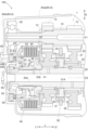
摩擦係合装置を含む変速機を備えた車両用駆動装置の実施形態について、図面を参照して説明する。図1及び図2に示すように、本実施形態の車両用駆動装置100は、概略的には、変速機1と、回転電機2と、差動歯車機構3と、それぞれが車輪Wに駆動連結される一対の出力部材4とを備えている。また、変速機1は、第1ギヤ12及び第2ギヤ14を備えた第1軸部材10と、第3ギヤ22及び第4ギヤ24を支持するとともに出力ギヤ25を備えた第2軸部材20と、噛み合い式係合装置30と、摩擦係合装置40とを備えている。これらは、ケース(駆動装置ケース)6内に収容されている。なお、出力部材4の一部は、ケース6の外部に露出している。 An embodiment of a vehicle drive device having a transmission including a friction engagement device will be described with reference to the drawings. As shown in Figs. 1 and 2, the vehicle drive device 100 of this embodiment generally includes a transmission 1, a rotating electric machine 2, a differential gear mechanism 3, and a pair of output members 4 each of which is drivingly connected to wheels W. The transmission 1 also includes a first shaft member 10 including a first gear 12 and a second gear 14, a second shaft member 20 supporting a third gear 22 and a fourth gear 24 and including an output gear 25, a meshing engagement device 30, and a friction engagement device 40. These are housed in a case (drive device case) 6. A portion of the output member 4 is exposed to the outside of the case 6.

ここで、「回転電機」は、モータ(電動機)、ジェネレータ(発電機)、及び必要に応じてモータ及びジェネレータの双方の機能を果たすモータ・ジェネレータのいずれをも含む概念として用いている。 Here, the term "rotating electric machine" is used as a concept that includes motors, generators, and motor-generators that function as both motors and generators as necessary.

また、「駆動連結」とは、2つの回転要素が駆動力を伝達可能に連結された状態を意味する。この概念には、2つの回転要素が一体回転するように連結された状態や、2つの回転要素が1つ以上の伝動部材を介して駆動力を伝達可能に連結された状態が含まれる。このような伝動部材には、回転を同速で又は変速して伝達する各種の部材(軸、歯車機構、ベルト、チェーン等)が含まれ、回転及び駆動力を選択的に伝達する係合装置(摩擦係合装置や噛み合い式係合装置等)が含まれても良い。 In addition, "driving connection" refers to a state in which two rotating elements are connected so that they can transmit a driving force. This concept includes a state in which two rotating elements are connected so that they rotate as a unit, and a state in which two rotating elements are connected so that they can transmit a driving force via one or more transmission members. Such transmission members include various members (shafts, gear mechanisms, belts, chains, etc.) that transmit rotation at the same speed or at a variable speed, and may also include engagement devices (friction engagement devices, meshing engagement devices, etc.) that selectively transmit rotation and driving force.

回転電機2及び第1軸部材10は、第1軸X1上に配置されている。第2軸部材20、噛み合い式係合装置30、及び摩擦係合装置40は、第2軸X2上に配置されている。差動歯車機構3及び出力部材4は、第3軸X3上に配置されている。第1軸X1、第2軸X2、及び第3軸X3は、互いに異なる平行な軸であり、以下ではこれらに平行な方向を「軸方向L」と言う。また、軸方向Lの一方側(本例では図1における左側)を軸方向第1側L1と言い、その反対側である軸方向Lの他方側(本例では図1における右側)を軸方向第2側L2と言う。また、以下では、軸方向Lに沿って見た状態を「軸方向視」と言う。 The rotating electric machine 2 and the first shaft member 10 are arranged on the first axis X1. The second shaft member 20, the meshing type engagement device 30, and the friction engagement device 40 are arranged on the second axis X2. The differential gear mechanism 3 and the output member 4 are arranged on the third axis X3. The first axis X1, the second axis X2, and the third axis X3 are parallel axes different from one another, and the direction parallel to these axes will be referred to as the "axial direction L" below. In addition, one side of the axial direction L (the left side in FIG. 1 in this example) will be referred to as the first axial side L1, and the other side of the axial direction L (the right side in FIG. 1 in this example) will be referred to as the second axial side L2. In addition, the state viewed along the axial direction L will be referred to as the "axial view" below.

回転電機2は、ケース6に固定されたステータ2Aと、このステータ2Aの径方向内側に回転自在に支持されたロータ2Bとを備えている。回転電機2は、蓄電装置(図示せず)から電力の供給を受けて力行し、或いは、車両の慣性力等によって発電した電力を蓄電装置に供給して蓄電させる。ロータ2Bは、ロータ軸2Cと一体的に回転するように連結されている。ロータ軸2Cは、軸方向Lの2箇所で、ロータ軸受91(図2を参照)によってケース6に対して回転自在に支持されている。ロータ軸2Cは、軸方向第1側L1の端部で、変速機1の第1軸部材10と一体的に回転するように連結されている。 The rotating electric machine 2 includes a stator 2A fixed to the case 6 and a rotor 2B supported rotatably on the radial inside of the stator 2A. The rotating electric machine 2 receives power from an electric storage device (not shown) to run, or supplies electric power generated by the inertial force of the vehicle or the like to the electric storage device for storage. The rotor 2B is connected to the rotor shaft 2C so as to rotate integrally therewith. The rotor shaft 2C is supported rotatably relative to the case 6 at two points in the axial direction L by rotor bearings 91 (see FIG. 2). The rotor shaft 2C is connected to the first shaft member 10 of the transmission 1 at the end of the first axial side L1 so as to rotate integrally therewith.

変速機1は、回転電機2側からの回転を変速して車輪W側に伝達する。本実施形態の変速機1は、第1ギヤ12及び第2ギヤ14を備えた第1軸部材10と、第3ギヤ22及び第4ギヤ24を支持するとともに出力ギヤ25を備えた第2軸部材20と、噛み合い式係合装置30と、摩擦係合装置40とを備えている。噛み合い式係合装置30が、第3ギヤ22及び第4ギヤ24のいずれか一方を第2軸部材20に対して選択的に連結することで、変速機1は、回転電機2側からの回転を2段階に変速して車輪W側に伝達することができる。摩擦係合装置40は、噛み合い式係合装置30が第4ギヤ24を第2軸部材20に対して連結する際に、係合状態となることで、第4ギヤ24と第2軸部材20との回転速度を同期させる。 The transmission 1 changes the speed of the rotation from the rotating electric machine 2 and transmits it to the wheels W. The transmission 1 of this embodiment includes a first shaft member 10 having a first gear 12 and a second gear 14, a second shaft member 20 supporting a third gear 22 and a fourth gear 24 and having an output gear 25, a meshing engagement device 30, and a friction engagement device 40. The meshing engagement device 30 selectively connects either the third gear 22 or the fourth gear 24 to the second shaft member 20, so that the transmission 1 can change the speed of the rotation from the rotating electric machine 2 in two stages and transmit it to the wheels W. The friction engagement device 40 is engaged when the meshing engagement device 30 connects the fourth gear 24 to the second shaft member 20, thereby synchronizing the rotational speeds of the fourth gear 24 and the second shaft member 20.

本実施形態では、噛み合い式係合装置30は、軸方向Lにおいて、第3ギヤ22と第4ギヤ24との間に配置されている。また、摩擦係合装置40は、第3ギヤ22及び第4ギヤ24に対して軸方向第1側L1に配置されている。また、出力ギヤ25は、第3ギヤ22及び第4ギヤ24に対して軸方向第2側L2に配置されている。 In this embodiment, the meshing engagement device 30 is disposed between the third gear 22 and the fourth gear 24 in the axial direction L. The friction engagement device 40 is disposed on the first axial side L1 relative to the third gear 22 and the fourth gear 24. The output gear 25 is disposed on the second axial side L2 relative to the third gear 22 and the fourth gear 24.

差動歯車機構3は、差動入力ギヤ3Aを備えており、この差動入力ギヤ3Aに入力される変速機1側からの回転及びトルクを、一対の出力部材4に分配して伝達する。一対の出力部材4は、それぞれが車輪Wに駆動連結されている。このように、回転電機2の側から伝達される回転が、変速機1を介して差動歯車機構3に伝達され、さらに差動歯車機構3により一対の出力部材4に分配され、さらに一対の車輪Wに伝達される。これにより、車両用駆動装置100は、回転電機2のトルクを車輪Wに伝達させて車両を走行させることができる。 The differential gear mechanism 3 has a differential input gear 3A, and distributes and transmits the rotation and torque from the transmission 1 side that is input to this differential input gear 3A to a pair of output members 4. Each of the pair of output members 4 is drivingly connected to the wheels W. In this way, the rotation transmitted from the rotating electric machine 2 side is transmitted to the differential gear mechanism 3 via the transmission 1, and is further distributed by the differential gear mechanism 3 to the pair of output members 4, and further transmitted to the pair of wheels W. In this way, the vehicle drive device 100 can transmit the torque of the rotating electric machine 2 to the wheels W to run the vehicle.

図2に示すように、ケース6は、第1ケース部6Aと第2ケース部6Bと第3ケース部6Cとを備えている。第1ケース部6Aは、第2ケース部6Bに対して軸方向第1側L1から接合されている。第1ケース部6Aは、変速機1及び差動歯車機構3を収容している。第1ケース部6Aは、変速機1及び差動歯車機構3の径方向外側を覆う第1周壁部6Aaと、変速機1及び差動歯車機構3の軸方向第1側L1を覆う第1支持壁部6Abとを備えている。第2ケース部6Bは回転電機2を収容している。第2ケース部6Bは、回転電機2の径方向外側を覆う第2周壁部6Baと、回転電機2の軸方向第1側L1を覆う第2支持壁部6Bbとを備えている。図示の例では、変速機1及び差動歯車機構3の一部も、第2ケース部6Bに収容されている。第3ケース部6Cは、第1ケース部6A及び第2ケース部6Bの内部で、変速機1及び差動歯車機構3の収容空間と回転電機2の収容空間とを区画している。 As shown in FIG. 2, the case 6 includes a first case portion 6A, a second case portion 6B, and a third case portion 6C. The first case portion 6A is joined to the second case portion 6B from the first axial side L1. The first case portion 6A houses the transmission 1 and the differential gear mechanism 3. The first case portion 6A includes a first peripheral wall portion 6Aa that covers the radial outside of the transmission 1 and the differential gear mechanism 3, and a first support wall portion 6Ab that covers the first axial side L1 of the transmission 1 and the differential gear mechanism 3. The second case portion 6B houses the rotating electric machine 2. The second case portion 6B includes a second peripheral wall portion 6Ba that covers the radial outside of the rotating electric machine 2, and a second support wall portion 6Bb that covers the first axial side L1 of the rotating electric machine 2. In the illustrated example, the transmission 1 and a part of the differential gear mechanism 3 are also housed in the second case portion 6B. The third case portion 6C separates the space inside the first case portion 6A and the second case portion 6B into a space for accommodating the transmission 1 and the differential gear mechanism 3 and a space for accommodating the rotating electric machine 2.

図2及び図3に示すように、変速機1は、第1ギヤ12及び第2ギヤ14を備えた第1軸部材10と、第3ギヤ22及び第4ギヤ24を支持するとともに出力ギヤ25を備えた第2軸部材20と、噛み合い式係合装置30と、摩擦係合装置40とを備えている。 As shown in Figures 2 and 3, the transmission 1 includes a first shaft member 10 having a first gear 12 and a second gear 14, a second shaft member 20 supporting a third gear 22 and a fourth gear 24 and having an output gear 25, a meshing engagement device 30, and a friction engagement device 40.

第1軸部材10は、変速機1の入力部材(変速入力部材)として機能する。第1軸部材10は、ロータ軸2Cに対して軸方向第1側L1に配置されている。第1軸部材10は、その軸方向第2側L2の端部がロータ軸2Cに挿入された状態で、当該ロータ軸2Cと一体的に回転するように連結されている。また、第1軸部材10は、軸方向Lの2箇所で、第1軸受92によってケース6に対して回転自在に支持されている。第1軸部材10は、軸方向第1側L1において、第1ケース部6Aに対して回転自在に支持され、軸方向第2側L2において、第3ケース部6Cに対して回転自在に支持されている。 The first shaft member 10 functions as an input member (transmission input member) of the transmission 1. The first shaft member 10 is disposed on the first axial side L1 relative to the rotor shaft 2C. The first shaft member 10 is connected to the rotor shaft 2C so as to rotate integrally with the rotor shaft 2C with its end on the second axial side L2 inserted into the rotor shaft 2C. The first shaft member 10 is also rotatably supported by the first bearing 92 at two points in the axial direction L relative to the case 6. The first shaft member 10 is rotatably supported by the first case portion 6A on the first axial side L1, and rotatably supported by the third case portion 6C on the second axial side L2.

本実施形態では、第1ケース部6Aの第1支持壁部6Abには、軸方向第2側L2に突出する筒状の第1筒状支持部61が形成されている(図3を参照)。この第1筒状支持部61に、一対の第1軸受92のうちの1つが内嵌されている。 In this embodiment, the first support wall 6Ab of the first case 6A is formed with a first cylindrical support portion 61 that protrudes toward the second axial side L2 (see FIG. 3). One of the pair of first bearings 92 is fitted into the first cylindrical support portion 61.

第1ギヤ12及び第2ギヤ14は、第1軸部材10と一体的に回転するように当該第1軸部材10に連結されている。本実施形態では、第1ギヤ12は、第1軸部材10の外周面に形成されている。第1ギヤ12は、第3ギヤ22に噛み合っている。また、第2ギヤ14は、第1軸部材10と一体的に回転するように当該第1軸部材10に連結された第2ギヤ形成部材13の外周面に形成されている。第2ギヤ14は、第4ギヤ24に噛み合っている。第2ギヤ14は、第1ギヤ12に対して、軸方向第1側L1に間隔を空けて配置されている。 The first gear 12 and the second gear 14 are connected to the first shaft member 10 so as to rotate integrally with the first shaft member 10. In this embodiment, the first gear 12 is formed on the outer peripheral surface of the first shaft member 10. The first gear 12 meshes with the third gear 22. The second gear 14 is formed on the outer peripheral surface of the second gear forming member 13 which is connected to the first shaft member 10 so as to rotate integrally with the first shaft member 10. The second gear 14 meshes with the fourth gear 24. The second gear 14 is disposed at a distance from the first gear 12 on the first axial side L1.

第2軸部材20は、第1軸部材10と平行に配置されている。第2軸部材20の軸方向Lの配置領域は、第1軸部材10の軸方向Lの配置領域に重複している。本実施形態では、第2軸部材20の軸方向Lの配置領域は、第1軸部材10の軸方向Lの配置領域に包含されている。また、第2軸部材20は、軸方向Lの2箇所で、第2軸受93によってケース6に対して回転自在に支持されている。第2軸部材20は、軸方向第1側L1において、第1ケース部6Aに対して回転自在に支持され、軸方向第2側L2において、第3ケース部6Cに対して回転自在に支持されている。 The second shaft member 20 is arranged parallel to the first shaft member 10. The arrangement area of the second shaft member 20 in the axial direction L overlaps with the arrangement area of the first shaft member 10 in the axial direction L. In this embodiment, the arrangement area of the second shaft member 20 in the axial direction L is included in the arrangement area of the first shaft member 10 in the axial direction L. The second shaft member 20 is supported rotatably relative to the case 6 by the second bearing 93 at two points in the axial direction L. The second shaft member 20 is supported rotatably relative to the first case portion 6A on the first axial side L1, and is supported rotatably relative to the third case portion 6C on the second axial side L2.

本実施形態では、第1ケース部6Aの第1支持壁部6Abには、軸方向第2側L2に突出する筒状の第2筒状支持部62が形成されている(図3を参照)。この第2筒状支持部62に、一対の第2軸受93のうちの1つが内嵌されている。 In this embodiment, the first support wall 6Ab of the first case 6A is formed with a second cylindrical support portion 62 that protrudes toward the second axial side L2 (see FIG. 3). One of the pair of second bearings 93 is fitted into the second cylindrical support portion 62.

第3ギヤ22及び第4ギヤ24は、第2軸部材20と相対回転可能な状態で当該第2軸部材20に支持されている。本実施形態では、第3ギヤ22は、第2軸部材20に対して軸受を介して回転可能に支持された第3ギヤ形成部材21の外周面に形成されている。第3ギヤ22は、第1ギヤ12に噛み合っている。また、第4ギヤ24は、第2軸部材20に対して軸受を介して回転可能に支持された第4ギヤ形成部材23の外周面に形成されている。第4ギヤ24は、第2ギヤ14に噛み合っている。図示の例では、第3ギヤ形成部材21及び第4ギヤ形成部材23を支持する軸受には、針状ころ軸受が用いられている。 The third gear 22 and the fourth gear 24 are supported by the second shaft member 20 in a state in which they can rotate relative to the second shaft member 20. In this embodiment, the third gear 22 is formed on the outer peripheral surface of the third gear forming member 21, which is rotatably supported on the second shaft member 20 via a bearing. The third gear 22 meshes with the first gear 12. The fourth gear 24 is formed on the outer peripheral surface of the fourth gear forming member 23, which is rotatably supported on the second shaft member 20 via a bearing. The fourth gear 24 meshes with the second gear 14. In the illustrated example, needle roller bearings are used as the bearings that support the third gear forming member 21 and the fourth gear forming member 23.

なお、本実施形態では、第1ギヤ12は第2ギヤ14よりも小径であり、それに対応して、第3ギヤ22は第4ギヤ24よりも大径となっている。 In this embodiment, the first gear 12 has a smaller diameter than the second gear 14, and correspondingly, the third gear 22 has a larger diameter than the fourth gear 24.

出力ギヤ25は、第2軸部材20と一体的に回転するように当該第2軸部材20に連結されている。本実施形態では、出力ギヤ25は、第2軸部材20の外周面に形成されている。出力ギヤ25は、第3ギヤ22が形成された第3ギヤ形成部材21に対して軸方向第2側L2に隣接する位置に形成されている。出力ギヤ25は、変速機1の出力部材(変速出力部材)として機能する。出力ギヤ25は、差動歯車機構3の差動入力ギヤ3Aに噛み合っている。 The output gear 25 is connected to the second shaft member 20 so as to rotate integrally with the second shaft member 20. In this embodiment, the output gear 25 is formed on the outer peripheral surface of the second shaft member 20. The output gear 25 is formed at a position adjacent to the second axial side L2 of the third gear forming member 21 on which the third gear 22 is formed. The output gear 25 functions as an output member (transmission output member) of the transmission 1. The output gear 25 meshes with the differential input gear 3A of the differential gear mechanism 3.

図3に示すように、噛み合い式係合装置30は、第1係合部31と、第2係合部32と、第3係合部33と、切替部材35とを備えている。 As shown in FIG. 3, the meshing engagement device 30 includes a first engagement portion 31, a second engagement portion 32, a third engagement portion 33, and a switching member 35.

第1係合部31は、第2軸部材20と一体的に回転するように当該第2軸部材20に連結されている。本実施形態では、第1係合部31は、第2軸部材20と一体的に回転するように当該第2軸部材20に連結された連結部材31Aの外周面に形成されている。第1係合部31は、外歯の係合部となっている。 The first engagement portion 31 is connected to the second shaft member 20 so as to rotate integrally with the second shaft member 20. In this embodiment, the first engagement portion 31 is formed on the outer circumferential surface of a connecting member 31A that is connected to the second shaft member 20 so as to rotate integrally with the second shaft member 20. The first engagement portion 31 is an external tooth engagement portion.

第2係合部32は、第3ギヤ22と一体的に回転するように当該第3ギヤ22に連結されている。本実施形態では、第2係合部32は、外周面に第3ギヤ22が形成された第3ギヤ形成部材21に形成されている。第2係合部32は、第1係合部31に対して軸方向第2側L2に隣接して配置されている。第2係合部32は、第1係合部31と同径同ピッチの外歯の係合部となっている。 The second engagement portion 32 is connected to the third gear 22 so as to rotate integrally with the third gear 22. In this embodiment, the second engagement portion 32 is formed on a third gear forming member 21 on whose outer circumferential surface the third gear 22 is formed. The second engagement portion 32 is disposed adjacent to the first engagement portion 31 on the second axial side L2. The second engagement portion 32 is an engagement portion with external teeth of the same diameter and pitch as the first engagement portion 31.

第3係合部33は、第4ギヤ24と一体的に回転するように当該第4ギヤ24に連結されている。本実施形態では、第3係合部33は、外周面に第4ギヤ24が形成された第4ギヤ形成部材23に形成されている。第3係合部33は、第1係合部31に対して軸方向第1側L1に隣接して配置されている。第3係合部33は、第1係合部31及び第2係合部32と同径同ピッチの外歯の係合部となっている。 The third engagement portion 33 is connected to the fourth gear 24 so as to rotate integrally with the fourth gear 24. In this embodiment, the third engagement portion 33 is formed on the fourth gear forming member 23 on whose outer circumferential surface the fourth gear 24 is formed. The third engagement portion 33 is disposed adjacent to the first axial side L1 of the first engagement portion 31. The third engagement portion 33 is an engagement portion with external teeth of the same diameter and pitch as the first engagement portion 31 and the second engagement portion 32.

切替部材35は、連結部材31Aの径方向Rの外側を覆う筒状に形成されている。そして、切替部材35の内周面には、それぞれが外歯の第1係合部31、第2係合部32、及び第3係合部33に噛み合う内歯の係合部が形成されている。切替部材35の内歯と第1係合部31、第2係合部32、及び第3係合部33の外歯とは、軸方向Lに相対移動可能、かつ、周方向に相対回転不能に係合する。 The switching member 35 is formed in a cylindrical shape that covers the outside of the connecting member 31A in the radial direction R. The inner peripheral surface of the switching member 35 is formed with internal tooth engagement portions that mesh with the first engagement portion 31, the second engagement portion 32, and the third engagement portion 33, which are external teeth. The internal teeth of the switching member 35 and the external teeth of the first engagement portion 31, the second engagement portion 32, and the third engagement portion 33 engage with each other so as to be movable relative to each other in the axial direction L, but not rotatable relative to each other in the circumferential direction.

噛み合い式係合装置30は、切替部材35が第1係合部31及び第2係合部32の両方に係合した状態で、第3ギヤ22と第2軸部材20とを一体的に回転するように連結する。また、噛み合い式係合装置30は、切替部材35が第1係合部31及び第3係合部33の両方に係合した状態で、第4ギヤ24と第2軸部材20とを一体的に回転するように連結する。このようにして、噛み合い式係合装置30は、第3ギヤ22及び第4ギヤ24のいずれか一方を第2軸部材20に対して選択的に連結する。第3ギヤ22と第2軸部材20とが一体的に回転するように連結された状態で、回転電機2の駆動力は、互いに噛み合う第1ギヤ12と第3ギヤ22とを介して車輪W側に伝達される。一方、第4ギヤ24と第2軸部材20とが一体的に回転するように連結された状態で、回転電機2の駆動力は、互いに噛み合う第2ギヤ14と第4ギヤ24とを介して車輪W側に伝達される。 The meshing engagement device 30 connects the third gear 22 and the second shaft member 20 to rotate together when the switching member 35 is engaged with both the first engagement portion 31 and the second engagement portion 32. The meshing engagement device 30 also connects the fourth gear 24 and the second shaft member 20 to rotate together when the switching member 35 is engaged with both the first engagement portion 31 and the third engagement portion 33. In this way, the meshing engagement device 30 selectively connects either the third gear 22 or the fourth gear 24 to the second shaft member 20. When the third gear 22 and the second shaft member 20 are connected to rotate together, the driving force of the rotating electric machine 2 is transmitted to the wheel W side via the first gear 12 and the third gear 22 that mesh with each other. On the other hand, when the fourth gear 24 and the second shaft member 20 are connected so as to rotate together, the driving force of the rotating electric machine 2 is transmitted to the wheel W side via the second gear 14 and the fourth gear 24, which mesh with each other.

なお、切替部材35が第1係合部31に係合しているが、第2係合部32及び第3係合部33の両方に係合していない状態では、噛み合い式係合装置30は非係合状態(解放状態)となる。そして、噛み合い式係合装置30が非係合状態で、かつ、摩擦係合装置40も非係合状態では、変速機1は駆動力を伝達しないニュートラル状態となる。 When the switching member 35 is engaged with the first engagement portion 31 but not engaged with either the second engagement portion 32 or the third engagement portion 33, the meshing engagement device 30 is in a disengaged state (disengaged state). When the meshing engagement device 30 is in a disengaged state and the friction engagement device 40 is also in a disengaged state, the transmission 1 is in a neutral state in which it does not transmit driving force.

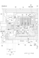
図3及び図4に示すように、摩擦係合装置40は、第1支持部材41と、第2支持部材42と、第1摩擦材43と、第2摩擦材44と、第1押圧部材45と、第2押圧部材46と、押圧駆動部49とを備えている。 As shown in Figures 3 and 4, the friction engagement device 40 includes a first support member 41, a second support member 42, a first friction material 43, a second friction material 44, a first pressing member 45, a second pressing member 46, and a pressing drive unit 49.

第1支持部材41は、第1摩擦材43を支持するための部材であり、回転可能に支持されている。第1支持部材41は、第1摩擦材支持部41Aと第1径方向延在部41Bと軸連結部41Cとを備えている。これらは、一体的に形成されている。第1摩擦材支持部41Aは、軸方向Lに沿う筒状に形成されており、第1摩擦材43を径方向Rの内側から支持している。第1摩擦材支持部41Aの外周面には、外歯が形成されている。第1径方向延在部41Bは、第1摩擦材支持部41Aから径方向Rの内側へ向けて延在している。本実施形態では、第1径方向延在部41Bは、第1摩擦材支持部41Aの軸方向第2側L2の端部から径方向Rの内側へ向けて延在している。 The first support member 41 is a member for supporting the first friction material 43, and is supported rotatably. The first support member 41 includes a first friction material support portion 41A, a first radial extension portion 41B, and a shaft connection portion 41C. These are integrally formed. The first friction material support portion 41A is formed in a cylindrical shape along the axial direction L, and supports the first friction material 43 from the inside in the radial direction R. External teeth are formed on the outer peripheral surface of the first friction material support portion 41A. The first radial extension portion 41B extends from the first friction material support portion 41A toward the inside in the radial direction R. In this embodiment, the first radial extension portion 41B extends from the end of the axial second side L2 of the first friction material support portion 41A toward the inside in the radial direction R.

軸連結部41Cは、第1径方向延在部41Bの下端部から軸方向Lに延在している。軸連結部41Cは、軸方向Lに沿う筒状に形成されており、第2軸部材20に外挿されている。軸連結部41Cは、第2軸部材20と一体的に回転するように連結されている。これにより、第1支持部材41の全体が、第2軸部材20と一体的に回転するように連結されている。第1支持部材41を構成する各部のうち、第1径方向延在部41Bは、第1押圧部材45に対して軸方向第2側L2に配置されている。 The shaft connecting portion 41C extends in the axial direction L from the lower end of the first radially extending portion 41B. The shaft connecting portion 41C is formed in a cylindrical shape along the axial direction L and is inserted onto the second shaft member 20. The shaft connecting portion 41C is connected to the second shaft member 20 so as to rotate integrally therewith. As a result, the entire first support member 41 is connected to the second shaft member 20 so as to rotate integrally therewith. Of the various portions constituting the first support member 41, the first radially extending portion 41B is disposed on the second axial side L2 relative to the first pressing member 45.

第2支持部材42は、第2摩擦材44を支持するための部材であり、第1支持部材41とは独立して回転可能に支持されている。第2支持部材42は、第2摩擦材支持部42Aと第2径方向延在部42Bとを備えている。これらは、一体的に形成されている。第2摩擦材支持部42Aは、軸方向Lに沿う筒状に形成されており、第2摩擦材44を径方向Rの外側から支持している。第2摩擦材支持部42Aの内周面には、内歯が形成されている。第2摩擦材支持部42Aは、第1摩擦材支持部41Aよりも径方向Rの外側に、第1摩擦材支持部41Aと同軸に配置されている。 The second support member 42 is a member for supporting the second friction material 44, and is supported rotatably independent of the first support member 41. The second support member 42 includes a second friction material support portion 42A and a second radially extending portion 42B, which are integrally formed. The second friction material support portion 42A is formed in a cylindrical shape along the axial direction L, and supports the second friction material 44 from the outside in the radial direction R. Internal teeth are formed on the inner peripheral surface of the second friction material support portion 42A. The second friction material support portion 42A is disposed coaxially with the first friction material support portion 41A, outside the radial direction R of the first friction material support portion 41A.

第2径方向延在部42Bは、第2摩擦材支持部42Aから径方向Rの内側へ向けて延在している。本実施形態では、第2径方向延在部42Bは、第2摩擦材支持部42Aの軸方向第2側L2の端部から径方向Rの内側へ向けて延在している。第2径方向延在部42Bは、第1径方向延在部41Bに対して軸方向第2側L2に隣接して配置されている。また、第2径方向延在部42Bは、第4ギヤ形成部材23に対して軸方向第1側L1に隣接して配置されている。第2径方向延在部42Bは、第4ギヤ24が形成された第4ギヤ形成部材23と一体的に回転するように連結されている。これにより、第2支持部材42の全体が、第4ギヤ24と一体的に回転するように連結されている。 The second radial extension portion 42B extends from the second friction material support portion 42A toward the inside in the radial direction R. In this embodiment, the second radial extension portion 42B extends from the end of the second axial side L2 of the second friction material support portion 42A toward the inside in the radial direction R. The second radial extension portion 42B is disposed adjacent to the first radial extension portion 41B on the second axial side L2. The second radial extension portion 42B is disposed adjacent to the fourth gear forming member 23 on the first axial side L1. The second radial extension portion 42B is connected to the fourth gear forming member 23 on which the fourth gear 24 is formed so as to rotate integrally. As a result, the entire second support member 42 is connected to the fourth gear 24 so as to rotate integrally.

第1摩擦材43は、軸方向Lに複数枚並んで配置されている。それぞれの第1摩擦材43の内周面には、第1摩擦材支持部41Aの外歯に噛み合う内歯が形成されている。第1摩擦材43は、第1摩擦材支持部41Aの外周面に、当該第1摩擦材支持部41Aに対して軸方向Lに相対移動可能、かつ、周方向に相対回転不能に支持されている。 The first friction material 43 is arranged in a row in the axial direction L. The inner circumferential surface of each first friction material 43 is formed with internal teeth that mesh with the external teeth of the first friction material support part 41A. The first friction material 43 is supported on the outer circumferential surface of the first friction material support part 41A so as to be movable relative to the first friction material support part 41A in the axial direction L, but not rotatable relative to the first friction material support part 41A in the circumferential direction.

第2摩擦材44は、軸方向Lに複数枚並んで配置されている。第1摩擦材43と第2摩擦材44とは、軸方向Lに交互に配置されており、互いに軸方向Lに対向するように配置されている。それぞれの第2摩擦材44の外周面には、第2摩擦材支持部42Aの内歯に噛み合う外歯が形成されている。第2摩擦材44は、第2摩擦材支持部42Aの内周面に、当該第2摩擦材支持部42Aに対して軸方向Lに相対移動可能、かつ、周方向に相対回転不能に支持されている。 The second friction materials 44 are arranged in a row in the axial direction L. The first friction materials 43 and the second friction materials 44 are arranged alternately in the axial direction L and arranged to face each other in the axial direction L. External teeth that mesh with the internal teeth of the second friction material support part 42A are formed on the outer circumferential surface of each second friction material 44. The second friction material 44 is supported on the inner circumferential surface of the second friction material support part 42A so as to be movable relative to the second friction material support part 42A in the axial direction L and non-rotatable relative to the second friction material support part 42A in the circumferential direction.

第1押圧部材45は、第2押圧部材46と協働して、第1摩擦材43と第2摩擦材44とを互いに押し付けるように押圧する。第1押圧部材45は、第1摩擦材43及び第2摩擦材44に対して軸方向第1側L1に配置されている。第1押圧部材45は、第1摩擦材支持部41Aの外歯に噛み合う内歯を備えており、第1摩擦材支持部41Aに対して軸方向Lに相対移動可能、かつ、周方向に相対回転不能に支持されている。こうして、第1押圧部材45は、第1支持部材41と一体的に回転するとともに当該第1支持部材41に対して軸方向Lに移動自在に支持されている。第1押圧部材45は、第2押圧部材46を介して押圧駆動部49により軸方向Lに駆動された場合に、第1摩擦材43及び第2摩擦材44を軸方向第1側L1から押圧して第1摩擦材43と第2摩擦材44とを互いに圧接する。 The first pressing member 45 cooperates with the second pressing member 46 to press the first friction material 43 and the second friction material 44 against each other. The first pressing member 45 is disposed on the first axial side L1 relative to the first friction material 43 and the second friction material 44. The first pressing member 45 has internal teeth that mesh with the external teeth of the first friction material support portion 41A, and is supported so as to be movable relative to the first friction material support portion 41A in the axial direction L and non-rotatable in the circumferential direction. In this way, the first pressing member 45 rotates integrally with the first support member 41 and is supported so as to be movable relative to the first support member 41 in the axial direction L. When the first pressing member 45 is driven in the axial direction L by the pressing drive unit 49 via the second pressing member 46, it presses the first friction material 43 and the second friction material 44 from the first axial side L1, thereby pressing the first friction material 43 and the second friction material 44 against each other.

第1押圧部材45は、摺動部45Aと押圧部45Bとを備えている。摺動部45Aは、第1摩擦材支持部41Aよりも径方向Rの内側に配置されており、当該第1摩擦材支持部41Aの内周面に沿って摺動する。本実施形態では、摺動部45Aにおける第1摩擦材支持部41Aの内周面に対向する面(摺動対向面)と第1摩擦材支持部41Aの内周面との間に、シール部材51が配置されている。摺動部45Aは、径方向Rに沿って延在するように形成されている。本例では、摺動部45Aは、第1摩擦材支持部41Aと第1支持部材41の軸連結部41Cとに亘るように径方向Rに沿って形成されている。また、摺動部45Aは、保持部材47によって保持された付勢部材48によって、軸方向第1側L1に向けて付勢されている。付勢部材48は、軸方向Lにおける、第1摩擦材43と第2摩擦材44とを互いに押し付ける側とは反対側へ向けて第1押圧部材45を付勢する。このような付勢部材48として、本実施形態ではリターンスプリングが用いられている。 The first pressing member 45 includes a sliding portion 45A and a pressing portion 45B. The sliding portion 45A is disposed inward in the radial direction R from the first frictional material support portion 41A, and slides along the inner circumferential surface of the first frictional material support portion 41A. In this embodiment, a seal member 51 is disposed between the surface (sliding opposing surface) of the sliding portion 45A facing the inner circumferential surface of the first frictional material support portion 41A and the inner circumferential surface of the first frictional material support portion 41A. The sliding portion 45A is formed so as to extend along the radial direction R. In this example, the sliding portion 45A is formed along the radial direction R so as to span the first frictional material support portion 41A and the shaft connecting portion 41C of the first support member 41. In addition, the sliding portion 45A is biased toward the first axial side L1 by a biasing member 48 held by the holding member 47. The biasing member 48 biases the first pressing member 45 in the axial direction L in the direction opposite to the side where the first friction material 43 and the second friction material 44 are pressed against each other. In this embodiment, a return spring is used as the biasing member 48.

押圧部45Bは、摺動部45Aから径方向Rの外側に延びている。押圧部45Bは、第1摩擦材支持部41Aよりも径方向Rの外側に配置されている。押圧部45Bは、第1摩擦材支持部41Aと第2摩擦材支持部42Aとの径方向Rの間に配置される部分を有するように形成されている。押圧部45Bは、摺動部45Aと一体的に軸方向Lに沿って移動して、第1摩擦材43及び第2摩擦材44を押圧する。 The pressing portion 45B extends outward in the radial direction R from the sliding portion 45A. The pressing portion 45B is disposed outward in the radial direction R from the first frictional material support portion 41A. The pressing portion 45B is formed to have a portion disposed between the first frictional material support portion 41A and the second frictional material support portion 42A in the radial direction R. The pressing portion 45B moves along the axial direction L integrally with the sliding portion 45A to press the first frictional material 43 and the second frictional material 44.

第2押圧部材46は、第1押圧部材45と協働して、第1摩擦材43と第2摩擦材44とを互いに押し付けるように押圧する。第2押圧部材46は、第1押圧部材45に対してさらに軸方向第1側L1に配置されている。本実施形態では、第2押圧部材46は、間にスラスト軸受95を介して、第1押圧部材45に隣接して配置されている。第2押圧部材46は、ケース6に対して軸方向Lに移動自在に支持されている。第1ケース部6Aの第1支持壁部6Abには、軸方向第2側L2に突出する筒状の第3筒状支持部63が形成されている。第3筒状支持部63は、第2筒状支持部62と同心に、当該第2筒状支持部62よりも大径に形成されている。第2押圧部材46は、径方向Rにおける第2筒状支持部62と第3筒状支持部63との間の環状空間に配置されている。 The second pressing member 46 cooperates with the first pressing member 45 to press the first friction material 43 and the second friction material 44 against each other. The second pressing member 46 is disposed on the first axial side L1 relative to the first pressing member 45. In this embodiment, the second pressing member 46 is disposed adjacent to the first pressing member 45 with a thrust bearing 95 interposed therebetween. The second pressing member 46 is supported on the case 6 so as to be movable in the axial direction L. The first support wall 6Ab of the first case portion 6A is formed with a cylindrical third cylindrical support portion 63 that protrudes to the second axial side L2. The third cylindrical support portion 63 is formed concentrically with the second cylindrical support portion 62 and has a larger diameter than the second cylindrical support portion 62. The second pressing member 46 is disposed in the annular space between the second cylindrical support portion 62 and the third cylindrical support portion 63 in the radial direction R.

第2押圧部材46は、第3筒状支持部63の内周面及び第2筒状支持部62の外周面に沿って摺動する。本実施形態では、第2押圧部材46における第3筒状支持部63の内周面に対向する面と第3筒状支持部63の内周面との間に、シール部材52が配置されている。また、第2押圧部材46における第2筒状支持部62の外周面に対向する面と第2筒状支持部62の外周面との間に、シール部材53が配置されている。第2押圧部材46は、非回転状態で軸方向Lに移動自在に支持されている。 The second pressing member 46 slides along the inner peripheral surface of the third cylindrical support portion 63 and the outer peripheral surface of the second cylindrical support portion 62. In this embodiment, a seal member 52 is disposed between the surface of the second pressing member 46 facing the inner peripheral surface of the third cylindrical support portion 63 and the inner peripheral surface of the third cylindrical support portion 63. In addition, a seal member 53 is disposed between the surface of the second pressing member 46 facing the outer peripheral surface of the second cylindrical support portion 62 and the outer peripheral surface of the second cylindrical support portion 62. The second pressing member 46 is supported in a non-rotating state so as to be freely movable in the axial direction L.

押圧駆動部49は、第2押圧部材46を軸方向Lに駆動する。本実施形態の押圧駆動部49は、油圧室49Aと作動油供給部49Bとを備えている。油圧室49Aは、第2押圧部材46に油圧を作用させるための空間である。本実施形態では、第2筒状支持部62と第3筒状支持部63と第1支持壁部6Abと第2押圧部材46とで囲まれた空間に、油圧室49Aが形成されている。作動油供給部49Bは、油圧室49Aに連通するように設けられており、当該油圧室49Aに油(作動油)を供給する。本実施形態では、作動油供給部49Bにより、「油圧室に油を供給する油供給部」が構成されている。油圧室49A及び作動油供給部49Bは、ケース6(本例では第1ケース部6A)に形成されている。 The pressing drive unit 49 drives the second pressing member 46 in the axial direction L. The pressing drive unit 49 in this embodiment includes a hydraulic chamber 49A and a hydraulic oil supply unit 49B. The hydraulic chamber 49A is a space for applying hydraulic pressure to the second pressing member 46. In this embodiment, the hydraulic chamber 49A is formed in a space surrounded by the second cylindrical support unit 62, the third cylindrical support unit 63, the first support wall unit 6Ab, and the second pressing member 46. The hydraulic oil supply unit 49B is provided so as to communicate with the hydraulic chamber 49A and supplies oil (hydraulic oil) to the hydraulic chamber 49A. In this embodiment, the hydraulic oil supply unit 49B constitutes an "oil supply unit that supplies oil to the hydraulic chamber." The hydraulic chamber 49A and the hydraulic oil supply unit 49B are formed in the case 6 (in this example, the first case unit 6A).

作動油供給部49Bから所定油圧の油が油圧室49Aに供給されると、その油圧によって、第2押圧部材46が軸方向第2側L2に移動する。すると、第2押圧部材46は、スラスト軸受95を介して第1押圧部材45と相対回転自在な状態で、当該第1押圧部材45を軸方向第1側L1から押圧する。これにより、第2押圧部材46及び第1押圧部材45は、連動して第1摩擦材43及び第2摩擦材44を軸方向第2側L2に押圧し、第1摩擦材43と第2摩擦材44とを互いに圧接する。 When oil of a predetermined hydraulic pressure is supplied from the hydraulic oil supply unit 49B to the hydraulic chamber 49A, the hydraulic pressure moves the second pressing member 46 to the second axial side L2. Then, the second pressing member 46 presses the first pressing member 45 from the first axial side L1 while being rotatable relative to the first pressing member 45 via the thrust bearing 95. As a result, the second pressing member 46 and the first pressing member 45 work together to press the first friction material 43 and the second friction material 44 to the second axial side L2, and the first friction material 43 and the second friction material 44 are pressed against each other.

このように、摩擦係合装置40は、第1摩擦材43を支持する第1摩擦材支持部41Aを備え、回転可能に支持された第1支持部材41と、第2摩擦材44を支持する第2摩擦材支持部42Aを備え、第1支持部材41とは独立して回転可能に支持された第2支持部材42と、第1支持部材41と一体的に回転するとともに当該第1支持部材41に対して軸方向Lに移動自在に支持され、第1摩擦材43と第2摩擦材44とを互いに押し付けるように第1摩擦材43及び第2摩擦材44を軸方向Lに押圧する第1押圧部材45と、ケース6に対して軸方向Lに移動自在に支持され、第1押圧部材45と相対回転自在な状態で当該第1押圧部材45を軸方向Lに押圧する第2押圧部材46と、第2押圧部材46を軸方向Lに駆動する押圧駆動部49とを備える。 Thus, the friction engagement device 40 includes a first support member 41 that is rotatably supported and includes a first friction material support portion 41A that supports the first friction material 43, a second support member 42 that is rotatably supported independently of the first support member 41 and includes a second friction material support portion 42A that supports the second friction material 44, a first pressing member 45 that rotates integrally with the first support member 41 and is supported movably in the axial direction L relative to the first support member 41 and presses the first friction material 43 and the second friction material 44 in the axial direction L so as to press the first friction material 43 and the second friction material 44 against each other, a second pressing member 46 that is supported movably in the axial direction L relative to the case 6 and presses the first pressing member 45 in the axial direction L while being rotatable relative to the first pressing member 45, and a pressing drive unit 49 that drives the second pressing member 46 in the axial direction L.

この構成によれば、摩擦係合装置40が、単一の押圧部材を備えるのではなく、互いに相対回転する第1押圧部材45と第2押圧部材46とを備え、押圧駆動部49によって軸方向Lに駆動される方の第2押圧部材46が非回転部材であるケース6に対して軸方向Lに移動自在に支持される。これにより、第2押圧部材46を駆動するための作動油は回転せず遠心油圧も加わらないため、摩擦係合装置40の制御性を向上させることができる。 According to this configuration, the friction engagement device 40 does not include a single pressing member, but includes a first pressing member 45 and a second pressing member 46 that rotate relative to each other, and the second pressing member 46 that is driven in the axial direction L by the pressing drive unit 49 is supported so as to be freely movable in the axial direction L relative to the case 6, which is a non-rotating member. As a result, the hydraulic oil for driving the second pressing member 46 does not rotate and centrifugal hydraulic pressure is not applied, improving the controllability of the friction engagement device 40.

摩擦係合装置40が互いに相対回転する第1押圧部材45と第2押圧部材46とを備えることとの関係で、第1支持部材41の第1径方向延在部41Bは、第2押圧部材46よりも軸方向第2側L2で第2軸部材20と一体的に回転するように連結されている。また、第2支持部材42の第2径方向延在部42Bは、第1径方向延在部41Bよりもさらに軸方向第2側L2で第4ギヤ24と一体的に回転するように連結されている。 In relation to the fact that the friction engagement device 40 includes a first pressing member 45 and a second pressing member 46 that rotate relative to each other, the first radial extension portion 41B of the first support member 41 is connected to the second shaft member 20 so as to rotate integrally with the second shaft member 20 on the second axial side L2 further than the second pressing member 46. In addition, the second radial extension portion 42B of the second support member 42 is connected to the fourth gear 24 so as to rotate integrally with the fourth gear 24 on the second axial side L2 further than the first radial extension portion 41B.

このように、第1支持部材41は、第1摩擦材支持部41Aから径方向Rの内側へ向けて延在する第1径方向延在部41Bをさらに備え、第1摩擦材支持部41Aは、軸方向Lに沿う筒状に形成され、第1径方向延在部41Bは、第1押圧部材45に対して軸方向第2側L2に配置され、第2支持部材42は、第2摩擦材支持部42Aから径方向Rの内側へ向けて延在する第2径方向延在部42Bをさらに備え、第2摩擦材支持部42Aは、軸方向Lに沿う筒状に形成され、第2径方向延在部42Bは、第1径方向延在部41Bに対して軸方向第2側L2に配置されている。 In this way, the first support member 41 further includes a first radial extension portion 41B extending inward in the radial direction R from the first friction material support portion 41A, the first friction material support portion 41A is formed in a cylindrical shape along the axial direction L, and the first radial extension portion 41B is disposed on the second axial side L2 relative to the first pressing member 45, and the second support member 42 further includes a second radial extension portion 42B extending inward in the radial direction R from the second friction material support portion 42A, the second friction material support portion 42A is formed in a cylindrical shape along the axial direction L, and the second radial extension portion 42B is disposed on the second axial side L2 relative to the first radial extension portion 41B.

この構成によれば、第1支持部材41と第2軸部材20との連結及び第2支持部材42と第4ギヤ24との連結の双方を、第1押圧部材45に対して軸方向第2側L2において行うことができる。よって、第1支持部材41及び第2支持部材42の双方を、第1押圧部材45及び第2押圧部材46の軸方向Lの押圧力の伝達経路と交差しないように配置することができ、装置構成の簡素化を図ることができる。 With this configuration, both the first support member 41 and the second shaft member 20 and the second support member 42 and the fourth gear 24 can be connected on the second axial side L2 with respect to the first pressing member 45. Therefore, both the first support member 41 and the second support member 42 can be positioned so as not to intersect with the transmission path of the pressing force of the first pressing member 45 and the second pressing member 46 in the axial direction L, which simplifies the device configuration.

第2押圧部材46は、第2軸部材20の軸方向第1側L1の端部を支持する第2軸受93と同心に、当該第2軸受93の径方向Rの外側に配置されている。また、第2押圧部材46は、第1軸部材10の軸方向第1側L1の端部を支持する第1軸受92と、外周部どうしを互いに対向させた状態で配置されている。こうして、第2押圧部材46は、第2軸受93に対して径方向Rの外側であって、周方向における一部が第1軸受92と第2軸受93との間に配置されている。そして、本実施形態では、第2押圧部材46の軸方向Lにおける配置領域D3が、第1軸受92の軸方向Lにおける配置領域D1及び第2軸受93の軸方向Lにおける配置領域D2の双方に重複している。なお、「重複」は、全体が重複する場合だけでなく、一部どうしが重複する場合も含む概念である。 The second pressing member 46 is arranged concentrically with the second bearing 93 supporting the end of the second shaft member 20 on the first axial side L1, and is arranged outside the second bearing 93 in the radial direction R. The second pressing member 46 is arranged with the first bearing 92 supporting the end of the first shaft member 10 on the first axial side L1, with their outer peripheries facing each other. Thus, the second pressing member 46 is arranged outside the second bearing 93 in the radial direction R, and a part of the second pressing member 46 in the circumferential direction is arranged between the first bearing 92 and the second bearing 93. In this embodiment, the arrangement area D3 of the second pressing member 46 in the axial direction L overlaps with both the arrangement area D1 of the first bearing 92 in the axial direction L and the arrangement area D2 of the second bearing 93 in the axial direction L. Note that "overlap" is a concept that includes not only the case where the entirety overlaps, but also the case where parts overlap.

ここで、第1軸受92の軸方向Lにおける配置領域D1は、軸方向Lにおける当該第1軸受92の外輪及び内輪の最大占有範囲を表す。外輪と内輪とで配置範囲が一致する場合は、当該領域が配置領域D1となる。また、外輪と内輪とで配置範囲が異なる場合において、一方の配置領域が他方の配置領域を包含する場合には、他方を包含する方の配置領域が配置領域D1となる。また、外輪と内輪とで配置範囲が異なる場合において、一方の配置領域と他方の配置領域とが包含関係とはならない場合には、軸方向第1側L1に位置する方の軸方向第1側L1の端部から軸方向第2側L2に位置する方の軸方向第2側L2の端部までの領域が配置領域D1となる。第2軸受93の軸方向Lにおける配置領域D2に関しても同様である。 Here, the arrangement area D1 in the axial direction L of the first bearing 92 represents the maximum occupancy range of the outer and inner rings of the first bearing 92 in the axial direction L. When the arrangement areas of the outer and inner rings are the same, the area is the arrangement area D1. When the arrangement areas of the outer and inner rings are different, and one arrangement area includes the other arrangement area, the arrangement area that includes the other is the arrangement area D1. When the arrangement areas of the outer and inner rings are different, and one arrangement area does not include the other arrangement area, the area from the end of the axial first side L1 located on the axial first side L1 to the end of the axial second side L2 located on the axial second side L2 is the arrangement area D1. The same applies to the arrangement area D2 in the axial direction L of the second bearing 93.

このように、第2押圧部材46は、第2軸受93に対して径方向Rの外側であって、周方向における一部が第1軸受92と第2軸受93との間に配置され、第2押圧部材46の軸方向Lにおける配置領域D3が、第1軸受92の軸方向Lにおける配置領域D1及び第2軸受93の軸方向Lにおける配置領域D2の双方に重複している。 In this way, the second pressing member 46 is located radially outward of the second bearing 93, with a portion of the second pressing member 46 located between the first bearing 92 and the second bearing 93 in the circumferential direction, and the arrangement area D3 in the axial direction L of the second pressing member 46 overlaps with both the arrangement area D1 in the axial direction L of the first bearing 92 and the arrangement area D2 in the axial direction L of the second bearing 93.

この構成によれば、第2押圧部材46の軸方向Lの配置領域D3を第1軸受92の軸方向Lの配置領域D1及び第2軸受93の軸方向Lの配置領域D2の双方と重複させることで、変速機1の軸方向寸法を小さく抑えやすい。制御性向上のために摩擦係合装置40が第1押圧部材45と第2押圧部材46とを備えるように構成しながら、第1軸受92と第2軸受93との間のスペースを利用して第2押圧部材46を配置して、装置全体の大型化を抑制することができる。 According to this configuration, the arrangement area D3 in the axial direction L of the second pressing member 46 overlaps with both the arrangement area D1 in the axial direction L of the first bearing 92 and the arrangement area D2 in the axial direction L of the second bearing 93, making it easier to keep the axial dimension of the transmission 1 small. While the friction engagement device 40 is configured to include the first pressing member 45 and the second pressing member 46 to improve controllability, the second pressing member 46 can be positioned using the space between the first bearing 92 and the second bearing 93, thereby preventing the device from becoming too large overall.

なお、第1軸受92及び第2軸受93はケース6に固定されているのに対して、第2押圧部材46は軸方向Lに移動可能である。このため、第2押圧部材46の軸方向Lにおける配置領域D3は、軸方向Lにおける第2押圧部材46の最大可動範囲を表すものとする。本実施形態では、第2押圧部材46の軸方向Lにおける配置領域D3は、その全体が第1軸受92の軸方向Lにおける配置領域D1と重複している。また、第2押圧部材46の軸方向Lにおける配置領域D3は、軸方向第1側L1の一部を除く部分が第2軸受93の軸方向Lにおける配置領域D2と重複している。 Note that while the first bearing 92 and the second bearing 93 are fixed to the case 6, the second pressing member 46 is movable in the axial direction L. For this reason, the arrangement area D3 in the axial direction L of the second pressing member 46 represents the maximum movable range of the second pressing member 46 in the axial direction L. In this embodiment, the arrangement area D3 in the axial direction L of the second pressing member 46 entirely overlaps with the arrangement area D1 in the axial direction L of the first bearing 92. In addition, the arrangement area D3 in the axial direction L of the second pressing member 46 overlaps with the arrangement area D2 in the axial direction L of the second bearing 93, except for a portion of the first axial side L1.

第1軸受92は、その周方向の一部が第2摩擦材支持部42Aよりも径方向Rの内側に位置するように配置されている。そして、図5に示すように、軸方向視で、第1軸受92と第1摩擦材43及び第2摩擦材44とが重複するように配置されている。本実施形態ででは、第1軸受92と第1摩擦材43及び第2摩擦材44とは、それぞれの外周部どうしが部分的に重複するように配置されている。 The first bearing 92 is arranged such that a portion of its circumference is located inward in the radial direction R from the second friction material support portion 42A. As shown in FIG. 5, the first bearing 92 is arranged so that the first friction material 43 and the second friction material 44 overlap when viewed in the axial direction. In this embodiment, the first bearing 92 is arranged so that the outer peripheries of the first friction material 43 and the second friction material 44 partially overlap each other.

車両用駆動装置100は、第1摩擦材43及び第2摩擦材44を潤滑及び冷却するための構造(以下、単に「潤滑構造」と言う。)を備えている。この潤滑構造は、摩擦係合装置40を支持している第2軸部材20の内部に形成された油路を利用して構成されている。本実施形態では、第2軸部材20の内部に、軸方向油路20aと径方向油路20bとが形成されている。軸方向油路20aは、第2軸部材20の中心部に軸方向Lに沿って直線状に形成されている。径方向油路20bは、軸方向油路20aから径方向Rに沿って延びて第2軸部材20の外周面に開口するように形成されている。径方向油路20bは、軸方向Lの複数箇所に設けられている。本例では、それら複数の径方向油路20bのうち、摩擦係合装置40の軸方向Lにおける配置領域と重複する位置に設けられている径方向油路20bを通った油が、摩擦係合装置40に供給される。 The vehicle drive device 100 has a structure (hereinafter, simply referred to as the "lubrication structure") for lubricating and cooling the first friction material 43 and the second friction material 44. This lubrication structure is configured by utilizing an oil passage formed inside the second shaft member 20 that supports the friction engagement device 40. In this embodiment, an axial oil passage 20a and a radial oil passage 20b are formed inside the second shaft member 20. The axial oil passage 20a is formed linearly along the axial direction L at the center of the second shaft member 20. The radial oil passage 20b is formed so as to extend from the axial oil passage 20a along the radial direction R and open on the outer circumferential surface of the second shaft member 20. The radial oil passage 20b is provided at multiple locations in the axial direction L. In this example, oil that passes through the radial oil passage 20b provided at a position that overlaps with the arrangement area of the friction engagement device 40 in the axial direction L among the multiple radial oil passages 20b is supplied to the friction engagement device 40.

軸方向油路20aの軸方向第1側L1の開口部に連通するように、ケース6(本例では第1ケース部6A)に潤滑油供給部55が形成されている。潤滑油供給部55から供給される油(以下、「潤滑油」と言う。)は、第2軸部材20内の軸方向油路20aを通って摩擦係合装置40の径方向Rの内側に供給される。そして、潤滑油は、さらに特定の径方向油路20bを通って摩擦係合装置40に供給される。 A lubricating oil supply section 55 is formed in the case 6 (first case section 6A in this example) so as to communicate with the opening of the axial oil passage 20a on the first axial side L1. The oil (hereinafter referred to as "lubricating oil") supplied from the lubricating oil supply section 55 passes through the axial oil passage 20a in the second shaft member 20 and is supplied to the inside of the friction engagement device 40 in the radial direction R. The lubricating oil is then further supplied to the friction engagement device 40 through a specific radial oil passage 20b.

本実施形態では、第1支持部材41の軸連結部41Cに、その内周面と外周面とを連通する連通油路41dが形成されている。この連通油路41dは、径方向油路20bと連通するように設けられている。このため、径方向油路20bから供給された潤滑油は、さらに連通油路41dを通って、径方向Rの外側にある第1摩擦材支持部41A側の空間(油溜め部56)に供給される。ここで、油溜め部56は、第1摩擦材支持部41Aの内周面と第1径方向延在部41Bと摺動部45Aとに囲まれた領域に形成される、潤滑油が溜まる部位である。第1支持部材41は第2軸部材20と共に回転するため、遠心油圧によって、油溜め部56において、潤滑油は第1摩擦材支持部41Aの内周面側に溜まる。本実施形態では、潤滑油供給部55、軸方向油路20a、径方向油路20b、及び連通油路41dにより、「油溜め部に油を供給する油供給部」が構成されている。 In this embodiment, a communication oil passage 41d is formed in the shaft connection portion 41C of the first support member 41, which communicates its inner peripheral surface with its outer peripheral surface. This communication oil passage 41d is provided so as to communicate with the radial oil passage 20b. For this reason, the lubricating oil supplied from the radial oil passage 20b is further supplied through the communication oil passage 41d to the space (oil reservoir 56) on the first friction material support portion 41A side, which is located outside the radial direction R. Here, the oil reservoir 56 is a portion where the lubricating oil is accumulated, which is formed in an area surrounded by the inner peripheral surface of the first friction material support portion 41A, the first radial extension portion 41B, and the sliding portion 45A. Since the first support member 41 rotates together with the second shaft member 20, the lubricating oil accumulates on the inner peripheral surface side of the first friction material support portion 41A in the oil reservoir 56 due to centrifugal hydraulic pressure. In this embodiment, the lubricating oil supply section 55, the axial oil passage 20a, the radial oil passage 20b, and the communicating oil passage 41d constitute an "oil supply section that supplies oil to the oil reservoir section."

第1支持部材41の第1摩擦材支持部41Aに、第1油路81が設けられている。第1油路81は、第1摩擦材支持部41Aの内周面と外周面とを連通するように設けられており、油溜め部56と第1摩擦部材及び第2摩擦部材が配置された領域(摩擦材配置領域P)とを連通する。本実施形態では、第1油路81は、第1摩擦材支持部41Aを径方向Rに貫通するように形成されている。また、第1油路81は、軸方向L及び周方向に分散して複数設けられている。油溜め部56に溜まった潤滑油は、遠心油圧により、第1油路81を通って摩擦材配置領域Pに供給され、第1摩擦材43及び第2摩擦材44を潤滑及び冷却する。 The first oil passage 81 is provided in the first friction material support portion 41A of the first support member 41. The first oil passage 81 is provided so as to communicate with the inner peripheral surface and the outer peripheral surface of the first friction material support portion 41A, and communicates the oil reservoir portion 56 with the area where the first friction member and the second friction member are arranged (friction material arrangement area P). In this embodiment, the first oil passage 81 is formed so as to penetrate the first friction material support portion 41A in the radial direction R. In addition, a plurality of first oil passages 81 are provided in a dispersed manner in the axial direction L and the circumferential direction. The lubricating oil stored in the oil reservoir portion 56 is supplied to the friction material arrangement area P through the first oil passage 81 by centrifugal hydraulic pressure, and lubricates and cools the first friction material 43 and the second friction material 44.

第1油路81を通って摩擦材配置領域Pに供給される油量に比べて軸方向油路20a側から油溜め部56に流入する油量が多ければ多いほど、油溜め部56にはより多くの潤滑油が溜まるようになる。特に本実施形態では、第1押圧部材45の摺動部45Aと第1摩擦材支持部41Aとの間にシール部材51が配置されており、これらの間の油密性が高くなっているので、油溜め部56には潤滑油が溜まりやすい。油溜め部56に溜まる潤滑油の量が多くなり過ぎると、溜まった潤滑油に遠心油圧が生じて、付勢部材48とは別に第1押圧部材45を押し戻すように作用する場合がある。このような遠心油圧はばらつきが大きいため、摩擦係合装置40の制御性が悪くなる可能性がある。 The more oil that flows into the oil reservoir 56 from the axial oil passage 20a side compared to the amount of oil supplied to the friction material arrangement area P through the first oil passage 81, the more lubricating oil accumulates in the oil reservoir 56. In particular, in this embodiment, the seal member 51 is arranged between the sliding portion 45A of the first pressing member 45 and the first friction material support portion 41A, and the oil tightness between them is high, so that lubricating oil is likely to accumulate in the oil reservoir 56. If too much lubricating oil accumulates in the oil reservoir 56, centrifugal oil pressure is generated in the accumulated lubricating oil, which may act to push back the first pressing member 45 separately from the biasing member 48. Such centrifugal oil pressure varies greatly, which may deteriorate the controllability of the friction engagement device 40.

そこで本実施形態では、第1支持部材41に、第1油路81とは別に、第2油路82がさらに設けられている。第2油路82は、油溜め部56と摩擦材配置領域P以外の空間とを連通するように設けられている。より具体的には、第2油路82は、第1支持部材41の第1径方向延在部41Bを軸方向Lに貫通するように形成されている。これにより、第2油路82は、油溜め部56と、第1支持部材41の第1径方向延在部41Bと第2支持部材42の第2径方向延在部42Bとの軸方向Lの間の空間とを連通している。第2油路82を通って油溜め部56から流出した潤滑油は、その後、第2摩擦材支持部42Aに形成された貫通穴42cから、第2支持部材42の外側に排出される。 Therefore, in this embodiment, the first support member 41 is further provided with a second oil passage 82 in addition to the first oil passage 81. The second oil passage 82 is provided so as to communicate the oil reservoir 56 with a space other than the friction material arrangement area P. More specifically, the second oil passage 82 is formed so as to penetrate the first radial extension portion 41B of the first support member 41 in the axial direction L. As a result, the second oil passage 82 communicates the oil reservoir 56 with the space between the first radial extension portion 41B of the first support member 41 and the second radial extension portion 42B of the second support member 42 in the axial direction L. The lubricating oil that flows out of the oil reservoir 56 through the second oil passage 82 is then discharged to the outside of the second support member 42 from the through hole 42c formed in the second friction material support portion 42A.

第2油路82における油溜め部56側に開口する開口部(第2開口部82a)は、第1油路81における油溜め部56側に開口する開口部(第1開口部81a)に対して径方向Rの内側に離間して配置されている。これにより、油溜め部56には第2開口部82aの位置に応じた一定量の潤滑油が溜まるようにして第1摩擦材43及び第2摩擦材44の潤滑及び冷却を適切に行えるようにしつつ、油溜め部56に溜まる油の量が多くなり過ぎないように規制することができる。よって、油溜め部56に溜まる油による遠心油圧によって第1押圧部材45が受ける影響を少なく抑えることができる。 The opening (second opening 82a) of the second oil passage 82 that opens to the oil reservoir 56 side is disposed at a distance inward in the radial direction R from the opening (first opening 81a) of the first oil passage 81 that opens to the oil reservoir 56 side. This allows a certain amount of lubricating oil according to the position of the second opening 82a to accumulate in the oil reservoir 56, allowing the first friction material 43 and the second friction material 44 to be properly lubricated and cooled, while regulating the amount of oil that accumulates in the oil reservoir 56 so that it does not become too large. This makes it possible to minimize the effect on the first pressing member 45 of the centrifugal oil pressure caused by the oil that accumulates in the oil reservoir 56.

このように、第1摩擦材支持部41Aに、油溜め部56と第1摩擦部材及び第2摩擦部材が配置された摩擦材配置領域Pとを連通する第1油路81が設けられ、第1支持部材41及び第1押圧部材45の少なくとも一方に、油溜め部56と摩擦材配置領域P以外の空間とを連通する第2油路82が設けられ、第1油路81における油溜め部56側に開口する開口部を第1開口部81aとし、第2油路82における油溜め部56側に開口する開口部を第2開口部82aとして、第2開口部82aが第1開口部81aに対して径方向Rの内側に離間して配置されている。 In this way, the first friction material support part 41A is provided with a first oil passage 81 that connects the oil reservoir 56 to the friction material arrangement area P where the first friction member and the second friction member are arranged, and at least one of the first support member 41 and the first pressing member 45 is provided with a second oil passage 82 that connects the oil reservoir 56 to a space other than the friction material arrangement area P, with the opening of the first oil passage 81 that opens to the oil reservoir 56 side being the first opening 81a, and the opening of the second oil passage 82 that opens to the oil reservoir 56 side being the second opening 82a, and the second opening 82a being spaced apart radially inward from the first opening 81a.

この構成によれば、潤滑油供給部55から供給されて油溜め部56に溜まった油を、第1油路81を介して摩擦材配置領域Pに供給することができる。よって、第1摩擦材43及び第2摩擦材44の潤滑を適切に行うことができる。また、油溜め部56に溜まった油のうち、第2開口部82aよりも径方向Rの内側にある油を、第2油路82を介して、油溜め部56の外に排出することができる。これにより、油溜め部56に溜まる油の量が多くなり過ぎないように規制することができる。よって、油溜め部56に溜まる油による遠心油圧によって第1押圧部材45が受ける影響を少なく抑えることができ、その結果、摩擦係合装置40の制御性を向上させることができる。 According to this configuration, the oil supplied from the lubricating oil supply unit 55 and stored in the oil reservoir 56 can be supplied to the friction material arrangement area P via the first oil passage 81. Therefore, the first friction material 43 and the second friction material 44 can be properly lubricated. In addition, the oil stored in the oil reservoir 56 that is located inside the second opening 82a in the radial direction R can be discharged to the outside of the oil reservoir 56 via the second oil passage 82. This makes it possible to regulate the amount of oil stored in the oil reservoir 56 so that it does not become too large. Therefore, the effect of the centrifugal oil pressure caused by the oil stored in the oil reservoir 56 on the first pressing member 45 can be reduced, and as a result, the controllability of the friction engagement device 40 can be improved.

本実施形態では、第2開口部82aは、シール部材51よりも径方向Rの内側に配置されている。これにより、油溜め部56に溜まる潤滑油の量を一定量以上確保することができる。また、第2開口部82aは、第1径方向延在部41Bの径方向Rの中央よりも径方向Rの外側に配置されている。さらに第2開口部82aは、付勢部材48よりも径方向Rの外側に配置されている。これにより、油溜め部56に溜まる潤滑油の量を適量に抑え、遠心油圧によって第1押圧部材45が受ける影響を極めて小さくすることができる。 In this embodiment, the second opening 82a is positioned further inward in the radial direction R than the seal member 51. This ensures that a certain amount or more of lubricating oil is stored in the oil reservoir 56. The second opening 82a is also positioned further outward in the radial direction R than the center in the radial direction R of the first radially extending portion 41B. Furthermore, the second opening 82a is positioned further outward in the radial direction R than the biasing member 48. This keeps the amount of lubricating oil stored in the oil reservoir 56 to an appropriate amount, and greatly reduces the effect of centrifugal oil pressure on the first pressing member 45.

以上、本実施形態の車両用駆動装置100について説明してきたが、これまで述べた主な特徴及び効果以外に、以下の特徴及び効果を有する。 The vehicle drive device 100 of this embodiment has been described above, but in addition to the main features and effects described above, it has the following features and effects.

押圧駆動部49は、第2押圧部材46に油圧を作用させるための油圧室49Aと、当該油圧室49Aに油を供給する作動油供給部49Bと、を備え、油圧室49A及び作動油供給部49Bが、ケース6に形成されている。 The pressing drive unit 49 includes a hydraulic chamber 49A for applying hydraulic pressure to the second pressing member 46, and a hydraulic oil supply unit 49B for supplying oil to the hydraulic chamber 49A. The hydraulic chamber 49A and the hydraulic oil supply unit 49B are formed in the case 6.

この構成によれば、押圧駆動部49を構成する油圧室49A及び作動油供給部49Bがケース6に形成されるので、押圧駆動部49を回転体に配置する場合とは異なり、当該押圧駆動部49に遠心油圧が作用することがない。このため、遠心油圧を打ち消すための構造を設ける必要がなく、装置構成の簡素化を図ることができる。 With this configuration, the hydraulic chamber 49A and hydraulic oil supply unit 49B that make up the pressure drive unit 49 are formed in the case 6, so unlike when the pressure drive unit 49 is disposed on a rotating body, centrifugal hydraulic pressure does not act on the pressure drive unit 49. Therefore, there is no need to provide a structure to counteract the centrifugal hydraulic pressure, and the device configuration can be simplified.

第1支持部材41は、第1摩擦材支持部41Aから径方向Rの内側へ向けて延在する第1径方向延在部41Bをさらに備え、第1摩擦材支持部41Aは、軸方向Lに沿う筒状に形成され、第1径方向延在部41Bは、第1押圧部材45に対して軸方向第2側L2に配置され、第2支持部材42は、第2摩擦材支持部42Aから径方向Rの内側へ向けて延在する第2径方向延在部42Bをさらに備え、第2摩擦材支持部42Aは、軸方向Lに沿う筒状に形成され、第2径方向延在部42Bは、第1径方向延在部41Bに対して軸方向第2側L2に配置されている。 The first support member 41 further includes a first radial extension portion 41B extending inward in the radial direction R from the first friction material support portion 41A, the first friction material support portion 41A is formed in a cylindrical shape along the axial direction L, and the first radial extension portion 41B is disposed on the second axial side L2 relative to the first pressing member 45, and the second support member 42 further includes a second radial extension portion 42B extending inward in the radial direction R from the second friction material support portion 42A, the second friction material support portion 42A is formed in a cylindrical shape along the axial direction L, and the second radial extension portion 42B is disposed on the second axial side L2 relative to the first radial extension portion 41B.

この構成によれば、第1支持部材41と第2軸部材20との連結及び第2支持部材42と第4ギヤ24との連結の双方を、第1押圧部材45に対して軸方向第2側L2において行うことができる。よって、第1支持部材41及び第2支持部材42の双方を、第1押圧部材45及び第2押圧部材46の軸方向Lの押圧力の伝達経路と交差しないように配置することができ、装置構成の簡素化を図ることができる。 With this configuration, both the first support member 41 and the second shaft member 20 and the second support member 42 and the fourth gear 24 can be connected on the second axial side L2 with respect to the first pressing member 45. Therefore, both the first support member 41 and the second support member 42 can be positioned so as not to intersect with the transmission path of the pressing force of the first pressing member 45 and the second pressing member 46 in the axial direction L, which simplifies the device configuration.

車両用駆動装置100は、変速機1と、第1軸部材10と同軸上に配置されて第1軸部材10と駆動連結されたロータ2Bを備えた回転電機2と、それぞれが車輪Wに駆動連結される一対の出力部材4と、差動歯車機構3と、を備え、回転電機2の側から伝達される回転が、変速機1を介して差動歯車機構3に伝達され、さらに差動歯車機構3により一対の出力部材4に分配され、変速機1は、第2軸部材20と一体的に回転するように当該第2軸部材20に連結された出力ギヤ25をさらに備え、第1軸部材10及びロータ2Bが配置された軸を第1軸X1、第2軸部材20が配置された軸を第2軸X2として、差動歯車機構3は、第1軸X1及び第2軸X2に平行な第3軸X3上に配置されて、出力ギヤ25に噛み合う差動入力ギヤ3Aを備える。 The vehicle drive device 100 includes a transmission 1, a rotating electric machine 2 with a rotor 2B arranged coaxially with the first shaft member 10 and drivingly connected to the first shaft member 10, a pair of output members 4 each of which is drivingly connected to wheels W, and a differential gear mechanism 3. The rotation transmitted from the rotating electric machine 2 is transmitted to the differential gear mechanism 3 via the transmission 1, and is further distributed to the pair of output members 4 by the differential gear mechanism 3. The transmission 1 further includes an output gear 25 connected to the second shaft member 20 so as to rotate integrally with the second shaft member 20. The axis on which the first shaft member 10 and the rotor 2B are arranged is the first axis X1, and the axis on which the second shaft member 20 is arranged is the second axis X2. The differential gear mechanism 3 is arranged on a third axis X3 parallel to the first axis X1 and the second axis X2, and includes a differential input gear 3A that meshes with the output gear 25.

この構成によれば、回転電機2の駆動力を、変速機1及び差動歯車機構3を介して一対の車輪Wに伝達させて、車両を駆動することができる。噛み合い式係合装置30と摩擦係合装置40とを併用した変速機1の採用により、エネルギー効率の向上と変速動作の円滑性の向上との双方を図ることができる。変速機1の装置構成の複雑化が抑えられているので、車両用駆動装置100全体としても、その大型化を抑制することができる。また、変速機1に備えられる摩擦係合装置40の制御性が向上されていることによっても、変速動作の円滑性のさらなる向上を図ることができる。 According to this configuration, the driving force of the rotating electric machine 2 can be transmitted to a pair of wheels W via the transmission 1 and the differential gear mechanism 3 to drive the vehicle. By adopting a transmission 1 that combines a meshing engagement device 30 and a friction engagement device 40, it is possible to improve both energy efficiency and the smoothness of the gear shifting operation. Since the complexity of the device configuration of the transmission 1 is suppressed, the size of the vehicle drive device 100 as a whole can also be suppressed. In addition, the smoothness of the gear shifting operation can be further improved by improving the controllability of the friction engagement device 40 provided in the transmission 1.

第1摩擦材43は、第1摩擦材支持部41Aの外周面に支持されており、第1油路81は、第1摩擦材支持部41Aを径方向Rに貫通するように形成され、第2油路82は、第1支持部材41の第1径方向延在部41Bを軸方向Lに貫通するように形成されている。 The first friction material 43 is supported on the outer peripheral surface of the first friction material support portion 41A, the first oil passage 81 is formed to penetrate the first friction material support portion 41A in the radial direction R, and the second oil passage 82 is formed to penetrate the first radially extending portion 41B of the first support member 41 in the axial direction L.

この構成によれば、第1摩擦材支持部41Aを径方向Rに貫通する第1油路81により、遠心油圧を利用して第1摩擦材43及び第2摩擦材44に油を供給し、これらの潤滑を適切に行うことができる。また、構造が複雑になりやすい第1押圧部材45ではなく、第1支持部材41に第2油路82を設けることで、第2油路82の配置自由度が高くなる。よって、油溜め部56に溜まる油を、第2油路82を介して適切に排出する構成を容易に実現できる。 According to this configuration, the first oil passage 81 that penetrates the first friction material support portion 41A in the radial direction R can use centrifugal oil pressure to supply oil to the first friction material 43 and the second friction material 44, thereby properly lubricating them. In addition, by providing the second oil passage 82 in the first support member 41, rather than in the first pressing member 45, which is likely to have a complex structure, the degree of freedom in arranging the second oil passage 82 is increased. Therefore, a configuration can be easily realized in which the oil that accumulates in the oil reservoir portion 56 is properly discharged via the second oil passage 82.

摺動部45Aに、第1押圧部材45を摩擦材配置領域Pから離間させるように軸方向Lに付勢する付勢部材48が取り付けられており、第2開口部82aは、付勢部材48よりも径方向Rの外側に配置されている。 A biasing member 48 is attached to the sliding portion 45A to bias the first pressing member 45 in the axial direction L so as to move it away from the friction material arrangement area P, and the second opening 82a is positioned outside the biasing member 48 in the radial direction R.

この構成によれば、第2開口部82aの位置を第1摩擦材支持部41A側に比較的寄せて配置することができ、油溜め部56に溜まる油を比較的少量に抑えることができる。よって、遠心油圧によって第1押圧部材45が受ける影響をさらに少なく抑えることができ、摩擦係合装置40の制御性をさらに向上させることができる。 With this configuration, the second opening 82a can be positioned relatively close to the first friction material support portion 41A, and the amount of oil that accumulates in the oil reservoir 56 can be kept relatively small. This further reduces the effect of centrifugal oil pressure on the first pressing member 45, further improving the controllability of the friction engagement device 40.

摺動部45Aは、第1摩擦材支持部41Aよりも径方向Rの内側に配置され、径方向Rに沿って延在するように形成され、摺動部45Aにおける第1摩擦材支持部41Aの内周面に対向する面である摺動対向面と、第1摩擦材支持部41Aの内周面との間にシール部材51が配置されている。 The sliding part 45A is disposed radially inward of the first frictional material support part 41A and is formed to extend along the radial direction R. A seal member 51 is disposed between the inner peripheral surface of the first frictional material support part 41A and a sliding opposing surface of the sliding part 45A that faces the inner peripheral surface of the first frictional material support part 41A.

この構成によれば、シール部材51を設けることにより、第1摩擦材支持部41Aの内周面に沿う領域に形成された油溜め部56に適切に油を溜めることができ、それによって第1摩擦材43及び第2摩擦材44の潤滑を適切に行うことができる。一方、そのようなシール部材51の存在によって、油溜め部56からの油の排出がほとんど行われない構造となるが、第2油路82を設けることで油の一部を油溜め部56の外に排出することができるので、油溜め部56に溜まる油を一定量以下に規制できる。 According to this configuration, by providing the sealing member 51, oil can be appropriately stored in the oil reservoir 56 formed in the area along the inner circumferential surface of the first friction material support portion 41A, thereby allowing the first friction material 43 and the second friction material 44 to be appropriately lubricated. On the other hand, the presence of such a sealing member 51 results in a structure in which almost no oil is discharged from the oil reservoir 56, but by providing the second oil passage 82, a portion of the oil can be discharged outside the oil reservoir 56, so that the amount of oil that accumulates in the oil reservoir 56 can be restricted to a certain amount or less.

車両用駆動装置100は、摩擦係合装置40と、第1軸X1上に配置されたロータ2Bを備え、車輪Wの駆動力源として機能する回転電機2と、それぞれが車輪Wに駆動連結される一対の出力部材4と、回転電機2の側から伝達される回転を変速する変速機1と、変速機1から伝達される回転を、一対の出力部材4に分配する差動歯車機構3と、回転電機2、変速機1、及び差動歯車機構3を収容する、ケース6としてのケース6と、を備え、変速機1は、第1軸X1上に配置された第1軸部材10と、第1軸部材10と一体的に回転するように連結された第1ギヤ12及び第2ギヤ14と、第1軸X1に平行な第2軸X2上に配置された第2軸部材20と、第2軸部材20に対して相対回転可能に支持された第3ギヤ22及び第4ギヤ24と、第2軸部材20と一体的に回転するように連結された出力ギヤ25と、を備え、第1ギヤ12と第3ギヤ22とが互いに噛み合うとともに、第2ギヤ14と第4ギヤ24とが互いに噛み合い、第3ギヤ22及び第4ギヤ24のいずれか一方を第2軸部材20に対して選択的に連結する噛み合い式係合装置30が、第2軸X2上であって、第3ギヤ22と第4ギヤ24との軸方向Lの間に配置され、差動歯車機構3は、第1軸X1及び第2軸X2に平行な第3軸X3上に配置されて、出力ギヤ25に噛み合う差動入力ギヤ3Aを備え、摩擦係合装置40が、第2軸X2上であって、第3ギヤ22及び第4ギヤ24に対して軸方向Lの一方側に配置されている。 The vehicle drive device 100 includes a friction engagement device 40, a rotating electric machine 2 having a rotor 2B arranged on a first axis X1 and functioning as a driving force source for the wheels W, a pair of output members 4 each of which is drivingly connected to the wheels W, a transmission 1 that changes the speed of the rotation transmitted from the rotating electric machine 2, a differential gear mechanism 3 that distributes the rotation transmitted from the transmission 1 to the pair of output members 4, and a case 6 that houses the rotating electric machine 2, the transmission 1, and the differential gear mechanism 3. The transmission 1 includes a first shaft member 10 arranged on the first axis X1, a first gear 12 and a second gear 14 connected to rotate integrally with the first shaft member 10, a second shaft member 20 arranged on a second axis X2 parallel to the first axis X1, and a gear 12 and a gear 14 supported so as to be rotatable relative to the second shaft member 20. The differential gear mechanism 3 includes a third gear 22 and a fourth gear 24 supported on the second shaft member 20, and an output gear 25 connected to rotate integrally with the second shaft member 20. The first gear 12 and the third gear 22 mesh with each other, and the second gear 14 and the fourth gear 24 mesh with each other. A meshing engagement device 30 that selectively connects either the third gear 22 or the fourth gear 24 to the second shaft member 20 is disposed on the second shaft X2 between the third gear 22 and the fourth gear 24 in the axial direction L. The differential gear mechanism 3 is disposed on a third axis X3 parallel to the first axis X1 and the second axis X2, and includes a differential input gear 3A that meshes with the output gear 25. A friction engagement device 40 is disposed on the second shaft X2 on one side of the third gear 22 and the fourth gear 24 in the axial direction L.

この構成によれば、回転電機2の駆動力を、変速機1及び差動歯車機構3を介して一対の車輪Wに伝達させて、車両を駆動することができる。噛み合い式係合装置30と摩擦係合装置40とを併用した変速機1の採用により、エネルギー効率の向上と変速動作の円滑性の向上との双方を図ることができる。特に、変速機1に備えられる摩擦係合装置40の制御性が向上されていることにより、変速動作の円滑性のさらなる向上を図ることができる。 With this configuration, the driving force of the rotating electric machine 2 can be transmitted to a pair of wheels W via the transmission 1 and the differential gear mechanism 3 to drive the vehicle. By adopting a transmission 1 that uses both a meshing engagement device 30 and a friction engagement device 40, it is possible to improve both energy efficiency and the smoothness of the gear shifting operation. In particular, the controllability of the friction engagement device 40 provided in the transmission 1 has been improved, which can further improve the smoothness of the gear shifting operation.

ケース6は、第2軸受93を径方向R外側から支持する第3筒状支持部63を備え、押圧駆動部49は、第2押圧部材46に油圧を作用させるための油圧室49Aと、当該油圧室49Aに油を供給する作動油供給部49Bと、を備え、作動油供給部49Bが、ケース6に形成され、油圧室49Aの内周面は、第3筒状支持部63の外周面を用いて形成されている。 The case 6 includes a third cylindrical support portion 63 that supports the second bearing 93 from the outside in the radial direction R, and the pressing drive portion 49 includes a hydraulic chamber 49A for applying hydraulic pressure to the second pressing member 46 and a hydraulic oil supply portion 49B for supplying oil to the hydraulic chamber 49A. The hydraulic oil supply portion 49B is formed in the case 6, and the inner peripheral surface of the hydraulic chamber 49A is formed using the outer peripheral surface of the third cylindrical support portion 63.

この構成によれば、第2軸受93を支持するためのケース6の構造(第3筒状支持部63)を利用して油圧室49Aを形成することで、押圧駆動部49を小型化することが容易となる。 With this configuration, the hydraulic chamber 49A is formed using the structure of the case 6 (third cylindrical support portion 63) for supporting the second bearing 93, making it easy to miniaturize the pressing drive portion 49.

第1軸受92は、第1軸部材10の軸方向第1側L1の端部を支持し、第2軸受93は、第2軸部材20の軸方向第1側L1の端部を支持している。 The first bearing 92 supports the end of the first shaft member 10 on the first axial side L1, and the second bearing 93 supports the end of the second shaft member 20 on the first axial side L1.

この構成によれば、軸方向Lにおける配置領域が互いに重複する第1軸受92と第2軸受93とによって、第1軸部材10及び第2軸部材20の双方が軸方向第1側L1の端部を支持されるので、これら第1軸部材10及び第2軸部材20の軸方向第1側L1への突出量を小さく抑えることができる。よって、変速機1の軸方向L寸法を小さく抑えやすい。 With this configuration, the ends of both the first shaft member 10 and the second shaft member 20 on the first axial side L1 are supported by the first bearing 92 and the second bearing 93, whose arrangement areas in the axial direction L overlap, so that the amount of protrusion of the first shaft member 10 and the second shaft member 20 on the first axial side L1 can be kept small. This makes it easier to keep the axial dimension L of the transmission 1 small.

第1軸部材10に、第1ギヤ12と第2ギヤ14とが支持されており、第2軸部材20に、第1ギヤ12に噛み合う第3ギヤ22と第2ギヤ14に噛み合う第4ギヤ24とが支持されており、第2ギヤ14及び第4ギヤ24は、第1ギヤ12及び第3ギヤ22に対して軸方向第1側L1に配置され、摩擦係合装置40は、第4ギヤ24よりも軸方向第1側L1に配置され、第1支持部材41は、第2軸部材20と一体的に回転するように連結され、第2支持部材42は、第4ギヤ24と一体的に回転するように連結されている。 The first gear 12 and the second gear 14 are supported on the first shaft member 10, and the third gear 22 meshing with the first gear 12 and the fourth gear 24 meshing with the second gear 14 are supported on the second shaft member 20, the second gear 14 and the fourth gear 24 are arranged on the first axial side L1 relative to the first gear 12 and the third gear 22, the friction engagement device 40 is arranged on the first axial side L1 relative to the fourth gear 24, the first support member 41 is connected to the second shaft member 20 so as to rotate integrally, and the second support member 42 is connected to the fourth gear 24 so as to rotate integrally.

この構成によれば、第1支持部材41と第2軸部材20との連結及び第2支持部材42と第4ギヤ24との連結の双方を、第1押圧部材45に対して軸方向第2側L2において行いやすい。その結果、第1支持部材41及び第2支持部材42の双方を、第1押圧部材45及び第2押圧部材46の軸方向Lの押圧力の伝達経路と交差しないように配置することができる。よって、装置構成の簡素化を図ることができる。 With this configuration, both the first support member 41 and the second shaft member 20 and the second support member 42 and the fourth gear 24 can be easily connected on the second axial side L2 with respect to the first pressing member 45. As a result, both the first support member 41 and the second support member 42 can be positioned so as not to intersect with the transmission path of the pressing force of the first pressing member 45 and the second pressing member 46 in the axial direction L. This allows for a simplified device configuration.

軸方向Lに沿う軸方向視で、第1軸受92と第1摩擦材43及び第2摩擦材44とが重複するように配置されている。 When viewed in the axial direction along the axial direction L, the first bearing 92 is arranged so as to overlap with the first friction material 43 and the second friction material 44.

この構成によれば、第1軸受92と第1摩擦材43及び第2摩擦材44とを径方向Rにずらして配置した構成に比べて、変速機1の径方向R寸法を小さく抑えることができる。よって、装置全体の大型化を効果的に抑制することができる。 This configuration makes it possible to reduce the radial R dimension of the transmission 1 compared to a configuration in which the first bearing 92 and the first and second friction materials 43 and 44 are arranged offset in the radial direction R. This effectively prevents the device as a whole from becoming too large.

〔その他の実施形態〕
(1)上記の実施形態では、回転電機2が第1軸部材10と駆動連結されている構成を例として説明した。しかし、そのような構成に限定されることなく、回転電機2が第2軸部材20と駆動連結され、回転電機2と噛み合い式係合装置30と摩擦係合装置40とが第2軸X2上において同軸に配置されても良い。この場合、第1軸部材10に出力ギヤ25が形成されると良い。
Other embodiments
(1) In the above embodiment, a configuration in which the rotating electric machine 2 is drivingly connected to the first shaft member 10 has been described as an example. However, the present invention is not limited to such a configuration, and the rotating electric machine 2 may be drivingly connected to the second shaft member 20, and the rotating electric machine 2, the meshing engagement device 30, and the friction engagement device 40 may be coaxially arranged on the second axis X2. In this case, it is preferable that an output gear 25 is formed on the first shaft member 10.

(2)上記の実施形態では、第1支持部材41に、油溜め部56と摩擦材配置領域P以外の空間とを連通する第2油路82が設けられている構成を例として説明した。しかし、そのような構成に限定されることなく、例えば第1押圧部材45に第2油路82が設けられても良い。或いは、第1支持部材41及び第1押圧部材45の両方に第2油路82が設けられても良い。 (2) In the above embodiment, a configuration has been described in which the first support member 41 is provided with a second oil passage 82 that connects the oil reservoir 56 to a space other than the friction material arrangement area P. However, the present invention is not limited to such a configuration, and the second oil passage 82 may be provided in the first pressing member 45, for example. Alternatively, the second oil passage 82 may be provided in both the first support member 41 and the first pressing member 45.

(3)上記の実施形態では、第1油路81が第1摩擦材支持部41Aを径方向Rに貫通するように形成されている構成を例として説明した。しかし、そのような構成に限定されることなく、例えば第1油路81が径方向Rに対して傾斜した方向に沿うように形成されても良い。 (3) In the above embodiment, a configuration in which the first oil passage 81 is formed to penetrate the first friction material support portion 41A in the radial direction R has been described as an example. However, the present invention is not limited to such a configuration, and the first oil passage 81 may be formed, for example, along a direction inclined with respect to the radial direction R.

(4)上記の実施形態では、第2油路82が第1径方向延在部41Bを軸方向Lに貫通するように形成されている構成を例として説明した。しかし、そのような構成に限定されることなく、例えば第2油路82が軸方向Lに対して傾斜した方向に沿うように形成されても良い。 (4) In the above embodiment, a configuration in which the second oil passage 82 is formed to penetrate the first radially extending portion 41B in the axial direction L has been described as an example. However, the present invention is not limited to such a configuration, and the second oil passage 82 may be formed, for example, along a direction inclined with respect to the axial direction L.

(5)上記の実施形態では、第2油路82の油溜め部56側に開口する第2開口部82aがシール部材51よりも径方向Rの内側であって付勢部材48よりも径方向Rの外側となる位置に配置されている構成を例として説明した。しかし、そのような構成に限定されることなく、第2開口部82aの位置は、第1開口部81aに対して径方向Rの内側に離間していれば任意の位置であって良い。例えば第2開口部82aは、軸方向視でシール部材51と重複する位置に配置されていても良いし、第1径方向延在部41Bにおける軸連結部41Cの近傍に配置されていても良い。 (5) In the above embodiment, the second opening 82a that opens to the oil reservoir 56 side of the second oil passage 82 is arranged in a position that is more inward in the radial direction R than the seal member 51 and more outward in the radial direction R than the biasing member 48. However, the present invention is not limited to such a configuration, and the position of the second opening 82a may be any position as long as it is spaced inward in the radial direction R from the first opening 81a. For example, the second opening 82a may be arranged in a position that overlaps with the seal member 51 when viewed in the axial direction, or may be arranged near the shaft connecting portion 41C in the first radially extending portion 41B.

(6)上記の実施形態では、押圧駆動部49が油圧室49Aと作動油供給部49Bとを備える構成を例として説明した。しかし、そのような構成に限定されることなく、例えば押圧駆動部49が電動アクチュエータ等を備えて構成されても良い。 (6) In the above embodiment, the pressure drive unit 49 is described as having a hydraulic chamber 49A and a hydraulic oil supply unit 49B. However, the present invention is not limited to such a configuration, and the pressure drive unit 49 may be configured to have, for example, an electric actuator.

(7)上記の実施形態では、付勢部材48としてコイルバネを用いて構成されたリターンスプリングを用いる構成を例として説明した。しかし、そのような構成に限定されることなく、例えば付勢部材48として板バネ等を用いても良い。 (7) In the above embodiment, a configuration has been described as an example in which a return spring formed of a coil spring is used as the biasing member 48. However, the present invention is not limited to such a configuration, and for example, a leaf spring or the like may be used as the biasing member 48.

(8)上記の実施形態では、摺動部45Aと第1摩擦材支持部41Aとの間にシール部材51が配置されている構成を例として説明した。しかし、そのような構成に限定されることなく、そのようなシール部材51が設けられていなくても良い。 (8) In the above embodiment, a configuration in which a seal member 51 is disposed between the sliding portion 45A and the first friction material support portion 41A has been described as an example. However, the present invention is not limited to such a configuration, and such a seal member 51 does not necessarily have to be provided.

(9)上記の実施形態では、第2押圧部材46の軸方向Lの配置領域D3の全体が、第1軸受92の軸方向Lの配置領域D1に含まれているとともに、第2軸受93の軸方向Lの配置領域D2と部分的に重複する構成を例として説明した。しかし、そのような構成に限定されることなく、例えば第2押圧部材46の軸方向Lの配置領域D3の全体が、第1軸受92の軸方向Lの配置領域D1及び第2軸受93の軸方向Lの配置領域D2の両方に含まれていても良い。或いは、第2押圧部材46の軸方向Lの配置領域D3が、第1軸受92の軸方向Lの配置領域D1及び第2軸受93の軸方向Lの配置領域D2のそれぞれと部分的に重複していても良い。 (9) In the above embodiment, the entire arrangement area D3 of the second pressing member 46 in the axial direction L is included in the arrangement area D1 of the first bearing 92 in the axial direction L and partially overlaps with the arrangement area D2 of the second bearing 93 in the axial direction L. However, without being limited to such a configuration, for example, the entire arrangement area D3 of the second pressing member 46 in the axial direction L may be included in both the arrangement area D1 of the first bearing 92 in the axial direction L and the arrangement area D2 of the second bearing 93 in the axial direction L. Alternatively, the arrangement area D3 of the second pressing member 46 in the axial direction L may partially overlap with each of the arrangement area D1 of the first bearing 92 in the axial direction L and the arrangement area D2 of the second bearing 93 in the axial direction L.

(10)上記の実施形態では、車両用駆動装置100を電動車両用の駆動装置に適用した構成を例として説明した。しかし、そのような構成に限定されることなく、本開示の技術は、例えば所謂エンジン車両や、エンジンと回転電機2とを併用するハイブリッド車両等、他のタイプの車両用駆動装置にも適用することが可能である。 (10) In the above embodiment, a configuration in which the vehicle drive device 100 is applied to a drive device for an electric vehicle has been described as an example. However, the present disclosure is not limited to such a configuration, and can be applied to other types of vehicle drive devices, such as so-called engine vehicles and hybrid vehicles that use both an engine and a rotating electric machine 2.

(11)上述した各実施形態(上記の実施形態及びその他の実施形態を含む;以下同様)で開示される構成は、矛盾が生じない限り、他の実施形態で開示される構成と組み合わせて適用することも可能である。その他の構成に関しても、本明細書において開示された実施形態は全ての点で例示であって、本開示の趣旨を逸脱しない範囲内で適宜改変することが可能である。 (11) The configurations disclosed in each of the above-described embodiments (including the above-described embodiments and other embodiments; the same applies below) can also be applied in combination with configurations disclosed in other embodiments, as long as no contradiction arises. As for other configurations, the embodiments disclosed in this specification are illustrative in all respects and can be appropriately modified within the scope of the present disclosure.

1:変速機、2:回転電機、2A:ステータ、2B:ロータ、2C:ロータ軸、3:差動歯車機構、3A:差動入力ギヤ、4:出力部材、6:ケース、6A:第1ケース部、6Aa:第1周壁部、6Ab:第1支持壁部、6B:第2ケース部、6Ba:第2周壁部、6Bb:第2支持壁部、6C:第3ケース部、10:第1軸部材、12:第1ギヤ、13:第2ギヤ形成部材、14:第2ギヤ、20:第2軸部材、20a:軸方向油路、20b:径方向油路、21:第3ギヤ形成部材、22:第3ギヤ、23:第4ギヤ形成部材、24:第4ギヤ、25:出力ギヤ、30:噛み合い式係合装置、31:第1係合部、31A:連結部材、32:第2係合部、33:第3係合部、35:切替部材、40:摩擦係合装置、41:第1支持部材、41A:第1摩擦材支持部、41B:第1径方向延在部、41C:軸連結部、41d:連通油路、42:第2支持部材、42A:第2摩擦材支持部、42B:第2径方向延在部、43:第1摩擦材、44:第2摩擦材、45:第1押圧部材、45A:摺動部、45B:押圧部、46:第2押圧部材、47:保持部材、48:付勢部材、49:押圧駆動部、49A:油圧室、49B:作動油供給部、51:シール部材、52:シール部材、53:シール部材、55:潤滑油供給部、56:油溜め部、61:第1筒状支持部、62:第2筒状支持部、63:第3筒状支持部、81:第1油路、81a:第1開口部、82:第2油路、82a:第2開口部、91:ロータ軸受、92:第1軸受、93:第2軸受、95:スラスト軸受、100:車両用駆動装置、D1:配置領域、D2:配置領域、D3:配置領域、L:軸方向、L1:軸方向第1側、L2:軸方向第2側、P:摩擦材配置領域、R:径方向、W:車輪、X1:第1軸、X2:第2軸、X3:第3軸 1: Transmission, 2: Rotating electric machine, 2A: Stator, 2B: Rotor, 2C: Rotor shaft, 3: Differential gear mechanism, 3A: Differential input gear, 4: Output member, 6: Case, 6A: First case part, 6Aa: First circumferential wall part, 6Ab: First support wall part, 6B: Second case part, 6Ba: Second circumferential wall part, 6Bb: Second support wall part, 6C: Third case part, 10: First shaft member, 12: First gear, 13: Second gear forming member, 14: Second gear, 20: Second shaft member, 20a: Axial oil passage, 20b: radial oil passage, 21: third gear forming member, 22: third gear, 23: fourth gear forming member, 24: fourth gear, 25: output gear, 30: meshing type engagement device, 31: first engagement portion, 31A: connecting member, 32: second engagement portion, 33: third engagement portion, 35: switching member, 40: friction engagement device, 41: first support member, 41A: first friction material support portion, 41B: first radial extension portion, 41C: shaft connecting portion, 41d: communicating oil passage, 42: second support holding member, 42A: second friction material support portion, 42B: second radially extending portion, 43: first friction material, 44: second friction material, 45: first pressing member, 45A: sliding portion, 45B: pressing portion, 46: second pressing member, 47: holding member, 48: biasing member, 49: pressing drive portion, 49A: hydraulic chamber, 49B: hydraulic oil supply portion, 51: sealing member, 52: sealing member, 53: sealing member, 55: lubricating oil supply portion, 56: oil reservoir portion, 61: first cylindrical support portion, 62: second cylindrical shaped support part, 63: third cylindrical support part, 81: first oil passage, 81a: first opening, 82: second oil passage, 82a: second opening, 91: rotor bearing, 92: first bearing, 93: second bearing, 95: thrust bearing, 100: vehicle drive device, D1: arrangement area, D2: arrangement area, D3: arrangement area, L: axial direction, L1: first axial side, L2: second axial side, P: friction material arrangement area, R: radial direction, W: wheel, X1: first axis, X2: second axis, X3: third axis

Claims (4)

第1摩擦材を支持する第1摩擦材支持部を備え、回転可能に支持された第1支持部材と、
第2摩擦材を支持する第2摩擦材支持部を備え、前記第1支持部材とは独立して回転可能に支持された第2支持部材と、
前記第1支持部材と一体的に回転するとともに当該第1支持部材に対して軸方向に移動自在に支持され、前記第1摩擦材と前記第2摩擦材とを互いに押し付けるように前記第1摩擦材及び前記第2摩擦材を前記軸方向に押圧する第1押圧部材と、
非回転部材に対して前記軸方向に移動自在に支持され、前記第1押圧部材と相対回転自在な状態で当該第1押圧部材を前記軸方向に押圧する第2押圧部材と、
前記第2押圧部材を前記軸方向に駆動する押圧駆動部と、を備え、
前記第1摩擦材支持部は、前記軸方向に沿う筒状に形成され、
前記第2摩擦材支持部は、前記第1摩擦材支持部よりも径方向の外側に当該第1摩擦材支持部と同軸に配置され、
前記第1摩擦材は、前記第1摩擦材支持部と一体的に回転するように連結され、
前記第2摩擦材は、前記第2摩擦材支持部と一体的に回転するように連結され、
前記第1摩擦材及び前記第2摩擦材は、前記第1摩擦材支持部と前記第2摩擦材支持部との前記径方向の間において、互いに前記軸方向に対向するように配置され、
前記第1支持部材は、前記第1摩擦材支持部から前記径方向の内側へ向けて延在する径方向延在部をさらに備え、
前記第1押圧部材は、前記第1摩擦材支持部の内周面に沿って摺動する摺動部を備え、
前記摺動部は、前記第1摩擦材支持部よりも前記径方向の内側に配置され、前記径方向に沿って延在するように形成され、
前記摺動部における前記第1摩擦材支持部の内周面に対向する面である摺動対向面と、前記第1摩擦材支持部の内周面との間にシール部材が配置され、
前記第1摩擦材支持部の内周面と前記径方向延在部と前記摺動部とに囲まれた領域に油溜め部が形成され、
前記油溜め部に油を供給する油供給部が設けられ、
前記第1摩擦材支持部に、前記油溜め部と前記第1摩擦材及び前記第2摩擦材が配置された摩擦材配置領域とを連通する第1油路が設けられ、
前記第1支持部材及び前記第1押圧部材の少なくとも一方に、前記油溜め部と前記摩擦材配置領域以外の空間とを連通する第2油路が設けられ、
前記第1油路における前記油溜め部側に開口する開口部を第1開口部とし、前記第2油路における前記油溜め部側に開口する開口部を第2開口部として、前記第2開口部が前記第1開口部に対して前記径方向の内側に離間して配置されている、摩擦係合装置。
a first support member including a first friction material support portion that supports a first friction material and is rotatably supported;
a second support member including a second friction material support portion that supports a second friction material, the second support member being supported rotatably independent of the first support member;
a first pressing member that rotates integrally with the first support member, is supported by the first support member so as to be movable in the axial direction, and presses the first friction material and the second friction material in the axial direction so as to press the first friction material and the second friction material against each other;
a second pressing member that is supported on the non-rotating member so as to be movable in the axial direction and presses the first pressing member in the axial direction while being rotatable relative to the first pressing member;
a pressing drive unit that drives the second pressing member in the axial direction,
The first friction material support portion is formed in a cylindrical shape along the axial direction,
the second friction material support portion is disposed radially outward of the first friction material support portion and coaxially with the first friction material support portion,
The first friction material is connected to the first friction material support portion so as to rotate integrally with the first friction material support portion,
the second friction material is connected to the second friction material support portion so as to rotate integrally with the second friction material,
the first friction material and the second friction material are disposed between the first friction material support portion and the second friction material support portion in the radial direction so as to face each other in the axial direction,
The first support member further includes a radially extending portion extending inward in the radial direction from the first friction material support portion,
the first pressing member includes a sliding portion that slides along an inner circumferential surface of the first friction material support portion,
The sliding portion is disposed radially inward of the first friction material support portion and is formed to extend along the radial direction,
a seal member is disposed between a sliding opposing surface of the sliding portion that faces an inner circumferential surface of the first friction material support portion and the inner circumferential surface of the first friction material support portion,
an oil reservoir is formed in a region surrounded by an inner circumferential surface of the first friction material support portion, the radially extending portion, and the sliding portion;
an oil supply unit that supplies oil to the oil reservoir;
a first oil passage is provided in the first friction material support portion, the first oil passage communicating with the oil reservoir and a friction material arrangement area in which the first friction material and the second friction material are arranged;
At least one of the first support member and the first pressing member is provided with a second oil passage that communicates the oil reservoir with a space other than the friction material arrangement area,
A friction engagement device, wherein an opening in the first oil passage that opens toward the oil reservoir is a first opening, and an opening in the second oil passage that opens toward the oil reservoir is a second opening, and the second opening is positioned radially inward and spaced apart from the first opening.
前記第1摩擦材は、前記第1摩擦材支持部の外周面に支持されており、
前記第1油路は、前記第1摩擦材支持部を前記径方向に貫通するように形成され、
前記第2油路は、前記第1支持部材の前記径方向延在部を前記軸方向に貫通するように形成されている、請求項1に記載の摩擦係合装置。
The first friction material is supported on an outer circumferential surface of the first friction material support portion,
The first oil passage is formed to penetrate the first friction material support portion in the radial direction,
The friction engagement device according to claim 1 , wherein the second oil passage is formed so as to penetrate the radially extending portion of the first support member in the axial direction.
前記摺動部に、前記第1押圧部材を前記摩擦材配置領域から離間させるように前記軸方向に付勢する付勢部材が取り付けられており、
前記第2開口部は、前記付勢部材よりも前記径方向の外側に配置されている、請求項1又は2に記載の摩擦係合装置。
a biasing member that biases the first pressing member in the axial direction so as to move the first pressing member away from the friction material arrangement region is attached to the sliding portion,
The friction engagement device according to claim 1 , wherein the second opening is disposed radially outward of the biasing member.
請求項1からのいずれか一項に記載の摩擦係合装置と、
第1軸上に配置されたロータを備え、車輪の駆動力源として機能する回転電機と、
それぞれが前記車輪に駆動連結される一対の出力部材と、
前記回転電機の側から伝達される回転を変速する変速機と、
前記変速機から伝達される回転を、一対の前記出力部材に分配する差動歯車機構と、
前記回転電機、前記変速機、及び前記差動歯車機構を収容する、前記非回転部材としてのケースと、を備え、
前記変速機は、前記第1軸上に配置された第1軸部材と、前記第1軸部材と一体的に回転するように連結された第1ギヤ及び第2ギヤと、前記第1軸に平行な第2軸上に配置された第2軸部材と、前記第2軸部材に対して相対回転可能に支持された第3ギヤ及び第4ギヤと、前記第2軸部材と一体的に回転するように連結された出力ギヤと、を備え、
前記第1ギヤと前記第3ギヤとが互いに噛み合うとともに、前記第2ギヤと前記第4ギヤとが互いに噛み合い、
前記第3ギヤ及び前記第4ギヤのいずれか一方を前記第2軸部材に対して選択的に連結する噛み合い式係合装置が、前記第2軸上であって、前記第3ギヤと前記第4ギヤとの前記軸方向の間に配置され、
前記差動歯車機構は、前記第1軸及び前記第2軸に平行な第3軸上に配置されて、前記出力ギヤに噛み合う差動入力ギヤを備え、
前記摩擦係合装置が、前記第2軸上であって、前記第3ギヤ及び前記第4ギヤに対して前記軸方向の一方側に配置されている、車両用駆動装置。
The friction engagement device according to any one of claims 1 to 3 ,
a rotating electric machine including a rotor disposed on a first shaft and functioning as a driving force source for the wheels;
A pair of output members each drivingly connected to one of the wheels;
a transmission that changes the speed of rotation transmitted from the rotating electric machine;
a differential gear mechanism that distributes rotation transmitted from the transmission to the pair of output members;
a case as the non-rotating member that houses the rotating electric machine, the transmission, and the differential gear mechanism,
The transmission includes a first shaft member disposed on the first shaft, a first gear and a second gear connected to rotate integrally with the first shaft member, a second shaft member disposed on a second shaft parallel to the first shaft, a third gear and a fourth gear supported to be rotatable relative to the second shaft member, and an output gear connected to rotate integrally with the second shaft member,
the first gear and the third gear mesh with each other, and the second gear and the fourth gear mesh with each other;
a meshing engagement device that selectively connects either the third gear or the fourth gear to the second shaft member is disposed on the second shaft between the third gear and the fourth gear in the axial direction,
the differential gear mechanism includes a differential input gear disposed on a third shaft parallel to the first shaft and the second shaft and meshing with the output gear;
The friction engagement device is disposed on the second shaft and on one side in the axial direction with respect to the third gear and the fourth gear.
JP2021055750A 2021-03-29 2021-03-29 Friction engagement device and vehicle drive device Active JP7635604B2 (en)

Priority Applications (1)

Application Number Priority Date Filing Date Title
JP2021055750A JP7635604B2 (en) 2021-03-29 2021-03-29 Friction engagement device and vehicle drive device

Applications Claiming Priority (1)

Application Number Priority Date Filing Date Title
JP2021055750A JP7635604B2 (en) 2021-03-29 2021-03-29 Friction engagement device and vehicle drive device

Publications (2)

Publication Number Publication Date
JP2022152823A JP2022152823A (en) 2022-10-12
JP7635604B2 true JP7635604B2 (en) 2025-02-26

Family

ID=83556280

Family Applications (1)

Application Number Title Priority Date Filing Date
JP2021055750A Active JP7635604B2 (en) 2021-03-29 2021-03-29 Friction engagement device and vehicle drive device

Country Status (1)

Country Link
JP (1) JP7635604B2 (en)

Citations (1)

* Cited by examiner, † Cited by third party
Publication number Priority date Publication date Assignee Title
JP2016516161A (en) 2013-03-12 2016-06-02 ツェットエフ、フリードリッヒスハーフェン、アクチエンゲゼルシャフトZf Friedrichshafen Ag Vehicle drivetrain and method of performing power changes

Family Cites Families (2)

* Cited by examiner, † Cited by third party
Publication number Priority date Publication date Assignee Title
JP2746993B2 (en) * 1989-03-22 1998-05-06 本田技研工業株式会社 Lubrication structure of multi-plate clutch
JP3214464B2 (en) * 1994-07-26 2001-10-02 三菱自動車工業株式会社 Clutch structure

Patent Citations (1)

* Cited by examiner, † Cited by third party
Publication number Priority date Publication date Assignee Title
JP2016516161A (en) 2013-03-12 2016-06-02 ツェットエフ、フリードリッヒスハーフェン、アクチエンゲゼルシャフトZf Friedrichshafen Ag Vehicle drivetrain and method of performing power changes

Also Published As

Publication number Publication date
JP2022152823A (en) 2022-10-12

Similar Documents

Publication Publication Date Title
US9950605B2 (en) Hybrid driving device
CA2054362C (en) Belt-type continuously variable transmission
JP2021021487A (en) Clutch device
CN100529478C (en) Lubricating device for planetary gear
JP4311477B2 (en) Hybrid drive device
JP6289239B2 (en) Lubrication structure in friction engagement element of automatic transmission for vehicle
JP7518652B2 (en) Oil supply structure for hydraulic clutch
JP7019280B2 (en) Power transmission device
JP7140290B2 (en) Vehicle drive system
JP5072672B2 (en) Lubricating structure of planetary gear unit
JP7635604B2 (en) Friction engagement device and vehicle drive device
JP2022089088A (en) Clutch device
JP6846319B2 (en) Power transmission device
US10221923B2 (en) Multi-stage transmission
JP7543964B2 (en) Transmission
JP7688159B2 (en) Fluid guide assembly for a friction multiplate clutch and clutch unit equipped with the fluid guide assembly
JP2008106923A (en) Planetary-roller-type transmission
JP2022152822A (en) Transmission and vehicle drive device
US20220242221A1 (en) Vehicle drive device
JP7598092B2 (en) Vehicle drive transmission device
JP2009008139A (en) Radial needle roller bearings
JP2012224151A (en) Driving device for hybrid vehicle
JP2020165474A (en) Frictional engagement device and drive transmission device
WO2017022699A1 (en) Power-split-type continuously variable transmission and oil supply structure
KR102575077B1 (en) Electric drive device for vehicles having oil reservoir

Legal Events

Date Code Title Description
A711 Notification of change in applicant

Free format text: JAPANESE INTERMEDIATE CODE: A712

Effective date: 20210423

A621 Written request for application examination

Free format text: JAPANESE INTERMEDIATE CODE: A621

Effective date: 20240111

A977 Report on retrieval

Free format text: JAPANESE INTERMEDIATE CODE: A971007

Effective date: 20240813

A131 Notification of reasons for refusal

Free format text: JAPANESE INTERMEDIATE CODE: A131

Effective date: 20240910

A521 Request for written amendment filed

Free format text: JAPANESE INTERMEDIATE CODE: A523

Effective date: 20241031

TRDD Decision of grant or rejection written
A01 Written decision to grant a patent or to grant a registration (utility model)

Free format text: JAPANESE INTERMEDIATE CODE: A01

Effective date: 20250114

A61 First payment of annual fees (during grant procedure)

Free format text: JAPANESE INTERMEDIATE CODE: A61

Effective date: 20250127

R150 Certificate of patent or registration of utility model

Ref document number: 7635604

Country of ref document: JP

Free format text: JAPANESE INTERMEDIATE CODE: R150