JP7635598B2 - Image forming device - Google Patents
Image forming device Download PDFInfo
- Publication number
- JP7635598B2 JP7635598B2 JP2021054459A JP2021054459A JP7635598B2 JP 7635598 B2 JP7635598 B2 JP 7635598B2 JP 2021054459 A JP2021054459 A JP 2021054459A JP 2021054459 A JP2021054459 A JP 2021054459A JP 7635598 B2 JP7635598 B2 JP 7635598B2
- Authority
- JP
- Japan
- Prior art keywords
- unit
- guide
- image forming
- forming apparatus
- device housing
- Prior art date
- Legal status (The legal status is an assumption and is not a legal conclusion. Google has not performed a legal analysis and makes no representation as to the accuracy of the status listed.)
- Active
Links
Images


Classifications
-
- G—PHYSICS
- G03—PHOTOGRAPHY; CINEMATOGRAPHY; ANALOGOUS TECHNIQUES USING WAVES OTHER THAN OPTICAL WAVES; ELECTROGRAPHY; HOLOGRAPHY
- G03G—ELECTROGRAPHY; ELECTROPHOTOGRAPHY; MAGNETOGRAPHY
- G03G21/00—Arrangements not provided for by groups G03G13/00 - G03G19/00, e.g. cleaning, elimination of residual charge
- G03G21/16—Mechanical means for facilitating the maintenance of the apparatus, e.g. modular arrangements
- G03G21/18—Mechanical means for facilitating the maintenance of the apparatus, e.g. modular arrangements using a processing cartridge, whereby the process cartridge comprises at least two image processing means in a single unit
- G03G21/1839—Means for handling the process cartridge in the apparatus body
- G03G21/1842—Means for handling the process cartridge in the apparatus body for guiding and mounting the process cartridge, positioning, alignment, locks
- G03G21/1853—Means for handling the process cartridge in the apparatus body for guiding and mounting the process cartridge, positioning, alignment, locks the process cartridge being mounted perpendicular to the axis of the photosensitive member
-
- G—PHYSICS
- G03—PHOTOGRAPHY; CINEMATOGRAPHY; ANALOGOUS TECHNIQUES USING WAVES OTHER THAN OPTICAL WAVES; ELECTROGRAPHY; HOLOGRAPHY
- G03G—ELECTROGRAPHY; ELECTROPHOTOGRAPHY; MAGNETOGRAPHY
- G03G15/00—Apparatus for electrographic processes using a charge pattern
- G03G15/06—Apparatus for electrographic processes using a charge pattern for developing
- G03G15/08—Apparatus for electrographic processes using a charge pattern for developing using a solid developer, e.g. powder developer
- G03G15/0896—Arrangements or disposition of the complete developer unit or parts thereof not provided for by groups G03G15/08 - G03G15/0894
-
- G—PHYSICS
- G03—PHOTOGRAPHY; CINEMATOGRAPHY; ANALOGOUS TECHNIQUES USING WAVES OTHER THAN OPTICAL WAVES; ELECTROGRAPHY; HOLOGRAPHY
- G03G—ELECTROGRAPHY; ELECTROPHOTOGRAPHY; MAGNETOGRAPHY
- G03G15/00—Apparatus for electrographic processes using a charge pattern
- G03G15/75—Details relating to xerographic drum, band or plate, e.g. replacing, testing
- G03G15/751—Details relating to xerographic drum, band or plate, e.g. replacing, testing relating to drum
-
- G—PHYSICS
- G03—PHOTOGRAPHY; CINEMATOGRAPHY; ANALOGOUS TECHNIQUES USING WAVES OTHER THAN OPTICAL WAVES; ELECTROGRAPHY; HOLOGRAPHY
- G03G—ELECTROGRAPHY; ELECTROPHOTOGRAPHY; MAGNETOGRAPHY
- G03G21/00—Arrangements not provided for by groups G03G13/00 - G03G19/00, e.g. cleaning, elimination of residual charge
- G03G21/16—Mechanical means for facilitating the maintenance of the apparatus, e.g. modular arrangements
- G03G21/1604—Arrangement or disposition of the entire apparatus
- G03G21/1619—Frame structures
-
- G—PHYSICS
- G03—PHOTOGRAPHY; CINEMATOGRAPHY; ANALOGOUS TECHNIQUES USING WAVES OTHER THAN OPTICAL WAVES; ELECTROGRAPHY; HOLOGRAPHY
- G03G—ELECTROGRAPHY; ELECTROPHOTOGRAPHY; MAGNETOGRAPHY
- G03G21/00—Arrangements not provided for by groups G03G13/00 - G03G19/00, e.g. cleaning, elimination of residual charge
- G03G21/16—Mechanical means for facilitating the maintenance of the apparatus, e.g. modular arrangements
- G03G21/1604—Arrangement or disposition of the entire apparatus
- G03G21/1623—Means to access the interior of the apparatus
-
- G—PHYSICS
- G03—PHOTOGRAPHY; CINEMATOGRAPHY; ANALOGOUS TECHNIQUES USING WAVES OTHER THAN OPTICAL WAVES; ELECTROGRAPHY; HOLOGRAPHY
- G03G—ELECTROGRAPHY; ELECTROPHOTOGRAPHY; MAGNETOGRAPHY
- G03G21/00—Arrangements not provided for by groups G03G13/00 - G03G19/00, e.g. cleaning, elimination of residual charge
- G03G21/16—Mechanical means for facilitating the maintenance of the apparatus, e.g. modular arrangements
- G03G21/1642—Mechanical means for facilitating the maintenance of the apparatus, e.g. modular arrangements for connecting the different parts of the apparatus
- G03G21/1647—Mechanical connection means
-
- G—PHYSICS
- G03—PHOTOGRAPHY; CINEMATOGRAPHY; ANALOGOUS TECHNIQUES USING WAVES OTHER THAN OPTICAL WAVES; ELECTROGRAPHY; HOLOGRAPHY
- G03G—ELECTROGRAPHY; ELECTROPHOTOGRAPHY; MAGNETOGRAPHY
- G03G21/00—Arrangements not provided for by groups G03G13/00 - G03G19/00, e.g. cleaning, elimination of residual charge
- G03G21/16—Mechanical means for facilitating the maintenance of the apparatus, e.g. modular arrangements
- G03G21/1661—Mechanical means for facilitating the maintenance of the apparatus, e.g. modular arrangements means for handling parts of the apparatus in the apparatus
- G03G21/1671—Mechanical means for facilitating the maintenance of the apparatus, e.g. modular arrangements means for handling parts of the apparatus in the apparatus for the photosensitive element
-
- G—PHYSICS
- G03—PHOTOGRAPHY; CINEMATOGRAPHY; ANALOGOUS TECHNIQUES USING WAVES OTHER THAN OPTICAL WAVES; ELECTROGRAPHY; HOLOGRAPHY
- G03G—ELECTROGRAPHY; ELECTROPHOTOGRAPHY; MAGNETOGRAPHY
- G03G21/00—Arrangements not provided for by groups G03G13/00 - G03G19/00, e.g. cleaning, elimination of residual charge
- G03G21/16—Mechanical means for facilitating the maintenance of the apparatus, e.g. modular arrangements
- G03G21/1661—Mechanical means for facilitating the maintenance of the apparatus, e.g. modular arrangements means for handling parts of the apparatus in the apparatus
- G03G21/1676—Mechanical means for facilitating the maintenance of the apparatus, e.g. modular arrangements means for handling parts of the apparatus in the apparatus for the developer unit
-
- G—PHYSICS
- G03—PHOTOGRAPHY; CINEMATOGRAPHY; ANALOGOUS TECHNIQUES USING WAVES OTHER THAN OPTICAL WAVES; ELECTROGRAPHY; HOLOGRAPHY
- G03G—ELECTROGRAPHY; ELECTROPHOTOGRAPHY; MAGNETOGRAPHY
- G03G21/00—Arrangements not provided for by groups G03G13/00 - G03G19/00, e.g. cleaning, elimination of residual charge
- G03G21/16—Mechanical means for facilitating the maintenance of the apparatus, e.g. modular arrangements
- G03G21/18—Mechanical means for facilitating the maintenance of the apparatus, e.g. modular arrangements using a processing cartridge, whereby the process cartridge comprises at least two image processing means in a single unit
- G03G21/1839—Means for handling the process cartridge in the apparatus body
- G03G21/1842—Means for handling the process cartridge in the apparatus body for guiding and mounting the process cartridge, positioning, alignment, locks
- G03G21/185—Means for handling the process cartridge in the apparatus body for guiding and mounting the process cartridge, positioning, alignment, locks the process cartridge being mounted parallel to the axis of the photosensitive member
-
- G—PHYSICS
- G03—PHOTOGRAPHY; CINEMATOGRAPHY; ANALOGOUS TECHNIQUES USING WAVES OTHER THAN OPTICAL WAVES; ELECTROGRAPHY; HOLOGRAPHY
- G03G—ELECTROGRAPHY; ELECTROPHOTOGRAPHY; MAGNETOGRAPHY
- G03G21/00—Arrangements not provided for by groups G03G13/00 - G03G19/00, e.g. cleaning, elimination of residual charge
- G03G21/16—Mechanical means for facilitating the maintenance of the apparatus, e.g. modular arrangements
- G03G21/18—Mechanical means for facilitating the maintenance of the apparatus, e.g. modular arrangements using a processing cartridge, whereby the process cartridge comprises at least two image processing means in a single unit
- G03G21/1875—Mechanical means for facilitating the maintenance of the apparatus, e.g. modular arrangements using a processing cartridge, whereby the process cartridge comprises at least two image processing means in a single unit provided with identifying means or means for storing process- or use parameters, e.g. lifetime of the cartridge
- G03G21/1896—Mechanical means for facilitating the maintenance of the apparatus, e.g. modular arrangements using a processing cartridge, whereby the process cartridge comprises at least two image processing means in a single unit provided with identifying means or means for storing process- or use parameters, e.g. lifetime of the cartridge mechanical or optical identification means, e.g. protrusions, bar codes
-
- G—PHYSICS
- G03—PHOTOGRAPHY; CINEMATOGRAPHY; ANALOGOUS TECHNIQUES USING WAVES OTHER THAN OPTICAL WAVES; ELECTROGRAPHY; HOLOGRAPHY
- G03G—ELECTROGRAPHY; ELECTROPHOTOGRAPHY; MAGNETOGRAPHY
- G03G2221/00—Processes not provided for by group G03G2215/00, e.g. cleaning or residual charge elimination
- G03G2221/16—Mechanical means for facilitating the maintenance of the apparatus, e.g. modular arrangements and complete machine concepts
- G03G2221/1651—Mechanical means for facilitating the maintenance of the apparatus, e.g. modular arrangements and complete machine concepts for connecting the different parts
- G03G2221/1654—Locks and means for positioning or alignment
-
- G—PHYSICS
- G03—PHOTOGRAPHY; CINEMATOGRAPHY; ANALOGOUS TECHNIQUES USING WAVES OTHER THAN OPTICAL WAVES; ELECTROGRAPHY; HOLOGRAPHY
- G03G—ELECTROGRAPHY; ELECTROPHOTOGRAPHY; MAGNETOGRAPHY
- G03G2221/00—Processes not provided for by group G03G2215/00, e.g. cleaning or residual charge elimination
- G03G2221/16—Mechanical means for facilitating the maintenance of the apparatus, e.g. modular arrangements and complete machine concepts
- G03G2221/1678—Frame structures
-
- G—PHYSICS
- G03—PHOTOGRAPHY; CINEMATOGRAPHY; ANALOGOUS TECHNIQUES USING WAVES OTHER THAN OPTICAL WAVES; ELECTROGRAPHY; HOLOGRAPHY
- G03G—ELECTROGRAPHY; ELECTROPHOTOGRAPHY; MAGNETOGRAPHY
- G03G2221/00—Processes not provided for by group G03G2215/00, e.g. cleaning or residual charge elimination
- G03G2221/16—Mechanical means for facilitating the maintenance of the apparatus, e.g. modular arrangements and complete machine concepts
- G03G2221/18—Cartridge systems
- G03G2221/183—Process cartridge
- G03G2221/1884—Projections on process cartridge for guiding mounting thereof in main machine
Landscapes
- Physics & Mathematics (AREA)
- General Physics & Mathematics (AREA)
- Engineering & Computer Science (AREA)
- Computer Vision & Pattern Recognition (AREA)
- Electrophotography Configuration And Component (AREA)
- Dry Development In Electrophotography (AREA)
Description
本発明は、画像形成装置に関する。 The present invention relates to an image forming device.
所定の順序およびガイドが形成する所定の挿入経路で装置本体の所定位置へ取り外せるように挿入される複数のカートリッジを備えた画像形成装置において、他のカートリッジよりも先に挿入されるカートリッジに、これの装置本体の所定位置への挿入状態にて、これの次に挿入される他のカートリッジの装置本体の所定位置への挿入を案内するガイド部を設け、他のカートリッジに次いで挿入されるカートリッジに、これの前に装置本体の所定位置に挿入されている他のカートリッジのガイド部に装置本体の所定位置への挿入を案内される被案内部を設け、ガイド部は、他のカートリッジの挿入を案内する装置本体自身に設けられたガイドに他のカートリッジが挿入されるように、他のカートリッジを案内する面であり、ガイド部は、装置本体のガイドと協働するものである画像形成装置が知られている(特許文献1)。 In an image forming device having a plurality of cartridges which are removably inserted into a predetermined position in the device body in a predetermined order and along a predetermined insertion path formed by a guide, a cartridge which is inserted before the other cartridges is provided with a guide portion which guides the insertion of the other cartridge which is inserted next into the predetermined position in the device body when the cartridge is inserted into the predetermined position in the device body, and a cartridge which is inserted after the other cartridges is provided with a guided portion which is guided for insertion into the predetermined position in the device body by the guide portion of the other cartridge which was inserted into the predetermined position in the device body before it, and the guide portion is a surface which guides the other cartridge so that the other cartridge is inserted into a guide provided in the device body itself which guides the insertion of the other cartridge, and the guide portion cooperates with a guide in the device body (Patent Document 1).
本発明は、ユニットの交換を容易にしてユニットの損傷を抑制するとともに、ユニット間でのトナークラウドの滞留を抑制する。 The present invention makes it easy to replace units, reduces damage to the units, and prevents toner clouds from building up between units.
前記課題を解決するために、請求項1に記載の画像形成装置は、
装置筐体に設けられ、像保持体を有する第1ユニットを挿抜方向に移動可能に吊り下げて保持する第1ガイドと、
前記装置筐体に設けられ、現像剤保持体を有する第2ユニットを挿抜方向に移動可能に吊り下げて保持する第2ガイドと、
前記第1ガイド及び前記第2ガイドに対し、前記挿抜方向における手前側で前記装置筐体から突出しないように前記装置筐体に一体に設けられ、前記装置筐体に挿入途中の前記第1ユニット及び前記第2ユニットを重力方向における下方から支え、前記装置筐体に位置決めされた前記第1ユニット及び前記第2ユニットには接触しない台座と、を備えた、
ことを特徴とする。
In order to solve the above problem, the image forming apparatus according to claim 1 is
a first guide provided in the device housing for suspending and holding a first unit having an image carrier so as to be movable in an insertion/removal direction;
a second guide provided in the device housing for suspending and holding a second unit having a developer holder so as to be movable in an insertion/removal direction;
a base that is integrally provided on the device housing so as not to protrude from the device housing on the front side in the insertion/removal direction with respect to the first guide and the second guide, supports the first unit and the second unit in the middle of being inserted into the device housing from below in the gravity direction, and does not come into contact with the first unit and the second unit positioned in the device housing;
It is characterized by:
請求項2に記載の発明は、請求項1に記載の画像形成装置において、
前記台座上に、前記第2ユニットと嵌り合い、前記第1ユニットの挿抜方向と交差する方向の動きを規制する第3ガイドを有する、
ことを特徴とする。
The present invention relates to an image forming apparatus comprising:
a third guide is provided on the base, the third guide being fitted with the second unit and restricting movement of the first unit in a direction intersecting with an insertion/removal direction;
It is characterized by:
請求項3に記載の発明は、請求項1又は2に記載の画像形成装置において、
前記第1ユニットは、前記第1ガイドに係り合うフック形状を有する、
ことを特徴とする。
The present invention relates to an image forming apparatus comprising:
The first unit has a hook shape that engages with the first guide.
It is characterized by:
請求項4に記載の発明は、請求項1又は2に記載の画像形成装置において、
前記第2ユニットは、前記第2ガイドに係り合うフック形状を有する、
ことを特徴とする。
The present invention relates to an image forming apparatus comprising:
The second unit has a hook shape that engages with the second guide.
It is characterized by:
請求項5に記載の発明は、請求項1ないし4のいずれか1項に記載の画像形成装置において、
前記第2ユニットは、前記第1ユニットの挿抜を案内する第4ガイドを有する、
ことを特徴とする。
According to a fifth aspect of the present invention, in the image forming apparatus according to any one of the first to fourth aspects,
The second unit has a fourth guide that guides the insertion and removal of the first unit.
It is characterized by:
請求項6に記載の発明は、請求項5に記載の画像形成装置において、
前記第1ユニットは、前記第1ユニットの挿抜が前記第4ガイドに案内される第5ガイドを有する、
ことを特徴とする。
According to a sixth aspect of the present invention, in the image forming apparatus according to the fifth aspect,
the first unit has a fifth guide that guides insertion and removal of the first unit to the fourth guide;
It is characterized by:
請求項7に記載の発明は、請求項6に記載の画像形成装置において、
前記第5ガイドは、断面形状が上方に頂点を有する略三角形状で前記像保持体及び前記現像剤保持体の回転に伴う空気流を分ける形状である、
ことを特徴とする。
According to a seventh aspect of the present invention, in the image forming apparatus according to the sixth aspect,
the fifth guide has a cross-sectional shape of a substantially triangular shape having an apex at an upper position, and is shaped to divide air flows accompanying rotation of the image carrier and the developer carrier;
It is characterized by:
請求項8に記載の発明は、請求項7に記載の画像形成装置において、
前記三角形状は、トナーの安息角を超える傾斜角度を有する傾斜面で構成されている、
ことを特徴とする。
According to an eighth aspect of the present invention, in the seventh aspect of the image forming apparatus,
the triangular shape is composed of inclined surfaces having an inclination angle exceeding the angle of repose of the toner;
It is characterized by:
請求項9に記載の発明は、請求項7又は8に記載の画像形成装置において、
前記三角形状は、前記像保持体の曲率に対して所定の間隙を有する傾斜面を一辺とする、、
ことを特徴とする。
The present invention relates to an image forming apparatus comprising:
The triangular shape has an inclined surface having a predetermined gap with respect to the curvature of the image carrier as one side.
It is characterized by:
請求項10に記載の発明は、請求項6ないし9のいずれか1項に記載の画像形成装置において、
前記第5ガイドは、前記第1ユニットの挿抜方向における両端部を連結するタイバーである、
ことを特徴とする。
According to a tenth aspect of the present invention, in the image forming apparatus according to any one of the sixth to ninth aspects,
The fifth guide is a tie bar connecting both ends of the first unit in an insertion/removal direction.
It is characterized by:
請求項11に記載の発明は、請求項1ないし10のいずれか1項に記載の画像形成装置において、
前記像保持体は、感光体ドラムであり、
前記第1ユニットは、ドラムユニットである、
ことを特徴とする。
According to an eleventh aspect of the present invention, in the image forming apparatus according to any one of the first to tenth aspects,
the image carrier is a photoconductor drum,
The first unit is a drum unit.
It is characterized by:
請求項1に記載の発明によれば、ユニットの交換を容易にしてユニットの損傷を抑制する。 The invention described in claim 1 makes it easy to replace the unit and reduces damage to the unit.
請求項2に記載の発明によれば、第2ユニットを装置筐体に挿入するときの姿勢を安定させることができる。 According to the invention described in claim 2, the posture of the second unit can be stabilized when it is inserted into the device housing.
請求項3に記載の発明によれば、第1ユニットを装置筐体に容易に挿抜することができる。 According to the invention described in claim 3, the first unit can be easily inserted and removed from the device housing.
請求項4に記載の発明によれば、第2ユニットを装置筐体に容易に挿抜することができる。 According to the invention described in claim 4, the second unit can be easily inserted and removed from the device housing.
請求項5、6に記載の発明によれば、装置筐体に先に挿入した第2ユニットで後から装置筐体に挿入される第1ユニットの姿勢を安定させることができる。 According to the inventions described in claims 5 and 6, the second unit inserted first into the device housing can stabilize the posture of the first unit to be inserted into the device housing later.
請求項7、8、9に記載の発明によれば、第1ユニットと第2ユニット間でのトナークラウドの滞留を抑制することができる。 According to the inventions described in claims 7, 8, and 9, it is possible to suppress the accumulation of toner clouds between the first unit and the second unit.
請求項10に記載の発明によれば、第1ユニットを省スペース化することができる。
According to the invention described in
請求項11に記載の発明によれば、感光体ドラムの損傷を抑制することができる。 According to the invention described in claim 11, damage to the photosensitive drum can be suppressed.
次に図面を参照しながら、以下に実施形態及び具体例を挙げ、本発明を更に詳細に説明するが、本発明はこれらの実施形態及び具体例に限定されるものではない。
また、以下の図面を使用した説明において、図面は模式的なものであり、各寸法の比率等は現実のものとは異なることに留意すべきであり、理解の容易のために説明に必要な部材以外の図示は適宜省略されている。
尚、以後の説明の理解を容易にするために、図面において、前後方向をX軸方向、左右方向をY軸方向、上下方向をZ軸方向とする。
The present invention will be described in more detail below with reference to the drawings, showing embodiments and specific examples, but the present invention is not limited to these embodiments and specific examples.
In addition, in the following explanation using the drawings, it should be noted that the drawings are schematic and the ratios of the dimensions, etc. may differ from the actual ones, and in order to make it easier to understand, illustrations other than those of parts necessary for the explanation have been appropriately omitted.
In order to facilitate understanding of the following description, in the drawings, the front-rear direction is defined as the X-axis direction, the left-right direction is defined as the Y-axis direction, and the up-down direction is defined as the Z-axis direction.
(1)画像形成装置の全体構成及び動作
(1.1)画像形成装置の全体構成
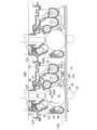
図1は本実施形態に係る画像形成装置1の概略構成の一例を示す断面模式図である。
画像形成装置1は、画像形成部10と、画像形成部10の一端に装着された用紙送り装置20と、画像形成部10の他の一端に設けられ、印刷された用紙が排紙される排紙部30と、上位機器から送信された印刷情報から画像情報を生成する画像処理部40(不図示)と、を備えて構成されている。
(1) Overall Configuration and Operation of Image Forming Apparatus (1.1) Overall Configuration of Image Forming Apparatus FIG. 1 is a schematic cross-sectional view showing an example of a schematic configuration of an image forming apparatus 1 according to this embodiment.
The image forming apparatus 1 is configured to include an
画像形成部10は、システム制御装置11(不図示)、露光装置12、感光体ユニット13、現像装置14、転写装置15、用紙搬送装置16a、16b、16c、定着装置17、駆動装置18(不図示)、を備えて構成され、画像処理部40から受け取った画像情報を用紙送り装置20から送り込まれた用紙上にトナー画像として形成する。
The
用紙送り装置20は、画像形成部10に対する用紙供給を行う。すなわち、種類(例えば、材質や厚さ、用紙サイズ、紙目)の異なる用紙を収容する複数の用紙積載部を備えており、これら複数の用紙積載部のいずれか一つから繰り出した用紙を画像形成部10に対して供給するように構成されている。
The
排紙部30は、画像形成部10にて画像出力が行われた用紙の排出を行う。そのために、排紙部30は、画像出力後の用紙が排出される排紙収容部を備えている。なお、排紙部30は、画像形成部10から出力される用紙束に対して、裁断やステープル(針綴じ)等の後処理を行う機能を有したものであってもよい。
The
(1.2)画像形成部の構成及び動作
このような構成の画像形成装置1では、画像形成のタイミングに合わせて用紙送り装置20のうち、印刷ジョブで印刷の1枚毎に指定された用紙積載部から繰り出された用紙が画像形成部10へ送り込まれる。
(1.2) Configuration and operation of the image forming unit In the image forming device 1 configured as above, paper is fed from the paper stacking section of the
第1ユニットの一例としての感光体ユニット13は、露光装置12の下方に、それぞれが並列して設けられ、回転駆動する像保持体としての感光体ドラム31を備えている。感光体ドラム31の回転方向に沿って、帯電ロール32、露光装置12、現像装置14、一次転写ロール52、クリーニングブレード34が配置されている。
The
第2ユニットの一例としての現像装置14は、内部に現像剤が収容される現像ハウジング41を有する。現像ハウジング41内には、感光体ドラム31に対向して配置された現像ロール42が配設されている。
それぞれの現像装置14は、現像ハウジング41に収容される現像剤を除いて略同様に構成され、それぞれがイエロー(Y)、マゼンタ(M)、シアン(C)、黒(K)のトナー像を形成する。
The developing
Each developing
現像装置14の上方には、現像剤(キャリアを含むトナー)を収容する交換可能なトナーカートリッジTと、それぞれのトナーカートリッジTから現像装置14に現像剤を供給する現像剤供給装置60が配置されている。本実施形態においては、イエロー(Y)、マゼンタ(M)、シアン(C)のトナーカートリッジTy、Tm、Tcと、黒(K)の2つのトナーカートリッジTkが着脱可能となっている。
Above the developing
回転する感光体ドラム31の表面は、帯電ロール32により帯電され、露光装置12から出射する潜像形成光により静電潜像が形成される。感光体ドラム31上に形成された静電潜像は現像ロール42によりトナー像として現像される。
The surface of the
転写装置15は、各感光体ユニット13の感光体ドラム31にて形成された各色トナー像が多重転写される中間転写ベルト51、各感光体ユニット13にて形成された各色トナー像を中間転写ベルト51に順次転写(一次転写)する一次転写ロール52、中間転写ベルト51上に重畳して転写された各色トナー像を記録媒体である用紙に一括転写(二次転写)する二次転写ロール53を備えて構成されている。
The
各感光体ユニット13の感光体ドラム31に形成された各色トナー像は、システム制御装置11により制御される電源装置等(不図示)から所定の転写電圧が印加された一次転写ロール52により中間転写ベルト51上に順次静電転写(一次転写)され、各色トナーが重畳された重畳トナー像が形成される。
The color toner images formed on the
中間転写ベルト51上の重畳トナー像は、中間転写ベルト51の移動に伴って、バックアップロール65に中間転写ベルト51を介して二次転写ロール53が圧接配置された二次転写部TRに搬送される。
重畳トナー像が二次転写部TRに搬送されると、そのタイミングに合わせて用紙送り装置20から用紙が二次転写部TRに供給される。そして、中間転写ベルト51を介して二次転写ロール53と対向するバックアップロール65には、システム制御装置11により制御される電源装置から予め定められた二次転写電圧が印加され、用紙に中間転写ベルト51上の多重トナー像が一括転写される。
The superimposed toner image on the
When the superimposed toner image is transported to the secondary transfer portion TR, a sheet is supplied to the secondary transfer portion TR from the
感光体ドラム31表面の残留トナーは、クリーニングブレード34により除去され、廃トナー収容部(不図示)に回収される。感光体ドラム31の表面は、帯電ロール32により再帯電される。
Residual toner on the surface of the
定着装置17は一方向へ回転する無端状の定着ベルト17aと、定着ベルト17aの周面に接し、一方向へ回転する加圧ロール17bとを有し、定着ベルト17aと加圧ロール17bの圧接領域によってニップ部(定着領域)が形成される。
転写装置15においてトナー像が転写された用紙は、トナー像が未定着の状態で用紙搬送装置16aを経由して定着装置17に搬送される。定着装置17に搬送された用紙は、一対の定着ベルト17aと加圧ロール17bにより、圧着と加熱の作用でトナー像が定着される。
The fixing
The paper onto which the toner image has been transferred in the
定着の終了した用紙は、用紙搬送装置16bを経由して排紙部30に送り込まれる。
尚、用紙の両面に画像出力を行う場合には、用紙搬送装置16cにより当該用紙の表裏が反転され、再び画像形成部10における二次転写部TRへ送り込まれる。そして、トナー像の転写および転写像の定着が行われた後に、排紙部30に送り込まれることになる。排紙部30へ送り込まれた用紙は、必要に応じて裁断やステープル(針綴じ)等の後処理を経た後に、排紙収容部へ排出される。
The paper on which the fixing has been completed is sent to the
When images are to be output on both sides of the paper, the paper is turned over by the
(2)画像形成装置のユニット構成と装着操作
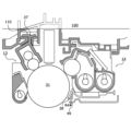
図2は画像形成装置1におけるユニット構成を説明するための断面模式図、図3(a)は装置筐体100の第1ガイド110、第2ガイド120、121及び台座130の配置を示す平面模式図、(b)は縦断面模式図である。以下、図面を参照しながら、感光体ユニット13、現像装置14及び装置筐体100の構成と装着操作について説明する。
(2) Unit Configuration and Installation Operation of Image Forming Apparatus Fig. 2 is a schematic cross-sectional view for explaining the unit configuration in the image forming apparatus 1, Fig. 3(a) is a schematic plan view showing the arrangement of the
図2に示すように、画像形成装置1は、複数の感光体ユニット13及び現像装置14が、装置筐体100内に着脱可能に収容されて配置されている。
As shown in FIG. 2, the image forming device 1 has a plurality of
(2.1)感光体ユニット
感光体ユニット13は、図2に示すように、ユニットハウジング35に感光体ドラム31が回転(図2中 矢印Aで示す)自在に支持され、ユニットハウジング35内には、帯電ロール32、クリーニングロール33、クリーニングブレード34、クリーニングブレード34で除去されたトナーを廃トナー回収容器(不図示)に搬送する搬送オーガ36が配置されている。
(2.1) Photoconductor Unit As shown in FIG. 2, in the
ユニットハウジング35には、後述する装置筐体100に設けられた第1ガイド110に係り合うフック形状の一例としての第1フック37が一体に設けられている。第1フック37は、感光体ユニット13の最も上部となる位置に上方(Z方向)に突出して感光体ユニット13の手前側から奥側に向かって延在して形成され、装置筐体100に設けられた第1のガイド110に吊り下げられた状態で感光体ユニット13の装置筐体100への挿抜を案内する。
The
また、ユニットハウジング35には、感光体ユニット13の下方で、感光体ドラム31と間隙を有して、感光体ユニット13の手前側から奥側に向かって延在する第5ガイド38が設けられている。第5ガイド38は、先に装置筐体100に挿入された現像装置14に案内されて、第1ガイド110で吊り下げられて挿抜される感光体ユニット13の姿勢を安定化させている。
The
(2.2)現像装置
現像装置14は、図2に示すように、現像ハウジング41に現像ロール42が回転自在に支持され、現像ハウジング41内には、撹拌オーガ43A、供給オーガ43Bが配置されている。現像ハウジング41内の撹拌オーガ43A、供給オーガ43Bの周囲には、現像剤が充填されて、カバー部材44で塞がれている。
2, in the developing
現像ロール42は、現像ハウジング41に対して回転可能に支持された円筒状の現像スリーブ42Aと、現像スリーブ42Aの内部空間に設けられ現像ハウジング41に対して固定された円柱状の磁石部材としてのマグネット42Bと、を備えている。
現像スリーブ42Aは、マグネット42Bの磁力によって現像剤が外周面に保持され、現像スリーブ42Aの回転(図2中 矢印Bで示す)により現像剤を感光体ドラム31の静電潜像へ搬送供給するように構成されている。
The developing
The developing
現像ハウジング41には、装置筐体100に設けられた第2ガイド120、121に係り合うフック形状の一例としての第2フック46、47が設けられている。第2フック46は、現像ハウジング41の挿抜方向における奥側に形成され、装置筐体100に設けられた第2ガイド120に吊り下げられた状態で現像装置14の装置筐体100への挿抜を案内する。第2フック47は、現像ハウジング41の挿抜方向における手前側から奥側に向かって延在して形成され、装置筐体100に設けられた第2ガイド121に吊り下げられた状態で現像装置14の装置筐体100への挿抜を案内する。
The developing
現像装置14の下面には、後述する装置筐体100の台座130上に設けられた第3ガイド131と嵌り合って現像装置14の装置筐体100への挿入開始時に現像装置14の左右の動きを規制するガイド溝48が形成されている。また、ガイド溝48の感光体ユニット13に面する先端側には、後から挿入される感光体ユニット13に設けられた第5ガイド38を受けて感光体ユニット13の挿抜を案内する第4ガイド49が設けられている。
A
(2.3)装置筐体
装置筐体100は、画像形成装置1の前面となる手前側に開口101aを有し、装置筐体100に感光体ユニット13及び現像装置14が挿抜可能となっている。
図3に示すように、装置筐体100には、挿抜される感光体ユニット13、現像装置14のそれぞれに対応して、第1ガイド110、第2ガイド120、121が設けられている。
(2.3) Apparatus Housing The
As shown in FIG. 3, the
第1ガイド110は、図3(a)に示すように、装置筐体100の手前側から奥側に向かって(Y方向)延在して設けられている。第1ガイド110は、図3(b)に示すように、受け部111、112が向かい合って、中央部には、溝部113が形成されている。第1ガイド110は、溝部113で手前側から挿入される感光体ユニット13に設けられた第1フック37を受け入れて、受け部111、112で吊り下げて保持する。
As shown in FIG. 3(a), the
第2ガイド120、121は、図3(a)に示すように、装置筐体100の手前側から奥側に向かって(Y方向)延在して設けられている。第2ガイド120は、現像装置14に設けられた第2フック46と係り合って、装置筐体100の手前側から挿入される現像装置14の現像ロール42側を吊り下げて保持する。また、第2ガイド121は、現像装置14に設けられた第2フック47と係り合って、装置筐体100の手前側から挿入される現像装置14の撹拌オーガ43A側を吊り下げて保持する。
本実施形態においては、装置筐体100に着脱可能な感光体ユニット13と現像装置14のうち、先に現像装置14が装着されるようになっており、現像装置14は、装置筐体100に挿抜方向と交差する方向にそれぞれ離間して設けられた第2ガイド120、121に吊り下げられて、水平を保った状態で挿抜される。
3A, the
In this embodiment, of the
図3に示すように、装置筐体100の第1ガイド110及び第2ガイド120、121に対し、感光体ユニット13及び現像装置14の挿抜方向にける手前側には、台座130が設けられている。台座130は、第1ガイド110及び第2ガイド120に対して装置筐体100の前方に平面視で重ならない位置に設けられ、挿入する感光体ユニット13及び現像装置14を重力方向における下方から支えるようになっている。そして、装置筐体100に挿入された感光体ユニット13及び現像装置14とは接触しない高さとなっている(図2 参照)。
3, a
台座130の上面には、第3ガイド131が設けられている。第3ガイド131は、台座130上で、上方に突出し、挿抜方向に延在して形成されている。第3ガイド131は、現像装置14の第2フック46、47の第2ガイド120、121への係り合いに先だって、台座130上に載置された現像装置14のガイド溝48と嵌り合って、現像装置14の左右の動きを規制するようになっている。これにより、現像装置14を装置筐体100に挿入するときの姿勢を安定させることができる。
尚、図3に示すように、台座130の上面に、現像装置14の挿抜方向と交差する方向の両端部に対応して、それぞれガイド132を設け、現像装置14の左右の動きを規制する構成としてもよい。
A
As shown in FIG. 3, guides 132 may be provided on the upper surface of the base 130 at both ends in a direction intersecting the insertion/removal direction of the developing
(2.4)感光体ユニット13及び現像装置14の装着
図4は装置筐体100への現像装置14の装着を説明する斜視図、図5は装置筐体100への感光体ユニット13の装着を説明する斜視図、図6は先に現像装置14が装着された状態での感光体ユニット13の装着を説明する正面断面図である。以下、図面を参照すながら感光体ユニット13及び現像装置14の装着について説明する。
(2.4) Mounting of the
図4に示すように、現像装置14を装置筐体100に装着する場合、まず、台座130上に現像装置14の挿抜方向における奥側を載置して、重力方向における下方から支える。このとき、図3に示す現像装置14のガイド溝48が、台座130上の第3ガイド131に挿抜方向で嵌るように載置する。これにより、重量がある現像装置14を一旦、重量方向における下方から支えて、装置筐体100の前方から現像装置14を長手方向に装着することができる状態になる。
As shown in FIG. 4, when installing the developing
そして、台座130で支えながら、現像装置14を第2ガイド120、121に向かってスライド移動させ、現像装置14の第2フック46を第2ガイド120に(図4中 矢印R1参照)、第2フック47を第2ガイド121に(図4中 矢印R2参照)載せて、奥側に向かって移動させる。これにより、現像装置14は、装置筐体100の第2ガイド120、121に第2フック46、47で吊り下げられた状態で保持され、ユニット交換が容易になる。
Then, while being supported by the
感光体ユニット13を装置筐体100に装着する場合は、図5に示すように、先に現像装置14が装置筐体100に装着された状態で、まず、台座130上に感光体ユニット13の挿抜方向における奥側を載置して、重力方向における下方から支える。
そして、台座130で支えながら、感光体ユニット13を第1ガイド110に向かってスライド移動させ(図5中 矢印R3参照)、感光体ユニット13の第1フック37を第1ガイド110に載せて、奥側に向かって移動させる。このとき、図6に示すように、感光体ユニット13の下方で、先に装着された現像装置14と相対する側に設けられた第5ガイド38が、現像装置14の下面に設けられた第4ガイド49に案内されて、感光体ユニット13の挿入姿勢が安定するように構成されている。すなわち、第1ガイド110に第1フック37で吊り下げられている感光体ユニット13の第1フック37を基点とした回転(図6中 矢印R4参照)が、現像装置14に設けられた第4ガイド49で規制されるようになっている。これにより、感光体ドラム31の傷を防止しながら、ユニット交換が容易になる。
When mounting the
Then, while being supported by the
(2.5)第5ガイドの作用
図7(a)は現像ロール42と感光体ドラム31の回転による空気の流れを説明する図、(b)は第5ガイド38による空気の分流を説明する図である。
図7(a)に示すように、現像ロール42は、現像スリーブ42Aの外周面にマグネット42Bの磁力によって現像剤を保持して回転することで、現像剤を対向して回転する感光体ドラム31の静電潜像へ搬送供給している。そのために、現像ロール42の回転方向下流側には、回転流としての空気の流れ(図中 矢印F参照)が形成されている。この空気には、現像で発生するクラウドトナーが含まれ、クラウドトナーが第5ガイド38の周辺に溜まり、その一部が例えば、感光体ユニット13及び現像装置14の下方で循環移動する中間転写ベルト51上に落下する虞があった。
(2.5) Function of Fifth Guide FIG. 7A is a diagram for explaining the air flow caused by the rotation of the developing
As shown in Fig. 7A, the developing
本実施形態に係る第5ガイド38は、感光体ユニット13の下方で、感光体ドラム31と間隙を有して、感光体ユニット13の手前側から奥側に向かって延在するように形成されている。第5ガイド38は、図7(b)に示すように、断面L字の金属製のプレート38A上に、断面形状が上方(Z方向)に頂点を有する略三角形状のガイド部材38Bが取り付けられている。プレート38Aは、ユニットハウジング35の手前側から奥側に亘って延在して設けられ、ユニットハウジング35を補強するタイバーともなっている。
The
ガイド部材38Bは、合成樹脂で形成され、三角形状は、トナーの安息角を超える傾斜角度の傾斜面で構成されている。なお、トナーの安息角は、現像剤の種類や、温湿度などの使用環境によって変わる。これにより、ガイド部材38Bの表面にクラウドトナーが付着したとしても、その付着したトナーの上に乗ったトナーは滑り落ちることになり、ガイド部材38Bの表面へのトナーの堆積及び落下を抑制することができる。 Guide member 38B is made of synthetic resin, and its triangular shape is made up of inclined surfaces with an inclination angle that exceeds the angle of repose of the toner. The angle of repose of the toner varies depending on the type of developer and the usage environment, such as temperature and humidity. As a result, even if cloud toner adheres to the surface of guide member 38B, the toner on top of the adhered toner slides off, preventing the accumulation and fall of toner on the surface of guide member 38B.
ガイド部材38Bの三角形状は、図7(b)に示すように、感光体ドラム31と対向する面38Baが、感光体ドラム31の曲率に対して所定の間隙Gを有して形成されている。これにより、現像ロール42の回転方向下流側に形成される空気の流れは、ガイド部材38Bの頂点38Bbを基点に、感光体ドラム31側(図中 矢印f1)と現像装置14側(図中 矢印f2)に分流されて、トナークラウドの滞留が抑制される。
As shown in FIG. 7B, the triangular shape of the guide member 38B is formed such that the surface 38Ba facing the
以上、本発明に係る実施形態を詳述したが、本発明は上記実施形態に限定されるものではなく、特許請求の範囲に記載された本発明の要旨の範囲内で種々の変更を行うことが可能である。
例えば、本実施形態ではベルトユニットとして、中間転写ベルトを備えた中間転写方式の画像形成装置1について説明したが、搬送ベルト上に保持された記録媒体を介して感光体ドラムと接触して、感光体ドラム上のトナー像を転写・搬送する直接転写方式の画像形成装置であっても適用することができる。
また、タンデム方式の画像形成装置のみならず、1個の感光体ユニットと現像装置を備えた画像形成装置であっても適用することができる。
Although the embodiment of the present invention has been described in detail above, the present invention is not limited to the above embodiment, and various modifications can be made within the scope of the gist of the present invention described in the claims.
For example, in this embodiment, an intermediate transfer type image forming apparatus 1 equipped with an intermediate transfer belt as a belt unit has been described, but the present invention can also be applied to a direct transfer type image forming apparatus that contacts a photosensitive drum via a recording medium held on a conveying belt and transfers and conveys a toner image on the photosensitive drum.
Furthermore, the present invention can be applied not only to a tandem type image forming apparatus, but also to an image forming apparatus having one photoconductor unit and a developing device.
1・・・画像形成装置
10・・・画像形成部
13・・・感光体ユニット
31・・・感光体ドラム、35・・・ユニットハウジング、37・・・第1フック、38・・・第5ガイド
14・・・現像装置
41・・・現像ハウジング、42・・・現像ロール、46、47・・・第2フック、48・・・ガイド溝、49・・・第4ガイド
20・・・用紙送り装置
30・・・排紙部
100・・・装置筐体、110・・・第1ガイド、120、121・・・第2ガイド、130・・・台座
131・・・第3ガイド
REFERENCE SIGNS LIST 1: image forming apparatus 10: image forming section 13: photoconductor unit 31: photoconductor drum, 35: unit housing, 37: first hook, 38: fifth guide 14: developing device 41: developing housing, 42: developing roll, 46, 47: second hook, 48: guide groove, 49: fourth guide 20: paper feed device 30: paper discharge section 100: device housing, 110: first guide, 120, 121: second guide, 130: base 131: third guide
Claims (11)
前記装置筐体に設けられ、現像剤保持体を有する第2ユニットを挿抜方向に移動可能に吊り下げて保持する第2ガイドと、
前記第1ガイド及び前記第2ガイドに対し、前記挿抜方向における手前側で前記装置筐体から突出しないように前記装置筐体に一体に設けられ、前記装置筐体に挿入途中の前記第1ユニット及び前記第2ユニットを重力方向における下方から支え、前記装置筐体に位置決めされた前記第1ユニット及び前記第2ユニットには接触しない台座と、を備えた、
ことを特徴とする画像形成装置。 a first guide provided in the device housing for suspending and holding a first unit having an image carrier so as to be movable in an insertion/removal direction;
a second guide provided in the device housing for suspending and holding a second unit having a developer holder so as to be movable in an insertion/removal direction;
a base that is integrally provided on the device housing so as not to protrude from the device housing on the front side in the insertion/removal direction with respect to the first guide and the second guide, supports the first unit and the second unit in the middle of being inserted into the device housing from below in the gravity direction, and does not come into contact with the first unit and the second unit positioned in the device housing;
1. An image forming apparatus comprising:
ことを特徴とする請求項1に記載の画像形成装置。 a third guide is provided on the base, the third guide being fitted with the second unit and restricting movement of the first unit in a direction intersecting with an insertion/removal direction;
2. The image forming apparatus according to claim 1,
ことを特徴とする請求項1又は2に記載の画像形成装置。 The first unit has a hook shape that engages with the first guide.
3. The image forming apparatus according to claim 1, wherein the first and second electrodes are arranged in a first direction.
ことを特徴とする請求項1又は2に記載の画像形成装置。 The second unit has a hook shape that engages with the second guide.
3. The image forming apparatus according to claim 1, wherein the first and second electrodes are arranged in a first direction.
ことを特徴とする請求項1ないし4のいずれか1項に記載の画像形成装置。 The second unit has a fourth guide that guides the insertion and removal of the first unit.
5. The image forming apparatus according to claim 1, wherein the image forming apparatus is a multi-color image forming apparatus.
ことを特徴とする請求項5に記載の画像形成装置。 the first unit has a fifth guide that guides insertion and removal of the first unit to the fourth guide;
6. The image forming apparatus according to claim 5,
ことを特徴とする請求項6に記載の画像形成装置。 the fifth guide has a cross-sectional shape of a substantially triangular shape having an apex at an upper position, and is shaped to divide air flows accompanying rotation of the image carrier and the developer carrier;
7. The image forming apparatus according to claim 6,
ことを特徴とする請求項7に記載の画像形成装置。 the triangular shape is composed of inclined surfaces having an inclination angle exceeding the angle of repose of the toner;
8. The image forming apparatus according to claim 7,
ことを特徴とする請求項7又は8に記載の画像形成装置。 the triangular shape has an inclined surface having a predetermined gap with respect to the curvature of the image carrier as one side;
9. The image forming apparatus according to claim 7, wherein the image forming apparatus is a multi-color image forming apparatus.
ことを特徴とする請求項6ないし9のいずれか1項に記載の画像形成装置。 The fifth guide is a tie bar connecting both ends of the first unit in an insertion/removal direction.
10. The image forming apparatus according to claim 6, wherein the first and second electrodes are arranged in a first direction.
前記第1ユニットは、ドラムユニットである、
ことを特徴とする請求項1ないし10のいずれか1項に記載の画像形成装置。 the image carrier is a photoconductor drum,
The first unit is a drum unit.
11. The image forming apparatus according to claim 1,
Priority Applications (4)
| Application Number | Priority Date | Filing Date | Title |
|---|---|---|---|
| JP2021054459A JP7635598B2 (en) | 2021-03-29 | 2021-03-29 | Image forming device |
| US17/399,258 US11609535B2 (en) | 2021-03-29 | 2021-08-11 | Image forming apparatus having guide members for detachably inserting cartridges |
| EP21193389.0A EP4068004B1 (en) | 2021-03-29 | 2021-08-26 | Image forming apparatus |
| CN202111039085.0A CN115128918A (en) | 2021-03-29 | 2021-09-06 | Image forming apparatus with a toner supply device |
Applications Claiming Priority (1)
| Application Number | Priority Date | Filing Date | Title |
|---|---|---|---|
| JP2021054459A JP7635598B2 (en) | 2021-03-29 | 2021-03-29 | Image forming device |
Publications (2)
| Publication Number | Publication Date |
|---|---|
| JP2022151906A JP2022151906A (en) | 2022-10-12 |
| JP7635598B2 true JP7635598B2 (en) | 2025-02-26 |
Family
ID=77520510
Family Applications (1)
| Application Number | Title | Priority Date | Filing Date |
|---|---|---|---|
| JP2021054459A Active JP7635598B2 (en) | 2021-03-29 | 2021-03-29 | Image forming device |
Country Status (4)
| Country | Link |
|---|---|
| US (1) | US11609535B2 (en) |
| EP (1) | EP4068004B1 (en) |
| JP (1) | JP7635598B2 (en) |
| CN (1) | CN115128918A (en) |
Citations (6)
| Publication number | Priority date | Publication date | Assignee | Title |
|---|---|---|---|---|
| JP2003036015A (en) | 2001-07-25 | 2003-02-07 | Casio Electronics Co Ltd | Image forming device |
| JP2004101961A (en) | 2002-09-10 | 2004-04-02 | Ricoh Co Ltd | Image forming device |
| JP2011253159A (en) | 2010-06-04 | 2011-12-15 | Canon Inc | Electrophotographic image forming apparatus |
| JP2017054082A (en) | 2015-09-11 | 2017-03-16 | 富士ゼロックス株式会社 | Image forming apparatus |
| JP2017167235A (en) | 2016-03-15 | 2017-09-21 | 富士ゼロックス株式会社 | Image formation device |
| JP2020166090A (en) | 2019-03-29 | 2020-10-08 | ブラザー工業株式会社 | Image forming device |
Family Cites Families (11)
| Publication number | Priority date | Publication date | Assignee | Title |
|---|---|---|---|---|
| JPS536577B1 (en) | 1971-06-29 | 1978-03-09 | ||
| JPS58194047A (en) * | 1982-05-10 | 1983-11-11 | Fuji Xerox Co Ltd | Armor and guide mechanism of copying machine |
| JP3507227B2 (en) | 1995-10-26 | 2004-03-15 | キヤノン株式会社 | Process cartridge and electrophotographic image forming apparatus |
| JP3536577B2 (en) | 1997-03-28 | 2004-06-14 | ミノルタ株式会社 | Cartridge and image forming apparatus using the same |
| JP5528092B2 (en) * | 2009-12-22 | 2014-06-25 | キヤノン株式会社 | Process cartridge and image forming apparatus |
| JP5100787B2 (en) * | 2010-05-11 | 2012-12-19 | シャープ株式会社 | Molding method of resin frame |
| US8755718B2 (en) | 2010-06-04 | 2014-06-17 | Canon Kabushiki Kaisha | Image forming apparatus |
| JP5826211B2 (en) * | 2013-05-23 | 2015-12-02 | 京セラドキュメントソリューションズ株式会社 | Image forming apparatus |
| JP2017191163A (en) * | 2016-04-12 | 2017-10-19 | キヤノン株式会社 | Process cartridge and image forming apparatus |
| JP7218167B2 (en) | 2018-12-13 | 2023-02-06 | シャープ株式会社 | image forming device |
| JP7255218B2 (en) | 2019-02-13 | 2023-04-11 | 富士フイルムビジネスイノベーション株式会社 | Image forming unit and image forming apparatus |
-
2021
- 2021-03-29 JP JP2021054459A patent/JP7635598B2/en active Active
- 2021-08-11 US US17/399,258 patent/US11609535B2/en active Active
- 2021-08-26 EP EP21193389.0A patent/EP4068004B1/en active Active
- 2021-09-06 CN CN202111039085.0A patent/CN115128918A/en active Pending
Patent Citations (6)
| Publication number | Priority date | Publication date | Assignee | Title |
|---|---|---|---|---|
| JP2003036015A (en) | 2001-07-25 | 2003-02-07 | Casio Electronics Co Ltd | Image forming device |
| JP2004101961A (en) | 2002-09-10 | 2004-04-02 | Ricoh Co Ltd | Image forming device |
| JP2011253159A (en) | 2010-06-04 | 2011-12-15 | Canon Inc | Electrophotographic image forming apparatus |
| JP2017054082A (en) | 2015-09-11 | 2017-03-16 | 富士ゼロックス株式会社 | Image forming apparatus |
| JP2017167235A (en) | 2016-03-15 | 2017-09-21 | 富士ゼロックス株式会社 | Image formation device |
| JP2020166090A (en) | 2019-03-29 | 2020-10-08 | ブラザー工業株式会社 | Image forming device |
Also Published As
| Publication number | Publication date |
|---|---|
| CN115128918A (en) | 2022-09-30 |
| US11609535B2 (en) | 2023-03-21 |
| JP2022151906A (en) | 2022-10-12 |
| EP4068004B1 (en) | 2023-05-24 |
| EP4068004A1 (en) | 2022-10-05 |
| US20220308523A1 (en) | 2022-09-29 |
Similar Documents
| Publication | Publication Date | Title |
|---|---|---|
| US9354543B2 (en) | Developing device and image forming device having the same | |
| US7062207B2 (en) | Powder transport apparatus and image forming apparatus that can stabilize replenishment of powder | |
| US20010022905A1 (en) | Image forming apparatus having protective layer on the surface of image bearing member to avoid adhesion of film of additives to image bearing member | |
| JP5152347B2 (en) | Developing unit, process device, and image forming apparatus | |
| EP3226075B1 (en) | Toner container | |
| EP2595002B1 (en) | Developing device and electrophotographic image forming apparatus including the same | |
| JP4363465B2 (en) | Developing unit, process device, and image forming apparatus | |
| JP7635598B2 (en) | Image forming device | |
| US9182699B2 (en) | Developing device, process cartridge, and image forming apparatus | |
| EP2942671B1 (en) | Developing unit, image forming unit, and image forming apparatus | |
| US7539439B2 (en) | Image carrier toner unit and image forming apparatus | |
| JP6525633B2 (en) | Developing device, process cartridge and image forming apparatus | |
| JP4319449B2 (en) | Image forming apparatus | |
| JP5343632B2 (en) | Developing device and image forming apparatus using the same | |
| JP5593272B2 (en) | Developing device, image forming unit, and image forming apparatus | |
| JP2006250972A (en) | Development device and image forming apparatus using the same | |
| JP4622371B2 (en) | Image forming apparatus | |
| JP2014178517A (en) | Image forming apparatus | |
| US20180364633A1 (en) | Image forming apparatus | |
| JP2008268283A (en) | Developing device, process cartridge, and image forming apparatus | |
| JPH07219328A (en) | Electrophotographic device | |
| JPH09281874A (en) | Image forming device |
Legal Events
| Date | Code | Title | Description |
|---|---|---|---|
| A621 | Written request for application examination |
Free format text: JAPANESE INTERMEDIATE CODE: A621 Effective date: 20240226 |
|
| A977 | Report on retrieval |
Free format text: JAPANESE INTERMEDIATE CODE: A971007 Effective date: 20240808 |
|
| A131 | Notification of reasons for refusal |
Free format text: JAPANESE INTERMEDIATE CODE: A131 Effective date: 20240820 |
|
| A521 | Request for written amendment filed |
Free format text: JAPANESE INTERMEDIATE CODE: A523 Effective date: 20241017 |
|
| TRDD | Decision of grant or rejection written | ||
| A01 | Written decision to grant a patent or to grant a registration (utility model) |
Free format text: JAPANESE INTERMEDIATE CODE: A01 Effective date: 20250114 |
|
| A61 | First payment of annual fees (during grant procedure) |
Free format text: JAPANESE INTERMEDIATE CODE: A61 Effective date: 20250127 |
|
| R150 | Certificate of patent or registration of utility model |
Ref document number: 7635598 Country of ref document: JP Free format text: JAPANESE INTERMEDIATE CODE: R150 |