JP7635488B2 - Seat belt retractor and seat belt device - Google Patents

Seat belt retractor and seat belt device Download PDF

Info

Publication number
JP7635488B2
JP7635488B2 JP2021019032A JP2021019032A JP7635488B2 JP 7635488 B2 JP7635488 B2 JP 7635488B2 JP 2021019032 A JP2021019032 A JP 2021019032A JP 2021019032 A JP2021019032 A JP 2021019032A JP 7635488 B2 JP7635488 B2 JP 7635488B2
Authority
JP
Japan
Prior art keywords
seat belt
rotating body
rotation
stopper
connecting portion
Prior art date
Legal status (The legal status is an assumption and is not a legal conclusion. Google has not performed a legal analysis and makes no representation as to the accuracy of the status listed.)
Active
Application number
JP2021019032A
Other languages
Japanese (ja)
Other versions
JP2022121998A (en
Inventor
篤 三原
隆章 木村
磊 陳
晋作 大塚
Current Assignee (The listed assignees may be inaccurate. Google has not performed a legal analysis and makes no representation or warranty as to the accuracy of the list.)
Joyson Safety Systems Japan GK
Original Assignee
Joyson Safety Systems Japan GK
Priority date (The priority date is an assumption and is not a legal conclusion. Google has not performed a legal analysis and makes no representation as to the accuracy of the date listed.)
Filing date
Publication date
Application filed by Joyson Safety Systems Japan GK filed Critical Joyson Safety Systems Japan GK
Priority to JP2021019032A priority Critical patent/JP7635488B2/en
Publication of JP2022121998A publication Critical patent/JP2022121998A/en
Application granted granted Critical
Publication of JP7635488B2 publication Critical patent/JP7635488B2/en
Active legal-status Critical Current
Anticipated expiration legal-status Critical

Links

Images

Landscapes

  • Automotive Seat Belt Assembly (AREA)

Description

本開示は、シートベルトリトラクタ及びシートベルト装置に関する。 This disclosure relates to a seat belt retractor and a seat belt device.

自動車等の車両に装備されたシートベルト装置は、緊急時(例えば、シートベルト装着状態で衝突時等の車両に大きな車両減速度が作用した時など)に、シートベルトで乗員を拘束することにより乗員のシートからの飛び出しを阻止する。 Seat belt devices installed in vehicles such as automobiles prevent occupants from being thrown out of their seats by restraining them with the seat belt in an emergency (for example, when the vehicle experiences a large deceleration during a collision while the seat belt is fastened).

このようなシートベルト装置には、シートベルトを引き出し可能に巻き取るシートベルトリトラクタが備えられている。このシートベルトリトラクタでは、シートベルトは、非装着時にはスプールに巻き取られているが、装着時には引き出されて乗員に装着される。そして、前述のような緊急時にシートベルトリトラクタのロック手段が作動してスプールのベルト引き出し方向の回転を阻止することにより、シートベルトの引き出しが阻止されるので、乗員は緊急時にシートベルトにより拘束される。 Such seat belt devices are equipped with a seat belt retractor that winds up the seat belt so that it can be withdrawn. In this seat belt retractor, the seat belt is wound around a spool when not worn, but is withdrawn and worn by the occupant when worn. In the event of an emergency such as the one described above, the locking means of the seat belt retractor is activated to prevent the spool from rotating in the belt withdrawal direction, thereby preventing the seat belt from being withdrawn, so that the occupant is restrained by the seat belt in the event of an emergency.

車両衝突等の緊急時に乗員がシートベルトにより拘束されるとき、大きな車両減速度が生じるため、乗員が大きな慣性により前方へ移動しようとする。このため、シートベルトには大きな荷重が加えられるとともに、乗員はこのシートベルトから大きな力を受けるようになる。乗員に対してこの力は特に問題ではないが、できれば制限される方が望ましい。 When an occupant is restrained by a seat belt in an emergency such as a vehicle collision, a large vehicle deceleration occurs, and the occupant tries to move forward due to large inertia. This places a large load on the seat belt, and the occupant receives a large force from the seat belt. This force is not particularly problematic for the occupant, but it is desirable to limit it if possible.

そこで、シートベルト装着状態での緊急時に、シートベルトに作用する荷重を制限して乗員のエネルギーを吸収緩和するエネルギー吸収機構(以下、EA機構ともいう)を備えるシートベルトリトラクタの開発が進んでいる。そのようなシートベルトリトラクタの一つとして、トーションバーのねじれにより発生する力を利用する機械的EA機構と、モータによる力を利用する電気式EA機構とを備えるリトラクタが存在する(例えば、特許文献1参照)。 Therefore, development is underway for seat belt retractors equipped with an energy absorption mechanism (hereinafter also referred to as an EA mechanism) that limits the load acting on the seat belt in the event of an emergency while the seat belt is fastened, thereby absorbing and mitigating the energy of the occupant. One such seat belt retractor is a retractor equipped with a mechanical EA mechanism that utilizes the force generated by the twisting of a torsion bar, and an electric EA mechanism that utilizes the force generated by a motor (see, for example, Patent Document 1).

特開2001-270423号公報JP 2001-270423 A 特開2020-172192号公報JP 2020-172192 A

近年、緊急時にシートベルトの引き出しを制限する荷重(EA荷重)を、よりフレキシブルに調整することが求められている。 In recent years, there has been a demand for more flexible adjustment of the load that limits seat belt withdrawal in an emergency (EA load).

本開示は、EA荷重をフレキシブルに調整可能なシートベルトリトラクタ及びシートベルト装置を提供する。 This disclosure provides a seat belt retractor and seat belt device that allows for flexible adjustment of the EA load.

本開示は、
シートベルトを巻き取るスプールと、
前記スプールと共に回転可能な回転体と、
前記回転体に相対回転不能に連結する第1連結部と、前記第1連結部から離れた箇所に設けられる第2連結部とを有する第1のエネルギー吸収機構と、
前記第2連結部に相対回転不能に連結されるロッキングベースを有するロック機構と、
前記回転体を回転させるモータと、
前記スプールに相対回転不能に連結する第3連結部と、前記回転体に相対回転不能に連結する第4連結部とを有し、前記第3連結部と前記第4連結部は互いに離れた箇所に設けられた第2のエネルギー吸収機構と、
トッパーと、を備え、
前記第1のエネルギー吸収機構は、前記ロッキングベースの回転がロックされた状態で、前記スプール及び前記回転体が前記シートベルトの引き出し方向に回転すると、変形し、
前記第2のエネルギー吸収機構は、前記回転体の回転が前記ストッパーによりロックされた状態で、前記スプールが前記引き出し方向に回転すると、変形する、シートベルトリトラクタを提供する。また、本開示は、当該シートベルトリトラクタを備えるシートベルト装置を提供する。
The present disclosure relates to
A spool for winding the seat belt;
A rotor that can rotate together with the spool;
a first energy absorbing mechanism including a first connecting portion connected to the rotating body so as not to rotate relative to the rotating body and a second connecting portion provided at a location spaced apart from the first connecting portion ;
a lock mechanism having a locking base connected to the second connecting portion so as not to rotate relative to the second connecting portion ;
A motor that rotates the rotating body;
a second energy absorbing mechanism including a third connecting portion connected to the spool so as not to rotate relative to the rotor and a fourth connecting portion connected to the rotor so as not to rotate relative to the rotor, the third connecting portion and the fourth connecting portion being provided at positions spaced apart from each other ;
A stopper ,
the first energy absorbing mechanism is deformed when the spool and the rotating body rotate in the seat belt withdrawing direction with the rotation of the locking base locked,
The present disclosure provides a seat belt retractor, in which the second energy absorption mechanism deforms when the spool rotates in the unwinding direction with the rotation of the rotating body locked by the stopper . The present disclosure also provides a seat belt device including the seat belt retractor.

本開示の技術によれば、緊急時にシートベルトに作用する荷重をフレキシブルに調整可能なシートベルトリトラクタ及びシートベルト装置を提供できる。 The technology disclosed herein can provide a seat belt retractor and seat belt device that can flexibly adjust the load acting on the seat belt in an emergency.

一実施形態におけるシートベルト装置の構成を例示する図である。1 is a diagram illustrating an example of a configuration of a seat belt device according to an embodiment; 一実施形態におけるシートベルトリトラクタの構成を例示するブロック図である。1 is a block diagram illustrating a configuration of a seat belt retractor according to an embodiment; スプールのストロークに対するEA荷重の変化を例示する図である。FIG. 13 is a diagram illustrating an example of a change in EA load with respect to a spool stroke. 第1の実施形態におけるシートベルトリトラクタの正面図である。1 is a front view of a seat belt retractor according to a first embodiment. 第1の実施形態におけるシートベルトリトラクタの右側面図である。FIG. 2 is a right side view of the seat belt retractor according to the first embodiment. 第1の実施形態におけるシートベルトリトラクタの左側面図である。FIG. 2 is a left side view of the seat belt retractor according to the first embodiment. 第1の実施形態におけるシートベルトリトラクタの切断面を矢視A-A(図6参照)で示す図である。7 is a cross-sectional view of the seat belt retractor according to the first embodiment taken along line AA (see FIG. 6). FIG. 第1の実施形態におけるシートベルトリトラクタの分解斜視図である。1 is an exploded perspective view of a seat belt retractor according to a first embodiment; シートベルトリトラクタの内部構造の一部の正面図である。FIG. 2 is a front view of a portion of the internal structure of the seat belt retractor. ストッパーの作動前の状態を矢視B-B(図9参照)で示す断面図である。10 is a cross-sectional view taken along line BB (see FIG. 9) showing a state before the stopper is actuated. ストッパーの作動後の状態を矢視B-B(図9参照)で示す断面図である。10 is a cross-sectional view taken along line BB (see FIG. 9) showing the state after the stopper has been actuated.

以下、本開示に係る実施形態を、図面を参照して説明する。 Embodiments of the present disclosure are described below with reference to the drawings.

図1は、本開示に係る一実施形態におけるシートベルト装置の構成を例示する図である。図1に示すシートベルト装置101は、車両に搭載されたシートベルト装置の一例である。シートベルト装置101は、例えば、シートベルト104と、リトラクタ103と、ショルダーアンカー106と、タング107と、バックル108とを備える。 FIG. 1 is a diagram illustrating an example of a seat belt device in one embodiment of the present disclosure. The seat belt device 101 shown in FIG. 1 is an example of a seat belt device installed in a vehicle. The seat belt device 101 includes, for example, a seat belt 104, a retractor 103, a shoulder anchor 106, a tongue 107, and a buckle 108.

シートベルト104は、車両のシート102に座る乗員111を拘束するシートベルトの一例であり、リトラクタ103に引き出し可能に巻き取られる帯状部材である。シートベルトは、ウェビングとも称される。シートベルト104の先端のベルトアンカー105は、シート102又はシート102の近傍の車体に固定される。 The seat belt 104 is an example of a seat belt that restrains an occupant 111 seated in a vehicle seat 102, and is a belt-shaped member that is wound up and can be withdrawn by a retractor 103. The seat belt is also called a webbing. A belt anchor 105 at the tip of the seat belt 104 is fixed to the seat 102 or to the vehicle body near the seat 102.

リトラクタ103は、シートベルト104の巻き取り又は引き出しを可能にするシートベルト巻き取り装置の一例である。リトラクタ103は、車両衝突時等の所定値以上の加減速度または車両角度が検知されると、シートベルト104がリトラクタ103から引き出されることを制限する。リトラクタ103は、シート102又はシート102の近傍の車体に固定される。リトラクタ103は、シートベルトリトラクタの一例である。 The retractor 103 is an example of a seat belt retracting device that allows the seat belt 104 to be retracted or pulled out. When acceleration/deceleration or vehicle angle equal to or greater than a predetermined value is detected during a vehicle collision, the retractor 103 restricts the seat belt 104 from being pulled out from the retractor 103. The retractor 103 is fixed to the seat 102 or to the vehicle body in the vicinity of the seat 102. The retractor 103 is an example of a seat belt retractor.

リトラクタ103は、モータ103aの動力によりシートベルト104をスプールに巻き取る機能を備える。リトラクタ103は、例えば、車両衝突前に、ミリ波レーダー等のセンサからの信号に基づいてモータ103aを作動してシートベルト104をスプールに巻き取り、シートベルト104にプリテンションを与えてシートベルト104による乗員拘束を迅速に行う。また、リトラクタ103は、例えば、タング107とバックル108との連結が解除された時にモータ103aを作動してシートベルト104をスプールで巻き取る。リトラクタ103は、例えば、モータ103aを作動してシートベルト104の張力をドライビングシチュエーション(車両の状態)に応じて調整することで、シートベルト104による乗員の拘束性やシートベルト104の装着時の快適性をそれぞれ向上させる。 The retractor 103 has a function of winding the seat belt 104 onto a spool using the power of the motor 103a. For example, before a vehicle collision, the retractor 103 operates the motor 103a based on a signal from a sensor such as a millimeter wave radar to wind the seat belt 104 onto the spool, and pretensions the seat belt 104 to quickly restrain the occupant with the seat belt 104. In addition, the retractor 103 operates the motor 103a to wind the seat belt 104 onto the spool when the tongue 107 and the buckle 108 are released from connection. The retractor 103 operates the motor 103a to adjust the tension of the seat belt 104 according to the driving situation (state of the vehicle), thereby improving the restraint of the occupant by the seat belt 104 and the comfort when wearing the seat belt 104.

車両の状態とは、例えば、シートベルト104の引き出しの有無、乗員111の有無、車両の走行速度、車両の加速度、ステアリング操作、アクセル操作、ブレーキ操作、バックル108の操作、ドア操作、乗員が操作可能な車載の選択スイッチの操作入力などを表す状態をいう。 The state of the vehicle refers to, for example, a state that indicates whether the seat belt 104 is pulled out, whether there is an occupant 111, the vehicle's traveling speed, the vehicle's acceleration, steering operation, accelerator operation, brake operation, buckle 108 operation, door operation, and the operation input of an on-board selection switch that can be operated by an occupant.

ショルダーアンカー106は、シートベルト104が挿通するベルト挿通具の一例であり、リトラクタ103から引き出されたシートベルト104を乗員111の肩部の方へガイドする部材である。ショルダーアンカー106は、シート102又はシート102の近傍の車体に固定される。 The shoulder anchor 106 is an example of a belt insertion tool through which the seat belt 104 is inserted, and is a member that guides the seat belt 104, which is pulled out from the retractor 103, toward the shoulder of the occupant 111. The shoulder anchor 106 is fixed to the seat 102 or to the vehicle body in the vicinity of the seat 102.

タング107は、シートベルト104が挿通するベルト挿通具の一例であり、ショルダーアンカー106によりガイドされたシートベルト104にスライド可能に取り付けられた部品である。 The tongue 107 is an example of a belt insertion device through which the seat belt 104 passes, and is a part that is slidably attached to the seat belt 104 guided by the shoulder anchor 106.

バックル108は、シートベルト104に取り付けられるタング107の平面状の係止部が挿抜される部品であり、タング107が着脱可能に連結される。バックル108は、例えば、シート102又はシート102の近傍の車体に固定される。 The buckle 108 is a part into which the flat locking portion of the tongue 107 attached to the seat belt 104 is inserted and removed, and the tongue 107 is removably connected. The buckle 108 is fixed, for example, to the seat 102 or to a vehicle body in the vicinity of the seat 102.

タング107がバックル108に連結された状態で、ショルダーアンカー106とタング107との間のシートベルト104の部分が、乗員111の胸部及び肩部を拘束するショルダーベルト部109である。タング107がバックル108に連結された状態で、ベルトアンカー105とタング107との間のシートベルト104の部分が、乗員111の腰部を拘束するラップベルト部110である。 When the tongue 107 is connected to the buckle 108, the portion of the seat belt 104 between the shoulder anchor 106 and the tongue 107 is the shoulder belt portion 109 that restrains the chest and shoulders of the occupant 111. When the tongue 107 is connected to the buckle 108, the portion of the seat belt 104 between the belt anchor 105 and the tongue 107 is the lap belt portion 110 that restrains the waist of the occupant 111.

図2は、本開示に係る一実施形態におけるシートベルトリトラクタの構成を例示するブロック図である。図2に示すリトラクタ1及びモータ12は、それぞれ、図1に示すリトラクタ103及びモータ103aに対応する。リトラクタ1は、例えば、スプール4、回転体52、第1のEA機構53、ロック機構6、動力伝達機構21、第2のEA機構54及びストッパー57を備えるシートベルトリトラクタである。 Figure 2 is a block diagram illustrating the configuration of a seat belt retractor in one embodiment of the present disclosure. The retractor 1 and motor 12 shown in Figure 2 correspond to the retractor 103 and motor 103a shown in Figure 1, respectively. The retractor 1 is a seat belt retractor including, for example, a spool 4, a rotating body 52, a first EA mechanism 53, a locking mechanism 6, a power transmission mechanism 21, a second EA mechanism 54, and a stopper 57.

スプール4は、不図示のフレームに回転可能に支持され、シートベルト104を引き出し可能に巻き取る部材である。 The spool 4 is a member that is rotatably supported on a frame (not shown) and winds up the seat belt 104 so that it can be withdrawn.

回転体52は、スプール4と共に回転可能な部材であり、ストッパー57によりロックされるまでスプール4と共に回転する。 The rotating body 52 is a member that can rotate together with the spool 4, and rotates together with the spool 4 until it is locked by the stopper 57.

ロック機構6は、非作動時にスプール4の回転を許容し、作動時にシートベルト104の引き出し方向へのスプール4の回転を阻止する。ロック機構6は、作動時に第1のEA機構53をロックすることによりシートベルト104の引き出し方向へのスプール4の回転を阻止する。 The locking mechanism 6 allows the spool 4 to rotate when not activated, and prevents the spool 4 from rotating in the direction in which the seat belt 104 is withdrawn when activated. The locking mechanism 6 prevents the spool 4 from rotating in the direction in which the seat belt 104 is withdrawn by locking the first EA mechanism 53 when activated.

第1のEA機構53は、シートベルト104の引き出し方向へのスプール4の回転とロック機構6による回転阻止とにより変形する。第1のEA機構53は、シートベルトに作用する荷重を制限して乗員のエネルギーを吸収緩和する第1のエネルギー吸収機構の一例である。第1のEA機構53は、回転体52に相対回転不能に連結する。第1のEA機構53は、ロック機構6によりロックされた状態で、スプール4及び回転体52がシートベルトの引き出し方向に回転すると、変形する。 The first EA mechanism 53 is deformed by the rotation of the spool 4 in the direction in which the seat belt 104 is withdrawn and by the prevention of rotation by the locking mechanism 6. The first EA mechanism 53 is an example of a first energy absorption mechanism that limits the load acting on the seat belt to absorb and mitigate the energy of the occupant. The first EA mechanism 53 is connected to the rotating body 52 so that it cannot rotate relative to the rotating body 52. The first EA mechanism 53 is deformed when the spool 4 and the rotating body 52 rotate in the direction in which the seat belt is withdrawn while locked by the locking mechanism 6.

動力伝達機構21は、例えば、回転体52を回転させるモータ12を有する。動力伝達機構21は、第1のEA機構53の変形により発生する第1の荷重(以下、ベース荷重BNとも称する)に、モータ12の出力により発生する第2の荷重(以下、アシスト荷重ANとも称する)を付加する。モータ12の出力軸の回転を減速して伝達する減速機構51の個数は、一つでも複数でもよい。図2には、一つの減速機構51が示されている。回転体52は、減速機構を備えてもよい。ベース荷重BN及びアシスト荷重ANは、緊急時にシートベルト104の引き出しを制限する荷重(EA荷重)に寄与する。リトラクタ1は、緊急時に、シートベルト104の引き出しをEA荷重で制限することで、シートベルト104に作用する荷重を緩和する。 The power transmission mechanism 21 has, for example, a motor 12 that rotates a rotating body 52. The power transmission mechanism 21 adds a second load (hereinafter also referred to as an assist load AN) generated by the output of the motor 12 to a first load (hereinafter also referred to as a base load BN) generated by the deformation of the first EA mechanism 53. The number of reduction mechanisms 51 that reduce the rotation of the output shaft of the motor 12 and transmit it may be one or more. One reduction mechanism 51 is shown in FIG. 2. The rotating body 52 may be equipped with a reduction mechanism. The base load BN and the assist load AN contribute to a load (EA load) that limits the withdrawal of the seat belt 104 in an emergency. The retractor 1 reduces the load acting on the seat belt 104 by limiting the withdrawal of the seat belt 104 with the EA load in an emergency.

第2のEA機構54は、スプール4及び回転体52に相対回転不能に連結する。第2のEA機構54は、EA荷重の増大を、自身の変形により制限する。第2のEA機構54は、スプール4がシートベルト104の引き出し方向に回転することで、自身に作用する荷重が設定値に達すると、変形する。第2のEA機構54は、シートベルトに作用する荷重を制限して乗員のエネルギーを吸収緩和する第2のエネルギー吸収機構の一例である。 The second EA mechanism 54 is connected to the spool 4 and the rotating body 52 so that it cannot rotate relative to the spool 4. The second EA mechanism 54 limits the increase in the EA load by deforming itself. The second EA mechanism 54 deforms when the load acting on it reaches a set value as a result of the spool 4 rotating in the direction in which the seat belt 104 is withdrawn. The second EA mechanism 54 is an example of a second energy absorption mechanism that limits the load acting on the seat belt to absorb and mitigate the energy of the occupant.

ストッパー57は、非作動時に回転体52の回転を許容し、作動時に回転体52をロックする部材である。ストッパー57は、回転体52をロックすることにより、回転体52の回転を阻止する。 The stopper 57 is a member that allows the rotor 52 to rotate when not in operation and locks the rotor 52 when in operation. The stopper 57 prevents the rotor 52 from rotating by locking the rotor 52.

次に、車両の衝突等の緊急時の動作の一例について説明する。 Next, we will explain an example of the operation in an emergency such as a vehicle collision.

緊急時、プリテンショナ8とモータ12との少なくとも一方の作動により、スプール4をベルト巻き取り方向に回転させることによって、シートベルト104はスプール4に強く巻き取られる。モータ12の出力は、減速機構51及びクラッチ25を介して回転体52に伝達することで、回転体52は回転し、回転体52の回転に伴ってスプール4はベルト巻き取り方向に回転する。その後、乗員が慣性により前方に移動することによって、シートベルト104はスプール4から引き出されようとする。この際、ロック機構6の作動により第1のEA機構53がロックされるので、第1のEA機構53に相対回転不能に連結する回転体52の回転は阻止され、回転体52の回転が阻止されることで、スプール4のベルト引き出し方向への回転が阻止される。しかしながら、スプール4は回転体52と共にベルト引き出し方向に回転しようとするので、シートベルト104の引き出し方向へのスプール4及び回転体52の回転とロック機構6による回転阻止とにより、第1のEA機構53は変形する。第1のEA機構53の変形により生ずるEA荷重で、スプール4からのシートベルト104の引き出しが制限されるので、乗員のエネルギーは、第1のEA機構53の変形により吸収緩和される。 In an emergency, the seat belt 104 is tightly wound around the spool 4 by rotating the spool 4 in the belt winding direction due to the operation of at least one of the pretensioner 8 and the motor 12. The output of the motor 12 is transmitted to the rotor 52 via the reduction mechanism 51 and the clutch 25, causing the rotor 52 to rotate, and the spool 4 rotates in the belt winding direction in conjunction with the rotation of the rotor 52. Thereafter, the seat belt 104 attempts to be withdrawn from the spool 4 as the occupant moves forward due to inertia. At this time, the first EA mechanism 53 is locked by the operation of the lock mechanism 6, so that the rotation of the rotor 52, which is connected to the first EA mechanism 53 so as not to rotate relative to it, is prevented, and the prevention of the rotation of the rotor 52 prevents the rotation of the spool 4 in the belt withdrawing direction. However, the spool 4 tends to rotate together with the rotor 52 in the belt withdrawing direction, so the first EA mechanism 53 is deformed by the rotation of the spool 4 and rotor 52 in the seat belt 104 withdrawing direction and the lock mechanism 6 preventing the rotation. The EA load generated by the deformation of the first EA mechanism 53 limits the withdrawal of the seat belt 104 from the spool 4, so the energy of the occupant is absorbed and mitigated by the deformation of the first EA mechanism 53.

図3は、スプール4のストロークに対するEA荷重の変化を例示する図である。横軸は、ロック機構6によるロックが作動してからスプール4がベルト引き出し方向に相対回転する量(ストローク)を表し、縦軸は、リトラクタ1により発生するEA荷重("制限荷重LN"とも称する)を表す。 Figure 3 is a diagram illustrating the change in EA load relative to the stroke of the spool 4. The horizontal axis represents the amount (stroke) of relative rotation of the spool 4 in the belt withdrawal direction after the locking mechanism 6 is activated, and the vertical axis represents the EA load (also called the "limit load LN") generated by the retractor 1.

図3に示すように、動力伝達機構21は、第1のEA機構53の変形により発生するベース荷重BNに、モータ12の出力により発生するアシスト荷重ANを上乗せすることによって、制限荷重LNを生成する。制限荷重LNは、ベース荷重BNとアシスト荷重ANとの和に略等しい。 As shown in FIG. 3, the power transmission mechanism 21 generates a limit load LN by adding an assist load AN generated by the output of the motor 12 to a base load BN generated by the deformation of the first EA mechanism 53. The limit load LN is approximately equal to the sum of the base load BN and the assist load AN.

制限荷重LNが上限荷重Lbに達していない状態では、アシスト荷重ANがベース荷重BNにそのまま上乗せされる。上限荷重Lbは、第2のEA機構54による第2の制限荷重N2によって決まる。第1の制限荷重N1は、モータ12と回転体52との間の力の伝達がクラッチ25のオフ等により遮断されている状態で、第1のEA機構53の変形により発生させることが可能な最大荷重である。第2の制限荷重N2は、第2のEA機構54の変形により発生させることが可能な最大荷重である。一方、制限荷重LNは、何らかの理由で過大になっても、波形cに示されるように、上限荷重Lbを超えないように制限されるので、過大な荷重がシートベルト104に作用することを防止できる。 When the limit load LN has not reached the upper limit load Lb, the assist load AN is added to the base load BN as is. The upper limit load Lb is determined by the second limit load N2 by the second EA mechanism 54. The first limit load N1 is the maximum load that can be generated by the deformation of the first EA mechanism 53 when the transmission of force between the motor 12 and the rotating body 52 is interrupted by turning off the clutch 25, for example. The second limit load N2 is the maximum load that can be generated by the deformation of the second EA mechanism 54. On the other hand, even if the limit load LN becomes excessive for some reason, it is limited so as not to exceed the upper limit load Lb, as shown in the waveform c, so that an excessive load can be prevented from acting on the seat belt 104.

また、リトラクタ1は、モータ12を制御することによってアシスト荷重ANを調整する制御部10(図2参照)を備えることにより、制限荷重LNを上限荷重Lb以下の範囲でフレキシブルに調整できる。 The retractor 1 also includes a control unit 10 (see FIG. 2) that adjusts the assist load AN by controlling the motor 12, allowing the limited load LN to be flexibly adjusted within a range not exceeding the upper limit load Lb.

例えば、制御部10は、アシスト荷重ANの立ち上がり速度をモータ12の制御により調整することによって、図3の波形d,eに示されるように、制限荷重LNの立ち上がり速度を調整できる。波形dは、アシスト荷重ANの立ち上がり速度が速くなるようにモータ12を制御する場合を示し、波形eは、アシスト荷重ANの立ち上がり速度が遅くなるようにモータ12を制御する場合を示す。 For example, the control unit 10 can adjust the rising speed of the limited load LN by controlling the motor 12 to adjust the rising speed of the assist load AN, as shown by waveforms d and e in FIG. 3. Waveform d shows a case where the motor 12 is controlled to increase the rising speed of the assist load AN, and waveform e shows a case where the motor 12 is controlled to decrease the rising speed of the assist load AN.

また、例えば、制御部10は、モータ12を制御することによって、ベース荷重BNに付加するプラスのアシスト荷重ANを増減させてもよい。これにより、図3の波形f,g,hに示されるように、第1の制限荷重N1から上限荷重Lbまでの範囲内で制限荷重LNを増減させることができる。また、制御部10は、モータ12を止めてアシスト荷重ANを零にすることによって、制限荷重LNを第1の制限荷重N1に調整できる。また、制御部10は、ベース荷重BNにマイナスのアシスト荷重ANが付加されるようにモータ12を制御することによって、制限荷重LNを第1の制限荷重N1よりも低く調整できる。例えば、制御部10は、ベース荷重BNに付加するマイナスのアシスト荷重ANをモータ12の制御により増減させることによって、制限荷重LNを第1の制限荷重N1よりも低い範囲で増減できる。 For example, the control unit 10 may increase or decrease the positive assist load AN added to the base load BN by controlling the motor 12. This allows the limited load LN to be increased or decreased within the range from the first limited load N1 to the upper limit load Lb, as shown in the waveforms f, g, and h of FIG. 3. The control unit 10 can adjust the limited load LN to the first limited load N1 by stopping the motor 12 and setting the assist load AN to zero. The control unit 10 can adjust the limited load LN to be lower than the first limited load N1 by controlling the motor 12 so that a negative assist load AN is added to the base load BN. For example, the control unit 10 can increase or decrease the limited load LN within a range lower than the first limited load N1 by increasing or decreasing the negative assist load AN added to the base load BN by controlling the motor 12.

このように、制御部10は、上限荷重Lb以下の範囲内でフレキシブルな制限荷重LNをモータ12の制御により生成できる。したがって、例えば、制御部10は、衝突条件や乗員の体格に応じて、適切な制限荷重LNを発生させることが可能となる。 In this way, the control unit 10 can generate a flexible limit load LN within a range equal to or less than the upper limit load Lb by controlling the motor 12. Therefore, for example, the control unit 10 can generate an appropriate limit load LN depending on the collision conditions and the physique of the occupant.

また、モータ12と回転体52との間の力の伝達がクラッチ25のオフや動力伝達機構21の故障等により遮断されている場合、アシスト荷重ANは、ベース荷重BNに付加されない。このような場合でも、回転体52がストッパー57によりロックされると、制限荷重LNを、波形iのように、上限荷重Lbを上限に制限できる。また、ベース荷重BNとアシスト荷重ANとの和が何らかの理由により過大になる場合がある。このような場合でも、回転体52がストッパー57によりロックされると、制限荷重LNを、波形j,kのように、上限荷重Lbを上限に制限できる。つまり、これらのような場合では、シートベルト104に作用する荷重を上限荷重Lbで制限できるので、過大な荷重がシートベルト104に作用することを防止できる。ストローク量Ssは、ストッパー57が回転体52のロックを開始する回転量としてストッパー57により予め設定された回転量に対応する量である。 In addition, when the transmission of force between the motor 12 and the rotating body 52 is interrupted due to the clutch 25 being off or the power transmission mechanism 21 failing, the assist load AN is not added to the base load BN. Even in such a case, when the rotating body 52 is locked by the stopper 57, the limit load LN can be limited to the upper limit load Lb as shown in waveform i. Also, the sum of the base load BN and the assist load AN may become excessive for some reason. Even in such a case, when the rotating body 52 is locked by the stopper 57, the limit load LN can be limited to the upper limit load Lb as shown in waveforms j and k. In other words, in such a case, the load acting on the seat belt 104 can be limited by the upper limit load Lb, so that an excessive load can be prevented from acting on the seat belt 104. The stroke amount Ss is an amount corresponding to the amount of rotation preset by the stopper 57 as the amount of rotation at which the stopper 57 starts locking the rotating body 52.

このように、リトラクタ1によれば、EA荷重をフレキシブルに調整できる。 In this way, retractor 1 allows for flexible adjustment of the EA load.

次に、図2に示す構成について、より詳細に説明する。 Next, the configuration shown in Figure 2 will be described in more detail.

モータ12とスプール4は、第2のEA機構54を介して相互に接続されることが好ましい。これにより、モータ12の動力は第2のEA機構54を介してスプール4に伝達されるので、アシスト荷重ANの大きさを第2のEA機構54による第2の制限荷重N2以下に精度良く制限できる。 The motor 12 and the spool 4 are preferably connected to each other via the second EA mechanism 54. As a result, the power of the motor 12 is transmitted to the spool 4 via the second EA mechanism 54, so that the magnitude of the assist load AN can be accurately limited to or below the second limit load N2 set by the second EA mechanism 54.

減速機構51は、モータ12の出力軸12aの回転を減速して回転体52に伝達する。 The reduction mechanism 51 reduces the rotation of the output shaft 12a of the motor 12 and transmits it to the rotating body 52.

また、動力伝達機構21は、回転体52からモータ12への力の伝達を遮断し、モータ12から回転体52への力の伝達を許容するクラッチ25を有することが好ましい。回転体52からモータ12への力の伝達を遮断するクラッチ25を設けることで、例えば、衝突時のプリテンショナ8によるシートベルト104の強大な巻き取りトルクが、スプール4と共に回転する回転体52を介して、モータ12に伝達することを防止できる。また、回転体52とモータ12の出力軸とが減速機構51を介して連結していると、乗員がシートベルト104をリトラクタ1から引き出す又はリトラクタ1に巻き取らせる操作をする時に、モータ12の負荷が、シートベルト104を操作する乗員に伝わってしまう。その結果、乗員はスムーズにシートベルト104を引き出す又は巻き取らせることができず、乗員に不快感を与えるおそれがある。これに対し、クラッチ25は、スプール4から回転体52を介してモータ12への回転力の伝達を遮断し、モータ12から回転体52を介してスプール4へ回転力を伝達するワンウェイクラッチである。よって、スプール4から回転体52を介してモータ12への回転力の伝達がクラッチ25により遮断されるので、乗員がスムーズにシートベルト104をリトラクタ1から引き出す又はリトラクタ1に巻き取らせることが可能になる。 In addition, it is preferable that the power transmission mechanism 21 has a clutch 25 that blocks the transmission of force from the rotating body 52 to the motor 12 and allows the transmission of force from the motor 12 to the rotating body 52. By providing the clutch 25 that blocks the transmission of force from the rotating body 52 to the motor 12, for example, it is possible to prevent the strong winding torque of the seat belt 104 by the pretensioner 8 at the time of a collision from being transmitted to the motor 12 via the rotating body 52 that rotates together with the spool 4. In addition, if the rotating body 52 and the output shaft of the motor 12 are connected via the reduction mechanism 51, when the occupant operates to pull out the seat belt 104 from the retractor 1 or to wind it up into the retractor 1, the load of the motor 12 is transmitted to the occupant operating the seat belt 104. As a result, the occupant cannot pull out or wind up the seat belt 104 smoothly, which may cause discomfort to the occupant. In contrast, the clutch 25 is a one-way clutch that blocks the transmission of rotational force from the spool 4 to the motor 12 via the rotor 52, and transmits rotational force from the motor 12 to the spool 4 via the rotor 52. Therefore, the transmission of rotational force from the spool 4 to the motor 12 via the rotor 52 is blocked by the clutch 25, so that the occupant can smoothly pull out the seat belt 104 from the retractor 1 or retract it into the retractor 1.

クラッチ25は、モータ12の出力軸12aの回転が停止している状態で回転体52から出力軸12aへの力の伝達を遮断し、出力軸12aが回転している状態で出力軸12aから回転体52への力の伝達を許容する。これにより、制御部10がモータ12を作動させて出力軸12aを回転させることにより、クラッチ25をオンにできる(出力軸12aから回転体52への力の伝達を許容できる)。一方、制御部10がモータ12を停止させて出力軸12aの回転を停止させることにより、クラッチ25をオフにできる(回転体52から出力軸12aへの力の伝達を遮断できる)。つまり、制御部10は、アシスト荷重ANを付加する動作に同期してクラッチ25をオンにできる。 The clutch 25 blocks the transmission of force from the rotating body 52 to the output shaft 12a when the rotation of the output shaft 12a of the motor 12 is stopped, and allows the transmission of force from the output shaft 12a to the rotating body 52 when the output shaft 12a is rotating. This allows the control unit 10 to turn on the clutch 25 (allowing the transmission of force from the output shaft 12a to the rotating body 52) by operating the motor 12 to rotate the output shaft 12a. On the other hand, the control unit 10 can turn off the clutch 25 (blocking the transmission of force from the rotating body 52 to the output shaft 12a) by stopping the motor 12 to stop the rotation of the output shaft 12a. In other words, the control unit 10 can turn on the clutch 25 in synchronization with the operation of applying the assist load AN.

次に、リトラクタ1の具体的な構成について説明する。 Next, the specific configuration of the retractor 1 will be described.

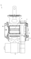
図4は、第1の実施形態におけるシートベルトリトラクタの正面図である。図5は、第1の実施形態におけるシートベルトリトラクタの右側面図である。図6は、第1の実施形態におけるシートベルトリトラクタの左側面図である。図7は、第1の実施形態におけるシートベルトリトラクタの切断面を矢視A-A(図6参照)で示す図である。図8は、第1の実施形態におけるシートベルトリトラクタの分解斜視図である。 Figure 4 is a front view of the seat belt retractor in the first embodiment. Figure 5 is a right side view of the seat belt retractor in the first embodiment. Figure 6 is a left side view of the seat belt retractor in the first embodiment. Figure 7 is a cross-sectional view of the seat belt retractor in the first embodiment taken along the line A-A (see Figure 6). Figure 8 is an exploded perspective view of the seat belt retractor in the first embodiment.

図4~8に示すリトラクタ1Aは、シートベルトリトラクタの一例であり、図2に示すリトラクタ1の一具体例である。リトラクタ1Aは、第1のEA機構53の一例である第1のEA機構53A及び第2のEA機構54の一例である第2のEA機構54Aを備える。第1のEA機構53Aは、回転体52とロック機構6との間に設けられるトーションバー7の変形により、ベース荷重BNを発生させる。第2のEA機構54Aは、回転体52とスプール4との間に設けられるトーションバー30の変形により、制限荷重LNの増大を制限する。トーションバー7は、第1のEA部材の一例であり、トーションバー30は、第2のEA部材の一例である。以下、図4~8を参照して、リトラクタ1Aの構成について説明する。 The retractor 1A shown in Figures 4 to 8 is an example of a seat belt retractor, and is a specific example of the retractor 1 shown in Figure 2. The retractor 1A includes a first EA mechanism 53A, which is an example of the first EA mechanism 53, and a second EA mechanism 54A, which is an example of the second EA mechanism 54. The first EA mechanism 53A generates a base load BN by deformation of the torsion bar 7 provided between the rotating body 52 and the locking mechanism 6. The second EA mechanism 54A limits the increase in the limit load LN by deformation of the torsion bar 30 provided between the rotating body 52 and the spool 4. The torsion bar 7 is an example of a first EA member, and the torsion bar 30 is an example of a second EA member. The configuration of the retractor 1A will be described below with reference to Figures 4 to 8.

リトラクタ1Aは、フレーム2、スプール4、回転体52、第1のEA機構53A、ビークルセンサ5、ロック機構6、動力伝達機構21A、リターンスプリング65、第2のEA機構54A及びストッパー57を備える。 The retractor 1A includes a frame 2, a spool 4, a rotating body 52, a first EA mechanism 53A, a vehicle sensor 5, a locking mechanism 6, a power transmission mechanism 21A, a return spring 65, a second EA mechanism 54A, and a stopper 57.

フレーム2は、スプール4を回転可能に収容し、リトラクタ1Aの骨格を形成する筐体である。フレーム2は、例えば、対峙する一対の側面部2b,2cと、側面部2b,2cを連結する背面部2aと、を有する。側面部2bの外側(つまり、側面部2bに対してスプール4の側とは反対側)には、ロック機構6が配置されている。一対の側面部2b,2cは、それぞれ、円形状(略円形状を含む)の開口を有する。 The frame 2 is a housing that rotatably houses the spool 4 and forms the framework of the retractor 1A. The frame 2 has, for example, a pair of opposing side portions 2b, 2c and a back portion 2a that connects the side portions 2b, 2c. A locking mechanism 6 is disposed on the outside of the side portion 2b (i.e., the side opposite the spool 4 side relative to the side portion 2b). Each of the pair of side portions 2b, 2c has a circular (including approximately circular) opening.

スプール4は、フレーム2の一対の側面部2b,2cの各開口と同心(略同心を含む)に且つ回転可能に支持され、シートベルト104を巻き取る巻き取り部材である。 The spool 4 is a winding member that is supported concentrically (including approximately concentrically) with each opening of the pair of side portions 2b, 2c of the frame 2 and rotatably, and winds up the seat belt 104.

回転体52は、スプール4と共に回転可能な部材であり、ストッパー57によりロックされるまでスプール4と共に回転する。この例では、回転体52は、ストッパー57によりロックされるまではスプール4と一体に回転し、且つ、ストッパー57によりロックされた後はスプール4が回転体52に対して相対回転する程度の嵌め合い力で、筒状のスプール4の内壁に嵌まっている。回転体52は、外歯52aが形成されたフランジを有する筒状のシャフトギアである。 The rotating body 52 is a member that can rotate together with the spool 4, and rotates together with the spool 4 until it is locked by the stopper 57. In this example, the rotating body 52 rotates together with the spool 4 until it is locked by the stopper 57, and after it is locked by the stopper 57, it is fitted into the inner wall of the cylindrical spool 4 with a fitting force that allows the spool 4 to rotate relative to the rotating body 52. The rotating body 52 is a cylindrical shaft gear having a flange on which external teeth 52a are formed.

第1のEA機構53Aは、回転体52に相対回転不能に連結するトーションバー7を有する。トーションバー7は、第1のトーションバーの一例である。トーションバー7は、回転体52に相対回転不能に連結する第1連結部15と、ロック機構6によりロックされる第2連結部16と、を有する。これらの連結部は、軸方向に互いに離れた箇所に設けられている。この例では、第1連結部15は、筒状の回転体52の内壁に相対回転不能に連結し、第2連結部16は、ロッキングベース17の筒状部17aの内壁に相対回転不能に連結する。 The first EA mechanism 53A has a torsion bar 7 that is non-rotatably connected to the rotating body 52. The torsion bar 7 is an example of a first torsion bar. The torsion bar 7 has a first connecting portion 15 that is non-rotatably connected to the rotating body 52, and a second connecting portion 16 that is locked by the locking mechanism 6. These connecting portions are provided at locations spaced apart from each other in the axial direction. In this example, the first connecting portion 15 is non-rotatably connected to the inner wall of the cylindrical rotating body 52, and the second connecting portion 16 is non-rotatably connected to the inner wall of the cylindrical portion 17a of the locking base 17.

トーションバー7は、第2連結部16から軸方向に突出する先端部7aを有する。先端部7aは、ロッキングベース17を貫通し、ベアリングキャップ62を介して、リテーナ61に回転可能に支持される。リテーナ61は、フレーム2の側面部2bに固定される。 The torsion bar 7 has a tip 7a that protrudes axially from the second connecting portion 16. The tip 7a penetrates the locking base 17 and is rotatably supported by the retainer 61 via the bearing cap 62. The retainer 61 is fixed to the side portion 2b of the frame 2.

ビークルセンサ5は、車両の挙動変化(具体的には、車両の挙動変化に伴って生ずる車両の加減速や傾きの急激な変化)を検出する検出機構の一例である。ビークルセンサ5は、例えば、緊急時に発生する車両減速度で移動する球体と、球体の移動によって作動する係止爪とを有する。 The vehicle sensor 5 is an example of a detection mechanism that detects changes in the vehicle's behavior (specifically, sudden changes in the vehicle's acceleration/deceleration and inclination that occur as a result of changes in the vehicle's behavior). The vehicle sensor 5 has, for example, a sphere that moves with the vehicle's deceleration that occurs in an emergency, and a locking claw that is activated by the movement of the sphere.

ロック機構6は、シートベルト104の引き出し方向へのスプール4の回転をロックするロック動作を行う。ロック機構6は、ロックギア14と、ロッキングベース17とを備える。ロックギア14は、フレーム2の側面部2bから外側へ突出するトーションバー7の先端部7aに、トーションバー7に対して相対回動可能に嵌まっている。先端部7aは、トーションバー7に軸方向に接続されるシャフト等の別部材でもよいし、トーションバー7自体の一部でもよい。ロッキングベース17は、後述の第2連結部16に一体回転可能に支持されかつパウルを揺動可能に保持する。ロッキングベース17は、ロッキング部材の一例であり、通常時にスプール4及び回転体52と共に回転し且つ作動時にスプール4のシートベルト104の引き出し方向への回転を阻止する。ロックギア14の外周には、ラチェット歯14aが形成されている。 The locking mechanism 6 performs a locking operation to lock the rotation of the spool 4 in the unwinding direction of the seat belt 104. The locking mechanism 6 includes a locking gear 14 and a locking base 17. The locking gear 14 is fitted to the tip 7a of the torsion bar 7 protruding outward from the side portion 2b of the frame 2 so as to be rotatable relative to the torsion bar 7. The tip 7a may be a separate member such as a shaft axially connected to the torsion bar 7, or may be a part of the torsion bar 7 itself. The locking base 17 is supported by the second connecting portion 16 described below so as to be rotatable together with the torsion bar 7 and holds the pawl so as to be swingable. The locking base 17 is an example of a locking member, which normally rotates together with the spool 4 and the rotating body 52 and prevents the rotation of the spool 4 in the unwinding direction of the seat belt 104 when activated. Ratchet teeth 14a are formed on the outer periphery of the locking gear 14.

ロックギア14は、通常時は、トーションバー7と一体回転する。一方、前述の緊急時は、ビークルセンサ5の球体が作動して、係止爪がラチェット歯14aに係合する。これにより、シートベルト104の引き出し方向へのロックギア14の回転が阻止(ロック)される。ロックギア14の回転がロックされると、ロッキングベース17とロックギア14との間に相対回転が生じて、ロッキングベース17に設けられたパウルが回転し、回転したパウルは、側面部2bに設けられた内歯2baに係合する。これにより、ロッキングベース17の回転が停止し、シートベルト104の引き出し方向へのスプール4及び回転体52の回転も阻止される。 Under normal circumstances, the lock gear 14 rotates together with the torsion bar 7. However, in the event of an emergency, the sphere of the vehicle sensor 5 is activated and the locking claw engages with the ratchet teeth 14a. This prevents (locks) the lock gear 14 from rotating in the direction in which the seat belt 104 is withdrawn. When the rotation of the lock gear 14 is locked, relative rotation occurs between the locking base 17 and the lock gear 14, causing the pawl provided on the locking base 17 to rotate, and the rotated pawl engages with the internal teeth 2ba provided on the side portion 2b. This stops the rotation of the locking base 17, and also prevents the spool 4 and the rotating body 52 from rotating in the direction in which the seat belt 104 is withdrawn.

動力伝達機構21Aは、図2に示す動力伝達機構21の一例である。動力伝達機構21Aは、モータ12、リテーナ28、減速機構51、ギアケース29及びクラッチ25を備える。 The power transmission mechanism 21A is an example of the power transmission mechanism 21 shown in FIG. 2. The power transmission mechanism 21A includes a motor 12, a retainer 28, a reduction mechanism 51, a gear case 29, and a clutch 25.

モータ12は、スプール4及び回転体52を回転させる動力を発生する。モータ12は、リテーナ28に固定される。 The motor 12 generates power to rotate the spool 4 and the rotor 52. The motor 12 is fixed to the retainer 28.

リテーナ28は、モータ12の出力軸12aが貫通する貫通孔28aと、クラッチ25のドライブギア23を回転可能に保持する保持面28bとを有する。 The retainer 28 has a through hole 28a through which the output shaft 12a of the motor 12 passes, and a holding surface 28b that rotatably holds the drive gear 23 of the clutch 25.

減速機構51は、モータギア20及びコネクトギア22を有し、モータ12の出力軸12aの回転を減速して伝達する。 The reduction gear mechanism 51 has a motor gear 20 and a connecting gear 22, and transmits the rotation of the output shaft 12a of the motor 12 at a reduced speed.

モータギア20は、モータ12の出力軸12aに一体回転可能に取り付けられている。モータギア20は、外歯20aと、出力軸12aが挿入される軸穴20bとを有する。 The motor gear 20 is attached to the output shaft 12a of the motor 12 so as to be able to rotate together with it. The motor gear 20 has external teeth 20a and a shaft hole 20b into which the output shaft 12a is inserted.

コネクトギア22は、モータギア20の外歯20aに常時噛み合う外歯22aと、ギアケース29から突出するボスが挿入される軸穴22bとを有する。外歯22aは、外歯20aよりも多い歯数を有する。コネクトギア22は、ギアケース29から突出する軸を中心に回転する。 The connect gear 22 has external teeth 22a that constantly mesh with the external teeth 20a of the motor gear 20, and an axial hole 22b into which a boss protruding from the gear case 29 is inserted. The external teeth 22a have a greater number of teeth than the external teeth 20a. The connect gear 22 rotates around an axis protruding from the gear case 29.

ギアケース29は、アイドルギア26を回転可能に保持するボスと、クラッチギア24を回転可能に保持するボスとを有する。 The gear case 29 has a boss that rotatably holds the idle gear 26 and a boss that rotatably holds the clutch gear 24.

アイドルギア26は、回転体52の外歯52aとクラッチギア24の外歯24aの両方と常時噛み合う外歯26aと、ギアケース29のボスが挿入される軸穴26bとを有する。 The idle gear 26 has external teeth 26a that constantly mesh with both the external teeth 52a of the rotor 52 and the external teeth 24a of the clutch gear 24, and a shaft hole 26b into which the boss of the gear case 29 is inserted.

クラッチ25は、ドライブギア23と、ドライブギア23と同軸に回転可能に支持されるクラッチギア24と、ドライブギア23に設けられる一対のクラッチパウル41と、一対のクラッチパウル41を付勢する一対のクラッチスプリング42とを有する。 The clutch 25 has a drive gear 23, a clutch gear 24 supported rotatably coaxially with the drive gear 23, a pair of clutch pawls 41 provided on the drive gear 23, and a pair of clutch springs 42 that bias the pair of clutch pawls 41.

ドライブギア23は、モータ12の力がモータギア20及びコネクトギア22を介して伝達され、モータ12の出力軸12aの回転に従って回転する。 The power of the motor 12 is transmitted to the drive gear 23 via the motor gear 20 and the connecting gear 22, and the drive gear 23 rotates in accordance with the rotation of the output shaft 12a of the motor 12.

クラッチギア24は、ドライブギア23と同軸に回転可能に支持され、アイドルギア26を介して回転体52と連結する。 The clutch gear 24 is supported rotatably coaxially with the drive gear 23 and is connected to the rotor 52 via the idle gear 26.

ドライブギア23の回転が停止している状態では、クラッチパウル41は、クラッチスプリング42の付勢力に従ってクラッチギア24のラチェット内歯と係合しない位置に保持される。 When the drive gear 23 is stopped rotating, the clutch pawl 41 is held in a position where it does not engage with the ratchet internal teeth of the clutch gear 24 due to the biasing force of the clutch spring 42.

一方、モータ12の出力軸12aが回転している状態では、モータギア20及びコネクトギア22の回転により、ドライブギア23も回転している。ドライブギア23が回転すると、クラッチパウル41に遠心力が働く。 On the other hand, when the output shaft 12a of the motor 12 is rotating, the drive gear 23 also rotates due to the rotation of the motor gear 20 and the connect gear 22. When the drive gear 23 rotates, a centrifugal force acts on the clutch pawl 41.

ドライブギア23が出力軸12aの回転によりシートベルト104の巻き取り方向に対応する方向に回転すると、クラッチパウル41は、クラッチスプリング42の付勢力に抗いながら、その遠心力により移動する。遠心力により移動したクラッチパウル41は、クラッチギア24のラチェット内歯と係合する。逆に、ドライブギア23が出力軸12aの回転によりシートベルト104の引き出し方向に対応する方向に回転すると、クラッチパウル41は、その遠心力が働いても、ドライブギア23のストッパーによってクラッチギア24のラチェット内歯に近づく方向への移動が規制される。よって、クラッチパウル41とラチェット内歯との係合が阻止される。 When the drive gear 23 rotates in a direction corresponding to the winding direction of the seat belt 104 due to the rotation of the output shaft 12a, the clutch pawl 41 moves due to the centrifugal force while resisting the biasing force of the clutch spring 42. The clutch pawl 41, which moves due to the centrifugal force, engages with the ratchet internal teeth of the clutch gear 24. Conversely, when the drive gear 23 rotates in a direction corresponding to the unwinding direction of the seat belt 104 due to the rotation of the output shaft 12a, the clutch pawl 41 is restricted from moving in a direction approaching the ratchet internal teeth of the clutch gear 24 by the stopper of the drive gear 23, even if the centrifugal force acts. Therefore, the clutch pawl 41 is prevented from engaging with the ratchet internal teeth.

したがって、ドライブギア23が出力軸12aの回転によりシートベルト104の巻き取り方向に対応する方向に回転している状態では、クラッチパウル41がラチェット内歯と係合した状態が維持される。この係合状態では、出力軸12aの回転動力は、モータギア20、コネクトギア22、クラッチギア24、アイドルギア26、回転体52の順路で伝達される。したがって、このような係合状態では、出力軸12aの回転力は、スプール4に伝達されるので、シートベルト104はスプール4に巻き取られる。 Therefore, when the drive gear 23 rotates in a direction corresponding to the winding direction of the seat belt 104 due to the rotation of the output shaft 12a, the clutch pawl 41 remains engaged with the ratchet internal teeth. In this engaged state, the rotational power of the output shaft 12a is transmitted in the following order: motor gear 20, connect gear 22, clutch gear 24, idle gear 26, and rotor 52. In this engaged state, the rotational force of the output shaft 12a is transmitted to the spool 4, so that the seat belt 104 is wound onto the spool 4.

一方、ドライブギア23が出力軸12aの回転によりシートベルト104の引き出し方向に対応する方向に回転している状態では、クラッチパウル41がラチェット内歯と係合しない状態が維持される。また、出力軸12aの回転が停止している状態では、ドライブギア23の回転は停止しているので、クラッチパウル41がラチェット内歯と係合しない状態が維持される。これらの非係合状態では、スプール4の回転軸の回転力は、回転体52、アイドルギア26、クラッチギア24の順路で伝達するが、ドライブギア23には伝達されない。したがって、これらのような非係合状態では、スプール4の回転軸の回転力は、出力軸12aには伝達されない。つまり、スプール4の回転軸から出力軸12aへの回転力の伝達は遮断される。 On the other hand, when the drive gear 23 is rotating in a direction corresponding to the unwinding direction of the seat belt 104 due to the rotation of the output shaft 12a, the clutch pawl 41 is maintained in a state of not engaging with the ratchet internal teeth. Also, when the rotation of the output shaft 12a is stopped, the rotation of the drive gear 23 is stopped, so the clutch pawl 41 is maintained in a state of not engaging with the ratchet internal teeth. In these disengaged states, the rotational force of the rotating shaft of the spool 4 is transmitted in the order of the rotating body 52, the idle gear 26, and the clutch gear 24, but is not transmitted to the drive gear 23. Therefore, in these disengaged states, the rotational force of the rotating shaft of the spool 4 is not transmitted to the output shaft 12a. In other words, the transmission of the rotational force from the rotating shaft of the spool 4 to the output shaft 12a is interrupted.

このように、クラッチ25は、回転体52からモータ12への回転力の伝達を遮断し、モータ12から回転体52へ回転力を伝達するワンウェイクラッチである。よって、スプール4からモータ12への回転力の伝達がクラッチ25により遮断されるので、乗員111がスムーズにシートベルト104をリトラクタ1から引き出す又はリトラクタ1に巻き取らせることが可能になる。 In this way, the clutch 25 is a one-way clutch that blocks the transmission of rotational force from the rotating body 52 to the motor 12 and transmits rotational force from the motor 12 to the rotating body 52. Therefore, the transmission of rotational force from the spool 4 to the motor 12 is blocked by the clutch 25, so that the occupant 111 can smoothly pull out the seat belt 104 from the retractor 1 or have the seat belt 104 retracted by the retractor 1.

リターンスプリング65は、スプール4がシートベルト104の巻き取り方向に回転するようにスプール4を付勢する。リターンスプリング65は、側面部2cに固定されるスプリングケース66に収納されている。 The return spring 65 biases the spool 4 so that the spool 4 rotates in the direction of winding the seat belt 104. The return spring 65 is housed in a spring case 66 that is fixed to the side portion 2c.

第2のEA機構54Aは、回転体52に相対回転不能に連結するトーションバー30を有する。トーションバー30は、第2のトーションバーの一例である。トーションバー30は、スプール4に相対回転不能に連結する第3連結部18と、回転体52に相対回転不能に連結する第4連結部19と、を有する。これらの連結部は、軸方向に互いに離れた箇所に設けられている。この例では、第3連結部18は、筒状のスプール4の内壁に相対回転不能に連結し、第4連結部19は、筒状の回転体52の内壁に相対回転不能に連結する。 The second EA mechanism 54A has a torsion bar 30 that is non-rotatably connected to the rotating body 52. The torsion bar 30 is an example of a second torsion bar. The torsion bar 30 has a third connecting portion 18 that is non-rotatably connected to the spool 4, and a fourth connecting portion 19 that is non-rotatably connected to the rotating body 52. These connecting portions are provided at positions spaced apart from each other in the axial direction. In this example, the third connecting portion 18 is non-rotatably connected to the inner wall of the cylindrical spool 4, and the fourth connecting portion 19 is non-rotatably connected to the inner wall of the cylindrical rotating body 52.

トーションバー30は、第3連結部18から軸方向に突出する先端部30aを有する。先端部30aは、ブッシュナット64を介して、スプリングケース66に回転可能に支持される。トーションバー30は、トーションバー7の径よりも太い径を有する。トーションバー30は、トーションバー7と同軸上に配置されている。 The torsion bar 30 has a tip 30a that protrudes axially from the third connecting portion 18. The tip 30a is rotatably supported by the spring case 66 via a bush nut 64. The torsion bar 30 has a diameter larger than the diameter of the torsion bar 7. The torsion bar 30 is arranged coaxially with the torsion bar 7.

ストッパー57は、非作動時に回転体52の回転を許容し、作動時に回転体52をロックする環状部材である。ストッパー57は、筒状の回転体52の内側に配置され、回転体52に対して相対回転不能に回転体52の内壁に連結されている。 The stopper 57 is an annular member that allows the rotor 52 to rotate when not in operation and locks the rotor 52 when in operation. The stopper 57 is disposed inside the cylindrical rotor 52 and is connected to the inner wall of the rotor 52 so that it cannot rotate relative to the rotor 52.

次に、車両の衝突等の緊急時のリトラクタ1Aの各部の動きについて説明する。図9は、リトラクタ1Aの内部構造の一部の正面図である。図10は、ストッパー57の作動前の状態を矢視B-B(図9参照)で示す断面図である。図11は、ストッパー57の作動後の状態を矢視B-B(図9参照)で示す断面図である。 Next, the movement of each part of the retractor 1A in an emergency such as a vehicle collision will be described. Figure 9 is a front view of a part of the internal structure of the retractor 1A. Figure 10 is a cross-sectional view taken along line B-B (see Figure 9) showing the state before the stopper 57 is activated. Figure 11 is a cross-sectional view taken along line B-B (see Figure 9) showing the state after the stopper 57 is activated.

図10において、第1のEA機構53Aは、ロック機構6が作動すると、ロッキングベース17の回転がロックされることにより、トーションバー7は、第2連結部16でロックされる。これにより、スプール4がシートベルト104の引き出し方向に回転することで、回転体52は、スプール4と共に回転する。トーションバー7は、回転体52に相対回転不能に圧入等により第1連結部15で連結しているので、ねじれ変形し始める。 In FIG. 10, when the locking mechanism 6 of the first EA mechanism 53A is activated, the rotation of the locking base 17 is locked, and the torsion bar 7 is locked at the second connecting portion 16. As a result, the spool 4 rotates in the direction in which the seat belt 104 is withdrawn, and the rotating body 52 rotates together with the spool 4. The torsion bar 7 begins to twist and deform because it is connected to the rotating body 52 by press-fitting or the like at the first connecting portion 15 so that it cannot rotate relative to the rotating body 52.

ストッパー57は、第1のEA機構53Aのトーションバー7のねじれ変形が所定の変形量に達すると、回転体52をロックするように作動する。ストッパー57は、自身の回転が設定回転量に達すると、回転体52をロックするように作動してもよい。第2のEA機構54Aのトーションバー30は、回転体52がストッパー57によりロックされた状態で、スプール4がシートベルト104の引き出し方向に回転することで、ねじれ変形し始める。トーションバー30は、回転体52に相対回転不能に圧入等により第4連結部19で連結しているからである。トーションバー30は、自身に作用する荷重が設定値に達すると、ねじれ変形し始める。 The stopper 57 operates to lock the rotating body 52 when the torsional deformation of the torsion bar 7 of the first EA mechanism 53A reaches a predetermined deformation amount. The stopper 57 may operate to lock the rotating body 52 when its own rotation reaches a set rotation amount. With the rotating body 52 locked by the stopper 57, the torsion bar 30 of the second EA mechanism 54A begins to twist and deform when the spool 4 rotates in the direction of withdrawing the seat belt 104. This is because the torsion bar 30 is connected to the rotating body 52 by the fourth connecting part 19 by press-fitting or the like so that it cannot rotate relative to the rotating body 52. The torsion bar 30 begins to twist and deform when the load acting on it reaches a set value.

ストッパー57は、回転体52の回転に依存して作動する。この例では、ストッパー57は、回転体52の回転に依存して回転する仕組みを有し、予め設定された回転量(設定回転量)に達すると、回転体52をロックするように作動する。ストッパー57の回転は、設定回転量に達すると停止する。ストッパー57は回転体52に対して相対回転不能に連結されているので、回転体52の回転は、ストッパー57の回転が停止することで、ロックされる。 The stopper 57 operates depending on the rotation of the rotating body 52. In this example, the stopper 57 has a mechanism that rotates depending on the rotation of the rotating body 52, and operates to lock the rotating body 52 when a preset amount of rotation (set amount of rotation) is reached. The rotation of the stopper 57 stops when the set amount of rotation is reached. Since the stopper 57 is connected to the rotating body 52 so that it cannot rotate relative to it, the rotation of the rotating body 52 is locked when the rotation of the stopper 57 stops.

この例では、ストッパー57は、回転体52の回転軸67を中心に回転しながら回転軸67に沿って移動する。回転体52は、スプール4と同軸上に配置されている。ロッキングベース17の筒状部17aに、雄ねじが形成され、ストッパー57の内面には、雌ねじが形成されている。これにより、ストッパー57は、回転体52と共に回転しながら、筒状部17aの軸方向(回転軸67)に沿って移動する(図11参照)。ストッパー57の回転及び移動は、例えば図11に示すように、ロック機構6のロッキングベース17に到達すると停止する。回転体52は、ストッパー57の回転及び移動が停止することでロックされる。 In this example, the stopper 57 moves along the rotation axis 67 while rotating around the rotation axis 67 of the rotating body 52. The rotating body 52 is arranged coaxially with the spool 4. A male thread is formed on the cylindrical portion 17a of the locking base 17, and a female thread is formed on the inner surface of the stopper 57. As a result, the stopper 57 moves along the axial direction (rotation axis 67) of the cylindrical portion 17a while rotating together with the rotating body 52 (see FIG. 11). The rotation and movement of the stopper 57 stops when it reaches the locking base 17 of the locking mechanism 6, as shown in FIG. 11, for example. The rotating body 52 is locked when the rotation and movement of the stopper 57 stops.

回転体52がロックされることにより、スプール4のみが回転し、第2のEA機構54Aのトーションバー30は、ねじれ変形し始める。 By locking the rotor 52, only the spool 4 rotates, and the torsion bar 30 of the second EA mechanism 54A begins to twist and deform.

このように、第2のEA機構54Aのトーションバー30は、回転体52がストッパー57によりロックされた状態で、スプール4が引き出し方向に回転し、自身に作用する荷重が前記設定値に達すると、変形する。これにより、シートベルト104に作用する荷重は、第2のEA機構54Aのトーションバー30の変形によるEA荷重で制限されるので、シートベルト104が作用する荷重が過大になることを抑制できる。例えば、第1のEA機構53Aのトーションバー7が変形し且つモータ12から回転体52への力が伝達している状態で、第2のEA機構54Aのトーションバー30に作用する荷重が設定値に達すると、第2のEA機構54Aのトーションバー30は変形する。 In this way, the torsion bar 30 of the second EA mechanism 54A deforms when the spool 4 rotates in the unwinding direction with the rotor 52 locked by the stopper 57 and the load acting on the torsion bar 30 reaches the set value. As a result, the load acting on the seat belt 104 is limited by the EA load caused by the deformation of the torsion bar 30 of the second EA mechanism 54A, so that the load acting on the seat belt 104 can be prevented from becoming excessive. For example, when the torsion bar 7 of the first EA mechanism 53A is deformed and a force is being transmitted from the motor 12 to the rotor 52, the torsion bar 30 of the second EA mechanism 54A deforms when the load acting on the torsion bar 30 of the second EA mechanism 54A reaches the set value.

なお、上記の構造を有するリトラクタ1Aによれば、第2のEA機構54Aのトーションバー30は、回転体52がストッパー57にロックされていない状態で、スプール4が引き出し方向に回転し、自身に作用する荷重が前記設定値に達しても、変形する。例えば、第2のEA機構54Aのトーションバー30は、回転体52がストッパー57にロックされていない状態で、第1のEA機構53Aのトーションバー7の変形とモータ12の出力とにより生ずる荷重が設定値に達しても、変形する。 In addition, according to the retractor 1A having the above structure, the torsion bar 30 of the second EA mechanism 54A deforms even if the load acting on it reaches the set value when the spool 4 rotates in the pull-out direction with the rotating body 52 not locked to the stopper 57. For example, the torsion bar 30 of the second EA mechanism 54A deforms even if the load generated by the deformation of the torsion bar 7 of the first EA mechanism 53A and the output of the motor 12 reaches the set value with the rotating body 52 not locked to the stopper 57.

また、リトラクタ1Aでは、モータ12の出力軸12aと回転体52との間の動力伝達経路には、クラッチ25が搭載されている。クラッチ25が作動した場合、回転体52にモータ12の出力軸12aが複数のギアを介して連結される。クラッチ25が作動していない場合は、モータ12の出力により生ずる荷重は、回転体52及びスプール4に伝達されない。 In addition, in the retractor 1A, a clutch 25 is installed in the power transmission path between the output shaft 12a of the motor 12 and the rotating body 52. When the clutch 25 is activated, the output shaft 12a of the motor 12 is connected to the rotating body 52 via multiple gears. When the clutch 25 is not activated, the load generated by the output of the motor 12 is not transmitted to the rotating body 52 and the spool 4.

また、リトラクタ1Aによれば、第1のEA機構53AによるEA荷重を確保した上で、モータ12によるEA荷重が何らかの異常で発生しない場合でも、ストッパー57が作動することにより、第2のEA機構54AによるEA荷重を発生させることが可能となる。これにより、例えば、比較的衝突エネルギーが高い衝突時に、モータ12によるEA荷重が発生しない場合でも、乗員をより適正に拘束できる。 In addition, with the retractor 1A, even if the EA load from the motor 12 is not generated due to some abnormality after ensuring the EA load from the first EA mechanism 53A, the stopper 57 is activated, making it possible to generate an EA load from the second EA mechanism 54A. This allows the occupant to be restrained more appropriately, for example, even if the EA load from the motor 12 is not generated during a collision with relatively high collision energy.

リトラクタ1Aは、スペーサ63を備えてもよい。ストッパー57がロッキングベース17の筒状部17aの軸方向に沿って移動できるように、ストッパー57と回転体52との間に所定の隙間が設定されている。そのため、ストッパー57と回転体52との間で、がたつきが生じるおそれがある。そこで、この隙間を例えば樹脂製のスペーサ63で埋めることによって、がたつきが生じるのを防止できる。 The retractor 1A may include a spacer 63. A predetermined gap is set between the stopper 57 and the rotating body 52 so that the stopper 57 can move along the axial direction of the cylindrical portion 17a of the locking base 17. This may cause rattling between the stopper 57 and the rotating body 52. Therefore, rattling can be prevented by filling this gap with, for example, a resin spacer 63.

以上、実施形態を説明したが、本開示の技術は上記実施形態に限定されない。他の実施形態の一部又は全部との組み合わせや置換などの種々の変形及び改良が可能である。 Although the embodiments have been described above, the technology of the present disclosure is not limited to the above-described embodiments. Various modifications and improvements are possible, such as combinations or substitutions with part or all of other embodiments.

1,1A リトラクタ
2 フレーム
4 スプール
5 ビークルセンサ
6 ロック機構
7 トーションバー
8 プリテンショナ
10 制御部
12 モータ
14 ロックギア
15 第1連結部
16 第2連結部
17 ロッキングベース
18 第3連結部
19 第4連結部
20 モータギア
21 動力伝達機構
22 コネクトギア
23 ドライブギア
24 クラッチギア
25 クラッチ
26 アイドルギア
28 リテーナ
29 ギアケース
30 トーションバー
41 クラッチパウル
51 減速機構
52 回転体
53 第1のEA機構
54 第2のEA機構
57 ストッパー
61 リテーナ
62 ベアリングキャップ
63 スペーサ
64 ブッシュナット
65 リターンスプリング
66 スプリングケース
67 回転軸
REFERENCE SIGNS LIST 1, 1A Retractor 2 Frame 4 Spool 5 Vehicle sensor 6 Lock mechanism 7 Torsion bar 8 Pretensioner 10 Control unit 12 Motor 14 Lock gear 15 First connecting portion 16 Second connecting portion 17 Locking base 18 Third connecting portion 19 Fourth connecting portion 20 Motor gear 21 Power transmission mechanism 22 Connect gear 23 Drive gear 24 Clutch gear 25 Clutch 26 Idle gear 28 Retainer 29 Gear case 30 Torsion bar 41 Clutch pawl 51 Reduction mechanism 52 Rotating body 53 First EA mechanism 54 Second EA mechanism 57 Stopper 61 Retainer 62 Bearing cap 63 Spacer 64 Bush nut 65 Return spring 66 Spring case 67 Rotating shaft

Claims (20)

シートベルトを巻き取るスプールと、
前記スプールと共に回転可能な回転体と、
前記回転体に相対回転不能に連結する第1連結部と、前記第1連結部から離れた箇所に設けられる第2連結部とを有する第1のエネルギー吸収機構と、
前記第2連結部に相対回転不能に連結されるロッキングベースを有するロック機構と、
前記回転体を回転させるモータと、
前記スプールに相対回転不能に連結する第3連結部と、前記回転体に相対回転不能に連結する第4連結部とを有し、前記第3連結部と前記第4連結部は互いに離れた箇所に設けられた第2のエネルギー吸収機構と、
トッパーと、を備え、
前記第1のエネルギー吸収機構は、前記ロッキングベースの回転がロックされた状態で、前記スプール及び前記回転体が前記シートベルトの引き出し方向に回転すると、変形し、
前記第2のエネルギー吸収機構は、前記回転体の回転が前記ストッパーによりロックされた状態で、前記スプールが前記引き出し方向に回転すると、変形する、シートベルトリトラクタ。
A spool for winding the seat belt;
A rotor that can rotate together with the spool;
a first energy absorbing mechanism including a first connecting portion connected to the rotating body so as not to rotate relative to the rotating body and a second connecting portion provided at a location spaced apart from the first connecting portion ;
a lock mechanism having a locking base connected to the second connecting portion so as not to rotate relative to the second connecting portion ;
A motor that rotates the rotating body;
a second energy absorbing mechanism including a third connecting portion connected to the spool so as not to rotate relative to the rotor and a fourth connecting portion connected to the rotor so as not to rotate relative to the rotor, the third connecting portion and the fourth connecting portion being provided at positions spaced apart from each other ;
A stopper ,
the first energy absorbing mechanism is deformed when the spool and the rotating body rotate in the seat belt withdrawing direction with the rotation of the locking base locked,
The second energy absorbing mechanism is deformed when the spool rotates in the unwinding direction with the rotation of the rotating body locked by the stopper .
前記第2のエネルギー吸収機構は、前記回転体の回転が前記ストッパーによりロックされた状態で、前記スプールが前記引き出し方向に回転し、自身に作用する荷重が定値に達すると、変形する、請求項1に記載のシートベルトリトラクタ。 2. The seat belt retractor according to claim 1, wherein the second energy absorption mechanism is deformed when the spool rotates in the unwinding direction with the rotation of the rotating body locked by the stopper and a load acting on the second energy absorption mechanism reaches a set value. 前記第2のエネルギー吸収機構は、前記回転体の回転が前記ストッパーによりロックされてない状態で、前記スプールが前記引き出し方向に回転し、自身に作用する荷重が前記設定値に達すると、変形する、請求項に記載のシートベルトリトラクタ。 3. The seat belt retractor according to claim 2, wherein the second energy absorption mechanism is deformed when the spool rotates in the unwinding direction while the rotation of the rotating body is not locked by the stopper, and the load acting on the second energy absorption mechanism reaches the set value. 前記ストッパーは、前記第1のエネルギー吸収機構の変形が所定の変形量に達すると、前記回転体の回転をロックするように作動する、請求項1から3のいずれか一項に記載のシートベルトリトラクタ。 4. The seat belt retractor according to claim 1, wherein the stopper is operable to lock the rotation of the rotating body when the deformation of the first energy absorbing mechanism reaches a predetermined deformation amount. 前記ストッパーは、前記回転体の回転に依存して作動する、請求項1から4のいずれか一項に記載のシートベルトリトラクタ。 A seat belt retractor according to any one of claims 1 to 4, wherein the stopper operates depending on the rotation of the rotating body. 前記ストッパーは、前記回転体の回転に依存して回転する、請求項5に記載のシートベルトリトラクタ。 The seat belt retractor according to claim 5, wherein the stopper rotates depending on the rotation of the rotating body. 前記ストッパーは、自身の回転が設定回転量に達すると、前記回転体の回転をロックするように作動する、請求項1から3のいずれか一項に記載のシートベルトリトラクタ。 4. The seat belt retractor according to claim 1 , wherein the stopper operates to lock the rotation of the rotating body when the rotation of the stopper itself reaches a set rotation amount. 前記ストッパーの回転は、前記設定回転量に達すると停止し、
前記回転体の回転は、前記ストッパーの回転が停止することでロックされる、請求項7に記載のシートベルトリトラクタ。
The rotation of the stopper stops when the set rotation amount is reached,
8. The seat belt retractor according to claim 7, wherein the rotation of the rotating body is locked by stopping the rotation of the stopper.
前記ストッパーは、前記回転体の回転軸を中心に回転しながら前記回転軸に沿って移動する、請求項6から8のいずれか一項に記載のシートベルトリトラクタ。 The seat belt retractor according to any one of claims 6 to 8, wherein the stopper moves along the rotation axis while rotating around the rotation axis of the rotating body. 前記ストッパーは、前記回転体の回転軸を中心に回転しながら前記回転軸に沿って移動する部材であり、
前記ストッパーの回転及び移動は、前記ロック機構に到達すると停止し、
前記回転体の回転は、前記ストッパーの回転及び移動が停止することでロックされる、請求項1から3のいずれか一項に記載のシートベルトリトラクタ。
the stopper is a member that moves along a rotation axis of the rotating body while rotating around the rotation axis,
The rotation and movement of the stopper stops when it reaches the locking mechanism,
4. The seat belt retractor according to claim 1 , wherein the rotation of the rotating body is locked by stopping the rotation and movement of the stopper.
前記回転体は、前記スプールと同軸上に配置されている、請求項1から10のいずれか一項に記載のシートベルトリトラクタ。 The seat belt retractor according to any one of claims 1 to 10, wherein the rotor is arranged coaxially with the spool. 前記回転体は、前記ストッパーにより前記回転体の回転がロックされるまで前記スプールと共に回転する、請求項1から11のいずれか一項に記載のシートベルトリトラクタ。 The seat belt retractor according to any one of claims 1 to 11, wherein the rotating body rotates together with the spool until rotation of the rotating body is locked by the stopper. 前記モータは、前記回転体を回転させて、前記スプールを前記シートベルトの巻き取り方向に回転させるものであり、
前記回転体から前記モータへの力の伝達を遮断し、前記モータから前記回転体への力の伝達を許容するクラッチを備える、請求項1から12のいずれか一項に記載のシートベルトリトラクタ。
The motor rotates the rotor to rotate the spool in a seat belt winding direction,
13. The seat belt retractor according to claim 1, further comprising a clutch that blocks transmission of force from the rotating body to the motor and allows transmission of force from the motor to the rotating body.
前記第1のエネルギー吸収機構は、前記第1連結部と前記第2連結部を有する第1のトーションバーを有する、請求項1から13のいずれか一項に記載のシートベルトリトラクタ。 14. The seat belt retractor according to claim 1, wherein the first energy absorbing mechanism includes a first torsion bar having the first connecting portion and the second connecting portion . 前記第1連結部と前記第2連結部は、前記第1トーションバーの軸方向に互いに離れている、請求項14に記載のシートベルトリトラクタ。 The seat belt retractor according to claim 14 , wherein the first connecting portion and the second connecting portion are spaced apart from each other in an axial direction of the first torsion bar . 前記第2のエネルギー吸収機構は、前記第3連結部と前記第4連結部を有する第2のトーションバーを有する、請求項14又は15に記載のシートベルトリトラクタ。 16. The seat belt retractor according to claim 14 or 15, wherein the second energy absorbing mechanism includes a second torsion bar having the third connecting portion and the fourth connecting portion. 前記第2のトーションバーは、前記第1のトーションバーと同軸上に配置されている、請求項16に記載のシートベルトリトラクタ。 The seat belt retractor according to claim 16, wherein the second torsion bar is arranged coaxially with the first torsion bar. 前記第3連結部と前記第4連結部は、前記第2トーションバーの軸方向に互いに離れている、請求項16又は17に記載のシートベルトリトラクタ。 18. The seat belt retractor according to claim 16 , wherein the third connecting portion and the fourth connecting portion are spaced apart from each other in an axial direction of the second torsion bar . 前記モータを制御する制御部を備える、請求項1から18のいずれか一項に記載のシートベルトリトラクタ。 The seat belt retractor according to any one of claims 1 to 18, further comprising a control unit that controls the motor. 請求項1から19のいずれか一項に記載のシートベルトリトラクタと、前記シートベルトと、前記シートベルトに取り付けられるタングと、前記タングが着脱可能に係合されるバックルとを備える、シートベルト装置。 A seat belt device comprising the seat belt retractor according to any one of claims 1 to 19, the seat belt, a tongue attached to the seat belt, and a buckle to which the tongue is removably engaged.
JP2021019032A 2021-02-09 2021-02-09 Seat belt retractor and seat belt device Active JP7635488B2 (en)

Priority Applications (1)

Application Number Priority Date Filing Date Title
JP2021019032A JP7635488B2 (en) 2021-02-09 2021-02-09 Seat belt retractor and seat belt device

Applications Claiming Priority (1)

Application Number Priority Date Filing Date Title
JP2021019032A JP7635488B2 (en) 2021-02-09 2021-02-09 Seat belt retractor and seat belt device

Publications (2)

Publication Number Publication Date
JP2022121998A JP2022121998A (en) 2022-08-22
JP7635488B2 true JP7635488B2 (en) 2025-02-26

Family

ID=82933044

Family Applications (1)

Application Number Title Priority Date Filing Date
JP2021019032A Active JP7635488B2 (en) 2021-02-09 2021-02-09 Seat belt retractor and seat belt device

Country Status (1)

Country Link
JP (1) JP7635488B2 (en)

Families Citing this family (2)

* Cited by examiner, † Cited by third party
Publication number Priority date Publication date Assignee Title
JPWO2024101010A1 (en) * 2022-11-08 2024-05-16
JPWO2024101057A1 (en) * 2022-11-08 2024-05-16

Citations (10)

* Cited by examiner, † Cited by third party
Publication number Priority date Publication date Assignee Title
JP2000071935A (en) 1998-06-15 2000-03-07 Takata Kk Seat belt retractor and occupant restraining protective system of vehicle with it
JP2007331563A (en) 2006-06-15 2007-12-27 Takata Corp Seat belt retractor and seat belt device having the same
JP2010030502A (en) 2008-07-30 2010-02-12 Autoliv Development Ab Seat belt retractor
US20110147509A1 (en) 2009-12-22 2011-06-23 Bin Wang Adaptive Load Limiting Retractor
JP2012025348A (en) 2010-07-27 2012-02-09 Tokai Rika Co Ltd Webbing take-up device
JP2013249030A (en) 2012-06-04 2013-12-12 Tokai Rika Co Ltd Webbing winder
WO2015076377A1 (en) 2013-11-25 2015-05-28 タカタ株式会社 Seatbelt retractor and seatbelt device equipped with same
JP2016037058A (en) 2014-08-05 2016-03-22 タカタ株式会社 Seat belt retractor and seat belt device with the same
WO2016063634A1 (en) 2014-10-22 2016-04-28 オートリブ ディベロップメント エービー Seat belt retractor
JP2020523237A (en) 2017-03-28 2020-08-06 ティ.ケイ.ホールディングス、インコーポレイテッド Seat belt retractor with energy absorption mechanism

Patent Citations (10)

* Cited by examiner, † Cited by third party
Publication number Priority date Publication date Assignee Title
JP2000071935A (en) 1998-06-15 2000-03-07 Takata Kk Seat belt retractor and occupant restraining protective system of vehicle with it
JP2007331563A (en) 2006-06-15 2007-12-27 Takata Corp Seat belt retractor and seat belt device having the same
JP2010030502A (en) 2008-07-30 2010-02-12 Autoliv Development Ab Seat belt retractor
US20110147509A1 (en) 2009-12-22 2011-06-23 Bin Wang Adaptive Load Limiting Retractor
JP2012025348A (en) 2010-07-27 2012-02-09 Tokai Rika Co Ltd Webbing take-up device
JP2013249030A (en) 2012-06-04 2013-12-12 Tokai Rika Co Ltd Webbing winder
WO2015076377A1 (en) 2013-11-25 2015-05-28 タカタ株式会社 Seatbelt retractor and seatbelt device equipped with same
JP2016037058A (en) 2014-08-05 2016-03-22 タカタ株式会社 Seat belt retractor and seat belt device with the same
WO2016063634A1 (en) 2014-10-22 2016-04-28 オートリブ ディベロップメント エービー Seat belt retractor
JP2020523237A (en) 2017-03-28 2020-08-06 ティ.ケイ.ホールディングス、インコーポレイテッド Seat belt retractor with energy absorption mechanism

Also Published As

Publication number Publication date
JP2022121998A (en) 2022-08-22

Similar Documents

Publication Publication Date Title
US7823679B2 (en) Seatbelt apparatus
US8087697B2 (en) Seat belt apparatus and seat belt control method
EP1468882B1 (en) Seat belt retractor
US20080029633A1 (en) Seatbelt retractor
JP2003500273A (en) Seat belt retractor
US6848717B2 (en) Belt tensioner
WO2013021787A1 (en) Retractor device for seatbelt, and seatbelt device
JP2006103453A (en) Seat belt retractor and seat belt device using the same
JP2001058559A (en) Seat belt retractor
JP7635488B2 (en) Seat belt retractor and seat belt device
US20060237572A1 (en) Seatbelt retractor
US20080093494A1 (en) Seat belt retractor and seat belt apparatus employing the same
EP2184210B1 (en) Seat belt retractor and seat belt apparatus
JP7182099B2 (en) seat belt retractor
US20070051840A1 (en) Seatbelt retractor and seatbelt apparatus
EP1531099A1 (en) Seat belt retractor
US6863234B2 (en) Seatbelt retractor
JP5264670B2 (en) Vehicle seat belt device
JP4357721B2 (en) Seat belt device
EP1975017B1 (en) Seat belt retractor and seat belt apparatus having the same
JP7329379B2 (en) Seatbelt retractor and seatbelt device
JP5117918B2 (en) Webbing take-up device
JP2020097358A (en) Seat belt device
JP7412894B2 (en) Seatbelt retractor and seatbelt device
JP2005047449A (en) Retractor device for seat belt

Legal Events

Date Code Title Description
A621 Written request for application examination

Free format text: JAPANESE INTERMEDIATE CODE: A621

Effective date: 20240109

A977 Report on retrieval

Free format text: JAPANESE INTERMEDIATE CODE: A971007

Effective date: 20240718

A131 Notification of reasons for refusal

Free format text: JAPANESE INTERMEDIATE CODE: A131

Effective date: 20240820

A521 Request for written amendment filed

Free format text: JAPANESE INTERMEDIATE CODE: A523

Effective date: 20241010

TRDD Decision of grant or rejection written
A01 Written decision to grant a patent or to grant a registration (utility model)

Free format text: JAPANESE INTERMEDIATE CODE: A01

Effective date: 20250114

A61 First payment of annual fees (during grant procedure)

Free format text: JAPANESE INTERMEDIATE CODE: A61

Effective date: 20250122

R150 Certificate of patent or registration of utility model

Ref document number: 7635488

Country of ref document: JP

Free format text: JAPANESE INTERMEDIATE CODE: R150

S343 Written request for registration of root pledge or change of root pledge

Free format text: JAPANESE INTERMEDIATE CODE: R316354

SZ02 Written request for trust registration

Free format text: JAPANESE INTERMEDIATE CODE: R316Z02