JP7635397B2 - Lighting system for a motor vehicle provided with a lighting module capable of emitting a pixelated lighting beam - Patents.com - Google Patents
Lighting system for a motor vehicle provided with a lighting module capable of emitting a pixelated lighting beam - Patents.com Download PDFInfo
- Publication number
- JP7635397B2 JP7635397B2 JP2023544433A JP2023544433A JP7635397B2 JP 7635397 B2 JP7635397 B2 JP 7635397B2 JP 2023544433 A JP2023544433 A JP 2023544433A JP 2023544433 A JP2023544433 A JP 2023544433A JP 7635397 B2 JP7635397 B2 JP 7635397B2
- Authority
- JP
- Japan
- Prior art keywords
- lighting
- command
- emit
- illumination
- controller
- Prior art date
- Legal status (The legal status is an assumption and is not a legal conclusion. Google has not performed a legal analysis and makes no representation as to the accuracy of the status listed.)
- Active
Links
Images


Classifications
-
- B—PERFORMING OPERATIONS; TRANSPORTING
- B60—VEHICLES IN GENERAL
- B60Q—ARRANGEMENT OF SIGNALLING OR LIGHTING DEVICES, THE MOUNTING OR SUPPORTING THEREOF OR CIRCUITS THEREFOR, FOR VEHICLES IN GENERAL
- B60Q1/00—Arrangement of optical signalling or lighting devices, the mounting or supporting thereof or circuits therefor
- B60Q1/02—Arrangement of optical signalling or lighting devices, the mounting or supporting thereof or circuits therefor the devices being primarily intended to illuminate the way ahead or to illuminate other areas of way or environments
- B60Q1/04—Arrangement of optical signalling or lighting devices, the mounting or supporting thereof or circuits therefor the devices being primarily intended to illuminate the way ahead or to illuminate other areas of way or environments the devices being headlights
- B60Q1/06—Arrangement of optical signalling or lighting devices, the mounting or supporting thereof or circuits therefor the devices being primarily intended to illuminate the way ahead or to illuminate other areas of way or environments the devices being headlights adjustable, e.g. remotely-controlled from inside vehicle
- B60Q1/08—Arrangement of optical signalling or lighting devices, the mounting or supporting thereof or circuits therefor the devices being primarily intended to illuminate the way ahead or to illuminate other areas of way or environments the devices being headlights adjustable, e.g. remotely-controlled from inside vehicle automatically
- B60Q1/10—Arrangement of optical signalling or lighting devices, the mounting or supporting thereof or circuits therefor the devices being primarily intended to illuminate the way ahead or to illuminate other areas of way or environments the devices being headlights adjustable, e.g. remotely-controlled from inside vehicle automatically due to vehicle inclination, e.g. due to load distribution
- B60Q1/115—Arrangement of optical signalling or lighting devices, the mounting or supporting thereof or circuits therefor the devices being primarily intended to illuminate the way ahead or to illuminate other areas of way or environments the devices being headlights adjustable, e.g. remotely-controlled from inside vehicle automatically due to vehicle inclination, e.g. due to load distribution by electric means
-
- B—PERFORMING OPERATIONS; TRANSPORTING
- B60—VEHICLES IN GENERAL
- B60Q—ARRANGEMENT OF SIGNALLING OR LIGHTING DEVICES, THE MOUNTING OR SUPPORTING THEREOF OR CIRCUITS THEREFOR, FOR VEHICLES IN GENERAL
- B60Q1/00—Arrangement of optical signalling or lighting devices, the mounting or supporting thereof or circuits therefor
- B60Q1/02—Arrangement of optical signalling or lighting devices, the mounting or supporting thereof or circuits therefor the devices being primarily intended to illuminate the way ahead or to illuminate other areas of way or environments
- B60Q1/04—Arrangement of optical signalling or lighting devices, the mounting or supporting thereof or circuits therefor the devices being primarily intended to illuminate the way ahead or to illuminate other areas of way or environments the devices being headlights
- B60Q1/06—Arrangement of optical signalling or lighting devices, the mounting or supporting thereof or circuits therefor the devices being primarily intended to illuminate the way ahead or to illuminate other areas of way or environments the devices being headlights adjustable, e.g. remotely-controlled from inside vehicle
-
- B—PERFORMING OPERATIONS; TRANSPORTING
- B60—VEHICLES IN GENERAL
- B60Q—ARRANGEMENT OF SIGNALLING OR LIGHTING DEVICES, THE MOUNTING OR SUPPORTING THEREOF OR CIRCUITS THEREFOR, FOR VEHICLES IN GENERAL
- B60Q1/00—Arrangement of optical signalling or lighting devices, the mounting or supporting thereof or circuits therefor
- B60Q1/02—Arrangement of optical signalling or lighting devices, the mounting or supporting thereof or circuits therefor the devices being primarily intended to illuminate the way ahead or to illuminate other areas of way or environments
- B60Q1/04—Arrangement of optical signalling or lighting devices, the mounting or supporting thereof or circuits therefor the devices being primarily intended to illuminate the way ahead or to illuminate other areas of way or environments the devices being headlights
- B60Q1/14—Arrangement of optical signalling or lighting devices, the mounting or supporting thereof or circuits therefor the devices being primarily intended to illuminate the way ahead or to illuminate other areas of way or environments the devices being headlights having dimming means
- B60Q1/1415—Dimming circuits
-
- B—PERFORMING OPERATIONS; TRANSPORTING
- B60—VEHICLES IN GENERAL
- B60Q—ARRANGEMENT OF SIGNALLING OR LIGHTING DEVICES, THE MOUNTING OR SUPPORTING THEREOF OR CIRCUITS THEREFOR, FOR VEHICLES IN GENERAL
- B60Q2200/00—Special features or arrangements of vehicle headlamps
- B60Q2200/30—Special arrangements for adjusting headlamps, e.g. means for transmitting the movements for adjusting the lamps
-
- B—PERFORMING OPERATIONS; TRANSPORTING
- B60—VEHICLES IN GENERAL
- B60Q—ARRANGEMENT OF SIGNALLING OR LIGHTING DEVICES, THE MOUNTING OR SUPPORTING THEREOF OR CIRCUITS THEREFOR, FOR VEHICLES IN GENERAL
- B60Q2300/00—Indexing codes for automatically adjustable headlamps or automatically dimmable headlamps
- B60Q2300/05—Special features for controlling or switching of the light beam
- B60Q2300/056—Special anti-blinding beams, e.g. a standard beam is chopped or moved in order not to blind
-
- B—PERFORMING OPERATIONS; TRANSPORTING
- B60—VEHICLES IN GENERAL
- B60Q—ARRANGEMENT OF SIGNALLING OR LIGHTING DEVICES, THE MOUNTING OR SUPPORTING THEREOF OR CIRCUITS THEREFOR, FOR VEHICLES IN GENERAL
- B60Q2300/00—Indexing codes for automatically adjustable headlamps or automatically dimmable headlamps
- B60Q2300/10—Indexing codes relating to particular vehicle conditions
- B60Q2300/11—Linear movements of the vehicle
- B60Q2300/112—Vehicle speed
-
- B—PERFORMING OPERATIONS; TRANSPORTING
- B60—VEHICLES IN GENERAL
- B60Q—ARRANGEMENT OF SIGNALLING OR LIGHTING DEVICES, THE MOUNTING OR SUPPORTING THEREOF OR CIRCUITS THEREFOR, FOR VEHICLES IN GENERAL
- B60Q2400/00—Special features or arrangements of exterior signal lamps for vehicles
- B60Q2400/50—Projected symbol or information, e.g. onto the road or car body
-
- F—MECHANICAL ENGINEERING; LIGHTING; HEATING; WEAPONS; BLASTING
- F21—LIGHTING
- F21S—NON-PORTABLE LIGHTING DEVICES; SYSTEMS THEREOF; VEHICLE LIGHTING DEVICES SPECIALLY ADAPTED FOR VEHICLE EXTERIORS
- F21S41/00—Illuminating devices specially adapted for vehicle exteriors, e.g. headlamps
- F21S41/10—Illuminating devices specially adapted for vehicle exteriors, e.g. headlamps characterised by the light source
- F21S41/14—Illuminating devices specially adapted for vehicle exteriors, e.g. headlamps characterised by the light source characterised by the type of light source
- F21S41/141—Light emitting diodes [LED]
- F21S41/143—Light emitting diodes [LED] the main emission direction of the LED being parallel to the optical axis of the illuminating device
-
- F—MECHANICAL ENGINEERING; LIGHTING; HEATING; WEAPONS; BLASTING
- F21—LIGHTING
- F21S—NON-PORTABLE LIGHTING DEVICES; SYSTEMS THEREOF; VEHICLE LIGHTING DEVICES SPECIALLY ADAPTED FOR VEHICLE EXTERIORS
- F21S41/00—Illuminating devices specially adapted for vehicle exteriors, e.g. headlamps
- F21S41/10—Illuminating devices specially adapted for vehicle exteriors, e.g. headlamps characterised by the light source
- F21S41/14—Illuminating devices specially adapted for vehicle exteriors, e.g. headlamps characterised by the light source characterised by the type of light source
- F21S41/141—Light emitting diodes [LED]
- F21S41/151—Light emitting diodes [LED] arranged in one or more lines
- F21S41/153—Light emitting diodes [LED] arranged in one or more lines arranged in a matrix
-
- F—MECHANICAL ENGINEERING; LIGHTING; HEATING; WEAPONS; BLASTING
- F21—LIGHTING
- F21S—NON-PORTABLE LIGHTING DEVICES; SYSTEMS THEREOF; VEHICLE LIGHTING DEVICES SPECIALLY ADAPTED FOR VEHICLE EXTERIORS
- F21S41/00—Illuminating devices specially adapted for vehicle exteriors, e.g. headlamps
- F21S41/60—Illuminating devices specially adapted for vehicle exteriors, e.g. headlamps characterised by a variable light distribution
- F21S41/65—Illuminating devices specially adapted for vehicle exteriors, e.g. headlamps characterised by a variable light distribution by acting on light sources
- F21S41/657—Illuminating devices specially adapted for vehicle exteriors, e.g. headlamps characterised by a variable light distribution by acting on light sources by moving light sources
-
- F—MECHANICAL ENGINEERING; LIGHTING; HEATING; WEAPONS; BLASTING
- F21—LIGHTING
- F21S—NON-PORTABLE LIGHTING DEVICES; SYSTEMS THEREOF; VEHICLE LIGHTING DEVICES SPECIALLY ADAPTED FOR VEHICLE EXTERIORS
- F21S41/00—Illuminating devices specially adapted for vehicle exteriors, e.g. headlamps
- F21S41/60—Illuminating devices specially adapted for vehicle exteriors, e.g. headlamps characterised by a variable light distribution
- F21S41/65—Illuminating devices specially adapted for vehicle exteriors, e.g. headlamps characterised by a variable light distribution by acting on light sources
- F21S41/663—Illuminating devices specially adapted for vehicle exteriors, e.g. headlamps characterised by a variable light distribution by acting on light sources by switching light sources
Landscapes
- Engineering & Computer Science (AREA)
- Mechanical Engineering (AREA)
- General Engineering & Computer Science (AREA)
- Lighting Device Outwards From Vehicle And Optical Signal (AREA)
Description
本発明は、自動車両の照明の分野に関するものである。具体的には本発明は、ピクセル化された照明ビームを放出することのできる照明モジュールを装備した自動車両の照明システムに関する。 The present invention relates to the field of automotive vehicle lighting. In particular, the present invention relates to a lighting system for an automotive vehicle equipped with a lighting module capable of emitting a pixelated lighting beam.
自動車両の照明の分野においては、光学装置と関連付けられて選択的に作動され得る十分な数の(基本光源、と呼ばれる)光源を備えた照明モジュールを採用することが既知の慣行である。それは、基本光源のうちの1つにより放出される基本光ビームによって各ピクセルが形成される、ピクセル化された照明機能(例えば、少なくとも500ピクセルを含んだもの)を実現することを可能とするためである。この型式のモジュールは例えば、特に防眩ハイビーム照明機能や、地面筆記照明機能や、地面マーキング照明機能や、更にはウエルカム・シナリオ照明機能を実現することを可能とするものである。防眩ハイビーム照明機能においては、追従されたり通り過ぎたりする目標車両のために、ハイビームの一部のピクセルが消灯ないしは減光される。地面筆記照明機能においては、ピクトグラムを表示するために、ロービームの一部のピクセルが増光されたり減光されたりする。地面マーキング照明機能においては、ラインなどのマーキングを実現するために、ロービームの一部のピクセルが増光されたり減光されたりする。ウエルカム・シナリオ照明機能においては、車両の解錠時および/または始動時にピクトグラムを表示するために、地面上や壁面上に投影されるように企図された光ビームの一部のピクセルが増光されたり減光されたりする。 In the field of lighting for motor vehicles, it is known practice to employ lighting modules with a sufficient number of light sources (called elementary light sources) that can be selectively activated in association with an optical device in order to realize pixelated lighting functions (e.g. including at least 500 pixels), in which each pixel is formed by an elementary light beam emitted by one of the elementary light sources. Modules of this type make it possible, for example, to realize, inter alia, anti-dazzle high beam lighting functions, ground marking lighting functions, and also welcome scenario lighting functions. In the anti-dazzle high beam lighting function, some pixels of the high beam are switched off or dimmed for a target vehicle that is being followed or passing by. In the ground marking lighting function, some pixels of the low beam are brightened or dimmed in order to display a pictogram. In the ground marking lighting function, some pixels of the low beam are brightened or dimmed in order to realize a marking such as a line. In the welcome scenario lighting feature, some pixels of a light beam intended to be projected onto the ground or a wall are brightened or dimmed to display a pictogram when the vehicle is unlocked and/or started.
この型式のモジュールを制御するため、中央コンピューターが、道路を撮影するカメラや、操舵角センサーや、ナビゲーション・システムなどの種々のセンサー類から情報を受け取って、当該モジュールによって発せられるべきピクセル化された照明機能の型式を決定し、この所望の機能を発せよとの命令を定期的に当該モジュールへ送る。コンピューターによって送られる命令は一般的に、機能の型式、および関連したパラメータ(例えば、幻惑されるべきでない車両の位置など)を含んでいる。制御器が、発光命令を受けるたびに、各基本光源について、この光源が発するべき光強度を定める。それは、その光源が放出するであろう基本ビームが、所望のピクセル化された照明機能を達成するのに必要なピクセルを実現するようにである。 To control this type of module, a central computer receives information from various sensors such as a camera photographing the road, a steering angle sensor, a navigation system, etc., determines the type of pixelated lighting function to be performed by the module, and periodically sends commands to the module to perform this desired function. The commands sent by the computer typically contain the type of function and related parameters (e.g. the position of the vehicle that should not be dazzled, etc.). Each time the controller receives a lighting command, it defines for each elementary light source the light intensity that this light source should emit, such that the elementary beam that it will emit will realize the pixels required to achieve the desired pixelated lighting function.
この型式の照明モジュールの欠点は、扱うことのできる道路上の発光区域である。具体的には、この発光区域の解像度や寸法が、この照明モジュールの採用している基本光源の数に直接結び付けられてしまうのである。容認可能なコストはもちろん、無理のない光学的、電子的、機械的な複雑性を維持するためには、この発光区域の寸法を制限する必要がある。しかしながら、上述した種々の照明機能を実現するのに必要な道路上での発光区域の位置、或いは種々の交通パラメータに応じて同じ機能を実現するのに必要な道路上での発光区域の位置さえも変化してしまうのである。この目的のために、例えば特許文献1(DE 10 2016 122 043)で説明されているのは、照明モジュールの発するピクセル化された照明機能が考えられているのと同時に、そのモジュールの鉛直方向の向きを調節することである。かくして、照明モジュールの鉛直方向の向きを変化させることによって、種々の発光区域に及び得るのである。 A drawback of this type of lighting module is the luminous area on the road that can be addressed. In particular, the resolution and size of this luminous area are directly linked to the number of elementary light sources employed by this lighting module. In order to maintain a reasonable optical, electronic and mechanical complexity as well as an acceptable cost, it is necessary to limit the size of this luminous area. However, the position of the luminous area on the road required to realize the various lighting functions mentioned above, or even the position of the luminous area on the road required to realize the same functions depending on various traffic parameters, changes. For this purpose, for example, DE 10 2016 122 043 describes a pixelated lighting function emitted by a lighting module, while at the same time adjusting the vertical orientation of the module. Thus, by changing the vertical orientation of the lighting module, various luminous areas can be reached.
この解決策は明白な利点を有してはいるが、自動車両のヘッドランプ内へ照明モジュールを組み込む観点からは十分なものではない。 Although this solution has obvious advantages, it is not satisfactory from the point of view of integrating the lighting module into the headlamp of a motor vehicle.
具体的には、そのような照明モジュールは、単独ではなく、他の照明モジュール(特に、平坦な上方カットオフを有した照明ビームを放出し得る照明モジュール)と組み合わせて用いられるのが一般的なのである。これら2つのモジュール同士の組合せによって、とりわけ、同じく上方カットオフを有するピクセル化された照明機能を発するよう照明モジュールを制御することによって、規制ハイビーム機能を実現することが可能となる。しかしながら、この照明モジュールの鉛直方向の向きが変更されると、2つの照明モジュール同士によって放出される全体的なビームの配光が変更され、ロービームの規制要件を満たさなくなってしまい得る。 In particular, such lighting modules are typically not used alone but in combination with other lighting modules, in particular lighting modules that may emit a lighting beam with a flat upper cutoff. The combination of these two modules allows, among other things, to achieve a regulated high beam function by controlling the lighting modules to emit a pixelated lighting function that also has an upper cutoff. However, if the vertical orientation of the lighting modules is changed, the overall light distribution of the beam emitted by the two lighting modules may change and no longer meet the regulatory requirements for low beam.
かくして、上方カットオフを有した照明ビームを放出し得る第1照明モジュールと、ピクセル化された照明ビームを放出し得る第2照明モジュールとを統合している自動車両の照明システムであって、規制照明機能を発する照明システムの能力を維持しながら同時に鉛直方向の向きを調節することを可能とするものへの要求が存在するのである。 Thus, there is a need for a vehicle lighting system that integrates a first lighting module capable of emitting a lighting beam with an upper cutoff and a second lighting module capable of emitting a pixelated lighting beam, which allows for vertical orientation adjustment while simultaneously maintaining the lighting system's ability to provide regulated lighting functions.
本発明は、この文脈の範囲内にあるものであり、この要求に取り組むことを目的としている。 The present invention is within this context and aims to address this need.
この目的のため、本発明の一主題は、上方カットオフを伴った第1照明ビームを放出することのできる第1照明モジュールと、ピクセル化された第2照明ビームを放出することのできる第2照明モジュールと、第1および第2照明ビームの鉛直方向の向きを機械的に調節するためのシステムと、所与の照明機能を発せよとの命令を受けることのできる制御器とを備え、その制御器は、当該命令に応じて第1および第2照明ビームの鉛直方向の向きの同時変更を生じさせるよう調節システムを制御するように構成されると共に、当該命令に応じて所定の特性を有するピクセル化された第2照明ビームを放出するよう第2照明モジュールを制御するように構成されている、自動車両の照明システムである。 To this end, one subject of the invention is a lighting system for a motor vehicle, comprising a first lighting module capable of emitting a first lighting beam with an upper cut-off, a second lighting module capable of emitting a pixelated second lighting beam, a system for mechanically adjusting the vertical orientation of the first and second lighting beams, and a controller capable of receiving a command to emit a given lighting function, the controller being configured to control the adjustment system in response to said command to cause a simultaneous change in the vertical orientation of the first and second lighting beams, and configured to control the second lighting module in response to said command to emit a pixelated second lighting beam having predetermined characteristics.
本発明によれば、第1照明モジュールはピクセル化された第2照明ビームを発光区域内に放出することができ、かくして第2照明ビームの鉛直方向の向きによって発光区域の位置が定められる。換言すれば、第1および第2照明ビームの鉛直方向の向きの同時変更によって、一方では第1照明ビームの上方カットオフの位置を、他方ではピクセル化された第2照明ビームの発光区域を、同時に移動させることが可能となる。そして、これらの移動と同時に、ピクセル化された第2照明ビームの諸特性を定めることが可能となる。それは、この上方カットオフと、この発光区域との両方の位置を考慮に入れる目的で、特に、第1および第2照明ビームの結合によって形成される全体的なビームが、当該所与の照明機能の実現を取り巻く規制要件を満たすようにするためである。 According to the invention, the first lighting module can emit a pixelated second lighting beam in the light-emitting area, the vertical orientation of the second lighting beam thus determining the position of the light-emitting area. In other words, the simultaneous change of the vertical orientation of the first and second lighting beams allows the simultaneous movement of the position of the upper cut-off of the first lighting beam, on the one hand, and the light-emitting area of the pixelated second lighting beam, on the other hand. And, at the same time as these movements, the characteristics of the pixelated second lighting beam can be determined, in order to take into account the position of both this upper cut-off and this light-emitting area, in particular so that the overall beam formed by the combination of the first and second lighting beams meets the regulatory requirements surrounding the realization of the given lighting function in question.
「ピクセル化された照明ビーム」は、複数の列および/または行に配置された複数のピクセルから成るビームを意味するものである。このビームは特に、各ピクセルの寸法や、このビームと関連付けられる発光区域の寸法に応じて定められる解像度を有している。第1照明ビームは、ピクセル化された第1照明ビームであっても、或いはピクセル化されていない第1照明ビームであってもよい、という有利性がある。適切な場合には、ピクセル化された第2照明ビームの解像度(特に、その鉛直解像度および/または、その水平解像度)は、第1照明ビームの解像度よりも高くなっていてよい。例えば、第1照明ビームの上方カットオフは、実質的に平坦なカットオフである。 "Pixelated illumination beam" means a beam consisting of a number of pixels arranged in a number of columns and/or rows. This beam has a resolution that is determined in particular according to the size of each pixel and the size of the light-emitting area associated with this beam. Advantageously, the first illumination beam can be a pixelated or non-pixelated first illumination beam. Where appropriate, the resolution of the pixelated second illumination beam (in particular its vertical resolution and/or its horizontal resolution) can be higher than the resolution of the first illumination beam. For example, the upper cut-off of the first illumination beam is a substantially flat cut-off.
第1および第2照明モジュールは、ピクセル化された第2照明ビームが少なくとも部分的に第1照明ビーム上に及ぶよう、特に、第2照明ビームの発光区域が第1照明ビームの上方カットオフの上下に広がるように構成され得ることが有利である。かくしてピクセル化された第2照明ビームは、種々の機能、特に代替的または累積的に以下の諸機能を実現し得る:
a.第2照明ビームの各ピクセルが、第1および第2照明ビームの結合によって形成される全体的なビームの上方カットオフの一部を形成するように制御され、この上方カットオフの一部が、第1照明ビームの上方カットオフと同一直線上にあるか、または同一直線上にはなく、かくして第2照明ビームの上方カットオフが、単独で、ないしは第1照明ビームの上方カットオフと組み合わされて、規制ロービーム・カットオフを形成している、ロービーム照明機能、
b.第1照明ビームの上方カットオフよりも上に位置した第2照明ビームの各ピクセルが、第1および第2照明ビームの結合によって形成される全体的なビーム内に暗域を形成し、残りの各ピクセルが点灯したままであるように制御される、非幻惑性ハイビーム照明機能、
c.第1照明ビームの上方カットオフよりも下に位置すると共に表示区域内に位置した第2照明ビームの各ピクセルが、第1および第2照明ビームの結合によって形成される全体的なビーム内に(例えば、ネガティブコントラストやポジティブコントラストによって)地面上のピクトグラムやマーキングを実現するように制御される、地面筆記照明機能。
Advantageously, the first and second illumination modules can be configured such that the pixelated second illumination beam extends at least partially over the first illumination beam, in particular such that the light emitting area of the second illumination beam extends above and below an upper cut-off of the first illumination beam. The pixelated second illumination beam can thus realize various functions, in particular alternatively or cumulatively the following functions:
a. a low beam lighting function, in which each pixel of the second illumination beam is controlled to form a portion of an upper cutoff of the overall beam formed by the combination of the first and second illumination beams, which portion of the upper cutoff may or may not be collinear with the upper cutoff of the first illumination beam, thus forming a regulated low beam cutoff, either alone or in combination with the upper cutoff of the first illumination beam;
b. A non-dazzling high beam illumination function, where each pixel of the second illumination beam located above the upper cutoff of the first illumination beam is controlled to form a dark area in the overall beam formed by the combination of the first and second illumination beams, and the remaining pixels remain illuminated;
c) A ground marking illumination function, where each pixel of the second illumination beam located below the upper cutoff of the first illumination beam and within the viewing area is controlled to achieve a pictogram or marking on the ground (e.g., with negative or positive contrast) within the overall beam formed by the combination of the first and second illumination beams.
本発明によれば、照明システムは、例えば自動車両の交通パラメータ、特に、その自動車両の速度および/または幻惑されるべきでない道路使用者らの存在(特に、自動車両のセンサーシステムによって検出されるもの)に応じて、所与の照明機能を発せよとの命令を出すことのできるコンピューターを備えていてよい。適切な場合には、当該命令は、発せられるべき照明機能の型式や、ことによると道路上のピクトグラムやマーキングの表示区域の位置および/または防眩暗域の位置を含んでいてもよい。 According to the invention, the lighting system may comprise a computer capable of issuing commands to activate certain lighting functions, for example as a function of traffic parameters of the motor vehicle, in particular the speed of the motor vehicle and/or the presence of road users that should not be dazzled (detected in particular by a sensor system of the motor vehicle). Where appropriate, the commands may include the type of lighting function to be activated and possibly the location of the display areas of pictograms or markings on the road and/or the location of anti-glare dark areas.
制御器は、当該所与の照明機能を発せよとの命令の発出を受けたとき、寸法および解像度がピクセル化された第2照明ビームの発光区域のものに相当する枠内に、当該所与の照明機能の一部を実現するデジタル像を生成するように構成され得ることが有利である。適切な場合、制御器は、第2照明モジュールの基本光源それぞれの(この光源の放出する基本照明ビームが、関連したピクセルを道路上に再現するような)点灯/消灯/光強度の制御によって、生成されたデジタル像に対応するピクセル化された第2照明ビームを発光区域内へ放出するよう、第2照明モジュールを制御するように構成されている。 Advantageously, the controller may be configured, when receiving a command to emit the given lighting function, to generate a digital image realizing a part of the given lighting function within a frame whose dimensions and resolution correspond to those of the light-emitting area of the pixelated second lighting beam. Where appropriate, the controller is configured to control the second lighting module to emit a pixelated second lighting beam corresponding to the generated digital image into the light-emitting area by controlling the on/off/light intensity of each of the elementary light sources of the second lighting module (such that the elementary light beam emitted by this light source reproduces the associated pixel on the road).
本発明の一実施形態においては、第1照明モジュールと第2照明モジュールとが同じ支持プレート上に取り付けられており、機械的な調節システムは、当該支持プレートに連結されて支持プレートの移動を生じさせることのできるアクチュエータを備え、制御器は、当該命令に応じて第1および第2照明ビームの鉛直方向の向きの同時変更を引き起こすプレートの移動を生じさせるよう当該アクチュエータを制御するように構成されている。「支持プレートの移動」は、第1および第2照明ビームの鉛直方向の向きを変更することを可能とする支持プレートの回動および/または並進を意味する。適切な場合、制御器は、受けた当該所与の照明機能を発せよとの命令に基づいて、第1および第2照明ビームの鉛直方向の向きについての鉛直方向移動角度の設定値を決定し、この鉛直方向移動角度の設定値に基づいて機械的調節システムを制御するように構成される。これらの特徴によれば、かくして照明ビームの鉛直方向の向きを調節するための同じアクチュエータを共用することによって、2つのモジュール同士の同じ照明システム内への統合を簡素化することが可能となる。 In one embodiment of the invention, the first and second lighting modules are mounted on the same support plate, the mechanical adjustment system comprises an actuator coupled to the support plate and capable of causing a movement of the support plate, the controller being configured to control the actuator to cause a movement of the plate causing a simultaneous change in the vertical orientation of the first and second lighting beams in response to the command. "Movement of the support plate" means a rotation and/or translation of the support plate allowing the vertical orientation of the first and second lighting beams to be changed. Where appropriate, the controller is configured to determine a set value of a vertical movement angle for the vertical orientation of the first and second lighting beams based on the received command to emit the given lighting function, and to control the mechanical adjustment system based on the set value of the vertical movement angle. These features thus allow a simplified integration of the two modules in the same lighting system by sharing the same actuator for adjusting the vertical orientation of the lighting beams.
本発明の別の実施形態において、機械的な調節システムは、第1照明モジュールに連結されて第1照明モジュールの移動を生じさせることのできる第1アクチュエータと、第2照明モジュールに連結されて第2照明モジュールの移動を生じさせることのできる第2アクチュエータとを備え、制御器は、当該命令に応じて第1および第2照明ビームの鉛直方向の向きの同時変更を引き起こす第1および第2照明モジュールの同時移動を生じさせるよう第1および第2アクチュエータを(特に、同時に)制御するように構成されている。 In another embodiment of the invention, the mechanical adjustment system comprises a first actuator coupled to the first lighting module and capable of causing a movement of the first lighting module, and a second actuator coupled to the second lighting module and capable of causing a movement of the second lighting module, and the controller is configured to control the first and second actuators (in particular simultaneously) to cause simultaneous movement of the first and second lighting modules in response to the command, causing a simultaneous change in the vertical orientation of the first and second lighting beams.
制御器は、当該命令に応じて、第1照明ビームの光強度を当該命令に応じた所定の設定値に従って変更するよう第1照明モジュールを制御するように構成されていることが有利である。例えば制御器は、受けた当該所与の照明機能を発せよとの命令に基づいて、第1照明ビームについての(例えば、この第1照明ビームの公称光強度のパーセンテージとしての)光強度設定値を決定し、この光強度設定値に従って第1照明ビームを放出するよう第1照明モジュールを制御するように設計されていてよい。 Advantageously, the controller is configured to control the first lighting module in response to the command to modify the light intensity of the first lighting beam according to a predefined setting value in response to the command. For example, the controller may be designed to determine a light intensity setting value for the first lighting beam (e.g. as a percentage of a nominal light intensity of the first lighting beam) based on the received command to emit the given lighting function, and to control the first lighting module to emit the first lighting beam in accordance with the light intensity setting value.
第2照明モジュールは、ピクセル化された第2照明ビームを発光区域内へ放出することができ、制御器は、当該命令に応じて、プロファイル、測光値、および/または発光区域内での位置が当該命令に応じて予め決められているピクセル化された照明ビームを放出するよう第2照明モジュールを制御するように構成されていることが有利である。先に説明したように、発光区域は、一定の寸法および一定の解像度を有していて、その道路上での位置だけが第2照明モジュールの機械的な移動によって変更される。例えば制御器は、当該命令に応じて、以下の操作のうち1つないし複数を(順次ないしは同時に)実施するように第2照明モジュールを制御してよい:
a.発光区域内での第2照明ビームの鉛直方向および/または水平方向の寸法の変更、
b.発光区域内での、第2照明ビームにおける上方カットオフの付加、除去、移動、並びに/または、形状、寸法、および/若しくは位置の変更、
c.発光区域内での、第2照明ビームにおける暗域の付加、除去、移動、並びに/または、形状、寸法、および/若しくは位置の変更、
d.発光区域内での、第2照明ビームにおける道路上のピクトグラム並びに/またはマーキングの、付加、除去、移動、並びに/または、形状、寸法、および/若しくは位置の変更、
e.発光区域内での第2照明ビームの局所的ないしは全体的な光強度の増加または減少。
Advantageously, the second lighting module is capable of emitting a pixelated second lighting beam into the light-emitting area, and the controller is configured to control the second lighting module in response to the instruction to emit a pixelated lighting beam whose profile, photometric value and/or position within the light-emitting area is predetermined in response to the instruction. As explained above, the light-emitting area has a fixed size and a fixed resolution, and only its position on the road is changed by mechanical movement of the second lighting module. For example, the controller may in response to the instruction control the second lighting module to perform one or more of the following operations (sequentially or simultaneously):
a. Varying the vertical and/or horizontal dimensions of the secondary illumination beam within the light emitting area;
b. adding, removing, moving and/or changing the shape, size and/or position of an upper cutoff in the second illumination beam within the light emitting area;
c. adding, removing, moving and/or changing the shape, size and/or position of dark areas in the second illumination beam within the light emitting area;
d. adding, removing, moving and/or changing the shape, size and/or position of pictograms and/or markings on the road in the second illumination beam within the illumination area;
e. An increase or decrease in the local or global light intensity of the secondary illumination beam within the light emitting area.
本発明の一実施形態において、制御器は例えば、少なくとも、非幻惑性ハイビーム照明ビームを放出せよとの命令、ロービーム照明ビームを放出せよとの命令、および市街地照明ビームを放出せよとの命令を選択的に受けることができる。適切な場合には、
a.制御器は、非幻惑性ハイビーム照明ビームを放出せよとの命令を受けたときには、第1照明ビームの上方カットオフが水平線に対して実質的に-0.57°の角度の所に位置するように、第1および第2照明ビームの鉛直方向の向きの同時変更を生じさせるよう調節システムを制御するように構成されており、
b.制御器は、ロービーム照明ビームを放出せよとの命令を受けたときには、第1照明ビームの上方カットオフが水平線に対して実質的に-1.57°の角度の所に位置するように、第1および第2照明ビームの鉛直方向の向きの同時変更を生じさせるよう調節システムを制御するように構成されており、
c.制御器は、市街地照明ビームを放出せよとの命令を受けたときには、第1照明ビームの上方カットオフが水平線に対して実質的に-2.57°の角度の所に位置するように、第1および第2照明ビームの鉛直方向の向きの同時変更を生じさせるよう調節システムを制御するように構成されている。
In one embodiment of the invention, the controller may, for example, selectively receive at least an instruction to emit a non-dazzling high beam lighting beam, an instruction to emit a low beam lighting beam, and an instruction to emit a city lighting beam.
a. the controller is configured, when commanded to emit a non-dazzling high beam illumination beam, to control the adjustment system to cause a simultaneous change in vertical orientation of the first and second illumination beams such that an upper cutoff of the first illumination beam is located at an angle of substantially -0.57° with respect to the horizon;
b. the controller is configured, when commanded to emit a low beam illumination beam, to control the adjustment system to cause a simultaneous change in vertical orientation of the first and second illumination beams such that an upper cutoff of the first illumination beam is located at an angle of substantially -1.57° with respect to the horizon;
c) the controller is configured, when commanded to emit the city lighting beam, to control the adjustment system to cause a simultaneous change in vertical orientation of the first and second lighting beams such that an upper cutoff of the first lighting beam is located at an angle of substantially -2.57 degrees relative to the horizon.
上記で言及した例において、上方カットオフの位置は特に、これらの寸法に対して第1照明モジュールから十分遠い距離(例えば、25メートル)の所に位置した鉛直なスクリーン上に第1照明ビームが投影された場合であると理解されたい。更に、これらの例は適応例として列挙されてきたものであって、本発明の範囲から逸脱することなく他の諸機能(特に、高速道路照明機能や悪天候条件照明機能)を考えることが可能である。 In the above mentioned examples, the position of the upper cut-off is to be understood in particular when the first illumination beam is projected onto a vertical screen located at a sufficiently large distance (e.g. 25 meters) from the first illumination module relative to these dimensions. Moreover, these examples have been listed as examples of applications, and other functions (e.g. highway lighting and bad weather conditions lighting functions) can be envisaged without departing from the scope of the invention.
一例によれば、制御器は更に、非幻惑性ハイビーム照明ビームを放出せよとの命令を受けたとき、100%の光強度設定値に従って第1照明ビームを放出するよう第1照明モジュールを制御すると共に、上方カットオフを備えるピクセル化された第2照明ビームを放出するよう第2照明モジュールを制御するように構成されていてよい。当該ピクセル化された第2照明ビームは、発光区域内で水平方向へは部分的にしか広がっておらず、第2照明ビームの上方カットオフは、第1照明ビームの(特に、実質的に平坦な)上方カットオフと同一直線上にある第1の実質的に平坦な部分と、当該上方カットオフよりも上に位置した第2の実質的に平坦な部分とを有し、第1および第2の部分同士が(特に、斜めの)段部によって連結されている。 According to one example, the controller may be further configured, when commanded to emit a non-dazzling high beam illumination beam, to control the first illumination module to emit the first illumination beam according to a 100% light intensity setting and to control the second illumination module to emit a pixelated second illumination beam with an upper cut-off, the pixelated second illumination beam only partially extending horizontally within the light-emitting area, the upper cut-off of the second illumination beam having a first substantially flat portion collinear with the (particularly substantially flat) upper cut-off of the first illumination beam and a second substantially flat portion located above the upper cut-off, the first and second portions being connected by a (particularly oblique) step.
代替的な例では、制御器は更に、非幻惑性ハイビーム照明ビームを放出せよとの命令を受けたとき、水平および鉛直方向で発光区域の全体に広がっていて(例えば、幻惑されるべきでない目標物体を枠内に収める)暗域を備える、ピクセル化された第2照明ビームを放出するよう第2照明モジュールを制御するように構成されていてもよい。 In an alternative example, the controller may be further configured to control the second illumination module to emit a pixelated second illumination beam when commanded to emit a non-dazzling high beam illumination beam, the pixelated second illumination beam extending across the entire light emitting area in horizontal and vertical directions and including a dark area (e.g., framing a target object that should not be dazzled).
一例によれば、制御器は、ロービーム照明ビームを放出せよとの命令を受けたとき、50%から100%の間の光強度設定値に従って第1照明ビームを放出するよう第1照明モジュールを制御すると共に、上方カットオフを備えるピクセル化された第2照明ビームを放出するよう第2照明モジュールを制御するように構成されていてよい。当該ピクセル化された第2照明ビームは、発光区域内で水平方向全体に広がっており、第2照明ビームの上方カットオフは、第1照明ビームの上方カットオフよりも上に位置した第1の実質的に平坦な部分と、第1の部分よりも上に位置した第2の実質的に平坦な部分とを有し、第1および第2の部分同士が(特に、斜めの)段部によって連結されている。 According to one example, the controller may be configured, when commanded to emit a low-beam illumination beam, to control the first illumination module to emit a first illumination beam according to a light intensity setting between 50% and 100% and to control the second illumination module to emit a pixelated second illumination beam with an upper cut-off, the pixelated second illumination beam being horizontally full in the light-emitting area, the upper cut-off of the second illumination beam having a first substantially flat portion located above the upper cut-off of the first illumination beam and a second substantially flat portion located above the first portion, the first and second portions being connected by a (particularly oblique) step.
一例によれば、制御器は、市街地照明ビームを放出せよとの命令を受けたとき、50%の光強度設定値に従って第1照明ビームを放出するよう第1照明モジュールを制御すると共に、実質的に平坦な上方カットオフを備えるピクセル化された第2照明ビームを放出するよう第2照明モジュールを制御するように構成されていてよい。当該ピクセル化された第2照明ビームは、発光区域内で水平方向全体に広がっており、第2照明ビームの上方カットオフは、第1照明ビームの(特に、実質的に平坦な)上方カットオフよりも上に位置している。 According to one example, the controller may be configured, when instructed to emit a city lighting beam, to control the first lighting module to emit a first lighting beam according to a light intensity setting of 50% and to control the second lighting module to emit a pixelated second lighting beam with a substantially flat upper cutoff, the pixelated second lighting beam being fully horizontally spread within the light emitting area, the upper cutoff of the second lighting beam being located above the (particularly substantially flat) upper cutoff of the first lighting beam.
制御器が、上方カットオフを有する、初期の、と呼ばれるピクセル化された第2照明ビームを放出するように第2照明モジュールを制御していて、新たな所与の照明機能を発せよとの命令を受けた場合、制御器は、当該命令に応じて、第1および第2照明ビームの鉛直方向の向きの同時変更を生じさせるよう調節システムを制御する間、位置が一定のままの上方カットオフを有するピクセル化された第2照明ビームを放出するよう第2照明モジュールを制御するように構成されており、その上方カットオフの位置は、初期のピクセル化された第2照明ビームと同一であり得ることが有利である。 Advantageously, when the controller is controlling the second lighting module to emit a pixelated second lighting beam, referred to as initial, having an upper cutoff, and receives a command to emit a new given lighting function, the controller is configured to, in response to the command, control the second lighting module to emit a pixelated second lighting beam having an upper cutoff whose position remains constant while controlling the adjustment system to cause a simultaneous change in the vertical orientation of the first and second lighting beams, the position of which may be the same as that of the initial pixelated second lighting beam.
例えば制御器は、ピクセル化された第2照明ビームにおける当該上方カットオフの、機械的調節システムによる第1および第2照明ビームの移動とは反対方向への移動を生じさせるよう第2照明モジュールを制御するように構成されていてよい。それは特に、この上方カットオフの位置および/または移動速度が、これらのビームの位置および/または移動速度に従うようにである。この場合、上方カットオフの移動は、デジタル的な移動であって機械的なものではなく、例えば、調節システムの制御中に第2照明モジュールを制御するために制御器による一連のデジタル像の生成によって実施され得るものであって、この上方カットオフの位置が照明ビームの移動とは反対に変化するのである、ということを理解されたい。この特徴のおかげで、上方カットオフの位置が道路上で一定のままであることが保証される。それは、規制によって規定される公差範囲から逸脱することを回避すると共に、このカットオフの移動が運転者の目を引く(これが運転者を邪魔してしまうかもしれない)ことを回避するようにである。 For example, the controller may be configured to control the second lighting module to cause a movement of said upper cut-off in the pixelated second lighting beam in the opposite direction to the movement of the first and second lighting beams by the mechanical adjustment system, in particular such that the position and/or the speed of movement of this upper cut-off follows the position and/or the speed of movement of these beams. It is to be understood that in this case the movement of the upper cut-off is a digital movement and not a mechanical one, which can be implemented for example by the generation of a series of digital images by the controller to control the second lighting module during the control of the adjustment system, so that the position of this upper cut-off changes in the opposite direction to the movement of the lighting beams. Thanks to this feature, it is ensured that the position of the upper cut-off remains constant on the road, in order to avoid deviations from the tolerance ranges prescribed by regulations and to avoid that the movement of this cut-off catches the driver's eye (which may disturb him).
変形例として、この上方カットオフが、第1および第2照明ビームとは異なる移動の速度および/または方向で変化したり、更には、これらの第1および第2照明ビームの移動に対する時間のずれを伴って変化したりすることができるようにしておいてもよい。 Alternatively, the upper cutoff may vary with a different speed and/or direction of movement than the first and second illumination beams, or even vary with a time lag relative to the movement of the first and second illumination beams.
制御器が、初期の、と呼ばれるピクセル化された第2照明ビームを放出するように第2照明モジュールを制御していて、(特に、最終的な、と呼ばれる、新たなピクセル化された第2照明ビームを定める)新たな所与の照明機能を発せよとの命令を受けた場合、制御器は、当該命令に応じて、第1および第2照明ビームの鉛直方向の向きの同時変更を生じさせるよう調節システムを制御する間、初期のピクセル化された第2照明ビームに対応したデジタル像のモーフィング(変形)および/または並進によって得られるデジタル像に基づいてピクセル化された第2照明ビームを放出するよう第2照明モジュールを制御するように構成されていることが有利である。できれば、デジタル像の当該モーフィングおよび/または当該並進は、最終的なピクセル化された第2照明ビームに対応するデジタル像に向かってのモーフィングおよび/または並進であってよい。これらの特徴によって、とりわけ、照明システムによって放出される全体的なビームの(運転者の目を引くであろう)急激な変更を回避することが可能となる。 Advantageously, when the controller, having controlled the second lighting module to emit a pixelated second lighting beam, called initial, receives a command to emit a new given lighting function (specifically defining a new pixelated second lighting beam, called final), the controller is configured to control the second lighting module to emit a pixelated second lighting beam based on a digital image obtained by morphing and/or translating a digital image corresponding to the initial pixelated second lighting beam, while controlling the adjustment system to cause a simultaneous change in the vertical orientation of the first and second lighting beams, in response to said command. Preferably, said morphing and/or said translation of the digital image may be a morphing and/or translation towards a digital image corresponding to the final pixelated second lighting beam. These features make it possible, inter alia, to avoid abrupt changes (which would catch the driver's eye) of the overall beam emitted by the lighting system.
所与の照明機能を発せよとの命令を受けたとき、制御器は、当該命令に応じて、可変速度を有した制御法則に従って第1および第2照明ビームの鉛直方向の向きの同時変更を生じさせるよう、調節システムを制御するように構成され得ることが有利である。例えば制御法則は、(上昇時間と呼ばれる)第1時間区間中の加速を、次に第2時間区間中の一定速度を、次に(下降時間と呼ばれる)第3時間区間中の減速を規定していてよい。これらの特徴によっても、代替的または累積的に、照明システムによって放出される全体的なビームの(運転者の目を引くであろう)急激な変更を回避することが可能となる。 Advantageously, when a command is received to emit a given lighting function, the controller may be configured to control the adjustment system to cause a simultaneous change in the vertical orientation of the first and second lighting beams in response to said command according to a control law having a variable speed. For example, the control law may prescribe an acceleration during a first time interval (called the rise time), then a constant speed during a second time interval, then a deceleration during a third time interval (called the fall time). These features also alternatively or cumulatively make it possible to avoid abrupt changes (which would catch the driver's eye) of the overall beam emitted by the lighting system.
本発明の例示的な一実施形態によれば、第1照明モジュールは、少なくとも、光源と、光源によって放出された光線を集光し反射して当該モジュールの光軸に沿った照明ビームとするように構成された反射表面を有した集光器と、照明ビームを投射するように構成された光学装置(特に、レンズ)とを備えている。光学装置は、集光器の反射表面の像を形成するように構成されると共に、集光器の後部の所に位置した焦点(特に、焦線)を有している。それは、本質的にその反射表面の後方縁部を映し出し(結像させ)、この後方縁部によって第1照明ビームの上方カットオフが実現されるようにである。 According to an exemplary embodiment of the invention, the first illumination module comprises at least a light source, a collector having a reflective surface configured to collect and reflect the light rays emitted by the light source into an illumination beam along the optical axis of the module, and an optical device (in particular a lens) configured to project the illumination beam. The optical device is configured to form an image of the reflective surface of the collector and has a focal point (in particular a focal line) located at the rear of the collector, such that it essentially images the rear edge of the reflective surface, which realizes an upper cut-off of the first illumination beam.
本発明の例示的な別の実施形態によれば、第1照明モジュールは、少なくとも、光源と、光源によって放出された光線を集光し反射して当該モジュールの光軸に沿った照明ビームとするように構成された集光器と、照明ビームを投射するように構成された光学装置(特に、レンズ)と、集光器と光学装置との間に配置されてカットオフ縁部を有した遮蔽体とを備えている。光学装置は、カットオフ縁部の所に位置した焦点(特に、焦線)を有している。それは、本質的にカットオフ縁部を映し出し(結像させ)、このカットオフ縁部によって第1照明ビームの上方カットオフが実現されるようにである。 According to another exemplary embodiment of the invention, the first illumination module comprises at least a light source, a collector configured to collect and reflect the light rays emitted by the light source into an illumination beam along the optical axis of the module, an optical device (particularly a lens) configured to project the illumination beam, and a shield arranged between the collector and the optical device and having a cut-off edge. The optical device has a focal point (particularly a focal line) located at the cut-off edge, such that it essentially images the cut-off edge, by which an upper cut-off of the first illumination beam is realized.
本発明の例示的な一実施形態によれば、第2照明モジュールは、ピクセル化された第2照明ビームが、複数の列および行(例えば、20列25行)に亘って分布した0.05°から0.3°の間の大きさの複数のピクセル(例えば、500ピクセル)を含む照明ビームであるように構成されている。例えば、第2照明モジュールは、複数の基本光源と、当該ピクセル化された第2照明ビームを一斉に放出するように構成された光学装置とを備えていてよい。適切な場合には、制御器が、第2照明モジュールの基本光源それぞれを選択的に制御するように構成されていてよい。それは、この光源が、ピクセル化された照明ビームのピクセルのうちの1つを形成する基本照明ビームを放出するようにである。「光源」は、光強度を制御可能な基本照明ビームを放出するよう選択的に作動させたり制御したりすることのできる、随意に電気光学素子と関連付けられる如何なる光源をも意味するものである。それは特に、発光半導体チップや、モノリシックなピクセル化された発光ダイオードの発光素子や、光源によって励起され得る光変換素子の一部や、更には液晶ないしはマイクロミラーと関連付けられた光源であってもよい。 According to an exemplary embodiment of the invention, the second lighting module is configured such that the pixelated second lighting beam is an illumination beam including a plurality of pixels (e.g. 500 pixels) with a size between 0.05° and 0.3° distributed over a plurality of columns and rows (e.g. 20 columns and 25 rows). For example, the second lighting module may comprise a plurality of elementary light sources and an optical device configured to emit the pixelated second lighting beam in unison. Where appropriate, a controller may be configured to selectively control each elementary light source of the second lighting module such that it emits an elementary lighting beam forming one of the pixels of the pixelated lighting beam. By "light source" is meant any light source, optionally associated with an electro-optical element, that can be selectively activated or controlled to emit an elementary lighting beam with a controllable light intensity. It may in particular be a light emitting semiconductor chip, a monolithic pixelated light emitting diode light emitting element, a part of a light conversion element that can be excited by a light source, or even a light source associated with a liquid crystal or a micromirror.
本発明の別の主題は、先行する請求項のうちいずれか一項に記載の照明システムを制御するための方法であって、
a.所与の照明機能を発せよとの命令を受ける段階と、
b.当該命令に応じて、第1および第2照明ビームの鉛直方向の向きの同時変更を生じさせるように調節システムを制御する段階と、
c.当該命令に応じて、所定の特性を有するピクセル化された第2照明ビームを放出するように第2照明モジュールを制御する段階と、
を備えた方法である。
Another subject of the invention is a method for controlling a lighting system according to any one of the preceding claims, comprising:
a. receiving a command to perform a given lighting function;
b. controlling an adjustment system in response to said command to cause simultaneous change in vertical orientation of the first and second illumination beams;
c. in response to the instructions, controlling a second illumination module to emit a pixelated second illumination beam having predetermined characteristics;
This is a method that includes the following.
ここで、単に例示的なものであって決して本発明の範囲を限定するものではない諸例を用いて、また種々の図が次のことを示している添付図面に基づいて、本発明を説明する。 The invention will now be described by way of examples which are merely illustrative and in no way limit the scope of the invention, and on the basis of the accompanying drawings in which various figures show:
以下の説明において、構造ないし機能において同一な種々の図面現れる要素同士は、別様に示されない限り、同じ参照符号を保持している。 In the following description, elements appearing in different drawings that are identical in structure or function retain the same reference numerals unless otherwise indicated.
図1は、本発明の一実施形態による自動車両の照明システム1を部分的に示している。
Figure 1 partially illustrates a
照明システム1は、ヘッドランプ11を備えている。そのヘッドランプ11内には、光源21と光学装置22とを備えた第1照明モジュール2が配置されている。第1モジュール2は、実質的に平坦なカットオフを有した第1照明ビームFを放出することができる。
The
ヘッドランプ11は、第2照明モジュール3を備えている。照明モジュール3は特に、レンズ32と関連付けられたピクセル化光源31を備えている。説明する例において、ピクセル化光源31は、モノリシックなピクセル化発光ダイオードである。その発光ダイオードにおける発光素子のそれぞれが基本光源31i,j を形成している。基本光源31i,j は、レンズ32に向かって光を放出するよう、組込み型制御器によって選択的に作動および制御され得る。かくしてレンズ32は、光強度を制御可能な基本照明ビームHDi,jを道路上へと投射する。各基本照明ビームHDi,jは、レンズによって、所与の発光方向と所与の開口角とによって規定される所与の発光円錐内へ投射される。かくして、説明する例においては、基本照明ビームHDi,jの全てによって、25行20列に亘って分布した500ピクセルを有するピクセル化された第2照明ビームHDが形成される。それは、水平方向で7.5°の角度範囲、鉛直方向で6°の鉛直角範囲によって画定される発光区域ZE内で広がっている。また、これらの基本照明ビームHDi,jのうちの1つによって、発光区域ZEの各ピクセルが形成されている。光源31における基本光源31i,jのうちの1つによって放出される各基本照明ビームHDi,jは、1°未満(例えば、0.3°)の水平方向および鉛直方向の開口を有している。
The
説明する例において、第1照明ビームFはピクセル化されていないビームである。そして、第1および第2照明モジュール2および3は、第2照明ビームHDの発光区域ZEが、第1照明ビームFの平坦なカットオフの上下に広がるように構成されている。
In the example described, the first illumination beam F is a non-pixelated beam, and the first and
第1照明モジュール2と第2照明モジュール3とは、ヘッドランプ11内に水平軸線Y周りに回動できるよう装着された同じ支持プレート41上に取り付けられている。ヘッドランプ11は、アクチュエータ42を具備した機械的調節システムを備えている。そのアクチュエータ42は、当該支持プレート41に連結されて、軸線Y周りの支持プレート41の回動を引き起こすことができるようになっている。支持プレート41が軸線Y周りに回動すると、第1および第2照明ビームFおよびHDの鉛直方向の向きが同時に変更されるのである、ということを理解されたい。
The
照明システム1は、自動車両のコンピューター12を含んでいる。そのコンピューター12は、種々のデータ、特に自動車両の種々のセンサーシステムから生じるもの(例えば、特に自動車両の速度や、更には自動車両の下流側の道路使用者らの存在など)を受け取る。コンピューター12は、これらの受け取ったデータに応じて、ヘッドランプ11によって所与の照明機能を発せよとの命令を出すように構成されている。
The
ヘッドランプ11は、コンピューター12によって出された命令を受ける制御器5を備えている。この制御器5は、コンピューター12から受けた所与の照明機能を発せよとの命令に基づいて、照明ビームFおよびHDの鉛直方向の向きについての角度設定値と、第1照明ビームFの光強度設定値とを決定するように構成されている。制御器5はまた、この受けた命令に応じて、寸法および解像度がピクセル化された第2照明ビームHDの発光区域ZEのものに相当する枠内に、当該所与の照明機能の一部を実現するデジタル像を生成するようにも構成されている。
The
かくして制御器5は、決定された角度設定値に従ったプレート42の回動を生じさせるようアクチュエータ42を制御するように構成されている。それは、この設定値に向かっての第1および第2照明ビームFおよびHDの鉛直方向の向きの同時変更を引き起こすようにである。
The controller 5 is thus configured to control the
制御器5はまた、決められた光強度設定値に従って第1照明モジュール2による第1照明ビームFの放出を制御するようにも構成されている。
The controller 5 is also configured to control the emission of the first illumination beam F by the
制御器5はまた、生成したデジタル像を、ピクセル化光源31の組込み型制御器へ送るようにも構成されている。この組込み型制御器は、基本光源31i,jのそれぞれを、この光源が放出し得る基本照明ビームHDi,jの点灯、消灯、および/または光強度の変更を行うよう選択的に制御する。その結果、この基本照明ビームが、この光源と関連付けられるデジタル像のピクセルを道路上に再現する。かくして、ピクセル化された第2照明ビームHDが、生成されたデジタル像を発光区域ZE内に再現するのである。
The controller 5 is also configured to send the generated digital image to an integrated controller of the pixelated
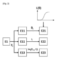
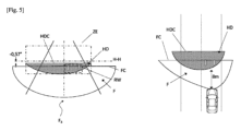
図2は、本発明の一実施形態による照明システム1を制御するための方法を示している。この方法は、図3および図4および図5との関連において説明されることとなる。図3および図4および図5はそれぞれ、図2の方法の実施時に実現される3つの異なる照明機能について、左側ではヘッドランプ11によって放出される照明ビームFおよびHDのスクリーン上への投影を、右側では道路現場の平面図を表している。
Figure 2 shows a method for controlling a
段階E1において、コンピューター12は、受け取ったデータに基づいて、所与の照明機能Fiを発せよとの命令を生成する。図3の例において、車両の速度が60km/hを超えていて多数の幻惑されるべきでない道路使用者らが検出されている場合に発せられるのがロービーム・モードの防眩ハイビーム照明機能F1である。図3の場合、機能F1を発せよとの命令は、それに加えて、自動車両の下流側に位置した障害物と衝突する危険性の警告を具体化する2本の水平な白帯を地面筆記区域RW内に生成することを要求する、ということに留意されたい。図4の例において、車両の速度が30km/hから60km/hの間であって少なくとも1人の幻惑されるべきでない道路使用者が検出されている場合に発せられるのがロービーム照明機能F2である。機能F2を発せよとの命令は、それに加えて、自動車両の下流側に位置した障害物と衝突する危険性の警告を具体化する3本の水平な白帯を地面筆記区域RW内に生成することを要求する。最後に図5の例において、車両の速度が30km/h未満の場合に発せられるのが市街地照明機能F3である。機能F3を発せよとの命令は、それに加えて、自動車両の大きさを具体化して運転者が精確な操縦を実現することを可能とする2本の鉛直な白帯を地面筆記区域RW内に生成することを要求する。上記で言及した諸機能は適応例として列挙されたものであって、ヘッドランプ11によって別の型式の照明機能を発せよとの命令をコンピューター12が生成してもよい、ということに留意されたい。
In step E1, the
制御器5は段階E1において、機能Fiを発せよとの命令に基づいて、機能Fiを実現することを可能とする照明ビームFおよびHDの鉛直方向の向きについての角度設定値θiを決定する。次に、段階E21において制御器5は、軸線Y周りのプレート41の回動を引き起こして、この角度設定値θiに向かって第1および第2照明ビームFおよびHDの鉛直方向の向きを変更するように、調節システムのアクチュエータ42を制御する。説明する例において、角度設定値θiは、第1照明ビームFの実質的に平坦なカットオフFCの水平線H-Hに対する位置をそれぞれ定めており、図3のロービーム・モードの防眩ハイビーム照明機能については-0.57°、図4のロービーム照明機能については-1.57°、図5の市街地照明機能については-2.57°となっている。
The controller 5 determines, in step E1, on the basis of a command to emit a function F i , an angle setpoint θ i for the vertical orientation of the illumination beams F and HD making it possible to realize the function F i . Then, in step E21, the controller 5 controls the
換言すれば、例えば図3に示すようにヘッドランプ11がロービーム・モードの防眩ハイビーム照明機能F1を発している間に、コンピューター12がロービーム照明機能F2の発出を要求した場合、制御器5は角度設定値θ2(即ち、-1.57°)を決定し、照明ビームFおよびHDの鉛直方向の向きの-1°だけの変更を生じさせるようにアクチュエータ42を制御するのである。この変更は、図4に示すように、第1照明ビームFのカットオフFCを1°だけ低くすること、そしてピクセル化された第2照明ビームHDの発光区域ZEを-1°だけ位置変更することに帰着する。かくして運転者の視点からは、発光区域ZEが自動車両へ4メートル近づくのである。
In other words, if the
同様に、例えば図4に示すようにヘッドランプ11がロービーム照明機能F2を発している間に、コンピューター12が市街地照明機能F3の発出を要求した場合、制御器5は角度設定値θ3(即ち、-2.57°)を決定し、照明ビームFおよびHDの鉛直方向の向きの-1°だけの変更を生じさせるようにアクチュエータ42を制御する。この変更は、第1照明ビームFのカットオフFCを1°だけ低くすること、そしてピクセル化された第2照明ビームHDの発光区域ZEを-1°だけ位置変更することに帰着する。かくして運転者の視点からは、発光区域ZEが自動車両へ3メートル近づくのである。
Similarly, if the
段階E21において、第1および第2照明ビームの鉛直方向の向きの変更は、制御法則L(θ)に従って実現される。その制御法則L(θ)は、照明ビームFおよびHDの初期の鉛直方向の向きθi-1と、当該角度設定値θiとの間における、それらの照明ビームについての移動速度設定値を規定している。説明する例において、制御法則L(θ)は次のようなものである。即ち、プレート41が、移動の始めには徐々に加速しながら、それから一定の速度で、移動の最後には徐々に減速しながら回動するようなものである。
In step E21, the change in the vertical orientation of the first and second illumination beams is realized according to a control law L(θ) which defines the movement speed setpoints for the illumination beams F and HD between their initial vertical orientation θ i−1 and the angular setpoint θ i in question. In the example illustrated, the control law L(θ) is such that the
同時に、制御器5は段階E12において、機能Fiを実現することを可能とする第1照明ビームFについての光強度設定値Iiを決定する。そして段階E22において、制御器5は、第1照明ビームFの光強度がこの設定値Iiに従うよう、第1照明モジュール2(具体的には、その光源21)を制御する。説明する例において、光強度設定値Iiは、光源21によって発せられ得る公称光強度のパーセンテージとして決定され、それぞれ図3のロービーム・モードの防眩ハイビーム照明機能については100%、図4のロービーム照明機能については75%、図5の市街地照明機能については50%である。
At the same time, the controller 5 determines, in step E12, a light intensity setpoint Ii for the first lighting beam F making it possible to realise the function F i . Then, in step E22, the controller 5 controls the first lighting module 2 (in particular its light source 21) so that the light intensity of the first lighting beam F complies with this setpoint Ii . In the example described, the light intensity setpoint Ii is determined as a percentage of the nominal light intensity that can be emitted by the
また同時に、段階E13において制御器5は一連のデジタル像Imj(Fi-1,Fi)を生成する。それらのデジタル像Imj(Fi-1,Fi)は、ピクセル化された第2照明ビームHDが、先に発せられている照明機能Fi-1から新たな機能Fiへと移行することを可能とするものである。 At the same time, in step E13, the controller 5 generates a series of digital images Im j (F i-1 , F i ) which enable the pixelated second illumination beam HD to transition from the previously emitted illumination function F i-1 to the new function F i .
具体的には、一連のデジタル像Imj(Fi-1,Fi)は、一方では次のように生成される。即ち、照明機能Fi-1について規定された第2照明ビームHDにおける上方カットオフHDCの位置が、段階E21における第1および第2照明ビームFおよびHDの鉛直方向の向きの変更中、実質的に一定のままであるようにである。この目的のために、制御器5によって生成される各デジタル像Imj(Fi-1,Fi)で規定されるカットオフHDCの位置は、先に生成されているデジタル像Imj-1(Fi-1,Fi)で規定されたカットオフHDCの位置に対して、段階E11で決定された鉛直方向の向きの変更とは反対方向に移動するのである。このようにして、このカットオフHDCのデジタル的な移動が、発光区域ZEの鉛直方向の向きの機械的な変更と相殺されるのである。その結果、カットオフHDCの位置は、この機械的な変更の過程に亘って実質的に同じままである。 In particular, a series of digital images Im j (F i-1 , F i ) is generated on the one hand such that the position of the upper cut-off HDC in the second illumination beam HD defined for the illumination function F i-1 remains substantially constant during the change in the vertical orientation of the first and second illumination beams F and HD in step E21. For this purpose, the position of the cut-off HDC defined in each digital image Im j (F i-1 , F i ) generated by the controller 5 is moved in the opposite direction to the change in the vertical orientation determined in step E11 with respect to the position of the cut-off HDC defined in the previously generated digital image Im j-1 (F i-1 , F i ). In this way, this digital movement of the cut-off HDC is counterbalanced with the mechanical change in the vertical orientation of the light-emitting area ZE. As a result, the position of the cut-off HDC remains substantially the same throughout the course of this mechanical change.
図3において、ピクセル化された第2照明ビームHDは、発光区域ZE内においてカットオフHDCによって画定されている。そのカットオフHDCは、第1照明ビームの実質的に平坦なカットオフFCと同一直線上にある第1の実質的に平坦な部分と、当該実質的に平坦なカットオフよりも上に位置した第2の実質的に平坦な部分とを有している。第1および第2の部分同士は(特に、斜めの)段部によって連結されている。かくして図4および図5においては、次のことが見て取られるであろう。即ち、実質的にカットオフFCは実際に機械的な方向転換を受けているが、それとは対照的に、カットオフHDCは同じ位置(即ち、-0.57°)のままである。それにより、この機械的な方向転換中も含めて、照明ビームFおよびHD同士の結合によって形成される全体的なビームを、照明ビームにおける上方カットオフの存在を取り巻く規制要件に従ったままにしておくことが可能となる。 In FIG. 3, the pixelated second illumination beam HD is defined in the light-emitting area ZE by a cut-off HDC. The cut-off HDC has a first substantially flat portion collinear with the substantially flat cut-off FC of the first illumination beam and a second substantially flat portion located above the substantially flat cut-off. The first and second portions are connected by a (particularly oblique) step. Thus, in FIGS. 4 and 5, it can be seen that the cut-off FC is actually mechanically redirected, whereas the cut-off HDC remains in the same position (i.e., −0.57°). This allows the overall beam formed by the combination of the illumination beams F and HD, including during this mechanical redirection, to remain in compliance with the regulatory requirements surrounding the presence of an upper cut-off in the illumination beam.
他方では、先に発せられた照明機能Fi-1の実現を可能とするデジタル像Im(Fi-1)を、新たな照明機能Fiの実現を可能とするデジタル像Im(Fi)に向かってモーフィング(変形)および/または並進させる操作によって、一連のデジタル像Imj(Fi-1,Fi)が生成される。 On the other hand, a series of digital images Im j (F i -1 , F i ) are generated by morphing and/or translating a digital image Im (F i-1 ) enabling the realization of a previously issued lighting function F i -1 towards a digital image Im (F i ) enabling the realization of a new lighting function F i .
例えば図3においては、デジタル像Im(F1)が、次のようなピクセル化された第2照明ビームHDを定めている。即ち、発光区域ZE内で水平方向へは部分的にしか広がっていない、上述したような特定のカットオフHDCを伴い、表示区域RW内に与えられる2本の水平な帯を備えているビームHDである。図4においては、デジタル像Im(F2)が、次のようなピクセル化された第2照明ビームHDを定めている。即ち、発光区域ZE内で水平方向全体に広がって、同じカットオフHDCを伴い、表示区域RW内に与えられる3本の水平な帯を備えているビームHDである。かくして、先に発せられた照明機能F1の実現を可能とするデジタル像Im(F1)を、新たな機能F2の実現を可能とするデジタル像Im(F2)に向かってモーフィングおよび/または並進させる操作によって、図3の機能F1の図4の機能F2に向かっての移行を可能とする一連のデジタル像Imj(F1,F2)が生成されるのである。 For example, in Fig. 3, the digital image Im( F1 ) defines a pixelated second illumination beam HD that is only partially spread horizontally in the light emitting area ZE and has two horizontal bands provided in the display area RW with a specific cut-off HDC as described above. In Fig. 4, the digital image Im( F2 ) defines a pixelated second illumination beam HD that is fully spread horizontally in the light emitting area ZE and has three horizontal bands provided in the display area RW with the same cut-off HDC. Thus, by morphing and/or translating a digital image Im( F1 ) enabling the realization of a previously issued lighting function F1 towards a digital image Im( F2 ) enabling the realization of a new function F2 , a series of digital images Imj ( F1 , F2 ) enabling the transition of function F1 in Figure 3 towards function F2 in Figure 4 is generated.
同様に、図5においては、デジタル像Im(F3)が、次のようなピクセル化された第2照明ビームHDを定めている。即ち、発光区域ZE内で水平方向全体に広がって、実質的に平坦な特定のカットオフHDCを伴い、表示区域RW内に与えられる2本の鉛直な帯を備えているビームHDである。かくして、先に発せられた照明機能F2の実現を可能とするデジタル像Im(F2)を、新たな機能F3の実現を可能とするデジタル像Im(F3)に向かってモーフィングおよび/または並進させる操作によって、図4の機能F2の図5の機能F3に向かっての移行を可能とする一連のデジタル像Imj(F2,F3)が生成されるのである。 Similarly, in Fig. 5, the digital image Im( F3 ) defines a pixelated second illumination beam HD, which is horizontally spread across the entire light emitting area ZE, with a substantially flat specific cut-off HDC and with two vertical bands provided in the display area RW. Thus, by morphing and/or translating the digital image Im( F2 ) enabling the realization of the previously emitted illumination function F2 towards the digital image Im( F3 ) enabling the realization of the new function F3 , a series of digital images Imj ( F2 , F3 ) enabling the transition of the function F2 of Fig . 4 towards the function F3 of Fig. 5 is generated.
段階E23においては、段階E21でのアクチュエータ42の制御と同時に、一連のデジタル像Imj(Fi-1,Fi)におけるデジタル像それぞれが、ピクセル化光源31の組込み型制御器へ伝達される。一連のものにおける最初の像は、鉛直方向の向きの変更の開始時に伝達され、一連のものにおける最後の像は、この鉛直方向の向きの変更の終了時に伝達される。かくして、組込み型制御器は、発光区域ZEの移動中、ピクセル化された第2照明ビームHDが、この発光区域ZE内に一連のデジタル像Imj(Fi-1,Fi)における各デジタル像を作り出すように、基本光源31i,jのそれぞれを選択的に制御する。
In step E23, simultaneously with the control of the
前述の説明は、本発明がそれ自体設定した目的を達成することを如何にして可能とするかを明瞭に解説している。それは特に、平坦な上方カットオフを有した照明ビームを放出し得る第1照明モジュールと、ピクセル化された照明ビームを放出し得る第2照明モジュールとを統合している自動車両の照明システムであって、発することが望まれる照明機能の型式に応じて2つのビームの鉛直方向の向きとピクセル化された照明ビームとが同時に制御される照明システムによるものである。その結果、鉛直方向の向きを調節しながら、同時に照明システムが規制照明機能を発する能力を維持することが可能となる。 The above description clearly explains how the invention enables the invention to achieve the object it sets out for itself, in particular by means of a lighting system for a motor vehicle integrating a first lighting module capable of emitting a lighting beam with a flat upper cut-off and a second lighting module capable of emitting a pixelated lighting beam, in which the vertical orientation of the two beams and the pixelated lighting beam are simultaneously controlled depending on the type of lighting function it is desired to emit. As a result, it is possible to adjust the vertical orientation while at the same time maintaining the ability of the lighting system to emit regulated lighting functions.
如何なる場合にも、本発明は、この文書で具体的に説明された諸実施形態に限定されるものと見做されるべきではなく、特に、如何なる等価な手段や、これらの手段同士の技術的に効力のある如何なる組合せにも及ぶものである。とりわけ、説明された型式以外の照明モジュール、特に光源と、選択的に作動され得るマイクロミラーの格子との組合せを備えた照明モジュールが考えられてよい。また、説明されてきた以外の照明機能、特に高速道路照明機能や悪天候条件照明機能、更には他の型式のピクトグラムや地面マーキングをもたらす照明機能を発するように照明システムを制御するのを考えることも可能である。また、それぞれに専用の調節アクチュエータが備え付けられた2つの異なるプレート上に各モジュールを配置するのを考えることも可能である。 In any case, the invention should not be considered as being limited to the embodiments specifically described in this document, but in particular extends to any equivalent means and any technically effective combination of these means. In particular, lighting modules of other types than those described may be envisaged, in particular lighting modules with a combination of a light source and a grid of micromirrors that can be selectively activated. It is also possible to envisage controlling the lighting system to emit lighting functions other than those that have been described, in particular highway lighting functions, bad weather conditions lighting functions, and also lighting functions that provide other types of pictograms or ground markings. It is also possible to envisage arranging the modules on two different plates, each equipped with its own adjustment actuator.
Claims (10)
ピクセル化された第2照明ビーム(HD)を放出することのできる第2照明モジュール(3)であって、前記第2照明ビーム(HD)の発光区域(ZE)は、前記第1照明ビーム(F)の平坦な前記上方カットオフ(FC)の下方および上方に広がっている、前記第2照明モジュール(3)と、
前記第1および第2照明ビームの鉛直方向の向きを機械的に調節するための調節システム(42)と、
所与の照明機能(Fi)を発せよとの命令を受けることのできる制御器(5)と、
を備え、
前記制御器(5)は、前記命令に応じて前記第1および第2照明ビームの鉛直方向の向きの同時変更を生じさせるよう前記調節システムを制御するように構成されると共に、前記命令に応じて所定の特性を有するピクセル化された第2照明ビームを放出するよう前記第2照明モジュールを制御するように構成されている、自動車両の照明システム(1)。 a first illumination module (2) capable of emitting a first illumination beam (F) with an upper cutoff (FC);
a second illumination module (3) capable of emitting a pixelated second illumination beam (HD) , the light emitting area (ZE) of which extends below and above the flat upper cut-off (FC) of the first illumination beam (F);
an adjustment system (42) for mechanically adjusting the vertical orientation of the first and second illumination beams;
a controller (5) capable of receiving a command to issue a given lighting function (F i ) ;
Equipped with
The controller (5) is configured to control the adjustment system to cause a simultaneous change in vertical orientation of the first and second illumination beams in response to the command, and to control the second lighting module to emit a pixelated second illumination beam having predetermined characteristics in response to the command.
a.前記制御器は、非幻惑性ハイビーム照明ビームを放出せよとの命令を受けたときには、前記第1照明ビーム(F)の前記上方カットオフ(FC)が水平線(H-H)に対して実質的に-0.57°の角度の所に位置するように、前記第1および第2照明ビームの鉛直方向の向きの同時変更を生じさせるよう前記調節システム(42)を制御するように構成されており、
b.前記制御器は、ロービーム照明ビームを放出せよとの命令を受けたときには、前記第1照明ビームの前記上方カットオフが水平線に対して実質的に-1.57°の角度の所に位置するように、前記第1および第2照明ビームの鉛直方向の向きの同時変更を生じさせるよう前記調節システム(42)を制御するように構成されており、
c.前記制御器は、市街地照明ビームを放出せよとの命令を受けたときには、前記第1照明ビームの前記上方カットオフが水平線に対して実質的に-2.57°の角度の所に位置するように、前記第1および第2照明ビームの鉛直方向の向きの同時変更を生じさせるよう前記調節システムを制御するように構成されている、請求項5に記載の照明システム(1)。 said controller (5) being selectively capable of receiving at least a command to emit a non-dazzling high beam lighting beam (F 1 ), a command to emit a low beam lighting beam (F 2 ), and a command to emit a city lighting beam (F 3 );
a) said controller is configured, when commanded to emit a non-dazzling high beam illumination beam, to control said adjustment system (42) to cause a simultaneous change in vertical orientation of said first and second illumination beams (F) such that said upper cutoff (FC) of said first illumination beam (F) is located at an angle of substantially -0.57° with respect to a horizontal line (H-H);
b) the controller is configured, when commanded to emit a low beam illumination beam, to control the adjustment system (42) to cause a simultaneous change in vertical orientation of the first and second illumination beams such that the upper cutoff of the first illumination beam is located at an angle of substantially -1.57° with respect to the horizon;
6. The lighting system (1) of claim 5, wherein the controller, when commanded to emit a city lighting beam, is configured to control the adjustment system to cause a simultaneous change in vertical orientation of the first and second lighting beams such that the upper cutoff of the first lighting beam is located at an angle of substantially -2.57° with respect to the horizon.
a.所与の照明機能(Fi)を発せよとの命令を受ける段階(E1)と、
b.前記命令に応じて、前記第1および第2照明ビーム(F,HD)の鉛直方向の向きの同時変更を生じさせるように前記調節システム(42)を制御する段階(E21)と、
c.前記命令に応じて、所定の特性を有するピクセル化された第2照明ビームを放出するように前記第2照明モジュール(3)を制御する段階(E23)と、
を備えた方法。 A method for controlling a lighting system (1) according to any one of claims 1 to 9, comprising:
a. a step (E1) of receiving a command to issue a given lighting function (F i );
b. controlling (E21) said adjustment system (42) in response to said command so as to cause a simultaneous change in the vertical orientation of said first and second illumination beams (F, HD);
c) controlling (E23) said second illumination module (3) in response to said command to emit a pixelated second illumination beam having predetermined characteristics;
The method according to claim 1,
Applications Claiming Priority (3)
| Application Number | Priority Date | Filing Date | Title |
|---|---|---|---|
| FR2100601A FR3119221A1 (en) | 2021-01-22 | 2021-01-22 | Automotive vehicle lighting system provided with a light module capable of emitting a pixelated light beam |
| FR2100601 | 2021-01-22 | ||
| PCT/EP2022/051404 WO2022157339A1 (en) | 2021-01-22 | 2022-01-21 | Motor vehicle illumination system provided with a lighting module able to emit a pixellated light beam |
Publications (2)
| Publication Number | Publication Date |
|---|---|
| JP2024505855A JP2024505855A (en) | 2024-02-08 |
| JP7635397B2 true JP7635397B2 (en) | 2025-02-25 |
Family
ID=75539491
Family Applications (1)
| Application Number | Title | Priority Date | Filing Date |
|---|---|---|---|
| JP2023544433A Active JP7635397B2 (en) | 2021-01-22 | 2022-01-21 | Lighting system for a motor vehicle provided with a lighting module capable of emitting a pixelated lighting beam - Patents.com |
Country Status (7)
| Country | Link |
|---|---|
| US (1) | US20240084992A1 (en) |
| EP (1) | EP4281321B1 (en) |
| JP (1) | JP7635397B2 (en) |
| CN (1) | CN116867676A (en) |
| FR (1) | FR3119221A1 (en) |
| PL (1) | PL4281321T3 (en) |
| WO (1) | WO2022157339A1 (en) |
Families Citing this family (6)
| Publication number | Priority date | Publication date | Assignee | Title |
|---|---|---|---|---|
| WO2024122454A1 (en) * | 2022-12-07 | 2024-06-13 | 株式会社小糸製作所 | Vehicle light fitting and controller for same |
| KR20240092756A (en) * | 2022-12-15 | 2024-06-24 | 현대모비스 주식회사 | Lamp system for vehicle |
| CN118596982B (en) * | 2023-12-25 | 2025-05-20 | 深圳引望智能技术有限公司 | Car light system, car light and vehicle |
| FR3161018A1 (en) * | 2024-04-05 | 2025-10-10 | Valeo Vision | Lighting device of a motor vehicle. |
| CN222167400U (en) * | 2024-04-24 | 2024-12-13 | 深圳引望智能技术有限公司 | Projection module, car light device and vehicle |
| WO2026057491A1 (en) * | 2024-09-11 | 2026-03-19 | Valeo Vision | Lighting device for a motor vehicle |
Citations (7)
| Publication number | Priority date | Publication date | Assignee | Title |
|---|---|---|---|---|
| JP2010137693A (en) | 2008-12-11 | 2010-06-24 | Koito Mfg Co Ltd | Headlight for vehicle |
| JP2015223887A (en) | 2014-05-26 | 2015-12-14 | 株式会社小糸製作所 | Vehicle lighting fixture system |
| JP2015230768A (en) | 2014-06-03 | 2015-12-21 | 株式会社小糸製作所 | Vehicle lighting |
| JP2018058412A (en) | 2016-10-03 | 2018-04-12 | 株式会社小糸製作所 | Vehicle lighting |
| DE102017223446A1 (en) | 2017-12-20 | 2019-06-27 | Audi Ag | Illuminating device for displaying animations for delimiting different light functions |
| US20190283666A1 (en) | 2017-03-09 | 2019-09-19 | Bayerische Motoren Werke Aktiengesellschaft | Lighting Apparatus for a Motor Vehicle |
| JP2019204772A (en) | 2018-04-03 | 2019-11-28 | ヴァレオ ビジョンValeo Vision | Motor vehicle lighting device with function of writing on ground |
Family Cites Families (17)
| Publication number | Priority date | Publication date | Assignee | Title |
|---|---|---|---|---|
| FR2890720A1 (en) * | 2005-09-09 | 2007-03-16 | Valeo Vision Sa | LIGHTING DEVICE FOR MOTOR VEHICLE |
| DE102009035743A1 (en) * | 2009-08-01 | 2011-02-17 | Automotive Lighting Reutlingen Gmbh | Light module for a motor vehicle headlight |
| US10066799B2 (en) * | 2014-06-26 | 2018-09-04 | Texas Instruments Incorporated | Pixelated projection for automotive headlamp |
| US10436409B2 (en) * | 2015-05-28 | 2019-10-08 | Texas Instruments Incorporated | Methods and apparatus for light efficient programmable headlamp with anamorphic optics |
| FR3038697B1 (en) * | 2015-07-10 | 2017-08-11 | Valeo Vision | METHOD FOR CONTROLLING A BRIGHT BEAM AND LIGHTING AND / OR SIGNALING MODULE THEREOF |
| AT517998B1 (en) | 2015-11-26 | 2017-10-15 | Zkw Group Gmbh | Headlight for motor vehicles |
| FR3047541B1 (en) * | 2015-12-10 | 2019-10-04 | Valeo Vision | AUTOMOTIVE LIGHTING MODULE WITH COMBINED CODE AND ROAD FUNCTIONS AND ADJUSTABLE LIGHT SOURCE |
| FR3056680B1 (en) * | 2016-09-29 | 2018-11-09 | Valeo Vision | LIGHTING SYSTEM FOR MOTOR VEHICLE |
| KR101947870B1 (en) * | 2016-10-10 | 2019-02-14 | 현대자동차주식회사 | Light apparatus for vehicle |
| KR20190058857A (en) * | 2017-11-22 | 2019-05-30 | 르노삼성자동차 주식회사 | Headlamp assembly for vehicles and method for driving the same |
| FR3079467A1 (en) * | 2018-04-03 | 2019-10-04 | Valeo Vision | MONOLITHIC MATRIX LUMINOUS DEVICE OF A MOTOR VEHICLE FOR WRITING ON THE GROUND |
| FR3082471B1 (en) * | 2018-06-15 | 2022-10-28 | Valeo Vision | LIGHTING DEVICE FOR MOTOR VEHICLE |
| FR3087875B1 (en) * | 2018-10-25 | 2021-07-30 | Valeo Vision | LIGHT MODULE FOR VEHICLE LIGHTING DEVICE |
| US11230224B2 (en) * | 2018-12-05 | 2022-01-25 | Sl Corporation | Lamp for vehicle |
| EP3689678A1 (en) * | 2019-02-01 | 2020-08-05 | Valeo Vision | Lighting system of an automotive vehicle |
| FR3096433B1 (en) * | 2019-05-20 | 2021-05-21 | Valeo Vision | PROCESS FOR CONTROL OF A LUMINOUS DEVICE FOR THE EMISSION OF A PIXELIZED LIGHT BEAM |
| FR3099541B1 (en) * | 2019-07-31 | 2024-09-20 | Valeo Vision | METHOD FOR CONTROLLING A LIGHTING DEVICE CAPABLE OF EMITTING TWO PIXELATED LIGHT BEAMS OF DIFFERENT RESOLUTIONS |
-
2021
- 2021-01-22 FR FR2100601A patent/FR3119221A1/en not_active Ceased
-
2022
- 2022-01-21 JP JP2023544433A patent/JP7635397B2/en active Active
- 2022-01-21 US US18/262,138 patent/US20240084992A1/en active Pending
- 2022-01-21 WO PCT/EP2022/051404 patent/WO2022157339A1/en not_active Ceased
- 2022-01-21 PL PL22701591.4T patent/PL4281321T3/en unknown
- 2022-01-21 EP EP22701591.4A patent/EP4281321B1/en active Active
- 2022-01-21 CN CN202280011115.3A patent/CN116867676A/en active Pending
Patent Citations (7)
| Publication number | Priority date | Publication date | Assignee | Title |
|---|---|---|---|---|
| JP2010137693A (en) | 2008-12-11 | 2010-06-24 | Koito Mfg Co Ltd | Headlight for vehicle |
| JP2015223887A (en) | 2014-05-26 | 2015-12-14 | 株式会社小糸製作所 | Vehicle lighting fixture system |
| JP2015230768A (en) | 2014-06-03 | 2015-12-21 | 株式会社小糸製作所 | Vehicle lighting |
| JP2018058412A (en) | 2016-10-03 | 2018-04-12 | 株式会社小糸製作所 | Vehicle lighting |
| US20190283666A1 (en) | 2017-03-09 | 2019-09-19 | Bayerische Motoren Werke Aktiengesellschaft | Lighting Apparatus for a Motor Vehicle |
| DE102017223446A1 (en) | 2017-12-20 | 2019-06-27 | Audi Ag | Illuminating device for displaying animations for delimiting different light functions |
| JP2019204772A (en) | 2018-04-03 | 2019-11-28 | ヴァレオ ビジョンValeo Vision | Motor vehicle lighting device with function of writing on ground |
Also Published As
| Publication number | Publication date |
|---|---|
| WO2022157339A1 (en) | 2022-07-28 |
| EP4281321A1 (en) | 2023-11-29 |
| EP4281321B1 (en) | 2025-09-17 |
| FR3119221A1 (en) | 2022-07-29 |
| CN116867676A (en) | 2023-10-10 |
| PL4281321T3 (en) | 2026-03-09 |
| JP2024505855A (en) | 2024-02-08 |
| US20240084992A1 (en) | 2024-03-14 |
Similar Documents
| Publication | Publication Date | Title |
|---|---|---|
| JP7635397B2 (en) | Lighting system for a motor vehicle provided with a lighting module capable of emitting a pixelated lighting beam - Patents.com | |
| JP6275408B2 (en) | Adaptive lighting system for automobiles | |
| JP7206460B2 (en) | Quasi-sparse optical illumination | |
| CN108343925B (en) | Vehicle headlight | |
| JP6946352B2 (en) | Vehicle lighting system, vehicle lighting control device, and vehicle lighting control method | |
| US11028992B2 (en) | Optical system for a pixelized light beam | |
| US10081294B2 (en) | Lighting apparatus for a vehicle | |
| US10415786B2 (en) | Pixel light headlamp for vehicles | |
| JP6932610B2 (en) | Vehicle lighting system, vehicle lighting control device, and vehicle lighting control method | |
| US10507759B2 (en) | Adaptive lighting system for an automobile vehicle | |
| US10767829B2 (en) | Light irradiation device and vehicular lamp | |
| WO2022131044A1 (en) | Vehicle light fixture system, light distribution control device, and light distribution control method | |
| CN103523114A (en) | Method for adjusting headlight using camera | |
| JP2011218999A (en) | Control device, vehicular lamp system, and vehicular lamp | |
| US20180031195A1 (en) | Variable aperture beam motor vehicle headlamp lighting module | |
| CN114867639B (en) | Method for controlling a lighting system of a motor vehicle | |
| US10876701B2 (en) | Programmable glare-free high beam | |
| JP6581442B2 (en) | Vehicle lighting | |
| JP7407174B2 (en) | Vehicle lighting and vehicle systems | |
| KR20190063984A (en) | Lamp for vehicle | |
| WO2021070787A1 (en) | Automotive lamp, and method for controlling adaptive headlight | |
| US20250361998A1 (en) | Control of vehicle headlamps | |
| JP2021030875A (en) | Vehicle lighting system |
Legal Events
| Date | Code | Title | Description |
|---|---|---|---|
| A621 | Written request for application examination |
Free format text: JAPANESE INTERMEDIATE CODE: A621 Effective date: 20230907 |
|
| A131 | Notification of reasons for refusal |
Free format text: JAPANESE INTERMEDIATE CODE: A131 Effective date: 20240827 |
|
| A977 | Report on retrieval |
Free format text: JAPANESE INTERMEDIATE CODE: A971007 Effective date: 20240828 |
|
| A521 | Request for written amendment filed |
Free format text: JAPANESE INTERMEDIATE CODE: A523 Effective date: 20241127 |
|
| TRDD | Decision of grant or rejection written | ||
| A01 | Written decision to grant a patent or to grant a registration (utility model) |
Free format text: JAPANESE INTERMEDIATE CODE: A01 Effective date: 20250117 |
|
| A61 | First payment of annual fees (during grant procedure) |
Free format text: JAPANESE INTERMEDIATE CODE: A61 Effective date: 20250212 |
|
| R150 | Certificate of patent or registration of utility model |
Ref document number: 7635397 Country of ref document: JP Free format text: JAPANESE INTERMEDIATE CODE: R150 |