JP7635367B2 - RRC re-establishment - Google Patents
RRC re-establishment Download PDFInfo
- Publication number
- JP7635367B2 JP7635367B2 JP2023518093A JP2023518093A JP7635367B2 JP 7635367 B2 JP7635367 B2 JP 7635367B2 JP 2023518093 A JP2023518093 A JP 2023518093A JP 2023518093 A JP2023518093 A JP 2023518093A JP 7635367 B2 JP7635367 B2 JP 7635367B2
- Authority
- JP
- Japan
- Prior art keywords
- rrc
- establishment
- control plane
- message
- establishment procedure
- Prior art date
- Legal status (The legal status is an assumption and is not a legal conclusion. Google has not performed a legal analysis and makes no representation as to the accuracy of the status listed.)
- Active
Links
Images


Classifications
-
- H—ELECTRICITY
- H04—ELECTRIC COMMUNICATION TECHNIQUE
- H04W—WIRELESS COMMUNICATION NETWORKS
- H04W76/00—Connection management
- H04W76/10—Connection setup
- H04W76/19—Connection re-establishment
Landscapes
- Engineering & Computer Science (AREA)
- Computer Networks & Wireless Communication (AREA)
- Signal Processing (AREA)
- Mobile Radio Communication Systems (AREA)
- Two-Way Televisions, Distribution Of Moving Picture Or The Like (AREA)
Description
本開示の例は、たとえばUEがRRC再確立プロシージャを実施すること、またはUEにRRC再確立プロシージャを実施するように命令することなど、RRC再確立に関する。 Examples of the present disclosure relate to RRC re-establishment, such as, for example, a UE performing an RRC re-establishment procedure or instructing a UE to perform an RRC re-establishment procedure.
第5世代の(5G)新無線(New Radio:NR)セルラ通信システムは、超高信頼低レイテンシ通信(URLLC)をサポートすることを目的とする。URLLCの特徴の例は、信頼性を増加させるためのPDCP複製機能、ならびに、UEがあるセルまたはビームから別のセルまたはビームに切り替わるハンドオーバにおいて、最小中断時間を保証するためのメークビフォアブレークハンドオーバプロシージャを含む。 The fifth generation (5G) New Radio (NR) cellular communication system aims to support ultra-reliable low latency communication (URLLC). Example features of URLLC include PDCP duplication functionality to increase reliability, as well as make-before-break handover procedures to ensure minimal interruption time during handovers where a UE switches from one cell or beam to another.
5G NRシステムの一般的な展開は、将来において、3GPP規定されたgノードB-中央ユニット-制御プレーン(gNB-CU-CP)機能など、5Gコアネットワークおよび上位無線アクセスネットワーク(RAN)機能をサポートするクラウドインフラストラクチャを利用することが予想される。クラウドインフラストラクチャは、セルラネットワーク機能をサポートするために旧来使用されてきた一般的な、専用のまたは特殊化されたハードウェアとは信頼性が異なる。1つのそのような差は、基礎をなすハードウェアの利用可能性であり、これは、旧来の専用ハードウェアと比較して、汎用既製クラウドハードウェアの場合、著しく信頼性が低くなり得る。したがって、通信機能のクラウド展開は、クラウドインフラストラクチャの障害に対処するための機構を導入し得る。そのような機構の例は、分散データベースを使用して、このデータベースをサポートする1つまたは複数のハードウェアノードの障害の場合でも、永続記憶域を提供することを含む。 It is expected that general deployment of 5G NR systems will utilize cloud infrastructure to support 5G core network and upper radio access network (RAN) functions, such as 3GPP-defined gNodeB-Central Unit-Control Plane (gNB-CU-CP) functions in the future. Cloud infrastructure differs in reliability from the generic, dedicated or specialized hardware that has traditionally been used to support cellular network functions. One such difference is the availability of the underlying hardware, which can be significantly less reliable for general-purpose off-the-shelf cloud hardware compared to traditional dedicated hardware. Thus, cloud deployment of communication functions may introduce mechanisms to address failures of the cloud infrastructure. Examples of such mechanisms include using a distributed database to provide persistent storage even in the event of failure of one or more hardware nodes supporting the database.
URLLCを使用してUEへの信頼できる接続を保証するための方法が、同じUEへの並列ユーザプレーン接続を、ユーザプレーン接続のうちの1つが失われた場合に他の接続を介してデータ送信を続けることが可能であり得るように、セットアップすることを含み得る。複数のユーザプレーン接続は、単一の制御プレーン接続(たとえば、RRC、NAS接続)を使用して、または2つの独立した制御プレーン接続を用いてのいずれかでサポートされ得、これは、デバイスが、デュアル無線能力を有し、2つの独立した無線接続をセットアップすることが可能であることを必要とし、これは、一般に、UEのコストを増加させる。後者のソリューションは、ネットワークが、2つの制御プレーン接続が関係することを理解することと、これらのデバイスが、単一障害点を回避するために異なるネットワークリソースを使用することに誘導されることを保証することとの両方を行う必要があることになるので、ネットワーク複雑度をも増加させる。 A method for ensuring a reliable connection to a UE using URLLC may include setting up parallel user plane connections to the same UE, such that if one of the user plane connections is lost, it may be possible to continue data transmission via the other connection. Multiple user plane connections may be supported either using a single control plane connection (e.g., RRC, NAS connection) or with two independent control plane connections, which requires the device to have dual-radio capability and be able to set up two independent radio connections, which generally increases the cost of the UE. The latter solution also increases network complexity, as the network would need to both understand that two control plane connections are involved and ensure that these devices are directed to use different network resources to avoid a single point of failure.
図1は、デュアルコネクティビティを使用するエンドツーエンド冗長ユーザプレーン経路についての例示的なシナリオ100を示す。たとえば、図1は、冗長が適用されるときのデュアルPDUセッションのユーザプレーンリソース設定を示す。一方のプロトコルデータユニット(PDU)セッション102が、UEからマスタNG-RANノードを介してPDUセッションアンカーとして働く第1のユーザプレーン機能(UPF1)にわたり、他方のPDUセッション104が、UEから2次NG-RANノードを介してPDUセッションアンカーとして働くUPF2にわたる。参照により本明細書に組み込まれる、3GPP技術仕様(TS)37.340において説明されるように、NG-RANは、2つのNG-RANノード(すなわち図1に示されているマスタNG-RANおよび2次NG-RAN)または単一のNG-RANノードを用いた2つのPDUセッションのために冗長ユーザプレーンリソースを実現し得る。どちらの場合も、マスタNG-RANノードからAMFへ向かう単一のN2インターフェースがある。
Figure 1 illustrates an
これらの2つのPDUセッション102および104に基づいて、2つの独立したユーザプレーン経路がセットアップされる。UPF1とUPF2とは、同じデータネットワーク(DN)に接続するが、UPF1およびUPF2を介したトラフィックは、DN内の異なるユーザプレーンノードを介してルーティングされ得る。
Based on these two
5G RANアーキテクチャ200は、参照により本明細書に組み込まれる3GPP TS38.401において説明されており、図2に示されている。NGアーキテクチャは、以下のようにさらに説明され得る。
・ NG-RANは、NGインターフェースを通して5GCに接続されるgNBのセットからなる。
・ gNBは、FDDモード、TDDモードまたはデュアルモード動作をサポートすることができる。
・ gNBは、Xnインターフェースを通して相互接続され得る。
・ gNBは、gNB-CU(中央ユニット)と1つまたは複数のgNB-DU(分散ユニット)とからなり得る。
・ gNB-CUとgNB-DUとは、F1論理インターフェースを介して接続される。
・ gNB-DUは、1つのgNB-CUのみに接続される。
The
- NG-RAN consists of a set of gNBs connected to 5GC through the NG interface.
The gNB may support FDD mode, TDD mode or dual mode operation.
- gNBs can be interconnected through the Xn interface.
- A gNB may consist of a gNB-CU (central unit) and one or more gNB-DUs (distributed units).
- The gNB-CU and gNB-DU are connected via an F1 logical interface.
- A gNB-DU is connected to only one gNB-CU.
NG、XnおよびF1は、論理インターフェースである。NG-RANの場合、gNB-CUとgNB-DUとからなるgNBのためのNGおよびXn-Cインターフェースは、gNB-CUにおいて終端する。E-UTRAN新無線デュアルコネクティビティ(EN-DC)の場合、gNB-CUとgNB-DUとからなるgNBのためのS1-UおよびX2-Cインターフェースは、gNB-CUにおいて終端する。gNB-CUおよび接続されたgNB-DUは、gNBとして他のgNBおよびコアネットワーク(5GC)に見えるにすぎない。 NG, Xn and F1 are logical interfaces. In case of NG-RAN, the NG and Xn-C interfaces for a gNB consisting of a gNB-CU and a gNB-DU terminate at the gNB-CU. In case of E-UTRAN New Radio Dual Connectivity (EN-DC), the S1-U and X2-C interfaces for a gNB consisting of a gNB-CU and a gNB-DU terminate at the gNB-CU. The gNB-CU and the connected gNB-DU only appear as a gNB to other gNBs and the core network (5GC).
NG-RANは、無線ネットワークレイヤ(RNL)とトランスポートネットワークレイヤ(TNL)とにレイヤ化される。NG-RANアーキテクチャ、すなわち、NG-RAN論理ノードと、NG-RAN論理ノード間のインターフェースとは、RNLの一部として規定される。各NG-RANインターフェース(NG、Xn、F1)では、関係するTNLプロトコルと機能とが指定される。TNLは、ユーザプレーントランスポートとシグナリングトランスポートとのためのサービスを提供する。NG-Flex設定では、各gNBが、アクセスおよびモビリティ機能(AMF)領域内のすべてのAMFに接続される。AMF領域は、参照により本明細書に組み込まれる3GPP TS23.501において規定されている。 The NG-RAN is layered into a Radio Network Layer (RNL) and a Transport Network Layer (TNL). The NG-RAN architecture, i.e., the NG-RAN logical nodes and the interfaces between the NG-RAN logical nodes, are specified as part of the RNL. At each NG-RAN interface (NG, Xn, F1), the relevant TNL protocols and functions are specified. The TNL provides services for user plane transport and signaling transport. In an NG-Flex setup, each gNB is connected to all Access and Mobility Functions (AMFs) within an AMF domain. The AMF domain is specified in 3GPP TS 23.501, which is incorporated herein by reference.
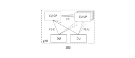
オープンインターフェースが、中央ユニット(CU)の、制御プレーン(CU-CP)部分とユーザプレーン(CU-UP)部分との間に指定された。関係する仕様は、参照により本明細書に組み込まれる3GPP TS38.463である。CU-CPとCU-UPとの間のオープンインターフェースは、E1と称する。アーキテクチャは、スプリットgNBアーキテクチャを示す図3に示されている。スプリットgNBについての3つの展開シナリオが、参照により本明細書に組み込まれる3GPP技術報告(TR)38.806に示されている。
- シナリオ1: 集中されたCU-CPおよびCU-UP、
- シナリオ2: 分散されたCU-CPおよび集中されたCU-UP、
- シナリオ3: 集中されたCU-CPおよび分散されたCU-UP。
An open interface was specified between the Control Plane (CU-CP) and User Plane (CU-UP) parts of the Central Unit (CU). The relevant specification is 3GPP TS 38.463, which is incorporated herein by reference. The open interface between the CU-CP and CU-UP is referred to as E1. The architecture is shown in FIG. 3, which shows a split gNB architecture. Three deployment scenarios for split gNB are shown in 3GPP Technical Report (TR) 38.806, which is incorporated herein by reference.
Scenario 1: Converged CU-CP and CU-UP,
Scenario 2: Distributed CU-CP and centralized CU-UP,
- Scenario 3: Centralized CU-CP and distributed CU-UP.
E1アプリケーションプロトコル(E1AP)は、TS38.463において規定されている。E1APは、UEにユーザプレーンサービスを提供するために、CU-CPとCU-UPとの間で交換されるメッセージを規定する。 The E1 Application Protocol (E1AP) is specified in TS 38.463. E1AP specifies the messages exchanged between the CU-CP and CU-UP to provide user plane services to the UE.
LTEおよびNRでは、UEとeNBまたはgNBとの間の無線接続をセットアップ、設定および維持するために、無線リソース制御(RRC)プロトコルが使用される。UEがeNBまたはgNBからRRCメッセージを受信したとき、UEは設定を適用またはコンパイルし、これが成功した場合、UEはRRC完了メッセージを生成し、RRC完了メッセージは、この応答をトリガしたメッセージのトランザクションIDを指示する。 In LTE and NR, the Radio Resource Control (RRC) protocol is used to set up, configure and maintain the radio connection between the UE and the eNB or gNB. When the UE receives an RRC message from the eNB or gNB, the UE applies or compiles the configuration and, if this is successful, the UE generates an RRC Complete message, which indicates the transaction ID of the message that triggered this response.
LTEリリース8(rel-8)以来、3つのシグナリング無線ベアラ(SRB)、すなわち、SRB0、SRB1およびSRB2が、UEとeNBとの間のRRCメッセージおよび非アクセス階層(NAS)メッセージのトランスポートのために利用可能になっている。また、SRB1bisとして知られる新しいSRBが、モノの狭帯域インターネット(NB-IoT)におけるDoNAS(データオーバーNAS)をサポートするためにrel-13において導入された。SRB0は、CCCH論理チャネルを使用するRRCメッセージのためのものであり、RRC接続セットアップ、RRC接続再開およびRRC接続再確立をハンドリングするために使用される。UEがeNBに接続される(すなわち、RRC接続セットアップまたはRRC接続再確立/再開が成功する)と、SRB1は、すべてがDCCH論理チャネルを使用する、(ピギーバックNASメッセージを含み得る)RRCメッセージをハンドリングするために、ならびに、SRB2の確立より前のNASメッセージのために使用される。SRB2は、すべてがDCCH論理チャネルを使用する、ロギングされた測定情報を含むRRCメッセージのためのもの、ならびに、NASメッセージのためのものである。SRB2は、ロギングされた測定情報およびNASメッセージが、長くなり得、より緊急のおよびより小さいSRB1メッセージの阻止を引き起こし得るので、SRB1よりも低い優先度を有する。SRB2は、常に、セキュリティアクティブ化の後にE-UTRANによって設定される。 Since LTE Release 8 (rel-8), three Signaling Radio Bearers (SRBs), namely SRB0, SRB1 and SRB2, have been available for transport of RRC and Non-Access Stratum (NAS) messages between the UE and the eNB. A new SRB, known as SRB1bis, was also introduced in rel-13 to support Data over NAS (DoNAS) in Narrowband Internet of Things (NB-IoT). SRB0 is for RRC messages that use the CCCH logical channel and is used to handle RRC connection setup, RRC connection resumption and RRC connection re-establishment. Once the UE is connected to the eNB (i.e., RRC connection setup or RRC connection re-establishment/resumption is successful), SRB1 is used to handle RRC messages (which may include piggybacked NAS messages), all of which use the DCCH logical channel, as well as for NAS messages prior to the establishment of SRB2. SRB2 is for RRC messages, including logged measurement information, as well as for NAS messages, all of which use the DCCH logical channel. SRB2 has a lower priority than SRB1, since logged measurement information and NAS messages may be long and may cause blocking of more urgent and smaller SRB1 messages. SRB2 is always configured by E-UTRAN after security activation.
rel-15では、デュアルコネクティビティ(マスタノードとしてのLTE、一方NRは2次ノード、またはその逆、ならびに2つのNRノードを使用するデュアルコネクティビティ)の場合、スプリットSRBが導入され、ここで、SRB1/2が、マスタノードまたは2次ノードの無線リソースを介してトランスポートされ得る(プロトコルはマスタノードにおいて終端される)。さらに、(2次ノードがNRである場合)SRB3と呼ばれる新しいSRBが導入され、SRB3はRRCメッセージを、マスタノードとの協調を必要としないメッセージについて、2次ノードからUEに直接転送するために使用される。 In rel-15, in case of dual connectivity (LTE as master node, while NR is secondary node or vice versa as well as dual connectivity using two NR nodes), split SRB is introduced, where SRB1/2 can be transported over radio resources of master node or secondary node (protocol is terminated at the master node). Furthermore, a new SRB called SRB3 is introduced (when secondary node is NR), which is used to forward RRC messages directly from secondary node to UE for messages that do not require coordination with the master node.
RRCプロシージャの大部分が、たとえば、測定報告設定、下位レイヤ設定、無線ベアラ設定など、UEの何らか挙動を再設定するために、ネットワークによって始動される。一般に、UEは、新しい設定が採用されたことを指示するRRC返答メッセージで、ネットワークからのRRCメッセージに確認応答する。
また、以下のものなど、いくつかのRRCプロシージャが、UEによって始動される。
- (たとえばUEモビリティのために使用される)測定報告
- 接続失敗の場合のRRC再確立
- 初期RRC接続セットアップ(たとえば、UEがアイドルモードであり、接続に遷移する必要がある場合)
Most of the RRC procedures are initiated by the network to reconfigure some behavior of the UE, e.g., measurement reporting configuration, lower layer configuration, radio bearer configuration, etc. Typically, the UE acknowledges an RRC message from the network with an RRC reply message indicating that the new configuration has been adopted.
Also, some RRC procedures are initiated by the UE, such as the following:
- Measurement reporting (e.g. used for UE mobility) - RRC re-establishment in case of connection failure - Initial RRC connection setup (e.g. when the UE is in idle mode and needs to transition to a connection)
RRCは、RRCメッセージのロスレス、順序、複製フリー配信を保証するためにPDCP/RLC/MACプロトコルに依拠する。順序配信は、PDCPシーケンス番号によって保証され、これは、RRCメッセージが、次の予想されるPDCPシーケンス番号(すなわち、番号が、最後の配信されたメッセージのPDCPシーケンス番号よりも1大きい)であるPDCPシーケンス番号を有する場合のみ、PDCPが、RRCメッセージを配信する(たとえば、PDCPレイヤの上の後のものに配信する)ことを意味する。これは、ネットワークが厳密なシーケンス番号を正確に推測しない場合、メッセージは、UEにおけるPDCPレイヤによって、UEにおける上位レイヤ(たとえばRRCレイヤ)に配信されないことになるので、ネットワークがUEによって予想される次のPDCPシーケンス番号の知識を失った場合、ネットワークは、いかなるRRCメッセージもUEに送ることが可能でないことになることを意味する。 RRC relies on the PDCP/RLC/MAC protocols to ensure lossless, in-order, and duplicate-free delivery of RRC messages. In-order delivery is guaranteed by the PDCP sequence number, which means that PDCP will deliver an RRC message (e.g., deliver it later up the PDCP layer) only if it has a PDCP sequence number that is the next expected PDCP sequence number (i.e., one greater than the PDCP sequence number of the last delivered message). This means that if the network loses knowledge of the next PDCP sequence number expected by the UE, it will not be able to send any RRC messages to the UE, since if the network does not correctly guess the exact sequence number, the message will not be delivered by the PDCP layer at the UE to the upper layers (e.g., the RRC layer) at the UE.
RRCプロトコルに加えて、UEは、UEとコアネットワークとの間にあるNASプロトコルによっても制御される。NASプロトコルは、RRCメッセージ内に埋め込まれて配信される。 In addition to the RRC protocol, the UE is also controlled by the NAS protocol between the UE and the core network. The NAS protocol is delivered embedded within the RRC messages.
図4は、NRにおける制御プレーン(CP)プロトコルスタック400の一例を示し、図5は、NRにおけるユーザプレーン(UP)プロトコルスタック500の一例を示し、ここで、CU/DUスプリットアーキテクチャが採用される(ここで、CUも、CU-UPとCU-CPとにスプリットされる)。CU-CP/CU-UPスプリットは機能的スプリットであり、したがって、2つの機能は、同じノードまたは異なるノードのいずれか中に存在することができ、さらには、機能のうちの1つ、すなわち、CU-UPまたはCU-CPは、所与のgNBについて、いくつかの物理ノード/エンティティにおいて物理的に実現され得、物理的に分散され得ることに留意されたい。たとえば、所与のgNBについてのCU-UP/CU-CPのいくつかのインスタンスが、冗長の目的でまたは負荷分散の目的でオペレータのクラウド中に存在することができる。
Figure 4 shows an example of a control plane (CP)
たとえば無線リンク障害、ハンドオーバ失敗(T304タイマー満了)またはRRCメッセージに適合することができないこと、完全性検証失敗などにより、UEとの接続が失敗した場合、UEは、RRC再確立プロシージャを始動することになる。NRでは、これは、セクション5.3.7における、参照により本明細書に組み込まれるTS38.331において捕捉される。図6は、RRC接続再確立(成功した)プロシージャ600の一例を示し、図7は、RRC確立へのフォールバックを伴うRRC再確立(成功した)プロシージャ700の一例を示す。再確立プロシージャの目的は、RRC接続を再確立することである。ASセキュリティがSRB2および少なくとも1つのDRBセットアップでアクティブ化された、RRC_CONNECTED状態にあるUEが、RRC接続を続けるためにRRC再接続プロシージャを始動し得る。ネットワークが、UEについての有効なUEコンテキストを見つけ、検証することが可能である場合、接続再確立は成功し、または、UEコンテキストが取り出され得ない場合、ネットワークは、たとえば図7に示されているようにRRCセットアップメッセージで応答する。
If the connection with the UE fails, for example due to radio link failure, handover failure (T304 timer expiry) or inability to match RRC messages, integrity verification failure, etc., the UE will initiate an RRC re-establishment procedure. In NR, this is captured in TS 38.331, incorporated herein by reference, in section 5.3.7. Figure 6 shows an example of an RRC connection re-establishment (successful)
ネットワークは、たとえば以下のようにプロシージャを適用する。
ASセキュリティがアクティブ化され、ネットワークがUEコンテキストを取り出すかまたは検証するとき、
- アルゴリズムを変更することなしにASセキュリティを再アクティブ化する、
- 再確立し、SRB1を再開する、
UEがRRC接続を再確立しつつあり、ネットワークがUEコンテキストを取り出すかまたは検証することが可能でないとき、
- 記憶されたASコンテキストを廃棄し、すべてのRBを解放する、
- 新しいRRC接続を確立するためにフォールバックする。
The network applies the procedure, for example, as follows:
When AS security is activated and the network retrieves or verifies the UE context,
- Reactivate AS security without changing algorithms;
- Re-establish and restart SRB1,
When the UE is re-establishing an RRC connection and the network is not able to retrieve or verify the UE context:
- Destroy the stored AS context and release all RBs;
- Fall back to establish a new RRC connection.
ASセキュリティがアクティブ化されなかった場合、UEはプロシージャを始動せず、代わりにRRC_IDLE状態に直接移動し、解放原因「その他(other)」を伴うものとする。ASセキュリティがアクティブ化されたが、SRB2および少なくとも1つのDRBがセットアップされない場合、UEは、プロシージャを始動せず、代わりにRRC_IDLEに直接移動し、解放原因「RRC接続失敗」を伴う。 If AS security was not activated, the UE shall not initiate the procedure and instead move directly to RRC_IDLE state with release cause "other". If AS security is activated but SRB2 and at least one DRB are not set up, the UE shall not initiate the procedure and instead move directly to RRC_IDLE with release cause "RRC connection failure".
UEは、問題を検出する前にUEが接続されたものとは異なるノードに、再確立することができる。ターゲットネットワークノードが、(たとえば図6または図7に示されている)RRC再確立要求メッセージを受信するとき、ターゲットネットワークノードは、UEについての古いUEコンテキストを特定することを試みるために、要求メッセージ中に含まれるReestabUE識別情報を使用することができる。ターゲットネットワークノードがコンテキストを特定することができる場合、ターゲットネットワークノードは、UEにRRC再確立メッセージを送信することができ、UEは、古い設定を復元することになる。ターゲットネットワークノードがUEコンテキストを見つけることができない場合、ターゲットネットワークノードは、NAS回復を実施しなければならず、代わりに、たとえば図7に示されているように、UEにRRCセットアップメッセージを送る。 The UE may re-establish to a different node than the one to which the UE was connected before detecting the problem. When the target network node receives an RRC re-establishment request message (e.g., as shown in FIG. 6 or FIG. 7), it may use the ReestabUE identity included in the request message to attempt to identify the old UE context for the UE. If the target network node is able to identify the context, it may send an RRC re-establishment message to the UE, which will restore the old configuration. If the target network node cannot find the UE context, it must perform NAS recovery and instead send an RRC setup message to the UE, as shown in FIG. 7.
ターゲットネットワークノードは、(参照により本明細書に組み込まれるTS38.423/36.423において規定されているように)ソースノード、すなわち、接続失敗の前にUEが接続されていたノードに、UEコンテキスト取出し要求を送信することになり、ソースノードは、(UE識別および検証が成功した場合)UEコンテキスト取出し応答で応答することができる。成功した場合、UEコンテキスト取出し応答は、UEコンテキストを含んでいる、TS38.331において規定されている、ハンドオーバ準備情報メッセージを含んでいることになる。UEが、RRC再確立メッセージを受信し、いくつかの設定(たとえばSRB1)を復元し、接続を再確立すると、UEは、ネットワークにRRC再確立完了メッセージを送信することになる。次いで、ネットワークは、RRC再設定メッセージをUEに送ることになり、UEは、UEにおける設定の残りを復元し、場合によっては再設定することになる。 The target network node will send a UE context retrieval request (as specified in TS 38.423/36.423, which are incorporated herein by reference) to the source node, i.e. the node to which the UE was connected before the connection failure, which can respond with a UE context retrieval response (if UE identification and verification was successful). If successful, the UE context retrieval response will contain a handover preparation information message, as specified in TS 38.331, which contains the UE context. Once the UE has received the RRC re-establishment message, restored some settings (e.g. SRB1) and re-established the connection, the UE will send an RRC re-establishment complete message to the network. The network will then send an RRC re-configuration message to the UE, which will restore and possibly re-configure the rest of the settings in the UE.
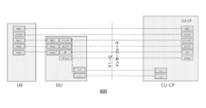
CU/DUスプリットのコンテキストにおいて、再確立プロシージャは(TS38.401、セクション8.7からの)図8に示されており、図8は、CU/DUスプリットアーキテクチャの場合のRRC再確立プロシージャ800の一例を示す。このプロシージャにおけるステップは、以下の通りである。
1. UEが、プリアンブルをgNB-DUに送る。
2. gNB-DUは、新しいC-RNTIを割り当て、ランダムアクセス応答(RAR)でUEに応答する。
3. UEは、古いC-RNTIと古い物理セルID(PCI)とを含んでいるRRC再確立要求メッセージをgNB-DUに送る。
4. gNB-DUは、RRCメッセージとUEについての対応する下位レイヤ設定とを初期UL RRCメッセージ転送メッセージ中に含め、gNB-CUに転送する。初期UL RRCメッセージ転送メッセージは、C-RNTIを含むべきである。
5. gNB-CUは、RRC再確立メッセージを含め、gNB-DUに転送する。UEが、最後のサービングgNB-DUにおけるRRC接続を再確立することを要求する場合、DL RRCメッセージ転送メッセージは古いgNB-DU UE F1AP IDを含むものとする。
6. gNB-DUは、古いgNB-DU UE F1AP IDに基づくUEコンテキストを取り出し、古いC-RNTI/PCIを新しいC-RNTI/PCIと置き換える。gNB-DUは、RRC再確立メッセージをUEに送る。
7~8. UEは、RRC再確立完了メッセージをgNB-DUに送る。gNB-DUは、RRCメッセージをUL RRCメッセージ転送メッセージ中にカプセル化し、gNB-CUに送る。
9~10. gNB-CUは、修正および解放されるべきDRBリスト(DRBs to be modified and released list)を含み得る、UEコンテキスト修正要求を送ることによって、UEコンテキスト修正プロシージャをトリガする。gNB-DUは、UEコンテキスト修正応答メッセージで応答する。
9’~10’. gNB-DUは、修正および解放されるべきDRBリストを含み得る、UEコンテキスト修正必要を送ることによって、UEコンテキスト修正プロシージャをトリガする。gNB-CUは、UEコンテキスト修正確認メッセージで応答する。
注: ここで、UEは、UEコンテキストがそのUEのために利用可能である、元のgNB-DUからアクセスすると仮定され、ステップ9~10またはステップ9’および10’のいずれかが存在し得るか、または両方ともスキップされ得る。
注: UEが、元のgNB-DU以外のgNB-DUからアクセスする場合、gNB-CUは、この新しいgNB-DUへ向かってUEコンテキストセットアッププロシージャをトリガするべきである。
11~12. gNB-CUは、RRC再設定メッセージをDL RRCメッセージ転送メッセージ中に含め、gNB-DUに転送する。gNB-DUは、それをUEにフォワーディングする。
13~14. UEはRRC再設定完了メッセージをgNB-DUに送り、gNB-DUはRRC再設定完了メッセージをgNB-CUにフォワーディングする。
In the context of CU/DU split, the re-establishment procedure is shown in Figure 8 (from TS 38.401, section 8.7), which shows an example of an RRC re-establishment procedure 800 for a CU/DU split architecture. The steps in this procedure are as follows:
1. The UE sends a preamble to the gNB-DU.
2. The gNB-DU allocates a new C-RNTI and responds with a Random Access Response (RAR) to the UE.
3. The UE sends an RRC re-establishment request message containing the old C-RNTI and old physical cell ID (PCI) to the gNB-DU.
4. The gNB-DU forwards the RRC message and the corresponding lower layer configuration for the UE in an initial UL RRC message forwarding message to the gNB-CU. The initial UL RRC message forwarding message should include the C-RNTI.
5. The gNB-CU includes and forwards the RRC re-establishment message to the gNB-DU. If the UE requests to re-establish the RRC connection in the last serving gNB-DU, the DL RRC message forwarding message shall include the old gNB-DU UE F1AP ID.
6. The gNB-DU retrieves the UE context based on the old gNB-DU UE F1AP ID and replaces the old C-RNTI/PCI with the new C-RNTI/PCI. The gNB-DU sends an RRC re-establishment message to the UE.
7-8. The UE sends an RRC re-establishment complete message to the gNB-DU. The gNB-DU encapsulates the RRC message in a UL RRC message transfer message and sends it to the gNB-CU.
9-10. The gNB-CU triggers the UE context modification procedure by sending a UE context modification request, which may include the DRBs to be modified and released list. The gNB-DU responds with a UE context modification response message.
9'-10'. The gNB-DU triggers the UE context modification procedure by sending a UE context modification required, which may include a list of DRBs to be modified and released. The gNB-CU responds with a UE context modification confirm message.
NOTE: Here, it is assumed that the UE accesses from the original gNB-DU, where the UE context is available for the UE, and either steps 9 to 10 or steps 9' and 10' may be present, or both may be skipped.
Note: If the UE accesses from a gNB-DU other than the original gNB-DU, the gNB-CU should trigger the UE context setup procedure towards this new gNB-DU.
11-12. The gNB-CU includes the RRC reconfiguration message in a DL RRC message transfer message and transfers it to the gNB-DU, which forwards it to the UE.
13-14. The UE sends an RRC reconfiguration complete message to the gNB-DU, and the gNB-DU forwards the RRC reconfiguration complete message to the gNB-CU.
RRCメッセージの配信のために使用されるシグナリング無線ベアラ(SRB)が、RRCメッセージのロスレス、複製フリー、順序配信を提供する。PDCPレイヤの上の(1つまたは複数の)レイヤへの順序および複製フリー配信を保証することは、PDCPレイヤの責任である。PDCPレイヤは、これを、PDCPシーケンス番号をあらゆるメッセージに割り振ることによって行う。シーケンス番号は、PDCPメッセージのPDCPヘッダ中で転送される。RRCメッセージを含んでいるパケットのPDCPシーケンス番号が、(最後に使用されたPDCPシーケンス番号+1である)次の予想されるPDCPシーケンス番号である場合、(たとえばUEにおける)受信PDCPエンティティは、PDCPパケット内のRRCメッセージをRRCレイヤに単に配信することになる。ネットワークが、失敗の前に最後に使用されたPDCPシーケンス番号よりも小さいPDCPシーケンス番号を使用する場合、UEは、パケットを複製と見なし、パケットを廃棄することになる。ネットワークが、UEにおける次の予想されるPDCPシーケンス番号よりも大きいPDCPシーケンスを使用する場合、UEは、メッセージをPDCPレイヤに記憶し、(1つまたは複数の)欠落したシーケンス番号をもつ(1つまたは複数の)欠落したパケットを待つことになる。たとえば、CP失敗の前の最後に受信されたRRCメッセージが、シーケンス番号(SN)xをもつPDCPパケット内にあり、RRCメッセージがSNx+2を伴って受信された場合、PDCPレイヤは、SNx+2をもつPDCPパケット中のRRCメッセージをRRCレイヤにフォワーディングする前に、SNx+1をもつPDCPパケットを待つことになる。すなわち、SNx+1をもつパケットが受信されない場合、SNx+2をもつパケットは、いつまでもUEに記憶されることになり、そのコンテンツは、上位レイヤに配信されないことになる。PDCPシーケンス番号はラップアラウンドするので、順序外れパケットが複製であるのか将来の順序外れパケットであるのかの決定は、パケットがPDCP受信ウィンドウ内にあるのかPDCP受信ウィンドウの外にあるかに基づく。 The Signaling Radio Bearers (SRBs) used for delivery of RRC messages provide lossless, duplication-free, in-order delivery of RRC messages. It is the responsibility of the PDCP layer to ensure in-order and duplication-free delivery to the layer(s) above it. The PDCP layer does this by assigning a PDCP sequence number to every message. The sequence number is transferred in the PDCP header of the PDCP message. If the PDCP sequence number of the packet containing the RRC message is the next expected PDCP sequence number (which is the last used PDCP sequence number + 1), the receiving PDCP entity (e.g. in the UE) will simply deliver the RRC message in the PDCP packet to the RRC layer. If the network uses a PDCP sequence number that is lower than the last used PDCP sequence number before the failure, the UE will consider the packet a duplicate and discard the packet. If the network uses a PDCP sequence that is greater than the next expected PDCP sequence number at the UE, the UE will store the message at the PDCP layer and wait for the missing packet(s) with the missing sequence number(s). For example, if the last received RRC message before the CP failure was in a PDCP packet with sequence number (SN) x, and an RRC message is received with SNx+2, the PDCP layer will wait for a PDCP packet with SNx+1 before forwarding the RRC message in a PDCP packet with SNx+2 to the RRC layer. That is, if the packet with SNx+1 is not received, the packet with SNx+2 will be stored in the UE indefinitely and its contents will not be delivered to upper layers. Because PDCP sequence numbers wrap around, the decision of whether an out-of-order packet is a duplicate or a future out-of-order packet is based on whether the packet is within or outside the PDCP reception window.
(TS38.331におけるセクション5.3.7.2による)再確立プロシージャの始動の間、UEは、
- MACをリセットする(すなわち、MACレベルにおける保留中のデータが、フラッシュされることになる)
- キャリアアグリゲーション(CA)とデュアルコネクティビティ(DC)の両方が解放される
- (再確立メッセージを送るために使用される、SRB0を除いて)すべてのDRBおよびSRBが中断される
During initiation of the re-establishment procedure (according to section 5.3.7.2 in TS 38.331), the UE shall:
- Reset the MAC (i.e. any pending data at the MAC level will be flushed)
- Both Carrier Aggregation (CA) and Dual Connectivity (DC) are released - All DRBs and SRBs (except SRB0, which is used to send re-establishment messages) are terminated
次いで、UEは、タイマーT311を開始し、セル再選択を実施し、これは、UEが前に接続された同じ1次セル、または別のセルを選択し得る。好適なセルが見つけられる前にタイマーが満了する場合、NAS回復は、アイドルモードを介して実施されなければならない。好適なセルが見つけられた場合、UEは、デフォルトMACおよび制御チャネル設定を適用し、タイマーT301を開始し、選定されたセルに(UE識別情報と、再確立がトリガされる前にUEが使用していた古いRRC完全性を使用して算出される、短いMAC-Iと呼ばれるセキュリティチェックサムと、以下の値、すなわち、無線リンク障害、再設定失敗、ハンドオーバ失敗、または他の失敗のうちの1つをとることができる、再確立原因とを含む)RRC再確立要求メッセージを送る。タイマーT301が、UEがネットワークからRRC再確立メッセージを受信する前に満了する場合、UEは、アイドルモードを介してNAS回復を実施しなければならない。 The UE then starts timer T311 and performs cell reselection, which may select the same primary cell to which the UE was previously connected, or another cell. If the timer expires before a suitable cell is found, NAS recovery must be performed via idle mode. If a suitable cell is found, the UE applies the default MAC and control channel configuration, starts timer T301, and sends an RRC re-establishment request message (containing the UE identity, a security checksum called short MAC-I, calculated using the old RRC integrity that the UE was using before the re-establishment was triggered, and a re-establishment cause, which may take one of the following values: radio link failure, re-establishment failure, handover failure, or other failure) to the selected cell. If timer T301 expires before the UE receives an RRC re-establishment message from the network, the UE must perform NAS recovery via idle mode.
NCC(ネクストホップチェイニングカウント)を含んでいるRRC再確立メッセージを受信するとすぐに、UEは、受信された再確立メッセージの完全性の検証のためにを含む、接続のために使用されるべき新しいユーザプレーンおよび制御プレーン暗号化および完全性保護鍵を導出するためにNCC値を使用する。ネットワークは、常に、再確立メッセージの後にRRC再設定メッセージ(仕様において「再確立の後の最初の再設定」と呼ばれる)を送る。この再設定メッセージは、完全な設定フラグを含んでおり、したがって、(C-RNTIとマスタ鍵に関連付けられたアクセス階層セキュリティ設定とを除いて)全無線設定をリセットし、その無線設定を新しい無線設定と置き換える。さらに、reestablishPDCPフィールドが、各SRB/DRBについて含まれることになり、これは、各SRB/DRBのPDCPエンティティを再確立することになる。PDCPの再確立は、再確立メッセージの受信に対して計算された新しいサイファ化および完全性保護鍵を使用するために、ならびに、送信PDCPエンティティについて、それらを新しい鍵で保護した後に保留中のPDCPパケットを送信するために、PDCPエンティティの再設定を生じることになる(ここで「保留中」は、すでに送られたそれらのパケット、古いセキュリティ鍵を使用して保護されるが、それらの受信の確認応答が受信されなかったことを意味する)。また、SRBの場合、PDCPの再確立は、初期値へのシーケンス番号のリセットを意味する。 Upon receiving an RRC re-establishment message containing the NCC (Next Hop Chaining Count), the UE uses the NCC value to derive new user plane and control plane ciphering and integrity protection keys to be used for the connection, including for verifying the integrity of the received re-establishment message. The network always sends an RRC re-establishment message (called "First re-establishment after re-establishment" in the specification) after the re-establishment message. This re-establishment message contains the full configuration flag, thus resetting the entire radio configuration (except for the C-RNTI and the access stratum security configuration associated with the master key) and replacing it with a new radio configuration. Additionally, a reestablishblishPDCP field will be included for each SRB/DRB, which will re-establish the PDCP entity of each SRB/DRB. Re-establishment of PDCP will result in reconfiguration of the PDCP entity to use the new ciphering and integrity protection keys calculated upon receipt of the re-establishment message, and for the transmitting PDCP entity, to transmit pending PDCP packets after protecting them with the new keys (here "pending" means those packets already sent, protected using the old security key, but for which no acknowledgement of their receipt was received). Also, in case of SRB, re-establishment of PDCP will imply resetting of sequence numbers to their initial values.
NCCの使用およびセキュリティ鍵の更新についての主要な理由は、セキュリティ観点から、同じシーケンス番号(Count)およびセキュリティ鍵を異なるデータのために再使用することが、回避されるべきであることであり、これは、通常ならば、SRBのシーケンス番号がリセットされるので再確立の間に起こり得る。これは、(参照により本明細書に組み込まれる3GPP TS33.501において、図D2.1.1-1に示されている)3GPPネットワークにおけるサイファ化原理が、鍵、シーケンス番号などに基づくサイファ化アルゴリズムによって生成されたセキュリティビットストリーム(鍵ストリームブロック)を伴うデータ(プレーンテキストブロック)の排他的論理和をとることに基づくことによるものである。同じビットストリームで暗号化された2つのメッセージの排他的論理和をとることによって、このセキュリティビットストリームを除去することが可能であり得る。その場合、残りのビットは、単に、2つの元のメッセージの排他的論理和(XOR)である。したがって、攻撃者がメッセージのうちの1つを推測することができた場合、自動的に、他のメッセージを復号することも可能であることになる。3GPP TS33.501のD2.1.1-1が、図9に示されている。 The main reason for the use of NCC and security key updates is that, from a security point of view, reusing the same sequence number (Count) and security key for different data should be avoided, which would otherwise occur during re-establishment since the sequence number of the SRB is reset. This is because the ciphering principle in 3GPP networks (shown in Figure D2.1.1-1 in 3GPP TS 33.501, incorporated herein by reference) is based on exclusive-oring the data (plaintext blocks) with a security bitstream (keystream block) generated by a ciphering algorithm based on the key, sequence number, etc. It may be possible to remove this security bitstream by exclusive-oring two messages encrypted with the same bitstream. The remaining bits are then simply the exclusive-or (XOR) of the two original messages. It follows that if an attacker is able to guess one of the messages, it will automatically be possible to decrypt the other message as well. D2.1.1-1 of 3GPP TS33.501 is shown in Figure 9.
RRC接続再確立プロシージャは、ネットワークとUEとを再同期させるために使用され得る。しかしながら、それは常に、ユーザプレーンのリセットにつながり、これは、たとえば、ユーザプレーンデータ無線ベアラ(DRB)が中断され、下位レイヤ状態マシン(たとえばRLC/MAC)におけるパケットがフラッシュされることを意味する。研究は、一般的なRRC接続再確立プロシージャが、100ms以上のユーザプレーンサービス中断を引き起こすことになることを示している。これは、設定可能な値を有するいくつかのタイマーによっても再確立が制御されるので、実際にはかなりより長くなり得る(たとえば、物理レイヤ問題を検出したときに開始されたT310は、最高2秒の長さであり得、UEは、このタイマーが満了するまで再確立プロシージャを始動しないことになる)。一般に、これは、接続の全体的性能が、そのようなサービス中断によって著しく影響を及ぼされないので、通常のモバイルブロードバンド(MBB)ユーザまたは他のユーザにとって問題ではない。しかしながら、URLLCを必要とする接続の場合、このサービス中断は、たとえば、レイテンシおよび/または信頼性など、URLLC要件が満たされないことを意味し得る。 The RRC connection re-establishment procedure may be used to resynchronize the network and the UE. However, it always leads to a user plane reset, which means, for example, that user plane Data Radio Bearers (DRBs) are interrupted and packets in the lower layer state machines (e.g. RLC/MAC) are flushed. Studies have shown that a typical RRC connection re-establishment procedure would cause a user plane service interruption of 100 ms or more. This may actually be much longer, since the re-establishment is also controlled by several timers with configurable values (e.g. T310, started when detecting a physical layer problem, may be up to 2 seconds long and the UE will not initiate the re-establishment procedure until this timer expires). In general, this is not an issue for a regular Mobile Broadband (MBB) user or other users, since the overall performance of the connection is not significantly affected by such a service interruption. However, for connections that require URLLC, this service interruption may mean that URLLC requirements, such as, for example, latency and/or reliability, are not met.
URLLC通信では、存続時間(survival time)は、URLLC通信サービスを消費するアプリケーションが、予期されるメッセージなしに続き得る時間である。存続時間が満了する前に通信サービス回復(たとえばRRC再確立)が完了されない場合、エンドユーザアプリケーションは、通信サービスを利用不可能と見なし、たとえば、回復するための緊急アクションをとり始め得る。存続時間はまた、(たとえばUEモビリティにおいて)許容されるユーザプレーン中断時間に制限を課する。存続時間は、存続時間が、アプリケーションダウンタイムを回避するためにシステムが失敗からどれくらい速く回復する必要があるかに制限を課するので、重要な要件である。通信失敗の後の回復時間が存続時間よりも短い場合、その失敗はアプリケーションによって見過ごされ得る。厳しい存続時間をもつ使用事例の例は、約100msの存続時間を有し得る公共安全ドローンと、トラフィックが、巡回的であり、頻繁な小さいパケットを伴い、一般に、工業イーサネットを使用する、工業自動化使用事例とを含む。これらの事例における存続時間は、単一のパケットまたは数個の連続するパケットのロスを許容し得る。たとえば、動き制御は、0~2msの存続時間、PLC間通信8~48ms、および無人搬送車(AGV)40~500msを有する。 In URLLC communication, the survival time is the time that an application consuming the URLLC communication service can go on without an expected message. If communication service recovery (e.g., RRC re-establishment) is not completed before the survival time expires, the end user application may consider the communication service unavailable and may, for example, begin to take emergency actions to recover. The survival time also imposes a limit on the tolerable user plane interruption time (e.g., in UE mobility). The survival time is an important requirement because it imposes a limit on how fast the system needs to recover from a failure to avoid application downtime. If the recovery time after a communication failure is shorter than the survival time, the failure may be overlooked by the application. Examples of use cases with strict survival times include public safety drones, which may have a survival time of around 100 ms, and industrial automation use cases, where the traffic is cyclical, with frequent small packets, and typically uses industrial Ethernet. The survival time in these cases may tolerate the loss of a single packet or a few consecutive packets. For example, motion control has a duration of 0-2 ms, PLC-to-PLC communication 8-48 ms, and automated guided vehicles (AGVs) 40-500 ms.
本開示の一態様は、RRC再確立プロシージャを実施するユーザ機器(UE)における方法を提供する。本方法は、ネットワークノードからRRC再確立プロシージャを実施するようにとの命令を受信することと、RRC再確立要求を送信することとを含む。 One aspect of the present disclosure provides a method in a user equipment (UE) for performing an RRC re-establishment procedure. The method includes receiving an instruction from a network node to perform an RRC re-establishment procedure and transmitting an RRC re-establishment request.
本開示の別の態様は、ユーザ機器(UE)にRRC再確立プロシージャを実施するように命令するネットワークノードにおける方法を提供する。本方法は、UEに関連付けられた第1の基地局制御プレーン機能が利用不可能であると決定することと、UEに、少なくとも、第2の基地局制御プレーン機能との制御プレーン接続を再確立させるために、RRC再確立プロシージャを実施するようにとの命令をUEに送ることとを含む。 Another aspect of the present disclosure provides a method in a network node for instructing a user equipment (UE) to perform an RRC re-establishment procedure. The method includes determining that a first base station control plane function associated with the UE is unavailable and sending an instruction to the UE to perform an RRC re-establishment procedure to cause the UE to re-establish a control plane connection with at least a second base station control plane function.
本開示のさらなる態様は、RRC再確立プロシージャを実施するためのユーザ機器(UE)における装置を提供する。本装置は、プロセッサとメモリとを備える。メモリは、本装置が、ネットワークノードからRRC再確立プロシージャを実施するようにとの命令を受信することと、RRC再確立要求を送信することとを行うように動作可能であるような、プロセッサによって実行可能な命令を含んでいる。 A further aspect of the present disclosure provides an apparatus in a user equipment (UE) for performing an RRC re-establishment procedure. The apparatus comprises a processor and a memory. The memory includes instructions executable by the processor such that the apparatus is operable to receive an instruction from a network node to perform an RRC re-establishment procedure and to transmit an RRC re-establishment request.
本開示のまたさらなる態様は、ユーザ機器(UE)にRRC再確立プロシージャを実施するように命令するネットワークノードにおける装置を提供する。本装置は、プロセッサとメモリとを備える。メモリは、本装置が、UEに関連付けられた第1の基地局制御プレーン機能が利用不可能であると決定することと、UEに、少なくとも、第2の基地局制御プレーン機能との制御プレーン接続を再確立させるために、RRC再確立プロシージャを実施するようにとの命令をUEに送ることとを行うように動作可能であるような、プロセッサによって実行可能な命令を含んでいる。 A further aspect of the present disclosure provides an apparatus in a network node for instructing a user equipment (UE) to perform an RRC re-establishment procedure. The apparatus includes a processor and a memory. The memory includes instructions executable by the processor such that the apparatus is operable to determine that a first base station control plane function associated with the UE is unavailable and to send an instruction to the UE to perform an RRC re-establishment procedure to cause the UE to re-establish a control plane connection with at least a second base station control plane function.
本開示の追加の態様は、RRC再確立プロシージャを実施するためのユーザ機器(UE)における装置を提供する。本装置は、ネットワークノードからRRC再確立プロシージャを実施するようにとの命令を受信することと、RRC再確立要求を送信することとを行うように設定される。 An additional aspect of the present disclosure provides an apparatus in a user equipment (UE) for performing an RRC re-establishment procedure. The apparatus is configured to receive an instruction to perform an RRC re-establishment procedure from a network node and to transmit an RRC re-establishment request.
本開示の別の態様は、ユーザ機器(UE)にRRC再確立プロシージャを実施するように命令するためのネットワークノードにおける装置を提供する。本装置は、UEに関連付けられた第1の基地局制御プレーン機能が利用不可能であると決定することと、UEに、少なくとも、第2の基地局制御プレーン機能との制御プレーン接続を再確立させるために、RRC再確立プロシージャを実施するようにとの命令をUEに送ることとを行うように設定される。 Another aspect of the present disclosure provides an apparatus in a network node for instructing a user equipment (UE) to perform an RRC re-establishment procedure. The apparatus is configured to determine that a first base station control plane function associated with the UE is unavailable and to send an instruction to the UE to perform an RRC re-establishment procedure to cause the UE to re-establish a control plane connection with at least a second base station control plane function.
本開示の例をより良く理解するために、および本開示の例がどのように実現され得るかをより明らかに示すために、次に、単に例として、以下の図面への参照がなされる。 For a better understanding of the present disclosure, and to more clearly show how the present disclosure may be realized, reference will now be made, by way of example only, to the following drawings:
以下は、限定ではなく説明の目的で、特定の実施形態または例など、具体的な詳細を記載する。他の例が、これらの具体的な詳細から離れて採用され得ることが当業者によって諒解されよう。いくつかの事例では、よく知られている方法、ノード、インターフェース、回路、およびデバイスの詳細な説明が、不要な詳細で説明を不明瞭にしないように省略される。説明される機能が、ハードウェア回路(たとえば、特殊な機能を実施するために相互接続されたアナログおよび/または個別論理ゲート、ASIC、PLAなど)を使用して、ならびに/あるいは1つまたは複数のデジタルマイクロプロセッサまたは汎用コンピュータとともにソフトウェアプログラムおよびデータを使用して、1つまたは複数のノードにおいて実装され得ることを、当業者は諒解されよう。また、エアインターフェースを使用して通信するノードは、好適な無線通信回路を有する。その上、適切な場合、本技術は、加えて、本明細書で説明される技法をプロセッサに行わせることになるコンピュータ命令の適切なセットを含んでいる、固体メモリ、磁気ディスク、または光ディスクなど、任意の形態のコンピュータ可読メモリ内で完全に具現されると見なされ得る。 The following describes specific details, such as specific embodiments or examples, for purposes of explanation and not limitation. It will be appreciated by those skilled in the art that other examples may be employed apart from these specific details. In some instances, detailed descriptions of well-known methods, nodes, interfaces, circuits, and devices are omitted so as not to obscure the description with unnecessary detail. It will be appreciated by those skilled in the art that the described functions may be implemented in one or more nodes using hardware circuits (e.g., analog and/or discrete logic gates interconnected to perform specialized functions, ASICs, PLAs, etc.) and/or using software programs and data in conjunction with one or more digital microprocessors or general-purpose computers. Also, nodes that communicate using an air interface have suitable wireless communication circuitry. Moreover, where appropriate, the present technology may be considered to be fully embodied in any form of computer-readable memory, such as solid-state memory, magnetic disks, or optical disks, that additionally contain an appropriate set of computer instructions that will cause a processor to perform the techniques described herein.
ハードウェア実装形態は、限定はしないが、デジタル信号プロセッサ(DSP)ハードウェアと、縮小命令セットプロセッサと、限定はしないが、(1つまたは複数の)特定用途向け集積回路(ASIC)および/または(1つまたは複数の)フィールドプログラマブルゲートアレイ(FPGA)を含むハードウェア(たとえば、デジタルまたはアナログ)回路と、(適切な場合)そのような機能を実施することが可能な状態マシンとを含むかまたは包含し得る。 Hardware implementations may include or include hardware (e.g., digital or analog) circuitry, including, but not limited to, digital signal processor (DSP) hardware, reduced instruction set processors, and hardware (e.g., digital or analog) circuitry, including, but not limited to, application specific integrated circuit (ASIC)(s) and/or field programmable gate array (FPGA)(s), and (where appropriate) state machines capable of performing such functionality.
制御プレーン機能の失敗または制御プレーン機能が利用不可能なこと、および制御プレーン機能の再開または再配置の後の、少なくとも3つの可能なシナリオがあり得る。いくつかの例では、制御プレーン機能の再配置は、異なる制御プレーン機能が、失敗したまたは利用不可能な制御プレーン機能によってサーブされていた(1つまたは複数の)UEおよび(1つまたは複数の)DUについての制御プレーン機能(function)/機能(functionality)の責任を担うことを意味し得る。第1のシナリオでは、ネットワークおよびUEコンテキストが同期している。たとえば、UEは、ネットワークによってUEに送られた最後のRRCメッセージを受信し、適切に適用/コンパイルし、SRB1についての次の予想されるPDCPシーケンス番号(SN)が、ネットワークによって送信される次のシーケンス番号と同じであることになる。このシナリオでは、ネットワークによって送られる次のRRCメッセージは、PDCPレイヤにおいて順次受信され、したがって、たとえばRRCレイヤなど、PDCPレイヤの上のレイヤにフォワーディングされることになる。 There may be at least three possible scenarios following a control plane function failure or unavailability and a resumption or relocation of the control plane function. In some examples, the relocation of the control plane function may mean that a different control plane function takes over the responsibility of the control plane function/functionality for the UE(s) and DU(s) that were served by the failed or unavailable control plane function. In the first scenario, the network and UE context are synchronized. For example, the UE receives the last RRC message sent to the UE by the network and applies/compiles it appropriately, such that the next expected PDCP sequence number (SN) for SRB1 is the same as the next sequence number sent by the network. In this scenario, the next RRC message sent by the network will be received sequentially at the PDCP layer and will therefore be forwarded to a layer above the PDCP layer, e.g., the RRC layer.
第2のシナリオでは、ネットワークは、より最新のコンテキストを有する。たとえば、ネットワークは、ネットワークが送った最新のRRCメッセージに従ってUEコンテキストを更新し、また、SRB1についてのPDCP SNを増分したが、そのメッセージはUEに到着していない(たとえば、そのメッセージがDUまたはUEに到着する前に、制御プレーン機能が失敗した)。したがって、ネットワークによって送られる次のRRCメッセージは、UEが予想するよりも大きいSNを有することになり、UEによっていつまでも記憶されることになり、UEは、UEが欠落していると見なす1つまたは複数のパケットまたはメッセージを待つ。 In the second scenario, the network has a more up-to-date context. For example, the network updated the UE context according to the latest RRC message it sent and also incremented the PDCP SN for SRB1, but that message has not arrived at the UE (e.g., a control plane function failed before the message arrived at the DU or UE). Thus, the next RRC message sent by the network will have a higher SN than the UE expects and will be stored indefinitely by the UE, waiting for one or more packets or messages that the UE considers missing.
第3のシナリオでは、UEは、より最新のコンテキストを有する。これは、たとえば、ネットワークが、記憶されたUEコンテキストをネットワークが更新する前に、ネットワークがUEからRRCメッセージの確認応答を受信するまで待ち、UEが、RRCメッセージを受信および適用し、確認応答を送ったが、確認応答の受信の前に制御プレーン機能が失敗した場合、起こり得る。この場合、ネットワークによって送られる次のRRCメッセージは、UEが予想するよりも低いSNを有することになり、複製と見なされることになり、ドロップされることになる。 In a third scenario, the UE has a more up-to-date context. This can happen, for example, if the network waits until it receives an acknowledgement of an RRC message from the UE before updating the stored UE context, and the UE receives and applies the RRC message and sends an acknowledgement, but the control plane function fails before receiving the acknowledgement. In this case, the next RRC message sent by the network will have a lower SN than the UE expects, will be considered a duplicate, and will be dropped.
本開示の実施形態は、たとえば、UEとネットワークとの間のコンテキスト再同期が、制御プレーン回復(たとえば、1つまたは複数のUEについての制御プレーン機能の再開始または再配置)時に実施されることを保証し得る。また、例示的な実施形態は、特にユーザプレーンデータ無線ベアラ(DRB)について、サービス不連続性なしにこれを達成し得る。例示的な実施形態は、UEに関連付けられた(たとえばUEをサーブする)制御機能が利用不可能であるとき、UEとネットワークとの間のコンテキスト再同期を実現するために、UEに再確立プロシージャを実施させるための機構を提供する。さらに、いくつかの例では、ユーザプレーンデータ無線ベアラの動作に影響を及ぼさない、制御プレーンのみの再確立プロシージャが提供される。 Embodiments of the present disclosure may, for example, ensure that context resynchronization between the UE and the network is performed upon control plane recovery (e.g., restart or relocation of control plane functions for one or more UEs). Also, the example embodiments may achieve this without service discontinuity, particularly for user plane data radio bearers (DRBs). The example embodiments provide mechanisms for having the UE perform re-establishment procedures to achieve context resynchronization between the UE and the network when a control function associated with (e.g., serving) the UE is unavailable. Furthermore, in some examples, a control plane-only re-establishment procedure is provided that does not impact the operation of user plane data radio bearers.
例示的な実施形態の利点は、以下のうちの1つまたは複数を含み得る。ネットワークは、ネットワークとUEとの間でUEコンテキスト、設定、RRC状態などを同期させるために、UEに再確立プロシージャを実施させ得る。再確立のトリガリングは現在、UEにおける条件、たとえば、無線リンク障害の検出、およびUEがコンパイルすることが可能でなかった再設定の受信に基づいて実施されるにすぎず、したがってUE駆動型である。したがって、例示的な実施形態は、ネットワーク駆動型RRC再確立プロシージャを導入する。いくつかの例では、制御プレーン再確立プロシージャが提供され、このプロシージャは、ユーザプレーンデータ無線ベアラに影響を及ぼさず、厳しいレイテンシおよび存続時間要件をもつベアラ/サービス(たとえばURLLC)のためのUEにおけるサービス品質(QoS)要件が、UEに関連付けられたまたはUEをサーブする制御プレーン機能が利用不可能なことの場合さえ、満たされ得ることを保証し得る。また、いくつかの例では、シグナリング最適化が達成され得、すなわち、ネットワークが、ネットワークとUEとにおけるUEのコンテキストが同期中であることを了解する場合、現在常に必要とされる、再確立の後に再設定メッセージを送ることを行う必要がないことになる。再同期が必要とされる場合でも、いくつかの例では、完全な再設定の代わりに部分再設定が送られ得る。 Advantages of the exemplary embodiments may include one or more of the following: The network may have the UE perform a re-establishment procedure to synchronize UE context, configuration, RRC state, etc. between the network and the UE. Currently, triggering of re-establishment is only performed based on conditions in the UE, e.g., detection of radio link failure and receipt of a re-configuration that the UE was not able to compile, and is therefore UE-driven. Thus, the exemplary embodiments introduce a network-driven RRC re-establishment procedure. In some examples, a control plane re-establishment procedure is provided that does not impact user plane data radio bearers and may ensure that quality of service (QoS) requirements in the UE for bearers/services (e.g., URLLC) with stringent latency and lifetime requirements can be met even in the case of unavailability of control plane functions associated with or serving the UE. Also, in some examples, signaling optimization may be achieved, i.e., if the network knows that the UE context in the network and the UE is in sync, there will be no need to send a reconfiguration message after re-establishment, which is always required today. Even if re-synchronization is required, in some examples, a partial reconfiguration may be sent instead of a full reconfiguration.
本開示の例では、言及される制御プレーン機能が、たとえば中央ユニット制御プレーン(CU-CP)を備え得る。 In examples of the present disclosure, the control plane functionality referred to may comprise, for example, a central unit control plane (CU-CP).
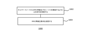
図10は、RRC再確立プロシージャを実施するユーザ機器(UE)における方法1000のフローチャートである。方法は、ステップ1002において、ネットワークノード(たとえば分散ユニット(DU))からRRC再確立プロシージャを実施するようにとの命令を受信することを含む。方法1000は、ステップ1004において、RRC再確立要求を送信することをも含む。したがって、たとえば、方法1000は、ネットワーク駆動型またはネットワーク始動型RRC再確立プロシージャを提供し得る。
Figure 10 is a flow chart of a
いくつかの例では、RRC再確立要求は、UEのためのRRC制御プレーン接続のみを再確立するようにとの要求を含む。これは、UEをサーブする制御プレーン機能が失敗したかまたは利用不可能である場合、有用であり得る。いくつかの例では、したがって、制御プレーンのみのRC再確立プロシージャは、UEにおけるユーザプレーンの動作に影響を及ぼさないことがあり、したがって、たとえばユーザプレーンDRBは影響を受けないことがある。いくつかの例では、メッセージのタイプ、および/あるいはフラグまたは情報エレメント(IE)などのメッセージ中の指示は、RRC再確立要求が制御プレーンのみの再確立のためのものであることを指示し得る。 In some examples, the RRC re-establishment request includes a request to re-establish only the RRC control plane connection for the UE. This may be useful if the control plane functionality serving the UE has failed or is unavailable. In some examples, the control plane only RC re-establishment procedure may therefore not affect the user plane operation at the UE, and thus, for example, the user plane DRB may not be affected. In some examples, the type of message and/or an indication in the message, such as a flag or information element (IE), may indicate that the RRC re-establishment request is for control plane only re-establishment.
追加または代替として、いくつかの例では、ネットワークノードからの命令は、制御プレーンのみの再確立プロシージャを実施するようにとの命令を含む。たとえば、命令を含んでいるメッセージのタイプは、RRC再確立プロシージャが制御プレーンのみのためのものであることを指示し得、および/またはそのメッセージは、RRC再確立プロシージャが制御プレーンのみのためのものであることを指示する指示(たとえばフラグまたはIE)を含んでいることがある。したがって、たとえば、そのプロシージャが制御プレーンのみのためのものである場合、方法1000は、いくつかの例では、UEのためのユーザプレーンUEコンテキストを維持することを含み得る。これは、たとえば、命令を受信する前に設定された1つまたは複数のデータ無線ベアラ(DRB)を使用し続けることを含み得る。いくつかの例では、これは、UEのユーザプレーン動作に対する中断がほとんどまたはまったくないことを保証し得る。いくつかの例では、方法1000は、ユーザプレーンデータ無線ベアラ(DRB)を中断することなしにRRC再確立プロシージャを実施することを含む。
Additionally or alternatively, in some examples, the instruction from the network node includes an instruction to perform a control plane only re-establishment procedure. For example, the type of message containing the instruction may indicate that the RRC re-establishment procedure is for the control plane only, and/or the message may include an indication (e.g., a flag or IE) indicating that the RRC re-establishment procedure is for the control plane only. Thus, for example, if the procedure is for the control plane only, the
いくつかの例では、UEは、命令を受信する前に第1の基地局制御プレーン機能に関連付けられ、RRC再確立プロシージャは、第2の基地局制御プレーン機能への制御プレーン接続を再確立する。第1および/または第2の制御プレーン機能は、たとえば中央ユニット制御プレーン(CU-CP)であり得る。したがって、方法1000は、たとえば、RRC再確立要求に応答して、第1の制御プレーン機能からの代わりに、第2の基地局制御プレーン機能からRRC再確立メッセージを受信することを含み得る。いくつかの例では、命令は、第2の基地局制御プレーン機能から、およびいくつかの例ではネットワークノードを介して、受信される。
In some examples, the UE is associated with a first base station control plane function prior to receiving the command, and the RRC re-establishment procedure re-establishes the control plane connection to a second base station control plane function. The first and/or second control plane function may be, for example, a central unit control plane (CU-CP). Thus, the
方法1000は、いくつかの例では、RRC再確立プロシージャの間、次の予想されるRRCメッセージシーケンス番号をリセットする間および/またはリセットすることなしに、MACバッファおよび/またはRLCバッファをフラッシュするのを控えることを含み得る。そのような特徴は、いくつかの例では、UEのユーザプレーン機能への影響を低減するかまたはなくし得る。
The
いくつかの例では、方法1000は、RRC再確立プロシージャ(たとえば図6に示されているプロシージャ)を実施することであって、RRC再確立プロシージャが、RRC再確立要求を送信するステップ1004を含む、RRC再確立プロシージャを実施することを含む(たとえば、ステップ1004は、図6に示されている第1のステップである)。
In some examples, the
いくつかの例では、ネットワークノードから命令を受信することは、ネットワークノードからRRCメッセージを受信することと、完全性検証鍵を使用して、RRCメッセージに対して完全性検証を実施することと、完全性検証が失敗した場合、RRCメッセージがRRC再確立プロシージャを実施するようにとの命令であると決定することとを含む。したがって、たとえば、ネットワークノード(または、ネットワーク中の他のノード)は、正しくないまたは代替の完全性保護鍵を使用して、RRCメッセージに対して暗号化または完全性保護を意図的に実施し得、したがって、そのメッセージはUEにおいて完全性保護に失敗することになる。これは、RRC再確立プロシージャをトリガし得る。いくつかの例では、制御プレーンのみの再確立プロシージャが最初に試みられ、その後に、制御プレーンのみのプロシージャが成功しない場合は「完全な」再確立プロシージャが続き得る。したがって、UEにおける完全性検証の失敗は、いくつかの例では、RRC再確立プロシージャ(制御プレーンのみまたはそれ以外)を実施するようにとの暗示された命令であり得る。 In some examples, receiving the instruction from the network node includes receiving an RRC message from the network node, performing an integrity verification on the RRC message using an integrity verification key, and determining that the RRC message is an instruction to perform an RRC re-establishment procedure if the integrity verification fails. Thus, for example, the network node (or other node in the network) may intentionally perform encryption or integrity protection on the RRC message using an incorrect or alternative integrity protection key, such that the message fails integrity protection at the UE. This may trigger an RRC re-establishment procedure. In some examples, a control plane only re-establishment procedure may be attempted first, followed by a "full" re-establishment procedure if the control plane only procedure is not successful. Thus, a failure of the integrity verification at the UE may be an implied instruction to perform an RRC re-establishment procedure (control plane only or otherwise) in some examples.
ステップ1002において受信された命令は、いくつかの例では、MAC制御エレメント(CE)中で、物理ダウンリンク制御チャネル(PDCCH)上で送信されるダウンリンク制御情報(DCI)中で、システム情報ブロック(SIB)中のフラグ中で、またはブロードキャストメッセージ中で受信され得る。
The instruction received in
いくつかの例では、RRC再確立要求は、RRC再確立プロシージャが制御プレーンのみの再確立プロシージャであるという指示を含む。追加または代替として、いくつかの例では、RRC再確立要求は、命令を受信する前の直近に受信されたRRCメッセージのシーケンス番号の指示を含む。 In some examples, the RRC re-establishment request includes an indication that the RRC re-establishment procedure is a control plane only re-establishment procedure. Additionally or alternatively, in some examples, the RRC re-establishment request includes an indication of the sequence number of the most recently received RRC message prior to receiving the command.
図11は、ユーザ機器(UE)にRRC再確立プロシージャを実施するように命令するネットワークノードにおける方法1100のフローチャートである。ネットワークノードは、たとえば分散ユニット(DU)あるいは任意の他の好適なネットワークノードまたは機能を備え得る。方法1100は、ステップ1102において、UEに関連付けられた(たとえばUEをサーブする)第1の基地局制御プレーン機能(たとえばCU-CP)が利用不可能であると決定することを含む。たとえば、第1の制御プレーン機能は、失敗していることがある。方法1100のステップ1104は、UEに、少なくとも、第2の基地局制御プレーン機能との制御プレーン接続を再確立させるために、RRC再確立プロシージャを実施するようにとの命令をUEに送ることを含む。これは、いくつかの例では、上記で言及されたステップ1002においてUEによって受信された命令であり得る。命令は、いくつかの例では、MAC制御エレメント(CE)中で、物理ダウンリンク制御チャネル(PDCCH)上で送信されるダウンリンク制御情報(DCI)中で、システム情報ブロック(SIB)中のフラグ中で、またはブロードキャストメッセージ中で送られ得る。
11 is a flow chart of a
いくつかの例では、方法は、命令をUEに送った後に、UEからRRC再確立要求を受信することと、RRC再確立要求を第2の基地局制御プレーン機能にフォワーディングすることとを含み得る。したがって、第2の基地局制御プレーン機能(たとえばCU-CP)は、たとえば再確立プロシージャの結果として、UEをサーブすることに対する責任を引き継ぎ、したがって、UEに関連付けられる、制御プレーン機能であり得る。いくつかの例では、RRC確立要求は、(たとえば、要求中で指示されるように)UEのためのRRC制御プレーン接続のみを再確立するようにとの要求を含む。追加または代替として、UEに送られた命令は、いくつかの例では上記で示唆されるように、制御プレーンのみの再確立プロシージャを実施するようにとの命令を含む。RRC再確立要求は、いくつかの例では、RRC再確立プロシージャが制御プレーンのみの再確立プロシージャであるという指示を含み得る。RRC再確立要求は、いくつかの例では、命令を受信する前の直近に受信されたRRCメッセージのシーケンス番号(SN)の指示を含み得る。 In some examples, the method may include receiving an RRC re-establishment request from the UE after sending the command to the UE, and forwarding the RRC re-establishment request to a second base station control plane function. Thus, the second base station control plane function (e.g., CU-CP) may be the control plane function that takes over responsibility for serving the UE, e.g., as a result of the re-establishment procedure, and is therefore associated with the UE. In some examples, the RRC establishment request includes a request to re-establish only the RRC control plane connection for the UE (e.g., as indicated in the request). Additionally or alternatively, the command sent to the UE may include an instruction to perform a control plane only re-establishment procedure, as alluded to above, in some examples. The RRC re-establishment request may include an indication that the RRC re-establishment procedure is a control plane only re-establishment procedure in some examples. The RRC re-establishment request may include an indication of the sequence number (SN) of the most recently received RRC message prior to receiving the command in some examples.
いくつかの例では、方法1100は、UEのためのユーザプレーンUEコンテキストを維持することを含む。これは、UEについてほとんどまたはまったくないユーザプレーン中断を保証し得る。UEのためのユーザプレーンUEコンテキストを維持することは、いくつかの例では、ステップ1102および/または1104の前に設定された1つまたは複数のデータ無線ベアラ(DRB)を使用し続けることを含む。いくつかの例では、命令は、ユーザプレーンデータ無線ベアラ(DRB)を中断することなしにRRC再確立プロシージャを実施するようにとのUEへの命令を含む。
In some examples, the
UEは、いくつかの例では、命令を受信する前に第1の基地局制御プレーン機能(たとえばCU-CP)に関連付けられ得る。RRC再確立プロシージャは、次いで、第2の基地局制御プレーン機能(たとえばCU-CP)への制御プレーン接続を再確立し得る。 The UE may, in some examples, be associated with a first base station control plane function (e.g., CU-CP) prior to receiving the command. The RRC re-establishment procedure may then re-establish the control plane connection to a second base station control plane function (e.g., CU-CP).
いくつかの例では、ステップ1104において命令をUEに送ることは、第2の基地局制御プレーン機能から命令を受信することと、命令をUEにフォワーディングすることとを含む。したがって、これらの例では、第2の制御プレーン機能は、ネットワークノード(たとえばDU)を介して再確立プロシージャを始動し得る。
In some examples, sending the command to the UE in
命令をUEに送ることは、いくつかの例では、たとえば上記で説明されたプロシージャと同様に、正しくない暗号化鍵でRRCメッセージを暗号化することと、RRCメッセージをUEにフォワーディングすることとを含む。 Sending the command to the UE may, in some examples, include encrypting the RRC message with an incorrect encryption key and forwarding the RRC message to the UE, e.g., similar to the procedure described above.
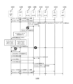
図12は、本明細書で説明される方法の間のネットワークにおける通信1200の特定の例示的な実施形態を示す。ネットワークは、UE1202と、DU1204と、第1の制御プレーン機能CU-CP1 1206と、第2の制御プレーン機能CU-CP2 1208と、UEコンテキストデータベース1210と、中央ユニットユーザプレーン(CU-UP)1212と、アクセスおよびモビリティ管理機能(AMF)1214と、ユーザプレーン機能(UPF)1216とを含む。
Figure 12 illustrates a particular example embodiment of
この例では、UEとネットワークとを再同期させるために、RRC再確立プロシージャが使用され得る。この例は、いくつかの場合には、遅延またはユーザプレーンデータ送信/受信中断につながり得るが、これは、UEが初め(たとえばNAS回復)から接続を確立しなければならない場合、いくつかの例ではNAS回復よりも依然として速くなり得る。しかしながら、現在のプロシージャは、ネットワーク始動型再確立を可能にしない。 In this example, an RRC re-establishment procedure may be used to resynchronize the UE with the network. This may lead to delays or user plane data transmission/reception interruptions in some cases, but this may still be faster in some examples than NAS recovery if the UE has to establish the connection from scratch (e.g. NAS recovery). However, current procedures do not allow for network-initiated re-establishment.
図12の通信1200のステップ1a)において、UE1202は、Su1204とCU-CP1 1206とを介したAMF1214への制御プレーン接続を有し、ステップ1b)において、UE1202は、DU1204とCU-UP1212とを介したUPF1216へのPDUセッションのためのユーザプレーン接続を有する。ステップ2)において、CU-CP1が、CU-CP2 1208および/またはUEコンテキストデータベース1210にUE情報を書き込む。したがって、たとえば、UEのために(1つまたは複数の)UEコンテキストが記憶または更新され得る。ステップ3)において、CU-CP1 1206は、失敗するか、または別の理由で利用不可能になる。ステップ4)において、DU1204は、CU-CP1 1206の失敗またはCU-CP1 1206が利用不可能なことを検出する。ステップ5において、DU1204は、たとえば、上記で説明されたステップ1002および1104に従って、UE1202におけるRRC再確立をトリガする。
In step 1a) of the
ステップ6a)において、RLCおよびMACレイヤが、UE1202においてフラッシュされ、ステップ6b)において、RLCおよびMACレイヤが、DU1204においてフラッシュされる。したがって、ステップ7)において、ユーザプレーン接続は中断される。ステップ8)において、図示の例では、ランダムアクセスプロシージャ(RACH)がある。たとえば、ランダムアクセスおよびランダムアクセス応答(RAR)プロシージャが、UEとDUとの間で実施される。UEは、ランダムアクセスチャネル(RACH)上でスペシャルプリアンブルを送り、ネットワーク(たとえばDU)は、ランダムアクセス応答(RAR)で応答し、「グラント」は、アップリンクRRCシグナリングを送るためのアップリンクリソース割り振りを含む。RARメッセージはまた、アップリンク時間同期を保証するための時間整合情報を含んでいることがある。
In step 6a), the RLC and MAC layers are flushed in the
ステップ9)において、DU1204は、CU-CP2 1208を選択する。ステップ10において、UE1202は、たとえば上記で説明されたステップ1004に従って、RRC再確立要求を送る。ステップ11)において、要求を受信したCU-CP2 1208は、UEコンテキストデータベース1210からUEコンテキストを取り出す。CU-CP2 1208は、次いで、ステップ12)において、RRC再確立メッセージをUE1202に送る。ステップ13)において、UE1202は、RRC再確立完了メッセージでCU-CP2 1208に返答する。
In step 9), the
ステップ14)において、CU-CP2 1208は、AMF1214を更新する(たとえば、CU-CP2 1208は、たとえばNG-APシグナリング関連付けの動きのみを指示する経路切替えプロシージャを実施することによって、AMF1214へのNG-Cインターフェースを更新する)。ステップ15)において、この例では、同じCU-UP1212が依然として使用され、CU-CP2 1208は、CU-UP1212中の関連のあるUEコンテキストを引き継ぐ。ステップ16)において、CU-CP2 1208は、UE RRC状態の随意の再同期をトリガし得る。このステップは、たとえばUEへ向かう保留中のRRCプロシージャがある場合、UEコンテキストデータベース1210コンテキストに依存し得る。ステップ17b)において、UE1202は、DU1204とCU-UP1212とを介したUPF1216へのPDUセッションのためのユーザプレーン接続を有する。
In step 14), CU-
通常の条件の間、いくつかの例では、UEを現在サーブしているCU-CP1 1206は、バックアップ制御プレーン機能(CU-CP2 1208)またはUEコンテキストデータベース1210中のUEコンテキストを継続的にまたは周期的に記憶または更新する。DU1204は、たとえば以下などのいくつかのやり方のうちの1つで制御プレーン機能CU-CP1 1206が利用不可能なことを検出することができる。
- SCTPキープアライブ要求に対する応答の欠如
- 所与の時間内に必要とされるF1-APコンテキスト修正などのF1-APメッセージに対する応答を受信しないこと
- 失敗したCU-CPから(再開時)、または利用不可能な制御プレーン機能から責任を引き継いだ新しいCU-CPから、明示的指示を受信すること。
During normal conditions, in some examples, the CU-
- Lack of response to an SCTP Keep-Alive request - Failure to receive a response to an F1-AP message such as a required F1-AP context modification within a given time - Receiving an explicit indication from a failed CU-CP (on restart) or from a new CU-CP that has taken over responsibility from an unavailable control plane function.
CU-CP2が(1つまたは複数の)UEコンテキストをすでに有する場合(たとえば、UEコンテキストが、ステップ2)においてCU-CP2 1208中で更新されたままであった場合)、ステップ11におけるコンテキスト取出しデータベースからのUEコンテキスト取出しの必要がない。
If CU-CP2 already has the UE context(s) (e.g., the UE context was kept updated in CU-
図12に示されている例は、ネットワークが、RRC接続を再確立するようにUEをトリガすることと、それにより、UEコンテキスト再同期が実施されることを保証することとを可能にする。しかしながら、ユーザプレーンデータの可能な中断があり得る。これを緩和するために、いくつかの例では、制御プレーンまたは制御プレーンの部分(たとえばSRB1)のみが、再確立される必要がある。たとえば、UEによって受信された命令は、制御プレーンのみの再確立プロシージャをトリガし得、UEは、MAC/RLCバッファをフラッシュするのを控え、データ無線ベアラの受信/送信を休止しないことがある。図13は、そのような例による、ネットワークにおける通信1300の一例を示す。ネットワークは、UE1202と、DU1204と、第1の制御プレーン機能CU-CP1 1206と、第2の制御プレーン機能CU-CP2 1208と、UEコンテキストデータベース1210と、中央ユニットユーザプレーン(CU-UP)1212と、アクセスおよびモビリティ管理機能(AMF)1214と、ユーザプレーン機能(UPF)1216とを含む。
The example shown in FIG. 12 allows the network to trigger the UE to re-establish an RRC connection, thereby ensuring that UE context resynchronization is performed. However, there may be a possible interruption of user plane data. To mitigate this, in some examples, only the control plane or a part of the control plane (e.g., SRB1) needs to be re-established. For example, a command received by the UE may trigger a re-establishment procedure of only the control plane, and the UE may refrain from flushing MAC/RLC buffers and may not pause reception/transmission of data radio bearers. FIG. 13 shows an example of
図13に示されているステップ1a)~4)は、図12に示され、上記で説明されたステップ1a)~4)と同様である。しかしながら、ステップ5)において、DU1204は、制御プレーン(CP)のみのRRC再確立をトリガし、ステップ6)において、ユーザプレーン接続は中断されない。たとえば、RLCおよびMACバッファは、UE1302およびDU1304によってフラッシュされないことがある。
Steps 1a)-4) shown in FIG. 13 are similar to steps 1a)-4) shown in FIG. 12 and described above. However, in step 5), the
ステップ7)において、DU1204は、CU-CP2 1208を選択する。ステップ8)において、UE1202は、たとえば上記で説明されたステップ1004に従って、RRC再確立要求を送る。ステップ9)において、要求を受信したCU-CP2 1208は、UEコンテキストデータベース1210からUEコンテキストを取り出す。CU-CP2 1208は、次いで、ステップ10)において、RRC再確立メッセージをUE1202に送る。ステップ11)において、UE1202は、RRC再確立完了メッセージでCU-CP2 1208に返答する。
In step 7), the
ステップ12)において、CU-CP2 1208は、AMF1214を更新する(たとえば、CU-CP2 1208は、たとえばNG-APシグナリング関連付けの動きのみを指示する経路切替えプロシージャを実施することによって、AMF1214へのNG-Cインターフェースを更新する)。ステップ13)において、この例では、同じCU-UP1212が依然として使用され、CU-CP2 1208は、CU-UP1212中の関連のあるUEコンテキストを引き継ぐ。ステップ14)において、CU-CP2 1208は、UE RRC状態の随意の再同期をトリガし得る。このステップは、たとえばUEへ向かう保留中のRRCプロシージャがある場合、UEコンテキストデータベース1210コンテキストに依存し得る。ステップ15)において、UE1202は、DU1204とCU-UP1212とを介したUPF1216へのPDUセッションのためのユーザプレーン接続を有する。
In step 12), CU-
上記では、ステップ5)において再確立をトリガするために使用されたメッセージは、いくつかの例では、下位レイヤシグナリング(たとえば、MAC制御エレメント(CE)、ダウンリンク制御情報(DCI)、システム情報ブロック(SIB)シグナリングなど)を使用してDU1204から送られ得る。しかしながら、いくつかの代替ソリューションがある。一例では、DU1204は、CU-CP1 1206が利用不可能なことに関してCU-CP2 1208に通知し得、CU-CP2 1208は、UE1202に再確立メッセージを送る。DU1204は、これをUE1202に透過的にフォワーディングする。代替的に、たとえば、CU-CP2 1208は、CU-CP1 1206が利用不可能なことを検出し得、DU1204を介してUE1202に制御プレーンのみの再確立命令を送る。いずれの場合も、DUは、これが制御プレーンのみの再確立であり、ユーザプレーンバッファ(たとえばMACおよびRLC)をフラッシュする必要がないことを(再確立命令中で暗黙的に、または明示的にのいずれかで)通知され得る。
Above, the message used to trigger re-establishment in step 5) may in some examples be sent from
いくつかの例では、CU-CP2 1208は、上記で示唆されたように、RRCパケットを生成し、そのRRCパケットを正しくない鍵(たとえばランダムまたは代替の鍵)で完全性保護し、そのRRCパケットをUE1202に送り得る。UE1202は、着信RRCパケットに対して完全性検証を実施し、完全性検証失敗を検出することになる。レガシーUEは、通常の再確立プロシージャをトリガすることになるが、いくつかの例では、上記で示唆されるように最初に制御プレーンのみの再確立を実施することを試み得る。ネットワークは、ネットワークが正しくない完全性保護を伴うRRCパケットを送ることによって再確立を命令したことを知っているので、ネットワークは、いくつかの例では、制御プレーンのみの再確立プロシージャを実施し得る。
In some examples, CU-
再確立が(無線リンク障害などの)レガシー再確立原因により始動されないことをネットワークに知らせるために、いくつかの例では、新しい再確立原因値(たとえばCP-Failure)が導入され得る。これは、たとえば、制御プレーン機能失敗がDU1204によって検出された場合、CU-CP2 1208にとって有用であり得、したがって、それが制御プレーンのみの再確立であることにDU1204が気づいている。
A new re-establishment cause value (e.g., CP-Failure) may be introduced in some examples to inform the network that the re-establishment is not triggered by a legacy re-establishment cause (such as a radio link failure). This may be useful for CU-
(たとえば上記で説明されたステップ1004において送られるような)再確立要求メッセージ中に、UEは、いくつかの例では、最後の受信されたRRC(たとえばSRB1)メッセージのPDCPシーケンス番号(SN)、または次の予想されるPDCP SNを含め得る。ネットワークは、したがって、ネットワークが送った最新のRRCメッセージをUEが受信したかどうか検証し得、受信した場合、UEおよびネットワークコンテキストは同期中であり、後続の再設定メッセージをUEに送る必要がないことになる。ネットワークが、UEとネットワークとの間のUEコンテキストが異なる(たとえば、再確立メッセージ中で指示された最後に受信されたPDCP SNが、ネットワークがUEに送った最後のSRB1メッセージのために使用されたSNよりもより小さい)ことを発見した場合、ネットワークは、同期を達成するために後続の再設定メッセージを送り得る。
In the re-establishment request message (e.g., as sent in
前の再確立プロシージャでは、SRB1についてのPDCPが再確立され、これは、SRB1についてのシーケンス番号(SN)が初期値にリセットされることを生じる。その結果、同じ鍵が同じSNを伴って使用されないことを保証するために(再確立メッセージ中の受信されたNCCを使用して)、再確立の間、セキュリティ鍵が更新される。制御プレーンのためのセキュリティ鍵の変更は、ユーザプレーンのためのセキュリティ鍵の変更をも生じることがあり、これは、DRBについてRLC/MACバッファが(それらが、古い鍵を使用して暗号化/完全性保護されたデータを含んでいるので)リセットされなければならず、確認応答を保留しているすべてのPDCPパケットが、新しい鍵で暗号化/完全性保護された後に再送信される必要があることになることを意味し得る。これは、ユーザプレーントラフィックについてのレイテンシの増加を生じ得る。しかしながら、本開示の例は、これらの欠点を緩和し得る。たとえば、UEおよびネットワークは、制御プレーンのみの再確立プロシージャについて、セキュリティ鍵(たとえばユーザプレーンセキュリティ鍵)を変更しないか、またはシーケンス番号をリセットしないことがある。 In the previous re-establishment procedure, PDCP for SRB1 is re-established, which results in the sequence number (SN) for SRB1 being reset to an initial value. As a result, security keys are updated during re-establishment (using the received NCC in the re-establishment message) to ensure that the same key is not used with the same SN. A change in security keys for the control plane may also result in a change in security keys for the user plane, which may mean that RLC/MAC buffers for DRBs must be reset (as they contain data encrypted/integrity protected using the old key) and all PDCP packets pending acknowledgment will need to be re-transmitted after being encrypted/integrity protected with the new key. This may result in increased latency for user plane traffic. However, examples of the present disclosure may mitigate these drawbacks. For example, the UE and network may not change security keys (e.g., user plane security keys) or reset sequence numbers for a control plane-only re-establishment procedure.
本明細書で説明されるように制御プレーンのみの再確立プロシージャを可能にするための3GPP仕様38.331、v16.0.0の変更の一例が、以下で示される。
********************************************************************************
5.3.7.2 始動
UEは、以下の条件のうちの1つが満足されるとき、プロシージャを始動する。
1> 5.3.10による、MCGの無線リンク障害、およびT316が設定されないことを検出すると、あるいは
1> サブクローズ5.3.5.8.3による、MCGの同期を伴う再設定失敗(re-configuration with sync failure)時に、あるいは
1> サブクローズ5.4.3.5による、NRからのモビリティ失敗(mobility from NR failure)時に、あるいは
1> 完全性検査失敗がRRCR再確立メッセージ上で検出される場合を除いて、SRB1またはSRB2に関係する下位レイヤからの完全性検査失敗指示時に、あるいは
1> サブクローズ5.3.5.8.2による、RRC接続再設定失敗時に、あるいは
1> NR-DCにおけるサブクローズ5.3.10.3による、またはNE-DCにおけるTS36.331[10]サブクローズ5.3.11.3による、MCG送信が中断されている間にSCGについての無線リンク障害を検出すると、あるいは
1> サブクローズ5.3.5.8.3による、MCG送信が中断されている間のSCGの同期を伴う再設定失敗時に、あるいは
1> TS36.331[10]サブクローズ5.3.5.7aによる、NE-DCにおけるMCG送信の間のSCG変更失敗時に、あるいは
1> NR-DCにおけるサブクローズ5.3.5.8.2によるまたはNE-DCにおけるTS36.331[10]サブクローズ5.3.5.5による、MCG送信が中断されている間のSCG設定失敗時に、あるいは
1> MCGが中断されている間のSRB3に関係するSCG下位レイヤからの完全性検査失敗指示時に、あるいは
1> サブクローズ5.7.3b.5による、T316満了時に、あるいは
1> ネットワークが再確立を要求するとの下位レイヤ(MAC CE)からの指示を受信すると
プロシージャの始動時に、UEは、以下を行うものとする。
1> 稼働している場合、タイマーT310を停止する。
1> 稼働している場合、タイマーT312を停止する。
1> 稼働している場合、タイマーT304を停止する。
1> タイマーT311を開始する。
1> 稼働している場合、タイマーT316を停止する。
1> 下位レイヤからの指示が再確立をトリガし、それが制御プレーンのみの再確立を指示する場合、
2> 5.3.7.4に従ってRRC CP再確立要求メッセージの送信を始動する。
1> そうでない場合、
2> MACをリセットする、
2> 設定された場合、(1つまたは複数の)MCG SCellを解放する。
2> UEにconditionalReconfigurationが設定されない場合、
3> 設定された場合、spCellConfigを解放する。
3> SRB0を除く、すべてのRBを中断する。
2> MR-DCが設定された場合、
3> クローズ5.3.5.10において指定されているように、MR-DC解放を実施する。
2> 設定された場合、delayBudgetReportingConfigを解放し、稼働している場合、タイマーT342を停止する。
2> 設定された場合、overheatingAssistanceConfigを解放し、稼働している場合、タイマーT345を停止する。
2> 設定された場合、idc-AssistanceConfigを解放する。
2> 設定された場合、drx-PreferenceConfigを解放し、稼働している場合、タイマーT346aを停止する。
2> 設定された場合、maxBW-PreferenceConfigを解放し、稼働している場合、タイマーT346bを停止する。
2> 設定された場合、maxCC-PreferenceConfigを解放し、稼働している場合、タイマーT346cを停止する。
2> 設定された場合、maxMIMO-LayerPreferenceConfigを解放し、稼働している場合、タイマーT346dを停止する。
2> 設定された場合、minSchedulingOffsetPreferenceConfigを解放し、稼働している場合、タイマーT346eを停止する。
2> 設定された場合、releasePreferenceConfigを解放し、稼働している場合、タイマーT346fを停止する。
2> TS38.304[20]、クローズ5.2.6において指定されているように、セル選択プロセスに従ってセル選択を実施する。
5.3.7.3 T311が稼働している間のセル選択に続くアクション
<<スキップされたテキスト>>
5.3.7.4 RRC再確立要求メッセージの送信に関係するアクション
UEは、以下のようにRRC再確立要求メッセージのコンテンツをセットするものとする。
1> 5.3.10.3において指定されているような無線リンク障害により、または5.3.5.8.3において指定されているようなハンドオーバ失敗により、プロシージャが始動された場合、
2> VarRLF-Report中のreestablishmentCellIdを、選択されたセルのグローバルセル識別情報にセットする。
1> 以下のようにue-Identityをセットする。
2> c-RNTIを、ソースPCell中で使用されるC-RNTIにセットする(同期を伴う再設定またはNRからのモビリティ失敗)か、または再確立のためのトリガが発生したPCell中で使用されるC-RNTIにセットする(他のケース)。
2> physCellIdを、ソースPCellの物理セル識別情報にセットする(同期を伴う再設定またはNRからのモビリティ失敗)、または再確立のためのトリガが発生したPCellの物理セル識別情報にセットする(他のケース)。
2> shortMAC-Iを、
3> クローズ8(すなわち、8ビットの倍数)VarShortMAC-Inputに従って符号化されたASN.1にわたって、
3> ソースPCell中で使用されたKRRCint鍵と完全性保護アルゴリズムとを用いて(同期を伴う再設定またはNRからのモビリティ失敗)、または再確立のためのトリガが発生したPCellのKRRCint鍵と完全性保護アルゴリズムとを用いて(他のケース)、および
3> バイナリ1にセットされた、COUNT、BEARERおよびDIRECTIONのためのすべての入力ビットを用いて
計算されたMAC-Iの16個の最下位ビットにセットする。
1> reestablishmentCauseを以下のようにセットする。
2> 再確立プロシージャが、5.3.5.8.2において指定されているように、再設定失敗により始動された場合、
3> reestablishmentCauseを値reconfigurationFailureにセットする。
2> そうではなく、再確立プロシージャが、5.3.5.8.3(NR内ハンドオーバ失敗)または5.4.3.5(NRからのRAT間モビリティ失敗)において指定されているように、同期を伴う再設定失敗により始動された場合、
3> reestablishmentCauseを値handoverFailureにセットする。
2> そうではなく、再確立プロシージャが、CPのみの再確立をトリガするようにとの指示の受信により始動された場合、
3> reestablishmentCauseを値CP-Failureにセットする。
2> そうでない場合、
3> reestablishmentCauseを値otherFailurerにセットする。
1> SRB1についてのPDCPを再確立する。
1> SRB1についてのPLCを再確立する。
1> SRB1について9.2.1において規定されている指定された設定を適用する。
1> SRB1について完全性保護およびサイファ化を中断するように下位レイヤを設定する。
注: サイファ化は、接続を再開するために使用される後続のRRC再確立メッセージのために適用されない。完全性検査は、下位レイヤによって実施されるが、RRCからの要求時に実施されるにすぎない。
1> SRB1を再開する。
1> 送信のためにRRC接続再確立要求メッセージを下位レイヤにサブミットする。
5.3.7.5 UEによるRRC再確立の受信
UEは、以下を行うものとする。
1> タイマーT301を停止する。
1> 現在のセルをPCellであると見なす。
1> reestablishCPが指示される場合、
2> 送信のためにRRC再確立完了メッセージを下位レイヤにサブミットする。
2 プロシージャが終了する。
1> RRC再確立メッセージ中で指示されるnextHopChainingCount値を記憶する。
1> TS33.501[11]において指定されているように、記憶されたnextHopChainingCount値を使用して、現在のKgNB鍵またはNHに基づいて、KgNB鍵を更新する。
1> TS33.501[11]において指定されているように、前に設定されたcipheringAlgorithmに関連付けられたKRRCenc鍵およびKUPenc鍵を導出する。
1> TS33.501[11]において指定されているように、前に設定されたintegrityProtAlgorithmに関連付けられたKRRCint鍵およびKUPint鍵を導出する。
1> 前に設定されたアルゴリズムとKRRCint鍵とを使用して、RRC再確立メッセージの完全性保護を検証するように下位レイヤに要求する。
1> RRC再確立メッセージの完全性保護検査が失敗した場合、
2> 解放原因「RRC接続失敗」を伴って、5.3.11において指定されているような、RRC_IDLEに入るときのアクションを実施し、そのとき、プロシージャが終了する。
1> 前に設定されたアルゴリズムとKRRCint鍵とを直ちに使用して、SRB1について完全性保護を再開するように下位レイヤを設定し、すなわち、完全性保護は、プロシージャの正常な完了を指示するために使用されるメッセージを含む、UEによって受信され、送られるすべての後続のメッセージに適用されるものとする。
1> 前に設定されたアルゴリズムとKRRCenc鍵とを直ちに使用して、SRB1についてサイファ化を再開するように下位レイヤを設定し、すなわち、サイファ化は、プロシージャの正常な完了を指示するために使用されるメッセージを含む、UEによって受信され、送られるすべての後続のメッセージに適用されるものとする。
1> 設定された場合、measGapConfigによって指示された測定ギャップ設定を解放し、
1> RRC再確立完了メッセージのコンテンツを以下のようにセットする。
2> UEが、NRのために利用可能なロギングされた測定を有する場合、およびRPLMNが、VarLogMeasReportに記憶されたplmn-IdentityList中に含まれる場合、
3> logMeasAvailableをRRC再確立完了メッセージ中に含める。
2> UEが、利用可能なBluetoothのロギングされた測定を有する場合、およびRPLMNが、VarLogMeasReportに記憶されたplmn-IdentityList中に含まれる場合、
3> logMeasAvailableBTをRRC再確立完了メッセージ中に含める。
2> UEが、利用可能なWLANのロギングされた測定を有する場合、およびRPLMNが、VarLogMeasReportに記憶されたplmn-IdentityList中に含まれる場合、
3> logMeasAvailableWLANをRRC再確立完了メッセージ中に含める。
2> UEが、VarConnEstFailReport中で利用可能な接続確立失敗情報を有する場合、およびRPLMNが、VarConnEstFailReportに記憶されたplmn-Identityに等しい場合、
3> connEstFailInfoAvailableをRRC再確立完了メッセージ中に含める。
2> UEが、VarRLF-Report中で利用可能な無線リンク障害またはハンドオーバ失敗情報を有する場合、およびRPLMNが、VarRLF-Reportに記憶されたplmn-IdentityList中に含まれる場合、
3> rlf-InfoAvailableをRRC再確立完了メッセージ中に含める。
2> UEが、TS36.331[10]のVarRLF-Report中で利用可能な無線リンク障害またはハンドオーバ失敗情報を有する場合、およびUEが、クロスRAT RLF報告が可能である場合、およびRPLMNが、TS36.331[10]のVarRLF-Reportに記憶されたplmn-IdentityList中に含まれる場合、
3> rlf-InfoAvailableをRRC再確立完了メッセージ中に含める。
1> 送信のためにRRC再確立完了メッセージを下位レイヤにサブミットする。
1> プロシージャが終了する。
********************************************************************************
An example of a modification of 3GPP specification 38.331, v16.0.0 to enable a control plane only re-establishment procedure as described herein is provided below.
********************************************************************************
5.3.7.2 Initiation The UE initiates the procedure when one of the following conditions is met:
1> upon detection of a radio link failure of the MCG and T316 not being established according to 5.3.10, or 1> upon a re-configuration with sync failure of the MCG according to subclause 5.3.5.8.3, or 1> upon a mobility from NR failure according to subclause 5.4.3.5, or 1> upon an integrity check failure indication from lower layers related to SRB1 or SRB2, except when the integrity check failure is detected on an RRCR re-establishment message, or 1> upon an RRC connection re-configuration failure according to subclause 5.3.5.8.2, or 1> or 1>upon detection of a radio link failure for the SCG while the MCG transmission is suspended according to subclause 5.3.10.3 in the NR-DC or according to subclause 5.3.11.3 of TS 36.331 [10] in the NE-DC, or 1>upon failure of reconfiguration with synchronization of the SCG while the MCG transmission is suspended according to subclause 5.3.5.8.3, or 1>upon failure of SCG modification during the MCG transmission in the NE-DC according to subclause 5.3.5.7a of TS 36.331 [10], or 1>upon failure of SCG configuration while the MCG transmission is suspended according to subclause 5.3.5.8.2 in the NR-DC or according to subclause 5.3.5.5 of TS 36.331 [10] in the NE-DC, or 1>upon an integrity check failure indication from the SCG lower layer related to SRB3 while the MCG transmission is suspended, or 1> Upon expiry of T316 according to subclause 5.7.3b.5 or upon initiation of the procedure upon receiving an indication from the lower layers (MAC CE) that 1> the network requires a re-establishment, the UE shall:
1> Stop timer T310 if running.
1> If running, stop timer T312.
1> If running, stop timer T304.
1> Start timer T311.
1> Stop timer T316 if it is running.
1> If an instruction from a lower layer triggers re-establishment and indicates re-establishment of the control plane only,
2> Initiate transmission of an RRC CP re-establishment request message according to 5.3.7.4.
1> If not,
2> Reset the MAC,
2> If set, release the MCG SCell(s).
2> If conditionalReconfiguration is not configured in the UE,
3> If set, release spCellConfig.
3> Suspend all RBs except SRB0.
2> When MR-DC is set,
3> Perform MR-DC release as specified in clause 5.3.5.10.
2> Release delayBudgetReportingConfig if set and stop timer T342 if running.
2> Release overheatingAssistanceConfig if set and stop timer T345 if running.
2> If set, release idc-AssistanceConfig.
2> Release drx-PreferenceConfig if set and stop timer T346a if running.
2> Release maxBW-PreferenceConfig if set and stop timer T346b if running.
2> Release maxCC-PreferenceConfig if set and stop timer T346c if running.
2> Release maxMIMO-LayerPreferenceConfig if set and stop timer T346d if running.
2> Release minSchedulingOffsetPreferenceConfig if set and stop timer T346e if running.
2> Release releasePreferenceConfig if set and stop timer T346f if running.
2> Perform cell selection according to the cell selection process as specified in TS 38.304 [20], clause 5.2.6.
5.3.7.3 Actions following cell selection while T311 is active <<Skipped text>>
5.3.7.4 Actions related to sending an RRC re-establishment request message The UE shall set the content of the RRC re-establishment request message as follows:
1> The procedure is triggered by a radio link failure as specified in 5.3.10.3 or by a handover failure as specified in 5.3.5.8.3,
2> Set the reestablishmentCellId in the VarRLF-Report to the global cell identity of the selected cell.
1> Set ue-Identity as follows:
2> Set the c-RNTI to the C-RNTI used in the source PCell (reconfiguration with synchronization or mobility failure from NR) or to the C-RNTI used in the PCell where the trigger for re-establishment occurred (other cases).
2> Set physCellId to the physical cell identity of the source PCell (reconfiguration with synchronization or mobility failure from NR) or to the physical cell identity of the PCell where the trigger for re-establishment occurred (other cases).
2> shortMAC-I,
3> over ASN.1 encoded according to close 8 (i.e., multiple of 8 bits) VarShort MAC-Input,
3> Set to the 16 least significant bits of the MAC-I calculated using the K RRCint key and integrity protection algorithm used in the source PCell (reconfiguration with synchronization or mobility from NR failure) or the K RRCint key and integrity protection algorithm of the PCell where the trigger for re-establishment occurred (other cases), and 3> With all input bits for COUNT, BEARER and DIRECTION set to binary 1.
1> Set reestablishmentCause as follows:
2> If the re-establishment procedure is triggered due to a re-establishment failure as specified in 5.3.5.8.2,
3> Set reestablishmentCause to the value reconfigurationFailure.
2> Otherwise, if the re-establishment procedure is triggered by a reconfiguration failure with synchronization as specified in 5.3.5.8.3 (intra-NR handover failure) or 5.4.3.5 (inter-RAT mobility failure from NR),
3> Set reestablishmentCause to the value handoverFailure.
2> Otherwise, if the re-establishment procedure is initiated by receiving an instruction to trigger the re-establishment of the CP only,
3> Set reestablishmentCause to the value CP-Failure.
2> If not,
3> Set reestablishmentCause to the value otherFailure.
1> Re-establish PDCP for SRB1.
1> Re-establish the PLC for SRB1.
1> Apply the specified settings specified in 9.2.1 for SRB1.
1> Configure lower layers to suspend integrity protection and ciphering for SRB1.
NOTE: Ciphering is not applied for subsequent RRC re-establishment messages used to resume the connection. Integrity checking is performed by lower layers, but only upon request from RRC.
1> Restart SRB1.
1> Submit an RRC connection re-establishment request message to lower layers for transmission.
5.3.7.5 Reception of RRC Re-establishment by UE The UE shall do the following:
1> Stop timer T301.
1> Consider the current cell to be the PCell.
1> When reestablishCP is indicated,
2> Submit an RRC re-establishment complete message to lower layers for transmission.
2 The procedure ends.
1> Store the nextHopChainingCount value indicated in the RRC re-establishment message.
1> Update the K gNB key based on the current K gNB key or NH using the stored nextHopChainingCount value as specified in TS33.501 [11].
1> Derive the K RRCenc and K UPenc keys associated with the previously configured cipheringAlgorithm as specified in TS 33.501 [11].
1> Derive the K RRCint and K UPint keys associated with the previously configured integrityProtAlgorithm as specified in TS 33.501 [11].
1> Request lower layers to verify the integrity protection of the RRC re-establishment message using the previously configured algorithm and the K RRCint key.
1> If the integrity protection check of the RRC re-establishment message fails,
2> Perform actions upon entering RRC_IDLE as specified in 5.3.11 with release cause "RRC connection failure", then the procedure ends.
1> Configure the lower layers to resume integrity protection for SRB1 immediately using the previously configured algorithm and K RRCint key, i.e. integrity protection shall be applied to all subsequent messages received and sent by the UE, including the message used to indicate successful completion of the procedure.
1> Configure the lower layers to restart ciphering for SRB1 immediately using the previously configured algorithm and K RRCenc key, i.e. ciphering shall apply to all subsequent messages received and sent by the UE, including the message used to indicate successful completion of the procedure.
1> if set, release the measurement gap configuration indicated by measGapConfig;
1> Set the content of the RRC re-establishment complete message as follows:
2> If the UE has logged measurements available for NR and the RPLMN is included in the plmn-IdentityList stored in the VarLogMeasReport,
3> Include logMeasAvailable in the RRC re-establishment complete message.
2> If the UE has Bluetooth logged measurements available and the RPLMN is included in the plmn-IdentityList stored in the VarLogMeasReport,
3> Include logMeasAvailableBT in the RRC re-establishment complete message.
2> If the UE has logged measurements of an available WLAN and if the RPLMN is included in the plmn-IdentityList stored in the VarLogMeasReport,
3> Include logMeasAvailableWLAN in the RRC re-establishment complete message.
2> If the UE has connection establishment failure information available in the VarConnEstFailReport, and if the RPLMN is equal to the plmn-Identity stored in the VarConnEstFailReport,
3> Include connEstFailInfoAvailable in the RRC re-establishment complete message.
2> If the UE has radio link failure or handover failure information available in the VarRLF-Report and if the RPLMN is included in the plmn-IdentityList stored in the VarRLF-Report,
3> Include rlf-InfoAvailable in the RRC re-establishment complete message.
2> If the UE has radio link failure or handover failure information available in the VarRLF-Report of TS 36.331 [10], and if the UE is capable of cross-RAT RLF reporting, and if the RPLMN is included in the plmn-IdentityList stored in the VarRLF-Report of TS 36.331 [10],
3> Include rlf-InfoAvailable in the RRC re-establishment complete message.
1> Submit an RRC re-establishment complete message to lower layers for transmission.
1> The procedure ends.
********************************************************************************
図14は、RRC再確立プロシージャを実施するためのユーザ機器(UE)における装置1400の一例の概略図である。装置1400は、処理回路1402(たとえば、1つまたは複数のプロセッサ)と、処理回路1402と通信しているメモリ1404とを備える。メモリ1404は、処理回路1402によって実行可能な命令を含んでいる。装置1400は、処理回路1402と通信しているインターフェース1406をも備える。インターフェース1406と、処理回路1402と、メモリ1404とは、直列に接続されて示されているが、これらは、代替的に、任意の他のやり方で、たとえば、バスを介して相互接続され得る。
14 is a schematic diagram of an example of an
いくつかの実施形態では、メモリ1404は、装置1400が、ネットワークノードからRRC再確立プロシージャを実施するようにとの命令を受信することと、RRC再確立要求を送信することとを行うように動作可能であるような、処理回路1402によって実行可能な命令を含んでいる。いくつかの例では、装置1400は、図10を参照しながら上記で説明された方法1000を行うように動作可能である。
In some embodiments, the
図15は、ユーザ機器(UE)にRRC再確立プロシージャを実施するように命令するネットワークノードにおける装置1500の一例の概略図である。装置1500は、処理回路1502(たとえば、1つまたは複数のプロセッサ)と、処理回路1502と通信しているメモリ1504とを備える。メモリ1504は、処理回路1502によって実行可能な命令を含んでいる。装置1500は、処理回路1502と通信しているインターフェース1506をも備える。インターフェース1506と、処理回路1502と、メモリ1504とは、直列に接続されて示されているが、これらは、代替的に、任意の他のやり方で、たとえば、バスを介して相互接続され得る。
15 is a schematic diagram of an example of an
一実施形態では、メモリ1504は、装置1500が、UEに関連付けられた第1の基地局制御プレーン機能が利用不可能であると決定することと、UEに、少なくとも、第2の基地局制御プレーン機能との制御プレーン接続を再確立させるために、RRC再確立プロシージャを実施するようにとの命令をUEに送ることとを行うように動作可能であるような、処理回路1502によって実行可能な命令を含んでいる。いくつかの例では、装置1500は、図11を参照しながら上記で説明された方法1100を行うように動作可能である。
In one embodiment, the
上述の例は本発明を限定するのではなく例示するものであること、および、当業者であれば添付の記述の範囲から逸脱することなく、多くの代替例を設計することが可能となることに留意されたい。「含む、備える(comprising)」という単語は、特許請求の範囲に列挙されているエレメントまたはステップ以外の、エレメントまたはステップの存在を除外せず、「a」または「an」は複数を除外せず、単一のプロセッサまたは他のユニットが、以下の記述に具陳されているいくつかのユニットの機能を果たし得る。「第1の(first)」、「第2の(second)」などの用語が使用される場合、それらは、単に、特定の特徴の好都合な識別のための標示として理解されるべきである。特に、それらは、別段に明記されていない限り、複数のそのような特徴のうちの第1の特徴または第2の特徴(すなわち、時間または空間において発生することになる、そのような特徴のうちの第1のものまたは第2のもの)を記述するものとして解釈されるべきでない。本明細書で開示された方法におけるステップは、別段に明確に述べられていない限り、任意の順序で行われ得る。記述におけるいかなる参照符号も、それらの範囲を限定するものと解釈されるべきではない。 It should be noted that the above examples are illustrative rather than limiting of the invention, and that those skilled in the art will be able to design many alternatives without departing from the scope of the accompanying description. The word "comprising" does not exclude the presence of elements or steps other than those recited in the claims, and "a" or "an" does not exclude a plurality, and a single processor or other unit may perform the functions of several units recited in the following description. When terms such as "first", "second", etc. are used, they should be understood as merely a convenient identification label of a particular feature. In particular, they should not be construed as describing a first or second feature of a plurality of such features (i.e., the first or second of such features to occur in time or space) unless expressly stated otherwise. Steps in the methods disclosed herein may be performed in any order unless expressly stated otherwise. Any reference signs in the description should not be construed as limiting their scope.
Claims (20)
ネットワークノードからRRC再確立プロシージャを実施するようにとの命令を受信することと、
前記命令の受信に応答して、RRC再確立要求を送信することと
を含み、
前記ネットワークノードからの前記命令が、制御プレーンのみの再確立プロシージャを実施するようにとの命令を含む、方法。 1. A method in a user equipment (UE) for performing an RRC re-establishment procedure, the method comprising:
receiving an instruction from a network node to perform an RRC re-establishment procedure;
in response to receiving the command, transmitting an RRC re-establishment request ;
The method , wherein the instructions from the network node include instructions to perform a control plane only re-establishment procedure .
前記ネットワークノードからRRCメッセージを受信することと、
完全性検証鍵を使用して、前記RRCメッセージに対して完全性検証を実施することと、
前記完全性検証が失敗した場合、前記RRCメッセージがRRC再確立プロシージャを実施するようにとの命令であると決定することと
を含む、請求項1から8のいずれか一項に記載の方法。 Receiving the instruction from the network node
receiving an RRC message from the network node;
performing integrity verification on the RRC message using an integrity verification key;
If the integrity verification fails, determining that the RRC message is an instruction to perform an RRC re-establishment procedure.
UEに関連付けられた第1の基地局制御プレーン機能が利用不可能であると決定することと、
前記UEに関連付けられた前記第1の基地局制御プレーン機能が利用不可能であると決定された場合、前記UEに、少なくとも、第2の基地局制御プレーン機能との制御プレーン接続を再確立させるために、RRC再確立プロシージャを実施するようにとの命令を前記UEに送ることと、
前記命令を前記UEに送った後に、前記UEからRRC再確立要求を受信することと、前記RRC再確立要求を前記第2の基地局制御プレーン機能にフォワーディングすることと
を含む、方法。 1. A method in a network node for instructing a user equipment (UE) to perform an RRC re-establishment procedure, the method comprising:
determining that a first base station control plane function associated with the UE is unavailable;
if it is determined that the first base station control plane function associated with the UE is unavailable, sending an instruction to the UE to perform an RRC re-establishment procedure to cause the UE to re-establish a control plane connection with at least a second base station control plane function;
receiving an RRC re-establishment request from the UE after sending the command to the UE; and forwarding the RRC re-establishment request to the second base station control plane function.
A method comprising:
ネットワークノードからRRC再確立プロシージャを実施するようにとの命令を受信することと、
前記命令の受信に応答して、RRC再確立要求を送信することと
を行うように設定され、
前記ネットワークノードからの前記命令が、制御プレーンのみの再確立プロシージャを実施するようにとの命令を含む、装置。 An apparatus in a user equipment (UE) for performing an RRC re-establishment procedure, the apparatus comprising:
receiving an instruction from a network node to perform an RRC re-establishment procedure;
in response to receiving the command, transmitting an RRC re-establishment request ;
The apparatus , wherein the instructions from the network node include instructions to perform a control plane only re-establishment procedure .
UEに関連付けられた第1の基地局制御プレーン機能が利用不可能であると決定することと、
前記UEに関連付けられた前記第1の基地局制御プレーン機能が利用不可能であると決定された場合、前記UEに、少なくとも、第2の基地局制御プレーン機能との制御プレーン接続を再確立させるために、RRC再確立プロシージャを実施するようにとの命令を前記UEに送ることと、
前記命令を前記UEに送った後に、前記UEからRRC再確立要求を受信することと、前記RRC再確立要求を前記第2の基地局制御プレーン機能にフォワーディングすることと
を行うように設定された、装置。 1. An apparatus in a network node for instructing a user equipment (UE) to perform an RRC re-establishment procedure, the apparatus comprising:
determining that a first base station control plane function associated with the UE is unavailable;
if it is determined that the first base station control plane function associated with the UE is unavailable, sending an instruction to the UE to perform an RRC re-establishment procedure to cause the UE to re-establish a control plane connection with at least a second base station control plane function ;
receiving an RRC re-establishment request from the UE after sending the command to the UE; and forwarding the RRC re-establishment request to the second base station control plane function.
The apparatus is configured to:
Applications Claiming Priority (1)
| Application Number | Priority Date | Filing Date | Title |
|---|---|---|---|
| PCT/SE2020/050889 WO2022066071A1 (en) | 2020-09-22 | 2020-09-22 | Rrc re-establishment |
Publications (2)
| Publication Number | Publication Date |
|---|---|
| JP2023542686A JP2023542686A (en) | 2023-10-11 |
| JP7635367B2 true JP7635367B2 (en) | 2025-02-25 |
Family
ID=72826947
Family Applications (1)
| Application Number | Title | Priority Date | Filing Date |
|---|---|---|---|
| JP2023518093A Active JP7635367B2 (en) | 2020-09-22 | 2020-09-22 | RRC re-establishment |
Country Status (5)
| Country | Link |
|---|---|
| US (1) | US12520364B2 (en) |
| EP (1) | EP4218356A1 (en) |
| JP (1) | JP7635367B2 (en) |
| CN (1) | CN116195353A (en) |
| WO (1) | WO2022066071A1 (en) |
Families Citing this family (8)
| Publication number | Priority date | Publication date | Assignee | Title |
|---|---|---|---|---|
| WO2022082565A1 (en) * | 2020-10-22 | 2022-04-28 | Zte Corporation | Methods and devices for enhancing integrated access backhaul networks for new radio |
| US12348989B2 (en) * | 2022-02-28 | 2025-07-01 | Dish Wireless L.L.C. | Intelligence layer on virtualized platform in communication with multiple distributed units |
| CN117098248A (en) * | 2022-05-13 | 2023-11-21 | 中兴通讯股份有限公司 | Wireless resource alignment method, device and system |
| EP4555827A1 (en) * | 2022-07-13 | 2025-05-21 | Nokia Technologies Oy | Managing central unit failure |
| WO2024011605A1 (en) * | 2022-07-15 | 2024-01-18 | Zte Corporation | Wireless communication method to support resiliency of ng-ran nodes |
| EP4311305A1 (en) * | 2022-07-20 | 2024-01-24 | Ntt Docomo, Inc. | Communication network component and method for re-establishment of a communication connection |
| WO2024035299A1 (en) * | 2022-08-08 | 2024-02-15 | Telefonaktiebolaget Lm Ericsson (Publ) | Service continuity on cu-cp failure |
| US12550034B2 (en) * | 2023-04-19 | 2026-02-10 | Boost SubscriberCo L.L.C. | Control plane and user plane reconnection |
Citations (3)
| Publication number | Priority date | Publication date | Assignee | Title |
|---|---|---|---|---|
| WO2017026263A1 (en) | 2015-08-12 | 2017-02-16 | 株式会社Nttドコモ | User device, and connection control method |
| WO2019190382A1 (en) | 2018-03-26 | 2019-10-03 | Telefonaktiebolaget Lm Ericsson (Publ) | Security verification when resuming an rrc connection |
| JP2020523946A (en) | 2017-06-16 | 2020-08-06 | 華為技術有限公司Huawei Technologies Co.,Ltd. | Method for handling radio link failure, terminal device and network device |
Family Cites Families (6)
| Publication number | Priority date | Publication date | Assignee | Title |
|---|---|---|---|---|
| CA2428236A1 (en) * | 2003-05-08 | 2004-11-08 | M-Stack Limited | Apparatus and method of handling universal terrestrial radio access network radio resource control connecting messages in universal mobile telecommunications system user equipment |
| TW201301915A (en) * | 2011-05-06 | 2013-01-01 | Interdigital Patent Holdings | Method and apparatus for using control plane to transmit and receive data |
| CN105357773B (en) * | 2011-07-15 | 2020-06-02 | 华为技术有限公司 | Wireless broadband communication method, device and system |
| CN114449603B (en) * | 2012-12-24 | 2024-06-07 | 北京三星通信技术研究有限公司 | Base station in wireless communication system and method performed by the same |
| US10820363B2 (en) * | 2016-07-28 | 2020-10-27 | Lg Electronics Inc. | Method for performing RRC connection re-establishment procedure and device supporting the same |
| CN108667559B (en) * | 2017-03-31 | 2020-12-15 | 华为技术有限公司 | A communication method and device |
-
2020
- 2020-09-22 JP JP2023518093A patent/JP7635367B2/en active Active
- 2020-09-22 CN CN202080105310.3A patent/CN116195353A/en active Pending
- 2020-09-22 EP EP20789711.7A patent/EP4218356A1/en active Pending
- 2020-09-22 US US18/026,842 patent/US12520364B2/en active Active
- 2020-09-22 WO PCT/SE2020/050889 patent/WO2022066071A1/en not_active Ceased
Patent Citations (3)
| Publication number | Priority date | Publication date | Assignee | Title |
|---|---|---|---|---|
| WO2017026263A1 (en) | 2015-08-12 | 2017-02-16 | 株式会社Nttドコモ | User device, and connection control method |
| JP2020523946A (en) | 2017-06-16 | 2020-08-06 | 華為技術有限公司Huawei Technologies Co.,Ltd. | Method for handling radio link failure, terminal device and network device |
| WO2019190382A1 (en) | 2018-03-26 | 2019-10-03 | Telefonaktiebolaget Lm Ericsson (Publ) | Security verification when resuming an rrc connection |
Also Published As
| Publication number | Publication date |
|---|---|
| JP2023542686A (en) | 2023-10-11 |
| WO2022066071A1 (en) | 2022-03-31 |
| EP4218356A1 (en) | 2023-08-02 |
| US20230337311A1 (en) | 2023-10-19 |
| CN116195353A (en) | 2023-05-30 |
| US12520364B2 (en) | 2026-01-06 |
Similar Documents
| Publication | Publication Date | Title |
|---|---|---|
| JP7635367B2 (en) | RRC re-establishment | |
| US12238802B2 (en) | Managing MCG fast recovery | |
| CN109618419B (en) | Security processing method and system for supporting double connection | |
| US20230045700A1 (en) | Conditional Configuration in a Distributed Base Station | |
| CN114600503B (en) | Fast primary cell group failure recovery through secondary node changes | |
| CN108924964B (en) | Method and user equipment for ensuring communication continuity | |
| US20230413356A1 (en) | Managing Secondary Cell Group Deactivation and Activation | |
| US12513568B2 (en) | Providing data in a PDCP message | |
| CN113677040B (en) | Wireless link failure recovery method and corresponding user equipment | |
| US12526702B2 (en) | Network node, UE and method for handling handover with parameter for deriving security context | |
| US12289784B2 (en) | Managing a conditional configuration upon addition or release of a bearer | |
| JP7652263B2 (en) | IAB communication method and device | |
| WO2022066070A1 (en) | Control plane function associating with and performing control plane functions for one or more user equipments | |
| US11638197B1 (en) | Method and apparatus for supporting UE-to-network relay communication in a wireless communication system | |
| US12538349B2 (en) | Managing data communication before and after a state transition | |
| WO2013152709A1 (en) | Method and apparatus for re-establishing radio link | |
| CN102388664B (en) | Packet data network communication apparatus and method | |
| CN117678292A (en) | Apparatus and method for configuring user equipment during small data transmission | |
| US12513581B2 (en) | Relay apparatus, communication apparatus, control method, and computer-readable storage medium for executing handover processing of relay apparatus | |
| US20260059402A1 (en) | System and methods for implementing lower layer triggered mobility (ltm) in next generation base station | |
| US20250331051A1 (en) | Managing central unit failure | |
| WO2026018370A1 (en) | Terminal device, base station device, and wireless communication system | |
| WO2025210821A1 (en) | Terminal device, base station device, and wireless communication system | |
| CN119096683A (en) | Managing small data transfer configuration parameters when failures are detected | |
| CN121587052A (en) | Method and apparatus for configuring parameters for lower-layer triggered mobility using a transport configuration indicator. |
Legal Events
| Date | Code | Title | Description |
|---|---|---|---|
| A521 | Request for written amendment filed |
Free format text: JAPANESE INTERMEDIATE CODE: A523 Effective date: 20230602 |
|
| A621 | Written request for application examination |
Free format text: JAPANESE INTERMEDIATE CODE: A621 Effective date: 20230602 |
|
| A977 | Report on retrieval |
Free format text: JAPANESE INTERMEDIATE CODE: A971007 Effective date: 20240410 |
|
| A131 | Notification of reasons for refusal |
Free format text: JAPANESE INTERMEDIATE CODE: A131 Effective date: 20240507 |
|
| A601 | Written request for extension of time |
Free format text: JAPANESE INTERMEDIATE CODE: A601 Effective date: 20240730 |
|
| A521 | Request for written amendment filed |
Free format text: JAPANESE INTERMEDIATE CODE: A523 Effective date: 20241106 |
|
| TRDD | Decision of grant or rejection written | ||
| A01 | Written decision to grant a patent or to grant a registration (utility model) |
Free format text: JAPANESE INTERMEDIATE CODE: A01 Effective date: 20250204 |
|
| A61 | First payment of annual fees (during grant procedure) |
Free format text: JAPANESE INTERMEDIATE CODE: A61 Effective date: 20250212 |
|
| R150 | Certificate of patent or registration of utility model |
Ref document number: 7635367 Country of ref document: JP Free format text: JAPANESE INTERMEDIATE CODE: R150 |