JP7628397B2 - Light-transmitting conductive sheet, touch sensor, light control element, photoelectric conversion element, heat control member, antenna, electromagnetic wave shielding member, and image display device - Google Patents
Light-transmitting conductive sheet, touch sensor, light control element, photoelectric conversion element, heat control member, antenna, electromagnetic wave shielding member, and image display device Download PDFInfo
- Publication number
- JP7628397B2 JP7628397B2 JP2020090596A JP2020090596A JP7628397B2 JP 7628397 B2 JP7628397 B2 JP 7628397B2 JP 2020090596 A JP2020090596 A JP 2020090596A JP 2020090596 A JP2020090596 A JP 2020090596A JP 7628397 B2 JP7628397 B2 JP 7628397B2
- Authority
- JP
- Japan
- Prior art keywords
- light
- transmitting conductive
- region
- thickness
- conductive sheet
- Prior art date
- Legal status (The legal status is an assumption and is not a legal conclusion. Google has not performed a legal analysis and makes no representation as to the accuracy of the status listed.)
- Active
Links
Images


Classifications
-
- B—PERFORMING OPERATIONS; TRANSPORTING
- B32—LAYERED PRODUCTS
- B32B—LAYERED PRODUCTS, i.e. PRODUCTS BUILT-UP OF STRATA OF FLAT OR NON-FLAT, e.g. CELLULAR OR HONEYCOMB, FORM
- B32B9/00—Layered products comprising a layer of a particular substance not covered by groups B32B11/00 - B32B29/00
- B32B9/005—Layered products comprising a layer of a particular substance not covered by groups B32B11/00 - B32B29/00 comprising one layer of ceramic material, e.g. porcelain, ceramic tile
-
- B—PERFORMING OPERATIONS; TRANSPORTING
- B32—LAYERED PRODUCTS
- B32B—LAYERED PRODUCTS, i.e. PRODUCTS BUILT-UP OF STRATA OF FLAT OR NON-FLAT, e.g. CELLULAR OR HONEYCOMB, FORM
- B32B7/00—Layered products characterised by the relation between layers; Layered products characterised by the relative orientation of features between layers, or by the relative values of a measurable parameter between layers, i.e. products comprising layers having different physical, chemical or physicochemical properties; Layered products characterised by the interconnection of layers
- B32B7/02—Physical, chemical or physicochemical properties
- B32B7/023—Optical properties
-
- B—PERFORMING OPERATIONS; TRANSPORTING
- B32—LAYERED PRODUCTS
- B32B—LAYERED PRODUCTS, i.e. PRODUCTS BUILT-UP OF STRATA OF FLAT OR NON-FLAT, e.g. CELLULAR OR HONEYCOMB, FORM
- B32B7/00—Layered products characterised by the relation between layers; Layered products characterised by the relative orientation of features between layers, or by the relative values of a measurable parameter between layers, i.e. products comprising layers having different physical, chemical or physicochemical properties; Layered products characterised by the interconnection of layers
- B32B7/02—Physical, chemical or physicochemical properties
- B32B7/025—Electric or magnetic properties
-
- B—PERFORMING OPERATIONS; TRANSPORTING
- B32—LAYERED PRODUCTS
- B32B—LAYERED PRODUCTS, i.e. PRODUCTS BUILT-UP OF STRATA OF FLAT OR NON-FLAT, e.g. CELLULAR OR HONEYCOMB, FORM
- B32B9/00—Layered products comprising a layer of a particular substance not covered by groups B32B11/00 - B32B29/00
- B32B9/04—Layered products comprising a layer of a particular substance not covered by groups B32B11/00 - B32B29/00 comprising such particular substance as the main or only constituent of a layer, which is next to another layer of the same or of a different material
- B32B9/045—Layered products comprising a layer of a particular substance not covered by groups B32B11/00 - B32B29/00 comprising such particular substance as the main or only constituent of a layer, which is next to another layer of the same or of a different material of synthetic resin
-
- G—PHYSICS
- G06—COMPUTING OR CALCULATING; COUNTING
- G06F—ELECTRIC DIGITAL DATA PROCESSING
- G06F3/00—Input arrangements for transferring data to be processed into a form capable of being handled by the computer; Output arrangements for transferring data from processing unit to output unit, e.g. interface arrangements
- G06F3/01—Input arrangements or combined input and output arrangements for interaction between user and computer
- G06F3/03—Arrangements for converting the position or the displacement of a member into a coded form
- G06F3/041—Digitisers, e.g. for touch screens or touch pads, characterised by the transducing means
-
- H—ELECTRICITY
- H01—ELECTRIC ELEMENTS
- H01Q—ANTENNAS, i.e. RADIO AERIALS
- H01Q1/00—Details of, or arrangements associated with, antennas
-
- B—PERFORMING OPERATIONS; TRANSPORTING
- B32—LAYERED PRODUCTS
- B32B—LAYERED PRODUCTS, i.e. PRODUCTS BUILT-UP OF STRATA OF FLAT OR NON-FLAT, e.g. CELLULAR OR HONEYCOMB, FORM
- B32B2255/00—Coating on the layer surface
- B32B2255/10—Coating on the layer surface on synthetic resin layer or on natural or synthetic rubber layer
-
- B—PERFORMING OPERATIONS; TRANSPORTING
- B32—LAYERED PRODUCTS
- B32B—LAYERED PRODUCTS, i.e. PRODUCTS BUILT-UP OF STRATA OF FLAT OR NON-FLAT, e.g. CELLULAR OR HONEYCOMB, FORM
- B32B2307/00—Properties of the layers or laminate
- B32B2307/20—Properties of the layers or laminate having particular electrical or magnetic properties, e.g. piezoelectric
- B32B2307/202—Conductive
-
- B—PERFORMING OPERATIONS; TRANSPORTING
- B32—LAYERED PRODUCTS
- B32B—LAYERED PRODUCTS, i.e. PRODUCTS BUILT-UP OF STRATA OF FLAT OR NON-FLAT, e.g. CELLULAR OR HONEYCOMB, FORM
- B32B2307/00—Properties of the layers or laminate
- B32B2307/40—Properties of the layers or laminate having particular optical properties
- B32B2307/412—Transparent
-
- B—PERFORMING OPERATIONS; TRANSPORTING
- B32—LAYERED PRODUCTS
- B32B—LAYERED PRODUCTS, i.e. PRODUCTS BUILT-UP OF STRATA OF FLAT OR NON-FLAT, e.g. CELLULAR OR HONEYCOMB, FORM
- B32B2309/00—Parameters for the laminating or treatment process; Apparatus details
- B32B2309/08—Dimensions, e.g. volume
- B32B2309/10—Dimensions, e.g. volume linear, e.g. length, distance, width
- B32B2309/105—Thickness
-
- B—PERFORMING OPERATIONS; TRANSPORTING
- B32—LAYERED PRODUCTS
- B32B—LAYERED PRODUCTS, i.e. PRODUCTS BUILT-UP OF STRATA OF FLAT OR NON-FLAT, e.g. CELLULAR OR HONEYCOMB, FORM
- B32B2457/00—Electrical equipment
- B32B2457/20—Displays, e.g. liquid crystal displays, plasma displays
Landscapes
- Engineering & Computer Science (AREA)
- General Engineering & Computer Science (AREA)
- Theoretical Computer Science (AREA)
- Ceramic Engineering (AREA)
- Human Computer Interaction (AREA)
- Physics & Mathematics (AREA)
- General Physics & Mathematics (AREA)
- Chemical & Material Sciences (AREA)
- Laminated Bodies (AREA)
- Non-Insulated Conductors (AREA)
- Physical Vapour Deposition (AREA)
Description
本発明は、光透過性導電性シート、タッチセンサ、調光素子、光電変換素子、熱線制御部材、アンテナ、電磁波シールド部材および画像表示装置に関する。 The present invention relates to a light-transmitting conductive sheet, a touch sensor, a light control element, a photoelectric conversion element, a heat control member, an antenna, an electromagnetic wave shielding member, and an image display device.
従来、基材フィルムと、ITOからなる透明導電膜とを備える透明導電性フィルムが知られている。 Conventionally, a transparent conductive film is known that comprises a substrate film and a transparent conductive film made of ITO.
例えば、非晶性ITO膜と、その上に配置される結晶性のITO膜とを備える透明導電膜が提案されている。(例えば、下記特許文献1参照。)。特許文献1の記載の透明導電膜では、非晶性ITO膜(下層)が、結晶性のITO膜(上層)より厚い。これによって、特許文献1に記載の透明導電膜は、エッチング性を向上させながら、耐久性に優れる。
For example, a transparent conductive film has been proposed that includes an amorphous ITO film and a crystalline ITO film disposed thereon (see, for example,
しかるに、透明導電膜には、低い比抵抗が求められる。しかし、特許文献1の記載の透明導電膜は、上記した要求を満足できないという不具合がある。
Therefore, a low resistivity is required for the transparent conductive film. However, the transparent conductive film described in
さらに、透明導電膜には、クラックの抑制が求められる。 In addition, transparent conductive films are required to suppress cracks.
本発明は、低い比抵抗を有しながら、クラックが抑制された光透過性導電層を備える光透過性導電性シートと、それを備えるタッチセンサ、調光素子、光電変換素子、熱線制御部材、アンテナ、電磁波シールド部材および画像表示装置とを提供する。 The present invention provides a light-transmitting conductive sheet having a light-transmitting conductive layer with low resistivity and suppressed cracking, and a touch sensor, a light control element, a photoelectric conversion element, a heat control member, an antenna, an electromagnetic wave shielding member, and an image display device that include the light-transmitting conductive sheet.
本発明(1)は、樹脂層と、光透過性導電層とを、厚み方向一方側に向かって順に備え、前記光透過性導電層は、第1領域と、第2領域とを、前記厚み方向一方側に向かって順に含み、前記第1領域の主要な領域は、非晶質であり、前記第2領域は、結晶質であり、前記第2領域は、前記第1領域の前記領域より厚く、前記光透過性導電層の厚みが、30nmを超過する、光透過性導電性シートを含む。 The present invention (1) includes a light-transmitting conductive sheet having a resin layer and a light-transmitting conductive layer, in that order toward one side in the thickness direction, the light-transmitting conductive layer including a first region and a second region, in that order toward the one side in the thickness direction, a main region of the first region being amorphous, the second region being crystalline, the second region being thicker than the first region, and the thickness of the light-transmitting conductive layer exceeding 30 nm.
本発明(2)は、前記光透過性導電層の厚みに対する前記第2領域の厚みの割合が、0.73以上である、(1)に記載の光透過性導電性シートを含む。 The present invention (2) includes the light-transmitting conductive sheet according to (1), in which the ratio of the thickness of the second region to the thickness of the light-transmitting conductive layer is 0.73 or more.
本発明(3)は、前記光透過性導電層の材料が、インジウムおよびスズを含有する複合酸化物である、請求項(1)または(2)に記載の光透過性導電性シートを含む。 The present invention (3) includes the light-transmitting conductive sheet according to claim (1) or (2), in which the material of the light-transmitting conductive layer is a composite oxide containing indium and tin.
本発明(4)は、(1)~(3)のいずれか一項に記載の光透過性導電性シートを備える、タッチセンサを含む。 The present invention (4) includes a touch sensor having a light-transmitting conductive sheet according to any one of (1) to (3).
本発明(5)は、(1)~(3)のいずれか一項に記載の光透過性導電性シートを備える、調光素子を含む。 The present invention (5) includes a light-adjusting element having a light-transmitting conductive sheet according to any one of (1) to (3).
本発明(6)は、(1)~(3)のいずれか一項に記載の光透過性導電性シートを備える、光電変換素子を含む。 The present invention (6) includes a photoelectric conversion element having a light-transmitting conductive sheet according to any one of (1) to (3).
本発明(7)は、(1)~(3)のいずれか一項に記載の光透過性導電性シートを備える、熱線制御部材を含む。 The present invention (7) includes a heat ray control member having a light-transmitting conductive sheet according to any one of (1) to (3).
本発明(8)は、(1)~(3)のいずれか一項に記載の光透過性導電性シートを備える、アンテナを含む。 The present invention (8) includes an antenna having a light-transmitting conductive sheet according to any one of (1) to (3).
本発明(9)は、(1)~(3)のいずれか一項に記載の光透過性導電性シートを備える、電磁波シールド部材を含む。 The present invention (9) includes an electromagnetic wave shielding member having a light-transmitting conductive sheet according to any one of (1) to (3).
本発明(10)は、(1)~(3)のいずれか一項に記載の光透過性導電性シートを備える、画像表示装置を含む。 The present invention (10) includes an image display device having the light-transmitting conductive sheet according to any one of (1) to (3).
本発明の光透過性導電性シートの光透過性導電層は、低い比抵抗を有しながら、クラックが抑制されている。 The light-transmitting conductive layer of the light-transmitting conductive sheet of the present invention has low resistivity while suppressing cracking.
本発明のタッチセンサ、調光素子、光電変換素子、熱線制御部材、アンテナ、電磁波シールド部材および画像表示装置は、上記した光透過性導電性シートを備えるので、信頼性に優れる。 The touch sensor, light control element, photoelectric conversion element, heat ray control member, antenna, electromagnetic wave shielding member, and image display device of the present invention are equipped with the above-mentioned light-transmitting conductive sheet, and therefore have excellent reliability.
(光透過性導電性シートの一実施形態)
本発明の光透過性導電性シートの一実施形態を、図1を参照して説明する。
(One embodiment of the light-transmitting conductive sheet)
One embodiment of the light-transmitting conductive sheet of the present invention will be described with reference to FIG.
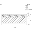
光透過性導電性シート1は、後述するタッチセンサ、調光素子、光電変換素子、熱線制御部材、アンテナ、電磁波シールド部材および画像表示装置などに備えられる一部材であって、光透過性導電性シート1は、それらを製造するための中間部材である。光透過性導電性シート1は、単独で流通し、産業上利用可能なデバイスである。
The light-transmitting
光透過性導電性シート1は、厚みを有し、厚み方向に直交する面方向に延びる平板形状を有する。光透過性導電性シート1は、樹脂層の一例としての基材シート2と、光透過性導電層3とを厚み方向一方側に向かって順に備える。具体的には、光透過性導電性シート1は、基材シート2と、基材シート2の厚み方向一方面に配置される光透過性導電層3とを備える。好ましくは、光透過性導電性シート1は、基材シート2と、光透過性導電層3とのみを備える。
The light-transmitting
(基材シート)
基材シート2は、厚みを有し、面方向に延びる平板形状を有する。基材シート2は、光透過性導電性シート1の厚み方向他方面を形成する。基材シート2は、面方向に延びるフィルム形状を有する。基材シート2は、可撓性を有する。基材シート2は、少なくとも基材層4を含む。具体的には、基材シート2は、基材層4と、ハードコート層5とを厚み方向一方側に向かって順に備える。なお、この一実施形態において、光透過性導電性シート1に備えられる基材シート2の数は、1である。
(Base sheet)
The
基材層4は、面方向に延びるフィルム形状を有する。基材層4は、基材シート2の厚み方向他方面を形成する。基材層4の材料は、特に限定されず、例えば、ポリマー、ガラスなどが挙げられる。好ましくは、ポリマーが挙げられる。ポリマーとしては、例えば、ポリエチレン、ポリプロピレン、シクロオレフィンポリマー(COP)などのオレフィン樹脂、例えば、ポリエチレンテレフタレート(PET)、ポリブチレンテレフタレート、ポリエチレンナフタレートなどのポリエステル樹脂、例えば、ポリメタクリレートなどの(メタ)アクリル樹脂(アクリル樹脂および/またはメタクリル樹脂)、例えば、ポリカーボネート樹脂、ポリエーテルスルフォン樹脂、ポリアリレート樹脂、メラミン樹脂、ポリアミド樹脂、ポリイミド樹脂、セルロース樹脂、ポリスチレン樹脂などの樹脂が挙げられ、好ましくは、ポリエステル樹脂、より好ましくは、PETが挙げられる。基材層4の厚みは、例えば、10μm以上、好ましくは、30μm以上であり、また、例えば、300μm以下、好ましくは、200μm以下、より好ましくは、100μm以下、さらに好ましくは、75μm以下である。〓
ハードコート層5は、光透過性導電層3に擦り傷を生じ難くするための擦傷保護層である。ハードコート層5は、基材シート2の厚み方向一方面を形成する。ハードコート層5は、基材層4の厚み方向一方面の全部に接触している。ハードコート層5は、特開2016?179686号公報に記載のハードコート組成物(アクリル樹脂、ウレタン樹脂など)の硬化物が挙げられる。ハードコート層5の厚みは、例えば、0.1μm以上、好ましくは、0.5μm以上であり、また、例えば、10μm以下、好ましくは、5μm以下である。
The
The
(基材の物性)
基材シート2の厚みは、例えば、1μm以上、好ましくは、10μm以上、より好ましくは、15μm以上、さらに好ましくは、30μm以上であり、また、例えば、310μm以下、好ましくは、210μm以下、より好ましくは、110μm以下、さらに好ましくは、80μm以下である。
(Physical properties of substrate)
The thickness of the
基材シート2の全光線透過率(JIS K 7375-2008)は、例えば、60%以上、好ましくは、80%以上、より好ましくは、85%以上であり、また、例えば、100%以下である。
The total light transmittance (JIS K 7375-2008) of the
(光透過性導電層)
光透過性導電層3は、光透過性導電性シート1の厚み方向一方面を形成する。光透過性導電層3は、その厚み方向他方側から、基材シート2に支持されている。光透過性導電層3は、基材シート2の厚み方向一方面の全部に接触している。つまり、光透過性導電層3は、基材シート2の厚み方向一方面に接触する。この光透過性導電層3は、第1領域6と、第2領域7とを、厚み方向一方側に向かって備える。そのため、この光透過性導電性シート1は、基材シート2と、第1領域6と、第2領域7とが、厚み方向一方側に向かって順に配置される。なお、この一実施形態において、光透過性導電性シート1に備えられる光透過性導電層3の数は、1である。
(Light-transmitting conductive layer)
The light-transmitting
(第1領域)
第1領域6は、この一実施形態では、光透過性導電層3における厚み方向他方側部分である。第1領域6は、光透過性導電層3の厚み方向他方面を含む。
(First region)
In this embodiment, the
この第1領域6は、断面視において、非晶質(非晶性)である領域を含む。第1領域6における非結晶性の態様としては、例えば、断面視において、第1領域6におけるすべての領域が非晶質である態様、例えば、断面視において、第1領域6において主要な領域が非晶質であり、残りわずかな領域が、結晶質である態様を含む。第1領域6における非晶性は、断面TEM画像の観察によって確認される。具体的には、例えば、図4に示すように、断面TEM画像によって、黒色の領域が非晶質の第1領域6として同定される。また、後述する通り、高倍率の断面TEM観察にて、格子縞の有無や格子縞が確認される領域の割合を観察することにより、第1領域6の非晶質であること、および/または、非晶質が主要な領域であることを同定することもできる。なお、断面視において、第1領域6における主要な領域の面積比(非晶質の面積比)は、例えば、0.6以上、好ましくは、0.8以上、より好ましくは、0.9以上であり、また、例えば、1以下である。
The
第1領域6の厚みは、上記した主要な領域の厚みであって、後述する第2領域7の厚みとの比が所望範囲となるように設定される。第1領域6の厚みは、例えば、30nm以下、好ましくは、25nm以下、より好ましくは、20nm以下、さらに好ましくは、15nm以下であり、また、例えば、1nm以上、好ましくは、5nm以上、より好ましくは、10nm以上である。
The thickness of the
第1領域6の厚みの測定方法は、実施例で説明する。
The method for measuring the thickness of the
(第2領域)
第2領域7は、この一実施形態では、光透過性導電層3における厚み方向一方側部分である。第2領域7は、光透過性導電層3の厚み方向一方面を含む。また、第2領域7は、第1領域6の厚み方向一方側に連続する。
(Second Area)
In this embodiment, the
この第2領域7は、断面視において、主要な領域として、結晶質である領域を含み、具体的には、結晶質(結晶性)である。
In cross-sectional view, this
第2領域7は非晶質(非晶性)をわずかに含んでいてもよい。具体的には、第2領域7における主要な領域の面積比(結晶質の面積比)は、例えば、0.7以上、好ましくは、0.8以上、より好ましくは、0.9以上であり、また、例えば、1以下である。
The
第2領域7における結晶性は、断面TEM画像の観察によって確認される。具体的には、例えば、図4に示すように、断面TEM画像によって、灰色の領域が結晶質の第2領域7として同定される。また、後述する通り、高倍率の断面TEM観察にて、格子縞の有無や格子縞が確認される領域の割合を観察することにより、第2領域7が結晶質であること、および/または、結晶質が主要な領域であることを同定することもできる。
The crystallinity of the
第2領域7は、第1領域6(第1領域6における主要な領域)より厚い。他方、第2領域7が、第1領域6より薄いか同一厚みであれば、比抵抗が上昇する。
The
具体的には、第1領域6の厚みに対する第2領域7の厚みの比は、1.0超過、好ましくは、1.3以上、より好ましくは、2以上、さらに好ましくは、4以上である。また、光透過性導電層3の厚みに対する第2領域7の厚みの比は、例えば、0.50超過、好ましくは、0.56以上、より好ましくは、0.70以上、さらに好ましくは、0.73以上、とりわけ好ましくは、0.80以上である。第1領域6の厚みに対する第2領域7の厚みの比、および/または、光透過性導電層3の厚みに対する第2領域7の厚みの比が、上記した下限以上であれば、光透過性導電層3における、低い比抵抗を確保できる。
Specifically, the ratio of the thickness of the
また、第1領域6の厚みに対する第2領域7の厚みの比は、例えば、1000以下、好ましくは、100以下、より好ましくは、50以下、さらに好ましくは、20以下、とりわけ好ましくは、15以下、とくに好ましくは、10以下である。また、透過性導電層3の厚みに対する第2領域7の厚みの比は、例えば、1.00未満、好ましくは、0.99以下、より好ましくは、0.95以下、より好ましくは、0.90である。第1領域6の厚みに対する第2領域7の厚みの比、および/または、透過性導電層3の厚みに対する第2領域7の厚みの比が上記した上限以下であれば、透過性導電層3のクラックの発生量を抑制できる。
The ratio of the thickness of the
また、第2領域7の厚みは、第2領域7の厚み比が上記範囲になるように設定され、具体的には、例えば、25nm超過、好ましくは、30nm以上、より好ましくは、50nm、さらに好ましくは、65nm以上、とりわけ好ましくは、100nm以上である。また、第2領域7の厚みは、例えば、500nm未満、好ましくは、300nm以下、より好ましくは、200nm以下である。
The thickness of the
第2領域7の厚みの測定方法は、実施例で説明する。
The method for measuring the thickness of the
(光透過性導電層の材料)
光透過性導電層3の材料としては、例えば、導電性酸化物が挙げられる。導電性酸化物としては、例えば、In、Sn、Zn、Ga、Sb、Ti、Si、Zr、Mg、Al、Au、Ag、Cu、Pd、Wからなる群より選択される少なくとも1種の金属または半金属を含む金属酸化物が挙げられる。金属酸化物には、必要に応じて、さらに上記群に示された金属原子または半金属原子をドープしていてもよい。
(Material for light-transmitting conductive layer)
Examples of materials for the light-transmitting
導電性酸化物としては、具体的には、インジウム亜鉛複合酸化物(IZO)、インジウムガリウム亜鉛複合酸化物(IGZO)、インジウムガリウム複合酸化物(IGO)、インジウムスズ複合酸化物(ITO)、アンチモンスズ複合酸化物(ATO)などの金属酸化物が挙げられる。導電性酸化物として、好ましくは、透明性および電気伝導性を向上する観点から、インジウムおよびスズの両方を含有するインジウムスズ複合酸化物(ITO)が挙げられる。導電酸化物がITOであれば、透明性および導電性により一層優れる。ITOにおける酸化インジウムの濃度および酸化スズの濃度は、用途および目的によって適宜設定される。具体的には、導電性酸化物における酸化スズの濃度は、例えば、0.1質量%以上、好ましくは、1質量%以上であり、例えば、30質量%以下である。 Specific examples of the conductive oxide include metal oxides such as indium zinc oxide (IZO), indium gallium zinc oxide (IGZO), indium gallium oxide (IGO), indium tin oxide (ITO), and antimony tin oxide (ATO). As the conductive oxide, indium tin oxide (ITO), which contains both indium and tin, is preferably used from the viewpoint of improving transparency and electrical conductivity. If the conductive oxide is ITO, the transparency and electrical conductivity are even more excellent. The concentration of indium oxide and the concentration of tin oxide in ITO are appropriately set according to the application and purpose. Specifically, the concentration of tin oxide in the conductive oxide is, for example, 0.1% by mass or more, preferably 1% by mass or more, and, for example, 30% by mass or less.
(光透過性導電層の物性)
光透過性導電層3の厚みは、30nmを超過する。光透過性導電層3の厚みが30nm以下であれば、光透過性導電層3の比抵抗が上昇する。また、光透過性導電層3の厚みは、好ましくは、40nm以上、より好ましくは、50nm超過、さらに好ましくは、60nm以上、とりわけ好ましくは、75nm以上、とくに好ましくは、100nm以上、もっとも好ましくは、125nm以上であり、また、例えば、500nm以下、好ましくは、300nm以下、より好ましくは、250nm以下、さらに好ましくは、200nm以下、とりわけ好ましくは、175nm以下である。光透過性導電層3の厚みが上記した下限以上あれば、比抵抗を低減できる。光透過性導電層3の厚みが上記した上限以下であれば、クラックを抑制できる。
(Physical Properties of Light-Transmitting Conductive Layer)
The thickness of the light-transmitting
光透過性導電層3の全光線透過率(JIS K 7375-2008)は、例えば、60%以上、好ましくは、80%以上、より好ましくは、85%以上であり、また、例えば、100%以下である。
The total light transmittance (JIS K 7375-2008) of the light-transmitting
光透過性導電層3の表面抵抗は、例えば、200Ω/□以下、好ましくは、65Ω/□以下、より好ましくは、45Ω以下、さらに好ましくは、30Ω/□以下、とりわけ好ましくは、20Ω/□以下であり、また、例えば、0Ω/□超過である。表面抵抗は、JIS K7194に準拠して、4端子法により測定する。
The surface resistance of the light-transmitting
光透過性導電層3の比抵抗は、例えば、7.0×10⁻⁴Ωcm以下、好ましくは、2.8×10⁻⁴Ωcm以下、より好ましくは、2.5×10⁻⁴Ωcm以下、さらに好ましくは、2.2×10⁻⁴Ωcm以下であり、また、例えば、0Ωcm超過、好ましくは、0.1×10⁻⁴Ωcm以上、より好ましくは、0.5×10⁻⁴Ωcm以上、さらに好ましくは、1.0×10⁻⁴Ωcm以上である。比抵抗は、表面抵抗に厚みを乗じて得られる。
The resistivity of the light transmissible
(光透過性導電性シートの物性)
光透過性導電性シート1の厚みは、例えば、1μm以上、好ましくは、10μm以上、より好ましくは、15μm以上、さらに好ましくは、30μm以上であり、また、例えば、310μm以下、好ましくは、210μm以下、より好ましくは、120μm以下、さらに好ましくは、90μm以下である。
(Physical properties of light-transmitting conductive sheet)
The thickness of the light-transmitting
光透過性導電性シート1の全光線透過率(JIS K 7375-2008)は、例えば、60%以上、好ましくは、80%以上、より好ましくは、85%以上であり、また、例えば、100%以下である。
The total light transmittance (JIS K 7375-2008) of the light-transmitting
(光透過性導電性シート1の製造方法)
次に、光透過性導電性シート1の製造方法を、図2を参照して説明する。この方法では、例えば、ロール-トゥ-ロール方式で、基材シート2に光透過性導電層3を成膜する。
(Method for manufacturing the light-transmitting conductive sheet 1)
Next, a method for producing the light-transmitting
この方法では、まず、基材シート2を準備する。具体的には、ハードコート組成物を、基材層4の厚み方向一方面に塗布および乾燥後、ハードコート組成物を硬化させる。これにより、基材層4と、ハードコート層5とを厚み方向一方側に順に備える基材シート2を準備する。
In this method, first, a
次いで、光透過性導電層3を、スパッタリングによって成膜する。具体的には、基材シート2をスパッタリング装置30で搬送しながら、光透過性導電層3を成膜する。
Next, the light-transmitting
[スパッタリング装置]
図2に示すように、スパッタリング装置30は、繰出部35と、スパッタ部36と、巻取部37とを順に備える。
[Sputtering Equipment]
As shown in FIG. 2, the sputtering
繰出部35は、繰出ロール38を備える。
The
スパッタ部36は、成膜ロール40と、第1成膜室41と、第2成膜室42とを備える。
The
成膜ロール40は、成膜ロール40を冷却するように構成される図示しない冷却装置を備える。
The film-forming
第1成膜室41は、第1ターゲット51と、第1ガス供給機61と、第1ポンプ71の排出口とを収容する。第1ターゲット51と、第1ガス供給機61と、第1ポンプ71の排出口とは、成膜ロール40に対して間隔を隔てて配置されている。第1成膜室41において、第1ターゲット51に対する成膜ロール40の反対側には、図示しないマグネットが配置されている。マグネットの磁場強度は、第1ターゲット51上の水平磁場強度が、例えば、10mT以上、200mT以下になるように、調整されている。
The
第1ターゲット51の材料としては、上記した導電性酸化物と同様の材料が挙げられる。なお、第1ターゲット51の材料は、導電性酸化物の焼結体を含む。第1ターゲット51は、所定の電力密度で電力印加できるように構成されている。
The material of the
第1ガス供給機61は、スパッタリングガスを、第1成膜室41に供給するように構成されている。スパッタリングガスとしては、例えば、窒素、アルゴンなどの不活性ガス、例えば、不活性ガスと、酸素などの反応性ガスとを含む混合ガスなどが挙げられ、好ましくは、混合ガスが挙げられる。スパッタリングガスが混合ガスであれば、第1ガス供給機61は、第1不活性ガス供給機63と、第1反応性ガス供給機64とを含んでおり、それぞれから、不活性ガスと、反応性ガスとが第1成膜室41に供給される。
The
第2成膜室42は、成膜ロール40の周方向において、第1成膜室41に隣接して配置される。第2成膜室42は、第2ターゲット52と、第2ガス供給機62と、第2ポンプ72の排出口とを収容する。第2ターゲット52と、第2ガス供給機62と、第2ポンプ72の排出口とは、成膜ロール40に対して間隔を隔てて配置されている。第2成膜室42において、第2ターゲット52に対する成膜ロール40の反対側には、図示しないマグネットが配置されている。マグネットの磁場強度は、第2ターゲット52上の水平磁場強度が、例えば、10mT以上、200mT以下になるように、調整されている。
The second
第2ターゲット52の材料としては、上記した導電性酸化物と同様の材料が挙げられる。なお、第2ターゲット52の材料は、導電性酸化物の焼結体を含む。第2ターゲット52は、所定の電力密度で電力を印加できるように構成されている。
The material of the
第2ガス供給機62は、第2のスパッタリングガスを、第2成膜室42に供給するように構成されている。第2のスパッタリングガスとしては、例えば、不活性ガス、混合ガスが挙げられ、好ましくは、混合ガスが挙げられる。第2のスパッタリングガスが第2混合ガスであれば、第2ガス供給機62は、第2不活性ガス供給機65と、第2反応性ガス供給機66とを含んでおり、それぞれから、不活性ガスと、反応性ガスとが第2成膜室42に供給される。
The
巻取部37は、巻取ロール39を備える。
The winding
[光透過性導電性シート1の製造方法]
このスパッタリング装置30を用いて、光透過性導電層3を基材シート2に成膜するには、まず、基材シート2を、繰出ロール38、成膜ロール40および巻取ロール39に掛け渡す。
[Method of manufacturing light-transmitting conductive sheet 1]
To form the light-transmitting
第1ポンプ71を駆動しながら、第1ガス供給機61からスパッタリングガスを第1成膜室41に供給する。スパッタリングガスが混合ガスであれば、混合ガスにおける不活性ガスに対する反応性ガスの比R1は、容量基準で、例えば、0.001以上、好ましくは、0.005以上であり、また、例えば、0.2以下、好ましくは、0.1以下である。第1成膜室41の圧力は、例えば、1Pa以下である。
While driving the
第2ポンプ72を駆動しながら、第2ガス供給機62からスパッタリングガスを第2成膜室42に供給する。スパッタリングガスが混合ガスであれば、混合ガスにおける不活性ガスに対する反応性ガスの比R2は、容量基準で、例えば、0.001以上、好ましくは、0.005以上であり、また、例えば、0.2以下、好ましくは、0.1以下である。また、比R2に対する比R1の比(R1/R2)は、例えば、2以下、好ましくは、1未満、より好ましくは、0.9以下、さらに好ましくは、0.8以下、とりわけ好ましくは、0.7以下であり、また、例えば、0.01以上、好ましくは、0.1以上、より好ましくは、0.5以上である。第2成膜室42の圧力は、例えば、1Pa以下である。
While driving the
また、冷却装置を駆動して、成膜ロール40(の表面)を冷却する。成膜ロール40の温度(表面温度)は、例えば、20℃以下、好ましくは、10℃以下、さらに好ましくは、0.0℃以下であり、また、例えば、-50℃以上、好ましくは、-25℃以上である。
The cooling device is also driven to cool the film-forming roll 40 (its surface). The temperature (surface temperature) of the film-forming
第1ターゲット51と第2ターゲット52とのそれぞれに電極を印加する。具体的には、第1ターゲット51に電力密度P1で電力を印加する。第2ターゲット52に電力密度P2で電力を印加する。
An electrode is applied to each of the
なお、第1ターゲット51と第2ターゲット52とのそれぞれに印加する電源は、特に限定されず、例えば、DC、RFなどが挙げられる。電源は、好ましくは、DCである。
The power source applied to each of the
第2ターゲット52における電力密度P2に対する第1ターゲット51における電力密度P1の比(P1/P2)は、例えば、0.45以下、好ましくは、0.40以下、より好ましくは、0.32以下、さらに好ましくは、0.30以下であり、また、例えば、0.05以上、好ましくは、0.10以上、より好ましくは、0.16以上、さらに好ましくは、0.20以上である。第1ターゲット51の電力密度P1の比(P1/P2)が上記した上限以下であれば、第1非晶質導電膜81(後述)より厚い第2非晶質導電膜82(後述)を確実に形成できる。第1ターゲット51の電力密度P1の比(P1/P2)が上記した下限以上であれば、後の結晶化工程においても非晶質性を維持する第1領域6となる第1非晶質導電膜81を確実に形成し易い。
The ratio (P1/P2) of the power density P1 in the
具体的には、第1ターゲット51における電力密度P1と、第2ターゲット52における電力密度P2とは、上記した比(P1/P2)が上記した範囲内になるように適宜設定され、それぞれ、例えば、0.1W/cm2以上、また、例えば、15W/cm2以下の範囲から設定される。
Specifically, the power density P1 in the
続いて、繰出ロール38と、成膜ロール40と、巻取ロール39とを駆動することにより、繰出ロール38から基材シート2が繰り出される。基材シート2は、成膜ロール40の表面に接触しながら、第1成膜室41と第2成膜室42とを順に移動する。この際、基材シート2は、成膜ロール40の表面との接触によって、冷却される。
Then, the pay-
第1ターゲット51の近傍において、第1ターゲット51に対する電力の印加によって、スパッタリングガスをイオン化させて、イオン化ガスを生成する。続いて、イオン化ガスが、第1ターゲット51に衝突し、第1ターゲット51のターゲット材料が粒子となって叩き出され、粒子が、基材シート2に付着(堆積)して、第1非晶質導電膜81が形成される。
In the vicinity of the
続いて、第2ターゲット52の近傍において、第2ターゲット52に対する電力の印加によって、スパッタリングガスをイオン化させて、イオン化ガスを生成する。続いて、イオン化ガスが、第2ターゲット52に衝突し、第2ターゲット52のターゲット材料が粒子となって叩き出され、粒子が、第1非晶質導電膜81に付着(堆積)して、第2非晶質導電膜82が形成される。
Next, in the vicinity of the
第1非晶質導電膜81と、第2非晶質導電膜82とは、それぞれが、主成分として同一の導電性酸化物を含有することから、それらの境界は明確に観察されない場合がある。
The first amorphous
これにより、基材シート2と、第1非晶質導電膜81と、第2非晶質導電膜82とを厚み方向に順に備える非晶質光透過性導電性シート10が得られる。
This results in an amorphous light-transmitting
その後、第2非晶質導電膜82を結晶化させる(結晶化工程)。第2非晶質導電膜82を結晶化させるには、例えば、非晶質光透過性導電性シート10を加熱する。加熱温度は、例えば、80℃以上、好ましくは、100℃以上、より好ましくは、150℃以上あり、また、例えば、200℃未満、好ましくは、180℃以下であり、また、加熱時間は、例えば、1分間以上、好ましくは、10分間以上、より好ましくは、30分間以上、さらに好ましくは、1時間以上であり、また、例えば、5時間以下、好ましくは、3時間以下である。または、非晶質光透過性導電性シート10を常温で長時間放置することもできる。例えば、非晶質光透過性導電性シート10を、20℃以上、40℃以下の雰囲気で、500時間以上、好ましくは、1000時間以上、2000時間以下、放置する。
Then, the second amorphous
上記した加熱、または、常温長時間放置によって、第2非晶質導電膜82が結晶化する一方、第1非晶質導電膜81は、結晶化しない。これは、第1ターゲット51における電力密度P1の比(P1/P2)が上記した範囲(例えば、0.45以下)にあることから、第1非晶質導電膜81は、第2非晶質導電膜82に比べて不純物(例えば、水素原子および/または炭素原子)が多く、そのため、非晶性を維持する。
While the second amorphous
これによって、第1非晶質導電膜81は、第1領域6をなし、第2非晶質導電膜82は、第2領域7をなす。
As a result, the first amorphous
これによって、基材シート2と、第1領域6および第2領域7を有する光透過性導電層3とを備える非晶質光透過性導電性シートが得られる。
This results in an amorphous light-transmitting conductive sheet comprising a
この光透過性導電性シート1は、種々の用途に用いられ、例えば、タッチセンサ、電磁波シールド、調光素子(PDLC、PNLC、やSPDなどの電圧駆動型調光素子やエレクトロクロクロミック(EC)等の電流駆動型調光素子)、光電変換素子(有機薄膜太陽電池や色素増感太陽電池に代表される太陽電池素子の電極など)、熱線制御部材(近赤外反射および/または吸収部材や遠赤外反射および/または吸収部材)、アンテナ部材(光透過性アンテナ)、ヒーター部材(光透過性ヒーター)、画像表示装置などに用いられる。
This light-transmitting
(一実施形態の作用効果)
そして、この光透過性導電性シート1の光透過性導電層3は、光透過性導電層3の低い比抵抗を有しながら、クラックが抑制されている。
(Effects of one embodiment)
The light-transmitting
具体的には、結晶質である第2領域7が、第1領域6において非晶質である領域より厚いので、光透過性導電層3の比抵抗を低くできる。また、光透過性導電層3の厚みが、30nmを超過するので、光透過性導電層3の比抵抗を低くできる。
Specifically, since the crystalline
また、光透過性導電性シート1では、光透過性導電層3の厚みに対する第2領域7の厚みの割合が、0.73以上であれば、光透過性導電層3が、より一層低い比抵抗、さらには、低い表面抵抗を確保できる。
Furthermore, in the light-transmitting
タッチセンサ、調光素子、光電変換素子、熱線制御部材、アンテナ、電磁波シールド部材、ヒータ部材、および画像表示装置は、上記した光透過性導電性シート1を備えるので、信頼性に優れる。
Touch sensors, dimming elements, photoelectric conversion elements, heat ray control members, antennas, electromagnetic wave shielding members, heater members, and image display devices are equipped with the above-mentioned light-transmitting
(変形例)
変形例において、一実施形態と同様の部材および工程については、同一の参照符号を付し、その詳細な説明を省略する。また、変形例は、特記する以外、一実施形態と同様の作用効果を奏することができる。さらに、一実施形態およびその変形例を適宜組み合わせることができる。
(Modification)
In the modified example, the same components and steps as those in the first embodiment are denoted by the same reference numerals, and detailed description thereof will be omitted. In addition, the modified example can achieve the same effects as those in the first embodiment, unless otherwise specified. Furthermore, the first embodiment and its modified example can be appropriately combined.
一実施形態では、光透過性導電層3は、単数の第1領域6を含むが、例えば、複数の第1領域6を含むことができる。例えば、第1領域6と、第2領域7と、第1領域6とが、厚み方向一方側に向かって、配置されていてもよい。また、光透過性導電層3は、単数の第2領域7を含むが、例えば、複数の第2領域7を含むことができる。すると、光透過性導電層3は、複数の第1領域6と、複数の第2領域7とを含むことができる。
In one embodiment, the light-transmitting
例えば、この光透過性導電層3では、第1領域6と、第2領域7とが、厚み方向一方側に向かって、交互に配置されていてもよい。例えば、図3に示すように、第1領域6と、第2領域7と、第1領域6と、第2領域7とが厚み方向一方側に向かって順に配置される。図3に示す光透過性導電層3を形成するには、例えば、図2に示すスパッタリング装置30を用いて、単数の第1非晶質導電膜81と単数の第2非晶質導電膜82とを形成し、巻取ロール39で巻き取った非晶質光透過性導電性シート10を、再び、スパッタリング装置30(の繰出ロール38)にセットして(巻き替えて)、第3非晶質導電膜83と、第4非晶質導電膜84とを、第2非晶質導電膜82の厚み方向一方側に順に形成する。その後、上記の積層体を加熱または常温長期間放置する。これによって、第2非晶質導電膜82と第4非晶質導電膜84とが、結晶化して、第2領域7を形成する。一方、第1非晶質導電膜81と第3非晶質導電膜83とは、非晶性を維持して、第1領域6を形成する。そのため、第1領域6と、第2領域7と、第1領域6と、第2領域7とが、厚み方向一方側に向かって順に配置される。
For example, in this light-transmitting
第1領域6が複数配置される変形例では、第1領域6の厚みは、複数の第1領域6の厚みの合算値である。第2領域7が複数配置される変形例では、第2領域7の厚みは、複数の第2領域7の厚みの合算値である。
In a modified example in which multiple
基材シート2は、他の機能層をさらに備えることができる。機能層は、例えば、誘電体であり、その表面抵抗が、例えば、1×10⁶Ω/□以上、好ましくは、1×108Ω/□以上である。また、機能層は、樹脂および/または無機物を含有する。機能層は、単一の層として形成しても、複数の層として形成してもよく、また、樹脂と無機物との混合物として形成してもよい。例えば、図1の仮想線で示すように、基材フィルム13の厚み方向他方面に配置され、樹脂と無機粒子との混合物からなるアンチブロッキング層25を備えることができる。
The
本発明の樹脂層は、図示しないが、基材層4のみであってもよく、また、ハードコート層5のみであってもよい。また、本発明の樹脂層は、機能層であってもよい。
Although not shown, the resin layer of the present invention may be only the
一実施形態では、光透過性導電性シート1に備えられる光透過性導電層3の数は、1であったが、例えば、図示しないが、2であってもよい。この場合には、光透過性導電層3と、基材シート2と、光透過性導電層3とが、厚み方向一方側に向かって配置される。つまり、2つの光透過性導電層3が、厚み方向において、1つの基材シート2が挟む。
In one embodiment, the number of light-transmitting
一実施形態では、スパッタリング装置30は、成膜ロール40を備えるが、これに代えて、表面が平坦な成膜板を備えることもできる。
In one embodiment, the sputtering
一実施形態では、2の成膜室を備えるスパッタリング装置30を用いたが、1つの成膜室を備えるスパッタリング装置30を用いることもできる。例えば、第1回目のスパッタで、第1非晶質導電膜81を形成し、非晶質光透過性導電性シート10を巻取ロール39で巻き取り、これを同じスパッタリング装置30(の繰出ロール38)にセットして(巻き替えて)、第2回目のスパッタで、第2非晶質導電膜82を形成する。この変形例では、例えば、第2回目のスパッタにおける電力密度P2に対する第1回目のスパッタにおける電力密度P1の比(P1/P2)は、第2ターゲット52における電力密度P2に対する第1ターゲット51における電力密度P1の比(P1/P2)と同様である。
In one embodiment, a sputtering
一実施形態では、成膜ロール40の温度(表面温度)を冷却(20℃以下)としている。変形例では、成膜ロール40を加熱する。成膜ロール40の温度は、例えば、20℃超過、180℃以下である。
In one embodiment, the temperature (surface temperature) of the film-forming
一実施形態では、第1成膜室41と、第2成膜室42とを備えるスパッタリング装置30を用いたが、成膜室の数は、これに限定されない。3つ以上の成膜室を備えるスパッタリング装置30を用いることもできる。例えば、3つの成膜室を備えるスパッタリング装置30は、第1成膜室41、第2成膜室42、および、第3成膜室(図示せず)を有する。また、第3成膜室は、例えば、第3ターゲット(図示せず)と、第3ガス供給機(図示せず)と、第3ポンプの排出口(図示せず)とを収容する。スパッタリングガスとして第3混合ガスを供給する場合、第3ガス供給機は、第3不活性ガス供給機(図示せず)と、第3反応性ガス供給機(図示せず)とを含んでおり、それぞれから、不活性ガスと、反応性ガスとが第3成膜室に供給される。光透過性導電層3は、第1ターゲット51、第2ターゲット52、第3ターゲットに電力を印加することで形成できるが、この変形例では、第1ターゲット51をスパッタすることにより、第1非晶質導電膜81を形成し、第2ターゲット52および第3ターゲットをスパッタすることにより、第2非晶質導電膜82を形成する。
In one embodiment, a
以下の記載において用いられる配合割合(含有割合)、物性値、パラメータなどの具体的数値は、上記の「発明を実施するための形態」において記載されている、それらに対応する配合割合(含有割合)、物性値、パラメータなど該当記載の上限値(「以下」、「未満」として定義されている数値)または下限値(「以上」、「超過」として定義されている数値)に代替することができる。また、以下の記載において特に言及がない限り、「部」および「%」は質量基準である。 Specific numerical values of the compounding ratio (content ratio), physical property values, parameters, etc. used in the following description can be replaced with the upper limit (numerical value defined as "less than or equal to") or lower limit (numerical value defined as "more than or equal to" or "exceeding") of the corresponding compounding ratio (content ratio), physical property value, parameter, etc. described in the above "Description of the Invention." In addition, unless otherwise specified in the following description, "parts" and "%" are based on mass.
実施例1
長尺のPETフィルム(三菱樹脂社製、厚み50μm)からなる基材層4の厚み方向一方面に、アクリル樹脂を含む紫外線硬化性のハードコート組成物を塗布し、これを紫外線照射して硬化させて、厚みが2μmであるハードコート層5を形成した。これにより、基材層4と、ハードコート層5とを備える基材シート2を準備した。
Example 1
An ultraviolet-curable hard coat composition containing an acrylic resin was applied to one surface in the thickness direction of a
次いで、基材シート2をスパッタリング装置30にセットした。成膜ロール40の温度を、-8℃にした。第1ポンプ71と第2ポンプ72とを駆動した。スパッタリング装置30において、第1ターゲット51と第2ターゲットとの材料は、いずれも、酸化インジウムと酸化スズとの焼結体であった。焼結体における酸化スズ濃度は、10質量%であった。
The
第1不活性ガス供給機63からアルゴンを第1成膜室41に供給し、第1反応性ガス供給機64から酸素を第1成膜室41に供給した。第1成膜室41の気圧は、0.4Paであった。第1成膜室41の混合ガス(アルゴンおよび酸素の全量)におけるアルゴンに対する酸素の比R1(容量基準)は、0.010であった。第1ターゲット51に電力密度P1で電力を印加して、第1ターゲット51をスパッタリングした。第1ターゲット51上の水平磁場強度は、90mTであった。第1ターゲット51に印加する電源は、DCを用いた。
Argon was supplied from the first
第2不活性ガス供給機65からアルゴンを第2成膜室42に供給し、第2反応性ガス供給機66から酸素を第2成膜室42に供給した。第2成膜室42の気圧は、0.4Paであった。第2成膜室42の混合ガス(アルゴンおよび酸素の全量)におけるアルゴンに対する酸素の比R2(容量基準)は、0.017であった。第2ターゲット52に電力密度P2で電力を印加して、第2ターゲット52をスパッタリングした。第2ターゲット52上の水平磁場強度は、90mTであった。第2ターゲット52に印加する電源は、DCを用いた。第2ターゲット52における電力密度P2に対する、第1ターゲット51における電力密度P1の比(P1/P2)は、0.31であった。
Argon was supplied from the second
これによって、第1非晶質導電膜81と第2非晶質導電膜82とを基材シート2の厚み方向一方側に順に形成した。これによって、基材シート2と、第1非晶質導電膜81と、第2非晶質導電膜82とを厚み方向一方側に向かって順に備える非晶質光透過性導電性シート10を作製した。
As a result, the first amorphous
次いで、非晶質光透過性導電性シート10を、23℃、1500時間静置し、その後、熱風オーブンで155℃、1.5時間加熱した。これにより、光透過性導電性シート1を得た。
Next, the amorphous light-transmitting
(実施例2、実施例4~比較例5)
表1に示すように、第1ターゲット51の電力密度P2に対する第1ターゲット51の電力密度P1の比(P1/P2)、反応性ガスの比R1/R2、光透過性導電層3の総厚等を変更した以外は、実施例1と同様に処理して、光透過性導電性シート1を得た。
(Example 2, Example 4 to Comparative Example 5)
As shown in Table 1, the ratio of the power density P1 of the
(実施例3)
表1に示すように、第1ターゲット51の電力密度P2に対する第1ターゲット51の電力密度P1の比(P1/P2)を変更して、実施例1と同様に、第1非晶質導電膜81と第2非晶質導電膜82とを形成して、非晶質光透過性導電性シート10を形成し、巻取ロール39でこれを巻き取った後、非晶質光透過性導電性シート10を再度スパッタリング装置30にセットして(巻き替えて)、第3非晶質導電膜83と第4非晶質導電膜84とを形成した。その後、これを、23℃、1500時間静置し、さらにこれを熱風オーブンで155℃、1.5時間加熱した。
Example 3
As shown in Table 1, the ratio (P1/P2) of the power density P1 of the
(厚みの測定、結晶性の確認、評価等)
各実施例および各比較例の光透過性導電性シート1について、以下の項目を評価した。結果を表1に記載する。
(Thickness measurement, confirmation of crystallinity, evaluation, etc.)
The following items were evaluated for the light-transmitting
(光透過性導電層の厚みと、非晶質および結晶質の判定)
FIBマイクロサンプリング法により、光透過性導電性シート1を断面調整した後、断面のFE-TEM観察を実施した。20万倍の観察倍率で撮影したTEM画像を用いて、光透過性導電層3の黒色の領域(第1領域6)の厚みと灰色の領域(第2領域7)の厚みとを測定した。また、それらを合算して、光透過性導電層3の厚みを取得した。
(Thickness of light-transmitting conductive layer and determination of amorphous or crystalline)
After the cross section of the light-transmitting
また、黒色の領域と、灰色の領域とのそれぞれにおいて、高倍率(200万倍)での断面TEM観察を実施した。灰色の領域では、断面視において全体の領域にわたって、格子縞が確認され、そのため、結晶質であり、第2領域7であることが分かった。一方、黒色の領域では、断面視において全体の領域にわたって、格子縞が確認されず、または、断面視において、一部の狭い領域で格子縞が確認されたが、格子縞の格子縞は、微小領域であることから、非晶質が支配的であるため、第1領域6であることが分かった。
In addition, cross-sectional TEM observations were performed at high magnification (2 million times) on both the black and gray regions. In the gray region, lattice fringes were observed over the entire region when viewed in cross section, and therefore it was determined that it was crystalline and was the
装置および測定条件は以下のとおりである。
FIB装置: Hitachi製 FB2200、 加速電圧: 10kV
FE-TEM 装置: JEOL製 JEM-2800、加速電圧: 200kV
実施例2のTEM写真を図4に示す。実施例3のTEM写真を図5に示す。
The apparatus and measurement conditions are as follows.
FIB device: Hitachi FB2200, Acceleration voltage: 10 kV
FE-TEM equipment: JEOL JEM-2800, accelerating voltage: 200 kV
The TEM photograph of Example 2 is shown in Figure 4. The TEM photograph of Example 3 is shown in Figure 5.
(表面抵抗)
光透過性導電層3の表面抵抗を、JIS K7194(1994年)に準じる四端子法により測定した。以下の基準で、表面抵抗を評価した。
<基準>
◎: 表面抵抗が、20Ω/□以下である。
〇: 表面抵抗が、20Ω/□超過、45Ω/□以下である。
△: 表面抵抗が、45Ω/□超過、65Ω/□以下である。
×: 表面抵抗が、65Ω/□超過である。
(Surface Resistance)
The surface resistance of the light-transmitting
<Standards>
⊚: Surface resistance is 20 Ω/□ or less.
◯: Surface resistance is greater than 20 Ω/□ and less than 45 Ω/□.
Δ: Surface resistance is more than 45 Ω/□ and less than 65 Ω/□.
×: The surface resistance is more than 65 Ω/□.
(比抵抗)
光透過性導電層3の表面抵抗に、光透過性導電層3の厚みを乗じて、比抵抗を取得した。以下の基準で、比抵抗を評価した。
<評価基準>
◎: 比抵抗が、2.2×10⁻⁴Ω・cm以下である。
〇: 比抵抗が、2.2×10⁻⁴Ω・cm超過、2.8×10⁻⁴Ω・cm以下である。
×: 比抵抗が、2.8×10⁻⁴Ω・cm超過である。
(resistivity)
The specific resistance was obtained by multiplying the surface resistance of the light-transmitting
<Evaluation criteria>
⊚: The resistivity is 2.2×10 −4 Ω·cm or less.
◯: The resistivity is more than 2.2×10 −4 Ω·cm and is 2.8×10 −4 Ω·cm or less.
×: The resistivity exceeds 2.8×10 −4 Ω·cm.
(クラック)
光透過性導電性シート1を、5cm×50cmのサイズに切り出した。次いで、平面視で、5cm10cmの区画を15個定め、各区画の光透過性導電層3の表面を目視で観察した。以下の基準で、光透過性導電層3のクラックのレベルを評価した。
<評価基準>
〇: クラックが観察された区画が、0以上、6以下である。
△: クラックが観察される区画が、7以上、12以下である。
×: クラックが観察される区画が、13以上である。
(crack)
The light-transmitting
<Evaluation criteria>
◯: The number of sections in which cracks were observed was 0 to 6.
Δ: Cracks were observed in 7 or more and 12 or less sections.
×: Cracks were observed in 13 or more sections.

1 光透過性導電性シート
2 基材シート
2 基材
3 光透過性導電層
6 第1領域
7 第2領域
11 基材
Claims (10)
前記光透過性導電層は、単数の第1領域と、単数の第2領域とからなり、これらを前記厚み方向一方側に向かって順に含み、
断面視において、
前記第1領域における非晶質の面積比は、0.6以上であり、
前記第2領域における結晶質の面積比は、0.7以上であり、
前記光透過性導電層の厚みが、30nmを超過し、
前記第1領域の厚みが、10nm以上であり、
前記第1領域の厚みに対する前記第2領域の厚みの比が、2以上100以下であることを特徴とする、光透過性導電性シート。 A resin layer and a light-transmitting conductive layer are provided in this order toward one side in a thickness direction,
the light-transmitting conductive layer includes a single first region and a single second region, the first region and the second region being arranged in order toward one side in the thickness direction;
In cross section,
the amorphous area ratio in the first region is 0.6 or more;
the area ratio of the crystalline material in the second region is 0.7 or more;
The thickness of the light-transmitting conductive layer is greater than 30 nm;
The thickness of the first region is 10 nm or more,
A light-transmitting conductive sheet, characterized in that a ratio of a thickness of the second region to a thickness of the first region is 2 or more and 100 or less.
Priority Applications (6)
| Application Number | Priority Date | Filing Date | Title |
|---|---|---|---|
| JP2020090596A JP7628397B2 (en) | 2020-05-25 | 2020-05-25 | Light-transmitting conductive sheet, touch sensor, light control element, photoelectric conversion element, heat control member, antenna, electromagnetic wave shielding member, and image display device |
| KR1020227040183A KR20230015908A (en) | 2020-05-25 | 2021-04-28 | Light-transmitting conductive sheet, touch sensor, light control element, photoelectric conversion element, heat wire control member, antenna, electromagnetic shield member and image display device |
| PCT/JP2021/016985 WO2021241118A1 (en) | 2020-05-25 | 2021-04-28 | Optically transparent electroconductive sheet, touch sensor, light control element, photoelectric conversion element, heat ray control member, antenna, electromagnetic wave shield member, and image display device |
| CN202180038417.5A CN115666928B (en) | 2020-05-25 | 2021-04-28 | Light-transmitting conductive sheet, touch sensor, light control element, photoelectric conversion element, heat ray control member, antenna, electromagnetic wave shielding member, and image display device |
| TW110116567A TW202212123A (en) | 2020-05-25 | 2021-05-07 | Translucent conductive sheet, touch sensor, dimming element, photoelectric conversion element, heat ray control member, antenna, electromagnetic wave shielding member, and image display device |
| JP2025012949A JP2025065189A (en) | 2020-05-25 | 2025-01-29 | Light-transmitting conductive sheet, touch sensor, light control element, photoelectric conversion element, heat control member, antenna, electromagnetic wave shielding member, and image display device |
Applications Claiming Priority (1)
| Application Number | Priority Date | Filing Date | Title |
|---|---|---|---|
| JP2020090596A JP7628397B2 (en) | 2020-05-25 | 2020-05-25 | Light-transmitting conductive sheet, touch sensor, light control element, photoelectric conversion element, heat control member, antenna, electromagnetic wave shielding member, and image display device |
Related Child Applications (1)
| Application Number | Title | Priority Date | Filing Date |
|---|---|---|---|
| JP2025012949A Division JP2025065189A (en) | 2020-05-25 | 2025-01-29 | Light-transmitting conductive sheet, touch sensor, light control element, photoelectric conversion element, heat control member, antenna, electromagnetic wave shielding member, and image display device |
Publications (2)
| Publication Number | Publication Date |
|---|---|
| JP2021186966A JP2021186966A (en) | 2021-12-13 |
| JP7628397B2 true JP7628397B2 (en) | 2025-02-10 |
Family
ID=78745305
Family Applications (2)
| Application Number | Title | Priority Date | Filing Date |
|---|---|---|---|
| JP2020090596A Active JP7628397B2 (en) | 2020-05-25 | 2020-05-25 | Light-transmitting conductive sheet, touch sensor, light control element, photoelectric conversion element, heat control member, antenna, electromagnetic wave shielding member, and image display device |
| JP2025012949A Pending JP2025065189A (en) | 2020-05-25 | 2025-01-29 | Light-transmitting conductive sheet, touch sensor, light control element, photoelectric conversion element, heat control member, antenna, electromagnetic wave shielding member, and image display device |
Family Applications After (1)
| Application Number | Title | Priority Date | Filing Date |
|---|---|---|---|
| JP2025012949A Pending JP2025065189A (en) | 2020-05-25 | 2025-01-29 | Light-transmitting conductive sheet, touch sensor, light control element, photoelectric conversion element, heat control member, antenna, electromagnetic wave shielding member, and image display device |
Country Status (5)
| Country | Link |
|---|---|
| JP (2) | JP7628397B2 (en) |
| KR (1) | KR20230015908A (en) |
| CN (1) | CN115666928B (en) |
| TW (1) | TW202212123A (en) |
| WO (1) | WO2021241118A1 (en) |
Families Citing this family (2)
| Publication number | Priority date | Publication date | Assignee | Title |
|---|---|---|---|---|
| JP7620041B2 (en) * | 2023-03-30 | 2025-01-22 | 日東電工株式会社 | Light-transmitting conductive layer and light-transmitting conductive sheet |
| JP7620042B2 (en) * | 2023-03-30 | 2025-01-22 | 日東電工株式会社 | Light-transmitting conductive sheet |
Citations (3)
| Publication number | Priority date | Publication date | Assignee | Title |
|---|---|---|---|---|
| JP2000243145A (en) | 1999-02-18 | 2000-09-08 | Teijin Ltd | Film with transparent conductive thin film and method for producing the same |
| JP2012172219A (en) | 2011-02-23 | 2012-09-10 | Toppan Printing Co Ltd | Transparent conductive laminate, and method for producing the same |
| CN104951165A (en) | 2015-07-10 | 2015-09-30 | 张家港康得新光电材料有限公司 | Transparent conductive film and capacitive touch screen comprising same |
Family Cites Families (12)
| Publication number | Priority date | Publication date | Assignee | Title |
|---|---|---|---|---|
| JPS6255127A (en) * | 1985-09-04 | 1987-03-10 | コニカ株式会社 | Conductive film |
| JP3176812B2 (en) | 1994-12-21 | 2001-06-18 | 住友ベークライト株式会社 | Transparent conductive film |
| JP3766453B2 (en) * | 1995-07-25 | 2006-04-12 | 大日本印刷株式会社 | Transparent conductive film and method for producing the same |
| JPH09174749A (en) * | 1995-12-28 | 1997-07-08 | Sumitomo Bakelite Co Ltd | Transparent conductive film |
| JP4269587B2 (en) * | 2002-07-12 | 2009-05-27 | 凸版印刷株式会社 | Conductive laminate and method for producing the same |
| JP4115283B2 (en) * | 2003-01-07 | 2008-07-09 | シャープ株式会社 | Semiconductor device and manufacturing method thereof |
| JP5381912B2 (en) * | 2010-06-28 | 2014-01-08 | 住友金属鉱山株式会社 | Transparent conductive substrate with surface electrode and method for producing the same, thin film solar cell and method for producing the same |
| US20160300632A1 (en) * | 2014-05-20 | 2016-10-13 | Nitto Denko Corporation | Transparent conductive film and manufacturing method thereof |
| JP6412539B2 (en) * | 2015-11-09 | 2018-10-24 | 日東電工株式会社 | Light transmissive conductive film and light control film |
| CN111391427B (en) * | 2015-11-09 | 2022-04-26 | 日东电工株式会社 | Light-transmitting conductive film and light-adjusting film |
| JP6654865B2 (en) * | 2015-11-12 | 2020-02-26 | 日東電工株式会社 | Amorphous transparent conductive film, crystalline transparent conductive film and method for producing the same |
| CN111149049A (en) * | 2017-09-29 | 2020-05-12 | 日东电工株式会社 | Electrochromic light-tuning member, light-transmitting conductive glass film, and electrochromic light-tuning element |
-
2020
- 2020-05-25 JP JP2020090596A patent/JP7628397B2/en active Active
-
2021
- 2021-04-28 KR KR1020227040183A patent/KR20230015908A/en active Pending
- 2021-04-28 WO PCT/JP2021/016985 patent/WO2021241118A1/en not_active Ceased
- 2021-04-28 CN CN202180038417.5A patent/CN115666928B/en active Active
- 2021-05-07 TW TW110116567A patent/TW202212123A/en unknown
-
2025
- 2025-01-29 JP JP2025012949A patent/JP2025065189A/en active Pending
Patent Citations (3)
| Publication number | Priority date | Publication date | Assignee | Title |
|---|---|---|---|---|
| JP2000243145A (en) | 1999-02-18 | 2000-09-08 | Teijin Ltd | Film with transparent conductive thin film and method for producing the same |
| JP2012172219A (en) | 2011-02-23 | 2012-09-10 | Toppan Printing Co Ltd | Transparent conductive laminate, and method for producing the same |
| CN104951165A (en) | 2015-07-10 | 2015-09-30 | 张家港康得新光电材料有限公司 | Transparent conductive film and capacitive touch screen comprising same |
Also Published As
| Publication number | Publication date |
|---|---|
| JP2021186966A (en) | 2021-12-13 |
| CN115666928B (en) | 2025-11-11 |
| CN115666928A (en) | 2023-01-31 |
| JP2025065189A (en) | 2025-04-17 |
| KR20230015908A (en) | 2023-01-31 |
| WO2021241118A1 (en) | 2021-12-02 |
| TW202212123A (en) | 2022-04-01 |
Similar Documents
| Publication | Publication Date | Title |
|---|---|---|
| JP2025065189A (en) | Light-transmitting conductive sheet, touch sensor, light control element, photoelectric conversion element, heat control member, antenna, electromagnetic wave shielding member, and image display device | |
| TW202145258A (en) | Transparent conductive film, and production method for transparent conductive film | |
| JP7686806B2 (en) | Light-transmitting conductive layer and light-transmitting conductive film | |
| JP7820593B2 (en) | Transparent conductive film and method for producing the same | |
| CN115428100A (en) | Light-transmitting conductive layer laminate | |
| TW202145259A (en) | Manufacturing method of transparent conductive film | |
| JP7102637B2 (en) | Method for manufacturing a light-transmitting conductive sheet | |
| CN116547139B (en) | Transparent conductive film | |
| KR102695635B1 (en) | Transparent conductive film | |
| CN115298757A (en) | Light-transmitting conductive film and transparent conductive film | |
| TWI864426B (en) | Laminated body | |
| KR102698069B1 (en) | Transparent electroconductive film | |
| JP7478721B2 (en) | Method for manufacturing a substrate with a transparent electrode | |
| JP2025108462A (en) | Transparent Conductive Film | |
| JP2025078213A (en) | Light-transmitting conductive layer and light-transmitting conductive film | |
| JP2022118004A (en) | transparent conductive film | |
| CN116745867A (en) | Transparent conductive film and method for manufacturing transparent conductive film |
Legal Events
| Date | Code | Title | Description |
|---|---|---|---|
| A621 | Written request for application examination |
Free format text: JAPANESE INTERMEDIATE CODE: A621 Effective date: 20230414 |
|
| A131 | Notification of reasons for refusal |
Free format text: JAPANESE INTERMEDIATE CODE: A131 Effective date: 20231114 |
|
| A521 | Request for written amendment filed |
Free format text: JAPANESE INTERMEDIATE CODE: A523 Effective date: 20231219 |
|
| A131 | Notification of reasons for refusal |
Free format text: JAPANESE INTERMEDIATE CODE: A131 Effective date: 20240312 |
|
| A521 | Request for written amendment filed |
Free format text: JAPANESE INTERMEDIATE CODE: A523 Effective date: 20240419 |
|
| A131 | Notification of reasons for refusal |
Free format text: JAPANESE INTERMEDIATE CODE: A131 Effective date: 20240806 |
|
| A521 | Request for written amendment filed |
Free format text: JAPANESE INTERMEDIATE CODE: A523 Effective date: 20240927 |
|
| TRDD | Decision of grant or rejection written | ||
| A01 | Written decision to grant a patent or to grant a registration (utility model) |
Free format text: JAPANESE INTERMEDIATE CODE: A01 Effective date: 20250107 |
|
| A61 | First payment of annual fees (during grant procedure) |
Free format text: JAPANESE INTERMEDIATE CODE: A61 Effective date: 20250129 |
|
| R150 | Certificate of patent or registration of utility model |
Ref document number: 7628397 Country of ref document: JP Free format text: JAPANESE INTERMEDIATE CODE: R150 |