JP7627770B2 - Non-flammable aerosol delivery device - Google Patents

Non-flammable aerosol delivery device Download PDF

Info

Publication number
JP7627770B2
JP7627770B2 JP2023545800A JP2023545800A JP7627770B2 JP 7627770 B2 JP7627770 B2 JP 7627770B2 JP 2023545800 A JP2023545800 A JP 2023545800A JP 2023545800 A JP2023545800 A JP 2023545800A JP 7627770 B2 JP7627770 B2 JP 7627770B2
Authority
JP
Japan
Prior art keywords
adapter
consumable
received
delivery device
aerosol
Prior art date
Legal status (The legal status is an assumption and is not a legal conclusion. Google has not performed a legal analysis and makes no representation as to the accuracy of the status listed.)
Active
Application number
JP2023545800A
Other languages
Japanese (ja)
Other versions
JP2024504776A (en
Inventor
ジェレミー キャンベル,
アンディ フィンチ,
ジョン ピーター フレデリック スプラトリー,
ダニエル トーマス アハーン,
マシュー ライト,
ダニエル アンソニー ウォルトン,
アンドリュー リチャード ブキャナン ハルケット,
ジェームズ ガーフィールド プライヤー,
ルーク ジェームズ ウォーレン,
Current Assignee (The listed assignees may be inaccurate. Google has not performed a legal analysis and makes no representation or warranty as to the accuracy of the list.)
Nicoventures Trading Ltd
Original Assignee
Nicoventures Trading Ltd
Priority date (The priority date is an assumption and is not a legal conclusion. Google has not performed a legal analysis and makes no representation as to the accuracy of the date listed.)
Filing date
Publication date
Application filed by Nicoventures Trading Ltd filed Critical Nicoventures Trading Ltd
Publication of JP2024504776A publication Critical patent/JP2024504776A/en
Application granted granted Critical
Publication of JP7627770B2 publication Critical patent/JP7627770B2/en
Active legal-status Critical Current
Anticipated expiration legal-status Critical

Links

Images

Classifications

    • AHUMAN NECESSITIES
    • A24TOBACCO; CIGARS; CIGARETTES; SIMULATED SMOKING DEVICES; SMOKERS' REQUISITES
    • A24FSMOKERS' REQUISITES; MATCH BOXES; SIMULATED SMOKING DEVICES
    • A24F40/00Electrically operated smoking devices; Component parts thereof; Manufacture thereof; Maintenance or testing thereof; Charging means specially adapted therefor
    • A24F40/40Constructional details, e.g. connection of cartridges and battery parts
    • AHUMAN NECESSITIES
    • A24TOBACCO; CIGARS; CIGARETTES; SIMULATED SMOKING DEVICES; SMOKERS' REQUISITES
    • A24FSMOKERS' REQUISITES; MATCH BOXES; SIMULATED SMOKING DEVICES
    • A24F40/00Electrically operated smoking devices; Component parts thereof; Manufacture thereof; Maintenance or testing thereof; Charging means specially adapted therefor
    • A24F40/40Constructional details, e.g. connection of cartridges and battery parts
    • A24F40/42Cartridges or containers for inhalable precursors
    • AHUMAN NECESSITIES
    • A24TOBACCO; CIGARS; CIGARETTES; SIMULATED SMOKING DEVICES; SMOKERS' REQUISITES
    • A24FSMOKERS' REQUISITES; MATCH BOXES; SIMULATED SMOKING DEVICES
    • A24F40/00Electrically operated smoking devices; Component parts thereof; Manufacture thereof; Maintenance or testing thereof; Charging means specially adapted therefor
    • A24F40/20Devices using solid inhalable precursors
    • AHUMAN NECESSITIES
    • A24TOBACCO; CIGARS; CIGARETTES; SIMULATED SMOKING DEVICES; SMOKERS' REQUISITES
    • A24FSMOKERS' REQUISITES; MATCH BOXES; SIMULATED SMOKING DEVICES
    • A24F40/00Electrically operated smoking devices; Component parts thereof; Manufacture thereof; Maintenance or testing thereof; Charging means specially adapted therefor
    • A24F40/40Constructional details, e.g. connection of cartridges and battery parts
    • A24F40/46Shape or structure of electric heating means

Description

本発明は、不燃性エアロゾル供給デバイスに関する。不燃性エアロゾル供給デバイスは、当該不燃性エアロゾル供給デバイスのユーザによる吸引用のエアロゾルを生成する。 The present invention relates to a non-flammable aerosol delivery device that produces an aerosol for inhalation by a user of the non-flammable aerosol delivery device.

シガレット、シガー等の物品は、使用中にタバコを燃焼させて、タバコ煙を生成する。燃焼なしに化合物を放出する製品の創出によって、タバコを燃焼させるこれらの物品の代替物を提供しようとする試みがなされている。このような製品の例は、いわゆる非燃焼加熱式製品(タバコ加熱製品としても知られる)又はタバコ加熱デバイスであり、材料を燃焼させずに加熱することによって化合物を放出する。この材料は、例えばタバコ、他の非タバコ製品、又はブレンドされた混合物等の組み合わせが考えられ、ニコチンを含んでいてもよいし、含んでいなくてもよい。 Cigarettes, cigars, and other articles burn tobacco during use to produce tobacco smoke. Attempts have been made to provide an alternative to these articles that burn tobacco by creating products that release compounds without combustion. Examples of such products are the so-called non-combustion heating products (also known as tobacco heating products) or tobacco heating devices, which release compounds by heating a material without burning it. This material may be, for example, tobacco, other non-tobacco products, or a combination, such as a blended mixture, which may or may not contain nicotine.

本発明の第1の態様によれば、消耗品に含まれるエアロゾル生成材料からエアロゾルを生成する不燃性エアロゾル供給デバイスであって、エアロゾル生成材料を含む消耗品を受容するレセプタクルと、レセプタクルに受容されるアダプタであり、サイズが異なる複数の消耗品それぞれを一度に1つずつ受容するように、レセプタクルを適応させるように構成された、アダプタと、を備える、不燃性エアロゾル供給デバイスが提供される。 According to a first aspect of the present invention, there is provided a non-flammable aerosol delivery device for generating an aerosol from an aerosol-generating material contained in a consumable, the non-flammable aerosol delivery device comprising: a receptacle for receiving the consumable containing the aerosol-generating material; and an adapter received in the receptacle, the adapter configured to adapt the receptacle to receive a plurality of consumables of different sizes, one at a time.

本発明の第2の態様によれば、消耗品中のエアロゾル生成材料を加熱して、前記エアロゾル生成材料の少なくとも1つの成分を揮発させる不燃性エアロゾル供給デバイスであって、複数のアダプタそれぞれを一度に1つずつ選択的に受容するレセプタクルと、一度に1つずつレセプタクルに受容される複数のアダプタと、を備え、複数のアダプタがそれぞれ、サイズが異なる複数の消耗品から、エアロゾル生成材料をそれぞれ含む各消耗品を一度に1つずつ受容するように、レセプタクルを適応させるように構成された、不燃性エアロゾル供給デバイスが提供される。 According to a second aspect of the present invention, there is provided a non-flammable aerosol delivery device for heating an aerosol generating material in a consumable to volatilize at least one component of the aerosol generating material, the non-flammable aerosol delivery device comprising a receptacle for selectively receiving each of a plurality of adapters one at a time, and a plurality of adapters received in the receptacle one at a time, each of the plurality of adapters being configured to adapt the receptacle to receive each of the consumables, each of which contains an aerosol generating material, one at a time, from a plurality of consumables of different sizes.

本発明の第3の態様によれば、第2の態様に記載の不燃性エアロゾル供給デバイスと、エアロゾル生成材料を含み、第1の消耗品長さ及び第1の消耗品幅を有する第1の消耗品と、エアロゾル生成材料を含み、第1の消耗品長さとは異なる第2の消耗品長さ及び第1の消耗品幅とは異なる第2の消耗品幅を有する第2の消耗品と、を備える不燃性エアロゾル供給システムが提供される。 According to a third aspect of the present invention, there is provided a non-flammable aerosol delivery system comprising the non-flammable aerosol delivery device according to the second aspect, a first consumable comprising an aerosol generating material and having a first consumable length and a first consumable width, and a second consumable comprising an aerosol generating material and having a second consumable length different from the first consumable length and a second consumable width different from the first consumable width.

本発明の第4の態様によれば、消耗品中のエアロゾル生成材料からエアロゾルを生成する不燃性エアロゾル供給デバイスであって、エアロゾル生成材料を含む消耗品を受容するレセプタクルと、レセプタクルに取り外し可能に受容されるアダプタと、を備え、レセプタクルが、アダプタがレセプタクルに受容されていない場合に第1のサイズを有する第1の消耗品を受容するように構成され、アダプタが、レセプタクルに受容された場合に第1のサイズとは異なる第2のサイズを有する第2の消耗品を受容するように、レセプタクルを適応させるように構成され、アダプタが、第2の消耗品を適所に保持するように構成された保持要素を備える、不燃性エアロゾル供給デバイスが提供される。 According to a fourth aspect of the present invention, there is provided a non-flammable aerosol delivery device for generating an aerosol from an aerosol-generating material in a consumable, comprising: a receptacle for receiving a consumable including the aerosol-generating material; and an adapter removably received in the receptacle, the receptacle configured to receive a first consumable having a first size when the adapter is not received in the receptacle, the adapter configured to adapt the receptacle to receive a second consumable having a second size different from the first size when received in the receptacle, and the adapter comprising a retaining element configured to hold the second consumable in place.

消耗品に含まれるエアロゾル生成材料からエアロゾルを生成する不燃性エアロゾル供給デバイスの模式ブロック図である。FIG. 1 is a schematic block diagram of a non-flammable aerosol delivery device that generates an aerosol from an aerosol-generating material contained in a consumable product. 第1の概念に係る、消耗品に含まれるエアロゾル生成材料からエアロゾルを生成する第2の不燃性エアロゾル供給デバイスの模式ブロック側断面図である。FIG. 1 is a schematic block cross-sectional side view of a second non-combustible aerosol delivery device according to a first concept, which generates an aerosol from an aerosol-generating material contained in a consumable. エアロゾル生成材料を含む第1の消耗品の模式側面図である。FIG. 2 is a schematic side view of a first consumable containing an aerosol-generating material. エアロゾル生成材料を含む第2の消耗品の模式側面図である。FIG. 2 is a schematic side view of a second consumable containing an aerosol-generating material. 第1の概念の第1の例に係る、アダプタの模式斜視図である。FIG. 1 is a schematic perspective view of an adapter according to a first example of a first concept. 第1の概念の第1の例に係る、アダプタの模式斜視拡大図及び模式平面図である。1A and 1B are a schematic enlarged perspective view and a schematic plan view of an adapter according to a first example of the first concept. 第1の概念の第1の例に係る、アダプタの側断面の模式斜視拡大図である。FIG. 2 is a schematic perspective enlarged view of a side cross section of an adapter according to a first example of the first concept. 第1の概念の第1の例に係る、第2の不燃性エアロゾル供給デバイスの模式斜視内部図である。A schematic perspective internal view of a second non-flammable aerosol delivery device according to a first example of the first concept. 第1の概念の第1の例に係る、アダプタの第1の模式側断面図及び第2の模式平面図である。1A and 1B are a first schematic cross-sectional side view and a second schematic plan view of an adapter according to a first example of a first concept. 第1の概念の第1の例に係る、アダプタの第2の模式側断面図及び第3の模式平面図である。11A and 11B are a second schematic cross-sectional side view and a third schematic plan view of an adapter according to the first example of the first concept. 第1の概念の第2の例に係る、アダプタの側断面の模式斜視図である。FIG. 11 is a schematic perspective view of a cross-section of an adapter according to a second example of the first concept; 第1の概念の第2の例に係る、アダプタの第1の模式平面図である。FIG. 11 is a first schematic plan view of an adapter according to a second example of the first concept. 第1の概念の第2の例に係る、アダプタの側断面の模式斜視拡大図である。FIG. 13 is a schematic perspective enlarged view of a side cross section of an adapter according to a second example of the first concept. 第2の概念の第2の例に係る、アダプタの側断面の模式斜視拡大図及び模式斜視図である。13A and 13B are schematic perspective enlarged views and schematic perspective views of a side cross section of an adapter according to a second example of the second concept. 第1の概念の第2の例に係る、第2の不燃性エアロゾル供給デバイスの模式斜視内部図である。FIG. 13 is a schematic perspective internal view of a second non-flammable aerosol delivery device according to a second example of the first concept. 第1の概念の第2の例に係る、アダプタの第1の模式側断面図及び第2の模式平面図である。1A and 1B are a first schematic cross-sectional side view and a second schematic plan view of an adapter according to a second example of the first concept. 第1の概念の第2の例に係る、アダプタの第2の模式側断面図及び第3の模式平面図である。13A and 13B are a second schematic cross-sectional side view and a third schematic plan view of an adapter according to a second example of the first concept. 第1の概念の第3の例に係る、アダプタの側断面の模式斜視図である。FIG. 11 is a schematic perspective view of a cross-section of an adapter according to a third example of the first concept; 第1の概念の第3の例に係る、アダプタの側断面の第1の模式斜視拡大図である。FIG. 13 is a first schematic perspective enlarged view of a side cross section of an adapter according to a third example of the first concept. 第1の概念の第3の例に係る、アダプタの側断面の第2の模式斜視拡大図である。FIG. 13 is a second schematic perspective enlarged view of a side cross section of the adapter according to the third example of the first concept. 第1の概念の第3の例に係る、アダプタの模式斜視図である。FIG. 11 is a schematic perspective view of an adapter according to a third example of the first concept. 第1の概念の第3の例に係る、第2の不燃性エアロゾル供給デバイスの模式斜視内部図である。FIG. 13 is a schematic perspective internal view of a second non-flammable aerosol delivery device according to a third example of the first concept. 第1の概念の第3の例に係る、アダプタの第1の模式側断面図及び第1の模式平面図である。13A and 13B are a first schematic cross-sectional side view and a first schematic plan view of an adapter according to a third example of the first concept. 第1の概念の第3の例に係る、アダプタの第2の模式側断面図及び第2の模式平面図である。13A and 13B are a second schematic cross-sectional side view and a second schematic plan view of an adapter according to a third example of the first concept. 第1の概念の第4の例に係る、第2の不燃性エアロゾル供給デバイスの第1の模式側断面図である。A first schematic cross-sectional side view of a second non-flammable aerosol delivery device according to a fourth example of the first concept. 第1の概念の第4の例に係る、第2の不燃性エアロゾル供給デバイスの第2の模式側断面図である。A second schematic cross-sectional side view of a second non-flammable aerosol delivery device according to a fourth example of the first concept. 第1の概念の第5の例に係る、第2の不燃性エアロゾル供給デバイスの第1の模式斜視図である。FIG. 11 is a first schematic perspective view of a second non-flammable aerosol delivery device according to a fifth example of the first concept. 第1の概念の第5の例に係る、第2の不燃性エアロゾル供給デバイスの第2の模式斜視図である。A second schematic perspective view of a second non-flammable aerosol delivery device according to a fifth example of the first concept. 第1の概念の第5の例に係る、第2の不燃性エアロゾル供給デバイスの第1の模式斜視内部図である。A first schematic oblique internal view of a second non-flammable aerosol delivery device according to a fifth example of the first concept. 第1の概念の第5の例に係る、第2の不燃性エアロゾル供給デバイスの第2の模式斜視内部図である。A second schematic oblique internal view of a second non-flammable aerosol delivery device according to a fifth example of the first concept. 第1の概念の第5の例に係る、第2の不燃性エアロゾル供給デバイスの第3の模式斜視内部図である。A third schematic oblique internal view of a second non-flammable aerosol delivery device according to a fifth example of the first concept. 第2の概念に係る、消耗品に含まれるエアロゾル生成材料からエアロゾルを生成する第3の不燃性エアロゾル供給デバイスの模式ブロック側断面図である。FIG. 13 is a schematic block cross-sectional side view of a third non-combustible aerosol delivery device according to the second concept, which generates an aerosol from an aerosol-generating material contained in a consumable. 第2の概念の第1の例に係る、第1のアダプタの第1の模式側断面図である。FIG. 11 is a first schematic cross-sectional side view of a first adapter according to a first example of the second concept. 第2の概念の第1の例に係る、第2のアダプタの模式側断面図である。FIG. 11 is a schematic cross-sectional side view of a second adapter according to a first example of the second concept. 第2の概念の第1の例に係る、第1のアダプタの第2の模式側断面図である。FIG. 11 is a second schematic cross-sectional side view of the first adapter according to the first example of the second concept. 第2の概念の第1の例に係る、第3の不燃性エアロゾル供給デバイスの模式斜視図である。FIG. 13 is a schematic perspective view of a third non-flammable aerosol delivery device according to a first example of the second concept. 第2の概念の第1の例に係る、第1のアダプタの模式斜視図及び模式斜視分解図である。1A and 1B are a schematic perspective view and a schematic exploded perspective view of a first adapter according to a first example of a second concept. 第2の概念の第2の例に係る、第1のアダプタの模式斜視図である。FIG. 11 is a schematic perspective view of a first adapter according to a second example of the second concept. 第2の概念の第2の例に係る、第1のアダプタの模式斜視拡大図である。FIG. 13 is a schematic enlarged perspective view of a first adapter according to a second example of the second concept. 第2の概念の第2の例に係る、第1のアダプタの側断面の模式斜視拡大図である。FIG. 13 is a schematic perspective enlarged view of a side cross section of a first adapter according to a second example of the second concept. 第2の概念の第2の例に係る、第2のアダプタの模式平面図及び模式側断面図である。13A and 13B are a schematic plan view and a schematic cross-sectional side view of a second adapter according to a second example of the second concept. 第2の概念の第2の例に係る、第1のアダプタの模式平面図及び模式側断面図である。13A and 13B are a schematic plan view and a schematic cross-sectional side view of a first adapter according to a second example of the second concept. 第2の概念の第2の例に係る、第3の不燃性エアロゾル供給デバイスの模式斜視内部図である。FIG. 13 is a schematic perspective internal view of a third non-flammable aerosol delivery device according to a second example of the second concept. 第1の任意選択としての特徴を含む第2の概念の第2の例に係る、第1のアダプタの第2の模式斜視図である。A second schematic perspective view of the first adapter according to the second example of the second concept including the first optional feature. 第2の任意選択としての特徴の第1の例を含む第2の概念の第2の例に係る、第1のアダプタの模式斜視拡大図である。FIG. 13 is a schematic perspective close-up view of a first adapter according to a second example of a second concept including a first example of a second optional feature. 第2の任意選択としての特徴の第1の例を含む第2の概念の第2の例に係る、第1のアダプタの側断面の模式斜視図である。FIG. 13 is a schematic perspective cross-sectional side view of a first adapter according to a second example of a second concept including a first example of a second optional feature. 第2の任意選択としての特徴の第2の例を含む第2の概念の第2の例に係る、第1のアダプタの側断面の模式斜視拡大図である。FIG. 13 is a schematic perspective close-up view of a cross-sectional side view of a first adapter according to a second example of a second concept including a second example of a second optional feature. 第2の概念の第3の例に係る、第1のアダプタの模式斜視図である。FIG. 11 is a schematic perspective view of a first adapter according to a third example of the second concept. 第2の概念の第3の例に係る、第1のアダプタの側断面の模式斜視図である。FIG. 13 is a schematic perspective view of a cross-section of a first adapter according to a third example of the second concept; 第2の概念の第3の例に係る、第1のアダプタの側断面の模式斜視拡大図である。FIG. 13 is a schematic perspective enlarged view of a side cross section of a first adapter according to a third example of the second concept. 第2の概念の第3の例に係る、第1のアダプタの側断面の第2の模式斜視拡大図である。FIG. 13 is a second schematic perspective enlarged view of a side cross section of the first adapter according to the third example of the second concept. 第2の概念の第3の例に係る、第1のアダプタの側断面の第3の模式斜視拡大図である。FIG. 13 is a third schematic perspective enlarged view of a side cross section of the first adapter according to the third example of the second concept. 第2の概念の第3の例に係る、第3の不燃性エアロゾル供給デバイスの模式斜視内部図である。FIG. 13 is a schematic perspective internal view of a third non-flammable aerosol delivery device according to a third example of the second concept. 第2の概念の第3の例に係る、第2のアダプタの模式平面図及び模式側断面図である。13A and 13B are a schematic plan view and a schematic side cross-sectional view of a second adapter according to a third example of the second concept. 第2の概念の第3の例に係る、第1のアダプタの模式平面図及び模式側断面図である。13A and 13B are a schematic plan view and a schematic side cross-sectional view of a first adapter according to a third example of the second concept. 第2の概念の第4の例に係る、第1のアダプタの第1の模式斜視図である。FIG. 11 is a first schematic perspective view of a first adapter according to a fourth example of the second concept. 第2の概念の第4の例に係る、第1のアダプタの第2の模式斜視図である。FIG. 13 is a second schematic perspective view of the first adapter according to the fourth example of the second concept. 第2の概念の第4の例に係る、第2のアダプタの第1の模式斜視図である。FIG. 11 is a first schematic perspective view of a second adapter according to a fourth example of the second concept. 第2の概念の第4の例に係る、第2のアダプタの第2の模式斜視図である。FIG. 13 is a second schematic perspective view of a second adapter according to a fourth example of the second concept. 第3の概念に係る、消耗品に含まれるエアロゾル生成材料からエアロゾルを生成する第4の不燃性エアロゾル供給デバイスの模式ブロック側断面図である。A schematic block cross-sectional side view of a fourth non-combustible aerosol delivery device according to a third concept, which generates an aerosol from an aerosol-generating material contained in a consumable. 第3の概念に係る、アダプタの側断面の模式斜視図である。FIG. 11 is a schematic perspective view of a cross-section of an adapter according to a third concept. 第3の概念に係る、アダプタの模式斜視拡大図である。FIG. 13 is a schematic enlarged perspective view of an adapter according to a third concept. 第3の概念に係る、第4の不燃性エアロゾル供給デバイスの模式側断面図である。FIG. 11 is a schematic cross-sectional side view of a fourth non-flammable aerosol delivery device according to the third concept.

図1は、不燃性エアロゾル供給デバイス100の模式ブロック図である。不燃性エアロゾル供給デバイス100は、チャンバ、キャビティ、又はホルダー等のレセプタクルを備える。レセプタクルは、エアロゾル生成材料を含む消耗品を受容するためのものである。例えば、レセプタクルは、加熱チャンバ102であってもよい。以下の説明は、レセプタクルが加熱チャンバである例を背景とする。 FIG. 1 is a schematic block diagram of a non-flammable aerosol delivery device 100. The non-flammable aerosol delivery device 100 includes a receptacle, such as a chamber, cavity, or holder, for receiving a consumable that includes an aerosol generating material. For example, the receptacle may be a heating chamber 102. The following description is in the context of an example in which the receptacle is a heating chamber.

エアロゾル生成材料は、例えば加熱、照射、又はその他任意の方法でエネルギー供給された場合にエアロゾルを生成可能な材料である。エアロゾル生成材料は、例えば固体、液体、又はゲルの形態であってもよく、活性物質及び/又は香味料を含んでいてもよいし、含んでいなくてもよい。いくつかの実施形態において、エアロゾル生成材料は、「アモルファス固体」を含んでいてもよく、これは代替として、「モノリシック固体」(すなわち、非繊維質)と称する場合もある。いくつかの実施形態において、アモルファス固体は、乾燥ゲルであってもよい。アモルファス固体は、液体等の何らかの流体を内部に保持可能な固体材料である。いくつかの実施形態において、エアロゾル生成材料は、例えばおよそ50wt%、60wt%、又は70wt%~およそ90wt%、95wt%、又は100wt%のアモルファス固体を含んでいてもよい。 An aerosol-generating material is a material capable of generating an aerosol when energized, e.g., by heating, irradiating, or in any other manner. The aerosol-generating material may be in the form of, e.g., a solid, liquid, or gel, and may or may not contain actives and/or flavorings. In some embodiments, the aerosol-generating material may comprise an "amorphous solid," which may alternatively be referred to as a "monolithic solid" (i.e., non-fibrous). In some embodiments, the amorphous solid may be a dry gel. An amorphous solid is a solid material capable of holding some fluid, such as a liquid, within it. In some embodiments, the aerosol-generating material may comprise, e.g., from about 50 wt%, 60 wt%, or 70 wt% to about 90 wt%, 95 wt%, or 100 wt% amorphous solid.

エアロゾル生成材料は、1つ若しくは複数の活性物質及び/若しくは香料、1つ若しくは複数のエアロゾル形成材料、並びに任意選択として、1つ若しくは複数の他の機能材料を含んでいてもよい。 The aerosol generating material may include one or more active substances and/or flavorings, one or more aerosol forming materials, and optionally one or more other functional materials.

消耗品は、エアロゾル生成材料を含む物品又はエアロゾル生成材料から成る物品であって、その一部又は全部がユーザによる使用時に消費されることが意図される。消耗品は、エアロゾル生成材料格納エリア格納エリア、エアロゾル生成材料移動コンポーネント、エアロゾル生成エリア、ハウジング、ラッパー、マウスピース、フィルタ、及び/又はエアロゾル変性剤等の1つ又は複数の他のコンポーネントを備えていてもよい。また、消耗品は、使用時に熱を放出してエアロゾル生成材料からエアロゾルを生成させる加熱器等のエアロゾル生成器を備えていてもよい。加熱器は、例えば燃焼性材料、電気伝導により加熱可能な材料、又はサセプタを含んでいてもよい。 A consumable is an article that includes or is composed of an aerosol-generating material, some or all of which is intended to be consumed upon use by a user. A consumable may include one or more other components, such as an aerosol-generating material storage area, an aerosol-generating material transfer component, an aerosol-generating area, a housing, a wrapper, a mouthpiece, a filter, and/or an aerosol modifier. A consumable may also include an aerosol generator, such as a heater that releases heat upon use to generate an aerosol from the aerosol-generating material. The heater may include, for example, a combustible material, a material that can be heated by electrical conduction, or a susceptor.

不燃性エアロゾル供給デバイス100は、消耗品中のエアロゾル生成材料からエアロゾルを生成するためのものである。不燃性エアロゾル供給デバイス100は、エアロゾル生成材料からエアロゾルを生成するエアロゾル生成器を備える。いくつかの例において、不燃性エアロゾル供給デバイス100は、消耗品に含まれるエアロゾル生成材料を加熱して、エアロゾル生成材料の少なくとも1つの成分を揮発させるためのものである。このような例において、エアロゾル生成器は、エアロゾル生成材料に熱を供給するように機能する。他の例において、エアロゾル生成器は、加熱なしにエアロゾル生成材料からエアロゾルを生成するように構成されている。例えば、エアロゾル生成器は、エアロゾル生成材料に振動、高圧、静電エネルギー、又は超音波エネルギーの使用によるのうちの1つ又は複数を加えるように構成されていてもよい。いくつかのこのような例において、エアロゾル生成器は、エアロゾル生成材料に振動を加える1つ又は複数の圧電素子を備える。 The non-flammable aerosol delivery device 100 is for generating an aerosol from an aerosol-generating material in a consumable. The non-flammable aerosol delivery device 100 includes an aerosol generator for generating an aerosol from the aerosol-generating material. In some examples, the non-flammable aerosol delivery device 100 is for heating the aerosol-generating material included in the consumable to volatilize at least one component of the aerosol-generating material. In such examples, the aerosol generator functions to provide heat to the aerosol-generating material. In other examples, the aerosol generator is configured to generate an aerosol from the aerosol-generating material without heating. For example, the aerosol generator may be configured to apply one or more of vibrations, high pressure, electrostatic energy, or ultrasonic energy to the aerosol-generating material. In some such examples, the aerosol generator includes one or more piezoelectric elements that apply vibrations to the aerosol-generating material.

不燃性エアロゾル供給デバイス100は、エアロゾル生成材料を加熱することにより生成されたエアロゾルを送達するように構成されていてもよい。消耗品106は、タバコ加熱製品(THP)の物品であってもよい。不燃性エアロゾル供給デバイス100は、例えば吸引可能エアロゾルの供給に使用する手持ちデバイスであってもよい。 The non-combustible aerosol delivery device 100 may be configured to deliver an aerosol generated by heating an aerosol generating material. The consumable 106 may be an article of tobacco heating product (THP). The non-combustible aerosol delivery device 100 may be, for example, a handheld device used to deliver an inhalable aerosol.

以下では、不燃性エアロゾル供給デバイス100をデバイス100と称する。以下の説明は、デバイス100がエアロゾル生成材料を加熱するように構成された例を背景とする。 Hereinafter, the non-flammable aerosol delivery device 100 will be referred to as device 100. The following description will be given in the context of an example in which device 100 is configured to heat an aerosol-generating material.

デバイス100は、上述の加熱チャンバ102に受容された消耗品中のエアロゾル生成材料を加熱するように構成されている。デバイス100は、加熱チャンバ102に受容された消耗品中のエアロゾル生成材料を加熱するエネルギーを供給するように構成された加熱構成体104を備える。いくつかの例において、加熱構成体104は、加熱チャンバ102と熱的接触して配置された1つ又は複数の抵抗加熱要素を備える。1つ又は複数の抵抗加熱要素の電気抵抗に対する電流の流れが熱を生成する。このプロセスは、ジュール加熱、オーム加熱、又は抵抗加熱と称する。 The device 100 is configured to heat an aerosol-generating material in a consumable received in the heating chamber 102 described above. The device 100 includes a heating configuration 104 configured to provide energy to heat the aerosol-generating material in a consumable received in the heating chamber 102. In some examples, the heating configuration 104 includes one or more resistive heating elements disposed in thermal contact with the heating chamber 102. The flow of electrical current against the electrical resistance of the one or more resistive heating elements generates heat. This process is referred to as Joule heating, Ohmic heating, or resistive heating.

サセプタは、交番磁場等の変動磁場の侵入により加熱可能な材料である。サセプタは、変動磁場の侵入によって加熱材料の誘導加熱が生じるように、導電性材料であってもよい。加熱材料は、変動磁場の侵入によって当該加熱材料の磁気ヒステリシス加熱が生じるように、磁性材料であってもよい。サセプタは、導電性及び磁性の両加熱メカニズムで加熱可能となるように、両特性であってもよい。本明細書においては、変動磁場を生成するように構成されたデバイスを磁場生成器と称する。 A susceptor is a material that can be heated by the penetration of a fluctuating magnetic field, such as an alternating magnetic field. The susceptor may be a conductive material, such that the penetration of the fluctuating magnetic field results in inductive heating of the heating material. The heating material may be a magnetic material, such that the penetration of the fluctuating magnetic field results in magnetic hysteresis heating of the heating material. The susceptor may be bi-directional, such that it can be heated by both conductive and magnetic heating mechanisms. In this specification, a device configured to generate a fluctuating magnetic field is referred to as a magnetic field generator.

いくつかの例において、加熱構成体104は、変動磁場を生成してサセプタを誘導加熱するように構成された磁場生成器である。磁場生成器は、交流が通過して変動磁場を生成する1つ又は複数のインダクタを備えていてもよい。いくつかの例において、磁場生成器は、1つ又は複数のサセプタを備える。他の例において、磁場生成器は、サセプタを備えていなくてもよく、代わりに、デバイス100での使用が意図された消耗品の一部として/消耗品とともに、1つ又は複数のサセプタが設けられていてもよい。 In some examples, the heating arrangement 104 is a magnetic field generator configured to generate a varying magnetic field to inductively heat the susceptor. The magnetic field generator may include one or more inductors through which an alternating current is passed to generate the varying magnetic field. In some examples, the magnetic field generator includes one or more susceptors. In other examples, the magnetic field generator may not include a susceptor, and instead, one or more susceptors may be provided as part of/with a consumable intended for use with the device 100.

デバイス100は、動力源106をさらに備える。動力源106は、デバイス100の様々な構成要素に電力を供給する。いくつかの例において、動力源106は、バッテリである。いくつかの例において、動力源106は、バッテリ及びDC-DCコンバータを備え、バッテリからDC-DCコンバータを通じて電力が供給される。DC-DCコンバータにより、電源106は、バッテリの電圧とは異なる電圧で電力を供給可能となり得る。いくつかの例において、デバイス100は、例えばバッテリからのDC電流をAC電流に変換して、例えば誘導加熱構成体である加熱構成体104の1つ又は複数のインダクタに電力を供給するDC-ACコンバータを備えていてもよい。以下の例においては、動力源106を単にバッテリ106と称する。 The device 100 further comprises a power source 106. The power source 106 provides power to the various components of the device 100. In some examples, the power source 106 is a battery. In some examples, the power source 106 comprises a battery and a DC-DC converter, with power provided from the battery through the DC-DC converter. The DC-DC converter may allow the power source 106 to provide power at a voltage different from the voltage of the battery. In some examples, the device 100 may comprise a DC-AC converter that converts DC current, for example from the battery, to AC current to provide power to one or more inductors of the heating arrangement 104, for example an induction heating arrangement. In the following examples, the power source 106 is simply referred to as the battery 106.

図1の例において、不燃性エアロゾル供給デバイス100は、コンピュータ可読メモリ110とデータ連通したプロセッサ108を備える。プロセッサ108は、デバイス100の動作の種々態様を制御するように構成されている。プロセッサ108は、コンピュータ可読メモリ110に格納された命令を実行することにより、種々態様を制御する。例えば、プロセッサ108は、加熱構成体104の動作を制御するようにしてもよい。例えば、プロセッサは、スイッチ等の様々な電気的構成要素(図1には示さず)を制御することによって、バッテリ106から加熱構成体104への電力の送達を制御するようにしてもよい。 In the example of FIG. 1, the non-flammable aerosol delivery device 100 includes a processor 108 in data communication with a computer-readable memory 110. The processor 108 is configured to control various aspects of the operation of the device 100. The processor 108 controls various aspects by executing instructions stored in the computer-readable memory 110. For example, the processor 108 may control the operation of the heating element 104. For example, the processor may control the delivery of power from the battery 106 to the heating element 104 by controlling various electrical components (not shown in FIG. 1), such as switches.

図1の例において、デバイス100は、保持装置112を備える。保持装置112は、デバイス100での使用が意図された消耗品を一度に1つずつ適所に保持するように構成されている。例えば、保持装置112は、加熱チャンバ102に受容された消耗品を適所に保持する。 In the example of FIG. 1, the device 100 includes a holding device 112. The holding device 112 is configured to hold in place consumables intended for use with the device 100, one at a time. For example, the holding device 112 holds in place consumables received in the heating chamber 102.

当然のことながら、デバイス100は、換気入口/出口、制御インターフェース、充電ポート等、図1に示さない他の構成要素を備えていてもよい。図1は、デバイス100に含み得る構成要素の数を示す模式的な略図に過ぎないことに留意するものとする。図1は、様々な構成要素の特定の位置を明らかにする意図ではない。例えば、保持装置112は、加熱チャンバ102に受容された消耗品を適所に保持するように機能する限り、デバイス100内/デバイス100上の如何なる位置に設けられていてもよい。 Of course, device 100 may include other components not shown in FIG. 1, such as ventilation inlets/outlets, control interfaces, charging ports, etc. It should be noted that FIG. 1 is merely a schematic diagram illustrating a number of components that may be included in device 100. FIG. 1 is not intended to reveal the specific locations of the various components. For example, retainer 112 may be located anywhere in/on device 100, so long as it functions to hold in place the consumables received in heating chamber 102.

また、デバイス100は、上述の構成要素が収容され得るハウジング114を備える。デバイス100のより具体的な例については、以下に説明する。 The device 100 also includes a housing 114 in which the above-mentioned components can be housed. A more specific example of the device 100 is described below.

本明細書における言及の通り、デバイス100又はデバイス100の構成要素の近位端は、使用時にデバイス100が供給するエアロゾルを吸引する場合のユーザの口に最も近い端部である。本明細書における言及の通り、デバイス100又はデバイス100の構成要素の遠位端は、使用時にデバイス100が供給するエアロゾルを吸引する場合のユーザの口から最も遠い端部である。 As referred to herein, the proximal end of device 100 or a component of device 100 is the end closest to a user's mouth when inhaling the aerosol delivered by device 100 in use. As referred to herein, the distal end of device 100 or a component of device 100 is the end furthest from a user's mouth when inhaling the aerosol delivered by device 100 in use.

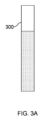
図3A及び図3Bは、複数の消耗品のうちの第1の消耗品300と、複数の消耗品のうちの第2の消耗品302と、を示している。第1の消耗品300は、第2の消耗品302の第2の長さよりも小さな第1の長さを有する。言い換えると、第2の消耗品302は、第1の消耗品300よりも長い。また、本例において、第1の消耗品300は、第2の消耗品302に対応する第2の幅よりも大きな第1の幅を有する。 FIGS. 3A and 3B show a first consumable 300 of the plurality of consumables and a second consumable 302 of the plurality of consumables. The first consumable 300 has a first length that is smaller than a second length of the second consumable 302. In other words, the second consumable 302 is longer than the first consumable 300. Also, in this example, the first consumable 300 has a first width that is larger than a second width corresponding to the second consumable 302.

いくつかの例において、消耗品は、当該消耗品の近位端側に空気流構造(例えば、空気の流れを可能にする開口又は材料の部位)が設けられていてもよい。使用時には、空気流を抑制するため、空気流構造の少なくとも一部を覆うのが望ましいと考えられる。これは、例えば意図される様態で当該消耗品をデバイス100とともに機能させるのが望ましいと考えられる。空気流構造は、複数の消耗品において、様々な消耗品の各近位端から特定の距離に設けられていてもよい。したがって、例えば第1の消耗品300及び第2の消耗品302が実質的に等しい量だけデバイス100から突き出ることを可能にしなければ、消耗品の使用が意図される様態では、異なる長さの消耗品をデバイス100で使用できない可能性がある。異なる長さの消耗品が相互に同じ量だけ突き出るようにすることで、消耗品の各近位端から特定の距離に配置された空気流構造が意図通り、ハウジング114及び/又は加熱チャンバ102に受容されるアダプタによって少なくとも部分的に覆われるようにすることができる。1つ又は複数のアダプタを備えるデバイス100に関する概念及び例については、以下に説明する。 In some examples, the consumables may have airflow structures (e.g., openings or areas of material that allow airflow) at the proximal end of the consumable. In use, it may be desirable to cover at least a portion of the airflow structures to inhibit airflow. This may be desirable, for example, to allow the consumables to function with the device 100 in the manner intended. The airflow structures may be located at a particular distance from the proximal ends of the various consumables in multiple consumables. Thus, for example, consumables of different lengths may not be usable with the device 100 in the manner in which the consumables are intended to be used unless the first consumable 300 and the second consumable 302 are allowed to protrude from the device 100 by substantially equal amounts. By allowing consumables of different lengths to protrude from each other by the same amount, airflow structures located at a particular distance from the proximal ends of the consumables may be at least partially covered by adapters received in the housing 114 and/or heating chamber 102, as intended. Concepts and examples of the device 100 with one or more adapters are described below.

いくつかの例においては、消耗品の予め定められた長さだけがデバイス100から突き出て、例えばデバイス100が叩かれたりした場合に消耗品がデバイス100から意図せずに取り出される可能性を低くするのが好都合と考えられる。いくつかの例において、加熱チャンバ102に受容される1つ又は複数のアダプタは、(例えば、1つ又は複数のアダプタが加熱チャンバ102に挿入され、取り出された場合に)加熱チャンバ102の洗浄を可能にし得る。いくつかの例において、1つ又は複数のアダプタは、使用時に消耗品の近位端を支持して、使用時の消耗品の損傷のリスクを低減するようにしてもよい。 In some examples, it may be advantageous for only a predetermined length of the consumable to protrude from the device 100 to reduce the likelihood that the consumable will be unintentionally removed from the device 100, for example if the device 100 is struck. In some examples, one or more adapters received in the heating chamber 102 may allow for cleaning of the heating chamber 102 (e.g., when one or more adapters are inserted and removed from the heating chamber 102). In some examples, the one or more adapters may support a proximal end of the consumable during use to reduce the risk of damage to the consumable during use.

第1の概念
図2は、第1の概念に係る、デバイス100の模式ブロック側断面図である。図2において、番号202は、デバイス100の近位端を示し、番号204は、デバイス100の遠位端を示す。近位端202は、デバイス100が意図通り、エアロゾルの吸引に用いられている場合に、ユーザが遠位端204よりも口の近くに保持する(例えば、口に向ける)端部である。一方、デバイス100の遠位端204は、デバイス100が意図通り、エアロゾルの吸引に用いられている場合に、ユーザが近位端202よりも口の遠くに保持する端部である。
First Concept FIG. 2 is a schematic block cross-sectional side view of device 100 according to the first concept. In FIG. 2, numeral 202 indicates a proximal end of device 100, and numeral 204 indicates a distal end of device 100. Proximal end 202 is the end that a user holds closer to the mouth (e.g., toward the mouth) than distal end 204 when device 100 is being used to inhale aerosols as intended. Meanwhile, distal end 204 of device 100 is the end that a user holds farther from the mouth than proximal end 202 when device 100 is being used to inhale aerosols as intended.

図2には、デバイス100の一部となり得るすべての構成要素を示しているわけではない。本概念において、加熱チャンバ102は、エアロゾル生成材料を含む消耗品を受容するためのものである。本概念のデバイス100は、加熱チャンバ102に受容されるアダプタ206を備えるが、このアダプタ206は、サイズが異なる複数の消耗品それぞれを一度に1つずつ受容するように、加熱チャンバ102を適応させるように構成されている。 2 does not show all components that may be part of the device 100. In this concept, the heating chamber 102 is for receiving a consumable that includes an aerosol generating material. The device 100 of this concept includes an adapter 206 that is received in the heating chamber 102 and is configured to adapt the heating chamber 102 to receive multiple consumables of different sizes, one at a time.

本明細書において、異なるサイズは、製造公差による消耗品のサイズの変動を表さない。本明細書において、異なるサイズは、消耗品の意図される異なる寸法を表す。例えば、意図される幅及び/又は長さが異なる消耗品は、異なるサイズのレセプタクルに収まる。意図されるサイズが異なる消耗品は、異なる種類の消耗品と称する場合がある。異なる種類の消耗品は、それぞれが異なるサイズであるという点だけが異なる場合もあるし、内部構成、内部構造等の他の態様が異なる場合もある。 As used herein, different sizes do not represent variations in the size of a consumable due to manufacturing tolerances. As used herein, different sizes represent different intended dimensions of a consumable. For example, consumables with different intended widths and/or lengths fit into different sized receptacles. Consumables with different intended sizes may be referred to as different types of consumables. Different types of consumables may differ only in that they are different sizes, or may differ in other aspects such as internal configuration, structure, etc.

例えば、複数の消耗品はそれぞれ、相互に異なる長さを有すること及び/又は相互に異なる幅を有することにより、サイズが異なっていてもよい。消耗品が(例えば、従来のシガレットと同様に)ロッド状である例において、消耗品の幅は、当該消耗品の外径として取得されるようになっていてもよい。 For example, the consumables may differ in size by having different lengths and/or different widths. In an example where the consumables are rod-shaped (e.g., similar to a conventional cigarette), the width of the consumable may be taken as the outer diameter of the consumable.

第1の概念に係る例1、例2、及び例3において、アダプタ206は、当該アダプタのアダプタ近位端で始まり、アダプタ遠位端に向かって延びる第1の円筒状本体を備える。第1の円筒状本体は、複数の消耗品それぞれを一度に1つずつ保持するように構成された保持要素を備える。 In Examples 1, 2, and 3 of the first concept, the adapter 206 includes a first cylindrical body beginning at the adapter proximal end and extending toward the adapter distal end of the adapter. The first cylindrical body includes a holding element configured to hold each of the multiple consumables, one at a time.

第1の概念に係る例1、例2、例3、例4、及び例5において、保持要素は、複数の消耗品のうちの第1の消耗品及び複数の消耗品のうちの第2の消耗品を一度に1つずつ適所に保持するように構成され、第1の消耗品は、第1の所与のサイズであり、第2の消耗品は、第2の所与のサイズである。例えば、保持要素は、第1の消耗品300及び第2の消耗品302を一度に1つずつ適所に保持するように構成されている。いくつかの例においては、保持要素が省略されてもよい。 In Examples 1, 2, 3, 4, and 5 of the first concept, the retaining element is configured to hold a first consumable of the plurality of consumables and a second consumable of the plurality of consumables in place one at a time, where the first consumable is a first given size and the second consumable is a second given size. For example, the retaining element is configured to hold the first consumable 300 and the second consumable 302 in place one at a time. In some examples, the retaining element may be omitted.

第1の概念に係る例1、例2、例3、例4、及び例5において、アダプタは、当該アダプタのアダプタ遠位端側に配置され、第1の消耗品がアダプタ遠位端の方向に越える動きを禁止するとともに、第2の消耗品がアダプタ遠位端の方向に越える動きを可能にするように寸法規定された第1のストッパを備える。いくつかの例においては、第1のストッパが省略されてもよい。 In Examples 1, 2, 3, 4, and 5 according to the first concept, the adapter includes a first stopper disposed on the adapter distal end side of the adapter and dimensioned to prohibit movement of the first consumable toward the adapter distal end and to allow movement of the second consumable toward the adapter distal end. In some examples, the first stopper may be omitted.

第1の概念に係る例1、例2、及び例3において、アダプタは、アダプタ遠位端側に配置されて第1のストッパを与える第2の円筒状本体であり、第1の所与のサイズに対応する第1の幅よりも小さく、第2の所与のサイズに対応する第2の幅よりも大きな最内径を有する、第2の円筒状本体を備える。例えば、最内径は、第1の消耗品300の幅よりも小さく、第2の消耗品302の幅よりも大きい。いくつかの例においては、第2の円筒状本体が省略されてもよい。 In Examples 1, 2, and 3 according to the first concept, the adapter includes a second cylindrical body disposed at the adapter distal end to provide a first stop, the second cylindrical body having an innermost diameter smaller than a first width corresponding to a first given size and larger than a second width corresponding to a second given size. For example, the innermost diameter is smaller than the width of the first consumable 300 and larger than the width of the second consumable 302. In some examples, the second cylindrical body may be omitted.

以下、第1の概念に係るデバイス100の種々例を説明する。以下の例では、アダプタ206に関するより具体的な特徴を記載する。 Various examples of the device 100 according to the first concept are described below. In the following examples, more specific features of the adapter 206 are described.

第1の概念の例1
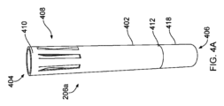
図4A~図4Fは、第1の概念の例1に係る、上述のアダプタを備える上述のデバイスを示している。図4A~図4Fにおいて、第1の概念の例1に係るアダプタには、番号206aが付されている。第1の円筒状本体402は、アダプタ近位端404で始まり、アダプタ遠位端406に向かって延びている。第1の円筒状本体402は、保持要素408を備える。第1の円筒状本体402は、円筒状本体近位端410及び円筒状本体遠位端412を備える。
First Concept Example 1
4A-4F show the above-mentioned device comprising the above-mentioned adapter according to Example 1 of the first concept. In Figures 4A-4F, the adapter according to Example 1 of the first concept is designated with the number 206a. The first cylindrical body 402 starts at an adapter proximal end 404 and extends towards an adapter distal end 406. The first cylindrical body 402 comprises a retaining element 408. The first cylindrical body 402 comprises a cylindrical body proximal end 410 and a cylindrical body distal end 412.

近位と称するアダプタ206a又はその上述の構成要素の部分は、アダプタが加熱チャンバ102に受容された場合にデバイス100の近位端202側となる。同様に、遠位と称するアダプタ206a又はその上述の構成要素の部分は、アダプタ206aが加熱チャンバ102に受容された場合にデバイス100の遠位端204側となる。 The portion of the adapter 206a or any of its components described above that is referred to as proximal is the portion that is toward the proximal end 202 of the device 100 when the adapter is received in the heating chamber 102. Similarly, the portion of the adapter 206a or any of its components described above that is referred to as distal is the portion that is toward the distal end 204 of the device 100 when the adapter 206a is received in the heating chamber 102.

図4Bは、保持要素408を示したアダプタ206aの模式斜視拡大図及びアダプタ206aの模式平面図である。図4Bを参照して、保持要素408は、2つ以上の弾性突起414を備える。弾性突起414は、円筒状本体近位端410側に設けられている。円筒状突起は、第1の円筒状本体402から、第1の円筒状本体402により規定されたキャビティに延入している。弾性突起414は、その間に第1及び第2の消耗品300、302を一度に1つずつ適所に収容及び保持するように変形可能である。本例において、突起414は、互いに円周方向に配置されている。 Figure 4B is a schematic perspective close-up view of the adapter 206a showing the retaining element 408 and a schematic plan view of the adapter 206a. With reference to Figure 4B, the retaining element 408 includes two or more resilient protrusions 414. The resilient protrusions 414 are provided on the cylindrical body proximal end 410 side. The cylindrical protrusions extend from the first cylindrical body 402 into a cavity defined by the first cylindrical body 402. The resilient protrusions 414 are deformable to receive and hold the first and second consumables 300, 302 in place therebetween, one at a time. In this example, the protrusions 414 are circumferentially disposed relative to one another.

第1の円筒状本体402は、弾性突起414の形成を可能にする材料を含んでいてもよい。例えば、第1の円筒状本体402は、当該第1の円筒状本体402の構成に適した伸縮性アルミニウム又は別の伸縮性金属を含んでいてもよい。いくつかの例においては、第1の円筒状本体402の基部構造(例えば、円筒状部)がある材料で形成され、弾性突起414が別の材料で形成されていてもよい。例えば、基部構造には、(構造強度のための)剛性材料が選択され、弾性突起414には、弾性を有する材料が選択されるようになっていてもよい。 The first cylindrical body 402 may include a material that allows for the formation of the elastic protrusions 414. For example, the first cylindrical body 402 may include stretchable aluminum or another stretchable metal suitable for the construction of the first cylindrical body 402. In some examples, the base structure (e.g., the cylindrical portion) of the first cylindrical body 402 may be formed of one material and the elastic protrusions 414 may be formed of another material. For example, a rigid material (for structural strength) may be selected for the base structure and a material having elasticity may be selected for the elastic protrusions 414.

図4Bは、初期配置の保持要素414を示している。弾性突起414は、初期配置側に付勢されている。初期配置においては、(例えば、第1の円筒状本体402への消耗品の挿入によって)平衡位置/形態から変形させる大きな力が弾性突起414には印加されない。初期配置の弾性突起414は、初期サイズの間隙を規定するが、本例においては、図4Bの破線で示す内周416により規定される。内周416により規定された間隙は、複数の消耗品の中の最小の幅よりも小さい。 Figure 4B shows the retention element 414 in an initial position. The resilient projection 414 is biased toward the initial position. In the initial position, no significant force is applied to the resilient projection 414 to distort it from its equilibrium position/configuration (e.g., by the insertion of a consumable into the first cylindrical body 402). The resilient projection 414 in the initial position defines a gap of an initial size, which in this example is defined by an inner perimeter 416 shown in dashed lines in Figure 4B. The gap defined by the inner perimeter 416 is smaller than the smallest width of the plurality of consumables.

消耗品が第1の円筒状本体402に挿入されると、弾性突起414に対して力が印加され、間隙のサイズが変化することにより、挿入された消耗品が収容及び保持され得る。弾性突起414が初期配置から離れる方向に撓み(外方に押され)、間隙のサイズが変化する(この場合は、大きくなる)。 When a consumable is inserted into the first cylindrical body 402, a force is applied against the elastic protrusions 414, causing the size of the gap to change so that the inserted consumable can be accommodated and retained. The elastic protrusions 414 are deflected (pushed outward) away from their initial position, causing the size of the gap to change (in this case, become larger).

弾性突起414は、挿入された消耗品にそれぞれが同時に接触するように構成されている。本例において、第1の円筒状本体402は実質的に、円形断面の消耗品との使用が意図される。弾性突起414は、実質的に円形の境界を第1の円筒状本体402の内側に構成することにより、当該弾性突起414がそれぞれ実質的に円形の断面の消耗品に接触し得るようにする。 The elastic protrusions 414 are configured to each simultaneously contact an inserted consumable. In this example, the first cylindrical body 402 is intended for use with a consumable having a substantially circular cross-section. The elastic protrusions 414 define a substantially circular boundary on the inside of the first cylindrical body 402, such that the elastic protrusions 414 can each contact a consumable having a substantially circular cross-section.

本例においては、弾性突起414が初期配置側に付勢され、複数の消耗品の中の最小の幅よりも小さなサイズの間隙を与えるため、弾性突起414が挿入された消耗品を半径方向内方に押して適所に保持することになる。 In this example, the elastic protrusions 414 are biased toward the initial placement side to provide a gap smaller than the smallest width of the multiple consumables, so that the elastic protrusions 414 push the inserted consumable radially inward to hold it in place.

弾性突起414を外方に押すことで、実質的に連続した様態へと変形可能である。したがって、第1の円筒状本体402は、当該第1の円筒状本体402での使用が意図され、初期配置の内周416により規定された間隙よりも大きく、当該第1の円筒状本体402及び弾性突起414の形状によって適度に収容可能な幅以下の幅を有する任意の消耗品を適所に保持するように機能し得る。 The elastic projections 414 can be pushed outwardly to deform into a substantially continuous configuration. Thus, the first cylindrical body 402 can function to hold in place any consumable intended for use with the first cylindrical body 402 that has a width greater than the gap defined by the initial placement inner circumference 416 and less than or equal to the width that can be reasonably accommodated by the shape of the first cylindrical body 402 and the elastic projections 414.

本例において、弾性突起414は、少なくとも第1の消耗品300及び第2の消耗品302を適所に保持する。弾性突起414は、加熱チャンバ102に受容されたアダプタ206aにこれらの消耗品が一度に1つずつ挿入された場合に、第1の円筒状本体402ひいては加熱チャンバ102内で消耗品の中心が位置合わせされるように、各消耗品を適所に保持する。これを実現するため、弾性突起414は、アダプタ206aが加熱チャンバ102に受容された場合に、間隙の中心が加熱チャンバ102と位置合わせされるように配置されている。 In this example, the elastic projections 414 hold at least the first consumable 300 and the second consumable 302 in place. The elastic projections 414 hold each consumable in place such that when the consumables are inserted one at a time into the adapter 206a received in the heating chamber 102, the centers of the consumables are aligned within the first cylindrical body 402 and thus the heating chamber 102. To achieve this, the elastic projections 414 are positioned such that when the adapter 206a is received in the heating chamber 102, the center of the gap is aligned with the heating chamber 102.

図4Aを再び参照して、この図は、第2の円筒状本体418も示している。第2の円筒状本体418は、難燃性のメタ系アラミド材料(例えば、ノーメックス(Nomex)(登録商標))、綿、紙、他のパラ系アラミド(例えば、トワロン(Twaron)(登録商標))、耐熱性且つ強靭な合成繊維(例えば、ケブラー(Kevlar)(登録商標))等を含んでいてもよい。 Referring again to FIG. 4A, this figure also shows a second cylindrical body 418. The second cylindrical body 418 may comprise a flame-retardant meta-aramid material (e.g., Nomex®), cotton, paper, other para-aramids (e.g., Twaron®), heat-resistant and tough synthetic fibers (e.g., Kevlar®), and the like.

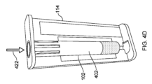
図4Cは、第1の円筒状本体402に取り付けられた第2の円筒状本体418を示した側断面の模式斜視拡大図である。上述の第1のストッパには、番号420が付されている。図4Dは、加熱チャンバ102に受容されたアダプタ206aを示したハウジング114の模式斜視内部図である。矢印422で示すように、消耗品がアダプタ206aに挿入されるようになっていてもよい。いくつかの例においては、アダプタ206a自体が加熱チャンバ102に受容される前に、消耗品がアダプタ206aに挿入されていてもよい。 Figure 4C is a schematic perspective close-up cross-sectional side view of the second cylindrical body 418 attached to the first cylindrical body 402. The first stop is designated 420. Figure 4D is a schematic perspective internal view of the housing 114 showing the adapter 206a received in the heating chamber 102. A consumable may be inserted into the adapter 206a, as indicated by arrow 422. In some instances, the consumable may be inserted into the adapter 206a before the adapter 206a itself is received in the heating chamber 102.

本例において、第1のストッパ420は、第1の消耗品300及び第2の消耗品302がそれぞれ、使用のため加熱チャンバ102に受容されたアダプタ206aに受容された場合に、実質的に等しい量だけデバイス100から突き出るようにすることができる。 In this example, the first stopper 420 can be configured to protrude from the device 100 by substantially equal amounts when the first consumable 300 and the second consumable 302 are each received in the adapter 206a received in the heating chamber 102 for use.

本明細書において、所与の消耗品がデバイス100から突き出る量は、ハウジング114又は上述のアダプタ等のその他任意の要素により覆われていない当該所与の消耗品の量(例えば、長さ)である。 As used herein, the amount that a given consumable protrudes from the device 100 is the amount (e.g., length) of that given consumable that is not covered by the housing 114 or any other element such as the adapter described above.

図3A及び図3Bの例において、第1の消耗品300は、第2の消耗品302よりも小さな長さで大きな幅を有する。また、第2の円筒状本体418が第1のストッパ420を提供する。本例において、第2の円筒状本体418は、第1の消耗品300が幅広で挿入できず、代わりに、第1の消耗品300がアダプタ206aに挿入された場合にその遠位端が第1のストッパ420に載るように寸法規定されている。第2の円筒状本体418は、第1の消耗品300が(加熱チャンバ102に受容されたアダプタ206aに挿入された場合に)デバイス100の近位端から所与の量だけ突き出るように、第1の円筒状本体402に対して配置されている。 3A and 3B, the first consumable 300 has a smaller length and a larger width than the second consumable 302. Also, the second cylindrical body 418 provides a first stopper 420. In this example, the second cylindrical body 418 is sized such that the first consumable 300 is too wide to be inserted, but instead the distal end of the first consumable 300 rests on the first stopper 420 when inserted into the adapter 206a. The second cylindrical body 418 is positioned relative to the first cylindrical body 402 such that the first consumable 300 (when inserted into the adapter 206a received in the heating chamber 102) protrudes a given amount from the proximal end of the device 100.

本例において、第2の円筒状本体418は、当該第2の円筒状本体418への挿入に対して第2の消耗品302が十分に幅狭で、第1のストッパ420により停止されないように寸法規定されている。本例において、第2の円筒状本体418の内径は、第2の消耗品302が第2の円筒状本体418の内面に接触して、第2の消耗品302の外面と第2の円筒状本体418の内面との間の摩擦により、第2の円筒状本体418によって適所に保持されるようになっている。このように、第2の消耗品302に対して、第2の円筒状本体418は、アダプタ遠位端404に設けられた保持構造として機能する。いくつかの例において、アダプタ遠位端406の遠位端は、第2の消耗品302がアダプタ遠位端406から突き出し得ないように配置されていてもよい。いくつかの例において、アダプタ206aが加熱チャンバ102に受容された場合、加熱チャンバ102及び/又は加熱チャンバ102に受容された場合のアダプタ206aの配置は、第2の消耗品302が特定の点を越えて進まないようにするものであってもよい。これらの例のいずれかにおいて、この配置は、第1の消耗品300が突き出るのと実質的に同じ所与の量だけ、(加熱チャンバ102に受容されたアダプタ206aに挿入された場合の)第2の消耗品302がデバイス100の近位端から突き出るようにする。 In this example, the second cylindrical body 418 is sized so that the second consumable 302 is narrow enough for insertion into the second cylindrical body 418 and is not stopped by the first stop 420. In this example, the inner diameter of the second cylindrical body 418 is such that the second consumable 302 contacts the inner surface of the second cylindrical body 418 and is held in place by the second cylindrical body 418 due to friction between the outer surface of the second consumable 302 and the inner surface of the second cylindrical body 418. In this way, for the second consumable 302, the second cylindrical body 418 functions as a retention structure provided on the adapter distal end 404. In some examples, the distal end of the adapter distal end 406 may be positioned such that the second consumable 302 cannot protrude from the adapter distal end 406. In some examples, when the adapter 206a is received in the heating chamber 102, the heating chamber 102 and/or the arrangement of the adapter 206a when received in the heating chamber 102 may be such that the second consumable 302 does not advance beyond a certain point. In any of these examples, the arrangement allows the second consumable 302 (when inserted into the adapter 206a received in the heating chamber 102) to protrude from the proximal end of the device 100 a given amount that is substantially the same as the first consumable 300 protrudes.

したがって、アダプタ206aは、第1の消耗品300及び第2の消耗品302が加熱チャンバ102に受容された当該アダプタ206aに受容された場合に、加熱チャンバ102において中心が位置合わせされ、実質的に同じ量だけデバイス100から突き出るようにすることができる。 The adapter 206a can thus be configured such that when the first consumable 300 and the second consumable 302 are received in the adapter 206a received in the heating chamber 102, the centers are aligned in the heating chamber 102 and protrude from the device 100 by substantially the same amount.

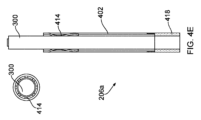
図4Eは、第1の消耗品300が挿入されたアダプタ206aの模式上面図及び模式側断面図である。図4Fは、第2の消耗品302が挿入されたアダプタ206aの模式上面図及び模式側断面図である。第1の消耗品300が第2の消耗品302よりも幅広であることから、第2の消耗品302がアダプタ206aに挿入される場合よりも第1の消耗品300が挿入される場合に、弾性突起414がさらに外方に押される。また、第1の消耗品300の遠位端が第1のストッパ420により停止される一方、第2の消耗品302はアダプタ206aにより深く挿入されるため、両消耗品が実質的に同じ量だけ突き出ることになる。 Figure 4E is a schematic top view and a schematic cross-sectional side view of the adapter 206a with the first consumable 300 inserted. Figure 4F is a schematic top view and a schematic cross-sectional side view of the adapter 206a with the second consumable 302 inserted. Because the first consumable 300 is wider than the second consumable 302, the elastic protrusions 414 are pushed further outward when the first consumable 300 is inserted than when the second consumable 302 is inserted into the adapter 206a. Also, because the distal end of the first consumable 300 is stopped by the first stopper 420 while the second consumable 302 is inserted deeper into the adapter 206a, both consumables protrude by substantially the same amount.

本例において、第1の円筒状本体402及び第2の円筒状本体418は、複数の消耗品それぞれを一度に1つずつ受容するチューブを一体的に提供する。アダプタ近位端404がチューブの近位端に対応し、アダプタ遠位端406がチューブの遠位端に対応する。保持要素408は、チューブの近位端側に形成され、複数の消耗品それぞれを一度に1つずつ適所に保持する第1の保持構造である。 In this example, the first cylindrical body 402 and the second cylindrical body 418 together provide a tube that receives each of the multiple consumables one at a time. The adapter proximal end 404 corresponds to the proximal end of the tube, and the adapter distal end 406 corresponds to the distal end of the tube. The retaining element 408 is a first retaining structure formed on the proximal end side of the tube that holds each of the multiple consumables in place one at a time.

上述の通り、いくつかの例においては、第1のストッパ420が省略されてもよい。このようないくつかの例において、複数の消耗品には、実質的に同じ幅の消耗品を含んでいてもよい。このような例において、第2の円筒状本体418は、チューブの遠位端側に形成され、複数の消耗品それぞれを一度に1つずつ適所に保持する第2の保持構造を提供していてもよい。このような例において、第2の円筒状本体418の内径は、複数の消耗品が一度に1つずつ第2の円筒状本体418の内面に接触して、当該消耗品の外面と第2の円筒状本体の内面との間の摩擦により、第2の円筒状本体418によって適所に保持されるようになっていてもよい。 As noted above, in some examples, the first stop 420 may be omitted. In some such examples, the plurality of consumables may include consumables of substantially the same width. In such examples, the second cylindrical body 418 may be formed at the distal end of the tube and provide a second retention structure to hold each of the plurality of consumables in place one at a time. In such examples, the inner diameter of the second cylindrical body 418 may be such that the plurality of consumables contact the inner surface of the second cylindrical body 418 one at a time and are held in place by the second cylindrical body 418 due to friction between the outer surface of the consumable and the inner surface of the second cylindrical body.

第1の概念の例2
図5A~図5Gは、第1の概念の例2に係る、上述のデバイス及びアダプタを示している。図5A~図5Gにおいて、第1の概念の例2に係るアダプタには、参照番号206bが付されている。図5Aは、アダプタ206bの側断面の模式斜視図である。本例において、第1の円筒状本体502は、波型材料を含む。この波型材料が保持要素として機能する。
First Concept Example 2
Figures 5A-5G show the above-mentioned device and an adapter according to a first concept example 2. In Figures 5A-5G, the adapter according to the first concept example 2 is designated by the reference number 206b. Figure 5A is a schematic perspective cross-sectional side view of the adapter 206b. In this example, the first cylindrical body 502 comprises a corrugated material. The corrugated material acts as a retaining element.

第1の円筒状本体502は、円筒状に形成された波型材料を含む。本明細書において、波型材料(fluted material)という用語は、例えば前後に折り曲げられて当該材料のひだ状シートを構成する連続材料シートを表すのに用いられる。言い換えると、連続材料シートは、例えば密な正弦波状パターンとして繰り返し折り曲げられている。 The first cylindrical body 502 includes a fluted material formed into a cylindrical shape. As used herein, the term fluted material is used to describe a continuous sheet of material that is folded, for example, back and forth to form a fluted sheet of the material. In other words, the continuous sheet of material is repeatedly folded, for example, in a tight sinusoidal pattern.

波型材料は、例えば波型紙であってもよい。以下の説明は、波型材料が波型紙であることを背景とする。上述の通りに折り曲げられた紙シートが図5Aに見られるような円筒状シートに形成されて、第1の円筒状本体502を構成する。第1の円筒状本体502は、第1の消耗品300及び第2の消耗品302を内部の適所に保持する保持要素である(保持要素として機能する)。 The corrugated material may be, for example, corrugated paper. The following description is based on the corrugated material being corrugated paper. The folded paper sheet as described above is formed into a cylindrical sheet as seen in FIG. 5A to form a first cylindrical body 502. The first cylindrical body 502 is (functions as) a retaining element that holds the first consumable 300 and the second consumable 302 in place therein.

第1の円筒状本体502は、アダプタ近位端504で始まり、アダプタ遠位端506に向かって延びている。近位と称するアダプタ206b又はその上述の構成要素の部分は、アダプタが加熱チャンバ102に受容された場合にデバイス100の近位端202側となる。同様に、遠位と称するアダプタ206b又はその上述の構成要素の部分は、アダプタ206bが加熱チャンバ102に受容された場合にデバイス100の遠位端204側となる。 The first cylindrical body 502 begins at the adapter proximal end 504 and extends toward the adapter distal end 506. The portion of the adapter 206b or its components described above that is referred to as proximal is toward the proximal end 202 of the device 100 when the adapter is received in the heating chamber 102. Similarly, the portion of the adapter 206b or its components described above that is referred to as distal is toward the distal end 204 of the device 100 when the adapter 206b is received in the heating chamber 102.

図5Bは、アダプタ206bの模式上面図である。図5Bには、第1の円筒状本体502の波型紙の折り目の一例が見られる。紙の折り目が第1の円筒状本体502の最内径を規定することが分かる。折り目は、その間に第1及び第2の消耗品300、302を適所に収容及び保持するように変形可能である。図5Bは、上述の折り目により形成された初期配置の保持要素を示している。折り目は、初期配置側に付勢されている。初期配置においては、(例えば、第1の円筒状本体502への消耗品の挿入によって)平衡位置/形態から変形させる大きな力が折り目には印加されない。初期配置の折り目は、初期サイズの間隙を規定するが、本例においては、図5Bの破線で示す内周508により規定される。内周508により規定された間隙は、複数の消耗品の中の最小の幅よりも小さい。 5B is a schematic top view of the adapter 206b. In FIG. 5B, an example of the corrugated paper folds of the first cylindrical body 502 can be seen. It can be seen that the paper folds define the innermost diameter of the first cylindrical body 502. The folds are deformable to accommodate and hold the first and second consumables 300, 302 in place therebetween. FIG. 5B shows the retention element formed by the folds in an initial configuration. The folds are biased toward the initial configuration. In the initial configuration, no significant force is applied to the folds to distort them from their equilibrium position/configuration (e.g., by the insertion of the consumables into the first cylindrical body 502). The folds in the initial configuration define an initial size gap, which in this example is defined by the inner circumference 508 shown in dashed lines in FIG. 5B. The gap defined by the inner circumference 508 is smaller than the smallest width of the plurality of consumables.

消耗品が第1の円筒状本体502に挿入されると、折り目に対して力が印加され、間隙のサイズが変化することにより、挿入された消耗品が収容及び保持され得る。折り目が初期配置から離れる方向に撓み(外方に押され)、間隙のサイズが変化する(この場合は、大きくなる)。 When a consumable is inserted into the first cylindrical body 502, a force is applied against the folds, changing the size of the gap to accommodate and retain the inserted consumable. The folds deflect (push outward) away from the initial configuration, changing the size of the gap (in this case, becoming larger).

折り目は、挿入された消耗品に接触するように構成されている。本例において、第1の円筒状本体502は実質的に、円形断面の消耗品との使用が意図される。折り目は、実質的に円形の境界を第1の円筒状本体502の内側に構成することにより、当該折り目が実質的に円形の断面の消耗品に接触し得るようにする。 The folds are configured to contact an inserted consumable. In this example, the first cylindrical body 502 is intended for use with a consumable having a substantially circular cross-section. The folds define a substantially circular boundary on the inside of the first cylindrical body 502 such that the folds can contact a consumable having a substantially circular cross-section.

本例においては、折り目が初期配置側に付勢され、複数の消耗品の中の最小の幅よりも小さなサイズの間隙を与えるため、折り目が挿入された消耗品を半径方向内方に押して適所に保持することになる。 In this example, the creases are biased toward the initial placement side to provide a gap smaller than the smallest width of the multiple consumables, so that the creases push the inserted consumable radially inward to hold it in place.

折り目を外方に押すことで、実質的に連続した様態へと変形可能である。したがって、第1の円筒状本体502は、当該第1の円筒状本体502での使用が意図され、初期配置の内周508により規定された間隙よりも大きく、当該第1の円筒状本体502及び折り目の形状によって適度に収容可能な幅以下の幅を有する任意の消耗品を適所に保持するように機能し得る。 The folds can be pushed outwardly to deform into a substantially continuous configuration. Thus, the first cylindrical body 502 can function to hold in place any consumable intended for use with the first cylindrical body 502 that has a width greater than the gap defined by the inner circumference 508 of the initial placement, but less than or equal to the width that can be reasonably accommodated by the shape of the first cylindrical body 502 and the folds.

本例において、折り目は、少なくとも第1の消耗品300及び第2の消耗品302を一度に1つずつ適所に保持する。折り目は、加熱チャンバ102に受容されたアダプタ206bにこれらの消耗品が一度に1つずつ挿入された場合に、第1の円筒状本体502ひいては加熱チャンバ102内で消耗品の中心が位置合わせされるように、各消耗品を適所に保持する。これを実現するため、折り目は、アダプタ206bが加熱チャンバ102に受容された場合に、間隙の中心が加熱チャンバ102と位置合わせされるように配置されている。 In this example, the folds hold at least the first consumable 300 and the second consumable 302 in place, one at a time. The folds hold each consumable in place such that when the consumables are inserted, one at a time, into the adapter 206b received in the heating chamber 102, the centers of the consumables are aligned within the first cylindrical body 502 and thus the heating chamber 102. To accomplish this, the folds are positioned such that when the adapter 206b is received in the heating chamber 102, the center of the gap is aligned with the heating chamber 102.

図5Aを再び参照して、この図は、第2の円筒状本体510も示している。第2の円筒状本体510は、難燃性のメタ系アラミド材料(例えば、ノーメックス(Nomex)(登録商標))、綿、紙、他のパラ系アラミド(例えば、トワロン(Twaron)(登録商標))、耐熱性且つ強靭な合成繊維(例えば、ケブラー(Kevlar)(登録商標))等を含んでいてもよい。 Referring again to FIG. 5A, this figure also shows a second cylindrical body 510. The second cylindrical body 510 may comprise a flame-retardant meta-aramid material (e.g., Nomex®), cotton, paper, other para-aramids (e.g., Twaron®), heat-resistant and tough synthetic fibers (e.g., Kevlar®), and the like.

図5Cは、第1の円筒状本体502に対してアダプタ遠位端506側に配置された第2の円筒状本体510を示した側断面の模式斜視拡大図である。本例においては、第1の円筒状本体502及び第2の円筒状本体510が相互に配置されている。図5Dは、第1の円筒状本体502及び第2の円筒状本体510のほか、外被512を示したアダプタ206bの側断面の模式斜視拡大図並びにアダプタ206bの模式斜視図である。外被512は、第1の円筒状本体502及び第2の円筒状本体510の両者を囲むことにより、それぞれの相対的な位置を固定する。 Figure 5C is a schematic perspective enlarged view of a cross-section of the adapter 206b showing the second cylindrical body 510 disposed on the adapter distal end 506 side relative to the first cylindrical body 502. In this example, the first cylindrical body 502 and the second cylindrical body 510 are disposed relative to each other. Figure 5D is a schematic perspective enlarged view of a cross-section of the adapter 206b showing the first cylindrical body 502 and the second cylindrical body 510 as well as the outer jacket 512, and a schematic perspective view of the adapter 206b. The outer jacket 512 surrounds both the first cylindrical body 502 and the second cylindrical body 510 to fix their relative positions.

外被512は、例えばアルミニウムを含んでいてもよいし、サセプタとして作用し得る別の材料を含んでいてもよい。使用時は、外被512の誘導加熱によって、挿入された消耗品中のエアロゾル化可能材料に熱を供給するようにしてもよい。 The housing 512 may comprise, for example, aluminum or another material that may act as a susceptor. In use, the housing 512 may be inductively heated to provide heat to the aerosolizable material in the inserted consumable.

上述の第1のストッパには、番号514が付されている。図5Eは、加熱チャンバ102に受容されたアダプタ206bを示したハウジング114の模式斜視内部図である。矢印516で示すように、消耗品がアダプタ206bに挿入されるようになっていてもよい。いくつかの例においては、アダプタ206b自体が加熱チャンバ102に受容される前に、消耗品がアダプタ206bに挿入されていてもよい。 The first stopper is labeled 514. FIG. 5E is a schematic perspective internal view of the housing 114 showing the adapter 206b received in the heating chamber 102. A consumable may be inserted into the adapter 206b, as indicated by arrow 516. In some instances, the consumable may be inserted into the adapter 206b before the adapter 206b itself is received in the heating chamber 102.

本例において、第1のストッパ514は、第1の消耗品300及び第2の消耗品302がそれぞれ、使用のため加熱チャンバ102に受容されたアダプタ206bに受容された場合に、実質的に等しい量だけデバイス100から突き出るようにすることができる。 In this example, the first stopper 514 can be configured to protrude from the device 100 by substantially equal amounts when the first consumable 300 and the second consumable 302 are each received in the adapter 206b received in the heating chamber 102 for use.

本明細書において、所与の消耗品がデバイス100から突き出る量は、ハウジング114又は上述のアダプタ等のその他任意の要素により覆われていない当該所与の消耗品の量(例えば、長さ)である。 As used herein, the amount that a given consumable protrudes from the device 100 is the amount (e.g., length) of that given consumable that is not covered by the housing 114 or any other element such as the adapter described above.

図3A及び図3Bの例において、第1の消耗品300は、第2の消耗品302よりも小さな長さで大きな幅を有する。また、第2の円筒状本体510が第1のストッパ514を提供する。本例において、第1のストッパ514は、第2の円筒状本体510の半径方向最内縁部により与えられたレッジの形態である。本例において、第2の円筒状本体510は、第1の消耗品300が幅広で挿入できず、代わりに、第1の消耗品300がアダプタ206bに挿入された場合にその遠位端が第1のストッパ514に載るように寸法規定されている。 3A and 3B, the first consumable 300 has a smaller length and a larger width than the second consumable 302. Also, the second cylindrical body 510 provides a first stop 514. In this example, the first stop 514 is in the form of a ledge provided by the radially innermost edge of the second cylindrical body 510. In this example, the second cylindrical body 510 is sized such that the first consumable 300 is too wide to be inserted, but instead, a distal end of the first consumable 300 rests on the first stop 514 when the first consumable 300 is inserted into the adapter 206b.

上述の通り、例2において、内周508により規定された間隙は、複数の消耗品の中の最小の幅よりも小さい。上述の通り、例2において、折り目は、少なくとも第1の消耗品300及び第2の消耗品302を一度に1つずつ適所に保持する。他の例において、折り目は、変形によって幅広の第1の消耗品300については適所に保持し得る一方、より細い第2の消耗品302については保持し得ないように内径を規定していてもよい。このような例において、第2の円筒状本体510の半径方向最内縁部は、第1の円筒状本体502の折り目の半径方向最内縁部と位置合わせされていてもよい。このような例においては、折り目が変形された場合(例えば、第1の消耗品300が挿入された場合)にのみ、上述のレッジが現れる。 As noted above, in Example 2, the gap defined by the inner circumference 508 is smaller than the smallest width of the consumables. As noted above, in Example 2, the folds hold at least the first consumable 300 and the second consumable 302 in place, one at a time. In other examples, the folds may define an inner diameter that may deform to hold the wider first consumable 300 in place, but not the thinner second consumable 302. In such examples, the radially innermost edge of the second cylindrical body 510 may be aligned with the radially innermost edge of the folds of the first cylindrical body 502. In such examples, the ledge described above appears only when the folds are deformed (e.g., when the first consumable 300 is inserted).

第2の円筒状本体510は、第1の消耗品300が(加熱チャンバ102に受容されたアダプタ206bに挿入された場合に)デバイス100の近位端から所与の量だけ突き出るように、第1の円筒状本体502に対して配置されている。 The second cylindrical body 510 is positioned relative to the first cylindrical body 502 such that the first consumable 300 (when inserted into the adapter 206b received in the heating chamber 102) protrudes a given amount from the proximal end of the device 100.

本例において、第2の円筒状本体510は、当該第2の円筒状本体510への挿入に対して第2の消耗品302が十分に幅狭で、第1のストッパ514により停止されないように寸法規定されている。本例において、第2の円筒状本体510の内径は、第2の消耗品302が第2の円筒状本体510の内面に接触して、第2の消耗品302の外面と第2の円筒状本体510の内面との間の摩擦により、第2の円筒状本体510によって適所に保持されるようになっている。このように、第2の消耗品302に対して、第2の円筒状本体510は、アダプタ遠位端506に設けられた保持構造として機能する。いくつかの例において、アダプタ遠位端506の遠位端は、第2の消耗品302がアダプタ遠位端506から突き出し得ないように配置されていてもよい。いくつかの例において、アダプタ206bが加熱チャンバ102に受容された場合、加熱チャンバ102及び/又は加熱チャンバ102に受容された場合のアダプタ206bの配置は、第2の消耗品302が特定の点を越えて進まないようにするものであってもよい。これらの例のいずれかにおいて、この配置は、第1の消耗品300が突き出るのと実質的に同じ所与の量だけ、(加熱チャンバ102に受容されたアダプタ206bに挿入された場合の)第2の消耗品302がデバイス100の近位端から突き出るようにする。 In this example, the second cylindrical body 510 is sized so that the second consumable 302 is narrow enough for insertion into the second cylindrical body 510 and is not stopped by the first stop 514. In this example, the inner diameter of the second cylindrical body 510 is such that the second consumable 302 contacts the inner surface of the second cylindrical body 510 and is held in place by the second cylindrical body 510 due to friction between the outer surface of the second consumable 302 and the inner surface of the second cylindrical body 510. In this way, for the second consumable 302, the second cylindrical body 510 functions as a retention structure provided on the adapter distal end 506. In some examples, the distal end of the adapter distal end 506 may be positioned such that the second consumable 302 cannot protrude from the adapter distal end 506. In some examples, when the adapter 206b is received in the heating chamber 102, the heating chamber 102 and/or the arrangement of the adapter 206b when received in the heating chamber 102 may be such that the second consumable 302 does not advance beyond a certain point. In any of these examples, the arrangement allows the second consumable 302 (when inserted into the adapter 206b received in the heating chamber 102) to protrude from the proximal end of the device 100 a given amount that is substantially the same as the first consumable 300 protrudes.

したがって、アダプタ206bは、第1の消耗品300及び第2の消耗品302が加熱チャンバ102に受容された当該アダプタ206bに受容された場合に、加熱チャンバ102において中心が位置合わせされ、実質的に同じ量だけデバイス100から突き出るようにすることができる。 Thus, the adapter 206b can be configured such that when the first consumable 300 and the second consumable 302 are received in the adapter 206b received in the heating chamber 102, the centers are aligned in the heating chamber 102 and protrude from the device 100 by substantially the same amount.

図5Fは、第1の消耗品300が挿入されたアダプタ206bの模式上面図及び模式側断面図である。図5Gは、第2の消耗品302が挿入されたアダプタ206bの模式上面図及び模式側断面図である。第1の消耗品300が第2の消耗品302よりも幅広であることから、第2の消耗品302が挿入される場合よりも第1の消耗品300が挿入される場合に、折り目がさらに外方に押される。また、第1の消耗品300の遠位端が第1のストッパ514により停止される一方、第2の消耗品302はアダプタ206bにより深く挿入されるため、両消耗品が実質的に同じ量だけ突き出ることになる。 Figure 5F is a schematic top view and a schematic cross-sectional side view of the adapter 206b with the first consumable 300 inserted. Figure 5G is a schematic top view and a schematic cross-sectional side view of the adapter 206b with the second consumable 302 inserted. Because the first consumable 300 is wider than the second consumable 302, the crease is pushed further outward when the first consumable 300 is inserted than when the second consumable 302 is inserted. Also, because the distal end of the first consumable 300 is stopped by the first stopper 514 while the second consumable 302 is inserted deeper into the adapter 206b, both consumables protrude by substantially the same amount.

本例において、第1の円筒状本体502及び第2の円筒状本体510は、複数の消耗品それぞれを一度に1つずつ受容するチューブを一体的に提供する。アダプタ近位端504がチューブの近位端に対応し、アダプタ遠位端506がチューブの遠位端に対応する。上述の折り目は、チューブの近位端側に形成され、複数の消耗品それぞれを一度に1つずつ適所に保持する第1の保持構造を与える。 In this example, the first cylindrical body 502 and the second cylindrical body 510 together provide a tube that receives each of the multiple consumables one at a time. The adapter proximal end 504 corresponds to the proximal end of the tube, and the adapter distal end 506 corresponds to the distal end of the tube. The folds described above are formed on the proximal end of the tube to provide a first retention structure that holds each of the multiple consumables in place one at a time.

上述の通り、いくつかの例においては、第1のストッパ514が省略されてもよい。このようないくつかの例において、複数の消耗品には、実質的に同じ幅の消耗品を含んでいてもよい。このような例において、第2の円筒状本体510は、チューブの遠位端側に形成され、複数の消耗品それぞれを一度に1つずつ適所に保持する第2の保持構造を提供していてもよい。このような例において、第2の円筒状本体510の内径は、複数の消耗品が一度に1つずつ第2の円筒状本体510の内面に接触して、当該消耗品の外面と第2の円筒状本体の内面との間の摩擦により、第2の円筒状本体510によって適所に保持されるようになっていてもよい。 As noted above, in some examples, the first stop 514 may be omitted. In some such examples, the plurality of consumables may include consumables of substantially the same width. In such examples, the second cylindrical body 510 may be formed at the distal end of the tube and provide a second retention structure for holding each of the plurality of consumables in place one at a time. In such examples, the inner diameter of the second cylindrical body 510 may be such that the plurality of consumables contact the inner surface of the second cylindrical body 510 one at a time and are held in place by the second cylindrical body 510 due to friction between the outer surface of the consumable and the inner surface of the second cylindrical body.

第1の概念の例3
図6A~図6Gは、第1の概念の例3に係る、上述のデバイス及びアダプタを示している。図6A~図6Gにおいて、第1の概念の例3に係るアダプタには、参照番号206cが付されている。図6Aは、アダプタ206cの側断面の模式斜視図である。本例において、第1の円筒状本体602は、当該第1の円筒状本体602から、当該第1の円筒状本体602により規定されたキャビティに延入した複数の弾性フィンガを備える。
First Concept Example 3
6A-6G show the above-mentioned device and an adapter according to a first concept example 3. In Figs. 6A-6G, the adapter according to the first concept example 3 is designated by reference numeral 206c. Fig. 6A is a schematic perspective cross-sectional side view of the adapter 206c. In this example, a first cylindrical body 602 includes a plurality of resilient fingers extending from the first cylindrical body 602 into a cavity defined by the first cylindrical body 602.

第1の円筒状本体602は、第1の消耗品300及び第2の消耗品302を一度に1つずつ内部の適所に保持する保持要素である(保持要素として機能する)。弾性フィンガ604は、第1の消耗品300及び第2の消耗品302を一度に1つずつ適所に収容及び保持するように変形可能である。 The first cylindrical body 602 is (functions as) a retaining element that holds the first consumable 300 and the second consumable 302 in place therein, one at a time. The resilient fingers 604 are deformable to accommodate and hold the first consumable 300 and the second consumable 302 in place, one at a time.

第1の円筒状本体602は、アダプタ近位端606で始まり、アダプタ遠位端608に向かって延びている。近位と称するアダプタ206c又はその上述の構成要素の部分は、アダプタが加熱チャンバ102に受容された場合にデバイス100の近位端202側となる。同様に、遠位と称するアダプタ206c又はその上述の構成要素の部分は、アダプタ206cが加熱チャンバ102に受容された場合にデバイス100の遠位端204側となる。 The first cylindrical body 602 begins at the adapter proximal end 606 and extends toward the adapter distal end 608. The portion of the adapter 206c or its components described above that is referred to as proximal is toward the proximal end 202 of the device 100 when the adapter is received in the heating chamber 102. Similarly, the portion of the adapter 206c or its components described above that is referred to as distal is toward the distal end 204 of the device 100 when the adapter is received in the heating chamber 102.

図6Bは、第1の円筒状本体602の側断面の模式斜視拡大図である。図6Bは、上述の第1の円筒状本体602及び弾性フィンガ604により形成された初期配置の保持要素を示している。弾性フィンガ604は、初期配置側に付勢されており、実質的に何の障害もなく、円筒形状により規定されたキャビティへと内方に延入している。初期配置においては、(例えば、第1の円筒状本体602への消耗品の挿入によって)平衡位置/形態から変形させる大きな力が弾性フィンガ604には印加されない。初期配置の弾性フィンガ604は、初期サイズの間隙を第1の円筒状本体602の内側に規定する。初期サイズの間隙は、複数の消耗品の中の最小の幅よりも小さい。 6B is a schematic perspective close-up view of a cross-section of the first cylindrical body 602. FIG. 6B shows the retention element formed by the first cylindrical body 602 and the elastic fingers 604 described above in an initial position. The elastic fingers 604 are biased toward the initial position and extend inwardly into the cavity defined by the cylindrical shape without any substantial obstruction. In the initial position, no significant force is applied to the elastic fingers 604 (e.g., by the insertion of a consumable into the first cylindrical body 602) to distort them from their equilibrium position/configuration. The elastic fingers 604 in the initial position define an initial size gap inside the first cylindrical body 602. The initial size gap is smaller than the smallest width of the plurality of consumables.

消耗品が第1の円筒状本体602に挿入されると、弾性フィンガ604に対して力が印加され、間隙のサイズが変化することにより、挿入された消耗品が収容及び保持され得る。弾性フィンガ604が初期配置から離れる方向に撓み(外方に押され)、間隙のサイズが変化する(この場合は、大きくなる)。 When a consumable is inserted into the first cylindrical body 602, a force is applied against the resilient fingers 604, causing the size of the gap to change so that the inserted consumable can be accommodated and retained. The resilient fingers 604 deflect (push outward) away from the initial position, causing the size of the gap to change (in this case, become larger).

弾性フィンガ604は、挿入された消耗品に接触するように構成されている。本例において、第1の円筒状本体602は実質的に、円形断面の消耗品との使用が意図される。弾性フィンガ604は、実質的に円形の境界を第1の円筒状本体602の内側に構成することにより、当該弾性フィンガ604が実質的に円形の断面の消耗品に接触し得るようにする。 The resilient fingers 604 are configured to contact an inserted consumable. In this example, the first cylindrical body 602 is intended for use with a consumable having a substantially circular cross-section. The resilient fingers 604 are configured with a substantially circular boundary on the inside of the first cylindrical body 602 such that the resilient fingers 604 can contact a consumable having a substantially circular cross-section.

本例においては、弾性フィンガ604が初期配置側に付勢され、複数の消耗品の中の最小の幅よりも小さなサイズの間隙を与えるため、弾性フィンガ604が挿入された消耗品を半径方向内方に押して適所に保持することになる。 In this example, the elastic fingers 604 are biased toward the initial placement side to provide a gap smaller than the smallest width of the multiple consumables, so that the elastic fingers 604 push the inserted consumable radially inward to hold it in place.

弾性フィンガ604を外方に押すことで、実質的に連続した様態へと変形可能である。したがって、第1の円筒状本体602は、当該第1の円筒状本体602での使用が意図され、初期配置により規定された間隙よりも大きく、当該第1の円筒状本体602及び弾性フィンガ604の形状によって適度に収容可能な幅以下の幅を有する任意の消耗品を適所に保持するように機能し得る。 The resilient fingers 604 can be deformed into a substantially continuous configuration by pushing outward. Thus, the first cylindrical body 602 can function to hold in place any consumable intended for use with the first cylindrical body 602 that has a width greater than the gap defined by the initial placement and less than or equal to that which can be reasonably accommodated by the shape of the first cylindrical body 602 and the resilient fingers 604.

本例において、弾性フィンガ604は、少なくとも第1の消耗品300及び第2の消耗品302を適所に保持する。弾性フィンガ604は、加熱チャンバ102に受容されたアダプタ206cにこれらの消耗品が一度に1つずつ挿入された場合に、第1の円筒状本体602ひいては加熱チャンバ102内で消耗品の中心が位置合わせされるように、各消耗品を適所に保持する。これを実現するため、弾性フィンガ604は、アダプタ206cが加熱チャンバ102に受容された場合に、間隙の中心が加熱チャンバ102と位置合わせされるように配置されている。 In this example, the resilient fingers 604 hold at least the first consumable 300 and the second consumable 302 in place. The resilient fingers 604 hold each consumable in place such that when the consumables are inserted one at a time into the adapter 206c received in the heating chamber 102, the centers of the consumables are aligned within the first cylindrical body 602 and thus the heating chamber 102. To accomplish this, the resilient fingers 604 are positioned such that when the adapter 206c is received in the heating chamber 102, the center of the gap is aligned with the heating chamber 102.

本例において、第1の円筒状本体602は、円筒状に形成された弾性シートを含む。弾性フィンガ604は、弾性シートが円筒状に形成された場合に、この円筒形状により規定されたキャビティに延入するように、弾性シートの表面から突き出ている。他の例において、第1の円筒状本体602は、弾性シートを含んでいなくてもよい。いくつかの例において、第1の円筒状本体602は、剛性又は非弾性の可撓性材料を含んでいてもよく、弾性フィンガが円筒形状の内面に(例えば、取り付けにより)設けられていてもよい。上述の弾性シート及び弾性フィンガ604は、天然ゴム、合成ゴム等の弾性材料を含んでいてもよい。 In this example, the first cylindrical body 602 includes an elastic sheet formed into a cylindrical shape. The elastic fingers 604 protrude from a surface of the elastic sheet such that when the elastic sheet is formed into a cylindrical shape, it extends into a cavity defined by the cylindrical shape. In other examples, the first cylindrical body 602 may not include an elastic sheet. In some examples, the first cylindrical body 602 may include a rigid or inelastic flexible material, and the elastic fingers may be provided (e.g., by attachment) on the inner surface of the cylindrical shape. The elastic sheet and elastic fingers 604 described above may include an elastic material such as natural rubber, synthetic rubber, etc.

図6Aを再び参照して、この図は、第2の円筒状本体610も示している。第2の円筒状本体510は、難燃性のメタ系アラミド材料(例えば、ノーメックス(Nomex)(登録商標))、綿、紙、他のパラ系アラミド(例えば、トワロン(Twaron)(登録商標))、耐熱性且つ強靭な合成繊維(例えば、ケブラー(Kevlar)(登録商標))等を含んでいてもよい。 Referring again to FIG. 6A, this figure also shows a second cylindrical body 610. The second cylindrical body 510 may comprise a flame-retardant meta-aramid material (e.g., Nomex®), cotton, paper, other para-aramids (e.g., Twaron®), heat-resistant and tough synthetic fibers (e.g., Kevlar®), and the like.

図6Cは、第1の円筒状本体602に対してアダプタ遠位端608側に配置された第2の円筒状本体610を示した側断面の模式斜視拡大図である。本例においては、第1の円筒状本体602及び第2の円筒状本体610が相互に配置されている。図6Dは、外被612により囲まれた第1の円筒状本体602及び第2の円筒状本体610を示したアダプタ206cの模式斜視図である。外被612は、第1の円筒状本体602及び第2の円筒状本体610の両者を囲むことにより、それぞれの相対的な位置を固定する。 Figure 6C is a schematic perspective close-up view of a cross-section of the second cylindrical body 610 disposed on the adapter distal end 608 side relative to the first cylindrical body 602. In this example, the first cylindrical body 602 and the second cylindrical body 610 are disposed relative to each other. Figure 6D is a schematic perspective view of the adapter 206c showing the first cylindrical body 602 and the second cylindrical body 610 surrounded by an outer jacket 612. The outer jacket 612 surrounds both the first cylindrical body 602 and the second cylindrical body 610, thereby fixing their relative positions.

外被612は、例えばアルミニウムを含んでいてもよいし、サセプタとして作用し得る別の材料を含んでいてもよい。使用時は、外被612の誘導加熱によって、挿入された消耗品中のエアロゾル化可能材料に熱を供給するようにしてもよい。いくつかの例においては、外被612が省略されてもよい。 The outer jacket 612 may comprise, for example, aluminum or another material that may act as a susceptor. In use, the outer jacket 612 may be inductively heated to provide heat to the aerosolizable material in the inserted consumable. In some examples, the outer jacket 612 may be omitted.

上述の第1のストッパには、番号614が付されている。図6Eは、加熱チャンバ102に受容されたアダプタ206cを示したハウジング114の模式斜視内部図である。矢印616で示すように、消耗品がアダプタ206cに挿入されるようになっていてもよい。いくつかの例においては、アダプタ206c自体が加熱チャンバ102に受容される前に、消耗品がアダプタ206cに挿入されていてもよい。 The first stopper is labeled 614. FIG. 6E is a schematic perspective internal view of the housing 114 showing the adapter 206c received in the heating chamber 102. As indicated by arrow 616, a consumable may be inserted into the adapter 206c. In some instances, the consumable may be inserted into the adapter 206c before the adapter 206c itself is received in the heating chamber 102.

本例において、第1のストッパ614は、第1の消耗品300及び第2の消耗品302がそれぞれ、使用のため加熱チャンバ102に受容されたアダプタ206cに受容された場合に、実質的に等しい量だけデバイス100から突き出るようにすることができる。 In this example, the first stopper 614 can be configured to protrude from the device 100 by substantially equal amounts when the first consumable 300 and the second consumable 302 are each received in the adapter 206c that is received in the heating chamber 102 for use.

本明細書において、所与の消耗品がデバイス100から突き出る量は、ハウジング114又は上述のアダプタ等のその他任意の要素により覆われていない当該所与の消耗品の量(例えば、長さ)である。 As used herein, the amount that a given consumable protrudes from the device 100 is the amount (e.g., length) of that given consumable that is not covered by the housing 114 or any other element such as the adapter described above.

図3A及び図3Bの例において、第1の消耗品300は、第2の消耗品302よりも小さな長さで大きな幅を有する。また、第2の円筒状本体610が第1のストッパ614を提供する。本例において、614は、第2の円筒状本体610の半径方向最内縁部により与えられたレッジの形態である。本例において、第2の円筒状本体610は、第1の消耗品300が幅広で挿入できず、代わりに、第1の消耗品300がアダプタ206cに挿入された場合にその遠位端が第1のストッパ614に載るように寸法規定されている。第2の円筒状本体610は、第1の消耗品300が(加熱チャンバ102に受容されたアダプタ206cに挿入された場合に)デバイス100の近位端から所与の量だけ突き出るように、第1の円筒状本体602に対して配置されている。 3A and 3B, the first consumable 300 has a smaller length and a larger width than the second consumable 302. The second cylindrical body 610 also provides a first stop 614. In this example, 614 is in the form of a ledge provided by the radially innermost edge of the second cylindrical body 610. In this example, the second cylindrical body 610 is dimensioned such that the first consumable 300 is too wide to be inserted, but instead the distal end of the first consumable 300 rests on the first stop 614 when inserted into the adaptor 206c. The second cylindrical body 610 is positioned relative to the first cylindrical body 602 such that the first consumable 300 (when inserted into the adaptor 206c received in the heating chamber 102) protrudes a given amount from the proximal end of the device 100.

上述の通り、例3において、弾性フィンガ604は、少なくとも第1の消耗品300及び第2の消耗品302を一度に1つずつ適所に保持する。他の例において、弾性フィンガ604は、変形によって幅広の第1の消耗品300については適所に保持し得る一方、より細い第2の消耗品302については保持し得ないように内径を規定していてもよい。このような例において、第2の円筒状本体610の半径方向最内縁部は、弾性フィンガ604により規定された半径方向最内縁部と位置合わせされていてもよい。このような例においては、折り目が変形された場合(例えば、第1の消耗品300が挿入された場合)にのみ、上述のレッジが現れる。 As described above, in Example 3, the resilient fingers 604 hold at least the first consumable 300 and the second consumable 302 in place, one at a time. In other examples, the resilient fingers 604 may define an inner diameter that may deform to hold the wider first consumable 300 in place, but not the thinner second consumable 302. In such examples, the radially innermost edge of the second cylindrical body 610 may be aligned with the radially innermost edge defined by the resilient fingers 604. In such examples, the ledge described above appears only when the fold is deformed (e.g., when the first consumable 300 is inserted).

本例において、第2の円筒状本体610は、当該第2の円筒状本体610への挿入に対して第2の消耗品302が十分に幅狭で、第1のストッパ614により停止されないように寸法規定されている。本例において、第2の円筒状本体610の内径は、第2の消耗品302が第2の円筒状本体610の内面に接触して、第2の消耗品302の外面と第2の円筒状本体610の内面との間の摩擦により、第2の円筒状本体610によって適所に保持されるようになっている。このように、第2の消耗品302に対して、第2の円筒状本体610は、アダプタ遠位端608に設けられた保持構造として機能する。いくつかの例において、アダプタ遠位端608の遠位端は、第2の消耗品302がアダプタ遠位端608から突き出し得ないように配置されていてもよい。いくつかの例において、アダプタ206cが加熱チャンバ102に受容された場合、加熱チャンバ102及び/又は加熱チャンバ102に受容された場合のアダプタ206cの配置は、第2の消耗品302が特定の点を越えて進まないようにするものであってもよい。これらの例のいずれかにおいて、この配置は、第1の消耗品300が突き出るのと実質的に同じ所与の量だけ、(加熱チャンバ102に受容されたアダプタ206cに挿入された場合の)第2の消耗品302がデバイス100の近位端から突き出るようにする。 In this example, the second cylindrical body 610 is sized so that the second consumable 302 is narrow enough for insertion into the second cylindrical body 610 and is not stopped by the first stop 614. In this example, the inner diameter of the second cylindrical body 610 is such that the second consumable 302 contacts the inner surface of the second cylindrical body 610 and is held in place by the second cylindrical body 610 due to friction between the outer surface of the second consumable 302 and the inner surface of the second cylindrical body 610. In this way, for the second consumable 302, the second cylindrical body 610 functions as a retention structure provided on the adapter distal end 608. In some examples, the distal end of the adapter distal end 608 may be positioned such that the second consumable 302 cannot protrude from the adapter distal end 608. In some examples, when the adaptor 206c is received in the heating chamber 102, the heating chamber 102 and/or the arrangement of the adaptor 206c when received in the heating chamber 102 may be such that the second consumable 302 does not advance beyond a certain point. In any of these examples, the arrangement allows the second consumable 302 (when inserted into the adaptor 206c received in the heating chamber 102) to protrude from the proximal end of the device 100 a given amount that is substantially the same as the first consumable 300 protrudes.

したがって、アダプタ206cは、第1の消耗品300及び第2の消耗品302が加熱チャンバ102に受容された当該アダプタ206cに受容された場合に、加熱チャンバ102において中心が位置合わせされ、実質的に同じ量だけデバイス100から突き出るようにすることができる。 Thus, the adapter 206c can be configured such that when the first consumable 300 and the second consumable 302 are received in the adapter 206c received in the heating chamber 102, they are centered in the heating chamber 102 and protrude from the device 100 by substantially the same amount.

図6Fは、第1の消耗品300が挿入されたアダプタ206cの模式上面図及び模式側断面図である。図6Gは、第2の消耗品302が挿入されたアダプタ206cの模式上面図及び模式側断面図である。第1の消耗品300が第2の消耗品302よりも幅広であることから、第2の消耗品302が挿入される場合よりも第1の消耗品300が挿入される場合に、弾性フィンガ604がさらに外方に押される。また、第1の消耗品300の遠位端が第1のストッパ514により停止される一方、第2の消耗品302はアダプタ206cにより深く挿入されるため、両消耗品が実質的に同じ量だけ突き出ることになる。 Figure 6F is a schematic top view and a schematic cross-sectional side view of the adapter 206c with the first consumable 300 inserted. Figure 6G is a schematic top view and a schematic cross-sectional side view of the adapter 206c with the second consumable 302 inserted. Because the first consumable 300 is wider than the second consumable 302, the resilient fingers 604 are pushed outward further when the first consumable 300 is inserted than when the second consumable 302 is inserted. Also, because the distal end of the first consumable 300 is stopped by the first stopper 514 while the second consumable 302 is inserted deeper into the adapter 206c, both consumables protrude by substantially the same amount.

本例において、第1の円筒状本体602及び第2の円筒状本体610は、複数の消耗品それぞれを一度に1つずつ受容するチューブを一体的に提供する。アダプタ近位端606がチューブの近位端に対応し、アダプタ遠位端608がチューブの遠位端に対応する。上述の弾性フィンガ604は、チューブの近位端側に形成され、複数の消耗品それぞれを一度に1つずつ適所に保持する第1の保持構造を提供する。 In this example, the first cylindrical body 602 and the second cylindrical body 610 together provide a tube that receives each of the multiple consumables one at a time. The adapter proximal end 606 corresponds to the proximal end of the tube, and the adapter distal end 608 corresponds to the distal end of the tube. The resilient fingers 604 described above are formed on the proximal end of the tube and provide a first retention structure that holds each of the multiple consumables in place one at a time.

上述の通り、いくつかの例においては、第1のストッパ614が省略されてもよい。このようないくつかの例において、複数の消耗品には、実質的に同じ幅の消耗品を含んでいてもよい。このような例において、第2の円筒状本体610は、チューブの遠位端側に形成され、複数の消耗品それぞれを一度に1つずつ適所に保持する第2の保持構造を提供していてもよい。このような例において、第2の円筒状本体610の内径は、複数の消耗品が一度に1つずつ第2の円筒状本体610の内面に接触して、当該消耗品の外面と第2の円筒状本体の内面との間の摩擦により、第2の円筒状本体610によって適所に保持されるようになっていてもよい。 As noted above, in some examples, the first stop 614 may be omitted. In some such examples, the plurality of consumables may include consumables of substantially the same width. In such examples, the second cylindrical body 610 may be formed at the distal end of the tube and provide a second retention structure for holding each of the plurality of consumables in place one at a time. In such examples, the inner diameter of the second cylindrical body 610 may be such that the plurality of consumables contact the inner surface of the second cylindrical body 610 one at a time and are held in place by the second cylindrical body 610 due to friction between the outer surface of the consumable and the inner surface of the second cylindrical body.

第1の概念の例4
図7A及び図7Bは、第1の概念の例4に係る、上述のアダプタを示している。図7A及び図7Bにおいて、第1の概念の例4に係るアダプタには、参照番号206dが付されている。図7Aは、第1の消耗品300が挿入されたアダプタ206dの模式側断面図である。図7Aの例において、第1の消耗品300は、デバイス100の磁場生成器により生成される変動磁場の存在下で加熱されるサセプタを含み得る第1の外カバー301を備える。図7Bは、第2の消耗品302が挿入されたアダプタ206dの模式側断面図である。図7Bの例において、第2の消耗品302は、デバイス100の加熱構成体104により生成される変動磁場の存在下で加熱されるサセプタを含み得る第2の外カバー303を備える。アダプタ206dは、アダプタ近位端704側に設けられた保持要素702を備える。本例において、保持要素702は、2つ以上の弾性部材を備える。2つ以上の弾性部材はそれぞれ、片持ちばねを構成するアームである。図7A及び図7Bにおいては、第1の片持ちばね702a及び第2の片持ちばね702bを示している。
First Concept Example 4
7A and 7B show the above-mentioned adapter according to the first concept example 4. In 7A and 7B, the adapter according to the first concept example 4 is designated by the reference number 206d. FIG. 7A is a schematic side cross-sectional view of the adapter 206d with the first consumable 300 inserted. In the example of FIG. 7A, the first consumable 300 comprises a first outer cover 301 that may include a susceptor that is heated in the presence of a fluctuating magnetic field generated by the magnetic field generator of the device 100. FIG. 7B is a schematic side cross-sectional view of the adapter 206d with the second consumable 302 inserted. In the example of FIG. 7B, the second consumable 302 comprises a second outer cover 303 that may include a susceptor that is heated in the presence of a fluctuating magnetic field generated by the heating arrangement 104 of the device 100. The adapter 206d comprises a holding element 702 provided on the adapter proximal end 704 side. In this example, the holding element 702 comprises two or more elastic members. Each of the two or more elastic members is an arm that constitutes a cantilever spring. In Figures 7A and 7B, a first cantilever spring 702a and a second cantilever spring 702b are shown.

第1の片持ちばね702a及び第2の片持ちばね702bは、当該片持ちばねに力が印加されず、平衡状態となっている場合に形成される配置である初期配置側に付勢されている。片持ちばねは、このように初期配置側に付勢されている。第1の片持ちばね702a及び第2の片持ちばね702bはそれぞれ、アダプタ近位端704側でアダプタ206dに固定された固定端及び自由端を備える。アダプタ206dは、当該アダプタ206dの構成部品を収容するハウジング706を備える。固定端は、ハウジング706のアダプタ近位端704側に固定されている。 The first cantilever spring 702a and the second cantilever spring 702b are biased toward an initial arrangement, which is an arrangement formed when the cantilever springs are in a state of equilibrium with no force applied thereto. The cantilever springs are biased toward the initial arrangement in this manner. The first cantilever spring 702a and the second cantilever spring 702b each have a fixed end and a free end that are fixed to the adapter 206d at the adapter proximal end 704 side. The adapter 206d has a housing 706 that houses the components of the adapter 206d. The fixed end is fixed to the housing 706 at the adapter proximal end 704 side.

自由端は、アダプタ206dへと内方に延入している。自由端は、その間に消耗品が挿入される間隙を規定する。片持ちばねに実質的な力が印加されていない場合(すなわち、初期配置の場合)は、その間の間隙が最小であり、複数の消耗品の中の最小の幅よりも小さい。例えば、初期配置の間隙は、第2の消耗品302(複数の消耗品の中で最小の幅を有する場合)の幅よりも小さい。 The free ends extend inwardly into the adapter 206d. The free ends define a gap between which the consumable is inserted. When no substantial force is applied to the cantilever spring (i.e., in the initial position), the gap therebetween is at a minimum and is smaller than the width of the smallest of the consumables. For example, the gap in the initial position is smaller than the width of the second consumable 302 (which has the smallest width of the consumables).

片持ちばねが初期配置から離れる方向に撓み、間隙のサイズが大きくなる。例えば、消耗品を片持ちばねの間に挿入すると、両片持ちばねに対して力が印加され、消耗品が片持ちばねを相互に離れる方向に押すことで間隙のサイズが大きくなる。そして、第1の片持ちばね702a及び第2の片持ちばね702bそれぞれの固定端が消耗品に接触する。片持ちばねは、初期配置側に付勢されているため、挿入された消耗品を押して適所に保持する。 The cantilever springs bend away from their initial position, increasing the size of the gap. For example, when a consumable is inserted between the cantilever springs, a force is applied to both cantilever springs, and the consumable pushes the cantilever springs away from each other, increasing the size of the gap. The fixed ends of the first cantilever spring 702a and the second cantilever spring 702b then come into contact with the consumable. Because the cantilever springs are biased toward the initial position, they push the inserted consumable and hold it in place.

片持ちばねが撓む量は、挿入される消耗品の幅によって決まる。例えば、(図7A及び図7Bから分かるように)幅広の第1の消耗品300が挿入される場合、片持ちばねは、第2の消耗品302の場合よりも撓む。 The amount that the cantilever spring deflects depends on the width of the consumable being inserted. For example, if a wider first consumable 300 is inserted (as can be seen in Figures 7A and 7B), the cantilever spring will deflect more than if a second consumable 302 were inserted.

本例において、各消耗品がアダプタ206dに受容され、アダプタ206dが加熱チャンバに受容された場合は、加熱チャンバ内で当該消耗品の中心が位置合わせされるように、片持ちばねが当該消耗品を適所に保持する。これを実現するため、片持ちばねは、アダプタ206dが加熱チャンバ102に受容された場合に、間隙の中心が加熱チャンバ102と位置合わせされるように配置されている。 In this example, each consumable is received in the adapter 206d, and a cantilever spring holds the consumable in place such that the center of the consumable is aligned within the heat chamber when the adapter 206d is received in the heat chamber. To accomplish this, the cantilever spring is positioned such that the center of the gap is aligned with the heat chamber 102 when the adapter 206d is received in the heat chamber 102.

片持ちばねを初期配置から離れる方向に押すことで、実質的に連続した様態へと変形可能である。したがって、保持要素702は、アダプタ206dとの使用が意図され、初期サイズの間隙よりも大きく、アダプタ206d及び当該保持装置702の形状によって適度に収容可能な幅以下の幅を有する任意の消耗品を適所に保持するように機能し得る。 The cantilever spring can be deformed into a substantially continuous configuration by pushing it away from the initial configuration. Thus, the retaining element 702 can function to hold in place any consumable intended for use with the adapter 206d and having a width larger than the initial size gap and less than or equal to that which can be reasonably accommodated by the adapter 206d and the configuration of the retaining device 702.

図7A及び図7Bは、アダプタ遠位端710側に配置された第1のストッパ708を示している。本例において、第1のストッパ708は、アダプタ206dのハウジング706に形成されている。本例において、第1のストッパ708は、レッジの形態である。第1のストッパ708は、第1の消耗品300の幅よりも小さく、第2の消耗品302の幅よりも大きな開口を構成する。したがって、第1の消耗品300は幅広のため、第1のストッパ708により形成された開口に挿入できず、代わりに、第1の消耗品300がアダプタ206dに挿入された場合にその遠位端が第1のストッパ708に載る。第1のストッパ708は、第1の消耗品300がアダプタ206dに受容され、アダプタ206dが加熱チャンバ102に受容された場合に、第1の消耗品300がデバイス100から実質的に所与の量だけ突き出るように、アダプタ206d内に配置されている。 7A and 7B show a first stopper 708 disposed on the adapter distal end 710. In this example, the first stopper 708 is formed on the housing 706 of the adapter 206d. In this example, the first stopper 708 is in the form of a ledge. The first stopper 708 defines an opening that is smaller than the width of the first consumable 300 and larger than the width of the second consumable 302. Thus, the first consumable 300 is too wide to be inserted into the opening defined by the first stopper 708, and instead, the distal end of the first consumable 300 rests on the first stopper 708 when the first consumable 300 is inserted into the adapter 206d. The first stopper 708 is disposed within the adapter 206d such that when the first consumable 300 is received in the adapter 206d and the adapter 206d is received in the heating chamber 102, the first consumable 300 protrudes substantially a given amount from the device 100.

第1のストッパ708よりもアダプタ遠位端710の近くには、第2のストッパ712が設けられている。本例において、第2のストッパ712は、レッジの形態である。他の例においては、第2のストッパ712が省略されてもよい。本例において、第2のストッパ712は、アダプタ206dのハウジング706に形成されている。第2のストッパ712は、第2の消耗品302が当該第2のストッパ712を越えてアダプタ206dに挿入可能となるように寸法規定されている。第2の消耗品302がアダプタ206dに挿入されると、第2の消耗品302の遠位端が第2のストッパ712に載る。第2のストッパ712は、第2の消耗品302がアダプタ206dに受容され、アダプタ206dが加熱チャンバ102に受容された場合に、第1のストッパ708によって第1の消耗品300が突き出るのと実質的に同じ所与の量だけ第2の消耗品302がデバイス100から突き出るように、アダプタ206d内に配置されている。 A second stopper 712 is provided closer to the adapter distal end 710 than the first stopper 708. In this example, the second stopper 712 is in the form of a ledge. In other examples, the second stopper 712 may be omitted. In this example, the second stopper 712 is formed on the housing 706 of the adapter 206d. The second stopper 712 is sized so that the second consumable 302 can be inserted into the adapter 206d beyond the second stopper 712. When the second consumable 302 is inserted into the adapter 206d, the distal end of the second consumable 302 rests on the second stopper 712. The second stopper 712 is disposed within the adapter 206d such that when the second consumable 302 is received in the adapter 206d and the adapter 206d is received in the heating chamber 102, the second consumable 302 protrudes from the device 100 a given amount that is substantially the same as the first stopper 708 causes the first consumable 300 to protrude.

本明細書において、所与の消耗品がデバイス100から突き出る量は、ハウジング114又は上述のアダプタ等のその他任意の要素により覆われていない当該所与の消耗品の量(例えば、長さ)である。 As used herein, the amount that a given consumable protrudes from the device 100 is the amount (e.g., length) of that given consumable that is not covered by the housing 114 or any other element such as the adapter described above.

第1のストッパ708及び第2のストッパ712により、第1の消耗品300及び第2の消耗品302はいずれも、使用のため当該消耗品がアダプタ206dに受容され、アダプタ206dが加熱チャンバ102に受容された場合に、実質的に同じ量だけデバイス100から突き出る。 The first stopper 708 and the second stopper 712 cause both the first consumable 300 and the second consumable 302 to protrude from the device 100 by substantially the same amount when the consumables are received in the adapter 206d for use and the adapter 206d is received in the heating chamber 102.

本例において、保持要素702は、第1の消耗品300及び第2の消耗品302がアダプタ206dに受容され、アダプタ206dが加熱チャンバ102に受容された場合に、両消耗品の中心が加熱チャンバにおいて位置合わせされるように、両消耗品を一度に1つずつ保持する。図7A及び図7Bにおいては、消耗品の中心が実質的に位置合わせされていることが分かる。図7Aにおいては、加熱チャンバ102に受容されたアダプタ206dに第1の消耗品300が受容されている。第1の消耗品300がデバイス100から所与の量だけ突き出るように、第1の消耗品300の遠位端が第1のストッパ708に載っている。図7Bにおいては、加熱チャンバ102に受容されたアダプタ206dに第2の消耗品302が受容されている。図7Aに示す構成において第1の消耗品300が突き出るのと同じ所与の量だけ第2の消耗品302がデバイス100から突き出るように、第2の消耗品302の遠位端が第2のストッパ712に載っている。 In this example, the holding element 702 holds the first consumable 300 and the second consumable 302, one at a time, such that when the first consumable 300 and the second consumable 302 are received in the adapter 206d and the adapter 206d is received in the heating chamber 102, the centers of the consumables are aligned in the heating chamber. In FIGS. 7A and 7B, it can be seen that the centers of the consumables are substantially aligned. In FIG. 7A, the first consumable 300 is received in the adapter 206d received in the heating chamber 102. The distal end of the first consumable 300 rests on the first stopper 708 so that the first consumable 300 protrudes a given amount from the device 100. In FIG. 7B, the second consumable 302 is received in the adapter 206d received in the heating chamber 102. The distal end of the second consumable 302 rests on the second stopper 712 so that the second consumable 302 protrudes from the device 100 a given amount that is the same as the first consumable 300 protrudes in the configuration shown in FIG. 7A.

第1の概念の例5
より具体的に、第1の概念の例5において、アダプタは、第1の消耗品300及び第2の消耗品302を一度に1つずつ受容するチューブを備える。チューブは、その近位端側に形成され、第1の消耗品300及び第2の消耗品302を一度に1つずつ適所に保持する第1の保持構造を含む。また、チューブは、その遠位端側に形成され、第1の消耗品300及び第2の消耗品を一度に1つずつ適所に保持する第2の保持構造を含む。
First Concept Example 5
More specifically, in first concept example 5, the adapter comprises a tube that receives the first consumable 300 and the second consumable 302, one at a time. The tube includes a first retention structure formed on a proximal end thereof that holds the first consumable 300 and the second consumable 302 in place, one at a time. The tube also includes a second retention structure formed on a distal end thereof that holds the first consumable 300 and the second consumable in place, one at a time.

図8A~図8Eは、第1の概念の例5に係る、上述のアダプタを示している。図8A~図8Eにおいて、第1の概念の例5に係るアダプタには、参照番号206eが付されている。本例において、アダプタ206eは、チューブ802を備える。図8Aは、デバイス100及びアダプタ206eの模式斜視図である。アダプタ206eは、チューブ802の近位端806側に形成された第1の保持構造804と、チューブ802の遠位端810側に形成された第2の保持構造808と、を含む。 Figures 8A to 8E show the above-mentioned adapter according to Example 5 of the first concept. In Figures 8A to 8E, the adapter according to Example 5 of the first concept is designated by reference number 206e. In this example, the adapter 206e comprises a tube 802. Figure 8A is a schematic perspective view of the device 100 and the adapter 206e. The adapter 206e includes a first retaining structure 804 formed on the proximal end 806 side of the tube 802 and a second retaining structure 808 formed on the distal end 810 side of the tube 802.

第1の保持構造804は、チューブ802により規定されたキャビティへと内方に延入した2つ以上の弾性突起804aを備える。弾性突起804aは、その間に第1及び第2の消耗品300、302を一度に1つずつ適所に収容及び保持するように変形可能である。同様に、第2の保持構造808は、チューブ802により規定されたキャビティへと内方に延入した2つ以上の弾性突起808aを備える。弾性突起808aは、その間に第1及び第2の消耗品300、302を一度に1つずつ適所に収容及び保持するように変形可能である。2つ以上の弾性突起804aは、互いに円周方向に配置されている。2つ以上の弾性突起808aは、互いに円周方向に配置されている。 The first retention structure 804 includes two or more resilient protrusions 804a extending inwardly into a cavity defined by the tube 802. The resilient protrusions 804a are deformable to receive and hold the first and second consumables 300, 302 in place therebetween, one at a time. Similarly, the second retention structure 808 includes two or more resilient protrusions 808a extending inwardly into a cavity defined by the tube 802. The resilient protrusions 808a are deformable to receive and hold the first and second consumables 300, 302 in place therebetween, one at a time. The two or more resilient protrusions 804a are circumferentially disposed relative to one another. The two or more resilient protrusions 808a are circumferentially disposed relative to one another.

チューブ802は、弾性突起804a、808aの形成を可能にする材料を含んでいてもよい。例えば、チューブ802は、当該チューブ802の構成に適した伸縮性アルミニウム又は別の伸縮性金属を含んでいてもよい。いくつかの例においては、チューブ802の基部構造(例えば、円筒状部)がある材料で形成され、弾性突起804a、808aが別の材料で形成されていてもよい。例えば、チューブ802の基部構造には、(構造強度のための)剛性材料が選択され、弾性突起804a、808aには、弾性を有する材料が選択されるようになっていてもよい。 The tube 802 may include a material that allows for the formation of the elastic protrusions 804a, 808a. For example, the tube 802 may include stretchable aluminum or another stretchable metal suitable for the construction of the tube 802. In some examples, the base structure (e.g., cylindrical portion) of the tube 802 may be formed of one material and the elastic protrusions 804a, 808a may be formed of another material. For example, a rigid material (for structural strength) may be selected for the base structure of the tube 802, and a material having elasticity may be selected for the elastic protrusions 804a, 808a.

図8Aは、デバイス100に受容されていない場合のチューブ802を示している。保持構造804、808は初期配置であって、弾性突起804a、808aには実質的な力が印加されていない。弾性突起804a、808aは、初期配置側に付勢されている。初期配置においては、(例えば、チューブ802への消耗品の挿入によって)平衡位置/形態から変形させる大きな力が弾性突起804a、808aには印加されない。初期配置の弾性突起804a、808aはそれぞれ、初期サイズの間隙を規定する(なお、いくつかの例において、第1の保持構造804の弾性突起804aが規定する初期サイズの間隙は、第2の保持構造808の弾性突起808aが規定する初期サイズの間隙と異なるサイズであってもよい)。他の例において、各間隙は、初期配置において同じ初期サイズを有していてもよい。以下に論じる例において、第1の保持構造804の弾性突起804aが規定する間隙の初期サイズは、第2の保持構造808の弾性突起808aが規定する間隙の初期サイズと実質的に同じである。 8A shows the tube 802 when not received in the device 100. The retention structures 804, 808 are in an initial configuration, with no substantial force being applied to the elastic protrusions 804a, 808a. The elastic protrusions 804a, 808a are biased toward the initial configuration. In the initial configuration, no significant force is applied to the elastic protrusions 804a, 808a to distort them from their equilibrium position/configuration (e.g., by the insertion of a consumable into the tube 802). Each of the elastic protrusions 804a, 808a in the initial configuration defines an initial size gap (note that in some examples, the initial size gap defined by the elastic protrusions 804a of the first retention structure 804 may be a different size than the initial size gap defined by the elastic protrusions 808a of the second retention structure 808). In other examples, each gap may have the same initial size in the initial configuration. In the example discussed below, the initial size of the gap defined by the elastic protrusion 804a of the first retention structure 804 is substantially the same as the initial size of the gap defined by the elastic protrusion 808a of the second retention structure 808.

消耗品がチューブ802に挿入されると、弾性突起804a、808aに対して力が印加され、各間隙のサイズが変化することにより、挿入された消耗品が収容及び保持され得る。弾性突起804a、808aが初期配置から離れる方向に撓み(外方に押され)、各間隙のサイズが変化する(この場合は、大きくなる)。 When a consumable is inserted into the tube 802, a force is applied to the elastic protrusions 804a, 808a, causing the size of each gap to change so that the inserted consumable can be accommodated and retained. The elastic protrusions 804a, 808a are deflected (pushed outward) away from their initial position, causing the size of each gap to change (in this case, become larger).

弾性突起804a、808aは、挿入された消耗品にそれぞれが同時に接触するように構成されている。本例において、チューブ802は実質的に、円形断面の消耗品との使用が意図される。弾性突起804a、808aは、実質的に円形の各境界をチューブ802の内側に構成することにより、当該弾性突起804a、808aがそれぞれ実質的に円形の断面の消耗品に接触し得るようにする。 The elastic projections 804a, 808a are configured to simultaneously contact the inserted consumable. In this example, the tube 802 is intended for use with a consumable having a substantially circular cross-section. The elastic projections 804a, 808a are configured with substantially circular boundaries on the inside of the tube 802, allowing the elastic projections 804a, 808a to each contact a consumable having a substantially circular cross-section.

本例において、弾性突起804a、808aが規定する各間隙のサイズは、複数の消耗品の中の最小の幅よりも小さい。これについて、弾性突起804a、808aが初期配置側に付勢されていることとの組み合わせは、弾性突起804a、808aが挿入された消耗品を半径方向内方に押して適所に保持することを意味する。 In this example, the size of each gap defined by the elastic protrusions 804a, 808a is smaller than the smallest width of the multiple consumables. In this regard, in combination with the elastic protrusions 804a, 808a being biased toward the initial placement side, this means that the elastic protrusions 804a, 808a push the inserted consumable radially inward to hold it in place.

弾性突起804a、808aを外方に押すことで、実質的に連続した様態へと変形可能である。したがって、チューブ802は、当該チューブ802での使用が意図され、初期配置の弾性突起804a、808aにより規定された間隙のうちの少なくとも1つよりも大きく、当該第1のチューブ802及び弾性突起804a、808aの形状によって適度に収容可能な幅以下の幅を有する任意の消耗品を適所に保持するように機能し得る。 The elastic protrusions 804a, 808a can be pushed outwardly to deform into a substantially continuous configuration. Thus, the tube 802 can function to hold in place any consumable intended for use with the tube 802 and having a width greater than at least one of the gaps defined by the elastic protrusions 804a, 808a in the initial position and less than or equal to a width that can be reasonably accommodated by the shape of the first tube 802 and the elastic protrusions 804a, 808a.

本例において、第1の消耗品300及び第2の消耗品302はそれぞれ、当該消耗品の近位端側の第1の保持構造804及び当該消耗品の遠位端側の第2の保持構造808によって適所に保持される。弾性突起804a、808aは、加熱チャンバ102に受容されたアダプタ206eにこれらの消耗品が一度に1つずつ挿入された場合に、チューブ802ひいては加熱チャンバ102内で消耗品の中心が位置合わせされるように、各消耗品を適所に保持する。これを実現するため、弾性突起804a、808aは、アダプタ206eが加熱チャンバ102に受容された場合に、各間隙の中心が加熱チャンバ102と位置合わせされるように配置されている。 In this example, the first consumable 300 and the second consumable 302 are held in place by a first retention structure 804 at the proximal end of the consumable and a second retention structure 808 at the distal end of the consumable. The resilient projections 804a, 808a hold each consumable in place such that when the consumables are inserted one at a time into the adapter 206e received in the heating chamber 102, the centers of the consumables are aligned within the tube 802 and thus the heating chamber 102. To achieve this, the resilient projections 804a, 808a are positioned such that when the adapter 206e is received in the heating chamber 102, the centers of the gaps are aligned with the heating chamber 102.

図8Bは、アダプタ206eの一部が加熱チャンバ102に受容されたデバイス100の模式斜視図である。矢印812で示すように、アダプタ206eを加熱チャンバ102に挿入することができる。図8Bの例において、アダプタ206eは、消耗品が当該アダプタ206eに受容されていない状態で、一部が加熱チャンバに受容されている。ただし、いくつかの例においては、消耗品がアダプタ206eに挿入された後、アダプタ206eが加熱チャンバ102に受容されるようになっていてもよい。図8Cは、加熱チャンバ102に全体が受容されたアダプタ206eの模式斜視内部図である。 Figure 8B is a schematic perspective view of the device 100 with a portion of the adapter 206e received in the heating chamber 102. The adapter 206e can be inserted into the heating chamber 102 as indicated by arrow 812. In the example of Figure 8B, the adapter 206e is partially received in the heating chamber without a consumable being received in the adapter 206e. However, in some examples, the adapter 206e may be received in the heating chamber 102 after a consumable is inserted in the adapter 206e. Figure 8C is a schematic perspective internal view of the adapter 206e fully received in the heating chamber 102.

アダプタ206eは、使用のため加熱チャンバ102に受容されたアダプタ206aに受容された場合に、第1の消耗品300及び第2の消耗品302が実質的に等しい量だけデバイス100から突き出るように構成されている。 The adapter 206e is configured such that when received in the adapter 206a, which is received in the heating chamber 102 for use, the first consumable 300 and the second consumable 302 protrude from the device 100 by substantially equal amounts.

本明細書において、所与の消耗品がデバイス100から突き出る量は、ハウジング114又は上述のアダプタ等のその他任意の要素により覆われていない当該所与の消耗品の量(例えば、長さ)である。 As used herein, the amount that a given consumable protrudes from the device 100 is the amount (e.g., length) of that given consumable that is not covered by the housing 114 or any other element such as the adapter described above.

図3A及び図3Bの例において、第1の消耗品300は、第2の消耗品302よりも小さな長さで大きな幅を有する。チューブ802には、第1の消耗品300及び第2の消耗品302の両者がデバイス100から実質的に同じ量だけ突き出るように、当該消耗品が当該チューブ802のより深くに移動することを禁止する1つ又は複数の配置構造(図示せず)が構成されていてもよい。 3A and 3B, the first consumable 300 has a smaller length and a larger width than the second consumable 302. The tube 802 may be configured with one or more configurations (not shown) that inhibit the first consumable 300 and the second consumable 302 from moving deeper into the tube 802 so that both protrude substantially the same amount from the device 100.

例えば、チューブ802は、上述の第1のストッパを備えていてもよい。このような例においては、第1のストッパが第1の消耗品300と接触する一方で、第2の消耗品302とは接触しないため、第1の消耗品300がチューブ802の特定の点を越える動きは禁止される一方、第2の消耗品302が当該特定の点を越える動きは禁止されない。この結果、アダプタ206eが加熱チャンバ102に受容され、第1の消耗品300がアダプタ206eに受容された場合は、第1の消耗品300がデバイス100から所与の量だけ突き出る。一方、チューブ802は、アダプタ206eが加熱チャンバ102に受容され、第2の消耗品302がアダプタ206eに受容された場合に、第2の消耗品302も(第1の消耗品300が突き出るのと)実質的に同じ所与の量だけ突き出るような寸法規定、受容された場合の加熱チャンバ102の構成、及び/又は第2のストッパの具備がなされていてもよい。 For example, the tube 802 may include the first stopper described above. In such an example, the first stopper contacts the first consumable 300 but not the second consumable 302, so that the first consumable 300 is prohibited from moving beyond a certain point on the tube 802, but the second consumable 302 is not prohibited from moving beyond the certain point. As a result, when the adapter 206e is received in the heating chamber 102 and the first consumable 300 is received in the adapter 206e, the first consumable 300 protrudes from the device 100 by a given amount. Alternatively, the tube 802 may be dimensioned, configured in the heating chamber 102 when received, and/or equipped with a second stopper such that when the adapter 206e is received in the heating chamber 102 and the second consumable 302 is received in the adapter 206e, the second consumable 302 also protrudes a given amount substantially the same as the first consumable 300 protrudes.

図8Dは、第1の消耗品300が加熱チャンバ102に受容されたデバイス100の模式斜視内部図である。図8Eは、第2の消耗品302が加熱チャンバ102に受容されたデバイス100の模式斜視図である。第1の消耗品300が第2の消耗品302よりも幅広であることから、第2の消耗品302が挿入される場合よりも第1の消耗品300が挿入される場合に、弾性突起804a、808aがさらに外方に押される。 Figure 8D is a schematic perspective internal view of device 100 with first consumable 300 received in heating chamber 102. Figure 8E is a schematic perspective view of device 100 with second consumable 302 received in heating chamber 102. Because first consumable 300 is wider than second consumable 302, elastic protrusions 804a, 808a are pushed further outward when first consumable 300 is inserted than when second consumable 302 is inserted.

第2の概念
図9は、第2の概念に係る、デバイス100の模式的な略図である。図9において、番号202は、デバイス100の近位端を示し、番号204は、デバイス100の遠位端を示す。
Second Concept FIG. 9 is a schematic diagram of a device 100 according to the second concept. In FIG. 9, numeral 202 denotes the proximal end of the device 100 and numeral 204 denotes the distal end of the device 100.

図9には、デバイス100の一部となり得るすべての構成要素を示しているわけではない。本概念において、加熱チャンバ102は、エアロゾル生成材料を含む消耗品を受容するためのものである。本概念において、デバイス100の加熱チャンバ102は、複数のアダプタそれぞれを一度に1つずつ選択的に受容するように構成されている。本概念において、デバイス100は、加熱チャンバ102に一度に1つずつ受容される複数のアダプタを備えており、複数のアダプタはそれぞれ、サイズが異なる複数の消耗品から、エアロゾル生成材料をそれぞれ含む各消耗品を一度に1つずつ受容するように、加熱チャンバ102を適応させるように構成されている。 9 does not show all components that may be part of the device 100. In this concept, the heating chamber 102 is for receiving a consumable containing an aerosol generating material. In this concept, the heating chamber 102 of the device 100 is configured to selectively receive each of a plurality of adapters one at a time. In this concept, the device 100 includes a plurality of adapters that are received one at a time in the heating chamber 102, each of the plurality of adapters configured to adapt the heating chamber 102 to receive each of a plurality of consumables of different sizes, each of which contains an aerosol generating material, one at a time.

例えば、複数の消耗品はそれぞれ、相互に異なる長さを有すること及び/又は相互に異なる幅を有することにより、サイズが異なっていてもよい。消耗品が(例えば、従来のシガレットと同様に)ロッド状である例において、消耗品の幅は、当該消耗品の外径として取得されるようになっていてもよい。 For example, the consumables may differ in size by having different lengths and/or different widths. In an example where the consumables are rod-shaped (e.g., similar to a conventional cigarette), the width of the consumable may be taken as the outer diameter of the consumable.

図9の例において、複数のアダプタは、複数の消耗品のうちの第1の消耗品を受容する第1のアダプタ902と、複数の消耗品のうちの第2の消耗品を受容する第2のアダプタ904と、を含む。他の例においては、設けられるアダプタの数は、2つ以外であってもよい。 In the example of FIG. 9, the multiple adapters include a first adapter 902 that receives a first consumable of the multiple consumables and a second adapter 904 that receives a second consumable of the multiple consumables. In other examples, the number of adapters provided may be other than two.

第2の概念に係るデバイス100、第1の消耗品300、及び第2の消耗品302を備える不燃性エアロゾル供給システムが提供され得る。第1の消耗品300が第1のアダプタ902に受容され、第1のアダプタ902が加熱チャンバ102に受容された場合、第1の消耗品300は、加熱チャンバ102内で中心が実質的に位置合わせされ、デバイス100の近位端202から実質的に所与の量だけ突き出る。第2の消耗品302が第2のアダプタ904に受容され、第2のアダプタ904が加熱チャンバ102に受容された場合、第2の消耗品は、加熱チャンバ102内で中心が実質的に位置合わせされ、デバイス100の近位端202から所与の量だけ突き出る。 A non-flammable aerosol supply system may be provided that includes a device 100 according to the second concept, a first consumable 300, and a second consumable 302. When the first consumable 300 is received in the first adapter 902 and the first adapter 902 is received in the heating chamber 102, the first consumable 300 is substantially centered within the heating chamber 102 and protrudes substantially a given amount from the proximal end 202 of the device 100. When the second consumable 302 is received in the second adapter 904 and the second adapter 904 is received in the heating chamber 102, the second consumable is substantially centered within the heating chamber 102 and protrudes a given amount from the proximal end 202 of the device 100.

第2の概念に係るデバイス100の例は、以下の特徴を含むことにより、上述の消耗品の中心位置合わせ及び突出を実現するようにしてもよい。第1のアダプタ902は、第1の消耗品300を受容する第1のキャビティを含んでいてもよく、第1のキャビティは、第1のアダプタ902が加熱チャンバ102に受容された場合に、加熱チャンバ102内で中心が位置合わせされる。第1のアダプタ902は、当該第1のアダプタ902が加熱チャンバ102に受容された場合に、デバイス100の近位端202から第1の距離にある第1のストッパを備えていてもよく、第1のストッパは、第1の消耗品300が当該第1のストッパを越えてデバイス100の遠位端204に向かう動きを禁止するためのものである。第2のアダプタ904は、第2の消耗品302を受容する第2のキャビティを含んでいてもよく、第2のキャビティは、第2のアダプタ904が加熱チャンバ102に受容された場合に、加熱チャンバ102e内で中心が位置合わせされる。第2のアダプタ904は、当該第2のアダプタ904が加熱チャンバ102に受容された場合に、デバイス100の近位端202から第1の距離とは異なる第2の距離にある第2のストッパを備えていてもよく、第2のストッパは、第2の消耗品302が当該第2のストッパを越えてデバイス100の遠位端204に向かう動きを禁止するためのものである。 An example of the device 100 according to the second concept may include the following features to achieve the above-mentioned consumable centering and protrusion. The first adapter 902 may include a first cavity for receiving the first consumable 300, the first cavity being centered within the heating chamber 102 when the first adapter 902 is received in the heating chamber 102. The first adapter 902 may include a first stopper at a first distance from the proximal end 202 of the device 100 when the first adapter 902 is received in the heating chamber 102, the first stopper being for prohibiting movement of the first consumable 300 beyond the first stopper toward the distal end 204 of the device 100. The second adapter 904 may include a second cavity for receiving the second consumable 302, the second cavity being centered within the heating chamber 102e when the second adapter 904 is received in the heating chamber 102. The second adapter 904 may include a second stopper that is a second distance different from the first distance from the proximal end 202 of the device 100 when the second adapter 904 is received in the heating chamber 102, the second stopper being for inhibiting movement of the second consumable 302 beyond the second stopper toward the distal end 204 of the device 100 when the second adapter 904 is received in the heating chamber 102.

本明細書において、所与の消耗品がデバイス100から突き出る量は、ハウジング114又は上述のアダプタ等のその他任意の要素により覆われていない当該所与の消耗品の量(例えば、長さ)である。 As used herein, the amount that a given consumable protrudes from the device 100 is the amount (e.g., length) of that given consumable that is not covered by the housing 114 or any other element such as the adapter described above.

以下、第2の概念の種々例を説明する。以下の説明において、例A~Eは、第2の概念の例である。 Various examples of the second concept are described below. In the following description, examples A to E are examples of the second concept.

第2の概念の例A
図10A~図10Eは、第2の概念の例Aに係る、第1のアダプタ及び第2のアダプタを示している。第2の概念の例Aに係る第1のアダプタには番号902aが付され、第2の概念の例Aに係る第2のアダプタには番号904aが付されている。
Second Concept Example A
10A-10E show a first adapter and a second adapter according to the second concept example A. The first adapter according to the second concept example A is labeled with the number 902a, and the second adapter according to the second concept example A is labeled with the number 904a.

図10Aは、第1のアダプタ902aの模式側断面図である。第1のアダプタ902aは、第1の消耗品300を収容するように構成された第1の管状部1002を備える。第1の管状部1002は、上述の第1のキャビティを規定する。第1の消耗品300は、第1の管状部1002の第1のキャビティに挿入可能である。第1の管状部1002の内径は、第1の消耗品300を収容できるように、第1の消耗品300の幅よりもわずかに大きい。 10A is a schematic cross-sectional side view of the first adaptor 902a. The first adaptor 902a comprises a first tubular portion 1002 configured to accommodate the first consumable 300. The first tubular portion 1002 defines the first cavity described above. The first consumable 300 is insertable into the first cavity of the first tubular portion 1002. The inner diameter of the first tubular portion 1002 is slightly larger than the width of the first consumable 300 so as to accommodate the first consumable 300.

第1の管状部1002は、第1の消耗品300がデバイス100の近位端202から実質的に所与の量だけ突き出るように、第1のアダプタ902aの第1のアダプタ遠位端1006に向かって、第1のアダプタ902aが加熱チャンバ102に受容された場合のデバイス100の近位端202からの上述の第1の距離である第1の終端深さ1004で終端する。第1のストッパは、第1の終端深さ1004に設けられている。第1の管状部1002は、第1の終端深さ1004で完全に封止されていなくてもよい。いくつかの例においては、第1の管状部1002中で第1の消耗品300がそれ以上進まないようにするレッジの形態の第1のストッパが第1の終端深さ1004に存在していてもよい。例えば、第1の終端深さ1004における第1のストッパは、第1の消耗品300が幅広のため、第1の終端深さ1004のストッパを越えて進むことができず、第1の消耗品300の遠位端が第1の終端深さ1004の第1のストッパに載るように、第1の管状部1002を狭めるものであってもよい。また、第1の消耗品300の遠位端へと空気が流れて到達し得るように、第1のアダプタ902aの第1のアダプタ遠位端1006に向かう1つ又は複数の空気経路が設けられていてもよい。 The first tubular portion 1002 terminates toward the first adapter distal end 1006 of the first adapter 902a at a first termination depth 1004, which is the above-mentioned first distance from the proximal end 202 of the device 100 when the first adapter 902a is received in the heating chamber 102, such that the first consumable 300 protrudes substantially a given amount from the proximal end 202 of the device 100. A first stopper is provided at the first termination depth 1004. The first tubular portion 1002 may not be completely sealed at the first termination depth 1004. In some examples, there may be a first stopper in the form of a ledge at the first termination depth 1004 that prevents the first consumable 300 from proceeding further in the first tubular portion 1002. For example, the first stop at the first end depth 1004 may narrow the first tubular portion 1002 so that the first consumable 300 is too wide to advance beyond the stop at the first end depth 1004 and the distal end of the first consumable 300 rests on the first stop at the first end depth 1004. Also, one or more air paths may be provided toward the first adapter distal end 1006 of the first adapter 902a to allow air to flow to reach the distal end of the first consumable 300.

また、第1のアダプタ902aは、当該第1のアダプタ902aの第1のアダプタ近位端1010側に設けられた第1の保持要素1008を備える。第1の保持要素1008は、第1の消耗品300を適所に保持するように構成されている。第1の保持要素1008の詳細については、以下により詳しく説明する。 The first adapter 902a also includes a first retaining element 1008 disposed at the first adapter proximal end 1010 of the first adapter 902a. The first retaining element 1008 is configured to hold the first consumable 300 in place. Details of the first retaining element 1008 are described in more detail below.

図10Bは、第2のアダプタ904aの模式側断面図である。第2のアダプタ904aは、第2の消耗品302を収容するように構成された第2の管状部1012を備える。第2の管状部1012は、上述の第2のキャビティを規定する。第2の消耗品302は、第2の管状部1012の第2のキャビティに挿入可能である。第2の管状部1012の内径は、第2の消耗品302を収容できるように、第2の消耗品302の幅よりもわずかに大きい。 10B is a schematic cross-sectional side view of the second adaptor 904a. The second adaptor 904a includes a second tubular portion 1012 configured to accommodate the second consumable 302. The second tubular portion 1012 defines the second cavity described above. The second consumable 302 is insertable into the second cavity of the second tubular portion 1012. The inner diameter of the second tubular portion 1012 is slightly larger than the width of the second consumable 302 so as to accommodate the second consumable 302.

第2の管状部1012は、第2の消耗品302がデバイス100の近位端202から実質的に所与の量(すなわち、第1のアダプタ902aの場合に第1の消耗品300が突き出るのと実質的に同じ所与の量)だけ突き出るように、第2のアダプタ904aの第2のアダプタ遠位端1016に向かって、第2のアダプタ904aが加熱チャンバ102に受容された場合のデバイス100の近位端202からの上述の第2の距離である第2の終端深さ1014で終端する。第2の距離は、第1の距離よりも大きい。したがって、第2の終端深さ1014は、第1のアダプタ902aが加熱チャンバ102に受容された場合の第1の終端深さ1004よりも、第2のアダプタ904aが加熱チャンバ102に受容された場合に近位端202から離れている。第2のストッパは、第2の終端深さ1014に設けられている。第2の管状部1012は、第2の終端深さ1014で完全に封止されていなくてもよい。いくつかの例においては、第2の管状部1012中で第2の消耗品302がそれ以上進まないようにするレッジの形態の第2のストッパが第2の終端深さ1014に存在していてもよい。例えば、第2の終端深さ1014における第2のストッパは、第2の消耗品302が幅広のため、第2の終端深さ1014のストッパを越えて進むことができず、第2の消耗品302の遠位端が第2の終端深さ1014の第2のストッパに載るように、第2の管状部1012を狭めるものであってもよい。また、第2の消耗品302の遠位端へと空気が流れて到達し得るように、第2のアダプタ904aの第2のアダプタ遠位端1016に向かう1つ又は複数の空気経路が設けられていてもよい。 The second tubular portion 1012 terminates toward the second adapter distal end 1016 of the second adapter 904a at a second termination depth 1014, which is the above-mentioned second distance from the proximal end 202 of the device 100 when the second adapter 904a is received in the heating chamber 102, such that the second consumable 302 protrudes substantially a given amount from the proximal end 202 of the device 100 (i.e., substantially the same given amount as the first consumable 300 protrudes in the case of the first adapter 902a). The second distance is greater than the first distance. Thus, the second termination depth 1014 is further from the proximal end 202 when the second adapter 904a is received in the heating chamber 102 than the first termination depth 1004 when the first adapter 902a is received in the heating chamber 102. The second stop is provided at the second termination depth 1014. The second tubular portion 1012 may not be completely sealed at the second end depth 1014. In some examples, there may be a second stop in the form of a ledge at the second end depth 1014 that prevents the second consumable 302 from progressing further in the second tubular portion 1012. For example, the second stop at the second end depth 1014 may narrow the second tubular portion 1012 such that the second consumable 302 is too wide to progress beyond the stop at the second end depth 1014 and the distal end of the second consumable 302 rests on the second stop at the second end depth 1014. Also, one or more air paths may be provided toward the second adaptor distal end 1016 of the second adaptor 904a to allow air to flow to reach the distal end of the second consumable 302.

また、第2のアダプタ904aは、当該第2のアダプタ904aの第2のアダプタ近位端1020側に設けられた第2の保持要素1018を備える。第2の保持要素1018は、第2の消耗品302を適所に保持するように構成されている。第2の保持要素1018の詳細については、以下により詳しく説明する。他の例においては、第1及び第2の保持要素1008、1018が省略されてもよい。 The second adapter 904a also includes a second retaining element 1018 disposed on the second adapter proximal end 1020 of the second adapter 904a. The second retaining element 1018 is configured to hold the second consumable 302 in place. Details of the second retaining element 1018 are described in more detail below. In other examples, the first and second retaining elements 1008, 1018 may be omitted.

第1及び第2の保持要素1008、1018はそれぞれ、2つ以上の弾性部材を備える。本例において、2つ以上の弾性部材は、片持ちばねを構成する2つ以上のアームを備える。図10Aの例においては、アーム1008aを示しており、図10Bの例においては、アーム1018aを示している。 The first and second retaining elements 1008, 1018 each include two or more elastic members. In this example, the two or more elastic members include two or more arms that form a cantilever spring. In the example of FIG. 10A, arm 1008a is shown, and in the example of FIG. 10B, arm 1018a is shown.

片持ちばね1008a、1018aは、初期配置側に付勢されている。各片持ちばねは、各保持要素の(当該アダプタの遠位端側に固定して取り付けられた)支持構造1008b、1018bに固定された固定端と、自由に動く自由端と、を備える。各片持ちばねの自由端は、屈曲部を備える。例えば、第1の保持要素1008の片持ちばね1008aが屈曲部1008cを備え、第2の保持要素1018の片持ちばね1018aが屈曲部1018cを備える。屈曲部1008cは、その間に第1の消耗品300が挿入される第1の間隙を規定し、屈曲部1018cは、その間に第2の消耗品302が挿入される第2の間隙を規定する。第1の保持要素1008の片持ちばね1008aの初期配置においては、第1の間隙が最小である。第2の保持要素1018の片持ちばね1018aの初期配置においては、第2の間隙が最小である。それぞれの初期配置においては、平衡位置/形態から離れる方向に変形させる(例えば、消耗品の挿入による)実質的な力が片持ちばねには印加されていない。 The cantilever springs 1008a, 1018a are biased toward the initial placement side. Each cantilever spring has a fixed end fixed to the support structure 1008b, 1018b (fixedly attached to the distal end side of the adapter) of each holding element, and a free end that moves freely. The free end of each cantilever spring has a bent portion. For example, the cantilever spring 1008a of the first holding element 1008 has a bent portion 1008c, and the cantilever spring 1018a of the second holding element 1018 has a bent portion 1018c. The bent portion 1008c defines a first gap between which the first consumable 300 is inserted, and the bent portion 1018c defines a second gap between which the second consumable 302 is inserted. In the initial placement of the cantilever spring 1008a of the first holding element 1008, the first gap is smallest. In the initial configuration of the cantilever spring 1018a of the second retention element 1018, the second gap is at a minimum. In each initial configuration, no substantial force is applied to the cantilever spring (e.g., due to the insertion of a consumable) that distorts it away from the equilibrium position/configuration.

各初期配置における第1の間隙のサイズは、少なくとも第1の消耗品300の幅よりも小さい。第1の消耗品300が挿入された場合には、第1の保持要素1008の片持ちばね1008aが各初期配置から離れる方向に撓むため、第1の間隙のサイズが大きくなる。例えば、第1の消耗品300を挿入すると、片持ちばね1008aに対して力が印加され、第1の消耗品300が片持ちばね1008aを相互に離れる方向に押すことで第1の間隙のサイズが大きくなる。片持ちばね1008aはそれぞれ、屈曲部1008cで第1の消耗品に接触する。片持ちばね1008aは、それぞれの初期配置側に付勢されているため、第1の消耗品300を押して適所に保持する。 The size of the first gap in each initial position is at least smaller than the width of the first consumable 300. When the first consumable 300 is inserted, the cantilever springs 1008a of the first holding element 1008 bend away from each initial position, increasing the size of the first gap. For example, when the first consumable 300 is inserted, a force is applied to the cantilever springs 1008a, and the first consumable 300 pushes the cantilever springs 1008a away from each other, increasing the size of the first gap. Each of the cantilever springs 1008a contacts the first consumable at a bend 1008c. The cantilever springs 1008a are biased toward their respective initial positions, so they push the first consumable 300 and hold it in place.

各初期配置における第2の間隙のサイズは、第2の消耗品302の幅よりも小さい。第2の消耗品302が挿入された場合には、第2の保持要素1018の片持ちばね1018aが各初期配置から離れる方向に撓むため、第2の間隙のサイズが大きくなる。例えば、第2の消耗品302を挿入すると、片持ちばね1018aに対して力が印加され、第2の消耗品302が片持ちばね1018aを相互に離れる方向に押すことで第2の間隙のサイズが大きくなる。片持ちばね1018aはそれぞれ、屈曲部1018cで第2の消耗品に接触する。片持ちばね1018aは、それぞれの初期配置側に付勢されているため、第2の消耗品302を押して適所に保持する。 The size of the second gap in each initial position is smaller than the width of the second consumable 302. When the second consumable 302 is inserted, the cantilever spring 1018a of the second holding element 1018 bends away from each initial position, increasing the size of the second gap. For example, when the second consumable 302 is inserted, a force is applied to the cantilever spring 1018a, and the second consumable 302 pushes the cantilever springs 1018a away from each other, increasing the size of the second gap. Each of the cantilever springs 1018a contacts the second consumable at the bend 1018c. The cantilever springs 1018a are biased toward their respective initial positions, so they push the second consumable 302 and hold it in place.

第1の保持要素1008は、加熱チャンバ102に受容された第1のアダプタ902aに第1の消耗品300が挿入された場合に、加熱チャンバ102内で第1の消耗品300の中心が位置合わせされるように、第1の消耗品300を適所に保持する。これを実現するため、片持ちばね1008aは、第1のアダプタ902aが加熱チャンバ102に受容された場合に、間隙の中心が加熱チャンバ102と位置合わせされるように配置されている。 The first retaining element 1008 holds the first consumable 300 in place such that the center of the first consumable 300 is aligned within the heating chamber 102 when the first adapter 902a is received in the heating chamber 102. To achieve this, the cantilever spring 1008a is positioned such that the center of the gap is aligned with the heating chamber 102 when the first adapter 902a is received in the heating chamber 102.

同様に、第2の保持要素1018は、加熱チャンバ102に受容された第2のアダプタ904aに第2の消耗品302が挿入された場合に、加熱チャンバ102内で第2の消耗品302の中心が位置合わせされるように、第2の消耗品302を適所に保持する。これを実現するため、片持ちばね1018aは、第2のアダプタ904aが加熱チャンバ102に受容された場合に、間隙の中心が加熱チャンバ102と位置合わせされるように配置されている。 Similarly, the second retaining element 1018 holds the second consumable 302 in place such that the center of the second consumable 302 is aligned within the heating chamber 102 when the second consumable 302 is inserted into the second adapter 904a received in the heating chamber 102. To achieve this, the cantilever spring 1018a is positioned such that the center of the gap is aligned with the heating chamber 102 when the second adapter 904a is received in the heating chamber 102.

上記説明は、第1及び第2の保持要素の具体例であることに留意するものとする。第2の概念の例Aの他のバージョンにおいては、それぞれが消耗品を伴う上述のアダプタ902a、904aが加熱チャンバ102に受容された場合に、加熱チャンバ102内で中心が位置合わせされるように消耗品を適所に保持する限りにおいて、様々な機構が保持要素として設けられていてもよい。 It should be noted that the above description is a specific example of the first and second retaining elements. In other versions of the second concept example A, various mechanisms may be provided as retaining elements so long as they hold the consumables in place so that they are centered and aligned within the heating chamber 102 when the above-mentioned adapters 902a, 904a, each with a consumable, are received in the heating chamber 102.

第1及び第2のアダプタ902a、904aは、それぞれに弾性リングが配置された1つ又は複数のチャネルを備えていてもよい。例えば、図10Aに見られるように、第1のアダプタ902aが第1のチャネル1022を備える。第1のチャネル1022には、弾性リング1024が配置されている。弾性リング1024は、Oリングと称する場合もある。図10Cは、加熱チャンバ102に受容された第1のアダプタ902aの模式側断面図である。図10Cにおいては、加熱チャンバ102の一部を概略的に示しており、弾性リング1024のうちのいくつかが加熱チャンバ102の内壁と接触している(その他の弾性リング1024は、図示しない加熱チャンバ102の他の部分又はハウジング114の他の内部部品と接触していてもよい)。第1のアダプタ902aが加熱チャンバ102に挿入された場合には、第1のアダプタ902aに対応する弾性リング1024によって、第1のアダプタ902aと加熱チャンバ102との間にシールが形成される。弾性リング1024は、例えば加熱チャンバ102の内壁に押し付けられた場合に変形して、シールを構成する。 The first and second adapters 902a, 904a may each have one or more channels in which an elastic ring is disposed. For example, as seen in FIG. 10A, the first adapter 902a has a first channel 1022. The first channel 1022 has an elastic ring 1024 disposed therein. The elastic ring 1024 may also be referred to as an O-ring. FIG. 10C is a schematic side cross-sectional view of the first adapter 902a received in the heating chamber 102. In FIG. 10C, a portion of the heating chamber 102 is shown in a schematic manner, with some of the elastic rings 1024 in contact with the inner wall of the heating chamber 102 (other elastic rings 1024 may be in contact with other parts of the heating chamber 102 or other internal parts of the housing 114, not shown). When the first adapter 902a is inserted into the heating chamber 102, a seal is formed between the first adapter 902a and the heating chamber 102 by an elastic ring 1024 corresponding to the first adapter 902a. The elastic ring 1024 deforms when pressed against the inner wall of the heating chamber 102, for example, to form a seal.

また、例えば、図10Bに見られるように、第2のアダプタ904bが第2のチャネル1026を備える。第2のチャネル1026には、弾性リング1028が配置されている。第1のアダプタ902aに関して上述したのと同様に、第2のアダプタ904aが加熱チャンバ102に挿入された場合には、第2のアダプタ904aに対応する弾性リング1028によって、第2のアダプタ904aと加熱チャンバ102との間にシールが形成される。他の例においては、第1のチャネル1022及び弾性リング1024並びに/又は第2のチャネル1026及び弾性リング1028が省略されてもよい。 Also, for example, as seen in FIG. 10B, the second adaptor 904b includes a second channel 1026. An elastic ring 1028 is disposed in the second channel 1026. As described above with respect to the first adaptor 902a, when the second adaptor 904a is inserted into the heating chamber 102, a seal is formed between the second adaptor 904a and the heating chamber 102 by the elastic ring 1028 corresponding to the second adaptor 904a. In other examples, the first channel 1022 and elastic ring 1024 and/or the second channel 1026 and elastic ring 1028 may be omitted.

本例において、複数のアダプタ(すなわち、例Aにおける第1及び第2のアダプタ
902a、904a)はそれぞれ、複数の消耗品それぞれを加熱する加熱要素を備える。第1のアダプタ902aは、熱を発生させて第1の消耗品300を加熱するように構成された加熱要素を備える。例えば、第1のアダプタ902aが加熱チャンバ102に受容されて加熱される場合には、(例えば、加熱要素が抵抗加熱要素である場合)電力が加熱要素に供給されるようになっていてもよい。同様に、第2のアダプタ904aは、熱を発生させて第2の消耗品302を加熱するように構成された加熱要素を備える。例えば、第2のアダプタ904aが加熱チャンバ102に受容されて加熱される場合には、(例えば、加熱要素が抵抗加熱要素である場合)電力が加熱要素に供給されるようになっていてもよい。
In this example, each of the multiple adapters (i.e., the first and second adapters 902a, 904a in Example A) includes a heating element configured to heat each of the multiple consumables. The first adapter 902a includes a heating element configured to generate heat to heat the first consumable 300. For example, when the first adapter 902a is received in the heating chamber 102 and heated, power may be provided to the heating element (e.g., if the heating element is a resistive heating element). Similarly, the second adapter 904a includes a heating element configured to generate heat to heat the second consumable 302. For example, when the second adapter 904a is received in the heating chamber 102 and heated, power may be provided to the heating element (e.g., if the heating element is a resistive heating element).

本例において、加熱要素は、サセプタ要素である。本例において、第1の管状部1002及び第2の管状部1012は、それぞれの管状部の長さに及ぶサセプタ要素を備え、このサセプタ要素は、デバイス100の磁場生成器により生成された変動磁場の侵入に応答して、熱を発生させるように構成されている。図10Aの例において、第1のアダプタ902aは、第1のサセプタ要素1030を備える。図10Bの例において、第2のアダプタ904aは、第2のサセプタ要素1032を備える。サセプタ要素1030、1032は、サセプタを備え、エアロゾル生成材料を含む各消耗品の部分を囲むチューブであってもよい。図10Cの例において、図示の加熱構成体104は、変動磁場の生成によってサセプタ要素を誘導的に発熱させるインダクタとして機能するコイルを備える。 In this example, the heating elements are susceptor elements. In this example, the first tubular portion 1002 and the second tubular portion 1012 include susceptor elements that span the length of the respective tubular portions and are configured to generate heat in response to the penetration of a fluctuating magnetic field generated by the magnetic field generator of the device 100. In the example of FIG. 10A, the first adapter 902a includes a first susceptor element 1030. In the example of FIG. 10B, the second adapter 904a includes a second susceptor element 1032. The susceptor elements 1030, 1032 may be tubes that include susceptors and surround the portions of the respective consumables that contain the aerosol generating material. In the example of FIG. 10C, the heating arrangement 104 shown includes a coil that functions as an inductor to inductively heat the susceptor elements by generating a fluctuating magnetic field.

いくつかの例において、加熱要素は、サセプタ要素でなくてもよい。いくつかの例においては、アダプタの一部として加熱要素が設けられていなくてもよい。 In some examples, the heating element may not be a susceptor element. In some examples, the heating element may not be provided as part of the adapter.

いくつかの例において、第1のアダプタ902a及び第2のアダプタ904aはそれぞれ、デバイス100のハウジング114のスロットに嵌入してデバイス100のハウジング114から一部が突き出ることにより、ユーザによる各アダプタの操作を可能にするように構成されたタブを備える。図10Aの例において、第1のアダプタ902aは、第1のタブ1034を備える。図10Bの例において、第2のアダプタ904aは、第2のタブ1036を備える。 In some examples, the first adapter 902a and the second adapter 904a each include a tab configured to fit into a slot in the housing 114 of the device 100 and extend partially out of the housing 114 of the device 100 to allow a user to manipulate each adapter. In the example of FIG. 10A, the first adapter 902a includes a first tab 1034. In the example of FIG. 10B, the second adapter 904a includes a second tab 1036.

図10Dは、第1のアダプタ902aが加熱チャンバ102に受容されたデバイス100の模式斜視図である。第1のアダプタ902aには、第1の消耗品300が受容されている。第1のタブ1034は、ハウジング114から突き出ることにより、例えば第1のアダプタ902aの取り出しを容易化するように操作可能であることが分かる。第2のタブ1036も同様に機能し得る。 10D is a schematic perspective view of the device 100 with the first adapter 902a received in the heating chamber 102. The first adapter 902a receives the first consumable 300. It can be seen that the first tab 1034 protrudes from the housing 114 and is operable to, for example, facilitate removal of the first adapter 902a. The second tab 1036 can function in a similar manner.

第1及び第2のアダプタ902a、904aは、加熱チャンバ102内で第1及び第2の消耗品300、302の中心が位置合わせされ、デバイス100から所与の量だけ突き出るように、使用のため両消耗品をそれぞれ加熱チャンバ102に受容可能とする。図10Eは、第1のアダプタ902aの模式斜視分解図及び模式斜視図であって、図示の特定例の様々な構成要素を示している。 The first and second adapters 902a, 904a are adapted to receive the first and second consumables 300, 302, respectively, into the heating chamber 102 for use such that the centers of the consumables are aligned within the heating chamber 102 and protrude a given amount from the device 100. FIG. 10E is a schematic perspective exploded view and a schematic perspective view of the first adapter 902a, showing various components of the particular example shown.

第2の概念の例B
図11A~図11Jは、第2の概念の例Bに係る、第1のアダプタ及び第2のアダプタを示している。第2の概念の例Bに係る第1のアダプタには番号902bが付され、第2の概念の例Bに係る第2のアダプタには番号904bが付されている。
Second Concept Example B
11A-11J show a first adapter and a second adapter according to the second concept example B. The first adapter according to the second concept example B is numbered 902b, and the second adapter according to the second concept example B is numbered 904b.

第1及び第2のアダプタ902b、904bはそれぞれ、吸収材料を含む吸収要素を備える。本例において、第1及び第2のアダプタ902b、904bそれぞれの吸収要素は、円筒状吸収要素である。本例において、円筒状吸収要素の近位端は、当該円筒状吸収要素の中心軸線に対して斜角を構成している。他の例において、円筒状吸収要素の近位端は、当該円筒状吸収要素の中心軸線に対して斜角を構成していなくてもよい。また、第1及び第2のアダプタ902b、904bはそれぞれ、円筒状吸収要素の遠位端側に配置された基部パッドを備える。いくつかの例においては、基部パッドが省略されてもよい。 Each of the first and second adapters 902b, 904b includes an absorbent element including an absorbent material. In this example, the absorbent element of each of the first and second adapters 902b, 904b is a cylindrical absorbent element. In this example, the proximal end of the cylindrical absorbent element forms an oblique angle with respect to the central axis of the cylindrical absorbent element. In other examples, the proximal end of the cylindrical absorbent element may not form an oblique angle with respect to the central axis of the cylindrical absorbent element. Additionally, each of the first and second adapters 902b, 904b includes a base pad disposed on the distal end side of the cylindrical absorbent element. In some examples, the base pad may be omitted.

図11Aは、第1のアダプタ902bの模式斜視図である。第1のアダプタ902bは、第1の円筒状吸収要素1102を備える。第1の円筒状吸収要素1102は、第1のキャビティを規定する。 Figure 11A is a schematic perspective view of the first adapter 902b. The first adapter 902b includes a first cylindrical absorbent element 1102. The first cylindrical absorbent element 1102 defines a first cavity.

図11Aにおいて、第1の円筒状吸収要素1102の中心軸線には、番号1104が付されている。第1の円筒状吸収要素1102の近位端1106は、中心軸線1104と当該近位端1106との間の角度が90°以外の角度となるように、中心軸線に対して角度が付けられている。本明細書において、近位端1106の角度を表す表現は、近位端1106にある第1の円筒状吸収要素1102の上面の角度を表すことが意図される。例えば、近位端1106と中心軸線1104との間の鋭角は、45°であってもよい。図11Bは、第1の円筒状吸収要素1102の近位端1106の模式斜視図であって、中心軸線1104に対する近位端1106の角度を示している。 In FIG. 11A, the central axis of the first cylindrical absorbent element 1102 is labeled 1104. The proximal end 1106 of the first cylindrical absorbent element 1102 is angled relative to the central axis such that the angle between the central axis 1104 and the proximal end 1106 is an angle other than 90°. In this specification, references to the angle of the proximal end 1106 are intended to represent the angle of the top surface of the first cylindrical absorbent element 1102 at the proximal end 1106. For example, the acute angle between the proximal end 1106 and the central axis 1104 may be 45°. FIG. 11B is a schematic perspective view of the proximal end 1106 of the first cylindrical absorbent element 1102, showing the angle of the proximal end 1106 relative to the central axis 1104.

第1の円筒状吸収要素1102の内径は、第1の消耗品300を挿入可能であると同時に、適所に保持可能(例えば、第1の消耗品300が受容された第1の円筒状吸収要素1102が上下逆さにされても重力で脱落/移動しないように十分保持可能)となっている。第1の消耗品300は、当該第1の消耗品の外面と第1の円筒状吸収要素1102の内面との間の摩擦により保持される。第1の円筒状吸収要素1102は、当該第1の円筒状吸収要素1102が加熱チャンバ102に受容され、第1の消耗品300が当該第1の円筒状吸収要素1102に受容された場合に、加熱チャンバ102内で第1の消耗品300の中心が実質的に位置合わせされるように寸法規定されるとともに配置されている。これは、第1のアダプタ902bが加熱チャンバ102に受容された場合に、第1の消耗品300が挿入される開口の中心が加熱チャンバ102内で実質的に位置合わせされるように第1の円筒状吸収要素1102を配置することによって実現される。 The inner diameter of the first cylindrical absorbent element 1102 is such that the first consumable 300 can be inserted and held in place (e.g., sufficient to hold the first cylindrical absorbent element 1102 with the first consumable 300 in place so that it does not fall out/move due to gravity even if the first cylindrical absorbent element 1102 with the first consumable 300 received therein is turned upside down). The first consumable 300 is held in place by friction between the outer surface of the first consumable and the inner surface of the first cylindrical absorbent element 1102. The first cylindrical absorbent element 1102 is sized and positioned such that when the first cylindrical absorbent element 1102 is received in the heating chamber 102 and the first consumable 300 is received in the first cylindrical absorbent element 1102, the center of the first consumable 300 is substantially aligned within the heating chamber 102. This is accomplished by positioning the first cylindrical absorbent element 1102 such that when the first adapter 902b is received in the heating chamber 102, the center of the opening through which the first consumable 300 is inserted is substantially aligned within the heating chamber 102.

図11Cは、第1の円筒状吸収要素1102の遠位端1106を示した第1の円筒状吸収要素1102の側断面の模式斜視拡大図である。第1のアダプタ902bは、第1の円筒状吸収要素1102の遠位端1106側に第1の基部パッド1108を備える。第1の基部パッド1108は、第1のストッパとして機能する。第1の基部パッド1108は、挿入された消耗品が当該第1の基部パッド1108を越えて動くことがないようにするものであって、代わりに、挿入された消耗品の遠位端が第1の基部パッド1108に載ることになる。第1のアダプタ902aの場合、第1の基部パッド1108は、第1のアダプタ902aが使用のため加熱チャンバ102に受容され、第1の消耗品300が第1のアダプタ902bに受容された場合に、第1の消耗品300がデバイス100から所与の量だけ突き出るように寸法規定されるとともに配置されている。 11C is a schematic perspective close-up view of a cross-section of the first cylindrical absorbent element 1102 showing the distal end 1106 of the first cylindrical absorbent element 1102. The first adapter 902b has a first base pad 1108 on the distal end 1106 side of the first cylindrical absorbent element 1102. The first base pad 1108 functions as a first stopper. The first base pad 1108 prevents the inserted consumable from moving beyond the first base pad 1108; instead, the distal end of the inserted consumable rests on the first base pad 1108. For the first adapter 902a, the first base pad 1108 is sized and positioned such that when the first adapter 902a is received in the heating chamber 102 for use and the first consumable 300 is received in the first adapter 902b, the first consumable 300 protrudes a given amount from the device 100.

図11Dは、第2の消耗品302が挿入された第2のアダプタ904bの模式上面図及び模式側断面図である。第2のアダプタ904bは、第2の円筒状要素1110を備える。第2の円筒状要素1110は、第2のキャビティを規定する。第1の円筒状吸収要素1102及び/又は第2の円筒状吸収要素1110の吸収材料には、難燃性のメタ系アラミド材料(例えば、ノーメックス(Nomex)(登録商標))、綿、紙、他のパラ系アラミド(例えば、トワロン(Twaron)(登録商標))、耐熱性且つ強靭な合成繊維(例えば、ケブラー(Kevlar)(登録商標))等を含んでいてもよい。 11D is a schematic top view and a schematic cross-sectional side view of the second adapter 904b with the second consumable 302 inserted. The second adapter 904b includes a second cylindrical element 1110. The second cylindrical element 1110 defines a second cavity. The absorbent material of the first cylindrical absorbent element 1102 and/or the second cylindrical absorbent element 1110 may include flame-retardant meta-aramid materials (e.g., Nomex®), cotton, paper, other para-aramids (e.g., Twaron®), heat-resistant and tough synthetic fibers (e.g., Kevlar®), and the like.

第2の円筒状吸収要素1110の近位端1112は、中心軸線1114と当該近位端1112との間の角度が90°以外の角度となるように、中心軸線1114に対して角度が付けられている。例えば、近位端1112と中心軸線1114との間の鋭角は、45°であってもよい。 The proximal end 1112 of the second cylindrical absorbent element 1110 is angled relative to the central axis 1114 such that the angle between the central axis 1114 and the proximal end 1112 is an angle other than 90°. For example, the acute angle between the proximal end 1112 and the central axis 1114 may be 45°.

第2の円筒状吸収要素1110の内径は、第1の消耗品300が第1の円筒状吸収要素1102内に保持されている様子と同様に、第2の消耗品302を挿入可能であると同時に、適所に保持可能(例えば、第2の消耗品302が受容された第2の円筒状吸収要素1110が上下逆さにされても重力で脱落/移動しないように十分保持可能)となっている。第2の消耗品302は、当該第2の消耗品302の外面と第2の円筒状吸収要素1110の内面との間の摩擦により保持される。 The inner diameter of the second cylindrical absorbent element 1110 is such that the second consumable 302 can be inserted and held in place (e.g., sufficiently large to prevent the second consumable 302 from falling out/moving due to gravity even when the second cylindrical absorbent element 1110 is turned upside down) similar to how the first consumable 300 is held in place within the first cylindrical absorbent element 1102. The second consumable 302 is held in place by friction between the outer surface of the second consumable 302 and the inner surface of the second cylindrical absorbent element 1110.

第2の円筒状吸収要素1110は、当該第2の円筒状吸収要素1110が加熱チャンバ102に受容され、第2の消耗品302が当該第2の円筒状吸収要素1110に受容された場合に、加熱チャンバ102内で第2の消耗品302の中心が実質的に位置合わせされるように寸法規定されるとともに配置されている。これは、第2のアダプタ904bが加熱チャンバ102に受容された場合に、第2の消耗品302が挿入される開口の中心が加熱チャンバ102内で実質的に位置合わせされるように第2の円筒状吸収要素1110を配置することによって実現される。 The second cylindrical absorbent element 1110 is sized and positioned such that when the second cylindrical absorbent element 1110 is received in the heating chamber 102 and the second consumable 302 is received in the second cylindrical absorbent element 1110, the center of the second consumable 302 is substantially aligned within the heating chamber 102. This is achieved by positioning the second cylindrical absorbent element 1110 such that when the second adapter 904b is received in the heating chamber 102, the center of the opening through which the second consumable 302 is inserted is substantially aligned within the heating chamber 102.

第1のアダプタ902bと同様に、第2のアダプタ904bは、第2の円筒状吸収要素1110の遠位端1118側に第2の基部パッド1116を備える。第2の基部パッド1116は、第2のストッパとして機能する。第2の基部パッド1116は、挿入された消耗品が当該第2の基部パッド1116を越えて動くことがないようにするものであって、代わりに、挿入された消耗品の遠位端が第2の基部パッド1116に載ることになる。第2のアダプタ904aの場合、第2の基部パッド1116は、第2のアダプタ904aが使用のため加熱チャンバ102に受容され、第2の消耗品302が第2のアダプタ904bに受容された場合に、第2の消耗品302がデバイス100から実質的に所与の量(すなわち、第1のアダプタ902bの場合に第1の消耗品300が突き出るのと実質的に同じ量)だけ突き出るように寸法規定されるとともに配置されている。 Similar to the first adapter 902b, the second adapter 904b includes a second base pad 1116 at the distal end 1118 of the second cylindrical absorbent element 1110. The second base pad 1116 acts as a second stopper. The second base pad 1116 prevents the inserted consumable from moving beyond the second base pad 1116; instead, the distal end of the inserted consumable rests on the second base pad 1116. For the second adapter 904a, the second base pad 1116 is sized and positioned such that when the second adapter 904a is received in the heating chamber 102 for use and the second consumable 302 is received in the second adapter 904b, the second consumable 302 protrudes from the device 100 by substantially a given amount (i.e., substantially the same amount as the first consumable 300 protrudes in the case of the first adapter 902b).

したがって、第2のアダプタ904bは、第2の消耗品302が所与の量だけ突き出るように加熱チャンバ102内で第2の消耗品302の中心を位置合わせするように構成された点を除いて、第1のアダプタ902bと同様に機能する。 The second adapter 904b thus functions similarly to the first adapter 902b, except that it is configured to align the center of the second consumable 302 within the heating chamber 102 so that the second consumable 302 protrudes a given amount.

第1及び第2の基部パッド1108、1116は、難燃性のメタ系アラミド材料(例えば、ノーメックス(Nomex)(登録商標))、綿、紙、他のパラ系アラミド(例えば、トワロン(Twaron)(登録商標))、耐熱性且つ強靭な合成繊維(例えば、ケブラー(Kevlar)(登録商標))等を含んでいてもよい。基部パッドは、それぞれの円筒状吸収要素に一体化されていてもよいし、別個の構成要素として形成された後、組み付けられるようになっていてもよい。 The first and second base pads 1108, 1116 may comprise flame-retardant meta-aramid materials (e.g., Nomex®), cotton, paper, other para-aramids (e.g., Twaron®), heat-resistant and tough synthetic fibers (e.g., Kevlar®), and the like. The base pads may be integral to the respective cylindrical absorbent elements or may be formed as separate components that are then assembled.

上述の円筒状吸収要素の角度付き近位端は、各消耗品のより容易な挿入を可能にし得るため都合が良い。消耗品は、加熱チャンバに受容される際に円筒状吸収要素に挿入されるようになっていてもよいし、前もって挿入されていてもよい。 The angled proximal end of the cylindrical absorbent element described above is advantageous because it may allow for easier insertion of each consumable. The consumable may be inserted into the cylindrical absorbent element upon receipt in the heating chamber, or may be pre-inserted.

図11Eは、第1の消耗品300が挿入された第1のアダプタ902bの模式上面図及び模式側断面図である。図11Dと比較した場合、幅広の第1の消耗品300を収容するため、第1の円筒状吸収要素1102が第2の円筒状吸収要素1110よりも大きな内径を有し、第2のアダプタ904bの場合の第2の消耗品302と実質的に同じ量だけ、短尺の第1の消耗品300がデバイス100から突き出るように、第1の基部パッド1108が第2の基部パッド1116よりも大きいことが図11Eから分かる。 11E is a schematic top view and a schematic cross-sectional side view of the first adapter 902b with the first consumable 300 inserted. In comparison with FIG. 11D, it can be seen from FIG. 11E that the first cylindrical absorbent element 1102 has a larger inner diameter than the second cylindrical absorbent element 1110 to accommodate the wider first consumable 300, and that the first base pad 1108 is larger than the second base pad 1116 so that the shorter first consumable 300 protrudes from the device 100 by substantially the same amount as the second consumable 302 in the case of the second adapter 904b.

本例において、上述の基部パッドは、それぞれの遠位端全体を物理的に占有する一方で通気性を有する(空気が通過可能である)。他の例において、上述の基部パッドは、挿入された消耗品がそれ以上動かないようにする一方、中空であってもよく、また、消耗品の幅よりも小さな内径を有していてもよく、これにより消耗品の動きを禁止することが意図される。これは、遠位端での空気の通過を可能にするためである。 In this example, the base pads described above are breathable (allow air to pass through) while physically occupying the entirety of each distal end. In other examples, the base pads described above may be hollow and have an inner diameter smaller than the width of the consumable, intended to inhibit movement of the consumable while preventing further movement of the inserted consumable, in order to allow air to pass through the distal end.

図11Fは、第1のアダプタ902bが加熱チャンバ102に受容されたデバイス100の模式斜視内部図である。矢印1120で示すように、第1及び第2のアダプタ902b、904bを加熱チャンバ102に挿入することができる。 FIG. 11F is a schematic perspective internal view of the device 100 with the first adapter 902b received in the heating chamber 102. The first and second adapters 902b, 904b can be inserted into the heating chamber 102 as indicated by arrow 1120.

いくつかの例において、第1及び第2のアダプタ902b、904bはそれぞれ、任意選択として、サセプタ(例えば、アルミニウム)を含む外ケーシングを備えていてもよい。図11Gは、任意選択としてのアルミニウム外ケーシング1122を備える第1のアダプタ902bの模式斜視図である。第2のアダプタ904bは、類似の外ケーシングを備えていてもよい。各外ケーシングは、デバイス100の加熱構成体104により与えられた変動磁場の存在下で熱を発生させることにより、各消耗品を加熱するようにしてもよい。 In some examples, the first and second adapters 902b, 904b may each optionally include an outer casing that includes a susceptor (e.g., aluminum). FIG. 11G is a schematic perspective view of the first adapter 902b with an optional aluminum outer casing 1122. The second adapter 904b may include a similar outer casing. Each outer casing may generate heat in the presence of a varying magnetic field provided by the heating arrangement 104 of the device 100, thereby heating the respective consumable.

いくつかの例において、第1及び第2のアダプタ902b、904bはそれぞれ、任意選択として、各円筒状吸収要素の内面を覆う内側シェルを備えていてもよく、この内側シェルがサセプタを含む。図11Hは、任意選択としての内側シェル1124を備える第1のアダプタ902aの近位端1106の模式斜視図である。内側シェル1124は事実上、第1の円筒状吸収要素1102の内側に配置されたチューブである。本例において、第1のアダプタ902bの内径は、上述のように第1の消耗品300を適所に保持するようになっている。 In some examples, the first and second adapters 902b, 904b may each optionally include an inner shell that covers the inner surface of each cylindrical absorbent element, the inner shell including the susceptor. FIG. 11H is a schematic perspective view of the proximal end 1106 of the first adapter 902a with the optional inner shell 1124. The inner shell 1124 is effectively a tube disposed inside the first cylindrical absorbent element 1102. In this example, the inner diameter of the first adapter 902b is adapted to hold the first consumable 300 in place as described above.

図11Iは、任意選択としての内側シェル1124を備える第1のアダプタ902bの側断面の模式斜視図である。本例において、内側シェル1124は、円滑/均一な表面を備える。他の例において、内側シェル1124は、穿孔されていてもよい。図11Jは、第1のアダプタ902bの近位端1106の模式斜視拡大図である。本例においては、内側シェル1124が穿孔されている。 FIG. 11I is a schematic perspective view of a cross-sectional side view of the first adaptor 902b with an optional inner shell 1124. In this example, the inner shell 1124 has a smooth/even surface. In other examples, the inner shell 1124 may be perforated. FIG. 11J is a schematic perspective close-up view of the proximal end 1106 of the first adaptor 902b. In this example, the inner shell 1124 is perforated.

内側シェルは、アルミニウム又は別のサセプタを含んでいてもよい。第2のアダプタ904bは、第1のアダプタ902bに関して上述したものと同様の内側シェルを備えていてもよい。 The inner shell may include aluminum or another susceptor. The second adapter 904b may have an inner shell similar to that described above with respect to the first adapter 902b.

第2の概念の例C
図12A~図12Hは、第2の概念の例Cに係る、第1のアダプタ及び第2のアダプタを示している。第2の概念の例Cに係る第1のアダプタには番号902cが付され、第2の概念の例Cに係る第2のアダプタには番号904cが付されている。
Second Concept Example C
12A-12H show a first adapter and a second adapter according to the second concept example C. The first adapter according to the second concept example C is numbered 902c, and the second adapter according to the second concept example C is numbered 904c.

第1及び第2のアダプタ902c、904cはそれぞれ、波型材料により形成された円筒状要素を備える。本例において、波型材料は、波型紙である。他の例において、波型材料は、紙以外の材料であってもよい。 The first and second adapters 902c, 904c each comprise a cylindrical element formed from a corrugated material. In this example, the corrugated material is corrugated paper. In other examples, the corrugated material may be a material other than paper.

本例において、第1及び第2のアダプタ902c、904cはそれぞれ、円筒状要素の遠位端側に配置された基部パッドと、円筒状要素の内面を覆う内側シェルと、を備えており、この内側シェルがサセプタを含む。いくつかの例においては、基部パッドが省略されてもよい。いくつかの例においては、内側シェルが省略されてもよい。 In this example, the first and second adapters 902c, 904c each include a base pad disposed on the distal end of the cylindrical element and an inner shell covering the inner surface of the cylindrical element, the inner shell including the susceptor. In some examples, the base pad may be omitted. In some examples, the inner shell may be omitted.

図12Aは、第1のアダプタ902cの模式斜視図である。第1のアダプタ902cは、波型紙が形成された第1の円筒状要素1202を備える。本明細書において、波型紙(fluted paper)という用語は、例えば前後に折り曲げられて当該紙のひだ状シートを構成する連続紙シートを表すのに用いられる。言い換えると、連続紙シートは、例えば密な正弦波状パターンとして繰り返し折り曲げられている。このように折り曲げられた紙シートが第1の円筒状要素1202に形成されている。 12A is a schematic perspective view of the first adapter 902c. The first adapter 902c comprises a first cylindrical element 1202 on which a fluted paper is formed. In this specification, the term fluted paper is used to describe a continuous sheet of paper that is, for example, folded back and forth to form a fluted sheet of the paper. In other words, the continuous sheet of paper is repeatedly folded, for example, in a dense sinusoidal pattern. The thus-folded sheet of paper is formed into the first cylindrical element 1202.

本例において、第1の円筒状要素1202の波型紙の折り目は、加熱チャンバ102の内径よりもわずかに大きな外径を構成する。折り目は、この初期配置側に付勢されている。第1のアダプタ902cが加熱チャンバ102に受容された場合は、折り目がわずかに変形して加熱チャンバ102の内面に押し付けられるため、第1のアダプタ902cが内部に収容されるとともに適所に保持される。 In this example, the folds in the corrugated paper of the first cylindrical element 1202 define an outer diameter that is slightly larger than the inner diameter of the heating chamber 102. The folds are biased toward this initial placement. When the first adapter 902c is received in the heating chamber 102, the folds deform slightly and press against the inner surface of the heating chamber 102, thereby receiving the first adapter 902c inside and holding it in place.

図12Bは、第1のアダプタ902cの側断面の模式斜視図である。また、第1のアダプタ902cは、第1の円筒状要素1202の遠位端1206側に配置された第1の基部パッド1204を備える。第1のアダプタ902cは、使用のため第1の消耗品300を受容することが意図される。第1の円筒状要素1202は、上述の第1のキャビティを規定する。本例においては、第1の基部パッド1204が上述の第1のストッパである。第1の基部パッド1204は、挿入された消耗品が当該第1の基部パッド1204を越えて動くことがないようにするものであって、代わりに、挿入された消耗品の遠位端が第1の基部パッド1204に載ることになる。第1のアダプタ902cの場合、第1の基部パッド1204は、第1のアダプタ902cが使用のため加熱チャンバ102に受容され、第1の消耗品300が第1のアダプタ902cに受容された場合に、第1の消耗品300がデバイス100から所与の量だけ突き出るように寸法規定されるとともに配置されている。 12B is a schematic perspective view of a cross section of the first adapter 902c. The first adapter 902c also includes a first base pad 1204 disposed on the distal end 1206 side of the first cylindrical element 1202. The first adapter 902c is intended to receive the first consumable 300 for use. The first cylindrical element 1202 defines the first cavity described above. In this example, the first base pad 1204 is the first stopper described above. The first base pad 1204 prevents the inserted consumable from moving beyond the first base pad 1204; instead, the distal end of the inserted consumable rests on the first base pad 1204. For the first adapter 902c, the first base pad 1204 is sized and positioned such that when the first adapter 902c is received in the heating chamber 102 for use and the first consumable 300 is received in the first adapter 902c, the first consumable 300 protrudes a given amount from the device 100.

また、第1のアダプタ902cは、第1の円筒状要素1202の内面を覆う第1の内側シェル1208を備える。他の例においては、第1の内側シェル1208が省略されてもよい。第1の円筒状要素1202及び第1の内側シェル1208は、当該第1の内側シェル1208が当該第1の円筒状要素1202の内側の適所に保持されるように寸法規定されている。いくつかの例において、内側シェル1208は、例えば適所で第1の円筒状要素1202に接着されることにより、適所に固定されていてもよい。第1の内側シェルは、アルミニウム又は別のサセプタを含んでいてもよい。他の例において、第1の内側シェルは、サセプタ以外の材料を含んでいてもよい。 The first adapter 902c also includes a first inner shell 1208 that covers the inner surface of the first cylindrical element 1202. In other examples, the first inner shell 1208 may be omitted. The first cylindrical element 1202 and the first inner shell 1208 are sized such that the first inner shell 1208 is held in place inside the first cylindrical element 1202. In some examples, the inner shell 1208 may be fixed in place, for example, by being glued in place to the first cylindrical element 1202. The first inner shell may include aluminum or another susceptor. In other examples, the first inner shell may include a material other than a susceptor.

第1の内側シェル1208の内径は、第1の消耗品300を挿入可能であると同時に、適所に保持可能(例えば、第1の消耗品300が受容されたアダプタ902cが上下逆さにされても重力で脱落/移動しないように十分保持可能)となっている。第1の消耗品300は、当該第1の消耗品300の外面と第1の内側シェル1208の内面との間の摩擦により保持される。第1の円筒状要素1202及び第1の内側シェル1208は、第1のアダプタ902cが加熱チャンバ102に受容され、第1の消耗品300が第1のアダプタ902cに受容された場合に、加熱チャンバ102内で第1の消耗品300の中心が実質的に位置合わせされるように寸法規定されるとともに配置されている。これは、第1のアダプタ902cが加熱チャンバ102に受容された場合に、第1の消耗品300が挿入される内側シェル1208の開口の中心が加熱チャンバ102内で実質的に位置合わせされるように第1のアダプタ902cを配置することによって実現される。本例においては、第1の円筒状要素1202及び第1の内側シェル1208が第1のキャビティを規定する。 The inner diameter of the first inner shell 1208 is such that the first consumable 300 can be inserted and held in place (e.g., sufficient to prevent the first consumable 300 from falling out/moving due to gravity even when the adapter 902c in which the first consumable 300 is received is turned upside down). The first consumable 300 is held by friction between the outer surface of the first consumable 300 and the inner surface of the first inner shell 1208. The first cylindrical element 1202 and the first inner shell 1208 are sized and positioned such that when the first adapter 902c is received in the heating chamber 102 and the first consumable 300 is received in the first adapter 902c, the center of the first consumable 300 is substantially aligned within the heating chamber 102. This is accomplished by positioning the first adaptor 902c such that when the first adaptor 902c is received in the heating chamber 102, the center of the opening in the inner shell 1208 through which the first consumable 300 is inserted is substantially aligned within the heating chamber 102. In this example, the first cylindrical element 1202 and the first inner shell 1208 define a first cavity.

図12Cは、第1のアダプタ902cの遠位端1206の側断面の模式斜視拡大図である。本例において、第1の内側シェル1208は、実質的に円滑/均一な表面を備える。他の例において、内側シェル1208は、穿孔されていてもよい。図12Dは、第2の概念の例Cの特定例に係る、第1のアダプタ902cの近位端1210の側断面の模式斜視拡大図である。図12Eは、第2の概念の例Cの別の特定例に係る、第1のアダプタ902cの近位端1210の側断面の模式斜視拡大図である。図12D及び図12Eに示す例においては、内側シェル1208が穿孔されている。図12Eの例において、穿孔は、図12Dの例よりも大きい。 12C is a schematic perspective close-up view of a cross-sectional side view of the distal end 1206 of the first adaptor 902c. In this example, the first inner shell 1208 has a substantially smooth/uniform surface. In other examples, the inner shell 1208 may be perforated. FIG. 12D is a schematic perspective close-up view of a cross-sectional side view of the proximal end 1210 of the first adaptor 902c according to a specific example of the second concept example C. FIG. 12E is a schematic perspective close-up view of a cross-sectional side view of the proximal end 1210 of the first adaptor 902c according to another specific example of the second concept example C. In the examples shown in FIGS. 12D and 12E, the inner shell 1208 is perforated. In the example of FIG. 12E, the perforations are larger than in the example of FIG. 12D.

したがって、第1の消耗品300は、使用のため加熱チャンバ102に受容された第1のアダプタ902cに受容された場合、加熱チャンバ内で中心が実質的に位置合わせされ、デバイス100から上記所与の量だけ突き出る。 Thus, when the first consumable 300 is received in the first adapter 902c that is received in the heating chamber 102 for use, the center of the first consumable 300 is substantially aligned within the heating chamber and protrudes from the device 100 by the given amount described above.

図12Fは、第1のアダプタ902cが加熱チャンバ102に受容されたデバイス100の模式斜視内部図である。矢印1212で示すように、第1のアダプタ902c(及び、後述の第2のアダプタ904c)を加熱チャンバ102に挿入することができる。 12F is a schematic perspective internal view of the device 100 with the first adaptor 902c received in the heating chamber 102. The first adaptor 902c (and the second adaptor 904c, described below) can be inserted into the heating chamber 102, as indicated by arrow 1212.

図12Gは、第2の消耗品302が挿入された第2のアダプタ904cの模式上面図及び模式側断面図である。第2のアダプタ904cは、第2の消耗品302との使用が意図される。第2のアダプタ904cは、波型紙が形成された第2の円筒状要素1214を備える。他の例において、第2の円筒状要素1214は、紙以外の波型材料を含んでいてもよい。第1のアダプタ902cに関して上述したのと同様に、波型紙の折り目がわずかに変形して加熱チャンバ102の内面に押し付けられるため、第2のアダプタ904cが内部に収容されるとともに適所に保持される。 12G is a schematic top view and a schematic cross-sectional side view of the second adapter 904c with the second consumable 302 inserted. The second adapter 904c is intended for use with the second consumable 302. The second adapter 904c comprises a second cylindrical element 1214 having corrugated paper formed thereon. In other examples, the second cylindrical element 1214 may include a corrugated material other than paper. In a similar manner as described above with respect to the first adapter 902c, the folds in the corrugated paper are slightly deformed and pressed against the inner surface of the heating chamber 102, thereby receiving and holding the second adapter 904c in place.

また、第2のアダプタ904cは、第2の円筒状要素1214の遠位端1218側に配置された第2の基部パッド1216を備える。第2のアダプタ904cは、使用のため第2の消耗品302を受容することが意図される。第2の円筒状要素1214は、第1のキャビティを規定する。本例においては、第2の基部パッド1216が上述の第2のストッパである。第2の基部パッド1216は、挿入された消耗品が当該第2の基部パッド1216を越えて動くことがないようにするものであって、代わりに、挿入された消耗品の遠位端が第2の基部パッド1216に載ることになる。第2のアダプタ904cの場合、第2の基部パッド1216は、第2のアダプタ904cが使用のため加熱チャンバ102に受容され、第2の消耗品302が第2のアダプタ904cに受容された場合に、第2の消耗品302がデバイス100から所与の量(すなわち、第1のアダプタ902cの場合に第1の消耗品300が突き出るのと実質的に同じ量)だけ突き出るように寸法規定されるとともに配置されている。 The second adapter 904c also includes a second base pad 1216 disposed on the distal end 1218 of the second cylindrical element 1214. The second adapter 904c is intended to receive the second consumable 302 for use. The second cylindrical element 1214 defines a first cavity. In this example, the second base pad 1216 is the second stopper described above. The second base pad 1216 prevents the inserted consumable from moving beyond the second base pad 1216; instead, the distal end of the inserted consumable rests on the second base pad 1216. For the second adapter 904c, the second base pad 1216 is sized and positioned such that when the second adapter 904c is received in the heating chamber 102 for use and the second consumable 302 is received in the second adapter 904c, the second consumable 302 protrudes from the device 100 by a given amount (i.e., substantially the same amount as the first consumable 300 protrudes in the case of the first adapter 902c).

また、第2のアダプタ904cは、第2の円筒状要素1214の内面を覆う第2の内側シェル1218を備える。他の例においては、第2の内側シェル1218が省略されてもよい。第2の円筒状要素1214及び第2の内側シェル1218は、当該第2の内側シェル1218が当該第2の円筒状要素1214の内側の適所に保持されるように寸法規定されている。いくつかの例において、内側シェル1218は、例えば適所で第2の円筒状要素1214に接着されることにより、適所に固定されていてもよい。第2の内側シェルは、アルミニウム又は別のサセプタを含んでいてもよい。他の例において、第2の内側シェルは、サセプタ以外の材料を含んでいてもよい。 The second adapter 904c also includes a second inner shell 1218 that covers the inner surface of the second cylindrical element 1214. In other examples, the second inner shell 1218 may be omitted. The second cylindrical element 1214 and the second inner shell 1218 are sized such that the second inner shell 1218 is held in place inside the second cylindrical element 1214. In some examples, the inner shell 1218 may be fixed in place, for example, by being glued in place to the second cylindrical element 1214. The second inner shell may include aluminum or another susceptor. In other examples, the second inner shell may include a material other than a susceptor.

第2の内側シェル1218の内径は、第2の消耗品302を挿入可能であると同時に、適所に保持可能(例えば、第2の消耗品302が受容された第2のアダプタ902cが上下逆さにされても重力で脱落/移動しないように十分保持可能)となっている。第2の消耗品302は、当該第2の消耗品302の外面と第2の内側シェル1218の内面との間の摩擦により保持される。第2の円筒状要素1214及び第2の内側シェル1218は、第2のアダプタ904cが加熱チャンバ102に受容され、第2の消耗品302が第2のアダプタ904cに受容された場合に、加熱チャンバ102内で第2の消耗品302の中心が実質的に位置合わせされるように寸法規定されるとともに配置されている。これは、第2のアダプタ904cが加熱チャンバ102に受容された場合に、第2の消耗品302が挿入される第2の内側シェル1218の開口の中心が加熱チャンバ102内で実質的に位置合わせされるように第2のアダプタ904cを配置することによって実現される。本例においては、第2の円筒状要素1214及び第2の内側シェル1218が第2のキャビティを規定する。 The inner diameter of the second inner shell 1218 is such that the second consumable 302 can be inserted and held in place (e.g., sufficient to hold the second consumable 302 in place when the second adapter 902c with the second consumable 302 is turned upside down so that it does not fall out/move due to gravity). The second consumable 302 is held in place by friction between the outer surface of the second consumable 302 and the inner surface of the second inner shell 1218. The second cylindrical element 1214 and the second inner shell 1218 are sized and positioned such that when the second adapter 904c is received in the heating chamber 102 and the second consumable 302 is received in the second adapter 904c, the center of the second consumable 302 is substantially aligned within the heating chamber 102. This is accomplished by positioning the second adaptor 904c such that when the second adaptor 904c is received in the heating chamber 102, the center of the opening in the second inner shell 1218 through which the second consumable 302 is inserted is substantially aligned within the heating chamber 102. In this example, the second cylindrical element 1214 and the second inner shell 1218 define a second cavity.

第2の内側シェル1218は、第1のアダプタ902cの第1の内側シェル1208に関して上述した通り、実質的に円滑/均一な表面又は穿孔表面を備えていてもよい。 The second inner shell 1218 may have a substantially smooth/uniform surface or a perforated surface as described above with respect to the first inner shell 1208 of the first adapter 902c.

したがって、第2の消耗品302は、使用のため加熱チャンバ102に受容された第2のアダプタ904cに受容された場合、加熱チャンバ内で中心が実質的に位置合わせされ、デバイス100から上記所与の量だけ突き出る。 Thus, when the second consumable 302 is received in the second adapter 904c that is received in the heating chamber 102 for use, the second consumable 302 is substantially centered within the heating chamber and protrudes from the device 100 by the given amount described above.

図12Hは、第1の消耗品300が挿入された第1のアダプタ902cの模式上面図及び模式側断面図である。図12G及び図12Hから、第1のアダプタ902cにおける短尺の第1の消耗品300と比較して、第2の基部パッド1216の寸法及び/又は位置により、長尺の第2の消耗品302が第2のアダプタ904cのより深くに挿入されることが分かる。さらに、各消耗品の幅に応じて内側シェルの直径が異なることも分かる。 12H is a schematic top view and a schematic cross-sectional side view of the first adaptor 902c with the first consumable 300 inserted. From FIGS. 12G and 12H, it can be seen that the size and/or position of the second base pad 1216 causes the longer second consumable 302 to be inserted deeper into the second adaptor 904c compared to the shorter first consumable 300 in the first adaptor 902c. It can also be seen that the diameter of the inner shell varies depending on the width of each consumable.

第2の概念の例D
図13A~図13Dは、第2の概念の例Dに係る、第1のアダプタ及び第2のアダプタを示している。第2の概念の例Dに係る第1のアダプタには番号902dが付され、第2の概念の例Dに係る第2のアダプタには番号904dが付されている。
Second Concept Example D
13A-13D show a first adapter and a second adapter according to a second concept example D. The first adapter according to the second concept example D is numbered 902d, and the second adapter according to the second concept example D is numbered 904d.

第1及び第2のアダプタ902d、904dはそれぞれ、各消耗品を受容するシースを備え、シースがプラスチック又はボール紙を含む。他の例において、シースは、プラスチック以外の材料及びボール紙以外の材料を含んでいてもよい。シースは、各アダプタの近位端から各アダプタの遠位端に向かって、各アダプタの長さの一部で下方に延びる複数のスリットを含む。他の例においては、シースがスリットを含んでいなくてもよい。 Each of the first and second adapters 902d, 904d includes a sheath for receiving the respective consumable, the sheath including plastic or cardboard. In other examples, the sheath may include materials other than plastic and other than cardboard. The sheath includes a number of slits that extend downwardly from the proximal end of each adapter toward the distal end of each adapter for a portion of the length of each adapter. In other examples, the sheath may not include slits.

図13Aは、第1のアダプタ902dの模式斜視図である。図13Aの例において、第1のアダプタ902dは、プラスチックを含む第1のシース1302を備える。他の例においては、第1のシース1302がボール紙を含んでいてもよい。 Figure 13A is a schematic perspective view of a first adapter 902d. In the example of Figure 13A, the first adapter 902d includes a first sheath 1302 that includes plastic. In other examples, the first sheath 1302 may include cardboard.

第1のシース1302は、一対のスリット1304を含む。一対のスリット1304は、第1のアダプタ902dの長さの一部で下方に延びている。一対のスリット1304は、第1のアダプタ902dの近位端1306から(近位端1306を起点として)第1のアダプタ902dの遠位端1308に向かって延びている。 The first sheath 1302 includes a pair of slits 1304. The pair of slits 1304 extend downwardly a portion of the length of the first adaptor 902d. The pair of slits 1304 extend from the proximal end 1306 of the first adaptor 902d (starting at the proximal end 1306) toward the distal end 1308 of the first adaptor 902d.

第1のシース1302の開口は、(例えば、消耗品の挿入による)実質的な力が近位端1306に印加されていない初期配置において最小である。第1のアダプタ902dは、第1の消耗品300を受容することが意図される。初期配置における開口のサイズは、第1の消耗品300の幅よりもわずかに小さい。開口は、初期配置側に付勢されている。第1の消耗品300が挿入されると、一対のスリット1304によって可能になるように、開口のサイズが大きくなる。付勢により、開口(及び、一対のスリット1304に沿った第1のシース1302の他の部分)が第1の消耗品300の内方に押し込まれ、これを適所に保持する。 The opening of the first sheath 1302 is smallest in the initial position where no substantial force (e.g., from the insertion of a consumable) is applied to the proximal end 1306. The first adapter 902d is intended to receive the first consumable 300. The size of the opening in the initial position is slightly smaller than the width of the first consumable 300. The opening is biased toward the initial position. When the first consumable 300 is inserted, the size of the opening increases, as allowed by the pair of slits 1304. The bias forces the opening (and other portions of the first sheath 1302 along the pair of slits 1304) inwardly into the first consumable 300, holding it in place.

第1のアダプタ902dが加熱チャンバ102に受容され、第1の消耗品300が第1のアダプタ902dに受容された場合、第1の消耗品300は、加熱チャンバ102と中心が位置合わせされるように、第1のアダプタ902dに保持される。これは、第1のアダプタ902dが加熱チャンバ102に受容された場合に、第1のシース1302の開口の中心が加熱チャンバ102と位置合わせされるような第1のアダプタ902dの構成及び寸法規定によって実現される。 When the first adapter 902d is received in the heating chamber 102 and the first consumable 300 is received in the first adapter 902d, the first consumable 300 is held in the first adapter 902d so that the center of the first consumable 300 is aligned with the heating chamber 102. This is achieved by the configuration and dimensional provisions of the first adapter 902d such that when the first adapter 902d is received in the heating chamber 102, the center of the opening of the first sheath 1302 is aligned with the heating chamber 102.

第1のシース1302は、第1の消耗品300がデバイス100から所与の量だけ突き出るような長さを有し、加熱チャンバ102に受容されるように構成されている。例えば、第1のシース1302は、第1の消耗品300がデバイス100から所与の量だけ突き出るように、加熱チャンバ102内の特定の深さまで受容されるように構成されていてもよい。例えば、加熱チャンバ102は、第1のシース1302が挿入され得る深さを決定する1つ又は複数の物理的構造を含んでいてもよい。 The first sheath 1302 has a length such that the first consumable 300 protrudes a given amount from the device 100 and is configured to be received in the heating chamber 102. For example, the first sheath 1302 may be configured to be received to a particular depth in the heating chamber 102 such that the first consumable 300 protrudes a given amount from the device 100. For example, the heating chamber 102 may include one or more physical structures that determine the depth to which the first sheath 1302 can be inserted.

したがって、第1のアダプタ902dは、当該第1のアダプタ902dが加熱チャンバ102に受容され、第1の消耗品300が当該第1のアダプタ902dに受容された場合、加熱チャンバ内で第1の消耗品300の中心が位置合わせされ、第1の消耗品300がデバイス100から所与の量だけ突き出るように構成されている。 The first adapter 902d is therefore configured such that when the first adapter 902d is received in the heating chamber 102 and the first consumable 300 is received in the first adapter 902d, the center of the first consumable 300 is aligned within the heating chamber and the first consumable 300 protrudes a given amount from the device 100.

図13Aに示すように、第1のアダプタ902dの近位端1306は、消耗品の容易な挿入を可能にするため、フレア状となっていてもよい。図13Bは、第1の消耗品300が挿入された第1のアダプタ902dの模式斜視図である。 As shown in FIG. 13A, the proximal end 1306 of the first adapter 902d may be flared to allow for easy insertion of the consumable. FIG. 13B is a schematic perspective view of the first adapter 902d with the first consumable 300 inserted.

図13Cは、第2のアダプタ904dの模式斜視図である。図13Aの例において、第2のアダプタ904dは、ボール紙を含む第2のシース1310を備える。他の例においては、第2のシース1310がプラスチックを含んでいてもよい。第1及び第2のシース1302、1310は、互いに同じ材料を含んでいてもよいし、異なる材料を含んでいてもよい。 Figure 13C is a schematic perspective view of the second adapter 904d. In the example of Figure 13A, the second adapter 904d includes a second sheath 1310 that includes cardboard. In other examples, the second sheath 1310 may include plastic. The first and second sheaths 1302, 1310 may include the same material as each other or may include different materials.

第2のシース1310は、一対のスリット1312を含む。スリット1312は、第1のシース1302に関して上述したのと同様に配置されている。第2のシース1310の開口は、(例えば、消耗品の挿入による)実質的な力が近位端1314に印加されていない初期配置において最小である。第2のアダプタ904dは、第2の消耗品302を受容することが意図される。初期配置における開口のサイズは、第2の消耗品302の幅よりもわずかに小さい。開口は、初期配置側に付勢されている。第2の消耗品302が挿入されると、一対のスリット1312によって可能になるように、開口のサイズが大きくなる。付勢により、開口(及び、一対のスリット1312に沿った第2のシース1310の他の部分)が第2の消耗品302の内方に押し込まれ、これを適所に保持する。 The second sheath 1310 includes a pair of slits 1312. The slits 1312 are arranged in a similar manner as described above with respect to the first sheath 1302. The opening of the second sheath 1310 is smallest in the initial position when no substantial force (e.g., from the insertion of a consumable) is applied to the proximal end 1314. The second adapter 904d is intended to receive the second consumable 302. The size of the opening in the initial position is slightly smaller than the width of the second consumable 302. The opening is biased toward the initial position. When the second consumable 302 is inserted, the size of the opening increases, as allowed by the pair of slits 1312. The bias causes the opening (and other portions of the second sheath 1310 along the pair of slits 1312) to be forced inwardly into the second consumable 302, holding it in place.

第2のアダプタ904dが加熱チャンバ102に受容され、第2の消耗品302が第2のアダプタ904dに受容された場合、第2の消耗品302は、加熱チャンバ102と中心が位置合わせされるように、第2のアダプタ904dに保持される。これは、第1のアダプタ902dに関して上述したのと同様に実現される。 When the second adapter 904d is received in the heating chamber 102 and the second consumable 302 is received in the second adapter 904d, the second consumable 302 is held in the second adapter 904d such that it is centrally aligned with the heating chamber 102. This is accomplished in a manner similar to that described above with respect to the first adapter 902d.

第2のシース1310は、第2の消耗品300がデバイス100から所与の量だけ突き出るような長さを有し、加熱チャンバ102に受容されるように構成されている。例えば、第2のシース1310は、これを実現するため、第1のシース1302に関して上述したように構成されていてもよい。 The second sheath 1310 has a length such that the second consumable 300 protrudes a given amount from the device 100 and is configured to be received in the heating chamber 102. For example, the second sheath 1310 may be configured as described above with respect to the first sheath 1302 to accomplish this.

したがって、第2のアダプタ904dは、当該第2のアダプタ904dが加熱チャンバ102に受容され、第2の消耗品302が当該第2のアダプタ904dに受容された場合、加熱チャンバ内で第2の消耗品302の中心が位置合わせされ、第2の消耗品302がデバイス100から所与の量だけ突き出るように構成されている。言い換えると、第2の消耗品302は、第1のアダプタ902dの場合に第1の消耗品300がデバイス100から突き出るのと実質的に同じ量だけ突き出る。図13Dは、第2の消耗品302が挿入された第2のアダプタ904dの模式斜視図である。 Thus, the second adapter 904d is configured such that when the second adapter 904d is received in the heating chamber 102 and the second consumable 302 is received in the second adapter 904d, the center of the second consumable 302 is aligned in the heating chamber and the second consumable 302 protrudes a given amount from the device 100. In other words, the second consumable 302 protrudes substantially the same amount as the first consumable 300 protrudes from the device 100 in the case of the first adapter 902d. Figure 13D is a schematic perspective view of the second adapter 904d with the second consumable 302 inserted.

第3の概念
図14は、第3の概念に係る、デバイス100の模式的な略図である。図14において、番号202は、デバイス100の近位端を示し、番号204は、デバイス100の遠位端を示す。
Third Concept FIG. 14 is a schematic diagram of a device 100 according to the third concept. In FIG. 14, numeral 202 denotes a proximal end of the device 100 and numeral 204 denotes a distal end of the device 100.

図14には、デバイス100の一部となり得るすべての構成要素を示しているわけではない。本概念において、加熱チャンバ102は、エアロゾル生成材料を含む消耗品を受容するためのものである。また、本概念において、デバイス100は、加熱チャンバ102に取り外し可能に受容されるアダプタ1402を備える。本概念において、加熱チャンバは、アダプタが当該加熱チャンバに受容されていない場合に第1のサイズを有する第1の消耗品を受容するとともに、アダプタが当該加熱チャンバに受容された場合に第1のサイズとは異なる第2のサイズを有する第2の消耗品を受容するように構成されている。 14 does not show all components that may be part of the device 100. In this concept, the heating chamber 102 is for receiving a consumable including an aerosol generating material. In this concept, the device 100 also includes an adapter 1402 that is removably received in the heating chamber 102. In this concept, the heating chamber is configured to receive a first consumable having a first size when the adapter is not received in the heating chamber, and to receive a second consumable having a second size different from the first size when the adapter is received in the heating chamber.

本概念において、デバイス100は、アダプタ1402を備える。アダプタ1402は、加熱チャンバ102に取り外し可能に受容される。本概念において、加熱チャンバ102は、アダプタ1402が当該加熱チャンバ102に受容されていない場合に第1の消耗品300を受容するように構成され、アダプタ1402は、当該アダプタ1402がレセプタクルに受容された場合に第2の消耗品302を受容するように、加熱チャンバ102を適応させるように構成されている。アダプタ1402は、第2の消耗品302を適所に保持するように構成された保持要素を備える。いくつかの例においては、保持要素が省略されてもよい。 In this concept, the device 100 includes an adapter 1402. The adapter 1402 is removably received in the heating chamber 102. In this concept, the heating chamber 102 is configured to receive the first consumable 300 when the adapter 1402 is not received in the heating chamber 102, and the adapter 1402 is configured to adapt the heating chamber 102 to receive the second consumable 302 when the adapter 1402 is received in a receptacle. The adapter 1402 includes a retention element configured to hold the second consumable 302 in place. In some examples, the retention element may be omitted.

本概念において、加熱チャンバ102は、当該加熱チャンバ102内で中心が位置合わせされた場合の第1の消耗品300を収容するように寸法規定されている。これは、第1の消耗品300が加熱チャンバ102に受容され、アダプタ1402が加熱チャンバ102に受容されていない場合(すなわち、アダプタ1402を伴わない使用の意図で第1の消耗品300が加熱チャンバ102に受容された場合)、加熱チャンバ102内で第1の消耗品300の中心が実質的に位置合わせされることを意味する。これは、第1の消耗品300が受容された場合に中心が実質的に位置合わせされる好適な物理的構成の加熱チャンバ102を提供することによって実現される。 In this concept, the heating chamber 102 is dimensioned to accommodate the first consumable 300 when the center is aligned within the heating chamber 102. This means that when the first consumable 300 is received in the heating chamber 102 and the adapter 1402 is not received in the heating chamber 102 (i.e., when the first consumable 300 is received in the heating chamber 102 with the intention of using it without the adapter 1402), the center of the first consumable 300 is substantially aligned within the heating chamber 102. This is achieved by providing a heating chamber 102 with a suitable physical configuration in which the center is substantially aligned when the first consumable 300 is received.

加熱チャンバ102は、第1の消耗品300が遠位端204に向かって越える動きを禁止する第1のストッパ1404を近位端202から第1の距離に備える。いくつかの例において、加熱チャンバ102は、第1の消耗品300がそれ以上進み得ないように、近位端202から第1の距離で終端する。これらの例においては、例えば加熱チャンバの終端位置に空気流構造(通路、孔等)が設けられていてもよい。他の例においては、第1の消耗品300が越える動きを禁止するレッジ等のストッパが設けられていてもよい。これは、第1の消耗品300が加熱チャンバ102に受容され、アダプタ1402が加熱チャンバ102に受容されていない場合に、第1の消耗品300がデバイス100の近位端202から所与の量だけ突き出ることを意味する。 The heating chamber 102 includes a first stop 1404 at a first distance from the proximal end 202 that prevents the first consumable 300 from moving beyond it toward the distal end 204. In some examples, the heating chamber 102 terminates at a first distance from the proximal end 202 such that the first consumable 300 cannot proceed any further. In these examples, for example, an airflow structure (passageway, hole, etc.) may be provided at the termination location of the heating chamber. In other examples, a stop such as a ledge may be provided that prevents the first consumable 300 from moving beyond it. This means that when the first consumable 300 is received in the heating chamber 102 and the adapter 1402 is not received in the heating chamber 102, the first consumable 300 protrudes a given amount from the proximal end 202 of the device 100.

第2の消耗品302は、デバイス100での使用のため、加熱チャンバ102に受容されたアダプタ1402に挿入される。アダプタ1402が挿入された後に第2の消耗品302が挿入されるようになっていてもよいし、その逆もまた同様である。 The second consumable 302 is inserted into an adapter 1402 received in the heating chamber 102 for use with the device 100. The adapter 1402 may be inserted before the second consumable 302 is inserted, or vice versa.

アダプタ1402は、第2の消耗品302を受容するアダプタキャビティを含む。アダプタキャビティは、アダプタ1402が加熱チャンバ102に受容された場合に、加熱チャンバ102内で中心が位置合わせされる。これは、アダプタ1402及び第2の消耗品302が加熱チャンバ102に受容された場合に、加熱チャンバ内で第2の消耗品302の中心が実質的に位置合わせされることを意味する。さらに、アダプタ1402は、当該アダプタ1402が加熱チャンバ102に受容された場合に、近位端202から第1の距離とは異なる第2の距離にある第2のストッパ(図示せず)を備える。第2のストッパは、第2の消耗品302が遠位端204に向かって当該第2のストッパを越える動きを禁止するためのものである。第2の距離は、第2の消耗品302がデバイス100の近位端202から実質的に所与の量だけ突き出るようになっている。言い換えると、アダプタ1402が第2の消耗品302と併せて用いられる場合、第2の消耗品302は、第1の消耗品300と同じ量だけ突き出る。 The adapter 1402 includes an adapter cavity that receives the second consumable 302. The adapter cavity is centered within the heating chamber 102 when the adapter 1402 is received in the heating chamber 102. This means that the center of the second consumable 302 is substantially aligned within the heating chamber when the adapter 1402 and the second consumable 302 are received in the heating chamber 102. Furthermore, the adapter 1402 includes a second stopper (not shown) that is at a second distance from the proximal end 202, which is different from the first distance, when the adapter 1402 is received in the heating chamber 102. The second stopper is for prohibiting the second consumable 302 from moving beyond the second stopper toward the distal end 204. The second distance is such that the second consumable 302 protrudes substantially a given amount from the proximal end 202 of the device 100. In other words, when the adapter 1402 is used in conjunction with the second consumable 302, the second consumable 302 protrudes the same amount as the first consumable 300.

図15Aは、アダプタ1402の一例の側断面の模式斜視図である。本例において、アダプタ1402は、チューブ1502を備える。チューブ1502は、第2の消耗品302を収容することが意図される。 Figure 15A is a schematic perspective view of a cross-section of an example of an adapter 1402. In this example, the adapter 1402 includes a tube 1502. The tube 1502 is intended to house the second consumable 302.

また、本例において、アダプタ1402は、チューブ1502の近位端1506に取り付けられた保持要素1504を備える。保持要素1504は、第2の消耗品302を適所に保持するように構成されている。 In this example, the adapter 1402 also includes a retaining element 1504 attached to the proximal end 1506 of the tube 1502. The retaining element 1504 is configured to hold the second consumable 302 in place.

本例において、保持要素1504は、初期配置において初期サイズの間隙を規定する複数の弾性アーム1504aを備える。初期サイズの間隙は、第2の消耗品302の幅よりも小さい。弾性アーム1504aは、初期配置側に付勢されている。初期配置は、(例えば、消耗品の挿入による)実質的な力が弾性アーム1504aに印加されていない場合に実現される配置である。 In this example, the retaining element 1504 includes a plurality of resilient arms 1504a that define an initial size gap in the initial configuration. The initial size gap is smaller than the width of the second consumable 302. The resilient arms 1504a are biased toward the initial configuration. The initial configuration is the configuration achieved when no substantial force is applied to the resilient arms 1504a (e.g., due to insertion of the consumable).

第2の消耗品302が挿入されると、弾性アーム1504aに力が印加され、付勢に対する移動によって間隙のサイズが大きくなる。これにより、第2の消耗品302が収容され得る。付勢により、弾性アーム1504aは、第2の消耗品302を押して適所に保持する。アダプタ1402は、当該アダプタ1402が加熱チャンバ102に受容された場合に、間隙の中心が加熱チャンバ102と位置合わせされるように構成されるとともに寸法規定されている。これにより、第2の消耗品302がアダプタ1402に受容され、アダプタ1402が加熱チャンバ102に受容された場合に、加熱チャンバ102内で第2の消耗品302の中心が位置合わせされ得る。 When the second consumable 302 is inserted, a force is applied to the resilient arm 1504a, which moves against the bias to increase the size of the gap. This allows the second consumable 302 to be accommodated. The bias causes the resilient arm 1504a to push and hold the second consumable 302 in place. The adapter 1402 is configured and dimensioned such that the center of the gap is aligned with the heating chamber 102 when the adapter 1402 is received in the heating chamber 102. This allows the second consumable 302 to be received in the adapter 1402, and the center of the second consumable 302 to be aligned within the heating chamber 102 when the adapter 1402 is received in the heating chamber 102.

図15Bは、保持要素1504及びチューブ1502の近位端1506の模式斜視図である。保持要素1504は、チューブ1502の近位端1506に取り付けられるように構成されたクリップ1505を備える。本例において、保持要素1504は、チューブ1502の近位端から取り外し可能である。例えば、ユーザは、クリップ1505を使用して、保持要素1504をチューブ1502の近位端1506に取り付ける。ユーザは、クリップ1505を解除(例えば、手動解除)することにより、チューブ1502の近位端1506から保持要素1504を取り外す。他の例において、保持要素1504は、チューブ1502と一体的に形成されていてもよい。いくつかの例においては、保持要素1504が省略されてもよい。保持要素1504は、弾性アーム1504a及びクリップ1504bの構成に適した材料を含んでいてもよい。例えば、保持要素1504は、ポリマー材料により成型されていてもよい。 15B is a schematic perspective view of the retaining element 1504 and the proximal end 1506 of the tube 1502. The retaining element 1504 includes a clip 1505 configured to be attached to the proximal end 1506 of the tube 1502. In this example, the retaining element 1504 is removable from the proximal end of the tube 1502. For example, a user attaches the retaining element 1504 to the proximal end 1506 of the tube 1502 using the clip 1505. The user removes the retaining element 1504 from the proximal end 1506 of the tube 1502 by releasing (e.g., manually releasing) the clip 1505. In other examples, the retaining element 1504 may be integrally formed with the tube 1502. In some examples, the retaining element 1504 may be omitted. The retaining element 1504 may include a material suitable for the configuration of the elastic arms 1504a and the clip 1504b. For example, the retaining element 1504 may be molded from a polymeric material.

アダプタ1402は、当該アダプタ1402が加熱チャンバ102に受容され、第2の消耗品302が当該アダプタ1402に受容された場合、第2の消耗品がデバイス100から所与の量(すなわち、第1の消耗品300が突き出るのと同じ量)だけ突き出るように構成されている。 The adapter 1402 is configured such that when the adapter 1402 is received in the heating chamber 102 and the second consumable 302 is received in the adapter 1402, the second consumable protrudes from the device 100 a given amount (i.e., the same amount as the first consumable 300 protrudes).

これを実現するため、いくつかの例において、アダプタ1402は、(第2の消耗品302よりも幅広の)第1の消耗品300が挿入され得るよりも深く、加熱チャンバ102に挿入可能であってもよい。この大きな深さは、長尺の第2の消耗品302が同じ量だけ突き出るようにするものであってもよい。例えば、加熱チャンバ102は、第1の消耗品300が加熱チャンバ102の特定の点を越えて移動することを禁止する一方、アダプタ1402を特定点よりも深く挿入可能とする物理的構造(ストッパ等)を含んでいてもよい。 To accomplish this, in some examples, the adapter 1402 may be insertable deeper into the heating chamber 102 than the first consumable 300 (which is wider than the second consumable 302) can be inserted. This greater depth may allow the elongated second consumable 302 to protrude the same amount. For example, the heating chamber 102 may include a physical structure (such as a stop) that prohibits the first consumable 300 from moving beyond a certain point in the heating chamber 102, while allowing the adapter 1402 to be inserted deeper than the certain point.

本明細書において、所与の消耗品がデバイス100から突き出る量は、ハウジング114又は上述のアダプタ等のその他任意の要素により覆われていない当該所与の消耗品の量(例えば、長さ)である。このため、いくつかの例において、アダプタ1402は、第1の消耗品と同じ深さまで挿入されるようになっていてもよいが、一方で、意図する挿入の場合に加熱チャンバ102から突き出て、近位端側で第2の消耗品302の一部を覆うことにより、第2の消耗品302が所与の量だけ突き出るようにしてもよい。 As used herein, the amount that a given consumable protrudes from the device 100 is the amount (e.g., length) of the given consumable that is not covered by the housing 114 or any other elements, such as the adapters described above. Thus, in some examples, the adapter 1402 may be inserted to the same depth as the first consumable, but may protrude from the heating chamber 102 upon intended insertion and cover a portion of the second consumable 302 at its proximal end, thereby causing the second consumable 302 to protrude a given amount.

図15Cは、デバイス100の模式側断面図である。矢印1508で示すように、アダプタ1402を加熱チャンバ102に挿入することができる。チューブ1502は、サセプタ(例えば、アルミニウム)を含んでいてもよく、また、例えば加熱構成体104により生成された変動磁場の存在下でエアロゾル生成材料を加熱する熱を発生させるようにしてもよい。 15C is a schematic cross-sectional side view of device 100. Adapter 1402 can be inserted into heating chamber 102, as indicated by arrow 1508. Tube 1502 can include a susceptor (e.g., aluminum) and can generate heat to heat aerosol-generating material in the presence of a varying magnetic field, such as that generated by heating arrangement 104.

上記例は、本発明の説明に役立つ実例として理解されるものとする。本発明の他の例も考えられる。任意の一例に関して記載の任意の特徴は、単独又は他の記載特徴との組み合わせにて使用可能であり、また、上記例のその他いずれか又はその任意の組み合わせの1つ又は複数の特徴との組み合わせにて使用可能であることが了解されるものとする。さらに、本発明の範囲から逸脱することなく、添付の特許請求の範囲に規定の上述していない同等物及び改良も採用可能である。
[発明の項目]
[項目1]
消耗品に含まれるエアロゾル生成材料からエアロゾルを生成する不燃性エアロゾル供給デバイスであって、
エアロゾル生成材料を含む消耗品を受容するレセプタクルと、
前記レセプタクルに受容されるアダプタであり、サイズが異なる複数の消耗品それぞれを一度に1つずつ受容するように、前記レセプタクルを適応させるように構成された、アダプタと
を備える、不燃性エアロゾル供給デバイス。
[項目2]
前記アダプタが、前記アダプタのアダプタ近位端で始まり、アダプタ遠位端に向かって延びる第1の円筒状本体を備え、前記アダプタ近位端が、使用時、前記アダプタが前記レセプタクルに受容されている間に当該不燃性エアロゾル供給デバイスが供給するエアロゾルを吸引する場合のユーザの口に最も近い前記アダプタの端部であり、前記アダプタ遠位端が、使用時、前記アダプタが前記レセプタクルに受容されている間に当該不燃性エアロゾル供給デバイスが供給するエアロゾルを吸引する場合の前記ユーザの口から最も遠い前記アダプタの端部であり、
前記第1の円筒状本体が、前記複数の消耗品それぞれを一度に1つずつ保持するように構成された保持要素を備える、項目1に記載の不燃性エアロゾル供給デバイス。
[項目3]
前記保持要素が、前記第1の円筒状本体から、前記第1の円筒状本体により規定されたキャビティに延入した2つ以上の弾性突起を備え、前記弾性突起が、その間に前記複数の消耗品それぞれを一度に1つずつ収容及び保持するように変形可能である、項目2に記載の不燃性エアロゾル供給デバイス。
[項目4]
前記2つ以上の弾性突起が、前記アダプタの前記アダプタ近位端側に設けられ、互いに円周方向に配置されている、項目3に記載の不燃性エアロゾル供給デバイス。
[項目5]
前記第1の円筒状本体が、円筒状に形成された波型材料を含み、前記波型材料が、前記保持要素として機能する、項目2に記載の不燃性エアロゾル供給デバイス。
[項目6]
前記保持要素が、前記第1の円筒状本体から、前記第1の円筒状本体により規定されたキャビティに延入した複数の弾性フィンガを備え、前記弾性フィンガが、前記複数の消耗品を一度に1つずつ適所に収容及び保持するように変形可能である、項目2に記載の不燃性エアロゾル供給デバイス。
[項目7]
前記アダプタが、前記アダプタのアダプタ遠位端側に配置され、前記複数の消耗品のうちの第1の所与のサイズの第1の消耗品が前記アダプタ遠位端の方向に越える動きを禁止するとともに、前記複数の消耗品のうちの第2の所与のサイズの第2の消耗品が前記アダプタ遠位端の方向に越える動きを可能にするように寸法規定された第1のストッパを備え、
アダプタ近位端が、使用時、前記アダプタが前記レセプタクルに受容されている間に当該不燃性エアロゾル供給デバイスが供給するエアロゾルを吸引する場合のユーザの口に最も近い前記アダプタの端部であり、前記アダプタ遠位端が、使用時、前記アダプタが前記レセプタクルに受容されている間に当該不燃性エアロゾル供給デバイスが供給するエアロゾルを吸引する場合の前記ユーザの口から最も遠い前記アダプタの端部である、項目1~6のいずれか一項に記載の不燃性エアロゾル供給デバイス。
[項目8]
前記アダプタが、前記第1のストッパよりも前記アダプタ遠位端に近く配置され、前記第2の消耗品が前記アダプタ遠位端の方向に越える動きを禁止するように寸法規定された第2のストッパを備える、項目7に記載の不燃性エアロゾル供給デバイス。
[項目9]
前記アダプタが、前記複数の消耗品それぞれを一度に1つずつ受容するチューブを備え、
前記チューブが、
前記チューブの近位端側に形成され、前記複数の消耗品それぞれを一度に1つずつ適所に保持する第1の保持構造と、
前記チューブの遠位端側に形成され、前記複数の消耗品それぞれを一度に1つずつ適所に保持する第2の保持構造と
を含み、
前記チューブの前記近位端が、使用時、前記アダプタが前記レセプタクルに受容されている間に当該不燃性エアロゾル供給デバイスが供給するエアロゾルを吸引する場合のユーザの口に最も近い端部であり、前記チューブの前記遠位端が、使用時、前記アダプタが前記レセプタクルに受容されている間に当該不燃性エアロゾル供給デバイスが供給するエアロゾルを吸引する場合の前記ユーザの口から最も遠い端部である、項目1に記載の不燃性エアロゾル供給デバイス。
[項目10]
前記第1の保持構造及び前記第2の保持構造がそれぞれ、その間に第1の消耗品及び第2の消耗品を一度に1つずつ適所に収容及び保持するように変形可能な2つ以上の弾性突起を備える、項目9に記載の不燃性エアロゾル供給デバイス。
[項目11]
前記2つ以上の弾性突起が、前記チューブから、前記チューブにより規定されたキャビティに延入し、互いに円周方向に配置された、項目10に記載の不燃性エアロゾル供給デバイス。
[項目12]
消耗品中のエアロゾル生成材料を加熱して、前記エアロゾル生成材料の少なくとも1つの成分を揮発させる不燃性エアロゾル供給デバイスであって、
複数のアダプタそれぞれを一度に1つずつ選択的に受容するレセプタクルと、
一度に1つずつ前記レセプタクルに受容される前記複数のアダプタと、
を備え、
前記複数のアダプタがそれぞれ、サイズが異なる複数の消耗品から、エアロゾル生成材料をそれぞれ含む各消耗品を一度に1つずつ受容するように、前記レセプタクルを適応させるように構成された、不燃性エアロゾル供給デバイス。
[項目13]
前記複数のアダプタが、第1のアダプタ及び第2のアダプタを含み、
前記第1のアダプタが、
前記複数の消耗品のうちの第1の消耗品を収容するように構成され、前記第1のアダプタの第1のアダプタ遠位端側の第1の終端深さで終端する第1の管状部であり、前記第1のアダプタの前記第1のアダプタ遠位端が、使用時、前記第1のアダプタが前記レセプタクルに受容されている間に当該不燃性エアロゾル供給デバイスが供給するエアロゾルを吸引する場合のユーザの口から最も遠い端部である、第1の管状部と、
前記第1のアダプタの第1のアダプタ近位端側に設けられ、第1の幅を有する前記第1の消耗品を適所に保持するように構成された第1の保持要素であり、前記第1のアダプタ近位端が、使用時、前記第1のアダプタが前記レセプタクルに受容されている間に当該不燃性エアロゾル供給デバイスが供給するエアロゾルを吸引する場合の前記ユーザの口に最も近い前記第1のアダプタの端部である、第1の保持要素と
を備え、
前記第2のアダプタが、
前記複数の消耗品のうちの第2の消耗品を収容するように構成され、前記第2のアダプタの第2のアダプタ遠位端側の第2の終端深さで終端する第2の管状部であり、前記第2のアダプタの前記第2のアダプタ遠位端が、使用時、前記第2のアダプタが前記レセプタクルに受容されている間に当該不燃性エアロゾル供給デバイスが供給するエアロゾルを吸引する場合の前記ユーザの口から最も遠い端部である、第2の管状部と、
前記第2のアダプタの第2のアダプタ近位端側に設けられ、第2の幅を有する前記第2の消耗品を適所に保持するように構成された第2の保持要素であり、前記第2のアダプタ近位端が、使用時、前記第2のアダプタが前記レセプタクルに受容されている当該不燃性エアロゾル供給デバイスが供給するエアロゾルを吸引する場合の前記ユーザの口に最も近い前記第2のアダプタの端部である、第2の保持要素と
を備える、項目12に記載の不燃性エアロゾル供給デバイス。
[項目14]
前記複数のアダプタがそれぞれ、1つ又は複数のチャネルを備え、前記1つ又は複数のチャネルそれぞれに弾性リングが存在し
前記アダプタのうちの所与のアダプタが前記レセプタクルに受容された場合に、前記所与のアダプタに対応する1つ又は複数の弾性リングを介して、前記所与のアダプタと前記レセプタクルとの間にシールが形成された、項目12又は13に記載の不燃性エアロゾル供給デバイス。
[項目15]
当該不燃性エアロゾル供給デバイスが、磁場生成器を備え、
第1の管状部及び第2の管状部がそれぞれ、各管状部の長さにまたがるサセプタ要素を備え
前記サセプタ要素が、前記磁場生成器により生成された変動磁場の侵入に応答して、熱を発生させるように構成された、項目13又は項目13に従属する場合の項目14に記載の不燃性エアロゾル供給デバイス。
[項目16]
当該不燃性エアロゾル供給デバイスが、ハウジングを備え、
第1のアダプタ及び第2のアダプタがそれぞれタブを備え、前記タブは、一部が前記ハウジングから外方に突き出てユーザによる対応の前記アダプタの操作を可能にするように、前記ハウジングのスロットに嵌入するように構成されている、項目13~15のいずれか一項に記載の不燃性エアロゾル供給デバイス。
[項目17]
前記複数のアダプタがそれぞれ、吸収材料を含む吸収要素を備える、項目12に記載の不燃性エアロゾル供給デバイス。
[項目18]
前記吸収要素が、円筒状吸収要素であり、
前記円筒状吸収要素の近位端が、前記円筒状吸収要素の中心軸線に対して斜角を構成し、前記円筒状吸収要素の前記近位端が、使用時、前記円筒状吸収要素が前記レセプタクルに受容されている間に当該不燃性エアロゾル供給デバイスが供給するエアロゾルを吸引する場合のユーザの口に最も近い端部である、項目17に記載の不燃性エアロゾル供給デバイス。
[項目19]
前記吸収要素が、円筒状吸収要素であり、
前記アダプタがそれぞれ、前記円筒状吸収要素の遠位端側に配置された基部パッドを備え、前記円筒状吸収要素の前記遠位端が、使用時、前記円筒状吸収要素が前記レセプタクルに受容されている間に当該不燃性エアロゾル供給デバイスが供給するエアロゾルを吸引する場合のユーザの口から最も遠い端部である、項目17又は18に記載の不燃性エアロゾル供給デバイス。
[項目20]
前記複数のアダプタがそれぞれ、サセプタを含む外側ケーシングを備える、項目17~19のいずれか一項に記載の不燃性エアロゾル供給デバイス。
[項目21]
前記吸収要素が、円筒状吸収要素であり、
前記複数のアダプタがそれぞれ、前記円筒状吸収要素の内面を覆う内側シェルを備え、前記内側シェルが、サセプタを含む、項目17~19のいずれか一項に記載の不燃性エアロゾル供給デバイス。
[項目22]
前記複数のアダプタがそれぞれ、波型材料により形成された円筒状要素を備える、項目12に記載の不燃性エアロゾル供給デバイス。
[項目23]
前記複数のアダプタがそれぞれ、前記円筒状要素の遠位端側に配置された基部パッドを備え、前記円筒状要素の前記遠位端が、使用時、前記円筒状要素が前記レセプタクルに受容されている間に当該不燃性エアロゾル供給デバイスが供給するエアロゾルを吸引する場合のユーザの口から最も遠い端部である、項目22に記載の不燃性エアロゾル供給デバイス。
[項目24]
前記複数のアダプタがそれぞれ、前記円筒状要素の内面を覆う内側シェルを備え、前記内側シェルが、サセプタを含む、項目22又は23に記載の不燃性エアロゾル供給デバイス。
[項目25]
前記複数のアダプタがそれぞれ、前記複数の消耗品それぞれを受容するシースを備え、前記シースが、プラスチック又はボール紙を含む、項目12に記載の不燃性エアロゾル供給デバイス。
[項目26]
前記シースが複数のスリットを備え、前記スリットは、対応の前記アダプタの近位端から対応の前記アダプタの遠位端に向かって、対応の前記アダプタの長さの一部で下方に延びており、
前記対応の前記アダプタの前記近位端が、使用時、前記対応の前記アダプタが前記レセプタクルに受容されている間に当該不燃性エアロゾル供給デバイスが供給するエアロゾルを吸引する場合のユーザの口に最も近い端部であり、
前記対応の前記アダプタの前記遠位端が、使用時、前記対応の前記アダプタが前記レセプタクルに受容されている間に当該不燃性エアロゾル供給デバイスが供給するエアロゾルを吸引する場合のユーザの口から最も遠い端部である、項目25に記載の不燃性エアロゾル供給デバイス。
[項目27]
前記複数のアダプタがそれぞれ、前記複数の消耗品それぞれを加熱する加熱要素を備える、項目12~26のいずれか一項に記載の不燃性エアロゾル供給デバイス。
[項目28]
前記複数のアダプタが、前記複数の消耗品のうちの第1の消耗品を受容する第1のアダプタ及び前記複数の消耗品のうちの第2の消耗品を受容する第2のアダプタを含み、
前記第1のアダプタが、前記第1の消耗品を受容する第1のキャビティを含み、前記第1のキャビティが、前記第1のアダプタが前記レセプタクルに受容された場合に、前記レセプタクル内で中心が位置合わせされ、
前記第1のアダプタが、前記第1のアダプタが前記レセプタクルに受容された場合に、当該不燃性エアロゾル供給デバイスの近位端から第1の距離にある第1のストッパを備え、前記第1のストッパが、前記第1の消耗品が当該不燃性エアロゾル供給デバイスの遠位端に向かって越える動きを禁止するためのものであり、
前記第2のアダプタが、前記第2の消耗品を受容する第2のキャビティを含み、前記第2のキャビティが、前記第2のアダプタが前記レセプタクルに受容された場合に、前記レセプタクル内で中心が位置合わせされ、
前記第2のアダプタが、前記第2のアダプタが前記レセプタクルに受容された場合に、当該不燃性エアロゾル供給デバイスの近位端から前記第1の距離とは異なる第2の距離にある第2のストッパを備え、前記第2のストッパが、前記第2の消耗品が当該不燃性エアロゾル供給デバイスの前記遠位端に向かって越える動きを禁止するためのものであり、
当該不燃性エアロゾル供給デバイスの前記近位端が、使用時、当該不燃性エアロゾル供給デバイスが供給するエアロゾルを吸引する場合のユーザの口に最も近い端部であり、
当該不燃性エアロゾル供給デバイスの前記遠位端が、使用時、当該不燃性エアロゾル供給デバイスが供給するエアロゾルを吸引する場合の前記ユーザの口から最も遠い端部である、項目12~27のいずれか一項に記載の不燃性エアロゾル供給デバイス。
[項目29]
項目28に記載の不燃性エアロゾル供給デバイスと、
エアロゾル生成材料を含み、第1の消耗品長さ及び第1の消耗品幅を有する第1の消耗品と、
エアロゾル生成材料を含み、前記第1の消耗品長さとは異なる第2の消耗品長さ及び前記第1の消耗品幅とは異なる第2の消耗品幅を有する第2の消耗品と
を備える不燃性エアロゾル供給システムであって、
前記第1の消耗品が前記第1のアダプタに受容され、前記第1のアダプタが前記レセプタクルに受容された場合に、前記第1の消耗品が、前記レセプタクル内で中心が位置合わせされ、前記不燃性エアロゾル供給デバイスの近位端から所与の量だけ突き出ており、
前記第2の消耗品が前記第2のアダプタに受容され、前記第2のアダプタが前記レセプタクルに受容された場合に、前記第2の消耗品が、前記レセプタクル内で中心が位置合わせされ、前記不燃性エアロゾル供給デバイスの前記近位端から前記所与の量だけ突き出る、不燃性エアロゾル供給システム。
[項目30]
消耗品中のエアロゾル生成材料からエアロゾルを生成する不燃性エアロゾル供給デバイスであって、
エアロゾル生成材料を含む消耗品を受容するレセプタクルと、
前記レセプタクルに取り外し可能に受容されるアダプタと
を備え、
前記レセプタクルが、前記アダプタが前記レセプタクルに受容されていない場合に第1のサイズを有する第1の消耗品を受容するように構成され、前記アダプタが、前記レセプタクルに受容された場合に前記第1のサイズとは異なる第2のサイズを有する第2の消耗品を受容するように、前記レセプタクルを適応させるように構成され、
前記アダプタが、前記第2の消耗品を適所に保持するように構成された保持要素を備える、不燃性エアロゾル供給デバイス。
[項目31]
前記アダプタが、チューブを備える、項目30に記載の不燃性エアロゾル供給デバイス。
[項目32]
前記保持要素が、チューブの近位端に取り付けられ、前記チューブの前記近位端が、使用時、前記アダプタが前記レセプタクルに受容されている間に当該不燃性エアロゾル供給デバイスが供給するエアロゾルを吸引する場合のユーザの口に最も近い端部である、項目30又は31に記載の不燃性エアロゾル供給デバイス。
[項目33]
前記レセプタクルが、前記第1の消耗品が前記レセプタクル内で中心が位置合わせされた場合に前記第1の消耗品を収容するように寸法規定され、
前記レセプタクルが、当該不燃性エアロゾル供給デバイスの近位端から第1の距離において、前記第1の消耗品が当該不燃性エアロゾル供給デバイスの遠位端に向かって越える動きを禁止する第1のストッパを備え、
前記アダプタが、前記第2の消耗品を受容するアダプタキャビティを含み、前記アダプタキャビティが、前記アダプタが前記レセプタクルに受容された場合に、前記レセプタクル内で中心が位置合わせされ、
前記アダプタが、前記アダプタが前記レセプタクルに受容された場合に、当該不燃性エアロゾル供給デバイスの前記近位端から前記第1の距離とは異なる第2の距離にある第2のストッパを備え、前記第2のストッパが、前記第2の消耗品が当該不燃性エアロゾル供給デバイスの前記遠位端に向かって越える動きを禁止するためのものであり、
当該不燃性エアロゾル供給デバイスの前記近位端が、使用時、当該不燃性エアロゾル供給デバイスが供給するエアロゾルを吸引する場合のユーザの口に最も近い端部である、項目30~32のいずれか一項に記載の不燃性エアロゾル供給デバイス。
The above examples are to be understood as illustrative examples of the invention. Other examples of the invention are also contemplated. It is to be understood that any feature described with respect to any example can be used alone or in combination with other described features, and can also be used in combination with one or more features of any other of the above examples or any combination thereof. Moreover, equivalents and modifications not described above can be employed without departing from the scope of the invention as defined in the appended claims.
[Items of the invention]
[Item 1]
1. A non-flammable aerosol delivery device for generating an aerosol from an aerosol-generating material contained in a consumable product, comprising:
a receptacle for receiving a consumable containing an aerosol-generating material;
an adapter received in the receptacle, the adapter configured to adapt the receptacle to receive each of a plurality of consumables of different sizes, one at a time;
A non-flammable aerosol delivery device comprising:
[Item 2]
the adapter comprises a first cylindrical body beginning at an adapter proximal end and extending toward an adapter distal end of the adapter, the adapter proximal end being an end of the adapter that, in use, is closest to a user's mouth when inhaling an aerosol delivered by the non-flammable aerosol delivery device while the adapter is received in the receptacle, and the adapter distal end being an end of the adapter that, in use, is furthest from a user's mouth when inhaling an aerosol delivered by the non-flammable aerosol delivery device while the adapter is received in the receptacle;
2. The non-flammable aerosol delivery device of claim 1, wherein the first cylindrical body comprises a holding element configured to hold each of the plurality of consumables one at a time.
[Item 3]
3. The non-flammable aerosol delivery device of claim 2, wherein the holding element comprises two or more resilient protrusions extending from the first cylindrical body into a cavity defined by the first cylindrical body, the resilient protrusions being deformable to accommodate and hold each of the plurality of consumables one at a time therebetween.
[Item 4]
4. The non-flammable aerosol delivery device of claim 3, wherein the two or more elastic protrusions are provided on the proximal end side of the adapter and are arranged circumferentially relative to each other.
[Item 5]
3. The non-flammable aerosol delivery device of claim 2, wherein the first cylindrical body comprises a cylindrically formed corrugated material, the corrugated material functioning as the retaining element.
[Item 6]
3. The non-flammable aerosol delivery device of claim 2, wherein the retaining element comprises a plurality of resilient fingers extending from the first cylindrical body into a cavity defined by the first cylindrical body, the resilient fingers being deformable to receive and hold the plurality of consumables in place one at a time.
[Item 7]
the adapter comprising a first stopper disposed on a distal end of the adapter and dimensioned to inhibit movement of a first consumable of a first given size among the plurality of consumables toward the adapter distal end and to allow movement of a second consumable of a second given size among the plurality of consumables toward the adapter distal end;
7. The non-flammable aerosol delivery device of any one of items 1 to 6, wherein the adapter proximal end is the end of the adapter closest to a user's mouth when inhaling an aerosol delivered by the non-flammable aerosol delivery device while the adapter is received in the receptacle, and the adapter distal end is the end of the adapter farthest from the user's mouth when inhaling an aerosol delivered by the non-flammable aerosol delivery device while the adapter is received in the receptacle, in use.
[Item 8]
8. The non-flammable aerosol delivery device of claim 7, wherein the adapter comprises a second stopper positioned closer to the adapter distal end than the first stopper and dimensioned to prohibit movement of the second consumable beyond in the direction of the adapter distal end.
[Item 9]
the adapter comprising a tube for receiving each of the plurality of consumables, one at a time;
The tube is
a first retention structure formed on a proximal end of the tube for retaining each of the plurality of consumables in place one at a time;
a second retention structure formed on the distal end of the tube for retaining each of the plurality of consumables in place, one at a time;
Including,
2. The non-flammable aerosol delivery device of item 1, wherein the proximal end of the tube is the end closest to a user's mouth when inhaling an aerosol delivered by the non-flammable aerosol delivery device while the adapter is received in the receptacle, and the distal end of the tube is the end furthest from the user's mouth when inhaling an aerosol delivered by the non-flammable aerosol delivery device while the adapter is received in the receptacle, in use.
[Item 10]
10. The non-flammable aerosol delivery device of claim 9, wherein the first retaining structure and the second retaining structure each include two or more resilient protrusions deformable to accommodate and hold in place a first consumable and a second consumable one at a time therebetween.
[Item 11]
11. The non-flammable aerosol delivery device of claim 10, wherein the two or more resilient protrusions extend from the tube into a cavity defined by the tube and are circumferentially disposed relative to one another.
[Item 12]
1. A non-flammable aerosol delivery device that heats an aerosol-forming material in a consumable to volatilize at least one component of the aerosol-forming material, comprising:
a receptacle for selectively receiving each of a plurality of adapters one at a time;
the plurality of adapters received in the receptacles one at a time;
Equipped with
A non-flammable aerosol delivery device, wherein each of the plurality of adapters is configured to adapt the receptacle to receive, one at a time, each of a plurality of consumables of different sizes, each of which contains an aerosol generating material.
[Item 13]
the plurality of adapters includes a first adapter and a second adapter;
The first adapter comprises:
a first tubular portion configured to accommodate a first consumable of the plurality of consumables and terminating at a first termination depth toward a first adapter distal end of the first adapter, the first adapter distal end of the first adapter being an end furthest from a user's mouth when in use inhaling aerosol dispensed by the non-flammable aerosol delivery device while the first adapter is received in the receptacle;
a first retaining element provided on a first adapter proximal end side of the first adapter and configured to hold the first consumable in place, the first adapter proximal end being an end of the first adapter that, in use, is closest to the mouth of the user when inhaling aerosol dispensed by the non-flammable aerosol delivery device while the first adapter is received in the receptacle;
Equipped with
The second adapter comprises:
a second tubular portion configured to accommodate a second consumable of the plurality of consumables and terminating at a second termination depth toward a second adapter distal end of the second adapter, the second adapter distal end of the second adapter being an end furthest from a user's mouth when in use inhaling aerosol dispensed by the non-flammable aerosol delivery device while the second adapter is received in the receptacle;
a second holding element provided on a second adapter proximal end of the second adapter and configured to hold the second consumable in place, the second adapter proximal end being an end of the second adapter that, in use, is closest to the mouth of the user when inhaling aerosol delivered by the non-flammable aerosol delivery device in which the second adapter is received in the receptacle; and
Item 13. The non-flammable aerosol delivery device of item 12, comprising:
[Item 14]
Each of the plurality of adapters includes one or more channels, and a resilient ring is present in each of the one or more channels.
14. The non-flammable aerosol delivery device of claim 12 or 13, wherein when a given one of the adapters is received in the receptacle, a seal is formed between the given adapter and the receptacle via one or more elastic rings corresponding to the given adapter.
[Item 15]
The non-flammable aerosol delivery device comprises a magnetic field generator;
The first tubular portion and the second tubular portion each include a susceptor element spanning the length of each tubular portion.
15. The non-flammable aerosol delivery device of claim 13 or claim 14 when dependent on claim 13, wherein the susceptor element is configured to generate heat in response to the intrusion of a fluctuating magnetic field generated by the magnetic field generator.
[Item 16]
The non-flammable aerosol delivery device comprises a housing;
16. The non-flammable aerosol delivery device of any one of claims 13 to 15, wherein the first adapter and the second adapter each have a tab configured to fit into a slot in the housing such that a portion of the tab protrudes outward from the housing to enable a user to operate the corresponding adapter.
[Item 17]
Item 13. The non-flammable aerosol delivery device of item 12, wherein each of the plurality of adapters comprises an absorbent element comprising an absorbent material.
[Item 18]
the absorbent element is a cylindrical absorbent element,
Item 18. The non-combustible aerosol delivery device of item 17, wherein the proximal end of the cylindrical absorbent element forms an oblique angle with respect to a central axis of the cylindrical absorbent element, and the proximal end of the cylindrical absorbent element is the end closest to a user's mouth when in use inhaling an aerosol delivered by the non-combustible aerosol delivery device while the cylindrical absorbent element is received in the receptacle.
[Item 19]
the absorbent element is a cylindrical absorbent element,
19. The non-combustible aerosol delivery device of claim 17 or 18, wherein each of the adapters comprises a base pad disposed on the distal end side of the cylindrical absorbent element, the distal end of the cylindrical absorbent element being the end farthest from a user's mouth when in use, the user inhales an aerosol delivered by the non-combustible aerosol delivery device while the cylindrical absorbent element is received in the receptacle.
[Item 20]
20. The non-flammable aerosol delivery device of any one of claims 17 to 19, wherein each of the plurality of adapters comprises an outer casing including a susceptor.
[Item 21]
the absorbent element is a cylindrical absorbent element,
20. The non-flammable aerosol delivery device of any one of claims 17 to 19, wherein each of the plurality of adapters comprises an inner shell covering the inner surface of the cylindrical absorbent element, the inner shell including a susceptor.
[Item 22]
13. The non-flammable aerosol delivery device of claim 12, wherein each of the plurality of adapters comprises a cylindrical element formed from a corrugated material.
[Item 23]
23. The non-flammable aerosol delivery device of claim 22, wherein each of the multiple adapters comprises a base pad disposed on the distal end side of the cylindrical element, the distal end of the cylindrical element being the end farthest from a user's mouth when in use inhaling an aerosol delivered by the non-flammable aerosol delivery device while the cylindrical element is received in the receptacle.
[Item 24]
24. The non-flammable aerosol delivery device of claim 22 or 23, wherein each of the plurality of adapters comprises an inner shell covering an inner surface of the cylindrical element, the inner shell including a susceptor.
[Item 25]
13. The non-flammable aerosol delivery device of claim 12, wherein each of the plurality of adapters comprises a sheath for receiving a respective one of the plurality of consumables, the sheath comprising plastic or cardboard.
[Item 26]
the sheath includes a plurality of slits, the slits extending downwardly from a proximal end of the corresponding adapter toward a distal end of the corresponding adapter a portion of the length of the corresponding adapter;
the proximal end of the corresponding adapter being an end closest to a user's mouth when, in use, inhaling an aerosol dispensed by the non-flammable aerosol delivery device while the corresponding adapter is received in the receptacle;
26. The non-flammable aerosol delivery device of claim 25, wherein the distal end of the corresponding adapter is the end farthest from a user's mouth when in use and inhaling the aerosol delivered by the non-flammable aerosol delivery device while the corresponding adapter is received in the receptacle.
[Item 27]
27. The non-flammable aerosol delivery device of any one of claims 12 to 26, wherein each of the plurality of adapters comprises a heating element for heating each of the plurality of consumables.
[Item 28]
the plurality of adapters includes a first adapter for receiving a first consumable of the plurality of consumables and a second adapter for receiving a second consumable of the plurality of consumables;
the first adapter includes a first cavity for receiving the first consumable, the first cavity being centered within the receptacle when the first adapter is received in the receptacle;
the first adapter comprises a first stopper at a first distance from a proximal end of the non-flammable aerosol delivery device when the first adapter is received in the receptacle, the first stopper being for inhibiting movement of the first consumable product beyond toward a distal end of the non-flammable aerosol delivery device;
the second adapter includes a second cavity for receiving the second consumable, the second cavity being centered within the receptacle when the second adapter is received in the receptacle;
the second adapter includes a second stopper at a second distance from a proximal end of the non-flammable aerosol delivery device when the second adapter is received in the receptacle, the second stopper being for inhibiting movement of the second consumable product beyond the distal end of the non-flammable aerosol delivery device when the second adapter is received in the receptacle, the second stopper being at a second distance from the proximal end of the non-flammable aerosol delivery device that is different from the first distance;
the proximal end of the non-flammable aerosol delivery device being an end that, in use, is closest to a user's mouth when inhaling the aerosol delivered by the non-flammable aerosol delivery device;
28. The non-flammable aerosol delivery device of any one of claims 12 to 27, wherein the distal end of the non-flammable aerosol delivery device is the end farthest from the user's mouth when inhaling the aerosol delivered by the non-flammable aerosol delivery device in use.
[Item 29]
29. The non-flammable aerosol delivery device of claim 28,
a first consumable including an aerosol-generating material and having a first consumable length and a first consumable width;
a second consumable including an aerosol-generating material, the second consumable having a second consumable length different from the first consumable length and a second consumable width different from the first consumable width;
A non-flammable aerosol delivery system comprising:
when the first consumable is received in the first adapter and the first adapter is received in the receptacle, the first consumable is centered within the receptacle and protrudes a given amount from a proximal end of the non-flammable aerosol delivery device;
A non-flammable aerosol delivery system, wherein when the second consumable is received in the second adapter and the second adapter is received in the receptacle, the second consumable is centered within the receptacle and protrudes from the proximal end of the non-flammable aerosol delivery device by the given amount.
[Item 30]
1. A non-flammable aerosol delivery device for generating an aerosol from an aerosol-generating material in a consumable product, comprising:
a receptacle for receiving a consumable containing an aerosol-generating material;
an adapter removably received in the receptacle;
Equipped with
the receptacle is configured to receive a first consumable having a first size when the adapter is not received in the receptacle, and the adapter is configured to adapt the receptacle to receive a second consumable having a second size different from the first size when received in the receptacle;
The adapter includes a retaining element configured to hold the second consumable in place.
[Item 31]
31. The non-flammable aerosol delivery device of claim 30, wherein the adapter comprises a tube.
[Item 32]
32. The non-flammable aerosol delivery device of claim 30 or 31, wherein the retaining element is attached to a proximal end of a tube, the proximal end of the tube being the end closest to a user's mouth when in use inhaling an aerosol delivered by the non-flammable aerosol delivery device while the adapter is received in the receptacle.
[Item 33]
the receptacle is sized to receive the first consumable when the first consumable is centered within the receptacle;
the receptacle comprises a first stopper that inhibits movement of the first consumable product beyond the first distance from the proximal end of the non-combustible aerosol delivery device toward the distal end of the non-combustible aerosol delivery device;
the adapter includes an adapter cavity that receives the second consumable, the adapter cavity being centered within the receptacle when the adapter is received in the receptacle;
the adapter comprises a second stopper at a second distance from the proximal end of the non-flammable aerosol delivery device different from the first distance when the adapter is received in the receptacle, the second stopper being for inhibiting movement of the second consumable product beyond the distal end of the non-flammable aerosol delivery device;
33. The non-flammable aerosol delivery device of any one of claims 30 to 32, wherein the proximal end of the non-flammable aerosol delivery device is the end closest to a user's mouth when inhaling the aerosol delivered by the non-flammable aerosol delivery device in use.

Claims (11)

消耗品に含まれるエアロゾル生成材料からエアロゾルを生成する不燃性エアロゾル供給デバイスであって、
エアロゾル生成材料を含む消耗品を受容するレセプタクルと、
前記レセプタクルに受容されるアダプタであり、サイズが異なる複数の消耗品それぞれを一度に1つずつ受容するように、前記レセプタクルを適応させるように構成された、アダプタと
を備え
前記アダプタが、前記アダプタのアダプタ近位端で始まり、アダプタ遠位端に向かって延びる第1の円筒状本体を備え、前記アダプタ近位端が、使用時、前記アダプタが前記レセプタクルに受容されている間に当該不燃性エアロゾル供給デバイスが供給するエアロゾルを吸引する場合のユーザの口に最も近い前記アダプタの端部であり、前記アダプタ遠位端が、使用時、前記アダプタが前記レセプタクルに受容されている間に当該不燃性エアロゾル供給デバイスが供給するエアロゾルを吸引する場合の前記ユーザの口から最も遠い前記アダプタの端部であり、
前記第1の円筒状本体が、前記複数の消耗品それぞれを一度に1つずつ保持するように構成された保持要素を備え、
前記保持要素が、前記第1の円筒状本体から、前記第1の円筒状本体により規定されたキャビティに延入した2つ以上の弾性突起を備え、前記弾性突起が、その間に前記複数の消耗品それぞれを一度に1つずつ収容及び保持するように変形可能である、不燃性エアロゾル供給デバイス。
1. A non-flammable aerosol delivery device for generating an aerosol from an aerosol-generating material contained in a consumable product, comprising:
a receptacle for receiving a consumable containing an aerosol-generating material;
an adapter received in the receptacle, the adapter configured to adapt the receptacle to receive each of a plurality of consumables of different sizes, one at a time ;
the adapter comprises a first cylindrical body beginning at an adapter proximal end and extending toward an adapter distal end of the adapter, the adapter proximal end being an end of the adapter that, in use, is closest to a user's mouth when inhaling an aerosol delivered by the non-flammable aerosol delivery device while the adapter is received in the receptacle, and the adapter distal end being an end of the adapter that, in use, is furthest from a user's mouth when inhaling an aerosol delivered by the non-flammable aerosol delivery device while the adapter is received in the receptacle;
the first cylindrical body comprising a holding element configured to hold each of the plurality of consumables one at a time;
A non-flammable aerosol delivery device, wherein the holding element comprises two or more resilient protrusions extending from the first cylindrical body into a cavity defined by the first cylindrical body, the resilient protrusions being deformable to accommodate and hold each of the plurality of consumables therebetween, one at a time .
前記2つ以上の弾性突起が、前記アダプタの前記アダプタ近位端側に設けられ、互いに円周方向に配置されている、請求項に記載の不燃性エアロゾル供給デバイス。 The non-flammable aerosol delivery device of claim 1 , wherein the two or more resilient protrusions are provided on the adapter proximal end side of the adapter and are arranged circumferentially relative to each other. 消耗品に含まれるエアロゾル生成材料からエアロゾルを生成する不燃性エアロゾル供給デバイスであって、
エアロゾル生成材料を含む消耗品を受容するレセプタクルと、
前記レセプタクルに受容されるアダプタであり、サイズが異なる複数の消耗品それぞれを一度に1つずつ受容するように、前記レセプタクルを適応させるように構成された、アダプタと
を備え、
前記アダプタが、前記アダプタのアダプタ近位端で始まり、アダプタ遠位端に向かって延びる第1の円筒状本体を備え、前記アダプタ近位端が、使用時、前記アダプタが前記レセプタクルに受容されている間に当該不燃性エアロゾル供給デバイスが供給するエアロゾルを吸引する場合のユーザの口に最も近い前記アダプタの端部であり、前記アダプタ遠位端が、使用時、前記アダプタが前記レセプタクルに受容されている間に当該不燃性エアロゾル供給デバイスが供給するエアロゾルを吸引する場合の前記ユーザの口から最も遠い前記アダプタの端部であり、
前記第1の円筒状本体が、前記複数の消耗品それぞれを一度に1つずつ保持するように構成された保持要素を備え、
前記第1の円筒状本体が、円筒状に形成された波型材料を含み、前記波型材料が、前記保持要素として機能する、不燃性エアロゾル供給デバイス。
1. A non-flammable aerosol delivery device for generating an aerosol from an aerosol-generating material contained in a consumable product, comprising:
a receptacle for receiving a consumable containing an aerosol-generating material;
an adapter received in the receptacle, the adapter configured to adapt the receptacle to receive each of a plurality of consumables of different sizes, one at a time;
Equipped with
the adapter comprises a first cylindrical body beginning at an adapter proximal end and extending toward an adapter distal end of the adapter, the adapter proximal end being an end of the adapter that, in use, is closest to a user's mouth when inhaling an aerosol delivered by the non-flammable aerosol delivery device while the adapter is received in the receptacle, and the adapter distal end being an end of the adapter that, in use, is furthest from a user's mouth when inhaling an aerosol delivered by the non-flammable aerosol delivery device while the adapter is received in the receptacle;
the first cylindrical body comprising a holding element configured to hold each of the plurality of consumables one at a time;
A non-flammable aerosol delivery device , wherein the first cylindrical body comprises a cylindrically formed corrugated material, the corrugated material functioning as the retaining element.
消耗品に含まれるエアロゾル生成材料からエアロゾルを生成する不燃性エアロゾル供給デバイスであって、
エアロゾル生成材料を含む消耗品を受容するレセプタクルと、
前記レセプタクルに受容されるアダプタであり、サイズが異なる複数の消耗品それぞれを一度に1つずつ受容するように、前記レセプタクルを適応させるように構成された、アダプタと
を備え、
前記アダプタが、前記アダプタのアダプタ近位端で始まり、アダプタ遠位端に向かって延びる第1の円筒状本体を備え、前記アダプタ近位端が、使用時、前記アダプタが前記レセプタクルに受容されている間に当該不燃性エアロゾル供給デバイスが供給するエアロゾルを吸引する場合のユーザの口に最も近い前記アダプタの端部であり、前記アダプタ遠位端が、使用時、前記アダプタが前記レセプタクルに受容されている間に当該不燃性エアロゾル供給デバイスが供給するエアロゾルを吸引する場合の前記ユーザの口から最も遠い前記アダプタの端部であり、
前記第1の円筒状本体が、前記複数の消耗品それぞれを一度に1つずつ保持するように構成された保持要素を備え、
前記保持要素が、前記第1の円筒状本体から、前記第1の円筒状本体により規定されたキャビティに延入した複数の弾性フィンガを備え、前記弾性フィンガが、前記複数の消耗品を一度に1つずつ適所に収容及び保持するように変形可能である、不燃性エアロゾル供給デバイス。
1. A non-flammable aerosol delivery device for generating an aerosol from an aerosol-generating material contained in a consumable product, comprising:
a receptacle for receiving a consumable containing an aerosol-generating material;
an adapter received in the receptacle, the adapter configured to adapt the receptacle to receive each of a plurality of consumables of different sizes, one at a time;
Equipped with
the adapter comprises a first cylindrical body beginning at an adapter proximal end and extending toward an adapter distal end of the adapter, the adapter proximal end being an end of the adapter that, in use, is closest to a user's mouth when inhaling an aerosol delivered by the non-flammable aerosol delivery device while the adapter is received in the receptacle, and the adapter distal end being an end of the adapter that, in use, is furthest from a user's mouth when inhaling an aerosol delivered by the non-flammable aerosol delivery device while the adapter is received in the receptacle;
the first cylindrical body comprising a holding element configured to hold each of the plurality of consumables one at a time;
A non-flammable aerosol delivery device, wherein the retaining element comprises a plurality of resilient fingers extending from the first cylindrical body into a cavity defined by the first cylindrical body, the resilient fingers being deformable to receive and hold the plurality of consumables in place one at a time.
前記アダプタが、前記アダプタのアダプタ遠位端側に配置され、前記複数の消耗品のうちの第1の所与のサイズの第1の消耗品が前記アダプタ遠位端の方向に越える動きを禁止するとともに、前記複数の消耗品のうちの第2の所与のサイズの第2の消耗品が前記アダプタ遠位端の方向に越える動きを可能にするように寸法規定された第1のストッパを備え、
アダプタ近位端が、使用時、前記アダプタが前記レセプタクルに受容されている間に当該不燃性エアロゾル供給デバイスが供給するエアロゾルを吸引する場合のユーザの口に最も近い前記アダプタの端部であり、前記アダプタ遠位端が、使用時、前記アダプタが前記レセプタクルに受容されている間に当該不燃性エアロゾル供給デバイスが供給するエアロゾルを吸引する場合の前記ユーザの口から最も遠い前記アダプタの端部である、請求項1~のいずれか一項に記載の不燃性エアロゾル供給デバイス。
the adapter comprising a first stopper disposed on a distal end of the adapter and dimensioned to inhibit movement of a first consumable of a first given size among the plurality of consumables toward the adapter distal end and to allow movement of a second consumable of a second given size among the plurality of consumables toward the adapter distal end;
The non-flammable aerosol delivery device of any one of claims 1 to 4, wherein the adapter proximal end is the end of the adapter closest to a user's mouth when inhaling an aerosol delivered by the non-flammable aerosol delivery device while the adapter is received in the receptacle, and the adapter distal end is the end of the adapter farthest from the user's mouth when inhaling an aerosol delivered by the non-flammable aerosol delivery device while the adapter is received in the receptacle, in use.
前記アダプタが、前記第1のストッパよりも前記アダプタ遠位端に近く配置され、前記第2の消耗品が前記アダプタ遠位端の方向に越える動きを禁止するように寸法規定された第2のストッパを備える、請求項に記載の不燃性エアロゾル供給デバイス。 6. The non-flammable aerosol delivery device of claim 5, wherein the adapter comprises a second stopper positioned closer to the adapter distal end than the first stopper and dimensioned to prohibit movement of the second consumable beyond the adapter distal end. 消耗品に含まれるエアロゾル生成材料からエアロゾルを生成する不燃性エアロゾル供給デバイスであって、
エアロゾル生成材料を含む消耗品を受容するレセプタクルと、
前記レセプタクルに受容されるアダプタであり、サイズが異なる複数の消耗品それぞれを一度に1つずつ受容するように、前記レセプタクルを適応させるように構成された、アダプタと
を備え、
前記アダプタが、前記アダプタのアダプタ遠位端側に配置され、前記複数の消耗品のうちの第1の所与のサイズの第1の消耗品が前記アダプタ遠位端の方向に越える動きを禁止するとともに、前記複数の消耗品のうちの第2の所与のサイズの第2の消耗品が前記アダプタ遠位端の方向に越える動きを可能にするように寸法規定された第1のストッパを備え、
アダプタ近位端が、使用時、前記アダプタが前記レセプタクルに受容されている間に当該不燃性エアロゾル供給デバイスが供給するエアロゾルを吸引する場合のユーザの口に最も近い前記アダプタの端部であり、前記アダプタ遠位端が、使用時、前記アダプタが前記レセプタクルに受容されている間に当該不燃性エアロゾル供給デバイスが供給するエアロゾルを吸引する場合の前記ユーザの口から最も遠い前記アダプタの端部である、不燃性エアロゾル供給デバイス。
1. A non-flammable aerosol delivery device for generating an aerosol from an aerosol-generating material contained in a consumable product, comprising:
a receptacle for receiving a consumable containing an aerosol-generating material;
an adapter received in the receptacle, the adapter configured to adapt the receptacle to receive each of a plurality of consumables of different sizes, one at a time;
Equipped with
the adapter comprising a first stopper disposed on a distal end of the adapter and dimensioned to inhibit movement of a first consumable of a first given size among the plurality of consumables toward the adapter distal end and to allow movement of a second consumable of a second given size among the plurality of consumables toward the adapter distal end;
A non-flammable aerosol delivery device, wherein the adapter proximal end is the end of the adapter closest to a user's mouth when inhaling an aerosol delivered by the non-flammable aerosol delivery device while the adapter is received in the receptacle, and the adapter distal end is the end of the adapter farthest from the user's mouth when inhaling an aerosol delivered by the non-flammable aerosol delivery device while the adapter is received in the receptacle , in use.
前記アダプタが、前記第1のストッパよりも前記アダプタ遠位端に近く配置され、前記第2の消耗品が前記アダプタ遠位端の方向に越える動きを禁止するように寸法規定された第2のストッパを備える、請求項7に記載の不燃性エアロゾル供給デバイス。 The non-flammable aerosol delivery device of claim 7, wherein the adapter includes a second stopper disposed closer to the adapter distal end than the first stopper and dimensioned to inhibit movement of the second consumable toward the adapter distal end. 消耗品に含まれるエアロゾル生成材料からエアロゾルを生成する不燃性エアロゾル供給デバイスであって、
エアロゾル生成材料を含む消耗品を受容するレセプタクルと、
前記レセプタクルに受容されるアダプタであり、サイズが異なる複数の消耗品それぞれを一度に1つずつ受容するように、前記レセプタクルを適応させるように構成された、アダプタと
を備え、
前記アダプタが、前記複数の消耗品それぞれを一度に1つずつ受容するチューブを備え、
前記チューブが、
前記チューブの近位端側に形成され、前記複数の消耗品それぞれを一度に1つずつ適所に保持する第1の保持構造と、
前記チューブの遠位端側に形成され、前記複数の消耗品それぞれを一度に1つずつ適所に保持する第2の保持構造と
を含み、
前記チューブの前記近位端が、使用時、前記アダプタが前記レセプタクルに受容されている間に当該不燃性エアロゾル供給デバイスが供給するエアロゾルを吸引する場合のユーザの口に最も近い端部であり、前記チューブの前記遠位端が、使用時、前記アダプタが前記レセプタクルに受容されている間に当該不燃性エアロゾル供給デバイスが供給するエアロゾルを吸引する場合の前記ユーザの口から最も遠い端部である、不燃性エアロゾル供給デバイス。
1. A non-flammable aerosol delivery device for generating an aerosol from an aerosol-generating material contained in a consumable product, comprising:
a receptacle for receiving a consumable containing an aerosol-generating material;
an adapter received in the receptacle, the adapter configured to adapt the receptacle to receive each of a plurality of consumables of different sizes, one at a time;
Equipped with
the adapter comprising a tube for receiving each of the plurality of consumables, one at a time;
The tube is
a first retention structure formed on a proximal end of the tube for retaining each of the plurality of consumables in place one at a time;
a second retention structure formed on a distal end of the tube for holding each of the plurality of consumables in place, one at a time;
A non-flammable aerosol delivery device, wherein the proximal end of the tube is the end closest to a user's mouth when inhaling an aerosol delivered by the non-flammable aerosol delivery device while the adapter is received in the receptacle , and the distal end of the tube is the end furthest from the user's mouth when inhaling an aerosol delivered by the non-flammable aerosol delivery device while the adapter is received in the receptacle, in use.
前記第1の保持構造及び前記第2の保持構造がそれぞれ、その間に第1の消耗品及び第2の消耗品を一度に1つずつ適所に収容及び保持するように変形可能な2つ以上の弾性突起を備える、請求項9に記載の不燃性エアロゾル供給デバイス。 The non-flammable aerosol delivery device of claim 9, wherein the first and second holding structures each include two or more resilient protrusions that are deformable to receive and hold in place the first and second consumables one at a time therebetween. 前記2つ以上の弾性突起が、前記チューブから、前記チューブにより規定されたキャビティに延入し、互いに円周方向に配置された、請求項10に記載の不燃性エアロゾル供給デバイス。 The non-flammable aerosol delivery device of claim 10, wherein the two or more resilient projections extend from the tube into a cavity defined by the tube and are circumferentially disposed relative to one another.
JP2023545800A 2021-02-03 2022-02-01 Non-flammable aerosol delivery device Active JP7627770B2 (en)

Applications Claiming Priority (3)

Application Number Priority Date Filing Date Title
GB2101466.7 2021-02-03
GBGB2101466.7A GB202101466D0 (en) 2021-02-03 2021-02-03 Non-combustible aerosol provision
PCT/EP2022/052370 WO2022167430A1 (en) 2021-02-03 2022-02-01 Non-combustible aerosol provision device

Publications (2)

Publication Number Publication Date
JP2024504776A JP2024504776A (en) 2024-02-01
JP7627770B2 true JP7627770B2 (en) 2025-02-06

Family

ID=74865437

Family Applications (1)

Application Number Title Priority Date Filing Date
JP2023545800A Active JP7627770B2 (en) 2021-02-03 2022-02-01 Non-flammable aerosol delivery device

Country Status (7)

Country Link
US (1) US20250325027A1 (en)
EP (1) EP4287867A1 (en)
JP (1) JP7627770B2 (en)
CN (1) CN117082991A (en)
BR (1) BR112023015181A2 (en)
GB (1) GB202101466D0 (en)
WO (1) WO2022167430A1 (en)

Citations (10)

* Cited by examiner, † Cited by third party
Publication number Priority date Publication date Assignee Title
JP2014533513A (en) 2011-11-21 2014-12-15 フィリップ・モーリス・プロダクツ・ソシエテ・アノニム Extractor for aerosol generator
JP2015500015A (en) 2011-12-06 2015-01-05 ブリティッシュ アメリカン タバコ (インヴェストメンツ) リミテッドBritish Americantobacco (Investments) Limited Smoking sleeve
JP2018537957A (en) 2015-10-22 2018-12-27 フィリップ・モーリス・プロダクツ・ソシエテ・アノニム Aerosol-generating articles and methods for producing such aerosol-generating articles, aerosol generating devices and systems
JP2019528714A (en) 2016-09-14 2019-10-17 ブリティッシュ アメリカン タバコ (インヴェストメンツ) リミテッドBritish American Tobacco (Investments) Limited Receptacle section
JP2019528734A (en) 2016-09-15 2019-10-17 フィリップ・モーリス・プロダクツ・ソシエテ・アノニム Aerosol generator
WO2020025746A1 (en) 2018-08-02 2020-02-06 Philip Morris Products S.A. System comprising aerosol-generating device and adapter element
US20200054074A1 (en) 2018-08-06 2020-02-20 Shenzhen Yocan Technology Co., Ltd. Adjustable Vaporizer That Accepts Atomizers Having Different Dimensions
JP2020505040A (en) 2017-01-31 2020-02-20 フィリップ・モーリス・プロダクツ・ソシエテ・アノニム Aerosol generator and aerosol generation system
JP2020516268A (en) 2017-04-11 2020-06-11 ケーティー・アンド・ジー・コーポレーション Aerosol generator
JP2020150817A (en) 2019-03-19 2020-09-24 インテレクチュアルディスカバリーシーオー.,エルティーディー Smoking jig

Family Cites Families (2)

* Cited by examiner, † Cited by third party
Publication number Priority date Publication date Assignee Title
GB201719579D0 (en) * 2017-11-24 2018-01-10 British American Tobacco Investments Ltd Removable member for an aerosol provision device
CN213604392U (en) * 2020-09-25 2021-07-06 深圳市合元科技有限公司 Aerosol generating device

Patent Citations (10)

* Cited by examiner, † Cited by third party
Publication number Priority date Publication date Assignee Title
JP2014533513A (en) 2011-11-21 2014-12-15 フィリップ・モーリス・プロダクツ・ソシエテ・アノニム Extractor for aerosol generator
JP2015500015A (en) 2011-12-06 2015-01-05 ブリティッシュ アメリカン タバコ (インヴェストメンツ) リミテッドBritish Americantobacco (Investments) Limited Smoking sleeve
JP2018537957A (en) 2015-10-22 2018-12-27 フィリップ・モーリス・プロダクツ・ソシエテ・アノニム Aerosol-generating articles and methods for producing such aerosol-generating articles, aerosol generating devices and systems
JP2019528714A (en) 2016-09-14 2019-10-17 ブリティッシュ アメリカン タバコ (インヴェストメンツ) リミテッドBritish American Tobacco (Investments) Limited Receptacle section
JP2019528734A (en) 2016-09-15 2019-10-17 フィリップ・モーリス・プロダクツ・ソシエテ・アノニム Aerosol generator
JP2020505040A (en) 2017-01-31 2020-02-20 フィリップ・モーリス・プロダクツ・ソシエテ・アノニム Aerosol generator and aerosol generation system
JP2020516268A (en) 2017-04-11 2020-06-11 ケーティー・アンド・ジー・コーポレーション Aerosol generator
WO2020025746A1 (en) 2018-08-02 2020-02-06 Philip Morris Products S.A. System comprising aerosol-generating device and adapter element
US20200054074A1 (en) 2018-08-06 2020-02-20 Shenzhen Yocan Technology Co., Ltd. Adjustable Vaporizer That Accepts Atomizers Having Different Dimensions
JP2020150817A (en) 2019-03-19 2020-09-24 インテレクチュアルディスカバリーシーオー.,エルティーディー Smoking jig

Also Published As

Publication number Publication date
US20250325027A1 (en) 2025-10-23
KR20230129460A (en) 2023-09-08
EP4287867A1 (en) 2023-12-13
WO2022167430A1 (en) 2022-08-11
JP2024504776A (en) 2024-02-01
CN117082991A (en) 2023-11-17
BR112023015181A2 (en) 2023-10-03
GB202101466D0 (en) 2021-03-17

Similar Documents

Publication Publication Date Title
US20240269400A1 (en) Aerosol delivery device including a moveable cartridge and related assembly method
US12419360B2 (en) Aerosol delivery device including a moveable cartridge and related assembly method
CN109068757B (en) Accessory and associated method configured to charge an aerosol delivery device
EP3071060B1 (en) Reservoir housing for an electronic smoking article
JP7551593B2 (en) Extraction tool for aerosol generating devices
PT2770858T (en) Aerosol generating device with heater assembly
JP2021531026A (en) Equipment for generating aerosols
JP7627770B2 (en) Non-flammable aerosol delivery device
KR102961079B1 (en) Non-flammable aerosol providing device
JP7717817B2 (en) Non-flammable aerosol delivery device
KR102847279B1 (en) Non-flammable aerosol providing device
RU2797484C2 (en) Extractor for removing aerosol-generating article, mouthpiece and aerosol-generating device containing such extractor
CN119097111A (en) Aerosol supply system
HK1258405B (en) Accessory configured to charge an aerosol delivery device and related method

Legal Events

Date Code Title Description
A521 Request for written amendment filed

Free format text: JAPANESE INTERMEDIATE CODE: A523

Effective date: 20230926

A621 Written request for application examination

Free format text: JAPANESE INTERMEDIATE CODE: A621

Effective date: 20230926

A977 Report on retrieval

Free format text: JAPANESE INTERMEDIATE CODE: A971007

Effective date: 20240905

A131 Notification of reasons for refusal

Free format text: JAPANESE INTERMEDIATE CODE: A131

Effective date: 20240917

A521 Request for written amendment filed

Free format text: JAPANESE INTERMEDIATE CODE: A523

Effective date: 20241216

TRDD Decision of grant or rejection written
A01 Written decision to grant a patent or to grant a registration (utility model)

Free format text: JAPANESE INTERMEDIATE CODE: A01

Effective date: 20250107

A61 First payment of annual fees (during grant procedure)

Free format text: JAPANESE INTERMEDIATE CODE: A61

Effective date: 20250127

R150 Certificate of patent or registration of utility model

Ref document number: 7627770

Country of ref document: JP

Free format text: JAPANESE INTERMEDIATE CODE: R150