JP7621697B2 - How to manufacture a drainage pump - Google Patents
How to manufacture a drainage pump Download PDFInfo
- Publication number
- JP7621697B2 JP7621697B2 JP2024079329A JP2024079329A JP7621697B2 JP 7621697 B2 JP7621697 B2 JP 7621697B2 JP 2024079329 A JP2024079329 A JP 2024079329A JP 2024079329 A JP2024079329 A JP 2024079329A JP 7621697 B2 JP7621697 B2 JP 7621697B2
- Authority
- JP
- Japan
- Prior art keywords
- rotor
- connecting shaft
- shaft
- rotor base
- drainage pump
- Prior art date
- Legal status (The legal status is an assumption and is not a legal conclusion. Google has not performed a legal analysis and makes no representation as to the accuracy of the status listed.)
- Active
Links
- 238000004519 manufacturing process Methods 0.000 title claims description 16
- 229920005989 resin Polymers 0.000 claims description 17
- 239000011347 resin Substances 0.000 claims description 17
- 238000000465 moulding Methods 0.000 claims description 11
- 230000002093 peripheral effect Effects 0.000 claims description 10
- 238000000034 method Methods 0.000 claims description 9
- XLYOFNOQVPJJNP-UHFFFAOYSA-N water Substances O XLYOFNOQVPJJNP-UHFFFAOYSA-N 0.000 description 6
- 238000001746 injection moulding Methods 0.000 description 5
- 239000000463 material Substances 0.000 description 4
- 239000002184 metal Substances 0.000 description 4
- 210000000078 claw Anatomy 0.000 description 2
- 230000007423 decrease Effects 0.000 description 2
- 238000010586 diagram Methods 0.000 description 2
- 230000005484 gravity Effects 0.000 description 2
- 229920005992 thermoplastic resin Polymers 0.000 description 2
- 238000001816 cooling Methods 0.000 description 1
- 238000009434 installation Methods 0.000 description 1
- 238000005304 joining Methods 0.000 description 1
- 238000003754 machining Methods 0.000 description 1
- 230000004048 modification Effects 0.000 description 1
- 238000012986 modification Methods 0.000 description 1
- 239000012778 molding material Substances 0.000 description 1
- 230000003014 reinforcing effect Effects 0.000 description 1
- 239000000243 solution Substances 0.000 description 1
- 229920003002 synthetic resin Polymers 0.000 description 1
- 239000000057 synthetic resin Substances 0.000 description 1
- 229920001187 thermosetting polymer Polymers 0.000 description 1
Images


Landscapes
- Structures Of Non-Positive Displacement Pumps (AREA)
- Connection Of Motors, Electrical Generators, Mechanical Devices, And The Like (AREA)
Description
本発明は、排水ポンプの製造方法に関する。 The present invention relates to a method for manufacturing a drainage pump.
空気調和機の冷房運転時に、空気中の水分が冷やされて室内ユニットの熱交換器にて結露し、その水滴が熱交換器の下方に設けられるドレンパン内に滴下する。ここで、壁掛け型の室内ユニットの場合、ドレンパン内に溜まったドレン水は、重力により排水管を通じて屋外に排出される。一方、天井埋込型のような室内ユニットの場合、重力を利用して排水を行えるように排水管を取り廻すことが一般的に困難である。そこで、このようなタイプの室内ユニットにおいては、モータを動力源として排水を行う排水ポンプが配設されている。 When the air conditioner is in cooling mode, the moisture in the air is cooled and condenses in the heat exchanger of the indoor unit, and the water droplets drip into the drain pan located below the heat exchanger. In the case of a wall-mounted indoor unit, the drain water that accumulates in the drain pan is discharged to the outdoors through a drain pipe by gravity. On the other hand, in the case of indoor units such as ceiling-embedded types, it is generally difficult to arrange a drain pipe so that gravity can be used to drain the water. Therefore, in these types of indoor units, a drain pump that uses a motor as a power source to drain the water is installed.
特許文献1には、ステータ組立体とロータ組立体とを備えた排水ポンプが開示されている。この排水ポンプにおいて、ステータ組立体に取付けたシャフトが、ロータ組立体のロータ中心体内に設けた軸受に挿入して組み付けられており、またロータ中心体は回転羽根に連結され、回転羽根と一体でステータ組立体によりシャフト回りに回転駆動され、それにより排水が行われるようになっている。
ロータ中心体と回転羽根は、いずれも樹脂成形品であり、例えば金型を用いた射出成形により形成することができる。射出成形においては、第1の型と第2の型を型締めした後に、型内部に形成された空洞内に溶融した樹脂を射出し、樹脂が固化した後に離型して成形品を取り出すことができる。 The rotor core and the rotor blades are both resin molded parts, and can be formed, for example, by injection molding using a metal mold. In injection molding, after the first and second molds are clamped together, molten resin is injected into the cavity formed inside the mold, and after the resin has solidified, the mold can be released and the molded part can be removed.
ここで、成形されたロータ中心体の内面には、第1の型の形状が転写される一方、ロータ中心体の外面には、第1の型とは異なる第2の型の形状が転写される。同一である型の形状が転写されたロータ中心体の内面と外面とは、それぞれ精度良く形成されるが、ロータ中心体の内面と外面との間には、型締め精度に応じてずれ(偏心)などが生じうる。したがって、たとえロータ中心体の外面と回転羽根とを精度よく連結できたとしても、ロータ中心体の内面と回転羽根との間には偏心が残存するおそれがある。ロータ中心体の内面には、固定シャフトに対してロータ中心体を回転可能に保持する軸受が配置されるため、ロータ中心体の内面と回転羽根との間に偏心が残存すると、回転羽根の振れ回りにより振動を招くおそれがある。 Here, the shape of the first mold is transferred to the inner surface of the molded rotor center body, while the shape of a second mold different from the first mold is transferred to the outer surface of the rotor center body. The inner and outer surfaces of the rotor center body to which the shapes of the same molds are transferred are each formed with high precision, but misalignment (eccentricity) may occur between the inner and outer surfaces of the rotor center body depending on the mold clamping precision. Therefore, even if the outer surface of the rotor center body and the rotating blades can be connected with high precision, eccentricity may remain between the inner surface of the rotor center body and the rotating blades. Since a bearing that rotatably holds the rotor center body relative to the fixed shaft is arranged on the inner surface of the rotor center body, if eccentricity remains between the inner surface of the rotor center body and the rotating blades, it may cause vibration due to the whirling of the rotating blades.
これに対し、ロータ中心体と回転羽根を接合した後に、回転バランス取りを行うことも一案であるが、それにより製造工数の増大を招き、また部品自体が小さいためバランス取りの作業も困難となる。 One solution to this problem would be to perform rotational balancing after joining the rotor core and the rotor blades, but this would increase the number of manufacturing steps, and because the parts themselves are small, the balancing work would be difficult.
そこで本発明は、製造工数の増大を抑えつつ、動作時の振動が抑制された排水ポンプの製造方法を提供することを目的とする。 Therefore, the present invention aims to provide a method for manufacturing a drainage pump that suppresses vibration during operation while minimizing increases in manufacturing man-hours.
上記目的を達成するために、本発明の排水ポンプの製造方法は、
固定シャフトを備えたハウジングと、
前記ハウジングに取り付けられたステータユニットと、
前記固定シャフトに対し回転可能に保持され、前記ステータユニットにより回転駆動されるロータ組立体と、
前記ロータ組立体と共に回転する回転羽根と、を有し、
前記ロータ組立体を構成するロータ基部と前記回転羽根は、前記ロータ組立体の回転軸線に同軸である連結シャフトを介して相互に連結されており、
前記ロータ組立体は、樹脂製のロータ基部および前記ロータ基部を前記固定シャフトに対して回転自在に保持する軸受を備えた排水ポンプの製造方法であって、
前記ロータ基部は、複数の金型により樹脂成形された成形品であり、前記軸受を保持する前記ロータ基部の内周面と、前記連結シャフトを保持する前記ロータ基部の受け面とを前記複数の金型のうち単一の金型により画定する
ことを特徴とする。
In order to achieve the above object, a method for manufacturing a drainage pump according to the present invention includes the steps of:
a housing having a fixed shaft;
a stator unit attached to the housing;
a rotor assembly rotatably held on the fixed shaft and rotated by the stator unit;
a rotor blade that rotates with the rotor assembly;
The rotor base and the rotor blades constituting the rotor assembly are connected to each other via a connecting shaft that is coaxial with the rotation axis of the rotor assembly,
The rotor assembly is a manufacturing method for a drainage pump including a rotor base made of resin and a bearing that rotatably holds the rotor base relative to the fixed shaft,
The rotor base is a molded product made of resin using a plurality of molds, and the inner surface of the rotor base that holds the bearing and the receiving surface of the rotor base that holds the connecting shaft are defined by a single mold among the plurality of molds.
本発明によれば、製造工数の増大を抑えつつ、動作時の振動が抑制された排水ポンプの製造方法を提供することができる。 The present invention provides a method for manufacturing a drainage pump that suppresses vibration during operation while minimizing increases in manufacturing man-hours.
(第1実施形態)
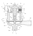
図1は、第1実施形態にかかる排水ポンプの縦断面図である。なお、ここではステータ組立体側を上側、回転羽根側を下側として説明する。また、回転羽根の回転軸線をXとする。
First Embodiment
1 is a vertical cross-sectional view of a drainage pump according to a first embodiment. In the following description, the stator assembly side is the upper side and the rotor blade side is the lower side. The axis of rotation of the rotor blade is designated as X.
排水ポンプ1は、合成樹脂製のハウジング2と、ステータユニット3と、ロータ組立体4と、回転羽根5とを有する。ハウジング2は、有底円筒状の上部ハウジング21と、下部ハウジング22とを有する。なお、後述するように、ステータユニット3は、ハウジングの一部(蓋部)としての機能を持ち合わせている。
The
上部ハウジング21は、周壁21aと、周壁21aの下端に連設された底壁21bと、底壁21bの中央に連設された中央円筒部21cとを有する。中空の中央円筒部21cは、上端が絞られており、中央円筒部21cの内側を介して底壁21bの上方空間と下方空間とが連通する。
The
下部ハウジング22は、皿状の下部本体22aと、下部本体22aの中央下端に連設された入口円筒部22bと、下部本体22aの側壁に連設された出口円筒部22cとを有する。下部本体22aの上端は、底壁21bにより覆われており、下部本体22aの内部空間と外部とは、入口円筒部22bと出口円筒部22cを介して連通する。下部本体22aの内部空間が、ポンプ室PCを形成する。
The
上部ハウジング21の周壁21aの下端と、下部ハウジング22の下部本体22aの上端とが連結され、両者の隙間に配設されたO-リングORにより封止されている。上部ハウジング21は、下部ハウジング22の上端外周から突出して形成される弾性変形可能な係止爪(不図示)を利用して、下部ハウジング22に対してスナップフィット機能により着脱自在に取り付けられる。
The lower end of the
ステータユニット3は、有頂円筒状である樹脂製のハウジング蓋部31と、ハウジング蓋部31内のコア周囲に配置されたボビン32と、ボビン32に巻回されたコイル33とを有している。ハウジング蓋部31の側面に、配線Hに接続されたコネクタ34が装着されており、外部の電源(不図示)より配線H及びコネクタ34を介してコイル33に給電が行われる。
The
ハウジング蓋部31の下端外周は、上部ハウジング21の周壁21aの上端内周に嵌合している。ハウジング蓋部31は、その下端外周から突出して連設される弾性変形可能な係止爪(不図示)を利用して、上部ハウジング21に対してスナップフィット機能により着脱自在に取り付けられる。
The lower outer periphery of the
ハウジング蓋部31の上壁下面中央に袋孔31aが形成されており、袋孔31aには金属製である固定シャフト35の上端が圧入により嵌合固定され、固定シャフト35はハウジング蓋部31から下方に向かって延在している。固定シャフト35の下端は、球面状となっている。
A
ロータ組立体4は、中空円筒状の樹脂成形品としてのロータ基部41と、連結シャフト42と、環状のロータマグネット43と、環状の上部軸受44と、環状の下部軸受45とを有する。上部軸受44及び下部軸受45は、滑り軸受である。
The
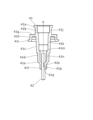
図2は、ロータ基部41の縦断面図である。ロータ基部41の外周面は、上方より、環状外周面41aと、環状外周面41aより小径の大円筒外側面41bと、大円筒外側面41bから下方に向かうにしたがって縮径する大円錐外側面41cと、大円錐外側面41cに対して段部を介して繋がる大円錐外側面41cより小径の中円筒外側面41dと、中円筒外側面41dから下方に向かうにしたがって縮径する小円錐外側面41eと、小円錐外側面41eに繋がる小円筒外側面41fとを有する。
Figure 2 is a vertical cross-sectional view of the
また、ロータ基部41は、大円筒外側面41bと大円錐外側面41cとの境界付近から径方向外方に延在する大鍔部41gと、大鍔部41gの外周から軸線方向下方に延在する鍔円筒部41hと、鍔円筒部41hの下端から径方向外方に延在する小鍔部41iとを連設してなる。
The
さらにロータ基部41の内周面は、上方より、大円筒内側面41jと、大円筒内側面41jに対して段部を介して繋がる大円筒内側面41jより小径の大円錐内側面41kと、大円錐内側面41kに繋がる中円筒内側面41mと、中円筒内側面41mに対して段部を介して繋がる中円筒内側面41mより小径の小円筒内側面41nと、小円筒内側面41nに対して段部を介して繋がる小円筒内側面41nより小径の円筒状である受け面41pとを有する。
The inner peripheral surface of the
連結シャフト42は、金属製であって円柱状であり、中央部外周面の一部に、周方向に連続せずまた軸線方向にも連続しない凹部42aを有する。連結シャフト42の上端は、平面状となっているが、球面状となっていてもよい。連結シャフト42は、受け面41pに凸部41qが形成されており、それにより連結シャフト42がロータ基部41に回転方向及び軸線方向に対して固定される。連結シャフト42の下端側は、ロータ基部41の下方に突出し、また連結シャフト42の上端側は、小円筒内側面41nの径方向内側に位置する。
The connecting
(ロータ基部及び回転羽根の製造)
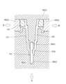
図3は、樹脂成形品としてのロータ基部41の製造工程を示す模式図である。図4は、ロータ組立体4と回転羽根5とを分解して示す縦断面図である。図3において、第1の型MD1は、中央に略円筒状のコアCRを備える。コアCRの下端中央に、第1袋孔BH1が形成されている。ここで、第1の型MD1において、コアCRおよび第1袋孔BH1とは同軸加工により形成されており、コアCRと第1袋孔BH1との同軸性は高精度(少なくとも、第2の型MD2、第3の型MD3との型締めによる誤差未満となる精度)に確保されている。またコアCRの根元周囲に、環状体を半割りした一対の第2の型MD2が配置され、第1の型MD1に対して水平方向にスライド可能に配置されている。
(Manufacture of rotor bases and rotor blades)
FIG. 3 is a schematic diagram showing a manufacturing process of the
第3の型MD3は、中央にキャビティCVを備える。キャビティCVの底部中央に、第2袋孔BH2が形成されている。 The third mold MD3 has a cavity CV in the center. A second blind hole BH2 is formed in the center of the bottom of the cavity CV.
本実施形態においては、インサート成形により、ロータ基部41、ロータマグネット43および連結シャフト42を一体に組み付けて形成する。ロータ基部41、ロータマグネット43および連結シャフト42の組み付け工程を以下に示す。なお、連結シャフト42には、予め凹部42aが形成されているものとする。
In this embodiment, the
ロータ基部の成形前において、第1の型MD1の第1袋孔BH1に、連結シャフト42の上端側を嵌合させる一方で、一対の第2の型MD2をコアCRの径方向外側から接近させるようにスライドさせてロータマグネット43を挟み込む。その後、第1の型MD1に対して第3の型MD3を下方から接近させると、第3の型MD3の第2袋孔BH2に、連結シャフト42の下端側が嵌合する。このとき、連結シャフト42の凹部42aは、キャビティCVに対して径方向内側に位置する。かかる型締め状態が、図3に示される。同図から明らかのように、型締め状態において、第1の型MD1と第3の型MD3とは、連結シャフト42が介在することによって同軸性が高精度に確保されることになる。
Before the rotor base is molded, the upper end of the connecting
その後、不図示のスプルー及びランナーを介して溶融した熱可塑性樹脂を、型MD1~MD3により形成される空洞内に注入する。樹脂が固化した後、第1の型MD1に対して第2の型MD2を矢印Bに示すように下方に離間させ、また一対の第3の型MD3をコアCRから矢印Aに沿って離間するように第1の型MD1に対してスライドさせる。第1の型MDから成形品を取り外すと、図2に示すように、回転軸線Xと同軸となる連結シャフト42が一体となったロータ基部41を得ることができる。尚、ロータ基部の成形材料としては、上記の熱可塑性樹脂に代え、熱硬化性樹脂、その他の重合性樹脂を用いてもよい。
Then, molten thermoplastic resin is injected into the cavity formed by the molds MD1 to MD3 through a sprue and runner (not shown). After the resin has solidified, the second mold MD2 is moved downward relative to the first mold MD1 as shown by arrow B, and the pair of third molds MD3 are slid relative to the first mold MD1 so as to move away from the core CR along arrow A. When the molded product is removed from the first mold MD, a
成形されたロータ基部41の内周面において、中円筒内側面41mに嵌合するようにして下部軸受45が圧入により取付けられ、また大円筒内側面41jに嵌合するようにして上部軸受44が圧入により取付けられる。これによりロータ組立体4が完成する。
The
回転羽根5は、円筒状の軸部51と、軸部51の周囲に配置された皿状部52と、軸部51と皿状部52とを連結する複数の羽根部53とを連設してなり、射出成形によって形成できる。各羽根部53は、軸部51の軸線を含む面に沿って径方向外方に延在するように、放射状に等角度で形成されている。軸部51の上端中央には、袋孔51aが形成され、皿状部52の中央には、軸部51が貫通する円形開口52aが形成されている。
上記構成を有する回転羽根5において、回転中心である軸部51のうち袋孔51aが形成された領域51bにおける成形精度が回転羽根5の回転精度に特に影響するため、当該領域51bの成形精度を確保することは重要である。同領域51bのうち羽根部53が連設された下部領域51baは、羽根部53が補強リブとして作用するため、成形精度は比較的高く保つことが可能である。他方、羽根部53が連設された領域より上の上部領域51bbは、金型からの離形後に樹脂材の変形による影響を受ける虞がある。そこで、本実施形態においては、この上部領域51bbが短くなるよう設計している。具体的には、この上部領域51bbの高さが、ロータ組立体4の上部軸受44の高さ方向の中心位置と下部軸受45の高さ方向の中心位置との間の距離(中心位置間距離)よりも短く設定されており、より好ましくは中間位置間距離の20%~80%の範囲に設定される。また、上部領域51bbの高さは、下部領域51baの高さよりも短く、回転羽根5の外径の10%~30%の範囲となるよう設計されている。
The
In the
(排水ポンプの組付)
排水ポンプ1の組付態様について説明する。ハウジング蓋部31には、コイル33や固定シャフト35等が予め組み付けられているものとする。まず、ロータ組立体4の上部軸受44および下部軸受45に、ハウジング蓋部31から下方に延在する固定シャフト35を挿通するようにして、ロータ組立体4をハウジング蓋部31に組み付ける。このとき、ロータ組立体4の内部に、固定シャフト35の先端に対応し、摺動性に優れた素材からなる円板46を配置しておく。円板46の外径は、連結シャフト42または固定シャフト35の外径よりも大きいと好ましい。固定シャフト35がハウジング蓋部31に組付けられることにより、円板46は、固定シャフト35の下端と連結シャフト42の上端との間に配置される。
(Drainage pump installation)
The manner of assembly of the
ハウジング蓋部31に組み付けられたロータ組立体4は、ロータマグネット43とコイル33内のコアとの間で磁気的吸引力が生じるため、ハウジング蓋部31から落下することがない。なお、小鍔部41iは、ロータ組立体4とハウジング蓋部31との間に異物が侵入しないようにカバーとして機能する。
The
次いで、ロータ組立体4を組み付けた状態で、ハウジング蓋部31の下端を、上部ハウジング21の上端側から嵌合させて組み付ける。上部ハウジング21に組み付けられた状態で、連結シャフト42は、底壁21bの中央円筒部21cを貫通し、その下端が底壁21bの下方に露出する。
Next, with the
さらに、連結シャフト42の露出した下端を、軸部51の袋孔51aに圧入により挿入し、連結シャフト42に回転羽根5を連結する。その後、上部ハウジング21にО-リングORおよび下部ハウジング22を取り付けると、回転羽根5の周囲に下部本体22aが配置され、軸部51が入口円筒部22b内に位置することとなる。これにより排水ポンプ1の組み付けが完了する。
The exposed lower end of the connecting
(排水ポンプの動作)
外部の電源よりコイル33に給電しロータマグネット43に磁気力が作用し、固定シャフト35の周囲をロータ組立体4が回転する。これにより回転羽根5が回転駆動されると、遠心力により入口円筒部22bからポンプ室PC内にドレン水が吸い上げられて出口円筒部22cを通じて排出される。ロータ組立体4は、固定シャフト35に対して、上部軸受44、下部軸受45、及び円板46により低フリクションで回転可能に支持されるため、省電力が図られる。
(Drainage pump operation)
When power is supplied to the
本実施形態によれば、下部軸受45が取付けられる中円筒内側面41mと、上部軸受44が取り付けられる大円筒内側面41jとを形成する第1の型MD1のコアCRに対して、連結シャフト42が精度よく同軸に位置決めされ、また連結シャフト42に対して回転羽根5が精度よく同軸に位置決めされる。したがって、連結シャフト42を介して、ロータ基部41と回転羽根5とを容易に且つ精度よく同軸に連結することができるため、ロータ組立体4と回転羽根5の組立体における回転バランスを高めることができ、それにより回転時の低振動を確保できる。
According to this embodiment, the connecting
(第1実施形態の変形例)
以上の実施形態において、連結シャフト42はインサート成形によりロータ基部41と連結され、ロータ組立体4の一部を成している。これに対し、インサート成形を行うことなく、ロータ基部の射出成形時に、第1の型MD1によって同軸の貫通孔(例えば後述する貫通孔41Ap)を形成し、射出成形後に該貫通孔の内周面である受け面に、円形軸(すなわち外周に凹部を有しない)である連結シャフトを圧入により嵌合させることによって、ロータ組立体を形成してもよい。それ以外の構成は、第1実施形態と同様である。
(Modification of the first embodiment)
In the above embodiment, the connecting
本変形例においても、ロータ基部と回転羽根の軸部の対向する孔に連結シャフトの両端側を嵌合させることにより、ロータ基部と回転羽根とを精度よく同軸に連結することができるため、ロータ組立体と回転羽根の組立体における回転バランスを高めることができ、それにより回転時の低振動を確保できる。 In this modified example, by fitting both ends of the connecting shaft into the opposing holes in the rotor base and the shaft of the rotating blade, the rotor base and the rotating blade can be precisely connected coaxially, improving the rotational balance of the rotor assembly and the rotating blade assembly, thereby ensuring low vibration during rotation.
(第2実施形態)
図5は、第2実施形態にかかるロータ組立体4Aと回転羽根5Aとを分解して示す縦断面図である。本実施形態では、回転羽根5Aに連結シャフト54Aが一体に形成される。ロータ組立体4Aと回転羽根5A以外の構成は、第1実施形態と同様であるため、重複説明を省略する。
Second Embodiment
5 is an exploded vertical cross-sectional view of a
ロータ組立体4Aのロータ基部41Aは、小円筒内側面41nに対して段部を介して繋がる円筒状の貫通孔41Apを有する。それ以外のロータ基部41Aの構成は、第1実施形態と同様であるため、同じ符号を付して重複説明を省略する。
The
回転羽根5Aの軸部51Aは、上端に円形袋孔状の受け面51Aaを有する。受け面51Aaに、径方向内側に突出した凸部51Abが形成されている。それ以外の回転羽根5Aの構成は、第1実施形態と同様であるため、同じ符号を付して重複説明を省略する。
The
連結シャフト54Aは、金属製であって円柱状であり、下端近傍の外周面の一部に、周方向に連続せずまた軸線方向にも連続しない凹部54Aaを有する。連結シャフト54Aは、インサート成形により、回転羽根5Aと一体的に構成されている。インサート成形においては、回転羽根5Aを構成する樹脂材により、連結シャフト54Aとの境界である受け面51Aaが形成される。また、樹脂材が連結シャフト54Aの凹部54Aaに充填されることにより、凸部51Abが形成され、それにより連結シャフト54Aが軸部51Aに回転方向及び軸線方向に対して固定される。連結シャフト54Aの上端側は、軸部51Aの上方に突出し、ロータ基部41Aの貫通孔41Apに圧入により嵌合する。
The connecting
本実施形態によれば、第1の型のコアにより、ロータ基部41Aの内周面(下部軸受45が取付けられる中円筒内側面41mと上部軸受44が取り付けられる大円筒内側面41j、貫通孔41Ap)が精度よく同軸に位置決めされ、また、インサート成形により連結シャフト54Aが軸部51Aに対して精度よく同軸に成形される。したがって、連結シャフト54Aを介して、ロータ基部41Aと回転羽根5Aとを容易に且つ精度よく同軸に連結することができるため、ロータ組立体4Aと回転羽根5Aの組立体における回転バランスを高めることができ、それにより回転時の低振動を確保できる。
According to this embodiment, the inner peripheral surface of the
上記した本発明による排水ポンプは、いわゆるプロダクト・バイ・プロセス形式により、物の発明が特定されているという見方もできる。ここで、連結シャフトがインサート成形により樹脂成形品に結合されたか否かを、製品としての排水ポンプから判別することが困難な場合がある。したがって、請求項において物をその構造又は特性により直接特定することが不可能であるか、又はおよそ実際的でないという事情(「不可能・非実際的事情」)が存在するものである。 The drainage pump according to the present invention described above can also be considered as a product that is specified by the so-called product-by-process format. Here, it may be difficult to determine from the drainage pump as a product whether the connecting shaft is joined to the resin molded product by insert molding. Therefore, there are circumstances in which it is impossible or not practical to directly specify the product in the claims by its structure or characteristics ("impossible/impractical circumstances").
1 排水ポンプ
2 ハウジング
3 ステータユニット
35 固定シャフト
4、4A ロータ組立体
41、41A ロータ基部
42、54A 連結シャフト
44 上部軸受
45 下部軸受
5、5A 回転羽根
51、51A 軸部
REFERENCE SIGNS
Claims (3)
前記ハウジングに取り付けられたステータユニットと、
前記固定シャフトに対し回転可能に保持され、前記ステータユニットにより回転駆動されるロータ組立体と、
前記ロータ組立体と共に回転する回転羽根と、を有し、
前記ロータ組立体を構成するロータ基部と前記回転羽根は、前記ロータ組立体の回転軸線に同軸である連結シャフトを介して相互に連結されており、
前記ロータ組立体は、樹脂製のロータ基部および前記ロータ基部を前記固定シャフトに対して回転自在に保持する軸受を備えた排水ポンプの製造方法であって、
前記ロータ基部は、複数の金型により樹脂成形された成形品であり、前記軸受を保持する前記ロータ基部の内周面と、前記連結シャフトを保持する前記ロータ基部の受け面とを前記複数の金型のうち単一の金型により画定する、
ことを特徴とする排水ポンプの製造方法。 a housing having a fixed shaft;
a stator unit attached to the housing;
a rotor assembly rotatably held on the fixed shaft and rotated by the stator unit;
a rotor blade that rotates with the rotor assembly;
The rotor base and the rotor blades constituting the rotor assembly are connected to each other via a connecting shaft that is coaxial with the rotation axis of the rotor assembly,
The rotor assembly is a manufacturing method for a drainage pump including a rotor base made of resin and a bearing that rotatably holds the rotor base relative to the fixed shaft,
the rotor base is a molded product produced by resin molding using a plurality of dies, and an inner peripheral surface of the rotor base that holds the bearing and a receiving surface of the rotor base that holds the connecting shaft are defined by a single die among the plurality of dies.
A method for manufacturing a drainage pump comprising the steps of:
前記連結シャフトの他端側を、前記回転羽根を構成する軸部の孔に嵌合し、
前記ロータ基部において、前記単一の金型に前記連結シャフトが保持された状態で樹脂成形されることにより、前記連結シャフトを保持する受け面が画定される、
ことを特徴とする請求項1に記載の排水ポンプの製造方法。 One end side of the connecting shaft is insert molded into the rotor base,
The other end side of the connecting shaft is fitted into a hole of a shaft portion constituting the rotary blade,
the rotor base is resin-molded in a state in which the connecting shaft is held in the single mold, thereby defining a receiving surface that holds the connecting shaft.
The method for manufacturing a drainage pump according to claim 1 .
前記連結シャフトの一端側を、前記回転羽根を構成する軸部にインサート成形し、
前記連結シャフトの他端側を、前記ロータ基部の孔に嵌合する、
ことを特徴とする請求項1に記載の排水ポンプの製造方法。 the rotor base has a hole having the receiving surface;
One end of the connecting shaft is insert-molded into a shaft portion that constitutes the rotor blade,
The other end of the connecting shaft is fitted into a hole in the rotor base.
The method for manufacturing a drainage pump according to claim 1 .
Priority Applications (1)
| Application Number | Priority Date | Filing Date | Title |
|---|---|---|---|
| JP2024079329A JP7621697B2 (en) | 2021-09-16 | 2024-05-15 | How to manufacture a drainage pump |
Applications Claiming Priority (2)
| Application Number | Priority Date | Filing Date | Title |
|---|---|---|---|
| JP2021151071A JP7493810B2 (en) | 2021-09-16 | 2021-09-16 | Drainage pump |
| JP2024079329A JP7621697B2 (en) | 2021-09-16 | 2024-05-15 | How to manufacture a drainage pump |
Related Parent Applications (1)
| Application Number | Title | Priority Date | Filing Date |
|---|---|---|---|
| JP2021151071A Division JP7493810B2 (en) | 2021-09-16 | 2021-09-16 | Drainage pump |
Publications (2)
| Publication Number | Publication Date |
|---|---|
| JP2024109693A JP2024109693A (en) | 2024-08-14 |
| JP7621697B2 true JP7621697B2 (en) | 2025-01-27 |
Family
ID=85482391
Family Applications (2)
| Application Number | Title | Priority Date | Filing Date |
|---|---|---|---|
| JP2021151071A Active JP7493810B2 (en) | 2021-09-16 | 2021-09-16 | Drainage pump |
| JP2024079329A Active JP7621697B2 (en) | 2021-09-16 | 2024-05-15 | How to manufacture a drainage pump |
Family Applications Before (1)
| Application Number | Title | Priority Date | Filing Date |
|---|---|---|---|
| JP2021151071A Active JP7493810B2 (en) | 2021-09-16 | 2021-09-16 | Drainage pump |
Country Status (2)
| Country | Link |
|---|---|
| JP (2) | JP7493810B2 (en) |
| CN (1) | CN115807786A (en) |
Families Citing this family (1)
| Publication number | Priority date | Publication date | Assignee | Title |
|---|---|---|---|---|
| WO2024214678A1 (en) * | 2023-04-11 | 2024-10-17 | 株式会社不二工機 | Drainage pump manufacturing method, and drainage pump |
Citations (4)
| Publication number | Priority date | Publication date | Assignee | Title |
|---|---|---|---|---|
| JP2014107893A (en) | 2012-11-26 | 2014-06-09 | Fuji Koki Corp | Motor for drainage pump |
| JP2014180146A (en) | 2013-03-15 | 2014-09-25 | Hitachi Automotive Systems Ltd | Rotor structure and electric fluid pump |
| JP2018194004A (en) | 2018-08-29 | 2018-12-06 | 日立アプライアンス株式会社 | Electric air blower and vacuum cleaner |
| JP2019105243A (en) | 2017-12-13 | 2019-06-27 | 株式会社不二工機 | Motor for drain pump and manufacturing method of the same and drain pump having the same |
Family Cites Families (4)
| Publication number | Priority date | Publication date | Assignee | Title |
|---|---|---|---|---|
| JP3576309B2 (en) * | 1996-03-15 | 2004-10-13 | 日本電産株式会社 | Fan motor impeller structure |
| JP6550698B2 (en) * | 2014-07-24 | 2019-07-31 | アイシン精機株式会社 | Electric pump |
| JP6831108B2 (en) * | 2017-07-03 | 2021-02-17 | 株式会社不二工機 | Drainage pump |
| JP2019103363A (en) * | 2017-12-07 | 2019-06-24 | 株式会社不二工機 | Motor for drainage pump and drainage pump including the same |
-
2021
- 2021-09-16 JP JP2021151071A patent/JP7493810B2/en active Active
-
2022
- 2022-08-15 CN CN202210972732.1A patent/CN115807786A/en active Pending
-
2024
- 2024-05-15 JP JP2024079329A patent/JP7621697B2/en active Active
Patent Citations (4)
| Publication number | Priority date | Publication date | Assignee | Title |
|---|---|---|---|---|
| JP2014107893A (en) | 2012-11-26 | 2014-06-09 | Fuji Koki Corp | Motor for drainage pump |
| JP2014180146A (en) | 2013-03-15 | 2014-09-25 | Hitachi Automotive Systems Ltd | Rotor structure and electric fluid pump |
| JP2019105243A (en) | 2017-12-13 | 2019-06-27 | 株式会社不二工機 | Motor for drain pump and manufacturing method of the same and drain pump having the same |
| JP2018194004A (en) | 2018-08-29 | 2018-12-06 | 日立アプライアンス株式会社 | Electric air blower and vacuum cleaner |
Also Published As
| Publication number | Publication date |
|---|---|
| CN115807786A (en) | 2023-03-17 |
| JP2023043428A (en) | 2023-03-29 |
| JP2024109693A (en) | 2024-08-14 |
| JP7493810B2 (en) | 2024-06-03 |
Similar Documents
| Publication | Publication Date | Title |
|---|---|---|
| US9371840B2 (en) | Centrifugal blowing fan | |
| US8568110B2 (en) | Blower fan and method of manufacturing the same | |
| US6445098B1 (en) | Can for a synthetic pump motor | |
| KR101713615B1 (en) | Radiator fan of a motor vehicle | |
| US8449268B2 (en) | Fan and method for manufacturing the same | |
| US9057379B2 (en) | Centrifugal fan and method for manufacturing the same | |
| CN110873061A (en) | Pump body and method for manufacturing rotor assembly for pump body | |
| JP7621697B2 (en) | How to manufacture a drainage pump | |
| JP2016023598A (en) | Centrifugal fan | |
| US20120003109A1 (en) | Blower fan | |
| JP5493339B2 (en) | Motor, fan, motor manufacturing method, and fan manufacturing method | |
| CN113839496A (en) | Motor outer rotors, brushless permanent magnet motors and electrical products | |
| WO2019116717A1 (en) | Motor for drain pump, manufacturing method therefor, and drain pump having said motor | |
| KR20150124762A (en) | Rotor assembly and motor including the same | |
| CN212850164U (en) | Injection molding stator and outer rotor motor | |
| CN219139452U (en) | Rotor assembly and centrifugal pump | |
| CN222423345U (en) | Rotor assemblies, motors, fans and electrical equipment | |
| CN221347361U (en) | Automobile electronic water pump rotor structure | |
| CN222936973U (en) | Cooling fan frame and double ball bearing cooling fan | |
| US20100074747A1 (en) | Mini axial fan with an improved core shaft structure | |
| CN113364158A (en) | Motor stator convenient for processing outer circular surface, motor and processing and assembling process of motor stator | |
| CN220964407U (en) | Motors and air conditioners | |
| CN111865002B (en) | An injection molded stator and outer rotor motor | |
| CN222848364U (en) | Outer rotor fan | |
| JP2019203481A (en) | Centrifugal fan |
Legal Events
| Date | Code | Title | Description |
|---|---|---|---|
| A621 | Written request for application examination |
Free format text: JAPANESE INTERMEDIATE CODE: A621 Effective date: 20240515 |
|
| A977 | Report on retrieval |
Free format text: JAPANESE INTERMEDIATE CODE: A971007 Effective date: 20241129 |
|
| TRDD | Decision of grant or rejection written | ||
| A01 | Written decision to grant a patent or to grant a registration (utility model) |
Free format text: JAPANESE INTERMEDIATE CODE: A01 Effective date: 20241210 |
|
| A61 | First payment of annual fees (during grant procedure) |
Free format text: JAPANESE INTERMEDIATE CODE: A61 Effective date: 20250107 |
|
| R150 | Certificate of patent or registration of utility model |
Ref document number: 7621697 Country of ref document: JP Free format text: JAPANESE INTERMEDIATE CODE: R150 |