JP7621692B2 - Earphones - Google Patents
Earphones Download PDFInfo
- Publication number
- JP7621692B2 JP7621692B2 JP2023569709A JP2023569709A JP7621692B2 JP 7621692 B2 JP7621692 B2 JP 7621692B2 JP 2023569709 A JP2023569709 A JP 2023569709A JP 2023569709 A JP2023569709 A JP 2023569709A JP 7621692 B2 JP7621692 B2 JP 7621692B2
- Authority
- JP
- Japan
- Prior art keywords
- unit
- cap
- acoustic tube
- air chamber
- wall
- Prior art date
- Legal status (The legal status is an assumption and is not a legal conclusion. Google has not performed a legal analysis and makes no representation as to the accuracy of the status listed.)
- Active
Links
Images
Classifications
-
- H—ELECTRICITY
- H04—ELECTRIC COMMUNICATION TECHNIQUE
- H04R—LOUDSPEAKERS, MICROPHONES, GRAMOPHONE PICK-UPS OR LIKE ACOUSTIC ELECTROMECHANICAL TRANSDUCERS; ELECTRIC HEARING AIDS; PUBLIC ADDRESS SYSTEMS
- H04R1/00—Details of transducers, loudspeakers or microphones
- H04R1/10—Earpieces; Attachments therefor ; Earphones; Monophonic headphones
- H04R1/1058—Manufacture or assembly
- H04R1/1075—Mountings of transducers in earphones or headphones
-
- H—ELECTRICITY
- H04—ELECTRIC COMMUNICATION TECHNIQUE
- H04R—LOUDSPEAKERS, MICROPHONES, GRAMOPHONE PICK-UPS OR LIKE ACOUSTIC ELECTROMECHANICAL TRANSDUCERS; ELECTRIC HEARING AIDS; PUBLIC ADDRESS SYSTEMS
- H04R1/00—Details of transducers, loudspeakers or microphones
- H04R1/10—Earpieces; Attachments therefor ; Earphones; Monophonic headphones
- H04R1/1016—Earpieces of the intra-aural type
-
- H—ELECTRICITY
- H04—ELECTRIC COMMUNICATION TECHNIQUE
- H04R—LOUDSPEAKERS, MICROPHONES, GRAMOPHONE PICK-UPS OR LIKE ACOUSTIC ELECTROMECHANICAL TRANSDUCERS; ELECTRIC HEARING AIDS; PUBLIC ADDRESS SYSTEMS
- H04R1/00—Details of transducers, loudspeakers or microphones
- H04R1/20—Arrangements for obtaining desired frequency or directional characteristics
- H04R1/22—Arrangements for obtaining desired frequency or directional characteristics for obtaining desired frequency characteristic only
- H04R1/28—Transducer mountings or enclosures modified by provision of mechanical or acoustic impedances, e.g. resonator, damping means
- H04R1/2807—Enclosures comprising vibrating or resonating arrangements
- H04R1/2815—Enclosures comprising vibrating or resonating arrangements of the bass reflex type
- H04R1/2823—Vents, i.e. ports, e.g. shape thereof or tuning thereof with damping material
- H04R1/2826—Vents, i.e. ports, e.g. shape thereof or tuning thereof with damping material for loudspeaker transducers
-
- H—ELECTRICITY
- H04—ELECTRIC COMMUNICATION TECHNIQUE
- H04R—LOUDSPEAKERS, MICROPHONES, GRAMOPHONE PICK-UPS OR LIKE ACOUSTIC ELECTROMECHANICAL TRANSDUCERS; ELECTRIC HEARING AIDS; PUBLIC ADDRESS SYSTEMS
- H04R2460/00—Details of hearing devices, i.e. of ear- or headphones covered by H04R1/10 or H04R5/033 but not provided for in any of their subgroups, or of hearing aids covered by H04R25/00 but not provided for in any of its subgroups
- H04R2460/11—Aspects relating to vents, e.g. shape, orientation, acoustic properties in ear tips of hearing devices to prevent occlusion
Landscapes
- Engineering & Computer Science (AREA)
- Physics & Mathematics (AREA)
- Acoustics & Sound (AREA)
- Signal Processing (AREA)
- Manufacturing & Machinery (AREA)
- Headphones And Earphones (AREA)
Description
本発明は、イヤホンに関する。 The present invention relates to earphones.
外耳道に挿入する、耳栓形状のカナル型ヘッドホン(イヤホン)が知られている。 Earplug-shaped in-ear headphones (earphones) that are inserted into the ear canal are known.
これまでにも、例えば、ドライバユニットより出力される音波を耳内に放音する開口を有するとともに、円筒支持部材の外側面が露出された状態で該円筒支持部材におけるドライバユニット放音側の端縁に取り付けられる放音部材と、円筒支持部材の外側面が露出された状態で、該円筒支持部材のドライバユニット放音側とは反対側の端縁に取り付けられる蓋部材とを備えるイヤホンが知られている(例えば、特許文献1参照)。Previously, earphones have been known that have an opening through which sound waves output from the driver unit are emitted into the ear, and that include a sound-emitting member that is attached to the edge of the cylindrical support member on the sound-emitting side of the driver unit with the outer surface of the cylindrical support member exposed, and a cover member that is attached to the edge of the cylindrical support member opposite the sound-emitting side of the driver unit with the outer surface of the cylindrical support member exposed (see, for example, Patent Document 1).
耳栓形状のカナル型イヤホンにおいては、小型のドライバユニットを外耳道内に設けることができるため、振動板を鼓膜に近接させることで、振動板の面積が小さくても低域音の損失を少なくすることができる。一方で、振動板と鼓膜の間の空間が小さくなるため、イヤホンを耳に挿入する際の圧力が振動板に与えられた結果、振動板が変形したり、潰れてしまったりするおそれがある。しかしながら、先行技術文献には、このような課題を解決する技術は開示されていない。 In earplug-shaped in-ear earphones, a small driver unit can be placed inside the ear canal, so by placing the diaphragm close to the eardrum, it is possible to reduce the loss of low-frequency sounds even if the area of the diaphragm is small. On the other hand, because the space between the diaphragm and the eardrum is small, there is a risk that the diaphragm will be deformed or crushed as a result of the pressure applied to the diaphragm when the earphone is inserted into the ear. However, prior art documents do not disclose any technology that solves this problem.
本発明は、振動板への圧力を軽減しつつ、高音質なイヤホンを提供することを目的とする。 The present invention aims to provide earphones that reduce pressure on the diaphragm while providing high sound quality.
本発明に係るイヤホンは、振動板と、前記振動板を前面に備えるドライバユニットと、前記ドライバユニットを収容するユニットキャップと、前記ユニットキャップの前面に連結され、前記振動板の前面に前側空気室を形成する音響管と、を備え、前記ユニットキャップは、前記ドライバユニットの側壁を保持するユニット保持壁と、前記ユニット保持壁の前方において、前記ユニット保持壁の内側と外側、および前記ユニットキャップの前面と後面とを連通する連通孔と、を備え、前記ユニット保持壁により規定されるユニット収容部の中心軸は、前記ユニットキャップの中心軸から偏心している。The earphones of the present invention comprise a diaphragm, a driver unit having the diaphragm on its front surface, a unit cap housing the driver unit, and an acoustic tube connected to the front surface of the unit cap and forming a front air chamber on the front surface of the diaphragm, the unit cap comprising a unit retaining wall that holds the side wall of the driver unit, and a communication hole in front of the unit retaining wall that connects the inside and outside of the unit retaining wall and the front and rear surfaces of the unit cap, the central axis of the unit housing portion defined by the unit retaining wall being eccentric to the central axis of the unit cap.
本発明によれば、振動板への圧力を軽減しつつ、高音質なイヤホンを提供できる。 The present invention makes it possible to provide earphones that produce high-quality sound while reducing pressure on the diaphragm.
以下、本発明にかかるイヤホンの実施の形態について、図面を参照しながら説明する。なお、以降の説明において、ドライバユニット5の軸方向をz方向、z方向に直交する方向をx方向およびy方向ともいう。また、+z方向に向く面を後面、-z方向に向く面を前面ともいう。
Embodiments of earphones according to the present invention will be described below with reference to the drawings. In the following description, the axial direction of the
●イヤホン●
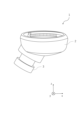
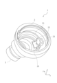
図1に示すように、イヤホン1は外観上、主として、ユニットキャップ2と、音響管3と、ハウジング4と、を有する。ユニットキャップ2は、前面側に底を有する有底円筒状の部材である。音響管3は、ユニットキャップ2の前面に連結される略円筒状の部材である。音響管3は、ユニットキャップ2の軸に対して斜めに伸び出ている。ユニットキャップ2と音響管3との連結部分は通気孔25(図2参照)が形成されており、この通気孔25により、ユニットキャップ2の内側空間と音響管3の内側空間は連通している。
●Earphones●
As shown in Fig. 1, the
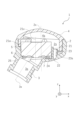
図2に示すように、ユニットキャップ2は、主として、ユニット保持壁21と、連通孔22と、後室壁23と、切欠部24と、通気孔25と、を備える。As shown in FIG. 2, the
ユニット保持壁21は、ユニットキャップ2の内側に形成される円筒状の部材である。ユニット保持壁21は、ドライバユニット5の側壁を保持する。すなわち、ユニット保持壁21の内側空間は、ドライバユニット5を収容するユニット収容部21aとなっている。ドライバユニット5はユニット収容部21aに略隙間なく嵌り込んでいるため、ドライバユニット5の中心軸は、ユニット収容部21aの中心軸21xと略同位置である。The unit
ドライバユニット5の前面には、振動板6が配設されている。振動板6の前方は、通気孔25を介して音響管3の内側空間と接続されている。その結果、音響管3の内側空間は、前側空気室3sとなっている。A
ユニット保持壁21により規定されるユニット収容部21aの中心軸21xは、ユニットキャップ2の中心軸2xから偏心している。この構成によれば、ドライバユニット5がユニットキャップ2の軸方向中央に配設される構成に比べて、ユニットキャップ2が小型であってもドライバユニット5の側方に空間2sを形成することができる。The
図2および図3に示すように、ユニットキャップ2には、ユニット保持壁21の前方に連通孔22が形成されている。連通孔22は、ユニットキャップ2の前面と後面とを連通する貫通孔である。連通孔22は、ユニットキャップ2の前面であって、空間2sを区画する壁面に形成される。すなわち、連通孔22は、ユニットキャップ2の半径方向において音響管3とは反対側に形成されている。
As shown in Figures 2 and 3, the
連通孔22は、ユニット保持壁21の半径方向内側および外側に渡って形成される。その結果、ユニット保持壁21の内側と外側とは、連通孔22およびユニットキャップ2外側の前方空間を介して連通される。また、連通孔22のy方向(図3参照)上下端部には、ユニットキャップ2の厚さを一部切り欠いた段部22aが形成され、この段部22aを適宜の形状に形成することにより通気量や空気の抜け方を調整してもよい。
なお、連通孔22の図面上の位置は例示であり、図2のように音響管3の略中央を通る縦断面に配設される構成には限定されないのは勿論である。連通孔22は、ユニット保持壁21の半径方向内側および外側にまたがって形成されていればよく、ユニット保持壁21の湾曲面に沿って、図4中の位置よりも図中上方又は下方に配設されていてもよい。その場合、連通孔22は、ユニット保持壁21の湾曲に応じて図4中の位置よりも図中左方に配設される。
The
The position of the
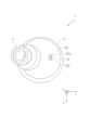
図2および図4に示すように、空間2sには、後室壁23が配設されている。後室壁23は、ユニット保持壁21の半径方向外側に配設される部分筒状体である。後室壁23は、平面視(図4参照)においてU字状になっている。また、後室壁23の内側の空間は、連通孔22と連通している。その結果、後室壁23とユニット保持壁21とに囲まれた空間は、連通孔22を介して前側空気室3sに連通する後側空気室23sとなっている。As shown in Figures 2 and 4, a
上述のような構成によれば、イヤホン1を外耳道に装着する際に生じる空気の圧力は、前側空気室3sから連通孔22を介して抜けていく。また、上述のような構成によれば、取り外す際に生じる振動板6を引っ張る方向の圧力、および梱包から取り出す際に生じる圧力変化に対しても、連通孔22を介して空気が流動する。したがって、振動板6と鼓膜の間の空間が小さい小型のイヤホンであっても、振動板6の前面にかかる空気の圧力変化を低減できる。ひいては、振動板6の変形や破損を防止できる。また、装着時の他、梱包や輸送時にかかる空気の圧力変化に対しても同様に軽減できる。
According to the above-mentioned configuration, the air pressure generated when the
また、連通孔22が空間2sと連通する構成によれば、空気を後面側に逃がすことができるため、振動板6にかかる負荷を軽減し、振動板6を応答性よく精確に振動させることができる。すなわち、高音質なイヤホンを実現できる。In addition, by configuring the
さらに、空間2sに後室壁23を配設し、後側空気室23sが形成されている構成によれば、空気の流入出が制御されるため、低域の音圧を担保できる。
Furthermore, by providing a
ユニットキャップ2の後面には、ドライバユニット5の後面を覆うハウジング4が連結されている。ハウジング4の内側の空間4sは、後側空気室23sと連通している。この構成によれば、後側空気室23sにおける空気の振動を空間4sにも伝達できる。また、本実施形態では、ハウジング4には、外気との図示しない連通孔が設けられているが、ハウジング4に当該連通孔を設けず、1つの連通孔22のみを介してハウジング4の内側の空間4sおよび後側空気室23sが外気と連通する構成であってもよい。
また、後室壁23を備えない構成であってもよい。この場合、ハウジング4の内側の空間4sおよび空間2sが、連通孔22を介して外気と連通する。
A
Moreover, the
図2、図4および図5に示すように、切欠部24は、連通孔22周辺の壁面、すなわちユニット保持壁21の一部およびユニットキャップ2の前面の内壁を厚さ方向に切り欠いて形成されている。本実施形態においては、切欠部24は、ユニット保持壁21およびユニットキャップ2が縦断面視略L字状に切欠かれた形状である。また、切欠部24は、ユニット保持壁21を矩形に切欠かいた形状である。なお、詳細な態様は上述に限られない。2, 4 and 5, the
切欠部24には音響抵抗材7が収容されている。音響抵抗材7は、切欠部24に沿って略L字状に配設される。音響抵抗材7は、連通孔22の少なくとも一部を覆っている。より具体的には、音響抵抗材7は、連通孔22のうち、ユニット収容部21aとユニットキャップ2の前方空間との間に介在している。すなわち、前側空気室3sと後側空気室23sとは、音響抵抗材7を介して連通している。An
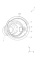
音響管3は、ユニットキャップ2の軸方向の中心に対して、ユニット収容部21aの中心軸21x側に偏心した位置に連結されている。すなわち、音響管3により形成される前側空気室3sは、ドライバユニット5の前面側に形成される。したがって、振動板6の振動が振動板6前面から前側空気室3sに伝達される。The
ここで、振動は、周波数が高いほど直線的に進行する性質がある。この点、音響管3がドライバユニット5の位置に合わせて偏心している本構成によれば、振動板6が通気孔25を介して前側空気室3sに面しているため、中高域の音の振動を音響管3の開口まで十分に伝達できる。すなわち、本構成によれば、小型のイヤホンでありながら、中高域の音源を高音質に再生できる。Here, vibrations have the tendency to progress more linearly as the frequency increases. In this regard, with the present configuration in which the
また、より具体的には、音響管3は、音響管3の中心軸に沿う仮想直線3xが通気孔25の中心を通る位置に配設されていてもよい。この構成によれば、通気孔25が、音響管3により構成される前側空気室3sに対して十分に開口し、振動板6の振動が前側空気室3sに直線的に伝達されるため、小型のイヤホン1であっても中高域の音源を一層高音質に再生できる。More specifically, the
また、図2においては、ユニット収容部21aの中心軸21xは、ユニットキャップ2の中心軸2xと略平行に描画されている。すなわち、ドライバユニット5の中心軸は、ユニットキャップ2の中心軸2xと略平行である。しかしながら、本発明の技術的範囲はこれに限られず、ユニット収容部21aの中心軸21xはユニットキャップ2の中心軸2xに対して傾いて形成されていてもよい。すなわち、ドライバユニット5がユニットキャップ2の中心軸2xに対して傾いて収容されるようになっていてもよい。2, the
また、音響管3はユニットキャップ2の前面に対して斜めに連結され、ドライバユニット5は音響管3の軸方向に傾斜して収容されていてもよい。ユニット収容部21aの中心軸21xおよびドライバユニット5の中心軸は、音響管3の中心軸に沿う仮想直線3xと略平行になっていてもよい。この場合、ドライバユニット5および振動板6は、通気孔25および音響管3内部に形成される前側空気室3sに正対する。この構成によっても、振動板6により生成される中高域の音の振動を音響管3の開口まで十分に伝達できる。また、イヤホン1の大きさを小型化することができる。さらに、このような構成によればイヤホンの意匠や構造設計の自由度を向上することができる。
The
また、本発明にかかる構成によれば、音質を担保したままイヤホンを小型化できるため、従来よりも音響管の細いイヤホンを実現できる。したがって、本発明にかかる構成によれば、耳が小さい、又は外耳道が細いユーザにも好適なイヤホンを実現することもできる。 In addition, the configuration of the present invention allows earphones to be made smaller while maintaining sound quality, making it possible to realize earphones with thinner acoustic tubes than conventional earphones. Therefore, the configuration of the present invention also makes it possible to realize earphones that are suitable for users with small ears or narrow ear canals.
●周波数応答特性
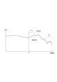
図6は、イヤホンの周波数特性を示している。すなわち横軸は周波数を、縦軸は出力レベル(dBV)を示している。破線は、関連技術に係るイヤホンの周波数特性を示しており、実線は、本発明に係るイヤホン1の周波数特性を示している。また、図6には、関連技術のイヤホンの周波数特性が重畳して示されている。関連技術のイヤホンは、ドライバユニットがユニットキャップの軸方向略中心に収容され、空間2sに対応する構成を有さない構造である。また、関連技術のイヤホンの音響管は、ユニットキャップの軸方向中心に連結されている。
Frequency response characteristics FIG. 6 shows the frequency characteristics of the earphone. That is, the horizontal axis shows frequency, and the vertical axis shows output level (dBV). The dashed line shows the frequency characteristics of the earphone according to the related art, and the solid line shows the frequency characteristics of the
図6に示すように、イヤホン1は、1kHz超の低周波数帯域F1において、関連技術のイヤホンよりも音圧が保たれている。すなわち、イヤホン1は、ユニットキャップ2の外形が小さいにも関わらず、低域の音を高音質に再生できる。また、低周波数帯域F1よりも高周波数の帯域である高周波数帯域F2においては、関連技術のイヤホンと比較して音圧の変動幅が小さい。すなわち、イヤホン1は、高域においても安定して出力できる。
As shown in Figure 6, the
以上説明した実施の形態によれば、振動板への圧力を軽減しつつ、高音質なイヤホンを提供できる。
以上、本発明を実施の形態を用いて説明したが、本発明の技術的範囲は上記実施の形態に記載の範囲には限定されず、その要旨の範囲内で種々の変形及び変更が可能である。
According to the embodiment described above, it is possible to provide earphones that reduce pressure on the diaphragm and produce high quality sound.
Although the present invention has been described above using the embodiments, the technical scope of the present invention is not limited to the scope described in the above embodiments, and various modifications and changes are possible within the scope of the gist of the present invention.
1 イヤホン
2 ユニットキャップ
21 ユニット保持壁
21a ユニット収容部
21x ユニット収容部の中心軸
22 連通孔
23 後室壁
23s 後側空気室
3 音響管
3s 前側空気室
4 ハウジング
5 ドライバユニット
6 振動板
Reference Signs List 1: Earphone 2: Unit cap 21:
Claims (8)
前記振動板を前面に備えるドライバユニットと、
前記ドライバユニットを収容するユニットキャップと、
前記ユニットキャップの前面に連結され、前記振動板の前面に前側空気室を形成する音響管と、
を備え、
前記ユニットキャップは、
前記ドライバユニットの側壁を保持するユニット保持壁と、
前記ユニット保持壁の前方において、前記ユニット保持壁の内側と外側、および前記ユニットキャップの前面と後面とを連通する連通孔と、
を備え、
前記ユニット保持壁により規定されるユニット収容部の中心軸は、前記ユニットキャップの中心軸から偏心している、
イヤホン。
A diaphragm;
A driver unit having the diaphragm on a front surface thereof;
a unit cap that houses the driver unit;
an acoustic tube connected to a front surface of the unit cap and forming a front air chamber in front of the diaphragm;
Equipped with
The unit cap is
a unit holding wall that holds a side wall of the driver unit;
a communication hole in front of the unit holding wall, the communication hole connecting the inside and outside of the unit holding wall and the front and rear surfaces of the unit cap;
Equipped with
A central axis of the unit accommodating portion defined by the unit holding wall is eccentric from a central axis of the unit cap.
Earphones.
請求項1記載のイヤホン。
The acoustic tube is connected to a position eccentric to a central axis of the unit holding wall with respect to the axial center of the unit cap.
The earphone according to claim 1.
前記ドライバユニットは前記音響管の軸方向に傾斜して収容されていて、前記音響管内部に形成される前記前側空気室に正対する、
請求項1記載のイヤホン。
The acoustic tube is connected obliquely to the front surface of the unit cap,
The driver unit is housed at an angle to the axial direction of the acoustic tube and faces the front air chamber formed inside the acoustic tube.
The earphone according to claim 1.
請求項1乃至3のいずれかに記載のイヤホン。
An air hole is formed at a connecting portion between the unit cap and the acoustic tube, the air hole communicating the diaphragm and the front air chamber, and a virtual straight line along a central axis of the acoustic tube passes through a center of the air hole.
The earphone according to any one of claims 1 to 3.
請求項1記載のイヤホン。
The communication hole is formed on the opposite side of the unit cap to the acoustic tube in the radial direction.
The earphone according to claim 1.
請求項1記載のイヤホン。
the unit cap further includes a rear chamber wall that is disposed on a rear surface side of the unit cap and radially outward of the unit holding wall and that forms a rear air chamber that communicates with the communication hole;
The earphone according to claim 1.
請求項6記載のイヤホン。
A housing that covers the rear surface of the driver unit is connected to the rear surface of the unit cap, and an inner space of the housing communicates with the rear air chamber.
The earphone according to claim 6.
前記切欠部には音響抵抗材が収容され、
前記前側空気室と前記後側空気室とは、前記音響抵抗材を介して連通している、
請求項6記載のイヤホン。
At least one of a front end portion of the unit holding wall and an inner wall on a front surface of the unit cap has a notch formed by cutting the unit holding wall or the inner wall in a thickness direction,
An acoustic resistor is housed in the cutout,
The front air chamber and the rear air chamber are in communication with each other via the acoustic resistance material.
The earphone according to claim 6.
Priority Applications (1)
| Application Number | Priority Date | Filing Date | Title |
|---|---|---|---|
| JP2025002409A JP2025063897A (en) | 2022-09-06 | 2025-01-07 | Earphones |
Applications Claiming Priority (3)
| Application Number | Priority Date | Filing Date | Title |
|---|---|---|---|
| JP2022141588 | 2022-09-06 | ||
| JP2022141588 | 2022-09-06 | ||
| PCT/JP2023/029306 WO2024053335A1 (en) | 2022-09-06 | 2023-08-10 | Earphone |
Related Child Applications (1)
| Application Number | Title | Priority Date | Filing Date |
|---|---|---|---|
| JP2025002409A Division JP2025063897A (en) | 2022-09-06 | 2025-01-07 | Earphones |
Publications (2)
| Publication Number | Publication Date |
|---|---|
| JPWO2024053335A1 JPWO2024053335A1 (en) | 2024-03-14 |
| JP7621692B2 true JP7621692B2 (en) | 2025-01-27 |
Family
ID=90191057
Family Applications (2)
| Application Number | Title | Priority Date | Filing Date |
|---|---|---|---|
| JP2023569709A Active JP7621692B2 (en) | 2022-09-06 | 2023-08-10 | Earphones |
| JP2025002409A Pending JP2025063897A (en) | 2022-09-06 | 2025-01-07 | Earphones |
Family Applications After (1)
| Application Number | Title | Priority Date | Filing Date |
|---|---|---|---|
| JP2025002409A Pending JP2025063897A (en) | 2022-09-06 | 2025-01-07 | Earphones |
Country Status (5)
| Country | Link |
|---|---|
| US (1) | US20250150747A1 (en) |
| EP (1) | EP4387267A4 (en) |
| JP (2) | JP7621692B2 (en) |
| CN (1) | CN117999799A (en) |
| WO (1) | WO2024053335A1 (en) |
Citations (4)
| Publication number | Priority date | Publication date | Assignee | Title |
|---|---|---|---|---|
| JP2015109542A (en) | 2013-12-04 | 2015-06-11 | パナソニックIpマネジメント株式会社 | Speaker, earphone, and hearing aid device |
| JP2017112531A (en) | 2015-12-17 | 2017-06-22 | 株式会社オーディオテクニカ | earphone |
| JP2019033365A (en) | 2017-08-08 | 2019-02-28 | 株式会社Jvcケンウッド | Ventilation path formation structure and earphone in earphone |
| JP2019047406A (en) | 2017-09-06 | 2019-03-22 | 株式会社Jvcケンウッド | earphone |
Family Cites Families (4)
| Publication number | Priority date | Publication date | Assignee | Title |
|---|---|---|---|---|
| JP5666797B2 (en) * | 2009-10-05 | 2015-02-12 | フォスター電機株式会社 | earphone |
| GB2493206B (en) * | 2011-07-29 | 2013-10-02 | Incus Lab Ltd | Earphone arrangements |
| EP2809082A1 (en) * | 2013-05-28 | 2014-12-03 | AKG Acoustics GmbH | Plug earphone or concha earphone |
| JP2017158045A (en) | 2016-03-02 | 2017-09-07 | 株式会社オーディオテクニカ | headphone |
-
2023
- 2023-08-10 US US18/691,126 patent/US20250150747A1/en active Pending
- 2023-08-10 CN CN202380012446.3A patent/CN117999799A/en active Pending
- 2023-08-10 EP EP23861655.1A patent/EP4387267A4/en active Pending
- 2023-08-10 JP JP2023569709A patent/JP7621692B2/en active Active
- 2023-08-10 WO PCT/JP2023/029306 patent/WO2024053335A1/en not_active Ceased
-
2025
- 2025-01-07 JP JP2025002409A patent/JP2025063897A/en active Pending
Patent Citations (4)
| Publication number | Priority date | Publication date | Assignee | Title |
|---|---|---|---|---|
| JP2015109542A (en) | 2013-12-04 | 2015-06-11 | パナソニックIpマネジメント株式会社 | Speaker, earphone, and hearing aid device |
| JP2017112531A (en) | 2015-12-17 | 2017-06-22 | 株式会社オーディオテクニカ | earphone |
| JP2019033365A (en) | 2017-08-08 | 2019-02-28 | 株式会社Jvcケンウッド | Ventilation path formation structure and earphone in earphone |
| JP2019047406A (en) | 2017-09-06 | 2019-03-22 | 株式会社Jvcケンウッド | earphone |
Also Published As
| Publication number | Publication date |
|---|---|
| US20250150747A1 (en) | 2025-05-08 |
| JPWO2024053335A1 (en) | 2024-03-14 |
| EP4387267A4 (en) | 2025-01-22 |
| EP4387267A1 (en) | 2024-06-19 |
| CN117999799A (en) | 2024-05-07 |
| WO2024053335A1 (en) | 2024-03-14 |
| JP2025063897A (en) | 2025-04-16 |
Similar Documents
| Publication | Publication Date | Title |
|---|---|---|
| JP5695703B2 (en) | Earphone with acoustic tuning mechanism | |
| JP4652474B1 (en) | earphone | |
| JP4662508B1 (en) | earphone | |
| CN101106831B (en) | Earphone for placement in an ear | |
| KR102124182B1 (en) | An earphone having a controlled acoustic leak port | |
| JP5695144B2 (en) | Headphone with passive diaphragm | |
| CN112565960A (en) | Internal control leak integrated in driver frame | |
| CN113242485B (en) | In-ear earphone | |
| CN110996225A (en) | Loudspeaker | |
| CN108989926A (en) | For earphone, dynamic receiver with sympathetic response protector | |
| CN111034224A (en) | Speaker and diaphragm unit | |
| CN114095818A (en) | Earphone set | |
| JP7723746B2 (en) | Earpiece with moving coil transducer and acoustic backspace - Patent Application 20070122997 | |
| CN110870326B (en) | Audio equipment | |
| EP3449642B1 (en) | Bass reflex tube for a loudspeaker | |
| JP5403780B2 (en) | Canale type earphone | |
| JP7621692B2 (en) | Earphones | |
| CN111107458B (en) | Ear shield structure | |
| JP6176096B2 (en) | Headphone device | |
| JP5348102B2 (en) | headphone | |
| TWI899698B (en) | Earphone | |
| CN216414550U (en) | a headphone | |
| CN115633287A (en) | A kind of earphone and related using method and customizing method | |
| JP7532992B2 (en) | Headphones | |
| WO2012144040A1 (en) | Earphones |
Legal Events
| Date | Code | Title | Description |
|---|---|---|---|
| A621 | Written request for application examination |
Free format text: JAPANESE INTERMEDIATE CODE: A621 Effective date: 20231215 |
|
| TRDD | Decision of grant or rejection written | ||
| A01 | Written decision to grant a patent or to grant a registration (utility model) |
Free format text: JAPANESE INTERMEDIATE CODE: A01 Effective date: 20241213 |
|
| A61 | First payment of annual fees (during grant procedure) |
Free format text: JAPANESE INTERMEDIATE CODE: A61 Effective date: 20250107 |
|
| R150 | Certificate of patent or registration of utility model |
Ref document number: 7621692 Country of ref document: JP Free format text: JAPANESE INTERMEDIATE CODE: R150 |