JP7621667B2 - A battery pack in which battery modules are stacked in multiple stages - Google Patents
A battery pack in which battery modules are stacked in multiple stages Download PDFInfo
- Publication number
- JP7621667B2 JP7621667B2 JP2022549521A JP2022549521A JP7621667B2 JP 7621667 B2 JP7621667 B2 JP 7621667B2 JP 2022549521 A JP2022549521 A JP 2022549521A JP 2022549521 A JP2022549521 A JP 2022549521A JP 7621667 B2 JP7621667 B2 JP 7621667B2
- Authority
- JP
- Japan
- Prior art keywords
- refrigerant
- heat sink
- battery
- protective cover
- battery pack
- Prior art date
- Legal status (The legal status is an assumption and is not a legal conclusion. Google has not performed a legal analysis and makes no representation as to the accuracy of the status listed.)
- Active
Links
Images


Classifications
-
- H—ELECTRICITY
- H01—ELECTRIC ELEMENTS
- H01M—PROCESSES OR MEANS, e.g. BATTERIES, FOR THE DIRECT CONVERSION OF CHEMICAL ENERGY INTO ELECTRICAL ENERGY
- H01M10/00—Secondary cells; Manufacture thereof
- H01M10/60—Heating or cooling; Temperature control
- H01M10/61—Types of temperature control
- H01M10/613—Cooling or keeping cold
-
- H—ELECTRICITY
- H01—ELECTRIC ELEMENTS
- H01M—PROCESSES OR MEANS, e.g. BATTERIES, FOR THE DIRECT CONVERSION OF CHEMICAL ENERGY INTO ELECTRICAL ENERGY
- H01M10/00—Secondary cells; Manufacture thereof
- H01M10/60—Heating or cooling; Temperature control
- H01M10/62—Heating or cooling; Temperature control specially adapted for specific applications
- H01M10/625—Vehicles
-
- H—ELECTRICITY
- H01—ELECTRIC ELEMENTS
- H01M—PROCESSES OR MEANS, e.g. BATTERIES, FOR THE DIRECT CONVERSION OF CHEMICAL ENERGY INTO ELECTRICAL ENERGY
- H01M10/00—Secondary cells; Manufacture thereof
- H01M10/60—Heating or cooling; Temperature control
- H01M10/65—Means for temperature control structurally associated with the cells
- H01M10/653—Means for temperature control structurally associated with the cells characterised by electrically insulating or thermally conductive materials
-
- H—ELECTRICITY
- H01—ELECTRIC ELEMENTS
- H01M—PROCESSES OR MEANS, e.g. BATTERIES, FOR THE DIRECT CONVERSION OF CHEMICAL ENERGY INTO ELECTRICAL ENERGY
- H01M10/00—Secondary cells; Manufacture thereof
- H01M10/60—Heating or cooling; Temperature control
- H01M10/65—Means for temperature control structurally associated with the cells
- H01M10/655—Solid structures for heat exchange or heat conduction
- H01M10/6551—Surfaces specially adapted for heat dissipation or radiation, e.g. fins or coatings
-
- H—ELECTRICITY
- H01—ELECTRIC ELEMENTS
- H01M—PROCESSES OR MEANS, e.g. BATTERIES, FOR THE DIRECT CONVERSION OF CHEMICAL ENERGY INTO ELECTRICAL ENERGY
- H01M10/00—Secondary cells; Manufacture thereof
- H01M10/60—Heating or cooling; Temperature control
- H01M10/65—Means for temperature control structurally associated with the cells
- H01M10/655—Solid structures for heat exchange or heat conduction
- H01M10/6556—Solid parts with flow channel passages or pipes for heat exchange
-
- H—ELECTRICITY
- H01—ELECTRIC ELEMENTS
- H01M—PROCESSES OR MEANS, e.g. BATTERIES, FOR THE DIRECT CONVERSION OF CHEMICAL ENERGY INTO ELECTRICAL ENERGY
- H01M10/00—Secondary cells; Manufacture thereof
- H01M10/60—Heating or cooling; Temperature control
- H01M10/65—Means for temperature control structurally associated with the cells
- H01M10/655—Solid structures for heat exchange or heat conduction
- H01M10/6556—Solid parts with flow channel passages or pipes for heat exchange
- H01M10/6557—Solid parts with flow channel passages or pipes for heat exchange arranged between the cells
-
- H—ELECTRICITY
- H01—ELECTRIC ELEMENTS
- H01M—PROCESSES OR MEANS, e.g. BATTERIES, FOR THE DIRECT CONVERSION OF CHEMICAL ENERGY INTO ELECTRICAL ENERGY
- H01M10/00—Secondary cells; Manufacture thereof
- H01M10/60—Heating or cooling; Temperature control
- H01M10/65—Means for temperature control structurally associated with the cells
- H01M10/656—Means for temperature control structurally associated with the cells characterised by the type of heat-exchange fluid
- H01M10/6561—Gases
- H01M10/6562—Gases with free flow by convection only
-
- H—ELECTRICITY
- H01—ELECTRIC ELEMENTS
- H01M—PROCESSES OR MEANS, e.g. BATTERIES, FOR THE DIRECT CONVERSION OF CHEMICAL ENERGY INTO ELECTRICAL ENERGY
- H01M10/00—Secondary cells; Manufacture thereof
- H01M10/60—Heating or cooling; Temperature control
- H01M10/65—Means for temperature control structurally associated with the cells
- H01M10/656—Means for temperature control structurally associated with the cells characterised by the type of heat-exchange fluid
- H01M10/6561—Gases
- H01M10/6566—Means within the gas flow to guide the flow around one or more cells, e.g. manifolds, baffles or other barriers
-
- H—ELECTRICITY
- H01—ELECTRIC ELEMENTS
- H01M—PROCESSES OR MEANS, e.g. BATTERIES, FOR THE DIRECT CONVERSION OF CHEMICAL ENERGY INTO ELECTRICAL ENERGY
- H01M10/00—Secondary cells; Manufacture thereof
- H01M10/60—Heating or cooling; Temperature control
- H01M10/65—Means for temperature control structurally associated with the cells
- H01M10/656—Means for temperature control structurally associated with the cells characterised by the type of heat-exchange fluid
- H01M10/6567—Liquids
-
- H—ELECTRICITY
- H01—ELECTRIC ELEMENTS
- H01M—PROCESSES OR MEANS, e.g. BATTERIES, FOR THE DIRECT CONVERSION OF CHEMICAL ENERGY INTO ELECTRICAL ENERGY
- H01M50/00—Constructional details or processes of manufacture of the non-active parts of electrochemical cells other than fuel cells, e.g. hybrid cells
- H01M50/20—Mountings; Secondary casings or frames; Racks, modules or packs; Suspension devices; Shock absorbers; Transport or carrying devices; Holders
-
- H—ELECTRICITY
- H01—ELECTRIC ELEMENTS
- H01M—PROCESSES OR MEANS, e.g. BATTERIES, FOR THE DIRECT CONVERSION OF CHEMICAL ENERGY INTO ELECTRICAL ENERGY
- H01M50/00—Constructional details or processes of manufacture of the non-active parts of electrochemical cells other than fuel cells, e.g. hybrid cells
- H01M50/20—Mountings; Secondary casings or frames; Racks, modules or packs; Suspension devices; Shock absorbers; Transport or carrying devices; Holders
- H01M50/204—Racks, modules or packs for multiple batteries or multiple cells
-
- H—ELECTRICITY
- H01—ELECTRIC ELEMENTS
- H01M—PROCESSES OR MEANS, e.g. BATTERIES, FOR THE DIRECT CONVERSION OF CHEMICAL ENERGY INTO ELECTRICAL ENERGY
- H01M2220/00—Batteries for particular applications
- H01M2220/20—Batteries in motive systems, e.g. vehicle, ship, plane
-
- Y—GENERAL TAGGING OF NEW TECHNOLOGICAL DEVELOPMENTS; GENERAL TAGGING OF CROSS-SECTIONAL TECHNOLOGIES SPANNING OVER SEVERAL SECTIONS OF THE IPC; TECHNICAL SUBJECTS COVERED BY FORMER USPC CROSS-REFERENCE ART COLLECTIONS [XRACs] AND DIGESTS
- Y02—TECHNOLOGIES OR APPLICATIONS FOR MITIGATION OR ADAPTATION AGAINST CLIMATE CHANGE
- Y02E—REDUCTION OF GREENHOUSE GAS [GHG] EMISSIONS, RELATED TO ENERGY GENERATION, TRANSMISSION OR DISTRIBUTION
- Y02E60/00—Enabling technologies; Technologies with a potential or indirect contribution to GHG emissions mitigation
- Y02E60/10—Energy storage using batteries
Landscapes
- Chemical & Material Sciences (AREA)
- Chemical Kinetics & Catalysis (AREA)
- Electrochemistry (AREA)
- General Chemical & Material Sciences (AREA)
- Engineering & Computer Science (AREA)
- Manufacturing & Machinery (AREA)
- Secondary Cells (AREA)
- Battery Mounting, Suspending (AREA)
Description
本出願は2020年06月08日付の韓国特許出願第2020-0069078号に基づく優先権の利益を主張し、当該韓国特許出願の文献に開示されたすべての内容はこの明細書の一部として含まれる。 This application claims the benefit of priority to Korean Patent Application No. 2020-0069078, filed on June 8, 2020, and all contents disclosed in the documents of that Korean patent application are incorporated herein by reference.
本発明は電池モジュールが多段に積層された電池パックに関し、具体的には多段に積層された電池モジュールで発生した熱を放出するために複数の冷却部を備えており、冷却部を保護し、冷媒の流出を最小化することができる電池モジュールが多段に積層された電池パックに関する。 The present invention relates to a battery pack in which battery modules are stacked in multiple stages, and more specifically, to a battery pack in which battery modules are stacked in multiple stages, which has multiple cooling units to release heat generated by the battery modules stacked in multiple stages, and which can protect the cooling units and minimize the leakage of refrigerant.
最近、化石燃料の使用による大気汚染、エネルギー枯渇による代替エネルギーの開発によって生産された電気エネルギーを貯蔵することができる二次電池に対する需要が増加している。充放電の可能な二次電池は、モバイル機器、電気自動車、ハイブリッド電気自動車動車などに使われるなど、日常生活に密接に使われている。 Recently, the demand for secondary batteries that can store electrical energy produced by the development of alternative energy sources due to air pollution caused by the use of fossil fuels and energy depletion has been increasing. Rechargeable secondary batteries are used in everyday life, including in mobile devices, electric vehicles, and hybrid electric vehicles.
現代社会で必要不可欠に使われている各種の電子機器のエネルギー源として使われている二次電池は、モバイル機器の使用量の増加および複雑化、電気自動車などの開発によって所要容量が増加している。使用者の需要を満たすために、小型機器には多数の電池セルを配置しているが、自動車などには多数の電池セルを電気的に連結する電池モジュールまたこのような電池モジュールを多数備えた電池パックが使われる。 Secondary batteries are used as an energy source for various electronic devices that are essential in modern society, and the required capacity is increasing due to the increased use and complexity of mobile devices and the development of electric vehicles. To meet user demand, small devices are equipped with many battery cells, while automobiles and other devices use battery modules that electrically connect many battery cells, or battery packs that include many such battery modules.
電池モジュールまたは電池パックは、容量及び出力を向上させるために、多数の電池セルを直列または並列に連結して使っている。多数の電池セルを連結して使用する場合、過負荷などの問題点が発生することがある。特に、電池パックの場合、多数の電池セルを収容している電池モジュールがケース内に多段に位置しているので、過負荷によって電池パックの内部温度が上昇して電池の異常状態を増幅させるなどの問題が発生している。このような問題を解決するために、一般的な電池パックは電池の内部温度を低めることができる冷却部を備えて電池の安全性を高め、空間効率を改善してエネルギー密度を高める必要がある。 A battery module or battery pack uses a number of battery cells connected in series or parallel to improve capacity and output. When a number of battery cells are connected and used, problems such as overload can occur. In particular, in the case of a battery pack, battery modules containing a number of battery cells are arranged in multiple stages within a case, so problems such as an increase in the internal temperature of the battery pack due to overload can occur, amplifying abnormal conditions in the battery. To solve these problems, a typical battery pack needs to be equipped with a cooling section that can lower the internal temperature of the battery to improve battery safety, improve space efficiency, and increase energy density.
図1は従来技術による電池モジュールの斜視図である。図1に示すように、従来技術による電池モジュールは、電池セルを収納するモジュールケース20、電池モジュールの上面に位置する冷却流路30、前記冷却流路30に冷媒を供給してから回収する冷媒輸送管40、及び前記冷却流路30を取り囲んで保護する上部保護カバー50及び下部保護カバー60を含む。ここで、図示されてはいないが、上部保護カバー50の上面に電池モジュールが多段に積層された電池モジュールに対する冷却効率を向上させ、上部保護カバー50及び下部保護カバー60を通して冷却流路30の冷媒が漏洩することを防止する電池モジュールである。
Figure 1 is a perspective view of a battery module according to the prior art. As shown in Figure 1, the battery module according to the prior art includes a module case 20 that houses battery cells, a cooling passage 30 located on the upper surface of the battery module, a
このように、従来技術は、電池モジュールと冷却流路30の冷媒との間の熱交換過程を改善して冷却性能を向上させ、冷却流路30を収納する溝部51、61を備えて空間活用度を改善したが、冷却流路30に冷媒を供給してから回収するための冷媒輸送管40が露出される構造であるので、電池パックの体積が大きいという問題点がある。
As described above, the conventional technology has improved the cooling performance by improving the heat exchange process between the battery module and the refrigerant in the cooling channel 30, and has improved space utilization by providing grooves 51 and 61 that house the cooling channel 30. However, the
また、冷媒が流れる冷媒輸送管40が外部に露出されているので、外部衝撃の際、損傷による冷媒漏洩によって深刻な事故につながることがある。
In addition, the
本発明は前記のような問題点を解決するためのものであり、多段に積層された電池モジュールで発生する熱を効果的に放出して安全性を改善した電池パックを提供することを目的とする。 The present invention is intended to solve the above problems and aims to provide a battery pack that effectively dissipates heat generated in multi-layered battery modules, improving safety.
また、本発明は、電池パックの内部からの冷媒流出を最小化することができる電池パックを提供することを目的とする。 Another object of the present invention is to provide a battery pack that can minimize the leakage of refrigerant from inside the battery pack.
また、本発明は、冷却のための各種の部品によって体積が増加することを抑制することができる電池パックを提供することを目的とする。 The present invention also aims to provide a battery pack that can suppress an increase in volume due to various cooling components.
さらに、本発明は、外部衝撃によってフレームが損傷しても冷媒の流出を制限することができる電池パックを提供することを目的とする。 Furthermore, the present invention aims to provide a battery pack that can limit the leakage of refrigerant even if the frame is damaged by an external impact.
前記のような目的を達成するために、本発明による電池パックは、二つ以上の電池モジュール(100)、及び前記電池モジュール(100)を収納するパックケース(200)を含み、前記電池モジュール(100)は、第1電池モジュール(110)、及び前記第1電池モジュール(110)の上部に垂直に積層された第2電池モジュール(120)を含み、前記第1電池モジュール(110)で発生した熱を放出するための第1冷却部(300)が、前記パックケース(200)の底面の内側上面と前記第1電池モジュール(110)との間に位置し、前記第2電池モジュール(120)で発生した熱を放出するための第2冷却部(400)が、前記第1電池モジュール(110)と第2電池モジュール(120)との間に位置することを特徴とする。 In order to achieve the above object, the battery pack according to the present invention includes two or more battery modules (100) and a pack case (200) for housing the battery modules (100), the battery module (100) includes a first battery module (110) and a second battery module (120) vertically stacked on the top of the first battery module (110), a first cooling unit (300) for dissipating heat generated in the first battery module (110) is located between the inner upper surface of the bottom surface of the pack case (200) and the first battery module (110), and a second cooling unit (400) for dissipating heat generated in the second battery module (120) is located between the first battery module (110) and the second battery module (120).
また、本発明による電池パックにおいて、前記パックケース(200)は、前面フレーム(210)、後面フレーム(220)、及び前記前面フレーム(210)と後面フレーム(220)とを連結する一対の側面フレーム(230)を含み、前記一対の側面フレーム(230)には、第1冷却部(300)に冷媒を供給してから回収するための冷媒循環路(231)が形成されていることを特徴とする。 In addition, in the battery pack according to the present invention, the pack case (200) includes a front frame (210), a rear frame (220), and a pair of side frames (230) connecting the front frame (210) and the rear frame (220), and the pair of side frames (230) are formed with a refrigerant circulation path (231) for supplying refrigerant to the first cooling section (300) and then recovering it.
また、本発明による電池パックにおいて、前記前面フレーム(210)には所定の距離で離隔した一対の冷媒流入ポート(211)及び冷媒流出ポート(212)が形成され、前記冷媒流入ポート(211)及び冷媒流出ポート(212)のそれぞれには前記冷媒循環路(231)と連通する冷媒移送管(213)が連結されることを特徴とする。 In addition, in the battery pack according to the present invention, a pair of refrigerant inlet ports (211) and refrigerant outlet ports (212) are formed in the front frame (210) at a predetermined distance apart, and a refrigerant transfer pipe (213) communicating with the refrigerant circulation path (231) is connected to each of the refrigerant inlet ports (211) and refrigerant outlet ports (212).
また、本発明による電池パックにおいて、前記側面フレーム(230)の冷媒循環路(231)付近には前記冷媒循環路(231)に平行な空気循環路(232)が位置することを特徴とする。 The battery pack according to the present invention is also characterized in that an air circulation path (232) parallel to the refrigerant circulation path (231) is located near the refrigerant circulation path (231) of the side frame (230).
また、本発明による電池パックにおいて、前記空気循環路(232)には、外部空気が通過することができる一つ以上の切開部(233)が形成されることを特徴とする。 Furthermore, in the battery pack according to the present invention, the air circulation path (232) is characterized by having one or more cutouts (233) through which outside air can pass.
また、本発明による電池パックにおいて、前記第1冷却部(300)は、冷媒が循環する空間部を提供するための一対の第1下部プレート(310’)及び第1上部プレート(310”)、及び前記冷媒循環路(231)と着脱可能に結合される第1冷媒流入口(311)及び第1冷媒流出口(312)を含む第1ヒートシンク(310)を含み、前記側面フレーム(230)の底面には前記第1冷媒流入口(311)及び第1冷媒流出口(312)と連結される締結ホール(234)が形成されることを特徴とする。 In addition, in the battery pack according to the present invention, the first cooling part (300) includes a pair of first lower plate (310') and first upper plate (310") for providing a space through which the refrigerant circulates, and a first heat sink (310) including a first refrigerant inlet (311) and a first refrigerant outlet (312) detachably coupled to the refrigerant circulation path (231), and a fastening hole (234) connected to the first refrigerant inlet (311) and the first refrigerant outlet (312) is formed on the bottom surface of the side frame (230).
また、本発明による電池パックにおいて、前記第2冷却部(400)は、第2ヒートシンク(410)、前記第2ヒートシンク(410)の下に位置する下部保護カバー(420)、前記第2ヒートシンク(410)の上部に位置する上部保護カバー(430)、及び第2ヒートシンク(410)を収納した状態で下部保護カバー(420)の縁部及び上部保護カバー430の縁部に沿って位置する結合バンド(440)を含むことを特徴とする。
In addition, in the battery pack according to the present invention, the second cooling part (400) includes a second heat sink (410), a lower protective cover (420) located under the second heat sink (410), an upper protective cover (430) located on the upper part of the second heat sink (410), and a connecting band (440) located along the edge of the lower protective cover (420) and the edge of the upper
また、本発明による電池パックにおいて、前記結合バンド(440)はCMT溶接によって形成されることを特徴とする。 Furthermore, in the battery pack according to the present invention, the joining band (440) is formed by CMT welding.
また、本発明による電池パックにおいて、前記第2冷却部は、第2ヒートシンク、前記第2ヒートシンクの下に位置する下部保護カバー、及び前記第2ヒートシンクの上部に位置する上部保護カバーを含み、前記下部保護カバーの縁部と上部保護カバーの縁部との間にはシーリングガスケットが備えられることを特徴とする。 In addition, in the battery pack according to the present invention, the second cooling unit includes a second heat sink, a lower protective cover located below the second heat sink, and an upper protective cover located above the second heat sink, and a sealing gasket is provided between the edge of the lower protective cover and the edge of the upper protective cover.
また、本発明による電池パックにおいて、前記第2ヒートシンク(410)は、第2ヒートシンク胴体(411)、前記第2ヒートシンク胴体(411)に第2冷媒を供給するための「L」字形の第2冷媒流入口(412)、及び第2冷媒を排出するための「L」字形の第2冷媒流出口(413)を含み、前記下部保護カバー(420)は、前記第2冷媒流入口(412)及び第2冷媒流出口(413)をそれぞれ収納するための一対の折曲管(422)を備えることを特徴とする。 In addition, in the battery pack according to the present invention, the second heat sink (410) includes a second heat sink body (411), an "L"-shaped second refrigerant inlet (412) for supplying a second refrigerant to the second heat sink body (411), and an "L"-shaped second refrigerant outlet (413) for discharging the second refrigerant, and the lower protective cover (420) includes a pair of bent pipes (422) for respectively accommodating the second refrigerant inlet (412) and the second refrigerant outlet (413).
また、本発明は前述した特徴のうちの一つ以上を含む電池パックが装着されたデバイスであることができる。 The present invention can also be a device equipped with a battery pack that includes one or more of the above-mentioned features.
以上で説明したように、本発明による電池モジュールが多段に積層された電池パックによれば、垂直に積層された電池モジュールの間にも冷却部を備えるので、冷却効率を高めることができるという利点がある。 As described above, the battery pack according to the present invention, in which battery modules are stacked in multiple stages, has the advantage of being able to improve cooling efficiency because it also has cooling sections between the vertically stacked battery modules.
また、本発明による電池モジュールが多段に積層された電池パックによれば、上部保護カバー及び下部保護カバーが第2ヒートシンクを取り囲んで保護するので、耐衝撃性に優れるだけでなく冷媒の漏出を最小化することができるという利点がある。 In addition, according to the battery pack in which the battery modules according to the present invention are stacked in multiple stages, the upper and lower protective covers surround and protect the second heat sink, which not only provides excellent impact resistance but also minimizes the leakage of refrigerant.
また、本発明による電池モジュールが多段に積層された電池パックによれば、側面フレーム自体に冷媒循環路が備えられているので、外部衝撃の際にも冷媒の流出を最小化することができるという利点がある。 In addition, the battery pack according to the present invention, in which the battery modules are stacked in multiple stages, has the advantage that the side frame itself is provided with a refrigerant circulation path, which minimizes the outflow of refrigerant even in the event of an external impact.
さらに、本発明による電池モジュールが多段に積層された電池パックによれば、冷媒循環路に沿って空気循環路が側面フレームにさらに備えられているので、冷却効率を高めることができ、さらに全体重さも減らすことができるという利点がある。 Furthermore, according to the battery pack in which the battery modules of the present invention are stacked in multiple stages, an air circulation path is further provided in the side frame along the refrigerant circulation path, which has the advantage of improving the cooling efficiency and reducing the overall weight.
以下、添付図面に基づき、本発明が属する技術分野で通常の知識を有する者が本発明を容易に実施することができる実施例を詳細に説明する。ただ、本発明の好適な実施例の動作原理を詳細に説明するにあたり、関連した公知の機能または構成についての具体的な説明が本発明の要旨を不必要にあいまいにする可能性があると判断される場合にはその詳細な説明を省略する。 Hereinafter, with reference to the accompanying drawings, a detailed description will be given of an embodiment of the present invention that will allow a person having ordinary skill in the art to which the present invention pertains to easily implement the present invention. However, when describing the operating principles of the preferred embodiments of the present invention in detail, if it is determined that a detailed description of related well-known functions or configurations may unnecessarily obscure the gist of the present invention, such a detailed description will be omitted.
また、図面全般にわたって類似の機能及び作用をする部分に対しては同じ図面符号を使う。明細書全般にわたって、ある部分が他の部分と連結されていると言うとき、これは直接的に連結されている場合だけでなく、その中間に他の素子を挟んで間接的に連結されている場合も含む。また、ある構成要素を含むというのは、特に反対の記載がない限り、他の構成要素を除くものではなく、他の構成要素をさらに含むことができることを意味する。 In addition, the same reference numerals are used throughout the drawings for parts that have similar functions and actions. Throughout the specification, when a part is said to be connected to another part, this includes not only the case where the part is directly connected, but also the case where the part is indirectly connected via another element in between. In addition, unless otherwise specified, "including certain components" does not mean to exclude other components, but means that other components may be further included.
図2は本発明の好適な第1実施例による電池パックの斜視図であり、図3は本発明の好適な第1実施例による電池パックの分解斜視図である。 Figure 2 is a perspective view of a battery pack according to a first preferred embodiment of the present invention, and Figure 3 is an exploded perspective view of a battery pack according to a first preferred embodiment of the present invention.
図2及び図3を参照して説明すると、本発明による電池パックは、電池モジュール100、前記電池モジュール100を収容するパックケース200、及び前記電池モジュール100で発生する熱を冷却させるための第1冷却部300及び第2冷却部400を含む。
Referring to FIG. 2 and FIG. 3, the battery pack according to the present invention includes a
まず、電池モジュール100について説明すると、電池モジュール100は、パックケース200の底面に着座する複数の第1電池モジュール110と、第1電池モジュール110の上部に位置する第2電池モジュール120とを含んでなる。
First, the
ここで、第1電池モジュール110及び第2電池モジュール120は一つ以上の単位セルを含む。ここで、単位セルは電極組立体及びこれを収納するセルケースを含むことができる。前記電極組立体は、長いシート状の正極及び負極の間に分離膜が介在された状態で巻き取られる構造を有するゼリーロール型組立体、長方形の正極及び負極が分離膜を間に介在した状態で積層される構造の単位セルから構成されるスタック型組立体、単位セルが長い分離フィルムによって巻き取られるスタックフォルディング型組立体、または単位セルが分離膜を間に介在した状態で積層されて互いに付着されるラミネーションスタック型組立体などからなることができるが、これに限定されない。本発明による電極組立体は、カーブドモジュールを形成するときに物理的ストレスが一番小さいスタックフォルディング型、またはラミネーションスタック型構造を有することが好ましい。
Here, the
前記電極組立体はセルケースに収納され、セルケースは、通常に内部層/金属層/外部層のラミネートシート構造を有する。内部層は電極組立体と直接的に接触するので、絶縁性及び耐電解液性を有しなければならなく、かつ外部に対する密閉のためにシーリング性、すなわち、内部層同士熱接着されたシーリング部位は優れた熱接着強度を有しなければならない。このような内部層の材料としては、耐化学性に優れながらもシーリング性が良いポリプロピレン、ポリエチレン、アクリル酸ポリエチレン、ポリブチレンなどのポリオレフィン系樹脂、ポリウレタン樹脂、及びポリイミド樹脂から選択されることができるが、これらに限定されなく、引張強度、剛性、表面硬度、耐衝撃強度などの機械的物性及び耐化学性に優れたポリプロピレンが一番好ましい。 The electrode assembly is housed in a cell case, which usually has a laminated sheet structure of an inner layer/metal layer/outer layer. The inner layer must have insulating properties and electrolyte resistance since it is in direct contact with the electrode assembly, and must have sealing properties to seal against the outside, i.e., the sealing portion where the inner layers are thermally bonded together must have excellent thermal adhesion strength. The material for such an inner layer may be selected from polyolefin resins such as polypropylene, polyethylene, polyethylene acrylate, and polybutylene, which have excellent chemical resistance and good sealing properties, polyurethane resins, and polyimide resins, but is not limited to these. Polypropylene, which has excellent mechanical properties such as tensile strength, rigidity, surface hardness, and impact strength, and excellent chemical resistance, is the most preferable.
内部層と接している金属層は外部から水分や各種のガスが電池の内部に浸透することを防止するバリア層に相当し、このような金属層の好適な材料としては、軽いながらも成形性に優れたアルミニウム薄膜を使うことができる。 The metal layer in contact with the internal layer corresponds to a barrier layer that prevents moisture and various gases from penetrating into the battery from the outside. A suitable material for such a metal layer is a thin aluminum film, which is lightweight yet has excellent formability.
そして、金属層の他側面には外部層を備えている。このような外部層は、電極組立体を保護しながら耐熱性及び耐化学性を確保することができるように、引張強度、透湿防止性、及び空気透過防止性に優れた耐熱性ポリマーを使うことができる。一例として、ナイロンまたはポリエチレンテレフタレートを使うことができるが、これに限定されない。 The other side of the metal layer is provided with an outer layer. This outer layer can be made of a heat-resistant polymer with excellent tensile strength, moisture permeability, and air permeability so as to protect the electrode assembly while ensuring heat resistance and chemical resistance. As an example, nylon or polyethylene terephthalate can be used, but is not limited to these.
たとえ図面では、9個の第1電池モジュール110、1個の第2電池モジュール120などの総10個の電池モジュール100を収納したものとして示しているが、これは一例示に過ぎないだけで、いくらでも変更が可能である。
Although the drawings show a total of 10
パックケース200は電池モジュール100を収納し、外部衝撃などから電池モジュール100を保護するためのものであり、前面フレーム210、後面フレーム220、及び一対の側面フレーム230を含んでなる。
The
具体的に、前面フレーム210には、所定の距離で離隔されている一対の冷媒流入ポート211及び冷媒流出ポート212が固定されており、そしてこれらのポートから側面フレーム230に向かって延びた一対の冷媒移送管213が連結される。
Specifically, a pair of
したがって、所定の温度に冷却された外部からの冷媒は冷媒流入ポート211に注入された後、冷媒流入ポート211と連結されている冷媒移送管213に移動する。そして、電池モジュール100の熱を吸収して所定の温度に高くなった冷媒は他の冷媒移送管213及び冷媒流出ポート212を通して排出され、所定の温度に冷却された後、再供給される。
Therefore, the refrigerant from the outside, cooled to a predetermined temperature, is injected into the
また、冷媒流入ポート211に流入した冷媒の一部は第2冷却部400に移動し、第2電池モジュール120で発生した熱を吸収した後、冷媒流出ポート212を通して排出されて冷却された後、再供給される。
In addition, a portion of the refrigerant that flows into the
ここで、一対の冷媒移送管213は側面フレーム230及び第2ヒートシンク410に冷媒を供給してから回収する。これについての詳細な説明は後述する。
Here, the pair of
一方、パックケース200の底面には、電池モジュール100が互いに一定の間隔を維持することができるように、複数の区画壁を備えることができる。
Meanwhile, the bottom surface of the
図4は図2のA-A’線に沿って切断した断面図であり、図5は本発明の好適な第1実施例による側面フレームを示す斜視図であり、図6は本発明の好適な第1実施例による側面フレームが結合される状態を説明するための斜視図である。 Figure 4 is a cross-sectional view taken along line A-A' in Figure 2, Figure 5 is a perspective view showing a side frame according to a first preferred embodiment of the present invention, and Figure 6 is a perspective view illustrating the state in which the side frame according to the first preferred embodiment of the present invention is assembled.
図4~図6を参照して説明すると、本発明による電池パックの側面フレーム230は、前面フレーム210と後面フレーム220とを互いに連結するように所定の距離で離隔した一対からなり、それぞれの側面フレーム230は、冷媒移送管213と連結された冷媒循環路231、空気循環路232、切開部233、及び締結ホール234を備えている。
Referring to Figures 4 to 6, the
まず、冷媒移送管213の一側と連結される冷媒循環路231は側面フレーム230の長手方向に沿って長く穿設された形状を有するように形成される。したがって、冷媒流入ポート211と連通する冷媒移送管213と連結される冷媒循環路231には第1ヒートシンク310に供給される冷たい冷媒が流れ、冷媒流出ポート212と連通する冷媒移送管213と連結される冷媒循環路231には吸熱によって一定の温度に上昇した冷媒が移動する。
First, the
従来には、冷媒循環管が別個に製作された後、パックケースの側面または底面に連結される構造であるので、外部衝撃によって破損しやすい構造であり、さらに破損によって漏出する冷媒は新しいイベントを引き起こすという欠点がある。 Conventionally, the refrigerant circulation pipe is manufactured separately and then connected to the side or bottom of the pack case, which makes it vulnerable to damage from external impacts. Furthermore, the refrigerant leaking due to damage can cause new events.
これに対し、本発明の冷媒循環路231は側面フレーム230自体に備えられるので、外部衝撃に対しても破損のおそれを最小化することができるだけでなく、全体体積を減らすことができるという利点がある。
In contrast, the
空気循環路232は冷媒が漏出しないように冷媒循環路231及び分離壁を挟んで位置し、冷媒循環路231を移動する冷媒が最大限自然に冷却されるように冷媒循環路231に平行に長く形成されている。
The
さらに、空気循環路232には外部空気が通過することができる一つ以上の切開部233が形成されているので、より効率的な冷却が可能である。すなわち、側面フレーム230には冷媒循環路231に沿って空気循環路232がさらに備えられているので、電池パックを速やかに冷却させることができるだけではなく全体重さも減らすことができる。
In addition, the
一方、一対の側面フレーム230の底面には、冷媒循環路231と連通する一つ以上の締結ホール234、より具体的には電池モジュール100の下に位置する第1ヒートシンク310の第1冷媒流入口311または第1冷媒流出口312と同じ個数の締結ホール234が形成されている。
Meanwhile, the bottom surface of the pair of side frames 230 is formed with one or
例えば、冷媒流入ポート211及び冷媒移送管213と順次連結される側面フレーム230の場合、側面フレーム230の底面の締結ホール234は第1ヒートシンク310の第1冷媒流入口311とそれぞれ締結及び固定され、よって冷媒流入ポート211に流入した冷媒は冷媒移送管213及び冷媒循環路231の順に移動した後、第1ヒートシンク310の第1冷媒流入口311に供給される。
For example, in the case of a
同様に、冷媒流出ポート212及び冷媒移送管213が連結されている他の側面フレーム230にも前記と構造と同じ構造に結合され、昇温した冷媒は第1ヒートシンク310の第1冷媒流出口312、冷媒移送管213、及び冷媒流出ポート212の順に循環する。
Similarly, the
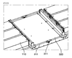
図7は図3の電池モジュール及び第1冷却部を説明するための分解斜視図であり、図8は図7の第1冷却部を説明するための分解斜視図である。 Figure 7 is an exploded perspective view illustrating the battery module and first cooling section of Figure 3, and Figure 8 is an exploded perspective view illustrating the first cooling section of Figure 7.
第1電池モジュール110で発生する熱を冷却させるための第1冷却部300は電池モジュール100とパックケース200の内側上面との間に位置し、第1ヒートシンク310、及び第1ヒートシンク310とパックケース200との間の第1放熱板320を含んでなる。
The
具体的に、第1ヒートシンク310は、冷媒が循環する空間部を提供するように、一対の第1下部プレート310’及び第1上部プレート310”から構成される。
Specifically, the
ここで、第1下部プレート310’には互いに向き合う一対の第1冷媒流入口311及び第1冷媒流出口312が形成されており、前述したように、側面フレーム230の底面の締結ホール234が結合される。
Here, the first lower plate 310' has a pair of first
一方、第1ヒートシンク310と第1電池モジュール110との間には第1放熱板320、かつ第1ヒートシンク310の下には第2放熱板330が位置することにより、第1電池モジュール110で発生する熱を第1ヒートシンク310に伝達する
Meanwhile, a
特に、第1放熱板320及び第2放熱板330は第1ヒートシンク310の上面及び下面に第1ヒートシンク310をもう一度取り囲む形状に位置するので、冷媒漏洩が発生しても電池パックの内部に冷媒が染みこむことを防止することができる利点がある。
In particular, the
前記のような第1ヒートシンク310、第1放熱板320、及び第2放熱板330は熱伝導性に優れた素材からなることが好ましい。一例として、アルミニウムからなることができる。
The
図9は本発明の好適な第1実施例による第2冷却分解斜視図である。 Figure 9 is an exploded perspective view of the second cooling system according to the first preferred embodiment of the present invention.
第2冷却部400は第1電池モジュール110の上面と第2電池モジュール120の下面との間に位置し、第2ヒートシンク410、下部保護カバー420、上部保護カバー430、及び結合バンド440を含んでなる。
The
具体的に、第2ヒートシンク410は、冷媒が循環する空間部を提供する第2ヒートシンク胴体411、第2冷媒流入口412、及び第2冷媒流出口413を含んでなる。
Specifically, the
ここで、第2冷媒流入口412及び第2冷媒流出口413は第2ヒートシンク胴体411の一側に所定の距離で離隔したままで位置し、略「L」字形を有する。そして、前述したように、第2冷媒流入口412は冷媒流入ポート211と結合され、第2冷媒流出口413は冷媒流出ポート212と結合される。
Here, the second refrigerant inlet 412 and the second
下部保護カバー420は、下部保護カバー胴体421及び「L」字形の折曲管422を含んでなる。これは、外部衝撃などから第2ヒートシンク410を物理的に保護し、さらに多様な原因で第2ヒートシンク410から冷媒が漏出しても電池パックの内部に冷媒が流入することを根本的に遮断して2次イベントの発生を防止するためである。
The lower
一方、下部保護カバー胴体421の縁部には一つ以上の第1締結部421’を備えることができ、これは後述する上部保護カバー胴体の第2締結部と固定される。
Meanwhile, the edge of the lower
上部保護カバー430は、平板状の上部保護カバー胴体431及び一つ以上の第2締結部431’を含んでなる。すなわち、下部保護カバー胴体421に第2ヒートシンク410が着座した状態でさらに上部保護カバー430が位置し、よって第2ヒートシンク410を一層堅固に保護することができる。
The upper
結合バンド440は下部保護カバー胴体421と上部保護カバー胴体431とを結合するためのものであり、一例として下部保護カバー胴体421と上部保護カバー胴体431とが会う端部の接合部に沿ってCMT(Cold Metal Transfer)溶接によって形成されることができる。
The joining
もちろん、下部保護カバー胴体421の第1締結部421’及び上部保護カバー胴体431の第2締結部431’を通してボルトなどで締結された後に溶接を遂行しても構わなく、第1締結部421’及び第2締結部431’を省略したままでCMT(Cold Metal Transfer)溶接のみ遂行することも可能である。
Of course, welding can be performed after fastening the first fastening portion 421' of the lower
一方、前記のような第2ヒートシンク410、下部保護カバー420、及び上部保護カバー430は熱伝導性に優れた素材からなることが好ましい。一例として、アルミニウムからなることができる。
Meanwhile, the
図10は本発明の好適な第2実施例による第2冷却部の分解斜視図である。 Figure 10 is an exploded perspective view of the second cooling section according to a second preferred embodiment of the present invention.
図10を参照して説明すると、第2実施例は、第2冷却部400の結合バンド440の代わりに、シーリングガスケット450を備えたことを除き、第1実施例による第2冷却部400と同様である。
Referring to FIG. 10, the second embodiment is similar to the
第2実施例による第2冷却部400のシーリングガスケット450について説明すると、シーリングガスケット450は下部保護カバー胴体421の縁部と上部保護カバー胴体431の縁部との間に沿って形成されることができる。これにより、第2ヒートシンク410が破損しも第2冷却部400の外部に冷媒が漏洩することを確かに遮断することができる。一例として、シーリングガスケット450は耐熱性ゴム素材からなることができるが、同じ機能を果たすことができるものであれば特に限定されない。
Regarding the sealing
たとえ図面には示されてはいないが、下部保護カバー胴体421及び上部保護カバー胴体431のいずれか一つ以上にシーリングガスケット450を収容するための溝部(図示せず)がさらに形成されることができる。
Although not shown in the drawings, at least one of the lower
図11は本発明の好適な第3実施例による電池パックを説明するための部分斜視図である。 Figure 11 is a partial perspective view illustrating a battery pack according to a third preferred embodiment of the present invention.
図11を参照して説明すると、本発明の好適な第2実施例は、冷媒循環管313をさらに備えた電池パックであることができる。
Referring to FIG. 11, a second preferred embodiment of the present invention may be a battery pack further including a
図2~図10を参照しながら説明した実施例では側面フレーム230の冷媒循環路231を通して冷媒が循環する一方で、第3実施例は冷媒循環管313をさらに備える。
While in the embodiment described with reference to Figures 2 to 10 the refrigerant circulates through the
すなわち、冷媒移送管213に流入するか排出される冷媒は冷媒循環管313を経由するように、冷媒移送管213と冷媒循環管313とが互いに連結され、冷媒循環管313は側面フレーム230の冷媒循環路231内に配置される。
In other words, the
このように、冷媒循環路231の内部に冷媒循環管313が位置することにより、外部衝撃などによって側面フレーム230が損傷しても冷媒の漏洩をより確かに遮断することができ、イベントの発生を抑制することができる。
In this way, by positioning the
本発明は前述した特徴のうちでいずれか一つ以上の特徴を有している電池パックが装着されたデバイスであることができ、前記デバイスは、電気自動車、ハイブリッド自動車、プラグインハイブリッド電気自動車などのように大容量の電池を含む電子機器であることができる。 The present invention can be a device equipped with a battery pack having one or more of the above-mentioned features, and the device can be an electronic device including a large-capacity battery, such as an electric vehicle, a hybrid vehicle, or a plug-in hybrid electric vehicle.
本発明が属する分野で通常の知識を有する者であれば前記内容に基づいて本発明の範疇内で多様な応用及び変形が可能であろう。 Anyone with ordinary skill in the art to which this invention pertains will be able to make various applications and modifications within the scope of this invention based on the above content.
100 電池モジュール
110 第1電池モジュール
120 第2電池モジュール
200 パックケース
210 前面フレーム
211 冷媒流入ポート
212 冷媒流出ポート
213 冷媒移送管
220 後面フレーム
230 側面フレーム
231 冷媒循環路
232 空気循環路
233 切開部
234 締結ホール
300 第1冷却部
310 第1ヒートシンク
310’ 第1下部プレート
310” 第1上部プレート
311 第1冷媒流入口
312 第1冷媒流出口
313 冷媒循環管
320 第1放熱板
330 第2放熱板
400 第2冷却部
410 第2ヒートシンク
411 第2ヒートシンク胴体
412 第2冷媒流入口
413 第2冷媒流出口
420 下部保護カバー
421 下部保護カバー胴体
421’ 第1締結部
422 折曲管
430 上部保護カバー
431 上部保護カバー胴体
431’ 第2締結部
440 結合バンド
450 シーリングガスケット
100
Claims (8)
前記電池モジュールを収納するパックケースと、を含む、電池モジュールが多段に積層された電池パックであって、
前記電池モジュールは、第1電池モジュール、及び前記第1電池モジュールの上部に垂直に積層された第2電池モジュールを含み、
前記第1電池モジュールで発生した熱を放出するために、前記パックケースの底面の内側上面と前記第1電池モジュールとの間には第1冷却部が位置し、
前記第2電池モジュールで発生した熱を放出するために、前記第1電池モジュールと第2電池モジュールとの間には第2冷却部が位置し、
前記パックケースは、前面フレーム、後面フレーム、及び前記前面フレームと前記後面フレームとを連結する一対の側面フレームを含み、
前記一対の側面フレームには、前記第1冷却部に冷媒を供給して回収するための冷媒循環路が形成され、
前記第2冷却部は、第2ヒートシンク、前記第2ヒートシンクの下に位置する下部保護カバー、前記第2ヒートシンクの上部に位置する上部保護カバー、及び前記第2ヒートシンクを収納した状態で前記下部保護カバーの縁部及び前記上部保護カバーの縁部の全周にわたって位置する結合バンドを含み、
前記側面フレームの冷媒循環路付近には、前 記冷媒循環路に平行な空気循環路が位置する、電池モジュールが多段に積層された電池パック。 Two or more battery modules;
A battery pack in which battery modules are stacked in multiple stages, the battery pack including a pack case that houses the battery modules,
the battery module includes a first battery module and a second battery module vertically stacked on top of the first battery module;
a first cooling unit is disposed between an inner upper surface of a bottom surface of the pack case and the first battery module to release heat generated in the first battery module;
a second cooling unit is disposed between the first and second battery modules to dissipate heat generated in the second battery module;
the pack case includes a front frame, a rear frame, and a pair of side frames connecting the front frame and the rear frame,
a refrigerant circulation path for supplying a refrigerant to the first cooling section and recovering the refrigerant is formed in the pair of side frames;
the second cooling unit includes a second heat sink, a lower protective cover located under the second heat sink, an upper protective cover located on an upper portion of the second heat sink, and a coupling band located around an entire periphery of an edge of the lower protective cover and an edge of the upper protective cover in a state in which the second heat sink is housed ,
A battery pack in which battery modules are stacked in multiple stages, with an air circulation path parallel to the refrigerant circulation path being located near the refrigerant circulation path of the side frame .
前記冷媒流入ポート及び前記冷媒流出ポートのそれぞれには前記冷媒循環路と連通する冷媒移送管が連結される、請求項1に記載の電池モジュールが多段に積層された電池パック。 The front frame is provided with a pair of refrigerant inlet and outlet ports spaced apart by a predetermined distance,
The battery pack according to claim 1 , wherein the refrigerant inlet port and the refrigerant outlet port are each connected to a refrigerant transfer pipe communicating with the refrigerant circulation path.
前記側面フレームの底面には、前記第1冷媒流入口及び前記第1冷媒流出口と連結される締結ホールが形成される、請求項1から3のいずれか一項に記載の電池モジュールが多段に積層された電池パック。 the first cooling unit includes a pair of a first lower plate and a first upper plate for providing a space through which a coolant circulates, and a first heat sink including a first coolant inlet and a first coolant outlet detachably coupled to the coolant circulation path,
4. The battery pack according to claim 1 , wherein a fastening hole connected to the first coolant inlet and the first coolant outlet is formed on a bottom surface of the side frame.
前記下部保護カバーの縁部と前記上部保護カバーの縁部との間にはシーリングガスケットが備えられる、請求項1から4のいずれか一項に記載の電池モジュールが多段に積層された電池パック。 the second cooling unit includes a second heat sink, a lower protective cover located under the second heat sink, and an upper protective cover located on an upper portion of the second heat sink;
The battery pack according to claim 1 , further comprising a sealing gasket provided between an edge of the lower protective cover and an edge of the upper protective cover.
前記下部保護カバーは、前記第2冷媒流入口及び前記第2冷媒流出口をそれぞれ収納するための一対の折曲管を備える、請求項1から6のいずれか一項に記載の電池モジュールが多段に積層された電池パック。 the second heat sink includes a second heat sink body, an "L" shaped second coolant inlet for supplying a second coolant to the second heat sink body, and an "L" shaped second coolant outlet for discharging the second coolant;
7. The battery pack according to claim 1 , wherein the lower protective cover includes a pair of bent pipes for respectively accommodating the second refrigerant inlet and the second refrigerant outlet.
Applications Claiming Priority (3)
| Application Number | Priority Date | Filing Date | Title |
|---|---|---|---|
| KR1020200069078A KR102819130B1 (en) | 2020-06-08 | 2020-06-08 | Battery Pack With Multi-Layered Battery Modules |
| KR10-2020-0069078 | 2020-06-08 | ||
| PCT/KR2021/006795 WO2021251670A1 (en) | 2020-06-08 | 2021-06-01 | Battery pack having battery modules stacked into multiple layers |
Publications (2)
| Publication Number | Publication Date |
|---|---|
| JP2023515018A JP2023515018A (en) | 2023-04-12 |
| JP7621667B2 true JP7621667B2 (en) | 2025-01-27 |
Family
ID=78846295
Family Applications (1)
| Application Number | Title | Priority Date | Filing Date |
|---|---|---|---|
| JP2022549521A Active JP7621667B2 (en) | 2020-06-08 | 2021-06-01 | A battery pack in which battery modules are stacked in multiple stages |
Country Status (7)
| Country | Link |
|---|---|
| US (1) | US20230063883A1 (en) |
| EP (1) | EP4087020B1 (en) |
| JP (1) | JP7621667B2 (en) |
| KR (1) | KR102819130B1 (en) |
| CN (1) | CN115066788B (en) |
| DE (1) | DE202021004367U1 (en) |
| WO (1) | WO2021251670A1 (en) |
Families Citing this family (6)
| Publication number | Priority date | Publication date | Assignee | Title |
|---|---|---|---|---|
| KR102848073B1 (en) * | 2020-07-21 | 2025-08-19 | 주식회사 엘지에너지솔루션 | Apparatus for measuring the capacity of a battery cell and a method for measuring the capacity of a battery cell |
| KR102629222B1 (en) * | 2023-03-06 | 2024-01-25 | 주식회사 이노벡스 | Battery cycler minimizing interference between channel modules |
| KR20250014595A (en) * | 2023-07-20 | 2025-02-03 | 삼성에스디아이 주식회사 | Rechargeable battery pack |
| KR20250057338A (en) * | 2023-10-20 | 2025-04-29 | 주식회사 엘지에너지솔루션 | Battery pack and electric vehicle |
| US20250167339A1 (en) * | 2023-11-20 | 2025-05-22 | GM Global Technology Operations LLC | Composite graphene-aluminum battery pack cooling plates |
| FR3164569A1 (en) * | 2024-07-11 | 2026-01-16 | Automotive Cells Company Se | Battery for electric or hybrid vehicles, including cross members with protruding ends against a cooling system |
Citations (4)
| Publication number | Priority date | Publication date | Assignee | Title |
|---|---|---|---|---|
| US20160372805A1 (en) | 2014-02-25 | 2016-12-22 | Lg Electronics Inc. | Battery pack |
| JP2017520883A (en) | 2014-09-30 | 2017-07-27 | ローベルト ボッシュ ゲゼルシャフト ミット ベシュレンクテル ハフツング | Cold plate for electric energy storage |
| US20170294693A1 (en) | 2014-10-31 | 2017-10-12 | Byd Company Limited | Heat sink and power battery system |
| WO2019221376A1 (en) | 2018-05-16 | 2019-11-21 | 삼성에스디아이 주식회사 | Battery pack comprising frame profile having integral refrigerant circuit member |
Family Cites Families (16)
| Publication number | Priority date | Publication date | Assignee | Title |
|---|---|---|---|---|
| JP4963902B2 (en) * | 2006-08-31 | 2012-06-27 | 三洋電機株式会社 | Power supply |
| DE102009040147A1 (en) * | 2009-09-04 | 2011-03-10 | Li-Tec Battery Gmbh | Electrochemical energy storage device for vehicles and method for cooling or heating such an electrochemical energy storage device |
| CN103314478B (en) | 2011-01-26 | 2016-02-03 | 株式会社Lg化学 | Cooling member with improved assembly efficiency and battery module using same |
| WO2016088476A1 (en) * | 2014-12-04 | 2016-06-09 | 本田技研工業株式会社 | Vehicular power supply device |
| KR102259414B1 (en) * | 2015-11-20 | 2021-06-01 | 주식회사 엘지에너지솔루션 | Heat sink and battery module including the same |
| KR102101905B1 (en) * | 2016-01-15 | 2020-04-17 | 주식회사 엘지화학 | Battery Pack Having Multi-Stage Battery Modules |
| CN105742539B (en) * | 2016-04-21 | 2019-04-05 | 宁德时代新能源科技股份有限公司 | Electricity core module |
| JP6352972B2 (en) * | 2016-05-19 | 2018-07-04 | 株式会社Subaru | Automotive battery |
| JP6504146B2 (en) * | 2016-11-24 | 2019-04-24 | トヨタ自動車株式会社 | Car battery pack |
| DE102017206185B4 (en) * | 2017-04-11 | 2018-11-08 | Audi Ag | Battery for a motor vehicle and motor vehicle |
| US10700323B2 (en) * | 2017-08-23 | 2020-06-30 | Ford Global Technologies, Llc | Apparatus for directed vent gas expulsion in battery cells |
| KR20190032843A (en) * | 2017-09-20 | 2019-03-28 | 에스케이이노베이션 주식회사 | Battery Module for Secondary Battery and Battery Pack having the Same |
| CN107732061A (en) * | 2017-09-29 | 2018-02-23 | 凌云工业股份有限公司 | A kind of integrated water-cooling housing of power cell for new-energy automobile |
| CN207233915U (en) * | 2017-09-29 | 2018-04-13 | 成都雅骏新能源汽车科技股份有限公司 | A kind of Battery case structure of water-cooling |
| EP3584877A1 (en) * | 2018-05-16 | 2019-12-25 | Samsung SDI Co., Ltd. | Battery pack comprising a frame profile with integral coolant circuit elements |
| KR102127764B1 (en) | 2018-12-06 | 2020-07-09 | 서울과학기술대학교 산학협력단 | System and method for generating panorama image |
-
2020
- 2020-06-08 KR KR1020200069078A patent/KR102819130B1/en active Active
-
2021
- 2021-06-01 JP JP2022549521A patent/JP7621667B2/en active Active
- 2021-06-01 US US17/797,659 patent/US20230063883A1/en active Pending
- 2021-06-01 EP EP21822831.0A patent/EP4087020B1/en active Active
- 2021-06-01 WO PCT/KR2021/006795 patent/WO2021251670A1/en not_active Ceased
- 2021-06-01 CN CN202180013118.6A patent/CN115066788B/en active Active
- 2021-06-01 DE DE202021004367.5U patent/DE202021004367U1/en active Active
Patent Citations (4)
| Publication number | Priority date | Publication date | Assignee | Title |
|---|---|---|---|---|
| US20160372805A1 (en) | 2014-02-25 | 2016-12-22 | Lg Electronics Inc. | Battery pack |
| JP2017520883A (en) | 2014-09-30 | 2017-07-27 | ローベルト ボッシュ ゲゼルシャフト ミット ベシュレンクテル ハフツング | Cold plate for electric energy storage |
| US20170294693A1 (en) | 2014-10-31 | 2017-10-12 | Byd Company Limited | Heat sink and power battery system |
| WO2019221376A1 (en) | 2018-05-16 | 2019-11-21 | 삼성에스디아이 주식회사 | Battery pack comprising frame profile having integral refrigerant circuit member |
Also Published As
| Publication number | Publication date |
|---|---|
| KR102819130B1 (en) | 2025-06-12 |
| WO2021251670A1 (en) | 2021-12-16 |
| JP2023515018A (en) | 2023-04-12 |
| US20230063883A1 (en) | 2023-03-02 |
| EP4087020A1 (en) | 2022-11-09 |
| EP4087020B1 (en) | 2026-04-08 |
| CN115066788A (en) | 2022-09-16 |
| EP4087020A4 (en) | 2023-09-13 |
| KR20210152238A (en) | 2021-12-15 |
| DE202021004367U1 (en) | 2023-12-08 |
| CN115066788B (en) | 2025-05-06 |
Similar Documents
| Publication | Publication Date | Title |
|---|---|---|
| KR102819130B1 (en) | Battery Pack With Multi-Layered Battery Modules | |
| KR101205180B1 (en) | Cooling Member of Compact Structure and Excellent Stability and Battery Module Employed with the Same | |
| JP7442921B2 (en) | Battery pack with cooling section outside the case | |
| US20130252042A1 (en) | Electric storage cell, electric storage apparatus, and vehicle having electric storage apparatus | |
| KR20220025420A (en) | Battery pack and device including the same | |
| JP7625327B2 (en) | Battery pack and device including same | |
| JP7636089B2 (en) | Battery module and battery pack including same | |
| KR20210125850A (en) | Battery pack and device including the same | |
| KR20210133886A (en) | Battery pack and device including the same | |
| KR20220151876A (en) | Battery pack and device including the same | |
| CN114586227A (en) | Battery pack and device including the same | |
| KR20210133538A (en) | Battery pack and device including the same | |
| JP7387204B2 (en) | Battery packs and devices containing them | |
| KR102902481B1 (en) | Battery Module With Improved Cooling Performance And Battery Pack Including It | |
| JP7362051B2 (en) | Battery pack with refrigerant circulation path in the pack case | |
| KR20230029016A (en) | Battery pack and device including the same | |
| JP7864265B2 (en) | Battery module and battery pack containing the same | |
| JP2026509619A (en) | Battery module and battery pack containing the same | |
| JP2026502918A (en) | Battery assembly and device including same | |
| KR20220170188A (en) | Battery module and battery pack including the same | |
| KR20210130658A (en) | Battery pack and device including the same | |
| KR20220167965A (en) | A Battery Module With A Curved Trap Part And A Battery Pack Containing It |
Legal Events
| Date | Code | Title | Description |
|---|---|---|---|
| A621 | Written request for application examination |
Free format text: JAPANESE INTERMEDIATE CODE: A621 Effective date: 20220817 |
|
| A131 | Notification of reasons for refusal |
Free format text: JAPANESE INTERMEDIATE CODE: A131 Effective date: 20230814 |
|
| A521 | Request for written amendment filed |
Free format text: JAPANESE INTERMEDIATE CODE: A523 Effective date: 20231114 |
|
| A131 | Notification of reasons for refusal |
Free format text: JAPANESE INTERMEDIATE CODE: A131 Effective date: 20240129 |
|
| A521 | Request for written amendment filed |
Free format text: JAPANESE INTERMEDIATE CODE: A523 Effective date: 20240425 |
|
| A02 | Decision of refusal |
Free format text: JAPANESE INTERMEDIATE CODE: A02 Effective date: 20240617 |
|
| A521 | Request for written amendment filed |
Free format text: JAPANESE INTERMEDIATE CODE: A523 Effective date: 20241009 |
|
| A911 | Transfer to examiner for re-examination before appeal (zenchi) |
Free format text: JAPANESE INTERMEDIATE CODE: A911 Effective date: 20241022 |
|
| TRDD | Decision of grant or rejection written | ||
| A01 | Written decision to grant a patent or to grant a registration (utility model) |
Free format text: JAPANESE INTERMEDIATE CODE: A01 Effective date: 20241216 |
|
| A61 | First payment of annual fees (during grant procedure) |
Free format text: JAPANESE INTERMEDIATE CODE: A61 Effective date: 20250107 |
|
| R150 | Certificate of patent or registration of utility model |
Ref document number: 7621667 Country of ref document: JP Free format text: JAPANESE INTERMEDIATE CODE: R150 |