JP7621642B2 - Sandpaper dispenser - Google Patents
Sandpaper dispenser Download PDFInfo
- Publication number
- JP7621642B2 JP7621642B2 JP2021074335A JP2021074335A JP7621642B2 JP 7621642 B2 JP7621642 B2 JP 7621642B2 JP 2021074335 A JP2021074335 A JP 2021074335A JP 2021074335 A JP2021074335 A JP 2021074335A JP 7621642 B2 JP7621642 B2 JP 7621642B2
- Authority
- JP
- Japan
- Prior art keywords
- sandpaper
- roll
- dispenser
- paper
- core
- Prior art date
- Legal status (The legal status is an assumption and is not a legal conclusion. Google has not performed a legal analysis and makes no representation as to the accuracy of the status listed.)
- Active
Links
- 238000003780 insertion Methods 0.000 description 5
- 230000037431 insertion Effects 0.000 description 5
- 229910000831 Steel Inorganic materials 0.000 description 4
- 239000010959 steel Substances 0.000 description 4
- 239000000463 material Substances 0.000 description 3
- 238000005516 engineering process Methods 0.000 description 2
- 239000002184 metal Substances 0.000 description 2
- 238000012986 modification Methods 0.000 description 2
- 230000004048 modification Effects 0.000 description 2
- 238000005192 partition Methods 0.000 description 2
- 239000002699 waste material Substances 0.000 description 2
- 239000000853 adhesive Substances 0.000 description 1
- 230000001070 adhesive effect Effects 0.000 description 1
- 239000002390 adhesive tape Substances 0.000 description 1
- 238000010411 cooking Methods 0.000 description 1
- 230000000694 effects Effects 0.000 description 1
- 238000004519 manufacturing process Methods 0.000 description 1
- 238000005498 polishing Methods 0.000 description 1
- 238000005096 rolling process Methods 0.000 description 1
- XLYOFNOQVPJJNP-UHFFFAOYSA-N water Substances O XLYOFNOQVPJJNP-UHFFFAOYSA-N 0.000 description 1
- 238000004804 winding Methods 0.000 description 1
Images

Landscapes
- Workshop Equipment, Work Benches, Supports, Or Storage Means (AREA)
- Polishing Bodies And Polishing Tools (AREA)
- Unwinding Webs (AREA)
Description
本発明は、ロール状に巻回したサンドーパーを取り出し易く保持し、かつ必要な種類及び必要な量に応じて取り出すことができるディスペンサーに関するものである。 The present invention relates to a dispenser that holds rolled sando-per in an easy-to-remove manner and can dispense the required type and amount.
従来、研磨用のサンドペーパーとして、動力で回転するディスクの表面に円形シート状に形成されたサンドペーパーを貼り付けて、被研磨物の表面仕上等に用いる手持ち形の研磨機(サンダーと称される)等に使用されるものがある。このサンドペーパーは、裏面に粘着剤を塗布し、帯状の台紙上に剥離可能に巻紙状に巻回してなるサンドペーパーロールとして提供される。 Conventionally, sandpaper for polishing is used in handheld polishers (called sanders) that are used for finishing the surface of an object to be polished, with the sandpaper formed into a circular sheet attached to the surface of a disk that rotates by power. This sandpaper is supplied as a sandpaper roll, with an adhesive applied to the backing and wound up in a removable manner on a strip-shaped backing paper.
そして、使用時には、サンドペーパーを適宜引延して所望の長さにカットしてサンダーのディスクに張付けて作業を行う。しかしながら、研磨作業でサンドペーパーが消耗し、サンドペーパーを交換する度に、作業場周辺に使用後のサンドペーパーが散乱することになり、作業効率を低下させる。また、サンドペーパーロールをそのままテーブルや床上に置いて使用すると、ペーパーを引き出す際にロールが不意に転がってしまうことがあり、使い勝手が悪いものであった。 When using the sandpaper, the sandpaper is stretched appropriately, cut to the desired length, and attached to the sander's disk for work. However, the sandpaper wears out during sanding work, and every time the sandpaper is replaced, the used sandpaper ends up scattered around the work area, reducing work efficiency. Also, if the sandpaper roll is placed directly on a table or floor, it can accidentally roll away when pulling out the paper, making it difficult to use.
そこで例えば、サンドペーパーロールを転動可能に収容する蓋付きの箱状の本体と、この本体側面に開口形成されて、サンドペーパーロールの台紙をサンドペーパーとともに外部へ引出す引出口と、この引出口に平行する位置に開口形成され、サンドペーパーを剥離した後の台紙を本体内に引込む引込み口と、本体内に回転可能に架設されて、本体側面に設けられたハンドルの回転操作によって回転して引込み口から引込まれた台紙を巻き取る台紙巻取軸とを具備してなるサンドペーパーロールの収納器が開示されている。サンドペーパーロールを箱に収容することにより、台紙を引延してもロールが転がることがなく、定位置に置いておくことができ、台紙を外部に散乱することを防止するものが開示されている(特許文献1参照)。 For example, a sandpaper roll storage container has been disclosed that includes a box-shaped main body with a lid that stores a rollable sandpaper roll, an opening formed on the side of the main body that pulls out the backing of the sandpaper roll together with the sandpaper to the outside, an opening formed in a position parallel to the opening that pulls in the backing after the sandpaper has been peeled off, and a backing winding shaft that is rotatably installed inside the main body and rotates by turning a handle provided on the side of the main body to wind up the backing that has been pulled in from the opening. By storing the sandpaper roll in a box, the roll does not roll even when the backing is stretched, and can be kept in a fixed position, preventing the backing from scattering to the outside (see Patent Document 1).
また、紙ヤスリを軸に2~3回巻き込み、巻き込んだなら蓋をしめて、蓋と本体の間にある紙ヤスリが蓋の部分によって固定されて、ラチェットと歯車の噛み合わせにより紙ヤスリが逆転することなく張設して平面仕上げ等に使用するサンドペーパー取付具(特許文献2参照。)。 Also, a sandpaper attachment tool that can be used for finishing flat surfaces by wrapping the sandpaper around the shaft 2-3 times, then closing the lid, and the sandpaper between the lid and the main body is fixed by the lid, and the sandpaper is tensioned without reversing due to the engagement of the ratchet and gear (see Patent Document 2).
他にも、トイレットペーパーやクッキングシート等用のものであるが、ブラケットと、このブラケットに回転可能に軸支される、ロールペーパーを保持するための保持シャフトと、この保持シャフトに保持されるロールペーパーとその外周面が接するようにブラケットに回転可能に軸支される位置決めシャフトと、この位置決めシャフトの外周面にその後端部が接触しうるようにブラケットに回転可能に軸支されるフラップとから成り、安定した引き出し状態を保持し、片手でも簡単かつ綺麗にペーパーをカットできるペーパーホルダー(特許文献3参照。)。 Other examples include a paper holder for toilet paper, cooking sheets, etc., which consists of a bracket, a holding shaft for holding the roll of paper that is rotatably supported by the bracket, a positioning shaft that is rotatably supported by the bracket so that the roll of paper held by the holding shaft comes into contact with its outer periphery, and a flap that is rotatably supported by the bracket so that its rear end can come into contact with the outer periphery of the positioning shaft, and which maintains a stable pulled-out state and allows the paper to be cut easily and neatly with one hand (see Patent Document 3).
ロールペーパー差込軸及び概ね反対側に軸受けを設けた回転体を二個設置し、片方のロールペーパーの差込軸に現用のロールペーパーを差し込み、他方の回転体の軸受けに取り付け、その空いているロールペーパーを差込軸に予備のロールペーパーを差し込んでおき、現用のロールペーパーを使い切ったら軸受けからロールペーパー差込軸を外し、両方の回転体を回転させて予備を差し込んであるロールペーパー差込軸を他方の軸受けに取り付けることで、空芯の処理を後回しにしてすばやく現用と予備のロールペーパーを切り替えて使用を開始することができる予備付きロールペーパーホルダーが開示されている(特許文献4参照。)。 A roll paper holder with spare is disclosed that has two rotors with a roll paper insertion shaft and a bearing on roughly opposite sides, inserting the current roll paper into one of the roll paper insertion shafts and attaching it to the bearing of the other rotor, inserting a spare roll paper into the free roll paper insertion shaft, and when the current roll paper is used up, removing the roll paper insertion shaft from the bearing, rotating both rotors and attaching the roll paper insertion shaft with the spare inserted to the other bearing, allowing you to postpone disposal of the empty core and quickly switch between the current and spare roll paper and start using it (see Patent Document 4).
本発明もまた上記従来技術の課題に鑑みなされたものであり、必要な番手及び長さのサンドペーパーを適宜無駄なく迅速に取り出すことができ使い勝手が良く、作業効率を向上することができるばかりでなく、作業場の整理整頓を図ることができるサンドペーパーディスペンサーを提供することを目的とする。 The present invention has also been developed in consideration of the problems with the conventional technology described above, and aims to provide a sandpaper dispenser that is easy to use and allows the user to quickly dispense the required grit and length of sandpaper without waste, and that not only improves work efficiency but also helps keep the workplace tidy and organized.
このため本発明のサンドペーパーディスペンサーは、基台に立設された一対の支柱と、当該支柱に上下移動可能に架設されると共に、ロール状に巻回してなるサンドペーパーを転動可能に保持する支軸となる巻芯ホルダーとからなり、当該巻芯ホルダーが筒状管で、その両端に前記支柱が上下に貫通する透孔が形成されていることを第1の特徴とする。また、一対の支柱と、当該支柱に対応する巻芯ホルダーを複数組並列して設けたことを第2の特徴とする。
For this reason, the sandpaper dispenser of the present invention is characterized in that it comprises a pair of support pillars erected on a base, a core holder that is vertically movable on the support pillars and serves as a support shaft for rotatably holding the sandpaper wound in a roll, and the core holder is a cylindrical tube having through holes formed at both ends through which the support pillars pass vertically. Also, the second characteristic is that multiple sets of the pair of support pillars and the core holders corresponding to the support pillars are provided in parallel.
本発明によれば、以下の優れた効果がある。
(1)必要な番手及び長さのサンドペーパーを必要な量に応じて、適宜無駄なく迅速に取り出すことができる。
(2)ロールの交換や取り外しが容易にでき、構造も簡単で経済的に製造できる。
(3)サンドペーパーが散乱することがなく、作業場の整理整頓を図ることができる。(4)巻芯ホルダーが、ロールを自ずと下方へ押圧することで、ストッパー機能が生じ、ロールが安置され、ロールが勝手に転動してほどけたり、無用に引き出されることを防止できる。
(5)器具全体が露呈してるので、搭載されたサンドペーパーの種別や残量を一瞥して看取できる。
The present invention has the following excellent effects.
(1) Sandpaper of the required size and length can be taken out quickly and efficiently in the required amount.
(2) The rolls can be easily replaced or removed, and the structure is simple and economical to manufacture.
(3) The sandpaper is not scattered, and the work area can be kept tidy. (4) The core holder naturally presses the roll downward, creating a stopper function that keeps the roll in place and prevents the roll from rolling over on its own and unwinding, or being pulled out unnecessarily.
(5) Since the entire tool is exposed, the type of sandpaper installed and the amount remaining can be seen at a glance.
以下、図面に示す実施例に基づいて本発明の実施の形態を詳細に説明する。
先ず、本発明と比較するために、図4に従来のディスペンサーの一例を示す。このディスペンサーは上面が解放された函体1に、番手の異なる複数個のサンドペーパーロール4を各々仕切板8で区画したスペース内に収容し、函体1の側面から軸棒7をロール4の空芯に貫通させ転動可能に保持し、函体1の前面の設けられたガイド板9に穿孔されたスリット10から必要量のサンドペーパー4を適宜引き出す構成とされている。
DETAILED DESCRIPTION OF THE PREFERRED EMBODIMENTS Hereinafter, the preferred embodiments of the present invention will be described in detail with reference to the accompanying drawings.
First, for comparison with the present invention, an example of a conventional dispenser is shown in Figure 4. This dispenser is configured such that a plurality of
この従来技術においても、確かに、番手異なる種類のサンドペーパーを搭載でき、使い勝手が良好になり、整理整頓に資するものの、実際、函体1の材質によっては耐水性及び耐久性に乏しく、収納できるサンドペーパーの径や帯幅等のサイズに対する自由度が低い、ロールの装填に手間がかかるといった欠点があった。
This conventional technology does indeed allow sandpaper of different grit sizes to be loaded, improving ease of use and helping to keep things tidy, but in reality, there are drawbacks to this, such as poor water resistance and durability depending on the material of the
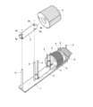
本発明のディスペンサーは、図1乃至図2に示すように、長方形板状の基台1に立設された一対の支柱2,2と、この支柱2,2に上下移動可能に架設されると共に、ロール状に巻回してなるサンドペーパーロール4を転動可能に保持する支軸となる巻芯ホルダー3からなることを基本的な構成としている。
As shown in Figs. 1 and 2, the dispenser of the present invention is basically composed of a pair of
基台1は鋼板等の金属製で、支柱2,2もそれぞれ棒状の鋼材が好ましい、巻芯ホルダー3は鋼製の筒状管、すなわち鋼管で、その両端に支柱2,2が上下に貫通可能な透孔3a,3aが穿孔されている。巻芯ホルダー3は、サンドペーパーロール3の帯幅よりも長いサズ、あるは種々の帯幅に応じた長さとする。そして、サンドペーパーロール4の空芯4aに巻芯ホルダー3を挿通させた後、その両端の透孔3a,3aを上方から支柱2,2に挿通させて固定する。これにより、支柱2,2にサンドペーパーロール4が上下移動可能及び転動可能に架設される。
The
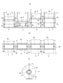
さらに、一対の支柱2,2と、支柱2,2に対応する巻芯ホルダー3を一組として、これを同じ基台1上に複数組並列して設けることで、番手や帯幅、ロール径等の異なるサンドペーパー4を複数種設置することができる。そして、必要な番手及び長さのサンドペーパー4を適宜無駄なく迅速に取り出すことができる。これにより、使い勝手が良く、作業効率を向上することができるばかりでなく、作業場の整理整頓を図ることができる。
Furthermore, by arranging a pair of
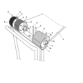
とくに、巻芯ホルダー3が、その自重により、サンドペーパーロール4を自ずと下方へ押圧することで、ストッパー機能が生じ、サンドペーパーロール4を安置し、ロールが不意に動いてほどけたり、無用に引き出されることを防止する。また、例えば、図3に示すように、作業台車5に固定しておけば、作業場内を自由に移動して使用することができ、さらに利便性が増す。
In particular, the
なお、本発明は上記実施例の形態に限定されるものではなく、特許請求の範囲に記載された範囲、実施形態の範囲で種々の変形例、例えば、支柱2を角柱やパイプ状にすること、金属以外への材質の変更、また、組み合わせが可能であり、これらの変形例、組み合わせも権利範囲に含むものである。
The present invention is not limited to the above-mentioned embodiment, but various modifications are possible within the scope of the claims and the scope of the embodiments, for example, making the
本発明のサンドペーパーディスペンサーの構成は、サンドペーパーの他にも、ロール状に巻回された、粘着テープ、トイレットペーパー、キッチンペーパー、装飾用リボン、紐や帯を使用する各種産業分野においても有益である。 The sandpaper dispenser configuration of the present invention is also useful in various industrial fields that use rolls of adhesive tape, toilet paper, kitchen paper, decorative ribbons, strings, and bands, in addition to sandpaper.
1 基台
2 支柱
3 巻芯ホルダー
3a 透孔
4 サンドペーパー
4a ロールの空芯
5 作業台車
6 函体
7 軸棒
8 仕切板
9 ガイド板
10 スリット
1
Claims (2)
Priority Applications (1)
| Application Number | Priority Date | Filing Date | Title |
|---|---|---|---|
| JP2021074335A JP7621642B2 (en) | 2021-04-26 | 2021-04-26 | Sandpaper dispenser |
Applications Claiming Priority (1)
| Application Number | Priority Date | Filing Date | Title |
|---|---|---|---|
| JP2021074335A JP7621642B2 (en) | 2021-04-26 | 2021-04-26 | Sandpaper dispenser |
Publications (2)
| Publication Number | Publication Date |
|---|---|
| JP2022168692A JP2022168692A (en) | 2022-11-08 |
| JP7621642B2 true JP7621642B2 (en) | 2025-01-27 |
Family
ID=83933683
Family Applications (1)
| Application Number | Title | Priority Date | Filing Date |
|---|---|---|---|
| JP2021074335A Active JP7621642B2 (en) | 2021-04-26 | 2021-04-26 | Sandpaper dispenser |
Country Status (1)
| Country | Link |
|---|---|
| JP (1) | JP7621642B2 (en) |
Citations (2)
| Publication number | Priority date | Publication date | Assignee | Title |
|---|---|---|---|---|
| JP2000052256A (en) | 1998-07-31 | 2000-02-22 | Minnesota Mining & Mfg Co <3M> | Dispenser |
| JP2002187648A (en) | 2000-12-20 | 2002-07-02 | Fuso Sangyo Kk | Stand for bag roll |
-
2021
- 2021-04-26 JP JP2021074335A patent/JP7621642B2/en active Active
Patent Citations (2)
| Publication number | Priority date | Publication date | Assignee | Title |
|---|---|---|---|---|
| JP2000052256A (en) | 1998-07-31 | 2000-02-22 | Minnesota Mining & Mfg Co <3M> | Dispenser |
| JP2002187648A (en) | 2000-12-20 | 2002-07-02 | Fuso Sangyo Kk | Stand for bag roll |
Also Published As
| Publication number | Publication date |
|---|---|
| JP2022168692A (en) | 2022-11-08 |
Similar Documents
| Publication | Publication Date | Title |
|---|---|---|
| US7121499B2 (en) | Powered tape dispenser | |
| JP4620056B2 (en) | Sticking machine and method for sticking a sheet material to a substrate | |
| US5641377A (en) | Retractable blade hand held tape applicators | |
| CA2764711C (en) | Hand dispenser for stretch wrap | |
| JP2007536507A (en) | Tape measure with automatic blade discharge mechanism | |
| US8555449B2 (en) | Floor cleaning apparatus with integrated dispensing and containment rolls | |
| JP7621642B2 (en) | Sandpaper dispenser | |
| US3923265A (en) | Paper towel holder | |
| US20040129123A1 (en) | Gift wrap work station | |
| US5938070A (en) | Self-adhesive stamp dispenser | |
| US7111727B2 (en) | Roll holding system | |
| US20070018023A1 (en) | Storage container and dispenser for rolled web products | |
| US20070034728A1 (en) | Party streamer dispenser | |
| JP4754016B2 (en) | Roll adder | |
| US4502621A (en) | Paper dispensing apparatus | |
| US5301883A (en) | Method and apparatus for consolidating partially used toilet tissue rolls | |
| US20070290092A1 (en) | Toilet tissue holder and dispenser | |
| JP5476529B1 (en) | Adhesive roller cleaner. | |
| KR20020065292A (en) | polishing apparatus | |
| JP3163320U (en) | Storage | |
| JPH08215100A (en) | Rolled sheet material holder | |
| US11910965B2 (en) | Spindle for restricted movement of continuous format products roll | |
| JP2017108793A (en) | Roll paper holder | |
| JP2025165466A (en) | Tape dispenser | |
| JP3149978U (en) | Hoist |
Legal Events
| Date | Code | Title | Description |
|---|---|---|---|
| A621 | Written request for application examination |
Free format text: JAPANESE INTERMEDIATE CODE: A621 Effective date: 20240408 |
|
| A977 | Report on retrieval |
Free format text: JAPANESE INTERMEDIATE CODE: A971007 Effective date: 20241113 |
|
| A131 | Notification of reasons for refusal |
Free format text: JAPANESE INTERMEDIATE CODE: A131 Effective date: 20241126 |
|
| A521 | Request for written amendment filed |
Free format text: JAPANESE INTERMEDIATE CODE: A523 Effective date: 20241129 |
|
| TRDD | Decision of grant or rejection written | ||
| A01 | Written decision to grant a patent or to grant a registration (utility model) |
Free format text: JAPANESE INTERMEDIATE CODE: A01 Effective date: 20241224 |
|
| A61 | First payment of annual fees (during grant procedure) |
Free format text: JAPANESE INTERMEDIATE CODE: A61 Effective date: 20250107 |
|
| R150 | Certificate of patent or registration of utility model |
Ref document number: 7621642 Country of ref document: JP Free format text: JAPANESE INTERMEDIATE CODE: R150 |