JP7621614B2 - Information output device, information output method, and program - Google Patents
Information output device, information output method, and program Download PDFInfo
- Publication number
- JP7621614B2 JP7621614B2 JP2021064295A JP2021064295A JP7621614B2 JP 7621614 B2 JP7621614 B2 JP 7621614B2 JP 2021064295 A JP2021064295 A JP 2021064295A JP 2021064295 A JP2021064295 A JP 2021064295A JP 7621614 B2 JP7621614 B2 JP 7621614B2
- Authority
- JP
- Japan
- Prior art keywords
- information
- code
- positional relationship
- unit
- output device
- Prior art date
- Legal status (The legal status is an assumption and is not a legal conclusion. Google has not performed a legal analysis and makes no representation as to the accuracy of the status listed.)
- Active
Links
- 238000000034 method Methods 0.000 title claims description 37
- 230000008859 change Effects 0.000 claims description 50
- 230000004048 modification Effects 0.000 claims description 9
- 238000012986 modification Methods 0.000 claims description 9
- 238000010586 diagram Methods 0.000 description 21
- 230000008569 process Effects 0.000 description 20
- 238000012545 processing Methods 0.000 description 20
- 238000004891 communication Methods 0.000 description 13
- 230000006870 function Effects 0.000 description 11
- 230000009466 transformation Effects 0.000 description 8
- 239000011159 matrix material Substances 0.000 description 7
- 230000004044 response Effects 0.000 description 6
- 238000013519 translation Methods 0.000 description 4
- 230000010365 information processing Effects 0.000 description 3
- 239000004065 semiconductor Substances 0.000 description 3
- 230000003287 optical effect Effects 0.000 description 2
- 238000012546 transfer Methods 0.000 description 2
- 241000122205 Chamaeleonidae Species 0.000 description 1
- 230000008901 benefit Effects 0.000 description 1
- 230000005540 biological transmission Effects 0.000 description 1
- 238000004590 computer program Methods 0.000 description 1
- 230000000694 effects Effects 0.000 description 1
- 238000003384 imaging method Methods 0.000 description 1
- 239000004973 liquid crystal related substance Substances 0.000 description 1
- 230000007774 longterm Effects 0.000 description 1
Images


Description
本発明は、コードの付与された対象物に関する情報を出力する情報出力装置等に関する。 The present invention relates to an information output device that outputs information about an object to which a code has been assigned.
従来、フォークリフトに配置されたカメラによって対象物のコードを撮影し、そのコードに対応付けられた対象物の識別子を取得して出力することが行われている(例えば、特許文献1参照)。このようにして、例えば、フォークリフトによって移動される対象物の識別子を自動的に取得することができ、その識別子を用いることによって、移動される対象物に関する管理等を行うことができるというメリットがある。 Conventionally, a camera installed on a forklift captures an image of an object's code, and the object's identifier associated with the code is acquired and output (see, for example, Patent Document 1). In this way, for example, it is possible to automatically acquire the identifier of an object being moved by a forklift, and there is an advantage in that the identifier can be used to manage the object being moved.
しかしながら、倉庫などにおいて、対象物が奥から手前まで保管されている場合などにおいて、一番手前の対象物については、コードを撮影することができるが、後方の対象物のコードを簡単に撮影することができない状況もあり得る。そのような状況において後方の対象物のコードを撮影するためには、例えば、撮影者が、後方の対象物の位置まで移動して撮影するか、そのような移動のための隙間がない場合には、手前の対象物を移動させてから撮影する必要があり、負担が大きいという問題があった。 However, in a warehouse or the like where objects are stored from the back to the front, it may be possible to photograph the code of the object at the front, but it may not be possible to easily photograph the code of the object behind. In such a situation, to photograph the code of the object at the back, for example, the photographer must move to the position of the object at the back to photograph it, or, if there is no space for such movement, the photographer must move the object at the front and then photograph it, which poses a significant burden.
本発明は、上記問題を解決するためになされたものであり、コードを撮影することができる対象物の背面側に存在する対象物についても、その対象物に関する情報を取得することができる情報出力装置等を提供することを目的とする。 The present invention has been made to solve the above problem, and aims to provide an information output device etc. that can obtain information about an object even if the object is located behind an object whose code can be photographed.
上記目的を達成するため、本発明の一態様による情報出力装置は、コードの付与された対象物の位置関係を示す情報である位置関係情報が記憶される記憶部と、対象物の撮影画像を受け付ける受付部と、受付部によって受け付けられた撮影画像に含まれるコードと、位置関係情報とを用いて、コードの付与された対象物の背面側に存在する対象物に関する情報を取得する取得部と、取得部によって取得された情報を出力する出力部と、を備えたものである。 To achieve the above object, an information output device according to one aspect of the present invention includes a storage unit that stores positional relationship information that indicates the positional relationship of an object to which a code has been assigned, a reception unit that receives a photographed image of the object, an acquisition unit that acquires information about an object present behind the object to which the code has been assigned using the code and the positional relationship information contained in the photographed image accepted by the reception unit, and an output unit that outputs the information acquired by the acquisition unit.
このような構成により、コードを撮影することができる対象物の背面側に存在する対象物についても、位置関係情報を用いることによって、その対象物に関する情報を取得することができる。したがって、コードの撮影者は、例えば、後方の対象物の位置まで移動して後方の対象物のコードを撮影したり、手前の対象物を移動させてから後方の対象物のコードを撮影したりする必要がなく、後方の対象物に関する情報を取得する際の負担を軽減することができる。 With this configuration, it is possible to obtain information about an object that exists behind an object whose code can be photographed by using the positional relationship information. Therefore, the person photographing the code does not need to, for example, move to the position of the rear object to photograph the code of the rear object, or move the object in front and then photograph the code of the rear object, thereby reducing the burden on the person photographing the code about the rear object.
また、本発明の一態様による情報出力装置では、位置関係情報は、対象物の相対的な位置関係を示す情報であってもよい。 In addition, in an information output device according to one aspect of the present invention, the positional relationship information may be information indicating the relative positional relationship of objects.
このような構成により、対象物の相対的な位置関係を示す位置関係情報を用いることによって、後方に存在する対象物を特定することができ、その特定した対象物に関する情報を取得することができるようになる。 With this configuration, it is possible to identify an object present behind the vehicle by using positional relationship information that indicates the relative positional relationship of the objects, and to obtain information about the identified object.
また、本発明の一態様による情報出力装置では、受付部は、新たな対象物が配置される際に、配置対象の対象物のコードの撮影画像と、配置対象の対象物の背面に存在する対象物のコードの撮影画像とを受け付け、受付部によって受け付けられた撮影画像に含まれる、配置対象の対象物のコードと、配置対象の対象物の背面に存在する対象物のコードとを用いて、配置対象の対象物の位置関係を位置関係情報に追加する変更部をさらに備えてもよい。 In addition, in an information output device according to one aspect of the present invention, the reception unit may further include a modification unit that, when a new object is placed, receives a photographed image of the code of the object to be placed and a photographed image of the code of an object present behind the object to be placed, and adds the positional relationship of the object to be placed to the positional relationship information using the code of the object to be placed and the code of the object present behind the object to be placed, both of which are included in the photographed image received by the reception unit.
このような構成により、対象物の新たな配置に応じた対象物の位置関係を、位置関係情報に追加することができる。 With this configuration, the positional relationship of the objects according to their new placement can be added to the positional relationship information.
また、本発明の一態様による情報出力装置では、位置関係情報は、コードの付与された対象物の位置を示す情報であり、現在位置を取得する現在位置取得部をさらに備え、取得部は、受付部によって受け付けられた撮影画像に含まれるコードと、位置関係情報と、現在位置とを用いて、コードの付与された対象物の背面側に存在する対象物に関する情報を取得してもよい。 In addition, in an information output device according to one aspect of the present invention, the positional relationship information is information indicating the position of the object to which the code is assigned, and the device further includes a current position acquisition unit that acquires the current position, and the acquisition unit may acquire information regarding an object present behind the object to which the code is assigned, using the code included in the captured image accepted by the acceptance unit, the positional relationship information, and the current position.
このような構成により、撮影された対象物の位置及びその他の対象物の位置を示す位置関係情報と、情報出力装置の現在位置とを用いることによって、撮影された対象物の後方に存在する対象物を特定することができ、その特定した対象物に関する情報を取得することができるようになる。 With this configuration, by using positional relationship information indicating the position of the photographed object and the positions of other objects, and the current position of the information output device, it becomes possible to identify objects that exist behind the photographed object, and obtain information about the identified object.
また、本発明の一態様による情報出力装置では、受付部は、新たな対象物が配置された際に、配置された対象物のコードの撮影画像を受け付け、受付部によって受け付けられた撮影画像に含まれる、配置された対象物のコードを用いて、コードと情報出力装置との相対的な位置関係を取得する相対位置関係取得部と、現在位置と相対的な位置関係とを用いて、配置された対象物の位置を取得して位置関係情報に追加する変更部と、をさらに備えてもよい。 In addition, in the information output device according to one aspect of the present invention, the reception unit may further include a relative positional relationship acquisition unit that receives a captured image of the code of the placed object when a new object is placed, and acquires a relative positional relationship between the code and the information output device using the code of the placed object contained in the captured image received by the reception unit, and a modification unit that acquires the position of the placed object using the relative positional relationship with the current position, and adds the position of the placed object to the positional relationship information.
このような構成により、対象物のコードの撮影画像によって、その対象物の位置を位置関係情報に追加することができるため、簡単な処理によって、位置関係情報の変更が可能になる。 With this configuration, the position of the object can be added to the positional relationship information by capturing an image of the object's code, making it possible to change the positional relationship information through simple processing.
また、本発明の一態様による情報出力方法は、コードの付与された対象物の位置関係を示す情報である位置関係情報が記憶される記憶部と、受付部と、取得部と、出力部とを用いて処理される情報出力方法であって、受付部が、対象物の撮影画像を受け付ける受付ステップと、取得部が、受付ステップにおいて受け付けられた撮影画像に含まれるコードと、位置関係情報とを用いて、コードの付与された対象物の背面側に存在する対象物に関する情報を取得する取得ステップと、出力部が、取得ステップにおいて取得された情報を出力する出力ステップと、を備えたものである。 An information output method according to one aspect of the present invention is an information output method that is processed using a storage unit that stores positional relationship information, which is information indicating the positional relationship of an object to which a code has been assigned, a reception unit, an acquisition unit, and an output unit, and includes a reception step in which the reception unit receives a photographed image of the object, an acquisition step in which the acquisition unit acquires information about an object present on the rear side of the object to which the code has been assigned using the code contained in the photographed image accepted in the reception step and the positional relationship information, and an output step in which the output unit outputs the information acquired in the acquisition step.
本発明の一態様による情報出力装置等によれば、コードを撮影することができる対象物の背面側に存在する対象物についても、その対象物に関する情報を取得することができるようになる。 According to an information output device according to one aspect of the present invention, it becomes possible to obtain information about an object that exists behind an object whose code can be photographed.
以下、本発明による情報出力装置、及び情報出力方法について、実施の形態を用いて説明する。なお、以下の実施の形態において、同じ符号を付した構成要素及びステップは同一または相当するものであり、再度の説明を省略することがある。 The information output device and information output method according to the present invention will be described below using embodiments. Note that in the following embodiments, components and steps with the same reference numerals are the same or equivalent, and repeated description may be omitted.
(実施の形態1)
本発明の実施の形態1による情報出力装置、及び情報出力方法について、図面を参照しながら説明する。本実施の形態による情報出力装置は、対象物の相対的な位置関係を示す位置関係情報を用いて、コードを撮影できる対象物の背面側に存在する対象物に関する情報を取得するものである。
(Embodiment 1)
An information output device and an information output method according to a first embodiment of the present invention will be described with reference to the drawings. The information output device according to the present embodiment acquires information about an object present behind an object whose code can be photographed, using positional relationship information indicating the relative positional relationship of the objects.
図1は、本実施の形態による情報出力装置1の構成を示すブロック図である。本実施の形態による情報出力装置1は、撮影部11と、受付部12と、記憶部13と、取得部14と、出力部15と、変更部16とを備える。情報出力装置1は、例えば、スマートフォンやタブレット端末、PDA(Personal Digital Assistant)等などの、撮影機能を有する携帯可能な情報処理端末であってもよく、外部の装置で撮影された撮影画像を受け付けるサーバ等の情報処理装置であってもよい。本実施の形態では、情報出力装置1が、撮影機能を有する携帯可能な情報処理端末である場合について主に説明する。
FIG. 1 is a block diagram showing the configuration of an
撮影部11は、コードの付与された対象物を撮影し、その対象物の撮影画像を取得する。その撮影画像には、対象物に付与されたコードの画像が含まれていることが好適である。対象物の撮影画像は、例えば、対象物の全体の撮影画像であってもよく、対象物の一部の撮影画像であってもよい。後者の場合であっても、コードについては、全体が撮影画像に含まれていることが好適である。撮影画像は、通常、静止画であるが、動画像に含まれるフレームが撮影画像であると考えてもよい。また、撮影画像に含まれるコードから、後述するコード識別子を取得するため、撮影画像は、コード識別子を取得できる程度の解像度であることが好適である。また、後述するように、撮影対象のコードがカラーコードである場合には、撮影画像は、カラーの画像であることが好適である。また、撮影画像は、実空間の上下方向が撮影画像の上下方向となり、実空間の水平方向が撮影画像の左右方向となるように撮影されることが好適である。
The photographing
撮影部11は、例えば、カメラ等の光学機器によって撮影画像を取得してもよい。撮影部11は、例えば、ユーザの指示に応じて撮影を行ってもよい。また、撮影部11によって取得された撮影画像(例えば、動画像に含まれる複数の撮影画像など)のうち、特定の撮影画像(例えば、ユーザによって特定された撮影画像など)が、受付部12に渡されてもよい。また、撮影部11によって取得された撮影画像は、例えば、撮影者が確認できるように表示されてもよい。
The photographing
受付部12は、対象物の撮影画像を受け付ける。この撮影画像は、撮影部11によって取得されたものである。受付部12によって受け付けられる撮影画像に含まれる対象物は、例えば、情報の出力の対象となる対象物であってもよく、位置関係情報の変更の対象となる対象物であってもよい。後者の場合には、受付部12は、例えば、新たな対象物が配置される際に、その配置対象の対象物のコードの撮影画像と、その配置対象の対象物の背面(後方)に存在する対象物のコードの撮影画像とを受け付けてもよい。対象物の背面は、通常、撮影位置を基準として対象物を見た場合の背面である。本実施の形態では、複数の対象物が倉庫等に配置される状況を主に想定している。そのため、例えば、倉庫の入り口や通路等に近い側が手前となり、倉庫の入り口から遠い側や壁側が背面、後方となってもよい。なお、対象物Aの背面に存在する対象物とは、例えば、対象物Aのすぐ後ろに存在する対象物のことであってもよい。すなわち、対象物Bの直前に対象物Aが配置される場合に、対象物Bが、対象物Aの背面に存在する対象物となってもよい。また、複数の対象物が上下方向に積層されている場合や、左右方向などに並べて配置されている場合に、受付部12は、その複数の対象物の撮影画像を受け付けてもよい。
The
受付部12は、撮影画像以外を受け付けてもよい。受付部12は、例えば、ユーザからの指示などを受け付けてもよい。ユーザからの指示の受け付けは、例えば、入力デバイス(例えば、キーボードやマウス、タッチパネルなど)から入力された指示の受け付けや、有線または無線の通信回線を介して送信された指示の受信であってもよい。なお、情報出力装置1が撮影部11を備える場合には、受付部12は、撮影部11と後段の各構成要素とを間のインターフェースであると考えてもよい。
The
記憶部13では、コードの付与された対象物の位置関係を示す情報である位置関係情報が記憶される。位置関係情報は、結果として対象物の位置関係が分かる情報であれば、どのような情報であってもよい。本実施の形態では、位置関係情報が、対象物の相対的な位置関係を示す情報である場合について説明する。なお、位置関係情報が、対象物の位置を示す情報である場合については、実施の形態2において説明する。
The
コードは、例えば、カメレオンコード(登録商標)などのカラーコードであってもよく、QRコード(登録商標)であってもよく、バーコードであってもよく、その他のコードであってもよい。本実施の形態では、コードがカラーコードである場合について主に説明する。 The code may be, for example, a color code such as a Chameleon Code (registered trademark), a QR Code (registered trademark), a barcode, or other code. In this embodiment, the case where the code is a color code will be mainly described.
対象物は、配置の対象となる物であり、例えば、段ボール箱やコンテナなどの箱状の対象物であってもよく、物流用のパレット等に載置される搬送対象物であってもよく、衣類用ハンガーにかけられた衣服であってもよく、その他の対象物であってもよい。通常、対象物は、移動の対象となる物である。 An object is an object that is the subject of placement, and may be, for example, a box-shaped object such as a cardboard box or container, an object to be transported that is placed on a logistics pallet, clothes hung on a clothes hanger, or any other object. Typically, an object is an object that is the subject of movement.
対象物にコードが付与される方法は問わない。例えば、対象物にコードが貼着されてもよく、対象物の表面にコードが印刷されてもよく、対象物にコードを表示したタグ(札)が取り付けられてもよく、その他の方法によって対象物にコードが付与されてもよい。なお、対象物へのコードの付与は、コードが読み取りやすいように行われることが好適である。例えば、コードの付与された対象物の箇所を撮影した際に、その撮影画像において、コードが読み取れるようになっていることが好適である。 The method by which the code is applied to the object is not important. For example, the code may be affixed to the object, the code may be printed on the surface of the object, a tag displaying the code may be attached to the object, or the code may be applied to the object by some other method. It is preferable that the code is applied to the object in such a way that it is easy to read. For example, it is preferable that when the part of the object to which the code is applied is photographed, the code can be read in the photographed image.
位置関係情報は、対象物の識別子によって識別される対象物の相対的な位置関係を示す情報であってもよい。対象物の識別子として、例えば、対象物に付与されたコードのコード識別子が用いられてもよく、または、そのコード識別子に対応する対象物の識別子が用いられてもよい。本実施の形態では、前者の場合について主に説明する。 The positional relationship information may be information indicating the relative positional relationship of objects identified by their identifiers. As the object identifier, for example, a code identifier of a code assigned to the object may be used, or an object identifier corresponding to the code identifier may be used. In this embodiment, the former case will be mainly described.
コード識別子は、コードを識別できるものであれば、どのような識別子であってもよい。コード識別子は、例えば、コードによって示される情報(すなわち、コードを読み取ることによって得られる情報)そのものであってもよく、または、コードを読み取った情報に対応付けて管理されている情報であってもよい。本実施の形態では、前者の場合について主に説明する。したがって、コードの撮影画像から、そのコードのコード識別子を取得することができるものとする。 The code identifier may be any identifier that can identify the code. For example, the code identifier may be the information indicated by the code (i.e., information obtained by reading the code), or may be information that is managed in association with the information obtained by reading the code. In this embodiment, the former case will be mainly described. Therefore, it is assumed that the code identifier of a code can be obtained from a photographed image of the code.
位置関係情報は、手前側の対象物と奥側の対象物との位置関係を示す情報、すなわち前後方向の対象物の位置関係を示す情報を含んでいてもよい。その情報は、例えば、ある対象物と、その対象物の背面に配置された対象物との関係を示す情報であってもよい。また、位置関係情報は、上側の対象物と下側の対象物との位置関係を示す情報、すなわち上下方向の対象物の位置関係を示す情報を含んでいてもよい。その情報は、例えば、ある対象物と、その対象物の上側に配置された対象物との関係を示す情報であってもよい。また、位置関係情報は、対象物の位置関係を示すその他の情報(例えば、左右方向の対象物の位置関係を示す情報等)を含んでいてもよい。なお、本実施の形態では、対象物に付与されたコードを正視した際の視線方向を、前後方向として主に説明する。すなわち、図5A等における両矢印の方向が前後方向となる。 The positional relationship information may include information indicating the positional relationship between an object in front and an object in the back, that is, information indicating the positional relationship between objects in the front-back direction. For example, the information may be information indicating the relationship between an object and an object arranged behind the object. The positional relationship information may also include information indicating the positional relationship between an object above and an object below, that is, information indicating the positional relationship between objects in the up-down direction. For example, the information may be information indicating the relationship between an object and an object arranged above the object. The positional relationship information may also include other information indicating the positional relationship between objects (for example, information indicating the positional relationship between objects in the left-right direction, etc.). In this embodiment, the line of sight when looking directly at the code attached to the object is mainly described as the front-back direction. In other words, the direction of the double arrow in FIG. 5A etc. is the front-back direction.
記憶部13では、位置関係情報以外の情報が記憶されてもよい。例えば、記憶部13では、対象物の識別子と、その対象物に関する情報とを対応付ける情報が記憶されていてもよい。対象物に関する情報は、特に限定されるものではないが、例えば、対象物の名称、種類、量、属性、賞味期限、消費期限、シリアルナンバー、所有者等を挙げることができる。本実施の形態では、対象物の識別子に、対象物の賞味期限が対応付けられている場合について主に説明する。対象物の識別子は、上記のように、コード識別子であってもよい。対象物の識別子と、その対象物に関する情報とを対応付ける情報は、例えば、対象物にコードが付与される際に記憶部13に蓄積されてもよい。または、例えば、ある対象物に関する位置関係を示す情報が位置関係情報に追加される際に、その対象物の識別子と、その対象物に関する情報とを対応付ける情報が記憶部13に蓄積されてもよい。
The
記憶部13に情報が記憶される過程は問わない。例えば、記録媒体を介して情報が記憶部13で記憶されるようになってもよく、通信回線等を介して送信された情報が記憶部13で記憶されるようになってもよく、入力デバイスを介して入力された情報が記憶部13で記憶されるようになってもよい。また、後述するように、記憶部13で記憶されている位置関係情報は、変更部16によって変更されてもよい。記憶部13は、不揮発性の記録媒体によって実現されることが好適であるが、揮発性の記録媒体によって実現されてもよい。記録媒体は、例えば、半導体メモリ、または磁気ディスクなどであってもよい。
The process by which information is stored in the
取得部14は、受付部12によって受け付けられた撮影画像に含まれるコードと、記憶部13で記憶されている位置関係情報とを用いて、そのコードの付与された対象物の背面側に存在する対象物に関する情報を取得する。具体的には、取得部14は、撮影画像に含まれるコードからコード識別子を取得する。そして、そのコードの付与されている対象物の識別子を取得する。なお、コード識別子が対象物の識別子を兼ねている場合には、対象物の識別子を取得する処理は不要である。コード識別子と、対象物の識別子とが別である場合には、取得部14は、例えば、コード識別子と、対象物の識別子とを対応付ける情報を用いて、取得したコード識別子に対応する対象物の識別子を取得してもよい。コード識別子と、対象物の識別子とを対応付ける情報は、例えば、記憶部13で記憶されてもよい。その後、取得部14は、位置関係情報を用いて、取得した対象物の識別子によって識別される対象物の背面側に存在する対象物の識別子を特定し、その特定した対象物の識別子で識別される対象物に関する情報を取得する。ある対象物の背面側に存在する対象物とは、位置関係情報によって、ある対象物よりも奥側に存在することが示される対象物であってもよい。対象物に関する情報は、例えば、対象物の識別子と、対象物に関する情報とを対応付ける情報を用いて取得されてもよい。また、対象物に関する情報は、例えば、対象物の識別子そのものであってもよい。
The
また、取得部14は、受付部12によって受け付けられた撮影画像に含まれるコードの付与された対象物に関する情報を取得してもよい。取得部14は、例えば、撮影画像に含まれるコードの付与された対象物の識別子を取得し、その取得した対象物の識別子で識別される対象物に関する情報を取得してもよい。上記のように、対象物の識別子は、コード識別子であってもよい。なお、撮影画像に含まれるコードの付与された対象物に関する情報の取得は行われなくてもよい。通常、撮影画像に含まれるコードの付与された対象物は、撮影者であるユーザも見ることができる対象物であるため、例えば、対象物に関する情報が対象物の表面等に表示されている場合には、ユーザは、情報出力装置1を用いなくても、その情報について知ることができるからである。なお、本実施の形態では、取得部14が、撮影画像に含まれるコードの付与された対象物に関する情報の取得も行う場合について主に説明する。
The
また、取得部14は、取得した対象物に関する情報を、その対象物の位置関係に応じて示す情報を生成してもよい。そのような情報が出力されることによって、ユーザは、実空間において配置されている各対象物と、各対象物に関する情報との関係を容易に把握することができるようになる。
The
出力部15は、取得部14によって取得された情報を出力する。出力対象の情報は、例えば、対象物に関する情報であってもよく、対象物に関する情報を、対象物の位置関係に応じて示す情報(例えば、図7で示される情報など)であってもよい。ここで、この出力は、例えば、表示デバイス(例えば、液晶ディスプレイ、有機ELディスプレイなど)への表示でもよく、所定の機器への通信回線を介した送信でもよく、プリンタによる印刷でもよく、記録媒体への蓄積でもよく、他の構成要素への引き渡しでもよい。本実施の形態では、出力が表示である場合について主に説明する。なお、出力部15は、出力を行うデバイス(例えば、表示デバイスやプリンタなど)を含んでもよく、または含まなくてもよい。また、出力部15は、ハードウェアによって実現されてもよく、または、それらのデバイスを駆動するドライバ等のソフトウェアによって実現されてもよい。
The
変更部16は、対象物の位置関係を位置関係情報に追加する。具体的には、変更部16は、受付部12によって受け付けられた撮影画像に含まれる、配置対象の対象物のコードと、その配置対象の対象物の背面に存在する対象物のコードとを用いて、その配置対象の対象物の位置関係を位置関係情報に追加してもよい。例えば、対象物Bの手前に対象物Aを配置する際に、対象物Aの撮影画像と、対象物Bの撮影画像とが取得され、対象物Aの背面に対象物Bが存在することが示される場合には、変更部16は、対象物Aの背面に対象物Bが存在することを示す位置関係を位置関係情報に追加してもよい。このようにして、前後方向に関する位置関係が位置関係情報に追加されることになる。対象物Aの背面に対象物Bが存在することは、例えば、撮影画像の受け付けの順序によって示されてもよく、ユーザによってその旨が入力されてもよい。前者の場合には、例えば、対象物Bの撮影画像が受け付けられた後に、対象物Aの撮影画像が受け付けられたときに、対象物Aの背面に対象物Bが存在すると判断されてもよい。
The
また、変更部16は、複数の対象物が上下方向に重ねられている撮影画像が受付部12によって受け付けられた場合に、対象物の上下方向の位置関係を位置関係情報に追加してもよい。例えば、受け付けられた撮影画像に含まれる複数のコードに関する上下方向の位置関係を取得することによって、各コードの付与された対象物の上下方向の位置関係を取得することができる。したがって、変更部16は、そのようにして取得した対象物の上下方向の位置関係を、位置関係情報に追加してもよい。
Furthermore, when a captured image in which multiple objects are stacked vertically is received by the receiving
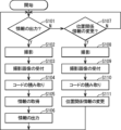
次に、情報出力装置1の動作について図2のフローチャートを用いて説明する。
Next, the operation of the
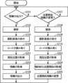
(ステップS101)取得部14は、情報の出力を行うかどうか判断する。そして、情報の出力を行う場合には、ステップS102に進み、そうでない場合には、ステップS107に進む。取得部14は、例えば、ユーザから、情報の出力を行う旨の指示が受け付けられた場合に、情報の出力を行うと判断してもよい。
(Step S101) The
(ステップS102)撮影部11は、対象物の撮影を行い、撮影画像を取得する。なお、撮影のタイミングや方向は、ユーザによって決められてもよい。
(Step S102) The
(ステップS103)受付部12は、撮影部11から撮影画像を受け取る。その撮影画像は、例えば、図示しない記録媒体で記憶されてもよい。
(Step S103) The
(ステップS104)取得部14は、受付部12で受け付けられた撮影画像に含まれるコードから、対象物の識別子であるコード識別子を取得する。撮影画像に2以上のコードが含まれる場合には、各コードについて、コード識別子が取得されてもよい。
(Step S104) The
(ステップS105)取得部14は、記憶部13で記憶されている位置関係情報を用いて、ステップS104で取得したコード識別子で識別される対象物の背面側に存在する各対象物を識別するコード識別子を特定する。そして、取得部14は、記憶部13で記憶されている、コード識別子と、そのコード識別子で識別される対象物に関する情報とを対応付ける情報を用いて、特定したコード識別子と、ステップS104で取得したコード識別子とに対応する対象物に関する情報をそれぞれ取得する。
(Step S105) The
(ステップS106)出力部15は、ステップS105で取得された、対象物に関する情報を出力する。そして、ステップS101に戻る。
(Step S106) The
(ステップS107)変更部16は、位置関係情報の変更を行うかどうか判断する。そして、位置関係情報の変更を行う場合には、ステップS108に進み、そうでない場合には、ステップS101に戻る。変更部16は、例えば、ユーザから位置関係情報の変更を行う旨の指示が受け付けられた場合に、位置関係情報の変更を行うと判断してもよい。
(Step S107) The
(ステップS108)撮影部11は、対象物の撮影を行い、撮影画像を取得する。なお、撮影のタイミングや方向は、ユーザによって決められてもよい。
(Step S108) The
(ステップS109)受付部12は、撮影部11から撮影画像を受け取る。その撮影画像は、例えば、図示しない記録媒体で記憶されてもよい。
(Step S109) The
(ステップS110)変更部16は、受付部12で受け付けられた撮影画像に含まれるコードから、対象物の識別子であるコード識別子を取得する。撮影画像に2以上のコードが含まれる場合には、各コードについて、コード識別子が取得されてもよい。
(Step S110) The
なお、ステップS108~S110の処理は、繰り返して行われてもよい。例えば、撮影画像に1個のコードのみが含まれる場合には、ステップS108~S110の処理が2回繰り返されてもよい。このようにして、配置対象の対象物のコード識別子と、その対象物の背面に存在する対象物のコード識別子とが取得されてもよい。一方、例えば、撮影画像に複数のコードが含まれる場合には、ステップS108~S110の処理は繰り返されなくてもよい。 The processes of steps S108 to S110 may be repeated. For example, if the captured image contains only one code, the processes of steps S108 to S110 may be repeated twice. In this way, the code identifier of the object to be placed and the code identifier of the object present behind the object may be obtained. On the other hand, for example, if the captured image contains multiple codes, the processes of steps S108 to S110 do not need to be repeated.
(ステップS111)変更部16は、ステップS110で取得したコード識別子を用いて、対象物の位置関係を位置関係情報に追加する。例えば、背面の対象物のコード識別子と、手前の対象物のコード識別子とを取得した場合には、変更部16は、それらの対象物の前後関係を示す情報を位置関係情報に追加してもよい。また、例えば、上下方向に並んだ複数のコードにそれぞれ対応する複数のコード識別子を取得した場合には、変更部16は、それらの対象物の上下関係を示す情報を位置関係情報に追加してもよい。そして、ステップS101に戻る。
(Step S111) The
なお、図2のフローチャートでは、情報の出力を行うのか、または、位置関係情報の変更を行うのかについて、例えば、ユーザが指示する場合について説明したが、そうでなくてもよい。例えば、受付部12によって受け付けられた撮影画像に、既知のコード識別子に対応するコードのみが含まれる場合には、情報の出力を行うと判断し、そうでない場合には、位置関係情報の変更を行うと判断してもよい。既知のコード識別子とは、位置関係情報によって位置関係が示される対象物のコード識別子のことである。この場合には、例えば、対象物の前後方向の位置関係を位置関係情報に追加する際に、配置対象の対象物の撮影をはじめに行うようにしてもよい。配置対象の対象物のコード識別子は、未知のコード識別子となるからである。また、図2のフローチャートにおける処理の順序は一例であり、同様の結果を得られるのであれば、各ステップの順序を変更してもよい。また、図2のフローチャートにおいて、電源オフや処理終了の割り込みにより処理は終了する。
2, the user instructs whether to output information or change the positional relationship information, but this is not necessary. For example, if the captured image accepted by the
次に、本実施の形態による情報出力装置1の動作について、具体例を用いて説明する。この具体例では、上記のように、ある対象物に付与されているコードのコード識別子が、その対象物の識別子であるとする。また、情報出力装置1は、スマートフォンであるとする。
Next, the operation of the
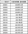
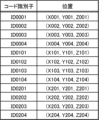
また、この具体例では、図3で示されるコード識別子と、そのコード識別子で識別されるコードの付与された対象物に関する情報である対象物情報とが対応付けられて記憶されているものとする。対象物情報は、対象物の賞味期限であるとする。図3において、例えば、コード識別子「ID0001」によって識別されるコードの付与された対象物の賞味期限は、「2020年12月」であることが示されている。 In addition, in this specific example, the code identifier shown in FIG. 3 is stored in association with object information, which is information about an object to which a code identified by the code identifier is assigned. The object information is the expiration date of the object. In FIG. 3, for example, the expiration date of an object to which a code identified by the code identifier "ID0001" is assigned is shown to be "December 2020."
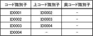
また、この具体例では、位置関係情報は、対象物の配置関係をツリー構造で示す情報であるとする。位置関係情報では、各対象物について、上面に配置された対象物のコード識別子(上コード識別子)と、背面に配置された対象物のコード識別子(奥コード識別子)とが対応付けられているものとする。なお、最上段の対象物に対応する上コード識別子は存在しない。また、奥コード識別子は、最下段の対象物にのみ対応付けられるものとする。また、最も奥側に存在する最下段の対象物に対応する奥コード識別子は存在しない。 In this specific example, the positional relationship information is information that indicates the positional relationship of objects in a tree structure. In the positional relationship information, for each object, the code identifier of the object located on the top surface (top code identifier) is associated with the code identifier of the object located on the back surface (back code identifier). Note that there is no top code identifier that corresponds to the object in the top row. Also, back code identifiers are associated only with the object in the bottom row. Also, there is no back code identifier that corresponds to the object in the bottom row that is located at the very back.
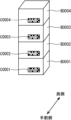
まず、図5Aで示されるように、対象物B0001~B0004が配置されたとする。対象物B0001~B0004には、それぞれコードC0001~C0004が付与されている。コードC0001~C0004にそれぞれ対応するコード識別子は、ID0001~ID0004であるとする。なお、この具体例において、コード識別子IDNで識別されるコードCNは、対象物BNに付与されているものとする。ここで、Nは、4桁の数字であるとする。 First, assume that objects B0001 to B0004 are placed as shown in FIG. 5A. Codes C0001 to C0004 are assigned to objects B0001 to B0004, respectively. The code identifiers corresponding to codes C0001 to C0004, respectively, are ID0001 to ID0004. Note that in this specific example, the code CN identified by the code identifier IDN is assigned to object BN. Here, N is a four-digit number.
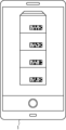
ユーザが、情報出力装置1を操作して、位置関係情報の変更を行う旨を入力したとする。その入力に応じて、変更部16は、位置関係情報の変更を行うと判断し、情報出力装置1を撮影モードに切り替える(ステップS107)。そして、図6Aで示されるように、対象物B0001~B0004の撮影が行われたとする。すると、その撮影画像が撮影部11で取得され、受付部12によって受け付けられる(ステップS108、S109)。また、受付部12によって受け付けられた撮影画像は、変更部16に渡される。撮影画像を受け取ると、変更部16は、撮影画像に含まれる複数のコードC0001~C0004を認識する。この場合には、複数のコードが撮影画像に含まれるため、変更部16は、各コードのコード識別子を撮影画像の下側から順番に特定する。具体的には、コード識別子ID0001、ID0002、ID0003、ID0004の順番にコード識別子が特定される(ステップS110)。
Assume that the user operates the
その後、変更部16は、特定した各コード識別子を位置関係情報に登録すると共に、あるコード識別子について、そのコード識別子の次に特定されたコード識別子を、上コード識別子に設定する。例えば、コード識別子ID0001の次にコード識別子ID0002が特定されたため、コード識別子ID0001には、上コード識別子ID0002が設定されることになる。その結果、図4Aで示されるように、位置関係情報が変更される(ステップS111)。
Then, the
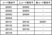
その後、新たな配置対象の対象物B0101を配置する前に、ユーザが、情報出力装置1を操作して、位置関係情報の変更を行う旨を入力したとする。その入力に応じて、変更部16は、位置関係情報の変更を行うと判断し、情報出力装置1を撮影モードに切り替える(ステップS107)。そして、図6Bで示されるように、最下段の対象物B0001に付与されたコードC0001の撮影が行われたとする。すると、その撮影画像が撮影部11で取得され、受付部12によって受け付けられて、変更部16によって、コードC0001のコード識別子ID0001が取得される(ステップS108~S110)。次に、ユーザが新たな配置対象の対象物B0101を図5Bで示されるように配置したとする。そして、図6Cで示されるように、新たに配置された対象物B0101に付与されたコードC0101の撮影が行われたとする。すると、その撮影画像が撮影部11で取得され、受付部12によって受け付けられて、変更部16によって、コードC0101のコード識別子ID0101が取得される(ステップS108~S110)。コード識別子ID0001、ID0101を取得すると、変更部16は、新たなコード識別子ID0101を位置関係情報に登録し、そのコード識別子ID0101に対応する奥コード識別子に、取得したコード識別子ID0001を設定する。その結果、図4Bで示されるように位置関係情報が変更される(ステップS111)。
After that, before placing the new object B0101 to be placed, the user operates the
なお、この具体例では、新たな対象物を配置する際に、背面の最下段の対象物のコードを撮影し、次に、その対象物の手前側に配置される対象物のコードを撮影する旨が決められているものとする。したがって、上記のようにして、対象物の前後関係を位置関係情報に登録することができる。 In this specific example, it is assumed that when placing a new object, the code of the object at the bottom of the back is photographed, and then the code of the object to be placed in front of that object is photographed. Therefore, in the above manner, the front-to-back relationship of the objects can be registered in the positional relationship information.
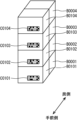
その後、図5Cで示されるように、対象物B0101の上に、対象物B0102~B0104が配置されたとする。そして、上記説明と同様にして、対象物B0101~B0104の撮影が行われて撮影画像が取得され、コード識別子ID0101~ID0104が順番に特定されたとする(ステップS107~S110)。すると、変更部16は、各コード識別子の登録と、各コード識別子に対応する上コード識別子の設定とを行う。なお、この場合には、コード識別子ID0101はすでに登録されているため、コード識別子ID0101については、上コード識別子ID0102の設定のみが行われることになる。このようにして、位置関係情報が、図4Cで示されるように変更される。
After that, as shown in FIG. 5C, objects B0102 to B0104 are placed on object B0101. Then, in the same manner as described above, objects B0101 to B0104 are photographed and photographed images are acquired, and code identifiers ID0101 to ID0104 are identified in order (steps S107 to S110). Then, the
その後、図5Dで示されるように対象物B0201~B0204を配置する際にも、対象物B0201と対象物B0101とを撮影することによって、コード識別子ID0201の登録や奥コード識別子ID0101の設定が行われ、また、対象物B0201~B0204を撮影することによって、コード識別子ID0202~ID0204の登録や、上コード識別子の設定が行われることになる(ステップS107~S111)。その結果、記憶部13で記憶されている位置関係情報は、図4Dで示されるようになる。
Thereafter, when placing objects B0201 to B0204 as shown in FIG. 5D, the code identifier ID0201 is registered and the back code identifier ID0101 is set by photographing objects B0201 and B0101, and the code identifiers ID0202 to ID0204 are registered and the top code identifier is set by photographing objects B0201 to B0204 (steps S107 to S111). As a result, the positional relationship information stored in
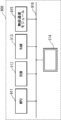
このようにして、位置関係情報の変更が行われる。位置関係情報は、図4Dで示されるように、ツリー構造となっている。そのツリー構造では、最も手前側の最下段の対象物のコード識別子がルートノードとなり、最上段の対象物のコード識別子がリーフノードとなっている。 In this way, the positional relationship information is changed. The positional relationship information has a tree structure, as shown in FIG. 4D. In this tree structure, the code identifier of the object at the bottom of the foreground is the root node, and the code identifier of the object at the top is the leaf node.
その後、位置関係情報を用いて、背面側の対象物に関する対象物情報(賞味期限)を出力する処理について説明する。図5Dで示されるように対象物が配置された状態において、ユーザが、情報出力装置1を操作して、情報の出力を行う旨を入力したとする。その入力に応じて、取得部14は、情報の出力を行うと判断し、情報出力装置1を撮影モードに切り替える(ステップS101)。そして、図6Dで示されるように、最も手前側の対象物B0201~B0204の撮影が行われたとする。すると、その撮影画像が撮影部11で取得され、受付部12によって受け付けられる(ステップS102、S103)。また、受付部12によって受け付けられた撮影画像は、取得部14に渡される。撮影画像を受け取ると、取得部14は、撮影画像に含まれる複数のコードC0201~C0204を認識し、撮影画像に含まれる各コードに対応するコード識別子ID0201~ID0204を取得する(ステップS104)。
Then, a process of outputting object information (best-before date) related to the object on the rear side using the positional relationship information will be described. With the objects arranged as shown in FIG. 5D, the user operates the
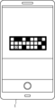
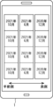
また、取得部14は、記憶部13で記憶されている図4Dの位置関係情報を用いて、取得した各コードIDから出発して、リーフノードのコードIDとなるまでの各コードIDを取得する。この場合には、コードID0001~ID0004、ID0101~ID0104が取得される。また、取得部14は、記憶部13で記憶されている図3の情報を参照し、撮影画像から取得した各コードID、及び位置関係情報を用いて取得した各コードIDに対応する賞味期限を取得する。そして、その賞味期限を、図4Dで示される位置関係情報の位置関係で示す情報を生成する(ステップS105)。その生成された情報は、対象物ごとの賞味期限を示す情報であり、また、対象物の上下関係及び前後関係が分かる情報であるとする。そのようにして生成された情報は、出力部15によって、スマートフォンである情報出力装置1のタッチパネルに図7で示されるように表示される(ステップS106)。図7で示される表示がなされることによって、最も手前側の対象物以外の対象物に関する情報(賞味期限)についても知ることができるようになる。例えば、奥側に賞味期限「2020年12月」の対象物が存在することを知ることができ、手前側の対象物よりも先に、奥側の対象物を出荷することができるようになる。
The
なお、この具体例では、位置関係情報において、最下段の対象物について奥コード識別子が設定される場合について説明したが、そうでなくてもよい。位置関係情報において、例えば、最上段の対象物、またはその他の対象物について、背面に存在する対象物を識別する識別子が設定されてもよい。また、この具体例では、位置関係情報において、奥コード識別子や、上コード識別子が設定される場合について説明したが、そうでなくてもよい。例えば、手前側の対象物を特定するための手前コード識別子が設定されてもよく、下側の対象物を特定するための下コード識別子が設定されてもよい。 In this specific example, a case where a deep code identifier is set for the bottom object in the positional relationship information has been described, but this is not necessarily the case. For example, an identifier that identifies an object present behind the top object or other object may be set in the positional relationship information. In addition, in this specific example, a case where a deep code identifier or a top code identifier is set in the positional relationship information has been described, but this is not necessarily the case. For example, a front code identifier may be set to identify an object in the foreground, and a bottom code identifier may be set to identify an object below.
また、この具体例では、対象物に関する情報を、対象物の位置関係に応じて示す情報が出力される場合について説明したが、そうでなくてもよい。対象物に関する情報のみが出力されてもよい。その場合であっても、コードの撮影された対象物の背面側に存在する対象物に関する情報について知ることができ、例えば、賞味期限のより短い対象物が背面側に存在することについて知ることができるようになる。 In addition, in this specific example, a case has been described in which information about the object is output according to the relative positions of the object, but this is not necessary. Only information about the object may be output. Even in this case, it is possible to know information about objects present behind the object whose code was photographed, for example, to know that an object with a shorter expiration date is present behind the object.
以上のように、本実施の形態による情報出力装置1、及び情報出力方法によれば、対象物の相対的な位置関係を示す位置関係情報を用いることにより、コードを撮影していない対象物についても、手前側の対象物のコードを撮影することによって情報を知ることができるようになる。そのため、コードの撮影者は、奥側の対象物にまで移動して奥側の対象物のコードを撮影する必要はなく、また、手前側の対象物を移動させてから奥側の対象物のコードを撮影する必要もなく、奥側の対象物の情報を取得する際の負担が軽減されることになる。そのように、奥側の対象物にまで移動しなくても、奥側に配置された対象物に関する情報を知ることができるため、例えば、対象物を倉庫や保管庫などに隙間なく配置することも可能となり、効率的な対象物の配置を実現することもできるようになる。また、撮影画像を用いて位置関係情報に情報を追加することも可能であり、簡単な処理によって、位置関係情報を構築することができるようになる。
As described above, according to the
ここで、本実施の形態による情報出力装置1の変形例について説明する。
Here, we will explain a modified example of the
[2以上の撮影部]
上記実施の形態では、受付部12が1個の撮影部11から撮影画像を受け付ける場合について説明したが、そうでなくてもよい。情報出力装置1は、例えば、新たな対象物を配置する場合に、配置対象の対象物を撮影する第1の撮影部と、それまでに配置されている対象物を撮影する第2の撮影部とを備えてもよい。この場合には、1個の撮影部11での撮影を繰り返すことなく、配置対象の対象物のコードの撮影画像と、その配置対象の対象物の背面に存在する対象物のコードの撮影画像とを一括して取得することも可能となる。例えば、対象物がフォークリフトなどを用いて配置される場合には、搬送中の対象物、すなわち配置対象の対象物のコードを撮影する第1の撮影部と、搬送先において既に配置されている対象物のコードを撮影する第2の撮影部とをそれぞれフォークリフトに配設することによって、両撮影を一括して行うことも可能となる。
[Two or more camera units]
In the above embodiment, the case where the
(実施の形態2)
本発明の実施の形態2による情報出力装置、及び情報出力方法について、図面を参照しながら説明する。本実施の形態による情報出力装置は、対象物の位置を示す位置関係情報を用いて、コードを撮影できる対象物の背面側に存在する対象物に関する情報を取得するものである。
(Embodiment 2)
An information output device and an information output method according to a second embodiment of the present invention will be described with reference to the drawings. The information output device according to the present embodiment uses positional relationship information indicating the position of the object to obtain information about an object present behind an object whose code can be photographed.
図8は、本実施の形態による情報出力装置2の構成を示すブロック図である。本実施の形態による情報出力装置2は、撮影部11と、受付部12と、記憶部13と、出力部15と、現在位置取得部21と、取得部22と、相対位置関係取得部23と、変更部24とを備える。なお、撮影部11、受付部12、記憶部13、出力部15については、記憶部13で記憶されている位置関係情報が異なる以外は、実施の形態1と同様であり、それらの説明を省略する。また、受付部12は、新たな対象物が配置された際に、配置された対象物のコードの撮影画像を受け付けてもよい。また、取得部22、変更部24は、以下で特に説明する処理以外は、実施の形態1の取得部14、変更部16と同様の処理を行ってもよい。
FIG. 8 is a block diagram showing the configuration of the
なお、本実施の形態では、コードは、あらかじめ決められた形状(例えば、矩形状、正方形状、三角形状、多角形状等)を有するものであることが好適である。コードの形状を用いて、コードと情報出力装置2との相対的な位置関係を取得するからである。
In this embodiment, it is preferable that the code has a predetermined shape (e.g., a rectangle, a square, a triangle, a polygon, etc.). This is because the shape of the code is used to obtain the relative positional relationship between the code and the
また、本実施の形態では、上記のように、位置関係情報は、コードの付与された対象物の位置を示す情報であるとする。対象物の位置は、例えば、対象物が配置される空間のグローバル座標系における位置であってもよい。このように、本実施の形態では、位置関係情報によって、対象物の絶対的な位置が示されることになる。各対象物の絶対的な位置が示される場合にも、その位置を用いて、結果として各対象物の位置関係を知ることができるため、本実施の形態における位置関係情報も、対象物の位置関係を示す情報であるということができる。本実施の形態における位置関係情報は、例えば、対象物の識別子と、その対象物の位置とを対応付ける情報であってもよい。その位置は、2次元平面における位置(すなわち、水平方向の位置)であってもよく、高さ方向も含む位置であってもよい。対象物の上下関係も知ることができるようにするため、本実施の形態では、位置に高さ方向も含まれている場合について主に説明する。対象物の位置として、例えば、対象物に付与されたコードの位置が用いられてもよい。本実施の形態では、対象物の位置がコードの位置である場合について主に説明する。また、実施の形態1と同様に、本実施の形態でも、対象物の識別子がコード識別子である場合について主に説明する。 In addition, in this embodiment, as described above, the positional relationship information is information indicating the position of the object to which the code is assigned. The position of the object may be, for example, a position in a global coordinate system of the space in which the object is placed. In this way, in this embodiment, the absolute position of the object is indicated by the positional relationship information. Even when the absolute position of each object is indicated, the positional relationship of each object can be known as a result by using the position, so the positional relationship information in this embodiment can also be said to be information indicating the positional relationship of the object. The positional relationship information in this embodiment may be, for example, information that associates the identifier of the object with the position of the object. The position may be a position in a two-dimensional plane (i.e., a horizontal position), or may be a position that also includes the height direction. In order to be able to know the up-down relationship of the object, in this embodiment, the case where the position also includes the height direction will be mainly described. For example, the position of the code assigned to the object may be used as the position of the object. In this embodiment, the case where the position of the object is the position of the code will be mainly described. Also, as in the first embodiment, in this embodiment, the case where the identifier of the object is a code identifier will also be mainly described.
現在位置取得部21は、現在位置を取得する。現在位置の取得は、例えば、無線通信を用いて行われてもよく、現在位置を取得できるその他の手段を用いてなされてもよい。無線通信を用いて現在位置を取得する方法としては、例えば、GPS(Global Positioning System)を用いる方法や、屋内GPSを用いる方法、最寄りの無線基地局を用いる方法などが知られている。現在位置は、対象物が配置される空間のグローバル座標系における位置であってもよい。現在位置は、例えば、水平方向の2次元の位置であってもよく、高さ方向も含む3次元の位置であってもよい。後者の場合には、例えば、高さ方向の位置については、予め決められた値(例えば、「0」など)が取得されてもよい。通常、情報出力装置2の高さ方向の位置が大きく変化することはないと考えられるからである。なお、情報出力装置2の高さ方向の位置も大きく変化しうる場合には、現在位置に含まれる高さ方向の位置も、正確な値が取得されることが好適である。現在位置取得部21は、情報出力装置2の向き(方向)を含む現在位置を取得することが好適である。その方向は、例えば、グローバル座標系に対する情報出力装置2のローカル座標系の角度(例えば、オイラー角など)によって示されてもよく、その他の方向を示す情報によって示されてもよい。その向きは、電子コンパスや地磁気センサ、ジャイロセンサ、傾きセンサ等によって取得されてもよい。
The current
取得部22は、受付部12によって受け付けられた撮影画像に含まれるコードと、記憶部13で記憶されている位置関係情報と、現在位置取得部21によって取得された現在位置とを用いて、そのコードの付与された対象物の背面側に存在する対象物に関する情報を取得する。より具体的には、取得部22は、撮影画像に含まれるコードのコード識別子に対応する位置を取得することによって、撮影画像に含まれるコードの付与された各対象物の位置を特定することができる。また、取得部22は、現在位置によって、情報出力装置2の位置を特定できる。また、取得部22は、位置関係情報によって、各対象物の位置を特定することができる。したがって、取得部22は、撮影画像に含まれるコードの付与された各対象物の奥側(後方側)に存在する対象物を特定することができる。そして、取得部22は、そのようにして特定した対象物に関する情報を取得してもよい。
The
なお、撮影画像に含まれるコードの付与された各対象物の奥側(後方側)に存在する対象物の特定は、例えば、次のようにして行われてもよい。まず、水平方向の円座標系において、現在位置を原点として、原点から、撮影画像に含まれるコードの付与された各対象物の位置、すなわち、そのコードのコード識別子に位置関係情報によって対応付けられている位置に延びる半直線の角度(以下、「方位角」とする。)を0度とする。そして、方位角が-δ度の半直線と、方位角が+δ度の半直線とによって挟まれた領域に位置が含まれる対象物を特定してもよい。このようにして特定した対象物が、撮影画像に含まれるコードの付与された各対象物の奥側に存在する対象物となる。なお、通常、方位角が-δ度の半直線と、方位角が+δ度の半直線とによって挟まれた領域において、撮影画像に含まれるコードの付与された対象物の位置よりも現在位置に近い側に対象物が存在することはないと考えられるが、仮に存在する場合には、方位角が-δ度の半直線と、方位角が+δ度の半直線とによって挟まれた領域における、撮影画像に含まれるコードの付与された対象物の位置よりも遠い側に存在する対象物のみを特定するようにしてもよい。なお、δは、予め決められた正の角度であり、通常、あまり大きくない角度である。δは、例えば、3度以上であってもよく、5度以上であってもよい。また、δは、例えば、30度以下であってもよく、20度以下であってもよく、10度以下であってもよい。なお、1個の撮影画像に複数のコードが含まれる場合には、各コードについて上記の処理を行い、各処理で特定された対象物をマージすることによって、最終的な対象物の特定結果としてもよい。または、複数のコードにそれぞれ対応する複数の位置の代表値(例えば、平均値など)を用いて、上記のように、対象物の特定を行ってもよい。 Note that the identification of objects present behind (behind) each object to which a code is assigned in the captured image may be performed, for example, as follows. First, in a horizontal circular coordinate system, the current position is set as the origin, and the angle of a half line extending from the origin to the position of each object to which a code is assigned in the captured image, i.e., the position associated with the code identifier of that code by the positional relationship information (hereinafter referred to as the "azimuth angle") is set to 0 degrees. Then, objects whose positions are included in the area between a half line with an azimuth angle of -δ degrees and a half line with an azimuth angle of +δ degrees may be identified. The objects identified in this way are the objects present behind each object to which a code is assigned in the captured image. In addition, in the region between the half line with an azimuth angle of -δ degrees and the half line with an azimuth angle of +δ degrees, it is generally considered that there is no object closer to the current position than the position of the object to which the code in the captured image is assigned in the region between the half line with an azimuth angle of -δ degrees and the half line with an azimuth angle of +δ degrees. If there is an object, only the object that exists on the farther side than the position of the object to which the code in the captured image is assigned in the region between the half line with an azimuth angle of -δ degrees and the half line with an azimuth angle of +δ degrees may be identified. In addition, δ is a predetermined positive angle, and is usually not very large. For example, δ may be 3 degrees or more, or 5 degrees or more. In addition, δ may be 30 degrees or less, 20 degrees or less, or 10 degrees or less. In addition, when a single captured image includes multiple codes, the above process may be performed for each code, and the objects identified in each process may be merged to obtain a final result of identifying the object. Alternatively, the object may be identified as described above using a representative value (for example, an average value) of multiple positions corresponding to multiple codes.
また、各対象物の位置を用いて、各対象物の上下方向及び前後方向の位置関係を取得する方法について簡単に説明する。取得部22は、各対象物の水平方向の位置を用いて、水平方向の位置の近いコード識別子が同じクラスタに属するように各対象物をクラスタリングする。そして、取得部22は、各クラスタにおいて、高さ方向の位置を用いて、上下関係を決定する。また、各クラスタの水平方向の位置の代表値(例えば、平均値や、ランダムに選択した対象物の位置など)と、現在位置との距離を用いて、情報出力装置2を基準として、各クラスタを手前側から奥側(距離の遠い側)に順番に並べることができる。このようにして、取得部22は、各対象物の位置と、情報出力装置2の現在位置とが分かった場合に、情報出力装置2を基準とした対象物の相対的な位置関係を取得することができる。取得部22は、このようにして取得した対象物の相対的な位置関係を用いて、実施の形態1の取得部14と同様に、対象物に関する情報を、対象物の位置関係に応じて示す情報を生成してもよい。また、そのような情報の生成を行わない場合には、取得部22は、対象物の相対的な位置関係の取得を行わなくてもよい。
A method of acquiring the vertical and front-rear positional relationships of each object using the position of each object will be briefly described. The
相対位置関係取得部23は、受付部12によって受け付けられた撮影画像に含まれる、配置された対象物のコードを用いて、そのコードと情報出力装置2との相対的な位置関係を取得する。相対的な位置関係は、例えば、撮影時における、コードと情報出力装置2との間の平行移動に関する情報を含んでいてもよく、コードと情報出力装置2との間の回転移動に関する情報を含んでいてもよい。本実施の形態では、その両方が相対的な位置関係に含まれている場合について主に説明する。
The relative positional
ここで、コードの撮影画像から相対的な位置関係を取得する方法について簡単に説明する。コードを撮影するカメラにおけるローカル座標系をカメラ座標系と呼び、撮影対象のコードにおけるローカル座標系をコード座標系と呼ぶことにする。カメラ座標系における座標と、コード座標系における座標とは、平行移動と回転とに応じた同次変換行列を用いて変換できることが知られている。3次元空間での平行移動には3つの未知数があり、3次元空間での回転にも3つの未知数があるため、その同次変換行列には、6つの未知数が存在することになる。一方、撮影画像に含まれるコードに関する実空間上での3点間の距離が既知である場合には、その3つの距離を用いることによって、同次変換行列の6つの未知数を求めることができ、同次変換行列を一意に特定できることが知られている。なお、その3点は、一直線上に存在しないものとする。例えば、矩形のコードの短辺の長さA1と長辺の長さA2とが既知である場合には、そのコードの4つの頂点間の距離がすべて既知であることになり(例えば、対角の長さは(A12+A22)1/2となる)、コードに関する3点間の距離が既知であることになるため、カメラ座標系とコード座標系との間の変換を行う同次変換行列を特定することができる。したがって、撮影画像に含まれるコードと、コードに関する3点間の距離とを用いることによって同次変換行列を算出でき、それを用いてカメラ座標系とコード座標系との相対的な位置関係を取得することができる。また、通常、カメラ座標系と、情報出力装置2のローカル座標系との関係は既知である。したがって、情報出力装置2のローカル座標系と、コード座標系との相対的な位置関係、すなわち、情報出力装置2とコードとの相対的な位置関係を取得することができる。なお、例えば、カメラ座標系が、情報出力装置2のローカル座標系であってもよい。
Here, a method for acquiring the relative positional relationship from a captured image of a code will be briefly described. The local coordinate system of the camera capturing the code is called the camera coordinate system, and the local coordinate system of the code to be captured is called the code coordinate system. It is known that coordinates in the camera coordinate system and coordinates in the code coordinate system can be transformed using a homogeneous transformation matrix corresponding to translation and rotation. Translation in a three-dimensional space has three unknowns, and rotation in a three-dimensional space also has three unknowns, so that the homogeneous transformation matrix has six unknowns. On the other hand, when the distances between three points in the real space related to the code included in the captured image are known, it is known that the six unknowns of the homogeneous transformation matrix can be obtained by using the three distances, and the homogeneous transformation matrix can be uniquely specified. It is assumed that the three points do not lie on a straight line. For example, when the length A1 of the short side and the length A2 of the long side of a rectangular code are known, the distances between the four vertices of the code are all known (for example, the length of the diagonal is (A1 2 +A2 2 ) 1/2 ), and the distances between three points on the code are known, so that a homogeneous transformation matrix for performing transformation between the camera coordinate system and the code coordinate system can be specified. Therefore, a homogeneous transformation matrix can be calculated by using the code included in the captured image and the distances between three points on the code, and the relative positional relationship between the camera coordinate system and the code coordinate system can be obtained using the homogeneous transformation matrix. In addition, usually, the relationship between the camera coordinate system and the local coordinate system of the
本実施の形態では、情報出力装置2のローカル座標系を基準としたコード座標系の平行移動に関する各座標軸方向の値(x,y,z)、及び各回転角度(θ,φ,ψ)が相対位置関係取得部23によって取得される場合について主に説明する。なお、情報出力装置2において、矩形のコードの縦横の長さがそれぞれ記憶されているものとする。相対的な位置関係の取得に必要だからである。また、撮影画像に複数のコードが含まれる場合には、各コードについて、情報出力装置2との相対的な位置関係が取得されることが好適である。
In this embodiment, a case will be mainly described in which the values (x, y, z) of each coordinate axis direction and each rotation angle (θ, φ, ψ) relating to the translation of the code coordinate system with respect to the local coordinate system of the
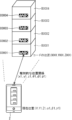
変更部24は、現在位置取得部21によって取得された現在位置と、相対位置関係取得部23によって取得された相対的な位置関係とを用いて、配置された対象物のコードの位置を取得して位置関係情報に追加する。図10で示されるように、グローバル座標系における情報出力装置2の現在位置(X1,Y1,Z1,α1,β1,γ1)、及び、コードC0001と情報出力装置2との相対的な位置関係(x1,y1,z1,θ1,φ1,ψ1)が分かっている場合には、グローバル座標系におけるコードC0001の位置(X001,Y001,Z001)を取得することができる。したがって、変更部24は、そのようにして撮影画像に含まれる各コードのグローバル座標系における位置を取得することができる。変更部24は、そのようにして取得した各コードの位置、すなわちそのコードの付与された対象物の位置と、そのコードの付与されている対象物の識別子とを対応付けて位置関係情報に追加してもよい。なお、上記した現在位置において、(X1,Y1,Z1)は、3次元のグローバル座標系における位置であり、α1,β1,γ1は、グローバル座標系に対する情報出力装置2の角度である。また、例えば、コードの位置(X001,Y001,Z001)の取得には、コードと情報出力装置2との相対的な角度(θ1,φ1,ψ1)は必ずしも必要ではないため、それらは取得されなくてもよい。
The
次に、情報出力装置2の動作について図9のフローチャートを用いて説明する。なお、ステップS201~S205以外の処理は、実施の形態1の図2のフローチャートと同様であり、その説明を省略する。
Next, the operation of the
(ステップS201)現在位置取得部21は、情報出力装置2の現在位置を取得する。なお、この現在位置の取得では、角度に関する情報は取得されなくてもよい。
(Step S201) The current
(ステップS202)取得部22は、ステップS201で取得された現在位置と、記憶部13で記憶されている位置関係情報と、ステップS104で取得したコード識別子とを用いて、そのコード識別子で識別されるコードの付与された対象物の背面側に存在する対象物を特定し、その対象物に関する情報をそれぞれ取得する。
(Step S202) The
(ステップS203)現在位置取得部21は、情報出力装置2の現在位置を取得する。
(Step S203) The current
(ステップS204)相対位置関係取得部23は、ステップS109で受け付けられた撮影画像に含まれるコードの画像を用いて、コードと情報出力装置2との相対的な位置関係を取得する。なお、2以上のコードが撮影画像に含まれる場合には、各コードについて、相対的な位置関係が取得されることが好適である。
(Step S204) The relative positional
(ステップS205)変更部24は、ステップS109で受け付けられた撮影画像に含まれる各コードの位置を、現在位置と、コードと情報出力装置2との相対的な位置関係とを用いて取得し、取得した各コードの位置を位置関係情報に追加する。そして、ステップS101に戻る。
(Step S205) The
なお、図9のフローチャートのステップS108~S110では、配置された対象物の撮影、その撮影画像の受け付け、及びその撮影画像に含まれる、配置された対象物のコードを識別するコード識別子の取得が行われるものとする。また、図9のフローチャートにおける処理の順序は一例であり、同様の結果を得られるのであれば、各ステップの順序を変更してもよい。また、図9のフローチャートにおいて、電源オフや処理終了の割り込みにより処理は終了する。 Note that steps S108 to S110 in the flowchart of FIG. 9 involve photographing the placed object, accepting the photographed image, and obtaining a code identifier that identifies the code of the placed object and is included in the photographed image. The order of processing in the flowchart of FIG. 9 is an example, and the order of each step may be changed as long as similar results are obtained. In the flowchart of FIG. 9, processing ends when the power is turned off or an interrupt is issued to end processing.
次に、本実施の形態による情報出力装置2の動作について、具体例を用いて説明する。なお、記憶部13で記憶されている位置関係情報が、対象物の位置を示す情報であること、及び現在位置取得部21、取得部22、相対位置関係取得部23、変更部24に関する処理以外は、実施の形態1の具体例と同様であり、適宜、説明を省略する。
Next, the operation of the
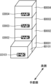
まず、図10で示されるように、対象物B0001~B0004が配置された状態において、位置関係情報の変更のための撮影が行われると、それに応じて、各コードのコード識別子が読み取られる(ステップS107~S110)。また、現在位置取得部21によって情報出力装置2の現在位置が取得されると共に、撮影画像に含まれる各コードについて、相対位置関係取得部23によって、情報出力装置2との相対的な位置関係が取得される(ステップS203、S204)。より具体的には、コードC0001との相対的な位置関係と、現在位置とを用いて、コードC0001の位置である対象物B0001の位置(X001,Y001,Z001)が取得される。同様にして、コードC0002~C0004との相対的な位置関係と、現在位置とを用いて、対象物B0002~B0004の位置(X002,Y002,Z002)~(X004,Y004,Z004)が取得される。それらの位置は、各コードのコード識別子ID0001~ID0004と対応付けられて位置関係情報に追加される(ステップS205)。
First, as shown in Figure 10, when objects B0001 to B0004 are positioned and an image is captured to change the positional relationship information, the code identifier of each code is read accordingly (steps S107 to S110). The current
同様にして、図5Cで示されるように対象物B0101~B0104が配置された際にもそれらの対象物の位置が位置関係情報に追加され、図5Dで示されるように対象物B0201~B0204が配置された際にもそれらの対象物の位置が位置関係情報に追加されることになる(ステップS107~S110,S203~S205)。その結果、記憶部13で記憶されている位置関係情報は、図11で示されるようになる。
Similarly, when objects B0101-B0104 are placed as shown in FIG. 5C, the positions of those objects are added to the positional relationship information, and when objects B0201-B0204 are placed as shown in FIG. 5D, the positions of those objects are added to the positional relationship information (steps S107-S110, S203-S205). As a result, the positional relationship information stored in
その後、ユーザが情報出力装置2を操作して図6Dで示されるように、情報の出力のために対象物B0201~B0204の撮影を行ったとする。すると、撮影画像において、各コードのコード識別子が読み取られる(ステップS101~S104)。また、現在位置取得部21によって情報出力装置2の現在位置が取得される(ステップS201)。その後、取得部22は、現在位置と、撮影画像から読み取られたコード識別子に対応する位置と、位置関係情報で示される各対象物の位置とを用いて、撮影画像から読み取られたコード識別子に対応する位置の背面側に存在する対象物のコード識別子を特定する。この場合には、コード識別子ID0001~ID0004、ID0101~ID0104が特定されたとする。すると、取得部22は、撮影画像から読み取ったコード識別子と、位置関係情報を用いて特定したコード識別子とに対応する水平方向の位置(例えば、(X001,Y001)など)を用いて、水平方向の位置の近いコード識別子が同じクラスタに属するように各コード識別子をクラスタリングする。そして、取得部22は、各クラスタにおいて、高さ方向の位置を用いて、上下関係を決定する。また、各クラスタの水平方向の位置の代表値(例えば、平均値や、ランダムに選択した対象物の位置など)と、現在位置との距離を用いて、情報出力装置2を基準として、各クラスタを手前側から奥側(距離の遠い側)に順番に並べる。このようにして、各対象物の前後方向及び上下方向の位置関係を取得することができ、実施の形態1の具体例と同様に、各対象物の賞味期限を、対象物の位置関係に応じて示す情報を生成することができる。そして、そのようにして生成された情報が出力部15によって、図7で示されるように表示されることにより、ユーザは、各対象物の賞味期限を知ることができるようになる。
Then, the user operates the
以上のように、本実施の形態による情報出力装置2、及び情報出力方法によれば、実施の形態1と同様に、コードを撮影していない対象物についても、手前側の対象物のコードを撮影することによって、情報を知ることができるようになる。また、位置関係情報を取得する際に、配置後の対象物のコードを撮影するだけでよいため、実施の形態1と比較して、撮影回数をより少なくすることも可能となる。
As described above, according to the
ここで、実施の形態1,2による情報出力装置1,2の変形例について説明する。
Here, we will explain modified examples of the
[撮影部を有しない情報出力装置]
上記実施の形態1,2では、情報出力装置1,2が撮影部11を有する場合について説明したが、そうでなくてもよい。撮影部11は、情報出力装置1,2の外部に存在してもよい。その場合には、外部の撮影部によって撮影された撮影画像を、受付部12が受け付けてもよい。その撮影画像の受け付けは、例えば、有線または無線の通信回線を介して送信された撮影画像の受信であってもよい。なお、この場合には、受付部12は、受け付けを行うためのデバイス(例えば、モデムやネットワークカードなど)を含んでもよく、または含まなくてもよい。また、受付部12は、ハードウェアによって実現されてもよく、または所定のデバイスを駆動するドライバ等のソフトウェアによって実現されてもよい。
[Information output device without a photographing unit]
In the above-mentioned first and second embodiments, the case where the
[変更部を有しない情報出力装置]
上記実施の形態1,2では、情報出力装置1,2が変更部16,24を有する場合について説明したが、そうでなくてもよい。記憶部13で記憶されている位置関係情報を変更しない場合には、情報出力装置1,2は、変更部16,24を備えていなくてもよい。変更部24を備えていない場合には、情報出力装置2は、相対位置関係取得部23も備えていなくてもよい。また、情報出力装置1,2が変更部16,24を備えていない場合には、例えば、位置関係情報は、作業者によって手作業で作成されてもよく、または、情報出力装置1,2とは別の装置によって、変更部16,24と同様の処理によって生成されてもよい。そして、作成された位置関係情報や生成された位置関係情報が、記憶部13に蓄積されてもよい。
[Information output device without a change unit]
In the above-mentioned first and second embodiments, the
[サーバとしての構成]
上記実施の形態1,2では、情報出力装置1,2がスタンドアロンである場合について主に説明したが、情報出力装置1,2は、スタンドアロンの装置であってもよく、サーバ・クライアントシステムにおけるサーバ装置であってもよい。後者の場合には、出力部や受付部は、通信回線を介して入力や撮影画像を受け付けたり、情報を出力したりしてもよい。
[Server configuration]
In the above-mentioned first and second embodiments, the case where the
[対象物の移動に応じた処理]
上記実施の形態1,2において、対象物が、配置されている場所から移動された場合、例えば、倉庫から出荷された場合には、その対象物に関する情報が位置関係情報から削除されてもよい。例えば、対象物が配置場所から除去される場合には、その対象物のコードが撮影され、それに応じて変更部16,24は、そのコードのコード識別子に関する情報を位置関係情報から削除してもよい。
[Processing in response to movement of object]
In the above-mentioned first and second embodiments, when an object is moved from the location where it is placed, for example, when it is shipped from a warehouse, information about the object may be deleted from the positional relationship information. For example, when an object is removed from the location where it is placed, the code of the object may be photographed, and accordingly, the
また、上記各実施の形態では、倉庫などに段ボール箱などの対象物を配置する場合について主に説明したが、対象物は他の形状のものであってもよい。例えば、上記のように、対象物はハンガーに掛けられた衣服であってもよい。そのような場合においても、後方側に存在する衣類に関する情報を容易に知ることができ、例えば、目的とする衣服を容易に探すことができるようになる。この場合には、対象物に関する情報は、衣類の種類に関する情報(例えば、グレーのチェックのジャケットなど)であってもよい。 Although the above embodiments have been described mainly with respect to cases where objects such as cardboard boxes are placed in a warehouse or the like, the object may have other shapes. For example, as described above, the object may be clothing hung on a hanger. Even in such a case, information about the clothing present in the rear can be easily obtained, and, for example, the desired clothing can be easily found. In this case, the information about the object may be information about the type of clothing (for example, a gray checked jacket, etc.).
また、上記各実施の形態において、各処理または各機能は、単一の装置または単一のシステムによって集中処理されることによって実現されてもよく、または、複数の装置または複数のシステムによって分散処理されることによって実現されてもよい。 In addition, in each of the above embodiments, each process or function may be realized by centralized processing in a single device or a single system, or may be realized by distributed processing in multiple devices or multiple systems.
また、上記各実施の形態において、各構成要素間で行われる情報の受け渡しは、例えば、その情報の受け渡しを行う2個の構成要素が物理的に異なるものである場合には、一方の構成要素による情報の出力と、他方の構成要素による情報の受け付けとによって行われてもよく、または、その情報の受け渡しを行う2個の構成要素が物理的に同じものである場合には、一方の構成要素に対応する処理のフェーズから、他方の構成要素に対応する処理のフェーズに移ることによって行われてもよい。 In addition, in each of the above embodiments, the transfer of information between components may be performed, for example, by one component outputting information and the other component receiving information if the two components transferring the information are physically different, or, if the two components transferring the information are physically the same, by shifting from a processing phase corresponding to one component to a processing phase corresponding to the other component.
また、上記各実施の形態において、各構成要素が実行する処理に関係する情報、例えば、各構成要素が受け付けたり、取得したり、選択したり、生成したり、送信したり、受信したりした情報や、各構成要素が処理で用いる閾値や数式、アドレス等の情報等は、上記説明で明記していなくても、図示しない記録媒体において、一時的に、または長期にわたって保持されていてもよい。また、その図示しない記録媒体への情報の蓄積を、各構成要素、または、図示しない蓄積部が行ってもよい。また、その図示しない記録媒体からの情報の読み出しを、各構成要素、または、図示しない読み出し部が行ってもよい。 In addition, in each of the above embodiments, information related to the processing performed by each component, such as information accepted, acquired, selected, generated, transmitted, or received by each component, and information such as thresholds, formulas, and addresses used by each component in processing, may be temporarily or long-term stored in a recording medium (not shown) even if not specified in the above description. Furthermore, each component or a storage unit (not shown) may store information in the recording medium (not shown). Furthermore, each component or a reading unit (not shown) may read information from the recording medium (not shown).
また、上記各実施の形態において、各構成要素等で用いられる情報、例えば、各構成要素が処理で用いる閾値やアドレス、各種の設定値等の情報がユーザによって変更されてもよい場合には、上記説明で明記していなくても、ユーザが適宜、それらの情報を変更できるようにしてもよく、または、そうでなくてもよい。それらの情報をユーザが変更可能な場合には、その変更は、例えば、ユーザからの変更指示を受け付ける図示しない受付部と、その変更指示に応じて情報を変更する図示しない変更部とによって実現されてもよい。その図示しない受付部による変更指示の受け付けは、例えば、入力デバイスからの受け付けでもよく、通信回線を介して送信された情報の受信でもよく、所定の記録媒体から読み出された情報の受け付けでもよい。 In addition, in each of the above embodiments, if the information used by each component, for example, information such as thresholds, addresses, and various setting values used by each component in processing, may be changed by the user, the user may or may not be able to change that information as appropriate, even if not specified in the above description. If the information is changeable by the user, the change may be realized, for example, by a reception unit (not shown) that receives a change instruction from the user, and a change unit (not shown) that changes the information in response to the change instruction. The reception unit (not shown) may accept the change instruction from an input device, may receive information transmitted via a communication line, or may receive information read from a specified recording medium.
また、上記各実施の形態において、情報出力装置1,2に含まれる2以上の構成要素が通信デバイスや入力デバイス等を有する場合に、2以上の構成要素が物理的に単一のデバイスを有してもよく、または、別々のデバイスを有してもよい。
In addition, in each of the above embodiments, when two or more components included in the
また、上記各実施の形態において、各構成要素は専用のハードウェアにより構成されてもよく、または、ソフトウェアにより実現可能な構成要素については、プログラムを実行することによって実現されてもよい。例えば、ハードディスクや半導体メモリ等の記録媒体に記録されたソフトウェア・プログラムをCPU等のプログラム実行部が読み出して実行することによって、各構成要素が実現され得る。その実行時に、プログラム実行部は、記憶部や記録媒体にアクセスしながらプログラムを実行してもよい。なお、上記各実施の形態における情報出力装置1,2を実現するソフトウェアは、以下のようなプログラムである。つまり、このプログラムは、コードの付与された対象物の位置関係を示す情報である位置関係情報が記憶される記憶部にアクセス可能なコンピュータを、対象物の撮影画像を受け付ける受付部、受付部によって受け付けられた撮影画像に含まれるコードと、位置関係情報とを用いて、コードの付与された対象物の背面側に存在する対象物に関する情報を取得する取得部、取得部によって取得された情報を出力する出力部として機能させるためのプログラムである。
In addition, in each of the above embodiments, each component may be configured with dedicated hardware, or a component that can be realized by software may be realized by executing a program. For example, each component may be realized by a program execution unit such as a CPU reading and executing a software program recorded on a recording medium such as a hard disk or semiconductor memory. During execution, the program execution unit may execute the program while accessing a storage unit or a recording medium. The software that realizes the
なお、上記プログラムにおいて、上記プログラムが実現する機能には、ハードウェアでしか実現できない機能は含まれない。例えば、情報を受け付ける受付部や、情報を出力する出力部などにおけるモデムやインターフェースカードなどのハードウェアでしか実現できない機能は、上記プログラムが実現する機能には少なくとも含まれない。 In addition, in the above program, the functions realized by the above program do not include functions that can only be realized by hardware. For example, functions that can only be realized by hardware such as a modem or interface card in the reception unit that receives information and the output unit that outputs information are at least not included in the functions realized by the above program.
また、このプログラムは、サーバなどからダウンロードされることによって実行されてもよく、所定の記録媒体(例えば、CD-ROMなどの光ディスクや磁気ディスク、半導体メモリなど)に記録されたプログラムが読み出されることによって実行されてもよい。また、このプログラムは、プログラムプロダクトを構成するプログラムとして用いられてもよい。 This program may also be executed by being downloaded from a server or the like, or by being read from a predetermined recording medium (for example, an optical disk such as a CD-ROM, a magnetic disk, or a semiconductor memory). This program may also be used as a program constituting a program product.
また、このプログラムを実行するコンピュータは、単数であってもよく、複数であってもよい。すなわち、集中処理を行ってもよく、または分散処理を行ってもよい。 The program may be executed by a single computer or multiple computers. In other words, it may perform centralized processing or distributed processing.
図12は、上記プログラムを実行して、上記各実施の形態による情報出力装置1,2を実現するコンピュータシステム900の一例を示す図である。上記各実施の形態は、コンピュータハードウェア及びその上で実行されるコンピュータプログラムによって実現されうる。
Figure 12 is a diagram showing an example of a
図12において、コンピュータシステム900は、MPU(Micro Processing Unit)911と、ブートアッププログラム等のプログラムや、アプリケーションプログラム、システムプログラム、及びデータが記憶されるフラッシュメモリ等のROM912と、MPU911に接続され、アプリケーションプログラムの命令を一時的に記憶すると共に、一時記憶空間を提供するRAM913と、タッチパネル914と、無線通信モジュール915と、MPU911、ROM912等を相互に接続するバス916とを備える。なお、無線通信モジュール915に代えて、有線通信モジュールを備えていてもよい。また、タッチパネル914に代えて、ディスプレイと、マウスやキーボード等の入力デバイスとを備えていてもよい。
In FIG. 12, the
コンピュータシステム900に、上記各実施の形態による情報出力装置1,2の機能を実行させるプログラムは、無線通信モジュール915を介してROM912に記憶されてもよい。プログラムは実行の際にRAM913にロードされる。なお、プログラムは、ネットワークから直接、ロードされてもよい。
A program that causes the
プログラムは、コンピュータシステム900に、上記各実施の形態による情報出力装置1,2の機能を実行させるオペレーティングシステム(OS)、またはサードパーティプログラム等を必ずしも含んでいなくてもよい。プログラムは、制御された態様で適切な機能やモジュールを呼び出し、所望の結果が得られるようにする命令の部分のみを含んでいてもよい。コンピュータシステム900がどのように動作するのかについては周知であり、詳細な説明は省略する。
The program does not necessarily have to include an operating system (OS) or a third-party program that causes the
また、本発明は、以上の実施の形態に限定されることなく、種々の変更が可能であり、それらも本発明の範囲内に包含されるものであることは言うまでもない。 Furthermore, the present invention is not limited to the above-described embodiment, and various modifications are possible, and it goes without saying that these are also included within the scope of the present invention.
以上より、本発明の一態様による情報出力装置等によれば、コードを撮影することができる対象物の背面側に存在する対象物についても、その対象物に関する情報を取得できるという効果が得られ、対象物に関する情報を出力する装置等として有用である。 As described above, the information output device according to one aspect of the present invention has the effect of being able to obtain information about an object that exists behind an object whose code can be photographed, making it useful as a device for outputting information about an object.
1、2 情報出力装置
12 受付部
13 記憶部
14、22 取得部
15 出力部
16、24 変更部
21 現在位置取得部
23 相対位置関係取得部
Claims (7)
前記対象物の撮影画像を受け付ける受付部と、
前記受付部によって受け付けられた撮影画像に含まれるコードと、前記位置関係情報とを用いて、当該コードの付与された対象物の背面側に存在する対象物に関する情報を取得する取得部と、
前記取得部によって取得された情報を出力する出力部と、を備えた情報出力装置。 A storage unit that stores positional relationship information that is information indicating a positional relationship of objects to which codes are assigned;
A reception unit that receives a captured image of the object;
an acquisition unit that acquires information about an object present behind the object to which the code is assigned, using the code included in the captured image accepted by the acceptance unit and the positional relationship information;
an output unit that outputs the information acquired by the acquisition unit.
前記受付部によって受け付けられた撮影画像に含まれる、前記配置対象の対象物のコードと、当該配置対象の対象物の背面に存在する対象物のコードとを用いて、当該配置対象の対象物の位置関係を前記位置関係情報に追加する変更部をさらに備えた、請求項2記載の情報出力装置。 the receiving unit receives, when a new object is to be placed, a photographed image of a code of the object to be placed and a photographed image of a code of an object present on a rear side of the object to be placed;
3. The information output device as described in claim 2, further comprising a modification unit that adds a positional relationship of the object to be placed to the positional relationship information using a code of the object to be placed contained in the captured image accepted by the acceptance unit and a code of an object present behind the object to be placed.
現在位置を取得する現在位置取得部をさらに備え、
前記取得部は、前記受付部によって受け付けられた撮影画像に含まれるコードと、前記位置関係情報と、前記現在位置とを用いて、当該コードの付与された対象物の背面側に存在する対象物に関する情報を取得する、請求項1記載の情報出力装置。 the positional relationship information is information indicating a position of an object to which a code is assigned,
A current location acquisition unit for acquiring a current location is further provided,
The information output device of claim 1 , wherein the acquisition unit acquires information about an object located behind the object to which the code is assigned using a code contained in the captured image accepted by the acceptance unit, the positional relationship information, and the current location.
前記受付部によって受け付けられた撮影画像に含まれる、前記配置された対象物のコードを用いて、当該コードと前記情報出力装置との相対的な位置関係を取得する相対位置関係取得部と、
前記現在位置と前記相対的な位置関係とを用いて、前記配置された対象物の位置を取得して前記位置関係情報に追加する変更部と、をさらに備えた、請求項4記載の情報出力装置。 the receiving unit receives, when a new object is placed, a captured image of a code of the placed object;
a relative positional relationship acquisition unit that acquires a relative positional relationship between the code of the arranged object included in the captured image accepted by the acceptance unit and the information output device using the code;
5. The information output device according to claim 4, further comprising a change unit that acquires the position of the placed object using the current position and the relative positional relationship, and adds the acquired position to the positional relationship information.
前記受付部が、前記対象物の撮影画像を受け付ける受付ステップと、
前記取得部が、前記受付ステップにおいて受け付けられた撮影画像に含まれるコードと、前記位置関係情報とを用いて、当該コードの付与された対象物の背面側に存在する対象物に関する情報を取得する取得ステップと、
前記出力部が、前記取得ステップにおいて取得された情報を出力する出力ステップと、を備えた情報出力方法。 An information output method that is processed using a storage unit that stores positional relationship information that is information indicating a positional relationship of an object to which a code is assigned, a reception unit, an acquisition unit, and an output unit,
a receiving step in which the receiving unit receives a captured image of the object;
an acquisition step in which the acquisition unit acquires information about an object present on a rear side of the object to which the code is assigned, using the code included in the photographed image accepted in the acceptance step and the positional relationship information;
an output step in which the output unit outputs the information acquired in the acquisition step.
前記対象物の撮影画像を受け付ける受付部、
前記受付部によって受け付けられた撮影画像に含まれるコードと、前記位置関係情報とを用いて、当該コードの付与された対象物の背面側に存在する対象物に関する情報を取得する取得部、
前記取得部によって取得された情報を出力する出力部として機能させるためのプログラム。 A computer that can access a storage unit that stores positional relationship information that is information indicating the positional relationship of objects to which codes are assigned,
A reception unit that receives a captured image of the object;
an acquisition unit that acquires information about an object present behind the object to which the code is assigned, using the code included in the captured image accepted by the acceptance unit and the positional relationship information;
A program for causing the program to function as an output unit that outputs the information acquired by the acquisition unit.
Priority Applications (1)
| Application Number | Priority Date | Filing Date | Title |
|---|---|---|---|
| JP2021064295A JP7621614B2 (en) | 2021-04-05 | 2021-04-05 | Information output device, information output method, and program |
Applications Claiming Priority (1)
| Application Number | Priority Date | Filing Date | Title |
|---|---|---|---|
| JP2021064295A JP7621614B2 (en) | 2021-04-05 | 2021-04-05 | Information output device, information output method, and program |
Publications (2)
| Publication Number | Publication Date |
|---|---|
| JP2022159855A JP2022159855A (en) | 2022-10-18 |
| JP7621614B2 true JP7621614B2 (en) | 2025-01-27 |
Family
ID=83641538
Family Applications (1)
| Application Number | Title | Priority Date | Filing Date |
|---|---|---|---|
| JP2021064295A Active JP7621614B2 (en) | 2021-04-05 | 2021-04-05 | Information output device, information output method, and program |
Country Status (1)
| Country | Link |
|---|---|
| JP (1) | JP7621614B2 (en) |
Families Citing this family (1)
| Publication number | Priority date | Publication date | Assignee | Title |
|---|---|---|---|---|
| WO2025141765A1 (en) * | 2023-12-27 | 2025-07-03 | 日本電気株式会社 | Information processing device, information processing method, recording medium, and article management system |
Citations (5)
| Publication number | Priority date | Publication date | Assignee | Title |
|---|---|---|---|---|
| WO2006001237A1 (en) | 2004-06-25 | 2006-01-05 | Nec Corporation | Article position management system, article position management method, terminal device, server, and article position management program |
| JP2006082927A (en) | 2004-09-16 | 2006-03-30 | Chugoku Electric Power Co Inc:The | Position information management device, position specifying information production device, position information management method and position information management program |
| JP2006219244A (en) | 2005-02-09 | 2006-08-24 | Toyota Industries Corp | Inventory control system |
| JP2008133132A (en) | 2006-10-26 | 2008-06-12 | Nec Engineering Ltd | Article position detection system |
| JP2016222371A (en) | 2015-05-27 | 2016-12-28 | ワム・システム・デザイン株式会社 | Information processing apparatus, information processing method, program, and forklift |
-
2021
- 2021-04-05 JP JP2021064295A patent/JP7621614B2/en active Active
Patent Citations (6)
| Publication number | Priority date | Publication date | Assignee | Title |
|---|---|---|---|---|
| WO2006001237A1 (en) | 2004-06-25 | 2006-01-05 | Nec Corporation | Article position management system, article position management method, terminal device, server, and article position management program |
| CN1968873A (en) | 2004-06-25 | 2007-05-23 | 日本电气株式会社 | Article position management system, article position management method, terminal device, server, and article position management program |
| JP2006082927A (en) | 2004-09-16 | 2006-03-30 | Chugoku Electric Power Co Inc:The | Position information management device, position specifying information production device, position information management method and position information management program |
| JP2006219244A (en) | 2005-02-09 | 2006-08-24 | Toyota Industries Corp | Inventory control system |
| JP2008133132A (en) | 2006-10-26 | 2008-06-12 | Nec Engineering Ltd | Article position detection system |
| JP2016222371A (en) | 2015-05-27 | 2016-12-28 | ワム・システム・デザイン株式会社 | Information processing apparatus, information processing method, program, and forklift |
Also Published As
| Publication number | Publication date |
|---|---|
| JP2022159855A (en) | 2022-10-18 |
Similar Documents
| Publication | Publication Date | Title |
|---|---|---|
| JP6339633B2 (en) | System, information processing apparatus, information processing method, and program | |
| US10210390B2 (en) | Installation of a physical element | |
| US20200074676A1 (en) | Management system, storage medium, position calculation method, and management apparatus | |
| CN112308915B (en) | Method and device for locating express parcels | |
| CN107145569B (en) | Document management method and device | |
| WO2019092411A1 (en) | Augmented reality based package finding assistant system | |
| JP7621614B2 (en) | Information output device, information output method, and program | |
| CN109816298A (en) | Logistics management method and system | |
| JP7633732B2 (en) | Work process management system, work process management method, and program | |
| JP5870444B2 (en) | LOCATION DEVICE, LOCATION METHOD, LOCATION PROGRAM, AND LOCATION SYSTEM | |
| JP7412260B2 (en) | Positioning system, positioning device, positioning method and positioning program | |
| CN114723821A (en) | Checkerboard label-based robot indoor positioning method and device | |
| JP4886637B2 (en) | Image management system, image evaluation apparatus, image management method, program, and storage medium | |
| CN117235299B (en) | Quick indexing method, system, equipment and medium for oblique photographic pictures | |
| CN112115741A (en) | Parking garage position detection method and device | |
| WO2020008999A1 (en) | Information processing device, information processing system, and information processing program | |
| JP6769529B2 (en) | Programs and information processing equipment | |
| KR102316619B1 (en) | Method and apparatus for inputting information on poi to map data | |
| JP2016136099A (en) | Positioning system and positioning method | |
| KR20230101575A (en) | Method and apparatus for PROVIDING VISUAL GUIDE FOR ACQUIRING 3D DATA | |
| JP2025159678A (en) | Information processing device, information processing method, and program | |
| JP2021125053A (en) | Information processing apparatus, program, information processing system, and information processing method | |
| JP7646199B2 (en) | Position measuring device, method and program | |
| JP2021087081A (en) | Photography support device, photography support method, and program | |
| JP7491770B2 (en) | Terminal device, information processing method, and program |
Legal Events
| Date | Code | Title | Description |
|---|---|---|---|
| A621 | Written request for application examination |
Free format text: JAPANESE INTERMEDIATE CODE: A621 Effective date: 20240321 |
|
| A977 | Report on retrieval |
Free format text: JAPANESE INTERMEDIATE CODE: A971007 Effective date: 20241126 |
|
| TRDD | Decision of grant or rejection written | ||
| A01 | Written decision to grant a patent or to grant a registration (utility model) |
Free format text: JAPANESE INTERMEDIATE CODE: A01 Effective date: 20241217 |
|
| A61 | First payment of annual fees (during grant procedure) |
Free format text: JAPANESE INTERMEDIATE CODE: A61 Effective date: 20250106 |
|
| R150 | Certificate of patent or registration of utility model |
Ref document number: 7621614 Country of ref document: JP Free format text: JAPANESE INTERMEDIATE CODE: R150 |