JP7621611B2 - Controller Design Method - Google Patents
Controller Design Method Download PDFInfo
- Publication number
- JP7621611B2 JP7621611B2 JP2021022029A JP2021022029A JP7621611B2 JP 7621611 B2 JP7621611 B2 JP 7621611B2 JP 2021022029 A JP2021022029 A JP 2021022029A JP 2021022029 A JP2021022029 A JP 2021022029A JP 7621611 B2 JP7621611 B2 JP 7621611B2
- Authority
- JP
- Japan
- Prior art keywords
- transfer function
- controller
- phase adjustment
- variation
- fluctuation
- Prior art date
- Legal status (The legal status is an assumption and is not a legal conclusion. Google has not performed a legal analysis and makes no representation as to the accuracy of the status listed.)
- Active
Links
- 238000013461 design Methods 0.000 title claims description 91
- 238000000034 method Methods 0.000 title claims description 76
- 238000012546 transfer Methods 0.000 claims description 174
- 238000012360 testing method Methods 0.000 claims description 31
- 238000012938 design process Methods 0.000 claims description 21
- 230000008569 process Effects 0.000 claims description 21
- 238000001514 detection method Methods 0.000 claims description 19
- 230000004044 response Effects 0.000 claims description 16
- 238000013016 damping Methods 0.000 claims description 15
- 238000013507 mapping Methods 0.000 claims description 11
- 239000000654 additive Substances 0.000 claims description 7
- 230000000996 additive effect Effects 0.000 claims description 7
- 238000010606 normalization Methods 0.000 claims description 7
- 230000015572 biosynthetic process Effects 0.000 claims description 4
- 238000003786 synthesis reaction Methods 0.000 claims description 4
- 238000010586 diagram Methods 0.000 description 18
- 238000011156 evaluation Methods 0.000 description 16
- 230000008878 coupling Effects 0.000 description 4
- 238000010168 coupling process Methods 0.000 description 4
- 238000005859 coupling reaction Methods 0.000 description 4
- 239000006096 absorbing agent Substances 0.000 description 3
- 238000004891 communication Methods 0.000 description 3
- 238000004364 calculation method Methods 0.000 description 1
- 230000001934 delay Effects 0.000 description 1
- 230000002068 genetic effect Effects 0.000 description 1
- 230000003278 mimic effect Effects 0.000 description 1
- 238000005457 optimization Methods 0.000 description 1
- 239000002245 particle Substances 0.000 description 1
- 230000004043 responsiveness Effects 0.000 description 1
- 230000001629 suppression Effects 0.000 description 1
- 230000009466 transformation Effects 0.000 description 1
Images


Landscapes
- Testing Of Engines (AREA)
- Feedback Control In General (AREA)
Description
本発明は、制御器設計方法に関する。 The present invention relates to a controller design method .
エンジンベンチシステムは、供試体であるエンジンとダイナモメータとを結合軸によって連結し、ダイナモメータをエンジンの動力吸収体として用いながら、スロットルアクチュエータによってエンジンのスロットル開度を制御することによって、エンジンの様々な特性を測定する。結合軸にはそのねじれトルクである軸トルクを検出する軸トルクメータが設けられており、ダイナモメータを動力吸収体として用いる際には、この軸トルクを所定の軸トルク指令に一致させる軸トルク制御が行われる。 The engine bench system connects the engine under test and a dynamometer with a connecting shaft, and measures various engine characteristics by using the dynamometer as a power absorber and controlling the throttle opening of the engine with a throttle actuator. The connecting shaft is equipped with an axle torque meter that detects the axle torque, which is the torsional torque, and when the dynamometer is used as a power absorber, axle torque control is performed to make this axle torque match a specified axle torque command.
特許文献1には、I-PD制御法による軸トルク制御器の設計方法が示されている。エンジンベンチシステムでは、エンジンにおいて発生する脈動トルクに起因して結合軸に共振が発生する場合がある。そこで特許文献1の設計方法では、エンジンベンチシステムの特性を2慣性系伝達関数で表現するとともに、この伝達関数とI-PD制御装置との結合によって得られる4次の閉ループ伝達関数の極の周波数を、エンジンベンチシステムの機械共振周波数程度に指定することによってI-PD制御で用いられるゲインパラメータを設定している。これにより特許文献1の設計方法によれば、共振抑制効果のある軸トルク制御が可能な軸トルク制御器を設計することができる。
ところで一般的なエンジンベンチシステムにおいて、エンジンとダイナモメータとを接続する結合軸には、そのばね剛性が大きく変動する特性があるクラッチが含まれている。特許文献1の軸トルク制御器によれば、結合軸のばね剛性が変動する場合であっても安定制御が可能である。しかしながら特許文献1の設計方法では、ばね剛性が低い場合における機械共振周波数を目安としてゲインパラメータを設定する。このため特許文献1の設計方法では保守的な結果しか得られず、これによって設計される軸トルク制御器は制御応答性が低い。
In a typical engine bench system, the connecting shaft that connects the engine and dynamometer includes a clutch whose spring stiffness tends to fluctuate greatly. The shaft torque controller of
これに対し本願出願人による特許文献2には、制御対象の入出力特性を特徴付けるパラメータの変動範囲を陽に指定しながら設計できる制御器設計方法が示されている。特許文献2に示された制御器設計方法は、一般化プラントや公称プラントに含まれるモデルパラメータに対し非有界の複素変動を与える変動部等が規定されたフィードバック制御系を定義し、このフィードバック制御系に対し小ゲイン定理に基づいて導かれるロバスト安定性に関する十分条件を設計条件として課すことによって制御器を設計する所謂ロバスト制御器設計方法に基づく。特に特許文献2に示された制御器設計方法では、ケーリー変換によって得られる有界の複素変動を変動出力信号として用いることによって、モデルパラメータの変動範囲を陽に指定しながら制御器の設計を可能としている。
In response to this,
特許文献2に示された制御器設計方法によれば、原理的には複数のモデルパラメータの変動を扱うことができるものの、この場合、多入力多出力システムに対する伝達関数(より具体的には、特許文献2において「位相調整伝達関数」と記載されている伝達関数)を導出する必要があり、困難を伴う。このため特許文献2には、制御対象を2慣性系モデルによって近似するとともに、この2慣性系モデルに含まれる1つのモデルパラメータの変動のみを扱った例が示されている。
According to the controller design method shown in
一方、特許文献2において制御対象として想定する試験システムは、低次の共振周波数を含む低周波帯では2慣性系モデルによって高い精度で近似できるが、高次の共振周波数を含む高周波帯では2慣性系モデルによって近似することができない。このため特許文献2に示された方法によって設計された制御器では、2慣性系モデルには含まれないモデルパラメータの変動に過敏に反応するおそれがあり、高周波帯での安定性を保証することができない。
On the other hand, the test system assumed as the controlled object in
本発明は、公称プラントをモデルパラメータ数が少ない低次モデルによって近似しつつ、低次モデルでは十分に再現できない高周波帯での安定性が保証された制御器を設計できる制御器設計方法を提供することを目的とする。
An object of the present invention is to provide a controller design method capable of approximating a nominal plant using a low-order model having a small number of model parameters, while designing a controller with guaranteed stability in high frequency bands that cannot be adequately reproduced by the low-order model.
(1)本発明に係る制御器設計方法は、制御対象の入出力特性を模した公称プラント及び当該公称プラントに含まれる少なくとも1つの変動モデルパラメータに対し変動を与える変動部を含む一般化プラントと、前記一般化プラントからの出力に基づいて当該一般化プラントへの入力を与える制御器と、を備えるフィードバック制御系において、所定の設計条件を満たすようにコンピュータによって前記制御器を設計する方法であって、前記公称プラントは、前記変動モデルパラメータを含みかつ前記制御対象の低周波帯における入出力特性を模した低次モデルと、前記変動モデルパラメータを含まずかつ前記低次モデルの出力に対し変動を与える変動要素と、を備え、前記変動要素の伝達関数は、前記低周波帯よりも高い高周波帯の少なくとも一部において、前記制御対象の前記高周波帯における入出力特性を模した高次モデルの伝達関数と前記低次モデルの伝達関数との差に基づいて定義される差分伝達関数よりもゲインが大きくなるように設定されることを特徴とする。 (1) The controller design method according to the present invention is a method for designing a controller by a computer so as to satisfy a predetermined design condition in a feedback control system including a nominal plant that mimics the input/output characteristics of a controlled object, a generalized plant including a fluctuation part that gives fluctuations to at least one fluctuation model parameter included in the nominal plant, and a controller that gives an input to the generalized plant based on an output from the generalized plant, wherein the nominal plant includes a low-order model that includes the fluctuation model parameters and mimics the input/output characteristics of the controlled object in a low-frequency band, and a fluctuation element that does not include the fluctuation model parameters and gives fluctuations to the output of the low-order model, and the transfer function of the fluctuation element is set so that the gain is larger in at least a part of a high-frequency band higher than the low-frequency band than a differential transfer function defined based on the difference between the transfer function of the high-order model that mimics the input/output characteristics of the controlled object in the high-frequency band and the transfer function of the low-order model.
(2)この場合、前記公称プラントにおいて、前記変動要素は、前記低次モデルの出力に対し乗法的変動を与え、前記低次モデルの伝達関数をPLとし、前記高次モデルの伝達関数をPHとした場合、前記差分伝達関数δは、下記式(1)によって定義されることが好ましい。

(3)この場合、前記公称プラントにおいて、前記変動要素は、前記低次モデルの出力に対し加法的変動を与え、前記低次モデルの伝達関数をPLとし、前記高次モデルの伝達関数をPHとした場合、前記差分伝達関数δは、下記式(2)によって定義されることが好ましい。

(4)この場合、前記変動要素の伝達関数を設定する変動要素設定工程では、前記高次モデルに含まれる複数のモデルパラメータのうち前記変動モデルパラメータとは別のモデルパラメータの値を所定の変動範囲内で変動させることによって得られる複数の前記差分伝達関数の全てよりもゲインが大きくなるように前記変動要素の伝達関数を設定することが好ましい。 (4) In this case, in the variable element setting step of setting the transfer function of the variable element, it is preferable to set the transfer function of the variable element so that the gain is greater than all of the multiple differential transfer functions obtained by varying the value of a model parameter other than the variable model parameter among the multiple model parameters included in the high-order model within a predetermined variation range.
(5)この場合、前記公称プラントは、所定の入力信号に前記変動モデルパラメータの公称値を乗算する公称値乗算部と、前記変動部の変動出力信号と前記公称値乗算部の出力信号とを合算する合算部と、を備え、前記変動部は、複素変動のケーリー変換による写像を用いることによって前記変動出力信号を生成することが好ましい。 (5) In this case, the nominal plant includes a nominal value multiplication unit that multiplies a predetermined input signal by the nominal value of the fluctuation model parameter, and an adder that adds the fluctuation output signal of the fluctuation unit and the output signal of the nominal value multiplication unit, and it is preferable that the fluctuation unit generates the fluctuation output signal by using a mapping by a Cayley transform of a complex fluctuation.
(6)この場合、前記変動部は、所定の入力信号に前記写像を乗算することにより有界の変動信号を生成する有界変動生成部と、位相調整伝達関数を用いて前記変動信号の位相を変化させる位相調整部と、前記位相調整部の出力信号と前記公称値乗算部の入力信号とを用いて前記変動出力信号のノルムを所定範囲内に制限する正規化部と、を備えることが好ましい。 (6) In this case, it is preferable that the variation unit includes a bounded variation generating unit that generates a bounded variation signal by multiplying a predetermined input signal by the mapping, a phase adjustment unit that changes the phase of the variation signal using a phase adjustment transfer function, and a normalization unit that limits the norm of the variation output signal to within a predetermined range using the output signal of the phase adjustment unit and the input signal of the nominal value multiplication unit.
(7)この場合、前記フィードバック制御系において前記変動信号から前記有界変動生成部への入力信号までの伝達関数が正実関数になるように前記コンピュータによって前記位相調整伝達関数を設定する位相調整伝達関数設定工程と、前記フィードバック制御系において前記設計条件を満たすように前記コンピュータによってサブ制御器を設計するサブ制御器設計工程と、前記位相調整伝達関数設定工程と前記サブ制御器設計工程とを交互にn回(nは2以上の整数)にわたり繰り返し行うことによって設計されたn台の前記サブ制御器を並列に接続することによって前記制御器を設計する制御器合成工程と、を備えることが好ましい。 (7) In this case, it is preferable to provide a phase adjustment transfer function setting process in which the computer sets the phase adjustment transfer function so that the transfer function from the fluctuation signal to the input signal to the bounded fluctuation generating unit in the feedback control system becomes a positive real function, a sub-controller design process in which the computer designs a sub-controller so that the design conditions are satisfied in the feedback control system, and a controller synthesis process in which the controller is designed by connecting n sub-controllers in parallel, which are designed by alternately repeating the phase adjustment transfer function setting process and the sub-controller design process n times (n is an integer equal to or greater than 2).
(8)この場合、1回目の前記位相調整伝達関数設定工程では、前記フィードバック制御系から前記制御器を切り離した状態で前記位相調整伝達関数を設定し、1回目の前記サブ制御器設計工程では、前記フィードバック制御系に1回目の前記位相調整伝達関数設定工程を経て設定された前記位相調整伝達関数を含めた状態で前記サブ制御器を設計し、2回目以降の前記位相調整伝達関数設定工程では、前記一般化プラントに1回目から前回の前記サブ制御器設計工程を経て設計された1台又は複数台の前記サブ制御器を並列に接続した状態で前記位相調整伝達関数を設定し、2回目以降の前記サブ制御器設計工程では、前記フィードバック制御系に前回の前記位相調整伝達関数設定工程を経て設定された前記位相調整伝達関数を含めかつ前記一般化プラントに1回目から前回の前記サブ制御器設計工程を経て設計された1台又は複数台の前記サブ制御器を並列に接続した状態で前記サブ制御器を設計することが好ましい。 (8) In this case, in the first phase adjustment transfer function setting step, the phase adjustment transfer function is set in a state where the controller is separated from the feedback control system, and in the first sub-controller design step, the sub-controller is designed in a state where the feedback control system includes the phase adjustment transfer function set through the first phase adjustment transfer function setting step, and in the second or subsequent phase adjustment transfer function setting steps, the phase adjustment transfer function is set in a state where one or more sub-controllers designed through the first to previous sub-controller design steps are connected in parallel to the generalized plant, and in the second or subsequent sub-controller design steps, the sub-controller is preferably designed in a state where the feedback control system includes the phase adjustment transfer function set through the previous phase adjustment transfer function setting step and the generalized plant includes one or more sub-controllers designed through the first to previous sub-controller design steps.
(9)この場合、前記位相調整伝達関数設定工程では、メタヒューリスティックアルゴリズムによって前記位相調整伝達関数を設定することが好ましい。 (9) In this case, in the phase adjustment transfer function setting step, it is preferable to set the phase adjustment transfer function using a metaheuristic algorithm.
(10)この場合、前記低次モデルは、所定の慣性モーメントで特徴付けられるi個(iは2以上の整数)以上の慣性体を所定のばね剛性及び減数係数で特徴付けられるi-1本以上の軸体で直列に連結して構成されるi慣性系に基づいて構築され、前記高次モデルは、所定の慣性モーメントで特徴付けられるj個(jはiより大きな整数)以上の慣性体を所定のばね剛性及び減衰係数で特徴付けられるj-1本以上の軸体で直列に連結して構成されるj慣性系に基づいて構築され、前記変動モデルパラメータは、前記慣性モーメント、前記ばね剛性、及び前記減衰係数の少なくとも何れかであることが好ましい。 (10) In this case, the low-order model is constructed based on an i-inertia system consisting of i (i is an integer equal to or greater than 2) or more inertial bodies characterized by a predetermined moment of inertia connected in series with i-1 or more shafts characterized by a predetermined spring stiffness and damping coefficient, and the high-order model is constructed based on a j-inertia system consisting of j (j is an integer greater than i) or more inertial bodies characterized by a predetermined moment of inertia connected in series with j-1 or more shafts characterized by a predetermined spring stiffness and damping coefficient, and the variable model parameters are preferably at least one of the moment of inertia, the spring stiffness, and the damping coefficient.
(11)この場合、前記制御対象は、供試体入力に応じてトルクを発生する供試体と、トルク電流指令信号に応じてトルクを発生するダイナモメータと、前記供試体と前記ダイナモメータとを接続する結合軸と、前記結合軸における軸トルクに応じた軸トルク検出信号を生成する軸トルクメータと、を備える試験システムであり、前記低次モデルは、i個(iは2以上の整数)の慣性体を所定のばね剛性で特徴付けられるi-1本の軸体で直列に連結して構成されるi慣性系に基づいて構築され、前記高次モデルは、j個(jはiより大きな整数)の慣性体を所定のばね剛性で特徴付けられるj-1本の軸体で直列に連結して構成されるj慣性系に基づいて構築され、前記変動モデルパラメータは、前記ばね剛性であり、前記制御器は、前記軸トルク検出信号及び当該軸トルク検出信号に対する軸トルク指令信号が入力されると前記トルク電流指令信号を出力する軸トルク制御器であることが好ましい。 (11) In this case, the controlled object is a test system including a test specimen that generates torque in response to a test specimen input, a dynamometer that generates torque in response to a torque current command signal, a connecting shaft that connects the test specimen and the dynamometer, and a shaft torque meter that generates a shaft torque detection signal in response to the shaft torque on the connecting shaft, and the low-order model is constructed based on an i-inertia system consisting of i (i is an integer of 2 or more) inertial bodies connected in series with i-1 shaft bodies characterized by a predetermined spring stiffness, the high-order model is constructed based on a j-inertia system consisting of j (j is an integer greater than i) inertial bodies connected in series with j-1 shaft bodies characterized by a predetermined spring stiffness, the fluctuation model parameter is the spring stiffness, and the controller is preferably a shaft torque controller that outputs the torque current command signal when the shaft torque detection signal and a shaft torque command signal for the shaft torque detection signal are input.
(1)本発明では、制御対象の入出力特性を模した公称プラント及びこの公称プラントに含まれる少なくとも1つの変動モデルパラメータに対し変動を与える変動部を含む一般化プラントと、この一般化プラントからの出力に基づいて一般化プラントへの入力を与える制御器と、を備えるフィードバック制御系において、所定の設計条件を満たすようにコンピュータによって制御器を設計する。本発明では、公称プラントとして、変動モデルパラメータを含みかつ制御対象の低周波帯における入出力特性を模した低次モデルを備えるものを用いる。これにより、低次モデルによって十分に近似できる低周波帯では、モデルパラメータの変動に対し安定性が保証された制御器を設計することができる。また本発明では、公称プラントとして、上記低次モデルに加え、変動パラメータを含まずかつこの低次モデルの出力に対し変動を与える変動要素を備えるものを用い、またこの変動要素の伝達関数を、制御対象の高周波帯における入出力特性を模した高次モデルの伝達関数と低次モデルの伝達関数との差に基づいて定義される差分伝達関数よりもゲインが大きくなるように設定する。これにより、低次モデルだけでは十分に近似できない高周波帯においても安定性が保証された制御器を設計することができる。 (1) In the present invention, in a feedback control system including a nominal plant that imitates the input/output characteristics of a controlled object, a generalized plant that includes a fluctuation part that imparts fluctuations to at least one fluctuation model parameter included in the nominal plant, and a controller that imparts an input to the generalized plant based on an output from the generalized plant, a controller is designed by a computer to satisfy a predetermined design condition. In the present invention, a nominal plant is used that includes a low-order model that includes a fluctuation model parameter and imitates the input/output characteristics in the low-frequency band of the controlled object. This makes it possible to design a controller whose stability is guaranteed against fluctuations in the model parameters in the low-frequency band that can be sufficiently approximated by the low-order model. In addition, in the present invention, a nominal plant is used that includes a fluctuation element that does not include a fluctuation parameter and imparts fluctuations to the output of the low-order model in addition to the above-mentioned low-order model, and the transfer function of this fluctuation element is set so that its gain is larger than that of a differential transfer function defined based on the difference between the transfer function of a high-order model that imitates the input/output characteristics in the high-frequency band of the controlled object and the transfer function of the low-order model. This makes it possible to design a controller whose stability is guaranteed even in the high-frequency band that cannot be sufficiently approximated by the low-order model alone.
(2)本発明では、低次モデルの出力に対し乗法的変動を与える変動要素の伝達関数を、上記式(1)によって定義される差分伝達関数δよりもゲインが大きくなるように設定する。これにより、高周波帯における安定性がさらに保証された制御器を設計することができる。 (2) In the present invention, the transfer function of the variable element that imparts a multiplicative variation to the output of the low-order model is set so that its gain is greater than the differential transfer function δ defined by the above formula (1). This makes it possible to design a controller that further guarantees stability in the high frequency band.
(3)本発明では、低次モデルの出力に対し加法的変動を与える変動要素の伝達関数を、上記式(2)によって定義される差分伝達関数δよりもゲインが大きくなるように設定する。これにより、高周波帯における安定性がさらに保証された制御器を設計することができる。 (3) In the present invention, the transfer function of the variable element that imparts additive variation to the output of the low-order model is set so that its gain is greater than the differential transfer function δ defined by the above formula (2). This makes it possible to design a controller with even greater guaranteed stability in the high frequency band.
(4)本発明において、変動要素の伝達関数を設定する変動要素設定工程では、高次モデルに含まれる複数のモデルパラメータのうち変動モデルパラメータとは別のモデルパラメータの値を所定の変動範囲内で変動させることによって得られる複数の差分伝達関数の全てよりもゲインが大きくなるように変動要素の伝達関数を設定する。これにより、低次モデルには含まれなないが高次モデルには含まれるモデルパラメータの変動に起因して高周波帯における制御が不安定になるのを防止することができる。 (4) In the present invention, in the variable element setting step of setting the transfer function of the variable element, the transfer function of the variable element is set so that the gain is greater than all of the multiple differential transfer functions obtained by varying the value of a model parameter other than the variable model parameter among the multiple model parameters included in the high-order model within a predetermined variation range. This makes it possible to prevent control in the high frequency band from becoming unstable due to the variation of a model parameter that is not included in the low-order model but is included in the high-order model.
(5)H∞制御やμ設計等の従来のロバスト制御器設計方法では、一般化プラントや公称プラントに含まれるモデルパラメータに対し非有界の複素変動を与える変動部等が規定されたフィードバック制御系を定義し、このフィードバック制御系に対し小ゲイン定理に基づいて導かれるロバスト安定性に関する十分条件を設計条件として課すことによって、この設計条件を満たすように制御器を設計する(例えば、劉康志著、「線形ロバスト制御」、コロナ社、2002年、を参照)。このように従来のロバスト制御器設計方法では非有界の複素変動を扱っているが、これは設計上モデルパラメータの変動範囲を虚数軸上で無限遠まで考慮することに相当し、現実的ではない。これに対し本発明の制御器設計方法では、変動部から出力される変動出力信号によって、低次モデルの変動モデルパラメータに対し加法的変動を与えるとともに、変動部では、複素変動のケーリー変換による写像を用いることによって上記変動出力信号を生成する。ケーリー変換によれば、複素平面の右半平面にわたる非有界の複素変動は、単位円内に写像される。このため本発明の制御器設計方法によれば、ケーリー変換によって得られる有界の複素変動を変動出力信号として用いることができるので、変動モデルパラメータの変動範囲を陽に指定しながら制御器を設計できる。 (5) In conventional robust controller design methods such as H∞ control and μ design, a feedback control system is defined in which a fluctuation part etc. that gives an unbounded complex fluctuation to the model parameters included in a generalized plant or a nominal plant is specified, and a sufficient condition for robust stability derived based on the small gain theorem is imposed as a design condition on this feedback control system, and a controller is designed to satisfy this design condition (see, for example, Liu Kangzhi, "Linear Robust Control", Corona Publishing, 2002). In this way, conventional robust controller design methods handle unbounded complex fluctuations, but this is equivalent to considering the fluctuation range of the model parameters to infinity on the imaginary axis in design, which is not realistic. In contrast, in the controller design method of the present invention, an additive fluctuation is given to the fluctuation model parameters of the low-order model by the fluctuation output signal output from the fluctuation part, and the fluctuation output signal is generated by using a mapping by the Cayley transform of the complex fluctuation. According to the Cayley transform, the unbounded complex fluctuation over the right half plane of the complex plane is mapped into a unit circle. Therefore, according to the controller design method of the present invention, the bounded complex fluctuation obtained by the Cayley transform can be used as the fluctuation output signal, so that the controller can be designed while explicitly specifying the fluctuation range of the fluctuation model parameters.
(6)本発明の制御器設計方法では、所定の入力信号にケーリー変換による写像を乗算することにより有界の変動信号を生成する有界変動生成部と、位相調整伝達関数を用いて変動信号の位相を変化させる位相調整部と、位相調整部の出力信号と公称値乗算部の入力信号とを用いて変動出力信号のノルムを所定範囲内に制限する正規化部とを備える変動部を用いることによって変動モデルパラメータに対する変動を与える。本発明の制御器設計方法によれば、変動モデルパラメータの変動範囲の上限や下限が予め判明している場合には、正規化部において変動出力信号のノルムをこれら上限及び下限を用いて定められる範囲内に制限することにより、現実に即した制御器を設計できる。 (6) In the controller design method of the present invention, a variation is given to the variation model parameters by using a variation unit that includes a bounded variation generating unit that generates a bounded variation signal by multiplying a predetermined input signal by a mapping based on the Cayley transform, a phase adjustment unit that changes the phase of the variation signal using a phase adjustment transfer function, and a normalization unit that limits the norm of the variation output signal to a predetermined range using the output signal of the phase adjustment unit and the input signal of the nominal value multiplication unit. According to the controller design method of the present invention, when the upper and lower limits of the variation range of the variation model parameters are known in advance, a controller that conforms to reality can be designed by limiting the norm of the variation output signal to a range determined using these upper and lower limits in the normalization unit.
(7)本願出願人による特許文献2に記載の制御器設計方法では、一般化プラントから制御器を切り離した状態において、有界変動生成部の出力である有界の変動信号から、有界変動生成部への入力信号までの伝達関数が正実関数になるように位相調整部における位相調整伝達関数をコンピュータによって設定する位相調整伝達関数設定工程と、設計条件を満たすようにコンピュータによって制御器を設計する制御器設計工程と、を経て制御器を設計する。ここで、これら2つの工程を経て設計された制御器を実システムに組み込むと、その位相は変化してしまう。これはすなわち、一般化プラントから制御器を切り離した状態で設定された位相調整伝達関数は、制御器が組み込まれた実システムでは最適でないことを意味する。このため特許文献2に記載の制御器設計方法に基づいて設計された制御器は、十分な性能を発揮できない場合がある。
(7) In the controller design method described in
これに対し本発明では、位相調整伝達関数設定工程とサブ制御器設計工程とを交互にn回(nは2以上の整数)にわたり繰り返し行うことによって設計されたn台のサブ制御器を並列に接続することによって制御器を設計する。これにより、位相調整伝達関数及び制御器を最適化することができる。 In contrast, in the present invention, a controller is designed by connecting n sub-controllers designed by alternately repeating the phase adjustment transfer function setting process and the sub-controller design process n times (n is an integer equal to or greater than 2) in parallel. This makes it possible to optimize the phase adjustment transfer function and the controller.
(8)本発明において、1回目の位相調整伝達関数設定工程では、フィードバック制御系から制御器を切り離した状態で位相調整伝達関数を設定し、1回目のサブ制御器設計工程では、フィードバック制御系に1回目の位相調整伝達関数設定工程を経て設定された位相調整伝達関数を含めた状態でサブ制御器を設計する。また2回目以降の位相調整伝達関数設定工程では、一般化プラントに1回目から前回のサブ制御器設計工程を経て設計された1台又は複数台のサブ制御器を並列に接続した状態で位相調整伝達関数を設定し、2回目以降のサブ制御器設計工程では、フィードバック制御系に前回の位相調整伝達関数設定工程を経て設定された位相調整伝達関数を含めかつ一般化プラントに1回目から前回のサブ制御器設計工程を経て設計された1台又は複数台のサブ制御器を並列に接続した状態でサブ制御器を設計する。これにより、位相調整伝達関数及び制御器を最適化することができる。 (8) In the present invention, in the first phase adjustment transfer function setting process, the phase adjustment transfer function is set in a state where the controller is separated from the feedback control system, and in the first sub-controller design process, the sub-controller is designed in a state where the feedback control system includes the phase adjustment transfer function set through the first phase adjustment transfer function setting process. In the second and subsequent phase adjustment transfer function setting processes, the phase adjustment transfer function is set in a state where one or more sub-controllers designed through the first to previous sub-controller design processes are connected in parallel to the generalized plant, and in the second and subsequent sub-controller design processes, the sub-controller is designed in a state where the feedback control system includes the phase adjustment transfer function set through the previous phase adjustment transfer function setting process and one or more sub-controllers designed through the first to previous sub-controller design process are connected in parallel to the generalized plant. This makes it possible to optimize the phase adjustment transfer function and the controller.
(9)本発明の制御器設計方法では、メタヒューリスティックアルゴリズムによって、上記変動信号から上記入力信号までの伝達関数が正実関数になるように位相調整伝達関数を設定する。これにより、設計者のスキルによらず速やかに位相調整伝達関数を設定できる。 (9) In the controller design method of the present invention, a metaheuristic algorithm is used to set a phase adjustment transfer function so that the transfer function from the fluctuation signal to the input signal becomes a positive real function. This allows the phase adjustment transfer function to be set quickly regardless of the designer's skill.
(10)本発明の制御器設計方法では、i個(iは2以上の整数)の慣性体をi-1本以上の軸体で直列に連結して構成されるi慣性系に基づいて低次モデルを構築し、j個(jはiより大きな整数)の慣性体をj-1本以上の軸体で直列に連結して構成されるj慣性系に基づいて高次モデルを構築する。また本発明では、上記慣性体の慣性モーメント、並びに上記軸体のばね剛性及び減衰係数の少なくとも何れかを、変動部によって変動を与える変動モデルパラメータとし、上記多慣性系を制御対象とする制御器を設計する。これにより、慣性モーメント、ばね剛性、及び減衰係数等が変動する場合であっても安定かつ高応答な制御を実現できる制御器を設計できる。 (10) In the controller design method of the present invention, a low-order model is constructed based on an i-inertia system consisting of i (i is an integer of 2 or more) inertial bodies connected in series with i-1 or more shaft bodies, and a high-order model is constructed based on a j-inertia system consisting of j (j is an integer greater than i) inertial bodies connected in series with j-1 or more shaft bodies. In addition, in the present invention, at least one of the inertia moment of the inertial body and the spring stiffness and damping coefficient of the shaft body is set as a variable model parameter that is fluctuated by a variable part, and a controller is designed to control the multi-inertia system. This makes it possible to design a controller that can achieve stable and highly responsive control even when the inertia moment, spring stiffness, damping coefficient, etc. fluctuate.
(11)本発明の制御器設計方法では、供試体入力に応じてトルクを発生する供試体と、トルク電流指令信号に応じてトルクを発生するダイナモメータと、供試体とダイナモメータとを接続する結合軸と、結合軸における軸トルクに応じた軸トルク検出信号を生成する軸トルクメータとを備える試験システムを制御対象とし、i慣性系に基づいて低次モデルを構築し、j慣性系に基づいて高次モデルを構築し、上記低次モデルの軸体のばね剛性を変動部によって変動を与える変動モデルパラメータとし、軸トルク検出信号及び軸トルク指令信号に応じてトルク電流指令信号を出力する制御器を設計する。上述のように供試体とダイナモメータとを接続する結合軸にはクラッチが含まれており、そのばね剛性が大きく変動する特性がある。これに対し本発明の制御器設計方法によれば、安定かつ高応答な制御を実現できる試験システムの制御器を設計できる。 (11) In the controller design method of the present invention, a test system including a test specimen that generates torque in response to a test specimen input, a dynamometer that generates torque in response to a torque current command signal, a connecting shaft that connects the test specimen and the dynamometer, and a shaft torque meter that generates a shaft torque detection signal in response to the shaft torque in the connecting shaft is treated as a control target, a low-order model is constructed based on the i-inertia system, a high-order model is constructed based on the j-inertia system, the spring stiffness of the shaft of the low-order model is set as a variable model parameter that is fluctuated by a fluctuating part, and a controller is designed that outputs a torque current command signal in response to the shaft torque detection signal and the shaft torque command signal. As described above, the connecting shaft that connects the test specimen and the dynamometer includes a clutch, and its spring stiffness has the characteristic of fluctuating greatly. In contrast, the controller design method of the present invention makes it possible to design a controller for a test system that can achieve stable and highly responsive control.
以下、本発明の一実施形態について、図面を参照しながら詳細に説明する。
図1は、本実施形態に係る制御器設計方法を適用して設計された軸トルク制御器7を搭載する試験システムSの構成を示す図である。試験システムSは、供試体であるエンジンEと、ダイナモメータ2と、結合軸3と、インバータ4と、軸トルクメータ5と、スロットルアクチュエータ6と、軸トルク制御器7と、を備える。試験システムSは、スロットルアクチュエータ6によってエンジンEのスロットル開度を制御しながら、ダイナモメータ2をエンジンEの動力吸収体として用いることにより、エンジンEの様々な特性を測定する所謂エンジンベンチシステムである。
Hereinafter, an embodiment of the present invention will be described in detail with reference to the drawings.
1 is a diagram showing the configuration of a test system S equipped with an
スロットルアクチュエータ6は、エンジンEのスロットル開度に対する指令に相当するスロットル開度指令信号が入力されると、これを実現するようにエンジンEのスロットル開度を制御し、これによりスロットル開度指令信号に応じたエンジントルクをエンジンEで発生させる。
When a throttle opening command signal corresponding to a command for the throttle opening of engine E is input,
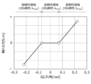
結合軸3は、エンジンEの出力軸とダイナモメータ2の出力軸とを接続する。結合軸3はクラッチを含み、したがってそのばね剛性は所定の範囲内で変動する特性がある。図2は、結合軸のねじれ角[rad]と軸トルク[Nm]との関係の一例を示す図である。図2では、傾きがばね剛性に相当する。図2に示すように結合軸のばね剛性は、ねじれ角が0[rad]を含む低剛性領域内では小さく、この低剛性領域外である高剛性領域内では大きくなる特性がある。すなわち、図2の例では、ばね剛性の変動範囲の下限値kminは結合軸が低剛性領域内にある状態におけるばね剛性に相当し、上限値kmaxは結合軸が高剛性領域内にある状態におけるばね剛性に相当する。
The connecting
図1に戻り、軸トルクメータ5は、結合軸3における軸トルクに応じた軸トルク検出信号を生成し、軸トルク制御器7へ送信する。軸トルク制御器7は、所定の軸トルク指令信号と軸トルクメータ5からの軸トルク検出信号との差である軸トルク制御偏差が無くなるように、これら軸トルク指令信号及び軸トルク検出信号を用いることによってダイナモメータ2で発生させるトルクに対する指令に相当するトルク電流指令信号を生成し、インバータ4に入力する。インバータ4は、軸トルク制御器7から入力されるトルク電流指令信号に応じた電力をダイナモメータ2に供給し、これによりトルク電流指令信号に応じたダイナモトルクをダイナモメータ2で発生させる。
Returning to FIG. 1, the
以上のような軸トルク制御を行う軸トルク制御器7は、図3に示すようなフィードバック制御系8を定義し、このフィードバック制御系8において所定の設計条件が満たされるように設計されたコントローラをデジタルシグナルプロセッサやマイクロコンピュータ等の入出力ポートを備えるハードウェアに実装して構成される。
The
以上のように構成された試験システムSにおいて、後述のコントローラKが実装された軸トルク制御器7は、図示しない上位コントローラから通信を介して送信される軸トルク指令信号と、ダイナモメータ2に装備された軸トルクメータ5から送信される軸トルク検出信号とが入力されると、トルク電流指令信号を生成し通信を介してインバータ4へ入力する。ダイナモメータ2と電気的に接続されているインバータ4は、軸トルク制御器7からトルク電流指令信号が入力されると、このトルク電流指令信号に応じたトルクをダイナモメータ2に発生させる。なおこの際に想定される外乱要素は、軸トルクメータ5において軸トルクを計測する際に発生するノイズや、各通信経路における時間の遅れ、インバータ4の制御応答等によるトルク電流指令信号と発生トルクとの間の非線形性のずれ等がある。なお上述の軸トルク指令信号は、上述のように軸トルク制御器7とは別の上位コントローラによって生成してもよいし、軸トルク制御器7の内部においてコントローラKとは別に構築されたモジュールによって生成してもよい。
In the test system S configured as above, the
図3のフィードバック制御系8は、エンジンEへの入力及びダイナモメータ2への入力から軸トルクメータ5の出力までの試験システムSの入出力特性を模した公称プラントNを有する一般化プラントPと、この一般化プラントPに対し入出力を与えるコントローラKと、公称プラントNに対し変動を与える変動部Δと、を組み合わせることによって構成される。
The
一般化プラントPには、第1外乱入力w1、第2外乱入力w2、及び第3外乱入力w3で構成される入力と、第1評価出力z1、第2評価出力z2、及び第3評価出力z3で構成される出力とが定義されている。以下では、第1外乱入力w1、第2外乱入力w2、及び第3外乱入力w3を成分とするベクトル量をwと表記し、第1評価出力z1、第2評価出力z2、及び第3評価出力z3を成分とするベクトル量をzと表記する。なお、一般化プラントPの具体的な構成については、後に図5及び図6を参照しながら詳細に説明する。 In the generalized plant P, an input consisting of a first disturbance input w1, a second disturbance input w2, and a third disturbance input w3, and an output consisting of a first evaluation output z1, a second evaluation output z2, and a third evaluation output z3 are defined. In the following, a vector quantity having components of the first disturbance input w1, the second disturbance input w2, and the third disturbance input w3 is denoted as w, and a vector quantity having components of the first evaluation output z1, the second evaluation output z2, and the third evaluation output z3 is denoted as z. The specific configuration of the generalized plant P will be described in detail later with reference to FIG. 5 and FIG. 6.
また一般化プラントPとコントローラKとの間には、軸トルク検出信号に相当する第1観測出力y1及び軸トルク指令信号に相当する第2観測出力y2と、トルク電流指令信号に相当する制御入力uとが定義されている。一般化プラントPとコントローラKとの間に以上のような入出力信号を設定することにより、図4に示すように、2つの伝達関数Ky1(s)及びKy2(s)を組み合わせて構成され、第1観測出力y1及び第2観測出力y2から制御入力uを出力する2自由度制御系のコントローラKが導出される。 Between the generalized plant P and the controller K, a first observation output y1 corresponding to the shaft torque detection signal, a second observation output y2 corresponding to the shaft torque command signal, and a control input u corresponding to the torque current command signal are defined. By setting the above-mentioned input/output signals between the generalized plant P and the controller K, as shown in FIG. 4, a two-degree-of-freedom control system controller K is derived that is configured by combining two transfer functions Ky1(s) and Ky2(s) and outputs a control input u from the first observation output y1 and the second observation output y2.
図3に戻り、一般化プラントPと変動部Δとの間には、スカラ量である変動入力ηとスカラ量である変動出力ξとが定義されている。変動部Δは、一般化プラントPから出力される変動入力ηに基づいて変動出力ξを生成し、この変動出力ξを一般化プラントPに与えることにより、公称プラントNに対し変動を与える。なおこの変動部Δの具体的な構成については、後に図10を参照して詳細に説明する。 Returning to FIG. 3, between the generalized plant P and the fluctuation section Δ, a fluctuation input η, which is a scalar quantity, and a fluctuation output ξ, which is also a scalar quantity, are defined. The fluctuation section Δ generates a fluctuation output ξ based on the fluctuation input η output from the generalized plant P, and provides this fluctuation output ξ to the generalized plant P, thereby providing a fluctuation to the nominal plant N. The specific configuration of this fluctuation section Δ will be described in detail later with reference to FIG. 10.
図5は、一般化プラントPの構成を示す図である。一般化プラントPは、制御対象である試験システムSの入出力特性を模した公称プラントNと、公称プラントNに含まれる少なくとも1つの変動モデルパラメータに対し変動を与える変動部Δと、複数の重み関数We(s),Wu(s),Wy(s),Wd(s),Wr(s),Wn(s)と、を組み合わせて構成される。 Figure 5 shows the configuration of the generalized plant P. The generalized plant P is composed of a nominal plant N that mimics the input/output characteristics of the test system S to be controlled, a fluctuation section Δ that imparts fluctuations to at least one fluctuation model parameter included in the nominal plant N, and multiple weighting functions We(s), Wu(s), Wy(s), Wd(s), Wr(s), and Wn(s).
公称プラントNは、図1の試験システムSにおいて、トルク電流指令信号に応じたダイナモトルクから軸トルク検出信号に応じた軸トルクまでの入出力特性を模した入出力特性を備える。 The nominal plant N has input/output characteristics that mimic the input/output characteristics from the dynamo torque corresponding to the torque current command signal to the shaft torque corresponding to the shaft torque detection signal in the test system S in Figure 1.
公称プラントNは、制御対象における入出力特性のうち特に低周波帯を模擬するように構築された低次モデルM1と、この低次モデルM1の出力に対し変動を与える変動要素M2と、を備える。図5に示すように、変動部Δは、低次モデルM1と接続されているが、変動要素M2とは接続されていない。換言すれば、低次モデルM1は変動モデルパラメータを含むのに対し、変動要素M2は変動モデルパラメータを含まない。 The nominal plant N comprises a low-order model M1 constructed to simulate the input/output characteristics of the controlled object, particularly the low-frequency band, and a variable element M2 that imparts variation to the output of the low-order model M1. As shown in FIG. 5, the variable part Δ is connected to the low-order model M1 but is not connected to the variable element M2. In other words, the low-order model M1 includes a variable model parameter, whereas the variable element M2 does not include a variable model parameter.
また本実施形態では、図5に示すように、変動要素M2は、低次モデルM1の出力に対し乗法的変動を与える場合について説明する。すなわち、低次モデルM1の伝達関数をPLとし、変動要素M2の伝達関数をWpとすると、公称プラントNの伝達関数PNは、下記式(3)によって表される。

図6は、公称モデルNの詳細な構成を示す図である。
上述のように低次モデルM1は、制御対象の低周波帯の入出力特性を模擬するように構築したものが用いられる。本実施形態では、低次モデルM1を、例えばエンジンEの慣性モーメントJEを有する第1慣性体と、ダイナモメータ2の慣性モーメントJDを有する第2慣性体とを、所定の公称値k0のばね剛性及び所定の減衰係数Dを有する1本の軸で連結して構成される2慣性系の運動方程式に基づいて構築した場合について説明する。この低次モデルM1は、図示しないエンジントルクと軸トルクとの和からエンジンに相当する第1慣性体の回転数(エンジン回転数)までの伝達関数Ga1(s)(下記式(4-1)参照)と、ダイナモトルクと軸トルクとの差からダイナモメータに相当する第2慣性体の回転数(ダイナモ回転数)までの伝達関数Ga2(s)(下記式(4-2)参照)と、エンジン回転数とダイナモ回転数との差から軸トルクまでの伝達関数Ga3(s)(下記式(4-3)参照)と、を図6に示すように組み合わせることによって構成される。

As described above, the low-order model M1 is constructed so as to simulate the input/output characteristics of the controlled object in the low frequency band. In this embodiment, the low-order model M1 is constructed based on the equation of motion of a two-inertia system formed by connecting, for example, a first inertial body having an inertial moment JE of an engine E and a second inertial body having an inertial moment JD of a
3つの伝達関数を組み合わせて構成される低次モデルM1において、慣性モーメントJE,JDは、それぞれ既知の方法によって取得されたエンジンEの慣性モーメント及びダイナモメータ2の慣性モーメントが用いられる。軸の減衰係数Dは、予め定められた正の値が用いられる。また、軸のばね剛性の公称値k0は、試験システムSで用いられる結合軸3のばね剛性に想定される変動範囲の下限値kminに定められる(k0=kmin)。ここでばね剛性の変動範囲の下限値kminとは、図2の例では、結合軸が低剛性領域内にあるときにおけるばね剛性の値である。
In the low-order model M1 formed by combining three transfer functions, the moments of inertia JE and JD are the moments of inertia of the engine E and the
以上のように、低次モデルM1では、エンジンの慣性モーメントと、ダイナモメータの慣性モーメントと、結合軸の減衰係数と、結合軸のばね剛性と、の4つのモデルパラメータが定義されている。変動部Δは、これら4つのモデルパラメータのうちの1つであるばね剛性に対し変動を与える。すなわち、低次モデルM1に含まれる4つのモデルパラメータのうち、変動部Δによって変動が付与される変動モデルパラメータは、ばね剛性となっている。より具体的には、低次モデルM1は、結合軸の回転速度に相当する入力信号ηにばね剛性の公称値k0を乗算する公称値乗算部51と、変動部Δの出力信号である変動出力信号ξと公称値乗算部51の出力信号とを合算する合算部52と、を備える。変動部Δは、公称値乗算部51に対する入力信号ηが入力されると、変動出力信号ξを生成し、合算部52へ入力する。これにより変動部Δは、低次モデルM1の変動モデルパラメータであるばね剛性に対し加法的変動を与える。
As described above, in the low-order model M1, four model parameters are defined: the moment of inertia of the engine, the moment of inertia of the dynamometer, the damping coefficient of the coupling shaft, and the spring stiffness of the coupling shaft. The variation unit Δ varies the spring stiffness, which is one of these four model parameters. That is, among the four model parameters included in the low-order model M1, the variation model parameter to which the variation unit Δ varies is the spring stiffness. More specifically, the low-order model M1 includes a nominal
変動要素M2は、以上のように制御対象の低周波帯における入出力特性を模した低次モデルM1の出力に対し、この低次モデルM1では模擬できない高周波帯において乗法的変動を与える重み関数である。すなわち変動要素M2は、主に低周波帯を模擬する低次モデルM1と変動要素M2とを合わせた公称プラントN全体により、制御対象の入出力特性の低周波帯から高周波帯までを模擬できるように設定される。 The variable element M2 is a weighting function that imparts a multiplicative variation in the high frequency band that cannot be simulated by the output of the low-order model M1, which imitates the input/output characteristics of the controlled object in the low frequency band as described above. In other words, the variable element M2 is set so that the input/output characteristics of the controlled object from the low frequency band to the high frequency band can be simulated by the entire nominal plant N, which combines the low-order model M1, which mainly simulates the low frequency band, and the variable element M2.
このため変動要素M2の伝達関数Wpは、制御対象の低周波帯及び高周波帯における入出力特性を模した高次モデルM3(後述の図7参照)の伝達関数PHと、制御対象の低周波帯における入出力特性を模した低次モデルM1の伝達関数PLとの差に基づいて定義される差分伝達関数δに基づいて設定される。変動要素M2によって低次モデルM1の出力に対し乗法的変動を与える場合、この差分伝達関数δは、下記式(5)によって定義される。

上記式(5)に示すような差分伝達関数δを定義した上、変動要素M2の伝達関数Wpは、全周波帯のうち低次モデルM1では模擬できない高周波帯の少なくとも一部において、差分伝達関数δよりもゲインが大きくなるように設定される。より具体的には、変動要素M2の伝達関数Wpは、高次モデルM3に含まれる複数のモデルパラメータのうち低次モデルM1に定義された変動モデルパラメータとは別のモデルパラメータの値を所定の変動範囲内で変動させることによって得られる複数の差分伝達関数δの全てよりも、高周波帯の全域においてゲインが大きくなるように設定される。 After defining the differential transfer function δ as shown in the above formula (5), the transfer function Wp of the variable element M2 is set so that the gain is greater than the differential transfer function δ in at least a part of the high frequency band that cannot be simulated by the low-order model M1 among all frequency bands. More specifically, the transfer function Wp of the variable element M2 is set so that the gain is greater across the entire high frequency band than all of the multiple differential transfer functions δ obtained by varying within a predetermined variation range the values of model parameters other than the variable model parameters defined in the low-order model M1 among the multiple model parameters included in the high-order model M3.
図7は、高次モデルM3の一例を示す図である。図7には、高次モデルM3を、慣性モーメントJ1,J2,J3,J4で特徴付けられる4個の慣性体をばね剛性k1,k2,k3,k4及び減衰係数D1,D2,D3,D4で特徴付けられる3本の軸体で直列に連結して構成される4慣性系の運動方程式に基づいて構築した場合を示す。なお上述の低次モデルM1において、変動部Δによって変動を付与するばね剛性k0は、図7に示す4慣性系ではばね剛性k3に相当し、低次モデルM1におけるエンジンEの慣性モーメントJEは、図7に示す4慣性系では慣性モーメントJ4に相当する。 Fig. 7 is a diagram showing an example of the high-order model M3. Fig. 7 shows a case where the high-order model M3 is constructed based on the equation of motion of a four-inertia system in which four inertia bodies characterized by inertia moments J1, J2 , J3 , and J4 are connected in series with three shaft bodies characterized by spring stiffnesses k1, k2, k3, and k4 and damping coefficients D1 , D2 , D3 , and D4 . In the above-mentioned low-order model M1, the spring stiffness k0 that is varied by the variable part Δ corresponds to the spring stiffness k3 in the four-inertia system shown in Fig. 7, and the inertia moment JE of the engine E in the low-order model M1 corresponds to the inertia moment J4 in the four-inertia system shown in Fig. 7.
図8は、低次モデルM1として採用する2慣性系モデル(実線参照)及び高次モデルM3として採用する4慣性系モデル(破線参照)の入出力特性を比較したボード線図である。図8に示すように、2慣性系モデルと4慣性系モデルとは、制御対象の1次共振周波数f1を含む低周波帯において概ね入出力特性が一致する。これに対し制御対象の2次共振周波数f2次及び3次共振周波数f3を含む高周波帯では、2慣性系モデルと4慣性系モデルとでは入出力特性が大きくずれる。すなわち4慣性系モデルは、制御対象の高周波帯における2次、及び3次共振点を再現できるのに対し、2慣性系モデルは、これら2次、3次共振点を再現することができない。以上のように高次モデルM3には、低次モデルM1では模擬できない高周波帯を模擬できるように構築したものが用いられる。 Figure 8 is a Bode diagram comparing the input/output characteristics of a two-inertia system model (see solid line) used as the low-order model M1 and a four-inertia system model (see dashed line) used as the high-order model M3. As shown in Figure 8, the two-inertia system model and the four-inertia system model have roughly the same input/output characteristics in the low-frequency band including the first-order resonance frequency f1 of the controlled object. In contrast, in the high-frequency band including the second-order resonance frequency f2 and the third-order resonance frequency f3 of the controlled object, the two-inertia system model and the four-inertia system model have a large difference in input/output characteristics. In other words, the four-inertia system model can reproduce the second-order and third-order resonance points in the high-frequency band of the controlled object, whereas the two-inertia system model cannot reproduce these second-order and third-order resonance points. As described above, the high-order model M3 is constructed to be able to simulate the high-frequency band that cannot be simulated by the low-order model M1.
なお以下では、低次モデルM1及び高次モデルM3をそれぞれ多慣性系モデルに基づいて構築した場合について説明するが、本発明はこれに限らない。すなわち低次モデルは、制御対象の低周波帯の入出力特性を模擬するように構築され、高次モデルは、この低次モデルでは模擬できない高周波帯の入出力特性を模擬するように構築されたものであればどのようなものであってもよい。 Note that, in the following, a case will be described in which the low-order model M1 and the high-order model M3 are each constructed based on a multi-inertia system model, but the present invention is not limited to this. In other words, the low-order model is constructed to simulate the input/output characteristics of the control target in the low frequency band, and the high-order model may be any model constructed to simulate the input/output characteristics of the high frequency band that cannot be simulated by the low-order model.
また以下では、低次モデルM1を2慣性系モデルに基づいて構築し、高次モデルM3を4慣性系モデルに基づいて構築した場合について説明するが、本発明はこれに限らない。低次モデルは、所定の慣性モーメントで特徴付けられるi個(iは、2以上の整数)以上の慣性体を所定のばね剛性及び減衰係数で特徴付けられるi-1本の軸体で直列に連結して構成されるi慣性系モデルに基づいて構築してもよい。またこの場合、高次モデルは、所定の慣性モーメントで特徴付けられるj個(jは、iより大きな整数)以上の慣性体を所定のばね剛性及び減衰係数で特徴付けられるj-1本の軸体で直列に連結して構成されるj慣性系モデルに基づいて構築してもよい。 In the following, a case will be described in which the low-order model M1 is constructed based on a two-inertia system model and the high-order model M3 is constructed based on a four-inertia system model, but the present invention is not limited to this. The low-order model may be constructed based on an i-inertia system model consisting of i (i is an integer equal to or greater than 2) or more inertial bodies characterized by a predetermined moment of inertia connected in series with i-1 shaft bodies characterized by predetermined spring stiffness and damping coefficient. In this case, the high-order model may be constructed based on a j-inertia system model consisting of j (j is an integer greater than i) or more inertial bodies characterized by a predetermined moment of inertia connected in series with j-1 shaft bodies characterized by predetermined spring stiffness and damping coefficient.
図9は、変動要素M2及び3つ差分伝達関数δ1,δ2,δ3の入出力特性を比較したボード線図である。より具体的には、図9は、変動要素M2の設定例を示す図である。なお図9には、上記式(5)によって定義される差分伝達関数δに含まれる複数のモデルパラメータのうち、低次モデルM1の変動モデルパラメータk0に相当するばね剛性k3以外のモデルパラメータであるばね剛性k2及び慣性モーメントJ3を所定の変動範囲内で変動させることによって得られる3つの差分伝達関数δ1,δ2,δ3を重ねてプロットした。 Fig. 9 is a Bode diagram comparing the input/output characteristics of the variable element M2 and the three differential transfer functions δ1, δ2, and δ3. More specifically, Fig. 9 is a diagram showing an example of setting the variable element M2. In Fig. 9, three differential transfer functions δ1, δ2, and δ3 obtained by varying the spring stiffness k2 and the moment of inertia J3 , which are model parameters other than the spring stiffness k3 corresponding to the variable model parameter k0 of the low-order model M1, within a predetermined variation range, among the multiple model parameters included in the differential transfer function δ defined by the above formula (5), are plotted in an overlapping manner.
図9に示すように、変動要素M2の伝達関数Wpは、1~3次共振周波数f1~f3を全て含む全周波帯において、3つの差分伝達関数δ1~δ3の全てよりもゲインが大きくなるように設定される。 As shown in FIG. 9, the transfer function Wp of the variable element M2 is set so that its gain is greater than that of all three differential transfer functions δ1 to δ3 in the entire frequency band including the first to third resonance frequencies f1 to f3.
なお本実施形態では、低次モデルM1の変動モデルパラメータをばね剛性k0とし、差分伝達関数δに含まれる複数のモデルパラメータのうちばね剛性k2及び慣性モーメントJ3を所定の変動範囲内で変動させた場合について説明したが、本発明はこれに限らない。例えば低次モデルM1の変動モデルパラメータを慣性モーメントJEとした場合、差分伝達関数δに含まれる複数のモデルパラメータのうちばね剛性k2,k3を所定の変動範囲内で変動させることによって複数の差分伝達関数を設定し、変動要素M2の伝達関数Wpをこれら差分伝達関数の全てよりもゲインが大きくなるように設定してもよい。 In this embodiment, the case has been described where the variable model parameter of the low-order model M1 is the spring stiffness k0 , and among the multiple model parameters included in the differential transfer function δ, the spring stiffness k2 and the moment of inertia J3 are varied within a predetermined variation range, but the present invention is not limited to this. For example, when the variable model parameter of the low-order model M1 is the moment of inertia JE , among the multiple model parameters included in the differential transfer function δ, the spring stiffnesses k2 and k3 are varied within a predetermined variation range to set multiple differential transfer functions, and the transfer function Wp of the variable element M2 may be set so that its gain is larger than all of these differential transfer functions.
図5に戻り、一般化プラントPには、第1外乱入力w1、第2外乱入力w2、第3外乱入力w3、第1評価出力z1、第2評価出力z2、第3評価出力z3、制御入力u、第1観測出力y1、第2観測出力y2、変動入力η、及び変動出力ξから成る複数の入出力信号が定義されている。これら入出力信号と図1の試験システムSとの対応関係は以下の通りである。 Returning to FIG. 5, the generalized plant P has multiple input/output signals defined, which are the first disturbance input w1, the second disturbance input w2, the third disturbance input w3, the first evaluation output z1, the second evaluation output z2, the third evaluation output z3, the control input u, the first observation output y1, the second observation output y2, the fluctuation input η, and the fluctuation output ξ. The correspondence between these input/output signals and the test system S in FIG. 1 is as follows:
第1外乱入力w1は、一般化プラントPへの入力信号であり、コントローラKから出力される制御入力uに対する外乱に相当する。第1外乱入力w1は、予め設定された重み関数Wd(s)によって重み付けされる。第2外乱入力w2は、一般化プラントPへの入力信号であり、コントローラKに入力される軸トルク指令信号に相当する。第2外乱入力w2は、予め設定された重み関数Wr(s)によって重み付けされる。第3外乱入力w3は、一般化プラントPへの入力信号であり、コントローラKに入力される軸トルク検出信号に対する外乱に相当する。第3外乱入力w3は、予め設定された重み関数Wn(s)によって重み付けされる。 The first disturbance input w1 is an input signal to the generalized plant P and corresponds to a disturbance to the control input u output from the controller K. The first disturbance input w1 is weighted by a preset weighting function Wd(s). The second disturbance input w2 is an input signal to the generalized plant P and corresponds to the shaft torque command signal input to the controller K. The second disturbance input w2 is weighted by a preset weighting function Wr(s). The third disturbance input w3 is an input signal to the generalized plant P and corresponds to a disturbance to the shaft torque detection signal input to the controller K. The third disturbance input w3 is weighted by a preset weighting function Wn(s).
制御入力uは、コントローラKから一般化プラントPへの入力信号であり、トルク電流指令信号に相当する。この制御入力uと、重み関数Wd(s)で重み付けされた第1外乱入力w1とを合算したものは、公称プラントNに入力される。第1観測出力y1は、一般化プラントPからコントローラKへの入力信号であり、軸トルク検出信号に相当する。この第1観測出力y1には、公称プラントNの出力と、重み関数Wn(s)で重み付けされた第3外乱入力w3とを合算したものが用いられる。第2観測出力y2は、コントローラKへの入力信号であり、軸トルク指令信号に相当する。この第2観測出力y2には、重み関数Wr(s)で重み付けされた第2外乱入力w2が用いられる。 The control input u is an input signal from the controller K to the generalized plant P, and corresponds to a torque current command signal. The sum of this control input u and the first disturbance input w1 weighted by the weighting function Wd(s) is input to the nominal plant N. The first observation output y1 is an input signal from the generalized plant P to the controller K, and corresponds to an axial torque detection signal. The first observation output y1 is the sum of the output of the nominal plant N and the third disturbance input w3 weighted by the weighting function Wn(s). The second observation output y2 is an input signal to the controller K, and corresponds to an axial torque command signal. The second disturbance input w2 weighted by the weighting function Wr(s) is used for this second observation output y2.
第1評価出力z1は、一般化プラントPの出力信号であり、重み付きの軸トルク制御偏差に相当する。この第1評価出力z1には、軸トルク指令信号に相当する第2観測出力y2からトルク電流指令信号に相当する制御入力uを減算して得られる偏差を、予め設定された重み関数We(s)で重み付けしたものが用いられる。第2評価出力z2は、一般化プラントPの出力信号であり、重み付きのトルク電流指令信号に相当する。この第2評価出力z2には、上述のようにトルク電流指令信号に相当する制御入力uを予め設定された重み関数Wu(s)によって重み付けしたものが用いられる。第3評価出力z3は、一般化プラントPの出力信号であり、重み付きの軸トルク検出信号に相当する。この第3評価出力z3には、公称プラントNの出力を予め設定された重み関数Wy(s)で重み付けしたものが用いられる。 The first evaluation output z1 is an output signal of the generalized plant P and corresponds to a weighted shaft torque control deviation. The deviation obtained by subtracting the control input u corresponding to the torque current command signal from the second observation output y2 corresponding to the shaft torque command signal is weighted by a preset weighting function We(s) and used as the first evaluation output z1. The second evaluation output z2 is an output signal of the generalized plant P and corresponds to a weighted torque current command signal. The second evaluation output z2 is a control input u corresponding to the torque current command signal weighted by a preset weighting function Wu(s) as described above and used as the second evaluation output z2. The third evaluation output z3 is an output signal of the generalized plant P and corresponds to a weighted shaft torque detection signal. The third evaluation output z3 is a nominal plant N output weighted by a preset weighting function Wy(s).
図10は、変動部Δの構成を示す図である。変動部Δは、有界変動生成部61と、位相調整部62と、正規化部63と、を備え、これらを用いることにより、公称プラントNから入力される入力信号ηから変動出力信号ξを生成し、公称プラントNへ入力する。
Figure 10 shows the configuration of the variation unit Δ. The variation unit Δ includes a bounded
有界変動生成部61は、正規化部63から入力される入力信号η1に、非有界の複素変動Δgのケーリー変換による写像を乗算することにより有界の変動信号ξ1を生成し、位相調整部62へ出力する。より具体的には、有界変動生成部61は、下記式(6)に示すように、複素変動Δgのケーリー変換による写像Δpを入力信号η1に乗算することによって変動信号ξ1を生成する。下記式(6)に示すケーリー変換によれば、複素平面の右半平面にわたる非有界の複素変動Δgは、図11に示すように、原点を中心とした半径が1の単位円内に写像される。

位相調整部62は、有界変動生成部61によって生成された有界の変動信号ξ1に所定の位相調整伝達関数Wscope(s)を乗算することによって変動信号ξ1の位相を変化させる。後に図12を参照して説明するように、この位相調整伝達関数Wscope(s)の関数形は、有界変動生成部61から出力される変動信号ξ1から有界変動生成部61へ入力される入力信号η1までの伝達関数M(s)が正実関数になるように設定される。ここで伝達関数M(s)について下記不等式(7)が成立する場合、伝達関数M(s)は正実関数であると定義される。ここでM*(s)は、M(s)の複素共役である。

正規化部63は、位相調整部62の出力信号と公称プラントNから入力される入力信号ηとを用いて、変動部Δから出力される変動出力信号ξのノルムを所定範囲内に制限する。正規化部63は、入力信号ηに所定の第2ノルムN2を乗算したものから位相調整部62の出力信号に所定の第1ノルムN1を乗算して得られる信号η1を有界変動生成部61へ入力するとともに、位相調整部62の出力信号に所定の第3ノルムN3を乗算することによって変動出力信号ξを生成し、公称プラントNへ入力する。ここで各ノルムN1,N2,N3は、例えば下記式(8)に示すように設定される。これにより、変動部Δによって生成される変動出力信号ξのノルムは0~kmax-kminの間に制限される。

図12は、本実施形態に係る制御器設計方法の具体的な手順を示すフローチャートである。 Figure 12 is a flowchart showing the specific steps of the controller design method according to this embodiment.
始めにS1では、設計者は、コンピュータを用いることによって低次モデルM1及び変動要素M2を設定し、これら低次モデルM1及び変動要素M2を組み合わせることによって、図6に示すように公称プラントNを設定する。より具体的には、設計者は、コンピュータを用いることによって、低次モデルM1及び高次モデルM3を設定し、これら低次モデルM1及び高次モデルM3を用いることによって上記式(5)に従って差分伝達関数δを設定し、この差分伝達関数δに基づいて変動要素M2の伝達関数を設定する。より具体的には、高次モデルM3に含まれる複数のモデルパラメータのうち変動モデルパラメータとは別のモデルパラメータの値を所定の変動範囲内で変動させることにより、複数の差分伝達関数を設定するとともに、図9を参照して説明したように、低周波帯及び高周波帯を含む全周波帯において、これら複数の差分伝達関数の全てよりもゲインが大きくなるように変動要素M2の伝達関数Wpを設定する。その後、設計者は、コンピュータを用いることによって、低次モデルM1と変動要素M2とを図6に示すように組み合わせることにより、公称プラントNを設定する。 First, in S1, the designer sets the low-order model M1 and the variable element M2 by using a computer, and sets the nominal plant N as shown in FIG. 6 by combining the low-order model M1 and the variable element M2. More specifically, the designer sets the low-order model M1 and the high-order model M3 by using a computer, and sets the differential transfer function δ according to the above formula (5) by using the low-order model M1 and the high-order model M3, and sets the transfer function of the variable element M2 based on this differential transfer function δ. More specifically, the designer sets multiple differential transfer functions by varying the values of model parameters other than the variable model parameters among the multiple model parameters included in the high-order model M3 within a predetermined variation range, and sets the transfer function Wp of the variable element M2 so that the gain is larger than all of the multiple differential transfer functions in all frequency bands including the low frequency band and the high frequency band, as described with reference to FIG. 9. After that, the designer sets the nominal plant N by combining the low-order model M1 and the variable element M2 as shown in FIG. 6 by using a computer.
次にS2では、設計者は、コンピュータを用いることによって、図5及び図10に示すように変動部Δ、及び重み関数Wd(s),Wr(s),Wn(s),We(s),Wu(s),Wy(s)を設定する。 Next, in S2, the designer uses a computer to set the variable part Δ and the weighting functions Wd(s), Wr(s), Wn(s), We(s), Wu(s), and Wy(s) as shown in Figures 5 and 10.
次にS3~S7では、設計者は、コンピュータを用いることによって、位相調整伝達関数設定工程(S3及びS5)とサブコントローラ設計工程(S4及びS6参照)とを交互にn回(nは、2以上の整数)にわたり繰り返し行うことによって(S7参照)、合計n台のサブコントローラを設計する。 Next, in S3 to S7, the designer uses a computer to alternately repeat the phase adjustment transfer function setting process (S3 and S5) and the subcontroller design process (see S4 and S6) n times (n is an integer equal to or greater than 2) (see S7) to design a total of n subcontrollers.
より具体的には、1回目の位相調整伝達関数設定工程(S3参照)では、設計者は、コンピュータを用いることによって、S1及びS2で設定された公称プラントN、変動部Δ、及び重み関数Wd(s)等を図5に示すように組み合わせ、フィードバック制御系を定義し、このフィードバック制御系に基づいて位相調整伝達関数Wscope(s)を設定する。より具体的には、1回目の位相調整伝達関数設定工程では、上記フィードバック制御系から設計対象であるコントローラKを切り離した状態で、変動部Δの有界変動生成部61から出力される変動信号ξ1から有界変動生成部61へ入力される入力信号η1までの伝達関数M(s)が正実関数になるように位相調整伝達関数Wscope(s)を設定する。より具体的には、遺伝的アルゴリズムや粒子群最適化法等の既知のメタヒューリスティックアルゴリズムを利用することによって上記伝達関数M(s)が正実関数になるように位相調整伝達関数Wscope(s)を設定する。
More specifically, in the first phase adjustment transfer function setting step (see S3), the designer uses a computer to combine the nominal plant N, the fluctuation part Δ, and the weight function Wd(s) set in S1 and S2 as shown in Fig. 5 to define a feedback control system, and sets the phase adjustment transfer function W scope (s) based on this feedback control system. More specifically, in the first phase adjustment transfer function setting step, in a state where the controller K, which is the design target, is separated from the feedback control system, the phase adjustment transfer function W scope (s) is set so that the transfer function M(s) from the fluctuation signal ξ1 output from the bounded
次に1回目のサブコントローラ設計工程(S4参照)では、設計者は、コンピュータを用いることによって、サブコントローラを設計する。より具体的には、設計者は、S3に示す1回目の位相調整伝達関数設定工程を経て設定された位相調整伝達関数Wscope(s)を含みかつコントローラKとして設計対象であるサブコントローラが接続されたフィードバック制御系において、ロバスト安定性が実現するように定められた所定の設計条件が満たされるように、コンピュータによってサブコントローラを設計する。より具体的には、このようなサブコントローラは、例えばコンピュータ上でD-Kイタレーション法に基づく反復演算を行うことによって導出される。 Next, in the first sub-controller design step (see S4), the designer uses a computer to design the sub-controller. More specifically, the designer uses a computer to design the sub-controller so that predetermined design conditions are satisfied that are set so as to realize robust stability in a feedback control system that includes the phase adjustment transfer function W scope (s) set through the first phase adjustment transfer function setting step shown in S3 and is connected to a sub-controller that is the design target as controller K. More specifically, such a sub-controller is derived, for example, by performing iterative calculations based on the D-K iteration method on a computer.
次に2回目以降の位相調整伝達関数設定工程(S5参照)では、一般化プラントに1回目から前回のサブコントローラ設計工程を経て設計された1台又は複数台のサブコントローラを並列に接続した状態で、1回目の位相調整伝達関数設定工程と同様の手順によって位相調整伝達関数Wscope(s)を再設定する。 Next, in the second or subsequent phase adjustment transfer function setting process (see S5), one or more sub-controllers designed through the first to previous sub-controller design process are connected in parallel to the generalized plant, and the phase adjustment transfer function W scope (s) is reset using a procedure similar to that of the first phase adjustment transfer function setting process.
次に2回目以降のサブコントローラ設計工程(S6参照)では、フィードバック制御系に前回の位相調整伝達関数設定工程を経て設定された位相調整伝達関数Wscope(s)を含めかつ一般化プラントに1回目から前回のサブコントローラ設計工程を経て設計された1台又は複数台のサブコントローラと今回設計対象とするサブコントローラとを並列に接続した状態で、1回目のサブコントローラ設計工程と同様の手順によってサブコントローラを設計する。 Next, in the second or subsequent sub-controller design process (see S6), the feedback control system includes the phase adjustment transfer function W scope (s) set through the previous phase adjustment transfer function setting process, and one or more sub-controllers designed through the first to previous sub-controller design processes and the sub-controller to be designed this time are connected in parallel to the generalized plant, and a sub-controller is designed using the same procedure as in the first sub-controller design process.
設計者は、以上のような位相調整伝達関数設定工程とサブコントローラ設計工程とを交互にn回にわたり繰り返し行うことにより、合計n台のサブコントローラの設計が完了した場合には、S8に移る。 The designer repeats the above-described phase adjustment transfer function setting process and sub-controller design process n times alternately, and when the design of a total of n sub-controllers is completed, the process proceeds to S8.
次にS8に示すサブコントローラ合成工程では、設計者は、コンピュータを用いることによって、図13に示すように、1回目のサブコントローラ設計工程を経て設計されたサブコントローラK1と、2回目のサブコントローラ設計工程を経て設計されたサブコントローラK2と、…n回目のサブコントローラ設計工程を経て設計されたサブコントローラKnとを並列に接続することによってコントローラKを設計する。 Next, in the subcontroller synthesis process shown in S8, the designer uses a computer to design controller K by connecting in parallel subcontroller K1 designed through the first subcontroller design process, subcontroller K2 designed through the second subcontroller design process, and subcontroller Kn designed through the nth subcontroller design process, as shown in FIG. 13.
次にS9では、設計者は、n台のサブコントローラを組み合わせて設計されたコントローラKをデジタルシグナルプロセッサに実装することによって軸トルク制御器7を設計する。
Next, in S9, the designer designs the
本実施形態に係る制御器設計方法によれば、以下の効果を奏する。 The controller design method according to this embodiment provides the following advantages:
(1)本実施形態では、制御対象の入出力特性を模した公称プラントN及びこの公称プラントNに含まれる少なくとも1つの変動モデルパラメータに対し変動を与える変動部Δを含む一般化プラントPと、この一般化プラントPからの出力に基づいて一般化プラントPへの入力を与えるコントローラKと、を備えるフィードバック制御系において、所定の設計条件を満たすようにコンピュータによってコントローラKを設計する。本発明では、公称プラントNとして、変動モデルパラメータを含みかつ制御対象の低周波帯における入出力特性を模した低次モデルM1を備えるものを用いる。これにより、低次モデルM1によって十分に近似できる低周波帯では、モデルパラメータの変動に対し安定性が保証されたコントローラKを設計することができる。また本実施形態では、公称プラントNとして、上記低次モデルM1に加え、変動パラメータを含まずかつこの低次モデルM1の出力に対し変動を与える変動要素M2を備えるものを用い、またこの変動要素M2の伝達関数Wpを、制御対象の高周波帯における入出力特性を模した高次モデルM3の伝達関数PHと低次モデルM1の伝達関数PLとの差に基づいて定義される差分伝達関数δよりもゲインが大きくなるように設定する。これにより、低次モデルM1だけでは十分に近似できない高周波帯においても安定性が保証されたコントローラKを設計することができる。 (1) In this embodiment, in a feedback control system including a nominal plant N simulating the input/output characteristics of a controlled object, a generalized plant P including a fluctuation part Δ that gives fluctuations to at least one fluctuation model parameter included in the nominal plant N, and a controller K that gives an input to the generalized plant P based on an output from the generalized plant P, the controller K is designed by a computer so as to satisfy a predetermined design condition. In the present invention, the nominal plant N is one that includes the fluctuation model parameters and has a low-order model M1 that simulates the input/output characteristics of the controlled object in a low-frequency band. This makes it possible to design a controller K whose stability against fluctuations in the model parameters is guaranteed in a low-frequency band that can be sufficiently approximated by the low-order model M1. In this embodiment, in addition to the above-mentioned low-order model M1, a nominal plant N is used that includes a variable element M2 that does not include a variable parameter and causes a fluctuation in the output of this low-order model M1, and the transfer function Wp of this variable element M2 is set so that its gain is larger than the differential transfer function δ defined based on the difference between the transfer function P H of the high-order model M3 that imitates the input/output characteristics of the controlled object in a high-frequency band and the transfer function P L of the low-order model M1. This makes it possible to design a controller K whose stability is guaranteed even in a high-frequency band that cannot be sufficiently approximated by the low-order model M1 alone.
(2)本実施形態では、低次モデルM1の出力に対し乗法的変動を与える変動要素M2の伝達関数Wpを、上記式(5)によって定義される差分伝達関数δよりもゲインが大きくなるように設定する。これにより、高周波帯における安定性がさらに保証されたコントローラKを設計することができる。 (2) In this embodiment, the transfer function Wp of the variable element M2 that imparts a multiplicative variation to the output of the low-order model M1 is set so that its gain is greater than the differential transfer function δ defined by the above formula (5). This makes it possible to design a controller K with even greater guaranteed stability in the high frequency band.
(3)本実施形態において、変動要素M2の伝達関数Wpを設定する変動要素設定工程(図12のS1参照)では、高次モデルM3に含まれる複数のモデルパラメータのうち変動モデルパラメータとは別のモデルパラメータの値を所定の変動範囲内で変動させることによって得られる複数の差分伝達関数の全てよりもゲインが大きくなるように変動要素M2の伝達関数Wpを設定する。これにより、低次モデルM1には含まれなないが高次モデルM3には含まれるモデルパラメータの変動に起因して高周波帯における制御が不安定になるのを防止することができる。 (3) In this embodiment, in the variable element setting step (see S1 in FIG. 12) for setting the transfer function Wp of the variable element M2, the transfer function Wp of the variable element M2 is set so that the gain is greater than all of the multiple differential transfer functions obtained by varying within a predetermined variation range the value of a model parameter other than the variable model parameter among the multiple model parameters included in the high-order model M3. This makes it possible to prevent control in the high frequency band from becoming unstable due to the variation of a model parameter that is not included in the low-order model M1 but is included in the high-order model M3.
(4)本実施形態では、変動部Δから出力される変動出力信号ξによって、低次モデルM1の変動モデルパラメータに対し加法的変動を与えるとともに、変動部Δでは、複素変動Δgのケーリー変換による写像Δpを用いることによって上記変動出力信号ξを生成する。ケーリー変換によれば、複素平面の右半平面にわたる非有界の複素変動Δgは、単位円内に写像される。このため本実施形態によれば、ケーリー変換によって得られる有界の複素変動を変動出力信号ξとして用いることができるので、変動モデルパラメータの変動範囲を陽に指定しながらコントローラKを設計できる。 (4) In this embodiment, the fluctuation output signal ξ output from the fluctuation unit Δ gives an additive fluctuation to the fluctuation model parameters of the low-order model M1, and the fluctuation unit Δ generates the fluctuation output signal ξ by using a mapping Δp by the Cayley transform of the complex fluctuation Δg. According to the Cayley transform, the unbounded complex fluctuation Δg across the right half plane of the complex plane is mapped within a unit circle. Therefore, according to this embodiment, the bounded complex fluctuation obtained by the Cayley transform can be used as the fluctuation output signal ξ, so that the controller K can be designed while explicitly specifying the fluctuation range of the fluctuation model parameters.
(5)本実施形態では、所定の入力信号η1にケーリー変換による写像Δpを乗算することにより有界の変動信号ξ1を生成する有界変動生成部61と、位相調整伝達関数Wscope(s)を用いて変動信号ξ1の位相を変化させる位相調整部62と、位相調整部62の出力信号と公称値乗算部51の入力信号ηとを用いて変動出力信号ξのノルムを所定範囲内に制限する正規化部63とを備える変動部Δを用いることによって変動モデルパラメータに対する変動を与える。本実施形態によれば、変動モデルパラメータの変動範囲の上限や下限が予め判明している場合には、正規化部63において変動出力信号ξのノルムをこれら上限及び下限を用いて定められる範囲内に制限することにより、現実に即したコントローラKを設計できる。
(5) In this embodiment, a variation is given to the variation model parameters by using a variation unit Δ including a bounded
(6)本実施形態では、位相調整伝達関数設定工程(図12のS3及びS5参照)とサブコントローラ設計工程(図12のS4及びS6参照)とを交互にn回(nは2以上の整数)にわたり繰り返し行うことによって設計されたn台のサブコントローラK1~Knを並列に接続することによってコントローラKを設計する。これにより、位相調整伝達関数Wscope(s)及びコントローラKを最適化することができる。 (6) In this embodiment, the phase adjustment transfer function setting step (see S3 and S5 in FIG. 12) and the sub-controller design step (see S4 and S6 in FIG. 12) are alternately repeated n times (n is an integer of 2 or more), and n sub-controllers K1 to Kn designed by these steps are connected in parallel to design the controller K. This makes it possible to optimize the phase adjustment transfer function W scope (s) and the controller K.
(7)本実施形態において、1回目の位相調整伝達関数設定工程では、フィードバック制御系からコントローラKを切り離した状態で位相調整伝達関数Wscope(s)を設定し、1回目のサブコントローラ設計工程では、フィードバック制御系に1回目の位相調整伝達関数設定工程を経て設定された位相調整伝達関数Wscope(s)を含めた状態でサブコントローラK1を設計する。また2回目以降の位相調整伝達関数設定工程では、一般化プラントに1回目から前回のサブコントローラ設計工程を経て設計された1台又は複数台のサブコントローラを並列に接続した状態で位相調整伝達関数Wscope(s)を設定し、2回目以降のサブコントローラ設計工程では、フィードバック制御系に前回の位相調整伝達関数設定工程を経て設定された位相調整伝達関数Wscope(s)を含めかつ一般化プラントに1回目から前回のサブコントローラ設計工程を経て設計された1台又は複数台のサブ制御器を並列に接続した状態でサブコントローラを設計する。これにより、位相調整伝達関数Wscope(s)及びコントローラKを最適化することができる。 (7) In this embodiment, in the first phase adjustment transfer function setting step, the phase adjustment transfer function W scope (s) is set in a state where the controller K is separated from the feedback control system, and in the first sub-controller design step, the sub-controller K1 is designed in a state where the phase adjustment transfer function W scope (s) set through the first phase adjustment transfer function setting step is included in the feedback control system. In the second and subsequent phase adjustment transfer function setting steps, the phase adjustment transfer function W scope (s) is set in a state where one or more sub-controllers designed through the first to previous sub-controller design steps are connected in parallel to the generalized plant, and in the second and subsequent sub-controller design steps, the sub-controller is designed in a state where the phase adjustment transfer function W scope (s) set through the previous phase adjustment transfer function setting step is included in the feedback control system and one or more sub-controllers designed through the first to previous sub-controller design steps are connected in parallel to the generalized plant. This makes it possible to optimize the phase adjustment transfer function W scope (s) and the controller K.
(8)本実施形態では、メタヒューリスティックアルゴリズムによって、上記変動信号ξ1から上記入力信号η1までの伝達関数M(s)が正実関数になるように位相調整伝達関数Wscope(s)を設定する。これにより、設計者のスキルによらず速やかに位相調整伝達関数Wscope(s)を設定できる。 (8) In this embodiment, a metaheuristic algorithm is used to set the phase adjustment transfer function W scope (s) so that the transfer function M(s) from the fluctuation signal ξ1 to the input signal η1 becomes a positive real function. This allows the phase adjustment transfer function W scope (s) to be set quickly regardless of the designer's skill.
(9)本実施形態では、i個(iは2以上の整数)の慣性体をi-1本以上の軸体で直列に連結して構成されるi慣性系に基づいて低次モデルM1を構築し、j個(jはiより大きな整数)の慣性体をj-1本以上の軸体で直列に連結して構成されるj慣性系に基づいて高次モデルM3を構築する。また本実施形態では、上記慣性体の慣性モーメント、並びに上記軸体のばね剛性及び減衰係数の少なくとも何れかを、変動部Δによって変動を与える変動モデルパラメータとし、上記多慣性系を制御対象とする軸トルク制御器7を設計する。これにより、慣性モーメント、ばね剛性、及び減衰係数等が変動する場合であっても安定かつ高応答な制御を実現できる軸トルク制御器7を設計できる。
(9) In this embodiment, a low-order model M1 is constructed based on an i-inertia system consisting of i (i is an integer of 2 or more) inertial bodies connected in series with i-1 or more shafts, and a high-order model M3 is constructed based on a j-inertia system consisting of j (j is an integer greater than i) inertial bodies connected in series with j-1 or more shafts. In this embodiment, at least one of the inertia moment of the inertial body and the spring stiffness and damping coefficient of the shaft is set as a variable model parameter that is fluctuated by a fluctuation part Δ, and an
(11)本実施形態では、スロットル開度指令信号に応じてトルクを発生するエンジンEと、トルク電流指令信号に応じてトルクを発生するダイナモメータ2と、エンジンEとダイナモメータ2とを接続する結合軸3と、結合軸3における軸トルクに応じた軸トルク検出信号を生成する軸トルクメータ5とを備える試験システムSを制御対象とし、2つの慣性体を1つ以上の軸体で直列に連結して構成される2慣性系に基づいて低次モデルM1を構築し、4慣性系に基づいて高次モデルM3を構築し、上記2慣性系の軸体のばね剛性k0を変動部Δによって変動を与える変動モデルパラメータとし、軸トルク検出信号及び軸トルク指令信号に応じてトルク電流指令信号を出力する軸トルク制御器7を設計する。上述のようにエンジンEとダイナモメータ2とを接続する結合軸にはクラッチが含まれており、そのばね剛性k0が大きく変動する特性がある。これに対し制御器設計方法によれば、安定かつ高応答な制御を実現できる試験システムSの軸トルク制御器7を設計できる。
(11) In this embodiment, a test system S including an engine E that generates torque in response to a throttle opening command signal, a
以上、本発明の一実施形態について説明したが、本発明はこれに限らない。本発明の趣旨の範囲内で、細部の構成を適宜変更してもよい。 Although one embodiment of the present invention has been described above, the present invention is not limited to this. The detailed configuration may be modified as appropriate within the scope of the spirit of the present invention.
例えば上記実施形態では、公称プラントNにおいて変動要素M2は、低次モデルM1の出力に対し乗法的変動を与える場合について説明したが、本発明はこれに限らない。例えば図14に示すように、公称プラントN´において、変動要素M2´は、低次モデルM1の出力に対し加法的変動を与えるようにしてもよい。なお図14に示すように公称モデルN´を定義した場合、差分伝達関数δは、下記式(9)によって定義したものが用いられる。

P…一般化プラント
N,N´…公称プラント
M1…低次モデル
M2,M2´…変動要素
M3…高次モデル
51…公称値乗算部
52…合算部
Δ…変動部
61…有界変動生成部
62…位相調整部
63…正規化部
K…コントローラ(制御器)
K1,…,Kn…サブコントローラ(サブ制御器)
S…試験システム
E…エンジン(供試体)
2…ダイナモメータ
3…結合軸
5…軸トルクメータ
7…軸トルク制御器
P...Generalized plant N, N'...Nominal plant M1...Low-order model M2, M2'...Variation factor M3...High-
K1, ..., Kn... sub-controllers (sub-controllers)
S: Test system E: Engine (test specimen)
2...
Claims (11)
前記公称プラントは、前記変動モデルパラメータを含みかつ前記制御対象の低周波帯における入出力特性を模した低次モデルと、前記変動モデルパラメータを含まずかつ前記低次モデルの出力に対し変動を与える変動要素と、を備え、
前記変動要素の伝達関数は、前記低周波帯よりも高い高周波帯の少なくとも一部において、前記制御対象の前記高周波帯における入出力特性を模した高次モデルの伝達関数と前記低次モデルの伝達関数との差に基づいて定義される差分伝達関数よりもゲインが大きくなるように設定されることを特徴とする制御器設計方法。 A controller design method for a feedback control system including a nominal plant simulating an input/output characteristic of a controlled object, a generalized plant including a fluctuation unit that fluctuates at least one fluctuation model parameter included in the nominal plant, and a controller that provides an input to the generalized plant based on an output from the generalized plant, the method comprising the steps of: designing the controller by a computer so as to satisfy a predetermined design condition,
the nominal plant comprises a low-order model including the variable model parameters and simulating an input/output characteristic in a low frequency band of the controlled object, and a variable element not including the variable model parameters and causing a fluctuation in an output of the low-order model,
a transfer function of the variable element is set so that, in at least a part of a high frequency band higher than the low frequency band, the transfer function has a larger gain than a differential transfer function defined based on the difference between a transfer function of a high-order model that imitates input/output characteristics of the controlled object in the high frequency band and a transfer function of the low-order model.
前記低次モデルの伝達関数をPLとし、前記高次モデルの伝達関数をPHとした場合、前記差分伝達関数δは、下記式(1)によって定義されることを特徴とする請求項1に記載の制御器設計方法。

2. The controller design method according to claim 1, wherein, when a transfer function of the low-order model is P L and a transfer function of the high-order model is P H , the differential transfer function δ is defined by the following equation (1):
前記低次モデルの伝達関数をPLとし、前記高次モデルの伝達関数をPHとした場合、前記差分伝達関数δは、下記式(2)によって定義されることを特徴とする請求項1に記載の制御器設計方法。

2. The controller design method according to claim 1, wherein, when a transfer function of the low-order model is P L and a transfer function of the high-order model is P H , the differential transfer function δ is defined by the following equation (2):
前記変動部は、複素変動のケーリー変換による写像を用いることによって前記変動出力信号を生成することを特徴とする請求項1から4の何れかに記載の制御器設計方法。 the nominal plant comprises a nominal value multiplication unit that multiplies a predetermined input signal by a nominal value of the fluctuation model parameter, and an adder that adds a fluctuation output signal of the fluctuation unit and an output signal of the nominal value multiplication unit,
5. The controller design method according to claim 1, wherein the variation unit generates the variation output signal by using a mapping according to a Cayley transform of a complex variation.
前記フィードバック制御系において前記設計条件を満たすように前記コンピュータによってサブ制御器を設計するサブ制御器設計工程と、
前記位相調整伝達関数設定工程と前記サブ制御器設計工程とを交互にn回(nは2以上の整数)にわたり繰り返し行うことによって設計されたn台の前記サブ制御器を並列に接続することによって前記制御器を設計する制御器合成工程と、を備えることを特徴とする請求項6に記載の制御器設計方法。 a phase adjustment transfer function setting step of setting the phase adjustment transfer function by the computer so that a transfer function from the fluctuation signal to an input signal to the bounded fluctuation generating unit in the feedback control system becomes a positive real function;
a sub-controller design process for designing a sub-controller by the computer so as to satisfy the design conditions in the feedback control system;
The controller design method according to claim 6, further comprising a controller synthesis process of designing the controller by connecting in parallel n sub-controllers designed by alternately repeating the phase adjustment transfer function setting process and the sub-controller design process n times (n is an integer equal to or greater than 2).
1回目の前記サブ制御器設計工程では、前記フィードバック制御系に1回目の前記位相調整伝達関数設定工程を経て設定された前記位相調整伝達関数を含めた状態で前記サブ制御器を設計し、
2回目以降の前記位相調整伝達関数設定工程では、前記一般化プラントに1回目から前回の前記サブ制御器設計工程を経て設計された1台又は複数台の前記サブ制御器を並列に接続した状態で前記位相調整伝達関数を設定し、
2回目以降の前記サブ制御器設計工程では、前記フィードバック制御系に前回の前記位相調整伝達関数設定工程を経て設定された前記位相調整伝達関数を含めかつ前記一般化プラントに1回目から前回の前記サブ制御器設計工程を経て設計された1台又は複数台の前記サブ制御器を並列に接続した状態で前記サブ制御器を設計することを特徴とする請求項7に記載の制御器設計方法。 In the first phase adjustment transfer function setting step, the phase adjustment transfer function is set in a state in which the controller is separated from the feedback control system;
In the first sub-controller design step, the sub-controller is designed in a state in which the phase adjustment transfer function set through the first phase adjustment transfer function setting step is included in the feedback control system;
In the second or subsequent phase adjustment transfer function setting steps, the phase adjustment transfer function is set in a state in which one or more of the sub-controllers designed through the first to previous sub-controller design steps are connected in parallel to the generalized plant,
The controller design method according to claim 7, characterized in that in the sub-controller design process from the second time onwards, the sub-controller is designed in a state in which the phase adjustment transfer function set via the previous phase adjustment transfer function setting process is included in the feedback control system and one or more sub-controllers designed via the sub-controller design process from the first time to the previous time are connected in parallel to the generalized plant.
前記高次モデルは、所定の慣性モーメントで特徴付けられるj個(jはiより大きな整数)以上の慣性体を所定のばね剛性及び減衰係数で特徴付けられるj-1本以上の軸体で直列に連結して構成されるj慣性系に基づいて構築され、
前記変動モデルパラメータは、前記慣性モーメント、前記ばね剛性、及び前記減衰係数の少なくとも何れかであることを特徴とする請求項1から9の何れかに記載の制御器設計方法。 The low-order model is constructed based on an i-inertia system configured by connecting i or more inertial bodies (i is an integer of 2 or more) characterized by a predetermined moment of inertia in series with i-1 or more shaft bodies characterized by a predetermined spring stiffness and reduction coefficient;
The high-order model is constructed based on a j-inertial system configured by connecting j or more inertial bodies (j is an integer greater than i) characterized by a predetermined moment of inertia in series with j-1 or more shaft bodies characterized by predetermined spring stiffness and damping coefficient,
10. The controller design method according to claim 1, wherein the variable model parameter is at least one of the moment of inertia, the spring stiffness, and the damping coefficient.
前記低次モデルは、i個(iは2以上の整数)の慣性体を所定のばね剛性で特徴付けられるi-1本の軸体で直列に連結して構成されるi慣性系に基づいて構築され、
前記高次モデルは、j個(jはiより大きな整数)の慣性体を所定のばね剛性で特徴付けられるj-1本の軸体で直列に連結して構成されるj慣性系に基づいて構築され、
前記変動モデルパラメータは、前記ばね剛性であり、
前記制御器は、前記軸トルク検出信号及び当該軸トルク検出信号に対する軸トルク指令信号が入力されると前記トルク電流指令信号を出力する軸トルク制御器であることを特徴とする請求項1から9の何れかに記載の制御器設計方法。 the controlled object is a test system including a test specimen that generates a torque in response to a test specimen input, a dynamometer that generates a torque in response to a torque current command signal, a connecting shaft that connects the test specimen and the dynamometer, and a shaft torque meter that generates a shaft torque detection signal in response to a shaft torque in the connecting shaft,
The low-order model is constructed based on an i-inertial system configured by connecting i inertial bodies (i is an integer equal to or greater than 2) in series with i-1 shaft bodies characterized by a predetermined spring stiffness;
The high-order model is constructed based on a j-inertial system configured by connecting j inertial bodies (j is an integer greater than i) in series with j-1 shaft bodies characterized by a predetermined spring stiffness,
the variation model parameter is the spring stiffness,
10. The controller design method according to claim 1, wherein the controller is a shaft torque controller that outputs the torque current command signal when the shaft torque detection signal and a shaft torque command signal corresponding to the shaft torque detection signal are input.
Priority Applications (1)
| Application Number | Priority Date | Filing Date | Title |
|---|---|---|---|
| JP2021022029A JP7621611B2 (en) | 2021-02-15 | 2021-02-15 | Controller Design Method |
Applications Claiming Priority (1)
| Application Number | Priority Date | Filing Date | Title |
|---|---|---|---|
| JP2021022029A JP7621611B2 (en) | 2021-02-15 | 2021-02-15 | Controller Design Method |
Publications (2)
| Publication Number | Publication Date |
|---|---|
| JP2022124325A JP2022124325A (en) | 2022-08-25 |
| JP7621611B2 true JP7621611B2 (en) | 2025-01-27 |
Family
ID=82941202
Family Applications (1)
| Application Number | Title | Priority Date | Filing Date |
|---|---|---|---|
| JP2021022029A Active JP7621611B2 (en) | 2021-02-15 | 2021-02-15 | Controller Design Method |
Country Status (1)
| Country | Link |
|---|---|
| JP (1) | JP7621611B2 (en) |
Citations (4)
| Publication number | Priority date | Publication date | Assignee | Title |
|---|---|---|---|---|
| JP2017228087A (en) | 2016-06-22 | 2017-12-28 | 株式会社明電舎 | Resonance suppression control circuit, test system employing the same and design method for resonance suppression control circuit |
| WO2018016628A1 (en) | 2016-07-22 | 2018-01-25 | 株式会社明電舎 | Shaft torque control device |
| JP2020057183A (en) | 2018-10-02 | 2020-04-09 | 株式会社明電舎 | Controller design method, controller, and shaft torque controller |
| WO2020095506A1 (en) | 2018-11-07 | 2020-05-14 | 株式会社明電舎 | Electric inertia control apparatus |
-
2021
- 2021-02-15 JP JP2021022029A patent/JP7621611B2/en active Active
Patent Citations (4)
| Publication number | Priority date | Publication date | Assignee | Title |
|---|---|---|---|---|
| JP2017228087A (en) | 2016-06-22 | 2017-12-28 | 株式会社明電舎 | Resonance suppression control circuit, test system employing the same and design method for resonance suppression control circuit |
| WO2018016628A1 (en) | 2016-07-22 | 2018-01-25 | 株式会社明電舎 | Shaft torque control device |
| JP2020057183A (en) | 2018-10-02 | 2020-04-09 | 株式会社明電舎 | Controller design method, controller, and shaft torque controller |
| WO2020095506A1 (en) | 2018-11-07 | 2020-05-14 | 株式会社明電舎 | Electric inertia control apparatus |
Also Published As
| Publication number | Publication date |
|---|---|
| JP2022124325A (en) | 2022-08-25 |
Similar Documents
| Publication | Publication Date | Title |
|---|---|---|
| Paine et al. | Actuator control for the NASA‐JSC valkyrie humanoid robot: A decoupled dynamics approach for torque control of series elastic robots | |
| CN109448686A (en) | Intersected based on secondary channel on-line identification new algorithm and updates active noise control system | |
| Efe et al. | A fractional adaptation law for sliding mode control | |
| CN104339351A (en) | Robot control device | |
| JPWO2018016628A1 (en) | Shaft torque control device | |
| Dong et al. | Research on spillover effects for vibration control of piezoelectric smart structures by ANSYS | |
| Mola et al. | Identification and adaptive position control of two mass systems with unknown backlash | |
| JP7621611B2 (en) | Controller Design Method | |
| JP7046774B2 (en) | Controller design method | |
| CN101696711A (en) | Method for controlling random vibration of electrohydraulic servo system | |
| JPH04275086A (en) | Controller for dynamic simulator | |
| Ayala et al. | Nonlinear model predictive control hardware implementation with custom-precision floating point operations | |
| Cuong et al. | Design of MRAS-based adaptive control systems | |
| Yadmellat et al. | Adaptive modeling of a fully hysteretic magneto-rheological clutch | |
| Ergenc et al. | Design, analysis and experimental verification of a novel nonlinear pi controller | |
| JP6687096B1 (en) | Design method of shaft torque controller and feedback controller of test system, and shaft torque controller designed based on this design method | |
| Lu et al. | Tip position control of single flexible manipulators based on LQR with the Mamdani model | |
| Huang et al. | Robust tracking control of a novel piezodriven monolithic flexure-hinge stage | |
| Van Mulders | Tackling two drawbacks of polynomial nonlinear state-space models | |
| Bigot et al. | Design of Non-linear Controller for a Flexible Rotatory Beam using State-Dependent Riccati Equation (SDRE) Control. | |
| Bigot et al. | Investigation of the State Dependent Riccati Equation (SDRE) adaptive control advantages for controlling non-linear systems as a flexible rotatory beam | |
| Mannarino | Nonlinear aeroservoelasticity: reduced order modeling and active control | |
| JP7554435B2 (en) | Method for designing a control device and method for designing an electric inertia control device | |
| CN111903052A (en) | Motor driving device | |
| Liu et al. | Trajectory Planning and Multi-Agent Reinforcement Learning Vibration Control of T-Shape Movable Three-Coupled Flexible Beam |
Legal Events
| Date | Code | Title | Description |
|---|---|---|---|
| A621 | Written request for application examination |
Free format text: JAPANESE INTERMEDIATE CODE: A621 Effective date: 20240116 |
|
| A977 | Report on retrieval |
Free format text: JAPANESE INTERMEDIATE CODE: A971007 Effective date: 20240625 |
|
| A131 | Notification of reasons for refusal |
Free format text: JAPANESE INTERMEDIATE CODE: A131 Effective date: 20240730 |
|
| A521 | Request for written amendment filed |
Free format text: JAPANESE INTERMEDIATE CODE: A523 Effective date: 20240920 |
|
| TRDD | Decision of grant or rejection written | ||
| A01 | Written decision to grant a patent or to grant a registration (utility model) |
Free format text: JAPANESE INTERMEDIATE CODE: A01 Effective date: 20241217 |
|
| A61 | First payment of annual fees (during grant procedure) |
Free format text: JAPANESE INTERMEDIATE CODE: A61 Effective date: 20250106 |
|
| R150 | Certificate of patent or registration of utility model |
Ref document number: 7621611 Country of ref document: JP Free format text: JAPANESE INTERMEDIATE CODE: R150 |