JP7617543B2 - USB outlet - Google Patents

USB outlet Download PDF

Info

Publication number
JP7617543B2
JP7617543B2 JP2019203582A JP2019203582A JP7617543B2 JP 7617543 B2 JP7617543 B2 JP 7617543B2 JP 2019203582 A JP2019203582 A JP 2019203582A JP 2019203582 A JP2019203582 A JP 2019203582A JP 7617543 B2 JP7617543 B2 JP 7617543B2
Authority
JP
Japan
Prior art keywords
usb
light
connection port
outlet
connection
Prior art date
Legal status (The legal status is an assumption and is not a legal conclusion. Google has not performed a legal analysis and makes no representation as to the accuracy of the status listed.)
Active
Application number
JP2019203582A
Other languages
Japanese (ja)
Other versions
JP2021077524A (en
Inventor
修次 松浦
栄一郎 新倉
Current Assignee (The listed assignees may be inaccurate. Google has not performed a legal analysis and makes no representation or warranty as to the accuracy of the list.)
Panasonic Intellectual Property Management Co Ltd
Original Assignee
Panasonic Intellectual Property Management Co Ltd
Priority date (The priority date is an assumption and is not a legal conclusion. Google has not performed a legal analysis and makes no representation as to the accuracy of the date listed.)
Filing date
Publication date
Application filed by Panasonic Intellectual Property Management Co Ltd filed Critical Panasonic Intellectual Property Management Co Ltd
Priority to JP2019203582A priority Critical patent/JP7617543B2/en
Publication of JP2021077524A publication Critical patent/JP2021077524A/en
Application granted granted Critical
Publication of JP7617543B2 publication Critical patent/JP7617543B2/en
Active legal-status Critical Current
Anticipated expiration legal-status Critical

Links

Images

Landscapes

  • Arrangement Of Elements, Cooling, Sealing, Or The Like Of Lighting Devices (AREA)
  • Charge And Discharge Circuits For Batteries Or The Like (AREA)

Description

本開示は、一般にUSBコンセントに関し、より詳細には、機器のUSBコネクタを接続可能なUSBコンセントに関する。 This disclosure relates generally to USB outlets, and more particularly to USB outlets to which a USB connector of a device can be connected.

特許文献1には、USBプラグが挿入接続されるUSBソケットを有するUSBコンセントが記載されている。このUSBコンセントは、USBソケットが実装されたプリント配線板と、USBプラグが挿通されるプラグ挿通穴を有してプリント配線板を収納するハウジングと、を備えている。ハウジングは、壁面等の施工面に固定される。 Patent document 1 describes a USB outlet having a USB socket into which a USB plug is inserted and connected. This USB outlet includes a printed wiring board on which the USB socket is mounted, and a housing that contains the printed wiring board and has a plug insertion hole through which the USB plug is inserted. The housing is fixed to a construction surface such as a wall surface.

特開2014-154802号公報JP 2014-154802 A

本開示は、利便性の向上を図りやすいUSBコンセントを提供することを目的とする。 The purpose of this disclosure is to provide a USB outlet that makes it easier to improve convenience.

本開示の一態様に係るUSBコンセントは、筐体と、電源回路と、発光部と、センサと、発光制御部と、を備える。前記筐体は、機器のUSBコネクタを接続可能な接続口を有する。前記電源回路は、前記接続口に接続された前記USBコネクタから前記機器に電力を供給する。前記発光部は、前記接続口の位置を示すように発光する。前記センサは、前記筐体から所定距離内における人の存在を検知する。前記発光制御部は、前記接続口への前記USBコネクタの接続状態に応じて前記発光部の発光態様を変化させる。前記発光部は、前記センサが前記人の存在を検知すると、前記筐体の周囲の明るさに関係なく発光する。前記発光部は、前記筐体の前面における前記接続口の周囲に配置される。前記発光部は、前記接続口の全周にわたって発光する。前記発光部は、前記筐体の前面における前記接続口の周縁部に、前記接続口の形状に沿って設けられる。
A USB outlet according to an aspect of the present disclosure includes a housing, a power supply circuit, a light-emitting unit, a sensor, and a light-emitting control unit. The housing has a connection port to which a USB connector of a device can be connected. The power supply circuit supplies power to the device from the USB connector connected to the connection port. The light-emitting unit emits light to indicate the position of the connection port. The sensor detects the presence of a person within a predetermined distance from the housing. The light-emitting control unit changes the light-emitting mode of the light-emitting unit depending on the connection state of the USB connector to the connection port. When the sensor detects the presence of the person, the light-emitting unit emits light regardless of the brightness of the surroundings of the housing. The light-emitting unit is disposed around the connection port on the front surface of the housing. The light-emitting unit emits light around the entire circumference of the connection port. The light-emitting unit is provided on the periphery of the connection port on the front surface of the housing along the shape of the connection port.

本開示によれば、利便性の向上を図りやすいUSBコンセントを提供することができる、という利点がある。 The present disclosure has the advantage of being able to provide a USB outlet that makes it easier to improve convenience.

図1は、実施形態1に係るUSBコンセントの使用例を示す概略図である。FIG. 1 is a schematic diagram showing an example of use of a USB outlet according to a first embodiment. 図2Aは、同上のUSBコンセントの正面図である。図2Bは、同上のUSBコンセントの接続口付近を拡大した正面図である。2A and 2B are front and enlarged views of the USB outlet and its connection port, respectively; 図3Aは、同上のUSBコンセントの取付対象物への取付構造を示す斜視図である。図3Bは、同上のUSBコンセントの取付対象物への取付状態を示す斜視図である。Fig. 3A is a perspective view showing a structure for mounting the USB outlet to an object to which the USB outlet is to be attached, and Fig. 3B is a perspective view showing a state in which the USB outlet is mounted to an object to which the USB outlet is to be attached. 図4は、同上のUSBコンセントを概念的に示すブロック図である。FIG. 4 is a block diagram conceptually showing the USB outlet of the above embodiment. 図5は、同上のUSBコンセントの動作例を示すフローチャートである。FIG. 5 is a flowchart showing an example of the operation of the USB outlet. 図6Aは、実施形態1の変形例に係るUSBコンセントの正面図である。図6Bは、実施形態1の他の変形例に係るUSBコンセントの正面図である。図6Cは、実施形態1の更に他の変形例に係るUSBコンセントの正面図である。Fig. 6A is a front view of a USB outlet according to a modification of embodiment 1. Fig. 6B is a front view of a USB outlet according to another modification of embodiment 1. Fig. 6C is a front view of a USB outlet according to yet another modification of embodiment 1. 図7Aは、実施形態2に係るUSBコンセントの取付対象物への取付状態を示す斜視図である。図7Bは、同上のUSBコンセントの要部を拡大した斜視図である。Fig. 7A is a perspective view showing a state in which the USB outlet according to the second embodiment is attached to an attachment target object, and Fig. 7B is an enlarged perspective view of a main part of the USB outlet.

(実施形態1)
(1)概要
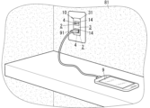
まず、本実施形態に係るUSB(Universal Serial Bus)コンセント(Outlet)10の概要について、図1及び図4を参照して説明する。
(Embodiment 1)
(1) Overview First, an overview of a USB (Universal Serial Bus) outlet 10 according to this embodiment will be described with reference to FIGS. 1 and 4. FIG.

本実施形態に係るUSBコンセント10は、機器9のUSBコネクタ91を接続可能な装置である。USBコンセント10は、USBコネクタ91が接続された状態で、USBコネクタ91を通して機器9(一例として、スマートフォン等)に電力を供給する装置である。機器9は、USBコンセント10から供給される電力にて、例えば、機器9に含まれている蓄電池92(図4参照)の充電を行う。 The USB outlet 10 according to this embodiment is a device to which the USB connector 91 of the device 9 can be connected. The USB outlet 10 is a device that supplies power to the device 9 (such as a smartphone, for example) through the USB connector 91 when the USB connector 91 is connected. The device 9 charges, for example, a storage battery 92 (see FIG. 4) included in the device 9 with the power supplied from the USB outlet 10.

本実施形態に係るUSBコンセント10は、例えば、建物の壁等の取付対象物81に設置される配線器具である。このようなUSBコンセント10は、100V又は200V等の交流電圧を出力する一般的なコンセント装置(Outlet)と同様に、電源(系統電源等)に対して常時、電気的に接続されており、基本的には、常時、通電状態にある。したがって、ユーザにおいては、USBコンセント10に機器9を接続するだけで、USBコンセント10からUSBコネクタ91経由で機器9に電力を供給することが可能となる。 The USB outlet 10 according to this embodiment is a wiring device that is installed on an attachment object 81, such as a wall of a building. This USB outlet 10 is electrically connected to a power source (such as a system power source) at all times, similar to a general outlet device (Outlet) that outputs an AC voltage of 100V or 200V, and is basically always in a powered state. Therefore, a user can supply power to the device 9 from the USB outlet 10 via the USB connector 91 simply by connecting the device 9 to the USB outlet 10.

ここで、100V又は200V等の交流電圧を出力する一般的なコンセント装置であれば、例えば、スマートフォン等の機器9を充電する場合、機器9に電力を供給するために交流電圧を直流電圧に変換する電源アダプタを用いる必要がある。これに対して、本実施形態に係るUSBコンセント10であれば、電源アダプタを用いることなく、USBコンセント10に対して機器9のUSBコネクタ91を直接的に接続することで、機器9に電力を供給することが可能である。よって、USBコンセント10によれば、電源アダプタの持ち合わせがなくても、例えば、スマートフォン等の機器9の充電が可能となり、しかも、電源アダプタが不要であるために、USBコンセント10の周辺がすっきりする。 Here, if a general outlet device outputs an AC voltage of 100V or 200V, for example, when charging a device 9 such as a smartphone, it is necessary to use a power adapter that converts AC voltage to DC voltage in order to supply power to the device 9. In contrast, with the USB outlet 10 according to this embodiment, it is possible to supply power to the device 9 by directly connecting the USB connector 91 of the device 9 to the USB outlet 10 without using a power adapter. Therefore, with the USB outlet 10, it is possible to charge a device 9 such as a smartphone even if you do not have a power adapter, and since a power adapter is not required, the area around the USB outlet 10 is neater.

本実施形態に係るUSBコンセント10は、筐体3と、電源回路11と、発光部14と、を備える。筐体3は、機器9のUSBコネクタ91を接続可能な接続口4を有する。電源回路11は、接続口4に接続されたUSBコネクタ91から機器9に電力を供給する。発光部14は、接続口4の位置を示すように発光する。 The USB outlet 10 according to this embodiment includes a housing 3, a power supply circuit 11, and a light-emitting unit 14. The housing 3 has a connection port 4 to which a USB connector 91 of a device 9 can be connected. The power supply circuit 11 supplies power to the device 9 from the USB connector 91 connected to the connection port 4. The light-emitting unit 14 emits light to indicate the position of the connection port 4.

この構成によれば、発光部14が発光することで、USBコネクタ91を接続するための接続口4の位置を示すことができる。そのため、例えば、夜間、又は、USBコンセント10が、家具の影となる場所、若しくは窓のない室内等の暗所に設置されている場合であっても、ユーザは、発光部14の光を頼りに接続口4の位置を把握しやすくなる。特に、USBコンセント10においては、例えば、スマートフォン等の機器9の充電時にのみUSBコネクタ91が接続される等、比較的、USBコネクタ91の挿抜の頻度が高い。このようにUSBコネクタ91の挿抜の頻度が高いUSBコンセント10において、接続口4の位置が容易に把握できることは、利便性の向上に寄与しやすい。結果的に、利便性の向上を図りやすいUSBコンセント10を提供することができる。 According to this configuration, the light emitting unit 14 emits light, thereby indicating the position of the connection port 4 for connecting the USB connector 91. Therefore, for example, even at night or when the USB outlet 10 is installed in a dark place such as a place shaded by furniture or a room without windows, the user can easily determine the position of the connection port 4 by relying on the light of the light emitting unit 14. In particular, in the USB outlet 10, the USB connector 91 is connected only when charging a device 9 such as a smartphone, and the USB connector 91 is inserted and removed relatively frequently. In this way, in the USB outlet 10 in which the USB connector 91 is inserted and removed frequently, being able to easily determine the position of the connection port 4 contributes to improving convenience. As a result, it is possible to provide a USB outlet 10 that is easy to improve convenience.

(2)詳細な構成
以下、本実施形態に係るUSBコンセント10の詳細な構成について、図1~図4を参照して説明する。
(2) Detailed Configuration Hereinafter, a detailed configuration of the USB outlet 10 according to the present embodiment will be described with reference to FIGS.

(2.1)前提
本開示でいう「USB」は、シリアルバス規格の1つであるUSB(Universal Serial Bus)の規格を意味する。本開示において、「USB」は、例えば、USB 1.0、USB 1.1、USB 2.0、USB 3.0、USB 3.1、USB 3.2、及びUSB4といった様々な世代(転送速度の規格)のUSBを含む。また、本開示において、USBの端子形状(接続口4の形状、及びUSBコネクタ91の形状)は、様々な形状を含む。USBの端子形状は、例えば、A端子(Type-A)、B端子(Type-B)及びC端子(Type-C)、並びに、ミニUSB(mini USB)及びマイクロUSB(micro USB)等、更にはこれらの組み合わせを含む。つまり、USBの端子形状は、一例として、ミニUSBのA端子(mini USB Type-A)、及びマイクロUSBのB端子(micro USB Type-B)等を含む。本実施形態では特に断りが無い限り、USBの端子形状がA端子(USB Type-A)である場合を例に説明する。本開示では、USBの端子形状の仕様を「USBコネクタ規格」ということもある。
(2.1) Premise In this disclosure, "USB" refers to the Universal Serial Bus (USB) standard, which is one of the serial bus standards. In this disclosure, "USB" includes various generations (transfer speed standards) of USB, such as USB 1.0, USB 1.1, USB 2.0, USB 3.0, USB 3.1, USB 3.2, and USB 4. In addition, in this disclosure, the USB terminal shape (the shape of the connection port 4 and the shape of the USB connector 91) includes various shapes. The USB terminal shape includes, for example, Type-A terminal, Type-B terminal, and Type-C terminal, as well as mini USB and micro USB, and further includes combinations of these. That is, examples of the USB terminal shape include a mini USB Type-A terminal and a micro USB Type-B terminal. In this embodiment, unless otherwise specified, a case where the USB terminal shape is an A terminal (USB Type-A) will be described as an example. In this disclosure, the specification of the USB terminal shape is sometimes referred to as a "USB connector standard."

本開示でいう「機器のUSBコネクタ」は、機器9に一体に設けられているコネクタであってもよいし、機器9に接続可能なUSBケーブルの先端に設けられているコネクタであってもよい。つまり、機器9のUSBコネクタ91は、機器9とは別体であって、機器9に対してケーブルを介して接続されるコネクタのように、機器9に付帯するコネクタ等を含む。また、本開示でいう「コネクタ」は、レセに挿入される「プラグ」であってもよいし、プラグが挿入される「レセ」であってもよい。本実施形態では特に断りが無い限り、機器9のUSBコネクタ91が、機器9に接続可能なUSBケーブルの先端に設けられているUSBプラグである場合を例に説明する。 The "USB connector of the device" in the present disclosure may be a connector that is integral with the device 9, or a connector that is provided at the end of a USB cable that can be connected to the device 9. In other words, the USB connector 91 of the device 9 includes a connector that is separate from the device 9 and that is attached to the device 9, such as a connector that is connected to the device 9 via a cable. Furthermore, the "connector" in the present disclosure may be a "plug" that is inserted into a receptacle , or a " receptacle " into which a plug is inserted. In this embodiment, unless otherwise specified, a case will be described in which the USB connector 91 of the device 9 is a USB plug that is provided at the end of a USB cable that can be connected to the device 9.

同様に、本開示でいう「接続部」は、機器9のUSBコネクタ91を電気的に接続可能な構造であればよく、プラグが挿入される「レセ」であってもよいし、レセに挿入される「プラグ」であってもよい。本実施形態では特に断りが無い限り、USBコンセント10の接続部2が、接続口4を含むレセである場合を例に説明する。つまり、本実施形態では、機器9のUSBコネクタ91がUSBプラグであるので、USBコンセント10の接続部2は、USBプラグを接続可能なレセである。そのため、USBコンセント10の筐体3が有する接続口4は、接続部2に含まれることになる。 Similarly, the "connection portion" in the present disclosure may be any structure capable of electrically connecting the USB connector 91 of the device 9, and may be a " receptacle " into which a plug is inserted, or a "plug" inserted into a receptacle . Unless otherwise specified, in this embodiment, a case will be described in which the connection portion 2 of the USB outlet 10 is a receptacle including a connection port 4. In other words, in this embodiment, since the USB connector 91 of the device 9 is a USB plug, the connection portion 2 of the USB outlet 10 is a receptacle to which a USB plug can be connected. Therefore, the connection port 4 of the housing 3 of the USB outlet 10 is included in the connection portion 2.

本開示でいう「機器」は、USBコンセント10に電気的に接続可能であって、USBコンセント10から電力供給を受ける電気機器(装置、設備及びシステム)である。機器9は、例えば、スマートフォン、タブレット端末若しくはウェアラブル端末等の情報端末、モバイルバッテリ、携帯電話機、カメラ、扇風機、懐中電灯又はテレビジョン受像機等を含む。USBコンセント10は機器9に対して直流の電圧を印加することで直流電力を供給するので、機器9は直流入力に対応した機器である。この種の機器9のうち、例えば、スマートフォン、タブレット端末又はウェアラブル端末等の機器9は、蓄電池92を備え、USBコンセント10から供給される電力を用いて蓄電池92を充電する機能を有する。以下では、蓄電池92を充電する機能を有する機器9を「充電式の機器」と呼ぶこともある。本実施形態では特に断りが無い限り、USBコンセント10に接続される機器9が、充電式の機器9である場合を例に説明する。 In the present disclosure, the term "device" refers to an electrical device (apparatus, equipment, and system) that can be electrically connected to the USB outlet 10 and receives power from the USB outlet 10. The device 9 includes, for example, an information terminal such as a smartphone, a tablet terminal, or a wearable terminal, a mobile battery, a mobile phone, a camera, an electric fan, a flashlight, or a television receiver. The USB outlet 10 supplies DC power by applying a DC voltage to the device 9, so the device 9 is a device that supports DC input. Among this type of device 9, for example, the device 9 such as a smartphone, a tablet terminal, or a wearable terminal includes a storage battery 92 and has a function of charging the storage battery 92 using power supplied from the USB outlet 10. In the following, the device 9 that has the function of charging the storage battery 92 may be referred to as a "rechargeable device." In this embodiment, unless otherwise specified, a case will be described in which the device 9 connected to the USB outlet 10 is a rechargeable device 9.

本実施形態では、USBコンセント10は、取付対象物81に固定される。本開示でいう「取付対象物」は、USBコンセント10が固定される部材であって、例えば、建物の壁、天井若しくは床等の造営物、又は机、棚、若しくはカウンタ台等の什器(建具を含む)等を含む。USBコンセント10は、例えば、戸建住宅若しくは集合住宅等の住宅施設、又は事務所、店舗、学校、工場、病院若しくは介護施設等の非住宅施設に設置される。本実施形態では一例として、USBコンセント10は、住宅施設の壁からなる取付対象物81に取り付けられる、埋込型の配線器具であると仮定する。特に、USBコンセント10は、建物の内部で使用される屋内用の配線器具であると仮定する。 In this embodiment, the USB outlet 10 is fixed to an attachment object 81. In this disclosure, the "attachment object" refers to a member to which the USB outlet 10 is fixed, and includes, for example, a structure such as a wall, ceiling, or floor of a building, or a fixture (including fittings) such as a desk, shelf, or counter. The USB outlet 10 is installed, for example, in a residential facility such as a detached house or an apartment building, or in a non-residential facility such as an office, store, school, factory, hospital, or nursing home. In this embodiment, as an example, it is assumed that the USB outlet 10 is a recessed wiring device that is attached to the attachment object 81, which is the wall of a residential facility. In particular, it is assumed that the USB outlet 10 is an indoor wiring device used inside a building.

以下、取付対象物81である住宅施設の壁にUSBコンセント10が固定された状態での、水平面に対して垂直な(直交する)方向をUSBコンセント10の「上下方向」として説明する場合がある。また、USBコンセント10を正面から見て下方をUSBコンセント10の「下方」として説明する場合がある。上下方向と直交し、かつ取付対象物81の表面(壁面)に平行な方向をUSBコンセント10の「左右方向」とし、USBコンセント10を正面から見て右方をUSBコンセント10の「右方」、左方をUSBコンセント10の「左方」として説明する場合がある。さらに、上下方向と左右方向との両方に直交する方向、つまり取付対象物81の表面(壁面)に直交する方向をUSBコンセント10の「前後方向」とし、取付対象物81の裏面側(壁裏側)をUSBコンセント10の「後方」として説明する場合がある。ただし、これらの方向はUSBコンセント10の使用時の方向を限定する趣旨ではない。 Hereinafter, the direction perpendicular (orthogonal) to the horizontal plane when the USB outlet 10 is fixed to the wall of the housing facility, which is the object of attachment 81, may be described as the "up-down direction" of the USB outlet 10. Also, the downward direction when the USB outlet 10 is viewed from the front may be described as the "downward direction" of the USB outlet 10. The direction perpendicular to the up-down direction and parallel to the surface (wall surface) of the object of attachment 81 may be described as the "left-right direction" of the USB outlet 10, and the right side when the USB outlet 10 is viewed from the front may be described as the "right side" of the USB outlet 10, and the left side when the USB outlet 10 is viewed from the front may be described as the "left side" of the USB outlet 10. Furthermore, the direction perpendicular to both the up-down direction and the left-right direction, that is, the direction perpendicular to the surface (wall surface) of the object of attachment 81, may be described as the "front-rear direction" of the USB outlet 10, and the back side (back of the wall) of the object of attachment 81 may be described as the "rear" of the USB outlet 10. However, these directions are not intended to limit the direction in which the USB outlet 10 can be used.

また、USBコンセント10における筐体3の前面31は、取付対象物81である住宅施設の壁にUSBコンセント10が固定された状態において、基本的には、前方を向くことになる。ただし、筐体3の前面31が前方に向けられることを限定する趣旨ではない。例えば、USBコンセント10が天井に設置される場合には、筐体3の前面31は下方に向けられることになる。 In addition, the front surface 31 of the housing 3 of the USB outlet 10 will basically face forward when the USB outlet 10 is fixed to the wall of the housing, which is the mounting object 81. However, this is not intended to limit the front surface 31 of the housing 3 to facing forward. For example, if the USB outlet 10 is installed on the ceiling, the front surface 31 of the housing 3 will face downward.

また、本開示において、2値の比較において、「以上」としているところは、2値が等しい場合、及び2値の一方が他方を超えている場合との両方を含む。ただし、これに限らず、ここでいう「以上」は、2値の一方が他方を超えている場合のみを含む「より大きい」と同義であってもよい。つまり、2値が等しい場合を含むか否かは、基準値等の設定次第で任意に変更できるので、「以上」か「より大きい」かに技術上の差異はない。同様に、「未満」においても「以下」と同義であってもよい。 In addition, in this disclosure, when comparing two values, "greater than or equal to" includes both the cases where the two values are equal and where one of the two values exceeds the other. However, without being limited to this, "greater than or equal to" here may be synonymous with "greater than," which includes only the cases where one of the two values exceeds the other. In other words, whether or not the cases where the two values are equal can be included can be arbitrarily changed depending on the setting of the reference value, etc., so there is no technical difference between "greater than or equal to" and "greater than." Similarly, "less than" may be synonymous with "less than or equal to."

(2.2)基本構成
次に、本実施形態に係るUSBコンセント10の基本構成について、図1~図3Bを参照して説明する。
(2.2) Basic Configuration Next, the basic configuration of the USB outlet 10 according to this embodiment will be described with reference to FIGS. 1 to 3B.

上述したように、本実施形態では一例として、USBコンセント10は、住宅施設の壁からなる取付対象物81に取り付けられる、埋込型の配線器具である。つまり、USBコンセント10は、取付対象物81に固定され、取付対象物81の裏側を通した配線L1(図4参照)を接続可能に構成された配線器具である。特に、このUSBコンセント10は、取付対象物81に形成されている施工孔82(図3A参照)に、筐体3の少なくとも一部が埋め込まれた状態で、筐体3が取付対象物81に固定される、埋込型の配線器具である。 As described above, in this embodiment, as an example, the USB outlet 10 is a recessed wiring device that is attached to the mounting object 81, which is a wall of a residential facility. In other words, the USB outlet 10 is a wiring device that is fixed to the mounting object 81 and is configured to be able to connect wiring L1 (see FIG. 4) that passes through the back side of the mounting object 81. In particular, this USB outlet 10 is a recessed wiring device in which the housing 3 is fixed to the mounting object 81 with at least a portion of the housing 3 embedded in a construction hole 82 (see FIG. 3A) formed in the mounting object 81.

また、USBコンセント10は、配線L1を接続するための端子部16(図4参照)を備えており、例えば、壁(取付対象物81)内に引き回された配線L1が端子部16に接続されることで、配線L1を介して系統電源等の電源に電気的に接続される。配線L1は、電源(系統電源等)に対して、直接的に接続されてもよいし、分電盤等を介して間接的に接続されてもよい。 The USB outlet 10 also has a terminal portion 16 (see FIG. 4) for connecting the wiring L1. For example, the wiring L1 routed inside the wall (mounting object 81) is connected to the terminal portion 16, and is thereby electrically connected to a power source such as a system power source via the wiring L1. The wiring L1 may be directly connected to the power source (system power source, etc.) or indirectly connected via a distribution board, etc.

本実施形態では一例として、USBコンセント10は、端子部16に配線L1が接続されることにより、配線L1を介して、単相100V、60Hzの商用の交流電源(系統電源)に電気的に接続される。ここで、USBコンセント10は、分電盤を介して交流電源(系統電源)に接続されており、分電盤のブレーカ(主幹ブレーカ及び分岐ブレーカ)が導通状態にあれば、常時、通電状態にある。そのため、USBコンセント10は、基本的には、常時、機器9に対して電力を供給可能な状態にある。 In this embodiment, as an example, the USB outlet 10 is electrically connected to a single-phase 100V, 60Hz commercial AC power source (system power source) via the wire L1 by connecting the wire L1 to the terminal portion 16. Here, the USB outlet 10 is connected to the AC power source (system power source) via a distribution board, and is always in a conducting state as long as the breakers (main breaker and branch breakers) of the distribution board are in a conducting state. Therefore, the USB outlet 10 is basically always in a state where it can supply power to the device 9.

また、本実施形態では一例として、2個のUSBコネクタ91を接続可能な2個口(2ポート)タイプのUSBコンセント10を例示する。すなわち、本実施形態に係るUSBコンセント10は、USBコネクタ91を接続するための接続部2(接続口4を含む)を複数(ここでは2つ)備え、これら複数の接続部2から機器9への電力供給が可能である。そのため、USBコンセント10は、複数の機器9のUSBコネクタ91が接続された状態で、これら複数の機器9に対して同時に電力供給することが可能である。本実施形態において、複数(ここでは2つ)の接続部2を区別する場合には、個々の接続部2を、第1の接続部21、第2の接続部22ということもある。同様に、複数(ここでは2つ)の接続口4を区別する場合には、個々の接続口4を、第1の接続口41、第2の接続口42ということもある。 In addition, in this embodiment, as an example, a two-outlet (two-port) type USB outlet 10 capable of connecting two USB connectors 91 is illustrated. That is, the USB outlet 10 according to this embodiment has a plurality (two in this embodiment) of connection parts 2 (including connection ports 4) for connecting the USB connectors 91, and can supply power to the device 9 from these plurality of connection parts 2. Therefore, the USB outlet 10 can simultaneously supply power to the plurality of devices 9 when the USB connectors 91 of the plurality of devices 9 are connected. In this embodiment, when the plurality of connection parts 2 (two in this embodiment) are to be distinguished, the individual connection parts 2 may be referred to as a first connection part 21 and a second connection part 22. Similarly, when the plurality of connection ports 4 (two in this embodiment) are to be distinguished, the individual connection ports 4 may be referred to as a first connection port 41 and a second connection port 42.

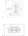
USBコンセント10は、図2A及び図2Bに示すように、電源回路11と、筐体3と、を備えている。図2Bは、図2Aにおける第1の接続口41付近の拡大図である。 As shown in Figures 2A and 2B, the USB outlet 10 includes a power supply circuit 11 and a housing 3. Figure 2B is an enlarged view of the first connection port 41 and its surroundings in Figure 2A.

電源回路11は、回路基板(プリント配線板)と、回路基板に実装された種々の電子部品と、を有している。電源回路11は、交流電源(系統電源)から端子部16に印加される交流電圧を、直流電圧に変換し、直流電圧を接続部2に出力する。これにより、電源回路11は、接続部2から機器9に電力を供給する。詳しくは後述するが、電源回路11の回路基板には、制御部101(図4参照)等も実装されている。電源回路11は、回路基板を1枚だけ含んでいてもよいし、複数枚の回路基板を含んでいてもよい。 The power supply circuit 11 has a circuit board (printed wiring board) and various electronic components mounted on the circuit board. The power supply circuit 11 converts the AC voltage applied to the terminal portion 16 from the AC power source (system power source) into a DC voltage and outputs the DC voltage to the connection portion 2. In this way, the power supply circuit 11 supplies power to the device 9 from the connection portion 2. As will be described in detail later, a control unit 101 (see Figure 4) and the like are also mounted on the circuit board of the power supply circuit 11. The power supply circuit 11 may include only one circuit board or may include multiple circuit boards.

筐体3は、上述したように、取付対象物81に固定される。筐体3は、電源回路11を収容する。厳密には、筐体3は、電源回路11の回路基板を収容することで、電源回路11だけでなく制御部101等も収容する。さらに、筐体3には、電源回路11及び制御部101の他、接続部2及び端子部16等の内部部品が適宜収容される。筐体3は、電気絶縁性を有する合成樹脂製である。 As described above, the housing 3 is fixed to the mounting object 81. The housing 3 houses the power supply circuit 11. Strictly speaking, the housing 3 houses not only the power supply circuit 11 but also the control unit 101 and the like by housing the circuit board of the power supply circuit 11. Furthermore, in addition to the power supply circuit 11 and the control unit 101, the housing 3 also houses internal parts such as the connection unit 2 and the terminal unit 16 as appropriate. The housing 3 is made of synthetic resin having electrical insulation properties.

本実施形態では、筐体3は、直方体状であって、3個モジュール寸法の配線器具と同程度の寸法に形成されている。筐体3は、筐体3が取付対象物81に取り付けられた状態で前方に露出する前面31を有する。ここでは、筐体3の前面31は、上下方向の寸法が左右方向の寸法よりも大きい長方形状である。筐体3の前面31には、少なくとも1つの接続口4が配置される。 In this embodiment, the housing 3 is rectangular and is formed with dimensions similar to those of a wiring device with three module dimensions. The housing 3 has a front surface 31 that is exposed forward when the housing 3 is attached to the attachment object 81. Here, the front surface 31 of the housing 3 is rectangular in shape with a larger vertical dimension than a horizontal dimension. At least one connection port 4 is arranged on the front surface 31 of the housing 3.

本実施形態では、2個口(2ポート)タイプのUSBコンセント10であるため、筐体3の前面31には、2つの接続口4が配置される。これら2つの接続口4は、上下方向において、一定の間隔を空けて並べて配置されている。2つの接続口4の各々は、図2A及び図2Bに示すように、正面視において、左右方向の寸法が上下方向の寸法よりも大きい長方形状である。つまり、各接続口4は、横向き(横長)の長孔である。 In this embodiment, the USB outlet 10 has two outlets (two ports), so two connection ports 4 are arranged on the front surface 31 of the housing 3. These two connection ports 4 are arranged next to each other with a certain distance between them in the vertical direction. As shown in Figures 2A and 2B, each of the two connection ports 4 has a rectangular shape with a larger left-right dimension than the vertical dimension when viewed from the front. In other words, each connection port 4 is a long hole that is oriented horizontally (horizontally long).

接続口4内には、金属製のシェル及びコンタクト等が配置されている。これにより、接続口4は、シェル及びコンタクト等と共に、機器9のUSBコネクタ91を電気的かつ機械的に接続するための接続部2(レセ)を構成する。このように構成される接続部2にUSBコネクタ91が正面からまっすぐ差し込まれることにより、接続部2にUSBコネクタ91が接続される。つまり、差込式のUSBコネクタ91が差込方向である前後方向に沿って接続口4に差し込まれることにより、接続部2に対してUSBコネクタ91が電気的に接続され、かつ機械的に結合されることになる。 A metallic shell, contacts, etc. are disposed within the connection port 4. Thus, the connection port 4, together with the shell, contacts, etc., constitutes a connection section 2 ( receptacle ) for electrically and mechanically connecting a USB connector 91 of the device 9. The USB connector 91 is connected to the connection section 2 by being inserted straight from the front into the connection section 2 thus configured. In other words, the plug-in type USB connector 91 is inserted into the connection port 4 along the front-rear direction, which is the insertion direction, so that the USB connector 91 is electrically connected to the connection section 2 and mechanically coupled thereto.

接続部2とUSBコネクタ91とが接続された状態において、USBコネクタ91が接続部2からまっすぐ引き抜かれることにより、接続部2とUSBコネクタ91との接続が解除される。つまり、USBコネクタ91が差込方向(前後方向)に沿って接続口4から抜去されることにより、接続部2に対するUSBコネクタ91の電気的な接続が解除され、かつ機械的な結合が解除される。要するに、ユーザは、筐体3の前面31に形成された接続口4に対して、USBコネクタ91を挿抜することによって、機器9(USBコネクタ91)の接続部2に対する接続/非接続を切り替えることができる。 When the connection unit 2 and the USB connector 91 are connected, the connection between the connection unit 2 and the USB connector 91 is released by pulling the USB connector 91 straight out from the connection unit 2. In other words, the electrical connection of the USB connector 91 to the connection unit 2 is released and the mechanical coupling is released by removing the USB connector 91 from the connection port 4 along the insertion direction (front-to-back direction). In short, the user can switch between connection/disconnection of the device 9 (USB connector 91) to the connection unit 2 by inserting and removing the USB connector 91 into and from the connection port 4 formed on the front surface 31 of the housing 3.

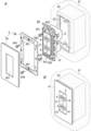
ここにおいて、本実施形態では、筐体3は、図3Aに示すように、筐体3を取付対象物81に固定するための取付枠84に対して、取外し可能に取り付けられている。さらに、取付枠84には、図3Aに示すように、コンセントプレート8が取り付けられる。ここで、本実施形態では、取付枠84及びコンセントプレート8を、USBコンセント10の構成要素に含まないこととする。ただし、取付枠84及びコンセントプレート8が、USBコンセント10の構成要素に含まれないことは必須でなく、取付枠84及びコンセントプレート8の少なくとも一方は、USBコンセント10の構成要素に含まれてもよい。 Here, in this embodiment, as shown in FIG. 3A, the housing 3 is removably attached to a mounting frame 84 for fixing the housing 3 to an attachment object 81. Furthermore, as shown in FIG. 3A, the outlet plate 8 is attached to the mounting frame 84. Here, in this embodiment, the mounting frame 84 and the outlet plate 8 are not included as components of the USB outlet 10. However, it is not essential that the mounting frame 84 and the outlet plate 8 are not included as components of the USB outlet 10, and at least one of the mounting frame 84 and the outlet plate 8 may be included as components of the USB outlet 10.

本実施形態では、USBコンセント10は、上述したように埋込型の配線器具であるので、例えば、埋込型のスイッチボックス等の取付部材83を用いて取付対象物81(ここでは壁)に取り付けられる。すなわち、取付対象物81には施工孔82が形成されており、取付対象物81の裏側(壁裏)に配置されたスイッチボックス等の取付部材83に対して、USBコンセント10が施工孔82を通して取り付けられる。 In this embodiment, the USB outlet 10 is a recessed wiring device as described above, and is therefore attached to the mounting object 81 (here, a wall) using a mounting member 83 such as a recessed switch box. That is, a mounting hole 82 is formed in the mounting object 81, and the USB outlet 10 is attached through the mounting hole 82 to a mounting member 83 such as a switch box that is arranged on the back side of the mounting object 81 (behind the wall).

取付枠84は、例えば、日本工業規格によって規格化された大角形連用配線器具の取付枠である。具体的には、取付枠84は、正面視において矩形枠状に形成されている。この取付枠84の内側に筐体3が位置するように、筐体3が取付枠84に装着されている。 The mounting frame 84 is, for example, a mounting frame for a large rectangular interconnect wiring device standardized by the Japanese Industrial Standards. Specifically, the mounting frame 84 is formed in a rectangular frame shape when viewed from the front. The housing 3 is attached to the mounting frame 84 so that the housing 3 is located inside the mounting frame 84.

取付枠84は、一例として、合成樹脂製である。取付枠84には、一対の取付孔841と、一対のプレート固定孔842と、が形成されている。一対の取付孔841を通して、一対の取付ねじ843がスイッチボックス等の取付部材83に締め付けられることで、取付枠84は、取付対象物81に取り付けられる。 The mounting frame 84 is made of synthetic resin, for example. The mounting frame 84 has a pair of mounting holes 841 and a pair of plate fixing holes 842 formed therein. The mounting frame 84 is attached to the mounting object 81 by fastening a pair of mounting screws 843 through the pair of mounting holes 841 to a mounting member 83 such as a switch box.

コンセントプレート8は、化粧プレート85と、固定プレート86と、を有している。つまり、本実施形態では、コンセントプレート8は、化粧プレート85及び固定プレート86の2部材で構成されている。コンセントプレート8(化粧プレート85及び固定プレート86)は、一例として、合成樹脂製である。 The outlet plate 8 has a decorative plate 85 and a fixed plate 86. That is, in this embodiment, the outlet plate 8 is composed of two members, the decorative plate 85 and the fixed plate 86. The outlet plate 8 (the decorative plate 85 and the fixed plate 86) are made of synthetic resin, for example.

固定プレート86は、取付枠84に固定される。化粧プレート85は、固定プレート86の前面を覆うように、固定プレート86に取り付けられる。このように、化粧プレート85は、筐体3が取り付けられている取付枠84に対し、固定プレート86を介して間接的に固定される。化粧プレート85には窓孔801が形成されており、コンセントプレート8が取付枠84に取り付けられた状態では、窓孔801から筐体3の前面31が露出することになる。 The fixing plate 86 is fixed to the mounting frame 84. The decorative plate 85 is attached to the fixing plate 86 so as to cover the front surface of the fixing plate 86. In this way, the decorative plate 85 is indirectly fixed to the mounting frame 84 to which the housing 3 is attached via the fixing plate 86. A window hole 801 is formed in the decorative plate 85, and when the outlet plate 8 is attached to the mounting frame 84, the front surface 31 of the housing 3 is exposed from the window hole 801.

つまり、コンセントプレート8は、窓孔801を有する枠状の部材であって、その窓孔801から筐体3の前面31を露出させるように、取付枠84と組み合わされる。言い換えれば、取付枠84とコンセントプレート8とが組み合われた状態では、正面視において、コンセントプレート8(化粧プレート85)の内側(窓孔801内)に筐体3の前面31が位置する。これにより、図3Bに示すように、コンセントプレート8が筐体3と共に取付対象物81に取り付けられた状態で、筐体3の周囲をコンセントプレート8が覆うことになり、取付枠84及び施工孔82等が露出せずに見映えがよくなる。 In other words, the outlet plate 8 is a frame-shaped member having a window hole 801, and is combined with the mounting frame 84 so that the front surface 31 of the housing 3 is exposed from the window hole 801. In other words, when the mounting frame 84 and the outlet plate 8 are combined, the front surface 31 of the housing 3 is located inside (within the window hole 801) of the outlet plate 8 (decorative plate 85) in a front view. As a result, as shown in FIG. 3B, when the outlet plate 8 is attached to the mounting object 81 together with the housing 3, the outlet plate 8 covers the periphery of the housing 3, and the mounting frame 84 and the construction holes 82 are not exposed, resulting in a good appearance.

より詳細には、化粧プレート85は、正面視において矩形枠状に形成されている。化粧プレート85の中央部には、化粧プレート85を前後方向に貫通する窓孔801が形成されている。化粧プレート85は、スナップフィット構造により、取外し可能な状態で、固定プレート86と機械的に結合される。すなわち、化粧プレート85及び固定プレート86は、化粧プレート85と固定プレート86との少なくとも一方の弾性を利用して、化粧プレート85及び固定プレート86一方の爪を、他方の孔に引っ掛けることにより、機械的に結合される。 More specifically, the decorative plate 85 is formed in a rectangular frame shape when viewed from the front. A window hole 801 is formed in the center of the decorative plate 85, penetrating the decorative plate 85 in the front-rear direction. The decorative plate 85 is mechanically coupled to the fixed plate 86 in a removable state by a snap-fit structure. That is, the decorative plate 85 and the fixed plate 86 are mechanically coupled by using the elasticity of at least one of the decorative plate 85 and the fixed plate 86 to hook a claw of one of the decorative plate 85 and the fixed plate 86 into a hole of the other.

また、固定プレート86は、正面視において矩形枠状に形成されている。さらに、固定プレート86には、一対の透孔861が形成されている。一対の透孔861を通して、一対の固定ねじ844が取付枠84の一対のプレート固定孔842に締め付けられることで、固定プレート86は、取付枠84に取り付けられる。 The fixing plate 86 is formed in a rectangular frame shape when viewed from the front. Furthermore, a pair of through holes 861 are formed in the fixing plate 86. The fixing plate 86 is attached to the mounting frame 84 by fastening a pair of fixing screws 844 through the pair of through holes 861 into a pair of plate fixing holes 842 of the mounting frame 84.

(2.3)USBコンセントの具体的構成
次に、本実施形態に係るUSBコンセント10の具体的な構成について、図2A、図2B及び図4を参照して説明する。
(2.3) Specific Configuration of USB Outlet Next, a specific configuration of the USB outlet 10 according to this embodiment will be described with reference to FIGS. 2A, 2B, and 4. FIG.

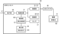
本実施形態に係るUSBコンセント10は、図4に示すように、電源回路11、少なくとも1つ(ここでは2つ)の接続部2、及び筐体3に加えて、端子部16、制御部101、発光部14及びセンサ17を更に備えている。制御部101は、発光制御部12を含んでいる。発光部14は、発光素子141を含んでいる。これら端子部16、制御部101及び発光部14の少なくとも一部は、電源回路11と共に筐体3に収容されている。 As shown in FIG. 4, the USB outlet 10 according to this embodiment further includes a terminal section 16, a control section 101, a light-emitting section 14, and a sensor 17 in addition to a power supply circuit 11, at least one (here, two) connection section 2, and a housing 3. The control section 101 includes a light-emitting control section 12. The light-emitting section 14 includes a light-emitting element 141. At least a portion of the terminal section 16, the control section 101, and the light-emitting section 14 are housed in the housing 3 together with the power supply circuit 11.

電源回路11は、交流電圧を直流電圧に変換するAC/DC変換回路を含んでいる。電源回路11は、端子部16と接続部2との間に挿入されており、端子部16から入力される交流電圧を直流電圧に変換して接続部2に出力する。ここでは一例として、電源回路11は、交流電源(系統電源)から端子部16に印加される100Vの交流電圧を5Vの直流電圧に変換する。これにより、端子部16に入力される100Vの交流電圧は電源回路11にて5Vの直流電圧に変換されて、接続部2に5Vの直流電圧が供給される。 The power supply circuit 11 includes an AC/DC conversion circuit that converts AC voltage into DC voltage. The power supply circuit 11 is inserted between the terminal unit 16 and the connection unit 2, and converts the AC voltage input from the terminal unit 16 into DC voltage and outputs it to the connection unit 2. As an example, the power supply circuit 11 converts the 100V AC voltage applied to the terminal unit 16 from the AC power source (system power source) into a 5V DC voltage. As a result, the 100V AC voltage input to the terminal unit 16 is converted into a 5V DC voltage by the power supply circuit 11, and the 5V DC voltage is supplied to the connection unit 2.

本実施形態では、1つの電源回路11に対して、複数(ここでは2つ)の接続部2が接続されている。つまり、電源回路11から出力される直流電圧は、第1の接続部21及び第2の接続部22の両方に印加される。これにより、電源回路11の出力を、複数(ここでは2つ)の接続部2から、機器9のUSBコネクタ91に対して出力することが可能である。 In this embodiment, multiple (here, two) connection parts 2 are connected to one power supply circuit 11. In other words, the DC voltage output from the power supply circuit 11 is applied to both the first connection part 21 and the second connection part 22. This makes it possible to output the output of the power supply circuit 11 from multiple (here, two) connection parts 2 to the USB connector 91 of the device 9.

このような構成においては、複数の接続部2から機器9に出力される電流(及び電力)の合計が、1つの電源回路11の出力電流となる。そのため、例えば、複数の接続部2の定格出力(電流又は電力)は、複数の接続部2の出力電流(又は出力電力)の合計値で規定される。本開示でいう「定格出力」は、電流及び/又は電力の定格値であって、定格電流及び定格電の少なくとも一方である。すなわち、電源回路11の定格出力(電流又は電力)によって、複数の接続部2の合計出力(電流又は電力)の定格値が決定されることになる。一例として、電源回路11の定格出力が4Aであるとすれば、複数(ここでは2つ)の接続部2の出力電流の合計が4Aで定格となる。 In such a configuration, the sum of the currents (and power) output from the multiple connection parts 2 to the device 9 becomes the output current of one power supply circuit 11. Therefore, for example, the rated output (current or power) of the multiple connection parts 2 is defined as the sum of the output currents (or output powers) of the multiple connection parts 2. The "rated output" in this disclosure is the rated value of the current and/or power, and is at least one of the rated current and the rated power . In other words, the rated value of the total output (current or power) of the multiple connection parts 2 is determined by the rated output (current or power) of the power supply circuit 11. As an example, if the rated output of the power supply circuit 11 is 4A, the sum of the output currents of the multiple (here, two) connection parts 2 is rated at 4A.

本実施形態では、上述したような定格出力をユーザが認識しやすいように、筐体3の前面31には、図2Aに示すように、割当表示部32が設けられている。本実施形態では一例として、割当表示部32は、筐体3の前面31に形成された刻印にて実現される。割当表示部32は、出力情報を表示する。本開示でいう「出力情報」は、接続部2の各々について出力可能な電力の大きさに関する情報である。例えば、接続部2の定格出力(電流又は電力)、つまり接続部2の定格電流及び定格電力は、いずれも接続部2の出力可能な電力の大きさに関連するので、「出力情報」に含まれる。図1では、割当表示部32の図示を省略している。 In this embodiment, as shown in FIG. 2A, an allocation display unit 32 is provided on the front surface 31 of the housing 3 so that the user can easily recognize the rated output as described above. In this embodiment, as an example, the allocation display unit 32 is realized by an engraving formed on the front surface 31 of the housing 3. The allocation display unit 32 displays output information. In this disclosure, "output information" is information related to the amount of power that can be output from each of the connection parts 2. For example, the rated output (current or power) of the connection part 2, that is, the rated current and rated power of the connection part 2, are both related to the amount of power that can be output from the connection part 2, and are therefore included in the "output information". The allocation display unit 32 is not shown in FIG. 1.

ここで、図2Aに示すように、割当表示部32は、筐体3の前面31における接続口4の周囲に配置されている。特に、本実施形態では、割当表示部32は、筐体3の前面31において、接続口4の上方及び下方に配置されている。具体的には、割当表示部32が表示する出力情報は、「2.5A」又は「1.5A」のように、接続部2ごとの定格出力(定格電流)を表す。ここでは一例として、第1の接続部21(第1の接続口41)に対応する割当表示部32は、定格出力としての「2.5A」という出力情報を文字列(テキスト)にて表記する。第2の接続部22(第2の接続口42)に対応する割当表示部32は、定格出力としての「1.5A」という出力情報を文字列(テキスト)にて表記する。 2A, the allocation display unit 32 is disposed around the connection port 4 on the front surface 31 of the housing 3. In particular, in this embodiment, the allocation display unit 32 is disposed above and below the connection port 4 on the front surface 31 of the housing 3. Specifically, the output information displayed by the allocation display unit 32 indicates the rated output (rated current) for each connection portion 2, such as "2.5 A" or "1.5 A." As an example, the allocation display unit 32 corresponding to the first connection portion 21 (first connection port 41) displays the output information "2.5 A" as the rated output in a character string (text). The allocation display unit 32 corresponding to the second connection portion 22 (second connection port 42) displays the output information "1.5 A" as the rated output in a character string (text).

さらに、割当表示部32が表示する出力情報は、「1」又は「2」のように、接続部2ごとの優先順位を表す優先情報を含む。ここでいう「優先情報」は、複数の接続部2について、優先的に使用することを推奨する順位を表す情報であればよく、「1」又は「2」のような数字に限らず、例えば、主又は副の関係を表す情報であってもよい。ここでは一例として、第1の接続部21(第1の接続口41)に対応する割当表示部32は、優先情報として「1」という優先順位を文字列(テキスト)にて表記する。第2の接続部22(第2の接続口42)に対応する割当表示部32は、優先情報として「2」という優先順位を文字列(テキスト)にて表記する。この例では、第2の接続部2に対して第1の接続部2を優先的に使用することが推奨されている。 Furthermore, the output information displayed by the allocation display unit 32 includes priority information such as "1" or "2" that indicates the priority of each connection unit 2. The "priority information" here may be information that indicates the order in which multiple connection units 2 are recommended to be used preferentially, and is not limited to numbers such as "1" or "2", and may be information that indicates, for example, a primary or secondary relationship. As an example, the allocation display unit 32 corresponding to the first connection unit 21 (first connection port 41) displays the priority of "1" as a character string (text) as priority information. The allocation display unit 32 corresponding to the second connection unit 22 (second connection port 42) displays the priority of "2" as a character string (text) as priority information. In this example, it is recommended that the first connection unit 2 be used preferentially over the second connection unit 2.

割当表示部32にて、このような出力情報が表示されることで、ユーザにおいては、まずは優先順位の高い第1の接続部2を使用することが推奨される。したがって、複数(ここでは2つ)の接続部2のうちの一方のみを使用する場合、ユーザは、基本的に第1の接続部2を使用することになる。そして、電源回路11の定格出力が4Aであるとすれば、第1の接続部2のみが使用されている状態では、第1の接続部2が定格(2.5A)内で使用されていれば、2つの接続部2の出力電流の合計は、当然ながら4A以内となる。また、第1の接続部2及び第2の接続部2の両方が使用されている状態では、第1の接続部2が定格(2.5A)内で使用され、かつ第2の接続部2が定格(1.5A)内で使用されていれば、2つの接続部2の出力電流の合計は、4A以内となる。 By displaying such output information on the allocation display unit 32, the user is recommended to use the first connection unit 2, which has a higher priority. Therefore, when using only one of the multiple (here, two) connection units 2, the user will basically use the first connection unit 2. If the rated output of the power supply circuit 11 is 4A, when only the first connection unit 2 is used, if the first connection unit 2 is used within the rated current (2.5A), the total output current of the two connection units 2 will naturally be within 4A. Also, when both the first connection unit 2 and the second connection unit 2 are used, if the first connection unit 2 is used within the rated current (2.5A) and the second connection unit 2 is used within the rated current (1.5A), the total output current of the two connection units 2 will be within 4A.

すなわち、本実施形態では、接続部2は複数設けられている。筐体3の前面31には、複数の接続部2の各々について出力可能な電力の大きさに関連する出力情報を表示する割当表示部32が設けられている。さらに、出力情報は、複数の接続部2の優先順位を表す優先情報を含む。複数の接続部2がある場合に、このような出力情報(優先情報を含む)が割当表示部32にて表示されていることで、ユーザにおいては、複数の接続部2のうちのいずれの接続部2を使用すべきか迷いにくくなる。 That is, in this embodiment, a plurality of connection parts 2 are provided. An allocation display unit 32 is provided on the front surface 31 of the housing 3, which displays output information related to the amount of power that can be output for each of the plurality of connection parts 2. Furthermore, the output information includes priority information that indicates the priority order of the plurality of connection parts 2. When there are a plurality of connection parts 2, such output information (including priority information) is displayed on the allocation display unit 32, making it less confusing for the user as to which of the plurality of connection parts 2 to use.

端子部16は、筐体3内に収容されている。ここで、筐体3の背面には、配線L1を接続するための端子孔が形成されている。端子部16は、筐体3内において端子孔に対応する位置に配置されている。端子部16は、端子板等を含み、端子孔に配線L1の先端部(心線)が差し込まれると、配線L1の先端部(心線)を機械的に保持し、かつ配線L1と電気的に接続される。本実施形態では一例として、端子部16は、端子孔から配線L1を差し込むだけで配線L1が接続される、差込式のいわゆる速結端子である。 The terminal portion 16 is housed in the housing 3. Here, a terminal hole for connecting the wiring L1 is formed on the rear surface of the housing 3. The terminal portion 16 is disposed in a position in the housing 3 corresponding to the terminal hole. The terminal portion 16 includes a terminal plate or the like, and when the tip end (core wire) of the wiring L1 is inserted into the terminal hole, the terminal portion 16 mechanically holds the tip end (core wire) of the wiring L1 and electrically connects to the wiring L1. As an example in this embodiment, the terminal portion 16 is a so-called quick-connect terminal of a plug-in type, in which the wiring L1 is connected simply by inserting the wiring L1 into the terminal hole.

制御部101は、例えば、1以上のプロセッサ及び1以上のメモリを有するマイクロコントローラを主構成として備えている。マイクロコントローラは、1以上のメモリに記録されているプログラムを1以上のプロセッサで実行することにより、制御部101としての機能を実現する。プログラムは、予めメモリに記録されていてもよいし、メモリカードのような非一時的記録媒体に記録されて提供されたり、電気通信回線を通して提供されたりしてもよい。言い換えれば、上記プログラムは、1以上のプロセッサを、制御部101として機能させるためのプログラムである。 The control unit 101 mainly comprises, for example, a microcontroller having one or more processors and one or more memories. The microcontroller realizes the function of the control unit 101 by executing a program recorded in one or more memories with one or more processors. The program may be recorded in the memory in advance, or may be provided recorded on a non-transitory recording medium such as a memory card, or provided through a telecommunications line. In other words, the above program is a program for causing one or more processors to function as the control unit 101.

制御部101は、少なくとも電源回路11を制御する。また、本実施形態では上述したように、制御部101は、電源回路11の回路基板に実装されており、電源回路11と共に、筐体3に収容されている。さらに、制御部101は、図4に示すように、発光制御部12としての機能を有している。発光制御部12は、発光部14を制御する。 The control unit 101 controls at least the power supply circuit 11. As described above in this embodiment, the control unit 101 is mounted on the circuit board of the power supply circuit 11 and is housed in the housing 3 together with the power supply circuit 11. Furthermore, as shown in FIG. 4, the control unit 101 also has a function as the light emission control unit 12. The light emission control unit 12 controls the light emission unit 14.

発光部14は、筐体3の前面に設けられており、その発光態様が、発光制御部12での制御によって変化する。本実施形態では、発光部14は、図2Bに示すように、発光素子141と、光学部材142と、を有している。発光素子141は、電力供給を受けて光を発する。この種の発光部14の発光態様には、例えば、点灯/消灯、発光色若しくは点灯パターン(点滅周期等)、又はこれらの組み合わせが含まれる。要するに、本実施形態では、発光制御部12が発光素子141に流れる電流を制御することで発光素子141を制御し、これによって、発光部14の点灯/消灯等の発光態様が変化する。 The light-emitting unit 14 is provided on the front surface of the housing 3, and its light-emitting mode changes under the control of the light-emitting control unit 12. In this embodiment, the light-emitting unit 14 has a light-emitting element 141 and an optical member 142, as shown in FIG. 2B. The light-emitting element 141 emits light when power is supplied. The light-emitting mode of this type of light-emitting unit 14 includes, for example, on/off, light-emitting color or lighting pattern (blinking cycle, etc.), or a combination of these. In short, in this embodiment, the light-emitting control unit 12 controls the light-emitting element 141 by controlling the current flowing through the light-emitting element 141, thereby changing the light-emitting mode of the light-emitting unit 14, such as on/off.

ここで、図2A及び図2Bに示すように、発光部14は、筐体3の前面31における接続口4の周囲に配置されている。特に、本実施形態では、発光部14は、筐体3の前面31において、接続口4の全周を囲むように配置されている。そのため、発光部14は、接続口4の全周にわたって発光する。言い換えれば、接続口4は、筐体3の前面31において、環状の発光部14に囲まれた領域に位置する。 Here, as shown in Figures 2A and 2B, the light-emitting unit 14 is disposed around the connection port 4 on the front surface 31 of the housing 3. In particular, in this embodiment, the light-emitting unit 14 is disposed so as to surround the entire circumference of the connection port 4 on the front surface 31 of the housing 3. Therefore, the light-emitting unit 14 emits light all around the connection port 4. In other words, the connection port 4 is located in an area on the front surface 31 of the housing 3 that is surrounded by the ring-shaped light-emitting unit 14.

具体的には、発光素子141は、例えば、制御部101からの電力供給を受けて発光する。発光素子141は、例えば、LED(Light Emitting Diode)からなる。発光素子141は、一例として白色に発光する。光学部材142は、例えば、アクリル樹脂等の透明樹脂の成形品であって、発光素子141の出力光を取り込んで、光学部材142の内部を通して光学部材142の表面(前面)まで導く、つまり導光する部材である。光学部材142は、正面視において矩形枠状に形成されており、その内側が接続口4となる。このような構成の発光部14では、発光素子141が発光することで、光学部材142の表面(前面)が発光する。つまり、接続口4を囲む光学部材142の表面(前面)が発光面となる。 Specifically, the light-emitting element 141 emits light by receiving power supply from the control unit 101, for example. The light-emitting element 141 is, for example, an LED (Light Emitting Diode). As an example, the light-emitting element 141 emits white light. The optical member 142 is, for example, a molded product of a transparent resin such as an acrylic resin, and is a member that takes in the output light of the light-emitting element 141 and guides it through the inside of the optical member 142 to the surface (front surface) of the optical member 142, that is, a light-guiding member. The optical member 142 is formed in a rectangular frame shape when viewed from the front, and the inside of the rectangular frame is the connection port 4. In the light-emitting unit 14 configured in this way, the light-emitting element 141 emits light, causing the surface (front surface) of the optical member 142 to emit light. In other words, the surface (front surface) of the optical member 142 surrounding the connection port 4 is the light-emitting surface.

また、本実施形態では、発光部14は、蓄光機能を有している。一例として、発光部14は、光学部材142に蓄光材料を含んでおり、光学部材142に蓄光機能が付与されている。そのため、光学部材142は、発光素子141の点灯時に光エネルギーを吸収し、発光素子141の消灯時に光を放出することで発光する。この構成では、発光素子141での消費電力を小さく抑えることが可能である。 In addition, in this embodiment, the light-emitting unit 14 has a luminous function. As an example, the light-emitting unit 14 includes a luminous material in the optical member 142, and the optical member 142 is endowed with a luminous function. Therefore, the optical member 142 emits light by absorbing light energy when the light-emitting element 141 is turned on and emitting light when the light-emitting element 141 is turned off. With this configuration, it is possible to keep the power consumption of the light-emitting element 141 low.

さらに、本実施形態では、発光部14は、接続部2(接続口4)に機器9のUSBコネクタ91が接続された状態であっても、前方から視認可能に構成されている。具体的には、正面視において、発光部14の少なくとも一部がUSBコネクタ91の周囲にはみ出すように、発光部14が構成されている。つまり、発光部14は、接続口4の周囲に設けられながらも、接続口4に差し込まれたUSBコネクタ91にて完全に隠れることはない。これにより、USBコンセント10に機器9のUSBコネクタ91が接続された状態であっても、発光部14の発光態様は視認可能である。 Furthermore, in this embodiment, the light-emitting unit 14 is configured to be visible from the front even when the USB connector 91 of the device 9 is connected to the connection unit 2 (connection port 4). Specifically, the light-emitting unit 14 is configured so that at least a portion of the light-emitting unit 14 extends around the USB connector 91 when viewed from the front. In other words, while the light-emitting unit 14 is provided around the connection port 4, it is not completely hidden by the USB connector 91 inserted into the connection port 4. As a result, the light-emitting state of the light-emitting unit 14 is visible even when the USB connector 91 of the device 9 is connected to the USB outlet 10.

また、本実施形態では、上述したように、接続部2は複数設けられている。そこで、発光部14は、複数の接続部2の各々について個別に設けられている。具体的には、発光部14は、図2A及び図2Bに示すように、接続口4ごとに設けられている。言い換えれば、発光部14は、複数の接続口4にそれぞれ対応して設けられている。つまり、発光部14は、複数の接続口4に一対一に対応するように複数設けられている。これら複数の発光部14は、第1の接続口41及び第2の接続口42のそれぞれの周囲に配置されている。図4では、発光部14は1つのように表記しているが、実際には、発光部14は複数(ここでは2つ)設けられている。発光部14の機能について詳しくは「(2.4)発光機能」の欄で説明する。 In addition, in this embodiment, as described above, a plurality of connection parts 2 are provided. Therefore, the light emitting part 14 is provided for each of the plurality of connection parts 2. Specifically, as shown in FIG. 2A and FIG. 2B, the light emitting part 14 is provided for each connection port 4. In other words, the light emitting part 14 is provided corresponding to each of the plurality of connection ports 4. That is, a plurality of light emitting parts 14 are provided in one-to-one correspondence with the plurality of connection ports 4. These plurality of light emitting parts 14 are disposed around the first connection port 41 and the second connection port 42, respectively. In FIG. 4, the light emitting part 14 is shown as one, but in reality, a plurality of light emitting parts 14 (two in this case) are provided. The function of the light emitting part 14 will be described in detail in the "(2.4) Light emitting function" section.

センサ17は、物理現象又は物理量を検出し、検出した物理現象又は物理量に応じた電気信号を出力する。センサ17は、一例として、接続部2(接続口4)に対してUSBコネクタ91が接続されているか否かを検出するセンサである。この種のセンサとしては、例えば、発光素子及び受光素子の間の光の到達状況に応じて出力が変化する透過型若しくは反射型の光学式センサ等の非接触式センサ、又は機械接点を有しUSBコネクタ91に押されることで接点がオンする接触式センサ等がある。他の例として、センサ17は、電源回路11から出力される電流を検出するセンサであってもよい。この種のセンサは、例えば、カレントトランス又はシャント抵抗等の適宜の電流センサにて実現可能である。 The sensor 17 detects a physical phenomenon or a physical quantity, and outputs an electrical signal corresponding to the detected physical phenomenon or physical quantity. As an example, the sensor 17 is a sensor that detects whether the USB connector 91 is connected to the connection portion 2 (connection port 4). Examples of this type of sensor include non-contact sensors such as a transmissive or reflective optical sensor whose output changes depending on the arrival state of light between a light-emitting element and a light-receiving element, or a contact sensor that has mechanical contacts and turns on when pressed by the USB connector 91. As another example, the sensor 17 may be a sensor that detects the current output from the power supply circuit 11. This type of sensor can be realized by an appropriate current sensor such as a current transformer or a shunt resistor.

(2.4)発光機能
次に、本実施形態に係るUSBコンセント10における発光機能について説明する。発光機能は、主として制御部101に含まれる発光制御部12、及び発光部14にて実現される。
(2.4) Light Emitting Function Next, a light emitting function of the USB outlet 10 according to this embodiment will be described. The light emitting function is mainly realized by the light emitting control unit 12 and the light emitting unit 14 included in the control unit 101.

発光制御部12は、上述したように、発光素子141に流れる電流を制御することで発光素子141を制御し、これによって、発光部14の点灯/消灯等の発光態様を変化させる。本実施形態では一例として、発光制御部12は、電源回路11の出力を利用して、発光素子141に電力(電流)を供給することで、発光素子141を点灯させる。発光素子141が点灯すれば、接続口4の位置を示すように発光部14が発光することになる。 As described above, the light emission control unit 12 controls the light emitting element 141 by controlling the current flowing through the light emitting element 141, thereby changing the light emission mode of the light emitting unit 14, such as turning it on and off. In this embodiment, as an example, the light emission control unit 12 uses the output of the power supply circuit 11 to supply power (current) to the light emitting element 141, thereby lighting up the light emitting element 141. When the light emitting element 141 lights up, the light emitting unit 14 emits light to indicate the position of the connection port 4.

すなわち、発光部14は、上述したように、筐体3の前面31における接続口4の周囲に配置されているので、発光部14が発光することで、その付近にある接続口4の位置が示されることになる。特に、本実施形態では、発光部14は、接続口4の全周にわたって発光するので、発光部14に囲まれた領域が接続口4となる。したがって、発光部14は、接続口4の位置を示すように発光することになる。 That is, as described above, the light-emitting unit 14 is disposed around the connection port 4 on the front surface 31 of the housing 3, and the light emitted by the light-emitting unit 14 indicates the position of the connection port 4 in the vicinity. In particular, in this embodiment, the light-emitting unit 14 emits light around the entire circumference of the connection port 4, and the area surrounded by the light-emitting unit 14 becomes the connection port 4. Therefore, the light-emitting unit 14 emits light to indicate the position of the connection port 4.

ところで、本実施形態では、主として、接続口4にUSBコネクタ91を差し込んで接続する際に、発光部14が接続口4の位置を示すように発光することで、USBコンセント10の利便性を向上させる。そのため、発光部14は、少なくとも接続口4にUSBコネクタ91が接続されていない状態で発光すればよく、接続口4にUSBコネクタ91が接続されている状態で発光することは必須でない。そこで、本実施形態では一例として、発光制御部12は、接続口4にUSBコネクタ91が接続されていない状態でのみ発光素子141を点灯させ、接続口4にUSBコネクタ91が接続されている状態では発光素子141を消灯させる。 In the present embodiment, the convenience of the USB outlet 10 is improved by having the light-emitting unit 14 emit light to indicate the position of the connection port 4 when the USB connector 91 is inserted into the connection port 4. Therefore, the light-emitting unit 14 only needs to emit light when the USB connector 91 is not connected to the connection port 4, and does not necessarily need to emit light when the USB connector 91 is connected to the connection port 4. Therefore, in the present embodiment, as an example, the light-emitting control unit 12 turns on the light-emitting element 141 only when the USB connector 91 is not connected to the connection port 4, and turns off the light-emitting element 141 when the USB connector 91 is connected to the connection port 4.

発光制御部12は、接続口4にUSBコネクタ91が接続されているか否かを、例えば、センサ17の出力に基づいて判断する。すなわち、センサ17は、上述したように、接続部2(接続口4)に対してUSBコネクタ91が接続されているか否かを検出するので、センサ17の出力(検出結果)に基づいて、発光制御部12は、発光素子141を制御する。具体的には、センサ17の出力が、接続口4にUSBコネクタ91が接続されていないことを示す場合には、発光制御部12は、発光素子141を点灯させる。一方、センサ17の出力が、接続口4にUSBコネクタ91が接続されていることを示す場合には、発光制御部12は、発光素子141を消灯させる。ただし、本実施形態では、発光部14は蓄光機能を有するので、接続口4にUSBコネクタ91が接続されている状態、つまり発光素子141が消灯している状態であっても、蓄光機能により発光部14は発光する。 The light emission control unit 12 judges whether the USB connector 91 is connected to the connection port 4, for example, based on the output of the sensor 17. That is, as described above, the sensor 17 detects whether the USB connector 91 is connected to the connection unit 2 (connection port 4), and the light emission control unit 12 controls the light emitting element 141 based on the output (detection result) of the sensor 17. Specifically, when the output of the sensor 17 indicates that the USB connector 91 is not connected to the connection port 4, the light emission control unit 12 turns on the light emitting element 141. On the other hand, when the output of the sensor 17 indicates that the USB connector 91 is connected to the connection port 4, the light emission control unit 12 turns off the light emitting element 141. However, in this embodiment, since the light emitting unit 14 has a light storing function, even when the USB connector 91 is connected to the connection port 4, that is, when the light emitting element 141 is turned off, the light emitting unit 14 emits light due to the light storing function.

また、本実施形態では、上述したように接続部2は複数設けられている。そこで、発光制御部12は、複数の接続部2(接続口4)の各々について個別にUSBコネクタ91が接続されているか否かを判断する。そして、第1の接続部21及び第2の接続部22の両方にUSBコネクタ91が接続されていない状態では、発光制御部12は、第1の接続部21及び第2の接続部22の両方に対応する発光部14の発光素子141を点灯させる。第1の接続部21及び第2の接続部22の両方にUSBコネクタ91が接続されている状態では、発光制御部12は、第1の接続部21及び第2の接続部22の両方に対応する発光部14の発光素子141を消灯させる。第1の接続部21のみUSBコネクタ91が接続されている状態では、発光制御部12は、第2の接続部22に対応する発光部14の発光素子141のみを点灯させる。第2の接続部22のみUSBコネクタ91が接続されている状態では、発光制御部12は、第1の接続部21に対応する発光部14の発光素子141のみを点灯させる。 In addition, in this embodiment, as described above, a plurality of connection parts 2 are provided. Therefore, the light emission control unit 12 judges whether or not the USB connector 91 is connected to each of the plurality of connection parts 2 (connection ports 4) individually. Then, in a state in which the USB connector 91 is not connected to both the first connection part 21 and the second connection part 22, the light emission control unit 12 lights up the light emitting element 141 of the light emitting unit 14 corresponding to both the first connection part 21 and the second connection part 22. In a state in which the USB connector 91 is connected to both the first connection part 21 and the second connection part 22, the light emission control unit 12 turns off the light emitting element 141 of the light emitting unit 14 corresponding to both the first connection part 21 and the second connection part 22. In a state in which the USB connector 91 is connected only to the first connection part 21, the light emission control unit 12 lights up only the light emitting element 141 of the light emitting unit 14 corresponding to the second connection part 22. When the USB connector 91 is connected only to the second connection section 22, the light emission control section 12 lights up only the light emitting element 141 of the light emitting section 14 that corresponds to the first connection section 21.

(3)動作
次に、本実施形態に係るUSBコンセント10の動作について、図5を参照して説明する。
(3) Operation Next, the operation of the USB outlet 10 according to this embodiment will be described with reference to FIG.

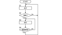
USBコンセント10は、起動後、まずは発光制御部12にて発光部14の発光素子141を点灯させる(S1)。このとき、発光部14では、発光素子141が白色に点灯することで、光学部材142の表面(前面)からなる発光面が白色に発光する。その後、USBコンセント10は、接続部2に対してUSBコネクタ91が接続されることをセンサ17にて検出する(S2)。接続部2に対してUSBコネクタ91が接続されなければ(S2:No)、USBコンセント10は、発光素子141の点灯を継続する(S1)。 After starting up, the USB outlet 10 first causes the light-emitting element 141 of the light-emitting unit 14 to light up via the light-emission control unit 12 (S1). At this time, in the light-emitting unit 14, the light-emitting element 141 lights up in white, causing the light-emitting surface consisting of the surface (front) of the optical member 142 to emit white light. After that, the USB outlet 10 detects via the sensor 17 that the USB connector 91 is connected to the connection unit 2 (S2). If the USB connector 91 is not connected to the connection unit 2 (S2: No), the USB outlet 10 keeps the light-emitting element 141 on (S1).

接続部2に対してUSBコネクタ91が接続されると(S2:Yes)、USBコンセント10は、発光制御部12にて発光部14の発光素子141を消灯させる(S3)。このとき、発光部14は、発光素子141が消灯することで、蓄光機能により、光学部材142の表面(前面)からなる発光面が発光する。その後、USBコンセント10は、接続部2に対するUSBコネクタ91の接続の解除をセンサ17にて検出する(S4)。USBコネクタ91の接続が解除されなければ(S4:No)、USBコンセント10は、発光素子141の消灯を継続する(S3)。 When the USB connector 91 is connected to the connection unit 2 (S2: Yes), the USB outlet 10 causes the light emission control unit 12 to turn off the light emitting element 141 of the light emitting unit 14 (S3). At this time, the light emitting unit 14 has a light emitting surface formed of the surface (front surface) of the optical member 142 that emits light due to the phosphorescence function as a result of the light emitting element 141 being turned off. The USB outlet 10 then detects with the sensor 17 that the USB connector 91 has been disconnected from the connection unit 2 (S4). If the USB connector 91 is not disconnected (S4: No), the USB outlet 10 continues to turn off the light emitting element 141 (S3).

一方、USBコネクタ91の接続が解除されると(S4:Yes)、USBコンセント10は、発光制御部12にて発光部14の発光素子141を点灯させる(S1)。 On the other hand, when the USB connector 91 is disconnected (S4: Yes), the USB outlet 10 causes the light emission control unit 12 to turn on the light emitting element 141 of the light emitting unit 14 (S1).

USBコンセント10は、上記S1~S4の処理を繰り返し実行する。図5のフローチャートは、USBコンセント10の動作の一例に過ぎず、処理を適宜省略又は追加してもよいし、処理の順番が適宜変更されていてもよい。 The USB outlet 10 repeatedly executes the above steps S1 to S4. The flowchart in FIG. 5 is merely one example of the operation of the USB outlet 10, and steps may be omitted or added as appropriate, and the order of steps may be changed as appropriate.

このように、本実施形態に係るUSBコンセント10は、少なくとも接続口4にUSBコネクタ91が接続されていない状態で発光部14が発光する。発光部14は、接続口4の位置を示すように発光するので、USBコネクタ91を接続するための接続口4の位置がわかりやすくなる。そのため、例えば、夜間、又は、USBコンセント10が、家具の影となる場所、若しくは窓のない室内等の暗所に設置されている場合であっても、ユーザは、発光部14の光を頼りに接続口4の位置を把握しやすくなる。特に、USBコンセント10においては、例えば、スマートフォン等の機器9の充電時にのみUSBコネクタ91が接続される等、比較的、USBコネクタ91の挿抜の頻度が高い。このようにUSBコネクタ91の挿抜の頻度が高いUSBコンセント10において、接続口4の位置が容易に把握できることは、利便性の向上に寄与しやすい。結果的に、利便性の向上を図りやすいUSBコンセント10を提供することができる。 In this way, in the USB outlet 10 according to this embodiment, the light emitting unit 14 emits light at least when the USB connector 91 is not connected to the connection port 4. Since the light emitting unit 14 emits light to indicate the position of the connection port 4, the position of the connection port 4 for connecting the USB connector 91 is easy to understand. Therefore, for example, even at night or when the USB outlet 10 is installed in a dark place such as a place shaded by furniture or a room without windows, the user can easily grasp the position of the connection port 4 by relying on the light of the light emitting unit 14. In particular, in the USB outlet 10, for example, the USB connector 91 is connected only when charging a device 9 such as a smartphone, and the USB connector 91 is inserted and removed relatively frequently. In the USB outlet 10 in which the USB connector 91 is inserted and removed frequently, being able to easily grasp the position of the connection port 4 easily contributes to improving convenience. As a result, it is possible to provide a USB outlet 10 that is easy to improve convenience.

さらに、発光部14からの光でユーザの手元(少なくともユーザが持つUSBコネクタ91)が照らされていれば、接続口4に対するUSBコネクタ91の接続作業がより行いやすくなる。例えば、USBの端子形状がA端子(USB Type-A)である場合には、接続口4にUSBコネクタ91を差し込む際に、USBコネクタ91の向きを合わせる必要があるが、ユーザの手元が照らされていれば、USBコネクタ91の向きを合わせやすい。これにより、例えば、USBコネクタ91が誤った向きで無理やり差し込まれることによる接続部2の破損等が生じにくい、という利点がある。 Furthermore, if the light from the light-emitting unit 14 illuminates the user's hand (at least the USB connector 91 held by the user), the operation of connecting the USB connector 91 to the connection port 4 becomes easier. For example, if the USB terminal shape is an A terminal (USB Type-A), it is necessary to adjust the orientation of the USB connector 91 when inserting the USB connector 91 into the connection port 4, but if the user's hand is illuminated, it is easy to adjust the orientation of the USB connector 91. This has the advantage that, for example, damage to the connection unit 2 due to forcibly inserting the USB connector 91 in the wrong orientation is less likely to occur.

(4)変形例
実施形態1は、本開示の様々な実施形態の一つに過ぎない。実施形態1は、本開示の目的を達成できれば、設計等に応じて種々の変更が可能である。本開示において説明する各図は、模式的な図であり、各図中の各構成要素の大きさ及び厚さそれぞれの比が、必ずしも実際の寸法比を反映しているとは限らない。また、実施形態1に係るUSBコンセント10と同等の機能は、方法、(コンピュータ)プログラム、又はプログラムを記録した非一時的記録媒体等で具現化されてもよい。
(4) Modifications The first embodiment is merely one of various embodiments of the present disclosure. Various modifications of the first embodiment are possible depending on the design, etc., as long as the object of the present disclosure can be achieved. Each figure described in this disclosure is a schematic diagram, and the ratio of the size and thickness of each component in each figure does not necessarily reflect the actual dimensional ratio. In addition, the function equivalent to the USB outlet 10 according to the first embodiment may be embodied by a method, a (computer) program, or a non-transitory recording medium on which a program is recorded, etc.

以下、実施形態1の変形例を列挙する。以下に説明する変形例は、適宜組み合わせて適用可能である。以下、実施形態1と同様の構成については、共通の符号を付して適宜説明を省略する。 Below, we will list some modified examples of the first embodiment. The modified examples described below can be combined as appropriate. Below, common reference symbols will be used for configurations similar to those of the first embodiment, and descriptions will be omitted as appropriate.

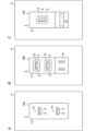
USBコンセント10の基本構成についても、実施形態1で説明した構成に限らず、例えば、図6A~図6Cに示すような種々の態様のUSBコンセント10A~10Cを実現可能である。 The basic configuration of the USB outlet 10 is not limited to the configuration described in the first embodiment, and various types of USB outlets 10A to 10C, such as those shown in Figures 6A to 6C, can be realized.

図6Aに示す態様では、USBコンセント10Aは、発光部14の態様が実施形態1とは異なり、対応する接続口4を囲む形状ではなく、接続口4の周囲の1カ所に配置されている。具体的には、図6Aの例では、発光部14は、対応する接続口4の上方に配置された点光源である。 In the embodiment shown in FIG. 6A, the USB outlet 10A differs from the first embodiment in that the light-emitting unit 14 is arranged in one location around the corresponding connection port 4, rather than surrounding the corresponding connection port 4. Specifically, in the example of FIG. 6A, the light-emitting unit 14 is a point light source arranged above the corresponding connection port 4.

図6Bに示す態様では、USBコンセント10Bは、筐体3が2個モジュール寸法の配線器具と同程度の寸法に形成されている。このUSBコンセント10Bは、例えば、100Vの交流電圧を出力するコンセント装置51と共に、取付枠84(図3A参照)にて取付対象物81(図3A参照)に取り付けられる。 In the embodiment shown in FIG. 6B, the USB outlet 10B has a housing 3 formed to have dimensions similar to those of a wiring device having two module dimensions. This USB outlet 10B is attached to an attachment object 81 (see FIG. 3A) by a mounting frame 84 (see FIG. 3A) together with an outlet device 51 that outputs an AC voltage of, for example, 100V.

図6Cに示す態様では、USBコンセント10Cは、筐体3が2個モジュール寸法の配線器具と同程度の寸法であって、かつ1個のUSBコネクタ91を接続可能な1個口(1ポート)タイプのUSBコンセントである。図6Cの例では、接続口4は、正面視において、上下方向の寸法が左右方向の寸法よりも大きい長方形状である。つまり、接続口4は、縦向き(縦長)に配置されている。さらに、このUSBコンセント10Cは、例えば、人感センサ等のセンサ装置52と共に、取付枠84(図3A参照)にて取付対象物81(図3A参照)に取り付けられる。センサ装置52は、人感センサに限らず、例えば、明るさセンサ、振動センサ、近接センサ若しくは音センサ、又はこれらの組み合わせであってもよい。USBコンセント10Cは、センサ装置52の出力に基づいて動作してもよい。例えば、センサ装置52が人感センサである場合には、USBコンセント10Cは、周辺に人が存在しなければ、接続部2への通電をオフとする。 In the embodiment shown in FIG. 6C, the USB outlet 10C is a single-outlet (one-port) type USB outlet in which the housing 3 is approximately the same size as a wiring device with two module dimensions and one USB connector 91 can be connected. In the example of FIG. 6C, the connection port 4 is rectangular in shape with a vertical dimension greater than a horizontal dimension when viewed from the front. In other words, the connection port 4 is arranged vertically (vertically long). Furthermore, this USB outlet 10C is attached to the attachment object 81 (see FIG. 3A) by a mounting frame 84 (see FIG. 3A) together with a sensor device 52 such as a human presence sensor. The sensor device 52 is not limited to a human presence sensor, and may be, for example, a brightness sensor, a vibration sensor, a proximity sensor, or a sound sensor, or a combination of these. The USB outlet 10C may operate based on the output of the sensor device 52. For example, if the sensor device 52 is a human presence sensor, the USB outlet 10C turns off the power supply to the connection portion 2 if there is no person in the vicinity.

また、USBコンセントにおいて、接続部2(接続口4)は、1つでもよいし、3つ以上でもよい。 Also, in a USB outlet, the number of connection parts 2 (connection ports 4) may be one or three or more.

また、複数の接続部2は、世代(転送速度の規格)及び/又はUSBの端子形状が異なる2つ以上の接続部2を含んでいてもよい。例えば、USBコンセント10は、A端子(USB Type-A)の接続部2と、C端子(USB Type-C)の接続部2と、を備えていてもよい。 The multiple connection parts 2 may also include two or more connection parts 2 with different generations (transfer speed standards) and/or USB terminal shapes. For example, the USB outlet 10 may include a connection part 2 with an A terminal (USB Type-A) and a connection part 2 with a C terminal (USB Type-C).

本開示におけるUSBコンセント10は、制御部101等にコンピュータシステムを含んでいる。コンピュータシステムは、ハードウェアとしてのプロセッサ及びメモリを主構成とする。コンピュータシステムのメモリに記録されたプログラムをプロセッサが実行することによって、本開示におけるUSBコンセント10としての機能が実現される。プログラムは、コンピュータシステムのメモリに予め記録されてもよく、電気通信回線を通じて提供されてもよく、コンピュータシステムで読み取り可能なメモリカード、光学ディスク、ハードディスクドライブ等の非一時的記録媒体に記録されて提供されてもよい。コンピュータシステムのプロセッサは、半導体集積回路(IC)又は大規模集積回路(LSI)を含む1ないし複数の電子回路で構成される。ここでいうIC又はLSI等の集積回路は、集積の度合いによって呼び方が異なっており、システムLSI、VLSI(Very Large Scale Integration)、又はULSI(Ultra Large Scale Integration)と呼ばれる集積回路を含む。さらに、LSIの製造後にプログラムされる、FPGA(Field-Programmable Gate Array)、又はLSI内部の接合関係の再構成若しくはLSI内部の回路区画の再構成が可能な論理デバイスについても、プロセッサとして採用することができる。複数の電子回路は、1つのチップに集約されていてもよいし、複数のチップに分散して設けられていてもよい。複数のチップは、1つの装置に集約されていてもよいし、複数の装置に分散して設けられていてもよい。ここでいうコンピュータシステムは、1以上のプロセッサ及び1以上のメモリを有するマイクロコントローラを含む。したがって、マイクロコントローラについても、半導体集積回路又は大規模集積回路を含む1ないし複数の電子回路で構成される。 The USB outlet 10 in the present disclosure includes a computer system in the control unit 101, etc. The computer system is mainly composed of a processor and a memory as hardware. The function of the USB outlet 10 in the present disclosure is realized by the processor executing a program recorded in the memory of the computer system. The program may be pre-recorded in the memory of the computer system, may be provided through an electric communication line, or may be recorded and provided in a non-transitory recording medium such as a memory card, an optical disk, or a hard disk drive that can be read by the computer system. The processor of the computer system is composed of one or more electronic circuits including a semiconductor integrated circuit (IC) or a large-scale integrated circuit (LSI). The integrated circuits such as IC or LSI referred to here are called differently depending on the degree of integration, and include integrated circuits called system LSI, VLSI (Very Large Scale Integration), or ULSI (Ultra Large Scale Integration). Furthermore, a field-programmable gate array (FPGA) that is programmed after the manufacture of the LSI, or a logic device that can reconfigure the connection relationship inside the LSI or reconfigure the circuit partition inside the LSI, can also be used as a processor. The multiple electronic circuits may be integrated into one chip, or may be distributed across multiple chips. The multiple chips may be integrated into one device, or may be distributed across multiple devices. The computer system referred to here includes a microcontroller having one or more processors and one or more memories. Therefore, the microcontroller is also composed of one or more electronic circuits including a semiconductor integrated circuit or a large-scale integrated circuit.

また、USBコンセント10の少なくとも一部の機能が、1つの筐体3内に集約されていることはUSBコンセント10に必須の構成ではなく、USBコンセント10の構成要素は、複数の筐体に分散して設けられていてもよい。例えば、制御部101の一部の機能が、接続部2(接続口4)とは別の筐体に設けられていてもよい。また、制御部101等の少なくとも一部の機能は、例えば、サーバ又はクラウド(クラウドコンピューティング)等によって実現されてもよい。 In addition, it is not essential for the USB outlet 10 that at least some of the functions of the USB outlet 10 are concentrated in one housing 3, and the components of the USB outlet 10 may be distributed across multiple housings. For example, some of the functions of the control unit 101 may be provided in a housing separate from the connection unit 2 (connection port 4). In addition, at least some of the functions of the control unit 101, etc. may be realized, for example, by a server or a cloud (cloud computing), etc.

また、USBコンセント10は、屋内用に限らず屋外用であってもよい。屋外用のUSBコンセント10においては、防雨(防滴)構造等が適宜採用される。 The USB outlet 10 may be for indoor use or for outdoor use. For outdoor USB outlets 10, a rainproof (drip-proof) structure, etc., is appropriately adopted.

また、実施形態1では、USBコンセント10に接続される機器9が、充電式の機器9である場合を例に説明したが、この例に限らず、USBコンセント10には、充電式でない機器9(充電式の機器9以外の機器9)を接続することも可能である。 In addition, in the first embodiment, the device 9 connected to the USB outlet 10 is a rechargeable device 9, but this is not the only example, and it is also possible to connect a non-rechargeable device 9 (a device 9 other than a rechargeable device 9) to the USB outlet 10.

また、USBコンセント10は、例えば、USBコンセント10に接続されている機器9が充電式か否かを判別する機能を有していてもよい。このような判別機能は、一例として、USBコンセント10が、USBコネクタ91を通した有線通信、又は無線通信により、機器9と通信することによって実現される。 The USB outlet 10 may also have a function of determining whether the device 9 connected to the USB outlet 10 is rechargeable or not. As an example, such a determination function is realized by the USB outlet 10 communicating with the device 9 by wired communication through the USB connector 91 or wireless communication.

また、USBコンセント10は、埋込型の配線器具に限らない。すなわち、USBコンセント10は、その全体が壁等の取付対象物81の表面から露出するように配置される「露出型」の配線器具であってもよい。この場合、USBコンセント10は、埋込型ではなく露出型のスイッチボックスを用いて取付対象物81に取り付けられる。また、USBコンセント10は、例えば、挟み金具等の、スイッチボックス以外の取付部材を用いて取付対象物81に取り付けられてもよい。 The USB outlet 10 is not limited to a recessed wiring device. That is, the USB outlet 10 may be an "exposed" wiring device that is arranged so that the entirety of the USB outlet 10 is exposed from the surface of the mounting object 81, such as a wall. In this case, the USB outlet 10 is attached to the mounting object 81 using an exposed switch box instead of a recessed one. The USB outlet 10 may also be attached to the mounting object 81 using a mounting member other than a switch box, such as a clamping bracket.

また、筐体3が取付枠84に取り付けられることは、USBコンセント10に必須の構成ではなく、例えば、筐体3は取付枠84と一体化されていてもよい。さらに、取付枠84に、コンセントプレート8が取り付けられることも、USBコンセント10に必須の構成ではなく、コンセントプレート8は適宜省略されてもよい。 Moreover, it is not essential for the USB outlet 10 that the housing 3 is attached to the mounting frame 84, and for example, the housing 3 may be integrated with the mounting frame 84. Furthermore, it is not essential for the USB outlet 10 that the outlet plate 8 is attached to the mounting frame 84, and the outlet plate 8 may be omitted as appropriate.

USBコンセント10は、例えば、パーソナルコンピュータ等の機器に備わっていてもよい。 The USB outlet 10 may be provided, for example, in a device such as a personal computer.

また、実施形態1では、1つの電源回路11に対して、複数の接続部2が接続されているが、この構成はUSBコンセント10に必須の構成ではなく、複数の接続部2の各々に対して個別の電源回路11が設けられていてもよい。つまり、USBコンセント10は、複数の接続部2と、複数の接続部2に一対一に対応する複数の電源回路11と、を備えていてもよい。この場合、複数の接続部2には、それぞれ個別の電源回路11から電力が供給されるので、定格出力(電流又は電力)に関しても、各接続部2について個別に規定される。 In addition, in the first embodiment, multiple connection parts 2 are connected to one power supply circuit 11, but this configuration is not essential for the USB outlet 10, and an individual power supply circuit 11 may be provided for each of the multiple connection parts 2. In other words, the USB outlet 10 may include multiple connection parts 2 and multiple power supply circuits 11 that correspond one-to-one to the multiple connection parts 2. In this case, since power is supplied to each of the multiple connection parts 2 from an individual power supply circuit 11, the rated output (current or power) is also specified individually for each connection part 2.

また、割当表示部32は、筐体3の前面31に形成された刻印に限らず、例えば、印字、シール、表示灯(発光素子)又はディスプレイ等で実現されてもよい。割当表示部32が表示灯又はディスプレイ等で実現される場合には、割当表示部32の表示内容は適宜変更可能である。 The allocation display unit 32 is not limited to an engraving formed on the front surface 31 of the housing 3, and may be realized, for example, by printing, a sticker, an indicator light (light-emitting element), a display, or the like. When the allocation display unit 32 is realized by an indicator light or a display, the display content of the allocation display unit 32 can be changed as appropriate.

また、割当表示部32は、USBコンセント10に必須の構成ではなく、割当表示部32は適宜省略されてもよい。 Furthermore, the allocation display unit 32 is not a required component of the USB outlet 10, and the allocation display unit 32 may be omitted as appropriate.

また、発光部14が発光素子141と光学部材142とを有することは、USBコンセント10に必須の構成ではなく、例えば、光学部材142が適宜省略されてもよい。また、発光部14は、複数の発光素子141を有していてもよい。さらに、発光部14は、例えば、発光素子141として、例えば、有機EL(Electro Luminescence)素子等を有してもよい。 Furthermore, it is not essential for the USB outlet 10 that the light-emitting unit 14 has the light-emitting element 141 and the optical member 142, and for example, the optical member 142 may be omitted as appropriate. The light-emitting unit 14 may have a plurality of light-emitting elements 141. Furthermore, the light-emitting unit 14 may have, for example, an organic EL (Electro Luminescence) element as the light-emitting element 141.

また、センサ17は、近距離にある物体の存在を検知する近距離センサであってもよい。このようなセンサ17は、例えば、筐体3の前面31に配置され、筐体3の前方に設定される検知エリア内に存在する物体を検知する。この種のセンサ17の具体例としては、検知エリア内の人を検知する焦電型の人感センサ、超音波センサ、光学式センサ又は電波センサ等で実現される。この場合においても、発光制御部12は、センサ17の出力(検知結果)に基づいて発光素子141を制御する。一例として、発光制御部12は、筐体3近傍の検知エリア内に人が存在することをセンサ17が検知した場合に発光素子141を点灯させ、筐体3近傍の検知エリア内に人が存在しなければ発光素子141を消灯させる。これにより、USBコンセント10を視認可能な位置に人がいなければ、発光素子141は消灯することになり、発光素子141での消費電力を抑えることが可能である。すなわち、本変形例では、USBコンセント10は、筐体3から所定距離内における物体の存在を検知するセンサ17を備えている。そして、発光部14は、センサ17の検知結果に基づいて発光する。 The sensor 17 may also be a short-distance sensor that detects the presence of an object in a short distance. Such a sensor 17 is, for example, disposed on the front surface 31 of the housing 3 and detects an object present within a detection area set in front of the housing 3. Specific examples of this type of sensor 17 include a pyroelectric human sensor, an ultrasonic sensor, an optical sensor, or a radio wave sensor that detects a person within the detection area. Even in this case, the light emission control unit 12 controls the light emitting element 141 based on the output (detection result) of the sensor 17. As an example, the light emission control unit 12 turns on the light emitting element 141 when the sensor 17 detects that a person is present within the detection area near the housing 3, and turns off the light emitting element 141 if there is no person within the detection area near the housing 3. As a result, if there is no person in a position where the USB outlet 10 is visible, the light emitting element 141 is turned off, making it possible to reduce power consumption in the light emitting element 141. That is, in this modified example, the USB outlet 10 is provided with a sensor 17 that detects the presence of an object within a predetermined distance from the housing 3. The light emitting unit 14 then emits light based on the detection result of the sensor 17.

(実施形態2)
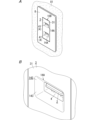
本実施形態に係るUSBコンセント10Dは、図7A及び図7Bに示すように、筐体3がガイド部143を有する点で、実施形態1に係るUSBコンセント10と相違する。以下、実施形態1と同様の構成については、共通の符号を付して適宜説明を省略する。
(Embodiment 2)
7A and 7B, the USB outlet 10D according to this embodiment differs from the USB outlet 10 according to the first embodiment in that the housing 3 has a guide portion 143. Hereinafter, the same components as those in the first embodiment will be denoted by the same reference numerals and the description thereof will be omitted as appropriate.

すなわち、本実施形態に係るUSBコンセント10Dは、ガイド部143を有している。ガイド部143は、接続口4へのUSBコネクタ91(図1参照)の挿入をガイドする。本実施形態では一例として、ガイド部143は、図7Bに示すように、筐体3の前面31における接続口4の周囲に形成されたテーパ面からなる。特に、本実施形態では、発光部14Aの光学部材142の表面(前面)が、ガイド部143として機能する。つまり、発光部14Aの光学部材142の表面は、接続口4を包囲しつつ前方に向けて傾斜した傾斜面からなる。言い換えれば、接続口4の周囲には、光学部材142の表面によって、筐体3の前面31を基準とし接続口4に近づくにつれて大きく窪んだ凹所が形成されており、この凹所の底部に接続口4が位置する。 That is, the USB outlet 10D according to this embodiment has a guide portion 143. The guide portion 143 guides the insertion of the USB connector 91 (see FIG. 1) into the connection port 4. In this embodiment, as an example, the guide portion 143 is a tapered surface formed around the connection port 4 on the front surface 31 of the housing 3, as shown in FIG. 7B. In particular, in this embodiment, the surface (front surface) of the optical member 142 of the light-emitting portion 14A functions as the guide portion 143. That is, the surface of the optical member 142 of the light-emitting portion 14A is an inclined surface that surrounds the connection port 4 and inclines toward the front. In other words, around the connection port 4, the surface of the optical member 142 forms a recess that is larger as it approaches the connection port 4, based on the front surface 31 of the housing 3, and the connection port 4 is located at the bottom of this recess.

このようなガイド部143が形成されていることにより、接続口4にUSBコネクタ91が挿入される際に、USBコネクタ91が接続口4に案内されやすくなって、USBコネクタ91の挿入が比較的簡単になる。つまり、接続口4へのUSBコネクタ91の挿入に際して、USBコネクタ91の先端がガイド部143に接触することで、ガイド部143に沿ってUSBコネクタ91が接続口4側に誘導されることになる。そのため、ユーザにおいては、例えば、USBコネクタ91の先端がガイド部143に接触した以降は、接続口4の周辺を目視できなくても、手探りでUSBコネクタ91をガイド部143に差し込むことが比較的簡単になる。結果的に、接続口4に対するUSBコネクタ91の挿入が比較的簡単になり、USBコンセント10Dの利便性の更なる向上を図ることができる。 By forming such a guide portion 143, when the USB connector 91 is inserted into the connection port 4, the USB connector 91 is easily guided into the connection port 4, making the insertion of the USB connector 91 relatively easy. In other words, when the USB connector 91 is inserted into the connection port 4, the tip of the USB connector 91 comes into contact with the guide portion 143, and the USB connector 91 is guided along the guide portion 143 toward the connection port 4. Therefore, for example, after the tip of the USB connector 91 comes into contact with the guide portion 143, it becomes relatively easy for the user to insert the USB connector 91 into the guide portion 143 by feel, even if the user cannot visually check the periphery of the connection port 4. As a result, the insertion of the USB connector 91 into the connection port 4 becomes relatively easy, and the convenience of the USB outlet 10D can be further improved.

また、本実施形態の変形例として、ガイド部143は、発光部14Aとは別に設けられていてもよい。さらに、ガイド部143は、テーパ面に限らず、例えば、筐体3の前面31から突出する構造であってもよい。 As a modification of this embodiment, the guide portion 143 may be provided separately from the light-emitting portion 14A. Furthermore, the guide portion 143 is not limited to a tapered surface, and may be structured to protrude from the front surface 31 of the housing 3, for example.

実施形態2で説明した構成(変形例を含む)は、実施形態1で説明した種々の構成(変形例を含む)と適宜組み合わせて採用可能である。 The configuration (including modified examples) described in embodiment 2 can be adopted in appropriate combination with the various configurations (including modified examples) described in embodiment 1.

(まとめ)
第1の態様に係るUSBコンセント(10,10A~10D)は、筐体(3)と、電源回路(11)と、発光部(14,14A)と、を備える。筐体(3)は、機器(9)のUSBコネクタ(91)を接続可能な接続口(4)を有する。電源回路(11)は、接続口(4)に接続されたUSBコネクタ(91)から機器(9)に電力を供給する。発光部(14,14A)は、接続口(4)の位置を示すように発光する。
(summary)
A USB outlet (10, 10A to 10D) according to a first aspect includes a housing (3), a power supply circuit (11), and a light-emitting unit (14, 14A). The housing (3) has a connection port (4) to which a USB connector (91) of a device (9) can be connected. The power supply circuit (11) supplies power to the device (9) from the USB connector (91) connected to the connection port (4). The light-emitting unit (14, 14A) emits light to indicate the position of the connection port (4).

この態様によれば、発光部(14,14A)が発光することで、USBコネクタ(91)を接続するための接続口(4)の位置を示すことができる。そのため、例えば、夜間、又は、USBコンセント(10,10A~10D)が、家具の影となる場所、若しくは窓のない室内等の暗所に設置されている場合であっても、ユーザは、発光部(14,14A)の光を頼りに接続口(4)の位置を把握しやすくなる。結果的に、利便性の向上を図りやすいUSBコンセント(10,10A~10D)を提供することができる。 According to this aspect, the light emitting unit (14, 14A) emits light, thereby indicating the location of the connection port (4) for connecting the USB connector (91). Therefore, for example, even at night or when the USB outlet (10, 10A-10D) is installed in a dark place such as a place shaded by furniture or a room without windows, the user can easily determine the location of the connection port (4) by relying on the light of the light emitting unit (14, 14A). As a result, it is possible to provide a USB outlet (10, 10A-10D) that is easy to improve convenience.

第2の態様に係るUSBコンセント(10,10A~10D)は、第1の態様において、発光部(14,14A)は、筐体(3)の前面(31)における接続口(4)の周囲に配置される。 The USB outlet (10, 10A to 10D) according to the second aspect is the first aspect, in which the light-emitting portion (14, 14A) is arranged around the connection port (4) on the front surface (31) of the housing (3).

この態様によれば、筐体(3)の前面(31)における接続口(4)の周囲で発光部(14,14A)が発光することで、ユーザにおいては、接続口(4)の位置が把握しやすくなる。 According to this embodiment, the light emitting portion (14, 14A) emits light around the connection port (4) on the front surface (31) of the housing (3), making it easier for the user to grasp the position of the connection port (4).

第3の態様に係るUSBコンセント(10,10A~10D)では、第2の態様において、発光部(14,14A)は、接続口(4)の全周にわたって発光する。 In the USB outlet (10, 10A to 10D) according to the third aspect, in the second aspect, the light-emitting portion (14, 14A) emits light around the entire circumference of the connection port (4).

この態様によれば、接続口(4)の全周にわたって発光部(14,14A)が発光することで、ユーザにおいては、接続口(4)の位置が把握しやすくなる。 According to this embodiment, the light emitting portion (14, 14A) emits light all around the connection port (4), making it easier for the user to grasp the position of the connection port (4).

第4の態様に係るUSBコンセント(10,10A~10D)では、第1~3のいずれかの態様において、発光部(14,14A)は、蓄光機能を有する。 In the USB outlet (10, 10A to 10D) according to the fourth aspect, in any of the first to third aspects, the light-emitting section (14, 14A) has a phosphorescent function.

この態様によれば、発光部(14,14A)に対して常時通電しなくても、発光部(14,14A)を発光させることが可能である。 According to this embodiment, it is possible to make the light-emitting unit (14, 14A) emit light without constantly applying electricity to the light-emitting unit (14, 14A).

第5の態様に係るUSBコンセント(10,10A~10D)では、第1~4のいずれかの態様において、発光部(14,14A)は、電力供給を受けて光を発する発光素子(141)を有する。 In the USB outlet (10, 10A to 10D) according to the fifth aspect, in any of the first to fourth aspects, the light-emitting section (14, 14A) has a light-emitting element (141) that emits light when supplied with power.

この態様によれば、発光素子(141)を制御することで、発光部(14,14A)の発光態様に多様性を持たせることができる。 According to this aspect, by controlling the light-emitting element (141), it is possible to provide diversity to the light-emitting mode of the light-emitting unit (14, 14A).

第6の態様に係るUSBコンセント(10,10A~10D)では、第1~5のいずれかの態様において、接続口(4)は複数設けられている。発光部(14,14A)は、複数の接続口(4)にそれぞれ対応して設けられている。 In the USB outlet (10, 10A to 10D) according to the sixth aspect, in any one of the first to fifth aspects, a plurality of connection ports (4) are provided. The light-emitting units (14, 14A) are provided in correspondence with the plurality of connection ports (4), respectively.

この態様によれば、複数の接続口(4)の位置を複数の発光部(14,14A)にて個別に示すことができる。 According to this embodiment, the positions of multiple connection ports (4) can be individually indicated by multiple light-emitting sections (14, 14A).

第7の態様に係るUSBコンセント(10,10A~10D)は、第1~6のいずれかの態様において、筐体(3)から所定距離内における物体の存在を検知するセンサ(17)を更に備える。発光部(14,14A)は、センサ(17)の検知結果に基づいて発光する。 The USB outlet (10, 10A to 10D) according to the seventh aspect is any one of the first to sixth aspects, and further includes a sensor (17) that detects the presence of an object within a predetermined distance from the housing (3). The light emitting unit (14, 14A) emits light based on the detection result of the sensor (17).

この態様によれば、必要なときだけ発光部(14,14A)を発光させることで、発光部(14,14A)の無駄な発光にかかるエネルギーを低減できる。 According to this embodiment, the light emitting unit (14, 14A) emits light only when necessary, thereby reducing the energy consumed by the light emitting unit (14, 14A) to emit light unnecessarily.

第8の態様に係るUSBコンセント(10,10A~10D)では、第1~7のいずれかの態様において、筐体(3)は、接続口(4)へのUSBコネクタ(91)の挿入をガイドするガイド部(143)を更に有する。 In the eighth aspect of the USB outlet (10, 10A to 10D), in any of the first to seventh aspects, the housing (3) further has a guide portion (143) that guides the insertion of the USB connector (91) into the connection port (4).

この態様によれば、接続口(4)にUSBコネクタ(91)が挿入される際に、USBコネクタ(91)が接続口(4)に案内されやすくなって、USBコネクタ(91)の挿入が比較的簡単になる。 According to this embodiment, when the USB connector (91) is inserted into the connection port (4), the USB connector (91) is easily guided into the connection port (4), making it relatively easy to insert the USB connector (91).

第2~8の態様に係る構成については、USBコンセント(10,10A~10D)に必須の構成ではなく、適宜省略可能である。 The configurations according to the second to eighth aspects are not essential for the USB outlet (10, 10A to 10D) and may be omitted as appropriate.

4 接続口
3 筐体
9 機器
10,10A~10D USBコンセント
11 電源回路
14,14A 発光部
17 センサ
31 前面
91 USBコネクタ
141 発光素子
143 ガイド部
4 Connection port 3 Housing 9 Device 10, 10A to 10D USB outlet 11 Power supply circuit 14, 14A Light emitting portion 17 Sensor 31 Front surface 91 USB connector 141 Light emitting element 143 Guide portion

Claims (6)

機器のUSBコネクタを接続可能な接続口を有する筐体と、
前記接続口に接続された前記USBコネクタから前記機器に電力を供給する電源回路と、
前記接続口の位置を示すように発光する発光部と、
前記筐体から所定距離内における人の存在を検知するセンサと、
前記接続口への前記USBコネクタの接続状態に応じて前記発光部の発光態様を変化させる発光制御部と、を備え、
前記発光部は、前記センサが前記人の存在を検知すると、前記筐体の周囲の明るさに関係なく発光し、
前記発光部は、前記筐体の前面における前記接続口の周囲に配置され、
前記発光部は、前記接続口の全周にわたって発光し、
前記発光部は、前記筐体の前面における前記接続口の周縁部に、前記接続口の形状に沿って設けられる、
USBコンセント。
A housing having a connection port to which a USB connector of a device can be connected;
a power supply circuit that supplies power to the device from the USB connector connected to the connection port;
a light emitting portion that emits light to indicate the position of the connection port;
a sensor that detects the presence of a person within a predetermined distance from the housing;
a light emission control unit that changes a light emission state of the light emitting unit in accordance with a connection state of the USB connector to the connection port,
When the sensor detects the presence of the person, the light emitting unit emits light regardless of the brightness of the surroundings of the housing;
the light emitting portion is disposed around the connection port on the front surface of the housing,
The light emitting portion emits light over the entire circumference of the connection port,
The light emitting portion is provided on a peripheral portion of the connection port on the front surface of the housing, the peripheral portion being aligned along a shape of the connection port.
USB outlet.
前記発光部は、前記接続口への前記USBコネクタの挿入をガイドするガイド部を有する、The light emitting portion has a guide portion that guides the insertion of the USB connector into the connection port.
請求項1に記載のUSBコンセント。2. The USB outlet of claim 1.
前記発光部は、蓄光機能を有する、The light-emitting unit has a phosphorescent function.
請求項1又は2に記載のUSBコンセント。3. A USB outlet according to claim 1 or 2.
前記発光部は、電力供給を受けて光を発する発光素子を有する、The light emitting unit has a light emitting element that emits light upon receiving power supply.
請求項1~3のいずれか1項に記載のUSBコンセント。A USB outlet according to any one of claims 1 to 3.
前記接続口は複数設けられており、The connection port is provided in plurality,
前記発光部は、前記複数の接続口にそれぞれ対応して設けられている、The light emitting units are provided corresponding to the plurality of connection ports, respectively.
請求項1~4のいずれか1項に記載のUSBコンセント。A USB outlet according to any one of claims 1 to 4.
前記筐体は、前記接続口への前記USBコネクタの挿入をガイドするガイド部を更に有する、The housing further includes a guide portion that guides the insertion of the USB connector into the connection port.
請求項1に記載のUSBコンセント。2. The USB outlet of claim 1.
JP2019203582A 2019-11-08 2019-11-08 USB outlet Active JP7617543B2 (en)

Priority Applications (1)

Application Number Priority Date Filing Date Title
JP2019203582A JP7617543B2 (en) 2019-11-08 2019-11-08 USB outlet

Applications Claiming Priority (1)

Application Number Priority Date Filing Date Title
JP2019203582A JP7617543B2 (en) 2019-11-08 2019-11-08 USB outlet

Publications (2)

Publication Number Publication Date
JP2021077524A JP2021077524A (en) 2021-05-20
JP7617543B2 true JP7617543B2 (en) 2025-01-20

Family

ID=75899826

Family Applications (1)

Application Number Title Priority Date Filing Date
JP2019203582A Active JP7617543B2 (en) 2019-11-08 2019-11-08 USB outlet

Country Status (1)

Country Link
JP (1) JP7617543B2 (en)

Citations (6)

* Cited by examiner, † Cited by third party
Publication number Priority date Publication date Assignee Title
JP2001338715A (en) 2000-05-26 2001-12-07 Matsushita Electric Works Ltd Electrical outlet
JP2009231091A (en) 2008-03-24 2009-10-08 Yasuhiro Kobayashi Display lamp and light-emitting method of display lamp
JP3176054U (en) 2011-04-15 2012-06-14 張 慶麟 USB wall-type charging socket
CN202817415U (en) 2012-06-20 2013-03-20 上海昆杰五金工具有限公司 Auxiliary lighting device
US20180048093A1 (en) 2016-08-12 2018-02-15 Norman R. Byrne Data-secure connector with indicator
JP3217592U (en) 2018-06-07 2018-08-16 ウエルシンジャパン株式会社 Table tap with free insertion position

Family Cites Families (3)

* Cited by examiner, † Cited by third party
Publication number Priority date Publication date Assignee Title
JP2001069165A (en) * 1999-08-25 2001-03-16 Matsushita Electric Works Ltd Usb hub
JP2015176651A (en) * 2014-03-13 2015-10-05 日本電気株式会社 Connector and its connection state detection method
JP6784102B2 (en) * 2016-08-30 2020-11-11 三菱電機株式会社 lighting equipment

Patent Citations (6)

* Cited by examiner, † Cited by third party
Publication number Priority date Publication date Assignee Title
JP2001338715A (en) 2000-05-26 2001-12-07 Matsushita Electric Works Ltd Electrical outlet
JP2009231091A (en) 2008-03-24 2009-10-08 Yasuhiro Kobayashi Display lamp and light-emitting method of display lamp
JP3176054U (en) 2011-04-15 2012-06-14 張 慶麟 USB wall-type charging socket
CN202817415U (en) 2012-06-20 2013-03-20 上海昆杰五金工具有限公司 Auxiliary lighting device
US20180048093A1 (en) 2016-08-12 2018-02-15 Norman R. Byrne Data-secure connector with indicator
JP3217592U (en) 2018-06-07 2018-08-16 ウエルシンジャパン株式会社 Table tap with free insertion position

Also Published As

Publication number Publication date
JP2021077524A (en) 2021-05-20

Similar Documents

Publication Publication Date Title
CN105655793B (en) Building block socket panel and layer module for building block socket panel
CN103368024B (en) Multi-functional multi output wall plug structure
TWI404273B (en) Electronic apparatus having power connector with light emitting function
TW201320489A (en) Modularize wall socket
US10483796B2 (en) Power control system
TW201112529A (en) Power device with lighted outlets
JP2021078247A (en) Usb receptacle
US20210376537A1 (en) Reel based outlet relocation/extension system
JP7617543B2 (en) USB outlet
JP7519615B2 (en) USB outlet
TWI547038B (en) Universal serial bus hub
TWI759923B (en) Usb outlet
JP7493169B2 (en) USB outlet
JP7689348B2 (en) Wireless communication device and wiring device system
CN219421231U (en) Image recognition equipment capable of being externally connected with module
JP7617544B2 (en) USB outlet
JP7462256B2 (en) USB outlet
JP7804925B2 (en) USB outlet
CN113823962A (en) Multi-application-scene wireless power supply socket
JP2021106122A (en) Usb receptacle
JP7373819B2 (en) Wiring equipment and wiring equipment systems
CN204616108U (en) Wall Embedded Wireless Router
TWI864375B (en) Wiring device
CN113920694B (en) Socket intelligent inspector with mobile phone APP alarm and fault feedback functions
CN223207341U (en) A smart central control screen, central control screen host and power box module

Legal Events

Date Code Title Description
A621 Written request for application examination

Free format text: JAPANESE INTERMEDIATE CODE: A621

Effective date: 20220711

A977 Report on retrieval

Free format text: JAPANESE INTERMEDIATE CODE: A971007

Effective date: 20230315

A131 Notification of reasons for refusal

Free format text: JAPANESE INTERMEDIATE CODE: A131

Effective date: 20230404

A521 Request for written amendment filed

Free format text: JAPANESE INTERMEDIATE CODE: A523

Effective date: 20230605

A02 Decision of refusal

Free format text: JAPANESE INTERMEDIATE CODE: A02

Effective date: 20231003

A521 Request for written amendment filed

Free format text: JAPANESE INTERMEDIATE CODE: A523

Effective date: 20231228

A911 Transfer to examiner for re-examination before appeal (zenchi)

Free format text: JAPANESE INTERMEDIATE CODE: A911

Effective date: 20240112

A912 Re-examination (zenchi) completed and case transferred to appeal board

Free format text: JAPANESE INTERMEDIATE CODE: A912

Effective date: 20240329

A521 Request for written amendment filed

Free format text: JAPANESE INTERMEDIATE CODE: A523

Effective date: 20240917

A61 First payment of annual fees (during grant procedure)

Free format text: JAPANESE INTERMEDIATE CODE: A61

Effective date: 20241220

R150 Certificate of patent or registration of utility model

Ref document number: 7617543

Country of ref document: JP

Free format text: JAPANESE INTERMEDIATE CODE: R150