JP7616680B2 - Gaming Machines - Google Patents
Gaming Machines Download PDFInfo
- Publication number
- JP7616680B2 JP7616680B2 JP2022105655A JP2022105655A JP7616680B2 JP 7616680 B2 JP7616680 B2 JP 7616680B2 JP 2022105655 A JP2022105655 A JP 2022105655A JP 2022105655 A JP2022105655 A JP 2022105655A JP 7616680 B2 JP7616680 B2 JP 7616680B2
- Authority
- JP
- Japan
- Prior art keywords
- effect
- performance
- game
- pattern
- cpu
- Prior art date
- Legal status (The legal status is an assumption and is not a legal conclusion. Google has not performed a legal analysis and makes no representation as to the accuracy of the status listed.)
- Active
Links
Images


Classifications
-
- Y—GENERAL TAGGING OF NEW TECHNOLOGICAL DEVELOPMENTS; GENERAL TAGGING OF CROSS-SECTIONAL TECHNOLOGIES SPANNING OVER SEVERAL SECTIONS OF THE IPC; TECHNICAL SUBJECTS COVERED BY FORMER USPC CROSS-REFERENCE ART COLLECTIONS [XRACs] AND DIGESTS
- Y02—TECHNOLOGIES OR APPLICATIONS FOR MITIGATION OR ADAPTATION AGAINST CLIMATE CHANGE
- Y02E—REDUCTION OF GREENHOUSE GAS [GHG] EMISSIONS, RELATED TO ENERGY GENERATION, TRANSMISSION OR DISTRIBUTION
- Y02E60/00—Enabling technologies; Technologies with a potential or indirect contribution to GHG emissions mitigation
- Y02E60/10—Energy storage using batteries
Landscapes
- Display Devices Of Pinball Game Machines (AREA)
Description
本発明は、遊技者によって遊技されるパチンコ遊技機等の遊技機に関する。 The present invention relates to gaming machines such as pachinko machines that are played by players.
従来、特別図柄抽選を行って、大当りしたか否かを報知する報知演出(変動演出)を行う遊技機がある(例えば、非特許文献1)。 Conventionally, there are gaming machines that perform a special pattern lottery and perform a notification effect (variable effect) that notifies the player whether or not a jackpot has been hit (for example, Non-Patent Document 1).
遊技機には、遊技媒体(遊技球、メダル等)を獲得することによる楽しみばかりではなく、遊技自体(演出やゲーム性)による楽しみが常に求められている。また、遊技機には、演出や報知等について、適度な分かりやすさも求められている。 Gaming machines are expected to provide not only the enjoyment of winning gaming media (gaming balls, medals, etc.), but also the enjoyment of the game itself (presentation and gameplay). Gaming machines are also expected to provide a reasonable level of ease of understanding in terms of presentation and notifications, etc.
それ故に、本発明の目的の一つは、遊技者を惹きつける遊技機を提供することである。 Therefore, one of the objectives of the present invention is to provide a gaming machine that attracts players.
上記の目的を達成するために、本発明の一局面は以下の構成を採用した。なお、括弧内の参照符号、説明文言等は、本発明の一局面の理解を助けるために後述する実施形態との対応関係を単なる一例として示したものであって、本発明の一局面の範囲を何ら限定するものではない。 In order to achieve the above object, one aspect of the present invention employs the following configuration. Note that the reference symbols, explanatory text, etc. in parentheses are merely examples of correspondence with the embodiments described below to aid in understanding this aspect of the present invention, and do not in any way limit the scope of this aspect of the present invention.
本発明の一局面に係る遊技機(1)は、
遊技者に有利な特別遊技(大当り遊技)を実行可能な遊技機であって、
判定を行う判定手段(100)と、
前記判定手段による判定結果に基づいて、遊技の進行を制御すると共に所定のコマンドを送信する遊技制御手段(100)と、
前記遊技制御手段により送信された前記所定のコマンドに基づいて、所定の遊技演出を制御する演出制御手段(400等)と、
前記遊技演出を表示可能とする表示手段(70)と、
遊技者に操作される操作手段(16)とを備え、
前記演出制御手段は、
特定画像(装飾図柄)が変動表示してから停止表示する表示演出(報知演出)を、前記表示手段に表示可能であり、
前記表示手段において、前記操作手段の操作を促す操作演出(ボタン画像等)の表示および当該操作演出を強調する所定の強調演出(ボタン画像強調演出)の実行が可能であり、
遊技方法を報知する第1特定報知(左打ち報知;図79)を実行可能であり、
演出効果に関する第2特定報知(音量/光量ゲージ表示等;図70等)を実行可能であり、
前記操作手段において、前記所定の強調演出に対応した演出(演出ボタンの発光/振動等)を実行可能であり、
前記所定の強調演出の実行中に前記第1特定報知が実行される場合、前記操作手段は、当該所定の強調演出に対応した演出を実行可能であり、当該第1特定報知に対応した演出の実行を制限可能であり、(図82、図83)
第1モードと第2モードとを含む複数のモードのうちの何れかのモード(演出モード)にて前記表示演出を設定可能であり、(段落0220等)
前記第1モードが設定されているときと前記第2モードが設定されているときとで、前記所定の強調演出の実行中の音を異ならせることが可能であり、
前記第1モードが設定されているときと前記第2モードが設定されているときとで、前記第2特定報知に関する報知音を共通にすることが可能である。(段落0580等)
A gaming machine (1) according to one aspect of the present invention comprises:
A gaming machine capable of executing a special game (jackpot game) advantageous to a player,
A determination means (100) for making a determination ;
a game control means (100) for controlling the progress of a game and transmitting a predetermined command based on the result of the judgment by the judgment means;
A presentation control means (400, etc.) for controlling a predetermined game presentation based on the predetermined command transmitted by the game control means;
A display means (70) capable of displaying the game performance;
An operating means (16) operated by a player,
The performance control means includes:
The display means can display a display effect (announcement effect) in which a specific image (decorative pattern) is displayed in a variable manner and then stopped .
The display means is capable of displaying an operation effect ( such as a button image) that prompts the user to operate the operation means and executing a predetermined emphasis effect (such as a button image emphasis effect) that emphasizes the operation effect ,
A first specific notification (left hit notification; FIG. 79) that notifies the game method can be executed.
A second specific notification (such as a volume/light gauge display; FIG. 70, etc.) regarding a performance effect can be executed.
The operation means is capable of executing a performance (e.g., light emission/vibration of a performance button) corresponding to the predetermined highlight performance,
When the first specific notification is executed during execution of the predetermined emphasis effect, the operation means is capable of executing an effect corresponding to the predetermined emphasis effect and is capable of restricting execution of the effect corresponding to the first specific notification (FIGS. 82 and 83).
The display effect can be set in any one of a plurality of modes (effect modes) including a first mode and a second mode (paragraph 0220, etc.).
A sound generated during execution of the predetermined emphasis effect can be made different between when the first mode is set and when the second mode is set,
The notification sound for the second specific notification may be the same when the first mode is set and when the second mode is set. (Paragraph 0580, etc.)
本発明によれば、遊技者の興味を惹きつける遊技機を提供することができる。 The present invention provides a gaming machine that attracts the interest of players.
(第1実施形態)
以下、適宜図面を参照しつつ、本発明の第1実施形態に係るパチンコ遊技機1について説明する。なお、パチンコ遊技機1を、単に、遊技機1という場合がある。
First Embodiment
Hereinafter, a
[パチンコ遊技機1の概略構成]
図1~図3を参照して、パチンコ遊技機1の概略構成について説明する。図1は、遊技機1の正面図の一例である。図2は、図1の第1可変入賞部49の拡大図である。図3は、遊技機1の裏面側の斜視図での一例である。
[General configuration of pachinko gaming machine 1]
The schematic configuration of a
遊技機1は、外枠2と、外枠2に対して回動可能に支持される遊技盤取付枠3と、遊技盤取付枠3に対して回動可能に支持されるガラス枠4と、遊技球(遊技媒体)が流下する遊技領域5aが形成された遊技盤5が設けられている。
The
外枠2は、中央部分が前後方向に開口する矩形状のベースフレーム2aの下部前面に飾り板2bが取り付けられており、遊技店の島設備に対して固着部材(例えば、釘や止め具など)を介して固定される。
The
遊技盤取付枠3は、水平方向の一端側において第1ヒンジ6を介して外枠2に対して脱着可能に連結されており、第1ヒンジ6を支点として回動可能に支持されている。そのため、遊技盤取付枠3を外枠2に対して扉のように回動すると、遊技盤取付枠3の裏面側が前方に露出するので、遊技盤取付枠3の裏面側に設けられた各種装置のメンテナンスなどを行うことが可能となる。
The game
ガラス枠4は、水平方向の一端側において第2ヒンジ7を介して遊技盤取付枠3に脱着自在に連結されており、第2ヒンジ7を支点として回動可能に支持されている。そのため、ガラス枠4を遊技盤取付枠3に対して扉のように回動すると、遊技盤5の遊技領域5aおよび遊技盤取付枠3の前面部分を開閉することができる。ガラス枠4の上部寄りの略中央部分には、前後方向(手前側奥側方向)に開口する開口部8(窓部)が形成され、開口部8を後方から塞ぐように透明部材8a(ガラス板やアクリル板など)が取り付けられており、開口部8および透明部材8aを介して遊技領域5aを視認可能としている。ガラス枠4の開口部8の周囲には、スピーカ9と、複数の装飾LEDを有する枠ランプ10と、付与条件の成立に基づいて払い出された遊技球等の遊技球を貯留するための上皿11と、上皿11に入りきらずに溢れ球流路に流入した遊技球を受け入れて貯留するための下皿(図示なし)と、遊技球を発射させるための操作が可能なレバー13とが設けられている。また、図1には記載しないが、遊技盤5には、複数の盤ランプ10a(図4参照)が設けられている。
The
スピーカ9は、ガラス枠4の上部の2箇所に間隔を空けて設けられ、BGM(バックグラウンドミュージック)、SE(サウンドエフェクト)等を出力することでサウンド(音楽、音声等)による演出を行うようになっている。また、枠ランプ10は、開口部8の周囲に複数設けられ、各ランプ(LED)の光の照射方向や発光色を変更することで照明による演出を行う。また、枠ランプ10は、ガラス枠4の開放や払出装置95(図3参照)から遊技球を払い出すことができない払出異常が発生した場合に点灯/点滅する。
The
上皿11は、その底面がレバー13の方向側(右方向)に向けて下り傾斜しており、下り傾斜の端部には球送りソレノイド(図示なし)が設けられている。上皿11に貯留された遊技球が流下して球送りソレノイドに到達すると、球送りソレノイドの動作によって遊技球が1個ずつ遊技盤取付枠3側に向けて送り出される。また、上皿11の中央手前側の部分には、後述する種々の演出に係る決定操作や選択操作等を行うための入力装置として機能する演出ボタン16と十字キー18が左右に並べて設けられている。さらに、上皿11の右寄りの部分には、遊技球の貸出操作や残金を記憶したカードなどの記憶媒体の返却操作を行うことが可能な貸出ボタン20が設けられている。
The bottom surface of the
演出ボタン16は、遊技者等が決定操作等の入力操作を行うことが可能であり、演出ボタン16の操作を検出するための演出ボタン検出スイッチ(図示なし)と、演出ボタン16を通常状態と通常状態よりも上方に位置する突出状態とに変化させるためのボタン駆動モータ(図示なし)及び演出ボタン16を通常状態と所定態様で振動する振動状態とに変化させるためのボタン振動モータを備えたボタン駆動装置(図示なし)、及び、演出ボタン16を消灯状態と所定態様で発光する点灯(又は点滅)状態とに変化させるための演出ボタン発光LED(図示なし)が設けられている。
The
十字キー18は、遊技者等が選択操作等の入力操作を行うことが可能であり、上ボタン、下ボタン、左ボタンおよび右ボタンと、十字キー19の操作を検出するための十字キー検出スイッチ(図示なし)が設けられている。
The cross key 18 allows the player to perform input operations such as selection operations, and is provided with an up button, a down button, a left button, and a right button, as well as a cross key detection switch (not shown) for detecting the operation of the
なお、本実施形態においては、ボタン駆動装置により演出ボタン16を振動させる構成としたが、例えば、演出ボタン16以外に別の操作手段(例えば、遊技者が入力操作可能な演出レバー)を設けた場合、当該演出レバーも振動するようにしてもよい。また、十字キー18が振動するようにしてもよいし、さらには、操作手段に限らず、遊技者が触れることが可能な位置に設けられた装飾部材(例えば、キャラクタを模したもの)が振動するようにしてもよい。
In this embodiment, the
貸出ボタン20は、操作されると遊技機1に並設される球貸機(図示なし)が受け付けている記憶媒体に記憶された残金を減算して遊技球の貸し出しが行われる。
When the
上皿11と下皿(図示なし)との間には、上皿11に入りきらない遊技球を受け入れて下皿に案内するための溢れ球流路(図示省略)が形成されている。また、溢れ球流路の途中には下皿に遊技球が満杯となる皿満杯エラーの発生を検出する満杯検出スイッチ(図示なし)が設けられ、満杯検出スイッチによって下皿の満杯が検出されている間は払出装置95(図3参照)による遊技球の払い出しが停止される。
Between the
レバー13は、回動可能に設けられた発射ハンドル15と、発射ハンドル15に遊技者の手が触れていることを検出するタッチセンサ(図示なし)と、発射ハンドル15の回動角度によって抵抗値が変化して遊技球の発射速度を変化させる可変抵抗器からなる発射ボリューム(図示なし)が設けられている。タッチセンサによって遊技者の手が発射ハンドル15に触れていることを検出すると、球送りソレノイド(図示なし)が作動して遊技球が1個ずつ送り出される。
The
遊技盤取付枠3には、遊技盤5を取り付けるための遊技盤取付部(図示なし)と、遊技球を遊技領域5aに向けて発射するための発射装置26と、遊技盤取付枠3及びガラス枠4を閉鎖状態にロックするためのロック機構27と、ガラス枠4の開放(開閉)を検出するための開放検出スイッチ(図示なし)が設けられている。
The game
遊技盤取付部は、遊技盤取付枠3の上部寄りの略中央に前方が開口する凹室状に形成され、遊技盤5を前方から収納可能となっている。遊技盤取付部の凹室の奥部には、前後方向に開放する開口が設けられており、この開口を介して遊技盤5の裏面側に設けられる各種装置等が遊技機1の後方に臨む。
The game board mounting section is formed in a recessed chamber shape that opens to the front at approximately the center near the top of the game
発射装置26は、遊技球を発射するための打出部材と、打出部材を駆動するための発射用ソレノイド(図示なし)と、打出部材から遊技盤の左下端部に向けて上り傾斜する発射レールと、発射レールの傾斜下端部となる発射位置に遊技球を停留させるストッパーが設けられている。そして、球送りソレノイドによって発射位置に送り出された遊技球を打出部材の動作によって遊技領域5aに向けて打ち出す。
The launching
ロック機構27は、遊技盤取付部の右側方に設けられ、鍵穴が形成されるシリンダーの前端部がガラス枠4の前面側に露出するようになっている。そして、シリンダーの鍵穴に専用の鍵を挿入して一方向に回動させると遊技盤取付枠3のロックが解除されて遊技盤取付枠3が開閉可能となり、他方向に回動させるとガラス枠4のロックが解除されてガラス枠4が開閉可能となる。
The
遊技盤5の外縁寄りの位置には、湾曲形状の内側レール35及び外側レール36が設けられており、この内側レール35および外側レール36によって囲まれた部分に遊技球が流下可能な遊技領域5aが形成される。また、内側レール35と外側レール36との間には、発射装置26により発射された遊技球を遊技領域5aの上流部に案内する発射球案内路38が形成されている。また、遊技領域5aの最下流部には、流下してきた遊技球を遊技領域外(遊技盤取付枠3の回収部)に導くためのアウト口39が形成されている。遊技領域5aの略中央には、内部への遊技球の進入を規制する枠状の飾り枠40(センターケース)が設けられ、飾り枠40によって遊技領域5aが、第1の発射強さで発射された遊技球が流下する左側遊技領域と第1の発射強さよりも強い第2の発射強さで発射された遊技球が流下する右側遊技領域とに分けられ、左側遊技領域と右側遊技領域とは飾り枠40の下方で繋がっている。
Curved inner and
飾り枠40の左側部には、左側遊技領域を流下する遊技球を飾り枠40の内部に導入するワープ装置41が設けられ、飾り枠40の下部には、ワープ装置41により飾り枠40の内部に導かれた遊技球を飾り枠40の下方に流下させるステージ部42が設けられている。また、飾り枠40の左寄りの下方には、遊技球が常時入賞(入球)可能な3つの普通入賞口(一般入賞口)43が設けられており、飾り枠40の右寄りの下方には、遊技球が常時入賞(入球)可能な1つの普通入賞口43が設けられている。普通入賞口43に入賞(入球)した遊技球が普通入賞口スイッチ43a(図4参照)によって検出される(付与条件が成立する)と、所定個数(例えば5個)の遊技球が払出装置95(図3参照)から賞球(賞価値の付与)として上皿11に払い出される。
At the left side of the
ステージ部42の下方には、遊技球が常時入賞(入球)可能な第1始動口45(第1特別図柄の始動入賞領域)が設けられており、第1始動口45に入賞(入球)した遊技球が第1始動口スイッチ45aで検出される(付与条件が成立する)と、所定個数の遊技球(例えば3個)が払出装置95(図3参照)から賞球(賞価値の付与)として上皿11に払い出される。また、特別遊技(大当り遊技)を実行するか否かの大当たり判定を行うための権利が付与される。
Below the
飾り枠40の下方であって第1始動口45の右斜め下方には、所定条件の成立に基づき遊技球の入賞(入球)が不可能又は困難な閉状態から遊技球の入賞が可能又は容易な開状態に切替可能な可変始動部46が設けられている。可変始動部46は、上面が左右方向(図1中左側)に向けて下り傾斜することで遊技球の流路となると共に、前後方向に移動可能な開閉部材48と、開閉部材48の直下で上方に向けて開口する第2始動口47(第2特別図柄の始動入賞領域)と、第2始動口47に入賞(入球)した遊技球を検出する第2始動口スイッチ47a(図4参照)と、第2始動口開閉部材48を前方(入賞規制位置)に向けて移動させることで第2始動口47を閉状態に変換すると共に、第2始動口開閉部材48を後方(入賞許容位置)に向けて移動させることで第2始動口47を開状態に変換するための第2始動口開閉部48b(ソレノイド)が設けられている。そして、第2始動口47に遊技球が入賞して第2始動口スイッチ47aで検出される(付与条件が成立する)と、所定個数の遊技球(例えば2個)が払出装置95(図3参照)から賞球(賞価値の付与)として上皿11に払い出される。また、特別遊技(大当り遊技)を実行するか否かの大当り判定(抽選)を行うための権利が付与される。
A
飾り枠40の右側となる右側遊技領域には、遊技球が常時通過可能なゲート44(普図始動領域)が設けられており、ゲート44を通過した遊技球がゲートスイッチ44aで検出されると、賞球は付与されないが、第2始動口47を開放するための普通図柄抽選が実行される。
In the right-side game area to the right of the
ゲート44の下方には、所定条件の成立(大当り判定で大当りと判定されたこと)に基づき遊技球の入賞(入球)が不可能もしくは困難な閉状態から入賞が可能もしくは容易な開状態に変換可能な第1可変入賞部49(第1可変入賞装置)が設けられている。
Below the
第1可変入賞部49は、上面が左右方向(図中右側)に向けて下り傾斜することで遊技球の流路となると共に、前後方向に移動可能な開閉部材51と、開閉部材51の直下で上方に向けて開口する第1大入賞口50(入賞領域)と、第1大入賞口50に入賞(入球)した遊技球を検出する第1大入賞口スイッチ50aと、開閉部材51を前方(入賞規制位置)に向けて移動させることで第1大入賞口50を閉状態に変化させると共に、開閉部材51を後方(入賞許容位置)に向けて移動させることで第1大入賞口50を開状態に変化させるための第1大入賞口開閉部51b(図4参照)が設けられている。そして、大当り遊技中に開閉部材51が後方に移動して第1大入賞口50が閉状態から開状態に変化されると、開閉部材51の上面を流下していた遊技球や第1大入賞口50に到達した遊技球が第1大入賞口50に遊技球が入賞して第1大入賞口スイッチ50aで検出されると、所定個数の遊技球(例えば10個)の遊技球が払出装置95(図3参照)から賞球として上皿11に払い出される。
The first
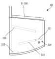
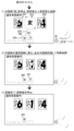
第1可変入賞部49は、図2に示すように、内部が視認可能となるように半透明であり、内部に、案内部材220、開閉部材221、案内部材222及び排出口223が設けられる。案内部材220及び案内部材222は固定されている一方で、開閉部材221は特定領域開閉部150(図2に図示なし)により前後方向(手前側奥行側)に移動可能である。開閉部材221の直下には特定領域224が設けられており、特定領域224を通過する遊技球は特定領域スイッチ151(図2に図示なし)により検出される。図2では、遊技者に視認できるように、特定領域224に「V」のマークが描かれている。開閉部材221が前方に向けて移動した閉状態の場合、第1大入賞口50に入賞して第1大入賞口スイッチ50a(図2に図示なし)に検出された遊技球は、案内部材220、開閉部材221及び案内部材222によって流下して、特定領域224を通過することなく排出口223に入る。一方、開閉部材221が後方に向けて移動した開状態の場合、第1大入賞口50に入賞して第1大入賞口スイッチ50a(図2に図示なし)に検出された遊技球は、高確率で、特定領域224を通過してから排出口223に入る。後述するが、特別図柄抽選で小当りに当選した場合には、小当り遊技が行われて開閉部材51及び開閉部材221が開放されて遊技球が特定領域224を通過可能となる。そして、小当り遊技中に特定領域224を遊技球が通過すると、大当り(第2種大当り)が発生して大当り遊技が行われる。なお、特別図柄抽選の大当りは、第1種大当りである。
2, the first
第1可変入賞部49の下方には、所定条件の成立(大当り発生と判定されたこと)に基づき遊技球の入賞(入球)が不可能又は困難な閉状態から入賞が可能又は容易な開状態に切替可能な第2可変入賞部55が設けられている。
Below the first
第2可変入賞部55(第2可変入賞装置)は、上面が左右方向(図中左側)に向けて下り傾斜することで遊技球の流路となると共に、前後方向に移動可能な開閉部材57と、開閉部材57の直下で上方に向けて開口する第2大入賞口56(入賞領域)と、第2大入賞口56に入賞(入球)した遊技球を検出する第2大入賞口スイッチ56aと、開閉部材57を前方(入賞規制位置)に向けて移動させることで第2大入賞口56を閉状態に変換すると共に、開閉部材57を後方(入賞許容位置)に向けて移動させることで第2大入賞口56を開状態に変化させるための第2大入賞口開閉部57b(ソレノイド)が設けられている。そして、大当り遊技中に開閉部材57が後方に移動して第2大入賞口56が閉状態から開状態に変化すると、開閉部材57の上面を流下していた遊技球や第2大入賞口56に到達した遊技球が第2大入賞口56に入賞して第2大入賞口スイッチ56aで検出され、所定個数の遊技球(例えば10個)の遊技球が払出装置95(図3参照)から賞球として上皿11に払い出される。
The second variable winning section 55 (second variable winning device) has an upper surface that slopes downward in the left-right direction (left side in the figure) to form a flow path for the game balls, and is provided with an opening/closing
なお、左側遊技領域に発射された遊技球は、飾り枠40の外縁に沿ってそのまま流下するか、ワープ装置41に流入してからステージ部42を介して流下し、飾り枠40の下方に設けられる3つの普通入賞口43、第1始動口45の何れかに入賞するか、アウト口39に流入することになる。そのため、右側遊技領域に設けられるゲート44、普通入賞口43、第1可変入賞部49(第1大入賞口50)及び第2可変入賞部55(第2大入賞口56)に入賞(通過)することはない。また、右側遊技領域に発射された遊技球は、上流流路91aを経由して流下し、右側遊技領域に設けられる1つの普通入賞口43、可変始動部46(第2始動口47)、第1可変入賞部49(第1大入賞口50)、第2可変入賞部55(第2大入賞口56)の何れかに入賞するか、アウト口39に流入することになる。そのため、左側遊技領域に設けられる普通入賞口43、第1始動口45に入賞することはない。
A game ball launched into the left-hand game area will either flow directly down along the outer edge of the
遊技盤5の裏側には、普通入賞口43、第1始動口45、第2始動口47、第1大入賞口50及び第2大入賞口56に入賞した遊技球、及び、アウト口39に流入した遊技球等からなるアウト球を受け入れて集合させながら流下させるアウト球流路が設けられ、アウト球流路の最下流部にはアウト球スイッチ(図示なし)が設けられている。アウト球スイッチで検出された遊技球は遊技機1の裏面側の排出口から遊技機1の外部(島設備)に排出されることになる。
On the back side of the
遊技領域5aの外側には、第1特別図柄表示器60、第2特別図柄表示器61及び普通図柄表示器62からなる図柄表示装置と、第1特別図柄保留表示器63、第2特別図柄保留表示器64及び普通図柄保留表示器65からなる保留表示装置と、ラウンド数表示器66と、右打ち表示器67と、状態確認表示器68とからなるメイン情報表示器59が設けられている。このメイン情報表示器59については、基本的にはLEDによって構成されており、ダイナミック点灯が行われるようになっている。
Outside the
第1特別図柄表示器60は、第1始動口45への遊技球の入賞(入球)に基づき行われる第1特別図柄の大当り判定の結果(特別図柄抽選の結果)を表示(報知)するための可変表示器である。第2特別図柄表示器61は、第2始動口47への遊技球の入賞(入球)に基づき行われる第2特別図柄の大当り判定の結果(特別図柄抽選の結果)を表示(報知)するための可変表示器である。普通図柄表示器62は、ゲート44への遊技球の通過(入球)に基づき行われる普通図柄の当り判定の結果(普通図柄抽選の結果)を表示(報知)するための可変表示器である。大当り判定とは、第1始動口45又は第2始動口47に遊技球が入賞(入球)したときに判定情報(大当り判定用乱数値、特別図柄判定用乱数値、リーチ判定用乱数値、特図変動パターン判定用乱数値等)を取得し、取得した判定情報に基づいて大当り遊技を実行するか否か等を判定するものである。そして、第1始動口45への遊技球の入賞に基づき大当り判定が行われると、第1特別図柄表示器60で第1特別図柄の変動表示が行われ、所定時間経過後に判定結果を報知する第1特別図柄の停止表示が行われる。また、第2始動口47への遊技球の入賞に基づき大当り判定が行われると、第2特別図柄表示器61で第2特別図柄の変動表示が行われ、所定時間経過後に判定結果を報知する第2特別図柄の停止表示が行われる。
The first
普通図柄表示器62は、普通図柄の変動表示においてLEDが所定の間隔もしくは順序で点滅する。そして、普通図柄を停止表示する場合には、普通図柄抽選の結果を報知する態様でLEDが点灯する。
When displaying the normal symbol in a variable manner, the LED of the
なお、第1特別図柄表示器60及び/又は第2特別図柄表示器61は、7セグメントのLEDで構成することができる。例えば、大当たり判定で大当たりと判定された場合には、「3」や「7」等の数字を停止表示し、ハズレと判定された場合には、「-」を停止表示するようにし、変動表示中にあっては消灯と「-」とを繰り返すようにするとよい。
The first
第1特別図柄保留表示器63は、第1始動口45に遊技球が入賞(入球)した場合に記憶される判定情報(第1保留)の個数である第1保留数(U1)を表示するためのものであり、第1保留の個数を示す態様で点灯又は点滅する。なお、第1保留は最大で4個まで記憶されるようになっているが、4個よりも少なくてもよいし多くてもよい。第2特別図柄保留表示器64は、第2始動口47に遊技球が入賞(入球)した場合に記憶される判定情報(第2保留)の個数である第2保留数(U2)を表示するためのものであり、第2保留の個数を示す態様で点灯又は点滅する。なお、第2保留は最大で4個まで記憶されるようになっているが、4個よりも少なくてもよいし多くてもよいし、第2保留を記憶しないようにしてもよい。普通図柄保留表示器65は、ゲート44に遊技球が入賞(通過)した場合に記憶される判定情報(普図保留)の個数である普図保留数を表示するためのものであり、普図保留の個数を示す態様で点灯又は点滅する。なお、普図保留は最大で4個まで記憶されるようになっているが、4個よりも少なくてもよいし多くてもよいし、普図保留を記憶しないようにしてもよい。
The first special symbol reserved
ラウンド数表示器66は、大当り状態(特別遊技)が発生した場合のラウンド数を表示するためのものであり、大当り遊技開始時にラウンド数を示す所定の態様でLEDの点灯を開始し、大当り遊技中はLEDの点灯を継続し、大当り遊技の終了時にLEDを消灯する。例えば、ラウンド数が4回の大当り遊技であれば、最も左のLEDのみが点灯し、ラウンド数が10回の大当たり遊技であれば、全てのLEDが点灯する。
The
右打ち表示器67は、大当り遊技中や時短遊技状態中等において右側遊技領域に向けて遊技球を発射すること(所謂右打ち)を促す右打ち表示を表示するためのものであり、大当り遊技中や時短遊技状態中等にLEDが点灯する。
The right-
状態確認表示器68は、特別図柄抽選の当選確率の設定値を変更するための設定変更モード、又は、当該設定値を確認するための設定確認モードに設定されていることを示すためのものである。遊技機1において、特別図柄抽選の当選確率は、遊技店により複数の当選確率のうちから設定値として何れか1つを設定可能である。設定変更モード又は設定確認モードに移行するとLEDの点灯を開始し、設定変更モード又は設定確認モードが終了するとLEDを消灯する。このように、状態確認表示器68が遊技機の正面(表面)に設けられているので、遊技店は設定変更モード又は設定確認モードに設定されているか否かを容易に確認することが可能となっている。なお、状態確認表示器68の設置位置は遊技機1の正面(表面)であればよく、その他の場所に設置してもよい。
The
遊技領域5aの内側には、サブ第1変動表示器81、サブ第2変動表示器82、サブ第1保留表示器83、サブ第2保留表示器84、サブ普図変動表示器85、サブ普図保留表示器86、サブ右打ち表示器87からなるサブ情報表示器80が設けられている。サブ情報表示器80は、基本的にはLEDによって構成されており、ダイナミック点灯が行われるようになっている。なお、サブ情報表示器80には、上記した状態確認表示器68のような設定変更モードや設定確認モードに設定されていることを示す表示器は設けられていない。
Inside the
サブ第1変動表示器81は、第1特別図柄が変動表示中であるか否かを表示(報知)するためのものであり、サブ第2変動表示器82は、第2特別図柄が変動表示中であるか否かを表示(報知)するためのものであり、それぞれ1個のLEDによって構成されている。そして、対応する特別図柄の変動表示が開始されるとLEDが所定周期(1秒)で点滅(0.5秒点灯→0.5秒消灯)し、対応する特別図柄が停止表示されると点灯する。なお、サブ第1変動表示器81やサブ第2変動表示器82で特別図柄の大当り判定の結果を報知するようにしてもよい。この場合には、大当りの場合にはLEDが点灯し、ハズレの場合にはLEDが消灯するようにするとよい。
The
サブ第1保留表示器83は、第1保留情報の個数(第1保留数)を表示するためのものであり、サブ第2保留表示器84は、第2保留情報の個数(第2保留数)を表示するためのものであり、それぞれ2個のLEDによって構成されている。そして、保留数が「0」のときに左右のLEDが消灯し、保留数が「1」のときに左側のLEDが点灯すると共に右側のLEDが消灯し、保留数が「2」のときに左右のLEDが点灯し、保留数が「3」のときに左側のLEDが点滅すると共に右側のLEDが点灯し、保留数が「4」のときに左右のLEDが点滅する。
The
サブ普図変動表示器85は、普通図柄抽選の結果を表示(報知)するためのものであり、1つのLEDによって構成されている。そして、普通図柄の変動表示が開始されるとLEDが所定の間隔で点滅(変動表示)する。そして、普通図柄が停止表示されると当り抽選の結果を示す態様(当りの場合には点灯、ハズレの場合には消灯)が停止表示される。なお、サブ普図変動表示器85において、普通図柄の変動表示中であるか否かのみが把握できるように、普通図柄の変動表示中に点滅し、停止表示されると点灯又は消灯するようにしてもよい。
The sub-regular
サブ普図保留表示器86は、普図保留記憶の個数(普図保留数)を表示するためのものであり、2個のLEDによって構成されている。そして、普図保留数が「0」のときに左右のLEDが消灯し、普図保留数が「1」のときに左側のLEDが点灯すると共に右側のLEDが消灯し、普図保留数が「2」のときに左側のLEDが点滅すると共に右側のLEDが点灯し、普図保留数が「4」のときに左右のLEDが点滅する。
The sub-regular
サブ右打ち表示器87は、遊技領域5aの右側領域に向けて遊技球を発射すること(所謂右打ち)を促すためのものであり、1個のLEDによって構成されている。そして、大当り遊技中及び時短遊技状態中等にLEDが点灯し、それ以外の遊技状態でLEDが消灯する。
The sub right-
飾り枠40の内側に画成される演出空間40aの奥部には、液晶表示ディスプレイからなるメイン画像表示部70が設けられ、演出空間40aの下部であってメイン画像表示部70の前方には、メイン画像表示部70よりもサイズが小さく形成された液晶表示ディスプレイからなるサブ画像表示部71が設けられる。演出空間40aの上部には、動作演出やランプ演出を実行するための可動役物733が設けられる。なお、メイン画像表示部70およびサブ画像表示部71を総称して、画像表示部という場合がある。
A main
メイン画像表示部70及びサブ画像表示部71では、遊技の進行に応じて様々な演出表示を行う。演出表示としては、特別図柄の変動表示の非実行中に行われる客待ちデモ演出や、特別図柄の変動表示の実行中に行われる装飾図柄(演出図柄)の変動表示を伴う報知演出(変動演出)や、大当り遊技の実行中に行われる大当り遊技演出等がある。また、サブ画像表示部71は、メイン画像表示部70で変動演出の実行中にソレノイドやモータ等によって移動することで移動演出を行うことが可能となっている。なお、サブ画像表示部71は必ずしも設ける必要はなく、例えば、サブ画像表示部71が設けられた位置に、ランプ発光および移動等の動作を行う可動役物を設けてもよい。
The main
遊技盤取付枠3及び遊技盤5の裏側には、予め定めた払出条件(賞球、球貸)の成立に基づいて遊技球を払い出すための払出装置95、島設備などから供給される遊技球を貯留して払出装置95に供給する遊技球貯留部96、メイン制御部100を構成する主制御基板を内蔵した主制御装置110Aと、払出制御部300及び発射制御部200を構成する払出制御基板を内蔵した払出制御装置120Aと、演出制御部400、画像音響制御部500及びランプ制御部600を構成する演出制御基板を内蔵した演出制御装置130Aと、電源基板を内蔵した電源装置160A、遊技機の外部(ホールコンピュータ等の情報収集装置)に遊技に関する情報を出力するための遊技情報出力端子板90等が設けられている。
On the back side of the game
また、主制御装置の上部及び演出制御装置の全体を後方から覆うように左右一側に設定された回転軸を中心として左右他側が左右方向に開閉する開閉扉式のカバー部材23が設けられており、演出制御装置130Aには、カバー部材23に覆われるようにスピーカ9から出力される演出音等の音量や表示装置(メイン画像表示部、サブ画像表示部)や各種照明装置(枠ランプ10等)の光量の調整に関わる調整モードを切り替えるための切替スイッチ22が設けられている。また、切替スイッチ22の近傍には、図3には記載しないが、背面キー170(図4参照)が設けられている。背面キー170は、切替スイッチ22によって音量を調整する調整モードとなっている場合には、遊技店の店員等によって遊技盤5の裏側から、スピーカ9から出力される音量を調整することができる。また、背面キー170は、切替スイッチ22によって光量を調整する調整モードとなっている場合には、遊技店の店員等によって遊技盤5の裏側から、各種照明装置(例えば枠ランプ10)等の光量を調整(通常の光量とそれより暗い光量の何れかに設定)することができる。
In addition, a
主制御基板の表面側には、遊技を制御するためのワンチップマイコンからなるメイン制御部100、メイン制御部100のRAM103の記憶内容をクリア又は遊技の有利度合い(特別図柄抽選の当選確率)を設定する設定値を更新するための信号を入力するRWMクリアスイッチ111a、設定変更モードや設定確認モードに移行させるための信号を入力する設定キースイッチ112a、遊技機の実性能を把握可能とする性能情報や設定値を表示するための情報表示器113、その他の電子部品等が実装されている。
On the front side of the main control board, there are mounted a
情報表示器113は、左右方向に並べられた4つの7セグメント表示器で構成されている。そして、左から2つの7セグメント表示器によって性能情報の種類(データ種別)を示す識別情報を表示するための識別セグが構成され、右から2つの7セグメント表示器によって設定値や性能情報の数値を示す数値情報を表示するための数値セグが構成されている。
The
[パチンコ遊技機1の制御装置の構成]
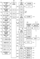
次に、図4を参照して、遊技機1における動作制御や信号処理を行う制御装置について説明する。なお、図4は、遊技機1に設けられた制御装置の主要な構成の一例を示すブロック図である。
[Configuration of the control device of the pachinko gaming machine 1]
Next, a control device for controlling operations and processing signals in the
図4において、遊技機1の制御装置は、メイン制御部100、発射制御部200、払出制御部300、演出制御部400、画像音響制御部500、およびランプ制御部600等を備えている。
In FIG. 4, the control device of the
メイン制御部100は、CPU(Central Processing Unit;中央処理装置)101、ROM(Read Only Memory)102、およびRAM(Random Access Memory)103を備えている。CPU101は、内部抽選および当選の判定等の払い出し賞球数に関連する各種制御を行う際の演算処理を行う。ROM102には、CPU101により実行されるプログラムや各種データ等が記憶されている。RAM103は、CPU101の作業用メモリ等として用いられる。以下、メイン制御部100の主な機能について説明する。
The
メイン制御部100は、第1始動口45または第2始動口47に遊技球が入賞すると特別図柄抽選(大当り抽選)を行い、特別図柄抽選で当選したか否かを示す判定結果データを演出制御部400に送る。
When a game ball enters the
メイン制御部100は、可変始動部46の開閉部材48が開状態となる開時間や開閉部材48が開閉する回数、さらには開閉部材48が開閉する開閉時間間隔を制御する。また、メイン制御部100は、遊技球が第1始動口45へ入賞したときの特別図柄抽選の実行保留回数、遊技球が第2始動口47へ入賞したときの特別図柄抽選の実行保留回数、および遊技球がゲート44を通過したときの普通図柄抽選の実行保留回数をそれぞれ管理し、これらの保留回数に関連するデータを演出制御部400に送る。
The
メイン制御部100は、特別図柄抽選の結果(大当り又は小当りの当選)に応じて、大入賞口(第1大入賞口50、第2大入賞口56)の開閉動作を制御する。例えば、メイン制御部100は、所定条件(例えば、29.5秒経過または遊技球10個の入賞)を満たすまで、大入賞口(第1大入賞口50又は第2大入賞口56)が開状態となるラウンドを所定回数(例えば、15回)だけ繰り返すように制御する。また、メイン制御部100は、大入賞口(第1大入賞口50、第2大入賞口56)が開閉する開閉時間間隔を制御する。
The
メイン制御部100は、特別図柄抽選で小当りに当選した場合、第1可変入賞部49(小当りの当選によって開状態となった第1大入賞口50)の内部の開閉部材221を閉状態から開状態にして特定領域224を遊技球が通過可能な状態にする(図2参照)。そして、この場合において、特定領域224を遊技球が通過すると、メイン制御部100は、大当りを発生させる。
When a small prize is won in the special pattern lottery, the
メイン制御部100は、遊技の進行に応じて遊技状態を変化させ、又、遊技の進行に応じて、特別図柄抽選の実行間隔(特別図柄がメイン情報表示器59に変動表示されてから停止表示される時間と言ってもよい)、可変始動部46の開閉動作等を変化させる。
The
メイン制御部100は、第1始動口45、第2始動口47、大入賞口(第1大入賞口50、第2大入賞口56)、および普通入賞口43に遊技球が入賞すると、遊技球が入賞した場所に応じて1つの遊技球当たり所定数の賞球を払い出すように払出制御部300に対して指示する。なお、メイン制御部100は、ゲート44を遊技球が通過したことを検出しても、それに連動した賞球の払い出しを払出制御部300に指示しない。払出制御部300がメイン制御部100の指示に応じて賞球の払い出しを行った場合、払出制御部300から払い出した賞球の個数に関する情報がメイン制御部100へ送られる。そして、メイン制御部100は、払出制御部300から取得した情報に基づいて、払い出した賞球の個数を管理する。
When a game ball enters the
メイン制御部100は、特別図柄抽選の結果、普通図柄抽選の結果、特別図柄抽選の保留数、普通図柄抽選の保留数、大当り遊技のラウンド数等を遊技者に表示(報知)する。また、メイン制御部100は、遊技機の実性能を把握可能とする性能情報や、遊技の有利度合い(特別図柄抽選の当選確率)を設定する設定値を主制御基板の表面において表示する。また、メイン制御部100は、遊技店の店員等の操作に応じて、RAM103の記憶内容をクリアし、又、上記した設定値として、予め定められた複数の固定値の何れかを設定する。また、メイン制御部100は、遊技店の店員等の操作に応じて、上記した設定値を変更可能な設定変更モードや、上記した設定値の設定状況を確認可能な設定確認モードに移行させる。また、メイン制御部100は、遊技機の外部(ホールコンピュータ等の情報収集装置)に遊技に関する情報を出力する。
The
上述した機能を実現するために、メイン制御部100には、第1始動口スイッチ45a、第2始動口スイッチ47a、第2始動口開閉部48b、ゲートスイッチ44a、第1大入賞口スイッチ50a、第2大入賞口スイッチ56a、第1大入賞口開閉部51b、第2大入賞口開閉部57b、特定領域スイッチ151、特定領域開閉部150、普通入賞口スイッチ43a、メイン情報表示器59(図1参照)、情報表示器113、RWMクリアスイッチ111a、設定キースイッチ112a、遊技情報出力端子板90が接続されている。
To realize the above-mentioned functions, the
第1始動口スイッチ45aは、第1始動口45へ遊技球が入賞したことに応じた信号をメイン制御部100へ送る。第2始動口スイッチ47aは、第2始動口47へ遊技球が入賞したことに応じた信号をメイン制御部100へ送る。第2始動口開閉部48bは、メイン制御部100から送られる制御信号に応じて、可変始動部46の開閉部材48を開閉する。ゲートスイッチ44aは、ゲート44を遊技球が通過したことに応じた信号をメイン制御部100へ送る。第1大入賞口スイッチ50aは、第1大入賞口50へ遊技球が入賞したことに応じた信号をメイン制御部100へ送る。第1大入賞口開閉部51bは、メイン制御部100から送られる制御信号に応じて、第1大入賞口50を開閉する。第2大入賞口スイッチ56aは、第2大入賞口56へ遊技球が入賞したことに応じた信号をメイン制御部100へ送る。第2大入賞口開閉部57bは、メイン制御部100から送られる制御信号に応じて、第2大入賞口56を開閉する。特定領域スイッチ151は、特定領域224(図2参照)を遊技球が通過したことに応じた信号をメイン制御部100へ送る。特定領域開閉部150は、メイン制御部100から送られる制御信号に応じて、特定領域224(開閉部材221)を開閉する。普通入賞口スイッチ43aは、普通入賞口43へ遊技球が入賞したことに応じた信号をメイン制御部100へ送る。メイン情報表示器59は、メイン制御部100から送られる制御信号に応じて、特別図柄抽選の結果、普通図柄抽選の結果、特別図柄抽選の保留数、普通図柄抽選の保留数、大当り遊技のラウンド数等を表示(報知)する。情報表示器113は、メイン制御部100から送られる制御信号に応じて、遊技機の実性能を把握可能とする性能情報や、遊技の有利度合い(特別図柄抽選の当選確率)を設定する設定値を(主制御基板の表面において)表示する。RWMクリアスイッチ113aは、遊技店の店員等の操作に応じて、RAM103の記憶内容をクリアするための信号や、上記した設定値を設定するための信号をメイン制御部100へ送る。設定キースイッチ112aは、上記した設定値を変更可能な設定変更モードや、上記した設定値の設定状況を確認可能な設定確認モードに移行させるための信号をメイン制御部100へ送る。遊技情報出力端子板90は、遊技機1の外部(ホールコンピュータ等の情報収集装置)に遊技に関する情報を出力する。
The first
発射制御部200は、CPU201、ROM202、およびRAM203を備えている。CPU201は、発射装置26に関連する各種制御を行う際の演算処理を行う。ROM202は、CPU201にて実行されるプログラムや各種データ等を記憶している。RAM203は、CPU201の作業用メモリ等として用いられる。
The
レバー13は、その位置が中立位置にある場合、信号を出力せずに発射停止状態となる。そして、レバー13は、遊技者によって時計回りに回転操作されると、その回転角度に応じた信号を打球発射指令信号として発射制御部200に出力する。発射制御部200は、打球発射指令信号に基づいて、発射装置26の発射動作を制御する。例えば、発射制御部200は、レバー13の回転角度が増すほど、遊技球が発射される速度が速くなるように、発射装置26の動作を制御する。発射制御部200は、レバー13に設けられた停止ボタン(図示なし)が押下された信号が出力された場合、発射装置26が遊技球を発射する動作を停止させる。
When the
払出制御部300は、CPU301、ROM302、およびRAM303を備えている。CPU301は、払出球の払い出しを制御する際の演算処理を行う。ROM302は、CPU301にて実行されるプログラムや各種データ等を記憶している。RAM303は、CPU301の作業用メモリ等として用いられる。
The
払出制御部300は、メイン制御部100から送られたコマンドに基づいて、払出球の払い出しを制御する。具体的には、払出制御部300は、メイン制御部100から、遊技球が入賞した場所に応じた所定数の賞球を払い出すコマンドを取得する。そして、コマンドに指定された数だけの賞球を払い出すように払出装置95を制御する。
The
演出制御部400は、CPU401、ROM402、RAM403、およびRTC(リアルタイムクロック)404を備えている。また、演出制御部400には、遊技者によって操作される十字キー18が接続され、演出制御部400は、遊技者による十字キー18の操作に応じて十字キー18から出力される操作データを取得する。また、演出制御部400は、ランプ制御部600を介して演出ボタン16から出力される操作データを取得する。CPU401は、演出を制御する際の演算処理を行う。ROM402は、CPU401にて実行されるプログラムや各種データ等を記憶している。RAM403は、CPU401の作業用メモリ等として用いられる。RTC404は、現時点の日時を計測する。
The
演出制御部400は、メイン制御部100から送られる特別図柄抽選結果等を示すデータに基づいて、演出内容を設定する。また、演出制御部400は、遊技者によって演出ボタン16または十字キー18が押下操作された場合、当該操作入力や検出結果に応じて演出内容を設定する場合もある。
The
画像音響制御部500は、CPU501、ROM502、RAM503を備えている。CPU501は、演出内容を表現する画像および音響を制御する際の演算処理を行う。ROM502は、CPU501にて実行されるプログラムや各種データ等を記憶している。RAM503は、CPU501の作業用メモリ等として用いられる。
The image and
画像音響制御部500は、演出制御部400から送られたコマンドに基づいて、画像表示部(メイン画像表示部70、サブ画像表示部71)に表示する画像およびスピーカ9から出力する音響を制御する。具体的には、画像音響制御部500のROM502には、特別図柄抽選結果を報知等するための装飾図柄画像、予告演出や先読み予告演出を表示するためのキャラクタやアイテム等の画像、特別図柄抽選が保留されていることを示す保留アイコン、および各種背景画像等を、画像表示部に表示するための画像データが記憶されている。また、画像音響制御部500のROM502には、画像表示部に表示される画像と連動させて、または表示される画像とは独立に、スピーカ9から出力させる楽曲や音声等の各種音響データが記憶されている。画像音響制御部500のCPU501は、ROM502に記憶された画像データや音響データの中から、演出制御部400から送られたコマンドに対応したものを選択して読み出す。そして、CPU501は、読み出した画像データを用いて、背景画像表示、装飾図柄画像表示、およびキャラクタ/アイテム表示等のための画像処理を行って、演出制御部400から送られたコマンドに対応した各種演出表示を行う。そして、CPU501は、画像処理された画像データが示す画像を画像表示部に表示する。また、CPU501は、読み出した音響データを用いて音声処理を行い、音声処理された音響データが示す音響をスピーカ9から出力する。また、画像音響制御部500は、背面キー170が操作されたことによる信号に応じて、スピーカ9から出力される音量を調整する。
Based on the command sent from the
ランプ制御部600は、CPU601、ROM602、およびRAM603を備えている。CPU601は、盤ランプ10a、枠ランプ10、演出ボタン16、可動役物73、及びサブ情報表示器80を制御する際の演算処理を行う。ROM602は、CPU601にて実行されるプログラムや各種データ等を記憶している。RAM603は、CPU601の作業用メモリ等として用いられる。
The
ランプ制御部600は、演出制御部400から送られたコマンドに基づいて、盤ランプ10a、枠ランプ10、演出ボタン16および可動役物73の点灯/点滅や発光色等を制御する。また、ランプ制御部600は、演出制御部400から送られたコマンドに基づいて、演出ボタン16および可動役物73の動作を制御する。具体的には、ランプ制御部600のROM602には、演出制御部400により設定される演出内容に応じた盤ランプ10a等での点灯/点滅パターンデータおよび発光色パターンデータ(発光パターンデータ)が記憶されている。CPU601は、ROM602に記憶された発光パターンデータの中から、演出制御部400から送られたコマンドに対応したものを選択して読み出す。そして、CPU601は、読み出した発光パターンデータに基づいて、盤ランプ10a等の発光を制御する。また、ROM602には、演出制御部400により設定される演出内容に応じた演出ボタン16および可動役物73の動作パターンデータが記憶されている。CPU601は、ROM602に記憶された動作パターンデータの中から、演出制御部400から送られたコマンドに対応したものを選択して読み出す。そして、CPU601は、読み出した動作パターンデータに基づいて、演出ボタン16および可動役物73の動作を制御する。また、ランプ制御部600は、演出制御部400から送られたコマンドに基づいて、サブ演出表示器80の表示(点灯等)を制御する。
The
また、ランプ制御部600は、背面キー170が操作されたことによる信号に応じて、盤ランプ10a、枠ランプ10、演出ボタン16および可動役物73のランプ(LED)の光量を調整する。
In addition, the
また、ランプ制御部600には、遊技者によって操作される演出ボタン16が接続され、ランプ制御部600は、遊技者による演出ボタン16の操作に応じて演出ボタン16から出力される操作データを取得して、当該操作データを演出制御部400に伝達する。
The
なお、演出制御部400は、ランプ制御部600から伝達される演出ボタン16の操作データ、および十字キー18から出力された操作データに基づいて、画像音響制御部500に対して、演出ボタン16および十字キー18の操作状態を通知する。ここで、演出ボタン16および十字キー18の操作状態とは、操作が行われているか否かや、どのような操作が行われているか(例えば、演出ボタン16の長押しや、十字キー18左方向キーの押下)等を含む情報である。したがって、例えば演出ボタン16が遊技者によって操作された場合、ランプ制御部600によって検出された演出ボタン16の操作状態が、演出制御部400を介して画像音響制御部500に伝達される。このため、画像音響制御部500は、演出制御部400から伝達される演出ボタン16等の操作状態に基づいて、演出内容等を変化させることもできる。また、演出制御部400は、ランプ制御部600から伝達される演出ボタン16の操作データに応じて、ランプ制御部600にコマンドを送信して可動役物73を動作させて可動役物演出を実行することもできる。
The
[本実施形態における遊技状態の概要]
次に、本実施形態における遊技機1の遊技状態について説明する。遊技機1の遊技状態としては、低確状態、時短状態、非時短状態が少なくとも存在する。低確状態は、特別図柄抽選の当選確率が通常の低確率(例えば1/300)に設定されている遊技状態である。なお、本実施形態における遊技機1には、特別図柄抽選の当選確率が低確状態よりも高確率(例えば1/50)に設定される高確状態は設けられていない。
[Outline of the gaming state in this embodiment]
Next, the gaming state of the
非時短状態は、特別図柄抽選の実行時間が通常の時間となる遊技状態であり、又、普通図柄抽選の当選確率が通常の低確率(例えば1/10)であり、かつ普通図柄抽選に当選した場合であっても可変始動部46が短時間(例えば0.10秒間を1回)しか開放制御されない遊技状態である。このため、非時短状態は、第2始動口47に遊技球が入球し難い遊技状態である。
The non-time-saving state is a game state in which the execution time of the special symbol lottery is the normal time, the probability of winning the normal symbol lottery is the normal low probability (e.g. 1/10), and even if the normal symbol lottery is won, the variable starting
時短状態は、特別図柄抽選の実行時間が、非時短状態よりも短縮されることとなる遊技状態であり、又、普通図柄抽選の当選確率が非電サポ状態よりも高確率(例えば10/10)であり、かつ普通図柄抽選に当選した場合に可変始動部46が長時間(例えば2.00秒間を3回)開放されるように制御される遊技状態である。このため、時短状態は、可変始動部46が頻繁に長時間開放されて第2始動口47に遊技球が頻繁に入球(入賞)し易く、非時短状態に比べて遊技球の消費を抑えつつ短時間で多数の特別図柄抽選を実行できる遊技状態である。
The time-saving state is a game state in which the execution time of the special symbol lottery is shorter than in the non-time-saving state, the probability of winning the normal symbol lottery is higher (e.g., 10/10) than in the non-electric support state, and when the normal symbol lottery is won, the
本実施形態では、低確状態かつ非時短状態に制御される遊技状態を低確非時短遊技状態(「通常遊技状態」という場合がある)といい、低確状態かつ時短状態に制御される遊技状態を低確時短遊技状態(「時短遊技状態」という場合がある)という。また、上記したように、本実施形態では、高確状態を設けていないので、高確状態かつ時短状態に制御される高確時短遊技状態(確変遊技状態)には制御されない。なお、大当り遊技中は通常遊技状態で制御されることになるが、大当り遊技が実行されているので、大当り遊技中は大当り遊技状態で制御されていると考えてもよい。 In this embodiment, a game state controlled to a low probability state and a non-time-saving state is called a low probability non-time-saving game state (sometimes called a "normal game state"), and a game state controlled to a low probability state and a time-saving state is called a low probability time-saving game state (sometimes called a "time-saving game state"). Also, as described above, this embodiment does not provide a high probability state, so it is not controlled to a high probability time-saving game state (probability variable game state) that is controlled to a high probability state and a time-saving state. Note that, although control is performed in the normal game state during jackpot play, since a jackpot play is being executed, it may be considered that control is performed in the jackpot game state during jackpot play.
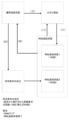
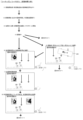
次に、図5を参照して、上述した「低確時短遊技状態(時短遊技状態)」の詳細について説明する。従来の遊技機では、図5の(イ)および(ニ)のルートで「低確非時短遊技状態(通常遊技状態)」から「低確時短遊技状態(時短遊技状態)」に移行するのが主流である。本実施形態においては、この従来の(イ)および(ニ)のルートの他に、「低確時短遊技状態(時短遊技状態)」への移行ルートを設けている。具体的には、図5の(ロ)で示すように、通常遊技状態において所定条件の成立が発生すると、大当たり遊技を経ることなく「低確時短遊技状態(時短遊技状態)」に移行する。 Next, the above-mentioned "low-probability time-saving game state (time-saving game state)" will be described in detail with reference to FIG. 5. In conventional gaming machines, the transition from the "low-probability non-time-saving game state (normal game state)" to the "low-probability time-saving game state (time-saving game state)" is typically made via the routes (a) and (d) in FIG. 5. In this embodiment, in addition to the conventional routes (a) and (d), a transition route to the "low-probability time-saving game state (time-saving game state)" is provided. Specifically, as shown in FIG. 5 (b), when a predetermined condition is met in the normal game state, the state transitions to the "low-probability time-saving game state (time-saving game state)" without going through a jackpot game.
「所定条件の成立」の一例として、起点から実行された特別図柄の変動表示の回数がN回に達したことが挙げられる。例えば、RAM103に、「低確非時短遊技状態(通常遊技状態)」における特別図柄の変動表示の回数を計数記憶する領域を設けて、当該領域で計数記憶する回数がN回に達すると、「低確非時短遊技状態(通常遊技状態)」から「低確時短遊技状態(時短遊技状態)」に移行するようにしている。
One example of "the fulfillment of a predetermined condition" is when the number of times the variable display of the special symbol has been executed from the starting point reaches N times. For example, an area is provided in
「N回」は、特別図柄抽選の当選確率を設定する設定値毎に、任意の回数を設定することができる。例えば、特別図柄抽選の当選確率が「1/199」であれば、N回として「500」回程度を設定することができ、特別図柄抽選の当選確率が「1/319」であれば、N回として「900」回程度を設定することができる。 "N times" can be set to any number of times for each setting value that sets the winning probability of the special symbol lottery. For example, if the winning probability of the special symbol lottery is "1/199", N times can be set to about "500", and if the winning probability of the special symbol lottery is "1/319", N times can be set to about "900".
「起点」は、一例として、例えば、RWMクリアスイッチ111aが操作されてRAM103の記憶情報(特別図柄抽選の実行回数や大当り回数等の情報)がクリアされるRWMクリアが行われた状態が挙げられる。また、例えば、「低確時短遊技状態(時短遊技状態)」の終了時、つまり、図5における(ホ)の状態が挙げられる。
An example of the "starting point" is the state where the RWM
「低確時短遊技状態(時短遊技状態)」の上限回数は、図5の(ニ)で移行した場合、例えば100回である。一方で、図5の(ロ)で移行した場合、例えば1000回である。つまり、大当り遊技を経て移行する場合における上限回数よりも、大当り遊技を経ずに所定条件の成立を経て移行する場合の方が、「低確時短遊技状態(時短遊技状態)」の上限回数が多い関係になっている。 The upper limit number of times for the "low-probability time-saving game state (time-saving game state)" is, for example, 100 times when transitioning via (d) in FIG. 5. On the other hand, the upper limit number of times for the "low-probability time-saving game state (time-saving game state)" is, for example, 1000 times when transitioning via (b) in FIG. 5. In other words, the upper limit number of times for the "low-probability time-saving game state (time-saving game state)" is higher when transitioning via the satisfaction of a predetermined condition without playing a jackpot game than when transitioning via playing a jackpot game.
これにより、遊技者に対して、遊技を行うか否かの判断材料を与えることができ、闇雲に遊技を行ってしまうような遊技者を減らすことができる。また、例えば、N回が900回程度である場合、長く大当りが得られなかった遊技者に対して救済的に措置を与えることができるので、遊技離れ等の防止に繋がる。なお、N回の回数については、雑誌等を通じて遊技者が容易に把握できるようにすればよい。また、所定条件の成立で「低確時短遊技状態(時短遊技状態)」に移行する場合、大当り遊技を経て「低確時短遊技状態(時短遊技状態)」に移行する場合よりも、「低確時短遊技状態(時短遊技状態)」の上限回数が多くなるので、「低確非時短遊技状態(通常遊技状態)」を積極的に遊技してみようと思わせることができ、遊技機の稼働を向上させることができる。 This provides players with information to help them decide whether or not to play, and reduces the number of players who play randomly. For example, if N is about 900 times, it is possible to provide relief measures to players who have not won a jackpot for a long time, which leads to preventing players from quitting gaming. The number of N times can be easily understood by players through magazines, etc. In addition, when a predetermined condition is met to transition to a "low-probability time-saving game state (time-saving game state)," the upper limit number of times for the "low-probability time-saving game state (time-saving game state)" is higher than when transitioning to a "low-probability time-saving game state (time-saving game state)" via a jackpot game, so players are encouraged to actively try playing the "low-probability non-time-saving game state (normal game state)," which improves the operation of the gaming machine.
なお、「所定条件の成立」について、「N回」までの回転数を積極的に報知するようにしてもよい。例えば、「あと○○回転で△△状態突入!」といったような報知(表示)をメイン画像表示部70等で行うようにしてもよい。一方で、積極的な報知は行わずに示唆に留めるようにしてもよい。例えば、「N回」が近い回転数になると、特別な演出態様(背景、モード)とすることで、「N回」に近づいていることを示唆するようにしてもよい。
When a "predetermined condition is met," the number of spins up to "N times" may be actively notified. For example, a notification (display) such as "XX spins left to enter △△ state!" may be made on the main
次に、パチンコ遊技機1が実行する処理フローについて説明する。
Next, we will explain the processing flow executed by the
[メイン制御部100によるメイン処理]
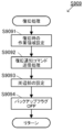
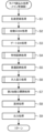
まず、図6を参照しつつ、メイン制御部100によって実行されるメイン処理について説明する。なお、このメイン処理は、遊技機1の電源が投入されると開始され、メイン制御部100が起動している間、継続的に実行される。
[Main Processing by Main Control Unit 100]
First, the main processing executed by the
図6のステップS901において、まず、CPU101は、例えば2000ms待機して、処理はステップS902に移る。なお、図示していないが、演出制御部400のCPU401は、遊技機1の電源が投入されると、待機処理を行うことなく、メイン制御部100からの信号を受信可能な状態となる。つまり、演出制御部400のCPU401は、メイン制御部100のCPU101よりも先に、処理を開始できる状態となる。
In step S901 of FIG. 6, the
ステップS902において、CPU101は、RAM103へのアクセスが可能となり、処理はステップS903に移る。
In step S902, the
ステップS903において、CPU101は、RAMクリアスイッチ111aが「ON」であるか否かを判定する。ステップS903での判定がYESの場合、処理はステップS904に移り、この判定がNOの場合、処理はステップS907に移る。
In step S903, the
ステップS904において、CPU101は、RAMクリアを行う。ここで、RAMクリアは、公知の技術であるため詳細な説明は省略するが、RAM103に格納されている各種情報(遊技状態を示す情報や特別図柄抽選の実行回数の情報等)を所定の初期状態とすることである。その後、処理はステップS905に移る。
In step S904, the
ステップS905において、CPU101は、RAMクリア時の作業領域を設定し、処理はステップS906に移る。
In step S905, the
ステップS906において、CPU101は、周辺部の初期設定を行う。ここで、周辺部とは、演出制御部400や払出制御部300等である。周辺部の初期設定は、それぞれの制御部に対して、初期設定の実行を指示する初期設定コマンドを送信することによって行われる。その後、処理はステップS910に移る。
In step S906, the
ステップS907において、CPU101は、バックアップフラグが「ON」であるか否かを判定する。なお、バックアップフラグとは、電源遮断時にバックアップデータの生成が正常に完了した場合、オンになるフラグであり、生成したバックアップデータに関連付けて、当該バックアップデータが有効であることを示すフラグである。ステップS907での判定がYESの場合、処理はステップS908に移り、この判定がNOの場合、処理はステップS904に移る。
In step S907,
ステップS908において、CPU101は、チェックサムが正常であるか否かを判定する。ステップS908での判定がYESの場合、処理はステップS909に移り、この判定がNOの場合、処理はステップS904に移る。
In step S908, the
ステップS909において、CPU101は、後述する復旧処理(図8参照)を実行し、処理はステップS910に移る。
In step S909, the
ステップS910において、CPU101は、内蔵されているCTC(タイマカウンタ)の周期(4ms)を設定する。なお、CPU101は、ここで設定された周期を用いて後述するタイマ割込処理(図9参照)を実行する。その後、処理はステップS911に移る。
In step S910, the
ステップS911において、CPU101は、後述する電源遮断監視処理(図7参照)を実行し、処理はステップS912に移る。
In step S911, the
ステップS912において、CPU101は、タイマ割込処理の割り込みを禁止する設定を行い、処理はステップS913に移る。
In step S912, the
ステップS913において、CPU101は、各種の初期値乱数を更新し(カウントアップし)、処理はステップS914に移る。ここで、初期値乱数とは、後述するタイマ割り込み処理(図9参照)においてカウントアップ更新される各種の乱数(大当り乱数、図柄乱数、リーチ乱数、変動パターン乱数)の開始値を決定するための乱数であり、各種の乱数に対応して複数の初期値乱数が用意されている。なお、初期値乱数は、所定のCTCの周期(4ms)ごとに発生するタイマ割込み処理(図9参照)と、その残余時間(つまり、この所定のCTCの周期からタイマ割込み処理に要する処理時間を減じた時間)に処理されるメイン処理(図6参照)の両方でカウントアップ更新され、設定されている乱数の最大値(例えば299)に達した後は再び最小値(例えば0)に戻る。また、この残余時間は、CPU101の処理状況に応じて異なるので、不規則な時間となっており、残余時間で更新される初期値乱数の更新回数も不規則となる。一方、詳細は後述するが、他の各種乱数(大当り乱数、図柄乱数、リーチ乱数、変動パターン乱数)は、タイマ割込み処理(図9参照)でしか更新されないため、初期値乱数とは乱数更新処理の処理周期が相違する。このように、処理周期が相違することにより、例えば、初期値乱数と大当り乱数の乱数範囲が同じ(例えば0~299)であったとしても、大当り乱数の開始値として取得される初期値乱数の値は毎回不規則なものとなる。そのため、大当りを発生させる大当り乱数値が取得されるタイミングを予測することを困難にすることができる。
In step S913, the
ステップS914において、CPU101は、タイマ割込処理の割り込みを許可する設定を行い、処理がステップS911に戻される。つまり、CPU101は、ステップS911~ステップS914の処理を繰り返し実行する。
In step S914, the
[メイン制御部100による電源遮断監視処理]
図7は、図6のステップS911における電源遮断監視処理の詳細フローチャートである。図6のステップS9111において、CPU101は、割込処理を禁止し、処理はステップS9112に移る。
[Power Shutdown Monitoring Processing by the Main Control Unit 100]
Fig. 7 is a detailed flowchart of the power cutoff monitoring process in step S911 in Fig. 6. In step S9111 in Fig. 6, the
ステップS9112において、CPU101は、不図示の電源部から電源遮断信号が入力されたか否かに基づいて、遊技機1に対する電源供給が遮断されたか否かを判定する。ステップS9112での判定がYESの場合、処理はステップS9114に移り、この判定がNOの場合、処理はステップS9113に移る。
In step S9112, the
ステップS9113において、CPU101は、割込処理を許可し、電源遮断監視処理を終了する(処理は図6のステップS912に移る)。
In step S9113, the
一方、ステップS9114において、CPU101は、CPU101に対して各種情報が入出力される出力ポートをクリアし、処理はステップS9115に移る。
On the other hand, in step S9114,
ステップS9115において、CPU101は、現在の遊技機1の遊技状態等に基づいて、バックアップデータをRAM103に作成後、RAM103の内容からチェックサムを作成してRAM103に格納する。なお、この処理は、メイン制御部100に供給される電源の電源遮断により電源電圧が低下し始めたことを検出してから(ステップS9112で「YES」と判定されてから)電源電圧が所定値まで低下するまでの期間に行われる。この処理によって、電源が遮断される直前の遊技状態情報等がRAM103に記憶される。その後、処理はステップS9116に移る。
In step S9115, the
ステップS9116において、CPU101は、バックアップフラグを「ON」に設定し、処理はステップS9117に移る。
In step S9116, the
ステップS9117において、CPU101は、RAM103へのアクセスを禁止し、電源遮断監視処理を終了する(処理は図6のステップS912に移る)。
In step S9117, the
[メイン制御部100による復旧処理]
図8は、図6のステップS909における復旧処理の詳細フローチャートである。まず、図8のステップS9091において、CPU101は、復旧時におけるRAM103の作業領域を設定し、処理はステップS9092に移る。
[Recovery process by main control unit 100]
Fig. 8 is a detailed flowchart of the recovery process in step S909 in Fig. 6. First, in step S9091 in Fig. 8, the
ステップS9092において、CPU101は、RAM103の情報を参照して、電源遮断時における遊技状態や特別図柄抽選の保留数等に関する情報を確認し、当該情報を含めた復旧通知コマンドを演出制御部400に対して送信する。このように、CPU101は、遊技機1に対する電源供給が復旧したことを通知するために、電源遮断時の状態を示す復旧通知コマンドを演出制御部400へ送信する。このステップS9092の処理により、演出制御部400は、電源遮断前の遊技状態等を確認することができる。
In step S9092, the
ステップS9093において、CPU101は、周辺部の設定を行い、処理はステップS9094に移る。
In step S9093, the
ステップS9094において、CPU101は、バックアップフラグを「OFF」に設定し、復旧処理を終了する(処理は図6のステップS910に移る)。
In step S9094, the
[メイン制御部のタイマ割り込み処理]
次に、メイン制御部100において実行されるタイマ割込処理について説明する。図9は、メイン制御部100によって行われるタイマ割込み処理の一例を示すフローチャートである。以下に、図9を参照して、メイン制御部100において行われるタイマ割込み処理について説明する。メイン制御部100は、電源投入時や電源断時等の特殊な場合を除く通常の動作時において、図9に示す一連の処理を一定時間(4ミリ秒)毎に繰り返し実行する。なお、図9以降のフローチャートに基づいて説明するメイン制御部100で行われる処理は、ROM102に記憶されているプログラムに基づいて実行される。
[Timer interrupt processing in the main control unit]
Next, the timer interrupt processing executed in the
まず、ステップS1において、メイン制御部100のCPU101は、大当り乱数、図柄乱数、リーチ乱数、及び変動パターン乱数等の各種の乱数の更新、および各乱数がカウントアップ更新される際の開始値となるそれぞれの初期値乱数の更新を行う乱数更新処理を実行する。ここで、大当り乱数は、特別図柄抽選の当選又は落選を判定する(つまり、特別図柄抽選を行う)ための乱数である。図柄乱数は、特別図柄抽選に当選した場合に大当りの種類を決定するための乱数である。なお、特別図柄抽選の当選又は落選の判定と、当選した場合の大当りの種類の決定とを合せて、特別図柄抽選と考えてもよい。大当り乱数及び図柄乱数は、後に説明する図11のステップS407の処理で使用される乱数である。リーチ乱数は、特別図柄抽選に落選した場合にリーチ演出を行うか否かを決定するための乱数である。変動パターン乱数は、特別図柄の変動時間等を規定する変動パターンを決定するための乱数である。ここで、特別図柄の変動時間は、この特別図柄の変動に同期して実行される報知演出(変動演出)の実行時間と等しい。リーチ乱数及び変動パターン乱数は、後に説明する図11のステップS408の処理で使用される。ステップS1の乱数更新処理において、大当り乱数、図柄乱数、リーチ乱数、及び変動パターン乱数等は、それぞれ、1ずつ加算されて更新される。つまり、カウントアップされる。そして、ステップS2の始動口スイッチ(SW)処理やステップS3のゲートスイッチ(SW)処理において各乱数が取得されて、後述するステップS4の特別図柄処理やステップS5の普通図柄処理で使用される。なお、このステップS1の処理を行うカウンタは、典型的にはループカウンタであり、設定されている乱数の最大値(例えば変動パターン乱数では299)に達した後は再び0に戻る(つまり、循環する)。また、ステップS1の乱数更新処理において、大当り乱数、図柄乱数、リーチ乱数、及び変動パターン乱数等の各カウンタは、それぞれ、ループカウンタのカウントが一巡すると、その時点での各乱数に対応する初期値乱数を取得して、当該初期値乱数の値を開始値として、新たにループカウンタのカウントを開始する。なお、大当り乱数、図柄乱数、リーチ乱数、及び変動パターン乱数等の乱数範囲は、任意に設定すればよいが、それぞれを異なる範囲に設定することで、これらの乱数の間でカウンタの値(カウント値)が同期しないように設定することが好ましい。
First, in step S1, the
次に、ステップS2において、CPU101は、第1始動口スイッチ45a及び第2始動口スイッチ47aの状態を監視し、第1始動口45又は第2始動口47に遊技球が入賞したと判定した時点で、第1特別図柄抽選の保留数U1や第2特別図柄抽選の保留数U2に関する処理や各種乱数を取得する処理を行う始動口スイッチ処理を実行する。この始動口スイッチ処理の詳細については、図10を参照して後に詳述する。
Next, in step S2, the
次に、ステップS3において、CPU101は、ゲートスイッチ44aの状態を監視し、ゲート44を遊技球が通過したと判定された時点で普通図柄抽選の保留数が上限値(例えば4)未満か否かを判断し、保留数が上限値未満であると判断した場合、後述するステップS5の普通図柄処理に使用される乱数を取得するゲートスイッチ処理を実行する。
Next, in step S3, the
次に、ステップS4において、CPU101は、第1特別図柄抽選又は第2特別図柄抽選を実行し、第1特別図柄表示器60又は第2特別図柄表示器61に特別図柄を変動表示させた後にこれらの抽選結果を示す停止図柄の表示処理や、演出制御部400へ各種コマンドを送信等するための特別図柄処理を実行する。この特別図柄処理については、図11を参照して後に詳述する。
Next, in step S4, the
次に、ステップS5において、CPU101は、ステップS3のゲートスイッチ処理で取得された乱数が所定の当り乱数と一致するか否かを判定する普通図柄処理を実行する。そして、CPU101は、普通図柄表示器62に普通図柄を変動表示させた後に判定結果を示す普通図柄を停止表示させる。具体的には、CPU101は、普通図柄を変動表示させた後に停止表示させる普通図柄変動時間を、非時短状態では例えば10秒に設定し、時短状態では例えば0.5秒に短縮する。また、CPU101は、普通図柄表示器62に表示された普通図柄が所定の当り図柄となる確率(つまり、普通図柄抽選の当選確率)を、非時短状態では低確率(例えば1/10)に設定し、時短状態では高確率(1例えば0/10)に上昇させる。
Next, in step S5, the
次に、ステップS6において、CPU101は、ステップS4の特別図柄処理で特別図柄抽選に当選したと判定された場合(大当りした場合)又は特別図柄抽選で小当りに当選したと判定された場合に、大入賞口開閉部(第1大入賞口開閉部51b、第2大入賞口開閉部57b)を制御して大入賞口(第1大入賞口50、第2大入賞口56)に所定の開閉動作を行わせる大入賞口処理を実行する。また、CPU101は、大当り遊技中に実行される大当り遊技演出および小当り遊技中に実行される小当り遊技演出等に関する各種コマンドを演出制御部400に対して送信する。この処理によって、大当り遊技(特別遊技)および小当り遊技が進行され、遊技者は多量の賞球を獲得可能となる。この大入賞口処理については、図16~図18を参照して後に詳述する。
Next, in step S6, if the special pattern processing in step S4 determines that the special pattern lottery has been won (if a big win has been won) or if the special pattern lottery has been won, the
次に、ステップS7において、CPU101は、ステップS5の普通図柄処理によって普通図柄表示器62に表示された普通図柄が所定の当り図柄である場合(つまり、普通図柄抽選に当選した場合)に、可変始動部46を作動させる第2始動口開閉処理を実行する。その際、CPU101は、非時短状態では可変始動部46を極短期間(例えば0.10秒間を1回)開放制御し、時短状態では可変始動部46を長期間(例えば0.90秒間を2回)開放制御する。なお、可変始動部46が開状態に制御されることによって第2始動口47に遊技球が入賞可能な状態となり、第2始動口47に遊技球が入賞することで、第2特別図柄抽選が行われることとなる。
Next, in step S7, the
次に、ステップS8において、CPU101は、遊技球の入賞個数の管理及び入賞に応じた賞球の払出しを制御する賞球処理を実行する。
Next, in step S8, the
次に、ステップS9において、CPU101は、ステップS2の始動口スイッチ処理、ステップS4の特別図柄処理、ステップS6の大入賞口処理、ステップS8の賞球処理等でRAM103にセットされた各種コマンドや演出に必要な情報を演出制御部400又は払出制御部300へ出力する出力処理を実行する。なお、CPU101は、第1始動口45、第2始動口47、第1大入賞口50、第2大入賞口56、普通入賞口43に遊技球が入賞する毎に、それぞれの入賞口に遊技球が入賞したことを通知するための入賞コマンドをRAM103にセットして、当該入賞コマンドを演出制御部400又は払出制御部300へ出力する。
Next, in step S9, the
[始動口スイッチ処理]
図10は、図9のステップS2における始動口スイッチ処理の詳細フローチャートの一例である。以下に、図9のステップS2における始動口スイッチ処理について、図10を参照して説明する。
[Start switch processing]
Fig. 10 is an example of a detailed flowchart of the start port switch processing in step S2 of Fig. 9. The start port switch processing in step S2 of Fig. 9 will be described below with reference to Fig. 10.
まず、ステップS201において、メイン制御部100のCPU101は、第1始動口スイッチ45aからの出力信号に基づいて、第1始動口45に遊技球が入賞したか否かを判定する。ステップS201での判定がYESの場合、処理はステップS202に移り、この判定がNOの場合、処理はステップS207に移る。
First, in step S201, the
ステップS202において、CPU101は、ROM102から第1特別図柄抽選の保留数の上限値Umax1(本実施形態では「4」)を読み出し、RAM103に記憶されている第1特別図柄抽選の保留数U1が上限値Umax1未満であるか否かを判定する。ステップS202での判定がYESの場合、処理はステップS203に移り、この判定がNOの場合、処理はステップS207に移る。
In step S202, the
ステップS203において、CPU101は、RAM103に記憶されている保留数U1の値を、1加算した値に更新する。また、CPU101は、第1始動口45に遊技球が入賞したことを演出制御部400に対して通知するための入賞コマンドをRAM103にセットする。この入賞コマンドは、図9のステップS9の出力処理によって演出制御部400へ送信される。その後、処理はステップS204に移る。
In step S203, the
ステップS204において、CPU101は、第1特別図柄抽選等に使用される乱数のセット(大当り乱数、図柄乱数、リーチ乱数、及び変動パターン乱数)を取得する。その後、処理はステップS205に移る。
In step S204, the
ステップS205において、CPU101は、事前判定処理を行い、ステップS204で取得した乱数の各セット(遊技情報)を時系列順でRAM103に格納する。具体的には、CPU101は、直近のステップS204の処理で取得された大当り乱数等の乱数セットの大当り乱数等がROM102に記憶されている所定値等と一致するか否かに基づいて、この大当り乱数を用いる第1特別図柄抽選の結果が大当りであるか否かや、リーチ演出を実行するか否か等を事前判定する。つまり、先読み予告演出や保留変化予告演出(保留変化演出)を実行するために必要な判定を、後述する図11のステップS407及びS408の処理に先立って事前判定する。なお、特別図柄抽選で小当りに当選すると、小当り遊技において特定領域224(図2参照)を高確率で遊技球が通過して大当りが発生するが、本実施形態では第1特別図柄抽選には小当りが無いので、ステップS205の事前判定処理では小当りであるか否かについて事前判定は行わない。その後、事前判定に用いた乱数の各セット(第1特別図柄抽選の保留データ)を時系列順でRAM103に格納する。なお、後述する図11のステップS406の処理によって第1特別図柄抽選の保留数U1の値が1減算される度に、RAM103に格納された上記乱数セットは、格納時期が早いものから順に1セットずつ削除される。このことから、例えば第1特別図柄抽選の保留数U1の値が「3」の場合、直近3回のステップS204の処理によって取得された直近3回の上記乱数セットが、時系列順でRAM103に格納されていることとなる。その後、処理はステップS206に移る。
In step S205, the
ステップS206において、CPU101は、第1特別図柄抽選の保留数が1増加したことを通知する第1保留数増加コマンドをRAM103にセットする。ここで、この第1保留数増加コマンドには、ステップS205の処理で行われた事前判定の結果を示す情報(以下、「事前判定情報」という)が含められている。なお、この事前判定情報を含む第1保留数増加コマンドが、図9のステップS9の出力処理によって出力されることにより、第1特別図柄抽選の保留に対する抽選結果が、第1特別図柄抽選における図柄変動が開始されるよりも前にメイン制御部100から演出制御部400に通知される。その後、処理はステップS207に移る。
In step S206, the
ステップS207において、CPU101は、第2始動口スイッチ47aからの出力信号に基づいて、第2始動口47に遊技球が入賞したか否かを判定する。ステップS207での判定がYESの場合、処理はステップS208に移り、この判定がNOの場合、処理は図9のステップS3(ゲートスイッチ処理)に移る。
In step S207, the
ステップS208において、CPU101は、ROM102から第2特別図柄抽選の保留数の上限値Umax2(本実施形態では「4」)を読み出し、RAM103に記憶されている第2特別図柄抽選の保留数U2が上限値Umax2未満であるか否かを判定する。ステップS208での判定がYESの場合、処理はステップS209に移り、この判定がNOの場合、処理は図8のステップS3(ゲートスイッチ処理)に移る。
In step S208, the
ステップS209において、CPU101は、RAM103に格納されている保留数U2の値を、1加算した値に更新する。また、CPU101は、第2始動口47に遊技球が入賞したことを演出制御部400に対して通知するための入賞コマンドをRAM103にセットする。この入賞コマンドは、図9のステップS9の出力処理によって演出制御部400へ送信される。その後、処理はステップS210に移る。
In step S209, the
ステップS210において、CPU101は、第2特別図柄抽選等に使用される乱数のセット(大当り乱数、図柄乱数、リーチ乱数、及び変動パターン乱数)を取得する。その後、処理はステップS211に移る。
In step S210, the
ステップS211において、CPU101は、事前判定処理を行い、ステップS210で取得した乱数の各セット(遊技情報)を時系列順でRAM103に格納する。具体的には、CPU101は、直近のステップS210の処理で取得された大当り乱数等の乱数セットの大当り乱数等がROM102に記憶されている所定値等と一致するか否かに基づいて、この大当り乱数を用いる第2特別図柄抽選の結果が大当り又は小当りであるか否かや、リーチ演出を実行するか否か等を事前判定する。つまり、先読み予告演出や保留変化予告演出(保留変化演出)を実行するために必要な判定を、後述する図11のステップS407及びS408の処理に先立って事前判定する。なお、特別図柄抽選で小当りに当選すると、小当り遊技において特定領域224(図2参照)を高確率で遊技球が通過して大当りが発生するので、ステップS211の事前判定処理では小当りであるか否かについても事前判定を行う。その後、事前判定に用いた乱数の各セット(第2特別図柄抽選の保留データ)を時系列順でRAM103に格納する。なお、後述する図11のステップS404の処理によって第2特別図柄抽選の保留数U2の値が1減算される度に、RAM103に格納された上記乱数セットは、格納時期が早いものから順に1セットずつ削除される。このことから、例えば第2特別図柄抽選の保留数U2の値が「3」の場合、直近3回のステップS210の処理によって取得された直近3回の上記乱数セットが、時系列順でRAM103に格納されていることとなる。その後、処理はステップS212に移る。
In step S211, the
ステップS212において、CPU101は、第2特別図柄抽選の保留数が1増加したことを通知する第2保留数増加コマンドをRAM103にセットする。ここで、この第2保留数増加コマンドには、ステップS211の処理で行われた事前判定の結果を示す情報(事前判定情報)が含められている。なお、この事前判定情報を含む第2保留数増加コマンドが、図9のステップS9の出力処理によって出力されることにより、第2特別図柄抽選の保留に対する抽選結果が、第2特別図柄抽選における図柄変動が開始されるよりも前にメイン制御部100から演出制御部400に通知される。その後、処理は図9のステップS3(ゲートスイッチ処理)に移る。
In step S212, the
[特別図柄処理]
図11は、図9のステップS4における特別図柄処理の詳細フローチャートの一例である。以下に、図11を参照して、図9のステップS4における特別図柄処理について説明する。
[Special pattern processing]
Fig. 11 is an example of a detailed flowchart of the special symbol processing in step S4 in Fig. 9. The special symbol processing in step S4 in Fig. 9 will be described below with reference to Fig. 11.
まず、ステップS401において、メイン制御部100のCPU101は、RAM103に記憶されている情報(例えばフラグによる情報)に基づいて、遊技機1の現在の状態が大当り遊技中又は小当り遊技中であるか否かを判定する。つまり、特別図柄抽選に当選した場合に実行される大当り遊技(特別遊技)又は特別図柄抽選で小当りに当選した場合に実行される小当り遊技の実行中であるか否かを判定する。ステップS401での判定がYESの場合、処理は図9のステップS5(普通図柄処理)に移り、この判定がNOの場合、処理はステップS402に移る。
First, in step S401, the
ステップS402において、CPU101は、第1特別図柄表示器60又は第2特別図柄表示器61による特別図柄の変動表示期間中であるか否かを判定する。なお、ここで言う特別図柄の変動表示期間は、特別図柄の変動停止直後に設けられる規定の特別図柄停止表示期間(規定時間;0.5秒間)を含んだものである。ステップS402での判定がYESの場合、処理はステップS411に移り、この判定がNOの場合、処理はステップS403に移る。
In step S402, the
ステップS403において、CPU101は、RAM103に記憶されている保留数U2が1以上であるか否か(つまり第2特別図柄抽選が保留されているか否か)を判定する。ステップS403での判定がYESの場合、処理はステップS404に移り、この判定がNOの場合、処理はステップS405に移る。
In step S403, the
ステップS404において、CPU101は、RAM103に記憶されている保留数U2を、1減算した値に更新する。また、その際、CPU101は、RAM103に格納されている図10のステップS210及びステップS211によって取得されて格納された乱数セットのうち格納時期が最も早いものを読み出してRAM103から削除する。その後、処理はステップS407に移る。
In step S404, the
一方、ステップS405において、CPU101は、RAM103に記憶されている保留数U1が1以上であるか否か(つまり第1特別図柄抽選が保留されているか否か)を判定する。ステップS405での判定がYESの場合、処理はステップS406に移り、この判定がNOの場合、実行されるべき特別図柄抽選は無いので、処理はステップS415に移る。
On the other hand, in step S405, the
ステップS406において、CPU101は、RAM103に記憶されている保留数U1を、1減算した値に更新する。また、その際、CPU101は、RAM103に格納されている図10のステップS204及びステップS205によって取得されて格納された乱数セットのうち格納時期が最も早いものを読み出してRAM103から削除する。その後、処理はステップS407に移る。
In step S406, the
以上のステップS403~S406の処理によって、第2特別図柄抽選が、第1特別図柄抽選よりも優先して実行されることとなる。 By carrying out the above steps S403 to S406, the second special symbol lottery is executed in priority over the first special symbol lottery.
ステップS407において、CPU101は、特別図柄抽選の結果が大当りであるかハズレであるか等を判定する大当り判定処理を実行する。具体的には、ステップS404の処理に続いてステップS407の処理を実行する場合、CPU101は、このステップS404の処理でRAM103から読み出した大当り乱数が、ROM102に記憶されている大当りの当選値等と一致するか否かに基づいて、第2特別図柄抽選の結果が、大当り、小当り(遊技者に有益な特定のハズレと考えることもできる)、ハズレの何れであるかを判定する。一方、ステップS406の処理に続いてステップS407の処理を実行する場合、CPU101は、このステップS406の処理でRAM103から読み出した大当り乱数が、ROM102に記憶されている大当りの当選値と一致するか否かに基づいて、第1特別図柄抽選の結果が大当りであるかハズレであるかを判定する。なお、上記したように、本実施形態において小当りは、第2特別図柄抽選にのみ設けられており、小当りの当選確率は例えば1/10である。そして、CPU101は、特別図柄抽選の結果がハズレと判定した場合、特別図柄抽選にハズレたことを表すハズレ図柄を、設定情報における特別図柄の停止図柄としてRAM103にセットする。一方、CPU101は、特別図柄抽選の結果が大当りであると判定した場合、この判定に使用した大当り乱数と共にRAM103から読み出された図柄乱数がROM102に記憶されている所定値の何れと一致するかに基づいて、今回の大当りの種類を判定する。なお、本実施形態では、一例として、大当り遊技後に時短遊技状態に設定される時短大当りと、大当り遊技後に通常遊技状態に設定される通常大当りとがある。また、本実施形態では、第1特別図柄抽選には時短大当りが50%通常大当りが50%で割り当てられており、第2特別図柄抽選には時短大当りが100%で当てられている。また、時短大当りの大当り遊技の実行後に設定される時短遊技状態は、(次の大当りによって終了する場合を除いて)100回転まで(特別図柄抽選が100回実行されるまで)実行される。そして、CPU101は、大当りしたこと又は小当りしたこと、及び、大当りした場合には大当りの種類を表す大当り図柄の情報等を、設定情報における特別図柄の停止図柄の情報としてRAM103にセットする。その後、処理はステップS408に移る。
In step S407, the
[変動パターン選択処理]
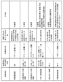
ステップS408において、CPU101は、変動パターン選択処理を実行する。具体的には、ステップS408において、CPU101は、通常遊技状態(非時短状態)のときには、図12及び図13に示す変動パターン決定テーブルHT1-1及びHT1-2を使用し、時短遊技状態のときには、図14及び図15に示す変動パターン決定テーブルHT2-1及びHT2-2を使用して、特別図柄抽選毎に変動パターンを決定(選択)する。ここで、この変動パターンは、特別図柄表示器(60、61)に特別図柄が変動表示されてから停止表示(確定停止表示)されるまでの時間である特別図柄変動時間であり、この特別図柄変動時間は、報知演出の実行時間と同期しており報知演出の実行時間と同じ時間である。なお、以下では、変動パターン決定テーブルHT1-1、HT1-2、HT2-1及びHT2-2を、単に、HT1-1、HT1-2、HT2-1及びHT2-2という場合がある。
[Variation pattern selection process]
In step S408, the
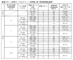
まず、通常遊技状態(非時短状態)のときに、図12及び図13に示すHT1-1及びHT1-2を使用して変動パターンを選択する場合について、説明する。図12は、通常遊技状態(非時短状態)においてステップS407の処理で第1特別図柄抽選が実行された場合に、変動パターン決定に使用されるテーブルである。図13は、通常遊技状態(非時短状態)においてステップS407の処理で第2特別図柄抽選が実行された場合に、変動パターン決定に使用されるテーブルである。 First, we will explain the case where a variation pattern is selected using HT1-1 and HT1-2 shown in Figures 12 and 13 during normal gameplay (non-time-saving state). Figure 12 is a table used to determine a variation pattern when a first special symbol lottery is executed in step S407 during normal gameplay (non-time-saving state). Figure 13 is a table used to determine a variation pattern when a second special symbol lottery is executed in step S407 during normal gameplay (non-time-saving state).
[非時短状態/第1特別図柄抽選での変動パターン選択処理]
以下に、図12を用いて、通常遊技状態(非時短状態)においてステップS407の処理で第1特別図柄抽選が実行された場合における変動パターンの決定について説明する。
[Non-time-saving state/variation pattern selection process in first special pattern lottery]
Below, with reference to FIG. 12, the determination of the variation pattern when the first special symbol lottery is executed in the processing of step S407 in the normal gaming state (non-time-saving state) will be explained.
ステップS408において、CPU101は、ステップS407の大当り判定処理で第1特別図柄抽選の結果が大当りであると判定した場合、変動パターン乱数に基づいて変動パターンを決定する。具体的には、CPU101は、ステップS407の大当り判定処理で使用した大当り乱数と共にRAM103から読み出された変動パターン乱数(0~299のうちの何れか1つ)が、HT1-1の「大当り」の部分の各変動パターンに割り振られた乱数値の何れと一致するかに基づいて、変動パターンを決定する。例えば、CPU101は、ステップS407の大当り判定処理で使用した大当り乱数と共にRAM103から読み出された変動パターン乱数が「92」である場合、HT1-1の「大当り」の部分の変動パターン「2」に割り振られた乱数値「20~299」に含まれるので、変動パターンとして「2」を決定する。ここで、HT1-1に示すように、「大当り」の部分の変動パターン「6」、「4」、「2」は、それぞれ、特別図柄の変動時間(つまり、報知演出の実行時間)「15秒」、「60秒」、「90秒」に対応し、又、報知演出の演出パターンのタイプ「リーチ当り」、「SP当り」、及び「SPSP当り」に対応する。また、「リーチ当り」はリーチ成立した後に大当りするタイプであり、「SP当り」はリーチ成立して最終的にSPリーチに発展した後に大当りするタイプであり、「SPSP当り」はリーチ成立して最終的にSPSPリーチに発展した後に大当りするタイプである。
In step S408, if the
なお、リーチ(リーチ演出)とは、報知演出において例えば複数の装飾図柄のうち最後に停止される変動中の装飾図柄が、特定の図柄で停止表示(仮停止表示)された場合には、既に停止中(仮停止中)の他の図柄と合わせて大当りの図柄パターンとなることを期待させる演出であり、典型的には、右側と左側の装飾図柄が同じ図柄(例えば7)で停止(仮停止)しており、最後に停止される中央の装飾図柄が、同じ図柄(例えば7)で停止(仮停止)する(つまり、ゾロ目777となる)ことを期待させて変動表示される演出である。このリーチの状態をリーチ状態と言ってもよい。また、SPリーチ(SPリーチ演出)とは、一般にスーパーリーチやスペシャルリーチと呼ばれ、リーチ状態で実行され、上記のリーチよりも大当りすることを更に期待させる演出であり、例えば主人公のキャラクタが敵キャラクタと戦う動画の演出である。また、SPSPリーチ(SPSPリーチ演出)とは、一般にスーパースーパーリーチやスペシャルスペシャルリーチと呼ばれ、リーチ状態で実行され、SPリーチよりも大当りすることを更に期待させる演出であり、例えば主人公のキャラクタが敵のボスキャラクタと戦う動画の演出である。 Note that a reach (reach effect) is an effect in which, for example, when the last of multiple decorative symbols to stop is displayed (temporarily stopped) as a specific symbol during a notification effect, it creates the expectation that it will form a jackpot pattern together with other symbols that are already stopped (temporarily stopped). Typically, the right and left decorative symbols stop (temporarily stopped) as the same symbol (e.g., 7), and the central decorative symbol that stops last will stop (temporarily stopped) as the same symbol (e.g., 7) (i.e., a repeat number 777). This reach state may be called a reach state. Also, an SP reach (SP reach effect), generally called a super reach or special reach, is an effect that is executed in a reach state and creates even more expectation of a jackpot than the above reaches, for example, a video effect in which the main character fights an enemy character. Additionally, the SPSP reach (SPSP reach effect), commonly known as the Super Super Reach or Special Special Reach, is performed in a reach state and is an effect that creates even greater anticipation of a jackpot than the SP reach, such as a video effect in which the main character fights an enemy boss character.
また、ステップS408において、CPU101は、ステップS407の大当り判定処理で第1特別図柄抽選の結果がハズレであると判定した場合、第1特別図柄抽選の保留数(U1)、リーチ乱数、及び変動パターン乱数に基づいて変動パターン(特別図柄変動時間)を決定する。
In addition, in step S408, if the
具体的には、CPU101は、第1特別図柄抽選の保留数が「0」である場合、ステップS407の大当り判定処理で使用した大当り乱数と共にRAM103から読み出されたリーチ乱数(0~99のうちの何れか1つ)がHT1-1の「ハズレ」の保留数「0」の部分のリーチ乱数値範囲「0~79」に含まれるのかリーチ乱数値範囲「80~99」に含まれるのかを判定する。
Specifically, when the reserved number for the first special pattern lottery is "0", the
そして、CPU101は、この読み出されたリーチ乱数がリーチ乱数値範囲「0~79」に含まれる場合、変動パターンとして「7」を決定する。ここで、HT1-1に示すように、変動パターン「7」は、特別図柄の変動時間「12秒」に対応し、又、報知演出の演出パターンのタイプ「即ハズレ」に対応する。
Then, if the read-out reach random number is within the reach random number range "0 to 79", the
一方、CPU101は、この読み出されたリーチ乱数がリーチ乱数値範囲「80~99」に含まれる場合、ステップS407の大当り判定処理で使用した大当り乱数と共にRAM103から読み出された変動パターン乱数(0~299のうちの何れか1つ)が、HT1-1の上記したリーチ乱数値範囲「80~99」の部分の各変動パターンに割り振られた変動パターン乱数値範囲の何れに含まれるかに基づいて、変動パターン(特別図柄変動時間)を決定する。例えば、CPU101は、ステップS407の大当り判定処理で使用した大当り乱数と共にRAM103から読み出された変動パターン乱数が「280」である場合、変動パターン「1」に割り振られた変動パターン乱数値範囲「244~285」に含まれるので、変動パターンとして「1」を決定する。ここで、HT1-1に示すように、HT1-1の上記したリーチ乱数値範囲「80~99」の部分の変動パターン「5」、「3」、「1」は、それぞれ、特別図柄の変動時間「15秒」、「60秒」、「90秒」に対応し、又、報知演出の演出パターンのタイプ「リーチハズレ」、「SPハズレ」及び「SPSPハズレ」に対応する。「リーチハズレ」はリーチ成立した後にハズレるタイプであり、「SPハズレ」はリーチ成立して最終的にSPリーチに発展した後にハズレるタイプであり、「SPSPハズレ」はリーチ成立して最終的にSPSPリーチに発展した後にハズレるタイプである。
On the other hand, if the read-out reach random number is within the reach random number value range "80-99", the
また、CPU101は、第1特別図柄抽選の保留数が「1」、「2」、「3、4」の場合、上記した第1特別図柄抽選の保留数が「0」の場合と基本的に同様にして、変動パターンを決定する。但し、第1特別図柄抽選の保留数が「1」、「2」、「3、4」の場合には、HT1-1に示すように、それぞれ、上記した第1特別図柄抽選の保留数が「0」の場合に対して、報知演出の演出パターンのタイプが「即ハズレ」であり特別図柄の変動時間が「12秒」の変動パターン「8」が加えられ、又、リーチ乱数および変動パターン乱数の割り振りが異なっている。
When the reserved number for the first special pattern lottery is "1", "2", "3, 4", the
[非時短状態/第2特別図柄抽選での変動パターン選択処理]
以下に、図13を用いて、通常遊技状態(非時短状態)においてステップS407の処理で第2特別図柄抽選が実行された場合における変動パターンの決定について説明する。ステップS408において、CPU101は、図12を用いて説明した変動パターン決定の処理と基本的に同様の処理を行って、変動パターンを決定する。但し、CPU101は、図12を用いて説明した変動パターン決定の処理ではHT1-1を用いて第1特別図柄抽選に対して処理を行ったのに対して、この変動パターン決定の処理では図13に示すHT1-2を用いて第2特別図柄抽選に対して処理を行う点で異なる。また、図13に示すHT1-2は、図12に示したHT1-1に対して、「第1特別図柄抽選の保留数」が「第2特別抽選の保留数」に置き換わり、又、小当りした場合の変動パターンが追加されている。また、ステップS407の大当り判定処理で小当りしたと判定した場合、ステップS408においてCPU101は、この大当り判定処理で使用した大当り乱数と共にRAM103から読み出された変動パターン乱数(0~299のうちの何れか1つ)が、HT1-2の「小当り」の部分の各変動パターンに割り振られた乱数値の何れと一致するかに基づいて、変動パターンを決定する。例えば、CPU101は、ステップS407の大当り判定処理で使用した大当り乱数と共にRAM103から読み出された変動パターン乱数が「2」である場合、HT1-2の「小当り」の部分の変動パターン「11」に割り振られた乱数値「0~3」に含まれるので、変動パターンとして「11」を決定する。ここで、HT1-2に示すように、「小当り」の部分の変動パターン「11」、「10」、「9」は、それぞれ、特別図柄の変動時間(つまり、報知演出の実行時間)「15秒」、「60秒」、「90秒」に対応し、又、報知演出の演出パターンのタイプ「リーチ当り」、「SP当り」、及び「SPSP当り」に対応する。
[Non-time-saving state/variation pattern selection process in second special pattern lottery]
The following describes the determination of the variation pattern when the second special symbol lottery is executed in the process of step S407 in the normal game state (non-time-saving state) with reference to FIG. 13. In step S408, the
[時短状態/第1特別図柄抽選での変動パターン選択処理]
以下に、図14を用いて、時短遊技状態(時短状態)においてステップS407の処理で第1特別図柄抽選が実行された場合における変動パターンの決定について説明する。ステップS408において、CPU101は、図12を用いて説明した変動パターン決定の処理と基本的に同様の処理を行って、変動パターンを決定する。但し、CPU101は、図12を用いて説明した変動パターン決定の処理ではHT1-1を用いて通常遊技状態(非時短状態)における第1特別図柄抽選に対して処理を行ったのに対して、この変動パターン決定の処理では図14に示すHT2-1を用いて時短遊技状態(時短状態)における第1特別図柄抽選に対して処理を行う点で異なる。ここで、図12に示したHT1-1では、第1特別図柄抽選の保留数が「1」~「4」の場合に変動パターン「8」(変動時間「2秒」の即ハズレに対応)を決定可能であったのに対して、図14に示すHT2-1は、保留数が「1」~「4」の場合においても変動パターン「8」を決定できない点で異なる。つまり、第1特別図柄抽選の保留数が「1」~「4」の場合でも、短い変動時間「2秒」が決定されることがない。
[Time-saving state/variation pattern selection process in the first special pattern lottery]
The following describes the determination of the variation pattern when the first special symbol lottery is executed in the process of step S407 in the time-saving game state (time-saving state) with reference to Fig. 14. In step S408, the
[時短状態/第2特別図柄抽選での変動パターン選択処理]
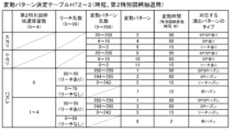
以下に、図15を用いて、時短遊技状態(時短状態)においてステップS407の処理で第2特別図柄抽選が実行された場合における変動パターンの決定について説明する。ステップS408において、CPU101は、図13を用いて説明した変動パターン決定の処理と基本的に同様の処理を行って、変動パターンを決定する。但し、CPU101は、図13を用いて説明した変動パターン決定の処理ではHT1-2を用いて時短遊技状態(時短状態)における第2特別図柄抽選に対して処理を行ったのに対して、この変動パターン決定の処理では図15に示すHT2-2を用いて時短遊技状態(時短状態)における第2特別図柄抽選に対して処理を行う点で異なる。また、図15に示すように、HT2-2は、図13に示したHT1-2に対して、保留数が「1」~「4」の場合において、リーチ乱数および変動パターン乱数の割り振りが共通であり、又、「リーチなし」に対応する変動パターンが「8」のみである。
[Time-saving state/variation pattern selection process in second special pattern lottery]
Hereinafter, the determination of the variation pattern when the second special symbol lottery is executed in the process of step S407 in the time-saving game state (time-saving state) will be described with reference to FIG. 15. In step S408, the
以上のようにしてステップS408において決定された変動パターンの情報(つまり、報知演出の実行時間や演出パターンのタイプの情報とも言える)は、設定情報としてRAM103にセットされる。その後、処理はステップS409に移る。
The information on the variation pattern determined in step S408 in the above manner (i.e., information on the execution time of the notification effect and the type of effect pattern) is set in
ステップS409において、CPU101は、ステップS407の大当り判定処理によってセットされた設定情報、及びステップS408の変動パターン選択処理によってセットされた設定情報を含む報知演出開始コマンドを生成して、RAM103にセットする。ここで、報知演出開始コマンドは、演出制御部400に対して、画像表示部(70、71)及びスピーカ9等による報知演出の開始を指示するコマンドである。また、報知演出開始コマンドに含まれる設定情報には、第1特別図柄抽選及び第2特別図柄抽選の何れが実行されたかを示す情報も含まれる。このことから、報知演出開始コマンドは、含まれる情報に応じた種類があるとも言える。また、CPU101は、現在の遊技状態(例えば、時短遊技状態)を示す遊技状態通知コマンドをRAM103にセットする。上記した報知演出開始コマンドおよび遊技状態通知コマンドは、図9のステップS9における出力処理によって、演出制御部400へ送信される。その後、処理はステップS410に移る。
In step S409, the
ステップS410において、CPU101は、ステップS409の処理でセットされた報知演出開始コマンドに含まれている設定情報に基づいて、第1特別図柄表示器60又は第2特別図柄表示器61による特別図柄の変動表示を開始する。その後、処理はステップS411に移る。
In step S410, the
ステップS411において、CPU101は、ステップS410における特別図柄の変動表示の開始時点から、ステップS408の変動パターン選択処理で設定された変動パターンが示す特別図柄変動時間が経過したか否かを判定する。ステップS411での判定がYESの場合、処理はステップS412に移り、この判定がNOの場合、処理は図9のステップS5(普通図柄処理)に移る。
In step S411, the
ステップS412において、CPU101は、画像表示部(70、71)等による報知演出の終了を指示する報知演出停止コマンド(図柄確定コマンド)をRAM103にセットする。その後、処理はステップS413に移る。なお、ステップS412でセットされた報知演出停止コマンドは、図9のステップS9の出力処理によって演出制御部400へ送信される。
In step S412, the
ステップS413において、CPU101は、ステップS410の処理で開始した第1特別図柄表示器60又は第2特別図柄表示器61による特別図柄の変動表示を終了し、第1特別図柄表示器60又は第2特別図柄表示器61に、特別図柄抽選結果を報知する図柄を停止した状態で規定時間(0.5秒間)表示させる。その後、処理はステップS414に移る。
In step S413, the
ステップS414において、CPU101は、停止中処理を実行する。具体的には、CPU101は、ステップS407の大当り判定処理で大当りしたと判定した場合、RAM103に記憶されている情報(例えばフラグによる情報)を大当り遊技中であることを示すものに変更し、大当り遊技演出の開始を指示するオープニングコマンドをRAM103にセットする。また、CPU101は、ステップS407の大当り判定処理で小当りしたと判定した場合、RAM103に記憶されている情報(例えばフラグによる情報)を小当り遊技中であることを示すものに変更し、小当り遊技演出の開始を指示するオープニングコマンドをRAM103にセットする。なお、大当り遊技および小当り遊技のオープニングコマンドは、ステップS413の処理で特別図柄の停止表示が開始された時点から規定時間(0.5秒間)経過時に、図9のステップS9の出力処理によって演出制御部400へ送信され、大当り遊技演出又は小当り遊技演出が開始される。
In step S414, the
ステップS415おいて、CPU101は、客待ちコマンドおよび現在の遊技状態を示す遊技状態通知コマンドを、ステップS416の処理(後述)で既に送信済みであるか否かを判定する。ここで、客待ちコマンドとは、特別図柄の停止表示が終了した時点において、特別図柄抽選の保留が存在しない場合に送信されるコマンドであり、特別図柄抽選の抽選結果を報知する報知演出が実行されていない状態(いわゆる客待ち状態)になったことを通知するコマンドである。ステップS415での判定がYESの場合、処理は図9のステップS5(普通図柄処理)に移り、この判定がNOの場合、処理はステップS416に移る。
In step S415, the
ステップS416おいて、CPU101は、客待ちコマンドおよび遊技状態通知コマンドをRAM103にセットする。この客待ちコマンドおよび遊技状態通知コマンドは図9のステップS9の出力処理によって演出制御部400へ送信され、客待ちコマンドに基づいて、所定の停止演出(例えば装飾図柄が停止表示された客待ち中の演出)が開始される。なお、上記した停止演出が開始されてから所定時間(例えば90秒)が経過すると、客待ち演出が開始される。ここで、客待ち演出は、例えば、遊技機1の題材となったコンテンツ(アニメや物語等)に関する映像を画像表示部(70、71)に表示させる演出や、例えば、遊技中に実行される所定の演出(例えばSPリーチ演出)の一部を画像表示部に表示させる演出である。その後、処理は図9のステップS5(普通図柄処理)に移る。
In step S416, the
[大入賞口処理]
図16~図18は、図9のステップS6における大入賞口処理の詳細フローチャートの一例である。以下に、図9のステップS6における大入賞口処理について、図16~図18を参照して説明する。
[Big prize slot processing]
Figures 16 to 18 are an example of a detailed flowchart of the special prize opening process in step S6 of Figure 9. The special prize opening process in step S6 of Figure 9 will be described below with reference to Figures 16 to 18.
まず、ステップS601において、メイン制御部100のCPU101は、RAM103に格納されている情報(例えば、フラグ情報)に基づいて、小当り遊技中であるか否かを判定する。ステップS601での判定がYESの場合、処理はステップS602に移り、この判定がNOの場合、処理は図17のステップS651に移る。
First, in step S601, the
ステップS602において、CPU101は、RAM103に格納されている情報に基づいて、小当り遊技のオープニング中であるか否かを判定する。ステップS602での判定がYESの場合、処理はステップS603に移り、この判定がNOの場合、処理はステップS606に移る。
In step S602, the
ステップS603において、CPU101は、小当り遊技のオープニングの実行時間を規定する設定オープニング時間が経過したか否かを判定する。ステップS603での判定がYESの場合、処理はステップS604に移り、この判定がNOの場合、オープニングは終了していないので、処理は図17のステップS651に移る。
In step S603, the
ステップS604において、CPU101は、第1大入賞口開閉部51bを制御して第1大入賞口50の開放制御を開始する。この処理によって、小当り遊技のラウンド(ラウンド遊技)が開始されて第1大入賞口50の開放動作(1回の開放動作)が開始される。なお、小当り遊技で実行されるラウンドの数は1回である。その後、処理はステップS605に移る。
In step S604, the
ステップS605において、CPU101は、小当り遊技のラウンド開始(ラウンド遊技開始)を通知するラウンド開始通知コマンドをRAM103にセットする。このラウンド開始通知コマンドは図9のステップS9の出力処理によって演出制御部400へ送信され、小当り遊技のラウンドに対応するラウンド演出が開始されることとなる。その後、処理はステップS607に移る。
In step S605, the
ステップS606において、CPU101は、RAM103に格納された情報に基づいて、小当り遊技のエンディング中であるか否かを判定する。ステップS606での判定がYESの場合、ステップS619に移り、この判定がNOの場合、処理はステップS607に移る。
In step S606, the
ステップS607において、CPU101は、第1大入賞口50(第1可変入賞部49)の内部の特定領域224(図2参照)を開放するタイミングであるか否かを判定する。なお、このタイミングは、ステップS604で第1大入賞口50が開放されてから所定時間(例えば、3秒)経過したタイミングである。ステップS607での判定がYESの場合、処理はステップS608に移り、この判定がNOの場合、処理はステップS609に移る。
In step S607, the
ステップS608において、CPU101は、特定領域開閉部150を制御して開閉部材221を開状態にして特定領域224を遊技球が通過可能とする特定領域開放制御を開始する。その後、処理はステップS609に移る。
In step S608, the
ステップS609において、CPU101は、ステップS608の処理で特定領域224の開放制御が開始された時点から規定の開放制御時間(例えば、5秒)が経過したか否かを判定する。つまり、特定領域224を開放する規定時間(例えば、5秒)が経過したか否かを判定する。ステップS609での判定がYESの場合、ステップS610に移り、この判定がNOの場合、処理はステップS611に移る。
In step S609, the
ステップS610において、CPU101は、特定領域開閉部150を制御して開閉部材221を閉状態にして、特定領域224の開放制御を終了する。その後、処理はステップS611に移る。
In step S610, the
ステップS611において、CPU101は、特定領域スイッチ151からの出力信号に基づいて、特定領域224を遊技球が通過したか否かを判定する。ステップS611での判定がYESの場合、ステップS612に移り、この判定がNOの場合、処理はステップS613に移る。
In step S611, the
ステップS612において、CPU101は、時短大当りの発生を設定し、又、特定領域224を遊技球が通過したことを示す特定領域通過通知コマンドをRAM103にセットする。この特定領域通過通知コマンドは図9のステップS9の出力処理によって演出制御部400へ送信され、特定領域224を遊技球が通過して時短大当りが発生したことを報知する演出が実行されることとなる。その後、処理はステップS613に移る。
In step S612, the
ステップS613において、CPU101は、第1大入賞口スイッチ50aからの出力信号に基づいて、第1大入賞口50に遊技球が入賞したか否かを判定する。ステップS613での判定がYESの場合、処理はステップS614に移り、この判定がNOの場合、処理はステップS615に移る。
In step S613, the
ステップS614において、CPU101は、RAM103に格納されている遊技球の入賞数Cを、1加算した値に更新する。ステップS614の処理が第1大入賞口50に遊技球が入賞する毎に実行されることで、小当り遊技のラウンド中に第1大入賞口50に入賞した遊技球の総数(入賞数C)がRAM103に累積記憶されていく。また、CPU101は、第1大入賞口50に遊技球が入賞したことを演出制御部400に対して通知するための入賞コマンドをRAM103にセットする。この入賞コマンドは、図9のステップS9の出力処理によって演出制御部400へ送信され、図21のステップS129の入賞処理指示が実行されることとなる。その後、処理はステップS615に移る。
In step S614, the
ステップS615において、CPU101は、ステップS604の処理で第1大入賞口50の開放制御が開始された時点から規定の開放制御時間(本実施形態では29.5秒間)が経過したか否かを判定する。ステップS615での判定がYESの場合、処理はステップS617に移り、この判定がNOの場合、処理はステップS616に移る。
In step S615, the
ステップS616において、CPU101は、小当り遊技のラウンドにおける遊技球の入賞数Cが、第1大入賞口50が閉塞されるタイミングを規定する上限遊技球数Cmax(本実施形態では「10」)となったか否かを判定する。ステップS616での判定がYESの場合、処理はステップS617に移り、この判定がNOの場合、処理は図17のステップS651に移る。
In step S616, the
ステップS617において、CPU101は、第1大入賞口開閉部51bを制御して、ステップS604で開始した第1大入賞口50の開放制御を終了する。このように、CPU101は、小当り遊技中のラウンドにおいて、第1大入賞口50を開放してから29.5秒が経過するまでに第1大入賞口スイッチ50aによって検出された遊技球の総数(入賞数C)が10個(Cmax)に達したこと、又は第1大入賞口50を開放してから29.5秒が経過したことを条件として第1大入賞口50を閉塞する。その後、処理はステップS618に移る。
In step S617, the
ステップS618において、CPU101は、演出制御部400に対して小当り遊技のエンディング演出の実行を指示するエンディングコマンドを、RAM103にセットする。この処理でセットされたエンディングコマンドは、図9のステップS9(出力処理)によって演出制御部400へ送信される。なお、本実施形態では、小当り遊技中に特定領域224を遊技球が高確率で通過して、殆どの場合において小当り遊技の直後に時短大当りの大当り遊技が実行される。そのため、小当り遊技中に特定領域224を遊技球が通過して時短大当りの大当り遊技が実行される場合、例えば、演出制御部400は、小当り遊技の演出と時短大当りの大当り遊技の演出とを、1つの(一体的な)大当り遊技演出として実行する。また、この場合、例えば、小当り遊技のオープニング演出、ラウンド演出、エンディング演出は、それぞれ、時短大当りの大当り遊技演出のオープニング演出、1ラウンド目のラウンド演出、1ラウンド目終了時のインターバル演出として実行される。その後、処理はステップS619に移る。
In step S618, the
ステップS619において、CPU101は、所定の設定エンディング時間(例えば、5秒)が経過したか否かを判定する。ステップS619での判定がYESの場合、処理はステップS620に移り、この判定がNOの場合、処理は図17のステップS651に移る。
In step S619, the
ステップS620において、CPU101は、小当り遊技を終了する。具体的には、CPU101は、RAM103に格納されている小当り遊技中であることを示す設定情報(例えば、フラグ情報)を解除して、小当り遊技を終了する。その後、処理はステップS621に移る。
In step S620, the
ステップS621において、CPU101は、ステップS612で時短大当りの発生が設定されているか否かを判定する。つまり、特定領域224を遊技球が通過したか否かを判定する。ステップS621での判定がYESの場合、処理はステップS622に移り、この判定がNOの場合、処理は図17のステップS651に移る。
In step S621, the
ステップS622において、CPU101は、出制御部400に対して時短大当りの大当り遊技のオープニング演出の実行を指示するオープニングコマンドを、RAM103にセットする。この処理でセットされたオープニングコマンドは、図9のステップS9(出力処理)によって演出制御部400へ送信される。なお、上記したように、小当り遊技中に特定領域224を遊技球が通過して時短大当りの大当り遊技が実行される場合、例えば、小当り遊技のオープニング演出、ラウンド演出、エンディング演出は、それぞれ、時短大当りの大当り遊技演出のオープニング演出、1ラウンド目のラウンド演出、1ラウンド目終了時のインターバル演出として実行される。この場合、例えば、時短大当りの大当り遊技のオープニング演出は、この大当り遊技の1ラウンド目終了時のインターバル演出(の後半部分)として実行される。その後、処理は図17のステップS651に移る。
In step S622, the
以上に説明したステップS601~S622の処理によって、小当り遊技が実行され、小当り遊技中に特定領域224を高確率で遊技球が通過して時短大当りが発生することとなる。
By performing the processing of steps S601 to S622 described above, a small win game is executed, and during the small win game, the game ball passes through the
図17のステップS651において、CPU101は、RAM103に格納されている情報に基づいて、大当り遊技中であるか否かを判定する。ステップS651での判定がYESの場合、処理はステップS652に移り、この判定がNOの場合、処理は図9のステップS7(第2始動口開閉処理)に移る。
In step S651 in FIG. 17, the
ステップS652において、CPU101は、RAM103に格納されている情報に基づいて、大当り遊技のオープニング中であるか否かを判定する。ステップS652での判定がYESの場合、処理はステップS653に移り、この判定がNOの場合、処理はステップS659に移る。
In step S652, the
ステップS653において、CPU101は、大当り遊技のオープニングの実行時間を規定する設定オープニング時間が経過したか否かを判定する。ステップS653での判定がYESの場合、処理はステップS654に移り、この判定がNOの場合、オープニングは終了していないので、処理は図9のステップS7(第2始動口開閉処理)に移る。
In step S653, the
ステップS654において、CPU101は、大当り遊技の全ラウンド数Rmaxと大当り遊技の第2大入賞口56の動作パターンとを設定し、その設定情報をRAM103にセットする。具体的には、CPU101は、大当り遊技に含まれるラウンドの数量(Rmax:本実施形態では「15」)と大当り遊技中の第2大入賞口56の動作パターンを設定し、その設定情報をRAM103にセットする。ステップS654の処理によって、大当り遊技の全ラウンド数Rmax、大当り遊技中のラウンドとラウンドとの間のインターバル時間、大当り遊技の最後にエンディング演出を行う時間である設定エンディング時間等が設定される。その後、処理はステップS655に移る。
In step S654, the
ステップS605において、CPU101は、RAM103に格納されている第2大入賞口56への遊技球の入賞数Cを「0」にリセットする。その後、処理はステップS656に移る。
In step S605, the
ステップS656において、CPU101は、RAM103に格納されている大当り遊技のラウンド数Rを、1加算した値に更新する。その後、処理はステップS657に移る。
In step S656, the
ステップS657において、CPU101は、第2大入賞口開閉部57bを制御して第2大入賞口56の開放制御を開始する。この処理によって、大当り遊技のラウンド(ラウンド遊技)が開始されて第2大入賞口56の開放動作(1回の開放動作)が開始される。その後、処理はステップS658に移る。
In step S657, the
ステップS658において、CPU101は、大当り遊技のラウンド開始(ラウンド遊技開始)を通知するラウンド開始通知コマンドをRAM103にセットする。このラウンド開始通知コマンドは図9のステップS9の出力処理によって演出制御部400へ送信され、大当り遊技のラウンド演出が開始されることとなる。なお、このラウンド開始通知コマンドには、ステップS654で設定された全ラウンド数Rmaxを示す情報およびステップS656の処理により更新された現在のラウンド数Rを示す情報が含まれている。その後、処理はステップS662に移る。
In step S658, the
ステップS659において、CPU101は、RAM103に格納された情報に基づいて、大当り遊技のインターバル中であるか否かを判定する。ステップS659での判定がYESの場合、処理はステップS660に移り、この判定がNOの場合、処理はステップS661に移る。
In step S659, the
ステップS660において、CPU101は、大当り遊技中の前回のラウンド終了時に第2大入賞口56が閉塞された時点から、ステップS654の処理で設定された大当り遊技中の設定インターバル時間が経過したか否かを判定する。ステップS660での判定がYESの場合、大当り遊技中の次のラウンドを開始するタイミングになっているので処理はステップS655に移り、この判定がNOの場合、大当り遊技中の次のラウンドを開始するタイミングになっていないので、処理は図9のステップS7(第2始動口開閉処理)に移る。
In step S660, the
ステップS661において、CPU101は、RAM103に格納された情報に基づいて、遊技機1の状態が大当り遊技のエンディング演出の実行中であるか否かを判定する。ステップS661での判定がYESの場合、処理は図18のステップS671に移り、この判定がNOの場合、処理はステップS662に移る。
In step S661, the
ステップS662において、CPU101は、大当り遊技のラウンド中であると判断して、第2大入賞口スイッチ56aからの出力信号に基づいて、第2大入賞口56に遊技球が入賞したか否かを判定する。ステップS662での判定がYESの場合、処理はステップS663に移り、この判定がNOの場合、処理はステップS664に移る。
In step S662, the
ステップS663において、CPU101は、RAM103に格納されている遊技球の入賞数Cを、1加算した値に更新する。ステップS663の処理が第2大入賞口56に遊技球が入賞する毎に実行されることで、大当り遊技の1つのラウンド中に第2大入賞口56に入賞した遊技球の総数(入賞数C)がRAM103に累積記憶されていく。また、CPU101は、第2大入賞口56に遊技球が入賞したことを演出制御部400に対して通知するための入賞コマンドをRAM103にセットする。この入賞コマンドは、図9のステップS9の出力処理によって演出制御部400へ送信され、図21のステップS129の入賞処理指示が実行されることとなる。その後、処理はステップS664に移る。
In step S663, the
ステップS664において、CPU101は、ステップS657の処理で第2大入賞口56の開放制御が開始された時点から規定の開放制御時間(本実施形態では29.5秒間)が経過したか否かを判定する。ステップS664での判定がYESの場合、処理はステップS666に移り、この判定がNOの場合、処理はステップS665に移る。
In step S664, the
ステップS665において、CPU101は、今回のラウンドにおける遊技球の入賞数Cが、第2大入賞口56が閉塞されるタイミングを規定する上限遊技球数Cmax(本実施形態では「10」)となったか否かを判定する。ステップS665での判定がYESの場合、処理はステップS666に移り、この判定がNOの場合、処理は図9のステップS7(第2始動口開閉処理)に移る。
In step S665, the
ステップS666において、CPU101は、第2大入賞口開閉部57bを制御して、ステップS657で開始した第2大入賞口56の開放制御を終了する。このように、CPU101は、大当り遊技中の各ラウンドにおいて、第2大入賞口56を開放してから29.5秒が経過するまでに第2大入賞口スイッチ56aによって検出された遊技球の総数(入賞数C)が10個(Cmax)に達したこと、又は第2大入賞口56を開放してから29.5秒が経過したことを条件として第2大入賞口56を閉塞する。その後、処理はステップS667に移る。
In step S666, the
ステップS667において、CPU101は、大当り遊技のラウンド終了(ラウンド遊技終了)を通知するラウンド終了通知コマンドをRAM103にセットする。このラウンド終了通知コマンドは図9のステップS9の出力処理によって演出制御部400へ送信され、大当り遊技のラウンド演出が終了されることとなる。その後、処理はステップS668に移る。
In step S667, the
ステップS668において、CPU101は、RAM103に格納されている現在のラウンド数Rが、ステップS654の処理で設定された大当り遊技の最大ラウンド数Rmaxに達したか否かを判定する。ステップS668での判定がYESの場合、処理は図18のステップS669に移り、この判定がNOの場合、処理は図9のステップS7(第2始動口開閉処理)に移る。
In step S668, the
図18のステップS669において、CPU101は、RAM103に格納されている大当り遊技のラウンド数Rを「0」にリセットする。その後、処理はステップS670に移る。
In step S669 of FIG. 18, the
ステップS670において、CPU101は、演出制御部400に対して大当り遊技のエンディング演出の実行を指示するエンディングコマンドを、RAM103にセットする。この処理でセットされたエンディングコマンドは、図9のステップS9(出力処理)によって演出制御部400へ送信される。なお、このエンディングコマンドとしては、大当り図柄(つまり、大当りの種類)及び大当り遊技終了後に制御される遊技状態に対応したコマンドが送信され、演出制御部400は、このエンディングコマンドに基づいて、エンディング演出終了後(大当り遊技演出終了後)の演出を制御する。具体的には、時短大当りを示す大当り図柄に対応したエンディングコマンドが送信された場合、演出制御部400は、当該エンディングコマンドに基づいて大当り遊技演出の終了後、時短遊技状態を示す演出モードで報知演出を実行する。また、通常大当りを示す大当り図柄に対応したエンディングコマンドが送信された場合、演出制御部400は、当該エンディングコマンドに基づいて大当り遊技演出の終了後、通常遊技状態を示す演出モードで報知演出を実行する。その後、処理はステップS671に移る。
In step S670, the
ステップS671において、CPU101は、ステップS670でエンディングコマンドをRAM103にセットした時点から図17のステップS654の処理で設定された設定エンディング時間が経過したか否かを判定する。ステップS671での判定がYESの場合、処理はステップS672に移り、この判定がNOの場合、処理は図7のステップS7(第2始動口開閉処理)に移る。
In step S671, the
ステップS672において、CPU101は、実行していた大当り遊技を終了する。具体的には、CPU101は、RAM103に格納されている大当り遊技中であることを示す設定情報(例えば、フラグ情報)を解除して、大当り遊技を終了する。その後、処理はステップS623に移る。
In step S672, the
ステップS673において、CPU101は、遊技状態設定処理を実行する。具体的には、CPU101は、ステップS622で大当り遊技を終了した場合に、今回の大当りの種類(大当り図柄)に応じて遊技状態を切り替える(つまり、可変始動部46の開放設定等を切り替える。その後、処理は図9のステップS7(第2始動口開閉処理)に移る。
In step S673, the
以上に説明したステップS651~S673の処理によって、大当り遊技が実行されることとなる。 The jackpot game is executed by the processing of steps S651 to S673 described above.
[演出制御部によるタイマ割込み処理]
図19は、演出制御部400によって行われるタイマ割込み処理の一例を示すフローチャートである。以下に、図19を参照して、演出制御部400において行われるタイマ割込み処理について説明する。演出制御部400は、電源投入時や電源断時等の特殊な場合を除く通常の動作時において、図19に示す一連の処理を一定時間(4ミリ秒)毎に繰り返し実行する。なお、図19以降のフローチャートに基づいて説明する演出制御部400で行われる処理は、ROM402に記憶されているプログラムに基づいて実行される。
[Timer interrupt processing by the production control unit]
Fig. 19 is a flow chart showing an example of timer interrupt processing performed by the
まず、ステップS11において、演出制御部400のCPU401は、メイン制御部100から図9のステップS9の出力処理により出力された各種コマンドを受信して、受信したコマンドに応じて演出内容を設定し、設定した演出内容の演出を画像音響制御部500及びランプ制御部600に実行指示するための各種コマンドをRAM403にセットするコマンド受信処理を実行する。このコマンド受信処理については、図20及び図21を参照して後に詳述する。
First, in step S11, the
次に、ステップS11-1において、CPU401は、遊技者等によって演出ボタン16等が操作されたことに応じて演出等を設定し、設定した内容の演出等を画像音響制御部500及びランプ制御部600に実行指示するための各種コマンドをRAM403にセットする操作入力処理を実行する。
Next, in step S11-1, the
次に、ステップS12において、CPU401は、ステップS11およびS11-1の処理でRAM403にセットされた各種コマンドを画像音響制御部500及びランプ制御部600に出力する出力処理を実行する。この処理によって、ステップS11およびS11-1の処理で実行決定された各種演出等が、画像音響制御部500及びランプ制御部600の実行制御により、画像表示部(70、71)、スピーカ9および盤ランプ10a等で実行されることとなる。
Next, in step S12, the
なお、上記したタイマ割り込み処理の実行毎に、CPU401は、演出の決定に使用する各種演出乱数を更新する乱数更新処理を行う。この乱数更新処理においても、図9のステップS1の乱数更新処理と同様に、典型的にはループカウンタが用いられ、そのカウント値(更新された乱数値)は、最大値(例えば、99)に達した後は再び0に戻る(つまり、循環する)。また、この乱数更新処理において、各演出乱数のカウンタは、それぞれ、1回循環するとランダムに初期値(循環の起点となる値)を更新する。このことによって、これらの演出乱数の間でカウンタの値(カウント値)が同期することを回避できる。
Each time the timer interrupt process is executed, the
[コマンド受信処理]
図20および図21は、図19のステップS11のコマンド受信処理の詳細フローチャートの一例である。以下に、図20および図21を参照して、図19のステップS11のコマンド受信処理について説明する。
[Command reception process]
Figures 20 and 21 are examples of detailed flowcharts of the command receiving process in step S11 in Figure 19. The command receiving process in step S11 in Figure 19 will be described below with reference to Figures 20 and 21.
まず、図20のステップS111において、演出制御部400のCPU401は、メイン制御部100から保留数増加コマンド(第1保留数増加コマンド又は第2保留数増加コマンド)を受信したか否かを判定する(図10のステップS206及びS212参照)。ステップS111での判定がYESの場合、処理はステップS112に移り、この判定がNOの場合、処理はステップS114に移る。
First, in step S111 of FIG. 20, the
ステップS112において、CPU401は、ステップS111の処理で受信した保留数増加コマンドに応じて、画像音響制御部500に指示して、画像表示部に特別図柄抽選の保留を示す保留アイコンを追加表示する処理等を行う保留アイコン表示処理を行う。なお、表示された保留アイコンは、後述するステップS115の処理に基づいて報知演出が開始される際に順番に消去される。また、この画像音響制御部500への指示は、コマンドをRAM403にセットすることで行われる。また、CPU401は、第1保留数増加コマンドを受信した場合、RAM403に、第1特別図柄抽選の保留を示すデータ(第1保留データ)を時系列順で1つ累積記憶させ、一方、第2保留数増加コマンドを受信した場合、RAM403に、第2特別図柄抽選の保留を示すデータ(第2保留データ)を時系列順で1つ累積記憶させる。また、その際に、CPU401は、保留数増加コマンドに含まれる事前判定情報を抽出して上記した各保留データに含めて、RAM403に記憶する。その後、処理はステップS113に移る。
In step S112, the
ステップS113において、CPU401は、先読み予告演出設定処理を行う。具体的には、CPU401は、RAM403に記憶されている特別図柄抽選の保留数(保留データの数)が、ステップS112で追加された保留を含めて2以上である場合、直近にRAM403に記憶された(つまり、直近の保留データに含まれる)事前判定情報に基づいて、先読み予告演出を実行するか否かを抽選等によって判定する。例えば、CPU401は、事前判定情報が、「大当り」を示すものである場合、「ハズレ」かつ「リーチ演出あり」を示すもの(リーチありハズレ)である場合、または、「ハズレ」かつ「リーチ演出なし」を示すもの(リーチなしハズレ)である場合のそれぞれにおいて、先読み乱数(演出乱数)を取得し、当該先読み乱数が所定の先読み当選値に一致した場合に、先読み予告演出を実行すると決定する。また、例えば、CPU401は、事前判定情報が、大当りに繋がる「小当り」を示すものである場合、「ハズレ」かつ「リーチ演出あり」を示すもの(リーチありハズレ)である場合、又は、「ハズレ」かつ「リーチ演出なし」を示すもの(リーチなしハズレ)である場合のそれぞれにおいて、先読み乱数(演出乱数)を取得し、当該先読み乱数が所定の先読み当選値に一致した場合に、先読み予告演出を実行すると決定する。
In step S113, the
なお、この先読み当選値は、事前判定情報が「大当り」又は「小当り」の場合と、「リーチありハズレ」の場合と、「リーチなしハズレ」の場合とで、それぞれ異なる個数が設定されるものとしてもよい。具体的には、「大当り」又は「小当り」の場合の先読み当選値の個数は、「リーチありハズレ」の場合の先読み当選値の個数よりも多く設定することにより、「大当り」又は「小当り」時には先読み予告演出が実行され易いものとしてもよい。そして、先読み予告演出を実行すると決定した場合、CPU401は、この事前判定情報の条件(大当り又は小当りしたか否かの条件等)を満たす多数の先読み予告演出のパターンから、抽選等によって、実行する先読み予告演出の内容を設定する。つまり、先読み予告演出として、各報知演出においてどの様な予告演出を行うかを設定する。なお、先読み予告演出は、例えば複数の報知演出に亘って大当り(又は小当り)の可能性を示唆可能な先読み連続予告演出である。その後、処理はステップS114に移る。
The pre-reading winning value may be set to a different number for the pre-judgment information of "big hit" or "small hit", "miss with reach", and "miss without reach". Specifically, the number of pre-reading winning values for "big hit" or "small hit" may be set to be greater than the number of pre-reading winning values for "miss with reach", so that the pre-reading notice performance is more likely to be executed at the time of "big hit" or "small hit". Then, when it is decided to execute the pre-reading notice performance, the
ステップS114において、CPU401は、図11のステップS409でセットされた報知演出開始コマンドおよび遊技状態通知コマンドを受信したか否かを判定する。ステップS114での判定がYESの場合、処理はステップS115に移り、この判定がNOの場合、処理はステップS116に移る。
In step S114, the
ステップS115において、CPU401は、ステップS114の処理で受信した報知演出開始コマンドに応じて、画像表示部等による報知演出の演出内容(演出パターン)を設定し、設定した内容の報知演出の実行を画像音響制御部500等に指示して開始させる報知演出設定処理を行う。ここで、報知演出(変動演出;単に「変動」と言う場合もある)は、特別図柄の変動表示に応じて画像表示部等において実行されて特別図柄抽選の結果を報知する演出であり、例えば、装飾図柄が変動表示され、当該変動表示された装飾図柄が停止表示(確定停止表示)されることにより特別図柄抽選の結果が報知される演出である。
In step S115, the
具体的には、CPU401は、受信した報知演出開始コマンドを解析して、報知演出開始コマンドに含まれている設定情報を取得する。そして、CPU401は、取得した設定情報に含まれる変動パターンに対応する演出パターンを、実行する報知演出の演出パターンとして決定する。例えば、CPU401は、設定情報に含まれる変動パターンが「3」ある場合(つまり、演出パターンのタイプ「SPハズレ」に対応する場合;図12等参照)、複数種類あるSPリーチ演出の中から実行するSPリーチ演出を抽選等によって決定し、リーチ成立してからこの決定したSPリーチ演出を実行した後に、特別図柄抽選にハズレたことを報知する演出パターンを設定し設定した内容の報知演出の実行を画像音響制御部500等に指示する。画像音響制御部500のCPU501は、指示された報知演出を構成する各演出の実行順序及び実行タイミングに基づいて、報知演出を構成する画像演出および音響演出等のスケジュールを作成し、このスケジュールに基づいて報知演出を実行(進行)する。
Specifically, the
なお、この画像音響制御部500等への指示は、コマンドをRAM403にセットすることで行われる。また、CPU401は、この報知演出設定処理によって設定される報知演出が第1特別図柄抽選の結果を報知するものである場合にはRAM403に時系列順で記憶されている第1保留データのうち最も先に記憶された第1保留データ(最も古い第1保留データ)を削除し、この報知演出設定処理によって設定される報知演出が第2特別図柄抽選の結果を報知するものである場合にはRAM403に時系列順で記憶されている第2保留データのうち最も先に記憶された第2保留データ(最も古い第2保留データ)を削除する。このように処理することで、メイン制御部100のRAM103に記憶されている乱数セットの情報(メイン制御部100側の保留データ)の内容と、演出制御部400のRAM403に記憶されている保留データ(演出制御部400側の保留データ)の内容とを一致させることができる。その後、処理はステップS116に移る。
The instruction to the image and
ステップS116において、CPU401は、図11のステップS412の処理でセットされた報知演出停止コマンド(図柄確定コマンド)を受信したか否かを判定する。ステップS116での判定がYESの場合、処理はステップS117に移り、この判定がNOの場合、処理は図21のステップS118に移る。
In step S116, the
ステップS117において、CPU401は、画像音響制御部500等に指示して、ステップS115の処理に応じて開始した報知演出を終了して、変動表示(仮停止も含む)させていた装飾図柄を最終的に全て完全に停止させて(規定時間(0.5秒間)確定停止表示させて)特別図柄抽選の結果を演出的に報知する。なお、画像音響制御部500等への各指示は、コマンドをRAM403にセットすることで行われる。その後、処理は図21のステップS118に移る。
In step S117, the
図21のステップS118において、CPU401は、図11のステップS414の停止中処理でセットされた小当り遊技のオープニングコマンドを受信したか否かを判定する。ステップS118での判定がYESの場合、処理はステップS119に移り、この判定がNOの場合、処理はステップS120に移る。
In step S118 of FIG. 21, the
ステップS119において、CPU401は、小当り遊技のオープニング演出指示を行う。具体的には、CPU401は、画像音響制御部500に対して、小当り遊技演出のオープニング演出の開始を指示する。ここで、小当り遊技のオープニング演出は、小当り遊技の開始を報知する演出であり、例えば、遊技者に、第1大入賞口50に向けて遊技球を発射するように(つまり、右打ちするように)促す演出画像表示および音声出力を行う演出(報知)である。なお、既に説明したように、殆どの場合において小当り遊技の直後に時短大当りの大当り遊技が実行されるので、例えば、小当り遊技の演出と時短大当りの大当り遊技の演出とを1つの(一体的な)大当り遊技演出として実行して、小当り遊技のオープニング演出を、時短大当りの大当り遊技演出のオープニング演出として実行してもよい。その後、処理はステップS120に移る。
In step S119, the
ステップS120において、CPU401は、図16のステップS605の処理でセットされた小当り遊技のラウンド開始通知コマンドを受信したか否かを判定する。ステップS120での判定がYESの場合、処理はステップS121に移り、この判定がNOの場合、処理はステップS122に移る。
In step S120, the
ステップS121において、CPU401は、小当り遊技のラウンド演出開始指示を行う。具体的には、CPU401は、画像音響制御部500等に対して、小当り遊技演出のラウンド演出の開始を指示する。ここで、小当り遊技のラウンド演出は、小当り遊技のラウンド遊技中に実行される演出であり、例えば、遊技者に対して、第1大入賞口50内の特定領域224(V領域;図2参照)に遊技球に通過させるように促す演出画像表示および音声出力を行う演出(報知)である。その後、処理はステップS122に移る。
In step S121, the
ステップS122において、CPU401は、図16のステップS612の処理でセットされた特定領域通過通知コマンドを受信したか否かを判定する。ステップS122での判定がYESの場合、処理はステップS123に移り、この判定がNOの場合、処理はステップS124に移る。
In step S122, the
ステップS123において、CPU401は、と特定領域通過演出指示を行う。具体的には、CPU401は、画像音響制御部500等に対して、特定領域224を遊技球が通過したことを報知する特定領域通過演出の実行を指示する。ここで、特定領域通過演出は、特定領域224を遊技球が通過したことを報知することによって時短大当りが発生したことを報知する演出であり、例えば、Vの文字が拡大表示されると共に金色のエフェクトが表示される演出画像表示および効果音の出力を行う演出である。その後、処理はステップS124に移る。
In step S123, the
ステップS124において、CPU401は、図11のステップS414又は図16のステップS622の処理でセットされた大当り遊技のオープニングコマンドを受信したか否かを判定する。ステップS124での判定がYESの場合、処理はステップS125に移り、この判定がNOの場合、処理はステップS126に移る。
In step S124, the
ステップS125において、CPU401は、大当り遊技のオープニング演出指示を行う。具体的には、CPU401は、画像音響制御部500等に対して、大当り遊技演出のオープニング演出の開始を指示する。ここで、通常大当りおよび特別図柄抽選当選による時短大当りの大当り遊技のオープニング演出は、大当り遊技の開始を報知する演出であり、典型的には、第2大入賞口56に向けて遊技球を発射するように(つまり、右打ちするように)遊技者に促す画像演出である。一方、既に説明したように、小当り遊技中に特定領域224を遊技球が通過して発生した時短大当りの大当り遊技のオープニング演出は、例えば、(小当り遊技の演出と時短大当りの大当り遊技の演出とを1つの(一体的な)大当り遊技演出として実行するために)大当り遊技演出の1つ目のインターバル演出(の一部分)として実行してもよい。その後、処理はステップS126に移る。
In step S125, the
ステップS126において、CPU401は、図17のステップS658の処理でセットされた大当り遊技のラウンド開始通知コマンドを受信したか否かを判定する。ステップS126での判定がYESの場合、処理はステップS127に移り、この判定がNOの場合、処理はステップS128に移る。
In step S126, the
ステップS127において、CPU401は、大当り遊技のラウンド演出開始指示を行う。具体的には、CPU401は、画像音響制御部500等に対して、大当り遊技演出のラウンド演出処理の開始を指示する。ここで、ラウンド演出は、大当り遊技のラウンド遊技中に実行される演出であり、例えば、主人公のキャラクタが敵のキャラクタと戦う画像等による演出である。その後、処理はステップS128に移る。
In step S127, the
ステップS128において、CPU401は、図16のステップS614や図17のステップS663等の処理でセットされ、図9のステップS9の出力処理によって出力された入賞コマンドを受信したか否かを判定する。ステップS128での判定がYESの場合、処理はステップS129に移り、この判定がNOの場合、処理はステップS130に移る。
In step S128, the
ステップS129において、CPU401は、入賞処理指示を行う。具体的にはCPU401は、画像音響制御部500に対して、入賞処理の開始を指示する。ここで、演出制御部400から入賞処理の開始の指示を受けた画像音響制御部500のCPU501は、演出制御部400を介して受信した入賞コマンドに基づいて、各入賞口(第1始動口45、第2始動口47、第1大入賞口50、第2大入賞口56、普通入賞口43)への遊技球の入賞数をカウントして、RAM503に記憶する。また、CPU501は、大入賞口への遊技球入賞に基づく入賞コマンドを受信すると(つまり、大入賞口へ遊技球が1つ入賞すると)、大入賞口に対応する賞球数「13」を、RAM503に記憶された賞球総数に加算して更新し、更新された賞球総数を(例えば、今回の大当り遊技中の賞球総数として)メイン画像表示部70に表示する。その後、処理はステップS130に移る。
In step S129, the
ステップS130において、CPU401は、図17のステップS667の処理でセットされた大当り遊技のラウンド終了通知コマンドを受信したか否かを判定する。ステップS130での判定がYESの場合、処理はステップS131に移り、この判定がNOの場合、処理はステップS132に移る。
In step S130, the
ステップS131において、CPU401は、画像音響制御部500等に指示して、大当り遊技演出のラウンド演出を終了する。その後、処理はステップS132に移る。
In step S131, the
ステップS132において、CPU401は、図16のステップS618の処理でセットされた小当り遊技のエンディングコマンドを受信したか否かを判定する。ステップS132での判定がYESの場合、処理はステップS133に移り、この判定がNOの場合、処理はステップS134に移る。
In step S132, the
ステップS133において、CPU401は、小当り遊技のエンディング演出指示を行う。具体的には、CPU401は、画像音響制御部500等に対して、小当り遊技演出のエンディング演出の実行を指示する。なお、既に説明したように、殆どの場合において小当り遊技の直後に時短大当りの大当り遊技が実行されるので、例えば、小当り遊技の演出と時短大当りの大当り遊技の演出とを1つの(一体的な)大当り遊技演出として実行して、小当り遊技のエンディング演出を、時短大当りの大当り遊技演出の1つ目のインターバル演出の一部分として実行してもよい。その後、処理はS134に移る。
In step S133, the
ステップS134において、CPU401は、図18のステップS670の処理でセットされた大当り遊技のエンディングコマンドを受信したか否かを判定する。ステップS134での判定がYESの場合、処理はステップS135に移り、この判定がNOの場合、処理はステップS136に移る。
In step S134, the
ステップS135において、CPU401は、大当り遊技のエンディング演出指示を行う。具体的には、CPU401は、画像音響制御部500等に対して、大当り遊技演出のエンディング演出の実行を指示する。ここで、大当り遊技演出のエンディング演出は、大当り遊技が終了することを報知する演出であり、典型的には、遊技機1のメーカーのマークを表示させる演出である。その後、処理はS136に移る。
In step S135, the
ステップS136において、CPU401は、図11のステップS416の処理でセットされた客待ちコマンドおよび遊技状態通知コマンドを受信したか否かを判定する。ステップS136での判定がYESの場合、処理はステップS137に移り、この判定がNOの場合、コマンド受信処理を終了し、処理は図19のステップS12に移る。
In step S136, the
ステップS137において、CPU401は、ステップS136で受信した客待ちコマンドおよび遊技状態通知コマンドに基づいて、画像音響制御部500に指示して、停止状態処理を開始させる。そして、コマンド受信処理を終了し、処理は図19のステップS12に移る。ここで、停止状態処理は、いわゆる客待ち状態になることを契機に開始される処理であり、停止状態処理の開始を指示された画像音響制御部500のCPU501は、遊技状態に応じた所定の停止演出(例えば、装飾図柄の全てが停止表示(確定停止表示)された演出)を画像表示部に表示する。なお、CPU501は、上記した停止演出を開始してから、所定時間(例えば90秒)が経過したときに、CPU401から、他の演出の指示を受けない場合、客待ち演出を開始する。客待ち演出は、例えば、遊技機1の題材となったコンテンツ(アニメや物語等)に関する映像を画像表示部に表示させる演出や、遊技中において実行される所定の演出(例えばSPリーチ演出)の一部を画像表示部に表示させる演出である。ただし、CPU501は、ゲート44を遊技球が通過したことを示す情報や、普通入賞口43に遊技球が入賞したことを示す情報を通知された場合には、停止状態処理を終了せずに継続する。
In step S137, the
[本実施形態による特徴的動作]
次に、以上にフローチャートを用いて説明した本実施形態において、画面(メイン画像表示部70等)およびスピーカ9等によって実行される報知演出(変動演出)の具体例について説明する。
[Characteristic operation of this embodiment]
Next, in the present embodiment described above using the flowchart, specific examples of notification effects (variable effects) executed by the screen (main
[装飾図柄]
図22及び図23は、報知演出において変動表示されてから最終的に確定停止表示され、確定停止表示された図柄(図柄の組み合せ)によって特別図柄抽選の結果を演出的に報知するための装飾図柄DIについて説明するための図である。
[Decorative design]
Figures 22 and 23 are figures to explain the decorative pattern DI, which is displayed in a variable manner during the notification performance and then finally displayed as a fixed, stopped pattern, and which is used to dramatically announce the result of the special pattern lottery by the pattern (combination of patterns) displayed as a fixed, stopped pattern.
図22に示すように、本実施形態では、装飾図柄として数字の1~9が描かれた9種類の装飾図柄がある。また、2、4、6、8が描かれた装飾図柄は青色であり、1、5、9が描かれた装飾図柄は緑色であり、3、7が描かれた装飾図柄は赤色である。ここで、3又は7の装飾図柄が揃って(例えば777のゾロ目となって)装飾図柄が確定停止することによって時短大当りしたことが演出的に示唆され、3及び7以外の装飾図柄が揃って(例えば222のゾロ目となって)装飾図柄が確定停止することによって通常大当りしたことが演出的に示唆される。なお、後述するが、数字が描かれた通常の図柄以外の図柄(連図柄等)も存在する。
As shown in FIG. 22, in this embodiment, there are nine types of decorative patterns, each of which depicts the
図23は、装飾図柄の具体例である。本実施形態において、装飾図柄は、図23(1)に示すように数字701とキャラクタ(キャラ)302が枠700で囲まれた表示態様(数字キャラ態様)と、図23(2)に示すように数字701のみの表示態様(数字態様)とがある。数字キャラ態様において、装飾図柄は、数字の1とキャラA、数字の2とキャラB、数字の3とキャラC、数字の4とキャラD、数字の5とキャラE、数字の6とキャラF、数字の7とキャラG、数字の8とキャラH、数字の9とキャラI、がそれぞれペアとなっている。図23(1)では、数字の3とキャラCがペアの数字キャラ態様の装飾図柄である。また、23(1)に例示する数字キャラ態様の装飾図柄では、枠の内側部分が半透明であり、報知演出の背景画像等が透けて見える。
なお、数字キャラ態様の装飾図柄はこの表示態様に限られず、例えば枠700に花等を模した装飾が追加されてもよいし、例えば枠700が無くてもよい。また、数字態様の装飾図柄はこの表示態様に限られず、例えば数字701に花等を模した装飾が追加されてもよい。
また、装飾図柄の表示態様は遊技状態に応じて異ならせてもよい。例えば、通常遊技状態では数字キャラ態様にする一方で時短遊技状態では数字態様にしてもよいし、時短遊技状態では数字キャラ態様にする一方で通常遊技状態では数字態様にしてもよい。更には、装飾図柄の表示態様は、演出モード(同じ遊技状態又は異なる遊技状態において背景画像等を異ならせることによって表現される報知演出のモード(ステージと呼んでもよい))に応じて異ならせてもよい。
FIG. 23 is a specific example of a decorative pattern. In this embodiment, the decorative pattern has a display mode (number character mode) in which a
The decorative pattern of the number character form is not limited to this display form, and for example, a decoration imitating a flower or the like may be added to the
The display mode of the decorative pattern may be different depending on the game state. For example, the decorative pattern may be a number character mode in the normal game state and a number mode in the time-saving game state, or a number character mode in the time-saving game state and a number mode in the normal game state. Furthermore, the display mode of the decorative pattern may be different depending on the presentation mode (a notification presentation mode (which may be called a stage) that is expressed by changing the background image or the like in the same game state or different game states).
[報知演出の概要]
図24は、報知演出(変動演出)において装飾図柄及び保留アイコンの表示の概要について説明するための具体図である。まず、図24を用いて、特別図柄抽選の結果を報知するために装飾図柄DIが変動表示されてから停止表示(確定停止表示)される様子を説明する。
[Outline of the notification display]
Fig. 24 is a specific diagram for explaining the outline of the display of the decorative pattern and the reserved icon in the notification performance (variable performance). First, with reference to Fig. 24, the state in which the decorative pattern DI is displayed variably and then stopped (determined stop display) in order to notify the result of the special pattern lottery will be explained.
本実施形態では3つの装飾図柄DI1~DI3の列を用いて特別図柄抽選の結果等を演出的に報知する。3つの装飾図柄DI1~DI3の列は、それぞれ、下から上に向かって数字の1が描かれた図柄から数字の9が描かれた図柄の順番に整列しており、数字の9が描かれた図柄の次には数字の1が描かれた図柄が続くように循環的に変動表示される。そして、装飾図柄DIが変動表示されてから停止表示(確定停止表示)されることによって特別図柄抽選の結果を報知する演出を報知演出(変動演出)という。また、報知演出は、様々な演出画像の表示や様々な演出音声の出力等を含む場合がある。なお、説明の便宜上、図24以降に示した例では、第1特別図柄抽選が保留されていることを示す保留アイコンRIのみを記載し、第2特別図柄の抽選が保留されていることを示す保留アイコンについては図示しない。また、以下では、第1特別図柄抽選が行われ、又、保留アイコンRIとして第1特別図柄が保留されていることを示す場合を例に説明するが、第2特別図柄抽選が行われる場合も同様である。
In this embodiment, the result of the special pattern lottery is notified in a dramatic manner using a row of three decorative patterns DI1 to DI3. The rows of three decorative patterns DI1 to DI3 are arranged from bottom to top in the order of a pattern with the
まず、図24(1)に示すように、メイン画像表示部70には、装飾図柄DI(DI1~DI3)、保留アイコンRI(RI0~RI4)、ステージST(ST0~ST4)が表示される。装飾図柄DIは、3つの(3列の)装飾図柄DI1~DI3から構成されてメイン画像表示部70に表示される。より具体的には、左側に左装飾図柄DI1が表示され、右側に右装飾図柄DI2が表示され、中央に中装飾図柄DI3が表示される。この左右中の装飾図柄DI1~DI3は、特別図柄の変動表示に応じて(変動表示に同期して)変動表示される。
First, as shown in FIG. 24(1), the main
次に、図24(2)に示すように、左装飾図柄DI1として、例えば数字「2」が描かれた図柄が仮停止する。その後、図24(3)に示すように、右装飾図柄DI2として、例えば数字「4」が描かれた図柄が仮停止する。そして、図24(4)に示すように、中装飾図柄DI3として、例えば数字「5」が描かれた図柄が仮停止した後、3つの装飾図柄DI1~DI3が完全に停止する(確定停止表示される;図示なし)。このタイミングで今回の特別図柄の変動表示が終了(今回の報知演出が終了)して、第1特別図柄抽選の結果が遊技者に報知されるとともに、ステージST0上の保留アイコンRI(RI0)が消去される。具体的には、装飾図柄DIが、当り目となる特定の図柄パターン(典型的にはゾロ目「777」等)で揃うことで第1特別図柄抽選の結果が大当りであることが報知され、特定の図柄で揃わないこと(ハズレ目:典型的にはバラケ目「254」等)で、第1特別図柄抽選の結果がハズレであることが報知される。そして、図24(5)に示すように、以降同様に次の特別図柄の変動表示に応じて装飾図柄DIの変動表示が開始される。なお、図24以降の図では、装飾図柄DIが上から下に変動している様子を矢印で表現している。 Next, as shown in FIG. 24(2), a symbol depicting, for example, the number "2" is temporarily stopped as the left decorative symbol DI1. After that, as shown in FIG. 24(3), a symbol depicting, for example, the number "4" is temporarily stopped as the right decorative symbol DI2. Then, as shown in FIG. 24(4), a symbol depicting, for example, the number "5" is temporarily stopped as the middle decorative symbol DI3, after which the three decorative symbols DI1 to DI3 stop completely (a definite stop is displayed; not shown). At this point, the variable display of the current special symbol ends (the current notification performance ends), the result of the first special symbol lottery is notified to the player, and the reserved icon RI (RI0) on stage ST0 is erased. Specifically, when the decorative pattern DI matches a specific winning pattern (typically a repeat number such as "777"), it is announced that the result of the first special pattern lottery is a jackpot, and when the decorative pattern DI does not match a specific pattern (a losing pattern: typically a random number such as "254"), it is announced that the result of the first special pattern lottery is a loss. Then, as shown in FIG. 24(5), the display of the decorative pattern DI changes in response to the display of the next special pattern. Note that in FIG. 24 and subsequent figures, arrows are used to show the decorative pattern DI changing from top to bottom.
ここで、保留アイコンRIは、第1特別図柄抽選が保留されている数を示すための画像である。また、メイン画像表示部70には、保留アイコンRIがそれぞれ表示される位置となる複数のステージST0~ST4が表示される。図24(1)~(4)では、メイン画像表示部70の下部領域に左右方向にそれぞれ列設されたステージST1~ST4の上方となる位置に、第1特別図柄抽選が保留されている回数それぞれに対応する保留アイコンRI(RI1~RI4)が表示されている。また、図24(1)~(4)では、ステージST0の上方となる位置には、第1特別図柄抽選の保留が消化されて報知演出が実行中となっていることを示す保留アイコンRI0が表示されている。このように、ステージST0上の保留アイコンは特別図柄抽選の保留を示しているわけではないので、保留消化アイコンと呼んでもよい。また、ステージST0は保留消化アイコンのステージなので、他のステージRI1~RI4とは異なる表示態様である。なお、テージST0上の保留アイコン(保留消化アイコン)を、他のステージRI1~RI4上の保留アイコンとは異なる表示態様としてもよい。
Here, the reserved icon RI is an image for indicating the number of reserved first special symbol lotteries. In addition, the main
図25は、保留アイコンの色と、その色によって示唆される大当り信頼度(大当り期待度)について示した図である。図25に示すように、白色の保留アイコンは大当り信頼度を示唆せず、青色、緑色及び赤色の保留アイコンは大当り信頼度が高いことを示唆し、その中で、青色の保留アイコンは大当り信頼度が低いことを示唆し、緑色の保留アイコンは大当り信頼度が中程度であることを示唆し、赤色の保留アイコンは大当り信頼度が高いことを示唆する。図24以降の図では、図示都合上、「白」の文字を付して保留アイコンの白色を表し、「青」の文字を付して保留アイコンの青色を表し、「緑」の文字を付して緑色を表し、「赤」の文字を付して保留アイコンの赤色を表す。 Figure 25 is a diagram showing the colors of reserved icons and the reliability of a jackpot (expected jackpot) suggested by the colors. As shown in Figure 25, a white reserved icon does not suggest a reliability of a jackpot, while blue, green, and red reserved icons suggest a high reliability of a jackpot, with a blue reserved icon suggesting a low reliability of a jackpot, a green reserved icon suggesting a medium reliability of a jackpot, and a red reserved icon suggesting a high reliability of a jackpot. In the figures from Figure 24 onwards, for convenience of illustration, the white color of the reserved icon is indicated with the character "white", the blue color of the reserved icon is indicated with the character "blue", the green color of the reserved icon is indicated with the character "green", and the red color of the reserved icon is indicated with the character "red".
一例として、図24(1)に示すように、ステージST1には、次に第1特別図柄抽選が行われる予定となっている(つまり、最も古く記憶された)保留(第1保留)に対応する保留アイコンRI1が表示される。また、ステージST1の左隣に配置されているステージST2には、上記第1保留の次に第1特別図柄抽選が行われる予定となっている保留(第2保留)に対応する保留アイコンRI2が表示される。また、ステージST2の左隣に配置されているステージST3には、上記第2保留の次に第1特別図柄抽選が行われる予定となっている保留(第3保留)に対応する保留アイコンRI3が表示される。また、ステージST3の左隣に配置されているステージST4には、上記第3保留の次に第1特別図柄抽選が行われる予定となっている保留(第4保留)に対応する保留アイコンRI4が表示される。 As an example, as shown in FIG. 24(1), stage ST1 displays a hold icon RI1 corresponding to the hold (first hold) for which the first special symbol drawing is scheduled to be performed next (i.e., the oldest stored hold). Stage ST2, located to the left of stage ST1, displays a hold icon RI2 corresponding to the hold (second hold) for which the first special symbol drawing is scheduled to be performed next after the first hold. Stage ST3, located to the left of stage ST2, displays a hold icon RI3 corresponding to the hold (third hold) for which the first special symbol drawing is scheduled to be performed next after the second hold. Stage ST4, located to the left of stage ST3, displays a hold icon RI4 corresponding to the hold (fourth hold) for which the first special symbol drawing is scheduled to be performed next after the third hold.
ステージST0上に表示された保留アイコンRIは、現在の特別図柄の変動表示(つまり、現在実行中の報知演出)が終了する直前に消滅する(消去される)。また、ステージRI1~RI4上にそれぞれ表示された保留アイコンRIは、第1特別図柄抽選が実行されて報知演出(特別図柄の変動表示)が開始されるごとに、順次表示位置(すなわち、ステージST)を変更する。具体的には、現在の特別図柄の変動表示が開始すると(報知演出が開始されると)、ステージST1に表示されていた保留アイコンRI1は、ステージST1からステージST0に移動し(つまり、第1保留が消化され)、ステージST2~ST4に表示されていた保留アイコンRI2~RI4は、それぞれステージST1~ST3へ移動する。このように、保留アイコンRIは第1特別図柄抽選の保留が消化されるごとに、順次ステージSTを移動していく。なお、本実施形態では、ステージSTの上方となる位置に保留アイコンRIが表示されるものとしたが、ステージSTが表示されずに、保留アイコンRIが所定の位置(予め定められた位置)に表示されるものとしてもよい。 The reserved icon RI displayed on stage ST0 disappears (is erased) immediately before the current special symbol variable display (i.e., the currently running notification performance) ends. In addition, the reserved icons RI displayed on stages RI1 to RI4 change their display positions (i.e., stages ST) sequentially each time the first special symbol lottery is executed and the notification performance (special symbol variable display) begins. Specifically, when the current special symbol variable display begins (notification performance begins), the reserved icon RI1 displayed on stage ST1 moves from stage ST1 to stage ST0 (i.e., the first reservation is consumed), and the reserved icons RI2 to RI4 displayed on stages ST2 to ST4 move to stages ST1 to ST3, respectively. In this way, the reserved icon RI moves sequentially through the stages ST each time the reservation for the first special symbol lottery is consumed. In this embodiment, the hold icon RI is displayed at a position above the stage ST, but the stage ST may not be displayed and the hold icon RI may be displayed at a specified position (a predetermined position).
ところで、前述したように、本実施形態では、第1特別図柄抽選の保留に対する抽選結果が、第1特別図柄抽選における特別図柄の変動表示が開始されるよりも前にメイン制御部100から演出制御部400に通知される。つまり、例えば第1保留アイコンRI1がステージST1からステージST0に移動して第1特別図柄抽選における特別図柄の変動が開始される(つまり第1保留が消化される)よりも前に、例えば第1保留が発生した時点で、第1保留に対する第1特別図柄抽選の抽選結果が事前判定される。本実施形態では、この事前判定等に基づいて、図36等を用いて後述する先読み示唆演出(同色チャンス目演出等)が実行されることにより、例えば、第1特別図柄抽選において当選する信頼度が相対的に高い保留が存在する可能性があることを、前もって遊技者に予告して大当りを期待させることができる。
As described above, in this embodiment, the lottery result for the reserved first special symbol lottery is notified to the
[報知演出の具体例]
図26及び図27は、本実施形態における報知演出の具体例について説明するためのタイムチャートである。図26及び図27に示す報知演出の各タイムチャートにおいて、上側に記載された演出内容は、報知演出の演出パターン(言い換えると、報知演出を構成するベースの演出)であり、下側に記載された演出内容(枠で囲った演出内容)は、この演出パターンに付加可能な演出内容である。なお、上側及び下側の全ての演出内容も全て含めて、報知演出の演出パターンと考えてもよい。
[Specific examples of notification effects]
26 and 27 are time charts for explaining specific examples of the notification performance in this embodiment. In each of the time charts of the notification performance shown in FIG. 26 and FIG. 27, the performance content written on the upper side is the performance pattern of the notification performance (in other words, the base performance that constitutes the notification performance), and the performance content written on the lower side (the performance content surrounded by a frame) is the performance content that can be added to this performance pattern. Note that all the performance contents on the upper and lower sides may be considered as the performance pattern of the notification performance.
[即ハズレ(変動時間2.00秒)の報知演出]
図26(1)は、図12等に示す変動パターン8に対応する変動時間2.00秒の「即ハズレ」の報知演出のタイムチャートである。図28は、図26(1)のタイムチャートで実行される変動時間2.00秒の「即ハズレ」の報知演出の具体例を説明するための図である。以下に、図26(1)及び図28を参照して、即ハズレ(変動時間2.00秒)の報知演出について説明する。
ここで、図28以降の図では、通常遊技状態において第1特別図柄抽選の結果を報知する報知演出が実行されているものとし、特に記載しない場合には装飾図柄の背景画像として通常遊技状態用の通常背景(例えば都市Aの背景)が動作表示(移動表示等)されているものとし、通常遊技背景が動作表示されていることを画面70の左上に「(通常背景動作)」と記載して表現する。また、報知演出の実行中及び装飾図柄が確定停止表示されている期間には、スピーカ9から通常遊技状態用の通常BGMが出力されている。なお、時短遊技状態において報知演出が実行されている場合には、時短遊技状態用の時短背景(例えば都市Bの背景)が動作表示され、時短遊技状態用の確変BGMが出力される。
[Instant miss (variation time 2.00 seconds) notification effect]
Fig. 26 (1) is a time chart of an "instant miss" notification effect with a fluctuation time of 2.00 seconds corresponding to the
Here, in the figures from FIG. 28 onwards, it is assumed that a notification effect for notifying the result of the first special symbol lottery is being executed in the normal game state, and unless otherwise specified, it is assumed that a normal background for the normal game state (for example, the background of city A) is displayed in motion (moving display, etc.) as a background image for the decorative symbol, and the display of the normal game background in motion is expressed by writing "(normal background operation)" in the upper left corner of the
まず、図28(1)に示す報知演出開始前(変動開始前)の数字キャラ態様で装飾図柄が確定停止表示されている状態から、図26(1)のt1において、図28(2)に示すように、変動開始されて(報知演出が開始されて)左装飾図柄DI1、中装飾図柄DI3、右装飾図柄DI2が同期(同調)して所定時間(例えば0.3秒間)揺動動作が実行される。揺動動作は、装飾図柄が(確定停止ではなく)仮停止していることを示唆するための動作である。また、この揺動動作に連動して、左装飾図柄DI1、中装飾図柄DI3、右装飾図柄DI2が同期(同調)して揺動強調演出が実行される。なお、報知演出等が実行されていない客待ち中(客待ち状態)において通常背景動作を実行し、客待ち中から報知演出を開始する場合に、客待ち中の通常背景動作をそのまま維持(継続)して報知演出を開始してもよい。 First, from the state in which the decorative pattern is displayed as a fixed stop in the number character mode before the notification performance starts (before the change starts) as shown in FIG. 28 (1), at t1 in FIG. 26 (1), the change starts (the notification performance starts) as shown in FIG. 28 (2), and the left decorative pattern DI1, the middle decorative pattern DI3, and the right decorative pattern DI2 are synchronized (synchronized) and a rocking action is performed for a predetermined time (for example, 0.3 seconds). The rocking action is an action to indicate that the decorative pattern is temporarily stopped (not fixed and stopped). In addition, in conjunction with this rocking action, the left decorative pattern DI1, the middle decorative pattern DI3, and the right decorative pattern DI2 are synchronized (synchronized) and a rocking emphasis performance is performed. Note that, when the normal background action is performed during customer waiting (customer waiting state) when the notification performance is not performed, and when the notification performance is started during customer waiting, the normal background action during customer waiting may be maintained (continued) as it is to start the notification performance.
図30は、揺動動作及び揺動強調演出の一例について説明するための図である。図30(1)~(3)に示すように、揺動動作は、装飾図柄の数字701が軸703(非表示である軸)を中心として左周りに所定角度(例えば30°;図30(3)参照)右周りに所定角度(例えば30°;図30(2)参照))自転する振り子動作を周期的に繰り返す動作である。
また、図30(1)~(3)に示すように、揺動強調演出304は、揺動動作を強調する演出であり、揺動動作と連動して、装飾図柄の数字701の表面で周期的に光が反射したように強調領域(304)を繰り返し変化(周期的に移動等)させる演出である。また、揺動強調演出は、効果音を含まない。
なお、揺動強調演出は、装飾図柄のキャラ702や枠700が所定の動作を行う揺動動作を実行する場合には、この揺動動作と連動して、キャラ702等の表面で周期的に光が反射したように強調領域(304)を繰り返し変化(周期的に移動等)させる演出としてもよい。また、揺動強調演出は、後述するように変動開始強調演出(図31参照)のキャラ動作(アクション)には影響されない一方で、変動開始強調演出の発光エフェクトには影響される場合(発光エフェクトにより視認性が低下する場合)がある。
30 is a diagram for explaining an example of a swinging motion and a swinging emphasis performance. As shown in Fig. 30(1) to (3), the swinging motion is a motion in which the
30(1) to (3), the rocking
In addition, when the
次に、図28(3)に示すように、左装飾図柄DI1、中装飾図柄DI3、右装飾図柄DI2の順番で、装飾図柄列の変動(スクロール)の開始を強調する変動開始強調演出が実行されてから装飾図柄列の変動(スクロール)が開始される。 Next, as shown in FIG. 28 (3), a change start emphasis effect is executed to emphasize the start of the change (scroll) of the decorative pattern row in the order of left decorative pattern DI1, center decorative pattern DI3, and right decorative pattern DI2, and then the change (scroll) of the decorative pattern row begins.
図31は、変動開始強調演出の一例について説明するための図である。まず、図31(1)に示す変動開始強調演出の開始前の状態(揺動動作及び揺動強調演出が実行されている状態)から、図31(2)に示すように変動開始強調演出が開始される。具体的には、図31(2)に示すように、装飾図柄が変動する方向と逆方向に僅かに移動すると共に、キャラ702が動作(アクション)する変動開始強調演出特有のキャラ動作が実行される。その後、図31(3)に示すように、キャラ動作等の実行中に、変動開始強調演出特有の発光エフェクト305の表示が開始されてから、図31(4)に示すように、発光エフェクト305が広がっていくと共に装飾図柄のスクロールが開始される。その後、図31(5)に示すように、キャラ動作等の実行中に、発光エフェクト305が更に広がって装飾図柄の外側まで広がると共に、装飾図柄のスクロールが加速される。その後、図31(6)に示すように、画像の透過度を上げる等の処理によって装飾図柄及び発光エフェクト305の視認性が低下すると共に、装飾図柄のが高速スクロールされる。また、図28(3)に示すように、変動開始強調演出として、例えば図31(5)のタイミングで、変動開始強調演出特有の効果音「グン」がスピーカ9から音量1/10で出力される。このように、変動開始強調演出は、(繰り返しではなく)単発的に実行されて、装飾図柄列の変動(スクロール)の開始を強調する。
なお、図31では、変動開始強調演出の実行中に揺動強調演出(及び揺動動作)が実行される例を挙げたが、変動開始強調演出の実行中には揺動強調演出(及び揺動動作)が実行されないものとしてもよい。また、図28(3)では、左装飾図柄DI1、中装飾図柄DI3、右装飾図柄DI2が順番に変動(スクロール)を開始する例を挙げたが、左装飾図柄DI1、中装飾図柄DI3、右装飾図柄DI2が同時に変動(スクロール)を開始してもよい。この場合、左装飾図柄DI1、中装飾図柄DI3、右装飾図柄DI2の揺動発光演出は、同時に(同期して)実行されることとなる。
FIG. 31 is a diagram for explaining an example of the change start emphasis performance. First, from the state before the start of the change start emphasis performance shown in FIG. 31 (1) (state in which the swinging action and the swinging emphasis performance are being executed), the change start emphasis performance is started as shown in FIG. 31 (2). Specifically, as shown in FIG. 31 (2), the decorative pattern moves slightly in the opposite direction to the direction of change, and the
In addition, in FIG. 31, an example is given in which the rocking emphasis effect (and rocking motion) is executed during the execution of the change start emphasis effect, but the rocking emphasis effect (and rocking motion) may not be executed during the execution of the change start emphasis effect. In addition, in FIG. 28(3), an example is given in which the left decorative pattern DI1, the middle decorative pattern DI3, and the right decorative pattern DI2 start to change (scroll) in order, but the left decorative pattern DI1, the middle decorative pattern DI3, and the right decorative pattern DI2 may start to change (scroll) simultaneously. In this case, the rocking light-emitting effects of the left decorative pattern DI1, the middle decorative pattern DI3, and the right decorative pattern DI2 are executed simultaneously (synchronized).
次に、図28(4)に示すように、(変動開始強調演出は終了されて)左右中の装飾図柄DI1~DI3は、視認性が低下した状態で高速で変動表示(スクロール)される。 Next, as shown in FIG. 28 (4), (the highlighting effect for the start of the change is ended) the decorative patterns DI1 to DI3 on the left, right, and center are displayed (scrolled) at high speed with reduced visibility.
次に、図26(1)のt2において、図29(1)に示すように、左右中の装飾図柄DI1~DI3に対して仮停止を強調する仮停止強調演出が同時に実行されてから、左右中の装飾図柄DI1~DI3が同時に仮停止される。 Next, at t2 in FIG. 26(1), as shown in FIG. 29(1), a temporary stop emphasis effect that emphasizes the temporary stop of the left, right, and center decorative patterns DI1 to DI3 is simultaneously executed, and then the left, right, and center decorative patterns DI1 to DI3 are temporarily stopped simultaneously.
図32は、仮停止強調演出の一例について説明するための図である。まず、図32(1)に示すように、スクロール中の左右中の装飾図柄の視認性が向上する(例えば透過度が下がる)と共にスクロール速度が低下する。その後、図32(2)に示すように仮停止強調演出が開始される。具体的には、図32(2)に示すように、装飾図柄が変動(スクロール)する方向に僅かに一旦行き過ぎてから戻るバウンド動作を開始する共に、キャラ702が動作(アクション)する仮停止強調演出特有のキャラ動作が実行される。なお、バウンド動作において、キャラ702自体も装飾図柄がスクロールする方向に一旦引っ張られてから元の姿勢に戻る動作を行ってもよい。その後、図32(3)に示すように、キャラ動作等の実行中にキャラ702が拡大されると共に、仮停止強調演出特有の発光エフェクト306の表示が開始され、又、数字701が拡大して一回転する。その後、図32(4)に示すように、キャラ動作中のキャラ702及び数字701が縮小されて元のサイズに戻ると共に、発光エフェクト306が広がっていく。その後、図32(5)に示すように、キャラ動作等の実行中に、発光エフェクト306が更に広がって装飾図柄の外側まで広がる。その後、図32(6)に示すように、発光エフェクト306が縮小されると共に、バウンド動作が終了される。その後、図32(7)に示すように、装飾図柄が仮停止して揺動強調演出が実行される。また、図29(5)に示すように、仮停止強調演出として、例えば図32(2)のタイミングで、仮停止強調演出特有の効果音「ズン」がスピーカ9から音量1/10で出力される。このように、仮停止強調演出は、(繰り返しではなく)単発的に実行されて、装飾図柄列の仮停止を強調する。
Figure 32 is a diagram for explaining an example of a temporary stop emphasis performance. First, as shown in FIG. 32 (1), the visibility of the decorative patterns on the left, right, and center during scrolling improves (for example, the transparency decreases) and the scroll speed decreases. Then, as shown in FIG. 32 (2), the temporary stop emphasis performance starts. Specifically, as shown in FIG. 32 (2), the decorative pattern goes slightly past in the direction of the movement (scroll) and then starts a bounding motion to return, and the
なお、図32では、仮停止強調演出の実行中には揺動強調演出(及び揺動動作)が実行されない例を挙げたが、仮停止強調演出の実行中に(例えば図32(2)(4)~(6)の期間に)揺動強調演出(及び揺動動作)が実行されるものとしてもよい。また、その場合において、左右中の装飾図柄の揺動強調演出(及び揺動動作)が終始同期して実行されてもよい。また、図29(5)では、左右中の装飾図柄が同時に(同期して)仮停止強調演出されて同時に仮停止する例を挙げたが、左右中の装飾図柄が順番に仮停止強調演出されて順番に仮停止してもよい。また、その場合において、揺動強調演出(及び揺動動作)が実行され、先に開始された揺動強調演出(及び揺動動作)と後に開始された揺動強調演出(及び揺動動作)とが同期する際に、後に(又は先に)開始された揺動強調演出(及び揺動動作)が(滑らかではなく)不連続に同期してもよい。 In FIG. 32, an example was given in which the rocking emphasis effect (and rocking motion) is not executed during the execution of the temporary stop emphasis effect, but the rocking emphasis effect (and rocking motion) may be executed during the execution of the temporary stop emphasis effect (for example, during the period of FIG. 32 (2) (4) to (6)). In that case, the rocking emphasis effect (and rocking motion) of the left, right, and center decorative patterns may be executed synchronously throughout. In FIG. 29 (5), an example was given in which the left, right, and center decorative patterns are executed simultaneously (synchronized) for the temporary stop emphasis effect and temporarily stopped at the same time, but the left, right, and center decorative patterns may be executed in order for the temporary stop emphasis effect and temporarily stopped in order. In that case, when the rocking emphasis effect (and rocking motion) is executed and the rocking emphasis effect (and rocking motion) started earlier and the rocking emphasis effect (and rocking motion) started later are synchronized, the rocking emphasis effect (and rocking motion) started later (or earlier) may be synchronized discontinuously (not smoothly).
次に、図29(6)に示すように、左右中の装飾図柄が同期(同調)して所定時間(例えば0.5秒間)揺動動作が実行され、この揺動動作に連動して、左右中の装飾図柄が同期(同調)して揺動強調演出が実行される。 Next, as shown in FIG. 29 (6), the decorative patterns on the left, right, and center are synchronized (harmonized) and a rocking motion is performed for a predetermined time (for example, 0.5 seconds), and in conjunction with this rocking motion, the decorative patterns on the left, right, and center are synchronized (harmonized) to perform a rocking emphasis effect.
次に、図26(1)のt3において、図29(7)に示すように、仮停止していた左右中の装飾図柄が確定停止表示されて、ハズレが報知される。なお、確定停止表示中の装飾図柄は、完全に停止されて動作等しない。 Next, at t3 in FIG. 26(1), the left, right, and center decorative symbols that were temporarily stopped are displayed as fixed stops, as shown in FIG. 29(7), and a miss is announced. Note that the decorative symbols that are displayed as fixed stops are completely stopped and do not move, etc.
以上のように、本実施形態によれば、大当りを期待させる演出のない短時間(2.00秒)の即ハズレの報知演出においても、キャラクタのアクションや装飾図柄の発光等によって演出効果を出して遊技者を飽きさせないようにしている。 As described above, according to this embodiment, even in the short (2.00 second) notification of an instant loss that does not give the player the expectation of a big win, the character's actions and the illumination of decorative patterns create dramatic effects to keep the player from getting bored.
[即ハズレ(変動時間12.00秒)の報知演出]
図26(2)は、図12等に示す変動パターン7に対応する変動時間12.00秒の「即ハズレ」の報知演出のタイムチャートである。図33~図35は、図26(2)のタイムチャートで実行される変動時間12.00秒の「即ハズレ」の報知演出の具体例を説明するための図である。
[Instant miss (variation time 12.00 seconds) notification effect]
Fig. 26(2) is a time chart of the notification effect of "instant loss" with a fluctuation time of 12.00 seconds corresponding to the
ここで、図26(2)に示すように、変動時間12.00秒の「即ハズレ」の報知演出において、リーチ煽り演出と擬似連煽り演出と同色チャンス目演出と保留変化演出の4つの演出は、何れか1つが実行可能である。そこで、図33及び図34を参照して、リーチ煽り演出が実行される場合、擬似連煽り演出が実行される場合、及び4つの演出全てが実行されない場合について、説明する。なお、上記の報知演出において、上記の4つの演出のうち2つ以上が実行可能な構成としてもよい。 As shown in FIG. 26 (2), in the notification effect of "instant miss" with a fluctuation time of 12.00 seconds, any one of the four effects, the reach prompting effect, the pseudo consecutive prompting effect, the same-color chance eye effect, and the hold change effect, can be executed. Therefore, with reference to FIG. 33 and FIG. 34, we will explain the case where the reach prompting effect is executed, the case where the pseudo consecutive prompting effect is executed, and the case where all four effects are not executed. Note that the notification effect may be configured so that two or more of the above four effects can be executed.
まず、図33(1)に示す報知演出開始前(変動開始前)の状態から、図26(2)のt1において、図33(2)に示すように、装飾図柄列の変動が開始される。次に、図33(3)に示すように、左の装飾図柄から順に変動開始強調演出が実行されてから装飾図柄列の変動(スクロール)が開始される。次に、図33(4)に示すように、左右中の装飾図柄DI1~DI3は変動表示(スクロール)される。図33(1)~(4)の内容は、図28(1)~(4)の内容と同じである。 First, from the state before the start of the notification performance (before the change starts) shown in FIG. 33(1), at t1 in FIG. 26(2), the decorative pattern row starts changing as shown in FIG. 33(2). Next, as shown in FIG. 33(3), a change start emphasis performance is executed starting from the left decorative pattern, and then the decorative pattern row starts changing (scrolling). Next, as shown in FIG. 33(4), the decorative patterns DI1 to DI3 on the left, right and center are displayed changing (scrolling). The contents of FIG. 33(1) to (4) are the same as the contents of FIG. 28(1) to (4).
次に、図31(2)のt2において、図33(5)に示すように、左装飾図柄DI1に対して仮停止を強調する仮停止強調演出(図32参照)が実行されて、左装飾図柄DI1が仮停止される。 Next, at t2 in FIG. 31(2), as shown in FIG. 33(5), a temporary stop emphasis effect (see FIG. 32) is executed to emphasize the temporary stop of the left decorative pattern DI1, and the left decorative pattern DI1 is temporarily stopped.
次に、図33(6)に示すように、左装飾図柄DI1に揺動動作が実行され、この揺動動作に連動して、左装飾図柄DI1に揺動強調演出が実行される。 Next, as shown in FIG. 33 (6), a rocking motion is performed on the left decorative pattern DI1, and in conjunction with this rocking motion, a rocking emphasis effect is performed on the left decorative pattern DI1.
次に、リーチ煽り演出が実行される場合には、図26(2)のt3において、図33(7)に示すように、右装飾図柄DI2が低速になってリーチ成立する図柄で仮停止することを煽る(期待させる)リーチ煽り演出が実行されると共に、リーチ煽り強調演出(図57等参照)が実行される。また、左装飾図柄DI1の揺動強調演出も継続されている。 Next, when a reach encouraging effect is executed, at t3 in FIG. 26 (2), as shown in FIG. 33 (7), the right decorative pattern DI2 slows down to encourage (create the expectation that) it will temporarily stop at a pattern that will result in a reach, and a reach encouraging effect (see FIG. 57, etc.) is executed. Also, the swing emphasis effect of the left decorative pattern DI1 continues.
次に、図26(2)のt4において、図33(8)に示すように、リーチ成立しない右装飾図柄DI2に対して仮停止を強調する仮停止強調演出(図32参照)が実行されて、この右装飾図柄DI2が仮停止される。また、左装飾図柄DI1の揺動強調演出も継続されている。
なお、図31(7)のリーチ煽り演出が実行された場合には、右装飾図柄DI2の仮停止強調演出を実行しない構成としてもよい。このようにすることで、リーチ成立となる図柄が流れた感じ(余韻)を効果的に表現できる。
Next, at t4 in Fig. 26(2), as shown in Fig. 33(8), a temporary stop emphasis effect (see Fig. 32) is executed to emphasize the temporary stop of the right decorative symbol DI2 that is not in a reach state, and the right decorative symbol DI2 is temporarily stopped. Also, the swing emphasis effect of the left decorative symbol DI1 is continued.
In addition, when the reach-inducing effect of Fig. 31 (7) is executed, the right decorative symbol DI2 may not be temporarily stopped to emphasize the effect. By doing so, the feeling of the flow of the symbols that are to be reached (afterglow) can be effectively expressed.
ここで、リーチ煽り演出を実行しない場合には、図33(6)の次に図33(8)の演出に移る。 If the reach teasing effect is not executed, the effect in Figure 33 (8) will follow after Figure 33 (6).
次に、図33(9)に示すように、左右の装飾図柄について同期(同調)して揺動動作が実行され、この揺動動作に連動して、左右の装飾図柄について同期(同調)して揺動強調演出が実行される。なお、この場合において、先に開始された左装飾図柄DI1の揺動強調演出(及び揺動動作)と後に開始された右装飾図柄DI2の揺動強調演出(及び揺動動作)が同期する際に、後に(又は先に)開始された装飾図柄の揺動強調演出(及び揺動動作)が(滑らかではなく)不連続に同期してもよい。 Next, as shown in FIG. 33 (9), a rocking motion is executed synchronously (in sync) for the left and right decorative patterns, and in conjunction with this rocking motion, a rocking emphasis effect is executed synchronously (in sync) for the left and right decorative patterns. Note that in this case, when the rocking emphasis effect (and rocking motion) of the left decorative pattern DI1 that started first and the rocking emphasis effect (and rocking motion) of the right decorative pattern DI2 that started later are synchronized, the rocking emphasis effect (and rocking motion) of the decorative pattern that started later (or earlier) may be synchronized discontinuously (rather than smoothly).
(擬似連煽り演出が実行されない場合には)次に、図26(2)のt6において、図34(4)に示すように、中装飾図柄DI3に対して仮停止を強調する仮停止強調演出(図32参照)が実行されて、この中装飾図柄DI3が仮停止される。また、左右の装飾図柄の同期した揺動強調演出(及び揺動動作)も継続されている。 (If the pseudo consecutive fanning effect is not executed) Next, at t6 in FIG. 26(2), as shown in FIG. 34(4), a temporary stop emphasis effect (see FIG. 32) is executed to emphasize the temporary stop of the middle decorative pattern DI3, and this middle decorative pattern DI3 is temporarily stopped. In addition, the synchronized rocking emphasis effect (and rocking action) of the left and right decorative patterns is also continued.
次に、図34(5)に示すように、左右中の装飾図柄が同期(同調)して所定時間(例えば0.5秒間)揺動動作が実行され、この揺動動作に連動して、左右中の装飾図柄が同期(同調)して揺動強調演出が実行される。なお、この場合において、先に開始された左右の装飾図柄の揺動強調演出(及び揺動動作)と後に開始された中装飾図柄の揺動強調演出(及び揺動動作)が同期する際に、後に(又は先に)開始された装飾図柄の揺動強調演出(及び揺動動作)が(滑らかではなく)不連続に同期してもよい。 Next, as shown in FIG. 34 (5), the left, right, and center decorative patterns are synchronized (in sync) to perform a rocking motion for a predetermined time (e.g., 0.5 seconds), and in conjunction with this rocking motion, the left, right, and center decorative patterns are synchronized (in sync) to perform a rocking emphasis effect. Note that in this case, when the rocking emphasis effect (and rocking motion) of the left and right decorative patterns that started first and the rocking emphasis effect (and rocking motion) of the center decorative pattern that started later are synchronized, the rocking emphasis effect (and rocking motion) of the decorative pattern that started later (or earlier) may be synchronized discontinuously (rather than smoothly).
次に、図26(2)のt7において、図34(6)に示すように、仮停止していた左右中の装飾図柄が確定停止表示されて、ハズレが報知される。 Next, at t7 in FIG. 26 (2), the left, right, and center decorative symbols that were temporarily stopped are displayed as fixed stops, as shown in FIG. 34 (6), and a miss is announced.
一方、擬似連煽り演出が実行される場合には、図33(6)から図34(1)に演出が移る。この場合、図26(2)のt4において、図34(1)に示すように、図33(8)と同様に、リーチ成立しない右装飾図柄DI2に対して仮停止を強調する仮停止強調演出(図32参照)が実行されて、この右装飾図柄DI2が仮停止される。また、左装飾図柄DI1の揺動強調演出も継続されている。 On the other hand, when a pseudo consecutive fanning effect is executed, the effect moves from FIG. 33(6) to FIG. 34(1). In this case, as shown in FIG. 34(1), at t4 in FIG. 26(2), a temporary stop emphasis effect (see FIG. 32) is executed to emphasize the temporary stop of the right decorative pattern DI2 that does not reach a reach, as in FIG. 33(8), and this right decorative pattern DI2 is temporarily stopped. In addition, the swing emphasis effect of the left decorative pattern DI1 is also continued.
次に、図34(2)に示すように、図33(9)と同様に、左右の装飾図柄について同期(同調)して揺動動作及び揺動強調演出が実行される。 Next, as shown in FIG. 34 (2), similar to FIG. 33 (9), the left and right decorative patterns are synchronously rocked and rocking emphasis is performed.
次に、図26(2)のt5において、図34(3)に示すように、中装飾図柄DI3として文字「連」が描かれた連図柄(通常の装飾図柄とは異なる装飾図柄であって仮停止することによって擬似連演出の実行を報知することができる特殊な装飾図柄)が低速になって仮停止することを煽る(つまり、擬似連演出が実行されることを期待させる)擬似連煽り演出(図57等参照)が実行される。 Next, at t5 in FIG. 26 (2), as shown in FIG. 34 (3), a pseudo-ren-triggering effect (see FIG. 57, etc.) is executed, which encourages a temporary stop of a repeat pattern (a special decorative pattern that is different from normal decorative patterns and can notify the execution of a pseudo-ren performance by temporarily stopping) in which the character "ren" is drawn as the middle decorative pattern DI3.
その後、既に説明したように、図26(2)のt6において図34(4)に示すように中装飾図柄DI3が仮停止してから、図34(5)に示すように左右中の装飾図柄DI1~DI3が同期(同調)し、図26(2)のt7において図34(6)に示すように左右中の装飾図柄DI1~DI3が確定停止表示されてハズレが報知される。
なお、擬似連煽り演出が実行された場合には、中装飾図柄DI3の仮停止強調演出を実行しない構成としてもよい。このようにすることで、連図柄が流れた感じ(余韻)を効果的に表現できる。
また、以上では即ハズレの報知演出において左右中の装飾図柄が同時に仮停止する態様(図29(5))や、左、右、中の固定された順番で装飾図柄が仮停止する態様(図33(5)(8)、図34(4)等)を説明した。しかし、装飾図柄が仮停止する順番は、これに限らず、例えば仮停止する順番が毎回異なってもよいし、毎回ランダムな順番で仮停止してもよいし、又、左右の装飾図柄が同時に仮停止してもよい。
As already explained, thereafter, at t6 in FIG. 26(2), the middle decorative pattern DI3 temporarily stops as shown in FIG. 34(4), then the left, right, and middle decorative patterns DI1 to DI3 synchronize (synchronize) as shown in FIG. 34(5), and at t7 in FIG. 26(2), the left, right, and middle decorative patterns DI1 to DI3 are displayed as definitely stopped as shown in FIG. 34(6), and a miss is announced.
In addition, when the pseudo consecutive fanning effect is executed, the temporary stop emphasizing effect of the middle decorative pattern DI3 may not be executed. By doing so, the feeling that the consecutive patterns flow (afterglow) can be effectively expressed.
Also, in the above, in the notification performance of an immediate loss, the mode in which the left, right, and center decorative patterns temporarily stop at the same time (FIG. 29(5)), and the mode in which the decorative patterns temporarily stop in a fixed order of left, right, and center (FIGS. 33(5)(8), 34(4), etc.) have been described. However, the order in which the decorative patterns temporarily stop is not limited to this, and for example, the order in which the decorative patterns temporarily stop may be different each time, or they may temporarily stop in a random order each time, or the left and right decorative patterns may temporarily stop at the same time.
次に、図35~図37を参照して、変動時間12.00秒の「常即ハズレ」の報知演出において(図26(2)参照)、同色チャンス目演出が実行される場合、及び保留変化演出が実行される場合について、説明する。 Next, referring to Figures 35 to 37, we will explain the cases where a same-color chance eye effect is executed and a reserve change effect is executed in the notification effect of "regular instant miss" with a fluctuation time of 12.00 seconds (see Figure 26 (2)).
まず、図35(1)に示す報知演出開始前(変動開始前)の状態から、図26(2)のt1において、図35(2)に示すように、装飾図柄列の変動が開始される。次に、図35(3)に示すように、左の装飾図柄から順に変動開始強調演出が実行されてから装飾図柄列の変動(スクロール)が開始される。次に、図35(4)に示すように、左右中の装飾図柄DI1~DI3は変動表示(スクロール)される。図35(1)~(4)の内容は、図28(1)~(4)の内容と同じである。 First, from the state before the start of the notification performance (before the change starts) shown in FIG. 35(1), at t1 in FIG. 26(2), the decorative pattern row starts changing as shown in FIG. 35(2). Next, as shown in FIG. 35(3), a change start emphasis performance is executed starting from the left decorative pattern, and then the decorative pattern row starts changing (scrolling). Next, as shown in FIG. 35(4), the decorative patterns DI1 to DI3 on the left, right and center are displayed changing (scrolling). The contents of FIG. 35(1) to (4) are the same as the contents of FIG. 28(1) to (4).
次に、図26(2)のt2において図35(5)に示すように左装飾図柄が仮停止されてから、図35(6)に示すように左装飾図柄の揺動強調演出が行われ、その後、図26(2)のt4において図35(7)に示すように右装飾図柄がリーチ成立しない図柄で仮停止されてから、図35(8)に示すように左右の装飾図柄が同期(同調)して揺動強調演出が行われる。図35(5)~(8)の内容は、図33(5)(6)(8)(9)の内容と同じである。 Next, at t2 in Fig. 26(2), the left decorative symbol is temporarily stopped as shown in Fig. 35(5), and then a swinging emphasis effect is produced for the left decorative symbol as shown in Fig. 35(6). Then, at t4 in Fig. 26(2), the right decorative symbol is temporarily stopped at a symbol that does not result in a win as shown in Fig. 35(7), and then the left and right decorative symbols are synchronized (harmonized) to produce a swinging emphasis effect as shown in Fig. 35(8). The contents of Figs. 35(5)-(8) are the same as the contents of Figs. 33(5),(6),(8),(9).
次に、図26(2)のt6において、図35(9)に示すように、中装飾図柄DI3が青色チャンス目が成立する図柄で仮停止して、左右中の装飾図柄DI1~DI3について青色のチャンス目強調演出が行われる。また、チャンス目強調演出の実行中に、左右中の装飾図柄について同期(同調)して揺動動作及び揺動強調演出が行われる。チャンス目強調演出は、同色チャンス目を強調することによって、後の報知演出(後の変動)で大当りする信頼度が比較的高いことを示唆(又は強調)する演出であり、チャンス目強調演出特有のキャラ動作、発光エフェクト、効果音等を含む。また、チャンス目強調演出は、左右中の装飾図柄が全て仮停止した際に行われるので、仮停止強調演出の一種と考えることもでき、通常の仮停止強調演出(図32)よりも大規模な強調演出と考えることもできる。ここで、青色チャンス目が成立するためには、左右中の装飾図柄DI1~DI3が全て青色の図柄(図22参照)で仮停止する必要がある。なお、図35(9)において中装飾図柄DI3が仮停止する際に、図34(4)と同様の演出(中装飾図柄DI3の仮停止強調演出)が一旦実行されてから、上記のように青色チャンス目強調演出が実行されてもよい。また、左右中の装飾図柄が同時に仮停止する場合には、左右中の装飾図柄について同時に仮停止強調演出されてから、上記のように青色チャンス目強調演出が実行されてもよい。また、中装飾図柄DI3を低速にして同色チャンス目(図35では青色チャンス目)が成立する図柄で仮停止することを煽る同色チャンス目煽り演出(及び、この演出を強調する同色チャンス目煽り強調演出)を行う構成としてもよい。更に、同色チャンス目煽り演出の実行後に同色チャンス目が成立しなかった場合に、中装飾図柄DI3の仮停止強調演出を実行しない構成としてもよい。このようにすることで、同色チャンス目が流れた感じ(余韻)を効果的に表現できる。 Next, at t6 in FIG. 26(2), as shown in FIG. 35(9), the center decorative pattern DI3 is temporarily stopped at a pattern that results in a blue chance eye, and a blue chance eye emphasis effect is performed for the left, right, and center decorative patterns DI1 to DI3. Also, during the execution of the chance eye emphasis effect, the left, right, and center decorative patterns are synchronously (synchronized) with each other to perform a swinging motion and a swinging emphasis effect. The chance eye emphasis effect is an effect that suggests (or emphasizes) that the reliability of a jackpot in the later notification effect (later fluctuation) is relatively high by emphasizing the same-color chance eye, and includes character motion, light-emitting effects, sound effects, etc., that are unique to the chance eye emphasis effect. Also, since the chance eye emphasis effect is performed when all the left, right, and center decorative patterns are temporarily stopped, it can be considered as a type of temporary stop emphasis effect, and can also be considered as an emphasis effect on a larger scale than the normal temporary stop emphasis effect (FIG. 32). Here, in order for the blue chance eye to be established, it is necessary for all the left, right, and center decorative patterns DI1 to DI3 to be temporarily stopped at blue patterns (see FIG. 22). In addition, when the middle decorative pattern DI3 temporarily stops in FIG. 35 (9), the same effect as in FIG. 34 (4) (temporary stop highlight effect of the middle decorative pattern DI3) may be executed once, and then the blue chance eye highlight effect may be executed as described above. In addition, when the left, right, and center decorative patterns temporarily stop at the same time, the left, right, and center decorative patterns may be simultaneously executed with the temporary stop highlight effect, and then the blue chance eye highlight effect may be executed as described above. In addition, the middle decorative pattern DI3 may be configured to perform a same-color chance eye teasing effect (and a same-color chance eye teasing emphasis effect that emphasizes this effect) that encourages the temporary stop at a pattern that achieves the same-color chance eye (blue chance eye in FIG. 35) by slowing down the speed of the middle decorative pattern DI3. Furthermore, if the same-color chance eye is not achieved after the execution of the same-color chance eye teasing effect, the temporary stop highlight effect of the middle decorative pattern DI3 may not be executed. In this way, the feeling of the same-color chance eye flowing (afterglow) can be effectively expressed.
次に、図26(2)のt7において、図35(10)に示すように、仮停止していた左右中の装飾図柄DI1~DI3は、青色チャンス目強調演出が終了してキャラクタが基本姿勢に戻ってから確定停止表示されて、ハズレが報知される。 Next, at t7 in Figure 26 (2), as shown in Figure 35 (10), the decorative patterns DI1 to DI3 on the left, right, and center that were temporarily stopped are displayed as definitely stopped after the blue chance eye highlighting effect ends and the character returns to its basic position, and a miss is announced.
図36は、同色チャンス目演出及びチャンス目強調演出の種類について説明するための具体図である。同色チャンス目演出には、左右中の装飾図柄DI1~DI3が、青色の図柄(図27参照)で仮停止する青色チャンス目演出(図36(1))と、緑色の図柄で仮停止する緑色チャンス目演出(図36(2))と、赤色の図柄で仮停止する赤色チャンス目演出(図36(3))とがある(図22参照)。また、青色チャンス目演出を強調する特有のキャラ動作、青色の発光エフェクト、効果音「ギーン」(音量6/10)を含む青色チャンス目強調演出と、緑色チャンス目演出を強調する特有のキャラ動作、緑色の発光エフェクト、効果音「ギギギーン」(音量8/10)を含む緑色チャンス目強調演出と、赤色チャンス目演出を強調する特有のキャラ動作、赤色の発光エフェクト、効果音「ギギーン」(音量7/10)を含む赤色チャンス目強調演出とがある。また、青色チャンス目演出よりも緑色チャンス目演出の方が、後の報知演出で大当りする信頼度が高く、緑色チャンス目演出よりも赤色チャンス目演出の方が、後の報知演出で大当りする信頼度が高い。また、複数の報知演出に亘って同色チャンス目演出を実行する場合には、大当り信頼度が低下しないように複数の同色チャンス目が実行される。
Figure 36 is a specific diagram for explaining the types of same-color chance eye effects and chance eye emphasis effects. The same-color chance eye effects include a blue chance eye effect (Figure 36 (1)) in which the left, right, and center decorative patterns DI1 to DI3 temporarily stop on a blue pattern (see Figure 27), a green chance eye effect (Figure 36 (2)) in which they temporarily stop on a green pattern, and a red chance eye effect (Figure 36 (3)) in which they temporarily stop on a red pattern (see Figure 22). In addition, there are blue chance eye emphasis effects that include a unique character action, blue light-emitting effect, and sound effect "Giin" (
一方、保留変化演出が実行される場合には、図35(8)から図37(1)に演出が移る。この場合、図26(2)のt6において、図37(1)に示すように、中装飾図柄DI3として文字「変」が描かれた変図柄(通常の装飾図柄とは異なる装飾図柄であって仮停止することによって保留アイコンが大当り信頼度が高いことを示唆する態様に変化することを報知できる特殊な装飾図柄)が仮停止すると共に、保留変化強調演出が実行される。保留変化強調演出は、先読み示唆対象の保留アイコンが大当り信頼度が高いことを示唆する態様に変化する保留変化演出を実行する際にこの保留アイコンを強調する演出であり、特有の動作と、発光エフェクトと、効果音とを含む。図37(1)では、先読み示唆対象である保留アイコンRI2が白色から大当り信頼度が高いことを示唆する緑色に変化する際に、保留アイコンRI2に向けて稲光が走る等の特有の動作が行われ、特有の発光エフェクトが保留アイコンRI2に表示され、特有の効果音「バリバリ」(音量7/10)が出力されている。
On the other hand, when the reserved change performance is executed, the performance shifts from FIG. 35 (8) to FIG. 37 (1). In this case, at t6 in FIG. 26 (2), as shown in FIG. 37 (1), a strange pattern (a special decorative pattern that is different from a normal decorative pattern and can inform the user that the reserved icon will change to a state that suggests a high probability of winning by temporarily stopping it) with the character "Hen" drawn as the middle decorative pattern DI3 is temporarily stopped, and a reserved change emphasis performance is executed. The reserved change emphasis performance is a performance that emphasizes the reserved icon when executing a reserved change performance in which the reserved icon that is the target of the pre-reading suggestion changes to a state that suggests a high probability of winning, and includes a unique action, a light-emitting effect, and a sound effect. In FIG. 37(1), when the reserved icon RI2, which is the subject of the pre-reading suggestion, changes from white to green, which indicates a high probability of a jackpot, a unique action such as lightning flashing toward the reserved icon RI2 is performed, a unique lighting effect is displayed on the reserved icon RI2, and a unique sound effect of "battery bang" (
ここで、保留変化演出には、保留アイコンが、青色に変化する青色保留変化演出(図示なし)と、緑色に変化する緑色保留変化演出(図38(1))と、赤色に変化する赤色保留変化演出(図示なし)とがある。また、青色保留変化演出を強調する特有の動作、発光エフェクト、効果音「バリ」(音量6/10)を含む青色保留変化強調演出と、緑色保留変化演出を強調する特有の動作、発光エフェクト、効果音「バリバリ」(音量7/10)を含む緑色保留変化強調演出と、赤色保留変化演出を強調する特有の動作、発光エフェクト、効果音「バリバリバリ」(音量8/10)を含む赤色保留変化強調演出とがある(図59等参照)。また、青色保留変化演出よりも緑色保留変化演出の方が大当り信頼度が高く、緑色保留変化演出よりも赤色保留変化演出の方が大当り信頼度が高い。また、複数の報知演出に亘って保留変化演出を実行する場合には、大当り信頼度が低下しないように複数の保留変化演出が実行される。
Here, the reserved change effects include a blue reserved change effect (not shown) in which the reserved icon changes to blue, a green reserved change effect (Fig. 38 (1)) in which the reserved icon changes to green, and a red reserved change effect (not shown) in which the reserved icon changes to red. In addition, there are blue reserved change emphasis effects including a unique action, light-emitting effect, and sound effect "bari" (
次に、図37(2)に示すように、変図柄が通常の装飾図柄に切り替わった後に、図34(5)等と同様に、左右中の装飾図柄について同期(同調)して揺動動作および揺動強調演出が実行される。 Next, as shown in FIG. 37 (2), after the variable pattern is switched to the normal decorative pattern, the left, right, and center decorative patterns are synchronously rocked and rocking emphasis is performed, similar to FIG. 34 (5) etc.
次に、図37(3)に示すように、図26(2)のt7において、仮停止していた左右中の装飾図柄DI1~DI3は確定停止表示されて、ハズレが報知される。なお、図37(1)において、変図柄を低速にして変図柄が仮停止することを煽る保留変化煽り演出(及びこの演出を強調する保留変化煽り強調演出)を行う構成としてもよい。更に、保留変化煽り演出の実行後に変図柄が仮停止しなかった場合に、変図柄から切り替わる通常の装飾図柄の仮停止強調演出を実行しない構成としてもよい。このようにすることで、保留変化演出が流れた感じ(余韻)を効果的に表現できる。 Next, as shown in FIG. 37(3), at t7 in FIG. 26(2), the decorative symbols DI1 to DI3 on the left, right, and center that had been temporarily stopped are displayed as definitely stopped, and a miss is announced. Note that in FIG. 37(1), a reserved change prompting effect (and a reserved change prompting emphasis effect that emphasizes this effect) may be performed by slowing down the variable symbol to prompt the player that the variable symbol has temporarily stopped. Furthermore, if the variable symbol does not temporarily stop after the reserved change prompting effect is performed, a reserved stop emphasis effect of the normal decorative symbol that switches from the variable symbol may not be performed. In this way, the feeling that the reserved change effect has flowed (afterglow) can be effectively expressed.
[リーチハズレ/リーチ当り(変動時間15.00秒)の報知演出]
図26(3)は、図12等に示す変動パターン番号5/6に対応する変動時間15.00秒の「リーチハズレ」/「リーチ当り」の報知演出のタイムチャートである。図38~図47は、図26(3)のタイムチャートで実行される変動時間15.00秒の「リーチハズレ」/「リーチ当り」の報知演出の具体例を説明するための図である。
[Notification of reach miss/reach hit (variable time 15.00 seconds)]
Fig. 26(3) is a time chart of the notification effect of "reach miss"/"reach hit" with a fluctuation time of 15.00 seconds corresponding to the
まず、図38(1)に示す報知演出開始前(変動開始前)の状態から、図26(3)のt1において、図38(2)に示すように、装飾図柄列の変動が開始される。次に、図38(3)に示すように、左の装飾図柄から順に変動開始強調演出が実行されてから装飾図柄列の変動(スクロール)が開始される。次に、図38(4)に示すように、左右中の装飾図柄DI1~DI3は変動表示(スクロール)される。図38(1)~(4)の内容は、図28(1)~(4)の内容と同じである。 First, from the state before the start of the notification performance (before the change starts) shown in FIG. 38(1), at t1 in FIG. 26(3), the decorative pattern row starts changing as shown in FIG. 38(2). Next, as shown in FIG. 38(3), a change start emphasis performance is executed starting from the left decorative pattern, and then the decorative pattern row starts changing (scrolling). Next, as shown in FIG. 38(4), the decorative patterns DI1 to DI3 on the left, right and center are displayed changing (scrolling). The contents of FIG. 38(1) to (4) are the same as the contents of FIG. 28(1) to (4).
次に、図38(5)に示すように、カットイン予告演出を実行する場合には、図26(3)のt2(例えば報知演出開始から2秒後)において、「熱い?」と描かれた青色のカットイン画像309が表示される青カットイン予告演出及び青カットイン予告強調演出が実行される。カットイン予告強調演出は、カットイン予告演出を強調する演出であり、特有の発光エフェクト及び効果音を含む。なお、特有の動作(例えば、カットイン画像の動作等)を含んでもよい。
Next, as shown in FIG. 38 (5), when a cut-in preview performance is executed, at t2 in FIG. 26 (3) (e.g., 2 seconds after the start of the notification performance), a blue cut-in preview performance in which a blue cut-in
ここで、カットイン予告演出には、「熱い?」と描かれた青色のカットイン画像が表示される青カットイン予告演出(図38(5)参照)と、「熱い!!」と描かれた緑色のカットイン画像が表示される緑カットイン予告演出(図49(5)参照)と、「激熱!!」と描かれた赤色のカットイン画像が表示される赤カットイン予告演出(図52(2)参照)とがある。また、青カットイン予告強調演出は、青カットイン予告演出を強調する演出であり、特有の発光エフェクト及び効果音「ズバン」(音量5/10)を含み、緑カットイン予告強調演出は、緑カットイン予告演出を強調する演出であり、特有の発光エフェクト及び効果音「ズババン」(音量6/10)を含み、赤カットイン予告強調演出は、赤カットイン予告演出を強調する演出であり、特有の発光エフェクト及び効果音「ズバババン」(音量7/10)を含む(図59等参照)。また、実行中の報知演出で大当りする信頼度は、青カットイン予告演出よりも緑カットイン予告演出の方が高く、緑カットイン予告演出よりも赤カットイン予告演出の方が高い。
Here, the cut-in preview effects include a blue cut-in preview effect in which a blue cut-in image with the words "Hot?" is displayed (see FIG. 38 (5)), a green cut-in preview effect in which a green cut-in image with the words "Hot!!" is displayed (see FIG. 49 (5)), and a red cut-in preview effect in which a red cut-in image with the words "Super hot!!" is displayed (see FIG. 52 (2)). The blue cut-in preview emphasis effect is an effect that emphasizes the blue cut-in preview effect and includes a unique light-emitting effect and sound effect "Zubaban" (
図38(4)又は(5)の次に、(擬似連演出が実行される場合には)図26(3)のt3において図38(6)に示すように左装飾図柄が仮停止されてから、図38(7)に示すように左装飾図柄の揺動強調演出が行われ、その後、図26(3)のt4において図38(8)に示すように右装飾図柄がリーチ成立しない図柄で仮停止されてから、図39(1)に示すように左右の装飾図柄が同期(同調)して揺動強調演出が行われる。図38(6)~(8)、図39(1)の内容は、図33(5)(6)(8)(9)の内容と同じである。 After Fig. 38(4) or (5), (if a pseudo consecutive performance is executed) at t3 in Fig. 26(3), the left decorative symbol is temporarily stopped as shown in Fig. 38(6), and then a swinging emphasis performance of the left decorative symbol is performed as shown in Fig. 38(7). Then, at t4 in Fig. 26(3), the right decorative symbol is temporarily stopped at a symbol that does not result in a reach as shown in Fig. 38(8), and then the left and right decorative symbols are synchronized (harmonized) to perform a swinging emphasis performance as shown in Fig. 39(1). The contents of Figs. 38(6)-(8) and Fig. 39(1) are the same as the contents of Figs. 33(5),(6),(8),(9).
次に、図26(3)のt5において、図39(2)に示すように、図34(3)と同様に擬似連煽り演出等が実行される。 Next, at t5 in FIG. 26 (3), as shown in FIG. 39 (2), a pseudo consecutive promotion effect is executed in the same manner as in FIG. 34 (3).
次に、図39(3)に示すように中装飾図柄DI3として連図柄が仮停止すると共に、擬似連強調演出が実行される。擬似連強調演出は、擬似連の実行を示唆する連図柄の仮停止を強調する演出であり、特有の動作、発光エフェクト、効果音「ガキーン」(音量7/10)を含む。
Next, as shown in FIG. 39 (3), the consecutive symbols temporarily stop as the middle decorative symbol DI3, and a pseudo consecutive highlight effect is executed. The pseudo consecutive highlight effect is an effect that emphasizes the temporary stop of the consecutive symbols, which suggests the execution of a pseudo consecutive, and includes a unique action, a light-emitting effect, and a "clack" sound effect (
図41及び図42は、それぞれ、図擬似連強調演出の一例を説明する図である。例えば図41(1)~(3)に示すように、連図柄が仮停止する際に、図擬似連強調演出において、連図柄の中央から広がっていき画面から見切れるまで拡大されるバツ形状の発光エフェクト309(特有の発光エフェクト)が表示される。また、例えば図42(1)~(3)に示すように、連図柄が仮停止する際に、図擬似連強調演出において、連図柄が画面から見切れるまで拡大されると共に、発光エフェクト309が連図柄の中央から広がっていき画面から見切れるまで拡大される。
Figures 41 and 42 are diagrams each illustrating an example of a pseudo-repeated pattern highlighting effect. For example, as shown in Figures 41(1) to (3), when the consecutive patterns temporarily stop, in the pseudo-repeated pattern highlighting effect, a X-shaped light-emitting effect 309 (a unique light-emitting effect) is displayed that spreads out from the center of the consecutive patterns until it can be seen off the screen. Also, as shown in Figures 42(1) to (3), when the consecutive patterns temporarily stop, in the pseudo-repeated pattern highlighting effect, the consecutive patterns are enlarged until they can be seen off the screen, and the light-emitting
次に、図26(3)のt6において、図39(4)に示すように仮停止していた左右中の装飾図柄DI1~DI3が再変動することによって擬似連演出が実行(完了)される。なお、この再変動は擬似的な再変動なので、再変動の際には変動開始強調演出(図31参照)を実行しない。また、図39(2)の擬似連煽り演出は実行されない場合がある。また、図39(2)の連図柄を仮停止させる演出と、図39(4)の仮停止していた装飾図柄を再変動させる演出とを合せて、擬似連演出と考えてもよい。 Next, at t6 in FIG. 26 (3), the left, right, and center decorative patterns DI1 to DI3 that were temporarily stopped are re-fluctuated as shown in FIG. 39 (4), and the pseudo consecutive performance is executed (completed). Note that since this re-fluctuation is a pseudo re-fluctuation, the fluctuation start emphasis performance (see FIG. 31) is not executed at the time of the re-fluctuation. Also, the pseudo consecutive promotion performance in FIG. 39 (2) may not be executed. Also, the performance in FIG. 39 (2) where the consecutive patterns are temporarily stopped and the performance in FIG. 39 (4) where the decorative patterns that were temporarily stopped are re-fluctuated may be considered as a pseudo consecutive performance.
ここで、図38(6)~(8)及び図39(1)~(4)を用いて説明した擬似連演出のセットは、1回の報知演出(一変動)において3セットまで実行可能であり、実行回数が多いほど、実行中の報知演出で大当りする信頼度が高くなる。そこで、擬似連演出のセットを更に1セット又は2セット実行する場合には、図39(5)に示すように、擬似連演出のセットを実行する。なお、擬似連演出の各セットにおいて、擬似連強調演出の少なくとも一部を異ならせてもよい。 The pseudo consecutive performance sets described using Figures 38 (6)-(8) and Figures 39 (1)-(4) can be executed up to three times in one notification performance (one change), and the more times they are executed, the higher the reliability of a jackpot in the currently executing notification performance. Therefore, when executing one or two more pseudo consecutive performance sets, a pseudo consecutive performance set is executed as shown in Figure 39 (5). Note that at least a portion of the pseudo consecutive performance highlighting effects may be different in each set of pseudo consecutive performances.
次に、図26(3)のt7において、図39(6)に示すように、図33(5)と同様の演出が実行されて左装飾図柄DI1が仮停止する。ここで、擬似連演出が実行されない場合には、図38(4)又は(5)から図39(6)に演出が移る。 Next, at t7 in FIG. 26(3), as shown in FIG. 39(6), the same effect as in FIG. 33(5) is executed and the left decorative pattern DI1 is temporarily stopped. If no pseudo consecutive effect is executed here, the effect moves from FIG. 38(4) or (5) to FIG. 39(6).
次に、リーチ煽り演出が実行される場合には、図26(3)のt8において、図39(8)に示すように、図33(7)と同様にリーチ煽り演出が実行される。 Next, when a reach prompting effect is executed, at t8 in FIG. 26 (3), as shown in FIG. 39 (8), the reach prompting effect is executed in the same manner as in FIG. 33 (7).
図39(7)又は(8)の次に、図26(3)のt9において、図40(1)に示すように、右装飾図柄DI2がリーチ成立する図柄で仮停止して(つまり、リーチ成立して)、リーチ成立強調演出が実行される。リーチ成立強調演出は、リーチ成立(リーチ目)を強調する演出であり、特有のキャラ動作等、発光エフェクト、効果音「ズギューン」(音量7/10)を含む(図59等参照)。また、リーチ成立した左右の装飾図柄(リーチ目)は同期(同調)して揺動強調演出が行われる。
After Figure 39 (7) or (8), at t9 in Figure 26 (3), as shown in Figure 40 (1), the right decorative pattern DI2 temporarily stops at a pattern that indicates a reach is reached (i.e., a reach is reached), and a reach-achieved highlighting effect is executed. The reach-achieved highlighting effect is an effect that emphasizes the reach being reached (reach eye), and includes unique character movements, lighting effects, and the sound effect "Zugyuun" (
図43は、リーチ成立強調演出の一例を説明する図である。例えば図43(1)に示すように、リーチ成立強調演出において、リーチ成立した左右の装飾図柄(リーチ目)で特有のキャラ動作(アクション)が実行され、リーチ目を同時に跨ぐ(結びつける)ライン状の特有の発光エフェクト310が表示される。また例えば、図43(2)に示すように、リーチ成立強調演出において、リーチ目で特有のキャラ動作(アクション)が実行され、リーチ目を同時に跨いで覆う特有の発光エフェクト310が表示される。また例えば、図43(3)に示すように、リーチ成立強調演出において、リーチ目で特有のキャラ動作(アクション)が実行され、リーチ目を同時に跨ぐ、文字「リーチ!!」が左から右に移動する特有の帯形状の発光エフェクト310が表示される。なお、右装飾図柄DI2がリーチ成立する図柄で仮停止した時に(図33(8)等と同様に)一旦仮停止強調演出が実行されてから、リーチ成立強調演出が実行されてもよい。
Figure 43 is a diagram for explaining an example of a reach-established highlighting effect. For example, as shown in Figure 43 (1), in the reach-established highlighting effect, a unique character action (action) is performed on the left and right decorative patterns (reach eyes) where the reach has been established, and a line-shaped unique light-emitting
次に、図40(2)に示すように、左右の装飾図柄(リーチ目)は、同期(同調)した揺動強調演出が行われながら拡大されていき、又、左右に離れていく。なお、リーチ目は、一旦画面から見切れるまで拡大されてもよい。 Next, as shown in FIG. 40 (2), the left and right decorative patterns (reach eyes) are enlarged while a synchronized (synchronized) swing emphasis effect is performed, and they also move apart to the left and right. Note that the reach eyes may be enlarged until they are no longer visible on the screen.
次に、図40(3)に示すように、中装飾図柄が大当りとなる図柄(ゾロ目となる図柄)で拡大されて低速となって仮停止することを煽る(期待させる)大当り停止煽り演出(及びこの演出を強調する大当り停止煽り強調演出;図61等参照)が実行される。 Next, as shown in FIG. 40 (3), the central decorative pattern is enlarged to a pattern that indicates a jackpot (a pattern that results in a repeating number), and the speed slows down to induce (create the expectation of) a temporary stop, leading to a jackpot stop teasing effect (and a jackpot stop teasing emphasis effect that emphasizes this effect; see FIG. 61, etc.).
次に、ハズレの場合には、図26(3)のt10において、図40(4)に示すように、図35(4)と同様の演出が実行されて、中装飾図柄DI3がハズレとなる図柄で仮停止して仮停止強調演出が実行される。なお、この仮停止強調演出(リーチハズレの仮停止強調演出)は、通常の仮停止強調演出(図32等参照)とは異なる演出としてもよい。具体的には、キャラ動作や発光エフェクト等を特有の演出にしてもよいし、(通常の仮停止強調演出よりも)小規模な演出としてもよい。更には、仮停止強調演出を実行しない構成としてもよい。このようにすることで、中装飾図柄DI3が再変動してから大当りとなる図柄で仮停止して大当りする復活当り演出(図示なし)が実行されるのではないかと、遊技者に期待感を残すことができる。その場合には、この復活当たり演出を低確率(例えば大当りした場合の1%)で実行可能な構成としておくことが望ましい。また、この仮停止強調演出(リーチハズレの仮停止強調演出)を、リーチハズレを強調するリーチハズレ強調演出と考えてもよい(図59等参照)。 Next, in the case of a miss, at t10 in FIG. 26 (3), as shown in FIG. 40 (4), the same effect as in FIG. 35 (4) is executed, and the middle decorative pattern DI3 temporarily stops at a pattern that is a miss, and a temporary stop emphasis effect is executed. Note that this temporary stop emphasis effect (temporary stop emphasis effect of a reach miss) may be an effect different from the normal temporary stop emphasis effect (see FIG. 32, etc.). Specifically, the character movement, light emission effect, etc. may be a unique effect, or it may be a smaller effect (than the normal temporary stop emphasis effect). Furthermore, it may be configured not to execute the temporary stop emphasis effect. In this way, it is possible to leave the player with a sense of expectation that a revival hit effect (not shown) will be executed, in which the middle decorative pattern DI3 will fluctuate again and then temporarily stop at a pattern that is a jackpot, resulting in a jackpot. In that case, it is desirable to configure this revival hit effect to be executable with a low probability (for example, 1% of the jackpot). In addition, this temporary stop emphasis effect (a temporary stop emphasis effect for a missed reach) can be considered as a missed reach emphasis effect that emphasizes a missed reach (see Figure 59, etc.).
次に、図40(5)に示すように、左右中の装飾図柄は、元の大きさに縮小され、同期(同調)した揺動強調演出が実行される。 Next, as shown in FIG. 40 (5), the decorative patterns on the left, right, and center are reduced to their original size, and a synchronized (synchronized) swing emphasis effect is executed.
次に、図26(3)のt11において、図40(6)に示すように、左右中の装飾図柄はリーチハズレ目で確定停止表示されて、ハズレが報知される。 Next, at t11 in FIG. 26 (3), as shown in FIG. 40 (6), the decorative symbols on the left, right, and center are displayed as confirmed stops with a reach miss, and a miss is announced.
一方、大当りの場合には、図26(3)のt10において、図40(7)に示すように、中装飾図柄DI3が大当りとなる図柄(ゾロ目)で仮停止して、ゾロ目成立強調演出が実行される。ゾロ目成立強調演出は、大当りの図柄(ゾロ目)を強調する演出であり、特有のキャラ動作、発光エフェクト、効果音「ドスン」(音量8/10)を含む。なお、仮停した左右中の装飾図柄について、同期(同調)して揺動強調演出が実行される。
On the other hand, in the case of a jackpot, at t10 in FIG. 26(3), as shown in FIG. 40(7), the center decorative symbol DI3 temporarily stops on the symbol (double number) that will result in a jackpot, and a double number highlighting effect is executed. The double number highlighting effect is an effect that emphasizes the jackpot symbol (double number), and includes unique character movements, light-emitting effects, and a "thud" sound effect (
図44及び図45は、それぞれ、ゾロ目成立強調演出の一例を説明する図である。例えば図44(1)~(3)に示すように、ゾロ目成立強調演出において、左右中の装飾図柄(ゾロ目)で特有のキャラ動作(アクション)が実行され、中装飾図柄の中央から広がっていき画面から見切れるまで拡大される十字の発光エフェクト311(特有の発光エフェクト)が表示される。また、例えば図45(1)~(3)に示すように、ゾロ目成立強調演出において、左右中の装飾図柄(ゾロ目)で特有のキャラ動作(アクション)が実行され、左右中の装飾図柄の複数の位置からそれぞれ広がっていき画面から見切れるまで拡大される多数の十字の発光エフェクト311(特有の発光エフェクト)が表示される。 Figures 44 and 45 are diagrams each illustrating an example of a doublet highlighting effect. For example, as shown in Figures 44 (1) to (3), in a doublet highlighting effect, a unique character action is performed on the left and right center decorative symbols (doublets), and a cross light-emitting effect 311 (unique light-emitting effect) is displayed, spreading from the center of the center decorative symbol until it can be seen off the screen. Also, as shown in Figures 45 (1) to (3), in a doublet highlighting effect, a unique character action is performed on the left and right center decorative symbols (doublets), and a number of cross light-emitting effects 311 (unique light-emitting effects) are displayed, spreading from multiple positions on the left and right center decorative symbols until they can be seen off the screen.
次に、図40(8)に示すように、仮停止の状態において、左右中の装飾図柄が確定することを示す図柄確定示唆強調演出が実行される。図柄確定示唆強調演出は、大当りの図柄(ゾロ目)を強調する演出であり、特有の発光エフェクト、効果音「キン」(音量2/10)を含む。なお、仮停止した左右中の装飾図柄について、同期(同調)して揺動強調演出が実行(継続)される。また、図柄確定示唆強調演出は、特有の動作演出(キャラ動作等)を含んでもよい。また、図柄確定示唆強調演出の実行前に、揺動強調演出が終了してもよい。
Next, as shown in FIG. 40 (8), in the temporary stop state, a pattern confirmation suggestion highlight effect is executed to indicate that the left, right, and center decorative patterns are confirmed. The pattern confirmation suggestion highlight effect is an effect that highlights the winning pattern (double number), and includes a unique light emitting effect and a sound effect "kin" (
図46及び図47は、それぞれ、図柄確定示唆強調演出の一例を示す図である。図42の(1)→(2)→(3)に示すように、図柄確定示唆強調演出は、反射して光っているように見える発光エフェクト312が例えば下から上に向かって移動する強調演出である。このように図柄確定示唆強調演出を実行することによって、仮停止の状態で揺動している装飾図柄を、揺動しているにも関わらず確定して完全に停止したように見せることができる。ここで、図柄確定示唆強調演出は、装飾図柄が大当りを示す図柄(ゾロ目)で確定的に停止することを示唆する重要な演出であり、大当りを期待等させる様々な演出が終了して最終的に大当りが確定したことを示唆するものであるため、敢えて演出規模が小さい(地味な)演出である。そのため、図柄確定示唆強調演出は大当りを期待させる様々な強調演出(カットイン強調演出、擬似連強調演出、リーチ成立強調演出、SP発展強調演出等)とは同時に実行されることはない。また例えば、図47の(1)(2)(3)に示すように、図柄確定示唆強調演出は、中装飾図柄DI3から発光エフェクト312が広がって最終的に画面全体を一瞬覆いつくすまで(例えば左右中の装飾図柄が識別困難又は識別不能となるまで)広がる非常に大規模な強調演出である。
Figures 46 and 47 are diagrams showing examples of the pattern confirmation suggestion emphasis effect. As shown in (1) → (2) → (3) of Figure 42, the pattern confirmation suggestion emphasis effect is an emphasis effect in which the light-emitting
次に、図26(3)のt11において、図40(9)に示すように、仮停止していた左右中の装飾図柄DI1~DI3は、元の大きさに縮小されると共に確定停止表示されて、大当りが報知される。 Next, at t11 in FIG. 26 (3), as shown in FIG. 40 (9), the decorative symbols DI1 to DI3 that were temporarily stopped on the left, right, and center are reduced to their original size and displayed as definitely stopped, and a jackpot is announced.
[SPハズレ/SP当り(変動時間60.00秒)の報知演出]
図27(1)は、図12等に示す変動パターン番号3/4に対応する変動時間60.00秒の「SPハズレ」/「SP当り」の報知演出のタイムチャートである。図48~図51は、図27(1)のタイムチャートで実行される変動時間60.00秒の「SPハズレ」/「SP当り」の報知演出の具体例を説明するための図である。
[Notification of SP miss/SP win (variable time 60.00 seconds)]
Fig. 27(1) is a time chart of the notification effect of "SP miss"/"SP hit" with a fluctuation time of 60.00 seconds corresponding to the
まず、図27(1)のt1~t6(正確にはt7の前まで)において、図48(1)に示すように、図38(1)から図39(5)までの演出と同様に、変動開始した後にカットイン予告演出及び最大3セットまで擬似連演出等を実行可能である。 First, from t1 to t6 in Figure 27 (1) (precisely, up to before t7), as shown in Figure 48 (1), after the fluctuation starts, it is possible to execute a cut-in preview effect and up to three sets of pseudo consecutive effects, similar to the effects in Figures 38 (1) to 39 (5).
次に、特定出目予告演出を実行する場合には、図48(2)~(5)に示すように、図33(5)(6)(8)(9)と同様の演出が実行されて、左装飾図柄DI1が仮停止してから、リーチ成立しない図柄で右装飾図柄DI2が仮停止して、左右の装飾図柄で同期(同調)して揺動強調演出が実行される。 Next, when a specific result prediction effect is executed, as shown in Figures 48 (2) to (5), an effect similar to that of Figures 33 (5), (6), (8), and (9) is executed, in which the left decorative pattern DI1 temporarily stops, and then the right decorative pattern DI2 temporarily stops with a pattern that does not result in a reach, and the left and right decorative patterns are synchronized (harmonized) to execute a swing emphasis effect.
その後、図27(1)のt7において、図48(6)に示すように、左右の装飾図柄と同じ青色の図柄で中装飾図柄DI3が仮停止して左右中の装飾図柄DI1~DI3が青色の特定出目が成立(図22参照)すると共に、青特定出目強調演出が実行される。特定出目強調演出は、特定出目の成立を強調する演出であって実行中の報知演出でゾーン演出が実行される期待度(ゾーン突入期待度)を示唆する演出であり、特有のキャラ動作(アクション)、発光エフェクト(青発光)、効果音「クイーン」(音量6/10)を含む。なお、中装飾図柄DI3が仮停止する際に、図34(4)と同様の演出(中装飾図柄DI3の仮停止強調演出)が実行されてから、上記のように青特定出目強調演出が実行されてもよい。また、特定出目強調演出は、装飾図柄の仮停止を強調する演出と考えることもできるので、通常の仮停止強調演出よりも規模の大きい仮停止強調演出の一種と考えてもよい。
After that, at t7 in FIG. 27(1), as shown in FIG. 48(6), the middle decorative pattern DI3 temporarily stops with the same blue pattern as the left and right decorative patterns, and the left and right middle decorative patterns DI1 to DI3 achieve a blue specific result (see FIG. 22), and a blue specific result highlighting effect is executed. The specific result highlighting effect is an effect that emphasizes the achievement of a specific result and indicates the expectation of a zone effect being executed (expectation of entering a zone) in the currently executed notification effect, and includes a unique character action (action), a light-emitting effect (blue light emission), and a sound effect "Queen" (
ここで、特定出目強調演出には、左右中の装飾図柄DI1~DI3が全て青色の図柄(図22参照)で仮停止すると青特定出目強調演出(図48(6))と、左右中の装飾図柄DI1~DI3が全て緑色の図柄で仮停止する緑特定出目強調演出(図示なし)と、左右中の装飾図柄DI1~DI3が全て赤色の図柄で仮停止する赤特定出目強調演出(図示なし)とがある。青特定出目強調演出は、特有のキャラ動作(アクション)、発光エフェクト(青発光)、効果音「クイーン」(音量6/10)を含み、緑特定出目強調演出は、特有のキャラ動作(アクション)、発光エフェクト(緑発光)、効果音「クイイーン」(音量7/10)を含み、赤特定出目強調演出は、特有のキャラ動作(アクション)、発光エフェクト(緑発光)、効果音「クイイイーン」(音量8/10)を含む。また、青特定出目強調演出よりも緑特定出目強調演出の方が、ゾーン突入期待度が高く、緑特定出目強調演出よりも赤特定出目強調演出の方が、ゾーン突入期待度が高い。また、1つの報知演出において特定出目強調演出を複数回実行する場合には、ゾーン突入期待度が低下しないように複数の特定出目強調演出が実行される。
Here, the specific result highlighting effects include a blue specific result highlighting effect (Fig. 48 (6)) when the left, right, and center decorative patterns DI1 to DI3 all temporarily stop at blue patterns (see Fig. 22), a green specific result highlighting effect (not shown) when the left, right, and center decorative patterns DI1 to DI3 all temporarily stop at green patterns, and a red specific result highlighting effect (not shown) when the left, right, and center decorative patterns DI1 to DI3 all temporarily stop at red patterns. The blue specific result highlighting effect includes a unique character action, a light-emitting effect (blue light-emitting), and a sound effect "Queen" (
次に、図48(7)に示すように、特定出目強調演出で仮停止された左右中の装飾図柄が再変動される。なお、この再変動は擬似的なものであるため、再変動に際して変動開始強調演出は実行されないことが望ましいが、実行されてもよい。 Next, as shown in FIG. 48 (7), the left, right, and center decorative symbols that were temporarily stopped in the specific result highlighting effect are changed again. Note that since this change again is a pseudo change, it is preferable that the change start highlighting effect is not executed when the change again occurs, but it may be executed.
次に、図48(2)~(7)を用いて説明した特定出目強調演出(特定出目予告)のセットを更に1セット又は2セット実行する場合には、図48(8)に示すように、特定出目強調演出のセットを実行する。 Next, if one or two more sets of the specific result highlighting effects (specific result announcement) described using Figures 48 (2) to (7) are to be executed, a set of specific result highlighting effects is executed as shown in Figure 48 (8).
次に、ゾーン演出を実行しない場合には、図27(1)のt9~t11において、図49(1)~(4)に示すように、図39(6)~(8)、図40(1)と同様の演出が実行されて、左装飾図柄DI1が仮停止してからリーチ煽り演出が実行された後に、右装飾図柄DI2が仮停止してリーチ成立する演出が実行される。なお、特定出目強調演出が実行されない場合には、図48(1)から図49(1)に演出が移る。 Next, if the zone effect is not executed, at t9 to t11 in FIG. 27(1), as shown in FIG. 49(1) to (4), the same effects as those in FIG. 39(6) to (8) and FIG. 40(1) are executed, in which the left decorative pattern DI1 temporarily stops and a reach-inducing effect is executed, followed by a right decorative pattern DI2 temporarily stopping and a reach being established effect. Note that if the specific result highlighting effect is not executed, the effect moves from FIG. 48(1) to FIG. 49(1).
次に、カットイン予告演出を実行する場合には、図27(1)のt12において、図49(5)に示すように、図38(5)と同様に、カットイン予告演出が実行される。なお、図49(5)では緑カットイン予告演出が実行されている。 Next, when a cut-in preview performance is to be executed, as shown in FIG. 49(5), a cut-in preview performance is executed at t12 in FIG. 27(1), similar to FIG. 38(5). Note that in FIG. 49(5), a green cut-in preview performance is executed.
一方、ゾーン演出を実行する場合には、図27(1)のt8において、図50(1)に示すように、ゾーン演出を開始すると共に、ゾーン突入強調演出が実行される。ゾーン演出は、実行中の報知演出において大当りする信頼度が高いことを示唆する演出であり、ゾーン演出用のゾーン背景および「弱ゾーン」又は「強ゾーン」と書かれた文字画像を移動表示させる帯画像を表示させる演出である。また、「弱ゾーン」の帯画像を表示するゾーン演出よりも、「強ゾーン」の帯画像を表示するゾーン演出の方が大当り信頼度が高い。図50(1)では、「弱ゾーン」の帯画像を表示するゾーン演出が実行されている。また、ゾーン演出の終了と共にSPリーチ演出が開始される。また、ゾーン突入強調演出は、ゾーン演出を強調する演出であり、特有の発光エフェクト(例えばゾーン背景の発光)、効果音「グイーン」(音量7/10)を含む。なお、特有の動作(例えば上記帯画像の動作等)が含まれてもよい。また、ゾーン突入強調演出を、弱ゾーンと強ゾーンとで異ならせてもよい。また、ゾーン演出の終了と共に、大当りを期待させる他の演出(例えばSPSPリーチ演出)が開始される構成としてもよい。
On the other hand, when executing the zone effect, at t8 in FIG. 27(1), as shown in FIG. 50(1), the zone effect is started and the zone entry emphasis effect is executed. The zone effect is an effect that suggests a high reliability of a jackpot in the currently executed notification effect, and is an effect that displays a band image that displays a moving text image of the zone effect background and "weak zone" or "strong zone". In addition, the zone effect that displays the band image of the "strong zone" has a higher reliability of a jackpot than the zone effect that displays the band image of the "weak zone". In FIG. 50(1), the zone effect that displays the band image of the "weak zone" is executed. In addition, the SP reach effect starts with the end of the zone effect. In addition, the zone entry emphasis effect is an effect that emphasizes the zone effect, and includes a unique light-emitting effect (for example, the light-emitting effect of the zone background) and a sound effect "Gween" (
次に、図27(1)のt9~t12において、図50(1)~(5)に示すように、ゾーン演出を実行しながら、図49(1)~(5)と同様の演出が実行されて、左装飾図柄DI1が仮停止してから、リーチ煽り演出が実行される場合はリーチ煽り演出が実行され、その後、リーチ成立して、カットイン予告演出が実行される場合はカットイン予告演出が実行される。なお、図50(5)では緑カットイン予告演出が実行されている。 Next, from t9 to t12 in FIG. 27 (1), as shown in FIG. 50 (1) to (5), a similar effect to FIG. 49 (1) to (5) is executed while executing the zone effect, and after the left decorative pattern DI1 temporarily stops, if a reach prompting effect is executed, the reach prompting effect is executed, and then, if a reach is established and a cut-in notice effect is executed, the cut-in notice effect is executed. Note that in FIG. 50 (5), a green cut-in notice effect is executed.
図49(4)(5)又は図50(4)(5)の次に、図27(1)のt13において、図51(1)に示すようにSPリーチ演出に発展する。具体的は、SPリーチ演出専用のSPリーチ背景(例えば、主人公のキャラクタが敵キャラクタと戦うSPバトル中の背景)を表示すると共に、SPリーチ演出に発展したことを強調するSP発展強調演出が実行される。SP発展強調演出は、SPリーチ背景を全体的に大規模に発光(例えば表示画面全体が発光)させる特有の発光エフェクトを表示し、特有の効果音「ギューン」(音量8/10)を出力する演出である(図63等参照)。また、その際に、装飾図柄を数字キャラ態様から数字態様(図23参照)に変化させて画面上部に離間して縮小表示させると共に、数字態様の装飾図柄(リーチ目)について、同期して揺動強調演出を実行(継続)する。
After Fig. 49 (4) (5) or Fig. 50 (4) (5), at t13 in Fig. 27 (1), the SP reach performance is developed as shown in Fig. 51 (1). Specifically, an SP reach background dedicated to the SP reach performance (for example, a background during an SP battle in which the protagonist character fights an enemy character) is displayed, and an SP development emphasis performance is executed to emphasize that the performance has developed into an SP reach performance. The SP development emphasis performance is a performance in which a unique light-emitting effect is displayed that causes the SP reach background to be illuminated on a large scale (for example, the entire display screen is illuminated), and a unique sound effect "Gyuuun" (
次に、ハズレの場合には、図27(1)のt14において、図51(2)に示すように、SPリーチ背景においてSPバトルに敗北したSPバトル敗北の画像を表示すると共に、SPリーチ背景等に対してSP敗北強調演出を実行する。SP敗北強調演出は、SPリーチの結果がハズレ(SPバトル敗北)であることを強調する演出であり、例えば、SPリーチ背景を部分的に小規模に発光(例えば表示画面の中央エリアが発光)させる特有の発光エフェクトを表示し、特有の効果音「ズーン」(音量7/10)を出力する演出である(図63等参照)。この特有の効果音は、ハズレとなる図柄で仮停止する中装飾図柄DI3の仮停止強調演出の効果音も兼ねている。また、図51(2)に示すように、この仮停止強調演出では、中装飾図柄DI3に対して小規模な特有の発光エフェクトが表示される。なお、仮停止された中装飾図柄DI3には、揺動強調演出が実行されていない。ここで、中装飾図柄DI3がハズレとなる図柄で仮停止する際には、中装飾図柄DI3について仮停止強調演出の発光エフェクトを表示しないようにすることで、中装飾図柄DI3が再変動してから大当りとなる図柄で仮停止して大当りする復活当り演出(図示なし)が実行されるのではないかと、遊技者に期待感を残すことができる。このため、この復活当たり演出を低確率(例えば大当りした場合の1%)で実行可能な構成としておくことが望ましい。
Next, in the case of a miss, at t14 in FIG. 27(1), as shown in FIG. 51(2), an image of the SP battle defeat in the SP reach background is displayed, and an SP defeat emphasis effect is executed on the SP reach background, etc. The SP defeat emphasis effect is an effect that emphasizes that the result of the SP reach is a miss (SP battle defeat), and for example, a unique light-emitting effect that partially lights up the SP reach background on a small scale (for example, the central area of the display screen lights up) is displayed, and a unique sound effect "Zoon" (
次に、図51(3)に示すように、仮停止中の装飾図柄が数字態様から数字キャラ態様(図23参照)に戻されて拡大表示されると共に、左右中の装飾図柄について同期(同調)して揺動強調演出が実行される。 Next, as shown in FIG. 51 (3), the decorative pattern that is temporarily stopped is returned from the number form to the number character form (see FIG. 23) and enlarged, and a swing emphasis effect is executed in synchronization (synchronization) with the decorative patterns on the left, right, and center.
次に、図27(1)のt15において、図51(4)に示すように、仮停止していた左右中の装飾図柄DI1~DI3は、元の大きさに縮小されると共に確定停止表示されて、ハズレが報知される。 Next, at t15 in FIG. 27(1), as shown in FIG. 51(4), the left, right, and center decorative patterns DI1 to DI3 that were temporarily stopped are reduced to their original size and displayed as fixed stops, and a miss is announced.
一方、大当りの場合には、図27(1)のt14において、図50(5)に示すように、SPリーチ背景においてSPバトルに勝利したSPバトル勝利の画像を表示すると共に、SPリーチ背景等に対してSP勝利強調演出を実行する。SP勝利強調演出は、SPリーチの結果が大当り(SPバトル勝利)であることを強調する演出であり、例えば、SPリーチ背景を全体的に大規模に発光(例えば表示画面全体が発光)させる特有の発光エフェクトを表示し、特有の効果音「ジャジャーン」(音9/10)を出力する演出である(図63等参照)。
On the other hand, in the case of a jackpot, at t14 in FIG. 27(1), as shown in FIG. 50(5), an image of the SP battle victory in which the SP battle has been won is displayed in the SP reach background, and an SP victory emphasis effect is executed on the SP reach background, etc. The SP victory emphasis effect is an effect that emphasizes that the result of the SP reach is a jackpot (SP battle victory), and for example, a unique lighting effect is displayed that causes the entire SP reach background to light up on a large scale (for example, the entire display screen lights up), and a unique sound effect "Tadaaaaa" (
また、図27(1)のt14において、図50(5)に示すように、中装飾図柄DI3が大当りとなる図柄で仮停止すると共に、中装飾図柄DI3に対して、特別な仮停止強調演出が実行される。この特別な仮停止強調演出(ゾロ目成立時の仮停止強調演出)では、通常の仮停止強調演出(図32)とは異なる演出が実行され、例えば、特別な発光エフェクトが表示される。また、仮停止された中装飾図柄DI3には、揺動強調演出が実行されない。なお、中装飾図柄DI3が大当りとなる図柄で仮停止する際に、仮停止強調演出を実行しない構成としてもよいし、又、上記した特有の効果音「ジャジャーン」を出力しない構成としてもよい。また、仮停止された中装飾図柄DI3に揺動強調演出が実行される構成としてもよい。 At t14 in FIG. 27(1), as shown in FIG. 50(5), the middle decorative pattern DI3 temporarily stops at a pattern that is a jackpot, and a special temporary stop emphasis effect is executed for the middle decorative pattern DI3. In this special temporary stop emphasis effect (temporary stop emphasis effect when a doublet is formed), an effect different from the normal temporary stop emphasis effect (FIG. 32) is executed, and for example, a special light-emitting effect is displayed. In addition, a swing emphasis effect is not executed for the temporarily stopped middle decorative pattern DI3. Note that, when the middle decorative pattern DI3 temporarily stops at a pattern that is a jackpot, the temporary stop emphasis effect may not be executed, and the above-mentioned special sound effect "ta-dah" may not be output. In addition, a swing emphasis effect may be executed for the temporarily stopped middle decorative pattern DI3.
次に、図51(6)に示すように、仮停止中の装飾図柄を数字態様から数字キャラ態様(図23参照)に戻して拡大表示して、ゾロ目成立強調演出を実行する(図44、図45、図61等参照)。 Next, as shown in FIG. 51 (6), the decorative pattern that is temporarily stopped is returned from the number form to the number character form (see FIG. 23) and enlarged, and a performance emphasizing the formation of the doublet is executed (see FIG. 44, FIG. 45, FIG. 61, etc.).
次に、図51(7)に示すように、図40(8)と同様に、左右中の装飾図柄について、図柄確定示唆強調演出が実行される(図46、図47、図61等参照)。 Next, as shown in FIG. 51 (7), similar to FIG. 40 (8), a pattern confirmation suggestion highlighting effect is executed for the decorative patterns on the left, right, and center (see FIG. 46, FIG. 47, FIG. 61, etc.).
次に、図27(1)のt15において、図51(8)に示すように、仮停止していた左右中の装飾図柄DI1~DI3は、元の大きさに縮小されると共に確定停止表示されて、大当りが報知される。 Next, at t15 in FIG. 27(1), as shown in FIG. 51(8), the decorative symbols DI1 to DI3 that were temporarily stopped on the left, right, and center are reduced to their original size and displayed as definitely stopped, and a jackpot is announced.
[SPSPハズレ/SPSP当り(変動時間90.00秒)の報知演出]
図27(2)は、図12等に示す変動パターン1/2に対応する変動時間90.00秒の「SPSPハズレ」/「SPSP当り」の報知演出のタイムチャートである。図52は、図27(2)のタイムチャートで実行される変動時間90.00秒の「SPSPハズレ」/「SPSP当り」の報知演出の具体例を説明するための図である。
[Notification of SPSP miss/SPSP hit (variable time 90.00 seconds)]
Fig. 27(2) is a time chart of the notification effect of "SPSP miss"/"SPSP hit" with a fluctuation time of 90.00 seconds corresponding to the
まず、図27(2)のt1~t13において、図52(1)に示すように、図27(1)のt1~t13(図48(1)~図51(1))と同様に、変動開始からSPリーチ演出までの演出が実行される。 First, from t1 to t13 in FIG. 27(2), as shown in FIG. 52(1), the effects from the start of fluctuation to the SP reach effect are executed in the same way as from t1 to t13 in FIG. 27(1) (FIG. 48(1) to FIG. 51(1)).
次に、カットイン予告演出を実行する場合には、図27(2)のt14において、図52(2)に示すように、SPリーチ演出を実行しながら、図38(5)と同様にカットイン予告演出等が実行される。図52(2)では赤カットイン予告演出等が実行されている。 Next, when a cut-in preview performance is to be executed, at t14 in FIG. 27(2), as shown in FIG. 52(2), a cut-in preview performance, etc. is executed in the same manner as in FIG. 38(5) while executing the SP reach performance. In FIG. 52(2), a red cut-in preview performance, etc. is executed.
図52(1)又は(2)の次に、図27(2)のt15において、図48(3)に示すようにSPSPリーチ演出に発展する。具体的は、SPSPリーチ演出専用のSPSPリーチ背景(例えば、主人公のキャラクタが敵ボスキャラクタと戦うSPSPバトル中の背景)を表示すると共に、SPSPリーチ演出に発展したことを強調するSPSP発展強調演出が実行される。SPSP発展強調演出は、SPSPリーチ背景を全体的に大規模に発光(例えば表示画面全体が発光)させる特有の発光エフェクトを表示し、特有の効果音「ギョーン」(音量9/10)を出力する演出である(図63等参照)。また、画面上部に縮小表示された数字態様の装飾図柄(リーチ目)については、同期した揺動強調演出が実行(継続)されている。なお、SPリーチ演出及び/又はSPSPリーチ演出において、装飾図柄を表示しない構成としてもよい。
After FIG. 52 (1) or (2), at t15 in FIG. 27 (2), the SPSP reach effect progresses as shown in FIG. 48 (3). Specifically, an SPSP reach background dedicated to the SPSP reach effect (for example, a background during an SPSP battle in which the protagonist character fights an enemy boss character) is displayed, and an SPSP development emphasis effect is executed to emphasize that the SPSP reach effect has progressed. The SPSP development emphasis effect is an effect in which a unique light-emitting effect that causes the SPSP reach background to be illuminated on a large scale (for example, the entire display screen is illuminated) is displayed overall, and a unique sound effect "Gyoon" (
次に、ハズレの場合には、図27(2)のt16において、図52(2)に示すように、SPSPリーチ背景においてSPSPバトルに敗北したSPSPバトル敗北の画像を表示すると共に、SPSPリーチ背景等に対してSPSP敗北強調演出を実行する。SPSP敗北強調演出は、SPSPリーチの結果がハズレ(SPSPバトル敗北)であることを強調する演出であり、例えば、SPSPリーチ背景を部分的に小規模に発光(例えば表示画面の中央エリアが発光)させる特有の発光エフェクトを表示し、特有の効果音「ズズーン」(音量7/10)を出力する演出である(図63等参照)。この特有の効果音は、ハズレとなる図柄で仮停止する中装飾図柄DI3の仮停止強調演出の効果音も兼ねている。また、図52(4)に示すように、この仮停止強調演出では、中装飾図柄DI3に対して小規模な特有の発光エフェクトが表示される。なお、仮停止された中装飾図柄DI3には、揺動強調演出が実行されていないが、実行されてもよい。ここで、中装飾図柄DI3がハズレとなる図柄で仮停止する際には、中装飾図柄DI3について仮停止強調演出の発光エフェクトを表示しないようにすることで、中装飾図柄DI3が再変動してから大当りとなる図柄で仮停止して大当りする復活当り演出(図示なし)が実行されるのではないかと、遊技者に期待感を残すことができる。このため、この復活当たり演出を低確率(例えば大当りした場合の1.5%)で実行可能な構成としておくことが望ましい。
Next, in the case of a miss, at t16 in FIG. 27(2), as shown in FIG. 52(2), an image of the SPSP battle defeat in which the SPSP battle is lost is displayed in the SPSP reach background, and an SPSP defeat emphasis effect is executed on the SPSP reach background, etc. The SPSP defeat emphasis effect is an effect that emphasizes that the result of the SPSP reach is a miss (SPSP battle defeat), and for example, a unique light-emitting effect that partially lights up the SPSP reach background on a small scale (for example, the central area of the display screen lights up) is displayed, and a unique sound effect "Zuzoon" (
次に、図52(5)に示すように、仮停止中の装飾図柄が数字態様から数字キャラ態様(図23参照)に戻されて拡大表示されると共に、左右中の装飾図柄について同期(同調)して揺動強調演出が実行される。 Next, as shown in FIG. 52 (5), the decorative pattern that is temporarily stopped is returned from the number form to the number character form (see FIG. 23) and enlarged, and a swing emphasis effect is executed in synchronization (synchronization) with the decorative patterns on the left, right, and center.
次に、図27(2)のt17において、図52(6)に示すように、仮停止していた左右中の装飾図柄DI1~DI3は、元の大きさに縮小されると共に確定停止表示されて、ハズレが報知される。 Next, at t17 in FIG. 27(2), as shown in FIG. 52(6), the decorative patterns DI1 to DI3 on the left, right, and center that were temporarily stopped are reduced to their original size and displayed as fixed stops, and a miss is announced.
一方、大当りの場合には、図27(2)のt16において、図52(7)に示すように、SPSPリーチ背景においてSPSPバトルに勝利したSPSPバトル勝利の画像を表示すると共に、SPSPリーチ背景等に対してSPSP勝利強調演出を実行する。SPSP勝利強調演出は、SPSPリーチの結果が大当り(SPSPバトル勝利)であることを強調する演出であり、例えば、SPSPリーチ背景を全体的に大規模に発光(例えば表示画面全体が発光)させる特有の発光エフェクトを表示し、特有の効果音「ジャジャジャーン」(音9/10)を出力する演出である(図63等参照)。
On the other hand, in the case of a jackpot, at t16 in FIG. 27(2), as shown in FIG. 52(7), an image of an SPSP battle victory in which the SPSP battle has been won is displayed in the SPSP reach background, and an SPSP victory emphasis effect is executed on the SPSP reach background, etc. The SPSP victory emphasis effect is an effect that emphasizes that the result of the SPSP reach is a jackpot (SPSP battle victory), and is, for example, an effect that displays a unique lighting effect that causes the entire SPSP reach background to light up on a large scale (for example, the entire display screen lights up) and outputs a unique sound effect "Ta-da-da-daaaaaah" (
また、図27(2)のt16において、図52(7)に示すように、図51(5)と同様に、中装飾図柄DI3が大当りとなる図柄で仮停止すると共に、中装飾図柄DI3に対して、特別な仮停止強調演出が実行される。この特別な仮停止強調演出(ゾロ目成立時の仮停止強調演出)では、通常の仮停止強調演出(図32)とは異なる演出が実行され、例えば、特別な発光エフェクトが表示される。また、仮停止された中装飾図柄DI3には、揺動強調演出が実行されていない。なお、中装飾図柄DI3が大当りとなる図柄で仮停止する際に、仮停止強調演出を実行しない構成としてもよいし、又、上記した特有の効果音「ジャジャジャーン」を出力しない構成としてもよい。また、上記したSPSP勝利強調演出とSP勝利強調演出とは、少なくとも一部(例えば発光エフェクト)が、同じであってもよいし異なってもよい。 Also, at t16 in FIG. 27(2), as shown in FIG. 52(7), similar to FIG. 51(5), the middle decorative pattern DI3 temporarily stops at a pattern that is a jackpot, and a special temporary stop highlighting effect is executed for the middle decorative pattern DI3. In this special temporary stop highlighting effect (temporary stop highlighting effect when a doublet is formed), a different effect is executed from the normal temporary stop highlighting effect (FIG. 32), and for example, a special light-emitting effect is displayed. In addition, no swing highlighting effect is executed for the temporarily stopped middle decorative pattern DI3. Note that when the middle decorative pattern DI3 temporarily stops at a pattern that is a jackpot, the temporary stop highlighting effect may not be executed, and the above-mentioned special sound effect "Ta-da-da-da-da" may not be output. In addition, at least a part (for example, light-emitting effect) of the above-mentioned SPSP victory highlighting effect and the SP victory highlighting effect may be the same or different.
次に、図52(8)に示すように、図51(6)と同様に、仮停止中の装飾図柄を数字態様から数字キャラ態様(図23参照)に戻して拡大表示して、ゾロ目成立強調演出を実行する(図44、図45、図61等参照)。なお、ゾロ目成立強調演出は、演出の場面(例えば、図52(8)の場面と図51(6)の場面)に応じて異なるものとしてもよい。 Next, as shown in Fig. 52 (8), similar to Fig. 51 (6), the decorative symbols during the temporary stop are returned from the number form to the number character form (see Fig. 23) and enlarged, and a doublet occurrence highlighting effect is executed (see Figs. 44, 45, 61, etc.). Note that the doublet occurrence highlighting effect may be different depending on the scene of the effect (for example, the scene of Fig. 52 (8) and the scene of Fig. 51 (6)).
次に、図52(9)に示すように、左右中の装飾図柄について、図51(7)と同様に、図柄確定示唆強調演出が実行される(図46、図47、図61等参照)。なお、図柄確定示唆強調演出は、演出の場面(例えば、図52(9)の場面と図51(7)の場面)に応じて異なるものとしてもよい。 Next, as shown in FIG. 52(9), for the decorative patterns on the left, right, and center, a pattern confirmation suggestion highlighting effect is executed in the same manner as in FIG. 51(7) (see FIG. 46, FIG. 47, FIG. 61, etc.). Note that the pattern confirmation suggestion highlighting effect may be different depending on the scene of the effect (for example, the scene of FIG. 52(9) and the scene of FIG. 51(7)).
次に、図27(2)のt17において、図52(10)に示すように、仮停止していた左右中の装飾図柄DI1~DI3は、元の大きさに縮小されると共に確定停止表示されて、大当りが報知される。 Next, at t17 in FIG. 27(2), as shown in FIG. 52(10), the decorative symbols DI1 to DI3 that were temporarily stopped on the left, right, and center are reduced to their original size and displayed as definitely stopped, and a jackpot is announced.
以上に説明したように、本実施形態では、報知演出(変動演出)において、様々な演出的意味を持つ様々な演出(カットイン予告演出、擬似連演出、リーチ演出、SPリーチ演出、チャンス目演出、特定出目予告演出等)を実行し、その様々な演出の際等に夫々の強調演出を実行する(図28~図52等参照)。このように強調演出を実行することによって、本実施形態によれば、上記した様々な演出の夫々が持つ演出的意味を示唆(暗示)したり、報知したり、強調したりすること等ができ、報知演出の演出効果を相乗的に高めることができる。 As explained above, in this embodiment, in the notification performance (variable performance), various performances with various presentation meanings (cut-in advance notice performance, pseudo consecutive performance, reach performance, SP reach performance, chance eye performance, specific result advance notice performance, etc.) are executed, and each of the various performances is executed during the various performances (see Figures 28 to 52, etc.). By executing the emphasis performances in this manner, according to this embodiment, it is possible to suggest (hint), notify, or emphasize the presentation meaning of each of the various performances mentioned above, and the presentation effect of the notification performance can be synergistically enhanced.
(第2実施形態)
以下では、図53~図55を参照して、第2実施形態について説明する。第2実施形態は、各実施形態に係る遊技機1において再抽選演出を実行する実施形態である。
Second Embodiment
The second embodiment will be described below with reference to Figures 53 to 55. The second embodiment is an embodiment in which a re-lottery presentation is executed in the
ここで、再抽選演出は、報知演出において、大当りを示す組合せ(ゾロ目)で装飾図柄を仮停止して一旦大当りしたことを報知した後に、仮停止している装飾図柄をゾロ目で再変動させてから大当りを示す組合せ(ゾロ目)で装飾図柄を再度仮停止させ、再度仮停止させた装飾図柄の図柄によって大当りの種類が変化したかのように演出可能な演出である(つまり、大当りの種類が抽選によって変化したように見せることができる演出である)。なお、既に説明したが、大当りには、大当り遊技後に通常遊技状態に設定される通常大当りと、大当り遊技後に時短遊技状態に設定されることで小当りを経由して大当り可能となる時短大当りとがあり、報知演出において、装飾図柄が図柄3又は7で揃って仮停止することで時短大当りに当選したことが示唆され、装飾図柄が図柄3及び7以外で揃って仮停止することで通常大当りに当選したことが示唆される。
Here, the re-lottery effect is an effect in which, in the notification effect, the decorative symbols are temporarily stopped in a combination (double number) that indicates a jackpot, a jackpot is notified, and then the temporarily stopped decorative symbols are changed again with a double number, and then the decorative symbols are temporarily stopped again with a combination (double number) that indicates a jackpot, and the type of jackpot is made to look as if it has changed depending on the decorative symbols that have been temporarily stopped again (that is, it is an effect that makes it look as if the type of jackpot has changed by lottery). As already explained, there are normal jackpots, which are set to a normal game state after a jackpot game, and time-saving jackpots, which are set to a time-saving game state after a jackpot game and can be won via a small jackpot, and in the notification effect, the decorative symbols are temporarily stopped with a
図53及び図54は、通常大当りが一旦示唆されてから時短大当りに変化する場合(大当りが昇格する場合)及び変化しない場合(大当りが昇格しない場合)の再抽選演出について説明するため具体図である。以下に、図53及び図54を用いて、通常大当りが一旦示唆されてから時短大当りに変化する場合(大当りが昇格する場合)及び変化しない場合(大当りが昇格しない場合)の再抽選演出について説明する。 Figures 53 and 54 are specific diagrams for explaining the re-draw performance when a normal jackpot is suggested and then changes to a time-limited jackpot (when the jackpot is upgraded) and when it does not change (when the jackpot is not upgraded). Below, using Figures 53 and 54, we will explain the re-draw performance when a normal jackpot is suggested and then changes to a time-limited jackpot (when the jackpot is upgraded) and when it does not change (when the jackpot is not upgraded).
まず、SPリーチ演出でSPバトル勝利して装飾図柄がゾロ目で仮停止(図51(5)参照)した後に(又はSPSPリーチ演出でSPSPバトル勝利して装飾図柄がゾロ目で仮停止(図52(7)参照)した後に)、図53(1)に示すように、図51(6)及び図52(8)と同様に演出が実行されて、左右中の装飾図柄についてゾロ目成立強調演出が実行される。 First, after the SP battle is won in the SP reach effect and the decorative symbols temporarily stop with a double number (see FIG. 51 (5)) (or after the SPSP battle is won in the SPSP reach effect and the decorative symbols temporarily stop with a double number (see FIG. 52 (7))), as shown in FIG. 53 (1), the effect is executed in the same way as in FIG. 51 (6) and FIG. 52 (8), and a double number formation highlighting effect is executed for the decorative symbols on the left, right, and center.
次に、図53(2)に示すように、図51(7)及び図52(9)と同様に演出が実行されて、左右中の装飾図柄が確定することを示す図柄確定示唆演出が実行される。 Next, as shown in FIG. 53 (2), the same effect as in FIG. 51 (7) and FIG. 52 (9) is executed, and a pattern confirmation suggestion effect is executed, indicating that the decorative patterns on the left, right, and center are confirmed.
次に、図53(3)に示すように、再抽選演出が実行される。具体的には、再抽選演出専用の再抽選背景(例えば、稲妻が飛び交っている雷雲の背景)を表示しながら装飾図柄を縮小表示して再変動させる再抽選演出を実行すると共に、再抽選強調演出を実行する。再抽選強調演出は、再抽選演出(再抽選背景)を強調する演出であり、特有の動作(例えば、動作)、発光エフェクト(例えば、再抽選背景が全体的に大規模に発光、効果音「グーン」(音量5/10)を含む(図65等参照)。なお、装飾図柄を縮小表示して再変動させる動作を、再抽選強調演出の一部と考えてもよい。また、再変動させるときに装飾図柄を数字キャラ態様から数字態様(図23参照)に変化させてもよい。また、再変動中に装飾図柄が非表示とされてもよいし、再変動の表示自体を実行しない構成としてもよい。また、再変動中に可動役物73(図1参照)を画面70の前面に移動させる可動役物演出を実行して、再変動中の装飾図柄の一部又は全部が隠れる(視認困難又は視認不能)となるようにしてもよい。
Next, as shown in Fig. 53 (3), a re-draw effect is executed. Specifically, a re-draw effect is executed in which the decorative pattern is displayed in a reduced size and re-varied while a re-draw background dedicated to the re-draw effect (for example, a background of a thundercloud with lightning flashing) is displayed, and a re-draw emphasis effect is executed. The re-draw emphasis effect is an effect that emphasizes the re-draw effect (re-draw background), and includes a unique action (e.g., action), a light-emitting effect (e.g., the re-draw background lights up on a large scale overall, and the sound effect "goong" (
次に、時短大当りに昇格しない場合には、図53(4)に示すように、縮小表示されて再変動していた装飾図柄を通常大当りを示す揃い図柄で画面全体に拡大表示(仮停止表示)すると共に、昇格失敗ゾロ目強調演出を実行する。昇格失敗ゾロ目強調演出は、通常大当りを示す揃い図柄(昇格失敗)を強調する演出であり、特有のキャラ動作(例えば、キャラクタが万歳する当りアクション)、発光エフェクト(例えば、左右中の装飾図柄が小規模に発光)、効果音「ドスーン」(音量6/10)を含む(図65等参照)。なお、この昇格失敗の演出の際にも、再抽選背景を表示していてもよい。また、通常大当りを示す揃い図柄で拡大表示(仮停止表示)する際に、画面70からはみ出す(一部見切れる)まで拡大表示してもよい。
Next, if the game does not progress to a time-limited jackpot, as shown in FIG. 53 (4), the decorative symbols that were reduced in size and changed again are enlarged (temporarily stopped) to the full screen as a matching symbol indicating a normal jackpot, and a promotion failure double digit highlighting effect is executed. The promotion failure double digit highlighting effect is an effect that emphasizes the matching symbol indicating a normal jackpot (promotion failure), and includes a unique character action (e.g., a winning action in which the character cheers), a light-emitting effect (e.g., the decorative symbols on the left, right, and center light up on a small scale), and a sound effect "thud" (
次に、図53(5)に示すように、仮停止中の左右中の装飾図柄が確定することを示す図柄確定示唆強調演出が実行される(図46、図47、図61等参照)。ここで、再抽選演出の図柄確定示唆強調演出の発光エフェクトは、下から上に向かって反射部分が移動する図46のキラン発光とは異なり、右下から右上に向かって反射部分が移動する。また、効果音も異なる。なお、図柄確定示唆強調演出の少なくとも一部(例えば発光エフェクト)を、演出の場面に応じて、異ならせてもよいし、規模を大きく(又は小さく)してもよい。 Next, as shown in FIG. 53 (5), a pattern confirmation suggestion emphasis effect is executed to indicate that the decorative patterns on the left, right, and center during the provisional stop will be confirmed (see FIG. 46, FIG. 47, FIG. 61, etc.). Here, the light emitting effect of the pattern confirmation suggestion emphasis effect of the re-draw effect differs from the sparkling light emitting of FIG. 46, in which the reflective part moves from bottom to top, in that the reflective part moves from the bottom right to the top right. The sound effects are also different. Note that at least a part of the pattern confirmation suggestion emphasis effect (e.g. the light emitting effect) may be made different or larger (or smaller) in scale depending on the scene of the effect.
次に、図53(6)に示すように、仮停止していた左右中の装飾図柄DI1~DI3は、元の大きさに縮小されると共に、図51(8)等の演出と同様に確定停止表示されて、最終的に、通常大当りしたことが報知される。 Next, as shown in FIG. 53 (6), the decorative symbols DI1 to DI3 on the left, right, and center that were temporarily stopped are reduced to their original size and displayed as definitely stopped, similar to the effects in FIG. 51 (8) and so on, and finally, a normal jackpot is announced.
一方、時短大当りに昇格する場合には、図53(3)から図54(1)に演出が移り、図54(1)に示すように、縮小表示されて再変動していた装飾図柄を時短大当りを示す揃い図柄で画面全体に拡大表示(仮停止表示)すると共に、昇格成功ゾロ目強調演出を実行する。昇格成功ゾロ目強調演出は、時短大当りを示す揃い図柄(昇格成功)を強調する演出であり、特有のキャラ動作(例えば、キャラクタが万歳する当りアクション)、発光エフェクト(例えば、左右中の装飾図柄が大規模に発光)、効果音「ドドドスーン」(音量9/10)を含む(図65等参照)。なお、この昇格成功の演出の際にも、再抽選背景を表示していてもよい。また、時短大当りを示す揃い図柄で拡大表示(仮停止表示)する際に、画面70からはみ出す(一部見切れる)まで拡大表示してもよい。
On the other hand, when the player is promoted to a time-saving jackpot, the presentation changes from FIG. 53(3) to FIG. 54(1), and as shown in FIG. 54(1), the decorative symbols that were displayed in a reduced size and then changed again are enlarged (temporarily stopped) to the entire screen with the matching symbols indicating a time-saving jackpot, and a promotion success double digit highlight presentation is executed. The promotion success double digit highlight presentation is a presentation that emphasizes the matching symbols indicating a time-saving jackpot (promotion success), and includes a unique character action (for example, a winning action in which the character cheers), a light-emitting effect (for example, the decorative symbols on the left, right, and center light up on a large scale), and a sound effect "boom boom boom" (
次に、図54(2)に示すように、図53(2)と同様に演出が行われて、再抽選演出の図柄確定示唆強調演出が実行される。 Next, as shown in FIG. 54 (2), the same effect as in FIG. 53 (2) is performed, and the re-selection effect highlighting the confirmed symbol is executed.
次に、図54(3)に示すように、図51(6)と同様に演出が行われて、仮停止していた左右中の装飾図柄DI1~DI3が確定停止表示されて、最終的に時短大当りしたことが報知される。 Next, as shown in FIG. 54 (3), the same presentation as in FIG. 51 (6) is performed, and the decorative symbols DI1 to DI3 on the left, right, and center that were temporarily stopped are displayed as fixed stops, and finally, a time-saving jackpot is announced.
図55は、時短大当りが一旦示唆されてから再抽選演出が実行されて時短大当りが再度示唆される再抽選演出について説明するための具体図である。以下に、図55を用いて、時短大当りが一旦示唆されてから再抽選演出が実行されて時短大当りが再度示唆される再抽選演出について説明する。 Figure 55 is a specific diagram for explaining a re-draw effect in which a time-saving jackpot is suggested once and then a re-draw effect is executed to suggest a time-saving jackpot again. Below, using Figure 55, we will explain a re-draw effect in which a time-saving jackpot is suggested once and then a re-draw effect is executed to suggest a time-saving jackpot again.
まず、SPリーチ演出でSPバトル勝利して装飾図柄がゾロ目で仮停止(図51(5)参照)した後に(又はSPSPリーチ演出でSPSPバトル勝利して装飾図柄がゾロ目で仮停止(図52(7)参照)した後に)、図55(1)に示すように、図53(1)と同様の演出が実行されて、左右中の装飾図柄が通常大当りを示す揃い図柄で仮停止表示される。 First, after the SP battle is won in the SP reach performance and the decorative symbols temporarily stop with a double number (see FIG. 51 (5)) (or after the SPSP battle is won in the SPSP reach performance and the decorative symbols temporarily stop with a double number (see FIG. 52 (7))), as shown in FIG. 55 (1), a performance similar to FIG. 53 (1) is executed, and the decorative symbols on the left, right, and center are displayed temporarily stopped with matching patterns that normally indicate a jackpot.
次に、図55(2)に示すように、図53(2)と同様の演出が実行されて、左右中の装飾図柄が確定することを示す図柄確定示唆強調演出が実行される。 Next, as shown in FIG. 55 (2), a presentation similar to that shown in FIG. 53 (2) is executed, and a pattern confirmation suggestion highlighting presentation is executed, indicating that the decorative patterns on the left, right, and center are confirmed.
次に、図55(3)に示すように、図53(3)と同様の演出が実行されて、再抽選演出が実行される。 Next, as shown in FIG. 55(3), a similar effect to that shown in FIG. 53(3) is executed, and a re-lottery effect is performed.
次に、図55(4)に示すように、図54(1)と同様の演出が実行されて、縮小表示されて再変動していた装飾図柄を時短大当りを示す揃い図柄で画面全体に拡大表示(仮停止表示)する。 Next, as shown in FIG. 55 (4), the same effect as in FIG. 54 (1) is executed, and the decorative symbols that were displayed in a reduced size and changed again are enlarged (temporarily stopped) to fill the entire screen as matching symbols indicating a time-saving jackpot.
次に、図55(5)に示すように、図54(2)と同様の演出が行われて、再抽選演出の図柄確定示唆強調演出が実行される。ここで、この図柄確定示唆強調演出は、昇格成功したわけではないので、昇格成功を示すのではなく、時短大当り確定を示唆することとなる。 Next, as shown in FIG. 55 (5), the same effect as in FIG. 54 (2) is performed, and the re-draw effect's symbol confirmation suggestion highlight effect is executed. Here, since this symbol confirmation suggestion highlight effect does not indicate successful promotion, it does not indicate successful promotion, but suggests a time-saving jackpot has been confirmed.
次に、図55(6)に示すように、図54(3)と同様に演出が行われて、仮停止していた左右中の装飾図柄DI1~DI3が確定停止表示されて、最終的に時短大当りしたことが報知される。 Next, as shown in FIG. 55 (6), the same presentation as in FIG. 54 (3) is performed, and the decorative symbols DI1 to DI3 on the left, right, and center that were temporarily stopped are displayed as fixed stops, and finally, a time-saving jackpot is announced.
以上に説明したように、本実施形態では、報知演出における再抽選演出において、様々な強調演出等を行うことによって、再抽選演出の演出効果を効果的に高めることができる。例えば、再抽選演出実行前の図柄確定示唆強調演出(図53(3)参照)によって少なくとも大当りを獲得したことが示唆され、再抽選演出実行後の昇格成功の図柄確定示唆強調演出(図54(2)参照)によって時短大当りを獲得したことが示唆され、一方、再抽選演出実行後の昇格失敗の図柄確定示唆強調演出(図53(5)参照)によって通常大当りを獲得したことが示唆される。なお、図55(1)のように時短大当りの図柄で仮停止した場合には、再抽選演出を実行しない構成としてもよい。また、以上では「SP当り」及び「SPSP当り」の演出パターン(図12等参照)の報知演出において再抽選演出を実行する例について説明したが、「リーチ当り」の演出パターンの報知演出においても再抽選演出を実行してもよい。 As described above, in this embodiment, the effect of the re-draw performance can be effectively enhanced by performing various emphasis effects in the re-draw performance in the notification performance. For example, the pattern confirmation suggestion emphasis effect (see FIG. 53 (3)) before the re-draw performance suggests that at least a jackpot has been obtained, the pattern confirmation suggestion emphasis effect (see FIG. 54 (2)) of successful promotion after the re-draw performance suggests that a time-saving jackpot has been obtained, while the pattern confirmation suggestion emphasis effect (see FIG. 53 (5)) of failed promotion after the re-draw performance suggests that a normal jackpot has been obtained. Note that, when the time-saving jackpot pattern is temporarily stopped as in FIG. 55 (1), the re-draw performance may not be performed. In addition, although an example of performing a re-draw performance in the notification performance of the performance patterns of "SP hit" and "SPSP hit" (see FIG. 12, etc.) has been described above, a re-draw performance may also be performed in the notification performance of the performance pattern of "reach hit".
(第3実施形態)
以下では、図56を参照して、第3実施形態について説明する。第3実施形態は、各実施形態に係る遊技機1において、報知演出の実行中等に特殊図柄400を表示する実施形態である。
Third Embodiment
Hereinafter, the third embodiment will be described with reference to Fig. 56. The third embodiment is an embodiment in which the
図56に示すように、特殊図柄400は、画面70の所定の位置(図57では右下の位置)に小さく表示され、左右のダイヤ形状の画像(ダイヤ画像)と、左右のダイヤ画像の上側に夫々表示される左右の数字保留アイコンと、左右のダイヤ画像の下側に表示される左右中の数字図柄(数字図柄列)とを含む。なお、図56では、説明の便宜上、特殊図柄400の拡大図を描いている。
As shown in FIG. 56, the
左のダイヤ画像は第1特別図柄抽選の結果を報知する報知演出の実行中に白色で表示され、それ以外の期間は灰色で表示される。右のダイヤ画像は第2特別図柄抽選の結果を報知する報知演出の実行中に白色で表示され、それ以外の期間は灰色で表示される。つまり、左右のダイヤ画像は、第1図柄抽選の報知演出と第2図柄抽選の報知演出のいずれの報知演出が実行されているのかを報知する画像である。
左の数字保留アイコンは第1特別図柄抽選の保留数を数字で示す画像であり、右の数字保留アイコンは第2特別図柄抽選の保留数を数字で示す画像である。左右の数字保留アイコンは、保留アイコンRIと同様に、特別図柄抽選の保留数を示唆(報知)するための図柄であるが、保留アイコンRIのように大当り信頼度を示唆する演出等を行ったり様々な演出に関わったりすることはなく、特別図柄抽選の保留数を明確に示唆(報知)する図柄である。つまり、保留アイコンRIは演出効果を重視している一方で、左右の数字保留アイコンは特別図柄抽選の保留数を明確に示唆(報知)することを重視している。
The left diamond image is displayed in white during the execution of the notification effect for notifying the result of the first special symbol lottery, and is displayed in gray during other periods. The right diamond image is displayed in white during the execution of the notification effect for notifying the result of the second special symbol lottery, and is displayed in gray during other periods. In other words, the left and right diamond images are images that notify which notification effect is being executed, the notification effect for the first symbol lottery or the notification effect for the second symbol lottery.
The left number reserved icon is an image showing the reserved number of the first special pattern lottery in numbers, and the right number reserved icon is an image showing the reserved number of the second special pattern lottery in numbers. The left and right number reserved icons are designs to suggest (report) the reserved number of the special pattern lottery, just like the reserved icon RI, but unlike the reserved icon RI, they do not perform effects that suggest the reliability of the big win or are involved in various effects, and are designs that clearly suggest (report) the reserved number of the special pattern lottery. In other words, the reserved icon RI places importance on the performance effect, while the left and right number reserved icons place importance on clearly suggesting (reporting) the reserved number of the special pattern lottery.
左右中の数字図柄は、左右中の装飾図柄DI1~DI3と同様に、変動表示されてから停止表示されることによって特別図柄抽選の結果を示唆(報知)するための図柄であるが、左右中の装飾図柄DI1~DI3のように様々な演出を行ったり様々な演出に関わったりすることはなく、特別図柄抽選の結果を明確に示唆(報知)する図柄である。つまり、左右中の装飾図柄DI1~DI3は演出効果を重視している一方で、左右中の数字図柄は特別図柄抽選の結果を明確に示唆(報知)することを重視している。 The number patterns in the middle left and right, like the decorative patterns DI1 to DI3 in the middle left and right, are patterns that suggest (inform) the results of the special pattern lottery by changing and then stopping to display, but unlike the decorative patterns DI1 to DI3 in the middle left and right, they do not perform or are involved in various performances, but are patterns that clearly suggest (inform) the results of the special pattern lottery. In other words, while the decorative patterns DI1 to DI3 in the middle left and right place emphasis on performance effects, the number patterns in the middle left and right place emphasis on clearly suggesting (informing) the results of the special pattern lottery.
以下に、図56を用いて、特殊図柄400について具体的に説明する。
図56(1)に示すように、報知演出の開始前の左右中の装飾図柄DI1~DI3の確定停止表示中の状態において、特殊図柄400は、左右のダイヤ画像が灰色で表示され、確定停止表示された左右中の装飾図柄と同じ数字で左右中の数字図柄が停止表示されている。
The
As shown in Figure 56 (1), when the left, right, and center decorative patterns DI1 to DI3 are displayed as fixed and stopped before the start of the notification performance, the
次に、図56(2)に示すように、報知演出の実行中(左右中の装飾図柄の変動中)の状態において、特殊図柄400は、左右のダイヤ画像の一方が白色で表示され、左右中の数字図柄が下方向に変動表示される。ここで、左右中の数字図柄は、それぞれ、図柄1→図柄2→図柄3→図柄4→図柄5→図柄6→図柄7→図柄8→図柄9→図柄1の順番で循環的に下方向にのみ変動する。
Next, as shown in FIG. 56 (2), while the notification effect is being performed (the decorative patterns in the left, right, and center are changing), the
次に、図56(3)に示すように、報知演出が終了して左右中の装飾図柄DI1~DI3が確定停止表示すると同時に、特殊図柄400は、左右のダイヤ画像が灰色で表示され、確定停止表示された左右中の装飾図柄DI1~DI3と同じ数字で左右中の数字図柄が停止表示される。
Next, as shown in FIG. 56 (3), when the notification effect ends and the left, right, and center decorative patterns DI1 to DI3 are displayed as fixed stops, the
ここで、演出効果を重視する左右中の装飾図柄DI1~DI3は、変動速度を変化させるが、特殊図柄400の左右中の数字図柄は、左右中の装飾図柄DI1~DI3の変動速度より早い固定の一定速度で変動表示される(変動速度は変化しない)。
また、特殊図柄400の左右中の数字図柄は、演出効果を重視する左右中の装飾図柄DI1~DI3とは異なり、態様が変化(色変化も含む)したり、拡大表示や縮小表示したり、図柄の発光演出等を行うこともない。
また、特殊図柄400の左右の数字保留アイコンは、演出効果を重視する保留アイコンRIとは異なり、態様が変化(色変化も含む)したり発光等したりすることもない。
また、特殊図柄400の左右中の数字図柄は、演出効果を重視する左右中の装飾図柄DI1~DI3と同様にリーチ成立するが、リーチ煽り演出は実行しない。なお、特殊図柄400の左右中の数字図柄はリーチ成立せずに、左右中の装飾図柄がリーチ成立しているときも変動していてもよい。
また、特殊図柄400は、装飾図柄とは異なり、少なくとも1回の報知演出の期間内において(又は常に)画面70の特定位置(固定位置)に同じ大きさで表示される。
また、特殊図柄400の数字図柄は、図柄1~図柄9の9種類であり、通常の図柄と異なる連図柄等がある装飾図柄よりも、種類が少ない。
また、特殊図柄400の数字図柄は、装飾図柄とは異なり、一定方向(下方向等)にのみ動く(変動)する。
また、特殊図柄400は、装飾図柄とは異なり、可動役物演出の実行によって可動役物73に一部(又は全て)が隠されることはない。
また、特殊図柄400は、大当り遊技中(大当り遊技演出中)には表示されない。
また、特殊図柄400は、装飾図柄等とは異なり、様々な発光演出等を実行しない。更には、特殊図柄400は、様々な演出画像(装飾図柄等)や様々な発光演出の発光演出(仮停止強調演出やSP発展強調演出等の発光エフェクト)が手前に重なることはなく、これらの影響を受けない。
また、特殊図柄400の数字図柄は、装飾図柄とは異なり、変動表示の一態様としての仮停止表示を行うことはなく、例えば装飾図柄が仮停止の状態で図柄確定示唆強調演出を実行しているときにも変動表示されている。なお、特殊図柄400の数字図柄も、装飾図柄と同様に、仮停止表示されてもよい。
Here, the left, right and center decorative patterns DI1 to DI3 which emphasize the presentation effect have their fluctuation speeds changed, but the left and right center number patterns of the
Furthermore, unlike the decorative patterns DI1 to DI3 on the left, right and center of the
Furthermore, unlike the reserve icon RI which emphasizes dramatic effect, the number reserve icons on the left and right of the
In addition, the number symbols in the center of the left and right of the
Furthermore, unlike decorative patterns, the
In addition, the number patterns of the
Moreover, unlike the decorative patterns, the number patterns of the
Furthermore, unlike decorative patterns, the
In addition, the
In addition, unlike decorative patterns, the
In addition, unlike the decorative patterns, the number patterns of the
以上に説明したように、本実施形態では、演出効果を重視する左右中の装飾図柄DI1~DI3を表示すると共に、特殊図柄400を表示して、特別図柄抽選の結果を明確に示唆(報知)している。そして、特殊図柄400では、発光演出(発光エフェクト)等を実行せず、又、発光演出等の影響を受けない。
As explained above, in this embodiment, the decorative patterns DI1 to DI3 on the left, right, and center, which emphasize the presentation effect, are displayed, and the
[強調演出の比較表]
図57~図66は、各実施形態等に記載した様々な強調演出の比較表である。図57~図66に示すように、各実施形態等に記載した様々な強調演出の特徴によって、報知演出の演出効果を相乗的に高めることができる。
[Comparison table of emphasis effects]
57 to 66 are comparison tables of various highlighting effects described in each embodiment, etc. As shown in Fig. 57 to 66, the effects of the notification effects can be synergistically enhanced by the features of the various highlighting effects described in each embodiment, etc.
例えば、リーチ成立強調演出(図59参照)は、その後に実行され得る背景画面が全体的に発光可能なSP発展強調演出(図63参照)やSPSP発展強調演出(図63参照)等と比べて、左右の装飾図柄を結ぶ発光領域の幅が狭い横方向のライン状の発光エフェクトを含む場合がある。
また、例えば、リーチ成立強調演出(図40(1)等)は、チャンス目形成する左右中の装飾図柄上及びその周囲が発光可能なチャンス目発光(図36)と比べて、左右の装飾図柄を結ぶ発光領域の幅が狭い横方向のライン状の発光エフェクトを含む場合がある。
また、例えば、リーチ成立強調演出は、上記したライン状の発光エフェクトを含み、各装飾図柄の表面だけで例えば下から上に向かって発光エフェクトが移動する図柄確定示唆強調演出(図61、図46等)とは、発光領域や発光範囲が異なる。
また、例えば、リーチ成立強調演出は、上記したライン状の発光を含み、中装飾図柄から発光エフェクトが画面全体まで広がる図柄確定示唆強調演出(図61、図47参照)とは、発光領域や発光範囲が異なる。
また、例えば、変動開始強調演出(図57、図31参照)や仮停止強調演出(図57、図32参照)は、装飾図柄およびその周囲を地味に(弱く)強調するものであり、大きな演出効果を狙う派手な強調演出(チャンス目強調演出、SP発展強調演出、SPSP発展強調演出、ゾロ目成立強調演出等)に比べて、規模が小さく発光範囲が狭い。
また、例えば、SP勝利強調演出(図63参照)は、SPリーチ背景の画面全体が強く発光する一方で、SP敗北強調演出(図63参照)は、SPリーチ背景の画面全体が弱く発光する。なお、SP勝利強調演出の発光範囲よりもSP敗北強調演出の発光範囲の方が狭い構成としてもよい。また、SPSP勝利発光とSPSP敗北発光との関係も同様である。
For example, the reach establishment emphasis effect (see Figure 59) may include a horizontal line-shaped light-emitting effect with a narrow light-emitting area connecting the left and right decorative patterns, compared to the SP development emphasis effect (see Figure 63) and SPSP development emphasis effect (see Figure 63) which may be executed subsequently and in which the entire background screen can be illuminated.
Also, for example, the reach establishment emphasis presentation (Figure 40 (1) etc.) may include a horizontal line-shaped light-emitting effect in which the width of the light-emitting area connecting the left and right decorative patterns is narrower than the chance eye light-emitting effect (Figure 36) in which the left, right and center decorative patterns that form the chance eye and their surroundings can be illuminated.
In addition, for example, the reach establishment emphasis effect includes the above-mentioned line-shaped light-emitting effect, and has a different light-emitting area and light-emitting range from the pattern confirmation suggestion emphasis effect (Figures 61, 46, etc.) in which the light-emitting effect moves, for example, from bottom to top, only on the surface of each decorative pattern.
Also, for example, the reach establishment highlighting effect includes the line-shaped illumination described above, and has a different illumination area and range from the pattern confirmation suggestion highlighting effect (see Figures 61 and 47) in which the illumination effect spreads from the central decorative pattern to the entire screen.
In addition, for example, the change start emphasis effect (see Figures 57 and 31) and the temporary stop emphasis effect (see Figures 57 and 32) subtly (weakly) emphasize the decorative pattern and its surroundings, and are smaller in scale and have a narrower light-emitting range than the flashy emphasis effects that aim for a greater effect (chance eye emphasis effect, SP development emphasis effect, SPSP development emphasis effect, double number establishment emphasis effect, etc.).
Also, for example, in the SP victory highlighting effect (see FIG. 63), the entire screen of the SP reach background is illuminated strongly, whereas in the SP defeat highlighting effect (see FIG. 63), the entire screen of the SP reach background is illuminated weakly. Note that the illumination range of the SP defeat highlighting effect may be narrower than that of the SP victory highlighting effect. The same applies to the relationship between the SP SP victory illumination and the SP SP defeat illumination.
また、図57~図66に示すように、各強調演出に応じて、「装飾図柄全体に対する強調領域の割合(最大値)」や「装飾図柄全体に強調領域が占める割合(最大値)」や「画面全体に対する強調領域の割合(最大値)」(以下、「3つの割合」という場合がある)が様々である。ここで、上記3つの割合において、「強調領域」は、例えば、キャラ動作及び発光エフェクトが行われる領域と考えてもよいし、発光エフェクトが行われる領域と考えてもよい。なお、図57~図66のこれらの割合の記載(%の記載)において、比較的望ましい割合(%)に下線を引いているが、これには限られない。
例えば、揺動強調演出は、仮停止強調演出、変動開始強調演出、リーチ成立強調演出、ゾロ目成立強調演出等よりも、3つの割合が小さくてもよい。
また、例えば、リーチハズレ強調演出は、リーチ成立強調演出およびゾロ目成立強調演出よりも、3つの割合が小さくてもよい。
また、例えば、仮停止強調演出および変動開始強調演出は、リーチ成立強調演出およびゾロ目成立強調演出よりも、3つの割合が小さくてもよい。
ここで、チャンス目強調演出は変動停止時(正確には装飾図柄の確定停止前)に実行される強調演出なので仮停止強調演出の一種と考えることができる。また、後述する変動開始時予告強調演出は変動開始時に実行される強調演出なので変動開始強調演出の一種と考えることができる。その場合、チャンス目強調演出及び変動停止時予告強調演出は、通常の仮停止強調演出及び変動開始強調演出よりも、3つの割合が大きくてもよい。
Also, as shown in Figs. 57 to 66, the "proportion (maximum value) of the highlighted area to the entire decorative pattern," the "proportion (maximum value) of the highlighted area to the entire decorative pattern," and the "proportion (maximum value) of the highlighted area to the entire screen" (hereinafter sometimes referred to as "three proportions") vary depending on each highlighting effect. Here, in the above three proportions, the "highlighted area" may be considered, for example, as an area where character movements and light emission effects are performed, or as an area where light emission effects are performed. Note that, in the descriptions of these proportions (description of percentages) in Figs. 57 to 66, relatively desirable proportions (%) are underlined, but this is not limiting.
For example, the proportion of the shaking emphasis effect may be smaller than that of the temporary stop emphasis effect, the fluctuation start emphasis effect, the reach establishment emphasis effect, the double number establishment emphasis effect, etc.
Also, for example, the ratio of three for reach miss emphasis effects may be smaller than that for reach success emphasis effects and repeat number success emphasis effects.
Also, for example, the proportion of temporary stop emphasis effects and fluctuation start emphasis effects may be smaller than the proportion of reach establishment emphasis effects and doublet establishment emphasis effects.
Here, the chance eye emphasis effect is an emphasis effect that is executed when the variation stops (more precisely, before the decorative pattern is fixed and stopped), so it can be considered as a kind of temporary stop emphasis effect. Also, the variation start notice emphasis effect, which will be described later, is an emphasis effect that is executed when the variation starts, so it can be considered as a kind of variation start emphasis effect. In that case, the chance eye emphasis effect and the variation stop notice emphasis effect may have a larger ratio of three than the normal temporary stop emphasis effect and variation start emphasis effect.
なお、図57~図66の比較表や他の図に記載した強調演出の様々な特徴は例示であり、これには限られない。例えば、高い演出効果を期待するは強調演出(例えば、リーチ成立強調演出、SP発展強調演出等)は、強く発光したり、広い範囲で発光したり、大きな音量の効果音を伴ったり、派手なアクションを伴ったりする特徴を持つようにしてもよい。また、例えば、高い演出効果をあまり期待しない強調演出(例えば、変動開始強調演出、仮停止強調演出等)の発光は、弱くしたり、狭い範囲で発光したり、小さな音量の効果音を伴ったり(効果音が無かったり)、地味なアクションを伴ったり(アクションを伴わなかったり)する特徴を持つようにしてもよい。また、各強調演出の態様を、遊技状態や演出ステージ(演出モード)や、演出の場面(例えば、特定の演出(リーチ成立演出や、SPリーチ発展演出等)の前後等)で異ならせてもよい。 Note that the various features of the emphasis effects described in the comparison tables of Figures 57 to 66 and other figures are examples and are not limited to these. For example, emphasis effects that are expected to have a high effect (e.g., reach establishment emphasis effects, SP development emphasis effects, etc.) may be characterized by strong light emission, wide range light emission, loud sound effects, and flashy actions. Also, emphasis effects that are not expected to have a high effect (e.g., fluctuation start emphasis effects, temporary stop emphasis effects, etc.) may be characterized by weak light emission, narrow range light emission, low sound effects (no sound effects), and modest actions (no action). Also, the aspect of each emphasis effect may be different depending on the game state, the presentation stage (presentation mode), and the presentation scene (for example, before and after a specific presentation (reach establishment presentation, SP reach development presentation, etc.)).
(第4実施形態)
以下では、図67~図69を参照して、第4実施形態について説明する。第4実施形態では、各実施形態に係る遊技機1において、演出ボタン16の操作を受け付ける操作有効期間(例えば5秒間)に演出ボタン16が所定操作された場合に、所定の演出(例えば所定の予告演出や可動役物演出等)を実行可能とする操作応答演出を実行する。また、操作応答演出を実行して演出効果を向上するために、操作有効期間に、遊技者に対して演出ボタン16の所定操作を行わせるための操作促進演出が実行される。操作促進演出は、操作促進画像351(具体的には、演出ボタン16を模したボタン画像、操作有効期間の残量を動的に示すゲージ画像および文字画像(「押せ!」等)を含む画像)の表示を含む。以下では、ゲージ画像等を含んだ操作促進画像を、ボタン画像という場合がある。なお、操作促進演出には、音声出力(「押せ!」等)が含まれてもよい。また、本実施形態では、操作有効期間に演出ボタン16が1回押下されたことに応じて操作応答演出を実行する一発押し操作応答演出と、操作有効期間に演出ボタン16が所定回数(例えば10回)押下されたことに応じて操作応答演出を実行する連打操作応答演出と、操作有効期間に演出ボタン16が所定時間(例えば2秒間)押下されたことに応じて操作応答演出を実行する長押し操作応答演出とがある。
Fourth Embodiment
The fourth embodiment will be described below with reference to FIG. 67 to FIG. 69. In the fourth embodiment, in the
図67を参照して、一発押し操作応答演出の場合の一例について説明する。まず、図67(1)に示すように、ボタン画像351を強調するボタン画像強調演出が実行される(図65等参照)。具体的には、遊技者に演出ボタン16の操作を促すボタン画像351が表示される位置に、ボタン画像351を予め強調すると共にボタン画像351が表示されることを示唆する発光エフェクト350が所定時間(例えば0.5秒)表示される。なお、ボタン画像強調演出の一部として特有の効果音が出力されてもよい。
An example of a single-push operation response effect will be described with reference to FIG. 67. First, as shown in FIG. 67 (1), a button image emphasis effect is executed to emphasize the button image 351 (see FIG. 65, etc.). Specifically, at a position where the button image 351 is displayed to prompt the player to operate the
次に、図67(2)に示すように、ボタン画像351が表示される。ここで、ボタン画像351は、発光エフェクト350の表示が終了する直前に(例えば0.1秒前に)表示開始される。つまり、ボタン画像351と発光エフェクト350とは一瞬同時に表示される。ここで、発光エフェクト350は半透明(例えば透過度50%)でありボタン画像351よりも大きいため、発光エフェクト350の奥側にボタン画像351が透けて見えることとなる。なお、表示されたボタン画像351には、ボタン画像351を強調する他の発光エフェクト(発光エフェクト350とは異なる発光エフェクト)が表示されてもよい。また、図67(2)に示すように、ボタン画像351の表示と共に(ボタン画像351の表示に連動して)、演出ボタン16を強調する演出ボタン強調演出が実行される(図65等参照)。演出ボタン強調演出は、演出ボタン16を強調する強調演出であり、演出ボタン16を発光させたり振動させたり突出(ボタン部分が例えば5cm飛び出す突出)させたりする強調演出である。図67(2)では、演出ボタン16を発光および振動させている。なお、演出ボタン16の振動は、物理的な振動音を伴うので、この振動音も演出ボタン強調演出と考えることができる。また、演出ボタン強調演出に特有の効果音(スピーカから出力される効果音)を含めてもよい。
Next, as shown in FIG. 67(2), the button image 351 is displayed. Here, the button image 351 starts to be displayed just before the display of the light-emitting effect 350 ends (for example, 0.1 seconds before). That is, the button image 351 and the light-emitting effect 350 are displayed simultaneously for a moment. Here, the light-emitting effect 350 is semi-transparent (for example, 50% transparency) and is larger than the button image 351, so the button image 351 can be seen through the light-emitting effect 350 behind it. Note that the displayed button image 351 may display another light-emitting effect (a light-emitting effect different from the light-emitting effect 350) that emphasizes the button image 351. Also, as shown in FIG. 67(2), together with the display of the button image 351 (linked to the display of the button image 351), a button highlight effect that emphasizes the
次に、図67(3)に示すように、操作有効期間内に演出ボタン16が押下(1回押下)されると、これに応じてボタン画像351が消滅する(非表示とされる)際に、ボタン画像351を強調するボタン画像強調演出が実行され(図65等参照)、演出ボタン強調演出が終了される。また、操作有効期間が(満了前であっても)終了する。具体的には、ボタン画像351が表示された位置に、ボタン画像351を強調する(ボタン画像351の消滅を強調する)発光エフェクト352が所定時間(例えば0.7秒)表示される。ここで、ボタン画像351は、発光エフェクト352の表示が開始した直後に(例えば0.2秒後に)非表示とされる。つまり、ボタン画像351と発光エフェクト352とは一瞬同時に表示される。ここで、発光エフェクト352は半透明(例えば透過度50%)でありボタン画像351よりも大きいため、発光エフェクト352の奥側にボタン画像351が透けて見えることとなる。なお、ボタン画像強調演出の一部として特有の効果音が出力されてもよい。また、ボタン画像351が消滅した後も演出ボタン強調演出を継続させることによって、大当り信頼度が高いことを示唆する場合があってもよい。
Next, as shown in FIG. 67 (3), when the
次に、図67(4)に示すように、演出ボタン16が操作されたことに応じて、操作応答演出(予告演出等)が実行される。なお、図67(2)に示したゲージ画像や文字画像(「押せ!」)を、操作促進画像ではなく、操作促進画像(つまりボタン画像)を強調するボタン画像強調演出の一部と考えることもできる。また、演出ボタン強調演出を、発光エフェクト350を表示するタイミングで開始してもよいし、それよりも前のタイミングで開始してもよい。
Next, as shown in FIG. 67 (4), an operation response effect (such as a preview effect) is executed in response to the operation of the
次に、図68を参照して、連打操作応答演出の場合の一例について説明する。まず、図68(1)に示すように、図67(1)と同様に、ボタン画像351を強調するボタン画像強調演出が実行される(図65等参照)。なお、ボタン画像強調演出の一部として特有の効果音が出力されてもよい。 Next, an example of a rapid-fire operation response effect will be described with reference to FIG. 68. First, as shown in FIG. 68(1), a button image highlighting effect is executed to highlight the button image 351, similar to FIG. 67(1) (see FIG. 65, etc.). Note that a unique sound effect may be output as part of the button image highlighting effect.
次に、タイプ1の連打操作応答演出の場合、図68(2-1)に示すように、図67(2)と同様の演出が行われ、ボタン画像351が表示される。但し、図68(2-1)では、文字画像「連打!」が表示されている。なお、表示されたボタン画像351には、ボタン画像351を強調する他の発光エフェクト(発光エフェクト350とは異なる発光エフェクト)が表示されてもよい。また、図68(2-1)に示すように、図67(2)と同様に、ボタン画像351の表示と共に(ボタン画像351の表示に連動して)、演出ボタン16を強調する演出ボタン強調演出が実行される(図65等参照)。なお、演出ボタン16の振動は、物理的な振動音を伴うので、この振動音も演出ボタン強調演出と考えることができる。また、演出ボタン強調演出に特有の効果音(スピーカから出力される効果音)を含めてもよい。
Next, in the case of the
次に、図68(3-1)に示すように、操作有効期間内に演出ボタン16が連打操作(又は長押し操作)されると、これに応じてボタン画像351を強調するボタン画像強調演出が実行される(図65等参照)。具体的には、演出ボタン16が連打操作(又は長押し操作)されている期間、ボタン画像351が表示された位置にボタン画像351を強調する半透明の発光エフェクト353(ボタン画像351よりも大きい発光エフェクト353)が表示され、又、ボタン画像351が連打されたように周期的に上下動作を繰り返すボタン画像連打動作表示が行われる。なお、このボタン画像連打動作表示と共に、ボタン画像強調演出の一部としてボタン画像が点滅発光してもよい。また、ボタン画像強調演出の一部として特有の効果音が出力されてもよい。また、ボタン画像連打動作表示をボタン画像強調演出の一部と考えることもできる。また、図68(3-1)に示すように、演出ボタン16を強調する演出ボタン強調演出は、異なる強調態様で(例えば異なる発光色となって)又は同じ強調態様で継続している。
Next, as shown in FIG. 68 (3-1), when the
一方、タイプ2の連打操作応答演出の場合、図68(2-1)と同様にボタン画像351が表示されてから、図68(2-2)に示すように、ボタン画像連打動作表示が行われる。なお、ボタン画像連打動作表示が行われるボタン画像351には、ボタン画像351を強調する他の発光エフェクト(発光エフェクト350とは異なる発光エフェクト)が表示されてもよい。また、図68(2-2)に示すように、図67(2)と同様に、ボタン画像351の表示と共に(ボタン画像351の表示に連動して)、演出ボタン16を強調する演出ボタン強調演出が実行される(図65等参照)。なお、演出ボタン16の振動は、物理的な振動音を伴うので、この振動音も演出ボタン強調演出と考えることができる。また、演出ボタン強調演出に特有の効果音(スピーカから出力される効果音)を含めてもよい。
On the other hand, in the case of the
次に、図68(3-2)に示すように、操作有効期間内に演出ボタン16が連打操作(又は長押し操作)されると、これに応じてボタン画像351を強調するボタン画像強調演出が実行される(図65等参照)。具体的には、演出ボタン16が連打操作(又は長押し操作)されている期間、ボタン画像351が表示された位置にボタン画像351を強調する半透明の発光エフェクト353が表示され、又、ボタン画像連打動作表示が継続される。なお、このボタン画像連打動作表示と共に、ボタン画像強調演出の一部としてボタン画像が点滅発光してもよい。また、ボタン画像強調演出の一部として特有の効果音が出力されてもよい。また、図68(3-2)に示すように、演出ボタン16を強調する演出ボタン強調演出は、異なる強調態様で(例えば異なる発光色となって)又は同じ強調態様で継続している。
Next, as shown in FIG. 68 (3-2), when the
図68(3-1)又は(3-2)の次に、図68(4)に示すように、操作応答演出の実行条件(例えば、10回連打や3秒長押し)が満たされたことに応じて、ボタン画像351、ボタン画像強調演出および演出ボタン強調演出が終了し、操作応答演出(予告演出等)が実行される。また、その際に、操作有効期間は(満了前であっても)終了される。なお、図68に示したゲージ画像や文字画像(「連打!」)を、操作促進画像ではなく、操作促進画像(つまりボタン画像)を強調するボタン画像強調演出の一部と考えることもできる。また、ボタン画像連打動作表示を、ボタン画像強調演出の一部と考えることもできる。 After FIG. 68 (3-1) or (3-2), as shown in FIG. 68 (4), when the conditions for executing the operation response effect (for example, 10 consecutive taps or a long press for 3 seconds) are met, the button image 351, the button image emphasis effect, and the button emphasis effect are terminated, and the operation response effect (such as a preview effect) is executed. At that time, the operation valid period ends (even if it has not yet expired). Note that the gauge image and text image ("Continuous tap!") shown in FIG. 68 can be considered not as an operation prompting image, but as part of the button image emphasis effect that emphasizes the operation prompting image (i.e., the button image). Also, the button image repeated tapping action display can be considered as part of the button image emphasis effect.
次に、図69を参照して、長押し操作応答演出の場合の一例について説明する。まず、図69(1)に示すように、図67(1)と同様に、ボタン画像351を強調するボタン画像強調演出が実行される(図65等参照)。なお、ボタン画像強調演出の一部として特有の効果音が出力されてもよい。 Next, an example of a long press operation response performance will be described with reference to FIG. 69. First, as shown in FIG. 69(1), a button image highlighting performance is executed to highlight the button image 351, similar to FIG. 67(1) (see FIG. 65, etc.). Note that a unique sound effect may be output as part of the button image highlighting performance.
次に、図69(2)に示すように、図67(2)と同様の演出が行われ、ボタン画像351が表示される。但し、図69(2)では、文字画像「長押!」が表示されている。なお、表示されたボタン画像351には、ボタン画像351を強調する他の発光エフェクト(発光エフェクト350とは異なる発光エフェクト)が表示されてもよい。また、図69(2)に示すように、図67(2)と同様に、ボタン画像351の表示と共に(ボタン画像351の表示に連動して)、演出ボタン16を強調する演出ボタン強調演出が実行される(図65等参照)。なお、演出ボタン16の振動は、物理的な振動音を伴うので、この振動音も演出ボタン強調演出と考えることができる。また、演出ボタン強調演出に特有の効果音(スピーカから出力される効果音)を含めてもよい。
Next, as shown in FIG. 69(2), the same effect as in FIG. 67(2) is performed, and the button image 351 is displayed. However, in FIG. 69(2), the text image "Long press!" is displayed. Note that the displayed button image 351 may display another light-emitting effect (a light-emitting effect different from the light-emitting effect 350) that emphasizes the button image 351. Also, as shown in FIG. 69(2), similar to FIG. 67(2), together with the display of the button image 351 (linked to the display of the button image 351), a button highlight effect that emphasizes the
次に、図69(3)に示すように、操作有効期間内に演出ボタン16が所定時間(例えば3秒間)長押し操作されると、これに応じてボタン画像351を強調するボタン画像強調演出が実行される(図65等参照)。また、操作有効期間は(満了前であっても)終了する。具体的には、演出ボタン16が長押し操作されている期間、ボタン画像351が表示された位置にボタン画像351を強調する半透明の発光エフェクト353(ボタン画像351よりも大きい発光エフェクト353)が表示され、又、ボタン画像351が長押しされたように押し込まれるが行われる。なお、このボタン画像長押し動作表示と共に、ボタン画像強調演出の一部としてボタン画像が点滅発光してもよい。また、ボタン画像強調演出の一部として特有の効果音が出力されてもよい。また、ボタン画像長押し動作表示をボタン画像強調演出の一部と考えることもできる。また、図69(3)に示すように、演出ボタン16を強調する演出ボタン強調演出は、異なる強調態様で(例えば異なる発光色となって)又は同じ強調態様で継続している。
Next, as shown in FIG. 69 (3), when the
次に、図69(4)に示すように、操作応答演出の実行条件(例えば、3秒長押し)が満たされたことに応じて、ボタン画像351、ボタン画像強調演出および演出ボタン強調演出が終了し、操作応答演出(予告演出等)が実行される。なお、図69に示したゲージ画像や文字画像(「長押!」)を、操作促進画像ではなく、操作促進画像(つまりボタン画像)を強調するボタン画像強調演出の一部と考えることもできる。また、図68~図69に示した一発押し操作応答演出、連打操作応答演出、長押し操作応答演出において、対応する強調演出(例えば、発光エフェクト350等)の態様を、互いに異なるものとしてもよい。 Next, as shown in FIG. 69 (4), in response to the execution conditions of the operation response performance (e.g., a long press for 3 seconds) being met, the button image 351, the button image emphasis performance, and the button emphasis performance are terminated, and the operation response performance (such as a preview performance) is executed. Note that the gauge image and text image ("Long press!") shown in FIG. 69 can also be considered as part of the button image emphasis performance that emphasizes the operation prompting image (i.e., the button image), rather than as an operation prompting image. Also, in the single press operation response performance, rapid-fire operation response performance, and long press operation response performance shown in FIG. 68 to FIG. 69, the aspects of the corresponding emphasis performances (e.g., light emission effect 350, etc.) may be different from each other.
以上のように、本実施形態によれば、操作促進画像(ボタン画像)を強調する様々な強調演出を実行することによって、演出の興趣性を大幅に向上することができる。 As described above, according to this embodiment, the entertainment value of the presentation can be significantly improved by implementing various highlighting effects that emphasize the operation prompting image (button image).
(第5実施形態)
以下では、図70~図77を参照して、第5実施形態について説明する。第5実施形態では、各実施形態に係る遊技機1において、メイン画像表示部70に音量ゲージ及び光量ゲージを表示させ、これらのゲージの視認性の低下を防ぐ制御を行う。
音量ゲージは、スピーカ9から出力される音量(最大音量)の大きさを示すゲージである。光量ゲージは、、可動役物73、演出ボタン16、盤ランプおよび枠ランプ等から出力される光量(最大光量)の大きさを示すゲージである。なお、本実施形態では、メイン画像表示部70およびサブ画像表示部71の光量は調整しないが、盤ランプ等と同様に(同時に)メイン画像表示部70およびサブ画像表示部71の光量も調整できるものとしてもよい。
Fifth Embodiment
The fifth embodiment will be described below with reference to Figures 70 to 77. In the fifth embodiment, in the
The volume gauge is a gauge that indicates the volume (maximum volume) output from the
図70は、メイン画像表示部70に表示される音量ゲージ360及び光量ゲージ361の一例を示す図である。
音量ゲージ360及び光量ゲージ361は、十字キー18(又は背面キー170)の何れかのキーが押下されることで同時に両方がに表示され、例えば十字キー18の最終の操作から所定時間(例えば5秒)経過すると同時に両方が非表示となる。なお、十字キー18の上下キーの操作に紐づいて音量ゲージ360の表示/非表示が行われ、十字キー18の左右キーの操作に紐づいて光量ゲージ361の表示/非表示が行われてもよい。また、背面キー170の何れかのキーが押下された場合には、音量ゲージ360のみが表示される構成としてもよい。
FIG. 70 is a diagram showing an example of a
The
図70に示すように、音量ゲージ360は、現在の音量(最大音量)を示す目盛り表示および文字表示と、十字キー18の上下キーで音量を変更できることを示唆する操作方法表示とを含む。図70では、目盛り表示として5目盛りが表示され、文字表示として「音量5」が表示されている。音量ゲージ360の目盛り表示および文字表示の最大値は「7」である。
また、図70に示すように、光量ゲージ361は、現在の光量(最大光量)を示す目盛り表示および光量を示す文字表示と、十字キー18の左右キーで光量を変更できることを示唆する操作方法表示とを含む。図70では、目盛り表示とし4目盛りが表示され、文字表示として「光量4」が表示されている。光量ゲージ361の目盛り表示および文字表示の最大値は「7」である。なお、音量ゲージ360と光量ゲージ361の目盛り表示および文字表示の最大値を異なるものとしてもよい。
As shown in Fig. 70, the
70, the
図71は、十字キー18を操作した場合の音量ゲージ360及び光量ゲージ361の表示の一例を示す図である。図71(1)に示すように、十字キー18の上キーを1回押下すると、音量ゲージ360の目盛り表示および文字表示が1つ増加表示されて、遊技機1の音量が1段階アップする。図71(2)に示すように、十字キー18の下キーを1回押下すると、音量ゲージ360の目盛り表示および文字表示が1つ減少表示されて、遊技機1の音量が1段階ダウンする。図71(3)に示すように、十字キー18の右キーを1回押下すると、光量ゲージ361の目盛り表示および文字表示が1つ増加表示されて、遊技機1の光量が1段階アップする。図71(4)に示すように、十字キー18の左キーを1回押下すると、光量ゲージ361の目盛り表示および文字表示が1つ減少表示されて、遊技機1の光量が1段階ダウンする。
71 is a diagram showing an example of the display of the
図72は、遊技盤の背面の背面キー170を遊技店の店員等が操作して音量ゲージ360の表示(及び最大音量)が変化する一例を示す図である。図72(1)に示すように、背面キー170の音量がアップするキーを1回押下すると、音量ゲージ360の目盛り表示および文字表示が2つ増加表示されて、遊技機1の音量が2段階アップする。図72(2)に示すように、背面キー170の音量ダウンするキーを1回押下すると、音量ゲージ360の目盛り表示および文字表示が2つ減少表示されて、遊技機1の音量が2段階ダウンする。
Figure 72 shows an example in which the display of the volume gauge 360 (and the maximum volume) changes when a store clerk or the like operates the
図73は、遊技機1(スピーカ9)の最大音量の上限を設定する操作の一例について説明するための図である。まず、遊技店の店員等が十字キー18及び演出ボタン16に対して所定の操作(例えばパスワード入力操作等)を行うことによって、店員等が操作するためのシステムメニュー(図示なし)が表示される。そして、店員等によりシステムメニューに表示された「最大音量制限設定」が選択操作されると、図73(1)に示すような最大音量制限設定画面がメイン画像表示部70に表示される。
Figure 73 is a diagram for explaining an example of an operation for setting an upper limit on the maximum volume of the gaming machine 1 (speaker 9). First, a store clerk or the like at the gaming facility performs a prescribed operation (e.g., a password input operation, etc.) on the
図73(1)に示すように、最大音量制限設定画面には、1~7までの7つの目盛りから成る音量目盛り363と、音量目盛り363の目盛りの何れか1つを指定するためのカーソル362が表示される。カーソル362はスピーカ9の最大音量の上限を指定するものであり、カーソル362が指定(位置)している目盛りの音量がスピーカ9の最大音量の上限(つまり出力可能な最大音量)として設定される。なお、音量目盛り363の7つの目盛りは、図70等を用いて説明した音量ゲージ360の7つの目盛りに対応している。
As shown in FIG. 73 (1), the maximum volume limit setting screen displays a
そして、十字キー18の左キー又は下キーが1回押下される毎にカーソル362が左方向(最大音量の上限が下がる方向)に1目盛り移動し、十字キー18の右キー又は上キーが1回押下される毎にカーソル362が右方向(最大音量の上限が上がる方向)に1目盛り移動する。図73(1)の例では、カーソル362が音量目盛り363の5番目の目盛りを指定した状態であり、スピーカ9の最大音量の上限が5番目の目盛りに設定されている(つまり、最大音量の上限の設定値が5に設定されている)。そして、この場合、図71及び図72を用いて説明した十字キー18や背面キー170の操作によって調整可能な最大音量は目盛り1~5までに制限される(つまり、目盛り6以上にはできない)。
このように、最大音量制限設定画面において所定の操作を行うことによって、遊技機1(スピーカ9)の最大音量の上限を設定することができる。このことによって、遊技店内の音量の上限を全体として調節(制限)することができる。
Each time the left or down key of the cross key 18 is pressed once, the
In this way, by performing a predetermined operation on the maximum volume limit setting screen, the upper limit of the maximum volume of the gaming machine 1 (speaker 9) can be set, which makes it possible to adjust (limit) the upper limit of the volume in the gaming facility as a whole.
図73(2)は、最大音量の上限の設定値と最大音量との関係の一例を示す図である。図73(2)に示すように、例えば、最大音量の上限の設定値が5の場合には、スピーカ9の最大音量は85dB(デシベル)に制限されることとなる。なお、不正行為の可能性を報知するエラー音(例えば、異常な磁気の検知、異常な揺れ、異常な入賞等)は、最大音量の上限の設定値に関わらず、所定の音量(例えば目盛り7の音量)で出力される。
Figure 73 (2) is a diagram showing an example of the relationship between the maximum volume limit setting value and the maximum volume. As shown in Figure 73 (2), for example, if the maximum volume limit setting value is 5, the maximum volume of the
図74は、メイン画像表示部70に表示された音量ゲージ360及び光量ゲージ361の視認性の低下を防ぐ制御の一例について説明するための図である。
Figure 74 is a diagram illustrating an example of control to prevent a decrease in visibility of the
まず、図74(1)に示すように、音量ゲージ360及び光量ゲージ361が表示されている。図74(1)では、左装飾図柄が仮停止して揺動強調演出が行われ、右中の装飾図柄が高速スクロールしている状態で、音量ゲージ360及び光量ゲージ361が高速スクロールしている右中装飾図柄の位置に表示されている。
次に、図74(2)に示すように、リーチ成立してリーチ成立強調演出が実行されて発光エフェクト310が音量ゲージ360及び光量ゲージ361と重なる位置に表示されると、音量ゲージ360及び光量ゲージ361は、発光エフェクト310と重ならない位置に移動制御される。また、図74(2)において、音量ゲージ360及び光量ゲージ361は、スペースが限られているために、縮小表示されている。
First, as shown in Fig. 74(1), a
Next, as shown in Fig. 74(2), when a reach is achieved and a reach achievement emphasizing effect is executed, and the
図75は、メイン画像表示部70に表示された音量ゲージ360及び光量ゲージ361の視認性の低下を防ぐ制御のフローチャートの一例である。以下、説明する。
Figure 75 is an example of a flow chart of control for preventing a decrease in visibility of the
まず、図75のステップS300において、画像音響制御部500のCPU501は、音量ゲージ360及び光量ゲージ361の表示中であるか否かを判定する。この判定がYESの場合、処理はステップS301に移り、この判定がNOの場合、処理はステップS300に戻る。
First, in step S300 of FIG. 75, the
ステップS301において、CPU501は、所定の強調演出が実行されるか否かを判定する。所定の強調演出は、例えば図57~図66に記載した強調演出のうちの所定の強調演出であり、図74の例ではリーチ成立強調演出である。なお、所定の強調演出ではなく、全ての強調演出が実行されるか否かを判定してもよい。この判定がYESの場合、処理はステップS302に移り、この判定がNOの場合、処理はステップS300に戻る。
In step S301, the
ステップS302において、CPU501は、ステップS301で実行されると判定した所定の強調演出の表示が音量ゲージ360及び光量ゲージ361に影響を与えるか否かを判定する。具体的には、CPU501は、この所定の強調演出の表示が音量ゲージ360及び光量ゲージ361と重なる位置に表示されるか否かを判定する。この判定がYESの場合、処理はステップS303に移り、この判定がNOの場合、処理はステップS300に戻る。
In step S302, the
ステップS303において、CPU501は、音量ゲージ360及び光量ゲージ361を、ステップS301で実行されると判定した所定の強調演出の表示(発光エフェクト310)に影響されない位置(重ならない位置)に移動させる。又、その際に、CPU501は、移動先のスペースに応じて、音量ゲージ360及び光量ゲージ361を縮小表示する場合もある。その後、処理はステップS300に戻る。
In step S303, the
以上のように制御することによって、所定の強調演出の表示が音量ゲージ360及び光量ゲージ361に影響を与えることを制限して、音量ゲージ360及び光量ゲージ361の視認性の低下を防ぐことができる。
By controlling in the manner described above, it is possible to limit the effect of the display of a specified emphasis effect on the
図76は、メイン画像表示部70に表示された音量ゲージ360及び光量ゲージ361の視認性の低下を防ぐ制御の他の一例について説明するための図である。
Figure 76 is a diagram illustrating another example of control to prevent a decrease in visibility of the
まず、図76(1)に示すように、図74(1)と同様に、音量ゲージ360及び光量ゲージ361が表示されている。
次に、図76(2)に示すように、リーチ成立してリーチ成立強調演出が実行されるタイミングになると、図76(3)に示すように、リーチ成立してリーチ成立強調演出が実行されてリーチ成立強調演出の効果音「ズキューン」が出力される。その一方で、図76(3)に示すように、リーチ成立強調演出の発光エフェクト310(図74(2)参照)は実行を制限されて実行されない。
First, as shown in FIG. 76(1), a
Next, as shown in Fig. 76(2), when the time comes when the reach is achieved and the reach achievement highlighting effect is executed, as shown in Fig. 76(3), the reach is achieved and the reach achievement highlighting effect sound effect "Zukyuun" is output. On the other hand, as shown in Fig. 76(3), the light emitting effect 310 (see Fig. 74(2)) of the reach achievement highlighting effect is restricted and not executed.
図76は、メイン画像表示部70に表示された音量ゲージ360及び光量ゲージ361の視認性の低下を防ぐ制御のフローチャートの他の一例である。以下、説明する。
Figure 76 is another example of a flow chart of control for preventing a decrease in visibility of the
図77は、メイン画像表示部70に表示された音量ゲージ360及び光量ゲージ361の視認性の低下を防ぐ制御のフローチャートの他の一例である。以下、説明する。
Figure 77 is another example of a flow chart of control for preventing a decrease in visibility of the
まず、図77のステップS310において、画像音響制御部500のCPU501は、音量ゲージ360及び光量ゲージ361の表示中であるか否かを判定する。この判定がYESの場合、処理はステップS311に移り、この判定がNOの場合、処理はステップS310に戻る。
First, in step S310 of FIG. 77, the
ステップS311において、CPU501は、所定の強調演出が実行されるか否かを判定する。所定の強調演出は、例えば図57~図66に記載した強調演出のうちの所定の強調演出であり、図77の例ではリーチ成立強調演出である。なお、所定の強調演出ではなく、全ての強調演出が実行されるか否かを判定してもよい。この判定がYESの場合、処理はステップS312に移り、この判定がNOの場合、処理はステップS310に戻る。
In step S311, the
ステップS312において、CPU501は、ステップS311で実行されると判定した所定の強調演出の表示が音量ゲージ360及び光量ゲージ361に影響を与えるか否かを判定する。具体的には、CPU501は、この所定の強調演出の表示が音量ゲージ360及び光量ゲージ361と重なる位置に表示されるか否かを判定する。この判定がYESの場合、処理はステップS313に移り、この判定がNOの場合、処理はステップS310に戻る。
In step S312, the
ステップS313において、CPU501は、ステップS311で実行されると判定した所定の強調演出の表示(発光エフェクト310)の実行を制限する。その後、処理はステップS310に戻る。
In step S313, the
以上のように制御することによって、所定の強調演出の表示が音量ゲージ360及び光量ゲージ361に影響を与えることを制限して、音量ゲージ360及び光量ゲージ361の視認性の低下を防ぐことができる。
By controlling in the manner described above, it is possible to limit the effect of the display of a specified emphasis effect on the
なお、客待ち中、報知演出中(変動中)、小当り遊技演出中および大当り遊技演出中において、十字キーの上下キーが操作されると、音量ゲージ360の目盛りが上下する(図71(1)(2)参照)と共に、操作音(例えば「ピコ」)が出力される一方で、背面キー170の音量アップ/ダウンキーが操作されると、音量ゲージ360の目盛りが上下する(図72(1)(2)参照)が、操作音は出力されない。
また、客待ち中には常に音量ゲージ360及び光量ゲージ361を表示してもよい。
また、客待ち中、報知演出中(変動中)、小当り遊技演出中および大当り遊技演出中において、十字キーの左右キーが操作されると、光量ゲージ361の目盛りが上下する(図71(3)(4)参照)と共に、操作音(例えば「ピコ」)が出力される。なお、光量ゲージ361の操作音と音量ゲージ360の操作音とは異なってもよい。
また、音量ゲージ360及び/又は光量ゲージ361の操作音操作音は、音量の目盛りが大きくなるに従って音階が異なる操作音が出力されてもよいし、常に同じ音階の操作音が出力されてもよい。
In addition, while waiting for customers, during the notification presentation (during fluctuation), during the small win game presentation, and during the big win game presentation, when the up and down keys on the directional pad are operated, the scale on the
Also, the
In addition, when the left or right key on the cross key is operated during waiting for customers, during notification performance (during fluctuation), during small win game performance, or during big win game performance, the scale of the
Furthermore, the operation sound of the
以上に説明したように、本実施形態によれば、所定の強調演出の表示が音量ゲージ360及び光量ゲージ361に影響を与えることを制限して、音量ゲージ360及び光量ゲージ361の視認性の低下を防ぐことができる。
As described above, according to this embodiment, the effect of the display of a specific emphasis effect on the
(第6実施形態)
以下では、図78~図81を参照して、第6実施形態について説明する。第6実施形態では、各実施形態に係る遊技機1において、右打ち報知および左打ち報知を行う。右打ち報知は、右側遊技領域に向けて遊技球を打ち出すべきことを報知するものであり、左打ち報知は、左側遊技領域に向けて遊技球を打ち出すべきことを報知するものである。
Sixth Embodiment
The sixth embodiment will be described below with reference to Figures 78 to 81. In the sixth embodiment, right-hit notification and left-hit notification are performed in the
図78は、右打ち報知の一例を示す図である。図78に示すように、右打ちをすべき状況(「右打ち期間」という場合がある;例えば、時短遊技状態、大当り遊技中、小当り遊技中等)において、右打ち報知が行われる。具体的には、画面70の右上等において、図78に示すように右打ち報知画像370を表示する。なお、大当り遊技の終了時や時短遊技状態が終了する際等において実行されるリザルト表示(大当りの連荘数や、単発又は連荘した大当り遊技等によって獲得した遊技球の総数等の結果表示)の実行中に、右打ち報知を実行してもよい。また、右打ち報知を開始する際に右打ち報知音声(「右打ち!」)を出力してもよい。
Figure 78 is a diagram showing an example of a right-hit notification. As shown in Figure 78, a right-hit notification is issued in a situation where a right-hit should be made (sometimes called a "right-hit period"; for example, during a time-saving game state, during a jackpot game, during a small jackpot game, etc.). Specifically, a right-hit notification image 370 is displayed in the upper right corner of the
図79は、左打ち報知について説明するための図である。以下、説明する。
まず、図79(1)に示すように左打ち報知の開始条件が成立すると、図79(2)に示すように左打ち報知を開始する。具体的には、画面70の中央等において、図79(2)に示すように左打ち報知画像371を表示すると共に、左打ち報知音声(「左打ちに戻してください!」)を複数回(例えば2回)出力(音量9/10)する。左打ち報知の開始条件は、右打ち期間以外の期間(右打ちすると遊技球を浪費する期間)に右打ちが検出されるという条件であり、例えば、ゲート44を遊技球が連続で所定数通過(例えば、3秒間に2つの遊技球が通過)したという条件である。なお、この条件は、右打ちが行われていることを検出できるものであればよく、例えば、右側遊技領域にのみ普通入賞口43が設けられている場合には、普通入賞口43に遊技球が所定数入賞したという条件でもよい。
Fig. 79 is a diagram for explaining the left hit notification.
First, when the start condition of the left hit notification is met as shown in FIG. 79(1), the left hit notification is started as shown in FIG. 79(2). Specifically, in the center of the
次に、図79(3)に示すように左打ち報知の終了条件が成立すると、図79(4)に示すように左打ち報知を終了する。左打ち報知の終了条件は、例えば、上記した複数回(例えば2回)の左打ち報知音声の出力(例えば5秒間の出力)が終了したという条件である。 Next, when the end condition for the left hit notification is met as shown in FIG. 79 (3), the left hit notification ends as shown in FIG. 79 (4). The end condition for the left hit notification is, for example, that the output of the left hit notification sound multiple times (e.g., twice) as described above (e.g., output for 5 seconds) has ended.
なお、左打ち報知音声の代わりに、又は左打ち報知音声に加えて、警告音を出力してもよい。
また、十字キー18等を操作しても(図71、図72参照)、左打ち報知音声や警告音の音量を調整することはできないが、十字キー18等を操作して左打ち報知音声や警告音の音量を調整できる構成としてもよい。
また、左打ち報知を、2段階の報知としてもよい。例えば、上記した左打ち報知の開始条件で上記したように1回目の左打ち報知が実行され、1回目の左打ち報知開始後の所定期間(例えば20秒)にゲート44を遊技球が連続で所定数通過(例えば、3秒間に2つの遊技球が通過)したという条件が成立した場合に2回目の左打ち報知を実行する構成としてもよい。また、この場合に、2回目の左打ち報知は、1回目の左打ち報知よりも、大規模なもの(例えば、左打ち報知の表示がより大きい、警告音がより大きい、報知実行時間が長い等)としてもよい。
In addition, a warning sound may be output instead of or in addition to the left hit notification sound.
In addition, even if the cross key 18 or the like is operated (see Figures 71 and 72), the volume of the left-hit notification sound and warning sound cannot be adjusted, but the configuration may be such that the volume of the left-hit notification sound and warning sound can be adjusted by operating the cross key 18 or the like.
The left hit notification may be a two-stage notification. For example, the first left hit notification may be executed as described above under the start conditions of the left hit notification, and the second left hit notification may be executed when a condition is met that a predetermined number of game balls pass through the
図80は、報知演出で実行可能な強調演出(図57~図66参照)および左打ち報知の実行期間の一例について説明するためのタイムチャートである。以下、図80を参照して説明する。 Figure 80 is a time chart to explain an example of an emphasis effect (see Figures 57 to 66) that can be executed in the notification effect and an execution period of a left hit notification. The following explanation will be given with reference to Figure 80.
まず、t1において、特別図柄の変動が開始されて報知演出(変動演出)が開始される。次に、t2において、左打ち報知の開始条件が成立して、左打ち報知が開始される。次に、t3において、特別図柄の変動が終了し報知演出が終了して装飾図柄が確定停止表示される。次に、t4において、装飾図柄の確定停止表示が終了すると共に、特別図柄の変動が開始されて報知演出が開始される。次に、t5において、左打ち報知の終了条件が成立して、左打ち報知が終了する。次に、t6において、左打ち報知の開始条件が成立して、左打ち報知が開始される。次に、t7において、特別図柄の変動が終了し報知演出が終了して装飾図柄が確定停止表示される。次に、t8において、装飾図柄の確定停止表示が終了して、次に実行される報知演出が無いことから(つまり、保留が無いことから)、装飾図柄の停止表示(確定停止表示)を引き継いだ状態で客待ちの状態となる。次に、t9において、客待ち中に、左打ち報知の終了条件が成立して、左打ち報知が終了する。 First, at t1, the special pattern starts to change and the notification effect (change effect) starts. Next, at t2, the start conditions for the left hit notification are met, and the left hit notification starts. Next, at t3, the special pattern stops changing, the notification effect ends, and the decorative pattern is displayed as a fixed stop. Next, at t4, the fixed stop display of the decorative pattern ends, and the special pattern starts to change and the notification effect starts. Next, at t5, the end conditions for the left hit notification are met, and the left hit notification ends. Next, at t6, the start conditions for the left hit notification are met, and the left hit notification starts. Next, at t7, the special pattern stops changing, the notification effect ends, and the decorative pattern is displayed as a fixed stop. Next, at t8, the fixed stop display of the decorative pattern ends, and since there is no notification effect to be executed next (i.e., there is no hold), the state of waiting for customers continues with the stop display of the decorative pattern (fixed stop display). Next, at t9, while waiting for customers, the condition for ending the left hit notification is met, and the left hit notification ends.
図81は、報知演出(変動演出)において実行されている強調演出(図57~図66参照)を報知演出の終了時に制限するフローチャートの一例である。以下、説明する。 Figure 81 is an example of a flowchart for limiting the highlighting effect (see Figures 57 to 66) that is being executed during the notification effect (variable effect) when the notification effect ends. This is explained below.
まず、図81のステップS320において、画像音響制御部500のCPU501は、報知演出が終了して装飾図柄が確定停止表示されたか否かを判定する(図80のt3等参照)。この判定がYESの場合、処理はステップS321に移り、この判定がNOの場合、処理は再びステップ320に戻る。
First, in step S320 in FIG. 81, the
ステップS321において、CPU501は、強調演出(図57~図66参照)の実行中か否かを判定する。この判定がYESの場合、処理はステップS322に移り、この判定がNOの場合、処理はステップ320に戻る。ここで、報知演出の終了時(装飾図柄の確定停止時)において、通常、各強調演出は終了する。しかし、報知演出を実行するプログラムのバグや、報知演出に関する処理遅延の影響等によって、報知演出の終了時において強調演出が実行されている場合がある。
In step S321, the
ステップS322において、CPU501は、実行されている強調演出を制限する(強制終了する)。その後、処理はステップ320に戻る。
In step S322, the
以上のように、本実施形態では、報知演出の終了時(装飾図柄の確定停止時)において、実行されている強調演出(図57~図66参照)を制限する(強制終了する)。また、一方で、報知演出終了後の装飾図柄の確定停止中及びその後の客待ち中において、左打ち報知を実行可能としている。
なお、右打ち期間の終了後(大当り遊技終了後や時短遊技状態が終了する際等)には、第1特別図柄抽選の保留より優先して消化される第2特別図柄抽選の保留が溜まっているが、この第2特別図柄抽選の保留(いわゆる残保留)で大当りすることが事前判定情報(先読み)により判明している場合等には、(再び右打ちすることとなるので)左打ち報知の開始条件が成立しても左打ち報知の実行を制限する構成としてもよい。
As described above, in this embodiment, when the notification effect ends (when the decorative symbols are fixed and stopped), the highlight effect being executed (see Figs. 57 to 66) is limited (forced to end). On the other hand, when the decorative symbols are fixed and stopped after the notification effect ends and while waiting for customers thereafter, the left hit notification can be executed.
In addition, after the right-hit period ends (such as when a jackpot game ends or when the time-saving game mode ends), reserved second special pattern lotteries are accumulated and are consumed in priority over reserved first special pattern lotteries. However, if it is known from advance judgment information (forward reading) that a jackpot will be won with the reserved second special pattern lotteries (so-called remaining reserved), the configuration may be such that the execution of the left-hit notification is restricted even if the start condition for the left-hit notification is met (since right-hitting will be performed again).
(第7実施形態)
以下では、図82~図83を参照して、第7実施形態について説明する。第7実施形態では、各実施形態に係る遊技機1において、可動役物73及び/又は演出ボタン16で、強調演出(図57~図66参照)や左打ち報知(図79参照)に対応した(連動した)演出を実行する。以下、説明する。
Seventh Embodiment
The seventh embodiment will be described below with reference to Figures 82 to 83. In the seventh embodiment, in the
図82は、本実施形態のフローチャートの一例である。
まず、図82のステップS330において、画像音響制御部500のCPU501は、左打ち報知が実行中であるか否かを判定する。この判定がYESの場合、処理はステップS331に移り、この判定がNOの場合、処理は再びステップ330に戻る。
FIG. 82 is an example of a flowchart of this embodiment.
82, the
ステップS331において、CPU501は、所定の強調演出(図57~図66参照)が実行中であるか否かを判定する。この判定がYESの場合、処理はステップS333に移り、この判定がNOの場合、処理はステップ332に移る。なお、上記の所定の強調演出は、図57~図66等に記載した強調演出の少なくとも1つである。
In step S331, the
ステップS332において、CPU501は、演出制御部400を介してランプ制御部600に指示して、可動役物73及び/又は演出ボタン16で左打ち報知に対応した(連動した)演出を実行する。具体的には、図83(1)に示すように、左打ち報知に対応して(連動して)、可動役物73を赤点滅させる演出を実行し、又、演出ボタン16を赤点滅させる演出を実行する。このことによって、左打ち報知をより目立たせることができる。
In step S332, the
一方、ステップS333において、CPU501は、可動役物73及び/又は演出ボタン16で、左打ち報知に対応した(連動した)演出の実行を制限する一方で、実行中の所定の強調演出に対応した(連動した)演出を実行する。例えば、図83(2)に示すように、可動役物73及び演出ボタン16において、左打ち報知に対応した(連動した)演出の実行を制限する一方で、可動役物73において、実行中のリーチ成立強調演出に対応した(連動した)演出(回転しながら黄色点滅する演出)を実行し、演出ボタン16において、実行中のリーチ成立強調演出に対応した(連動した)演出(振動しながら黄色点滅する演出)を実行する。
On the other hand, in step S333, the
以上のように、本実施形態によれば、可動役物73等による連動演出(他の演出等と連動する演出)を、臨機応変に実行できる。
なお、可動役物73及び/又は演出ボタン16が、所定の強調演出の実行の有無に関わらず、左打ち報知(図79参照)の実行中において当該左打ち報知に対応した(連動した)演出を実行しない(制限する)構成としてもよい。
また、上記した連動演出は、可動役物73や演出ボタン16に限らず、盤ランプ10aや枠ランプ10等で実行されてもよい。
As described above, according to this embodiment, linked effects (effects that are linked with other effects, etc.) using
In addition, the
In addition, the above-mentioned linked performance may be performed not only by the
(第8実施形態)
以下では、図84を参照して、第8実施形態について説明する。第8実施形態では、各実施形態に係る遊技機1において、電源が遮断された場合(電断した場合)に、同時に消灯することを回避する。以下、説明する。
Eighth embodiment
The eighth embodiment will be described below with reference to Fig. 84. In the eighth embodiment, in the
図84は、遊技機1が電断した場合において、各部分が消灯する順番の一例を示す図である。図84に示すように、電断すると、まずメイン画像表示部70とサブ画像表示部71が消灯し、その後、可動役物73のランプと演出ボタン16のランプが消灯する。その後、盤ランプ10aのランプと楽ランプ10のランプが消灯し、サブ情報表示器80が消灯してから、メイン情報表示器59が消灯する。
Figure 84 is a diagram showing an example of the order in which each part goes out when the
以上のように、本実施形態では、電断した場合に、各部分が同時に消灯することを回避する制御が行われて、各部分が所定の順番で消灯する。ここで、遊技店では遊技機1の演出の迫力をより感じられるようにするために、店内の照明を暗くしている場合がある。このような場合には特に、遊技機1が電断して遊技機の各部分が同時に消灯すると、遊技者が驚いて心理的負担がかかる場合がある。そこで、本実施形態では、電断時に各部分が順番に消灯する制御を行うことで、遊技者の心理的負担を軽減している。
なお、電断時に各部分が消灯するタイミング(順番)は、上記に限られず、各部分の機能等に応じた順番であってもよい。また、遊技機1の電源が復旧して各部分が点灯する場合も、同様に、各部分が所定の順番で点灯してもよい。
As described above, in this embodiment, when power is interrupted, control is performed to prevent each part from turning off at the same time, and each part turns off in a predetermined order. Here, in amusement stores, the lights in the store may be dimmed to make the performance of the
The timing (order) in which each part is turned off when the power is cut off is not limited to the above, and may be an order according to the function of each part, etc. Similarly, when the power supply of the
(第9実施形態)
以下では、図85~図87を参照して、第9実施形態について説明する。第9実施形態では、第1実施形態に対して、大当り及び遊技状態の内容が異なり、又、時短が付与されるハズレ(特殊ハズレ)が追加されている点等で異なる。また、第9実施形態では、背景画像の制御等に特徴がある。
Ninth embodiment
The ninth embodiment will be described below with reference to Figures 85 to 87. The ninth embodiment differs from the first embodiment in that the contents of the big win and the game state are different, and a miss (special miss) that grants time reduction is added. The ninth embodiment is also characterized by the control of the background image.
図85は、、第9実施形態における遊技フローの一例を説明するための図である。第9実施形態において、遊技機1には、第1種大当りが5種類、第2種大当りが3種類の合計8種類の大当たりがある。特別図柄抽選で大当りすると、第1種大当りの大当り遊技が特別遊技として実行される。特別図柄抽選で小当りすると、小当り遊技が実行され、小当り遊技において、特定領域224(図2参照)に遊技球が入賞すると、第2種大当りの大当たり遊技が特別遊技として実行される。8種類の大当りは以下の通りである。
Figure 85 is a diagram for explaining an example of a game flow in the ninth embodiment. In the ninth embodiment, the
「第1種10R当りA」
この大当たりは、第1特別図柄抽選で当選可能であり、この大当り遊技では、第1ラウンド~第10ラウンドのラウンド遊技を行う。各ラウンド遊技では、第1大入賞口50の入賞個数が規定個数(例えば9個)に達するか規定時間(例えば29秒)が経過するまでの第1大入賞口50の開放→2秒間の第1大入賞口50の閉鎖、という開閉態様で第1大入賞口50を開閉する。
"
This jackpot can be won by a first special symbol lottery, and in this jackpot game, round games from
ここで、本実施形態の遊技状態には、左打ちで遊技を行う通常遊技状態及び低ベース時短遊技状態と、右打ちで遊技を行う高ベース時短遊技状態とがある。図85に示すように、通常遊技状態で第1種10R当りAになった場合、特別遊技後の遊技状態は、再び通常遊技状態になる。低ベース時短遊技状態で第1種10R当りAになった場合、特別遊技後の遊技状態は、再び低ベース時短遊技状態になる。第1種10R当りAの大当り遊技を経て低ベース時短遊技状態になったときの時短回数(B)は、500回である。
The game states in this embodiment include a normal game state and a low base time-saving game state in which the game is played by hitting from the left, and a high base time-saving game state in which the game is played by hitting from the right. As shown in FIG. 85, if the
通常遊技状態(以下、「通常状態」という場合がある)では、普通図柄の変動時間が60秒となり、普通図柄抽選の当選1回あたりの第2始動口47の開閉部材48(図1参照)の開放時間が0.1秒となる。
In the normal game state (hereinafter sometimes referred to as the "normal state"), the normal symbol variation time is 60 seconds, and the opening time of the opening/closing member 48 (see Figure 1) of the
低ベース時短遊技状態(以下、「低ベース時短状態」という場合がある)では、普通図柄の変動時間が59秒となり、普通図柄抽選の当選1回あたりの開閉部材48の開放時間が0.11秒となる。
In the low base time-saving game state (hereinafter sometimes referred to as the "low base time-saving state"), the normal symbol fluctuation time is 59 seconds, and the opening time of the opening/closing
高ベース時短遊技状態(以下、「高ベース時短状態」という場合がある)では、普通図柄の変動時間が5秒となり、普通図柄抽選の当選1回あたりの開閉部材48の開放時間が6秒となる。
In the high base time-saving game state (hereinafter sometimes referred to as the "high base time-saving state"), the normal symbol fluctuation time is 5 seconds, and the opening time of the opening/closing
ここで、低ベース時短状態の普通図柄の変動時間と通常状態の普通図柄の変動時間の差はわずか1秒であり、低ベース時短状態の補助遊技(普通図柄抽選に当選して開閉部材48が開放されて第2始動口に入賞可能となる遊技)に関わる有利度は通常状態の補助遊技に関わる有利度とほぼ同じである。高ベース時短状態の普通図柄の変動時間は、通常状態や低ベース時短状態の普通図柄の変動時間よりも50秒以上短く、高ベース時短状態の補助遊技に関わる有利度は通常状態や低ベース時短状態の補助遊技に関わる有利度よりも高い。
また、低ベース時短状態と通常状態との普通図柄抽選に当選した場合の開閉部材48の開放時間の差はわずか0.01秒であり、このことからも、低ベース時短状態の補助遊技に関わる有利度は通常状態の補助遊技に関わる有利度とほぼ同じである。また、高ベース時短状態の上記開放時間は、通常状態や低ベース時短状態の上記開放時間よりも5秒程度長く、このことからも、高ベース時短状態の補助遊技に関わる有利度は通常状態や低ベース時短状態の補助遊技に関わる有利度よりも高い。
以上のことから、通常状態を第1通常状態とするならば、低ベース時短状態は、第1通常状態よりも補助遊技に関わる有利度が高い第2通常状態ということができ、高ベース時短状態は、第2通常状態よりも補助遊技に関わる有利度がさらに高い時短状態ということができる。
Here, the difference between the normal symbol fluctuation time in the low base time-saving state and the normal symbol fluctuation time in the normal state is only 1 second, and the advantage of the auxiliary game in the low base time-saving state (a game in which the normal symbol lottery is won and the opening and closing
In addition, the difference in the opening time of the opening/closing
From the above, if the normal state is defined as the first normal state, the low base time-saving state can be said to be the second normal state which has a higher advantage in terms of auxiliary play than the first normal state, and the high base time-saving state can be said to be the time-saving state which has an even higher advantage in terms of auxiliary play than the second normal state.
「第1種2R当りB」
この大当たりは、第1特別図柄で当選可能であり、この大当り遊技では、第1ラウンド~第2ラウンドのラウンド遊技を行う。各ラウンド遊技では、第1大入賞口50の入賞個数が規定個数に達するか規定時間が経過するまでの第1大入賞口50の開放→2秒間の第1大入賞口50の閉鎖、という開閉態様で第1大入賞口50を開閉する。
"
This jackpot can be won with the first special symbol, and in this jackpot game, round games from the first round to the second round are played. In each round game, the first large
図85に示すように、通常状態で第1種2R当りBになった場合、大当り遊技後の遊技状態は、再び通常状態になる。低ベース時短状態で第1種2R当りBになった場合、大当り遊技後の遊技状態は、通常状態になる。
As shown in FIG. 85, if a
「第1種2R当りC」
この大当りは、第1特別図柄で当選可能であり、この大当り遊技では、第1ラウンド~第2ラウンドのラウンド遊技を行う。各ラウンド遊技では、第1大入賞口50の入賞個数が規定個数に達するか規定時間が経過するまでの第1大入賞口50の開放→2秒間の第1大入賞口50の閉鎖、という開閉態様で第1大入賞口50を開閉する。
"
This jackpot can be won with the first special symbol, and in this jackpot game, round games from the first round to the second round are played. In each round game, the first large
図85に示すように、通常状態で第1種2R当りCになった場合、大当り遊技後の遊技状態は、高ベース時短状態になる。第1種2R当りCの大当り遊技を経て高ベース時短状態になったときの時短回数(J)は、100回である。低ベース時短状態で第1種2R当りCになった場合、大当り遊技後の遊技状態は、再び低ベース時短状態になる。第1種2R当りCの特別遊技を経て低ベース時短状態になったときの時短回数(B)は、700回である。
As shown in FIG. 85, when the
「第1種10R当りF」
この大当たりは、第2特別図柄で当選可能であり、この大当り遊技では、第1ラウンド~第10ラウンドのラウンド遊技を行う。各ラウンド遊技では、第1大入賞口50の入賞個数が規定個数に達するか規定時間が経過するまでの第1大入賞口50の開放→2秒間の第1大入賞口50の閉鎖、という開閉態様で第1大入賞口50を開閉する。
"
This jackpot can be won with the second special symbol, and in this jackpot game, round games from the first round to the tenth round are played. In each round game, the first large
図85に示すように、高ベース時短状態で第1種10R当りFになった場合、大当り遊技後の遊技状態は、再び高ベース時短状態になる。第1種10R当りFの大当り遊技を経て高ベース時短状態になったときの時短回数(J)は、100回である。
As shown in Figure 85, if the
「第1種2R当りG」
この大当りは、第2特別図柄で当選可能であり、この大当り遊技では、第1ラウンド~第2ラウンドのラウンド遊技を行う。各ラウンド遊技では、第1大入賞口50の入賞個数が規定個数に達するか規定時間が経過するまでの第1大入賞口50の開放→2秒間の第1大入賞口50の閉鎖、という開閉態様で第1大入賞口50を開閉する。
"
This jackpot can be won with the second special symbol, and in this jackpot game, round games from the first round to the second round are played. In each round game, the first large
図85に示すように、高ベース時短状態で第1種2R当りGになった場合、大当り遊技後の遊技状態は、再び高ベース時短状態になる。第1種2R当りGの大当り遊技を経て高ベース時短状態になったときの時短回数(J)は、100回である。
As shown in Figure 85, if the
「第2種実質9R当りH」
この大当りは、第2特別図柄で当選可能であり、この大当り遊技では、実質的な第1ラウンドである小当り遊技と特定領域224への入賞の後に、第2ラウンド~第10ラウンドのラウンド遊技を行う。各ラウンド遊技では、第1大入賞口50の入賞個数が規定個数に達するか規定時間が経過するまでの第1大入賞口50の開放→2秒間の第1大入賞口50の閉鎖、という開閉態様で第1大入賞口50を開閉する。
"
This jackpot can be won with the second special symbol, and in this jackpot game, after the small jackpot game, which is essentially the first round, and winning in the
図85に示すように、高ベース時短状態で第2種実質9R当りHになった場合、大当り遊技後の遊技状態は、再び高ベース時短状態になる。第2種実質9R当りHの大当り遊技を経て高ベース時短状態になったときの時短回数(J)は、100回である。 As shown in Figure 85, if the second type actual 9R H is reached in the high base time-saving state, the game state after the jackpot game will return to the high base time-saving state. The number of time-saving times (J) when the high base time-saving state is reached after the second type actual 9R H jackpot game is reached is 100 times.
「第2種実質2R当たりI」
この大当たりは、第2特別図柄で当選可能であり、この大当り遊技では、実質的な第1ラウンドである小当り遊技と特定領域224への入賞の後に、第2ラウンド~第3ラウンドのラウンド遊技を行う。各ラウンド遊技では、第1大入賞口50の入賞個数が規定個数に達するか規定時間が経過するまでの第1大入賞口50の開放→2秒間の第1大入賞口50の閉鎖、という開閉態様で第1大入賞口50を開閉する。
"
This big win can be won with the second special symbol, and in this big win game, the second and third rounds of round play are played after the small win game, which is essentially the first round, and winning in the
図85に示すように、高ベース時短状態で第2種実質2R当りIになった場合、大当り遊技後の遊技状態は、再び高ベース時短状態になる。第2種実質2R当りIの大当り遊技を経て高ベース時短状態になったときの時短回数(J)は、100回である。 As shown in Figure 85, if the high base time-saving state is reached when the second type actual 2R hit I is reached, the game state after the jackpot game will return to the high base time-saving state. The number of time-saving times (J) when the high base time-saving state is reached after the second type actual 2R hit I jackpot game is reached will be 100 times.
「第2種実質9R当たりJ」
この大当りは、第2特別図柄で当選可能であり、この大当り遊技では、実質的な第1ラウンドである小当り遊技と特定領域224への入賞の後に、第2ラウンド~第10ラウンドのラウンド遊技を行う。各ラウンド遊技では、第1大入賞口50の入賞個数が規定個数に達するか規定時間が経過するまでの第1大入賞口50の開放→2秒間の第1大入賞口50の閉鎖、という開閉態様で第1大入賞口50を開閉する。
"
This jackpot can be won with the second special symbol, and in this jackpot game, after the small jackpot game, which is essentially the first round, and winning in the
図85に示すように、高ベース時短状態で第2種実質9R当りJになった場合、大当り遊技後の遊技状態は、通常状態になる。つまり、本実施形態では、高ベース時短状態の間は、第1種10R当りF、第1種10R当りG、第2種実質9R当りH、第2種実質2R当りIになれば、最も有利な高ベース時短状態が続くが、第2種実質9R当りJになると、通常状態に落ちる。 As shown in Figure 85, if the second type actual 9R hit J occurs during the high base time-saving state, the game state after the jackpot game will be in the normal state. In other words, in this embodiment, if the first type actual 10R hit F, the first type actual 10R hit G, the second type actual 9R hit H, or the second type actual 2R hit I occurs during the high base time-saving state, the most advantageous high base time-saving state will continue, but if the second type actual 9R hit J occurs, it will return to the normal state.
また、本実施形態では、4種類の特殊ハズレがある。特殊ハズレは、第1特別図柄抽選においてのみ選ばれ得る特殊なハズレである。4種類の特殊ハズレは、以下の通りである。 In addition, in this embodiment, there are four types of special misses. The special misses are special misses that can only be selected in the first special pattern lottery. The four types of special misses are as follows:
「高ベース時短作動特殊ハズレa」
図85に示すように、通常状態で特殊ハズレaになった場合、高ベース時短状態になる。特殊ハズレaを経て高ベース時短状態になったときの時短回数(J)は、100回である。
"High base time-saving special miss a"
As shown in Fig. 85, when the special miss a occurs in the normal state, the high base time-saving state is entered. The number of time-saving times (J) when the high base time-saving state is entered after the special miss a is 100 times.
「低ベース時短作動特殊ハズレb」
図85に示すように、通常状態で特殊ハズレbになった場合、低ベース時短状態になる。特殊ハズレbを経て低ベース時短状態になったときの時短回数(B)は、700回である。
"Low base time-saving special miss b"
As shown in Fig. 85, when the special miss b occurs in the normal state, the state becomes a low base time-saving state. The number of time-saving times (B) when the state becomes a low base time-saving state through the special miss b is 700 times.
「低ベース時短作動特殊ハズレc」
図85に示すように、通常状態で特殊ハズレcになった場合、低ベース時短状態になる。特殊ハズレcを経て低ベース時短状態になったときの時短回数(B)は、500回である。
"Low base time-saving special miss c"
As shown in FIG. 85, when the special miss c occurs in the normal state, the state becomes a low base time-saving state. The number of time-saving times (B) when the state becomes a low base time-saving state through the special miss c is 500 times.
「低ベース時短作動特殊ハズレd」
図85に示すように、通常状態で特殊ハズレdになった場合、低ベース時短状態になる。特殊ハズレdを経て低ベース時短状態になったときの時短回数(B)は、300回である。
"Low base time-saving special miss d"
As shown in Fig. 85, when the special miss d occurs in the normal state, the state becomes a low base time-saving state. The number of time-saving times (B) when the state becomes a low base time-saving state after the special miss d is 300 times.
上記の4種類の特殊ハズレ以外のハズレは、通常ハズレである。通常ハズレの図柄で停止すること自体は、遊技状態の変更の契機とはならない。しかし、図85に示すように、高ベース時短状態でない遊技状態の間に、通常ハズレの図柄で停止する変動表示が900回に渡って続いた場合、900回目の図柄の停止後に、遊技状態が、高ベース時短状態になる。900回の通常ハズレを経て高ベース時短状態になったときの時短回数(J)は、100回である。 Any miss other than the four types of special misses mentioned above is a normal miss. Stopping on a normal miss pattern in itself does not trigger a change in the game state. However, as shown in Figure 85, if the variable display that stops on a normal miss pattern continues for 900 times during a game state that is not in the high base time-saving state, the game state will change to the high base time-saving state after the 900th pattern stops. The number of time-saving times (J) when the high base time-saving state is reached after 900 normal misses is 100.
上述したように、低ベース時短状態は、補助遊技に関わる有利度が、通常状態よりも高い。しかし、図85に示すように、低ベース時短状態では、特別図柄が如何なる図柄で停止しても、高ベース時短状態にならないのに対し、通常状態では、特別図柄が第1種2R当りCの図柄で停止すると、大当り遊技の終了後に、高ベース時短状態になり、高ベース時短作動特殊ハズレaの図柄で停止すると、直ちに、高ベース時短状態になる。このため、高ベース時短状態へのなり易さという点で見ると、通常状態のほうが低ベース時短状態よりも有利度が高い。よって、本実施形態では、遊技者は、通常状態の間は、そこに留まり、第1種2R当りCや高ベース時短作動特殊ハズレaの図柄を引き当てて高ベース時短状態に進む機会を多く得ることを望む。また、遊技者は、低ベース時短状態の間は、できるだけ、早く第1種2R当りBの図柄を引き当てるか、低ベース時短回数(B)の変動を消化して、通常状態に進むことを望む。
As mentioned above, the low base time-saving state has a higher advantage in terms of auxiliary play than the normal state. However, as shown in FIG. 85, in the low base time-saving state, no matter what the special symbol stops on, it does not enter the high base time-saving state, whereas in the normal state, when the special symbol stops on the symbol of the
ここで、遊技機1が設置された店舗では、閉店前に遊技機1の電源を遮断し、翌日の開店前に遊技機1の電源を再投入するという操作を日々行っている。(例えば閉店前に)遊技機1が電源遮断されたとき、メイン制御部100は、ROM102の遊技状態等を示す情報をバックアップし、(例えば翌日の開店前に)遊技機1の電源が再投入されたとき、メイン制御部100は、(前日の)電源遮断の時点の遊技状態等を復元し、どの遊技状態で電源復旧されたかを示す電源復旧コマンド(復旧通知コマンド)と遊技状態コマンド(遊技状態通知コマンド)を演出制御部400に送信する。
Here, in the store where the
仮に、前日の閉店前の電源遮断(電断)のときの遊技状態が通常状態であった場合、翌日の電源投入の直後は、通常状態で電源復旧し、前日の閉店前の電源断のときの遊技状態が低ベース時短状態であった場合、翌日の電源投入の直後は、低ベース時短状態で電源復旧する。但し、電源投入の際等に店員等によってRAMクリアが行われた場合には、通常状態で電源復旧することとなる。 If the game state was normal when the power was cut off (power outage) before closing the previous day, the power will be restored in normal state immediately after the power is turned on the next day, and if the game state was low base time-saving state when the power was cut off before closing the previous day, the power will be restored in low base time-saving state immediately after the power is turned on the next day. However, if the RAM is cleared by a store employee or other person when the power is turned on, the power will be restored in normal state.
メイン制御部100は、通常状態で電源復旧した場合は、通常状態に対応する電源復旧コマンドと遊技状態コマンドを演出制御部400に送信し、低ベース時短状態で電源復旧した場合は、低ベース時短状態に対応する遊技状態コマンドを演出制御部400に送信する。
When power is restored in the normal state, the
次に、遊技機1に電源が投入されてから実行される報知演出(変動演出)の背景画像の制御について説明する。
演出制御部400は、遊技機1の電源投入の直後は、遊技機1が、通常状態で電源復旧したか、低ベース時短状態で電源復旧したかに関わらず、通常状態の背景である夕方背景(夕背景)の背景画像(又は低ベース時短状態の背景である昼背景の背景画像)を、通常状態と低ベース時短状態に共通の背景画像(報知演出の背景画像)として、メイン画像表示部70に表示させる。なお、高ベース時短状態の背景は夜背景である。
Next, the control of the background image of the notification effect (variable effect) that is executed after the power to the
Immediately after the power supply of the
図86は、遊技機1に電源が投入されてから開始される報知演出(変動演出)の背景画像の制御の例について説明するための図である。
Figure 86 is a diagram to explain an example of the control of the background image of the notification effect (variable effect) that starts after the power is turned on to the
図86(1)は、遊技機1が通常状態で電源復旧した場合について説明するものである。図86(1)に示すように、t1において、電源投入されると、メイン制御部100から演出制御部400に電源投入コマンドが送信される。次に、t2において、メイン制御部100から演出制御部400に電源復旧コマンドが送信される。この電源復旧コマンドは通常状態であることを示す情報を含んでいる。次に、t3において、メイン制御部100から演出制御部400に、通常状態を示す遊技状態コマンドが送信され、演出制御部400は(画像音響制御部500に指示して)背景画像として夕背景(本来の背景)を表示する。次に、t4において、報知演出(変動演出)が開始され、メイン制御部100から演出制御部400に通常状態を示す遊技状態コマンドが送信される。次に、t5において、報知演出が終了して、メイン制御部100から演出制御部400に通常状態を示す遊技状態コマンドが送信される。次に、t6において、報知演出が開始され、メイン制御部100から演出制御部400に通常状態を示す遊技状態コマンドが送信される。次に、t7において、報知演出が終了して遊技状態が通常状態から低ベース時短状態に切り替わり、メイン制御部100から演出制御部400に低ベース時短状態を示す遊技状態コマンドが送信され、演出制御部400は背景画像を昼背景(本来の背景とは異なる背景)に切り替える。次に、t8において、報知演出が開始され、メイン制御部100から演出制御部400に低ベース時短状態を示す遊技状態コマンドが送信される。次に、t9において、報知演出が開始され、メイン制御部100から演出制御部400に低ベース時短状態を示す遊技状態コマンドが送信される。次に、t10において、報知演出が開始され、メイン制御部100から演出制御部400に低ベース時短状態を示す遊技状態コマンドが送信される。
Figure 86 (1) explains the case where the power is restored when the
図86(2)は、遊技機1が低ベース時短状態で電源復旧した場合について説明するものである。図86(2)に示すように、t1において、電源投入されると、メイン制御部100から演出制御部400に電源投入コマンドが送信される。次に、t2において、メイン制御部100から演出制御部400に電源復旧コマンドが送信される。この電源復旧コマンドは低ベース時短状態であることを示す情報を含んでいる。次に、t3において、メイン制御部100から演出制御部400に、低ベース時短状態を示す遊技状態コマンドが送信され、演出制御部400は、(画像音響制御部500に指示して)背景画像として夕背景(本来の背景とは異なる背景)を表示する。次に、t4において、報知演出(変動演出)が開始され、メイン制御部100から演出制御部400に低ベース時短状態を示す遊技状態コマンドが送信されるが、演出制御部400は、背景画像として夕背景(本来の背景とは異なる背景)の表示を継続(維持)する。次に、t5において、報知演出が終了して、メイン制御部100から演出制御部400に低ベース時短状態を示す遊技状態コマンドが送信されるが、演出制御部400は、背景画像として夕背景(本来の背景とは異なる背景)の表示を継続(維持)する。次に、t6において、報知演出が開始され、メイン制御部100から演出制御部400に低ベース時短状態を示す遊技状態コマンドが送信されるが、演出制御部400は、背景画像として夕背景(本来の背景とは異なる背景)の表示を継続(維持)する。このように、演出制御部400は、電源復旧から報知演出が所定回数(30回)実行されるまで、同様に、低ベース時短状態を示す遊技状態コマンドが送信されても、背景画像として夕背景(本来の背景とは異なる背景)の表示を継続(維持)する。そして、t9において、30回目の報知演出が終了して、メイン制御部100から演出制御部400に低ベース時短状態を示す遊技状態コマンドが送信されと、演出制御部400は、背景画像を昼背景(本来の背景)に切り替える。次に、t10において、報知演出が開始され、メイン制御部100から演出制御部400に低ベース時短状態を示す遊技状態コマンドが送信され、演出制御部400は、昼背景(本来の背景)の表示を継続する。
Figure 86 (2) explains the case where the power is restored when the
以上にように(図86(1)参照)、演出制御部400は、遊技機1の電源投入の直後の遊技状態が通常状態である場合、通常状態の本来の背景である夕背景を選択し、夕背景の背景画像をメイン画像表示部70に表示させる。その後、演出制御部400は、低ベース時短状態の遊技状態コマンドを受信するまで、夕背景の背景画像の表示を維持し、低ベース時短状態の遊技状態コマンドを受信すると、その遊技状態コマンドに従って、背景を昼背景(本来の背景)にする。
As described above (see FIG. 86 (1)), when the game state immediately after the
また、以上にように(図86(2)参照)、演出制御部400は、遊技機1の電源投入の直後の遊技状態が低ベース時短状態である場合、通常状態と同一の背景である夕背景(本来の背景と異なる背景)を選択し、夕背景の背景画像をメイン画像表示部70に表示させる。その後、演出制御部400は、特別図柄の30回の変動(報知演出の30回の実行)を、本来の背景に戻すための所定条件とし、特別図柄の30回の変動が済むまでの間は、通常状態と同一の背景画像の表示中に、低ベース時短状態の遊技状態コマンドを受信した場合でも、背景画像の表示については当該遊技状態コマンドを無視し、夕背景の背景画像の表示を維持する。特別図柄の30回の変動が済んで所定条件が満たされた場合は、背景を本来のものに戻し、通常状態の遊技状態コマンドを受信したときは通常状態と対応する背景である夕背景の背景画像を表示させ、低ベース時短状態の遊技状態コマンドを受信したときは低ベース時短状態と対応する背景である昼背景の背景画像を表示させる。
As described above (see FIG. 86 (2)), when the game state immediately after the power supply of the
図87は、遊技機1に電源が投入されてから開始される報知演出(変動演出)の背景画像の制御の他の例について説明するための図である。
Figure 87 is a diagram to explain another example of the control of the background image of the notification effect (variable effect) that starts after the
図87(1)は、遊技機1が通常状態で電源復旧した場合について説明するものである。図87(2)に示すように、t1において、電源投入されると、メイン制御部100から演出制御部400に電源投入コマンドが送信される。次に、t2において、メイン制御部100から演出制御部400に電源復旧コマンドが送信される。この電源復旧コマンドは通常状態であることを示す情報を含んでいる。次に、t3において、メイン制御部100から演出制御部400に、通常状態を示す遊技状態コマンドが送信され、演出制御部400は、(画像音響制御部500に指示して)背景画像として昼背景(本来の背景とは異なる背景)を表示する。次に、t4において、報知演出(変動演出)が開始され、メイン制御部100から演出制御部400に通常状態を示す遊技状態コマンドが送信されるが、演出制御部400は、背景画像として昼背景(本来の背景とは異なる背景)の表示を継続(維持)する。次に、t5において、報知演出が終了して、メイン制御部100から演出制御部400に通常状態を示す遊技状態コマンドが送信されるが、演出制御部400は、背景画像として昼背景(本来の背景とは異なる背景)の表示を継続(維持)する。次に、t6において、報知演出が開始され、メイン制御部100から演出制御部400に通常状態を示す遊技状態コマンドが送信されるが、演出制御部400は、背景画像として昼背景(本来の背景とは異なる背景)の表示を継続(維持)する。このように、演出制御部400は、電源復旧から報知演出が30回実行されるまで、同様に、通常状態を示す遊技状態コマンドが送信されても、背景画像として昼背景(本来の背景とは異なる背景)の表示を継続(維持)する。そして、t9において、30回目の報知演出が終了して、メイン制御部100から演出制御部400に通常状態を示す遊技状態コマンドが送信されと、演出制御部400は、背景画像を夕背景(本来の背景)に切り替える。次に、t10において、報知演出が開始され、メイン制御部100から演出制御部400に通常状態を示す遊技状態コマンドが送信され、演出制御部400は、昼背景(本来の背景)の表示を継続する。
Figure 87 (1) explains the case where the power is restored when the
図87(2)は、遊技機1が低ベース時短状態で電源復旧した場合について説明するものである。図87(2)に示すように、t1において、電源投入されると、メイン制御部100から演出制御部400に電源投入コマンドが送信される。次に、t2において、メイン制御部100から演出制御部400に電源復旧コマンドが送信される。この電源復旧コマンドは低ベース時短状態であることを示す情報を含んでいる。次に、t3において、メイン制御部100から演出制御部400に、低ベース時短状態を示す遊技状態コマンドが送信され、演出制御部400は(画像音響制御部500に指示して)背景画像として昼背景(本来の背景)を表示する。次に、t4において、報知演出(変動演出)が開始され、メイン制御部100から演出制御部400に低ベース時短状態を示す遊技状態コマンドが送信される。次に、t5において、報知演出が終了して、メイン制御部100から演出制御部400に低ベース時短状態を示す遊技状態コマンドが送信される。次に、t6において、報知演出が開始され、メイン制御部100から演出制御部400に低ベース時短状態を示す遊技状態コマンドが送信される。次に、t7において、報知演出が終了して遊技状態が低ベース時短状態から通常状態に切り替わり、メイン制御部100から演出制御部400に通常状態を示す遊技状態コマンドが送信され、演出制御部400は背景画像を夕背景(本来の背景)に切り替える。次に、t8において、報知演出が開始され、メイン制御部100から演出制御部400に通常状態を示す遊技状態コマンドが送信される。次に、t9において、報知演出が開始され、メイン制御部100から演出制御部400に通常状態を示す遊技状態コマンドが送信される。次に、t10において、報知演出が開始され、メイン制御部100から演出制御部400に通常状態を示す遊技状態コマンドが送信される。
Figure 87 (2) explains the case where the power is restored when the
以上にように(図87(1)参照)、演出制御部400は、遊技機1の電源投入の直後の遊技状態が通常状態である場合、低ベース時短状態と同一の背景である昼背景を選択し、昼背景の背景画像をメイン画像表示部70に表示させる。その後、演出制御部400は、特別図柄の所定回(30回)の変動(報知演出の30回の実行)を、本来の背景に戻すための所定条件とし、特別図柄の30回の変動が済むまでの間は、低ベース時短状態と同一の背景画像の表示中に、通常状態の遊技状態指定コマンドを受信した場合でも、背景画像の表示については、当該遊技状態指定コマンドを無視し、昼背景の背景画像の表示を維持する。特別図柄の30回の変動が済んで所定条件が満たされた場合は、背景を本来のものに戻し、低ベース時短状態の遊技状態指定コマンドを受信したときは低ベース時短状態と対応する背景である昼背景の背景画像を表示させ、通常状態の遊技状態指定コマンドを受信したときは通常状態と対応する背景である夕方背景の背景画像を表示させる。
As described above (see FIG. 87(1)), when the game state immediately after the power supply of the
また、以上にように(図87(2)参照)、演出制御部400は、遊技機1の電源投入の直後の遊技状態が低ベース時短状態である場合、低ベース時短状態の本来の背景である昼背景を選択し、昼背景の背景画像をメイン画像表示部70に表示させる。その後、演出制御部400は、通常状態の遊技状態指定コマンドを受信するまで、昼背景の背景画像の表示を維持し、通常状態の遊技状態指定コマンドを受信すると、その遊技状態指定コマンドに従って、背景を夕方背景にする。
As described above (see FIG. 87 (2)), when the gaming state immediately after the
以上のように、本実施形態によれば、遊技機1の電源投入の直後は、遊技機1が、通常状態で電源復旧したか、低ベース時短状態で電源復旧したかに関わらず、通常状態の背景である夕方背景(夕背景)の背景画像(又は低ベース時短状態の背景である昼背景の背景画像)を、通常状態と低ベース時短状態に共通の背景画像(報知演出の背景画像)として、メイン画像表示部70に表示させる。このことによって、遊技機1の電源投入の直後において、通常状態であるのか低ベース時短状態であるのか(図85参照)かが分かり難くなり(又は分からなくなり)、遊技の興趣性が向上する。
なお、遊技機1の電源投入の直後において、通常状態の本来の背景である夕背景及び低ベース時短状態の本来の背景である昼背景のいずれとも異なる背景(例えば星の背景)の画像を、通常状態と低ベース時短状態に共通の演出画像として、メイン画像表示部70に表示さてもよい。
As described above, according to this embodiment, immediately after the power supply of the
In addition, immediately after the
(第10実施形態)
以下では、図88を参照して、第10実施形態について説明する。第10実施形態では、各実施形態に係る遊技機1において、客待ちの状態から報知演出(変動演出)を開始する際に、装飾図柄において特有の演出を行う。以下、説明する。
Tenth embodiment
The tenth embodiment will be described below with reference to Fig. 88. In the tenth embodiment, when the notification effect (variable effect) is started from the customer waiting state in the
本実施形態では、図88(1)に示すように、客待ち中において、装飾図柄の数字701は静止(停止)している一方で、キャラ702は演出動作(例えば、腕を動かす動作)を実行している。なお、キャラ702は、数字701の背後側(奥側)に表示される。
In this embodiment, as shown in FIG. 88(1), while waiting for customers, the
そして、報知演出が開始されると、図88(2)に示すように、装飾図柄の数字701は揺動動作を行い、キャラ702は演出動作をそのまま継続(維持)する。
When the notification effect starts, as shown in FIG. 88 (2), the
本実施形態によれば、客待ち中において、キャラ702に演出動作を行わせることによって客待ち中に閑散とした印象を与えることを回避する一方で、キャラ702よりも手前側の数字701を静止表示することによって報知演出が実行されていない客待ち中であることを明確に表すことができる。
そして、報知演出が開始されると、数字701が揺動動作を開始して報知演出が開始されたことを明確に表す一方で、キャラ702の演出動作をそのまま継続(維持)することで客待ちから途切れなく滑らかに報知演出が開始された印象を与えることができる。
According to this embodiment, while waiting for customers, the impression that the station is deserted can be avoided by having the
Then, when the notification performance starts, the
(第11実施形態)
以下では、本発明の第11実施形態について説明する。第11実施形態では、以上に説明した実施形態の構成(特徴)に関連等した様々な実施例について以下に記載する。
Eleventh Embodiment
An eleventh embodiment of the present invention will be described below. In the eleventh embodiment, various examples related to the configurations (features) of the above-described embodiments will be described below.
図89は、演出モードを識別する識別画像380の例について説明するための図である。演出モードは、異なる遊技状態又は同じ遊技状態において実行される演出のモード(演出のステージ)であり、例えば、演出モード毎に特有の背景画像が表示される。図89(1)に示すように、識別画像380は、画面70の右上に表示されて、現在の演出モード(単に「モード」又は「ステージ」という場合がある)を報知する。また、図89(2)及び(3)に示すように、識別画像380は、演出モード名を示す特定部382と、特定部382を装飾等して強調する強調部383とを含む。そして、第1演出モード(例えば、通常遊技状態の第1ステージ)と、第2演出モード(例えば、時短遊技状態のステージ、通常遊技状態の第2ステージなど)とで、強調部383の表示態様を異ならせることが可能である。また、第1演出モードと、第2演出モードとで、音量ゲージ360/光量ゲージ361の表示態様や、その音響出力の態様等(報知態様)を共通にすることが可能である。
Figure 89 is a diagram for explaining an example of an
また、図89を用いて説明した識別画像380は、ゾーン名(ゾーン演出の名称)を示す特定部382と、特定部382を装飾等して強調する強調部383とを含んで構成されてもよい。また、識別画像380は、右打ち報知画像370(図78)であり、文字画像「右打ち」である特定部382と、特定部382を装飾等して強調する強調部383(例えば、矢印の画像、他の装飾画像等)とを含んで構成されてもよい。また、識別画像380は、左打ち報知画像370(図79)であり、文字画像「左打ち」である特定部382と、特定部382を装飾等して強調する強調部383(例えば、矢印の画像、他の装飾画像等)とを含んで構成されてもよい。
そして、第1演出モード(例えば、通常遊技状態や時短遊技状態の第1ステージ)と、第2演出モード(例えば、通常遊技状態や時短遊技状態の第2ステージなど)とで、演出モード名を示す第1の識別画像380(例えば、演出モード名を示す識別画像等)の強調部383の表示態様を異ならせ、又、第2の識別画像380(例えば、右打ち報知画像370等)の強調部383の表示態様を異ならせることが可能である。
Also, the
Furthermore, it is possible to differ the display mode of the highlighting
また、第1モード(通常遊技状態の第1ステージ)と、第2モード(時短遊技状態のステージ、通常遊技状態の第2ステージなど)とで、仮停止強調演出(図32)の演出態様(キャラ動作や発光エフェクトなど)を異ならせることが可能である。また、第1モードと第2モードとで、音量ゲージ360/光量ゲージ361の表示態様やその音響出力の態様等(報知態様)を共通にすることが可能である。また、第1モードと第2モードとで、右打ち報知や左打ち報知等(図78、図79)の表示態様やその音響出力の態様等(報知態様)を共通にすることが可能である。
It is also possible to make the presentation mode (character movement, light emission effects, etc.) of the temporary stop emphasis presentation (Fig. 32) different between the first mode (first stage in normal game mode) and the second mode (stage in time-saving game mode, second stage in normal game mode, etc.). It is also possible to make the display mode of the
また、第1モード(通常遊技状態の第1ステージ)と、第2モード(時短遊技状態のステージ、通常遊技状態の第2ステージなど)とで、リーチ成立強調演出(図43)の演出態様(キャラ動作や発光エフェクトなど)を異ならせることが可能である。また、第1モードと第2モードとで、音量ゲージ360/光量ゲージ361の表示態様やその音響出力の態様等(報知態様)を共通にすることが可能である。更には、第1モードに対応した特有のリーチ成立強調演出を実行し、第2モードに対応した特有のリーチ成立強調演出を実行してもよい(この特徴は、リーチ成立強調演出に限らず他の強調演出に適用してもよい)。
It is also possible to make the presentation mode (such as character movement and light emission effects) of the reach achievement highlighting effect (Figure 43) different between the first mode (first stage in normal game mode) and the second mode (stage in time-saving game mode, second stage in normal game mode, etc.). It is also possible to make the display mode of the
また、第1モード(通常遊技状態の第1ステージ)と、第2モード(時短遊技状態のステージ、通常遊技状態の第2ステージなど)とで、リーチ成立してから最後に仮停止する中装飾図柄を強調する強調演出(図40(4)(7)、図51(2)(5)等)を異ならせることが可能である。また、第1モードと第2モードとで、音量ゲージ360/光量ゲージ361の表示態様やその音響出力の態様等(報知態様)を共通にすることが可能である。
In addition, it is possible to have different emphasis effects (e.g., Fig. 40 (4) (7), Fig. 51 (2) (5)) that emphasize the intermediate decorative pattern that temporarily stops at the end after a reach is achieved between the first mode (first stage in normal game mode) and the second mode (stage in time-saving game mode, second stage in normal game mode, etc.). In addition, it is possible to have the same display mode of the
また、第1モード(通常遊技状態の第1ステージ)と、第2モード(時短遊技状態のステージ、通常遊技状態の第2ステージなど)とで、リーチハズレの報知演出において(図38~図40)、リーチ成立してから最後に仮停止するハズレの中装飾図柄を強調する強調演出(図40(4))を異ならせることが可能である。また、第1モードと第2モードとで、音量ゲージ360/光量ゲージ361の表示態様やその音響出力の態様等(報知態様)を共通にすることが可能である。
In addition, in the notification effect of a reach miss (Figs. 38 to 40), it is possible to make the emphasis effect (Fig. 40 (4)) that emphasizes the central decorative pattern of a miss that is temporarily stopped at the end after the reach is established different between the first mode (first stage of the normal game state) and the second mode (stage of the time-saving game state, second stage of the normal game state, etc.). Also, it is possible to make the display mode of the
また、特定のモード(通常遊技状態の第1ステージ等)において、第1装飾図柄(例えば「6」図柄;図22、図23)の仮停止強調演出(図32)と、第2演出図柄(例えば「7」図柄)の仮停止強調演出とで、強調態様(キャラ動作、発光エフェクト等)を異ならせることが可能である。 In addition, in a particular mode (such as the first stage in normal game mode), it is possible to make the emphasis mode (character movement, light emission effect, etc.) different between the temporary stop emphasis effect (Fig. 32) of the first decorative symbol (e.g., the "6" symbol; Figs. 22 and 23) and the temporary stop emphasis effect of the second effect symbol (e.g., the "7" symbol).
また、特定のモード(例えば通常遊技状態の第1ステージ)において、特定の第1装飾図柄(例えば「6」図柄の左装飾図柄)の強調演出(例えばリーチ成立強調演出)と、所定の第1装飾図柄(例えば「7」図柄の左装飾図柄)の強調演出(例えばリーチ成立強調演出)とで、強調態様(キャラ動作、発光エフェクト等;図43)を異ならせることが可能である。また、特定のモードにおいて、第1装飾図柄が表示されているときと、第2装飾図柄が表示されているときとで、音量ゲージ360/光量ゲージ361の表示態様やその音響出力の態様等(報知態様)を共通にすることが可能である。
In addition, in a particular mode (for example, the first stage in normal game mode), it is possible to make the emphasis mode (character movement, light emission effect, etc.; Figure 43) different between the emphasis effect (for example, the reach achievement emphasis effect) of a particular first decorative pattern (for example, the left decorative pattern of a "6" pattern) and the emphasis effect (for example, the reach achievement emphasis effect) of a predetermined first decorative pattern (for example, the left decorative pattern of a "7" pattern). Also, in a particular mode, it is possible to make the display mode of the
また、特定のモード(例えば通常遊技状態の第1ステージ)において、第1装飾図柄(例えば左装飾図柄)の仮停止強調演出と、第2装飾図柄(例えば中装飾図柄)の仮停止強調演出とで、強調態様(キャラ動作、発光エフェクト等;図43)を異ならせることが可能である。また、特定のモードにおいて、第1装飾図柄が表示されているときと、第2装飾図柄が表示されているときとで、音量ゲージ360/光量ゲージ361の表示態様やその音響出力の態様等(報知態様)を共通にすることが可能である。
In addition, in a specific mode (e.g., the first stage in normal game mode), it is possible to make the emphasis mode (character movement, light emission effect, etc.; FIG. 43) different between the temporary stop emphasis performance of the first decorative symbol (e.g., the left decorative symbol) and the temporary stop emphasis performance of the second decorative symbol (e.g., the middle decorative symbol). In addition, in a specific mode, it is possible to make the display mode of the
また、特定領域(左装飾図柄の表示領域、中図柄の表示領域など)に表示される装飾図柄には、第1演出図柄(例えば「6」図柄の左装飾図柄)と、第2演出図柄(例えば「7」図柄の左装飾図柄)とがあり、特定のモード(例えば通常遊技状態の第1ステージ)において、第1装飾図柄のゾロ目成立強調演出と、第2演出図柄のゾロ目成立強調演出とで、強調態様(キャラ動作、発光エフェクト等;図44、図45)を異ならせることが可能である。また、特定のモードにおいて、第1装飾図柄が表示されているときと、第2装飾図柄が表示されているときとで、音量ゲージ360/光量ゲージ361の表示態様やその音響出力の態様等(報知態様)を共通にすることが可能である。
In addition, the decorative patterns displayed in specific areas (such as the display area for the left decorative pattern and the display area for the center pattern) include a first performance pattern (e.g., a left decorative pattern of a "6" pattern) and a second performance pattern (e.g., a left decorative pattern of a "7" pattern), and in a specific mode (e.g., the first stage in normal play mode), it is possible to make the emphasis mode (character movement, light-emitting effects, etc.; Figures 44 and 45) different between the emphasis mode for the first decorative pattern when a double number is formed and the emphasis mode for the second decorative pattern when a double number is formed. In addition, in a specific mode, it is possible to make the display mode of the
また、報知演出(変動演出)における特別演出(例えば、リーチ成立演出、SPリーチ発展演出、擬似連演出等)の開始前と開始以降とで、ボタン画像強調演出(図67等)の強調態様(例えば、ボタン画像の動作、ボタン画像表示前又は後の発光エフェクト等)を異ならせることが可能である。また、報知演出における特別演出の開始前と開始以降とで、音量ゲージ360/光量ゲージ361の表示態様やその音響出力の態様等(報知態様)を共通にすることが可能である。更には、報知演出における特別演出の開始前と開始以降とで、右打ち報知画像370/左打ち報知画像371(図78、図79)の表示態様やその音響出力の態様等(報知態様)を共通にすることが可能である。
It is also possible to make the emphasis mode (e.g., the operation of the button image, the light emitting effect before or after the button image is displayed, etc.) of the button image emphasis mode (Figure 67, etc.) different before and after the start of a special effect (e.g., a reach establishment effect, a SP reach development effect, a pseudo consecutive effect, etc.) in the notification effect (variable effect). It is also possible to make the display mode of the
また、第1モード(例えば通常遊技状態中)と、第2モード(例えば時短遊技状態中)とで、ボタン画像強調演出(図67等)の強調態様(例えば、ボタン画像の動作(ボタン画像の連打速度も含む)、発光エフェクト等)を異ならせることが可能である。また、第1モードと、第2モードとで、音量ゲージ360/光量ゲージ361の表示態様やその音響出力の態様等(報知態様)を共通にすることが可能である。更には、第1モードと、第2モードとで、右打ち報知画像370/左打ち報知画像371(図78、図79)の表示態様やその音響出力の態様等(報知態様)を共通にすることが可能である。
It is also possible to make the emphasis mode (e.g., the operation of the button image (including the speed at which the button image is repeatedly hit), the light emission effect, etc.) of the button image emphasis performance (Fig. 67, etc.) different between the first mode (e.g., during normal game play) and the second mode (e.g., during time-saving game play). It is also possible to make the display mode of the
また、ボタン画像を表示する(図67等)第1操作演出と第2操作演出とで、ボタン画像強調演出の強調態様(例えば、ボタン画像動作、発光エフェクト等;図67~図69等)を異ならせることが可能である。また、第1操作演出(例えば、大当り信頼度を示唆しない白色のボタン画像、一発押しの操作(図67)等)が実行されているときと、第2操作演出(例えば、大当り信頼度が高いことを示唆する赤色のボタン画像、連打操作や長押し操作(図68、図69)等)が実行されているときとで、音量ゲージ360/光量ゲージ361の表示態様やその音響出力の態様等(報知態様)を共通にすることが可能である。更には、第1操作演出が実行されているときと、第2操作演出が実行されているときとで、右打ち報知画像370/左打ち報知画像371(図78、図79)の表示態様やその音響出力の態様等(報知態様)を共通にすることが可能である。
It is also possible to make the highlighting mode of the button image highlighting mode (e.g., button image operation, light emission effect, etc.; Figs. 67 to 69, etc.) different between the first operation performance in which a button image is displayed (Fig. 67, etc.) and the second operation performance. It is also possible to make the display mode of the
また、演出ボタン強調演出(図67等)の第1振動演出(例えば短時間振動)と第2振動演出(例えば長時間振動)とで、演出ボタン強調演出の発光エフェクトや突出動作等(及びその実行時間)を異ならせることが可能である。また、第1振動演出が実行されているときと、第2振動演出が実行されているときとで、音量ゲージ360/光量ゲージ361の表示態様やその音響出力の態様等(報知態様)を共通にすることが可能である。
In addition, it is possible to make the light emitting effect and protruding action (and its execution time) of the button highlighting effect (e.g., FIG. 67, etc.) different between the first vibration effect (e.g., short-time vibration) and the second vibration effect (e.g., long-time vibration) of the button highlighting effect.
In addition, it is possible to make the display mode of the
また、大当りしたことを示唆又は報知する演出(ゾロ目仮停止等)の実行中に実行可能な強調演出(例えば、ゾロ目成立強調演出、図柄確定示唆強調演出、大当り報知色彩強調(虹色強調)等)を実行可能であり、第1モード(例えば通常遊技状態のステージ)と、第2モード(例えば時短遊技状態のステージ)とで、強調演出の態様を異ならせることが可能である。また、第1モードと、第2モードとで、音量ゲージ360/光量ゲージ361の表示態様やその音響出力の態様等(報知態様)を共通にすることが可能である。
In addition, it is possible to execute highlight effects (for example, highlight effects for highlighting the formation of a double number, highlight effects suggesting that a pattern has been confirmed, highlight colors for highlighting a jackpot (rainbow highlighting), etc.) that can be executed during the execution of effects that suggest or notify a jackpot (such as a temporary stop of a double number), and it is possible to differ the manner of the highlight effects between the first mode (for example, the stage in the normal game state) and the second mode (for example, the stage in the time-saving game state). In addition, it is possible to make the display manner of the
また、大当りを期待させる演出の画像(例えば、カットイン予告、ゾーン演出等;図38(5)、図50等)には、強調演出(例えば発光エフェクトや動作演出等)が実行可能であり、又、第1態様(例えば白文字)と、第1態様よりも大当りの期待度が高い第2態様(例えば赤文字)とがある構成としてもよい。
そして、大当りを期待させる演出の画像の第1態様と第2態様とで、強調演出の態様を異ならせることが可能である。また、大当りを期待させる演出の画像が第1態様で実行されているときと第2態様で実行されているときとで、音量ゲージ360/光量ゲージ361の表示態様やその音響出力の態様等(報知態様)を共通にすることが可能である。
In addition, images of effects that anticipate a jackpot (e.g., cut-in announcements, zone effects, etc.; Figure 38 (5), Figure 50, etc.) can be enhanced with effects (e.g., light-emitting effects, action effects, etc.), and the image may be configured to have a first mode (e.g., white characters) and a second mode (e.g., red characters) that has a higher expectation of a jackpot than the first mode.
It is possible to make the mode of the emphasis effect different between the first mode and the second mode of the image of the effect expecting a big win. Also, it is possible to make the display mode of the
また、報知演出における特別演出(例えば、リーチ成立演出、SPリーチ発展演出、擬似連演出等)の開始前と開始以降とで、可動役物強調演出(図83等)の態様を異ならせることが可能である。また、報知演出における特別演出の開始前と開始以降とで、音量ゲージ360/光量ゲージ361の表示態様やその音響出力の態様等(報知態様)を共通にすることが可能である。
It is also possible to make the appearance of the movable role highlighting effect (e.g., FIG. 83) different before and after the start of a special effect in the notification effect (e.g., a reach establishment effect, a SP reach development effect, a pseudo consecutive effect, etc.). It is also possible to make the display appearance of the
また、大当りを期待させる演出画像(例えば、カットイン予告、ゾーン演出、保留アイコンの変化;図25、図38(5)、図50等)には、強調演出(例えば、発光エフェクトや動作演出等)が実行可能であり、又、第1演出画像(例えば、文字を表示するカットイン予告やゾーン演出)と第2演出画像(例えば、保留アイコンの変化)とがある。そして、第1演出画像には、第1態様(白文字の態様)と、第2態様(赤文字の態様)とがあり、第2演出画像には、第3態様(白色アイコン)と、第4態様(赤色アイコン)とがある構成としてもよい。そして、第1演出画像の第2態様(赤文字)と、第2演出画像の第4態様(赤色アイコン)とで、強調演出の態様を異ならせることが可能である。また、第2態様の第1演出画像が表示されているときと、第4態様の第2演出画像が表示されているときとで、音量ゲージ360/光量ゲージ361の表示態様やその音響出力の態様等(報知態様)を共通にすることが可能である。
In addition, in the performance images that anticipate a jackpot (e.g., cut-in notices, zone effects, changes in reserved icons; Figures 25, 38 (5), 50, etc.), emphasis effects (e.g., light-emitting effects, action effects, etc.) can be executed, and there are first performance images (e.g., cut-in notices and zone effects that display text) and second performance images (e.g., changes in reserved icons). The first performance image may have a first aspect (white text aspect) and a second aspect (red text aspect), and the second performance image may have a third aspect (white icon) and a fourth aspect (red icon). It is possible to make the aspect of the emphasis effect different between the second aspect (red text) of the first performance image and the fourth aspect (red icon) of the second performance image. In addition, the display mode of the
また、報知演出における特別演出(例えば、リーチ成立演出、SPリーチ発展演出、擬似連演出等)の開始前と開始以降とで、ボタン画像強調演出(図67~図69)の態様の変化時間(例えば、ボタン画像の連打動作や点滅の時間等;図68等)を異ならせることが可能である。また、報知演出における特別演出の開始前と開始以降とで、音量ゲージ360/光量ゲージ361の表示態様やその音響出力の態様等(報知態様)を共通にすることが可能である。更には、報知演出における特別演出の開始前と開始以降とで、右打ち報知画像370/左打ち報知画像371(図78、図79)の表示態様やその音響出力の態様等(報知態様)を共通にすることが可能である。
It is also possible to make the time for the button image highlighting effect (Figs. 67-69) to change (for example, the time for the button image to be tapped repeatedly or to flash; Fig. 68, etc.) different before and after the start of a special effect in the notification effect (for example, a reach establishment effect, a SP reach development effect, a pseudo consecutive effect, etc.). It is also possible to make the display mode of the
また、ボタン画像強調演出(図67~図69)の態様の変化時間(例えば、ボタン画像の連打動作や点滅の時間等;図68等)と、音量ゲージ360/光量ゲージ361(又は右打ち報知画像370/左打ち報知画像371)の表示や音響出力による報知時間とを異ならせることが可能である。
It is also possible to make the time for the mode of the button image highlighting effect (Figs. 67 to 69) to change (for example, the time for the button image to be repeatedly tapped or blinked; Fig. 68, etc.) different from the time for the display of the
また、ボタン画像強調演出(図67~図69)の第1強調演出(例えば、大当り信頼度を示唆しない白色のボタン画像、一発押しの場合の演出(図67)等)と第2強調演出(例えば、大当り信頼度が高いことを示唆する赤色のボタン画像、連打操作や長押しの場合の演出(図68、図69)等)とで、ボタン画像強調演出の態様の変化時間(例えば、ボタン画像の連打動作や点滅の時間等;図68等)を異ならせることが可能である。また、第1強調演出が実行されているときと、第2強調演出が実行されているときとで、音量ゲージ360/光量ゲージ361(又は右打ち報知画像370/左打ち報知画像371)の表示や音響出力による報知時間とを共通にすることが可能である。
It is also possible to make the time for the button image emphasis effect to change (for example, the time for the button image to be repeatedly pressed or blinked; Fig. 68, etc.) different between the first emphasis effect (for example, a white button image that does not indicate a high probability of a jackpot, the effect in the case of a single press (Fig. 67)) and the second emphasis effect (for example, a red button image that indicates a high probability of a jackpot, the effect in the case of a repeated press or long press (Figs. 68, 69)) of the button image emphasis effects (Figs. 67 to 69). It is also possible to make the display of the
また、第1モード(例えば、通常遊技状態中)と、第2モード(例えば、時短遊技状態中)とで、ボタン画像強調演出の態様の変化時間(例えば、ボタン画像の連打動作や点滅の時間等;図68等)を異ならせることが可能である。また、第1モードと、第2モードとで、音量ゲージ360/光量ゲージ361の表示や音響出力による報知時間とを共通にすることが可能である。
It is also possible to make the time for the button image highlighting effect to change (for example, the time for the button image to be repeatedly tapped or blinked; see FIG. 68, etc.) different between the first mode (for example, during normal game play) and the second mode (for example, during time-saving game play). It is also possible to make the display of the
また、右打ち報知画像370を強調す強調演出(例えば、矢印表示、矢印の動作表示、発光エフェクト表示等)と、左打ち報知画像371を強調す強調演出(例えば、矢印表示、矢印の動作表示、発光エフェクト表示等)とを実行し、右打ち報知画像370と左打ち報知画像371とで、強調演出の実行時間を異ならせることが可能である。また、右打ち報知画像370が表示されているときと、左打ち報知画像371が表示されているときとで、音量ゲージ360/光量ゲージ361の表示や音響出力による報知時間とを共通にすることが可能である。
It is also possible to execute emphasis effects (e.g., arrow display, arrow movement display, light-emitting effect display, etc.) that emphasize the right-hit notification image 370 and emphasis effects (e.g., arrow display, arrow movement display, light-emitting effect display, etc.) that emphasize the left-hit notification image 371, and to make the execution time of the emphasis effects different between the right-hit notification image 370 and the left-hit notification image 371. It is also possible to make the display of the
また、大当りしたことを示唆又は報知する演出(例えばゾロ目仮停止等)の実行中に実行可能な強調演出(例えば、ゾロ目成立強調演出、図柄確定示唆強調演出、大当り報知色彩強調(虹色強調)等)を実行可能であり、第1モード(例えば通常遊技状態中)と、第2モード(例えば時短遊技状態中)とで、強調演出の実行時間を異ならせることが可能である。また、第1モードと、第2モードとで、音量ゲージ360/光量ゲージ361の表示や音響出力による報知時間とを共通にすることが可能である。
In addition, it is possible to execute highlight effects (e.g., highlight effects for highlighting the formation of a double number, highlight effects suggesting that a pattern has been confirmed, highlight colors for highlighting a jackpot (rainbow highlight), etc.) that can be executed during the execution of effects that suggest or notify a jackpot (e.g., a temporary stop of a double number, etc.), and it is possible to make the execution time of the highlight effects different between the first mode (e.g., during normal play mode) and the second mode (e.g., during time-saving play mode). In addition, it is possible to make the display of the
また、報知演出における特別演出(例えば、リーチ成立演出、SPリーチ発展選出、擬似連演出等)の開始前と開始以降とで、演出ボタン強調演出の振動演出が実行されているときに所定の強調演出(例えば、演出ボタン強調演出の発光演出)を実行可能であり、この所定の強調演出の実行時間を異ならせることが可能である。また、報知演出における特別演出の開始前と開始以降とで、音量ゲージ360/光量ゲージ361の表示や音響出力による報知時間とを共通にすることが可能である。
In addition, a specified emphasis effect (e.g., a light-emitting effect of the effect button emphasis effect) can be executed when a vibration effect of the effect button emphasis effect is being executed before and after the start of a special effect in the notification effect (e.g., a reach establishment effect, a SP reach development selection, a pseudo consecutive effect, etc.), and the execution time of this specified emphasis effect can be made different. Also, it is possible to make the display of the
また、演出ボタン強調演出の振動演出が実行されているときに所定の強調演出(例えば、演出ボタン強調演出の発光演出)を実行可能であり、所定の強調演出の実行時間と、音量ゲージ360/光量ゲージ361の表示や音響出力による報知時間とを異ならせることが可能である。
In addition, a specified emphasis effect (for example, a light-emitting effect of the effect button emphasis effect) can be executed when a vibration effect of the effect button emphasis effect is being executed, and it is possible to differentiate the execution time of the specified emphasis effect from the display of the
また、演出ボタン強調演出の振動演出が実行されているときに所定の強調演出(例えば、演出ボタン強調演出の発光演出)を実行可能であり、第1モード(例えば通常遊技状態中)と、第2モード(例えば時短遊技状態中)とで、所定の強調演出の実行時間を異ならせることが可能である。また、第1モードと第2モードとで、音量ゲージ360/光量ゲージ361の表示や音響出力による報知時間とを共通にすることが可能である。
In addition, a specified emphasis effect (e.g., a light-emitting effect of the effect button emphasis effect) can be executed when a vibration effect of the effect button emphasis effect is being executed, and the execution time of the specified emphasis effect can be made different between the first mode (e.g., during normal play mode) and the second mode (e.g., during time-saving play mode). In addition, the display of the
また、報知演出における特別演出(例えば、リーチ成立演出、SPリーチ発展選出、擬似連演出等)の開始前と開始以降とで、可動役物強調演出(83等)の実行時間(例えば動作時間や発光時間等)を異ならせることが可能である。また、報知演出における特別演出の開始前と開始以降とで、音量ゲージ360/光量ゲージ361(又は右打ち報知画像370/左打ち報知画像371)の表示や音響出力による報知時間とを共通にすることが可能である。
It is also possible to make the execution time (e.g., operation time, light emission time, etc.) of the movable role highlighting effect (83, etc.) different before and after the start of a special effect in the notification effect (e.g., reach establishment effect, SP reach development selection, pseudo consecutive effect, etc.). It is also possible to make the display of the
また、可動役物強調演出の実行時間と、音量ゲージ360/光量ゲージ361の表示や音響出力による報知時間とを異ならせることが可能である。
It is also possible to make the execution time of the movable object emphasis performance different from the display of the
また、左打ち報知画像371を強調する強調演出(例えば、矢印表示、矢印動作表示、発光エフェクト等)の実行時間と、音量ゲージ360/光量ゲージ361の表示や音響出力による報知時間とを異ならせることが可能である。
また、右打ち報知画像370を強調する強調演出(例えば、矢印表示、矢印動作表示、発光エフェクト等)の実行時間と、音量ゲージ360/光量ゲージ361の表示や音響出力による報知時間とを異ならせることが可能である。
In addition, it is possible to make the execution time of an emphasis effect (e.g., an arrow display, an arrow action display, a light emitting effect, etc.) that emphasizes the left-hit notification image 371 different from the notification time by the display of the
In addition, it is possible to make the execution time of an emphasis effect (e.g., an arrow display, an arrow action display, a light emitting effect, etc.) that emphasizes the right-hit notification image 370 different from the notification time by the display of the
また、大当りしたことを示唆又は報知する演出(例えばゾロ目仮停止等)を強調する第1強調演出(例えば、ゾロ目成立強調演出、図柄確定示唆強調演出、大当り報知色彩強調(虹色強調)等)を実行可能であり、又、大当りしたことを示唆又は報知する演出(例えばゾロ目仮停止等)の実行中に特定の振動演出(例えば、演出ボタン強調演出の特定の振動演出)を実行可能とする。そして、特定の振動演出が実行されているときに、第2強調演出(例えば、演出ボタン強調演出が虹色発光する強調演出等)を実行可能とし、第1強調演出の実行時間、第2強調演出の実行時間、および、音量ゲージ360/光量ゲージ361の表示や音響出力による報知時間を、何れも異ならせることが可能である。
It is also possible to execute a first emphasis effect (e.g., a double number confirmation emphasis effect, a pattern confirmation suggestion emphasis effect, a jackpot notification color emphasis (rainbow emphasis), etc.) that emphasizes an effect that suggests or notifies a jackpot (e.g., a double number temporary stop, etc.), and it is also possible to execute a specific vibration effect (e.g., a specific vibration effect of the effect button emphasis effect) while an effect that suggests or notifies a jackpot (e.g., a double number temporary stop, etc.) is being executed.
It is also possible to execute a second emphasis effect (e.g., an emphasis effect in which the effect button emphasis effect emits rainbow colors, etc.) while a specific vibration effect is being executed, and it is possible to vary the execution time of the first emphasis effect, the execution time of the second emphasis effect, and the display of the
また、特別演出(例えば、リーチ成立演出、SP発展演出、擬似連演出等)の開始以降に、所定の強調演出の画像(図57~図66)を表示可能であり、この所定の強調演出の画像を、装飾図柄にかかり、音量ゲージ360/光量ゲージ361にはかからないように制御することが可能である。
In addition, after the start of a special effect (for example, a reach-established effect, a SP development effect, a pseudo consecutive effect, etc.), it is possible to display an image of a specified emphasis effect (Figures 57 to 66), and it is possible to control the image of this specified emphasis effect so that it covers the decorative pattern but does not cover the
また、演出図柄を強調する強調演出(例えば、仮停止強調演出等)の発光エフェクトを、装飾図柄にかかり、音量ゲージ360/光量ゲージ361にはかからないように制御することが可能である。
In addition, it is possible to control the lighting effects of emphasis effects (such as temporary stop emphasis effects) that emphasize the effect patterns so that they are applied to the decorative patterns and not to the
また、ゾロ目成立強調演出の発光エフェクトを、装飾図柄にかかり、音量ゲージ360/光量ゲージ361にはかからないように制御することが可能である。
In addition, it is possible to control the lighting effect for emphasizing the occurrence of a double number so that it is applied to the decorative pattern and not to the
また、ボタン画像の表示前に表示可能なボタン画像強調演出の発光エフェクト(図67(1)等)を、装飾図柄にかかり、音量ゲージ360/光量ゲージ361にはかからないように制御することが可能である。
In addition, it is possible to control the light emitting effect for emphasizing the button image (such as FIG. 67(1)) that can be displayed before the button image is displayed so that it applies to the decorative pattern but not to the
また、演出ボタン16の操作に応じたボタン画像強調演出の発光エフェクト(図68(3-1)等)を、装飾図柄にかかり、音量ゲージ360/光量ゲージ361にはかからないように制御することが可能である。
In addition, it is possible to control the light emission effect (such as FIG. 68 (3-1)) of the button image highlighting effect in response to the operation of the
また、擬似連強調演出(図41等)の発光エフェクトを、装飾図柄にかかり、音量ゲージ360/光量ゲージ361にはかからないように制御することが可能である。
In addition, it is possible to control the lighting effect of the pseudo consecutive highlighting performance (Figure 41, etc.) so that it applies to the decorative pattern and not to the
また、大当りしたことを示唆又は報知する演出(例えばゾロ目仮停止等)を強調する強調演出(例えば、ゾロ目成立強調演出、図柄確定示唆強調演出、大当り報知色彩強調(虹色強調)等)を実行可能であり、この強調演出の画像(発光エフェクト等)を、装飾図柄にかかり、音量ゲージ360/光量ゲージ361にはかからないように制御することが可能である。
It is also possible to execute emphasis effects (e.g. emphasis effects for the formation of a double number, emphasis effects suggesting that a pattern has been confirmed, emphasis effects for color accentuation (rainbow emphasis), etc.) that emphasize effects that suggest or notify a jackpot (e.g. a temporary stop of a double number, etc.), and it is possible to control the image of this emphasis effect (light emitting effect, etc.) so that it applies to the decorative pattern and not to the
また、右打ち報知画像370(又は左打ち報知画像371)を強調する強調演出(例えば、矢印表示、矢印動作表示、発光エフェクト等)を実行可能とし、この強調演出の画像(発光エフェクト等)を、装飾図柄にかかり、音量ゲージ360/光量ゲージ361にはかからないように制御することが可能である。
It is also possible to execute an emphasis effect (e.g., an arrow display, an arrow action display, a light-emitting effect, etc.) that emphasizes the right-hit notification image 370 (or the left-hit notification image 371), and it is possible to control the image of this emphasis effect (light-emitting effect, etc.) so that it applies to the decorative pattern but not to the
また、報知演出において、所定演出(例えば、SPリーチ演出等)を実行可能であり、所定演出においてハズレ目の装飾図柄を表示してから特別画像(例えば、画面全体(又は画面の一部)に表示され視線を引いて気分を切り替えさせるアイキャッチ画像)を表示可能である。そして、この特別画像の表示中は、装飾図柄を強調する特定の強調演出(例えば、仮停止強調演出、揺動強調演出等)を制限するが、音量ゲージ360/光量ゲージ361の表示や音響出力による報知は実行可能である。
In addition, in the notification performance, a predetermined performance (for example, an SP reach performance, etc.) can be executed, and in the predetermined performance, a decorative pattern with a losing outcome can be displayed, followed by a special image (for example, an eye-catching image that is displayed on the entire screen (or part of the screen) to draw the eye and change the mood). While this special image is displayed, certain emphasis performances that emphasize the decorative pattern (for example, a temporary stop emphasis performance, a swing emphasis performance, etc.) are restricted, but the display of the
また、第1モード(例えば通常遊技状態中)よりも遊技者に有利な第2モード(例えば時短遊技状態中)における特定の変動演出(例えば、リザルト表示中の第2特別図柄抽選の保留消化による変動等)においては、装飾図柄の変動演出を制限して所定の強調演出(例えば、変動開始強調演出、仮停止強調演出等)を制限するが、音量ゲージ360/光量ゲージ361の表示や音響出力による報知は実行可能である。
In addition, in a specific change effect (e.g., a change due to pending consumption of the second special pattern lottery while the result is being displayed) in the second mode (e.g., during a time-saving game state) which is more advantageous to the player than the first mode (e.g., during a normal game state), the change effect of the decorative pattern is restricted and specific emphasis effects (e.g., a change start emphasis effect, a temporary stop emphasis effect, etc.) are restricted, but the display of the
また、大当りしたことを示唆又は報知する特定の可動役物強調演出の実行中に大当り報知色彩強調(虹色強調)演出を実行可能であり、大当り報知色彩強調演出が実行(表示)されているときに、装飾図柄の視認容易な表示を制限するが、音量ゲージ360/光量ゲージ361の表示や音響出力による報知は実行可能である。
In addition, a jackpot notification color emphasis (rainbow emphasis) effect can be executed during the execution of a specific movable role emphasis effect that suggests or notifies the player that a jackpot has been hit. When the jackpot notification color emphasis effect is being executed (displayed), the display of the decorative pattern that is easily visible is restricted, but the display of the
また、特別図柄が変動停止するときに、報知演出において、装飾図柄の強調演出(例えば、仮停止強調演出、揺動強調演出等)および音量ゲージ360/光量ゲージ361の表示や音響出力による報知を何れも制限することが可能である。
In addition, when the special symbol stops changing, it is possible to limit the decorative symbol emphasis effect (e.g., temporary stop emphasis effect, swing emphasis effect, etc.) and the display of the
また、特別図柄が変動停止するときに、報知演出において、音量ゲージ360/光量ゲージ361の表示や音響出力による報知を制限せずに、装飾図柄の強調演出(例えば、仮停止強調演出、揺動強調演出等)を制限することが可能である。
In addition, when the special symbol stops fluctuating, it is possible to limit the decorative symbol emphasis effect (for example, temporary stop emphasis effect, swing emphasis effect, etc.) in the notification effect without limiting the display of the
また、特定の強調演出(例えば、大当り報知色彩強調(虹色強調)等)が実行されているときに、十字キー18が操作された場合に、音量ゲージ360/光量ゲージ361の表示や音響出力による報知を実行可能であり、又、背面キー170が操作された場合に、上記報知の少なくとも一部を実行しないことが可能である。
In addition, when a specific emphasis effect (for example, jackpot notification color emphasis (rainbow emphasis), etc.) is being performed, if the cross key 18 is operated, it is possible to display the
また、客待ち中と、報知演出において所定の強調演出(例えば、大当り報知色彩強調(虹色強調)演出)の実行中とで、音量ゲージ360/光量ゲージ361の表示や音響出力による報知の態様を異ならせることが可能である。
In addition, it is possible to change the display of the
また、所定の強調演出(図57~図66)が実行されているときに十字キー18が操作された場合には、音量ゲージ360/光量ゲージ361の表示や音響出力による報知を実行可能である。一方で、客待ち中に、十字キー18が操作された場合と背面キー170が操作された場合とで、音量ゲージ360/光量ゲージ361の表示や音響出力による報知の態様を異ならせることが可能である。
In addition, if the cross key 18 is operated while a specific emphasis effect (FIGS. 57 to 66) is being performed, it is possible to display the
また、所定の強調演出(図57~図66)は、装飾図柄の視認性を低下させるが、音量ゲージ360等の視認性を低下させず、音量ゲージ360等が表示されているときに十字キー18が操作された場合は、報知音を出力して、演出効果(音量・光量)を調整可能である。また、音量ゲージ360等が表示されているときに背面キー170が操作された場合は、報知音を出力せずに、演出効果(音量・光量)を調整可能である。
In addition, a certain emphasis effect (Figs. 57 to 66) reduces the visibility of the decorative pattern but does not reduce the visibility of the
また、第1モードと第2モードとで、所定の強調演出(図57~図66)の効果音を異ならせることが可能であり、第1モードと第2モードとで、特定の報知(例えば、右打ち報知、左打ち報知、音量ゲージ等を表示する報知)の際に出力される報知音を共通にすることが可能である。 In addition, it is possible to make the sound effects of a specified emphasis performance (Figures 57 to 66) different between the first and second modes, and it is possible to make the notification sounds output for specific notifications (for example, notifications for right-hit, left-hit, notifications displaying a volume gauge, etc.) common between the first and second modes.
また、第1装飾図柄(例えば、左装飾図柄)と第2装飾図柄(例えば、右装飾図柄)とで、仮停止強調演出の表示態様を異ならせる一方で、仮停止強調演出の効果音は共通にすることが可能である。また、第1装飾図柄が仮停止するときも、第2装飾図柄が仮停止するときも、特定の報知(例えば、右打ち報知、左打ち報知、音量ゲージ等を表示する報知)の際に出力される報知音を共通にすることが可能である。 In addition, while the display mode of the temporary stop emphasis effect can be different between the first decorative pattern (e.g., the left decorative pattern) and the second decorative pattern (e.g., the right decorative pattern), it is possible to make the sound effects of the temporary stop emphasis effect the same. Also, when the first decorative pattern temporarily stops and when the second decorative pattern temporarily stops, it is possible to make the notification sound output at the time of a specific notification (e.g., a right hit notification, a left hit notification, a notification displaying a volume gauge, etc.) the same.
また、第1装飾図柄(例えば装飾図柄の「1」図柄)と第2装飾図柄(例えば装飾図柄の「2」図柄)とでは、仮停止強調演出の効果音が同じだが、第1装飾図柄と第3装飾図柄(例えば装飾図柄の「7」図柄)とでは強調音を異ならせることが可能である。一方で、第1装飾図柄、第2装飾図柄、第3装飾図柄の何れが停止するときにおいて、特定の報知(例えば、右打ち報知、左打ち報知、音量ゲージ等を表示する報知)の際に出力される報知音を共通にすることが可能である。 In addition, the sound effect of the temporary stop emphasis performance is the same for the first decorative pattern (e.g., the decorative "1" pattern) and the second decorative pattern (e.g., the decorative "2" pattern), but it is possible to make the emphasis sound different for the first decorative pattern and the third decorative pattern (e.g., the decorative "7" pattern). On the other hand, when any of the first, second, and third decorative patterns stops, it is possible to make the notification sound output at the time of a specific notification (e.g., a right hit notification, a left hit notification, a notification that displays a volume gauge, etc.) the same.
また、第1装飾図柄(例えば、左右の装飾図柄)の第1仮停止強調演出と第2装飾図柄(例えば、中装飾図柄)の第2仮停止強調演出とで、表示態様は異なる(例えば、キャラ動作、発光エフェクト等)一方で、効果音は共通にすることが可能である。また、第1仮停止強調演出の実行中と第2仮停止強調演出の実行中とで、特定の報知(例えば、右打ち報知、左打ち報知、音量ゲージ等を表示する報知)の際に出力される報知音を共通にすることが可能である。 In addition, while the display modes of the first temporary stop emphasis performance of the first decorative pattern (e.g., the left and right decorative patterns) and the second temporary stop emphasis performance of the second decorative pattern (e.g., the middle decorative pattern) are different (e.g., character movements, light-emitting effects, etc.), it is possible for the sound effects to be the same. Also, it is possible for the notification sounds output during specific notifications (e.g., right hit notification, left hit notification, notifications displaying a volume gauge, etc.) to be the same during the execution of the first temporary stop emphasis performance and the execution of the second temporary stop emphasis performance.
また、第1装飾図柄(例えば装飾図柄の「4」図柄)の仮停止を期待させるリーチ煽り強調演出と、第2装飾図柄(例えば装飾図柄の「7」図柄)の仮停止を期待させるリーチ煽り強調演出とで、演出態様を異ならせることが可能である。そして、第1装飾図柄の仮停止を期待させるリーチ煽り強調演出の実行中と、第2装飾図柄の仮停止を期待させるリーチ煽り強調演出の実行中とで、特定の報知(例えば、右打ち報知、左打ち報知、音量ゲージ等を表示する報知)の際に出力される報知音を共通にすることが可能である。 It is also possible to have different presentation styles for the reach-teasing emphasis presentation that creates the expectation of a temporary stop of the first decorative symbol (e.g., the decorative symbol "4") and the reach-teasing emphasis presentation that creates the expectation of a temporary stop of the second decorative symbol (e.g., the decorative symbol "7"). It is also possible to have the same notification sound output at the time of a specific notification (e.g., a right-hit notification, a left-hit notification, a notification that displays a volume gauge, etc.) during the execution of the reach-teasing emphasis presentation that creates the expectation of a temporary stop of the first decorative symbol and during the execution of the reach-teasing emphasis presentation that creates the expectation of a temporary stop of the second decorative symbol.
また、第1装飾図柄(例えば装飾図柄の「4」図柄)でリーチ成立する際のリーチ成立強調演出と、第2装飾図柄(例えば装飾図柄の「7」図柄)でリーチ成立する際のリーチ成立強調演出とで、演出態様を異ならせることが可能である。そして、第1装飾図柄でリーチ成立する際と、第2装飾図柄でリーチ成立する際とで、特定の報知(例えば、右打ち報知、左打ち報知、音量ゲージ等を表示する報知)の際に出力される報知音を共通にすることが可能である。 It is also possible to have different presentation styles for the reach-achievement highlighting presentation when a reach is achieved with a first decorative symbol (e.g., the decorative symbol "4") and the reach-achievement highlighting presentation when a reach is achieved with a second decorative symbol (e.g., the decorative symbol "7"). It is also possible to have the same notification sound output for a specific notification (e.g., a right-hit notification, a left-hit notification, a notification displaying a volume gauge, etc.) when a reach is achieved with the first decorative symbol and when a reach is achieved with the second decorative symbol.
また、第1リーチ成立強調演出(例えば、青色の発光エフェクトを含むリーチ成立強調演出)を実行するときと、第2リーチ成立強調演出(例えば、赤色の発光エフェクトを含むリーチ成立強調演出)を実行するときとで、リーチ成立強調演出の効果音を異ならせることが可能である。また、第1リーチ成立強調演出を実行しているときと、第2リーチ成立強調演出を実行しているときとで、特定の報知(例えば、右打ち報知、左打ち報知、音量ゲージ等を表示する報知)の際に出力される報知音を共通にすることが可能である。 It is also possible to make the sound effects of the reach-established highlighting effect different when executing the first reach-established highlighting effect (e.g., a reach-established highlighting effect including a blue light-emitting effect) and when executing the second reach-established highlighting effect (e.g., a reach-established highlighting effect including a red light-emitting effect). It is also possible to make the notification sound output at the time of a specific notification (e.g., a right-hit notification, a left-hit notification, a notification displaying a volume gauge, etc.) the same when executing the first reach-established highlighting effect and when executing the second reach-established highlighting effect.
また、ゾロ目となる中装飾図柄(例えば、大当りとなる中装飾図柄)を強調する第1大当り停止煽り強調演出と、ゾロ目とならない中装飾図柄(例えば、ハズレとなる中装飾図柄)を強調する第2大当り停止煽り強調演出とを、同時に(又は交互に)実行可能であり、第1大当り停止煽り強調演出と第2大当り停止煽り強調演出とで大当り停止煽り強調演出の効果音を異ならせることが可能である。また、第1大当り停止煽り強調演出が行われているときと第2大当り停止煽り強調演出が行われているときとで、特定の報知(例えば、右打ち報知、左打ち報知、音量ゲージ等を表示する報知)の際に出力される報知音を共通にすることが可能である。 In addition, the first jackpot stop prompting emphasis effect, which emphasizes the center decorative pattern that is a repeat (e.g., the center decorative pattern that is a jackpot), and the second jackpot stop prompting emphasis effect, which emphasizes the center decorative pattern that is not a repeat (e.g., the center decorative pattern that is a miss), can be executed simultaneously (or alternately), and it is possible to make the sound effects of the jackpot stop prompting emphasis effect different between the first jackpot stop prompting emphasis effect and the second jackpot stop prompting emphasis effect. Also, it is possible to make the notification sound output at the time of a specific notification (e.g., a right hit notification, a left hit notification, a notification that displays a volume gauge, etc.) the same when the first jackpot stop prompting emphasis effect is being performed and when the second jackpot stop prompting emphasis effect is being performed.
また、第1装飾図柄(例えば装飾図柄の「4」図柄)でゾロ目となる第1ゾロ目成立強調演出と、第2装飾図柄(例えば装飾図柄の「7」図柄)でゾロ目となる第2ゾロ目成立強調演出とを実行可能であり、第1ゾロ目成立強調演出と第2ゾロ目成立強調演出とでゾロ目成立強調演出の効果音を異ならせることが可能である。また、第1ゾロ目成立強調演出が行われているときと第2ゾロ目成立強調演出が行われているときとで、特定の報知(例えば、右打ち報知、左打ち報知、音量ゲージ等を表示する報知)の際に出力される報知音を共通にすることが可能である。 It is also possible to execute a first doublet highlighting effect in which a first decorative symbol (e.g., a "4" decorative symbol) produces a doublet, and a second doublet highlighting effect in which a second decorative symbol (e.g., a "7" decorative symbol) produces a doublet, and it is possible to make the sound effects of the first doublet highlighting effect and the second doublet highlighting effect different. It is also possible to make the notification sound output at the time of a specific notification (e.g., a right-hit notification, a left-hit notification, a notification that displays a volume gauge, etc.) the same when the first doublet highlighting effect is being performed and when the second doublet highlighting effect is being performed.
また、第1モードと2モードとで、ゾロ目成立強調演出の効果音を異ならせることが可能である一方で、特定の報知(例えば、右打ち報知、左打ち報知、音量ゲージ等を表示する報知)の際に出力される報知音を共通にすることが可能である。 In addition, while it is possible to have different sound effects for emphasizing the occurrence of a double number between the first and second modes, it is possible to have the same notification sound output for certain notifications (for example, notifications for right-hit, left-hit, notifications that display a volume gauge, etc.).
また、リーチ成立強調演出とSP発展強調演出とで、演出態様を異ならせることが可能であり、リーチ成立強調演出を実行しているときと、SP発展強調演出を実行しているときとで、特定の報知(例えば、右打ち報知、左打ち報知、音量ゲージ等を表示する報知)の際に出力される報知音を共通にすることが可能である。 In addition, it is possible to have different presentation styles for reach establishment emphasis effects and SP development emphasis effects, and it is possible to have the same notification sound output for specific notifications (for example, notifications for right hits, left hits, notifications that display a volume gauge, etc.) when a reach establishment emphasis effect is being executed and when a SP development emphasis effect is being executed.
また、特定の演出(例えば、リーチ成立演出、SP発展演出等)の前において可動役物強調演出が行われるときと、特定の演出の後において可動役物強調演出が行われるときとで、可動役物強調演出の態様が異なる一方で、特定の報知(例えば、右打ち報知、左打ち報知、音量ゲージ等を表示する報知)の際に出力される報知音を共通にすることが可能である。なお、各実施形態において、効果音や報知音等の音響出力が共通か否かについて、音響出力の実行時間についても考慮してよい。 In addition, while the manner in which the movable role emphasis performance is performed differs between when the movable role emphasis performance is performed before a specific performance (e.g., a reach completion performance, a SP development performance, etc.) and when the movable role emphasis performance is performed after a specific performance, it is possible to make the notification sound output at the time of a specific notification (e.g., a right hit notification, a left hit notification, a notification that displays a volume gauge, etc.) the same. Note that in each embodiment, the execution time of the sound output may also be taken into consideration when deciding whether or not the sound output of sound effects, notification sounds, etc. is common.
また、第1モードと第2モードとで、可動役物強調演出(および画面70の中央等に降下した可動役物73の背後に表示される大当り報知色彩強調(虹色強調)演出等)の効果音を、異ならせることが可能である一方で、特定の報知(例えば、右打ち報知、左打ち報知、音量ゲージ等を表示する報知)の際に出力される報知音を共通にすることが可能である。
In addition, while it is possible to have different sound effects for the movable part emphasis effect (and the jackpot notification color emphasis (rainbow emphasis) effect displayed behind the
また、大当りを期待させる期待演出(例えば、リーチ成立演出、チャンス目演出等)を強調する所定の強調演出(例えば、リーチ成立強調演出、チャンス目強調演出等)には、第1態様(例えば、赤色の発光エフェクトの態様)と第2態様(例えば、金色の発光エフェクトの態様)とがあり、第1態様と第2態様とで、上記所定の強調演出の効果音を異ならせることが可能である。また、第1態様で上記所定の強調演出が行われる場合と、第2態様で上記所定の強調演出が行われる場合とで、特定の報知(例えば、右打ち報知、左打ち報知、音量ゲージ等を表示する報知)の際に出力される報知音を共通にすることが可能である。 In addition, the predetermined emphasis effects (e.g., reach-achievement emphasis effects, chance eye emphasis effects, etc.) that emphasize the expected effects (e.g., reach-achievement emphasis effects, chance eye emphasis effects, etc.) that raise the expectation of a jackpot can be classified into a first mode (e.g., a red light-emitting effect mode) and a second mode (e.g., a gold light-emitting effect mode), and it is possible to make the sound effects of the predetermined emphasis effects different between the first mode and the second mode. In addition, it is possible to make the notification sound output at the time of a specific notification (e.g., a right-hit notification, a left-hit notification, a notification that displays a volume gauge, etc.) the same when the predetermined emphasis effect is performed in the first mode and when the predetermined emphasis effect is performed in the second mode.
また、保留変化演出において、保留アイコン(ステージST0上の保留アイコンも含む;図24、図25等)が第1態様(例えば青色)で表示されるときと第2態様(例えば赤色)で表示されるときとで、保留変化強調演出の効果音を異ならせることが可能である一方で、特定の報知(例えば、右打ち報知、左打ち報知、音量ゲージ等を表示する報知)の際に出力される報知音を共通にすることが可能である。 In addition, in the hold change presentation, it is possible to make the sound effect of the hold change emphasis presentation different when the hold icon (including the hold icon on stage ST0; Figures 24, 25, etc.) is displayed in a first mode (e.g., blue) and when it is displayed in a second mode (e.g., red), while it is possible to make the notification sound output for certain notifications (e.g., right hit notification, left hit notification, notification displaying a volume gauge, etc.) the same.
また、第1モードと第2モードとで、ボタン画像強調演出(図67等)の効果音を異ならせることが可能である一方で、特定の報知(例えば、右打ち報知、左打ち報知、音量ゲージ等を表示する報知)の際に出力される報知音を共通にすることが可能である。なお、この効果音は、例えば、ボタン画像351表示直前に発光エフェクト350が表示される際に出力される効果音(例えば、「ピコン」や「ピーン」)や、ボタン画像351表示中に出力される効果音等である。 In addition, while it is possible to make the sound effects of the button image emphasis performance (such as FIG. 67) different between the first and second modes, it is possible to make the notification sound output for a specific notification (for example, a right hit notification, a left hit notification, a notification that displays a volume gauge, etc.) the same. Note that this sound effect is, for example, a sound effect output when the light-emitting effect 350 is displayed just before the button image 351 is displayed (for example, a "beep" or "ping"), or a sound effect output while the button image 351 is displayed.
また、ボタン画像強調演出(図67等)において第1態様(例えば、ボタン画像351表示直前に発光エフェクト350が表示された態様)の強調演出を行う場合と、第2態様(例えば、発光エフェクト350の表示からボタン画像351が徐々に明確に表示される態様)の強調演出を行う場合とで、ボタン画像強調演出の効果音を異ならせることが可能である一方で、特定の報知(例えば、右打ち報知、左打ち報知、音量ゲージ等を表示する報知)の際に出力される報知音を共通にすることが可能である。なお、同じ演出モードにおいてボタン画像強調演出の効果音を異なららせてもよいし、演出モード毎にボタン画像強調演出の効果音を異なららせてもよい。 In addition, in the button image emphasis performance (Figure 67, etc.), it is possible to make the sound effects of the button image emphasis performance different when performing the first mode (e.g., a mode in which the light-emitting effect 350 is displayed immediately before the button image 351 is displayed) and when performing the second mode (e.g., a mode in which the button image 351 is gradually and clearly displayed from the display of the light-emitting effect 350), while it is possible to make the notification sound output at the time of a specific notification (e.g., a right-hit notification, a left-hit notification, a notification that displays a volume gauge, etc.). Note that the sound effects of the button image emphasis performance may be different in the same presentation mode, or the sound effects of the button image emphasis performance may be different for each presentation mode.
また、第1ボタン画像強調演出(例えば、一発押し操作応答演出のボタン画像強調演出;図67)を行う場合と第2ボタン画像強調演出(例えば、長押し操作応答演出のボタン画像強調演出;図69)を行う場合とで、ボタン画像強調演出の効果音を異ならせることが可能である一方で、特定の報知(例えば、右打ち報知、左打ち報知、音量ゲージ等を表示する報知)の際に出力される報知音を共通にすることが可能である。なお、操作応答演出の種類(例えば、一発押し、連打、長押し)に応じて、ボタン画像の消え方が異なってもよいし、又、ボタン画像の動作(ボタン画像強調演出のボタン画像の動作)が異なってもよい。 In addition, while it is possible to make the sound effect of the button image emphasis performance different when performing a first button image emphasis performance (for example, a button image emphasis performance for a single press operation response performance; FIG. 67) and when performing a second button image emphasis performance (for example, a button image emphasis performance for a long press operation response performance; FIG. 69), it is possible to make the notification sound output for a specific notification (for example, a right hit notification, a left hit notification, a notification that displays a volume gauge, etc.) the same. Note that the way the button image disappears may differ depending on the type of operation response performance (for example, a single press, repeated hits, long press), and the behavior of the button image (the behavior of the button image in the button image emphasis performance) may also differ.
また、特別演出(例えば、リーチ成立演出、SP発展演出、擬似連演出等)の実行前と実行後とで、ボタン画像強調演出の効果音を異ならせることが可能である一方で、特定の報知(例えば、右打ち報知、左打ち報知、音量ゲージ等を表示する報知)の際に出力される報知音を共通にすることが可能である。 In addition, while it is possible to have different sound effects for button image emphasis effects before and after the execution of special effects (e.g., reach establishment effects, SP development effects, pseudo consecutive effects, etc.), it is possible to have the same notification sound output for specific notifications (e.g., right-hit notifications, left-hit notifications, notifications that display a volume gauge, etc.).
また、操作有効期間中に演出ボタン16が操作されることに応じて実行可能な操作応答演出(図67(4)等)として、所定の操作応答演出(例えば、カットイン予告演出等;図38(5)等)を実行可能とし、又、所定の操作応答演出を強調する所定の強調演出(例えば、カットイン強調演出等;図38(5)等)を実行可能である。そして、第1の所定の強調演出と第2の所定の強調演出とで、所定の強調演出の効果音を異ならせることが可能である一方で、第1の所定の強調演出を行う場合と第2の所定の強調演出を行う場合とで、特定の報知(例えば、右打ち報知、左打ち報知、音量ゲージ等を表示する報知)の際に出力される報知音を共通にすることが可能である。
Furthermore, as an operation response effect (e.g., FIG. 67 (4) etc.) that can be executed in response to the operation of the
また、第1モードと第2モードとで、所定の強調演出(図57~図66)の効果音の出力時間(音が鳴っている期間)を異ならせることが可能である一方で、特定の報知(例えば、右打ち報知、左打ち報知、音量ゲージ等を表示する報知)の際に出力される報知音の出力時間(音が鳴っている期間)を共通にすることが可能である。 In addition, while it is possible to make the output time (period during which the sound is played) of the sound effects of a specified emphasis performance (Figures 57 to 66) different between the first and second modes, it is possible to make the output time (period during which the sound is played) of the notification sounds that are output for specific notifications (for example, notifications of right hits, notifications of left hits, notifications that display a volume gauge, etc.) the same.
また、特別演出(例えば、リーチ成立演出、SP発展演出、擬似連演出等)の実行前に実行される第1強調演出(例えば、リーチ成立強調演出等)と特別演出の実行後に実行される第1強調演出とで、強調演出の効果音の出力時間(音が鳴っている期間)を異ならせることが可能である一方で、第1強調演出を実行しているときと、第2強調演出を実行しているときとで、特定の報知(例えば、右打ち報知、左打ち報知、音量ゲージ等を表示する報知)の際に出力される報知音の出力時間(音が鳴っている期間)を共通にすることが可能である。 In addition, while it is possible to make the output time (period during which the sound is played) of the sound effect of the emphasis effect different between the first emphasis effect (e.g., a reach establishment emphasis effect, SP development effect, pseudo consecutive effect, etc.) that is executed before the execution of a special effect and the first emphasis effect that is executed after the execution of a special effect, it is possible to make the output time (period during which the sound is played) of the notification sound that is output at the time of a specific notification (e.g., a right hit notification, a left hit notification, a notification that displays a volume gauge, etc.) the same when the first emphasis effect is being executed and when the second emphasis effect is being executed.
また、第1モードと第2モードとで、大当りを示唆又は報知する装飾図柄(ゾロ目)を強調する所定の強調演出(例えば、ゾロ目成立強調演出、図柄確定示唆強調演出、大当り報知色彩強調(虹色強調)演出等)の効果音の出力時間(音が鳴っている期間)を異ならせることが可能である一方で、特定の報知(例えば、右打ち報知、左打ち報知、音量ゲージ等を表示する報知)の際に出力される報知音の出力時間(音が鳴っている期間)を共通にすることが可能である。 In addition, while it is possible to make the output time (period during which the sound is played) of the sound effects of the specified emphasis effects (e.g., emphasis effects when the number of repeated numbers is reached, emphasis effects indicating that the number of repeated numbers has been reached, emphasis effects indicating that the number of repeated numbers has been reached, and color emphasis effects (rainbow emphasis effects) that indicate a jackpot, etc.) that emphasize decorative patterns (double numbers) that suggest or notify a jackpot can be different between the first and second modes, it is possible to make the output time (period during which the sound is played) of the notification sounds that are output at the time of specific notifications (e.g., notifications for right-hit notifications, left-hit notifications, notifications that display a volume gauge, etc.) the same.
また、第1モードと第2モードとで、ボタン画像強調演出の効果音の出力時間(音が鳴っている期間)を異ならせることが可能である一方で、特定の報知(例えば、右打ち報知、左打ち報知、音量ゲージ等を表示する報知)の際に出力される報知音の出力時間(音が鳴っている期間)を共通にすることが可能である。 In addition, while it is possible to make the output time (period during which the sound is played) of the sound effect of the button image emphasis performance different between the first mode and the second mode, it is possible to make the output time (period during which the sound is played) of the notification sound output at the time of a specific notification (for example, a right hit notification, a left hit notification, a notification that displays a volume gauge, etc.) the same.
また、第1モードと第2モードとで、可動役物強調演出(又は画面70の中央等に降下した稼働役物73の背後で実行され稼働役物73を強調可能な大当り報知色彩強調(虹色強調)演出)の効果音の出力時間(音が鳴っている期間)を異ならせることが可能である一方で、特定の報知(例えば、右打ち報知、左打ち報知、音量ゲージ等を表示する報知)の際に出力される報知音の出力時間(音が鳴っている期間)を共通にすることが可能である。
In addition, while it is possible to make the output time (period during which the sound is being played) of the sound effect of the movable part emphasis performance (or the jackpot notification color emphasis (rainbow emphasis) performance that is executed behind the
また、大当りを期待させる期待演出(例えば、リーチ成立演出、チャンス目演出等)を強調する所定の強調演出(例えば、リーチ成立強調演出、チャンス目強調演出等)には、第1態様(例えば、赤色の発光エフェクトの態様)と第2態様(例えば、金色の発光エフェクトの態様)とがあり、第1態様と第2態様とで、所定の強調演出の効果音の出力時間(音が鳴っている期間)を異ならせることが可能である一方で、第1態様で所定の強調演出が行われる場合と第2態様で所定の強調演出が行われる場合とで、特定の報知(例えば、右打ち報知、左打ち報知、音量ゲージ等を表示する報知)の際に出力される報知音を共通にすることが可能である。 In addition, the predetermined emphasis effects (e.g., reach-achievement emphasis effects, chance eye emphasis effects, etc.) that emphasize the expected effects (e.g., reach-achievement emphasis effects, chance eye emphasis effects, etc.) that anticipate a jackpot can be classified into a first mode (e.g., a red light-emitting effect mode) and a second mode (e.g., a gold light-emitting effect mode). It is possible to make the output time (the period during which the sound is played) of the sound effect of the predetermined emphasis effect different between the first mode and the second mode, while it is possible to make the notification sound output at the time of a specific notification (e.g., a right-hit notification, a left-hit notification, a notification that displays a volume gauge, etc.) the same when the predetermined emphasis effect is performed in the first mode and when the predetermined emphasis effect is performed in the second mode.
また、保留変化演出において、保留アイコン(ステージST0上の保留アイコンも含む;図24、図25等)が第1態様(例えば青色)で表示されるときと第2態様(例えば赤色)で表示されるときとで、所定の強調演出の効果音の出力時間(音が鳴っている期間)を異ならせることが可能である一方で、特定の報知(例えば、右打ち報知、左打ち報知、音量ゲージ等を表示する報知)の際に出力される報知音を共通にすることが可能である。 In addition, in the hold change performance, it is possible to make the output time (period during which the sound is played) of a specified emphasis performance sound effect different when the hold icon (including the hold icon on stage ST0; Figures 24, 25, etc.) is displayed in a first state (e.g., blue) from when it is displayed in a second state (e.g., red), while it is possible to make the notification sound output at the time of a specific notification (e.g., right hit notification, left hit notification, notification displaying a volume gauge, etc.) the same.
また、所定の強調演出(図58~図66)の実行前と実行後とで、報知演出(変動演出)実行中に継続出力可能な所定音(例えば、BGM等)を異ならせることが可能である一方で、特定の報知(例えば、右打ち報知、左打ち報知、音量ゲージ等を表示する報知)の際に出力される報知音を共通にすることが可能である。なお、所定の強調演出の実行前、実行中、実行後の何れかで、所定音を切り替えてもよく、又、所定の強調演出専用の所定音があってもよい。 In addition, while it is possible to have different predetermined sounds (e.g., background music, etc.) that can be continuously output during the execution of a notification effect (variable effect) before and after the execution of a predetermined emphasis effect (Figures 58 to 66), it is possible to have the same notification sound output for specific notifications (e.g., right-hit notification, left-hit notification, notification that displays a volume gauge, etc.). Note that the predetermined sound may be switched before, during, or after the execution of a predetermined emphasis effect, and there may also be a predetermined sound dedicated to the predetermined emphasis effect.
また、第1強調演出(例えば、リーチ成立強調演出等)の実行前と実行後とで、報知演出(変動演出)実行中に継続出力可能な所定音(例えば、BGM等)を共通とし、第1強調演出よりも大当りの期待度が高い第2強調演出(例えば、SP発展強調演出等)の実行前と実行後とで、所定音を異ならせることが可能である。また、第1強調演出の実行前と実行後とで、特定の報知(例えば、右打ち報知、左打ち報知、音量ゲージ等を表示する報知)の際に出力される報知音を共通とし、第2強調演出の実行前と実行後とで、報知音を共通とすることが可能である。 In addition, it is possible to have the same predetermined sound (e.g., background music, etc.) that can be continuously output during the notification effect (variable effect) before and after the execution of the first emphasis effect (e.g., reach establishment emphasis effect, etc.), and to have a different predetermined sound before and after the execution of the second emphasis effect (e.g., SP development emphasis effect, etc.), which has a higher expectation of a jackpot than the first emphasis effect. Also, it is possible to have the same notification sound output at the time of a specific notification (e.g., right hit notification, left hit notification, notification displaying a volume gauge, etc.) before and after the execution of the first emphasis effect, and to have the same notification sound before and after the execution of the second emphasis effect.
また、大当りを示唆又は報知する装飾図柄(ゾロ目)を強調する所定の強調演出(例えば、ゾロ目成立強調演出、図柄確定示唆強調演出、大当り報知色彩強調(虹色強調)演出等)よりも、特定の報知(例えば、右打ち報知、左打ち報知、音量ゲージ等を表示する報知)を優先的に実行することが可能である。 In addition, it is possible to give priority to specific notifications (e.g., notifications for right-hit, left-hit, notifications that display a volume gauge, etc.) over predetermined emphasis effects that emphasize decorative patterns (double numbers) that suggest or notify a jackpot (e.g., emphasis effects for double numbers, emphasis effects that suggest a confirmed pattern, color emphasis effects (rainbow emphasis) for jackpot notification, etc.).
また、大当りを示唆又は報知する装飾図柄(ゾロ目)を強調する所定の強調演出(例えば、ゾロ目成立強調演出、図柄確定示唆強調演出、大当り報知色彩強調(虹色強調)演出等)よりも、特定の報知(例えば、右打ち報知、左打ち報知、音量ゲージ等を表示する報知)の実行時間の方を長くすることが可能である。 In addition, it is possible to lengthen the execution time of specific notifications (e.g., notifications that display a right-hit notification, a left-hit notification, a volume gauge, etc.) compared to predetermined emphasis effects that emphasize decorative patterns (double numbers) that suggest or notify a jackpot (e.g., double number confirmation emphasis effects, pattern confirmation suggestion emphasis effects, jackpot notification color emphasis (rainbow emphasis), etc.).
また、大当りを示唆又は報知する装飾図柄(ゾロ目)を強調する所定の強調演出(例えば、ゾロ目成立強調演出、図柄確定示唆強調演出、大当り報知色彩強調(虹色強調)演出等)の実行中に特定報知(例えば、右打ち報知、左打ち報知、音量ゲージ等を表示する報知)が実行される場合、装飾図柄及び所定の強調演出の少なくとも一部が特定報知の画像によって視認困難又は視認不可能になることがある。 In addition, when a specific notification (e.g., a notification that displays a right-hand hit notification, a left-hand hit notification, a volume gauge, etc.) is executed during the execution of a specified emphasis effect (e.g., a double-number emphasis effect, a pattern confirmation suggestion emphasis effect, a jackpot notification color emphasis (rainbow emphasis) effect, etc.) that emphasizes a decorative pattern (double numbers) that suggests or indicates a jackpot, at least a part of the decorative pattern and the specified emphasis effect may become difficult or impossible to see due to the image of the specific notification.
また、特定報知(例えば、左打ち報知)の表示は、所定時間継続される一方で、所定時間経過前でも特別図柄が停止表示された場合(例えば、大当りして大当り遊技が開始される場合)は終了可能である。また、特定報知の報知音も、同様に、終了可能である(なお、終了せず継続してもよい)。 In addition, while the display of a specific notification (e.g., a left hit notification) continues for a predetermined time, it can be terminated if a special symbol is displayed stationary even before the predetermined time has elapsed (e.g., when a jackpot is hit and jackpot play begins). Similarly, the notification sound of the specific notification can also be terminated (although it may continue without being terminated).
また、特定報知(例えば、右打ち報知、左打ち報知、音量ゲージ等を表示する報知)と可動役物73による演出とを同時に実行する場合、可動役物73による演出に伴う強調演出(例えば、画面70の中央に降下する際の可動役物73の背後に表示される大当り報知英記載強調(虹色強調)演出)よりも特定報知を優先表示する一方で、可動役物73を画面70の中央に降下させることが可能である。
In addition, when a specific notification (for example, a notification that displays a right-hit notification, a left-hit notification, a volume gauge, etc.) and an effect by the
また、大当りを示唆又は報知する装飾図柄(ゾロ目)を強調する所定の強調演出(例えば、ゾロ目成立強調演出、図柄確定示唆強調演出、大当り報知色彩強調(虹色強調)演出等)の実行後、特定報知(例えば、右打ち報知)を実行可能であり、所定報知(例えば、左打ち報知)は第1時間継続し、特定報知は第1時間よりも長い第2時間継続可能である。 In addition, after a predetermined emphasis effect (e.g., a double-digit highlight effect, a confirmed-digit highlight effect, a jackpot notification color highlight (rainbow highlight) effect, etc.) that highlights a decorative pattern (double numbers) that suggests or notifies a jackpot is executed, a specific notification (e.g., a right-hit notification) can be executed, and the predetermined notification (e.g., a left-hit notification) can continue for a first time, and the specific notification can continue for a second time that is longer than the first time.
また、大当りを示唆又は報知する装飾図柄(ゾロ目)を強調する所定の強調演出(例えば、ゾロ目成立強調演出、図柄確定示唆強調演出、大当り報知色彩強調(虹色強調)演出等)の実行中は、右側遊技領域に遊技球を打ち出す右打ち操作が行われた場合に特定報知(例えば、左打ち報知)を実行可能であり、所定の強調演出の実行後は、右打ち操作が行われた場合に特定報知を実行しないことが可能である。 In addition, during the execution of a predetermined emphasis effect (e.g., a doublet occurrence emphasis effect, a confirmed pattern emphasis effect, a jackpot announcement color emphasis (rainbow emphasis) effect, etc.) that emphasizes a decorative pattern (doublet number) that suggests or notifies a jackpot, a specific announcement (e.g., a left hit announcement) can be executed when a right hit operation that shoots the game ball into the right-side game area is performed, and after the execution of the predetermined emphasis effect, it is possible not to execute the specific announcement when a right hit operation is performed.
また、大当りを示唆又は報知する装飾図柄(ゾロ目)を強調する所定の強調演出(例えば、ゾロ目成立強調演出、図柄確定示唆強調演出、大当り報知色彩強調(虹色強調)演出等)の実行後、大当り遊技の開始に伴って第1特定報知(例えば、右打ち報知)を実行可能である。また、第2特定報知(例えば、左打ち報知)は画面70の固定の第1位置(例えば画面70の中央)で実行され、第1特定報知は画面70の第2位置(例えば画面70の左上)で実行されてから第3位置(例えば画面70右上)で実行されることが可能である。また、第1特定報知は、遊技の場面(演出の場面)に応じた位置に表示可能としてもよい。 In addition, after a predetermined emphasis effect (e.g., emphasis effect when a repeat number is established, emphasis effect when a pattern is confirmed, emphasis effect when a jackpot is announced color (rainbow emphasis effect), etc.) that emphasizes a decorative pattern (double number) that suggests or notifies a jackpot is executed, a first specific notification (e.g., right-hit notification) can be executed in conjunction with the start of a jackpot game. In addition, a second specific notification (e.g., left-hit notification) can be executed at a fixed first position on the screen 70 (e.g., the center of the screen 70), and the first specific notification can be executed at a second position on the screen 70 (e.g., the top left of the screen 70) and then at a third position (e.g., the top right of the screen 70). In addition, the first specific notification can be displayed at a position according to the game scene (scene of the presentation).
また、時短遊技状態において、特定報知(例えば、右打ち報知)中に、所定の強調演出(例えば、ゾロ目成立強調演出、仮停止強調演出等)が実行される場合、特定報知(右打ち報知)は、所定の強調演出の一部にかかり、かつ、所定の強調演出の一部よりも優先的に表示されることが可能である。 In addition, in the time-saving game mode, if a specific emphasis effect (e.g., a double-digit emphasis effect, a temporary stop emphasis effect, etc.) is executed during a specific notification (e.g., a right-hit notification), the specific notification (right-hit notification) can overlap with part of the specific emphasis effect and be displayed with priority over part of the specific emphasis effect.
また、時短遊技状態において第1特定報知(例えば、右打ち報知)を実行可能であり、時短遊技状態から通常遊技状態に移行した場合、第2特定報知(例えば、左打ち報知)を実行可能である。また、通常遊技状態において、第2特定報知を、装飾図柄および仮停止強調演出よりも優先して表示可能である。 In addition, a first specific notification (e.g., a right-hit notification) can be executed in the time-saving game state, and when the time-saving game state transitions to the normal game state, a second specific notification (e.g., a left-hit notification) can be executed. In addition, in the normal game state, the second specific notification can be displayed in priority over the decorative pattern and the temporary stop highlighting effect.
また、時短遊技状態から通常遊技状態に移行する際に特定報知(例えば、左打ち報知)が行われる場合、第1態様(例えば、中規模の報知態様)で特定報知を行い、通常遊技状態で右打ちが検出された場合、第1態様で特定報知を行ってから第2態様(例えば、大規模の報知態様)で特定報知を行うことが可能である。 In addition, if a specific notification (e.g., a left hit notification) is made when transitioning from a time-saving play state to a normal play state, the specific notification can be made in a first manner (e.g., a medium-sized notification manner), and if a right hit is detected in the normal play state, the specific notification can be made in the first manner and then in a second manner (e.g., a large-sized notification manner).
また、再抽選強調演出よりも特定報知(例えば、右打ち報知、左打ち報知、音量ゲージ等を表示する報知)を優先して表示可能である。 In addition, it is possible to prioritize specific notifications (for example, notifications that display a right-hit notification, a left-hit notification, a volume gauge, etc.) over the re-selection emphasis effect.
また、大当りを示す図柄(ゾロ目)の組み合わせで装飾図柄を変動表示させる全回転リーチ演出を強調する強調演出(例えば、特有の発光エフェクト等)よりも、特定報知(例えば、右打ち報知、左打ち報知、音量ゲージ等を表示する報知)を優先して表示可能である。 In addition, it is possible to give priority to specific notifications (e.g. notifications that display a right-hit notification, a left-hit notification, a volume gauge, etc.) over highlighting effects (e.g., special lighting effects, etc.) that emphasize the full-rotation reach effect, in which decorative patterns are displayed in a changing manner based on a combination of patterns (double numbers) that indicate a jackpot.
また、特別演出(例えば、リーチ成立演出、SPリーチ演出等)において、ハズレを示す装飾図柄(ハズレ目)を表示してから表示可能な特定の画像(例えば、画面全体(又は画面の一部)に表示され視線を引いて気分を切り替えさせるアイキャッチ画像)の表示中に、所定の強調演出(例えば、仮停止強調演出等)の効果音の出力を制限可能である一方で、特定の報知(例えば、右打ち報知、左打ち報知、音量ゲージ等を表示する報知)に関する報知音は出力可能である。 In addition, in special effects (e.g., reach success effects, SP reach effects, etc.), while a specific image (e.g., an eye-catching image that is displayed on the entire screen (or part of the screen) to draw the eye and change the mood) that can be displayed after a decorative pattern (losing eye) indicating a loss is displayed, the output of sound effects for a specific emphasis effect (e.g., temporary stop emphasis effect, etc.) can be restricted, while notification sounds for specific notifications (e.g., notifications that display a right hit notification, left hit notification, volume gauge, etc.) can be output.
また、大当りを期待させる演出(例えば、カットイン予告演出、リーチ成立演出等)を強調する所定の強調演出(例えば、カットイン強調演出、リーチ成立強調演出等)の実行中に特定報知(例えば、右打ち報知)が行われる場合において、十字キー18が操作されると、所定の強調演出の効果音(演出効果)を調整可能であると共に特定報知の報知音を調整可能である(又は特定の報知の報知音を調整しない)。 In addition, when a specific notification (e.g., a right-hit notification) is made during the execution of a specific emphasis effect (e.g., a cut-in notice effect, a reach-established emphasis effect, etc.) that emphasizes an effect that anticipates a jackpot (e.g., a cut-in notice effect, a reach-established emphasis effect, etc.), when the cross key 18 is operated, the sound effect (performance effect) of the specific emphasis effect can be adjusted and the notification sound of the specific notification can be adjusted (or the notification sound of the specific notification can not be adjusted).
また、大当りを期待させる演出(例えば、カットイン予告演出、リーチ成立演出等)又は装飾図柄を強調する所定の強調演出(例えば、カットイン強調演出、リーチ成立強調演出、リーチ成立強調演出、仮停止強調演出等)の実行中において、十字キー18が操作されると、所定の強調演出の効果音(演出効果)を調整可能であると共に特定報知(音量変更の操作音出力)を行うことが可能であり、背面キー170が操作されると、特定報知(音量変更の操作音出力)を行うことなく所定の強調演出の効果音(演出効果)を調整可能である。なお、背面キー170が操作されたことに応じて、音量ゲージ360や光量ゲージ361の表示を開始しないが、既に表示されている音量ゲージ360や光量ゲージ361の目盛りは増減するものとしてもよい。
In addition, when the cross key 18 is operated during the execution of a performance that anticipates a big win (for example, a cut-in preview performance, a reach completion performance, etc.) or a predetermined emphasis performance that emphasizes a decorative pattern (for example, a cut-in emphasis performance, a reach completion emphasis performance, a reach completion emphasis performance, a temporary stop emphasis performance, etc.), the sound effect (performance effect) of the predetermined emphasis performance can be adjusted and a specific notification (output of an operation sound for changing the volume) can be made, and when the
また、背面キー170又は背面キー170の操作に応じて、所定の強調演出(図57~図66)の効果音(演出効果)を第1状態(例えば、音量1の状態)から第2状態(例えば、音量2の状態)に変更可能であり、時短遊技状態のモードにおいて所定の強調演出の効果音が第2状態に設定されているときに電断してから電源投入された場合、時短遊技状態のモードが維持されるが、所定の強調演出の効果音は第1状態に戻すことが可能である。なお、この場合において、所定の強調演出の効果音を第2状態に維持してもよい。
In addition, depending on the operation of the
[変形例等]
なお、揺動強調演出(図30)において、装飾図柄が揺動しない場合があってもよい。この場合、発光エフェクト304の動き(移動)によって装飾図柄が揺動しているように見せることができる。また、装飾図柄の揺動動作(図30)には、装飾図柄の数字701が自転する動作に限らず、例えば、装飾図柄全体が形状を変えずにゆらゆら位置変化するものや、キャラ702、枠700、数字701の少なくとも1つが動作するものが含まれてもよい。また、揺動強調演出は、仮停止強調演出および変動開始強調演出のキャラ動作に影響されない一方で、発光エフェクトには影響される場合がある。また、揺動強調演出は、左右中の装飾図柄の少なくとも1つの図柄に実行されてもよい。また、揺動強調演出は、特有の効果音を含んでもよい。
[Modifications, etc.]
In addition, in the swing emphasis performance (FIG. 30), the decorative pattern may not swing. In this case, the movement (movement) of the light-emitting
また、変動開始時予告強調(図59参照)を実行してもよい。変動開始時予告強調は、報知演出の開始時に、例えばチャンス目強調演出(図36)のように装飾図柄を強調する演出であり、実行中の報知演出での大当りを期待させる強調演出である。変動開始時予告強調は、変動開始時に実行されるので、変動開始強調演出の一種と考えることもできる。 In addition, a notice highlighting at the start of a fluctuation (see FIG. 59) may be executed. The notice highlighting at the start of a fluctuation is an effect that emphasizes a decorative pattern at the start of a notification effect, for example, like a chance eye emphasis effect (FIG. 36), and is an emphasis effect that raises expectations of a big win in the notification effect being executed. As the notice highlighting at the start of a fluctuation is executed at the start of a fluctuation, it can also be considered a type of notice highlighting effect at the start of a fluctuation.
また、装飾図柄を強調する強調演出(例えば、変動開始強調演出、仮停止強調演出、揺動強調演出等)は、装飾図柄の拡大/縮小や回転(自転)等によって強調領域の大きさ(装図に占める割合等)を変化させることが可能である。 In addition, emphasis effects that emphasize decorative patterns (for example, change start emphasis effects, temporary stop emphasis effects, swing emphasis effects, etc.) can change the size of the emphasis area (proportion of the decorative pattern, etc.) by enlarging/reducing or rotating (rotating) the decorative pattern.
また、仮停止強調演出や変動開始強調演出は、左右中の装飾図柄が同時に仮停止する場合には、実行されなかったり、より小さい強調領域で実行されたりしてもよい。 In addition, the temporary stop highlighting effect and the change start highlighting effect may not be performed or may be performed in a smaller highlight area if the decorative patterns on the left, right, and center temporarily stop at the same time.
また、変動開始強調演出は、仮停止強調演出と同様に、装飾図柄の拡大/縮小や回転(自転)による強調を含んでもよい。 In addition, the change start emphasis effect may include emphasis by enlarging/reducing or rotating (rotating) the decorative pattern, similar to the temporary stop emphasis effect.
また、最後に変動開始(又は仮停止)する中装飾図柄が左右の装飾図柄よりも小さい(又は大きい)変動態様があり、その場合、変動開始強調演出(又は仮停止強調演出)は、最後に変動開始(又は仮停止)する中装飾図柄の強調領域の装飾図柄に占める(又は対する)割合を、左右の装飾図柄の強調領域の装飾図柄に占める(又は対する)割合よりも小さく(又は大きく)してもよい。 In addition, there may be a change pattern in which the central decorative pattern that last starts to change (or temporarily stops) is smaller (or larger) than the decorative patterns on the left and right, and in this case, the change start emphasis effect (or temporary stop emphasis effect) may be such that the proportion of the emphasis area of the central decorative pattern that last starts to change (or temporarily stops) in the decorative pattern is smaller (or larger) than the proportion of the emphasis area of the decorative patterns on the left and right.
また、遊技状態や演出モード(演出ステージ)に応じて、装飾図柄についての強調演出(例えば、、仮停止強調演出、変動開始強調演出)の強調領域の装飾図柄に占める(又は対する)割合を異ならせてもよい。また、変動開始強調演出、仮停止強調演出、リーチ成立強調演出、ゾロ目成立強調演出等の発光エフェクトの表示と同時に、この発光エフェクトの下側で揺動強調演出を実行可能である。 In addition, the proportion of the decorative pattern that is taken up by the emphasis area of the decorative pattern emphasis effect (for example, temporary stop emphasis effect, fluctuation start emphasis effect) may be varied depending on the game state and the presentation mode (presentation stage). In addition, at the same time as the display of light-emitting effects such as fluctuation start emphasis effect, temporary stop emphasis effect, reach success emphasis effect, and double number success emphasis effect, a swing emphasis effect can be executed below this light-emitting effect.
また、報知演出における特別演出(例えば、リーチ成立演出、SP発展演出等)の開始前と開始以降とで、ボタン画像強調演出の態様(例えば、連打動作表示の頻度や速さ)を異ならせてもよい。 In addition, the mode of the button image highlighting effect (for example, the frequency or speed of the rapid-fire action display) may be different before and after the start of a special effect in the notification effect (for example, a reach-established effect, an SP development effect, etc.).
また、報知演出における特別演出(例えば、リーチ成立演出、SP発展演出等)の開始前と開始以降とで、各強調演出(図57~図66)の演出態様を異ならせてもよい。また、演出モードに応じて、各強調演出(図57~図66)の演出態様を異ならせてもよい。 The presentation mode of each of the emphasis effects (FIGS. 57 to 66) may be different before and after the start of a special effect (e.g., a reach achievement effect, an SP development effect, etc.) in the notification effect. The presentation mode of each of the emphasis effects (FIGS. 57 to 66) may be different depending on the presentation mode.
また、演出モード(演出ステージ)の変更に伴って演出モードを識別する識別画像380(図89)の少なくとも一部(例えば、強調部383)を変化させる際に、所定の強調演出を実行してもよい。また、所定の強調演出には、第1の所定の強調演出(例えば、演出モード変更に伴う所定の強調演出)と、第2の所定の強調演出(例えば、ゾーン演出実行に伴う所定の強調演出)とがあってもよい。また、その場合に、第1の所定の強調演出(例えば、青色の発光エフェクトを表示する所定の強調演出)が実行される報知演出よりも、第2の所定の強調演出(例えば、赤色の発光エフェクトを表示する所定の強調演出)が実行される報知演出の方が、大当りの期待度が高いものとしてもよい。 A predetermined emphasis effect may be executed when at least a part (e.g., the emphasis portion 383) of the identification image 380 (FIG. 89) that identifies the presentation mode in association with a change in presentation mode (presentation stage) is changed. The predetermined emphasis effect may include a first predetermined emphasis effect (e.g., a predetermined emphasis effect associated with a change in presentation mode) and a second predetermined emphasis effect (e.g., a predetermined emphasis effect associated with the execution of a zone presentation). In that case, the notification effect in which the second predetermined emphasis effect (e.g., a predetermined emphasis effect displaying a red light emitting effect) is executed may have a higher expectation of a jackpot than the notification effect in which the first predetermined emphasis effect (e.g., a predetermined emphasis effect displaying a blue light emitting effect) is executed.
また、通常遊技状態(又は時短遊技状態)の第1演出ステージと第2演出ステージとで、数字キャラ態様(図23)の装飾図柄に関する強調演出(例えば、仮停止強調演出)の表示態様は異なるが、数字態様の装飾図柄に関する強調演出の表示態様は異ならないものとしてもよい。 In addition, the display mode of the highlighting effect (e.g., temporary stop highlighting effect) for the decorative pattern of the number character mode (Figure 23) may be different between the first and second presentation stages in the normal game state (or the time-saving game state), but the display mode of the highlighting effect for the decorative pattern of the number mode may not be different.
また、通常遊技状態(又は時短遊技状態)の第1演出ステージと第2演出ステージとで、リーチ成立以降の左右の装飾図柄に関する強調演出(例えば、仮停止強調演出)の表示態様は異なるが、リーチ成立強調演出の表示は異ならないものとしてもよい。 In addition, the display mode of the highlighting effects (e.g., temporary stop highlighting effects) for the decorative symbols on the left and right after a reach is achieved may differ between the first and second presentation stages in the normal game state (or time-saving game state), but the display of the reach achievement highlighting effects may not differ.
また、通常遊技状態(又は時短遊技状態)の第1演出ステージと第2演出ステージとで、リーチ成立以降の中装飾図柄の強調演出(例えば、仮停止強調演出)の態様は異なるが、擬似連強調図柄の態様は同じとしてもよい。 In addition, the manner in which the highlighting effect of the intermediate decorative symbols (for example, the temporary stop highlighting effect) occurs after the establishment of a reach is different between the first and second presentation stages in the normal game state (or the time-saving game state), but the manner in which the pseudo consecutive highlighting symbols occur may be the same.
また、通常遊技状態(又は時短遊技状態)の第1演出ステージと第2演出ステージとで、左右の装飾図柄の仮停止強調演出の少なくとも一部を異ならせてもよい。 In addition, at least a portion of the temporary stop emphasis effects of the left and right decorative symbols may be different between the first and second performance stages in the normal game state (or the time-saving game state).
また、特定の演出ステージにおいて、数字の異なる装飾図柄について、仮停止強調演出の少なくとも一部を異ならせてもよい。 In addition, at least a portion of the temporary stop emphasis effects may be different for decorative symbols with different numbers in a particular performance stage.
また、リーチ目の数字(例えば、「2」図柄のリーチ目や「7」のリーチ目)によって、リーチ煽り演出(及びリーチ煽り強調演出)の実行割合を異ならせてもよい。 The execution rate of the reach teasing effect (and the reach teasing emphasis effect) may also be varied depending on the reach number (for example, the reach number of the "2" symbol or the reach number of the "7" symbol).
また、左右の装飾図柄と、中装飾図柄とで、所定の強調演出(例えば、仮停止強調演出、変動開始強調演出等)の種類の数を異ならせてもよい。 In addition, the number of types of specified emphasis effects (for example, temporary stop emphasis effects, change start emphasis effects, etc.) may be different between the left and right decorative patterns and the center decorative pattern.
また、特定の演出ステージにおいて、奇数図柄ゾロ目か偶数図柄ゾロ目かで所定の強調演出(例えば、仮停止強調演出、ゾロ目成立強調演出等)の少なくとも一部が異なってもよい。 In addition, in a particular performance stage, at least some of the specified emphasis performances (for example, temporary stop emphasis performances, double number establishment emphasis performances, etc.) may differ depending on whether the odd number pattern is a double number or an even number pattern is a double number.
また、報知演出の前半(例えば、リーチ成立前、SPリーチ演出開始前等)と後半とで、ボタン画像の表示以前(又は表示後)のボタン強調演出を、共通にすることが可能であり、又、異ならせることが可能である。 In addition, the button highlighting effect before (or after) the button image is displayed can be the same in the first half of the notification effect (for example, before a reach is achieved, before the SP reach effect starts, etc.) and the second half, or it can be different.
また、通常遊技状態(又は時短遊技状態)の第1演出ステージと第2演出ステージとで、ボタン画像の表示以前(又は表示後)のボタン強調演出を、共通にすることが可能であり、又、異ならせることが可能である。 In addition, the button highlighting effects before (or after) the button images are displayed can be the same for the first and second presentation stages in the normal game mode (or time-saving game mode), or they can be different.
また、ボタン画像351(図67(2))の文字画像(例えば「押せ!」)や操作有効期間の残り時間を示すゲージを、ボタン画像強調演出の一種と考えてもよい。また、この場合に、報知演出の前半(例えば、リーチ成立前、SPリーチ演出開始前等)と後半とで、ボタン画像強調演出の第1部分(例えば、文字画像「押せ!」)および第2部分(例えば、ボタン画像の押下動作表示)の少なくとも一方を共通にしてもよい。
また、通常遊技状態(又は時短遊技状態)の第1演出ステージと第2演出ステージとで、ボタン画像強調演出の第1部分(例えば、文字画像「押せ!」)および第2部分(例えば、ボタン画像の押下動作表示)の少なくとも一方を共通にしてもよい。
また、ボタン画像強調演出のボタン画像の動作表示(例えば、連打動作表示)には、複数の動作周期があってもよい。
また、特別演出(例えば、リーチ成立演出、SP発展演出等)の開始前と開始以降とで、ボタン画像強調演出の第1部分(例えば、文字画像「押せ!」)の実行時間およびボタン画像強調演出の第2部分(例えば、ボタン画像の押下動作表示)の実行時間の少なくとも一方を異ならせてもよい。
また、特別演出(例えば、リーチ成立演出、SP発展演出等)の開始前において、ボタン画像強調演出の第1部分(例えば、文字画像「押せ!」)の実行時間とボタン画像強調演出の第2部分(例えば、ボタン画像の押下動作表示)の実行時間とを異ならせてもよい。
また、特別演出(例えば、リーチ成立演出、SP発展演出等)の開始以降において、ボタン画像強調演出の第1部分(例えば、文字画像「押せ!」)の実行時間とボタン画像強調演出の第2部分(例えば、ボタン画像の押下動作表示)の実行時間とを異ならせてもよい。
また、通常遊技状態と時短遊技状態とで、ボタン画像強調演出の第1部分(例えば、文字画像「押せ!」)の実行時間およびボタン画像強調演出の第2部分(例えば、ボタン画像の押下動作表示)の実行時間の少なくとも一方を異ならせてもよい。
また、通常遊技状態(又は時短遊技状態)において、ボタン画像強調演出の第1部分(例えば、文字画像「押せ!」)の実行時間とボタン画像強調演出の第2部分(例えば、ボタン画像の押下動作表示)の実行時間の少なくとも一方を異ならせてもよい。
Also, the text image (e.g., "Press!") of the button image 351 (FIG. 67(2)) and the gauge indicating the remaining time of the effective operation period may be considered as a type of button image emphasis effect. In this case, at least one of the first part (e.g., the text image "Press!") and the second part (e.g., the button image pressing action display) of the button image emphasis effect may be common between the first half of the notification effect (e.g., before a reach is established, before a SP reach effect starts, etc.) and the second half.
In addition, at least one of the first part (e.g., the text image "Press!") and the second part (e.g., the display of the button image pressing action) of the button image emphasis effect may be common between the first and second presentation stages in the normal game play state (or the time-saving game play state).
Furthermore, the motion display of the button image for the button image highlighting effect (for example, a continuous tap motion display) may have a plurality of motion cycles.
In addition, at least one of the execution time of the first part of the button image emphasis effect (e.g., the text image ``Press!'') and the execution time of the second part of the button image emphasis effect (e.g., the display of the button image pressing action) may be different before and after the start of a special effect (e.g., a reach establishment effect, an SP development effect, etc.).
In addition, before the start of a special effect (e.g., a reach establishment effect, an SP development effect, etc.), the execution time of a first part of the button image emphasis effect (e.g., the text image ``Press!'') may be made different from the execution time of a second part of the button image emphasis effect (e.g., the display of the button image pressing action).
In addition, after the start of a special effect (e.g., a reach establishment effect, an SP development effect, etc.), the execution time of a first part of the button image emphasis effect (e.g., the text image ``Press!'') may be made different from the execution time of a second part of the button image emphasis effect (e.g., the display of the button image pressing action).
In addition, at least one of the execution time of the first part of the button image emphasis effect (e.g., the text image "Press!") and the execution time of the second part of the button image emphasis effect (e.g., the display of the button image pressing action) may be made different between the normal game state and the time-saving game state.
In addition, in the normal game state (or the time-saving game state), at least one of the execution time of the first part of the button image emphasis effect (e.g., the text image "Press!") and the execution time of the second part of the button image emphasis effect (e.g., the display of the button image pressing action) may be made different.
また、第1操作応答演出(例えば、一発押し)のボタン画像強調演出には第1部分(例えば、文字画像「押せ!」)と第2部分(例えば、ボタン画像の押下動作表示)とがあり、第2操作応答演出(例えば、連打/長押し)のボタン画像強調演出には第3部分(例えば、文字画像「押せ!」)と第4部分(例えば、ボタン画像の押下動作表示)とがあってもよい。そして、第1部分~第4部分の態様の少なくとも2つを異ならせてもよい。また、第1部分~第4部分の演出の実行時間の少なくとも2つを異ならせてもよい。 In addition, the button image emphasis effect of the first operation response effect (e.g., a single press) may have a first part (e.g., a text image "Press!") and a second part (e.g., a pressing action display of the button image), and the button image emphasis effect of the second operation response effect (e.g., repeated press/long press) may have a third part (e.g., a text image "Press!") and a fourth part (e.g., a pressing action display of the button image). At least two of the aspects of the first part to the fourth part may be different. At least two of the execution times of the effects of the first part to the fourth part may be different.
また、大当りか否かに応じて演出ボタン16が操作された場合に実行される強調演出(例えば、ボタン画像強調演出の態様)が異なるものとしてもよい。
また、同じ遊技状態(又は異なる遊技状態)の第1演出ステージと第2演出ステージとで、第1演出ボタン強調演出(例えば、演出ボタン16の振動)が実行されているときの第2演出ボタン強調演出(例えば、演出ボタン16の発光)を共通にしてもよいし異ならせてもよい。
また、遊技状態に応じて、第1演出ボタン強調演出(例えば、演出ボタン16の振動)が実行されているときの第2演出ボタン強調演出(例えば、演出ボタン16の発光)を共通にしてもよいし、異ならせてもよい。
また、第1演出ボタン強調演出(例えば、演出ボタン16の振動)と第2演出ボタン強調演出(例えば、演出ボタン16の発光)とが実行される場合において、第1演出ボタン強調演出の実行時間と第2演出ボタン強調演出の実行時間とを共通にしてもよいし異ならせてもよい。
また、特別演出(例えば、リーチ演出、SP発展演出等)の開始前と開始以降とで、第1演出ボタン強調演出(例えば、演出ボタン16の振動)の実行時間に対する第2演出ボタン強調演出(例えば、演出ボタン16の発光)の実行時間の割合を異ならせてもよい。
また、遊技状態に応じて、第1演出ボタン強調演出(例えば、演出ボタン16の振動)の実行時間に対する第2演出ボタン強調演出(例えば、演出ボタン16の発光)の実行時間の割合を異ならせてもよい。
In addition, the emphasis effect (for example, the type of button image emphasis effect) executed when the
In addition, the second presentation button emphasis effect (e.g., illumination of the presentation button 16) when the first presentation button emphasis effect (e.g., vibration of the presentation button 16) is executed may be the same or different between the first presentation stage and the second presentation stage in the same game state (or different game states).
In addition, depending on the game status, the second effect button emphasis effect (e.g., illumination of effect button 16) when the first effect button emphasis effect (e.g., vibration of effect button 16) is executed may be the same or different.
In addition, when a first effect button emphasis effect (e.g., vibration of effect button 16) and a second effect button emphasis effect (e.g., illumination of effect button 16) are executed, the execution time of the first effect button emphasis effect and the execution time of the second effect button emphasis effect may be the same or different.
In addition, the ratio of the execution time of the second effect button emphasis effect (e.g., the illumination of the effect button 16) to the execution time of the first effect button emphasis effect (e.g., the vibration of the effect button 16) may be different before and after the start of a special effect (e.g., a reach effect, a SP development effect, etc.).
In addition, the ratio of the execution time of the second effect button emphasis effect (e.g., illumination of the effect button 16) to the execution time of the first effect button emphasis effect (e.g., vibration of the effect button 16) may be varied depending on the game status.
また、同じ遊技状態の第1演出ステージと第2演出ステージとで、大当りを報知する演出(例えばゾロ目成立演出)の強調演出(例えば、ゾロ目成立強調演出、大当り報知色彩強調(虹色強調)演出等)を共通としてもよいし、異ならせてもよい。
また、特別演出(例えば、リーチ成立演出、SP発展演出等)の開始前と開始以降とで、可動役物強調演出の第1部分(例えば、可動役物73の動作、可動役物73の非可動中の発光)が同じ場合と異なる場合とがあり、又、可動役物強調演出の第2部分(例えば、可動役物73の発光、可動役物73の可動中の発光)が同じ場合と異なる場合とがあってもよい。
また、特別演出(例えば、リーチ成立演出、SP発展演出等)の開始前と開始以降とで、上記第1部分の実行時間および上記第2部分の実行時間の少なくとも一方を異ならせてもよい。
また、特別演出(例えば、リーチ成立演出、SP発展演出等)の開始前(又は開始以降)において、上記第1部分の実行時間と上記第2部分の実行時間とを異ならせてもよいし、共通としてもよい。
また、遊技状態や演出ステージに応じて、上記第1部分の実行時間および上記第2部分の実行時間の少なくとも一方を異ならせてもよい。
また、同じ遊技状態や演出ステージにおいて、上記第1部分の実行時間と上記第2部分の実行時間とを異ならせてもよいし、共通としてもよい。
In addition, the first and second presentation stages in the same game state may have the same or different emphasis effects (e.g., a double-digit occurrence emphasis effect, a jackpot announcement color emphasis (rainbow emphasis) effect, etc.) for effects that notify of a jackpot (e.g., a double-digit occurrence emphasis effect) that notify of a jackpot.
In addition, the first part of the movable part highlighting performance (e.g., the operation of the
In addition, at least one of the execution time of the first part and the execution time of the second part may be made different before and after the start of a special effect (for example, a reach establishment effect, a SP development effect, etc.).
In addition, before (or after) the start of a special effect (e.g., a reach establishment effect, an SP development effect, etc.), the execution time of the first part and the execution time of the second part may be different or may be the same.
In addition, at least one of the execution time of the first portion and the execution time of the second portion may be made different depending on the game state or the presentation stage.
Furthermore, in the same game state or presentation stage, the execution time of the first portion and the execution time of the second portion may be different or may be the same.
また、各強調演出(図57~図66)の実行に応じて、強調演出の一種とも言えるランプ(盤ランプ10a、枠ランプ10等)の発光(実行される強調演出に応じた特有の発光)等が行われてもよい。また、その場合に、実行される強調演出に対応した、特有のランプ発光が行われてもよい。 In addition, depending on the execution of each emphasis effect (FIGS. 57 to 66), a lamp (such as the board lamp 10a or the frame lamp 10) may be illuminated (a specific illumination corresponding to the emphasis effect being executed), which may be considered a type of emphasis effect. In this case, a specific lamp illumination corresponding to the emphasis effect being executed may be performed.
また、第1演出モードと第2演出モードとでは、同じ色のボタン強調画像演出(白色のボタン画像、赤色のボタン画像等)であっても、ボタン画像表示以前のボタン画像強調演出の態様を異ならせてもよい。
また、第1演出モードと第2演出モードとでは、操作有効期間におけるボタン画像強調演出について、ボタン画像強調演出の第1部分の態様(例えば、ボタン画像の色)は同じだが、、ボタン画像強調演出の第1部分の態様(例えば、文字やボタン画像の動作態様)を異ならせてもよい。
In addition, even if the button highlighting image presentation is the same color (white button image, red button image, etc.) between the first presentation mode and the second presentation mode, the manner of the button image highlighting presentation before the button image is displayed may be different.
In addition, in the first presentation mode and the second presentation mode, for the button image emphasis presentation during the effective operation period, the appearance of the first part of the button image emphasis presentation (e.g., the color of the button image) is the same, but the appearance of the first part of the button image emphasis presentation (e.g., the operation appearance of the characters or the button image) may be different.
また、SPリーチ演出が実行されてハズレ目が停止された後や、演出ステージが変更される際に表示されるアイキャッチ画像は、保留アイコンの手前側に表示される場合があるが、音量ゲージ360や光量ゲージ361の手前側に表示されないものとしてもよい。
また、音量ゲージ360や光量ゲージ361は、装飾図柄の手前側に表示される場合があるが、特殊図柄400(図56)の手前側に表示されないものとしてもよい。
また、左打ち報知画像371は、音量ゲージ360や光量ゲージ361の手前側に表示されることが好ましい。
また、十字キー18によって音量調整の操作が行われても、左打ち報知の警告音は調整されないのが好ましい。
また、左打ち報知画像371は、各強調演出(図57~図66)の手前に表示されるのが好ましい。
また、左打ち報知の実行時間は、所定の強調演出(図57~図66)よりも長い場合がある。また、報知演出の終了時(装飾図柄の確定停止時)に、左打ち報知は一旦終了してもよい。
In addition, the eye-catching image that is displayed after the SP reach performance is executed and the losing numbers are stopped, or when the performance stage is changed, may be displayed in front of the hold icon, but it does not have to be displayed in front of the
Further, the
In addition, it is preferable that the left hit notification image 371 is displayed in front of the
Also, even if the volume is adjusted using the cross key 18, it is preferable that the warning sound for the left-handed hit notification is not adjusted.
In addition, it is preferable that the left hit notification image 371 is displayed in front of each emphasis effect (Figures 57 to 66).
In addition, the execution time of the left hit notification may be longer than the predetermined emphasis effect (FIGS. 57 to 66). In addition, the left hit notification may end once at the end of the notification effect (when the decorative pattern is fixed and stopped).
また、SPリーチ演出(又はSPSPリーチ演出)が実行されてハズレ目が表示されてアイキャッチ画像が表示された後には、仮停止強調を実行してもよい。その一方で、復活当り演出が実行される場合には、SPリーチ演出(又はSPSPリーチ演出)が実行されてハズレ目が表示されてアイキャッチ画像が表示された後に、仮停止強調を実行してもよい。
また、時短遊技状態では、装飾図柄についての所定の強調演出(例えば、変動開始強調演出、仮停止強調演出等)が実行される報知演出よりも、所定の強調演出が制限される報知演出(例えば、残保留を消化する報知演出)の方が、実行時間(変動時間)が短くなり易くしてもよい。
また、大当りを示唆又は報知する可動役物73の演出が実行されているときには、可動役物73に隠れて装飾図柄の視認が制限される場合があるが、音量ゲージ360/光量ゲージ361は少なくとも一部が遊技者に視認可能に表示されることが好ましい。
また、報知演出終了時(装飾図柄確定停止時)において、音量ゲージ360/光量ゲージ361の表示および報知音(調整音)のうちの一方は制限されるが、他方は制限されないものとしてもよい。
また、音量ゲージ360/光量ゲージ361は、各強調演出(図57~図66)の手前に表示されてもよい。
Also, after the SP reach performance (or SPSP reach performance) is executed, a losing number is displayed, and an eye-catching image is displayed, a temporary stop emphasis may be executed. On the other hand, when a revival winning performance is executed, after the SP reach performance (or SPSP reach performance) is executed, a losing number is displayed, and an eye-catching image is displayed, a temporary stop emphasis may be executed.
In addition, in a time-saving game state, the execution time (fluctuation time) of an announcement effect in which a predetermined emphasis effect on a decorative pattern (for example, a fluctuation start emphasis effect, a temporary stop emphasis effect, etc.) is limited (for example, an announcement effect that consumes remaining reserves) may be made shorter than that of an announcement effect in which a predetermined emphasis effect on a decorative pattern is executed (for example, a fluctuation start emphasis effect, a temporary stop emphasis effect, etc.).
In addition, when the performance of the
In addition, when the notification performance ends (when the decorative pattern determination stops), one of the display of the
In addition, the
また、音量ゲージ360/光量ゲージ361は、演出ステージや遊技状態に関わらず同じ表示態様により表示されることが好ましい。
また、音量ゲージ360/光量ゲージ361は、十字キー18が1回操作された場合には、報知演出実行中の何れのタイミングでも、表示時間は一定であることが好ましい。
また、客待ち中は、報知演出実行中よりも、音量ゲージ360/光量ゲージ361の表示時間を長くしてもよい。
また、客待ち中と報知演出実行中とで、音量ゲージ360/光量ゲージ361の表示態様を異ならせてもよいし、共通としてもよい。
また、十字キー18を操作して(光量ゲージ361を表示して)光量の操作を行うと、ランプ類(演出ボタン16のランプ、可動役物73のランプ、枠ランプ10等)の光量は変わるが、メイン/サブ画像表示部70、71の光量は変わらないのが好ましい。
また、十字キー18の操作による音量調整の操作音と光量調整の操作音は、異ならせてもよいし、共通としてもよい。
また、音量ゲージ360/光量ゲージ361が、変動中の演出図柄にかかる場合があるが、確定停止中の演出図柄にはかからないように制御してもよい。
また、報知演出を実行していないときに、演出ボタン強調演出や可動役物強調演出を実行可能としてもよい。
また、報知演出終了時に、音量ゲージ360/光量ゲージ361、および、その調整音の一方を制限してもよい。
また、音量ゲージ360/光量ゲージ361の表示時間は、十字キー18の操作に応じた表示開始から特定時間(例えば5秒)だが、音量ゲージ360/光量ゲージ361の表示中に十字キー18が操作されると、この操作時から特定時間(例えば最後の操作時から5秒)表示されるよう制御されてもよい。
Moreover, it is preferable that the
In addition, it is preferable that the display time of the
In addition, while waiting for customers, the display time of the
In addition, the display mode of the
In addition, when the light intensity is adjusted by operating the cross key 18 (displaying the light intensity gauge 361), the light intensity of the lamps (the lamps of the
Furthermore, the operation sound for adjusting the volume and the operation sound for adjusting the light amount by operating the cross key 18 may be different or may be the same.
Also, the
In addition, when the notification effect is not being executed, it may be possible to execute an effect button emphasis effect or a movable part emphasis effect.
In addition, when the notification performance ends, one of the
In addition, the display time of the
また、音量ゲージ360の表示段階数(目盛り総数)と背面キー170によって音量操作する場合の音量の段階数とが異なってもよいし、同じであてもよい。
また、音量ゲージ360の一つの段階(目盛り)に、背面キー170の音量操作の複数の段階が対応付けられてもよい。
また、十字キー18を操作して音量を操作すると操作音を出力し、背面キー170を操作しても操作音を出力しない構成とすることが好ましい。
また、報知演出の実行中に背面キー170を操作して音量調整すると、音量が変化し、その際に、音量ゲージ360は表示されてもよいし、表示されなくてもよい。
Furthermore, the number of display steps (total number of marks) of the
Furthermore, a single step (scale) of the
It is also preferable that an operation sound is output when the
In addition, when the volume is adjusted by operating the
また、左打ち報知の報知音の音量は、音量操作によって変更できてもよいし、固定音量で変更できなくてもよい。
また、左打ち報知には、1回目の左打ち報知と、2回目の左打ち報知とがあり、1回目の左打ち報知よりも1回目の左打ち報知の方が報知時間が長くてもよい。
また、1回目の左打ち報知は左打ち報知画像371を表示すると共に報知音を出力し、2回目の左打ち報知には更にランプ類による報知が追加されてもよい。
また、左打ち報知画像371は、音量ゲージ360/光量ゲージ361の手前に表示されてもよいし、後ろ側に表示されてもよい。
また、第1演出ステージと、第2演出ステージとで、左打ち報知画像371を、同じ表示態様にしてもよいし、異なる表示態様にしてもよい。
また、左打ち報知画像371および左打ち報知画像370を強調する強調演出(例えば、強調動作、発光エフェクト、強調音等)を実行し、両方の強調演出が共通であってもよいし、少なくとも一部が異なってもよい。
また、右打ち報知が行われる場合に、報知音を伴ってもよいし伴わなくてもよく、又、左打ち報知が行われる場合に、報知音を伴ってもよいし伴わなくてもよい。
また、右打ち報知画像370は画面70の右側(右上等)に表示し、左打ち報知画像371は画面70の左側(左上等)に表示してもよい。
また、右打ち報知画像370と左打ち報知画像371とは表示位置および大きさの少なくとも一つが異なってもよい。
In addition, the volume of the notification sound for left-handed hits may be changeable by volume manipulation, or may be fixed and unchangeable.
In addition, the left hit notification may include a first left hit notification and a second left hit notification, and the notification time of the first left hit notification may be longer than that of the first left hit notification.
In addition, the first left-handed hit notification may be made by displaying the left-handed hit notification image 371 and outputting a notification sound, and the second left-handed hit notification may be further notified by lamps or the like.
Furthermore, the left hit notification image 371 may be displayed in front of the
Furthermore, the left hit notification image 371 may be displayed in the same manner or in different manners in the first and second performance stages.
In addition, emphasis effects (e.g., emphasis movements, light-emitting effects, emphasis sounds, etc.) are executed to emphasize the left hit notification image 371 and the left hit notification image 370, and both emphasis effects may be common to each other or at least some of them may be different.
In addition, when a right-hit notification is made, it may or may not be accompanied by an alarm sound, and when a left-hit notification is made, it may or may not be accompanied by an alarm sound.
In addition, the right hit notification image 370 may be displayed on the right side (upper right, etc.) of the
In addition, the right hit notification image 370 and the left hit notification image 371 may differ in at least one of the display position and size.
また、左打ち報知(又は右打ち報知)に対応するランプ類(例えば、枠ランプ、可動役物のランプ、演出ボタンのランプ等)の発光が行われる場合と、行われない場合とがあってもよい。 In addition, lamps corresponding to left-hit notifications (or right-hit notifications) (for example, frame lamps, movable part lamps, effect button lamps, etc.) may or may not be illuminated.
また、リザルト表示中に右打ち報知画像370が表示されてもよいし、表示されなくてもよい。また、残保留で大当りする場合において、大当りするまでに左打ち報知を実行してもよいし実行しなくてもよい。 The right-hit notification image 370 may or may not be displayed while the result is being displayed. Also, if a jackpot occurs with remaining reserved balls, a left-hit notification may or may not be executed before the jackpot occurs.
また、大当りの報知演出において、演出制御部400がメイン制御部100からのコマンドを受信できなくなると、所定の強調演出(例えば、ゾロ目成立強調演出等)は実行するが、左打ち報知は実行されない制御としてもよい。
また、特定の演出(例えば、先読み予告演出、リーチ演出等)が行われる報知演出において、演出制御部400がメイン制御部100からのコマンドを受信できなくなると、特定の演出に伴う強調演出(例えば、チャンス目強調演出、リーチ成立強調演出等)は実行するが、左打ち報知は実行されない制御としてもよい。
In addition, in the case of a jackpot notification display, if the
In addition, in a notification effect in which a specific effect (for example, a pre-reading preview effect, a reach effect, etc.) is performed, if the
また、演出制御部400がメイン制御部100からの報知演出開始コマンドを取りこぼした場合に、変動開始強調演出及び第1事前判定演出(例えば、チャンス目予告演出等)は実行不可能であるが、第2事前判定演出(例えば、保留変化予告演出等)は実行可能に制御してもよい。
In addition, if the
また、演出制御部400がメイン制御部100からの報知演出停止コマンドを取りこぼした場合は、報知演出演出を終了せず(つまり、装飾図柄を確定停止表示せず仮停止を)継続し、その状態で次の報知演出開始開始コマンドを受信した場合は、受信した報知演出開始コマンドに応じた報知演出を実行する制御としてもよい。
また、演出制御部400がメイン制御部100からの報知演出開始コマンドを取りこぼし、次の報知演出開始コマンドも取りこぼした場合は、変動開始強調演出は通常通り実行するが、保留アイコンをシフト(移動)する演出は通常とは異なる態様(例えば、保留アイコンが不連続にワープしたような態様)となるように制御してもよい。
また、特定の強調演出(例えば、ゾロ目成立強調演出、リーチ成立強調演出、チャンス目強調演出等)が実行される報知演出の実行中において、演出制御部400がメイン制御部100からのコマンドを受信できない状態になった場合、特定の強調演出は実行するが、装飾図柄の仮停止後の揺動期間(及び揺動強調演出の実行期間)が、正常にコマンドを受信できる場合よりも長くなる制御としてもよい。
In addition, if the
In addition, if the
In addition, if the
また、各強調演出(図57~図66)に対応するランプ発光(例えば、演出ボタンのランプ発光、可動役物のランプ発光、枠ランプの発光等)を実行してもよい。 In addition, lamp illumination (e.g., illumination of the lamp of the effect button, illumination of the lamp of the movable part, illumination of the frame lamp, etc.) corresponding to each emphasis effect (Figures 57 to 66) may be performed.
また、以上に説明した各強調演出の各特徴について、他の強調演出の特徴に入れ替えたり、他の強調演出の特徴を追加したりして、興趣性向上等を行ってもよい。 Furthermore, each feature of each of the emphasis effects described above may be replaced with a feature of another emphasis effect, or another feature of the emphasis effect may be added, thereby increasing interest, etc.
また、以上、各実施形態の特徴や変形例の特徴(構成)について説明したが、これらの特徴を組み合わせて興趣性向上等を行ってもよいことは言うまでもない。また、以上に説明した各実施形態の特徴や変形例の特徴について、その特徴を逆にした特徴としてもよい。例えば、或る動作等を実行する構成を、この或る動作等を実行しない構成としてもよい。また、或る動作等を実行しない構成を、この或る動作等を実行する構成としてもよい。 Although the features (configurations) of each embodiment and the variations have been described above, it goes without saying that these features may be combined to improve interest, etc. Furthermore, the features of each embodiment and the variations described above may be reversed to create the opposite features. For example, a configuration that executes a certain operation, etc. may be a configuration that does not execute this certain operation, etc. Furthermore, a configuration that does not execute a certain operation, etc. may be a configuration that executes this certain operation, etc.
また、上述したパチンコ遊技機1に設けられている各構成要素の形状、数、および設置位置等は、単なる一例に過ぎず他の形状、数、および設置位置であっても、本発明の範囲を逸脱しなければ本発明を実現できることは言うまでもない。また、上述した処理で用いられている数値等は、単なる一例に過ぎず他の数値であっても、本発明を実現できることは言うまでもない。
Furthermore, the shape, number, installation position, etc. of each component provided in the
以上、本発明を実施形態を用いて詳細に説明してきたが、前述の説明はあらゆる点において本発明の例示にすぎず、その範囲を限定しようとするものではない。本発明の範囲を逸脱することなく種々の改良や変形を行うことができることは言うまでもない。また、本明細書において使用される用語は、特に言及しない限り、当該分野で通常用いられる意味で用いられることが理解されるべきである。したがって、他に定義されない限り、本明細書中で使用される全ての専門用語および技術用語は、本発明の属する分野の当業者によって一般的に理解されるのと同じ意味を有する。矛盾する場合、本明細書(定義も含めて)が優先する。 Although the present invention has been described in detail above using the embodiments, the above description is merely illustrative of the present invention in all respects and is not intended to limit its scope. It goes without saying that various improvements and modifications can be made without departing from the scope of the present invention. In addition, it should be understood that the terms used in this specification are used in the sense commonly used in the field unless otherwise specified. Therefore, unless otherwise defined, all technical terms and technical terms used in this specification have the same meaning as commonly understood by those skilled in the art to which this invention belongs. In the event of a conflict, this specification (including definitions) will take precedence.
1…遊技機
9…スピーカ
16…演出ボタン
18…十字キー
43…普通入賞口
45、47…始動口
44…ゲート
50、56…大入賞口
70、71…画像表示部(画面)
73…可動役物
1
73... Movable parts
Claims (1)
判定を行う判定手段と、
前記判定手段による判定結果に基づいて、遊技の進行を制御すると共に所定のコマンドを送信する遊技制御手段と、
前記遊技制御手段により送信された前記所定のコマンドに基づいて、所定の遊技演出を制御する演出制御手段と、
前記遊技演出を表示可能とする表示手段と、
遊技者に操作される操作手段とを備え、
前記演出制御手段は、
特定画像が変動表示してから停止表示する表示演出を、前記表示手段に表示可能であり、
前記表示手段において、前記操作手段の操作を促す操作演出の表示および当該操作演出を強調する所定の強調演出の実行が可能であり、
遊技方法を報知する第1特定報知を実行可能であり、
演出効果に関する第2特定報知を実行可能であり、
前記操作手段において、前記所定の強調演出に対応した演出を実行可能であり、
前記所定の強調演出の実行中に前記第1特定報知が実行される場合、前記操作手段は、当該所定の強調演出に対応した演出を実行可能であり、当該第1特定報知に対応した演出の実行を制限可能であり、
第1モードと第2モードとを含む複数のモードのうちの何れかのモードにて前記表示演出を設定可能であり、
前記第1モードが設定されているときと前記第2モードが設定されているときとで、前記所定の強調演出の実行中の音を異ならせることが可能であり、
前記第1モードが設定されているときと前記第2モードが設定されているときとで、前記第2特定報知に関する報知音を共通にすることが可能である、遊技機。 A gaming machine capable of executing a special game advantageous to a player,
A determination means for making a determination ;
game control means for controlling the progress of a game and transmitting a predetermined command based on the result of the determination by the determination means;
A presentation control means for controlling a predetermined game presentation based on the predetermined command transmitted by the game control means;
A display means for displaying the game performance;
An operation means operated by a player,
The performance control means includes:
A display effect in which a specific image is displayed in a varying manner and then stopped is displayed on the display means,
The display means is capable of displaying an operation effect that prompts the user to operate the operation means and executing a predetermined emphasis effect that emphasizes the operation effect ,
A first specific notification that notifies a game method is executable,
A second specific notification regarding a performance effect can be executed,
The operation means is capable of executing a performance corresponding to the predetermined highlight performance,
When the first specific notification is executed during execution of the predetermined emphasis effect, the operation means is capable of executing an effect corresponding to the predetermined emphasis effect and is capable of restricting execution of the effect corresponding to the first specific notification ,
The display performance can be set in any one of a plurality of modes including a first mode and a second mode,
A sound generated during execution of the predetermined emphasis effect can be made different between when the first mode is set and when the second mode is set,
A gaming machine in which it is possible to make the notification sound regarding the second specific notification common when the first mode is set and when the second mode is set .
Priority Applications (1)
| Application Number | Priority Date | Filing Date | Title |
|---|---|---|---|
| JP2022105655A JP7616680B2 (en) | 2022-06-30 | 2022-06-30 | Gaming Machines |
Applications Claiming Priority (1)
| Application Number | Priority Date | Filing Date | Title |
|---|---|---|---|
| JP2022105655A JP7616680B2 (en) | 2022-06-30 | 2022-06-30 | Gaming Machines |
Publications (2)
| Publication Number | Publication Date |
|---|---|
| JP2024005466A JP2024005466A (en) | 2024-01-17 |
| JP7616680B2 true JP7616680B2 (en) | 2025-01-17 |
Family
ID=89539814
Family Applications (1)
| Application Number | Title | Priority Date | Filing Date |
|---|---|---|---|
| JP2022105655A Active JP7616680B2 (en) | 2022-06-30 | 2022-06-30 | Gaming Machines |
Country Status (1)
| Country | Link |
|---|---|
| JP (1) | JP7616680B2 (en) |
Citations (4)
| Publication number | Priority date | Publication date | Assignee | Title |
|---|---|---|---|---|
| JP2016106903A (en) | 2014-12-08 | 2016-06-20 | 株式会社大一商会 | Game machine |
| JP2017051396A (en) | 2015-09-09 | 2017-03-16 | 株式会社ソフイア | Game machine |
| JP2017205353A (en) | 2016-05-19 | 2017-11-24 | 株式会社ニューギン | Game machine |
| JP2020127505A (en) | 2019-02-07 | 2020-08-27 | 京楽産業.株式会社 | Amusement machine |
-
2022
- 2022-06-30 JP JP2022105655A patent/JP7616680B2/en active Active
Patent Citations (4)
| Publication number | Priority date | Publication date | Assignee | Title |
|---|---|---|---|---|
| JP2016106903A (en) | 2014-12-08 | 2016-06-20 | 株式会社大一商会 | Game machine |
| JP2017051396A (en) | 2015-09-09 | 2017-03-16 | 株式会社ソフイア | Game machine |
| JP2017205353A (en) | 2016-05-19 | 2017-11-24 | 株式会社ニューギン | Game machine |
| JP2020127505A (en) | 2019-02-07 | 2020-08-27 | 京楽産業.株式会社 | Amusement machine |
Also Published As
| Publication number | Publication date |
|---|---|
| JP2024005466A (en) | 2024-01-17 |
Similar Documents
| Publication | Publication Date | Title |
|---|---|---|
| JP7549374B2 (en) | Gaming Machines | |
| JP7555605B2 (en) | Gaming Machines | |
| JP7555604B2 (en) | Gaming Machines | |
| JP7594801B2 (en) | Gaming Machines | |
| JP7549375B2 (en) | Gaming Machines | |
| JP7616680B2 (en) | Gaming Machines | |
| JP7616679B2 (en) | Gaming Machines | |
| JP7616682B2 (en) | Gaming Machines | |
| JP7616686B2 (en) | Gaming Machines | |
| JP7616681B2 (en) | Gaming Machines | |
| JP7616684B2 (en) | Gaming Machines | |
| JP7616685B2 (en) | Gaming Machines | |
| JP7594802B2 (en) | Gaming Machines | |
| JP7629647B2 (en) | Gaming Machines | |
| JP7685241B2 (en) | Gaming Machines | |
| JP7616683B2 (en) | Gaming Machines | |
| JP7609458B2 (en) | Gaming Machines | |
| JP7609457B2 (en) | Gaming Machines | |
| JP7604005B2 (en) | Gaming Machines | |
| JP7685238B2 (en) | Gaming Machines | |
| JP7594799B2 (en) | Gaming Machines | |
| JP7685240B2 (en) | Gaming Machines | |
| JP7685239B2 (en) | Gaming Machines | |
| JP7685237B2 (en) | Gaming Machines | |
| JP7594800B2 (en) | Gaming Machines |
Legal Events
| Date | Code | Title | Description |
|---|---|---|---|
| A621 | Written request for application examination |
Free format text: JAPANESE INTERMEDIATE CODE: A621 Effective date: 20231116 |
|
| A977 | Report on retrieval |
Free format text: JAPANESE INTERMEDIATE CODE: A971007 Effective date: 20240712 |
|
| A131 | Notification of reasons for refusal |
Free format text: JAPANESE INTERMEDIATE CODE: A131 Effective date: 20240716 |
|
| A521 | Request for written amendment filed |
Free format text: JAPANESE INTERMEDIATE CODE: A523 Effective date: 20240910 |
|
| TRDD | Decision of grant or rejection written | ||
| A01 | Written decision to grant a patent or to grant a registration (utility model) |
Free format text: JAPANESE INTERMEDIATE CODE: A01 Effective date: 20241217 |
|
| A61 | First payment of annual fees (during grant procedure) |
Free format text: JAPANESE INTERMEDIATE CODE: A61 Effective date: 20241223 |
|
| R150 | Certificate of patent or registration of utility model |
Ref document number: 7616680 Country of ref document: JP Free format text: JAPANESE INTERMEDIATE CODE: R150 |
|
| S531 | Written request for registration of change of domicile |
Free format text: JAPANESE INTERMEDIATE CODE: R313531 |
|
| R350 | Written notification of registration of transfer |
Free format text: JAPANESE INTERMEDIATE CODE: R350 |