JP7616601B2 - Exercise training device and program - Google Patents

Exercise training device and program Download PDF

Info

Publication number
JP7616601B2
JP7616601B2 JP2021059732A JP2021059732A JP7616601B2 JP 7616601 B2 JP7616601 B2 JP 7616601B2 JP 2021059732 A JP2021059732 A JP 2021059732A JP 2021059732 A JP2021059732 A JP 2021059732A JP 7616601 B2 JP7616601 B2 JP 7616601B2
Authority
JP
Japan
Prior art keywords
force
operation unit
axis
parameter
motor
Prior art date
Legal status (The legal status is an assumption and is not a legal conclusion. Google has not performed a legal analysis and makes no representation as to the accuracy of the status listed.)
Active
Application number
JP2021059732A
Other languages
Japanese (ja)
Other versions
JP2022156174A (en
Inventor
善之 野田
達也 大森
Current Assignee (The listed assignees may be inaccurate. Google has not performed a legal analysis and makes no representation or warranty as to the accuracy of the list.)
Canon Finetech Nisca Inc
University of Yamanashi NUC
Original Assignee
Canon Finetech Nisca Inc
University of Yamanashi NUC
Priority date (The priority date is an assumption and is not a legal conclusion. Google has not performed a legal analysis and makes no representation as to the accuracy of the date listed.)
Filing date
Publication date
Application filed by Canon Finetech Nisca Inc, University of Yamanashi NUC filed Critical Canon Finetech Nisca Inc
Priority to JP2021059732A priority Critical patent/JP7616601B2/en
Publication of JP2022156174A publication Critical patent/JP2022156174A/en
Application granted granted Critical
Publication of JP7616601B2 publication Critical patent/JP7616601B2/en
Active legal-status Critical Current
Anticipated expiration legal-status Critical

Links

Images

Landscapes

  • Rehabilitation Tools (AREA)

Description

本発明は運動訓練装置に係り、特に、使用者の平面運動を支援可能な運動訓練装置、及び、運動訓練装置に用いられるプログラムに関する。 The present invention relates to an exercise training device, and in particular to an exercise training device capable of assisting a user in performing planar exercise, and a program used with the exercise training device.

従来、運動機能を向上させるために様々な運動訓練が行われている。例えば、机上を拭くような動作で肩や肘を屈伸させるワイピング訓練や傾斜したボード上で手を上下方向に滑動させるサンディング訓練が広く行われている。そして、これらの運動訓練を支援するために種々の運動訓練装置が提案されている。 Conventionally, various types of exercise training have been performed to improve motor function. For example, wiping training, in which the shoulders and elbows are flexed and extended as if wiping the surface of a desk, and sanding training, in which the hands are slid up and down on an inclined board, are widely used. In order to support these exercise training methods, various exercise training devices have been proposed.

例えば、特許文献1には、XY平面で移動可能な操作部と、X軸およびY軸方向駆動モータを有し操作部をXY平面で駆動する駆動部と、操作部に作用するX軸およびY軸方向の力Fx,Fyを検出する力センサと、力センサで検出されたX軸およびY軸方向の力Fx,Fyに基づいてX軸およびY軸方向駆動モータを制御する制御部とを備えた運動訓練装置が開示されている。また、特許文献1には、操作部の移動方向に対し摩擦力が生じるようにモータを制御する構成が開示されている。 For example, Patent Document 1 discloses an exercise training device that includes an operating unit that can move on the XY plane, a drive unit that has X-axis and Y-axis direction drive motors and drives the operating unit on the XY plane, a force sensor that detects X-axis and Y-axis direction forces Fx, Fy acting on the operating unit, and a control unit that controls the X-axis and Y-axis direction drive motors based on the X-axis and Y-axis direction forces Fx, Fy detected by the force sensor. Patent Document 1 also discloses a configuration for controlling the motors so that a frictional force is generated in the direction of movement of the operating unit.

特開2020-89621号公報JP 2020-89621 A

しかしながら、運動訓練装置において、更なる訓練効果が得られる装置が求められている。 However, there is a demand for exercise training devices that can provide even greater training benefits.

本発明の一態様は、XY平面で移動可能な操作部と、X軸およびY軸方向駆動モータを有し、前記操作部をXY平面で駆動する駆動部と、前記操作部を操作する使用者から前記操作部に作用するX軸およびY軸方向の力Fx,Fyを検出する力センサと、前記力センサの出力と、設定されたパラメータに応じて、前記X軸およびY軸方向駆動モータを制御する制御部と、を備え、前記制御部は、前記操作部が一定の方向に一定速度で移動している場合において、前記パラメータが第1の値に設定された場合には、前記操作部が前記一定の方向に前記一定速度で移動することを維持するために必要な前記力センサに入力される前記X軸およびY軸方向の力Fx,Fyの入力合成力F が第1の力になるように、前記X軸およびY軸方向駆動モータを制御し、前記パラメータが前記第1の値よりも小さい第2の値に設定された場合には、前記入力合成力F が前記第1の力よりも大きい第2の力になるように、前記X軸およびY軸方向駆動モータを制御する、ことを特徴とする運動訓練装置である One aspect of the present invention is an exercise training device comprising: an operation unit movable in an XY plane; a drive unit having X-axis and Y-axis drive motors and driving the operation unit in the XY plane; a force sensor that detects X-axis and Y-axis forces Fx, Fy acting on the operation unit from a user operating the operation unit; and a control unit that controls the X-axis and Y-axis drive motors in accordance with an output of the force sensor and a set parameter, wherein when the operation unit is moving in a constant direction at a constant speed , if the parameter is set to a first value, the control unit controls the X-axis and Y-axis drive motors so that an input resultant force F I of the X-axis and Y-axis forces Fx, Fy input to the force sensor necessary to maintain the operation unit moving in the constant direction at the constant speed becomes a first force, and when the parameter is set to a second value smaller than the first value , the control unit controls the X-axis and Y-axis drive motors so that the input resultant force F I becomes a second force larger than the first force .

発明の一態様は、XY平面で移動可能な操作部と、X軸およびY軸方向駆動モータを有し、前記操作部をXY平面で駆動する駆動部と、前記操作部を操作する使用者から前記操作部に作用するX軸およびY軸方向の力Fx,Fyを検出する力センサと、前記力センサの出力と、設定されたパラメータに応じて、前記X軸およびY軸方向駆動モータを制御する制御部と、を備えた運動訓練装置に用いられるプログラムであって、前記パラメータを第1の値と前記第1の値よりも小さい第2の値との何れかに設定する第1工程と、前記操作部が一定の方向に一定速度で移動している場合において、前記パラメータが前記第1の値に設定された場合には、前記操作部が前記一定方向前記一定速度で移動することを維持するために必要な前記力センサに入力される前記X軸およびY軸方向の力Fx,Fyの入力合成力F が第1の力になるように、前記制御部に前記X軸およびY軸方向駆動モータを制御させ、前記パラメータが前記第2の値に設定された場合には、前記入力合成力F が前記第1の力よりも大きい第2の力になるように、前記制御部に前記X軸およびY軸方向駆動モータを制御させる第2工程と、をコンピュータにより実行させる、ことを特徴とするプログラムである One aspect of the present invention is a program for use in an exercise training device including an operation unit movable in an XY plane, a drive unit having X-axis and Y-axis drive motors and driving the operation unit in the XY plane, a force sensor that detects forces Fx and Fy in the X-axis and Y-axis directions acting on the operation unit from a user operating the operation unit, and a control unit that controls the X-axis and Y-axis drive motors in accordance with an output of the force sensor and a set parameter, the program including a first step of setting the parameter to either a first value or a second value smaller than the first value, and when the operation unit is moving at a constant speed in a constant direction, when the parameter is set to the first value, causing the control unit to control the X-axis and Y-axis drive motors so that an input resultant force F I of the X-axis and Y-axis forces Fx and Fy input to the force sensor necessary to maintain the operation unit moving at the constant speed in the constant direction becomes a first force, and when the parameter is set to the second value, causing the control unit to control the X-axis and Y-axis drive motors so that an input resultant force F I of the X-axis and Y-axis forces Fx and Fy input to the force sensor necessary to maintain the operation unit moving at the constant speed in the constant direction becomes a first force, and a second step of causing the control unit to control the X-axis and Y-axis direction drive motors so that I becomes a second force greater than the first force .

本発明によれば、更なる訓練効果が得られる。 The present invention provides even greater training benefits.

実施形態の運動訓練システムの外観斜視図。1 is an external perspective view of an exercise training system according to an embodiment. 実施形態の運動訓練装置の装置本体の斜視図。FIG. 2 is a perspective view of a main body of the exercise training device according to the embodiment. 第1アクチュエータ機構の詳細を示す断面図。FIG. 4 is a cross-sectional view showing details of a first actuator mechanism. 第2アクチュエータ機構の詳細を示す断面図。FIG. 4 is a cross-sectional view showing details of a second actuator mechanism. 操作部の構成を示す分解斜視図。FIG. 運動訓練システムの制御部のブロック図。FIG. 2 is a block diagram of a control unit of the exercise training system. 力センサにより検出される合成力の大きさや方向を示す第1チャートと、エンコーダにより検出された操作部3の位置を軌跡と共に示す第2チャートを示す図。4A and 4B are diagrams showing a first chart indicating the magnitude and direction of a resultant force detected by a force sensor, and a second chart indicating the position of an operation unit 3 detected by an encoder together with a trajectory. (a)第1のパラメータが大きく、且つ、第2のパラメータが小さい状態で、使用者が操作部をコントロールできていない場合の合成力の方向と大きさを示す図、(b)同じく操作部の位置を示す図。FIG. 13A is a diagram showing the direction and magnitude of a resultant force when the first parameter is large and the second parameter is small and the user is unable to control the operating unit, and FIG. 13B is a diagram showing the position of the operating unit. (a)第1のパラメータが大きく、且つ、第2のパラメータが小さい状態で、使用者が操作部をコントロールできている場合の合成力の方向と大きさを示す図、(b)同じく操作部の位置を示す図。FIG. 13A is a diagram showing the direction and magnitude of a resultant force when a first parameter is large and a second parameter is small and a user can control the operation unit, and FIG. 13B is a diagram showing the position of the operation unit. (a)第1のパラメータが小さく、且つ、第2のパラメータが大きい状態で、使用者が操作部をコントロールできている場合及びできていない場合の合成力の方向と大きさを示す図、(b)同じく操作部の位置を示す図。(a) A diagram showing the direction and magnitude of the resultant force when the first parameter is small and the second parameter is large, and when the user can and cannot control the operating unit, and (b) a diagram showing the position of the operating unit. (a)第1のパラメータが小さく、且つ、第2のパラメータが小さい状態で、使用者が操作部をコントロールできている場合の合成力の方向と大きさを示す図、(b)同じく操作部の位置を示す図。FIG. 13A is a diagram showing the direction and magnitude of a resultant force when the first parameter is small, the second parameter is small, and the user can control the operation unit, and FIG. 13B is a diagram showing the position of the operation unit. アシストモードの運動訓練開始時において操作部に作用する力と速度ベクトルとの関係を説明する図。13A and 13B are diagrams illustrating the relationship between the force acting on the operation unit and the velocity vector at the start of exercise training in the assisted mode. アシストモードで使用者により操作される操作部の位置が所定の目標領域内にある場合に、操作部に作用する力と速度ベクトルとの関係を説明する図。13A and 13B are diagrams for explaining the relationship between the force acting on the operation part and the velocity vector when the position of the operation part operated by the user in the assist mode is within a predetermined target area. アシストモードで使用者により操作される操作部の位置が所定の目標領域から外れた場合に、操作部に作用する力と速度ベクトルとの関係を説明する図。13A and 13B are diagrams illustrating the relationship between the force acting on the operation part and the velocity vector when the position of the operation part operated by the user in the assist mode is outside a predetermined target area. 第1のパラメータが小さい状態で、アシストモードで使用者により操作される操作部の位置が所定の目標領域から外れた後、所定の目標領域内に戻った場合に、操作部に作用する力と速度ベクトルとの関係を説明する図。FIG. 13 is a diagram for explaining the relationship between the force acting on the operation part and the velocity vector when the position of the operation part operated by the user in assist mode moves out of a predetermined target area and then returns to within the predetermined target area when the first parameter is small. 第1のパラメータが大きい状態で、アシストモードで使用者により操作される操作部の位置が所定の目標領域から外れた後、所定の目標領域内に戻った場合に、操作部に作用する力と速度ベクトルとの関係を説明する図。FIG. 13 is a diagram for explaining the relationship between the force acting on the operation part and the velocity vector when the position of the operation part operated by the user in assist mode moves out of a predetermined target area and then returns to within the predetermined target area when the first parameter is large.

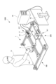
以下、図面を参照して本発明が適用可能な実施形態の運動訓練装置について説明する。なお、本実施形態の運動訓練装置は略水平な載置面に載置され、例えば、使用者(運動訓練者)の上肢の運動機能向上を目的として行われる運動訓練に使用される(図1参照)。運動訓練装置1は、図1に示すように、操作部3を有し、使用者Uは運動訓練装置1の前側に位置し、例えば上肢運動訓練を行うために、右腕ULを前方に伸ばして操作部3を右手で把持している。尚、本明細書中では、図1の運動訓練装置1における使用者Uの手前側を前側、奥側を後側と称することとする。 Below, an embodiment of an exercise training device to which the present invention can be applied will be described with reference to the drawings. The exercise training device of this embodiment is placed on a substantially horizontal support surface and is used, for example, for exercise training performed to improve the motor function of the upper limbs of a user (trainee) (see FIG. 1). As shown in FIG. 1, the exercise training device 1 has an operation unit 3, and a user U is positioned in front of the exercise training device 1, and in order to perform upper limb exercise training, for example, the user extends his right arm UL forward and grasps the operation unit 3 with his right hand. In this specification, the side in front of the user U in the exercise training device 1 in FIG. 1 will be referred to as the front side, and the rear side will be referred to as the rear side.

運動訓練装置1は、装置本体100と、PC(パーソナルコンピューター)70とを有する。また、本実施形態では、これら装置本体100及びPC70に加えて、運動訓練装置1の情報を表示するモニター76を含めて運動訓練システム1000を構成している。なお、PC70は、運動訓練システム1000全体を制御する制御部であり、制御プログラムがインストールされた汎用性のあるPCでも良いし、運動訓練装置1専用のものであっても良い。いずれにしても、制御部は、CPU(Central Processing Unit)、ROM(Read Only Memory)、RAM(Random Access Memory)を有している。CPUは、ROMに格納された制御手順に対応するプログラムを読み出しながら各部の制御を行う。また、RAMには、作業用データや入力データが格納されており、CPUは、前述のプログラム等に基づいてRAMに収納されたデータを参照して制御を行う。 The exercise training device 1 has a device main body 100 and a PC (personal computer) 70. In this embodiment, the exercise training system 1000 is configured by including the device main body 100 and the PC 70, as well as a monitor 76 that displays information about the exercise training device 1. The PC 70 is a control unit that controls the entire exercise training system 1000, and may be a general-purpose PC with a control program installed, or may be a dedicated PC for the exercise training device 1. In either case, the control unit has a CPU (Central Processing Unit), a ROM (Read Only Memory), and a RAM (Random Access Memory). The CPU controls each part while reading a program corresponding to the control procedure stored in the ROM. In addition, the RAM stores working data and input data, and the CPU performs control by referring to the data stored in the RAM based on the above-mentioned program, etc.

装置本体100は、XY平面(載置面および基台2と平行な水平面)で移動可能な操作部3、操作部3をXY平面で駆動する駆動部200などを有する。これら操作部3や駆動部200は、基台2上に配置されている。駆動部200は、X軸およびY軸方向駆動モータとしての第1モータ6及び第2モータ30を有する。具体的には、駆動部200は、第1モータ6を有し、操作部3をX軸方向(図2の矢印Xの方向)に移動させる第1アクチュエータ機構AXと、第2モータ30を有し、操作部3及び第1アクチュエータ機構AXをY軸方向(図2の矢印Yの方向)に移動させる第2アクチュエータ機構AYとを備えている。 The device main body 100 has an operation unit 3 that can move in the XY plane (a horizontal plane parallel to the placement surface and the base 2), a drive unit 200 that drives the operation unit 3 in the XY plane, and the like. The operation unit 3 and the drive unit 200 are arranged on the base 2. The drive unit 200 has a first motor 6 and a second motor 30 as X-axis and Y-axis direction drive motors. Specifically, the drive unit 200 has a first actuator mechanism AX that has the first motor 6 and moves the operation unit 3 in the X-axis direction (the direction of the arrow X in FIG. 2), and a second actuator mechanism AY that has the second motor 30 and moves the operation unit 3 and the first actuator mechanism AX in the Y-axis direction (the direction of the arrow Y in FIG. 2).

操作部3は、ハンドル部材62に作用するX軸およびY軸方向の力を検出する力センサ60(図5参照)を備えている。PC70は、力センサ60、モータ制御部27,31及びモニター76に接続されている。X軸およびY軸方向駆動モータ6,30は、XY平面での操作部3の位置を検出する位置検出手段としてのエンコーダ6a、30a(図6)と一体に構成されている。 The operation unit 3 is equipped with a force sensor 60 (see FIG. 5) that detects forces acting on the handle member 62 in the X-axis and Y-axis directions. The PC 70 is connected to the force sensor 60, motor control units 27, 31, and a monitor 76. The X-axis and Y-axis drive motors 6, 30 are integrally configured with encoders 6a, 30a (FIG. 6) that serve as position detection means for detecting the position of the operation unit 3 on the XY plane.

これらの構成により、制御部としてのPC70は、力センサ60やエンコーダ6a、30aからの入力値に基づいて、モータ制御部27,31を介して第1モータ6及び第2モータ30の駆動を制御し、操作部3をXY平面上で移動させ、訓練情報や操作部3の移動軌跡等をモニター76に表示する。 With this configuration, the PC 70 as a control unit controls the driving of the first motor 6 and the second motor 30 via the motor control units 27, 31 based on the input values from the force sensor 60 and the encoders 6a, 30a, moves the operation unit 3 on the XY plane, and displays training information, the movement trajectory of the operation unit 3, etc. on the monitor 76.

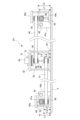
以下、図2~図5に基づいて各構成について詳細に説明する。操作部3は、第1スライダーブロック4(第1保持部材)に取付プレート5を介して取り付けられており、第1スライダーブロック4と一体となって移動するように構成されている。第1スライダーブロック4は、XY平面上のX軸方向に延設した第1ガイドロッド9aおよび9bに沿ってスライド可能に設けられている。そして、第1ベルト10の一部は、ベルト固定プレート28とビス29によって第1スライダーブロック4に固定されている。これにより、第1ベルト10が第1モータ(X軸方向駆動モータ)6によって回転駆動すると、第1スライダーブロック4は第1ガイドロッド9a,9bに沿ってX軸方向にスライド移動する。 Each component will be described in detail below with reference to Figs. 2 to 5. The operation unit 3 is attached to the first slider block 4 (first holding member) via a mounting plate 5, and is configured to move integrally with the first slider block 4. The first slider block 4 is provided so as to be slidable along first guide rods 9a and 9b extending in the X-axis direction on the XY plane. A portion of the first belt 10 is fixed to the first slider block 4 by a belt fixing plate 28 and a screw 29. As a result, when the first belt 10 is driven to rotate by the first motor (X-axis direction drive motor) 6, the first slider block 4 slides in the X-axis direction along the first guide rods 9a and 9b.

図3に示す通り、第1アクチュエータ機構AXの第1モータ6の駆動は、軸13、プーリー14、ベルト15、プーリー17および軸16を介してプーリー18に伝達される。第1モータ6は支持板21に設けられており、支持板21は支持板11に固定されている。支持板11は、軸16を回転可能に支持し、第2スライダーブロック7とモータ制御部27を固定支持している。なお、支持板11及び第2スライダーブロック7を併せて第1ガイドロッド9a,9bの一端およびプーリー18を保持する第2保持部材という。 As shown in FIG. 3, the drive of the first motor 6 of the first actuator mechanism AX is transmitted to the pulley 18 via the shaft 13, pulley 14, belt 15, pulley 17, and shaft 16. The first motor 6 is provided on a support plate 21, which is fixed to the support plate 11. The support plate 11 rotatably supports the shaft 16, and fixedly supports the second slider block 7 and the motor control unit 27. The support plate 11 and the second slider block 7 together are referred to as a second holding member that holds one end of the first guide rods 9a, 9b and the pulley 18.

X軸方向において第1モータ6の反対側には、支持板12,24が設けられている。支持板12,24は、軸19を回転可能に支持し、第3スライダーブロック8を固定支持している。軸19にはプーリー20が設けられており、プーリー18とプーリー19との間に第1ベルト10が架け渡されている。また、第1ガイドロッド9a,9bの一端は第2スライダーブロック7に固定支持され、第1ガイドロッド9a,9bの他端は第3スライダーブロック8に固定支持されている。なお、支持板12,24及び第3スライダーブロック8を併せて第1ガイドロッド9a,9bの他端およびプーリー20を保持する第3保持部材という。 Support plates 12 and 24 are provided on the opposite side of the first motor 6 in the X-axis direction. The support plates 12 and 24 rotatably support the shaft 19 and fixedly support the third slider block 8. A pulley 20 is provided on the shaft 19, and the first belt 10 is stretched between the pulleys 18 and 19. One end of the first guide rods 9a and 9b is fixedly supported by the second slider block 7, and the other end of the first guide rods 9a and 9b is fixedly supported by the third slider block 8. The support plates 12 and 24 and the third slider block 8 are collectively referred to as a third holding member that holds the other ends of the first guide rods 9a and 9b and the pulley 20.

上述した通り、第1スライダーブロック4は、第1ベルト10の一部が固定されており、第1モータ6を駆動するとプーリー18が回転してプーリー19と共に第1ベルト10が回転する。このため、第1スライダーブロック4は、第1ガイドロッド9a,9bに沿ってX軸方向にスライド移動する。なお、第1ベルト10と第1ガイドロッド9a,9bは、それぞれX軸方向に平行で且つ第1ベルト10の両側に第1ガイドロッド9aと9bが配置され、基台2からの高さ位置は略同一となっている。 As described above, a portion of the first belt 10 is fixed to the first slider block 4, and when the first motor 6 is driven, the pulley 18 rotates, causing the first belt 10 to rotate together with the pulley 19. Therefore, the first slider block 4 slides in the X-axis direction along the first guide rods 9a and 9b. The first belt 10 and the first guide rods 9a and 9b are each parallel to the X-axis direction, and the first guide rods 9a and 9b are disposed on both sides of the first belt 10, and are at approximately the same height from the base 2.

図2に示す様に、第1アクチュエータ機構AXが有する第2スライダーブロック7と第3スライダーブロック8は、第2ガイドロッド55と第3ガイドロッド48に対してY軸方向にスライド移動可能に支持されている。そして、第2ベルト53と第3ベルト46が回転することで、第1アクチュエータ機構AX全体がY軸方向に移動可能となっている。図3に示す通り、第2ベルト53の一部は、第2スライダーブロック7に固定された支持板21に設けられたベルト固定プレートにビス23によって固定されている。また、第3ベルト46の一部は、第3スライダーブロック8に固定された支持板24に設けられたベルト固定プレート25にビス26によって固定されている。そして、第2アクチュエータ機構AYの第2モータ(Y軸方向駆動モータ)30が回転駆動することによって第3ベルト46および第2ベルト53が回転し、それにより第1アクチュエータ機構AXはY軸方向にスライド移動する。 2, the second slider block 7 and the third slider block 8 of the first actuator mechanism AX are supported by the second guide rod 55 and the third guide rod 48 so as to be slidable in the Y-axis direction. The second belt 53 and the third belt 46 rotate, so that the entire first actuator mechanism AX can move in the Y-axis direction. As shown in FIG. 3, a part of the second belt 53 is fixed by a screw 23 to a belt fixing plate provided on a support plate 21 fixed to the second slider block 7. Also, a part of the third belt 46 is fixed by a screw 26 to a belt fixing plate 25 provided on a support plate 24 fixed to the third slider block 8. The third belt 46 and the second belt 53 rotate by the rotational drive of the second motor (Y-axis direction drive motor) 30 of the second actuator mechanism AY, and thereby the first actuator mechanism AX slides in the Y-axis direction.

次に、図2と図4を用いて第2アクチュエータ機構AYについて説明する。第2アクチュエータ機構AYは、第1アクチュエータ機構AXをY軸方向に移動させるための機構である。第2モータ30およびモータ制御部31は、基台2に設けられた支持板34,支柱33および支持板32からなる支持フレームの上部に設けられている。この支持フレームは使用者Uと反対の装置奥側(基台2のモニター76側)の中央部に固定されている。 Next, the second actuator mechanism AY will be described with reference to Figures 2 and 4. The second actuator mechanism AY is a mechanism for moving the first actuator mechanism AX in the Y-axis direction. The second motor 30 and motor control unit 31 are provided on the upper part of a support frame consisting of a support plate 34, a support column 33, and a support plate 32 provided on the base 2. This support frame is fixed to the center of the rear side of the device (the monitor 76 side of the base 2) opposite the user U.

第2モータ30には不図示の軸およびプーリーが設けられており、プーリー36との間でベルト37が架け渡されている。支持板32と34との間には軸35が回転可能に支持され、この軸35にはプーリー37,38および39が設けられており、プーリー36の回転力が軸35を通じてプーリー38および39に伝達される。 The second motor 30 is provided with a shaft and pulley (not shown), and a belt 37 is stretched between the shaft 35 and the pulley 36. A shaft 35 is rotatably supported between the support plates 32 and 34, and pulleys 37, 38, and 39 are provided on the shaft 35. The rotational force of the pulley 36 is transmitted to the pulleys 38 and 39 via the shaft 35.

支持フレーム32~34のX軸方向の両側には、コの字に形成された支持板45a,52aが設けられている。支持板45aは、軸43を回転可能に支持しており、軸43にプーリー42と44aが設けられている。プーリー38とプーリー42にはベルト40が架け渡されており、第2モータ30の回転駆動をベルト37,プーリー36,軸35,プーリー38,ベルト40,プーリー42および軸43を介してプーリー44aに伝達する。つまり、ベルト40は、第2モータ30の駆動を第3ベルト46に伝達するための第5ベルトである。 Support plates 45a, 52a formed in a U-shape are provided on both sides of the support frames 32-34 in the X-axis direction. The support plate 45a rotatably supports a shaft 43, on which pulleys 42 and 44a are provided. A belt 40 is stretched between pulleys 38 and 42, and transmits the rotational drive of the second motor 30 to pulley 44a via belt 37, pulley 36, shaft 35, pulley 38, belt 40, pulley 42 and shaft 43. In other words, belt 40 is a fifth belt for transmitting the drive of the second motor 30 to the third belt 46.

支持板45a近傍にはガイド支持部47aが設けられており、第3ガイドロッド48の一端を支持している。また、基台2上で支持板45aのY軸方向における反対側(装置右手前側)には、支持板45aの対となる支持板45bとガイド支持部47aの対となるガイド支持部47bとが配置されている。 A guide support portion 47a is provided near the support plate 45a and supports one end of the third guide rod 48. In addition, on the opposite side of the base 2 in the Y-axis direction to the support plate 45a (the front right side of the device), a support plate 45b that is paired with the support plate 45a and a guide support portion 47b that is paired with the guide support portion 47a are arranged.

支持板45bは、軸43bを回転可能に支持し、軸43bにはプーリー44aの対となるプーリー44bが設けられている。第3ベルト46はプーリー44aと44bとの間で架け渡されており、上述した通りその一部が第3スライダーブロック8と一体に移動するベルト固定プレート25に固定されている。また、ガイド支持部47bは、第3ガイドロッド48の他端を支持し、ガイド支持部47aと共に第3ガイドロッド48を固定支持している。第3ベルト46と第3ガイドロッド48とはそれぞれY軸方向に平行に延設され、基台2からの高さ位置は略同一となっている。 The support plate 45b rotatably supports the shaft 43b, and the shaft 43b is provided with a pulley 44b that is a pair with the pulley 44a. The third belt 46 is stretched between the pulleys 44a and 44b, and as described above, a part of it is fixed to the belt fixing plate 25 that moves integrally with the third slider block 8. The guide support part 47b supports the other end of the third guide rod 48, and together with the guide support part 47a, fixes and supports the third guide rod 48. The third belt 46 and the third guide rod 48 are each provided to extend parallel to the Y-axis direction, and are at approximately the same height position from the base 2.

X軸方向において支持フレームに対して支持板45aの反対側(基台2の左奥側)には、支持板52aが配置されている。支持板52aは、軸49を回転可能に支持しており、軸49にプーリー50と51aが設けられている。プーリー39とプーリー50には、ベルト41が架け渡されており、第2モータ30の回転駆動をベルト37,プーリー36,軸35,プーリー39,ベルト41,プーリー50および軸49を介してプーリー51aに伝達する。つまり、ベルト41は、第2モータ30の駆動を第2ベルト53に伝達するための第4ベルトである。 A support plate 52a is disposed on the opposite side of the support frame to the support plate 45a in the X-axis direction (the left rear side of the base 2). The support plate 52a rotatably supports the shaft 49, which is provided with pulleys 50 and 51a. A belt 41 is stretched between the pulleys 39 and 50, and transmits the rotational drive of the second motor 30 to the pulley 51a via the belt 37, pulley 36, shaft 35, pulley 39, belt 41, pulley 50, and shaft 49. In other words, the belt 41 is a fourth belt for transmitting the drive of the second motor 30 to the second belt 53.

支持板52a近傍にはガイド支持部54aが設けられており、第2ガイドロッド55の一端を支持している。また、基台2上で支持板52aのY軸方向における反対側(装置左手前側)には支持板52aの対となる支持板52bとガイド支持部54aの対となるガイド支持部54bとが配置されている。 A guide support portion 54a is provided near the support plate 52a and supports one end of the second guide rod 55. In addition, on the opposite side of the base 2 in the Y-axis direction to the support plate 52a (the front left side of the device), a support plate 52b that is paired with the support plate 52a and a guide support portion 54b that is paired with the guide support portion 54a are arranged.

支持板52bは軸49bを回転可能に支持し、軸49bにはプーリー51aの対となるプーリー51bが設けられている。第2ベルト53は、プーリー51aと51bとの間で架け渡されており、上述した通りその一部が第2スライダーブロック7と一体に移動するベルト固定プレート22に固定されている。また、ガイド支持部54bは、第2ガイドロッド55の他端を支持し、ガイド支持部54aと共に第2ガイドロッド55を固定支持している。第3ベルト46と第3ガイドロッド48とは、それぞれY軸方向に平行に延設され、基台2からの高さ位置は略同一となっている。 The support plate 52b rotatably supports the shaft 49b, and the shaft 49b is provided with a pulley 51b that is a pair with the pulley 51a. The second belt 53 is stretched between the pulleys 51a and 51b, and as described above, a part of it is fixed to the belt fixing plate 22 that moves integrally with the second slider block 7. The guide support part 54b supports the other end of the second guide rod 55, and supports the second guide rod 55 in a fixed manner together with the guide support part 54a. The third belt 46 and the third guide rod 48 are each provided to extend parallel to the Y-axis direction, and are at approximately the same height position from the base 2.

上述した通り、第2モータ30の回転駆動はプーリー44aとプーリー51aに伝達され、第3ベルト46と第2ベルト53が回転する。これにより、第3ベルト46と第2ベルト53にそれぞれ固定された第3スライダーブロック8と第2スライダーブロック7(つまり第1アクチュエータ機構AX全体)が第2ガイドロッド8と第2ガイドロッド55に沿ってY軸方向にスライド移動する。 As described above, the rotational drive of the second motor 30 is transmitted to the pulley 44a and the pulley 51a, causing the third belt 46 and the second belt 53 to rotate. This causes the third slider block 8 and the second slider block 7 (i.e., the entire first actuator mechanism AX), which are fixed to the third belt 46 and the second belt 53, respectively, to slide in the Y-axis direction along the second guide rod 8 and the second guide rod 55.

ここで、図4を参照するとベルト40とベルト41とは、X軸方向に平行に延設しているが、高さ方向の位置(基台2からの距離)が異なっている。具体的には、ベルト40の下方にベルト41が配置されている。そして、この高さ方向において、第3ベルト46、第3ガイドロッド48、第2ベルト53および第2ガイドロッド55は、ベルト40とベルト41との間で略同一高さに配置されている。 Now, referring to FIG. 4, belts 40 and 41 extend parallel to the X-axis direction, but their positions in the height direction (distance from base 2) are different. Specifically, belt 41 is disposed below belt 40. In addition, in this height direction, third belt 46, third guide rod 48, second belt 53, and second guide rod 55 are disposed at approximately the same height between belt 40 and belt 41.

また、図2及び図3を参照すると、操作部3をX軸方向に移動させるための第1ガイドロッド9a,9bおよび第1ベルト10は、操作部3および第1アクチュエータ機構AXをY軸方向に移動させるための第3ガイドロッド48と第2ガイドロッド55との間で、且つ、Y軸方向に平行に配置された第3ガイドロッド48,第3ベルト46,第2ガイドロッド55および第2ベルト53に対して直交するX軸方向に延設するように配置されている。そして、これらの第1ベルト10,第1ガイドロッド9a・9b,第3ベルト46,第3ガイドロッド48,第2ベルト53および第2ガイドロッド55は、高さ方向においてベルト40とベルト41との間に配置されている。これにより、運動訓練装置の高さ方向の寸法を薄く構成することができる。 2 and 3, the first guide rods 9a and 9b and the first belt 10 for moving the operating unit 3 in the X-axis direction are arranged between the third guide rod 48 and the second guide rod 55 for moving the operating unit 3 and the first actuator mechanism AX in the Y-axis direction, and are arranged to extend in the X-axis direction perpendicular to the third guide rod 48, the third belt 46, the second guide rod 55, and the second belt 53 arranged parallel to the Y-axis direction. The first belt 10, the first guide rods 9a and 9b, the third belt 46, the third guide rod 48, the second belt 53, and the second guide rod 55 are arranged between the belts 40 and 41 in the height direction. This allows the height dimension of the exercise training device to be made thin.

言い換えると、図4において基台2からプーリー44a,51aの上端までの距離(XY平面と直交する方向、つまり高さ)をL1、基台2からプーリー44a,51aの下端までの距離をL2、基台2からプーリー38,42の下端までの距離をL3、基台2からプーリー39,50までの距離をL4としたときに、以下の関係が成り立つように各部材が配置されている。「L1>L2」「L3>L1」「L2>L4」。よって、「L3>L1>L2>L4」となり、プーリー44aとプーリー51aとはL3とL4との間に配置されている。そして、ベルトはそれぞれプーリーの上端と下端との間で架け渡されており、第3ベルト46,第2ベルト53の高さ方向における中央と第3ガイドロッド48,第2ガイドロッド55の高さ方向の中央とが略同一で、第3ガイドロッド48の上端がベルト40に干渉せず、第2ガイドロッド55の下端がベルト41に干渉しないように配置されている。 In other words, in Figure 4, when the distance from the base 2 to the upper ends of pulleys 44a and 51a (the direction perpendicular to the XY plane, i.e. the height) is L1, the distance from the base 2 to the lower ends of pulleys 44a and 51a is L2, the distance from the base 2 to the lower ends of pulleys 38 and 42 is L3, and the distance from the base 2 to pulleys 39 and 50 is L4, the various components are arranged so that the following relationships hold: "L1>L2", "L3>L1", "L2>L4". Therefore, "L3>L1>L2>L4", and pulleys 44a and 51a are arranged between L3 and L4. The belts are each stretched between the upper and lower ends of the pulleys, and the centers in the height direction of the third belt 46 and second belt 53 are approximately the same as the centers in the height direction of the third guide rod 48 and second guide rod 55, and are positioned so that the upper end of the third guide rod 48 does not interfere with the belt 40, and the lower end of the second guide rod 55 does not interfere with the belt 41.

また、図3において基台2とプーリー18,19の上端までの距離がL1、基台2とプーリー18,19の下端までの距離がL2となるように配置されている。以上から、第1ベルト10、第1ガイドロッド9a,9b、第3ベルト46、第3ガイドロッド48、第2ベルト53および第2ガイドロッド55は、高さ方向においてL3とL4との間、すなわちプーリー38,42の下端とプーリー39,50の上端との間で重複して配置されている。 3, the distance between the base 2 and the upper ends of the pulleys 18 and 19 is L1, and the distance between the base 2 and the lower ends of the pulleys 18 and 19 is L2. As a result, the first belt 10, the first guide rods 9a and 9b, the third belt 46, the third guide rod 48, the second belt 53, and the second guide rod 55 are arranged to overlap in the height direction between L3 and L4, that is, between the lower ends of the pulleys 38 and 42 and the upper ends of the pulleys 39 and 50.

また、第1ベルト10は第1ガイドロッド9a,9bに挟まれるように配置されている。よって、使用者Uが操作部3に力を加えた際に第1ガイドロッド9aまたは9bを中心に回転する力を受けることができ、回転方向の移動を抑えることができる。 The first belt 10 is also positioned so that it is sandwiched between the first guide rods 9a and 9b. Therefore, when the user U applies force to the operating unit 3, it can receive a force that rotates around the first guide rod 9a or 9b, and movement in the rotational direction can be suppressed.

操作部3は、図1に示すように第1スライダーブロック4の前方向に配置され、図5に示すように、比較的短い垂直な操作ロッド61と、その上端に設けられたハンドル部材62とからなる。本実施形態のハンドル部材62は、使用者Uの上肢ULの運動機能を訓練するために片手で掴むことができるように、比較的厚い小型の円形ディスク状に形成されている。ハンドル部材62は、使用者Uが掴んだ手で回すことができるように、操作ロッド61を中心に回動可能に取り付けられる。 The operating unit 3 is disposed in front of the first slider block 4 as shown in FIG. 1, and is composed of a relatively short vertical operating rod 61 and a handle member 62 attached to its upper end as shown in FIG. 5. The handle member 62 in this embodiment is formed in a relatively thick, small circular disk shape so that it can be grasped with one hand to train the motor function of the upper limb UL of the user U. The handle member 62 is attached rotatably around the operating rod 61 so that the user U can turn it with the hand that is grasping it.

また、操作部3は、操作ロッド61に一体に設けられた力センサ60を有する。力センサ60は、取付プレート5を介して、第1アクチュエータ機構AXのスライダーブロック4に一体に固定されている。力センサ60は、使用者Uが自力で操作部3を動かす能動訓練モード及び操作部3の力で上肢又は下肢を動かす受動訓練モードのいずれにおいても、ハンドル部材62から操作ロッド61に作用する使用者Uの力を検出する。本実施形態では、力センサ60として、歪みゲージを用いた6軸力覚センサが採用されている。 The operation unit 3 also has a force sensor 60 that is integrally provided on the operation rod 61. The force sensor 60 is fixed integrally to the slider block 4 of the first actuator mechanism AX via the mounting plate 5. The force sensor 60 detects the force of the user U acting on the operation rod 61 from the handle member 62 in both an active training mode in which the user U moves the operation unit 3 by himself/herself and a passive training mode in which the upper limbs or lower limbs are moved by the force of the operation unit 3. In this embodiment, a six-axis force sensor using a strain gauge is used as the force sensor 60.

一般に、6軸力覚センサは、直交する3軸方向x,y,zの力(Fx,Fy,Fz)とx,y,z3軸周りのモーメント(Mx,My,Mz)とを検出することができる。本実施形態では、6軸力覚センサを、そのX軸及びY軸が、第1アクチュエータ機構AXの左右方向(第1ガイドロッド9a,9bと平行な方向)及び前後方向(第3ガイドロッド48および第3ガイドロッド53と平行な方向)とそれぞれ一致するように配向する。 In general, a six-axis force sensor can detect forces (Fx, Fy, Fz) in three orthogonal axial directions x, y, and z, and moments (Mx, My, Mz) about the three axes x, y, and z. In this embodiment, the six-axis force sensor is oriented so that its X-axis and Y-axis coincide with the left-right direction (direction parallel to the first guide rods 9a, 9b) and the front-rear direction (direction parallel to the third guide rods 48 and 53) of the first actuator mechanism AX, respectively.

これにより、力センサ60は、使用者Uの上肢又は下肢が操作部3を動かし又は該操作部により動かされるとき、操作ロッド61が使用者Uの上肢又は下肢から直接受ける力を、前後方向の力成分と左右方向の力成分とそれらに直交する垂直方向の力成分とに分けて、更に前後方向、左右方向及び垂直方向の各軸周りにそれぞれ作用するモーメントとして、検出することができる。 As a result, when the upper or lower limbs of the user U move the operating unit 3 or are moved by the operating unit, the force sensor 60 can separate the force that the operating rod 61 receives directly from the upper or lower limbs of the user U into a force component in the front-to-rear direction, a force component in the left-to-right direction, and a vertical force component perpendicular to these, and further detect these as moments acting around each axis in the front-to-rear direction, left-to-right direction, and vertical direction.

実際の運動訓練装置1の使用において、力センサ60が検出する前後方向(Y軸方向)、左右方向(X軸方向)及び垂直方向(XY平面と直交する高さ方向)の力成分は、第1及び/又は第2駆動モータ6、30の回転力と使用者Uが操作部3に及ぼす力との差分、即ち操作部3が使用者Uの上肢又は下肢から受ける抗力として検出される。 When the exercise training device 1 is actually used, the force components in the front-back direction (Y-axis direction), left-right direction (X-axis direction), and vertical direction (height direction perpendicular to the XY plane) detected by the force sensor 60 are detected as the difference between the rotational force of the first and/or second drive motor 6, 30 and the force exerted by the user U on the operation unit 3, that is, the resistance force that the operation unit 3 receives from the upper or lower limbs of the user U.

上述のように、運動訓練装置1は、第1モータ6及び第2モータ30を制御するための制御部としてのPC70を備える。PC70は、図6に示すように、駆動制御部71と、信号制御部72と、表示制御部73と、メモリ74と、それらを制御管理するための制御CPU75とを備える。 As described above, the exercise training device 1 includes a PC 70 as a control unit for controlling the first motor 6 and the second motor 30. As shown in FIG. 6, the PC 70 includes a drive control unit 71, a signal control unit 72, a display control unit 73, a memory 74, and a control CPU 75 for controlling and managing them.

駆動制御部71は、モータ制御部27,31を介して第1モータ6及び第2モータ30に接続され、それらの駆動を制御する。モータ制御部27,30は、PC70の中に組み込んでもよい。信号制御部72は、力センサ60及びエンコーダ6a、30aに接続され、力センサ60及びエンコーダ6a、30aから出力される信号を受信する。表示制御部73は、モニター76に接続され、該モニター76の表示を制御する。メモリ74は、運動訓練装置1を動作させるためのプログラムに加えて、例えば使用者Uの個人データや訓練履歴等の訓練に関するデータを保存する。 The drive control unit 71 is connected to the first motor 6 and the second motor 30 via the motor control units 27 and 31, and controls the drive thereof. The motor control units 27 and 30 may be incorporated in the PC 70. The signal control unit 72 is connected to the force sensor 60 and the encoders 6a and 30a, and receives signals output from the force sensor 60 and the encoders 6a and 30a. The display control unit 73 is connected to the monitor 76, and controls the display of the monitor 76. The memory 74 stores, in addition to the program for operating the exercise training device 1, data related to training, such as the user U's personal data and training history.

制御CPU75は、力センサ60、エンコーダ6a,30a、および不揮発性のメモリ74から入力される情報に基づいて操作部3の速度を求め、駆動制御部71に電流値(出力電流Ii、デューティ)を出力して、第1モータ6及び第2モータ30への電力供給を制御する。 The control CPU 75 determines the speed of the operation unit 3 based on information input from the force sensor 60, the encoders 6a and 30a, and the non-volatile memory 74, and outputs a current value (output current Ii, duty) to the drive control unit 71 to control the power supply to the first motor 6 and the second motor 30.

なお、本実施形態では、操作部3を取付プレート5を介して第1スライダーブロック4と高さ方向において重複する位置に設け、操作部3の下端が基台2から浮いている状態で固定する態様を示したが、取付プレート5の下面に自由回転するコロなどの摺動部材を設けて基台2上で滑らかに動くようにした上で取付プレート5の下面と基台2とが接触するように構成してもよい。これにより、使用者Uによる下方にかかる力を基台2で受けることができる。また、操作部3を第1スライダーブロック4の上部に取り付けるようにしてもよい。そうすることで操作部3の可動領域がより装置奥側に広げることができる。 In this embodiment, the operation unit 3 is provided at a position overlapping the first slider block 4 in the height direction via the mounting plate 5, and the bottom end of the operation unit 3 is fixed in a state where it is floating above the base 2. However, a sliding member such as a freely rotating roller may be provided on the bottom surface of the mounting plate 5 so that it moves smoothly on the base 2, and the bottom surface of the mounting plate 5 may come into contact with the base 2. This allows the base 2 to receive the force applied downward by the user U. The operation unit 3 may also be attached to the top of the first slider block 4. This allows the movable area of the operation unit 3 to be expanded further toward the back of the device.

次に、本実施形態の運動訓練装置1を含む運動訓練システム1000の動作について説明する。運動訓練装置1により使用者Uが運動訓練を行う際には、例えば、使用者Uが操作部3を掴みその上から訓練指導者が使用者Uの手をとって使用者Uの上肢状況に応じた動作範囲で操作部3を移動させることで、操作部3が辿る軌跡を設定するための軌跡設定モードと、使用者Uのみが操作部3を掴み軌跡設定モードで設定された軌跡を辿ることで、使用者Uによる操作部3の位置(軌跡)とそのときに操作部3が受ける負荷とを検出するための負荷検出モードと経て、運動訓練モードで行われる。 Next, the operation of the exercise training system 1000 including the exercise training device 1 of this embodiment will be described. When the user U performs exercise training using the exercise training device 1, for example, the user U grasps the operation unit 3, and the training instructor holds the user U's hand from above and moves the operation unit 3 within a range of motion according to the condition of the user U's upper limbs, so that the exercise training is performed in a trajectory setting mode for setting the trajectory to be followed by the operation unit 3, and a load detection mode for detecting the position (trajectory) of the operation unit 3 by the user U and the load received by the operation unit 3 at that time by the user U grasping the operation unit 3 alone and tracing the trajectory set in the trajectory setting mode, and then in the exercise training mode.

[運動訓練モード]
まず、運動訓練モードには、使用者Uが自ら軌跡設定モードで設定された軌跡をなぞるように操作部3を移動させる能動訓練モード(アシストモード、トレーニングモード)と、自動的に軌跡を辿る操作部3に引っ張られて運動する受動訓練モード(自動モード)とがある。受動訓練モードは主としてリハビリ中の人を対象とする運動訓練モード、能動訓練モードはリハビリ最終段階の人や健常者を対象とする運動訓練モードとして想定されている。なお、アシストモードは、訓練中に操作部3に適宜アシスト力を作用させて行う能動訓練モードであり、トレーニングモードは、アシストモードのようなアシスト力がない能動訓練モードである。
[Exercise training mode]
First, the exercise training modes include an active training mode (assist mode, training mode) in which the user U moves the operation unit 3 to trace the trajectory set in the trajectory setting mode, and a passive training mode (automatic mode) in which the user U exercises by being pulled by the operation unit 3 that automatically follows the trajectory. The passive training mode is intended mainly for people undergoing rehabilitation, while the active training mode is intended for people in the final stage of rehabilitation or healthy people. The assist mode is an active training mode in which an appropriate assist force is applied to the operation unit 3 during training, and the training mode is an active training mode without an assist force like the assist mode.

運動訓練システム1000では、これらの各モードの何れかを選択して実行可能である。また、各モードにおいて、それぞれパラメータを設定可能であり、使用者Uに応じて適切な負荷などを設定して運動訓練モードを行うことができる。例えば、前述の特許文献1では、能動訓練モードにおいて、平面運動における静止摩擦を模擬した仮想モデルを介して操作部に発生させるべきX軸方向の速度およびY軸方向の速度を算出してX軸方とY軸方向の駆動モータを制御するようにしている。そして、この仮想モデルのパラメータを変更することで、様々な負荷で能動訓練モードを行えるようにしている。 In the exercise training system 1000, one of these modes can be selected and executed. In addition, parameters can be set for each mode, and the exercise training mode can be performed by setting an appropriate load according to the user U. For example, in the above-mentioned Patent Document 1, in the active training mode, the speed in the X-axis direction and the speed in the Y-axis direction to be generated in the operation unit are calculated via a virtual model that simulates static friction in planar motion, and the drive motors in the X-axis direction and Y-axis direction are controlled. Then, by changing the parameters of this virtual model, the active training mode can be performed with various loads.

特許文献1においては、モニターに、例えば運動量や静止摩擦力の大きさに応じて予め定めた幾とおりかの選択子にその説明(例えば、運動量:大、静止摩擦力:中)を加えた画面を表示したり、運動量や静止摩擦力の大きさを調整可能に表したレベルメータを表示したりすることでパラメータの入力を容易にしている。 In Patent Document 1, the input of parameters is made easy by displaying on the monitor a screen with several predefined options corresponding to the magnitude of momentum or static friction force, along with their explanations (e.g., momentum: large, static friction force: medium), or by displaying a level meter that indicates the magnitude of momentum or static friction force in an adjustable manner.

ここで、特許文献1では、静止摩擦を模擬した仮想モデルを使用することで運動訓練を行っているが、運動訓練装置では、更なる訓練効果が得られる装置が求められている。そこで、本実施形態では、運動訓練モードにおいて、操作部3を次のように制御するようにしている。 In Patent Document 1, exercise training is performed by using a virtual model that simulates static friction, but there is a demand for exercise training devices that can provide even greater training effects. Therefore, in this embodiment, in the exercise training mode, the operation unit 3 is controlled as follows.

本実施形態の場合も、特許文献1における制御と同様に、PC70の制御CPU75は、信号制御部72により力センサ60及びエンコーダ6a、30aから出力される信号を受信し、駆動制御部71により第1モータ6及び第2モータ30を制御することで、各種運動訓練モードを実行可能である。この際、本実施形態では、静止摩擦力と動摩擦力を模擬したパラメータに加えて、その運動が維持されるような力(例えば、慣性力)を模擬したパラメータを設定可能としている。本実施形態では、その運動が維持されるような力を模擬したパラメータを第1のパラメータ、静止摩擦力と動摩擦力を模擬したパラメータを第2のパラメータとする。このような第1のパラメータ及び第2のパラメータは、トレーニングモードやアシストモードなどの能動訓練モードにおいて好ましく使用できる。なお、第2のパラメータについては、上述の特許文献1に記載の内容と同様であるので、第1のパラメータについて説明する。 In the present embodiment, similar to the control in Patent Document 1, the control CPU 75 of the PC 70 receives signals output from the force sensor 60 and the encoders 6a and 30a by the signal control unit 72, and controls the first motor 6 and the second motor 30 by the drive control unit 71, thereby enabling various exercise training modes to be executed. In this case, in addition to the parameters simulating the static friction force and the kinetic friction force, a parameter simulating a force (e.g., an inertial force) that maintains the motion can be set in this embodiment. In this embodiment, the parameter simulating the force that maintains the motion is the first parameter, and the parameter simulating the static friction force and the kinetic friction force is the second parameter. Such first and second parameters can be preferably used in active training modes such as training mode and assist mode. Note that the second parameter is the same as the contents described in Patent Document 1 above, so the first parameter will be described.

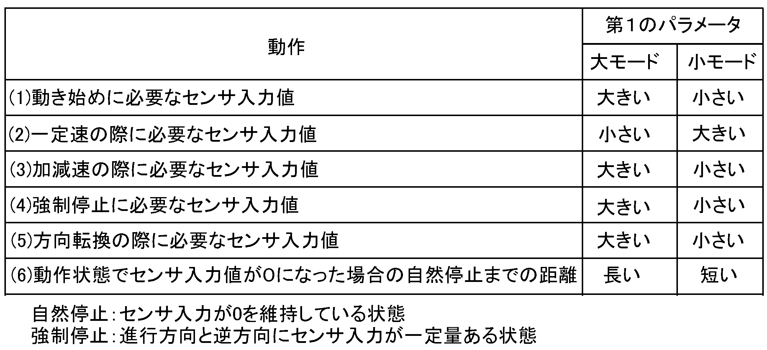
第1のパラメータを説明するために、次の(1)~(6)の動作で、第1モータ6及び第2モータ30がどのように制御されるかを説明する。なお、制御CPU75は、設定される第1パラメータに応じて、第1モータ6及び第2モータ30を制御することで操作部3に発生させる力を変更可能である。 To explain the first parameter, the following operations (1) to (6) will be described to explain how the first motor 6 and the second motor 30 are controlled. Note that the control CPU 75 can change the force generated by the operation unit 3 by controlling the first motor 6 and the second motor 30 according to the set first parameter.

(1)操作部3の動き始め
まず、使用者Uが操作部3を動かし始める場合について説明する。即ち、操作部3が静止している状態で、力センサ60が力を検出した場合である。PC70の制御CPU75は、操作部3が停止している状態で、力センサ60がX軸およびY軸方向の力Fx,Fyの合成力FОを検出した場合に、合成力FОと反対方向に合成力F以下の力が発生するように第1モータ6及び第2モータ30を制御する。
(1) Starting to Move Operation Unit 3 First, a case where the user U starts to move the operation unit 3 will be described. That is, the case where the force sensor 60 detects a force when the operation unit 3 is stationary. When the force sensor 60 detects a resultant force F O of the forces Fx and Fy in the X-axis and Y-axis directions when the operation unit 3 is stationary, the control CPU 75 of the PC 70 controls the first motor 6 and the second motor 30 so as to generate a force equal to or less than the resultant force F O in the direction opposite to the resultant force F O.

この制御について、第2のパラメータが固定状態で、第1のパラメータを大きさが異なる2つの値に設定した場合に、操作部3を動かすために必要な力(力センサ60に入力される入力合成力F)を比較して説明する。なお、以下では、第1のパラメータを2つの値に設定した場合を比較しているが、第1のパラメータは、2つ以上の複数の異なる値に設定可能としても良い。 This control will be described by comparing the force required to move the operation unit 3 (the combined input force F I input to the force sensor 60) when the second parameter is fixed and the first parameter is set to two values of different magnitudes. Note that, although a comparison is made below between the cases where the first parameter is set to two values, the first parameter may be set to two or more different values.

制御CPU75は、第1のパラメータが第1の値に設定された場合(大モード)において、操作部3を動かすために必要な力センサ60に入力されるX軸およびY軸方向の力Fx,Fyの入力合成力Fが第1の力になるように、第1モータ6及び第2モータ30を制御する。一方、制御CPU75は、第1パラメータが第1の値よりも小さい第2の値に設定された場合(小モード)、入力合成力Fが第1の力よりも小さい第2の力になるように、第1モータ6及び第2モータ30を制御する。即ち、制御CPU75は、操作部3を動かし始める場合、第1のパラメータが大きい程、使用者Uが操作部3を動かすために必要な力が大きくなるように、第1モータ6及び第2モータ30を制御する。 When the first parameter is set to a first value (large mode), the control CPU 75 controls the first motor 6 and the second motor 30 so that the input resultant force FI of the forces Fx and Fy in the X-axis and Y-axis directions, which is input to the force sensor 60 and is necessary to move the operation unit 3, becomes a first force. On the other hand, when the first parameter is set to a second value smaller than the first value (small mode), the control CPU 75 controls the first motor 6 and the second motor 30 so that the input resultant force FI becomes a second force smaller than the first force. That is, when starting to move the operation unit 3, the control CPU 75 controls the first motor 6 and the second motor 30 so that the force necessary for the user U to move the operation unit 3 becomes larger as the first parameter becomes larger.

(2)操作部3を一定速度で維持
次に、使用者Uが操作部3を一定速度で動かす場合について説明する。まず、操作部3が入力される合成力Fの方向が変わらずに移動している場合、PC70の制御CPU75は、力センサ60により検出されるX軸およびY軸方向の力Fx,Fyの合成力Fの方向に、合成力F以下の力が操作部3に発生するように第1モータ6及び第2モータ30を制御する。また、制御CPU75は、操作部3の移動中に、力センサ60により検出されるX軸およびY軸方向の力Fx,Fyの合成力FがF1からF2に低下した場合には、合成力Fの方向に、F2よりも大きくF1以下の力が操作部3に発生するように第1モータ6及び第2モータ30を制御する。
(2) Maintaining the Operation Unit 3 at a Constant Speed Next, a case where the user U moves the operation unit 3 at a constant speed will be described. First, when the operation unit 3 is moving without changing the direction of the input composite force F0 , the control CPU 75 of the PC 70 controls the first motor 6 and the second motor 30 so that a force equal to or less than the composite force F0 is generated in the operation unit 3 in the direction of the composite force F0 of the forces Fx and Fy in the X-axis and Y-axis directions detected by the force sensor 60. In addition, when the composite force F0 of the forces Fx and Fy in the X-axis and Y-axis directions detected by the force sensor 60 decreases from F1 to F2 while the operation unit 3 is moving, the control CPU 75 controls the first motor 6 and the second motor 30 so that a force greater than F2 and equal to or less than F1 is generated in the direction of the composite force F0 in the operation unit 3.

このように操作部3が入力される合成力Fの方向が変わらずに、即ち、一定の方向に移動している場合で、操作部3の速度を一定速度に維持する制御について、第2のパラメータが固定状態で、第1のパラメータを大きさが異なる2つの値に設定した場合に、操作部3が一定速度で移動するために必要な力(力センサ60に入力される入力合成力F)を比較して説明する。 In this manner, when the direction of the composite force F0 input to the operating unit 3 does not change, i.e., when the operating unit 3 moves in a constant direction, the control for maintaining the speed of the operating unit 3 at a constant speed will be explained by comparing the force (composite input force F I input to the force sensor 60 ) required for the operating unit 3 to move at a constant speed when the second parameter is fixed and the first parameter is set to two values of different magnitudes.

制御CPU75は、第1のパラメータが第1の値に設定された場合(大モード)、操作部3が一定速度で移動するために必要な力センサ60に入力されるX軸およびY軸方向の力Fx,Fyの入力合成力Fが第1の力になるように、第1モータ6及び第2モータ30を制御する。一方、制御CPU75は、第1のパラメータが第1の値よりも小さい第2の値に設定された場合(小モード)、入力合成力Fが第1の力よりも大きい第2の力になるように、第1モータ6及び第2モータ30を制御する。即ち、制御CPU75は、操作部3を一定速度で動かす場合、第1のパラメータが大きい程、使用者Uが操作部3の速度を維持するために必要な力が小さくなるように、第1モータ6及び第2モータ30を制御する。 When the first parameter is set to a first value (large mode), the control CPU 75 controls the first motor 6 and the second motor 30 so that the input resultant force FI of the forces Fx and Fy in the X-axis and Y-axis directions, which is required for the operation unit 3 to move at a constant speed and is input to the force sensor 60, becomes a first force. On the other hand, when the first parameter is set to a second value smaller than the first value (small mode), the control CPU 75 controls the first motor 6 and the second motor 30 so that the input resultant force FI becomes a second force larger than the first force. In other words, when moving the operation unit 3 at a constant speed, the control CPU 75 controls the first motor 6 and the second motor 30 so that the force required by the user U to maintain the speed of the operation unit 3 becomes smaller as the first parameter becomes larger.

(3)操作部3の移動中に加減速
次に、使用者Uが操作部3を加速又は減速する場合について説明する。まず、使用者Uが操作部3を移動中に加速させる場合について説明する。制御CPU75は、操作部3の移動中に、力センサ60により検出されるX軸およびY軸方向の力Fx,Fyの合成力FがF3からF4に増加した場合には、合成力Fの方向とは反対方向にF4以下の力が操作部3に発生するように第1モータ6及び第2モータ30を制御する。
(3) Acceleration/Deceleration During Movement of Operation Unit 3 Next, a case where the user U accelerates or decelerates the operation unit 3 will be described. First, a case where the user U accelerates the operation unit 3 while moving will be described. When the resultant force F0 of the forces Fx and Fy in the X-axis and Y-axis directions detected by the force sensor 60 increases from F3 to F4 while the operation unit 3 is moving, the control CPU 75 controls the first motor 6 and the second motor 30 so that a force of F4 or less is generated in the operation unit 3 in the direction opposite to the direction of the resultant force F0 .

この操作部3の加速時の制御について、第2のパラメータが固定状態で、第1のパラメータを大きさが異なる2つの値に設定した場合に、操作部3の速度を増加させるために必要な力(力センサ60に入力される入力合成力F)を比較して説明する。 Regarding the control during acceleration of the operating unit 3, the force required to increase the speed of the operating unit 3 (the combined input force F I input to the force sensor 60) will be compared and explained when the second parameter is fixed and the first parameter is set to two values of different magnitudes.

制御CPU75は、第1のパラメータが第1の値に設定された場合(大モード)、操作部3の速度を増加させるために必要な力センサ60に入力されるX軸およびY軸方向の力Fx,Fyの入力合成力Fが第1の力になるように、第1モータ6及び第2モータ30を制御する。一方、制御CPU75は、第1のパラメータが第1の値よりも小さい第2の値に設定された場合(小モード)、入力合成力Fが第1の力よりも小さい第2の力になるように、第1モータ6及び第2モータ30を制御する。即ち、制御CPU75は、操作部3を加速させる場合、第1のパラメータが大きい程、使用者Uが操作部3を加速させるために必要な力が大きくなるように、第1モータ6及び第2モータ30を制御する。 When the first parameter is set to a first value (large mode), the control CPU 75 controls the first motor 6 and the second motor 30 so that the input composite force FI of the forces Fx and Fy in the X-axis and Y-axis directions, which is required to increase the speed of the operation unit 3 and is input to the force sensor 60, becomes a first force. On the other hand, when the first parameter is set to a second value smaller than the first value (small mode), the control CPU 75 controls the first motor 6 and the second motor 30 so that the input composite force FI becomes a second force smaller than the first force. That is, when accelerating the operation unit 3, the control CPU 75 controls the first motor 6 and the second motor 30 so that the force required by the user U to accelerate the operation unit 3 becomes larger as the first parameter becomes larger.

次に、使用者Uが操作部3を移動中に減速させる場合について説明する。制御CPU75は、操作部3の移動中に、力センサ60により検出されるX軸およびY軸方向の力Fx,Fyの合成力Fの方向が第1方向から第2方向に変更された場合には、操作部3に対して第1方向に力が発生するように第1モータ6及び第2モータ30を制御する。ここで、操作部3を減速させる場合とは、第2方向が第1方向と逆方向になる場合である。 Next, a case will be described in which the user U decelerates the operation unit 3 while moving it. When the direction of the resultant force F0 of the forces Fx and Fy in the X-axis and Y-axis directions detected by the force sensor 60 is changed from the first direction to the second direction while the operation unit 3 is moving, the control CPU 75 controls the first motor 6 and the second motor 30 so that a force is generated in the first direction on the operation unit 3. Here, the operation unit 3 is decelerated when the second direction is opposite to the first direction.

この操作部3の減速時の制御について、第2のパラメータが固定状態で、第1のパラメータを大きさが異なる2つの値に設定した場合に、操作部3の速度を低下させるために必要な力(力センサ60に入力される入力合成力F)を比較して説明する。 Regarding the control during deceleration of the operating unit 3, the force required to slow down the speed of the operating unit 3 (the combined input force F I input to the force sensor 60) will be compared and explained when the second parameter is fixed and the first parameter is set to two values of different magnitudes.

制御CPU75は、第1のパラメータが第1の値に設定された場合(大モード)、操作部3の速度を低下させるために必要な力センサ60に入力されるX軸およびY軸方向の力Fx,Fyの入力合成力Fが第1の力になるように、第1モータ6及び第2モータ30を制御する。一方、制御CPU75は、第1のパラメータが第1の値よりも小さい第2の値に設定された場合(小モード)、入力合成力Fが第1の力よりも小さい第2の力になるように、第1モータ6及び第2モータ30を制御する。即ち、制御CPU75は、操作部3を減速させる場合、第1のパラメータが大きい程、使用者Uが操作部3を減速させるために必要な力が大きくなるように、第1モータ6及び第2モータ30を制御する。 When the first parameter is set to a first value (large mode), the control CPU 75 controls the first motor 6 and the second motor 30 so that the input composite force FI of the forces Fx and Fy in the X-axis and Y-axis directions, which is required to slow down the speed of the operation unit 3 and is input to the force sensor 60, becomes a first force. On the other hand, when the first parameter is set to a second value smaller than the first value (small mode), the control CPU 75 controls the first motor 6 and the second motor 30 so that the input composite force FI becomes a second force smaller than the first force. That is, when decelerating the operation unit 3, the control CPU 75 controls the first motor 6 and the second motor 30 so that the force required by the user U to decelerate the operation unit 3 becomes larger as the first parameter becomes larger.

このように、操作部3を加速又は減速させる場合、制御CPU75は、第1のパラメータが大きい程、使用者Uが操作部3を加速又は減速させるために必要な力が大きくなるように、第1モータ6及び第2モータ30を制御する。 In this way, when accelerating or decelerating the operation unit 3, the control CPU 75 controls the first motor 6 and the second motor 30 so that the greater the first parameter, the greater the force required by the user U to accelerate or decelerate the operation unit 3.

(4)操作部3の強制停止
次に、使用者Uが操作部3の移動を強制的に停止させる場合について説明する。この場合は、上述の操作部3の減速時と同様であり、制御CPU75は、第1のパラメータが大きい程、使用者Uが操作部3を停止させるために必要な力が大きくなるように、第1モータ6及び第2モータ30を制御する。
(4) Forced Stop of Operation Unit 3 Next, a description will be given of a case where the user U forcibly stops the movement of the operation unit 3. This case is similar to the above-described case where the operation unit 3 is decelerated, and the control CPU 75 controls the first motor 6 and the second motor 30 so that the greater the first parameter is, the greater the force required by the user U to stop the operation unit 3 becomes.

(5)操作部3の方向転換
次に、使用者Uが操作部3の移動中に移動方向を変える場合について説明する。この場合、上述の減速時の動作において説明したように、操作部3の移動中に、力センサ60により検出される合成力Fの方向が第1方向から第2方向に変更された場合であり、制御CPU75は、操作部3に対して第1方向に力が発生するように第1モータ6及び第2モータ30を制御する。
(5) Changing Direction of Operation Unit 3 Next, a description will be given of a case where the user U changes the direction of movement of the operation unit 3 while it is moving. In this case, as described above in the operation during deceleration, the direction of the resultant force F0 detected by the force sensor 60 while the operation unit 3 is moving is changed from the first direction to the second direction, and the control CPU 75 controls the first motor 6 and the second motor 30 so that a force is generated on the operation unit 3 in the first direction.

この操作部3の方向転換の制御について、第2のパラメータが固定状態で、第1のパラメータを大きさが異なる2つの値に設定した場合に、操作部3の移動方向を変更させるために必要な力(力センサ60に入力される入力合成力F)を比較して説明する。 Regarding the control of changing the direction of the operating unit 3, we will explain this by comparing the force (the input resultant force F I input to the force sensor 60) required to change the direction of movement of the operating unit 3 when the second parameter is fixed and the first parameter is set to two values of different magnitudes.

制御CPU75は、第1のパラメータが第1の値に設定された場合(大モード)、操作部3の移動方向を変更させるために必要な力センサ60に入力されるX軸およびY軸方向の力Fx,Fyの入力合成力Fが第1の力になるように、第1モータ6及び第2モータ30を制御する。一方、制御CPU75は、第1のパラメータが第1の値よりも小さい第2の値に設定された場合(小モード)、入力合成力Fが第1の力よりも小さい第2の力になるように、第1モータ6及び第2モータ30を制御する。即ち、制御CPU75は、操作部3を方向転換させる場合、第1のパラメータが大きい程、使用者Uが操作部3を方向転換させるために必要な力が大きくなるように、第1モータ6及び第2モータ30を制御する。 When the first parameter is set to a first value (large mode), the control CPU 75 controls the first motor 6 and the second motor 30 so that the input composite force FI of the forces Fx and Fy in the X-axis and Y-axis directions, which is required to change the moving direction of the operation unit 3 and is input to the force sensor 60, becomes a first force. On the other hand, when the first parameter is set to a second value smaller than the first value (small mode), the control CPU 75 controls the first motor 6 and the second motor 30 so that the input composite force FI becomes a second force smaller than the first force. That is, when changing the direction of the operation unit 3, the control CPU 75 controls the first motor 6 and the second motor 30 so that the force required by the user U to change the direction of the operation unit 3 becomes larger as the first parameter becomes larger.

(6)操作部3の移動中に力センサ60への入力が0
次に、使用者Uが操作部3の移動中に力センサ60に入力される力が0になった場合(例えば、手を離した場合)について説明する。制御CPU75は、操作部3の移動中に、力センサ60により検出されるX軸およびY軸方向の力Fx,Fyの合成力Fが0になっても、操作部3の移動が維持される力が操作部3に対して発生するように第1モータ6及び第2モータ30を制御する。
(6) When the input to the force sensor 60 is zero while the operation unit 3 is moving
Next, a case will be described where the force input to the force sensor 60 becomes 0 (for example, when the user U releases his/her hand) while the operation unit 3 is moving. The control CPU 75 controls the first motor 6 and the second motor 30 so that a force that maintains the movement of the operation unit 3 is generated for the operation unit 3 even if the resultant force F0 of the forces Fx and Fy in the X-axis and Y-axis directions detected by the force sensor 60 becomes 0 while the operation unit 3 is moving.

この操作部3の移動中に力センサ60に入力される力が0になった場合の制御について、第2のパラメータが固定状態で、第1のパラメータを大きさが異なる2つの値に設定した場合に、操作部3が停止するまでの移動距離を比較して説明する。 Regarding the control when the force input to the force sensor 60 becomes zero while the operating unit 3 is moving, we will explain this by comparing the distance traveled until the operating unit 3 stops when the second parameter is fixed and the first parameter is set to two values of different magnitudes.

制御CPU75は、第1のパラメータが第1の値に設定された場合(大モード)、合成力Fが0になってから操作部3が停止するまで合成力Fが0のままである場合の操作部3の移動距離(自然停止するまでの距離)が第1の距離になるように、第1モータ6及び第2モータ30を制御する。一方、制御CPU75は、第1のパラメータが第1の値よりも小さい第2の値に設定された場合(小モード)、合成力Fが0になってから操作部3が自然停止するまでの移動距離が第1の距離よりも短い第2の距離になるように、第1モータ6及び第2モータ30を制御する。即ち、制御CPU75は、操作部3の移動中に力センサ60に入力される力が0になった場合、第1のパラメータが大きい程、操作部3が自然停止するまでの移動距離が長くなるように、第1モータ6及び第2モータ30を制御する。 When the first parameter is set to a first value (large mode), the control CPU 75 controls the first motor 6 and the second motor 30 so that the moving distance of the operation unit 3 (distance until it naturally stops) when the composite force F0 remains at 0 from when the composite force F0 becomes 0 until the operation unit 3 stops is a first distance. On the other hand, when the first parameter is set to a second value smaller than the first value (small mode), the control CPU 75 controls the first motor 6 and the second motor 30 so that the moving distance of the operation unit 3 from when the composite force F0 becomes 0 until the operation unit 3 naturally stops is a second distance shorter than the first distance. That is, when the force input to the force sensor 60 becomes 0 during the movement of the operation unit 3, the control CPU 75 controls the first motor 6 and the second motor 30 so that the moving distance until the operation unit 3 naturally stops is longer as the first parameter becomes larger.

上述の(1)~(6)の各動作条件における、第1のパラメータが大きい場合(大モード)と、小さい場合(小モード)とで、その動作を達成するために必要なセンサ入力値(力センサ60に入力される入力合成力F)の大きさや操作部3の移動距離をまとめたものを、表1に示す。

Figure 0007616601000001
Table 1 shows the magnitude of the sensor input value (the input resultant force F I input to the force sensor 60) and the movement distance of the operating unit 3 required to achieve the operation when the first parameter is large (large mode) and when it is small (small mode) for each of the operating conditions ( 1 ) to (6) described above.
Figure 0007616601000001

なお、第1のパラメータと第2のパラメータの両方を設定すると、例えば、操作部3が移動している場合には、次のような制御となる。即ち、制御CPU75は、操作部3が移動している場合に、その移動方向に移動する方向に作用する第1方向の力と、移動方向と逆方向に作用する第2方向の力の合力が操作部3に発生するように、第1モータ6及び第2モータ30を制御する。ここで、第1方向の力は、主として第1のパラメータによる影響が大きく、第2方向の力は、主として第2のパラメータによる影響が大きい。 When both the first parameter and the second parameter are set, for example, when the operation unit 3 is moving, the following control is performed. That is, when the operation unit 3 is moving, the control CPU 75 controls the first motor 6 and the second motor 30 so that a resultant force of a first directional force acting in the direction of movement of the operation unit 3 and a second directional force acting in the opposite direction to the direction of movement is generated in the operation unit 3. Here, the force in the first direction is mainly influenced by the first parameter, and the force in the second direction is mainly influenced by the second parameter.

[具体例]
次に、第1のパラメータが第1の値と、第1の値よりも小さい第2の値の何れかに設定し、更に第2のパラメータを第3の値と、第3の値よりも小さい第4の値の何れかに設定した場合に、力センサ60が検出する合成力の大きさ及び方向、更には操作部3の軌跡がどのようになるかを具体的に説明する。
[Specific examples]
Next, a specific explanation will be given of the magnitude and direction of the resultant force detected by the force sensor 60, as well as the trajectory of the operating unit 3, when the first parameter is set to either a first value or a second value smaller than the first value, and the second parameter is further set to either a third value or a fourth value smaller than the third value.

まず、本実施形態では、図7に示すように、モニター76に、力センサ60により検出される合成力の大きさや方向を示す第1チャートと、位置検出手段としてのエンコーダ6a、30aにより検出された操作部3の位置を軌跡と共に示す第2チャートとを、同じ時系列で表示可能である。 First, in this embodiment, as shown in FIG. 7, a first chart showing the magnitude and direction of the resultant force detected by the force sensor 60 and a second chart showing the position of the operating unit 3 detected by the encoders 6a and 30a as position detection means together with the trajectory can be displayed on the monitor 76 in the same chronological order.

第1チャートは、同一の中心を有し半径が異なる複数の円からなるチャートであり、中心からの周方向の位置が合成力の方向を示し、中心からの距離が合成力の大きさを示すように、力センサ60の検出結果がプロットされる。図7に示す第2チャートは、使用者Uが操作部3を移動させる目標軌跡が円で、この目標軌跡と共に操作部3の位置をその移動軌跡と共に表示するチャートである。この第1チャート及び第2チャートを用いて、上述のように第1のパラメータ及び第2のパラメータを変化させた場合の具体例について説明する。 The first chart is a chart consisting of multiple circles with the same center and different radii, and the detection results of the force sensor 60 are plotted so that the circumferential position from the center indicates the direction of the resultant force, and the distance from the center indicates the magnitude of the resultant force. The second chart shown in FIG. 7 is a chart that displays the target trajectory along which the user U moves the operation unit 3, which is a circle, and displays the position of the operation unit 3 along the movement trajectory. Using these first and second charts, specific examples will be described when the first and second parameters are changed as described above.

[第1のパラメータが大、第2のパラメータが小]
まず、図8(a)、(b)及び図9(a)、(b)を用いて、第1のパラメータが大きく(第1の値)、且つ、第2のパラメータが小さい(第4の値)状態で、使用者Uが操作部3をコントロールできていない場合と、使用者Uが操作部3をコントロールできている場合とを比較して説明する。即ち、第1のパラメータの影響を第2のパラメータに対して大きくした場合の例である。
[First parameter is large, second parameter is small]
8(a), (b) and 9(a), (b) will be used to compare and explain a case where the user U cannot control the operation unit 3 when the first parameter is large (first value) and the second parameter is small (fourth value) with a case where the user U can control the operation unit 3. That is, this is an example where the influence of the first parameter is large relative to the second parameter.

図8(a)、(b)は、使用者Uが操作部3をコントロールできていない場合を示しており、図8(b)に太線で示すように、操作部3が実際に移動した軌跡は、目標軌跡に対してずれている。また、この動作において力センサ60に入力された合成力の大きさ及び方向は、図8(a)に太線で示すような状態となっている。即ち、第1のパラメータを大きくすることで、使用者Uが目標軌跡通りに操作部3をコントロールしにくくなっている状態である。 Figures 8(a) and (b) show a case where the user U is unable to control the operation unit 3, and as shown by the thick line in Figure 8(b), the trajectory that the operation unit 3 actually moves along deviates from the target trajectory. Also, the magnitude and direction of the resultant force input to the force sensor 60 during this movement are as shown by the thick line in Figure 8(a). In other words, by increasing the first parameter, it becomes difficult for the user U to control the operation unit 3 along the target trajectory.

そして、この状態から同じ条件で運動訓練を行い、使用者Uが目標軌跡通りに操作部3をほぼコントロールできた状態が、図9(a)、(b)に示すチャートである。図9(b)に太線で示すように、操作部3の移動した軌跡がほぼ目標軌跡と重なっている。また、この動作において力センサ60に入力された合成力の大きさ及び方向は、図9(a)に太線で示すような状態となっている。 Then, from this state, exercise training is performed under the same conditions, and the state in which the user U is able to control the operation unit 3 almost exactly along the target trajectory is shown in the charts in Figures 9(a) and (b). As shown by the bold line in Figure 9(b), the trajectory of movement of the operation unit 3 almost overlaps with the target trajectory. Furthermore, the magnitude and direction of the resultant force input to the force sensor 60 during this movement are as shown by the bold line in Figure 9(a).

[第1のパラメータが小、第2のパラメータが大]
次に、図10(a)、(b)を用いて、第1のパラメータが小さく(第2の値)、且つ、第2のパラメータが大きい(第3の値)状態で、使用者Uが操作部3をコントロールできていない場合と、使用者Uが操作部3をコントロールできている場合とを比較して説明する。即ち、第2のパラメータの影響を第1のパラメータに対して大きくした場合の例である。図10(a)、(b)では、使用者Uが操作部3をコントロールできていない場合を太線で、使用者Uが操作部3をコントロールできている場合を破線で、それぞれ示している。
[First parameter is small, second parameter is large]
Next, with reference to Figures 10(a) and (b), a comparison will be made between a case where the user U cannot control the operation unit 3 and a case where the user U can control the operation unit 3 when the first parameter is small (second value) and the second parameter is large (third value). That is, this is an example where the influence of the second parameter is made larger than that of the first parameter. In Figures 10(a) and (b), the case where the user U cannot control the operation unit 3 is indicated by a thick line, and the case where the user U can control the operation unit 3 is indicated by a dashed line.

第2のパラメータの影響が大きい場合、使用者Uは操作部3に加える力に応じて操作部3を動かすことができるので、第1のパラメータの影響を大きくした場合と比較して操作部3をコントロールし易い。このため、図10(a)、(b)に示すように、破線と実線で大きな差が生じていない。 When the influence of the second parameter is large, the user U can move the operation unit 3 according to the force applied to the operation unit 3, and therefore it is easier to control the operation unit 3 compared to when the influence of the first parameter is large. For this reason, as shown in Figures 10(a) and (b), there is no significant difference between the dashed line and the solid line.

[第1のパラメータが小、第2のパラメータが小]
次に、図11(a)、(b)を用いて、第1のパラメータが小さく(第2の値)、且つ、第2のパラメータも小さい(第4の値)状態について説明する。この場合、使用者Uが操作部3を最もコントロールし易い状態であり、図11(a)、(b)に太線で示すように、使用者Uが操作部3をほぼ目標軌跡通りに移動させることができ、操作部3に加える力の大きさの変化も少ない。
[First parameter is small, second parameter is small]
11A and 11B, a state in which the first parameter is small (second value) and the second parameter is also small (fourth value) will be described. In this state, the user U can most easily control the operation unit 3, and as shown by the thick lines in FIG. 11A and 11B, the user U can move the operation unit 3 almost along the target trajectory, and the change in the magnitude of the force applied to the operation unit 3 is small.

[第1のパラメータの影響]
ここで、図8(a)及び図9(a)と図10(a)を比較して、第1のパラメータの影響について説明する。上述のように、第2のパラメータの影響が大きく、第1のパラメータの影響が小さい場合、図10(a)に示すように、使用者Uが操作部3に加える力は大きくなるが、力の大きさに応じて操作部3を移動させることができるため、操作部3のコントロールは比較的容易である。これに対して、第1のパラメータの影響が大きく、第2のパラメータの影響が小さい場合、図8(a)及び図9(a)に示すように、使用者Uが操作部3に加える力の大きさ及び方向は、図10(a)に対して複雑になっている。即ち、第1のパラメータの影響を大きくすることで、使用者Uが操作部3をコントロールしにくくなっていることが分かる。
[Effect of the first parameter]
Here, the influence of the first parameter will be described by comparing FIG. 8(a), FIG. 9(a) and FIG. 10(a). As described above, when the influence of the second parameter is large and the influence of the first parameter is small, as shown in FIG. 10(a), the force applied by the user U to the operation unit 3 is large, but since the operation unit 3 can be moved according to the magnitude of the force, it is relatively easy to control the operation unit 3. On the other hand, when the influence of the first parameter is large and the influence of the second parameter is small, as shown in FIG. 8(a) and FIG. 9(a), the magnitude and direction of the force applied by the user U to the operation unit 3 are complicated compared to FIG. 10(a). That is, it can be seen that by increasing the influence of the first parameter, it becomes difficult for the user U to control the operation unit 3.

以上より、操作部3のコントロール性は、図11(a)、(b)、図10(a)、(b)、図8(a)、(b)及び図9(a)、(b)の順番で低下する。このため、訓練の順番として、例えば、図11(a)、(b)に示した条件から始め、この条件で使用者Uが目標軌跡通りに操作部3をコントロールできたら、次に、図10(a)、(b)の条件で訓練を行う。そして、この条件で使用者Uが目標軌跡通りに操作部3をコントロールできたら、図8(a)、(b)及び図9(a)、(b)の条件で訓練を行うようにすれば、徐々に訓練の難易度を上げることができ、効果的な訓練を行うことができる。 As a result, the controllability of the operation unit 3 decreases in the order of Figs. 11(a), (b), 10(a), (b), 8(a), (b), and 9(a), (b). For this reason, the training sequence may be, for example, to start with the conditions shown in Figs. 11(a) and (b), and once the user U is able to control the operation unit 3 along the target trajectory under these conditions, training is then performed under the conditions of Figs. 10(a) and (b). Then, once the user U is able to control the operation unit 3 along the target trajectory under these conditions, training is performed under the conditions of Figs. 8(a), (b) and 9(a), (b), which allows the difficulty of the training to be gradually increased, resulting in effective training.

[アシストモード]
次に、アシストモードにおいて、第1のパラメータが大きい場合と小さい場合との制御の一例について説明する。アシストモードとは、使用者Uが操作部3を操作している際に、操作部3の位置が所定の領域から外れた場合に、操作部3を所定の領域に戻すアシスト力Fを発生させるように、第1モータ6及び第2モータ30を制御する能動訓練モードの1つである。
[Assist Mode]
Next, an example of control in the assist mode when the first parameter is large and when it is small will be described. The assist mode is one of the active training modes in which, when the user U is operating the operation unit 3 and the position of the operation unit 3 deviates from a predetermined area, the first motor 6 and the second motor 30 are controlled to generate an assist force F A that returns the operation unit 3 to the predetermined area.

即ち、本実施形態において、PC70の制御CPU75は、使用者Uにより操作される操作部3の位置が、予め設定した所定の領域内にある場合と、所定の領域から外れた場合とで、操作部3の駆動制御を切り替えて行う。所定の領域は、予め設定した目標軌跡上の各点から一定の距離の範囲であり、この一定の距離は、運動訓練の観点から操作部3が実質的に目標軌跡をなぞるように操作されていると見なすことができる大きさに設定される。本実施形態では、PC70は、このようなアシストモードを実行可能である。 That is, in this embodiment, the control CPU 75 of the PC 70 switches the drive control of the operation unit 3 between when the position of the operation unit 3 operated by the user U is within a predetermined area and when it is outside the predetermined area. The predetermined area is a range of a certain distance from each point on a predetermined target trajectory, and this certain distance is set to a size that allows the operation unit 3 to be regarded as being operated to substantially trace the target trajectory from the viewpoint of exercise training. In this embodiment, the PC 70 is capable of executing such an assist mode.

具体的には、アシストモードでは、PC70の制御CPU75は、使用者Uにより操作されてXY平面を移動する操作部3の位置が所定の領域内にあることをエンコーダ6a、30aが検出するとき、力センサ60により検出されるX軸およびY軸方向の力Fx,Fyの合成力Fの大きさに基づいた第1速度ベクトルに応じて第1モータ6及び第2モータ30を制御する。即ち、操作部3の位置が所定の領域内にある場合には、アシスト力Fを発生させない。 Specifically, in the assist mode, when the encoders 6a, 30a detect that the position of the operation unit 3, which is operated by the user U and moves on the XY plane, is within a predetermined area, the control CPU 75 of the PC 70 controls the first motor 6 and the second motor 30 in accordance with a first velocity vector based on the magnitude of a resultant force F0 of forces Fx, Fy in the X-axis and Y-axis directions detected by the force sensor 60. In other words, when the position of the operation unit 3 is within the predetermined area, the assist force F A is not generated.

一方、制御CPU75は、使用者Uにより操作されてXY平面を移動する操作部3の位置が所定の領域から外れていることをエンコーダ6a、30aが検出するとき、第1速度ベクトルと、操作部3を所定の領域内に戻すように作用する第2速度ベクトルとに応じたアシスト方向に操作部3を移動させるアシスト力Fを発生させるように、第1モータ6及び第2モータ30を制御する。 On the other hand, when the encoders 6a, 30a detect that the position of the operation unit 3, which is operated by the user U and moves on the XY plane, is outside the specified area, the control CPU 75 controls the first motor 6 and the second motor 30 to generate an assist force F A that moves the operation unit 3 in an assist direction according to the first velocity vector and the second velocity vector that acts to return the operation unit 3 to within the specified area.

[第1パラメータが小さい場合]
まず、アシストモードにおいて、第1のパラメータが小さい場合の制御について、図12~図15を用いて説明する。ここでは、第2のパラメータの方が第1のパラメータよりも影響が大きいとする。
[When the first parameter is small]
First, the control in the assist mode when the first parameter is small will be described with reference to Figures 12 to 15. Here, it is assumed that the second parameter has a larger effect than the first parameter.

図12は、アシストモードの運動訓練開始時において、操作部3の中心Oが目標軌跡TL上の開始位置TP0に一致するように配置されている場合を示している。所定の領域は、その外郭を目標軌跡TL上の点(図12では、開始位置TP0)を中心とする円TRで表している。操作部3の中心Oから延びる太い矢印FAは、使用者Uから操作部3に加えられる操作力の向きおよび大きさを表しており、その大きさ|FA|と、その向きを表す操作力FAのX軸方向およびY軸方向成分は、力センサ60への入力値として検出される。操作力FAは、同図に示すように、操作部3に発生する速度ベクトルNで表すことができる。 Figure 12 shows a case where, at the start of exercise training in the assisted mode, the center O of the operating unit 3 is positioned to coincide with the starting position TP0 on the target trajectory TL. The outline of the predetermined area is represented by a circle TR centered on a point on the target trajectory TL (starting position TP0 in Figure 12). A thick arrow FA extending from the center O of the operating unit 3 represents the direction and magnitude of the operating force applied to the operating unit 3 by the user U, and the magnitude |FA| and the X-axis and Y-axis components of the operating force FA representing the direction are detected as input values to the force sensor 60. As shown in the figure, the operating force FA can be represented by a velocity vector N generated in the operating unit 3.

図12の運動訓練開始時には、操作部3の中心Oが目標軌跡TL上に位置して、目標領域(所定の領域)TR内にあるので、制御CPU75は、使用者Uからの操作力FAに対応する力センサ60への入力値に基づいて、速度ベクトルNに等しい速度ベクトルQを操作部3に発生させるように、第1モータ6及び第2モータ30を制御する。別言すれば、使用者Uの操作を妨げたり操作力FA以外の余計な力を発揮させることなく、操作部3を動かすことができるように、第1モータ6及び第2モータ30を駆動する。 At the start of the exercise training in FIG. 12, the center O of the operation unit 3 is located on the target trajectory TL and is within the target region (predetermined region) TR, so the control CPU 75 controls the first motor 6 and the second motor 30 to generate a speed vector Q equal to the speed vector N in the operation unit 3 based on the input value to the force sensor 60 corresponding to the operation force FA from the user U. In other words, the first motor 6 and the second motor 30 are driven so that the operation unit 3 can be moved without interfering with the operation of the user U or exerting any unnecessary force other than the operation force FA.

図13は、使用者Uの操作により図12の開始位置TP0から移動した操作部3の現在位置LPにおいて、その中心Oが目標軌跡TL上の目標位置TPから逸れているが、目標領域TR内にある場合を示している。この場合、制御CPU75は、図12の場合と同様に、使用者Uからの操作力FAに対応する力センサ60への入力値に基づいて、速度ベクトルNに等しい速度ベクトルQを操作部3に発生させるように、第1モータ6及び第2モータ30を制御する。従って、操作部3は、使用者Uからの操作力FAに対応する力センサ60への入力値に基づいて、使用者Uが動かす向きに移動する。 Figure 13 shows a case where the center O of the current position LP of the operating unit 3, which has been moved from the start position TP0 in Figure 12 by the operation of the user U, deviates from the target position TP on the target trajectory TL but is within the target region TR. In this case, the control CPU 75 controls the first motor 6 and the second motor 30, as in the case of Figure 12, so as to generate a speed vector Q equal to the speed vector N in the operating unit 3 based on the input value to the force sensor 60 corresponding to the operating force FA from the user U. Therefore, the operating unit 3 moves in the direction moved by the user U based on the input value to the force sensor 60 corresponding to the operating force FA from the user U.

図14は、使用者Uの操作により図13の位置から移動した操作部3の現在位置LPにおいて、その中心Oが目標領域TRから外れた場合を示している。この場合、制御CPU75は、使用者Uからの操作力FAに対応する力センサ60への入力値に基づく速度ベクトルNに加えて、操作部3を目標領域TRに戻す向きに働く速度ベクトルWを発生させるように、第1モータ6及び第2モータ30を制御する。それにより、操作部3には、速度ベクトルNと速度ベクトルWとの合成ベクトルである速度ベクトルQが発生する。従って、操作部3は、使用者Uからの操作力FAに速度ベクトルWを加えて補助することにより、使用者Uが動かす向きを目標領域TRに戻すように調節して移動させることができる。 Figure 14 shows a case where the center O of the operation unit 3 at the current position LP, which has been moved from the position in Figure 13 by the operation of the user U, is outside the target area TR. In this case, the control CPU 75 controls the first motor 6 and the second motor 30 to generate a velocity vector W acting in a direction returning the operation unit 3 to the target area TR, in addition to a velocity vector N based on an input value to the force sensor 60 corresponding to the operating force FA from the user U. As a result, a velocity vector Q, which is a composite vector of the velocity vector N and the velocity vector W, is generated in the operation unit 3. Therefore, by supplementing the operating force FA from the user U with the velocity vector W, the operation unit 3 can be moved by adjusting the direction of the movement of the user U so as to return it to the target area TR.

制御CPU75は、操作部3の中心Oが、図14のように目標領域TRから外れた位置から目標領域TRに戻ると、操作力FAを補助する速度ベクトルWを0または小さくして、操作部3の移動速度を遅らせる。それにより、操作部3が目標領域TRを通り過ぎて、反対側の外れた位置まで移動することを未然に回避することができる。 When the center O of the operation unit 3 returns to the target area TR from a position outside the target area TR as shown in FIG. 14, the control CPU 75 reduces the speed vector W that supplements the operating force FA to 0 or to slow down the moving speed of the operation unit 3. This makes it possible to prevent the operation unit 3 from passing through the target area TR and moving to a position on the opposite side that is outside the target area TR.

図15は、操作部3の中心Oが目標領域TR内に戻ったとき、速度ベクトルWを0にした場合を示している。速度ベクトルWによる補助が無くなることにより、操作部3に作用する力及び速度ベクトルは、上述した図13の状態と同じになる。即ち、制御CPU75は、使用者Uからの操作力FAに対応する力センサ60への入力値に基づいて、速度ベクトルNに等しい速度ベクトルQを操作部3に発生させるように、第1モータ6及び第2モータ30を制御し、操作部3は、使用者Uからの操作力FAに対応して、使用者Uが動かす向きに移動する。 Figure 15 shows the case where the velocity vector W is set to 0 when the center O of the operating unit 3 returns to within the target region TR. With the assistance from the velocity vector W gone, the force and velocity vector acting on the operating unit 3 become the same as in the state shown in Figure 13 above. That is, the control CPU 75 controls the first motor 6 and the second motor 30 to generate a velocity vector Q equal to the velocity vector N in the operating unit 3 based on the input value to the force sensor 60 corresponding to the operating force FA from the user U, and the operating unit 3 moves in the direction moved by the user U in response to the operating force FA from the user U.

[第1パラメータが大きい場合]
次に、アシストモードにおいて、第1のパラメータが大きい場合の制御について、図12~図14及び図16を用いて説明する。ここでは、第1のパラメータの方が第2のパラメータよりも影響が大きいとする。
[When the first parameter is large]
Next, control in the assist mode when the first parameter is large will be described with reference to Figures 12 to 14 and 16. Here, it is assumed that the first parameter has a greater influence than the second parameter.

第1のパラメータの影響が大きい場合でも、操作部3の現在位置LPにおいて、その中心Oが目標領域TR内にある場合には、基本的な動作は図12~図14と同じである。但し、操作部3の位置が図14の位置から図16に示す位置に戻った場合であっても、図15に示した場合と異なり、速度ベクトルWが残った状態となる。したがって、図14で説明した場合と同様に、操作部3には、速度ベクトルNと速度ベクトルWとの合成ベクトルである速度ベクトルQが発生する。 Even when the influence of the first parameter is large, if the center O of the current position LP of the operation unit 3 is within the target region TR, the basic operation is the same as in Figures 12 to 14. However, even if the position of the operation unit 3 returns from the position in Figure 14 to the position shown in Figure 16, unlike the case shown in Figure 15, the velocity vector W remains. Therefore, similar to the case described in Figure 14, a velocity vector Q, which is a composite vector of velocity vector N and velocity vector W, is generated in the operation unit 3.

即ち、制御CPU75は、アシストモードの実行時に、エンコーダ6a、30aにより検出される操作部3の位置が、アシスト方向にアシスト力Fによって目標領域TRから外れた位置から目標領域TR内に進入した場合に、アシスト方向にアシスト力F以下の力が操作部に発生するように第1モータ6及び第2モータ30を制御する。したがって、第1のパラメータの影響が大きい場合、使用者Uが操作部3を目標領域TR外から目標領域TR内に戻した場合でも、目標領域TR内に戻す方向に操作部3に作用しているアシスト力F又はこれよりも小さい力がまだ続いている。このため、使用者Uは、操作部3の位置が目標領域TR内に戻っても、このアシスト力F又はこれよりも小さい力に抗して操作部3をコントロールする必要があり、上述の図15の場合よりも使用者Uが操作部3を操作しにくい。 That is, when the position of the operation unit 3 detected by the encoders 6a and 30a enters the target area TR from a position outside the target area TR by the assist force F A in the assist direction, the control CPU 75 controls the first motor 6 and the second motor 30 so that a force equal to or less than the assist force F A is generated in the operation unit in the assist direction. Therefore, when the influence of the first parameter is large, even if the user U returns the operation unit 3 from outside the target area TR to within the target area TR, the assist force F A or a force smaller than this continues to act on the operation unit 3 in the direction to return it to the target area TR. Therefore, even if the position of the operation unit 3 returns to within the target area TR, the user U needs to control the operation unit 3 against this assist force F A or a force smaller than this, and it is more difficult for the user U to operate the operation unit 3 than in the case of FIG. 15 described above.

また、この目標領域TR内に戻っても続くアシスト力F又はこれよりも小さい力は、操作部3の位置が目標領域TR内に戻ったら徐々に小さくなるようにする。即ち、速度ベクトルWを徐々に小さくするようにする。この際、設定される第1のパラメータに応じて、この速度ベクトルWが小さくなっていく割合を変えるようにしても良い。 In addition, the assist force F A or a force smaller than this that continues even after returning to the target region TR is gradually reduced when the position of the operation unit 3 returns to the target region TR. That is, the velocity vector W is gradually reduced. At this time, the rate at which the velocity vector W is reduced may be changed according to the first parameter that is set.

ここで、アシストモードにおいて、第2のパラメータが固定状態で、第1のパラメータを大きさが異なる2つの値に設定した場合に、目標領域TR内に戻っても続くアシスト力F又はこれよりも小さい力が0になるまでの移動距離を比較して説明する。 Here, in the assist mode, when the second parameter is fixed and the first parameter is set to two values of different magnitudes, a comparison will be given of the travel distance until the assist force F A, which continues even after returning to the target region TR, or a force smaller than this becomes 0.

制御CPU75は、第1のパラメータが第1の値に設定された場合(大モード)、操作部3の位置が目標領域TR内に進入してからアシスト力F以下の力が0になるまでの操作部3の移動距離が第1の距離になるように、第1モータ6及び第2モータ30を制御する。一方、制御CPU75は、第1のパラメータが第1の値よりも小さい第2の値に設定された場合(小モード)、上述の移動距離が第1の距離よりも短い第2の距離になるように、第1モータ6及び第2モータ30を制御する。即ち、制御CPU75は、操作部3の位置が目標領域TR内に戻った場合、第1のパラメータが大きい程、アシスト力F以下の力が0になるまでの移動距離が長くなるように、第1モータ6及び第2モータ30を制御する。 When the first parameter is set to a first value (large mode), the control CPU 75 controls the first motor 6 and the second motor 30 so that the movement distance of the operation unit 3 from when the position of the operation unit 3 enters the target area TR until the force equal to or less than the assist force F A becomes 0 becomes a first distance. On the other hand, when the first parameter is set to a second value smaller than the first value (small mode), the control CPU 75 controls the first motor 6 and the second motor 30 so that the movement distance becomes a second distance shorter than the first distance. That is, when the position of the operation unit 3 returns to within the target area TR, the control CPU 75 controls the first motor 6 and the second motor 30 so that the movement distance until the force equal to or less than the assist force F A becomes 0 becomes longer as the first parameter becomes larger.

本実施形態では、このように第2のパラメータに加えて第1のパラメータを設定して、第1モータ6及び第2モータ30を制御するようにすることで、使用者Uが操作部3を操作しにくい状況を作り出し、訓練の効果を高めることができる。即ち、第2のパラメータの設定だけである場合、第2のパラメータを大きくしても操作部3が動きにくくなる、言い換えれば、重くなるだけであり、使用者Uが力を入れれば動くことになる。このような構成であっても訓練の効果はあるが、更なる訓練効果を得るためには、第2のパラメータだけでは難しい。 In this embodiment, by setting the first parameter in addition to the second parameter in this way and controlling the first motor 6 and the second motor 30, a situation is created in which it is difficult for the user U to operate the operation unit 3, thereby enhancing the effectiveness of the training. In other words, if only the second parameter is set, increasing the second parameter makes it difficult to move the operation unit 3; in other words, it simply becomes heavier, and the operation unit 3 can be moved if the user U applies force. Even with this configuration, there is a training effect, but it is difficult to obtain a further training effect with only the second parameter.

そこで、本実施形態では、第1のパラメータを導入することで、第2のパラメータだけでの場合よりも操作部3を操作しにくい状態を作り出し、訓練効果を高めるようにしている。例えば、前述の表1を参照して、第1のパラメータの影響が大きい場合に、操作部3の動き始めから停止までに使用者Uがどのような力を操作部3に加える必要があるかを説明する。 In this embodiment, the first parameter is introduced to create a state in which it is more difficult to operate the operation unit 3 than when only the second parameter is used, thereby enhancing the training effect. For example, with reference to Table 1 above, it will be explained what kind of force the user U needs to apply to the operation unit 3 from the start of movement of the operation unit 3 until it stops when the influence of the first parameter is large.

まず、「(1)操作部3の動き始め」で説明したように、操作部3を動かす際には力が必要となる。一方、「(2)操作部3を一定速度で維持」で説明したように、動き始めた操作部3を一定速度で移動させようとした場合、操作部3に加える力を弱める必要がある。即ち、動き出しは力が必要で、動き始めたら力を抜く必要がある。これを第2のパラメータのみの設定で行った場合、動き出しに力は必要であることは同じだが、操作部3を一定速度で動かす場合には、そのまま力を入れ続けて一定速度を維持するようにすればよく、第1のパラメータで実現できるような、力を抜く動作が必要となる状況を作りにくい。 First, as explained in "(1) Starting to move the operation unit 3", force is required to move the operation unit 3. On the other hand, as explained in "(2) Maintaining the operation unit 3 at a constant speed", if you want to move the operation unit 3 at a constant speed after it has started to move, you need to weaken the force applied to the operation unit 3. In other words, force is required to start moving, and the force needs to be released once movement has begun. If this is done by setting only the second parameter, force is still required to start moving, but when moving the operation unit 3 at a constant speed, it is sufficient to continue applying force to maintain the constant speed, and it is difficult to create a situation where the action of releasing force is required, as can be achieved with the first parameter.

また、「(3)操作部3の移動中に加減速」及び「(5)操作部3の方向転換」で説明したように、操作部3を加速又は減速させる場合や操作部3の方向を転換するときは力を入れる必要がある。特に、操作部3を減速させる場合、移動方向と逆方向に力を加える必要がある。これを第2のパラメータのみの設定で行った場合、操作部3に加える力を抜くだけで操作部3が減速することになる。したがって、第1のパラメータを加えることで、減速時の動作についても操作をしにくい状況を作り出すことができる。これは、「(4)操作部3の強制停止」の場合も同様である。 As explained in "(3) Acceleration and deceleration while the operation unit 3 is moving" and "(5) Changing the direction of the operation unit 3", when accelerating or decelerating the operation unit 3 or when changing the direction of the operation unit 3, force is required. In particular, when decelerating the operation unit 3, force must be applied in the opposite direction to the direction of movement. If this is done by setting only the second parameter, the operation unit 3 will decelerate simply by removing the force applied to it. Therefore, by adding the first parameter, it is possible to create a situation in which it is difficult to operate the operation even when decelerating. The same is true in the case of "(4) Forced stop of the operation unit 3".

また、操作部3の方向転換を行う場合、第1のパラメータが大きいと、操作部3が方向転換する前の方向に進もうとする力に抗して操作部3の移動方向を変える必要がある。これを第2のパラメータのみの設定で行った場合、操作部3が方向転換する前の方向に進もうとする力は生じない。したがって、第1のパラメータを加えることで、方向転換の動作についても操作をしにくい状況を作り出すことができる。 Furthermore, when changing the direction of the operation unit 3, if the first parameter is large, it is necessary to change the direction of movement of the operation unit 3 against a force that tries to move the operation unit 3 in the direction before the direction change. If this is done by setting only the second parameter, no force that tries to move the operation unit 3 in the direction before the direction change occurs. Therefore, by adding the first parameter, it is possible to create a situation in which it is difficult to operate the operation of changing direction.

更に、「(6)操作部3の移動中に手を放す」で説明したように、使用者Uが移動中に操作部3に加える力を0にしても、操作部3がそのまま移動し続けようとするため、使用者Uは、操作部3の移動を停止させようとした場合、単に力を抜くだけではなく、「(4)操作部3の強制停止」で説明したように、移動方向と逆方向に力を入れる必要がある。これを第2のパラメータのみの設定で行った場合、使用者Uが力を抜けば、何れは操作部3の移動が停止することになり、強制停止させる場合にも第1のパラメータを設定した場合よりも停止させるために必要な力は小さくなる。 Furthermore, as explained in "(6) Releasing the hand while the operation unit 3 is moving", even if the force applied by the user U to the operation unit 3 while it is moving is reduced to zero, the operation unit 3 will continue to move as is, so when the user U tries to stop the movement of the operation unit 3, they do not simply release their force, but as explained in "(4) Forcibly stopping the operation unit 3", they need to apply force in the opposite direction to the direction of movement. If this is done by setting only the second parameter, the movement of the operation unit 3 will eventually stop once the user U releases their force, and even when forcibly stopping it, the force required to stop it will be smaller than when the first parameter is set.

このように第1のパラメータを設定することで、操作部3の動きだしから停止までの間に様々な力の加減が必要になり、筋肉のコントロールが難しくなる。したがって、このように第1のパラメータを設定することで、敢えて操作しにくい状況を作り出すことができ、それをコントロールできるように訓練することで、更なる訓練効果を得ることができる。 By setting the first parameters in this way, various amounts of force must be applied from the time the operation unit 3 starts to move until it stops, making muscle control difficult. Therefore, by setting the first parameters in this way, it is possible to deliberately create a situation that is difficult to operate, and by training to be able to control this, further training effects can be obtained.

[他の実施形態]
上述の運動訓練装置1は、例えば、予めPC70に、上述の制御が可能なプログラムがインストールされているが、既に設置されている運動訓練装置や運動訓練システムが備えるコンピュータにこのプログラムをインストールするようにしても良い。即ち、本発明は、上述の運動訓練装置1に用いられるプログラムであっても良い。
[Other embodiments]
In the above-mentioned exercise training device 1, for example, a program capable of the above-mentioned control is installed in advance in the PC 70, but this program may also be installed in a computer included in an exercise training device or exercise training system that has already been installed. In other words, the present invention may be a program used in the above-mentioned exercise training device 1.

例えば、前述の「(2)操作部3を一定速度で維持」の動作に対応するプログラムは、次の2つの工程をコンピュータにより実行させるものである。まず、第1工程では、力センサ60によりX軸およびY軸方向の力Fx,Fyの合成力Fを検出する。第2工程では、操作部3が移動している場合に、第1工程で力センサ60により検出された合成力Fの方向に、合成力F以下の力が操作部3に発生するように、制御CPU75に第1モータ6及び第2モータ30を制御させる。また、このプログラムに、「(2)操作部3を一定速度で維持」で述べたような第1パラメータを複数に設定した場合の制御をこのプログラムに組み込んでも良い。 For example, a program corresponding to the above-mentioned operation of "(2) Maintaining the operation unit 3 at a constant speed" causes a computer to execute the following two steps. First, in the first step, the force sensor 60 detects a resultant force F0 of forces Fx and Fy in the X-axis and Y-axis directions. In the second step, when the operation unit 3 is moving, the control CPU 75 controls the first motor 6 and the second motor 30 so that a force equal to or less than the resultant force F0 is generated in the operation unit 3 in the direction of the resultant force F0 detected by the force sensor 60 in the first step. In addition, this program may incorporate control in the case where a plurality of first parameters are set as described in "(2) Maintaining the operation unit 3 at a constant speed".

また、「(3)操作部3の移動中に加減速」のうちの減速動作、「(4)操作部3の強制停止」及び「(5)操作部3の方向転換」の動作に対応するプログラムは、次の2つの工程をコンピュータにより実行させるものである。まず、第1工程では、力センサ60によりX軸およびY軸方向の力Fx,Fyの合成力Fを検出する。第2工程では、操作部3の移動中に、第1工程で力センサ60により検出された合成力Fの方向が第1方向から第2方向に変更された場合には、操作部3に対して第1方向に力が発生するように、制御CPU75に第1モータ6及び第2モータ30を制御させる。また、このプログラムに、上述の各動作で述べたような第1パラメータを複数に設定した場合の制御をこのプログラムに組み込んでも良い。 In addition, the program corresponding to the deceleration operation of "(3) accelerating and decelerating while the operation unit 3 is moving", "(4) forcibly stopping the operation unit 3" and "(5) changing the direction of the operation unit 3" causes the computer to execute the following two steps. First, in the first step, the force sensor 60 detects a resultant force F0 of the forces Fx and Fy in the X-axis and Y-axis directions. In the second step, when the direction of the resultant force F0 detected by the force sensor 60 in the first step is changed from the first direction to the second direction while the operation unit 3 is moving, the control CPU 75 controls the first motor 6 and the second motor 30 so that a force is generated in the first direction on the operation unit 3. In addition, the program may incorporate control in the case where the first parameter is set to a plurality of values as described in each of the above-mentioned operations.

また、「(6)操作部3の移動中に力センサ60への入力が0」の動作に対応するプログラムは、次の2つの工程をコンピュータにより実行させるものである。まず、第1工程では、力センサ60によりX軸およびY軸方向の力Fx,Fyの合成力Fを検出する。第2工程では、操作部3の移動中に、第1工程で力センサ60により検出された合成力Fが0になった場合には、合成力Fの方向に操作部3が移動するように、制御CPU75に第1モータ6及び第2モータ30を制御させる。また、このプログラムに、上述の動作で述べたような第1パラメータを複数に設定した場合の制御をこのプログラムに組み込んでも良い。 Also, the program corresponding to the operation of "(6) The input to the force sensor 60 is 0 while the operation unit 3 is moving" causes a computer to execute the following two steps. First, in the first step, the force sensor 60 detects a resultant force F0 of the forces Fx and Fy in the X-axis and Y-axis directions. In the second step, when the resultant force F0 detected by the force sensor 60 in the first step becomes 0 while the operation unit 3 is moving, the control CPU 75 controls the first motor 6 and the second motor 30 so that the operation unit 3 moves in the direction of the resultant force F0 . Also, this program may incorporate control in the case where the first parameter is set to a plurality of values as described in the above operation.

更に、「アシストモード」の動作に対応するプログラムは、次の2つの工程をコンピュータにより実行させるものである。まず、第1工程では、エンコーダ6a、30aにより操作部3の位置を検出する。第2工程では、アシストモードの実行時に、第1工程でエンコーダ6a、30aにより検出された操作部3の位置が、アシスト方向にアシスト力Fによって目標領域TRから外れた位置から目標領域TR内に進入した場合に、アシスト方向にアシスト力F以下の力が操作部3に発生するように、制御CPU75に第1モータ6及び第2モータ30を制御させる。また、このプログラムに、上述の動作で述べたような第1パラメータを複数に設定した場合の制御をこのプログラムに組み込んでも良い。 Furthermore, a program corresponding to the operation of the "assist mode" causes a computer to execute the following two steps. First, in the first step, the position of the operation unit 3 is detected by the encoders 6a and 30a. In the second step, when the assist mode is executed, if the position of the operation unit 3 detected by the encoders 6a and 30a in the first step enters the target area TR from a position outside the target area TR by the assist force F A in the assist direction, the control CPU 75 controls the first motor 6 and the second motor 30 so that a force equal to or less than the assist force F A is generated in the operation unit 3 in the assist direction. In addition, the control in the case where the first parameter described in the above operation is set to a plurality of values may be incorporated in this program.

1・・・運動訓練装置
3・・・操作部
6・・・第1モータ(X軸方向駆動モータ)
6a・・・エンコーダ(位置検出手段)
30・・・第2モータ(Y軸方向駆動モータ)
30a・・・エンコーダ(位置検出手段)
60・・・力センサ
70・・・PC(制御部)
200・・・駆動部
1: Exercise training device 3: Operation unit 6: First motor (X-axis direction drive motor)
6a...Encoder (position detection means)
30: Second motor (Y-axis direction drive motor)
30a...Encoder (position detection means)
60: Force sensor 70: PC (control unit)
200...Drive unit

Claims (3)

XY平面で移動可能な操作部と、
X軸およびY軸方向駆動モータを有し、前記操作部をXY平面で駆動する駆動部と、
前記操作部を操作する使用者から前記操作部に作用するX軸およびY軸方向の力Fx,Fyを検出する力センサと、
前記力センサの出力と、設定されたパラメータに応じて、前記X軸およびY軸方向駆動モータを制御する制御部と、
を備え、
前記制御部は、前記操作部が一定の方向に一定速度で移動している場合において
前記パラメータが第1の値に設定された場合には、前記操作部が前記一定の方向に前記一定速度で移動することを維持するために必要な前記力センサに入力される前記X軸およびY軸方向の力Fx,Fyの入力合成力F が第1の力になるように、前記X軸およびY軸方向駆動モータを制御し、
前記パラメータが前記第1の値よりも小さい第2の値に設定された場合には、前記入力合成力F が前記第1の力よりも大きい第2の力になるように、前記X軸およびY軸方向駆動モータを制御する
ことを特徴とする運動訓練装置。
An operation unit that is movable on the XY plane;
A drive unit having X-axis and Y-axis direction drive motors for driving the operation unit on an XY plane;
a force sensor for detecting forces Fx and Fy in the X-axis and Y-axis directions acting on the operation unit from a user operating the operation unit;
A control unit that controls the X-axis and Y-axis direction drive motors in accordance with an output of the force sensor and set parameters ;
Equipped with
When the operation unit is moving in a constant direction at a constant speed , the control unit
When the parameter is set to a first value, the X-axis and Y-axis direction drive motors are controlled so that a composite input force F I of the X-axis and Y-axis direction forces Fx, Fy, which is input to the force sensor and is necessary to keep the operation unit moving at the constant speed in the constant direction, becomes a first force;
when the parameter is set to a second value smaller than the first value, the X-axis and Y-axis direction drive motors are controlled so that the input resultant force F I becomes a second force larger than the first force.
An exercise training device characterized by:
前記制御部は、前記操作部の移動中に、前記力センサにより検出される前記X軸およびY軸方向の力Fx,Fyの合成力FがF1からF2に低下した場合には、前記合成力Fの方向に、前記F2よりも大きく前記F1以下の力が前記操作部に発生するように前記X軸およびY軸方向駆動モータを制御する、
ことを特徴とする、請求項1に記載の運動訓練装置。
when a resultant force F0 of the forces Fx and Fy in the X-axis and Y-axis directions detected by the force sensor decreases from F1 to F2 during movement of the operation unit, the control unit controls the X-axis and Y-axis direction drive motors so that a force greater than F2 and equal to or less than F1 is generated in the direction of the resultant force F0 on the operation unit.
2. The exercise training device according to claim 1 .
XY平面で移動可能な操作部と、
X軸およびY軸方向駆動モータを有し、前記操作部をXY平面で駆動する駆動部と、
前記操作部を操作する使用者から前記操作部に作用するX軸およびY軸方向の力Fx,Fyを検出する力センサと、
前記力センサの出力と、設定されたパラメータに応じて、前記X軸およびY軸方向駆動モータを制御する制御部と、を備えた運動訓練装置に用いられるプログラムであって、
前記パラメータを第1の値と前記第1の値よりも小さい第2の値との何れかに設定する第1工程と、
前記操作部が一定の方向に一定速度で移動している場合において
前記パラメータが前記第1の値に設定された場合には、前記操作部が前記一定の方向に前記一定速度で移動することを維持するために必要な前記力センサに入力される前記X軸およびY軸方向の力Fx,Fyの入力合成力F が第1の力になるように、前記制御部に前記X軸およびY軸方向駆動モータを制御させ、
前記パラメータが前記第2の値に設定された場合には、前記入力合成力F が前記第1の力よりも大きい第2の力になるように、前記制御部に前記X軸およびY軸方向駆動モータを制御させる第2工程と、をコンピュータにより実行させる、
ことを特徴とするプログラム。
An operation unit that is movable on the XY plane;
A drive unit having X-axis and Y-axis direction drive motors for driving the operation unit on an XY plane;
a force sensor for detecting forces Fx and Fy in the X-axis and Y-axis directions acting on the operation unit from a user operating the operation unit;
A program for use in an exercise training device including a control unit that controls the X-axis and Y-axis direction drive motors in accordance with an output of the force sensor and set parameters ,
a first step of setting the parameter to either a first value or a second value smaller than the first value ;
When the operation unit is moving in a constant direction at a constant speed ,
When the parameter is set to the first value, the control unit controls the X-axis and Y-axis direction drive motors so that a resultant input force F I of the X-axis and Y-axis direction forces Fx, Fy, which is input to the force sensor and is necessary to keep the operation unit moving at the constant speed in the constant direction, becomes a first force;
and a second step of causing the control unit to control the X-axis and Y-axis direction drive motors so that the input resultant force F I becomes a second force greater than the first force when the parameter is set to the second value .
A program characterized by:
JP2021059732A 2021-03-31 2021-03-31 Exercise training device and program Active JP7616601B2 (en)

Priority Applications (1)

Application Number Priority Date Filing Date Title
JP2021059732A JP7616601B2 (en) 2021-03-31 2021-03-31 Exercise training device and program

Applications Claiming Priority (1)

Application Number Priority Date Filing Date Title
JP2021059732A JP7616601B2 (en) 2021-03-31 2021-03-31 Exercise training device and program

Publications (2)

Publication Number Publication Date
JP2022156174A JP2022156174A (en) 2022-10-14
JP7616601B2 true JP7616601B2 (en) 2025-01-17

Family

ID=83559966

Family Applications (1)

Application Number Title Priority Date Filing Date
JP2021059732A Active JP7616601B2 (en) 2021-03-31 2021-03-31 Exercise training device and program

Country Status (1)

Country Link
JP (1) JP7616601B2 (en)

Families Citing this family (1)

* Cited by examiner, † Cited by third party
Publication number Priority date Publication date Assignee Title
KR102794574B1 (en) * 2022-11-23 2025-04-15 울산과학기술원 Rehabilitation robot system method for controlling rehabilitation robot

Citations (4)

* Cited by examiner, † Cited by third party
Publication number Priority date Publication date Assignee Title
CN205459686U (en) 2016-01-14 2016-08-17 清华大学 Rehabilitation training device
WO2017213202A1 (en) 2016-06-08 2017-12-14 株式会社国際電気通信基礎技術研究所 Motion teaching system and motion teaching method
JP2019097578A (en) 2017-11-28 2019-06-24 キヤノンファインテックニスカ株式会社 Motion training device
JP2020089623A (en) 2018-12-07 2020-06-11 キヤノンファインテックニスカ株式会社 Exercise training equipment

Patent Citations (4)

* Cited by examiner, † Cited by third party
Publication number Priority date Publication date Assignee Title
CN205459686U (en) 2016-01-14 2016-08-17 清华大学 Rehabilitation training device
WO2017213202A1 (en) 2016-06-08 2017-12-14 株式会社国際電気通信基礎技術研究所 Motion teaching system and motion teaching method
JP2019097578A (en) 2017-11-28 2019-06-24 キヤノンファインテックニスカ株式会社 Motion training device
JP2020089623A (en) 2018-12-07 2020-06-11 キヤノンファインテックニスカ株式会社 Exercise training equipment

Also Published As

Publication number Publication date
JP2022156174A (en) 2022-10-14

Similar Documents

Publication Publication Date Title
Winfree et al. A high fidelity ungrounded torque feedback device: The iTorqU 2.0
US8485996B2 (en) Method and system for motion improvement
WO1999023399A2 (en) Improvements for force feedback transmission mechanisms
EP3818513B1 (en) Motion generator
JP7616601B2 (en) Exercise training device and program
JP2011059862A (en) Non-grounded inner force sense presentation device
JP7157980B2 (en) exercise training device
JP7004549B2 (en) Exercise training device
JP2022083593A (en) Exercise training device
JP5238626B2 (en) Sensory presentation device
US20220175606A1 (en) Motion training apparatus
JP7610456B2 (en) Exercise training system, exercise training device, display method and program
JP2022175860A (en) Motion training device and program
JP7209282B2 (en) exercise training device
JP7071820B2 (en) Exercise training device
JP7209281B2 (en) exercise training device
JP2022175861A (en) Motion training device and program
JP6723380B2 (en) System and method for simulating reaction forces from virtual objects
JP2022175862A (en) Motion training system and program
JP4376712B2 (en) Operating device
JPH08215429A (en) Acceleration sensor
JP7157979B2 (en) exercise training device
JP2022175863A (en) Motion training system and program
US20220175607A1 (en) Motion training apparatus
Reed Specialization in Dyadic Shared Manual Tasks

Legal Events

Date Code Title Description
A621 Written request for application examination

Free format text: JAPANESE INTERMEDIATE CODE: A621

Effective date: 20240329

A977 Report on retrieval

Free format text: JAPANESE INTERMEDIATE CODE: A971007

Effective date: 20240809

A131 Notification of reasons for refusal

Free format text: JAPANESE INTERMEDIATE CODE: A131

Effective date: 20240813

A521 Request for written amendment filed

Free format text: JAPANESE INTERMEDIATE CODE: A523

Effective date: 20241011

TRDD Decision of grant or rejection written
A01 Written decision to grant a patent or to grant a registration (utility model)

Free format text: JAPANESE INTERMEDIATE CODE: A01

Effective date: 20241126

A61 First payment of annual fees (during grant procedure)

Free format text: JAPANESE INTERMEDIATE CODE: A61

Effective date: 20241220

R150 Certificate of patent or registration of utility model

Ref document number: 7616601

Country of ref document: JP

Free format text: JAPANESE INTERMEDIATE CODE: R150