JP7616552B2 - Secondary battery and manufacturing method thereof - Google Patents
Secondary battery and manufacturing method thereof Download PDFInfo
- Publication number
- JP7616552B2 JP7616552B2 JP2023526136A JP2023526136A JP7616552B2 JP 7616552 B2 JP7616552 B2 JP 7616552B2 JP 2023526136 A JP2023526136 A JP 2023526136A JP 2023526136 A JP2023526136 A JP 2023526136A JP 7616552 B2 JP7616552 B2 JP 7616552B2
- Authority
- JP
- Japan
- Prior art keywords
- cid
- hole
- secondary battery
- electrode
- vent
- Prior art date
- Legal status (The legal status is an assumption and is not a legal conclusion. Google has not performed a legal analysis and makes no representation as to the accuracy of the status listed.)
- Active
Links
Images




Classifications
-
- H—ELECTRICITY
- H01—ELECTRIC ELEMENTS
- H01M—PROCESSES OR MEANS, e.g. BATTERIES, FOR THE DIRECT CONVERSION OF CHEMICAL ENERGY INTO ELECTRICAL ENERGY
- H01M50/00—Constructional details or processes of manufacture of the non-active parts of electrochemical cells other than fuel cells, e.g. hybrid cells
- H01M50/30—Arrangements for facilitating escape of gases
- H01M50/342—Non-re-sealable arrangements
-
- H—ELECTRICITY
- H01—ELECTRIC ELEMENTS
- H01M—PROCESSES OR MEANS, e.g. BATTERIES, FOR THE DIRECT CONVERSION OF CHEMICAL ENERGY INTO ELECTRICAL ENERGY
- H01M10/00—Secondary cells; Manufacture thereof
- H01M10/04—Construction or manufacture in general
-
- H—ELECTRICITY
- H01—ELECTRIC ELEMENTS
- H01M—PROCESSES OR MEANS, e.g. BATTERIES, FOR THE DIRECT CONVERSION OF CHEMICAL ENERGY INTO ELECTRICAL ENERGY
- H01M10/00—Secondary cells; Manufacture thereof
- H01M10/04—Construction or manufacture in general
- H01M10/049—Processes for forming or storing electrodes in the battery container
-
- H—ELECTRICITY
- H01—ELECTRIC ELEMENTS
- H01M—PROCESSES OR MEANS, e.g. BATTERIES, FOR THE DIRECT CONVERSION OF CHEMICAL ENERGY INTO ELECTRICAL ENERGY
- H01M10/00—Secondary cells; Manufacture thereof
- H01M10/42—Methods or arrangements for servicing or maintenance of secondary cells or secondary half-cells
- H01M10/44—Methods for charging or discharging
- H01M10/446—Initial charging measures
-
- H—ELECTRICITY
- H01—ELECTRIC ELEMENTS
- H01M—PROCESSES OR MEANS, e.g. BATTERIES, FOR THE DIRECT CONVERSION OF CHEMICAL ENERGY INTO ELECTRICAL ENERGY
- H01M50/00—Constructional details or processes of manufacture of the non-active parts of electrochemical cells other than fuel cells, e.g. hybrid cells
- H01M50/10—Primary casings; Jackets or wrappings
- H01M50/102—Primary casings; Jackets or wrappings characterised by their shape or physical structure
- H01M50/107—Primary casings; Jackets or wrappings characterised by their shape or physical structure having curved cross-section, e.g. round or elliptic
-
- H—ELECTRICITY
- H01—ELECTRIC ELEMENTS
- H01M—PROCESSES OR MEANS, e.g. BATTERIES, FOR THE DIRECT CONVERSION OF CHEMICAL ENERGY INTO ELECTRICAL ENERGY
- H01M50/00—Constructional details or processes of manufacture of the non-active parts of electrochemical cells other than fuel cells, e.g. hybrid cells
- H01M50/10—Primary casings; Jackets or wrappings
- H01M50/147—Lids or covers
-
- H—ELECTRICITY
- H01—ELECTRIC ELEMENTS
- H01M—PROCESSES OR MEANS, e.g. BATTERIES, FOR THE DIRECT CONVERSION OF CHEMICAL ENERGY INTO ELECTRICAL ENERGY
- H01M50/00—Constructional details or processes of manufacture of the non-active parts of electrochemical cells other than fuel cells, e.g. hybrid cells
- H01M50/10—Primary casings; Jackets or wrappings
- H01M50/147—Lids or covers
- H01M50/148—Lids or covers characterised by their shape
- H01M50/152—Lids or covers characterised by their shape for cells having curved cross-section, e.g. round or elliptic
-
- H—ELECTRICITY
- H01—ELECTRIC ELEMENTS
- H01M—PROCESSES OR MEANS, e.g. BATTERIES, FOR THE DIRECT CONVERSION OF CHEMICAL ENERGY INTO ELECTRICAL ENERGY
- H01M50/00—Constructional details or processes of manufacture of the non-active parts of electrochemical cells other than fuel cells, e.g. hybrid cells
- H01M50/10—Primary casings; Jackets or wrappings
- H01M50/147—Lids or covers
- H01M50/166—Lids or covers characterised by the methods of assembling casings with lids
- H01M50/171—Lids or covers characterised by the methods of assembling casings with lids using adhesives or sealing agents
-
- H—ELECTRICITY
- H01—ELECTRIC ELEMENTS
- H01M—PROCESSES OR MEANS, e.g. BATTERIES, FOR THE DIRECT CONVERSION OF CHEMICAL ENERGY INTO ELECTRICAL ENERGY
- H01M50/00—Constructional details or processes of manufacture of the non-active parts of electrochemical cells other than fuel cells, e.g. hybrid cells
- H01M50/30—Arrangements for facilitating escape of gases
-
- H—ELECTRICITY
- H01—ELECTRIC ELEMENTS
- H01M—PROCESSES OR MEANS, e.g. BATTERIES, FOR THE DIRECT CONVERSION OF CHEMICAL ENERGY INTO ELECTRICAL ENERGY
- H01M50/00—Constructional details or processes of manufacture of the non-active parts of electrochemical cells other than fuel cells, e.g. hybrid cells
- H01M50/30—Arrangements for facilitating escape of gases
- H01M50/317—Re-sealable arrangements
- H01M50/325—Re-sealable arrangements comprising deformable valve members, e.g. elastic or flexible valve members
-
- H—ELECTRICITY
- H01—ELECTRIC ELEMENTS
- H01M—PROCESSES OR MEANS, e.g. BATTERIES, FOR THE DIRECT CONVERSION OF CHEMICAL ENERGY INTO ELECTRICAL ENERGY
- H01M50/00—Constructional details or processes of manufacture of the non-active parts of electrochemical cells other than fuel cells, e.g. hybrid cells
- H01M50/30—Arrangements for facilitating escape of gases
- H01M50/342—Non-re-sealable arrangements
- H01M50/3425—Non-re-sealable arrangements in the form of rupturable membranes or weakened parts, e.g. pierced with the aid of a sharp member
-
- H—ELECTRICITY
- H01—ELECTRIC ELEMENTS
- H01M—PROCESSES OR MEANS, e.g. BATTERIES, FOR THE DIRECT CONVERSION OF CHEMICAL ENERGY INTO ELECTRICAL ENERGY
- H01M50/00—Constructional details or processes of manufacture of the non-active parts of electrochemical cells other than fuel cells, e.g. hybrid cells
- H01M50/50—Current conducting connections for cells or batteries
- H01M50/531—Electrode connections inside a battery casing
-
- H—ELECTRICITY
- H01—ELECTRIC ELEMENTS
- H01M—PROCESSES OR MEANS, e.g. BATTERIES, FOR THE DIRECT CONVERSION OF CHEMICAL ENERGY INTO ELECTRICAL ENERGY
- H01M50/00—Constructional details or processes of manufacture of the non-active parts of electrochemical cells other than fuel cells, e.g. hybrid cells
- H01M50/50—Current conducting connections for cells or batteries
- H01M50/572—Means for preventing undesired use or discharge
- H01M50/574—Devices or arrangements for the interruption of current
- H01M50/578—Devices or arrangements for the interruption of current in response to pressure
-
- H—ELECTRICITY
- H01—ELECTRIC ELEMENTS
- H01M—PROCESSES OR MEANS, e.g. BATTERIES, FOR THE DIRECT CONVERSION OF CHEMICAL ENERGY INTO ELECTRICAL ENERGY
- H01M50/00—Constructional details or processes of manufacture of the non-active parts of electrochemical cells other than fuel cells, e.g. hybrid cells
- H01M50/50—Current conducting connections for cells or batteries
- H01M50/572—Means for preventing undesired use or discharge
- H01M50/584—Means for preventing undesired use or discharge for preventing incorrect connections inside or outside the batteries
- H01M50/59—Means for preventing undesired use or discharge for preventing incorrect connections inside or outside the batteries characterised by the protection means
- H01M50/593—Spacers; Insulating plates
-
- H—ELECTRICITY
- H01—ELECTRIC ELEMENTS
- H01M—PROCESSES OR MEANS, e.g. BATTERIES, FOR THE DIRECT CONVERSION OF CHEMICAL ENERGY INTO ELECTRICAL ENERGY
- H01M50/00—Constructional details or processes of manufacture of the non-active parts of electrochemical cells other than fuel cells, e.g. hybrid cells
- H01M50/10—Primary casings; Jackets or wrappings
- H01M50/147—Lids or covers
- H01M50/166—Lids or covers characterised by the methods of assembling casings with lids
- H01M50/167—Lids or covers characterised by the methods of assembling casings with lids by crimping
-
- Y—GENERAL TAGGING OF NEW TECHNOLOGICAL DEVELOPMENTS; GENERAL TAGGING OF CROSS-SECTIONAL TECHNOLOGIES SPANNING OVER SEVERAL SECTIONS OF THE IPC; TECHNICAL SUBJECTS COVERED BY FORMER USPC CROSS-REFERENCE ART COLLECTIONS [XRACs] AND DIGESTS
- Y02—TECHNOLOGIES OR APPLICATIONS FOR MITIGATION OR ADAPTATION AGAINST CLIMATE CHANGE
- Y02E—REDUCTION OF GREENHOUSE GAS [GHG] EMISSIONS, RELATED TO ENERGY GENERATION, TRANSMISSION OR DISTRIBUTION
- Y02E60/00—Enabling technologies; Technologies with a potential or indirect contribution to GHG emissions mitigation
- Y02E60/10—Energy storage using batteries
-
- Y—GENERAL TAGGING OF NEW TECHNOLOGICAL DEVELOPMENTS; GENERAL TAGGING OF CROSS-SECTIONAL TECHNOLOGIES SPANNING OVER SEVERAL SECTIONS OF THE IPC; TECHNICAL SUBJECTS COVERED BY FORMER USPC CROSS-REFERENCE ART COLLECTIONS [XRACs] AND DIGESTS
- Y02—TECHNOLOGIES OR APPLICATIONS FOR MITIGATION OR ADAPTATION AGAINST CLIMATE CHANGE
- Y02P—CLIMATE CHANGE MITIGATION TECHNOLOGIES IN THE PRODUCTION OR PROCESSING OF GOODS
- Y02P70/00—Climate change mitigation technologies in the production process for final industrial or consumer products
- Y02P70/50—Manufacturing or production processes characterised by the final manufactured product
Landscapes
- Chemical & Material Sciences (AREA)
- Chemical Kinetics & Catalysis (AREA)
- Electrochemistry (AREA)
- General Chemical & Material Sciences (AREA)
- Engineering & Computer Science (AREA)
- Manufacturing & Machinery (AREA)
- Gas Exhaust Devices For Batteries (AREA)
- Connection Of Batteries Or Terminals (AREA)
- Sealing Battery Cases Or Jackets (AREA)
Description
関連出願(ら)との相互引用
本出願は、2021年6月3日付韓国特許出願第10-2021-0072370号に基づいた優先権の利益を主張し、当該韓国特許出願の文献に開示された全ての内容は本明細書の一部として組み含まれる。
Cross-reference to related application(s) This application claims the benefit of priority based on Korean Patent Application No. 10-2021-0072370 dated June 3, 2021, and all contents disclosed in the documents of the Korean patent application are incorporated herein by reference.
本発明は、二次電池およびその製造方法に関し、より具体的には活性化工程で発生したガスの排出が可能な二次電池およびその製造方法に関する。 The present invention relates to a secondary battery and a manufacturing method thereof, and more specifically to a secondary battery capable of discharging gas generated during the activation process and a manufacturing method thereof.
最近、化石燃料の枯渇によるエネルギー源の価格上昇、環境汚染への関心が増幅しつつ、環境にやさしい代替エネルギー源に対する要求が未来の生活のための必須不可欠な要因になってきている。そこで、原子力、太陽光、風力、潮力など多様な電力生産技術に対する研究が続いており、このように生産されたエネルギーをより効率的に使用するための電力貯蔵装置にも大きな関心が持続している。 Recently, as the depletion of fossil fuels has led to rising energy prices and growing concern over environmental pollution, the demand for environmentally friendly alternative energy sources is becoming an essential factor for future life. As a result, research into various electricity production technologies, such as atomic, solar, wind, and tidal power, is ongoing, and there continues to be great interest in power storage devices to use the energy produced in this way more efficiently.
特に、モバイル機器に対する技術開発と需要が増加することに伴いエネルギー源としての電池の需要が急激に増加しており、そのため、多様な要求に応えることができる電池に対する多くの研究が行われている。 In particular, the demand for batteries as an energy source is growing rapidly as technological development and demand for mobile devices increases, and as a result, much research is being conducted into batteries that can meet a variety of requirements.
代表的に高いエネルギー密度、放電電圧、出力安定性などの長所を有するリチウムイオン電池、リチウムイオンポリマー電池などのようなリチウム二次電池に対する需要が高い。 There is a high demand for lithium secondary batteries, such as lithium ion batteries and lithium ion polymer batteries, which have advantages such as high energy density, discharge voltage, and output stability.
また、二次電池は、正極、負極、および正極と負極との間に介される分離膜が積層された構造の電極組立体が如何なる構造からなっているのかにより分類されたりもする。代表的には、長いシート形の正極と負極を分離膜が介された状態で巻き取った構造のジェリーロール型電極組立体、所定の大きさの単位に切り取った多数の正極と負極を分離膜を介した状態で順次に積層したスタック型電極組立体などが挙げられる。最近は、前記ジェリーロール型電極組立体およびスタック型電極組立体が有する問題点を解決するために、前記ジェリーロール型とスタック型の混合形態として、所定単位の正極と負極を分離膜を介した状態で積層した単位セルを分離フィルム上に位置させた状態で順次に巻き取った構造のスタック/フォルディング型電極組立体が開発されている。 Secondary batteries are also classified according to the structure of the electrode assembly, which is a stack of positive and negative electrodes and a separator between the positive and negative electrodes. Representative examples include a jelly roll type electrode assembly in which long sheet-shaped positive and negative electrodes are wound with a separator between them, and a stack type electrode assembly in which a number of positive and negative electrodes cut into units of a predetermined size are stacked in sequence with a separator between them. Recently, in order to solve the problems of the jelly roll type electrode assembly and the stack type electrode assembly, a stack/folding type electrode assembly has been developed as a hybrid of the jelly roll type and the stack type, in which unit cells in which a predetermined number of positive and negative electrodes are stacked with a separator between them are positioned on a separator film and then wound in sequence.
また、二次電池は、ケースの形状により、電極組立体が円筒型のケースに内装されている円筒型電池、電極組立体が角型のケースに内装されている角型電池、および電極組立体がアルミニウムラミネートシートのパウチ型ケースに内装されているパウチ型電池に分類され得る。 Secondary batteries can also be classified according to the shape of the case into cylindrical batteries, in which the electrode assembly is housed in a cylindrical case, prismatic batteries, in which the electrode assembly is housed in a prismatic case, and pouch batteries, in which the electrode assembly is housed in a pouch case made of an aluminum laminate sheet.
一方、二次電池は使用用途に適した性能を満足させると同時に安全性を備えてこそ市場で適宜に活用可能である。二次電池を設計する時はこのような性能と安全性の側面を同時に考慮して設計因子を決定するようになる。設計および製作が完了した電池は寿命、高率特性、高温/低温特性などの性能評価と共に過充電、過放電、衝撃(impact)、ネール試験(Nail Test)、ホットボックス(hot box)などの安全性評価を行うようになる。 Meanwhile, secondary batteries can only be used appropriately in the market if they meet the performance required for their intended use and are also safe. When designing a secondary battery, design factors are determined by considering both performance and safety aspects at the same time. Once the design and manufacture of the battery is complete, performance evaluations such as lifespan, high rate characteristics, high/low temperature characteristics, etc. are performed, as well as safety evaluations such as overcharging, over-discharging, impact, nail tests, and hot box tests.
多様な形態の二次電池のうち、円筒型二次電池は、過充電などの非正常な状態で二次電池内部にガスが急激に発生して内圧が一定水準以上になると、電極端子と電極タブ間の電流を遮断して追加的な反応が起こらないように防止するCID(Current Interrupt Device)フィルターを含むことができる。 Among the various types of secondary batteries, cylindrical secondary batteries can include a CID (Current Interrupt Device) filter that cuts off the current between the electrode terminals and electrode tabs to prevent additional reactions from occurring when gas is suddenly generated inside the secondary battery in an abnormal state such as overcharging, causing the internal pressure to exceed a certain level.
図1は従来の円筒型二次電池の上部の断面を示す部分断面図である。 Figure 1 is a partial cross-sectional view showing the upper section of a conventional cylindrical secondary battery.
図1を参照すると、電極組立体20が円筒型ケース30に収納され、円筒型ケース30の開放された上部にキャップ組立体40が装着されて円筒型二次電池10が製造され得る。
Referring to FIG. 1, the
電極組立体20は、第1電極21、第2電極22および分離膜23が巻き取られたジェリーロール型電極組立体であり得る。
The
キャップ組立体40は、上端キャップ41、内部圧力降下用安全ベント42および電流遮断部材(Current Interrupt Device、CID)43を含むことができる。上端キャップ41と安全ベント42は互いに密着した構造を形成することができ、安全ベント42は電流遮断部材43の中心部と連結され得る。CIDフィルター43の下端部に第1電極21から突出した第1電極タブ21tが連結され得る。ここで第1電極21は正極であり、第1電極タブ21tは正極タブであり得る。
The
前記のように、上端キャップ41は、安全ベント42、電流遮断部材43および第1電極タブ21tと直間接的に連結されて電極組立体20と電気的に連結され得、電極端子として機能することができる。
As described above, the
一方、キャップ組立体40と円筒型ケース30間の密封のためのガスケット70および電流遮断部材43の周縁を囲むCIDガスケット80が配置され得る。
Meanwhile, a
図2は図1の円筒型二次電池の内圧が上昇した時の様子を示す部分断面図である。 Figure 2 is a partial cross-sectional view showing the state of the cylindrical secondary battery in Figure 1 when the internal pressure increases.
図2を参照すると、円筒型二次電池10が高温に露出したり非正常な作動状態になって内部圧力が上昇すると、安全ベント42の形状が逆転し、CIDフィルター43が分離されて電流を遮断する。具体的に、CIDフィルター43が安全ベント42と連結された部分43aおよび第1電極タブ21tと連結された部分43bに分けられることで、電極端子として機能する上端キャップ41と第1電極タブ21t間の電流の流れが遮断される。また内部圧力が大きく上昇した場合、安全ベント42のノッチ部分が切られながら安全ベント42が開かれ、内部ガスが排出される。
Referring to FIG. 2, when the cylindrical
従来の円筒型二次電池10のように上端キャップ41を備えた場合、構造的剛性には優れるが、安全ベント42が開かれながら内部ガスが排出される時、上端キャップ41により空間的な部分が劣位にあるため、安全ベント42が完全に開かれず、ガス排出が制限されるという短所がある。また、CIDフィルター43が確実に分離されない場合が発生して、非正常な作動状態でも電流が継続して流れる問題があり得る。
When a
一方、一般にリチウム二次電池は製造過程で化成(formation)工程、つまり、活性化工程を行う。前記活性化工程は、電池の組立後に充電と放電を行って電池を活性化する工程であり、充電時に正極から出たリチウムイオンが負極に移動して挿入され、この時、負極表面で固体電解質界面(solid electrolyte interface:SEI)膜が形成される。このような活性化工程は、一般に一定範囲の定電流または定電圧で充放電を繰り返すことで行われる。 Lithium secondary batteries generally undergo a formation process, or activation process, during the manufacturing process. The activation process is a process in which the battery is activated by charging and discharging after assembly. During charging, lithium ions released from the positive electrode move to and are inserted into the negative electrode, forming a solid electrolyte interface (SEI) film on the surface of the negative electrode. This activation process is generally performed by repeatedly charging and discharging at a constant current or voltage within a certain range.
このような活性化工程で、電極被膜形成やセル内部水分の分解により多量のガスが発生するが、活性化工程で発生したガスは量も多く、電極被膜と持続的に反応するため、これを排出させる工程が必要となる。これを脱気(degas)工程という。 During this activation process, a large amount of gas is generated due to the formation of the electrode coating and the decomposition of moisture inside the cell. Since the amount of gas generated during the activation process is large and it reacts continuously with the electrode coating, a process to exhaust it is necessary. This is called the degassing process.
しかし、図1および図2を再び参照すると、従来の円筒型二次電池10は、電解液注入後に密閉を維持しなければならないため、活性化工程で発生したガスを排出することが容易でない。活性化工程で発生したガスが排出されないと、正極と負極間の電池反応を妨害して、電池の初期容量、安定的固体電解質界面(SEI)形成、寿命性能発現特性などに悪影響を与えることがある。また、ガスが排出されず、前述した安全性評価の結果に影響を与えたりもする。
However, referring again to FIG. 1 and FIG. 2, the conventional cylindrical
そこで、活性化工程で発生したガスの排出が可能な円筒型二次電池に対する開発が必要であるのが実情である。 Therefore, there is a need to develop a cylindrical secondary battery that can release the gas generated during the activation process.
本発明が解決しようとする課題は、活性化工程以降にガス排出が可能な二次電池およびその製造方法を提供することにある。 The problem that the present invention aims to solve is to provide a secondary battery that can release gas after the activation process and a method for manufacturing the same.
しかし、本発明の実施形態が解決しようとする課題は、前述した課題に限定されず、本発明に含まれている技術的な思想の範囲で多様に拡張され得る。 However, the problems that the embodiments of the present invention aim to solve are not limited to the problems described above, and can be expanded in various ways within the scope of the technical ideas contained in the present invention.
本発明の一実施形態による二次電池は、電極組立体;前記電極組立体が収納され、上部が開放された電池ケース;および前記電池ケースの開放された上部に結合するキャップ組立体を含む。前記キャップ組立体は、安全ベント;および前記安全ベントの下に位置したCIDフィルターを含む。前記安全ベントは、上端で外部に露出し、前記安全ベントに上下に貫通したベントホールが形成され、前記CIDフィルターに、上下に貫通し、前記ベントホールと連結されるCIDホールが形成される。前記電極組立体から延長された第1電極タブが前記CIDフィルターに接合され、前記CIDホールは前記第1電極タブにより閉鎖されるか開放される。 A secondary battery according to one embodiment of the present invention includes an electrode assembly; a battery case in which the electrode assembly is housed and whose top is open; and a cap assembly coupled to the open top of the battery case. The cap assembly includes a safety vent; and a CID filter positioned below the safety vent. The safety vent is exposed to the outside at an upper end, a vent hole penetrating vertically is formed in the safety vent, and a CID hole penetrating vertically and connected to the vent hole is formed in the CID filter. A first electrode tab extending from the electrode assembly is joined to the CID filter, and the CID hole is closed or opened by the first electrode tab.
前記ベントホールおよび前記CIDホールは同一の垂直線上に位置することができ、前記CIDホールを閉鎖した前記第1電極タブが前記ベントホールおよび前記CIDホールを通じて外部から見えることができる。 The vent hole and the CID hole may be positioned on the same vertical line, and the first electrode tab that closes the CID hole may be visible from the outside through the vent hole and the CID hole.
前記ベントホールは、前記CIDホールより大きい直径を有することができる。 The vent hole may have a larger diameter than the CID hole.
前記第1電極タブは、上側タブ部および下側タブ部を含むことができる。前記下側タブ部は前記電極組立体に連結され得、前記下側タブ部と連結された前記上側タブ部の一端が前記CIDフィルターに接合され得る。 The first electrode tab may include an upper tab portion and a lower tab portion. The lower tab portion may be connected to the electrode assembly, and one end of the upper tab portion connected to the lower tab portion may be joined to the CID filter.
前記上側タブ部の他端が前記CIDフィルターの下面に密着するか離隔しながら、前記CIDホールを閉鎖するか開放することができる。 The other end of the upper tab portion can be brought into close or open contact with the underside of the CID filter.
前記第1電極タブは、弾性復原力を有する素材を含むことができ、前記上側タブ部の前記他端が前記CIDフィルターの下面に弾力的に密着することができる。 The first electrode tab may include a material having an elastic restoring force, and the other end of the upper tab portion may be elastically attached to the lower surface of the CID filter.
前記CIDホールの内周面下端と前記上側タブ部が溶接接合され得る。 The lower end of the inner periphery of the CID hole and the upper tab portion may be welded together.
前記第1電極タブは、前記CIDホールに挿入される突起部を含むことができる。 The first electrode tab may include a protrusion that is inserted into the CID hole.
前記二次電池は、前記CIDホールに挿入された密閉ボールをさらに含むことができる。 The secondary battery may further include a sealed ball inserted into the CID hole.
前記電池ケースの上部一端が曲がって前記安全ベントの外周部分を囲みながらクリンピング部を形成することができる。 The upper end of the battery case can be bent to surround the outer periphery of the safety vent to form a crimping portion.
本発明の一実施形態による二次電池の製造方法は、電極組立体を上部が開放された電池ケースに収納する段階;前記電池ケースの開放された上部に、安全ベントおよびCIDフィルターを含むキャップ組立体を結合する段階;前記電極組立体を活性化する活性化段階;および前記活性化段階で発生したガスを前記安全ベントに形成されたベントホールと前記CIDフィルターに形成されたCIDホールを通じて外部に排出するガス排出段階を含む。前記安全ベントは、上端で外部に露出し、前記電極組立体から延長された第1電極タブが前記CIDホールを閉じた状態で前記CIDフィルターに接合される。前記ガス排出段階で、前記ベントホールと前記CIDホールを通じて前記第1電極タブを下部方向に押して前記CIDホールを開放させ、前記ガスが前記CIDホールと前記ベントホールを通じて外部に排出され得る。 A method for manufacturing a secondary battery according to an embodiment of the present invention includes the steps of: housing an electrode assembly in a battery case with an open top; associating a cap assembly including a safety vent and a CID filter with the open top of the battery case; activating the electrode assembly; and discharging gas generated during the activation step to the outside through a vent hole formed in the safety vent and a CID hole formed in the CID filter. The safety vent is exposed to the outside at its upper end, and a first electrode tab extending from the electrode assembly is joined to the CID filter with the CID hole closed. During the gas discharging step, the first electrode tab is pushed downward through the vent hole and the CID hole to open the CID hole, and the gas can be discharged to the outside through the CID hole and the vent hole.
前記ガス排出段階で、棒部材や吸入装置を前記ベントホールと前記CIDホールを通じて挿入して、前記第1電極タブを下部方向に押すことができる。 During the gas exhaust step, a rod member or an inhalation device can be inserted through the vent hole and the CID hole to push the first electrode tab downward.
前記ガス排出段階以降、前記第1電極タブを押す力を除去し、前記第1電極タブを元の位置に復帰させて前記CIDホールを再び閉鎖することができる。 After the gas discharge step, the force pressing on the first electrode tab can be removed, and the first electrode tab can be returned to its original position to close the CID hole again.
前記二次電池の製造方法は、前記ガス排出段階以降、前記CIDホールの内周面下端を前記第1電極タブと溶接する溶接段階をさらに含むことができる。 The method for manufacturing the secondary battery may further include a welding step of welding the lower end of the inner periphery of the CID hole to the first electrode tab after the gas exhaust step.
前記二次電池の製造方法は、前記ベントホールを通じて前記CIDホールに密閉ボールを挿入する密閉ボール挿入段階をさらに含むことができる。 The method for manufacturing the secondary battery may further include a sealing ball insertion step of inserting a sealing ball into the CID hole through the vent hole.
前記二次電池の製造方法は、前記CIDホールに挿入された前記密閉ボールを溶融する段階をさらに含むことができる。 The method for manufacturing the secondary battery may further include a step of melting the sealing ball inserted into the CID hole.
本発明の実施形態によると、上端キャップを除去し、安全ベントを外部に露出させて安全ベントに対する空間的制約をなくすことによって、内部圧力の上昇時に安全ベントが完全に開かれることができ、ガス排出に効果的になり得る。 According to an embodiment of the present invention, by removing the top cap and exposing the safety vent to the outside, eliminating spatial constraints on the safety vent, the safety vent can be fully opened when internal pressure increases, making it effective for gas release.
また、安全ベントが外部に露出しているため、安全ベントに別途のベントホールを形成して活性化工程で発生したガスを容易に排出させることができる。そのために、ガスによる電極組立体の膨張、変形などの問題や残留ガス気泡によるリチウム析出誘発の問題を解決することができる。 In addition, because the safety vent is exposed to the outside, a separate vent hole can be formed in the safety vent to easily release gas generated during the activation process. This solves problems such as expansion and deformation of the electrode assembly due to gas, and problems with lithium precipitation caused by residual gas bubbles.
本発明の効果は、以上で言及した効果に制限されず、言及されていないまた他の効果は特許請求の範囲の記載から当業者に明確に理解され得るだろう。 The effects of the present invention are not limited to those mentioned above, and other effects not mentioned will be clearly understood by those skilled in the art from the claims.
以下、添付した図面を参照して本発明の多様な実施形態について本発明が属する技術分野における通常の知識を有する者が容易に実施することができるように詳細に説明する。本発明は、多様な異なる形態に実現することができ、ここで説明する実施形態に限定されない。 Hereinafter, various embodiments of the present invention will be described in detail with reference to the accompanying drawings so that those having ordinary skill in the art to which the present invention pertains can easily implement the present invention. The present invention may be realized in various different forms and is not limited to the embodiments described herein.
本発明を明確に説明するために、説明上不要な部分は省略し、明細書全体にわたって同一または類似の構成要素については同一の参照符号を付した。 In order to clearly explain the present invention, parts that are not necessary for the explanation have been omitted, and the same or similar components are given the same reference symbols throughout the specification.
また、図面に示された各構成の大きさおよび厚さは、説明の便宜のために任意に示したため、本発明が必ずしも図示されたところに限定されるのではない。図面において、複数の層および領域を明確に表現するために厚さを拡大して示した。そして図面において、説明の便宜のために、一部の層および領域の厚さを誇張して示した。 The size and thickness of each component shown in the drawings are shown arbitrarily for the convenience of explanation, and the present invention is not necessarily limited to what is shown. In the drawings, the thickness is shown enlarged to clearly express multiple layers and regions. In the drawings, the thickness of some layers and regions is shown exaggerated for the convenience of explanation.
また、層、膜、領域、板などの部分が他の部分の「上」にあるという時、これは他の部分の「直上」にある場合だけでなく、その中間にまた他の部分がある場合も含む。反対に、ある部分が他の部分の「直上」にあるという時には中間にまた他の部分がないことを意味する。また、基準となる部分の「上」にあるということは、基準となる部分の上または下に位置することであり、必ずしも重力反対方向に向かって「上」に位置することを意味するのではない。 Furthermore, when a part such as a layer, film, region, or plate is said to be "above" another part, this does not only mean that it is "directly above" the other part, but also includes the case where there is another part in between. Conversely, when a part is said to be "directly above" another part, it means that there is no other part in between. Also, being "above" a reference part means being located above or below the reference part, and does not necessarily mean being "above" in the opposite direction of gravity.
また、明細書全体において、ある部分がある構成要素を「含む」という時、これは特に反対になる記載がない限り、他の構成要素を除外せず、他の構成要素をさらに含むことができることを意味する。 In addition, throughout the specification, when a part "comprises" certain elements, this does not mean to exclude other elements and may further include other elements, unless specifically stated to the contrary.
また、明細書全体において、「平面上」という時、これは対象部分を上方から見た時を意味し、「断面上」という時、これは対象部分を垂直に切断した断面を側方から見た時を意味する。 In addition, throughout the specification, "on a plane" means when the subject part is viewed from above, and "on a cross section" means when the subject part is cut vertically and viewed from the side.
図3は本発明の一実施形態による二次電池の分解斜視図である。図4は図3の二次電池に含まれている安全ベントの断面斜視図である。図5は本発明の一実施形態による二次電池の上部の断面図である。特に、図5は図3の二次電池の各部品を組立てた後、xz平面に沿って切断した断面の上部を示す断面図である。 Figure 3 is an exploded perspective view of a secondary battery according to one embodiment of the present invention. Figure 4 is a cross-sectional perspective view of a safety vent included in the secondary battery of Figure 3. Figure 5 is a cross-sectional view of the upper part of a secondary battery according to one embodiment of the present invention. In particular, Figure 5 is a cross-sectional view showing the upper part of a cross section cut along the xz plane after each component of the secondary battery of Figure 3 is assembled.
図3から図5を参照すると、本発明の一実施形態による二次電池100は、電極組立体200;電極組立体200が収納され、上部が開放された電池ケース300;および電池ケース300の開放された上部に結合するキャップ組立体400を含む。
Referring to Figures 3 to 5, a
まず、本実施形態による電極組立体200は、第1電極210、第2電極220および分離膜230を含むことができる。第1電極210、第2電極220および分離膜230が共に巻き取られてジェリーロール型電極組立体200が形成され得る。分離膜230は第1電極210と第2電極220の間に介され得る。
First, the
具体的に図示していないが、第1電極210は、第1電極集電体上に電極活物質を塗布して形成され得る。一方、前記第1電極集電体のうち、電極活物質が塗布されず、前記第1電極集電体が露出する部分に第1電極タブ213が溶接などの方法で付着され得る。
Although not specifically illustrated, the
第2電極220は、第2電極集電体上に電極活物質が塗布されて形成され得る。一方、前記第2電極集電体のうち、電極活物質が塗布されず、前記第2電極集電体が露出する部分に第2電極タブ223が溶接などの方法で付着され得る。
The
この時、第1電極210は正極であり、第2電極220は負極であり得る。そのために、第1電極タブ213は正極タブであり、第2電極タブ223は負極タブであり得る。一方、巻き取られた電極組立体200に対して、第1電極タブ213と第2電極タブ223は互いに反対方向に突出することができる。図3に示されているように、第1電極タブ213はキャップ組立体400が位置した方向(z軸方向)に突出することができ、第2電極タブ223は電池ケース300の底部が位置した方向(-z軸方向)に突出することができる。第1電極タブ213はキャップ組立体400と連結され、第2電極タブ223は電池ケース300の底部と連結され得る。つまり、キャップ組立体400と電池ケース300がそれぞれ二次電池100の電極端子として機能することができる。
In this case, the
一方、電池ケース300は、電解液が含浸された電極組立体200を収納する構造物であって、金属素材を含むことができ、円筒型ケースであり得る。
Meanwhile, the
本実施形態によるキャップ組立体400は、安全ベント(Safety vent)410、および安全ベント410の下に位置したCID(Current Interrupt Device)フィルター420を含む。安全ベント410は上端で外部に露出する。安全ベント410に上下に貫通したベントホール410Hが形成され、CIDフィルター420に上下に貫通し、ベントホール410Hと連結されるCIDホール420Hが形成される。ここでベントホール410HとCIDホール420Hが連結されるという意味は、それぞれが形成するホール内部の空間が互いに連結されることを意味する。
The
本実施形態によるキャップ組立体400は、従来の円筒型二次電池10(図1参照)とは異なり、上端キャップが除去された構造であり、安全ベント410が上端で外部に露出する。
The
このような安全ベント410はCIDフィルター420上に位置し、CIDフィルター420に電気的に連結され得る。具体的に、ベントホール410Hを除いた安全ベント410の中心部分とCIDホール420Hを除いた後述するCIDフィルター420の第1部分421が物理的、電気的に連結され得る。CIDフィルター420には電極組立体200から延長された第1電極タブ213が接合される。具体的に、CIDフィルター420の下端部には第1電極210から突出した第1電極タブ213が接合され得る。
Such a
安全ベント410は電流を通じる薄膜構造物であって、円盤形プレートであり得る。安全ベント410、CIDフィルター420および第1電極タブ213が順次に連結されて、安全ベント410が電極組立体200の電気的連結を案内する電極端子として機能することができる。
The
本実施形態によるCIDフィルター420は、電流を通じる板材部材であり、ガスの排出のための排出口422Hが形成され得る。また、CIDフィルター420は、安全ベント410と連結された第1部分421、および第1電極タブ213と連結された第2部分422を含むことができ、第1部分421はCIDフィルター420の中心部分に位置し、第2部分422はCIDフィルター420の外周部分に位置することができる。
The
二次電池100の内圧が上昇する場合、安全ベント410の形状が逆転され得る。安全ベント410の形状逆転により、CIDフィルター420の第1部分421が共に上昇して、CIDフィルター420の第1部分421と第2部分422が互いに分離され得る。内圧上昇によるこのような分離を誘導するために第1部分421と第2部分422の間は多少弱い強度を有するように設計され得る。第1部分421と第2部分422の分離により、安全ベント410と第1電極タブ213間の電流が遮断される。
When the internal pressure of the
また、図5に示されたように、安全ベント410に一種の溝(groove)のようなノッチ構造が設けられ得る。内圧上昇により、このようなノッチ構造が切れたり破れながら安全ベント410が開かれるようになり、内部ガスが排出される。従来の円筒型二次電池10(図1参照)の場合、上端キャップ41が安全ベント42上に位置しているため、空間的な部分が劣位にあり、安全ベント42が完全に開かれない。そのため、ガスが効果的に排出されない。また上端キャップ41自体がガス排出に邪魔になることがある。これとは異なり、本実施形態による二次電池100は、上端キャップなしに安全ベント410が上端で外部に露出しているため、内圧上昇時に安全ベント410の形状逆転や分離が邪魔なしに自由になされ得る。したがって、従来の円筒型二次電池10と比較して、ガス排出により効果的であり、非正常な作動状態で第1部分421と第2部分422の分離による電流遮断がより確実になされ得る。
5, the
以下、本実施形態によるベントホール410H、CIDホール420H、第1電極タブ213の構造について詳細に説明する。
The structures of the
図6は図5の「A」部分を拡大して示す部分図面である。 Figure 6 is a partial drawing showing an enlarged view of part "A" in Figure 5.
図5および図6を参照すると、前述したとおり、電極組立体200から延長された第1電極タブ213がCIDフィルター420に接合される。CIDホール420Hは第1電極タブ213により閉鎖されるか開放される。
Referring to Figures 5 and 6, as described above, the
また、ベントホール410HとCIDホール420Hが連結される。特に、安全ベント410とCIDフィルター420が結合し、安全ベント410とCIDフィルター420が結合した部分でベントホール410HとCIDホール420Hが互いに連結され得る。より具体的に、CIDホール420HはCIDフィルター420のうち、安全ベント410と連結された第1部分421に形成され得る。
Also, the
具体的に、第1電極タブ213がCIDフィルター420に密着する場合、CIDホール420Hが閉鎖され、第1電極タブ213がCIDフィルター420から離隔する場合、CIDホール420Hが開放される。
Specifically, when the
後述するが、長い棒を安全ベント410のベントホール410HおよびCIDフィルター420のCIDホール420Hに貫通させた後、CIDホール420Hを閉じている第1電極タブ213を下部方向に押すことができる。そのため、CIDホール420Hが開放されながら後述する活性化過程で発生したガスをCIDホール420Hとベントホール410Hを通じて外部に排出させることができる。したがって、残存ガスによる電極組立体の膨張、変形などの問題や残留ガス気泡によるリチウム析出誘発の問題を解決することができる。
As described below, a long rod can be inserted through the
また、本実施形態による二次電池100は、上端キャップが除去された構造であるため、長い棒をベントホール410HとCIDホール420Hに通過させやすい。言い換えると、ベントホール410HとCIDホール420Hを毀損させずに棒を挿入させて第1電極タブ213を押すことができる。
In addition, since the
本実施形態による二次電池100は、第1電極タブ213によりCIDホール420Hが閉鎖されているため、活性化工程で安定的に充放電を行うことができる。活性化工程以降、第1電極タブ213を下部方向に押して開放されたCIDホール420Hを通じて内部ガスを外部に排出することができる。ガス排出が完了されると第1電極タブ213とCIDホール420Hが密封されるように溶接して電解液漏出を防止する。このような一連の製造過程は、図9から図15を通じて再び詳細に説明する。
The
一方、ベントホール410HおよびCIDホール420Hは棒が挿入され得る最小限の直径を有することができる。一例として、ベントホール410HおよびCIDホール420Hは1~3mmの直径を有することができ、そのために電池ケース300内部のガスを外部に排出する一方で、ベントホール410HおよびCIDホール420Hを通じた異物流入は防止することができる。
Meanwhile, the
一方、ベントホール410HおよびCIDホール420Hは同一の垂直線上に位置することができる。ベントホール410HおよびCIDホール420Hが上下方向に配置され、同一の垂直線上に位置することができる。そのためにCIDホール420Hを塞いでいる第1電極タブ213がベントホール410HおよびCIDホール420Hを通じて外部から見えることができる。その結果、二次電池100外部でCIDホール420Hの閉鎖有無を容易に確認することができる。さらに、本実施形態による二次電池100は、上端キャップが除去された形態であるため、CIDホール420Hの閉鎖有無をより容易に確認することができる。
Meanwhile, the
また、ベントホール410HおよびCIDホール420Hが一直線上に位置することによって、第1電極タブ213をより効果的に押してCIDホール420Hを開放することができる。ここで、ベントホール410Hは安全ベント410の中心点に形成され、CIDホール420HはCIDフィルター420の中心点に形成されて、強度弱化を最小化することができる。
In addition, since the
一方、本発明の他の一実施形態として、ベントホール410HおよびCIDホール420Hは一部だけ同一の垂直線上に位置することができる。一例として、ベントホール410HおよびCIDホール420Hは半分だけ同一の垂直線上に位置し、残りの半分は互いに異なる垂直線上に位置することができる。そのためにベントホール410HおよびCIDホール420Hに不必要な物体や異物が流入することを防止することができ、同時に、不必要な物体により第1電極タブ213が押されることを防止することができる。
Meanwhile, in another embodiment of the present invention, the
一方、ベントホール410Hの直径d1はCIDホール420Hの直径d2より大きくてもよい。ベントホール410Hに第1電極タブ213を押すための長い棒を挿入する時、前記棒の遊動現象により簡単に挿入し難いこともある。そのために、ベントホール410HはCIDホール420Hより大きい直径を有することによって、棒を容易に貫通させることができる。特に、第1電極タブ213を押す棒によりベントホール410Hが毀損されることを防止することができる。安全ベント410は、前述したとおり、二次電池100の爆発防止のために形状逆転や分離が行われなければならないが、ベントホール410Hとその周辺部の毀損により不良が発生することがある。これを防止するためにベントホール410HはCIDホール420Hの直径より大きくてもよい。一例として、ベントホール410Hの直径は3mmであり、CIDホール420Hの直径は2mmであり得る。
Meanwhile, the diameter d1 of the
前述したとおり、安全ベント410とCIDフィルター420が結合し、安全ベント410とCIDフィルター420が結合した部分でベントホール410HとCIDホール420Hが互いに連結され得る。特に、ベントホール410Hの外周面とCIDホール420Hの外周面とが互いに接合され得る。具体的に、ベントホール410Hの下部外周面とCIDホール420Hの上部外周面とが溶接接合されて接合部分Wが形成され得る。つまり、安全ベント410とCIDフィルター420が密封されるように接合されて、安全ベント410とCIDフィルター420との間を通じてベントホール410HとCIDホール420Hに異物が流入したり電解液が漏れ出ることを防止することができる。
As described above, the
本実施形態による第1電極タブ213は、上側タブ部213aおよび下側タブ部213bを含むことができる。下側タブ部213bは電極組立体200に連結され得る。つまり、下側タブ部213bは電極組立体200から延長された部分であり得る。
The
下側タブ部213bと連結された上側タブ部213aの一端がCIDフィルター420に接合され得る。特に、上側タブ部213aの前記一端がCIDフィルター420の下面と溶接接合されて接合部分Wが形成され得る。
One end of the
また、上側タブ部213aの他端はCIDフィルター420の下面に密着するか離隔しながら、CIDホール420Hを閉鎖するか開放することができる。具体的に、CIDホール420Hを閉じている上側タブ部213aを後述する棒などで押すと、上側タブ部213aの他端がCIDフィルター420から離隔しながらCIDホール420Hが開放される。上側タブ部213aの他端を押した力を除去すると、上側タブ部213aの弾性復原力により上側タブ部213aの他端がCIDフィルター420に再び密着しながらCIDホール420Hを閉鎖する。
In addition, the other end of the
そのために第1電極タブ213は、二次電池100の活性化工程の間にCIDホール420Hを安定的に密閉することができ、活性化工程後、CIDフィルター420から離隔してCIDホール420Hを開放してガスを排出することができる。
To this end, the
第1電極タブ213は、弾性復原力を有する素材を含むことができ、上側タブ部213aの前記他端がCIDフィルター420の下面に弾力的に密着することができる。上側タブ部213aの他端を押した外力を除去すると弾性復原力により上側タブ部213aの他端が元の位置に迅速に復帰し、その結果、CIDホール420Hを迅速かつ安定的に閉鎖することができる。ここで第1電極タブ213は弾性復原力を有する素材を含有する合金鋼であり得る。
The
一方、ガス排出後、CIDホール420Hの内周面下端と第1電極タブ213の上側タブ部213aとが溶接接合され得る。つまり、CIDフィルター420の下面に密着した上側タブ部213aの他端は、ガス排出後、CIDフィルター420に接合され、そのためにCIDホール420Hが完全に密封される。その結果、ガス排出以降に異物が流入したり電解液が漏れ出ることを防止することができる。
Meanwhile, after the gas is discharged, the lower end of the inner periphery of the
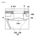
図7は本発明の変形された一実施形態により突起部が形成された第1電極タブを示す部分図面である。 Figure 7 is a partial view showing a first electrode tab having a protrusion according to a modified embodiment of the present invention.
図7を参照すると、本発明の変形された一実施形態による第1電極タブ213は、CIDホール420Hに挿入される突起部213a-1を含むことができる。具体的に、前述したとおり、第1電極タブ213は上側タブ部213aおよび下側タブ部213bを含むことができるが、上側タブ部213aに突出した形態の突起部213a-1が形成され得る。
Referring to FIG. 7, the
突起部213a-1は、第1電極タブ213とCIDホール420H間の密封力を高めるためのものであり、CIDホール420Hの直径と同一の直径を有することができる。このような突起部213a-1がCIDホール420Hに挿入されながら第1電極タブ213とCIDホール420Hの間の密封力を高める。特に突起部213a-1は、半球形態の隆起構造で形成され、そのために突起部213a-1をCIDホール420Hに容易に結合することもでき、容易に分離させることもできる。
The
図8は本発明の一実施形態によりCIDホールに挿入された密閉ボールを示す部分図面である。 Figure 8 is a partial view showing a sealed ball inserted into a CID hole according to one embodiment of the present invention.
図5、図6および図8を共に参照すると、本実施形態による二次電池100は、CIDホール420Hに挿入された密閉ボール500をさらに含むことができる。活性化工程以降に発生したガスの排出が完了されると、CIDホール420Hに密閉ボール500が挿入され得る。密閉ボール500はCIDホール420Hを密封するためのもので、円柱形態または球形態を有し、ベントホール410Hを通じてCIDホール420Hに挿入されながらCIDホール420Hを密封する。
Referring to FIG. 5, FIG. 6 and FIG. 8 together, the
この時、円柱形態または球形態の密閉ボール500がCIDホール420Hにボール溶接(Ball welding)で接合され得る。ここでボール溶接とは、ボール形態の構成を前記ボールより直径が小さい孔に発射して、前記孔を詰める接合方式を意味する。つまり、CIDホール420Hに満たされる前に密閉ボール500の直径はCIDホール420Hの内径より大きくてもよい。このような密閉ボール500を強く発射してCIDホール420Hに無理に挿入させることによって、CIDホール420Hを塞ぐことができる。図8は密閉ボール500がCIDホール420Hにボール溶接で挿入および接合された状態を示す図面である。
At this time, the cylindrical or spherical sealed
また、密閉ボール500はCIDホール420Hに挿入された後、熱融着装置(図示せず)を通じて溶融され得る。そのために密閉ボール500がCIDホール420Hの内周面に接合されながらCIDホール420Hと密閉ボール500間の密封力を高めることができる
In addition, the sealing
この時、本実施形態による安全ベント410は、上端キャップの除去により外部に露出する構造であるため、CIDホール420Hを密閉することが容易である。従来の円筒型二次電池10(図1参照)の場合、CIDホールが形成されているとしても、上端キャップ41が存在するため、ガスの排出以降にCIDホールを再び塞ぐことが構造的に非常に難しい。ガス排出のためには上端キャップ41と安全ベント42共にホールが形成されなければならないが、上端キャップ41の存在により安全ベント42とCIDフィルター43に形成されたホールを塞ぐことが構造的に複雑で、難しくならざるを得ない。これとは異なり、本実施形態によるキャップ組立体400は、安全ベント410が最上端に露出した構造であるため、ガス排出以降に前述したとおり、CIDホール420Hの内周面下端と上側タブ部213a間の溶接接合や密閉ボール500の挿入などの方法でCIDホール420Hを密封することが容易である。
At this time, since the
一方、図3から図5を再び参照すると、本実施形態による電池ケース300は、クリンピング部300Cおよびビーディング部300Bを含むことができる。ビーディング部300Bは円筒型の電池ケース300のうちの一部が電極組立体200の中心方向に湾入された部分を称すもので、電極組立体200の遊動防止のためのものである。
Meanwhile, referring again to FIG. 3 to FIG. 5, the
クリンピング部300Cはビーディング部300Bの上部に位置して、キャップ組立体400を囲む部分を称すもので、キャップ組立体400の安定した結合のためのものである。電池ケース300の上部一端が曲がってキャップ組立体400を囲みながらクリンピング部300Cを形成することができる。より具体的には、電池ケース300の上部一端が曲がって安全ベント410の外周部分を囲みながらクリンピング部300Cを形成することができる。
The crimping
密封用ガスケット700は、クリンピング部300Cとビーディング部300Bの内面に装着されてキャップ組立体400と電池ケース300間の密封力を増大させることができる。また、ガスケット700はキャップ組立体400と電池ケース300間の電気的連結を遮断することができる。電池ケース300とキャップ組立体400間にガスケット700を位置させ、電池ケース300の上部一端を曲げてクリンピング(Crimping)結合を実施してクリンピング部300Cを形成することができる。つまり、クリンピング結合によりキャップ組立体400の装着、二次電池100の密封および電池ケース300とキャップ組立体400間の絶縁がなされ得る。このようなガスケット700はクリンピング部300Cと安全ベント410との間に位置することができる。
The sealing
一方、本実施形態による安全ベント410には屈曲部410Bが形成され得る。具体的に、図4および図5に示されているように、安全ベント410の一部分が上向き方向に曲がって屈曲部410Bが形成され得る。このような屈曲部410Bが形成されて、クリンピング結合時に安全ベント410に伝達される変形を減らすことができる。また、前述したとおり、非正常な作動状態で安全ベント410の形状逆転により、CIDフィルター420の第1部分421が共に上昇して、CIDフィルター420の第1部分421と第2部分422が互いに分離される。これにより電流の流れが遮断されるが、効果的な電流遮断のために安全ベント410とCIDフィルター420との間にある程度の間隔が形成されることが好ましい。そこで、キャップ組立体400自体の高さは最小化すると共に、安全ベント410とCIDフィルター420間の間隔を増やすために上向き方向に曲がった屈曲部410Bを形成することができる。
Meanwhile, the
一方、前述したクリンピング結合の場合、強い物理的圧着がキャップ組立体400に印加され得、そのためにキャップ組立体400が損傷する問題があり得る。特に、本実施形態でのように、上端キャップなしに安全ベント410が露出する構造で安全ベント410が損傷する虞がある。それでも安全ベント410の剛性補完のために安全ベント410の厚さを既存より厚く形成すれば、内圧上昇時に安全ベント410の形状逆転や分離などが良好になされない可能性が高い。
On the other hand, in the case of the crimping connection described above, a strong physical pressure may be applied to the
本実施形態によるキャップ組立体では、単純に安全ベント410の厚さを厚くするのではなく、安全ベント410のうちクリンピング部300Cと対応する部分にカーリング部(Curling part)410Cを設けることができる。具体的に、安全ベント410は安全ベント410の外周部分で曲がったカーリング部410Cを含むことができる。説明の便宜のために図3および図4にはカーリング部410Cが形成される以前にフランジ部(Flange part)410Fの様子を示し、図5ではフランジ部410Fが内側に曲がってカーリング部410Cを形成した様子を示した。
In the cap assembly according to this embodiment, instead of simply increasing the thickness of the
電池ケース300のクリンピング部300Cがガスケット700を間に置いて安全ベント410を囲むことができるが、その中でも安全ベント410のカーリング部410Cを囲みながらクリンピング結合がなされ得る。そこで、安全ベント410の中心部分は1重で形成されるが、クリンピング部300Cが囲む安全ベント410の外周部分は2重で形成され得る。つまり、カーリング部410Cを設けることによって、クリンピング結合時に発生し得る安全ベント410の損傷を防止すると同時に内圧上昇時に安全ベント410の形状逆転や分離などに邪魔にならないようにした。
The crimping
以下、図9から図15を参照して、本発明の一実施形態による二次電池の製造方法について詳細に説明する。ただし、先に説明した内容と重複する部分は説明の反復を避けるために省略する。 Hereinafter, a method for manufacturing a secondary battery according to an embodiment of the present invention will be described in detail with reference to FIG. 9 to FIG. 15. However, parts that overlap with the contents described above will be omitted to avoid repetition.
図9から図15は本発明の一実施形態による二次電池の製造方法を説明するための断面図である。具体的に、全て二次電池の上部の断面を示した。 Figures 9 to 15 are cross-sectional views illustrating a method for manufacturing a secondary battery according to one embodiment of the present invention. Specifically, all of the cross-sections show the upper part of a secondary battery.
まず、図3、図4および図9を参照すると、本発明の一実施形態による二次電池の製造方法は、電極組立体200を上部が開放された電池ケース300に収納する段階、および電池ケース300の開放された上部に、安全ベント410およびCIDフィルター420を含むキャップ組立体400を結合する段階を含む。この時、前述したとおり、電極組立体200は第1電極210、第2電極220および分離膜230が共に巻き取りされてジェリーロール形態であり、電池ケース300は円筒型ケースであり得る。また、キャップ組立体400の結合以前に電極組立体200と共に電解液を電池ケース300内部に注入することができる。
3, 4 and 9, a method for manufacturing a secondary battery according to an embodiment of the present invention includes the steps of placing an
キャップ組立体400の安全ベント410は上端で外部に露出し、安全ベント410にベントホール410Hが形成され、CIDフィルター420にCIDホール420Hが形成される。安全ベント410とCIDフィルター420の具体的な構造は先に説明した内容であるため省略する。
The
図5および図6を再び参照すると、キャップ組立体400を配置する時、電極組立体200から延長された第1電極タブ213がCIDホール420Hを閉じた状態でCIDフィルター420の下面に接合される。この時、前述したとおり、第1電極タブ213は上側タブ部213aおよび下側タブ部213bを含むことができる。
Referring again to FIG. 5 and FIG. 6, when the
前記キャップ組立体400を結合する段階で、上側タブ部213aをCIDフィルター420の下面に密着させた後、上側タブ部213aの他端を移動させてCIDホール420Hを閉鎖する。次に、上側タブ部213aの一端をCIDフィルター420の下面に溶接接合する。言い換えると、上側タブ部213aの他端はCIDホール420Hを含むCIDフィルター420の下面に密着しながらCIDホール420Hを閉鎖し、上側タブ部213aの一端はCIDフィルター420に溶接される。このような形態で、CIDフィルター420と第1電極タブ213が連結される。特に第1電極タブ213はCIDホール420H方向に弾性力を有し、そのために前記CIDホール420Hが閉じられた状態で維持され得る。
In the step of assembling the
一方、図7に示されているように、第1電極タブ213の上側タブ部213aに突起部213a-1が形成された場合、CIDフィルター420と第1電極タブ213を連結する過程で、突起部213a-1がCIDホール420Hに挿入され得る。
Meanwhile, as shown in FIG. 7, if a
図9および図10を参照すると、前記キャップ組立体400を結合する段階は、電池ケース300の上部一端300Uを曲げて安全ベント410を囲むクリンピング部300Cを形成する段階を含むことができる。より具体的に、ガスケット700をキャップ組立体400の安全ベント410と電池ケース300との間に位置させ、電池ケース300の上部一端300Uを曲げてクリンピング結合を実施することができる。
9 and 10, the step of coupling the
この時、安全ベント410は安全ベント410の外周部分で曲がったカーリング部410Cを含むことができ、クリンピング部300Cがカーリング部410Cを囲むようにクリンピング結合がなされ得る。このようなカーリング部410Cは上向きのフランジ部410F(図4参照)を内側に曲げることにより形成され得る。
At this time, the
次に図10を参照すると、本実施形態による二次電池の製造方法は、電極組立体200を活性化する活性化段階を含む。第1電極タブ213がCIDホール420Hを閉じている状態で、一定範囲の定電流または定電圧で充放電を繰り返して前記活性化段階がなされ得る。活性化段階は、負極表面での固体電解質界面(solid electrolyte interface:SEI)膜の形成および低電圧選別などを目的で、充電と放電を繰り返して行う工程である。電極端子として機能する安全ベント410と電池ケース300に定電流または定電圧を印加して、充放電を繰り返すことができる。活性化段階の間、電極組立体と電解液の相互反応により電池ケース300内部にガスが発生し、前記ガスは電池ケース300内部に蓄積されながら圧力を増大させる。
Next, referring to FIG. 10, the method for manufacturing a secondary battery according to the present embodiment includes an activation step of activating the
図11を参照すると、本実施形態による二次電池の製造方法は、前記活性化段階で発生したガスを安全ベント410に形成されたベントホール410HとCIDフィルター420に形成されたCIDホール420Hを通じて外部に排出するガス排出段階を含む。具体的に、前記ガス排出段階で、ベントホール410HとCIDホール420Hを通じて第1電極タブ213を下部方向に押してCIDホール420Hを開放させ、前記ガスがCIDホール420Hとベントホール410Hを通じて外部に排出される。第1電極タブ213の中でも上側タブ部213aを押す。
Referring to FIG. 11, the method of manufacturing a secondary battery according to this embodiment includes a gas exhaust step of exhausting the gas generated during the activation step to the outside through the
本実施形態によると、前記ガス排出段階で、棒部材1000をベントホール410HとCIDホール420Hを通じて挿入して、第1電極タブ213を下部方向に押すことができる。同様に、棒部材1000が第1電極タブ213の中でも上側タブ部213aを下部方向に押すことができる。すると、CIDホール420Hが開放されながら電池ケース300内部に発生したガスがCIDホール420Hとベントホール410Hを通じて外部に排出される。
According to this embodiment, in the gas exhaust step, the
特に、本実施形態による二次電池100は、上端キャップが除去された構造であるため、棒部材1000をベントホール410HとCIDホール420Hに通過させやすい。言い換えると、ベントホール410HとCIDホール420Hを毀損させずに棒を挿入させて第1電極タブ213を押すことができる。また、上端キャップが除去されているため、ガス排出もより円滑になされ得る。
In particular, since the
一方、図12を参照すると、本発明の変形された一実施形態による二次電池の製造方法は、吸入装置1100を利用したガス排出段階を含むことができる。具体的に、図11での棒部材1000でなく、別途の吸入装置1100をベントホール410HとCIDホール420Hを通じて挿入させて第1電極タブ213の上側タブ部213aを下部方向に押すことができる。CIDホール420Hが開放された状態で、吸入装置1100が電池ケース300内部のガスを吸入することができる。単純に棒部材1000を挿入する場合に比べて、より効果的に電池ケース300内部のガスを除去することができる。
Meanwhile, referring to FIG. 12, the method for manufacturing a secondary battery according to a modified embodiment of the present invention may include a gas exhaust step using an
次に図13を参照すると、前記ガス排出段階以降、第1電極タブ213を押す力を除去し、第1電極タブ213を元の位置に復帰させてCIDホール420Hを再び閉鎖することができる。第1電極タブ213を押す力を除去することは、棒部材1000や吸入装置1100を除去することを意味する。CIDホール420Hが閉じられると、ガス排出は仕上げられる。
Referring now to FIG. 13, after the gas discharge step, the force pressing the
本実施形態による二次電池の製造方法は、前記ガス排出段階以降、CIDホール420Hの内周面下端を第1電極タブ213と溶接する溶接段階をさらに含むことができる。具体的に、別途の溶接装置(図示せず)をベントホール410HおよびCIDホール420Hを通過するように挿入してCIDホール420Hの内周面下端を第1電極タブ213に溶接する。図13には当該部分に溶接による接合部分Wが形成されたことが表現されている。特に上側タブ部213aがCIDホール420Hに密着した状態で、上側タブ部213aとCIDホール420Hの内周面を溶接してCIDフィルター420と第1電極タブ213との間を密封する。これによりガス排出段階以降、CIDホール420Hが一次的に密封され得る。
The method for manufacturing a secondary battery according to the present embodiment may further include a welding step of welding the lower end of the inner periphery of the
次に図14を参照すると、本実施形態による二次電池の製造方法は、ベントホール410Hを通じてCIDホール420Hに密閉ボール500を挿入する密閉ボール挿入段階をさらに含むことができる。前記密閉ボール挿入段階で、CIDホール420Hに密閉ボール500を締まりばめ方式で挿入することができる。そのためにCIDホール420Hが効果的に密封され得る。具体的に、CIDホール420Hに密閉ボール500をボール溶接で接合させることができる。CIDホール420Hは円形の貫通口であり、密閉ボール500は円柱形態または球形態であり得る。密閉ボール500がCIDホール420Hに強く発射され、密閉ボール500がCIDホール420Hに挿入され得る。
Next, referring to FIG. 14, the method for manufacturing a secondary battery according to the present embodiment may further include a sealing ball inserting step of inserting a sealing
次に図15を参照すると、本実施形態による二次電池の製造方法は、CIDホール420Hに挿入された密閉ボール500を溶融する段階をさらに含むことができる。具体的に、ベントホール410Hを通じて溶融装置1200を挿入した後、密閉ボール500に熱を加えることができる。これにより、一部が溶融された密閉ボール500がCIDホール420Hの内周面と接合する。すると、CIDホール420Hを完全に密封することができる。
Referring now to FIG. 15, the method for manufacturing a secondary battery according to this embodiment may further include a step of melting the sealing
活性化段階で、電極被膜形成やセル内部水分の分解により多量のガスが発生するが、活性化段階で発生したガスは量も多く、電極被膜と持続的に反応するため、これを排出させる工程が必要である。前記のように、本発明の一実施形態により製造された二次電池100は、活性化段階で発生したガスを排出してから最終的に密封されることによって、残存ガスによる電極組立体の膨張、変形などの問題や残留ガス気泡によるリチウム析出誘発の問題を解決することができる。
During the activation step, a large amount of gas is generated due to the formation of the electrode coating and the decomposition of moisture inside the cell. The amount of gas generated during the activation step is large and it reacts continuously with the electrode coating, so a process to exhaust the gas is necessary. As described above, the
本実施形態で前、後、左、右、上、下のような方向を示す用語が使用されているが、このような用語は説明の便宜のためのものに過ぎず、対象となる事物の位置や観測者の位置などにより変わり得る。 In this embodiment, terms indicating directions such as front, back, left, right, up, and down are used, but these terms are merely for convenience of explanation and may change depending on the position of the target object or the position of the observer, etc.
前述した本実施形態による二次電池が複数で集まって電池モジュールを形成することができる。前記電池モジュールは、BMS(Battery Management System)、冷却システムなどの各種制御および保護システムと共に装着されて電池パックを形成することができる。 A battery module can be formed by assembling a plurality of secondary batteries according to the present embodiment. The battery module can be mounted with various control and protection systems, such as a BMS (Battery Management System) and a cooling system, to form a battery pack.
前記二次電池、前記電池モジュールや前記電池パックは、多様なデバイスに適用され得る。具体的には、電気自転車、電気自動車、ハイブリッドなどの運送手段やESS(Energy Storage System)に適用され得るが、これに制限されず、二次電池を使用することができる多様なデバイスに適用可能である。 The secondary battery, the battery module, and the battery pack can be applied to various devices. Specifically, they can be applied to transportation means such as electric bicycles, electric cars, and hybrids, and ESS (Energy Storage Systems), but are not limited thereto, and can be applied to various devices that can use secondary batteries.
以上で本発明の好ましい実施形態について詳細に説明したが、本発明の範囲はこれに限定されず、特許請求の範囲で定義している本発明の基本概念を利用した当業者の多様な変形および改良形態も本発明の範囲に属する。 Although the preferred embodiment of the present invention has been described in detail above, the scope of the present invention is not limited thereto, and various modifications and improvements made by those skilled in the art using the basic concept of the present invention defined in the claims also fall within the scope of the present invention.
100:二次電池
200:電極組立体
300:電池ケース
400:キャップ組立体
410:安全ベント
410H:ベントホール
420:CIDフィルター
420H:CIDホール
100: Secondary battery 200: Electrode assembly 300: Battery case 400: Cap assembly 410:
Claims (16)
前記電極組立体が収納され、上部が開放された電池ケース;および
前記電池ケースの開放された上部に結合するキャップ組立体を含み、
前記キャップ組立体は、安全ベント;および前記安全ベントの下に位置したCIDフィルターを含み、
前記安全ベントは、上端で外部に露出し、
前記安全ベントに上下に貫通したベントホールが形成され、
前記CIDフィルターに、上下に貫通し、前記ベントホールと連結されるCIDホールが形成され、
前記電極組立体から延長された第1電極タブが前記CIDフィルターに接合され、
前記ベントホールと前記CIDホールは前記第1電極タブにより閉鎖された状態および開放された状態を取り得る、活性化工程で発生したガスの排出が可能な二次電池。 Electrode assembly;
a battery case in which the electrode assembly is housed and which has an open top; and a cap assembly which is coupled to the open top of the battery case,
the cap assembly includes a safety vent; and a CID filter located below the safety vent;
The safety vent is exposed to the outside at an upper end,
The safety vent has a vent hole penetrating vertically,
The CID filter has a CID hole penetrating vertically and connected to the vent hole,
a first electrode tab extending from the electrode assembly is joined to the CID filter;
The vent hole and the CID hole can be in a closed or open state by the first electrode tab, and the secondary battery is capable of discharging gas generated during an activation process .
前記CIDホールを閉鎖した前記第1電極タブが前記ベントホールおよび前記CIDホールを通じて外部から見える、請求項1に記載の二次電池。 the vent hole and the CID hole are located on the same vertical line;
The secondary battery of claim 1 , wherein the first electrode tab closing the CID hole is visible from the outside through the vent hole and the CID hole.
前記下側タブ部は前記電極組立体に連結され、
前記下側タブ部と連結された前記上側タブ部の一端が前記CIDフィルターに接合される、請求項1に記載の二次電池。 the first electrode tab includes an upper tab portion and a lower tab portion;
the lower tab portion is connected to the electrode assembly,
The secondary battery of claim 1 , wherein one end of the upper tab portion connected to the lower tab portion is joined to the CID filter.
前記上側タブ部の前記他端が前記CIDフィルターの下面に弾力的に密着する、請求項5に記載の二次電池。 the first electrode tab includes a material having an elastic restoring force;
The secondary battery of claim 5 , wherein the other end of the upper tab portion is elastically in close contact with a lower surface of the CID filter.
前記電池ケースの開放された上部に、安全ベントおよびCIDフィルターを含むキャップ組立体を結合する段階;
前記電極組立体を活性化する活性化段階;および
前記活性化段階で発生したガスを前記安全ベントに形成されたベントホールと前記CIDフィルターに形成されたCIDホールを通じて外部に排出するガス排出段階を含み、
前記安全ベントは、上端で外部に露出し、
前記電極組立体から延長された第1電極タブが前記CIDホールを閉じた状態で前記CIDフィルターに接合され、
前記ガス排出段階で、前記ベントホールと前記CIDホールを通じて前記第1電極タブを下部方向に押して前記CIDホールを開放させ、前記ガスが前記CIDホールと前記ベントホールを通じて外部に排出される二次電池の製造方法。 placing the electrode assembly in a battery case having an open top;
coupling a cap assembly including a safety vent and a CID filter to the open top of the battery case;
an activation step of activating the electrode assembly; and a gas exhaust step of exhausting gas generated in the activation step to the outside through a vent hole formed in the safety vent and a CID hole formed in the CID filter,
The safety vent is exposed to the outside at an upper end,
a first electrode tab extending from the electrode assembly is attached to the CID filter while closing the CID hole;
In the gas discharging step, the first electrode tab is pressed downward through the vent hole and the CID hole to open the CID hole, and the gas is discharged to the outside through the CID hole and the vent hole.
棒部材や吸入装置を前記ベントホールと前記CIDホールを通じて挿入して、前記第1電極タブを下部方向に押す、請求項11に記載の二次電池の製造方法。 In the gas exhaust step,
The method of claim 11, further comprising inserting a rod member or an inhalation device through the vent hole and the CID hole to push the first electrode tab downward.
Applications Claiming Priority (3)
| Application Number | Priority Date | Filing Date | Title |
|---|---|---|---|
| KR1020210072370A KR102813935B1 (en) | 2021-06-03 | 2021-06-03 | Secondary battery and manufacturing method of the same |
| KR10-2021-0072370 | 2021-06-03 | ||
| PCT/KR2022/006535 WO2022255673A1 (en) | 2021-06-03 | 2022-05-09 | Secondary battery and method for manufacturing same |
Publications (2)
| Publication Number | Publication Date |
|---|---|
| JP2023548131A JP2023548131A (en) | 2023-11-15 |
| JP7616552B2 true JP7616552B2 (en) | 2025-01-17 |
Family
ID=84323393
Family Applications (1)
| Application Number | Title | Priority Date | Filing Date |
|---|---|---|---|
| JP2023526136A Active JP7616552B2 (en) | 2021-06-03 | 2022-05-09 | Secondary battery and manufacturing method thereof |
Country Status (6)
| Country | Link |
|---|---|
| US (1) | US20240006708A1 (en) |
| EP (1) | EP4224622A4 (en) |
| JP (1) | JP7616552B2 (en) |
| KR (1) | KR102813935B1 (en) |
| CN (1) | CN116547860A (en) |
| WO (1) | WO2022255673A1 (en) |
Families Citing this family (1)
| Publication number | Priority date | Publication date | Assignee | Title |
|---|---|---|---|---|
| WO2026089494A1 (en) * | 2024-10-24 | 2026-04-30 | 주식회사 엘지에너지솔루션 | Battery cell, and battery pack and vehicle including same |
Citations (3)
| Publication number | Priority date | Publication date | Assignee | Title |
|---|---|---|---|---|
| JP2003142060A (en) | 2001-11-01 | 2003-05-16 | Toyota Motor Corp | Energy storage device and method of manufacturing the same |
| JP2009272085A (en) | 2008-05-02 | 2009-11-19 | Sony Corp | Nonaqueous electrolyte battery |
| WO2015146078A1 (en) | 2014-03-28 | 2015-10-01 | 三洋電機株式会社 | Cylindrical sealed battery and battery pack |
Family Cites Families (10)
| Publication number | Priority date | Publication date | Assignee | Title |
|---|---|---|---|---|
| KR100950038B1 (en) * | 2006-02-20 | 2010-03-29 | 주식회사 엘지화학 | Lithium secondary battery with improved safety against overcharging |
| WO2011118961A2 (en) * | 2010-03-22 | 2011-09-29 | 주식회사 엘지화학 | Secondary battery and cover assembly employed in same |
| KR101201111B1 (en) * | 2011-02-28 | 2012-11-13 | 삼성에스디아이 주식회사 | Cylinder type lithium secondary battery |
| KR102578862B1 (en) * | 2016-03-22 | 2023-09-13 | 삼성에스디아이 주식회사 | Rechargeable battery |
| KR102314627B1 (en) * | 2017-07-25 | 2021-10-20 | 주식회사 엘지에너지솔루션 | Secondary battery |
| KR102275779B1 (en) * | 2017-11-17 | 2021-07-13 | 주식회사 엘지에너지솔루션 | Secondary battery |
| KR102487217B1 (en) * | 2018-02-01 | 2023-01-11 | 주식회사 엘지에너지솔루션 | Cap Assembly Having Rivet, and Cylindrical Battery Comprising Beading-part free and Climping-part free and the Cap Assembly |
| KR20210072370A (en) | 2019-12-09 | 2021-06-17 | 이장면 | Straightener holder |
| KR102738146B1 (en) * | 2020-02-06 | 2024-12-05 | 주식회사 엘지에너지솔루션 | Cap assembly, secondary battery and battery pack comprising the same |
| KR102706444B1 (en) * | 2020-02-06 | 2024-09-13 | 주식회사 엘지에너지솔루션 | Manufacturing method of secondary battery and manufacturing method of battery pack comprising the same |
-
2021
- 2021-06-03 KR KR1020210072370A patent/KR102813935B1/en active Active
-
2022
- 2022-05-09 CN CN202280007657.3A patent/CN116547860A/en active Pending
- 2022-05-09 JP JP2023526136A patent/JP7616552B2/en active Active
- 2022-05-09 US US18/037,897 patent/US20240006708A1/en active Pending
- 2022-05-09 WO PCT/KR2022/006535 patent/WO2022255673A1/en not_active Ceased
- 2022-05-09 EP EP22816332.5A patent/EP4224622A4/en active Pending
Patent Citations (3)
| Publication number | Priority date | Publication date | Assignee | Title |
|---|---|---|---|---|
| JP2003142060A (en) | 2001-11-01 | 2003-05-16 | Toyota Motor Corp | Energy storage device and method of manufacturing the same |
| JP2009272085A (en) | 2008-05-02 | 2009-11-19 | Sony Corp | Nonaqueous electrolyte battery |
| WO2015146078A1 (en) | 2014-03-28 | 2015-10-01 | 三洋電機株式会社 | Cylindrical sealed battery and battery pack |
Also Published As
| Publication number | Publication date |
|---|---|
| CN116547860A (en) | 2023-08-04 |
| EP4224622A1 (en) | 2023-08-09 |
| EP4224622A4 (en) | 2025-03-12 |
| KR20220163779A (en) | 2022-12-12 |
| KR102813935B1 (en) | 2025-05-27 |
| WO2022255673A1 (en) | 2022-12-08 |
| US20240006708A1 (en) | 2024-01-04 |
| JP2023548131A (en) | 2023-11-15 |
Similar Documents
| Publication | Publication Date | Title |
|---|---|---|
| JP4920111B2 (en) | Pouch type secondary battery | |
| CN111033799B (en) | Pouch type secondary battery having gas discharge member | |
| CN106356490B (en) | Rechargeable battery and battery module including rechargeable battery | |
| JP7673999B2 (en) | Secondary battery and manufacturing method thereof | |
| CN101517776A (en) | Pouch-shaped secondary battery having non-sealing residue portion | |
| KR101546545B1 (en) | Pouch type lithium secondary battery | |
| JP7722789B2 (en) | Secondary battery and manufacturing method thereof | |
| EP3996187A1 (en) | Battery and manufacturing method thereof | |
| KR20170007876A (en) | Battery Case Having Alloy of Low Melting Point and Battery Cell Comprising the Same | |
| KR102941253B1 (en) | Secondary battery and manufacturing method of secondary battery | |
| KR102867399B1 (en) | Secondary battery and battery module including the same | |
| CN220138646U (en) | Secondary battery and battery module including the same | |
| KR102813935B1 (en) | Secondary battery and manufacturing method of the same | |
| JP7484060B2 (en) | Secondary battery and manufacturing method thereof | |
| JP7551089B2 (en) | Battery pack housing with fire suppression structure | |
| KR102955997B1 (en) | Secondary battery and battery module including the same | |
| KR102963792B1 (en) | Battery cell, Battery pack comprising the same and vehicle | |
| WO2026081661A1 (en) | Battery cell, battery apparatus, and electric device | |
| JP2024524061A (en) | Secondary battery and battery module including the same | |
| KR20260066647A (en) | Battery cell, battery pack and vehicle including the same | |
| JP2024511497A (en) | Secondary batteries, their manufacturing methods, and devices containing them |
Legal Events
| Date | Code | Title | Description |
|---|---|---|---|
| A621 | Written request for application examination |
Free format text: JAPANESE INTERMEDIATE CODE: A621 Effective date: 20230509 |
|
| A977 | Report on retrieval |
Free format text: JAPANESE INTERMEDIATE CODE: A971007 Effective date: 20240523 |
|
| A131 | Notification of reasons for refusal |
Free format text: JAPANESE INTERMEDIATE CODE: A131 Effective date: 20240604 |
|
| A521 | Request for written amendment filed |
Free format text: JAPANESE INTERMEDIATE CODE: A523 Effective date: 20240903 |
|
| TRDD | Decision of grant or rejection written | ||
| A01 | Written decision to grant a patent or to grant a registration (utility model) |
Free format text: JAPANESE INTERMEDIATE CODE: A01 Effective date: 20241203 |
|
| A61 | First payment of annual fees (during grant procedure) |
Free format text: JAPANESE INTERMEDIATE CODE: A61 Effective date: 20241218 |
|
| R150 | Certificate of patent or registration of utility model |
Ref document number: 7616552 Country of ref document: JP Free format text: JAPANESE INTERMEDIATE CODE: R150 |