JP7614795B2 - POWER TRANSMISSION DEVICE, CONTROL METHOD FOR POWER TRANSMISSION DEVICE, AND PROGRAM - Google Patents

POWER TRANSMISSION DEVICE, CONTROL METHOD FOR POWER TRANSMISSION DEVICE, AND PROGRAM Download PDF

Info

Publication number
JP7614795B2
JP7614795B2 JP2020188572A JP2020188572A JP7614795B2 JP 7614795 B2 JP7614795 B2 JP 7614795B2 JP 2020188572 A JP2020188572 A JP 2020188572A JP 2020188572 A JP2020188572 A JP 2020188572A JP 7614795 B2 JP7614795 B2 JP 7614795B2
Authority
JP
Japan
Prior art keywords
power
power transmission
receiving device
transmitting
power receiving
Prior art date
Legal status (The legal status is an assumption and is not a legal conclusion. Google has not performed a legal analysis and makes no representation as to the accuracy of the status listed.)
Active
Application number
JP2020188572A
Other languages
Japanese (ja)
Other versions
JP2022077656A (en
Inventor
隆広 七野
和夫 森友
元 岩瀬
朋樹 平松
元 志村
Current Assignee (The listed assignees may be inaccurate. Google has not performed a legal analysis and makes no representation or warranty as to the accuracy of the list.)
Canon Inc
Original Assignee
Canon Inc
Priority date (The priority date is an assumption and is not a legal conclusion. Google has not performed a legal analysis and makes no representation as to the accuracy of the date listed.)
Filing date
Publication date
Application filed by Canon Inc filed Critical Canon Inc
Priority to JP2020188572A priority Critical patent/JP7614795B2/en
Priority to PCT/JP2021/040528 priority patent/WO2022102494A1/en
Publication of JP2022077656A publication Critical patent/JP2022077656A/en
Priority to US18/313,693 priority patent/US12322983B2/en
Priority to JP2024219727A priority patent/JP2025032340A/en
Application granted granted Critical
Publication of JP7614795B2 publication Critical patent/JP7614795B2/en
Active legal-status Critical Current
Anticipated expiration legal-status Critical

Links

Images

Classifications

    • HELECTRICITY
    • H02GENERATION; CONVERSION OR DISTRIBUTION OF ELECTRIC POWER
    • H02JCIRCUIT ARRANGEMENTS OR SYSTEMS FOR SUPPLYING OR DISTRIBUTING ELECTRIC POWER; SYSTEMS FOR STORING ELECTRIC ENERGY
    • H02J50/00Circuit arrangements or systems for wireless supply or distribution of electric power
    • H02J50/40Circuit arrangements or systems for wireless supply or distribution of electric power using two or more transmitting or receiving devices
    • HELECTRICITY
    • H02GENERATION; CONVERSION OR DISTRIBUTION OF ELECTRIC POWER
    • H02JCIRCUIT ARRANGEMENTS OR SYSTEMS FOR SUPPLYING OR DISTRIBUTING ELECTRIC POWER; SYSTEMS FOR STORING ELECTRIC ENERGY
    • H02J50/00Circuit arrangements or systems for wireless supply or distribution of electric power
    • H02J50/10Circuit arrangements or systems for wireless supply or distribution of electric power using inductive coupling
    • HELECTRICITY
    • H02GENERATION; CONVERSION OR DISTRIBUTION OF ELECTRIC POWER
    • H02JCIRCUIT ARRANGEMENTS OR SYSTEMS FOR SUPPLYING OR DISTRIBUTING ELECTRIC POWER; SYSTEMS FOR STORING ELECTRIC ENERGY
    • H02J50/00Circuit arrangements or systems for wireless supply or distribution of electric power
    • H02J50/60Circuit arrangements or systems for wireless supply or distribution of electric power responsive to the presence of foreign objects, e.g. detection of living beings
    • HELECTRICITY
    • H02GENERATION; CONVERSION OR DISTRIBUTION OF ELECTRIC POWER
    • H02JCIRCUIT ARRANGEMENTS OR SYSTEMS FOR SUPPLYING OR DISTRIBUTING ELECTRIC POWER; SYSTEMS FOR STORING ELECTRIC ENERGY
    • H02J50/00Circuit arrangements or systems for wireless supply or distribution of electric power
    • H02J50/80Circuit arrangements or systems for wireless supply or distribution of electric power involving the exchange of data, concerning supply or distribution of electric power, between transmitting devices and receiving devices
    • HELECTRICITY
    • H02GENERATION; CONVERSION OR DISTRIBUTION OF ELECTRIC POWER
    • H02JCIRCUIT ARRANGEMENTS OR SYSTEMS FOR SUPPLYING OR DISTRIBUTING ELECTRIC POWER; SYSTEMS FOR STORING ELECTRIC ENERGY
    • H02J50/00Circuit arrangements or systems for wireless supply or distribution of electric power
    • H02J50/90Circuit arrangements or systems for wireless supply or distribution of electric power involving detection or optimisation of position, e.g. alignment
    • HELECTRICITY
    • H02GENERATION; CONVERSION OR DISTRIBUTION OF ELECTRIC POWER
    • H02JCIRCUIT ARRANGEMENTS OR SYSTEMS FOR SUPPLYING OR DISTRIBUTING ELECTRIC POWER; SYSTEMS FOR STORING ELECTRIC ENERGY
    • H02J7/00Circuit arrangements for charging or depolarising batteries or for supplying loads from batteries

Landscapes

  • Engineering & Computer Science (AREA)
  • Power Engineering (AREA)
  • Computer Networks & Wireless Communication (AREA)
  • Charge And Discharge Circuits For Batteries Or The Like (AREA)

Description

本開示は、無線電力伝送の制御に関する。 This disclosure relates to control of wireless power transmission.

近年、無線電力伝送システムの技術開発が広く行われている。そして、無線充電規格の標準化団体Wireless Power Consortium(WPC)が策定する規格(以下、WPC規格という)に準拠した送電装置及び受電装置が提供されている。 In recent years, technological development of wireless power transmission systems has been widely carried out. Furthermore, power transmitting devices and power receiving devices that comply with standards (hereinafter referred to as WPC standards) established by the Wireless Power Consortium (WPC), a standardization organization for wireless charging standards, are being provided.

また、特許文献1には、複数の送電コイルを有する送電装置が開示されている。 Patent document 1 also discloses a power transmission device having multiple power transmission coils.

特開2018-186699号公報JP 2018-186699 A

特許文献1では、複数の送電コイルの配置については開示されているが、複数の送電コイルを有する送電装置の無線電力伝送の制御方法については考慮されていない。 Patent document 1 discloses the arrangement of multiple power transmission coils, but does not consider how to control wireless power transmission from a power transmission device having multiple power transmission coils.

本開示は、複数の送電コイルを有する送電装置において、無線電力伝送に関する適切な制御を行うことができる技術を提供することを目的とする。 The present disclosure aims to provide a technology that can perform appropriate control of wireless power transmission in a power transmission device having multiple power transmission coils.

本開示に係る送電装置は、受電装置に無線で送電を行うために使用される複数のコイルと、前記複数のコイルのうち少なくとも1つを使用して、第1の領域における受電装置に無線で送電を行う第1の送電手段と、前記複数のコイルのうち少なくとも1つを使用して、第2の領域における受電装置に無線で送電を行う第2の送電手段と、前記第1の送電手段により前記第1の領域と前記第2の領域とが重複する共通領域における第1の受電装置に送電が行われている間に、前記第1の領域のうち前記共通領域ではない領域に第2の受電装置が載置されることに基づいて、前記第1の送電手段による前記第1の受電装置への送電を停止させ、前記第1の受電装置に、前記第2の送電手段により送電が行われるように制御する制御手段とを有し、前記複数のコイルは、前記第1の領域と前記第2の領域の少なくとも一方に含まれ、前記複数のコイルのうち前記共通領域に含まれるコイルは、前記第1の送電手段と前記第2の送電手段によって、前記受電装置への送電に使用され得、前記複数のコイルのうち前記第1の領域に含まれ前記共通領域に含まれないコイルは、前記第1の送電手段により前記受電装置への送電に使用され、前記第2の送電手段によっては前記受電装置への送電に使用されず、前記複数のコイルのうち前記第2の領域に含まれ前記共通領域に含まれないコイルは、前記第2の送電手段により前記受電装置への送電に使用され、前記第1の送電手段によっては前記受電装置への送電に使用されないことを特徴とする。 A power transmission device according to the present disclosure includes a plurality of coils used for wirelessly transmitting power to a power receiving device, a first power transmission means for wirelessly transmitting power to a power receiving device in a first area using at least one of the plurality of coils, and a second power transmission means for wirelessly transmitting power to a power receiving device in a second area using at least one of the plurality of coils. While the first power transmission means is transmitting power to a first power receiving device in a common area where the first area and the second area overlap, based on a second power receiving device being placed in an area of the first area that is not the common area, the power transmission device stops transmitting power to the first power receiving device by the first power transmission means and controls the second power transmission means to transmit power to the first power receiving device. and a control means for controlling the control of the power receiving device, the plurality of coils being included in at least one of the first area and the second area, the coils among the plurality of coils included in the common area can be used by the first power transmission means and the second power transmission means to transmit power to the power receiving device, the coils among the plurality of coils that are included in the first area but not included in the common area are used by the first power transmission means for transmitting power to the power receiving device and are not used by the second power transmission means for transmitting power to the power receiving device, and the coils among the plurality of coils that are included in the second area but not included in the common area are used by the second power transmission means for transmitting power to the power receiving device and are not used by the first power transmission means for transmitting power to the power receiving device .

本開示によれば、複数の送電コイルを有する送電装置において、無線電力伝送に関する適切な制御を行うことができる。 According to the present disclosure, it is possible to perform appropriate control of wireless power transmission in a power transmission device having multiple power transmission coils.

無線電力伝送システムの構成を説明するための図である。FIG. 1 is a diagram for explaining a configuration of a wireless power transmission system. 送電装置の機能構成の一例を説明するための図である。2 is a diagram illustrating an example of a functional configuration of a power transmitting device. FIG. 受電装置の機能構成の一例を説明するための図である。2 is a diagram illustrating an example of a functional configuration of a power receiving device. FIG. 送電装置が有する送電コイル群の構成の一例を説明するための図である。2A and 2B are diagrams for explaining an example of the configuration of a power transmission coil group included in a power transmission device. WPC規格に準拠した送電装置及び受電装置が行う処理を説明するための図である。1 is a diagram for explaining processing performed by a power transmitting device and a power receiving device that comply with the WPC standard. 複数の送電コイルを有する送電装置が行う処置を説明するための図である。1A and 1B are diagrams for explaining a process performed by a power transmission device having a plurality of power transmission coils. 実施形態1における送電装置が行う処理を説明するためのフローチャートである。4 is a flowchart for explaining a process performed by a power transmitting device according to the first embodiment. 実施形態1における送電装置及び受電装置が行う処理を説明するためのシーケンス図である。4 is a sequence diagram for explaining processing performed by a power transmitting device and a power receiving device in the first embodiment. FIG. 実施形態2における送電装置及び受電装置が行う処理を説明するためのシーケンス図である。13 is a sequence diagram for explaining processing performed by a power transmitting device and a power receiving device in a second embodiment. FIG. 実施形態2における送電装置が行う処理を説明するためのフローチャートである。10 is a flowchart for explaining a process performed by a power transmitting device according to a second embodiment. 送電装置及び送電装置が有する送電コイル群の構成の一例を説明するための図である。2A to 2C are diagrams illustrating an example of a configuration of a power transmitting device and a power transmitting coil group included in the power transmitting device. 実施形態3における送電装置が行う処理を説明するためのフローチャートである。13 is a flowchart for explaining a process performed by a power transmitting device according to a third embodiment. 実施形態3における送電装置及び受電装置が行う処理を説明するためのシーケンス図である。13 is a sequence diagram for explaining processing performed by a power transmitting device and a power receiving device in a third embodiment. FIG. 送電コイル群及び受電装置の配置の一例を示す図である。4 is a diagram illustrating an example of an arrangement of a power transmitting coil group and a power receiving device. FIG. 実施形態4における送電装置が行う処理を説明するためのフローチャートである。13 is a flowchart for explaining a process performed by a power transmitting device according to a fourth embodiment. 送電装置が行う送電及び検出用信号の送信のタイミングを表す図である。4 is a diagram showing timing of power transmission and detection signal transmission performed by the power transmitting device. FIG. 受電装置の配置の一例を示す図である。FIG. 2 is a diagram illustrating an example of an arrangement of power receiving devices. 実施形態5における送電装置が行う処理を説明するためのフローチャートである。13 is a flowchart for explaining a process performed by a power transmitting device according to a fifth embodiment. 実施形態5における送電装置及び受電装置が行う処理を説明するためのシーケンス図である。13 is a sequence diagram for explaining processing performed by a power transmitting device and a power receiving device in a fifth embodiment. FIG.

以下、本開示の実施形態について、図面を参照しながら説明する。なお、以下の実施形態に記載される構成要素は、本開示の実施の形態の一例を示すものであり、本開示をそれらのみに限定するものではない。 Embodiments of the present disclosure will be described below with reference to the drawings. Note that the components described in the following embodiments are examples of embodiments of the present disclosure, and the present disclosure is not limited to these.

(実施形態1)
[システムの構成]
図1に本実施形態に係る無線電力伝送システムの一例を示す。本実施形態における無線電力伝送システムは、送電装置100及び受電装置(第一受電装置101a及び第二受電装置101b)を含んで構成される。本実施形態における送電装置100は、自身が送電可能な範囲内に載置された第一受電装置101aと第二受電装置101bとを同時に充電する機能を有する。なお、図1では2台の受電装置が送電装置上に存在する例が示されるが、これに限定されない。例えば、送電装置100は1台に対して充電を行ってもよい。また、送電装置100は、3台以上の受電装置を同時に充電可能な構成としてもよい。
(Embodiment 1)
[System Configuration]
FIG. 1 shows an example of a wireless power transmission system according to the present embodiment. The wireless power transmission system in the present embodiment includes a power transmission device 100 and power receiving devices (a first power receiving device 101a and a second power receiving device 101b). The power transmission device 100 in the present embodiment has a function of simultaneously charging the first power receiving device 101a and the second power receiving device 101b placed within a range in which the power transmission device 100 can transmit power. Note that, although an example in which two power receiving devices exist on the power transmission device is shown in FIG. 1, this is not limiting. For example, the power transmission device 100 may charge one device. In addition, the power transmission device 100 may be configured to be capable of simultaneously charging three or more power receiving devices.

なお、本実施形態において、受電装置が載置される、というのは、以下のような状態を含む。受電装置が載置される状態は、例えば、受電装置が送電装置の送電可能な範囲内の面上に置かれる(設置される)場合を含む。しかしながら、本実施形態において説明する方法は、少なくとも、送電装置が送電可能な範囲の中に受電装置が含まれている状態において適用可能であり、例えば受電装置と送電装置とが非接触の状態でもよい。また、受電装置が載置され得る面は、水平面だけでなく、垂直面や傾斜のある面であってもよい。 In this embodiment, the state in which the power receiving device is placed includes the following states. The state in which the power receiving device is placed includes, for example, the case in which the power receiving device is placed (installed) on a surface within the range in which the power transmitting device can transmit power. However, the method described in this embodiment is applicable at least in a state in which the power receiving device is included within the range in which the power transmitting device can transmit power, and for example, the power receiving device and the power transmitting device may be in a non-contact state. Furthermore, the surface on which the power receiving device can be placed may not only be a horizontal surface, but also a vertical surface or an inclined surface.

[装置構成]
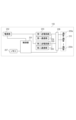
図2は、送電装置100の機能構成を説明するためのブロック図である。送電装置100は、制御部201、電源部202、第一送電回路203、第一通信部204、第二送電回路205、第二通信部206、メモリ207、選択部208、及び、送電コイル群210を有する。また、送電コイル群210は、複数の送電コイル209a~209nを有する。なお、送電コイル209a~209bの数は、2以上でありうる。また、以下の説明では、特に区別する必要がない場合は単に送電コイル209と表記する。以下、各処理部について説明する。
[Device configuration]
2 is a block diagram for explaining the functional configuration of the power transmitting device 100. The power transmitting device 100 includes a control unit 201, a power supply unit 202, a first power transmitting circuit 203, a first communication unit 204, a second power transmitting circuit 205, a second communication unit 206, a memory 207, a selection unit 208, and a power transmitting coil group 210. The power transmitting coil group 210 includes a plurality of power transmitting coils 209a to 209n. The number of the power transmitting coils 209a to 209b may be two or more. In the following description, the power transmitting coils 209a to 209b will be simply referred to as the power transmitting coil 209 unless there is a particular need to distinguish them. Each processing unit will be described below.

制御部201は、送電装置100全体の制御を行う。制御部201は、例えば、CPU(Central Processing Unit)やMPU(Micro Processing Unit)等の1つ以上のプロセッサを含んで構成される。なお、制御部201は、後述の処理を実行するように構成された、特定用途向け集積回路(ASIC)やフィールドプログラマブルゲートアレイ(FPGA)等を含んでもよい。 The control unit 201 controls the entire power transmission device 100. The control unit 201 includes one or more processors, such as a CPU (Central Processing Unit) or an MPU (Micro Processing Unit). The control unit 201 may also include an application specific integrated circuit (ASIC) or a field programmable gate array (FPGA) configured to execute the processes described below.

電源部202は、制御部201、第一送電回路203、及び、第二送電回路205が動作するため電力を供給する電源である。電源部202は、例えば、商用電源から電力の供給を受ける有線受電回路やバッテリ等でありうる。 The power supply unit 202 is a power supply that supplies power for the control unit 201, the first power transmission circuit 203, and the second power transmission circuit 205 to operate. The power supply unit 202 can be, for example, a wired power receiving circuit that receives power from a commercial power source, a battery, etc.

第一送電回路203及び第二送電回路205は、後述する送電コイル群210に含まれる任意の送電コイル209に、交流電圧及び交流電流を発生させる。第一送電回路203及び第二送電回路205は、例えば、電源部202が供給する直流電圧を、FET(Field Effect Transistor)を使用したハーフブリッジ又はフルブリッジ構成のスイッチング回路を用いて交流電圧に変換する。この場合、送電回路203は、FETのON/OFFを制御するゲ-トドライバを含む。 The first power transmission circuit 203 and the second power transmission circuit 205 generate an AC voltage and an AC current in any of the power transmission coils 209 included in the power transmission coil group 210 described below. The first power transmission circuit 203 and the second power transmission circuit 205 convert the DC voltage supplied by the power supply unit 202 into an AC voltage using, for example, a half-bridge or full-bridge switching circuit using FETs (Field Effect Transistors). In this case, the power transmission circuit 203 includes a gate driver that controls the ON/OFF of the FETs.

第一通信部204は、後述する受電装置の通信部との間で、Wireless Power Consortium(WPC)が策定する規格(以下、WPC規格という)に基づいた無線電力伝送の制御通信を行う。本実施形態では、第1通信部204は、第一送電回路203が発生させる交流電圧又は交流電流を負荷変調し、送電する電力に通信データを重畳することにより、通信データを受電装置に送信する。また、第一通信部204は、後述する受電装置の通信部により変調された交流電圧又は交流電流を復調することにより、受電装置から送信される通信データを受信する。この処理により、制御通信が実現される。第二通信部206は、第一通信部204と同様に、第二送電回路205が発生させる交流電圧又は交流電流を負荷変調又は復調し、通信データの送受信を行うことにより、制御通信を実現する。 The first communication unit 204 performs control communication of wireless power transmission based on the standard (hereinafter referred to as the WPC standard) established by the Wireless Power Consortium (WPC) with the communication unit of the power receiving device described later. In this embodiment, the first communication unit 204 load-modulates the AC voltage or AC current generated by the first power transmission circuit 203, and transmits the communication data to the power receiving device by superimposing the communication data on the power to be transmitted. The first communication unit 204 also receives the communication data transmitted from the power receiving device by demodulating the AC voltage or AC current modulated by the communication unit of the power receiving device described later. This process realizes control communication. The second communication unit 206, like the first communication unit 204, load-modulates or demodulates the AC voltage or AC current generated by the second power transmission circuit 205, and transmits and receives communication data, thereby realizing control communication.

メモリ207は、送電装置100、及び、無線電力伝送システムの各要素及び全体の状態を記憶する。 The memory 207 stores the power transmission device 100 and each element of the wireless power transmission system, as well as the overall state.

送電コイル群210は、複数の送電コイル209を有する。複数の送電コイル209のうち任意の1つ又は複数の送電コイル209は、第一送電回路203又は第二送電回路205に接続される。選択部208は、送電コイル群210が有する任意の1つまたは複数の送電コイル209と、第一送電回路203又は第二送電回路205とを接続する。選択部208は、第一送電回路203を任意の1つ又は複数の送電コイル209に接続し、第二送電回路205を他の1つ又は複数の送電コイル209に接続する。第一送電回路203及び第二送電回路205といずれの送電コイル209とを接続させるかは、制御部201が選択部208を制御することにより決定される。選択部208は、制御部201による制御に応じて、第一送電回路203及び第二送電回路205と送電コイルとの接続を切り替える。第一送電回路203及び第二送電回路205と送電コイルとの接続の制御については、後述する。 The power transmission coil group 210 has a plurality of power transmission coils 209. Any one or more of the power transmission coils 209 are connected to the first power transmission circuit 203 or the second power transmission circuit 205. The selection unit 208 connects any one or more of the power transmission coils 209 included in the power transmission coil group 210 to the first power transmission circuit 203 or the second power transmission circuit 205. The selection unit 208 connects the first power transmission circuit 203 to any one or more power transmission coils 209, and connects the second power transmission circuit 205 to the other one or more power transmission coils 209. The control unit 201 controls the selection unit 208 to determine which power transmission coil 209 is to be connected to the first power transmission circuit 203 and the second power transmission circuit 205. The selection unit 208 switches the connection between the first power transmission circuit 203 and the second power transmission circuit 205 and the power transmission coils according to the control by the control unit 201. The control of the connection between the first power transmission circuit 203 and the second power transmission circuit 205 and the power transmission coil will be described later.

本実施形態における第一送電回路203及び第二送電回路205は独立して動作可能であり、それぞれ同時に最大1つの受電装置に充電のための電力を送電することができる。つまり、送電装置100は最大2台の受電装置を同時に充電することが可能である。 In this embodiment, the first power transmission circuit 203 and the second power transmission circuit 205 can operate independently, and each can transmit power for charging to a maximum of one power receiving device at the same time. In other words, the power transmission device 100 can charge a maximum of two power receiving devices at the same time.

図2では、制御部201、電源部202、第一送電回路203、第一通信部204、第二送電回路205、第二通信部206、メモリ207、選択部208、及び送電コイル群210がそれぞれ別個のブロックとして記載されているが、これに限定されない。上記のうちの2つ以上のブロックが1つのチップ等によってまとめられてもよい。また、1つのブロックが複数のブロックに分割されてもよい。 In FIG. 2, the control unit 201, power supply unit 202, first power transmission circuit 203, first communication unit 204, second power transmission circuit 205, second communication unit 206, memory 207, selection unit 208, and power transmission coil group 210 are each depicted as separate blocks, but are not limited to this. Two or more of the above blocks may be integrated into one chip or the like. Also, one block may be divided into multiple blocks.

図3は、第一受電装置101a及び第二受電装置101bの機能構成を説明するためのブロック図である。本実施形態における第一受電装置101a及び第二受電装置101bは同様の機能構成を有するものとし、特に区別する必要がない場合は、単に受電装置101と表記する。ただし、第一受電装置101aと第二受電装置101bとは、種類の異なるデバイスであってもよい。受電装置101は、制御部301、受電部302、通信部303、メモリ304、受電コイル305、充電部306、及び、バッテリ307を有する。以下、各処理部について説明する。 Figure 3 is a block diagram for explaining the functional configuration of the first power receiving device 101a and the second power receiving device 101b. In this embodiment, the first power receiving device 101a and the second power receiving device 101b have the same functional configuration, and when there is no need to particularly distinguish between them, they are simply referred to as the power receiving device 101. However, the first power receiving device 101a and the second power receiving device 101b may be devices of different types. The power receiving device 101 has a control unit 301, a power receiving unit 302, a communication unit 303, a memory 304, a power receiving coil 305, a charging unit 306, and a battery 307. Each processing unit is described below.

制御部301は、受電装置101全体の制御を行う。制御部301は、例えば、CPU(Central Processing Unit)やMPU(Micro Processing Unit)等の1つ以上のプロセッサを含んで構成される。なお、制御部201は、後述の処理を実行するように構成された、特定用途向け集積回路(ASIC)やフィールドプログラマブルゲートアレイ(FPGA)等を含んでもよい。制御部301は、送電装置100から所定の電力を受電することにより起動する。 The control unit 301 controls the entire power receiving device 101. The control unit 301 includes one or more processors, such as a CPU (Central Processing Unit) or an MPU (Micro Processing Unit). The control unit 201 may include an application specific integrated circuit (ASIC) or a field programmable gate array (FPGA) configured to execute the processes described below. The control unit 301 is activated by receiving a predetermined amount of power from the power transmitting device 100.

受電部302は、送電コイル群210に含まれる任意の1以上の送電コイル209からの送電によって受電コイル305に生じた交流電圧及び交流電流を取得する。また、受電部302は、取得した交流電圧及び交流電流を、制御部301及び充電部306等が動作するための直流電圧及び直流電流に変換する。 The power receiving unit 302 acquires the AC voltage and AC current generated in the power receiving coil 305 by power transmission from any one or more of the power transmitting coils 209 included in the power transmitting coil group 210. The power receiving unit 302 also converts the acquired AC voltage and AC current into a DC voltage and DC current for the operation of the control unit 301, the charging unit 306, etc.

通信部303は、送電装置100の第一通信部204又は第二通信部206との間で、WPC規格に基づいた無線電力伝送のための制御通信を行う。通信部303は、受電コイル305で受電された交流電圧及び交流電流を負荷変調することにより、通信データを送電装置100に送信する。また、通信部303は、送電装置100により変調された交流電圧及び交流電流を復調することにより、送電装置100から送信される通信データを受信する。 The communication unit 303 performs control communication for wireless power transmission based on the WPC standard with the first communication unit 204 or the second communication unit 206 of the power transmission device 100. The communication unit 303 transmits communication data to the power transmission device 100 by load modulating the AC voltage and AC current received by the power receiving coil 305. The communication unit 303 also receives communication data transmitted from the power transmission device 100 by demodulating the AC voltage and AC current modulated by the power transmission device 100.

充電部306は、受電部302から供給される直流電圧と直流電流を利用して、バッテリ307を充電する。メモリ304は、受電装置101及び無線電力伝送システムの各要素及び全体の状態を記憶する。 The charging unit 306 charges the battery 307 using the DC voltage and DC current supplied from the power receiving unit 302. The memory 304 stores the state of each element of the power receiving device 101 and the wireless power transmission system, as well as the overall state.

図3では制御部301、受電部302、通信部303、メモリ304、及び充電部306がそれぞれ別個のブロックとして記載されているが、これに限定されない。上記のうちの2つ以上のブロックが1つのチップ等によってまとめられてもよい。また、1つのブロックが複数のブロックに分割されてもよい。 In FIG. 3, the control unit 301, the power receiving unit 302, the communication unit 303, the memory 304, and the charging unit 306 are each depicted as separate blocks, but this is not limited thereto. Two or more of the above blocks may be integrated into one chip or the like. Also, one block may be divided into multiple blocks.

なお、受電装置101と送電装置100は無線充電以外のアプリケーションを実行する機能を有しうる。受電装置101の一例はスマートフォンであり、送電装置100の一例はそのスマートフォンを充電するためのアクセサリ機器である。受電装置101及び送電装置100は、ハードディスク装置やメモリ装置などの記憶装置であってもよいし、パーソナルコンピュータ(PC)などの情報処理装置であってもよい。また、受電装置101及び送電装置100は、例えば、撮像装置(カメラやビデオカメラ等)やスキャナ等の画像入力装置であってもよいし、プリンタやコピー機、プロジェクタ等の画像出力装置であってもよい。また、送電装置100がスマートフォンであってもよい。この場合、受電装置101は、別のスマートフォンでもよいし、無線イヤフォンであってもよい。また、送電装置100は、自動車内のコンソール等に設置される充電器であってもよい。 The power receiving device 101 and the power transmitting device 100 may have a function of executing applications other than wireless charging. An example of the power receiving device 101 is a smartphone, and an example of the power transmitting device 100 is an accessory device for charging the smartphone. The power receiving device 101 and the power transmitting device 100 may be a storage device such as a hard disk device or a memory device, or an information processing device such as a personal computer (PC). The power receiving device 101 and the power transmitting device 100 may be, for example, an image input device such as an imaging device (camera, video camera, etc.) or a scanner, or an image output device such as a printer, copier, or projector. The power transmitting device 100 may be a smartphone. In this case, the power receiving device 101 may be another smartphone or a wireless earphone. The power transmitting device 100 may be a charger installed in a console or the like in a car.

次に、本実施形態における送電装置100が有する送電コイル群210の構成を、図4を使用して説明する。図4は、送電コイル群210を上面視した図を表している。すなわち、図4は、2次元平面であるxy平面上における複数の送電コイル209の配置である。ただし、実際の複数の送電コイル209は、高さ方向を含む3次元空間に配置され得る。なお、図4が示す複数の送電コイルの配置は一例であり、これに限定されるものではない。また、以下の説明における送電コイル400~411は、送電コイル210を構成する複数の送電コイル209に対応する。 Next, the configuration of the power transmission coil group 210 of the power transmission device 100 in this embodiment will be described with reference to FIG. 4. FIG. 4 shows a top view of the power transmission coil group 210. That is, FIG. 4 shows an arrangement of multiple power transmission coils 209 on a two-dimensional xy plane. However, the actual multiple power transmission coils 209 may be arranged in a three-dimensional space including the height direction. Note that the arrangement of multiple power transmission coils shown in FIG. 4 is one example, and is not limited to this. Also, in the following description, power transmission coils 400 to 411 correspond to the multiple power transmission coils 209 that make up the power transmission coil 210.

図4(a)、(b)は送電コイル群210の一部を上面視した図である。図4(a)は、送電コイル400~405の6つの円形コイルの配置を示す。送電コイル400、送電コイル401及び送電コイル402は、それぞれ、送電コイルの円周が他の2つのコイルに接するように配置される。同様に、送電コイル403、送電コイル404及び送電コイル405は、それぞれ、送電コイルの円周が他の2つのコイルに接するように配置される。同様に、送電コイル402、送電コイル403及び送電コイル404は、それぞれ、送電コイルの円周が他の2つのコイルに接するように配置される。 Figures 4(a) and (b) are top views of a portion of the power transmission coil group 210. Figure 4(a) shows the arrangement of six circular coils, power transmission coils 400 to 405. Power transmission coils 400, 401, and 402 are each arranged so that the circumference of the power transmission coil is in contact with the other two coils. Similarly, power transmission coils 403, 404, and 405 are each arranged so that the circumference of the power transmission coil is in contact with the other two coils. Similarly, power transmission coils 402, 403, and 404 are each arranged so that the circumference of the power transmission coil is in contact with the other two coils.

図4(b)は、送電コイル406~411の6つの円形コイルの配置を示す。図4(a)が示す送電コイル406~411の配置は、図4(b)が示す送電コイル400~405の配置を左右反転させた配置に対応する。送電コイル409、送電コイル410及び送電コイル411は、それぞれ、送電コイルの円周が他の2つのコイルに接するように配置される。同様に、送電コイル406、送電コイル407及び送電コイル408は、それぞれ、送電コイルの円周が他の2つのコイルに接するように配置される。同様に、送電コイル408、送電コイル409及び送電コイル411は、それぞれ、送電コイルの円周が他の2つのコイルに接するように配置される。 Figure 4(b) shows the arrangement of six circular coils, power transmission coils 406 to 411. The arrangement of power transmission coils 406 to 411 shown in Figure 4(a) corresponds to the arrangement of power transmission coils 400 to 405 shown in Figure 4(b) reversed from left to right. Power transmission coils 409, 410, and 411 are each arranged so that the circumference of the power transmission coil is in contact with the other two coils. Similarly, power transmission coils 406, 407, and 408 are each arranged so that the circumference of the power transmission coil is in contact with the other two coils. Similarly, power transmission coils 408, 409, and 411 are each arranged so that the circumference of the power transmission coil is in contact with the other two coils.

図4(c)は、送電コイル群210全体を上面視した図である。送電コイル群210は図4(b)に示す送電コイル406~411の上部に、図4(a)に示す送電コイル400~405を重ねて配置することにより構成される。 Figure 4(c) is a top view of the entire power transmission coil group 210. The power transmission coil group 210 is configured by stacking the power transmission coils 400 to 405 shown in Figure 4(a) on top of the power transmission coils 406 to 411 shown in Figure 4(b).

図4(d)は、送電コイル同士の位置関係を説明するための図である。図4(d)には、図4(c)に示す送電コイル群210のうち、送電コイル400、401、410、411が示される。送電コイル400と送電コイル410とは、上面視した場合に重なっている。このような位置関係を有する送電コイルは「重複する」と表現する。同様に、送電コイル401及び送電コイル410は重複する。一方、送電コイル400と送電コイル411とは、上面視した場合に重なっていない。このような位置関係を有する送電コイルは「重複しない」と表現する。また、距離412は、送電コイル400の円周の接線と、送電コイル411の円周の接線との距離である。各接線は、送電コイル400の円の中心と送電コイル411の円の中心とを結ぶ直線と各送電コイルの円周との交点を通る。すなわち、距離412は、送電コイル400と送電コイル411との最短距離であり、送電コイル400と送電コイル411とが距離412だけ離れていることを示す。なお、本実施形態においては、送電コイルどうしの距離の定義として、複数の送電コイルを上面視した場合における送電コイル上の位置どうしの距離であるものとしたが、距離の定義はこれに限定されない。例えば、送電コイルの重心などを基準点とし、送電コイルの基準点どうしの距離を、送電コイルどうしの距離としてもよい。また、図4(d)における距離412はxy平面上における距離であるが、複数のコイルはz軸方向を含む3次元空間の任意の位置に配置され得る。この場合も同様に、送電コイルどうしの距離は、xyz空間における送電コイルどうしの最短距離であってもよいし、送電コイルどうしの基準点どうしの距離であってもよい。 Figure 4(d) is a diagram for explaining the positional relationship between the power transmission coils. In Figure 4(d), power transmission coils 400, 401, 410, and 411 are shown among the power transmission coil group 210 shown in Figure 4(c). Power transmission coil 400 and power transmission coil 410 overlap when viewed from above. Power transmission coils having such a positional relationship are expressed as "overlapping". Similarly, power transmission coil 401 and power transmission coil 410 overlap. On the other hand, power transmission coil 400 and power transmission coil 411 do not overlap when viewed from above. Power transmission coils having such a positional relationship are expressed as "not overlapping". In addition, distance 412 is the distance between the tangent to the circumference of power transmission coil 400 and the tangent to the circumference of power transmission coil 411. Each tangent passes through the intersection of the straight line connecting the center of the circle of power transmission coil 400 and the center of the circle of power transmission coil 411 and the circumference of each power transmission coil. That is, the distance 412 is the shortest distance between the power transmission coil 400 and the power transmission coil 411, and indicates that the power transmission coil 400 and the power transmission coil 411 are separated by the distance 412. In this embodiment, the definition of the distance between the power transmission coils is the distance between the positions on the power transmission coil when the multiple power transmission coils are viewed from above, but the definition of the distance is not limited to this. For example, the center of gravity of the power transmission coil may be used as a reference point, and the distance between the reference points of the power transmission coil may be the distance between the power transmission coils. Also, the distance 412 in FIG. 4(d) is the distance on the xy plane, but the multiple coils may be placed at any position in a three-dimensional space including the z-axis direction. In this case, the distance between the power transmission coils may be the shortest distance between the power transmission coils in the xyz space, or may be the distance between the reference points of the power transmission coils.

また、送電コイルを円形コイルで説明したが、形状はこれに限られない。送電コイルは例えば四角形の矩形形状を有するコイルであってもよい。 Although the power transmission coil has been described as a circular coil, the shape is not limited to this. The power transmission coil may be, for example, a coil having a rectangular shape.

図4(e)は、第一送電回路203及び第二送電回路205が送電可能な範囲を説明するための図である。本実施形態における第一送電回路203は、送電コイル400、401、402、403、405、408、409、410、411と接続可能であるものとする。これにより、第一送電回路203は、点線により示される領域413に載置される受電装置101に送電を行うことが可能となる。また、本実施形態における第二送電回路205は、送電コイル402、403、404、405、406、407、408、409、411と接続可能であるものとする。これにより、第二送電回路205は、一点鎖線により示される領域414に載置される受電装置101に送電を行うことが可能となる。 Figure 4 (e) is a diagram for explaining the range in which the first power transmission circuit 203 and the second power transmission circuit 205 can transmit power. The first power transmission circuit 203 in this embodiment is connectable to the power transmission coils 400, 401, 402, 403, 405, 408, 409, 410, and 411. This allows the first power transmission circuit 203 to transmit power to the power receiving device 101 placed in the area 413 shown by the dotted line. The second power transmission circuit 205 in this embodiment is connectable to the power transmission coils 402, 403, 404, 405, 406, 407, 408, 409, and 411. This allows the second power transmission circuit 205 to transmit power to the power receiving device 101 placed in the area 414 shown by the dashed line.

領域415は、領域413と領域414とが重複する共通領域である。領域415は、送電コイル402、403、405、408により送電可能な範囲であり、これらの送電コイルは、第一送電回路203と第二送電回路205のいずれとも接続可能である。すなわち、領域415に載置された受電装置101は、第一送電回路203と第二送電回路205とのいずれかから送電される。以下の説明においては、領域415を共用領域415と表現する。また、領域413のうち共用領域415を除いた領域を、第一送電回路203の専用領域416と表現する。専用領域416に載置された受電装置101は、第一送電回路203のみから充電可能である。また、領域414のうち共用領域415を除いた領域を、第二送電回路205の専用領域417と表現する。領域417に載置された受電装置101は、第二送電回路205のみから充電可能である。 The area 415 is a common area where the area 413 and the area 414 overlap. The area 415 is a range in which power can be transmitted by the power transmission coils 402, 403, 405, and 408, and these power transmission coils can be connected to either the first power transmission circuit 203 or the second power transmission circuit 205. That is, the power receiving device 101 placed in the area 415 is transmitted from either the first power transmission circuit 203 or the second power transmission circuit 205. In the following description, the area 415 is expressed as the shared area 415. The area of the area 413 excluding the shared area 415 is expressed as the dedicated area 416 of the first power transmission circuit 203. The power receiving device 101 placed in the dedicated area 416 can be charged only from the first power transmission circuit 203. The area of the area 414 excluding the shared area 415 is expressed as the dedicated area 417 of the second power transmission circuit 205. The power receiving device 101 placed in area 417 can be charged only from the second power transmission circuit 205.

次に、本実施形態における送電装置100と受電装置101との制御の流れについて説明する。まず、WPC規格に準拠した無線電力伝送の制御について説明する。図5は、WPC規格v1.2.3に準拠した送電装置及び受電装置の制御の流れを示すシーケンス図である。図5に示すシーケンスは、本実施形態のように複数の送電コイル及び複数の送電回路を有する送電装置100に限らず、WPC規格に適合する構成を有する送電装置により実行される制御である。以下の説明では、送電装置100が任意の送電コイル209を使用して受電装置101に送電を行うものとして説明する。なお、以下では、送電装置や受電装置がWPC規格v1.2.3に準拠する場合について説明するが、これに限られない。つまり、本開示の送電装置や受電装置は、WPC規格v1.2.3以降のバージョンのWPC規格に準拠していてもよいし、WPC規格v1.2.3より前のバージョンに準拠していてもよい。 Next, the flow of control between the power transmitting device 100 and the power receiving device 101 in this embodiment will be described. First, the control of wireless power transmission conforming to the WPC standard will be described. FIG. 5 is a sequence diagram showing the flow of control of the power transmitting device and the power receiving device conforming to the WPC standard v1.2.3. The sequence shown in FIG. 5 is not limited to the power transmitting device 100 having multiple power transmitting coils and multiple power transmitting circuits as in this embodiment, but is a control executed by a power transmitting device having a configuration conforming to the WPC standard. In the following description, the power transmitting device 100 is described as transmitting power to the power receiving device 101 using an arbitrary power transmitting coil 209. Note that, although the following description is of a case where the power transmitting device and the power receiving device conform to the WPC standard v1.2.3, this is not limited thereto. In other words, the power transmitting device and the power receiving device disclosed herein may conform to the WPC standard version after the WPC standard v1.2.3, or may conform to a version earlier than the WPC standard v1.2.3.

WPC規格では、充電用の送電が実行されるPower Transferフェーズと、充電用の送電が行われる前のフェーズとを含んだ、複数のフェーズが規定される。電力伝送が行われる前のフェーズは、(1)Selectionフェーズ、(2)Pingフェーズ、(3)Identification&Configurationフェーズ、(4)Negotiationフェーズ、(5)Calibrationフェーズを含む。なお、以下では、Identification and ConfigurationフェーズをI&Cフェーズと呼ぶ。 The WPC standard specifies multiple phases, including a Power Transfer phase in which power transmission for charging is performed, and a phase before power transmission for charging is performed. The phases before power transmission include (1) a Selection phase, (2) a Ping phase, (3) an Identification & Configuration phase, (4) a Negotiation phase, and (5) a Calibration phase. Note that hereinafter, the Identification and Configuration phase is referred to as the I&C phase.

Selectionフェーズにおいて、送電装置100は、送電コイル209の近傍に存在する物体を検出する為にAnalog Ping(以下、A-Pingという)を送電する(F500)。なお、本実施形態のA-Pingの制御方法については後述する。A―Pingはパルス状の電力で、物体を検出するための電力である。また、受電装置がA―Pingを受電したとしても、受電装置101の制御部301を起動することができないほど微小な電力である。送電装置100は、A―Pingを間欠的に送電する。ここで、送電装置100の送電可能範囲に物体が載置される場合と、物体が載置されていない場合とでは、送電コイル209に印加される電圧や電流に変化が生じる。そこで、送電装置100の制御部201は、A―Pingを送信した時の送電コイル209の電圧値と電流値の少なくともいずれか一方を検出する。制御部201は、検出した電圧値がある閾値を下回る場合又は電流値がある閾値を超える場合に物体が存在すると判定し、Pingフェーズに遷移する。 In the Selection phase, the power transmission device 100 transmits an Analog Ping (hereinafter referred to as an A-Ping) to detect an object present in the vicinity of the power transmission coil 209 (F500). The control method of the A-Ping in this embodiment will be described later. The A-Ping is a pulsed power for detecting an object. Even if the power receiving device receives the A-Ping, the power is so small that it cannot start the control unit 301 of the power receiving device 101. The power transmission device 100 transmits the A-Ping intermittently. Here, the voltage and current applied to the power transmission coil 209 change depending on whether an object is placed within the power transmission range of the power transmission device 100 or not. Therefore, the control unit 201 of the power transmission device 100 detects at least one of the voltage value and current value of the power transmission coil 209 when the A-Ping is transmitted. If the detected voltage value falls below a certain threshold or if the detected current value exceeds a certain threshold, the control unit 201 determines that an object is present and transitions to the Ping phase.

Pingフェーズにおいて、送電装置100は、A―Pingにより物体が載置されたことを検出すると、送電コイル209のQ値(Quality Factor)を測定する(F501)。送電装置100は、Q値測定が終了すると、Digital Ping(以下、D-Pingという)の送電を開始する(F502)。D―Pingは受電装置101の制御部301を起動させるための電力で、A―Pingよりも大きい電力である。以降、送電装置100は、D―Pingの送電を開始してから(F502)、受電装置101から送電停止を要求するEPT(End Power Transfer)パケットを受信するまで(F522)、D―Ping以上の電力を送電し続ける。受電装置101の制御部301は、D―Pingを受電して起動すると、受電したD―Pingの電圧値を格納したデータであるSignal Strengthパケットを送電装置100に送信する(F503)。送電装置100は、D-Pingを受信した送電装置101からSignal Strengthパケットを受信することにより、Selectionフェーズにおいて検出された物体が受電装置であることを認識する。送電装置100は、Signal Strengthパケットを受信すると、I&Cフェーズに遷移する。 In the Ping phase, when the power transmitting device 100 detects that an object has been placed by A-Ping, it measures the Q-factor (Quality Factor) of the power transmitting coil 209 (F501). When the Q-factor measurement is completed, the power transmitting device 100 starts transmitting a Digital Ping (hereinafter referred to as D-Ping) (F502). The D-Ping is a power for starting the control unit 301 of the power receiving device 101, and is a power greater than that of the A-Ping. After that, the power transmitting device 100 continues to transmit power equal to or greater than that of the D-Ping from the start of D-Ping transmission (F502) until it receives an EPT (End Power Transfer) packet from the power receiving device 101 requesting the stop of power transmission (F522). When the control unit 301 of the power receiving device 101 receives a D-Ping and starts up, it transmits a Signal Strength packet, which is data that stores the voltage value of the received D-Ping, to the power transmitting device 100 (F503). By receiving the Signal Strength packet from the power transmitting device 101 that received the D-Ping, the power transmitting device 100 recognizes that the object detected in the Selection phase is a power receiving device. When the power transmitting device 100 receives the Signal Strength packet, it transitions to the I&C phase.

I&Cフェーズにおいて、受電装置101は、受電装置101が準拠しているWPC規格のバージョン情報やデバイス識別情報を含むIDを格納したデータを送信する(F504)。また、受電装置101は、受電部302が負荷(充電部306)へ供給する電力の最大値を示す情報等を含むConfigurationパケットを送電装置100に送信する(F505)。送電装置100は、ID及びConfigurationパケットを受信することによって、受電装置101が自身の準拠するWPC規格に対応するバージョンであるかを判定し、ACKを送信する。具体的には、送電装置100は、受電装置101がWPC規格 v1.2以降の拡張プロトコル(後述するNegotiationフェーズにおける処理を含む)に対応していると判定すると、ACKで応答する(F506)。受電装置101はACKを受信すると、送受電する電力の交渉などを行うNegotiationフェーズに遷移する。 In the I&C phase, the power receiving device 101 transmits data that stores an ID including version information of the WPC standard to which the power receiving device 101 complies and device identification information (F504). The power receiving device 101 also transmits a Configuration packet to the power transmitting device 100 that includes information indicating the maximum value of the power that the power receiving unit 302 supplies to the load (charging unit 306) (F505). By receiving the ID and the Configuration packet, the power transmitting device 100 determines whether the version of the power receiving device 101 corresponds to the WPC standard to which it complies, and transmits an ACK. Specifically, when the power transmitting device 100 determines that the power receiving device 101 complies with the extended protocol of the WPC standard v1.2 or later (including the processing in the Negotiation phase described later), it responds with an ACK (F506). When the power receiving device 101 receives the ACK, it transitions to the Negotiation phase, where it negotiates the power to be transmitted and received.

Negotiationフェーズにおいて、受電装置101は、送電装置100に対してFOD Statusデータを送信する(F507)。本実施形態では当該FOD StatusデータをFOD(Q)と表現する。送電装置100は、受信したFOD(Q)に格納されているQ値とQ値測定で測定したQ値に基づいて異物検出を行い、異物がない可能性が高いと判定したことを示すACKを受電装置に送信する(F508)。 In the negotiation phase, the power receiving device 101 transmits FOD Status data to the power transmitting device 100 (F507). In this embodiment, the FOD Status data is expressed as FOD(Q). The power transmitting device 100 performs foreign object detection based on the Q value stored in the received FOD(Q) and the Q value measured in the Q value measurement, and transmits an ACK to the power receiving device indicating that it has determined that there is a high possibility that no foreign object is present (F508).

受電装置はACKを受信すると、送電装置100の能力を問い合わせるデータであり、WPC規格で規定されているGeneral Requestの1つであるGeneral Request(Capabiliy)パケットを送信する(F535)。以降、General Request(Capabiliy)パケットをGRQ(CAP)パケットと表現する。送電装置100はGRQ(CAP)パケットを受信すると、自身が対応している能力情報を格納したCapabilityパケット(以下、CAPという)を送信する(F536)。 When the power receiving device receives the ACK, it transmits a General Request (Capability) packet (F535), which is data inquiring about the capabilities of the power transmitting device 100 and is one of the General Requests defined in the WPC standard. Hereinafter, the General Request (Capability) packet will be referred to as a GRQ (CAP) packet. When the power transmitting device 100 receives the GRQ (CAP) packet, it transmits a Capability packet (hereinafter referred to as CAP) that stores the capability information that the power transmitting device 100 supports (F536).

受電装置101は、受電を要求する電力値の最大値であるGuaranteed Power(以下、GPという)の交渉を行う。具体的には、Guaranteed Powerは、送電装置100との交渉で合意された、受電装置101が利用可能な電力量を表す。すなわち、GPは、受電装置101の負荷に供給するために使用することができる電力(充電部306が消費する電力)の最大値である。交渉は、WPC規格で規定されているSpecific Requestパケットの内、受電装置が要求するGuaranteed Powerの値を格納したパケットを送電装置100に送信することにより実現される(F509)。本実施形態では当該データをSRQ(GP)パケットと表現する。 The power receiving device 101 negotiates Guaranteed Power (hereinafter referred to as GP), which is the maximum power value requested for power reception. Specifically, Guaranteed Power represents the amount of power available to the power receiving device 101, agreed upon in negotiation with the power transmitting device 100. In other words, GP is the maximum amount of power (power consumed by the charging unit 306) that can be used to supply power to the load of the power receiving device 101. The negotiation is realized by transmitting to the power transmitting device 100 a packet that contains the value of Guaranteed Power requested by the power receiving device, which is included in a Specific Request packet defined in the WPC standard (F509). In this embodiment, the data is expressed as an SRQ (GP) packet.

送電装置100は自身の送電能力等を考慮して、SRQ(GP)パケットに応答する。送電装置100は、Guaranteed Powerを受け入れられると判定した場合、当該要求を受入れたことを示すACKを送信する(F510)。受電装置101は、Guaranteed Powerを含む複数のパラメータの交渉が終了すると、Specific Requestの内、交渉の終了(End Negotiation)を要求するSRQ(EN)を送電装置に送信する(F511)。送電装置100は、SRQ(EN)パケットに対してACKを送信し(F512)、Negotiationを終了し、パワーロス手法に基づく異物検出を実施するための基準を作成するCalibrationフェーズに遷移する。なお、異物検出とは、送電装置100の送電可能範囲内に、受電装置とは異なる物体(以下、異物という)が存在する、又は、異物が存在する可能性があるか否かを判定する処理である。 The power transmitting device 100 responds to the SRQ (GP) packet, taking into account its own power transmission capability, etc. If the power transmitting device 100 determines that the Guaranteed Power can be accepted, it transmits an ACK indicating that the request has been accepted (F510). When the power receiving device 101 finishes negotiation of multiple parameters including the Guaranteed Power, it transmits an SRQ (EN) to the power transmitting device, which is a Specific Request requesting the end of negotiation (End Negotiation) (F511). The power transmitting device 100 transmits an ACK in response to the SRQ (EN) packet (F512), ends the negotiation, and transitions to the Calibration phase in which a standard for performing foreign object detection based on the power loss method is created. Foreign object detection is a process that determines whether an object other than the power receiving device (hereinafter referred to as a foreign object) is present or there is a possibility that a foreign object is present within the power transmission range of the power transmitting device 100.

Calibrationフェーズにおいて、受電装置101は、受電部302と負荷(バッテリ307)とを接続しない状態で、受電装置101がD―Pingを受電したときの受電電力値R1を送電装置100に通知する。このとき、受電装置100は、受電電力値R1を格納したReceived Powerパケット(mode1)(以下、PR1という)を送電装置100に送信する。送電装置100は、RP1を受信すると、ACKを受電装置101に送信する(F514)。この時送電装置100は、自身の送電電力値T1を計測し、パワーロスであるT1とR1の差分Δ1を計算する。受電装置101は、ACKを受信後、受電部302と負荷とを接続した状態で、送電装置100に対して受電電圧の増減を送電装置100に要求するControl Errorパケット(以後、CEと表現する)を送電装置100に送信する。CEには符号及び数値が格納され、CEに格納される数値の符号がプラスであれば受電電圧を上げることを、マイナスであれば受電電圧を下げることを、数値がゼロであれば受電電圧を維持することを要求することを意味する。ここでは受電装置は、受電電圧を上げることを示すCE(+)を送電装置100に送信する(F515)。 In the calibration phase, the power receiving device 101 notifies the power transmitting device 100 of the received power value R1 when the power receiving device 101 receives a D-Ping with the power receiving unit 302 not connected to the load (battery 307). At this time, the power receiving device 100 transmits a Received Power packet (mode 1) (hereinafter referred to as PR1) that stores the received power value R1 to the power transmitting device 100. When the power transmitting device 100 receives RP1, it transmits an ACK to the power receiving device 101 (F514). At this time, the power transmitting device 100 measures its own transmitted power value T1 and calculates the difference Δ1 between T1, which is the power loss, and R1. After receiving the ACK, the power receiving device 101, with the power receiving unit 302 and the load connected, transmits a Control Error packet (hereinafter referred to as CE) to the power transmitting device 100, requesting the power transmitting device 100 to increase or decrease the receiving voltage. A code and a value are stored in CE, and if the code of the value stored in CE is positive, it indicates a request to increase the receiving voltage, if it is negative, it indicates a request to decrease the receiving voltage, and if the value is zero, it indicates that the receiving voltage is to be maintained. Here, the power receiving device transmits CE(+) to the power transmitting device 100, indicating that the receiving voltage should be increased (F515).

送電装置100はCE(+)を受信すると、送電回路の設定値を変更し送電電圧を上げる(F516)。受電装置100は、CE(+)に応答して受電電力が上昇すると、受電した電力を負荷である充電部306に供給し、RP2(Received Powerパケット(mode2)(以下、RP2という)を送電装置100に送信する(F517)。ここでRP2には、受電装置101が受電部302の出力を負荷(バッテリ307)に供給した状態における受電電力値R2が格納されている。 When the power transmitting device 100 receives CE(+), it changes the setting value of the power transmitting circuit and increases the transmission voltage (F516). When the power receiving device 100 responds to CE(+) and the received power increases, it supplies the received power to the charging unit 306, which is the load, and transmits RP2 (Received Power Packet (mode 2) (hereinafter referred to as RP2) to the power transmitting device 100 (F517). Here, RP2 stores the received power value R2 in the state in which the power receiving device 101 supplies the output of the power receiving unit 302 to the load (battery 307).

送電装置100は、RP2を受信すると、ACKを受電装置に送信する(F514)。この時送電装置100は、自身の送電電力値T2を計測し、パワーロスであるT2とR2の差分Δ2を計算する。送電装置100は、受電部302と負荷を接続せず負荷の消費電力が0である場合のパワーロスΔ1と、受電部302と負荷を接続し負荷の消費電力が0でない場合のパワーロスΔ2を基準として、パワーロスに基づく異物検出を行う。具体的には、送電装置100はΔ1とΔ2から任意の受電電力値において異物がない状態におけるパワーロスを予測し、実際に受信した受電電力値と送電電力値に基づいて異物検出を行うことができる。送電装置100はRP2に対してACKを送信すると、Power Transferフェーズに遷移する。 When the power transmitting device 100 receives RP2, it transmits an ACK to the power receiving device (F514). At this time, the power transmitting device 100 measures its own transmission power value T2 and calculates the difference Δ2 between T2, which is the power loss, and R2. The power transmitting device 100 performs foreign object detection based on the power loss, using as a reference the power loss Δ1 when the power receiving unit 302 is not connected to a load and the power consumption of the load is zero, and the power loss Δ2 when the power receiving unit 302 is connected to a load and the power consumption of the load is not zero. Specifically, the power transmitting device 100 predicts the power loss in a state where there is no foreign object at any received power value from Δ1 and Δ2, and can perform foreign object detection based on the actually received received power value and transmitted power value. When the power transmitting device 100 transmits an ACK to RP2, it transitions to the Power Transfer phase.

Power Transferフェーズにおいて、送電装置100は、受電装置がNegotiationフェーズで交渉した最大15ワットを受電可能な電力を送電する。受電装置101は、送電装置100に対して、CE及び現在の受電電力値を格納したRP0(Received Powerパケット(mode0)(以下、RP0という)を送電装置100に定期的に送信する(F519、F520)。送電装置100は、受電装置からRP0を受信すると、前記Δ1とΔ2から任意の受電電力におけるパワーロスを予測し異物検出を行う。送電装置100は、異物検出の結果、異物がない可能性が高いと判定した場合、ACKを受電装置に送信する(F521)。ここで、異物がある可能性が高いと判定した場合は、送電装置100はNAKを受電装置に送信する。 In the Power Transfer phase, the power transmitting device 100 transmits the power that the power receiving device can receive up to 15 watts, which was negotiated in the Negotiation phase. The power receiving device 101 periodically transmits RP0 (Received Power Packet (mode 0) (hereinafter referred to as RP0) that stores CE and the current received power value to the power transmitting device 100 (F519, F520). When the power transmitting device 100 receives RP0 from the power receiving device, it predicts the power loss at any received power from Δ1 and Δ2 and performs foreign object detection. If the power transmitting device 100 determines that there is a high possibility that there is no foreign object as a result of the foreign object detection, it transmits an ACK to the power receiving device (F521). If it determines that there is a high possibility that there is a foreign object, the power transmitting device 100 transmits a NAK to the power receiving device.

受電装置101は、バッテリ307への充電が終了すると、送電装置100に対して送電を停止することを要求するEPT(End Power Transfer)パケットを送信する(F522)。以上がWPC規格v1.2.3に準拠した送電装置100及び受電装置の制御の流れである。 When charging of the battery 307 is completed, the power receiving device 101 transmits an EPT (End Power Transfer) packet to the power transmitting device 100 requesting that the power transmitting device 100 stop transmitting power (F522). This is the flow of control of the power transmitting device 100 and the power receiving device that complies with the WPC standard v1.2.3.

次に、WPC規格に基づき、複数の送電コイル209を有する送電装置100が送電を行う際の制御の例を、図6を使用して説明する。本実施形態における送電装置100が有する第一送電回路203及び第二送電回路205は、それぞれが図5に示す処理を行うことができる。なお、図6では説明の簡略のためいくつかの処理の記載を省略しているが、実際は図5に示す処理と同様の処理が実行されるものとする。 Next, an example of control when a power transmission device 100 having multiple power transmission coils 209 transmits power based on the WPC standard will be described using FIG. 6. The first power transmission circuit 203 and the second power transmission circuit 205 of the power transmission device 100 in this embodiment can each perform the processing shown in FIG. 5. Note that, although some processing is omitted in FIG. 6 for the sake of simplicity, in reality, processing similar to that shown in FIG. 5 is executed.

まず、第一送電回路203及び第二送電回路205は、それぞれ、自身が接続された送電コイル209を使用して、送電装置100の送電可能範囲に載置される受電装置を検出するためのA-Pingを間欠的に送電する(F541)。本実施形態のA-Pingの制御方法については後述する。ここで、第一送電回路203が接続される送電コイル209の近傍に、第一受電装置101aが載置されると、第一受電装置203は、第一受電装置101aに対してD-Pingを送電する(F542、543)。また、第一送電回路203は、上述した制御通信を行い、Power Transferフェーズに遷移して第一受電装置101aに充電用の送電を行う(F544)。このとき、第二送電回路205は、A-Pingを送電し続けるものとする(F545)。 First, the first power transmission circuit 203 and the second power transmission circuit 205 each use the power transmission coil 209 to which they are connected to transmit A-Pings intermittently to detect a power receiving device placed within the power transmission range of the power transmission device 100 (F541). The control method of A-Pings in this embodiment will be described later. Here, when the first power receiving device 101a is placed near the power transmission coil 209 to which the first power transmission circuit 203 is connected, the first power receiving device 203 transmits D-Pings to the first power receiving device 101a (F542, 543). In addition, the first power transmission circuit 203 performs the above-mentioned control communication, transitions to the Power Transfer phase, and transmits power for charging to the first power receiving device 101a (F544). At this time, the second power transmission circuit 205 continues to transmit A-Pings (F545).

そして、第二送電回路205が接続される送電コイル209の近傍に、第二受電装置101bが載置されると、第二受電装置205は、第二受電装置101bに対してD-Pingを送電する(546)。また、第二送電回路205は、上述した制御通信を行い、Power Transferフェーズに遷移して第二受電装置101bに充電用の送電を行う(F547)。以上説明した処理により、送電装置100は、複数の受電装置に対して同時に充電を行うことができる。 When the second power receiving device 101b is placed near the power transmitting coil 209 to which the second power transmitting circuit 205 is connected, the second power receiving device 205 transmits a D-Ping to the second power receiving device 101b (546). The second power transmitting circuit 205 also performs the control communication described above, transitions to the Power Transfer phase, and transmits power for charging to the second power receiving device 101b (F547). Through the above-described process, the power transmitting device 100 can simultaneously charge multiple power receiving devices.

[送電装置における処理]
本実施形態において解決すべき課題について説明する。第一送電回路203及び第二送電回路205が、それぞれ制御通信及び送電を行う場合に、一方の送電回路に接続される送電コイルが送電する電力が、他方の送電回路に接続される送電コイルの電力に重畳されることがある。この現象を本実施形態では干渉と表現する。干渉する、干渉しない、の定義について説明する。2つの送電コイルは「干渉しない」場合は以下の通りである。すなわち、2つの送電コイルの一方で送受信される変調信号の電圧・電流振幅変動又は周波数変動量が他方の送電コイルで観測されない場合、又は観測されるレベルが所定値以下であり他方の変調信号を通信部が復調する際の復調性能に影響を与えない場合である。また、2つの送電コイルは「干渉する」場合は以下の通りである。すなわち、2つの送電コイルの一方で送受信される変調信号の電圧・電流振幅変動又は周波数変動が他方の送電コイルで観測される場合、又は観測されるレベルが所定値より大きく他方の変調信号を通信部が復調する際の復調性能に影響を与える場合である。
[Processing in power transmission device]
A problem to be solved in this embodiment will be described. When the first power transmission circuit 203 and the second power transmission circuit 205 perform control communication and power transmission, respectively, the power transmitted by the power transmission coil connected to one power transmission circuit may be superimposed on the power of the power transmission coil connected to the other power transmission circuit. This phenomenon is expressed as interference in this embodiment. The definitions of interference and non-interference will be described. The two power transmission coils "do not interfere" as follows. That is, when the voltage/current amplitude fluctuation or frequency fluctuation of the modulated signal transmitted and received by one of the two power transmission coils is not observed by the other power transmission coil, or when the observed level is equal to or lower than a predetermined value and does not affect the demodulation performance when the communication unit demodulates the other modulated signal. In addition, the two power transmission coils "interfere" as follows. That is, when the voltage/current amplitude fluctuation or frequency fluctuation of the modulated signal transmitted and received by one of the two power transmission coils is observed by the other power transmission coil, or when the observed level is greater than a predetermined value and affects the demodulation performance when the communication unit demodulates the other modulated signal.

また、電磁的に結合された(つまり、結合係数がゼロでない)2つの送電コイルのうち一方の送電コイルに印加される高周波電圧または高周波電流に基づいて、干渉の有無を表現してもよい。すなわち、一方の送電コイルに印加される高周波電圧又は高周波電流の変動が、他方の送電コイルに誘起されない、又は誘起されるレベルが所定値以下である場合は「干渉しない」とし、そうでない場合は「干渉する」としてもよい。 The presence or absence of interference may also be expressed based on the high-frequency voltage or high-frequency current applied to one of two electromagnetically coupled (i.e., non-zero coupling coefficient) power transmission coils. In other words, if the fluctuation of the high-frequency voltage or high-frequency current applied to one power transmission coil is not induced in the other power transmission coil, or the induced level is below a predetermined value, it may be said that there is "no interference," and otherwise it may be said that there is "interference."

上述した干渉は、例えば、第一送電回路203及び第二送電回路205が同時に制御通信あるいは送電を行う場合に発生しうる。干渉を発生させないためには、例えば第一送電回路203及び第二送電回路205が制御通信あるいは送電を行うタイミングをずらす方法でもよい。以下では、干渉を生じさせないように、複数の送電コイルを使用してA-Pingを出力して物体検出を行う方法について説明する。この方法によれば、異なる位置の送電コイルからA-Pingを同時に出力するため、短時間で効率よく物体を検出することができる。 The above-mentioned interference may occur, for example, when the first power transmission circuit 203 and the second power transmission circuit 205 simultaneously perform control communication or power transmission. In order to prevent interference, for example, a method may be used in which the timing at which the first power transmission circuit 203 and the second power transmission circuit 205 perform control communication or power transmission is shifted. Below, a method of detecting an object by outputting A-Ping using multiple power transmission coils so as to prevent interference is described. With this method, A-Pings are output simultaneously from power transmission coils in different positions, making it possible to efficiently detect an object in a short time.

干渉の度合いは、2つの送電コイルの位置関係によって異なる。本実施形態では、2つの送電コイルが所定の距離D以上離れていれば2つの送電コイルは干渉しないものとする。今、図4(d)に示す送電コイル400と送電コイル411との距離412は、Dであるものとする。この場合、送電コイル400と送電コイル411は干渉しない送電コイルと言える。また、送電コイル400と送電コイル410、送電コイル401と送電コイル410はそれぞれ重複しており、それぞれ距離D以上離れていないので、互いに干渉する送電コイルと言える。 The degree of interference varies depending on the relative positions of the two power transmission coils. In this embodiment, if the two power transmission coils are separated by a predetermined distance D or more, the two power transmission coils do not interfere with each other. Now, the distance 412 between the power transmission coil 400 and the power transmission coil 411 shown in FIG. 4(d) is assumed to be D. In this case, the power transmission coil 400 and the power transmission coil 411 can be said to be power transmission coils that do not interfere with each other. Also, the power transmission coil 400 and the power transmission coil 410, and the power transmission coil 401 and the power transmission coil 410 overlap each other and are not separated by the distance D or more, so they can be said to be power transmission coils that interfere with each other.

なお、所定の距離Dは、例えば、干渉が発生しない送電コイル同士の距離を測定することにより、予め設定されるものとする。例えば、複数の送電コイルのうち所定の送電コイルに電圧又は電流を印加し、このときの他の送電コイルにおける電圧又は電流の変動を測定する。この測定により、変動が発生しない、又は変動が所定の量以下である送電コイルを特定し、所定の送電コイルとの距離を測定すれば、干渉が発生しない距離Dを取得することができる。また、例えば、複数の送電コイルのうち所定の送電コイルに印加した電圧又は電流の振幅又は周波数を変動させ、このときの他の送電コイルにおける電圧又は電流の振幅又は周波数の変動を測定する。この測定により、変動が発生しない、又は変動が所定の量以下である送電コイルを特定し、所定の送電コイルとの距離を測定すれば、干渉が発生しない距離Dを取得することができる。干渉の有無の判定に使用される所定値、及び、所定の距離Dは、WPC規格で規定されてもよい。 The predetermined distance D is set in advance, for example, by measuring the distance between the power transmission coils at which no interference occurs. For example, a voltage or current is applied to a predetermined power transmission coil among the multiple power transmission coils, and the voltage or current fluctuation at the other power transmission coils at this time is measured. By this measurement, a power transmission coil at which no fluctuation occurs or the fluctuation is below a predetermined amount is identified, and the distance from the predetermined power transmission coil is measured, so that the distance D at which no interference occurs can be obtained. Also, for example, the amplitude or frequency of the voltage or current applied to a predetermined power transmission coil among the multiple power transmission coils is varied, and the fluctuation of the amplitude or frequency of the voltage or current at the other power transmission coils at this time is measured. By this measurement, a power transmission coil at which no fluctuation occurs or the fluctuation is below a predetermined amount is identified, and the distance from the predetermined power transmission coil is measured, so that the distance D at which no interference occurs can be obtained. The predetermined value used to determine the presence or absence of interference and the predetermined distance D may be specified in the WPC standard.

なお、干渉が発生しない所定の距離Dは、送電コイルどうしの距離の定義によって異なる値となりうる。例えば、送電コイルどうしの距離が、送電コイルの基準点(例えば、重心等)どうしの距離である場合と、送電コイルどうしの最短距離である場合とでは、所定の距離Dは異なる値となりうる。また、図4のように2次元平面上に配置されるだけでなく、3次元空間に(例えば、高さ方向に)配置される場合もありうる。本実施形態は、いずれの条件においても、同様の方法によって干渉の発生しない所定の距離Dを取得し、後述する制御を実施することができる。 The predetermined distance D at which no interference occurs can be a different value depending on the definition of the distance between the power transmission coils. For example, the predetermined distance D can be a different value when the distance between the power transmission coils is the distance between the reference points (e.g., centers of gravity) of the power transmission coils and when it is the shortest distance between the power transmission coils. Also, the power transmission coils may be arranged not only on a two-dimensional plane as in FIG. 4, but also in three-dimensional space (e.g., in the height direction). In this embodiment, the predetermined distance D at which no interference occurs can be obtained in the same manner under all conditions, and the control described below can be performed.

上述したように、所定の位置関係にある送電コイルから同時に送電が行われることにより、送電コイルが互いに干渉し、それぞれの送電コイルの送電や制御通信に影響を及ぼす場合がある。したがって、本実施形態における送電装置100は、第一送電回路203及び第二送電回路205に接続する送電コイルを選択する際に、互いに干渉しないような、所定の距離D以上離れた位置にある送電コイルを選択するように動作する。これにより、複数の送電コイルを使用した送電においても、適切な送電を行うことができるようになる。 As described above, when power is transmitted simultaneously from power transmission coils in a predetermined positional relationship, the power transmission coils may interfere with each other, affecting the power transmission and control communication of each power transmission coil. Therefore, when selecting power transmission coils to connect to the first power transmission circuit 203 and the second power transmission circuit 205, the power transmission device 100 in this embodiment operates to select power transmission coils that are located at a predetermined distance D or more away so as not to interfere with each other. This makes it possible to transmit power appropriately even when transmitting power using multiple power transmission coils.

なお、本開示において、具体的な所定の距離Dを決めない方法を用いることも可能である。具体的には、ある送電コイルへの送電によって干渉が生じる他の送電コイルが特定されていればよい。つまり、ある送電コイルへの送電に伴い、干渉する他の送電コイル、あるいは干渉しない他の送電コイルを予め特定し、その特定した結果を保持するようにしてもよい。この特定の結果を基に、ある送電コイルを選択する際に、干渉しないと特定した送電コイルを選択する。選択されたそれらの送電コイルを用いて動作させればよい。 Note that in the present disclosure, it is also possible to use a method in which a specific predetermined distance D is not determined. Specifically, it is sufficient to identify other power transmission coils that will cause interference when transmitting power to a certain power transmission coil. In other words, it is possible to identify in advance other power transmission coils that will interfere with power transmission to a certain power transmission coil, or other power transmission coils that will not interfere, and to store the results of this identification. Based on this identification result, when selecting a certain power transmission coil, the power transmission coils that have been identified as not interfering are selected. It is sufficient to operate using the selected power transmission coils.

図7は、本実施形態における送電装置100により実行される処理を説明するためのフローチャートである。また、図8は本実施形態における送電装置100により実行される処理を示すフシーケンス図である。図7に示すフローチャート及び図8に示すシーケンス図は、送電装置100の制御部201がメモリ207に記憶されている制御プログラムを実行し、情報の演算及び加工並びに各ハードウェアの制御を実行することにより実現され得る。 Figure 7 is a flowchart for explaining the processing executed by the power transmission device 100 in this embodiment. Also, Figure 8 is a sequence diagram showing the processing executed by the power transmission device 100 in this embodiment. The flowchart shown in Figure 7 and the sequence diagram shown in Figure 8 can be realized by the control unit 201 of the power transmission device 100 executing a control program stored in the memory 207, and performing calculations and processing of information and control of each piece of hardware.

送電装置100の電源をONにすると(S601)、制御部201は、送電コイル群210の中から、第一送電回路203及び第二送電回路205に接続する送電コイルを選択する処理を行う。このとき、送電装置100がすでに充電のための送電処理を実施中か否かによって処理が変わる(S602)。ここでは、送電装置100は電源ON直後であることから、送電処理は実施されていないとし、S603へ処理を進める。制御部201は、第一送電回路203、第二送電回路205が同時に使用しても干渉が発生しないコイルを選択する。 When the power transmission device 100 is turned on (S601), the control unit 201 performs a process of selecting a power transmission coil to be connected to the first power transmission circuit 203 and the second power transmission circuit 205 from the power transmission coil group 210. At this time, the process changes depending on whether the power transmission device 100 is already performing a power transmission process for charging (S602). Here, since the power transmission device 100 has just been turned on, it is assumed that a power transmission process is not being performed, and the process proceeds to S603. The control unit 201 selects a coil that will not cause interference even if used simultaneously by the first power transmission circuit 203 and the second power transmission circuit 205.

ここで干渉が発生しないコイルの選択方法について説明する。図4(d)を用いて説明したように、2つの送電コイルが距離D以上離れていれば、コイル間の干渉は発生しない。制御部201は、図4(d)に示す送電コイル400と送電コイル411のように、互いに距離D以上離れている送電コイルの組み合わせを決定する。一例として、制御部201は、図4(c)に示す送電コイル群210において干渉が発生しない送電コイルの組み合わせを(400、411)、(401、409)、(402、404)、(403、407)、(405、406)、(408、410)とする。なおこの組み合わせ例は一例にすぎず、他の組み合わせが決定されてもよい。選択部208は、制御部201が決定した組み合わせに従い、干渉しない位置関係の2つの送電コイルを、それぞれ第一送電回路203及び第二送電回路205に接続する(S603)。 Here, a method for selecting coils that do not cause interference will be described. As described with reference to FIG. 4(d), if two power transmission coils are separated by a distance D or more, interference between the coils will not occur. The control unit 201 determines a combination of power transmission coils that are separated by a distance D or more, such as the power transmission coil 400 and the power transmission coil 411 shown in FIG. 4(d). As an example, the control unit 201 determines the combinations of power transmission coils that do not cause interference in the power transmission coil group 210 shown in FIG. 4(c) as (400, 411), (401, 409), (402, 404), (403, 407), (405, 406), and (408, 410). Note that this combination example is merely an example, and other combinations may be determined. The selection unit 208 connects two power transmission coils that are in a positional relationship that does not cause interference to the first power transmission circuit 203 and the second power transmission circuit 205, respectively, according to the combination determined by the control unit 201 (S603).

送電装置100は、受電装置が送電装置100に載置されるのを待つ(S605)。図8を用いて、A-Pingの制御について、詳しく説明する。選択部208は、決定された送電コイルの組み合わせに基づき、まず、第一送電回路203とコイル400、第二送電回路205とコイル411とを接続する。また、制御部201は、コイル400とコイル411とからA-Pingを同時に出力することにより、物体の検出処理を行う(F701)。送電コイル400と送電コイル411とは、互いに干渉しない位置関係であるので、第一送電回路203及び第二送電回路205が同時にA-Pingを送電するように制御しても、送電コイルどうしの干渉は発生しない。なお、2つの送電コイルそれぞれからA-Pingが出力されるタイミングや期間が一致していてもいいし、一致していなくてもよい。2つの送電コイルそれぞれからA-Pingが出力される期間どうしが少なくとも一部の期間で重なっていればよい。なお、干渉を発生させないためには、複数の送電コイルそれぞれからA-Pingが出力される期間が重ならないようにする方法を用いてもよい。 The power transmitting device 100 waits for the power receiving device to be placed on the power transmitting device 100 (S605). The control of A-Ping will be described in detail with reference to FIG. 8. Based on the determined combination of power transmitting coils, the selection unit 208 first connects the first power transmitting circuit 203 and the coil 400, and the second power transmitting circuit 205 and the coil 411. The control unit 201 also performs object detection processing by simultaneously outputting A-Pings from the coils 400 and 411 (F701). Since the power transmitting coil 400 and the power transmitting coil 411 are in a positional relationship that does not interfere with each other, even if the first power transmitting circuit 203 and the second power transmitting circuit 205 are controlled to transmit A-Pings simultaneously, interference between the power transmitting coils does not occur. Note that the timing and period at which A-Pings are output from each of the two power transmitting coils may or may not be the same. It is sufficient that the periods during which A-Pings are output from the two transmitting coils overlap at least partially. Note that, in order to prevent interference, a method may be used in which the periods during which A-Pings are output from the multiple transmitting coils do not overlap.

ここで受電装置が検出されなかった場合は、選択部208は次に、第一送電回路203とコイル401、第二送電回路205とコイル409とを接続して、受電装置の検出処理を行う。このように、送電装置100は、受電装置が検出されるまで、決定したコイルの組み合わせに基づいて第一送電回路203及び第二送電回路205それぞれと送電コイルとを接続し、物体の検出処理を行う。 If no power receiving device is detected, the selection unit 208 then connects the first power transmission circuit 203 to the coil 401 and the second power transmission circuit 205 to the coil 409, and performs a process of detecting a power receiving device. In this way, the power transmission device 100 connects the first power transmission circuit 203 and the second power transmission circuit 205 to the power transmission coils based on the determined coil combination until a power receiving device is detected, and performs a process of detecting an object.

F702において、送電装置100の上に受電装置が載置された場合、その時点でA-Pingを送信している送電装置100のコイル400における電圧又は電流の変化が検出される。そして送電装置100は、上述したPingフェーズにおけるD-Pingを送電する。そして、Pingフェーズにおける通信により、送電装置100は、その物体が受電装置101であると特定する。こうして、受電装置101が検出される(F703)。 In F702, when a power receiving device is placed on the power transmitting device 100, a change in voltage or current is detected in the coil 400 of the power transmitting device 100 that is currently transmitting an A-Ping. The power transmitting device 100 then transmits a D-Ping in the Ping phase described above. Then, through communication in the Ping phase, the power transmitting device 100 identifies the object as the power receiving device 101. In this way, the power receiving device 101 is detected (F703).

図7に戻り、送電装置100の制御部201は、受電装置が載置されたことを検出すると(S506でYes)、第一送電回路203はWPC規格で規定された複数のフェーズを経て送電処理を実施する(S606)。ここでは、送電装置100は、第一送電回路203に接続された送電コイル400を介して、受電装置101の載置を検出したとする。送電装置100は、受電装置を検出した送電コイル400を使用して、充電用の送電を行う。制御部201は、送電コイル群210において送電処理に使用される送電コイル(ここでは、送電コイル400)と干渉を起こすコイルの使用を禁止とする。具体的には、図4(c)にて、送電コイル400と距離D以上離れていない送電コイルは(401、402、409、410)である。よってこれらのコイルは送電コイル400が使用中は使用禁止とする(S607)。 Returning to FIG. 7, when the control unit 201 of the power transmission device 100 detects that a power receiving device has been placed (Yes in S506), the first power transmission circuit 203 performs power transmission processing through multiple phases defined by the WPC standard (S606). Here, it is assumed that the power transmission device 100 detects the placement of the power receiving device 101 via the power transmission coil 400 connected to the first power transmission circuit 203. The power transmission device 100 transmits power for charging using the power transmission coil 400 that detected the power receiving device. The control unit 201 prohibits the use of coils in the power transmission coil group 210 that cause interference with the power transmission coil (here, the power transmission coil 400) used for power transmission processing. Specifically, in FIG. 4(c), the power transmission coils that are not at a distance D or more from the power transmission coil 400 are (401, 402, 409, 410). Therefore, these coils are prohibited from use while the power transmission coil 400 is in use (S607).

一方、第二送電回路205は受電装置の載置を検出していないので(S608でNo)、S602以降の処理を再度行うことにより、コイル群210から送電コイルを選択して受電装置の載置を検出する。すでに第一送電回路203が送電処理実施中であるため(S602でYes)、第二送電回路205は、コイル群210から、使用禁止とした送電コイル以外の送電コイルを選択して、受電装置の載置を検出するまで検出処理を行う(S610)。すなわち、第二送電回路205は、第一送電回路203が充電用の送電に使用している送電コイル400と干渉しない位置関係を有する送電コイルを使用して、新たに載置される受電装置を検出する。 On the other hand, since the second power transmission circuit 205 has not detected the placement of a power receiving device (No in S608), it repeats the process from S602 onwards to select a power transmission coil from the coil group 210 and detect the placement of a power receiving device. Since the first power transmission circuit 203 is already performing power transmission processing (Yes in S602), the second power transmission circuit 205 selects a power transmission coil from the coil group 210 other than the prohibited power transmission coil, and performs detection processing until it detects the placement of a power receiving device (S610). In other words, the second power transmission circuit 205 detects the newly placed power receiving device using a power transmission coil that is positioned so as not to interfere with the power transmission coil 400 that the first power transmission circuit 203 is using for power transmission for charging.

図8を用いて詳しく説明する。送電装置100は、送電コイル400で受電装置が載置されたことを検出すると、(F703)、送電コイル400を使用して充電用の送電を開始する(F704)。また、送電装置100は、送電コイル400と干渉する送電コイルの使用を禁止する(F705)。送電装置100は、使用禁止された送電コイル以外の送電コイルと第二送電回路205とを順に接続し、受電装置の検出のためのA-Pingの送電を実行する(F706)。 A detailed explanation will be given using FIG. 8. When the power transmission device 100 detects that a power receiving device has been placed on the power transmission coil 400 (F703), it starts transmitting power for charging using the power transmission coil 400 (F704). The power transmission device 100 also prohibits the use of power transmission coils that interfere with the power transmission coil 400 (F705). The power transmission device 100 sequentially connects the power transmission coils other than the prohibited power transmission coils to the second power transmission circuit 205, and executes A-Ping power transmission for detecting the power receiving device (F706).

図7に戻り、第二送電回路205が受電装置を検出した場合は、前記したWPC規格で規定された複数のフェーズを経て送電処理を実施する(S606)。送電装置100は、全ての送電回路が充電用の送電を行っている場合(S608でYes)、送電のための制御処理を終了する。なお、受電装置からEPTパケットを受信するなどして送電処理を終了した送電回路は、再度S602以降の処理を実行し、新たな受電装置の検出及び送電を行う。図7に示す処理は、送電装置100の電源がOFFになるまで繰り返し行われるものとする。 Returning to FIG. 7, if the second power transmission circuit 205 detects a power receiving device, it performs power transmission processing through multiple phases defined in the WPC standard described above (S606). If all power transmission circuits are transmitting power for charging (Yes in S608), the power transmission device 100 ends the control processing for power transmission. Note that a power transmission circuit that has ended the power transmission processing by receiving an EPT packet from a power receiving device, etc., executes the processing from S602 onwards again to detect and transmit power to a new power receiving device. The processing shown in FIG. 7 is repeated until the power transmission device 100 is powered off.

以上説明したように、本実施形態における送電装置100は、複数の送電コイルのうち、互いに所定の距離離れた位置よりも近い位置に配置される2つの送電コイルからは同時にA-Pingが出力されないように制御する。本実施形態によれば、複数の送電コイルが隙間なく敷き詰められた構成であっても、送電コイルどうしの干渉を発生させないようにしつつ、効率よく送電の制御を行うことが可能となる。これにより、送電装置100は、送電装置100上の任意の場所に複数の受電装置が載置されても、適切に検出及び送電を行うことができる。 As described above, the power transmission device 100 in this embodiment controls the power transmission coils so that A-Pings are not output simultaneously from two of the multiple power transmission coils that are located closer than a predetermined distance apart. According to this embodiment, even if multiple power transmission coils are closely spaced, it is possible to efficiently control power transmission while preventing interference between the power transmission coils. This allows the power transmission device 100 to appropriately detect and transmit power even if multiple power receiving devices are placed in any location on the power transmission device 100.

なお、充電用の送電には、物体(受電装置)を検出した送電コイルを用いて行う例を説明したが、本開示はこれに限られない。効率的な送電を行うために、物体(受電装置)を検出した送電コイルとは異なるコイルを用いて充電用の送電を行うようにしてもよい。その場合、充電用に用いられる送電回路とは異なる送電回路は、充電用の送電を行う送電コイルと干渉しない送電コイルを用いて、A-Pingを送信するようにする。つまり、充電用の送電に用いられる送電コイルと干渉しない送電コイルを特定し、その送電コイルを用いてA-Pingを送信するようにすればよい。 Note that, although an example has been described in which power transmission for charging is performed using a power transmission coil that detects an object (power receiving device), the present disclosure is not limited to this. In order to perform efficient power transmission, power transmission for charging may be performed using a coil different from the power transmission coil that detects the object (power receiving device). In this case, a power transmission circuit different from the power transmission circuit used for charging transmits A-Ping using a power transmission coil that does not interfere with the power transmission coil that transmits power for charging. In other words, a power transmission coil that does not interfere with the power transmission coil used for power transmission for charging can be identified, and A-Ping can be transmitted using that power transmission coil.

また、本実施形態においては、送電回路が2つである例について説明したが、本実施形態で説明した方法は、送電回路が3つ以上の場合においても適用可能である。例えば、送電装置100が、第一送電回路203及び第二送電回路205の他に、不図示の第三送電回路の3つの送電回路を有する場合は、送電装置100は以下のような処理を行う。すなわち、送電装置100の制御部201は、それぞれの送電回路を使用して物体検出のための信号を出力させる場合に、各送電回路に接続される3つの送電コイル209として互いに所定の距離D以上離れた位置に配置されたものが使用されるようにする。図4(c)に示す送電コイル群210の例においては、例えば、3つの送電コイルとして送電コイル400、403、411が選択される。この3つの送電コイルは、それぞれが互いに距離D以上離れているため、同時にA-Pingを送電しても干渉が発生しない。このように各送電回路に接続する送電コイル209を選択することにより、送電装置100は、3つの送電コイル209からA-Pingを出力しても、互いに干渉が発生しないようにすることができる。送電回路が4つ以上の場合も同様である。 In addition, in this embodiment, an example in which there are two power transmission circuits has been described, but the method described in this embodiment can also be applied to cases in which there are three or more power transmission circuits. For example, when the power transmission device 100 has three power transmission circuits, including a third power transmission circuit (not shown) in addition to the first power transmission circuit 203 and the second power transmission circuit 205, the power transmission device 100 performs the following process. That is, when the control unit 201 of the power transmission device 100 uses the three power transmission coils 209 connected to each power transmission circuit when outputting a signal for object detection using each power transmission circuit, the three power transmission coils 209 are arranged at a position that is at least a predetermined distance D from each other. In the example of the power transmission coil group 210 shown in FIG. 4(c), for example, the power transmission coils 400, 403, and 411 are selected as the three power transmission coils. Since these three power transmission coils are at least a distance D from each other, no interference occurs even if A-Ping is transmitted at the same time. By selecting the power transmission coil 209 to be connected to each power transmission circuit in this way, the power transmission device 100 can prevent interference between the three power transmission coils 209 even when A-Pings are output from the three power transmission coils 209. The same applies when there are four or more power transmission circuits.

(実施形態2)
上述した実施形態1においては、第一送電回路203及び第二送電回路205の送電能力は同じでもよいし、異なっていてもよい。本実施形態では、送電装置が有する複数の送電回路の送電能力が異なる場合の制御について説明する。送電能力の異なる複数の送電回路を有する送電装置を使用して受電装置に送電を行う場合、以下のような問題が発生しうる。例えば、受電装置が送電装置上に載置された場合に、受電装置が受電可能な電力を十分に送電することができない(送電能力が低い)送電回路により送電処理が行われる場合がある。これにより、受電装置の充電が効率よく行われないという問題がある。このように、送電能力の異なる送電回路を有する送電装置を使用して受電装置に送電を行う際に、適切な送電がされない場合がある。
(Embodiment 2)
In the above-described first embodiment, the first power transmission circuit 203 and the second power transmission circuit 205 may have the same or different power transmission capabilities. In this embodiment, control in the case where the power transmission capabilities of the multiple power transmission circuits of the power transmission device are different will be described. When transmitting power to a power receiving device using a power transmission device having multiple power transmission circuits with different power transmission capabilities, the following problems may occur. For example, when a power receiving device is placed on the power transmission device, a power transmission process may be performed by a power transmission circuit that cannot sufficiently transmit the power that the power receiving device can receive (has low power transmission capabilities). This causes a problem that charging of the power receiving device is not performed efficiently. In this way, when transmitting power to a power receiving device using a power transmission device having power transmission circuits with different power transmission capabilities, appropriate power transmission may not be performed.

本実施形態では、送電回路の送電能力と、受電装置の受電能力を基に、いずれの送電回路を送電に使用するかを判定することにより、受電装置に対して十分な電力を供給することができるようにする方法について説明する。本実施形態において、実施形態1と同様の構成については、同じ名称及び符号を使用する。 In this embodiment, a method is described for supplying sufficient power to a power receiving device by determining which power transmitting circuit to use for power transmission based on the power transmission capacity of the power transmitting circuit and the power receiving capacity of the power receiving device. In this embodiment, the same names and symbols are used for configurations similar to those in embodiment 1.

[送電装置における処理]
以下、送電装置100が実行する処理について、図9、10を用いて説明する。図9(a)の処理は、図5に示す処理に、本実施形態において説明する送電回路の切替え処理を加えたものである。F505において、送電装置100は、受電装置101からConfigurationパケットを取得すると、取得したパケットから受電装置101の受電能力を取得する。ここでいう受電能力とは、受電装置101の受電部302が負荷(充電部306)へ供給する電力の最大値等に基づく、受電装置101が受電可能な電力であり、具体的には、WPC規格におけるMaximum Powerに相当する電力に相当する電力である。送電装置100は、受電装置を充電するために自身が送電可能な最大電力(送電能力)と、取得した受電装置101の受電能力とに基づいて、切替え処理を実行する(F826)。この切替え処理は、Power Transferフェーズに遷移する前に実行されてもよい。
[Processing in power transmission device]
The process executed by the power transmitting device 100 will be described below with reference to Figs. 9 and 10. The process in Fig. 9(a) is the process shown in Fig. 5 plus the switching process of the power transmitting circuit described in this embodiment. In F505, when the power transmitting device 100 acquires a Configuration packet from the power receiving device 101, the power transmitting device 100 acquires the power receiving capability of the power receiving device 101 from the acquired packet. The power receiving capability here is the power that the power receiving device 101 can receive based on the maximum value of the power that the power receiving unit 302 of the power receiving device 101 supplies to the load (charging unit 306), and more specifically, is the power that corresponds to the maximum power in the WPC standard. The power transmitting device 100 executes the switching process based on the maximum power (power transmission capability) that the power transmitting device 100 can transmit to charge the power receiving device and the acquired power receiving capability of the power receiving device 101 (F826). This switching process may be executed before transitioning to the Power Transfer phase.

図10は、本実施形態による送電装置の送電回路切り替え処理の処理フローである。図10に示す処理は、図9のF826において行われる。今、送電装置100は、第一送電回路203により受電装置101を検出し、受電装置101からConfigurationパケットを取得したものとする。まず、送電装置100は、受電装置と制御通信を行っている第一送電回路203よりも送電能力の高い他の送電回路が送電に使用可能かを判定する(S901)。つまり、送電装置100は、第一送電回路203よりも送電能力が高く、且つまだ他の受電装置に対して送電を行っていない送電回路が存在するかを判定する。ここで、第二送電回路205は第一送電回路203よりも送電能力が高く、且つ送電を行っていないものとする。なお、受電装置と制御通信を行っている送電回路が第二送電回路の場合、そもそも第二送電回路よりも送電能力の高い送電回路が存在しないので、S901の判定においては、Noとなる。 Figure 10 is a processing flow of the power transmission circuit switching process of the power transmission device according to this embodiment. The process shown in Figure 10 is performed in F826 of Figure 9. Now, it is assumed that the power transmission device 100 detects the power receiving device 101 by the first power transmission circuit 203 and acquires a Configuration packet from the power receiving device 101. First, the power transmission device 100 determines whether another power transmission circuit with a higher power transmission capacity than the first power transmission circuit 203 performing control communication with the power receiving device can be used for power transmission (S901). In other words, the power transmission device 100 determines whether there is a power transmission circuit that has a higher power transmission capacity than the first power transmission circuit 203 and has not yet transmitted power to another power receiving device. Here, it is assumed that the second power transmission circuit 205 has a higher power transmission capacity than the first power transmission circuit 203 and is not transmitting power. In addition, if the power transmission circuit performing control communication with the power receiving device is the second power transmission circuit, there is no power transmission circuit with a higher power transmission capacity than the second power transmission circuit, so the determination in S901 is No.

該当する送電回路が送電に使用可能である場合(S901でYes)、送電装置100は、現在受電装置と制御通信を行っている送電回路の送電能力が、受電装置の受電能力より低いか否かを判定する(S902)。ここでは、Configurationパケットに含まれるMaximus Powerを満たす送電を送電装置100が行うことができない場合に、受電能力よりも送電能力が低いものとする。送電能力が受電能力より低い場合(S902でYes)、送電装置100は、受電装置101と制御通信を行っている第一送電回路203を、より送電能力の高い他の送電回路に切り替える(S903)。ここでは、送電装置100は、選択部208を使用して、受電装置101と制御通信を行う送電コイルの接続を、第一送電回路203から第二送電回路205に切り替える。一方、送電能力が受電能力よりも高い場合(S902でNo)、処理を終了する。 If the corresponding power transmission circuit can be used for power transmission (Yes in S901), the power transmission device 100 determines whether the power transmission capacity of the power transmission circuit currently performing control communication with the power receiving device is lower than the power receiving capacity of the power receiving device (S902). Here, if the power transmission device 100 cannot perform power transmission that satisfies the Maximus Power included in the Configuration packet, the power transmission capacity is considered to be lower than the power receiving capacity. If the power transmission capacity is lower than the power receiving capacity (Yes in S902), the power transmission device 100 switches the first power transmission circuit 203 performing control communication with the power receiving device 101 to another power transmission circuit with a higher power transmission capacity (S903). Here, the power transmission device 100 uses the selection unit 208 to switch the connection of the power transmission coil performing control communication with the power receiving device 101 from the first power transmission circuit 203 to the second power transmission circuit 205. On the other hand, if the power transmission capacity is higher than the power receiving capacity (No in S902), the process ends.

また、S901において該当する他の送電回路が存在しない場合(S901でNo)についても説明する。S901においてNo場合、送電装置100は、送電能力がより低い他の送電回路を有し、且つ当該他の送電回路が使用可能か否かを判定する(S906)。送電能力がより低い他の送電回路が使用可能である場合(S906においてYes)、S904へ処理を進める。一方、送電能力のより低い他の送電回路が使用可能でない場合は、送電回路の切り替えをせずに処理を終了する。送電装置100は、送電能力がより低い他の送電回路の送電能力が、受電装置の受電能力以上であるか否かを判定する(S904)。すなわち、送電装置100は、他の送電回路の送電可能な最大電力が、受電装置が受電可能な電力以上であるか否かを判定する。他の送電回路の送電能力が受電能力以上である場合、第一送電装置100は、受電装置と制御通信を行っている送電コイルの接続を、より送電能力の低い他の送電回路に切り替える(S905)。受電能力より低い場合、処理を終了する。ここで説明した処理を行うことにより、後述するような2台目の受電装置が載置された場合に、2台目の受電装置に対して十分な電力を送電することができるようになり、送電装置100の送電能力を有効に活用することができるという効果がある。 We will also explain the case where there is no other applicable power transmission circuit in S901 (No in S901). If No in S901, the power transmission device 100 determines whether there is another power transmission circuit with a lower power transmission capacity and whether the other power transmission circuit is available (S906). If the other power transmission circuit with a lower power transmission capacity is available (Yes in S906), the process proceeds to S904. On the other hand, if the other power transmission circuit with a lower power transmission capacity is not available, the process ends without switching the power transmission circuit. The power transmission device 100 determines whether the power transmission capacity of the other power transmission circuit with a lower power transmission capacity is equal to or greater than the power receiving capacity of the power receiving device (S904). That is, the power transmission device 100 determines whether the maximum power that can be transmitted by the other power transmission circuit is equal to or greater than the power that can be received by the power receiving device. If the power transmission capacity of the other power transmission circuit is equal to or greater than the power receiving capacity, the first power transmission device 100 switches the connection of the power transmission coil that is performing control communication with the power receiving device to the other power transmission circuit with the lower power transmission capacity (S905). If the power receiving capacity is lower than the power receiving capacity, the process ends. By performing the process described here, when a second power receiving device is placed as described below, it becomes possible to transmit sufficient power to the second power receiving device, and the power transmission capacity of the power transmission device 100 can be effectively utilized.

ここで、具体例を用いて本実施形態の送電装置の処理を説明する。今、第一送電回路の送電能力15w、第二送電回路の送電能力60wである送電装置100に受電能力が60wである第一受電装置101aが置かれた場合について、受電装置に対して十分な電力を供給する方法について説明する。送電装置100は、図9(a)のF500において、第一送電回路203を介してA-Pingを送る。第一受電装置101aが載置されると、第一送電装置100と第一受電装置101aはシーケンスF509からF506までを実行する。ここで、第一送電装置100はF505において、Configurationパケットに含まれる最大の受電電力の値により、第一受電装置101aの受電能力は60wであることを知ることができる。送電装置100は、第一送電回路203を介して送電を行っているため、第一受電装置101aに対して十分な電力を供給することができない。そこで、第一送電装置100は送電回路切り替え処理F826を行う。送電装置100は、図10のS901において、送電能力が60wである第二送電回路205が存在するので、処理をS902に進める。続いて、送電装置100はS902において、現在送電を行っている第一送電回路203の送電能力が受電装置の受電能力である60w以下であるため、処理をS903に進める。送電装置100はS903において、送電を停止し第一受電装置101aに送電を行う送電回路を第二送電回路205に切り替える。送電装置100は、第二送電回路205を使用して、F507以降の処理を行う。また、第一送電回路203は受電装置と通信を行っていないので、新たな受電装置を検出するためのA-Pingを送電する。このように、複数の能力の異なる送電回路を持つ送電装置において、受電装置の受電能力と送電回路の送電能力を基に、受電装置に送電を行う送電回路を切り替えることで、受電装置に対して十分な電力を供給することが可能になる。 Here, the processing of the power transmission device of this embodiment will be described using a specific example. Now, a method of supplying sufficient power to the power receiving device will be described for the case where a first power receiving device 101a with a power receiving capacity of 60W is placed on a power transmission device 100 with a power transmission capacity of 15W of the first power transmission circuit and a power transmission capacity of 60W of the second power transmission circuit. In F500 of FIG. 9(a), the power transmission device 100 sends an A-Ping via the first power transmission circuit 203. When the first power receiving device 101a is placed, the first power transmission device 100 and the first power receiving device 101a execute sequences F509 to F506. Here, the first power transmission device 100 can know in F505 that the power receiving capacity of the first power receiving device 101a is 60W from the value of the maximum received power included in the Configuration packet. Since the power transmitting device 100 transmits power via the first power transmitting circuit 203, it cannot supply sufficient power to the first power receiving device 101a. Therefore, the first power transmitting device 100 performs a power transmitting circuit switching process F826. Since the second power transmitting circuit 205 with a power transmitting capacity of 60W exists in S901 of FIG. 10, the power transmitting device 100 advances the process to S902. Next, since the power transmitting device 100 advances the process to S903 in S902, the power transmitting capacity of the first power transmitting circuit 203 currently transmitting power is equal to or less than 60W, which is the power receiving capacity of the power receiving device. In S903, the power transmitting device 100 stops transmitting power and switches the power transmitting circuit that transmits power to the first power receiving device 101a to the second power transmitting circuit 205. The power transmitting device 100 uses the second power transmitting circuit 205 to perform the processes from F507 onwards. Also, because the first power transmission circuit 203 is not communicating with the power receiving device, it transmits an A-Ping to detect a new power receiving device. In this way, in a power transmission device that has multiple power transmission circuits with different capabilities, it is possible to supply sufficient power to the power receiving device by switching the power transmission circuit that transmits power to the power receiving device based on the power receiving capability of the power receiving device and the power transmission capability of the power transmission circuit.

図9(b)は、各送電回路の動作、及び、2台目の受電装置が載置された場合の処理を説明するためのシーケンス図である。図9に示す処理において、図5及び図9(a)に示す処理と同様の処理については、同じ符号を付し、説明を省略する。図9(b)において、第一送電回路203が受電装置101aの載置を検出すると(F542)、第一送電回路203は受電装置101aにD-Pingを送電し、制御通信を行う(F543)。第一送電回路203は、第一受電装置101aからConfigurationパケットを取得すると(F505)、第一受電装置101aにACKを送信し(F506)、図10に示す送電回路の切替え処理を行う(F826)。これにより、以降の処理は第二送電回路205により行われる。 Figure 9 (b) is a sequence diagram for explaining the operation of each power transmission circuit and the processing when a second power receiving device is placed. In the processing shown in Figure 9, the same processes as those shown in Figures 5 and 9 (a) are given the same reference numerals and the description is omitted. In Figure 9 (b), when the first power transmission circuit 203 detects the placement of the power receiving device 101a (F542), the first power transmission circuit 203 transmits a D-Ping to the power receiving device 101a and performs control communication (F543). When the first power transmission circuit 203 receives a Configuration packet from the first power receiving device 101a (F505), it transmits an ACK to the first power receiving device 101a (F506) and performs the power transmission circuit switching processing shown in Figure 10 (F826). As a result, the subsequent processing is performed by the second power transmission circuit 205.

第二送電回路205は、図9(a)のF507以降の処理を行い、第一受電装置101aに充電用の送電を行う(F827)。なお、送電装置100は、第一送電回路203を介して第一受電装置101aに関する情報をすでに取得しているので、第二送電回路205は再度Configurationパケット等の情報を取得することなく送電の処理を行うことができる。一方、第一送電回路203は、新たな受電装置の載置を検出するため、A-Pingの送電を行う(F828)。ここで、第一送電回路203は、新たに第二受電装置101bが載置されたことを検出すると、第二受電装置101bにD-Pingを送信して制御通信を行い(F829)、充電用の送電を開始する(F830)。 The second power transmission circuit 205 performs the process from F507 onward in FIG. 9A and transmits power to the first power receiving device 101a for charging (F827). Note that since the power transmission device 100 has already acquired information about the first power receiving device 101a via the first power transmission circuit 203, the second power transmission circuit 205 can perform the power transmission process without acquiring information such as a Configuration packet again. Meanwhile, the first power transmission circuit 203 transmits an A-Ping to detect the placement of a new power receiving device (F828). Here, when the first power transmission circuit 203 detects that the second power receiving device 101b has been newly placed, it transmits a D-Ping to the second power receiving device 101b to perform control communication (F829) and starts transmitting power for charging (F830).

ここで、図9(b)の処理の具体例について説明する。今、第一送電回路の送電能力15w、第二送電回路の送電能力5wである送電装置100に、受電能力が5wである第一受電装置101aが置かれた後、受電能力が15wである受電装置が置かれたものとする。第一送電装置100は、F541において、第一送電回路203を介してA-Pingを送る。第一受電装置101aが載置されると、第一送電装置100はF506において第一受電装置101aからConfigurationパケットを取得し、第一受電装置101aの受電能力は5wであることを知ることができる。第一送電装置100は図10に示す送電回路切り替え処理を行う(F826)。送電装置はS901において、制御通信を行っている送電回路高い送電能力を持つ他の送電回路が存在しないので、処理をS906に進める。S906において、送電装置100は、制御通信を行っている送電回路よりも送電能力の低い他の送電回路(第二送電回路205)が使用可能であるので、S904へ処理を進める。続いて、送電装置100はS904において、他の送電回路の送電能力が、受電装置の受電能力以上であるため、処理をS905に進める。送電装置はS905において、第一受電装置101aに送電を行う送電回路を第二送電回路205に切り替える。 Here, a specific example of the process of FIG. 9B will be described. Now, assume that the first power receiving device 101a with a power receiving capacity of 5W is placed on the power transmitting device 100 with a power transmission capacity of 15W of the first power transmitting circuit and a power receiving device with a power receiving capacity of 15W is placed on the power transmitting device 100 with a power transmission capacity of 15W of the second power transmitting circuit. The first power transmitting device 100 sends an A-Ping via the first power transmitting circuit 203 in F541. When the first power receiving device 101a is placed, the first power transmitting device 100 obtains a Configuration packet from the first power receiving device 101a in F506 and can know that the power receiving capacity of the first power receiving device 101a is 5W. The first power transmitting device 100 performs the power transmitting circuit switching process shown in FIG. 10 (F826). In S901, the power transmitting device advances the process to S906 because there is no other power transmitting circuit with a higher power transmitting capacity than the power transmitting circuit that is performing control communication. In S906, the power transmitting device 100 advances the process to S904 because another power transmitting circuit (second power transmitting circuit 205) with a lower power transmitting capacity than the power transmitting circuit performing the control communication is available. Next, in S904, the power transmitting device 100 advances the process to S905 because the power transmitting capacity of the other power transmitting circuit is equal to or greater than the power receiving capacity of the power receiving device. In S905, the power transmitting device switches the power transmitting circuit that transmits power to the first power receiving device 101a to the second power transmitting circuit 205.

第一送電装置100は、F828において、第一送電回路203を介してA-Pingを送る。その後、受電能力が15wである第二受電装置101bが載置されると、第二受電装置101bに対してD-Pingを送信し(F829)、充電用の送電を開始する(F830)。ここで、第二送電回路205は、図9(b)には不図示であるが、F828の後に第二受電装置101bからConfigurationパケットを取得し、同様に切替え処理を行うものとする。ただし、送電装置100はすでに第一送電回路203による送電が行われ、第二送電回路205以外に使用可能な送電回路が存在しないことを把握しているため、切替え処理を省略してもよい。 In F828, the first power transmission device 100 sends an A-Ping via the first power transmission circuit 203. Thereafter, when the second power receiving device 101b, which has a power receiving capacity of 15W, is placed, the first power transmission device 100 sends a D-Ping to the second power receiving device 101b (F829) and starts transmitting power for charging (F830). Here, although not shown in FIG. 9B, the second power transmission circuit 205 obtains a Configuration packet from the second power receiving device 101b after F828 and performs a switching process in the same manner. However, since the power transmission device 100 is aware that power transmission has already been performed by the first power transmission circuit 203 and that there is no other power transmission circuit available other than the second power transmission circuit 205, the switching process may be omitted.

上述した処理により、送電装置100は新たに載置された第二受電装置101bに対して十分な電力を供給することができる。このように、複数の能力の異なる送電回路を持つ送電装置において、受電装置の受電能力と送電回路の送電能力を基に、受電装置に送電を行う送電回路を切り替えることで、十分な電力を供給することが可能になる。本実施形態では、送電回路の切り替えを、送電が停止しないように選択部208を用いて送電回路を切り替えたが、他の方法でもよい。例えば、送電装置100は第一受電装置101aにEPTを送信し、送電を停止した後、選択部208を用いて送電回路を切り替え、A-Pingから処理を再開する。これにより、瞬時に送電回路を切り替えることのできない送電装置においても、受電装置に対して十分な電力を供給することができるようになる。また、送電装置100は、受電装置からConfigurationパケットを受信した場合に、ACKで応答する前に切り替え処理を行ってもよい。 The above-mentioned process allows the power transmission device 100 to supply sufficient power to the newly placed second power receiving device 101b. In this way, in a power transmission device having a plurality of power transmission circuits with different capabilities, it is possible to supply sufficient power by switching the power transmission circuit that transmits power to the power receiving device based on the power receiving capability of the power receiving device and the power transmission capability of the power transmission circuit. In this embodiment, the power transmission circuit is switched using the selection unit 208 so that power transmission is not stopped, but other methods may be used. For example, the power transmission device 100 transmits an EPT to the first power receiving device 101a, stops power transmission, and then switches the power transmission circuit using the selection unit 208 and resumes processing from A-Ping. This makes it possible to supply sufficient power to the power receiving device even in a power transmission device that cannot instantly switch the power transmission circuit. In addition, when the power transmission device 100 receives a Configuration packet from the power receiving device, it may perform the switching process before responding with an ACK.

なお、本実施形態では、I&Cフェーズにおいて送電装置100が取得するConfigurationパケットに含まれる情報に基づいて、送電回路の切り替えの判定を行うものとしたが、これに限定されない。送電装置100は、例えば、Negotiationフェーズにおいて受電装置101から取得されるGPの情報に基づいて、送電回路の切り替えの判定を行う構成であってもよい。送電装置100は、送電回路が送電可能な電力と、受電装置101から取得されるSRQ(GP)パケットに含まれるGPにより表される電力とを比較し、送電回路の切り替え判定を行う。送電装置100は、GPに相当する電力を送電することができない場合は、送電能力がより高い送電回路に切り替える(図10のS902でYes、S903)。また、送電回路100は、送電能力がより低い他の送電回路が送電可能な電力がGPよりも大きい場合は、送電能力がより低い他の送電回路に切り替える(図10のS904でYes、S905)。この場合、図9(a)のシーケンスにおいて、送電装置100はF511でSRQ(GP)パケットを取得した後、又はF512でSRQ(GP)パケットに対する応答としてACKを送信した後に切り替え処理を行う。 In this embodiment, the power transmission device 100 determines whether to switch the power transmission circuit based on information included in the Configuration packet acquired by the power transmission device 100 in the I&C phase, but this is not limited to the above. The power transmission device 100 may be configured to determine whether to switch the power transmission circuit based on GP information acquired from the power receiving device 101 in the Negotiation phase, for example. The power transmission device 100 compares the power that the power transmission circuit can transmit with the power represented by the GP included in the SRQ (GP) packet acquired from the power receiving device 101, and determines whether to switch the power transmission circuit. If the power transmission device 100 cannot transmit power equivalent to the GP, it switches to a power transmission circuit with a higher transmission capacity (Yes in S902 in FIG. 10, S903). Furthermore, if the power that the other power transmission circuit with a lower power transmission capacity can transmit is greater than GP, the power transmission circuit 100 switches to the other power transmission circuit with a lower power transmission capacity (Yes in S904 in FIG. 10, S905). In this case, in the sequence in FIG. 9(a), the power transmission device 100 performs the switching process after acquiring the SRQ (GP) packet in F511, or after transmitting an ACK as a response to the SRQ (GP) packet in F512.

また、送電装置100は、送電中にGPが変更された場合に、変更されたGPを基に送電回路切り替え処理を行ってもよい。送電装置100及び受電装置101は、再交渉(Renegotiation)を行うことにより、GPを変更可能な構成とすることができる。この場合に、送電装置100は、再交渉によって決定したGPに相当する電力が送電できない場合は、より高い送電能力を有する送電回路に切り替える。これにより、送電中の送電回路では十分な電力を供給できない場合に、送電回路を切り替えることで十分な電力を供給することができるようになる。また、送電装置100は、送電能力の低い他の送電回路が送電可能な電力が、再交渉によって決定したGPに相当する電力よりも大きい場合、より低い送電能力を有する他の送電回路に切り替える。これにより、新たな受電装置が載置された場合に、新たな受電装置に対して送電能力の高い送電回路を使用した送電を行うことができる。この結果、送電装置100は送電回路の送電能力を有効に活用することができる。 In addition, when the GP is changed during power transmission, the power transmission device 100 may perform a power transmission circuit switching process based on the changed GP. The power transmission device 100 and the power receiving device 101 can be configured to be able to change the GP by performing renegotiation. In this case, if the power transmission device 100 cannot transmit power equivalent to the GP determined by the renegotiation, it switches to a power transmission circuit with a higher power transmission capacity. As a result, when the power transmission circuit during power transmission cannot supply sufficient power, it becomes possible to supply sufficient power by switching the power transmission circuit. In addition, when the power that can be transmitted by another power transmission circuit with a low power transmission capacity is greater than the power equivalent to the GP determined by the renegotiation, the power transmission device 100 switches to another power transmission circuit with a lower power transmission capacity. As a result, when a new power receiving device is placed, power can be transmitted to the new power receiving device using a power transmission circuit with a high power transmission capacity. As a result, the power transmission device 100 can effectively utilize the power transmission capacity of the power transmission circuit.

また、送電装置100は、I&Cフェーズにおいて送電に使用する送電回路を決定したのち、さらにNegotiationフェーズにおいて取得したSRQパケットに含まれる情報に基づいて送電回路を切り替えてもよい。また、送電装置100は、さらに再交渉(Renegotiation)において取得される情報に基づいて送電回路を切り替えてもよい。 In addition, after determining the power transmission circuit to be used for power transmission in the I&C phase, the power transmission device 100 may switch the power transmission circuit based on information contained in the SRQ packet acquired in the negotiation phase. In addition, the power transmission device 100 may switch the power transmission circuit based on information acquired in renegotiation.

また、受電装置の受電能力は、最大の受電電力の値やGPとしたが、これに限らない。例えば、受電装置の識別番号、受電装置の種別を特定可能な情報、及び、WPCのバージョンの情報等を基に、受電装置の受電能力を取得し、送電回路切り替え処理を行ってもよい。例えば、送電装置は、受電装置の識別番号に基づいて、過去に送電したことのある受電装置であることを特定し、過去の送電記録に従って使用する送電回路を決定することができる。また例えば、送電装置は、受電装置の種別を特定し、受電装置がスマートフォンである場合とPCである場合とで送電装置を切り替えることができる。なお、ここで述べた受電装置の種別は一例であり、上記以外の種別の受電装置であってもよい。また、受電装置から取得される上述したような情報のうち任意の数の情報に基づいて、切替え処理が行われる構成であってもよい。 Although the power receiving capacity of the power receiving device is the maximum power receiving value or GP, this is not limited to this. For example, the power receiving capacity of the power receiving device may be acquired based on the identification number of the power receiving device, information that can identify the type of the power receiving device, and information on the version of the WPC, and the like, and the power transmission circuit switching process may be performed. For example, the power transmitting device may identify that the power receiving device is one that has transmitted power in the past based on the identification number of the power receiving device, and determine the power transmission circuit to be used according to the past power transmission record. For example, the power transmitting device may identify the type of the power receiving device and switch the power transmitting device depending on whether the power receiving device is a smartphone or a PC. Note that the types of power receiving devices described here are only examples, and the power receiving device may be of a type other than the above. Also, the configuration may be such that the switching process is performed based on any number of pieces of information such as those described above that are acquired from the power receiving device.

また、本実施形態で説明した方法は、図2及び図4に示すような複数の送電コイルを有する送電装置でなくても適用可能である。すなわち、本実施形態は、送電能力の異なる複数の送電回路を有する送電装置に適用可能である。例えば、一つの送電コイルに対して、送電能力の異なる複数の送電回路を接続可能な送電装置であってもよい。また、本実施形態の方法は、少なくとも送電能力の異なる2つの送電回路を含む複数の送電回路を有する送電装置に適用可能である。例えば、2つ以上の送電回路を有する送電装置においても、図10に示す処理を適用することにより、適切な送電回路を使用した送電を行うことができる。 The method described in this embodiment is also applicable to power transmission devices other than those having multiple power transmission coils as shown in Figures 2 and 4. That is, this embodiment is applicable to power transmission devices having multiple power transmission circuits with different power transmission capabilities. For example, the power transmission device may be capable of connecting multiple power transmission circuits with different power transmission capabilities to one power transmission coil. The method of this embodiment is also applicable to power transmission devices having multiple power transmission circuits, including at least two power transmission circuits with different power transmission capabilities. For example, even in a power transmission device having two or more power transmission circuits, power transmission using an appropriate power transmission circuit can be performed by applying the process shown in Figure 10.

(実施形態3)
本実施形態では、複数の送電回路を有する送電装置が、1台以上の受電装置に対して送電中に別の受電装置を検出する場合を考える。この時、受電装置に対して送電中に、別の受電装置を検出するために定常的に各送電コイルからA-Pingを送信した場合、放射ノイズが増大し、周辺の機器(既存の送電)に悪影響を与えてしまうという課題がある。また、複数の送電コイルからA-Pingを送電し続けるため、別の受電装置が載置されない間、送電装置は不要な電力を消費するという課題がある。このように、複数の送電コイルを有する送電装置が受電装置の検出を行う際に、送電コイル間で悪影響を及ぼす恐れがある。
(Embodiment 3)
In this embodiment, a case is considered in which a power transmitting device having a plurality of power transmitting circuits detects another power receiving device while transmitting power to one or more power receiving devices. At this time, if A-Ping is constantly transmitted from each power transmitting coil to detect another power receiving device while transmitting power to the power receiving device, there is a problem that radiation noise increases and adversely affects surrounding devices (existing power transmission). In addition, since A-Ping is continuously transmitted from the plurality of power transmitting coils, there is a problem that the power transmitting device consumes unnecessary power while another power receiving device is not placed. In this way, when a power transmitting device having a plurality of power transmitting coils detects a power receiving device, there is a risk of adverse effects between the power transmitting coils.

この課題を解決するため、本実施形態における送電装置は、受電装置に送電中か否かを判定し、送電中の場合は送電コイルにおけるA-Pingの送信を停止し、物体検出用コイルにおける物理量(物理パラメータ)の変化に基づいて物体の検出を行う。そして、物体検出用コイルにより物体を検出した場合にのみ、各送電コイルからのA-Pingの送信を行う。これにより、不要なA-Pingの送信を抑制することで、放射ノイズの発生による既存の送電に対する悪影響を軽減しながら、新たな受電装置の載置を検出することができる。また、不要な電力消費を抑制することができる。 To solve this problem, the power transmission device in this embodiment determines whether or not power is being transmitted to the power receiving device, and if power is being transmitted, stops transmitting A-Pings from the power transmission coils and detects an object based on changes in physical quantities (physical parameters) in the object detection coils. Then, only when an object is detected by the object detection coils, does the power transmission device transmit A-Pings. In this way, by suppressing unnecessary transmission of A-Pings, it is possible to detect the placement of a new power receiving device while reducing the adverse effects on existing power transmission caused by the generation of radiation noise. It is also possible to suppress unnecessary power consumption.

以下、添付図面を参照して実施形態を詳しく説明する。なお、上述した実施形態と同様の構成については、同じ名称及び符号を使用する。 The following describes the embodiment in detail with reference to the attached drawings. Note that the same names and symbols are used for configurations similar to those of the above-described embodiment.

[装置の構成]
図11は、本実施形態における送電装置200の構成を説明するための図である。図11(a)に示すように、送電装置200は、送電コイル群210の送電範囲全体を包含するように構成された物体検出用コイル211をさらに有するものとする。物体検出用コイルの構成例を図11(b)に示す。物体検出用コイル211は、例えば、図4(c)に示す伝送コイル群210を囲むように構成されるコイルである。すなわち、物体掲出用コイル211が送電可能な領域は、送電コイル群210が送電可能な領域を包含する。なお、物体検出用コイル211の形状は図11(b)に限定されない。
[Apparatus configuration]
FIG. 11 is a diagram for explaining the configuration of the power transmitting device 200 in this embodiment. As shown in FIG. 11(a), the power transmitting device 200 further includes an object detection coil 211 configured to encompass the entire power transmission range of the power transmitting coil group 210. FIG. 11(b) shows an example of the configuration of the object detection coil. The object detection coil 211 is, for example, a coil configured to surround the transmission coil group 210 shown in FIG. 4(c). That is, the area in which the object display coil 211 can transmit power encompasses the area in which the power transmitting coil group 210 can transmit power. The shape of the object detection coil 211 is not limited to that shown in FIG. 11(b).

[送電装置における処理]
続いて、送電装置200が実行する処理の流れについて説明する。図12に、送電装置200に実行される処理のフローチャートを示す。本処理は、例えば送電装置の制御部201がメモリ207から読み出したプログラムを実行することによって、実現されうる。なお、以下の手順の少なくとも一部がハードウェアによって実現されてもよい。この場合のハードウェアは、例えば、所定のコンパイラを用いて、各処理ステップを実現するためのプログラムからFPGA等のゲートアレイ回路を用いた専用回路を自動的に生成することによって実現されうる。また、本処理は、送電装置200の電源がオンとされたことに応じて、送電装置200のユーザが非接触充電アプリケーションの開始指示を入力したことに応じて、又は、送電装置200が商用電源に接続され電力供給を受けていることに応じて、実行されうる。また、他の契機によって本処理が開始されてもよい。なお、送電装置200は、複数の送電コイル209を用いて本処理を実行するが、そのうちの1つを逐次選択して用いて実行してもよいし、そのうちの複数または全ての送電コイルにおいて並行して実行してもよい。
[Processing in power transmission device]
Next, the flow of the process executed by the power transmitting device 200 will be described. FIG. 12 shows a flowchart of the process executed by the power transmitting device 200. This process can be realized, for example, by the control unit 201 of the power transmitting device executing a program read from the memory 207. At least a part of the following procedure may be realized by hardware. In this case, the hardware can be realized, for example, by using a predetermined compiler to automatically generate a dedicated circuit using a gate array circuit such as an FPGA from a program for realizing each processing step. This process can be executed in response to the power transmitting device 200 being turned on, in response to the user of the power transmitting device 200 inputting an instruction to start a contactless charging application, or in response to the power transmitting device 200 being connected to a commercial power source and receiving power supply. This process may also be started by another trigger. The power transmitting device 200 executes this process using a plurality of power transmitting coils 209, but may sequentially select one of them and execute the process, or may execute the process in parallel using a plurality or all of the power transmitting coils.

なお、以下の説明において、1台以上の受電装置が送電装置200上(例えば、送電装置200において複数の送電コイルに近接するように構成された充電台(載置面)上)に載置される場合を想定するが、これに限定されない。1台以上の受電装置が、例えば当該送電装置200の送電可能範囲の中に存在する場合を想定してもよい。 In the following description, it is assumed that one or more power receiving devices are placed on the power transmitting device 200 (for example, on a charging stand (mounting surface) configured to be close to multiple power transmitting coils in the power transmitting device 200), but this is not limited to the above. It may also be assumed that one or more power receiving devices are present within the power transmitting range of the power transmitting device 200, for example.

まず、送電装置200は、受電装置に送電中であるか否かの判定を行う(S1001)。受電装置へ送電中である場合(S1001でYes)、処理はS1002へ進み、受電装置へ送電中でない場合(S1001でNo)、処理はS1005へ進む。次に、S1002において、送電装置200は物体検出用コイル211から物体検出用信号を送信し、処理はS1003へ進む。このとき、送電装置200は、例えば1秒間などの所定の時間長の間に物体を検出するためには、物体検出用コイル211から1秒に一回物体検出用信号としてA-Pingを送信する。 First, the power transmitting device 200 determines whether or not power is being transmitted to the power receiving device (S1001). If power is being transmitted to the power receiving device (Yes in S1001), the process proceeds to S1002, and if power is not being transmitted to the power receiving device (No in S1001), the process proceeds to S1005. Next, in S1002, the power transmitting device 200 transmits an object detection signal from the object detection coil 211, and the process proceeds to S1003. At this time, in order to detect an object within a predetermined time period, such as one second, the power transmitting device 200 transmits an A-Ping as an object detection signal from the object detection coil 211 once per second.

ここで、物体検出信号は、WPC規格のA-Pingでありうるが、他の信号であってもよい。S1003において、送電装置200は物体検出用コイル211における物理量の変化量の算出を行い、処理はS1004へ進む。ここで、物理量の変化量は、物体検出用コイル211の状態が変化することにより生じる物体検出用コイル211の電流値を計測し、前回計測した値との差分を求めることにより算出しうるが、これに限らない。例えば、物体検出用コイル211にかかる電圧値の差分や、物体検出用コイル211の共振周波数のシフト量、物体検出用コイル211の特性インピーダンスの差分であってもよい。このように、物体検出用信号の送信により、物体検出用コイル211内の状態に変化があった場合には、コイルに生じる電流や電圧、共振周波数等の少なくともいずれかに変化が生じる。送電装置200の制御部201は、この変化に基づき新たに受電装置が載置された可能性があることを検出することができる。コイル内の電流や電圧、共振周波数等が変化するのは、物体検出用コイル211内の状態に変化が生じることで、コイル内の磁束が変化する、あるいは特性インピーダンスが変化するためである。 Here, the object detection signal may be A-Ping of the WPC standard, but may be another signal. In S1003, the power transmission device 200 calculates the amount of change in the physical quantity in the object detection coil 211, and the process proceeds to S1004. Here, the amount of change in the physical quantity may be calculated by measuring the current value of the object detection coil 211 caused by a change in the state of the object detection coil 211 and calculating the difference from the previously measured value, but is not limited to this. For example, it may be the difference in the voltage value applied to the object detection coil 211, the shift amount of the resonant frequency of the object detection coil 211, or the difference in the characteristic impedance of the object detection coil 211. In this way, when the state inside the object detection coil 211 changes due to the transmission of the object detection signal, at least one of the current, voltage, resonant frequency, etc. generated in the coil changes. Based on this change, the control unit 201 of the power transmission device 200 can detect that a new power receiving device may have been placed. The current, voltage, resonant frequency, etc. in the coil change because a change in the state of the object detection coil 211 causes a change in the magnetic flux in the coil or a change in the characteristic impedance.

S1004において、送電装置200は物体検出用コイル211において算出した物理量の変化量が閾値以上であるか否か、すなわち、新たに受電装置が載置された可能性があるか否かの判定を行う。物理量の変化量が閾値以上である場合(S1004でYes)、処理はS1005へ進み、物理量の変化量が閾値未満である場合(S1004でNo)、処理はS1001へ戻る。物理量の変化量が閾値以上である場合とは、新たに物体が送電装置200上に載置されることを意味する。 In S1004, the power transmitting device 200 determines whether the change in the physical quantity calculated by the object detection coil 211 is equal to or greater than a threshold, i.e., whether there is a possibility that a new power receiving device has been placed. If the change in the physical quantity is equal to or greater than the threshold (Yes in S1004), the process proceeds to S1005, and if the change in the physical quantity is less than the threshold (No in S1004), the process returns to S1001. If the change in the physical quantity is equal to or greater than the threshold, this means that a new object has been placed on the power transmitting device 200.

次に、S1005において、送電装置200は上述したWPC規格のSelectionフェーズとして規定されている処理を開始する。送電装置200は、送電コイル209から順次A-Pingを送信し、送電可能範囲内に存在する物体の位置を検知する。このとき、送電装置200は、例えば1秒間などの所定の時間長の間に物体の位置を検知するためには、1秒間に複数の送電コイル209のそれぞれからA-Pingを送信する必要がある。したがって、この場合の送電装置200は、例えば(1/N)秒(Nは送電コイル209の数)ごとに複数の送電コイル209から順次A-Pingを送信する。 Next, in S1005, the power transmission device 200 starts the process defined as the Selection phase of the WPC standard described above. The power transmission device 200 transmits A-Pings sequentially from the power transmission coils 209 to detect the position of an object present within the power transmission range. At this time, in order to detect the position of an object within a predetermined time period, such as one second, the power transmission device 200 needs to transmit an A-Ping from each of the multiple power transmission coils 209 per second. Therefore, in this case, the power transmission device 200 transmits A-Pings sequentially from the multiple power transmission coils 209 every (1/N) seconds (N is the number of power transmission coils 209), for example.

送電装置200は、送電可能範囲内にある物体を検知すると、WPC規格のPingフェーズへ移行し、物体を検出した送電コイル209を用いて、D-Pingを送信する。送電装置200は、D-Pingに対する所定の応答があった場合に、検知された物体が受電装置であり、受電装置が対象送電コイル上に載置されたと判定し、記憶する(S1006)。送電装置200は、受電装置が載置されたことを検知すると、上述したWPC規格のI&Cフェーズへ移行し、受電装置の識別子情報や能力情報を取得する(S1007)。続いて、送電装置200は、上述したWPC規格のNegotiationフェーズへ移行し、受電装置との間でGPの値を決定する(S1008)。送電装置200は、GPの決定後、上述したWPC規格のCalibrationフェーズへ移行する。ここで、送電装置200は、受電装置が所定の受電電力値(軽負荷状態における受信電力値/最大負荷状態における受信電力値)を送電装置200へ通知し、送電装置200が効率よく送電するための調整を行う。 When the power transmitting device 200 detects an object within the power transmitting range, it transitions to the Ping phase of the WPC standard and transmits a D-Ping using the power transmitting coil 209 that detected the object. When there is a predetermined response to the D-Ping, the power transmitting device 200 determines that the detected object is a power receiving device and that the power receiving device has been placed on the target power transmitting coil, and stores this (S1006). When the power transmitting device 200 detects that a power receiving device has been placed, it transitions to the I&C phase of the WPC standard described above and acquires identifier information and capability information of the power receiving device (S1007). Next, the power transmitting device 200 transitions to the Negotiation phase of the WPC standard described above and determines the value of GP with the power receiving device (S1008). After determining the GP, the power transmitting device 200 transitions to the Calibration phase of the WPC standard described above. Here, the power receiving device notifies the power transmitting device 200 of a predetermined received power value (received power value in a light load state/received power value in a maximum load state), and the power transmitting device 200 makes adjustments to transmit power efficiently.

次に、送電装置200は、上述したWPC規格のPower Transferフェーズへ移行し、送電の継続、及び、エラーや満充電による送電停止等のための制御を行い(S1010)、処理はS1001へ戻る。なお、送電装置200への電源供給が停止されれば、送電装置100は、処理を終了する。 Next, the power transmission device 200 transitions to the Power Transfer phase of the WPC standard described above, and performs control for continuing power transmission and stopping power transmission due to an error or full charge (S1010), and the process returns to S1001. Note that if the power supply to the power transmission device 200 is stopped, the power transmission device 100 ends the process.

以上のように、本実施形態の送電装置は、受電装置へ送電中で且つ物体の載置を検出していない場合は、送電コイルにおける物体検出のための処理、すなわち、上述したWPC規格のSelectionフェーズとして規定されている処理を開始しない。これにより、放射ノイズの発生による既存の送電に対する悪影響を軽減することができる。また、不要な電力消費を抑制することができる。 As described above, when the power transmission device of this embodiment is transmitting power to the power receiving device and has not detected the placement of an object, it does not start the process for object detection in the power transmission coil, i.e., the process defined as the Selection phase of the WPC standard described above. This makes it possible to reduce the adverse effects on existing power transmission caused by the generation of radiation noise. It also makes it possible to suppress unnecessary power consumption.

[システム全体の処理]
次に、図13、14を用いて送電装置200の動作シーケンスについて説明する。ここでは、説明の簡略のため、送電装置200は、図14(a)で示すように3つの送電コイル209a~209c、及び物体検出用コイル211を有するものとする。なお、初期状態として、受電装置は送電装置200に載置されておらず、送電装置200は受電装置の要求するGPでの送電を実行可能な程度の十分な送電能力を有しているものとする。また、物体検出用コイルで算出する物理量の変化量に対する閾値は、所定値としてあらかじめ送電装置200に設定されているものとする。なお、当該閾値は、ユーザによる入力操作等により設定されてもよい。また、以下の説明における、送電装置200の送電コイル209上に受電装置が載置される、という表現は、以下の場合を含む。すなわち、受電装置が載置される、とは、当該送電コイル209に近接して構成される充電台(載置面)に受電装置が載置されることや、当該送電コイル209の近傍(送電可能範囲)に受電装置が配置されることと同義である。
[System-wide processing]
Next, the operation sequence of the power transmitting device 200 will be described with reference to Figs. 13 and 14. Here, for the sake of simplicity, the power transmitting device 200 has three power transmitting coils 209a to 209c and an object detection coil 211 as shown in Fig. 14(a). Note that, in an initial state, the power receiving device is not placed on the power transmitting device 200, and the power transmitting device 200 has a sufficient power transmitting capability to be able to transmit power at the GP required by the power receiving device. Also, it is assumed that a threshold value for the amount of change in the physical quantity calculated by the object detection coil is set in advance in the power transmitting device 200 as a predetermined value. Note that the threshold value may be set by an input operation by the user. Also, in the following description, the expression that the power receiving device is placed on the power transmitting coil 209 of the power transmitting device 200 includes the following cases. In other words, placing the power receiving device is synonymous with placing the power receiving device on a charging stand (placing surface) configured in close proximity to the power transmission coil 209, or arranging the power receiving device in the vicinity of the power transmission coil 209 (power transmission range).

本実施形態では、送電装置200が第一受電装置101aの載置を検知し、送電を開始する。この時、送電装置200は第一受電装置101aへ送電を開始したことを契機に、送電コイル209におけるA-Pingの送信を停止し、物体検出用コイル211における物体検出用信号の送信による物体検出を開始する。そして、第二受電装置101bが載置されると、物体検出用コイル211の状態が変化することにより物理量が変化し、その差分が閾値以上となるため、送電装置200は物体が載置されたと判定する。送電装置200は、送電コイル209におけるA-Pingの送信を再開して第二受電装置101bの載置を検知し、送電を開始する。その後、送電装置200は、再度送電コイル209におけるA-Pingの送信を停止、物体検出用コイル211における物体検出用信号の送信による物体検出を再開する。 In this embodiment, the power transmission device 200 detects the placement of the first power receiving device 101a and starts power transmission. At this time, the power transmission device 200, upon starting power transmission to the first power receiving device 101a, stops the transmission of A-Ping from the power transmission coil 209 and starts object detection by transmitting an object detection signal from the object detection coil 211. When the second power receiving device 101b is placed, the state of the object detection coil 211 changes, causing a change in physical quantity, and the difference becomes equal to or greater than a threshold, so the power transmission device 200 determines that an object has been placed. The power transmission device 200 resumes the transmission of A-Ping from the power transmission coil 209 to detect the placement of the second power receiving device 101b and starts power transmission. After that, the power transmission device 200 again stops the transmission of A-Ping from the power transmission coil 209 and resumes object detection by transmitting an object detection signal from the object detection coil 211.

図13において、送電装置200は、受電装置に送電をしていないため、送電コイル209a~209cにおいて、順次A-Pingを送信することによって物体が載置されるのを待つ(S1001でNo、F1101)。送電装置200は、第一受電装置300が載置されることにより、送電コイル209aから送信したA-Pingに変化が生じ、これにより物体が載置されたことを検出する(F1102、F1103、F1104)。第一受電装置300は、続くD-Pingにより、第一受電装置300自身が送電装置200上(送電コイル209aの近傍)に載置されたことを検知する(F1105、F1106)。また、送電装置200は、D-Pingの応答により、載置された物体が受電装置(第一受電装置300)であることを検知し、送電コイル209a上に載置されたことを記憶する(S1005、S1006)。 13, the power transmission device 200 is not transmitting power to the power receiving device, so it waits for an object to be placed by sequentially transmitting A-Pings from the power transmission coils 209a to 209c (No in S1001, F1101). When the first power receiving device 300 is placed, a change occurs in the A-Ping transmitted from the power transmission coil 209a, and the power transmission device 200 detects that an object has been placed (F1102, F1103, F1104). The first power receiving device 300 detects that the first power receiving device 300 itself has been placed on the power transmission device 200 (near the power transmission coil 209a) by the subsequent D-Ping (F1105, F1106). In addition, the power transmission device 200 detects from the D-Ping response that the placed object is a power receiving device (first power receiving device 300) and stores the fact that it has been placed on the power transmission coil 209a (S1005, S1006).

続いて、I&Cフェーズの通信により、送電装置200は、第一受電装置300から識別情報及び能力情報を取得する(S1007、F1107)。次に、送電装置200と第一受電装置300は、Negotiationフェーズの通信を実行し、GP=15Wに決定されたものとする(S1008、F1108)。続いて、送電装置200及び第一受電装置300は、Calibrationフェーズの通信により、Calibrationデータの導出を行う(S1009、F1109)。その後、送電装置200は、第一受電装置101aへの送電を実行する(S1010、F1110)。 Next, through communication in the I&C phase, the power transmitting device 200 acquires identification information and capability information from the first power receiving device 300 (S1007, F1107). Next, the power transmitting device 200 and the first power receiving device 300 execute communication in the Negotiation phase, and it is determined that GP=15W (S1008, F1108). Next, the power transmitting device 200 and the first power receiving device 300 derive calibration data through communication in the Calibration phase (S1009, F1109). Thereafter, the power transmitting device 200 executes power transmission to the first power receiving device 101a (S1010, F1110).

続いて、送電装置は第一受電装置300へ送電中であるため、送電コイル209におけるA-Pingの送信を停止し、物体検出用コイル211から物体検出用信号の送信を行い、物理量の変化量を算出する(S1001~1003、F1111~1113)。この時、新たな受電装置は載置されておらず、算出した物理量の変化量は閾値未満となるため、新たな物体は検知されていないと判定する。また、送電装置200は、物体検出用信号の送信と物理量の変化量の算出を所定の間隔で繰り返し実行する(S1004でNo、S1001~1003、F1112~1113)。その後、第二受電装置310が載置されると、送電装置200は算出した物理量の変化量が閾値以上となるため、新たな物体を検知したと判定する。送電装置200は、送電中の送電コイル209aを除く209b~209cにおけるA-Pingの送信を再開する(S1004でYes、F1114~1116)。送電装置200は、第二受電装置101bが載置されることにより、送電コイル209cから送信したA-Pingに変化が生じ、これにより物体が送電コイル209c上に載置されたことを検出する(F1117、F1118)。以降、F1119~F1124の処理は、F1105~F1110と同様のため、説明を省略する。送電コイル209cを介して第二受電装置310への送電を実行すると、送電装置200は第一受電装置101a及び第二受電装置101bへ送電中であるため、送電コイル209におけるA-Pingによる物体検出を再度停止する。また、送電装置200は、物体検出用コイル211から物体検出用信号の送信を行い、物理量の変化量を算出する(S1001でYes、S1002~1003、F1125~1127)。 Next, since the power transmission device is transmitting power to the first power receiving device 300, the power transmission coil 209 stops transmitting A-Ping, the object detection coil 211 transmits an object detection signal, and the change in physical quantity is calculated (S1001-1003, F1111-1113). At this time, since a new power receiving device is not placed and the calculated change in physical quantity is less than the threshold, it is determined that a new object has not been detected. In addition, the power transmission device 200 repeatedly transmits the object detection signal and calculates the change in physical quantity at a predetermined interval (No in S1004, S1001-1003, F1112-1113). After that, when the second power receiving device 310 is placed, the power transmission device 200 determines that a new object has been detected because the calculated change in physical quantity is equal to or greater than the threshold. The power transmitting device 200 resumes the transmission of A-Ping from the power transmitting coil 209b to 209c, excluding the power transmitting coil 209a that is transmitting power (Yes in S1004, F1114 to 1116). When the second power receiving device 101b is placed, a change occurs in the A-Ping transmitted from the power transmitting coil 209c, and the power transmitting device 200 detects that an object has been placed on the power transmitting coil 209c (F1117, F1118). Since the processes of F1119 to F1124 are the same as those of F1105 to F1110, their explanations will be omitted. When power transmission to the second power receiving device 310 is executed via the power transmitting coil 209c, the power transmitting device 200 stops object detection by A-Ping in the power transmitting coil 209 again because the power transmitting device 200 is transmitting power to the first power receiving device 101a and the second power receiving device 101b. The power transmission device 200 also transmits an object detection signal from the object detection coil 211 and calculates the amount of change in the physical quantity (Yes in S1001, S1002 to 1003, F1125 to 1127).

以上説明した動作によれば、送電装置200は受電装置への送電開始後、各送電コイル209からA-Pingの送信を停止し、物体検出用コイルでの物体検出を開始する。そして、送電装置200は、物体検出用コイルを使用して物体を検出したことに基づいて、各送電コイル209から物体検出用信号(A-Ping)を送信することにより、受電装置を検出する。この時、物体検出用コイルは送電コイル群の送電範囲全体を包含するように構成されている。このため、所定の時間長において物体検出用コイルから物体検出用信号を送信する回数は、同じ所定の時間長において各送電コイルからA-Pingを送信する回数の合計よりも少なくなる。これにより、相対的に放射ノイズ等の発生を抑制することが可能となり、既存の受電装置への送電に対する悪影響を軽減しながら、新たな受電装置の載置を検出することができる。また、物体検出用コイルのみからA-Pingを送電することにより、各送電コイルからA-Pingを送信するよりも相対的に消費電力を少なくすることができる。 According to the above-described operation, after the power transmission device 200 starts transmitting power to the power receiving device, it stops transmitting A-Ping from each power transmission coil 209 and starts object detection with the object detection coil. Then, the power transmission device 200 detects the power receiving device by transmitting an object detection signal (A-Ping) from each power transmission coil 209 based on the detection of an object using the object detection coil. At this time, the object detection coil is configured to include the entire power transmission range of the power transmission coil group. Therefore, the number of times that the object detection signal is transmitted from the object detection coil in a predetermined time length is less than the total number of times that A-Ping is transmitted from each power transmission coil in the same predetermined time length. This makes it possible to relatively suppress the generation of radiation noise, etc., and to detect the placement of a new power receiving device while reducing the adverse effect on power transmission to existing power receiving devices. In addition, by transmitting A-Ping only from the object detection coil, it is possible to relatively reduce power consumption compared to transmitting A-Ping from each power transmission coil.

上述した実施形態において、送電装置は受電装置への送電を開始すると、各送電コイルからのA-Pingの送信を停止し、物体検出用コイルから物体検出用信号を送信して物理量の変化量を算出するようにしたが、物体検出用信号を送信しなくてもよい。この時、送電装置は送電中の送電コイルから送信される電力により生じる物体検出用コイル内の状態の変化により生じる物理量の変化量を算出しうる。これにより、物体検出用信号を送信した場合と比べて、より放射ノイズ等の発生の抑制、及び、不要な消費電力の抑制を行うことができる。 In the above-described embodiment, when the power transmitting device starts transmitting power to the power receiving device, it stops transmitting A-Pings from each power transmitting coil and transmits an object detection signal from the object detection coil to calculate the amount of change in the physical quantity, but it is not necessary to transmit an object detection signal. At this time, the power transmitting device can calculate the amount of change in the physical quantity caused by a change in the state inside the object detection coil caused by the power transmitted from the power transmitting coil during power transmission. This makes it possible to further suppress the generation of radiation noise and unnecessary power consumption compared to the case where an object detection signal is transmitted.

なお、上述した実施形態において、送電装置は受電装置へ送電中でない場合は、各送電コイルから順次A-Pingを送信するようにしたが、これに限定されない。すなわち、送電装置200は、受電装置へ送電中でない(受電装置が1台も載置されていない)場合も、物体検出用コイル211から物体検出用信号を送信し、物理量の変化量を算出することにより物体検出を行ってもよい。これにより、受電装置へ送電中でない場合であっても、不要な消費電力を抑制することができる。 In the above-described embodiment, the power transmission device transmits A-Pings sequentially from each power transmission coil when power is not being transmitted to the power receiving device, but this is not limited to the above. In other words, even when power is not being transmitted to the power receiving device (when no power receiving device is placed on the device), the power transmission device 200 may transmit an object detection signal from the object detection coil 211 and perform object detection by calculating the amount of change in the physical quantity. This makes it possible to reduce unnecessary power consumption even when power is not being transmitted to the power receiving device.

また、上述した実施形態において、送電装置は送電コイル群の送電範囲全体を包含するように構成された物体検出用コイルを有するものとしたが、これに限定されない。例えば、送電装置200は、送電中の送電コイル209以外の特定の送電コイル209を選択し、決定した特定の送電コイル209からA-Pingを送信するようにしてもよい。これにより、複数の送電コイルからA-Pingを順次送信する場合と比べて、放射ノイズ等の発生の抑制、及び、不要な消費電力の抑制を行うことができる。また、この構成の場合は、送電装置200は、送電コイル群210を囲むような物体検出用コイル211を有していなくともよい。 In the above-described embodiment, the power transmission device has an object detection coil configured to encompass the entire power transmission range of the power transmission coil group, but this is not limited to this. For example, the power transmission device 200 may select a specific power transmission coil 209 other than the power transmission coil 209 currently transmitting power, and transmit an A-Ping from the determined specific power transmission coil 209. This makes it possible to suppress the generation of radiated noise and the like, and to suppress unnecessary power consumption, compared to the case where A-Pings are transmitted sequentially from multiple power transmission coils. In addition, in this configuration, the power transmission device 200 does not need to have an object detection coil 211 that surrounds the power transmission coil group 210.

また、上述した実施形態において、送電装置は送電コイル群の送電範囲全体を包含するように構成された物体検出用コイルを1つ有するものとしたが、これに限定されない。送電装置200は、物体検出用コイルを複数有していてもよい。例えば、各送電回路が送電可能な領域(例えば、図4の専用領域416及び専用領域417)をそれぞれ包含するような複数の物体検出用コイルが配置される場合について説明する。この場合、送電装置200は、送電中ではない送電回路が送電可能な領域を包含する物体検出用コイルでのみ物体検出を開始し、物体を検出した場合には当該物体検出用コイルが包含する領域の送電コイルでのみA-Pingを送信しうる。このように、物体を検出したと判定された領域でのみA-Pingを送信することで、送電範囲全体でA-Pingを順次送信する場合と比べて、信号の送信回数は少なくなる。これにより、相対的に放射ノイズ等の発生を抑制することが可能となり、既存の受電装置への送電に対する悪影響をより軽減しながら、新たな受電装置の載置を検出することができる。 In the above-described embodiment, the power transmission device has one object detection coil configured to include the entire power transmission range of the power transmission coil group, but this is not limited to this. The power transmission device 200 may have multiple object detection coils. For example, a case will be described in which multiple object detection coils are arranged to include the areas where each power transmission circuit can transmit power (for example, the dedicated area 416 and the dedicated area 417 in FIG. 4). In this case, the power transmission device 200 can start object detection only with the object detection coil that includes the area where the power transmission circuit that is not transmitting power can transmit power, and when an object is detected, transmit A-Ping only with the power transmission coil in the area included by the object detection coil. In this way, by transmitting A-Ping only in the area where it is determined that an object has been detected, the number of signal transmissions is reduced compared to the case where A-Pings are transmitted sequentially throughout the entire power transmission range. This makes it possible to relatively suppress the generation of radiation noise, etc., and detect the placement of a new power receiving device while further reducing the adverse effect on power transmission to existing power receiving devices.

(実施形態4)
上述の実施形態1において説明したように、複数の送電コイルから同時に送電が行われる場合、適切に送電コイルを適切に選択しないと、各送電コイルから送電される電力によって、お互いが干渉してしまうという課題があった。実施形態1では、干渉しない位置関係を有する(所定の距離D以上離れている)送電コイルを使用して送電を行うことにより、干渉を抑制する方法について説明した。本実施形態では、送電コイルどうしの干渉を抑制するための他の方法について説明する。本実施形態では、特に、送電コイルで充電用の送電が行われている間に、他の送電コイルが物体検出のためのA-Pingを送信する場合における送電コイルどうしの影響(干渉)を抑制するための方法について説明する。なお、上述した実施形態と同様の構成については、同じ名称及び符号を使用する。
(Embodiment 4)
As described in the above-mentioned embodiment 1, when power is transmitted from a plurality of power transmitting coils simultaneously, if the power transmitting coils are not appropriately selected, the power transmitted from each power transmitting coil may interfere with each other. In the embodiment 1, a method for suppressing interference by transmitting power using power transmitting coils having a positional relationship that does not interfere with each other (separated by a predetermined distance D or more) is described. In the present embodiment, another method for suppressing interference between power transmitting coils is described. In particular, in the present embodiment, a method for suppressing the influence (interference) between power transmitting coils in a case where a power transmitting coil transmits an A-Ping for object detection while another power transmitting coil transmits an A-Ping for object detection while a power transmitting coil transmits power for charging is described. Note that the same names and symbols are used for configurations similar to those in the above-mentioned embodiment.

[送電装置における処理]
図15は、送電装置100により実行される処理を示すフローチャートである。図15に示すフローチャートは、送電装置100の制御部201がメモリ207に記憶されている制御プログラムを実行し、情報の演算及び加工並びに各ハードウェアの制御を実行することにより実現され得る。
[Processing in power transmission device]
Fig. 15 is a flowchart showing a process executed by the power transmitting device 100. The flowchart shown in Fig. 15 can be realized by the control unit 201 of the power transmitting device 100 executing a control program stored in the memory 207, and performing calculations and processing of information and control of each piece of hardware.

まず、送電装置の電源がONになると処理が開始される(S1301)。送電装置100は、制御部201を介して、送電コイル群210の中から第一送電回路203が送電に使用する第一の送電コイルと、第二送電回路205が送電に使用する第二の送電コイルとを選択し、各送電回路と各送電コイルとを接続する(S1302)。ここで、送電装置100は、第一送電回路と第二送電回路から同時にA-Pingの送電が行われた場合においても、お互いの干渉が発生しない送電コイルを選択する。このときの選択方法は、例えば実施形態1に記載の方法を用いてもよい。 First, when the power supply of the power transmission device is turned ON, processing is started (S1301). The power transmission device 100 selects, via the control unit 201, from the power transmission coil group 210, a first power transmission coil to be used for power transmission by the first power transmission circuit 203 and a second power transmission coil to be used for power transmission by the second power transmission circuit 205, and connects each power transmission circuit to each power transmission coil (S1302). Here, the power transmission device 100 selects a power transmission coil that does not cause interference with each other even when A-Ping power is transmitted simultaneously from the first power transmission circuit and the second power transmission circuit. The selection method at this time may be, for example, the method described in embodiment 1.

次に、送電装置100は、送電回路が送電中か否かを判定する(S1303)。ここでは送電装置は電源ON直後であることから、いずれの送電回路においても送電は実施されていないとする(S1303でNo)。次に、送電装置100は、各送電回路に接続される各送電コイルから、上述したA-Pingを送信(送電)する(S1304)。当該A-Pingの電力は、送電時の送電電力に比べて、小さな電力である。 Next, the power transmission device 100 determines whether the power transmission circuit is transmitting power (S1303). Here, since the power transmission device has just been turned on, it is assumed that no power transmission is being performed in any of the power transmission circuits (No in S1303). Next, the power transmission device 100 transmits (transmits) the above-mentioned A-Ping from each power transmission coil connected to each power transmission circuit (S1304). The power of the A-Ping is smaller than the transmission power during power transmission.

次に、送電装置100は、送電装置のコイル上に、受電装置が載置されたか否かを判定する(S1305)。ここで、送電装置100は、A-Pingで送電装置に物体が載置されていることを検知した場合、上述したSelectionフェーズ、Pingフェーズ、I&Cフェーズを経て、受電装置の載置を検出する。 Next, the power transmission device 100 determines whether or not a power receiving device has been placed on the coil of the power transmission device (S1305). Here, if the power transmission device 100 detects that an object has been placed on the power transmission device by A-Ping, it detects the placement of the power receiving device through the above-mentioned Selection phase, Ping phase, and I&C phase.

次に、送電装置はS1305で検出された受電装置に対して、上述したWPC規格で規定された複数のフェーズを経て送電処理を実施し、送電を開始する(S1306)。 Next, the power transmitting device performs power transmission processing for the power receiving device detected in S1305 through multiple phases defined in the WPC standard described above, and starts transmitting power (S1306).

次に、送電装置100は、送電装置の送電回路がすべて使用されているかを判定する(S1307)。すべて使用されている場合には、送電装置100は、送電のための制御を終了する。なお、図15には表されていないが、送電装置100は、例えば受電装置のバッテリが満充電になる等して、受電装置からの送電停止のコマンド(EPT)を受信するまで、充電用の送電を行う。また、送電装置100は、充電用の送電を終了すると、新たな受電装置を検出するため、S1303以降の処理を再度実行する。S1303以降の処理は、送電装置100の電源がOFFになるまで繰り返し実行されるものとする。また、S1305で、所定の時間が経過するまでに受電装置が検出されなかった場合にも、所定の時間経過後、S1303へ戻る。 Next, the power transmitting device 100 determines whether all the power transmitting circuits of the power transmitting device are in use (S1307). If all are in use, the power transmitting device 100 ends the control for power transmission. Although not shown in FIG. 15, the power transmitting device 100 transmits power for charging until it receives a command (EPT) to stop power transmission from the power receiving device, for example, when the battery of the power receiving device becomes fully charged. Furthermore, when the power transmitting device 100 ends the power transmission for charging, it executes the process from S1303 onwards again to detect a new power receiving device. The process from S1303 onwards is repeated until the power transmitting device 100 is turned off. Furthermore, if no power receiving device is detected before a predetermined time has elapsed in S1305, the process returns to S1303 after the predetermined time has elapsed.

次に、S1303で、送電装置が送電中である、と判定された場合について述べる。ここでは、第一送電回路203及び第二送電回路205が、それぞれ第一の送電コイル及び第二の送電コイルを用いて送電可能な構成であるとする。ここで説明する制御を行う理由は以下の通りである。すなわち、第一の送電コイルからの送電と、第二の送電コイルからの物体検出用信号であるA-Pingの送信とが同時に行われると、電力として小さいA-Pingは、電力の大きい送電の電力により乱されてしまう場合がある。このため、第二の送電コイルから送信されるA-Pingは、検出用信号として正しく機能しなくなり、物体の誤検出につながる可能性がある。本実施形態における送電装置100は、以降の処理を行うことにより、A-Pingが乱されてしまう問題を抑制する。 Next, a case where it is determined in S1303 that the power transmission device is transmitting power will be described. Here, it is assumed that the first power transmission circuit 203 and the second power transmission circuit 205 are configured to be able to transmit power using the first power transmission coil and the second power transmission coil, respectively. The reason for performing the control described here is as follows. That is, if power transmission from the first power transmission coil and transmission of A-Ping, which is an object detection signal, from the second power transmission coil are performed simultaneously, the A-Ping, which has a small power, may be disturbed by the power of the high power transmission. For this reason, the A-Ping transmitted from the second power transmission coil will no longer function correctly as a detection signal, which may lead to erroneous detection of an object. The power transmission device 100 in this embodiment suppresses the problem of A-Ping being disturbed by performing the following processing.

S1303で、送電装置が送電中である、と判定された場合(S1303でYes)、送電装置100は、第一送電回路203からの送電を一時的に瞬断し、送電を停止する。そして、送電装置100が送電を停止している期間(瞬間)に、送電に使用されていない他の送電コイルから検出用信号を送信する。ここでは、第二の送電コイルは、送電に使用されていないものとし、検出用信号を第二の送電コイルから送信されるものとする。送電装置100は、送電を行っている第一の送電コイルからの送電を所定の期間停止(瞬断)する(S1308)。そして、第一の送電コイルからの送電が停止されている期間に、送電を行っていない第二の送電コイルから、検出用信号を送信する(S1309)。つまり、送電を行う第一送電回路203からの送電を停止する期間に、送電を行っていない第二送電回路205を用いて、A-Pingを送信する。そして、送電装置100は、所定の期間送電を停止した後、送電を再開する(S1310)。このとき、第二送電回路205が物体検出のために出力するA-Pingが、第一送電回路203が行う送電と重ならないようにする必要がある。つまり、第一の送電コイルからの送電が停止されている期間は、第二の送電コイルから検出用信号が送信されている期間よりも長い期間となるように制御する。このため、送電が停止される所定の期間は、第二送電回路205が物体の検出を行うための期間よりも長い期間となる。この処理によって、第一の送電コイルから送電される充電用の電力と、第二の送電コイルから送信される検出用信号送信とが重なることなく、第二の送電コイルから送信される検出用信号を送信することができる。 If it is determined in S1303 that the power transmission device is transmitting power (Yes in S1303), the power transmission device 100 temporarily interrupts power transmission from the first power transmission circuit 203 and stops power transmission. Then, during the period (moment) when the power transmission device 100 stops power transmission, a detection signal is transmitted from another power transmission coil that is not used for power transmission. Here, the second power transmission coil is assumed to be not used for power transmission, and a detection signal is transmitted from the second power transmission coil. The power transmission device 100 stops (interrupts) power transmission from the first power transmission coil that is transmitting power for a predetermined period (S1308). Then, during the period when power transmission from the first power transmission coil is stopped, a detection signal is transmitted from the second power transmission coil that is not transmitting power (S1309). In other words, during the period when power transmission from the first power transmission circuit 203 that transmits power is stopped, A-Ping is transmitted using the second power transmission circuit 205 that is not transmitting power. Then, the power transmitting device 100 resumes power transmission after stopping power transmission for a predetermined period (S1310). At this time, it is necessary to ensure that the A-Ping output by the second power transmitting circuit 205 for object detection does not overlap with the power transmission performed by the first power transmitting circuit 203. In other words, the period during which power transmission from the first power transmitting coil is stopped is controlled to be longer than the period during which a detection signal is transmitted from the second power transmitting coil. Therefore, the predetermined period during which power transmission is stopped is longer than the period during which the second power transmitting circuit 205 detects an object. This process makes it possible to transmit a detection signal transmitted from the second power transmitting coil without overlapping the charging power transmitted from the first power transmitting coil and the detection signal transmitted from the second power transmitting coil.

図16を用いて、送電装置100による充電用の送電の停止のタイミングと、検出用信号送信のタイミングについて説明する。上述した実施形態では、送電装置100は、2つの送電回路と、それぞれに接続される2つの送電コイルを使用して送電処理を行う場合について述べた。しかしながらこれに限定されず、さらに多くの送電回路及び送電コイルを使用した送電処理においても、本実施形態は適用可能である。今、第一送電回路203が第一の送電コイルを使用して、充電用の送電を行っているものとする。また、第二送電回路205は、第二の送電コイル、第三の送電コイル、及び第四の送電コイルと順次接続され、それぞれの送電コイルからA-Pingを送信するものとする。 The timing of stopping power transmission for charging by the power transmission device 100 and the timing of transmitting a detection signal will be described with reference to FIG. 16. In the above embodiment, the power transmission device 100 performs power transmission processing using two power transmission circuits and two power transmission coils connected to each of them. However, this is not limited to this, and this embodiment can also be applied to power transmission processing using more power transmission circuits and power transmission coils. It is assumed that the first power transmission circuit 203 is currently transmitting power for charging using the first power transmission coil. In addition, the second power transmission circuit 205 is connected in sequence to the second power transmission coil, the third power transmission coil, and the fourth power transmission coil, and transmits an A-Ping from each of the power transmission coils.

図16において、第一の送電コイルは送電に使用されており、受電装置に対して送電を行う。そして、所定の時間経過後、第一送電回路203は、第一のタイミングにおいて第一の送電コイルからの送電を所定の期間停止(瞬断)する(S1308)。そして、送電が停止された期間に、第二送電回路205は、第二の送電コイルを使用してA-Pingを送信する(S1309)。第一の送電コイルに接続される第一の送電回路は、所定の期間送電を瞬断したのち、送電を再開する(S1310)。第二送電回路205により受電装置が検出されなかった場合(S1305)、所定の時間経過後、第一送電回路203は、第二のタイミングにおいて第一の送電コイルからの送電を所定の期間停止(瞬断)する(S1308)。そして、送電が停止された期間に、第二送電回路205は、第三の送電コイルを使用してA-Pingを送信する(S1309)。そして第一の送電回路203は、所定の期間送電を停止したら、送電を再開する(S1310)。第二送電回路205により受電装置が検出されなかった場合(S1305)、所定の時間経過後、第一送電回路203は、第三のタイミングにおいて第一の送電コイルからの送電を所定の期間停止(瞬断)する(S1308)。そして、送電が停止された期間に、第二送電回路205は、第三の送電コイルを使用してA-Pingを送信する(S1309)。そして第一の送電回路203は、所定の期間送電を停止したら、送電を再開する(S1310)。 In FIG. 16, the first power transmission coil is used for power transmission and transmits power to the power receiving device. Then, after a predetermined time has elapsed, the first power transmission circuit 203 stops (momentarily interrupts) power transmission from the first power transmission coil at a first timing for a predetermined period of time (S1308). Then, during the period in which power transmission is stopped, the second power transmission circuit 205 transmits an A-Ping using the second power transmission coil (S1309). The first power transmission circuit connected to the first power transmission coil momentarily interrupts power transmission for a predetermined period of time and then resumes power transmission (S1310). If the second power transmission circuit 205 does not detect a power receiving device (S1305), after a predetermined time has elapsed, the first power transmission circuit 203 stops (momentarily interrupts) power transmission from the first power transmission coil at a second timing for a predetermined period of time (S1308). During the period when power transmission is stopped, the second power transmission circuit 205 transmits an A-Ping using the third power transmission coil (S1309). After the first power transmission circuit 203 has stopped power transmission for a predetermined period, it resumes power transmission (S1310). If the second power transmission circuit 205 does not detect a power receiving device (S1305), after a predetermined time has elapsed, the first power transmission circuit 203 stops (momentarily interrupts) power transmission from the first power transmission coil at a third timing for a predetermined period (S1308). During the period when power transmission is stopped, the second power transmission circuit 205 transmits an A-Ping using the third power transmission coil (S1309). After the first power transmission circuit 203 has stopped power transmission for a predetermined period, it resumes power transmission (S1310).

以上述べた処理は、第二送電回路205が受電装置を検出するまで繰り返し行われる。第二送電回路205がA-Pingで送電装置に載置される物体を検知し、所定の複数のフェーズを経て受電装置を検出した場合(S1305)、送電装置は第二送電回路205により、S1305で検出された受電装置に対して送電を開始する(S1306)。 The above-described process is repeated until the second power transmission circuit 205 detects a power receiving device. When the second power transmission circuit 205 detects an object placed on the power transmitting device by A-Ping and detects a power receiving device after a predetermined number of phases (S1305), the power transmitting device starts transmitting power to the power receiving device detected in S1305 via the second power transmission circuit 205 (S1306).

このように、送電装置100は、充電用の送電を停止しつつ他の送電コイルから順番に検出用信号を送信することによって、定期的に各送電コイルの近傍に受電装置が存在しないかどうかを確認することが可能となる。なお、送電装置100が充電用の送電を停止するタイミングは、送電装置100にあらかじめ設定されてもよい。また、送電装置100が送電を停止する所定の期間は、受電装置の受電処理に影響を及ぼさない長さに設定されるようにしてもよい。あるいは、送電装置100は、充電用の送電を行っている受電装置のバージョン等により、送電を瞬断しても問題ないかを判定したうえで上記の処理を行う構成でもよい。また、送電装置100は、例えばNegotiationフェーズにおいて、送電を瞬断するタイミングを表す情報を受電装置に送信する、又は当該情報を受電装置から取得することにより、送電を瞬断するタイミングを互いに共有するようにしてもよい。 In this way, the power transmission device 100 can periodically check whether or not there is a power receiving device near each power transmission coil by transmitting detection signals from the other power transmission coils in turn while stopping power transmission for charging. The timing at which the power transmission device 100 stops power transmission for charging may be set in advance in the power transmission device 100. The predetermined period during which the power transmission device 100 stops power transmission may be set to a length that does not affect the power receiving process of the power receiving device. Alternatively, the power transmission device 100 may perform the above process after determining whether there is no problem with interrupting power transmission based on the version of the power receiving device that is transmitting power for charging. The power transmission device 100 may also transmit information indicating the timing of interrupting power transmission to the power receiving device in the negotiation phase, for example, or obtain the information from the power receiving device, thereby sharing the timing of interrupting power transmission with each other.

また、送電回路と送電コイルの構成は上述したものに限定されない。例えば、4つの送電回路を使用し、第一の送電コイルは第一の送電回路に接続され、第二の送電コイルは第二の送電回路に接続され、第三の送電コイルは第三の送電回路に接続され、第四の送電コイルは第四の送電回路に接続される構成でもよい。また、送電コイルの数も任意の数であって良い。 The configuration of the power transmission circuit and the power transmission coil is not limited to the above. For example, four power transmission circuits may be used, with the first power transmission coil connected to the first power transmission circuit, the second power transmission coil connected to the second power transmission circuit, the third power transmission coil connected to the third power transmission circuit, and the fourth power transmission coil connected to the fourth power transmission circuit. The number of power transmission coils may also be any number.

また、上述した実施形態では、送電装置100は送電に使用していない送電コイルから順番に検出用信号を送信することとしたが、検出用信号であるA-Pingは複数のコイルから同時に送信されてもよい。すなわち、送電装置は第一の送電コイルからの送電を一時的に停止(瞬断)し、その送電を停止した期間に、第二の送電コイルと、第三の送電コイルと、第四の送電コイルとから同時にA-Pingを送信するようにしてもよい。あるいは、第一の送電回路には、第一の送電コイル、第二の送電コイルに接続可能であり、第二の送電回路には、第三の送電コイルが接続され、第三の送電回路には、第四の送電コイルが接続されている構成でもよい。そして、上記構成において、送電装置100は、第一の送電コイルからの送電を一時的に停止(瞬断)し、第一の送電回路は第二の送電コイルに接続して、第二の送電コイル、第三の送電コイル、及び第四の送電コイルから同時にA-Pingを送信してもよい。なお、このとき同時にA-Pingを送信する送電コイルの組み合わせは、例えば上述した実施形態1の方法を使用して決定されてもよい。 In the above embodiment, the power transmission device 100 transmits the detection signal in order from the power transmission coil not used for power transmission, but the A-Ping, which is the detection signal, may be transmitted simultaneously from multiple coils. That is, the power transmission device may temporarily stop (flash) the power transmission from the first power transmission coil, and transmit A-Pings simultaneously from the second power transmission coil, the third power transmission coil, and the fourth power transmission coil during the period when the power transmission is stopped. Alternatively, the first power transmission circuit may be connected to the first power transmission coil and the second power transmission coil, the second power transmission circuit may be connected to the third power transmission circuit, and the third power transmission coil may be connected to the fourth power transmission coil. In the above configuration, the power transmission device 100 may temporarily stop (flash) the power transmission from the first power transmission coil, connect the first power transmission circuit to the second power transmission coil, and transmit A-Pings simultaneously from the second power transmission coil, the third power transmission coil, and the fourth power transmission coil. In addition, the combination of transmitting coils that simultaneously transmit A-Pings may be determined using, for example, the method described in embodiment 1 above.

また、上述の本実施形態では、送電装置から送信される検出用信号は、受電装置を検出するための信号として述べた。しかし、当該検出用信号は、受電装置とは異なる異物(物体)を検出するために使用されてもよい。送電装置上に、例えば導体の異物が存在すると、送電装置が送電を行った際に、当該異物で電力が消費され、異物が発熱する可能性がある。よって、送電装置100は、S1304あるいはS1309において送信されるA-Pingで物体があることを検出し、「異物有り」あるいは「異物が存在する可能性あり」と判定された場合には、送電を停止するように制御してもよい。異物の有無の判定は、上述したPingフェーズ、Selectionフェーズ、Pingフェーズ、Identification and Configurationフェーズ、Negotiationフェーズを経ることで行うことができる。これにより、図14に示した送電装置は、送電に使用していない送電コイルから、順番に検出用信号を送信することによって、定期的に、各送電コイルの近傍に異物が存在しないかどうかを確認することが可能となる。よって、送電装置は送電装置上の異物を高精度に検出することが可能となる。 In the above embodiment, the detection signal transmitted from the power transmitting device is described as a signal for detecting the power receiving device. However, the detection signal may be used to detect a foreign object (object) other than the power receiving device. If a foreign object, such as a conductor, is present on the power transmitting device, when the power transmitting device transmits power, the foreign object may consume power and generate heat. Therefore, the power transmitting device 100 may detect the presence of an object by the A-Ping transmitted in S1304 or S1309, and may control the power transmission to stop when it is determined that a "foreign object is present" or that a "foreign object may be present". The presence or absence of a foreign object can be determined by going through the above-mentioned Ping phase, Selection phase, Ping phase, Identification and Configuration phase, and Negotiation phase. As a result, the power transmission device shown in FIG. 14 can periodically check whether there is a foreign object near each power transmission coil by sequentially transmitting a detection signal from the power transmission coils that are not being used for power transmission. This allows the power transmission device to detect foreign objects on the power transmission device with high accuracy.

また、送電を瞬断する際の送電コイルにおける電圧または電流の過渡応答に基づいて、異物を検出するようにしてもよい。 Foreign objects may also be detected based on the transient response of the voltage or current in the power transmission coil when power transmission is interrupted.

また、上述した実施形態においては、第一の送電回路と、第二の送電回路との両方から、受電装置に対して同時に送電が可能な構成について述べた。しかし、各送電回路から同時に送電せずに、どちらか一方の送電回路からのみ、送電を行う構成にしてもよい。すなわち、第一の送電コイルにより第一の受電装置が存在することを検知し、第二の送電コイル近傍にも第二の受電装置が存在することを検知した場合(S1305)、S1305の後に、所定の条件に基づいて、どちらか一方の受電装置を選択する。ここで、受電装置が選択される所定の条件として、例えば、送電対象となるべき優先度(優先順位)に基づいて選択されてもよい。優先度は、送電装置が、第一の受電装置及び第二の受電装置と通信を行い、優先度を決定するための情報である。送電装置が送電対象としてどちらか一方の受電装置を選定する理由は、以下の通りである。例えば、第一の送電回路と第二の送電回路から送電される送電電力が非常に大きい場合、送電に使用する送電コイルの選択を適切に行っても、第一送電回路から送電される電力と、第二送電回路から送電される電力で干渉が発生する場合がある。これにより、送電装置と受電装置との間の通信エラー等が発生するおそれがあるからである。また、複数の送電回路から送電されることによって、発生するノイズが基準値よりも大きくなるおそれがある。したがって、「受電装置の選択」を実施し、選択した受電装置に対する送電を行うことにより、電力の干渉を抑制する。 In the above-described embodiment, the configuration is described in which power can be simultaneously transmitted to the power receiving device from both the first power transmission circuit and the second power transmission circuit. However, the configuration may be such that power is transmitted only from one of the power transmission circuits without simultaneously transmitting power from each power transmission circuit. That is, when the first power transmission coil detects the presence of the first power receiving device and detects the presence of the second power receiving device in the vicinity of the second power transmission coil (S1305), after S1305, one of the power receiving devices is selected based on a predetermined condition. Here, the predetermined condition for selecting the power receiving device may be, for example, based on the priority (priority order) to be the power transmission target. The priority order is information for the power transmitting device to communicate with the first power receiving device and the second power receiving device and to determine the priority order. The reason why the power transmitting device selects one of the power receiving devices as the power transmission target is as follows. For example, when the transmission power transmitted from the first power transmission circuit and the second power transmission circuit is very large, even if the power transmission coil used for power transmission is appropriately selected, interference may occur between the power transmitted from the first power transmission circuit and the power transmitted from the second power transmission circuit. This is because there is a risk of communication errors occurring between the power transmission device and the power receiving device. In addition, there is a risk that the noise generated by transmitting power from multiple power transmission circuits will be greater than a reference value. Therefore, power interference is suppressed by performing "selection of a power receiving device" and transmitting power to the selected power receiving device.

また、複数の送電回路から送電を行うと送電装置のハードウェアの電力供給能力を超えてしまう場合においても、「受電装置の選択」を行うことで適切に送電を行うことが可能となる。また、このような「受電装置の選択」を行う場合も、本実施形態の方法により、送電装置に新たな受電装置が載置されていないかを定期的に確認し、例えば優先度の高い受電装置が新たに載置された場合でも、早期に検出及び送電を開始することが可能となる。 Even if transmitting power from multiple power transmission circuits would exceed the power supply capacity of the power transmission device's hardware, appropriate power transmission can be achieved by "selecting a power receiving device." Even when performing such "selecting a power receiving device," the method of this embodiment periodically checks whether a new power receiving device has been installed on the power transmission device, and makes it possible to detect and start power transmission early even if, for example, a new power receiving device with a high priority is installed.

(実施形態5)
本実施形態では、第一受電装置101a及び第二受電装置101bが送電コイル群210の上に載置された場合の送電装置100の動作について説明する。図17を使用して、本実施形態で解決すべき課題について説明する。図17は送電コイル群210と受電装置の配置構成図である。なお、本実施形態における送電装置の構成は実施形態1と同様であり、送電装置100が有する第一送電回路203及び第二送電回路205は、それぞれ最大1台の受電装置に対して送電可能であるものとする。
(Embodiment 5)
In this embodiment, the operation of the power transmitting device 100 when the first power receiving device 101a and the second power receiving device 101b are placed on the power transmitting coil group 210 will be described. The problem to be solved in this embodiment will be described with reference to Fig. 17. Fig. 17 is a diagram showing the arrangement of the power transmitting coil group 210 and the power receiving devices. Note that the configuration of the power transmitting device in this embodiment is the same as that in the first embodiment, and the first power transmitting circuit 203 and the second power transmitting circuit 205 of the power transmitting device 100 are each capable of transmitting power to a maximum of one power receiving device.

図17(a)は共用領域415に第一受電装置101aが載置されており、第一送電回路203の専用領域416及び第二送電回路205の専用領域417に受電装置は載置されていない。図17(b)は、図17(a)の状態から、さらに第二受電装置101bが第一送電回路203の専用領域416に載置されたことを示している。ここで、図17(a)において共用領域415に載置された第一受電装置101aに対して第一送電回路203が送電しているものとする。この場合、図17(b)のように第二受電装置101bが新たに第一送電回路203の専用領域に載置された場合には、第一送電回路203は第二受電装置101bに送電することができない。なぜなら、第一送電回路203は同時に送電できる受電装置の最大数は1だからである。このように、送電装置100自体は2つの送電回路を有し、同時に2台の受電装置に送電可能な構成であっても、受電装置の載置の順番及び載置される位置によっては、1台の受電装置にしか送電できないという課題がある。 In FIG. 17(a), the first power receiving device 101a is placed in the shared area 415, and no power receiving device is placed in the dedicated area 416 of the first power transmission circuit 203 or the dedicated area 417 of the second power transmission circuit 205. FIG. 17(b) shows that the second power receiving device 101b is placed in the dedicated area 416 of the first power transmission circuit 203 from the state of FIG. 17(a). Here, it is assumed that the first power transmission circuit 203 is transmitting power to the first power receiving device 101a placed in the shared area 415 in FIG. 17(a). In this case, if the second power receiving device 101b is newly placed in the dedicated area of the first power transmission circuit 203 as shown in FIG. 17(b), the first power transmission circuit 203 cannot transmit power to the second power receiving device 101b. This is because the maximum number of power receiving devices to which the first power transmission circuit 203 can transmit power simultaneously is one. Thus, even if the power transmission device 100 itself has two power transmission circuits and is configured to transmit power to two power receiving devices at the same time, there is a problem that power can only be transmitted to one power receiving device depending on the order and position in which the power receiving devices are placed.

以下では、複数の受電装置に送電可能な送電装置において、受電装置の載置条件によらずに、適切に送電の制御が行われるようにするための実施形態について説明する。なお、上述した他の実施形態と同様の構成については、同じ名称及び符号を使用する。 The following describes an embodiment in which a power transmission device capable of transmitting power to multiple power receiving devices appropriately controls power transmission regardless of the placement conditions of the power receiving devices. Note that the same names and symbols are used for configurations similar to those of the other embodiments described above.

[送電装置における処理]
本実施形態における送電装置が行う処理を、図17、18を使用して説明する。なお、本処理は、送電回路203が電源部202から電源供給を受ける等によって電源が投入されて起動したことに応じて開始されうる。また、本処理は、制御部201が、メモリ207に記憶されたプログラムを実行することによって実現されうる。ただし、これらに限られず、例えばユーザによる所定のボタンの押下等の操作によって電力伝送機能が起動されたことに応じて、本処理が実行されてもよい。また、図18に示される処理の少なくとも一部がハードウェアによって実現されてもよい。少なくとも一部の処理がハードウェアによって実現される場合、例えば、その処理ステップを実現するためのプログラムから、所定のコンパイラを用いてFPGA上に自動的に生成された専用回路が用いられうる。また、FPGAと同様に、Gate Array回路によって、所定の処理ステップを実行するためのハードウェアが実現されてもよい。
[Processing in power transmission device]
The process performed by the power transmitting device in this embodiment will be described with reference to FIGS. 17 and 18. This process can be started in response to the power being turned on and the power transmitting circuit 203 being started by receiving power supply from the power supply unit 202, etc. In addition, this process can be realized by the control unit 201 executing a program stored in the memory 207. However, this is not limited to these, and for example, this process may be executed in response to the power transmission function being started by an operation such as pressing a predetermined button by a user. In addition, at least a part of the process shown in FIG. 18 may be realized by hardware. When at least a part of the process is realized by hardware, for example, a dedicated circuit automatically generated on an FPGA using a predetermined compiler from a program for realizing the processing steps may be used. In addition, similar to an FPGA, hardware for executing a predetermined processing step may be realized by a gate array circuit.

図18において、送電装置100が電源ONとなることにより、処理が開始される。送電装置100は、A-Pingを送信し、受電装置が載置されたかを判定する(S1600)。ここで、図17(a)に示すように、第一受電装置101aが共用領域415に載置されたとする。送電装置100は、受電装置の載置を検出すると(S1600でYes)、S1602へ処理を進める。 In FIG. 18, the process starts when the power transmission device 100 is powered on. The power transmission device 100 transmits an A-Ping and determines whether a power receiving device has been placed (S1600). Here, as shown in FIG. 17(a), it is assumed that the first power receiving device 101a has been placed in the shared area 415. When the power transmission device 100 detects that a power receiving device has been placed (Yes in S1600), the process proceeds to S1602.

送電装置100は、D-Pingを送信し、Signal Strengthパケットを受信すると、第一受電装置101aを検出したと判定する。ここでは、前記D-Pingは第一送電回路203が送電したものとする。ここで送電装置100は現在送電している(Power Transferフェーズである)受電装置数と、送電回路が送電可能な受電装置の台数の上限値を比較する(S1602)。図17(a)の例では、第一送電回路203は第一受電装置101aにD-Ping送電してはいるが、Power Transferフェーズで送電中の受電装置はないため、受電装数は0である。また、第一送電回路203の上限値は前述のとおり1である。受電装置数より上限値の方が大きいので(S1602でYes)、送電装置100はS1611へ処理を進める。送電装置100は、受電装置を検出した領域において送電中の受電装置数と、受電装置を検出した領域における送電可能な受電装置の上限値とを比較する(S1611)。ここでは、共用領域415における受電装置数と、第一送電回路203が共用領域415において送電可能な受電装置の台数を表す上限値とが比較される。今、共用領域415において送電中の受電装置は存在しないので、受電装置数は0である。また、第一送電回路203が共用領域415で送電可能な受電装置の上限値は1である。受電装置の数は領域の上限値より小さいので(S1611でYes)、送電装置100は第一受電装置101aを検出した第一送電回路203が第一受電装置101aに送電を行うと決定し(S1607)、処理を終了する。受電装置に送電する送電回路が決まったので、送電装置100は図5のフローに基づいて、第一受電装置101aに送電する。 When the power transmission device 100 transmits a D-Ping and receives a Signal Strength packet, it determines that it has detected the first power receiving device 101a. Here, it is assumed that the D-Ping was transmitted by the first power transmission circuit 203. Here, the power transmission device 100 compares the number of power receiving devices to which it is currently transmitting power (in the Power Transfer phase) with the upper limit of the number of power receiving devices to which the power transmission circuit can transmit power (S1602). In the example of FIG. 17(a), the first power transmission circuit 203 is transmitting D-Ping power to the first power receiving device 101a, but there is no power receiving device currently transmitting power in the Power Transfer phase, so the number of power receiving devices is 0. Also, the upper limit of the first power transmission circuit 203 is 1 as described above. Since the upper limit is greater than the number of power receiving devices (Yes in S1602), the power transmission device 100 proceeds to S1611. The power transmitting device 100 compares the number of power receiving devices currently transmitting power in the area where the power receiving device is detected with the upper limit of the number of power receiving devices to which the first power transmitting circuit 203 can transmit power in the area where the power receiving device is detected (S1611). Here, the number of power receiving devices in the shared area 415 is compared with the upper limit of the number of power receiving devices to which the first power transmitting circuit 203 can transmit power in the shared area 415. Since there is no power receiving device currently transmitting power in the shared area 415, the number of power receiving devices is 0. Also, the upper limit of the number of power receiving devices to which the first power transmitting circuit 203 can transmit power in the shared area 415 is 1. Since the number of power receiving devices is smaller than the upper limit of the area (Yes in S1611), the power transmitting device 100 determines that the first power transmitting circuit 203 that detected the first power receiving device 101a will transmit power to the first power receiving device 101a (S1607), and ends the process. Now that the power transmission circuit that transmits power to the power receiving device has been determined, the power transmitting device 100 transmits power to the first power receiving device 101a based on the flow in FIG. 5.

続いて、図17(b)に示すように、第二受電装置101bが第一送電回路203の専用領域416にさらに載置されたとする。送電装置100は、A-Pingを使用して、第二受電装置101bを検出する(S1600でYes)。送電装置100は第一受電装置101aに送電中ではあるが、実施形態3に示す物体検出用コイルで第二受電装置101bを検出してもよい。また、送電装置100は、実施形態4に示すように、第一送電回路が共用領域416で第一受電装置101aに対して行っている送電を瞬断している間に第二受電装置101bを検出してもよい。具体的には、送電装置100は前記瞬断している間に専用領域416に含まれる送電コイルを用いて専用領域416に載置された第二受電装置101bを検出してもよい。 Next, as shown in FIG. 17(b), it is assumed that the second power receiving device 101b is further placed in the dedicated area 416 of the first power transmitting circuit 203. The power transmitting device 100 detects the second power receiving device 101b using A-Ping (Yes in S1600). Although the power transmitting device 100 is transmitting power to the first power receiving device 101a, it may detect the second power receiving device 101b using the object detection coil shown in the third embodiment. Also, as shown in the fourth embodiment, the power transmitting device 100 may detect the second power receiving device 101b while the first power transmitting circuit is interrupting the power transmission to the first power receiving device 101a in the shared area 416. Specifically, the power transmitting device 100 may detect the second power receiving device 101b placed in the dedicated area 416 using the power transmitting coil included in the dedicated area 416 during the interruption.

送電装置100は第二受電装置101bを検出すると、受電装置数と上限値とを比較する(S1602)。第一送電回路203は第一受電装置101aに送電中なので、受電装置数は1である。第一送電回路203の上限値は1であるので、上限値は受電装置数より大きくないと判定される(S1602でNo)。そして送電装置100は送電中の受電装置も含めて検出した受電装置の載置領域を取得する(S1601)。受電装置がいずれの領域に載置されているかどうかは、図4(e)のいずれの送電コイルでSignal Strength Packetを受信したかによって判定できる。 When the power transmission device 100 detects the second power receiving device 101b, it compares the number of power receiving devices with the upper limit (S1602). Because the first power transmission circuit 203 is transmitting power to the first power receiving device 101a, the number of power receiving devices is 1. Because the upper limit of the first power transmission circuit 203 is 1, it is determined that the upper limit is not greater than the number of power receiving devices (No in S1602). Then, the power transmission device 100 acquires the placement area of the detected power receiving devices, including the power receiving device currently transmitting power (S1601). It can be determined in which area the power receiving device is placed by which power transmission coil in FIG. 4(e) has received the Signal Strength Packet.

今、第一送電回路203が第一受電装置101aに共用領域415で送電中なので(S1603でYes)、送電装置100は共用領域415で送電可能な他の送電回路を選択する(S1604)。ここでは、第二送電回路205が共用領域415で送電可能なので、送電装置100は第二送電回路205を選択し(S1604)、第二送電回路205が送電中の受電装置数と、送電可能な受電装置の台数の上限値とを比較する(S1605)。この時点で第二送電回路205はいずれの受電装置にも送電していないので、上限値(=1)は受電装置数(=0)より大きい(S1605でYes)。次に送電装置は現在の共用領域における送電中の受電装置数と共用領域における送電可能な受電装置の上限値を比較する。共用領域415において第一受電装置101aに送電中であるので、受電装置数は1である。また、選択されている第二送電回路205が共用領域415において送電可能な受電装置の台数の上限値は1である。したがって、受電装置の数は領域の上限値以下なので(S1610でYes)、送電装置100は共用領域415に載置されている第一受電装置101aは現在選択している第二送電回路205が送電すると決定する(S1606)。 Now, since the first power transmission circuit 203 is transmitting power to the first power receiving device 101a in the shared area 415 (Yes in S1603), the power transmission device 100 selects another power transmission circuit that can transmit power in the shared area 415 (S1604). Here, since the second power transmission circuit 205 can transmit power in the shared area 415, the power transmission device 100 selects the second power transmission circuit 205 (S1604) and compares the number of power receiving devices to which the second power transmission circuit 205 is transmitting power with the upper limit of the number of power receiving devices to which power can be transmitted (S1605). At this point, since the second power transmission circuit 205 is not transmitting power to any power receiving device, the upper limit (=1) is greater than the number of power receiving devices (=0) (Yes in S1605). Next, the power transmission device compares the number of power receiving devices currently transmitting power in the shared area with the upper limit of the number of power receiving devices to which power can be transmitted in the shared area. Since power is being transmitted to the first power receiving device 101a in the shared area 415, the number of power receiving devices is 1. Also, the upper limit of the number of power receiving devices to which the selected second power transmission circuit 205 can transmit power in the shared area 415 is 1. Therefore, since the number of power receiving devices is equal to or less than the upper limit of the area (Yes in S1610), the power transmission device 100 determines that the currently selected second power transmission circuit 205 will transmit power to the first power receiving device 101a placed in the shared area 415 (S1606).

送電装置100は、現在共用領域415で送電している第一送電回路203の送電を停止する(S1609)。また、第二送電回路205は図5に示すフローに基づいて、共用領域415における第一受電装置101aに送電する。ここで、第一送電回路203はいずれの受電装置にも送電していない状態となる。送電装置100は、第一送電回路203を使用して専用領域416に載置された第二受電装置101bを検出し(S1600)、送電中の受電装置数と、送電可能な受電装置の台数の上限値とを比較する(S1602)。比較の結果、第一送電回路203の上限値(=1)は、送電中の受電装置数(=0)よりも大きいと判定し、S1611に処理を進める。なお、送電装置100はすでに第二受電装置101bを検出済みであるので、ここでの検出処理は省略してもよい。送電装置100は、送電中の受電装置数(=0)と、専用領域416において送電可能な受電装置の台数の上限値(=0)とを比較し(S1611)、第二受電装置101bに送電を行う(S1607)。 The power transmission device 100 stops the power transmission of the first power transmission circuit 203 currently transmitting power in the shared area 415 (S1609). The second power transmission circuit 205 transmits power to the first power receiving device 101a in the shared area 415 based on the flow shown in FIG. 5. At this time, the first power transmission circuit 203 is in a state where it is not transmitting power to any power receiving device. The power transmission device 100 detects the second power receiving device 101b placed in the dedicated area 416 using the first power transmission circuit 203 (S1600) and compares the number of power receiving devices currently transmitting power with the upper limit of the number of power receiving devices to which power can be transmitted (S1602). As a result of the comparison, it is determined that the upper limit of the first power transmission circuit 203 (=1) is greater than the number of power receiving devices currently transmitting power (=0), and the process proceeds to S1611. Note that the power transmission device 100 has already detected the second power receiving device 101b, so the detection process here may be omitted. The power transmission device 100 compares the number of power receiving devices currently transmitting power (= 0) with the upper limit (= 0) of the number of power receiving devices to which power can be transmitted in the dedicated area 416 (S1611), and transmits power to the second power receiving device 101b (S1607).

以上が、本実施形態における送電装置100が行う送電の制御処理である。上述した制御を行うことにより、複数の送電回路を使用して複数の受電装置に効率よく送電を行うことが可能となる。 The above is the power transmission control process performed by the power transmission device 100 in this embodiment. By performing the above-mentioned control, it becomes possible to efficiently transmit power to multiple power receiving devices using multiple power transmission circuits.

また、送電制御の他の例について説明する。ここでは、図17(b)において、最初に第二受電装置101bが第一送電回路203の専用領域416に載置され、そのあとに第一受電装置101aが共用領域415に載置されたものとする。この場合、送電装置100は、まず、第一送電回路203を使用して第二受電装置101bに送電を行う。続いて、送電装置100は、第一受電装置101aが共用領域415に載置されたときに、第一送電回路203又は第二送電回路205により第一受電装置101aを検出する。第一送電回路203が第一受電装置101aを検出した場合は、S1602においてNoとなるので、送電装置100はS1604にて第二送電回路205を選択し、第二送電回路205を使用して第一受電装置101aに送電する。また、第二送電回路205が第一受電装置101aを検出した場合は、S1602においてYesとなるので、S1607にて第二送電回路205が第一受電装置101aに送電する。 Another example of power transmission control will be described. Here, in FIG. 17(b), the second power receiving device 101b is first placed in the dedicated area 416 of the first power transmission circuit 203, and then the first power receiving device 101a is placed in the shared area 415. In this case, the power transmitting device 100 first transmits power to the second power receiving device 101b using the first power transmission circuit 203. Next, when the first power receiving device 101a is placed in the shared area 415, the power transmitting device 100 detects the first power receiving device 101a using the first power transmission circuit 203 or the second power transmission circuit 205. If the first power transmission circuit 203 detects the first power receiving device 101a, the result in S1602 is No, so the power transmitting device 100 selects the second power transmission circuit 205 in S1604 and transmits power to the first power receiving device 101a using the second power transmission circuit 205. Furthermore, if the second power transmission circuit 205 detects the first power receiving device 101a, the result in S1602 becomes Yes, and the second power transmission circuit 205 transmits power to the first power receiving device 101a in S1607.

また、図示はしないが、図17(b)の状態から第二送電回路205の専用領域417に第三受電装置が載置されたとする。この場合、第二送電回路205が送電可能な受電装置の台数の上限値(=1)は、送電中の受電装置数(=1)より大きくない(S1605でNo)。よって送電装置100は第三受電装置に対してはいずれの送電回路も送電しないと判定する(S1608)。なお、第三受電装置を検出するさいにも、送電装置100は実施形態3に示す物体検出用コイルで第二受電装置101bを検出してもよい。また、実施形態4で説明したように、第一送電回路203が専用領域416で、第二送電回路205が共用領域416で行っていた送電を瞬断し、図15のフローに基づいて動作してもよい。具体的には、第一送電回路203は定期的に前記瞬断している間に専用領域416及び共用領域416に含まれる送電コイルを用いてA-Pingを送電する。第二送電回路205は定期的に前記瞬断している間に専用領域417及び共用領域416に含まれる送電コイルを用いてA-Pingを送電し、第三受電装置を検出してもよい。 Although not shown, assume that a third power receiving device is placed in the dedicated area 417 of the second power transmission circuit 205 from the state of FIG. 17(b). In this case, the upper limit (=1) of the number of power receiving devices to which the second power transmission circuit 205 can transmit power is not greater than the number of power receiving devices (=1) currently transmitting power (No in S1605). Therefore, the power transmission device 100 determines that none of the power transmission circuits transmit power to the third power receiving device (S1608). Note that when detecting the third power receiving device, the power transmission device 100 may detect the second power receiving device 101b with the object detection coil shown in embodiment 3. Also, as described in embodiment 4, the power transmission performed by the first power transmission circuit 203 in the dedicated area 416 and the second power transmission circuit 205 in the shared area 416 may be interrupted, and the operation may be performed based on the flow of FIG. 15. Specifically, the first power transmission circuit 203 periodically transmits an A-Ping during the momentary interruption using the power transmission coils included in the dedicated area 416 and the shared area 416. The second power transmission circuit 205 periodically transmits an A-Ping during the momentary interruption using the power transmission coils included in the dedicated area 417 and the shared area 416, and may detect the third power receiving device.

また、図15(c)のように、第一受電装置101a及び第二受電装置101bが第一送電回路203及び第二送電回路205のそれぞれの専用領域に載置された場合は、以下のような動作となる。すなわち、第一送電回路203及び第二送電回路205がそれぞれS1602、S1611、S1607の処理に従い、第一受電装置101a及び第二受電装置101bに送電する。 When the first power receiving device 101a and the second power receiving device 101b are placed in the dedicated areas of the first power transmission circuit 203 and the second power transmission circuit 205 as shown in FIG. 15(c), the following operation is performed. That is, the first power transmission circuit 203 and the second power transmission circuit 205 transmit power to the first power receiving device 101a and the second power receiving device 101b according to the processes of S1602, S1611, and S1607, respectively.

また、図15(d)のように、最初に第一受電装置101aが第一送電回路203の専用領域416に載置され第一送電回路203が第一受電装置101aに送電中に、第二受電装置101bが第一送電回路203の専用領域416に載置された場合を考える。この場合は、送電装置100は上述した実施形態3あるいは実施形態4で説明した方法を視よして第二受電装置101bを検出する。この場合、第二受電装置101bが載置された時点で、専用領域416においてこれ以上受電装置に送電できないので(S1610でNo)、送電装置100は検出した第二受電装置101bにはいずれの送電回路も送電しないと決定する(S1608)。 Also, as shown in FIG. 15(d), consider a case where the first power receiving device 101a is first placed in the dedicated area 416 of the first power transmission circuit 203 and the first power transmission circuit 203 is transmitting power to the first power receiving device 101a, and then the second power receiving device 101b is placed in the dedicated area 416 of the first power transmission circuit 203. In this case, the power transmitting device 100 detects the second power receiving device 101b using the method described in the above-mentioned embodiment 3 or embodiment 4. In this case, when the second power receiving device 101b is placed, power cannot be transmitted to the power receiving device in the dedicated area 416 any more (No in S1610), so the power transmitting device 100 decides not to transmit power to the detected second power receiving device 101b via any of the power transmission circuits (S1608).

[システム全体の処理]
図17(a)、(b)、及び図19を使用して、システム全体の処理を説明する。送電装置100は、第一送電回路203及び第二送電回路205を使用してA-Pingを送電し(F1701)、受電装置の検出処理を行う。ここで、第一受電装置101aが共用領域415に載置され、第一送電回路203が送信したA-Pingにより検出されたものとする。第一送電回路203は、D-Pingを第一受電装置101aに送電し(F1701)、図5に示すフローに従って、充電用の送電を行う(F1702)。ここで、第一送電回路203の専用領域416に第二受電装置101bがさらに載置され、第一送電回路203が送電したA-Pingにより検出されたものとする(F1703)。第一送電回路203は、D-Ping(F1711)を送電し、図18のS1602の処理を行う。第一送電回路203は、すでに第一受電装置101aに送電中であるため(S1602でNo)、送電装置100はS1604にて第二送電回路205を選択し、第二送電回路205を使用して第一受電装置101aに対し送電を行うように制御する(S1609)。また、送電装置100は第一送電回路203による第一受電装置101aへの送電を停止させる(S1609、F1704)。なお、図19ではF1711にてD-Pingを送信するものとしたが、D-Pingを送電せずにF1704にて送電停止を行う構成でもよい。
[System-wide processing]
The processing of the entire system will be described with reference to Figs. 17(a), (b) and 19. The power transmitting device 100 transmits A-Ping using the first power transmitting circuit 203 and the second power transmitting circuit 205 (F1701) and performs a detection process of the power receiving device. Here, it is assumed that the first power receiving device 101a is placed in the common area 415 and detected by the A-Ping transmitted by the first power transmitting circuit 203. The first power transmitting circuit 203 transmits D-Ping to the first power receiving device 101a (F1701) and performs power transmission for charging according to the flow shown in Fig. 5 (F1702). Here, it is assumed that the second power receiving device 101b is further placed in the dedicated area 416 of the first power transmitting circuit 203 and detected by the A-Ping transmitted by the first power transmitting circuit 203 (F1703). The first power transmission circuit 203 transmits a D-Ping (F1711) and performs the process of S1602 in FIG. 18. Since the first power transmission circuit 203 is already transmitting power to the first power receiving device 101a (No in S1602), the power transmission device 100 selects the second power transmission circuit 205 in S1604 and controls the second power transmission circuit 205 to transmit power to the first power receiving device 101a (S1609). In addition, the power transmission device 100 stops the power transmission to the first power receiving device 101a by the first power transmission circuit 203 (S1609, F1704). Note that, although the D-Ping is transmitted in F1711 in FIG. 19, the power transmission may be stopped in F1704 without transmitting the D-Ping.

第二送電回路205は、A-Ping(S1705)及びD-Ping(F1706)を送電し、第一受電装置101aに送電を行う(F1707)。第一送電回路203はA-Ping(S1708)及びD-Ping(F1709)を送電し、第二受電装置101bに送電を行う(F1710)。 The second power transmission circuit 205 transmits an A-Ping (S1705) and a D-Ping (F1706) to transmit power to the first power receiving device 101a (F1707). The first power transmission circuit 203 transmits an A-Ping (S1708) and a D-Ping (F1709) to transmit power to the second power receiving device 101b (F1710).

以上のように、本実施形態における送電装置は受電装置が載置された場合に、送電回路が送電可能な受電装置数の上限値と、載置された領域とに基づいて載置された受電装置に送電する送電回路を決定する。これにより、例えば図17(b)に示すように受電装置が載置された場合であっても、複数台の受電装置に対して同時に送電することが可能となる。 As described above, when a power receiving device is placed on the power transmitting device in this embodiment, the power transmitting device determines the power transmitting circuit to transmit power to the placed power receiving device based on the upper limit of the number of power receiving devices to which the power transmitting circuit can transmit power and the area in which the power receiving device is placed. This makes it possible to transmit power to multiple power receiving devices simultaneously, even when the power receiving devices are placed as shown in FIG. 17(b), for example.

上述した方法によれば、送電装置100は送電回路が送電可能な受電装置数の上限値と、載置された領域とに基づいて、載置された受電装置に送電する送電回路を決定する。しかしこれに限定されず、送電装置100は、送電回路が受電装置に対して所定の処理を行っていることに基づいて、受電装置に送電する送電回路を決定してもよい。例えば、送電回路が同時に送電可能な受電装置数が1の場合、送電装置100は、送電回路が下記の処理を行っているか否かを判定する。すなわち、送電装置100は、送電回路がA-Pingを送電している(Selectionフェーズである)、又はD-Pingを送電している(Negotiationフェーズ、Power Transferフェーズである)かを判定する。送電装置100は、図18に示すS1602及びS1605の処理において、送電回路がA-PingまたはD-Pingを送電している場合はNo、送電していない場合はYesと判定する。これにより、送電回路100は、すでにA-Ping又はD-Pingを送電している送電回路はこれ以上新たな受電装置に対して送電ができないものと判定されることとなる。 According to the above-mentioned method, the power transmission device 100 determines the power transmission circuit to transmit power to the placed power receiving device based on the upper limit of the number of power receiving devices to which the power transmission circuit can transmit power and the area in which the device is placed. However, without being limited to this, the power transmission device 100 may determine the power transmission circuit to transmit power to the power receiving device based on the power transmission circuit performing a predetermined process on the power receiving device. For example, when the number of power receiving devices to which the power transmission circuit can simultaneously transmit power is 1, the power transmission device 100 determines whether the power transmission circuit is performing the following process. That is, the power transmission device 100 determines whether the power transmission circuit is transmitting A-Ping (selection phase) or D-Ping (negotiation phase, power transfer phase). In the processing of S1602 and S1605 shown in FIG. 18, the power transmission device 100 determines No if the power transmission circuit is transmitting A-Ping or D-Ping, and determines Yes if the power transmission circuit is not transmitting power. As a result, the power transmission circuit 100 determines that the power transmission circuit that is already transmitting A-Ping or D-Ping cannot transmit power to a new power receiving device any more.

また、本実施形態の送電装置100は送電したD-Pingに対してSignal Strength Packetを受信すると、第一受電装置101aを検出したと判定したが、これはA-Pingで物体が近傍に存在すると判定してもよい。 In addition, when the power transmission device 100 of this embodiment receives a Signal Strength Packet in response to the transmitted D-Ping, it determines that it has detected the first power receiving device 101a, but this may be done by determining that an object is present nearby using an A-Ping.

なお、図15(d)のように、送電回路が送電可能な上限値または同じ領域に当該領域で送電可能な受電装置の上限値を超える数の受電装置が載置された場合は、以下のような処理が行われてもよい。例えば、送電装置100は、送電装置100が後から載置された第二受電装置101bに対して、通信部を使用して「受電装置数」に関するメッセージを送信してもよい。具体的には、「送電装置ないし送電回路が同時に送電可能な受電装置数の上限値を超えていること」または「送電装置ないし送電回路が同一の領域で送電可能な受電装置数の上限値を超えていること」を示すメッセージでよい。または、単に「多い(many,much)」「多すぎる(too much)」というメッセージであってよい。また、当該メッセージは「複数の受電装置間の距離」に関するものでよい。具体的には「載置されている複数の受電装置間の距離が近いこと」または単に「近い(close)」「近すぎる(too close)」というメッセージでよい。こうすることで、送電装置100は受電装置に送電を行わない理由を通知することができる。また受電装置は送電装置100が送電を行わない理由を認識することができる。 As shown in FIG. 15(d), when the number of power receiving devices placed exceeds the upper limit of the power transmission circuit to which power can be transmitted or the upper limit of the power receiving devices to which power can be transmitted in the same area, the following processing may be performed. For example, the power transmitting device 100 may use the communication unit to transmit a message regarding the "number of power receiving devices" to the second power receiving device 101b to which the power transmitting device 100 was placed later. Specifically, the message may indicate that "the power transmitting device or the power transmitting circuit has exceeded the upper limit of the number of power receiving devices to which power can be transmitted simultaneously" or "the power transmitting device or the power transmitting circuit has exceeded the upper limit of the number of power receiving devices to which power can be transmitted in the same area". Or, it may simply be a message saying "many, much" or "too much". The message may also be related to the "distance between multiple power receiving devices". Specifically, the message may be "The distance between the multiple power receiving devices placed is close" or simply "close" or "too close." In this way, the power transmitting device 100 can notify the power receiving device of the reason for not transmitting power. Also, the power receiving device can recognize the reason why the power transmitting device 100 does not transmit power.

さらに、当該メッセージを受電した受電装置は受電装置のUIに当該受電装置に送電が可能になるように受電装置を送電コイル群210の異なる位置に載置することを促す表示をしてもよい。例えば、「充電デバイスを別の場所においてください」「ワイヤレス充電を行うには他の充電デバイス(受電装置)との距離が近すぎます」「ワイヤレス充電を行うには他の充電デバイス(受電装置)との距離を離して置いてください」等の表示がされてもよい。 Furthermore, the power receiving device that has received the message may display on the UI of the power receiving device a message urging the user to place the power receiving device in a different position of the power transmission coil group 210 so that power can be transmitted to the power receiving device. For example, messages such as "Place the charging device in a different location," "The distance to other charging devices (power receiving devices) is too close for wireless charging," or "Place the charging device farther away from other charging devices (power receiving devices) for wireless charging" may be displayed.

また充電デバイス(受電装置)の属性を、WPC規格で規定されている前記Identificationパケット、Extended Identificationパケット、Configurationパケットで検出し、当該属性をUI表示してもよい。例えば第一受電装置101aがスマートフォンで第二受電装置101bがスマートウォッチだった場合は、スマートウォッチのUIに以下のような表示がされる。例えば「ワイヤレス充電を行うにはスマートフォンと別の場所においてください」「ワイヤレス充電を行うにはスマートフォンとの距離が近すぎます」「ワイヤレス充電を行うにはスマートフォンとの距離を離して置いてください」等の表示がされる。 The attributes of the charging device (power receiving device) may be detected using the Identification packet, Extended Identification packet, and Configuration packet defined in the WPC standard, and the attributes may be displayed on the UI. For example, if the first power receiving device 101a is a smartphone and the second power receiving device 101b is a smartwatch, the following messages may be displayed on the UI of the smartwatch. For example, messages such as "Please place the device in a different location from the smartphone for wireless charging", "The device is too close to the smartphone for wireless charging", or "Please place the device farther away from the smartphone for wireless charging" may be displayed.

上述したようなメッセージを確認したユーザが、例えば図15(d)における第二受電装置101bを共用領域415に移動させれば、送電装置100は第二受電装置101bに送電することが可能となる。このように、送電装置は送電できない理由を受電装置に通知し、通知された受電装置は送電できない理由または送電できるようにするための方法に加え、機器の属性をUIに表示するようにした。こうすることで、受電装置に送電を行うことが可能となる。同様のメッセージは、図示はしないが例えば第一受電装置101aと第二受電装置101bがともに共用領域416に載置され、他の受電装置は載置されていないという場合も同様の効果が得られる。 If a user who has confirmed the above-mentioned message moves, for example, the second power receiving device 101b in FIG. 15(d) to the shared area 415, the power transmitting device 100 will be able to transmit power to the second power receiving device 101b. In this way, the power transmitting device notifies the power receiving device of the reason why power transmission is not possible, and the notified power receiving device displays the device attributes on the UI in addition to the reason why power transmission is not possible or a method for enabling power transmission. In this way, it becomes possible to transmit power to the power receiving device. Although not shown, a similar message can be displayed in a case where, for example, the first power receiving device 101a and the second power receiving device 101b are both placed in the shared area 416 and no other power receiving device is placed there, and the same effect can be obtained.

また、図15(b)において送電装置100は第一受電装置101aに送電する送電回路を第一送電回路203から第二送電回路205に切り替えた。そして第二送電回路205は図5のフローに従いA-Pingの送電(S500、F1705)、つまりSelectionフェーズから開始した。しかしこれは、送電回路は第一送電回路203から第二送電回路205に切り替わるものの、第一受電装置101aの情報は送電装置100がすでに把握しているので、第二送電回路205は図5のフローの途中から開始してもよい。具体的にはNegotiation処理やCalibration処理を省略し、Power Transferフェーズの送電を開始してもよい。そうすることで、第一受電装置101aへの送電を早期に開始することができる。 In addition, in FIG. 15(b), the power transmission device 100 switches the power transmission circuit that transmits power to the first power receiving device 101a from the first power transmission circuit 203 to the second power transmission circuit 205. The second power transmission circuit 205 then starts A-Ping power transmission (S500, F1705) according to the flow of FIG. 5, that is, from the Selection phase. However, although the power transmission circuit switches from the first power transmission circuit 203 to the second power transmission circuit 205, since the power transmission device 100 already knows the information of the first power receiving device 101a, the second power transmission circuit 205 may start from the middle of the flow of FIG. 5. Specifically, the Negotiation process and the Calibration process may be omitted, and power transmission in the Power Transfer phase may be started. By doing so, power transmission to the first power receiving device 101a can be started early.

また、第一受電装置101aがスマートフォンのように表示部を有する装置で、第二受電装置101bが無線イヤフォンのように表示ができない装置である場合に、送電装置が充電中のスマートフォンに以下のような情報を表示させてもよい。送電装置がスマートフォンに表示させる情報は、例えば、送電装置が送電可能な受電装置の台数の上限値、同一の領域で送電可能な上限値を超えている旨のメッセージ、及び、充電できないデバイスの情報等である。そして、送電装置は、充電中のスマートフォンの表示部に、無線イヤフォンに関する情報を表示してもよい。例えば「無線イヤフォンをワイヤレス充電するにはスマートフォンと別の場所においてください」「無線イヤフォンをワイヤレス充電するにはスマートフォンとの距離が近すぎます」という表示がされてもよい。また、例えば「無線イヤフォンをワイヤレス充電するにはスマートフォンとの距離を離して置いてください」という表示がされてもよい。これによい、ユーザは、表示部を有しないデバイス(無線イヤフォン等)の情報も確認することが可能となる。 In addition, when the first power receiving device 101a is a device with a display unit such as a smartphone, and the second power receiving device 101b is a device that cannot display such as a wireless earphone, the power transmitting device may display the following information on the smartphone during charging. The information displayed by the power transmitting device on the smartphone is, for example, the upper limit of the number of power receiving devices to which the power transmitting device can transmit power, a message indicating that the upper limit of power transmission in the same area has been exceeded, and information on devices that cannot be charged. The power transmitting device may also display information about the wireless earphone on the display unit of the smartphone during charging. For example, a message may be displayed saying "Please place the wireless earphone in a different location from the smartphone to wirelessly charge it" or "The distance between the smartphone and the wireless earphone is too close to wirelessly charge it." In addition, a message may be displayed saying "Please place the wireless earphone away from the smartphone to wirelessly charge it." This allows the user to check information about devices that do not have a display unit (such as wireless earphones).

また、送電装置100は、後から載置された第二受電装置101bに対して、通信部が送電可能な上限値または同一の領域で送電可能な上限値を超えている旨のメッセージを送信してもよい。そして、送電装置は、送電回路が送電可能な上限値または同一の領域で送電可能な上限値を超えている場合は送電できない理由を送電できないデバイスの表示部に表示させてもよい。例えば、送電装置は「同時にワイヤレス充電できるデバイスの数を超えています」「ワイヤレス充電を行うには他のデバイスのワイヤレス充電を終了してください」と表示させる。 The power transmission device 100 may also transmit a message to the second power receiving device 101b, which is placed later, to the effect that the communication unit has exceeded the upper limit of power transmission or the upper limit of power transmission in the same area. If the power transmission circuit has exceeded the upper limit of power transmission or the upper limit of power transmission in the same area, the power transmission device may display the reason why power transmission is not possible on the display unit of the device to which power cannot be transmitted. For example, the power transmission device may display a message such as "The number of devices that can be wirelessly charged simultaneously has been exceeded" or "Please stop wireless charging of other devices to perform wireless charging."

また、共用領域416に存在する送電コイル402、送電コイル403、送電コイル405、送電コイル408、送電コイル409、送電コイル411は第一送電回路203及び第二送電回路205のいずれとも排他的に接続可能とした。しかしこれは、第一送電回路203または第二送電回路205が共用領域416に置かれた受電装置に第一送電回路203または第二送電回路205のいずれかが送電できれば、各送電回路が上記の送電コイルすべてに接続できなくてよい。例えば、第一送電回路203は送電コイル402、送電コイル403、送電コイル405に接続可能で、第二送電回路205は送電コイル408、送電コイル409、送電コイル411に接続可能な構成でもよい。 Furthermore, the power transmission coil 402, the power transmission coil 403, the power transmission coil 405, the power transmission coil 408, the power transmission coil 409, and the power transmission coil 411 present in the shared area 416 can be exclusively connected to both the first power transmission circuit 203 and the second power transmission circuit 205. However, this does not mean that each power transmission circuit can be connected to all of the above power transmission coils as long as either the first power transmission circuit 203 or the second power transmission circuit 205 can transmit power to a power receiving device placed in the shared area 416. For example, the first power transmission circuit 203 may be configured to be connectable to the power transmission coil 402, the power transmission coil 403, and the power transmission coil 405, and the second power transmission circuit 205 may be configured to be connectable to the power transmission coil 408, the power transmission coil 409, and the power transmission coil 411.

また、受電装置は送電装置の通信部が送信するメッセージに基づいてUI表示を行うようにしたが、当該メッセージは通信部とは異なる別の通信部でWPC規格外の通信部が送信してもよい。当該通信部はBluetooth Low Energy規格、もしくはWi-Fi規格もしくはNFC規格に準拠した通信部でよい。 In addition, the power receiving device is configured to display a UI based on a message transmitted by the communication unit of the power transmitting device, but the message may be transmitted by a different communication unit that is different from the communication unit of the power transmitting device and that does not comply with the WPC standard. The communication unit may be a communication unit that complies with the Bluetooth Low Energy standard, the Wi-Fi standard, or the NFC standard.

また、本実施形態では送電回路が第一送電回路203と第二受電装置101bの2つで、共用領域415が1つの送電装置100を例に説明を行った。しかしこれは、任意の数の送電回路と任意の数の共用領域415及び専用領域があっても適用可能であることは明らかである。 In addition, in this embodiment, the explanation has been given using as an example a power transmission device 100 having two power transmission circuits, the first power transmission circuit 203 and the second power receiving device 101b, and one shared area 415. However, it is clear that this can be applied even if there are any number of power transmission circuits and any number of shared areas 415 and dedicated areas.

(その他の実施形態)
上述した実施形態1~5は、任意の実施形態を組み合わせて実施することが可能である。
Other Embodiments
The above-described first to fifth embodiments can be implemented in any combination.

本開示は、上述の実施形態の1以上の機能を実現するプログラムを、ネットワーク又は記憶媒体を介してシステム又は装置に供給し、そのシステム又は装置のコンピュータにおける1つ以上のプロセッサがプログラムを読出し実行する処理でも実現可能である。また、1以上の機能を実現する回路(例えば、ASIC)によっても実現可能である。 The present disclosure can also be realized by supplying a program that realizes one or more of the functions of the above-described embodiments to a system or device via a network or a storage medium, and having one or more processors in the computer of the system or device read and execute the program. It can also be realized by a circuit (e.g., an ASIC) that realizes one or more of the functions.

100 送電装置
201 制御部
203 第一送電回路
205 第二送電回路
209 送電コイル
210 送電コイル群
REFERENCE SIGNS LIST 100 Power transmitting device 201 Control unit 203 First power transmitting circuit 205 Second power transmitting circuit 209 Power transmitting coil 210 Power transmitting coil group

Claims (5)

受電装置に無線で送電を行うために使用される複数のコイルと、
前記複数のコイルのうち少なくとも1つを使用して、第1の領域における受電装置に無線で送電を行う第1の送電手段と、
前記複数のコイルのうち少なくとも1つを使用して、第2の領域における受電装置に無線で送電を行う第2の送電手段と、
前記第1の送電手段により前記第1の領域と前記第2の領域とが重複する共通領域における第1の受電装置に送電が行われている間に、前記第1の領域のうち前記共通領域ではない領域に第2の受電装置が載置されることに基づいて、前記第1の送電手段による前記第1の受電装置への送電を停止させ、前記第1の受電装置に、前記第2の送電手段により送電が行われるように制御する制御手段と
を有し、
前記複数のコイルは、前記第1の領域と前記第2の領域の少なくとも一方に含まれ、
前記複数のコイルのうち前記共通領域に含まれるコイルは、前記第1の送電手段と前記第2の送電手段によって、前記受電装置への送電に使用され得、
前記複数のコイルのうち前記第1の領域に含まれ前記共通領域に含まれないコイルは、前記第1の送電手段により前記受電装置への送電に使用され、前記第2の送電手段によっては前記受電装置への送電に使用されず、
前記複数のコイルのうち前記第2の領域に含まれ前記共通領域に含まれないコイルは、前記第2の送電手段により前記受電装置への送電に使用され、前記第1の送電手段によっては前記受電装置への送電に使用されないことを特徴とする送電装置。
A plurality of coils used for wirelessly transmitting power to a power receiving device;
a first power transmitting means for wirelessly transmitting power to a power receiving device in a first area by using at least one of the plurality of coils;
a second power transmitting means for wirelessly transmitting power to a power receiving device in a second area using at least one of the plurality of coils;
a control means for controlling the first power receiving device to stop power transmission by the first power transmitting means and to transmit power to the first power receiving device by the second power transmitting means, based on a fact that a second power receiving device is placed in an area of the first area that is not the common area while the first power transmitting means is transmitting power to the first power receiving device in a common area where the first area and the second area overlap,
the plurality of coils are included in at least one of the first region and the second region;
A coil included in the common region among the plurality of coils can be used by the first power transmitting means and the second power transmitting means to transmit power to the power receiving device,
A coil included in the first area and not included in the common area among the plurality of coils is used for transmitting power to the power receiving device by the first power transmitting means, and is not used for transmitting power to the power receiving device by the second power transmitting means,
A power transmission device characterized in that among the plurality of coils, coils that are included in the second area but not included in the common area are used by the second power transmission means to transmit power to the power receiving device, and are not used by the first power transmission means to transmit power to the power receiving device .
前記制御手段は、前記第2の受電装置に、前記第1の送電手段により送電が行われるように制御することを特徴とする請求項1に記載の送電装置。 The power transmission device according to claim 1, characterized in that the control means controls the first power transmission means to transmit power to the second power receiving device. 前記第1の送電手段は、前記第1の領域において第1の数の受電装置に送電可能であり、
前記制御手段は、前記第1の送電手段により、前記第1の領域において、前記共通領域における前記第1の受電装置を含む前記第1の数の受電装置に送電が行われている間に、前記第1の領域のうち前記共通領域ではない領域に前記第2の受電装置が載置される場合、前記第1の受電装置に、前記第2の送電手段により送電が行われるように制御する
ことを特徴とする請求項1又は2に記載の送電装置。
the first power transmitting means is capable of transmitting power to a first number of power receiving devices in the first area;
The power transmission device according to claim 1 or 2, characterized in that when the second power receiving device is placed in an area of the first area that is not the common area while the first power transmission means is transmitting power to the first number of power receiving devices, including the first power receiving device in the common area, in the first area, the control means controls the second power transmission means to transmit power to the first power receiving device.
前記第2の送電手段は、前記第2の領域において第2の数の受電装置に送電可能であり、
前記制御手段は、前記第2の送電手段により、前記第2の領域において前記第2の数の受電装置に送電が行われている場合、前記第2の受電装置には送電がされないように制御する
ことを特徴とする請求項1乃至3のいずれか1項に記載の送電装置。
the second power transmitting means is capable of transmitting power to a second number of power receiving devices in the second area;
The power transmission device according to any one of claims 1 to 3, characterized in that the control means controls the second power transmission means so that when power is being transmitted to the second number of power receiving devices in the second area, power is not transmitted to the second power receiving device.
コンピュータを、請求項1乃至のいずれか1項に記載の送電装置として機能させるためのプログラム。 A program for causing a computer to function as the power transmitting device according to claim 1 .
JP2020188572A 2020-11-12 2020-11-12 POWER TRANSMISSION DEVICE, CONTROL METHOD FOR POWER TRANSMISSION DEVICE, AND PROGRAM Active JP7614795B2 (en)

Priority Applications (4)

Application Number Priority Date Filing Date Title
JP2020188572A JP7614795B2 (en) 2020-11-12 2020-11-12 POWER TRANSMISSION DEVICE, CONTROL METHOD FOR POWER TRANSMISSION DEVICE, AND PROGRAM
PCT/JP2021/040528 WO2022102494A1 (en) 2020-11-12 2021-11-04 Power transmission device, power transmission device control method, and program
US18/313,693 US12322983B2 (en) 2020-11-12 2023-05-08 Power transmission apparatus, control method of power transmission apparatus, and storage medium
JP2024219727A JP2025032340A (en) 2020-11-12 2024-12-16 Power transmission device and method performed by the power transmission device

Applications Claiming Priority (1)

Application Number Priority Date Filing Date Title
JP2020188572A JP7614795B2 (en) 2020-11-12 2020-11-12 POWER TRANSMISSION DEVICE, CONTROL METHOD FOR POWER TRANSMISSION DEVICE, AND PROGRAM

Related Child Applications (1)

Application Number Title Priority Date Filing Date
JP2024219727A Division JP2025032340A (en) 2020-11-12 2024-12-16 Power transmission device and method performed by the power transmission device

Publications (2)

Publication Number Publication Date
JP2022077656A JP2022077656A (en) 2022-05-24
JP7614795B2 true JP7614795B2 (en) 2025-01-16

Family

ID=81601179

Family Applications (2)

Application Number Title Priority Date Filing Date
JP2020188572A Active JP7614795B2 (en) 2020-11-12 2020-11-12 POWER TRANSMISSION DEVICE, CONTROL METHOD FOR POWER TRANSMISSION DEVICE, AND PROGRAM
JP2024219727A Pending JP2025032340A (en) 2020-11-12 2024-12-16 Power transmission device and method performed by the power transmission device

Family Applications After (1)

Application Number Title Priority Date Filing Date
JP2024219727A Pending JP2025032340A (en) 2020-11-12 2024-12-16 Power transmission device and method performed by the power transmission device

Country Status (3)

Country Link
US (1) US12322983B2 (en)
JP (2) JP7614795B2 (en)
WO (1) WO2022102494A1 (en)

Citations (2)

* Cited by examiner, † Cited by third party
Publication number Priority date Publication date Assignee Title
JP2012100491A (en) 2010-11-04 2012-05-24 Canon Inc Wireless power transmission system, control method for wireless power transmission system, wireless power transmission device, control method for wireless power transmission device, and program
JP2018085929A (en) 2013-10-02 2018-05-31 キヤノン株式会社 Power transmission device, power transmission method, and program

Family Cites Families (22)

* Cited by examiner, † Cited by third party
Publication number Priority date Publication date Assignee Title
JP4029853B2 (en) * 2004-03-23 2008-01-09 サンケン電気株式会社 Switching power supply
KR100999770B1 (en) * 2007-02-20 2010-12-08 세이코 엡슨 가부시키가이샤 Transmission Control Units, Transmission Units, Electronic Devices and Solid State Power Transmission Systems
US7804197B2 (en) * 2007-06-29 2010-09-28 Seiko Epson Corporation Power transmission control device, power transmission device, electronic instrument, and non-contact power transmission system
JP4600462B2 (en) * 2007-11-16 2010-12-15 セイコーエプソン株式会社 Power transmission control device, power transmission device, electronic device, and non-contact power transmission system
US8446046B2 (en) 2008-10-03 2013-05-21 Access Business Group International Llc Power system
JP4640496B2 (en) * 2008-12-02 2011-03-02 カシオ計算機株式会社 Power transmission equipment
JP4835697B2 (en) * 2009-01-08 2011-12-14 パナソニック電工株式会社 Non-contact power transmission circuit
JP6696771B2 (en) 2012-11-05 2020-05-20 アップル インコーポレイテッドApple Inc. Inductively coupled power transmission method and system
CN107257167B (en) 2014-05-27 2020-01-21 松下知识产权经营株式会社 Power transmission device and wireless power transmission system
JP6516519B2 (en) 2015-03-18 2019-05-22 キヤノン株式会社 Power transmission device, control method performed by power transmission device, and program
KR102329582B1 (en) 2015-03-24 2021-11-23 지이 하이브리드 테크놀로지스, 엘엘씨 Wireless power transmission and charging system
KR20170054708A (en) 2015-11-10 2017-05-18 엘지이노텍 주식회사 Multi-Coil Wireless Charging Method and Apparatus and System therefor
US10897148B2 (en) 2016-09-23 2021-01-19 Apple Inc. Wireless charging mats with multi-layer transmitter coil arrangements
JP2019004566A (en) 2017-06-13 2019-01-10 オムロンオートモーティブエレクトロニクス株式会社 Power transmission device
US10840007B2 (en) * 2017-07-24 2020-11-17 Apple Inc. Shielding for multi-coil wireless power transfer systems
US20190081517A1 (en) * 2017-09-08 2019-03-14 Apple Inc. Sensor modules for wireless charging mats
JP6760322B2 (en) 2018-03-22 2020-09-23 株式会社豊田中央研究所 Power transmission system
WO2019195882A1 (en) 2018-04-13 2019-10-17 Pixelated Induction Pty Ltd Wireless power transfer device & method
US20190326782A1 (en) 2018-04-24 2019-10-24 Apple Inc. Wireless Charging System With Metallic Object Detection
US11018530B2 (en) 2018-08-31 2021-05-25 Ge Hybrid Technologies, Llc Wireless power transmission apparatus with multiple controllers
JP6741831B2 (en) 2019-08-07 2020-08-19 キヤノン株式会社 Power transmission device, control method, and program
JP7614725B2 (en) 2020-02-14 2025-01-16 キヤノン株式会社 Power transmission device and method performed by the power transmission device

Patent Citations (2)

* Cited by examiner, † Cited by third party
Publication number Priority date Publication date Assignee Title
JP2012100491A (en) 2010-11-04 2012-05-24 Canon Inc Wireless power transmission system, control method for wireless power transmission system, wireless power transmission device, control method for wireless power transmission device, and program
JP2018085929A (en) 2013-10-02 2018-05-31 キヤノン株式会社 Power transmission device, power transmission method, and program

Also Published As

Publication number Publication date
US12322983B2 (en) 2025-06-03
JP2025032340A (en) 2025-03-11
JP2022077656A (en) 2022-05-24
WO2022102494A1 (en) 2022-05-19
US20230318362A1 (en) 2023-10-05

Similar Documents

Publication Publication Date Title
JP7686869B2 (en) Power transmission device and method performed by the power transmission device
KR102736501B1 (en) Wireless power transferring method and device therefor
WO2021161966A1 (en) Power transmission device and power receiving device, and control method and program therefor
JP7358043B2 (en) Power receiving device, power transmitting device, control method and program
JP7612746B2 (en) Power transmission device and program
WO2021261053A1 (en) Power transmission device, control method for power transmission device, and program
JP7679192B2 (en) POWER TRANSMISSION DEVICE, CONTROL METHOD FOR POWER TRANSMISSION DEVICE, AND PROGRAM
WO2021161766A1 (en) Power transmission device, power receiving device, control method performed by power transmission device, control method performed by power receiving device, and program
WO2022264760A1 (en) Power transmission device, power reception device, control method, and program
JP7614795B2 (en) POWER TRANSMISSION DEVICE, CONTROL METHOD FOR POWER TRANSMISSION DEVICE, AND PROGRAM
WO2022102498A1 (en) Power transmission device, method for controlling power transmission device, and program
WO2022102496A1 (en) Power transmission device, power transmission device control method, and program
US20250233462A1 (en) Power transmission apparatus, control method of power transmission apparatus, and storage medium
WO2024128019A1 (en) Power transmission device, method for controlling power transmission device, and storage medium
JP7707088B2 (en) Power receiving device and method
WO2022264878A1 (en) Power transmitting device, power receiving device, control method, and program
JP7538630B2 (en) POWER TRANSMISSION DEVICE, CONTROL METHOD FOR POWER TRANSMISSION DEVICE, AND PROGRAM
JP2024112114A (en) Power transmission device, control method thereof, and program
JP2023087891A (en) POWER RECEIVING DEVICE, CONTROL METHOD AND PROGRAM FOR POWER RECEIVING DEVICE
JP2022191156A (en) Power transmitting device, power receiving device, control method, and program
WO2023276580A1 (en) Power transmitting device, power receiving device, wireless power transmission method, and program
JP2022191155A (en) Power transmitting device, power receiving device, control method, and program

Legal Events

Date Code Title Description
RD01 Notification of change of attorney

Free format text: JAPANESE INTERMEDIATE CODE: A7421

Effective date: 20201209

A621 Written request for application examination

Free format text: JAPANESE INTERMEDIATE CODE: A621

Effective date: 20231108

RD01 Notification of change of attorney

Free format text: JAPANESE INTERMEDIATE CODE: A7421

Effective date: 20231213

A131 Notification of reasons for refusal

Free format text: JAPANESE INTERMEDIATE CODE: A131

Effective date: 20240903

A521 Request for written amendment filed

Free format text: JAPANESE INTERMEDIATE CODE: A523

Effective date: 20241030

TRDD Decision of grant or rejection written
A01 Written decision to grant a patent or to grant a registration (utility model)

Free format text: JAPANESE INTERMEDIATE CODE: A01

Effective date: 20241203

A61 First payment of annual fees (during grant procedure)

Free format text: JAPANESE INTERMEDIATE CODE: A61

Effective date: 20241227

R150 Certificate of patent or registration of utility model

Ref document number: 7614795

Country of ref document: JP

Free format text: JAPANESE INTERMEDIATE CODE: R150