JP7614031B2 - Antenna Device - Google Patents
Antenna Device Download PDFInfo
- Publication number
- JP7614031B2 JP7614031B2 JP2021103223A JP2021103223A JP7614031B2 JP 7614031 B2 JP7614031 B2 JP 7614031B2 JP 2021103223 A JP2021103223 A JP 2021103223A JP 2021103223 A JP2021103223 A JP 2021103223A JP 7614031 B2 JP7614031 B2 JP 7614031B2
- Authority
- JP
- Japan
- Prior art keywords
- antenna
- dipole antenna
- dipole
- antenna device
- disposed
- Prior art date
- Legal status (The legal status is an assumption and is not a legal conclusion. Google has not performed a legal analysis and makes no representation as to the accuracy of the status listed.)
- Active
Links
Images


Landscapes
- Aerials With Secondary Devices (AREA)
- Variable-Direction Aerials And Aerial Arrays (AREA)
Description
本発明は、アンテナ装置に関する。 The present invention relates to an antenna device.
従来、複数の周波数帯の電波を送受信できる周波数共用のアンテナとして例えば特許文献1,2,3に記載されたアンテナが知られている。
特許文献1は、各アンテナユニットのアンテナ素子として、直線状の素子導体とこの素子導体の側方に平行に設けられた折り返し導体とを有する折り返しダイポールアンテナ素子を用いている。
特許文献2は、反射板から予め定められた第1の距離に設けられ、第1の周波数帯の電波を送受信する、第1の誘電体基板上に構成された第1のダイポールアンテナと、当該反射板の第1のダイポールアンテナの設けられた側において、当該反射板から予め定められた第2の距離に設けられ、第1の周波数帯より高い第2の周波数帯の電波を送受信する、第2の誘電体基板上に構成された第2のダイポールアンテナと、を備える。
特許文献3は、第1の周波数帯に共振する複数の垂直偏波用ダイポール素子が垂直方向に配列されてなる第1のアンテナ素子アレイと、第1の周波数帯に共振する複数の水平偏波用ダイポール素子が、第1のアンテナ素子アレイの近傍に、かつ第1のアンテナ素子アレイと重ならない形態で、垂直方向に配列されてなる第2のアンテナ素子アレイと、第2の周波数帯に共振し、2つの異なる偏波を共用した複数の偏波共用素子が、第1のサブアレイの近傍に、かつ前記第1のサブアレイ及び前記第2のアンテナ素子アレイと重ならない形態で、垂直方向に配列されてなる第3のアンテナ素子アレイと、第3の周波数帯に共振し、2つの異なる偏波を共用した複数の偏波共用素子が、第2のサブアレイの近傍に、かつ第2のサブアレイ及び第2のアンテナ素子アレイと重ならない形態で、垂直方向に配列されてなる第4のアンテナ素子アレイとを備える。
2. Description of the Related Art Conventionally, antennas disclosed in, for example,
In
近年、移動通信システムが利用可能な複数の周波数帯に広く適用することができるアンテナとして良好なアンテナ特性と小型化が要望されている。しかしながら、上述した従来のアンテナでは不十分であった。 In recent years, there has been a demand for antennas with good antenna characteristics and compact size that can be widely applied to multiple frequency bands available for mobile communication systems. However, the conventional antennas mentioned above have been insufficient.
本発明は、このような事情を考慮してなされたものであり、その目的は、複数の周波数帯に広く適用すること及び良好なアンテナ特性と小型化を図ることにある。 The present invention was made taking these circumstances into consideration, and its purpose is to achieve broad application to multiple frequency bands, good antenna characteristics, and compact size.
本発明の一態様は、800メガヘルツ帯に適用される第1ダイポールアンテナと4.5ギガヘルツ帯に適用される第2ダイポールアンテナとを備え、前記第1ダイポールアンテナと前記第2ダイポールアンテナとは第1地板から同じ55ミリメートルの高さに配置され、前記第1ダイポールアンテナと前記第2ダイポールアンテナとは35ミリメートルの間隔で平行に配置され、前記第2ダイポールアンテナは第2地板から一定の14ミリメートルの高さに配置され、前記第2地板は前記第1地板から一定の41ミリメートルの高さに配置され、前記第2地板は、横幅が80ミリメートルであり且つ縦幅が80ミリメートルである方形状の箱形の導体である、アンテナ装置である。
本発明の一態様は、上記のアンテナ装置において、前記第1ダイポールアンテナと前記第2ダイポールアンテナとが前記間隔を保って前記第1地板の面方向にずらされた、アンテナ装置である。
本発明の一態様は、上記のアンテナ装置において、1個の前記第1ダイポールアンテナに対して複数の前記第2ダイポールアンテナが前記間隔で平行に配置された、アンテナ装置である。
本発明の一態様は、上記のアンテナ装置において、前記第1ダイポールアンテナ及び前記第2ダイポールアンテナにおいて、それぞれに、水平偏波用のアンテナ素子と垂直偏波用のアンテナ素子とが設けられた、アンテナ装置である。
One aspect of the present invention is an antenna device comprising a first dipole antenna applicable to the 800 MHz band and a second dipole antenna applicable to the 4.5 GHz band , the first dipole antenna and the second dipole antenna being arranged at the same height of 55 mm from a first base plate, the first dipole antenna and the second dipole antenna being arranged in parallel with an interval of 35 mm , the second dipole antenna being arranged at a constant height of 14 mm from the second base plate, the second base plate being arranged at a constant height of 41 mm from the first base plate, and the second base plate being a rectangular box-shaped conductor with a horizontal width of 80 mm and a vertical width of 80 mm .
One aspect of the present invention is the antenna device, wherein the first dipole antenna and the second dipole antenna are shifted in a planar direction of the first base plate while maintaining the gap between them .
One aspect of the present invention is the antenna device, in which a plurality of the second dipole antennas are arranged in parallel with the one first dipole antenna at the intervals .
One aspect of the present invention is the antenna device, wherein the first dipole antenna and the second dipole antenna are each provided with an antenna element for horizontal polarization and an antenna element for vertical polarization.
本発明によれば、複数の周波数帯に広く適用すること及び良好なアンテナ特性と小型化を図ることができるという効果が得られる。 The present invention has the advantage of being widely applicable to multiple frequency bands, and achieving good antenna characteristics and compact size.
以下、図面を参照し、本発明の実施形態について説明する。 The following describes an embodiment of the present invention with reference to the drawings.
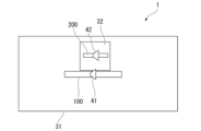
図1-図4を参照して本実施形態に係るアンテナ装置1の構成を説明する。図1-図4は、本実施形態に係るアンテナ装置1の構成を示す図である。図1は、本実施形態に係るアンテナ装置1の全体の外観図である。図2は、本実施形態に係るアンテナ装置1の上面図である。図3は、本実施形態に係る第1ダイポールアンテナ100の側面側の外観図である。図4は、本実施形態に係る第2ダイポールアンテナ200の側面側の外観図である。
The configuration of the
図1、図2に示されるように、アンテナ装置1は、第1ダイポールアンテナ100と第2ダイポールアンテナ200とを備える。第1ダイポールアンテナ100は、平板状の導体から成る2個のアンテナ素子から構成されるものであって、当該アンテナ素子間に給電点41が設けられている。第2ダイポールアンテナ200は、平板状の導体から成る2個のアンテナ素子から構成されるものであって、当該アンテナ素子間に給電点42が設けられている。
As shown in Figs. 1 and 2, the
第1ダイポールアンテナ100と第2ダイポールアンテナ200とは近接して配置される。第1ダイポールアンテナ100と第2ダイポールアンテナ200とは平行して配置される。第1ダイポールアンテナ100は、第1地板31から一定の高さに配置されている。第1地板31は、平板状の導体である。第1ダイポールアンテナ100は、給電点41から給電される。第2ダイポールアンテナ200は、第2地板32から一定の高さに配置されている。第2地板32は、方形状の箱形の導体である。第2ダイポールアンテナ200は、給電点42から給電される。
The
図3に示されるように、第1ダイポールアンテナ100は、絶縁体150によって、第1地板31から一定の高さHに配置されている。第1ダイポールアンテナ100は、給電線160により給電点41から給電される。
As shown in FIG. 3, the
図4に示されるように、第2ダイポールアンテナ200は、絶縁体(図示せず)によって、第2地板32から一定の高さH2に配置されている。第2地板32は、絶縁体250によって、第1地板31から一定の高さ「H-H2」に配置されている。これにより、第2ダイポールアンテナ200は、第1地板31から一定の高さHに配置される。したがって、第1ダイポールアンテナ100と第2ダイポールアンテナ200とは、第1地板31から同じ高さHに配置されている。第2ダイポールアンテナ200は、給電線260により給電点42から給電される。
As shown in FIG. 4, the
第1ダイポールアンテナ100は、第1周波数帯に適用される。第2ダイポールアンテナ200は、第2周波数帯に適用される。本実施形態の一例として、第1ダイポールアンテナ100は800メガヘルツ(MHz)帯に適用され、第2ダイポールアンテナ200は4.5ギガヘルツ(GHz)帯に適用される。
The
図5は、本実施形態に係る第1ダイポールアンテナ及び第2ダイポールアンテナの寸法図である。図5を参照して、第1ダイポールアンテナ100及び第2ダイポールアンテナ200の寸法を説明する。ここでは、第1ダイポールアンテナ100の使用周波数帯が800MHz帯であり、第2ダイポールアンテナ200の使用周波数帯が4.5GHz帯である場合の寸法の一例を以下に示す。単位はミリメートル(mm)である。
Figure 5 is a dimensional diagram of the first dipole antenna and the second dipole antenna according to this embodiment. The dimensions of the
(第1ダイポールアンテナ100:使用周波数帯「800MHz帯」)
Wa1=150
Wb1=20
(First dipole antenna 100: Frequency band used: 800 MHz band)
Wa1=150
Wb1=20
(第2ダイポールアンテナ200、第2地板32:使用周波数帯「4.5GHz帯」)
Wa2=70
Wb2=10
Wa3=80
Wb3=80
(
Wa2=70
Wb2=10
Wa3=80
Wb3=80
また、第1地板31から第1ダイポールアンテナ100及び第2ダイポールアンテナ200までの高さHは「H=55mm」である。第2地板32から第2ダイポールアンテナ200までの高さH2は、「H2=14mm」である。
The height H from the
図6、図7、図8は、本実施形態に係るアンテナ装置1のシミュレーション結果のグラフ図である。図6のシミュレーションは、リターンロス特性のシミュレーションである。図7、図8のシミュレーションは、水平面内のアンテナ指向特性のシミュレーションである。図6、図7、図8に使用するアンテナ装置1は、上記した第1ダイポールアンテナ100及び第2ダイポールアンテナ200の寸法の例を適用したものである。したがって、第1ダイポールアンテナ100の使用周波数帯が800MHz帯であり、第2ダイポールアンテナ200の使用周波数帯が4.5GHz帯である。また、第1ダイポールアンテナ100及び第2ダイポールアンテナ200は、第1地板31から55mmの高さに配置される。第2ダイポールアンテナ200は、第2地板32から14mmの高さに配置される。
Figures 6, 7, and 8 are graphs showing the results of a simulation of the
図6のグラフ図において、横軸は周波数(単位はギガヘルツ(GHz)、縦軸はリターンロス(単位はデシベル(dB))である。図6のグラフ図には、2つのグラフ波形S1,S2が示される。グラフ波形S1は、第1ダイポールアンテナ100のリターンロス特性であり、第1ダイポールアンテナ100の使用周波数帯「800MHz帯」においてリターンロスが「-10dB」以下であり、良好な結果が得られている。グラフ波形S2は、第2ダイポールアンテナ200のリターンロス特性であり、第2ダイポールアンテナ200の使用周波数帯「4.5GHz帯」においてリターンロスが「-10dB」以下であり、良好な結果が得られている。
In the graph of FIG. 6, the horizontal axis is frequency (units are gigahertz (GHz)) and the vertical axis is return loss (units are decibels (dB)). The graph of FIG. 6 shows two graph waveforms S1 and S2. Graph waveform S1 is the return loss characteristic of the
図7のグラフ図において、グラフ波形FH1は、第1ダイポールアンテナ100の使用周波数帯「800MHz帯」における水平面内のアンテナ指向特性を示しており、歪みがない良好なアンテナ指向特性が得られている。図8のグラフ図において、グラフ波形FH2は、第2ダイポールアンテナ200の使用周波数帯「4.5GHz帯」における水平面内のアンテナ指向特性を示しており、歪みがない良好なアンテナ指向特性が得られている。
In the graph of FIG. 7, the graph waveform FH1 shows the antenna directional characteristics in the horizontal plane in the 800 MHz frequency band of the
図6、図7、図8に示されるリターンロス特性及びアンテナ指向特性は、移動通信システムに適用可能な良好な結果である。例えば、第4世代移動通信システム(4G)及び第5世代移動通信システム(5G)にアンテナ装置1を適用することができる。
The return loss characteristics and antenna directivity characteristics shown in Figures 6, 7, and 8 are good results that can be applied to mobile communication systems. For example, the
本実施形態によれば、第1ダイポールアンテナ100と第2ダイポールアンテナ200とによって例えば使用周波数帯「800MHz帯」と使用周波数帯「4.5GHz帯」とにおいて良好なアンテナ特性が得られる。さらに、第1ダイポールアンテナ100と第2ダイポールアンテナ200とを近接して配置することができることから、アンテナ装置1の小型化を図ることができる。
According to this embodiment, the
次に、図9-図11を参照して本実施形態に係るアンテナ装置のいくつかの変形例を説明する。図9-図11において上述したアンテナ装置1(図1-図4)に対応する部分には同一の符号を付している。
Next, several modified examples of the antenna device according to this embodiment will be described with reference to Figures 9 to 11. In Figures 9 to 11, parts corresponding to the
(第1変形例)
図9は、本実施形態に係るアンテナ装置の第1変形例の構成を示す上面図である。図9に示されるように、アンテナ装置1aは、図2のアンテナ装置1において第1ダイポールアンテナ100と第2ダイポールアンテナ200の位置関係を第1地板31の面方向にずらしている。このように第1ダイポールアンテナ100と第2ダイポールアンテナ200とを近接させたまま第1地板31の面方向にずらしてもよい。
(First Modification)
Fig. 9 is a top view showing the configuration of a first modified example of the antenna device according to this embodiment. As shown in Fig. 9, in the
(第2変形例)
図10は、本実施形態に係るアンテナ装置の第2変形例の構成を示す上面図である。図10に示されるように、アンテナ装置1bは、1個の第1ダイポールアンテナ100と複数(図10では4個)の第2ダイポールアンテナ200とを備える。各第2ダイポールアンテナ200は、第1ダイポールアンテナ100に近接して配置される。このように1個の第1ダイポールアンテナ100に対して複数の第2ダイポールアンテナ200を近接させて配置してもよい。
(Second Modification)
Fig. 10 is a top view showing the configuration of a second modified example of the antenna device according to this embodiment. As shown in Fig. 10, the
(第3変形例)
図11は、本実施形態に係るアンテナ装置の第3変形例の構成を示す上面図である。
第3変形例は、上述した第2変形例の図10の第1ダイポールアンテナ100及び第2ダイポールアンテナ200において、それぞれに、水平偏波用のアンテナ素子と垂直偏波用のアンテナ素子とが設けられたものである。図11に示されるように、アンテナ装置1cは、図10の第1ダイポールアンテナ100に対して水平偏波用の第1ダイポールアンテナ100hと垂直偏波用の第1ダイポールアンテナ100vとを備える。また、アンテナ装置1cは、図10の第2ダイポールアンテナ200に対して水平偏波用の第2ダイポールアンテナ200hと垂直偏波用の第2ダイポールアンテナ200vとを備える。このように、第1ダイポールアンテナ100及び第2ダイポールアンテナ200において、それぞれに、水平偏波用のアンテナ素子と垂直偏波用のアンテナ素子とを設けてもよい。なお、第3変形例は、上述したアンテナ装置1(図1-図4)及び第1変形例(図9)に適用されてもよい。
(Third Modification)
FIG. 11 is a top view showing the configuration of a third modified example of the antenna device according to this embodiment.
In the third modification, the
上述したように本実施形態に係るアンテナ装置によれば、複数の周波数帯に広く適用すること及び良好なアンテナ特性と小型化を図ることができる。これにより、例えば第4世代移動通信システム(4G)や第5世代移動通信システム(5G)等の移動通信システムにおいて基地局に、本実施形態に係るアンテナ装置を適用することができる。 As described above, the antenna device according to this embodiment can be widely applied to multiple frequency bands and can achieve good antenna characteristics and compact size. This allows the antenna device according to this embodiment to be applied to base stations in mobile communication systems such as the fourth generation mobile communication system (4G) and the fifth generation mobile communication system (5G).
なお、これにより、例えば移動通信システムにおける総合的なサービス品質の向上を実現することができることから、国連が主導する持続可能な開発目標(SDGs)の目標9「レジリエントなインフラを整備し、持続可能な産業化を推進するとともに、イノベーションの拡大を図る」に貢献することが可能となる。 As a result, it will be possible to improve the overall service quality of mobile communication systems, for example, and contribute to Goal 9 of the United Nations' Sustainable Development Goals (SDGs), which is to "build resilient infrastructure, promote sustainable industrialization and foster innovation."
以上、本発明の実施形態について図面を参照して詳述してきたが、具体的な構成はこの実施形態に限られるものではなく、本発明の要旨を逸脱しない範囲の設計変更等も含まれる。 The above describes an embodiment of the present invention in detail with reference to the drawings, but the specific configuration is not limited to this embodiment and includes design modifications and the like that do not deviate from the gist of the present invention.
例えば、導体として、PEC(Perfect Electric Conductor)を使用してもよい。 For example, a perfect electric conductor (PEC) may be used as the conductor.
1,1a,1b,1c…アンテナ装置、100,100h,100v…第1ダイポールアンテナ、200,200h,200v…第2ダイポールアンテナ、31…第1地板、32…第2地板、41,42…給電点、150…絶縁体、160,260…給電線 1, 1a, 1b, 1c...antenna device, 100, 100h, 100v...first dipole antenna, 200, 200h, 200v...second dipole antenna, 31...first ground plate, 32...second ground plate, 41, 42...power supply point, 150...insulator, 160, 260...power supply line
Claims (4)
前記第1ダイポールアンテナと前記第2ダイポールアンテナとは第1地板から同じ55ミリメートルの高さに配置され、
前記第1ダイポールアンテナと前記第2ダイポールアンテナとは35ミリメートルの間隔で平行に配置され、
前記第2ダイポールアンテナは第2地板から一定の14ミリメートルの高さに配置され、
前記第2地板は前記第1地板から一定の41ミリメートルの高さに配置され、
前記第2地板は、横幅が80ミリメートルであり且つ縦幅が80ミリメートルである方形状の箱形の導体である、
アンテナ装置。 A first dipole antenna adapted to an 800 MHz band and a second dipole antenna adapted to a 4.5 GHz band ,
The first dipole antenna and the second dipole antenna are disposed at the same height of 55 mm from the first ground plane,
The first dipole antenna and the second dipole antenna are arranged in parallel with each other with a gap of 35 mm therebetween ,
The second dipole antenna is disposed at a constant height of 14 mm from the second ground plane,
The second base plate is disposed at a constant height of 41 mm from the first base plate,
The second ground plane is a rectangular box-shaped conductor having a width of 80 mm and a length of 80 mm.
Antenna device.
請求項1に記載のアンテナ装置。 The first dipole antenna and the second dipole antenna are shifted in a plane direction of the first base plate while maintaining the interval .
2. The antenna device according to claim 1.
請求項1又は2のいずれか1項に記載のアンテナ装置。 A plurality of the second dipole antennas are arranged in parallel with one of the first dipole antennas at the intervals .
3. An antenna device according to claim 1 or 2 .
請求項1から3のいずれか1項に記載のアンテナ装置。 The first dipole antenna and the second dipole antenna are each provided with an antenna element for horizontal polarization and an antenna element for vertical polarization.
4. An antenna device according to claim 1.
Priority Applications (1)
| Application Number | Priority Date | Filing Date | Title |
|---|---|---|---|
| JP2021103223A JP7614031B2 (en) | 2021-06-22 | 2021-06-22 | Antenna Device |
Applications Claiming Priority (1)
| Application Number | Priority Date | Filing Date | Title |
|---|---|---|---|
| JP2021103223A JP7614031B2 (en) | 2021-06-22 | 2021-06-22 | Antenna Device |
Publications (2)
| Publication Number | Publication Date |
|---|---|
| JP2023002166A JP2023002166A (en) | 2023-01-10 |
| JP7614031B2 true JP7614031B2 (en) | 2025-01-15 |
Family
ID=84797550
Family Applications (1)
| Application Number | Title | Priority Date | Filing Date |
|---|---|---|---|
| JP2021103223A Active JP7614031B2 (en) | 2021-06-22 | 2021-06-22 | Antenna Device |
Country Status (1)
| Country | Link |
|---|---|
| JP (1) | JP7614031B2 (en) |
Citations (6)
| Publication number | Priority date | Publication date | Assignee | Title |
|---|---|---|---|---|
| JP2003032031A (en) | 2001-07-11 | 2003-01-31 | Ntt Docomo Inc | Dipole antenna device |
| US20140168027A1 (en) | 2012-12-14 | 2014-06-19 | Raja Reddy KATIPALLY | Broadband In-Line Antenna Systems And Related Methods |
| JP2015050669A (en) | 2013-09-02 | 2015-03-16 | 日本電業工作株式会社 | Antenna and sector antenna |
| JP2015167337A (en) | 2014-03-04 | 2015-09-24 | 日本電業工作株式会社 | Array antenna and sector antenna |
| WO2018211597A1 (en) | 2017-05-16 | 2018-11-22 | 日本電業工作株式会社 | Antenna, array antenna, sector antenna, and dipole antenna |
| US20210083397A1 (en) | 2018-02-23 | 2021-03-18 | Telefonaktiebolaget Lm Ericsson (Publ) | Multiband antenna array for mobile radio applications |
-
2021
- 2021-06-22 JP JP2021103223A patent/JP7614031B2/en active Active
Patent Citations (6)
| Publication number | Priority date | Publication date | Assignee | Title |
|---|---|---|---|---|
| JP2003032031A (en) | 2001-07-11 | 2003-01-31 | Ntt Docomo Inc | Dipole antenna device |
| US20140168027A1 (en) | 2012-12-14 | 2014-06-19 | Raja Reddy KATIPALLY | Broadband In-Line Antenna Systems And Related Methods |
| JP2015050669A (en) | 2013-09-02 | 2015-03-16 | 日本電業工作株式会社 | Antenna and sector antenna |
| JP2015167337A (en) | 2014-03-04 | 2015-09-24 | 日本電業工作株式会社 | Array antenna and sector antenna |
| WO2018211597A1 (en) | 2017-05-16 | 2018-11-22 | 日本電業工作株式会社 | Antenna, array antenna, sector antenna, and dipole antenna |
| US20210083397A1 (en) | 2018-02-23 | 2021-03-18 | Telefonaktiebolaget Lm Ericsson (Publ) | Multiband antenna array for mobile radio applications |
Also Published As
| Publication number | Publication date |
|---|---|
| JP2023002166A (en) | 2023-01-10 |
Similar Documents
| Publication | Publication Date | Title |
|---|---|---|
| US12088017B2 (en) | Radiating element, antenna assembly and base station antenna | |
| US9590313B2 (en) | Planar dual polarization antenna | |
| CN1248363C (en) | Two-frequency antenna, multiple-frequency antenna, two-or multiple-frequency antenna array | |
| JP5956582B2 (en) | antenna | |
| CN110380202B (en) | Low-cost low-profile broadband Massive MIMO antenna unit | |
| US20170062940A1 (en) | Compact wideband dual polarized dipole | |
| US10103440B2 (en) | Stripline coupled antenna with periodic slots for wireless electronic devices | |
| CN110957569B (en) | Broadband radiation unit and antenna | |
| KR20130134793A (en) | Dual polarization dipole antenna for dual-band and antenna array using it | |
| US20140118211A1 (en) | Omnidirectional 3d antenna | |
| JPH11163621A (en) | Plane radiation element and omnidirectional antenna utilizing the element | |
| KR101954819B1 (en) | A 1d tightly coupled dipole array antenna | |
| US10522908B2 (en) | Antenna control method | |
| CN104979642A (en) | Multi-frequency antenna and multi-frequency antenna configuration method | |
| US6426730B1 (en) | Multi-frequency array antenna | |
| WO2013063335A1 (en) | Omnidirectional 3d antenna | |
| JP4512630B2 (en) | Dipole antenna and dipole array antenna | |
| JP7614031B2 (en) | Antenna Device | |
| CN206850028U (en) | Broadband High Gain Vertically Polarized Omnidirectional Antenna | |
| US20150097733A1 (en) | Antenna | |
| JP6052344B2 (en) | 3 frequency antenna | |
| JP4588749B2 (en) | Array antenna | |
| US20240304987A1 (en) | Antenna with lobe shaping | |
| JP5803741B2 (en) | 3 frequency antenna | |
| JP2006229337A (en) | Multi-frequency antenna |
Legal Events
| Date | Code | Title | Description |
|---|---|---|---|
| A621 | Written request for application examination |
Free format text: JAPANESE INTERMEDIATE CODE: A621 Effective date: 20230718 |
|
| A977 | Report on retrieval |
Free format text: JAPANESE INTERMEDIATE CODE: A971007 Effective date: 20240725 |
|
| A131 | Notification of reasons for refusal |
Free format text: JAPANESE INTERMEDIATE CODE: A131 Effective date: 20240730 |
|
| A601 | Written request for extension of time |
Free format text: JAPANESE INTERMEDIATE CODE: A601 Effective date: 20240930 |
|
| A521 | Request for written amendment filed |
Free format text: JAPANESE INTERMEDIATE CODE: A523 Effective date: 20241125 |
|
| TRDD | Decision of grant or rejection written | ||
| A01 | Written decision to grant a patent or to grant a registration (utility model) |
Free format text: JAPANESE INTERMEDIATE CODE: A01 Effective date: 20241203 |
|
| A61 | First payment of annual fees (during grant procedure) |
Free format text: JAPANESE INTERMEDIATE CODE: A61 Effective date: 20241226 |
|
| R150 | Certificate of patent or registration of utility model |
Ref document number: 7614031 Country of ref document: JP Free format text: JAPANESE INTERMEDIATE CODE: R150 |