JP7609727B2 - Work machine and method for controlling a work machine - Google Patents
Work machine and method for controlling a work machine Download PDFInfo
- Publication number
- JP7609727B2 JP7609727B2 JP2021117773A JP2021117773A JP7609727B2 JP 7609727 B2 JP7609727 B2 JP 7609727B2 JP 2021117773 A JP2021117773 A JP 2021117773A JP 2021117773 A JP2021117773 A JP 2021117773A JP 7609727 B2 JP7609727 B2 JP 7609727B2
- Authority
- JP
- Japan
- Prior art keywords
- steering
- angle
- neutral
- range
- vehicle body
- Prior art date
- Legal status (The legal status is an assumption and is not a legal conclusion. Google has not performed a legal analysis and makes no representation as to the accuracy of the status listed.)
- Active
Links
Images


Classifications
-
- E—FIXED CONSTRUCTIONS
- E02—HYDRAULIC ENGINEERING; FOUNDATIONS; SOIL SHIFTING
- E02F—DREDGING; SOIL-SHIFTING
- E02F9/00—Component parts of dredgers or soil-shifting machines, not restricted to one of the kinds covered by groups E02F3/00 - E02F7/00
- E02F9/20—Drives; Control devices
- E02F9/2058—Electric or electro-mechanical or mechanical control devices of vehicle sub-units
- E02F9/2087—Control of vehicle steering
-
- B—PERFORMING OPERATIONS; TRANSPORTING
- B62—LAND VEHICLES FOR TRAVELLING OTHERWISE THAN ON RAILS
- B62D—MOTOR VEHICLES; TRAILERS
- B62D1/00—Steering controls, i.e. means for initiating a change of direction of the vehicle
- B62D1/02—Steering controls, i.e. means for initiating a change of direction of the vehicle vehicle-mounted
- B62D1/04—Hand wheels
-
- B—PERFORMING OPERATIONS; TRANSPORTING
- B62—LAND VEHICLES FOR TRAVELLING OTHERWISE THAN ON RAILS
- B62D—MOTOR VEHICLES; TRAILERS
- B62D1/00—Steering controls, i.e. means for initiating a change of direction of the vehicle
- B62D1/02—Steering controls, i.e. means for initiating a change of direction of the vehicle vehicle-mounted
- B62D1/12—Hand levers
-
- B—PERFORMING OPERATIONS; TRANSPORTING
- B62—LAND VEHICLES FOR TRAVELLING OTHERWISE THAN ON RAILS
- B62D—MOTOR VEHICLES; TRAILERS
- B62D5/00—Power-assisted or power-driven steering
- B62D5/06—Power-assisted or power-driven steering fluid, i.e. using a pressurised fluid for most or all the force required for steering a vehicle
- B62D5/065—Power-assisted or power-driven steering fluid, i.e. using a pressurised fluid for most or all the force required for steering a vehicle characterised by specially adapted means for varying pressurised fluid supply based on need, e.g. on-demand, variable assist
-
- B—PERFORMING OPERATIONS; TRANSPORTING
- B62—LAND VEHICLES FOR TRAVELLING OTHERWISE THAN ON RAILS
- B62D—MOTOR VEHICLES; TRAILERS
- B62D6/00—Arrangements for automatically controlling steering depending on driving conditions sensed and responded to, e.g. control circuits
-
- E—FIXED CONSTRUCTIONS
- E02—HYDRAULIC ENGINEERING; FOUNDATIONS; SOIL SHIFTING
- E02F—DREDGING; SOIL-SHIFTING
- E02F9/00—Component parts of dredgers or soil-shifting machines, not restricted to one of the kinds covered by groups E02F3/00 - E02F7/00
- E02F9/20—Drives; Control devices
-
- E—FIXED CONSTRUCTIONS
- E02—HYDRAULIC ENGINEERING; FOUNDATIONS; SOIL SHIFTING
- E02F—DREDGING; SOIL-SHIFTING
- E02F9/00—Component parts of dredgers or soil-shifting machines, not restricted to one of the kinds covered by groups E02F3/00 - E02F7/00
- E02F9/20—Drives; Control devices
- E02F9/22—Hydraulic or pneumatic drives
- E02F9/225—Control of steering, e.g. for hydraulic motors driving the vehicle tracks
-
- E—FIXED CONSTRUCTIONS
- E02—HYDRAULIC ENGINEERING; FOUNDATIONS; SOIL SHIFTING
- E02F—DREDGING; SOIL-SHIFTING
- E02F3/00—Dredgers; Soil-shifting machines
- E02F3/04—Dredgers; Soil-shifting machines mechanically-driven
- E02F3/76—Graders, bulldozers, or the like with scraper plates or ploughshare-like elements; Levelling scarifying devices
- E02F3/7663—Graders with the scraper blade mounted under a frame supported by wheels, or the like
Landscapes
- Engineering & Computer Science (AREA)
- Mining & Mineral Resources (AREA)
- Civil Engineering (AREA)
- General Engineering & Computer Science (AREA)
- Structural Engineering (AREA)
- Combustion & Propulsion (AREA)
- Chemical & Material Sciences (AREA)
- Transportation (AREA)
- Mechanical Engineering (AREA)
- Steering Control In Accordance With Driving Conditions (AREA)
- Operation Control Of Excavators (AREA)
- Steering Controls (AREA)
- Power Steering Mechanism (AREA)
Description
本発明は、作業機械、及び、作業機械を制御するための方法に関する。 The present invention relates to a work machine and a method for controlling a work machine.
作業機械は、走行輪を左右に操舵するためのステアリングホイール、或いはステアリングレバーなどのステアリング部材を備えている。ステアリング部材は、中立位置から左右に操作可能である。作業機械のオペレータが、ステアリング部材を操作することで、作業機械は、走行輪の操舵角を中立角から左右に変更する。それにより、作業機械が左右に旋回する。 The work machine is equipped with a steering member, such as a steering wheel or a steering lever, for steering the running wheels left and right. The steering member can be operated left and right from a neutral position. When the operator of the work machine operates the steering member, the work machine changes the steering angle of the running wheels from the neutral angle to the left and right. This causes the work machine to turn left and right.
作業機械は、走行中に土砂による負荷、或いは路面の不均一により、目標とする進路から逸れやすい。そのため、オペレータは、ブレードなどの作業機を操作しながら、進路を維持するためにステアリング部材の操作を同時に行う必要がある。このような操作は、難易度が高く、オペレータへの操作負担が大きい。 Work machines can easily deviate from the intended course while traveling due to the load of soil and sand or unevenness of the road surface. For this reason, the operator must simultaneously operate the steering member to maintain the course while operating the work equipment such as the blade. This type of operation is highly difficult and places a large burden on the operator.
そこで、特許文献1では、作業機械が進行方向を維持するように、操舵角を自動的に制御するステアリング自動制御が開示されている。このステアリング自動制御では、ステアリング操作部材の操作が停止されたときの作業機械の向きが、目標方向として決定される。そして、作業機械が目標方向に向かって直進するように、操舵角が自動的に制御される。
しかし、特許文献1のように、ステアリング操作部材の操作が停止されたときの作業機械の向きに向かって、作業機械が直進したときには、オペレータが作業機械の挙動に違和感を覚える場合がある。本発明の目的は、操舵角の自動制御によってオペレータの操作負担を軽減すると共に、オペレータへの違和感を低減することにある。
However, as in
本発明の第1の態様に係る作業機械は、車体と、走行輪と、ステアリング部材と、アクチュエータと、操作センサと、操舵角センサと、方向センサと、コントローラとを備える。走行輪は、車体に支持される。ステアリング部材は、左操舵範囲と、右操舵範囲と、中立範囲とに操作可能である。中立範囲は、左操舵範囲と右操舵範囲との間に位置する。アクチュエータは、ステアリング部材が中立範囲に位置する場合に、走行輪の操舵角を所定の中立角とする。アクチュエータは、ステアリング部材の操作に応じて、操舵角を中立角から左右に変化させる。操作センサは、ステアリング部材の操作を示す操作信号を出力する。操舵角センサは、操舵角を示す角度信号を出力する。方向センサは、車体の進行方向を検出する方向信号を出力する。 The working machine according to the first aspect of the present invention includes a vehicle body, running wheels, a steering member, an actuator, an operation sensor, a steering angle sensor, a direction sensor, and a controller. The running wheels are supported by the vehicle body. The steering member can be operated to a left steering range, a right steering range, and a neutral range. The neutral range is located between the left steering range and the right steering range. When the steering member is located in the neutral range, the actuator sets the steering angle of the running wheels to a predetermined neutral angle. The actuator changes the steering angle from the neutral angle to the left or right in response to the operation of the steering member. The operation sensor outputs an operation signal indicating the operation of the steering member. The steering angle sensor outputs an angle signal indicating the steering angle. The direction sensor outputs a direction signal that detects the traveling direction of the vehicle body.
コントローラは、操作信号と角度信号と方向信号とを取得する。コントローラは、ステアリング部材が、左操舵範囲又は右操舵範囲から中立範囲に操作されたときに、操舵角が中立角に戻ったかを判定する。コントローラは、操舵角が中立角に戻ったと判定したときの進行方向を、目標方向として決定する。コントローラは、進行方向を目標方向に保持するように、アクチュエータを制御する。 The controller acquires an operation signal, an angle signal, and a direction signal. When the steering member is operated from the left steering range or the right steering range to the neutral range, the controller determines whether the steering angle has returned to the neutral angle. The controller determines the traveling direction when it is determined that the steering angle has returned to the neutral angle as the target direction. The controller controls the actuator so as to maintain the traveling direction in the target direction.
本発明の第2の態様に係る方法は、作業機械を制御するための方法である。作業機械は、車体と、走行輪と、アクチュエータとを含む。走行輪は、車体に支持される。アクチュエータは、走行輪の操舵角を所定の中立角から左右に変化させる。本態様に係る方法は、左操舵範囲と、右操舵範囲と、左操舵範囲と右操舵範囲との間の中立範囲とに操作可能なステアリング部材の操作を示す操作信号を取得することと、ステアリング部材が中立範囲に位置する場合に、操舵角を所定の中立角とするようにアクチュエータを制御することと、ステアリング部材の操作に応じて、操舵角を中立角から左右に変化させるようにアクチュエータを制御することと、操舵角を示す角度信号を取得することと、車体の進行方向を検出する方向信号を取得することと、ステアリング部材が左操舵範囲又は右操舵範囲から中立範囲に操作されたときに、操舵角が中立角に戻ったかを判定することと、操舵角が中立角に戻ったと判定したときの進行方向を、目標方向として決定することと、進行方向を目標方向に保持するように、アクチュエータを制御すること、を備える。 A method according to a second aspect of the present invention is a method for controlling a work machine. The work machine includes a vehicle body, running wheels, and an actuator. The running wheels are supported by the vehicle body. The actuator changes the steering angle of the running wheels to the left or right from a predetermined neutral angle. The method according to this aspect includes acquiring an operation signal indicating the operation of a steering member that can be operated in a left steering range, a right steering range, and a neutral range between the left steering range and the right steering range, controlling an actuator to set the steering angle to a predetermined neutral angle when the steering member is located in the neutral range, controlling the actuator to change the steering angle from the neutral angle to the left or right in response to the operation of the steering member, acquiring an angle signal indicating the steering angle, acquiring a direction signal detecting the traveling direction of the vehicle body, determining whether the steering angle has returned to the neutral angle when the steering member is operated from the left steering range or the right steering range to the neutral range, determining the traveling direction when it is determined that the steering angle has returned to the neutral angle as a target direction, and controlling the actuator to maintain the traveling direction in the target direction.
本発明では、車体の進行方向を目標方向に保持するように、アクチュエータが制御される。また、ステアリング部材が中立範囲に操作されたときではなく、操舵角が中立角に戻ったときの車体の進行方向が、目標方向として決定される。そのため、作業機械は、操舵角が実際に中立角に戻ったときの進行方向に向かって直進するように制御される。それにより、オペレータの操作負担が軽減されると共に、オペレータへの違和感が低減される。 In the present invention, the actuator is controlled so as to maintain the vehicle body's traveling direction in the target direction. Furthermore, the traveling direction of the vehicle body when the steering angle returns to the neutral angle, not when the steering member is operated into the neutral range, is determined as the target direction. Therefore, the work machine is controlled so as to move straight in the traveling direction when the steering angle actually returns to the neutral angle. This reduces the operating burden on the operator and reduces any discomfort felt by the operator.
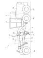
以下図面を参照して、本発明の実施形態について説明する。図1は、実施形態に係る作業機械1の斜視図である。図2は、作業機械1の側面図である。図1に示すように、作業機械1は、車体2と、前輪3A,3Bと、後輪4A-4Dと、作業機5とを備える。車体2は、フロントフレーム11と、リアフレーム12と、キャブ13と、動力室14とを含む。
Embodiments of the present invention will now be described with reference to the drawings. FIG. 1 is a perspective view of a
リアフレーム12は、フロントフレーム11に接続されている。フロントフレーム11は、リアフレーム12に対して、左右にアーティキュレート可能である。なお、以下の説明において、前後左右の各方向は、アーティキュレート角が0、すなわち、フロントフレーム11とリアフレーム12とが真っすぐな状態での車体2の前後左右の各方向を意味するものとする。
The
キャブ13と動力室14とは、リアフレーム12上に配置されている。キャブ13には、図示しない運転席が配置されている。動力室14は、キャブ13の後方に配置されている。フロントフレーム11は、リアフレーム12から前方へ延びている。前輪3A,3Bは、フロントフレーム11に取り付けられている。後輪4A-4Dは、リアフレーム12に取り付けられている。
The
作業機5は、車体2に対して可動的に接続されている。作業機5は、支持部材15とブレード16とを含む。支持部材15は、車体2に可動的に接続されている。支持部材15は、ブレード16を支持している。支持部材15は、ドローバ17とサークル18とを含む。ドローバ17は、フロントフレーム11の下方に配置される。
The
ドローバ17は、フロントフレーム11の前部19に接続されている。ドローバ17は、フロントフレーム11の前部19から後方へ延びている。ドローバ17は、フロントフレーム11に対して、少なくとも車体2の上下方向と左右方向とに揺動可能に支持されている。例えば、前部19は、ボールジョイントを含む。ドローバ17は、ボールジョイントを介して、フロントフレーム11に対して回転可能に接続されている。
The
サークル18は、ドローバ17の後部に接続されている。サークル18は、ドローバ17に対して回転可能に支持される。ブレード16は、サークル18に接続される。ブレード16は、サークル18を介して、ドローバ17に支持されている。図2に示すように、ブレード16は、チルト軸21回りに回転可能にサークル18に支持されている。チルト軸21は、左右方向に延びている。
The
作業機械1は、作業機5の姿勢を変更するための複数のアクチュエータ22-26を備えている。複数のアクチュエータ22-26は、複数の油圧シリンダ22-25を含む。複数の油圧シリンダ22-25は、作業機5に接続されている。複数の油圧シリンダ22-25は、油圧によって伸縮する。複数の油圧シリンダ22-25は、伸縮することで、車体2に対する作業機5の姿勢を変更する。以下の説明では、油圧シリンダの伸縮を「ストローク動作」と呼ぶ。
The
詳細には、複数の油圧シリンダ22-25は、左リフトシリンダ22と、右リフトシリンダ23と、ドローバシフトシリンダ24と、ブレードチルトシリンダ25とを含む。左リフトシリンダ22と右リフトシリンダ23とは、左右方向に互いに離れて配置されている。左リフトシリンダ22と右リフトシリンダ23とは、ドローバ17に接続されている。左リフトシリンダ22と右リフトシリンダ23とは、リフタブラケット29を介して、フロントフレーム11に接続されている。左リフトシリンダ22と右リフトシリンダ23とのストローク動作により、ドローバ17は、上下に揺動する。それにより、ブレード16が上下に移動する。
In detail, the multiple hydraulic cylinders 22-25 include a
ドローバシフトシリンダ24は、ドローバ17とフロントフレーム11とに接続されている。ドローバシフトシリンダ24は、リフタブラケット29を介してフロントフレーム11に接続されている。ドローバシフトシリンダ24は、フロントフレーム11からドローバ17に向かって、斜め下方に延びている。ドローバシフトシリンダ24のストローク動作により、ドローバ17は、左右に揺動する。ブレードチルトシリンダ25は、サークル18とブレード16とに接続されている。ブレードチルトシリンダ25のストローク動作により、ブレード16がチルト軸21回りに回転する。
The
複数のアクチュエータ22-26は、回転アクチュエータ26を含む。回転アクチュエータ26は、ドローバ17とサークル18とに接続されている。回転アクチュエータ26は、ドローバ17に対してサークル18を回転させる。それにより、ブレード16が、上下方向に延びる回転軸回りに回転する。
The actuators 22-26 include a
図3は、作業機械1の構成を示す模式図である。図3に示すように、作業機械1は、駆動源31と、第1油圧ポンプ32と、動力伝達装置33と、作業機バルブ34とを含む。駆動源31は、例えば内燃機関である。或いは、駆動源31は、電動モータ、或いは内燃機関と電動モータとのハイブリッドであってもよい。第1油圧ポンプ32は、駆動源31によって駆動されることで、作動油を吐出する。
Figure 3 is a schematic diagram showing the configuration of the
作業機バルブ34は、油圧回路を介して、第1油圧ポンプ32と複数の油圧シリンダ22-25とに接続されている。作業機バルブ34は、複数の油圧シリンダ22-25にそれぞれ接続される複数の弁を含む。作業機バルブ34は、第1油圧ポンプ32から複数の油圧シリンダ22-25に供給される作動油の流量を制御する。作業機バルブ34は、例えば電磁比例制御弁である。或いは、作業機バルブ34は、油圧パイロット式の比例制御弁であってもよい。
The
本実施形態では、回転アクチュエータ26は、油圧モータである。作業機バルブ34は、油圧回路を介して第1油圧ポンプ32と回転アクチュエータ26とに接続されている。作業機バルブ34は、第1油圧ポンプ32から回転アクチュエータ26に供給される作動油の流量を制御する。なお、回転アクチュエータ26は、電動モータであってもよい。
In this embodiment, the
動力伝達装置33は、駆動源31からの駆動力を後輪4A-4Dに伝達する。動力伝達装置33は、トルクコンバータ、及び/又は、複数の変速ギアを含んでもよい。或いは、動力伝達装置33は、HST(Hydraulic Static Transmission)、或いは、HMT(Hydraulic Mechanical Transmission)などのトランスミッションであってもよい。
The
作業機械1は、作業機操作部材35と、シフト部材53と、アクセル操作部材36と、コントローラ37とを含む。作業機操作部材35は、作業機5の姿勢を変更するためにオペレータによって操作可能である。作業機操作部材35は、例えば複数の操作レバーを含む。或いは、作業機操作部材35は、スイッチ、或いはタッチパネルなどの他の部材であってもよい。作業機操作部材35は、オペレータによる作業機操作部材35への操作を示す信号を出力する。
The
シフト部材53は、作業機械1の前進と後進とを切り換えるためのオペレータによって操作可能である。シフト部材53は、例えばシフトレバーを含む。或いは、シフト部材53は、スイッチ、或いはタッチパネルなどの他の部材であってもよい。シフト部材53は、オペレータによるシフト部材53への操作を示す信号を出力する。アクセル操作部材36は、作業機械1を走行させるためにオペレータによって操作可能である。アクセル操作部材36は、例えばアクセルペダルを含む。或いは、アクセル操作部材36は、スイッチ、或いはタッチパネルなどの他の部材であってもよい。アクセル操作部材36は、オペレータによるアクセル操作部材36への操作を示す信号を出力する。
The shift member 53 can be operated by an operator to switch the
コントローラ37は、シフト部材53の操作に応じて、動力伝達装置33を制御することで、作業機械1の前進と後進とを切り換える。或いは、シフト部材53は、機械的に動力伝達装置33に接続されてもよい。シフト部材53の動作が機械的に動力伝達装置33に伝達されることで、動力伝達装置33の前進と後進のギアが切り替えられてもよい。
The
コントローラ37は、アクセル操作部材36の操作に応じて、駆動源31及び動力伝達装置33を制御することで、作業機械1を走行させる。また、コントローラ37は、作業機操作部材35の操作に応じて、第1油圧ポンプ32と作業機バルブ34とを制御することで、作業機5を動作させる。
The
コントローラ37は、記憶装置38とプロセッサ39とを含む。プロセッサ39は、例えばCPUであり、作業機械1を制御するためのプログラムを実行する。記憶装置38は、RAM及びROMなどのメモリと、SSD或いはHDDなどの補助記憶装置を含む。記憶装置38は、作業機械1を制御するためのプログラムとデータとを記憶している。
The
作業機械1は、方向センサ52を備えている。方向センサ52は、車体2の進行方向を検出する。方向センサ52は、車体2の進行方向を示す方向信号を出力する。コントローラ37は、方向センサ52からの方向信号により、車体2の進行方向を取得する。車体2の進行方向は、例えば車体2のヨー角で示される。方向センサ52は、例えばIMU(慣性計測装置)である。コントローラ37は、車体2の加速度および角速度に基づいて、車体2の進行方向を算出する。或いは、方向センサ52は、GPS(Global Positioning System)などのGNSS(Global Navigation Satellite System)レシーバであってもよい。コントローラ37は、方向センサ52が検出した作業機械1の位置の変化から、車体2の進行方向を取得してもよい。
The
図3に示すように、作業機械1は、操舵角センサ40と、ステアリングアクチュエータ41と、ステアリングバルブ42とを備えている。ステアリングアクチュエータ41は、油圧シリンダである。ステアリングアクチュエータ41は、第1油圧ポンプ32からの作動油によって伸縮する。ステアリングアクチュエータ41は、伸縮することで、前輪3A,3Bを操舵する。
As shown in FIG. 3, the
図4は、作業機械1の前部を示す上面図である。図4に示すように、前輪3A,3Bは、第1前輪3Aと第2前輪3Bとを含む。第1前輪3Aと第2前輪3Bとは、左右方向に離れて配置されている。第1前輪3Aは、第1ステアリング軸43回りに回動可能にフロントフレーム11に支持されている。第2前輪3Bは、第2ステアリング軸44回りに回動可能にフロントフレーム11に支持されている。第1ステアリング軸43と第2ステアリング軸44とは、上下方向に延びている。
Figure 4 is a top view showing the front of the
ステアリングアクチュエータ41は、前輪3A,3Bとフロントフレーム11とに接続されている。ステアリングアクチュエータ41は、前輪3A,3Bの操舵角θ1を所定の中立角から左右に変化させる。図4に示すように、操舵角θ1は、作業機械1の前後方向に対する前輪3A,3Bの向きの角度である。作業機械1の前後方向は、フロントフレーム11の前後方向を意味するものとする。ただし、作業機械1の前後方向は、リアフレーム12の前後方向を意味してもよい。
The steering
中立角は、0度の操舵角θ1である。従って、操舵角θ1が中立角であることは、前輪3A,3Bが作業機械1の真正面を向いていることを意味する。なお、図4において、3A’は、中立角から左方に操舵角θ1だけ操舵された第1前輪3Aを示している。3B’は、中立角から左方に操舵角θ1だけ操舵された第2前輪3Bを示している。
The neutral angle is a steering angle θ1 of 0 degrees. Therefore, when the steering angle θ1 is the neutral angle, it means that the
ステアリングバルブ42は、油圧回路を介して、第1油圧ポンプ32とステアリングアクチュエータ41とに接続されている。ステアリングバルブ42は、第1油圧ポンプ32からステアリングアクチュエータ41に供給される作動油の流量を制御する。ステアリングバルブ42は、油圧パイロット式の制御弁である。
The steering
操舵角センサ40は、操舵角θ1を検出する。操舵角センサ40は、操舵角θ1を示す角度信号を出力する。コントローラ37は、操舵角センサ40からの角度信号により現在の操舵角θ1を取得する。操舵角センサ40は、例えば、ステアリングアクチュエータ41のストローク量を検出する。操舵角θ1は、ステアリングアクチュエータ41のストローク量から算出される。或いは、操舵角センサ40は、操舵角θ1を直接的に検出してもよい。
The
作業機械1は、第1ステアリング部材45と第2ステアリング部材46とを含む。第1ステアリング部材45と第2ステアリング部材46とは、前輪3A,3Bの操舵角θ1を左右に変化させるために、オペレータによって操作可能である。第1ステアリング部材45は、ジョイスティックなどのレバーである。或いは、第1ステアリング部材45は、レバー以外の部材であってもよい。第1ステアリング部材45は、中立位置N1から左右に傾倒可能である。第1ステアリング部材45は、第1操作センサ51に接続されている。第1操作センサ51は、オペレータによる第1ステアリング部材45への操作を示す第1操作信号を出力する。コントローラ37は、第1操作センサ51からの第1操作信号により、第1ステアリング部材45の操作量を取得する。
The
第2ステアリング部材46は、ステアリングホイールである。或いは、第2ステアリング部材46は、ステアリングホイール以外の部材であってもよい。第2ステアリング部材46は、回転軸Ax1回りに回転可能である。第2ステアリング部材46には、第2操作センサ47が取り付けられている。第2操作センサ47は、オペレータによる第2ステアリング部材46への操作を示す第2操作信号を出力する。例えば、第2操作センサ47は、第2ステアリング部材46の回転軸Ax1回りの角度変位を検出する。コントローラ37は、第2操作センサ47からの第2操作信号により、第2ステアリング部材46の操作量を取得する。なお、第2ステアリング部材46は、オペレータによって操作されていない場合には、最後に操作された位置に保持される。
The
作業機械1は、第2油圧ポンプ48と、第1パイロットバルブ49と、第2パイロットバルブ50とを含む。第2油圧ポンプ48は、駆動源31によって駆動されることで、作動油を吐出する。第1パイロットバルブ49は、油圧回路を介して、第2油圧ポンプ48とステアリングバルブ42とに接続されている。第1パイロットバルブ49は、第2油圧ポンプ48からステアリングバルブ42のパイロットポートに供給される作動油の圧力を制御する。第1パイロットバルブ49は、電磁比例制御弁である。
The
第1パイロットバルブ49は、コントローラ37からの信号によって制御される。コントローラ37は、第1操作センサ51からの第1操作信号に応じて、第1パイロットバルブ49を制御することで、ステアリングアクチュエータ41を伸縮させる。それにより、コントローラ37は、第1ステアリング部材45の操作に応じて、前輪3A,3Bの操舵角θ1を変更するように、ステアリングアクチュエータ41を制御する。第1ステアリング部材45による操舵角θ1の制御については、後に詳細に説明する。
The
第2パイロットバルブ50は、油圧回路を介して、第2油圧ポンプ48とステアリングバルブ42とに接続されている。第2パイロットバルブ50は、第2ステアリング部材46に接続されている。第2パイロットバルブ50は、第2ステアリング部材46の操作に応じて、第2油圧ポンプ48からステアリングバルブ42のパイロットポートに供給される作動油の圧力を制御する。それにより、ステアリングアクチュエータ41は、前輪3A,3Bの操舵角θ1が、第2ステアリング部材46の操作量に応じた角度となるように、前輪3A,3Bの操舵角θ1を変化させる。
The
第2ステアリング部材46の操作量が一定に保持されている場合には、ステアリングアクチュエータ41は、前輪3A,3Bの操舵角θ1を、第2ステアリング部材46の操作量に応じた角度に保持する。なお、第2パイロットバルブ50は、第1パイロットバルブ49と同様に、電磁比例制御弁であってもよい。その場合、コントローラ37は、第2ステアリング部材46の操作に応じて、第2パイロットバルブ50を制御してもよい。
When the amount of operation of the
次に、第1ステアリング部材45による操舵角θ1の制御について説明する。コントローラ37は、操舵速度データを参照して、第1ステアリング部材45の操作量から、目標操舵速度を決定する。コントローラ37は、操舵角θ1が目標操舵速度で変化するように、ステアリングアクチュエータ41を制御する。操舵速度データは、第1ステアリング部材45の操作量に対する目標操舵速度を規定する。
Next, the control of the steering angle θ1 by the
図5は、操舵速度データの一例を示す図である。図5に示すように、第1ステアリング部材45は、中立範囲と、左操舵範囲と、右操舵範囲とに操作可能である。中立範囲は、第1ステアリング部材45の操作量0の位置、すなわち中立位置N1を含む範囲である。中立範囲は、左操舵範囲と右操舵範囲との間に位置する。左操舵範囲は、中立範囲の左方に位置する。右操舵範囲は、中立範囲の右方に位置する。
Figure 5 is a diagram showing an example of steering speed data. As shown in Figure 5, the
操舵速度データは、左操舵範囲において、第1ステアリング部材45の左方への操作量の増大に応じて、0から左方への最大速度VLまでの間で増大する左方への目標操舵速度を規定する。従って、コントローラ37は、第1ステアリング部材45が、左操舵範囲内に位置している場合には、前輪3A,3Bの操舵角θ1を、第1ステアリング部材45の操作量に応じた速度で、左方に変化させるように、ステアリングアクチュエータ41を制御する。
The steering speed data specifies a target steering speed to the left that increases between 0 and a maximum leftward speed VL in response to an increase in the leftward operation amount of the
例えば、コントローラ37は、第1ステアリング部材45が、左方への操作量A1で操作された場合には、操作量A1に応じた操舵速度V1を、目標操舵速度として決定する。そして、コントローラ37は、前輪3A,3Bの操舵角θ1を、操舵速度V1で、左方に変化させるように、ステアリングアクチュエータ41を制御する。また、第1ステアリング部材45が、左方への操作量A1に保持されている間、前輪3A,3Bの操舵角θ1は、左方への最大操舵角に到達するまで、操舵速度V1で、左方に変化し続ける。
For example, when the
操舵速度データは、右操舵範囲において、第1ステアリング部材45の右方への操作量の増大に応じて、0から右方方への最大速度VRまでの間で増大する右方への目標操舵速度を規定する。従って、コントローラ37は、第1ステアリング部材45が、右操舵範囲内に位置している場合には、前輪3A,3Bの操舵角θ1を、第1ステアリング部材45の操作量に応じた速度で、右方に変化させるように、ステアリングアクチュエータ41を制御する。
The steering speed data specifies a target steering speed to the right that increases between 0 and a maximum speed VR to the right in response to an increase in the amount of rightward operation of the
例えば、コントローラ37は、第1ステアリング部材45が、右方への操作量A2で操作された場合には、操作量A2に応じた操舵速度V2を、目標操舵速度として決定する。そして、コントローラ37は、前輪3A,3Bの操舵角θ1を、操舵速度V2で、右方に変化させるように、ステアリングアクチュエータ41を制御する。また、第1ステアリング部材45が、右方への操作量A2に保持されている間、前輪3A,3Bの操舵角θ1は、右方への最大操舵角に到達するまで、操舵速度V2で、右方に変化し続ける。
For example, when the
コントローラ37は、第1ステアリング部材45が、中立範囲内に位置している場合には、操舵角θ1を中立角に保持するように、ステアリングアクチュエータ41を制御する。例えば、操舵角θ1が中立角であるときに第1ステアリング部材45が、中立範囲内に位置している場合には、操舵角θ1は変化せず、中立角に保持される。
When the
なお、第1ステアリング部材45と第2ステアリング部材46とが同時に操作されている場合には、コントローラ37は、第2ステアリング部材46の操作を優先する。従って、第1ステアリング部材45と第2ステアリング部材46とが同時に操作されている場合には、コントローラ37は、上述した第1ステアリング部材45による操舵角θ1の制御を行わない。そのため、操舵角θ1は、第2ステアリング部材46の操作に応じて変化する。
When the
次に、操舵角θ1の自動制御について説明する。コントローラ37は、操舵角θ1を所定の目標角度とするように、ステアリングアクチュエータ41を制御する自動制御を実行する。自動制御は、センターリターンモードとステアリングスタビライザモードとを含む。
Next, the automatic control of the steering angle θ1 will be described. The
センターリターンモードでは、コントローラ37は、第1ステアリング部材45が左操舵範囲、又は、右操舵範囲から中立範囲に戻されたときに、操舵角θ1を自動的に中立角に戻すように、ステアリングアクチュエータ41を制御する。
In the center return mode, the
例えば、操舵角θ1が、左方への所定角度であるときに、第1ステアリング部材45が、中立範囲に戻されると、コントローラ37は、操舵角θ1が、左方への所定角度から中立角に戻るように、ステアリングアクチュエータ41を制御する。操舵角θ1が、右方への所定角度であるときに、第1ステアリング部材45が、中立範囲に戻されると、コントローラ37は、操舵角θ1が、右方への所定角度から中立角に戻るように、ステアリングアクチュエータ41を制御する。
For example, when the steering angle θ1 is a predetermined angle to the left and the
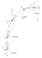
図6は、第1ステアリング部材45の操作による作業機械1の走行の一例を示す図である。図6に示すように、作業機械1が地点P1では、第1ステアリング部材45は中立位置N1に位置している。操舵角θ1は中立角であり、作業機械1は直進している。地点P2において、オペレータが第1ステアリング部材45を左操作範囲内の操作量A1に操作すると、前輪3A,3Bの操舵角θ1が中立角から左方へ変化し始める。それにより、作業機械1は左方へ旋回する。
Figure 6 is a diagram showing an example of the travel of the
地点P2から地点P3までの間、オペレータが第1ステアリング部材45を操作量A1に保持すると、前輪3A,3Bの操舵角θ1は、左方への最大操舵角θmaxまで増大し続ける。それにより、作業機械1は、左方へ旋回し続ける。
When the operator holds the
そして、地点P3において、オペレータが第1ステアリング部材45を中立範囲に戻すと、センターリターンモードにより、前輪3A,3Bの操舵角θ1は、最大操舵角θmaxから中立角へ向かって減少する。そして、地点P5において、前輪3A,3Bの操舵角θ1が中立角に戻る。
Then, at point P3, when the operator returns the
ステアリングスタビライザモードでは、コントローラ37は、車体2の進行方向を目標方向に保持するように、操舵角θ1を制御する。図6に示すように、地点P3において、オペレータが第1ステアリング部材45を中立範囲に戻した後、コントローラ37は、操舵角θ1が中立角に戻ったかを判定する。コントローラ37は、地点P5において、操舵角θ1が中立角に戻ったと判定する。コントローラ37は、操舵角θ1が中立角に戻ったと判定したときの車体2の進行方向H1を、目標方向として決定する。その後、コントローラ37は、車体2の進行方向を目標方向(H1)に保持するように、ステアリングアクチュエータ41を制御する。それにより、作業機械1は、目標方向(H1)に向かって直進する。
In the steering stabilizer mode, the
詳細には、コントローラ37は、車体2の現在の進行方向と目標方向との差に基づいて、操舵角θ1の目標角度を決定する。コントローラ37は、操舵角θ1が目標角度となるように、ステアリングアクチュエータ41を制御する。例えば、コントローラ37は、車体2の現在の進行方向と目標方向との差に、所定のゲインを乗じることで、操舵角θ1の目標角度を決定する。コントローラ37は、車速が大きいほどゲインを小さくする。それにより、車速が大きいほど、目標角度が小さくなる。コントローラ37は、操舵角θ1が目標角度に保持されるように、フィードバック制御により、ステアリングアクチュエータ41を制御する。
In detail, the
なお、コントローラ37は、上述したGNSSレシーバによって検出された作業機械1の位置の変化から、車速を算出してもよい。或いは、動力伝達装置33の出力回転速度を検出する回転センサが作業機械1に設けられてもよい。コントローラ37は、動力伝達装置33の出力回転速度から、車速を算出してもよい。
The
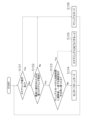
図7は、自動制御の開始を判定するための処理を示すフローチャートである。図7に示すように、ステップS101では、コントローラ37は、ステアリング操作がなされているかを判定する。コントローラ37は、第1ステアリング部材45と第2ステアリング部材46との少なくとも一方が操作されているときに、ステアリング操作がなされていると判定する。
Figure 7 is a flowchart showing the process for determining whether to start automatic control. As shown in Figure 7, in step S101, the
コントローラ37は、第1操作信号により、第1ステアリング部材45が、左操舵範囲、または、右操舵範囲内に位置している場合に、第1ステアリング部材45が操作されていると判定する。コントローラ37は、第1操作信号により、第1ステアリング部材45が、中立範囲内に位置している場合に、第1ステアリング部材45が操作されていないと判定する。
When the
コントローラ37は、第2操作信号により、第2ステアリング部材46の操作速度を取得する。コントローラ37は、操作速度が閾値より大きいあるときに、第2ステアリング部材46が操作されていると判定する。コントローラ37は、操作速度が閾値以下であるときに、第2ステアリング部材46が操作されていないと判定する。例えば、コントローラ37は、第2ステアリング部材46の角速度を算出する。コントローラ37は、第2ステアリング部材46の角速度が閾値以下であるときに、第2ステアリング部材46が操作されていないと判定する。
The
ステップS101において、コントローラ37が、ステアリング操作がなされていると判定したときには、処理はステップS106に進む。ステップS106では、マニュアルモードにて、ステアリングアクチュエータ41が制御される。すなわち、コントローラ37は、自動制御を実行せず、上述したように、オペレータによる、第1ステアリング部材45、或いは、第2ステアリング部材46の操作に応じて、ステアリングアクチュエータ41が制御される。
When the
ステップS101において、コントローラ37が、ステアリング操作がなされていないと判定したときには、処理はステップS102に進む。ステップS102では、コントローラ37は、第1ステアリング部材45と第2ステアリング部材46とのうち、第1ステアリング部材45が最後に操作されたかを判定する。ステップS102において、第1ステアリング部材45と第2ステアリング部材46とのうち、第1ステアリング部材45が最後に操作されていないと、コントローラ37が判定したときには、処理はステップS106に進む。すなわち、最後に操作されたのが第2ステアリング部材46であるときには、コントローラ37は自動制御を実行せず、マニュアルモードにてステアリングアクチュエータ41が制御される。
In step S101, when the
ステップS102において、第1ステアリング部材45が最後に操作されたとコントローラ37が判定したときには、処理はステップS103に進む。ステップS103では、コントローラ37は、マニュアルモードから自動制御に遷移後、一度でも操舵角θ1が中立角に戻ったかを判定する。マニュアルモードから自動制御に遷移後、一度も操舵角θ1が中立角に戻っていないとコントローラ37が判定したときには、処理はステップS104に進む。
When the
ステップS104において、コントローラ37は、センターリターンモードにて、ステアリングアクチュエータ41を制御する。すなわち、コントローラ37は、図6の地点P3から地点P5に示すように、操舵角θ1を中立角に戻すように、ステアリングアクチュエータ41を制御する。
In step S104, the
ステップS103において、マニュアルモードから自動制御に遷移後、一度でも操舵角θ1が中立角に戻ったとコントローラ37が判定したときには、処理はステップS105に進む。ステップS105において、コントローラ37は、ステアリングスタビライザモードにて、ステアリングアクチュエータ41を制御する。図6の地点P5に示すように、ステアリングスタビライザモードでは、コントローラ37は、車体2の進行方向を目標方向(H1)に保持するように、操舵角θ1を制御する。
In step S103, if the
以上説明した本実施形態に係る作業機械1では、車体2の進行方向を目標方向に保持するように、ステアリングアクチュエータ41が制御される。また、第1ステアリング部材45が中立範囲に操作されたときではなく、操舵角θ1が中立角に戻ったときの車体2の進行方向が、目標方向として決定される。
In the
例えば、図6の地点P3に示すように、第1ステアリング部材45が中立範囲に操作されたときの車体2の進行方向H2は、操舵角θ1が中立角に戻ったときの車体2の進行方向H1と異なる。本実施形態に係る作業機械1では、操舵角θ1が中立角に戻ったときの車体2の進行方向H1が、目標方向として決定される。そのため、作業機械1は、操舵角θ1が実際に中立角に戻ったときの進行方向H1に向かって直進するように制御される。それにより、オペレータへの操作負担が軽減されると共に、オペレータへの違和感が低減される。
For example, as shown at point P3 in FIG. 6, the traveling direction H2 of the
以上、本発明の一実施形態について説明したが、本発明は上記実施形態に限定されるものではなく、発明の要旨を逸脱しない範囲で種々の変更が可能である。 Although one embodiment of the present invention has been described above, the present invention is not limited to the above embodiment, and various modifications are possible without departing from the spirit of the invention.
作業機械1は、モータグレーダに限らず、ホイールローダ、ダンプトラック、フォークリフトなどの他の作業機械であってもよい。ステアリングアクチュエータ41の数は1つに限らず、2つ以上であってもよい。ステアリングアクチュエータ41は、油圧シリンダに限らず、油圧モータ、或いは電動モータであってもよい。
The
操舵速度データは、上記の実施形態のものに限らず、変更されてもよい。或いは、センターリターンモードは、省略されてもよい。上記の実施形態では、コントローラ37は、第1ステアリング部材45の操作量に応じた速度で、操舵角θ1を変化させるように、ステアリングアクチュエータ41を制御する。しかし、コントローラ37は、操舵角θ1が、第1ステアリング部材45の操作量に応じた角度となるように、ステアリングアクチュエータ41を制御してもよい。すなわち、第1ステアリング部材45による操舵角θ1の制御は、速度制御型に限らず、位置制御型であってもよい。
The steering speed data is not limited to that of the above embodiment, and may be changed. Alternatively, the center return mode may be omitted. In the above embodiment, the
コントローラ37は、車体2が後進しているときには、車体2が前進しているときに対して操舵角θ1の目標角度を左右逆にしてもよい。例えば、前進での目標方向が作業機械1の左方である場合には、コントローラ37は、目標角度を中立角よりも左方の角度に決定する。後進での目標方向が作業機械1の左方である場合には、コントローラ37は、目標角度を中立角よりも右方の角度に決定する。前進での目標方向が作業機械1の右方である場合には、コントローラ37は、目標角度を中立角よりも右方の角度に決定する。後進での目標方向が作業機械1の右方である場合には、コントローラ37は、目標角度を中立角よりも左方の角度に決定する。
When the
なお、コントローラ37は、シフト部材53から信号により、車体2が前進しているか後進しているかを判定してもよい。或いは、コントローラ37は、GNSSレシーバが検出した作業機械1の位置の変化により、車体2が前進しているか後進しているかを判定してもよい。或いは、コントローラ37は、動力伝達装置33の出力軸の回転方向から、車体2が前進しているか後進しているかを判定してもよい。
The
本発明によれば、操舵角の自動制御によってオペレータの操作負担を軽減すると共に、オペレータへの違和感を低減することができる。 According to the present invention, automatic control of the steering angle can reduce the burden on the operator and reduce the sense of discomfort felt by the operator.
2:車体
3A,3B:前輪
37:コントローラ
40:操舵角センサ
41:ステアリングアクチュエータ
45:第1ステアリング部材
51:第1操作センサ
52:方向センサ
2:
Claims (8)
前記車体に支持される走行輪と、
左操舵範囲と、右操舵範囲と、前記左操舵範囲と前記右操舵範囲との間の中立範囲とに操作可能なステアリング部材と、
前記ステアリング部材が前記中立範囲に位置する場合に、前記走行輪の操舵角を所定の中立角として、前記ステアリング部材の操作に応じて、前記操舵角を前記中立角から左右に変化させるアクチュエータと、
前記ステアリング部材の操作を示す操作信号を出力する操作センサと、
前記操舵角を示す角度信号を出力する操舵角センサと、
前記車体の進行方向を示す方向信号を出力する方向センサと、
前記操作信号と前記角度信号と前記方向信号とを取得するコントローラと、
を備え、
前記コントローラは、
前記ステアリング部材が、前記左操舵範囲又は前記右操舵範囲から、前記中立範囲に操作されたときに、前記操舵角が前記中立角に戻ったかを判定し、
前記操舵角が前記中立角に戻ったと判定したときの前記進行方向を、目標方向として決定し、
前記進行方向を前記目標方向に保持するように、前記アクチュエータを制御する、
作業機械。 The car body and
A running wheel supported on the vehicle body;
a steering member operable in a left steering range, a right steering range, and a neutral range between the left steering range and the right steering range;
an actuator that, when the steering member is located in the neutral range, sets a steering angle of the running wheels to a predetermined neutral angle, and changes the steering angle to the left or right from the neutral angle in response to an operation of the steering member;
an operation sensor that outputs an operation signal indicative of an operation of the steering member;
a steering angle sensor that outputs an angle signal indicative of the steering angle;
a direction sensor that outputs a direction signal indicating a traveling direction of the vehicle body;
a controller that acquires the operation signal, the angle signal, and the direction signal;
Equipped with
The controller:
When the steering member is operated from the left steering range or the right steering range to the neutral range, it is determined whether the steering angle has returned to the neutral angle;
determining, as a target direction, the traveling direction when it is determined that the steering angle has returned to the neutral angle;
controlling the actuator so as to maintain the traveling direction in the target direction;
Working machinery.
前記進行方向と前記目標方向との差に基づいて、前記操舵角の目標角度を決定し、
前記操舵角が前記目標角度となるように、前記アクチュエータを制御する、
請求項1に記載の作業機械。 The controller:
determining a target angle of the steering angle based on a difference between the traveling direction and the target direction;
controlling the actuator so that the steering angle becomes the target angle;
2. The work machine of claim 1.
前記車体の車速を取得し、
前記車速が大きいほど前記目標角度を小さくする、
請求項2に記載の作業機械。 The controller:
Acquire a vehicle speed of the vehicle body;
The higher the vehicle speed, the smaller the target angle.
3. A work machine according to claim 2.
前記車体が前進しているか後進しているかを判定し、
前記車体が後進しているときには、前記車体が前進しているときに対して前記目標角度を左右逆にする、
請求項2又は3に記載の作業機械。 The controller:
determining whether the vehicle body is moving forward or backward;
When the vehicle body is moving backward, the target angle is reversed from the target angle when the vehicle body is moving forward.
A work machine according to claim 2 or 3.
左操舵範囲と、右操舵範囲と、前記左操舵範囲と前記右操舵範囲との間の中立範囲とに操作可能なステアリング部材の操作を示す操作信号を取得することと、
前記ステアリング部材が前記中立範囲に位置する場合に、前記操舵角を所定の中立角とするように、前記アクチュエータを制御することと、
前記ステアリング部材の操作に応じて、前記操舵角を前記中立角から左右に変化させるように、前記アクチュエータを制御することと、
前記操舵角を示す角度信号を取得することと、
前記車体の進行方向を検出する方向信号を取得することと、
前記ステアリング部材が、前記左操舵範囲又は前記右操舵範囲から、前記中立範囲に操作されたときに、前記操舵角が前記中立角に戻ったかを判定することと、
前記操舵角が前記中立角に戻ったと判定したときの前記進行方向を、目標方向として決定することと、
前記進行方向を前記目標方向に保持するように、前記アクチュエータを制御すること、
を備える方法。 A method for controlling a work machine including a vehicle body, running wheels supported on the vehicle body, and an actuator for changing a steering angle of the running wheels to the left or right from a predetermined neutral angle, comprising:
acquiring an operation signal indicating an operation of a steering member operable in a left steering range, a right steering range, and a neutral range between the left steering range and the right steering range;
controlling the actuator so that the steering angle is a predetermined neutral angle when the steering member is located in the neutral range;
Controlling the actuator so as to change the steering angle from the neutral angle to the left or right in response to an operation of the steering member;
obtaining an angle signal indicative of the steering angle;
acquiring a direction signal for detecting a traveling direction of the vehicle body;
When the steering member is operated from the left steering range or the right steering range to the neutral range, determining whether the steering angle has returned to the neutral angle;
determining, as a target direction, the traveling direction when it is determined that the steering angle has returned to the neutral angle;
controlling the actuator so as to maintain the traveling direction in the target direction;
A method for providing the above.
前記操舵角が前記目標角度となるように、前記アクチュエータを制御すること、
をさらに備える請求項5に記載の方法。 determining a target angle of the steering angle based on a difference between the traveling direction and the target direction;
controlling the actuator so that the steering angle becomes the target angle;
The method of claim 5 further comprising:
前記車速が大きいほど前記目標角度を小さくすること、
をさらに備える請求項6に記載の方法。 Obtaining a vehicle speed of the vehicle body;
The higher the vehicle speed, the smaller the target angle.
The method of claim 6 further comprising:
前記車体が後進しているときには、前記車体が前進しているときに対して前記目標角度を左右逆にすること、
をさらに備える請求項6又は7に記載の方法。 determining whether the vehicle body is moving forward or backward;
When the vehicle body is moving backward, the target angle is reversed from left to right as compared with when the vehicle body is moving forward;
The method of claim 6 or 7, further comprising:
Priority Applications (4)
| Application Number | Priority Date | Filing Date | Title |
|---|---|---|---|
| JP2021117773A JP7609727B2 (en) | 2021-07-16 | 2021-07-16 | Work machine and method for controlling a work machine |
| PCT/JP2022/020630 WO2023286443A1 (en) | 2021-07-16 | 2022-05-18 | Work machine and method for controlling work machine |
| CN202280029254.9A CN117177899A (en) | 2021-07-16 | 2022-05-18 | Work machine and method for controlling work machine |
| US18/558,238 US20240218633A1 (en) | 2021-07-16 | 2022-05-18 | Work machine and method for controlling work machine |
Applications Claiming Priority (1)
| Application Number | Priority Date | Filing Date | Title |
|---|---|---|---|
| JP2021117773A JP7609727B2 (en) | 2021-07-16 | 2021-07-16 | Work machine and method for controlling a work machine |
Publications (2)
| Publication Number | Publication Date |
|---|---|
| JP2023013528A JP2023013528A (en) | 2023-01-26 |
| JP7609727B2 true JP7609727B2 (en) | 2025-01-07 |
Family
ID=84919931
Family Applications (1)
| Application Number | Title | Priority Date | Filing Date |
|---|---|---|---|
| JP2021117773A Active JP7609727B2 (en) | 2021-07-16 | 2021-07-16 | Work machine and method for controlling a work machine |
Country Status (4)
| Country | Link |
|---|---|
| US (1) | US20240218633A1 (en) |
| JP (1) | JP7609727B2 (en) |
| CN (1) | CN117177899A (en) |
| WO (1) | WO2023286443A1 (en) |
Citations (7)
| Publication number | Priority date | Publication date | Assignee | Title |
|---|---|---|---|---|
| JP2008278839A (en) | 2007-05-14 | 2008-11-20 | Kubota Corp | Work vehicle |
| JP2016024541A (en) | 2014-07-17 | 2016-02-08 | 株式会社クボタ | Traveling work machine and automatic steering system used therefor |
| JP2017087779A (en) | 2015-11-03 | 2017-05-25 | 日立建機株式会社 | Wheel-mounted work vehicle |
| WO2019030828A1 (en) | 2017-08-08 | 2019-02-14 | 株式会社小松製作所 | Work vehicle control system, method, and work vehicle |
| JP2019050776A (en) | 2017-09-15 | 2019-04-04 | 井関農機株式会社 | Work vehicle |
| JP2021043556A (en) | 2019-09-06 | 2021-03-18 | 株式会社クボタ | Work vehicle |
| WO2021065135A1 (en) | 2019-09-30 | 2021-04-08 | 株式会社小松製作所 | Control system, work vehicle control method, and work vehicle |
Family Cites Families (9)
| Publication number | Priority date | Publication date | Assignee | Title |
|---|---|---|---|---|
| JP3694649B2 (en) * | 2000-12-26 | 2005-09-14 | 日本輸送機株式会社 | Power steering device |
| JP3883108B2 (en) * | 2001-12-10 | 2007-02-21 | 本田技研工業株式会社 | Vehicle steering device |
| JP4732060B2 (en) * | 2005-08-03 | 2011-07-27 | 株式会社アイチコーポレーション | Steering device for work vehicle |
| JP4605265B2 (en) * | 2008-07-22 | 2011-01-05 | トヨタ自動車株式会社 | Vehicle steering device |
| JP5822108B2 (en) * | 2011-03-31 | 2015-11-24 | Kyb株式会社 | Steering shaft rotation angle detection device |
| US8903607B2 (en) * | 2012-01-11 | 2014-12-02 | GM Global Technology Operations LLC | Lane tracking system with active rear-steer |
| JP6137534B2 (en) * | 2013-04-03 | 2017-05-31 | 株式会社ジェイテクト | Vehicle steering system |
| US9051711B2 (en) * | 2013-09-05 | 2015-06-09 | Caterpillar Inc. | Path detection-based steering command filtering method for motor grader automatic articulation feature |
| JP7236810B2 (en) * | 2018-03-28 | 2023-03-10 | 株式会社小松製作所 | WORK VEHICLE CONTROL SYSTEM, METHOD, AND WORK VEHICLE |
-
2021
- 2021-07-16 JP JP2021117773A patent/JP7609727B2/en active Active
-
2022
- 2022-05-18 WO PCT/JP2022/020630 patent/WO2023286443A1/en not_active Ceased
- 2022-05-18 CN CN202280029254.9A patent/CN117177899A/en active Pending
- 2022-05-18 US US18/558,238 patent/US20240218633A1/en active Pending
Patent Citations (7)
| Publication number | Priority date | Publication date | Assignee | Title |
|---|---|---|---|---|
| JP2008278839A (en) | 2007-05-14 | 2008-11-20 | Kubota Corp | Work vehicle |
| JP2016024541A (en) | 2014-07-17 | 2016-02-08 | 株式会社クボタ | Traveling work machine and automatic steering system used therefor |
| JP2017087779A (en) | 2015-11-03 | 2017-05-25 | 日立建機株式会社 | Wheel-mounted work vehicle |
| WO2019030828A1 (en) | 2017-08-08 | 2019-02-14 | 株式会社小松製作所 | Work vehicle control system, method, and work vehicle |
| JP2019050776A (en) | 2017-09-15 | 2019-04-04 | 井関農機株式会社 | Work vehicle |
| JP2021043556A (en) | 2019-09-06 | 2021-03-18 | 株式会社クボタ | Work vehicle |
| WO2021065135A1 (en) | 2019-09-30 | 2021-04-08 | 株式会社小松製作所 | Control system, work vehicle control method, and work vehicle |
Also Published As
| Publication number | Publication date |
|---|---|
| CN117177899A (en) | 2023-12-05 |
| US20240218633A1 (en) | 2024-07-04 |
| WO2023286443A1 (en) | 2023-01-19 |
| JP2023013528A (en) | 2023-01-26 |
Similar Documents
| Publication | Publication Date | Title |
|---|---|---|
| JP7727427B2 (en) | Work machine and method for controlling a work machine | |
| WO2024089987A1 (en) | Work machine and method for controlling work machine | |
| US20240337089A1 (en) | Work machine and method for controlling work machine | |
| WO2024232167A1 (en) | Work machine and method for controlling work machine | |
| JP7609727B2 (en) | Work machine and method for controlling a work machine | |
| JP7705291B2 (en) | Work machine and method for controlling a work machine | |
| JP7766450B2 (en) | Systems and methods for controlling a work machine | |
| JP7406414B2 (en) | Motor grader and motor grader control method | |
| JP7734020B2 (en) | Work machine and method for controlling a work machine | |
| US12584292B2 (en) | Work machine, and method and system for controlling work machine | |
| JP7833284B2 (en) | A working machine, a method for controlling a working machine, and a system | |
| US20240426081A1 (en) | Work machine, and method and system for controlling work machine | |
| US20250305238A1 (en) | Work machine and method for controlling work machine | |
| CN115151473B (en) | Steering device and work machine | |
| JP7406415B2 (en) | Motor grader and motor grader control method | |
| WO2024084791A1 (en) | Work machine and method for controlling work machine |
Legal Events
| Date | Code | Title | Description |
|---|---|---|---|
| A621 | Written request for application examination |
Free format text: JAPANESE INTERMEDIATE CODE: A621 Effective date: 20240605 |
|
| TRDD | Decision of grant or rejection written | ||
| A01 | Written decision to grant a patent or to grant a registration (utility model) |
Free format text: JAPANESE INTERMEDIATE CODE: A01 Effective date: 20241210 |
|
| A61 | First payment of annual fees (during grant procedure) |
Free format text: JAPANESE INTERMEDIATE CODE: A61 Effective date: 20241219 |
|
| R150 | Certificate of patent or registration of utility model |
Ref document number: 7609727 Country of ref document: JP Free format text: JAPANESE INTERMEDIATE CODE: R150 |