JP7608892B2 - Power supply system, control method and power conditioner - Google Patents
Power supply system, control method and power conditioner Download PDFInfo
- Publication number
- JP7608892B2 JP7608892B2 JP2021040575A JP2021040575A JP7608892B2 JP 7608892 B2 JP7608892 B2 JP 7608892B2 JP 2021040575 A JP2021040575 A JP 2021040575A JP 2021040575 A JP2021040575 A JP 2021040575A JP 7608892 B2 JP7608892 B2 JP 7608892B2
- Authority
- JP
- Japan
- Prior art keywords
- power
- power supply
- supply device
- inductor
- output
- Prior art date
- Legal status (The legal status is an assumption and is not a legal conclusion. Google has not performed a legal analysis and makes no representation as to the accuracy of the status listed.)
- Active
Links
Images


Landscapes
- Supply And Distribution Of Alternating Current (AREA)
- Charge And Discharge Circuits For Batteries Or The Like (AREA)
- Secondary Cells (AREA)
Description
本発明は、出力電力の電圧制御を伴う電力供給源を複数に含む分散型電源システムおよび制御方法に関する。 The present invention relates to a distributed power supply system including multiple power supply sources with voltage control of output power, and a control method thereof.
近年、太陽光発電等の発電装置や蓄電池等の蓄電装置を構成に含み、商用の電力系統に連系して運用される分散型電源システムが普及してきている。このような分散型電源システムにおいては、例えば、停電によって商用の電力系統から電力が供給されないときには、分散型電源を構成する太陽光発電等の発電装置の発電電力や蓄電池等の蓄電電力が使用されることになる。しかし、系統停電中に蓄電池を放電しきった場合に充電できない場合があった。なお、本明細書で説明する技術に関連する技術が記載されている先行技術文献としては、以下の特許文献が存在している。 In recent years, distributed power supply systems that include power generation devices such as solar power generation and storage devices such as storage batteries and are operated in connection with a commercial power grid have become popular. In such distributed power supply systems, for example, when power is not supplied from the commercial power grid due to a power outage, the power generated by the power generation devices such as solar power generation that constitute the distributed power supply and the stored power of the storage batteries are used. However, there are cases where the storage batteries cannot be charged if they are fully discharged during a power outage. The following patent documents are prior art documents that describe technologies related to the technology described in this specification.
分散型電源システムの運用において、自立運転の際には、太陽光発電等の発電装置によって発電された発電電力は当該発電装置に設けられたパワーコンディショナを介して交流電力に変換され、負荷を駆動するための駆動電力として出力されるとともに、蓄電池を充電する充電電力として蓄電装置のパワーコンディショナに入力される。発電装置から負荷を駆動するために十分な発電電力が得られないような場合には、蓄電装置の運転モードを充電モードから放電モードに切換え、蓄電池の蓄電電力が当該蓄電装置のパワーコンディショナを介して交流電力に変換され、負荷に供給される。 In the operation of a distributed power supply system, during independent operation, the power generated by a power generation device such as a solar power generation device is converted to AC power via a power conditioner installed in the power generation device, and is output as driving power to drive a load, and is also input to the power conditioner of the storage device as charging power to charge the storage battery. When the power generation device cannot generate enough power to drive the load, the operation mode of the storage device is switched from charging mode to discharging mode, and the stored power of the storage battery is converted to AC power via the power conditioner of the storage device and supplied to the load.
ところで、蓄電装置の運転モードの切換えの際(充電モードから放電モード)には、一時的に負荷の動作を停止させる必要があった。負荷を駆動するための電力源である発電装置の出力電圧制御と、蓄電装置における放電モード時の出力電圧制御とが相互に干渉するためである。需要家においては、自立運転時における分散型電源からの電力供給に関し、蓄電装置の運転モードの切換えの際には、一時的に負荷の動作を停止させる等の制約があった。 However, when switching the operation mode of the energy storage device (from charge mode to discharge mode), it was necessary to temporarily stop the operation of the load. This is because there is mutual interference between the output voltage control of the power generation device, which is the power source for driving the load, and the output voltage control of the energy storage device in discharge mode. For consumers, there were restrictions regarding the power supply from distributed power sources during independent operation, such as temporarily stopping the operation of the load when switching the operation mode of the energy storage device.
本発明は、上記のような事情に鑑みてなされたものであり、その目的は、分散型電源システムの自立運転時における発電装置の出力電圧制御と蓄電装置の出力電圧制御との干渉を抑制し、連続的な電力供給が可能な技術を提供することにある。 The present invention was made in consideration of the above circumstances, and its purpose is to provide a technology that suppresses interference between the output voltage control of the power generation device and the output voltage control of the power storage device during independent operation of a distributed power system, enabling a continuous power supply.
上記の課題を解決するための開示の技術の一形態は、
第1の給電装置と、第2の給電装置とを含み、前記第1の給電装置と前記第2の給電装置の少なく一方から出力された交流電力を負荷に供給可能な電源システムであって、
前記第1の給電装置は、前記第2の給電装置から出力された交流電力が一端に接続され、前記第1の給電装置と前記負荷とが接続される経路の接続点に他端が接続されるインダクタを備え、
前記第2の給電装置は、前記インダクタの一端に係る電圧値を制御目標値にするフィー
ドバック制御を行うとともに、
前記第1の給電装置は、前記インダクタの他端に係る電圧値を制御目標値にするフィードバック制御を行うことで、該第1の給電装置から前記負荷に供給される交流電力の出力電圧を制御する、
ことを特徴とする。
One aspect of the disclosed technique for solving the above problem is to
A power supply system including a first power supply device and a second power supply device, capable of supplying AC power output from at least one of the first power supply device and the second power supply device to a load,
the first power supply device includes an inductor having one end connected to the AC power output from the second power supply device and having the other end connected to a connection point of a path connecting the first power supply device and the load;
The second power supply device performs feedback control to set a voltage value related to one end of the inductor to a control target value, and
the first power supply device controls an output voltage of AC power supplied from the first power supply device to the load by performing feedback control to set a voltage value related to the other end of the inductor to a control target value;
It is characterized by:
これにより、電源システムにおいては、第1の給電装置である蓄電装置2の蓄電PCS20aは、インダクタL(24)を通じ、当該インダクタの一端側に接続された第2の給電装置である発電装置3で発電された交流電力を、接続点2aを介して入力することができる。そして、蓄電装置2の蓄電PCS20aは、インダクタL(24)の出力端側の電圧に基づいて充放電に関する蓄電制御処理を行うことができる。蓄電装置2においては、インダクタL(24)の出力端側の電圧をフィードバック情報として、インダクタL(24)の出力端側の電圧(負荷電圧)が制御目標値となるように、蓄電池ユニット27に蓄電された電力を放電することができる。発電装置3と蓄電装置2とを備える電源システムにおいては、インダクタL(24)の両端に係る電圧を個別に制御できるため、蓄電装置2の放電時における出力電圧制御と、発電装置3における出力電圧制御とが相互に干渉することなく、連続的な電力供給が可能になる。蓄電装置2と発電装置3との並列運転が可能になる。
In this way, in the power supply system, the
また、開示の技術の一形態においては、前記第1の給電装置は、蓄電池と、前記蓄電池と接続される第1パワーコンディショナと、を有する蓄電装置であって、前記第1パワーコンディショナは、前記蓄電装置の運転モードに充電モードが指定されるときには、前記第2の給電装置から前記インダクタを介して前記接続点に供給された交流電力を直流電力に変換して前記蓄電池に充電し、前記運転モードに放電モードが指定されるときには、前記蓄電池から放電された直流電力を交流電力に変換し、前記インダクタの一端に係る電圧値と、該インダクタの他端に係る電圧値とに基づいて、該交流電力の出力電圧を制御する、ようにしてもよい。これにより、蓄電装置2の第1パワーコンディショナである蓄電PCS20aは、インダクタL(24)の入力端側の電圧をフィードバック情報として、インダクタL(24)の出力端側の電圧(負荷電圧)が制御目標値となるように、蓄電池ユニット27に蓄電された電力を放電することができる。電源システムにおいては、自立運転の際に、蓄電装置2の充電モードから放電モードへの切換えにおいて、一時的に負荷の動作を停止させずに連続的な電力供給が可能になる。
In one embodiment of the disclosed technology, the first power supply device is a storage device having a storage battery and a first power conditioner connected to the storage battery, and when a charging mode is specified as the operation mode of the storage device, the first power conditioner converts AC power supplied from the second power supply device to the connection point via the inductor into DC power and charges the storage battery, and when a discharging mode is specified as the operation mode, converts DC power discharged from the storage battery into AC power and controls the output voltage of the AC power based on a voltage value related to one end of the inductor and a voltage value related to the other end of the inductor. As a result, the
また、開示の技術の一形態においては、前記第1パワーコンディショナは、前記インダクタの他端に出力される交流電力の電圧値と出力電圧指令値との偏差から電流基準値を生成する第1制御部と、前記インダクタの一端に係る電圧値および前記負荷に供給される交流電力の出力電圧値に基づくフィードバック量を制御変数とし、前記インダクタの他端に出力される交流電力の電圧値を操作変数として、前記電流基準値を目標値として追値制御を行う第2制御部と、を備えるようにしてもよい。蓄電PCS20aにおいては、インダクタL(24)の入力端側の電圧および出力端側の電圧を制御目標値にフィードバックさせて、当該PCSから出力される交流電力の電流量を制御することができる。自立運転の際に蓄電PCS20aの放電モードを併用することで当該蓄電PCS20aの定格容量までの電力使用が可能になる。
In one embodiment of the disclosed technology, the first power conditioner may include a first control unit that generates a current reference value from the deviation between the voltage value of the AC power output to the other end of the inductor and an output voltage command value, and a second control unit that performs value tracking control with a feedback amount based on the voltage value related to one end of the inductor and the output voltage value of the AC power supplied to the load as a control variable, a voltage value of the AC power output to the other end of the inductor as a manipulated variable, and the current reference value as a target value. In the
また、開示の技術の一形態においては、前記第2の給電装置は、太陽光発電モジュールと、前記太陽光発電モジュールと接続される第2パワーコンディショナと、を有する発電装置であって、前記第2パワーコンディショナは、最大電力点追従制御、または前記太陽光発電モジュールから入力される直流電圧を所定の値に一定に保つ直流電圧制御に関する制御指令に基づいて前記太陽光発電モジュールで発電された直流電力を交流電力に変換して前記インダクタの一端に出力する、ようにしてもよい。発電装置3の第2パワーコンデ
ィショナであるPV-PCS30aは、インダクタL(24)の入力端側の電圧値と最大電力点追従制御に関する制御指令に基づいて、太陽光発電モジュール37の発電出力が最大となる最大電力(電流×電圧の値)点あるいは最適動作点でDC/DCコンバータ32が動作するように制御できる。
In one embodiment of the disclosed technology, the second power supply device may be a power generation device having a photovoltaic power generation module and a second power conditioner connected to the photovoltaic power generation module, and the second power conditioner may convert the DC power generated by the photovoltaic power generation module into AC power based on a control command related to maximum power point tracking control or DC voltage control for keeping the DC voltage input from the photovoltaic power generation module constant at a predetermined value, and output the AC power to one end of the inductor. The PV-
また、開示の技術の他の一形態は、
第1の給電装置と、第2の給電装置とを含み、前記第1の給電装置と前記第2の給電装置の少なく一方から出力された交流電力を負荷に供給可能な電源システムの制御方法であって、
前記第1の給電装置は、前記第2の給電装置から出力された交流電力が一端に接続され、前記第1の給電装置と前記負荷とが接続される経路の接続点に他端が接続されるインダクタを備え、
前記第2の給電装置に、前記インダクタの一端に係る電圧値を制御目標値にするフィードバック制御を実行させるとともに、
前記第1の給電装置に、前記インダクタの他端に係る電圧値を制御目標値にするフィードバック制御を実行させることで、該第1の給電装置から前記負荷に供給される交流電力の出力電圧を制御させる、
ことを実行させる。
In addition, another aspect of the disclosed technology is
A control method for a power supply system including a first power supply device and a second power supply device, capable of supplying AC power output from at least one of the first power supply device and the second power supply device to a load, comprising:
the first power supply device includes an inductor having one end connected to the AC power output from the second power supply device and having the other end connected to a connection point of a path connecting the first power supply device and the load;
The second power supply device executes feedback control to set a voltage value related to one end of the inductor to a control target value;
causing the first power supply device to execute feedback control for setting a voltage value related to the other end of the inductor to a control target value, thereby controlling an output voltage of AC power supplied from the first power supply device to the load;
Make the following happen.
このような形態であっても、電源システムにおいては、第1の給電装置である蓄電装置2の蓄電PCS20aは、インダクタL(24)を通じ、当該インダクタの一端側に接続された第2の給電装置である発電装置3で発電された交流電力を、接続点2aを介して入力することができる。そして、蓄電装置2の蓄電PCS20aは、インダクタL(24)の出力端側の電圧に基づいて充放電に関する蓄電制御処理を行うことができる。蓄電装置2においては、インダクタL(24)の出力端側の電圧をフィードバック情報として、インダクタL(24)の出力端側の電圧(負荷電圧)が制御目標値となるように、蓄電池ユニット27に蓄電された電力を放電することができる。発電装置3と蓄電装置2とを備える電源システムにおいては、インダクタL(24)の両端に係る電圧を個別に制御できるため、蓄電装置2の放電時における出力電圧制御と、発電装置3における出力電圧制御とが相互に干渉することなく、連続的な電力供給が可能になる。蓄電装置2と発電装置3との並列運転が可能になる。
Even in such a configuration, in the power supply system, the
また、開示の技術の他の一形態は、
第1の給電装置と、第2の給電装置とを含み、前記第1の給電装置と前記第2の給電装置の少なく一方から出力された交流電力を負荷に供給可能な電源システムのパワーコンディショナであって、
前記パワーコンディショナは、
前記第2の給電装置から出力された交流電力が一端に接続され、前記第1の給電装置と前記負荷とが接続される経路の接続点に他端が接続されるインダクタを備え、
前記第2の給電装置は、前記インダクタの一端に係る電圧値を制御目標値にするフィードバック制御を行うとともに、
前記第1の給電装置は、前記インダクタの他端に係る電圧値を制御目標値にするフィードバック制御を行うことで、該第1の給電装置から前記負荷に供給される交流電力の出力電圧を制御する、
ことを特徴とする。
In addition, another aspect of the disclosed technology is
A power conditioner of a power supply system including a first power supply device and a second power supply device, capable of supplying AC power output from at least one of the first power supply device and the second power supply device to a load,
The power conditioner comprises:
an inductor having one end connected to the AC power output from the second power supply device and the other end connected to a connection point of a path connecting the first power supply device and the load;
The second power supply device performs feedback control to set a voltage value related to one end of the inductor to a control target value, and
the first power supply device controls an output voltage of AC power supplied from the first power supply device to the load by performing feedback control to set a voltage value related to the other end of the inductor to a control target value;
It is characterized by:
このような形態であっても、電源システムにおいては、パワーコンディショナは、インダクタL(24)を通じて、当該インダクタの一端側に接続された第2の給電装置である発電装置3で発電された交流電力を、接続点2aを介して入力することができる。そして、第2の給電装置である蓄電装置2は、インダクタL(24)の出力端側の電圧に基づい
て充放電に関する蓄電制御処理を行うことができる。蓄電装置2においては、インダクタL(24)の出力端側の電圧をフィードバック情報として、インダクタL(24)の出力端側の電圧(負荷電圧)が制御目標値となるように、蓄電池ユニット27に蓄電された電力を放電することができる。発電装置3と蓄電装置2とを備える電源システムにおいては、インダクタL(24)の両端に係る電圧を個別に制御できるため、蓄電装置2の放電時における出力電圧制御と、発電装置3における出力電圧制御とが相互に干渉することなく、連続的な電力供給が可能になる。蓄電装置2と発電装置3との並列運転が可能になる。
Even in such a configuration, in the power supply system, the power conditioner can input AC power generated by the
本発明によれば、分散型電源システムの自立運転時における発電装置の出力電圧制御と蓄電装置の出力電圧制御との干渉を抑制し、連続的な電力供給が可能になる。 The present invention makes it possible to suppress interference between the output voltage control of the power generation device and the output voltage control of the power storage device during independent operation of a distributed power system, thereby enabling a continuous power supply.
〔適用例〕
以下、本発明の適用例について、図面を参照しつつ説明する。
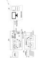
図1は、本発明の適用対象になる分散型電源システム1の概略構成を示すブロック図である。図1に例示の分散型電源システム1は、蓄電装置2と、発電装置3とを含むハイブリッド型の電源システムである。分散型電源システム1は、需要家の構内に設けられた商用の電力系統80と連系して負荷50や連系する電力系統80に交流電力を供給する電力供給システムを構成する。電力系統80と分電盤82とは電力線83を介して接続され、分電盤82を介して負荷50が接続される。分散型電源システム1を構成する蓄電装置2と分電盤82との間には電力計81(電流計、電圧計)が設けられる。
[Application example]
Hereinafter, application examples of the present invention will be described with reference to the drawings.
Fig. 1 is a block diagram showing a schematic configuration of a
分散型電源システム1において、蓄電装置2は、蓄電池ユニット27と、パワーコンディショナ(以下、「PCS」ともいう)20を備える。PCS20(以下、「蓄電PCS20」ともいう)は、制御部21と、双方向DC/DCコンバータ22と、電力変換部23とを備える。双方向DC/DCコンバータ22は蓄電池ユニット27と接続される。また、発電装置3は、太陽光発電モジュール37と、パワーコンディショナ(PCS)30を備える。PCS30(以下、「PV-PCS30」ともいう)は、制御部31と、DC/DCコンバータ32と、電力変換部33とを備える。DC/DCコンバータ32は太陽光発電モジュール37と接続される。
In the distributed
蓄電PCS20には、蓄電池ユニット27と双方向DC/DCコンバータ22との間に設けられた電力センサ28(電流センサ、電圧センサ)、電力計81を含む各種のセンサの出力が入力され、当該各種センサを通じて検出された負荷状況等や、予め設定された充放電に関するモード等に基づいて、充放電に関する制御処理が行われる。例えば、放電を行う場合には、蓄電池ユニット27から放電された電力を双方向DC/DCコンバータ22を介して電圧変換し、電圧変換後の直流電力を電力系統80と同期のとれた交流電力に変換して電力変換部23から出力するように制御する。放電を停止する場合には、蓄電池ユニット27からの放電を停止させて、当該放電電力に基づく電力変換部23から出力される交流電力を停止するように制御する。さらに、上記モードや負荷状況、蓄電池ユニット27の充電状態等に基づいて、充電を行うと判定した場合には、電力系統80やPV-PCS30を通じて接続点2aに供給された交流電力を変換し、蓄電池ユニット27へ充電するように制御する。
The
PV-PCS30には、太陽光発電モジュール37とDC/DCコンバータ32との間に設けられた電力センサ38(電流センサ、電圧センサ)、および、電力計81を含む各種のセンサの出力が入力される。そして、PV-PCS30では、上記各種センサを通じて検出された情報に基づいて、太陽光発電モジュール37の発電出力が最大となる最大電力(電流×電圧の値)点あるいは最適動作点でDC/DCコンバータ32が動作するように最大電力点追従制御(Maximum power point tracking、MPPT)、あるいは、太陽光発電モジュール37からの入力電圧をある一定の値に保つ制御が行われる。
The PV-
適用対象の分散型電源システム1においては、図2に示すように、PV-PCS30から入力された交流電力が得られる場合には、蓄電PCS20とPV-PCS30との両方が負荷に供給される負荷電圧を制御すると、相互の制御が干渉し合う為、充放電に関する制御処理を充電モードに切換えて蓄電装置2が運転される。蓄電PCS20では、例えば、接続点2aに導通されたPV-PCS30からの自立出力を充電電力とする電流制御が行われ、電力変換部(INV)33、双方向DC/DCコンバータ22を介して蓄電池ユニット27が充電される。また、充電モードの蓄電PCS20からは、接続点2aに導通されたPV-PCS30の自立入力が、需要家内の負荷に対する特定負荷電力として出力される。
In the distributed
ところで、分散型電源システム1を構成する発電装置3には予め仕様等で規定される定格容量が存在する。例えば、発電装置3の定格容量が1.5KVAの場合では、自立運転時に付加に供給可能な特定負荷電力は1.5KVA以下に制限されることになる。例えば、需要家内の負荷容量が1.8KVAである場合には、発電装置3が供給可能な定格容量1.5KVAを超えないように負荷機器の使用が制限される。また、当該制限下で負荷を使用していても、1.5KVAを超える一時的な負荷容量の変動に対応することは困難である。蓄電装置2が、発電装置3の定格容量を超える仕様の場合(例えば、2.0KVA)には、蓄電PCS30の充放電に関する制御処理を放電モードに切換え、需要家内負荷に対する特定負荷電力の供給が可能であるが、PV-PCS30の出力電圧制御と、蓄電PCS30の出力電圧制御とが相互に干渉するため、負荷の動作を一時的に停止することを要していた。
The
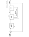
図3に示すように本発明の適用例に係る分散型電源システム1においては、蓄電装置2の蓄電PCS20aはインダクタL(24)を備える。そして、当該インダクタLを通じて、PV-PCS30aから出力された自立出力を入力する。インダクタL(24)の一端側にはPV-PCS30aの電力変換部(INV)33の自立出力が自立入力端子2bを介して接続され、他端側には接続点2aが接続される。インダクタL(24)の電磁気的特性により、当該インダクタLは、PV-PCS30aから出力された自立出力に対するバッファとして機能し、当該インダクタLの両端で個別に電圧制御を行うことが可能に
なる。
As shown in Fig. 3, in the distributed
具体的には、図3から図7に示すように、発電装置3のPV-PCS30aは、インダクタL(24)の入力端側に設けられた電力センサ25で検出されたセンサ情報に基づいて、当該PCSの自立出力が蓄電PCS30aに入力される入力端側の電圧制御を行う。そして、蓄電装置2の蓄電PCS20aは、インダクタL(24)の他端側の接続点2aで検出されたセンサ情報に基づいて、需要家内負荷に供給される特定負荷電力の負荷電圧制御を行う。蓄電PCS20aは、インダクタL(24)の他端側の接続点2aで検出された電流・電圧をフィードバック情報として、電力計81で検出された電力値(電流値、電圧値)が制御目標値となるように双方向DC/DCコンバータ22および電力変換部23を制御する。
Specifically, as shown in Figures 3 to 7, the PV-
本適用例に係る分散型電源システム1においては、自立運転の際に、PV-PCS30aは、インダクタL(24)の入力端側の電圧が制御目標値となるようにフィードバック制御を行い、太陽光発電モジュール37で発電された電力を交流電力に変換し、出力できる。そして、蓄電PCS20aは、放電モード時に、インダクタL(24)の出力端側の電圧(負荷電圧)が制御目標値となるようにフィードバック制御を行い、蓄電池ユニット27に蓄電された電力を放電することができる。本適用例に係る分散型電源システム1によれば、インダクタL(24)の両端に係る電圧を個別に制御できるため、蓄電装置2の放電時における出力電圧制御と、発電装置3における出力電圧制御とが相互に干渉することはない。本適用例においては、自立運転の際の、蓄電装置2の充電モードから放電モードへの切換えにおいて、一時的に負荷の動作を停止させずに連続的な電力供給が可能になる。また、蓄電装置2と発電装置3との並列運転が可能になる。
In the distributed
〔実施例1〕
以下では、本発明の具体的な実施の形態について、図面を用いて、より詳細に説明する。
Example 1
Hereinafter, specific embodiments of the present invention will be described in more detail with reference to the drawings.
<システム構成>
図1は、本発明の適用対象になる分散型電源システム1の概略構成を示すブロック図である。図1の分散型電源システム1は、蓄電装置2と、発電装置3とを含むハイブリッド型の電源システムである。図1に示すように、分散型電源システム1は、需要家の構内に設けられた商用の電力系統80と連系して負荷50や連系する電力系統80に交流電力を供給する電力供給システムを構成する。分散型電源システム1においては、電力系統80と分電盤82とは電力線83を介して接続され、分電盤82を介して負荷50が接続される。分散型電源システム1を構成する蓄電装置2と分電盤82との間には電力計81(電流計、電圧計)が設けられる。
<System Configuration>
Fig. 1 is a block diagram showing a schematic configuration of a distributed
図1の分散型電源システム1において、蓄電装置2は、蓄電池ユニット27と、パワーコンディショナ(以下、「PCS」ともいう)20を備える。PCS20は、制御部21と、双方向DC/DCコンバータ22と、電力変換部23とを備える。双方向DC/DCコンバータ22は蓄電池ユニット27と接続される。蓄電池ユニット27は、定格等で定められた所定容量の電力を蓄積する蓄電池であり、当該定格等により充放電の回数が制限される。また、発電装置3は、太陽光発電モジュール37と、パワーコンディショナ(PCS)30を備える。PCS30は、制御部31と、DC/DCコンバータ32と、電力変換部33とを備える。DC/DCコンバータ32は太陽光発電モジュール37と接続される。太陽光発電モジュール37は、太陽光をエネルギー源とする発電機構である。PCS30の電力変換部33からの出力(交流電力)は、PCS20に入力され、PCS20内の配線を介して接続点2aに接続される。なお、以下では、蓄電装置2のPCS20を「蓄電PCS20」、発電装置3のPCS30を「PV-PCS30」ともいう。また、
本実施例においては、発電装置として太陽光発電による形態を用いて説明するが、本発明の適用対象になる分散型電源システム1においては、太陽光発電以外の他の形態の発電形態が採用できる。他の発電形態として、風力や水力等の自然エネルギーを用いた発電形態や、燃料を用いた自家発電形態等が例示される。
In the distributed
In this embodiment, a solar power generation system is used as the power generation device, but other power generation systems besides solar power generation can be used in the distributed
蓄電PCS20において、双方向DC/DCコンバータ22と電力変換部23とは所定のバス(直流バス)で接続される。双方向DC/DCコンバータ22は、蓄電池ユニット27から放電された放電電力の電圧、電力変換部23から供給された蓄電池ユニット27への充電電力の電圧を双方向に変換するユニットである。電力変換部23は、電力系統80から接続点2aを通じて供給された交流電力、または、PV-PCS30から接続点2aに出力された交流電力を直流電力に変換して所定のバスに出力するAC/DCコンバータ、所定のバスに出力された直流電力を電力系統80と同期のとれた交流電力に変換するDC/ACコンバータを含み構成される。蓄電池ユニット27や双方向DC/DCコンバータ22には、制御部21からの制御指令を受けて動作するマイコン等が組み込まれている。
In the
制御部21は、プロセッサ(CPU等)、メモリ、ゲートドライバ、通信インタフェース回路等を含んで構成されるユニットである。制御部21には、蓄電池ユニット27と双方向DC/DCコンバータ22との間に設けられた電力センサ28(電流センサ、電圧センサ)、および、電力計81を含む各種のセンサの出力が入力される。制御部21では、電力センサ28や電力計81を含む各種センサを通じて検出された負荷状況等や、予め設定された充放電に関するモード等に基づいて、充放電に関する制御処理(蓄電制御処理ともいう)が行われる。例えば、制御部21は、放電を行う場合には、蓄電池ユニット27から放電された電力を双方向DC/DCコンバータ22を介して電圧変換し、電圧変換後の直流電力を電力系統80と同期のとれた交流電力に変換して電力変換部23から出力するように制御する。放電を停止する場合には、蓄電池ユニット27からの放電を停止させて、当該放電電力に基づく電力変換部23から出力される交流電力を停止するように制御する。さらに、制御部21は、上記モードや負荷状況、蓄電池ユニット27の充電状態等に基づいて、充電を行うと判定した場合には、電力系統80やPV-PCS30を通じて接続点2aに供給された交流電力を変換し、蓄電池ユニット27へ充電するように制御する。制御部21からの上記蓄電制御処理に関する制御指令を受け、蓄電池ユニット27および双方向DC/DCコンバータ22、電力変換部23の動作が制御される。
The
PV-PCS30では、DC/DCコンバータ32と電力変換部33とは所定のバス(直流バス)で接続される。DC/DCコンバータ32は、太陽光発電モジュール37で発電された直流電力の電圧を変換(昇圧)して所定のバスに供給するユニットである。電力変換部32は、所定のバスにDC/DCコンバータ32から供給された直流電力を電力系統80と同期のとれた交流電力に変換するDC/ACコンバータを含むユニットである。DC/DCコンバータ32、電力変換部33には、制御部31からの制御指令を受けて動作するマイコン等が組み込まれている。
In the PV-
PV-PCS30の制御部31は、プロセッサ(CPU等)、メモリ、ゲートドライバ、通信インタフェース回路等を含んで構成されるユニットである。制御部31には、太陽光発電モジュール37とDC/DCコンバータ32との間に設けられた電力センサ38(電流センサ、電圧センサ)、および、電力計81を含む各種のセンサの出力が入力される。制御部31では、電力センサ38、電力計81を含む各種センサを通じて検出された情報に基づいて、太陽光発電モジュール37の発電出力が最大となる最大電力(電流×電圧の値)点あるいは最適動作点でDC/DCコンバータ32が動作するように最大電力点追従制御(Maximum power point tracking、MPPT)、あるいは、太陽光発電モジュール37からの入力電圧をある一定の値に保つ制御が行われる。
The control unit 31 of the PV-
図2は、分散型電源システム1の自立運転時における電力の流れを説明する説明図である。分散型電源システム1では、自立運転の際には、ハッチングされた矢印に示すように、太陽光発電モジュール37によって発電された発電電力がPV-PCS30のDC/DCコンバータ32、電力変換部(INV)33を介して交流電力に変換され、蓄電PCS20に入力される(自立入力)。電力変換部(INV)33から出力(自立出力)された交流電力は、蓄電PCS20内の配線を介して接続点2aに接続される。
Figure 2 is an explanatory diagram that explains the flow of power during independent operation of the distributed
蓄電PCS30では、PV-PCS30から入力された交流電力が得られる場合には、充放電に関する制御処理を充電モードに切換え、蓄電装置2を動作させる。既に説明したように、蓄電PCS20とPV-PCS30との両方が負荷に供給される負荷電圧を制御すると、相互の制御が干渉し合う為である。充電モードの蓄電PCS20では、接続点2aに導通されたPV-PCS30からの自立出力を充電電力とする電流制御が行われ、電力変換部(INV)33、双方向DC/DCコンバータ22を介して蓄電池ユニット27が充電される。なお、充電モードの蓄電PCS20においては、接続点2aに導通されたPV-PCS30の自立入力が、需要家内の負荷に対する特定負荷電力として出力される。
When AC power input from the PV-
ところで、分散型電源システム1を構成する発電装置3には予め仕様等で規定される定格容量が存在する。例えば、発電装置3の定格容量が1.5KVAの場合では、自立運転時に付加に供給可能な特定負荷電力は1.5KVA以下に制限されることになる。例えば、需要家内の負荷容量が1.8KVAである場合には、発電装置3が供給可能な定格容量1.5KVAを超えないように負荷機器の使用が制限される。また、当該制限下で負荷を使用していても、1.5KVAを超える一時的な負荷容量の変動に対応することは困難である。また、発電装置3の発電量が天候等(太陽光、風力、水力、地熱等の自然エネルギーに基づく発電)に影響されて低下する場合もある。蓄電装置2が、発電装置3の定格容量を超える仕様の場合(例えば、2.0KVA)には、蓄電PCS30の充放電に関する制御処理を放電モードに切換え、需要家内負荷に対する特定負荷電力の供給が可能であるが、PV-PCS30の出力電圧制御と、蓄電PCS30の出力電圧制御とが相互に干渉するため、負荷の動作を一時的に停止することを要していた。
The
図3は、本実施例に係る分散型電源システム1の構成概要を説明する説明図である。本実施例に係る分散型電源システム1の蓄電装置2の蓄電PCS20aはインダクタL(24)を備え、当該インダクタLを通じて、PV-PCS30aから出力された自立出力が自立入力端子2bを介して入力される。インダクタL(24)の一端側にはPV-PCS30aの電力変換部(INV)33の自立出力が接続され、他端側には接続点2aが接続される。インダクタL(24)の電磁気的特性により、当該インダクタLは、PV-PCS30aから出力された自立出力に対するバッファとして機能するため、当該インダクタLの両端で個別に電圧制御を行うことが可能になる。
Figure 3 is an explanatory diagram for explaining the general configuration of the distributed
具体的には、本実施例に係る分散型電源システム1の蓄電装置2の蓄電PCS20aは、インダクタL(24)のPV-PCS30aから出力された自立出力が入力される一端側に電力センサ25(電流センサ、電圧センサ)を備える。電力センサ25によって検出された情報は、蓄電PCS20aの制御部21a、および、PV-PCS30aの制御部31aに入力される。そして、発電装置3のPV-PCS30aは、電力センサ25で検出されたセンサ情報に基づいて蓄電PCS30aの自立入力端側における電圧制御を行う。PV-PCS30aの制御部31aでは、電力計81で検出された情報を電力センサ25で検出されたセンサ情報に換えて、太陽光発電モジュール37の発電出力が最大となる最大電力(電流×電圧の値)点で動作するように最大電力点追従制御、あるいは最適動作点でDC/DCコンバータ32が動作するように直流電圧制御が行われる。この直流電圧
制御は、太陽光発電モジュール37からの入力電圧をある一定の値に保つ制御をいう。
Specifically, the
そして、蓄電装置2の蓄電PCS20aは、電力センサ25で検出されたセンサ情報に基づいて、需要家内負荷に供給される特定負荷電力の負荷電圧制御を行う。蓄電PCS20a制御部21aでは、電力センサ25で検出されたセンサ情報と、電力センサ28、電力計81等の各種センサを通じて検出された負荷状況等や、予め設定された充放電に関するモード等に基づいて、充放電に関する蓄電制御処理が行われる。制御処理については図5を用いて後述する。
The
本実施例に係る分散型電源システム1においては、蓄電PCS20aはインダクタL(24)を備え、当該インダクタLを通じて、PV-PCS30aから出力された自立出力を接続点2aに接続させることができる。このため、分散型電源システム1においては、インダクタL(24)の両端に係る電圧を個別に制御することが可能になる。分散型電源システム1のPV-PCS30aは、自立運転の際に、インダクタL(24)の入力端側の電圧を制御目標値として、太陽光発電モジュール37で発電された電力を交流電力に変換し、出力することができる(自立出力)。また、蓄電PCS20aは、インダクタL(24)の出力端側の電圧に基づいて充放電に関する蓄電制御処理を行うことができる。蓄電PCS20aは、放電を行う場合には、インダクタL(24)の出力端側の電圧をフィードバック情報として、インダクタL(24)の出力端側の電圧(負荷電圧)が制御目標値となるように、蓄電池ユニット27に蓄電された電力を放電することができる。本実施例に係る分散型電源システム1によれば、インダクタL(24)の両端に係る電圧を個別に制御できるため、蓄電装置2の放電時における出力電圧制御と、発電装置3における出力電圧制御とが相互に干渉することはない。本実施例においては、自立運転の際の、蓄電装置2の充電モードから放電モードへの切換えにおいて、一時的に負荷の動作を停止させずに連続的な電力供給が可能になる。また、蓄電装置2と発電装置3との並列運転が可能になる。
In the distributed
<制御部構成>
図4は、本実施例に係る蓄電PCS20aの制御部21aのハードウェア構成の一例を示す図である。図4に示すように、制御部21aは、接続バス106によって相互に接続されたプロセッサ101、主記憶装置102、補助記憶装置103、通信IF104、入出力IF105を構成要素に含むコンピュータである。主記憶装置102および補助記憶装置103は、制御部21aが読み取り可能な記録媒体である。上記の構成要素はそれぞれ複数に設けられてもよいし、一部の構成要素を設けないようにしてもよい。なお、蓄電池ユニット27や双方向DC/DCコンバータ22、PV-PCS30aの制御部31aやDC/DCコンバータ32が備えるマイコンは、制御部21aと実質的に同等のハードウェア構成によって実現される。
<Control unit configuration>
FIG. 4 is a diagram showing an example of the hardware configuration of the
プロセッサ101は、制御部21a全体の制御を行う中央処理演算装置である。プロセッサ101は、例えば、CPU(Central Processing Unit)やMPU(Micro-Processing Unit)、DSP(Digital Signal Processor)等である。プロセッサ101は、例えば、補助記憶装置103に記憶されたプログラムを主記憶装置102の作業領域に実行可能に展開し、当該プログラムの実行を通じて周辺機器の制御を行うことで所定の目的に合致した機能を提供する。但し、プロセッサ101が提供する一部または全部の機能が、ASIC(Application Specific Integrated Circuit)、GPU(Graphics Processing Unit)等によって提供されてもよい。同様にして、一部または全部の機能が、FPGA(Field-Programmable Gate Array)、数値演算プロセッサ等の専用LSI(large scale integration)、その他のハードウェア回路で実現されてもよい。
The
主記憶装置102および補助記憶装置103は、制御部21aのメモリを構成する。主
記憶装置102は、プロセッサ101が実行するプログラム、当該プロセッサが処理するデータ等を記憶する。主記憶装置102は、フラッシュメモリ、RAM(Random Access Memory)やROM(Read Only Memory)を含む。補助記憶装置103は、プロセッサ101等により実行されるプログラムや、動作の設定情報などを記憶する記憶媒体である。補助記憶装置103は、例えば、HDD(Hard-disk Drive)やSSD(Solid State Drive)、EPROM(Erasable Programmable ROM)、フラッシュメモリ、USBメモリ、S
D(Secure Digital)メモリカード等を含む。通信IF104は、通信ネットワークとの通信インタフェースである。通信IF104は、接続される通信ネットワークとの接続方式に応じて適宜の構成を採用できる。本実施例においては、通信IF104を介して接続された双方向DC/DCコンバータ22、蓄電池ユニット27との間で各種の制御指令が通知される。また、制御部31aにおいては、DC/DCコンバータ32との間で各種の制御指令が通知される。入出力IF105は、蓄電PCS21aの備える入力デバイス、出力デバイスとの間でデータの入出力を行うインタフェースである。入出力IF105を通じて、LCD等の表示デバイスや、蓄電PCS21aに接続されたプリンタ等の出力デバイスに出力される。また、入出力IF105を通じて、操作指示が受け付けられ、当該操作指示に基づいて操作者の意図する処理が行われる。さらに、本実施例においては、入出力IF105を通じて接続された電力センサ25(電流センサ、電圧センサ)や電力センサ28、電力計81を含む各種のセンサの出力信号が制御部21aに入力される。また、制御部31aにおいては、入出力IF105を通じて接続された電力センサ25(電流センサ、電圧センサ)や電力センサ37を含む各種のセンサの出力信号が入力される。
The
D (Secure Digital) memory cards and the like. The communication IF 104 is a communication interface with a communication network. The communication IF 104 can adopt an appropriate configuration according to the connection method with the communication network to be connected. In this embodiment, various control commands are notified between the bidirectional DC/
<処理の流れ>
図5は、本実施例に係る蓄電PCS20aで実行される放電時の制御処理の一例を示す機能ブロック図である。図5に示す制御処理は、例えば、蓄電PCS20aの制御部21aと電力変換部(INV)23の協働により提供される。本実施例に係る蓄電PCS20aの放電時においては、図5に示す制御処理により、インダクタL(24)の出力端側の電圧(負荷電圧)が制御目標値となるようにフィードバック制御が行われ、需要家内の負荷に対する特定負荷電力として出力される。なお、インダクタL(24)の入力端側の電圧と、出力端側の電圧は、一定の周期間隔で定期的に取得される。インダクタL(24)の入力端側の電圧は、PV-PCS30aから蓄電PCS20aに入力された自立入力電圧を表す。なお、図5に示す制御処理は、カスケード制御の一例である。
<Processing flow>
FIG. 5 is a functional block diagram showing an example of a control process executed by the
図5において、蓄電PCS20aに入力されたPV-PCS30aからの自立入力電圧は、フィードバック電圧として回路部43に入力される。回路部43では、入力されたフィードバック電圧から、PV-PCS30aから入力された電流値(太陽光PCS入力電流)が算出されて、マイナー制御部42に出力される。なお、回路部43では、マイナー制御部42から回路部43に入力された電圧に応じた電流値が算出されて、再びマイナー制御部42に出力される。また、回路部43から負荷側に供給される出力電圧がフィードバック情報としてマイナー制御部42に入力される。なお、出力電圧(蓄電PCS20aの出力電圧)は、演算器S1に入力される。
In FIG. 5, the independent input voltage from the PV-
図5の演算器S1においては、出力電圧指令値と出力電圧との差分電圧(偏差)が求められ、当該差分電圧は出力電圧制御部41に入力される。なお、出力電圧指令値は蓄電PCS20aの制御部によって生成される。
In the calculator S1 in FIG. 5, the differential voltage (deviation) between the output voltage command value and the output voltage is calculated, and the differential voltage is input to the output
出力電圧制御部41では、演算器S1によって算出された差分電圧(偏差)に基づいて、蓄電PCS20aの出力電圧値を制御目標値とするマイナーループ制御のための電流基準値が生成される。出力電圧制御部41で生成された電流基準値は、マイナー制御部42に入力される。マイナー制御部42では、回路部43からフィードバック入力された、出力電流および太陽光PCS入力電流の各電流値を制御変数、出力電圧を操作変数として、
出力電圧制御部41から入力された電流基準値を目標値とする追値制御が行われる。マイナー制御部42により、回路部43からフィードバック入力された出力電流および太陽光PCS入力電流の各電流値に基づいて電流制御が行われ、出力電圧が一定であるように制御される。この結果、蓄電PCS20aでは、インダクタL(24)の両端に係る電圧値に基づいて負荷電圧が制御目標値となるようにフィードバック制御が行われ、特定負荷電力が出力される。
In the output
A follow-up control is performed with the current reference value input from the output
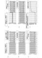
図6から図8は、本実施例に係る制御処理によるシミュレーション結果を示す図である。図6においては、PV-PCS30aから出力された自立入力がインダクタL(24)を介して接続点2aに接続された状態で、蓄電PCS20aの運転モードが充電モードから放電モードへ移行すると同時に、PV-PCS30aの出力電流が0Aに変化した場合のシミュレーション結果が例示される。図6(a)においては、蓄電PCS20aに入力されたPV-PCS30aの電圧の推移、図6(b)においては、需要家内負荷に供給される特定負荷電力の電圧推移、図6(c)においては、蓄電PCS20aの電力変換部(INV)33の出力電圧の推移が例示される。図6(a)から(c)の、縦軸は電圧値、横軸は時間経過を表す。また、図6(d)においては、蓄電PCS20aの電力変換部(INV)33の出力電流の推移、図6(e)においては、需要家内負荷に供給される特定負荷電力の電流推移、図6(f)においては、蓄電PCS20aから出力される電力の推移が例示される。図6(d)から(f)の横軸は時間経過を表し、図6(d)、(e)の縦軸は電流値、(f)の縦軸は電力値を表す。なお、各グラフにおける破線は、負荷に供給される電力がPV-PCS30aから蓄電PCS20aに切り替えられたタイミングを表す。
Figures 6 to 8 are diagrams showing the results of a simulation using the control process according to this embodiment. In Figure 6, the output current of the PV-
図6(a)から(f)に示すように、切り替え前後において、各電流値、電圧値、電力値は一時的に中断することなく連続して供給されていることがわかる。なお、図6(f)に示すように、負荷に供給される電力がPV-PCS30aから蓄電PCS20aに切り替えられる場合には所定の電力値(例えば、0Wから1000W)が出力される迄には演算処理によるタイムラグが生じているが、図6(b)、(e)に示すように、特定負荷電力として供給される電力値は連続して供給されていることがわかる。
As shown in Figures 6(a) to (f), it can be seen that the current values, voltage values, and power values are supplied continuously without any temporary interruption before and after the switch. Note that, as shown in Figure 6(f), when the power supplied to the load is switched from PV-
図7においては、蓄電PCS20aの充電中に、特定負荷に供給される電力が、PV-PCS30aから蓄電PCS20aに切替えられた場合のシミュレーション結果が例示される。図7(a)から(f)のグラフの種別は、図6と同様である。図7(a)から(f)に示すように、切り替え前後において、各電流値、電圧値、電力値は一時的に中断することなく連続して供給されていることがわかる。また、この形態においても、蓄電PCS20aから所定の電力値(例えば、-150Wから1000W)が出力される迄には演算処理によるタイムラグが生じているが、図7(b)、(e)に示すように、特定負荷電力として供給される電力値は連続して供給されていることがわかる。なお、図7(f)では、負荷に供給される電力がPV-PCS30aから蓄電PCS20aに切替えられる以前の電力値が負側の値となっているが、これは蓄電PCS20aが充電中であるためである。
In FIG. 7, the simulation results are illustrated when the power supplied to the specific load is switched from the PV-
図8においては、PV-PCS30aと蓄電PCS20aとの並列運転された場合の特定負荷に供給される電力のシミュレーション結果が例示される。図8(a)から(f)のグラフの種別は、図6と同様である。図8(a)から(f)に示すように、インダクタL(24)の入力端側の電圧と、出力端側の電圧とを用いて制御されたPV-PCS30aと蓄電PCS20aとが並列して動作し、負荷に係る電力が安定して供給されていることがわかる。このため、図8(e)に示す需要家内負荷に供給される特定負荷電力の電流推移は、PV-PCS30aおよび蓄電PCS20aのそれぞれから出力された電流値の合算値となっている。図8(f)に示すように、当該並列動作においては、蓄電PCS20
aから200W程度の電力が出力されていることがわかる。
FIG. 8 illustrates a simulation result of power supplied to a specific load when the PV-
It can be seen that a power of about 200 W is output from a.
以上、説明したように、本実施例に係る分散型電源システム1では、蓄電装置2の蓄電PCS20aはインダクタL(24)を備え、当該インダクタLを通じて、PV-PCS30aから出力された自立出力を入力することができる。PV-PCS30aから出力された自立出力は、例えば、自立入力端子2bを介して入力される。インダクタL(24)を介してPV-PCS30aから出力された自立出力を、接続点2aに接続させることにより、本実施例に係る分散型電源システム1では、当該インダクタLの両端において個別に電圧制御を行うことが可能になる。
As described above, in the distributed
例えば、発電装置3のPV-PCS30aでは、インダクタL(24)の入力端側に設けられた電力センサ25によって検出されたセンサ情報に基づいて、自立運転時における自立出力の電圧制御が行われる。また、蓄電装置2の蓄電PCS20aでは、インダクタL(24)の出力端側に設けられた電力計81によって検出された計測値に基づいて、自立運転時の放電モードにおける自立出力の電圧制御が行われる。本実施例においてPV-PCS30aは、インダクタL(24)の入力端側の電圧を制御目標値としてフィードバック制御し、太陽光発電モジュール37で発電された電力を交流電力に変換して出力し、蓄電PCS20aは、インダクタL(24)の入力端側および出力端側の電圧に基づいて充放電に関する蓄電制御処理を行うことができる。蓄電PCS20aは、例えば、インダクタL(24)の出力端側の電圧(負荷電圧)が制御目標値となるようにフィードバック制御し、蓄電池ユニット27に蓄電された電力を放電することができる。本実施例に係る分散型電源システム1によれば、インダクタL(24)の両端に係る電圧を個別に制御できるため、蓄電装置2の放電時における出力電圧制御と、発電装置3における出力電圧制御とが相互に干渉することはない。本実施例においては、自立運転の際の、蓄電装置2の充電モードから放電モードへの切換えにおいて、一時的に負荷の動作を停止させずに連続的な電力供給が可能になる。
For example, in the PV-
(その他)
上記の実施形態はあくまでも一例であって、本実施の形態の開示はその要旨を逸脱しない範囲内で適宜変更して実施し得る。本開示において説明した処理や手段は、技術的な矛盾が生じない限りにおいて、自由に組合せて実施することができる。例えば、本実施例で開示された形態は、バッテリ等の蓄電池と回生エネルギーを用いた発電機構とを備える電気自動車(EV、Electric Vehicle)に適用してもよい。さらに、発電機構として太陽光発電モジュールを備えたソーラーカー、燃料電池を搭載する燃料電池自動車に適用されるとしてもよい。このような形態であっても、発電機構と蓄電池とから出力される電力を干渉させずに制御することが可能になる。
(others)
The above embodiment is merely an example, and the disclosure of the present embodiment may be modified as appropriate within the scope of the gist of the present disclosure. The processes and means described in the present disclosure may be freely combined and implemented as long as no technical contradiction occurs. For example, the embodiment disclosed in the present embodiment may be applied to an electric vehicle (EV, Electric Vehicle) equipped with a storage battery such as a battery and a power generation mechanism using regenerative energy. Furthermore, it may be applied to a solar car equipped with a solar power generation module as a power generation mechanism, or a fuel cell car equipped with a fuel cell. Even in such a form, it is possible to control the power output from the power generation mechanism and the storage battery without interference.
また、1つの装置が行うものとして説明した処理が、複数の装置によって分担して実行されてもよい。あるいは、異なる装置が行うものとして説明した処理が、1つの装置によって実行されても構わない。コンピュータシステムにおいて、各機能をどのようなハードウェア構成によって実現するかは柔軟に変更可能である。 In addition, a process described as being performed by one device may be shared and executed by multiple devices. Or, a process described as being performed by different devices may be executed by a single device. In a computer system, the hardware configuration that realizes each function can be flexibly changed.
《コンピュータが読み取り可能な記録媒体》
情報処理装置その他の機械、装置(以下、コンピュータ等)に上記何れかの機能を実現させるプログラムをコンピュータ等が読み取り可能な記録媒体に記録することができる。そして、コンピュータ等に、この記録媒体のプログラムを読み込ませて実行させることにより、その機能を提供させることができる。
<Computer-readable recording medium>
A program for causing an information processing device or other machine or device (hereinafter, computer, etc.) to realize any of the above functions can be recorded on a recording medium readable by the computer, etc. Then, the computer, etc. can provide the function by reading and executing the program from the recording medium.
ここで、コンピュータ等が読み取り可能な記録媒体とは、データやプログラム等の情報を電気的、磁気的、光学的、機械的、または化学的作用によって蓄積し、コンピュータ等
から読み取ることができる記録媒体をいう。このような記録媒体のうちコンピュータ等から取り外し可能なものとしては、例えばフレキシブルディスク、光磁気ディスク、CD-ROM、CD-R/W、DVD、ブルーレイディスク、DAT、8mmテープ、フラッシュメモリなどのメモリカード等がある。また、コンピュータ等に固定された記録媒体としてハードディスクやROM等がある。
Here, a computer-readable recording medium refers to a recording medium that stores information such as data and programs through electrical, magnetic, optical, mechanical, or chemical action and can be read by a computer, etc. Among such recording media, those that can be removed from a computer, etc. include, for example, flexible disks, magneto-optical disks, CD-ROMs, CD-R/Ws, DVDs, Blu-ray disks, DAT, 8 mm tapes, memory cards such as flash memories, etc. Furthermore, examples of recording media that are fixed to a computer, etc. include hard disks and ROMs.
なお、以下には本発明の構成要件と実施例の構成とを対比可能とするために、本発明の構成要件を図面の符号付きで記載しておく。
<発明1>
第1の給電装置(2)と、第2の給電装置(3)とを含み、前記第1の給電装置(2)と前記第2の給電装置(3)の少なく一方から出力された交流電力を負荷(50)に供給可能な電源システム(1)であって、
第1の給電装置(2)は、前記第2の給電装置(3)から出力された交流電力が一端に接続され、前記第1の給電装置(1)と前記負荷(50)とが接続される経路の接続点(2a)に他端が接続されるインダクタ(24)を備え、
前記第2の給電装置(3)は、前記インダクタ(24)の一端に係る電圧値を制御目標値にするフィードバック制御を行うとともに、
前記第1の給電装置(2)は、前記インダクタ(24)の他端に係る電圧値を制御目標値にするフィードバック制御を行うことで、該第1の給電装置(2)から前記負荷(50)に供給される交流電力の出力電圧を制御する、
ことを特徴とする電源システム(1)。
In the following, the components of the present invention will be described with reference to the reference numerals in the drawings in order to make it possible to compare the components of the present invention with the configurations of the embodiments.
<
A power supply system (1) including a first power supply device (2) and a second power supply device (3), capable of supplying AC power output from at least one of the first power supply device (2) and the second power supply device (3) to a load (50),
The first power supply device (2) includes an inductor (24) having one end connected to the AC power output from the second power supply device (3) and the other end connected to a connection point (2a) of a path connecting the first power supply device (1) and the load (50);
The second power supply device (3) performs feedback control to set a voltage value related to one end of the inductor (24) to a control target value,
The first power supply device (2) controls an output voltage of AC power supplied from the first power supply device (2) to the load (50) by performing feedback control to set a voltage value related to the other end of the inductor (24) to a control target value.
A power supply system (1).
1 分散型電源システム
2 蓄電装置
2a 接続点
3 発電装置
20、20a パワーコンディショナ(蓄電PCS)
21、21a 制御部
22 双方向DC/DCコンバータ
23 電力変換部(INV)
24 インダクタ
25、28 電力センサ
27 蓄電池ユニット
30、30a パワーコンディショナ(PV-PCS)
31、31a 制御部
32 DC/DCコンバータ
33 電力変換部
37 太陽光発電モジュール
38 電力センサ
41 出力電圧制御部
42 マイナー制御部
43 回路部
50 負荷
80 電力系統
81 電力計
101 プロセッサ
102 主記憶装置
103 補助記憶装置
104 通信IF
105 入出力IF
106 接続バス
1 Distributed
21,
24
105 Input/Output IF
106 Connection bus
Claims (6)
前記第1の給電装置は、前記第2の給電装置から出力された交流電力が一端に接続され、前記第1の給電装置と前記負荷とが接続される経路の接続点に他端が接続されるインダクタを備え、
前記第2の給電装置は、前記インダクタの一端に係る電圧値を制御目標値にするフィードバック制御を行うとともに、
前記第1の給電装置は、前記インダクタの他端に係る電圧値を制御目標値にするフィードバック制御を行うことで、該第1の給電装置から前記負荷に供給される交流電力の出力電圧を制御する、
ことを特徴とする電源システム。 A power supply system including a first power supply device and a second power supply device, capable of supplying AC power output from at least one of the first power supply device and the second power supply device to a load,
the first power supply device includes an inductor having one end connected to the AC power output from the second power supply device and having the other end connected to a connection point of a path connecting the first power supply device and the load;
The second power supply device performs feedback control to set a voltage value related to one end of the inductor to a control target value, and
the first power supply device controls an output voltage of AC power supplied from the first power supply device to the load by performing feedback control to set a voltage value related to the other end of the inductor to a control target value;
A power supply system comprising:
蓄電池と、前記蓄電池と接続される第1パワーコンディショナと、を有する蓄電装置であって、
前記第1パワーコンディショナは、前記蓄電装置の運転モードに充電モードが指定されるときには、前記第2の給電装置から前記インダクタを介して前記接続点に供給された交流電力を直流電力に変換して前記蓄電池に充電し、前記運転モードに放電モードが指定されるときには、前記蓄電池から放電された直流電力を交流電力に変換し、前記インダクタの他端に係る電圧値に基づいて、該交流電力の出力電圧を制御する、ことを特徴とする請求項1に記載の電源システム。 The first power supply device is
A power storage device including a storage battery and a first power conditioner connected to the storage battery,
2. The power supply system according to claim 1, wherein, when a charge mode is designated as the operation mode of the power storage device, the first power conditioner converts AC power supplied from the second power supply device to the connection point via the inductor into DC power and charges the storage battery, and, when a discharge mode is designated as the operation mode of the power storage device, converts DC power discharged from the storage battery into AC power and controls an output voltage of the AC power based on a voltage value associated with the other end of the inductor.
前記インダクタの他端に出力される交流電力の電圧値と出力電圧指令値との偏差から電流基準値を生成する第1制御部と、
前記インダクタの一端に係る電圧値および前記負荷に供給される交流電力の出力電圧値に基づくフィードバック量を制御変数とし、前記インダクタの他端に出力される交流電力の電圧値を操作変数として、前記電流基準値を目標値として追値制御を行う第2制御部と、を備えることを特徴とする請求項2に記載の電源システム。 The first power conditioner includes:
a first control unit that generates a current reference value from a deviation between a voltage value of the AC power output to the other end of the inductor and an output voltage command value;
and a second control unit that performs tracking control with a feedback amount based on a voltage value related to one end of the inductor and an output voltage value of the AC power supplied to the load as a control variable, a voltage value of the AC power output to the other end of the inductor as a manipulated variable, and the current reference value as a target value.
太陽光発電モジュールと、前記太陽光発電モジュールと接続される第2パワーコンディショナと、を有する発電装置であって、
前記第2パワーコンディショナは、前記インダクタの一端に係る電圧値と最大電力点追従制御、または前記太陽光発電モジュールから入力される直流電圧を所定の値に一定に保つ直流電圧制御に関する制御指令に基づいて前記太陽光発電モジュールで発電された直流電力を交流電力に変換して前記インダクタの一端に出力する、ことを特徴とする請求項1または2に記載の電源システム。 The second power supply device is
A power generation device having a solar power generation module and a second power conditioner connected to the solar power generation module,
3. The power supply system according to claim 1, wherein the second power conditioner converts DC power generated by the photovoltaic power generation module into AC power based on a control command related to a voltage value related to one end of the inductor and maximum power point tracking control or DC voltage control for keeping the DC voltage input from the photovoltaic power generation module constant at a predetermined value, and outputs the AC power to one end of the inductor.
前記第1の給電装置は、前記第2の給電装置から出力された交流電力が一端に接続され、前記第1の給電装置と前記負荷とが接続される経路の接続点に他端が接続されるインダクタを備え、
前記第2の給電装置に、前記インダクタの一端に係る電圧値を制御目標値にするフィードバック制御を実行させるとともに、
前記第1の給電装置に、前記インダクタの他端に係る電圧値を制御目標値にするフィー
ドバック制御を実行させることで、該第1の給電装置から前記負荷に供給される交流電力の出力電圧を制御させる、
ことを実行させる制御方法。 A control method for a power supply system including a first power supply device and a second power supply device, capable of supplying AC power output from at least one of the first power supply device and the second power supply device to a load, comprising:
the first power supply device includes an inductor having one end connected to the AC power output from the second power supply device and having the other end connected to a connection point of a path connecting the first power supply device and the load;
The second power supply device executes feedback control to set a voltage value related to one end of the inductor to a control target value;
causing the first power supply device to execute feedback control for setting a voltage value related to the other end of the inductor to a control target value, thereby controlling an output voltage of AC power supplied from the first power supply device to the load;
A control method for executing the above.
前記パワーコンディショナは、
前記第2の給電装置から出力された交流電力が一端に接続され、前記第1の給電装置と前記負荷とが接続される経路の接続点に他端が接続されるインダクタを備え、
前記第2の給電装置は、前記インダクタの一端に係る電圧値を制御目標値にするフィードバック制御を行うとともに、
前記第1の給電装置は、前記インダクタの他端に係る電圧値を制御目標値にするフィードバック制御を行うことで、該第1の給電装置から前記負荷に供給される交流電力の出力電圧を制御する、
ことを特徴とするパワーコンディショナ。 A power conditioner of a power supply system including a first power supply device and a second power supply device, capable of supplying AC power output from at least one of the first power supply device and the second power supply device to a load,
The power conditioner comprises:
an inductor having one end connected to the AC power output from the second power supply device and the other end connected to a connection point of a path connecting the first power supply device and the load;
The second power supply device performs feedback control to set a voltage value related to one end of the inductor to a control target value, and
the first power supply device controls an output voltage of AC power supplied from the first power supply device to the load by performing feedback control to set a voltage value related to the other end of the inductor to a control target value;
The power conditioner is characterized by the above.
Priority Applications (1)
| Application Number | Priority Date | Filing Date | Title |
|---|---|---|---|
| JP2021040575A JP7608892B2 (en) | 2021-03-12 | 2021-03-12 | Power supply system, control method and power conditioner |
Applications Claiming Priority (1)
| Application Number | Priority Date | Filing Date | Title |
|---|---|---|---|
| JP2021040575A JP7608892B2 (en) | 2021-03-12 | 2021-03-12 | Power supply system, control method and power conditioner |
Publications (2)
| Publication Number | Publication Date |
|---|---|
| JP2022139970A JP2022139970A (en) | 2022-09-26 |
| JP7608892B2 true JP7608892B2 (en) | 2025-01-07 |
Family
ID=83399789
Family Applications (1)
| Application Number | Title | Priority Date | Filing Date |
|---|---|---|---|
| JP2021040575A Active JP7608892B2 (en) | 2021-03-12 | 2021-03-12 | Power supply system, control method and power conditioner |
Country Status (1)
| Country | Link |
|---|---|
| JP (1) | JP7608892B2 (en) |
Families Citing this family (1)
| Publication number | Priority date | Publication date | Assignee | Title |
|---|---|---|---|---|
| JP7806611B2 (en) * | 2022-05-06 | 2026-01-27 | オムロン株式会社 | Power supply system and power conversion device |
Citations (2)
| Publication number | Priority date | Publication date | Assignee | Title |
|---|---|---|---|---|
| JP2007215344A (en) | 2006-02-10 | 2007-08-23 | Meidensha Corp | Uninterruptible power supply system |
| JP2016144298A (en) | 2015-02-02 | 2016-08-08 | 三菱電機株式会社 | Storage power conditioner system |
-
2021
- 2021-03-12 JP JP2021040575A patent/JP7608892B2/en active Active
Patent Citations (2)
| Publication number | Priority date | Publication date | Assignee | Title |
|---|---|---|---|---|
| JP2007215344A (en) | 2006-02-10 | 2007-08-23 | Meidensha Corp | Uninterruptible power supply system |
| JP2016144298A (en) | 2015-02-02 | 2016-08-08 | 三菱電機株式会社 | Storage power conditioner system |
Also Published As
| Publication number | Publication date |
|---|---|
| JP2022139970A (en) | 2022-09-26 |
Similar Documents
| Publication | Publication Date | Title |
|---|---|---|
| US9866028B2 (en) | Power control apparatus, power control method, program, and energy management system | |
| JP6320539B2 (en) | Method and apparatus for controlling a hybrid energy storage system | |
| JP6430775B2 (en) | Storage battery device | |
| JP6939452B2 (en) | Solar system | |
| US9853452B2 (en) | Power control apparatus, power control method, program, and energy management system | |
| US9780565B2 (en) | System and method for controlling frequency | |
| US11993180B2 (en) | In-vehicle solar charge control system, in-vehicle solar charge control method, and program | |
| EP2693594B1 (en) | Power control apparatus and power control method | |
| KR20160082319A (en) | Microgrid energy management system and power storage method of energy storage system | |
| KR101545136B1 (en) | Method and System for controlling generator output of islanded microgrids | |
| US10840729B2 (en) | Method and system for operating a DC-DC converter of an electrical system to distribute a load | |
| JP2019193317A (en) | Power storage system, charge/discharge control device, control method thereof, and program | |
| KR102013413B1 (en) | HILS development system of ESS and operation method of ESS using the same | |
| Zainurin et al. | A review of battery charging-discharging management controller: A proposed conceptual battery storage charging–discharging centralized controller | |
| CN104283227A (en) | System and method for managing energy of micro-grid | |
| WO2021054074A1 (en) | Control device, system, control method, and program | |
| JP7608892B2 (en) | Power supply system, control method and power conditioner | |
| WO2017163747A1 (en) | Power storage system, charge/discharge control device, control method therefor, and program | |
| JP7789478B2 (en) | Power generation system, control method and program | |
| JP7806611B2 (en) | Power supply system and power conversion device | |
| JP6016719B2 (en) | Charge control system | |
| JP7556250B2 (en) | Power generation system, control method and program | |
| CN120879722B (en) | Fuel cell power generation system and its control method | |
| KR102917366B1 (en) | System and Method for automating integration management of Energy Storage System | |
| JP7556249B2 (en) | Power generation system, control method and program |
Legal Events
| Date | Code | Title | Description |
|---|---|---|---|
| A621 | Written request for application examination |
Free format text: JAPANESE INTERMEDIATE CODE: A621 Effective date: 20240116 |
|
| A977 | Report on retrieval |
Free format text: JAPANESE INTERMEDIATE CODE: A971007 Effective date: 20241111 |
|
| TRDD | Decision of grant or rejection written | ||
| A01 | Written decision to grant a patent or to grant a registration (utility model) |
Free format text: JAPANESE INTERMEDIATE CODE: A01 Effective date: 20241119 |
|
| A61 | First payment of annual fees (during grant procedure) |
Free format text: JAPANESE INTERMEDIATE CODE: A61 Effective date: 20241202 |
|
| R150 | Certificate of patent or registration of utility model |
Ref document number: 7608892 Country of ref document: JP Free format text: JAPANESE INTERMEDIATE CODE: R150 |