JP7608885B2 - Control system and control method - Google Patents
Control system and control method Download PDFInfo
- Publication number
- JP7608885B2 JP7608885B2 JP2021039408A JP2021039408A JP7608885B2 JP 7608885 B2 JP7608885 B2 JP 7608885B2 JP 2021039408 A JP2021039408 A JP 2021039408A JP 2021039408 A JP2021039408 A JP 2021039408A JP 7608885 B2 JP7608885 B2 JP 7608885B2
- Authority
- JP
- Japan
- Prior art keywords
- control unit
- virtual
- integrated
- file
- project
- Prior art date
- Legal status (The legal status is an assumption and is not a legal conclusion. Google has not performed a legal analysis and makes no representation as to the accuracy of the status listed.)
- Active
Links
Images


Landscapes
- Programmable Controllers (AREA)
Description
本開示は、制御システムに関し、より特定的には、複数の制御ユニットのプロジェクトファイルの統合に関する。 The present disclosure relates to control systems, and more particularly to integrating project files for multiple control units.
様々な生産現場において、PLC(プログラマブルコントローラ)等の制御装置を用いたFA(Factory Automation)技術が広く普及している。生産現場では、例えば、複数の制御装置が設置され、各制御装置は、複数のロボットまたは工作機器等を制御し得る。 Factory automation (FA) technology using control devices such as programmable controllers (PLCs) is becoming more and more common in various production sites. For example, multiple control devices are installed in a production site, and each control device can control multiple robots or machine tools.
制御装置に関して、例えば、特開2019-036043号公報(特許文献1)は、「実行毎に全体がスキャンされる第1のプログラムと、逐次実行される第2のプログラムとを格納する記憶部と、予め定められた制御周期毎に第1のプログラムを実行して第1の指令値を演算する実行処理部と、第2のプログラムの少なくとも一部を解釈して中間コードを生成するインタプリタと、インタプリタが事前に生成した中間コードに従って制御周期毎に第2の指令値を演算する指令値演算部と、実行処理部により演算された第1の指令値および指令値演算部により演算された第2の指令値を制御周期毎に出力する出力部とを含む」制御装置を開示している([要約]参照)。 Regarding the control device, for example, JP 2019-036043 A (Patent Document 1) discloses a control device including "a storage unit that stores a first program whose entirety is scanned for each execution and a second program that is executed sequentially, an execution processing unit that executes the first program for each predetermined control period to calculate a first command value, an interpreter that interprets at least a portion of the second program to generate intermediate code, a command value calculation unit that calculates a second command value for each control period according to the intermediate code generated in advance by the interpreter, and an output unit that outputs the first command value calculated by the execution processing unit and the second command value calculated by the command value calculation unit for each control period" (see [Abstract]).
特許文献1に開示された技術によると、複数の制御ユニット用のプロジェクトファイルを容易に統合することができない。したがって、複数の制御ユニット用のプロジェクトファイルを容易に統合するための技術が必要とされている。
According to the technology disclosed in
本開示は、上記のような背景に鑑みてなされたものであって、ある局面における目的は、複数の制御ユニット用のプロジェクトファイルを容易に統合するための技術を提供することにある。 The present disclosure has been made in light of the above background, and in one aspect, the objective is to provide a technique for easily integrating project files for multiple control units.
本開示の一例に従えば、制御システムが提供される。制御システムは、第1の制御ユニット用の第1のプロジェクトファイルと、第2の制御ユニット用の第2のプロジェクトファイルと、第1および第2のプロジェクトファイルに基づいて生成される統合プロジェクトファイルとを格納する記憶部と、各プロジェクトファイルに基づいて処理を実行する制御部とを備える。第1および第2のプロジェクトファイルの各々は、各プロジェクトファイルごとに独立して複数のノードの各々に割り当てられた複数のノード識別子を含む。統合プロジェクトファイルは、全てのノードの各々に一意に割り当て直したノード識別子を含む。制御部は、全てのノードの各々に一意に割り当て直したノード識別子を用いて、通信するノードのノード識別子を特定する。 According to one example of the present disclosure, a control system is provided. The control system includes a storage unit that stores a first project file for a first control unit, a second project file for a second control unit, and an integrated project file generated based on the first and second project files, and a control unit that executes processing based on each project file. Each of the first and second project files includes a plurality of node identifiers that are assigned to each of a plurality of nodes independently for each project file. The integrated project file includes node identifiers that are uniquely reassigned to each of all nodes. The control unit identifies the node identifiers of the nodes to communicate with, using the node identifiers that are uniquely reassigned to each of all nodes.
この開示によれば、制御システムは、第1および第2のプロジェクトファイルに含まれる全てのノードの各々に一意なノード識別子を設定することで、各ノードと通信可能になる。 According to this disclosure, the control system is able to communicate with each node by setting a unique node identifier for each of all nodes included in the first and second project files.
上記の開示において、記憶部は、第1の仮想制御ユニットと、第2の仮想制御ユニットと、仮想統合制御ユニットとをさらに格納する。制御部は、第1の仮想制御ユニットに、第1のプロジェクトファイルをインストールし、第2の仮想制御ユニットに、第2のプロジェクトファイルをインストールし、仮想統合制御ユニットに、統合プロジェクトファイルをインストールし、仮想統合制御ユニットおよびノードの各々間の通信データを第1の仮想制御ユニットまたは第2の仮想制御ユニットのいずれかに転送する。 In the above disclosure, the storage unit further stores a first virtual control unit, a second virtual control unit, and a virtual integrated control unit. The control unit installs a first project file in the first virtual control unit, installs a second project file in the second virtual control unit, installs an integrated project file in the virtual integrated control unit, and transfers communication data between the virtual integrated control unit and each of the nodes to either the first virtual control unit or the second virtual control unit.
この開示によれば、制御システムは、各制御ユニットを仮想制御ユニットとして動作させることにより統合し、また、各制御ユニットおよび各ノード間の通信を転送し得る。 According to this disclosure, the control system can integrate each control unit by operating them as a virtual control unit and can also transfer communications between each control unit and each node.
上記の開示において、記憶部は、第1のプロジェクトファイルに含まれる第1のネットワーク情報ファイルおよび第2のプロジェクトファイルに含まれる第2のネットワーク情報ファイルと、統合プロジェクトファイルに含まれる統合ネットワーク情報ファイルとの変換情報をさらに格納する。第1のネットワーク情報ファイル、第2のネットワーク情報ファイルおよび統合ネットワーク情報ファイルの各々は、各プロジェクト内で使用されるノード識別子を含む。制御部は、変換情報を用いて、仮想統合制御ユニットおよびノードの各々間の通信データを第1の仮想制御ユニットまたは第2の仮想制御ユニットのいずれかに転送する。 In the above disclosure, the storage unit further stores conversion information between the first network information file included in the first project file and the second network information file included in the second project file, and the integrated network information file included in the integrated project file. Each of the first network information file, the second network information file, and the integrated network information file includes a node identifier used within each project. The control unit transfers communication data between the virtual integrated control unit and each of the nodes to either the first virtual control unit or the second virtual control unit using the conversion information.
この開示によれば、制御システムは、変換情報を用いて、各仮想統合制御ユニットが管理するノード識別子と、実ネットワーク上の各ノードに割り当てられたノード識別子とを相互に変換し得る。 According to this disclosure, the control system can use the conversion information to convert between node identifiers managed by each virtual integrated control unit and node identifiers assigned to each node on the real network.
上記の開示において、制御部は、第1のネットワーク情報ファイルで定義されている第1の制御周期と、第2のネットワーク情報ファイルで定義されている第2の制御周期との公約数である制御周期に基づいて、ノードの各々と通信する。 In the above disclosure, the control unit communicates with each of the nodes based on a control period that is a common divisor of a first control period defined in a first network information file and a second control period defined in a second network information file.
この開示によれば、制御システムは、統合する各プロジェクトファイル内で使用される制御周期の公約数である制御周期で動作することにより、各仮想制御ユニットの制御周期(通信周期)で各ノードと通信し得る。 According to this disclosure, the control system can communicate with each node at the control period (communication period) of each virtual control unit by operating at a control period that is a common divisor of the control periods used in each project file to be integrated.
上記の開示において、制御システムは、複数のプロジェクトファイルを統合する装置をさらに含む。装置は、第1のプロジェクトファイルと、第2のプロジェクトファイルとに基づいて、統合プロジェクトファイルを生成する。制御部は、装置から、第1のプロジェクトファイルと、第2のプロジェクトファイルと、統合プロジェクトファイルとを取得する。 In the above disclosure, the control system further includes a device that integrates multiple project files. The device generates an integrated project file based on the first project file and the second project file. The control unit acquires the first project file, the second project file, and the integrated project file from the device.
この開示によれば、制御システムは、装置によって生成された統合プロジェクトファイルを取得することができる。 According to this disclosure, the control system can obtain an integrated project file generated by the device.
上記の開示において、装置は、制御システムの制御周期内における、第1の仮想制御ユニットの処理時間の占有率と、第2の仮想制御ユニットの処理時間の占有率との合計が100%を超えることに基づいて、エラーを出力する。 In the above disclosure, the device outputs an error based on the sum of the occupancy rate of the processing time of the first virtual control unit and the occupancy rate of the processing time of the second virtual control unit exceeding 100% within the control period of the control system.
この開示によれば、制御システムは、制御システムの制御周期内における各仮想制御ユニットの処理時間の占有率の合計が100%を超える場合、エラーを出力することにより、ユーザにプロジェクトが統合できないことを知らせることができる。 According to this disclosure, if the sum of the processing time occupancy rates of each virtual control unit within a control period of the control system exceeds 100%, the control system can output an error to inform the user that the projects cannot be integrated.
上記の開示において、制御部は、第1のプロジェクトファイルと、第2のプロジェクトファイルとに基づいて、統合プロジェクトファイルを生成する。 In the above disclosure, the control unit generates an integrated project file based on the first project file and the second project file.
この開示によれば、制御システムは、制御部により統合プロジェクトファイルとを生成することができる。 According to this disclosure, the control system can generate an integrated project file by the control unit.
本開示の一例に従えば、制御ユニットを含む制御システムの制御方法が提供される。制御方法は、第1の制御ユニット用の第1のプロジェクトファイルと、第2の制御ユニット用の第2のプロジェクトファイルとに基づいて生成される統合プロジェクトファイルを参照するステップを含む。第1および第2のプロジェクトファイルの各々は、各プロジェクトファイルごとに独立して複数のノードの各々に割り当てられた複数のノード識別子を含む。統合プロジェクトファイルは、全てのノードの各々に一意に割り当て直したノード識別子を含む。全てのノードの各々に一意に割り当て直したノード識別子を用いて、通信するノードのノード識別子を特定するステップをさらに含む。 According to one example of the present disclosure, a control method for a control system including a control unit is provided. The control method includes a step of referencing an integrated project file generated based on a first project file for a first control unit and a second project file for a second control unit. Each of the first and second project files includes a plurality of node identifiers assigned to each of a plurality of nodes independently for each project file. The integrated project file includes node identifiers uniquely reassigned to each of all the nodes. The control method further includes a step of identifying the node identifier of the communicating node using the node identifiers uniquely reassigned to each of all the nodes.
この開示によれば、第1および第2のプロジェクトファイルに含まれる全てのノードの各々に一意なノード識別子を設定することで、各ノードと通信可能になる。 According to this disclosure, by setting a unique node identifier for each of all nodes included in the first and second project files, it becomes possible to communicate with each node.
上記の開示において、制御方法は、第1の仮想制御ユニットに、第1のプロジェクトファイルをインストールするステップと、第2の仮想制御ユニットに、第2のプロジェクトファイルをインストールするステップと、仮想統合制御ユニットに、統合プロジェクトファイルをインストールするステップと、仮想統合制御ユニットおよびノードの各々間の通信データを第1の仮想制御ユニットまたは第2の仮想制御ユニットのいずれかに転送するステップとをさらに含む。 In the above disclosure, the control method further includes a step of installing a first project file in the first virtual control unit, a step of installing a second project file in the second virtual control unit, a step of installing an integrated project file in the virtual integrated control unit, and a step of transferring communication data between the virtual integrated control unit and each of the nodes to either the first virtual control unit or the second virtual control unit.
この開示によれば、各制御ユニットを仮想制御ユニットとして動作させることにより統合し、また、各制御ユニットおよび各ノード間の通信を転送し得る。 According to this disclosure, each control unit can be integrated by operating it as a virtual control unit, and communications between each control unit and each node can be forwarded.
上記の開示において、制御方法は、第1のプロジェクトファイルに含まれる第1のネットワーク情報ファイルおよび第2のプロジェクトファイルに含まれる第2のネットワーク情報ファイルと、統合プロジェクトファイルに含まれる統合ネットワーク情報ファイルとの変換情報にアクセスするステップをさらに含む。第1のネットワーク情報ファイル、第2のネットワーク情報ファイルおよび統合ネットワーク情報ファイルの各々は、各プロジェクト内で使用されるノード識別子を含む。制御方法は、変換情報を用いて、仮想統合制御ユニットおよびノードの各々間の通信データを第1の仮想制御ユニットまたは第2の仮想制御ユニットのいずれかに転送するステップをさらに含む。 In the above disclosure, the control method further includes a step of accessing conversion information between the first network information file included in the first project file and the second network information file included in the second project file, and the integrated network information file included in the integrated project file. Each of the first network information file, the second network information file, and the integrated network information file includes a node identifier used within each project. The control method further includes a step of transferring communication data between the virtual integrated control unit and each of the nodes to either the first virtual control unit or the second virtual control unit using the conversion information.
この開示によれば、変換情報を用いて、各仮想統合制御ユニットが管理するノード識別子と、実ネットワーク上の各ノードに割り当てられたノード識別子とを相互に変換し得る。 According to this disclosure, the conversion information can be used to convert between node identifiers managed by each virtual integrated control unit and node identifiers assigned to each node on the real network.
上記の開示において、制御方法は、第1のネットワーク情報ファイルで定義されている第1の制御周期と、第2のネットワーク情報ファイルで定義されている第2の制御周期との公約数である制御周期に基づいて、ノードの各々と通信するステップをさらに含む。 In the above disclosure, the control method further includes a step of communicating with each of the nodes based on a control period that is a common divisor of a first control period defined in the first network information file and a second control period defined in the second network information file.
この開示によれば、統合する各プロジェクトファイル内で使用される制御周期の公約数である制御周期で動作することにより、各仮想制御ユニットの制御周期(通信周期)で各ノードと通信し得る。 According to this disclosure, by operating at a control period that is a common divisor of the control periods used in each project file to be integrated, it is possible to communicate with each node at the control period (communication period) of each virtual control unit.
上記の開示において、制御方法は、制御システムの制御周期内における、第1の仮想制御ユニットの処理時間の占有率と、第2の仮想制御ユニットの処理時間の占有率との合計が100%を超えることに基づいて、エラーを出力するステップをさらに含む。 In the above disclosure, the control method further includes a step of outputting an error based on the sum of the occupancy rate of the processing time of the first virtual control unit and the occupancy rate of the processing time of the second virtual control unit exceeding 100% within the control period of the control system.
この開示によれば、制御システムの制御周期内における各仮想制御ユニットの処理時間の占有率の合計が100%を超える場合、エラーを出力することにより、ユーザにプロジェクトが統合できないことを知らせることができる。 According to this disclosure, if the total occupancy rate of the processing time of each virtual control unit within the control period of the control system exceeds 100%, an error can be output to inform the user that the projects cannot be merged.
ある実施の形態に従うと、複数の制御ユニット用のプロジェクトファイルを容易に統合することが可能である。 In accordance with one embodiment, project files for multiple control units can be easily merged.
この開示内容の上記および他の目的、特徴、局面および利点は、添付の図面と関連して理解される本開示に関する次の詳細な説明から明らかとなるであろう。 The above and other objects, features, aspects and advantages of this disclosure will become apparent from the following detailed description of the present disclosure taken in conjunction with the accompanying drawings.
以下、図面を参照しつつ、本開示に係る技術思想の実施の形態について説明する。以下の説明では、同一の部品には同一の符号を付してある。それらの名称および機能も同じである。したがって、それらについての詳細な説明は繰り返さない。 Below, an embodiment of the technical concept of the present disclosure will be described with reference to the drawings. In the following description, the same components are given the same reference numerals. Their names and functions are also the same. Therefore, detailed descriptions thereof will not be repeated.
<A.適用例>
まず、図1を参照して、本実施の形態に従う技術が適用される場面について説明する。
<A. Application Examples>
First, with reference to FIG. 1, a situation in which the technique according to the present embodiment is applied will be described.
図1は、本実施の形態が適用される制御ユニットの一例を示す図である。図1を参照して、第1の制御ユニット20Aの第1のプロジェクトファイルと、第2の制御ユニット20Bの第2のプロジェクトファイルと、第3の制御ユニット20Cの第3のプロジェクトファイルとを統合して統合制御ユニット20Dにインストールする手順を例に、本実施の形態に従う技術の概要について説明する。統合制御ユニット20Dは、第1の制御ユニット20A、第2の制御ユニット20Bおよび第3の制御ユニット20Cと同一のハードウェア構成である。これ以降、第1の制御ユニット20A、第2の制御ユニット20B、第3の制御ユニット20Cおよび統合制御ユニット20Dを総称する場合は、制御ユニット20と呼ぶ。なお、制御ユニット20は、1または複数の装置、または、システムとして構成されてもよい。
FIG. 1 is a diagram showing an example of a control unit to which the present embodiment is applied. With reference to FIG. 1, an overview of the technology according to the present embodiment will be described using an example of a procedure for integrating a first project file of a
なお、図1に示す場面は一例であり、本実施の形態に従う技術は、2台以上の任意の数の制御ユニット20のプロジェクトファイルを統合することができる。プロジェクトファイルは、少なくとも、制御ユニット20が実行する制御プログラムと、フィールドネットワーク7上の構成を定義するネットワーク情報ファイルとを含む。
Note that the scene shown in FIG. 1 is just an example, and the technology according to this embodiment can integrate project files of any number of
PLC等の制御ユニット20は、フィールドネットワーク7(図2参照)を介して、複数のロボットまたは工作機等の制御対象8を制御する。ある局面において、フィールドネットワーク7は、EtherCAT(登録商標)により実現されてもよい。この場合、ネットワーク情報ファイルは、一例として、ENI(EtherCAT Network Information)ファイルであってもよい。なお、ネットワーク情報ファイルは、独自のフォーマットのファイルであってもよい。
A
制御ユニット20は、これらの制御対象8をノードとして管理する。各ノードには、一意なノード識別子(ノードID(Identifier))が割り当てられる。第1の制御ユニット20A、第2の制御ユニット20Bおよび第3の制御ユニット20Cは、いずれも1~10のノード識別子を割り当てられたノードを管理する。
The
各制御ユニット20は、各ノード識別子を管理するためのネットワーク情報ファイルを二次記憶装置33(図4参照)に格納する。各制御ユニット20は、当該ネットワーク情報ファイルと、制御プログラムとに基づいて、各ノードと通信する。ネットワーク情報ファイルおよび制御プログラムは、プロジェクトという単位で管理され得る。プロジェクトに含まれる各種データをまとめてプロジェクトファイルとも呼ぶ。
Each
図1に示す例では、第1の制御ユニット20Aは第1のプロジェクトファイルを格納し、第2の制御ユニット20Bは第2のプロジェクトファイルを格納し、第3の制御ユニット20Cは第3のプロジェクトファイルを格納する。言い換えれば、第1の制御ユニット20Aは第1のプロジェクトによって動作し、第2の制御ユニット20Bは第2のプロジェクトによって動作し、第3の制御ユニット20Cは第3のプロジェクトによって動作する。
In the example shown in FIG. 1, the
第1のプロジェクトファイルは、少なくとも、第1の制御ユニット20Aが実行する第1の制御プログラムのオブジェクトファイルと、第1の制御ユニット20Aが制御する1または複数のノード識別子を含む第1のネットワーク情報ファイルとを含む。同様に、第2のプロジェクトファイルは、少なくとも、第2の制御ユニット20Bが実行する第2の制御プログラムのオブジェクトファイルと、第2の制御ユニット20Bが制御する1または複数のノード識別子を含む第2のネットワーク情報ファイルとを含む。また、第3のプロジェクトファイルは、少なくとも、第3の制御ユニット20Cが実行する第3の制御プログラムのオブジェクトファイルと、第3の制御ユニット20Cが制御する1または複数のノード識別子を含む第3のネットワーク情報ファイルとを含む。
The first project file includes at least an object file of a first control program executed by the
1台の制御ユニット20が複数のノードと通信する場合、各ノード識別子はユニークでなければならない。同じフィールドネットワーク7上に同一のノード識別子を割り当てられた複数のノードが存在する場合、制御ユニット20は、これらのノードと正常に通信することができない。例えば、統合制御ユニット20Dが、第1の制御ユニット20A、第2の制御ユニット20Bおよび第3の制御ユニット20Cのプロジェクトファイルをそのまま読み込んで使用した場合、ノード識別子「1~10」が重複するため正常に各ノードと通信できない。
When one
そのため、本実施の形態に従う技術は、複数の制御ユニット20の各プロジェクトファイルを統合するときに、全てのノードに一意となるノード識別子を設定し直す。こうすることで、ユーザは、例えば、複数の制御ユニット20を用いて、分業で制御プログラムを作成し、運用時にはこれらの複数の制御プログラムを統合して運用することができる。
Therefore, the technology according to this embodiment resets unique node identifiers for all nodes when integrating the project files of
より具体的には、本実施の形態に従う技術は、複数の制御ユニットの各プロジェクトファイル(第1~第3のプロジェクトファイル)を統合制御ユニット20D内の複数の仮想制御ユニット610(図6参照)の各々にインストールする。また、本実施の形態に従う技術は、第1~第3のプロジェクトファイルから、全てのノードに一意となるノード識別子を設定し直した統合プロジェクトファイルを生成し、当該統合プロジェクトファイルを仮想統合制御ユニット640(図6参照)にインストールする。言い換えれば、統合制御ユニット20D内で、仮想的な第1の制御ユニット20A、仮想的な第2の制御ユニット20Bおよび仮想的な第3の制御ユニット20Cと、仮想統合制御ユニット640とが動作する。統合プロジェクトファイルは、全てのノードに対して一意に割り当て直した識別子を含む。統合制御ユニット20Dは、当該全てのノードに対して一意に割り当て直した識別子により、通信するノードのノード識別子を特定し得る。
More specifically, the technology according to this embodiment installs each project file (first to third project files) of the multiple control units into each of the multiple virtual control units 610 (see FIG. 6) in the
ある局面において、統合制御ユニット20Dは、インストールされた各プロジェクトファイル(第1~第3のプロジェクトファイル)から統合プロジェクトファイルを生成してもよい。他の局面において、サポート装置6(図2参照)等を含む外部の情報処理装置が、各プロジェクトファイル(第1~第3のプロジェクトファイル)から統合プロジェクトファイルを生成して、各プロジェクトファイルおよび統合プロジェクトファイルを統合制御ユニット20Dにインストールしてもよい。
In one aspect, the
統合制御ユニット20D内の仮想的な第1の制御ユニット20A、第2の制御ユニット20Bおよび第3の制御ユニット20Cは、ノード識別子「1~10」が重複する第1~第3のプロジェクトファイルを使用するため、直接ノードと通信することはできない。そこで、当該仮想統合制御ユニット640は、ノード識別子の変換処理を実行しながら、ノード(制御対象8)のいずれかから受信した通信データを複数の仮想制御ユニット610のいずれかに転送する。また、当該仮想統合制御ユニット640は、ノード識別子の変換処理を実行しながら、複数の仮想制御ユニット610のいずれかから受信した通信データをノードのいずれかに転送する。図1を例に説明すると、仮想統合制御ユニット640は、ノード101と通信したデータを仮想制御ユニット610に転送する場合、ノード識別子「101」(統合プロジェクト内でのノード識別子)をノード識別子「1」(第2のプロジェクト内でのノード識別子)に変換する。
The virtual
上記のように、本実施の形態に従う技術は、統合制御ユニット20D内で、複数の仮想制御ユニット610と、仮想統合制御ユニット640とを動作させ、仮想統合制御ユニット640にノード識別子の変換処理を実行させる。こうすることで、ユーザは、複数のプロジェクトファイルに変更を加えることなく、これらの複数のプロジェクトファイルを統合して使用し得る。
As described above, the technology according to this embodiment operates multiple virtual control units 610 and virtual
さらに、本実施の形態に従う技術は、統合前の各プロジェクトファイル(第1~第3のプロジェクトファイル)自体には変更を加えない。そのため、ユーザは、並列的に複数のプロジェクトファイルを作成して、当該複数のプロジェクトファイルを容易に統合することができる。また、統合後の制御プログラムに変更がある場合でも、ユーザは統合前のプロジェクトファイルの各々を個別に編集して再度統合処理を実行するだけでよく、プロジェクトファイルの保守性も向上する。 Furthermore, the technology according to this embodiment does not make any changes to the project files (first to third project files) before they are integrated. Therefore, the user can create multiple project files in parallel and easily integrate the multiple project files. Even if there are changes to the control program after integration, the user only needs to edit each of the project files before integration individually and execute the integration process again, which also improves the maintainability of the project files.
<B.システム構成>
次に、図2を参照して、本実施の形態に従うネットワークシステム10の構成例について説明する。これ以降の説明における制御システム1のようなシステムは、1または複数の装置から構成されてもよい。また、当該システムは、装置の一部または他の装置と連携するものであってもよい。
B. System Configuration
Next, a configuration example of a
図2は、本実施の形態に従う制御システム1を備えるネットワークシステム10の全体構成を模式的に示す図である。上述した制御ユニット20は、制御システム1の一部として実現され得る。
Figure 2 is a diagram showing a schematic diagram of the overall configuration of a
ネットワークシステム10は、構成として、制御システム1、サーバ装置2、表示装置3およびゲートウェイ(GW: Gateway)4を備える。これらの構成は、ネットワーク5を介して、相互に接続され得る。また、ネットワーク5は、ゲートウェイ4を介して、外部ネットワークであるインターネットに接続されている。ある局面において、ネットワーク5は、一般的なネットワークプロトコルであるイーサネット(登録商標)またはEtherNet/IP(登録商標)により実現されてもよい。
The
制御システム1は、フィールドネットワーク7を介して、フィールドの設備および装置、ならびに、それらに配置されている各種デバイス(センサまたはアクチュエータ等)を含む制御対象8に接続されている。フィールドネットワーク7は、データの到達時間が保証される、定周期通信を行うバスまたはネットワークを採用することが好ましい。
The
サポート装置6は、ユーザが制御システム1を運用するのを支援する支援ツールを提供する。また、サポート装置6は、制御システム1にプログラムをインストールする機能を備えていてもよい。ある局面において、サポート装置6は、パーソナルコンピュータ、タブレット、スマートフォン、またはその他の任意の情報処理装置であってもよい。
The
一例として、サポート装置6は、USB(Universal Serial Bus)により、着脱可能に制御システム1に接続される。このUSB通信には、通信のセキュリティを確保するために、ユーザ認証を行なうための通信プロトコルが採用され得る。他の例として、サポート装置6は、ネットワーク5を介して制御システム1と通信してもよい。
As one example, the
サーバ装置2は、一例として、データベースシステム、製造実行システム(MES:Manufacturing Execution System)等である。製造実行システムは、制御対象の製造装置または設備からの情報を取得して、生産全体を監視および管理し、例えば、オーダ情報、品質情報、出荷情報その他の生産に関する情報等を扱うこともできる。また、他の例として、サーバ装置2は、情報系サービス(制御対象から各種情報を取得して、マクロ的またはミクロ的な分析等を行う処理)を提供する装置であってもよい。
As an example, the
表示装置3は、ユーザからの操作を受けて、制御システム1に対してユーザ操作に応じたコマンド等を出力するとともに、制御システム1での演算結果等をグラフィカルに表示する。ある局面において、表示装置3は、液晶ディスプレイまたは有機EL(Electro-Luminescence)ディスプレイ等の任意の出力装置を備えていてもよい。また、表示装置3は、タッチパネルまたはスイッチ等の任意の入力装置を備えていてもよい。
The display device 3 receives operations from a user, outputs commands to the
ゲートウェイ4は、ネットワーク5と外部ネットワーク(インターネット)との間のプロトコル変換と、ファイヤウォールとしての処理とを実行する。
The gateway 4 performs protocol conversion between the
<C.ハードウェア構成>
次に、図3~図5を参照して、本実施の形態に従う主な装置またはシステム(制御システム1、制御ユニット20、および、サポート装置6)のハードウェア構成について説明する。
C. Hardware Configuration
Next, the hardware configuration of the main devices or systems (
(a.制御システム1の外観)
図3は、本実施の形態に従う制御システム1の構成例を示す外観図である。制御システム1は、制御ユニット20、セキュリティユニット21、セーフティユニット22、1または複数の機能ユニット23、および電源ユニット24を含む。ある局面において、制御システム1は、制御ユニット20、セキュリティユニット21、セーフティユニット22、機能ユニット23、および電源ユニット24の各々を1または複数台含んでいてもよい。
(a. Appearance of control system 1)
3 is an external view showing a configuration example of the
制御ユニット20とセキュリティユニット21とは、PCI Expressのバス等を介して相互に接続される。また、制御ユニット20、セーフティユニット22、1または複数の機能ユニット23、および電源ユニット24は、内部バスを介して相互に接続されている。
The
制御ユニット20は、制御プログラムを実行することで、制御対象を制御する。制御プログラムは、制御対象である設備および装置、ならびに、それらに配置されている各種デバイス(センサまたはアクチュエータ等)との間で信号を遣り取りするIOリフレッシュ、制御演算処理等のプログラムを含む。具体的には、IOリフレッシュは、制御ユニット20において算出される指令値を制御対象へ出力、あるいは、制御対象からの入力値を収集する。制御演算処理は、例えば、IOリフレッシュにより収集した入力値に基づいた指令値または制御量を算出する。このような機能を備える制御プログラムは、制御対象の要求仕様に従ってユーザまたは開発会社が作成するプログラムを含む「ユーザプログラム」の一例でもある。
The
セキュリティユニット21は、制御システム1の、より特定的には制御ユニット20のセキュリティを設定する。このセキュリティの設定(ACLテーブル)は、制御プログラムの意図しない複製、すなわち不正な複製を防止するための設定を含む。
The
セーフティユニット22は、制御ユニット20とは独立して、制御対象に関するセーフティ機能を実現するための制御演算を実行する。機能ユニット23は、制御システム1による様々な制御対象に対する制御を実現するための各種機能を提供する。
The
機能ユニット23は、典型的には、I/Oユニット、セーフティI/Oユニット、通信ユニット、モーションコントローラユニット、温度調整ユニット、パルスカウンタユニット等を包含し得る。I/Oユニットとしては、例えば、デジタル入力(DI)ユニット、デジタル出力(DO)ユニット、アナログ出力(AI)ユニット、アナログ出力(AO)ユニット、パルスキャッチ入力ユニット、および、複数の種類を混合させた複合ユニット等が挙げられる。セーフティI/Oユニットは、セーフティ制御に係るI/O処理を担当する。電源ユニット24は、制御システム1を構成する各ユニットに対して、所定電圧の電源を供給する。
The
(b.制御ユニット20のハードウェア構成)
次に、本実施の形態に従う制御システム1が含む制御ユニット20のハードウェア構成例について説明する。
(b. Hardware Configuration of Control Unit 20)
Next, a hardware configuration example of the
図4は、本実施の形態に従う制御システム1を構成する制御ユニット20のハードウェア構成例を示す模式図である。図4を参照して、制御ユニット20は、主たるコンポーネントとして、CPU(Central Processing Unit)またはGPU(Graphical Processing Unit)等のプロセッサ31、チップセット32、二次記憶装置33、主記憶装置34、通信コントローラ35、インジケータ36、スイッチインターフェイス37、内部バスコントローラ39、ネットワークコントローラ40,41,42、メモリカードインターフェイス43、およびUSBコントローラ44を含む。
Fig. 4 is a schematic diagram showing an example of the hardware configuration of the
プロセッサ31は、二次記憶装置33に格納された各種プログラムを読み出して、当該各種プログラムを主記憶装置34に展開して実行することで、制御演算およびサービス処理を含む各種の処理を実現する。チップセット32は、プロセッサ31と各コンポーネントとの間のデータの遣り取りを仲介することで、制御ユニット20全体としての処理を実現する。
The
主記憶装置34は、DRAM(Dynamic Random Access Memory)またはSRAM(Static Random Access Memory)等の揮発性記憶装置を備える。これら揮発性記憶装置の少なくとも一部は、復号済み制御プログラム51を格納するための揮発性記憶領域50を構成する。ある局面において、復号済み制御プログラム51は、例えば、複数の仮想制御ユニット用の制御プログラムと、仮想統合制御ユニット用の制御プログラムとを含み得る。また、復号済み制御プログラム51は、複数の仮想制御ユニット用のネットワーク情報ファイルと、仮想統合制御ユニット用のネットワーク情報ファイルとを参照し得る。
The
二次記憶装置33は、典型的には、例えば、HDD(Hard Disk Drive)またはSSD(Solid State Drive)、ROM(Read Only Memory)、EPROM(Erasable Programmable Read Only Memory)、EEPROM(Electrically Erasable Programmable Read-Only Memory)等の不揮発性記憶装置を備える。これら不揮発性記憶装置の少なくとも一部は、暗号化済み制御プログラム49を格納するための不揮発性記憶領域48を構成する。
The
二次記憶装置33は、さらに、OS(Operating System)を含むシステムプログラム45、サービスプログラム46、および、統合プログラム401等を格納する。システムプログラム45は、復号済み制御プログラム51およびサービスプログラム46等のユーザプログラムが動作するためのプログラム実行環境を提供する。
The
統合プログラム401は、複数のプロジェクトファイルを統合する。より具体的には、統合プログラム401は、複数のプロジェクトファイルから、統合プロジェクトファイルを生成する。統合プロジェクトファイルは、仮想統合制御ユニット640上で動作する統合制御プログラムと、統合ネットワーク情報ファイル645(図6参照)と、ノード識別子を変換するための変換表650(図6参照)とを含む。
The
変換表650は、統合前の各プロジェクト内(またはプロジェクトファイル内)のネットワーク情報ファイルに含まれるノード識別子と、統合プロジェクト内(または統合プロジェクトファイル内)のネットワーク情報ファイルに含まれるノード識別子との変換処理に使用される。図1を例に説明すると、制御ユニット20は、例えば、ノード識別子「101」(統合プロジェクト内で使用されるノード識別子)と、ノード識別子「1」(第2のプロジェクト内で使用されるノード識別子)との変換処理に、変換表650を使用する。言い換えれば、変換表650は、第1のネットワーク情報ファイル615A、第2のネットワーク情報ファイル615Bおよび第3のネットワーク情報ファイル615Cと、統合プロジェクトファイルに含まれる統合ネットワーク情報ファイル645との変換情報である。ある局面において、サポート装置6が統合ツール552(図5参照)を含む場合、制御ユニット20は統合プログラム401を含まなくてもよい。
The conversion table 650 is used for the conversion process between the node identifiers included in the network information files in each project (or project file) before integration and the node identifiers included in the network information file in the integrated project (or integrated project file). Taking FIG. 1 as an example, the
通信コントローラ35は、バス52を介して、セキュリティユニット21とデータを送受信する。通信コントローラ35は、例えば、PCI Express等のバスに対応した通信チップにより実現され得る。
The
インジケータ36は、制御ユニット20の動作状態等を通知するものであり、ユニット表面に配置された1または複数のLED(Light Emitting Diode)等で構成される。スイッチインターフェイス37は、一例として、ディップスイッチ38に接続されており、当該ディップスイッチ38のONまたはOFFの信号をプロセッサ31に出力する。
The
内部バスコントローラ39は、制御システム1を構成するセーフティユニット22と、1または複数の機能ユニット23との間で、内部バスを介してデータを送受信する。この内部バスには、メーカ固有の通信プロトコルを用いてもよいし、いずれかの産業用ネットワークプロトコルと同一あるいは準拠した通信プロトコルを用いてもよい。
The
ネットワークコントローラ40,41,42の各々は、ネットワークを介した任意のデバイスとの間のデータの遣り取りを担当する。ネットワークコントローラ40,41,42は、EtherCAT、EtherNet/IP(登録商標)、DeviceNet(登録商標)、CompoNet(登録商標)等の産業用ネットワークプロトコルを採用してもよい。
Each of the
メモリカードインターフェイス43は、SDカード等のメモリカード53を着脱可能に構成されており、メモリカード53に対してユーザプログラムまたは各種設定等のデータを書込み、あるいは、メモリカード53から当該ユーザプログラムまたは各種設定等のデータを読出すことが可能になっている。USBコントローラ44は、USB接続を介して、サポート装置6を含む任意の情報処理装置とデータを送受信し得る。ある局面において、制御ユニット20は、メモリカードインターフェイス43以外にも、任意の記憶媒体を接続可能な外部機器インターフェイスを備えていてもよい。
The
図4は、プロセッサ31がプログラムを実行することで必要な機能が提供される構成例を示しているが、これらの提供される機能の一部または全部は、専用のハードウェア回路(例えば、ASIC(Application Specific Integrated Circuit)またはFPGA(Field-Programmable Gate Array)等)を用いて実装されてもよい。あるいは、制御ユニット20の主要部を、汎用的なアーキテクチャに従うハードウェア(例えば、汎用パソコンをベースとした産業用パソコン)を用いて実現してもよい。この場合には、仮想化技術を用いて、用途の異なる複数のOSを並列的に実行させるとともに、各OS上で必要なアプリケーションを実行させるようにしてもよい。
Figure 4 shows an example of a configuration in which the necessary functions are provided by the
(c.サポート装置6のハードウェア構成)
次に、本実施の形態に従う制御システム1に接続され得るサポート装置6のハードウェア構成例について説明する。
(c. Hardware Configuration of Support Device 6)
Next, a hardware configuration example of the
図5は、本実施の形態に従う制御システム1に接続され得るサポート装置6のハードウェア構成例を示す模式図である。サポート装置6は、一例として、汎用的なアーキテクチャに従う装置(パーソナルコンコンピュータまたはタブレット等)を用いて実現され得る。
Figure 5 is a schematic diagram showing an example of the hardware configuration of a
サポート装置6は、CPUまたはGPU等のプロセッサ91、主記憶装置92、入力部93、出力部94、二次記憶装置95、光学ドライブ96、および通信インターフェイス97を含む。これらのコンポーネントは、プロセッサバス98を介して接続されている。主記憶装置92および二次記憶装置95は、それぞれ、制御ユニット20の主記憶装置34および二次記憶装置33と同様に構成することができるので、それらの説明を繰返さない。
The
プロセッサ91は、二次記憶装置95に格納されたプログラム(一例として、OS554およびサポートプログラム553)を読出して、主記憶装置92に展開して実行することで、各種処理を実現する。
The
二次記憶装置95は、基本的な機能を実現するためのOS554に加えて、サポート装置6としての機能を提供するためのサポートプログラム553を格納する。サポート装置6(実質的にはプロセッサ91)は、サポートプログラム553を実行することで、サポート装置6が提供する各種サポートツールの機能を実現する。当該サポートツールは、サポート装置6におけるプログラムの開発環境を提供する。
The
また、二次記憶装置95は、サポートツールを用いて作成された制御プログラム551と、統合ツール552とを格納する。制御プログラム551は、制御ユニット20で実行されるプログラムのソースコードであってもよい。また、制御プログラム551は、制御ユニット20で実行されるプログラムの実行ファイル(オブジェクトファイル)を含んでいてもよい。
The
統合ツール552は、複数のプロジェクトファイルを統合する。より具体的には、統合ツール552は、複数のプロジェクトファイルから、統合プロジェクトファイルを生成する。統合プロジェクトファイルは、仮想統合制御ユニット640上で動作する統合制御プログラムと、統合ネットワーク情報ファイル645と、ノード識別子を変換するための変換表650とを含む。ある局面において制御ユニット20が統合プログラム401を含む場合、サポート装置6は統合ツール552(図5参照)を含まなくてもよい。
The integration tool 552 integrates multiple project files. More specifically, the integration tool 552 generates an integrated project file from multiple project files. The integrated project file includes an integration control program that runs on the virtual
また、ある局面において、二次記憶装置95は、暗号化済み制御プログラムを格納してもよい。さらに、二次記憶装置95は、制御プログラム551の暗号化のための鍵、および暗号化処理を実行する暗号化処理プログラムを格納してもよい。また、二次記憶装置95は、暗号化処理プログラムよりも簡易で高速な暗号化処理を実行する簡易暗号化処理プログラムを格納してもよい。プロセッサ91は、簡易暗号化処理プログラムを実行することで、簡易暗号化済み制御プログラムを生成し得る。
In addition, in one aspect, the
入力部93は、キーボードまたはマウス等で構成され、ユーザの操作を受け付ける。ある局面において、入力部93は、さらに、カメラ、マイク、およびその他の任意のデバイスを含んでいてもよい。他の局面において、これらのデバイスは、通信インターフェイス97を介してサポート装置6に接続されてもよい。出力部94は、ディスプレイ、各種インジケータ、プリンタ等で構成され、プロセッサ91からの処理結果等を出力する。
The
サポート装置6は、光学ドライブ96を有する。光学ドライブ96は、記録媒体550(例えば、DVD(Digital Versatile Disc)等の光学記録媒体)から、その中に格納されたプログラムを読み取り、当該プログラムを二次記憶装置95等にインストールする。
The
通信インターフェイス97は、USBまたはイーサネット等の任意の通信媒体を介して、制御システム1が備える制御ユニット20またはセキュリティユニット21と、データを送受信し得る。
The
サポート装置6で実行されるサポートプログラム553等は、コンピュータ読取可能な記録媒体550を介してインストールされてもよいが、ネットワーク上のサーバ装置等からダウンロードする形でインストールされてもよい。また、本実施の形態に従うサポート装置6が提供する機能は、OS554が提供するモジュールの一部を利用する形で実現され得る。
The support program 553 and the like executed by the
図5は、プロセッサ91がプログラムを実行することで、サポート装置6として必要な機能が提供される構成例を示しているが、これらの提供される機能の一部または全部は、専用のハードウェア回路(例えば、ASICまたはFPGA等)を用いて実装されてもよい。また、本実施の形態では、制御システム1の稼動中に、サポート装置6が、制御システム1から取り外されていてもよい。
Figure 5 shows an example of a configuration in which the
<D.制御ユニット20の動作>
次に、図6および図7を参照して、本実施の形態に従う制御ユニット20の動作について説明する。
D. Operation of the
Next, the operation of
図6は、本実施の形態に従う制御ユニット20の動作例を示す模式図である。図6に示す例において、制御ユニット20は、図1を参照して説明した統合制御ユニット20Dとして動作する。すなわち、制御ユニット20は、3つのプロジェクトファイル(第1の制御ユニット20Aの第1のプロジェクトファイル、第2の制御ユニット20Bの第2のプロジェクトファイルおよび第3の制御ユニット20Cの第3のプロジェクトファイル)を統合して使用するものとする。また、各ノード識別子も図1に示すノード識別子と同じであるとする。なお、図6に示す構成は一例であり、制御ユニット20は、2台以上の任意の台数の制御ユニットのプロジェクトファイルを統合し得る。
Figure 6 is a schematic diagram showing an example of the operation of the
(a.制御ユニット20の機能構成)
制御ユニット20は、主な機能構成として、第1の仮想制御ユニット610Aと、第2の仮想制御ユニット610Bと、第3の仮想制御ユニット610Cと(総称する場合は「仮想制御ユニット610」と呼ぶ)、仮想ネットワークドライバ620,630と、仮想統合制御ユニット640と、ネットワークドライバ660と、ハードウェア670とを含む。ある局面において、仮想制御ユニット610と、仮想ネットワークドライバ620,630と、仮想統合制御ユニット640と、ネットワークドライバ660とは、プログラムにより実現されてもよい。他の局面において、複数の仮想制御ユニット610と、仮想ネットワークドライバ620,630と、仮想統合制御ユニット640と、ネットワークドライバ660とは、ハードウェアとして実現されてもよい。
(a. Functional configuration of control unit 20)
The
制御ユニット20は、読み込んだプロジェクトファイルの数だけ仮想制御ユニット610を含む。図6に示す例では、制御ユニット20は、3つのプロジェクトファイルを読み込んでいるため、3台の仮想制御ユニット610を含む。ある局面において、プロセッサ31は、仮想制御ユニットを実現するプログラムを実行してもよい。
The
ハードウェア670は、一例として、図4に示すハードウェアである。ネットワークドライバ660は、システムプログラム45等がネットワークコントローラ40,41,42等を使用するときに使用するドライバである。
各仮想制御ユニット610は、制御ユニット20と同じ動作をするプログラムである。仮想制御ユニット610は、制御ユニット20と同様に、インストールされたプロジェクトファイル(制御プログラム、およびENIファイル等のネットワーク情報ファイル)に基づいて動作する。例えば、第1の制御ユニット20Aに対応する仮想制御ユニット610には、第1の制御ユニット20A用の第1のプロジェクトファイルがインストールされる。これ以降、一例として、第1の仮想制御ユニット610Aは、第1の制御ユニット20Aに対応し、第2の仮想制御ユニット610Bは、第2の制御ユニット20Bに対応し、第3の仮想制御ユニット610Cは、第3の制御ユニット20Cに対応するものとして説明する。
Each virtual control unit 610 is a program that operates in the same way as the
各仮想制御ユニット610は、プロジェクトファイルをインストールされた制御ユニット20と同じ動作をする。例えば、第1のプロジェクトファイルをインストールされた第1の仮想制御ユニット610Aは、第1のプロジェクトファイルをインストールされた第1の制御ユニット20Aと同じ動作をする。第1の仮想制御ユニット610A、第2の仮想制御ユニット610Bおよび第3の仮想制御ユニット610Cの各々は、第1~第3のプロジェクトファイルの各々をインストールされる。
Each virtual control unit 610 operates in the same way as the
仮想統合制御ユニット640は、各仮想制御ユニット610と、各ノードとの通信を仲介する。また、仮想統合制御ユニット640は、仮想ネットワークドライバ620,630を介して、各仮想制御ユニット610と通信する。また、仮想統合制御ユニット640は、ネットワークドライバ660およびハードウェア670を介して、フィールドネットワーク7上の各ノード(制御対象8)と通信する。仮想統合制御ユニット640は、統合プロジェクトファイルをインストールされる。
The virtual
(b.ノード識別子の管理)
次に、図6に示す構成において、ノード識別子がどのように管理されるのかについて説明する。第1の仮想制御ユニット610A、第2の仮想制御ユニット610Bおよび第3の仮想制御ユニット610Cは、独立して動作し得る。より具体的には、例えば、第1の仮想制御ユニット610Aは、第1のプロジェクトファイルに基づいて、各ノードと通信する。このとき、第1の仮想制御ユニット610Aの動作は、第2の仮想制御ユニット610Bおよび第3の仮想制御ユニット610Cの動作から完全に独立していてもよいし、同期していてもよい。
(b. Management of Node Identifiers)
Next, how the node identifiers are managed in the configuration shown in Fig. 6 will be described. The first
各仮想制御ユニット610は、ノードへの命令を仮想統合制御ユニット640に送信する。また、各仮想制御ユニット610は、仮想統合制御ユニット640から、ノードからのデータを受信し得る。仮想統合制御ユニット640は、受信したノードへの命令に含まれるノード識別子を各仮想制御ユニット610において使用されるノード識別子から、仮想統合制御ユニット640において使用されるノード識別子に変換し、変換後のノードへの命令をいずれかのノードに送信する。逆に、仮想統合制御ユニット640は、受信したノードからのデータに含まれるノード識別子を仮想統合制御ユニット640において使用されるノード識別子から、各仮想制御ユニット610において使用されるノード識別子に変換し、変換後のノードからのデータをいずれかの仮想制御ユニット610に送信する。
Each virtual control unit 610 transmits a command to the node to the virtual
例えば、第1の仮想制御ユニット610Aは、第1のネットワーク情報ファイル615A(ENIファイル等)に基づいて、通信するノードに対してノード識別子「1~10」を割り当てている。同様に、第2の仮想制御ユニット610Bは、第2のネットワーク情報ファイル615B(ENIファイル等)に基づいて、通信するノードに対してノード識別子「1~10」を割り当てている。また、第3の仮想制御ユニット610Cは、第3のネットワーク情報ファイル615C(ENIファイル等)に基づいて、通信するノードに対してノード識別子「1~10」を割り当てている。なお、第1のネットワーク情報ファイル615A、第2のネットワーク情報ファイル615Bおよび第3のネットワーク情報ファイル615Cを総称する場合は、ネットワーク情報ファイル615と呼ぶ。
For example, the first
これに対して、仮想統合制御ユニット640は、第1の仮想制御ユニット610Aが通信するノードにノード識別子「201~210」を割り当て、第2の仮想制御ユニット610Bが通信するノードにノード識別子「101~110」を割り当て、第3の仮想制御ユニット610Cが通信するノードにノード識別子「1~10」を割り当てている。統合ネットワーク情報ファイル645は、これらの新しく割り当てられたノード識別子(ノード識別子「1~10」、「101~110」および「201~210」)を含む。
In response, the virtual
変換表650は、各ネットワーク情報ファイル615に含まれるノード識別子と、統合ネットワーク情報ファイル645に含まれるノード識別子との対応関係を管理する。例えば、変換表650は、第1のネットワーク情報ファイル615Aに含まれるノード識別子「1~10」と、統合ネットワーク情報ファイル645に含まれるノード識別子「201~210」とを対応付けて管理する。同様に、変換表650は、第2のネットワーク情報ファイル615Bに含まれるノード識別子「1~10」と、統合ネットワーク情報ファイル645に含まれるノード識別子「101~110」とを対応付けて管理する。また、変換表650は、第3のネットワーク情報ファイル615Cに含まれるノード識別子「1~10」と、統合ネットワーク情報ファイル645に含まれるノード識別子「1~10」とを対応付けて管理する。
The conversion table 650 manages the correspondence between the node identifiers included in each network information file 615 and the node identifiers included in the integrated
上記のように、第1の仮想制御ユニット610A、第2の仮想制御ユニット610Bおよび第3の仮想制御ユニット610Cの各々は、第1のネットワーク情報ファイル615A、第2のネットワーク情報ファイル615Bおよび第3のネットワーク情報ファイル615Cのみを管理すればよい。仮想統合制御ユニット640は、統合ネットワーク情報ファイル645と、変換表650とを管理する。仮想統合制御ユニット640は、変換表650に基づいて、統合ネットワーク情報ファイル645内のノード識別子と、各ネットワーク情報ファイル615内のノード識別子とを相互に変換し得る。こうすることで、仮想統合制御ユニット640は、各仮想制御ユニット610が使用するノード識別子が重複していたとしても、各仮想制御ユニット610および各ノード間の通信を相互に転送し得る。
As described above, each of the first
(c.通信の流れの一例)
次に、第2の仮想制御ユニット610Bおよびノード201(ノード識別子「201」のノード)間の通信を例に制御ユニット20の動作を説明する。
(c. Example of communication flow)
Next, the operation of the
第2の仮想制御ユニット610Bがノード201に命令を送信する場合、第1のステップにおいて、第2の仮想制御ユニット610Bは、第2のネットワーク情報ファイル615Bを参照して、仮想ネットワークドライバ620,630を介して、ノード識別子「1」を含む命令を仮想統合制御ユニット640に送信する。
When the second
第2のステップにおいて、仮想統合制御ユニット640は、変換表650を参照して、第2のネットワーク情報ファイル615B内のノード識別子「1」に対応する統合ネットワーク情報ファイル645内のノード識別子「201」を取得する。第3のステップにおいて、仮想統合制御ユニット640は、命令に含まれるノード識別子「1」をノード識別子「201」に変更する。
In the second step, the virtual
第4のステップにおいて、仮想統合制御ユニット640は、ネットワークドライバ660およびハードウェア670を介して、ノード識別子を変更された命令をフィールドネットワーク7に出力する。当該ノード識別子を変更された命令は、ノード201によって受信される。
In the fourth step, the virtual
ノード201が、第2の仮想制御ユニット610Bにデータを送信する場合、第1のステップにおいて、ノード201は、ノード識別子「201」を含むデータをフィールドネットワーク7に出力する。そして、仮想統合制御ユニット640は、ネットワークドライバ660およびハードウェア670を介して、当該データを取得する。
When the
第2のステップにおいて、仮想統合制御ユニット640は、変換表650を参照して、統合ネットワーク情報ファイル645内のノード識別子「201」に対応する第2のネットワーク情報ファイル615B内のノード識別子「1」を取得する。第3のステップにおいて、仮想統合制御ユニット640は、命令に含まれるノード識別子「201」をノード識別子「1」に変更する。
In the second step, the virtual
第4のステップにおいて、仮想統合制御ユニット640は、仮想ネットワークドライバ620,630を介して、ノード識別子を変更されたデータを第2の仮想制御ユニット610Bに送信する。
In the fourth step, the virtual
図7は、制御ユニット20が転送するフレームの一例を示す模式図である。制御ユニット20からノードに送信される命令およびノードから制御ユニット20に送信されるデータは、図7に示すフレームの形式で実現される。
Figure 7 is a schematic diagram showing an example of a frame transferred by the
フレーム700は、各仮想制御ユニット610および仮想統合制御ユニット640の間で送受信される。フレーム710は、仮想統合制御ユニット640および各ノードの間で送受信される。フレーム700,710は、ヘッダ(Header)、データ(Data)およびCRC(Cyclic Redundancy Check)を含む。さらに、ヘッダは、フレームタイプ(Frame Type)およびノード識別子(Node ID)を含む。
第2の仮想制御ユニット610Bがノード201に命令を送信する場合、第2の仮想制御ユニット610Bは、ノード識別子701「1」を含むフレーム700を仮想統合制御ユニット640に送信する。次に、仮想統合制御ユニット640は、変換表650を参照して、ノード識別子701「1」をノード識別子711「201」に変更することにより、フレーム700をフレーム710に変換する。そして、仮想統合制御ユニット640は、フレーム710をノード201に送信する。言い換えれば、仮想統合制御ユニット640は、フレーム700のノード識別子701を書き換えて、当該ノード識別子701を書き換えられたフレーム700をノード201に転送している。
When the second
ノード201が第2の仮想制御ユニット610Bにデータを送信する場合、ノード201は、ノード識別子711「201」を含むフレーム710を仮想統合制御ユニット640に送信する。次に、仮想統合制御ユニット640は、変換表650を参照して、ノード識別子711「201」をノード識別子701「1」に変更することにより、フレーム710をフレーム700に変換する。そして、仮想統合制御ユニット640は、フレーム700を第2の仮想制御ユニット610Bに送信する。言い換えれば、仮想統合制御ユニット640は、フレーム710のノード識別子711を書き換えて、当該ノード識別子711を書き換えられたフレーム710を第2の仮想制御ユニット610Bに転送している。
When
<E.プロジェクトファイルの統合手順>
次に、図8~図12を参照して、プロジェクトファイルの統合の手順について説明する。プロジェクトファイルの統合は、少なくとも、各プロジェクトファイルに含まれるネットワーク情報ファイル615から、統合ネットワーク情報ファイル645、変換表650および仮想統合制御ユニット640用の制御プログラムを生成することを含む。
<E. Project file integration procedure>
Next, a procedure for integrating project files will be described with reference to Figures 8 to 12. The integration of project files includes at least generating an integrated network information file 645, a conversion table 650, and a control program for the virtual
図8は、ネットワーク情報ファイルの統合の一例を示す模式図である。制御ユニット20またはサポート装置6は、複数のプロジェクト内のネットワーク情報ファイル615(ENIファイル等)に基づいて、統合ネットワーク情報ファイル645(統合ENIファイル等)を生成する。
Figure 8 is a schematic diagram showing an example of integrating network information files. The
より具体的には、制御ユニット20が統合ネットワーク情報ファイル645を生成する場合、まず、制御ユニット20は、複数のプロジェクトファイルをいずれかのインターフェイス(通信コントローラ35、USBコントローラ44またはメモリカードインターフェイス43等)から取得して、当該複数のプロジェクトファイルを二次記憶装置33に保存する。
More specifically, when the
次に、制御ユニット20は、統合プログラム401を用いて、複数のプロジェクト内のネットワーク情報ファイル615に基づいて、統合ネットワーク情報ファイル645を生成する。同時に、制御ユニット20は、統合プログラム401を用いて、複数のプロジェクト内のネットワーク情報ファイル615に基づいて、変換表650および統合制御プログラムを生成する。最後に、制御ユニット20は、生成した統合ネットワーク情報ファイル645、変換表650および統合制御プログラムを統合プロジェクトファイルに含めて二次記憶装置33に保存する。なお、統合制御プログラムは、主にフレームの転送処理およびノード識別子の変換処理を含む。
Next, the
サポート装置6が統合ネットワーク情報ファイル645を生成する場合、サポート装置6は、統合ツール552を用いて、制御ユニット20と同様の手順で統合プロジェクトファイル(統合ネットワーク情報ファイル645、変換表650および制御プログラムを含む)を生成する。次に、サポート装置6は、複数のプロジェクトファイルおよび統合プロジェクトファイルを制御ユニット20に送信する。
When the
図9は、統合ネットワーク情報ファイル645の一例を示す模式図である。統合ネットワーク情報ファイルは、全てのノードに一意に割り当てられたノード識別子910を含む。統合プログラム401または統合ツール552は、複数のネットワーク情報ファイルに含まれる複数のノード識別子を取得する。そして、統合プログラム401または統合ツール552は、取得した複数のノード識別子に重複がある場合、図9に示される例のように、全てのノードに一意に識別可能なノード識別子910を割り当て直すことで、統合ネットワーク情報ファイル645を生成する。
Figure 9 is a schematic diagram showing an example of an integrated
図10は、変換表650の一例を示す模式図である。変換表650は、装置識別子1010と、第1のノード識別子1020と、第2のノード識別子1030とを含む。装置識別子1010は、仮想制御ユニット610を一意に特定する。第1のノード識別子1020は、仮想制御ユニット610が使用するノード識別子である。第2のノード識別子1030は、仮想統合制御ユニット640が使用するノード識別子である。
Figure 10 is a schematic diagram showing an example of a conversion table 650. The conversion table 650 includes a
第2の仮想制御ユニット610Bおよびノード201(ノード識別子「201」のノード)間の通信を例に説明すると、装置識別子1010「2」は、第2の仮想制御ユニット610Bを特定する。第1のノード識別子1020は、第2の仮想制御ユニット610Bが使用するノード識別子「1」であり、第2のノード識別子1030は、仮想統合制御ユニット640が使用するノード識別子「201」である。仮想統合制御ユニット640は、これらの情報を参照することで、各仮想制御ユニット610および各ノード間の通信の転送処理を実行する。
Taking the example of communication between the second
図11は、統合制御ユニット20Dの制御周期の一例を示す模式図である。通常、各制御ユニット20は、プロジェクトファイルで定められた制御周期に基づいて各ノードと通信する。図11に示す例において、第1の制御ユニット20Aは、制御周期「1.5ms」(ミリ秒)でグループA内の各ノードと通信する。また、第2の制御ユニット20Bは、制御周期「1.5ms」でグループB内の各ノードと通信する。また、第3の制御ユニット20Cは、制御周期「2.0ms」でグループC内の各ノードと通信する。
Figure 11 is a schematic diagram showing an example of the control period of the
統合制御ユニット20Dは、第1~第3のプロジェクトファイルを統合して使用する場合、制御周期「1.5ms」でグループA内の各ノードと通信し、制御周期「1.5ms」でグループB内の各ノードと通信し、制御周期「2.0ms」でグループC内の各ノードと通信する必要がある。
When the
そこで、統合制御ユニット20Dは、第1~第3のプロジェクト内で定められた各制御周期の公約数となる制御周期で処理を実行する。第1~第3のプロジェクト内で定められた各制御周期は、「1.5ms」、「1.5ms」および「2.0ms」である。これらの周期の公約数は「0.1ms、0.25ms、0.5ms」等である。ある局面において、統合制御ユニット20Dは、第1~第3のプロジェクト内で定められた各制御周期の最大公約数となる制御周期で処理を実行してもよい。
Therefore, the
統合制御ユニット20Dは、第1~第3のプロジェクト内で定められた各制御周期の公約数(例えば、「0.1ms」)で動作することにより、制御周期「1.5ms」でグループA内の各ノードと通信し、制御周期「1.5ms」でグループB内の各ノードと通信し、制御周期「2.0ms」でグループC内の各ノードと通信することができる。
The
図12は、ネットワーク情報ファイル615に含まれる制御周期の一例を示す模式図である。各プロジェクト内のネットワーク情報ファイル615(ENIファイル等)は、ノード識別子以外にも制御周期1210を項目として含む。統合プログラム401または統合ツール552は、各プロジェクト内のネットワーク情報ファイルに含まれる制御周期1210を取得する。ある局面において、統合プログラム401または統合ツール552は、各プロジェクト内の制御プログラムまたは他の任意のファイルから制御周期を取得してもよい。
Figure 12 is a schematic diagram showing an example of a control period included in the
統合プログラム401または統合ツール552は、取得した複数の制御周期1210から、当該複数の制御周期1210の公約数となる制御周期を算出し、算出した制御周期を統合ネットワーク情報ファイル645に含める。
The
ある局面において、統合プログラム401または統合ツール552は、各プロジェクト内のネットワーク情報ファイル615に基づいて、各プロジェクトの処理時間の占有率を算出してもよい。処理時間の占有率とは、仮想統合制御ユニット640の制御周期内における処理時間の占有率である。例えば、仮想統合制御ユニット640の制御周期が「1.0ms」の場合に、第1の仮想制御ユニット610Aの処理時間が「0.2ms」のとき、第1の仮想制御ユニット610Aの処理時間の占有率は「20%(0.2ms/1.0ms*100=20)」になる。
In one aspect, the
また、図11の例において、仮想統合制御ユニット640の制御周期内における第1の仮想制御ユニット610Aの処理時間の占有率、第2の仮想制御ユニット610Bの処理時間の占有率、および第3の仮想制御ユニット610Cの処理時間の占有率の合計が、仮想統合制御ユニット640の制御周期を超える場合(処理時間の占有率の合計が1(100%)を超える場合)、仮想統合制御ユニット640(統合制御ユニット20D)は、第1~第3のプロジェクトファイルの処理を実行できないことになる。この場合、統合プログラム401または統合ツール552は、各プロジェクトファイルを統合できないため、いずれかのインターフェイスを介して、エラーを出力し得る。
In the example of FIG. 11, if the sum of the processing time occupancy rates of the first
<F.フローチャート>
次に、図13および図14を参照して、複数のプロジェクトファイルの統合処理と、統合後のプロジェクトファイルをインストールされた制御ユニット20の動作手順について説明する。
<F. Flowchart>
Next, the process of integrating a plurality of project files and the operation procedure of the
図13は、複数のプロジェクトファイルの統合処理の手順の一例を示すフローチャートである。図13を参照して、サポート装置6(統合ツール552)が、複数のプロジェクトファイルを統合する手順について説明する。なお、制御ユニット20(統合プログラム401)も、以下に示す手順と同様の手順で複数のプロジェクトファイルを統合することができる。 Figure 13 is a flowchart showing an example of the procedure for integrating multiple project files. The procedure for the support device 6 (integration tool 552) to integrate multiple project files will be described with reference to Figure 13. Note that the control unit 20 (integration program 401) can also integrate multiple project files using a procedure similar to that shown below.
ある局面において、プロセッサ91は、図13の処理を行うためのプログラム(統合ツール552)を二次記憶装置95から主記憶装置92に読み込んで、当該プログラムを実行してもよい。他の局面において、当該処理の一部または全部は、当該処理を実行するように構成された回路素子の組み合わせとしても実現され得る。
In one aspect, the
ステップS1310において、プロセッサ91は、各制御ユニット20のプロジェクトファイルをビルドして、オブジェクトファイル(制御プログラムのオブジェクトファイル)、およびネットワーク情報ファイル615を生成する。
In step S1310, the
ステップS1320において、プロセッサ91は、各制御ユニット20のオブジェクトファイルおよびネットワーク情報ファイル615を統合ツール552にインポートする。ある局面において、プロセッサ91は、各制御ユニット20からオブジェクトファイルおよびネットワーク情報ファイルして、当該取得したオブジェクトファイルおよびネットワーク情報ファイル615を統合ツール552にインポートしてもよい。
In step S1320, the
ステップS1330において、プロセッサ91は、統合制御ユニット20Dの仮想ネットワークドライバに仮想制御ユニット610を割り当て、さらに、各仮想制御ユニット610に装置識別子1010を割り当てる。
In step S1330, the
ステップS1340において、プロセッサ91は、統合ツール552により、統合後のファイルをビルドして、統合ネットワーク情報ファイル645と、変換表650と、統合制御プログラムとを生成する。統合制御プログラムは、仮想統合制御ユニット640が実行する制御プログラムである。プロセッサ91は、統合ネットワーク情報ファイル645、変換表650、および統合制御プログラムを含む統合プロジェクトファイルと、統合前の各プロジェクトファイルとを統合制御ユニットに送信またはインストールする。
In step S1340, the
図14は、統合プロジェクトファイルをインストールされた制御ユニット20(統合制御ユニット)の処理の手順の一例を示すフローチャートである。ある局面において、プロセッサ31は、図14の処理を行うためのプログラム(統合プログラム401)を二次記憶装置33から主記憶装置34に読み込んで、当該プログラムを実行してもよい。他の局面において、当該処理の一部または全部は、当該処理を実行するように構成された回路素子の組み合わせとしても実現され得る。
Figure 14 is a flowchart showing an example of the processing procedure of the control unit 20 (integrated control unit) in which an integrated project file has been installed. In one aspect, the
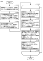
ステップS1410において、仮想制御ユニット610の各々は、起動後に、スレーブ(ノード)との通信確立待ち状態になる。 In step S1410, after startup, each virtual control unit 610 enters a state of waiting for communication to be established with a slave (node).
ステップS1420において、仮想統合制御ユニット640は、ハードウェア(物理層)670の起動後に、統合ネットワーク情報ファイルに記載されている全スレーブを確認する。
In step S1420, after the hardware (physical layer) 670 starts up, the virtual
ステップS1430において、仮想統合制御ユニット640は、統合後の全スレーブに、統合後のノード番号(図9におけるノード識別子910に相当)を割り当てることで、全スレーブと通信可能状態になる。ある局面において、ステップS1410~S1430までの処理は、並列的に実行されてもよいし、順番が入れ替わってもよい。
In step S1430, the virtual
ステップS1440において、仮想統合制御ユニット640および仮想制御ユニット610の各々は、ステップS1450以降の処理を繰り返し実行する。
In step S1440, each of the virtual
ステップS1450において、仮想制御ユニット610の各々は、スレーブとの通信可能状態を確認し、仮想ネットワークドライバ620,630を介して、各スレーブとの通信を開始する。ある局面において、仮想制御ユニット610の各々は、各スレーブに対して生存確認用のフレームを送信しその返信を受信することで、スレーブとの通信可能状態を確認してもよい。
In step S1450, each of the virtual control units 610 checks whether communication with the slaves is possible, and starts communication with each slave via the
ステップS1460において、仮想統合制御ユニット640は、仮想ネットワークドライバ620,630にセットされた(仮想制御ユニット610により送信された)フレーム700内のノード識別子701を、実ネットワーク(フィールドネットワーク7)のノード識別子711に変更し、フレーム710の送受信を行う。
In step S1460, the virtual
ステップS1470において、仮想統合制御ユニット640は、変換表650を用いて、実ネットワークから受信したフレーム710内のノード識別子711を、仮想制御ユニット610内のノード識別子701に変更する。そして、仮想統合制御ユニット640は、フレーム700を仮想ネットワークドライバ620,630にセットする(フレーム700を仮想制御ユニット610のいずれかに送信する)。
In step S1470, the virtual
ステップS1480において、仮想制御ユニット610の各々は、仮想ネットワークドライバ620,630からのレスポンスを受信し、当該レスポンスを元に仮想制御ユニット610内の処理を実行する。
In step S1480, each virtual control unit 610 receives a response from the
ステップS1490において、仮想統合制御ユニット640および仮想制御ユニット610の各々は、停止要求等の入力を検知した場合は処理を終了する。そうでない場合、仮想統合制御ユニット640および仮想制御ユニット610の各々は、ステップS1450以降の処理を繰り返し実行する。ある局面において、ステップS1450~S1480までの処理は、仮想制御ユニット610および仮想統合制御ユニット640の各々により、並列的に実行されてもよいし、順番が入れ替わってもよい。
In step S1490, if the virtual
以上説明した通り、本実施の形態に従う技術は、統合制御ユニット内で、複数の仮想制御ユニット610と、仮想統合制御ユニット640とを動作させ、仮想統合制御ユニット640にノード識別子の変換処理を実行させる。こうすることで、ユーザは、複数のプロジェクトファイルに変更を加えることなく、これらの複数のプロジェクトファイルを統合して使用し得る。
As described above, the technology according to this embodiment operates multiple virtual control units 610 and a virtual
さらに、本実施の形態に従う技術は、統合前の各プロジェクトファイル自体には変更を加えない。そのため、ユーザは、並列的に複数のプロジェクトファイルを作成して、当該複数のプロジェクトファイルを容易に統合することができる。また、統合後の制御プログラムに変更がある場合でも、ユーザは統合前のプロジェクトファイルの各々を個別に編集して再度統合処理を実行するだけでよく、プロジェクトファイルの保守性も向上する。 Furthermore, the technology according to this embodiment does not make any changes to the individual project files before integration. Therefore, the user can create multiple project files in parallel and easily integrate the multiple project files. Even if there are changes to the control program after integration, the user only needs to edit each of the project files before integration individually and execute the integration process again, which also improves the maintainability of the project files.
<G.付記>
以上のように、本実施の形態は以下のような開示を含む。
(構成1)
第1の制御ユニット用(20A)の第1のプロジェクトファイルと、第2の制御ユニット(20B)用の第2のプロジェクトファイルと、上記第1および第2のプロジェクトファイルに基づいて生成される統合プロジェクトファイルとを格納する記憶部と、
各プロジェクトファイルに基づいて処理を実行する制御部(31)とを備え、
上記第1および第2のプロジェクトファイルの各々は、各プロジェクトファイルごとに独立して複数のノードの各々に割り当てられた複数のノード識別子を含み、
上記統合プロジェクトファイルは、全てのノードの各々に一意に割り当て直したノード識別子を含み、
上記制御部(31)は、上記全てのノードの各々に一意に割り当て直したノード識別子を用いて、通信するノードのノード識別子を特定する、制御システム(1,20)。
(構成2)
上記記憶部は、第1の仮想制御ユニット(610)と、第2の仮想制御ユニット(610)と、仮想統合制御ユニット(640)とをさらに格納し、
上記制御部(31)は、
上記第1の仮想制御ユニット(610)に、上記第1のプロジェクトファイルをインストールし、
上記第2の仮想制御ユニット(610)に、上記第2のプロジェクトファイルをインストールし、
上記仮想統合制御ユニット(640)に、上記統合プロジェクトファイルをインストールし、
上記仮想統合制御ユニット(640)および上記ノードの各々間の通信データを上記第1の仮想制御ユニット(610)または上記第2の仮想制御ユニット(610)のいずれかに転送する、構成1の制御システム(1,20)。
(構成3)
上記記憶部(33)は、上記第1のプロジェクトファイルに含まれる第1のネットワーク情報ファイルおよび上記第2のプロジェクトファイルに含まれる第2のネットワーク情報ファイルと、上記統合プロジェクトファイルに含まれる統合ネットワーク情報ファイルとの変換情報をさらに格納し、
上記第1のネットワーク情報ファイル、上記第2のネットワーク情報ファイルおよび上記統合ネットワーク情報ファイルの各々は、各プロジェクト内で使用されるノード識別子を含み、
上記制御部(31)は、上記変換情報を用いて、上記仮想統合制御ユニット(640)および上記ノードの各々間の通信データを上記第1の仮想制御ユニット(610)または上記第2の仮想制御ユニット(610)のいずれかに転送する、構成2の制御システム(1,20)。
(構成4)
上記制御部(31)は、上記第1のネットワーク情報ファイルで定義されている第1の制御周期と、上記第2のネットワーク情報ファイルで定義されている第2の制御周期との公約数である制御周期に基づいて、上記ノードの各々と通信する、構成3の制御システム(1,20)。
(構成5)
複数のプロジェクトファイルを統合する装置(6)をさらに含み、
上記装置(6)は、上記第1のプロジェクトファイルと、上記第2のプロジェクトファイルとに基づいて、上記統合プロジェクトファイルを生成し、
上記制御部(31)は、上記装置(6)から、上記第1のプロジェクトファイルと、上記第2のプロジェクトファイルと、上記統合プロジェクトファイルとを取得する、構成2~4のいずれかの制御システム(1,20)。
(構成6)
上記装置(6)は、上記制御システム(1,20)の制御周期内における、上記第1の仮想制御ユニット(610)の処理時間の占有率と、上記第2の仮想制御ユニット(610)の処理時間の占有率との合計が100%を超えることに基づいて、エラーを出力する、構成5の制御システム(1,20)。
(構成7)
上記制御部(31)は、上記第1のプロジェクトファイルと、上記第2のプロジェクトファイルとに基づいて、上記統合プロジェクトファイルを生成する、構成1の制御システム(1,20)。
(構成8)
制御ユニット(20)を含む制御システム(1,20)の制御方法であって、
第1の制御ユニット(20)用の第1のプロジェクトファイルと、第2の制御ユニット(20)用の第2のプロジェクトファイルとに基づいて生成される統合プロジェクトファイルを参照するステップを含み、
上記第1および第2のプロジェクトファイルの各々は、各プロジェクトファイルごとに独立して複数のノードの各々に割り当てられた複数のノード識別子を含み、
上記統合プロジェクトファイルは、全てのノードの各々に一意に割り当て直したノード識別子を含み、
上記全てのノードの各々に一意に割り当て直したノード識別子を用いて、通信するノードのノード識別子を特定するステップをさらに含む、制御方法。
(構成9)
第1の仮想制御ユニット(610)に、上記第1のプロジェクトファイルをインストールするステップと、
第2の仮想制御ユニット(610)に、上記第2のプロジェクトファイルをインストールするステップと、
仮想統合制御ユニット(640)に、上記統合プロジェクトファイルをインストールするステップと、
上記仮想統合制御ユニット(640)および上記ノードの各々間の通信データを上記第1の仮想制御ユニット(610)または上記第2の仮想制御ユニット(610)のいずれかに転送するステップとをさらに含む、構成8の制御方法。
(構成10)
上記第1のプロジェクトファイルに含まれる第1のネットワーク情報ファイルおよび上記第2のプロジェクトファイルに含まれる第2のネットワーク情報ファイルと、上記統合プロジェクトファイルに含まれる統合ネットワーク情報ファイルとの変換情報にアクセスするステップをさらに含み、
上記第1のネットワーク情報ファイル、上記第2のネットワーク情報ファイルおよび上記統合ネットワーク情報ファイルの各々は、各プロジェクト内で使用されるノード識別子を含み、
上記変換情報を用いて、上記仮想統合制御ユニット(640)および上記ノードの各々間の通信データを上記第1の仮想制御ユニット(610)または上記第2の仮想制御ユニット(610)のいずれかに転送するステップをさらに含む、構成9の制御方法。
(構成11)
上記第1のネットワーク情報ファイルで定義されている第1の制御周期と、上記第2のネットワーク情報ファイルで定義されている第2の制御周期との公約数である制御周期に基づいて、上記ノードの各々と通信するステップをさらに含む、構成10の制御方法。
(構成12)
上記制御システム(1,20)の制御周期内における、上記第1の仮想制御ユニット(610)の処理時間の占有率と、上記第2の仮想制御ユニット(610)の処理時間の占有率との合計が100%を超えることに基づいて、エラーを出力するステップをさらに含む、構成11の制御方法。
<G. Notes>
As described above, the present embodiment includes the following disclosure.
(Configuration 1)
a storage unit that stores a first project file for a first control unit (20A), a second project file for a second control unit (20B), and an integrated project file generated based on the first and second project files;
A control unit (31) that executes processing based on each project file,
each of the first and second project files includes a plurality of node identifiers assigned to each of a plurality of nodes independently for each project file;
the integrated project file includes uniquely reassigned node identifiers for all nodes;
The control unit (31) identifies the node identifier of the node with which to communicate, using the node identifiers uniquely reassigned to each of all the nodes.
(Configuration 2)
The storage unit further stores a first virtual control unit (610), a second virtual control unit (610), and a virtual integrated control unit (640);
The control unit (31)
Installing the first project file in the first virtual control unit (610);
Installing the second project file in the second virtual control unit (610);
Installing the integrated project file in the virtual integrated control unit (640);
A control system (1, 20) of
(Configuration 3)
the storage unit (33) further stores conversion information between a first network information file included in the first project file and a second network information file included in the second project file, and an integrated network information file included in the integrated project file;
each of the first network information file, the second network information file and the integrated network information file includes a node identifier used within each project;
A control system (1, 20) of
(Configuration 4)
A control system (1, 20) of configuration 3, wherein the control unit (31) communicates with each of the nodes based on a control period that is a common divisor of a first control period defined in the first network information file and a second control period defined in the second network information file.
(Configuration 5)
The method further includes a device (6) for integrating a plurality of project files,
The device (6) generates the integrated project file based on the first project file and the second project file,
A control system (1, 20) of any of
(Configuration 6)
The control system (1, 20) of
(Configuration 7)
A control system (1, 20) of a
(Configuration 8)
A control method for a control system (1, 20) including a control unit (20), comprising:
Referencing an integrated project file generated based on a first project file for a first control unit (20) and a second project file for a second control unit (20);
each of the first and second project files includes a plurality of node identifiers assigned to each of a plurality of nodes independently for each project file;
the integrated project file includes uniquely reassigned node identifiers for all nodes;
The control method further includes a step of identifying a node identifier of a communicating node using the node identifiers uniquely reassigned to each of all of the nodes.
(Configuration 9)
installing said first project file in a first virtual control unit (610);
installing said second project file in a second virtual control unit (610);
Installing the integrated project file in a virtual integrated control unit (640);
and transferring communication data between the virtual integrated control unit (640) and each of the nodes to either the first virtual control unit (610) or the second virtual control unit (610).
(Configuration 10)
The method further includes a step of accessing conversion information between a first network information file included in the first project file and a second network information file included in the second project file, and an integrated network information file included in the integrated project file;
each of the first network information file, the second network information file and the integrated network information file includes a node identifier used within each project;
The control method of configuration 9 further includes a step of using the conversion information to forward communication data between the virtual integrated control unit (640) and each of the nodes to either the first virtual control unit (610) or the second virtual control unit (610).
(Configuration 11)
The control method of
(Configuration 12)
The control method of configuration 11 further includes a step of outputting an error based on the sum of the processing time occupancy rate of the first virtual control unit (610) and the processing time occupancy rate of the second virtual control unit (610) exceeding 100% within a control period of the control system (1, 20).
今回開示された実施の形態は全ての点で例示であって制限的なものではないと考えられるべきである。本開示の範囲は上記した説明ではなくて特許請求の範囲によって示され、特許請求の範囲と均等の意味及び範囲内で全ての変更が含まれることが意図される。また、実施の形態および各変形例において説明された開示内容は、可能な限り、単独でも、組合わせても、実施することが意図される。 The embodiments disclosed herein should be considered to be illustrative in all respects and not restrictive. The scope of the present disclosure is indicated by the claims rather than the above description, and is intended to include all modifications within the meaning and scope of the claims. Furthermore, it is intended that the disclosure contents described in the embodiments and each modified example may be implemented, as far as possible, either alone or in combination.
1 制御システム、2 サーバ装置、3 表示装置、4 ゲートウェイ、5 ネットワーク、6 サポート装置、7 フィールドネットワーク、8 制御対象、10 ネットワークシステム、20 制御ユニット、20A 第1の制御ユニット、20B 第2の制御ユニット、20C 第3の制御ユニット、20D 統合制御ユニット、21 セキュリティユニット、22 セーフティユニット、23 機能ユニット、24 電源ユニット、31,91 プロセッサ、32 チップセット、33,95 二次記憶装置、34,92 主記憶装置、35 通信コントローラ、36 インジケータ、37 スイッチインターフェイス、38 ディップスイッチ、39 内部バスコントローラ、40,41,42 ネットワークコントローラ、43 メモリカードインターフェイス、44 USBコントローラ、45 システムプログラム、46 サービスプログラム、48 不揮発性記憶領域、49 暗号化済み制御プログラム、50 揮発性記憶領域、51 復号済み制御プログラム、52 バス、53 メモリカード、93 入力部、94 出力部、96 光学ドライブ、97 通信インターフェイス、98 プロセッサバス、101,201 ノード、401 統合プログラム、550 記録媒体、551 制御プログラム、552 統合ツール、553 サポートプログラム、610 仮想制御ユニット、610A 第1の仮想制御ユニット、610B 第2の仮想制御ユニット、610C 第3の仮想制御ユニット、615 ネットワーク情報ファイル、615A 第1のネットワーク情報ファイル、615B 第2のネットワーク情報ファイル、615C 第3のネットワーク情報ファイル、620,630 仮想ネットワークドライバ、640 仮想統合制御ユニット、645 統合ネットワーク情報ファイル、650 変換表、660 ネットワークドライバ、670 ハードウェア、700,710 フレーム、701,711,910 ノード識別子、1010 装置識別子、1020 第1のノード識別子、1030 第2のノード識別子、1210 制御周期。 1 Control system, 2 Server device, 3 Display device, 4 Gateway, 5 Network, 6 Support device, 7 Field network, 8 Control target, 10 Network system, 20 Control unit, 20A First control unit, 20B Second control unit, 20C Third control unit, 20D Integrated control unit, 21 Security unit, 22 Safety unit, 23 Functional unit, 24 Power supply unit, 31, 91 Processor, 32 Chip set, 33, 95 Secondary storage device, 34, 92 Main storage device, 35 Communication controller, 36 Indicator, 37 Switch interface, 38 DIP switch, 39 Internal bus controller, 40, 41, 42 Network controller, 43 Memory card interface, 44 USB controller, 45 System program, 46 Service program, 48 Non-volatile storage area, 49 Encrypted control program, 50 Volatile storage area, 51 Decrypted control program, 52 Bus, 53 Memory card, 93 Input unit, 94 Output unit, 96 Optical drive, 97 Communication interface, 98 Processor bus, 101, 201 Node, 401 Integration program, 550 Recording medium, 551 Control program, 552 Integration tool, 553 Support program, 610 Virtual control unit, 610A First virtual control unit, 610B Second virtual control unit, 610C Third virtual control unit, 615 Network information file, 615A First network information file, 615B Second network information file, 615C Third network information file, 620, 630 Virtual network driver, 640 Virtual integrated control unit, 645 Integrated network information file, 650 Conversion table, 660 Network driver, 670 Hardware, 700, 710 Frame, 701, 711, 910 Node identifier, 1010 Device identifier, 1020 First node identifier, 1030 Second node identifier, 1210 Control period.
Claims (12)
第1の制御ユニット用の第1のプロジェクトファイルと、第2の制御ユニット用の第2のプロジェクトファイルと、前記第1および第2のプロジェクトファイルに基づいて生成される統合プロジェクトファイルとを格納する記憶部と、
各プロジェクトファイルに基づいて処理を実行する制御部とを備え、
前記第1のプロジェクトファイルは、前記第1の制御ユニットが、前記第1の制御ユニットに接続されたフィールドネットワーク上の複数のノードの各々と通信するための複数のノード識別子の各々を含み、
前記第2のプロジェクトファイルは、前記第2の制御ユニットが、前記第2の制御ユニットに接続されたフィールドネットワーク上の複数のノードの各々と通信するための複数のノード識別子の各々を含み、
前記統合プロジェクトファイルは、前記第1のプロジェクトファイルおよび前記第2のプロジェクトファイルに含まれる全てのノードの各々に一意に割り当て直した複数のノード識別子の各々を含み、
前記制御部は、前記全てのノードの各々に一意に割り当て直した複数のノード識別子の各々を用いて、前記制御システムに接続されたフィールドネットワーク上の複数のノードの各々と通信可能に構成される、制御システム。 1. A control system comprising:
a storage unit that stores a first project file for a first control unit, a second project file for a second control unit, and an integrated project file that is generated based on the first and second project files;
a control unit that executes processing based on each project file,
the first project file includes a plurality of node identifiers for the first control unit to communicate with a plurality of nodes on a field network connected to the first control unit,
the second project file includes a plurality of node identifiers for the second control unit to communicate with a plurality of nodes on a field network connected to the second control unit,
the integrated project file includes a plurality of node identifiers uniquely reassigned to each of all nodes included in the first project file and the second project file ,
The control unit is configured to be able to communicate with each of a plurality of nodes on a field network connected to the control system using each of a plurality of node identifiers uniquely reassigned to each of all of the nodes.
前記制御部は、
前記第1の仮想制御ユニットに、前記第1のプロジェクトファイルをインストールし、
前記第2の仮想制御ユニットに、前記第2のプロジェクトファイルをインストールし、
前記仮想統合制御ユニットに、前記統合プロジェクトファイルをインストールし、
前記仮想統合制御ユニットにおいて、前記制御システムに接続されたフィールドネットワーク上のいずれかのノードから受信した通信データを前記第1の仮想制御ユニットまたは前記第2の仮想制御ユニットのいずれかに転送する、請求項1に記載の制御システム。 The storage unit further stores a first virtual control unit, a second virtual control unit, and a virtual integrated control unit;
The control unit is
Installing the first project file in the first virtual control unit;
Installing the second project file in the second virtual control unit;
Installing the integrated project file in the virtual integrated control unit;
The control system according to claim 1 , wherein the virtual integrated control unit transfers communication data received from any node on a field network connected to the control system to either the first virtual control unit or the second virtual control unit.
前記第1のネットワーク情報ファイル、前記第2のネットワーク情報ファイルおよび前記統合ネットワーク情報ファイルの各々は、各プロジェクト内で使用されるノード識別子を含み、
前記制御部は、前記変換情報を用いて、前記通信データを前記第1の仮想制御ユニットまたは前記第2の仮想制御ユニットのいずれかに転送するように構成される、請求項2に記載の制御システム。 the storage unit further stores conversion information between a first network information file included in the first project file and a second network information file included in the second project file, and an integrated network information file included in the integrated project file;
each of the first network information file, the second network information file and the integrated network information file includes a node identifier used within each project;
The control system of claim 2 , wherein the control unit is configured to use the conversion information to forward the communication data to either the first virtual control unit or the second virtual control unit.
前記装置は、前記第1のプロジェクトファイルと、前記第2のプロジェクトファイルとに基づいて、前記統合プロジェクトファイルを生成し、
前記制御部は、前記装置から、前記第1のプロジェクトファイルと、前記第2のプロジェクトファイルと、前記統合プロジェクトファイルとを取得する、請求項2~4のいずれかに記載の制御システム。 a device for integrating a plurality of project files;
The apparatus generates the integrated project file based on the first project file and the second project file;
The control system according to any one of claims 2 to 4, wherein the control unit acquires the first project file, the second project file, and the integrated project file from the device.
第1の制御ユニット用の第1のプロジェクトファイルと、第2の制御ユニット用の第2のプロジェクトファイルとに基づいて生成される統合プロジェクトファイルを参照するステップを含み、
前記第1のプロジェクトファイルは、前記第1の制御ユニットが、前記第1の制御ユニットに接続されたフィールドネットワーク上の複数のノードの各々と通信するための複数のノード識別子の各々を含み、
前記第2のプロジェクトファイルは、前記第2の制御ユニットが、前記第2の制御ユニットに接続されたフィールドネットワーク上の複数のノードの各々と通信するための複数のノード識別子の各々を含み、
前記統合プロジェクトファイルは、前記第1のプロジェクトファイルおよび前記第2のプロジェクトファイルに含まれる全てのノードの各々に一意に割り当て直した複数のノード識別子の各々を含み、
前記全てのノードの各々に一意に割り当て直した複数のノード識別子の各々を用いて、前記制御システムに接続されたフィールドネットワーク上の複数のノードの各々と通信するステップをさらに含む、制御方法。 A control method for a control system including a control unit, comprising:
Referencing an integrated project file generated based on a first project file for a first control unit and a second project file for a second control unit;
the first project file includes a plurality of node identifiers for the first control unit to communicate with a plurality of nodes on a field network connected to the first control unit,
the second project file includes a plurality of node identifiers for the second control unit to communicate with a plurality of nodes on a field network connected to the second control unit,
the integrated project file includes a plurality of node identifiers uniquely reassigned to each of all nodes included in the first project file and the second project file ,
The control method further includes a step of communicating with each of a plurality of nodes on a field network connected to the control system using each of a plurality of node identifiers uniquely reassigned to each of all of the nodes.
第2の仮想制御ユニットに、前記第2のプロジェクトファイルをインストールするステップと、
仮想統合制御ユニットに、前記統合プロジェクトファイルをインストールするステップと、
前記仮想統合制御ユニットにおいて、前記制御システムに接続されたフィールドネットワーク上のいずれかのノードから受信した通信データを前記第1の仮想制御ユニットまたは前記第2の仮想制御ユニットのいずれかに転送するステップとをさらに含む、請求項8に記載の制御方法。 installing the first project file in a first virtual control unit;
installing the second project file in a second virtual control unit;
installing the integration project file in a virtual integration control unit;
The control method according to claim 8, further comprising a step of transferring, in the virtual integrated control unit, communication data received from any node on a field network connected to the control system to either the first virtual control unit or the second virtual control unit.
前記第1のネットワーク情報ファイル、前記第2のネットワーク情報ファイルおよび前記統合ネットワーク情報ファイルの各々は、各プロジェクト内で使用されるノード識別子を含み、
前記変換情報を用いて、前記通信データを前記第1の仮想制御ユニットまたは前記第2の仮想制御ユニットのいずれかに転送するステップをさらに含む、請求項9に記載の制御方法。 The method further includes a step of accessing conversion information between a node identifier included in each of a first network information file included in the first project file and a second network information file included in the second project file, and an integrated network information file included in the integrated project file;
each of the first network information file, the second network information file and the integrated network information file includes a node identifier used within each project;
The control method of claim 9 , further comprising the step of forwarding the communication data to either the first virtual control unit or the second virtual control unit using the conversion information.
Priority Applications (1)
| Application Number | Priority Date | Filing Date | Title |
|---|---|---|---|
| JP2021039408A JP7608885B2 (en) | 2021-03-11 | 2021-03-11 | Control system and control method |
Applications Claiming Priority (1)
| Application Number | Priority Date | Filing Date | Title |
|---|---|---|---|
| JP2021039408A JP7608885B2 (en) | 2021-03-11 | 2021-03-11 | Control system and control method |
Publications (2)
| Publication Number | Publication Date |
|---|---|
| JP2022139149A JP2022139149A (en) | 2022-09-26 |
| JP7608885B2 true JP7608885B2 (en) | 2025-01-07 |
Family
ID=83399474
Family Applications (1)
| Application Number | Title | Priority Date | Filing Date |
|---|---|---|---|
| JP2021039408A Active JP7608885B2 (en) | 2021-03-11 | 2021-03-11 | Control system and control method |
Country Status (1)
| Country | Link |
|---|---|
| JP (1) | JP7608885B2 (en) |
Citations (5)
| Publication number | Priority date | Publication date | Assignee | Title |
|---|---|---|---|---|
| JP2000341357A (en) | 1999-05-27 | 2000-12-08 | Mitsubishi Electric Corp | Communication control device, measurement control system, and recording medium |
| JP2008159027A (en) | 2006-12-21 | 2008-07-10 | Hitachi Ltd | Method and apparatus for file system virtualization |
| JP2014010811A (en) | 2012-07-03 | 2014-01-20 | Yokogawa Electric Corp | Process controller and system |
| JP2014206830A (en) | 2013-04-11 | 2014-10-30 | 富士電機株式会社 | Support device for programmable controller, program therefor, and programmable controller system |
| JP2019159631A (en) | 2018-03-12 | 2019-09-19 | オムロン株式会社 | Control system, controller, and control method |
Family Cites Families (1)
| Publication number | Priority date | Publication date | Assignee | Title |
|---|---|---|---|---|
| JP3232216B2 (en) * | 1995-07-10 | 2001-11-26 | 三菱電機株式会社 | Computer system for processing line |
-
2021
- 2021-03-11 JP JP2021039408A patent/JP7608885B2/en active Active
Patent Citations (5)
| Publication number | Priority date | Publication date | Assignee | Title |
|---|---|---|---|---|
| JP2000341357A (en) | 1999-05-27 | 2000-12-08 | Mitsubishi Electric Corp | Communication control device, measurement control system, and recording medium |
| JP2008159027A (en) | 2006-12-21 | 2008-07-10 | Hitachi Ltd | Method and apparatus for file system virtualization |
| JP2014010811A (en) | 2012-07-03 | 2014-01-20 | Yokogawa Electric Corp | Process controller and system |
| JP2014206830A (en) | 2013-04-11 | 2014-10-30 | 富士電機株式会社 | Support device for programmable controller, program therefor, and programmable controller system |
| JP2019159631A (en) | 2018-03-12 | 2019-09-19 | オムロン株式会社 | Control system, controller, and control method |
Also Published As
| Publication number | Publication date |
|---|---|
| JP2022139149A (en) | 2022-09-26 |
Similar Documents
| Publication | Publication Date | Title |
|---|---|---|
| JP6891174B2 (en) | Equipment and methods for using the Internet of Things Secure Gateway | |
| EP2937751B1 (en) | Control device and operation method for control device | |
| US20200344293A1 (en) | Distributed robotic controllers | |
| CN104169817B (en) | Control device for controlling a safety-critical process and its parameterization method | |
| JP6978443B2 (en) | Legacy Level 1 Controller Virtualization System and Method | |
| WO2016163235A1 (en) | Plc control data generation device, plc control data generation method, and plc control data generation program | |
| US20220156392A1 (en) | Control system, security device, and method | |
| JP2009217707A (en) | Fa apparatus and file access system | |
| JP7608885B2 (en) | Control system and control method | |
| US20200092126A1 (en) | Building automation system providing for integration of subsystems | |
| CN110324220A (en) | Support device, computer readable storage medium, setting method | |
| Anwar et al. | Human machine interface using OPC (OLE for process control) | |
| CN105579920B (en) | The control method of programmable controller and programmable controller | |
| CN102955466A (en) | Method for operating an automation system | |
| US8301273B2 (en) | Method for providing functions in an industrial automation system, control program and industrial automation system | |
| CN110161896A (en) | Affiliated method for the control system of Power Supply Assembly and for being started, being controlled and being monitored for Power Supply Assembly | |
| JP6741850B1 (en) | Machine system, machine tool, information processing system, setting data inheritance method, and setting data inheritance program | |
| JP7200580B2 (en) | Control system, support equipment, support program | |
| JP6863305B2 (en) | Network system, control method and control device | |
| KR102131669B1 (en) | Data link system | |
| CN112748705A (en) | Industrial process control and automation system with decoupled controller | |
| JP7629197B2 (en) | Relay device, method and program | |
| JPWO2020166026A1 (en) | Management equipment, management system, management method and program | |
| Zhang | Apply SOA paradigms in cyber-physical system to enhance interoperability: State-of-the-art review | |
| KR102216824B1 (en) | Module and method for actuator linkage in robot system |
Legal Events
| Date | Code | Title | Description |
|---|---|---|---|
| A621 | Written request for application examination |
Free format text: JAPANESE INTERMEDIATE CODE: A621 Effective date: 20240116 |
|
| A977 | Report on retrieval |
Free format text: JAPANESE INTERMEDIATE CODE: A971007 Effective date: 20240731 |
|
| A131 | Notification of reasons for refusal |
Free format text: JAPANESE INTERMEDIATE CODE: A131 Effective date: 20240806 |
|
| A521 | Request for written amendment filed |
Free format text: JAPANESE INTERMEDIATE CODE: A523 Effective date: 20240830 |
|
| TRDD | Decision of grant or rejection written | ||
| A01 | Written decision to grant a patent or to grant a registration (utility model) |
Free format text: JAPANESE INTERMEDIATE CODE: A01 Effective date: 20241119 |
|
| A61 | First payment of annual fees (during grant procedure) |
Free format text: JAPANESE INTERMEDIATE CODE: A61 Effective date: 20241202 |
|
| R150 | Certificate of patent or registration of utility model |
Ref document number: 7608885 Country of ref document: JP Free format text: JAPANESE INTERMEDIATE CODE: R150 |