JP7608877B2 - Battery Cooling System - Google Patents
Battery Cooling System Download PDFInfo
- Publication number
- JP7608877B2 JP7608877B2 JP2021035853A JP2021035853A JP7608877B2 JP 7608877 B2 JP7608877 B2 JP 7608877B2 JP 2021035853 A JP2021035853 A JP 2021035853A JP 2021035853 A JP2021035853 A JP 2021035853A JP 7608877 B2 JP7608877 B2 JP 7608877B2
- Authority
- JP
- Japan
- Prior art keywords
- battery
- cooling pipe
- cooler
- cooling
- refrigerant
- Prior art date
- Legal status (The legal status is an assumption and is not a legal conclusion. Google has not performed a legal analysis and makes no representation as to the accuracy of the status listed.)
- Active
Links
Images


Classifications
-
- Y—GENERAL TAGGING OF NEW TECHNOLOGICAL DEVELOPMENTS; GENERAL TAGGING OF CROSS-SECTIONAL TECHNOLOGIES SPANNING OVER SEVERAL SECTIONS OF THE IPC; TECHNICAL SUBJECTS COVERED BY FORMER USPC CROSS-REFERENCE ART COLLECTIONS [XRACs] AND DIGESTS
- Y02—TECHNOLOGIES OR APPLICATIONS FOR MITIGATION OR ADAPTATION AGAINST CLIMATE CHANGE
- Y02E—REDUCTION OF GREENHOUSE GAS [GHG] EMISSIONS, RELATED TO ENERGY GENERATION, TRANSMISSION OR DISTRIBUTION
- Y02E60/00—Enabling technologies; Technologies with a potential or indirect contribution to GHG emissions mitigation
- Y02E60/10—Energy storage using batteries
Landscapes
- Battery Mounting, Suspending (AREA)
- Secondary Cells (AREA)
Description
本開示は、電池の冷却装置に関する。 This disclosure relates to a battery cooling device.
特許文献1では、液体が流路内を流れる際に流路壁間の摩擦によって調整弁または制御弁等に用いられる樹脂製のダイヤフラム弁等の絶縁部が帯電することによって絶縁破壊されることを防止する技術が記載されている。この技術では、ダイヤフラムの腹部近傍に導電性部材を、液体流路の流路側に貫通させて配置することによって液体に接触させ、かつ導電製部材および流路が形成されたボディ本体を介してアースに電気的に接続することによって、ダイヤフラム等の絶縁部が帯電することを抑制する。
近年、リチウムイオン電池では、小型化を図るため、リチウムイオン電池を冷却する冷却器に集電板としての機能を兼ねさせる構造が検討されている。この冷却器に集電板としての機能を兼ねさせる構造では、冷却液が流れる冷却器の一部が高電圧な高電圧部となり、安全性を確保するため、絶縁部材を介して、冷却器と、高電圧部以外の絶縁部として機能する冷却配管と、を遮断する必要がある。 In recent years, in order to miniaturize lithium-ion batteries, a structure has been considered in which the cooler that cools the lithium-ion battery also functions as a current collector. In this structure in which the cooler also functions as a current collector, the part of the cooler through which the cooling liquid flows becomes a high-voltage part, and in order to ensure safety, it is necessary to isolate the cooler from the cooling pipes that function as an insulating part other than the high-voltage part via an insulating member.
しかしながら、上述した特許文献1の絶縁部材に電荷が帯電することを抑制する技術であっても、冷却液が冷却配管を流れる際の摩擦によって冷却配管に帯電が発生することで、局所的に耐電圧を超過し、冷却配管が絶縁破壊される可能性があるうえ、冷却配管が高電圧部と接している場合、アースを介して短絡する可能性がある。
However, even with the technology of
本開示は、上記に鑑みてなされたものであって、冷却器と、冷却配管と、を接続する場合であっても、冷却配管が絶縁破壊されることを防止することができる電池の冷却装置を提供することを目的とする。 The present disclosure has been made in consideration of the above, and aims to provide a battery cooling device that can prevent insulation breakdown of the cooling piping even when the cooler and the cooling piping are connected.
本開示に係る電池の冷却装置は、複数の電池セルが積層された電池モジュールを有する電池の冷却装置であって、前記電池モジュールと導通可能な導電性部材を用いて形成され、内部に冷媒が循環する流路を有する冷却器と、前記冷却器に前記冷媒を供給する冷却配管と、絶縁部材を用いて形成され、前記冷却配管と前記冷却器とを接続するコネクタ部と、前記コネクタ部が前記冷却器と接続する接続箇所から所定の距離を離した前記冷却配管の位置に電気的に接続されたアース線と、を備える。 The battery cooling device according to the present disclosure is a battery cooling device having a battery module in which multiple battery cells are stacked, and includes a cooler formed using a conductive material that is electrically conductive with the battery module and has a flow path through which a refrigerant circulates, a cooling pipe that supplies the refrigerant to the cooler, a connector portion formed using an insulating material that connects the cooling pipe and the cooler, and an earth wire that is electrically connected to a position on the cooling pipe that is a predetermined distance away from a connection point where the connector portion connects to the cooler.
本開示によれば、コネクタ部を介して冷却器および冷却配管を接続し、かつ、コネクタ部が冷却器と接続する接続箇所から所定の距離を離した冷却配管の位置に電気的に接続されたアース線を設けたので、冷却器と、冷却配管と、を接続する場合であっても、冷却配管が絶縁破壊されることを防止することができるという効果を奏する。 According to the present disclosure, the cooler and the cooling piping are connected via the connector, and an earth wire is provided that is electrically connected to a position on the cooling piping that is a predetermined distance away from the connection point where the connector connects to the cooler. This has the effect of preventing insulation breakdown of the cooling piping even when the cooler and the cooling piping are connected.
以下、図面を参照して、本開示の実施の形態における電池の冷却装置について、図面を参照しながら説明する。なお、以下の実施の形態により本開示が限定されるものでない。また、以下において、同一の部分には同一の符号を付して説明する。 The battery cooling device according to the embodiment of the present disclosure will be described below with reference to the drawings. Note that the present disclosure is not limited to the following embodiment. In addition, the same parts will be denoted by the same reference numerals in the following description.
(実施の形態1)
〔車両の概略構成〕
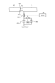
図1は、実施の形態1に係る電池が搭載される車両の概略構成を示す模式図である。図1に示す車両1は、モータ等を動力源とする電動車両(EV)またはプラグインハイブリッド車両(PHV)等が想定される。
(Embodiment 1)
[General configuration of the vehicle]
Fig. 1 is a schematic diagram showing a general configuration of a vehicle equipped with a battery according to
車両1は、モータ2と、パワーコントロールユニット3(以下、「PCU3」という)と、電池4と、冷却配管5と、電動ポンプ6と、熱交換器7と、ECU(Electronic Control Unit)8と、を備える。
The
モータ2は、電池4の電力により走行用の動力を出力する。モータ2は、PCU3を介して電池4と電気的に接続されている。車両1では、モータ2から出力された動力が動力伝達装置を介して駆動輪へ伝達される。
The
PCU3は、モータ2を駆動制御する。PCU3は、少なくとも、モータ2を駆動するインバータと、昇圧コンバータと、DC/DCコンバータと、を含んで構成されている。例えば、PCU3は、インバータが電池4の直流電力を交流電力に変換してモータ2に供給する。
The PCU 3 drives and controls the
電池4は、モータ2に供給するための電力を蓄える。具体的には、電池4は、外部電源から供給された電力を充電可能な蓄電装置である。電池4は、車両1に設けられた充電口(図示せず)を介して外部の充電設備の充電プラグと電気的に接続され、充電設備から供給される電力を充電する。電池4は、複数の平面セルが鉛直方向に積層された電池モジュールと、電池モジュールを冷却する冷却器と、を用いて構成される。なお、電池4の詳細な構成は、後述する。
冷却配管5は、流路上に電池4、電動ポンプ6および熱交換器7が接続され、電池4を冷却する冷媒が循環する。ここで、冷媒には、空気、水、鉱物油、合成油、シリコンオイル、フッ素オイル、絶縁性冷媒(例えばR134a等の代替フロン系冷媒)および絶縁油のいずれかが用いられる。実施の形態1では、冷媒として水を用いた場合について説明する。また、冷却配管5は、非導電材料等を用いて構成される。具体的には、冷却配管5は、ゴムまたは樹脂等を用いて構成される。
The
電動ポンプ6は、ECU8の制御のもと、冷却配管5内の冷媒を循環させる。具体的には、電動ポンプ6は、リザーブタンク内に貯留された冷媒を吸入し、吐出口から冷媒を冷却配管5に向けて吐出する。電動ポンプ6によって吐出された冷媒は、電動ポンプ6の吐出圧によって冷却配管5、電池4および熱交換器7を介して循環する。
The
熱交換器7は、ECU8の制御のもと、冷却配管5内を循環する冷媒との間で熱交換を行うことによって冷媒から放熱させる。熱交換器7は、例えばラジエータおよび電動ファン等を用いて構成される。
Under the control of the
ECU8は、電動ポンプ6および熱交換器7の駆動を制御する。ECU8は、メモリと、CPU(Central Processing Unit)等のハードウェアを有するプロセッサを用いて構成される。
The ECU 8 controls the operation of the
〔電池の詳細な構成〕
次に、電池4の詳細な構成について説明する。図2は、電池の概略構成を示す斜視図である。
[Detailed battery configuration]
Next, a detailed configuration of the
図2に示すように、電池4は、複数の電池セル410が積層された電池モジュール41と、電池モジュール41の上下両面に接続され、電池モジュール41を冷却する平板状の冷却器42と、を備える。具体的には、図2に示すように、電池4は、冷却器42、電池モジュール41および冷却器42の順に積層されて構成されている。なお、図2に示す電池4は、電池モジュール41が1つであるが、電池モジュール41を積層する数は、電池モジュール41の上下面を冷却器42によって挟み込んで積層することができれば、適宜変更することができる。さらに、冷却器42の数は、電池モジュール41を挟み込んで積層することができればよく、電池モジュール41を積層する数に合わせて適宜変更することができる。
2, the
電池モジュール41は、平板状の電池セル410が鉛直方向に沿って複数積層されて構成される。電池セル410は、バイポーラ構造およびモノポーラ構造の一方を用いて構成される。さらに、図2では、電池セル410を4層積層して電池4を構成しているが、電池セル410を積層する数を適宜変更することができる。
The
冷却器42は、冷却配管5と接続され、冷却配管5を介して電動ポンプ6からの冷媒Waが供給されるインレット部421と、冷却配管5と接続され、冷媒Waを冷却配管5へ流出するアウトレット部422と、を有する。冷却器42は、内部に形成された流路内を冷媒Waが循環することによって電池モジュール41を冷却する。冷却器42は、導電性部材、例えばアルミニウム等を用いて構成される。さらに、電池4の上下に位置する冷却器42は、電池モジュール41と電気的に導通することによって電池4の電極(集電板)として機能する。これにより、電池4に対して電力を取り出すための端子を設ける必要がないため、電池4の小型化を図ることができる。なお、実施の形態1では、冷却配管5、電動ポンプ6、熱交換器7および冷却器42が電池4の冷却装置として機能する。
The
〔冷却配管と冷却器との接続〕
次に、冷却配管5と冷却器42との接続方法について詳細に説明する。図3は、図2の矢視Aから見た冷却配管5と冷却器42の要部の側面図である。なお、図3では、冷却配管5と冷却器42のインレット部421との接続について詳細に説明するが、冷却配管5と冷却器42のアウトレット部422でも同様の方法によって接続される。
[Connection between cooling piping and cooler]
Next, a method for connecting the
図3に示すように、冷却器42のインレット部421は、コネクタ部51を介して冷却配管5に接続される。コネクタ部51は、絶縁部材、例えばゴムや樹脂等で形成され、筒状をなす。さらに、冷却配管5には、コネクタ部51がインレット部421と接続する接続側の端部421aから所定の距離D1離れた位置に、アースに接地されたアース線52が電気的に接続されている。なお、アースは、車両1と導通している。
As shown in FIG. 3, the
ここで、所定の距離D1とは、電池4の電圧が400vの場合において、JISC0664による汚損度3の環境下における0.8mmの最小空間距離、最小沿面距離5.6mmのとき、コネクタ部51の接続側(インレット部421の端部421a側)から冷却配管5に向けて5.6mmまでの位置である。即ち、アース線52は、コネクタ部51と冷却配管5とを合わせた距離が高圧部として機能する冷却器42(インレット部421)から5.6mm以上離した位置に電気的に接続される。
Here, the predetermined distance D1 is a position from the connection side of the connector part 51 (the
これにより、電池4は、電池モジュール41と冷却器42との導通状態を遮断することができるうえ、冷却配管5が帯電した場合であっても、絶縁部として機能する冷却配管5が絶縁破壊させることを防止することができる。
This allows the
以上説明した実施の形態1では、コネクタ部51を介して冷却配管5と冷却器42とを接続し、コネクタ部51が冷却器42と接続する接続箇所から所定の距離を離した冷却配管5の位置に電気的に接続されたアース線52を設けたので、冷却配管5が絶縁破壊されることを防止することができる。
In the
なお、実施の形態1では、冷却器42のインレット部421と冷却配管5との間にコネクタ部51を設けていたが、冷却器42のアウトレット部422と冷却配管5との間にコネクタ部51を設け、所定の距離だけ離れた位置にアース線52を電気的に接続してもよい。
In the first embodiment, the
また、実施の形態1では、冷却配管5を非導電性部材によって形成していたが、これに限定されることなく、例えば導電部材によって形成し、冷却配管5の表面、および冷却液が流れる流路内の内壁に、絶縁部材を塗布する絶縁処理またはアルマイト処理等を行い、絶縁皮膜を施すことによって絶縁部として機能するように構成してもよい。
In addition, in the first embodiment, the
(実施の形態2)
次に、実施の形態2について説明する。図4は、実施の形態2に係る冷却配管と冷却器の要部の側面図である。
(Embodiment 2)
Next, a description will be given of
図4に示すように、実施の形態1の冷却配管5およびコネクタ部51に換えて、冷却配管5Aおよびコネクタ部51Aを備える。
As shown in FIG. 4, a
冷却配管5Aは、導電性部材を用いて構成される。冷却配管5Aは、例えば、アルミニウムおよびアルミニウム合金等を用いて構成される。さらに、冷却配管5Aは、アース線52が電気的に接続される。
The
コネクタ部51Aは、冷媒Waが流れる流路方向(長手方向)において所定の長さD2を有する。具体的には、コネクタ部51Aの長さD2は、JISC0664による汚損度3の環境下において0.8mmの最小空間距離、最小沿面距離5.6mmのとき、5.6mmである。コネクタ部51Aは、絶縁部材、例えばゴムや樹脂等で形成され、筒状をなす。
The
以上説明した実施の形態2によれば、所定の長さD2を有するコネクタ部51Aを介して冷却器42と冷却配管5Aとを接続することによって、絶縁破壊の可能性がある絶縁物の使用箇所を少なくすることができるうえ、絶縁材として機能するコネクタ部51Aと接続する面積を大きくすることができるため、実施の形態1と比して冷却配管5Aに絶縁破壊が生じることをより防止することができる。
According to the second embodiment described above, by connecting the cooler 42 and the
(実施の形態3)
次に、実施の形態3について説明する。図5は、実施の形態3に係る冷却配管と冷却器の要部の側面図である。
(Embodiment 3)
Next, a description will be given of
図5に示すように、冷却配管5には、実施の形態1の構成に加えて、SW1と、コンデンサC1と、SW2と、電力ヒューズR1と、が電気的に接続される。
As shown in FIG. 5, in addition to the configuration of
冷却配管5は、SW1およびコンデンサC1を介してアースに電気的に接続される。コンデンサC1の容量は、帯電による絶縁破壊が発生しない容量が用いられる。さらに、冷却配管5は、コンデンサC1と並列に電力ヒューズR1(抵抗)がスイッチSW2を介してアースに電気的に接続される。電力ヒューズR1の容量は、コンデンサC1の電荷放電時に切断しない容量であり、かつ、短絡時のみ切断する容量が用いられる。SW1およびSW2は、ECU8の制御のもと、オンオフ動作を行う。これにより、コンデンサC1に帯電する電荷が電力ヒューズR1を介して定期的に放電される。
The
以上説明した実施の形態3によれば、コンデンサC1および電力ヒューズR1の少なくとも一方を介して冷却配管5に電気的にアースを接続することによって、アースの位置が高電圧部として機能する冷却器42との絶縁に必要な距離を確保できない場合であっても、冷却配管5に絶縁破壊が生じることを防止することができる。
According to the third embodiment described above, by electrically connecting the
さらに、実施の形態3によれば、ECU8がコンデンサC1からの放電時にスイッチSW1を介して冷却配管5から電気的に遮断させるので、冷却器42に帯電する電荷を定期的に排出することができる。
Furthermore, according to the third embodiment, the
(その他の実施の形態)
さらなる効果や変形例は、当業者によって容易に導き出すことができる。本発明のより広範な態様は、以上のように表しかつ記述した特定の詳細および代表的な実施の形態に限定されるものではない。したがって、添付のクレームおよびその均等物によって定義される総括的な発明の概念の精神または範囲から逸脱することなく、様々な変更が可能である。
Other Embodiments
Further advantages and modifications may readily occur to those skilled in the art. The invention in its broader aspects is not limited to the specific details and representative embodiments shown and described above. Thus, various modifications may be made without departing from the spirit or scope of the general inventive concept as defined by the appended claims and equivalents thereof.
1 車両
2 モータ
3 PCU
4 電池
5,5A 冷却配管
6 電動ポンプ
7 熱交換器
8 ECU
41 電池モジュール
42 冷却器
51,51A コネクタ部
52 アース線
410 電池セル
421 インレット部
421a 端部
422 アウトレット部
C1 コンデンサ
R1 電力ヒューズ
SW1,SW2 スイッチ
Wa 冷媒
1
4 Battery 5.5A
41
Claims (1)
前記電池モジュールと導通可能な導電性部材を用いて形成され、内部に冷媒が循環する流路を有する冷却器と、
前記冷却器に前記冷媒を供給する冷却配管と、
絶縁部材を用いて形成され、前記冷却配管と前記冷却器とを接続するコネクタ部と、
前記コネクタ部が前記冷却器と接続する接続箇所から所定の距離を離した前記冷却配管の位置に電気的に接続されたアース線と、
を備える、
電池の冷却装置。 A cooling device for a battery having a battery module in which a plurality of battery cells are stacked,
a cooler formed of a conductive member capable of conducting with the battery module and having a flow path therein through which a refrigerant circulates;
A cooling pipe for supplying the refrigerant to the cooler;
a connector portion formed using an insulating material and connecting the cooling pipe and the cooler;
a ground wire electrically connected to the cooling pipe at a position separated by a predetermined distance from a connection point where the connector portion is connected to the cooler;
Equipped with
Battery cooling device.
Priority Applications (1)
| Application Number | Priority Date | Filing Date | Title |
|---|---|---|---|
| JP2021035853A JP7608877B2 (en) | 2021-03-05 | 2021-03-05 | Battery Cooling System |
Applications Claiming Priority (1)
| Application Number | Priority Date | Filing Date | Title |
|---|---|---|---|
| JP2021035853A JP7608877B2 (en) | 2021-03-05 | 2021-03-05 | Battery Cooling System |
Publications (2)
| Publication Number | Publication Date |
|---|---|
| JP2022135796A JP2022135796A (en) | 2022-09-15 |
| JP7608877B2 true JP7608877B2 (en) | 2025-01-07 |
Family
ID=83231987
Family Applications (1)
| Application Number | Title | Priority Date | Filing Date |
|---|---|---|---|
| JP2021035853A Active JP7608877B2 (en) | 2021-03-05 | 2021-03-05 | Battery Cooling System |
Country Status (1)
| Country | Link |
|---|---|
| JP (1) | JP7608877B2 (en) |
Families Citing this family (1)
| Publication number | Priority date | Publication date | Assignee | Title |
|---|---|---|---|---|
| JP2024157457A (en) * | 2023-04-25 | 2024-11-07 | トヨタ自動車株式会社 | Battery Cooling System |
Citations (3)
| Publication number | Priority date | Publication date | Assignee | Title |
|---|---|---|---|---|
| JP2004234881A (en) | 2003-01-28 | 2004-08-19 | Nissan Motor Co Ltd | Fuel cell system |
| JP2006351469A (en) | 2005-06-20 | 2006-12-28 | Nissan Motor Co Ltd | Fuel cell system |
| JP2011146320A (en) | 2010-01-18 | 2011-07-28 | Kawasaki Heavy Ind Ltd | Cooling system of secondary battery |
-
2021
- 2021-03-05 JP JP2021035853A patent/JP7608877B2/en active Active
Patent Citations (3)
| Publication number | Priority date | Publication date | Assignee | Title |
|---|---|---|---|---|
| JP2004234881A (en) | 2003-01-28 | 2004-08-19 | Nissan Motor Co Ltd | Fuel cell system |
| JP2006351469A (en) | 2005-06-20 | 2006-12-28 | Nissan Motor Co Ltd | Fuel cell system |
| JP2011146320A (en) | 2010-01-18 | 2011-07-28 | Kawasaki Heavy Ind Ltd | Cooling system of secondary battery |
Also Published As
| Publication number | Publication date |
|---|---|
| JP2022135796A (en) | 2022-09-15 |
Similar Documents
| Publication | Publication Date | Title |
|---|---|---|
| CN108028446B (en) | Battery system and electric vehicle with battery system | |
| CN205104554U (en) | Storage battery assembly | |
| CN102593549B (en) | Electric storage element and electric storage device | |
| US9290101B2 (en) | Power control unit for electric vehicle with converters cooled by surfaces of a cooling unit | |
| US20090233158A1 (en) | Electric power supply system | |
| US20150199376A1 (en) | Rotating electric machine system | |
| US20120298433A1 (en) | Battery module, battery system, electric vehicle, movable body, power storage device, and power supply device | |
| JP2011187275A (en) | Battery module, battery box housing the same, and rolling stock equipped with the same | |
| US11358480B2 (en) | Vehicle including fuel cell and residual energy discharge method performed in the vehicle | |
| US20240234850A1 (en) | Battery and vehicle | |
| JP2023171684A (en) | battery pack | |
| JP2006302629A (en) | Fuel cell module and power generation system using fuel cell module | |
| JP7608877B2 (en) | Battery Cooling System | |
| US20200403282A1 (en) | Energy storage system | |
| JP2024157457A (en) | Battery Cooling System | |
| JP7420129B2 (en) | relay unit | |
| WO2022168575A1 (en) | Electronic device module and power source system | |
| CN223583134U (en) | Battery device and electric equipment | |
| US11395430B1 (en) | Busbar assembly for current sensing | |
| EP4607159A1 (en) | Battery system with integrated cooling manifold | |
| CN119650961A (en) | Traction battery pack thermal management system and thermal management method | |
| WO2025100262A1 (en) | Power conversion device | |
| JP2025079243A (en) | Power Conversion Equipment | |
| CN121097280A (en) | Multi-layer thermal barrier assembly for traction battery packs | |
| CN120854693A (en) | Lead-acid battery with anti-leakage structure |
Legal Events
| Date | Code | Title | Description |
|---|---|---|---|
| A621 | Written request for application examination |
Free format text: JAPANESE INTERMEDIATE CODE: A621 Effective date: 20231219 |
|
| A977 | Report on retrieval |
Free format text: JAPANESE INTERMEDIATE CODE: A971007 Effective date: 20241111 |
|
| TRDD | Decision of grant or rejection written | ||
| A01 | Written decision to grant a patent or to grant a registration (utility model) |
Free format text: JAPANESE INTERMEDIATE CODE: A01 Effective date: 20241119 |
|
| A61 | First payment of annual fees (during grant procedure) |
Free format text: JAPANESE INTERMEDIATE CODE: A61 Effective date: 20241202 |
|
| R150 | Certificate of patent or registration of utility model |
Ref document number: 7608877 Country of ref document: JP Free format text: JAPANESE INTERMEDIATE CODE: R150 |