JP7608869B2 - Display method and program - Google Patents
Display method and program Download PDFInfo
- Publication number
- JP7608869B2 JP7608869B2 JP2021031442A JP2021031442A JP7608869B2 JP 7608869 B2 JP7608869 B2 JP 7608869B2 JP 2021031442 A JP2021031442 A JP 2021031442A JP 2021031442 A JP2021031442 A JP 2021031442A JP 7608869 B2 JP7608869 B2 JP 7608869B2
- Authority
- JP
- Japan
- Prior art keywords
- image
- input
- mask
- area
- pixel
- Prior art date
- Legal status (The legal status is an assumption and is not a legal conclusion. Google has not performed a legal analysis and makes no representation as to the accuracy of the status listed.)
- Active
Links
Images


Classifications
-
- G—PHYSICS
- G09—EDUCATION; CRYPTOGRAPHY; DISPLAY; ADVERTISING; SEALS
- G09G—ARRANGEMENTS OR CIRCUITS FOR CONTROL OF INDICATING DEVICES USING STATIC MEANS TO PRESENT VARIABLE INFORMATION
- G09G3/00—Control arrangements or circuits, of interest only in connection with visual indicators other than cathode-ray tubes
- G09G3/001—Control arrangements or circuits, of interest only in connection with visual indicators other than cathode-ray tubes using specific devices not provided for in groups G09G3/02 - G09G3/36, e.g. using an intermediate record carrier such as a film slide; Projection systems; Display of non-alphanumerical information, solely or in combination with alphanumerical information, e.g. digital display on projected diapositive as background
- G09G3/002—Control arrangements or circuits, of interest only in connection with visual indicators other than cathode-ray tubes using specific devices not provided for in groups G09G3/02 - G09G3/36, e.g. using an intermediate record carrier such as a film slide; Projection systems; Display of non-alphanumerical information, solely or in combination with alphanumerical information, e.g. digital display on projected diapositive as background to project the image of a two-dimensional display, such as an array of light emitting or modulating elements or a CRT
-
- G—PHYSICS
- G06—COMPUTING OR CALCULATING; COUNTING
- G06F—ELECTRIC DIGITAL DATA PROCESSING
- G06F3/00—Input arrangements for transferring data to be processed into a form capable of being handled by the computer; Output arrangements for transferring data from processing unit to output unit, e.g. interface arrangements
- G06F3/01—Input arrangements or combined input and output arrangements for interaction between user and computer
- G06F3/048—Interaction techniques based on graphical user interfaces [GUI]
- G06F3/0484—Interaction techniques based on graphical user interfaces [GUI] for the control of specific functions or operations, e.g. selecting or manipulating an object, an image or a displayed text element, setting a parameter value or selecting a range
- G06F3/04847—Interaction techniques to control parameter settings, e.g. interaction with sliders or dials
-
- G—PHYSICS
- G06—COMPUTING OR CALCULATING; COUNTING
- G06F—ELECTRIC DIGITAL DATA PROCESSING
- G06F3/00—Input arrangements for transferring data to be processed into a form capable of being handled by the computer; Output arrangements for transferring data from processing unit to output unit, e.g. interface arrangements
- G06F3/01—Input arrangements or combined input and output arrangements for interaction between user and computer
- G06F3/048—Interaction techniques based on graphical user interfaces [GUI]
- G06F3/0487—Interaction techniques based on graphical user interfaces [GUI] using specific features provided by the input device, e.g. functions controlled by the rotation of a mouse with dual sensing arrangements, or of the nature of the input device, e.g. tap gestures based on pressure sensed by a digitiser
- G06F3/0488—Interaction techniques based on graphical user interfaces [GUI] using specific features provided by the input device, e.g. functions controlled by the rotation of a mouse with dual sensing arrangements, or of the nature of the input device, e.g. tap gestures based on pressure sensed by a digitiser using a touch-screen or digitiser, e.g. input of commands through traced gestures
- G06F3/04883—Interaction techniques based on graphical user interfaces [GUI] using specific features provided by the input device, e.g. functions controlled by the rotation of a mouse with dual sensing arrangements, or of the nature of the input device, e.g. tap gestures based on pressure sensed by a digitiser using a touch-screen or digitiser, e.g. input of commands through traced gestures for inputting data by handwriting, e.g. gesture or text
-
- G—PHYSICS
- G09—EDUCATION; CRYPTOGRAPHY; DISPLAY; ADVERTISING; SEALS
- G09G—ARRANGEMENTS OR CIRCUITS FOR CONTROL OF INDICATING DEVICES USING STATIC MEANS TO PRESENT VARIABLE INFORMATION
- G09G5/00—Control arrangements or circuits for visual indicators common to cathode-ray tube indicators and other visual indicators
- G09G5/02—Control arrangements or circuits for visual indicators common to cathode-ray tube indicators and other visual indicators characterised by the way in which colour is displayed
-
- G—PHYSICS
- G09—EDUCATION; CRYPTOGRAPHY; DISPLAY; ADVERTISING; SEALS
- G09G—ARRANGEMENTS OR CIRCUITS FOR CONTROL OF INDICATING DEVICES USING STATIC MEANS TO PRESENT VARIABLE INFORMATION
- G09G2340/00—Aspects of display data processing
- G09G2340/04—Changes in size, position or resolution of an image
-
- G—PHYSICS
- G09—EDUCATION; CRYPTOGRAPHY; DISPLAY; ADVERTISING; SEALS
- G09G—ARRANGEMENTS OR CIRCUITS FOR CONTROL OF INDICATING DEVICES USING STATIC MEANS TO PRESENT VARIABLE INFORMATION
- G09G2340/00—Aspects of display data processing
- G09G2340/12—Overlay of images, i.e. displayed pixel being the result of switching between the corresponding input pixels
-
- G—PHYSICS
- G09—EDUCATION; CRYPTOGRAPHY; DISPLAY; ADVERTISING; SEALS
- G09G—ARRANGEMENTS OR CIRCUITS FOR CONTROL OF INDICATING DEVICES USING STATIC MEANS TO PRESENT VARIABLE INFORMATION
- G09G2354/00—Aspects of interface with display user
-
- G—PHYSICS
- G09—EDUCATION; CRYPTOGRAPHY; DISPLAY; ADVERTISING; SEALS
- G09G—ARRANGEMENTS OR CIRCUITS FOR CONTROL OF INDICATING DEVICES USING STATIC MEANS TO PRESENT VARIABLE INFORMATION
- G09G2360/00—Aspects of the architecture of display systems
- G09G2360/14—Detecting light within display terminals, e.g. using a single or a plurality of photosensors
- G09G2360/145—Detecting light within display terminals, e.g. using a single or a plurality of photosensors the light originating from the display screen
-
- G—PHYSICS
- G09—EDUCATION; CRYPTOGRAPHY; DISPLAY; ADVERTISING; SEALS
- G09G—ARRANGEMENTS OR CIRCUITS FOR CONTROL OF INDICATING DEVICES USING STATIC MEANS TO PRESENT VARIABLE INFORMATION
- G09G2360/00—Aspects of the architecture of display systems
- G09G2360/16—Calculation or use of calculated indices related to luminance levels in display data
-
- G—PHYSICS
- G09—EDUCATION; CRYPTOGRAPHY; DISPLAY; ADVERTISING; SEALS
- G09G—ARRANGEMENTS OR CIRCUITS FOR CONTROL OF INDICATING DEVICES USING STATIC MEANS TO PRESENT VARIABLE INFORMATION
- G09G5/00—Control arrangements or circuits for visual indicators common to cathode-ray tube indicators and other visual indicators
- G09G5/22—Control arrangements or circuits for visual indicators common to cathode-ray tube indicators and other visual indicators characterised by the display of characters or indicia using display control signals derived from coded signals representing the characters or indicia, e.g. with a character-code memory
- G09G5/24—Generation of individual character patterns
- G09G5/28—Generation of individual character patterns for enhancement of character form, e.g. smoothing
-
- G—PHYSICS
- G09—EDUCATION; CRYPTOGRAPHY; DISPLAY; ADVERTISING; SEALS
- G09G—ARRANGEMENTS OR CIRCUITS FOR CONTROL OF INDICATING DEVICES USING STATIC MEANS TO PRESENT VARIABLE INFORMATION
- G09G5/00—Control arrangements or circuits for visual indicators common to cathode-ray tube indicators and other visual indicators
- G09G5/36—Control arrangements or circuits for visual indicators common to cathode-ray tube indicators and other visual indicators characterised by the display of a graphic pattern, e.g. using an all-points-addressable [APA] memory
- G09G5/39—Control of the bit-mapped memory
- G09G5/395—Arrangements specially adapted for transferring the contents of the bit-mapped memory to the screen
- G09G5/397—Arrangements specially adapted for transferring the contents of two or more bit-mapped memories to the screen simultaneously, e.g. for mixing or overlay
Landscapes
- Engineering & Computer Science (AREA)
- Theoretical Computer Science (AREA)
- General Engineering & Computer Science (AREA)
- Physics & Mathematics (AREA)
- General Physics & Mathematics (AREA)
- Human Computer Interaction (AREA)
- Computer Hardware Design (AREA)
- Image Analysis (AREA)
- Controls And Circuits For Display Device (AREA)
- User Interface Of Digital Computer (AREA)
Description
本発明は、表示方法およびプログラムに関する。 The present invention relates to a display method and a program.
例えば下記特許文献1には、入力画像から被写体を検出する被写体検出方法が開示されている。特許文献1の被写体検出方法は、入力画像から特徴量を取得し、特徴量に基づいて被写体の存在確率を示す確率分布画像を生成し、確率分布画像をあらかじめ記憶された閾値と比較することによって被写体を検出する。 For example, Patent Document 1 below discloses a subject detection method for detecting a subject from an input image. The subject detection method of Patent Document 1 acquires features from the input image, generates a probability distribution image indicating the probability of the subject's existence based on the features, and detects the subject by comparing the probability distribution image with a pre-stored threshold value.
上述した特許文献1では、被写体の検出にあらかじめ記憶された閾値を用いるので、ユーザーが真に検出したい領域が検出されない可能性がある。したがって、従来の技術では、ユーザーの感性に合わせて、領域を簡単に調整できなかった。 In the above-mentioned Patent Document 1, a pre-stored threshold is used to detect the subject, so there is a possibility that the area that the user actually wants to detect may not be detected. Therefore, with conventional technology, it is not possible to easily adjust the area to suit the user's sensibilities.
本発明の一態様に係る表示方法は、閾値の入力を受け付けることと、前記閾値を用いることによって、第1画像のうち入力画像を表示する領域であるマスク領域、または前記第1画像のうち前記入力画像を表示しない領域である非マスク領域を示す、第2画像を生成することと、前記第2画像を前記入力画像に重畳した投射用画像を表示させることと、を含む。 A display method according to one aspect of the present invention includes accepting input of a threshold value, generating a second image using the threshold value to indicate a masked region of a first image in which an input image is displayed, or a non-masked region of the first image in which the input image is not displayed, and displaying a projection image in which the second image is superimposed on the input image.
本発明の一態様に係るプログラムは、コンピューターに、閾値の入力を受け付けることと、前記閾値を用いることによって、第1画像のうち入力画像を表示する領域であるマスク領域、または前記第1画像のうち前記入力画像を表示しない領域である非マスク領域を示す、第2画像を生成することと、前記第2画像を前記入力画像に重畳した投射用画像を表示させることと、を実行させる。 A program according to one aspect of the present invention causes a computer to receive a threshold value as input, generate a second image using the threshold value to indicate a masked area in a first image where an input image is displayed, or a non-masked area in the first image where the input image is not displayed, and display a projection image in which the second image is superimposed on the input image.
以下、添付図面を参照しながら本発明に係る好適な実施形態を説明する。なお、図面において各部の寸法または縮尺は実際と適宜に異なり、理解を容易にするために模式的に示している部分もある。また、本発明の範囲は、以下の説明において特に本発明を限定する旨の記載がない限り、これらの形態に限られない。 Below, preferred embodiments of the present invention will be described with reference to the attached drawings. Note that the dimensions or scale of each part in the drawings may differ from the actual dimensions, and some parts are shown diagrammatically to facilitate understanding. Furthermore, the scope of the present invention is not limited to these forms unless otherwise specified in the following description to the effect that the present invention is limited thereto.
1.第1実施形態
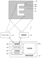
図1は、実施形態に係る投射システム1の一例を示す概略図である。図1に示すように投射システム1は、プロジェクター10と、撮像装置20と、情報処理装置30と、を含む。図1に示す投射システム1は、3次元形状を有する物体40に画像を投射するためのシステムである。本実施形態では、物体40は、所定の厚さを有する板状の部材を「E」の文字の形状に切り出すことにより形成されている。物体40は、壁面42と接する図示しない接着面と、接着面と反対側の面である表面400と、接着面と表面400とを接続する側面402とを有する。本実施形態では、物体40の表面400が画像の投射領域に設定される。プロジェクター10からの画像の投射領域が、後述するマスク領域に対応する。
1. First embodiment FIG. 1 is a schematic diagram showing an example of a projection system 1 according to an embodiment. As shown in FIG. 1, the projection system 1 includes a
プロジェクター10は、後述する投射用画像56,58を投射するための液晶ライトバルブ、投射射レンズ、および液晶駆動部を備える。また、プロジェクター10は、光源として超高圧水銀ランプまたはメタルハライドランプを備える。プロジェクター10は、例えばケーブルによって情報処理装置30と通信可能に接続される。プロジェクター10は、ケーブルを介した通信により情報処理装置30から投射用画像データを取得する。プロジェクター10は、取得した投射用画像データが示す投射用画像56,58をマスク領域に投射する。以下では、マスク領域は、後述する入力画像562,582が表示される領域であり、マスク領域以外の領域は、入力画像562,582が表示されない、すなわちマスクされない領域である。本実施形態では、プロジェクター10と情報処理装置30との間の通信は、例えば、イーサネットやUSB(Universal Serial Bus)等の規格に準拠した有線通信である。しかし、プロジェクター10と情報処理装置30との間の通信は、Wi-Fi等の規格に準拠した無線通信であってもよい。なお、Wi-Fiおよびイーサネットは登録商標である。
The
撮像装置20は、例えば、集光された光を電気信号に変換する撮像素子であるCCD(Charge Coupled Device)またはCMOS(Complementary Metal Oxide Semiconductor)等を備えたカメラである。以下では、説明を簡略化するため、撮像装置20は、静止画像を撮像するものとする。なお、撮像装置20は、静止画像を撮像することに代えて、動画像を撮像してもよい。撮像装置20は、物体40を含む撮像領域44の画像を撮像する。本実施形態では、撮像領域44には、物体40と壁面42とが含まれる。なお、本実施形態では、撮像装置20での撮像時にはプロジェクター10からの投射は行わないものとする。すなわち、撮像装置20で撮像された撮像画像50は、プロジェクター10からの投射が行われていない状態で撮像領域44を撮像した画像である。撮像画像50は、図3に例示される。撮像装置20は、プロジェクター10と同様に、例えばケーブルによって情報処理装置30と通信可能に接続される。撮像装置20は、撮像した画像を表す撮像画像データを情報処理装置30へ送信する。本実施形態では、撮像装置20と情報処理装置30との間の通信は、例えばイーサネットやUSB等の規格に準拠した有線通信であるが、Wi-Fi等の規格に準拠した無線通信であってもよい。また、本実施形態では、撮像装置20は情報処理装置30およびプロジェクター10とは別体であるが、撮像装置20は情報処理装置30およびプロジェクター10のいずれかに搭載されていてもよい。
The
情報処理装置30は、電子機器の一例であり、例えばパーソナルコンピューターである。図1に示すように、情報処理装置30は、通信装置300、タッチパネル310、記憶装置320、および処理装置330を有する。通信装置300には、ケーブルを介してプロジェクター10が接続される。また、通信装置300には、ケーブルを介して撮像装置20が接続される。通信装置300は、撮像装置20から送信される撮像画像データを受信する。また、通信装置300は、処理装置330による制御の下、物体40に投射する画像を表す投射用画像データをプロジェクター10へ送信する。
The
タッチパネル310は、各種情報を表示する表示装置と、ユーザーにより情報が入力される入力装置とが、一体化された装置である。入力装置は、例えば透明なシート状の接触センサーである。入力装置は、表示装置の表示面を覆うように設けられる。入力装置は、当該入力装置に接触する物体と当該入力装置とによって特定される静電容量を用いてタッチ位置を検出する。入力装置は、検出したタッチ位置を示すデータを処理装置330へ出力する。これにより、タッチパネル310に対するユーザーの操作内容が処理装置330へ伝達される。本実施形態では、タッチパネル310が表示装置と入力装置とを兼ねるものとするが、表示装置と入力装置とが別個に設けられていてもよい。具体的には、例えば情報処理装置30が、表示装置としてディスプレイを備えるとともに、入力装置としてキーボードとマウスとを備えていてもよい。
The
記憶装置320は、処理装置330が読み取り可能な記録媒体である。記憶装置320は、例えば、不揮発性メモリーと揮発性メモリーとを含む。不揮発性メモリーは、例えば、ROM(Read Only Memory)、EPROM(Erasable Programmable Read Only Memory)またはEEPROM(Electrically Erasable Programmable Read Only Memory)である。揮発性メモリーは、例えば、RAM(Random Access Memory)である。
The
記憶装置320の不揮発性メモリーには、処理装置330によって実行されるプログラム322が予め記憶される。記憶装置320の揮発性メモリーはプログラム322を実行する際のワークエリアとして処理装置330によって利用される。プログラム322は、「アプリケーションプログラム」、「アプリケーションソフトウェア」または「アプリ」とも称され得る。プログラム322は、例えば、通信装置300を介して不図示のサーバー等から取得され、その後、記憶装置320に記憶される。
The non-volatile memory of the
処理装置330は、例えばCPU(Central Processing Unit)等のプロセッサー、即ちコンピューターを含んで構成される。処理装置330は、単一のコンピューターで構成されてもよいし、複数のコンピューターで構成されてもよい。処理装置330は、プログラム322の実行開始を指示する操作が入力装置に対してなされたことを契機としてプログラム322を不揮発性メモリーから揮発性メモリーに読み出す。処理装置330は、揮発性メモリーに読み出したプログラム322を実行する。
The
図2は、処理装置330の機能的構成を示すブロック図である。プログラム322に従って作動中の処理装置330は、図2に示す撮像画像取得部331、領域選択受付部332、確率算出部333、閾値受付部334、マスク画像生成部335、および表示制御部336として機能する。図2に示す撮像画像取得部331、領域選択受付部332、確率算出部333、閾値受付部334、マスク画像生成部335、および表示制御部336は、処理装置330をプログラム322に従って動作させることで実現されるソフトウェアモジュールである。
FIG. 2 is a block diagram showing the functional configuration of the
撮像画像取得部331は、物体40を含む撮像領域44を撮像した撮像画像50を撮像装置20から取得する。撮像画像50は、第1画像に対応する。本実施形態では、撮像画像取得部331は、通信装置300を介して撮像装置20から撮像画像データを受信する。撮像画像50は、撮像装置20が撮像した画像そのものであってもよいし、構造化光投影法等を用いて撮像装置20が撮像した画像をプロジェクター10からの視点で撮像した画像に座標変換した画像であってもよい。
The captured
領域選択受付部332は、撮像画像取得部331が取得した撮像画像50をタッチパネル310に表示させるとともに、撮像画像50を用いてマスク領域を選択する情報の入力を受け付ける。本実施形態では、領域選択受付部332は、撮像画像50に対する描画入力をユーザーから受け付ける。この描画入力は、撮像画像50上でマスク領域の一部または非マスク領域の一部を指定するものである。
The area
図3および図4は、領域選択受付部332による領域選択の受付態様の一例を示す図である。図3では、タッチパネル310に撮像画像50が表示されている。撮像画像50は、図1に示す物体40を含む撮像領域44を撮像した画像であり、物体40の表面400に対応する第1領域500、物体40の側面402に対応する第2領域502、および壁面42に対応する第3領域504を含む。
Figures 3 and 4 are diagrams showing an example of how region selection is accepted by the region
また、タッチパネル310には、撮像画像50とともに、描画ボタン60、取り消しボタン62、完了ボタン64が表示される。ユーザーが描画ボタン60に触れると、領域選択受付部332は、図4に示されるように今回の描画がマスク領域と非マスク領域のいずれを指定するものかを指定する領域種別指定部66を表示させる。領域種別指定部66は、選択項目としてマスク領域指定部660と非マスク領域指定部662とを含んでいる。ユーザーは、マスク領域の指定時にはマスク領域指定部660を選択し、非マスク領域の指定時には非マスク領域指定部662を選択する。図4では、マスク領域指定部660が選択されている。この状態でユーザーが撮像画像50に触れると、領域選択受付部332は、その軌跡をペンで描画したように表示させる。領域選択受付部332は、撮像画像50のうち、軌跡が表示された画素がマスク領域に含まれる画素であるものとして、描画入力によって指定された任意の画素の情報を受け付ける。また、非マスク領域指定部662が選択された状態でユーザーが撮像画像50に触れた場合にも同様に、領域選択受付部332は、その軌跡をペンで描画したように表示させる。この場合、領域選択受付部332は、撮像画像50のうち、軌跡が表示された画素が非マスク領域に含まれる画素であるものとして受け付ける。
In addition, on the
本実施形態では、物体40の表面400をマスク領域とするので、ユーザーは、マスク領域指定部660を選択した場合には、撮像画像50のうち第1領域500に対して描画を行うことになる。この時、ユーザーは、例えば軌跡L1のように第1領域500の全体をなぞるように描画してもよいし、軌跡L2のように第1領域500の1点のみ、または複数点をタッチして描画してもよい。また、軌跡L1のような線の描画と、軌跡L2のような点の描画を組み合わせてもよい。また、ユーザーが非マスク領域を選択する場合には、領域種別指定部66で非マスク領域指定部662を選択し、撮像画像50のうち第2領域502または第3領域504の少なくともいずれかに対して描画を行う。ユーザーは、撮像画像50のうち、少なくとも1画素を指定し、これがマスク領域に含まれるのか、または非マスク領域に含まれるのかを指定すればよい。
In this embodiment, the
なお、ユーザーがマスク領域指定部660を指定して描画した後、非マスク領域指定部662を指定して更に描画するなどにより、マスク領域指定部660と非マスク領域指定部662の両方を指定できるようにしてもよい。この時、マスク領域指定部660を選択した際の軌跡の色と、非マスク領域指定部662を選択した際の軌跡の色とを変えれば、ユーザーは自身が選択した箇所の領域種別を認識しやすくなり、操作性が向上する。
Note that the user may be able to specify both the masked
取り消しボタン62は、描画入力を取り消すことに用いられる。例えば軌跡が第1領域500からはみ出た場合など、描画を取り消したい場合、ユーザーは、取り消しボタン62に触れた上で、軌跡のうち取り消したい部分をなぞる。すると、領域選択受付部332は、当該部分の軌跡を消去し、対応する画素のマスク領域または非マスク領域としての指定を解除する。なお、なぞった部分が描画入力の全部であれば全部が、一部であれば一部が、取り消される。
The cancel
描画ボタン60の下部には、スライダーバー600が表示されている。スライダーバー600は、描画ボタン60をタッチして描画を行う際の軌跡の太さを調整するインターフェースである。スライダーバー600は、所定方向に延びるバー602と、バー602上を移動可能なスライダー604とを備える。図4の例では、バー602はタッチパネル310の画面左右方向に延びている。バー602の左右方向の中心位置が、スライダー604の基準位置であり、この時の軌跡の幅を基準幅とする。ユーザーがスライダー604を基準位置より右方向に移動させると、領域選択受付部332は、軌跡の幅を基準幅より大きくする。これにより、スライダー604が基準位置にある時と同じ描画動作を行っても、マスク領域または非マスク領域として指定される画素が多くなる。また、ユーザーがスライダー604を基準位置より左方向に移動させると、領域選択受付部332は、軌跡の幅を基準幅より小さくする。これにより、スライダー604が基準位置にある時と同じ描画動作を行っても、マスク領域または非マスク領域として指定される画素が少なくなる。
A
取り消しボタン62の下部にも同様に、スライダーバー620が表示されている。スライダーバー620は、取り消しボタン62をタッチして描画の取り消しを行う際の取り消し領域の幅を調整するインターフェースである。スライダーバー620は、所定方向に延びるバー622と、バー622上を移動可能なスライダー624とを備える。図4の例では、バー622はタッチパネル310の画面左右方向に延びている。バー622の左右方向の中心位置が、スライダー624の基準位置であり、この時の取り消し領域の幅を基準幅とする。ユーザーがスライダー624を基準位置より右方向に移動させると、領域選択受付部332は、取り消し領域の幅を基準幅より大きくする。これにより、スライダー624が基準位置にある時と同じ取り消し動作を行っても、取り消される軌跡の画素が多くなる。また、ユーザーがスライダー624を基準位置より左方向に移動させると、領域選択受付部332は、取り消し領域の幅を基準幅より小さくする。これにより、スライダー604が基準位置にある時と同じ描画動作を行っても、取り消される軌跡の画素が少なくなる。
Similarly, a
ユーザーは、マスク領域または非マスク領域への描画を終了すると、完了ボタン64を押下する。領域選択受付部332は、完了ボタン64が押下された時点における描画内容に基づいて、ユーザーがマスク領域または非マスク領域として選択する画素を受け付ける。
When the user has finished drawing in the masked or non-masked area, he or she presses the done
すなわち、領域選択受付部332は、撮像画像50を表示させるとともに、撮像画像50を用いてマスク領域を選択する情報の入力を受け付ける。領域選択受付部332でマスク領域を選択する情報の入力を受け付けることは、撮像画像50の任意の画素が、マスク領域を構成する画素である、または非マスク領域を構成する画素である、ことを指定することを含む。また、領域選択受付部332でマスク領域を選択する情報の入力を受け付けることは、撮像画像50に対する描画入力を受け付けることを含む。さらに領域選択受付部332でマスク領域を選択する情報の入力を受け付けることは、取り消しボタン62を用いて描画入力の少なくとも一部を取り消すことを含む。
That is, the area
なお、本実施形態では、領域選択受付部332は、マスク領域または非マスク領域に対する描画を受け付けることによりマスク領域または非マスク領域の選択を受け付けたが、選択の方法はこれに限られない。例えば、各画素がナンバリングされた撮像画像50を用いて、マスク領域に含まれる画素の番号または非マスク領域に含まれる画素の番号をユーザーが指定してもよい。なお、ナンバリングは全ての画素に行っても、一部の画素に行ってもよい。
In this embodiment, the area
図2に示される確率算出部333は、撮像画像50の各画素がマスク領域を構成する画素である確率を算出する。画像上の任意の画素が特定の領域に含まれる確率を算出する方法は、Growcut法など様々なものが知られている。一例を挙げると、例えば領域選択受付部332でマスク領域として選択された画素は、マスク領域である確率を100%とする。それ以外の画素は、マスク領域として選択された画素との類似度によってマスク領域である確率を算出する。画素間の類似度は、例えば画素の色、深度、マスク領域として選択された画素からの距離などのパラメーターを用いて算出することができる。以下、マスク領域として選択された画素を「マスク領域画素」、確率を算出する画素を「対象画素」という。
The
例えば色を用いて確率を算出する場合、対象画素のRGB値[Rx,Gx,Bx]とマスク領域画素のRGB値[R0,G0,B0]とを用いて、対象画素がマスク領域画素である確率P1を下記式(1)で算出することができる。P1は、0から1の間の値をとり、値が大きいほど対象画素がマスク領域画素である確率が高い。なお、下記式(1)の分母の「255」は、階調が8bitで表現される、すなわち、Rx,Gx,Bx,R0,G0,B0の各値が0から255の整数で表される場合の値である。階調が8bitでない場合には、下記式(1)の「255」に対応する値は、階調数から1を減じた値とする。 For example, when calculating the probability using color, the probability P1 that the target pixel is a mask area pixel can be calculated using the RGB values [Rx, Gx, Bx] of the target pixel and the RGB values [R0, G0, B0] of the mask area pixel with the following formula (1). P1 takes a value between 0 and 1, and the higher the value, the higher the probability that the target pixel is a mask area pixel. Note that the "255" in the denominator of the following formula (1) is the value when the gradation is expressed in 8 bits, that is, when the values of Rx, Gx, Bx, R0, G0, and B0 are each expressed as integers from 0 to 255. If the gradation is not 8 bits, the value corresponding to "255" in the following formula (1) is the number of gradations minus 1.

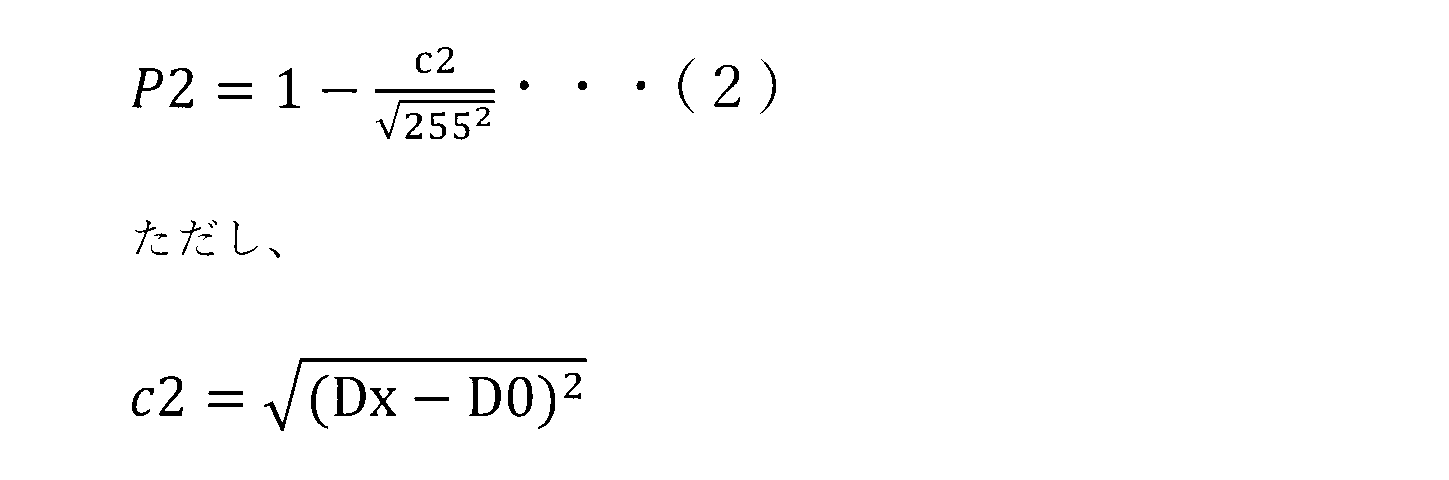
例えば距離を用いて確率を算出する場合、対象画素の距離[Dx]と、マスク領域画素の距離[D0]とを用いて、対象画素がマスク領域画素である確率P2を下記式(2)で算出することができる。P2は、0から1の間の値をとり、値が大きいほど対象画素がマスク領域画素である確率が高い。なお、下記式(2)において、距離DxおよびD0は、上記式(1)とスケールを合わせるために、0から255の値にスケーリングされている。 For example, when calculating the probability using distance, the probability P2 that the target pixel is a mask area pixel can be calculated using the distance [Dx] of the target pixel and the distance [D0] of the mask area pixel with the following formula (2). P2 takes a value between 0 and 1, and the larger the value, the higher the probability that the target pixel is a mask area pixel. Note that in the following formula (2), the distances Dx and D0 are scaled to values between 0 and 255 to match the scale of the above formula (1).
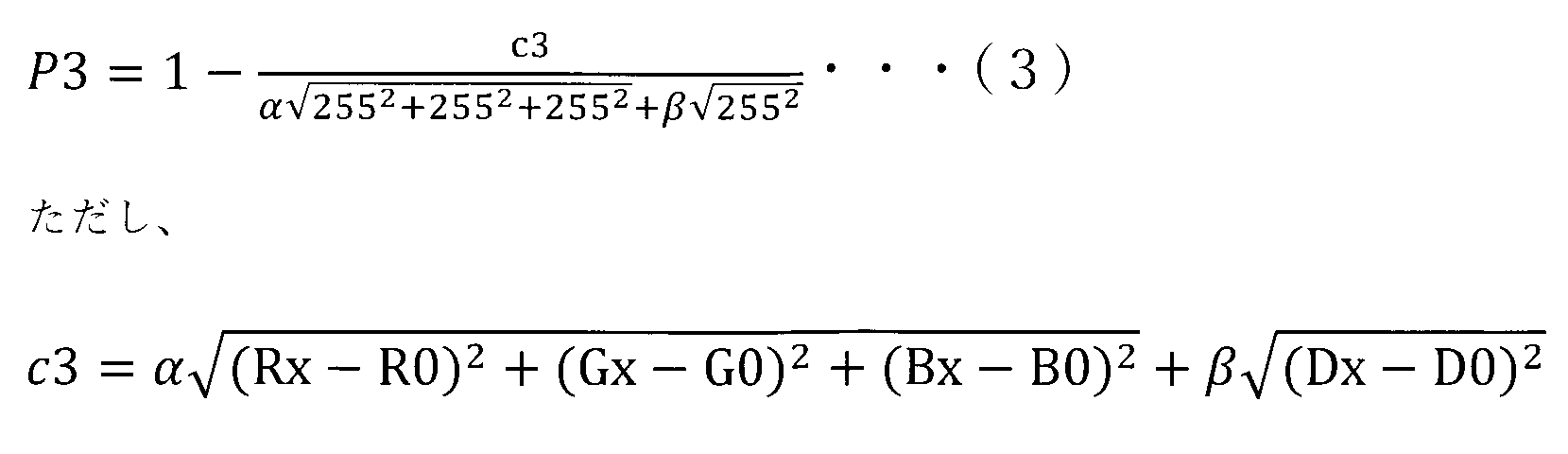
例えば色と距離を用いて確率を算出する場合、対象画素のRGB値[Rx,Gx,Bx]とマスク領域画素のRGB値[R0,G0,B0]と、対象画素の距離[Dx]と、マスク領域画素の距離[D0]とを用いて、対象画素がマスク領域画素である確率P3を下記式(3)で算出することができる。P3は、0から1の間の値をとり、値が大きいほど対象画素がマスク領域画素である確率が高い。下記式(3)では、色の階調は8bit、すなわち0から255の整数で表現されている。また、画素の距離についても0から255の値にスケーリングされている。αは色の重み、βは距離の重みであり、どちらのパラメーターを重視するかによって、任意に設定することができる。重みα、βは設定しなくてもよい。すなわち、αおよびβを1としてもよい。 For example, when calculating the probability using color and distance, the probability P3 that the target pixel is a mask area pixel can be calculated using the RGB values [Rx, Gx, Bx] of the target pixel, the RGB values [R0, G0, B0] of the mask area pixel, the distance [Dx] of the target pixel, and the distance [D0] of the mask area pixel, using the following formula (3). P3 takes a value between 0 and 1, and the higher the value, the higher the probability that the target pixel is a mask area pixel. In the following formula (3), the color tone is expressed in 8 bits, that is, an integer between 0 and 255. The pixel distance is also scaled to a value between 0 and 255. α is the color weight, and β is the distance weight, and can be set arbitrarily depending on which parameter is emphasized. The weights α and β do not need to be set. In other words, α and β can be set to 1.
深度などを用いる場合も、同様の方法で対象画像がマスク領域画素である確率を求めることができる。複数のパラメーターを用いて確率を求める場合には、上記式(3)で例示したように、例えば各パラメーターを用いて求めた確率に対して重みづけを設定した上で、これらを足し合わせばよい。また、マスク領域画素が複数選択されている場合、確率算出部333は、例えば全てのマスク領域画素における確率算出用のパラメーターの値の平均値を用いて確率を算出してもよいし、対象画素と最も近い位置にあるマスク領域画素のパラメーターの値を用いて確率を算出してもよい。
When depth or the like is used, the probability that the target image is a mask area pixel can be calculated in a similar manner. When calculating the probability using multiple parameters, as exemplified in the above formula (3), for example, weights may be assigned to the probabilities calculated using each parameter, and then these may be added together. Furthermore, when multiple mask area pixels are selected, the
また、確率算出部333は、撮像装置20とプロジェクター10との座標変換テーブルを用いて、撮像画像50の各画素がマスク領域を構成する画素である確率を算出してもよい。構造化光投影法で求めた座標変換テーブルでは、隣接する座標が同一平面にある時は値が連続的に変化するのに対して、隣接する座標に高さ方向の変化がある場合には値が不連続的に変化する。これを用いて、確率算出部333は、平面と立体物の境界部分の位置を推定可能となる。本実施形態では、確率算出部333は、物体40と壁面42の境界の位置や物体40の表面400と側面402の境界の位置を推定することによって、撮像画像50の各画素が表面400である確率を算出することができる。
The
また、確率算出部333は、領域選択受付部332で非マスク領域が選択された場合には、対象画像が非マスク領域を構成する画素である確率を算出してもよい。
In addition, when a non-masked region is selected by the region
図5は、確率算出部333が生成する確率分布画像52の一例を示す図である。図5では各画素がマスク領域である確率を5種類の網掛けで分類している。ここで、α1~α4を1以下かつ0を超える正の数とし、α1>α2>α3>α4であるものとする。網掛けのパターン1は、例えばマスク領域である確率がα1以上の領域である。網掛けのパターン2は、マスク領域である確率がα1未満かつα2以上の領域である。網掛けのパターン3は、マスク領域である確率がα2未満かつα3以上の領域である。網掛けのパターン4は、マスク領域である確率がα3未満かつα4以上の領域である。網掛けのパターン5は、マスク領域である確率がα4未満の領域である。
FIG. 5 is a diagram showing an example of a
なお、確率算出部333は、撮像画像50のそれぞれの画素についてマスク領域である確率または非マスク領域である確率を算出すればよく、図5のような確率分布画像52は必ずしも生成しなくてよい。撮像画像50の各画素がマスク領域である確率または非マスク領域である確率を示す情報を、確率分布情報という。また、本実施形態では、情報処理装置30が確率分布情報を生成するものとするが、これに限らず、例えば他の情報処理装置で生成した確率分布情報を情報処理装置30が通信等で取得してもよい。また、例えば過去に確率算出部333が生成した確率分布情報を記憶装置320に記憶しておき、処理装置330がこれを読みだしてもよい。
Note that the
図2に示される閾値受付部334は、ユーザーから閾値の入力を受け付ける。この閾値は、後述するマスク画像生成部335が撮像画像50の各画素がマスク領域を構成する画素であるか否か判定する際に用いる値である。より詳細には、閾値は、撮像画像50の各画素がマスク領域を構成する画素である確率を示す値である。後述するマスク画像生成部335は、マスク領域である確率が、閾値受付部334で受け付けた閾値以上である画素が、マスク領域を構成する画素であるものとしてマスク画像560,580を生成する。
The
図6は、閾値受付部334による閾値入力の受付態様の一例を示す図である。本実施形態では、後述する表示制御部336が、タッチパネル310に仮マスク画像540を含む仮投射用画像54を表示させると同時に、タッチパネル310に閾値入力を受け付けるユーザーインターフェースであるスライダーバー70を表示させる。閾値受付部334は、スライダーバー70への操作を閾値入力として受け付ける。
Figure 6 is a diagram showing an example of how a threshold input is received by the
まず、仮投射用画像54について説明する。本実施形態では、仮投射用画像54は、仮マスク画像540と、入力画像542と、背景画像544とを含んでいる。仮マスク画像540は、後述するマスク画像生成部335により生成される。仮マスク画像540は、図5に示される確率分布画像52のうち、マスク領域である確率が所定の仮閾値以上の画素をマスク領域とした画像である。図6では、仮閾値はα2に設定されている。すなわち、図6の仮マスク画像540は、図5に示される確率分布画像52のうち、マスク領域である確率がα2以上である画素、すなわちパターン1およびパターン2で示される領域をマスク領域としている。仮閾値は、プログラム322に予め設定された固定値であってもよいし、ユーザーにより指定された値であってもよい。仮マスク画像540は、マスク領域のエッジを示す線で構成される。線で囲まれた領域がマスク領域である。入力画像542は、マスク領域内に投射される画像である。入力画像542は、処理装置330に対して外部から入力された画像であってもよいし、処理装置330の内部で単色の入力画像542を生成してもよい。背景画像544は、仮マスク画像540の背景となる画像であり、図6の例では撮像装置20により撮像された物体40を含む画像、すなわち撮像画像50を用いている。このような撮像画像50を用いた背景画像544に仮マスク画像540および入力画像542を重畳させることにより、実際にプロジェクター10による投射を行った際のイメージをユーザーがより詳細に把握することができる。背景画像544は、マスク領域の外において入力画像542が非表示となっている状態を示す画像と言うこともできる。
First, the
表示制御部336は、図6のように情報処理装置30のタッチパネル310に仮投射用画像54を表示させる他、例えばプロジェクター10から物体40に対して実際に仮投射用画像54を投射させるようにしてもよい。仮投射用画像54が物体40に対して実際に投射されることによって、例えば物体40とマスク領域との位置関係や色味のバランス等を、ユーザーがより正確かつ詳細に把握することができる。プロジェクター10から物体40に対して仮投射用画像54が投射される場合には、一般的には仮投射用画像54は仮マスク画像540と入力画像542とからなると考えられるが、更に背景画像544を含んでいてもよい。
The
つぎに、スライダーバー70について説明する。スライダーバー70は、所定方向に延びるバー700と、バー700上を移動可能なスライダー702とを備える。図6の例では、バー700はタッチパネル310の画面左右方向に延びている。バー700の左右方向の中心位置が、スライダー702の基準位置である。ユーザーがスライダー702を基準位置より右方向に移動させると、閾値受付部334は、仮閾値よりも大きい値が閾値として指定されたものとして受け付ける。この場合、ユーザーは、マスク領域である確率が仮閾値よりも高い画素に絞ってマスク領域を設定するよう指示していることになる。また、ユーザーがスライダー702を基準位置より左方向に移動させると、閾値受付部334は、仮閾値よりも小さい値が閾値として指定されたものとして受け付ける。この場合、ユーザーは、マスク領域である確率が仮閾値よりも低い画素も含めてマスク領域を設定するよう指示していることになる。
Next, the
仮投射用画像54がプロジェクター10から物体40に対して実際に投射される場合には、例えばタッチパネル310にはスライダーバー70のみが表示されてもよい。または、スライダーバー70とともに、プロジェクター10から仮投射用画像54の投射を受ける物体40を撮像装置20で撮像した画像が表示されてもよい。または、図6のような画面表示がプロジェクター10からの投射と同時に行われてもよい。
When the
図2に示されるマスク画像生成部335は、プロジェクター10からの画像の投射領域、すなわちマスク領域を特定するためのマスク画像560,580を生成する。マスク画像560,580は、図7および図8に例示される。より詳細には、マスク画像生成部335は、閾値受付部334に入力された閾値を用いることによって、撮像画像50のうち入力画像542を表示する領域であるマスク領域、または撮像画像50のうち入力画像542を表示しない領域である非マスク領域を示す、マスク画像560,580を生成する。このマスク画像560,580が、第2画像に対応する。マスク領域は、撮像領域44の投射領域に対応する撮像画像50の領域と言うこともできる。上述のようにマスク画像生成部335は、マスク領域である確率が、確率算出部333で生成した確率分布画像52のうち閾値受付部334で受け付けた閾値以上である画素が、マスク領域を構成する画素であるものとしてマスク画像560,580を生成する。閾値受付部334に対して閾値の変更が入力される都度、マスク画像生成部335で生成されるマスク画像560,580も変化する。
2 generates
表示制御部336は、マスク画像560,580を入力画像562,582に重畳した投射用画像56,58を表示させる。
The
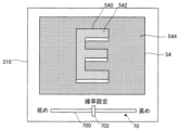
図7および図8は、表示制御部336による投射用画像56,58の表示態様の一例を示す図である。図7は、図6に示す仮投射用画像54に対して、閾値を大きくする操作入力が行われた場合、すなわち、スライダー702が基準位置より右側に移動された場合の表示例である。図7および図8のスライダー702は、表示されているマスク画像560,580に設定された閾値に対応する位置に表示されている。図7では、スライダーバー70の操作により、閾値がα1に指定されているものとする。図7において、投射用画像56は、マスク画像560と、入力画像562と、物体40を含む撮像画像50である背景画像564とを含み、タッチパネル310に表示されている。マスク画像560では、図5に示される確率分布画像52のうち、マスク領域である確率がα1以上である画素、すなわちパターン1で示される領域がマスク領域となっている。すなわち、マスク画像560は、図6に示す仮投射用画像54における仮マスク画像540よりも面積が小さい。
7 and 8 are diagrams showing an example of the display mode of the
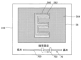
図8は、図6に示す仮投射用画像54に対して、閾値を小さくする操作入力が行われた場合、すなわち、スライダー702が基準位置より左側に移動された場合の表示例である。図8では、スライダーバー70の操作により、閾値がα3に指定されているものとする。図8において、投射用画像58は、マスク画像580と、入力画像582と、物体40を含む撮像画像50である背景画像584とを含み、タッチパネル310に表示されている。図8のマスク画像580は、図5に示される確率分布画像52のうち、マスク領域である確率がα3以上である画素、すなわちパターン1~3で示される領域がマスク領域となっている。すなわち、マスク画像580は、図6に示す仮投射用画像54における仮マスク画像540よりも面積が大きい。
Figure 8 is a display example when an operation input is made to reduce the threshold value for the
表示制御部336は、図7や図8のように情報処理装置30のタッチパネル310に投射用画像56,58を表示させる他、例えばプロジェクター10から物体40に対して、実際に投射用画像56,58を投射させるようにしてもよい。物体40に対して実際に投射用画像56,58を投射させることによって、例えば物体40と閾値調整後のマスク領域との位置関係や色味のバランス等を、ユーザーがより正確かつ詳細に把握することができる。プロジェクター10から物体40に対して投射用画像56,58を投射させる場合には、一般的には投射用画像56,58はマスク画像560,580と入力画像562,582とからなると考えられるが、更に背景画像564,584を含んでいてもよい。
The
また、図7および図8では、タッチパネル310に、ユーザーから閾値の入力を受け付けるスライダーバー70が表示されている。スライダーバー70の構成および機能は、図6を用いて説明したものと同様である。マスク画像560,580を含んだ投射用画像56,58を表示中にユーザーがスライダーバー70に対して操作を行った場合、マスク画像生成部335は、スライダーバー70の操作量に応じてマスク領域に含める画素を変更する。そして、表示制御部336は、変更後のマスク画像560,580を含む投射用画像56,58をタッチパネル310に表示させる。
7 and 8, a
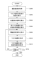
図9は、情報処理装置30の処理装置330がプログラム322に従って実行する表示方法の流れを示すフローチャートである。図9では、投射用画像56,58の表示先は、タッチパネル310であるものとする。処理装置330は、撮像画像取得部331として機能することにより、物体40を含む領域を撮像した撮像画像50を撮像装置20から取得する(ステップS200)。
Figure 9 is a flowchart showing the flow of a display method executed by the
処理装置330は、領域選択受付部332として機能することにより、マスク領域を構成する画素の指定をユーザーから受け付ける(ステップS202)。すなわち、処理装置330は、ステップS200で取得した撮像画像50をタッチパネル310に表示させるとともに、撮像画像50に対する描画入力をユーザーから受け付ける。ユーザーは、撮像画像50のうちマスク領域に対応する箇所に触れて描画する。なお、ステップS202において、処理装置330は、非マスク領域を構成する画素の指定を受け付けてもよい。
The
処理装置330は、確率算出部333として機能することにより、撮像画像50の各画素がマスク領域である確率を算出する(ステップS204)。この時、処理装置330は、例えば撮像画像50の各画素とステップS202で指定されたマスク領域を構成する画素との類似度に基づいて確率を算出する。
The
処理装置330は、表示制御部336として機能することにより、タッチパネル310に仮マスク画像540を含む仮投射用画像54を表示させる(ステップS206)。仮マスク画像540は、ステップS204で算出した確率が所定の仮閾値以上の画素をマスク領域とした画像である。また、処理装置330は、図6に示すように、仮投射用画像54とともに閾値調整用のスライダーバー70をタッチパネル310に表示させる。
The
処理装置330は、閾値受付部334として機能することにより、ユーザーから閾値設定操作を受け付ける(ステップS208)。上述のように、閾値は、マスク領域に含める画素を決定するための値である。処理装置330は、スライダーバー70に対する操作を閾値の入力として受け付ける。
The
処理装置330は、マスク画像生成部335として機能し、ステップS208で設定された閾値に基づくマスク画像560,580を生成する(ステップS210)。すなわち、処理装置330は、マスク領域である確率がステップS208で算出された閾値以上の画素をマスク領域としたマスク画像560,580を生成する。
The
処理装置330は、表示制御部336として機能することにより、ステップS210で生成されたマスク画像560,580を含む投射用画像56,58をタッチパネル310に表示させる(ステップS212)。この時、処理装置330は、投射用画像56,58とともに、閾値の再設定用のスライダーバー70も表示させる。
The
ユーザーは、タッチパネル310に表示された投射用画像56,58を見て、物体40に投射される画像がイメージ通りか、更に調整が必要かを判断する。処理装置330は、例えば、ステップS208またはステップS212において、調整を完了するか否かの入力を受け付けるボタンをタッチパネル310に表示し、ユーザーの操作に基づいて、調整を完了するか否かを判定してもよい(ステップS214)。表示の例としては、少なくとも、完了する場合に選択するボタンを表示する。調整を継続する場合は、継続する場合に選択するボタンを表示してもよく、ボタンを表示せずに、スライダーバー70に対する操作があった場合に、調整を継続すると判定してもよい。ユーザーによる調整が完了するまでは(ステップS214:NO)、処理装置330は、ステップS208に戻り以降の処理を繰り返す。完了することを指示するボタンが押下され、ユーザーによる調整が完了したと判定すると(ステップS214:YES)、処理装置330は、本フローチャートの処理を終了する。
The user looks at the
以上説明したように、実施形態に係る情報処理装置30の処理装置330は、プログラム322を実行することにより、撮像画像取得部331、領域選択受付部332、確率算出部333、閾値受付部334、マスク画像生成部335、および表示制御部336として機能する。閾値受付部334は、閾値の入力を受け付ける。マスク画像生成部335は、閾値を用いることによって、撮像画像50のうち入力画像562,582を表示する領域であるマスク領域、または撮像画像50のうち入力画像562,582を表示しない領域である非マスク領域を示す、マスク画像560,580を生成する。表示制御部336は、マスク画像560,580を入力画像562,582に重畳した投射用画像56,58を表示させる。マスク画像560,580は、入力された閾値に基づいて生成されるので、閾値を固定値とする場合と比較して、生成可能なマスク画像560,580の数が多くなる。よって、ユーザーは、その感性に合わせたマスク領域の調整を簡単に行うことができる。
As described above, the
また、閾値は、撮像画像50の各画素がマスク領域を構成する画素であるか否かを判定することに用いる値である。よって、マスク領域に含まれる画素の範囲をユーザーが容易に設定することができる。
The threshold value is a value used to determine whether each pixel of the captured
また、閾値は、撮像画像50の各画素がマスク領域を構成する画素である確率を示す値である。よって、ユーザーは、マスク領域に含まれる画素の範囲を、各画素がマスク領域を構成する画素である確率に基づいて設定することができる。
The threshold value is a value that indicates the probability that each pixel of the captured
また、マスク領域は、撮像画像50に映る物体40に対応するマスク画像560,580の所定の部分、または所定の部分以外のマスク画像560,580の部分のいずれかである。これにより、処理装置330は、マスク領域とその他の領域との選別を精度よく行うことができる。また、ユーザーは、物体40の形状に合わせて容易にマスク領域を設定することができる。
The mask area is either a specified portion of the
また、領域選択受付部332は、撮像画像50を表示させた上で撮像画像50を用いてマスク領域を選択する情報の入力を受け付ける。また、マスク画像生成部335は、マスク画像560,580を生成する際に、閾値と、マスク領域を選択する情報とに基づいてマスク領域を抽出する。これにより、ユーザーはマスク領域に含めたい領域を撮像画像50上で直接指定することができ、より正確にユーザーの意図を反映したマスク画像560,580を生成することができる。
The area
また、領域選択受付部332でマスク領域を選択する情報の入力を受け付けることは、撮像画像50に対する描画入力を受け付けることを含み、マスク領域を選択する情報は、描画入力で指定された画素の情報を含む。これにより、ユーザーは、撮像画像50中でマスク領域に含めたい箇所を容易かつ直感的に指定することができ、ユーザーの利便性を向上させることができる。
Furthermore, accepting input of information for selecting a mask area in the area
また、領域選択受付部332でマスク領域を選択する情報の入力を受け付けることは、描画入力の少なくとも一部を取り消すことを含む。これにより、ユーザーは、描画入力を誤った場合にも容易にその描画入力を取り消すことができ、ユーザーが描画入力を行う際の利便性を向上させることができる。
Furthermore, accepting input of information for selecting a mask area in the area
また、領域選択受付部332でマスク領域を選択する情報の入力を受け付けることは、撮像画像50の任意の画素がマスク領域を構成する画素であること、または、撮像画像50の任意の画素が非マスク領域を構成する画素である、ことを指定することを含む。これにより、マスク領域のみならず非マスク領域の画素を指定してもマスク画像560,580が生成可能となり、ユーザーの利便性を向上させることができる。
In addition, accepting input of information for selecting a mask region in the region
2.変形例
以上に例示した各形態は多様に変形され得る。前述の各形態に適用され得る具体的な変形の態様を以下に例示する。以下の例示から任意に選択された2以上の態様は、相互に矛盾しない範囲で適宜に併合され得る。
表示制御装置40のユーザーは、表示様態が変更された第1格子点147aを視認することで、第1格子点147aが所望の格子点147であるか否かを確認することができる。第1格子点147aが所望の格子点147であると確認することによって、ユーザーは、カーソル200が所望の位置に位置していることを確認することができる。
2. Modifications Each of the above-mentioned embodiments may be modified in various ways. Specific modifications that may be applied to each of the above-mentioned embodiments are illustrated below. Two or more embodiments selected from the following examples may be combined as appropriate to the extent that they are not mutually contradictory.
By visually checking the first lattice point 147a whose display mode has been changed, the user of the
本実施形態では、処理装置330は、ユーザーから閾値の指定を受け付けるインターフェースとしてスライダーバー70を表示させるものとしたが、インターフェースはこれに限られない。例えば一方が閾値の増加、他方が閾値の減少に対応付けられた2つのボタンがインターフェースであってもよい。この場合、処理装置330は、ユーザーが閾値の増加に対応付けられたボタンを1回押す毎に、所定の値閾値を増加させる。また、処理装置330は、ユーザーが閾値の減少に対応付けられたボタンを1回押す毎に、所定の値閾値を減少させる。2つのボタンは、例えば三角形など、相反する方向を指し示すマークが付されていたり、ボタンそのものが相反する方向を指し示す形状であってもよい。これにより、ユーザーは直感的に操作しやすくなる。また、例えばユーザーが数値を入力可能なフォームがインターフェースであってもよい。この場合、ユーザーは、例えば閾値を指定する数値を入力する。また、例えば音声入力により閾値の指定を受け付けるインターフェースが設けられてもよい。
In this embodiment, the
また、本実施形態では、物体40の表面400をマスク領域とすることを目的とし、撮像装置20で撮像された撮像画像50から表面400に対応する確率が閾値以上の部分を抽出することによりマスク領域を設定した。すなわち、マスク領域は、撮像画像50に映る物体40によって特定される所定の部分であった。しかしながら、例えば撮像画像50に映る物体40によって特定される所定の部分以外の領域、例えば物体40が取り付けられた壁面42をマスク領域として指定してもよい。この場合、ユーザーは、図4に示す領域種別指定部66のマスク領域指定部660を選択した上で撮像画像50の壁面42に対応する箇所に描画を行ってもよいし、非マスク領域指定部662を選択した上で撮像画像50の表面400に対応する箇所に描画を行ってもよい。
In addition, in this embodiment, the purpose is to set the
1…投射システム、10…プロジェクター、20…撮像装置、30…情報処理装置、40…物体、42…壁面、44…撮像領域、300…通信装置、310…タッチパネル、320…記憶装置、322…プログラム、330…処理装置、331…撮像画像取得部、332…領域選択受付部、333…確率算出部、334…閾値受付部、335…マスク画像生成部、336…表示制御部。 1...projection system, 10...projector, 20...imaging device, 30...information processing device, 40...object, 42...wall surface, 44...imaging area, 300...communication device, 310...touch panel, 320...storage device, 322...program, 330...processing device, 331...captured image acquisition unit, 332...area selection reception unit, 333...probability calculation unit, 334...threshold reception unit, 335...mask image generation unit, 336...display control unit.
Claims (10)
前記閾値を用いることによって、第1画像のうち入力画像を表示する領域であるマスク領域、または前記第1画像のうち前記入力画像を表示しない領域である非マスク領域を示す、第2画像を生成することと、
前記第2画像を前記入力画像に重畳した投射用画像を表示させることと、
を含み、
前記閾値は、前記第1画像の各画素が前記マスク領域を構成する画素であるか否かを判定することに用いる値であり、前記第1画像の各画素が前記マスク領域を構成する画素である確率を示す値である、
表示方法。 Accepting an input of a threshold value;
generating a second image using the threshold value to indicate a masked region of the first image that displays an input image or a non-masked region of the first image that does not display the input image;
displaying an image for projection in which the second image is superimposed on the input image; and
Including,
The threshold value is a value used to determine whether or not each pixel of the first image is a pixel that constitutes the mask region, and is a value indicating a probability that each pixel of the first image is a pixel that constitutes the mask region.
Display method.
請求項1記載の表示方法。 The mask area is either a predetermined portion of the second image corresponding to an object shown in the first image, or a portion of the second image other than the predetermined portion.
The display method according to claim 1 .
前記第1画像を用いて、前記マスク領域を選択する情報の入力を受け付けることと、を更に含み、
前記第2画像を生成することは、
前記閾値と、前記マスク領域を選択する情報とに基づいて前記マスク領域を抽出すること、を含む、
請求項1から2のいずれか1項記載の表示方法。 Displaying the first image;
and receiving an input of information for selecting the mask region using the first image;
Producing the second image includes:
extracting the mask region based on the threshold and information for selecting the mask region.
The display method according to any one of claims 1 to 2 .
前記第1画像に対する描画入力を受け付けることを含み、
前記マスク領域を選択する情報は、前記描画入力によって指定された画素の情報を含む、
請求項3記載の表示方法。 Receiving input of information for selecting the mask region
receiving a drawing input for the first image;
the information for selecting the mask region includes information on a pixel designated by the drawing input;
The display method according to claim 3 .
前記描画入力の少なくとも一部を取り消すことを含む、
請求項4記載の表示方法。 Receiving input of information for selecting the mask region
canceling at least a portion of the drawing input.
The display method according to claim 4 .
前記第1画像の任意の画素が前記マスク領域を構成する画素であること、または、前記第1画像の任意の画素が前記非マスク領域を構成する画素であること、を指定することを含む、
請求項3から5のいずれか1項記載の表示方法。 Receiving input of information for selecting the mask region
Specifying that any pixel of the first image is a pixel that constitutes the mask region, or that any pixel of the first image is a pixel that constitutes the non-mask region,
The display method according to any one of claims 3 to 5 .
前記閾値を用いることによって、第1画像のうち入力画像を表示する領域であるマスク領域、または前記第1画像のうち前記入力画像を表示しない領域である非マスク領域を示す、第2画像を生成することと、generating a second image using the threshold value to indicate a masked region of the first image that displays an input image or a non-masked region of the first image that does not display the input image;
前記第2画像を前記入力画像に重畳した投射用画像を表示させることと、displaying an image for projection in which the second image is superimposed on the input image; and
前記第1画像を表示することと、Displaying the first image;
前記第1画像を用いて、前記マスク領域を選択する情報の入力を受け付けることと、Receiving an input of information for selecting the mask region using the first image;
を含み、Including,
前記第2画像を生成することは、Producing the second image includes:
前記閾値と、前記マスク領域を選択する情報とに基づいて前記マスク領域を抽出すること、を含み、extracting the mask region based on the threshold and information for selecting the mask region;
前記マスク領域を選択する情報の入力を受け付けることは、Receiving input of information for selecting the mask region
前記第1画像に映る物体に対応する画素、または、前記第1画像に映る物体以外の部分に対応する画素を指定することを含む、Specifying pixels corresponding to an object appearing in the first image or pixels corresponding to a portion other than the object appearing in the first image.
表示方法。Display method.
前記閾値を用いることによって、第1画像のうち入力画像を表示する領域であるマスク領域、または前記第1画像のうち前記入力画像を表示しない領域である非マスク領域を示す、第2画像を生成することと、generating a second image using the threshold value to indicate a masked region of the first image that displays an input image or a non-masked region of the first image that does not display the input image;
前記第2画像を前記入力画像に重畳した投射用画像を表示させることと、displaying an image for projection in which the second image is superimposed on the input image; and
前記第1画像を表示することと、Displaying the first image;
前記第1画像を用いて、前記マスク領域を選択する情報の入力を受け付けることと、Receiving an input of information for selecting the mask region using the first image;
を含み、Including,
前記第2画像を生成することは、Producing the second image includes:
前記閾値と、前記マスク領域を選択する情報とに基づいて前記マスク領域を抽出すること、を含み、extracting the mask region based on the threshold and information for selecting the mask region;
前記マスク領域を選択する情報の入力を受け付けることは、Receiving input of information for selecting the mask region
前記第1画像に対する描画入力を受け付けることを含み、receiving a drawing input for the first image;
前記マスク領域を選択する情報は、前記描画入力によって指定された画素の情報を含む、the information for selecting the mask region includes information on a pixel designated by the drawing input;
表示方法。Display method.
閾値の入力を受け付けることと、
前記閾値を用いることによって、第1画像のうち入力画像を表示する領域であるマスク領域、または前記第1画像のうち前記入力画像を表示しない領域である非マスク領域を示す、第2画像を生成することと、
前記第2画像を前記入力画像に重畳した投射用画像を表示させることと、
を実行させ、
前記閾値は、前記第1画像の各画素が前記マスク領域を構成する画素であるか否かを判定することに用いる値であり、前記第1画像の各画素が前記マスク領域を構成する画素である確率を示す値である、
プログラム。 On the computer,
Accepting an input of a threshold value;
generating a second image using the threshold value to indicate a masked region of the first image that displays an input image or a non-masked region of the first image that does not display the input image;
displaying an image for projection in which the second image is superimposed on the input image; and
Run the command ,
The threshold value is a value used to determine whether or not each pixel of the first image is a pixel that constitutes the mask region, and is a value indicating a probability that each pixel of the first image is a pixel that constitutes the mask region.
program.
閾値の入力を受け付けることと、Accepting an input of a threshold value;
前記閾値を用いることによって、第1画像のうち入力画像を表示する領域であるマスク領域、または前記第1画像のうち前記入力画像を表示しない領域である非マスク領域を示す、第2画像を生成することと、generating a second image using the threshold value to indicate a masked region of the first image that displays an input image or a non-masked region of the first image that does not display the input image;
前記第2画像を前記入力画像に重畳した投射用画像を表示させることと、displaying an image for projection in which the second image is superimposed on the input image; and
前記第1画像を表示することと、Displaying the first image;
前記第1画像を用いて、前記マスク領域を選択する情報の入力を受け付けることと、Receiving an input of information for selecting the mask region using the first image;
を実行させ、Run the command,
前記第2画像を生成することは、Producing the second image includes:
前記閾値と、前記マスク領域を選択する情報とに基づいて前記マスク領域を抽出すること、を含み、extracting the mask region based on the threshold and information for selecting the mask region;
前記マスク領域を選択する情報の入力を受け付けることは、Receiving input of information for selecting the mask region
前記第1画像に対する描画入力を受け付けることを含み、receiving a drawing input for the first image;
前記マスク領域を選択する情報は、前記描画入力によって指定された画素の情報を含む、the information for selecting the mask region includes information on a pixel designated by the drawing input;
プログラム。program.
Priority Applications (2)
| Application Number | Priority Date | Filing Date | Title |
|---|---|---|---|
| JP2021031442A JP7608869B2 (en) | 2021-03-01 | 2021-03-01 | Display method and program |
| US17/682,156 US12080203B2 (en) | 2021-03-01 | 2022-02-28 | Projection image displaying method and a non-transitory computer-readable storage medium storing program |
Applications Claiming Priority (1)
| Application Number | Priority Date | Filing Date | Title |
|---|---|---|---|
| JP2021031442A JP7608869B2 (en) | 2021-03-01 | 2021-03-01 | Display method and program |
Publications (3)
| Publication Number | Publication Date |
|---|---|
| JP2022132789A JP2022132789A (en) | 2022-09-13 |
| JP2022132789A5 JP2022132789A5 (en) | 2024-01-11 |
| JP7608869B2 true JP7608869B2 (en) | 2025-01-07 |
Family
ID=83007208
Family Applications (1)
| Application Number | Title | Priority Date | Filing Date |
|---|---|---|---|
| JP2021031442A Active JP7608869B2 (en) | 2021-03-01 | 2021-03-01 | Display method and program |
Country Status (2)
| Country | Link |
|---|---|
| US (1) | US12080203B2 (en) |
| JP (1) | JP7608869B2 (en) |
Citations (5)
| Publication number | Priority date | Publication date | Assignee | Title |
|---|---|---|---|---|
| US20040032906A1 (en) | 2002-08-19 | 2004-02-19 | Lillig Thomas M. | Foreground segmentation for digital video |
| JP2011082798A (en) | 2009-10-07 | 2011-04-21 | Sanyo Electric Co Ltd | Projection graphic display device |
| JP2017228146A (en) | 2016-06-23 | 2017-12-28 | Kddi株式会社 | Image processing device, image processing method, and computer program |
| JP2018097414A (en) | 2016-12-08 | 2018-06-21 | 富士ゼロックス株式会社 | Image processing apparatus, image processing method, image processing system and program |
| US20200020108A1 (en) | 2018-07-13 | 2020-01-16 | Adobe Inc. | Automatic Trimap Generation and Image Segmentation |
Family Cites Families (11)
| Publication number | Priority date | Publication date | Assignee | Title |
|---|---|---|---|---|
| CA2268208C (en) * | 1998-04-06 | 2011-06-14 | Smart Technologies, Inc. | Method for erasing on an electronic writeboard |
| US7936361B2 (en) * | 2007-04-30 | 2011-05-03 | Hewlett-Packard Development Company, L.P. | System and method for masking and overlaying images in multiple projector system |
| JP2010206671A (en) * | 2009-03-05 | 2010-09-16 | Seiko Epson Corp | Projector and projector system |
| JP5652596B2 (en) * | 2009-06-11 | 2015-01-14 | セイコーエプソン株式会社 | Projector, program, information storage medium, and image projection method |
| JP5706131B2 (en) | 2010-11-05 | 2015-04-22 | グローリー株式会社 | Subject detection method and subject detection device |
| JP2017091298A (en) | 2015-11-12 | 2017-05-25 | 日本電信電話株式会社 | Image processing apparatus, image processing method, and image processing program |
| JP6642032B2 (en) * | 2016-01-21 | 2020-02-05 | セイコーエプソン株式会社 | Projector and projector control method |
| JP6460088B2 (en) | 2016-12-14 | 2019-01-30 | カシオ計算機株式会社 | Projection apparatus, projection method, and program |
| JP6949795B2 (en) | 2018-09-25 | 2021-10-13 | 富士フイルム株式会社 | Image processing equipment, image processing system, image processing method, and program |
| US20200364913A1 (en) * | 2019-05-14 | 2020-11-19 | Matterport, Inc. | User guided segmentation network |
| US12019674B2 (en) * | 2019-05-29 | 2024-06-25 | New York University | System and method for tumor characterization |
-
2021
- 2021-03-01 JP JP2021031442A patent/JP7608869B2/en active Active
-
2022
- 2022-02-28 US US17/682,156 patent/US12080203B2/en active Active
Patent Citations (5)
| Publication number | Priority date | Publication date | Assignee | Title |
|---|---|---|---|---|
| US20040032906A1 (en) | 2002-08-19 | 2004-02-19 | Lillig Thomas M. | Foreground segmentation for digital video |
| JP2011082798A (en) | 2009-10-07 | 2011-04-21 | Sanyo Electric Co Ltd | Projection graphic display device |
| JP2017228146A (en) | 2016-06-23 | 2017-12-28 | Kddi株式会社 | Image processing device, image processing method, and computer program |
| JP2018097414A (en) | 2016-12-08 | 2018-06-21 | 富士ゼロックス株式会社 | Image processing apparatus, image processing method, image processing system and program |
| US20200020108A1 (en) | 2018-07-13 | 2020-01-16 | Adobe Inc. | Automatic Trimap Generation and Image Segmentation |
Also Published As
| Publication number | Publication date |
|---|---|
| JP2022132789A (en) | 2022-09-13 |
| US12080203B2 (en) | 2024-09-03 |
| US20220277674A1 (en) | 2022-09-01 |
Similar Documents
| Publication | Publication Date | Title |
|---|---|---|
| CN107615214B (en) | Interface control system, interface control device, interface control method and program | |
| TWI534661B (en) | Image recognition device and operation determination method and computer program | |
| US20090002342A1 (en) | Information Processing Device | |
| US10234955B2 (en) | Input recognition apparatus, input recognition method using maker location, and non-transitory computer-readable storage program | |
| JP2011028366A (en) | Operation control device and operation control method | |
| CN106020436A (en) | Image analyzing apparatus and image analyzing method | |
| KR20140029222A (en) | Gesture recognition device, control method thereof and display device and control recording medium of recording program | |
| US10168769B2 (en) | Input apparatus, input method, and program | |
| US20140078056A1 (en) | Pointer speed adjusting method and display system using the same | |
| EP4075391A1 (en) | Apparatus and method for generating virtual model | |
| JP6501806B2 (en) | INFORMATION PROCESSING APPARATUS, OPERATION DETECTING METHOD, AND COMPUTER PROGRAM | |
| JP7608869B2 (en) | Display method and program | |
| JP6555958B2 (en) | Information processing apparatus, control method therefor, program, and storage medium | |
| KR100939831B1 (en) | Operating input device for reducing input error and information device operation apparatus | |
| JP6618301B2 (en) | Information processing apparatus, control method therefor, program, and storage medium | |
| US11948482B2 (en) | Display method and non-transitory computer-readable storage medium storing program | |
| JP6452658B2 (en) | Information processing apparatus, control method thereof, and program | |
| JP2018049498A (en) | Image processing apparatus, operation detection method, computer program, and storage medium | |
| JP2023026293A (en) | Information processor, information processing system, information processing method, and program | |
| JP2018055685A (en) | Information processing apparatus, control method therefor, program, and storage medium | |
| JP2012113653A (en) | Control device, input device, input determination method, and program | |
| JP2008242881A (en) | Input device and input program | |
| CN105391888A (en) | Image processing apparatus | |
| JP7427937B2 (en) | Image processing device, image processing method, and program | |
| JP6733789B2 (en) | Input device, input operation detection method, and input operation detection computer program |
Legal Events
| Date | Code | Title | Description |
|---|---|---|---|
| RD04 | Notification of resignation of power of attorney |
Free format text: JAPANESE INTERMEDIATE CODE: A7424 Effective date: 20210915 |
|
| RD03 | Notification of appointment of power of attorney |
Free format text: JAPANESE INTERMEDIATE CODE: A7423 Effective date: 20211104 |
|
| A521 | Request for written amendment filed |
Free format text: JAPANESE INTERMEDIATE CODE: A523 Effective date: 20231227 |
|
| A621 | Written request for application examination |
Free format text: JAPANESE INTERMEDIATE CODE: A621 Effective date: 20231227 |
|
| A131 | Notification of reasons for refusal |
Free format text: JAPANESE INTERMEDIATE CODE: A131 Effective date: 20240723 |
|
| A977 | Report on retrieval |
Free format text: JAPANESE INTERMEDIATE CODE: A971007 Effective date: 20240731 |
|
| A521 | Request for written amendment filed |
Free format text: JAPANESE INTERMEDIATE CODE: A523 Effective date: 20240920 |
|
| TRDD | Decision of grant or rejection written | ||
| A01 | Written decision to grant a patent or to grant a registration (utility model) |
Free format text: JAPANESE INTERMEDIATE CODE: A01 Effective date: 20241119 |
|
| A61 | First payment of annual fees (during grant procedure) |
Free format text: JAPANESE INTERMEDIATE CODE: A61 Effective date: 20241202 |
|
| R150 | Certificate of patent or registration of utility model |
Ref document number: 7608869 Country of ref document: JP Free format text: JAPANESE INTERMEDIATE CODE: R150 |