JP7608868B2 - Liquid leakage detection device and inkjet recording device - Google Patents
Liquid leakage detection device and inkjet recording device Download PDFInfo
- Publication number
- JP7608868B2 JP7608868B2 JP2021029956A JP2021029956A JP7608868B2 JP 7608868 B2 JP7608868 B2 JP 7608868B2 JP 2021029956 A JP2021029956 A JP 2021029956A JP 2021029956 A JP2021029956 A JP 2021029956A JP 7608868 B2 JP7608868 B2 JP 7608868B2
- Authority
- JP
- Japan
- Prior art keywords
- absorbent layer
- absorption layer
- liquid
- layer
- detection device
- Prior art date
- Legal status (The legal status is an assumption and is not a legal conclusion. Google has not performed a legal analysis and makes no representation as to the accuracy of the status listed.)
- Active
Links
Images


Classifications
-
- B—PERFORMING OPERATIONS; TRANSPORTING
- B41—PRINTING; LINING MACHINES; TYPEWRITERS; STAMPS
- B41J—TYPEWRITERS; SELECTIVE PRINTING MECHANISMS, i.e. MECHANISMS PRINTING OTHERWISE THAN FROM A FORME; CORRECTION OF TYPOGRAPHICAL ERRORS
- B41J2/00—Typewriters or selective printing mechanisms characterised by the printing or marking process for which they are designed
- B41J2/005—Typewriters or selective printing mechanisms characterised by the printing or marking process for which they are designed characterised by bringing liquid or particles selectively into contact with a printing material
- B41J2/01—Ink jet
- B41J2/135—Nozzles
- B41J2/165—Prevention or detection of nozzle clogging, e.g. cleaning, capping or moistening for nozzles
- B41J2/16579—Detection means therefor, e.g. for nozzle clogging
-
- B—PERFORMING OPERATIONS; TRANSPORTING
- B41—PRINTING; LINING MACHINES; TYPEWRITERS; STAMPS
- B41J—TYPEWRITERS; SELECTIVE PRINTING MECHANISMS, i.e. MECHANISMS PRINTING OTHERWISE THAN FROM A FORME; CORRECTION OF TYPOGRAPHICAL ERRORS
- B41J2/00—Typewriters or selective printing mechanisms characterised by the printing or marking process for which they are designed
- B41J2/005—Typewriters or selective printing mechanisms characterised by the printing or marking process for which they are designed characterised by bringing liquid or particles selectively into contact with a printing material
- B41J2/01—Ink jet
- B41J2/135—Nozzles
- B41J2/165—Prevention or detection of nozzle clogging, e.g. cleaning, capping or moistening for nozzles
- B41J2/16505—Caps, spittoons or covers for cleaning or preventing drying out
- B41J2/16508—Caps, spittoons or covers for cleaning or preventing drying out connected with the printer frame
- B41J2/16511—Constructions for cap positioning
-
- B—PERFORMING OPERATIONS; TRANSPORTING
- B41—PRINTING; LINING MACHINES; TYPEWRITERS; STAMPS
- B41J—TYPEWRITERS; SELECTIVE PRINTING MECHANISMS, i.e. MECHANISMS PRINTING OTHERWISE THAN FROM A FORME; CORRECTION OF TYPOGRAPHICAL ERRORS
- B41J2/00—Typewriters or selective printing mechanisms characterised by the printing or marking process for which they are designed
- B41J2/005—Typewriters or selective printing mechanisms characterised by the printing or marking process for which they are designed characterised by bringing liquid or particles selectively into contact with a printing material
- B41J2/01—Ink jet
- B41J2/135—Nozzles
- B41J2/165—Prevention or detection of nozzle clogging, e.g. cleaning, capping or moistening for nozzles
- B41J2/16517—Cleaning of print head nozzles
- B41J2/16535—Cleaning of print head nozzles using wiping constructions
- B41J2/16538—Cleaning of print head nozzles using wiping constructions with brushes or wiper blades perpendicular to the nozzle plate
-
- B—PERFORMING OPERATIONS; TRANSPORTING
- B41—PRINTING; LINING MACHINES; TYPEWRITERS; STAMPS
- B41J—TYPEWRITERS; SELECTIVE PRINTING MECHANISMS, i.e. MECHANISMS PRINTING OTHERWISE THAN FROM A FORME; CORRECTION OF TYPOGRAPHICAL ERRORS
- B41J2/00—Typewriters or selective printing mechanisms characterised by the printing or marking process for which they are designed
- B41J2/005—Typewriters or selective printing mechanisms characterised by the printing or marking process for which they are designed characterised by bringing liquid or particles selectively into contact with a printing material
- B41J2/01—Ink jet
- B41J2/135—Nozzles
- B41J2/165—Prevention or detection of nozzle clogging, e.g. cleaning, capping or moistening for nozzles
- B41J2/16517—Cleaning of print head nozzles
- B41J2/16535—Cleaning of print head nozzles using wiping constructions
- B41J2/16544—Constructions for the positioning of wipers
-
- B—PERFORMING OPERATIONS; TRANSPORTING
- B41—PRINTING; LINING MACHINES; TYPEWRITERS; STAMPS
- B41J—TYPEWRITERS; SELECTIVE PRINTING MECHANISMS, i.e. MECHANISMS PRINTING OTHERWISE THAN FROM A FORME; CORRECTION OF TYPOGRAPHICAL ERRORS
- B41J2/00—Typewriters or selective printing mechanisms characterised by the printing or marking process for which they are designed
- B41J2/005—Typewriters or selective printing mechanisms characterised by the printing or marking process for which they are designed characterised by bringing liquid or particles selectively into contact with a printing material
- B41J2/01—Ink jet
- B41J2/135—Nozzles
- B41J2/165—Prevention or detection of nozzle clogging, e.g. cleaning, capping or moistening for nozzles
- B41J2/16585—Prevention or detection of nozzle clogging, e.g. cleaning, capping or moistening for nozzles for paper-width or non-reciprocating print heads
-
- B—PERFORMING OPERATIONS; TRANSPORTING
- B41—PRINTING; LINING MACHINES; TYPEWRITERS; STAMPS
- B41J—TYPEWRITERS; SELECTIVE PRINTING MECHANISMS, i.e. MECHANISMS PRINTING OTHERWISE THAN FROM A FORME; CORRECTION OF TYPOGRAPHICAL ERRORS
- B41J2/00—Typewriters or selective printing mechanisms characterised by the printing or marking process for which they are designed
- B41J2/005—Typewriters or selective printing mechanisms characterised by the printing or marking process for which they are designed characterised by bringing liquid or particles selectively into contact with a printing material
- B41J2/01—Ink jet
- B41J2/17—Ink jet characterised by ink handling
- B41J2/1721—Collecting waste ink; Collectors therefor
- B41J2/1728—Closed waste ink collectors
-
- B—PERFORMING OPERATIONS; TRANSPORTING
- B41—PRINTING; LINING MACHINES; TYPEWRITERS; STAMPS
- B41J—TYPEWRITERS; SELECTIVE PRINTING MECHANISMS, i.e. MECHANISMS PRINTING OTHERWISE THAN FROM A FORME; CORRECTION OF TYPOGRAPHICAL ERRORS
- B41J2/00—Typewriters or selective printing mechanisms characterised by the printing or marking process for which they are designed
- B41J2/005—Typewriters or selective printing mechanisms characterised by the printing or marking process for which they are designed characterised by bringing liquid or particles selectively into contact with a printing material
- B41J2/01—Ink jet
- B41J2/17—Ink jet characterised by ink handling
- B41J2/175—Ink supply systems ; Circuit parts therefor
- B41J2/17503—Ink cartridges
- B41J2/17513—Inner structure
-
- B—PERFORMING OPERATIONS; TRANSPORTING
- B41—PRINTING; LINING MACHINES; TYPEWRITERS; STAMPS
- B41J—TYPEWRITERS; SELECTIVE PRINTING MECHANISMS, i.e. MECHANISMS PRINTING OTHERWISE THAN FROM A FORME; CORRECTION OF TYPOGRAPHICAL ERRORS
- B41J2/00—Typewriters or selective printing mechanisms characterised by the printing or marking process for which they are designed
- B41J2/005—Typewriters or selective printing mechanisms characterised by the printing or marking process for which they are designed characterised by bringing liquid or particles selectively into contact with a printing material
- B41J2/01—Ink jet
- B41J2/17—Ink jet characterised by ink handling
- B41J2/175—Ink supply systems ; Circuit parts therefor
- B41J2/17503—Ink cartridges
- B41J2/1752—Mounting within the printer
-
- B—PERFORMING OPERATIONS; TRANSPORTING
- B41—PRINTING; LINING MACHINES; TYPEWRITERS; STAMPS
- B41J—TYPEWRITERS; SELECTIVE PRINTING MECHANISMS, i.e. MECHANISMS PRINTING OTHERWISE THAN FROM A FORME; CORRECTION OF TYPOGRAPHICAL ERRORS
- B41J2/00—Typewriters or selective printing mechanisms characterised by the printing or marking process for which they are designed
- B41J2/005—Typewriters or selective printing mechanisms characterised by the printing or marking process for which they are designed characterised by bringing liquid or particles selectively into contact with a printing material
- B41J2/01—Ink jet
- B41J2/17—Ink jet characterised by ink handling
- B41J2/175—Ink supply systems ; Circuit parts therefor
- B41J2/17503—Ink cartridges
- B41J2/17553—Outer structure
-
- G—PHYSICS
- G01—MEASURING; TESTING
- G01M—TESTING STATIC OR DYNAMIC BALANCE OF MACHINES OR STRUCTURES; TESTING OF STRUCTURES OR APPARATUS, NOT OTHERWISE PROVIDED FOR
- G01M3/00—Investigating fluid-tightness of structures
- G01M3/02—Investigating fluid-tightness of structures by using fluid or vacuum
- G01M3/04—Investigating fluid-tightness of structures by using fluid or vacuum by detecting the presence of fluid at the leakage point
- G01M3/16—Investigating fluid-tightness of structures by using fluid or vacuum by detecting the presence of fluid at the leakage point using electric detection means
- G01M3/18—Investigating fluid-tightness of structures by using fluid or vacuum by detecting the presence of fluid at the leakage point using electric detection means for pipes, cables or tubes; for pipe joints or seals; for valves; for welds; for containers, e.g. radiators
- G01M3/186—Investigating fluid-tightness of structures by using fluid or vacuum by detecting the presence of fluid at the leakage point using electric detection means for pipes, cables or tubes; for pipe joints or seals; for valves; for welds; for containers, e.g. radiators for containers, e.g. radiators
-
- B—PERFORMING OPERATIONS; TRANSPORTING
- B41—PRINTING; LINING MACHINES; TYPEWRITERS; STAMPS
- B41J—TYPEWRITERS; SELECTIVE PRINTING MECHANISMS, i.e. MECHANISMS PRINTING OTHERWISE THAN FROM A FORME; CORRECTION OF TYPOGRAPHICAL ERRORS
- B41J2/00—Typewriters or selective printing mechanisms characterised by the printing or marking process for which they are designed
- B41J2/005—Typewriters or selective printing mechanisms characterised by the printing or marking process for which they are designed characterised by bringing liquid or particles selectively into contact with a printing material
- B41J2/01—Ink jet
- B41J2/17—Ink jet characterised by ink handling
- B41J2/175—Ink supply systems ; Circuit parts therefor
- B41J2/17596—Ink pumps, ink valves
Landscapes
- Physics & Mathematics (AREA)
- General Physics & Mathematics (AREA)
- Ink Jet (AREA)
Description
本発明は、液漏れを検知する液漏れ検知装置及び液漏れ検知装置を備えるインクジェット記録装置に関する。 The present invention relates to a liquid leakage detection device that detects liquid leakage and an inkjet recording device equipped with a liquid leakage detection device.
インクジェット記録装置は、インクコンテナ、ポンプ、サブタンク、インクジェットヘッド、洗浄液タンク、廃液タンク等を備え、これらが配管で接続されている。このような構成において、インク、洗浄液、廃液等の液体が装置内に漏出すると、装置を構成する部材や記録用紙の汚染、電気回路の短絡等が発生するおそれがある。そこで、従来、装置内の液漏れを検知する手段が検討されている。例えば、特許文献1では、シート状の吸収体に吸収されたインクをセンサーで検知する構成が提案されている。特許文献2では、インクによって溶かされた個体の形状の変化を検知する構成が提案されている。
An inkjet recording device is equipped with an ink container, a pump, a sub-tank, an inkjet head, a cleaning liquid tank, a waste liquid tank, etc., which are connected by piping. In such a configuration, if liquids such as ink, cleaning liquid, waste liquid, etc. leak into the device, there is a risk of contamination of the components constituting the device and the recording paper, short-circuiting of electrical circuits, etc. Therefore, conventionally, means for detecting leakage within the device have been considered. For example,
ところで、液体を吸収する吸収体に端子を接触させておき、漏れた液体が吸収体に吸収されたときの端子と吸収体との接触抵抗の低下を捉えることで液漏れを検知する構成が考えられる。このような構成において誤検知を抑制するには、液体が吸収体に吸収されていないときの接触抵抗が大きいことが望ましい。接触抵抗を大きくするためには、体積抵抗値が大きい材料を使用するか、あるいは、同一体積抵抗値の場合には吸収体が薄い方がよい。しかし、その場合、吸収可能な液体の量が少ないため、吸収体の周囲に液体が流出するおそれがある。一方、吸収可能な量を増やすために吸収体を厚くすると、高湿環境下で空気中の水分が吸収体に吸収されて体積抵抗値が低下し、それに伴って接触抵抗値も低下するため、誤検知が生じる可能性が高くなる。 A possible configuration is to place a terminal in contact with an absorbent that absorbs liquid, and detect a liquid leak by detecting a decrease in contact resistance between the terminal and the absorbent when the leaked liquid is absorbed by the absorbent. In order to suppress false detection in such a configuration, it is desirable that the contact resistance is large when the liquid is not absorbed by the absorbent. To increase the contact resistance, a material with a high volume resistance is used, or, for the same volume resistance, a thinner absorbent is better. However, in that case, the amount of liquid that can be absorbed is small, and there is a risk that the liquid will leak out around the absorbent. On the other hand, if the absorbent is made thicker to increase the amount that can be absorbed, moisture in the air is absorbed by the absorbent in a high humidity environment, decreasing the volume resistance, and the contact resistance also decreases, increasing the possibility of false detection.
本発明は、上記事情を考慮し、吸収可能な液体の量を多くするとともに、高湿環境下での誤検知を抑制することのできる液漏れ検知装置及びインクジェット記録装置を提供することを目的とする。 In consideration of the above circumstances, the present invention aims to provide a liquid leakage detection device and inkjet recording device that can absorb a large amount of liquid and suppress false detection in high humidity environments.
上記課題を解決するため、本発明に係る液漏れ検知装置は、液体を吸収する第1吸収層と、前記第1吸収層に積層され、前記液体を吸収する第2吸収層と、前記第2吸収層にのみ接触する1対の端子と、を備え、前記第1吸収層と前記第2吸収層が積層されていることにより、前記第2吸収層のみの場合よりも吸収可能な前記液体の量が多く、且つ、前記第1吸収層のみの場合よりも前記第2吸収層の接触抵抗値が大きいことを特徴とする。 In order to solve the above problem, the liquid leakage detection device of the present invention comprises a first absorbent layer that absorbs liquid, a second absorbent layer that is laminated on the first absorbent layer and absorbs the liquid, and a pair of terminals that contact only the second absorbent layer, and is characterized in that, by laminating the first absorbent layer and the second absorbent layer, the amount of liquid that can be absorbed is greater than when only the second absorbent layer is used, and the contact resistance value of the second absorbent layer is greater than when only the first absorbent layer is used.
前記第1吸収層は、前記第2吸収層よりも吸収可能な前記液体の量が多く、前記第2吸収層は、前記第1吸収層よりも接触抵抗値が大きくてもよい。 The first absorption layer may be capable of absorbing a larger amount of the liquid than the second absorption layer, and the second absorption layer may have a higher contact resistance than the first absorption layer.
前記第2吸収層の体積抵抗値は、前記第1吸収層よりも大きくてもよい。 The volume resistivity of the second absorption layer may be greater than that of the first absorption layer.
前記第2吸収層の厚みは、前記第1吸収層よりも小さくてもよい。 The thickness of the second absorbent layer may be less than that of the first absorbent layer.
前記第1吸収層は、前記第2吸収層との境界部に空洞を有し、前記1対の端子は、前記第2吸収層の前記空洞に対応する箇所を貫通していてもよい。 The first absorbent layer may have a cavity at the boundary with the second absorbent layer, and the pair of terminals may penetrate the second absorbent layer at a location corresponding to the cavity.
前記第1吸収層と前記第2吸収層との境界部の一部又は全部が接着されていなくてもよい。 A part or all of the boundary between the first absorbent layer and the second absorbent layer may not be bonded.
前記液漏れ検知装置は、前記1対の端子を支持する基板と、金属板で形成され、前記基板を支持する支持部材と、前記支持部材と前記第2吸収層との間に設けられた絶縁層と、を備えていてもよい。 The liquid leakage detection device may include a substrate supporting the pair of terminals, a support member formed of a metal plate and supporting the substrate, and an insulating layer provided between the support member and the second absorption layer.
前記液漏れ検知装置は、前記1対の端子を支持する基板と、樹脂で形成され、前記基板を支持する支持部材と、を備えていてもよい。 The liquid leak detection device may include a substrate that supports the pair of terminals, and a support member that is made of resin and supports the substrate.
また、本発明に係るインクジェット記録装置は、前記のいずれかの液漏れ検知装置を備えることを特徴とする。 The inkjet recording device according to the present invention is characterized by being equipped with any one of the above-mentioned liquid leakage detection devices.
本発明によれば、吸収可能な液体の量を多くするとともに、高湿環境下での誤検知を抑制することができる。 The present invention makes it possible to increase the amount of liquid that can be absorbed and to reduce false detections in high humidity environments.
以下、図面を参照しつつ本発明の一実施形態に係るプリンター1(インクジェット記録装置の一例)について説明する。 The following describes a printer 1 (an example of an inkjet recording device) according to one embodiment of the present invention, with reference to the drawings.
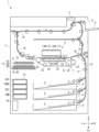
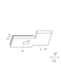
最初に、プリンター1の全体の構成について説明する。図1は、プリンター1の外観を示す斜視図である。図2は、プリンター1の内部構成を模式的に示す正面図である。図3は、プリンター1のインク供給機構50と廃液回収機構60を模式的に示す図である。以下、図2における紙面手前側を画像形成システム100の正面側(前側)とし、左右の向きは画像形成システム100を正面から見た方向を基準として説明する。各図において、U、Lo、L、R、Fr、Rrは、それぞれ上、下、左、右、前、後を示す。
First, the overall configuration of the
プリンター1は、直方体状のハウジング3を備える(図2参照)。ハウジング3内の下部には、普通紙、コート紙等の枚葉のシートSが収容される給紙カセット4と、給紙カセット4からシートSを送り出す給紙ローラー5が設けられている。給紙カセット4の上方には、シートSを吸着してY方向に搬送する搬送ユニット7が設けられている。搬送ユニット7の上方には、シートSにインクを吐出する作像ユニット6が設けられている。ハウジング3の右上部には、画像が形成されたシートSを排出する排紙ローラー対8と、排出されたシートSが積載される排紙トレイ9が設けられている。
The
ハウジング3の内部には、給紙カセット4から搬送ユニット7と作像ユニット6との間隙を経て排紙トレイ9に至る搬送路10が設けられている。搬送路10は、シートSを通過させる間隙を空けて互いに対向する板状部材によって形成されており、シートSを挟持して搬送する搬送ローラー対17が搬送方向Yの複数箇所に設けられている。作像ユニット6よりも搬送方向上流側には、レジストローラー対18が設けられている。
Inside the
搬送ユニット7は、多数の通気孔(図示省略)が設けられ、複数のローラー22に巻き掛けられた無端の搬送ベルト21と、多数の通気孔が設けられ、上面が搬送ベルト21の内面に接触する支持板23と、支持板23の通気孔を介して空気を吸引することでシートSを搬送ベルト21に吸着させる吸引部24と、を備える。モーター等の駆動部(図示省略)により複数のローラー22の1つが駆動されることで搬送ベルト21が反時計回り方向に回転し、搬送ベルト21に吸着されたシートSがY方向に搬送される。
The
作像ユニット6は、ヘッドユニット11Y、11Bk、11C、11M(ヘッドユニット11と総称する)を備え、それぞれイエロー、ブラック、シアン、マゼンタのインクを吐出する。ヘッドユニット11Y、11Bk、11C、11Mには、それぞれイエロー、ブラック、シアン、マゼンタのインクが充填されたインクコンテナ20Y、20Bk、20C、20M(インクコンテナ20と総称する)が接続されている。インクコンテナ20は、給紙カセット4の左方に設けられたコンテナ装着部51に装着されている。
The
ヘッドユニット11は、1つ以上のインクジェットヘッド12、例えば、千鳥に配置された複数のインクジェットヘッド12を備える(図3参照)。インクジェットヘッド12は、前後方向を長手方向とする直方体状の筐体12Hと、筐体12Hの底部に設けられたノズルプレート12Pと、を備える。ノズルプレート12Pは、前後方向に並ぶ多数のノズルを備え、各ノズルの吐出口がノズルプレート12Pの下面であるノズル面12Nに設けられている。各ノズルには圧電素子が設けられ、筐体12Hの内部には圧電素子を駆動する駆動回路が設けられている。
The head unit 11 has one or
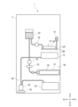
プリンター1は、インクジェットヘッド12にインクを供給するインク供給機構50を備える(図3参照)。同図では、1つのインクジェットヘッド12に対応するインク供給機構50が図示されている。インク供給機構50は、インクコンテナ20と、インクを濾過するフィルター52と、インクコンテナ20からフィルター52を介してインクを吸引するポンプ53と、ポンプ53から送り出されたインクを貯留するサブタンク54と、サブタンク54に貯留されたインクをインクジェットヘッド12に供給するポンプ55と、を備える。インクジェットヘッド12には、洗浄液を収容する洗浄液タンク61が接続されている。
The
制御部2(図2参照)は、演算部と記憶部とを備える。演算部は、例えば、CPU(Central Processing Unit)である。記憶部は、ROM(Read Only Memory)、RAM(Random Access Memory)、EEPROM(Electrically Erasable Programmable Read Only Memory)等の記憶媒体を含む。演算部は、記憶部に記憶されている制御プログラムを読み出して実行することで各種処理を実施する。なお、制御部2は、ソフトウェアを用いない集積回路によって実現されてもよい。
The control unit 2 (see FIG. 2) includes a calculation unit and a memory unit. The calculation unit is, for example, a CPU (Central Processing Unit). The memory unit includes storage media such as a ROM (Read Only Memory), a RAM (Random Access Memory), and an EEPROM (Electrically Erasable Programmable Read Only Memory). The calculation unit performs various processes by reading and executing control programs stored in the memory unit. Note that the
ハウジング3の上面の右後部には、操作パネル19が設けられている(図1参照)。操作パネル19は、表示パネルと、表示パネルの表示面に重ねて設けられたタッチパネルと、表示パネルに隣接するキーパッドと、を備える。制御部2は、プリンター1の操作メニューを表す画面を表示パネルに表示させ、タッチパネル及びキーパッドで検知された操作に応じてプリンター1の各部を制御する。
An
プリンター1の基本的な画像形成動作は、次のとおりである。外部のコンピューター等からプリンター1に画像形成ジョブが入力されると、給紙ローラー5が給紙カセット4から搬送路10にシートSを送り出し、回転が停止されたレジストローラー対18がシートSの斜行を補正する。レジストローラー対18が所定のタイミングで搬送ユニット7にシートSを送り出すと、搬送ユニット7が搬送ベルト21にシートSを吸着してY方向に搬送する。制御部2がシートSの搬送と同期させてインクジェットヘッド12の各ノズルに対応する階調データを駆動回路に供給すると、駆動回路が階調データに応じた駆動信号を圧電素子に供給することでノズルからインク滴が吐出され、シートSに画像が形成される。排紙ローラー対8は、画像が形成されたシートSを排紙トレイ9に排出する。
The basic image forming operation of the
[トリートメントユニット]
トリートメントユニット13(図2参照)は、インクジェットヘッド12のノズル面12Nを覆うキャップユニット70と、ノズル面12Nを清掃するワイプユニット80と、を備える。キャップユニット70は、支持板71と、支持板71の上面に設けられた樹脂製のキャップ72と、を備える。インクジェットヘッド12の各々に対して1つのキャップ72が設けられている。ワイプユニット80は、支持板81と、支持板81の上方に設けられた樹脂製のワイプブレード82と、ワイプブレード82を駆動するワイプ機構(図示省略)と、を備える。ワイプ機構は、ノズル面12Nに接触させたワイプブレード82を前後方向にスライドさせることでノズル面12Nを清掃する。支持板81は、ノズル面12Nの清掃で発生する廃液を受け止める受け皿を兼ねる。
[Treatment unit]
The treatment unit 13 (see FIG. 2) includes a
ワイプユニット80は、キャップユニット70の下方に配置されている。キャップユニット70とワイプユニット80は、キャリッジ90に支持されており、キャリッジ90に対して昇降可能である。キャリッジ90は、キャリッジスライド機構(図示省略)を介してハウジング3に支持されている。キャリッジスライド機構は、ハウジング3に対してキャリッジ90を左右方向にスライドさせる。キャップユニット70は、キャップユニットスライド機構(図示省略)を介してキャリッジ90に支持されている。キャップユニットスライド機構は、キャリッジ90に対してキャップユニット70を左右方向にスライドさせる。搬送ユニット7は、昇降機構(図示省略)を介してハウジング3に支持されている。昇降機構は、ハウジング3に対して搬送ユニット7を昇降させる。
The wipe unit 80 is disposed below the
図2は、画像形成時の様子を示しており、搬送ベルト21の上面がインクジェットヘッド12のノズル面12Nから1mm程度下方に位置し、トリートメントユニット13が搬送ユニット7の左方の退避位置に退避させられている。
Figure 2 shows the state during image formation, with the upper surface of the
制御部2は、所定のタイミングで以下の処理を実行する。最初に、制御部2は、昇降機構により搬送ユニット7を下降させ、キャリッジスライド機構によりキャリッジ90を搬送ユニット7と作像ユニット6との間へスライドさせる。次に、制御部2は、キャップユニットスライド機構によりキャップユニット70を退避位置にスライドさせ、昇降機構により搬送ユニット7を上昇させてワイプユニット80を押し上げさせる。次に、制御部2は、粘度の増大したインクをインクジェットヘッド12から強制的に吐出させる(パージ処理)。
The
次に、制御部2は、ワイプ機構によりワイプブレード82を前後方向にスライドさせてノズル面12Nを清掃させる。このとき、ノズル面12Nには、前述の洗浄液タンク61から洗浄液が供給され、ノズル面12Nに残留したインクが希釈される。ワイプブレード82は、洗浄液とインクが混ざり合った廃液を掻き取って支持板81に落下させる。
Next, the
次に、制御部2は、昇降機構により搬送ユニット7を下降させ、キャップユニットスライド機構によりキャップユニット70をワイプユニット80の上方にスライドさせ、昇降機構により搬送ユニット7を上昇させてワイプユニット80を介してキャップユニット70を押し上げさせる。この動作により、ノズル面12Nがキャップ72で覆われ、吐出口の目詰まりが防止される。
Next, the
[廃液回収機構]
プリンター1は、インクジェットヘッド12のノズル面12Nの清掃によって発生した廃液を回収する廃液回収機構60を備える(図3参照)。トリートメントユニット13には、廃液ポンプ62と廃液タンク63が接続されている。廃液ポンプ62は、ハウジング3内の左下の後部に設けられている。廃液タンク63は、廃液ポンプ62の前方に設けられている。廃液ポンプ62は、例えばチューブポンプであり、ワイプユニット80の支持板81に溜まった廃液を吸引して廃液タンク63に搬送する。
[Waste liquid recovery mechanism]
The
[液漏れ検知装置]
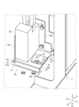
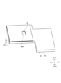
液漏れ検知装置30は、廃液ポンプ62の下方に設けられ、廃液ポンプ62からの液漏れを検知する。図4は、液漏れ検知装置30及び廃液ポンプ62の斜視図である。図5は、液漏れ検知装置30の断面を示す斜視図である。図6は、液漏れ検知装置30の断面図である。図7は、液漏れ検知装置30の斜視図である。図8、9は、第1吸収層31、第2吸収層32及び絶縁層36の斜視図である。
[Leak detection device]
The liquid
液漏れ検知装置30は、液体を吸収する第1吸収層31と、第1吸収層31に積層され、液体を吸収する第2吸収層32と、第2吸収層32にのみ接触する1対の端子33と、を備え、第1吸収層31と第2吸収層32が積層されていることにより、第2吸収層32のみの場合よりも吸収可能な液体の量が多く、且つ、第1吸収層31のみの場合よりも第2吸収層32の接触抵抗値が大きい。
The liquid
[第1吸収層、第2吸収層]
第1吸収層31は、フェルトで形成された層である。第2吸収層32は不織布であるが、実質的には薄いフェルトの層である。第2吸収層32は、第1吸収層31よりも厚みが小さい。第2吸収層32は、第1吸収層31の上方に積層されている。第2吸収層32としては、例えば、ヒメロン(登録商標)が用いられてもよい。第1吸収層31と第2吸収層32は、同一の繊維状物質を用いて形成されている。従って、第1吸収層31と第2吸収層32の構成上の実質的な違いは厚みだけであるが、第1吸収層31よりも体積抵抗値が大きい材質で第2吸収層32を構成してもよい。
[First absorption layer, second absorption layer]
The first
第1吸収層31は、ハウジング3の底板の上面に敷設されている(図4乃至6参照)。第1吸収層31は、第2吸収層32及び絶縁層36を挟んで後述する支持部材35の底部35Bに対向する対向部31Aと、対向部31Aの左方に設けられ、支持部材35の底部35Bに対向しない非対向部31Bと、を有する(図4乃至9参照)。対向部31Aの中央よりも左寄りの位置には、空洞31Cが形成されている(図9参照)。空洞31Cは、上下方向に貫通している。空洞31Cの大きさは、後述する1対の端子33が第1吸収層31に接触しない程度の大きさである。なお、非対向部31Bの端部は、フェルトの体積を大きくするために(大きな吸液スペースを確保するために)、上方に折り曲げられていてもよい。
The first
第2吸収層32は、対向部31Aの上面に積層されている。第1吸収層31の空洞31Cの上部は、第2吸収層32によって塞がれている。第2吸収層32と第1吸収層31との境界部の一部が両面粘着テープ、接着剤等を用いて接着されている。例えば、境界部の前端部と後端部が接着されている。接着されている領域では、毛細管現象による第1吸収層31から第2吸収層32への液体の上昇が遮断されるが、接着されていない領域では、液体の上昇は遮断されない。従って、検知精度の観点からは、接着する領域の面積は小さいことが望ましい。
The second
第2吸収層32の上面には、絶縁層36が積層されている。絶縁層36は、例えば、PET(ポリエチレンテレフタラート)フィルムである。絶縁層36には、第1吸収層31の空洞31Cに対応する箇所に、第1吸収層31の空洞31Cと同等の大きさ又はやや小さい開口部36Aが設けられている(図5乃至8参照)。開口部36Aは上下方向に貫通しており、開口部36Aにおいて第2吸収層32の上面が露出されている。
An insulating
[端子、基板、支持部材]
絶縁層36の上方には、支持部材35が設けられている(図4乃至7参照)。支持部材35は、絶縁層36及び第2吸収層32を挟んで第1吸収層31の対向部31Aに対向する底部35Bと、底部35Bの右端部から上方に設けられた第1壁部351と、第1壁部351の前端部から左方に設けられた第2壁部352と、を備える。支持部材35は、鋼板等の金属板で形成されている。第2壁部352がハウジング3に固定されている。底部35Bは、絶縁層36との間に所定の大きさの間隙を空けて配置されている。
[Terminals, boards, support members]
A
底部35Bの左右方向の長さは、廃液ポンプ62よりも長い。廃液ポンプ62は、第1壁部351寄りに配置され、底部35Bと第1壁部351の少なくとも一方に固定されている。底部35Bには、第1吸収層31の空洞31Cに対応する箇所に、空洞31Cと同等の大きさの上下方向に貫通した開口部35Aが設けられている。底部35Bの上面には、廃液ポンプ62よりも左方に、基板34が設けられている。基板34は、底部35Bの開口部35Aよりも大きく、開口部35Aのほぼ全部を塞いでいる。
The length of the bottom 35B in the left-right direction is longer than that of the
基板34には、1対の端子33と、センサー37と、が設けられている。1対の端子33は、支持部材35の底部の開口部35Aと、絶縁層36の開口部36Aと、に対応する箇所に設けられ、基板34を上下方向に貫通している。1対の端子33の上端部は、基板34の上面から突出している。1対の端子33の下端部は、基板34の下面から突出し、第2吸収層32を貫通している。1対の端子33は、第2吸収層32にのみ接触しており、支持部材35、絶縁層36、第1吸収層31、ハウジング3の底部のいずれにも接触していない。
The
センサー37は、1対の端子33に接続されており、1対の端子33と第2吸収層32との接触抵抗の低下を検知する。第2吸収層32に液体が吸収されていない場合の接触抵抗値は閾値よりも高く、第2吸収層32に液体が吸収された場合の接触抵抗値は閾値よりも低くなる。廃液ポンプ62等から廃液が漏れた場合、漏れた廃液は、ハウジング3の底部に落下して第1吸収層31に吸収され、毛細管現象により上昇し、第2吸収層32に浸透する。浸透した廃液により第2吸収層32の体積抵抗値が低下し、それに伴って、第2吸収層32と端子33との接触抵抗値が閾値未満に低下する。センサー37は、接触抵抗値が閾値未満に低下した場合に、液漏れが検知されたことを示す検知信号を制御部2に出力する。
The
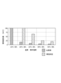
図10は、接触抵抗値の実験結果を示すグラフである。横軸は、温度と湿度(相対湿度)である。縦軸は、接触抵抗値である。温度と湿度を、22℃と60%、28℃と80%、32℃と85%、40℃と905、55℃と90%の5段階に変化させた。比較例では、第2吸収層32が設けられておらず、1対の端子33が第1吸収層31に接触している。そのため、比較例では、端子33と第1吸収層31との接触抵抗値を計測し、実施形態では、端子33と第2吸収層32との接触抵抗値を計測した。
Figure 10 is a graph showing the experimental results of the contact resistance value. The horizontal axis is temperature and humidity (relative humidity). The vertical axis is contact resistance value. The temperature and humidity were changed in five stages: 22°C and 60%, 28°C and 80%, 32°C and 85%, 40°C and 905, and 55°C and 90%. In the comparative example, the
実験の結果、比較例では、湿度が60%の場合に接触抵抗値が100MΩ以上であったのに対して、湿度が80%を超えると15MΩ程度まで急激に低下した。これに対して、実施形態では、湿度が80%の場合でも接触抵抗値は100MΩ以上が得られ、湿度が85%の場合でも65MΩ程度となり、比較例と比べて、大幅な改善が見られた。 As a result of the experiment, in the comparative example, the contact resistance value was 100 MΩ or more when the humidity was 60%, but dropped rapidly to about 15 MΩ when the humidity exceeded 80%. In contrast, in the embodiment, the contact resistance value was 100 MΩ or more even when the humidity was 80%, and was about 65 MΩ even when the humidity was 85%, showing a significant improvement compared to the comparative example.
以上説明した本実施形態に係る液漏れ検知装置30によれば、液体を吸収する第1吸収層31と、第1吸収層31に積層され、液体を吸収する第2吸収層32と、第2吸収層32にのみ接触する1対の端子33と、を備え、第1吸収層31と第2吸収層32が積層されていることにより、第2吸収層32のみの場合よりも吸収可能な液体の量が多く、且つ、第1吸収層31のみの場合よりも第2吸収層32の接触抵抗値が大きい。この構成によれば、第1吸収層31が設けられていない場合と比べて、吸収可能な液体の量を多くすることができる。また、この構成によれば、第1吸収層31に1対の端子33を接触させる場合と比べて、高湿環境下での誤検知を抑制することができる。
According to the liquid
また、本実施形態に係る液漏れ検知装置30によれば、第1吸収層31は、第2吸収層32よりも吸収可能な液体の量が多く、第2吸収層32は、第1吸収層31よりも接触抵抗値が大きいから、第1吸収層31が設けられていない場合と比べて、吸収可能な液体の量を多くすることができる。また、この構成によれば、第1吸収層31に1対の端子33を接触させる場合と比べて、高湿環境下での誤検知を抑制することができる。
In addition, according to the liquid
また、本実施形態に係る液漏れ検知装置30によれば、第2吸収層32の体積抵抗値は、第1吸収層31よりも大きいから、第2吸収層32の接触抵抗値を第1吸収層31よりも大きくすることができる。
In addition, according to the liquid
また、本実施形態に係る液漏れ検知装置30によれば、第2吸収層32の厚みは、第1吸収層31よりも小さく、また体積抵抗も大きいため、接触抵抗値を第1吸収層31よりも大きくすることができる。また、第1吸収層31が吸収可能な液体の量を第2吸収層32よりも多くすることができる。
In addition, according to the liquid
また、本実施形態に係る液漏れ検知装置30によれば、第1吸収層31は、第2吸収層32との境界部に空洞31Cを有し、1対の端子33は、第2吸収層32の空洞31Cに対応する箇所を貫通しているから、端子33を第2吸収層32に確実に接触させるとともに、第1吸収層31に端子33が接触することを防ぐことができる。
In addition, according to the liquid
また、本実施形態に係る液漏れ検知装置30によれば、第1吸収層31と第2吸収層32との境界部の一部が接着されていないから、第1吸収層31から第2吸収層32への液体の上昇を遮断しないようにすることができる。
In addition, with the liquid
また、本実施形態に係る液漏れ検知装置30によれば、1対の端子33を支持する基板34と、金属板で形成され、基板34を支持する支持部材35と、支持部材35と第2吸収層32との間に設けられた絶縁層36と、を備えるから、支持部材35を介した漏れ電流による誤検知を防ぐことができる。また、樹脂で支持部材35を形成する場合の金型の製作が不要であるから、少量生産の場合にコストを抑制することができる。なお、本実施形態では金属を多用しているため絶縁層36が有効であるが、樹脂を多用する場合には絶縁層36を備えていなくても良い。
The liquid
上記実施形態が以下のように変形されてもよい。 The above embodiment may be modified as follows:
上記実施形態では、第1吸収層31としてフェルトを用いた例が示されたが、第1吸収層31としてスポンジ等が用いられてもよい。
In the above embodiment, an example was shown in which felt was used as the first
上記実施形態では、第2吸収層32の厚みを第1吸収層31よりも小さくすることで第2吸収層32の接触抵抗値を第1吸収層31よりも大きくした例が示されたが、第1吸収層31よりも体積抵抗値の大きい材料を第2吸収層32として用いてもよい。この構成によっても、第2吸収層32の接触抵抗値を第1吸収層31よりも大きくすることができる。
In the above embodiment, an example is shown in which the thickness of the
上記実施形態では、空洞31Cが第1吸収層31を上下方向に貫通している例が示されたが、空洞31Cは、少なくとも1対の端子33が第1吸収層31に接触しない程度の大きさがあればよく、空洞31Cが第1吸収層31を貫通していなくてもよい。
In the above embodiment, an example is shown in which the
上記実施形態では、第1吸収層31は、第2吸収層32との境界部に空洞31Cを有し、1対の端子33は、第2吸収層32の空洞31Cに対応する箇所を貫通している例が示されたが、1対の端子33は、第2吸収層32を貫通していなくてもよい。その場合、第1吸収層31に空洞31Cが設けられていなくてもよい。
In the above embodiment, the
上記実施形態では、第1吸収層31と第2吸収層32との境界部の一部が接着されていない例が示されたが、境界部の全部が接着されていなくてもよい。
In the above embodiment, an example is shown in which part of the boundary between the first
上記実施形態では、第1吸収層31と第2吸収層32とが接着されている例が示されたが、接着以外の手段で第1吸収層31と第2吸収層32が接合されていてもよい。例えば、ニードルパンチにより繊維を絡ませることで第1吸収層31と第2吸収層32が一体化されていてもよい。
In the above embodiment, an example in which the first
上記実施形態では、支持部材35が金属板で形成されている例が示されたが、支持部材35は樹脂で形成されていてもよい。この場合、絶縁層36は設けられていなくてもよい。この構成によれば、絶縁層36を省くことができる。また、射出成形で支持部材35の製造が可能であるから、大量生産の場合にコストを抑制することができる。
In the above embodiment, an example was shown in which the
上記実施形態では、第2吸収層32の上面に絶縁層36が積層されている例が示されたが、絶縁層36は支持部材35の底部35Bの下面に設けられていてもよい。
In the above embodiment, an example is shown in which the insulating
上記実施形態の構成に加えて、第1吸収層31の下面に絶縁層36が設けられていてもよい。
In addition to the configuration of the above embodiment, an insulating
1 プリンター(インクジェット記録装置)
30 液漏れ検知装置
31 第1吸収層
31C 空洞
32 第2吸収層
33 端子
34 基板
35 支持部材
36 絶縁層
1. Printer (inkjet recording device)
30 Liquid
Claims (8)
前記第1吸収層に積層され、前記液体を吸収する第2吸収層と、
前記第2吸収層にのみ接触する1対の端子と、を備え、
前記第1吸収層と前記第2吸収層が積層されていることにより、前記第2吸収層のみの場合よりも吸収可能な前記液体の量が多く、且つ、前記第1吸収層のみの場合よりも前記第2吸収層の接触抵抗値が大きく、
前記第1吸収層は、前記第2吸収層との境界部に空洞を有し、
前記1対の端子は、前記第2吸収層の前記空洞に対応する箇所を貫通していることを特徴とする液漏れ検知装置。 a first absorbent layer for absorbing liquid;
a second absorbent layer laminated to the first absorbent layer and configured to absorb the liquid;
a pair of terminals contacting only the second absorbent layer;
Since the first absorbent layer and the second absorbent layer are laminated, the amount of the liquid that can be absorbed is larger than that in the case of only the second absorbent layer, and the contact resistance value of the second absorbent layer is larger than that in the case of only the first absorbent layer,
the first absorbent layer has a cavity at the boundary with the second absorbent layer,
A liquid leakage detection device , characterized in that the pair of terminals penetrate the second absorbent layer at locations corresponding to the cavities .
前記第2吸収層は、前記第1吸収層よりも接触抵抗値が大きいことを特徴とする請求項1に記載の液漏れ検知装置。 the first absorbent layer is capable of absorbing a larger amount of the liquid than the second absorbent layer;
The liquid leakage detection device according to claim 1 , wherein the second absorbent layer has a contact resistance greater than that of the first absorbent layer.
金属板で形成され、前記基板を支持する支持部材と、
前記支持部材と前記第2吸収層との間に設けられた絶縁層と、を備えることを特徴とする請求項1乃至5のいずれか1項に記載の液漏れ検知装置。 a substrate supporting the pair of terminals;
A support member formed of a metal plate and configured to support the substrate;
6. The liquid leakage detection device according to claim 1, further comprising an insulating layer provided between the support member and the second absorbent layer.
樹脂で形成され、前記基板を支持する支持部材と、を備えることを特徴とする請求項1乃至5のいずれか1項に記載の液漏れ検知装置。 A substrate supporting the pair of terminals;
6. The liquid leakage detection device according to claim 1, further comprising: a support member made of resin for supporting the substrate.
Priority Applications (2)
| Application Number | Priority Date | Filing Date | Title |
|---|---|---|---|
| JP2021029956A JP7608868B2 (en) | 2021-02-26 | 2021-02-26 | Liquid leakage detection device and inkjet recording device |
| US17/681,624 US11872820B2 (en) | 2021-02-26 | 2022-02-25 | Liquid leakage detection device including two absorption layers and pair of terminals, and ink jet recording apparatus |
Applications Claiming Priority (1)
| Application Number | Priority Date | Filing Date | Title |
|---|---|---|---|
| JP2021029956A JP7608868B2 (en) | 2021-02-26 | 2021-02-26 | Liquid leakage detection device and inkjet recording device |
Publications (2)
| Publication Number | Publication Date |
|---|---|
| JP2022131157A JP2022131157A (en) | 2022-09-07 |
| JP7608868B2 true JP7608868B2 (en) | 2025-01-07 |
Family
ID=83006857
Family Applications (1)
| Application Number | Title | Priority Date | Filing Date |
|---|---|---|---|
| JP2021029956A Active JP7608868B2 (en) | 2021-02-26 | 2021-02-26 | Liquid leakage detection device and inkjet recording device |
Country Status (2)
| Country | Link |
|---|---|
| US (1) | US11872820B2 (en) |
| JP (1) | JP7608868B2 (en) |
Citations (1)
| Publication number | Priority date | Publication date | Assignee | Title |
|---|---|---|---|---|
| JP2018030263A (en) | 2016-08-23 | 2018-03-01 | セイコーエプソン株式会社 | Liquid jet device |
Family Cites Families (6)
| Publication number | Priority date | Publication date | Assignee | Title |
|---|---|---|---|---|
| DE69314922T2 (en) * | 1992-12-28 | 1998-03-19 | Canon Kk | Ink jet recorder |
| JPH06340089A (en) | 1993-06-02 | 1994-12-13 | Canon Inc | Ink jet recording device and ink leakage detecting method |
| JP3167598B2 (en) * | 1995-10-13 | 2001-05-21 | キヤノン株式会社 | Ink tank and inkjet recording device |
| JP3658367B2 (en) * | 2001-12-21 | 2005-06-08 | キヤノン株式会社 | Liquid storage container and ink jet recording apparatus using the container |
| JP2006231803A (en) | 2005-02-28 | 2006-09-07 | Seiko Instruments Inc | Ink leakage detector and ink jet recorder |
| JP2018130858A (en) * | 2017-02-14 | 2018-08-23 | セイコーエプソン株式会社 | Liquid ejector |
-
2021
- 2021-02-26 JP JP2021029956A patent/JP7608868B2/en active Active
-
2022
- 2022-02-25 US US17/681,624 patent/US11872820B2/en active Active
Patent Citations (1)
| Publication number | Priority date | Publication date | Assignee | Title |
|---|---|---|---|---|
| JP2018030263A (en) | 2016-08-23 | 2018-03-01 | セイコーエプソン株式会社 | Liquid jet device |
Also Published As
| Publication number | Publication date |
|---|---|
| US11872820B2 (en) | 2024-01-16 |
| JP2022131157A (en) | 2022-09-07 |
| US20220274408A1 (en) | 2022-09-01 |
Similar Documents
| Publication | Publication Date | Title |
|---|---|---|
| JP5790271B2 (en) | Liquid ejection device | |
| JP7608868B2 (en) | Liquid leakage detection device and inkjet recording device | |
| JP5991113B2 (en) | Inkjet recording device | |
| JP5782961B2 (en) | Droplet ejector | |
| JP6111533B2 (en) | Liquid ejection device | |
| JP5948943B2 (en) | Image recording device | |
| US8926057B2 (en) | Liquid ejection apparatus | |
| JP2012158036A (en) | Recorder | |
| US20250065630A1 (en) | Maintenance device and inkjet recording apparatus | |
| CN116198219B (en) | Recording device and recording device control method | |
| JP2025029628A (en) | Maintenance device and inkjet recording device | |
| JP2024092756A (en) | Cap Unit | |
| JP6083293B2 (en) | Liquid ejection device | |
| JP6350689B2 (en) | Liquid ejection device | |
| JP4860516B2 (en) | Waste liquid container and image forming apparatus | |
| JP2025091279A (en) | Inkjet recording device | |
| US20250050640A1 (en) | Maintenance device and inkjet recording apparatus | |
| JP2025090972A (en) | Inkjet recording device | |
| EP4566822A1 (en) | Inkjet recording apparatus | |
| JP7786565B2 (en) | Degassing device and liquid ejection device | |
| US20250229537A1 (en) | Maintenance device and inkjet recording apparatus | |
| US20250289236A1 (en) | Inkjet recording apparatus | |
| JP2025091280A (en) | Inkjet recording device | |
| US20250065627A1 (en) | Maintenance device and inkjet recording apparatus | |
| JP5929426B2 (en) | Liquid ejecting apparatus and control method thereof |
Legal Events
| Date | Code | Title | Description |
|---|---|---|---|
| A621 | Written request for application examination |
Free format text: JAPANESE INTERMEDIATE CODE: A621 Effective date: 20240129 |
|
| A131 | Notification of reasons for refusal |
Free format text: JAPANESE INTERMEDIATE CODE: A131 Effective date: 20240827 |
|
| A521 | Request for written amendment filed |
Free format text: JAPANESE INTERMEDIATE CODE: A523 Effective date: 20241021 |
|
| TRDD | Decision of grant or rejection written | ||
| A01 | Written decision to grant a patent or to grant a registration (utility model) |
Free format text: JAPANESE INTERMEDIATE CODE: A01 Effective date: 20241119 |
|
| A61 | First payment of annual fees (during grant procedure) |
Free format text: JAPANESE INTERMEDIATE CODE: A61 Effective date: 20241202 |
|
| R150 | Certificate of patent or registration of utility model |
Ref document number: 7608868 Country of ref document: JP Free format text: JAPANESE INTERMEDIATE CODE: R150 |