JP7608866B2 - Signal generating device, signal generating system, and signal generating method - Google Patents
Signal generating device, signal generating system, and signal generating method Download PDFInfo
- Publication number
- JP7608866B2 JP7608866B2 JP2021029331A JP2021029331A JP7608866B2 JP 7608866 B2 JP7608866 B2 JP 7608866B2 JP 2021029331 A JP2021029331 A JP 2021029331A JP 2021029331 A JP2021029331 A JP 2021029331A JP 7608866 B2 JP7608866 B2 JP 7608866B2
- Authority
- JP
- Japan
- Prior art keywords
- propagation delay
- processing
- sub
- blocks
- waveform
- Prior art date
- Legal status (The legal status is an assumption and is not a legal conclusion. Google has not performed a legal analysis and makes no representation as to the accuracy of the status listed.)
- Active
Links
Images


Classifications
-
- Y—GENERAL TAGGING OF NEW TECHNOLOGICAL DEVELOPMENTS; GENERAL TAGGING OF CROSS-SECTIONAL TECHNOLOGIES SPANNING OVER SEVERAL SECTIONS OF THE IPC; TECHNICAL SUBJECTS COVERED BY FORMER USPC CROSS-REFERENCE ART COLLECTIONS [XRACs] AND DIGESTS
- Y02—TECHNOLOGIES OR APPLICATIONS FOR MITIGATION OR ADAPTATION AGAINST CLIMATE CHANGE
- Y02A—TECHNOLOGIES FOR ADAPTATION TO CLIMATE CHANGE
- Y02A90/00—Technologies having an indirect contribution to adaptation to climate change
- Y02A90/10—Information and communication technologies [ICT] supporting adaptation to climate change, e.g. for weather forecasting or climate simulation
Landscapes
- Measurement Of Velocity Or Position Using Acoustic Or Ultrasonic Waves (AREA)
Description
本発明は、伝搬遅延および周波数シフトを模擬した信号を生成する信号生成装置、信号生成システムおよび信号生成方法に関する。 The present invention relates to a signal generating device, a signal generating system, and a signal generating method for generating a signal that simulates a propagation delay and a frequency shift.
従来、音源から受波点への波の伝搬を模擬するシミュレータなどにおいて、波の伝搬遅延、およびドップラー効果による周波数シフトを模擬した信号を生成する信号生成装置が知られている。また、信号生成装置ではないが、解析対象の波が電波の場合について、電波を海面に発射し、その反射波を測定して、海流の流れなどの海象情報を観測する海洋レーダ観測装置が知られている(例えば、特許文献1参照)。 Conventionally, a signal generating device is known that generates a signal simulating the propagation delay of a wave and the frequency shift due to the Doppler effect in a simulator that simulates the propagation of a wave from a sound source to a receiving point. In addition, although it is not a signal generating device, when the wave to be analyzed is a radio wave, a marine radar observation device is known that emits radio waves onto the sea surface, measures the reflected waves, and observes oceanographic information such as ocean currents (see, for example, Patent Document 1).
特許文献1に開示された海洋レーダ観測装置は、船舶によって発生する水位変動のノイズに対し、レンジ方向の観測範囲をブロック分割し、分割されたブロック内で流れの回帰曲線を求め、回帰曲線からのズレと標準偏差に基づき不正常な流束値を検出して補正する。
The marine radar observation device disclosed in
特許文献1に開示された海洋レーダ観測装置は、ブロック長を一定として補正処理を行っている。特許文献1に開示された技術を信号生成装置に適用し、信号処理の単位である処理ブロックの長さを一定とした場合、ドップラー係数がブロック間で大きく変化すると、処理ブロック間で連続性を担保した波形を模擬できなくなるおそれがある。例えば、音源と受波点との距離が近い場合、音源と受波点との距離が遠い場合と比べて、連続するブロック間でドップラー係数が大きく変化するからである。
The marine radar observation device disclosed in
本発明に係る信号生成装置は、波形に対して伝搬遅延および周波数シフトを模擬する信号生成装置であって、波形に対して、信号処理の単位である処理ブロック毎の伝搬遅延を記憶する記憶手段と、伝搬遅延に基づいて、連続する処理ブロック間のドップラー係数変化度を算出する係数変化度算出手段と、ドップラー係数変化度が予め決められた閾値以下であるか否かを判定する判定手段と、ドップラー係数変化度が閾値よりも大きい場合、処理ブロックを複数のサブブロックに分割する分割手段と、伝搬遅延に基づいて、サブブロック毎に補間が必要なサンプル点位置を算出するサンプル位置算出手段と、サンプル点位置に基づいて、サブブロック毎に補間処理を実行する補間処理手段と、伝搬遅延に基づいて、補間処理後のサブブロック毎にサンプル遅延を実行する遅延処理手段と、を有するものである。 The signal generating device according to the present invention is a signal generating device that simulates a propagation delay and a frequency shift for a waveform, and includes a storage means for storing a propagation delay for each processing block, which is a unit of signal processing, for the waveform, a coefficient change degree calculation means for calculating a Doppler coefficient change degree between successive processing blocks based on the propagation delay, a determination means for determining whether the Doppler coefficient change degree is equal to or less than a predetermined threshold, a division means for dividing the processing block into a plurality of subblocks if the Doppler coefficient change degree is greater than the threshold, a sample position calculation means for calculating a sample point position requiring interpolation for each subblock based on the propagation delay, an interpolation processing means for performing an interpolation process for each subblock based on the sample point position, and a delay processing means for performing a sample delay for each subblock after the interpolation process based on the propagation delay.
本発明に係る信号生成システムは、波形に対して伝搬遅延および周波数シフトを模擬する信号生成システムであって、波形に対して、信号処理の単位である処理ブロック毎の伝搬遅延を記憶する記憶手段と、伝搬遅延に基づいて、連続する処理ブロック間のドップラー係数変化度を算出する係数変化度算出手段と、ドップラー係数変化度が予め決められた閾値以下であるか否かを判定する判定手段と、ドップラー係数変化度が閾値よりも大きい場合、処理ブロックを複数のサブブロックに分割する分割手段と、伝搬遅延に基づいて、サブブロック毎に補間が必要なサンプル点位置を算出するサンプル位置算出手段と、サンプル点位置に基づいて、サブブロック毎に補間処理を実行する補間処理手段と、伝搬遅延に基づいて、補間処理後のサブブロック毎にサンプル遅延を実行する遅延処理手段と、を有するものである。 The signal generation system according to the present invention is a signal generation system that simulates a propagation delay and a frequency shift for a waveform, and includes a storage means for storing a propagation delay for each processing block, which is a unit of signal processing, for the waveform, a coefficient change degree calculation means for calculating a Doppler coefficient change degree between successive processing blocks based on the propagation delay, a determination means for determining whether the Doppler coefficient change degree is equal to or less than a predetermined threshold, a division means for dividing the processing block into a plurality of subblocks if the Doppler coefficient change degree is greater than the threshold, a sample position calculation means for calculating a sample point position requiring interpolation for each subblock based on the propagation delay, an interpolation processing means for performing an interpolation process for each subblock based on the sample point position, and a delay processing means for performing a sample delay for each subblock after the interpolation process based on the propagation delay.
本発明に係る信号生成方法は、波形に対して伝搬遅延および周波数シフトを模擬する情報処理装置による信号生成方法であって、波形に対して、信号処理の単位である処理ブロック毎の伝搬遅延を記憶するステップと、伝搬遅延に基づいて、連続する処理ブロック間のドップラー係数変化度を算出するステップと、ドップラー係数変化度が予め決められた閾値以下であるか否かを判定するステップと、ドップラー係数変化度が閾値よりも大きい場合、処理ブロックを複数のサブブロックに分割するステップと、伝搬遅延に基づいて、サブブロック毎に補間が必要なサンプル点位置を算出するステップと、サンプル点位置に基づいて、サブブロック毎に補間処理を実行するステップと、伝搬遅延に基づいて、補間処理後のサブブロック毎にサンプル遅延を実行するステップと、を有するものである。 The signal generation method according to the present invention is a signal generation method by an information processing device that simulates a propagation delay and a frequency shift for a waveform, and includes the steps of: storing a propagation delay for each processing block, which is a unit of signal processing, for the waveform; calculating a Doppler coefficient change rate between successive processing blocks based on the propagation delay; determining whether the Doppler coefficient change rate is equal to or less than a predetermined threshold; dividing the processing block into a plurality of subblocks if the Doppler coefficient change rate is greater than the threshold; calculating sample point positions that require interpolation for each subblock based on the propagation delay; performing an interpolation process for each subblock based on the sample point positions; and performing a sample delay for each subblock after the interpolation process based on the propagation delay.
本発明によれば、ドップラー係数変化度に対して閾値判定を行い、ドップラー係数変化度が小さい場合、処理ブロックの単位で波形を推定し、ドップラー係数変化度が大きい場合、処理ブロックをより細かいブロック長のサブブロックに自動的に分割して波形を推定する。そのため、連続する処理ブロック間でドップラー係数の変化が大きくても、連続性を担保した波形を模擬することができる。 According to the present invention, a threshold determination is performed on the Doppler coefficient change rate, and if the Doppler coefficient change rate is small, the waveform is estimated in units of processing blocks, and if the Doppler coefficient change rate is large, the processing block is automatically divided into sub-blocks of finer block lengths to estimate the waveform. Therefore, even if there is a large change in the Doppler coefficient between consecutive processing blocks, it is possible to simulate a waveform that ensures continuity.
実施の形態1.
本実施の形態1では、信号生成装置が、波の伝搬を模擬するシミュレータにおいて、伝搬遅延、およびドップラー効果による周波数シフトを模擬した信号を生成する装置の場合で説明する。本実施の形態1の信号生成装置について説明する前に、信号生成装置が模擬する対象となる波について、音の伝搬を例として説明する。なお、文章中では、種々のパラメータを示すギリシャ文字またはローマ字についてベクトル表記(太字表記、文字の上に矢印添付など)が困難なため、以下では、文章中でのベクトル表記を省略する。
In the
図1は、音源の位置ベクトルおよび受波点の位置ベクトルの時間変化の一例を示す模式図である。図1に示すように、音源および受波点の一方または両方の移動に伴って、音源の位置ベクトルpsおよび受波点の位置ベクトルprが時間変化する状況を考慮する必要がある。つまり、音源から放射された音が伝搬した受波点での受波信号を模擬する疑似信号を生成する場合、伝搬遅延、およびドップラー効果による周波数シフトした信号を模擬することが行われる。 Figure 1 is a schematic diagram showing an example of time changes in the position vector of a sound source and the position vector of a receiving point. As shown in Figure 1, it is necessary to consider a situation in which the position vector ps of the sound source and the position vector pr of the receiving point change over time as one or both of the sound source and the receiving point move. In other words, when generating a pseudo signal that simulates the received signal at the receiving point to which the sound radiated from the sound source has propagated, the propagation delay and the frequency-shifted signal due to the Doppler effect are simulated.
次に、本実施の形態1の信号生成装置による信号生成方法を理解しやすくするために、伝搬遅延、およびドップラー効果によって周波数シフトする信号を模擬する方法として、3つの比較例を説明する。
Next, to facilitate understanding of the signal generation method using the signal generation device of this
はじめに、第1の比較例について、図2を参照して説明する。第1の比較例は位相積分方式である。図2は、第1の比較例を説明するための模式図である。音源信号s(n)が式(1)で表されるものとする。 First, a first comparative example will be described with reference to FIG. 2. The first comparative example is a phase integration method. FIG. 2 is a schematic diagram for explaining the first comparative example. Assume that the sound source signal s(n) is expressed by equation (1).
![]()
![]()
式(1)において、fは信号周波数[Hz]であり、φ0は初期位相[rad]、fsはサンプリング周波数[Hz]、nは離散時刻インデックスを表す。図2に示すように処理ブロック1における伝搬遅延時間がτ1[s]、ドップラー係数がd1とし、続く処理ブロック2における伝搬遅延時間がτ2[s]、ドップラー係数がd2であるとする。処理ブロックは、例えば、音源信号の波形の時間変化を示す音源信号時間波形に対して、信号処理の単位として、決められた時間の範囲で切り取られる信号である。ドップラー係数は、音源と受波点の相対的な速度の存在によって周波数が変化する比率であり、式(2)に示す。
In formula (1), f is the signal frequency [Hz], φ 0 is the initial phase [rad], f s is the sampling frequency [Hz], and n is the discrete time index. As shown in FIG. 2, the propagation delay time in

式(2)において、f’は変化後の周波数[Hz]であり、cは音速[m/s]である。vs’はベクトルvs’の大きさであり、音源の受波点方向の速度成分[m/s]を表す。vr’はベクトルvr’の大きさであり、受波点の音源方向と逆方向の速度成分[m/s]を表す。処理ブロック1が伝搬した後の受信信号x1(t)と、処理ブロック2が伝搬した後の受信信号x2(t)とを、式(3)~(5)に表す。
In equation (2), f' is the changed frequency [Hz], and c is the speed of sound [m/s]. vs' is the magnitude of vector vs' and represents the velocity component [m/s] in the direction of the sound source receiving point. vr' is the magnitude of vector vr' and represents the velocity component [m/s] in the opposite direction to the sound source direction of the receiving point. The received signal x 1 (t) after propagation through
![]()
![]()
![]()
![]()
![]()
![]()
ここで、処理ブロック2の初期位相φ1は、式(5)で計算される処理ブロック1の末尾の位相である。処理ブロックlまで拡張した式を、式(6)および(7)に示す。
Here, the initial phase φ1 of
![]()
![]()
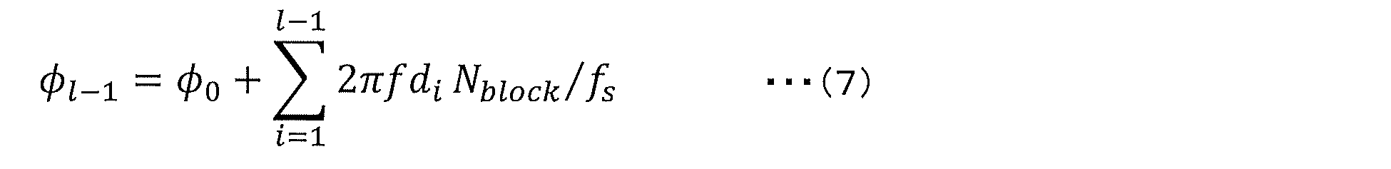
位相積分方式は、ドップラー係数が式(6)および(7)のように狭帯域信号の位相回転速度に表れ、処理ブロック末尾の位相が次処理ブロックの初期位相となるように位相を積分していく方式である。 The phase integration method integrates the phase so that the Doppler coefficient is expressed in the phase rotation speed of the narrowband signal as shown in equations (6) and (7), and the phase at the end of a processing block becomes the initial phase of the next processing block.
次に、第2の比較例について、図3を参照して説明する。第2の比較例は、サンプル更新方式である。図3は、第2の比較例を説明するための模式図である。図3に示すように、サンプル更新方式では、音源波形の1サンプル毎に変化し得る伝搬遅延をそれぞれ与えられた系列からなる波形を求める。例えば、伝搬遅延を毎時刻変化する有限インパルス応答による遅延フィルタhn=[hn(0),hn(1),・・・,hn(M)]を音源信号s(n)に畳み込むことで、波形x(n)が式(8)に示すように得られる。 Next, a second comparative example will be described with reference to FIG. 3. The second comparative example is a sample update method. FIG. 3 is a schematic diagram for explaining the second comparative example. As shown in FIG. 3, the sample update method obtains a waveform consisting of a series in which a propagation delay that can change for each sample of the sound source waveform is given. For example, by convolving a delay filter hn = [hn(0), hn(1), ..., hn(M)] based on a finite impulse response in which the propagation delay changes every time, with the sound source signal s(n), a waveform x(n) is obtained as shown in equation (8).

次に、第3の比較例について、図4を参照して説明する。第3の比較例は、処理ブロック伸縮方式である。図4は、第3の比較例を説明するための模式図である。図4に示すように、処理ブロックlの伝搬遅延時間がτlであり、これに続く処理ブロックl+1の伝搬遅延時間がτl+1であるとき、τl+1-τl≠0であれば、波形の連続性から処理ブロックlの末尾はτl+1の伝搬遅延に等しいと考えられる。すなわち、処理ブロックlの時間長をNblock[サンプル]からNblock+(τl+1-τl)*fs[サンプル]へ伸縮させることで、波形の連続性を保つことができる。また、波形の伸縮によって、式(9)で示されるドップラー係数dによる周波数シフトをしていることと等価となる。 Next, a third comparative example will be described with reference to FIG. 4. The third comparative example is a processing block expansion/contraction method. FIG. 4 is a schematic diagram for explaining the third comparative example. As shown in FIG. 4, when the propagation delay time of the processing block l is τ l and the propagation delay time of the following processing block l+1 is τ l+1 , if τ l+1 - τ l ≠ 0, the end of the processing block l is considered to be equal to the propagation delay of τ l+1 from the continuity of the waveform. That is, by expanding or contracting the time length of the processing block l from N block [samples] to N block + (τ l+1 - τ l ) * f s [samples], the continuity of the waveform can be maintained. In addition, the expansion or contraction of the waveform is equivalent to a frequency shift by the Doppler coefficient d shown in equation (9).

処理ブロックの伸縮後の波形x(n)は、ドップラー係数dに対応して音源波形s(n)={s(0),s(1),・・・,s(Nblock-1),s(Nblock)}を式(10)に示すようにリサンプルすることで得られる。 The waveform x(n) after the processing block is expanded or contracted is obtained by resampling the sound source waveform s(n) = {s(0), s(1), ..., s(N block -1), s(N block )} according to the Doppler coefficient d as shown in equation (10).

なお、元の離散音源波形s(n)のサンプル点からずれたs(d),s(2d),・・・は、補間によって求められる。 Note that s(d), s(2d), ..., which are shifted from the sample points of the original discrete sound source waveform s(n), are found by interpolation.
ここまで、3つの比較例について説明したが、各比較例には、次のような課題がある。第1の比較例である位相積分方式は、位相回転速度を変化させることで周波数シフトの模擬は可能である。しかし、適用できる信号が狭帯域信号に限定されてしまう。また、出力される処理ブロックの長さと入力される処理ブロックの長さとが同じで、かつ、これらの長さは一定である。そのため、処理ブロック1の信号の伝搬遅延がドップラー係数にしか現れず、受信時刻としては考慮されていないという問題がある。
So far, three comparative examples have been explained, but each has the following problems. The first comparative example, the phase integration method, can simulate a frequency shift by changing the phase rotation speed. However, the signals that can be applied are limited to narrowband signals. Also, the length of the output processing block is the same as the length of the input processing block, and these lengths are constant. Therefore, there is a problem in that the propagation delay of the signal in
第2の比較例であるサンプル更新方式は、1サンプル毎に変化する伝搬遅延が表現された遅延フィルタを畳み込むことで、任意の信号波形に対して、正確な伝搬遅延および周波数シフトの模擬が可能である。受信時刻に伝搬遅延が反映されるが、1サンプル毎に伝搬遅延計算を行うため、計算コストが大きいという問題がある。 The sample update method, which is the second comparative example, can accurately simulate the propagation delay and frequency shift for any signal waveform by convolving a delay filter that expresses the propagation delay that changes for each sample. The propagation delay is reflected in the reception time, but there is a problem in that the calculation cost is high because the propagation delay is calculated for each sample.
第3の比較例である処理ブロック伸縮方式は、処理ブロック内の信号波形を伸縮させることでブロック単位での周波数シフトを模擬可能である。しかし、サンプル更新方式と異なり、処理ブロック内で一律のドップラー係数となるため、処理ブロック内でドップラー係数が大きく変化する場合には適していない。この場合、処理ブロック内でドップラー係数が一定とみなせるほど処理ブロック長を短く設定しておくことで対応できるが、一律で処理ブロック長を短くすることは計算コストとのトレードオフを考える必要がある。 The processing block expansion/contraction method, which is the third comparative example, can simulate frequency shifts on a block-by-block basis by expanding or contracting the signal waveform within the processing block. However, unlike the sample update method, the Doppler coefficient is uniform within the processing block, so it is not suitable for cases where the Doppler coefficient changes significantly within the processing block. In this case, it is possible to deal with this by setting the processing block length short enough that the Doppler coefficient can be considered constant within the processing block, but shortening the processing block length uniformly requires consideration of the trade-off with calculation costs.
本実施の形態1の信号生成装置は、これらの問題を解決するものである。本実施の形態1の信号生成装置の構成を説明する。図5は、実施の形態1に係る信号生成装置の一構成例を示す図である。 The signal generating device of the first embodiment solves these problems. The configuration of the signal generating device of the first embodiment will be described. Figure 5 is a diagram showing an example of the configuration of the signal generating device according to the first embodiment.
信号生成装置1は、コンピュータ等の情報処理装置である。図5に示すように、信号生成装置1は、入力部2と、記憶部3と、制御部4と、出力部5とを有する。記憶部3は、例えば、HDD(Hard Disk Drive)装置である。出力部5は、例えば、ディスプレイ装置である。制御部4は、プログラムを記憶するメモリ11と、プログラムにしたがって処理を実行するCPU(Central Processing Unit)12とを有する。メモリ11は、例えば、フラッシュメモリ等の不揮発性メモリである。入力部2には、模擬信号の基準となる音源信号時間波形が入力される。
The
図6は、図5に示した制御部の一構成例を示す機能ブロック図である。制御部4は、処理ブロック更新手段21と、係数変化度算出手段22と、判定手段23と、サンプル位置算出手段31と、補間処理手段32と、遅延処理手段33とを有する。また、制御部4は、分割手段41と、サブブロック更新手段43とを有する。CPU12がプログラムを実行することで、処理ブロック更新手段21、係数変化度算出手段22、判定手段23、サンプル位置算出手段31、補間処理手段32、遅延処理手段33、分割手段41およびサブブロック更新手段43が構成される。
Figure 6 is a functional block diagram showing an example of the configuration of the control unit shown in Figure 5. The
記憶部3は、複数にメモリ領域が分割されている。図6に示す構成例においては、記憶部3は、データを記憶させるメモリ領域として、音源波形ブロックメモリ51と、伝搬遅延メモリ52と、サブメモリ53とを有する。音源波形ブロックメモリ51は、音源信号時間波形を処理ブロック毎に記憶する記憶手段である。伝搬遅延メモリ52は、処理ブロック毎の伝搬遅延を記憶する記憶手段である。伝搬遅延メモリ52は、ブロックインデックスに対応して、処理ブロックのブロック長と伝搬遅延とを組として記憶する。
The
サブメモリ53は、音源波形サブブロックメモリ54と、伝搬遅延サブメモリ55とを有する。サブメモリ53の領域は、分割手段41によって記憶部3に作成される。音源波形サブブロックメモリ54は、分割手段41によって分割されたサブブロック毎に対応する時間範囲の音源信号時間波形を記憶する。伝搬遅延サブメモリ55は、サブブロック数のサブブロックインデックスに対応して、サブブロックのブロック長と伝搬遅延とを組として記憶する。サブブロックは、処理ブロックが複数に分割されたときの1つの時間範囲である。
The sub-memory 53 has a sound source
処理ブロック更新手段21は、音源信号時間波形およびブロックインデックスを入力として、伝搬遅延および周波数シフトさせる対象となる処理ブロックの範囲の音源信号時間波形を音源波形ブロックメモリ51に記憶させる。本実施の形態1では、伝搬遅延メモリ52が処理ブロック毎の伝搬遅延を記憶する場合で説明するが、処理ブロック更新手段21が、音源信号時間波形に対して、処理ブロック毎に伝搬遅延を算出する伝搬遅延算出手段として機能してもよい。
The processing block update means 21 receives the sound source signal time waveform and the block index as input, and stores the sound source signal time waveform in the range of the processing block to be subjected to the propagation delay and frequency shift in the sound source
係数変化度算出手段22は、伝搬遅延メモリ52からブロックインデックスに対応する時刻の伝搬遅延を読み出し、読み出した伝搬遅延を入力とし、ドップラー係数変化度を算出し、ドップラー係数変化度を判定手段23に出力する。判定手段23は、ドップラー係数変化度を入力とし、ドップラー係数変化度が予め決められた閾値以下か否かを判定する。判定手段23は、判定結果の情報を、係数変化度算出手段22、サンプル位置算出手段31および分割手段41に通知する。
The coefficient change degree calculation means 22 reads out the propagation delay at the time corresponding to the block index from the
分割手段41は、ドップラー係数変化度が閾値より大きい場合、伝搬遅延メモリ52からブロックインデックスに対応する時刻の伝搬遅延を読み出し、読み出した伝搬遅延と、ドップラー係数変化度とを入力とし、補間した伝搬遅延およびサブブロックのブロック長を求めて伝搬遅延サブメモリ55に記憶させる。
When the Doppler coefficient change rate is greater than the threshold, the division means 41 reads the propagation delay at the time corresponding to the block index from the
分割手段41の構成を、図7を参照して説明する。図7は、図6に示した分割手段の一構成例を示す機能ブロック図である。分割手段41は、ブロック長算出手段141と、伝搬遅延補間処理手段142とを有する。 The configuration of the division means 41 will be described with reference to FIG. 7. FIG. 7 is a functional block diagram showing an example of the configuration of the division means shown in FIG. 6. The division means 41 has a block length calculation means 141 and a propagation delay interpolation processing means 142.
ブロック長算出手段141は、伝搬遅延メモリ52を参照してブロックインデックスに対応する時刻の伝搬遅延を読み出し、読み出した伝搬遅延とドップラー係数変化度とを入力とし、処理ブロックを複数のサブブロックに分割し、サブブロック数およびサブブロックのブロック長の情報を伝搬遅延補間処理手段142に出力する。伝搬遅延補間処理手段142は、伝搬遅延メモリ52を参照してブロックインデックスに対応する時刻の伝搬遅延を読み出し、読み出した伝搬遅延とブロック長とを入力とし、伝搬遅延補間処理を行い、伝搬遅延サブメモリ55が記憶する情報を更新する。
The block length calculation means 141 refers to the
図6に示すサブブロック更新手段43は、伝搬遅延サブメモリ55からサブブロックインデックスに対応するサブブロックのブロック長を読み出し、音源波形ブロックメモリ51からブロックインデックスに対応する時間範囲の音源信号時間波形を読み出す。サブブロック更新手段43は、読み出したブロック長および音源信号時間波形と、サブブロックインデックスとを入力とし、サブブロックインデックスに対応する時間範囲の音源信号時間波形を音源波形サブブロックメモリ54に記憶させる。
The subblock update means 43 shown in FIG. 6 reads the block length of the subblock corresponding to the subblock index from the
サンプル位置算出手段31は、ドップラー係数変化度が閾値以下である場合、伝搬遅延メモリ52からブロックインデックスに対応する時刻の伝搬遅延を読み出し、読み出した伝搬遅延を入力とし、サンプル点位置の情報を補間処理手段32に出力する。サンプル位置算出手段31は、ドップラー係数変化度が閾値より大きい場合、伝搬遅延サブメモリ55からサブブロックインデックスに対応する伝搬遅延を読み出し、読み出した伝搬遅延とブロック長とを入力とし、サンプル点位置を算出し、サンプル点位置の情報を補間処理手段32に出力する。
When the Doppler coefficient change rate is equal to or less than the threshold, the sample position calculation means 31 reads the propagation delay at the time corresponding to the block index from the
補間処理手段32は、音源波形ブロックメモリ51に格納されている処理ブロックの音源信号時間波形と、サンプル点位置とを入力とし、位相遅延および周波数シフトを表現した信号を生成して遅延処理手段33に出力する。補間処理手段32は、音源波形サブブロックメモリ54からサブブロックインデックスに対応する時間範囲の音源信号時間波形を読み出し、読み出した音源信号時間波形とサンプル点位置とを入力とし、位相遅延および周波数シフトを表現した信号を生成して遅延処理手段33に出力する。
The interpolation processing means 32 receives the sound source signal time waveform of the processing block stored in the sound source
遅延処理手段33は、伝搬遅延メモリ52からブロックインデックスに対応する時刻の伝搬遅延を読み出し、読み出した伝搬遅延と、位相遅延および周波数シフトを表現した信号とを入力とし、伝搬遅延および周波数シフトした後の波形を生成して、図5に示した出力部5に出力する。遅延処理手段33は、伝搬遅延サブメモリ55からサブブロックインデックスに対応する伝搬遅延を読み出し、読み出した伝搬遅延と、位相遅延および周波数シフトを表現した信号とを入力とし、伝搬遅延および周波数シフトした後の波形を生成して、図5に示した出力部5に出力する。
The delay processing means 33 reads out the propagation delay at the time corresponding to the block index from the
なお、本実施の形態1では、図6に示すように、音源波形ブロックメモリ51、伝搬遅延メモリ52およびサブメモリ53が記憶部3に設けられる場合で説明したが、これらのメモリが図5に示したメモリ11に設けられてもよい。
In the first embodiment, as shown in FIG. 6, the sound source
次に、本実施の形態1の信号生成装置1の動作を説明する。図8は、実施の形態1に係る信号生成装置の動作手順の一例を示すフローチャートである。図9は、図6に示した伝搬遅延メモリおよび伝搬遅延サブメモリが記憶する情報の一例を示す図である。
Next, the operation of the
ここでは、信号生成装置1が、音の伝搬を例として、音源および受波点の位置ベクトルが時間変化する状況での受波点の受信波形を模擬する疑似信号を生成する場合を考える。図9の上段に示すように、伝搬遅延メモリ52は、各処理ブロックに対応する時刻の伝搬遅延を記憶しているものとする。
Here, we consider the case where the
音源信号時間波形として、式(11)に示す音源時間信号s(n)が制御部4に入力される(ステップS101)。ステップS102において、処理ブロック更新手段21は、音源時間信号s(n)を入力とし、ブロックインデックスlに対応する時刻インデックスの集合nlの時間波形s(nl)を音源波形ブロックメモリ51に記憶させる。ステップS102において、処理ブロックがブロックインデックスlに対応して、順次、更新される。時間波形nlを式(12)に示す。ここで、ブロックインデックスlは処理ブロックのインデックスであり、Lは全処理ブロック数である。
As the sound source signal time waveform, the sound source time signal s(n) shown in equation (11) is input to the control unit 4 (step S101). In step S102, the processing block update means 21 receives the sound source time signal s(n) and stores the time waveform s(n l ) of the set of time indexes n l corresponding to the block index l in the sound source

![]()
![]()
ステップS102以降の処理で必要となる伝搬遅延τl、τl+1、τl+2は、伝搬遅延メモリ52が記憶するτ={τ1,τ2,・・・,τL}からブロックインデックスlを基に参照される。ステップS103において、係数変化度算出手段22は、伝搬遅延τl、τl+1、τl+2を次の式(13)に入力し、ドップラー係数変化度Δdlを算出する。
The propagation delays τ l , τ l+1 , and τ l+2 required for the processes in and after step S102 are referenced based on the block index l from τ = {τ 1 , τ 2 , ..., τ L } stored in the
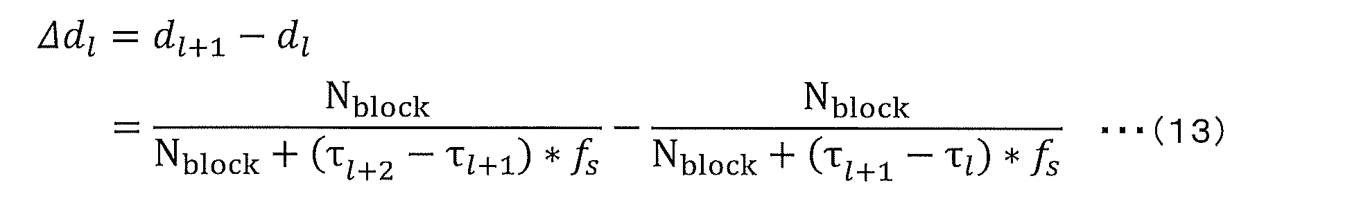
ステップS104において、判定手段23は、ドップラー変化度|Δdl|と予め決められた閾値δとを比較し、ドップラー変化度|Δdl|が閾値δ以下か否かを判定する。閾値δは、計算コストを重視する場合、0.01に近い大きめの値が設定され、模擬度を重視する場合、0に近い小さめの値が設定される。ドップラー変化度|Δdl|が閾値δ以下の場合、ブロックインデックスlに対応する時間範囲ではドップラー係数は大きく変化しないと考えられる。そのため、係数変化度算出手段22は、音源および受波点の相対速度の情報を用いないで、連続する処理ブロック間の伝搬遅延差を用いて処理ブロックの伸縮率を推定する。 In step S104, the determination means 23 compares the Doppler change rate |Δd l | with a predetermined threshold value δ to determine whether the Doppler change rate |Δd l | is equal to or less than the threshold value δ. When the calculation cost is emphasized, the threshold value δ is set to a larger value close to 0.01, and when the simulation degree is emphasized, a smaller value close to 0 is set. When the Doppler change rate |Δd l | is equal to or less than the threshold value δ, it is considered that the Doppler coefficient does not change significantly in the time range corresponding to the block index l. Therefore, the coefficient change rate calculation means 22 estimates the expansion/contraction rate of the processing block using the propagation delay difference between successive processing blocks without using information on the relative speed between the sound source and the wave receiving point.
ステップS105において、サンプル位置算出手段31は、推定された伸縮率で処理ブロック全体を伸縮し、対応するサンプル点を補間によって取得し、伝搬遅延および周波数シフト後のサンプル点の位置を算出する。具体的には、サンプル位置算出手段31は、次のようにして、補間処理手段32に出力する時刻インデックスの集合nl’を求める。時刻インデックスの集合nl’を、式(14)に示す。 In step S105, the sample position calculation means 31 expands or contracts the entire processing block by the estimated expansion/contraction rate, obtains the corresponding sample points by interpolation, and calculates the positions of the sample points after the propagation delay and frequency shift. Specifically, the sample position calculation means 31 determines a set n l ' of time indexes to be output to the interpolation processing means 32 as follows. The set n l ' of time indexes is shown in Equation (14).

式(14)において、Nblock’はサンプル数Nblockの処理ブロックlの波形伸縮後のサンプル数である。dlはブロックインデックスに対応するドップラー係数であり、式(13)の第2項に示されている。φlは式(15)に表される初期サンプルズレ位置である。 In equation (14), N block ' is the number of samples after waveform expansion and contraction of processing block l of sample number N block . d l is the Doppler coefficient corresponding to the block index and is shown in the second term of equation (13). φ l is the initial sample shift position expressed in equation (15).
![]()
![]()
式(15)において、記号floor[・]は、小数点以下を切り捨てる演算を表す。%xはxで除算したときの余りを表し、{ }内が1になったとき、{1}%1=0とするための処理である。 In formula (15), the symbol floor[.] represents an operation to truncate the decimal point. %x represents the remainder when dividing by x, and is a process to make {1}%1=0 when the value in { } becomes 1.
小数サンプル遅延である場合、整数サンプル遅延floor[τlfs]の端数τlfs-floor[τlfs]だけブロックの元始点時刻が移動する。波形としてサンプルされるのは元の時間スケールのサンプル時刻{1-(τlfs-floor[τlfs])}となるが、ドップラー効果が発生している場合には係数倍だけ開始時刻がずれる。 In the case of a fractional sample delay, the original start time of the block is shifted by a fraction τ l fs -floor[τ l fs ] of the integer sample delay floor[τ l fs ]. The sample time of the original time scale {1 - (τ l fs -floor[τ l fs ])} is sampled as the waveform, but if the Doppler effect occurs, the start time is shifted by a factor.
ステップS106において、補間処理手段32は、次のようにして、波形補間処理を行う。補間処理手段32は、波形の離散点系列から連続信号である補間関数を推定する。具体的には、補間処理手段32は、元の波形s(n=nl)の離散信号からスプライン補間により連続関数であるスプライン関数f(n)(lNblock≦n≦(l+1)Nblock)を求める。そして、補間処理手段32は、サンプル位置算出手段31から入力された時刻インデックスの集合nl’をスプライン関数に代入し、小数サンプル遅延および周波数シフト後の波形s’(n)を得る。波形s’(n)を式(16)に示す。 In step S106, the interpolation processing means 32 performs waveform interpolation processing as follows. The interpolation processing means 32 estimates an interpolation function, which is a continuous signal, from a series of discrete points of the waveform. Specifically, the interpolation processing means 32 obtains a spline function f(n) (lN block ≦n≦(l+1)N block ), which is a continuous function, from the discrete signal of the original waveform s (n=n l ) by spline interpolation. Then, the interpolation processing means 32 substitutes the set of time indexes n l ' input from the sample position calculation means 31 into the spline function to obtain a waveform s'(n) after fractional sample delay and frequency shift. The waveform s'(n) is shown in equation (16).

ステップS107において、遅延処理手段33は、次の式(17)に示すように、サンプル遅延floor[τlfs]だけ波形をずらす処理を行う。 In step S107, the delay processing means 33 performs processing to shift the waveform by a sample delay floor[τ l f s ] as shown in the following equation (17).
![]()
![]()
一方、ステップS104の判定の結果、ドップラー変化度|Δdl|が閾値δよりも大きい場合、対応する時間範囲でドップラー係数が大きく変化する。そのため、本実施の形態1の制御部4は、ステップS108の処理に進み、ドップラー係数の変化が追随できる程度の細かいサブブロックに処理ブロックを分割して、サブブロックの単位で伝搬遅延および周波数シフトを求める処理を行う。ここで、ドップラー変化度|Δdl|と閾値δとの比をa=|Δdl|/δ>1とおく。
On the other hand, if the result of the determination in step S104 is that the Doppler gradient |Δd l | is greater than the threshold δ, the Doppler coefficient changes significantly in the corresponding time range. Therefore, the
ステップS108において、分割手段41は、図9に示すように、ブロックインデックスlの中で処理ブロックをfloor[a]+1個のサブブロックに分割する。これにより、サブブロックは、処理ブロックのブロック長が等分された(Nblock/floor[a]+1)サンプルとなる。分割手段41は、連続するサブブロック間を補間して得られるドップラー係数から伝搬遅延を求める。分割手段41の動作については、後で詳しく説明する。 In step S108, the division means 41 divides the processing block into floor[a]+1 sub-blocks in block index l as shown in Fig. 9. As a result, the sub-blocks become (N block /floor[a]+1) samples in which the block length of the processing block is equally divided. The division means 41 calculates the propagation delay from the Doppler coefficient obtained by interpolating between consecutive sub-blocks. The operation of the division means 41 will be described in detail later.
ステップS109において、サブブロック更新手段43は、音源時間信号s(n)を入力とし、サブブロックインデックスl’に対応する時刻インデックスの集合nl,の時間波形s(nl,)を音源波形サブブロックメモリ54に記憶させる。ステップS109において、サブブロックがサブブロックインデックスl’に対応して、順次、更新される。音源時間信号s(n)を式(18)に示し、時刻インデックスの集合nl,を式(19)に示す。
In step S109, the subblock update means 43 receives the sound source time signal s(n) and stores the time waveform s(n l, ) of the set of time indexes n l, corresponding to the subblock index l' in the sound source


ステップS110において、サンプル位置算出手段31は、処理ブロックの代わりにサブブロックを処理対象として、ステップS105で説明した処理と同様に演算処理を行う。具体的には、サンプル位置算出手段31は、補間処理手段32に出力する時刻インデックスの集合nl,’を求める。時刻インデックスの集合nl,’を式(20)に示す。 In step S110, the sample position calculation means 31 performs calculation processing similar to the processing described in step S105, but with a sub-block as the processing target instead of the processing block. Specifically, the sample position calculation means 31 obtains a set of time indexes n l, ' to be output to the interpolation processing means 32. The set of time indexes n l, ' is shown in equation (20).

式(20)において、Nblock’’はサンプル数(Nblock/floor[a]+1)のサブブロックl’の波形伸縮後のサンプル数である。dl,はサブブロックインデックスに対応するドップラー係数である。φl,は次の式(21)で表される初期サンプルズレ位置である。 In equation (20), N block ″ is the number of samples after waveform expansion and contraction of sub-block l′ having the number of samples (N block /floor[a]+1). d l, is the Doppler coefficient corresponding to the sub-block index. φ l, is the initial sample shift position expressed by the following equation (21).
![]()
![]()
ステップS111において、補間処理手段32は、次のようにして、波形補間処理を行う。補間処理手段32は、元の波形s(nl,)の離散信号からスプライン補間により連続関数であるスプライン関数f(n)(lNblock+(l’-1)(Nblock/floor[a]+1)≦n<lNblock+l’(Nblock/floor[a]+1))を求める。そして、補間処理手段32は、サンプル位置算出手段31から入力された時刻インデックスの集合nl,’をスプライン関数に代入し、小数サンプル遅延および周波数シフト後の波形s’(n)を得る。波形s’(n)を式(22)に示す。 In step S111, the interpolation processing means 32 performs waveform interpolation processing as follows. The interpolation processing means 32 obtains a spline function f(n) (lN block + ( l' -1) (N block /floor[a] + 1) ≤ n < lN block + l' (N block /floor[a] + 1)), which is a continuous function, by spline interpolation from the discrete signal of the original waveform s(n l, ). Then, the interpolation processing means 32 substitutes the set of time indexes n l, ' input from the sample position calculation means 31 into the spline function to obtain a waveform s'(n) after fractional sample delay and frequency shift. The waveform s'(n) is shown in equation (22).

ステップS112において、遅延処理手段33は、次の式(23)に示すように、サンプル遅延floor[τl,’fs]だけ波形をずらす処理を行う。 In step S112, the delay processing means 33 performs processing to shift the waveform by a sample delay floor[τ l, 'f s ] as shown in the following equation (23).
![]()
![]()
サブブロック更新手段43は、遅延処理手段33からサブブロックインデックスの情報を受信すると、サブブロックインデックスを更新し(ステップS113)、ステップS109に戻る。制御部4は、ステップS109~S113の処理をサブブロックインデックスl’=1,・・・,L’(ただし、L’=floor[a]+1)まで繰り返す。これにより、ステップS104において、ドップラー係数変化度が閾値δより大きいと判定される場合のブロックインデックスlについて、伝搬遅延および周波数シフトされた後の波形が、遅延処理手段33から出力される。
When the subblock update means 43 receives information on the subblock index from the delay processing means 33, it updates the subblock index (step S113) and returns to step S109. The
処理ブロック更新手段21は、遅延処理手段33からブロックインデックスの情報を受信すると、ブロックインデックスを更新し(ステップS114)、ステップS102に戻る。制御部4がステップS102~S114までをブロックインデックスl=1,・・・,Lまで繰り返すことで、全時間の音源波形について、伝搬遅延および周波数シフトされた後の波形が遅延処理手段33から出力される。このようにして、波形の連続性を担保しながら、受波点における、伝搬遅延および周波数シフトを模擬した信号が生成される。
When the processing block update means 21 receives the block index information from the delay processing means 33, it updates the block index (step S114) and returns to step S102. The
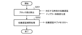
次に、図8に示したステップS108の処理における、分割手段41の動作について、図7、図9および図10を参照して説明する。図10は、図8に示したステップS108の処理における、分割手段の動作手順の一例を示すフローチャートである。 Next, the operation of the splitting means 41 in the process of step S108 shown in FIG. 8 will be described with reference to FIG. 7, FIG. 9, and FIG. 10. FIG. 10 is a flowchart showing an example of the operation procedure of the splitting means in the process of step S108 shown in FIG. 8.
ドップラー係数変化度|Δdl|=aδ(a>1)であるとき、演算処理の負荷を軽減するために、ドップラー係数が線形に変化すると仮定する。ステップS201において、ブロック長算出手段141は、元の処理ブロック長をfloor[a]+1個に等分することで、サブブロック間のドップラー係数変化度を閾値δ以下にすることができる。すなわち、ブロックインデックス内のfloor[a]+1個のサブブロックのドップラー係数は、以下(式(24))に示すようになる。 When the Doppler coefficient change degree |Δd l |=aδ (a>1), it is assumed that the Doppler coefficient changes linearly in order to reduce the load of the calculation process. In step S201, the block length calculation means 141 divides the original processing block length into floor[a]+1 equal parts, thereby making it possible to make the Doppler coefficient change degree between sub-blocks equal to or less than the threshold value δ. That is, the Doppler coefficients of floor[a]+1 sub-blocks in the block index are as shown below (Equation (24)).

次に、伝搬遅延補間処理手段142は、上記のように補間によって得られたドップラー係数から式(9)を変形して得られる式(25)によって、伝搬遅延を逐次的に得る(ステップS202)。 Next, the propagation delay interpolation processing means 142 sequentially obtains the propagation delay using equation (25), which is obtained by transforming equation (9) from the Doppler coefficient obtained by the interpolation as described above (step S202).

ここで、伝搬遅延補間処理手段142は、初期サブブロック伝搬遅延として、τ1’=τ1を使用する。伝搬遅延補間処理手段142は、これをl’=1,2,・・・,floor[a]について解くことで、伝搬遅延サブメモリ55に記憶させる情報を得る。図9の下段に、伝搬遅延サブメモリ55が記憶する情報を示す。
Here, the propagation delay interpolation processing means 142 uses τ 1 '=τ 1 as the initial sub-block propagation delay. The propagation delay interpolation processing means 142 solves this for l'=1, 2, ..., floor[a] to obtain information to be stored in the
本実施の形態1の信号生成装置1は、波形に対して信号処理の単位である処理ブロック毎の伝搬遅延を記憶する記憶手段と、係数変化度算出手段と、判定手段と、分割手段と、サンプル位置算出手段と、補間処理手段と、遅延処理手段とを有する。記憶手段は、例えば、伝搬遅延メモリ52である。係数変化度算出手段22は、伝搬遅延に基づいて、連続する処理ブロック間のドップラー係数変化度を算出する。判定手段23は、ドップラー係数変化度が予め決められた閾値以下であるか否かを判定する。分割手段41は、ドップラー係数変化度が閾値よりも大きい場合、処理ブロックを複数のサブブロックに分割する。サンプル位置算出手段31は、伝搬遅延に基づいて、サブブロック毎に補間が必要なサンプル点位置を算出する。補間処理手段32は、サンプル点位置に基づいて、サブブロック毎に補間処理を実行する。遅延処理手段33は、伝搬遅延に基づいて、補間処理後のサブブロック毎にサンプル遅延を実行する。
The
本実施の形態1によれば、ドップラー係数変化度に対して閾値判定を行い、ドップラー係数変化度が小さい場合、処理ブロックの単位で波形を推定し、ドップラー係数変化度が大きい場合、処理ブロックをよりブロック長の細かいサブブロックに自動的に分割して波形を推定する。音源が受波点よりも遠方にあり、ドップラー係数の変化が緩やかな場合、処理ブロックの単位で処理するため、必要な演算の計算コストが少なくてすむ。また、音源に対して受波点が最接近距離(CPA:Closest Point of Approach)付近のように近く、ドップラー係数が急に変化する場合、処理ブロックを複数のサブブロックに分割して処理するため、波形の位相的連続性だけでなく、ドップラー変化の連続性も模擬することができる。本実施の形態1は、ドップラー係数の変化率に対応して推定する適応的なブロック長でブロック伸縮方式を適用することで、処理ブロック間でドップラー係数が大きく変化しても、模擬する信号の波形の連続性を担保するとともに、計算コストを削減できる。 According to the first embodiment, a threshold judgment is performed on the Doppler coefficient change rate, and if the Doppler coefficient change rate is small, the waveform is estimated in units of processing blocks, and if the Doppler coefficient change rate is large, the processing block is automatically divided into subblocks with smaller block lengths to estimate the waveform. When the sound source is farther away than the receiving point and the Doppler coefficient changes slowly, the processing is performed in units of processing blocks, so the calculation cost of the required calculation is small. In addition, when the receiving point is close to the sound source, such as near the closest point of approach (CPA), and the Doppler coefficient changes suddenly, the processing block is divided into multiple subblocks for processing, so not only the phase continuity of the waveform but also the continuity of the Doppler change can be simulated. In the first embodiment, by applying a block stretching method with an adaptive block length that is estimated in response to the rate of change of the Doppler coefficient, the continuity of the waveform of the simulated signal can be ensured and the calculation cost can be reduced even if the Doppler coefficient changes significantly between processing blocks.
第1の比較例は入力される処理ブロックの長さも出力される処理ブロックの長さも同じで、かつ一定であるのに対し、本実施の形態1では、ドップラー係数の変化率に対応してブロック伸縮方式を適用して模擬信号を推定することができる。 In the first comparative example, the length of the input processing block and the length of the output processing block are the same and constant, whereas in the first embodiment, the block stretching method is applied in response to the rate of change of the Doppler coefficient to estimate the simulation signal.
第2の比較例は1サンプル毎に伝搬遅延を表現して遅延フィルタを畳み込んで波形を伸縮させるため、計算コストが大きくなる。これに対して、本実施の形態1は、処理ブロック毎の伝搬遅延を用いて、ドップラー係数変化度が閾値以下の場合、処理ブロック単位で演算処理を行っているため、計算コストを削減することができる。 The second comparative example expresses the propagation delay for each sample and convolves a delay filter to expand or contract the waveform, resulting in high calculation costs. In contrast, the first embodiment uses the propagation delay for each processing block, and when the Doppler coefficient change rate is below a threshold, calculation processing is performed on a processing block basis, thereby reducing calculation costs.
第3の比較例は処理ブロック内でドップラー係数が一律なので処理ブロック内でドップラー係数が大きく変化する場合に模擬信号の精度が低くなる。これに対して、本実施の形態1は、ドップラー係数の変化率に対応して適応的なブロック長でブロック伸縮方式を適用して推定するので、計算コストを抑制するとともに、模擬信号の精度を向上させることができる。 In the third comparative example, the Doppler coefficient is uniform within the processing block, so the accuracy of the simulated signal decreases when the Doppler coefficient changes significantly within the processing block. In contrast, in the first embodiment, the estimation is performed by applying a block stretching method with an adaptive block length corresponding to the rate of change of the Doppler coefficient, so that the calculation cost can be reduced and the accuracy of the simulated signal can be improved.
(本実施の形態1の利用形態の説明)
上述の実施の形態1では、音の伝搬を例に説明したが、波であれば、例えば、レーダに用いられる電波にも適用できる。
(Description of Usage of the First Embodiment)
In the above-mentioned first embodiment, the propagation of sound has been described as an example, but the present invention can also be applied to any wave, such as radio waves used in radar.
上述の実施の形態1において、伝搬遅延メモリ52が全処理ブロックの伝搬遅延時間の情報を記憶する場合で説明したが、伝搬遅延の算出には、連続する3つの処理ブロックの遅延時間があればよい。具体的には、処理ブロックlと、処理ブロックlに続く処理ブロックl+1および処理ブロックl+2とのそれぞれの遅延時間である。伝搬遅延メモリ52は、保持する処理ブロックlおよび処理ブロックl+1のそれぞれの伝搬遅延と、新たに算出された処理ブロックl+2の伝搬遅延を保持する。そして、伝搬遅延メモリ52は、図8に示したステップS107またはS111の処理がされた後、ステップS102の処理において、処理ブロックlの伝搬遅延を消去し、処理ブロックl+1および処理ブロックl+2のそれぞれの伝搬遅延を保持する。伝搬遅延メモリ52は、記憶する伝搬遅延および消去する伝搬遅延を順次変えることで、必要なメモリ容量を削減できる。処理ブロック更新手段21が、上述のようにして、伝搬遅延メモリ52が記憶する情報の管理を行ってもよい。
In the above-mentioned
また、図8のステップS106およびS111の波形補間処理について、サンプルデータ点を必ず通り、ブロック境界点の1次微分および2次微分が連続し、任意の位置の値を出力しやすいスプライン補間を例に説明したが、この補間方法に限らない。任意の補間位置の値を出力することができる補間処理であれば、計算量と後段の信号処理への影響を勘案して、線形補間またはラグランジュ補間等を用いてもよい。 In addition, the waveform interpolation process in steps S106 and S111 in FIG. 8 has been described using spline interpolation as an example, which always passes through sample data points, has continuous first and second derivatives at block boundary points, and is easy to output a value at any position, but this is not the only possible interpolation method. As long as the interpolation process can output a value at any interpolated position, linear interpolation, Lagrange interpolation, or the like may be used, taking into account the amount of calculation and the impact on subsequent signal processing.
上述の実施の形態1では、単体の情報処理装置の場合で説明したが、複数の情報処理装置を有する信号生成システムであってもよい。図11は、実施の形態1に係る信号生成システムの一構成例を示すブロック図である。信号生成システム10は、情報処理装置101~103を有する。情報処理装置101~103は、インターネット等のネットワーク200を介して互いに接続される。情報処理装置101は図6に示した記憶部3を有する。情報処理装置102は図6に示した制御部4のサンプル位置算出手段31、補間処理手段32および遅延処理手段33を有する。情報処理装置103は図6に示した制御部4の処理ブロック更新手段21、係数変化度算出手段22、判定手段23、分割手段41およびサブブロック更新手段43を有する。図11に示す構成例の場合、本実施の形態1の信号生成方法の実行に必要な演算処理を複数の情報処理装置101~103が分担して行うため、演算処理のスピードを速くすることができる。
In the above-mentioned first embodiment, the case of a single information processing device has been described, but the signal generation system may have multiple information processing devices. FIG. 11 is a block diagram showing an example of a configuration of a signal generation system according to the first embodiment. The
1 信号生成装置
2 入力部
3 記憶部
4 制御部
5 出力部
10 信号生成システム
11 メモリ
12 CPU
21 処理ブロック更新手段
22 係数変化度算出手段
23 判定手段
31 サンプル位置算出手段
32 補間処理手段
33 遅延処理手段
41 分割手段
43 サブブロック更新手段
51 音源波形ブロックメモリ
52 伝搬遅延メモリ
53 サブメモリ
54 音源波形サブブロックメモリ
55 伝搬遅延サブメモリ
101~103 情報処理装置
141 ブロック長算出手段
142 伝搬遅延補間処理手段
200 ネットワーク
REFERENCE SIGNS
21 Processing block update means 22 Coefficient change degree calculation means 23 Decision means 31 Sample position calculation means 32 Interpolation processing means 33 Delay processing means 41 Division means 43 Sub-block update means 51 Excitation source
Claims (7)
前記波形に対して、信号処理の単位である処理ブロック毎の伝搬遅延を記憶する記憶手段と、
前記伝搬遅延に基づいて、連続する前記処理ブロック間のドップラー係数変化度を算出する係数変化度算出手段と、
前記ドップラー係数変化度が予め決められた閾値以下であるか否かを判定する判定手段と、
前記ドップラー係数変化度が前記閾値よりも大きい場合、前記処理ブロックを複数のサブブロックに分割する分割手段と、
前記伝搬遅延に基づいて、前記サブブロック毎に補間が必要なサンプル点位置を算出するサンプル位置算出手段と、
前記サンプル点位置に基づいて、前記サブブロック毎に補間処理を実行する補間処理手段と、
前記伝搬遅延に基づいて、前記補間処理後の前記サブブロック毎にサンプル遅延を実行する遅延処理手段と、
を有する信号生成装置。 1. A signal generator for simulating a propagation delay and a frequency shift for a waveform, comprising:
A storage means for storing a propagation delay for each processing block, which is a unit of signal processing, for the waveform;
a coefficient variation calculation means for calculating a Doppler coefficient variation between successive processing blocks based on the propagation delay;
a determination means for determining whether the Doppler coefficient change rate is equal to or less than a predetermined threshold;
a dividing means for dividing the processing block into a plurality of sub-blocks when the Doppler coefficient change rate is greater than the threshold value;
a sample position calculation means for calculating sample point positions requiring interpolation for each of the sub-blocks based on the propagation delay;
an interpolation processing means for executing an interpolation process for each of the sub-blocks based on the sample point positions;
a delay processing means for executing a sample delay for each of the sub-blocks after the interpolation processing based on the propagation delay;
A signal generating device having the following:
連続する前記サブブロック間の伝搬遅延差を用いて前記サブブロックの伸縮率を推定する、
請求項1に記載の信号生成装置。 The coefficient variation degree calculation means
estimating a stretching ratio of the sub-blocks using a propagation delay difference between the successive sub-blocks;
2. A signal generating device according to claim 1.
連続する前記サブブロック間でドップラー係数が線形に変化するように前記伝搬遅延を補間する、
請求項1または2に記載の信号生成装置。 The dividing means is
interpolating the propagation delays such that the Doppler coefficient varies linearly between successive sub-blocks;
3. A signal generating device according to claim 1 or 2.
前記サブブロックに対応する前記伝搬遅延に係る時間、および、前記係数変化度算出手段によって推定された前記伸縮率に基づいて、前記サブブロックにおける前記サンプル点位置を算出する、
請求項2に記載の信号生成装置。 The sample position calculation means
calculating the sample point positions in the sub-blocks based on the propagation delay times corresponding to the sub-blocks and the expansion/contraction ratios estimated by the coefficient variation degree calculation means ;
3. A signal generating device according to claim 2.
前記波形の離散点系列から連続信号である補間関数を推定し、前記補間関数に前記サンプル点位置の値を入力することで離散点間の位置の値を出力する、
請求項1~4のいずれか1項に記載の信号生成装置。 The interpolation processing means
an interpolation function, which is a continuous signal, is estimated from the discrete point series of the waveform, and the values of the sample point positions are input to the interpolation function to output values of positions between the discrete points;
A signal generating device according to any one of claims 1 to 4.
前記波形に対して、信号処理の単位である処理ブロック毎の伝搬遅延を記憶する記憶手段と、
前記伝搬遅延に基づいて、連続する前記処理ブロック間のドップラー係数変化度を算出する係数変化度算出手段と、
前記ドップラー係数変化度が予め決められた閾値以下であるか否かを判定する判定手段と、
前記ドップラー係数変化度が前記閾値よりも大きい場合、前記処理ブロックを複数のサブブロックに分割する分割手段と、
前記伝搬遅延に基づいて、前記サブブロック毎に補間が必要なサンプル点位置を算出するサンプル位置算出手段と、
前記サンプル点位置に基づいて、前記サブブロック毎に補間処理を実行する補間処理手段と、
前記伝搬遅延に基づいて、前記補間処理後の前記サブブロック毎にサンプル遅延を実行する遅延処理手段と、
を有する信号生成システム。 1. A signal generation system for simulating a propagation delay and a frequency shift for a waveform, comprising:
A storage means for storing a propagation delay for each processing block, which is a unit of signal processing, for the waveform;
a coefficient variation calculation means for calculating a Doppler coefficient variation between successive processing blocks based on the propagation delay;
a determination means for determining whether the Doppler coefficient change rate is equal to or less than a predetermined threshold;
a dividing means for dividing the processing block into a plurality of sub-blocks when the Doppler coefficient change rate is greater than the threshold value;
a sample position calculation means for calculating sample point positions requiring interpolation for each of the sub-blocks based on the propagation delay;
an interpolation processing means for executing an interpolation process for each of the sub-blocks based on the sample point positions;
a delay processing means for executing a sample delay for each of the sub-blocks after the interpolation processing based on the propagation delay;
A signal generating system comprising:
前記波形に対して、信号処理の単位である処理ブロック毎の伝搬遅延を記憶するステップと、
前記伝搬遅延に基づいて、連続する前記処理ブロック間のドップラー係数変化度を算出するステップと、
前記ドップラー係数変化度が予め決められた閾値以下であるか否かを判定するステップと、
前記ドップラー係数変化度が前記閾値よりも大きい場合、前記処理ブロックを複数のサブブロックに分割するステップと、
前記伝搬遅延に基づいて、前記サブブロック毎に補間が必要なサンプル点位置を算出するステップと、
前記サンプル点位置に基づいて、前記サブブロック毎に補間処理を実行するステップと、
前記伝搬遅延に基づいて、前記補間処理後の前記サブブロック毎にサンプル遅延を実行するステップと、
を有する信号生成方法。 1. A signal generation method for simulating a propagation delay and a frequency shift in a waveform by an information processing device, comprising:
storing a propagation delay for each processing block, which is a unit of signal processing, for the waveform;
calculating a Doppler coefficient change rate between successive processing blocks based on the propagation delay;
determining whether the Doppler coefficient change rate is equal to or less than a predetermined threshold;
if the Doppler coefficient variation is greater than the threshold, dividing the processing block into a plurality of sub-blocks;
calculating sample point positions requiring interpolation for each of the sub-blocks based on the propagation delay;
performing an interpolation process for each of the sub-blocks based on the sample point positions;
performing a sample delay for each of the sub-blocks after the interpolation process based on the propagation delay;
A signal generating method comprising:
Priority Applications (1)
| Application Number | Priority Date | Filing Date | Title |
|---|---|---|---|
| JP2021029331A JP7608866B2 (en) | 2021-02-26 | 2021-02-26 | Signal generating device, signal generating system, and signal generating method |
Applications Claiming Priority (1)
| Application Number | Priority Date | Filing Date | Title |
|---|---|---|---|
| JP2021029331A JP7608866B2 (en) | 2021-02-26 | 2021-02-26 | Signal generating device, signal generating system, and signal generating method |
Publications (2)
| Publication Number | Publication Date |
|---|---|
| JP2022130763A JP2022130763A (en) | 2022-09-07 |
| JP7608866B2 true JP7608866B2 (en) | 2025-01-07 |
Family
ID=83153459
Family Applications (1)
| Application Number | Title | Priority Date | Filing Date |
|---|---|---|---|
| JP2021029331A Active JP7608866B2 (en) | 2021-02-26 | 2021-02-26 | Signal generating device, signal generating system, and signal generating method |
Country Status (1)
| Country | Link |
|---|---|
| JP (1) | JP7608866B2 (en) |
Citations (1)
| Publication number | Priority date | Publication date | Assignee | Title |
|---|---|---|---|---|
| JP2004514374A (en) | 2000-11-15 | 2004-05-13 | エレクトロビット・オサケユキテュア | Radio channel simulation method and channel simulator |
-
2021
- 2021-02-26 JP JP2021029331A patent/JP7608866B2/en active Active
Patent Citations (1)
| Publication number | Priority date | Publication date | Assignee | Title |
|---|---|---|---|---|
| JP2004514374A (en) | 2000-11-15 | 2004-05-13 | エレクトロビット・オサケユキテュア | Radio channel simulation method and channel simulator |
Also Published As
| Publication number | Publication date |
|---|---|
| JP2022130763A (en) | 2022-09-07 |
Similar Documents
| Publication | Publication Date | Title |
|---|---|---|
| TWI440269B (en) | Advanced laser wavelength control technology | |
| CN104112079A (en) | Fuzzy adaptive variational Bayesian unscented Kalman filter method | |
| JP4998039B2 (en) | Observation data assimilation method | |
| KR102090539B1 (en) | Method and device for reinforcement learning using novel centering operation based on probability distribution | |
| US9081091B2 (en) | Method and device for tracking the path of motion of a moving object as well as computer program and data storage media | |
| JP5692091B2 (en) | Information processing apparatus, information processing method, and computer program | |
| WO2018003621A1 (en) | River water level and flow rate calculating device and program | |
| Acar | Simultaneous optimization of shape parameters and weight factors in ensemble of radial basis functions | |
| CN117972637A (en) | Angular velocity data fusion method and angular velocity data fusion device for angular vibration table | |
| JP7608866B2 (en) | Signal generating device, signal generating system, and signal generating method | |
| JP2010127771A (en) | Synthetic aperture sonar, and method and program for correcting phase error of synthetic aperture sonar | |
| JP6024012B1 (en) | Estimation method of wave propagation time between two points | |
| JP2017227452A (en) | Device and method for calculating propagation loss | |
| JP2010056778A (en) | Echo canceller, echo canceling method, echo canceling program, and recording medium | |
| RU2207622C2 (en) | Method and device for trend separation by multiplying estimates for its single original implementation | |
| JP2018136671A (en) | Internal wave parameter estimation apparatus and internal wave parameter estimation method | |
| RU2610831C1 (en) | Method for estimating parameters of object's trajectory | |
| Dorwarth et al. | Nonlinear model order reduction for high Q MEMS gyroscopes | |
| JP6524371B1 (en) | Filtering device, sensor device, filtering method and program | |
| JP2023028225A (en) | Propagation delay time calculation device, propagation delay time calculation system, method for propagation delay time calculation and program | |
| JP2005331248A (en) | Target-tracking device and target-tracking method | |
| JP7318211B2 (en) | SOUND PROPAGATION SIMULATION SYSTEM AND SOUND PROPAGATION SIMULATION METHOD | |
| CN112649848B (en) | Method and device for solving seismic wave impedance using wave equation | |
| RU2393535C1 (en) | Device for processing of signals based on double-criteria method | |
| RU2362265C1 (en) | Digital intelligent iterative filter |
Legal Events
| Date | Code | Title | Description |
|---|---|---|---|
| A621 | Written request for application examination |
Free format text: JAPANESE INTERMEDIATE CODE: A621 Effective date: 20231109 |
|
| A977 | Report on retrieval |
Free format text: JAPANESE INTERMEDIATE CODE: A971007 Effective date: 20240807 |
|
| A131 | Notification of reasons for refusal |
Free format text: JAPANESE INTERMEDIATE CODE: A131 Effective date: 20240910 |
|
| A521 | Request for written amendment filed |
Free format text: JAPANESE INTERMEDIATE CODE: A523 Effective date: 20241016 |
|
| TRDD | Decision of grant or rejection written | ||
| A01 | Written decision to grant a patent or to grant a registration (utility model) |
Free format text: JAPANESE INTERMEDIATE CODE: A01 Effective date: 20241119 |
|
| A61 | First payment of annual fees (during grant procedure) |
Free format text: JAPANESE INTERMEDIATE CODE: A61 Effective date: 20241202 |
|
| R150 | Certificate of patent or registration of utility model |
Ref document number: 7608866 Country of ref document: JP Free format text: JAPANESE INTERMEDIATE CODE: R150 |